Embed Size (px)
Citation preview
RUPESH CH, et al, International Journal of Research Sciences and Advanced Engineering [IJRSAE]TM Volume 2, Issue 16, PP:320 - 334, DEC’ 2016.
International Journal of Research Sciences and Advanced Engineering
Vol.2 (16), ISSN: 2319-6106, DEC’ 2016. PP: 320 - 334
COMPARATIVE STUDY ON DIFFERENT REGULAR SHAPES
(SQUARE, CIRCLULE, TRANGULAR) BUILDING DESIGN
CH RUPESH 1*, Dr. DUMPA VENKATESWARLU 2*
1. Student, Dept of CIVIL, GODAVARI INSTITUTE OF ENGINEERING AND TECHNOLOGY,
RAJAHMUNDRY. 2. Head - Dept of CIVIL, GODAVARI INSTITUTE OF ENGINEERING AND TECHNOLOGY,
RAJAHMUNDRY.
ABSTRACT
Modern tall buildings have efficient structural systems, and utilize high-strength materials,
resulting in reduced building height, and thus, become more slender and flexible with low
damping. These flexible buildings are very sensitive to wind excitation and earthquake load
causing discomfort to the building occupants. Therefore, in order to mitigate such an
excitation and to improve the performance of tall buildings against wind loads and
earthquake loads, many researches and studies have been performed. Early integration of
aerodynamic shaping, wind engineering considerations, and structural system selections
play a major role in the architectural design of a tall building in order to mitigate the
building response to the wind excitations. A tall building, whose shape is unsuitable, often
requires a great deal of steel or a special damping mechanism to reduce its dynamic
displacement within the limits of the criterion level for the design wind speed.
Understandably, an appropriate choice of building shape and architectural modifications are
also extremely important and effective design approaches to reduce wind and earthquake
induced motion by altering the flow pattern around the building, hence for this research
work four different shaped buildings are generally studied namely circular, rectangular,
square and triangular. To achieve these purposes, firstly, a literature survey, which includes
the definition, design parameters, and lateral load considerations of tall buildings, is
presented. Then the results are interpreted for different shaped buildings and of different
stories thereby concluding as to which shaped high rise building is most stable for different
conditions.
Keywords: High-rise Building, Wind loads Effect, Earthquake load effect.
INTRODUCTION
Tall buildings, which are usually designed
for office or commercial use, are among
the most distinguished space definitions in
the architectural history of American
urbanism in the twentieth century. They
are primarily a reaction to the rapid
growth of the urban population and the
demand by business activities to be as
close to each other as possible. Architects
reinterpretations of the building type, the
high cost of land in urban areas, the
desire to prevent the disorganized
expansion, the need to preserve
agricultural production, the concept of
skyscraper, influence of cultural
significance and prestige, have all
contributed to force buildings upward.
Today, it is virtually impossible to imagine
a major city without tall buildings. The
importance of tall buildings in the
RUPESH CH, et al, International Journal of Research Sciences and Advanced Engineering [IJRSAE]TM Volume 2, Issue 16, PP:320 - 334, DEC’ 2016.
International Journal of Research Sciences and Advanced Engineering
Vol.2 (16), ISSN: 2319-6106, DEC’ 2016. PP: 320 - 334
contemporary urban development is
without doubt ever increasing despite
their several undeniable negative effects
on the quality of urban life.
Many researches and studies have been
done in order to mitigate excitations and
improve the performance of tall buildings
against wind loads & earthquake loads. An
extremely important and effective design
approach among these methods is
aerodynamic modifications, including,
modifications of building’s corner
geometry and its cross-sectional shape.
Tall buildings are gigantic projects
demanding incredible logistics and
management, and require enormous
financial investment. A careful
coordination of the structural elements
and the shape of a building which
minimize the lateral displacement, may
offer considerable savings. Nowadays, the
challenge of designing an efficient tall
building has considerably changed. The
conventional approach to tall building
design in the past was to limit the forms
of the buildings to a rectangular shape
mostly, but today, much more
complicated building geometries could be
utilized.
Earthquake is one of the major natural
disaster which is result in sudden release
of energy in the earth crust that’s creates
seismic waves. Many of buildings
constructed have a ground storey is left
open such buildings are more vulnerable
in earthquakes. During the earthquake
displacement of ground surface or shaking
of ground surface takes place whish
results damage to structures. Shear walls
are relatively thin reinforced vertical wall.
Shear wall are used in a building to resist
the effect of gravity loads and story shear
due to seismic forces. Buildings designed
with typical method of construction lack in
resistance of lateral forces developed
during the earthquake. Properly designed
and detailed building with the shear wall
has shown good performance in the past
earthquake. Shear walls are easy to
construct, because the reinforcement
detailing of walls are relatively simple and
therefore easily implemented at site.
Shear walls starts from the foundation of
building and extended up to the full height
of building
In the beginning, there were slide-rules,
pencils and drafting boards. There were
Building Codes, but they were
considerably smaller than telephone
books. To the modern engineer, these
time-honored tools of the trade may seem
quaint and primitive, but in the hands of a
skilled engineer they were all that was
needed to design safe and sometimes
magnificent structures.
It may seem as if these were simpler
times, but there is no question that
practicing structural engineering was hard
work. Structural engineers made a good
living at their trade, but seldom got rich at
it. The engineer was respected by the
contractor and held in high esteem by the
other members of the project team.
Computers are a relatively recent addition
to the engineer’s toolbox. The
development of the first digital computer
began as a classified military project
during World War II with the first working
model, the ENIAC, making its debut at the
University of Pennsylvania in 1946. This
early computer was an experimental
contraption with vacuum tube circuits that
could only run for short periods of time
RUPESH CH, et al, International Journal of Research Sciences and Advanced Engineering [IJRSAE]TM Volume 2, Issue 16, PP:320 - 334, DEC’ 2016.
International Journal of Research Sciences and Advanced Engineering
Vol.2 (16), ISSN: 2319-6106, DEC’ 2016. PP: 320 - 334
before the vacuum tubes began to blow
out and the system would shut down.
It was the development of silicon
transistor circuits, and later microchip
circuits, that made digital computers a
practical reality in the 1960s. Still, in
those days computers were only seen in
science fiction movies and in the back
rooms of a few universities. When main-
frame computers made their entrance on
the scene, the engineering profession was
quick to see the potential for this
technology to relieve them of the
drudgery and imprecision of tedious and
repetitive hand calculations.
Early use of computers by engineers in
the 1960s was achieved with teletype
connections to a main-frame computer at
a far-off (and sometimes far-out)
university. The computer could be dialed
up on a telephone and, when the
connection was made, the handset of the
phone would be inserted into the modem
of the teletype. In those days "time-
share" did not refer to a vacation
condominium. The engineer would type in
a simple FORTRAN program he had
written himself for the computer to
process. It was unthinkable at the time
that an engineering office could own its
own computer.
In 1972, the first hand-held calculator was
introduced by Hewlett Packard. It did not
take long for engineers to discard their
slide-rules. They were no longer limited to
calculations with a precision of three
significant digits and a wild guess at the
location of the decimal point.
Throughout the 1970s, the use of
computers by engineers increased
steadily. Main-frame computers left school
and became common in large
corporations. Teletypes were replaced by
punch cards and card readers as
computers and computer programs
became larger and more powerful. But, an
engineer owning his own computer was
still just a dream. In the early 1980s,
Apple Computers was born and introduced
the Apple II computer to the consumer
market. Hot on the heels of Apple, IBM
introduced the IBM-PC computer. At long
last, every engineer could afford to own
his very own personal computer. The
practice of structural engineering has not
been the same since.
OBJECTIVE & SCOPE
The main objective of this work is to
contribute to the development of the
design guidance for high rise buildings in
relation to different shapes of building to
control wind excitation and earthquake
load as a reference for architects,
engineers, developers, andstudents.In this
research, the concept of high rise building,
which include the definition, basic design
considerations, and lateral loads; shape
modifications of tall buildings, are studied.
Then the results for different conditions
are interpreted and conclusions are made
as to which shaped buildings out of four
taken in the consideration is most stable.
Further work can also be done on more
complicated shapes of buildings and come
to conclusion as to which is most stable
and economical shapes under given
condition for wind and earthquake loads.
LITERATURE REVIEW
M.Y.Kaltakci,M.H. Arslan& G.
Yavuz[1]studied the effect of external
RUPESH CH, et al, International Journal of Research Sciences and Advanced Engineering [IJRSAE]TM Volume 2, Issue 16, PP:320 - 334, DEC’ 2016.
International Journal of Research Sciences and Advanced Engineering
Vol.2 (16), ISSN: 2319-6106, DEC’ 2016. PP: 320 - 334
and internal shear wall location on
strengthing weak RC frames. They
concluded that shear wall and frame
columns worked monolithically and any
anchorage debonding was not seen at
column-shear joint.
AbolhassanAstaneha[2]bout the
seismic behavior and design of steel shear
wall. Author divide the steel shear wall
system into two categories namely
singular shear wall system and dual shear
wall system Based on the result of tests
reported steel seismic design provision
were developed and proposed by the
author.
Philip Line[3] demonstrates the example
of two storey building. In the example
sufficient strength to resist applied load is
provided by perforated shear wall without
the use of typical stamping and anchor
required by other method. However no
study was conducted on the difference of
behavior of a RC building between the
steel and concrete shear wall. In this
paper author compare the behavior of
building with steel and concrete building .
K. H. YANG and A. F. ASHOUR1,
studied the most codes of practice, such
as EC2 and ACI 318-05, recommend the
use of strut-and-tie models for the design
of reinforced concrete deep beams.
However, studies on the validity of the
strut-and-tie models for continuous deep
beams are rare. This paper evaluates the
strut-and-tie model specified by ACI 318-
05 and mechanism analysis of the
plasticity theory in predicting the load
capacity of 75 reinforced concrete
continuous deep beams tested in the
literature. The influence of such main
parameters as compressive strength of
concrete, shear span-to-overall depth
ratio, main longitudinal bottom
reinforcement, and shear reinforcement
on the load capacity is also investigated
using both methods and experimental
results. Experimental results were closer
to the predictions obtained from the
mechanism analysis than the strut-and-tie
model. The strut-and-tie model highly
over estimated the load capacity of
continuous deep beams without shear
reinforcement.
METHODS OF ANALYSIS AND RESULT
OF STRUCTURE
METHODOLOGY
Code-based procedure for seismic analysis
Main features of seismic method of
analysis according to IS1893 (Part 1):
2002 are described as follows
•Equivalent Static Analysis (Linear Static)
•Response Spectrum Analysis (Linear
Dynamic)
•Time History Analysis (Nonlinear
Dynamic)
•Pushover Analysis (Nonlinear Static)
Suitable methods of analysis are provided
in codes of practice; in general, the more
complex and tall the building, the more
stringent the analysis that is required.
Regular buildings up to around 15 storeys
in height can usually be designed using
RUPESH CH, et al, International Journal of Research Sciences and Advanced Engineering [IJRSAE]TM Volume 2, Issue 16, PP:320 - 334, DEC’ 2016.
International Journal of Research Sciences and Advanced Engineering
Vol.2 (16), ISSN: 2319-6106, DEC’ 2016. PP: 320 - 334
equivalent static analysis; tall buildings or
those with significant irregularities in
elevation or plan require modal response
spectrum analysis.
Equivalent static analysis
All design against earthquake effects must
consider the dynamic nature of the load.
However, for simple regular structures,
analysis by equivalent linear static
methods is often sufficient. This is
permitted in most codes of practice for
regular, low- to medium-rise buildings and
begins with an estimate of peak
earthquake load calculated as a function
of the parameters given in the code.
Response spectrum analysis
It is a dynamic method of analysis. In the
calculation of structural response the
structure should be so represented by
means of an analytical or computational
model that reasonable and rational results
can be obtained by its behavior, when
response spectrum method is used with
modal analysis procedure. At least 3
modes of response of the structure should
be considered except in those cases where
it can be shown qualitatively that either
third mode or the second mode produces
negligible response. The model maxima
should be combined using the square root
of the sum of the squares of the individual
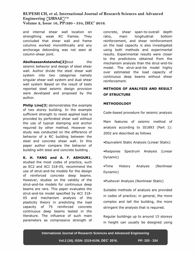
model values. With the advent of powerful
desktop computers, this type of analysis
has become the norm. It involves
calculating the principal elastic modes of
vibration of a structure. The maximum
responses in each mode are then
calculated from a response spectrum and
these are summed by appropriate
methods to produce the overall maximum
response. There are computational
advantages in using the response
spectrum method of seismic analysis for
prediction of displacements and member
forces in structural systems. The method
involves the calculation of only the
maximum values of the displacements and
member forces in each mode of vibration
using smooth design spectra that are the
average of several earthquake motions.
Figure - 3.1: Basic wind speed zone map
in India
RUPESH CH, et al, International Journal of Research Sciences and Advanced Engineering [IJRSAE]TM Volume 2, Issue 16, PP:320 - 334, DEC’ 2016.
International Journal of Research Sciences and Advanced Engineering
Vol.2 (16), ISSN: 2319-6106, DEC’ 2016. PP: 320 - 334
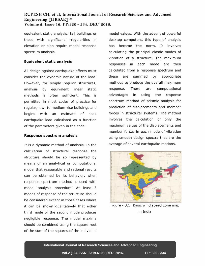
Table – 3.1: Zone wise basic wind speeds
in m/s
The major advantages of modal response
spectrum analysis (RSA), compared with
the more complex time-history analysis
are as follows.
(1) The size of the problem is reduced to
finding only the maximum response of a
limited number of modes of the structure,
rather than calculating the entire time
history of responses during the
earthquake. This makes the problem
much more tractable in terms both of
processing time and (equally significant)
size of computer output.
(2) Examination of the mode shapes and
periods of a structure gives the designer a
good feel for its dynamic response.
(3) The use of smoothed envelope spectra
makes the analysis independent of the
characteristics of a particular earthquake
record.
(4) RSA can very often be useful as a
preliminary analysis, to check the
reasonableness of results produced by
linear and non-linear time-history
analysis.
Time-history analysis
In this analysis dynamic response of the
building will be calculated at each time
intervals. This analysis can be carried out
by taking recorded ground motion data
from past earthquake database. A linear
time-history analysis of this type
overcomes all the disadvantages of
Response spectrum analysis, provided
non-linear behavior is not involved. The
method involves significantly greater
computational effort than the
corresponding Response spectrum
analysis and at least three representative
earthquake motions must be considered
to allow for the uncertainty in precise
frequency content of the design motions
at a site. With current computing power
and software, the task of performing the
number crunching and then handling the
large amount of data produced has
become a non specialist task.
RUPESH CH, et al, International Journal of Research Sciences and Advanced Engineering [IJRSAE]TM Volume 2, Issue 16, PP:320 - 334, DEC’ 2016.
International Journal of Research Sciences and Advanced Engineering
Vol.2 (16), ISSN: 2319-6106, DEC’ 2016. PP: 320 - 334
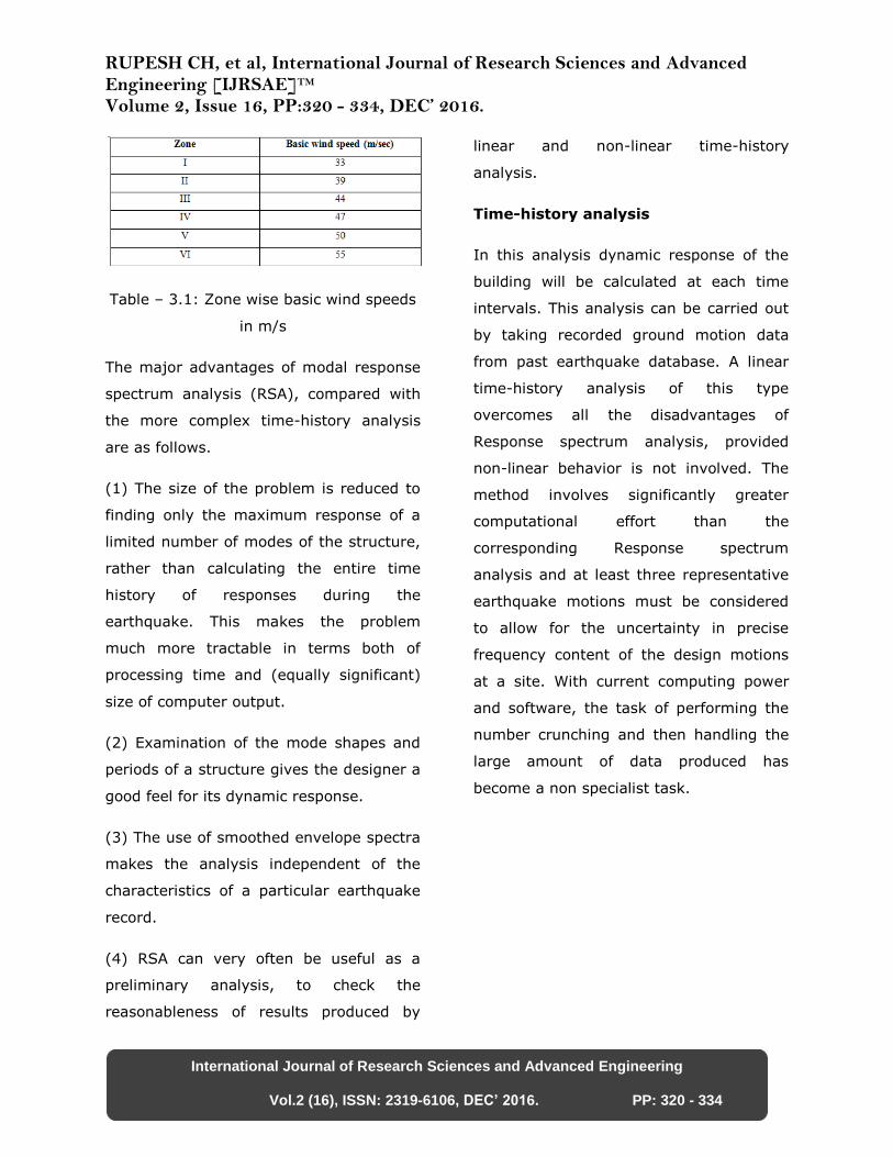
Figure - 3.2: Seismic zone map of India
Push over analysis:
STAAD PRO
Structural Design Software for Structural
Analysis Professionals:
STAAD.Pro V8i is the structural engineer’s
software choice for steel, concrete,
timber, aluminum and cold-formed steel
structure design of low and high-rise
buildings, culverts, petrochemical plants,
tunnels, bridges, piles, aquatic structures
and much more!
What Does STAAD.Pro V8i Structural
Software Offer?
•State-of-the art 2D/3D graphical
environment with standard MS Windows
functionality.
•Full range of structural analysis including
static, P-delta, pushover, response
spectrum,
time history, cable (linear and non-linear),
buckling and steel, concrete and timber
design.
•Concurrent engineering-based user
environment for model development,
analysis, design, visualization, and
verification.
•Object-oriented intuitive 2D/3D CAD
model generation.
•Supports truss and beam members,
plates, solids, linear and non-linear
cables, and curvilinear beams.
•Advanced automatic load generation
facilities for wind, area, floor, and moving
loads.
•Customizable
•structural templates for creating a model.
•Toggle display of loads, supports,
properties, joints, members, etc.
•Isometric and perspective views with 3D
shapes.
•Joint, member/element, mesh generation
with flexible user-controlled numbering
scheme.
•Rectangular and cylindrical coordinate
systems with mix and match capabilities.
Advantages of STAAD.Pro V8i
Structural Analysis Software:
We revolutionized the concurrent
use of spreadsheets, a 3D CAD graphical
modeler, and a text-based input language
editor. With over 40 step-by-step movie
tutorials and hundreds of examples and
verification problems, even a novice user
RUPESH CH, et al, International Journal of Research Sciences and Advanced Engineering [IJRSAE]TM Volume 2, Issue 16, PP:320 - 334, DEC’ 2016.
International Journal of Research Sciences and Advanced Engineering
Vol.2 (16), ISSN: 2319-6106, DEC’ 2016. PP: 320 - 334
can become productive in a matter of
days.
DESIGN AND RESULTOF (SQUARE,
CIRCULAR, AND TRIANGLE) OF TALL
BUILDINGS
DEFINITION OF TALL BUILDING
The tall building can be described as a
multistory building generally provided with
high speed elevators, constructed using a
structural frame, and combining
extraordinary height with ordinary room
spaces such as could be found in low-
buildings. In aggregate, it is a physical,
economic, and technological expression of
the city’s power base, representing its
private and public investments
WIND EFFECTS ON TALL BUILDINGS
The wind is the most powerful and
unpredictable force affecting tall buildings.
Tall building can be defined as a mast
anchored in the ground, bending and
swaying in the wind. This movement,
known as wind drift, should be kept within
acceptable limits. Moreover, for a well-
designed tall building, the wind drift
should not surpass the height of the
building divided by 500. Wind loads on
buildings increase considerably with the
increase in building heights. Furthermore,
the speed of wind increases with height,
and the wind pressures increase as the
square of the wind speed. Thus, wind
effects on a tall building are compounded
as its height increases. Besides this, with
innovations in architectural treatment,
increase in the strengths of materials, and
advances in methods of analysis, tall
building have become more efficient and
lighter, and so, more vulnerable to
deflection, and even to swaying under
wind loading. Despite all the engineering
sophistication performed with computers,
wind is still a complex phenomenon,
mainly owing to two major problems.
Unlike dead loads and live loads, wind
loads change rapidly and even abruptly,
creating effects much larger than when
the same loads were applied gradually,
and that they limit building accelerations
below human perception. Although the
true complexity of the wind and the
acceptable human tolerance to it have just
begun to be understood, there is still a
need to understand more the nature of
wind and its interaction with a tall
building, with particular reference to
allowable defections and comfort of
occupants.
VARIATION OF WIND SPEED WITH
HEIGHT
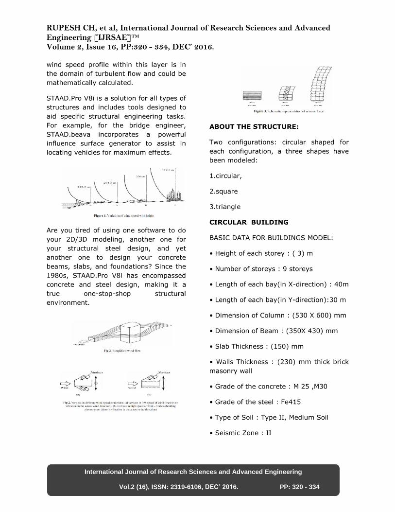
An important characteristic of wind is the
variation of its speed with height (Figure
1). The wind speed increase follows a
curved line varying from zero at the
ground surface to a maximum at some
distance above the ground. The height at
which the speed stops to increase is called
the gradient height, and the
corresponding speed, the gradient wind
speed. This important characteristic of
wind is a well understood phenomenon
that higher design pressures are specified
at higherelevations in most building
codes. Additionally, at heights of
approximately 366 m from the
ground,surface friction has an almost
negligible effect on the wind speed; as
such the wind movement is only depend
on the prevailing seasonal and local wind
effects. The height through which the
wind speed is affected by the topography
is called atmospheric boundary layer. The
RUPESH CH, et al, International Journal of Research Sciences and Advanced Engineering [IJRSAE]TM Volume 2, Issue 16, PP:320 - 334, DEC’ 2016.
International Journal of Research Sciences and Advanced Engineering
Vol.2 (16), ISSN: 2319-6106, DEC’ 2016. PP: 320 - 334
wind speed profile within this layer is in
the domain of turbulent flow and could be
mathematically calculated.
STAAD.Pro V8i is a solution for all types of
structures and includes tools designed to
aid specific structural engineering tasks.
For example, for the bridge engineer,
STAAD.beava incorporates a powerful
influence surface generator to assist in
locating vehicles for maximum effects.
Are you tired of using one software to do
your 2D/3D modeling, another one for
your structural steel design, and yet
another one to design your concrete
beams, slabs, and foundations? Since the
1980s, STAAD.Pro V8i has encompassed
concrete and steel design, making it a
true one-stop-shop structural
environment.
ABOUT THE STRUCTURE:
Two configurations: circular shaped for
each configuration, a three shapes have
been modeled:
1.circular,
2.square
3.triangle
CIRCULAR BUILDING
BASIC DATA FOR BUILDINGS MODEL:
• Height of each storey : ( 3) m
• Number of storeys : 9 storeys
• Length of each bay(in X-direction) : 40m
• Length of each bay(in Y-direction):30 m
• Dimension of Column : (530 X 600) mm
• Dimension of Beam : (350X 430) mm
• Slab Thickness : (150) mm
• Walls Thickness : (230) mm thick brick
masonry wall
• Grade of the concrete : M 25 ,M30
• Grade of the steel : Fe415
• Type of Soil : Type II, Medium Soil
• Seismic Zone : II
RUPESH CH, et al, International Journal of Research Sciences and Advanced Engineering [IJRSAE]TM Volume 2, Issue 16, PP:320 - 334, DEC’ 2016.
International Journal of Research Sciences and Advanced Engineering
Vol.2 (16), ISSN: 2319-6106, DEC’ 2016. PP: 320 - 334
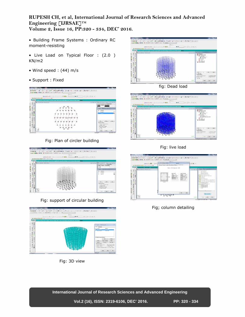
• Building Frame Systems : Ordinary RC
moment-resisting
• Live Load on Typical Floor : (2.0 )
KN/m2
• Wind speed : (44) m/s
• Support : Fixed
Fig: Plan of circler building
Fig: support of circular building
Fig: 3D view
fig: Dead load
Fig: live load
Fig; column detailing
RUPESH CH, et al, International Journal of Research Sciences and Advanced Engineering [IJRSAE]TM Volume 2, Issue 16, PP:320 - 334, DEC’ 2016.
International Journal of Research Sciences and Advanced Engineering
Vol.2 (16), ISSN: 2319-6106, DEC’ 2016. PP: 320 - 334
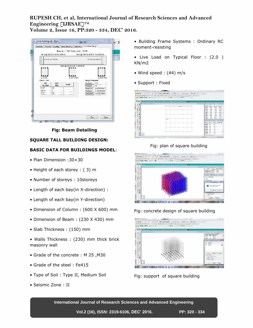
Fig: Beam Detailing
SQUARE TALL BUILDING DESIGN:
BASIC DATA FOR BUILDINGS MODEL:
• Plan Dimension :30×30
• Height of each storey : ( 3) m
• Number of storeys : 10storeys
• Length of each bay(in X-direction) :
• Length of each bay(in Y-direction)
• Dimension of Column : (600 X 600) mm
• Dimension of Beam : (230 X 430) mm
• Slab Thickness : (150) mm
• Walls Thickness : (230) mm thick brick
masonry wall
• Grade of the concrete : M 25 ,M30
• Grade of the steel : Fe415
• Type of Soil : Type II, Medium Soil
• Seismic Zone : II
• Building Frame Systems : Ordinary RC
moment-resisting
• Live Load on Typical Floor : (2.0 )
KN/m2
• Wind speed : (44) m/s
• Support : Fixed
Fig: plan of square building
Fig: concrete design of square building
Fig: support of square building
RUPESH CH, et al, International Journal of Research Sciences and Advanced Engineering [IJRSAE]TM Volume 2, Issue 16, PP:320 - 334, DEC’ 2016.
International Journal of Research Sciences and Advanced Engineering
Vol.2 (16), ISSN: 2319-6106, DEC’ 2016. PP: 320 - 334
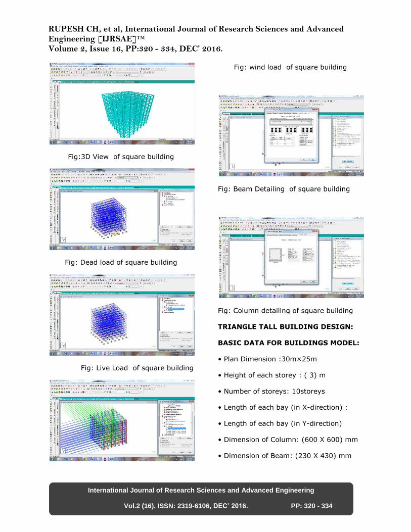
Fig:3D View of square building
Fig: Dead load of square building
Fig: Live Load of square building
Fig: wind load of square building
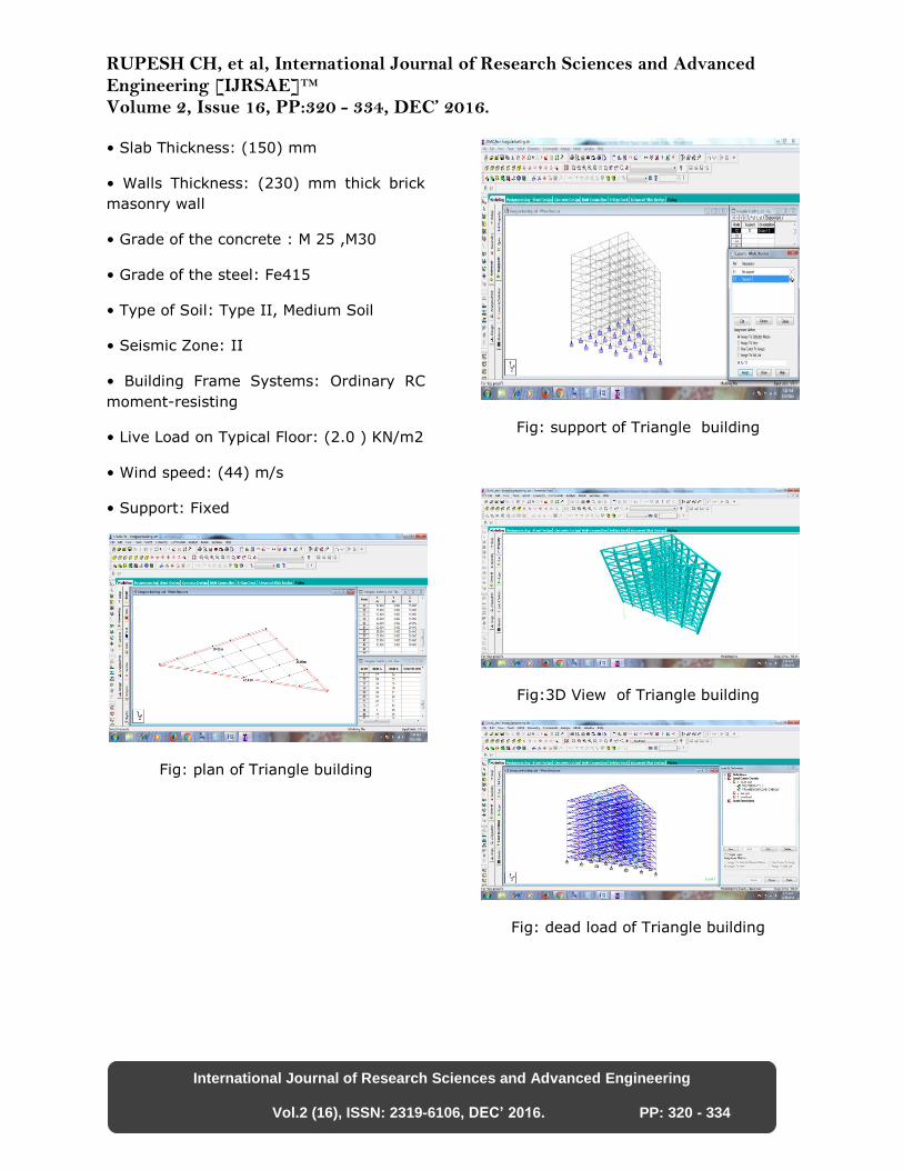
Fig: Beam Detailing of square building
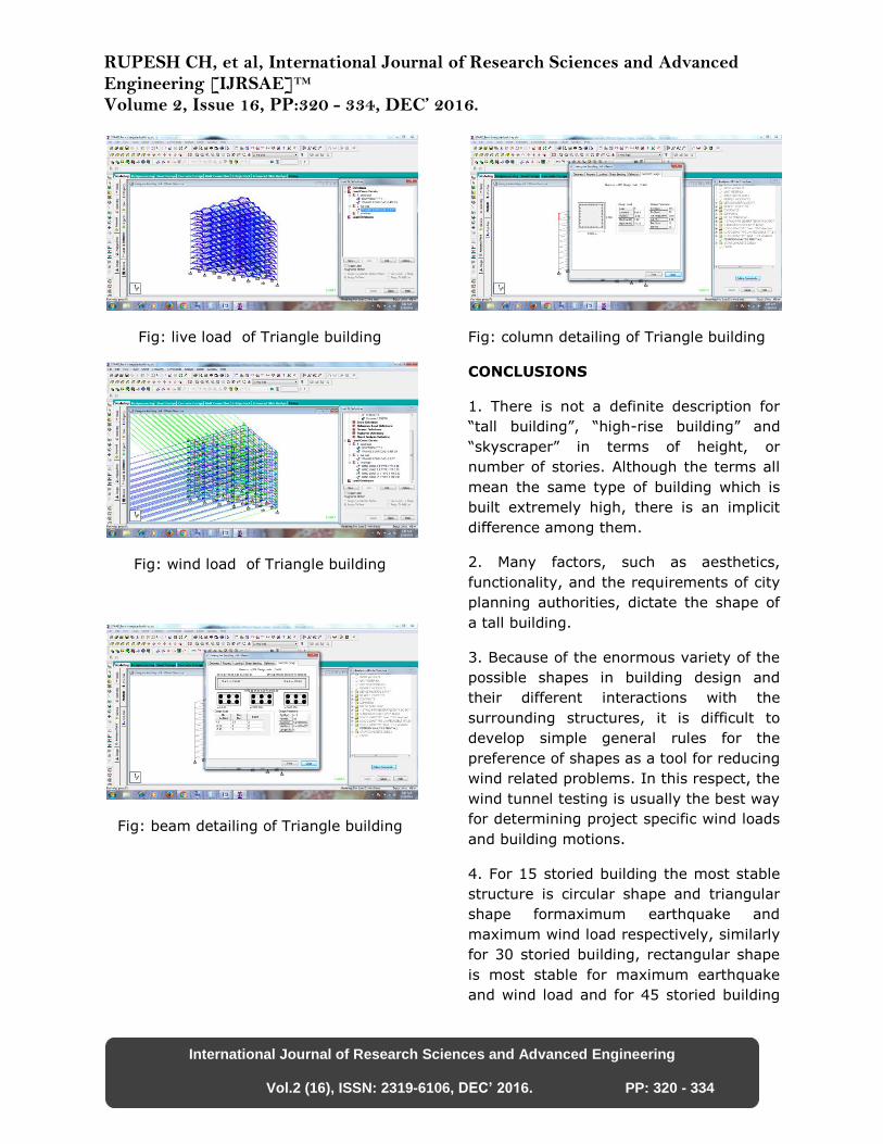
Fig: Column detailing of square building
TRIANGLE TALL BUILDING DESIGN:
BASIC DATA FOR BUILDINGS MODEL:
• Plan Dimension :30m×25m
• Height of each storey : ( 3) m
• Number of storeys: 10storeys
• Length of each bay (in X-direction) :
• Length of each bay (in Y-direction)
• Dimension of Column: (600 X 600) mm
• Dimension of Beam: (230 X 430) mm
RUPESH CH, et al, International Journal of Research Sciences and Advanced Engineering [IJRSAE]TM Volume 2, Issue 16, PP:320 - 334, DEC’ 2016.
International Journal of Research Sciences and Advanced Engineering
Vol.2 (16), ISSN: 2319-6106, DEC’ 2016. PP: 320 - 334
• Slab Thickness: (150) mm
• Walls Thickness: (230) mm thick brick
masonry wall
• Grade of the concrete : M 25 ,M30
• Grade of the steel: Fe415
• Type of Soil: Type II, Medium Soil
• Seismic Zone: II
• Building Frame Systems: Ordinary RC
moment-resisting
• Live Load on Typical Floor: (2.0 ) KN/m2
• Wind speed: (44) m/s
• Support: Fixed
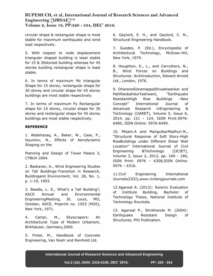
Fig: plan of Triangle building
Fig: support of Triangle building
Fig:3D View of Triangle building
Fig: dead load of Triangle building
RUPESH CH, et al, International Journal of Research Sciences and Advanced Engineering [IJRSAE]TM Volume 2, Issue 16, PP:320 - 334, DEC’ 2016.
International Journal of Research Sciences and Advanced Engineering
Vol.2 (16), ISSN: 2319-6106, DEC’ 2016. PP: 320 - 334
Fig: live load of Triangle building
Fig: wind load of Triangle building
Fig: beam detailing of Triangle building
Fig: column detailing of Triangle building
CONCLUSIONS
1. There is not a definite description for
“tall building”, “high-rise building” and
“skyscraper” in terms of height, or
number of stories. Although the terms all
mean the same type of building which is
built extremely high, there is an implicit
difference among them.
2. Many factors, such as aesthetics,
functionality, and the requirements of city
planning authorities, dictate the shape of
a tall building.
3. Because of the enormous variety of the
possible shapes in building design and
their different interactions with the
surrounding structures, it is difficult to
develop simple general rules for the
preference of shapes as a tool for reducing
wind related problems. In this respect, the
wind tunnel testing is usually the best way
for determining project specific wind loads
and building motions.
4. For 15 storied building the most stable
structure is circular shape and triangular
shape formaximum earthquake and
maximum wind load respectively, similarly
for 30 storied building, rectangular shape
is most stable for maximum earthquake
and wind load and for 45 storied building
RUPESH CH, et al, International Journal of Research Sciences and Advanced Engineering [IJRSAE]TM Volume 2, Issue 16, PP:320 - 334, DEC’ 2016.
International Journal of Research Sciences and Advanced Engineering
Vol.2 (16), ISSN: 2319-6106, DEC’ 2016. PP: 320 - 334
circular shape & rectangular shape is most
stable for maximum earthquake and wind
load respectively.
5. With respect to node displacement
triangular shaped building is least stable
for 15 & 30storied building whereas for 45
stories building rectangular shape is least
stable.
6. In terms of maximum Mz triangular
Shape for 15 storey, rectangular shape for
30 storey and circular shape for 45 storey
buildings are most stable respectively.
7. In terms of maximum Fy Rectangular
shape for 15 storey, circular shape for 30
storey and rectangular shape for 45 storey
buildings are most stable respectively.
REFERENCE
1. Abdelrazaq, A., Baker, W., Case, P.,
Isyumov, N., Effects of Aerodynamic
Shaping on the
Planning and Design of Tower Palace 3,
CTBUH 2004.
2. Baskaran, A., Wind Engineering Studies
on Tall Buildings-Transition in Research,
Buildingand Environment, Vol. 28, No. 1,
p. 1-19, 1993.
3. Beedle, L. S., What’s a Tall Building?,
ASCE Annual and Environmental
EngineeringMeeting, St. Louis, MO,
October, ASCE, Preprint no. 1553 (M20),
New York, 1971.
4. Campi, M., Skyscrapers: An
Architectural Type of Modern Urbanism,
Birkhäuser, Germany,2000.
5. Fintel, M., Handbook of Concrete
Engineering, Van Nostr and Reinhold Ltd.
6. Gaylord, E. H., and Gaylord, C. N.,
Structural Engineering Handbook.
7. Guedes, P. (Ed.), Encyclopedia of
Architectural Technology, McGraw-Hill,
New York, 1979.
8. Houghton, E., L., and Carruthers, N.,
B., Wind Forces on Buildings and
Structures: AnIntroduction, Edward Arnold
Ltd., London, 1976.
9. DharaneSidramappaShivashaankar and
PatilRaobahdurYashwant, “Earthquake
ResistantHigh Rise Buildings –New
Concept” International Journal of
Advanced Research inEngineering &
Technology (IJARET), Volume 5, Issue 6,
2014, pp. 121 - 124, ISSN Print:0976-
6480, ISSN Online: 0976-6499.
10. Misam.A and MangulkarMadhuri.N.,
“Structural Response of Soft Story-High
RiseBuildings under Different Shear Wall
Location” International Journal of Civil
Engineering &Technology (IJCIET),
Volume 3, Issue 2, 2012, pp. 169 - 180,
ISSN Print: 0976 – 6308,ISSN Online:
0976 – 6316.
11.Civil Engineering International
Journals(CEIJ),www.civilengjournals.com
12.Agarwal A. (2012): Seismic Evaluation
of Institute Building, Bachelor of
Technology Thesis, National Institute of
Technology Rourkela.
13. Agarwal P., Shrikhande M. (2004):
Earthquake Resistant Design of
Structures, PHI Publication.