Embed Size (px)
Citation preview

IJCTA Vol.8, No.1, Jan-June 2015, Pp.253-263 © International Sciences Press, India
Comparative Study of Speed Control of 6/4 Switched Reluctance Motor Using Hybrid Fuzzy Logic Controller Mrs.K. Radha Rani1, Ms.SK.Salma2, Sri A. Raghunath3 and Sri K. Praveen Kumar4 1Associate Professor, EEE Department, RVR & JC College of Engg 2M.Tech Student, EEE Department, RVR & JC College of Engg 3Associate Professor, Associate Professor, Vignan’s University 4Assistant Professor, IT Department, Vignan’s University Email:[email protected]; [email protected]; [email protected] ABSTRACT This presents a hybrid intelligent controller technique for speed control of switched reluctance motor. The controlling technique is used to enhance the performance of switched reluctance motor with six stator poles and four rotor poles. This paper deals with the comparative study of speed control techniques of 6/4 switched reluctance motor by using PI, Fuzzy and Hybrid Fuzzy logic controller. The proposed controlling technique is simulated using MATLAB and its performance is compared with the conventional methods. Keywords: - 6/4 Switched Reluctance Motor, Fuzzy controller technique, Hybrid Fuzzy logic controller.
1. INTRODUCTION SRM is a type of reluctance motor that runs by reluctance torque [1]-[2].It is one
of the attractive solutions for variable speed applications. Due to many inherent advantages like simplicity, robustness, low manufacturing cost, high speed, high starting torque & high efficiency, it has the ability to operate in four quadrants and hence it is a competitive choice to other motors[3]-[4]. The disadvantage of a switched reluctance motor is that it has high torque ripples and has high acoustic noise.Because of the many advantages of [7] SRM drives are used in vast applications where in some cases the speed is to be maintained constant throughout the operation.
Hence the speed control of SRM is necessary. The research work focuses on SRM control and torque smoothness in order to make it a competitor to both fully controlled dc and ac drives [8]. 2. CONSTRUCTIONAL OVERVIEW OF SRM
Switched Reluctance Motor does not consist of any everlasting magnets. Stator is like a dc motor without brushes. The switched reluctance motor consists of stator and rotor poles, made of laminated steel with high magnetic permeability. Only the stator poles are excited by coils. In addition to this ,the converter circuit used is simple with

254
reduced number of switches due to unidirectional current requirements are needed[ 5]-[6].A sequence of anti-clockwise excitations of the different phases results in a clockwise rotation of the rotor due to a positive torque generation. The applied Phase voltage is given as,
Figure:16/4 SRM
By solving the input power equation, the expression for torque is obtained as,
This torque is called Electromagnetic torque. The mathematical model can be obtained as the following
2.1. Motor phase equation
2.2. Mechanical equation
2.3. Angular speed equation
dt
iiLdRsIV
}),({ θ+=
θθdidLTe i ),(
21 2=
255
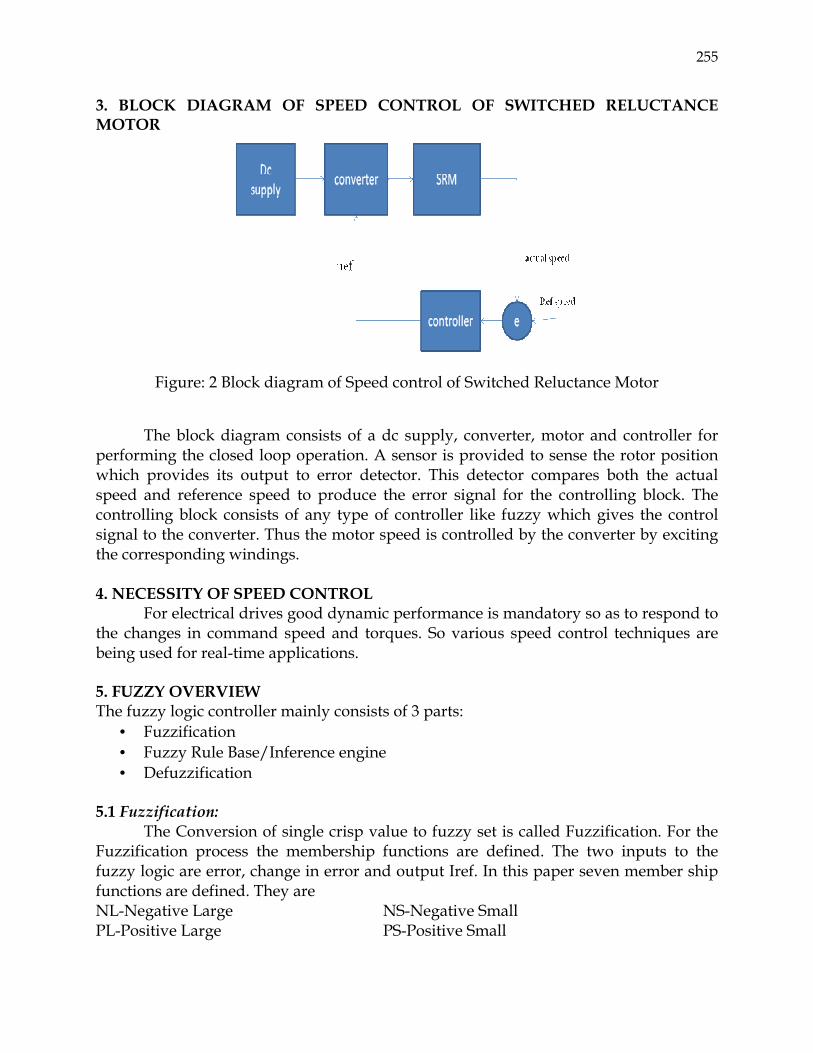
3. BLOCK DIAGRAM OF SPEED CONTROL OF SWITCHED RELUCTANCE MOTOR
Figure: 2 Block diagram of Speed control of Switched Reluctance Motor
The block diagram consists of a dc supply, converter, motor and controller for performing the closed loop operation. A sensor is provided to sense the rotor position which provides its output to error detector. This detector compares both the actual speed and reference speed to produce the error signal for the controlling block. The controlling block consists of any type of controller like fuzzy which gives the control signal to the converter. Thus the motor speed is controlled by the converter by exciting the corresponding windings. 4. NECESSITY OF SPEED CONTROL
For electrical drives good dynamic performance is mandatory so as to respond to the changes in command speed and torques. So various speed control techniques are being used for real-time applications. 5. FUZZY OVERVIEW The fuzzy logic controller mainly consists of 3 parts:
• Fuzzification • Fuzzy Rule Base/Inference engine • Defuzzification
5.1 Fuzzification:
The Conversion of single crisp value to fuzzy set is called Fuzzification. For the Fuzzification process the membership functions are defined. The two inputs to the fuzzy logic are error, change in error and output Iref. In this paper seven member ship functions are defined. They are NL-Negative Large NS-Negative Small PL-Positive Large PS-Positive Small

256
NM-Negative Medium Z-Zero PM-Positive Medium Fuzzy membership Functions are
-1 -0.8 -0.6 -0.4 -0.2 0 0.2 0.4 0.6 0.8 1
0
0.2
0.4
0.6
0.8
1
e
Deg
ree
of m
embe
rship
ZRNS PSNM PMNL PL
-0.4 -0.3 -0.2 -0.1 0 0.1 0.2 0.3 0.4
0
0.2
0.4
0.6
0.8
1
ce
Deg
ree
of m
embe
rship
ZRNS PSNM PMNL PL
-0.2 -0.15 -0.1 -0.05 0 0.05 0.1 0.15 0.2
0
0.2
0.4
0.6
0.8
1
DEL.THETA
Deg
ree
of m
embe
rshi
p
ZRNS PSNM PMNL PL
MF for Error MF for Change in Error MF for Change in Angle
Figure: 3 Fuzzy membership Functions
5.2 Fuzzy inference: Fuzzy inference also referred to as approximate reasoning refers to computational
procedures used for evaluating linguistic descriptions. The two important inferring procedures are
• Generalized Modus Ponens (GMP) • Generalized Modus Tollens (GMT)
Fuzzy Rule Base:
Fuzzy Linguistic descriptions are formal representations of systems made through fuzzy IF_THEN rules. A collection of rules referring to a particular system is known as a fuzzy rule base. The Fuzzy Rule Base used in this paper is shown below.
Table:1 Rule Base for Fuzzy logic controller
5.3 De Fuzzification: The conversion of a fuzzy set to a single crisp value is called a
Defuzzification.Here Centroid Method is used.

257
6. SIMULATION RESULTS FOR VARIOUS CONTROLLING TECHNIQUES
• Simulink Diagram of SRM based on PI controller
(a) Speed vs. Time

258
(b) Torque vs. Time
(c) Inductance vs. Time
(d) Current Vs. Time
Figure: 4 Based on PI control

259
• Simulink Diagram of SRM based on Fuzzy controller
(a) Speed vs. Time

260
(b) Torque vs. Time
(c) Inductance vs. Time

261
(d) Current Vs. Time
Figure: 5 Based on Fuzzy Logic Controller
• Simulink Diagram of SRM based on Hybrid Fuzzy controller
(a) Speed vs. Time

262
(b) Torque vs. Time
(d)Inductance vs. Time
(e) Current vs. Time
Figure: 6 Based on Hybrid Fuzzy Logic Controller

263
7. CONCLUSION The 6/4 SRM is modeled in MATLAB/SIMULINK. The required pulses were
generated using the asymmetric converter. Thus the speed control of SRM is obtained by the proposed method which is hybrid fuzzy logic control and the simulation results are compared with the Proportional integral method and fuzzy logic controller. With the Proposed method although the motor rotates with the speed less than the reference speed, steady state is achieved faster than the conventional methods. REFERENCES [1] I. Kioskeridis, and C. Mademlis, “Maximum Efficiency in Single-Pulse Controlled
Switched Reluctance Motor Drives”, IEEE transactions on Energy Conversion, VOL.20, NO. 4, pp. 809-817, DECEMBER 2005.
[2] Yana Zhou, Changliang Xia, Ziming He and Ximing Xie, “Torque Ripple Minimization in a Sensorless Switched Reluctance Motor Based on Flexible Neural Networks”, in Proc. IEEE International Conference of Control and Automation, May 2007.
[3] T. J. E. Miller, “Switched reluctance motors and their control”, Oxford University Press, 1993.
[4] P. J. Lawrenson, “Variable speed switched reluctance motors”, IEE Proc. Vol. 127, No. 4, pp. 253-265, 1980.
[5] Hany M.Hasanien, N.H Saad, M.A.Mostfa, and M.A.Badr,”Speed control of axial laminations switched reluctance motor provided with digital pole placement controller”, in proc. Of the International Conference on Electrical Machines (ICEM), Sept 2006.
[6] B.W. Williams and C. Pollock “Power converter circuit for switched reluctance motors with minimum number of switches”, IEE Proceedings, vol.137, pt. B, No. 6, November 1990.
[7] Hassan Moghbelli, Gayle E.Adams and Richard G. Hoft, “Performance of a 10-HP switched reluctance motor and comparison with induction motors”, IEEE Transactions on industrial applications, vol. 27, No. 3, May/June 1991
[8] Nicholas J. Nagel and Robert D. Loranz, “Rotating vector method for torque control of switched reluctance motor drive”, IEEE Transaction of industrial Applications, vol.36, No. 2, March/April 2000.