Embed Size (px)
Citation preview

ARTICLE IN PRESS
Contents lists available at ScienceDirect
Mechanical Systems and Signal Processing
Mechanical Systems and Signal Processing 23 (2009) 2113–2129
0888-32
doi:10.1
� Cor
E-m
journal homepage: www.elsevier.com/locate/jnlabr/ymssp
Comparative study of damped FE model updating methods
Vikas Arora �, S.P. Singh, T.K. Kundra
Department of Mechanical Engineering, Indian Institute of Technology, Hauz Khas, New Delhi 110016, India
a r t i c l e i n f o
Article history:
Received 9 September 2008
Received in revised form
25 March 2009
Accepted 11 April 2009Available online 3 May 2009
Keywords:
Model updating
Damping
Complex FRFs
70/$ - see front matter & 2009 Elsevier Ltd. A
016/j.ymssp.2009.04.003
responding author. Tel.: +9111 26591136; fax:
ail address: [email protected] (V. Arora
a b s t r a c t
Most of finite element (FE) model updating techniques do not employ damping matrices
and hence, cannot be used for accurate prediction of complex frequency response
functions (FRFs) and complex mode shapes. In this paper, a detailed comparison of two
approaches of obtaining damped FE model updating methods are evaluated with the
objective that the FRFs obtained from damped updated FE models is able to predict the
measured FRFs accurately. In the first method, damped updating FE model is obtained
by complex parameter-based updating procedure, which is a single-step procedure. In
the second method, damped updated model is obtained by the FE model updating with
damping identification, which is a two-step procedure. In the first step, mass and
stiffness matrices are updated and in the second step, damping matrix is identified
using updated mass and stiffness matrices, which are obtained in the previous step. The
effectiveness of both methods is evaluated by numerical examples as well as by actual
experimental data. Firstly, a study is performed using a numerical simulation based on
fixed–fixed beam structure with non-proportional viscous damping model. The
numerical study is followed by a case involving actual measured data for the case of
F-shaped test structure. The updated results have shown that the complex parameter-
based FE model updating procedure gives better matching of complex FRFs with the
experimental data.
& 2009 Elsevier Ltd. All rights reserved.
1. Introduction
The study of the dynamic behavior of a structure can be divided into two separate routes, namely theoretical route andexperimental route. The most widely used theoretical route is the finite element (FE) method (Bathe [1]). It is well knownthat finite element predictions are often called into question when they are in conflict with test results (Ewins [2] and Maiaand Silva [3]). Inaccuracies in finite element model and errors in results predicted by it can arise due to use of incorrectmodeling of boundary conditions, incorrect modeling of joints, and difficulties in modeling of damping. This has led to thedevelopment of model updating techniques, which aim at reducing the inaccuracies present in an analytical model in thelight of measured dynamic test data. A number of model updating methods have been proposed in recent years as shown inthe surveys by Imregun and Visser [4], and Mottershead and Friswell [5] and details of these can be found in the work ofFriswell and Mottershead [6]. Model updating methods can be broadly classified into direct methods, which are essentiallynon-iterative ones, and the iterative methods. A significant number of methods (Baruch and Bar-Itzhack [7], Berman andNagy [8], Baruch [9]), which were first to emerge belonged to the direct category. Although, these methods arecomputationally cheaper and reproduce the measured modal data exactly, they violate structural connectivity and updated
ll rights reserved.
+9111 26582053.
).

ARTICLE IN PRESS
V. Arora et al. / Mechanical Systems and Signal Processing 23 (2009) 2113–21292114
structural matrices are difficult to interpret. On the other hand, by using iterative methods, structural connectivity can beeasily maintained and corrections suggested in the selected parameters can be physically interpreted. These methods alsoprovide a wide choice of parameters for updating. Iterative methods either use eigendata or frequency response function(FRF) data. Iterative methods are based on minimizing an objective function that is generally a non-linear function ofselected updating parameters. Quite often eigenvalues, eigenvectors or response data are used to construct the objectivefunction. Collins et al. [10] used the eigendata sensitivity for analytical model updating in an iterative framework. Lin andEwins [11] proposed response function method (RFM), which use measured FRF data to update an analytical model. TheRFM method is not an inverse sensitivity method but a force balance method. Disadvantage of the RFM method is that thesystem and correction matrices must either be condensed to the measured DOFs or the measured FRFs have to be expandedto the unmeasured DOFs. For small structures, the reduction/expansion errors are not critical; however, if real industrialstructures of more than 100,000 DOFs with not more than about 100 measured DOFs have to be considered the methodwill fail. Another disadvantage comes from the fact that the sensitivity matrix contains the test data which are inevitablypolluted by measurement noise which results in biased estimates [12]. Most of the updating methods neglect the damping.So these methods can be used up to the point of predicting the natural frequencies and real modes. But these cannot beused for complex frequency response functions (FRFs) and complex modes. All structures exhibit some form of damping,but despite a large literature on the damping, it still remains one of the least well-understood aspects of general vibrationanalysis. A commonly used model proposed by Rayleigh [13] assumes that instantaneous generalized velocities are theonly variables. Material damping can arise from variety of micro structural mechanisms (Bert [14]) but for small strains it isoften adequate to represent it through an equivalent linear model of the material. Maia et al. [15] emphasized the need forthe development of identification methodologies of general damping models and indicated several difficulties that mightarise. Pilkey [16] described two types of procedures, direct and iterative, for computation of the system-damping matrix.The damping matrices so identified are symmetric in nature and use either accurate mass matrix or both mass and stiffnessmatrices along with experimentally obtained modal data. Adhikari and Woodhouse [17] identified viscous damping usingresidues. Adhikari and Woodhouse [18] identified the damping of the system as viscous damping. However, viscousdamping is by no means the only damping model. Adhikari [19] identified viscous and non-viscous damping usingLancaster’s formulation of identification of damping.
Some research efforts have also been made to update the damping matrices. Imregun et al. [20,21] conducted severalstudies using simulated and experimental data to gauge the effectiveness of RFM and extended the RFM to updateproportional damping matrix by updating the coefficients of damping matrix. Ladeveze and Chouaki [22] proposed aprocedure to update the mass, stiffness, and damping properties using the Drucker error approach. Lin and Zhu [23]extended RFM to update damping coefficients in addition to mass and stiffness matrices. Arora et al. [24] proposed acomplex parameter-based model updating method in which FE model is updated in such a way that the updated modelreflects general damping in the experimental model by considering the updating parameters as complex. Arora et al. [25]proposed a damped FE model updating procedure in which damped is identified explicitly. This procedure is a two-stepprocedure. In the first step, mass and stiffness matrices are updated and in the second step, damping is identified usingupdated mass and stiffness matrices obtained in the previous step.
In this paper, comparative study of the two damped model updating methods are carried out with an objective to studythe accuracy with which damped updated models predict complex FRFs. In the first method [24], updated damped FEmodel is obtained using single-step complex parameter-based updating procedure. In the second method [25], updateddamped FE model is obtained in two steps. In the first step, mass and stiffness matrices are updated using FRF data and inthe second step damping is identified using complex modal data. In order to study the accuracy of both methods, first astudy is performed using numerical simulation based on fixed–fixed beam structure with non-proportional viscousdamping model. This is followed by a study involving actual measured data for the case of an F-shape test structure, whichresembles the skeleton of a drilling machine.
2. Model updating using complex updating parameters
Complex parameter-based updating method [24] is a development of response function method given by Lin and Ewins[11], which is an iterative method and uses measured FRF data directly without requiring any modal extraction. In thismethod, it is assumed that initially there is no damping in the analytical model, which results in real FRFs whereasexperimental FRFs are complex because of presence of damping. Following identities relating dynamic stiffness matrix [Z]and receptance FRF matrix [a] for the analytical model as well as the actual structure can be written as, respectively:
½ZRA�½a
RA� ¼ ½I� ðinitiallyÞ (1)
½ZCX �½a
CX � ¼ ½I� (2)
where subscripts A and X denote analytical (like an FE model) and experimental model, respectively, and superscripts R andC represent real and complex values. Expressing [ZX] in Eq. (2) as [ZA
R]+[DZC] and then subtracting Eq. (1) from it, followingmatrix equation is obtained:
½DZC�½aC
X � ¼ ½ZRA�ð½a
RA� � ½a
CX �Þ (3)

ARTICLE IN PRESS
V. Arora et al. / Mechanical Systems and Signal Processing 23 (2009) 2113–2129 2115
Pre-multiplying above equation by [aA] and using Eq. (1) gives
½aRA�½DZC
�½aCX � ¼ ½a
RA� � ½a
CX � (4)
If only the jth column of experimentally measured FRF matrix {aX}j, is available then the above equation is reduced to
½aRA�½DZC
�faCXgj ¼ fa
RAgj � fa
CXgj (5)
which is the basic relationship of the response function method. With this method, a physical variable-based updatingparameter formulation is used. Linearizing [DZ] with respect to {p}, {p} ¼ {p1, p2,y,pnu}t being the vector of physicalvariables associated with individual or group of finite elements, gives
½DZC� ¼
Xnu
i¼1
@½Z�
@pCi
DpCi
!(6)
where nu is the total number of updating parameters. [Z] in Eq. (6) is replaced by [K]�o2[M]. Dividing and multiplying Eq.(6) by pi and then writing ui in place of Dpi/pi. We can write Eq. (6) as
½DZC� ¼
Xnu
i¼1
@ð½K� �o2½M�Þ
@pCi
pCi
!uC
i (7)
Thus, {u} ¼ {u1, u2,y,unu}t is the unknown vector of fractional correction factors to be determined during updating.Eq. (5), after making the substitution for [DZ] from Eq. (7), can be written at various frequency points chosen from thefrequency range considered. The resulting equations can be framed in the following matrix form:
½SC�ðn�nf Þ�ðnuÞfu
Cgnu�1 ¼ f�Cgðn�nf Þ�1 (8)
where n represents the number of degrees of freedom at which measurements are available, while nf represents thenumber of frequency points used in setting the equations; [S], and {e} are sensitivity of dynamic stiffness matrix withrespect to updating parameters and error vector between experimental and analytical values at frequency pointsconsidered, respectively. The parameters are updated iteratively till error vector become sufficiently small. After firstiteration, the analytical receptance FRF matrix [aA] will also become complex. The performance is judged on the basis of theaccuracy with which the FRFs predicted by updated FE model match the simulated experimental FRFs or the experimentalFRFs.
3. Model updating with damping identification
In this method, damped updated finite element model is obtained in two steps [25]. In the first step, mass and stiffnessmatrices are updated using real part of the FRF data by response function method [11]. In the second step, damping matrixis identified by direct method using complex modal [16].
3.1. Response function method
The response function method proposed by Lin and Ewins [11], is an FRF-based iterative method and uses real part ofFRF data for updating. This method presents another version of the same type of equations as given in the complexparameter-based updated method (as shown in Eqs. (1)–(8)), but in this case the system matrices are real instead ofcomplex. The final formula for this method is same as that given in Eq. (8) as
½S�ðn�nf Þ�ðnuÞfugnu�1 ¼ f�gðn�nf Þ�1 (9)
Here, both the analytical and experimental FRFs are real. The resulting updating parameters are also real. The parametersare updated iteratively till error vector becomes very small. The performance is judged on the basis of the accuracy withwhich the real part of FRFs predicted by updated FE model match the real part of simulated experimental FRFs or theexperimental FRFs.
3.2. Damping identification
Damping identification method requires prior knowledge of accurate stiffness and mass matrices and also complexeigendata. Damping matrix, C, can be computed directly using Lancaster’s formulation [26]:
C ¼ �MðFL2FTþFL2FT
ÞM (10)
where Fi is the eigenvector and li the eigenvalue. The overall bar represents complex conjugate and L is the diagonalmatrix of complex eigenvalues li.

ARTICLE IN PRESS
V. Arora et al. / Mechanical Systems and Signal Processing 23 (2009) 2113–21292116
The above formulation requires normalized complex eigenvectors (F). The complex eigenvectors are normalized bydirect method given by Pilkey [16] as
FTi ðMl2
i � KÞFi ¼ li (11)
where M and K are mass and stiffness matrices. The updated mass and stiffness obtained in the previous section are usedfor normalization of complex eigenvectors.
4. Case study of a fixed–fixed beam structure using simulated data
A simulated study on a fixed–fixed beam is conducted to evaluate the performance of both the methods. The dimensionsof the beam are 910�50�5 mm3. The beam is modeled using 30, two-noded beam elements with nodes at the two endsbeing fixed as shown in Fig. 1. The displacements in the y-direction and the rotation about the z-axis are taken as twodegrees of freedom at each node. Analytical data of the FRFs is obtained with known discrepancies in the thickness of allthe finite elements as shown in Table 1. The simulated complex FRF data, which is treated as experimental data, is obtainedby generating a damped finite element model with non-proportional viscous damping.
Non-proportional damping is added to the beam by first creating proportional damping at each iteration of theassembly of the global matrices except in the tenth element, where the distribution of the stiffness to the damping matrixis reduced by 50%. It is easily verified that non-Rayleigh style damping ensues with the simple equation
CM�1KaKM�1C (12)
Fig. 1. Beam structure and its FE mesh.
Table 1Discrepancies between the finite element and the simulated experimental model for the case of fixed–fixed beam structure.
Element number 3 5 11 16 25 29 All other elements
% deviation in thickness +20 +40 25 +40 +30 +30 +20
0 10 20 30 40 50 60020
4060
-300
-200
-100
0
100
200
300
400
500
D.O.F
D.O.F
Fig. 2. Mesh of damping matrix.

ARTICLE IN PRESS
0 200 400 600 800 1000-200
-180
-160
-140
-120
-100
-80
-60
-40
-20
Frequency in Hz
Rec
epta
nce
MA
G in
dB
AnalyticalSimulated Experimental
Fig. 3. Overlay of simulated experimental and analytical FRFs before updating.
0 200 400 600 800 1000-200
-180
-160
-140
-120
-100
-80
-60
-40
-20
Frequency in Hz
Rec
epta
nce
MA
G in
dB
Damped Updated (Complex)
Simulated Experimental
Fig. 4. Overlay of simulated experimental and damped updated FRFs obtained using complex updating parameters.
V. Arora et al. / Mechanical Systems and Signal Processing 23 (2009) 2113–2129 2117
A mesh of the non-proportional damping matrix is shown in Fig. 2. Fig. 3 shows the overlay of analytical FRF, which isundamped, and simulated experimental FRF (noise free) obtained considering non-proportional damping in theexperimental data. It can be observed that the analytical FRF (5y5y) and simulated experimental FRF (5y5y) do notmatch each other. 5y5y represents excitation at node 5 and response at node 5 both in the y-direction.
Firstly, a case study is carried out for damped FE model updating using complex updating parameters considering non-proportional damping in the simulated experimental data. Thicknesses of the each beam element are taken as updatingparameter and is considered complex. The overlay of the simulated experimental FRFs is given in Fig. 4. It can be observedfrom Fig. 4 that damped updated FRF and simulated experimental FRF matches very well with each other even at resonanceand at antiresonance frequencies. The real part of thickness is very close to 5 mm which is the actual value of the thicknessof the beam as shown in Fig. 5 and imaginary value reflects damping present in the system. The simulated study is alsocarried out for different frequency range. It is observed that updated FRF matches well the simulated experimental FRFbeyond the frequency range considered.

ARTICLE IN PRESS
0 5 10 15 20 25 300
1
2
3
4
5x 10⁻³
Element number
Rea
l par
t of t
hick
ness
0 5 10 15 20 25 30-4
-3
-2
-1
0
1
2
3
4x 10⁻⁴
Element number
Imag
inar
y pa
rt of
thic
knes
s
Fig. 5. Value of thickness of each beam element after updating (a) real part and (b) imaginary part.
V. Arora et al. / Mechanical Systems and Signal Processing 23 (2009) 2113–21292118
For the case of model updating with damping identification, in the first step, mass and stiffness matrices are updated usingreal part of the FRF. Thicknesses of each element of the beam structure are considered as updating parameters. So for the beamstructure, 30 updating parameters are taken. The proposed procedure has been evaluated for the case of incomplete data. Thereal-life measured data are always incomplete, as it is not practical to measure all the coordinates specified in the analyticalfinite element model. Incompleteness is considered by assuming that only lateral degrees of freedom at all the 29 nodes aremeasured. The frequency range from 0 to 1000 Hz is considered for updating procedure. The performance of the proposedprocedure is judged on the basis of accuracy with which the FRFs obtained by updated model match the simulatedexperimental FRFs. After updating, simulated experimental FRF and updated FRF match as shown in Fig. 6. It can be observedfrom Fig. 6 that simulated experimental and updated FRFs match each other except at the resonance and antiresonancefrequencies. The final value of the thickness of each element is close to 5 mm (the original thickness).
In the second step, damping is identified using complex eigendata. Direct method of damping identification is applied.As discussed above, only lateral degrees of freedom, at all the 29 nodes are measured. For direct method of dampingidentification, updated mass and stiffness matrices are reduced to the degrees of freedom measured using iterated IRSmethod [27] considering the measurement points. The reduced actual damping matrix is given in Fig. 7. In real life, all themodes cannot be measured. Three typical cases are presented here:
(a)
All modes are measured. (b) First five modes are measured. (c) First three modes are measured.
ARTICLE IN PRESS
0 5 10 15 20 25 300
10
20
30-300
-200
-100
0
100
200
300
400
D.O.F
D.O.F
Fig. 7. Mesh of reduced damping matrix.
0 200 400 600 800 1000-200
-180
-160
-140
-120
-100
-80
-60
-40
-20
Frequency in Hz
Rec
epta
nce
MA
G in
dB
Updated
Simulated Experimental
Fig. 6. Overlay of simulated experimental and undamped updated FRFs after step 1.
V. Arora et al. / Mechanical Systems and Signal Processing 23 (2009) 2113–2129 2119
experimental FRFs matches completely and identified damping is presented in Fig. 9 and the error between the actual andidentified damping is very low as shown in Fig. 10. Similarly, overlay of the damped updated and simulated experimental
In the first case, when all the modes are measured. It can be observed from Fig. 8 that damped updated and simulated
FRFs for the cases of first five and three modes measured are shown in Figs. 11 and 12, respectively. It can be observed fromFigs. 11 and 12 that the updated and simulated FRFs matches up to the measured mode, beyond that the matching isvery poor.
From the simulated study, it is observed that damped updated FE model obtained using FE model updating withdamping identification is able to predict FRFs accurately for the frequency range covering the number of modes considered.However, beyond modes considered, the FRF matching is poor. Also, damping matrix identified using direct method issymmetrical but positive definiteness of the matrix is questionable as number of modes considered for identification ofdamping matrix decreases [16]. Whereas, the model updating using complex updating parameters able to predictaccurately complex FRFs beyond the frequency range considered and also the matrices are always positive definite,independent of frequency range considered. It can be concluded from the simulated experimental study that parametric

ARTICLE IN PRESS
0 5 10 15 20 25 300
10
20
30-300
-200
-100
0
100
200
300
400
D.O.F
D.O.F
Fig. 9. Mesh of identified damping matrix.
0 200 400 600 800 1000-200
-180
-160
-140
-120
-100
-80
-60
-40
-20
Frequency in Hz
Rec
epta
nce
MA
G in
dB
Damped Updated
Simulated Experimental
Fig. 8. Overlay of simulated experimental and damped updated FRFs when all modes are measured.
V. Arora et al. / Mechanical Systems and Signal Processing 23 (2009) 2113–21292120
approach, which is complex updated parameters method, gives better FRF matching as compared with FE model updatingwith damping identification.
5. Case study of F-shape structure using experimental data
An F-shaped test structure, resembling the skeleton of a drilling machine tool, as shown in Fig. 13, is considered forproposed procedure of damped model updating case study using experimental data. The F-shaped structure is assembledfrom square cross-section beam members connected by one welded and two bolted joints. The structure is welded at thebottom to a base plate. The structure is 13.8 kg in weight. The instrumentation set-up used for performing the modal teston the F-shape structure using impact excitation is shown in Fig. 14. The response accelerometer (B&K model 4368) is fixed

ARTICLE IN PRESS
0 200 400 600 800 1000-200
-180
-160
-140
-120
-100
-80
-60
-40
-20
Frequency in Hz
Rec
epta
nce
MA
G in
dB
Damped Updated
Simulated Experimental
Fig. 11. Overlay of simulated experimental and damped updated FRFs when first five modes are measured.
010
2030
0
10
20
30-4
-2
0
2
4
x 10-6
D.O.FD.O.F
Fig. 10. Mesh of error in identification of damping matrix.
V. Arora et al. / Mechanical Systems and Signal Processing 23 (2009) 2113–2129 2121
at one of the locations while the structure is excited with an impact hammer (B&K model 8202). The response and forcesignals are fed to an FFT analyzer (DI model PL 202) via charge amplifiers (B&K model 4368).
Finite element model of the F-structure is built, as shown in Fig. 15, using 48 two-dimensional frame elements (twotranslational degrees of freedom in the x- and y-direction and one rotational degree of freedom) to model in-planedynamics. In the F-shaped structure there are three joints, which are modeled by taking coincident nodes at each of them.Thus, two nodes that are geometrically coincident are taken as joint instead of one node. A horizontal, a vertical and arotational spring couple two nodes at each of such coincident pair of nodes and the stiffness of these springs is Kx, Ky, and Kr,respectively. The FRFs of the F-structure are obtained by impacting the structure one by one at 16 locations. First four in-plane modes identified above have been used to identify damping matrix. Fig. 16 shows an overlay of the analytical andexperimental FRF of the F-shaped structure before updating. It is clear that the mass and stiffness matrices are not accurate,since even the natural frequencies of the FRF do not match.
Choice of updating parameters on the basis of engineering judgment about the possible locations of modeling errors in astructure is one of the strategies to ensure that only physically meaningful corrections are made. In case of F-structure, the

ARTICLE IN PRESS
Fig. 13. F-shaped structure.
0 200 400 600 800 1000-200
-180
-160
-140
-120
-100
-80
-60
-40
-20
Frequency in Hz
Rec
epta
nce
MA
G in
dB
Damped Updated
Simulated Experimental
Fig. 12. Overlay of simulated experimental and damped updated FRFs when first three modes are measured.
V. Arora et al. / Mechanical Systems and Signal Processing 23 (2009) 2113–21292122

ARTICLE IN PRESS
Fig. 15. Initial FE model of F-shaped structure.
Fig. 14. Instrumentation set-up for modal test using impact excitation.
V. Arora et al. / Mechanical Systems and Signal Processing 23 (2009) 2113–2129 2123
presence of three joints and their stiffness modeling are expected to be the dominant source of inaccuracy in the FE model.The stiffness of horizontal, vertical, and rotational spring of each joint are potential updating parameters allowing toaccount for the deviation in the stiffness of the regions covered by each joint. A sensitivity analysis was performed to

ARTICLE IN PRESS
Table 2Values of rotational stiffness of each joint after updating for complex updating parameters.
Updating variable Initial value (N m rad�1) Updated values using complex parameter-based updated method (N m rad�1)
Real Imaginary
Kr1 3.28E+06 2.59E+05 4.36E+03
Kr2 3.28E+06 2.78E+05 5.1E+03
Kr3 3.28E+06 3.1E+05 5.78E+03
200 400 600 800 1000-200
-180
-160
-140
-120
-100
-80
-60
Frequency in Hz
Rec
epta
nce
(14x
17x)
- MA
G in
dB
Updated (Complex)
Experimental
Fig. 17. Overlay of the measured FRF and the corresponding updated model FRF after updating using complex updating parameter method.
200 400 600 800 1000-200
-180
-160
-140
-120
-100
-80
-60
Frequency in Hz
Rec
epta
nce
(14x
17x)
-MA
G in
dB
Analytical
Experimental
Fig. 16. Overlay of the measured FRF and the corresponding FE model FRF before updating.
V. Arora et al. / Mechanical Systems and Signal Processing 23 (2009) 2113–21292124

ARTICLE IN PRESS
200 400 600 800 1000-200
-180
-160
-140
-120
-100
-80
-60
Frequency in Hz
Rec
epta
nce
(14x
17x)
-MA
G in
dB
Updated (Undamped)
Experimental
Fig. 18. Overlay of the measured FRF and the corresponding undamped FE model FRF after updating.
200 400 600 800 1000-200
-180
-160
-140
-120
-100
-80
-60
Frequency in Hz
Rec
epta
nce
(14x
17x)
-MA
G in
dB
Updated (Direct)
Experimental
Fig. 19. Overlay of the measured FRFs and the corresponding damped FE model FRF with damping identification.
Table 3Values of rotational stiffness of each joint after updating for updated model with damping identification method.
Updating variable Initial value (N m rad�1) Updated values (N m rad�1)
Kr1 3.28E+06 2.57E+05
Kr2 3.28E+06 2.83E+05
Kr3 3.28E+06 3.1E+05
V. Arora et al. / Mechanical Systems and Signal Processing 23 (2009) 2113–2129 2125
reduce the number of unknowns. It is noticed from sensitivity analysis that eigenvalues are far more sensitive to therotational stiffness at three joints than to other spring-stiffness parameters. In light of these observations, the threerotational stiffness parameters are chosen as updating variables. The other stiffness is taken very large to represent rigidcoupling of those degrees of freedom.

ARTICLE IN PRESS
V. Arora et al. / Mechanical Systems and Signal Processing 23 (2009) 2113–21292126
For the case of damped model updating using complex updating parameters, the initial and final values of the rotationalspring stiffness of each joint are given in Table 2. It is observed that the real values of stiffness of the rotational springscorresponding to three joints are reduced and the values of three springs are not very different from each other while theimaginary values of the stiffness represent damping in the system. Fig. 17 shows the overlay of measured and updated FRF.It can be noticed that the shape of the updated FRF matches very well with the measured FRF.
For the case of model updating with damping identification, prior knowledge of the correct mass and stiffness matricesare required. So before damping identification, the mass and stiffness matrices are updated using response functionmethod. In this work, FRF is matched in two steps:
Step 1: Updating of mass and stiffness matrices.Step 2: Identification of damping matrix.
Step 1: Updating of mass and stiffness matrices—mass and stiffness matrices are updated in the first step. Since theundamped FE model is being updated, the FRF corresponding to the FE model has only real part so only the real part of the
measured FRFs is considered. The initial and final values of the rotational spring of each joint are given in Table 3. It isobserved that the values of stiffness of the rotational spring corresponding to three joints are reduced and also valuesof three springs are not very different from each other. Fig. 18 shows the overlay of measured and undamped updated FRFs.It is noticed that the shape of the updated FRFs is same as that of measured FRFs. Only near the resonant points, the FRFs donot match since updating is done by neglecting damping and the effect of damping is maximum near the resonance region.In the second step, damping is identified so that the resonant points of measured and updated FRFs also match witheach other.Step 2: Identification of damping matrix—in this step, damping is identified using direct method of dampingidentification. The direct method of damping identification requires prior knowledge of accurate mass and stiffnessmatrices. For direct method updated mass and stiffness matrices are reduced to the degrees of freedom measuredusing iterated IRS method [27] considering the measurement points. For the case of F-shaped structure, total degreesof freedom are 153 and number of measured points is 16. So, the updated mass and stiffness matrices are reducedfrom 153 degrees of freedom to only 16 measured degrees of freedom. At this point, it can be noted that only 5 modeshave been captured experimentally and first four modes are used for identification of damping matrix. For the dampingidentification method the damping matrix is found out in one step and the FRFs of damping updated and measuredFRFs are shown in Fig. 19. It can be observed that this method also predicts damping in the system with reasonablegood accuracy and the updated FRF is close to the actual FRF for the first four modes; after that FRF prediction is verypoor.
From the experimental case study, it can also be observed that damped updated FE model obtained using FE modelupdating with damping identification is able to predict FRFs accurately for the frequency range covering the number ofmodes considered. However, beyond modes considered, the FRF matching is poor. Whereas, complex parameter-basedmodel updating method able to predict accurately complex FRFs.
Fig. 20. F-shape structure with (a) mass modification and (b) beam modification.

ARTICLE IN PRESS
V. Arora et al. / Mechanical Systems and Signal Processing 23 (2009) 2113–2129 2127
6. Structural dynamic modification using damped updated models
The damped updated models obtained above are used for predicting the effects of potential design modifications madeto the structure. This section gives a comparison of the measured changes in dynamic characteristics due to structuralmodifications (mass modification and beam modification) with those predicted using damped updated models. A massmodification is introduced by attaching a mass of 1.8 kg as shown in Fig. 20(a). A beam modification is introduced in theform of a stiffener of width 38.2 mm and thickness 5 mm as shown in Fig. 20(b). The mass and beam modifications areintroduced analytically in the damped updated model and subsequently its modal data and FRFs, corresponding to theupdated model, are obtained. For the case of mass modification, a comparison of the modified FRF as predicted by updatedmodel with complex parameter-based updated method; damping identification and measured modified FRF are shown inFig. 21. It is observed from Fig. 21 that updated model with damping identification predicts amplitude of first four modes
200 400 600 800 1000-220
-200
-180
-160
-140
-120
-100
-80
Frequency in Hz
Rec
epta
nce
(14x
17x)
-MA
G in
dB
Experimental (Modified)
Perdicted (Complex)
200 400 600 800 1000-220
-200
-180
-160
-140
-120
-100
-80
Frequency in Hz
Rec
epta
nce
(14x
17x)
-MA
G in
dB
Experimental (Modified)
Perdicted (Direct)
Fig. 21. Comparison of the measured FRF and the predicted damped FRF after mass modification using (a) complex parameter-based updating method
and (b) updated model with damping identification.
ARTICLE IN PRESS
200 400 600 800 1000-220
-200
-180
-160
-140
-120
-100
-80
Rec
epta
nce
(24x
17x)
-MA
G in
dB
Experimental (Modified)
Predicted (Complex)
200 400 600 800 1000-220
-200
-180
-160
-140
-120
-100
-80
Frequency in Hz
Rec
epta
nce
(24x
17x)
-MA
G in
dB
Experimental (Modified)
Predicted (Direct)
Frequency in Hz
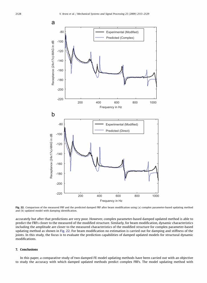
Fig. 22. Comparison of the measured FRF and the predicted damped FRF after beam modification using (a) complex parameter-based updating method
and (b) updated model with damping identification.
V. Arora et al. / Mechanical Systems and Signal Processing 23 (2009) 2113–21292128
accurately but after that predictions are very poor. However, complex parameter-based damped updated method is able topredict the FRFs closer to the measured of the modified structure. Similarly, for beam modification, dynamic characteristicsincluding the amplitude are closer to the measured characteristics of the modified structure for complex parameter-basedupdating method as shown in Fig. 22. For beam modification no estimation is carried out for damping and stiffness of thejoints. In this study, the focus is to evaluate the prediction capabilities of damped updated models for structural dynamicmodifications.
7. Conclusions
In this paper, a comparative study of two damped FE model updating methods have been carried out with an objectiveto study the accuracy with which damped updated methods predict complex FRFs. The model updating method with

ARTICLE IN PRESS
V. Arora et al. / Mechanical Systems and Signal Processing 23 (2009) 2113–2129 2129
damping identification predicts accurately for the range covering the number of modes considered. However, beyond themodes of considered, FRF prediction are poor. Whereas, complex parameter-based model updating method is able topredict accurately complex FRFs beyond the frequency range considered. The effectiveness of the both the methods aredemonstrated by numerical examples as well as by actual experimental data and structural dynamic modifications. It canbe concluded from the simulated as well as experimental studies that parametric approach, which is complex updatedparameters method, gives better FRF matching as compared with model updating with damping identification.
References
[1] K.J. Bathe, Finite Element Procedures, Prentice-Hall, Englewood Cliffs, NJ, 1996.[2] D.J. Ewins, Modal Testing: Theory, Practice and Application, Research Studies Press, England, 2000.[3] N.M.M. Maia, J.M.M. Silva, Theoretical and Experimental Modal Analysis, Research Studies Press, England, 1997.[4] M. Imregun, W.J. Visser, A review of model updating techniques, Shock and Vibration Digest 23 (1991) 141–162.[5] J.E. Mottershead, M.I. Friswell, Model updating in structural dynamics: a survey, Journal of Sound and Vibration 167 (1993) 347–375.[6] M.I. Friswell, J.E. Mottershead, Finite Element Model Updating in Structural Dynamics, Kluwer Academic Publishers, Dordrecht, 1995.[7] M. Baruch, Y. Bar-Itzhack, Optimal weighted orthogonalisation of the measured modes, AIAA Journal 16 (1978) 346–351.[8] A. Berman, E.J. Nagy, Improvement of a large analytical model using test data, AIAA Journal 21 (1983) 927–928.[9] M. Baruch, Methods of reference basis for identification of linear dynamic structures, AIAA Journal 22 (1984) 561–564.
[10] J.D. Collins, G.C. Hart, T.K. Hasselman, B. Kennedy, Statistical identification of structures, AIAA Journal 12 (1974) 185–190.[11] R.M. Lin, D.J. Ewins, Model updating using FRF data, in: Proceedings of the 15th International Seminar on Modal Analysis, Belgium, 1990.[12] D.J. Ewins, D.J. Inman, Structural Dynamics 2000—Current Status and Future Directions, Research Studies Press, England, 2001.[13] Lord Rayleigh, Theory of Sound (Two Volumes), Dover, USA, 1897.[14] C.W. Bert, Material damping: an introduction review of mathematical models, measures and experimental techniques, Journal of Sound and
Vibration 29 (1973) 129–153.[15] N.M.M. Maia, J.M.M. Silva, A.M.R. Ribeiro, On a general model for damping, Journal of Sound and Vibration 218 (1998) 749–767.[16] D.F. Pilkey, Computation of damping matrix for finite element model updating, Ph.D Thesis, Virginia Polytechnic Institute and State University, 1998.[17] S. Adhikari, J. Woodhouse, Identification of damping, Part 1. Viscous damping, Journal of Sound and Vibration 243 (2000) 43–61.[18] S. Adhikari, J. Woodhouse, Identification of damping, Part 2. Non-viscous damping, Journal of Sound and Vibration 243 (2000) 63–88.[19] S. Adhikari, Lancaster’s method of damping identification revisited, Journal of Vibration and Acoustics—Transactions of the ASME 124 (4) (2002)
617–627.[20] M. Imregun, W.J. Visser, D.J. Ewins, Finite element model updating using frequency response function data—1: theory and initial investigation,
Mechanical Systems and Signal Processing 9 (2) (1995) 187–202.[21] M. Imregun, K.Y. Sanliturk, D.J. Ewins, Finite element model updating using frequency response function data—II: case study on a medium size finite
element model, Mechanical Systems and Signal Processing 9 (2) (1995) 203–213.[22] P. Ladeveze, A. Chouaki, A modelling error estimator for dynamic model updating of damped structures, in: M. Tanaka, G.S. Dulikravich (Eds.), Inverse
Problems in Engineering Mechanics, Elsevier, London, 1998, pp. 187–196.[23] R.M. Lin, J. Zhu, Model updating of damped structures using FRF data, Mechanical Systems and Signal Processing 20 (2006) 2200–2218.[24] Vikas Arora, S.P. Singh, T.K. Kundra, Damped model updating using complex updating parameters, Journal of Sound and Vibration 320 (2009)
438–451.[25] Vikas Arora, S.P. Singh, T.K. Kundra, On the use of damped updated FE model for dynamic design, Mechanical Systems and Signal Processing 23 (3)
(2009) 580–587.[26] P. Lancaster, Expression for damping matrices in linear vibration, Journal of the Aerospace Sciences 28 (1961) 256.[27] M.I. Friswell, S.D. Garvey, J.E.T. Penny, The convergence of the iterated IRS technique, Journal of Sound and Vibration 211 (1998) 123–132.