Embed Size (px)
Citation preview
Comparative Study of Active and Passive Sensing with AE and PWAS Transducers
Lingyu Yu1*, Victor Giurgiutiu1, Jianguo Yu2, Paul Ziehl2, Liuxian Zhao1 1Mechanical Engineering Department, University of South Carolina, Columbia, SC 29208
2Civil and Environmental Engineering Department, University of South Carolina, Columbia, SC 29208
Abstract: Monitoring of fatigue cracking in bridges using a combined passive and active scheme has been approached by the authors. Passive Acoustic Emission (AE) monitoring has shown to be able to detect crack growth behavior by picking up the stress waves resulting from the breathing of cracks while active ultrasonic pulsing can quantitatively assess structural integrity by sensing out an interrogating pulse and receive the structural reflections from the discontinuity. In this paper, we present a comparative study of active and passive sensing with two types of transducers: (a) AE transducers, and (b) embeddable piezoelectric wafer active sensors (PWAS). The study was performed experimentally on steel plates. Both pristine and damaged (notched) conditions were considered. For active sensing, pitch-catch configuration was examined in which one transducer was the transmitter and another transducer acted as the receiver. The ping signal was generated by the AE hardware/software package AEwin. For passive sensing, 0.5-mm lead breaks were executed both on top and on the edge of the plate. The comparative nature of the study was achieved by having the AE and PWAS transducers placed on the same location but on the opposite sides of the plate. The paper presents the main findings of this study in terms of (a) signal strength; (b) signal-to-noise (S/N) ratio; (c) waveform clarity; (d) waveform Fourier spectrum contents and bandwidth; (e) capability to detect and localize AE source; (f) capability to detect and localize damage. The paper performs a critical discussion of the two sensing methodologies, conventional AE transducers vs. PWAS transducers.
Keywords: Piezoelectric Wafer Active Sensors, R15I, Acoustic Emission, Active Sensing, Bridge Health Monitoring
1 INTRODUCTION
According to the Federal Highway Administration (FHWA) National Bridge Inventory (NBI) of 2007, the number of structurally deficient and functionally obsolete bridges is 72,524 and 79,792, respectively. While there are about 10,000 bridges being constructed, replaced, or rehabilitated annually in the United States at a cost of over $5 billion, the total annual costs including maintenance and routine operation are significantly higher [1]. As the inventory continues to age, routine inspection practices will not be sufficient for the timely identification of areas of concern and to provide enough information to bridge owners to make informed decisions for safety and maintenance prioritization. Continuous monitoring is needed for long term evaluation; monitoring areas of concern, such as retrofits, previous repairs or monitoring an area with known flaws, while scheduling and awaiting a repair or continuous monitoring for bridge impacts (ship or vehicle). Continuous monitoring can also be used in cases that there is a concern about vandalism, terrorism, and/or bridge element integrity. Therefore, monitoring of fatigue cracking in steel bridges is of interest to many bridge owners and agencies.
1.1 DUAL PASSIVE-ACTIVE SENSING SCHEME
The research presented in this paper is sponsored by National Institute of Standards and Technology (NIST) through the Technology Innovation Program (TIP), which incorporates novel and promising sensing approaches together with energy harvesting devices to reduce the dramatic uncertainty inherent into any bridge inspection and maintenance plan [2]. One of the challenges in this research is focused on * Contact author, email [email protected]
the use of fused sensor data with multiple sensor types to provide information related to the degradation state of the structure and its correlation to a global performance index. AE detection method has shown the excellent potential for global bridge health monitoring, but has not been exploited to date [3-16]. Combining AE with additional dedicated approach will strengthen the proposed damage detection process. Therefore a dual use passive AE and active pulsing for steel bridge fatigue crack detection is currently being pursued. The combined schematic is to use AE to detect the presence of fatigue cracks in steel bridges in their early stage since methods such as ultrasonics are unable to quantify the initial condition of crack growth since most of the fatigue life for these details is consumed while the fatigue crack is too small to be reliably detected. After the crack is present, active pulsing is activated to allow for further quantification of cracks in the absence of dynamic crack growth, which complements AE sensing that relies on damage progression for quantification. The integration of passive AE detection with active sensing will be a technological leap forward from the current practice of periodic and subjective visual inspection, and bridge management based primarily on history of past performance. The combination of different sensing techniques is realistically envisioned to greatly improve the reliability of damage detection, and provide the reward of optimized decision-making.
1.2 DUAL MODE TRANSDUCERS
Two types of transducers have been investigated by the researchers for the goal of dual mode passive and active sensing. They are the piezoelectric wafer active sensor (PWAS) and R15I AE transducers.
1.2.1 Piezoelectric wafer active sensors (PWAS)
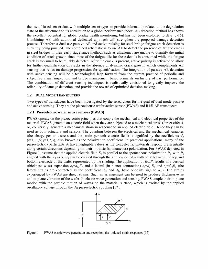
PWAS operate on the piezoelectric principles that couple the mechanical and electrical properties of the material. PWAS generate an electric field when they are subjected to a mechanical stress (direct effect), or, conversely, generate a mechanical strain in response to an applied electric field. Hence they can be used as both actuators and sensors. The coupling between the electrical and the mechanical variables (the charge per unit stress and the strain per unit electric field) is signified by the coefficients dij (i=1,…,6; j=1,2,3), also known as the polarization coefficient. In practical applications, many of the piezoelectric coefficients dij have negligible values as the piezoelectric materials respond preferentially along certain directions depending on their intrinsic (spontaneous) polarization. For PWAS depicted in Figure 1, assume that the applied electric field E3 is parallel to the spontaneous polarization Ps, with Ps aligned with the x3 axis. E3 can be created through the application of a voltage V between the top and bottom electrode of the wafer represented by the shading. The application of E3//Ps results in a vertical (thickness wise) expansion ε3=d33E3 and a lateral (in plane) contractions ε1=d31E3 and ε2=d32E3 (the lateral strains are contracted as the coefficient d31 and d32 have opposite sign to d33). The strains experienced by PWAS are direct strains. Such an arrangement can be used to produce thickness-wise and in-plane vibration of the wafer. In elastic wave generation and sensing, PWAS couple their in-plane motion with the particle motion of waves on the material surface, which is excited by the applied oscillatory voltage through the d31 piezoelectric coupling [17].
Figure 1 PWAS elastic wave generation and reception, the induced-strain responses [17]
x1
x3
-
+
V -
+ E3
-
+ Ps
x2
e3
e1, e2
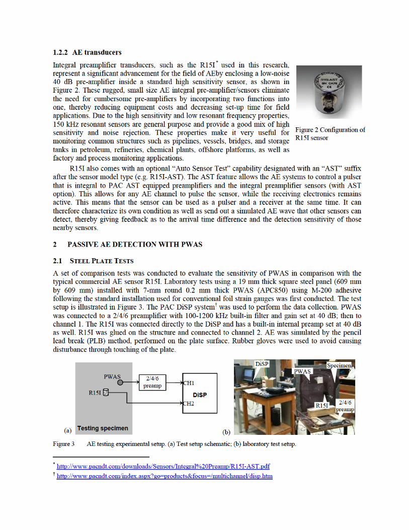
On the 19 mm steel plate, a 0.5-mm PLB was performed on the surface to generate mostly in-plane waves. Distances from PLB to R15I and PWAS are 98.2 mm and 72.11 mm, respectively. Both R15I and PWAS detected the AE with amplitude at 89 dB and 75 dB, respectively. Hit times were 1.5 μs apart. Both waveforms were well captured as presented in Figure 4. This confirms PWAS validity on AE detection on the thick steel plate. Also noticed from the test is, though low in SNR on the thick steel plate, PWAS provides a much wider frequency response to PLB AE which cannot be obtained from the resonant type R15I sensor.
Figure 4 PLB simulated AE detection on 19 mm steel plate. (a) R15I AE signal and its spectrum; (b) PWAS
AE signal and its spectrum
In the validation tests, it has been noticed that PWAS on steel specimens exhibited higher floor noise compared to the standard R15I AE sensors, therefore, providing a poor SNR ratio. To enhance the signal quality for field applications and decrease the background floor noise, we improved PWAS installation by using a coaxial cable similar to that used for R15I sensors. The shield of the coax was connected to the steel plate very close to the PWAS while the center conductor was connected to the positive electrode of the PWAS, as shown in Figure 5a.
Detection of a 0.3 mm PLB about 20 mm away from a coaxial cable wired PWAS was evaluated. The rest of the setup remained the same as for the tests presented in the last section. The resulting waveform had an amplitude of 71 dB, approximately 400 mV. The background floor noise was discernibly decreased and approximated at 10 mV. Therefore, the SNR was measured at 40 or 32 dB, significantly improved compared to the 12 dB presented in section Figure 5b.
0 100 200 300 400 500 600 700 800 900 1000-0.6
-0.4
-0.2
0
0.2
0.4
Vol
t
100 200 300 400 500
1
2
3x 10
-3
|A|
R15I PWAS
f, kHz f, kHz
t, μs 0 100 200 300 400 500 600 700 800 900 1000
-2
-1
0
1
2
Vol
t
100 200 300 400 500
0.02
0.04
0.06
|A|
t, μs
(b)(a)

Figure 5 PLB detection on steel plate using coaxial cable wired PWAS. (a) PWAS installed with coaxial cable;
(b) improved PWAS AE signal and its frequency spectrum
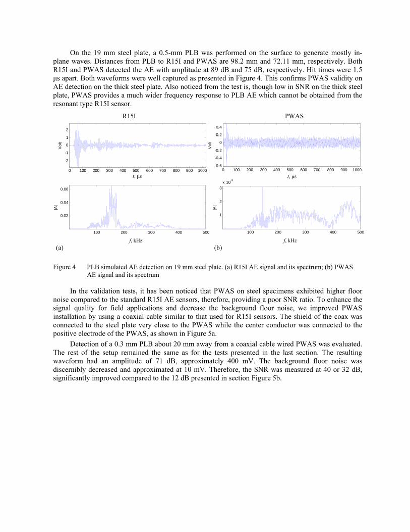
2.2 COMPACT TENSION TESTING
Compact Tension (CT) specimens made of structural steel A572 grade 50, the same material for the aforementioned 19 mm steel plate, were used in this study. The geometry of the specimens is displayed in Figure 6. Custom fixtures were designed and fabricated to mount the CT specimens. Cyclic tension loads of minimum 1 KN and maximum 50 KN were applied to the specimen using servo hydraulic mechanical testing machine (810 Material Test System). Fatigue tests were conducted under load-controlled mode with frequency of 1 HZ. A clip gage was employed to measure the crack mouth opening displacement (CMOD) to clarify crack opening and closure and to determine the magnitude of the CMOD. The surface cracks were also monitored optically with a high resolution recording microscope. Two different pre-amplifiers, one with the bandpass filter in the range of 100-200 kHz and the other with wideband BP-SYS, have been used.
The comparison of crack localization analyzed by PAC AEwin software between PWAS AE sensor and commercially available R15I during CT testing is shown in Figure 7. With R15I, 1171 AE events were detected before the final failure, while 54 were detected by PWAS. Figure 7a gives the cumulative acoustic energy of R15I and PWAS together with the crack opening displacement. While PWAS detect a fewer number of acoustic activities, they detect the crack growth when the crack size reaches 0.83 mm. From Figure 7c it can be seen that PWAS localization is closer and concentrated around the crack tip compared with the R15I detection in Figure 7b. It should be noted that the localization algorithm in the PAC AE localization software was not optimized for this specimen.
f, kHz
t, μs0 200 400 600 800 1000
-0.2
0
0.2
Vo
lt
100 200 300 400 500
5
10
15
x 10-4
|A|
PWAS AE waveform
(b)(a)
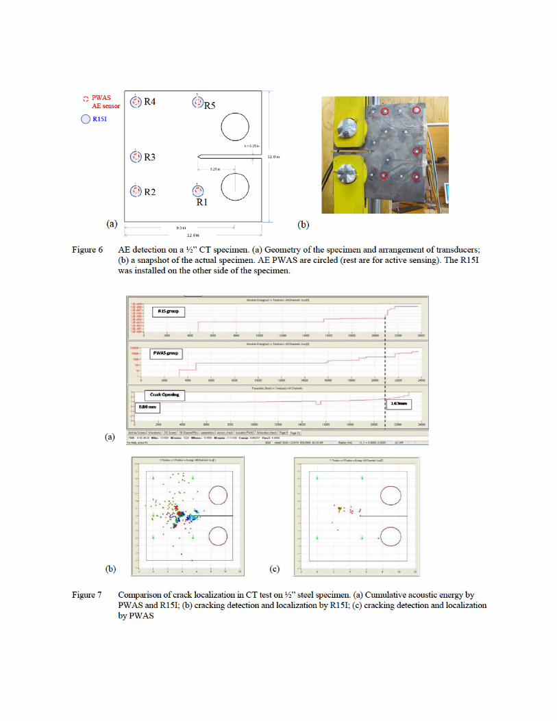


Figure 9 R15I active sensing signals collected at crack # 4 and #13 by R5
3.2 CRACK DETECTION AND ANALYSIS
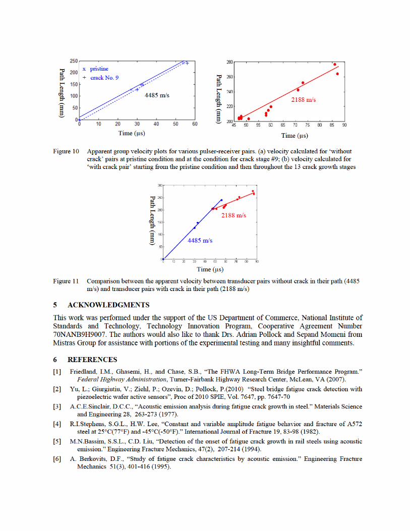
During testing of the compact tension specimen, crack growth was developed from the initial notch. For pulsing-receiving between R1 and R5 (referred as "with crack" pair), this created a diffracted path for wave propagating, as indicated by the solid arrow in Figure 8. That is to say, the wave propagation is from R1 to the crack tip and then from the crack tip to R5. But for others such as those between R1 and R2, R1 and R3, and R1 and R4 (referred as "without crack" pairs) direct wave propagation occurs at most stages of crack development (note that the crack growth stopped before the tip reached the path from R1 to R5), as indicated by the dashed arrows in Figure 8. The path between R1 and R4 will be broken when the crack increases to size #10. We calculated the apparent velocity of wave propagation as the ratio between the wave propagation distance and wave propagation time. Wave propagation time is obtained from the data acquisition system using the arrival time delta t. The velocity calculated from the without crack pairs in the pristine specimen before the crack development and the velocity calculated from the ‘with crack’ pair throughout the crack development are plotted in Figure 10a and Figure 10b, respectively.
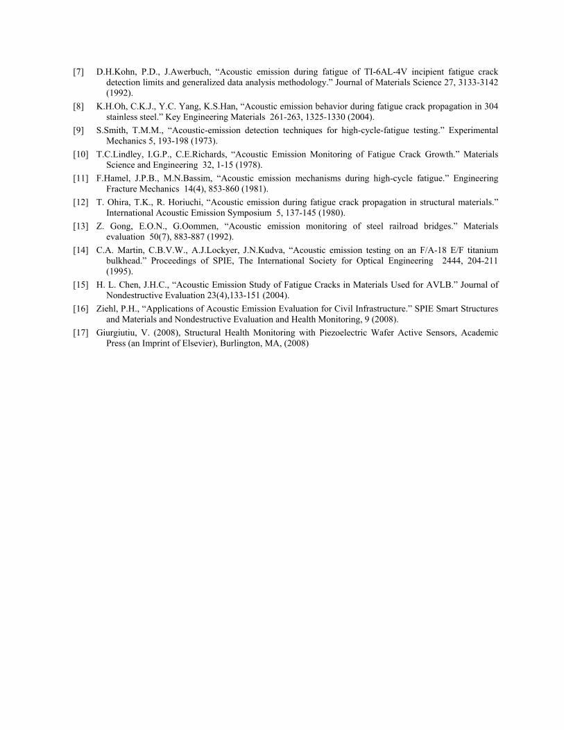
An interesting result can be observed from comparison of Figure 10a and Figure 10b. For ‘without crack’ pairs, the apparent wave velocity is around 4485 m/s (calculated at pristine and crack No. 9). However, for the ‘with crack’ pair R1 to R5, the situation is different. In the initial stage, when the crack is very small and the diffraction is negligible, the apparent velocity is also around 4000 m/s. But as the crack increased, the apparent velocity decreased and became approximately 2188 m/s. The comparison of these two situations is plotted in Figure 11. The possible reason for this difference in velocities could be that the diffraction caused by the crack between R1 and R5 decreases the energy arrived at R5, therefore delayed the time when the signal threshold of the DiSP system is passed, thus resulting in a larger delta t being recorded. This apparent delay in arrival of the received signal results in a decrease in the calculated apparent velocity. Further study need to be conducted to evaluate this finding and developed a full explanation of the phenomenon.
4 CONCLUSIONS
It is well recognized that, as the national highway and off-system bridge inventory continue to age, routine inspection practices will not keep pace with the demands. Continuous monitoring is needed for long term evaluation from an integrated sensing system that would act as a monitoring and early warning alarm system and be able to communicate the information from the bridge directly to the bridge owners for potential and immediate action. The subject NIST project incorporates novel active and passive sensing approaches based on the piezoelectric wafer active sensors to reduce the dramatic uncertainty inherent into any inspection and maintenance plan. In the work presented in this paper, we explored the potentials of using piezoelectric wafer active sensors (PWAS) for passive AE detection and using conventional R15I AE transducers for active crack growth monitoring. This work lays the foundation toward the development of a wireless dual mode sensor network for online bridge health monitoring.
[7] D.H.Kohn, P.D., J.Awerbuch, “Acoustic emission during fatigue of TI-6AL-4V incipient fatigue crack detection limits and generalized data analysis methodology.” Journal of Materials Science 27, 3133-3142 (1992).
[8] K.H.Oh, C.K.J., Y.C. Yang, K.S.Han, “Acoustic emission behavior during fatigue crack propagation in 304 stainless steel.” Key Engineering Materials 261-263, 1325-1330 (2004).
[9] S.Smith, T.M.M., “Acoustic-emission detection techniques for high-cycle-fatigue testing.” Experimental Mechanics 5, 193-198 (1973).
[10] T.C.Lindley, I.G.P., C.E.Richards, “Acoustic Emission Monitoring of Fatigue Crack Growth.” Materials Science and Engineering 32, 1-15 (1978).
[11] F.Hamel, J.P.B., M.N.Bassim, “Acoustic emission mechanisms during high-cycle fatigue.” Engineering Fracture Mechanics 14(4), 853-860 (1981).
[12] T. Ohira, T.K., R. Horiuchi, “Acoustic emission during fatigue crack propagation in structural materials.” International Acoustic Emission Symposium 5, 137-145 (1980).
[13] Z. Gong, E.O.N., G.Oommen, “Acoustic emission monitoring of steel railroad bridges.” Materials evaluation 50(7), 883-887 (1992).
[14] C.A. Martin, C.B.V.W., A.J.Lockyer, J.N.Kudva, “Acoustic emission testing on an F/A-18 E/F titanium bulkhead.” Proceedings of SPIE, The International Society for Optical Engineering 2444, 204-211 (1995).
[15] H. L. Chen, J.H.C., “Acoustic Emission Study of Fatigue Cracks in Materials Used for AVLB.” Journal of Nondestructive Evaluation 23(4),133-151 (2004).
[16] Ziehl, P.H., “Applications of Acoustic Emission Evaluation for Civil Infrastructure.” SPIE Smart Structures and Materials and Nondestructive Evaluation and Health Monitoring, 9 (2008).
[17] Giurgiutiu, V. (2008), Structural Health Monitoring with Piezoelectric Wafer Active Sensors, Academic Press (an Imprint of Elsevier), Burlington, MA, (2008)