Embed Size (px)
Citation preview
Page 1 of 16
Comparative study between wear of uncoated and TiAlN coated carbide tools in milling of Ti6Al4V
M. S. Uddin1,* Binh Pham1, Ahmed Sarhan2, Animesh Basak3 and Alokesh Pramanik4
1School of Engineering, University of South Australia, Mawson Lakes, SA 5095, Australia
2Department of Mechanical Engineering, University of Malaya, Kuala Lumpur, Malaysia
3Adelaide Microscopy Unit, University of Adelaide, SA 5005, Australia
4Department of Mechanical Engineering, Curtin University of Technology, Bently, WA
6845, Australia
*Corresponding email: [email protected]
Abstract:
As is recognised widely, tool wear is a major problem in machining of difficult-to-cut
titanium alloys. Therefore, it is of significant interest and importance to understand and
determine quantitatively and qualitatively tool wear evolution and the underlying wear
mechanisms. The main aim of this paper is to investigate and analyse wear, wear mechanisms
along with surface and chip generation of uncoated and TiAlN coated carbide tools in a dry
milling of Ti6Al4V alloys. Quantitative flank wear and roughness were measured and
recorded. Optical and SEM observations of tool cutting edge, machined surface and chips
were conducted. Results show that the TiAlN coated tool exhibits approximately 44% longer
tool life than the uncoated tool at a cutting distance of 16 m. A more regular progressive
abrasion between the flank face of tool and workpiece is found to be the underlying wear
mechanism. The TiAlN coated tool generates smooth machined surface with a 31% lower
roughness than the uncoated tool. As is expected, both tools generate the serrated chips;
however, burnt chips with blue colour are noticed for the uncoated tool as the cutting
continues further. The results are shown to be consistent with observation of other
researchers, and further imply that the coated tools with appropriate combination of cutting
parameters would be able to increase the tool life in cutting of titanium alloys.
Keywords: Tool wear, titanium alloys, tungsten carbide tools, wear mechanisms, high speed
machining
Manuscript
1 2 3 4 5 6 7 8 9 10 11 12 13 14 15 16 17 18 19 20 21 22 23 24 25 26 27 28 29 30 31 32 33 34 35 36 37 38 39 40 41 42 43 44 45 46 47 48 49 50 51 52 53 54 55 56 57 58 59 60 61 62 63 64 65
Page 2 of 16
1. Introduction
Due to their excellent strength to weight ratio, toughness at high temperature, corrosion
resistance, titanium alloys (e.g. Ti6Al4V) have attracted tremendous attentions and been
extensively applied as structural components in aerospace and biomedical industries, e.g. [1],
[2]. Machining as a mechanical processing technique has been one of the fast, effective
operations in manufacturing to provide the final shape of such components with required
geometric accuracy and finish. However, the key challenge is the difficulty to cut or shape
titanium alloy materials due to their very low thermal conductivity, e.g. [3]. As a result, the
high temperature is generated at the cutting zone, thus affecting the cutting tool life (i.e. wear
performance) and surface integrity of the final product. In the past, different types of cutting
tool materials along with combination of various cutting parameters and environments have
been investigated in cutting of titanium alloys. Cutting tools studied were made of carbide,
HSS, diamond, while cutting speed and feed rate have been the dominating parameters
influencing the machinability of titanium alloys [4], [5].A common coconscious in evaluating
the machinability is that the cutting tool wear is the major factor, which is a resultant of the
underlying interaction and mechanics between the tool and the workpiece, impacting the
manufacturing productivity. Among many tools, tungsten carbide has been a good choice and
widely used cutting tool in the machining industries due to its high strength and wear
resistance, e.g. [6]. The carbide tools are made of tungsten carbide (WC) with cobalt (Co)
binders via compacting and sintering, making the material hard and resilient to heat and wear
[7]. Often the degree of composition of WC-Co is varied to produce the tool with required
mechanical and tribological properties. While diamond tools (e.g. PCD) offer relatively
improved machining performance in terms of tool life, they are quite expensive and may not
be affordable for mass manufacturing [8], [9]. As a result, tungsten carbide has shown
tremendous potential in high speed cutting of titanium alloys. Ove the years, carbide tools
have been studied in cutting of titanium alloys with a focus on understanding of wear and the
associated wear mechanisms, e.g. [10], [11]. In cutting of non-ferrous metals, abrasion,
adhesion, attrition and diffusion are shown to be the typical wear mechanisms, in which,
adhesions and diffusions are often iterated as the dominating, particularly, when machining of
titanium. Ghani et al. [12]studied the effect of various high cutting speeds (120-135 m/min)
on carbide tool wear in cutting of titanium and reported that higher speed causes brittle
fracture and cracking of tool edge due to high temperature induced stress concentration and
intermitted fast thermal loading. They recommended suitable conservative cutting parameters
to minimize tool wear effects. Hartung et al. [13] showed that crater wear due to adhesive
1 2 3 4 5 6 7 8 9 10 11 12 13 14 15 16 17 18 19 20 21 22 23 24 25 26 27 28 29 30 31 32 33 34 35 36 37 38 39 40 41 42 43 44 45 46 47 48 49 50 51 52 53 54 55 56 57 58 59 60 61 62 63 64 65
Page 3 of 16
layers on the rake face is more dominant at lower cutting speeds (61-122 m/min), while the
tool fails due to plastic deformation at high cutting speeds (122-610 m/min). Adhesive layers
are the result of chemical between titanium and carbide particles via diffusion, which
essentially decrease the toughness of tool edge. Generally different tool materials behave
differently to different wear mechanisms. In this regard, hard and wear resistant coatings, e.g.
TiN, TiCN, are applied on the tool edge to improve the performance. Surprisingly, Ezugwu
and Wang [14]found that the uncoated tool outperforms the coated tool in cutting of titanium.
This is however bit contradictory to the findings of other researchers, e.g. [15]. Wear due to
elemental diffusion-dissolution through tool-chip of carbide tools at high cutting speeds was
further emphasized in [16]. In a dry cutting of titanium alloy, Gerez et al. [17]observed that
adhesive layer or built up edge generated at low cutting speeds often act as a lubricant,
minimizing abrasion; however, the layers are momentarily removed at high cutting speeds,
hence accelerating abrasion at the tool-rake interface.
Therefore, it is clear that insightful understanding of wear development and mechanisms are
therefore becoming more important to determine the limit of the tool capability, enabling one
to predict the onset of generation of degraded surface due to a worn-out/failed cutting edge of
the tool. This also allows one to design and develop better cutting tool materials. The notion
of importance of the effect of tool wear on the machinability is stressed out by a wider
community of machining researchers, e.g. [4], [18].
Keeping this sprit in mind, this paper focuses on further investigation and analysis of wear
and wear mechanisms of uncoated and TiAlN coated tungsten carbide tools in cutting of
Ti6Al4V alloys in dry conditions. To follow up and measure consistent wear development, a
series side milling operations with the same cutting parameters were performed. Cutting edge
wear, surface roughness and chips were observed and measured at a certain interval of cutting
distance (often noted as cutting time). Results were discussed and analysed with respect to
the findings available in literature.
2. Experimental details
2.1 Workpieces
The machining was conducted on the workpieces made of Ti-6Al-4V alloys. The chemical
compositions and mechanical properties of the material are presented in Tables 1 and 2. As-
received material block was cut into a size of 100 (L) x 100 (W) x 80 (H) mm. The top and
bottom surfaces of the specimen were further rough machined with very small depth of cut to
1 2 3 4 5 6 7 8 9 10 11 12 13 14 15 16 17 18 19 20 21 22 23 24 25 26 27 28 29 30 31 32 33 34 35 36 37 38 39 40 41 42 43 44 45 46 47 48 49 50 51 52 53 54 55 56 57 58 59 60 61 62 63 64 65
Page 4 of 16
clean and even out the surfaces. This process used a 60 mm diameter solid carbide indexed
cutter running with a feed rate of 500 mm/min and spindle speed of 1200 rpm.
Table 1 Chemical composition (in wt %) of Ti-6Al-4V alloy
Element Ti Al V Fe C N H O
Wt (%) Balance 6.15 4.40 0.09 0.05 0.01 0.005 -
Table 2 Mechanical properties of Ti-6Al-4V alloy at room temperature of 25oC
Hardness
(HRC)
Elastic modulus
(GPa)
Yield strength
(MPa)
Tensile strength
(MPa)
Density (kg/m3)
36 114 830 993 4540
2.2 Cutting tools
As cutters, two types of tungsten carbide end mills are used. One is uncoated (Hanita D014
supplied by Wahida Inc. Japan) and the other coated with TiAlN by physical vapour
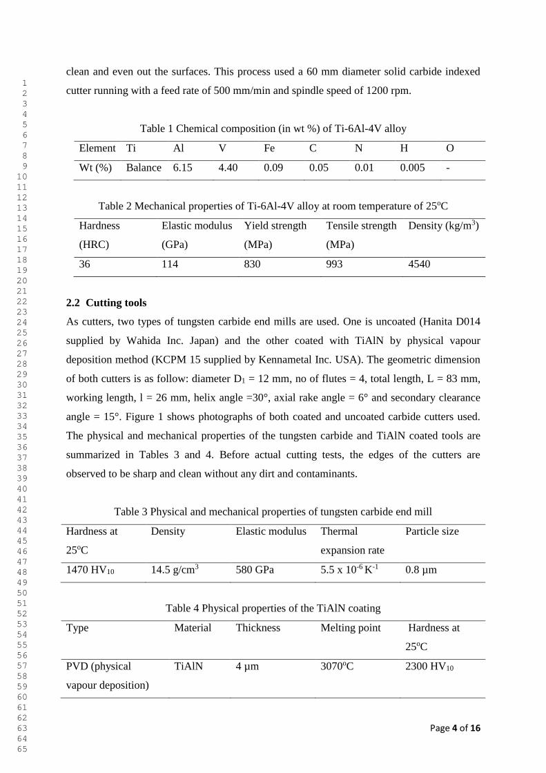
deposition method (KCPM 15 supplied by Kennametal Inc. USA). The geometric dimension
of both cutters is as follow: diameter D1 = 12 mm, no of flutes = 4, total length, L = 83 mm,
working length, l = 26 mm, helix angle =30°, axial rake angle = 6° and secondary clearance
angle = 15°. Figure 1 shows photographs of both coated and uncoated carbide cutters used.
The physical and mechanical properties of the tungsten carbide and TiAlN coated tools are
summarized in Tables 3 and 4. Before actual cutting tests, the edges of the cutters are
observed to be sharp and clean without any dirt and contaminants.
Table 3 Physical and mechanical properties of tungsten carbide end mill
Hardness at
25oC
Density Elastic modulus Thermal
expansion rate
Particle size
1470 HV10 14.5 g/cm3 580 GPa 5.5 x 10⁻⁶ K-1 0.8 µm
Table 4 Physical properties of the TiAlN coating
Type Material Thickness Melting point Hardness at
25oC
PVD (physical
vapour deposition)
TiAlN 4 µm 3070oC 2300 HV10
1 2 3 4 5 6 7 8 9 10 11 12 13 14 15 16 17 18 19 20 21 22 23 24 25 26 27 28 29 30 31 32 33 34 35 36 37 38 39 40 41 42 43 44 45 46 47 48 49 50 51 52 53 54 55 56 57 58 59 60 61 62 63 64 65
Page 5 of 16
Fig. 1 Tungsten carbide end mills used in the tests
2.3 Experimental
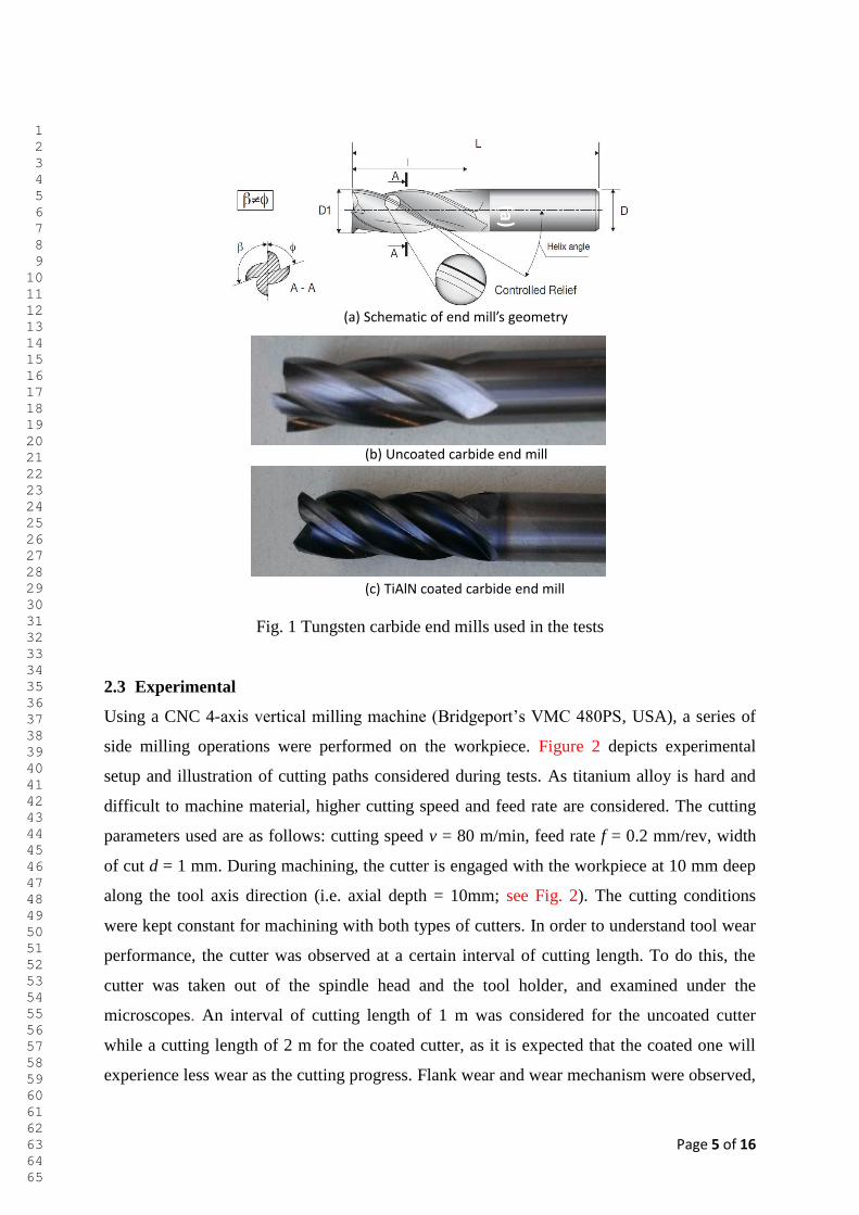
Using a CNC 4-axis vertical milling machine (Bridgeport’s VMC 480PS, USA), a series of
side milling operations were performed on the workpiece. Figure 2 depicts experimental
setup and illustration of cutting paths considered during tests. As titanium alloy is hard and
difficult to machine material, higher cutting speed and feed rate are considered. The cutting
parameters used are as follows: cutting speed v = 80 m/min, feed rate f = 0.2 mm/rev, width
of cut d = 1 mm. During machining, the cutter is engaged with the workpiece at 10 mm deep
along the tool axis direction (i.e. axial depth = 10mm; see Fig. 2). The cutting conditions
were kept constant for machining with both types of cutters. In order to understand tool wear
performance, the cutter was observed at a certain interval of cutting length. To do this, the
cutter was taken out of the spindle head and the tool holder, and examined under the
microscopes. An interval of cutting length of 1 m was considered for the uncoated cutter
while a cutting length of 2 m for the coated cutter, as it is expected that the coated one will
experience less wear as the cutting progress. Flank wear and wear mechanism were observed,
(a)
(a) Schematic of end mill’s geometry
(b) Uncoated carbide end mill
(c) TiAlN coated carbide end mill
1 2 3 4 5 6 7 8 9 10 11 12 13 14 15 16 17 18 19 20 21 22 23 24 25 26 27 28 29 30 31 32 33 34 35 36 37 38 39 40 41 42 43 44 45 46 47 48 49 50 51 52 53 54 55 56 57 58 59 60 61 62 63 64 65
Page 6 of 16
measured and recorded by an optical microscope equipped with high resolution camera (Wild
Heedbrugg’s Wild M20, V=1.4X, Switzerland). Cutting chips were collected to understand
and observe the effect of tool wear on the change of temperature in cutting zone. Topology of
tool, machined surface and chips were further observed by scanning electron microscopes
(SEM) (FEI’s Quanta 450 equipped with EDX capability, Netherland) for a closer look as
well as detailed analysis. The process was kept repeated until the cutters reach closer to
failure (i.e. average VB = 0.3 mm) according to the failure criterion [19]. All the machining
was performed in dry environment without using any external coolant and lubricant. In
addition to wear, roughness average of the machined surface was measured by a roughness
tester (Mitutoyo’s Surftest SJ-210, cut-off length =2.5 mm, contact mode, stylus tip radius=5
µm, complies JIS-B0601 standard, Japan). Roughness on five points of the surface was
measured and their average was considered the final reading. The same experimental
procedure was followed for cutting tests with both uncoated and TiAlN coated tungsten
carbide cutters.
Fig. 2 Experimental setup and cutting paths used in milling tests
3. Results and discussion
3.1 Tool wear
The main focus is to investigate tool wear and wear mechanism associated when machining
of titanium alloy. In general, cutting tests continue until the tool reaches a standard failure
criterion (i.e. average flank wear = 0.3 mm for carbide tool). Figure 3 depicts a comparison of
tool flank wear progression with respect to the cutting length for uncoated and coated tools. It
can be seen from Fig. 3 that, as the cutting length increases, TiAlN coated carbide tool
Axial depth
End mill
3D view
Width of cut
Top view
End mill
Cutting paths
End mill holder
Carbide end mill
Ti6Al4V workpiece
(a) Experimental setup (b) Illustration of cutting paths
workpiece
workpiece
1 2 3 4 5 6 7 8 9 10 11 12 13 14 15 16 17 18 19 20 21 22 23 24 25 26 27 28 29 30 31 32 33 34 35 36 37 38 39 40 41 42 43 44 45 46 47 48 49 50 51 52 53 54 55 56 57 58 59 60 61 62 63 64 65
Page 7 of 16
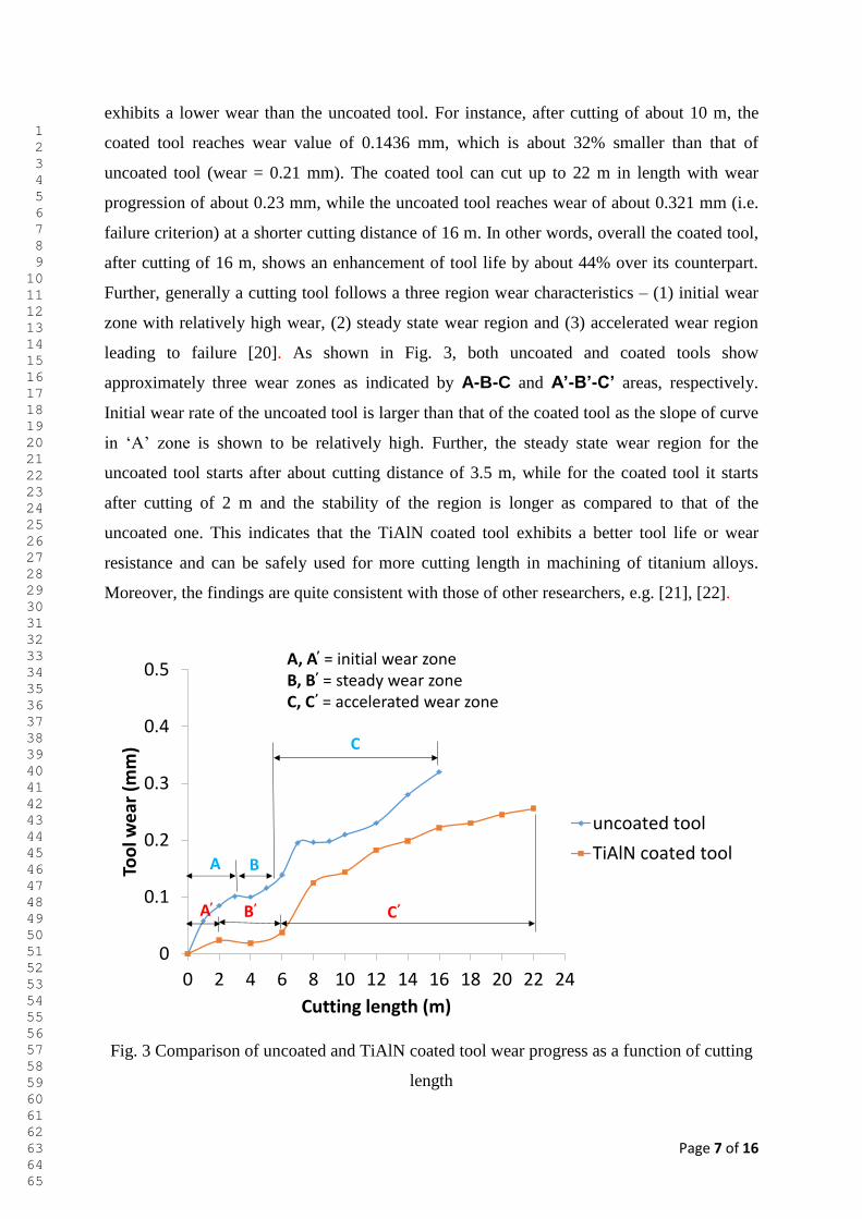
exhibits a lower wear than the uncoated tool. For instance, after cutting of about 10 m, the
coated tool reaches wear value of 0.1436 mm, which is about 32% smaller than that of
uncoated tool (wear = 0.21 mm). The coated tool can cut up to 22 m in length with wear
progression of about 0.23 mm, while the uncoated tool reaches wear of about 0.321 mm (i.e.
failure criterion) at a shorter cutting distance of 16 m. In other words, overall the coated tool,
after cutting of 16 m, shows an enhancement of tool life by about 44% over its counterpart.
Further, generally a cutting tool follows a three region wear characteristics – (1) initial wear
zone with relatively high wear, (2) steady state wear region and (3) accelerated wear region
leading to failure [20]. As shown in Fig. 3, both uncoated and coated tools show
approximately three wear zones as indicated by A-B-C and A’-B’-C’ areas, respectively.
Initial wear rate of the uncoated tool is larger than that of the coated tool as the slope of curve
in ‘A’ zone is shown to be relatively high. Further, the steady state wear region for the
uncoated tool starts after about cutting distance of 3.5 m, while for the coated tool it starts
after cutting of 2 m and the stability of the region is longer as compared to that of the
uncoated one. This indicates that the TiAlN coated tool exhibits a better tool life or wear
resistance and can be safely used for more cutting length in machining of titanium alloys.
Moreover, the findings are quite consistent with those of other researchers, e.g. [21], [22].
Fig. 3 Comparison of uncoated and TiAlN coated tool wear progress as a function of cutting
length
0
0.1
0.2
0.3
0.4
0.5
0 2 4 6 8 10 12 14 16 18 20 22 24
Too
l we
ar (
mm
)
Cutting length (m)
uncoated tool
TiAlN coated tool
C
B’
A B
A’ C’
A, A’ = initial wear zoneB, B’ = steady wear zoneC, C’ = accelerated wear zone
1 2 3 4 5 6 7 8 9 10 11 12 13 14 15 16 17 18 19 20 21 22 23 24 25 26 27 28 29 30 31 32 33 34 35 36 37 38 39 40 41 42 43 44 45 46 47 48 49 50 51 52 53 54 55 56 57 58 59 60 61 62 63 64 65
Page 8 of 16
3.2 Wear mechanisms
In order to evaluate the machining performance of the cutting tools, understanding of the
underlying wear mechanisms is essential. Wear and wear mechanism vary with the
combination and interaction of the cutting tool and workpiece, in addition to cutting
environments. As titanium is a hard material, wear mechanisms that influence the failure of
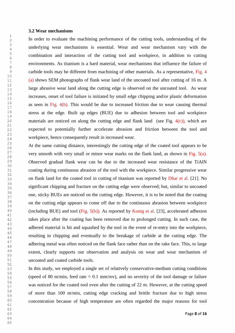
carbide tools may be different from machining of other materials. As a representative, Fig. 4
(a) shows SEM photographs of flank wear land of the uncoated tool after cutting of 16 m. A
large abrasive wear land along the cutting edge is observed on the uncoated tool. As wear
increases, onset of tool failure is initiated by small edge chipping and/or plastic deformation
as seen in Fig. 4(b). This would be due to increased friction due to wear causing thermal
stress at the edge. Built up edges (BUE) due to adhesion between tool and workpiece
materials are noticed on along the cutting edge and flank land (see Fig. 4(c)), which are
expected to potentially further accelerate abrasion and friction between the tool and
workpiece, hence consequently result in increased wear.
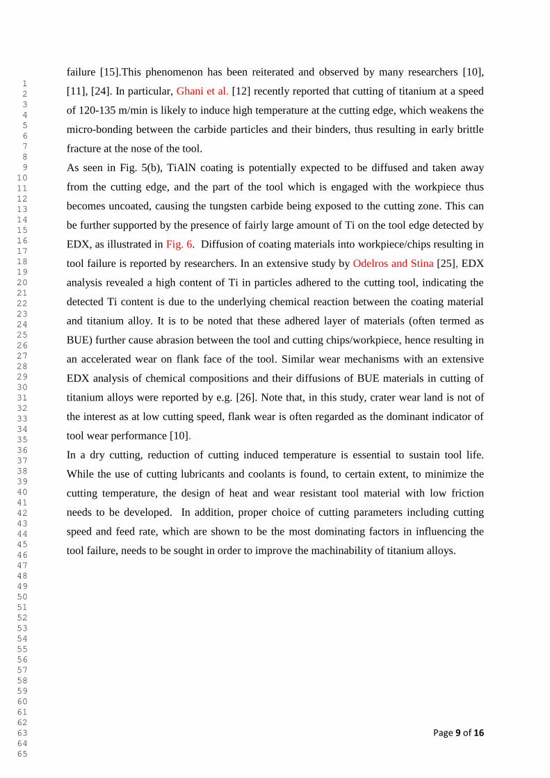
At the same cutting distance, interestingly the cutting edge of the coated tool appears to be
very smooth with very small or minor wear marks on the flank land, as shown in Fig. 5(a).
Observed gradual flank wear can be due to the increased wear resistance of the TiAlN
coating during continuous abrasion of the tool with the workpiece. Similar progressive wear
on flank land for the coated tool in cutting of titanium was reported by Dhar et al. [21]. No
significant chipping and fracture on the cutting edge were observed; but, similar to uncoated
one, sticky BUEs are noticed on the cutting edge. However, it is to be noted that the coating
on the cutting edge appears to come off due to the continuous abrasion between workpiece
(including BUE) and tool (Fig. 5(b)). As reported by Konig et al. [23], accelerated adhesion
takes place after the coating has been removed due to prolonged cutting. In such case, the
adhered material is hit and squashed by the tool in the event of re-entry into the workpiece,
resulting in chipping and eventually to the breakage of carbide at the cutting edge. The
adhering metal was often noticed on the flank face rather than on the rake face. This, to large
extent, clearly supports our observation and analysis on wear and wear mechanism of
uncoated and coated carbide tools.
In this study, we employed a single set of relatively conservative-medium cutting conditions
(speed of 80 m/min, feed rate = 0.1 mm/rev), and no severity of the tool damage or failure
was noticed for the coated tool even after the cutting of 22 m. However, at the cutting speed
of more than 100 m/min, cutting edge cracking and brittle fracture due to high stress
concentration because of high temperature are often regarded the major reasons for tool
1 2 3 4 5 6 7 8 9 10 11 12 13 14 15 16 17 18 19 20 21 22 23 24 25 26 27 28 29 30 31 32 33 34 35 36 37 38 39 40 41 42 43 44 45 46 47 48 49 50 51 52 53 54 55 56 57 58 59 60 61 62 63 64 65
Page 9 of 16
failure [15].This phenomenon has been reiterated and observed by many researchers [10],
[11], [24]. In particular, Ghani et al. [12] recently reported that cutting of titanium at a speed
of 120-135 m/min is likely to induce high temperature at the cutting edge, which weakens the
micro-bonding between the carbide particles and their binders, thus resulting in early brittle
fracture at the nose of the tool.
As seen in Fig. 5(b), TiAlN coating is potentially expected to be diffused and taken away
from the cutting edge, and the part of the tool which is engaged with the workpiece thus
becomes uncoated, causing the tungsten carbide being exposed to the cutting zone. This can
be further supported by the presence of fairly large amount of Ti on the tool edge detected by
EDX, as illustrated in Fig. 6. Diffusion of coating materials into workpiece/chips resulting in
tool failure is reported by researchers. In an extensive study by Odelros and Stina [25], EDX
analysis revealed a high content of Ti in particles adhered to the cutting tool, indicating the
detected Ti content is due to the underlying chemical reaction between the coating material
and titanium alloy. It is to be noted that these adhered layer of materials (often termed as
BUE) further cause abrasion between the tool and cutting chips/workpiece, hence resulting in
an accelerated wear on flank face of the tool. Similar wear mechanisms with an extensive
EDX analysis of chemical compositions and their diffusions of BUE materials in cutting of
titanium alloys were reported by e.g. [26]. Note that, in this study, crater wear land is not of
the interest as at low cutting speed, flank wear is often regarded as the dominant indicator of
tool wear performance [10].
In a dry cutting, reduction of cutting induced temperature is essential to sustain tool life.
While the use of cutting lubricants and coolants is found, to certain extent, to minimize the
cutting temperature, the design of heat and wear resistant tool material with low friction
needs to be developed. In addition, proper choice of cutting parameters including cutting
speed and feed rate, which are shown to be the most dominating factors in influencing the
tool failure, needs to be sought in order to improve the machinability of titanium alloys.
1 2 3 4 5 6 7 8 9 10 11 12 13 14 15 16 17 18 19 20 21 22 23 24 25 26 27 28 29 30 31 32 33 34 35 36 37 38 39 40 41 42 43 44 45 46 47 48 49 50 51 52 53 54 55 56 57 58 59 60 61 62 63 64 65
Page 10 of 16
Fig. 4 Wear land and mechanism of uncoated carbide tool at a cutting length of 16 m
Fig. 5 Wear land and mechanism of TiAlN coated carbide tool at a cutting length of 16 m
abrasive wear on flank land
edge chipping/plastic deformation
built-up edges (BUE) due to adhesion
(a)(b)
(C)
coating comes off due to abrasion
exposing carbide toolflank wear land with sticky BUE on edge
BUE
(a) (b)
1 2 3 4 5 6 7 8 9 10 11 12 13 14 15 16 17 18 19 20 21 22 23 24 25 26 27 28 29 30 31 32 33 34 35 36 37 38 39 40 41 42 43 44 45 46 47 48 49 50 51 52 53 54 55 56 57 58 59 60 61 62 63 64 65
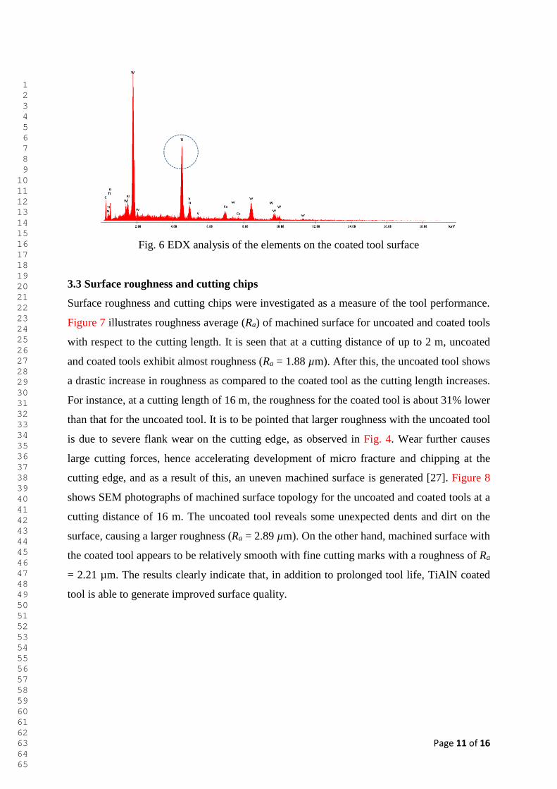
Page 11 of 16
Fig. 6 EDX analysis of the elements on the coated tool surface
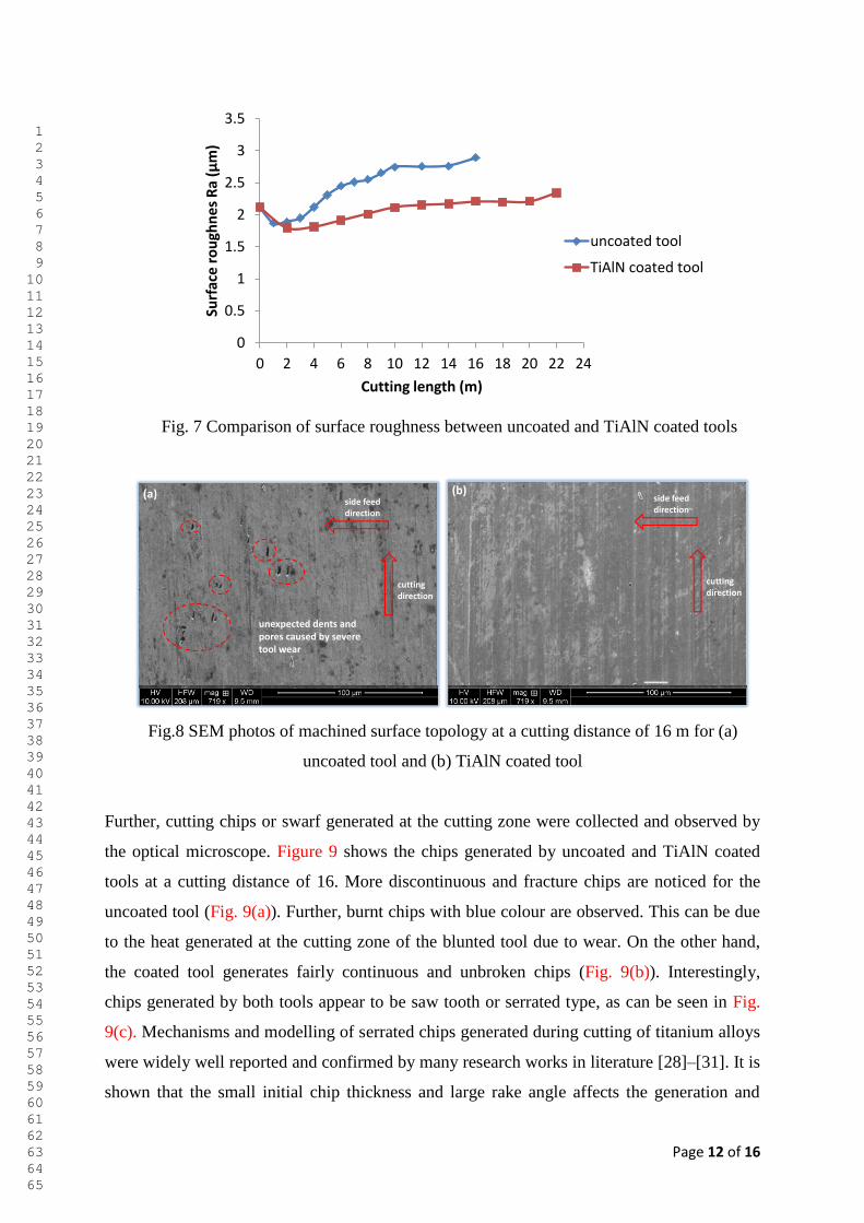
3.3 Surface roughness and cutting chips
Surface roughness and cutting chips were investigated as a measure of the tool performance.
Figure 7 illustrates roughness average (Ra) of machined surface for uncoated and coated tools
with respect to the cutting length. It is seen that at a cutting distance of up to 2 m, uncoated
and coated tools exhibit almost roughness (Ra = 1.88 µm). After this, the uncoated tool shows
a drastic increase in roughness as compared to the coated tool as the cutting length increases.
For instance, at a cutting length of 16 m, the roughness for the coated tool is about 31% lower
than that for the uncoated tool. It is to be pointed that larger roughness with the uncoated tool
is due to severe flank wear on the cutting edge, as observed in Fig. 4. Wear further causes
large cutting forces, hence accelerating development of micro fracture and chipping at the
cutting edge, and as a result of this, an uneven machined surface is generated [27]. Figure 8
shows SEM photographs of machined surface topology for the uncoated and coated tools at a
cutting distance of 16 m. The uncoated tool reveals some unexpected dents and dirt on the
surface, causing a larger roughness (Ra = 2.89 µm). On the other hand, machined surface with
the coated tool appears to be relatively smooth with fine cutting marks with a roughness of Ra
= 2.21 µm. The results clearly indicate that, in addition to prolonged tool life, TiAlN coated
tool is able to generate improved surface quality.
1 2 3 4 5 6 7 8 9 10 11 12 13 14 15 16 17 18 19 20 21 22 23 24 25 26 27 28 29 30 31 32 33 34 35 36 37 38 39 40 41 42 43 44 45 46 47 48 49 50 51 52 53 54 55 56 57 58 59 60 61 62 63 64 65
Page 12 of 16
Fig. 7 Comparison of surface roughness between uncoated and TiAlN coated tools
Fig.8 SEM photos of machined surface topology at a cutting distance of 16 m for (a)
uncoated tool and (b) TiAlN coated tool
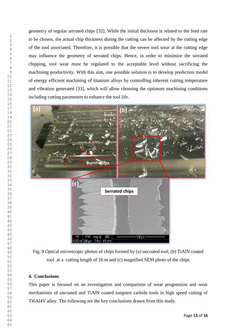
Further, cutting chips or swarf generated at the cutting zone were collected and observed by
the optical microscope. Figure 9 shows the chips generated by uncoated and TiAlN coated
tools at a cutting distance of 16. More discontinuous and fracture chips are noticed for the
uncoated tool (Fig. 9(a)). Further, burnt chips with blue colour are observed. This can be due
to the heat generated at the cutting zone of the blunted tool due to wear. On the other hand,
the coated tool generates fairly continuous and unbroken chips (Fig. 9(b)). Interestingly,
chips generated by both tools appear to be saw tooth or serrated type, as can be seen in Fig.
9(c). Mechanisms and modelling of serrated chips generated during cutting of titanium alloys
were widely well reported and confirmed by many research works in literature [28]–[31]. It is
shown that the small initial chip thickness and large rake angle affects the generation and
0
0.5
1
1.5
2
2.5
3
3.5
0 2 4 6 8 10 12 14 16 18 20 22 24
Surf
ace
ro
ugh
ne
s R
a (µ
m)
Cutting length (m)
uncoated tool
TiAlN coated tool
unexpected dents and pores caused by severe tool wear
(a)
cutting direction
side feed direction
(b)
cutting direction
side feed direction
1 2 3 4 5 6 7 8 9 10 11 12 13 14 15 16 17 18 19 20 21 22 23 24 25 26 27 28 29 30 31 32 33 34 35 36 37 38 39 40 41 42 43 44 45 46 47 48 49 50 51 52 53 54 55 56 57 58 59 60 61 62 63 64 65
Page 13 of 16
geometry of regular serrated chips [32]. While the initial thickness is related to the feed rate
to be chosen, the actual chip thickness during the cutting can be affected by the cutting edge
of the tool associated. Therefore, it is possible that the severe tool wear at the cutting edge
may influence the geometry of serrated chips. Hence, in order to minimize the serrated
chipping, tool wear must be regulated to the acceptable level without sacrificing the
machining productivity. With this aim, one possible solution is to develop prediction model
of energy efficient machining of titanium alloys by controlling inherent cutting temperature
and vibration generated [33], which will allow choosing the optimum machining conditions
including cutting parameters to enhance the tool life.
Fig. 9 Optical microscopic photos of chips formed by (a) uncoated tool, (b) TiAlN coated
tool at a cutting length of 16 m and (c) magnified SEM photo of the chips
4. Conclusions
This paper is focused on an investigation and comparison of wear progression and wear
mechanisms of uncoated and TiAlN coated tungsten carbide tools in high speed cutting of
Ti6Al4V alloy. The following are the key conclusions drawn from this study.
Burnt chips
Serrated chips
(a) (b)
(c)
1 2 3 4 5 6 7 8 9 10 11 12 13 14 15 16 17 18 19 20 21 22 23 24 25 26 27 28 29 30 31 32 33 34 35 36 37 38 39 40 41 42 43 44 45 46 47 48 49 50 51 52 53 54 55 56 57 58 59 60 61 62 63 64 65
Page 14 of 16
The TiAlN coated tool exhibits improved tool life with approximately 44% lower
flank wear than the uncoated tool at a cutting distance of 16 m.
A more regular progressive abrasion between the flank face of tool and workpiece is
found to be the underlying wear mechanism and small edge chipping and/or plastic
deformation for prolonged cutting are noticed for the uncoated tool.
Diffusion as a form of BUEs due to the chemical reaction between the coating and the
workpiece materials at high cutting temperature is shown to cause the removal of
coating from the tool, and weaken the cutting edge, which may result in further
acceleration of potential failures.
The TiAlN coated tool generates smooth machined surface with a 31% lower
roughness (Ra) over the uncoated tool. As is expected, both tools generate the serrated
chips; however, burnt chips with blue colour are noticed for the uncoated tool as the
cutting continues further.
Acknowledgements:
The authors like to thank Adelaide Microscopy Unit of University of Adelaide for their
support in using SEM and EDX for observation of cutting tools and machined surfaces.
References
[1] P.-J. Arrazola, A. Garay, L.-M. Iriarte, M. Armendia, S. Marya, and F. Le Maître, “Machinability of titanium alloys (Ti6Al4V and Ti555.3),” J. Mater. Process. Technol., vol. 209, no. 5, pp. 2223–2230, Mar. 2009.
[2] S. A. Niknam, R. Khettabi, and V. Songmene, “Machinability and Machining of Titanium Alloys: A Review,” in Machining of Titanium Alloys, J. P. Davim, Ed. Berlin, Heidelberg: Springer Berlin Heidelberg, 2014, pp. 1–30.
[3] M. Nouari and H. Makich, “On the Physics of Machining Titanium Alloys: Interactions between Cutting Parameters, Microstructure and Tool Wear,” Metals, vol. 4, no. 3, pp. 335–358, Jul. 2014.
[4] J. A. Arsecularatne, L. C. Zhang, and C. Montross, “Wear and tool life of tungsten carbide, PCBN and PCD cutting tools,” Int. J. Mach. Tools Manuf., vol. 46, no. 5, pp. 482–491, Apr. 2006.
[5] A. R. Zareena and S. C. Veldhuis, “Tool wear mechanisms and tool life enhancement in ultra-precision machining of titanium,” J. Mater. Process. Technol., vol. 212, no. 3, pp. 560–570, Mar. 2012.
[6] T. Santhanam, P. Tierney, and J. L. Hunt, Properties and selection: Nonferrous alloys and special-purpose materials, 10th ed., vol. 2. Kennametal Inc, 1990.
[7] K. Egashira, S. Hosono, S. Takemoto, and Y. Masao, “Fabrication and cutting performance of cemented tungsten carbide micro-cutting tools,” Precis. Eng., vol. 35, no. 4, pp. 547–553, Oct. 2011.
1 2 3 4 5 6 7 8 9 10 11 12 13 14 15 16 17 18 19 20 21 22 23 24 25 26 27 28 29 30 31 32 33 34 35 36 37 38 39 40 41 42 43 44 45 46 47 48 49 50 51 52 53 54 55 56 57 58 59 60 61 62 63 64 65
Page 15 of 16
[8] S. Honghua, P. LIU, Y. FU, and J. XU, “Tool Life and Surface Integrity in High-speed Milling of Titanium Alloy TA15 with PCD/PCBN Tools,” Chin. J. Aeronaut., vol. 25, no. 5, pp. 784–790, Oct. 2012.
[9] A. Li, J. Zhao, D. Wang, J. Zhao, and Y. Dong, “Failure mechanisms of a PCD tool in high-speed face milling of Ti–6Al–4V alloy,” Int. J. Adv. Manuf. Technol., vol. 67, no. 9–12, pp. 1959–1966, Nov. 2012.
[10] A. Jawaid, S. Sharif, and S. Koksal, “Evaluation of wear mechanisms of coated carbide tools when face milling titanium alloy,” J. Mater. Process. Technol., vol. 99, no. 1–3, pp. 266–274, Mar. 2000.
[11] A. Bhatt, H. Attia, R. Vargas, and V. Thomson, “Wear mechanisms of WC coated and uncoated tools in finish turning of Inconel 718,” Tribol. Int., vol. 43, no. 5–6, pp. 1113–1121, May 2010.
[12] J. Ghani, C. H. Che Haron, S. H. Hamdan, A. Y. Md Said, and S. H. Tomadi, “Failure mode analysis of carbide cutting tools used for machining titanium alloy,” Ceram. Int., vol. 39, no. 4, pp. 4449–4456, May 2013.
[13] P. D. Hartung, B. M. Kramer, and B. F. von Turkovich, “Tool Wear in Titanium Machining,” CIRP Ann. - Manuf. Technol., vol. 31, no. 1, pp. 75–80, 1982.
[14] E. O. Ezugwu and Z. M. Wang, “Titanium alloys and their machinability—a review,” J. Mater. Process. Technol., vol. 68, no. 3, pp. 262–274, Aug. 1997.
[15] A. Ginting and M. Nouari, “Experimental and numerical studies on the performance of alloyed carbide tool in dry milling of aerospace material,” Int. J. Mach. Tools Manuf., vol. 46, no. 7–8, pp. 758–768, Jun. 2006.
[16] D. Jianxin, L. Yousheng, and S. Wenlong, “Diffusion wear in dry cutting of Ti–6Al–4V with WC/Co carbide tools,” Wear, vol. 265, no. 11–12, pp. 1776–1783, Nov. 2008.
[17] J. M. Gerez, M. Sanchez‐Carrilero, J. Salguero, M. Batista, and M. Marcos, “A SEM and EDS based Study of the Microstructural Modifications of Turning Inserts in the Dry Machining of Ti6Al4V Alloy,” in AIP Conference Proceedings, 2009, vol. 1181, pp. 567–574.
[18] A. Pramanik, M. N. Islam, A. Basak, and G. Littlefair, “Machining and Tool Wear Mechanisms during Machining Titanium Alloys,” Adv. Mater. Res., vol. 651, pp. 338–343, Jan. 2013.
[19] S. Zhang, J. F. Li, J. Sun, and F. Jiang, “Tool wear and cutting forces variation in high-speed end-milling Ti-6Al-4V alloy,” Int. J. Adv. Manuf. Technol., vol. 46, no. 1–4, pp. 69–78, May 2009.
[20] V. P. Astakhov and J. P. Davim, “Tools (Geometry and Material) and Tool Wear - Springer,” in Machining: Fundamentals and Recent Advances, Springer Berlin Heidelberg, 2008, pp. 25–57.
[21] N. R. Dhar, S. Islam, M. Kamruzzaman, and S. Paul, “Wear behavior of uncoated carbide inserts under dry, wet and cryogenic cooling conditions in turning C-60 steel,” J. Braz. Soc. Mech. Sci. Eng., vol. 28, no. 2, pp. 146–152, Jun. 2006.
[22] S. Sharif, E. Abd, and H. Sasahar, “Machinability of Titanium Alloys in Drilling,” in Titanium Alloys - Towards Achieving Enhanced Properties for Diversified Applications, A. K. M. N. Amin, Ed. InTech, 2012.
[23] W. König, R. Fritsch, and D. Kammermeier, “Physically vapor deposited coatings on tools: performance and wear phenomena,” in Metallurgical Coatings and Thin Films 1991, Oxford: Elsevier, 1991, pp. 316–324.
1 2 3 4 5 6 7 8 9 10 11 12 13 14 15 16 17 18 19 20 21 22 23 24 25 26 27 28 29 30 31 32 33 34 35 36 37 38 39 40 41 42 43 44 45 46 47 48 49 50 51 52 53 54 55 56 57 58 59 60 61 62 63 64 65
Page 16 of 16
[24] Y. Zhang, Z. Zhou, J. Wang, and X. Li, “Diamond Tool Wear in Precision Turning of Titanium Alloy,” Mater. Manuf. Process., vol. 28, no. 10, pp. 1061–1064, Oct. 2013.
[25] S. Odelros, “Tool wear in titanium machinin,” Uppasla University, 2012. [26] Q. Bai, “Interactions Between Wear Mechanisms in a WC-Co / Ti-6Al-4V Machining
Tribosystem,” Thesis, 2014. [27] C. H. Che-Haron and A. Jawaid, “The effect of machining on surface integrity of
titanium alloy Ti–6% Al–4% V,” J. Mater. Process. Technol., vol. 166, no. 2, pp. 188–192, Aug. 2005.
[28] M. J. Bermingham, S. Palanisamy, and M. S. Dargusch, “Understanding the tool wear mechanism during thermally assisted machining Ti-6Al-4V,” Int. J. Mach. Tools Manuf., vol. 62, pp. 76–87, Nov. 2012.
[29] M. Cotterell and G. Byrne, “Dynamics of chip formation during orthogonal cutting of titanium alloy Ti–6Al–4V,” CIRP Ann. - Manuf. Technol., vol. 57, no. 1, pp. 93–96, 2008.
[30] H. Li, G. He, X. Qin, G. Wang, C. Lu, and L. Gui, “Tool wear and hole quality investigation in dry helical milling of Ti-6Al-4V alloy,” Int. J. Adv. Manuf. Technol., vol. 71, no. 5–8, pp. 1511–1523, Jan. 2014.
[31] G. Sutter and G. List, “Very high speed cutting of Ti–6Al–4V titanium alloy – change in morphology and mechanism of chip formation,” Int. J. Mach. Tools Manuf., vol. 66, pp. 37–43, Mar. 2013.
[32] C. Gao and L. Zhang, “EFFECT OF CUTTING CONDITIONS ON THE SERRATED CHIP FORMATION IN HIGH-SPEED CUTTING,” Mach. Sci. Technol., vol. 17, no. 1, pp. 26–40, Jan. 2013.
[33] Z. Wang, S. Nakashima, and M. Larson, “Energy Efficient Machining of Titanium Alloys by Controlling Cutting Temperature and Vibration,” Procedia CIRP, vol. 17, pp. 523–528, 2014.
1 2 3 4 5 6 7 8 9 10 11 12 13 14 15 16 17 18 19 20 21 22 23 24 25 26 27 28 29 30 31 32 33 34 35 36 37 38 39 40 41 42 43 44 45 46 47 48 49 50 51 52 53 54 55 56 57 58 59 60 61 62 63 64 65


![MECHANICAL AND TRIBOLOGICAL PROPERTIES OF ...tribolab.mas.bg.ac.rs/proceedings/2015/137-142.pdfTiAlN/TiSiN coating. TiAlN TiAlN/TiSiN H [GPa] 25.2 38.9 E [GPa] 372.0 247.6 H3/E*2 [GPa]](https://img.pdfslide.us/doc/110x75/6090b172324120134a61f5f9/mechanical-and-tribological-properties-of-tialntisin-coating-tialn-tialntisin.jpg)