Embed Size (px)
Citation preview
Direk, M., et al.: Comparative Performance Analysis of Experimental … THERMAL SCIENCE, Year 2016, Vol. 20, No. 6, pp. 2065-2072 2065
COMPARATIVE PERFORMANCE ANALYSIS OF EXPERIMENTAL FRIGORIFIC AIR CONDITIONING SYSTEM USING
R-134A AND HFO-1234YF AS A REFRIGERANT
by
Mehmet DIREKa*, Cuneyt TUNCKALb, and Fikret YUKSELa
a Department of Energy Systems Engineering, Faculty of Engineering, Yalova University, Yalova, Turkey
b Air Conditioning and Refrigeration Technology Program, Electric and Energy Department, Vocational School of Yalova, Yalova University, Yalova, Turkey
Original scientific paper DOI: 10.2298/TSCI140715130D
In this study, to evaluate the comparative experimental performances, a frigorific air conditioning system using HFO1234yf and R134a was developed and refrig-erated air was introduced into a conditioned room. The experiment was carried out at different condenser inlet temperatures and using the refrigerants at differ-ent charges, 1250, 1500, and 1750 grams. Experiments were conducted for a standard frigorific air conditioning system using the HFO1234yf and R-134a sys-tem. Air flow was introduced to the conditioned room for 60 minutes for each performance test. The results revealed that the temperature gradient in time was comparable for both refrigerants. The results of this investigation propose utilis-ing HFO1234yf as a replacement for the currently favoured R134a in a frigorific air conditioning system Key words: R134a, frigorific air conditioning system, HFO1234yf
Introduction
Starting from 2017, the European Union’s F-gas regulations [1, 2] specify that new models introduced after January 1, 2011, and after 2017, all automobiles coupled with air con-ditioning systems, can not be manufactured using greenhouse gases that have global warming potentials (GWP) greater than 150. Since the similar performance index of HFO1234yf system has been evaluated as an alternative for the R134a system, HFO1234yf could be implemented in existing air conditioning systems using R134a. Consequently, it has a GWP of 4 and is widely being considered as a possible replacement for R134a in automotive applications [3].
Meyer [3] revealed that the cooling capacity and coefficients of performance (COP) of HFO1234yf could be made relatively equal to the baseline R134a values using only simple system modifications. Minor and Spatz [4] demonstrated that there remain several issues that are currently being investigated through on-going research and development work in order to replace R134a with HFO1234yf in automotive applications.
The effects of using improved components in air conditioning systems were studied experimentally by Petitjean and Benouali [5]. They found that the condenser plays a far more significant role than the evaporator in the optimization of the HFO1234yf performance re-
–––––––––––––– * Corresponding author; e-mail: [email protected]
Direk, M., et al.: Comparative Performance Analysis of Experimental … 2066 THERMAL SCIENCE, Year 2016, Vol. 20, No. 6, pp. 2065-2072
garding the conventional heat exchangers. They also showed that the HFO1234yf perfor-mance can match or even better that of R134a with correctly designed and tuned components. Lee and Jung [6] observed the conditions for mobile air conditioners, the performance of both HFO1234yf and R134a were investigated in a heat pump bench tester. The results revealed that, because of its good environmental properties and reasonable performance, HFO1234yf could potentially be seen as a long term environmentally friendly solution for use in mobile air conditioners.
Navarro et al. [7] compared HFO1234yf, R134a, and R290 for an open piston com-pressor at different operating conditions. They detected a reduction of between 10-15% in the system’s cooling capacity when using HFO1234yf to that which used R134a. Akram et al. [8] study compared the lubricity of the two refrigerants, the environmentally friendly HFO1234yf and the traditional R134a, for air conditioning compressor applications. The results demon-strated that, for gray cast iron material interfaces, HFO1234yf offered greater lubricity than R134a. Lee et al. [9] study proposed replacing R134a in applications such as mobile air con-ditioners, centrifugal chillers, and beverage coolers with an azeotropic mixture of R134a and HFO1234yf. This is because the COP capacity and discharge temperature of R134a is similar to that of HFO1234yf and the HFO1234yf/R134a mixture. They found that, in the HFO1234yf/R134a mixture when more R134a was added the danger of flammability decreas-es, while compositions with R134a above 10%, the mixture became non-flammable. Tanaka and Higashi [10] reported also that toxicity and thermodynamic properties critical tempera-ture, critical density, and critical pressured of HFO1234yf are similar to those of R134a. SAE research program [11] concluded that HFO1234yf can be used to globally replace refrigerants used in future mobile air conditioning systems. A comparative analysis showed that ignition potential and being exposed to hydrogen floride was extremely low. A comparative analysis show that HFO1234yf is a non-ozone depleting substance with a GWP of 4 and analysis also show that risks were well below those commonly considered acceptable by the public and regulatory agencies.
In this study, the performance of R134a and HFO1234yf are compared using a frigo-rific air conditioning system, respectively. The refrigerated air was sent into the conditioned room for both refrigerants. The experiment was carried out using the refrigerants at different charges, 1250 g, 1500 g, and 1750 g. The effects of using R134a and HFO1234yf, as a refrig-erant in a frigorific air conditioning system, and their respective performances were deter-mined comparatively. As can be seen from the relative literature concerning this topic, this is the first time a comparison of the performance parameters for a frigorific air conditioning sys-tem using HFO1234yf and R134a has been made. The originality of this paper is to compare two refrigerants transient and steady-state situations, at different charges. This study com-pared the refrigerants HFO1234yf and R134a in a transient scenario, and used a conditioning room to dertermine the performance of these refrigerants.
Description of the experimental set-up
The experimental system was made from original components of a frigorific air conditioning system, as schematically shown in fig. 1. It employed a 7-cylinder fixed-capacity swash-plate SANDEN SD 5750 W compressor at 2200 rpm, a 9500 W parallel-flow micro-channel condenser, a 5750 W laminated type evaporator and thermostatic expansion valves. An experimental system was connected to a refrigerated room for the test. The room dimen-sions were determined as 210 cm × 220 cm × 220 cm. This conditioned room was insulated by 8 cm thick insulation panels.
Direk, M., et al.: Comparative Performance Analysis of Experimental … THERMAL SCIENCE, Year 2016, Vol. 20, No. 6, pp. 2065-2072 2067
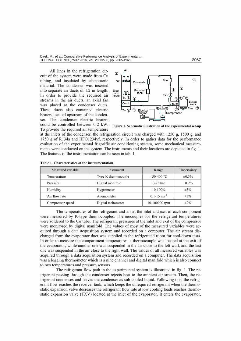
All lines in the refrigeration cir-cuit of the system were made from Cu tubing, and insulated by elastomeric material. The condenser was inserted into separate air ducts of 1.2 m length. In order to provide the required air streams in the air ducts, an axial fan was placed at the condenser ducts. These ducts also contained electric heaters located upstream of the conden-ser. The condenser electric heaters could be controlled between 0-2 kW. To provide the required air temperature at the inlets of the condenser, the refrigeration circuit was charged with 1250 g, 1500 g, and 1750 g of R134a and HFO1234yf, respectively. In order to gather data for the performance evaluation of the experimental frigorific air conditioning system, some mechanical measure-ments were conducted on the system. The instruments and their locations are depicted in fig. 1. The features of the instrumentation can be seen in tab. 1.
Table 1. Characteristics of the instrumentation
The temperatures of the refrigerant and air at the inlet and exit of each component were measured by K-type thermocouples. Thermocouples for the refrigerant temperatures were soldered to the Cu tube. The refrigerant pressures at the inlet and exit of the compressor were monitored by digital manifold. The values of most of the measured variables were ac-quired through a data acquisition system and recorded on a computer. The air stream dis-charged from the evaporator duct was supplied to the refrigerated room for cool-down tests. In order to measure the compartment temperatures, a thermocouple was located at the exit of the evaporator, while another one was suspended in the air close to the left wall, and the last one was suspended in the air close to the right wall. The values of all measured variables was acquired through a data acquisition system and recorded on a computer. The data acquisition was a logging thermometer which is a nine channel and digital manifold which is also connect to two temperatures and pressure sensors.
The refrigerant flow path in the experimental system is illustrated in fig. 1. The re-frigerant passing through the condenser rejects heat to the ambient air stream. Then, the re-frigerant condenses and leaves the condenser as sub-cooled liquid. Following this, the refrig-erant flow reaches the receiver tank, which keeps the unrequired refrigerant when the thermo-static expansion valve decreases the refrigerant flow rate at low cooling loads reaches thermo-static expansion valve (TXV) located at the inlet of the evaporator. It enters the evaporator,
Figure 1. Schematic illustration of the experimental set-up
Measured variable Instrument Range Uncertainty
Temperature Type K thermocouple –50-400 °C ±0.3%
Pressure Digital monifold 0-25 bar ±0.2%
Humidity Hygrometer 10-100% ±3%
Air flow rate Anemometer 0.1-15 ms-1 ±3%
Compressor speed Digital tachometer 10-100000 rpm ±2%
Direk, M., et al.: Comparative Performance Analysis of Experimental … 2068 THERMAL SCIENCE, Year 2016, Vol. 20, No. 6, pp. 2065-2072
where it rejects cool air taken from the refrigerated room, and leaves the evaporator as low pressure superheated vapour. Finally, the refrigerant is directed to the compressor, which re-ceives the low pressure refrigerant vapour and compresses it to a high pressure. The perfor-mance of HFO1234yf was tested in a standard R134a frigorific air conditioning without any alterations being made.
Thermodynamic analysis
The performance parameters of the experimental frigorific air conditioning system can be evaluated by applying the first law of thermodynamics to the system. Using this law for the condenser, the cooling capacity of the experimental frigorific air conditioning system can be evaluated from:
evap r evap,in evap,out( )Q m h h= −
(1)
where ṁr is the refrigerant mass flow rate. Assuming that the compressor is adiabatic, the power absorbed by the refrigerant
during the compression process can be expressed:
comp r comp,out comp,in( )W m h h= −
(2)
The COP of the frigorific air conditioning system defined as the ratio between cool-ing capacity and compressor power, i. e. can be determined:
evap
comp
QCOP
W=
(3)
Testing procedure
In all tests condenser air flow rate was adjusted to its maximum (0.312 m3/s). In the summer season the temperature range is between 25 °C to 40 °C, respectively, in most parts of Turkey. Before performing the tests, air temperatures at the inlets of the condenser, Tcond,in, were both fixed to either 25 °C to 40 °C, depending on the test. Meanwhile, the relative hu-midity of the air stream entering the outdoor coil was usually between 50-70%. Prior to the experiment, the conditioning room was set to 25 °C. Following this, the system was started up. Then, the compressor of the experimental system and data acquisition system were started simultaneously. During the experiment, the evaporator and condenser operating pressure was usually between 1.6-2.5 bar and 8.5-12.5 bar, respectively. Data were collected until the steady-state was achieved, which took a time period of 60 minutes. The first experiment was conducted using the refrigerants at 1250 g charge, then 1500 g, and 1750 g, respectively.
Results and discussion
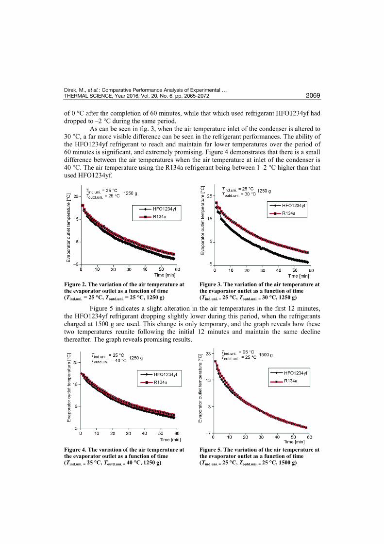
Figure 2 indicates the changes in the air temperatures at the outlet of the evaporator when the temperatures of the air streams entering the condenser are maintained at 25 °C and refrigerants charged at 1250 g are used. As can be seen in the graph, there is a steady drop in the air temperatures when both the HFO1234yf, and R134a refrigerants are used. However, after a period of 60 minutes there is a visible difference between the air temperatures, with the air temperature using the R134a refrigerant being between 2 °C and 4 °C higher than that that used HFO1234yf. The air temperature that used refrigerant R134a dropped to a temperature
Direk, M., et al.: Comparative Performance Analysis of Experimental … THERMAL SCIENCE, Year 2016, Vol. 20, No. 6, pp. 2065-2072 2069
of 0 °C after the completion of 60 minutes, while that which used refrigerant HFO1234yf had dropped to –2 °C during the same period.
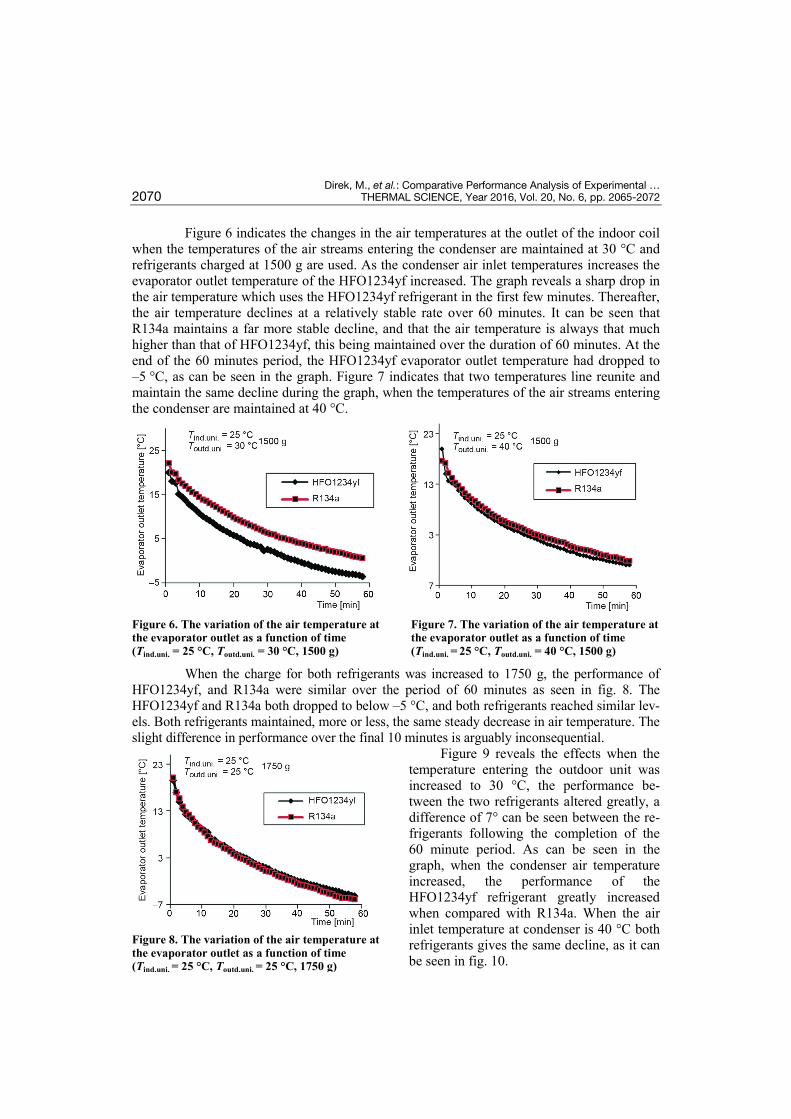
As can be seen in fig. 3, when the air temperature inlet of the condenser is altered to 30 °C, a far more visible difference can be seen in the refrigerant performances. The ability of the HFO1234yf refrigerant to reach and maintain far lower temperatures over the period of 60 minutes is significant, and extremely promising. Figure 4 demonstrates that there is a small difference between the air temperatures when the air temperature at inlet of the condenser is 40 °C. The air temperature using the R134a refrigerant being between 1–2 °C higher than that used HFO1234yf.
Figure 2. The variation of the air temperature at the evaporator outlet as a function of time (Tind.uni. = 25 °C, Toutd.uni. = 25 °C, 1250 g)
Figure 3. The variation of the air temperature at the evaporator outlet as a function of time (Tind.uni. = 25 °C, Toutd.uni. = 30 °C, 1250 g)
Figure 5 indicates a slight alteration in the air temperatures in the first 12 minutes, the HFO1234yf refrigerant dropping slightly lower during this period, when the refrigerants charged at 1500 g are used. This change is only temporary, and the graph reveals how these two temperatures reunite following the initial 12 minutes and maintain the same decline thereafter. The graph reveals promising results.
Figure 4. The variation of the air temperature at the evaporator outlet as a function of time (Tind.uni. = 25 °C, Toutd.uni. = 40 °C, 1250 g)
Figure 5. The variation of the air temperature at the evaporator outlet as a function of time (Tind.uni. = 25 °C, Toutd.uni. = 25 °C, 1500 g)
Direk, M., et al.: Comparative Performance Analysis of Experimental … 2070 THERMAL SCIENCE, Year 2016, Vol. 20, No. 6, pp. 2065-2072
Figure 6 indicates the changes in the air temperatures at the outlet of the indoor coil when the temperatures of the air streams entering the condenser are maintained at 30 °C and refrigerants charged at 1500 g are used. As the condenser air inlet temperatures increases the evaporator outlet temperature of the HFO1234yf increased. The graph reveals a sharp drop in the air temperature which uses the HFO1234yf refrigerant in the first few minutes. Thereafter, the air temperature declines at a relatively stable rate over 60 minutes. It can be seen that R134a maintains a far more stable decline, and that the air temperature is always that much higher than that of HFO1234yf, this being maintained over the duration of 60 minutes. At the end of the 60 minutes period, the HFO1234yf evaporator outlet temperature had dropped to –5 °C, as can be seen in the graph. Figure 7 indicates that two temperatures line reunite and maintain the same decline during the graph, when the temperatures of the air streams entering the condenser are maintained at 40 °C.
Figure 6. The variation of the air temperature at the evaporator outlet as a function of time (Tind.uni. = 25 °C, Toutd.uni. = 30 °C, 1500 g)
Figure 7. The variation of the air temperature at the evaporator outlet as a function of time (Tind.uni. = 25 °C, Toutd.uni. = 40 °C, 1500 g)
When the charge for both refrigerants was increased to 1750 g, the performance of HFO1234yf, and R134a were similar over the period of 60 minutes as seen in fig. 8. The HFO1234yf and R134a both dropped to below –5 °C, and both refrigerants reached similar lev-els. Both refrigerants maintained, more or less, the same steady decrease in air temperature. The slight difference in performance over the final 10 minutes is arguably inconsequential.
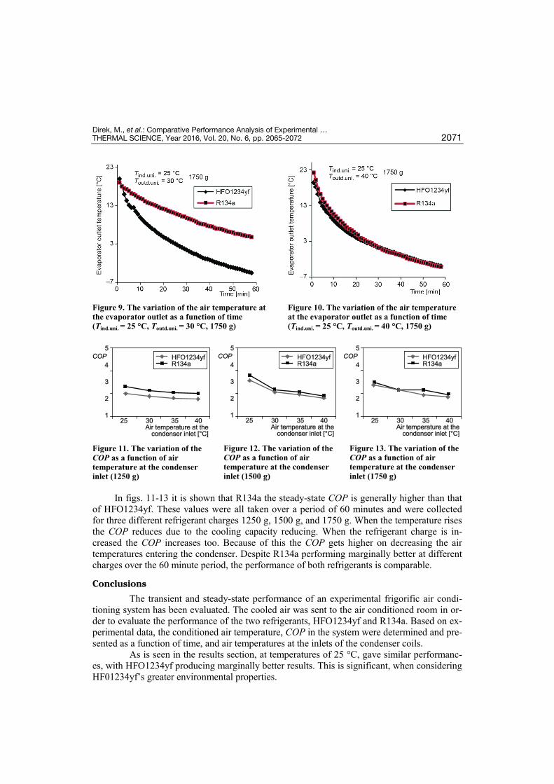
Figure 9 reveals the effects when the temperature entering the outdoor unit was increased to 30 °C, the performance be-tween the two refrigerants altered greatly, a difference of 7° can be seen between the re-frigerants following the completion of the 60 minute period. As can be seen in the graph, when the condenser air temperature increased, the performance of the HFO1234yf refrigerant greatly increased when compared with R134a. When the air inlet temperature at condenser is 40 °C both refrigerants gives the same decline, as it can be seen in fig. 10.
Figure 8. The variation of the air temperature at the evaporator outlet as a function of time (Tind.uni. = 25 °C, Toutd.uni. = 25 °C, 1750 g)
Direk, M., et al.: Comparative Performance Analysis of Experimental … THERMAL SCIENCE, Year 2016, Vol. 20, No. 6, pp. 2065-2072 2071
Figure 9. The variation of the air temperature at the evaporator outlet as a function of time (Tind.uni. = 25 °C, Toutd.uni. = 30 °C, 1750 g)
Figure 10. The variation of the air temperature at the evaporator outlet as a function of time (Tind.uni. = 25 °C, Toutd.uni. = 40 °C, 1750 g)
Figure 11. The variation of the COP as a function of air temperature at the condenser inlet (1250 g)
Figure 12. The variation of the COP as a function of air temperature at the condenser inlet (1500 g)
Figure 13. The variation of the COP as a function of air temperature at the condenser inlet (1750 g)
In figs. 11-13 it is shown that R134a the steady-state COP is generally higher than that of HFO1234yf. These values were all taken over a period of 60 minutes and were collected for three different refrigerant charges 1250 g, 1500 g, and 1750 g. When the temperature rises the COP reduces due to the cooling capacity reducing. When the refrigerant charge is in-creased the COP increases too. Because of this the COP gets higher on decreasing the air temperatures entering the condenser. Despite R134a performing marginally better at different charges over the 60 minute period, the performance of both refrigerants is comparable.
Conclusions
The transient and steady-state performance of an experimental frigorific air condi-tioning system has been evaluated. The cooled air was sent to the air conditioned room in or-der to evaluate the performance of the two refrigerants, HFO1234yf and R134a. Based on ex-perimental data, the conditioned air temperature, COP in the system were determined and pre-sented as a function of time, and air temperatures at the inlets of the condenser coils.
As is seen in the results section, at temperatures of 25 °C, gave similar performanc-es, with HFO1234yf producing marginally better results. This is significant, when considering HF01234yf’s greater environmental properties.
Direk, M., et al.: Comparative Performance Analysis of Experimental … 2072 THERMAL SCIENCE, Year 2016, Vol. 20, No. 6, pp. 2065-2072
Refrigerant HFO1234yf gave visibly better performances than R134a when the tem-peratures of the air streams entering the condenser were maintained at 30 °C. These improved performances over R134a are promising. When the temperature rises the COP reduces due to the cooling capacity reducing. Results were comparable during this phase of the investigation.
The results of this investigation propose the utilisation of HFO1234yf as a replace-ment over the currently favoured R134a in a frigorific air conditioning system. In order to ob-tain a more comprehensive performance of HFO-1234yf can be performed with water cooled condensers in future studies.
Acknowledgment
The authors would like to thank the University of Yalova for supporting this study through a Research Project No: 2013/BAP/063.
Nomenclature COP − coefficient of performance h − enthalpy, [kJkg –1] ṁ − mass flow rate, [gs –1] Q − cooling capacity, [W] Ẇ − work, [W] Subscripts
comp − compressor
cond − condenser evap − evaporator in − inlet ind.uni. − indoor unit out − exit outd.uni. − outdoor unit r − refrigerant ref − refrigerated room
References [1] ***, Regulation (EC) No 842/2006 of the European Parliament and of the Council of 17 May 2006 on
Certain Fluorinated Greenhouse Gases. Official Journal of the European Communities. Retrieved online at, http://eur-lex.europa.eu/LexUriServ/LexUriServ.do?uri = OJ:L:2006: 161:0001:0011:EN:PDF
[2] ***, Directive 2006/40/EC of The European Parliament and of the Council of 17 May, Relating to Emis-sions from Air-Conditioning Systems in Motor Vehicles and Amending Council Directive 70/156/EEC retrieved online at, http://www.bis.gov.uk/files/file30125.pdf (2006)
[3] Meyer, J., HFO1234yf System Enhancements and Comparison to R134a, Proceedings, SAE Alternative Refrigerant Systems Symposium, Phoenix, Azriz, USA, 2008
[4] Minor, B., Spatz, M., HFO-1234yf low GWP Refrigerant Update, Proceedings, International Refrigera-tion and Air Conditioning Conference at Purdue, Paper No. 2349, West Lafayette, Ind., USA, 2008
[5] Petitjean, S., Benouali, J., R-1234yf Validation & A/C System Energy Efficiency Improvements, Pro-ceedings, SAE Alternate Refrigerant Symposium, AARS, Scottsdale, Ariz., USA, 2010
[6] Lee, Y., Jung, D., A Brief Performance Comparison of HFO1234yf and R134a in a Bench Tester for Au-tomobile Applications, Applied Thermal Engineering, 35 (2012), Mar., pp. 240-242
[7] Navarro, I. O., et al., Comparative Experimental Study of an Open Piston Compressor Working with HFO1234yf, R134a and R-290, International Journal of Refrigeration, 36 (2013), 3, pp. 768-775
[8] Akram, M. W., et al., Lubricity of Environmentally Friendly HFO1234yf Refrigerant, Tribology Inter-national, 57 (2013), Jan., pp. 92-100
[9] Lee, Y., et al., Performance of Non-Flammable Azeotropic HFO1234yf/HFC134a Mixture for HFC134a Applications, International Journal of Refrigeration, 36 (2013), 4, pp. 1203-1207
[10] Tanaka, K, Higashi, Y., Thermodynamic Properties of HFO_1234yf (2,3,3,3– Tetrafluoropropene), In-ternational Journal of Refrigeration, 33 (2010), 3, pp. 474-9
[11] ***, SAE International, Cooperative Research Program, Additional Risk Assessment of Alternative Re-frigerant R-1234yf, Retrieved online at http://www.sae.org/standardsdev/tsb/cooperative/crp_1234-4_report.pdf, 2013
Paper submitted: July 15, 2014 Paper revised: November 4, 2014 Paper accepted: November 4, 2014


![un agent frigorific - arctic.ro · Aceast\ vitrin\ frigorific\ pe care a]i achizi]ionat-o este cea mai nou\ realizare a noastr\ din gama produselor . Are un design nou, atractiv [i](https://img.pdfslide.us/doc/110x75/5e137bbd61fa9c141f64ca41/un-agent-frigorific-aceast-vitrin-frigorific-pe-care-ai-achiziionat-o-este.jpg)