Embed Size (px)
Citation preview
Comparative Evaluation of the Mobile
Internet Protocol 6 Suite
by
Johan Pieterse
Thesis presented in partial ful�lment of the requirements for
the degree Master of Science in Engineering at Stellenbosch
University.
Department of Electrical and Electronic Engineering,University of Stellenbosch
Supervisor: Dr. R. Wolhuter
March 2015

Declaration
By submitting this thesis electronically, I declare that the entirety of the workcontained therein is my own, original work, that I am the sole author thereof(save to the extent explicitly otherwise stated), that reproduction and pub-lication thereof by Stellenbosch University will not infringe any third partyrights and that I have not previously in its entirety or in part submitted it forobtaining any quali�cation.
March 2015Date: . . . . . . . . . . . . . . . . . . . . . . . . . . . . . . .
Copyright© 2015 Stellenbosch UniversityAll rights reserved.
i
Stellenbosch University https://scholar.sun.ac.za

Abstract
Comparative Evaluation of the
Mobile Internet Protocol 6 SuiteJ. Pieterse
Department of Electrical and Electronic Engineering,
University of Stellenbosch
Thesis: MSc(Eng)
March 2015
Mobile IPv6 is a proposed mobility standard for Next Generation Wire-less Access Networks that allows mobile nodes, such as laptops, tablets, smartphones to stay reachable while moving around in an IPv6 Internet network.The need for MIPv6 exists because a mobile device cannot maintain the pre-viously connected link when changing location and IP address. The initial IPMobility protocol was �rst presented in 1993 for IPv4 and in 2004 for IPv6.The Mobile IP protocol solves the TCP/IP Stack Layer 3 mobility issue, byassigning a permanent IP Home Agent address to the mobile node. IPv4 hassome drawbacks, the main one being IP address exhaustion, making MIPv6the future option for mobility protocol in IP Networks.The main goal of themobility protocol is to enable network applications to operate continuously atthe required quality of service for both wired and wireless networks while themobile node moves around in the network.
MIPv6 on its own needs optimization techniques to improve the handoverlatency of the protocol and to minimize the latency. This thesis investigatesMIPv6 simulated using OMNeT++ Network Simulator Framework and theimplementation thereof on a Linux IPv6 test bed. The test bed was used totest handover latency, overhead added by the MIPv6 extensions and packetloss. The developed test set up can also be used to evaluate di�erent handoverschemes that might enhance the MIPv6 protocol, decreasing handover latencyand enabling real-time IPv6 applications such as Voice over IP. FMIPv6 andPMIPv6 are extensions to MIPv6 to enhance it's functionality. These protocolsare investigated and evaluated against MIPv6 in order to make recommenda-tions on possible improvements of these mobility protocols.
ii
Stellenbosch University https://scholar.sun.ac.za

Uittreksel
Comparative Evaluation of the
Mobile Internet Protocol 6 SuiteJ. Pieterse
Departement Elektries en Elektroniese Ingenieurswese,
Universiteit van Stellenbosch
Tesis: MSc(Ing)
Maart 2015
Mobiele IPv6 is 'n voorgestelde standaard vir mobiele netwerke of die so-genaamde Volgende Generasie Netwerke wat mobiele nodes sal toelaat om be-reikbaar te bly wanneer die nodes rondbeweeg in 'n IPv6 Internet omgewing.Die behoefte aan 'n kontinue netwerksessie is baie groot en dit kan toegeskryfword aan die vinnige toename in mobiele nodes, soos skootrekenaars, tabletteen slimfone. Die oorspronklike IP Mobiele protokol was voorgestel in 1993 virIPv4 en in 2004 vir IPv6. Mobiele IP dien as 'n oplossing vir netwerk mobi-liteit deur te fokus op Laag 3 van die TCP/IP Stapel. Kontinue sessies wordbereik deur 'n permanente Basis Adres aan die mobiele node te bind. IPv4 hetheelwat nadele, waarvan die grootste een verseker IP adres uitputting is, andernadele sluit in driehoekige roetering en invloei �ltering wanneer die mobielenode rondbeweeg. Weens die genoemde nadele van MIPv4 en die stelselma-tige oorgang van IPv4 na IPv6 word die fokus gerig op MIPv6 vir toekomstigeverbetering en implementering. Die hoofdoel van MIPv6 is om te sorg datmobiele nodes kan rondbeweeg in 'n network sonder om netwerk konneksie teverloor en ook om die gehalte van diens te handhaaf.
MIPv6 benodig addisionele optimalisering tegnieke om die oorhandigingslatensie van die protokol te verbeter en dus die gehalte van diens ook te ver-beter. In die tesis ondersoek ons die elemente wat oorhandigingstydperk be-invloed en verhoog, deur MIPv6 in 'n OMNeT++ Simuleerder te evalueer.Nadat die nodige simulasie resultate verkry is, word MIPv6 geimplementeerop 'n toets netwerk om die oorhandigingstydperk te toets wanner die noderondbeweeg, oorhoofse inligting wat bygevoeg word deur MIPv6 en die aantalnetwerk pakkies wat verlore gaan tydens die oorhandigingsproses. Hierna word
iii
Stellenbosch University https://scholar.sun.ac.za

UITTREKSEL iv
die optimalisering tegnieke genaamd PMIPv6 en FMIPv6 ook geimplementeerop die toets netwerk om die e�ektiwiteit en optimaliserings voordele teenoordie toets resultate van MIPv6 te vergelyk. Die resultate kan gebruik word omverbeterings en voorstelle te maak rakende die mobiele protokols.
Stellenbosch University https://scholar.sun.ac.za
Acknowledgements
I would like to express my sincere gratitude to the following people andorganisations...
Pioneers in Network Mobility:
Prof. Thomas NoëlDr. Emil Ivov
University of Stellenbosch:
Dr. Riaan WolhuterJaco du ToitJoseph WamichaAnita van der Spuy
University of the North West (Potchefstroom):
Albert SorgdragerHester Oelofse
University of Strasbourg:
Prof. Thomas NoëlProf. Antoine GallaisDr. Emil IvovDr. Damien Roth
INRIA:
Dr. Nathalie MittonPriyanka Rawat
v
Stellenbosch University https://scholar.sun.ac.za

ACKNOWLEDGEMENTS vi
Conferences:
IEEE-APS: Topical Conference on Antennas and Propagation in WirelessCommunications, Cape Town, South Africa - 2012
4th International Conference on Ad Hoc Networks, Paris, France - 2012
Industry related:
Altech AcademyAltech ISISINRIA (National Institute for Research in Computer Science and Control)DSP lab (University of Stellenbosch)Niel Bester
Stellenbosch University https://scholar.sun.ac.za
Contents
Declaration i
Abstract ii
Uittreksel iii
Acknowledgements v
Contents vii
List of Figures ix
List of Tables xi
Nomenclature xii
1 Introduction 11.1 Background . . . . . . . . . . . . . . . . . . . . . . . . . . . . . 11.2 Motivation . . . . . . . . . . . . . . . . . . . . . . . . . . . . . . 21.3 Problem Description . . . . . . . . . . . . . . . . . . . . . . . . 41.4 Research Objectives . . . . . . . . . . . . . . . . . . . . . . . . . 41.5 Methodology . . . . . . . . . . . . . . . . . . . . . . . . . . . . 51.6 Summary of Results and Complementary Work . . . . . . . . . 61.7 Outline of Thesis . . . . . . . . . . . . . . . . . . . . . . . . . . 7
2 Literature Review 92.1 Introduction . . . . . . . . . . . . . . . . . . . . . . . . . . . . . 92.2 Internet Protocol Version 6 . . . . . . . . . . . . . . . . . . . . . 102.3 Wireless Sensor Networks . . . . . . . . . . . . . . . . . . . . . 232.4 OSI Layer Mobility . . . . . . . . . . . . . . . . . . . . . . . . . 282.5 Mobile IPv6 . . . . . . . . . . . . . . . . . . . . . . . . . . . . . 312.6 Network Mobility . . . . . . . . . . . . . . . . . . . . . . . . . . 442.7 Fast Handover for Mobile IPv6 . . . . . . . . . . . . . . . . . . 462.8 Proxy Mobile IPv6 . . . . . . . . . . . . . . . . . . . . . . . . . 552.9 Hierarchical Mobile IPv6 . . . . . . . . . . . . . . . . . . . . . . 60
vii
Stellenbosch University https://scholar.sun.ac.za

CONTENTS viii
2.10 Discrete Event Simulator . . . . . . . . . . . . . . . . . . . . . . 612.11 Conclusion . . . . . . . . . . . . . . . . . . . . . . . . . . . . . . 68
3 Design and Implementation 703.1 Introduction . . . . . . . . . . . . . . . . . . . . . . . . . . . . . 703.2 Simulation Model . . . . . . . . . . . . . . . . . . . . . . . . . . 713.3 MIPv6 Network . . . . . . . . . . . . . . . . . . . . . . . . . . . 773.4 FMIPv6 Network . . . . . . . . . . . . . . . . . . . . . . . . . . 833.5 PMIPv6 Network . . . . . . . . . . . . . . . . . . . . . . . . . . 863.6 Simulation Model MIPv6 for 6LoWPAN . . . . . . . . . . . . . 893.7 Conclusion . . . . . . . . . . . . . . . . . . . . . . . . . . . . . . 90
4 Results 924.1 Introduction . . . . . . . . . . . . . . . . . . . . . . . . . . . . . 924.2 Evaluation Methodology . . . . . . . . . . . . . . . . . . . . . . 924.3 Simulation Results . . . . . . . . . . . . . . . . . . . . . . . . . 934.4 MIPv6 Protocol Results . . . . . . . . . . . . . . . . . . . . . . 954.5 FMIPv6 Protocol Results . . . . . . . . . . . . . . . . . . . . . 984.6 PMIPv6 Protocol Results . . . . . . . . . . . . . . . . . . . . . 1014.7 Comparing Protocol Results . . . . . . . . . . . . . . . . . . . . 1054.8 MIPv6 for 6LoWPAN . . . . . . . . . . . . . . . . . . . . . . . . 1104.9 Conclusion . . . . . . . . . . . . . . . . . . . . . . . . . . . . . . 111
5 Conclusion, Outcomes and Recommendations 1125.1 Conclusion . . . . . . . . . . . . . . . . . . . . . . . . . . . . . . 1125.2 Outcomes of Completed Work . . . . . . . . . . . . . . . . . . . 1145.3 Recommendations for Future Work . . . . . . . . . . . . . . . . 116
Appendices 117
A 118A.1 xMIPv6 Runtime Parameters . . . . . . . . . . . . . . . . . . . 118
B 123B.1 Router Advertisement Test Bed Con�guration . . . . . . . . . . 123B.2 MIPv6 Test Bed Con�guration . . . . . . . . . . . . . . . . . . 123B.3 FMIPv6 Test Bed Con�guration . . . . . . . . . . . . . . . . . . 126B.4 PMIPv6 Test Bed Con�guration . . . . . . . . . . . . . . . . . . 128
C 132C.1 MIPv6 Contiki Runtime Parameters . . . . . . . . . . . . . . . . 132
List of References 133
Stellenbosch University https://scholar.sun.ac.za
List of Figures
2.1 IPv6 Packet Structure . . . . . . . . . . . . . . . . . . . . . . . . . 152.2 IPv4 and IPv6 Header Di�erences [1] . . . . . . . . . . . . . . . . . 162.3 Chaining Extension Headers in IPv6 Packets [1] . . . . . . . . . . . 202.4 ICMPv6 Router Advertisement Message . . . . . . . . . . . . . . . 232.5 Wireless Sensor Network (6LoWPAN Architecture) . . . . . . . . . 242.6 IEEE 802.15.4 Uncompressed Frame . . . . . . . . . . . . . . . . . 252.7 IEEE 802.15.4 HC1 Encoded Frame . . . . . . . . . . . . . . . . . . 262.8 IEEE 802.15.4 LOWPAN_IPHC Encoded Frame . . . . . . . . . . 272.9 MIPv6 Network . . . . . . . . . . . . . . . . . . . . . . . . . . . . . 322.10 MIPv6 Message Flow . . . . . . . . . . . . . . . . . . . . . . . . . . 372.11 MIPv6 Bidirectional Tunneling Mode . . . . . . . . . . . . . . . . . 382.12 MIPv6 Route Optimization Mode . . . . . . . . . . . . . . . . . . . 392.13 Mobility Header for IPv6 Protocol . . . . . . . . . . . . . . . . . . 402.14 Message Data �eld in Mobility Header for Binding Update . . . . . 422.15 Message Data in Mobility Header for BU Acknowledgement . . . . 432.16 MIPv6 Message Flow in 6LoWPAN Network . . . . . . . . . . . . . 442.17 NEMO Network [2] . . . . . . . . . . . . . . . . . . . . . . . . . . . 452.18 FMIPv6 Protocol . . . . . . . . . . . . . . . . . . . . . . . . . . . . 472.19 FMIPv6 Predictive Handover [3] . . . . . . . . . . . . . . . . . . . 492.20 FMIPv6 Reactive Handover [3] . . . . . . . . . . . . . . . . . . . . 502.21 PMIPv6 Network . . . . . . . . . . . . . . . . . . . . . . . . . . . . 552.22 PMIPv6 Message Flow . . . . . . . . . . . . . . . . . . . . . . . . . 582.23 PMIPv6 Handover Signaling Flow . . . . . . . . . . . . . . . . . . . 592.24 HMIPv6 Network . . . . . . . . . . . . . . . . . . . . . . . . . . . . 612.25 OMNeT++ Simulation Environment . . . . . . . . . . . . . . . . . 632.26 OMNeT++ IPv6 Compound Module . . . . . . . . . . . . . . . . . 642.27 Analysis Editor . . . . . . . . . . . . . . . . . . . . . . . . . . . . . 652.28 Analysis Editor Charts . . . . . . . . . . . . . . . . . . . . . . . . . 652.29 ns-2 Network Animator . . . . . . . . . . . . . . . . . . . . . . . . . 66
3.1 OMNeT++ MIPv6 Simulation Network . . . . . . . . . . . . . . . 713.2 OMNeT++ Mobile Node Modules . . . . . . . . . . . . . . . . . . 723.3 MN Movement in Simulation . . . . . . . . . . . . . . . . . . . . . 743.4 Components of Handover Latency - OMNeT++ Implementation . . 77
ix
Stellenbosch University https://scholar.sun.ac.za

LIST OF FIGURES x
3.5 MIPv6 Testbed Overview . . . . . . . . . . . . . . . . . . . . . . . 783.6 MIPv6 Testbed with IP Assignment . . . . . . . . . . . . . . . . . . 793.7 FMIPv6 Testbed with IP Assignment . . . . . . . . . . . . . . . . . 843.8 PMIPv6 Testbed with IP Assignment . . . . . . . . . . . . . . . . . 873.9 PMIPv6 Software Architecture [4] . . . . . . . . . . . . . . . . . . . 883.10 MIPv6 6LoWPAN Testbed [5] . . . . . . . . . . . . . . . . . . . . . 90
4.1 Handover Latency in MIPv6 OMNeT++ Simulation . . . . . . . . 934.2 RR and CN Handover Delay MIPv6 Simulation . . . . . . . . . . . 944.3 UDP Throughput in MIPv6 OMNeT++ Simulation . . . . . . . . . 944.4 TCP Throughput in MIPv6 OMNeT++ Simulation . . . . . . . . . 954.5 UDP Throughput in MIPv6 . . . . . . . . . . . . . . . . . . . . . . 964.6 UDP Throughput in MIPv6 During Handover . . . . . . . . . . . . 964.7 UDP Jitter in MIPv6 . . . . . . . . . . . . . . . . . . . . . . . . . . 974.8 TCP Throughput in MIPv6 . . . . . . . . . . . . . . . . . . . . . . 984.9 UDP Throughput in FMIPv6 . . . . . . . . . . . . . . . . . . . . . 994.10 UDP Throughput in FMIPv6 During Handover . . . . . . . . . . . 994.11 UDP Jitter in FMIPv6 . . . . . . . . . . . . . . . . . . . . . . . . . 1004.12 TCP Throughput in FMIPv6 . . . . . . . . . . . . . . . . . . . . . 1014.13 UDP Throughput in PMIPv6 . . . . . . . . . . . . . . . . . . . . . 1024.14 UDP Throughput in PMIPv6 During Handover . . . . . . . . . . . 1024.15 UDP Jitter in PMIPv6 . . . . . . . . . . . . . . . . . . . . . . . . . 1034.16 TCP Throughput in PMIPv6 . . . . . . . . . . . . . . . . . . . . . 1044.17 IP Camera TCP Throughput in PMIPv6 . . . . . . . . . . . . . . . 1044.18 IP Camera TCP Packet Throughput in PMIPv6 . . . . . . . . . . . 1054.19 MIPv6 UDP Throughput - OMNeT++ Simulation vs Testbed . . . 1064.20 MIPv6 TCP Throughput - OMNeT++ Simulation vs Testbed . . . 1064.21 UDP Throughput in MIPv6, FMIPv6 and PMIPv6 during Handover1074.22 UDP Throughput MIPv6, FMIPv6 and PMIPv6 . . . . . . . . . . . 1084.23 TCP Throughput MIPv6, FMIPv6 and PMIPv6 . . . . . . . . . . . 1084.24 Handover Latency of MIPv6, FMIPv6 and PMIPv6 . . . . . . . . . 1094.25 UDP Packet Loss MIPv6, FMIPv6 and PMIPv6 . . . . . . . . . . . 1094.26 UDP Jitter Comparison . . . . . . . . . . . . . . . . . . . . . . . . 1104.27 MIPv6 WSN Handover Latency . . . . . . . . . . . . . . . . . . . . 111
Stellenbosch University https://scholar.sun.ac.za

List of Tables
2.1 Di�erences between IPv4 and IPv6 [6] . . . . . . . . . . . . . . . . 122.2 Special Syntax for IPv6 Addressing . . . . . . . . . . . . . . . . . . 142.4 IPv6 Address Type Identi�cation [1] . . . . . . . . . . . . . . . . . 152.5 IP protocol numbers for Next Header �eld [1] . . . . . . . . . . . . 182.6 Extension Headers for Next Header �eld . . . . . . . . . . . . . . . 192.7 Di�erences in IPv4 and IPv6 Header Fields [7] . . . . . . . . . . . . 212.8 Types of ICMPv6 messages [7] . . . . . . . . . . . . . . . . . . . . . 222.9 Mobility Header Types [8] . . . . . . . . . . . . . . . . . . . . . . . 412.10 Comparison of OMNeT++ and ns-2 [9] . . . . . . . . . . . . . . . . 66
3.1 MIPv6 Parameters for Test Scenarios . . . . . . . . . . . . . . . . . 753.2 IP Assignment for MIPv6 Network Interfaces . . . . . . . . . . . . 823.3 MIPv6 Test Bed Setup . . . . . . . . . . . . . . . . . . . . . . . . . 833.4 FMIPv6 Test Bed Setup . . . . . . . . . . . . . . . . . . . . . . . . 853.5 IP Assignment for FMIPv6 Network Interfaces . . . . . . . . . . . . 863.6 IP Assignment for PMIPv6 Network Interfaces . . . . . . . . . . . . 893.7 PMIPv6 Test Bed Setup . . . . . . . . . . . . . . . . . . . . . . . . 89
4.1 Protocol Results . . . . . . . . . . . . . . . . . . . . . . . . . . . . 110
A.1 MIPv6 OMNeT++ Simulation Parameters . . . . . . . . . . . . . . 118
B.1 MIP6D MN Parameters . . . . . . . . . . . . . . . . . . . . . . . . 124B.2 MIP6D HA Parameters . . . . . . . . . . . . . . . . . . . . . . . . 125B.3 MIP6D CN Parameters . . . . . . . . . . . . . . . . . . . . . . . . . 125B.4 FMIPv6 MN Parameters . . . . . . . . . . . . . . . . . . . . . . . . 126B.5 FMIPv6 PAR Parameters . . . . . . . . . . . . . . . . . . . . . . . 127B.6 FMIPv6 NAR Parameters . . . . . . . . . . . . . . . . . . . . . . . 127B.7 PMIPv6 LMA Parameters . . . . . . . . . . . . . . . . . . . . . . . 128B.8 PMIPv6 MAG1 Parameters . . . . . . . . . . . . . . . . . . . . . . 129B.9 PMIPv6 MAG2 Parameters . . . . . . . . . . . . . . . . . . . . . . 130
C.1 WSN MIPv6 Contiki Simulation Parameters . . . . . . . . . . . . . 132
xi
Stellenbosch University https://scholar.sun.ac.za

Nomenclature
Acronyms: General Network Terms
3GPP 3rd Generation Partnership ProjectAPI Application programming interfaceARP Address Resolution ProtocolBDP Bandwidth Delay ProductDAD Duplicate Address DetectionDES Discrete Event SimulatorDHCP Dynamic Host Con�guration ProtocolDHCPv6 Dynamic Host Con�guration Protocol Version 6DNS Domain Name SystemDOS Denial Of ServiceFTP File Transfer ProtocolGNED Graphical Network EditorHMIPv6 Hierarchical Mobile Internet Protocol 6ICMPv6 Internet Control Message Protocol for IPv6ICMPv4 Internet Control Message Protocol for IPv4IEFT Internet Engineering Task ForceIGMP Internet Group Management ProtocolIoF Internet of ThingsIPsec Internet Protocol securityIPv6 Internet Protocol 6ITS Intelligent Transportation SystemsLAN Local Area NetworkLTE Long Term EvolutionMLD Multicast Listener DiscoveryNED Network DescriptionNDP Neighbor Discovery ProtocolNIC Network Interface CardNUD Neighbor Unreachability DetectionOSI Open Systems InterconnectionOTcl Object oriented Tool Command LanguagePDU Protocol Data Unit
xii
Stellenbosch University https://scholar.sun.ac.za

NOMENCLATURE xiii
QoS Quality of ServiceTCP Transmission Control ProtocolTOS Type of Service FieldUDP User Datagram ProtocolWSN Wireless Sensor Network
Acronyms: Mobile Internet Protocol 6
AP Access PointBU Binding UpdateCN Correspondent NodeCoA Care-of AddressCoT Care-of TestFA Foreign AgentFN Foreign NetworkHA Home AgentHN Home NetworkHoT Home TestKbm Binging Management KeyMIPv6 Mobile Internet Protocol 6MH Mobility HeaderMN Mobile NodeRA Router AdvertisementRR Return Routability
Acronyms: Fast Handover for Mobile Internet Protocol 6
AR Access RouterFBack Fast Binding AcknowledgmentFBU Fast Binding UpdateFMIPv6 Fast Handover for Mobile Internet Protocol 6HAck Handover AcknowledgeHI Handover InitiateNAR New Access RouterNCoA New Care-of AddressPAR Previous Access RouterPC0A Previous Care-of AddressPrRtAdv Proxy Router AdvertisementRtSolPr Router Solicitation for Proxy AdvertisementUNA Unsolicited Neighbor Advertisement
Stellenbosch University https://scholar.sun.ac.za

NOMENCLATURE xiv
Acronyms: Proxy Mobile Internet Protocol 6
AAA Authentication, Authorization, and AccountingLMA Local Mobility AnchorLMAA LMA AddressMAG Mobile Access GatewayMN-Identi�er Mobile Node Identi�erMN-HNP Mobile Node's Home Network Pre�xMN-HoA Mobile Node's Home AddressMN-LL-Identi�er Mobile Node Link-layer Identi�erNETLMM Network-based Localized Mobility ManagementPBA Proxy Binding AcknowledgementPBU Proxy Binding UpdatePMIPv6 Proxy Mobile Internet Protocol 6Proxy-CoA Proxy Care-of AddressRADIUS Remote Access Dial In User Service
Acronyms: Hierarchical Mobile Internet Protocol 6
LCoA On-Link Care-of AddressMAP Mobility Anchor PointRCoA Regional Care-of Address
Acronyms: IPv6 over Low power WPAN
6LoWPAN IPv6 over Low Power Wireless Personal NetworkBR Border RouterIPHC IP Header CompressionNHC Next Header CompressionWSN Wireless Sensor Networks
Acronyms: Network Mobility Basic Support Protocol
NEMO Network Mobility Basic Support Protocol
Stellenbosch University https://scholar.sun.ac.za

Chapter 1
Introduction
1.1 Background
The initial IP Mobility protocol was �rst presented in 1993 for IPv4 [10]. Mo-bile IP protocol solves TCP/IP Layer 3 mobility, because the mobile node hasa permanent IP address assigned to it even when moving around in networks.Mobile IP includes both MIPv4 and MIPv6 but IPv4 has some drawbacks formobility, the main drawback being IP address exhaustion, which makes MIPv6the future option for mobility protocols in IP Networks [10].The main goal ofthe mobility protocol is to enable network applications to operate continuouslyat the required quality of service for both wired and wireless networks [11].MIPv6 uses the existing IPv6 protocol to enable seamless roaming between dif-ferent access points [12]. MIPv6 on its own needs optimization techniques toimprove the handover latency of the protocol and to minimize latency causedby control message exchange. To date, there are various technologies underdevelopment for enhancing and optimizing the existing MIPv6 protocol. TheMobile IPv6 Suite comprises various variations of the standard MIPv6. Themain variations being:
� Proxy Mobile IPv6 (PMIPv6)
� Fast Handovers for Mobile IPv6 (FMIPv6)
� Hierarchical Mobile IPv6 (HMIPv6)
FMIPv6 proposes some enhancements to minimize the handover latency ofa MIPv6 network by reducing latency caused by control message exchangeand Duplicate Address Detection between two nodes. PMIPv6 focuses onthe mobility of the network as a whole and requires no adaptation by themobile node to accommodate mobility. HMIPv6 focuses to reduce the signalingbetween the mobile node, the correspondent node and the home agent in thespeci�ed network. HMIPv6 reduces binding update message overhead in largescale mobility networks [13].
1
Stellenbosch University https://scholar.sun.ac.za

CHAPTER 1. INTRODUCTION 2
The following list indicates the main requirements for MIPv6 protocols andmobile networks [14]:
� Migration Transparency: Permanent connectivity to the Internet has tobe provided to all times, since continuous sessions are expected by themobility protocol.
� Performance Transparency and Seamless Mobility: Limited network over-head should be added by mobility messages needed for MIPv6. The mo-bility protocol needs to decrease handover latency and packet loss duringhandover.
� Operational Transparency: MIPv6 is to be implemented on the IP layerand is expected to be transparent to upper layers. This means that anyupper-layer protocol can run unchanged on top of the extended mobileIP layer.
� Arbitrary Con�gurations: This should allow the mobile node to changetheir point of attachment within the mobile network. Should allow con-nection of foreign mobile nodes in the network.
� Scalability: A mobile network is expected to scale to a large number ofmobile nodes, correspondent nodes and HA.
� Backward Compatibility: A mobile network should be able to functionwith established IPv6 standards. Address allocation, con�guration mech-anisms, security protocols and access control protocols should functionnormally.
� Secure Signaling: A mobile network should comply with usual IETFsecurity policies and recommendations.
MIPv6 is also being adapted to be used in Sensor Networks. Due to theevolution of sensor networks to accommodate non-static sensor nodes, the needfor a mobility mechanism is ever increasing. Sensor nodes are very low pow-ered nodes and also not very powerful when it comes to computational power.Sensor nodes thus use scaled down versions of the IPv6, namely 6LoWPAN.6LoWPAN makes use of header compression techniques allowing the send-ing and receiving of packets over IEEE 802.15.4 based networks [15]. MIPv6can be used as a mobility protocol for these networks but control signalingand neighborhood discovery needs to be adapted to accommodate low powerdevices [5].
1.2 Motivation
The main problem with IPv4 is the relatively small address space thats avail-able, this is caused by the decision to only use 32 bits to compile the IP ad-
Stellenbosch University https://scholar.sun.ac.za

CHAPTER 1. INTRODUCTION 3
dress [16]. Under the original classful addressing allocation scheme for IPv4,the number of available addresses decreased rapidly due to the vast expandingnumber of internet devices. Moving to classless addressing has helped post-pone the exhaustion of addresses, as has technology like IP Network AddressTranslation (NAT), that allowed privately-addressed hosts Internet access.
The current 32-bit address space is too small for the present and future sizeof the Internet. The only solution to this problem is to enlarge the addressspace to 64-bit addressing. This led to the next version of the Internet Protocol,IPv6 [17]. Implementation of IPv6 was o�cially launched on 6 June 2012, andsince then the global use of IPv6 has more than doubled [18]. It is clear thatIPv6 will be the future network layer protocol used by standard networks, aswell as by mobile networks.
As the number of mobile devices is increasing very rapidly, the need fora network mobility protocol becomes ever more demanding. The increasingnumber of mobile users leads to a problem in that when the mobile user movesfrom one location to another, the messages between the user and the networkmust be able to follow him. IPv6 mobility support is particularly important,as laptops, smart phones, tablets etc. are likely to account for the biggest orat least a substantial number of the Internet population. MIPv6 [8] was intro-duced as a proposed layer 3 mobility solution. During the handover period,there is a delay caused by IP protocol operations and link switching, wherethe mobile node is unable to send or receive packets. The handover latencyresulting from Mobile IPv6 procedures needs to be decreased to allow satisfac-tory Quality if Service (QoS) for users. The primary challenge of MIPv6 is toeliminate the handover latency caused by ISO layer 3 control messages, thishas led to various extensions of MIPv6.
FMIPv6 is proposed in [19] which aims at reducing the handover latencyand related packet losses by performing operations such as movement detectionand new CoA con�guration (including Duplicate Address Detection (DAD) forthe newly formed Address) in advance. In order to determine whether FMIPv6achieves this, the testing and evaluation of the protocol on test platforms areof utmost importance. PMIPv6 introduces a network based mobility man-agement approach, with minimal client participation. As a result of this, theProxy Mobile IPv6 [20], a network-based mobility management protocol wasstandardized in 2008. The protocol was designed with the goal that the net-work would perform the mobility management on behalf of the client, PMIPv6would keep the client involvement to minimal proportions, such as allowing theclient to perform inter-technology hando�s or allowing the client to expresshando� or �ow preferences [21]. Various link layer technologies exist today,but this thesis will focus on the use of WLAN, 802.11n. Wireless LAN (Wi-Fi)is arguably becoming one of the most popular and easiest ways to connect tothe Internet, because of its easy setup, relatively low deployment cost and fastnetwork speed.
Wireless sensor networks (WSN) have recently been proposed for a large
Stellenbosch University https://scholar.sun.ac.za

CHAPTER 1. INTRODUCTION 4
range of applications in home automation, industrial or environmental mon-itoring and health care [5]. Recently, the research community has tried toenable IPv6 connectivity in WSN. Such support would provide numerous ad-vantages to WSN. Enabling MIPv6 on low power devices need a great need ofinvestigation into adapting MIPv6 for better support.
The subject of this work is the investigation, analysis, implementation andtesting of the above mentioned mobility protocols, which allow for networkmobility in an all mobile Internet world.
1.3 Problem Description
The standard IP network design introduces one main issue that can be ad-dressed by Mobile IP. The issue being that a mobile node will always have adi�erent IP address when moving between networks. This introduces a prob-lem in the transport layer session, used by TCP connections and UDP basedtransactions. Data connections are lost when a node moves between networksbecause of the change in IP address. For example when a mobile node hasan TCP video stream connection with a correspondent node and the mobilemoves to a di�erent network the data connection will be lost. The MobileIP design aims to solve these issue by allowing the mobile node to always bereachable with a static IP, which is called the Home of Address (HoA). Byallowing the mobile node to be reachable at the HoA the transport sessionlayer stays connected even when the mobile node moves to a visited network.
MIPv6 do not improve the Layer 2 handover between a mobile node andan access point. Thus FMIPv6 is introduced to decrease handover latencycaused by MIPv6 and standard IPv6 messaging. FMIPv6 proposes a solutionto remove the latency caused by Duplicate Address Detection and to decreasethe Layer 2 handover latency between the access point and the mobile node,but still keeping the mobile connected via the same IP address.
For a network to be MIPv6 compatible, the mobile node, correspondentnode and the home agent needs to have the MIPv6 IP stack. This introducesthe need for modi�cation of every mobile node's IP layer, which is not ideal.PMIPv6 is proposed to move the mobility from the mobile node to the network.Thus only the network needs to be MIPv6 compatible and the mobility istransparent for the mobile node. The objectives for this thesis are set out inthe next section.
1.4 Research Objectives
No real comparative information could be found in literature on the relativeperformance of the mobility protocols and in view of the increasing importanceof these protocols in current and new envisaged applications in mobile data
Stellenbosch University https://scholar.sun.ac.za

CHAPTER 1. INTRODUCTION 5
communications, the main objectives for the work done under this project werede�ned as follows:
� To investigate and evaluate mobility protocols, as well as the associatedand required handover strategies, in a Mobile IPv6 network.
� To evaluate the capability of the IPv6 network protocol in a mobileenvironment was also evaluated.
� To evaluate the e�ciency and reliability of the di�erent handover strate-gies for MIPv6, as this is the main cause of packet loss and thus a re-duction in service quality in mobile networks. A particular e�ort in thisregard was made to implement FMIPv6 on the network to test reduc-tion in handover latency and evaluate possible improvements over thehandover latency of MIPv6.
� To establish a simulation environment suitable for present and futuretrial purposes for MIPv6.
� To create a physical and realistic testbed for the di�erent protocols as acomplementary evaluation platform to the simulation environment.
� The implementation of MIPv6 in Wireless Sensor Networks, was seenas an outside mainstream application, but nevertheless important, inview of the increasing deployment of WSN's. This was investigated byimplementation and simulation of MIPv6 in the Contiki OS wireless en-vironment. It was shown that MIPv6 is e�ective as a WSN mobilityprotocol.
� The dual simulation/hardware based approach enabled the comparisonof di�erent strategy performance and enhanced the credibility of theresults.
The establishment of a dual evaluation vehicle was seen as important in termsof more detailed application driven future work.
1.5 Methodology
The following methodologies were applied:
� Provide the relevant theory and working of the following Protocols:
� Internet Protocol version 6 (RFC 2460)
� IPv6 over Low Power WPAN (RFC 6282)
� Mobile IPv6 (RFC 6275)
Stellenbosch University https://scholar.sun.ac.za

CHAPTER 1. INTRODUCTION 6
� Fast Handover for Mobile IPv6 (RFC 5568)
� Proxy Mobile IPv6 (RFC 5949)
� Network Mobility (RFC 3963)
� The Internet of Things
� Provide the relevant theory and working of the simulation engine to beused as simulation platform for MIPv6.
� Design and develop a IPv6 testbed, in order to evaluate di�erent pro-posed mobility protocols.
� Implement MIPv6 on the IPv6 testbed to evaluate protocol performanceand handover latency.
� Implement FMIPv6 on the network to evaluate the improvements on thehandover latency of MIPv6.
� Implement PMIPv6 on the network to compare the protocol with MIPv6.
� Investigate MIPv6 for low power devices such as sensor networks withthe use of the Cooja simulation program.
� Evaluate and present possible improvements regarding MIPv6.
� Evaluate the protocols to conclude the best mobility approach for mobileIPv6 networks and propose enhancement for mobility in IPv6 networks.
The various protocols will be tested with real world data, like VoIP or videostreaming over the test network.
1.6 Summary of Results and Complementary
Work
The main outcomes of the thesis are outlined as follows:
� A detailed investigation into IPv6 and the enhancement of IPv6 for mo-bility of networks.
� Explanations of why mobility in networks is necessary and problemsexisting today in non-mobile networks.
� A thorough investigation and explanation of proposed network layer andnon-network layer mobility protocols.
� Implementation and performance evaluation of MIPv6 in OMNeT++network simulator.
Stellenbosch University https://scholar.sun.ac.za

CHAPTER 1. INTRODUCTION 7
� Comparison of simulation results and physical results of testbed to im-prove the performance of the MIPv6 simulation module.
� Design and building of an IPv6 test platform to evaluate di�erent net-work protocols in the IPv6 environment.
� Implementation, con�guration and testing of MIPv6 in a physical testbedenvironment.
� Implementation, con�guration and testing of Proxy Mobile IPv6 on topof MIPv6 in a physical environment.
� Implementation, con�guration and testing of FMIPv6 to decrease han-dover latency in MIPv6.
� Investigation of handover strategies to reduce handover latency in 802.11networks.
� Identi�cation of the most suitable mobility protocol for further enhance-ments and development.
� Complete evaluation of all the mobility protocols and proposed problemswith large scale implementation of protocols.
� Investigation of a compression mechanism to enable IPv6 on low powerdevices.
� Investigation of MIPv6 on a 6LoWPAN architecture.
� It was also found interesting enough by the general research community,to accept two research papers for an European conference and an IEEEconference:
� IEEE-APS: Topical Conference on Antennas and Propagation inWireless Communications, Cape Town, South Africa - 2012 [22].
� 4th International Conference on Ad Hoc Networks, Paris, France -2012 [23].
1.7 Outline of Thesis
In this section, an overview of the topics is presented and they are explained.An overview is given in Chapter 2 of all the relevant network layer mobilityprotocols, these protocols include Mobile IPv6, Proxy Mobile IPv6 and FastHandover for Mobile IPv6. An introduction is also given to the changes andmain advantages of Internet Protocol Version 6 compared to Internet ProtocolVersion 4. IPv6 is also explained in more detail and mobility support in IPv6is explained in detail. Furthermore Chapter 2 looks at Simulation Modules
Stellenbosch University https://scholar.sun.ac.za

CHAPTER 1. INTRODUCTION 8
and Engines. The main focus of this Chapter is to explain mobility protocolsand IPv6.
The simulation module, MIPv6, FMIPv6 and PMIPv6 implementation arepresented in Chapter 3. Detailed implementation of the OMNeT++ MIPv6simulation module and functioning thereof is described. Chapter 3 includesdetailed network designs for all the mobility protocols and how these proto-cols are implemented in the physical test environment. The design includeshardware setups, software con�guration, network con�guration, network per-formance tools and handover scenarios for testing. In Chapter 4 all resultsobtained from the simulation and testbed are presented and evaluated. Com-parisons are made between the MIPv6 simulation and the MIPv6 Testbed.The di�erent mobility protocols are compared as regards to TCP, UDP, Jitterand Handover Latency results. The results also show that FMIPv6 reducesthe handover latency tremendously compared to MIPv6 and PMIPv6. Lastly,Chapter 4 shows the advantages of PMIPv6 due to the low e�ect and nochanges on the Mobile Node, performance is also relatively good compared tothat of MIPv6.
Finally, in Chapter 5, the research �ndings and results are discussed indetail. A conclusion is arrived at using the related results to identify a mobilityprotocol for future research and development. A conclusion is also given onthe performance of these protocols with live data streaming, such as VoIP andVideo.
Stellenbosch University https://scholar.sun.ac.za

Chapter 2
Literature Review
2.1 Introduction
As the number of mobile devices is increasing very rapidly, the need for anetwork mobility protocol becomes ever more urgent. The current exhaustionof IPv4 addresses paves the way for a worldwide implementation of IPv6. Theincreasing number of mobile users presents the problem that when the mobileuser moves from one location to another, the messages between the user and thenetwork must be able to follow them. Mobility was not kept in mind during thedesign and implementation of IPv4, but later mobility extensions was addedto allow for more mobility in IPv4. IPv6 has a better designed solution fornetwork mobility. It is clear that IPv6 will be the future network layer protocolused by standard networks, as well as by mobile networks. Various mobilityprotocols are introduced to accommodate the movement of nodes and to allowcontinuous throughput when moving around. The main mobility protocol isMobile IPv6.
Recently many alternative additions have been introduced to the MIPv6framework to allow various enhancements. Some of the proposed enhance-ments to MIPv6 can be seen as Proxy Mobile IPv6, Fast Handovers for MIPv6and Hierarchical MIPv6. Hierarchical MIPv6 focusses on reduces network mo-bility massages in large scale networks and will thus not be evaluated in thisthesis. Mobility features are also being considered for low power devices inorder to solve issues introduced by the Internet of Things [24]. To accommo-date IPv6 in low power devices, 6LoWPAN [15] was introduced to solve IPv6connectivity in a simple low cost communication network. The main reasonlow power nodes are not able to use standard IPv6 is because of their lim-ited processing power, the energy e�ciency of nodes and the huge decreasein header space. Various IPv6 header encoding mechanisms, such as HC1[15] and LOWPAN_IPHC [25] were introduced to decrease the header spaceand enable IPv6 for low power devices. MIPv6 is also an option as mobilityprotocol for 6LoWPAN networks, due to availability of IPv6 connectivity in
9
Stellenbosch University https://scholar.sun.ac.za

CHAPTER 2. LITERATURE REVIEW 10
6LoWPAN networks.This chapter presents a literature review looking at various di�erences be-
tween and enhancements of IPv4 and IPv6, such as auto-con�guration, ex-panded IP addresses, enhanced mobility and better Quality of Service(QOS).An in-depth explanation of the mobility protocols, namely MIPv6, FMIPv6and PMIPv6 is included in this chapter. IPv6 encoding mechanisms for 6LoW-PAN networks is discussed and explained. Lastly the chapter focuses on variousnetwork simulation engines that are available.
2.2 Internet Protocol Version 6
With the rapid expansion of the Internet the current IPv4 is becoming ex-hausted and will make way for the next generation IP version 6 that is de-signed to enable ongoing expansion of the Internet. The current IP architec-ture requires an evolution to handle the constant growth of the Internet, theincreasing number of users and applications, as well as the accommodatingnew technologies [6, 26].
2.2.1 IPv6 New Features
IPv6 o�ers integrated IP services such as auto-con�guration, expanded IP ad-dresses, end-to-end security, enhanced mobility and QOS. IPv6 was intention-ally design to introduce minimal impact on lower and upper layer protocols.This is accomplished by building the functionality into to the architecture andavoiding the random addition of new features as in IPv4 [6].
� Large address space: IP address size is increase from 32 bits to 128 bits inIPv6, as seen in Figure 2.2. This increase in addressing space allows for agreater number of addressable nodes, more levels of addressing hierarchyand easier auto-con�guration of addresses. A scope �eld was added tothe multicast addresses to improve the scalability of multicast routing.A new type of address called the anycast address was also de�ned inIPv6 and is used for sending a packet to a group of nodes.
� Extensibility: IPv6 has the ability to easily add new features, this is doneby adding new extension headers after the IPv6 header. The number ofextension headers that can be added to IPv6 is only constrained to thepacket size of IPv6, but in IPv4 only 40 bytes of options is supported.
� Improved support for prioritized delivery of packets: Packets belongingto speci�c tra�c �ow will be labeled if the sender requested special han-dling of the packets. The special handling request can be presented bynon-default quality of service or real-time service. IPsec, mobility andsupport for prioritized delivery was built into IPv6.
Stellenbosch University https://scholar.sun.ac.za
CHAPTER 2. LITERATURE REVIEW 11
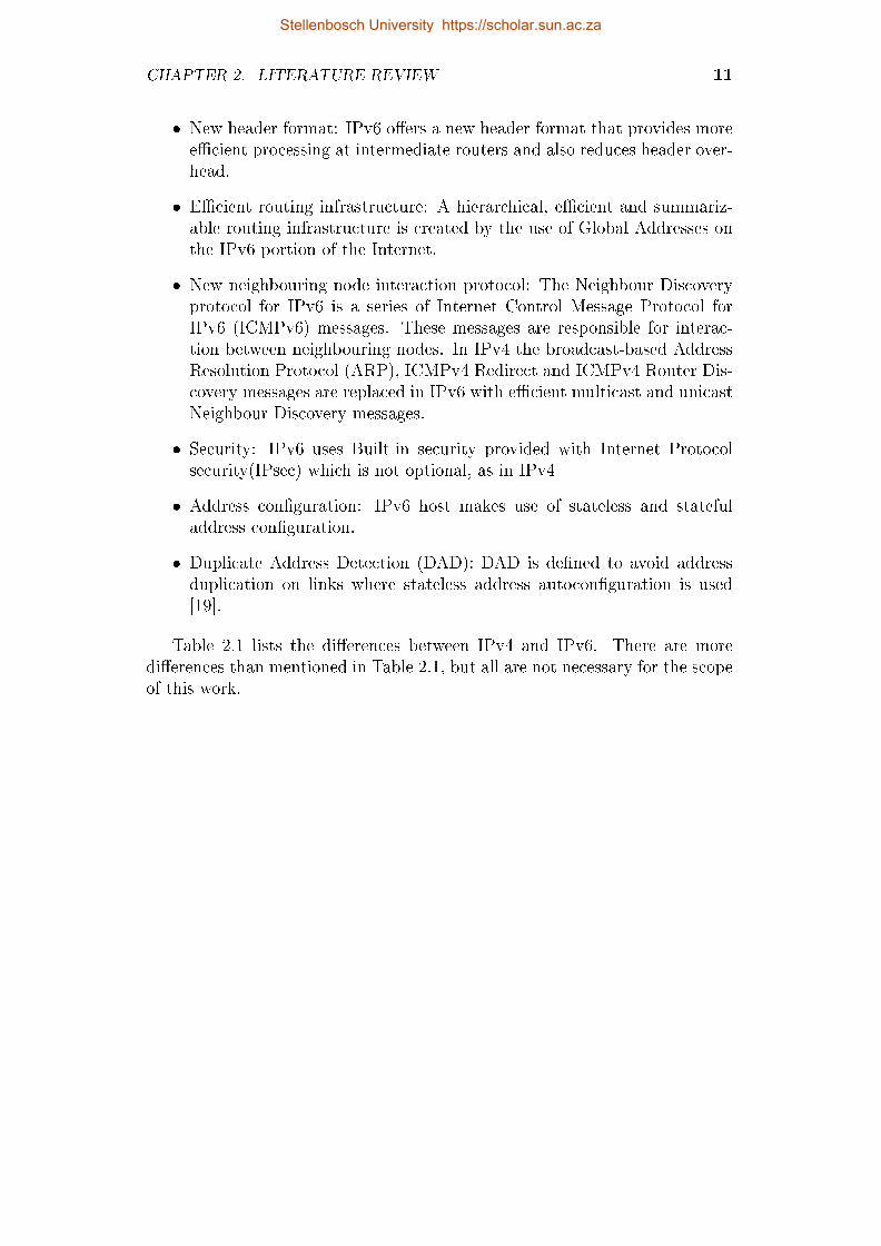
� New header format: IPv6 o�ers a new header format that provides moree�cient processing at intermediate routers and also reduces header over-head.
� E�cient routing infrastructure: A hierarchical, e�cient and summariz-able routing infrastructure is created by the use of Global Addresses onthe IPv6 portion of the Internet.
� New neighbouring node interaction protocol: The Neighbour Discoveryprotocol for IPv6 is a series of Internet Control Message Protocol forIPv6 (ICMPv6) messages. These messages are responsible for interac-tion between neighbouring nodes. In IPv4 the broadcast-based AddressResolution Protocol (ARP), ICMPv4 Redirect and ICMPv4 Router Dis-covery messages are replaced in IPv6 with e�cient multicast and unicastNeighbour Discovery messages.
� Security: IPv6 uses Built-in security provided with Internet Protocolsecurity(IPsec) which is not optional, as in IPv4
� Address con�guration: IPv6 host makes use of stateless and statefuladdress con�guration.
� Duplicate Address Detection (DAD): DAD is de�ned to avoid addressduplication on links where stateless address autocon�guration is used[19].
Table 2.1 lists the di�erences between IPv4 and IPv6. There are moredi�erences than mentioned in Table 2.1, but all are not necessary for the scopeof this work.
Stellenbosch University https://scholar.sun.ac.za

CHAPTER 2. LITERATURE REVIEW 12
Table 2.1: Di�erences between IPv4 and IPv6 [6]
IPv4 IPv6IPsec is optional security in IPv4. IPsec support is required.IP Address is 32-bits long. IP address is 128-bits long.IPv4 header doesn't supportpacket �ow identi�cation byrouters for QoS
Flow Label Field is used forpacket �ow identi�cation for QoShandling by routers and is in-cluded in the IPv6 Header Field.
Routers and sending host do frag-mentation.
Fragmentation is only done by thesending host and not by routers.
Checksum is included in theheader.
Checksum is not included in theheader.
Header include Options �eld. No Options �eld in IPv6, but Ex-tension Headers are used for op-tional data.
ARP uses broadcast requestframes to resolve IPv4 addresses.
Multicast Neighbour Solicitationmessages replace ARP requestframes.
Internet Group Management Pro-tocol (IGMP) is used to maintainsubnet groups.
IGMP is replaced by MulticastListener Discovery messages.
To determine best default gate-way IPv4 address, ICMP RouterDiscovery is used, but is optional.
ICMP Router Discovery is re-placed by ICMPv4 Router Solici-tation and Router Advertisementmessages, which are not optional.
Broadcast messages are used tosend messages to all nodes on sub-net.
No IPv6 broadcast messages.Link-Local scope all-nodes multi-cast address is used.
Con�guration only manually orwith DHCP.
Address autocon�guration, doesnot require manual or DHCP.
DNS - Uses host address (A) re-source records to determine hostname IPv4 address
DNS - Uses host address (AAAA)resource records to map hostname IPv6 address.
Packet size of 576-bytes mustbe supported and can be frag-mented.
Packet size of 1280-bytes mustbe supported without fragmenta-tion.
2.2.2 IPv6 Addressing
In this section the IPv6 addressing model, addresses, de�nition of IPv6 uni-cast addresses, anycast addresses and multicast addresses is looked at. IPv6
Stellenbosch University https://scholar.sun.ac.za

CHAPTER 2. LITERATURE REVIEW 13
addresses are 128-bit identi�ers and consist of three types of addresses:
� Unicast: Unicast addresses are used for a individual interface. If a packetis sent with an unicast address, it can be delivered only to the interfaceidenti�ed by that unicast address.
� Anycast: Anycast addresses is an identi�er for multiple interfaces (typ-ically belonging to di�erent nodes). A packet with an anycast addresswill be delivered to anyone of the interfaces, usually the closest nodecalculated by the routing protocol.
� Multicast: Multicast addresses is an identi�er for multiple interfaces(typically belonging to di�erent nodes). A packet sent to a multicastaddress is delivered to all interfaces containing the multicast address.
IPv6 does not have Broadcast addresses, as the function of broadcast messagesis replaced by multicast messages. An interface can be assigned with all theIPv6 addressing types. Each interface belongs to an individual node, andthis means that any of that node's interface unicast addresses can be used toidentify the node. Each interface must have at least one Link-Local unicastaddress, but can also have multiple addresses which can be of any type or scope.In IPv4 one link is associated with a subnet pre�x and IPv6 currently continueswith this model. IPv6 has the functionality to assign multiple pre�xes to thesame link [1].
IPv6 addresses can written in three conventional forms of text string:
� The preferred IPv6 addressing form is x:x:x:x:x:x:x:x, where the x's rep-resent one to four hexadecimal digits of the eight 16-bit pieces that formthe address. Leading zeros can be left out, but there must be at leastone numeral in every �eld. Examples:
ABCD:EF02:1234:5678:ABCD:EF02:1234:5678
2001:DB6:0:0:9:800:200C:417A
� The methods of allocating the IPv6 addresses can cause an address tocontain a long string of zero bits. To make the reading and writing ofthe address easier, a special syntax can be used for this. The use of `::'indicates single or multiple groups of 16 bits of zeros and can only appearonce in an address. The previous mentioned syntax can also be used tocompress leading or trailing zeros in an address. Table 2.2 indicates howthe special syntax can be applied to IPv6 addressing.
Stellenbosch University https://scholar.sun.ac.za

CHAPTER 2. LITERATURE REVIEW 14
Table 2.2: Special Syntax for IPv6 Addressing
Original Address Special Syntax Address Address Type2001:0DB8:0:0:8:800:100C:500A 2001:DB8::8:800:100C:500A Unicast addressFF01:0:0:0:0:0:0:1 FF01::1 Multicast address0:0:0:0:0:0:0:1 ::1 Loopback address0:0:0:0:0:0:0:0 :: Unspeci�ed address
� An alternative form can be used when the environment consist of bothIPv4 and IPv6, x:x:x:x:x:x:d.d.d.d. The x's represent the six high-order16-bit pieces in hexadecimal value and the d's represent the lower-order8-bit pieces in decimal value. Examples:
� 0:0:0:0:0:0:12.2.70.4
� 0:0:0:0:0:FFFF:128.133.42.28
or in special syntax form:
� ::12.2.70.4
� ::FFFF:128.133.42.28
IPv6 pre�x addresses can be written as follows: IPv6-address/pre�x-length.Were IPv6-address represent the actual IPv6 address of the interface and thedecimal value pre�x-length speci�es how many of the address bits are used forthe pre�x. For example, the following are legal representations of the 60-bitpre�x 20010DB90000CE4 (hexadecimal):
� 2001:0DB9:0000:CE40:0000:0000:0000:0000/60
� 2001:0DB9::CE40:0:0:0:0/60
� 2001:0DB9:0:CE40::/60
If you want to combine the node address:
� 2001:0DB9:0:CE40:123:4567:88AB:CDEG
with the subnet number:
� 2001:0DB9:0:CE40::/60
the address result in:
� 2001:0DB8:0:CD30:123:4567:88AB:CDEG/60
Stellenbosch University https://scholar.sun.ac.za

CHAPTER 2. LITERATURE REVIEW 15
Table 2.4 shows how the di�erent types of IPv6 address are identi�ed. Thehigh-order bits are used to identify the type of the address. No distinguishbetween anycast and unicast addresses can be made, because anycast addressesare derived from unicast messages. Unicast addresses can be of several types,in particular global, link-local and site-local unicast. The latter type has beendeprecated. A link-local address is intended only for communications withinthe segment of a local IPv6 network or a point-to-point connection that a hostis connected to. Link-local addresses will not be forwarded by routers [27].
Table 2.4: IPv6 Address Type Identi�cation [1]
Address type Binary pre�x IPv6 formatUnspeci�ed 00...0 (128 bits) ::/128Loopback 00...0 (128 bits) ::1/128Multicast 11111111 FF00::/8Link-Local unicast 1111111010 FE80::/10Site-Local unicast 1111111011 FEC0::/10
2.2.3 IPv6 Header
Figure 2.2 shows the di�erences between the IPv4 and IPv6 header. Theadvantage of the simpler and more e�cient IPv6 header is that it greatlyreduces processing costs. The IPv6 header is stripped of unnecessary or rarelyused �elds. The header also provides better support for real-time applicationsby the addition of new �elds to the header. This section looks into the IPv6header and shows the di�erences between the IPv4 and IPv6 header.
Figure 2.1: IPv6 Packet Structure
Figure 2.1 illustrates the structure of an IPv6 packet. The most importantpart of the packet is the IPv6 header which is described in more detail. Thestructure of the packet consists of the following components, as seen in Figure2.1:
� IPv6 Header: The IPv6 header is a �xed size of 40 bytes.
Stellenbosch University https://scholar.sun.ac.za

CHAPTER 2. LITERATURE REVIEW 16
� Extension Headers: The extension header format is very �exible. This�exibility ads support for future needs and capabilities for IPv6. Theextension headers replace the Option �eld in the IPv4 header, as seen inFigure 2.2.
� Upper Layer Protocol Data Unit (PDU): The Upper Layer PDU is con-structed of a PDU header and a payload, the payload can consist of anUDP message, TCP segment or ICMPv6 message.
IPv4 HeaderBits 0 4 8 16 31
Version IHL Type of Service Total LengthIdentification Flags Fragment Offset
Time to Live Protocol Header ChecksumSource Address
Destination AddressOptions Padding
IPv6 HeaderBits 0 3 15 31
Version Traffic Class Flow LabelPayload Length Next Header Hop Limit
128 bit Source Address
128 bit Destination Address
LegendSame field name in IPv6 as in IPv4
Field not the same in IPv6Name and position changed in IPv6
New in IPv6
Figure 2.2: IPv4 and IPv6 Header Di�erences [1]
The IPv6 header is made up of eight �elds, as shown in Figure 2.2. IPv6header �elds are:
� Version: This �eld contains the version number of the Internet Protocolversion used, in our case it is version 6. This is a 4-bit �eld.
� Tra�c Class: The Type of Service Field (TOS) in IPv4 is replaced bythis 8-bit �eld. The tra�c class �eld is used by forwarding routers and/or
Stellenbosch University https://scholar.sun.ac.za

CHAPTER 2. LITERATURE REVIEW 17
originating nodes to identify and distinguish IPv6 packets that have dif-ferent priorities or classes. The Tra�c Class �eld is important to fa-cilitate in the handling of data that requires special handling, such asreal-time data.
� Flow Label: Flow Label is a 20-bit �eld. This �eld is used to indicatethat a packet belongs to a certain sequence of packets between a sourceand destination address. Flow Label is a newly added �eld.
� Payload Length: The size of the payload �eld is 16 bits. The lengthconsist of the length of the extension headers, plus the upper layer PDU's.
� Next Header:The �eld was renamed in IPv6 to re�ect the new organiza-tion of IP packets. This 8-bit �eld speci�es the type of the next header,if it was UDP or TCP the value will be 17 or 6. This �eld will containthe various types of Extension headers when used. Table 2.5 lists someof the Next Header value options available.
Stellenbosch University https://scholar.sun.ac.za

CHAPTER 2. LITERATURE REVIEW 18
Table 2.5: IP protocol numbers for Next Header �eld [1]
Value Description0 IPv6 Hop-by-Hop Option1 Internet Control Message Protocol v4 - IPv4 Support2 Internet Control Message Protocol v44 IPv4 Encapsulation5 Internet Stream Protocol6 Transmission Control Protocol8 Exterior Gateway Protocol17 User Datagram Protocol41 IPv6 (encapsulation)43 Routing Header for IPv644 Fragment Header for IPv645 Inter-Domain Routing Protocol46 Resource Reservation Protocol50 Encapsulating Security Payload (ESP)51 Authentication Header (AH)55 IP Mobility (Min Encap)58 ICMP for IPv659 No Next Header for IPv660 Destination Options for IPv688 Enhanced Interior Gateway Routing Protocol89 Open Shortest Path First108 IP Payload Compression Protocol115 Layer Two Tunneling Protocol Version 3132 Stream Control Transmission Protocol135 Mobility Header140 Site Multihoming by IPv6 Intermediation141-252 Unassigned255 Reserved
� Hop Limit: Replaces the Time to Live �eld in IPv4. The value of this�eld is decremented by one at each intermediate node. As soon as thehop limit reaches zero, the packet will be discarded.
� Source Address: The 128-bit IPv6 address of the sending node and nota 32-bit address as in IPv4.
� Destination Address: The 128-bit IPv6 address of the destination node(s)and not a 32-bit address as in IPv4.
Stellenbosch University https://scholar.sun.ac.za

CHAPTER 2. LITERATURE REVIEW 19
Optional internet-layer information in IPv6 is encoded in separate headers.These headers can be placed between the IPv6 header and the upper-layerheader. The current IPv6 speci�cation (RFC 2460) de�nes a small numberof such extension headers, each identi�ed by a unique Next Header value aslisted in Table 2.6. If there are no more extension headers, the next header�eld will be a upper-layer header, like UDP, TCP, ICMPv6 header or othernext header values[17].
Table 2.6: Extension Headers for Next Header �eld
Value Name Description0 IPv6 Hop-by-Hop Option This option must be examined by
all devices on the path.43 Routing Header for IPv6 Methods to specify the route for
a datagram (used with MobileIPv6).
44 Fragment Header for IPv6 Contains parameters for fragmen-tation of datagrams.
50 Encapsulating SecurityPayload (ESP)
Carries encrypted data for securecommunication.
51 Authentication Header(AH)
Contains information used to ver-ify the authenticity of most partsof the packet.
60 Destination Options forIPv6
Only examined by the destinationof the packet.
135 Mobility Header Parameters used with MobileIPv6.
Figure 2.3 shows how the Extension Headers of 8 octets are used. Thenumber of Extension Headers used can be zero, one or multiple. Extensionheaders are only processed by the node that is identi�ed as the DestinationAddress �eld of the IPv6 header. Extension headers of a multicast destinationaddress are processed by all the nodes in the multicast group. The order inwhich the Extension Headers appear is also the order in which they must beexecuted. If a node cannot process the Next Header �eld, the packet must bediscarded and a ICMPv6 Parameter Problem message is sent back to the IPv6Source Address [7].
Stellenbosch University https://scholar.sun.ac.za

CHAPTER 2. LITERATURE REVIEW 20
Bits 0 3 15 31Version Traffic Class Flow Label
Payload Length Next Header EH1 Hop Limit
128 bit Source Address
128 bit Destination Address
Next Header = EH2 Extension Header 1Next Header = EH3 Extension Header 2Next Header = UL Extension Header 3
Upper Layer(UL) Header PAYLOAD
Figure 2.3: Chaining Extension Headers in IPv6 Packets [1]
Table 2.7 provides the di�erences between the structure of an IPv4 headerand IPv6 header. Some of the important changes are the addition of ExtensionHeaders and the removal of the header checksum.
Stellenbosch University https://scholar.sun.ac.za

CHAPTER 2. LITERATURE REVIEW 21
Table 2.7: Di�erences in IPv4 and IPv6 Header Fields [7]
IPv4 Header IPv6 HeaderVersion Change from 4 to 6.Internet Header Length Removed, Header Length is a �xed size of 40
bytes.Type of Service Replaced by Tra�c Class �eld.Total Length Payload Length replaces this �eld in IPv6.Identi�cationFragmentation FlagsFragment O�set Removed in IPv6, fragmentation data is in-
cluded in the Fragment Extension Header.Time to Live Hop Limit �eld in IPv6 serves as replace-
ment.Protocol Next Header �eld in IPv6 serves as replace-
ment.Header Checksum Do not exists in IPv6.Source Address Same as in IPv4 but changes to a 128-bit
address.Destination Address Field is the same as in IPv4 but changes to
a 128-bit address.Option Removed, Extension Headers are used for
this.
2.2.4 IPv6 Autocon�guration
In current IPv4, addresses can only be assigned by ways of manual con�gura-tion by a administrator or by the use of DHCP. IPv6 autocon�guration is anew feature that provides the facility to assign IPv6 addresses to network in-terfaces without the use of DHCP or manual intervention. Autocon�gurationcomprises of two types, stateless and stateful autocon�guration. The computerbuilds a link local address as soon as the network interface comes up. Thisaddress is concatenated with the link local pre�x 'fe80::' and another 64-bitnumber which is derived from the 48-bit MAC address of the network inter-face. Packets with a link local address will never be relayed by a router andcan only be used in the same local network. The link local address is assumedto be unique because the MAC addresses are supposedly unique worldwide.
Table 2.8 shows the di�erent types of ICMPv6 messages.
Stellenbosch University https://scholar.sun.ac.za

CHAPTER 2. LITERATURE REVIEW 22
Table 2.8: Types of ICMPv6 messages [7]
Value Description1 Destination Unreachable4 Parameter Problem128 Echo Request129 Echo Reply130 Multicast Listener Query131 Multicast Listener Report132 Multicast Listener Done133 Router Solicitation (NDP)134 Router Advertisement (NDP)135 Neighbour Solicitation (NDP)136 Neighbour Advertisement (NDP)137 Redirect Message (NDP)138 Router Renumbering139 ICMP Node Information Query144 Home Agent Address Discovery Request Message145 Home Agent Address Discovery Reply Message146 Mobile Pre�x Solicitation147 Mobile Pre�x Advertisement151 Multicast Router Advertisement152 Multicast Router Solicitation140 Site Multihoming by IPv6 Intermediation
� Stateless Autocon�guration: Nodes can connect to a network and auto-matically generate global IPv6 addresses without the need for manualcon�guration or the help of a server, such as a Dynamic Host Con�gura-tion Protocol (DHCP) server. With IPv6, a device on the link advertisesany global pre�xes in Router Advertisement (RA) messages, as well as itswillingness to function as a default device for the link. RA messages aresent periodically and in response to device solicitation messages, whichare sent by hosts at system startup. A node on the link can automati-cally con�gure global IPv6 addresses by appending its interface identi�er(64 bits) to the pre�xes (64 bits) included in the RA messages. The re-sulting 128-bit IPv6 addresses con�gured by the node are then subjectedto duplicate address detection to ensure their uniqueness on the link. Ifthe pre�xes advertised in the RA messages are globally unique, then theIPv6 addresses con�gured by the node are also guaranteed to be globallyunique. Device solicitation messages, which have a value of 133 in theType �eld of the ICMP packet header, as seen in Table 2.8, are sent by
Stellenbosch University https://scholar.sun.ac.za

CHAPTER 2. LITERATURE REVIEW 23
hosts at system startup so that the host can immediately autocon�gurewithout needing to wait for the next scheduled RA message [28]. Whenthe M-�ag (managed address con�guration) bit in Figure 2.4 is set to 0,the stateless autocon�guration protocol will be used to assign an addressto the node. If the M-�ag is set to 1, the node must not use statelessautocon�guration to build the address, but should use the con�gurationserver to assign the IPv6 address to the node. If the node uses statelessautocon�guration but needs to receive additional information from thecon�guration server, the O-�ag bit will be set to 1. Figure 2.4 shows theICMPv6 Router Advertisement Message construction.
Type (134) Code (0) ChecksumCur Hop Limit M O Reserved Route Lifetime
Reachable TimeRetransmit Timer
Options
Figure 2.4: ICMPv6 Router Advertisement Message
� Stateful Autocon�guration: In this autocon�guration process DHCPv6is used to supply an address and other con�guration information to thehost. This mechanism is called stateful because there is bidirectional andreliable communication between the server and client. The server thathosts DHCPv6 keeps track of all the addresses being assigned and towhich nodes they are assigned. DHCPv6 is capable of being used undertwo sets of circumstances, with or without stateless autocon�guration. Ifstateless autocon�guration is already used on the link, a DHCPv6 clientcan be used to obtain DHCPv6 options only, such as DNS and NTPservers. If DHCPv6 is used to obtain options, addresses, and routes,the process becomes slightly more complex, and uses link-local and well-known multicast addresses to communicate with the DHCPv6 servers.It is not the preferred method of autocon�guration, because it requiresadditional resources to assign an IPv6 address[29].
2.3 Wireless Sensor Networks
This section describes the functioning of wireless sensor networks and the6LoWPAN IPv6 stack used in these devices. A wireless sensor network (WSN)is constructed of speci�cally placed nodes and is used to measure physical orenvironmental conditions, such as sound, temperature, air pressure, and hu-midity. The network will cooperatively pass the measured data back to a mainelement where the data will be stored. Recently, the research community has
Stellenbosch University https://scholar.sun.ac.za

CHAPTER 2. LITERATURE REVIEW 24
been trying to enable IPv6 connectivity in WSN. Such support would pro-vide numerous advantages to WSN. Compression techniques used to minimizepacket length and header compression mechanism is also be described. Thesetechniques allow low-power devices to send IPv6 packets over low-rate wirelesspersonal area networks (LR-WPAN) based networks and to participate in theInternet of Things[30]. The Internet of Things is further describe in Section2.3.1.2. Figure 2.5 shows an example of a basic WSN that can be used tomonitor various conditions or to capture information.
Border Router
Internet
Wireless Sensor Networks (6LoWPAN)
User/ Data Processing
Unit
Sensor Node
Routing Direction
Figure 2.5: Wireless Sensor Network (6LoWPAN Architecture)
2.3.1 IPv6 over Low Power Wireless Personal Netwoks
A 6LoWPAN network [15] as seen in Figure 2.5 is a simple low cost communi-cation network that allows IPv6 connectivity. It is formed by devices that arecompatible with the IEEE 802.15.4 standard [31] and characterized by shortrange, low bit rate, low memory usage and low cost. Unlike standard IP ac-cess networks, a 6LoWPAN network has a tree structure[5]. WSN cannot fullysupport IPv6, one of the main problems being the relatively limited frame sizeavailable on WSN (127 bytes) as shown by Figure 2.6. IPv6 has a �xed headersize of 40 bytes and this means that the overhead imposed by multiple head-ers would drastically reduce the number of bytes left for data transmission.
Stellenbosch University https://scholar.sun.ac.za

CHAPTER 2. LITERATURE REVIEW 25
6LoWPAN consists of a sensor node, router and border router. The borderrouter is the root of the 6LoWPAN network and connects the network to therest of the IPv6 Internet. The border router is also responsible for assignmentof IPv6 pre�xes inside the 6LoWPAN network.
There are two routing mechanisms for 6LoWPAN networks, namely route-over and mesh-under. The route-over mechanism uses the network layer forrouting, thus each hop inside the 6LoWPAN network is seen as one IP hop.By using this routing mechanism sensor nodes can communicate only withrouters. Mesh-under router mechanism enables layer 2 routing. As a result,each sensor node is one IP hop away from the border router, regardless of thenumber of layer 2 transmissions needed to reach the BR[32].
In a standard IPv6 packet the maximum transmission size for a packet is1024 bytes; however, in 6LoWPAN this size is reduced to 127 bytes. Thisshows clearly that the IPv6 packet does not �t into an IEEE 802.15.4 frame.Figure 2.6 shows that 25 bytes are used for the MAC header and another 40bytes are used for the IPv6 header. This leaves only 62 bytes for the payload.Another 8 bytes can be used for the UDP headers and this leaves a maximumpayload size of only 54 bytes. Looking at the small frame size available fora payload, the IETF has de�ned an adaptation layer in order to reduce theoverhead of the IPv6 header [15]. This adaptation layer is placed between theMAC layer and the network layer[5].
MAC Header IPv6 Header Payload
25 bytes 40 bytes 62 bytes
IEEE 802.15.4 frame: 127 Bytes
Figure 2.6: IEEE 802.15.4 Uncompressed Frame
2.3.1.1 HC1 Encoding
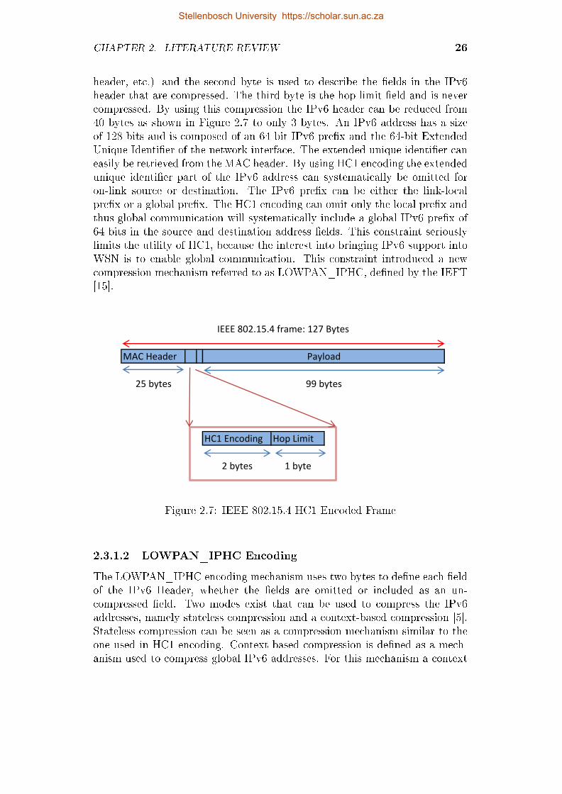
The �rst header compression mechanism proposed, was referred to as HC1 [25].Figure 2.7 shows how the resulting 6LoWPAN packet is constructed when usingthis compression mechanism. The HC1 mechanism introduces the option toomit some of the IPv6 header �elds. This is possible because certain �elds arealways the same and can either be retrieved implicitly, for example version �eldis always 6, or from other layers, e.g. the header length can be computed fromthe MAC header. The only �eld that will always stay uncompressed is the hoplimit �eld [5]. HC1 encoding makes use of 2 bytes to compress the header. The�rst byte is used to di�erentiate the next content (IPv6 header, fragmentation
Stellenbosch University https://scholar.sun.ac.za
CHAPTER 2. LITERATURE REVIEW 26
header, etc.) and the second byte is used to describe the �elds in the IPv6header that are compressed. The third byte is the hop limit �eld and is nevercompressed. By using this compression the IPv6 header can be reduced from40 bytes as shown in Figure 2.7 to only 3 bytes. An IPv6 address has a sizeof 128 bits and is composed of an 64 bit IPv6 pre�x and the 64-bit ExtendedUnique Identi�er of the network interface. The extended unique identi�er caneasily be retrieved from the MAC header. By using HC1 encoding the extendedunique identi�er part of the IPv6 address can systematically be omitted foron-link source or destination. The IPv6 pre�x can be either the link-localpre�x or a global pre�x. The HC1 encoding can omit only the local pre�x andthus global communication will systematically include a global IPv6 pre�x of64 bits in the source and destination address �elds. This constraint seriouslylimits the utility of HC1, because the interest into bringing IPv6 support intoWSN is to enable global communication. This constraint introduced a newcompression mechanism referred to as LOWPAN_IPHC, de�ned by the IEFT[15].
MAC Header
25 bytes
HC1 Encoding Hop Limit
2 bytes 1 byte
99 bytes
IEEE 802.15.4 frame: 127 Bytes
Payload
Figure 2.7: IEEE 802.15.4 HC1 Encoded Frame
2.3.1.2 LOWPAN_IPHC Encoding
The LOWPAN_IPHC encoding mechanism uses two bytes to de�ne each �eldof the IPv6 Header, whether the �elds are omitted or included as an un-compressed �eld. Two modes exist that can be used to compress the IPv6addresses, namely stateless compression and a context-based compression [5].Stateless compression can be seen as a compression mechanism similar to theone used in HC1 encoding. Context-based compression is de�ned as a mech-anism used to compress global IPv6 addresses. For this mechanism a context
Stellenbosch University https://scholar.sun.ac.za

CHAPTER 2. LITERATURE REVIEW 27
ID which consists of a set of 4 bits, is de�ned for each global pre�x used inthe 6LoWPAN network. For o�-link communication, the context ID of 4 bitsis used to replace the IPv6 pre�x of 64 bits. When using this con�guration,an additional byte is added after the LOWPAN_IPHC encoding �eld, whichcontains the pre�xes of the source and the destination [15]. For the remainderof the IPv6 address the same techniques are used as in stateless compressionmode. Figure 2.8 shows LOWPAN_IPHC encoding message format as well asthe additional byte added during o�-link communication.
MAC Header
25 bytes
IPHC Encoding Context ID
2 bytes 1 byte
IEEE 802.15.4 frame: 127 Bytes
Payload
99 bytes
Figure 2.8: IEEE 802.15.4 LOWPAN_IPHC Encoded Frame
2.3.2 Internet of Things
"If we had computers that knew everything there was to know aboutthings-using data they gathered without any help from us we would be able totrack and count everything, and greatly reduce waste, loss, and cost. We
would know when things needed replacing, repairing or recalling, and whetherthey were fresh or past their best. The Internet of Things has the potential tochange the world, just as the Internet did. Maybe even more so." -Kevin
Ashton, originator of the term, Internet of Things - 1999 [30].
IPv6 is emerging as the actual solution for scaling up the Internet to host analmost unlimited number of devices with globally unique reachable addresses[24]. Development of RFID tags, sensors, actuators and smart phones makesit possible to materialise an Internet of Things. The Internet of Things anddevices like these mentioned can improve service and can be accessible anytime,from anywhere by interacting and co-operating with each other [33].
Stellenbosch University https://scholar.sun.ac.za

CHAPTER 2. LITERATURE REVIEW 28
2.4 OSI Layer Mobility
This section looks at mobility options across the di�erent layers of the OSIStack. When we look at the classical TCP/IP stack, mobility has no well-de�ned place. From the application layer to the link layer a lot of di�erenttypes of support for mobility have been proposed. The physical layer is notinvolved in mobility. The reason being that the wireless access technologyis implicitly responsible for handling mobility at the physical layer, e.g. themovement of mobile nodes in the area surrounding a wireless access point [34].
2.4.1 Physical Layer Mobility
During physical transmission the message is actually sent out and transportedacross the network. The physical layer is mainly used for encoding, sending ofdata(transmission), signaling and the receiving(decoding) of data. Encodingand signaling have to do with transforming the data from bytes, to a signalthat can be transmitted over a physical medium. After this has been done,data is also received on this layer and decoded back to bytes that can be readby the computer. It is obvious that mobility is not applicable, because thedata still needs to be send over the medium while the mobile node is moving.Mobility challenges are not associated with the physical layer [34].
2.4.2 Link Layer Mobility
Link layer mobility is where the actual hando� occurs between di�erent nodesand is also known as layer hando�s. Two types of hando� exist, namely hori-zontal hando�s and vertical hando�s [34]. Horizontal hando�s are invisible tothe higher layers, whereas vertical hando�s are the hando�s between di�erentaccess technologies and are only visible to the network layers. If one looks atmobility on the link layer, the link layer is responsible for scanning, detectingof potential access technologies, monitors channel conditions, authenticationand re-association. The link layer is also useful in detecting di�erent link layertechnologies, supplying the signal to noise ratio from di�erent access pointsavailable, the channel of operation and information on overlaying networks.Information on channel conditions is very useful in making decisions aboutrouting, queuing, QoS and packet drop [35]. Information about the link andlink properties is useful in the case of overlaying networks. The responsibilityfor communication between di�erent link layer devices, lies with the di�er-ent link layer technologies. This enables heterogeneity and proactive contextcaching for fast hando�s [34]. In order to detect link layer hando�s, the hando�scheme makes use of the signal strength level.
Stellenbosch University https://scholar.sun.ac.za

CHAPTER 2. LITERATURE REVIEW 29
2.4.3 Network Layer Mobility
The network layer is used to connect di�erent and remote networks and to allowcommunication between them. The two main services of the network layer thatcould a�ect mobility are location management (e.g. interface change) and IP-address assigning (e.g. inter-network and subnet mobility). QoS is providedby the network layer and this could be impacted by the service of mobility.As soon as a mobile node enters a new network, the mobile node undergoesan IP change and this can lead to huge challenges in location managementwhich is also the responsibility of the network layer. When a mobile nodechanges its network, the change requires the mobile node to be con�guredwith new network settings. The mobile node must be in a position to receive anew IP address, this allows the node to be reachable by corresponding nodes.The mechanisms for location management are Domain Name System (DNS),Dynamic DNS and home agent binding in Mobile IP. Another problem thatis posed by mobility is dynamic routing of packets to reach their destinations.For dynamic routing the approach to overcome this is mentioned in [34, 8].
2.4.4 Transport layer Mobility
The network layer mobility a�ects the transport layer mobility directly dueto link capacity, packet loss and change of IP address. Packet loss a�ects thecongestion control algorithms. The connection's window size is determinedby the Bandwidth Delay Product (BDP). The BDP is used for the rest ofthe connection, but the link capacity might change when the device moves toa new network. This change will a�ect the BDP directly and causes a newwindow size negotiation between the nodes. The mobility aware transportlayer protocol are used to dealt with the issues of BDP. The most a�ectedconventional layer when mobility management is used, will be the transportlayer. The reason being the tight binding of the the transport layer withthe layer above and below it. The transport layer mobility is a�ected by thefollowing processes [34]:
� Inter-subnet mobility
� Inter-network mobility
� Horizontal hando�
� Vertical hando�
� Address change
� Session mobility and
� Application/�ow mobility
Stellenbosch University https://scholar.sun.ac.za
CHAPTER 2. LITERATURE REVIEW 30
It is the responsibility of the transport layer and higher layer mobility man-agement mechanism's to handle all the issue produced by the above mentionedprocesses [36].
2.4.5 Session Layer Mobility
The maintaining of parameters related to communication and session stateis handled by the session layer and this serves as the main purpose of thesession layer [34]. Unexpected termination of the transport layer can be causedby mobility and this can lead to the corruption or loss of the state of thesession. Session layer mobility is a�ected only when application mobility ispresent. When using the session layer, the following is stored as session stateinformation:
� The byte size already transferred and written to disk during a �le trans-fer.
� Information related to a secure login session. This information can con-sist of encryption keys and security associations set up during the securelogin.
� Maintaining synchronization data used for combining incoming networkstreams.
Session layer mobility ensures that the above mentioned information is notlost when the transport layer has an unexpected connection termination. Therelevant session layer mobility handling mechanism is required to pause andrestart the current session. The mobility handling mechanism must be grantedaccess by the application to all the required information. This information canthen be reused when a new connection socket has been set up [34].
2.4.6 Presentation layer Mobility
The Presentation layer is mainly responsible for data formatting, as required bythe Application layer. In the case of mobility, the Presentation layer will haveto deal with the following issues like screen resolution, codec and applicationversions. The mobility management of the application should be capable ofdetecting the capabilities of the new device and modify and adapt the contentaccordingly for display on the new device [34].
2.4.7 Application layer Mobility
Application layer mobility solutions, or also known as application speci�c mo-bility solutions have no set requirements for mobility management. The ap-plication layer is dependent on the underlying layers for network access and
Stellenbosch University https://scholar.sun.ac.za

CHAPTER 2. LITERATURE REVIEW 31
socket establishment, which makes the application layer highly �exible. Ifthe presentation layer is not responsible for the session mobility control, thedrawback is that the application needs to be redesigned so that the servicesprovided by the session layer can be used [34].
2.5 Mobile IPv6
Mobile IPv6 is a proposed mobility standard for IPv6 networks [8, 37]. MIPv6enables a mobile node to stay connected when moving around in di�erentnetworks while maintaining one IP address. MIPv6 is suitable for mobilityin heterogeneous networks, for example it allows a mobile node to transferbetween di�erent Ethernet segments, as well as from an Ethernet segment toa Wi� cell. The mobile node is able to change between di�erent 802.11 AccessPoints while maintaining its home network IP address, even if the new pointof attachment is in a new network. The home address is used to identify themobile node and the node will always be reachable through this address. Thenetwork consists of a home network and a foreign network also called a visitingnetwork. The home network assigns an IPv6 home address to the mobile node.This address is then used to form a binding between the mobile node and thehome network. This enables the home network to always know the locationof the mobile node when it is in a foreign network. Further in this sectionthe functioning of the protocol is described in more detail. The basic setupof a MIPv6 network can be seen in Figure 2.9 with route optimization andtriangular routing visible.
Stellenbosch University https://scholar.sun.ac.za

CHAPTER 2. LITERATURE REVIEW 32
CorrespondentNode
Home Network
Mobile Node
Mobile NodeHome Network
Movement of MN
Internet
IPv6 TunnelRouteOptimization
IPv6 Tunnel TriangularRouting
Message flow withoutRoute Optimization
MIPv6 message flows:
Message flow withRoute Optimization
Home Agent
Without RouteOptimization
Visited Network
Figure 2.9: MIPv6 Network
2.5.1 MIPv6 Network Elements
� Mobile Node (MN): The MN is an IPv6 enabled node that passes aroundin an IPv6 network and thus stays connected through its home address.The MN creates a binding with the HA when moving to a visiting net-work where it receives a Care-of address.
� Home Agent (HA): The HA is a router located in the Home Networkand stores information about MNs whose permanent home address isin the HA's network. The HA stores the binding messages, the Care-ofAddresses (CoA) of the MN and performs forwarding of data destinedfor the MN in triangular routing. Both the correspondent node and theHA keep binding information in their binding caches.
� Home Network (HN): The HA resides in the HN. The HN uses the homesubnet pre�x and assign the mobile node's home address from this pre�x.
� Correspondent Node (CN): The CN is any node that wants to establisha connection with the mobile node. The correspondent node needs onlyIPv6 capabilities and not MIPv6 capabilities to communicate with theMN. If the CN is MIPv6 capable, route optimization can be used toreduce overhead and direct communication with the mobile node.
Stellenbosch University https://scholar.sun.ac.za

CHAPTER 2. LITERATURE REVIEW 33
� Visited Network (VN): This is any network that the MN visits outsideits home network. The mobile node receives a CoA from this networkwhich has a di�erent network pre�x to that of the home network.
� Home Address (HoA): The home address is the IPv6 address the mobilenode receives when connected to the home network. The mobile nodewill always be reachable through this address, even if the mobile nodehas moved to a visiting network. The mobile node is always logicallyconnected to the home network because the mobile node is always as-signed with the home address. If the mobile node moves to a visitingnetwork, the home agent will intercept packets destined for the mobilenode and forward the packets to the CoA.
� Care-of Address (CoA): The CoA is the IPv6 address the mobile nodereceives when in a visiting network. A mobile node can have multipleCoAs but only one can be linked as the primary CoA at the home agent.The binding that is made between the mobile node and the home agentis an association of these two addresses. Both the correspondent nodeand the home agent keep binding information in their binding caches.
� Route Optimization (RO): Route Optimization is a process that removesmuch of the overhead caused by the MIPv6 protocol, as seen in Figure2.11, by the use of Bidirectional Tunneling. Route Optimization can beseen in Figure 2.9 and Figure 2.12. Communication is directly betweenthe mobile node and the correspondent node, without the home agenthaving to intercept the packets destined for the mobile node. An IPv6tunnel is establish between the mobile node and correspondent node thatmakes communication possible.
2.5.2 Comparison between MIPv6 and MIPv4
Mobile IPv4 is the �rst implementation of mobility in IP networks and wasimplemented on the Internet Protocol version 4. The design of MIPv6 bene�tsa lot from the experience gained from the implementation of the MIPv4 version.IPv6 also o�ers a lot of advantages for mobility and the following sectiondescribes the di�erences between MIPv4 and MIPv6 implementations [38].
� In MIPv4 the network consists of a foreign agent, this is a router in theFN that acts as the agent when the MN roams to a new network. InMIPv6 there is no need for a foreign agent because of the NeighbourDiscovery and Address Auto-con�guration features that enable an MNto function in any location without the services of any special router(FA)in that location.
Stellenbosch University https://scholar.sun.ac.za

CHAPTER 2. LITERATURE REVIEW 34
� Route optimization is a very important part of mobile IP and for MIPv4it is a non-standard extension of the protocol. This way route optimiza-tion was better built into the IPv6/MIPv6 protocols.
� Route optimization is also implemented in such a way that it coexistse�ciently with routers that implement ingress �ltering. In MIPv4 thiswill happen because the CN sends a packet that contains a source addressthat is set to the home address and is discarded by ingress �ltering. InMIPv6 the CN puts the CoA as the source address and uses the HomeAddress Destination option in the IP packet header for the home addressand this enables CoA to be transparent over the IP layer.
� Symmetric reachability is ensured between the MN and the default routerin the current location by IPv6 Neighbour Unreachability Detection.
� The overhead of packets is reduced by avoiding IP encapsulation andinstead using the IPv6 routing header options.
� Mobile IPv6 is not linked to any particular link layer, as it does not useAddress Resolution Protocol (ARP) but instead IPv6 Neighbour Discov-ery. This ability improves the robustness of the protocol [39, 40].
2.5.3 MIPv6 Drawbacks and Known Issues
Mobile IPv6 has some known limitations and this leads to the argument thatMobile IP could be unsuccessful and impractical. The following section ex-plains the challenges faced by Mobile IP and possible solutions to these chal-lenges [12].
2.5.3.1 Security Attacks
� Denial Of Service Attacks: These attacks occur when a large number ofpackets are sent from an attacker to a certain host. This tremendousnumber of packets being sent to a host may cause the host CPU to godown. During this period of processing the bogus packets, no usefulinformation can be transmitted on the network. DOS attacks can alsohappen when the attacker interferes with packets �owing between twonodes on a network. The attacker can generate bogus Registration Re-quest packets specifying his own IP address as the CoA of the node. Thiswill cause all the packets destined for the CoA to be routed by the HomeAgent to the attacker's IP. The possible prevention method for this is torequire cryptographically strong authentication in all registration mes-sages exchanged by a mobile node and its home agent [12]. IPsec is also amandatory requirement for MIPv6 to enable secure communication [41].
Stellenbosch University https://scholar.sun.ac.za

CHAPTER 2. LITERATURE REVIEW 35
� Theft of Information Passive Eavesdropping: This will allow an attackerto gain wired or wireless access to the network infrastructure. PassiveEavesdropping can be prevented by using End-to-End encryption tech-nologies like IPSec [41].
� Replay Attack: An attacker host machine can obtain a copy of a Reg-istration Request message and by using this at a later stage be able toregister a bogus CoA. Prevention of this is easy by making use of theIdenti�cation �eld. The identi�cation �eld is generated in such a waythat when the packet is received by the Home Agent it will be recognizedas being out of date [12].
2.5.3.2 Triangulation Problem
The triangular routing problem is responsible for delays in the delivery ofdata packets to mobile nodes. This delay of data packets causes a lot ofoverhead in the network and thus lowering the performance of the networkand the relative routers in the network. Route optimization can be used toimprove the overhead by avoiding a packet route through the home network,but instead delivering the packets directly to the CoA of the mobile node.The triangular routing problem can be seen in Figure 2.9 as can the solution.In [42] an analytical evaluation of these the methods can be seen. From thisresearch it is clearly visible that route optimization has a great importanceespecially for real-time application. The functioning of triangular routing androute optimization in MIPv6 will be explained in more detail in the followingsection.
2.5.4 Basic Functioning of Protocol
AMobile node must also be addressable at its home address, even when movingaround in di�erent subnets. The home address is the IPv6 address that themobile node received in the home network and it is within the home network'ssubnet pre�x. If the MN is in the home network, the packets are addressed tothe MNs home address and use conventional routing mechanism to deliver thepackets. When the mobile node moves to a di�erent network, it receives anIPv6 address that is in the same range as the foreign network's pre�x. Thisnew IPv6 address is called the CoA of the MN. The CoA is assigned to the MNusing conventional mechanisms like stateless or state-full auto-con�guration.For the period that the MN is in the foreign network packets destined for theMN is addressed to the MN's CoA [8, 37].
The association between the MN's home address and Care-of address iscalled a binding. The MN and the home agent will make a binding every timethe MN moves to a new foreign network. The MN forms this binding withthe home agent by sending a binding update (BU) to the home agent. This
Stellenbosch University https://scholar.sun.ac.za

CHAPTER 2. LITERATURE REVIEW 36
process registers the MN CoA with the MN and the home agent knows thatthe MN is reachable at the CoA. The home agent sends a binding update ac-knowledgement to the MN after receiving the BU and processing of the BUis successful. A correspondent node is any node in the network that wants tocommunicate with the MN, and can be a stationary or mobile node. The MNcan send information of its location to the CN by a process called correspon-dent registration. This way the CN will know where the MN is located andreturn routability is used to authorize the binding between the MN and theCN [8, 43].
The message �ow of MIPv6 with Route Optimization is shown in Figure2.10. The mobile node travels to a foreign network, using IPv6 Router Adver-tisement and Neighbour Discovery to detect the movement to a new network.The mobile node can ask the foreign node for router advertisement by sendinga router solicitation message to the default router in the foreign network. Arouter on the foreign network will then reply with a Router Advertisementmessage to the mobile node that includes the network pre�x of the FN. Themobile node uses this message to detect movement to a new subnet, and isassigned a Care-of address by the router. After the mobile node receives aCoA, the node sends a BU message to the Home Agent. The Bu message isencrypted and authenticated using IPSec [44].
If the BU message is correct and veri�ed by the Home Agent, the HomeAgent sends a Binding Acknowledgement (BAck) message to the mobile nodeif the A-bit has been set in the BU as seen in Figure 2.14. Now that thebinding is formed between the mobile node and home agent, data packets canbe sent between the mobile node and correspondent node via bidirectionaltunneling as seen in Figure 2.11. To enable Route optimization between themobile node and correspondent node, the mobile node sends a Home Test Init(HoTI) message to the correspondent node via the HA. The MN also sendsa Care-of Test Init (CoTI) message directly to the correspondent node. Byexchanging these messages between the HA, MN and the CN, the CN canobtain some reasonable assurance that MN are reachable at its HoA and CoA.The correspondent node returns a Home Test and Care-of Test message to theMN. After these message have been accepted, the mobile node sends a newBU message to the CN to enable Route Optimization. The data packets cannow be sent directly from the CN to the MN and from the MN to CN [8, 43].
Stellenbosch University https://scholar.sun.ac.za

CHAPTER 2. LITERATURE REVIEW 37
MN AP HA
Router Solicitation
Router Advertisement
CN
Neighbor Solicitation
Neighbor Advertisement
Binding Update
Binding Acknowledgement
Binding Update
Binding Acknowledgement
Data Packets
Data Packets
Home Test Init
Home Test
Care-of Test Init
Care-of Test
Home Test Init
Care-of Test Init
Home Test
Care-of Test
Figure 2.10: MIPv6 Message Flow
The MN and the CN can communicate via two options known as bidi-rectional tunneling mode or route optimization mode. Figure 2.11 shows theBidirectional Tunneling Mode in MIPv6.
Stellenbosch University https://scholar.sun.ac.za

CHAPTER 2. LITERATURE REVIEW 38
Packet destined from MN to CN
Mobile Node
Home Network
Correspondent Node
Home Agent
Packet destined from CN to MN
Visited Network Local Network
Outer Source IP
Outer Source IP Source IP
Source IP Dest IP
Dest IP
Outer Dest IP
Outer Dest IP
Inner Dest IP
Inner Dest IP
Inner Source IP
Inner Source IP
MN IPv6 CoA
MN IPv6 CoA
HA IPv6 Address
HA IPv6 Address
CN IPv6 Address
CN IPv6 Address
MN IPv6 H Address
CN IPv6 Address
CN IPv6 Address
MN IPv6 H Address
MN IPv6 H Address
MN IPv6 H Address
Figure 2.11: MIPv6 Bidirectional Tunneling Mode
In bidirectional tunneling the CN needs only to be IPv6 enabled to com-municate with the MN and there is also no binding between the MN and theCN. The CN routes packets to the HA and from here packets are tunneled tothe MN. The red line in Figure 2.11 indicates the path of the packets. TheMN tunnels packets to the HA and from here it is routed to the CN usingnormal routing protocols. The blue line in Figure 2.11 indicates the path ofthe packets destined for the CN. This process is also called reverse tunnelingmode. In order for the HA to intercept packets destined for the mobile node,it uses proxy Neighbour Discovery and intercepts all the packets addressed tothe MN's home address. Intercepted packets are than tunneled to the MNcurrent CoA by the use of IPv6 encapsulation [6, 8].
The second mode is called route optimization and for this the CN alsoneeds to support MIPv6 [43]. This mode can be seen in Figure 2.12.
Stellenbosch University https://scholar.sun.ac.za

CHAPTER 2. LITERATURE REVIEW 39
Packet destined from MN to CN
Mobile Node
Home Network
Correspondent Node
Home Agent
Packet destined from CN to MN
Visited Network Local Network
Source IP Destination IP
CN IPv6 Address
MN IPv6 CoA Address
IPv6 Home AddressIPv6 CoA CN to MN
MN to CN
Figure 2.12: MIPv6 Route Optimization Mode
In this mode the MN and the CN con�gure an BU between them. Whenthe CN wants to send any IPv6 packet it �rst checks the cache bindings tosee whether any binding entry exists for the IPv6 address. If the CN �ndsan BU for that speci�c address, a new routing header is used by the CN toroute the packet directly to the MN's information captured in the binding.The advantages of this mode are that the overhead in the network is hugelyreduced and congestion at the home agent is also minimized. This mode alsoensures that the packets reach the targeted node via the shortest possible routeand this eliminates the home agent as a Single Point of Failure in the network[10].
If packets are routed directly to the MN, the CN will set the DestinationAddress of the IPv6 header to the CoA of the MN as seen in Figure 2.12. Forpackets that are sent from the MN to CN the MN uses the CoA as the sourceaddress of the packet and adds a new IPv6 home address destination option tocarry the MN's home address. By adding the home address destination optionto the packet the use of the CoA is transparent above the network layer.
MIPv6 also supports multiple home agents and has limited support forhome network recon�guration. If the mobile node is not sure who the homeagent is in the network, the MN can make use of dynamic home agent addressdiscovery to identify the home agent in the network [6, 8, 43]
Stellenbosch University https://scholar.sun.ac.za

CHAPTER 2. LITERATURE REVIEW 40
2.5.5 Mobility Header for IPv6 Protocol
Mobile IPv6 de�nes a new Mobility Header (MH) to carry various MIPv6messages. The Mobility Header is used by MN, CN, and HA during bindingcreation and management of bindings. The MH uses a value of 135 for theNext Header �eld to be identi�ed in the immediately preceding header. Thiscan be seen in Table 2.5. The MH has the same alignment requirements asany IPv6 protocol header, an 8-octet boundary [8]. Figure 2.13 illustrates theformat of a MH in IPv6.
Payload Proto Header Lenght MH Type ReservedChecksum
Message Data
Figure 2.13: Mobility Header for IPv6 Protocol
� Payload Proto: 8-bit Selector �eld. This �eld uses the same values as inTable 2.5 and identi�es the header type following the MH.
� Header Length: This 8-bit unsigned integer �eld is used to represent thelength of the MH and must always be in a multiples of 8 octets.
� MH Type: 8-bit Selector. This �eld is used to identify the type ofmobility message. If this indicator contains an invalid MH type, an errorindication will be sent. The various mobility header types can be seenin Table 2.9.
� Reserved: 8-bit �eld reserved for future use.
� Checksum: This �eld contains a 16-bit unsigned integer checksum ofthe Mobility Header and is composed of the 16-bit ones complement ofthe ones complement sum of this string. The home address of the mobilenode will be used as the value of the IPv6 source address �eld if available[8].
� Message Data: This variable length �eld contains the relevant data forthe indicated MH type.
Stellenbosch University https://scholar.sun.ac.za

CHAPTER 2. LITERATURE REVIEW 41
Table 2.9: Mobility Header Types [8]
Value Description0 Binding Refresh Request1 Home Test Init2 Care-of Test Init3 Home Test4 Care-of Test5 Binding Update6 Binding Acknowledgement7 Binding Error8 Fast Binding Update9 Fast Binding Acknowledgment10 Fast Neighbour Advertisement (Deprecated)11 Experimental Mobility Header12 Home Agent Switch Message13 Heartbeat Message14 Handover Initiate Message15 Handover Acknowledge Message16 Binding Revocation Message17 Localized Routing Initiation18 Localized Routing Acknowledgment
The following list of messages is carried by the new Mobility Header andTable 2.9 indicates the MH Type values for all the messages.
� Binding Refresh Request: A binding update is valid only for a certainperiod of time. If the binding time is reached, the CN or HA will send aBinding Refresh Request to re-establish the binding with the MN. Thismessage is typically used when the cache binding is active and the CNsees that the binding's lifetime is reaching its expiry date. An indicationby which the CN checks to see whether the connections are in active use,is to check for recent tra�c and open transport layer connections on thenetwork.
� Home Test Init: This message is used to trigger the RR procedure by theMN. During this procedure the MN will request a home keygen tokenfrom the CN. An MH Type of 1 is used by this message.
� Care-of Test Init: The care-of Test Init (CoTI) message is used to triggerthe RR procedure by the MN. During this procedure the MN will requesta care-of keygen token from the CN.
Stellenbosch University https://scholar.sun.ac.za

CHAPTER 2. LITERATURE REVIEW 42
� Home Test: The Home Test (HoT) message is sent from the CN to theMN and is a response to the Home Test Init message. It uses the MHHeader type 3 and it contains a 64-bit keygen token and home init cookiethat is used in the RR procedure.
� Care-of Test: The Care-of Test (CoT) message is sent from the CN tothe MN and is a response to the CoTI message. Uses MH Header type 4and it contains a 64-bit keygen token and care-of init cookie used in theRR procedure.
� Binding Update: A Binding Update (BU) is an authorization messagebetween the MN and the CN, or the MN and the HA to notify them ofits current binding and to notify other nodes of a new CoA. A BU usesthe value 5 as MH Header type and Figure 2.14 indicates the format ofthe Message Data �eld in the MH. The Acknowledge (A) bit is set bythe MN to request a Binding Acknowledgement message upon receipt ofthe Binding Update by the CN or HA. This option is mandatory whena BU is sent to a CN. The H-bit, or Home Registration bit is used torequest the node to act as a HA. The node must be a router sharing thesame network pre�x as the home network of the MN. The Link-LocalAddress Compatibility bit (L) is set if the MN home address has thesame interface identi�er as the mobile node's link-local address. If theKey Management Mobility Capability (K) is cleared, the protocol usedto establish IPsec security associations between the MN and the HAdoes not survive movement. The bit must be cleared when manual IPseccon�guration is used. The 16-bit Sequence integer is used to sequenceBU so that the received Binding Update Acknowledgement message canbe matched to a certain U. The 16-bit Lifetime �eld is used to indicatethe lifetime of a Binding before it will expire.
Sequence #A H L K Reserved Lifetime
Mobility Options
Figure 2.14: Message Data �eld in Mobility Header for Binding Update
� Binding Acknowledgement Message: A Binding Acknowledgement (BAck)message acknowledges the receipt of a BU message. An BU message willtrigger a BAck message if requested in the BU message. The BAck hasthe MH Type value 6 and the Message �eld is shown in Figure 2.15. The
Stellenbosch University https://scholar.sun.ac.za

CHAPTER 2. LITERATURE REVIEW 43
Status is an 8-bit integer indicating the nature of the BU. The Status�eld can have di�erent values, but the most used value is 0, which meansthe BU has been accepted. A value of 1 also means the BU was accepted,but pre�x discovery is necessary. Values of 174 and 131 mean that theBU was not successful because the MN use an invalid CoA or home regis-tration is not supported. The Key Management Mobility Capability (K)bit is cleared, thus the IPsec security associations between the MN andthe HA do not support movement. The Sequence �eld is used to matcha BU Acknowledgment to a BU. The Lifetime �eld, in time units of 4seconds, is used to indicate the time to retain MN entry in its BindingCache.
Status K ReservedSequence # Lifetime
Mobility Options
Figure 2.15: Message Data in Mobility Header for BU Acknowledgement
� Binding Error Message: The CN and HA uses binding error messages toindicate errors relating to binding associations. The HA use this messageto indicate to the MN that it has received an unrecognized MobilityHeader Message Type. The CN node will use the binding error messageif an attempt is made to use a home address destination option withoutthe existence of a valid binding.
2.5.6 MIPv6 for WSN
MIPv6 easily �ts into the 6LoWPAN network structure due to the availabilityof IPv6. For IPv6-in-IPv6 tunneling in MIPv6 the standard IPv6 features areused, which are available in the 6LoWPAN adaptation layer. As describedin the previous sections, MIPv6 introduces some new control messages calledBU and BAck. These messages, however, use the IPv6 extension headers andthis increases the overhead and reduces frame space available for payload. BUand BAck messages have a minimum size of 12 bytes. Furthermore a BUalso includes a destination option with a home address size of 20 additionalbytes. An BAck message includes a type 2 routing header with an additionalsize of 12 bytes [5]. By using the HC1 compression mechanism, an encodingmechanism was proposed to reduce the overhead of the Mobile IPv6 controlmessages [45]. For compression of the mobility headers the adaptation layeris the same as the 6LoWPAN adaption layer. The gain of this compression
Stellenbosch University https://scholar.sun.ac.za

CHAPTER 2. LITERATURE REVIEW 44
mechanism depends on the type and size of header to compress.An uncompressed binding update uses 32 bytes:
� 12 bytes for the mobility header.
� 20 byte for options.
A compressed binding update uses 23 bytes:
� 3 bytes for the mobility header.
� 20 byte for options.
Figure 2.16 illustrates the message �ows in MIPv6 for 6LoWPAN networks.
Mobile Sensor Router Home Agent
Router Solicitation
Router Advertisement
Binding Ack
IPv6-in-IPv6 tunnel establish
Neighbor Solicitation
Neighbor Acknowledgement
Binding Update
Figure 2.16: MIPv6 Message Flow in 6LoWPAN Network
2.6 Network Mobility
In the previous section MIPv6 was described in detail and diagrams was sup-plied to illustrate the functioning of the protocols. In this section NEMO BasicSupport Protocol is described. NEMO [46] is a protocol extension to MIPv6
Stellenbosch University https://scholar.sun.ac.za

CHAPTER 2. LITERATURE REVIEW 45
to enable persistent connection of moving networks (e.g.,trains with wirelesshosts of passengers inside the carriages) to the Internet [2]. The main goal ofthis scheme is to preserve ongoing internal and external communication ses-sions of nodes attached to a moving network during the network's movement.The NEMO Basic Support ensures session continuity for all the nodes in theMobile Network, even as the Mobile Router changes its point of attachmentto the Internet. As in MIPv6 all the tra�c between the Mobile Node and theCorrespondent Node are routed through the Home Agent[46].
CorrespondentNode
Bi-directional Tunnel
Mobile RouterHome Agent
Mobile Router 1
Mobile Network Node 1 Mobile
Network Node 2
Access Router 1
NEMO 1
Data Flow
Figure 2.17: NEMO Network [2]
A Mobile Network can be described as a network segment or subnet thathas the ability to move and attach to arbitrary points in the routing infrastruc-ture. The architecture of NEMO can be seen in Figure 2.17. NEMO makesit possible that only the MR must be involved in the handover operations onbehalf of the whole moving structure. To access the Mobile Network thereare speci�c Gateways called Mobile Routers that is responsible for the manag-ing of mobile network movements. The Mobile Router also forms the defaultgateway of a Mobile Network. The Home Agent advertises an aggregation ofMobile Networks to the rest of the network infrastructure and this enablesconnectivity to the network (Visited Network). A Mobile Network can alsocomprise of multiple and nested subnets. A router without mobility supportmay be permanently attached to a Mobile Network for local distribution. Mo-bile Routers are also allowed to connect to Mobile Networks owned by di�erentMobile Routers. NEMO Basic Mobility Protocol is de�ned as a mobility pro-tocol network solution where the Mobile Router can at any time act either asa Mobile Host or as a Mobile Router.
Stellenbosch University https://scholar.sun.ac.za

CHAPTER 2. LITERATURE REVIEW 46
NEMO routing optimization techniques are used to further improve thesolution and enabling the roaming of whole networks and provides transparentprovision of Internet access in public transportation systems for passengers.The widest scale of Intelligent Transportation Systems (ITS) scenarios (e.g.,road safety on the move entertainment) or even in personal area networks(PAN) where various electronic devices (like tablets,digital cameras, e-healthsensors, etc.) would connect to the Internet through a smartphone simulatingthe role of the mobile router [46].
In the following section PMIPv6 is described, this forms part of the NEMOnetwork mobility extension. PMIPv6 de�nes a Mobile Network and not justmobile nodes as with MIPv6.
2.7 Fast Handover for Mobile IPv6
Mobile IPv6, as described in RFC6275 and in Section 2.5, is a protocol usedto enable an MN to stay connected in a IPv6 network while changing its pointof attachment. But this protocol does not perform well when tested againstreal-time application, due to a long handover latency. The operations involvedin MIPv6 that introduce the longest handover latency are movement detec-tion of the node, link-layer procedures, IP address con�guration and locationmanagement. For MIPv6 to handle real-time tra�c and to enable a seamlesshandover, Mobile IPv6 Fast Handover(FMIPv6) was introduced in RFC5568[19]. FMIPv6 is used to minimize the operations mentioned earlier, thus reduc-ing the handover latency. FMIPv6 is used to address two common problemsthat exist in current IP operations. The �rst one is to enable the MN to senddata as soon as the MN connects to a new subnet and the second one is todeliver packets to an MN as soon as the MN attaches to the new access router[3]. FMIPv6 is not dependent on link layer technologies and does not addressimproving the link-layer switching latency [37, 47]. Figure 2.18 shows the ba-sic elements of an FMIPv6 network and the various elements are described inSubsection 2.7.1.
Stellenbosch University https://scholar.sun.ac.za
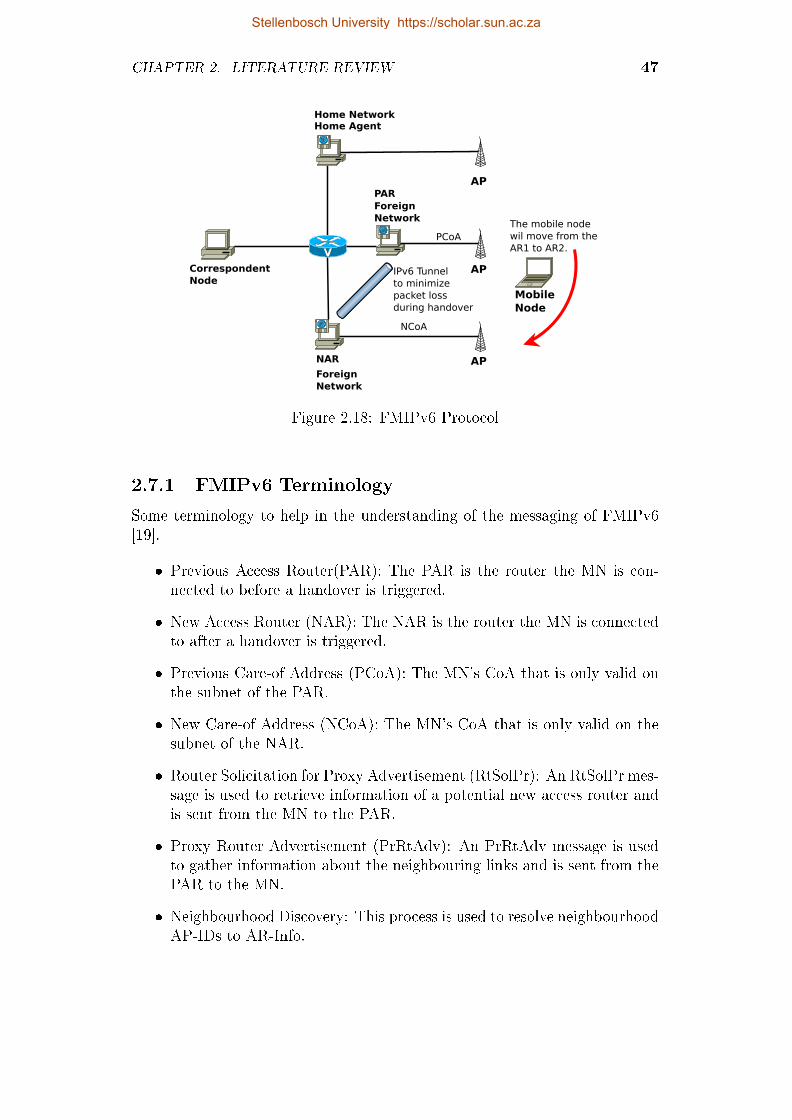
CHAPTER 2. LITERATURE REVIEW 47
Home Agent
NAR
CorrespondentNode
Mobile Node
The mobile nodewil move from theAR1 to AR2.
Home Network
PAR
AP
AP
AP
ForeignNetwork
ForeignNetwork
PCoA
NCoA
IPv6 Tunnel to minimizepacket lossduring handover
Figure 2.18: FMIPv6 Protocol
2.7.1 FMIPv6 Terminology
Some terminology to help in the understanding of the messaging of FMIPv6[19].
� Previous Access Router(PAR): The PAR is the router the MN is con-nected to before a handover is triggered.
� New Access Router (NAR): The NAR is the router the MN is connectedto after a handover is triggered.
� Previous Care-of Address (PCoA): The MN's CoA that is only valid onthe subnet of the PAR.
� New Care-of Address (NCoA): The MN's CoA that is only valid on thesubnet of the NAR.
� Router Solicitation for Proxy Advertisement (RtSolPr): An RtSolPr mes-sage is used to retrieve information of a potential new access router andis sent from the MN to the PAR.
� Proxy Router Advertisement (PrRtAdv): An PrRtAdv message is usedto gather information about the neighbouring links and is sent from thePAR to the MN.
� Neighbourhood Discovery: This process is used to resolve neighbourhoodAP-IDs to AR-Info.
Stellenbosch University https://scholar.sun.ac.za

CHAPTER 2. LITERATURE REVIEW 48
� Fast Binding Update (FBU): The MN sends an FBU to the PAR, thismessage is used to trigger a redirection of the MN's tra�c to the NAR.
� Fast Binding Acknowledgment (FBAck): When a PAR receives an FBU,it will respond with an FBAck message.
� Predictive Fast Handover: When the MN is able to send an FBU whenits still connected to the PAR is called Predictive Fast Handover. In thiscase the MN can predict the NAR before the handover process starts.
� Reactive Fast Handover: When the MN is only able to send an FBUwhen its connected to the NAR is called Reactive Fast Handover. Inthis case the MN can not predict the NAR before the handover processstarts.
� Unsolicited Neighbour Advertisement (UNA): An UNA will be sent tothe NAR by the MN as soon as the MN establishes connectivity withthe NAR. The UNA will trigger any bu�ered or arriving packets to beforwarded to the MN.
� Handover Initiate (HI): A message stating that the MN's handover pro-cess that is about to start and is send from the PAR to the NAR.
� Handover Acknowledge (HAck): A response message on an HI messageand is send from NAR to PAR.
� AP-ID, AR-Info tuple: The tuple consist of the AR's IP addresses, L2information and valid pre�xes on the AR's interface.
2.7.2 Protocol Overview
The FMIPv6 protocol starts when the MN sends a RtSolPr message to thePAR to resolve one or more AP identi�ers to subnet-speci�c information. Inresponse to a RtSolPr message, the AR, in this case the PAR, will send aPrRtAdv message to the MN. The PrRtAdv consists of one or more [AP-ID,AR-Info] tuples. The rate of RtSolPr messages is determined by the MN andcan be sent at any convenient time, like when performing router discovery oras a response to some link-speci�c triggers. Before the MN can send a RtSolPrmessage, the MNmust �rst discover the available APs by link-speci�c methods.
The MN uses information from the PrRtAdv message to formulate a NCoA.After the NCoA has been formulated the MN sends a FBU update to the PAR.FBU's are used to authorize the PAR to make a binding between PCoA and theNCoA to start tunneling packets to the new location of the MN. FMIPv6 hastwo modes of operation, predictive and reactive handover mode. If possible,the FBU should be sent from the PAR's link to trigger predictive handover
Stellenbosch University https://scholar.sun.ac.za
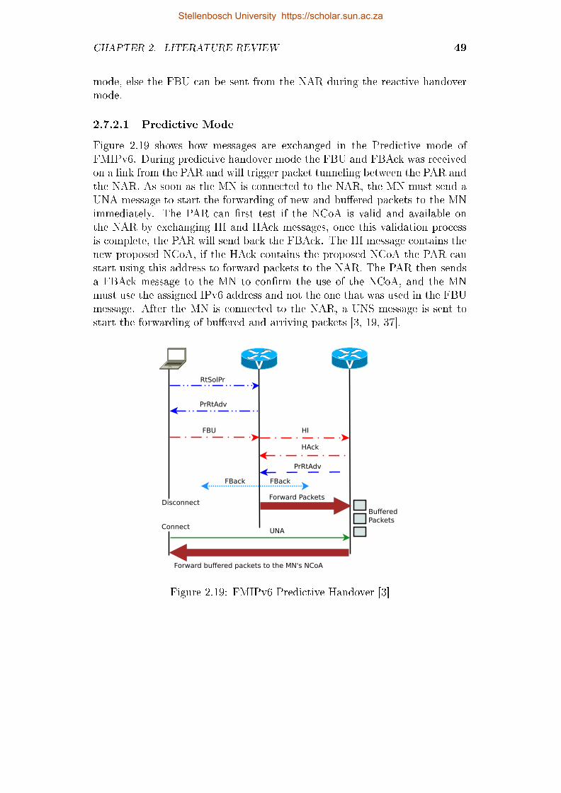
CHAPTER 2. LITERATURE REVIEW 49
mode, else the FBU can be sent from the NAR during the reactive handovermode.
2.7.2.1 Predictive Mode
Figure 2.19 shows how messages are exchanged in the Predictive mode ofFMIPv6. During predictive handover mode the FBU and FBAck was receivedon a link from the PAR and will trigger packet tunneling between the PAR andthe NAR. As soon as the MN is connected to the NAR, the MN must send aUNA message to start the forwarding of new and bu�ered packets to the MNimmediately. The PAR can �rst test if the NCoA is valid and available onthe NAR by exchanging HI and HAck messages, once this validation processis complete, the PAR will send back the FBAck. The HI message contains thenew proposed NCoA, if the HAck contains the proposed NCoA the PAR canstart using this address to forward packets to the NAR. The PAR then sendsa FBAck message to the MN to con�rm the use of the NCoA, and the MNmust use the assigned IPv6 address and not the one that was used in the FBUmessage. After the MN is connected to the NAR, a UNS message is sent tostart the forwarding of bu�ered and arriving packets [3, 19, 37].
MN PAR NAR
RtSolPr
PrRtAdv
FBU HI
PrRtAdv
FBack FBack
UNA
Disconnect
Connect
Forward Packets
Forward buffered packets to the MN's NCoA
Buffered Packets
HAck
Figure 2.19: FMIPv6 Predictive Handover [3]
Stellenbosch University https://scholar.sun.ac.za

CHAPTER 2. LITERATURE REVIEW 50
2.7.2.2 Reactive Mode
In Figure 2.20 an FBAck is not send back to the MN. The reason for notreceiving an FBAck on the previous link can be due to the fact that the MNdid not sent an FBU or the MN disconnected from the link before receivingthe FBAck. The MN is not sure if the FBU has been received and processedsuccessfully due to the fact that no FBAck was received from the PAR. In thecase where the FBAck has not been received, a new FBU message will be sendimmediately after the UNA message has been sent [3, 19, 37].
MN PAR NAR
RtSolPr
PrRtAdv
UNA (FBU)
FBU
FBack
Disconnect
Connect
Forward Packets
Forward buffered packets to the MN's NCoA
HAck
HI
Figure 2.20: FMIPv6 Reactive Handover [3]
2.7.3 Detail Protocol Functioning
For the detailed functioning of the protocol, we refer to Figure 2.18. After theMN has �nished discovering nearby APs, RtSolPr messages are send by theMN to the PAR, to determine AP identi�ers and subnet router information.RtSolPr messages are send by the MN at any time one or more APs havebeen discovered, but the most convenient way is right after router discoveryhas completed. The trigger for sending RtSolPr messages can be link-speci�cdata, like a stronger signal strength at a nearby AP and fading signal strength
Stellenbosch University https://scholar.sun.ac.za

CHAPTER 2. LITERATURE REVIEW 51
at its current AP. When the PAR receives a RtSolPr message, it will replywith a PrRtAdv message. This message will indicate the following conditions:
� If the PAR cannot �nd an entry for a certain AR contained in the RtSolPrmessage, the PAR must reply that the AR is unknown. FMIPv6 will thenstop on the MN because the surrounding ARs do not support FMIPv6.
� When the new AR is connected on the same link as the PAR, the PARwill indicate to the MN that the AR is on the same link and will notinclude any pre�x information in the message. This scenario may occurwhen multiple APs are bridged into a wired network.
� If the new AR is identi�ed by the PAR, the PAR will respond to theMN indicating that the AP is recognized and also supplies the [AP-ID,AR-Info] tuple.
� If the AP is not recognized the PAR should supply neighbourhood [AP-ID, AR-Info] tuples that are subject to path maximum transmission unit(MTU) restrictions.
If the router supports a fast handover mechanism, PrRtAdv and RtSolPr mes-sages must be implemented by the MN and the the access routers. Howeverwhen the MN attaches to the NAR and all the information required to sendpackets immediately is supplied by the link layer handover technology, theabove messages are optional. After the MN has received a PrRtAdv mes-sage, the MN sends an FBU to the PAR router. The timing of this messagedepends on link-speci�c events like signal strength. The FBU includes a pro-posed NCoA for the MN ones connected to the NAR. The MN must, wheneverpossible transmit the FBU from the link associated with the PAR. When theMN cannot anticipate when the handover will occur, the FBU can still be sentfrom the NAR link. If the MN does not receive a FBAck from the previouslink, the MN must send a FBU immediately after attaching to the NAR. Afterthe PAR receives the FBU from the MN, an HI message must be transmittedfrom the PAR to the NAR. In reply to the HI message the NAR will send aHAck message to the PAR. In order for the PAR to determine the address ofthe NAR, the PAR can make use of longest pre�x match on the NCoA pre�xlist of the neighbouring access routers. The HI message is composed of thePCoA, link-layer address and the proposed NCoA of the MN. The HI messagesent from the PAR link will contain a Code 0, and if the HI message was sentfrom the NAR link it will contain the Code 0.
An HI message with Code 0 will be processed as follows: The NAR deter-mines whether the proposed NCoA is valid on the link and unique. DAD isused to determine the uniqueness of the address. DAD can also be avoided inthe protocol if the probability of the address not being unique on the network
Stellenbosch University https://scholar.sun.ac.za

CHAPTER 2. LITERATURE REVIEW 52
is low. Once the address has been identi�ed as unique, the NAR can startproxying for the lifetime that the MN is expected to be connect to the NAR.The NAR will then create a proxy neighbour cache entry for the NCoA andwill also begin to defend the NCoA. If the NCoA cannot be assigned or ac-cepted a host route must be set up between the PCoA. In this case a reversetunnel must be set up between the PAR and the NAR to intercept packets des-tined for the PCoA, after which the NAR sends a HAck message to the PAR. Ifthe Code of the HAck message is 1, all of the above operations must be skipped.
If an HI message with code 1 is used, the NAR will validate the createdneighbour cache entry for the MN.
This means that the NAR can use the knowledge that its trusted peer,PAR, has a trust relationship with the MN.When the NAR assigns a di�erentNCoA as proposed by the MN in the FBU message, the NAR will include thisNCoA in the HAck message to the PAR. The PAR must then include thisaddress in the FBAck message to the MN and the MN must use this NCoA.The result of a FBU and FBAck is that the PAR starts to tunnel packets tothe NCoA of the MN. When the MN establishes link connectivity at the NARthe following protocol operations start:
� The MN sends a UNA message to the NAR. If no FBAck has beenreceived by the MN, it must send a FBU message following the UNAmessage.
� MN joins the solicited-node and all-nodes multicast groups correspondingto the NCoA.
� At this point, DAD probing can start depending on the con�guration ofthe protocol.
� As soon as the NAR receives the UNA message it will delete the neigh-bour cache entry and the NAR starts forwarding the new and bu�eredpackets to the MN.
For data forwarding, the PAR tunnels packets using its global IP address validon the interface to which the MN was attached. The MN reverse tunnels all ofits packets to the same global IP address of the PAR. When the PAR receivesa reverse-tunneled packet, it must verify whether a secure binding exists forthe MN identi�ed by the PCoA in the tunneled packet, before forwarding thepacket.
2.7.4 Other Considerations of FMIPv6
� Handover Capability Exchange: In scenarios where the PAR does notsupport FMIPv6 capabilities, the MN will send RtSolPr until the maxi-mum number of RtSolPr retries are reached. If the MN did not receive
Stellenbosch University https://scholar.sun.ac.za
CHAPTER 2. LITERATURE REVIEW 53
any PrRtAdv messages in response to the RtSolPr messages, the MNwill assume that the PAR does not support FMIPv6. FMIPv6 will thenbe terminated and stop sending RtSolPr messages.
� DAD Handling: The biggest part of handover latency is caused by Du-plicate Address Detection to verify the uniqueness of a IPv6 address ona link. The probability of an address not being unique is very low, butcannot be ignored, and thus the need for DAD does exist. In FMIPv6the NAR sends a DAD probe before the NAR starts to defend the NCoA,and thus minimizing DAD delay. The NAR will perform DAD before theMN is connected and the success of this process is translated to the MNwith the use of a HAck message.
� Assignment of NCoA: The NCoA is formulated by the MN with theinformation received in the PrRtAdv message. However, if the MN isnot sure whether this address is usable at the NAR, the MN will send aFBU message to the PAR. This indicates to the PAR that the MN wantsto do a handover. The reason for handover is not �xed and depends ondi�erent factors. The PAR will then send a HI message to the NARand it must use the NCoA con�gured by the MN in the HI message.The NAR will then use DAD to verify the correctness of the NCoAaddress and whether the address can be used on the link. The NARwill then reply to the HI message with a HAck message, which containseither the original IP address formulated by the MN or the new addressformulated by the NAR due to DAD failure or wrong formulation. ThePAR will receive the HAck message and will forward these data by usingan FBAck message. The MN is then required to use the NCoA in theFBAck message. If the MN does the handover after sending the FBU,the address can be veri�ed after the connection to the NAR. Howeverhandover latency will increase due to extra time spend on DAD. WhenDHCP is used the MN must perform DHCP operations once it attachesto the NAR even though it formulates an NCoA for transmitting theFBU.
� Pre�x Management: The pre�x that is valid on the link to which theMN connects, is contained in the pre�x part of the AR-Info message.FMIPv6 works regardless of the length, the assignment policies or themanagement of the pre�x on the network. When per-mobile pre�x as-signment is used, the AR-Info advertised in PrRtAdv still includes the(aggregate) pre�x valid on the interface to which the target AP is at-tached, unless the access routers communicate with each other (using HIand HAck messages) to manage the per-mobile pre�x [19]. The NCoAwill still be formulated by the MN using the aggregate pre�x, but thereturn pre�x in the HI and HAck messages will use the per-mobile pre�x.
Stellenbosch University https://scholar.sun.ac.za

CHAPTER 2. LITERATURE REVIEW 54
� Packet Loss: Handover involves link switching, which may not be ex-actly coordinated with fast handover signaling. The arrival of a patternof packets is dependent on many factors, including application character-istics, network queuing behaviours, etc. This means that packets is lostif the packets arrive at the NAR before the MN has completed the han-dover process and the NAR is not able to bu�er these packets. Similarly,if the MN attaches to the NAR and then sends an FBU message, pack-ets arriving at the PAR, until the FBU is processed, will be lost unlessthey are bu�ered. FMIPv6 supports the option to request bu�ering atthe NAR in the HI message. If the NAR supports bu�ering this protocolcan support a smooth handover, but the bu�er size and the rate at whichbu�ered packets are eventually forwarded are important considerationswhen providing bu�ering support.
� Some applications will transmit fewer packets over a certain periodand this will continuously change the bu�ering requirements. Voiceover IP will need less bu�er space than live video streaming becauseof the di�erence in packet size and packet rate.
� When the MN has completed handover to a new link, the bu�er-ing router may bottle neck the network routers or the MN withbu�ered packets. In particular, transmitting a large number ofbu�ered packets in succession can congest the path between thebu�ering router and the mobile node. Furthermore the base stationbetween the MN and NAR, may drop some of the packets or evenbu�er the packets itself. This will also cause an increase in the jitterof the packets arriving after the bu�ered packets.
� Routers are not involved in end-to-end communication, so this meansthat they will not have any knowledge of the transport conditionsof the network.
� The wireless connectivity of the mobile node can also change andcan cause a decrease in bandwidth. This may cause congestionwhen the bu�ered packets are being forwarded.
The above points just show why it is very di�cult to formulate an al-gorithm to handle bu�ering under all these scenarios. The purpose ofFMIPv6 is to reduce packet loss. Routers that are implementing bu�er-ing of packets, must at least use the default algorithm, which is based onthe original arrival rates of the bu�ered packets. A maximum of 5 pack-ets may be sent one after another, but all subsequent packets shoulduse a sending rate that is determined by metering the rate at whichpackets have entered the bu�er, potentially using smoothing techniquessuch as recent activity over a sliding time window and weighted averages[19, 47, 48].
Stellenbosch University https://scholar.sun.ac.za

CHAPTER 2. LITERATURE REVIEW 55
� Fast or Erroneous Movement: IP layer mobility introduces it's own limitin the speed of movement by the MN. The handovers should occur atsuch a rate that the binding message can be made to the Home Agentand the Correspondent Node in the network. Packet loss may occur ifthe MN moves faster than this speed.
2.8 Proxy Mobile IPv6
Proxy Mobile IPv6 [20] is the standardized mobility protocol by IETF fornetwork-based localized mobility management in IPv6 networks. PMIPv6 is asolution especially for inter-access system handover between 3GPP and non-3GPP networks. The advantage of PMIPv6 over the previously mentionedMobility Protocols is that PMIPv6 requires only changes to the edge routersand no changes to the IPv6 stack of the MN. This makes PMIPv6 a verypromising network mobility option and can support mobility service to a widerange of network users. All the network mobility intelligence resides in thenetwork thus PMIPv6 becomes questionable and requires a solution for de-ployment in large scale networks [49]. A basic setup of PMIPv6 can be seenin Figure 2.21 and the new terminology is described in Subsection 2.8.1.
pMAG
Correspondent Node
802.11n AP
The mobile node wil move from the Home Network to
the Visited Network and back as shown by the red
arrow.
802.11n AP
Mobile Node
nMAG
LMA
Figure 2.21: PMIPv6 Network
Stellenbosch University https://scholar.sun.ac.za

CHAPTER 2. LITERATURE REVIEW 56
2.8.1 PMIPv6 Terminology
The following describes the new terminology introduced by PMIPv6.
� Mobile Access Gateway (MAG): The MAG is used to detect the move-ment of the MN to and from the access link and to initiate mobilitymessages with the LMA on behalf of the MN.
� Local Mobility Anchor (LMA): The LMA is like the Home Agent inMIPv6. The LMA is the topological anchor point for the MN's homenetwork pre�xes and manages the MN's binding state. The LMA hasthe same functionality as that of the HA but can also support PMIPv6.
� Proxy Binding Update (PBU): The MAG sends a PBU message to theLMA to initiate and setup a binding between MAG and LMA.
� Proxy Binding Acknowledgement (PBA): The MAG waits for the PBAmessage from the LMA as conformation of binding status.
� Proxy Mobile IPv6 Domain (PMIPv6-Domain): This domain refers tothe network where the mobility management of the MN is handled byPMIPv6.
� LMA Address (LMAA): This is the global address that is con�gured onthe LMA. This address forms the endpoint of the bidirectional tunnelbetween the LMA and the MAG. The MAG send PBU to this address.
� Proxy Care-of Address (Proxy-CoA): The Proxy-CoA is the global ad-dress con�gured on the MAG that forms the transport endpoint of thebidirectional tunnel between MAG and LAM. This address is viewed bythe LMA as the Care-of Address of the mobile node [49].
� Mobile Node's Home Network Pre�x (MN-HNP): The MN-HNP is thepre�x assigned to the link between the mobile node and the MAG. Mul-tiple pre�xes can be assigned between the link and all of the assignedpre�xes are managed as a set associated with a mobility session. Mul-tiple pre�xes assigned to one interface wil be managed as one mobilitysession.
� Mobile Node's Home Address (MN-HoA): This is the address the mobilenode received on the home network's pre�x. The MN is able to use thisaddress as long as the MN is attached to the PMIPv6 network domain.
� Mobile Node Identi�er (MN-Identi�er): The identity of the MN in thePMIPv6 network domain. This is usually a Media Access Control (MAC)address or a Network Access Identi�er (NAI) and is used to predictablyidentify a MN.
Stellenbosch University https://scholar.sun.ac.za

CHAPTER 2. LITERATURE REVIEW 57
� Mobile Node Link-layer Identi�er (MN-LL-Identi�er): An identi�er thatidenti�es the attached interface of a mobile node. Typically the link-layeridenti�er will be used as the MN-LL-Identi�er.
� Mobile Node's Home Link: A layer 3 address is obtained from this linkwith address con�guration once the MN has moved into the PMIPv6network domain [49].
2.8.2 Protocol Overview
This description refers to Figure 2.21 and Figure 2.22. PMIPv6 is designed toimplement network mobility without requiring any changes to the IPv6 stackof the MN. The MN is also not required to participate in any of the mobilitysignaling. The mobility entities in the network like the LMA and MAG, tracksthe movement of the mobile node in the PMIPv6 domain and initiates themobility messaging and sets up the required routing. The main functionalentities in the NETLMM network are the Local Mobility Anchor and theMobility Access Gateway. The LAM is mostly responsible for maintaining theMN's connection and reachability on the PMIPv6 domain. LMA forms thetopological anchor point for the MN's home network pre�xes.
The MAG is used to detect the MN's movements and to initiate mobilitymessages to the LMA on behalf of the MN. The MAG is used to track themovement of the MN's link to and from the access link. The MAG also per-forms binding registrations to the LMA on behalf of the MN. The PMIPv6architecture can be seen in Figure 2.21.
When the MN enters the PMIPv6 domain and connection to the accesslink is complete, the MAG will acquire the identity of the MN. The MAGwill then determine if the MN is authorized to use the network-based mobilitymanagement service. After the authorization of the MN has been completed,the MN will obtain address con�guration by using any of the address con-�guration mechanisms available on the network. The address con�gurationconsists of obtaining IPv6 address/es from it's home network pre�xes/es, thedefault router address on the link and various other con�guration parameterswhich is discussed later in the section. The entire PMIPv6 domain appearsas a single link for the MN. This ensures that the MN does not detect anychanges with respect to its layer-3 attachment even if the MN moves aroundin the network.
In the scenario where the MN connects to the PMIPv6 domain using mul-tiple interfaces, the network will allocate a unique set of home pre�xes foreach of the interfaces of the MN. The home addresses that is con�gured onthe interfaces will make use of the di�erent home pre�xes. A handover can beperformed by either changing from one interface to another on the same MAG,or by changing from one MAG to a di�erent MAG in the PMIPv6 domain.
Stellenbosch University https://scholar.sun.ac.za

CHAPTER 2. LITERATURE REVIEW 58
MN pMAG LMA
Mobile Node Attachment
PBA with HNP
Bi-directional tunnel
Rtr Sol
Rtr Adv with HNP
PBU with MN-ID
Acquire MN-ID & Profile
Setup Tunnel & Routing
Figure 2.22: PMIPv6 Message Flow
The message �ow is showed in Figure 2.22. The Router Solicitation mes-sage sent from the MN may arrive at any time after the connection has beenmade to the MAG and has no ordering restriction towards the message call�ow. The local mobility anchor needs to be updated about the MN move-ment. The MAG sends a Proxy Binding Update message to the LMA andif the LMA accepts the Proxy Binding Update it will reply with a ProxyBinding Acknowledgement.The Proxy Binding Acknowledgement includes thehome network pre�xes on the interface/s. After completion of the Proxy Bind-ing Acknowledgement the LMA also sets up the bidirectional tunnel with thetunnel endpoint as the MAG address. After the MAG has received the ProxyBinding Acknowledgement, it sets up it's bidirectional tunnel endpoint as theLMA. Forwarding will also be set up for the MN's tra�c. The MAG willstart to send Router Advertisement to the MN, advertising the home networkpre�xes as the hosted on-link pre�xes.
When the MN receives the Router Advertisement it will attempt to con�g-ure it's interface using either stateful or stateless address con�guration. Thisdecision is based on the con�guration modes that are permitted on the accesslink as indicated by the Router Advertisement. If the address con�gurationhas been completed successfully, the MN will have one or more addresses fromit's home network. The MAG serving the MN and the LMA also set up properrouting states for handling tra�c to and from the MN. The LMA is the topo-
Stellenbosch University https://scholar.sun.ac.za

CHAPTER 2. LITERATURE REVIEW 59
logical anchor point of the PMIPv6 domain and thus intercepts all the packetsdestined for the MN from a source in or outside of the PMIPv6 domain. Thesepackets are then forwarded to the MAG serving the MN with the use of thebidirectional tunnel that was setup. The MAG receives the packets from theLMA destined for the MN, removes the outer header from the packets andforwards the packets to the MN. If data is sent from a correspondent nodeconnected locally to the MAG, it is forwarded to the MN and not to the LMA.
If the MN sends packets to a correspondent node, the MAG forwards pack-ets to the LMA with the use of the bidirectional tunnel. When the packetsare received at the LMA, the outer header is removed and the packets areforwarded to the destination address. The reason for removing the outer ad-dresses is to ensure IP transparency an tunneling.
MN pMAG LMA
Mobile Node Attached
PBA with HNP
Bi-directional tunnel
Rtr Adv with HNP
Rtr Sol
Standard Registration steps to establish
connection to nMAG
nMAG
Mobile Node Detached
Dereg PBU
Accept PBU Event
Bi-directional tunnel
Figure 2.23: PMIPv6 Handover Signaling Flow
Figure 2.23 shows the signaling �ow during handover from a previous MAGto a new MAG. When the MN moves from a MAG to a new MAG, the MN hasalready con�gured it's IPv6 address for the PMIPv6 domain. The previousMAG will register the movement of the MN and signal to the LMA to removethe binding and routing state for the MN. The LMA will identify the mobilitysession for the speci�c MN, after this the LMA will wait for certain amountof time to allow the MAG on the new access link to update the binding ofthe MN. If the LMA doesn't receive a PBU from the new MAG, the LMA
Stellenbosch University https://scholar.sun.ac.za

CHAPTER 2. LITERATURE REVIEW 60
will delete the binding cache for that MN. The message signaling will be thesame from here as illustrated in Figure 2.22. The new MAG will set up abidirectional tunnel with the LMA as the endpoint and the handover will betransparent to the application layer on the MN and CN. All of the signal-ing messages must be protected by a end-to-end security association and dataorigin authentication. Proxy Binding Update, Proxy Binding Acknowledge-ment and other signaling messages make use of IPSec for protection and is themandatory security mechanism.
2.9 Hierarchical Mobile IPv6
Internet engineering task force(IETF) has proposed hierarchical mobile IPv6(HMIPv6) in order to reduce a frequent location registration of a mobile nodein MIPv6 [50]. The main focus point of HMIPv6 is to reduce the number ofsignaling required when changing access points and thus improving handoverspeed and network overhead caused by MIPv6. HMIPv6 also separate localmobility from global mobility, this is achieved by using MIPv6 mechanism forglobal mobility, while local hando�s are managed locally. HMIPv6 is necessaryto improve the scalability of MIPv6, a large number of overhead is added inlarge scale MIPv6 networks due to the exchange of binding updates messages.HMIPv6 is not included and evaluated in the thesis because the thesis do notfocus on the scalability of these protocols. One disadvantage of HMIPv6 is theMAP, the MAP forms a single point of failure in the network. A basic setupof HMIPv6 can be seen in Figure 2.24 and the new terminology is describedin Subsection 2.9.1.
Stellenbosch University https://scholar.sun.ac.za

CHAPTER 2. LITERATURE REVIEW 61
AR-1
CN
802.11n AP
The mobile node wil movefrom the Home Network to
the Visited Network andback as shown by the red
arrow.
802.11n AP
MN
AR-2
MAP
HA
RCoA
LCoA-1 LCoA-2
Figure 2.24: HMIPv6 Network
2.9.1 HMIPv6 Terminology
The following describes the new terminology introduced by HMIPv6 [13].
� Access Router (AR): The AR is the access point the MN connects to andis used to aggregate the outbound tra�c of mobile nodes.
� Mobility Anchor Point (MAP): An MAP is a router located in a networkvisited by the MN. The MAP acts as local home agent for the MN andthere can be more than one located in a visited network.
� Regional Care-of Address (RCoA): An RCoA is an address allocated bythe MAP to the MN.
� On-Link Care-of Address: The LCoA is the on-link CoA con�gured on aMN's interface based on the pre�x advertised by its default router. TheLCoA is basically the same as the CoA in MIPv6.
� Local Binding Update (LBU): The LBU is used to establish a bindngbetween the RCoa and the LCoA.
2.10 Discrete Event Simulator
In this section di�erent Discrete Event Simulator (DES) software was exam-ined for use to simulate MIPv6 networks to determine the most appropriate
Stellenbosch University https://scholar.sun.ac.za

CHAPTER 2. LITERATURE REVIEW 62
simulator. In section 2.10.3 a comparison is made between OMNeT ++ andns-2. The comparison focuses on the framework structure, model manage-ment, programming model and tracing ability of each simulation framework.In classical thinking there are three types of simulation: discrete event, con-tinuous, and MonteCarlo. A DES simulation is described by Mike Albrechtthe following way:
Discrete event simulation utilizes a mathematical/logical model of a physi-cal system that portrays state changes at precise points in simulated time. Boththe nature of the state change and the time at which the change occurs man-date precise description [51].
A DES simulator is composed of the following components [52]:
� Clock: A clock is used so that the simulation can keep track of thecurrent simulation time. In discrete-event simulations, as opposed toreal time simulations, time 'hops' because events are instantaneous - theclock skips to the next event start time as the simulation proceeds.
� Events List: The simulation will at least maintain one list of all thesimulation events. This is sometimes called the pending event set becauseit lists events that are pending as a result of previously simulated eventsbut has yet to be simulated themselves. Events are described by the timeat which it occurs and its type.
� Random-Number Generators (RNG): Random numbers needs to be gen-erated for the simulation and is dependent on the system model. Forthe simulation to be rerun with the same values, pseudorandom numbergenerators are used. This allows the simulation to be rerun with theexact same behavior over and over. To overcome one problem of ran-dom number generators in DES, bootstrapping needs to be performedon the simulation model. The problem that exists with the use of ran-dom number generators in DES is that the steady-state distributions ofevent times may not be known in advance. As a result, the initial setof events placed into the pending event set will not have arrival timesrepresentative of the steady-state distribution. These initial events, how-ever, schedule additional events, and with time, the distribution of eventtimes approaches its steady state and this is called bootstrapping [53].
� Statistics: The simulation model will also keep track of certain statisticinformation during simulation.
� Ending Condition: A DES could theoretically run for ever because ofbootstrapping. Ending conditions must be used in the simulation tostop the simulation when certain conditions are reached.
Stellenbosch University https://scholar.sun.ac.za

CHAPTER 2. LITERATURE REVIEW 63
2.10.1 OMNeT++
OMNeT++ is a modular, component based and open-architecture DES and isused for the simulation of communication networks, complex IT systems andqueuing networks. The OMNeT++ 4.x Integrated Development Environmentis based on the Eclipse platform and basic layout of the environment can beseen in Figure 2.25. As mentioned the component structure of OMNeT++,models can be assembled from reusable components and can be combined invarious ways like Lego blocks to build the desired model. OMNeT++ have awide range of simulation packages that can be used to simulate di�erent typesof simulation. For network simulations one of the most popular packages isthe INET framework [54]. The INET framework contains several models forboth wireless and wired communications.
Figure 2.25: OMNeT++ Simulation Environment
Modules can be connected with each other via gates and combined to formcompound modules. An example of a compound module, in this case theIPv6 compound module can be seen in Figure 2.26. Connections are createdwithin a single level of module hierarchy: a submodule can be connected withanother, or with the containing compound module. Every simulation modelis an instance of a compound module type. In Figure 2.26 illustrates how themodules are connected together to form a working IPv6 compound module.
Stellenbosch University https://scholar.sun.ac.za

CHAPTER 2. LITERATURE REVIEW 64
Figure 2.26: OMNeT++ IPv6 Compound Module
As mentioned in Section 2.10, a DES makes use of random number gen-erators. OMNeT++ default random number generator is Mersenne Twister.The other RNG is a legacy LCG generator with a 231-1 long sequence genera-tor. The Mersenne Twister RNG provides fast generation of very high-qualitypseudorandom numbers and is based on a matrix linear recurrence over a �-nite binary �eld [55]. The statistics that are recorded in OMNeT++ are inthe form of output vectors and output scalars. These statistics can either bevisualized in OMNeT++ with the use of the of the Analysis Editor in the IDEenvironment, or with you're own personal choice of analysis software. TheAnalysis Editor for OMNeT++ can be seen in Figure 2.27 and an example ofa line chart in the analysis editor can be seen in Figure 2.28.
Stellenbosch University https://scholar.sun.ac.za

CHAPTER 2. LITERATURE REVIEW 65
Figure 2.27: Analysis Editor
Figure 2.28: Analysis Editor Charts
Stellenbosch University https://scholar.sun.ac.za
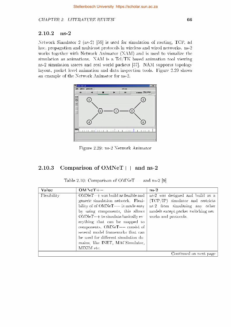
CHAPTER 2. LITERATURE REVIEW 66
2.10.2 ns-2
Network Simulator 2 (ns-2) [56] is used for simulation of routing, TCP, adhoc, propagation and multicast protocols in wireless and wired networks. ns-2works together with Network Animator (NAM) and is used to visualize thesimulation as animations. NAM is a Tcl/TK based animation tool viewingns-2 simulation traces and real world packets [57]. NAM supports topologylayout, packet level animation and data inspection tools. Figure 2.29 showsan example of the Network Animator for ns-2.
Figure 2.29: ns-2 Network Animator
2.10.3 Comparison of OMNeT++ and ns-2
Table 2.10: Comparison of OMNeT++ and ns-2 [9]
Value OMNeT++ ns-2
Flexibility OMNeT++ was build as �exible andgeneric simulation network. Flexi-bility of of OMNeT++ is made easyby using components, this allowsOMNeT++ to simulate basically ev-erything that can be mapped tocomponents. OMNeT++ consist ofseveral model frameworks that canbe used for di�erent simulation do-mains, like INET, MACSimulator,MIXIM etc.
ns-2 was designed and build as a(TCP/IP) simulator and restrictsns-2 from simulating any othermodels except packet-switching net-works and protocols.
Continued on next page
Stellenbosch University https://scholar.sun.ac.za
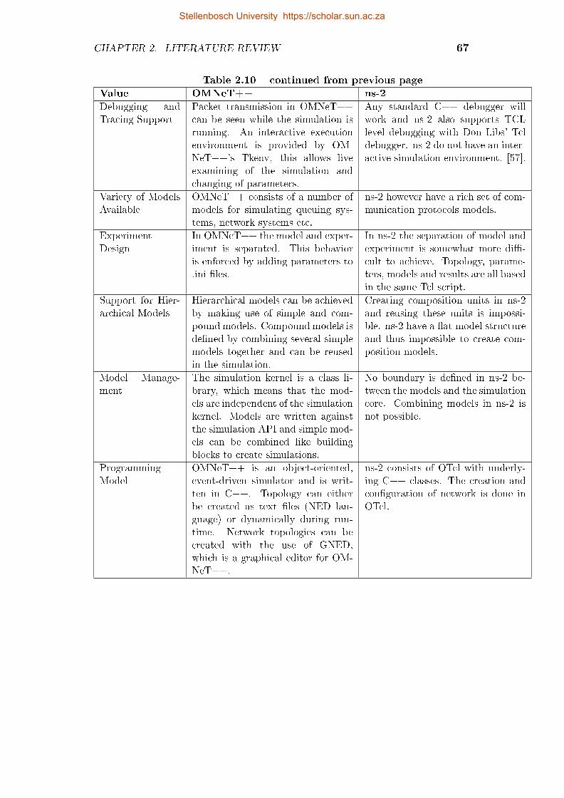
CHAPTER 2. LITERATURE REVIEW 67
Table 2.10 � continued from previous page
Value OMNeT++ ns-2
Debugging andTracing Support
Packet transmission in OMNeT++can be seen while the simulation isrunning. An interactive executionenvironment is provided by OM-NeT++'s Tkenv, this allows liveexamining of the simulation andchanging of parameters.
Any standard C++ debugger willwork and ns-2 also supports TCLlevel debugging with Don Libs' Tcldebugger. ns-2 do not have an inter-active simulation environment. [57].
Variety of ModelsAvailable
OMNeT++ consists of a number ofmodels for simulating queuing sys-tems, network systems etc.
ns-2 however have a rich set of com-munication protocols models.
ExperimentDesign
In OMNeT++ the model and exper-iment is separated. This behavioris enforced by adding parameters to.ini �les.
In ns-2 the separation of model andexperiment is somewhat more di�-cult to achieve. Topology, parame-ters, models and results are all basedin the same Tcl script.
Support for Hier-archical Models
Hierarchical models can be achievedby making use of simple and com-pound models. Compound models isde�ned by combining several simplemodels together and can be reusedin the simulation.
Creating composition units in ns-2and reusing these units is impossi-ble. ns-2 have a �at model structureand thus impossible to create com-position models.
Model Manage-ment
The simulation kernel is a class li-brary, which means that the mod-els are independent of the simulationkernel. Models are written againstthe simulation API and simple mod-els can be combined like buildingblocks to create simulations.
No boundary is de�ned in ns-2 be-tween the models and the simulationcore. Combining models in ns-2 isnot possible.
ProgrammingModel
OMNeT++ is an object-oriented,event-driven simulator and is writ-ten in C++. Topology can eitherbe created as text �les (NED lan-guage) or dynamically during run-time. Network topologies can becreated with the use of GNED,which is a graphical editor for OM-NeT++.
ns-2 consists of OTcl with underly-ing C++ classes. The creation andcon�guration of network is done inOTcl.
Stellenbosch University https://scholar.sun.ac.za

CHAPTER 2. LITERATURE REVIEW 68
2.10.4 Cooja
Cooja [58] is a sensor network simulator designed and used in Contiki. Coojaallows large and small networks of Contiki motes1, or more widely known assensor nodes to be simulated. Motes can be emulated at the hardware level,which is slower but allows precise inspection of the system behavior, or at aless detailed level, which is faster and allows simulation of larger networks.Cooja controls and analyzes a Contiki system via a few functions and this al-lows Cooja to simulate motes at hardware level. The main reason for choosingCooja is because it can simulated the hardware (actual mote) on the hardwarelevel. These simulations can than be easily ported over to the actual moteto be used in further experiments. The Cooja simulator was used to investi-gate the implementation of 6LoWPAN for low power devices and the possibleimplementation of MIPv6 in the 6LoWPAN network stack.
2.11 Conclusion
IPv4 addresses are being depleted rapidly because of the fast growing numbersof mobile devices worldwide such as smart phones, tablets, notebooks andsensor nodes. IPv6 [17] is introduced as a replacement for IPv4 due the itsmore extensive range of IP addressing. Particular attention was given to thedi�erences between IPv4 and IPv6 as well as the improvements presented byIPv6. IPv6 introduces enhancements like auto-con�guration, expanded IPaddresses, enhanced mobility capabilities and better QOS. This chapter alsointroduced the need for mobility protocols due the fast increasing amount ofmobile devices worldwide. Network mobility was explained for all the layers ofthe ISO stack and how mobility can be accommodated on each layer, except forthe physical layer where mobility is handled implicitly by the wireless accesstechnology.
Network layer mobility protocols was introduced and explained in detail.These protocols consist of MIPv6 [8], PMIPv6 [20] and FMIPv6 [19]. MobileIPv6 makes it possible for a mobile node to move around seamlessly in di�er-ent networks. MIPv6 does not solve the handover latency introduced by thephysical layer. MIPv6 introduces several new network elements like the HomeAgent, correspondent node, access routers, mobile nodes and handshake mes-sages namely bindings. FMIPv6 focuses to minimize the handover latency byremoving duplicate address detection during address assignment and to formu-late care of addresses for mobile nodes before the actual handover to the newnetwork will occur. PMIPv6's attention is more focused on network mobility
1A mote, also known as a sensor node, is a node in a wireless sensor network that is
capable of performing some processing, gathering sensory information and communicating
with other connected nodes in the network. A mote is a node but a node is not always a
mote.
Stellenbosch University https://scholar.sun.ac.za

CHAPTER 2. LITERATURE REVIEW 69
than of the mobility of the node itself. In PMIPv6 the network is responsi-ble for mobility handling, the main advantage of this being that mobility istransparent to the mobile nodes.
Furthermore the chapter looked at IPv6 adoption for low power devices.Due to the limited processing power and limited frame size of only 127 bytes,which is a lot less than the 1024 bytes of IPv6, 6LoWPAN [15] is introducedto solve this issue. 6LoWPAN introduces several encoding and compressionmechanisms. These mechanisms are used to compress the IPv6 headers andto allow IPv6 communication over low power devices. Due to the availabilityof IPv6, MIPv6 can also be used on low power devices for seamless movementacross networks. This mobility of mobile nodes contributes hugely to theInternet of Things [30]. The Internet of Things refers to uniquely identi�ableobjects/nodes and their virtual representations in an Internet-like structure.
Lastly, attention was giving to various simulation frameworks that can beused for the above mentioned protocols. Cooja was selected for the 6LoW-PAN simulations and OMNeT++ for IEEE 802.11n networks. A comparisonof the ns-2 and OMNeT++ can be seen in Section 2.10.3. The main advantageof OMNeT++ is the re-usability of models and the combining of models toform compound models. OMNeT++ consists of various simulation packagesand as mentioned in Section 2.10.1 the INET package will be used base net-work framework. OMNeT++ was also chosen above ns-2 because of previousexperience with ns-2 where results was invalidated because of undocumentedbehavior by ns-2. The simulation and testbed designs for the various networksas well as the implementation of the IPv6 testbed will be presented in thefollowing chapter.
Stellenbosch University https://scholar.sun.ac.za

Chapter 3
Design and Implementation
3.1 Introduction
In the preceding chapter an overview of Mobility Protocols in an IPv6 networkwas given. The basic and fundamental protocol is MIPv6, this protocol also hasa few variations to improve handover latency and overall network performance.This chapter focuses on the design and implementation of the following networksetups, simulations and implementation for a test environment:
� Simulation Model: MIPv6 Network
� IPv6 Network
� MIPv6 Network
� FMIPv6 Network
� PMIPv6 Network
The simulation model will make use of the INET Framework [54], this is aopen-source communication networks simulation package for OMNeT++. TheINET Framework contains several models for wire and wireless connectivity.The simulation model will consist of the basic MIPv6 setup. The network iscomposed of two foreign networks, a home network and visiting network. Theresults comprises of handover latency, UDP and TCP throughput.
The Chapter also describes the methodology for the comparison of MIPv6,FMIPv6 and PMIPv6 by using IPv6 Software tools to measure the protocolperformances with di�erent tra�c source categories such as video, FTP, VoIPand TCP/UDP transfers. The various protocol implementations used for thiswork were also described and explained. Testbed architectures are presentedin this chapter, together with the implementation setup and hardware usedfor the testbed.
70
Stellenbosch University https://scholar.sun.ac.za

CHAPTER 3. DESIGN AND IMPLEMENTATION 71
3.2 Simulation Model
The simulation for MIPv6 in OMNeT++ consists mainly of the ExtensibleMobile IPv6 (xMIPv6) Simulation Model for OMNeT++ [59]. This modelimplemented the MIPv6 protocol in OMNeT++ 3.2, but is also available inOMNeT++ Version 4. The network setup for the MIPv6 network can be seenin Figure 3.1. The network consists of one HA, one MN, and multiple CNs.
Figure 3.1: OMNeT++ MIPv6 Simulation Network
3.2.1 Home Agent
The HA is a standard IPv6 router, which was developed from the standardRouter6 model in INET. Parameters for the HA include isMobileNode andisHomeAgent. If the �rst parameter is set to true, the router acts as an MNand if the isHomeAgent parameter is set, the router acts as the HA for thatnetwork. Both parameters cannot be set to true. The HA will carry a singleinstance of the BindingCache module and this is used to hold the binding databetween the HA and the MNs.
3.2.2 Mobile Node
The MN is derived from the INET StandardHost6 compound node and is anIPv6 enabled node. The MN has a WLAN interface (Ieee80211NicSTA) and a
Stellenbosch University https://scholar.sun.ac.za

CHAPTER 3. DESIGN AND IMPLEMENTATION 72
mobility module to handle the mobility of the MN between di�erent subnets.For the MN the isMobileNode must be set to true, while the isHomeAgent andisRouter must be set to false. MN consists of a BindingUpdateList to hold theinformation of bindings made between the MN, CN and HA. In Figure 3.2 theMN IPv6 and BuList module can be seen. The xMobileIPv6 module is con-nected to a modi�ed IPv6 INET module. The IPv6 INET module is modi�edto receive, recognize and forward mobility packets to and from xMobileIPv6module.
Figure 3.2: OMNeT++ Mobile Node Modules
3.2.3 Correspondent Node
The CN is a generic INET StandardHost6 node and all of the mobility para-meters mentioned are set to false. The CN also includes a BindingCache tocapture all the binding information for Route Optimisation between the MNand the CN.
3.2.4 Runtime Parameters
The runtime parameters for the simulation can be seen in Appendix A.1. Theseinclude all the parameters for the simulation and the parameters that aredirectly linked to MIPv6 modules are described brie�y. A number of di�erentscenarios and parameter values were used to see the e�ect of the parameterson the handover latency of MIPv6.
� neighbourDiscovery.minIntervalBetweenRAs: This parameter is describedin RFC 6275 and this speci�es the minimum interval between RouterAdvertisements in the network. The parameter value was varied in the
Stellenbosch University https://scholar.sun.ac.za

CHAPTER 3. DESIGN AND IMPLEMENTATION 73
simulation to see the e�ect on the handover latency. If the minimumtime of the RA is shorter, the MN will receive router information morequickly after handover, and this may cause a decrease in handover la-tency. However, if the interval becomes too low, it can cause a �oodingof the network and a decrease in the throughput of the network. Thevalue for this parameter can be determined by looking at the networkcon�guration and the throughput the network requires to operate, if thethroughput is not the main attribute required of the network, the RAinterval can be increased.
� neighbourDiscovery.maxIntervalBetweenRAs: This parameter is describedin RFC 6275 and it speci�es the maximum interval between Router Ad-vertisements in the network. See further explanation as described in theparagraph above at neighbourDiscovery.minIntervalBetweenRAs.
� Tra�c Generators: Tra�c on the network will be generated using TCP,UDP and PING connections between the MN and the CN. The MN willact as a TCP host and the CN will be the TCP server. This was used tomeasure throughput and handover latency during full loaded network.
� AP Wireless Parameters: The APs in the simulation use the parame-ters for the wireless environment as described in Appendix A.1. Theparameters preceded by '**.radio.' relates to the wireless parameters.
� Mobility: The mobility used for the MN is rectangular mobility. TheMN will move from a preset starting position in a rectangular form.The movement of the MN can be seen in Figure 3.3. The MN startsat position (180,100) and stops at (530,110). From here the MN movesdown (530,285) and returns to the home network (180,285). This is doneto simulate the MN returning home and to break the bindings betweenthe CN and HA nodes. The speed of the MN was also varied to see theimpact of an MN traveling at di�erent speeds on the handover latency.The speed of the MN is also aligned to the update speed of the mobilityin the simulation. The update interval will be set very small to overcomeany impact on the simulation results. An update interval that is too bigwill not allow a smooth movement of the MN and will cause a 'jumping'style of movement. The update interval was set to 0.1 s for all thesimulations after experimenting with the mobility simulation.
Stellenbosch University https://scholar.sun.ac.za

CHAPTER 3. DESIGN AND IMPLEMENTATION 74
X1 = 180Y1 = 100
X2 = 530Y2 = 110
X3 = 530Y3 = 285
X4 = 180Y4 = 285
Figure 3.3: MN Movement in Simulation
Table 3.1 shows the di�erent tests that were done on the simulation. Thesimulation comprised of 8 tests with di�erent parameter values. The �rst fourtests were set up to the determine the in�uence of the RA interval time onthe handover latency. The �rst three tests had random values for the RAtime, test four used the RA interval time as described by RFC 6275 [8]. Intest 1-4 no data was generated on the network, because the handover timewith no data was the variable tested. During tests 5 and 6 TCP and UDPperformance was determined using the prescribed RA interval. Throughput,jitter and packet loss was measured. In tests 7 and 8, the moving speed of theMN was changed from 1m/s to 8m/s and lastly to 15m/s. This showed thee�ect that the moving speed of the MN had on the protocol.
Stellenbosch University https://scholar.sun.ac.za

CHAPTER 3. DESIGN AND IMPLEMENTATION 75
Table 3.1: MIPv6 Parameters for Test Scenarios
Test Runs Min RA Int(s) Min RA Int(s) TCP UDP PING Speed(ms)Test 1: 5 10 No No Yes 1Test 2: 1 4 No No Yes 1Test 3: 0.1 1.5 No No Yes 1Test 4: 0.03 0.07 No No Yes 1Test 5: 0.03 0.07 Yes No No 1Test 6: 0.03 0.07 No Yes No 1Test 7: 0.03 0.07 No No Yes 8Test 8: 0.03 0.07 No No Yes 15
3.2.5 Statistic Capturing
OMNeT++ o�ers basic classes which compute basic statistics such as meanand standard deviation; some classes deal with density estimation, and otherclasses support automatic detection of the end of a transient, and automaticdetection of accuracy of collected statistics. For the simulation the followingclasses in OMNeT++ will be used:
� cOutVector is used to record vector simulation results (an output vector,containing (time, value) pairs) to �le.
� cStdDev keeps mean, standard deviation, minimum and maximum valueetc.
TTHO = THRD + TCRD + TL2D + TRDD + TRRD + TDAD (3.2.1)
The components of handover latency for MIPv6 can be seen in Equation 3.2.1.TTHO comprises the total handover latency and this is the sum of the Layer2(TL2D) delay and the Layer 3(TL3D) delay. Figure 3.4 shows the messageexchange of MIPv6 and the delays related to the messaging. Figure 3.4 alsoshows the statistic functions implemented in the simulation to capture therequired delay times. The components are:
� TTHO = Total Handover Delay: Comprises the complete Layer 2 andLayer 3 handover latency.
� TL2D = Layer 2 Handover Delay: The handover latency incurred by L2hando� process. The delay was measured as soon as the MN started ascan request and dissociation had been completed with the old AP. Thedelay was completed when the MN had successfully associated with thenew AP. The Layer 2 delay stayed almost the same in all the simulations
Stellenbosch University https://scholar.sun.ac.za

CHAPTER 3. DESIGN AND IMPLEMENTATION 76
because this is not part of the protocol testing. MIPv6 does not proposea way to improve the Layer 2 delay and the parameters for propagationloss will stay the same.
� TRDD = Router Discovery Delay: The time it takes the MN to detect itsmovement and discover a new access router, which is dependent on theRA interval. The router discovery delay starts when the MN has �nishedthe Layer 2 handover and is completed when the MN receives an RA andneighbour advertisement message. The values of the RA intervals willbe varied as seen in Table 3.1.
� TDADD = Duplicate Address Detection Delay: Delay caused by the veri-�cation of the uniqueness of IPv6 address(CoA). This delay is combinedwith the Router discovery delay but was measured independently. DADforms the biggest part of the total handover delay for MIPv6.
� THRD = Home Registration Delay: This delay is the time it takes theMN to make a binding association with the HA and receive a BAck back.
� TRRD = Return Routability Delay: The latency caused by the returnroutability procedure. CoTI message and HoTI message exchange be-tween the MN, HA and CN. The delay �nishes when the MN receivesCoT and HoT messages from the CN and HA nodes.
� TCRD =Correspondent Registration Delay: The delay which occurs whenthe MN makes a binding association with the CN until a BAck messagehas been received. This delay takes place only when return routabilityis used. If Return Routability is not used, there will not be any delayhere.
Stellenbosch University https://scholar.sun.ac.za

CHAPTER 3. DESIGN AND IMPLEMENTATION 77
MN AP HA
Router Solicitation
Router Advertisement
CN
Neighbor Solicitation
Neighbor Advertisement
Binding Update
Binding Acknowledgement
Binding Update
Binding Acknowledgement
Data Packets
Data Packets
Home Test Init
Home Test
Care-of Test Init
Care-of Test
Home Test Init
Care-of Test Init
Home Test
Care-of Test
recordScalar("SCAN_DELAY",authenticateReq - scanReq)recordScalar("AUTHENTICATE_DELAY",authenticateConfirm - authenticateReq)
recordScalar("ASSOCIATE_DELAY",associateConfirm - authenticateConfirm)recordScalar("L2_HO_DELAY",associateConfirm - scanReq)
Layer 2 Handover delay:
Router Discovery Delay:
Return Routability Delay:
Correspondent Registration Delay:
Home Registration Delay:
statVectorHoTItoCN.setName("HoTI to CN")statVectorCoTItoCN.setName("CoTI to CN")statVectorHoTtoMN.setName("HoT to MN")statVectorCoTtoMN.setName("CoT to MN")
statVectorHoTfromCN.setName("HoT from CN")statVectorCoTfromCN.setName("CoT from CN")
statVectorBUtoCN.setName("BU to CN")statVectorBAfromCN.setName("BA from CN")
statVectorBUtoMN.setName("BU to MN")statVectorBAfromHA.setName("BA from HA")
statVectorBAtoMN.setName("BA to MN")
associateConfirmVector.setName("ASSOC_CONFIRM")associateBU_HA_Vector.setName("BU_HA")
Duplicate Address Detection Delay:
Figure 3.4: Components of Handover Latency - OMNeT++ Implementation
3.3 MIPv6 Network
This section describes the methodology and hardware setup for the MIPv6implementation. The MIPv6 source code used for the testbed is UMIP 0.4 fromUMIP.org [60]. The main components of the network can be seen in Figure 3.5and are the Correspondent Node, Home Agent and Mobile Node. Performances
Stellenbosch University https://scholar.sun.ac.za
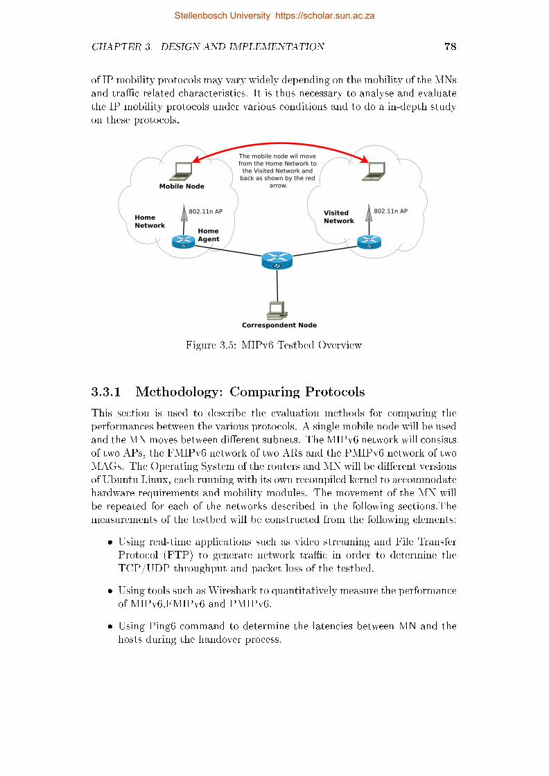
CHAPTER 3. DESIGN AND IMPLEMENTATION 78
of IP mobility protocols may vary widely depending on the mobility of the MNsand tra�c related characteristics. It is thus necessary to analyse and evaluatethe IP mobility protocols under various conditions and to do a in-depth studyon these protocols.
Home Agent
Correspondent Node
802.11n AP
The mobile node wil move from the Home Network to
the Visited Network and back as shown by the red
arrow.
Home Network
802.11n APVisited Network
Mobile Node
Figure 3.5: MIPv6 Testbed Overview
3.3.1 Methodology: Comparing Protocols
This section is used to describe the evaluation methods for comparing theperformances between the various protocols. A single mobile node will be usedand the MN moves between di�erent subnets. The MIPv6 network will consistsof two APs, the FMIPv6 network of two ARs and the PMIPv6 network of twoMAGs. The Operating System of the routers and MN will be di�erent versionsof Ubuntu Linux, each running with its own recompiled kernel to accommodatehardware requirements and mobility modules. The movement of the MN willbe repeated for each of the networks described in the following sections.Themeasurements of the testbed will be constructed from the following elements:
� Using real-time applications such as video streaming and File TransferProtocol (FTP) to generate network tra�c in order to determine theTCP/UDP throughput and packet loss of the testbed.
� Using tools such as Wireshark to quantitatively measure the performanceof MIPv6,FMIPv6 and PMIPv6.
� Using Ping6 command to determine the latencies between MN and thehosts during the handover process.
Stellenbosch University https://scholar.sun.ac.za

CHAPTER 3. DESIGN AND IMPLEMENTATION 79
� Using Jperf [61] to determine the network performance through tests ofboth TCP and UDP for comparison between the MN and the CN.
3.3.2 IPv6 Network
The IPv6 Network setup can be seen in Figure 3.6. The IP assignment for eachof the network interfaces was con�gured with the use of RADVD, the routeradvertisement daemon in Linux. The con�gurations of the various RADVDdaemons for di�erent interfaces can be seen in Appendix B.1.
Home Agent
Correspondent Node
802.11n AP
The mobile node moves from the Home Network to
the Visited Network and back as shown by the red
arrow.
Home Network
802.11n AP
Visited Network
Mobile NodePermanent home IP2001:db8:abcd:14:217:c4ff:fe39:7306
Correspondent Node2001:db8:abcd:13:205:5dff:fe74:be8d
Subnet 1: Home Network2001:db8:abcd:14::12001:db8:abcd:14::/64
Subnet 2: Visiting Network2001:db8:abcd:15::12001:db8:abcd:15::/64
Permanent home IP:2001:db8:abcd:14:217:c4ff:fe39:7306Care-Of Addres:2001:db8:abcd:15:217:c4ff:fe39:7306
2001:db8:abcd:12::2 2001:db8:abcd:11::2
Subnet 3:2001:db8:abcd:13::22001:db8:abcd:13::/64
2001:db8:abcd:14:20C:43FF:FE30:5077 2001:db8:abcd:15:20C:43FF:FE30:5077
Correspondent Node: IPv6 Camera2001:db8:abcd:16:240:8cff:fea7:f711
Correspondent Node: IPv6 Camera
2001:db8:abcd:11::12001:db8:abcd:12::1
Router 1
Router 2
Subnet 4:2001:db8:abcd:16::22001:db8:abcd:16::/64
Subnet 5 Subnet 6
Figure 3.6: MIPv6 Testbed with IP Assignment
The following paragraph gives a detailed explanation of the network setupand it refers to Figure 3.6. The network is made up of six di�erent subnetallocations. The subnet allocations for the network are shown in Table 3.2.Router 1 was used to connect all the network elements. The Router was astandard Linux PC with multiple network cards which had been set up as arouter. Router 1 made use of Quagga routing daemon to dynamically assignroutes for the network. Router 1 used RADVD to assign IPv6 addresses toSubnets 3 and 4. All the subnets used a pre�x assignment of /64, which meansthe �rst 64 bits are used for subnet pre�x assignment and the last 64 bits of the
Stellenbosch University https://scholar.sun.ac.za
CHAPTER 3. DESIGN AND IMPLEMENTATION 80
address are derived from the MAC address of the hardware. Subnets 3 and 4were used by the two Correspondent Nodes that were communicating with theMobile Node. Router 1 did not need to run the MIPv6 software because therouter is not involved with MIPv6 mobility messages. The Linux kernels forthe following components were recompiled to include some mobility featuresand important kernel modules that are used by the MIPv6 software.
The Home Agent was a standard Linux OS PC with multiple networkcards. The HA was used for mobility management in the home network andran the MIPv6 software to capture Binding update messages related to themovement of the Mobile Node. The HA consists of two subnets, 1 and 5.Subnet 1(2001:db8:abcd:14::/64) was used as the Home Network subnet andallowed connection to the Mobile Node and to Access Points devices. Subnet5(2001:db8:abcd:12::/64) was used as a manual setup between the Home Agentrouter and Router 1, this formed the connection to the Correspondent Nodeand the Visiting Network. The router advertisement con�guration for the HAis shown in Appendix B.1, the Home Agent �ag for the router advertisementwas turned on because this router acted as the Home Agent for the Mobilenodes. The Home Agent Lifetime for the HA is set to 1800, this value isused to specify the time the HA will be o�ering MIPv6 Home Agent services.In this case the value was large to avoid interruption during operation. Thecon�guration for the MIPv6 software can be seen in Appendix B.2.2. Thecon�guration �le also explains all the values and uses of the con�gurationparameters for the Home Agent setup. Some of the important parameters arelisted and described below:
� Interface: Con�gures which network device to use on the MN
� DoRouteOptimizationCN/MN: Enables route optimization between theother MN's or between the MN and the CN. In all the tests route opti-mization will be enabled.
� UseMnHaIPsec: Enables IPsec for communication between the MN andthe HA.
� OptimisticHando�: Used by MN to indicate whether route optimizationshould start before receiving the BAck.
� MnMaxHa/CNBindingLife: Speci�es the maximum time of the bindinglifetime.
� MnHomeLink: Used to set up the Home addresses of the MN. Multiplehome addresses can be used.
� IPsecPolicySet: Con�guration of the IPSec setup.
Stellenbosch University https://scholar.sun.ac.za

CHAPTER 3. DESIGN AND IMPLEMENTATION 81
The mobile node consisted of only one wireless network card that was usedto establish connection to the access points. The mobile node used the recom-piled kernel and also the MIPv6 software. No routing daemon and RADVDwas used by the mobile node, the con�guration �le for the MIPv6 softwarecan be seen in Appendix B.2.1. The mobile node moved between two accesspoints, as seen in Figure 3.5. During the movement of the mobile node thecorrespondent node had an active TCP or UDP connection with the mobilenode. The connection was established and measurements were made with theuse of Iperf. Iperf is a network protocol analyzer/measuring tool and was usedto measure the handover latency, UDP/TCP throughput and UDP jitter. Dur-ing the movement process the mobile node would hand over to di�erent accesspoints. When the mobile node was in the home network, it received an HoAfrom the Home Agent using RADVD. The mobile node must be reachable atall times at the HoA address. When the mobile node moved into the rangeof the visiting network, the mobile node dissociated from the home network'sAP and established a connection with the new access point. The mobile nodekept the HoA and received a CoA from Router 2 via RADVD. Before ReturnRoutability is set up, all packets destined for the mobile and back are routedvia triangular routing, which caused some overhead in the network. The re-turn routability procedure would then use the Care-of-Init and Home-of-Initmessages to determine whether the mobile node is the owner of the HoA andthe CoA. When the return routability was successfully established, route op-timization would then allow direct packet exchange between the mobile nodeand the correspondent node. A secondary correspondent node consisted of aIPv6 camera to stream live video over the network to the mobile node. Thiswas used to investigate the performance of MIPv6 with real-time data andto see how the handover latency would a�ect the QoS. The camera acting asthe second correspondent node is not able to implement MIPv6, so triangularrouting was used to route packets in the network.
Stellenbosch University https://scholar.sun.ac.za

CHAPTER 3. DESIGN AND IMPLEMENTATION 82
Table 3.2: IP Assignment for MIPv6 Network Interfaces
Component Interfaces IP Assignment RA Con�g Subnet
HA Eth0Eth1
2001:db8:abcd:12::12001:db8:abcd:14::1
None2001:db8:abcd:14::/64
15
AP1 Eth0Wlan0
2001:db8:abcd:14:20C:43�:fe30:50772001:db8:abcd:14:20C:43�:fe30:5077
None 1
AP2 Eth0Wlan0
2001:db8:abcd:15:20C:43�:fe30:50772001:db8:abcd:15:20C:43�:fe30:5077
None 2
MN Wlan0 HoA: 2001:db8:abcd:14:217:c4�:fe39:7306CoA: 2001:db8:abcd:15:217:c4�:fe39:7306
None 12
CN Eth0 2001:db8:abcd:13:205:5d�:fe74:be8d None 3CN: Camera Eth0 2001:db8:abcd:16:240:8c�:fea7:f711 None 4Router 1 Eth0
Eth1Eth2Eth4
2001:db8:abcd:12::22001:db8:abcd:11::22001:db8:abcd:13::22001:db8:abcd:16::2
NoneNone2001:db8:abcd:13::/642001:db8:abcd:16::/64
5634
Router 2 Eth0Eth1
2001:db8:abcd:11::12001:db8:abcd:15::1
None2001:db8:abcd:15::/64
62
Router 2, which forms the visiting network, consists of two subnets. Subnet2 (2001:db8:abcd:15::/64) was used as the visiting network. RA was used toassign IPv6 addresses to Access Points and the CoA of the Mobile Node whenmoving from the Home Network. This router was also not involved in MIPv6messaging and thus did not require the MIPv6 software and updated Linuxkernel. Router 2 also had a second Subnet 6 (2001:db8:abcd:11::/64), a manualsetup between Router 2 and Router 1. Router 2 also used Quagga to assigndynamic routes on the router.
The Mobile Node was moved around to switch between Subnet 1 and 2.The Mobile Node was running the MIPv6 software and updated kernel readyfor IPv6 mobility. Software con�guration can be seen in Appendix B.2.1. Themobile node receives an HoA when in the home network and a CoA when inthe visiting network. During handover the connectivity of the mobile nodewas tested to make sure the mobile node stayed reachable through the HoA.The mobile node received live video stream data from the correspondent IPv6camera.
Stellenbosch University https://scholar.sun.ac.za

CHAPTER 3. DESIGN AND IMPLEMENTATION 83
Table 3.3: MIPv6 Test Bed Setup
Component Network Con�guration Software setup
Home Agent Consists of multiple NICs and IPv6forwarding is enabled to act asrouter.
Linux MIPv6 2.6.38 compiled ker-nel, Radvd 1.7, Quagga routing dae-mon and MIPv6 UMIP 0.4 homeagent setup.
Access Point IPv6 802.11n access point OpenWrt Firmware and Linux 3.2.5compiled kernel with IPv6 enabled.
Router 2 Consists of multiple NICs and IPv6forwarding is enabled to act asrouter.
Linux 2.6.38-generic kernel, Radvd1.7 and Quagga routing daemon.
Mobile Node IPv6 802.11n access point Linux MIPv6 2.6.38 compiled kerneland MIPv6 UMIP 0.4 mobile nodesetup.
CorrespondentNode
Standard PC with ethernet connec-tion
Linux MIPv6 2.6.38 compiled kerneland MIPv6 UMIP 0.4 CN setup.
CN IPv6 Cam-era
IPv6 ready IP Camera Axis IPv6 ready camera.
Router 1 Consists of multiple NICs and IPv6forwarding is enabled to act asrouter.
Linux 2.6.38-generic kernel, Radvd1.7 and Quagga routing daemon.
Iperf was used to generate tra�c on the network between the mobile nodeand the correspondent node. The Iperf application was set up to make use ofthe new IPv6 ready features. The correspondent node was set up as the hostserver and the mobile node as the client. The size of the data packages hassigni�cant impact on the required results. To determine the UDP jitter causedby the various protocols, the build feature of Iperf was used to measure thejitter. To measure the performance of the network with live video stream feedand to determine the impact of the handover latency on video streaming orVoIP, the mobile node connected to a IPv6 ready streaming camera.
3.4 FMIPv6 Network
In this section the Fast Mobile IPv6 network setup and protocol implementa-tion is discussed. The FMIPv6 network setup is similar to the MIPv6 describedin Section 3.3. For the network to be FMIPv6 capable, the following nodesneeds to be FMIPv6 ready:
� Mobile Node
� Previous Access Router (PAR)
� New Access Router (NAR)
Stellenbosch University https://scholar.sun.ac.za

CHAPTER 3. DESIGN AND IMPLEMENTATION 84
The results and measurement of the network were similar to those of the MIPv6network in order to compare the protocols and to measure the improvementintroduced by FMIPv6. The full network setup can be seen in Figure 3.7. Thenetwork consisted of the same hardware as used by MIPv6, but some extranodes were introduced into the network. The measurements of the networkincluded UDP and TCP throughput, UDP jitter, and most important: Thehandover latency caused by FMIPv6. The protocol implementation was doneby the FMIPv6.org [62]. The implementation was built on top of the MIPv6implementation and also required the MIPv6 software to handle the basicmobility messages. The FMIPv6 was responsible for handover between theAccess Routers, assignment of PCoA, NCoA and to set up a tunnel betweenthe PAR and the NAR to minimize packet loss during the handover process.
Home Agent
Access Router 2 (PAR)
MN
802.11n Access Point 12001:DB8:ABCD:14:20C:43FF:FE30:5077
802.11n 2001:DB8:ABCD:15:821F:2FF:FE4E:AD17
The mobile nodewil move from thePAR to NAR.
Access Router 1 (NAR)
Correspondent NodeIPv6 Ready Camera
2001:db8:abcd:16:240:8cff:fea7:f711 Subnet 1 Home Network:2001:db8:abcd:14::/642001:db8:abcd:14::1
Subnet 3 Access Router:2001:db8:abcd:15::/642001:db8:abcd:15::1
Mobile Node IP addresses:HoA: 2001:db8:abcd:14:217:c4ff:fe39:7306PCoA: 2001:db8:abcd:15:217:c4ff:fe39:7306NCoA: 2001:db8:abcd:17:217:c4ff:fe39:7306
Subnet 4:2001:db8:abcd:13::/642001:db8:abcd:13::1
802.11n2001:DB8:ABCD:17:20C:2FF:FE00:AD19
Subnet 2 Access Router:2001:db8:abcd:17::/642001:db8:abcd:17::1
Correspondent Node2001:db8:abcd:13:205:5dff:fe74:be8d
Subnet 5:2001:db8:abcd:16::/642001:db8:abcd:16::1
2001:db8:abcd:11::2
2001:db8:abcd:11::1
2001:db8:abcd:12::2
2001:db8:abcd:12::1
Subnet 6
Subnet 7
Figure 3.7: FMIPv6 Testbed with IP Assignment
The network consisted of various nodes with di�erent software requirementsfor each of the nodes. Table 3.4 shows all the various nodes and the softwaresetup for each node. The Home Agent for FMIPv6 was set up similarly tothe Home Agent in Section 3.3. This is possible because the Home Agent wasnot involved in FMIPv6 protocol operation. The Home Agent implementedMIPv6 to allow standard mobility in the network.
Router 1 and Router 2 acted as the Previous Access Router and the NewAccess Router when looking at FMIPv6 node de�nitions. The PAR/NARimplemented FMIPv6 and the FMIPv6 runtime con�guration for PAR can be
Stellenbosch University https://scholar.sun.ac.za

CHAPTER 3. DESIGN AND IMPLEMENTATION 85
seen in Appendix B.3.2 and that for the NAR in Appendix B.3.3. The mobilenode changed its point of attachment from the PAR to the NAR. During thishandover process the PAR and the NAR constructed an IPv6 tunnel to forwardpackets destined for the mobile node to the NAR. The data was bu�ered at theNAR, as soon as the NAR received the UNA message from the mobile node.This process was used to minimize packet loss in FMIPv6 and improved theQoS of the network. The PAR was also used to assign a New Care-of Addressto the mobile node. The NCoA needs to be veri�ed by the NAR. This processof veri�cation makes use of the HI, HAck and FBack messages to con�rm theuse of the NCoA by the mobile node. This process improves the handoverlatency, because DAD and IP assignment latency are avoided.
Table 3.4: FMIPv6 Test Bed Setup
Component Network Con�guration Software setup
Home Agent Consists of multiple NICs and IPv6forwarding is enabled to act asrouter.
Linux MIPv6 2.6.38 compiled ker-nel, Radvd 1.7, Quagga routing dae-mon and MIPv6 UMIP home agentsetup.
Router 1 Consists of multiple NICs and IPv6forwarding is enabled to act asrouter.
Linux 2.6.38-generic kernel, Radvd1.7 and Quagga routing daemon.FMIPv6 NAR node setup.
Router 2 Consists of multiple NICs and IPv6forwarding is enabled to act asrouter.
Linux 2.6.38-generic kernel, Radvd1.7 and Quagga routing daemon.FMIPv6 PAR node setup.
CorrespondentNode
Standard PC with ethernet connec-tion
Linux MIPv6 2.6.38 compiled kerneland MIPv6 UMIP 0.4 CN setup.
CN IPv6 Cam-era
IPv6 ready IP Camera Axis IPv6 ready camera.
Access Point 1 IPv6 802.11n access point OpenWrt Firmware and Linux 3.2.5compiled kernel with IPv6 enabled.
Mobile Node 2 x IPv6 802.11n network adapter Linux MIPv6 2.6.38 compiled kerneland MIPv6 UMIP 0.4 mobile nodesetup. FMIPv6 software setup asmobile node.
The MN was con�gured with FMIPv6. The MN consists of two wirelessnetwork adapters (wlan0 and wlan1). The FMIPv6 con�guration parameterscan be seen in Appendix B.3.1. The MN used the second wireless card to scanfor available networks in the surrounding area. The MN can be con�gured tobase its handover decision on the signal strength level of the current connectionor the handover can be initiated by a hard handover process. The MN wascon�gured for only hard handover, this means that the handover was initiatedfrom the MN operator only and not from the signal level. The secondarynetwork scans the area before the previous connection is dropped, this is used
Stellenbosch University https://scholar.sun.ac.za

CHAPTER 3. DESIGN AND IMPLEMENTATION 86
to obtain information from the available access routers. The MN recorded theinformation on the NAR during scan and also knew the subnet pre�x of theNAR network subnet. This information was used to suggest an NCoA duringthe handover process. The home agent is set up the same way as described inthe previous section for MIPv6. The home agent does not need any additionalcon�guration other than standard MIPv6 to accommodate FMIPv6.
Table 3.5: IP Assignment for FMIPv6 Network Interfaces
Component Interfaces IP Assignment RA Con�g Subnet
HA Eth0Eth1eth2
2001:db8:abcd:12::22001:db8:abcd:14::12001:db8:abcd:16::1
None2001:db8:abcd:14::/642001:db8:abcd:16::/64
615
AP1 Eth0Wlan0
2001:db8:abcd:14:20C:43�:fe30:50772001:db8:abcd:14:20C:43�:fe30:5077
None 1
AP2 PAR Eth0Wlan0
2001:db8:abcd:15:20C:43�:fe30:50772001:db8:abcd:15:20C:43�:fe30:5077
None 3
AP3 NAR Eth0Wlan0
2001:db8:abcd:17:20c:2�:fe00:ad192001:db8:abcd:17:20c:2�:fe00:ad19
None 2
MN Wlan0 HoA: 2001:db8:abcd:14:217:c4�:fe39:7306PCoA: 2001:db8:abcd:15:217:c4�:fe39:7306NCoA: 2001:db8:abcd:17:217:c4�:fe39:7306
None 132
CN Eth0 2001:db8:abcd:13:205:5d�:fe74:be8d None 4CN: Camera Eth0 2001:db8:abcd:16:240:8c�:fea7:f711 None 5Router 1 Eth0
Eth1Eth2Eth4
2001:db8:abcd:12::12001:db8:abcd:11::12001:db8:abcd:13::12001:db8:abcd:17::1
NoneNone2001:db8:abcd:13::/642001:db8:abcd:17::/64
6742
Router 2 Eth0Eth1
2001:db8:abcd:11::22001:db8:abcd:15::1
None2001:db8:abcd:15::/64
73
3.5 PMIPv6 Network
The following section describes the implementation of Proxy Molbile IPv6, asdescribed in Section 2.8.1. In PMIPv6 the mobile node requires no mobilityimplementation, which is the main advantage of PMIPv6. The protocol isimplemented on the same testbed as MIPv6 and FMIPv6. The implementationruns on top of the standard MIPv6 protocol, with minor patches to the UMIP0.4 MIPv6 implementation. The network design architecture for the PMIPv6testbed is shown if Figure 3.8
Stellenbosch University https://scholar.sun.ac.za

CHAPTER 3. DESIGN AND IMPLEMENTATION 87
MAG1
Correspondent Node
802.11n AP
The mobile node moves from the Home Network to
the Visited Network and back as shown by the red
arrow.
Home Network(PMIPv6 Domain)
802.11n AP
Visited Network(PMIPv6 Domain)
Mobile NodePermanent home IP2001:db8:abcd:14:217:c4ff:fe39:7306
Correspondent Node2001:db8:abcd:13:205:5dff:fe74:be8d
Subnet 1: Home Network2001:db8:abcd:14::12001:db8:abcd:14::/64
Subnet 2: Visiting Network2001:db8:abcd:15::12001:db8:abcd:15::/64
Permanent home IP:2001:db8:abcd:14:217:c4ff:fe39:7306Care-Of Addres:2001:db8:abcd:15:217:c4ff:fe39:7306
2001:db8:abcd:12::2 2001:db8:abcd:12::2
Subnet 3:2001:db8:abcd:13::22001:db8:abcd:13::/64
2001:db8:abcd:14:20C:43FF:FE30:5077 2001:db8:abcd:15:20C:43FF:FE30:5077
Correspondent Node: IPv6 Camera2001:db8:abcd:16:240:8cff:fea7:f711
Correspondent Node: IPv6 Camera
2001:db8:abcd:12::32001:db8:abcd:12::1
LMA
MAG2
Subnet 4:2001:db8:abcd:17::22001:db8:abcd:17::/64
Subnet 5 Subnet 6
Figure 3.8: PMIPv6 Testbed with IP Assignment
Figure 3.9 illustrates the software architecture of the Open Air InterfaceProxy Mobile IPv6 (OAI PMIPv6) [4]. OAI PMIPv6 is built on top of theUMIP modules for Linux. The UMIP implementation makes use of di�erentthreads for the handling of the various mobility messages, one thread is usedfor ICMPv6 messages, one thread is used for the Mobility header messagesand the last thread is used for handling tasks and timing events. A handler isused to handle all the mobility messages and these are then passed to the �nitestate machine. The state machine makes appropriate decisions and controls allother elements to provide a correct prede�ned protocol behaviour dependingon the input received from the handler. The PMIPv6 binding cache is usedto store all the information about an MN and is kept up-to-date as the MNmoves around in the network.
Stellenbosch University https://scholar.sun.ac.za

CHAPTER 3. DESIGN AND IMPLEMENTATION 88
Figure 3.9: PMIPv6 Software Architecture [4]
The network components and IP assignments for the network are listed inTable 3.6. The network consisted of two correspondent nodes, the one being astandard Linux PC and the other being an IPv6 ready camera that was usedto stream live video feed over the network. The two CNs are located in subnets3 and 4 respectively. The CNs both connected to the LMA, as seen in Figure3.8. The various router advertisement con�gurations for each subnet can alsobe seen in Table 3.6, RADVD (The Router Advertisement Daemon) was used.An example of a con�guration �le can be seen in Appendix B.1. For PMIPv6the Home Agent con�guration items are not used.
The LMA, which is like the Home Agent in MIPv6, is mainly responsiblefor the MN's home network pre�xes and manages the MN's binding state.The LMA comprises of four subnets, each on its own network card. Subnets3 and 4 were used for the two CNs. A Freeradius server was also installedon the LMA; this was used to provide AAA management for MNs. Subnet5 was used to connect the LMA with MAG1, and subnet 6 was used for theconnection to MAG2. For the MAGs, Freeradius clients were installed toprovide AAA management for the MAGs. The Freeradius server con�gurationcan be found in Appendix B.4.4 and client con�guration in Appendix B.4.5.During protocol operation the MN connected to two APs, one located in thehome network in subnet 1 and the other AP in the visited network in subnet 2.The MN continuously moved between the two APs. The various con�gurationparameters for PMIPv6 can be seen in Appendix B.4.
Stellenbosch University https://scholar.sun.ac.za
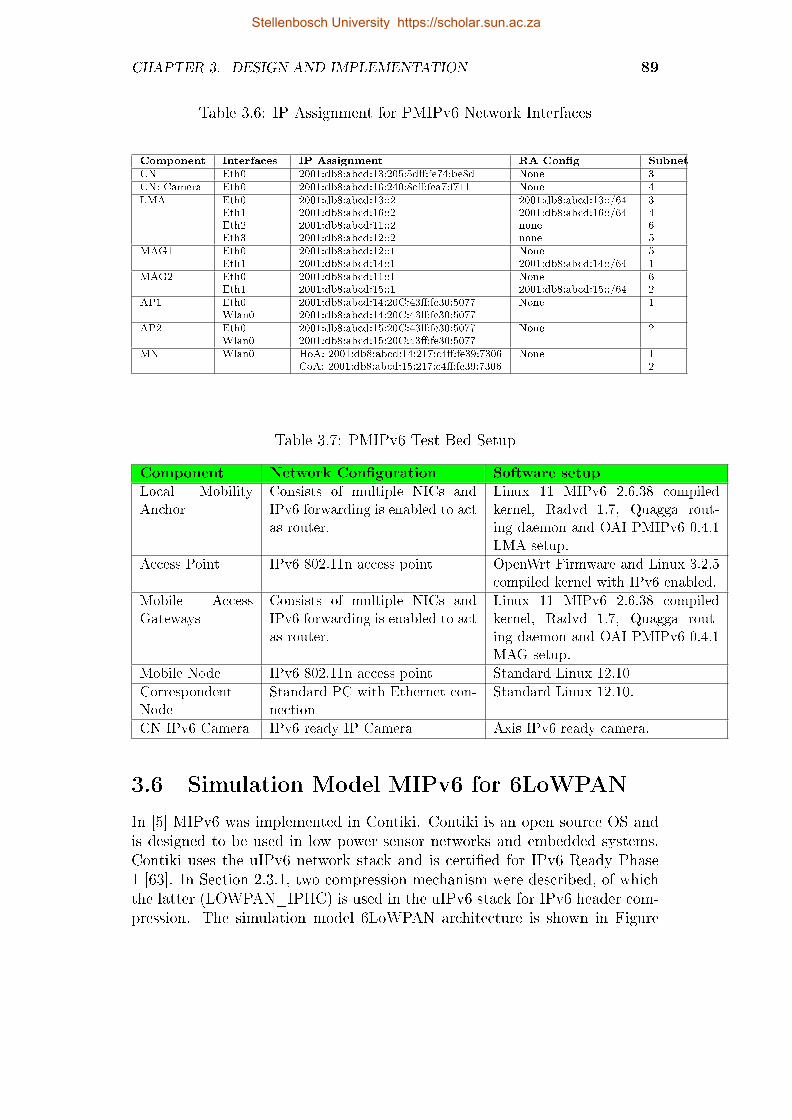
CHAPTER 3. DESIGN AND IMPLEMENTATION 89
Table 3.6: IP Assignment for PMIPv6 Network Interfaces
Component Interfaces IP Assignment RA Con�g Subnet
CN Eth0 2001:db8:abcd:13:205:5d�:fe74:be8d None 3CN: Camera Eth0 2001:db8:abcd:16:240:8c�:fea7:f711 None 4LMA Eth0
Eth1Eth2Eth3
2001:db8:abcd:13::22001:db8:abcd:16::22001:db8:abcd:11::22001:db8:abcd:12::2
2001:db8:abcd:13::/642001:db8:abcd:16::/64nonenone
3465
MAG1 Eth0Eth1
2001:db8:abcd:12::12001:db8:abcd:14::1
None2001:db8:abcd:14::/64
51
MAG2 Eth0Eth1
2001:db8:abcd:11::12001:db8:abcd:15::1
None2001:db8:abcd:15::/64
62
AP1 Eth0Wlan0
2001:db8:abcd:14:20C:43�:fe30:50772001:db8:abcd:14:20C:43�:fe30:5077
None 1
AP2 Eth0Wlan0
2001:db8:abcd:15:20C:43�:fe30:50772001:db8:abcd:15:20C:43�:fe30:5077
None 2
MN Wlan0 HoA: 2001:db8:abcd:14:217:c4�:fe39:7306CoA: 2001:db8:abcd:15:217:c4�:fe39:7306
None 12
Table 3.7: PMIPv6 Test Bed Setup
Component Network Con�guration Software setup
Local MobilityAnchor
Consists of multiple NICs andIPv6 forwarding is enabled to actas router.
Linux 11 MIPv6 2.6.38 compiledkernel, Radvd 1.7, Quagga rout-ing daemon and OAI PMIPv6 0.4.1LMA setup.
Access Point IPv6 802.11n access point OpenWrt Firmware and Linux 3.2.5compiled kernel with IPv6 enabled.
Mobile AccessGateways
Consists of multiple NICs andIPv6 forwarding is enabled to actas router.
Linux 11 MIPv6 2.6.38 compiledkernel, Radvd 1.7, Quagga rout-ing daemon and OAI PMIPv6 0.4.1MAG setup.
Mobile Node IPv6 802.11n access point Standard Linux 12.10
CorrespondentNode
Standard PC with Ethernet con-nection
Standard Linux 12.10.
CN IPv6 Camera IPv6 ready IP Camera Axis IPv6 ready camera.
3.6 Simulation Model MIPv6 for 6LoWPAN
In [5] MIPv6 was implemented in Contiki. Contiki is an open source OS andis designed to be used in low power sensor networks and embedded systems.Contiki uses the uIPv6 network stack and is certi�ed for IPv6 Ready Phase1 [63]. In Section 2.3.1, two compression mechanism were described, of whichthe latter (LOWPAN_IPHC) is used in the uIPv6 stack for IPv6 header com-pression. The simulation model 6LoWPAN architecture is shown in Figure
Stellenbosch University https://scholar.sun.ac.za

CHAPTER 3. DESIGN AND IMPLEMENTATION 90
3.10. The network consisted of two visiting networks (each containing 1 bor-der router), a home agent, 1 mobile sensor (moving between the two visitingnetworks) and 1 correspondent node. The motes used for the mobile sensorand the border router were TelosB [64] developed by Crossbow. For movementdetection, MIPv6 relies on router advertisement and from [8] it is suggestedthat the time between two consecutive router advertisements should be variedbetween 30ms to 70ms. For WSN, this rate will increase the power use of anode, as well as the contention on the wireless medium. WSN should thus relyon other mechanisms to detect node movement. By using the movement de-tection adaption proposed in [5], MIPv6 was simulated in Contiki. The variousruntime parameters used for the simulation can be seen in Appendix C.1.
CorrespondentNode
Border RouterBorder Router
Home Agent
Mobile SensorMovement
IPv6 RouterHome Network
Visited Network
Visited Network
Figure 3.10: MIPv6 6LoWPAN Testbed [5]
3.7 Conclusion
In this chapter the testbed setup and network designs for the various protocolshave been illustrated and explained in detail. The three protocols consisted ofbasically the same network design with some small changes regarding networklayout and con�guration. All the con�gurations for the various test setupscan be seen in Appendix B. Network design for MIPv6 can be seen in Figure3.6 and the UMIP0.4 MIPv6[60] protocol was implemented on top of the IPv6network setup beforehand. The functioning of this protocol relies heavily onthe hardware/software support of the network.
The network design for FMIPv6 can be seen in Figure 3.7 and was imple-mented on top of the MIPv6 network setup. Once again the implementationof this protocol relies heavily on the hardware/software support of the networkand is functional only in certain versions of Linux OS. To simulate a reactive
Stellenbosch University https://scholar.sun.ac.za

CHAPTER 3. DESIGN AND IMPLEMENTATION 91
handover in FMIPv6 the MN was manually switched to the new access point.For predictive handovers, the signal strength of the previous access point waslowered.
The PMIPv6 network design can be seen in Figure 3.8. The network designfor this implementation di�ers widely from the previous two implementations.In PMIPv6, the mobility resides in the network and not on the mobile nodes.
Lastly, the simulation for the wireless sensor MIPv6 network can be seen inFigure 3.10. The simulation consisted of two border routers that acted as theoutward point for the two 6LoWPAN networks. The results of the tests doneusing the simulation module and the testbed with the various test networksetups, will be discussed in the next chapter.
Stellenbosch University https://scholar.sun.ac.za
Chapter 4
Results
4.1 Introduction
In this chapter various results of the network protocol tests are discussed. Theresults provide handover latency, as determined by the simulation module. Thetestbed implementation results consists of UDP/TCP throughput, UDP jitter,and handover latency for MIPv6, FMIPv6 and PMIPv6. Iperf [61] was usedto generate tra�c between the mobile node and the correspondent node. Themeasurements were done for all the protocols under the same conditions andnetwork load. From these results a very accurate conclusion can be reachedin order to evaluate the performance of each protocol and to identify a futureprotocol for mobility.
4.2 Evaluation Methodology
The evaluation of the testbed for MIPv6, FMIPv6 and PMIPv6 consisted ofthe following performance metrics:
� Handover Latency (Using Iperf)
� Measure the handover latency produced by MIPv6 when movingfrom home network to visiting network.
� Measure the handover latency produced by FMIPv6 for the predic-tive case when moving from home network to visiting network.
� Measure the handover latency produced by PMIPv6 when movingfrom home network to visiting network.
� Compare the average handover latency produced by MIPv6, FMIPv6and PMIPv6 during handover.
� TCP Throughput (Using Iperf)
� Comparison of TCP throughput for the various protocols.
92
Stellenbosch University https://scholar.sun.ac.za

CHAPTER 4. RESULTS 93
� UDP Throughput, UDP Jitter and Packet loss (Using Iperf)
� Measure UDP throughput while running IPv6 application
� Measure Packet loss during handover process.
� Comparison of UDP throughput for the various protocols.
� Comparison of UDP jitter for the various protocols.
� Live video streaming evaluation
� Measure throughput while streaming live video feed.
� Compare protocol performance under live streaming.
4.3 Simulation Results
This section shows the results of the OMNet++ simulation module for MIPv6.The UDP and TCP throughput results obtained from the simulation modelfor MIPv6 are compared to the MIPv6 testbed in Section 4.7.
4.3.1 Handover Latency
Figure 4.1 shows total handover latency caused by MIPv6 messaging during5 simulation runs. The layer 2 handover delay is around 1.5s for each of thesimulation runs. The delay caused by binding messages is around 2s andthe other main contribution to handover delay is caused by duplicate addressdetection. The delay caused by DAD is between 1.5 - 2s.
0
0.5
1
1.5
2
2.5
3
3.5
4
1 2 3 4 5
Han
do
ver
Tim
e (
s)
Handover Number
Total Handover Delay MIPv6 Simulation
RR Delay
DAD Delay
HA Delay
CN Registration Delay
Layer 2 Delay
Figure 4.1: Handover Latency in MIPv6 OMNeT++ Simulation
Stellenbosch University https://scholar.sun.ac.za

CHAPTER 4. RESULTS 94
Figure 4.2 shows total handover latency caused by MIPv6 return routabi-lity. The latency introduced by this messaging are very small and do not haveany real impact on the overall latency.
0
0.002
0.004
0.006
0.008
0.01
0.012
0.014
0.016
1 2 3 4 5
Han
do
ver
Tim
e (
s)
Handover Number
RR and CN Handover Delay MIPv6 Simulation
RR Delay
CN Registration Delay
Figure 4.2: RR and CN Handover Delay MIPv6 Simulation
4.3.2 UDP Throughput
Figure 4.3 shows the UDP throughput for MIPv6 when the MN performs ahandover to a new access router in the visited network.
0
2000
4000
6000
8000
10000
12000
1 2 3 4 5 6 7 8 9 10 11 12 13 14 15 16
Thro
ugh
pu
t (K
bit
s/se
c)
Time (sec)
UDP Throughput During MIPv6 Simulation
Test 1
Test 2
Test 3
Figure 4.3: UDP Throughput in MIPv6 OMNeT++ Simulation
Stellenbosch University https://scholar.sun.ac.za

CHAPTER 4. RESULTS 95
4.3.3 TCP Throughput
Figure 4.4 shows the TCP throughput for MIPv6 when the MN performs ahandover to a new access router in the visited network.
0
5000
10000
15000
1 2 3 4 5 6 7 8 9 10 11 12 13 14 15 16 17 18 19 20 21 22
Thro
ugh
pu
t (K
bit
s/se
c)
Time (sec)
TCP Throughput During MIPv6 Simulation
Test 1
Test 2
Test 3
Figure 4.4: TCP Throughput in MIPv6 OMNeT++ Simulation
4.4 MIPv6 Protocol Results
The following section provides the various testbed results for MIPv6. Theresults obtained from the testbed are used to evaluate the performance ofMIPv6 by comparing the UDP and TCP measurements to the results of theother protocols presented later in this chapter. The evaluation methodologyfor testing can be seen in Section 4.2.
4.4.1 UDP Throughput
In the �rst experiment the UDP throughput, UDP jitter, TCP throughputand packet loss were measured for MIPv6. With the use of JPerf, the MN wasset up as the client and the CN as the server. The JPerf setup for UDP waskept at the default values, with the UDP bandwidth set to 10 Mbps, bu�ersize set to 41 Kbytes and a packet size of 1500 bytes. Figure 4.5 shows theaverage throughput on the MIPv6 if no handover is performed. The averagethroughput of the network is 9960 Kbits/sec with a transmission rate of 10Mbps.
Stellenbosch University https://scholar.sun.ac.za
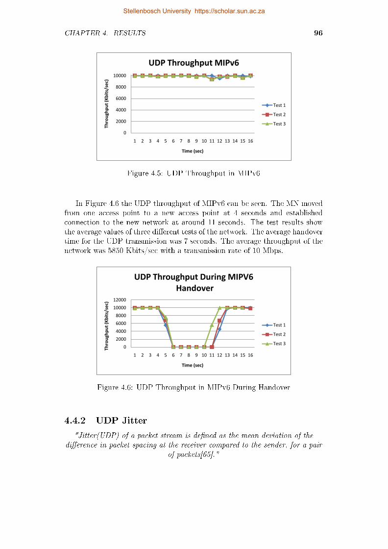
CHAPTER 4. RESULTS 96
0
2000
4000
6000
8000
10000
1 2 3 4 5 6 7 8 9 10 11 12 13 14 15 16
Thro
ugh
pu
t (K
bit
s/se
c)
Time (sec)
UDP Throughput MIPv6
Test 1
Test 2
Test 3
Figure 4.5: UDP Throughput in MIPv6
In Figure 4.6 the UDP throughput of MIPv6 can be seen. The MN movedfrom one access point to a new access point at 4 seconds and establishedconnection to the new network at around 11 seconds. The test results showthe average values of three di�erent tests of the network. The average handovertime for the UDP transmission was 7 seconds. The average throughput of thenetwork was 5850 Kbits/sec with a transmission rate of 10 Mbps.
0
2000
4000
6000
8000
10000
12000
1 2 3 4 5 6 7 8 9 10 11 12 13 14 15 16
Th
rou
gh
pu
t (K
bit
s/se
c)
Time (sec)
UDP Throughput During MIPV6
Handover
Test 1
Test 2
Test 3
Figure 4.6: UDP Throughput in MIPv6 During Handover
4.4.2 UDP Jitter
"Jitter(UDP) of a packet stream is de�ned as the mean deviation of thedi�erence in packet spacing at the receiver compared to the sender, for a pair
of packets[65]."
Stellenbosch University https://scholar.sun.ac.za

CHAPTER 4. RESULTS 97
Figure 4.7 shows the comparison of MIPv6 UDP jitter when no handover isperformed and when a handover is performed by the mobile node. It is clearlyvisible how the jitter increases when the mobile node goes into the handoverprocess. The average jitter when a handover is performed is in the order of1.1666 ms, compared with 0.654 ms when no handover is performed on thenetwork. The reason for the increase in jitter after the handover process hascompleted is that Route Optimization has not yet completed, which causesmore overhead on the network. This increases the jitter, as packets have to berouted via the Home Agent, because the bidirectional tunnel setup has not yetbeen completed. The average jitter also increases when Route Optimization isused, because additional routing headers need to be added to the packet forencapsulation.
0
0.5
1
1.5
2
1 2 3 4 5 6 7 8 9 10 11 12 13 14 15 16 17
Jitt
er
(ms)
Time (sec)
UDP Jitter of MIPv6
MIPv6 No Handover
MIPv6 Handover
Figure 4.7: UDP Jitter in MIPv6
4.4.3 TCP Throughput
TCP performance of the network was also tested with the use of JPerf. AllJperf's default values for the TCP bu�er length (2), TCP Windows Size (56)and TCP Max Segment Size (1) were used in the setup. Figure 4.8 showsthe throughput of the network when MIPv6 is used. The handover periodis clearly visible from the �gure and total handover latency is around 12 s.After handover completion the throughput is lower than before the handoveroccurred. This is for a number of reasons, one being the new access point andaccess router. Other reasons include the overhead added by MIPv6.
Stellenbosch University https://scholar.sun.ac.za

CHAPTER 4. RESULTS 98
0
2000
4000
6000
8000
10000
12000
14000
16000
1 3 5 7 9 11 13 15 17 19 21 23 25
Thro
ugh
pu
t (K
bit
s/se
c)
Time (sec)
TCP Throughput During MIPv6 Handover
Test 1
Test 2
Figure 4.8: TCP Throughput in MIPv6
4.5 FMIPv6 Protocol Results
This section presents the results of the testbed after FMIPv6 had been imple-mented on the testbed. The results presented are similar to those measuredin Section 4.4 and an in depth comparison is made in Section 4.7.
4.5.1 UDP Throughput
The second experiment consisted of FMIPv6 UDP throughput, UDP jitter,TCP throughput and packet loss measurements. The same experiment andmeasurement setup was used as in Section 4.4.1. The JPerf setup for UDPwas kept at the default values, with the UDP bandwidth set to 10 Mbps, bu�ersize set to 41 Kbytes and a packet size of 1500 bytes. Figure 4.9 shows theaverage throughput on the FMIPv6 if no handover is performed. The averagethroughput of the network is 9914 Kbits/sec with a transmission rate of 10Mbps.
Stellenbosch University https://scholar.sun.ac.za

CHAPTER 4. RESULTS 99
0
2000
4000
6000
8000
10000
12000
1 2 3 4 5 6 7 8 9 10 11 12 13 14 15 16
Thro
ugh
pu
t (K
bit
s/se
c)
Time (sec)
UDP Throughput FMIPv6
Test 1
Test 2
Test 3
Figure 4.9: UDP Throughput in FMIPv6
In Figure 4.10 the UDP throughput of FMIPv6 can be seen. The MNmoved from the Previous Access Router to the New Access Router at 5.5seconds and established connection to the new network at around 7.5 seconds.The test results show the average values of three di�erent tests of the network.The average handover time for the UDP transmission was 2 seconds. Theaverage throughput of the network was 7436 Kbits/sec with a transmissionrate of 10 Mbps.
0
2000
4000
6000
8000
10000
12000
1 2 3 4 5 6 7 8 9 10 11 12
Th
rou
gh
pu
t (K
bit
s/se
c)
Time (sec)
UDP Throughput During FMIPv6
Handover
Test 1
Test 2
Test 3
Figure 4.10: UDP Throughput in FMIPv6 During Handover
4.5.2 UDP Jitter
Figure 4.11 shows the comparison of FMIPv6 UDP Jitter when no handover isperformed and when a handover is performed by the mobile node. It is clearly
Stellenbosch University https://scholar.sun.ac.za

CHAPTER 4. RESULTS 100
visible how the jitter increases when the mobile node goes into the handoverprocess. The average jitter when a handover is performed is the order of 1.006ms compared to 0.671 ms when no handover is performed on the network.Handover increases the jitter as packets have to be routed via the Home Agentbecause the bidirectional tunnel setup has not yet been completed.
0
0.5
1
1.5
2
2.5
3
3.5
4
1 2 3 4 5 6 7 8 9 10 11 12 13 14 15 16 17 18 19
Jitt
er
(ms)
Time (sec)
UDP Jitter of FMIPv6
FMIPv6 No Handover
FMIPv6 Handover
Figure 4.11: UDP Jitter in FMIPv6
4.5.3 TCP Throughput
TCP performance of the network was also tested with the use of JPerf. AllJPerf's default values for the TCP bu�er length (2), TCP Windows Size (56)and TCP Max Segment Size (1) were used in the setup. Figure 4.12 showsthe throughput of the network when FMIPv6 was used. The handover pe-riod is clearly visible from the �gure and total handover latency is around 8s. After handover completion the throughput is lower than before the han-dover occurred. This could be caused by a number of reasons, one being thelocation of the new access point which could contribute to a weaker signalstrength, another that the NAR uses the same channel as the surrounding AP.These overlapping channels can lead to more congestion which can cause lowerthroughput. Another reason could be the overhead added by FMIPv6. Figure4.8 shows the throughput of the MIPv6 network, it can be seen that the afterhandover the throughput is also lower. This adds support to the belief thatthe main cause is the secondary AP used and not MIPv6 or FMIPv6 overhead.
Stellenbosch University https://scholar.sun.ac.za

CHAPTER 4. RESULTS 101
0
5000
10000
15000
20000
25000
1 2 3 4 5 6 7 8 9 10 11 12 13 14 15 16 17 18 19
Thro
ugh
pu
t (K
bit
s/se
c)
Time (sec)
TCP Throughput During FMIPv6 Handover
Test 1
Test 2
Figure 4.12: TCP Throughput in FMIPv6
4.6 PMIPv6 Protocol Results
The following section provides the various testbed results for PMIPv6. Theresults obtained from the testbed were used to evaluate the performance ofPMIPv6 by comparing the UDP and TCP measurements with those of MIPv6and FMIPv6 presented earlier in this chapter.
4.6.1 UDP Throughput
The third experiment comprised of PMIPv6 UDP throughput, UDP jitter,TCP throughput and packet loss measurements. The same experiment andmeasurement setup were used as in Section 4.4.1. The JPerf setup for UDPwas kept at the default values, with the UDP bandwidth set to 10 Mbps, bu�ersize set to 41 Kbytes and a packet size of 1500 bytes. Figure 4.13 shows theaverage throughput on the PMIPv6 if no handover is performed. The averagethroughput of the network was 9971.8 Kbits/sec with a transmission rate of10 Mbps.
Stellenbosch University https://scholar.sun.ac.za

CHAPTER 4. RESULTS 102
0
2000
4000
6000
8000
10000
12000
1 2 3 4 5 6 7 8 9 10 11 12 13 14 15
Th
rou
gh
pu
t (K
bit
s/se
c)
Time (sec)
UDP Throughput PMIPv6
Test 1
Test 2
Test 3
Figure 4.13: UDP Throughput in PMIPv6
In Figure 4.14 the UDP throughput of PMIPv6 when a handover is per-formed can be seen. The MN moved from LMA1 to LMA2 at 4.5 seconds andestablished connection to the new network at around 11.5 seconds. The testresults showed the average values of three di�erent tests of the network. Theaverage handover time for the UDP transmission was 6.5 seconds. The averagethroughput of the network was 4983 Kbits/sec with a transmission rate of 10Mbps.
0
2000
4000
6000
8000
10000
12000
1 2 3 4 5 6 7 8 9 10 11 12 13 14 15
Thro
ugh
pu
t (K
bit
s/se
c)
Time (sec)
UDP Throughput During PMIPv6 Handover
Test 1
Test 2
Test 3
Figure 4.14: UDP Throughput in PMIPv6 During Handover
Stellenbosch University https://scholar.sun.ac.za
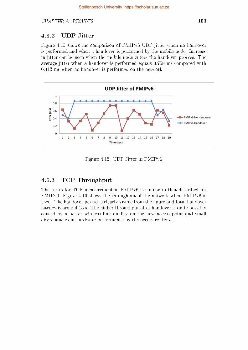
CHAPTER 4. RESULTS 103
4.6.2 UDP Jitter
Figure 4.15 shows the comparison of PMIPv6 UDP jitter when no handoveris performed and when a handover is performed by the mobile node. Increasein jitter can be seen when the mobile node enters the handover process. Theaverage jitter when a handover is performed equals 0.758 ms compared with0.413 ms when no handover is performed on the network.
0
0.2
0.4
0.6
0.8
1
1 2 3 4 5 6 7 8 9 10 11 12 13 14 15 16 17 18 19
Jitt
er
(ms)
Time (sec)
UDP Jitter of PMIPv6
PMIPv6 No Handover
PMIPv6 Handover
Figure 4.15: UDP Jitter in PMIPv6
4.6.3 TCP Throughput
The setup for TCP measurement in PMIPv6 is similar to that described forFMIPv6. Figure 4.16 shows the throughput of the network when PMIPv6 isused. The handover period is clearly visible from the �gure and total handoverlatency is around 13 s. The higher throughput after handover is quite possiblycaused by a better wireless link quality on the new access point and smalldiscrepancies in hardware performance by the access routers.
Stellenbosch University https://scholar.sun.ac.za

CHAPTER 4. RESULTS 104
0
5000
10000
15000
20000
25000
30000
35000
1 2 3 4 5 6 7 8 9 1011121314151617181920212223
Thro
ugh
pu
t (K
bit
s/se
c)
Time (sec)
TCP Throughput During PMIPv6 Handover
Test 1
Test 2
Test 3
Figure 4.16: TCP Throughput in PMIPv6
Figure 4.17 shows the TCP throughput achieved by PMIPv6 when using anIP camera to generate real-time tra�c on the testbed. The results also indicatea handover latency of about 13 s when the MN is not reachable. After thehandover had been completed, the throughput was not as consistent as beforethe handover. The lower throughput is caused by various factors, namelyhardware performance, wireless link quality and overhead produced by thePMIPv6 mobility messages. Figure 4.18 shows the average packet throughputfor PMIPv6.
0
2000
4000
6000
8000
10000
12000
1 3 5 7 9 11 13 15 17 19 21 23 25 27 29 31 33
Th
rou
gh
pu
t (K
Bit
s/se
c)
Time (sec)
IPv6-Camera Throughput PMIPv6
Test 1
Test 2
Figure 4.17: IP Camera TCP Throughput in PMIPv6
Stellenbosch University https://scholar.sun.ac.za

CHAPTER 4. RESULTS 105
0
200
400
600
800
1000
1200
1400
1600
1 3 5 7 9 11 13 15 17 19 21 23 25 27 29 31 33
Pac
ket
Thro
ugh
pu
t (P
acke
ts/s
ec)
Time (sec)
IPv6-Camera Packet Throughput PMIPv6
Test 1
Test 2
Figure 4.18: IP Camera TCP Packet Throughput in PMIPv6
4.7 Comparing Protocol Results
In this section the various test results shown in the previous sections are com-pared with each other. The UDP and TCP results from the MIPv6 OMNeT++simulation model will be compared to the results obtained from the MIPv6testbed. The section will also look at UDP, TCP, UDP jitter and Packet losscomparisons for MIPv6, FMIPv6 and PMIPv6. The handover latency of theprotocols will also be compared.
4.7.1 MIPv6 Comparison - OMNeT++ Simulation and
Testbed
UDP throughput comparison between the MIPv6 simulation and the MIPv6testbed can be seen in Figure 4.19. Its clear that the total handover latencyfrom the simulation is inline with the results obtained from the testbed.
Stellenbosch University https://scholar.sun.ac.za

CHAPTER 4. RESULTS 106
0
2000
4000
6000
8000
10000
12000
1 3 5 7 9 11 13 15 17 19
Thro
ugh
pu
t (K
bit
s/se
c)
Time (sec)
UDP Throughput MIPv6 - Simulation vs Testbed
MIPv6 Simulation
MIPv6 Testbed
Figure 4.19: MIPv6 UDP Throughput - OMNeT++ Simulation vs Testbed
TCP throughput comparison between the MIPv6 simulation and the MIPv6testbed can be seen in Figure 4.20. The handover latency varies a bit. Thehandover latency for the simulation is around 8s, where handover latency forthe testbed is around 14s. A possible reason for this variation can because ofdi�erences in the TCP/IP stack of OMNeT++ INET package and the testbed.
0
5000
10000
15000
1 3 5 7 9 11 13 15 17 19 21 23
Thro
ugh
pu
t (K
bit
s/se
c)
Time (sec)
TCP Throughput MIPv6 - Simulation vs Testbed
MIPv6 Simulation
MIPv6 Testbed
Figure 4.20: MIPv6 TCP Throughput - OMNeT++ Simulation vs Testbed
Stellenbosch University https://scholar.sun.ac.za

CHAPTER 4. RESULTS 107
4.7.2 UDP Throughput Comparison
UDP throughput comparison can be seen in Figure 4.21. It is clearly visi-ble that FMIPv6 outperforms the other protocols in the time it takes to re-establish connection with the corresponding node. The average time taken byFMIPv6 is around 2 seconds, compared to 7 seconds for MIPv6 and 6.5 secondsfor PMIPv6. The average throughput for protocols can be seen in Table 4.1column 6, named 'Throughput HO (Kbits/sec)'. The average throughput forFMIPv6 is better, compared with the other protocols over the same period oftime. This is because of the decrease in handover latency for FMIPv6. MIPv6and PMIPv6 are fairly equal in throughput comparison.
0
2000
4000
6000
8000
10000
12000
1 2 3 4 5 6 7 8 9 10 11 12 13 14 15 16
Th
rou
gh
pu
t (K
bit
s/se
c)
Time (sec)
MIPV6, FMIPV6 and PMIPV6 UDP Throughput
MIPV6 UDP
FMIPV6 UDP
PMIPV6 UDP
Figure 4.21: UDP Throughput in MIPv6, FMIPv6 and PMIPv6 during Han-dover
UDP throughput comparison during handover and when no handover istriggered can be seen in Figure 4.22. Figure 4.22 is used to illustrate the aver-age throughput of protocols as seen in Table 4.1 column 5 (Throughput (Kbit-s/sec)) and column 6 (Throughput HO (Kbits/sec)). The average throughputfor FMIPv6 is better compared to that of the other protocols over the sameperiod of time when a handover is performed. MIPv6 and PMIPv6 are fairlyequal in throughput comparison during handover and the average throughputwhen no handover is performed is very similar for all three protocols.
Stellenbosch University https://scholar.sun.ac.za

CHAPTER 4. RESULTS 108
0
2000
4000
6000
8000
10000
12000
1 2 3 4 5 6 7 8 9 10 11 12 13 14 15 16 17 18
Thro
ugh
pu
t (K
bit
s/se
c)
Time (sec)
UDP Throughput MIPv6, FMIPv6 and PMIPv6
MIPv6 No Handover
MIPv6 Handover
FMIPv6 No Handover
FMIPv6 Handover
PMIPv6 No Handover
PMIPv6 Handover
Figure 4.22: UDP Throughput MIPv6, FMIPv6 and PMIPv6
4.7.3 TCP Comparison Throughput
The average TCP throughput can be seen in Figure 4.23.
0
5000
10000
15000
20000
25000
30000
1 2 3 4 5 6 7 8 9 10 11 12 13 14 15 16 17 18 19 20 21 22
Th
rou
gh
pu
t (K
bit
s/se
c)
Time (sec)
MIPV6, FMIPV6 and PMIPV6 TCP Throughput
MIPV6 TCP
FMIPV6 TCP
PMIPV6 TCP
Figure 4.23: TCP Throughput MIPv6, FMIPv6 and PMIPv6
4.7.4 Handover Latency Comparison
Figure 4.24 shows the handover latency in seconds for MIPv6, FMIPv6 andPMIPv6 on three separate test sets. This �gure shows that FMIPv6 has thesmallest handover latency and PMIPv6 the largest handover latency for UDP
Stellenbosch University https://scholar.sun.ac.za

CHAPTER 4. RESULTS 109
and TCP protocols. FMIPv6 performs better because of various advantagesit possesses regarding to duplicate address detection and IPv6 con�gurationduring handover.
0
2
4
6
8
10
12
14
UDP MIPv6 UDP FMIPv6 UDP PMIPv6 TCP MIPv6 TCP FMIPv6 TCP PMIPv6
Han
do
ver
Late
ncy
(s)
Protocol (UDP or TCP)
Handover Latency of MIPv6, FMIPv6 and PMIPv6
Test 1
Test 2
Test 3
Figure 4.24: Handover Latency of MIPv6, FMIPv6 and PMIPv6
4.7.5 UDP Packet Loss Comparison
Figure 4.25 shows the comparison in packet loss for the various protocols. Thetotal number of packets transmitted by the server for the test period can beseen compared with the total number of packets lost. A handover to a newaccess point took place during this time. The results of two tests for eachprotocol under similar network conditions are presented.
0
2000
4000
6000
8000
10000
12000
14000
16000
18000
Test 1: MIPv6
UDP
Test 2: MIPv6
UDP
Test 1: FMIPv6
UDP
Test 2: FMIPv6
UDP
Test 1: PMIPv6
UDP
Test 2: PMIPv6
UDP
Pa
cke
ts
Test/Protocol Number
UDP Packet Loss
Lost Packets
Total Packets
Figure 4.25: UDP Packet Loss MIPv6, FMIPv6 and PMIPv6
Stellenbosch University https://scholar.sun.ac.za

CHAPTER 4. RESULTS 110
4.7.6 UDP Jitter Comparison
UDP jitter comparison can be seen in Figure 4.26. This shows the averagejitter over the test period. During this period handovers were performed to anew access router.
0
0.2
0.4
0.6
0.8
1
1.2
1.4
PMIPv6 FMIPv6 MIPv6
Ava
rage
Jit
ter
(ms)
Protocol
Average Jitter Comparison
No Handover
Handover
Figure 4.26: UDP Jitter Comparison
Table 4.1 shows a quick comparison of various test results. These resultswere used mainly to determine the QoS and the overall performance of eachprotocol. The results give the comparison of Handover time in seconds, jitterand throughput comparison.
Table 4.1: Protocol Results
Protocol TCP HO(s) UDP HO(s) Jitter(ms)
Throughput(Kbits/sec)
Throughput HO(Kbits/sec)
MIPv6 12 7 1.166 9960 6301FMIPv6 8 2 1.006 9914 8899PMIPv6 13 6.5 0.758 9971 5502
4.8 MIPv6 for 6LoWPAN
In section 2.5.6 an implementation of MIPv6 was introduced for 6LoWPAN[5]. This section will look at the results obtained from a 6LoWPAN MIPv6simulation module in the Cooja Network simulator for Contiki. Figure 4.27
Stellenbosch University https://scholar.sun.ac.za
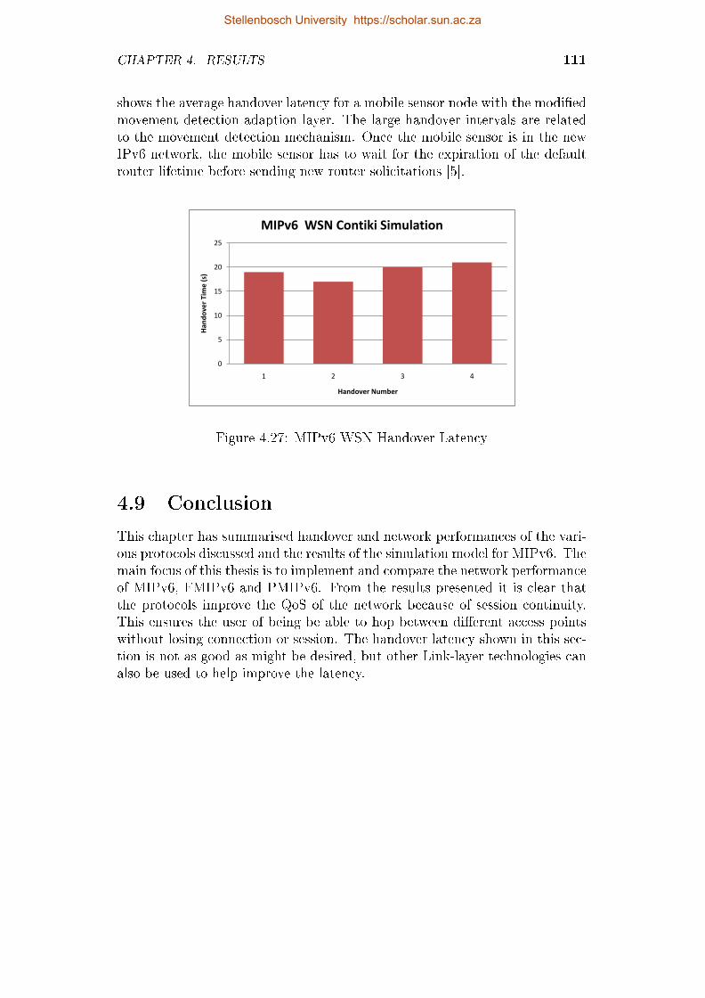
CHAPTER 4. RESULTS 111
shows the average handover latency for a mobile sensor node with the modi�edmovement detection adaption layer. The large handover intervals are relatedto the movement detection mechanism. Once the mobile sensor is in the newIPv6 network, the mobile sensor has to wait for the expiration of the defaultrouter lifetime before sending new router solicitations [5].
0
5
10
15
20
25
1 2 3 4
Han
do
ver
Tim
e (
s)
Handover Number
MIPv6 WSN Contiki Simulation
Figure 4.27: MIPv6 WSN Handover Latency
4.9 Conclusion
This chapter has summarised handover and network performances of the vari-ous protocols discussed and the results of the simulation model for MIPv6. Themain focus of this thesis is to implement and compare the network performanceof MIPv6, FMIPv6 and PMIPv6. From the results presented it is clear thatthe protocols improve the QoS of the network because of session continuity.This ensures the user of being be able to hop between di�erent access pointswithout losing connection or session. The handover latency shown in this sec-tion is not as good as might be desired, but other Link-layer technologies canalso be used to help improve the latency.
Stellenbosch University https://scholar.sun.ac.za

Chapter 5
Conclusion, Outcomes and
Recommendations
The previous chapter presented all the results obtained from the various ex-periments. The results consisted of TCP, UDP and handover performances forMIPv6, FMIPv6 and PMIPv6. A further result was the evaluation of the ef-fects on the performance of the application when using the mobility protocols.The implementation of MIPv6 for 6LoWPAN networks was also investigated.This chapter presents the outcomes of the completed work and recommenda-tions for future work.
5.1 Conclusion
This thesis presents the evaluation of mobility protocols to determine the ef-fectiveness and e�ciency of these protocols. As the number of mobile devicesgrows rapidly and IPv4 addresses are being exhausted, making MIPv6 the fu-ture option as a network mobility protocol for IP Networks. The main goal ofthe mobility protocol is to enable network applications to operate continuouslyat the required QoS for both wired and wireless networks.
The protocols were tested on a real testbed environment to ensure reliableand real world results. MIPv6 was simulated under the OMNeT++ simulationframework. The results obtained from the simulation were used as a compar-ison for the testbed results. If one looks at the results that were obtainedfrom the various experiments, it is clear that many external factors need to beconsidered to before any conclusion can be reached on the performance of theprotocols.
From the results obtained in the simulation module it is clearly visible thatthe largest contribution of handover latency is Duplicate Address Detection.The simulation module serves as a very good platform to develop and expandthe basic MIPv6 protocol and to introduce possible enhancements. Theseenhancements can be used to build FMIPv6 and PMIPv6 on top of the existing
112
Stellenbosch University https://scholar.sun.ac.za

CHAPTER 5. CONCLUSION, OUTCOMES AND RECOMMENDATIONS 113
MIPv6 implementation.
� The functional characteristics and performance of the simulation modelare very similar to those of the testbed.
� Router advertisements interval delay mainly a�ects the TRDD componentof the overall delay and has a direct impact on the time it takes for theMN to determine whether it has moved or not.
� Router advertisements do not a�ect the MIPv6 protocol speci�c delayincurring components (THRD, TRRD, TCRD) and hence remain constantthrough all the test runs in both the test bed and simulation model.
The various protocols are implemented in a Linux OS environment andis strongly dependent on the hardware support of the network. The testbedsetup was done in such a way that no network element other than those beingused in the testbed can generate tra�c on the network. The network wasisolated from the outside network and each protocol was tested with the samenetwork parameters to ensure consistent and reliable results.
� All protocols allow the mobile node always to be reachable at its homeIP address and ensuring session continuity when changing access points.
� The implementation of layer 3 mobility protocols is transparent to allhigher applications. The application layer is unaware of the changeswhen moving around in the network.
� The MIPv6 testbed behaved as expected and introduced session conti-nuity for the MN when moving around in the network.
� The main contribution to handover delay was DAD and IP addressescon�guration during handover.
The implementation of FMIPv6 on the testbed was a huge challenge duethe fact that FMIPv6 is very dependent on the hardware/�rmware of the net-work components. The FMIPv6 testbed behaved as expected and introducedlower handover latency for the MN when moving around in the network. Theresults showed that FMIPv6 outperformed the other protocols when it cameto handover latency and packet loss. The reason for this is that FMIPv6 al-lows packet forwarding and bu�ering when the mobile node is changing accesspoints. FMIPv6 also improves the DAD delay when a handover is performedby pre-con�guration of the NCoA for the mobile node before the handovertakes place. On the other hand, FMIPv6 had a few drawbacks that make itimpractical to implement, the main reasons being:
� FMIPv6 is implemented and con�gured for a speci�c network only.
Stellenbosch University https://scholar.sun.ac.za

CHAPTER 5. CONCLUSION, OUTCOMES AND RECOMMENDATIONS 114
� For FMIPv6 implementation all the MAC addresses of the access routersneed to be known and must be con�gured individually, making it verydi�cult and impractical to deploy on large scale networks.
� FMIPv6 does not provide a way for MN to discover a candidate accessrouter. Sending an RtSolPr to PAR only requests the MAC address ofcandidate access router. FMIPv6 does not tell the MN whether it is inrange of any of the candidate access routes. The only way for MN todiscover a suitable AR is to perform periodic scanning and this can alsotake a long time to complete and is dependent on the type of hardwareused.
� On the other hand, FMIPv6 also has the option to monitor the signalstrength of the surrounding AP and can use this to make a decision onwhen to switch to a new AP.
The PMIPv6 testbed behaved as expected and introduced lower handoverlatency than MIPv6 for the MN when moving around in the network. PMIPv6introduces a huge advantage when compared to MIPv6 and FMIPv6. The mo-bile node is independent of the network mobility and no enhancement is neededon the mobile node for mobility control messaging. The PMIPv6 networkmakes use of a Radius server to allow authentication of mobile nodes and thisallows for easy management of mobile nodes in the PMIPv6 network domain.PMIPv6 has been chosen by 3rd Generation Partnership Project (3GPP) andLong Term Evolution (LTE) technologies as best mobility solution due to thefact that MN needs no stack modi�cation.
The thesis has presented a brief overview of 6LoWPAN and the adaptationlayer used by 6LoWPAN to reduce the length of the multiple headers usedin IPv6 packets. Results obtained from a simulation for MIPv6 over 6LoW-PAN [5] indicates that MIPv6 could be a practical solution for layer 3 mobilitysupport in low power devices. The main focus of improving the handover e�-ciency is to look at optimizing the movement detection of the sensor. Possiblesolutions are presented in [66] and make use of neighbor detection through theprocess of overhearing.
5.2 Outcomes of Completed Work
The outcomes of this thesis in terms of the functioning of mobile IP networks,speci�cally Mobile IPv6, Fast Handovers for Mobile IPv6 and Proxy MobileIPv6, the applicability of this protocols and simulation thereof are as follows:
� Investigation and explanation of the fundamental changes in IPv6 overIPv4 and the improvements made on IPv6 to enable network layer mo-bility in IPv6. Explanation of how IPv6 headers are implemented toenable mobility in the network layer and IP encapsulation.
Stellenbosch University https://scholar.sun.ac.za

CHAPTER 5. CONCLUSION, OUTCOMES AND RECOMMENDATIONS 115
� In depth explanation of the functioning of mobility protocols namelyMobile IPv6, Fast Handovers for Mobile IPv6 and Proxy Mobile IPv6.The thesis also explains the di�erences between the various protocolsmentioned, how they can improve the handover latency and QoS of thenetwork.
� Provision of insight into Network Mobility (NEMO) and the Internet-of-Things and how this correlates to the network protocols implemented inthis thesis.
� Performance analysis of MIPv6 using OMNeT++ as a simulation envi-ronment (Section 3.2).
� Development of an IPv6 network (Section 3.3) to serve as a platform forevaluation of mobility protocols and handover scenarios applicable to awireless network environment.
� Implementation and evaluation of MIPv6, FMIPv6 and PMIPv6 on thetestbed platform.
� Explanation of IPv6 compression techniques to allow functioning of IPv6in low power networks/devices.
� Investigation into the use of MIPv6 in a 6LoWPAN architecture.
� Explanation and illustration of the functioning of protocols. This virtu-ally illustrates the mobility feature imposed by these networks and howit compares to a standard IPv6 network.
� Presentation of results obtained from the various tests conducted on thetestbed and simulation environment. These results consisted of the han-dover latency produced and general network performance measurementssuch as throughput, packet loss and jitter.
� Discussion of various protocol advantages and drawbacks. This stipu-lates the practical implementation readiness of protocols in a large areanetwork.
� Establishment of a realistic and comprehensive testbed to facilitate fur-ther mobility testing and evaluation into future research activities.
This thesis has attempted to present a detailed explanation, understandingand evaluation of a proposed mobility solution in an IPv6 network. The resultsproduced in the thesis consist of in depth testing and simulation of mobilityprotocols. In particular, results was produced applicable to the handover la-tency of MIPv6, FMIPv6 and PMIPv6, as well as general network performanceof the various protocols mentioned. This thesis can be used to determine abase point in protocol performances and as reference for deciding on a speci�c
Stellenbosch University https://scholar.sun.ac.za

CHAPTER 5. CONCLUSION, OUTCOMES AND RECOMMENDATIONS 116
mobility protocol or future enhancement of protocols.
In terms of the objectives initially de�ned, these have been achieved. Theresults suggest some interesting avenues for further research.
5.3 Recommendations for Future Work
The work reported in this thesis could form part of structured way to imple-ment mobility protocols and to set up valuable testbeds to perform mobilitytesting and future enhancement testing. The work illustrates detailed eval-uation of all the protocols and this can be used as a baseline for protocolperformance and functioning. From the results obtained, PMIPv6 is a bettercandidate for future mobility, but still has some drawbacks to overcome beforeit can be considered a perfect solution for mobility. The development of sim-ulation models for FMIPv6 and PMIPv6 in OMNeT++ can be seen as futurework. This will contribute to the evaluation and improvement of the respectedprotocols. Future work will follow up on the drawbacks identi�ed and willbe aimed at possible solutions to improve mobility protocols and to overcomethe drawbacks. Possible focus points are to investigate link layer handovertechniques to minimize the delays produced by this, research can be based onwork done in [67] as well as optimizing movement detection of mobile nodes.The establishment of a dual evaluation vehicle can also be seen as importantin terms of more detailed application driven future work. Further work canalso be focused on the Internet of Things [30]. The basic idea is that IoT willconnect objects around us to provide seamless communication and contextualservices provided by them.
Stellenbosch University https://scholar.sun.ac.za

Appendices
117
Stellenbosch University https://scholar.sun.ac.za

Appendix A
A.1 xMIPv6 Runtime Parameters
All the parameters used for the MIPv6 simulation as well as a description ofthe parameters are included in this section. These parameters are used forenabling certain simulation modules like TCP, UDP etc. Table A.1 shows allthe simulation parameters for the MIPv6 simulation.
Table A.1: MIPv6 OMNeT++ Simulation Parameters
Parameter Name Value Description
isHomeAgent boolean Specify if the node is a HA ornot
isMobileNode boolean Specify if the node is MN irnot
num-rngs 2 Number of RNG used for thesimulation
debug-on-errors false Enable debugging after simu-lation errors
sim-time-limit 308 Specify simulation time in (s)**.debug true Enable debug mode*.total_mn 1 Number of MN's in the net-
work*.total_cn 2 Number of CN's in the net-
work
**.CNAddress "CN[0]" Used by the MN to directly ac-cess the CN address.
**.CNAddress1 "CN[1]" Used by the MN to directly ac-cess the CN address.
**.gen[*].rng-0 1 Map physical RNG 1 to Gen-eral Test
**.neighbourDiscovery.minIntervalBetweenRAs 0.03s Minimum RA interval speci-�ed by (RFC 6275)
Continued on next page
118
Stellenbosch University https://scholar.sun.ac.za
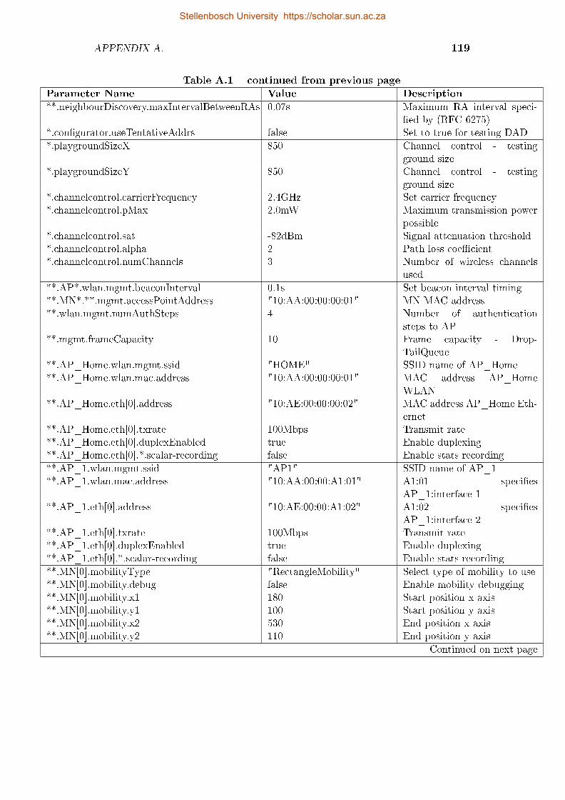
APPENDIX A. 119
Table A.1 � continued from previous page
Parameter Name Value Description
**.neighbourDiscovery.maxIntervalBetweenRAs 0.07s Maximum RA interval speci-�ed by (RFC 6275)
*.con�gurator.useTentativeAddrs false Set to true for testing DAD
*.playgroundSizeX 850 Channel control - testingground size
*.playgroundSizeY 850 Channel control - testingground size
*.channelcontrol.carrierFrequency 2.4GHz Set carrier frequency*.channelcontrol.pMax 2.0mW Maximum transmission power
possible*.channelcontrol.sat -82dBm Signal attenuation threshold*.channelcontrol.alpha 2 Path loss coe�cient*.channelcontrol.numChannels 3 Number of wireless channels
used
**.AP*.wlan.mgmt.beaconInterval 0.1s Set beacon interval timing**.MN*.**.mgmt.accessPointAddress "10:AA:00:00:00:01" MN MAC address**.wlan.mgmt.numAuthSteps 4 Number of authentication
steps to AP**.mgmt.frameCapacity 10 Frame capacity - Drop-
TailQueue**.AP_Home.wlan.mgmt.ssid "HOME" SSID name of AP_Home**.AP_Home.wlan.mac.address "10:AA:00:00:00:01" MAC address AP_Home
WLAN**.AP_Home.eth[0].address "10:AE:00:00:00:02" MAC address AP_Home Eth-
ernet**.AP_Home.eth[0].txrate 100Mbps Transmit rate**.AP_Home.eth[0].duplexEnabled true Enable duplexing**.AP_Home.eth[0].*.scalar-recording false Enable stats recording
**.AP_1.wlan.mgmt.ssid "AP1" SSID name of AP_1**.AP_1.wlan.mac.address "10:AA:00:00:A1:01" A1:01 speci�es
AP_1:interface 1**.AP_1.eth[0].address "10:AE:00:00:A1:02" A1:02 speci�es
AP_1:interface 2**.AP_1.eth[0].txrate 100Mbps Transmit rate**.AP_1.eth[0].duplexEnabled true Enable duplexing**.AP_1.eth[0].*.scalar-recording false Enable stats recording
**.MN[0].mobilityType "RectangleMobility" Select type of mobility to use**.MN[0].mobility.debug false Enable mobility debugging**.MN[0].mobility.x1 180 Start position x axis**.MN[0].mobility.y1 100 Start position y axis**.MN[0].mobility.x2 530 End position x axis**.MN[0].mobility.y2 110 End position y axis
Continued on next page
Stellenbosch University https://scholar.sun.ac.za

APPENDIX A. 120
Table A.1 � continued from previous page
Parameter Name Value Description
**.MN[0].mobility.startPos 0 Used to determine start posi-tion
**.MN[0].mobility.speed 1mps Speed of the MN**.MN[0].mobility.updateInterval 0.1s Interval of updating mobility
**.numUdpApps 0 Set to 1 to enable UDP**.udpAppType "UDPBasicApp" Select UDP app to use
**.MN[*].numTcpApps 0 To eanble change to 1**.MN[*].tcpAppType "TelnetApp"**.MN[0].tcpApp[0].address "aaaa:b::aaa:�:fe00:7" Source addr of MN[0] TCP
app**.MN[1].tcpApp[0].address "aaaa:b::aaa:�:fe00:8" Source addr of MN[1] TCP
app**.MN[0].tcpApp[0].port -1 Select prot to listen on, -1 is
all ports**.MN[1].tcpApp[0].port -1 See above**.MN[*].tcpApp[0].connectAddress "CN" Address to connect to**.MN[0].tcpApp[0].connectPort 1000 Same destination port num-
bers**.MN[1].tcpApp[0].connectPort 1000 Same destination port num-
bers**.MN[*].tcpApp[0].numCommands exponential(1) Exponential distribution be-
tween 1**.MN[*].tcpApp[0].commandLength exponential(1) Exponential distribution be-
tween 1**.MN[*].tcpApp[0].keyPressDelay exponential(0.1) Exponential distribution be-
tween 0.1**.MN[*].tcpApp[0].commandOutputLength exponential(40) Exponential distribution be-
tween 40**.MN[*].tcpApp[0].thinkTime truncnormal(2,3) Truncnormal distribution**.MN[*].tcpApp[0].idleInterval truncnormal(3600,1200) Idle interval truncnormal dis-
tribution**.MN[*].tcpApp[0].reconnectInterval 30s Reconnect interval**.CN*.numTcpApps 0 To eanble change to 1**.CN*.tcpAppType "TCPGenericSrvApp" Select server type**.CN*.tcpApp[0].address ""**.CN*.tcpApp[0].port 1000**.CN*.tcpApp[0].replyDelay 0**.tcp.mss 1024**.tcp.advertisedWindow 14336 14*mss**.tcp.sendQueueClass "TCPMsgBasedSendQueue"**.tcp.receiveQueueClass "TCPMsgBasedRcvQueue"**.tcp.tcpAlgorithmClass "TCPReno"**.tcp.recordStats true
Continued on next page
Stellenbosch University https://scholar.sun.ac.za
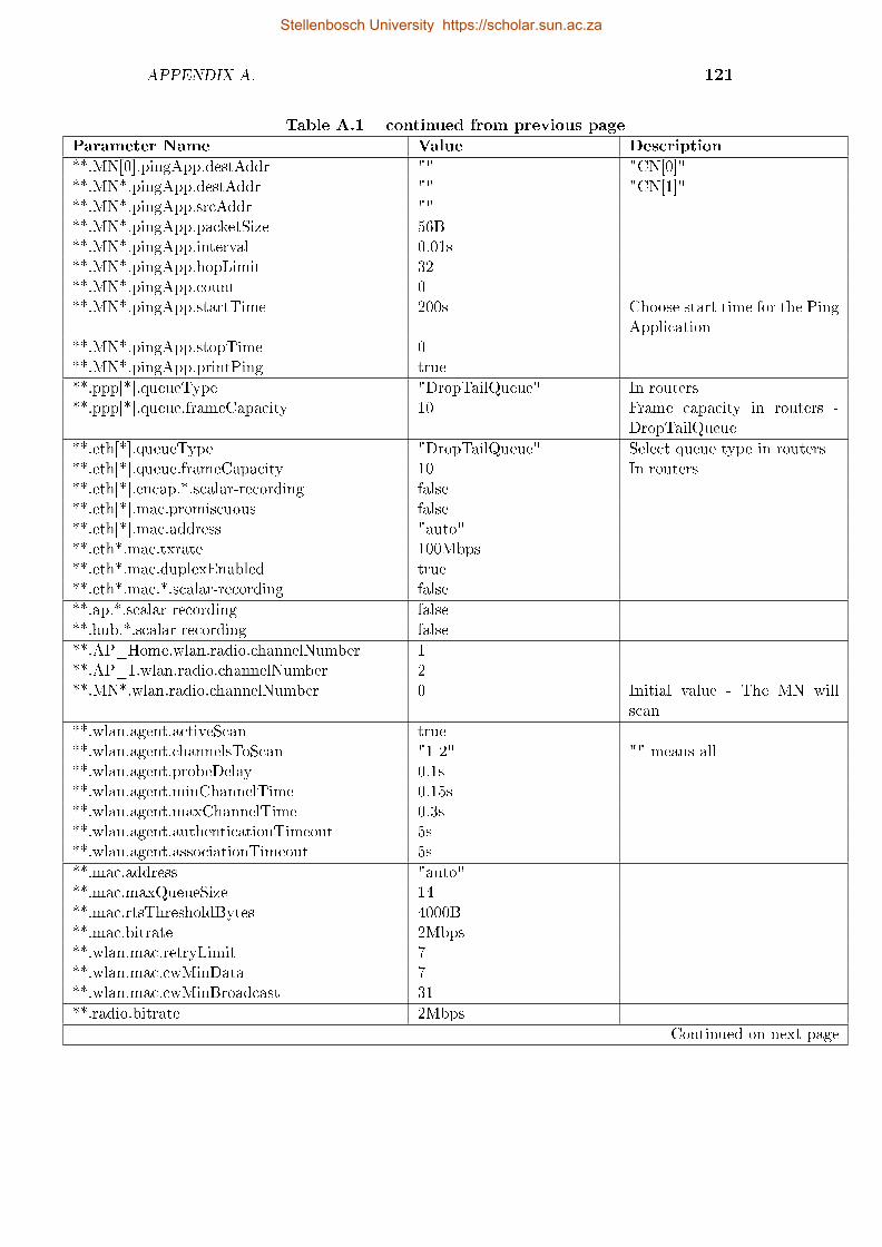
APPENDIX A. 121
Table A.1 � continued from previous page
Parameter Name Value Description
**.MN[0].pingApp.destAddr "" "CN[0]"**.MN*.pingApp.destAddr "" "CN[1]"**.MN*.pingApp.srcAddr ""**.MN*.pingApp.packetSize 56B**.MN*.pingApp.interval 0.01s**.MN*.pingApp.hopLimit 32**.MN*.pingApp.count 0**.MN*.pingApp.startTime 200s Choose start time for the Ping
Application**.MN*.pingApp.stopTime 0**.MN*.pingApp.printPing true
**.ppp[*].queueType "DropTailQueue" In routers**.ppp[*].queue.frameCapacity 10 Frame capacity in routers -
DropTailQueue
**.eth[*].queueType "DropTailQueue" Select queue type in routers**.eth[*].queue.frameCapacity 10 In routers**.eth[*].encap.*.scalar-recording false**.eth[*].mac.promiscuous false**.eth[*].mac.address "auto"**.eth*.mac.txrate 100Mbps**.eth*.mac.duplexEnabled true**.eth*.mac.*.scalar-recording false
**.ap.*.scalar-recording false**.hub.*.scalar-recording false
**.AP_Home.wlan.radio.channelNumber 1**.AP_1.wlan.radio.channelNumber 2**.MN*.wlan.radio.channelNumber 0 Initial value - The MN will
scan
**.wlan.agent.activeScan true**.wlan.agent.channelsToScan "1 2" "" means all**.wlan.agent.probeDelay 0.1s**.wlan.agent.minChannelTime 0.15s**.wlan.agent.maxChannelTime 0.3s**.wlan.agent.authenticationTimeout 5s**.wlan.agent.associationTimeout 5s
**.mac.address "auto"**.mac.maxQueueSize 14**.mac.rtsThresholdBytes 4000B**.mac.bitrate 2Mbps**.wlan.mac.retryLimit 7**.wlan.mac.cwMinData 7**.wlan.mac.cwMinBroadcast 31
**.radio.bitrate 2Mbps
Continued on next page
Stellenbosch University https://scholar.sun.ac.za

APPENDIX A. 122
Table A.1 � continued from previous page
Parameter Name Value Description
**.radio.transmitterPower 2.0mW**.radio.carrierFrequency 2.4GHz**.radio.thermalNoise -110dBm**.radio.sensitivity -82mW**.radio.pathLossAlpha 2**.radio.snirThreshold 4dB
**.relayUnitType "MACRelayUnitNP"**.relayUnit.addressTableSize 100**.relayUnit.agingTime 120s**.relayUnit.bu�erSize 1MB**.relayUnit.highWatermark 512KB**.relayUnit.pauseUnits 300 pause for 300*512 bit (19200
byte) time**.relayUnit.addressTableFile ""**.relayUnit.numCPUs 2**.relayUnit.processingTime 2us**.relayUnit.*.scalar-recording false
Stellenbosch University https://scholar.sun.ac.za

Appendix B
B.1 Router Advertisement Test Bed
Con�guration
The con�guration for the Router Advertisement of the home network can beseen below. It is important to notice the MinRtrAdvInterval and MaxRtrAd-vInterval. These parameters are speci�ed in [8] but are continuously changedfor evaluation purpose. The AdvHomeAgentFlag is used by the Home Agentto indicate to the network that is serves as a Home Agent on the network.interface wlan0 {
AdvSendAdvert on;AdvManagedFlag o�;MinRtrAdvInterval 3;MaxRtrAdvInterval 10;AdvHomeAgentFlag on;AdvHomeAgentInfo on;HomeAgentLifetime 1800;HomeAgentPreference 10;pre�x 2001:db8:abcd:14::/64 {
AdvOnLink on;AdvAutonomous on;AdvRouterAddr on;
};};
B.2 MIPv6 Test Bed Con�guration
The MIPv6 network setup con�guration used for the mip6d daemon runningon the network to enable handling of mobility messages is described in this sec-tion. For the MIPv6 setup the con�guration is split up into three section, HomeAgent con�guration, Mobile Node con�guration and Correspondent Node con-�guration.
123
Stellenbosch University https://scholar.sun.ac.za

APPENDIX B. 124
B.2.1 MIP6D MN Con�guration
All the con�guration for the mobile in the MIPv6 network can be seen in TableB.1.
Table B.1: MIP6D MN Parameters
Parameter Name Value Description
NodeCon�g MN Specify if the node is a MN,HA or CN
DebugLevel 10 If set to > 0, will not detachfrom tty
DoRouteOptimizationCN enabled Support route optimizationwith other MN's
DoRouteOptimizationMN enabled Use route optimization withCN's
UseCnBuAck disabled Indicates if the Ack bit shouldbe set in BU sent to CN
OptimisticHando� disabled Begin RO before the MN re-ceived a BAck
MnMaxHaBindingLife 420 Specify the maximum HAbinding lifetime
MnMaxCnBindingLife 420 Specify the maximum CNbinding lifetime
MnDiscardHaParamProb disabled Toggles if the MN shoulddiscard ICMPv6 ParameterProblem messages from HA.
Interface "wlan0" Choose wireless interface forMN
MnRouterProbes 1 Indicates how many times theMN should send NUD probesto its old router after receivinga RA from a new one.
MnHomeLink {IsMobRtrHomeAddressHomeAgentAddressMnRoPolicy }
"wlan0"enabled2001:db8:abcd:14:217:c4�:fe39:7306/642001:db8:abcd:14::1enabled
Setup for the Homelink struc-ture, multiple HomeAddressand MN.
UseMnHaIPsec enabled Enable IPSec for MIPv6KeyMngMobCapability enabled Enable Key Management Mo-
bility Capability
Continued on next page
Stellenbosch University https://scholar.sun.ac.za

APPENDIX B. 125
Table B.1 � continued from previous page
Parameter Name Value Description
IPsecPolicySet {HomeAgentAddressHomeAddressIPsecPolicy MhIPsecPolicy ICMPIPsecPolicy TunnelMh }
2001:db8:abcd:14::12001:db8:abcd:14:217:c4�:fe39:7306/64UseESP 1 2UseESP 5UseESP 3 4
IPsec settings for security inBinding messages.
B.2.2 MIP6D HA Con�guration
Table B.2 shows the con�guration for the home agent in the MIPv6 network.
Table B.2: MIP6D HA Parameters
Parameter Name Value Description
NodeCon�g HA Specify if the node is a MN,HA or CN
DebugLevel 10 If set to > 0, will not detachfrom tty
Interface "eth1" Choose wireless interface forMN
DoRouteOptimizationMN enabled Support route optimizationwith other MN's
DoRouteOptimizationCN enabled Use route optimization withCN's
UseMnHaIPsec enabled Enable IPSec for MIPv6
B.2.3 MIP6D CN Con�guration
Table B.3 shows the con�guration for the correspondent node in the MIPv6network.
Table B.3: MIP6D CN Parameters
Parameter Name Value Description
NodeCon�g CN Specify if the node is a MN,HA or CN
DoRouteOptimizationCN enabled Support route optimizationwith other MN's.
Stellenbosch University https://scholar.sun.ac.za

APPENDIX B. 126
B.3 FMIPv6 Test Bed Con�guration
In this section the FMIPv6 network setup con�guration used for the fmip6ddaemon running on the network to enable handling of mobility messages forFMIPv6 is described. For the FMIPv6 setup, the con�guration is split upinto three section, Previous Access Router con�guration, New Access Routercon�guration and Mobile Node con�guration. The FMIPv6 daemon is run ontop of the MIPv6 protocol and this means that the con�guration described inSection B.2 is also applicable in this network setup.
B.3.1 FMIPv6 MN Con�guration
Table B.4 shows the con�guration for a Mobile Node in a FMIPv6 networksetup.
Table B.4: FMIPv6 MN Parameters
Parameter Name Value Description
DetachFromTTY true Speci�es if FMIPv6 runs asdaemon
DebugLevel 1 Specify debug level for dea-mon
PrimaryInterface {IfName } wlan0
Speci�es a primary interfacefor use.
LinkQuality{UseLinkQualityTriggersThreshold }
false-50
Link quality and threshold forLink-Layer handover trigger.
ScanningInterface {IfName } wlan1
Speci�es an alternate interfaceused for scanning
OptimizeL2onlyHovers true Indicates whether the MN op-timizes L2-only handovers ornot
ScanNoti�cationWorkaround false Indicates whether the driverfor the scanning interface isbroken or not.
Stellenbosch University https://scholar.sun.ac.za

APPENDIX B. 127
B.3.2 FMIPv6 PAR Con�guration
In Table B.5 the con�guration for a previous access router can be seen.
Table B.5: FMIPv6 PAR Parameters
Parameter Name Value Description
DetachFromTTY true Specify if FMIPv6 runs asdaemon
DebugLevel 1 Specify debug level for dea-mon
AskSupportForBu�ering true Ask NAR to bu�er incomingpackets until MN �nishes itsHandover.
Bu�erLength 5 Number of packets bu�ered onNAR until the MN attaches.
Interface {IfNamePreference}
eth11
Speci�es an interface and op-tions associated with it.
NIHover{do_ni_hoverdo_ni_hover }
true00:0C:02:00:AD:19
Speci�es whereas the AccessRouter incites the MobileNodes to perform a handover.When do_ni_hover is set totrue, every RtSolPr acts as atrigger for a Network InitiatedHandover.
nap MIP4-AP {nap_llanr_llanr_addrnr_pfx }
00:0C:02:00:AD:1900:19:d1:75:b1:e12001:db8:abcd:15::1/642001:db8:abcd:15::/64
Known access points con�gu-ration.
B.3.3 FMIPv6 NAR Con�guration
Table B.6 shows the con�guration for the new access router in a FMIPv6network.
Table B.6: FMIPv6 NAR Parameters
Parameter Name Value Description
DetachFromTTY true Specify if FMIPv6 runs asdaemon
Continued on next page
Stellenbosch University https://scholar.sun.ac.za

APPENDIX B. 128
Table B.6 � continued from previous page
Parameter Name Value Description
DebugLevel 1 Specify debug level for dea-mon
AskSupportForBu�ering true Ask NAR to bu�er incomingpackets until MN �nishes itsHandover.
Bu�erLength 5 Number of packets bu�ered onNAR until the MN attaches.
Interface {IfNamePreference}
eth11
Speci�es an interface and op-tions associated with it.
NIHover{do_ni_hoverdo_ni_hover }
true80:1F:02:4E:AD:17
Speci�es whereas the AccessRouter incites the MobileNodes to perform a handover.When do_ni_hover is set totrue, every RtSolPr acts as atrigger for a Network InitiatedHandover.
nap MIP4-AP {nap_llanr_llanr_addrnr_pfx }
80:1F:02:4E:AD:1700:13:72:7a:09:f72001:db8:abcd:17::1/642001:db8:abcd:17::/64
Known access points con�gu-ration.
B.4 PMIPv6 Test Bed Con�guration
To enable the handling of mobility messages, the pmip6d daemon must be ableto run thus the PMIPv6 network was set up as described in this section. Forthe PMIPv6 setup the con�guration is split up into three section, Local Mo-bility Anchor con�guration, Mobile Access Router 1 con�guration and MobileAccess Router 2 con�guration. The PMIPv6 network setup does not rely oncon�guration mentioned in Section B.2 and Section B.3.
B.4.1 PMIPv6 LMA Con�guration
Table B.7 shows the con�guration for the local mobility anchor in a PMIPv6network.
Table B.7: PMIPv6 LMA Parameters
Parameter Name Value Description
NodeCon�g LMA Specify if the node is a MN, HA or CNContinued on next page
Stellenbosch University https://scholar.sun.ac.za

APPENDIX B. 129
Table B.7 � continued from previous page
Parameter Name Value Description
DebugLevel 10 Specify debug level for daemonDoRouteOptimizationCN disabled Speci�es a primary interface for use.DoRouteOptimizationMN disabled Link quality and threshold for Link-
Layer handover trigger.UseMnHaIPsec disabled Speci�es an alternate interface used for
scanningKeyMngMobCapability disabled Indicates whether the MN optimizes
L2-only handovers or notProxyMipLma "LMA testbed n1" {TimestampBasedApproachInUseMobileNodeGeneratedTimestampInUseFixedMAGLinkLocalAddressOnAllAccessLinksFixedMAGLinkLayerAddressOnAllAccessLinksMinDelayBeforeBCEDeleteMaxDelayBeforeNewBCEAssignTimestampValidityWindowLmaAddressLmaPmipNetworkDeviceLmaCoreNetworkAddressLmaCoreNetworkAddressRetransmissionTimeOutMaxMessageRetransmissionsTunnelingEnabledDynamicTunnelingEnabledMag1AddressIngressMag1AddressEgressMag2AddressIngressMag2AddressEgress}
enableddisabledfe80::211:22�:fe33:445500:11:22:33:44:55100001500300
eth0
eth05005enabledenabled
Indicates whether the driver for thescanning interface is broken or not.
B.4.2 PMIPv6 MAG1 Con�guration
Table B.8 shows the con�guration for mobile access gateway 1 as seen in Figure3.8 in a PMIPv6 network.
Table B.8: PMIPv6 MAG1 Parameters
Parameter Name Value Description
NodeCon�g MAG Specify if the node is aMN, HA or CN
DebugLevel 10 Specify debug level fordaemon
DoRouteOptimizationCN disabled Speci�es a primary in-terface for use.
DoRouteOptimizationMN disabled Link quality andthreshold for Link-Layer handover trig-ger.
UseMnHaIPsec disabled Speci�es an alternateinterface used for scan-ning
KeyMngMobCapability disabled Indicates whether theMN optimizes L2-onlyhandovers or notContinued on next page
Stellenbosch University https://scholar.sun.ac.za

APPENDIX B. 130
Table B.8 � continued from previous page
Parameter Name Value Description
ProxyMipMag "MAG2 testbed n1" {TimestampBasedApproachInUseMobileNodeGeneratedTimestampInUseFixedMAGLinkLocalAddressOnAllAccessLinksFixedMAGLinkLayerAddressOnAllAccessLinksEnableMAGLocalRoutingLmaAddressMagAddressIngressMagAddressEgressMagDeviceIngressMagDeviceEgressPBULifeTimeRetransmissionTimeOutMaxMessageRetransmissionsTunnelingEnabledDynamicTunnelingEnabledRadiusClientCon�gFileRadiusPasswordPcapSyslogAssociationGrepStringPcapSyslogDeAssociationGrepString}
enableddisabled00:11:22:33:44:55enabled
�eth1��eth0�400005005enabledenabled/usr/local/etc/radiusclient/radiusclient.confpasswordReAssociation Success:STAReceived Deauth:STA
Indicates whether thedriver for the scanninginterface is broken ornot.
B.4.3 PMIPv6 MAG2 Con�guration
Table B.9 shows the con�guration for mobile access gateway 2 as seen in Figure3.8 in a PMIPv6 network.
Table B.9: PMIPv6 MAG2 Parameters
Parameter Name Value Description
NodeCon�g MAG Specify if the node is aMN, HA or CN
DebugLevel 10 Specify debug level fordaemon
DoRouteOptimizationCN disabled Speci�es a primary in-terface for use.
DoRouteOptimizationMN disabled Link quality andthreshold for Link-Layer handover trig-ger.
UseMnHaIPsec disabled Speci�es an alternateinterface used for scan-ning
KeyMngMobCapability disabled Indicates whether theMN optimizes L2-onlyhandovers or notContinued on next page
Stellenbosch University https://scholar.sun.ac.za

APPENDIX B. 131
Table B.9 � continued from previous page
Parameter Name Value Description
ProxyMipMag "MAG2 testbed n1"TimestampBasedApproachInUseMobileNodeGeneratedTimestampInUseFixedMAGLinkLocalAddressOnAllAccessLinksFixedMAGLinkLayerAddressOnAllAccessLinksEnableMAGLocalRoutingLmaAddressMagAddressIngressMagAddressEgressMagDeviceIngressMagDeviceEgressPBULifeTimeRetransmissionTimeOutMaxMessageRetransmissionsTunnelingEnabledDynamicTunnelingEnabledRadiusClientCon�gFileRadiusPasswordPcapSyslogAssociationGrepStringPcapSyslogDeAssociationGrepString
enableddisabled00:11:22:33:44:55enabled
�eth1��eth0�400005005enabledenabled/usr/local/etc/radiusclient/radiusclient.confpasswordReAssociation Success:STAReceived Deauth:STA
Indicates whether thedriver for the scanninginterface is broken ornot.
B.4.4 PMIPv6 FreeRadius Server
The following text is a example for the FreeRadius server con�guration. Thisspeci�es the MN's that will have to access the LMA for control messages. Thiscon�guration will only be used to authorize the MN.
0000001c232fe989Auth-Type := Accept, User-Password == "linux"Service-Type = Authenticate-Only,Framed-Interface-Id = 0000:0000:0000:0000,Framed-IPv6-Pre�x = 2001:0100:0005:6000::/64
B.4.5 PMIPv6 FreeRadius Client
The FreeRadius client was updated to accommodate IPv6. The followingcon�guration is used to identify the clients.client 2001:100::3
secret = testing123shortname = mag2nastype = otherpassword = linux
Stellenbosch University https://scholar.sun.ac.za

Appendix C
C.1 MIPv6 Contiki Runtime Parameters
Table C.1 shows all the simulation parameters for the MIPv6 WSN simulationin Contiki. The parameters consist of node parameters, 802.15.4 parametersand 6 LoWPAN network parameters.
Table C.1: WSN MIPv6 Contiki Simulation Parameters
Parameter Name Value
Number of nodes 1 deployed MN
Network setup 2 Visited networks
Network dimension Spacing between the two network is10m.
Application model Time-driven
Packet size Between 20 to 35 bytes
Router lifetime 30s
Unicast router solicitationtimeout
1s
Device frequency 2.4 GHz
Queue length 10
132
Stellenbosch University https://scholar.sun.ac.za

List of References
[1] R. Hinden and S. Deering, �IP Version 6 Addressing Architecture,�http://tools.ietf.org/html/rfc4291, February 2006.
[2] J. Kovács, L. Bokor, Z. Kanizsai, and S. Imre, Review of Advanced Mo-bility Solutions for Multimedia Networking in IPv6. June 2013.
[3] S. Khan, K. Loo, and A. Kiani, �Tested Evaluation of Fast and SecureHandover in FMIPv6,� International Journal of Communication Networksand Information Security (IJCNIS), vol. 2, April 2010.
[4] EUROCOM, �OpenAirInterface Proxy Mobile IPv6,�http://www.openairinterface.org/openairinterface-proxy-mobile-ipv6-oai-pmipv6.
[5] D. Roth, J. Montavont, and T. Noel, �Performance evaluation of mobileIPv6 over 6LoWPAN,� in Proceedings of the 9th ACM symposium on Per-formance evaluation of wireless ad hoc, sensor, and ubiquitous networks,PE-WASUN '12, (New York, NY, USA), pp. 77�84, ACM, 2012.
[6] P. Ngamtura, �Performance Comparison Of Mipv6 And Fmipv6 OverWLAN,� Master's thesis, Faculty Of Graduate Studies Mahidol Univer-sity, March 2010.
[7] C. Systems, �IPv6 Extension Headers Review and Considerations,�http://www.cisco.com/en/US/technologies/tk648/tk872/technologies_white_paper0900aecd8054d37d.html,pp. 1,12, October 2006.
[8] C.Perkins, D. Johnson, and J. Arkko, �Mobility Support in IPv6,�http://tools.ietf.org/html/rfc6275, July 2011.
[9] A. Sekercioglu and A. Varga, � OMNeT++ Comparison,� Tech. Rep. 1.6,March 2013.
[10] R. Prasad and S. Dixit,Wireless IP and Building the Internet. The ArtechHouse Universal Personal Communications Series, Artech House, 2002.
[11] G. Xie, J. Chen, H. Zheng, J. Yang, and Y. Zhang, �Handover Latencyof MIPv6 Implementation in Linux,� in Global Telecommunications Con-ference, 2007. GLOBECOM '07. IEEE, pp. 1780�1785, 2007.
133
Stellenbosch University https://scholar.sun.ac.za

LIST OF REFERENCES 134
[12] J. Chandrasekaran, �Mobile IP: Issues, Challenges and Solutions,� in CS552 Computer Networks, Rutgers University, 2009.
[13] H. Soliman, C. Castelluccia, K. ElMalki, and L. Bellier, �Hi-erarchical Mobile IPv6 (HMIPv6) Mobility Management,�http://tools.ietf.org/html/rfc5380, October 2008.
[14] T. Ernst, �Network Mobility Support Goals and Requirements,�http://tools.ietf.org/html/rfc4886#page-2, July 2007.
[15] J. Hui and P. Thubert, �Compression Format for IPv6 Datagramsover IEEE 802.15.4-Based Networks,� http://tools.ietf.org/html/rfc6282,September 2011.
[16] � Internet Protocol, Version 4 (IPv4) Speci�cation,� Tech. Rep. RFC 791,IETF Secretariat, September 1981.
[17] S. Deering and R. Hinden, � Internet Protocol, Version 6 (IPv6) Speci�-cation,� Tech. Rep. RFC 2460, IETF Secretariat, December 1998.
[18] �World IPv6 Launch,� June 2012.
[19] R. Koodli, �Fast Handovers for Mobile IPv6,�http://tools.ietf.org/html/rfc5568, July 2009.
[20] K. Leung, V. Devarapalli, K. Chowdhury, and B. Patil, �Proxy MobileIPv6,� http://tools.ietf.org/html/rfc5213, August 2008.
[21] S. Gundavelli, �Extensions to Proxy Mobile IPv6 - Motivation,�http://tools.ietf.org/html/draft-gundavelli-netext-extensions-motivation-00, May 2009.
[22] J. Pieterse and R. Wolhuter, �Investigation of handover techniques in aIPv6 mobile network,� in Antennas and Propagation in Wireless Commu-nications (APWC), 2012 IEEE-APS Topical Conference on, pp. 1020�1023, 2012.
[23] J. Pieterse, R. Wolhuter, and N. Mitton, �Implementation and Analysisof FMIPv6, an Enhancement of MIPv6,� in Ad Hoc Networks (J. Zheng,N. Mitton, J. Li, and P. Lorenz, eds.), vol. 111 of Lecture Notes of theInstitute for Computer Sciences, Social Informatics and Telecommunica-tions Engineering, pp. 351�364, Springer Berlin Heidelberg.
[24] S. Ziegler, C. Crettaz, L. Ladid, S. Krco, A. Skarmeta, A. Jara, andW. Kastner, �IoT6 � Moving to an IPv6-based Future IoT report,� Tech.Rep. 20, 2013.
Stellenbosch University https://scholar.sun.ac.za

LIST OF REFERENCES 135
[25] G. Montenegro, N. Kushalnagar, J. Hui, and D. Culler,�Transmission of IPv6 Packets over IEEE 802.15.4 Networks,�http://tools.ietf.org/html/rfc4944, September 2007.
[26] M. Grayson, K. Shatzkamer, and K. Wierenga, Building the Mobile In-ternet. Cisco Press, 1 ed., February 2011.
[27] �Understanding IPv6 Link Local Address,�http://www.cisco.com/en/US/tech/tk872/technologies_con�guration_example09186a0080ba1d07.shtml,November 2011.
[28] C. Systems, IPv6 Con�guration Guide, Cisco IOS Release, ch. IPv6 State-less Autocon�guration. Cisco Systems, July 2012.
[29] M. Kamicho�, �Stateful Autocon�guration (DHCPv6),� April 2004.
[30] D. MINOLI, Building the Internet of Things with IPv6 and MIPv6: TheEvolving World of M2M Communications, vol. The Evolving World ofThe Evolving World. John Wiley & Sons, wol online book ed., July 2013.
[31] �IEEE Standard 802.15.4-2009: Wireless medium access control and phys-ical layer speci�cations for low-rate wireless personal area network ,�http://standards.ieee.org/about/get/802/802.15.html, April 2009.
[32] Z. Shelby and C. Bormann, �The Wireless Embedded Internet,� p. 244,December 2009.
[33] G. M. Lee, J. Park, N. Kong, N. Crespi, and I. Chong,�The Internet of Things - Concept and Problem Statement,�http://tools.ietf.org/html/draft-lee-iot-problem-statement-00, July 2012.
[34] F. Nazir and A. Seneviratne, �Towards Mobility Enabled Protocol StackFor Future Wireless Networks,� Ubiquitous Computing and Communica-tion Journal, vol. 2, no. 4, 2010.
[35] Y. Chen and L. Li, �A fair packet dropping algorithm considering chan-nel condition in di�-serv wireless networks,� in Computer and Informa-tion Technology, 2004. CIT '04. The Fourth International Conference on,pp. 554�559, 2004.
[36] M. Atiquzzaman and A. Reaz, �Survey and classi�cation of transport layermobility management schemes,� in Personal, Indoor and Mobile RadioCommunications, 2005. PIMRC 2005. IEEE 16th International Sympo-sium on, vol. 4, pp. 2109�2115 Vol. 4, 2005.
[37] X. Perez-Costa, M. Torrent-Morenoab, and H. Hartenstein, �A Perfor-mance Comparison of Mobile IPv6, Hierarchical Mobile IPv6, Fast Han-dovers for Mobile IPv6 and their Combination,� Mobile Computing andCommunications Review, vol. 7, no. 4, 2004.
Stellenbosch University https://scholar.sun.ac.za

LIST OF REFERENCES 136
[38] A. Cabellos-Aparicio and H. Julian-Bertomeu, �Measurement-BasedComparison of IPv4/IPv6 Mobility Protocols on a WLAN Scenario,� Uni-versitat Politècnica de Catalunya, 2010.
[39] V. Vassiliou and Z. Zinonos, �An Analysis of the Handover Latency Com-ponents in Mobile IPv6,� JOURNAL OF INTERNET ENGINEERING,vol. 3, December 2009.
[40] J. Darwich, �Comparative study of Mobile IPv4 and Mobile IPv6,� p. 26,2011.
[41] R. Atkinson, �Security Architecture for the Internet Protocol,�http://www.ietf.org/rfc/rfc2401.txt, November 1998.
[42] M. SKOREPA and K. MOLNAR, �Time analysis of Route Optimiza-tion in MIPv6,� in Recent Advances in Computers (N. E. Mastorakis,V. Mladenov, Z. Bojkovic, S. Kartalopoulos, and A. Varonides, eds.),p. 659, December 2012.
[43] J. Arkko, C. Vogt, and W. Haddad, �Enhanced Route Optimization forMobile IPv6,� http://www.ietf.org/rfc/rfc4866.txt, May 2007.
[44] S. Sudanthi, �SANS Institute InfoSec Reading Room - Mobile IPv6,�SANS Institute, January 2003.
[45] R. Silva and J. S. Silva, �An Adaptation Model for Mobile IPv6 supportin lowPANs,� https://www.cisuc.uc.pt/publication/show/2300, 2009.
[46] V. Devarapalli, R. Wakikawa, A. Petrescu, and P. Thu-bert, �Network Mobility (NEMO) Basic Support Protocol,�http://tools.ietf.org/html/rfc3963, January 2005.
[47] J. Xie, I. Howitt, and I. Shibeika, �IEEE 802.11-Based Mobile IP FastHando� Latency Analysis,� in Communications, 2007. ICC '07. IEEEInternational Conference on, pp. 6055�6060, 2007.
[48] Y. Bernet, S. Blake, D. Grossman, and A. Smith, �An Informal Man-agement Model for Di�serv Routers,� http://tools.ietf.org/html/rfc3290,May 2002.
[49] H. N. Nguyen and C. Bonnet, �Scalable proxy mobile IPv6 for heteroge-neous wireless networks,� in Mobiworld 2008, 2008 International Work-shop on Mobile IPv6 and Network-based Localized Mobility Management,in conjunction with Mobility Conference 2008, September 10-12, I-Lan,Taiwan, 09 2008.
Stellenbosch University https://scholar.sun.ac.za

LIST OF REFERENCES 137
[50] Y. Kim and Y. Mun, �Adaptive Selection of MIPv6 and HierarchicalMIPv6 for Minimizing Signaling Cost,� in Computational Science and ItsApplications - ICCSA 2006 (M. Gavrilova, O. Gervasi, V. Kumar, C. Tan,D. Taniar, A. Laganá, Y. Mun, and H. Choo, eds.), vol. 3981 of LectureNotes in Computer Science, pp. 611�620, Springer Berlin Heidelberg.
[51] M. C. M. Albrecht, �Introduction to Discrete Event Simulation.� January2010.
[52] L. Leemis and S. Park, Discrete-Event Simulation: A First Course .No. 6�2004, December 2004.
[53] L. Leemis and S. Park, Random Number Generation. No. 6�2004, Decem-ber 2004.
[54] INET Framework for OMNeT++, June 2012.
[55] M. Matsumoto and T. Nishimura, �Mersenne Twister: A 623-Dimensionally Equidistributed Uniform Pseudo-RNG,� ACM Transac-tions on Modeling and Computer Simulation, vol. 8, pp. 3�30, January1998.
[56] S. Mustafa, F. Sardar, S. Shabbir, and A. Maqsood, �Analysis Of MobileIP Handover Latency And Packet Loss Issues Using Simulation,� Master'sthesis, Department of Electrical Engineering, Feb 2011.
[57] T. Henderson, LBNL's Network Simulator 2, November 2011.
[58] A. Alignan, �Introduction to Cooja,� January 2013.
[59] F. Z. Yousaf, C. Bauer, and C. Wietfeld, �An accurate and extensiblemobile IPv6 (xMIPV6) simulation model for OMNeT++,� in Proceedingsof the 1st international conference on Simulation tools and techniquesfor communications, networks and systems & workshops, Simutools '08,pp. 88:1�88:8, ICST (Institute for Computer Sciences, Social-Informaticsand Telecommunications Engineering), 2008.
[60] V. Nuorvala and A. J. Tuominen, �UMIP - Mobile IPv6 and NEMO forLinux,� April 2013.
[61] �Iperf: Network Performance,� tech. rep., July 2011.
[62] �FMIPv6.org: Fast Handovers for Mobile IPv6,� September 2007.
[63] A. Dunkels, �Full TCP/IP for 8-bit architectures,� in Proceedings of the1st international conference on Mobile systems, applications and services,MobiSys '03, (New York, NY, USA), pp. 85�98, ACM, 2003.
Stellenbosch University https://scholar.sun.ac.za

LIST OF REFERENCES 138
[64] J. Polastre, R. Szewczyk, and D. Culler, �Telos: enabling ultra-low powerwireless research,� in Information Processing in Sensor Networks, 2005.IPSN 2005. Fourth International Symposium on.
[65] J. Postel, �The User Datagram Protocol (UDP),�http://www.erg.abdn.ac.uk/ gorry/course/inet-pages/udp.html, May1996.
[66] D. Roth, J. Montavont, and T. Noel, �MOBINET: Mobility managementacross di�erent wireless sensor networks,� in Wireless Communicationsand Networking Conference (WCNC), 2011 IEEE, pp. 351�356, 2011.
[67] E. Ivov and T. Noel, �Soft Handovers over 802.1lb with Multiple In-terfaces,� in Wireless Communication Systems, 2005. 2nd InternationalSymposium on, pp. 549�554, 2005.
Stellenbosch University https://scholar.sun.ac.za