Embed Size (px)
Citation preview

COMPARATIVE ANALYSIS OF GEOREFERENCING PROCEDURES USING VARIOUS SOURCES OF CONTROL DATA
A. Habiba, A. Jarvisa, A. P. Kerstinga, Y. Alghamdia
aDepartment of Geomatics Engineering, University of Calgary, Calgary, Alberta, Canada T2N 1N4
[email protected] - (amyjarvi, ana.kersting, yamalgha)@ucalgary.ca
Commission IV, WG IV/9 KEY WORDS: Digital Camera, Georeferencing, Orthoimage Generation, Object Reconstruction, Performance Analysis, Sensor Fusion ABSTRACT: The increasing efficiency and affordability of modern spatial acquisition systems, such as LiDAR, have provided reliable alternative sources of control data for image georeferencing. Indirect georeferencing using LiDAR control features to derive the exterior orientation parameters (EOP) allows for a straight-forward integration of LiDAR and photogrammetric data which can be used, for example, for more effective orthoimage generation and 3-D city modeling. This paper presents a comparative analysis of indirect georeferencing by investigating the use of three sources of control data, namely, ground control points, LiDAR patches, and LiDAR lines. In this regard, ground control points are obtained through GPS surveying and are used to derive the EOPs of the involved imagery. Point features cannot be distinguished in LiDAR data however, and thus when using LiDAR as the source of control for photogrammetric georeferencing, linear and areal features are used. Moreover, a semi-automated approach for the extraction of lines and patches from LiDAR data is presented. Linear and areal features are identified in the imagery while conjugate LiDAR features are extracted through planar patch segmentation and intersection. Following the extraction procedure, the mathematical models for incorporating the image and LiDAR features for georeferencing are discussed. RMSE analysis and orthoimage generation using the three sets of EOP – obtained from GCPs, LiDAR patches, and LiDAR lines – are used to quantitatively and qualitatively compare the object reconstruction results using the three sources of control data. Finally, the practicality issues of these methods are compared in terms of the effort involved in the derivation of control information and the underlying procedures.
1. INTRODUCTION
Photogrammetric reconstruction procedures aim at deriving three-dimensional information from two-dimensional images. These procedures create surfaces that are rich in semantic information, which can be clearly recognized in the captured imagery, and provide highly accurate results due to the inherent redundancy associated with photogrammetric reconstruction. Many photogrammetric applications, such as mapping and orthoimage production, require the interior and exterior orientation parameters of the imaging sensor. The interior orientation parameters (IOP), which include the principal point coordinates, focal length, and distortion parameters, can be derived from a camera calibration procedure or obtained from the camera manufacturer. The exterior orientation parameters (EOP), which include the position and attitude of the camera at the time of exposure with respect to object space coordinates frame, can be derived either through indirect georeferencing using ground control information or direct georeferencing when GPS/INS is available onboard the imaging platform. The quality of the reconstructed surface is affected by the accuracy of the IOP and EOP, and thus it is essential that these parameters be determined to a high degree of accuracy. In direct georeferencing, the IMU body frame attitude and the GPS phase centre position are directly measured using onboard GPS/INS systems. In addition, the IMU boresighting angles and the GPS antenna offsets relative to the camera perspective centre are computed to determine the position (X0, Y0, Z0) and attitude (ω, φ, κ) of the camera at the time of exposure with respect to object space coordinates frame. This approach is
computationally efficient since only an intersection procedure is required, as well as economical in the long run since no ground control is required. Nonetheless, indirect georeferencing is traditionally favourable due to its accuracy and robustness against IOP biases (Cramer et al., 2000). In indirect georeferencing, the EOPs are determined indirectly using ground control, where the most common type of control involves the use of ground control points obtained through field surveying procedures. This form of ground control can be costly in terms of the required time and effort but has proven to be an accurate source of control for the georeferencing procedure. With the recent developments in spatial acquisition systems, however, some reliable alternative forms of control are becoming available. In this regard, LiDAR scanning is rapidly taking its place in the mapping industry as a fast and cost-effective 3-D data acquisition technology for capturing accurate positional information from physical surfaces. LiDAR georeferencing is directly established through the GPS/INS components of the LiDAR system. The increased accuracy and affordability of GPS/INS systems are the main reasons behind the expanding adoption of LiDAR systems. The use of LiDAR derived control has two main advantages. First, it allows for a straight-forward integration of LiDAR and photogrammetric data, which has numerous benefits such as effective production of 3-D city modeling and orthoimage generation. In addition, the use of LiDAR control features can eliminate the need for ground control points which simplifies the indirect georeferencing procedure and makes it more affordable.
1147

The International Archives of the Photogrammetry, Remote Sensing and Spatial Information Sciences. Vol. XXXVII. Part B4. Beijing 2008
The objective of this paper is to present a comparative analysis of indirect georeferencing using real data to evaluate the use of three sources of control data, namely, ground control points, LiDAR patches, and LiDAR lines. Section 2 of this paper describes indirect georeferencing using LiDAR patches and LiDAR lines. A semi-automated approach for the extraction of patches and lines from LiDAR data is presented and used to obtain the image EOP from LiDAR control features. In Section 3, quantitative analysis, using RMSE analysis, and qualitative analysis, using orthoimage generation, are presented to demonstrate the comparison between the object reconstruction results using the three sources of control data. Finally, the conclusions are summarized in Section 4.
2. GEOREFERENCING METHODS
Photogrammetric georeferencing is the process of relating the image and ground coordinate systems by defining the position and orientation information (EOP) of the camera at the moment of exposure relative to the object space coordinate system. Computing the EOP is performed either directly (direct georeferencing) when GPS/INS is available onboard the imaging platform, or indirectly (indirect georeferencing) using ground control information. Ground control points (GCPs) are traditionally the most commonly used source of control for photogrammetric indirect georeferencing. Despite its proven accuracy in photogrammetric reconstruction, using GCPs as a source of control is costly and labour intensive as it requires field surveying. For this reason, other sources of control data require investigation. The availability of LiDAR data, however, allows for alternative methods for image georeferencing. In particular, LiDAR-derived control features can be utilized for the georeferencing of the photogrammetric data relative to the LiDAR reference frame. Since the LiDAR footprints are irregularly distributed, however, no point-to-point correspondence can be assumed between the photogrammetric and LiDAR data. As such, it is almost impossible to identify distinct conjugate points in overlapping photogrammetric and LiDAR data. Consequently, LiDAR patches (Section 2.1) and LiDAR lines (Section 2.2) will be used as control information for the georeferencing of the photogrammetric data. 2.1 Indirect Georeferencing using LiDAR patches
This section outlines the procedure in which LiDAR patches are used to obtain the image georeferencing parameters. The steps for this procedure include the extraction of the LiDAR patches from the LiDAR point cloud, followed by the incorporation of LiDAR-derived areal features in the photogrammetric triangulation procedure. 2.1.1 Extraction of LiDAR Patches: In order to utilize LiDAR control features, the features must be extracted from the LiDAR point cloud. This section outlines the process for the extraction of areal features from irregular LiDAR footprints (Al-Durgham, 2007). The extraction of features from LiDAR is performed using a developed program. The process begins by displaying the LiDAR intensity images in the program window, in which the user selects an area where it appears that areal features might be present. The user clicks on the centre of the area after defining the radius of a circle within which the original LiDAR footprints will be extracted. It should be noted that the LiDAR intensity images are only used for visualization purposes. Figure 1a shows a sample area as well as the original LiDAR footprints located in a selected area. Then, a
segmentation technique (Kim et al., 2007) is used to identify planar patches in the point cloud within the selected area. The outcome from the segmentation is an aggregated set of points representing planar patches in the selected area (Figure 1b).
(a) (b)
Figure 1: a) Area of interest selection and LiDAR point cloud
extraction, b) Segmented planar patches.
2.1.2 Incorporation of Areal Features for Image Georeferencing: The approaches used to incorporate areal features extracted from LiDAR data in a photogrammetric triangulation procedure are now presented. The first outlined approach is the coplanarity-based incorporation of areal features. The second approach involves the use of a point-based incorporation of areal features, where the weight matrix of the utilized points is modified. Coplanarity-based Incorporation of Planar Patches In this approach, the planar patch in the imagery is defined by a minimum of three points, for example points a, b, and c, which are located in the image space, while the LiDAR patch is defined as a set of LiDAR points in object space (Habib et al., 2007). The points, a, b, and c should be visible in at least two overlapping images. The collinearity equations are used to relate the image space coordinates of the points cba ,, to their object space coordinates, A,B,C. The LiDAR points belonging to a certain planar-surface patch should coincide with the photogrammetric patch representing the same object space surface. The coplanarity of the LiDAR and photogrammetric points is explained mathematically in Habib et al. (2007). In physical terms, this constraint means that the normal distance between any LiDAR point P and the corresponding photogrammetric surface consisting of the three points should be zero. In other words, the volume of the tetrahedron comprised of the four points (A, B, C and P) should be equal to zero, as these points belong to the same plane. This constraint is applied for all LiDAR points located within this surface patch.
Point-based Incorporation of Planar Patches A second approach for the incorporation of planar patches uses a point-based technique, in which existing bundle adjustment procedures which are based on the collinearity equations, can be used for the incorporation of control areal features (Aldelgawy et al., 2008). For this approach, conjugate patch vertices are defined in at least two overlapping images. Then, the corresponding control patch is extracted from the LiDAR point cloud using the procedure described in section 2.1.1. From the extracted LiDAR control patch, which consists of hundred of points, some points are selected as patch vertices. The number of points selected in the LiDAR patch should be equivalent to the number of vertices defined in the imagery.
1148

The International Archives of the Photogrammetry, Remote Sensing and Spatial Information Sciences. Vol. XXXVII. Part B4. Beijing 2008
One should note that the points selected in the imagery and in LiDAR patch need not be conjugate (Figure 2). In order to compensate for the non-correspondence between the vertices defined in the imagery and the vertices in the control patch, we will restrict the weight of the selected points from the LiDAR control patch, along the plane direction. The weight restriction procedure is performed as follows. First, a local coordinate system (UVW) with the U and V axes aligned along the plane direction is defined. The relationship between the original coordinate system (XYZ) and the local coordinate system (UVW) is defined by the rotation matrix R. The rotation matrix is defined using the orientation of the normal to the planar patch, which is derived through a plane fitting procedure using all points of the control LiDAR patch. The original weight
matrix, XYZP ,is defined as the inverse of the variance-
covariance matrix ∑ XYZ , which depends on the accuracy
specification of the LiDAR data. Using the law of error propagation, the weight of the points in the local coordinate system ( UVWP ) can be derived according to Equation 1, where
XYZP is the weight matrix in the object coordinate system
defined by the LiDAR data, and UVWP is the weight matrix in the patch coordinate system. Then, the weight matrix can be modified according to Equation 2 by assigning a zero value for the weights along the planar patch, to obtain a new weight matrix UVWP' in the plane coordinate system. Finally, the
modified weight matrix XYZP' in the original coordinate system can be derived according to Equation 3.
TXYZUVW RRPP =
(1)
⎥⎥⎥
⎦
⎤
⎢⎢⎢
⎣
⎡
=
pP
W
UVW
00000000
' (2)
RPRP UVWT
XYZ '' = (3) Next, a point-based solution using a regular bundle adjustment procedure, with the modified weight matrix ( XYZP' ), is applied to georeference the involved imagery. It is important to mention that in order to de-correlate the estimated parameters in the bundle adjustment procedure, one should make sure to use planar patches with varying slope and orientation when using control planar patches.
Figure 2: Point-based incorporation of planar patches in
photogrammetry.
2.2 Indirect Georeferencing using LiDAR lines
Similar to LiDAR-derived areal features, LiDAR-derived linear features can be used as control information for the georeferencing of the photogrammetric data. This section outlines two methods for the integration of LiDAR linear control features in a photogrammetric triangulation procedure. 2.2.1 Extraction of LiDAR Lines: Similar to the extraction of areal features, the extraction of linear features from a LiDAR point cloud is performed using a developed program (Figure 3). Once LiDAR patches are extracted (Section 2.1.1), neighbouring planar patches are identified and intersected to produce infinite straight-line segments. Then, the LiDAR points in the segmented patches that are within a certain distance from the infinite lines are projected onto the lines. The most extreme projected points along the infinite lines are chosen as the line endpoints. This procedure is repeated until all the LiDAR linear features are extracted. Once these features are extracted from the LiDAR data, the next step is the incorporation of these features in photogrammetric georeferencing.
Figure 3: Extracted linear features, through planar patch intersection.
2.2.2 Incorporation of Linear Features for Image Georeferencing: This section presents the two approaches used for incorporating linear features extracted from LiDAR for the georeferencing of photogrammetric data. The first approach is the coplanarity-based incorporation of linear features, while the second one is the point-based incorporation of linear features, where restrictions are imposed on the weight matrix. The mathematical models for these approaches are provided in detail in the following sub-sections. Coplanarity-based Incorporation of Linear Features The coplanarity-based incorporation of linear features was presented by Habib et al., 2004. This technique defines a line in object space by its two end points. These two points in the object space are extracted from the LiDAR data using the previously mentioned procedure. In the image space, the line is defined by a group of intermediate points. Each of the intermediate points satisfies the coplanarity constraint shown in
Equation 4. In Equation 4, vector 1V is the vector from the perspective centre to the first LiDAR end point of the line,
vector 2V is the vector from the perspective centre to the
second LiDAR end point of the line, and vector 3V is the vector from the perspective centre to any intermediate image point on
1149

The International Archives of the Photogrammetry, Remote Sensing and Spatial Information Sciences. Vol. XXXVII. Part B4. Beijing 2008
the line. The constraint in Equation 4 indicates that these three vectors are coplanar, and can be introduced for all the intermediate points along image space linear features.
( ) 0321=•× VVV (4)
Point-based Incorporation of Linear Features Another technique is presented here for the incorporation of linear features for photogrammetric georeferencing. This technique uses a point-based approach in which a line is defined in image space, by selecting any two points along the same line, in overlapping imagery (Figure 4). Then, the corresponding line is extracted from LiDAR data using the procedure described in section 2.2.1, in which the extracted LiDAR-derived line is also represented by two points. One should note that none of the endpoints, whether in image space or object space, are required to be conjugate points (Aldelgawy et al., 2008). The only requirement is that the selected points should be along the same line. This approach is based on restricting the weight matrix of the points in the line direction. Consequently, the behaviour of these points will be fixed in all directions except for the line direction. This means that the points are free to move only along the line, which is considered as a constraint. The collinearity equations are used as the mathematical model.
A
B
a bImage space line
Object space line
b
aImage space line
Figure 4: Point based incorporation of linear features.
In this work, the weight restriction is performed in the image space. Therefore it uses a 2x2 weight matrix, where the weights of the points along the linear features are set to zero. For this procedure, a minimum of two non-coplanar line segments is needed (Habib, 2004). Having outlined the methodologies for the various georeferencing techniques, the remainder of the paper will focus on experimental results and analysis of the different methods.
3. EXPERIMENTAL RESULTS
Experimental work was conducted to validate the feasibility and applicability of the above approaches, and to compare the performance of each method. A bundle adjustment was performed using overlapping photogrammetric and LiDAR data captured over the University of Calgary campus. Nine photos in three strips were used. The photos were captured by an RC30 frame analogue camera, with an average flying height of 770m, and a focal length of 153.33mm. The photos were then digitally scanned at 12 microns resolution, obtaining a 6cm GSD. Based on these specifications, the expected photogrammetric horizontal accuracy is around 0.09m, and vertical accuracy of about 0.30m (assuming an image measurement accuracy of 1 pixel). Ten LiDAR strips were captured in two flight missions over the study area (six strips in the first day and four strips in the second day), with an Optech 3100 sensor. The data was
capture with a flying height of 1000m for the first flight mission, and 1400m for the second. The LiDAR system provided a 0.75m ground point spacing, and a vertical accuracy of 15cm for both flight missions. The horizontal accuracy for the frist flight mission is 50cm, and 70cm for the second. The experiment was conducted by applying all the alternatives mentioned above using control points, control patches, and control lines. The number of control points was 24, the number of control lines was 50, and the number of control patches was 42. In the experiments using control patches and control lines, the number of tie points was 48. The comparative performance of the introduced methodologies was evaluated through quantitative and qualitative analyses. The following section, 3.1, provides a quantitative analysis on the experimental work performed using mean, standard deviation, and RMSE values, while Section 3.2 provides a qualitative analysis using orthoimage generation. 3.1 Quantitative Analysis
The quantitative analysis is performed for the three sources of control information as per the following sub-sections. 3.1.1 Georeferencing Results Using GCPs: Out of the 24 independently collected GPS surveyed points, 8 points are used as the ground control points, while the remaining 16 are used as check points. The results are summarized in the second column of Table 1. With a pixel size of 12 microns and an image measurement accuracy of 1 pixel, the expected horizontal accuracy is around 0.09m, while the expected vertical accuracy is around 0.30m. From Table 1, it can be seen that the expected accuracies match closely with the results computed in this experiment (RMSEX, RMSEY, RMSEZ,). 3.1.2 Georeferencing Results Using Areal Features: The results from the georeferencing of the imagery using LiDAR-derived planar features are presented in columns 3 and 4, in Table 1. A relatively large amount of bias is present in the results (MeanΔX, MeanΔY, MeanΔZ), which is not present in the results from Section 3.1.1 This is because a bias was observed between the LiDAR reference frame and the used GPS coordinate system. Moreover, a bias in the LiDAR system parameters is suspected as well. However the error amount (σX, σY, σZ) is reasonable. The horizontal standard deviation is similar to the results from Section 3.1.1, while the vertical standard deviation is improved compared to Section 3.1.1 results. A possible reason for this is that many more areal control features were used in comparison to the number of ground control points used in Section 3.1.1. That is, the improved vertical accuracy may be due to the higher redundancy. This bias value has affected the final values of the root mean square error (RMSEX, RMSEY, RMSEZ, RMSETotal), which are larger than those presented in the second column of Table 1. The two methods of incorporating areal features yield similar results. However, it was observed from the experiments that the weight restriction method is more sensitive to blunders than the coplanarity method. This can be explained by the fact that blunders in the planar patches will affect the estimated plane parameters, which might cause singularities. In the coplanarity method, on the other hand, planar patches are incorporated in the bundle adjustment by forcing the point patches to lie on the plane defined by three photogrammetric vertices. In other words, each point in the segmented patch provides one condition equation. The high redundancy promotes higher robustness against possible blunders.
1150
The International Archives of the Photogrammetry, Remote Sensing and Spatial Information Sciences. Vol. XXXVII. Part B4. Beijing 2008
Although the coplanarity method is more robust against blunders, it takes more processing time. As a final note, when using control planar patches, one should make sure to use
planar patches with varying slope and orientation in order to de-correlate the estimated parameters in the bundle adjustment procedure.
METHOD Surveyed GCP Coplanarity
Method (Patches)
Weight Restriction –Object Space
(Patches)
Coplanarity Method (Lines)
Weight Restriction – Image Space
(Lines)
MeanΔX (m) 0.05 1.09 1.05 1.00 1.01
MeanΔY (m) -0.01 -0.70 -0.75 -0.76 -0.78
MeanΔZ (m) 0.14 0.53 0.58 0.65 0.68
σX (m) 0.09 0.11 0.14 0.10 0.11
σY (m) 0.11 0.12 0.14 0.10 0.10
σZ (m) 0.25 0.10 0.10 0.11 0.11
RMSEX (m) 0.10 1.09 1.06 1.00 1.02
RMSEY (m) 0.10 0.71 0.76 0.77 0.78
RMSEZ (m) 0.28 0.54 0.58 0.66 0.68
RMSETotal (m) 0.32 1.41 1.43 1.43 1.45
Table 1: Mean, standard deviation, and RMSE analysis of the 24 Check Points using surveyed GCP, LiDAR areal control features,
and LiDAR linear control features 3.1.3 Georeferencing Results Using Linear Features: The results from the georeferencing of the imagery using LiDAR-derived linear features are presented in the last two columns in Table 1. It can be noted that the bias between the LiDAR reference frame and the GPS coordinate system detected in Section 3.1.2 is also visible in the results of the experiments using linear features. This is seen in the relatively large amount of bias in the results (MeanΔX, MeanΔY, MeanΔZ). However, the standard deviations (σX, σY, σZ) are reasonable, and are compatible with the results of the experiments done using areal features. That is, the horizontal standard deviation is similar to the results from experiments conducted using GCPs, while the vertical standard deviation is improved compared the results obtained using GCPs as the control features. A possible reason for this, as suggested in Section 3.1.2, is that many more linear control features were used in comparison to the number of ground control points (50 linear control features versus 24 ground control points). That is, the improved vertical accuracy may be due to the higher redundancy. This bias value has affected the final values of the root mean square error (RMSEX, RMSEY, RMSEZ, RMSETotal). 3.2 Qualitative Analysis
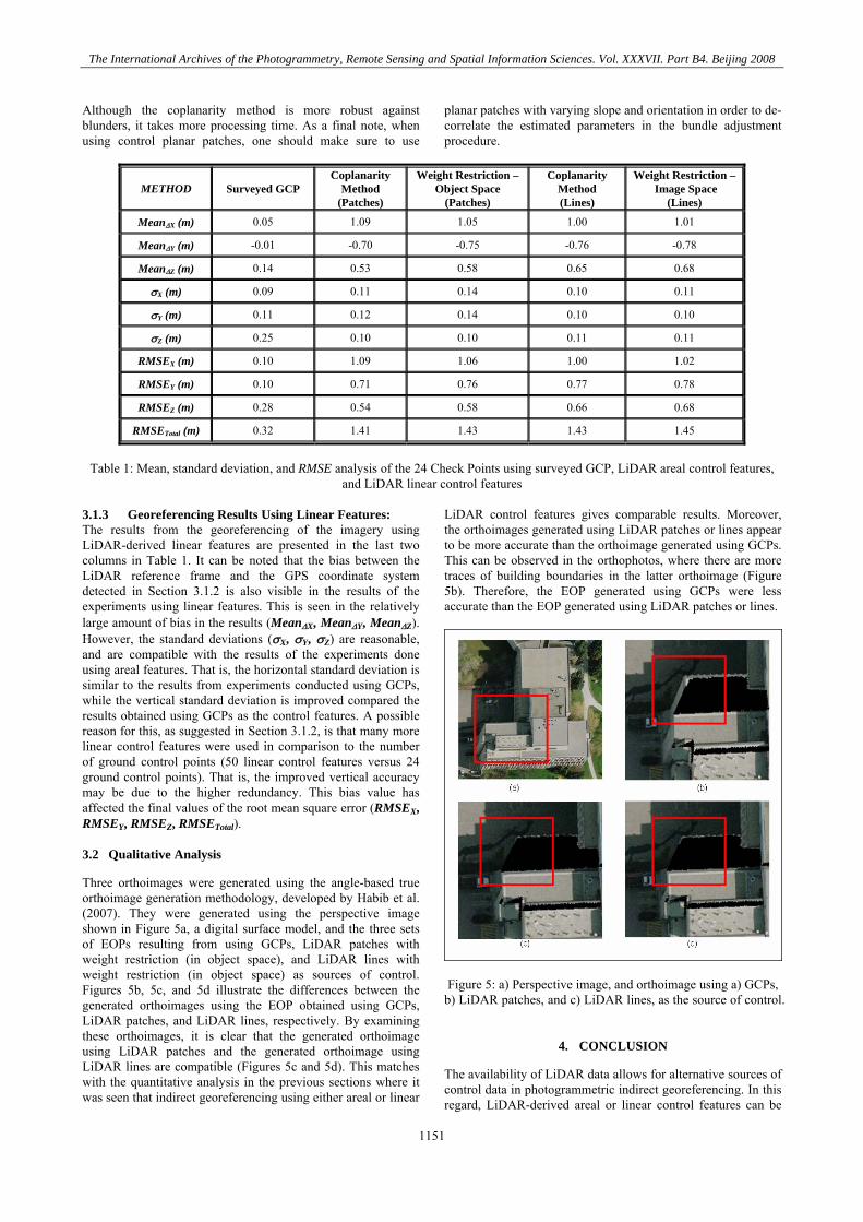
Three orthoimages were generated using the angle-based true orthoimage generation methodology, developed by Habib et al. (2007). They were generated using the perspective image shown in Figure 5a, a digital surface model, and the three sets of EOPs resulting from using GCPs, LiDAR patches with weight restriction (in object space), and LiDAR lines with weight restriction (in object space) as sources of control. Figures 5b, 5c, and 5d illustrate the differences between the generated orthoimages using the EOP obtained using GCPs, LiDAR patches, and LiDAR lines, respectively. By examining these orthoimages, it is clear that the generated orthoimage using LiDAR patches and the generated orthoimage using LiDAR lines are compatible (Figures 5c and 5d). This matches with the quantitative analysis in the previous sections where it was seen that indirect georeferencing using either areal or linear
LiDAR control features gives comparable results. Moreover, the orthoimages generated using LiDAR patches or lines appear to be more accurate than the orthoimage generated using GCPs. This can be observed in the orthophotos, where there are more traces of building boundaries in the latter orthoimage (Figure 5b). Therefore, the EOP generated using GCPs were less accurate than the EOP generated using LiDAR patches or lines.
Figure 5: a) Perspective image, and orthoimage using a) GCPs, b) LiDAR patches, and c) LiDAR lines, as the source of control.
4. CONCLUSION
The availability of LiDAR data allows for alternative sources of control data in photogrammetric indirect georeferencing. In this regard, LiDAR-derived areal or linear control features can be
1151

The International Archives of the Photogrammetry, Remote Sensing and Spatial Information Sciences. Vol. XXXVII. Part B4. Beijing 2008
used to derive the EOP of the involved imagery. The advantages of such an approach include eliminating the need for costly ground control points and allowing a direct integration of LiDAR and photogrammetric data for the purpose of, for instance, orthoimage generation and 3-D city modeling. In addition, any bias that exists in the LiDAR data will not be visible in the final orthoimages, when the source of control data and the digital surface model have both been obtained from the same (although biased) data source. Different alternatives of incorporating both linear and areal LiDAR-derived features into a photogrammetric georeferencing procedure were outlined. An approach that adds a coplanarity constraint (for both areal and linear features) into the existing bundle adjustment procedure was explained. A second approach for incorporating LiDAR-derived control was outlined, in which the regular collinearity equations are used to incorporate areal and linear features, after applying weight restrictions along the features. A comparative analysis of indirect georeferencing using ground control points, LiDAR areal features, and LiDAR linear features was performed using real data. A semi-automated approach for the extraction of patches and lines from LiDAR data through planar patch segmentation and intersection was illustrated, and the mathematical models for incorporating these features with imagery for georeferencing were explained. A quantitative analysis of the georeferencing results was performed for each method using a check point analysis. Based on the experimental results, the use of LiDAR features and GCPs for georeferencing appeared to give compatible horizontal accuracies. On the other hand, LiDAR features seemed to give better vertical accuracies. A possible reason for this is that many more areal and linear control features were used in comparison to the number of ground control points. That is, the improved vertical accuracy may be due to the higher redundancy. It was found that the methods that use LiDAR-derived features as the source of control yield compatible results. However, when using planar patches it is important that planes varying in slope and orientation be available in the dataset, and when using linear control features, a minimum of two non-coplanar line segments are required. A qualitative analysis was then performed, by comparing the quality of the generated orthoimages. The orthoimage generated using GCPs appeared to be less accurate than the orthoimages generated using LiDAR areal or linear features, as more traces of building boundaries were visible in the former orthoimage. The reason for the inferior quality of the orthophotos generated using GCP, is that the EOP were not as accurately derived in this triangulation procedure, due to the fewer number of available control points. In addition, when using the GCP as the source of control, the derived EOP are in the GPS reference frame, while the DSM used to produce the orthophoto is in the LiDAR reference frame. The bias between these reference frames contributes to the less accurate EOP that were obtained using the GCP. In comparing the orthophotos produced using LiDAR areal and linear features, using either one seemed to give compatible results. This observation was assured by the close similarity between the two orthoimages generated using
LiDAR areal and linear features (Figure 5). Future research will focus on automation of the extraction of lines and areal features from the imagery. In addition, the performance of the presented methodologies for LiDAR calibration and camera calibration will be investigated.
ACKNOWLEDGMENT
The authors would like to thank the GEOIDE Network of Centers of Excellence of Canada for the financial support of this research (SII#43), as well as NSERC. In addition, the authors thank the University of Calgary Information Technology for providing the LiDAR/image data and the valuable feedback.
REFERENCES
Al-Durgham, M. M. (2007). Alternative Methodologies for the Quality Control of LiDAR Systems. Thesis UCGE Reports Number 20259, University of Calgary, AB, Canada. Aldelgawy, M, Detchev, I. D., and Habib, A. F. (2008) Alternative Procedures for the Incorporation of LiDAR-Derived Linear and Areal Features for Photogrammetric Geo-referencing. ASPRS 2008 Conference Proceedings. Cramer, M., Stallmann, D., and Haala, N. (2000). Direct Georeferencing Using GPS/Inertial Exterior Orientations for Photogrammetric Applications, International Archives of Photogrammetry and Remote Sensing, 33(B3), pp. 198-205. Habib, A., Bang, K., Aldelgawy, M., and Shin, S. (2007). Integration of Photogrammetric and LiDAR Data in a Multi-primitive Triangulation Procedure, Proceedings of the ASPRS 2007, Tampa, Florida. Habib, Ayman, Eui-Myoung Kim, Chang-Jae Kim, 2005. New Methodologies for True Orthophoto Generation. PE&RS Photogrammetric Engineering & Remote Sensing, 73(1), pp. 25–36. Habib, A., Morgan, M., Kim, E., and Cheng, R. (2004). Linear Features in Photogrammetric Activities, ISPRS Congress, Istanbul, Turkey, 2004, PS ICWG II/IV: Automated Geo-Spatial Data Production and Updating, pp.610. Habib, A., Ghanma, M. S., Kim, C. J., Mitishita, E. Alternative Approaches for Utilizing LiDAR Data As a Source of Control Information for Photogrammetric Models. International Archives of the Photogrammetry,Remote Sensing and Spatial Information Sciences, 35(B1): 193–198. Kim C., Habib A., and Mrstik P. (2007). New Approach for Planar Patch Segmentation using Airborne Laser Data. Proceedings of the ASPRS 2007, Tampa, Florida
1152