Embed Size (px)
Citation preview

Research ArticleComparative Analysis between PI and Linear-ADRCControl of a Grid Connected Variable Speed WindEnergy Conversion System Based on a Squirrel CageInduction Generator
Hammadi Laghridat ,1 Ahmed Essadki,1 and Tamou Nasser2
1High School of Technical Education (ENSET), Mohammed V University, Rabat, Morocco2National High School for Computer Science and Systems (ENSIAS), Mohammed V University, Rabat, Morocco
Correspondence should be addressed to Hammadi Laghridat; [email protected]
Received 10 December 2018; Revised 21 January 2019; Accepted 3 March 2019; Published 26 March 2019
Academic Editor: Denizar Cruz Martins
Copyright © 2019 Hammadi Laghridat et al. This is an open access article distributed under the Creative Commons AttributionLicense, which permits unrestricted use, distribution, and reproduction in any medium, provided the original work is properlycited.
This paper aims at contributing to the modeling and control of a variable speed Wind Energy Conversion System (WEC-System)based on a Squirrel Cage Induction Generator (SCI-Generator). The connection between the SCI-Generator and the main utilitygrid is achieved by back-to-back three phase power converters (Generator andGrid SideConverters). A new control strategy namedthe Active Disturbance Rejection Control (ADRC) is proposed and utilized to control theWind Energy Conversion (WEC) systembased on the SCI-Generator. The objective is to control both the generator and the grid side converters in order to operate thesystem and to ensure the connection with the power grid. The first converter is used to control the SCI-Generator speed and fieldto extract the available maximum power from the wind turbine by using a Maximum Power Point Tracking (MPPT) techniqueand, also, to ensure that the extracted power does not exceed its rated value in case of strong wind speeds; in this case a pitchactuator system is used to control the blades pitch angle of the wind turbine.The second converter is used to control the active andreactive powers injected into the utility grid as well as to regulate the DC-Link Voltage.This control takes into account the rejectionof internal disturbances as the variation of electrical parameters (the resistance, the inductance. . .) and the external disturbancesas voltage dips and frequency droops in the main grid. To test and validate the performances of the proposed controller, a seriesof simulations were developed under MATLAB/Simulink environment, and the results have demonstrated the effectiveness of theproposed control under different case of simulations.
1. Introduction
Very early in the history of technology, wind was exploitedto extract mechanical energy from it, where the conversionof wind energy into mechanical energy is indeed relativelyeasy; it is only necessary to have a satisfactory potential and toresist the whims of excessive winds. Commonly, mechanicaldevices called “wind turbines” are utilized in this purpose.And for the conversion of this power into electrical energy,electrical generators are used. Generally, there are three typesof generators: Doubly Fed Induction Generators (DFIG),
Squirrel Cage Induction Generators (SCIG), and PermanentMagnet Synchronous Generators (PMSG). For the high-power production, the SCI-Generators are the one to be used;their main interest lies in their simple structure where theconnection with the utility grid is accomplished by back-to-back power converters.
The proliferation of wind turbines has led electricalengineering researchers to conduct investigations to improvethe efficiency of electromechanical conversion and the qualityof the energy supplied. For better operation of these systems,Maximum Power Point Tracking (MPPT) algorithms are
HindawiMathematical Problems in EngineeringVolume 2019, Article ID 8527183, 16 pageshttps://doi.org/10.1155/2019/8527183

2 Mathematical Problems in Engineering
needed to improve the energy efficiency and to extract themaximum power available from the wind turbine. In litera-ture, several techniques were used going from the utilizationof classical extreme algorithms such as Perturb and Observes(P&O), Incremental Conductance (INC), and Hil Climbing(HCS) [1] to those based on artificial intelligence as FuzzyLogic and Neural networks [2]. However, the wind turbinehas an advantages that it can be reliably characterized by itsspecific function 𝐶𝑝(𝜆). This is why the literature commonlyrefers to MPPT algorithms that seek to bring the operatingpoint to the maximum point that this function forms; wecan find among them the tip speed ratio (TSR) and OptimalTorque Control (OTC) techniques; the last one is to be usedin this paper.
To ensure the accurate integration of the WEC-Systemwith the utility grid, the regulation of active and reactivepowers is needed aswell as the synchronization of voltage andfrequency. In this context numerous publications are found inliterature as, in [3], the authors proposed an indirect vectorcontrol of a Squirrel Cage Induction Generator wind turbinewhere the objective is to control the DC-bus voltage and thereactive power by using the classical Proportional Integrator(PI) controller, authors in [4] used the Sliding Mode Controlto drive the WEC-System based on a SCI-Generator, authorsin [5] proposed a Fuzzy Logic Control of a variable speedcagemachinewind generation system, and, in [6], the authorshave used the Backstepping technique, Furthermore, addi-tional types of controllers were also considered for squirrelcage-based WEC-Systems as cited in [3–16]. Nevertheless,another controller appeared in the last 10 years and it is usedfor the control applications in several area; this controlleris known as the Active Disturbance Rejection Controller(ADRC); it is proposed by Jingqing Han [10]. However,to the authors’ best knowledge, very few publications areavailable in the literature that address the issue of controllingWind Energy Conversion systems, where in [11] the authorsproposed the control of a wind system based on a DFIG bythe ADRC technique and in [12] the authors discussed thecontrol of a direct driven wind turbine based on PermanentMagnetic Synchronous Generator by ADRC, but for theWECSCI-Generator the application of this control cannot befound. The main advantage of this controller lies in the realtime rejection of internal and external disturbances based onan extended state observer (ESO). There are different typesof disturbances, whether internal disturbances as variationof the generator parameters (resistance or inductance) andexternal disturbances like the instability of the grid causedeither by voltage droops or frequency variation. As a result,we propose in this paper the application of Linear-ADRCcontroller to Wind Energy Conversion System based on SCI-Generator.
The contribution of this work lies in the developmentof a Linear Active Disturbance Rejection controller (Linear-ADRC) to control both the generator and the grid sideconverters.Thefirst control is used to regulate themechanicalspeed of the generator in order to guarantee the extraction ofmaximum power available from the wind at different speeds;also another attention is given to the pitch angle control inorder to operate the wind turbine in high wind speed and
to limit the extracted power (The generator side converter).The second control is used to regulate the DC-Link Voltageas well as the active reactive powers exchange with the grid(the grid side converter). To summarize, this paper seeks toevaluate the dynamical performances and sensitivity to SCIGparameter changes with comparing the classical IndirectFieldOrientedControl based on the PI controller and the newLinear Active Disturbance Rejection Control.
This paper is organized as follows, where Section 2presents the modeling of the Wind Energy ConversionSystem based SCI-Generator. The Optimal Torque Controland pitch angle control are given in Section 3. The WindEnergyConversion System control by PI controller is detailedin Section 4, the application of the Linear Active DisturbanceRejection Control of the Wind Energy Conversion System isdemonstrated in Section 5, and, finally, the simulation resultsand discussions are presented in Section 6.
2. Wind Energy Conversion(WEC) System Model
This section deals with the Wind Energy Conversion (WEC)system model. The configuration of the SCI-Generator andit’s illustrated in Figure 1. It consists of two parts.The first partconsists with the turbine model, the SCI-Generator, and theAC/DC converter (The stator side). The second part of themodel consists of the DC-Link, the DC/AC converter, and afilter (The grid side).
The aim of the wind turbine is to capture the wind kineticenergy and convert it to a torque that rotates the rotors blades.Thereafter, the SCI-Generator converts themechanical power(𝑃𝑚) into an electrical power to be exchanged with the gridthrough the power converters (AC/DC/AC). Firstly, we beganwith themodeling the mechanical part and then the electricalpart.
2.1. Turbine Model (Mechanical Part). Themechanical poweravailable from the mind turbine rotor is given by the follow-ing:
𝑃𝑚 = 12𝐶𝑝 (𝜆, 𝛽) 𝜌𝐴𝑤3 (1)
where 𝐶𝑝 is the aerodynamic coefficient; 𝛽 is the blades pitchangle, 𝜆 is the turbine tip speed ratio, and 𝐴 is the turbineblades area. 𝜌 and 𝑤 are representing the air density and thewind speed, respectively.
The tip speed ratio is given by
𝜆 = 𝑅Ω𝑡𝑢𝑟V
(2)
where Ω𝑡𝑢𝑟 is the turbine speed and 𝑅 is the turbine radiusblades.
The mechanical torque 𝑇𝑚 is given by
𝑇𝑚 = 𝑃𝑚Ω𝑡𝑢𝑟 (3)
The coefficient 𝐶𝑝 is a nonlinear equation which depends onthe tip speed 𝜆, and it is expressed by

Mathematical Problems in Engineering 3
R
AC
DC
DC
AC Grid
Rf ,Lf
Vi_abc
Ig_abc
Vg_abc
Is_abcIs Ig
Vdc
Turbine
SSC GSC
s1....s6 g1....g6
Icwind
690V/50Hz
SCIG
Gear Box
Figure 1: Structure of a Wind Energy Conversion (WEC) System Using SCI-Generator.
The Pitch Angle
Tip-Speed Ratio
0
0.1
0
0.2
0.3
The P
ower
Coe
ffici
ent
0.4
0.5
10 40353025201520 1050
β=0 Cp=0.48=8.1λ
Figure 2: The Aerodynamic coefficient for WEC-System.
𝐶𝑝 (𝜆, 𝛽) = 𝑐1 (𝑐2 1𝜆𝑖 − 𝑐3𝛽 − 𝑐4) 𝑒𝑥𝑝(−𝑐5/𝜆𝑖) + 𝑐6𝜆 (4)
where1𝜆𝑖 =
1𝜆 + 𝑐7𝛽 − 𝑐8
𝛽3 + 1 (5)
where 𝑐1 = 0.5176, 𝑐2 = 166, 𝑐3 = 0.4, 𝑐4 = 5, 𝑐5 = 21, 𝑐6 =0.0068, 𝑐7 = 0.08, and 𝑐8 = 0.035.
Figure 2 represents 𝐶𝑝 according to 𝜆 for different valuesof pitch angle 𝛽. The figure shows that 𝐶𝑝 is maximum when𝛽 = 0𝑑𝑒𝑔 and 𝜆 = 8.1.
The gearbox is a device which adapts the (slow) turbinespeed Ω𝑡𝑢𝑟 to the (fast) generator speed Ω𝑚𝑒𝑐. This gearboxcan be mathematically modeled by the following:
𝑇𝑔 = 𝑇𝑚𝐺 (6)
Ω𝑡𝑢𝑟 = Ω𝑚𝑒𝑐𝐺 (7)
where 𝐺 is the gearbox ratio.The system mechanical equation is given by
𝐽dΩ𝑚𝑒𝑐d𝑡 = 𝑇𝑚 − 𝑇𝑒𝑚 − 𝑓Ω𝑚𝑒𝑐 (8)
where 𝑇𝑒𝑚 is the induction generator electromagnetic torqueand 𝑓 is the friction coefficient. 𝐽 represents the total inertiaof the generator (𝐽𝑆𝐶𝐼𝐺) and the turbine (𝐽𝑡𝑢𝑟) which can becalculated by
𝐽 = 𝐽𝑡𝑢𝑟𝐺2 + 𝐽𝑆𝐶𝐼𝐺 (9)
2.2. SCI-GeneratorModel. TheSquirrel Cage Induction (SCI)generator dynamic model in the direct-quadrature frame ispresented by
dΨ𝑠𝑑d𝑡 = −𝑅𝑠𝑖𝑠𝑑 + 𝜔𝑠Ψ𝑠𝑞 + V𝑠𝑑 (10)
dΨ𝑠𝑞d𝑡 = −𝑅𝑠𝑖𝑠𝑞 − 𝜔𝑠Ψ𝑠𝑑 + V𝑠𝑞 (11)
dΨ𝑟𝑑d𝑡 = −𝑅𝑟𝑖𝑟𝑑 + 𝜔𝑟Ψ𝑟𝑞 (12)
dΨ𝑟𝑞d𝑡 = −𝑅𝑟𝑖𝑟𝑞 − 𝜔𝑟Ψ𝑟𝑑 (13)
where 𝑖𝑠𝑑 and 𝑖𝑠𝑞 are the direct and quadrature stator currents;𝑖𝑟𝑑 and 𝑖𝑟𝑞 are the direct and quadrature rotor currents. Ψ𝑠𝑑and Ψ𝑠𝑞 are the direct-quadrature frame stator fields;Ψ𝑟𝑑 andΨ𝑟𝑞 are the direct-quadrature frame rotor fields. The statorvoltages in the direct-quadrature frame are V𝑠𝑑 and V𝑠𝑞. Also,𝑅𝑠 and 𝑅𝑟 are the stator and the rotor phases resistances; and𝜔𝑟 is the rotor electrical speed and 𝜔𝑠 is the stator electricalspeed.
The stator and rotor fields equations are given by
Ψ𝑠𝑑 = 𝐿 𝑠𝑖𝑠𝑑 +𝑀𝑖𝑟𝑑 (14)
Ψ𝑠𝑞 = 𝐿 𝑠𝑖𝑠𝑞 +𝑀𝑖𝑟𝑞 (15)
Ψ𝑟𝑑 = 𝐿𝑟𝑖𝑟𝑑 +𝑀𝑖𝑠𝑑 (16)
Ψ𝑟𝑞 = 𝐿𝑟𝑖𝑟𝑞 + 𝑀𝑖𝑠𝑞 (17)
where𝑀 is themutual inductance and𝐿 𝑠 and𝐿𝑟 are the statorinductance and the rotor inductance respectively.
The electromagnetic torque 𝑇𝑒𝑚 is expressed by
𝑇𝑒𝑚 = 𝑝𝑀𝐿𝑟 (Ψ𝑟𝑑𝑖𝑠𝑞 − Ψ𝑟𝑞𝑖𝑠𝑑) (18)
where p is the pole pairs number.The active and reactive powers (𝑃𝑠, 𝑄𝑠) produced by the
SCI-Generator can be written as follows:
𝑃𝑠 = 32 (V𝑠𝑑𝑖𝑠𝑑 + V𝑠𝑞𝑖𝑠𝑞) (19)
𝑄𝑠 = 32 (V𝑠𝑞𝑖𝑠𝑑 − V𝑠𝑑𝑖𝑠𝑞) (20)
The state model of the SCI-Generator can be written asfollows:

4 Mathematical Problems in Engineering
d𝑖𝑠𝑑d𝑡 = −𝑘1𝑖𝑠𝑑 + 𝜔𝑠𝑖𝑠𝑞 + 𝑘2Ψ𝑟𝑑 + 𝑘3Ω𝑚𝑒𝑐Ψ𝑟𝑞 + 𝑘4V𝑠𝑑 (21)
d𝑖𝑠𝑞d𝑡 = −𝑘1𝑖𝑠𝑞 − 𝜔𝑠𝑖𝑠𝑑 + 𝑘2Ψ𝑟𝑞 − 𝑘3Ω𝑚𝑒𝑐Ψ𝑟𝑑 + 𝑘4V𝑠𝑞 (22)
dΨ𝑟𝑑d𝑡 = 𝑘5𝑖𝑠𝑑 − 𝑘6Ψ𝑟𝑑 + (𝜔𝑠 − 𝑝Ω𝑚𝑒𝑐) Ψ𝑟𝑞 (23)
dΨ𝑟𝑞d𝑡 = 𝑘5𝑖𝑠𝑞 − 𝑘6Ψ𝑟𝑞 − (𝜔𝑠 − 𝑝Ω𝑚𝑒𝑐) Ψ𝑟𝑑 (24)
where
𝑘1 = 𝐿2𝑟𝑅𝑠 +𝑀2𝑅𝑟𝜎𝐿 𝑠𝐿2𝑟 ;
𝑘2 = 𝑅𝑟𝑀𝜎𝐿 𝑠𝐿2𝑟 ;
𝑘3 = 𝑝𝑅𝑟𝜎𝐿 𝑠𝐿𝑟 ;
𝑘4 = 1𝜎𝐿 𝑠 ;
𝑘5 = 𝑀𝑅𝑟𝐿𝑟 ;
𝑘6 = 𝑅𝑟𝐿𝑟 .
(25)
with 𝜎 = (1 −𝑀2/𝐿 𝑠𝐿𝑟) being the dispersion coefficient.
2.3. Grid Side Converter (GSC) Model. The grid side equa-tions can be expressed by
𝑉𝑔𝑎 = 𝑅𝑓𝑖𝑔𝑎 + 𝐿𝑓d𝑖𝑔𝑎d𝑡 + V𝑖𝑎
𝑉𝑔𝑏 = 𝑅𝑓𝑖𝑔𝑏 + 𝐿𝑓d𝑖𝑔𝑏d𝑡 + V𝑖𝑏
𝑉𝑔𝑐 = 𝑅𝑓𝑖𝑔𝑐 + 𝐿𝑓d𝑖𝑔𝑐d𝑡 + V𝑖𝑐
(26)
Applying the d-q transformation, (26) become as follows:
V𝑖𝑑 = 𝑅𝑓𝑖𝑔𝑑 + 𝐿𝑓d𝑖𝑔𝑑d𝑡 − 𝜔𝑔𝐿𝑓𝑖𝑖𝑞 + V𝑔𝑑 (27)
V𝑖𝑞 = 𝑅𝑓𝑖𝑔𝑞 + 𝐿𝑓d𝑖𝑔𝑞d𝑡 + 𝜔𝑔𝐿𝑓𝑖𝑖𝑑 + V𝑔𝑞 (28)
where V𝑔𝑑 and V𝑔𝑞 are the grid voltage components (direct andquadrature) and 𝑖𝑔𝑑 and 𝑖𝑔𝑞 are the grid current components(direct and quadrature).The voltages V𝑖𝑑 and V𝑖𝑞 are the sourceinverter direct and quadrature components; 𝑅𝑓 and 𝐿𝑓 arethe resistance and the inductance of the filter. 𝜔𝑔 = 2𝜋𝑓𝑔; 𝑓𝑔is the grid frequency, it is given by the PLL (Phase LockedLoop).
The above equations can be written as
d𝑖𝑔𝑑d𝑡 = −𝑘7𝑖𝑔𝑑 + 𝜔𝑔𝑖𝑔𝑞 + 𝑘8 (V𝑖𝑑 − V𝑔𝑑) (29)
d𝑖𝑔𝑞d𝑡 = −𝑘7𝑖𝑔𝑞 − 𝜔𝑔𝑖𝑔𝑑 + 𝑘8 (V𝑖𝑞 − V𝑔𝑞) (30)
where 𝑘7 = 𝑅𝑓/𝐿𝑓 and 𝑘8 = 1/𝐿𝑓.The active and reactive powers (𝑃𝑔, 𝑄𝑔) injected to grid
are given by the following:
𝑃𝑔 = 32 (V𝑔𝑑𝑖𝑔𝑑 + V𝑔𝑞𝑖𝑔𝑞) (31)
𝑄𝑔 = 32 (V𝑔𝑞𝑖𝑔𝑑 − V𝑔𝑑𝑖𝑔𝑞) (32)
The voltage equation of the DC-Link can be written as
𝐶dV𝑑𝑐d𝑡 = 𝑖𝑑𝑐 = 𝑖𝑠 − 𝑖𝑔 (33)
where V𝑑𝑐 and 𝑖𝑑𝑐 are the DC-Link Voltage and the DC-Linkcurrent. The currents 𝑖𝑠 and 𝑖𝑔 are the SCI-Generator sidecurrent and the grid side current, respectively, and 𝐶 is theDC-Link Capacitor.
3. Optimal Torque Control andPitch Angle Control
3.1. Optimal Torque Control (MPPT Technique). The Maxi-mum Power Point Tracking is a technique used to extractthe maximum power from the turbine for different windspeed. It is necessary that the turbine speed must be adjustedrelatively to the wind speed to obtain the maximum availablepower from the turbine. Therefore, the tip speed ratio mustbe maintained to an optimum value of the tip speed ratio(𝜆 = 𝜆𝑜𝑝𝑡) and of the power coefficient (𝐶𝑝 = 𝐶𝑚𝑎𝑥𝑝 ).
The maximum mechanical power can be expressed as afunction of the rotational speed:
𝑃𝑚𝑎𝑥𝑚 = 12𝜌𝜋𝑅
5𝐶𝑚𝑎𝑥𝑝
𝜆𝑜𝑝𝑡3Ω3𝑚𝑒𝑐𝐺3 (34)
The optimal torque (desired torque) is such that
𝑇𝑟𝑒𝑓𝑒𝑚 = 𝐶𝑜𝑝𝑡Ω𝑚𝑒𝑐2 (35)
where the Optimal Torque Coefficient is
𝐶𝑜𝑝𝑡 = 12𝜌𝜋𝑅
5𝐶𝑚𝑎𝑥𝑝
𝜆𝑜𝑝𝑡31𝐺3 (36)
The mechanical speed reference is given by
Ω𝑟𝑒𝑓𝑚𝑒𝑐 = 𝐺𝜆𝑜𝑝𝑡𝑅 𝑤 (37)

Mathematical Problems in Engineering 5
3.2. Pitch Angle Control. In the previous part, it has beenshown that the maximum power is generated by MPPTTechnique. Nevertheless, it is necessary to limit the powerof the WEC-System; As a pitch angle control is used it isoperated by acting on the orientation of the turbine bladesarea 𝛽, to avoid the power not exceeding its rated value incase of strong wind speeds.
The equation between the power 𝑃 and the pitch angle𝛽 is approached by a first-order system, and this approachallows controlling the SCI-Generator power by a closed loopPI controller [3].
The equation between 𝛽 and𝛽𝑟𝑒𝑓 can bewritten under thefollowing form (closed loop):
𝛽 = 11 + 𝑇𝛽𝑠𝛽
𝑟𝑒𝑓 (38)
where 𝑠 is a Laplace operator; 𝑇𝛽 is the time constant of thepitch servo. The pitch angle control scheme is depicted in theFigure 3.
The PI controller is used to decrease the error signalbetween the rated power and the measured power. It is toproduce at its output the reference pitch angle 𝛽𝑟𝑒𝑓. In normalcase, the pitch angle rates are at the maximum and minimum( 𝛽𝑚𝑖𝑛, 𝛽𝑚𝑎𝑥) allowable values between ±10 degrees/s and theangle (𝛽𝑚𝑖𝑛, 𝛽𝑚𝑎𝑥) allowable between (0 degrees, 45 degrees).
4. Wind Energy Conversion SystemControl by PI
This section focuses on the strategy adopted to control theWEC-System using a SCI-Generator by PI Controller. Twocontrollers are used.The first is used to control the stator sideconverter, where the objective is to extract maximum powerform the wind turbines (regulates the electromagnetic torqueand the field of the SCI-Generator). The second controller(grid side converter control) is used to regulate the DC-busvoltage and to control the grid powers (active and reactive),which is depicted in Figure 4.
4.1. Stator Side Converter (SSC) Control by PI. The PI con-troller is considered as the most used to control the WEC-System based on a SCI-Generator, because of its simplestimplementation. The objective in this part is to regulate theelectromagnetic torque and the field of the SCI-Generator toextract the maximum mechanical power 𝑃𝑚 available fromthe turbine for different wind speeds.
To archive the decoupled control of electromagnetictorque and field of the generator, the Indirect Rotor FieldOriented Control (IRFOC) used let
Ψ𝑟𝑞 = 0;Ψ𝑟𝑑 = Ψ𝑟
(39)
Then the SCI-Generator Model
d𝑖𝑠𝑑d𝑡 = −𝑘1𝑖𝑠𝑑 + 𝜔𝑠𝑖𝑠𝑞 + 𝑘2Ψ𝑟𝑑 + 𝑘4V𝑠𝑑 (40)
d𝑖𝑠𝑞d𝑡 = −𝑘1𝑖𝑠𝑞 − 𝜔𝑠𝑖𝑠𝑑 − 𝑘3Ω𝑚𝑒𝑐Ψ𝑟𝑑 + 𝑘4V𝑠𝑞 (41)
dΨ𝑟𝑑d𝑡 = 𝑘5𝑖𝑠𝑑 − 𝑘6Ψ𝑟𝑑 (42)
The electromagnetic torque equation is given by
𝑇𝑒𝑚 = 𝑝𝑀𝐿𝑟 Ψ𝑟𝑑𝑖𝑠𝑞 (43)
The electromagnetic torque expression is a proportion withthe quadrature stator current provided that the direct rotorfield is constant, for this we will regulate field of the rotor.
From (42) and (43), the reference quadrature statorcurrent and the estimated direct component of the rotor fieldare given by
𝑖𝑟𝑒𝑓𝑠𝑞 = 𝐿𝑟𝑝𝑀Ψ𝑟𝑒𝑓
𝑟𝑑
𝑇𝑟𝑒𝑓𝑒𝑚 (44)
Ψ𝑒𝑠𝑡𝑟𝑑 = 𝑘5𝑘6 + 𝑠 𝑖𝑠𝑑 (45)
where 𝑠 is a Laplace operator and the torque 𝑇𝑟𝑒𝑓𝑒𝑚 is theoptimal torque (generated by MPPT).
The rotor field angle is
𝜃𝑓 = ∫ (𝜔𝑠𝑙 + 𝑝Ω𝑚𝑒𝑐) 𝑑𝑡 (46)
with the slip frequency being obtained by
𝜔𝑠𝑙 = 𝑅𝑟𝑀𝐿 𝑠
𝑖𝑠𝑞Ψ𝑒𝑠𝑡𝑟𝑑
(47)
The compensation and the coupling terms are gathers in thefollowing:
𝑒𝑠𝑑 = 1𝑘4𝜔𝑠𝑖𝑠𝑞 +
𝑘2𝑘4Ψ𝑟𝑑 (48)
𝑒𝑠𝑞 = 1𝑘4𝜔𝑠𝑖𝑠𝑑 +
𝑘3𝑘4𝜔𝑚𝑒𝑐Ψ𝑟𝑑 (49)
Figure 5 depicts the control of stator side converter scheme ofthe SCI-Generator by PI Controller.
4.2. Grid Side Converter (GSC) Control by PI. The grid sideconverter is used to deliver the generated power into theelectrical grid; the first controller is used to regulate the DC-Link Voltage and the other controller to control the powerinjected into the grid during wind variations to achieve a unitpower factor. Therefore for independent control of the gridactive and the grid reactive power, we use Voltage Oriented(VOC) Control. Hence V𝑔𝑑 = 0 and V𝑔𝑞 = V𝑔, and thereforethe output 𝑃𝑔 and 𝑄𝑔 of the WEC-System can be written as
𝑃𝑔 = 32V𝑔𝑖𝑔𝑞 (50)
𝑄𝑔 = 32V𝑔𝑖𝑔𝑑 (51)

6 Mathematical Problems in Engineering
Controller Pn
Pmeas
βrefβ 1
sβ
.1Tβ
−+ −
+
Figure 3: Pitch Angle Control.
R
AC
DC
DC
AC Grid
Rf ,Lf
Vi_abc
Ig_abc
Vg_abc
Is Ig
Vdc
Turbine
SSC GSC
Icwind
690V/50Hz
Gear Box
SCIG
SSC Control
GSC Control
Is_abc
Ψrdref
PitchControl
DC-link
Ωmec
Temref Q g
refVdvref
MPPT
Figure 4: Control Wind Energy Conversion (WEC) System Using SCI-Generator.
AC
DC
Is_abc
Turbine
dq
abc
dq
abc
PWM
6
Ic
I s
wind
690V/50Hz
Gear Box
PitchControl
DC-link
SCIG
MPPT
isd
isq
isq
vsqref
vsdref
isq
isq
sl
isd
isd
Tem
isd
ref
ref
ref
Ψrdref
Ψrdest
Eq-44
Eq-45
Ωmec
Ψrdest Eq-47 Eq-46
Ωmec
f ff
Vdc
Ωmec
Ωmec
SSCPs
esq
PIController
PIControllerPI
Controlleresd
++
+−
Figure 5:The Generator Side Converter Control by PI.
And the grid currents
d𝑖𝑔𝑑d𝑡 = −𝑘7𝑖𝑔𝑑 + 𝜔𝑔𝑖𝑔𝑞 + 𝑘8V𝑖𝑑 (52)
d𝑖𝑔𝑞d𝑡 = −𝑘7𝑖𝑔𝑞 − 𝜔𝑔𝑖𝑔𝑑 + 𝑘8 (V𝑖𝑞 − V𝑔) (53)
From (51) the reference current 𝑖𝑟𝑒𝑓𝑔𝑑
is calculated by thedesired delivery of reactive power:
𝑖𝑟𝑒𝑓𝑔𝑑 = 23V𝑔𝑄
𝑟𝑒𝑓𝑔 (54)
The compensation and the coupling terms are expressed inthe following:
𝑒𝑔𝑑 = V𝑔𝑑 − 1𝑘8𝜔𝑔𝑖𝑔𝑞 (55)
𝑒𝑔𝑞 = V𝑔𝑞 + 1𝑘8𝜔𝑔𝑖𝑔𝑑 (56)
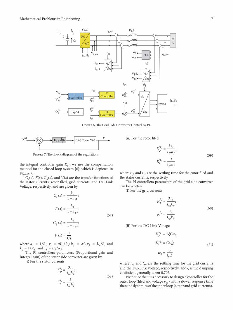
where V𝑔𝑑 = 0 and V𝑔𝑞 = V𝑔. Figure 6 depicts the controlof grid side converter scheme of the SCI-Generator by PIController.
4.3. The Synthesis of PI Correctors. To tune the parameters ofthe PI controllers (the proportional gain controller 𝐾𝑝 and
Mathematical Problems in Engineering 7
1.... 6
DC
AC Grid
Vi_abc
Ig_abc
Vg_abc
Is Ig
Vdc
GSC
Ic
dq
abc
PLL
dq
abc
Wg
VgqVgd
Igd
Igq
dq
abc
Igd
PWM
Vdc
Eq-54
Igq
Q refg
Vrefdc Igq
ref
Igdref
PI ControllerPI
Controller
egq
Vgdref
Vgqref
PI Controller
egd
+
++
−
g g
g1....g6
g
gg
g
Rf ,Lf
Figure 6: The Grid Side Converter Control by PI.
Kp + sKiXref
Ci(s), F(s) or V(s) X
Figure 7: The Block diagram of the regulations.
the integral controller gain 𝐾𝑖), we use the compensationmethod for the closed loop system [6]; which is depicted inFigure 7.
𝐶𝑠(𝑠), 𝐹(𝑠), 𝐶𝑔(𝑠), and 𝑉(𝑠) are the transfer functions ofthe stator currents, rotor filed, grid currents, and DC-LinkVoltage, respectively, and are given by
𝐶𝑠 (𝑠) = 𝑘𝑠1 + 𝜏𝑠𝑠 ;
𝐹 (𝑠) = 𝑘𝑓1 + 𝜏𝑓𝑠 ;
𝐶𝑔 (𝑠) =𝑘𝑔
1 + 𝜏𝑔𝑠 ;
𝑉 (𝑠) = 1𝐶𝑠
(57)
where 𝑘𝑠 = 1/𝑅𝑠, 𝜏𝑠 = 𝜎𝐿 𝑠/𝑅𝑠; 𝑘𝑓 = 𝑀, 𝜏𝑓 = 𝐿𝑟/𝑅𝑟 and𝑘𝑔 = 1/𝑅𝑓, and 𝜏𝑓 = 𝐿𝑓/𝑅𝑓.The PI controllers parameters (Proportional gain and
Integral gain) of the stator side converter are given by(i) For the stator currents
𝐾𝑖𝑠𝑝 = 3𝜏𝑠𝑡𝑟𝑐𝑘𝑠 ;
𝐾𝑖𝑠𝑖 = 3𝑡𝑟𝑐𝑘𝑠
(58)
(ii) For the rotor filed
𝐾Ψ𝑟𝑝 = 3𝜏𝑓𝑡𝑟𝑓𝑘𝑓 ;
𝐾Ψ𝑟𝑖 = 3𝑡𝑟𝑓𝑘𝑓
(59)
where 𝑡𝑟𝑓 and 𝑡𝑟𝑐 are the settling time for the rotor filed andthe stator currents, respectively.
The PI controllers parameters of the grid side convertercan be written:
(i) For the grid currents
𝐾𝑖𝑔𝑝 = 3𝜏𝑔𝑡𝑟𝑔𝑘𝑔 ;
𝐾𝑖𝑔𝑖 = 3𝑡𝑟𝑔𝑘𝑔
(60)
(ii) For the DC-Link Voltage
𝐾V𝑑𝑐𝑝 = 2𝜉𝐶𝜔0;
𝐾V𝑑𝑐𝑖 = 𝐶𝜔20 ;𝜔0 = 3
𝑡𝑟V𝜉
(61)
where 𝑡𝑟𝑔 and 𝑡𝑟V are the settling time for the grid currentsand the DC-Link Voltage, respectively, and 𝜉 is the dampingcoefficient generally taken 0.707.
We notice that it is necessary to design a controller for theouter loop (filed and voltage V𝑑𝑐) with a slower response timethan the dynamics of the inner loop (stator and grid currents).

8 Mathematical Problems in Engineering
5. Wind Energy Conversion (WEC) SystemControl by Linear-ADRC
This section focuses on the strategy adopted to control theWEC-System based a SCI-Generator by Linear-ADRC. Thesame control scheme presented in Figure 4 is used to controlthe stator side converter and the grid side converter whileusing the Linear-ADRC controller instead of the PI one. Thegeneral theory of the Linear-ADRC is detailed below.
5.1. Linear-ADRC Controller Design. The Active DisturbanceRejection Control (ADRC) is a robust control strategy, pro-posed byHan in 1995 [10].Themain advantage of this controlis to compensate in real time the various external and internaldisturbances. This control is based on the observer (ESO)which constitutes its kernel and which makes it possibleto estimate the total disturbances. There are two types, theLinear-ADRC and NonLinear-ADRC. In order to reduce themodel complexity and the controller computational, a Linear-ADRC design method is proposed and applied to control theSCI-Generator based WEC-System.
The observer used to estimate the process state variablesand total distributions is represented by the model:
𝑥 = 𝐴𝑥 + 𝐵𝑢 + 𝐿 (𝑦 − 𝑦)𝑦 = 𝐶𝑥 (62)
where 𝑥 = [𝑥1 𝑥2]𝑇 the estimated variables, 𝐿 = [𝛽1 𝛽2]𝑇 isthe observer gain vector, and 𝐴, 𝐵, 𝐶 are gain matrices.
The extended state observer gains are determined by [10]
𝛽1 = 2𝜔𝑜𝑏𝑠;𝛽2 = 𝜔𝑜𝑏𝑠2
(63)
𝜔𝑜𝑏𝑠 is determined according to the closed loop system polesto ensure both a fast dynamic of the observer and aminimumsensitivity to noise.
The canonical form of Linear-ARDC can be written:
�� (𝑡) = 𝑓 (𝑦, 𝑑, 𝑢) + 𝑏0𝑢 (𝑡) (64)
where 𝑓(𝑦, 𝑑, 𝑢) represents the total (internal and external)disturbance, 𝑏0 is known part of the process (system), 𝑑(𝑡)represents the external disturbance, and 𝑢(𝑡) and 𝑦(𝑡) areinput and output of the process, respectively.
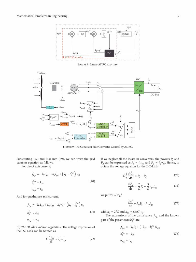
The combination of the linear ES-Observer and thecorrector represents the Linear-ADRC whose structure isgiven in Figure 8.
In practice, we chose 𝑘𝑝 = 𝜔𝑐 = 4/𝑡𝑟 with 𝑡𝑟 being thesystem desired time. Also, we chose 𝜔𝑜𝑏𝑠 in a range of 𝜔𝑜𝑏𝑠 =3 ∼ 10𝜔𝑐 because the ES-Observer dynamic is faster than thesystem dynamic.
5.2. Stator Side Converter (SS-Converter) Control by Linear-ADRC. To control the stator side converter by ADRC, weelaborate three-Linear-ADRC controller; two Linear-ADRCcontrollers are used to regulate the stator currents 𝑖𝑠𝑑 and𝑖𝑠𝑞 and the other one to control the direct rotor field Ψ𝑟𝑑 to
track their reference. Figure 9 depicts the Active DisturbanceRejection Control of the stator side converter (SSC).
(i) The Stator Currents Controllers. The stator currents regu-lations are achieved by two Linear-ADRC controllers, where(40) and (41) are adapted to the canonical form of Linear-ARDC:
𝑖𝑠𝑑𝑞 = 𝑓𝑠𝑑𝑞 (𝑦, 𝑑, 𝑢) + 𝑏𝑖𝑠𝑑𝑞0 𝑢𝑠𝑑𝑞 (65)
For the d-axis stator current we have
𝑓𝑖𝑠𝑑 = −𝑘1𝑖𝑠𝑑 + 𝜔𝑠𝑖𝑠𝑞 + 𝑘2Ψ𝑟𝑑 + (𝑘4 − 𝑏𝑖𝑠𝑑0 ) V𝑠𝑑𝑏𝑖𝑠𝑑0 = 𝑘4;𝑢𝑖𝑠𝑑 = V𝑠𝑑
(66)
And for q-axis stator current we have
𝑓𝑖𝑠𝑞 = −𝑘1𝑖𝑠𝑞 − 𝜔𝑠𝑖𝑠𝑑 − 𝑘3Ω𝑚𝑒𝑐Ψ𝑟𝑑 + (𝑘4 − 𝑏𝑖𝑠𝑞0 ) V𝑠𝑞𝑏𝑖𝑠𝑞0 = 𝑘4;𝑢𝑖𝑠𝑞 = V𝑠𝑞
(67)
or 𝑓𝑖𝑠𝑑 and 𝑓𝑖𝑠𝑞 are the total (external and internal) distur-bances affecting the stator currents 𝑖𝑠𝑑 and 𝑖𝑠𝑞, respectively.𝑢𝑖𝑠𝑑 and 𝑢𝑖𝑠𝑞 are the control inputs of the 𝑖𝑠𝑑 and 𝑖𝑠𝑞,respectively. 𝑏𝑖s𝑑0 and 𝑏𝑖𝑠𝑞0 are the known parts of the systemparameters.
(ii)The Rotor Field Controller. We rewrite the field expression(42) under the canonical form (CF) of a Linear-ADRCregulator (65), and the expressions of the disturbance and theknown part of the parameters are
𝑓Ψ𝑟𝑑 = −𝑘6Ψ𝑟𝑑 + (𝑘5 − 𝑏Ψ𝑟𝑑0 ) 𝑖𝑠𝑑𝑏Ψ𝑟𝑑0 = 𝑘5;𝑢Ψ𝑟𝑑 = 𝑖𝑠𝑑
(68)
where 𝑓Ψ𝑟𝑑 is the total (external and internal) disturbancesaffecting the fieldΨ𝑟𝑑. 𝑢Ψ𝑟𝑑 and 𝑏Ψ𝑟𝑑0 are the control inputs andthe known parts of the field Ψ𝑟𝑑, respectively.5.3. Grid Side Converter (GSC) Control by Linear-ADRC.Similarly to the stator side converter control, we elaboratethree-Linear-ADRC controller; but in this case the twoLinear-ADRC controllers are used to regulates the active andreactive power delivery into the grid by controls the gridcurrents 𝑖𝑔𝑑 and 𝑖𝑔𝑞 ((52) and (53)), and the other controlleris used to maintain constant DC-Link Voltage.
(i) The Grid Currents Controllers. The grid currents regula-tions are achieved by two Linear-ADRC controllers, wherethe equations of 𝑖𝑔𝑑 and 𝑖𝑔𝑞 are adapted to the canonical formof Linear-ADRC.
𝑖𝑔𝑑𝑞 = 𝑓𝑔𝑑𝑞 (𝑦, 𝑑, 𝑢) + 𝑏𝑖𝑔𝑑𝑞0 𝑢𝑔𝑑𝑞 (69)
Mathematical Problems in Engineering 9
+- +-Kp Systemr(t)
LADRC Controller
d(t) y(t) u(t)
y(t) ESOx1=y
u0(t)
x2= f
1
b0
u(t)
Figure 8: Linear-ADRC structure.
AC
DC
Is_abc
Turbine
dq
abc
dq
abc
PWM
6
Ic
V
IsSSC
wind
690V/50Hz
Gear Box
PitchControl
DC-Bus
SCIG
MPPT
isd
isq
isq
vsdref
vsqrefisq
isq
sl
isd
isd
Tem
isd
ref
ref
ref
Ψrdref
Eq-44
Eq-45Ψrd
est
Ψ rdest Eq-47 Eq-46
Ωmec
dc
Ωmec
Ωmec
Ωmec
ADRCController
ADRCControllerADRC
Controller
f f f
Figure 9: The Generator Side Converter Control by ADRC.
Substituting (52) and (53) into (69), we can write the gridcurrents equation as follows.
For direct axis current,
𝑓𝑖𝑔𝑑 = −𝑘7𝑖𝑔𝑑 + 𝜔𝑔𝑖𝑔𝑞 + (𝑘8 − 𝑏𝑖𝑔𝑑0 ) V𝑖𝑑𝑏𝑖𝑔𝑑0 = 𝑘8;𝑢𝑖𝑔𝑑 = V𝑖𝑑
(70)
And for quadrature axis current,
𝑓𝑖𝑔𝑞 = −𝑘7𝑖𝑔𝑞 + 𝜔𝑔𝑖𝑔𝑑 − 𝑘8V𝑔 + (𝑘8 − 𝑏𝑖𝑔𝑞0 ) V𝑖𝑞𝑏𝑖𝑔𝑞0 = 𝑘8;𝑢𝑖𝑔𝑞 = V𝑖𝑞
(71)
(ii)The DC-Bus Voltage Regulation. The voltage expression ofthe DC-Link can be written as
𝐶dV𝑑𝑐d𝑡 = 𝑖𝑠 − 𝑖𝑔 (72)
If we neglect all the losses in converters, the powers 𝑃𝑠 and𝑃𝑔 can be expressed as 𝑃𝑠 = 𝑖𝑠V𝑑𝑐 and 𝑃𝑔 = 𝑖𝑔V𝑑𝑐. Hence, toobtain the voltage equation for the DC-Link
𝐶12dV2𝑑𝑐d𝑡 = 𝑃𝑠 − 𝑃𝑔 (73)
dV2𝑑𝑐d𝑡 = 2
𝐶𝑃𝑠 − 3𝐶V𝑔𝑞𝑖𝑞𝑔 (74)
we put𝑊 = V𝑑𝑐2
d𝑊d𝑡 = 𝑘9𝑃𝑠 − 𝑘10𝑖𝑞𝑔 (75)
with 𝑘9 = 2/𝐶 and 𝑘10 = (3/𝐶)V𝑔.The expressions of the disturbance 𝑓V𝑑𝑐 and the known
part of the parameters 𝑏V𝑑𝑐0 are
𝑓V𝑑𝑐 = −𝑘9𝑃𝑠 + (−𝑘10 − 𝑏V𝑑𝑐0 ) 𝑖𝑔𝑞𝑏V𝑑𝑐0 = −𝑘10;𝑢V𝑑𝑐 = 𝑖𝑔𝑞
(76)

10 Mathematical Problems in Engineering
DC
AC Grid
Vi_abc
Ig_abc
Vg_abc
Is Ig
Vdc
GSC
Ic
dq
abc
PLL
dq
abc
Wg
VgqVgd
Igd
Igq
dq
abc
Igd
PWM
Vdc
Eq-54Q refg
Vrefdc
Igdref
Igqref
Vgqref
Vgdref
IgqADRC
Controller
ADRCController
ADRCController
1.... 6g g
Rf ,Lf
1.... 6g g
g
g
gg
Figure 10: The Grid Side Converter Control by Linear-ADRC.
6
8
10
12
14
16
Win
d Sp
eed
(m/s
)
0.5 1 1.5 2 2.5 3 3.5 4 4.5 50Time (s)
Figure 11: The Wind Speed Profile.
Figure 10 depicts the Active Disturbance Rejection Control ofthe grid side converter (GSC).
6. Simulation Results and Discussion
The simulations results of the presented control strategyare given and discussed in this section. The proposedWEC-System control has been simulated using the Mat-lab/Simulink. We have applied a variable wind speed profileas it is illustrated at Figure 11; the parameters of the WEC-System are given in the Appendix.
As it can be noticed in Figures 12 and 13, when thewind speed exceeds the rated speed, the mechanical speedof the turbine is limited by adjusting the pitch angle, andconsequently the power coefficient and tip speed ratio of theturbine decrease.
Figures 14 and 15 present the simulation results of thestator side converter, for the two control strategies (ADRCcontrol and PI control).
As it can be seen in Figures 14 and 15, the control by PI andthe control by ADRC tracks their references, but the controlby ADRC is faster (case of the electromagnetic torque andquadrature currents), more precise (case of the Rotor Field),and also without fluctuations (case of the direct current). InFigures 16–19 the simulation results of the grid side converterare presented.
As illustrated, the Linear-ADRC approach offers a fastertrackness characteristic while controlling the DC-Link Volt-age compared to the conventional approach by PI, wherethe DC-Link Voltage is maintained at its reference withoutpresenting an overshoot at the transitional regime.Also, it canbe noticed that the Linear-ADRC regulates the grid currentsto their references.
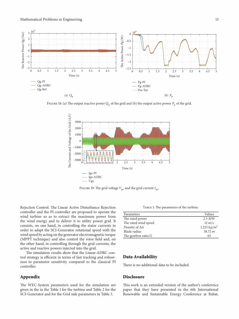
The control of the active and reactive powers is also done.As can be seen in Figure 18, the power injected into thegrid tracks its reference (the extracted power from the windturbine minus joules and DC-Link losses). And the reactivepower was set to zero to ensure a unit power factor. Hencethe voltage and current of the grid are in phase as seen inFigure 19.
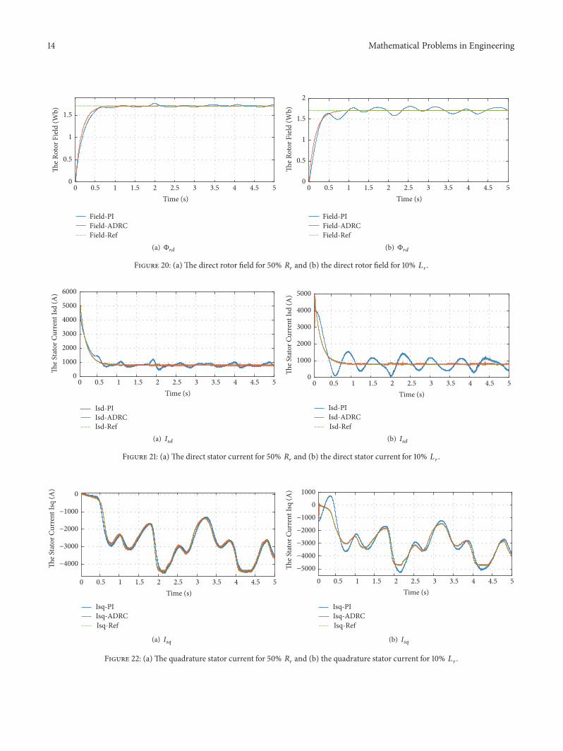
Finally, to test the robustness of the proposed controlstrategies, we have performed a change in the rotor resistanceand the rotor inductance of the SCI-Generator by an increaseof 50% and 10%, respectively, of their nominal value. Theresults obtained by LADRC controller and PI controller arehighlighted in Figures 20 and 21.
Figures 20–22 show that the Linear-ADRC controlresponses presents better results than the control based on PI

Mathematical Problems in Engineering 11
Smec-PISmec-ADRCSmec-Rated
020406080
100120140160180
The G
ener
ator
Spe
ed (r
ad/s
)
0.5 1 1.5 2 2.5 3 3.5 4 4.5 50Time (s)
(a) Ω𝑚𝑒𝑐
Time (s)
Beta-PIBeta-ADRC
0 54.543.532.521.510.5−2
0
2
4
6
8
Pitc
h an
gle (
deg)
(b) 𝛽
Figure 12: (a) The SCI-Generator Speed and (b) the blades pitch angel.
Cp-PICp-ADRCCp-Max
0
0.1
0.2
0.3
0.4
0.5
Pow
er C
oeffi
cien
t Cp
0.5 1 1.5 2 2.5 3 3.5 4 4.5 50 Time (s)
(a) 𝐶𝑝
S-ratio-PIS-ratio-ADRCS-ratio-Opt
0
2
4
6
8
10 sp
eed
ratio
(p.u
)
0.5 1 1.5 2 2.5 3 3.5 4 4.5 50Time (s)
(b) 𝜆
Figure 13: (a) The aerodynamic coefficient and (b) the turbine tip speed ratio.
Field-PIField-ADRCField-Ref
0
0.5
1
1.5
The R
otor
Fie
ld (W
b)
0.5 1 1.5 2 2.5 3 3.5 4 4.5 50 Time (s)
(a) Ψ𝑟𝑑
Time (s)Tem-PITem-ADRCTem-Ref
0 54.543.532.521.510.5−16000−14000−12000−10000
−8000−6000−4000−2000
0
The e
lect
rom
agne
tic to
rque
(N.m
)
(b) 𝑇𝑒𝑚
Figure 14: (a) The direct rotor fluxes of the SCI-Generator and (b) the electromagnetic torque of the SCI-Generator.

12 Mathematical Problems in Engineering
Isd-PIIsd-ADRCIsd-Ref
0
1000
2000
3000
4000
5000
6000
The S
tato
r Cur
rent
Isd
(A)
0.5 1 1.5 2 2.5 3 3.5 4 4.5 50 Time (s)
(a) 𝐼𝑠𝑑
Isq-PIIsq-ADRCIsq-Ref
−5000
−4000
−3000
−2000
−1000
0
The S
tato
r Cur
rent
Isq
(A)
0.5 1 1.5 2 2.5 3 3.5 4 4.5 50 Time (s)
(b) 𝐼𝑠𝑞
Figure 15: The stator currents: (a) d-axis 𝐼𝑠𝑑 and (b) q-axis 𝐼𝑠𝑞.
Vdc-PIVdc-ADRCVdc-Ref
0200400600800
1000120014001600
DC-
Link
Vol
tage
(V)
0.5 1 1.5 2 2.5 3 3.5 4 4.5 50Time (s)
Figure 16: The DC-Link Voltage 𝑉𝑑𝑐.
Igd-PIIgd-ADRCIgd-Ref
−400−300−200−100
0100200300400
The G
rid C
urre
nt Ig
d (A
)
0.5 1 1.5 2 2.5 3 3.5 4 4.5 50Time (s)
(a) 𝐼𝑔𝑑
Igq-PIIgq-ADRCIgq-Ref
−2500
−2000
−1500
−1000
−500
0
The G
rid C
urre
nt Ig
q (A
)
0.5 1 1.5 2 2.5 3 3.5 4 4.5 50 Time (s)
(b) 𝐼𝑔𝑞
Figure 17: The grid currents: (a) d-axis 𝐼𝑔𝑑 and (b) q-axis 𝐼𝑔𝑞.
one. The Linear-ADRC is more robust and stable during thevariation of the generator parameters.
The simulation results clearly indicate that the proposedLinear-ADRC strategy when applied to the WEC-System isable to track the desired values for both controls of the statorside converter and the grid side converter. Moreover, it isefficient in terms of stability and robustness regarding thevariation of the generator parameters.
7. Conclusion
This paper deals with the modeling and control of a WindEnergy Conversion System using a Squirrel Cage InductionGenerator. It seeks to evaluate the dynamical performancesand sensitivity to SCI-Generator parameter changes withcomparing the classical Indirect FieldOrientedControl basedon the PI controller and the new Linear Active Disturbance
Mathematical Problems in Engineering 13
105
Qg-PIQg-ADRCQg-Ref
−3
−2
−1
0
1
2
3
The R
eact
ive P
ower
Qg
(Var
)
0.5 1 1.5 2 2.5 3 3.5 4 4.5 50 Time (s)
(a) 𝑄𝑔
106
Pg-PIPg-ADRCPm-Tur
−2.5
−2
−1.5
−1
−0.5
0
The A
ctiv
e Pow
er P
g (W
)
0.5 1 1.5 2 2.5 3 3.5 4 4.5 50Time (s)
(b) 𝑃𝑔
Figure 18: (a) The output reactive power 𝑄𝑔 of the grid and (b) the output active power 𝑃𝑔 of the grid.
Time (s)Iga-PIIga-ADRCVga
0.64 0.80.780.760.740.720.70.680.66
−1000
−500
0
500
1000
0 54.543.532.52−3000
−2000
−1000
0
1000
2000
3000
The C
urre
nt an
d Vo
ltage
of t
he G
rid (A
,V)
Figure 19: The grid voltage 𝑉𝑔𝑎 and the grid current 𝐼𝑔𝑎.
Rejection Control. The Linear Active Disturbance Rejectioncontroller and the PI controller are proposed to operate thewind turbine so as to extract the maximum power fromthe wind energy and to deliver it to utility power grid. Itconsists, on one hand, in controlling the stator currents inorder to adapt the SCI-Generator rotational speed with thewind speed by acting on the generator electromagnetic torque(MPPT technique) and also control the rotor field and, onthe other hand, in controlling through the grid currents, theactive and reactive powers injected into the grid.
The simulation results show that the Linear-ADRC con-trol strategy is efficient in terms of fast tracking and robust-ness to parameter sensitivity compared to the classical PIcontroller.
Appendix
The WEC-System parameters used for the simulation aregiven in the in the Table 1 for the turbine and Table 2 for theSCI-Generator and for the Grid side parameters in Table 3.
Table 1: The parameters of the turbine.
Parameters ValuesThe rated power 2.3𝑀𝑊The rated wind speed 12𝑚/𝑠Density of Air 1.225 𝑘𝑔/𝑚3
Blade radius 38.72𝑚The gearbox ratio 𝐺 63
Data Availability
There is no additional data to be included.
Disclosure
This work is an extended version of the author’s conferencepaper that they have presented in the 6th InternationalRenewable and Sustainable Energy Conference at Rabat,
14 Mathematical Problems in Engineering
Field-PIField-ADRCField-Ref
0
0.5
1
1.5
The R
otor
Fie
ld (W
b)
0.5 1 1.5 2 2.5 3 3.5 4 4.5 50 Time (s)
(a) Φ𝑟𝑑
Field-PIField-ADRCField-Ref
0
0.5
1
1.5
2
The R
otor
Fie
ld (W
b)
0.5 1 1.5 2 2.5 3 3.5 4 4.5 50 Time (s)
(b) Φ𝑟𝑑
Figure 20: (a)The direct rotor field for 50% 𝑅𝑟 and (b) the direct rotor field for 10% 𝐿𝑟.
Isd-PIIsd-ADRCIsd-Ref
0
1000
2000
3000
4000
5000
6000
The S
tato
r Cur
rent
Isd
(A)
0.5 1 1.5 2 2.5 3 3.5 4 4.5 50 Time (s)
(a) 𝐼𝑠𝑑
Isd-PIIsd-ADRCIsd-Ref
0
1000
2000
3000
4000
5000 Th
e Sta
tor C
urre
nt Is
d (A
)
0.5 1 1.5 2 2.5 3 3.5 4 4.5 50Time (s)
(b) 𝐼𝑠𝑑
Figure 21: (a) The direct stator current for 50% 𝑅𝑟 and (b) the direct stator current for 10% 𝐿𝑟.
Isq-PIIsq-ADRCIsq-Ref
−4000
−3000
−2000
−1000
0
The S
tato
r Cur
rent
Isq
(A)
0.5 1 1.5 2 2.5 3 3.5 4 4.5 50 Time (s)
(a) 𝐼𝑠𝑞
Isq-PIIsq-ADRCIsq-Ref
−5000
−4000
−3000
−2000
−1000
0
1000
The S
tato
r Cur
rent
Isq
(A)
0.5 1 1.5 2 2.5 3 3.5 4 4.5 50 Time (s)
(b) 𝐼𝑠𝑞
Figure 22: (a)The quadrature stator current for 50% 𝑅𝑟 and (b) the quadrature stator current for 10% 𝐿𝑟 .

Mathematical Problems in Engineering 15
Table 2: The parameters of the SCI-Generator.
Parameters ValuesThe Rated Power 𝑃𝑛 2.3𝑀𝑊The Rated Voltage 𝑈𝑛 690 𝑉The Nominal Frequency 50𝐻𝑧The Rated Rotor Speed 1512 𝑡𝑟/𝑚𝑖𝑛The Number of Pole Pairs 2The Stator Resistance 𝑅𝑠 1.102𝑚ΩThe Rotor Resistance 𝑅𝑟 1.497 𝑚ΩThe Stator Leakage Inductance 𝐿𝑠𝑙 0.06492𝑚𝐻The Rotor Leakage Inductance 𝐿𝑟𝑙 0.06492𝑚𝐻TheMagnetizing Inductance𝑀 2.13461 𝑚𝐻
Table 3: The parameters of the grid side.
Parameters ValuesThe DC-Link Voltage 𝑉𝑑𝑐 1320 𝑉The DC-Link Capacitor 𝐶 17316.17 𝜇𝐹The Filter Resistance 𝑅𝑟 0.1838ΩThe Filter Inductancer 𝐿𝑟 0.61187𝑚𝐻
Morocco. This extended version explores the control of thegrid side converter and the pitch angle control compared withthe paper presented in the conference.
Conflicts of Interest
The authors declare that there are no conflicts of interestregarding the publication of this paper.
References
[1] S. Lalouni, D. Rekioua, K. Idjdarene, andA. Tounzi, “Maximumpower point tracking based hybrid hill-climb search methodapplied to wind energy conversion system,” Electric PowerComponents and Systems, vol. 43, no. 8-10, pp. 1028–1038, 2015.
[2] A.Meharrar,M. Tioursi,M.Hatti, andA. Boudghne Stambouli,“A variable speed wind generator maximum power trackingbased on adaptative neuro-fuzzy inference system,” ExpertSystems with Applications, vol. 38, no. 6, pp. 7659–7664, 2011.
[3] M. Benchagra, M. Hilal, Y. Errami, M. Ouassaid, and M.Maaroufi, “Modeling and control of SCIG based variable-speedwith power factor control,” International Review on Modellingand Simulations, vol. 4, no. 3, pp. 1007–1014, 2011.
[4] M. Zribi, M. Alrifai, and M. Rayan, “Sliding mode control of avariable-speed wind energy conversion system using a squirrelcage induction generator,” Energies, vol. 10, no. 5, article 604,2017.
[5] M. G. Simoes, B. K. Bose, and R. J. Spiegel, “Fuzzy logicbased intelligent control of a variable speed cage machine windgeneration system,” IEEE Transactions on Power Electronics, vol.12, no. 1, pp. 87–95, 1997.
[6] M. Benchagra, Y. Errami, M. Hilal, M.Maaroufi,M. Cherkaoui,andM. Ouassaid, “New control strategy for inductin generator-wind turbine connected grid,” in Proceedings of the 2012 Inter-national Conference on Multimedia Computing and Systems,ICMCS ’12, pp. 1043–1048, IEEE, 2012.
[7] K. A. Naik and C. P. Gupta, “Fuzzy logic based pitch anglecontroller/or SCIG based wind energy system,” in Proceedingsof the Recent Developments in Control, Automation and PowerEngineering, RDCAPE ’17, pp. 60–65, IEEE, October 2017.
[8] V. D. Dhareppagol and S. Nagendraprasad, “Modelling andsimulation of wecs for maximum power extration and optimalefficincy control using squirrel cage induction generator,” inProceedings of the Power, Communication and InformationTechnology Conference (PCITC ’15), pp. 912–917, IEEE, October2015.
[9] A. Edrisian, A. Goudarzi, I. E. Davidson, A. Ahmadi, and G.K. Venayagamoorthy, “Enhancing SCIG-based wind turbinegenerator performance through reactive power control,” inProceedings of the Clemson University Power Systems Conference(PSC ’15), IEEE, South Carolina, SC, USA, March 2015.
[10] R. Chakib, A. Essadki, and M. Cherkaoui, “Active disturbancerejection control for wind system based on a DFIG,” Interna-tional Journal of Electrical Computer Energetic Electronic andCommunication Engineering, vol. 8, pp. 1306–1315, 2014.
[11] A. Boukhriss, A. Essadki, A. Bouallouch, and T. Nasser, “Max-imization of generated power from wind energy conversionsystems using a doubly fed induction generator with activedisturbance rejection control,” in Proceedings of the 2nd WorldConference on Complex Systems, WCCS 2014, pp. 330–335,November 2014.
[12] A. Imad, S. El Hani, and A. Echchaachouai, “Robust activedisturbance rejection control of a direct driven PMSG windturbine,” in Proceedings of the International Renewable andSustainable Energy Conference (IRSEC ’17), pp. 1–6, IEEE, 2017.
[13] M.Arbaoui, A. Essadki, T.Nasser, andH.Chalawane, “Compar-ative analysis of ADRC & PI controllers used in wind turbinesystem driving a DFIG,” International Journal of RenewableEnergy Research, vol. 7, no. 4, pp. 1816–1824, 2017.
[14] M. A. H. Navas, J. L. A. Puma, and A. J. S. Filho, “Directtorque control for squirrel cage induction generator based onwind energy conversion system with battery energy storagesystem,” in Proceedings of the Power Electronics and PowerQuality Applications (PEPQA ’15), p. 16, IEEE, 2015.

16 Mathematical Problems in Engineering
[15] L. Liu, Z. Xu, and Q. Mei, “Induction motor drive system basedon ADRC and PI regulator,” in Proceedings of the InternationalWorkshop on Intelligent Systems and Applications, ISA ’09, pp.1–4, IEEE, May 2009.
[16] J. L. Domınguez-Garcıa, O. Gomis-Bellmunt, L. Trilla-Romeroet al., “Vector control of squirrel cage induction generator forwind power,” in Proceedings of the 19th International Conferenceon Electrical Machines, ICEM ’10, pp. 1–6, IEEE, 2010.

Hindawiwww.hindawi.com Volume 2018
MathematicsJournal of
Hindawiwww.hindawi.com Volume 2018
Mathematical Problems in Engineering
Applied MathematicsJournal of
Hindawiwww.hindawi.com Volume 2018
Probability and StatisticsHindawiwww.hindawi.com Volume 2018
Journal of
Hindawiwww.hindawi.com Volume 2018
Mathematical PhysicsAdvances in
Complex AnalysisJournal of
Hindawiwww.hindawi.com Volume 2018
OptimizationJournal of
Hindawiwww.hindawi.com Volume 2018
Hindawiwww.hindawi.com Volume 2018
Engineering Mathematics
International Journal of
Hindawiwww.hindawi.com Volume 2018
Operations ResearchAdvances in
Journal of
Hindawiwww.hindawi.com Volume 2018
Function SpacesAbstract and Applied AnalysisHindawiwww.hindawi.com Volume 2018
International Journal of Mathematics and Mathematical Sciences
Hindawiwww.hindawi.com Volume 2018
Hindawi Publishing Corporation http://www.hindawi.com Volume 2013Hindawiwww.hindawi.com
The Scientific World Journal
Volume 2018
Hindawiwww.hindawi.com Volume 2018Volume 2018
Numerical AnalysisNumerical AnalysisNumerical AnalysisNumerical AnalysisNumerical AnalysisNumerical AnalysisNumerical AnalysisNumerical AnalysisNumerical AnalysisNumerical AnalysisNumerical AnalysisNumerical AnalysisAdvances inAdvances in Discrete Dynamics in
Nature and SocietyHindawiwww.hindawi.com Volume 2018
Hindawiwww.hindawi.com
Di�erential EquationsInternational Journal of
Volume 2018
Hindawiwww.hindawi.com Volume 2018
Decision SciencesAdvances in
Hindawiwww.hindawi.com Volume 2018
AnalysisInternational Journal of
Hindawiwww.hindawi.com Volume 2018
Stochastic AnalysisInternational Journal of
Submit your manuscripts atwww.hindawi.com