Embed Size (px)
Citation preview
IEICE TRANS. COMMUN., VOL.E100–B, NO.9 SEPTEMBER 20171653
INVITED PAPER Special Issue on the Past, Present, and Future of Communications Technologies in the IEICE
Compact X-Band Synthetic Aperture Radar for 100 kg ClassSatellite
Hirobumi SAITO†a), Prilando Rizki AKBAR†, Hiromi WATANABE†, Members,Vinay RAVINDRA†, Nonmember, Jiro HIROKAWA††, Fellow, Kenji URA†††,
and Pyne BUDHADITYA††††, Nonmembers
SUMMARY We proposed a new architecture of antenna, transmitterand receiver feeding configuration for small synthetic aperture radar (SAR)that is compatible with 100 kg class satellite. Promising applications areconstellations of earth observations together with optical sensors, and re-sponsive, disaster monitoring missions. The SAR antenna is a deployable,passive, honeycomb panel antenna with slot array that can be stowed com-pactly. RF (radio frequency) instruments are in a satellite body and RFsignal is fed to a deployable antenna through non-contacting choke flangesat deployable hinges. This paper describes its development strategy andthe present development status of the small spaceborne SAR based on thisarchitecture.key words: synthetic aperture radar, 100 kg class small satellite, X band,deployable honeycomb slot array antenna
1. Introduction
Synthetic Aperture Radar (SAR) is a well-known remotesensing technique [1], [2] with reliable capabilities. Large ormedium size satellites with hundreds kilo-grams or more canafford SAR sensors. Medium SAR satellites such as SAR-Lupe [3] (Germany, total mass 770 kg, 2006), TecSAR [4](Israel, 300 kg, 2008) have been launched. NovaSAR-S [5](United Kingdom, 400 kg) and ASNARO-2 (Japan, 500 kg)are planned to be launched. SAR-Lupe is provided with solidparabolic antenna of which size is 3.3 m x 2.7 m. TecSAR isprovided with umbrella-type deployable parabolic antenna ofwhich stowed size is about 2 m long. ASNARO-2 is providedwith deployable solid parabolic antenna of which stowed sizeis 1.5 m x 1.5 m x 2 m. These large or medium satellites costhundreds million US dollars including launching cost.
On the other hand, there is a strong social demand torealize small, low cost SAR satellites. If 100 kg class smallSAR satellites with 1–10 m ground resolution are realized,they will be utilized for earth observations and monitoringmissions such as surveillance and observation for naturaldisasters. Especially, constellation missions with SAR sen-
Manuscript received September 21, 2016.Manuscript revised January 27, 2017.Manuscript publicized March 22, 2017.†The authors are with JAXA, Sagamihara-shi, 252-5210 Japan.††The author is with Tokyo Institite of Technology, Tokyo, 152-
8522 Japan.†††The author is with Kamakura Works, Mitsubishi Electric Cor-
poration, kamakura-shi, 252-5295 Japan.††††The author is with The University of Tokyo, Tokyo, 113-8656
Japan.a) E-mail: [email protected]
DOI: 10.1587/transcom.2016PFI0008
sors and optical sensors can realize nearly real time groundmonitoring in all-weather condition.
To respond these social demands, 100 kg class SARsatellites are recently proposed. Conceptual study of Panel-SAR [6] (Netherlands) proposes deployable active phased ar-ray antenna for SAR observation, which is essentially similarto classical medium and large SAR satellites. Real hardwaredevelopment of ICEYE is not initiated yet. ICEYE satellite[7] (Finland) is being developed for a limited SAR mission,sea ice detection with low resolution. ICEYE satellite is alsoprovided with conventional active phased array panel anten-nas. Active phased array antennas with phase shifters orTX(transmitter)/RX(receiver) modules are exposed to harshspace environments. Complicated design and manufacturingprocesses with thermal, structure, and RF issues are requiredand drastic cost-down seems impossible.
Authors proposed [8] a new concept of 100 kg classSAR satellite which is provided with deployable, passive,slot array plane antenna fed with microwave through non-contact waveguides at deployable hinges. The antenna andthe feeder system is passive, compact and simple. It ispossible to reduce drastically cost and satellite size.
This paper describes its development strategy and thepresent development status of a small spaceborne SAR sys-tem that is compatible to 100 kg class satellite. Section 2describes the strategy of our small SAR system. Section 3discusses SAR system scaling law and the specification ofthe SAR system. Sections 4, 5, and 6 describe the SARantenna, the high power amplifier, and the power and datamanagement, respectively. Section 7 is the conclusion re-mark.
2. Strategy for Small SAR System
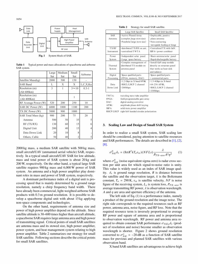
In order to explain our development strategy for small SARsystem, mass and power allocation of SAR satellites areoverviewed. Figure 1 is a conceptual block diagram of SARsystem. A SAR system consists of a digital unit for signalgeneration and receiving, an RF unit for signal generationand receiving, a high power amplifier for signal transmitting,a SAR antenna, a data recorder unit and a data link, a powersupply system and a heat management system for a highpower amplifier.
Table 1 shows major specifications, power consump-tion, mass budget of a typical large SAR satellite with
Copyright © 2017 The Institute of Electronics, Information and Communication Engineers
1654IEICE TRANS. COMMUN., VOL.E100–B, NO.9 SEPTEMBER 2017
Fig. 1 System block of SAR.
Table 1 Typical power and mass allocations of spaceborne and airborneSAR system.
2000 kg mass, a medium SAR satellite with 500 kg mass,small aircraft/UAV (unmanned aerial vehicle) SAR, respec-tively. In a typical small aircraft/UAV SAR for low altitude,mass and total power of SAR system is about 20 kg and200 W, respectively. On the other hand, a typical large SARsatellite requires 900 kg mass and 6,000 W power of SARsystem. An antenna and a high power amplifier play domi-nant roles in mass and power of SAR system, respectively.
A dominant performance index of a digital unit is pro-cessing speed that is mainly determined by a ground rangeresolution, namely a chirp frequency band width. Therehave already been commercial, light-weighted airborne SARproducts with 0.3 m ground resolution. It is possible to de-velop a spaceborne digital unit with about 15 kg applyingnon-space components and technologies.
On the other hand, requirements of antenna size andpower of high power amplifier depend on the altitude. Sincesatellite altitude is 30–600 times higher than aircraft altitude,a spaceborne SAR requires large antenna area and high powerof transmitting signal. Critical points of small SAR satellitesare antenna mass and its stowed size, high power amplifier,power system, and heat management system relating to highpower amplifier. Table 2 summarizes our strategy for smallSAR satellite. Following sections describe the critical pointsfor small SAR satellites.
Table 2 Strategy for small SAR satellite.
3. Scaling Law and Design of Small SAR System
In order to realize a small SAR system, SAR scaling lawshould be considered, paying attention to satellite resourcesand SAR performances. The details are described in [1], [2],[8].
σ0NEδr = (8πR3kTovst )(NFLs)
λ
PTX−aveA2η2 (1)
where σ0NE (noise equivalent sigma zero) is radar cross sec-
tion per unit area for which signal-to-noise ratio is unity.This value is widely used as an index of SAR image qual-ity. δr is ground range resolution, R is distance betweenthe satellite and the observation target, k is the Boltzmannconstant, To = 290 K, vst is satellite velocity, NF is noisefigure of the receiving system, Ls is system loss, PTX−ave isaverage transmitting RF power, λ is observation wavelength.A and η are area and aperture efficiency of the antenna.
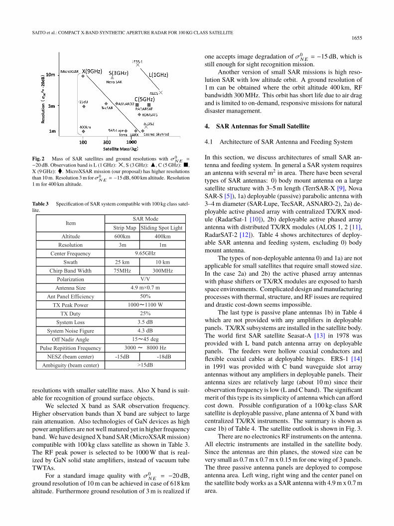
The left side of Eq. (1) is a performance index, namelya product of the ground resolution and the image noise. Theright side corresponds to the required resources such as RFpower, antenna area, noise figure, and RF loss. Note that therequired resource term is inversely proportional to averageRF power and square of antenna area and is proportionalto observation wavelength. RF power and antenna area re-quired to obtain constant SAR performance σNEoδr (prod-uct of resolution and noise) become smaller as observationwavelength is shorter. Figure 2 shows ground resolutionconverted to σo
NE = −20 dB as a function of SAR satellitemass for previous and planned SAR satellites with variousobservation band.
X band SAR satellites are advantageous to achieve high
SAITO et al.: COMPACT X-BAND SYNTHETIC APERTURE RADAR FOR 100 KG CLASS SATELLITE1655
Fig. 2 Mass of SAR satellites and ground resolutions with σ0NE =
−20 dB. Observation band is L (1 GHz): ×, S (3 GHz): ▲, C (5 GHz): ■,X (9 GHz): ♦. MicroXSAR mission (our proposal) has higher resolutionsthan 10 m. Resolution 3 m forσ0
NE = −15 dB, 600 km altitude. Resolution1 m for 400 km altitude.
Table 3 Specification of SAR system compatible with 100 kg class satel-lite.
resolutions with smaller satellite mass. Also X band is suit-able for recognition of ground surface objects.
We selected X band as SAR observation frequency.Higher observation bands than X band are subject to largerain attenuation. Also technologies of GaN devices as highpower amplifiers are not well matured yet in higher frequencyband. We have designed X band SAR (MicroXSAR mission)compatible with 100 kg class satellite as shown in Table 3.The RF peak power is selected to be 1000 W that is real-ized by GaN solid state amplifiers, instead of vacuum tubeTWTAs.
For a standard image quality with σ0NE = −20 dB,
ground resolution of 10 m can be achieved in case of 618 kmaltitude. Furthermore ground resolution of 3 m is realized if
one accepts image degradation of σ0NE = −15 dB, which is
still enough for sight recognition mission.Another version of small SAR missions is high reso-
lution SAR with low altitude orbit. A ground resolution of1 m can be obtained where the orbit altitude 400 km, RFbandwidth 300 MHz. This orbit has short life due to air dragand is limited to on-demand, responsive missions for naturaldisaster management.
4. SAR Antennas for Small Satellite
4.1 Architecture of SAR Antenna and Feeding System
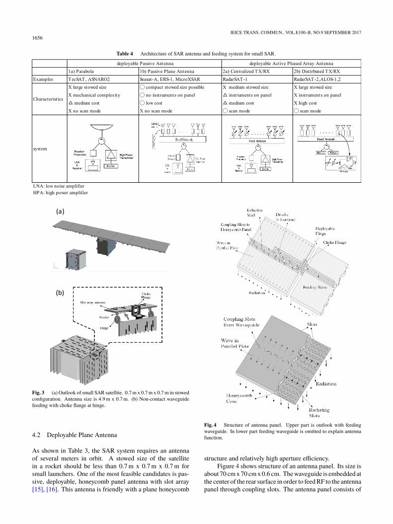
In this section, we discuss architectures of small SAR an-tenna and feeding system. In general a SAR system requiresan antenna with several m2 in area. There have been severaltypes of SAR antennas: 0) body mount antenna on a largesatellite structure with 3–5 m length (TerrSAR-X [9], NovaSAR-S [5]), 1a) deployable (passive) parabolic antenna with3–4 m diameter (SAR-Lupe, TecSAR, ASNARO-2), 2a) de-ployable active phased array with centralized TX/RX mod-ule (RadarSat-1 [10]), 2b) deployable active phased arrayantenna with distributed TX/RX modules (ALOS 1, 2 [11],RadarSAT-2 [12]). Table 4 shows architectures of deploy-able SAR antenna and feeding system, excluding 0) bodymount antenna.
The types of non-deployable antenna 0) and 1a) are notapplicable for small satellites that require small stowed size.In the case 2a) and 2b) the active phased array antennaswith phase shifters or TX/RX modules are exposed to harshspace environments. Complicated design and manufacturingprocesses with thermal, structure, and RF issues are requiredand drastic cost-down seems impossible.
The last type is passive plane antennas 1b) in Table 4which are not provided with any amplifiers in deployablepanels. TX/RX subsystems are installed in the satellite body.The world first SAR satellite Seasat-A [13] in 1978 wasprovided with L band patch antenna array on deployablepanels. The feeders were hollow coaxial conductors andflexible coaxial cables at deployable hinges. ERS-1 [14]in 1991 was provided with C band waveguide slot arrayantennas without any amplifiers in deployable panels. Theirantenna sizes are relatively large (about 10 m) since theirobservation frequency is low (L and C band). The significantmerit of this type is its simplicity of antenna which can affordcost down. Possible configuration of a 100 kg-class SARsatellite is deployable passive, plane antenna of X band withcentralized TX/RX instruments. The summary is shown ascase 1b) of Table 4. The satellite outlook is shown in Fig. 3.
There are no electronics RF instruments on the antenna.All electric instruments are installed in the satellite body.Since the antennas are thin planes, the stowed size can bevery small as 0.7 m x 0.7 m x 0.15 m for one wing of 3 panels.The three passive antenna panels are deployed to composeantenna area. Left wing, right wing and the center panel onthe satellite body works as a SAR antenna with 4.9 m x 0.7 marea.
1656IEICE TRANS. COMMUN., VOL.E100–B, NO.9 SEPTEMBER 2017
Table 4 Architecture of SAR antenna and feeding system for small SAR.
Fig. 3 (a) Outlook of small SAR satellite. 0.7 m x 0.7 m x 0.7 m in stowedconfiguration. Antenna size is 4.9 m x 0.7 m. (b) Non-contact waveguidefeeding with choke flange at hinge.
4.2 Deployable Plane Antenna
As shown in Table 3, the SAR system requires an antennaof several meters in orbit. A stowed size of the satellitein a rocket should be less than 0.7 m x 0.7 m x 0.7 m forsmall launchers. One of the most feasible candidates is pas-sive, deployable, honeycomb panel antenna with slot array[15], [16]. This antenna is friendly with a plane honeycomb
Fig. 4 Structure of antenna panel. Upper part is outlook with feedingwaveguide. In lower part feeding waveguide is omitted to explain antennafunction.
structure and relatively high aperture efficiency.Figure 4 shows structure of an antenna panel. Its size is
about 70 cm x 70 cm x 0.6 cm. The waveguide is embedded atthe center of the rear surface in order to feed RF to the antennapanel through coupling slots. The antenna panel consists of
SAITO et al.: COMPACT X-BAND SYNTHETIC APERTURE RADAR FOR 100 KG CLASS SATELLITE1657
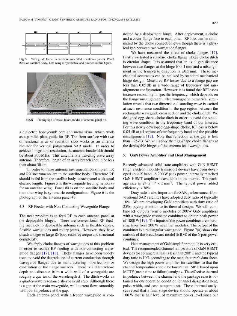
Fig. 5 Waveguide feeder network is embedded in antenna panels. Panel#0 is on satellite body. Left wing is symmetric and omitted in this figure.
Fig. 6 Photograph of bread board model of antenna panel #3.
a dielectric honeycomb core and metal skins, which workas a parallel plate guide for RF. The front surface with twodimensional array of radiation slots works as an antennaradiator for vertical polarization SAR mode. In order toachieve 1 m ground resolution, the antenna bandwidth shouldbe about 300 MHz. This antenna is a traveling wave arrayantenna. Therefore, length of an array branch should be lessthan about 30 cm.
In order to make antenna instrumentation simpler, TXand RX instruments are in the satellite body. Therefore RFshould be fed from the satellite body to each panel with equalelectric length. Figure 5 is the waveguide feeding networksfor an antenna wing. Panel #0 is on the satellite body andthe other wing is symmetric configuration. Figure 6 is thephotograph of the antenna panel #3.
4.3 RF Feeder with Non-Contacting Waveguide Flange
The next problem is to feed RF to each antenna panel atthe deployable hinges. There are conventional RF feed-ing methods to deployable antenna such as flexible cables,flexible waveguides and rotary joints. However, they havedisadvantages of large RF loss, resistive torque and structuralcomplexity.
We apply choke flanges of waveguides to this problemin order to realize RF feeding with non-contacting wave-guide flanges [17], [18]. Choke flanges have been widelyused to avoid the degradation of current conduction throughwaveguide flanges due to manufacturing imperfections oroxidization of the flange surfaces. There is a ditch whosedepth and distance from a wide wall of a waveguide areroughly a quarter of the wavelength λ. The ditch works asa quarter-wave resonance short-circuit stub. Although thereis a gap at the main waveguide, wall current flows smoothlywith low impedance at the gap.
Each antenna panel with a feeder waveguide is con-
nected by a deployment hinge. After deployment, a chokeand a cover flange face to each other. RF loss can be mini-mized by the choke connection even though there is a phys-ical gap between two waveguide flanges.
We have measured the effect of choke flanges [17].Firstly we tested a standard choke flange whose choke ditchis circular shape. It is assumed that an axial gap distancebetween two flanges at the hinge is 0–1 mm and a misalign-ment in the transverse direction is ±0.5 mm. These me-chanical accuracies can be realized by standard mechanicalhinge design. Measured RF losses due to a flange gap areless than 0.05 dB in a wide range of frequency and mis-alignment configuration. However, it is found that RF lossesincrease resonantly in specific frequency, which depends onthe flange misalignment. Electromagnetic numerical simu-lation reveals that two dimensional standing wave is excitedat such resonance condition in the gap region between therectangular waveguide cross section and the choke ditch. Wedesigned egg-shape choke ditch in order to avoid the stand-ing wave condition in the frequency band of our interest.For this newly developed egg-shape choke, RF loss is below0.05 dB at all regions of our frequency band and the possiblemisalignment [17]. Note that reflection at the gap is lessthan −25 dB. We will apply the egg-shape choke flanges atthe deployable hinges of the antenna feed waveguides.
5. GaN Power Amplifier and Heat Management
Recently advanced solid state amplifiers with GaN HEMT(high electron mobility transistor) devices have been devel-oped up to X band. A 200 W peak power, internally matchedGaN HEMT amplifier is available in the market. The pack-age size is 24 x 17 x 5 mm3. The typical power addedefficiency is 38%.
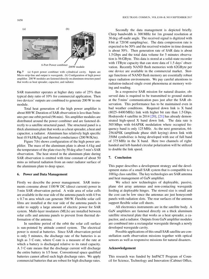
Duty ratio is also important for SAR performance. Con-ventional SAR satellites have adopted duty ratio of typically10%. We are developing GaN amplifiers with duty ratio of25%, paying attention to its thermal design. We will com-bine RF outputs from 6 modules of 200W GaN amplifierswith a waveguide resonator combiner to obtain peak powerof 1000 W [19]. The inputs of the power combiner are micro-strip lines from 200 W amplifier modules. The output of thecombiner is a rectangular waveguide. Figure 7(a) shows theoutlook of the bread board model (BBM) of the 6-port powercombiner.
Heat management of GaN amplifier module is very crit-ical. The recommended channel temperature of GaN HEMTdevices for commercial use is less than 200◦C and the typicalduty ratio is 10% according to the manufacturer’s data sheet.We design the high power amplifier for satellites so that thechannel temperature should be lower than 150◦C based uponMTTF (mean time to failure) analysis. The effective thermalimpedance between the channel and the package case is ob-tained for our operation condition (channel dissipation heat,pulse width, and case temperature). These thermal analy-ses reveal that a final stage device should operate at about100 W that is half level of maximum power level since our
1658IEICE TRANS. COMMUN., VOL.E100–B, NO.9 SEPTEMBER 2017
Fig. 7 (a) 6-port power combiner with cylindrical cavity. Inputs areMicro-strip-line and output is waveguide. (b) Configuration of high poweramplifier. 200 W modules are fastened directly on aluminum structure panelthat works as heat spreader, capacitor, and radiator.
SAR transmitter operates at higher duty ratio of 25% thantypical duty ratio of 10% for commercial application. Thentwo devices’ outputs are combined to generate 200 W in onemodule.
Total heat generation of the high power amplifier isabout 800 W. Duration of SAR observation is less than 5min-utes per one orbit period (96 min). Six amplifier modules aredistributed around the power combiner and are fastened di-rectly to a satellite structural panel. The structural panel is athick aluminum plate that works as a heat spreader, a heat andcapacitor, a radiator. Aluminum has relatively high specificheat (0.9 kJ/K/kg) and thermal conductance (200 W/K/m).
Figure 7(b) shows configuration of the high power am-plifier. The mass of the aluminum plate is about 4.4 kg andthe temperature of the plate rises by 50 deg after 5 min’s SARobservation. The heat stored in the aluminum plate duringSAR observation is emitted with time constant of about 50mins as infrared radiation from an outer radiator surface ofthe aluminum plate to deep space.
6. Power and Data Management
Firstly we describe the power management. SAR instru-ments consume about 1100 W DC (direct current) power in5 min SAR observation period. A wide area of solar cellsare available in the rear side of the antenna panels with 4.9 mx 0.7 m area which can generate 500 W. Flexible solar cellfilms are installed at the rear side of the antenna panels inorder to supply a large amount of electric power for SARsystem. Multi-layer insulators (MLIs) are installed betweensolar cells and antenna panels to prevent from thermal de-formation of the antenna.
In sunshine period of the orbit the solar cell surfaceis sun-pointed by attitude control system. The electricalpower is stored at batteries. Since SAR observation periodis only 5 minutes, the discharge rate of the batteries is ashigh as 3 C-rate, where C-rate is a measure of the rate atwhich a battery is discharged relative to its rated capacity.A 3 C-rate means that the discharge current will dischargethe entire battery in 1/3 hour. Conventional space qualifiedbatteries cannot afford such high discharge rates. We applycommercial batteries that are robust for high discharge rates.
Secondly the data management is depicted briefly.Chirp bandwidth is 300 MHz for 1m ground resolution at30 deg off-nadir angle. The received signal is digitized with8 bit at 720 M sampling/sec. The data compression rate isexpected to be 50% and the received window in time domainis about 50%. Then generation rate of SAR data is about1.5 Gbps and the total data volume for 5 minutes observa-tion is 56 GByte. This data is stored at a solid-state recorderwith 1TByte capacity that can store data of 1.5 days’ obser-vation. Recently NAND flush memories with 62GByte perone device are available in the commercial market. Stor-age functions of NAND flush memory are essentially robustspace radiation environments. We pay careful attentions toradiation-induced single event phenomena at memory writ-ing and reading.
In a responsive SAR mission for natural disaster, ob-served data is required to be transmitted to ground stationat the 5 mins’ communication pass just after the SAR ob-servation. This performance has to be maintained even inbad weather conditions. Required down link is X band(8025–8400 MHz) link with higher bit rate than 1.5 Gbps.Hodoyoshi 4 satellite in 2014 [20], [21] has already demon-strated high-speed X band down link. The data rate is505 Mbps with 64APSK modulation where occupied fre-quency band is only 125 MHz. As the next generation, 64-256APSK (amplitude phase shift keying) down link with350M symbol/sec is being developed with use of full bandof 375 MHz in the X band. Here two channels of right-handed and left-handed circular polarization will be utilizedto double the link speed.
7. Conclusion
This paper describes a development strategy and the devel-opment status of a small SAR system that is compatible to a100 kg class satellite. The key technologies are SAR antennaand heat management of GaN amplifier.
We select new technologies of deployable, passive,plane slot array antennas and non-contacting waveguidefeeding at deployable hinges. The stowed size is small andthe cost can be low since the antennas are just honeycombpanels with radiation slots. The rear surfaces of the antennasupport flexible solar cell sheets.
All electronics instruments are in the satellite body. AGaN amplifiers are fastened directly on a thick aluminumsatellite structural plate that works as a heat spreader, a ca-pacitor, and a radiator. Outputs from GaN amplifier modulesare combined into a rectangular waveguide through a newlydeveloped waveguide cavity.
Possible applications of this small SAR satellite are con-stellation earth observation missions together with opticalsensors as well as responsive missions for natural disasters.
Acknowledgement
This research was funded by ImPACT Program of Coun-cil for Science, Technology and Innovation (Cabinet Office,

SAITO et al.: COMPACT X-BAND SYNTHETIC APERTURE RADAR FOR 100 KG CLASS SATELLITE1659
Government of Japan).
References
[1] M.I Skolnik, Radar Handbook, Third Ed., McGraw-Hill, USA, 2008.[2] K. Tomiyasu, “Tutorial review of synthetic-aperture radar (SAR) with
applications to imaging of the ocean surface,” Proc. IEEE, vol.66,no.5, pp.563–583, May 1978.
[3] H.M. Braun and P.E. Knobloch, “SAR on small satellites - Shown onthe SAR-lupe example,” Proc. International Radar Symposium 2007(IRS 2007), Cologne, Germany, Sept. 2007.
[4] U. Naftaly and R. Levy-Nathansohn, “Overview of the TECSARsatellite hardware and mosaic mode,” IEEE Geosci. Remote Sens.Lett., vol.5, no.3, pp.423–426, 2008.
[5] P. Davies, P. Whittaker, R. Bird, L. Gomes, B. Stern, Prof Sir M.Sweeting, M. Cohen, and D. Hall, “NovaSAR-S bringing radar ca-pability to the disaster monitoring constellation” 4S Symposium,Slovenia, June 2012.
[6] P. van Duijn and M. Pastena, “PanelSAR: A smallsat radar instru-ment,” SSC13-I-5 AIAA Small Satellite Conf., Logan, USA, Aug.2013.
[7] P. Laurlia, R. Modrzewski, T. Cheng, B. Cambell, V. Garas, andV.G. Yanni, “Validation of ICEYE small satellite SAR design for icedetection and imaging,” Arctic Technology Conference, Oct. 24–26,2016.
[8] H. Saito, A. Tomiki, P.R. Akbar, T. Ohtani, K. Nishijo, J. Hirokawa,and M. Ando, “Synthetic aperture radar compatible with 100 kgclass piggy-back satellite,” IEEE, APSAR2013 (2013 Asia-pacificconference on synthetic aperture radar), TU2.R1.4, 2013.
[9] B. Grafmuller, A. Herschlein, and C. Fischer, “The Terra SAR-Xantenna system,” IEEE International Radar Conference, 2005. Insti-tute of Electrical & Electronics Engineers (IEEE), 2005. [Online].Available: http://dx.doi.org/10.1109/RADAR.2005.1435823
[10] R. Raney, A. Luscombe, E. Langham, and S. Ahmed, “RADARSAT(SAR imaging),” Proc. IEEE, vol.79, no.6, pp.839–849, June 1991.[Online]. Available: http://dx.doi.org/10.1109/5.90162
[11] Y. Kankaku, Y. Osawa, S. Suzuki, and T. Watanabe, “The overviewof the l-band sar onboard alos-2,” Proc. Progress in ElectromagneticsResearch Symposium, 2009.
[12] S. Riendeau and C. Grenier, “RADARSAT-2 antenna,” AerospaceConference, 2007 IEEE, pp.1–9, 2007.
[13] R. Jordan, “The Seasat-A synthetic aperture radar system,” IEEE J.Ocean. Eng., vol.5, no.2, pp.154–164, April 1980. [Online]. Avail-able: http://dx.doi.org/10.1109/JOE.1980.1145451
[14] E. Attema, “The active microwave instrument on-board the ERS-1satellite,” Proc. IEEE, vol.79, no.6, pp.791–799, June 1991. [Online].Available: http://dx.doi.org/10.1109/5.90158
[15] J. Hirokawa, M. Ando, and N. Goto, “Waveguide-fed parallel plateslot array antenna,” IEEE Trans. Antennas Propag., vol.40, no.2,pp.218–222, Feb. 1992.
[16] P.R. Akbar, H. Saito, M. Zhang, J. Hirokawa, and M. Ando, “Parallel-plate slot array antenna for deployable SAR antenna onboard smallsatellite,” IEEE Trans. Antennas Propag., vol.64, no.5, pp.1661–1671, May, 2016.
[17] R. Naruse, H. Saito, J. Hirokawa, and Z. Miao, “Non-contact wavefeed with the choke-flange waveguide at the development section ofthe expansion antenna for small satellite,” IEICE, Technical Report,SANE2014-61, 2014.
[18] H. Saito and A. Tomiki, in progress for Japanese patent, 2013-128851.
[19] V. Ravindra, H. Saito, J. Hirokawa, and M. Zhang, “Cylindricalcavity microwave power combiner with microstrip line inputs andrectangular waveguide output,” 2015 IEEE MTT-S International Mi-crowave Symposium (IMS), 17-22-22, May 2015.
[20] H. Saito, et al., “High spectral - efficiency communication in X bandfor small earth observation satellites - result of 505 Mbps demonstra-tion and plan for 2 Gbps link -,” 4S Symposium 2016, 217, Valletta,
Malta, May–June, 2016.[21] H. Saito, et al., “High bit-rate communication in X band for small
earth observation satellites- result of 505 Mbps demonstration andplan for 2 Gbps link –,” AIAA Small Satellite Conf. 2016, LoganUSA, SSC16-VII-01, Aug. 2016.
Hirobumi Saito received the B.S., M.S. andPh.D. degrees in Electrical Engineering fromUniversity of Tokyo in 1976, 1978 and 1981respectively. He is now a professor of Insti-tute of Space and Astraunoutical Science, JapanAerospace and Exploration Agency. His re-search area is small satellite technologies.
Prilando Rizki Akbar received his B.Eng degree in electrical engineering from STTTelkom (now is known as Telkom University),Bandung, Indonesia, in 2001. Then, he receivedhis M.Eng and Ph.D. degrees in information sci-ence from Chiba University, Chiba, Japan, in2009 and 2012, respectively. Since April 2013,he has been working as Project Research Asso-ciate in Department of Spacecraft Engineering atJapan Aerospace Exploration Agency (JAXA).He is engaging in research on the development
of antenna for synthetic aperture radar onboard a small satellite. Dr. Akbaris also a member of IEICE and IEEE.
Hiromi Watanabe graduated in Departmentof Earth and Planetary science from The Univer-sity of Tokyo 2010. Now He belongs to Depart-ment of Electrical Engineering and InformationSystems, Graduate School of Engineering, TheUniversity of Tokyo.
Vinay Ravindra received his B.E. degreein Electronics and Communication from Visves-varaya University of Technology in 2010, and hisM.S. degrees in Space Science and Technologyfrom Lulea University of Technology, Swedenand University of Wuerzburg, Germany in 2012.He is now with the Japan Aerospace ExplorationAgency (JAXA). His research interests are smallsatellites and passive microwave devices.

1660IEICE TRANS. COMMUN., VOL.E100–B, NO.9 SEPTEMBER 2017
Jiro Hirokawa received the B.S., M.S. andD.E. degrees in electrical and electronic engi-neering from Tokyo Institute of Technology, To-kyo, Japan in 1988, 1990 and 1994, respectively.He is currently a Professor there. He was with theantenna group of Chalmers University of Tech-nology, Gothenburg, Sweden, as a PostdoctoralFellow from 1994 to 1995. His research areahas been in slotted waveguide array antennasand millimeter-wave antennas. He is a Fellowof IEEE.
Kenji Ura received the B.S.and M.S. de-grees in Electrical Engineering from ShizuokaUniversity in 2007, and 2009, respectively. Hejoined Kamakura Works of Mitsubishi ElectricCorporation in 2009, has worked as a systemengineer of synthetic aperture radar.
Pyne Budhaditya received his Bachelors’degreee in Electrical Engineering (B.E.E) fromJadavpur University, Kolkata, India in 2013 andhis Masters’ degree in Electrical Engineeringand Information Systems (ME) from the Uni-versity of Tokyo in 2015.