Embed Size (px)
Citation preview
IM-UK-RO CH Issue 1 1
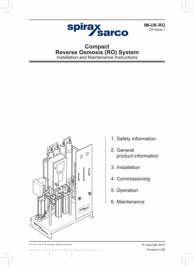
Compact Reverse Osmosis (RO) SystemInstallation and Maintenance Instructions
1. Safety information
2. General product information
3. Installation
4. Commissioning
5. Operation
6. Maintenance
IM-UK-ROCH Issue 1
© Copyright 2013
Printed in GB
IM-UK-RO CH Issue 12
Note: This document refers only to the mechanical installation and commissioning of the Spirax Compact Reverse Osmosis System and should be used in conjunction with the relevant IMIs for the other system components and supplementary safety information for all the system components.
WarningThis product is designed and constructed to withstand the forces encountered during normal use.
Use of the product for any purpose other than its intended use could cause damage to the product and may cause injury or fatality to personnel.
Before any installation or maintenance procedure, always ensure that all associated primary steam, condensate return and secondary water lines are isolated.
Ensure any residual internal pressure in the system or connecting pipework is carefully relieved.
Always wear appropriate safety clothing before carrying out any installation or maintenance work.
LiftingThe Spirax Compact Reverse Osmosis System should be lifted by a suitable forklift truck, from the base, placed in position and securely bolted to the floor *.
Please note: As the weight of the water is perceived to be sufficient to keep the unit safely in position it only needs to be bolted to the floor at the customers request.
Warning:On no account is the Spirax Compact Reverse Osmosis System to be lifted by any other part, other than the base.
Note: Sufficient space should be provided around the system location to allow access for maintenance.
1. Safety information
*
IM-UK-RO CH Issue 1 3
Safe operation of these products can only be guaranteed if they are properly installed, commissioned, used and maintained by qualified personnel (see Section 1.11) in compliance with the operating instructions. General installation and safety instructions for pipeline and plant construction, as well as the proper use of tools and safety equipment must also be complied with.
1.1 Intended useReferring to the Installation and Maintenance Instructions, name-plate and Technical Information Sheet, check that the product is suitable for the intended use / application. These products comply with the requirements of the European Pressure Equipment Directive 97 / 23 / EC and fall within category 'SEP'. It should be noted that products rated as 'SEP' are required by the Directive not to carry the mark.
i) The product has been specifically designed for use on water which is in Group 2 of the above mentioned Pressure Equipment Directive. The products’ use on other fluids may be possible but, if this is contemplated, Spirax Sarco should be contacted to confirm the suitability of the product for the application being considered.
ii) Check material suitability, pressure and temperature and their maximum and minimum values. If the maximum operating limits of the product are lower than those of the system in which it is being fitted, or if malfunction of the product could result in a dangerous overpressure or overtemperature occurrence, ensure a safety device is included in the system to prevent such over-limit situations.
iii) Determine the correct installation situation and direction of fluid flow.
iv) Spirax Sarco products are not intended to withstand external stresses that may be induced by any system to which they are f itted. It is the responsibility of the installer to consider these stresses and take adequate precautions to minimise them.
v) Remove protection covers from all connections and protective film from allname-plates, where appropriate, before installation on steam or other high temperature applications.
1.2 AccessEnsure safe access and if necessary a safe working platform (suitably guarded) before attempting to work on the product. Arrange suitable lifting gear if required.
1.3 LightingEnsure adequate lighting, particularly where detailed or intricate work is required.
1.4 Hazardous liquids or gases in the pipelineConsider what is in the pipeline or what may have been in the pipeline at some previous time. Consider: flammable materials, substances hazardous to health, extremes of temperature.
IM-UK-RO CH Issue 14
1.5 Hazardous environment around the productConsider: explosion risk areas, lack of oxygen (e.g. tanks, pits), dangerous gases, extremes of temperature, hot surfaces, fire hazard (e.g. during welding), excessive noise, moving machinery.
1.6 The systemConsider the effect on the complete system of the work proposed. Will any proposed action (e.g. closing isolation valves, electrical isolation) put any other part of the system or any personnel at risk? Dangers might include isolation of vents or protective devices or the rendering ineffective of controls or alarms. Ensure isolation valves are turned on and off in a gradual way to avoid system shocks.
1.7 Pressure systems Ensure that any pressure is isolated and safely vented to atmospheric pressure. Consider double isolation (non return valve) and the locking or labelling of closed valves. Do not assume that the system has depressurised even when the pressure gauge indicates zero.
1.8 TemperatureThe Spirax Compact Reverse Osmosis System is a cold water device, designed for maximum temperatures of 40°C - this temperature should not be exceeded. Failure to do so would cause critical membrane failure.
1.9 Tools and consumablesBefore starting work ensure that you have suitable tools and / or consumables available. Use only genuine Spirax Sarco replacement parts.
1.10 Protective clothingConsider whether you and / or others in the vicinity require any protective clothing to protect against the hazards of, for example, chemicals, high/low temperature, radiation, noise, falling objects, and dangers to eyes and face.
1.11 Permits to workAll work must be carried out or be supervised by a suitably competent person.Installation and operating personnel should be trained in the correct use of the product according to the Installation and Maintenance Instructions.Where a formal 'permit to work' system is in force it must be complied with. Where there is no such system, it is recommended that a responsible person should know what work is going on and, where necessary, arrange to have an assistant whose primary responsibility is safety.Post 'warning notices' if necessary.
1.12 HandlingManual handling of large and / or heavy products may present a risk of injury. Lifting, pushing, pulling, carrying or supporting a load by bodily force can cause injury particularly to the back. You are advised to assess the risks taking into account the task, the individual, the load and the working environment and use the appropriate handling method depending on the circumstances of the work being done.Please note that if lifting straps are required we would recommend that they be fitted around the baffle plate legs to prevent damage to the unit.
IM-UK-RO CH Issue 1 5
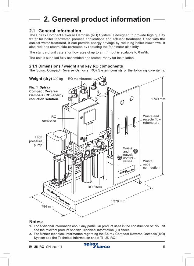
2.1 General informationThe Spirax Compact Reverse Osmosis (RO) System is designed to provide high quality water for boiler feedwater, process applications and effluent treatment. Used with the correct water treatment, it can provide energy savings by reducing boiler blowdown. It also reduces steam side corrosion by reducing the feedwater alkalinity.
The standard unit caters for flowrates of up to 2 m3/h, but is scalable to 6 m3/h.
The unit is supplied fully assembled and tested, ready for installation.
2.1.1 Dimensions / weight and key RO componentsThe Spirax Compact Reverse Osmosis (RO) System consists of the following core items:
Weight (dry) 300 kg
2. General product information
Fig. 1 Spirax Compact Reverse Osmosis (RO) energy reduction solution
Notes:1. For additional information about any particular product used in the construction of this unit see the relevent product specific Technical Information (TI) sheet.2. For further technical information regarding the Spirax Compact Reverse Osmosis (RO) System see the Technical Information sheet TI-UK-RO.
1 749 mm
1 378 mm784 mm
RO controller
RO membranes
High pressure
pump
RO filters
Waste outlet connection
Wasteandrecyclecontrolvalves
Waste and recycle flow rotameters
IM-UK-RO CH Issue 16
2.2 Reverse osmosis operationThe control system of the Spirax Reverse Osmosis plant is based around a control device with fixed algorithms. This controller governs the automation and control of the process. A series of valves are used with a high pressure pump and membranes, regimented and controlled by a HMI and PLC.
Process overviewRO relies on semi-permeable membranes, which have pores so fine that only water molecules are small enough to pass through them. In nature, similar membranes are responsible for regulating the water and nutrient levels in living cells. In industrial applications, pumps apply pressure to the raw water side and force pure water through a synthetic membrane, leaving salts and other contaminating molecules behind. Probably the easiest way to visualize RO is as a filtration system.
For most applications it is envisaged that Spirax RO systems will be used to clean raw water that enters steam generators, boilers and hot water systems. This application ensures the boiler TDS is optimized for the most efficient running capacity. Its primary function will be to reduce boiler blowdown frequency, saving significant energy losses.
2.3 The Spirax RO unit nomenclatureThe product nomenclature is a reflection of the core items and unit options that have been ordered and supplied - See table below:
InstrumentationTag No. DescriptionC01 Feedwater conductivity probe
C02 Product water conductivity probe
PT01 Feedwater pre filter pressure
PT02 Feedwater post filter pressure
PS01 HP pump high pressure switch
DrivesTag No. DescriptionP1 HP pump
DivertersTag No. DescriptionV1 Feedwater isolation solenoid valve
V2 Feedwater bypass solenoid valve
V3 Product water outlet isolation solenoid valve
IM-UK-RO CH Issue 1 7
2.4 OperationManual controlEach of the following plant items shall have the facility for manual control. It remains the responsibility of the person placing any device into manual control to ensure the safety of plant, people and process.
InstrumentationTag No. DescriptionC01 Feedwater conductivity probeC02 Product water conductivity probePT01 Feedwater pre filter pressurePT02 Feedwater post filter pressurePS01 HP pump high pressure switch
DrivesTag No. DescriptionP1 HP PumpV1 Feedwater Isolation Solenoid ValveV2 Feedwater Bypass Solenoid ValveV3 Product Water Outlet Isolation Solenoid Valve
If any of the items above are placed into Manual control and are therefore unavailable for automatic control an alarm shall be raised on the HMI.
Stopped / IdleWhen idle and before entering the start-up routine, i.e. on initial power up, the valves will be orientated as follows;
¨ V01 Feedwater isolation valve CLOSED¨ V02 Feedwater bypass valve OPENED¨ V03 Product water outlet valve CLOSED¨ P1 HP Pump OFF
Start-upOn receipt of an enable system, either from a remote source or via the start button from the HMI, providing that the RO system has all the required devices in Auto, then the following start up operation will occur;
¨ V01 Feedwater isolation valve OPENED¨ V02 Feedwater bypass valve CLOSED¨ V03 Product water outlet valve OPENED¨ P1 HP Pump ON
High permeate conductivity (C02)If the conductivity probe (C02) registers a conductivity measurement higher than the high permeate alarm set point, the HMI alarm shall be raised and the following control actions will take place;
¨ V01 Feedwater isolation valve OPENED¨ V02 Feedwater bypass valve CLOSED¨ V03 Product water outlet valve CLOSED¨ P1 HP Pump ON
IM-UK-RO CH Issue 18
Prolonged high permeate conductivity (C02)If the conductivity probe C02 continues to register high conductivity measurement the HMI alarm shall be raised and the following control actions will take place;
¨ V01 Feedwater isolation valve CLOSED¨ V02 Feedwater bypass valve CLOSED¨ V03 Product water outlet valve OPENED¨ P1 HP Pump OFF
High raw water feedline Conductivity (C01)If the conductivity probe C01 registers a conductivity measurement higher than the raw water set point and the HMI alarm shall be raised and the following controlling actions will take place;
¨ V01 Feedwater isolation valve CLOSED¨ V02 Feedwater bypass valve CLOSED¨ V03 Product water outlet valve OPENED¨ P1 HP Pump OFF
Feedwater pre filter pressure (PT01)If the feedwater pre filter pressure transducer (PT01) registers a high pressure measurement, the HMI alarm shall be raised and the following control actions will take place;
¨ V01 Feedwater isolation valve CLOSED¨ V02 Feedwater bypass valve CLOSED¨ V03 Product water outlet valve OPENED¨ P1 HP Pump OFF
High HP pump pressure (PS01)If the pressure switch (PS01) is registering a high pressure, the HMI alarm shall be raised and the following control actions will take place;
¨ V01 Feedwater isolation valve CLOSED¨ V02 Feedwater bypass valve CLOSED¨ V03 Product water outlet valve OPENED¨ P1 HP Pump OFF
Feedwater post filter pressure (PT02)If the feedwater post filter pressure transducer (PT02) registers a high pressure measurement,the HMI alarm shall be raised and the following control actions will take place;
¨ V01 Feedwater isolation valve CLOSED¨ V02 Feedwater bypass valve CLOSED¨ V03 Product water outlet valve OPENED¨ P1 HP Pump OFF
IM-UK-RO CH Issue 1 9
3. InstallationNote: Before actioning any installation observe the 'Safety information' in Section 1.
3.1 Water connectionsIt is important that the raw water supply is of softened water quality at all times. The supply water must have:- A minimum pressure of 4 bar. Failure to achieve this could result in the plant tripping out
on low pressure.- A free chlorine (or total oxidant) level less than 0.1 mg / l.- No abnormally high levels of iron, manganese or organics.- Total Hardness levels <4mg / l.- (SDI) <5- Temperature <40°C maximum.
Pressure / temperature Iimits
Pump suction side Maximum operating pressure 5 barg
Maximum operating temperature 40°C
Test pressure 6 .2 bar g @ 20°C
Pump delivery side Maximum operating pressure 13 .6 bar g
Maximum operating temperature 40°C
Test pressure 15 bar g @ 20°C
ConnectionsSoftened water inlet RO water outlet Drain By-pass
All ¾"
The water supply should comply to the statements above and water temperature should never exceed 40ºC.
The water supply should always be maintained at the specified design pressure and temperature for the unit. The Spirax RO must not operate above the maximum pressure and temperatures indicated on the name-plate attached to the RO.
The installation of an appropriately sized non return valve on the permeate side is recommended if the permeate is connected directly to a boiler hotwell.
IM-UK-RO CH Issue 110
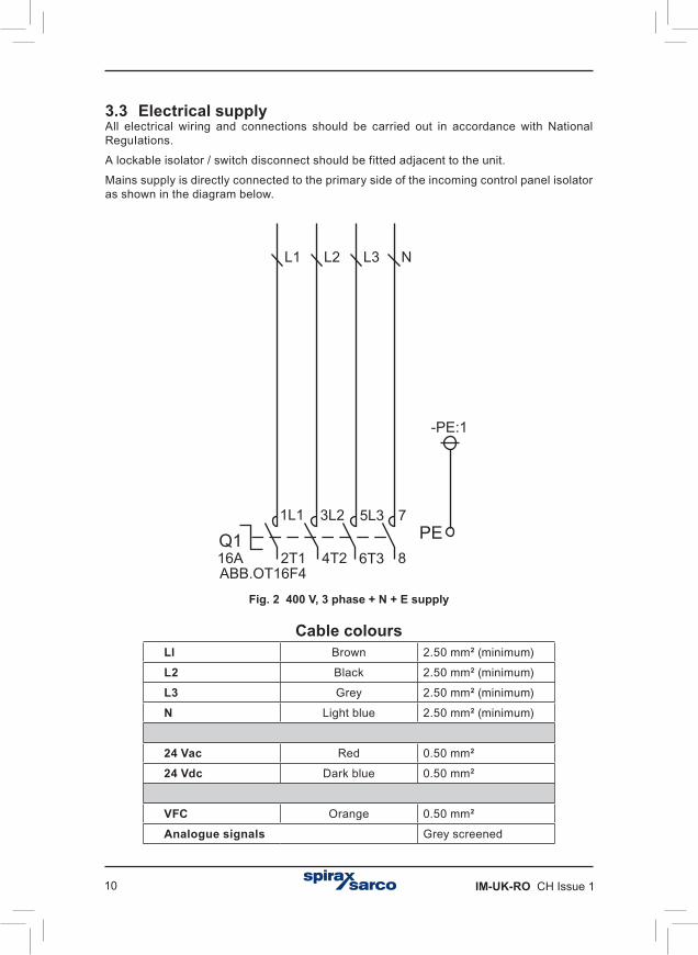
3.3 Electrical supplyAll electrical wiring and connections should be carried out in accordance with National ReguIations.
A lockable isolator / switch disconnect should be fitted adjacent to the unit.
Mains supply is directly connected to the primary side of the incoming control panel isolator as shown in the diagram below.
Cable coloursLl Brown 2.50 mm2 (minimum)
L2 Black 2.50 mm2 (minimum)
L3 Grey 2.50 mm2 (minimum)
N Light blue 2.50 mm2 (minimum)
24 Vac Red 0.50 mm2
24 Vdc Dark blue 0.50 mm2
VFC Orange 0.50 mm2
Analogue signals Grey screened
Fig. 2 400 V, 3 phase + N + E supply
�� �� ���
��� ��� ��� �
��� ��� ��� ��������������
��
� ���
�
IM-UK-RO CH Issue 1 11
3.4 Electrical specifications
All control equipment is pre-wired and ready for connection to the power source (system activation via volt-free contact from level control in supply tank or hot well).
Electrical supplyPower supply 400 V, 3 phase, 50 Hz
Supply fuse 20 A
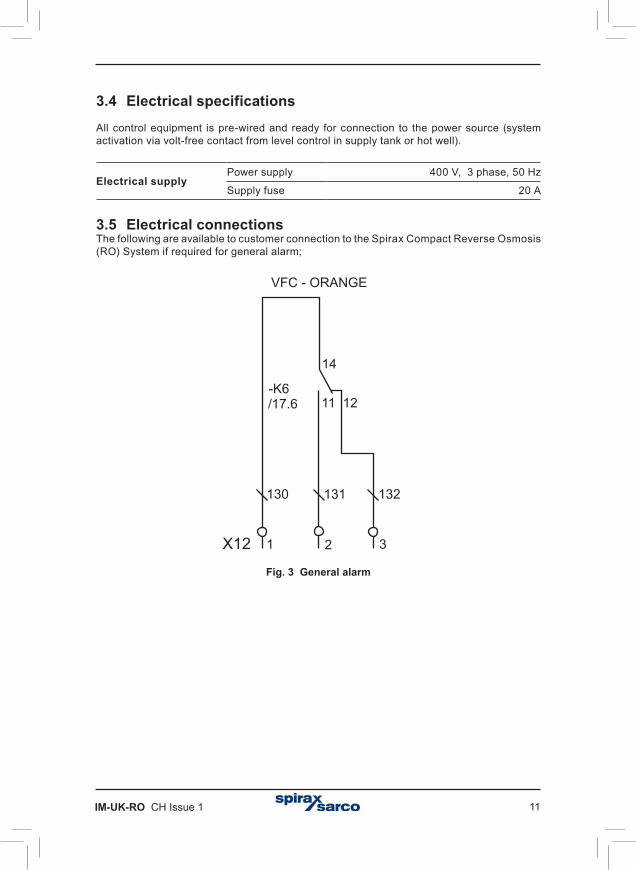
3.5 Electrical connectionsThe following are available to customer connection to the Spirax Compact Reverse Osmosis (RO) System if required for general alarm;
Fig. 3 General alarm
������������
��������
��
�����
��� ��� ��
� ��
IM-UK-RO CH Issue 112
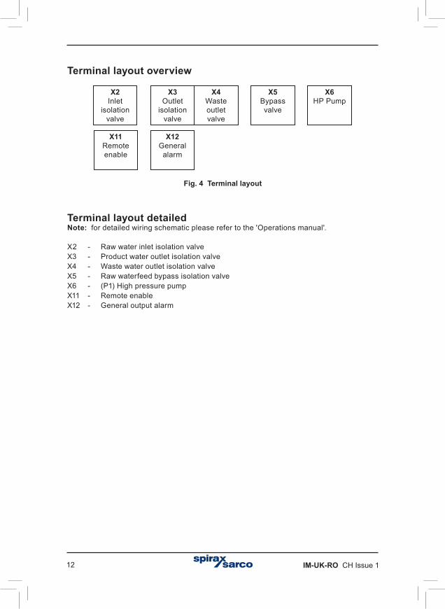
Terminal layout overview
Terminal layout detailedNote: for detailed wiring schematic please refer to the 'Operations manual'.
X2 - Raw water inlet isolation valveX3 - Product water outlet isolation valveX4 - Waste water outlet isolation valveX5 - Raw waterfeed bypass isolation valveX6 - (P1) High pressure pumpX11 - Remote enableX12 - General output alarm
X2Inlet
isolationvalve
X3Outlet
isolationvalve
X4Wasteoutletvalve
X5Bypassvalve
X6HP Pump
X11Remoteenable
X12Generalalarm
Fig. 4 Terminal layout
IM-UK-RO CH Issue 1 13
4. CommissioningSoftware copyrightCertain computer programs contained in this product [or device] were developed by Spirax-Sarco Limited ('the Work(s)'). Copyright © Spirax-Sarco Limited 2013 All Rights ReservedSpirax-Sarco Limited grants the legal user of this product (or device) the right to use the Work(s) solely within the scope of the legitimate operation of the product (or device). No other right is granted under this licence. In particular and without prejudice to the generality of the foregoing, the Work(s) may not be used, sold, licensed, transferred, copied or reproduced in whole or in part or in any manner or form other than as expressly granted here without the prior written consent of Spirax-Sarco Limited.
4.1 Commissioning requirements and tasksWe recommend that you use the service and support of a Spirax Sarco commissioning engineer. Details of this service can be found by contacting Spirax Sarco.
Note: Pre commissioning requirements:- A minimum pressure of 4 bar. Failure to achieve this could result in the plant tripping out on low pressure.- A free chlorine (or total oxidant) level less than 0.1 mg / l.- No abnormally high levels of iron, manganese or organics.- Total Hardness levels <4 mg / l.- (SDI) <5- Temperature <40°C maximum.- Inspect all pipework, pumps and tanks for leaks and general condition.- Test and prove all pump and level switch control systems.- Test and prove the feed water to the RO plant for hardness and particulate matter.- Check and calibrate any conductivity instruments and clean the conductivity cells.- Test and prove all pressure switches and interlinks within the RO control system.- Check filters have been loaded.- Check all electrical connections are secure and as per the wiring diagram - Sections 3.3 and 3.4.- Complete a full RO performance tests and record the results.
IM-UK-RO CH Issue 114
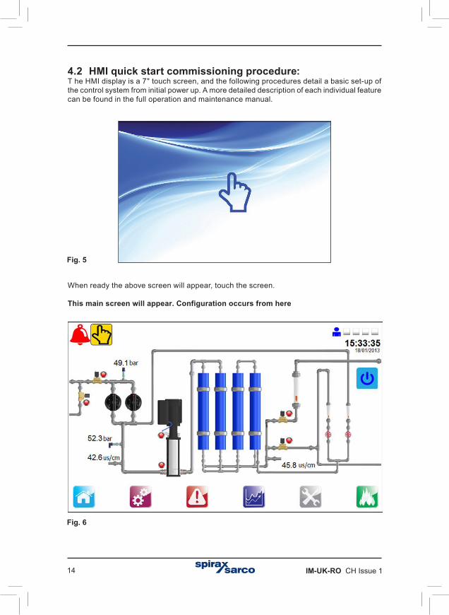
4.2 HMI quick start commissioning procedure:T he HMI display is a 7" touch screen, and the following procedures detail a basic set-up of the control system from initial power up. A more detailed description of each individual feature can be found in the full operation and maintenance manual.
When ready the above screen will appear, touch the screen.
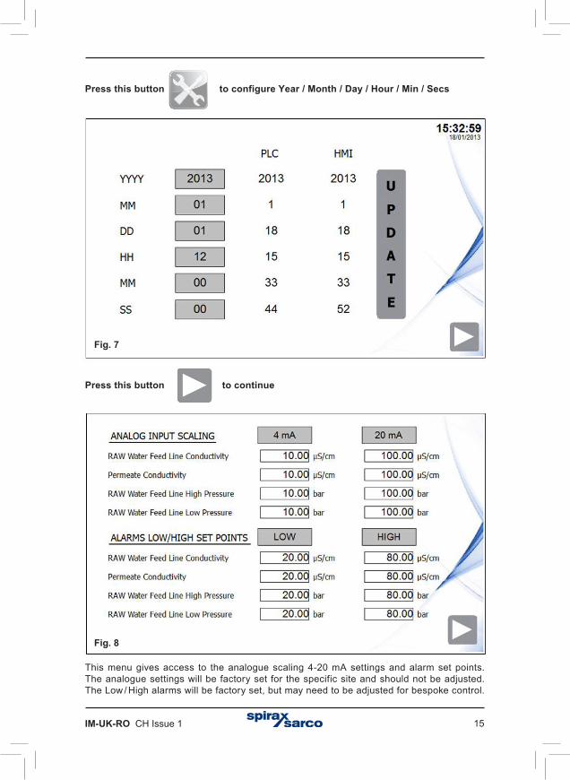
This main screen will appear. Configuration occurs from here
Fig. 5
Fig. 6
IM-UK-RO CH Issue 1 15
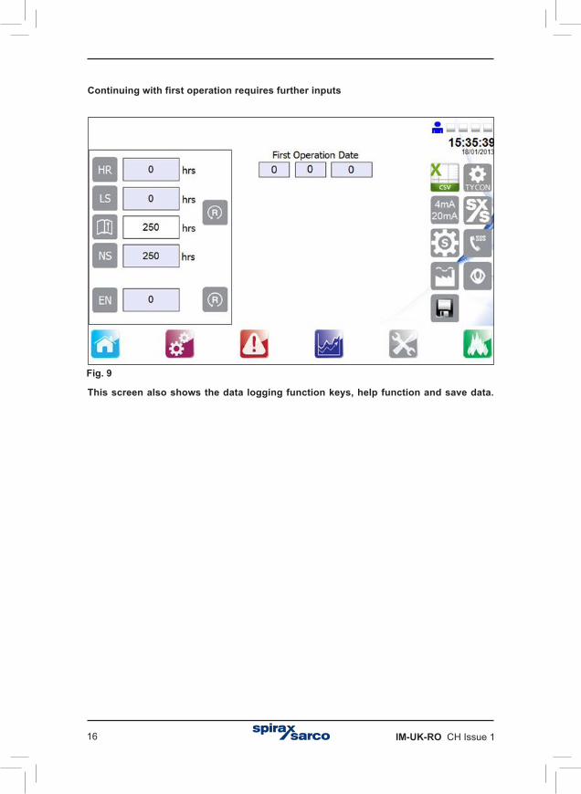
Press this button to configure Year / Month / Day / Hour / Min / Secs
Press this button to continue
This menu gives access to the analogue scaling 4-20 mA settings and alarm set points.The analogue settings will be factory set for the specific site and should not be adjusted.The Low / High alarms will be factory set, but may need to be adjusted for bespoke control.
!
Fig. 7
Fig. 8
IM-UK-RO CH Issue 116
Continuing with first operation requires further inputs
This screen also shows the data logging function keys, help function and save data.
Fig. 9
IM-UK-RO CH Issue 1 17
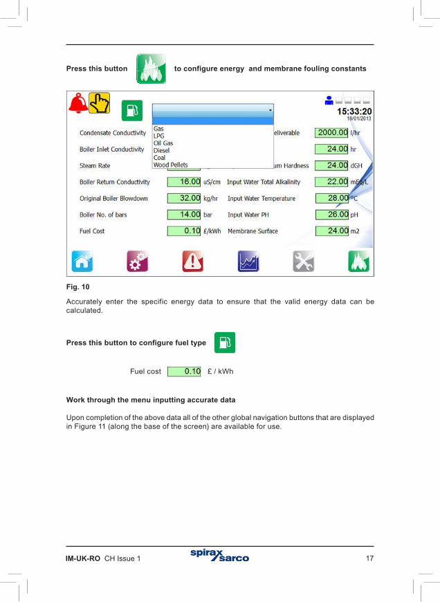
Press this button to configure energy and membrane fouling constants
Accurately enter the specific energy data to ensure that the valid energy data can be calculated.
Press this button to configure fuel type
Work through the menu inputting accurate data
Upon completion of the above data all of the other global navigation buttons that are displayed in Figure 11 (along the base of the screen) are available for use.
!
Fuel cost £ / kWh
Fig. 10
IM-UK-RO CH Issue 118
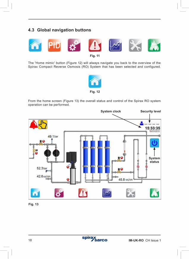
4.3 Global navigation buttons
The 'Home mimic' button (Figure 12) will always navigate you back to the overview of the Spirax Compact Reverse Osmosis (RO) System that has been selected and configured.
From the home screen (Figure 13) the overall status and control of the Spirax RO system operation can be performed.
!
!
System clock Security level
System status
Fig. 11
Fig. 12
Fig. 13
IM-UK-RO CH Issue 1 19
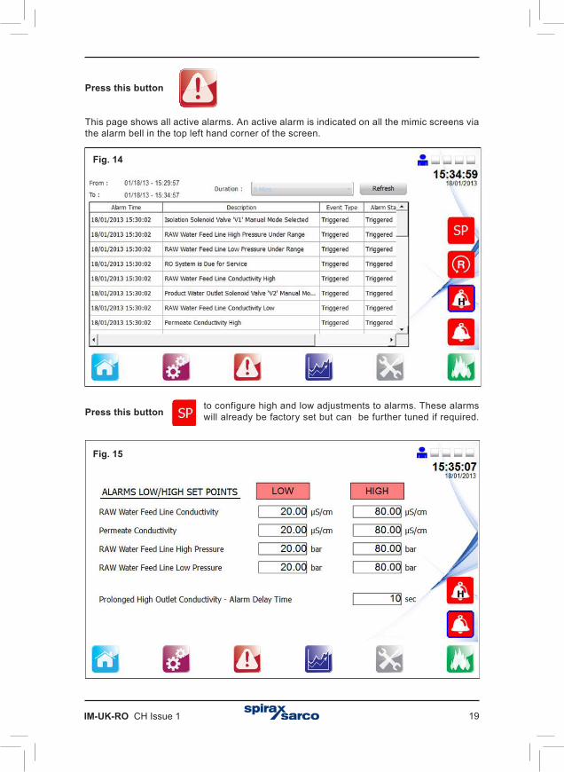
Press this button
This page shows all active alarms. An active alarm is indicated on all the mimic screens via the alarm bell in the top left hand corner of the screen.
!
Press this button to configure high and low adjustments to alarms. These alarms will already be factory set but can be further tuned if required.
Fig. 14
Fig. 15
IM-UK-RO CH Issue 120
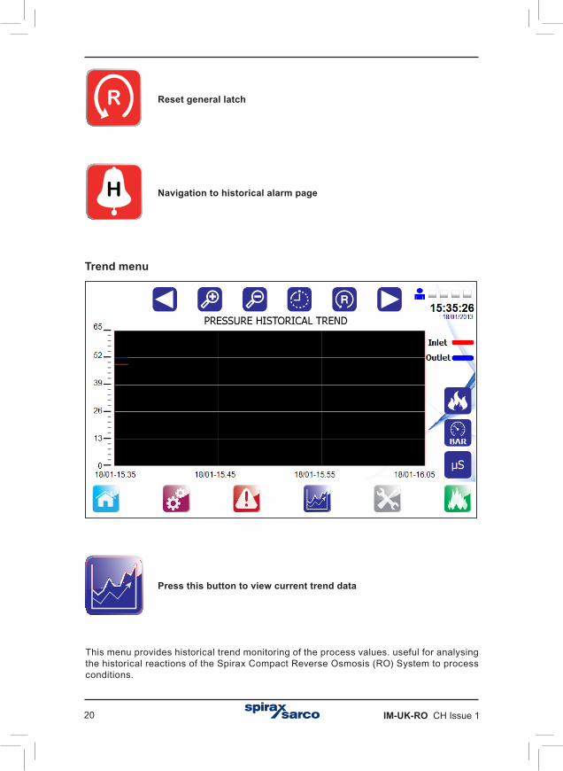
Trend menu
Press this button to view current trend data
This menu provides historical trend monitoring of the process values. useful for analysingthe historical reactions of the Spirax Compact Reverse Osmosis (RO) System to process conditions.
R Reset general latch
Navigation to historical alarm pageH
H
IM-UK-RO CH Issue 1 21
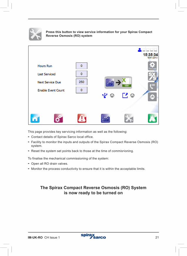
Press this button to view service information for your Spirax Compact Reverse Osmosis (RO) system
This page provides key servicing information as well as the following:- Contact details of Spirax Sarco local office.- Facility to monitor the inputs and outputs of the Spirax Compact Reverse Osmosis (RO) system.- Reset the system set points back to those at the time of commis•ioning.
To finalise the mechanical commissioning of the system:- Open all RO drain valves.- Monitor the process conductivity to ensure that it is within the acceptable limits.
The Spirax Compact Reverse Osmosis (RO) Systemis now ready to be turned on
!
IM-UK-RO CH Issue 122
6. MaintenanceNote: Before actioning any maintenance observe the 'Safety information' in Section 1.
6.1 GeneralFor maintenance of the individual components that make up the system, please see the relevant product specific IMI’s for the components concerned.
RO feed requirementsThe RO should only be fed with a good reliable supply of softened water and adequate treated water storage facilities downstream.
The RO plant requires:
- Total hardness <4 mg / l
- Free chlorine <0.1 mg / l
- SDI <5
- Minimum of 4 bar pressure
- No abnormally high levels of iron, manganese or organics.
- Failure to remove organics and particulates of >5 SDI will reults in membrane and filter fouling.

IM-UK-RO CH Issue 1 23

IM-UK-RO CH Issue 124


![Spirax Strainer[1]](https://img.pdfslide.us/doc/110x75/5477b71cb4af9f9c108b4912/spirax-strainer1.jpg)