Embed Size (px)
Citation preview
INSTRUCTION MANUAL NI-281WE Rev. 11 05/18
COMPACT PRESS. SWITCHES SERIES PCS & PCA
All data, statements and recommendations supplied with this manual are based on information believed by us to be reliable. As the conditions of effective use are beyond our control, our products are sold under the condition that the user himself evaluates such conditions before following our recommendations for the purpose or use foreseen by him.
This document is the property of ALEXANDER WIEGAND SE &Co and may not be reproduced in any form, nor used for any purpose other than for which it is supplied.
WEATHERPROOF AND INTRINSICALLY SAFE: MODELS PCS; FLAMEPROOF: MODELS PCA
Sensor P Sensor G Sensor M,T,V
A = Pressure connection B = Cable entry
For surface mounting use two screws M5 (not supplied with the instrument) WEIGHT 1 kg dimension unit: mm
NOTE: dimensions and weights are not binding unless released on certified drawings.
CAUTION
Before installing, using or carrying out maintenance on the instrument it is necessary to read and understand the indications given in the attached Instruction Manual.
The instrument must only be installed and maintained by qualified personnel in relation to working with instruments for hazardous areas.
INSTALLATION IS TO BE CARRIED OUT ONLY AFTER CHECKING THAT INSTRUMENT CHARACTERISTICS ARE CONSISTENT WITH PROCESS AND PLANT REQUIREMENTS
The functional features of the instrument and its degree of protection are shown on the identification plate fixed to the case.
CONTENTS: 1 - GENERAL NOTES 2 - OPERATING PRINCIPLE 3 - MODEL CODE 4 - IDENTIFICATION PLATE AND MARKINGS 5 - SPECIAL CONDITIONS FOR SAFE USE (X) 6 - SET POINT REGULATION 7 - SET POINT CALIBRATION 8 - INSTRUMENT PLUMBING 9 - MOUNTING AND CONNECTIONS 10 - SAFETY INTEGRITY LEVEL (SIL) INSTALLATION REQUIREMENTS 11 - PUTTING INTO OPERATION 12 - VISUAL INSPECTION 13 - FUNCTIONAL VERIFICATION 14 - STOPPING AND DISMOUNTING 15 - DISPOSAL 16 - TROUBLESHOOTING
SAFETY INSTRUCTIONS FOR USE IN HAZARDOUS ATMOSPHERES. RECOMMENDATIONS FOR PRESSURE SWITCH SAFE USE.
RELATED DOCUMENT To authentified document with certificate
N° IECEx PRE 16.0072X N° IECEx PRE 16.0074X
INSTRUCTION MANUAL NI-281WE Rev. 11 05/18
2 of 7
1 - GENERAL NOTES
1.1 FOREWORD
The wrong choice of a models or a version, as well as the incorrect installation, lead to malfunction and reduce instrument life. Failure to abide by the indications given in this manual can cause damage to the instrument, the environment and persons.
1.2 ALLOWED OVERRANGE
Pressures exceeding the working range can be occasionally allowed only for testing proposal up to the proof pressure. Continuous pressures exceeding the (adjustable) “RANGE” (see fig 1) can be applied to the instrument, provided they are clearly stated in the instrument features (see fig.1, “MAX PRESSURE”). The current and voltage values stated in the technical specifications and data plate must not be exceeded: transitory overranges can have a destructive effect on the switch.
1.3 TEMPERATURE
The temperature of the instrument is influenced by the environmental and process temperature. Special attention must be taken to avoid the exceeding of the limits specified in table 1.
As far as the process temperature, some suitable measures (valves, protection against heat radiation, fluid separators, cooling coils, heated lockers), have to be taken to limit the temperature to the specified values in table 1.
Table 1 – Temperature conditions Temperature Classification
Ambient temperature
range (Tamb)
Max Process temperature
(at the process connection of the instrument) (Tp)
(see page 1)
Max electrical rating (resistive load)
T6 -60 … +60 °C +60 °C
See nameplate of the instrument
(electrical rating)
T5
T4
-60 … +85 °C +85 °C T3
T2
T1
The process fluid or its impurities must not however solidify in the instrument.
2 - OPERATING PRINCIPLE
A pressure-tight diaphragm (or an O-ring sealed piston) applies a force to a stiff disc. This force is directly proportional to the pressure value and is contrasted by a compression spring charged by a suitable bush. When the force balance point is exceeded, the stiff disc shifts and, by means of a rigid rod, actuates one or two simultaneous release electric microswitches. The microswitches are of the snap acting type with automatic reset. When the pressure moves away from the set values, returning towards the normal values, the switch is reset.
3 - MODEL CODE
See Annex 1
4 - IDENTIFICATION PLATE AND MARKINGS
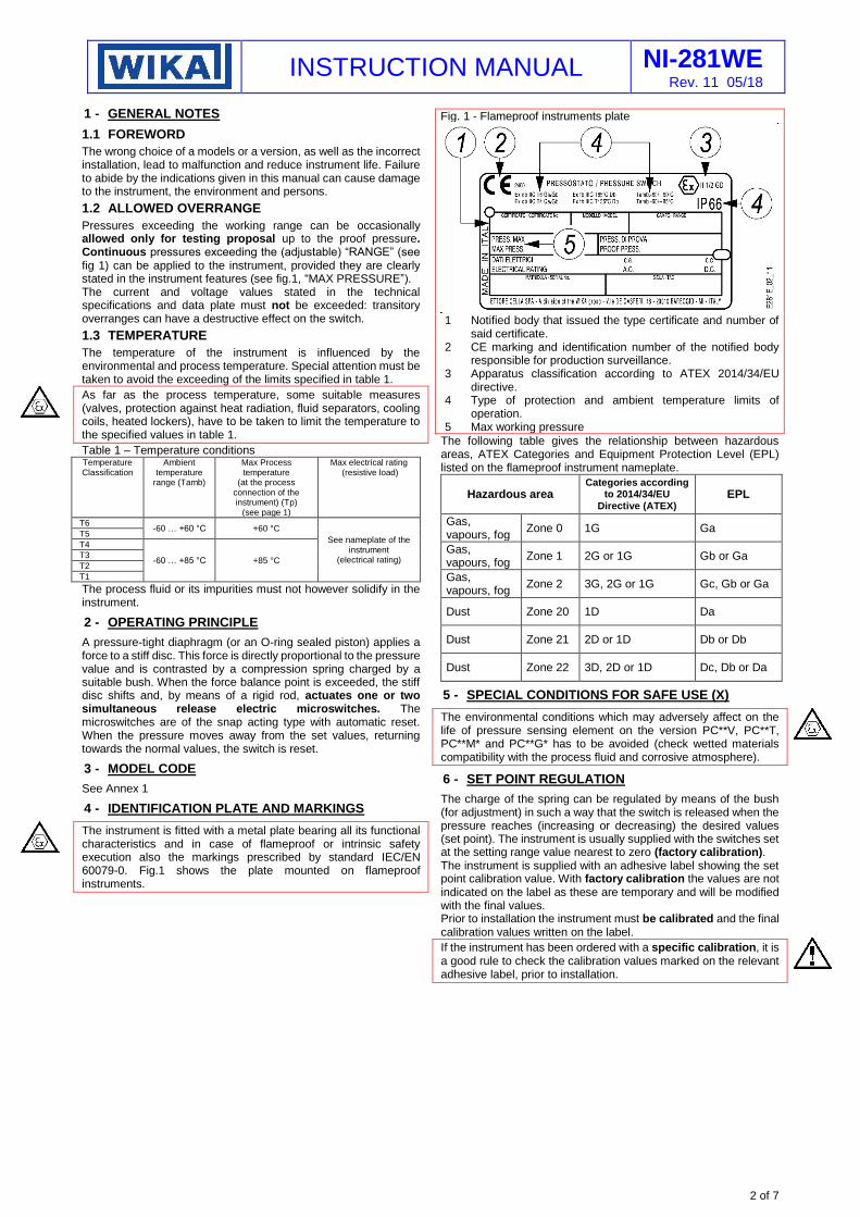
The instrument is fitted with a metal plate bearing all its functional characteristics and in case of flameproof or intrinsic safety execution also the markings prescribed by standard IEC/EN 60079-0. Fig.1 shows the plate mounted on flameproof instruments.
Fig. 1 - Flameproof instruments plate
1 Notified body that issued the type certificate and number of
said certificate. 2 CE marking and identification number of the notified body
responsible for production surveillance. 3 Apparatus classification according to ATEX 2014/34/EU
directive. 4 Type of protection and ambient temperature limits of
operation. 5 Max working pressure
The following table gives the relationship between hazardous areas, ATEX Categories and Equipment Protection Level (EPL) listed on the flameproof instrument nameplate.
Hazardous area Categories according
to 2014/34/EU Directive (ATEX)
EPL
Gas, vapours, fog
Zone 0 1G Ga
Gas, vapours, fog
Zone 1 2G or 1G Gb or Ga
Gas, vapours, fog
Zone 2 3G, 2G or 1G Gc, Gb or Ga
Dust Zone 20 1D Da
Dust Zone 21 2D or 1D Db or Db
Dust Zone 22 3D, 2D or 1D Dc, Db or Da
5 - SPECIAL CONDITIONS FOR SAFE USE (X)
The environmental conditions which may adversely affect on the life of pressure sensing element on the version PC**V, PC**T, PC**M* and PC**G* has to be avoided (check wetted materials compatibility with the process fluid and corrosive atmosphere).
6 - SET POINT REGULATION
The charge of the spring can be regulated by means of the bush (for adjustment) in such a way that the switch is released when the pressure reaches (increasing or decreasing) the desired values (set point). The instrument is usually supplied with the switches set at the setting range value nearest to zero (factory calibration). The instrument is supplied with an adhesive label showing the set point calibration value. With factory calibration the values are not indicated on the label as these are temporary and will be modified with the final values. Prior to installation the instrument must be calibrated and the final calibration values written on the label.
If the instrument has been ordered with a specific calibration, it is a good rule to check the calibration values marked on the relevant adhesive label, prior to installation.
INSTRUCTION MANUAL NI-281WE Rev. 11 05/18
3 of 7
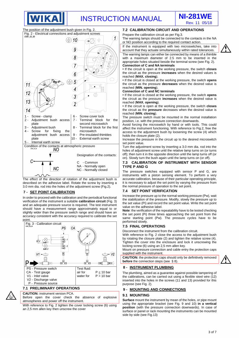
The position of the adjustment bush given in Fig. 2.
Fig. 2 - Electrical connections and adjustment screws
1 - Screw - clamp 2 - Adjustment bush access
plate 3 - Adjustment bush 4 - Screw for fixing the
adjustment bush access plate
5 - Internal earth screw
6 - Screw cover lock 7 - Terminal block for the
second microswitch 8 - Terminal block for the first
microswitch 9 - Pre-insulated thimbles
10 - External earth screw
Condition of the contacts at atmospheric pressure
Designation of the contacts: C - Common NA - Normally open NC - Normally closed
The effect of the direction of rotation of the adjustment bush is described on the adhesive label. Rotate the screw by inserting a 3.0 mm dia. rod into the holes of the adjustment screw (Fig.2).
7 - SET POINT CALIBRATION
In order to proceed with the calibration and the periodical functional verification of the instrument a suitable calibration circuit (Fig. 3) and an adequate pressure source is required. The test instrument should have a measurement range approximately equal to or slightly wider than the pressure switch range and should have an accuracy consistent with the accuracy required to calibrate the set point.
Fig. 3 - Calibration circuit
PS - Pressure switch CA - Test gauge V1 - Inlet valve V2 - Discharge valve P - Pressure source
Test fluid: air for P < 10 bar water for P > 10 bar
7.1 PRELIMINARY OPERATIONS
CAUTION: instrument version PCA. Before open the cover check the absence of explosive atmospheres and power off the instrument.
With reference to Fig. 2 tighten the cover locking screw (6) using an 2,5 mm allen key then unscrew the cover
7.2 CALIBRATION CIRCUIT AND OPERATIONS
Prepare the calibration circuit as per Fig.3. The warning lamps should be connected to the contacts in the NA or NO position according to the required contact action.
If the instrument is equipped with two microswitches, take into account that they actuate simultaneously within rated tolerances.
The warning lamps can either be connected by means of a thimble with a maximum diameter of 2.5 mm to be inserted in the appropriate holes situated beside the terminal screw (see Fig. 2). Connection of C and NA terminals • If the circuit is open at the working pressure, the switch closes the circuit as the pressure increases when the desired values is reached (MAX. closing). • If the circuit is closed at the working pressure, the switch opens the circuit as the pressure decreases when the desired value is reached (MIN. opening). Connection of C and NC terminals • If the circuit is closed at the working pressure, the switch opens the circuit as the pressure increases when the desired value is reached (MAX. opening). • If the circuit is open at the working pressure, the switch closes the circuit as the pressure decreases when the desired value is reached (MIN. closing). The pressure switch must be mounted in the normal installation position, i.e. with the pressure connection downwards. Avoid forcing the microswitch by hand or with tools. This could affect the instrument functioning. With reference to Fig.2, free the access to the adjustment bush by loosening the screw (4) which holds the closure plate (2). Increase the pressure in the circuit up to the desired microswitch set point value. Turn the adjustment screw by inserting a 3.0 mm dia. rod into the holes of adjustment screw until the relative lamp turns on (or turns off); then turn it in the opposite direction until the lamp turns off (or on). Slowly turn the bush again until the lamp turns on (or off).
7.3 CALIBRATION OF INSTRUMENT WITH SENSOR TYPE P AND G
The pressure switches equipped with sensor P and G, are instruments with a piston sensing element. To perform a very accurate calibration, because of their particular operating principle, it is necessary to adjust the set point by varying the pressure from the normal pressure of operation to the set point.
7.4 SET POINT VERIFICATION
Increase the pressure up to the normal working pressure (Pw), wait the stabilization of the pressure. Modify, slowly the pressure up to the set value (Pi) and record the set point value. Write the set point value on the adhesive label. Note: the verification of the repeatability have to be tested checking the set point (Pi) three times approaching the set point from the same starting point (Pw). The pressure cycles have to be performed slowly.
7.5 FINAL OPERATIONS
Disconnect the instrument from the calibration circuit. With reference to Fig. 2 close the access to the adjustment bush by rotating the closure plate (2) and tighten the relative screw (4). Tighten the cover into the enclosure and lock it unscrewing the locking screw (6) using an 2,5 mm allen key. Mount on pressure connection and cable entry the protection caps supplied with the instrument.
CAUTION: the protection caps should only be definitively removed before the connection steps (see § 8).
8 - INSTRUMENT PLUMBING
The plumbing, aimed as a guarantee against possible tampering of the calibrations, can be carried out using a flexible steel wire (12) inserted into the holes in the screws (11 and 13) provided for this purpose (see Fig. 2).
9 - MOUNTING AND CONNECTIONS
9.1 MOUNTING
Surface mount the instrument by mean of the holes, or pipe mount using the appropriate bracket (see Fig. 9 and 10) in a vertical position (with the pressure connection downwards). In case of surface or panel or rack mounting the instruments can be mounted side by side (see Fig.13)
INSTRUCTION MANUAL NI-281WE Rev. 11 05/18
4 of 7
Warning: Intrinsic safety instruments with aluminum enclosure. The instrument must be protected against accidental impacts of the housing.
The chosen position must be such that the possibility of shocks or temperature changes are within tolerable limits.
CAUTION: Make sure not to exceed the max temperature at the instrument process connection as specified at table 1.
With gas or vapour process fluid, the instrument must be positioned higher than the pipe inlet (see Fig. 12). With a liquid process fluid, the instrument can be positioned higher or lower, indifferently (see Fig. 11 and 12). In this case, during set point calibration the negative or positive head must be taken into account.
CAUTION: Positions other than vertical are allowed provided environmental conditions do not cause condensation to form or water to enter the instrument through the adjustment bush access plate (see Fig. 2).
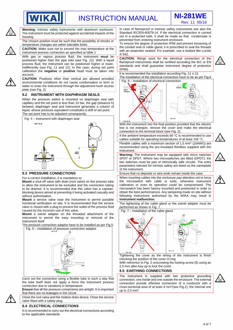
9.2 INSTRUMENT WITH DIAPHRAGM SEALS
When the pressure switch is mounted on diaphragm seal with capillary and the set point is less than 10 bar, the gap (distance h) between diaphragm seal and instrument generates a column of liquid, whose pressure equivalent constitutes a drift of set point. The set point has to be adjusted consequently.
Fig. 4 – Instrument with diaphragm seal
9.3 PRESSURE CONNECTIONS
For a correct installation, it is mandatory to: Mount a shut-off valve with drain (root valve) on the process tube to allow the instrument to be excluded and the connection tubing to be drained. It is recommended that this valve has a capstan-blocking device aimed at preventing it being activated casually and without authorisation. Mount a service valve near the instrument to permit possible functional verification on site. It is recommended that the service valve is closed with a plug to prevent the outlet of the process fluid caused by the incorrect use of this valve. Mount a swivel adapter on the threaded attachment of the instrument to permit the easy mounting or removal of the instrument itself. The pressure connection adaptor have to be installed as per Fig.5.
Fig. 5 – Installation of pressure connection adaptor
Carry out the connection using a flexible tube in such a way that the tube itself does not apply a force the instrument process connection due to variations in temperature. Ensure that all the pressure connections are airtight. It is important that there are no leakages in the circuit.
Close the root valve and the relative drain device. Close the service valve fitted with a safety plug.
9.4 ELECTRICAL CONNECTIONS
It is recommended to carry out the electrical connections according to the applicable standards.
In case of flameproof or intrinsic safety instruments see also the Standard IEC/EN-60079-14. If the electrical connection is carried out in a protected tube, it shall be made so that condensate is prevented from entering instrument enclosure. To ensure the degree of protection IP66 and prevent loosening of the conduit seal or cable gland, it is prescribed to seal the threads with an anaerobic sealant. For example, use a sealant like Loctite ® 542.
CAUTION: fittings used for the electrical connection of the flameproof instruments shall be certified according the IEC or EN standards and shall guarantee instrument degree of protection (IP66).
It is recommended the installation according Fig. 11 o 12. The installation of the electrical connection have to be as per Fig.6
Fig. 6 – Installation of electrical connection
With the instrument into the final position provided that the electric line is not energize, remove the cover and make the electrical connection to the terminal block (see Fig. 2).
If the ambient temperature exceeds 60 °C is recommended to use cables suitable for operating temperatures of at least 105 °C.
Flexible cables with a maximum section of 1,5 mm2 (16AWG) are recommended using the pre-insulated thimbles supplied with the instrument.
Warning: The instrument may be equipped with micro switches SPDT or DPDT. Where two microswitches are fitted (DPDT), the two switches must be part of intrinsically safe circuits. The entry parameters relevant for intrinsic safety are listed on the nameplate of the instrument.
Ensure that no deposits or wire ends remain inside the case.
When inserting cables into the enclosure pay attention not to force the microswitch with cable or tools, otherwise instrument calibration or even its operation could be compromised. The microswitch has been factory mounted and positioned in order to obtain the best performances. Any tampering made on site without following instructions authorised by the WIKA may result in instrument malfunction.
The tightening of the cable gland or the swivel adapter must be performed as shown in Fig. 7.
Fig. 7 – Installation of the cable gland
Tightening the cover as the wiring of the instrument is finish checking the position of the cover O-ring. With reference to Fig. 2 unscrewing the locking screw (6) using an 2,5 mm allen key up to lock the cover.
9.5 EARTHING CONNECTIONS
The instrument is supplied with two protective grounding connection, one inside and one outside the enclosure. The external connection provide effective connection of a conductor with a cross-sectional area of at least 4 mm2(see Fig.2), the internal one up to 2.5 mm2.
INSTRUCTION MANUAL NI-281WE Rev. 11 05/18
5 of 7
10 - SAFETY INTEGRITY LEVEL (SIL) INSTALLATION REQUIREMENTS
The pressure switches have been evaluated as Type A safety related hardware with a hardware fault tolerance of 0 used in one out one configuration (1oo1). Evaluate the installation necessity to permit a proof test to detect dangerous undetected fault as follows - Take appropriate action to avoid a false trip - Force the pressure switch to reach a define max or min
threshold value and verify that output goes into the safe state. - Force the pressure switch to reach a define normal threshold
value and verify that output goes into the normal state. - Repeat the check two times evaluating average set point
value and repeatability, - Restore the loop to full operation - Restore normal operation The installation requirements, the useful life and the failure of the pressure switch is discussed in the Failure Modes,Effects and Diagnostic Analysis Report
11 - PUTTING INTO OPERATION
The instrument comes into operations as soon as the root valve is opened. Any possible drainage of the connection tubing can be carried out by removing the safety plug and opening the service valve with the necessary caution (see fig.11 and 12).
Do not dispose of the process fluid into the environment, if this can cause pollution or damage to people
12 - VISUAL INSPECTION
Periodically check the external condition of the enclosure. There should be no trace of leakage of process fluid outside the instrument. In case of flameproof or intrinsic safety instruments, inspections of the electrical installation are to be carried out also according to customer procedures and at least in accordance with Standard EN-60079-17.
The flameproof and the intrinsic safety instruments installed in explosive atmospheres for the combustible dust presence, must be periodically cleaned up externally in order to avoid dust accumulating.
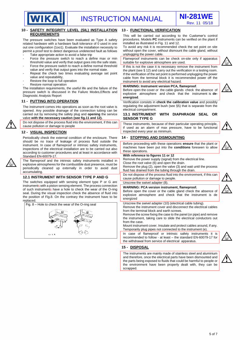
12.1 INSTRUMENT WITH SENSOR TYPE P AND G
The switches equipped with sensing element type P or G are instruments with a piston sensing element. The process connection of such instruments have a hole to check the wear of the O-ring seal. During the visual inspection check the absence of fluid into the position of Fig.8. On the contrary the instrument have to be replaced.
Fig. 8 – Hole to check the wear of the O-ring seal
13 - FUNCTIONAL VERIFICATION
This will be carried out according to the Customer’s control procedures. Models PC instruments can be verified on the plant if installed as illustrated in Fig. 11 and 12. To avoid any risk it is recommended check the set point on site without open the cover, without dismount the cable gland, without unplugging the power cable.
Flameproof instruments can be check on-site only if apparatus suitable for explosive atmosphere are used.
If this is not the case it is necessary remove the instrument from the plant (see § 12) and carry out the verification in a testing room. If the verification of the set point is performed unplugging the power cable from the terminal block it is recommended power off the instrument to avoid any electrical hazard.
WARNING: Instrument version PCA, flameproof. Before open the cover or the cable glands check the absence of explosive atmosphere and check that the instrument is de-energized.
Verification consists in check the calibration value and possibly regulating the adjustment bush (see §5) that is separate from the electrical compartment.
13.1 INSTRUMENT WITH DIAPHRAGM SEAL OR SENSOR TYPE G
These instruments, because of their particular operating principle, if used as an alarm of max pressure, have to be functional inspected every year as minimum.
14 - STOPPING AND DISMOUNTING
Before proceeding with these operations ensure that the plant or machines have been put into the conditions foreseen to allow these operations.
With reference to figures 11 or 12 Remove the power supply (signal) from the electrical line. Close the root valve (6) and open the drain. Remove the plug (2), open the valve (3) and wait until the process fluid has drained from the tubing through the drain.
Do not dispose of the process fluid into the environment, if this can cause pollution or damage to people.
Unscrew the swivel adapter (8).
WARNING: PCA version instrument, flameproof. Before open the cover or the cable gland check the absence of explosive atmosphere and check that the instrument is de energized
Unscrew the swivel adapter (10) (electrical cable tubing). Remove the instrument cover and disconnect the electrical cables from the terminal block and earth screws. Remove the screw fixing the case to the panel (or pipe) and remove the instrument, taking care to slide the electrical conductors out from the case. Mount instrument cover. Insulate and protect cables around, if any. Temporarily plug pipes not connected to the instrument (e).
In case of flameproof or intrinsic safety instruments it is recommended to follow - at least – the standard EN-60079-17 for the withdrawal from service of electrical apparatus.
15 - DISPOSAL
The instruments are mainly made of stainless steel and aluminium and therefore, once the electrical parts have been dismounted and the parts being exposed to fluids that could be harmful to people or the environment have been properly dealt with, they can be scrapped.
INSTRUCTION MANUAL NI-281WE Rev. 11 05/18
6 of 7
16 - TROUBLESHOOTING
IMPORTANT NOTE: operations involving replacement of essential components must be carried out at our workshop, especially for instruments with flameproof certificate; this is to guarantee the user the total and correct restoration of the product original characteristics.
MALFUNCTION PROBABLE CAUSE REMEDY
Set point shift
Permanent deformation of the sensitive element due to fatigue or excess over-ranges.
Variation of the elastic features of the sensitive element due to its chemical corrosion.
O-ring wear (only PC**P).
Recalibrate or replace the sensitive element. Recalibrate or replace the sensitive element
with another made of a suitable material. If necessary apply diaphragm seals.
Replace the piston subgroup and recalibrate (^).
Poor repeatability O-ring wear (only PC**P). Air bubbles or condensation (only for types with pressure
< 1 bar).
Replace the piston subgroup and recalibrate (^). Drain the process connection lines and if
necessary modify them.
Slow response Clogged or obstructed connection line. Root valve partially closed. Too viscous fluid.
Check and clean line. Open valve. Provide instrument with suitable fluid separator.
No actuation or undue actuation
Root valve closed. Microswitch contacts damaged. Loosened electrical joints. Interrupted or short-circuited.
Open the valve. Replace the microswitch (^). Check all electrical joints. Check the conditions of the electric line.
Undue actuation Accidental shocks. Modify the mounting.
(^) For the correct restoration of the product characteristics it is recommended to use only original spare parts.
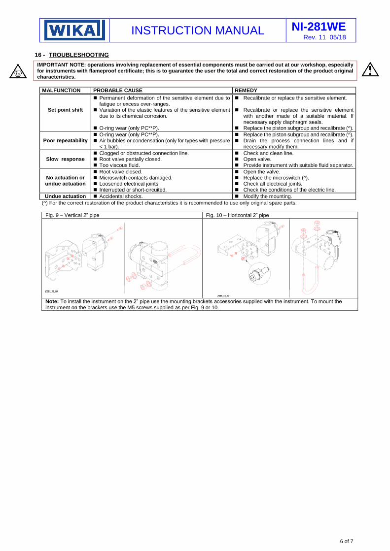
Fig. 9 – Vertical 2” pipe Fig. 10 – Horizontal 2” pipe
Note: To install the instrument on the 2” pipe use the mounting brackets accessories supplied with the instrument. To mount the instrument on the brackets use the M5 screws supplied as per Fig. 9 or 10.
INSTRUCTION MANUAL NI-281WE Rev. 11 05/18
WIKA Alexander Wiegand SE & Co. KG Alexander-Wiegand-Straße 30 63911 Klingenberg • Germany Tel. +49 9372 132-0 Fax +49 9372 132-406 [email protected] www.wika.de
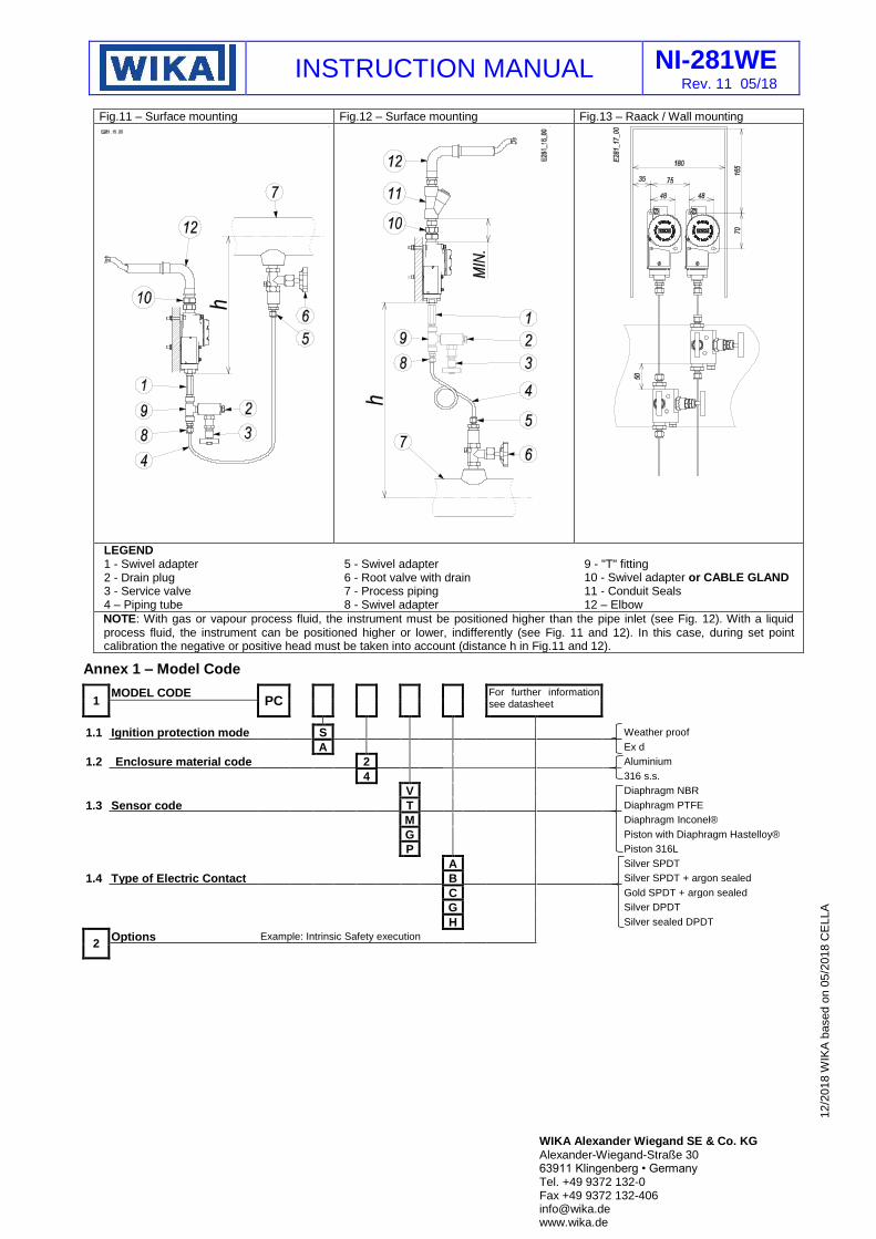
Fig.11 – Surface mounting Fig.12 – Surface mounting Fig.13 – Raack / Wall mounting
LEGEND 1 - Swivel adapter 2 - Drain plug 3 - Service valve 4 – Piping tube
5 - Swivel adapter 6 - Root valve with drain 7 - Process piping 8 - Swivel adapter
9 - "T" fitting 10 - Swivel adapter or CABLE GLAND 11 - Conduit Seals 12 – Elbow
NOTE: With gas or vapour process fluid, the instrument must be positioned higher than the pipe inlet (see Fig. 12). With a liquid process fluid, the instrument can be positioned higher or lower, indifferently (see Fig. 11 and 12). In this case, during set point calibration the negative or positive head must be taken into account (distance h in Fig.11 and 12).
Annex 1 – Model Code
1 MODEL CODE
PC
For further information
see datasheet
1.1 Ignition protection mode S Weather proof
A Ex d
1.2 Enclosure material code (Materiale)
2 Aluminium
4 316 s.s.
V Diaphragm NBR
1.3 Sensor code T Diaphragm PTFE
M Diaphragm Inconel®
G Piston with Diaphragm Hastelloy®
P Piston 316L
A Silver SPDT
1.4 Type of Electric Contact B Silver SPDT + argon sealed
C Gold SPDT + argon sealed
G Silver DPDT
H Silver sealed DPDT
2 Options Example: Intrinsic Safety execution
12/2
018 W
IKA
based o
n 0
5/2
018 C
ELLA