Embed Size (px)
Citation preview

24 · Compact Optical Receivers for Coherent Optical Communication
INFOCOMMUNICATIONS
1. Introduction
Communication traffic is increasing continuously along with the expansion of video streaming service and the popularization of smartphones and other mobile devices requiring high-speed, large-capacity transmission. Digital coherent optical communication technology using multi-level modulation formats has already been used for long haul systems and is now attracting attention as a means of long-distance, large-capacity optical communication that meets the demand for the increase in communication traffic. To expand the application of this technology to metro systems in the future, it is critical to downsize the optical transceivers and thereby increase port density and transmission capacity per port. A CFP2-ACO*1 optical transceiver(1) complying with the Optical Internetworking Forum (OIF)*2 implementation agreement is drawing particular attention as a promising device that can meet the above requirement.
Since 2013, Sumitomo Electric Industries, Ltd. has continued to develop compact optical receivers(2),(3) comprising InP-based photonic devices for coherent optical communication applications. We have recently developed a further downsized optical receiver that can be installed in the CFP2-ACO optical transceiver. The new optical receiver conforms to the OIF implementation agreement for micro-intradyne coherent receivers (Micro-ICR).*3, (4)
This paper discusses the design and principal charac-teristics of the new optical receiver.
2. Configuration of New Optical Receiver
2-1 InP-based photonic integrated circuitThe top view and functional block diagram of the
InP-based photonic integrated circuit (PIC) are shown in Figs. 1 (a) and (b), respectively.
The InP-based PIC is a 1.6 × 4.1 mm InP chip on which four waveguide photodiodes (PDs) and a 90° hybrid
are integrated. The 90° hybrid has the advantage of elimi-nating the need for crossing output optical waveguides by combining a 2 × 4 MMI*4 and 2 × 2 MMI.(5) The new optical receiver achieves a high optical responsivity by butt jointing (BJ) an optical waveguide comprising a GalnAsP core layer and a PD comprising a GalnAs light-absorbing layer.(6) The spot-size converter (SSC) located in the optical input port efficiently couples the incident light with the optical waveguide layer.(7) Metal insulator metal (MIM) capacitors are integrated at the PD bias terminal to bypass high-frequency signals and thereby ensure an exceptional high-frequency characteristic.(8)
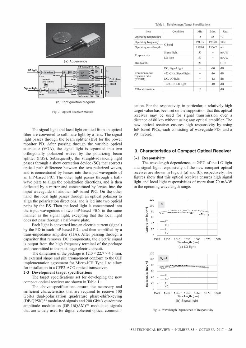
2-2 Configuration of optical receiver moduleThe external appearance of the optical receiver
module is shown in Fig. 2 (a), and its configuration diagram is shown in Fig. 2 (b).(9)
Compact Optical Receivers for Coherent Optical Communication
Masaru TAKECHI*, Yoshihiro TATEIWA, Munetaka KUROKAWA, Hideki YAGI, and Hiroshi HARA
----------------------------------------------------------------------------------------------------------------------------------------------------------------------------------------------------------------------------------------------------------Digital coherent optical communication technology using multi-level modulation formats has been adopted in long haul systems as a crucial solution to the rapidly increasing optical traffic. This technology is expected to further expand to metro systems, where smaller optical transceivers are required. We have developed compact optical receivers that can be installed in the CFP2-ACO optical transceivers, complying with the OIF implementation agreement for Micro-ICR. The new optical receivers have achieved a high responsivity in a small package of 12.0 × 22.7 × 4.5 mm due to an InP-based PIC that consists of waveguide PDs and a 90 degree hybrid. They also include a VOA and signal monitor PD. The digital coherent transmission was verified by the successful demodulation of 128 Gbit/s DP-QPSK modulation and 224 Gbit/s DP-16QAM. This paper presents the design and typical characteristics of the compact optical receivers.----------------------------------------------------------------------------------------------------------------------------------------------------------------------------------------------------------------------------------------------------------Keywords: Optical receiver, coherent optical communication, InP, ICR, CFP2-ACO
4.1 mm
(a) Top view
(b) Functional block diagram1.
6 m
m
Fig. 1. InP-based PIC
SEI TECHNICAL REVIEW · NUMBER 85 · OCTOBER 2017 · 25
The signal light and local light emitted from an optical fiber are converted to collimate light by a lens. The signal light passes through the beam splitter (BS) for the power monitor PD. After passing through the variable optical attenuator (VOA), the signal light is separated into two orthogonally polarized waves by the polarizing beam splitter (PBS). Subsequently, the straight-advancing light passes through a skew correction device (SC) that corrects optical path difference between the two polarized waves, and is concentrated by lenses into the input waveguide of an InP-based PIC. The other light passes through a half-wave plate to align the polarization directions, and is then deflected by a mirror and concentrated by lenses into the input waveguide of another InP-based PIC. On the other hand, the local light passes through an optical polarizer to align the polarization directions, and is led into two optical paths by the BS. Then the local light is concentrated into the input waveguides of two InP-based PICs in the same manner as the signal light, excepting that the local light does not pass through a half-wave plate.
Each light is converted into an electric current (signal) by the PD in each InP-based PIC, and then amplified by a trans-impedance amplifier (TIA). After passing through a capacitor that removes DC components, the electric signal is output from the high frequency terminal of the package and transmitted to the post-stage electric circuit.
The dimension of the package is 12.0 × 22.7 × 4.5 mm. Its external shape and pin arrangement conform to the OIF implementation agreement for Micro-ICR Type 1 to allow for installation in a CFP2-ACO optical transceiver.2-3 Development target specifications
The target specifications set for developing the new compact optical receiver are shown in Table 1.
The above specifications ensure the necessary and sufficient characteristics that are required to receive 100 Gbit/s dual-polarization quadrature phase-shift-keying (DP-QPSK)*5 modulated signals and 200 Gbit/s quadrature amplitude modulation (DP-16QAM)*6 modulated signals that are widely used for digital coherent optical communi-
cation. For the responsivity, in particular, a relatively high target value has been set on the supposition that this optical receiver may be used for signal transmission over a distance of 80 km without using any optical amplifier. The new optical receiver ensures high responsivity by using InP-based PICs, each consisting of waveguide PDs and a 90° hybrid.
3. Characteristics of Compact Optical Receiver
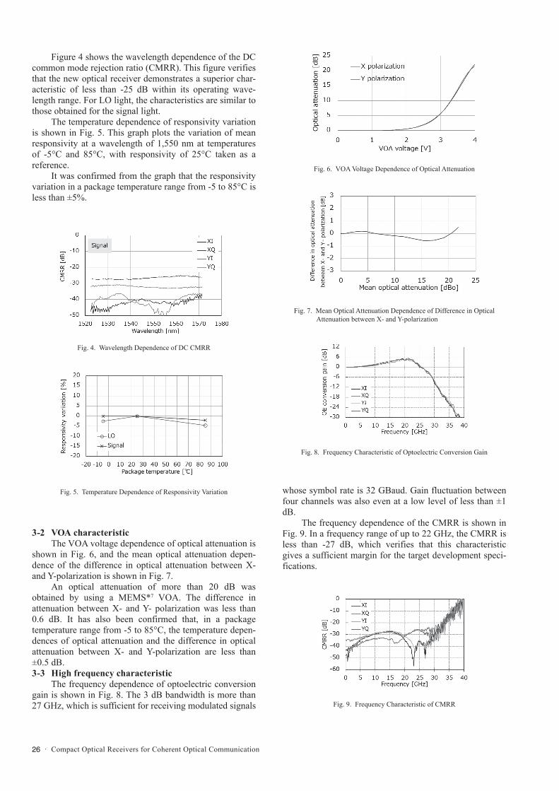
3-1 ResponsivityThe wavelength dependences at 25°C of the LO light
and signal light responsivity of the new compact optical receiver are shown in Figs. 3 (a) and (b), respectively. The figures show that this optical receiver ensures high signal light and local light responsivities of more than 70 mA/W in the operating wavelength range.
(a) Appearance
(b) Configuration diagram
Fig. 2. Optical Receiver Module
Table 1. Development Target Specifications
Item Condition Min Max Unit
Operating temperature -5 85 °C
Operating frequencyC-band
191.35 196.20 THz
Operating wavelength 1528.0 1566.7 nm
ResponsivitySignal light 50 - mA/W
LO light 50 - mA/W
Bandwidth 20 - GHz
Common mode rejection ratio (CMRR)
DC, Signal light - -20 dB
~22 GHz, Signal light - -16 dB
DC, LO light - -12 dB
~22 GHz, LO light - -10 dB
VOA attenuation 10 - dB
(a) LO light
(b) Signal light
Fig. 3. Wavelength Dependence of Responsivity
26 · Compact Optical Receivers for Coherent Optical Communication
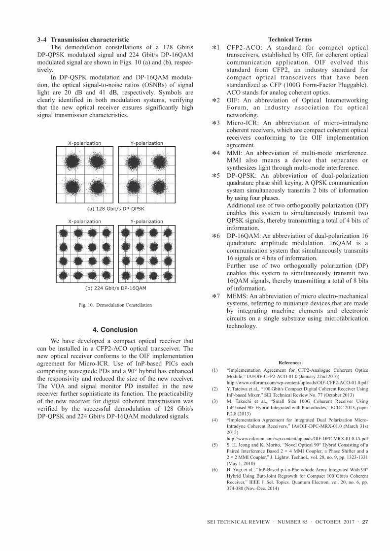
Figure 4 shows the wavelength dependence of the DC common mode rejection ratio (CMRR). This figure verifies that the new optical receiver demonstrates a superior char-acteristic of less than -25 dB within its operating wave-length range. For LO light, the characteristics are similar to those obtained for the signal light.
The temperature dependence of responsivity variation is shown in Fig. 5. This graph plots the variation of mean responsivity at a wavelength of 1,550 nm at temperatures of -5°C and 85°C, with responsivity of 25°C taken as a reference.
It was confirmed from the graph that the responsivity variation in a package temperature range from -5 to 85°C is less than ±5%.
3-2 VOA characteristicThe VOA voltage dependence of optical attenuation is
shown in Fig. 6, and the mean optical attenuation depen-dence of the difference in optical attenuation between X- and Y-polarization is shown in Fig. 7.
An optical attenuation of more than 20 dB was obtained by using a MEMS*7 VOA. The difference in attenuation between X- and Y- polarization was less than 0.6 dB. It has also been confirmed that, in a package temperature range from -5 to 85°C, the temperature depen-dences of optical attenuation and the difference in optical attenuation between X- and Y-polarization are less than ±0.5 dB.3-3 High frequency characteristic
The frequency dependence of optoelectric conversion gain is shown in Fig. 8. The 3 dB bandwidth is more than 27 GHz, which is sufficient for receiving modulated signals
whose symbol rate is 32 GBaud. Gain fluctuation between four channels was also even at a low level of less than ±1 dB.
The frequency dependence of the CMRR is shown in Fig. 9. In a frequency range of up to 22 GHz, the CMRR is less than -27 dB, which verifies that this characteristic gives a sufficient margin for the target development speci-fications.
Fig. 4. Wavelength Dependence of DC CMRR
Fig. 5. Temperature Dependence of Responsivity Variation
Fig. 9. Frequency Characteristic of CMRR
Fig. 6. VOA Voltage Dependence of Optical Attenuation
Fig. 8. Frequency Characteristic of Optoelectric Conversion Gain
Fig. 7. Mean Optical Attenuation Dependence of Difference in Optical Attenuation between X- and Y-polarization
SEI TECHNICAL REVIEW · NUMBER 85 · OCTOBER 2017 · 27
3-4 Transmission characteristicThe demodulation constellations of a 128 Gbit/s
DP-QPSK modulated signal and 224 Gbit/s DP-16QAM modulated signal are shown in Figs. 10 (a) and (b), respec-tively.
In DP-QSPK modulation and DP-16QAM modula-tion, the optical signal-to-noise ratios (OSNRs) of signal light are 20 dB and 41 dB, respectively. Symbols are clearly identified in both modulation systems, verifying that the new optical receiver ensures significantly high signal transmission characteristics.
4. Conclusion
We have developed a compact optical receiver that can be installed in a CFP2-ACO optical transceiver. The new optical receiver conforms to the OIF implementation agreement for Micro-ICR. Use of InP-based PICs each comprising waveguide PDs and a 90° hybrid has enhanced the responsivity and reduced the size of the new receiver. The VOA and signal monitor PD installed in the new receiver further sophisticate its function. The practicability of the new receiver for digital coherent transmission was verified by the successful demodulation of 128 Gbit/s DP-QPSK and 224 Gbit/s DP-16QAM modulated signals.
Technical Terms*1 CFP2-ACO: A standard for compact optical
transceivers, established by OIF, for coherent optical communication application. OIF evolved this standard from CFP2, an industry standard for compact optical transceivers that have been standardized as CFP (100G Form-Factor Pluggable). ACO stands for analog coherent optics.
*2 OIF: An abbreviation of Optical Internetworking Forum, an industry association for optical networking.
*3 Micro-ICR: An abbreviation of micro-intradyne coherent receivers, which are compact coherent optical receivers conforming to the OIF implementation agreement.
*4 MMI: An abbreviation of multi-mode interference. MMI also means a device that separates or synthesizes light through multi-mode interference.
*5 DP-QPSK: An abbreviation of dual-polarization quadrature phase shift keying. A QPSK communication system simultaneously transmits 2 bits of information by using four phases.
Additional use of two orthogonally polarization (DP) enables this system to simultaneously transmit two QPSK signals, thereby transmitting a total of 4 bits of information.
*6 DP-16QAM: An abbreviation of dual-polarization 16 quadrature amplitude modulation. 16QAM is a communication system that simultaneously transmits 16 signals or 4 bits of information.
Further use of two orthogonally polarization (DP) enables this system to simultaneously transmit two 16QAM signals, thereby transmitting a total of 8 bits of information.
*7 MEMS: An abbreviation of micro electro-mechanical systems, referring to miniature devices that are made by integrating machine elements and electronic circuits on a single substrate using microfabrication technology.
References(1) “Implementation Agreement for CFP2-Analogue Coherent Optics
Module,” IA#OIF-CFP2-ACO-01.0 (January 22nd 2016) http://www.oiforum.com/wp-content/uploads/OIF-CFP2-ACO-01.0.pdf (2) Y. Tateiwa et al., “100 Gbit/s Compact Digital Coherent Receiver Using
InP-based Mixer,” SEI Technical Review No. 77 (October 2013)(3) M. Takechi et al., “Small Size 100G Coherent Receiver Using
InP-based 90◦ Hybrid Integrated with Photodiodes,” ECOC 2013, paper P.2.8 (2013)
(4) “Implementation Agreement for Integrated Dual Polarization Micro-Intradyne Coherent Receivers,” IA#OIF-DPC-MRX-01.0 (March 31st 2015)
http://www.oiforum.com/wp-content/uploads/OIF-DPC-MRX-01.0-IA.pdf(5) S. H. Jeong and K. Morito, “Novel Optical 90° Hybrid Consisting of a
Paired Interference Based 2 × 4 MMI Coupler, a Phase Shifter and a 2 × 2 MMI Coupler,” J. Lightw. Technol., vol. 28, no. 9, pp. 1323-1331 (May 1, 2010)
(6) H. Yagi et al., “InP-Based p-i-n-Photodiode Array Integrated With 90° Hybrid Using Butt-Joint Regrowth for Compact 100 Gbit/s Coherent Receiver,” IEEE J. Sel. Topics. Quantum Electron, vol. 20, no. 6, pp. 374-380 (Nov.-Dec. 2014)
X-polarization Y-polarization
X-polarization Y-polarization
(a) 128 Gbit/s DP-QPSK
(b) 224 Gbit/s DP-16QAM
Fig. 10. Demodulation Constellation

28 · Compact Optical Receivers for Coherent Optical Communication
(7) H. Yagi et al., “High receiver responsivity and low dark current of InP-based pin-photodiode array monolithically integrated with 90° hybrid and spot-size converter using selective embedding regrowth,” IEICE Electronics Express, vol. 12, no. 2, pp. 1-7 (Jan. 2015)
(8) R. Masuyama et al., “Monolithic Integration of InP-Based Waveguide Photodiodes with MIM Capacitors for Compact Coherent Receiver,” IPRM 2013, paper MoD3-6 (2013)
(9) M. Kurokawa et al., “100 Gbit/s Compact Intradyne Coherent Receiver with Variable Optical Attenuator,” IEICE General Conference 2016, C-4-15, p.167
Contributors The lead author is indicated by an asterisk (*).
M. TAKECHI*• Assistant General Manager, Transmission Devices
Laboratory
Y. TATEIWA• Sumitomo Electric Device Innovations, Inc.
M. KUROKAWA• Transmission Devices Laboratory
H. YAGI• Ph. D.
Assistant General Manager, Transmission Devices Laboratory
H. HARA• Group Manager, Transmission Devices Laboratory


![COHERENT OPTICAL RECEIVERS AND IDEAL PERFORMANCEd90/IfLink/documentation/PhaseModulation/... · ELO (t) = [AL + n~ (t)]ejWLotx, (3.4) where AL is the continuous-wave amplitude of](https://img.pdfslide.us/doc/110x75/5fcd4a523d239f7379495034/coherent-optical-receivers-and-ideal-performance-d90iflinkdocumentationphasemodulation.jpg)