Embed Size (px)
Citation preview
DATA SHEET > Compact NX5 > 20151119
COMPACT NX5MULTIFUNCTIONAL TEST GENERATOR FOR TRANSIENTS(EFT/BURST, SURGE & POWER FAIL) UP TO 5.5 KV
FOR TESTS ACCORDING TO ...
> EN 300329> EN 300340> EN 300342-1> EN 300386 V1.3.2> EN 301489-1> EN 301489-17> EN 301489-24> EN 301489-7> EN 50121> EN 55024> EN 61000-4-11> EN 61000-4-29> EN 61000-4-4> EN 61000-4-5> EN 61000-4-8> EN 61000-4-9> EN 61000-6-1> EN 61000-6-2> FCC 97-270 (part 68)> IEC 60255-22-5> IEC 61000-4-11> ...
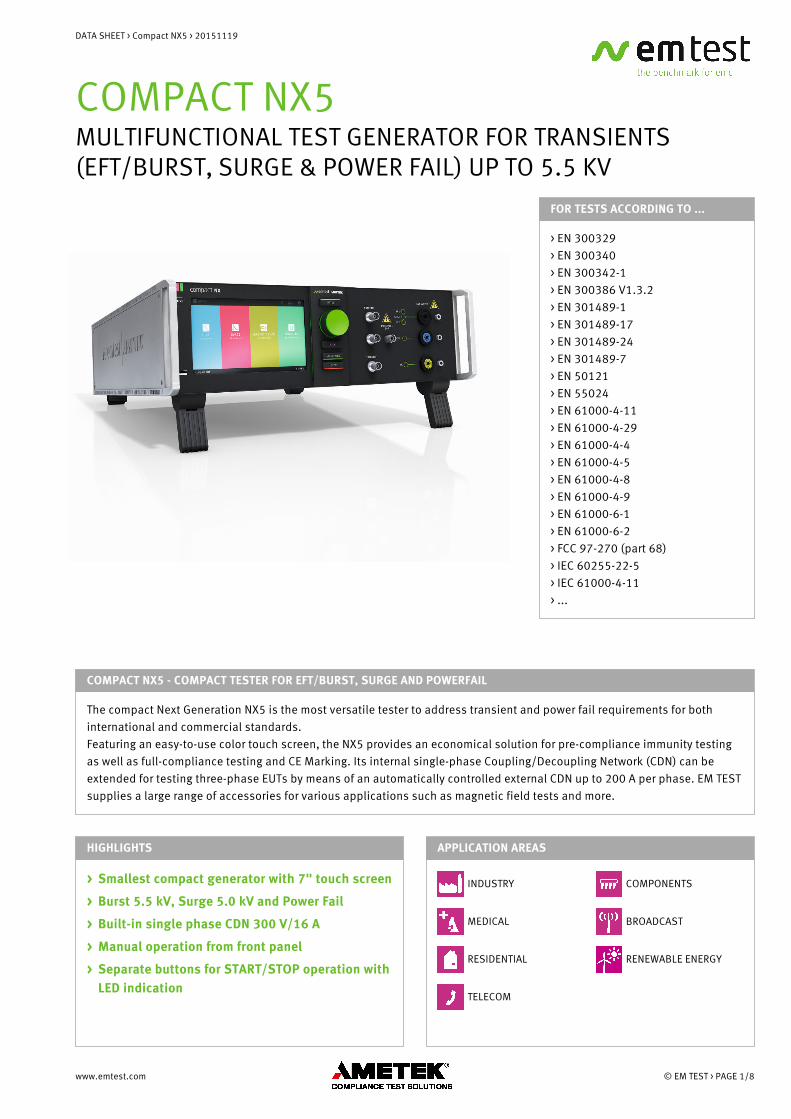
COMPACT NX5 - COMPACT TESTER FOR EFT/BURST, SURGE AND POWERFAIL
The compact Next Generation NX5 is the most versatile tester to address transient and power fail requirements for bothinternational and commercial standards. Featuring an easy-to-use color touch screen, the NX5 provides an economical solution for pre-compliance immunity testingas well as full-compliance testing and CE Marking. Its internal single-phase Coupling/Decoupling Network (CDN) can beextended for testing three-phase EUTs by means of an automatically controlled external CDN up to 200 A per phase. EM TESTsupplies a large range of accessories for various applications such as magnetic field tests and more.
HIGHLIGHTS
> Smallest compact generator with 7" touch screen
> Burst 5.5 kV, Surge 5.0 kV and Power Fail
> Built-in single phase CDN 300 V/16 A
> Manual operation from front panel
> Separate buttons for START/STOP operation withLED indication
APPLICATION AREAS
INDUSTRY
MEDICAL
RESIDENTIAL
TELECOM
COMPONENTS
BROADCAST
RENEWABLE ENERGY
www.emtest.com © EM TEST > PAGE 1/8
DATA SHEET > Compact NX5 > 20151119
TECHNICAL DETAILS
BENEFITS
ALL IN ONE - ALL YOU NEED FOR YOUR TESTS
The compact NX5 is a standalone generator whichincludes everything necessary to perform fully complianttests. With separate power mains supply inputs, it allowsthe utilization of different EUT supply voltages formaximum flexibility.
The NX5 can be operated manually from the intuitive fronttouch screen or remotely via its built-in Ethernet, USB oroptical interface. Failure inputs allow control of anongoing test sequence based on the state of the EUT.Monitoring outputs (BNC) offer easy signal verificationand measurements. For enhanced safety requirements,features like interlock and a warning lamp are available.
NX5 is the first generator that recognizes the connectedEUT power configuration. Only coupling selections toactive lines are enabled. Non existing lines will bedisabled from the menu settings. Pre-programmedroutines with common Test Standards allow maximumuser convenience. Quick Start Test routines whereparameters can be changed during susceptibility levelevaluation are also available.
OPERATION
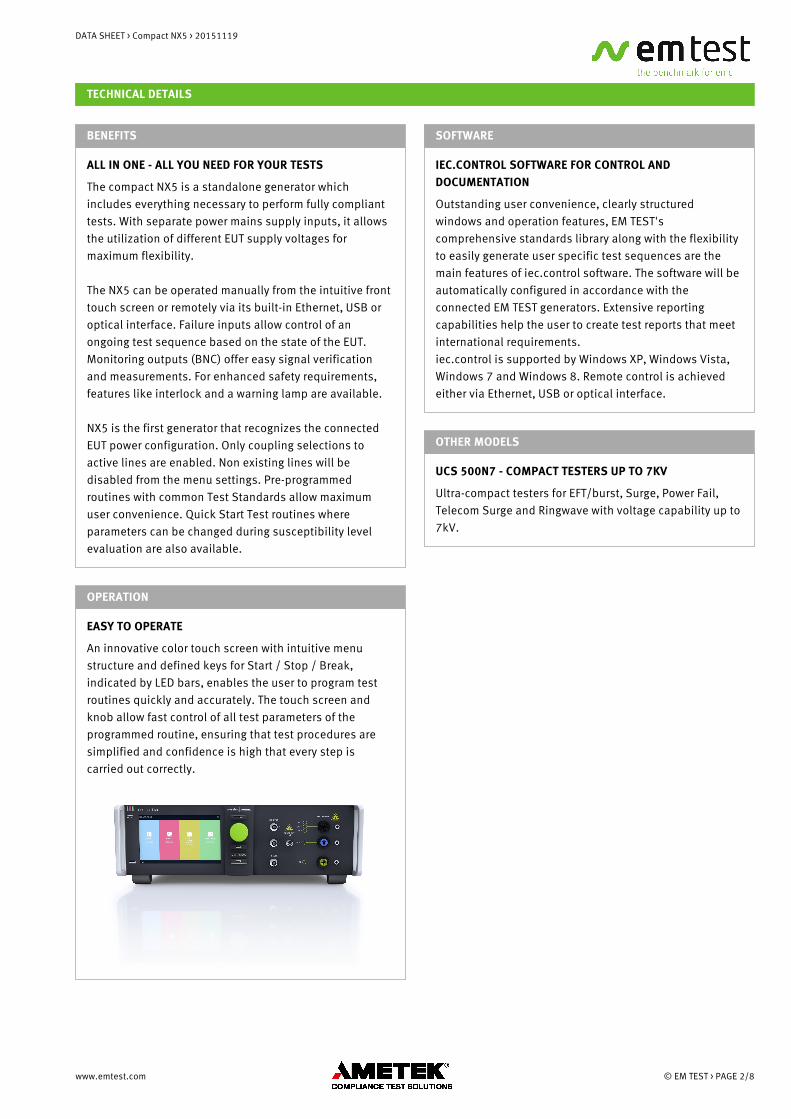
EASY TO OPERATE
An innovative color touch screen with intuitive menustructure and defined keys for Start / Stop / Break,indicated by LED bars, enables the user to program testroutines quickly and accurately. The touch screen andknob allow fast control of all test parameters of theprogrammed routine, ensuring that test procedures aresimplified and confidence is high that every step iscarried out correctly.
SOFTWARE
IEC.CONTROL SOFTWARE FOR CONTROL ANDDOCUMENTATION
Outstanding user convenience, clearly structuredwindows and operation features, EM TEST'scomprehensive standards library along with the flexibilityto easily generate user specific test sequences are themain features of iec.control software. The software will beautomatically configured in accordance with theconnected EM TEST generators. Extensive reportingcapabilities help the user to create test reports that meetinternational requirements.iec.control is supported by Windows XP, Windows Vista,Windows 7 and Windows 8. Remote control is achievedeither via Ethernet, USB or optical interface.
OTHER MODELS
UCS 500N7 - COMPACT TESTERS UP TO 7KV
Ultra-compact testers for EFT/burst, Surge, Power Fail,Telecom Surge and Ringwave with voltage capability up to7kV.
www.emtest.com © EM TEST > PAGE 2/8
DATA SHEET > Compact NX5 > 20151119
TECHNICAL DETAILS
AUXILIARY DEVICES
COUPLING NX5 - 3PHASE COUPLING/DECOUPLINGNETWORKS FOR BURST AND SURGE
EM TEST offers a range of fully automatic 3-phasecoupling/decoupling networks for burst, surge andringwave to extend the test capability for three-phaseEUTs. The networks have a rated current of up to 200 A.
MV 2616 - MOTORISED VARIAC FOR VOLTAGE VARIATION
A motorized variac is offered as an alternative to thetapped autotransformers for voltage dips/interruptionsand voltage variation tests as per IEC/EN 61000-4-11. Themotorized variac can also be used for automatedmagnetic field tests.
TVT 1-250-16 - TAPPED VOLTAGE TRANSFORMER FORVOLTAGE DIPS
The TVT 1-250-16 tapped autotransformer is designed tosupply the required voltages as per IEC/EN 61000-4-11 toperform voltage dips.
TVT 1-250-16.1 - TAPPED STEP TRANSFORMERAUTOMATIC FOR VOLTAGE DIPS
The TVT 1-250-16.1 is an automatic tapped autotransformer, designed to supply the required voltages asper IEC/EN 61000-4-11 to perform voltage dips andinterruptions. Compared to the manually operated TVT1-250-16, the TVT 1-250-16.1 model offers automaticchange of taps according to the selected voltage level.
CNV 504/508 N- AND T-SERIES - SURGECOUPLING/DECOUPLING NETWORKS FOR SIGNAL/DATALINES
CNV 504/508 N- and T-series coupling/decouplingnetworks are available to perform surge tests on I/O lines,signal/data lines and telecom lines as per IEC/EN 61000-4-5 Ed 3.0
ACCESSORIES
MFC SERIES - MAGNETIC FIELD COIL FORPOWER-FREQUENCY AND PULSED MAGNETIC FIELDS
The MFC 1000 is a 1m x 1m magnetic field coil asspecified in IEC/EN 61000-4-8 and IEC/EN 61000-4-9. Itsdesign allows easy moving of the coil. The field coil isadjustable in height and allows for 360degree rotation.To generate power-frequency magnetic fields in the lowerrange the current transformer MFT 30 is used whilehigh-field strength above 100 A/m up to 1000 A/mrequires the MFT 100 current transformer.
CCI - CAPACITIVE COUPLING CLAMP
Capacitive coupling clamp as per specification IEC/EN61000-4-4.
ITP - IMMUNITY TEST PROBES
ITP is a tool being used for development test. It consistsof a variety of electrical field probes. The probes allow tolocate weak points within a system or on a PCB. The burstpulse is used to generate the disturbance signal.
PVF BKIT 1 - VERIFICATION KIT FOR EFT/BURST PULSES
As per IEC/EN 61000-4-4 the characteristic of the burstgenerator needs to be verified with two different loads, 50ohm and 1,000 ohm. EM TEST offers a calibration kitconsisting of the two loads and an adapter to verify thepulses at the EUT output.
CCI PVKIT 1 - VERIFICATION KIT FOR CAPACITIVECOUPLING CLAMP
The IEC/EN 61000-4-4 Ed 3.0 standard published in 2012recommends the calibration of the capacitive couplingclamp into a 50 ohm coaxial load.The capacitive coupling clamp (CCI) is connected to the50 ohm output of the EFT generator. A flexible insulatedplate inside the HFK is connected to a coaxial 50 ohmload resistor for verifying the EFT/Burst wave of thecapacitive coupling clamp.
www.emtest.com © EM TEST > PAGE 3/8
DATA SHEET > Compact NX5 > 20151119
TECHNICAL DETAILS
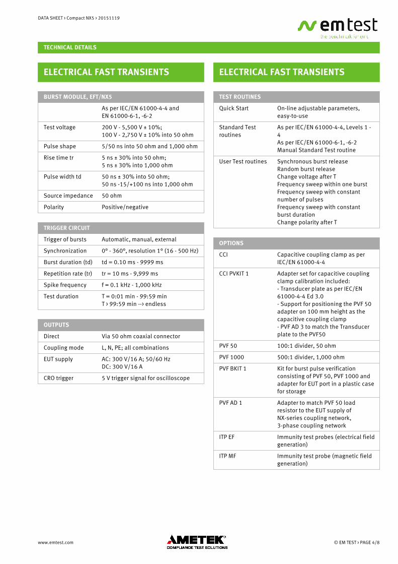
ELECTRICAL FAST TRANSIENTS
BURST MODULE, EFT/NX5
As per IEC/EN 61000-4-4 and EN 61000-6-1, -6-2
Test voltage 200 V - 5,500 V ± 10%;100 V - 2,750 V ± 10% into 50 ohm
Pulse shape 5/50 ns into 50 ohm and 1,000 ohm
Rise time tr 5 ns ± 30% into 50 ohm;5 ns ± 30% into 1,000 ohm
Pulse width td 50 ns ± 30% into 50 ohm;50 ns -15/+100 ns into 1,000 ohm
Source impedance 50 ohm
Polarity Positive/negative
TRIGGER CIRCUIT
Trigger of bursts Automatic, manual, external
Synchronization 0° - 360°, resolution 1° (16 - 500 Hz)
Burst duration (td) td = 0.10 ms - 9999 ms
Repetition rate (tr) tr = 10 ms - 9,999 ms
Spike frequency f = 0.1 kHz - 1,000 kHz
Test duration T = 0:01 min - 99:59 minT > 99:59 min --> endless
OUTPUTS
Direct Via 50 ohm coaxial connector
Coupling mode L, N, PE; all combinations
EUT supply AC: 300 V/16 A; 50/60 HzDC: 300 V/16 A
CRO trigger 5 V trigger signal for oscilloscope
ELECTRICAL FAST TRANSIENTS
TEST ROUTINES
Quick Start On-line adjustable parameters,easy-to-use
Standard Testroutines
As per IEC/EN 61000-4-4, Levels 1 -4As per IEC/EN 61000-6-1, -6-2Manual Standard Test routine
User Test routines Synchronous burst releaseRandom burst releaseChange voltage after TFrequency sweep within one burstFrequency sweep with constantnumber of pulsesFrequency sweep with constant burst durationChange polarity after T
OPTIONS
CCI Capacitive coupling clamp as per IEC/EN 61000-4-4
CCI PVKIT 1 Adapter set for capacitive couplingclamp calibration included:- Transducer plate as per IEC/EN61000-4-4 Ed 3.0- Support for positioning the PVF 50adapter on 100 mm height as thecapacitive coupling clamp- PVF AD 3 to match the Transducerplate to the PVF50
PVF 50 100:1 divider, 50 ohm
PVF 1000 500:1 divider, 1,000 ohm
PVF BKIT 1 Kit for burst pulse verificationconsisting of PVF 50, PVF 1000 andadapter for EUT port in a plastic casefor storage
PVF AD 1 Adapter to match PVF 50 loadresistor to the EUT supply ofNX-series coupling network,3-phase coupling network
ITP EF Immunity test probes (electrical fieldgeneration)
ITP MF Immunity test probe (magnetic fieldgeneration)
www.emtest.com © EM TEST > PAGE 4/8
DATA SHEET > Compact NX5 > 20151119
TECHNICAL DETAILS
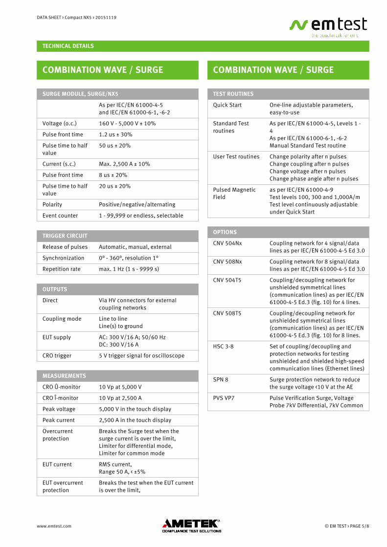
COMBINATION WAVE / SURGE
SURGE MODULE, SURGE/NX5
As per IEC/EN 61000-4-5 and IEC/EN 61000-6-1, -6-2
Voltage (o.c.) 160 V - 5,000 V ± 10%
Pulse front time 1.2 us ± 30%
Pulse time to halfvalue
50 us ± 20%
Current (s.c.) Max. 2,500 A ± 10%
Pulse front time 8 us ± 20%
Pulse time to halfvalue
20 us ± 20%
Polarity Positive/negative/alternating
Event counter 1 - 99,999 or endless, selectable
TRIGGER CIRCUIT
Release of pulses Automatic, manual, external
Synchronization 0° - 360°, resolution 1°
Repetition rate max. 1 Hz (1 s - 9999 s)
OUTPUTS
Direct Via HV connectors for externalcoupling networks
Coupling mode Line to lineLine(s) to ground
EUT supply AC: 300 V/16 A; 50/60 HzDC: 300 V/16 A
CRO trigger 5 V trigger signal for oscilloscope
MEASUREMENTS
CRO Û-monitor 10 Vp at 5,000 V
CRO Î-monitor 10 Vp at 2,500 A
Peak voltage 5,000 V in the touch display
Peak current 2,500 A in the touch display
Overcurrentprotection
Breaks the Surge test when thesurge current is over the limit, Limiter for differential mode,Limiter for common mode
EUT current RMS current,Range 50 A, < ±5%
EUT overcurrentprotection
Breaks the test when the EUT currentis over the limit,
COMBINATION WAVE / SURGE
TEST ROUTINES
Quick Start One-line adjustable parameters,easy-to-use
Standard Testroutines
As per IEC/EN 61000-4-5, Levels 1 -4As per IEC/EN 61000-6-1, -6-2Manual Standard Test routine
User Test routines Change polarity after n pulsesChange coupling after n pulsesChange voltage after n pulsesChange phase angle after n pulses
Pulsed MagneticField
as per IEC/EN 61000-4-9Test levels 100, 300 and 1,000A/mTest level continuously adjustableunder Quick Start
OPTIONS
CNV 504Nx Coupling network for 4 signal/datalines as per IEC/EN 61000-4-5 Ed 3.0
CNV 508Nx Coupling network for 8 signal/datalines as per IEC/EN 61000-4-5 Ed 3.0
CNV 504T5 Coupling/decoupling network forunshielded symmetrical lines(communication lines) as per IEC/EN61000-4-5 Ed.3 (fig. 10) for 4 lines.
CNV 508T5 Coupling/decoupling network forunshielded symmetrical lines(communication lines) as per IEC/EN61000-4-5 Ed.3 (fig. 10) for 8 lines.
HSC 3-8 Set of coupling/decoupling andprotection networks for testingunshielded and shielded high-speedcommunication lines (Ethernet lines)
SPN 8 Surge protection network to reducethe surge voltage <10 V at the AE
PVS VP7 Pulse Verification Surge, VoltageProbe 7kV Differential, 7kV Common
www.emtest.com © EM TEST > PAGE 5/8
DATA SHEET > Compact NX5 > 20151119
TECHNICAL DETAILS
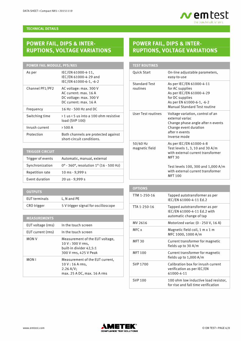
POWER FAIL, DIPS & INTER-RUPTIONS, VOLTAGE VARIATIONS
POWER FAIL MODULE, PFS/NX5
As per IEC/EN 61000-4-11, IEC/EN 61000-4-29 and IEC/EN 61000-6-1, -6-2
Channel PF1/PF2 AC voltage: max. 300 VAC current: max. 16 ADC voltage: max. 300 VDC current: max. 16 A
Frequency 16 Hz - 500 Hz and DC
Switching time > 1 us < 5 us into a 100 ohm resistiveload (SVP 100)
Inrush current > 500 A
Protection Both channels are protected againstshort-circuit conditions.
TRIGGER CIRCUIT
Trigger of events Automatic, manual, external
Synchronization 0° - 360°, resolution 1° (16 - 500 Hz)
Repetition rate 10 ms - 9,999 s
Event duration 20 us - 9,999 s
OUTPUTS
EUT terminals L, N and PE
CRO trigger 5 V trigger signal for oscilloscope
MEASUREMENTS
EUT voltage (rms) In the touch screen
EUT current (rms) In the touch screen
MON V Measurement of the EUT voltage,10 V : 300 V rms,built-in divider 42,5:1 300 V rms, 425 V Peak
MON I Measurement of the EUT current,10 V : 16 A rms, 2.26 A/V; max. 25 A DC, max. 16 A rms
POWER FAIL, DIPS & INTER-RUPTIONS, VOLTAGE VARIATIONS
TEST ROUTINES
Quick Start On-line adjustable parameters,easy-to-use
Standard Testroutines
As per IEC/EN 61000-4-11 for AC suppliesAs per IEC/EN 61000-4-29 for DC suppliesAs per EN 61000-6-1, -6-2Manual Standard Test routine
User Test routines Voltage variation, control of anexternal variacChange phase angle after n eventsChange event duration after n eventsInverse mode
50/60 Hzmagnetic field
As per IEC/EN 61000-4-8Test levels 1, 3, 10 and 30 A/m with external current transformerMFT 30
Test levels 100, 300 and 1,000 A/mwith external current transformerMFT 100
OPTIONS
TTM 1-250-16 Tapped autotransformer as perIEC/EN 61000-4-11 Ed.2
TTA 1-250-16 Tapped autotransformer as perIEC/EN 61000-4-11 Ed.2 withautomatic change of tap
MV 2616 Motorized variac (0 - 250 V, 16 A)
MFC x Magnetic field coil, 1 m x 1 mMFC 1000, 1000 A/m
MFT 30 Current transformer for magneticfields up to 30 A/m
MFT 100 Current transformer for magneticfields up to 1,000 A/m
SVP 1700 Calibration box for inrush currentverification as per IEC/EN61000-4-11
SVP 100 100 ohm low inductive load resistor,for rise and fall time verification
www.emtest.com © EM TEST > PAGE 6/8
DATA SHEET > Compact NX5 > 20151119
TECHNICAL DETAILS
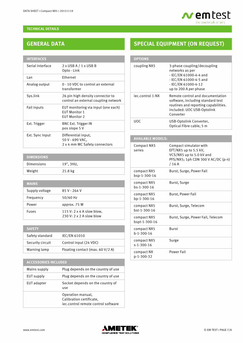
GENERAL DATA
INTERFACES
Serial interface 2 x USB A / 1 x USB BOpto - Link
Lan Ethernet
Analog output 0 - 10 VDC to control an externaltransformer
Sys.link 26 pin high density connector tocontrol an external coupling network
Fail inputs EUT monitoring via input (one each)EUT Monitor 1EUT Monitor 2
Ext. Trigger BNC Ext. Trigger INpos slope 5 V
Ext. Sync Input Differential input,50 V - 690 VAC,2 x 4 mm MC Safety connectors
DIMENSIONS
Dimensions 19", 3HU,
Weight 21.8 kg
MAINS
Supply voltage 85 V - 264 V
Frequency 50/60 Hz
Power approx. 75 W
Fuses 115 V: 2 x 4 A slow blow,230 V: 2 x 2 A slow blow
SAFETY
Safety standard IEC/EN 61010
Security circuit Control input (24 VDC)
Warning lamp Floating contact (max. 60 V/2 A)
ACCESSORIES INCLUDED
Mains supply Plug depends on the country of use
EUT supply Plug depends on the country of use
EUT adapter Socket depends on the country ofuse
Operation manual, Calibration certificate, iec.control remote control software
SPECIAL EQUIPMENT (ON REQUEST)
OPTIONS
coupling NX5 3-phase coupling/decouplingnetworks as per - IEC/EN 61000-4-4 and- IEC/EN 61000-4-5 and- IEC/EN 61000-4-12up to 200 A per phase
iec.control 1-NX Remote control and documentationsoftware, including standard testroutines and reporting capabilities.included: UOC USB-OptolinkConverter
UOC USB-Optolink Converter,Optical Fibre cable, 5 m
AVAILABLE MODELS:
Compact NX5series
Compact simulator with EFT/NX5 up to 5.5 kV, VCS/NX5 up to 5.0 kV and PFS/NX5; 1ph CDN 300 V AC/DC (p-n)/ 16 A
compact NX5bsp-1-300-16
Burst, Surge, Power Fail
compact NX5bs-1-300-16
Burst, Surge
compact NX5bp-1-300-16
Burst, Power Fail
compact NX5bst-1-300-16
Burst, Surge, Telecom
compact NX5bspt-1-300-16
Burst, Surge, Power Fail, Telecom
compact NX5b-1-300-16
Burst
compact NX5s-1-300-16
Surge
compact NXp-1-300-32
Power Fail
www.emtest.com © EM TEST > PAGE 7/8

DATA SHEET > Compact NX5 > 20151119
COMPETENCE WHEREVERYOU ARE
CONTACT EM TEST DIRECTLY
SwitzerlandEM TEST (Switzerland) GmbH > Sternenhofstraße 15 > 4153 Reinach >SwitzerlandPhone +41 (0)61/7179191 > Fax +41 (0)61/7179199Internet: www.emtest.ch > E-mail: [email protected]
GermanyAMETEK CTS Germany GmbH > Lünener Straße 211 > 59174 Kamen >DeutschlandPhone +49 (0)2307/26070-0 > Fax +49 (0)2307/17050Internet: www.emtest.com > E-mail: [email protected]
FranceEM TEST FRANCE > Le Trident - Parc des Collines > Immeuble B1 - Etage 3 > 36, rue Paul Cézanne > 68200 Mulhouse > FrancePhone +33 (0)389 31 23 50 > Fax +33 (0)389 31 23 55Internet: www.emtest.fr > E-mail: [email protected]
PolandEM TEST Polska > ul. Ogrodowa 31/35, 00-893 Warszawa > Polska Phone +48 (0)518 64 35 12Internet: www.emtest.com/pl > E-mail: [email protected]
USA / CanadaAMETEK Compliance Test Solutions > 52 Mayfield Ave. > Edison > NJ 08837Phone +1 (732) 417-0501Internet: www.emtest.com > E-mail: [email protected]
P.R. ChinaE & S Test Technology Limited > Rm 913, Leftbank > No. 68 Bei Si Huan Xi Lu > Haidian District > Beijing 100080 > P.R. ChinaPhone +86 (0)10 82 67 60 27 > Fax +86 (0)10 82 67 62 38Internet: www.emtest.com > E-mail: [email protected]
Republic of KoreaEM TEST Korea Limited > #405 > WooYeon Plaza > #986-8 > YoungDeok-dong >Giheung-gu > Yongin-si > Gyeonggi-do > KoreaPhone +82 (31) 216 8616 > Fax +82 (31) 216 8616Internet: www.emtest.co.kr > E-mail: [email protected]
Information about scope of delivery, visual design and technical data correspond with the state of development at time of release. Subject tochange without further notice.
www.emtest.com © EM TEST > PAGE 8/8