Embed Size (px)
Citation preview
®
Compact Nitrogen Gas Springs 90.60 / 90.60N Series
Catalog No. C09112A
- PHASING OUT -Replace with L Series and UH Series Models:
L.500, L.750, UH.0800, UH.1000, UH.2600 and UH.4600
PED 2014/68/EUCOMPLIANT
90.60 / 90.60N SeriesNitrogen Gas Springs
734.207.1100 • 800.DADCO.USA • fax 734.207.2222 • www.dadco.net
®
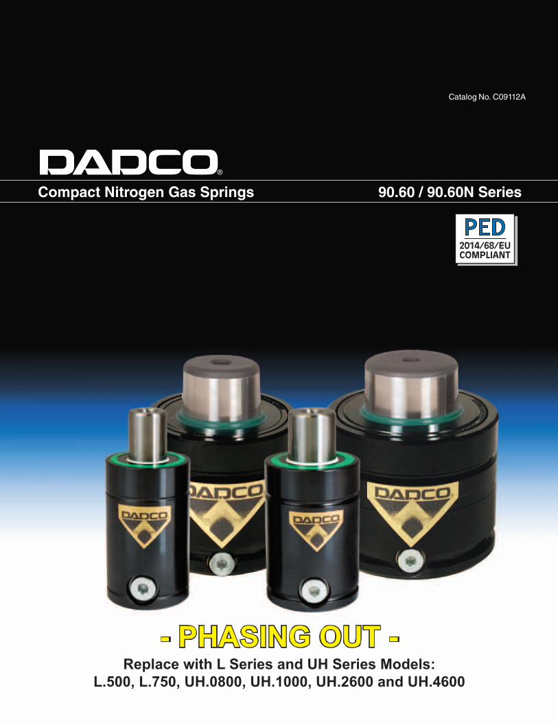
On-Contact Forcebar MPa daN kgf150 15 471 480125 12.5 392 400100 10 314 32075 7.5 235 24050 5 157 16025 2.5 78 8015 1.5 47 48
ModelS On-Contact
ForceMax Force* C L Pressure
Increase** Weight
inch daN(kgf)
daN(kgf)
mm ±0.25 % kg
90.60N.00500.E003 .25
471 (480)
632(644)
57.15 63.5
34
0.5590.60N.00500.E005 .50 63.50 76.2 0.5990.60N.00500.E008 .75 69.85 88.9 0.6290.60N.00500.E010 1.00 76.20 101.6 0.6690.60N.00500.E015 1.50 88.90 127.0 0.7490.60N.00500.E020 2.00 101.60 152.4 0.8290.60N.00500.E025 2.50 114.30 177.8 0.8990.60N.00500.E030 3.00 127.00 203.2 0.9790.60N.00500.E035 3.50 139.70 228.6 1.0590.60N.00500.E040 4.00 152.40 254.0 1.1290.60N.00500.E045 4.50 165.10 279.4 1.2090.60N.00500.E050 5.00 177.80 304.8 1.28
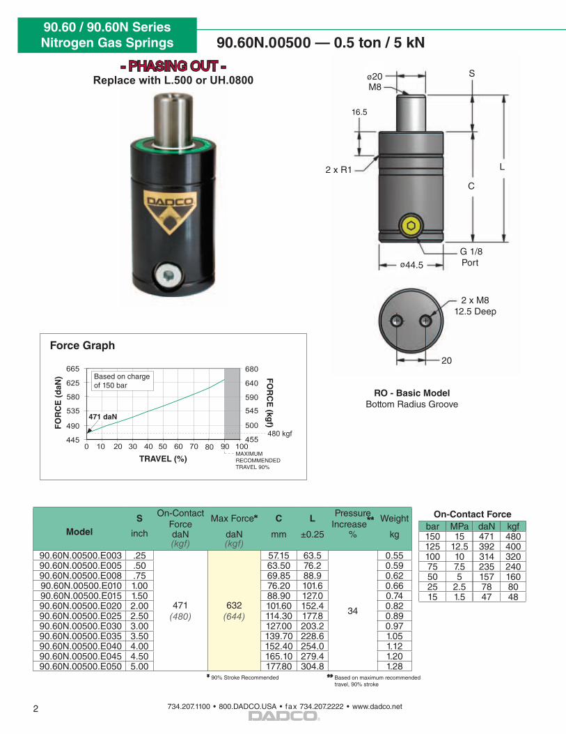
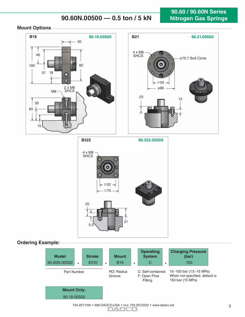
90.60N.00500 — 0.5 ton / 5 kN
2
C
S
L
M8
2 x R1
20
2 x M8 12.5 Deep
ø20
G 1/8 Portø44.5
RO - Basic Model Bottom Radius Groove
* 90% Stroke Recommended
16.5
** Based on maximum recommended travel, 90% stroke
90.60N.00500
1500
1750
2000
2250
2500
2750
2500
3000
3500
4000
4500
5000
90.60.03000
90.60.01500
0 10 20 30 40 50 60 70 80 90 100
0 10 20 30 40 50 60 70 80 90 100
2550
3060
3570
4080
4590
5100
1530
1780
2040
2290
2550
2800
445
490
535
580
625
665
0 10 20 30 40 50 60 70 80 90 100455
500
545
590
640
680
700
800
900
1000
1100
1200
90.60N.00750
0 10 20 30 40 50 60 70 80 90 100710
820
920
1020
1120
1220
480 kgf
746 kgf
3005 kgf
1555 kgf
TRAVEL (%)
FO
RC
E (
daN
) FO
RC
E (kg
f)
MAXIMUM RECOMMENDED TRAVEL 90%
471 daN
Based on charge of 150 bar
Force Graph
- PHASING OUT -Replace with L.500 or UH.0800
90.60 / 90.60N SeriesNitrogen Gas Springs
734.207.1100 • 800.DADCO.USA • fax 734.207.2222 • www.dadco.net
®
90.60N.00500 — 0.5 ton / 5 kN
3
Ordering Example:
Mount Options
Model Stroke MountOperating
SystemCharging Pressure
(bar)
90.60N.00500 • E010 • B19 • C • 150
Part Number 15~150 bar (1.5~15 MPa)When not specified, default is 150 bar (15 MPa)
Mount Only:
90.19.00500
RO: Radius Groove
C: Self-containedF: Open Flow Fitting
B21 90.21.00500
4 x M8 SHCS
23
ø70.7 Bolt Circle
50
ø862 x M8 SHCS
37
82
46
30
100
60
30
15
B19 90.19.00500
B322 90.322.00500
18
M8
13
4 x M8 SHCS
20
52
70
215.5
90.60 / 90.60N SeriesNitrogen Gas Springs
734.207.1100 • 800.DADCO.USA • fax 734.207.2222 • www.dadco.net
®
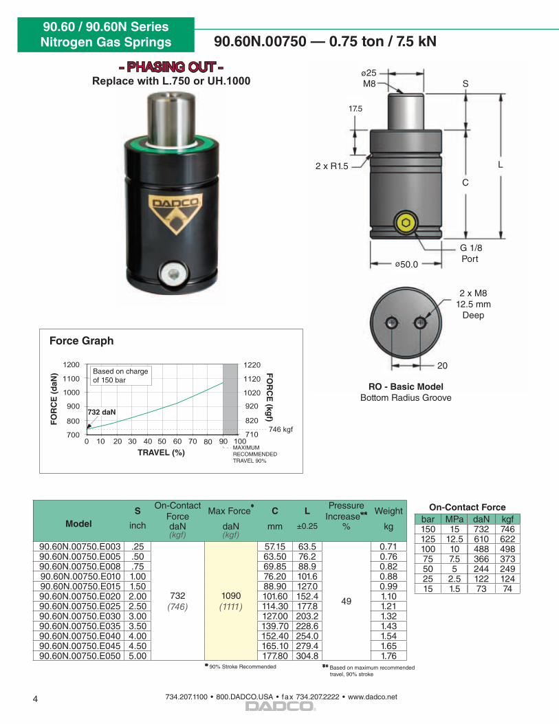
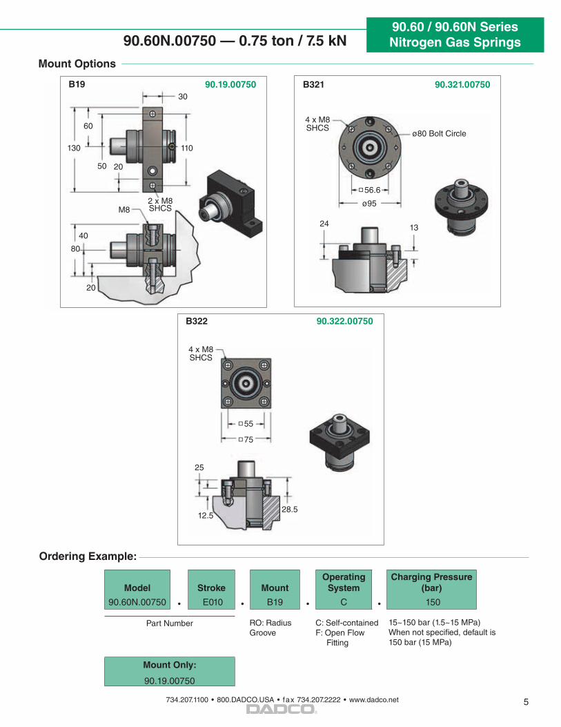
90.60N.00750 — 0.75 ton / 7.5 kN
4
On-Contact Forcebar MPa daN kgf150 15 732 746125 12.5 610 622100 10 488 49875 7.5 366 37350 5 244 24925 2.5 122 12415 1.5 73 74
ModelS
On-Contact Force
Max Force* C LPressure
Increase** Weight
inch daN(kgf)
daN(kgf)
mm ±0.25 % kg
90.60N.00750.E003 .25
732 (746)
1090(1111)
57.15 63.5
49
0.7190.60N.00750.E005 .50 63.50 76.2 0.7690.60N.00750.E008 .75 69.85 88.9 0.8290.60N.00750.E010 1.00 76.20 101.6 0.8890.60N.00750.E015 1.50 88.90 127.0 0.9990.60N.00750.E020 2.00 101.60 152.4 1.1090.60N.00750.E025 2.50 114.30 177.8 1.2190.60N.00750.E030 3.00 127.00 203.2 1.3290.60N.00750.E035 3.50 139.70 228.6 1.4390.60N.00750.E040 4.00 152.40 254.0 1.5490.60N.00750.E045 4.50 165.10 279.4 1.6590.60N.00750.E050 5.00 177.80 304.8 1.76
C
S
L
M8
2 x R1.5
20
ø25
G 1/8 Portø50.0
RO - Basic Model Bottom Radius Groove
2 x M8 12.5 mm
Deep
17.5
* 90% Stroke Recommended ** Based on maximum recommended travel, 90% stroke
90.60N.00500
1500
1750
2000
2250
2500
2750
2500
3000
3500
4000
4500
5000
90.60.03000
90.60.01500
0 10 20 30 40 50 60 70 80 90 100
0 10 20 30 40 50 60 70 80 90 100
2550
3060
3570
4080
4590
5100
1530
1780
2040
2290
2550
2800
445
490
535
580
625
665
0 10 20 30 40 50 60 70 80 90 100455
500
545
590
640
680
700
800
900
1000
1100
1200
90.60N.00750
0 10 20 30 40 50 60 70 80 90 100710
820
920
1020
1120
1220
480 kgf
746 kgf
3005 kgf
1555 kgf
TRAVEL (%)
FO
RC
E (
daN
) FO
RC
E (kg
f)
MAXIMUM RECOMMENDED TRAVEL 90%
732 daN
Based on charge of 150 bar
Force Graph
- PHASING OUT -Replace with L.750 or UH.1000
90.60 / 90.60N SeriesNitrogen Gas Springs
734.207.1100 • 800.DADCO.USA • fax 734.207.2222 • www.dadco.net
®
90.60N.00750 — 0.75 ton / 7.5 kN
5
Mount Options
Ordering Example:
Model Stroke MountOperating
SystemCharging Pressure
(bar)
90.60N.00750 • E010 • B19 • C • 150
Part Number 15~150 bar (1.5~15 MPa)When not specified, default is 150 bar (15 MPa)
Mount Only:
90.19.00750
RO: Radius Groove
C: Self-containedF: Open Flow Fitting
B321 90.321.00750
4 x M8 SHCS
24
ø80 Bolt Circle
56.6
ø952 x M8 SHCS
50
110
60
40
130
80
30
20
B19 90.19.00750
B322 90.322.00750
20
M8
13
4 x M8 SHCS
25
55
75
28.512.5
90.60 / 90.60N SeriesNitrogen Gas Springs
734.207.1100 • 800.DADCO.USA • fax 734.207.2222 • www.dadco.net
®
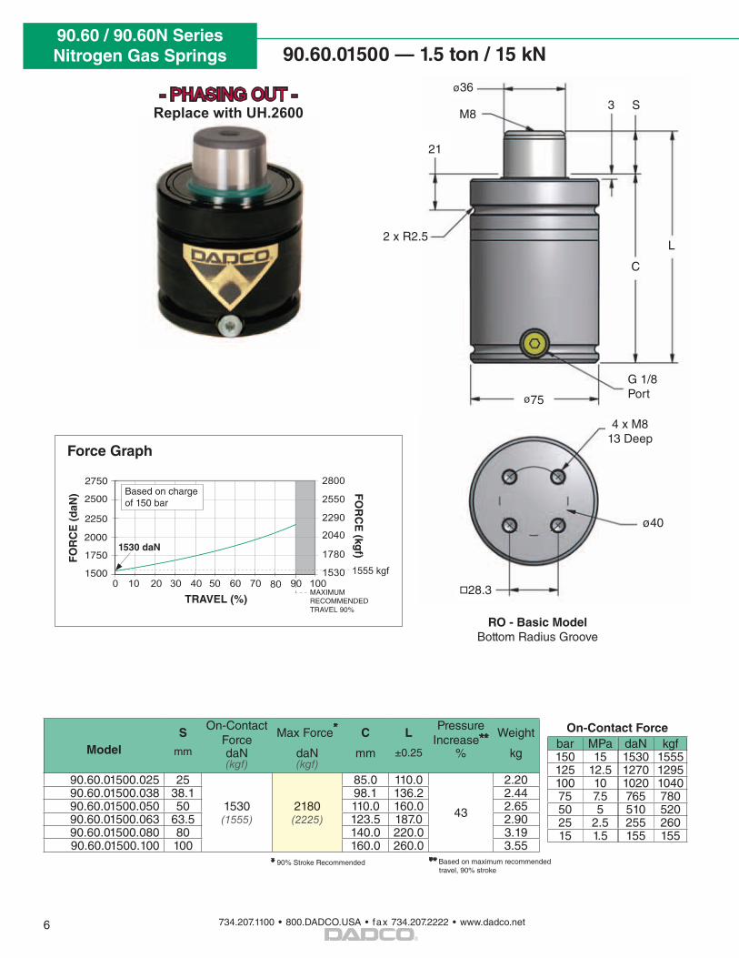
90.60.01500 — 1.5 ton / 15 kN
C
S
L
M8
2 x R2.5
ø40
ø36
G 1/8 Portø75
4 x M8 13 Deep
21
3
28.3
6
On-Contact Forcebar MPa daN kgf150 15 1530 1555125 12.5 1270 1295100 10 1020 104075 7.5 765 78050 5 510 52025 2.5 255 26015 1.5 155 155
ModelS
On-Contact Force
Max Force* C LPressure
Increase** Weight
mm daN(kgf)
daN(kgf)
mm ±0.25 % kg
90.60.01500.025 25
1530(1555)
2180(2225)
85.0 110.0
43
2.2090.60.01500.038 38.1 98.1 136.2 2.4490.60.01500.050 50 110.0 160.0 2.6590.60.01500.063 63.5 123.5 187.0 2.9090.60.01500.080 80 140.0 220.0 3.1990.60.01500.100 100 160.0 260.0 3.55
* 90% Stroke Recommended ** Based on maximum recommended travel, 90% stroke
RO - Basic Model Bottom Radius Groove
90.60N.00500
1500
1750
2000
2250
2500
2750
2500
3000
3500
4000
4500
5000
90.60.03000
90.60.01500
0 10 20 30 40 50 60 70 80 90 100
0 10 20 30 40 50 60 70 80 90 100
2550
3060
3570
4080
4590
5100
1530
1780
2040
2290
2550
2800
445
490
535
580
625
665
0 10 20 30 40 50 60 70 80 90 100455
500
545
590
640
680
700
800
900
1000
1100
1200
90.60N.00750
0 10 20 30 40 50 60 70 80 90 100710
820
920
1020
1120
1220
480 kgf
746 kgf
3005 kgf
1555 kgf
TRAVEL (%)
FO
RC
E (
daN
) FO
RC
E (kg
f)
MAXIMUM RECOMMENDED TRAVEL 90%
1530 daN
Based on charge of 150 bar
Force Graph
- PHASING OUT -Replace with UH.2600
90.60 / 90.60N SeriesNitrogen Gas Springs
734.207.1100 • 800.DADCO.USA • fax 734.207.2222 • www.dadco.net
®
90.60.01500 — 1.5 ton / 15 kN
7
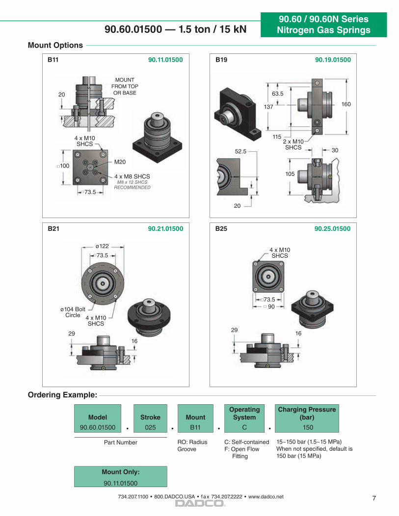
Mount Options
Ordering Example:
Model Stroke MountOperating
SystemCharging Pressure
(bar)
90.60.01500 • 025 • B11 • C • 150
Part Number 15~150 bar (1.5~15 MPa)When not specified, default is 150 bar (15 MPa)
Mount Only:
90.11.01500
RO: Radius Groove
C: Self-containedF: Open Flow Fitting
B11 90.11.01500
B25 90.25.01500
4 x M10 SHCS
73.5
20
29 16
4 x M10 SHCS
73.590
100M20
4 x M8 SHCSM8 x 12 SHCS
RECOMMENDED
MOUNT FROM TOP OR BASE
B21 90.21.01500
4 x M10 SHCS
29
ø104 Bolt Circle
73.5
ø122
16
2 x M10 SHCS
63.5
137
115
30
160
105
52.5
20
B19 90.19.01500
90.60 / 90.60N SeriesNitrogen Gas Springs
734.207.1100 • 800.DADCO.USA • fax 734.207.2222 • www.dadco.net
®
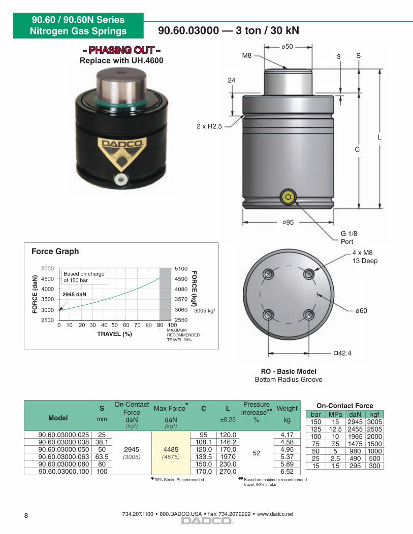
90.60.03000 — 3 ton / 30 kN
8
On-Contact Forcebar MPa daN kgf150 15 2945 3005125 12.5 2455 2505100 10 1965 200075 7.5 1475 150050 5 980 100025 2.5 490 50015 1.5 295 300
ModelS
On-Contact Force
Max Force* C LPressure
Increase** Weight
mm daN(kgf)
daN(kgf)
±0.25 % kg
90.60.03000.025 25
2945 (3005)
4485(4575)
95 120.0
52
4.1790.60.03000.038 38.1 108.1 146.2 4.5890.60.03000.050 50 120.0 170.0 4.9590.60.03000.063 63.5 133.5 197.0 5.3790.60.03000.080 80 150.0 230.0 5.8990.60.03000.100 100 170.0 270.0 6.52
* 90% Stroke Recommended ** Based on maximum recommended travel, 90% stroke
90.60N.00500
1500
1750
2000
2250
2500
2750
2500
3000
3500
4000
4500
5000
90.60.03000
90.60.01500
0 10 20 30 40 50 60 70 80 90 100
0 10 20 30 40 50 60 70 80 90 100
2550
3060
3570
4080
4590
5100
1530
1780
2040
2290
2550
2800
445
490
535
580
625
665
0 10 20 30 40 50 60 70 80 90 100455
500
545
590
640
680
700
800
900
1000
1100
1200
90.60N.00750
0 10 20 30 40 50 60 70 80 90 100710
820
920
1020
1120
1220
480 kgf
746 kgf
3005 kgf
1555 kgf
TRAVEL (%)
FO
RC
E (
daN
)
FO
RC
E (kg
f)
MAXIMUM RECOMMENDED TRAVEL 90%
2945 daN
Based on charge of 150 bar
Force Graph
C
S
L
M8
2 x R2.5
ø60
ø50
G 1/8Port
ø95
4 x M8 13 Deep
24
3
42.4
RO - Basic Model Bottom Radius Groove
- PHASING OUT -Replace with UH.4600
90.60 / 90.60N SeriesNitrogen Gas Springs
734.207.1100 • 800.DADCO.USA • fax 734.207.2222 • www.dadco.net
®
90.60.03000 — 3 ton / 30 kN
9
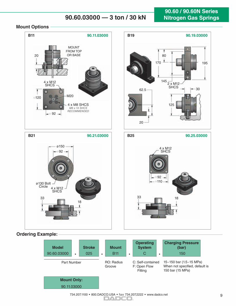
Mount Options
Ordering Example:
Model Stroke MountOperating
SystemCharging Pressure
(bar)
90.60.03000 • 025 • B11 • C • 150
Part Number 15~150 bar (1.5~15 MPa)When not specified, default is 150 bar (15 MPa)
Mount Only:
90.11.03000
RO: Radius Groove
C: Self-containedF: Open Flow Fitting
B11 90.11.03000
B25 90.25.03000
4 x M12 SHCS
92
20
33 18
4 x M12 SHCS
92110
120 M20
4 x M8 SHCSM8 x 14 SHCS
RECOMMENDED
MOUNT FROM TOP OR BASE
B21 90.21.03000
4 x M12 SHCS
33
ø130 Bolt Circle
18
2 x M12 SHCS
80
170
145
30
195
125
62.5
20
B19 90.19.03000
92
ø150
90.60 / 90.60N SeriesNitrogen Gas Springs
734.207.1100 • 800.DADCO.USA • fax 734.207.2222 • www.dadco.net
®
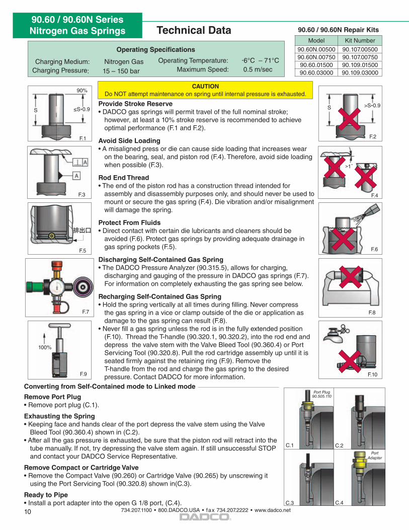
Technical Data
10
Operating Temperature: -6°C – 71°C Maximum Speed: 0.5 m/sec
Charging Medium: Nitrogen Gas Charging Pressure: 15 – 150 bar
Operating Specifications
CAUTIONDo NOT attempt maintenance on spring until internal pressure is exhausted.
Converting from Self-Contained mode to Linked mode
Remove Port Plug• Remove port plug (C.1).
Exhausting the Spring• Keeping face and hands clear of the port depress the valve stem using the Valve
Bleed Tool (90.360.4) shown in (C.2).• After all the gas pressure is exhausted, be sure that the piston rod will retract into the
tube manually. If not, try depressing the valve stem again. If still unsuccessful STOP and contact your DADCO Service Representative.
Remove Compact or Cartridge Valve• Remove the Compact Valve (90.260) or Cartridge Valve (90.265) by unscrewing it
using the Port Servicing Tool (90.320.8) shown in(C.3).
Ready to Pipe• Install a port adapter into the open G 1/8 port, (C.4).
Provide Stroke Reserve• DADCO gas springs will permit travel of the full nominal stroke;
however, at least a 10% stroke reserve is recommended to achieve optimal performance (F.1 and F.2).
Avoid Side Loading• A misaligned press or die can cause side loading that increases wear
on the bearing, seal, and piston rod (F.4). Therefore, avoid side loading when possible (F.3).
Rod End Thread • The end of the piston rod has a construction thread intended for
assembly and disassembly purposes only, and should never be used to mount or secure the gas spring (F.4). Die vibration and/or misalignment will damage the spring.
Protect From Fluids• Direct contact with certain die lubricants and cleaners should be
avoided (F.6). Protect gas springs by providing adequate drainage in gas spring pockets (F.5).
Discharging Self-Contained Gas Spring• The DADCO Pressure Analyzer (90.315.5), allows for charging,
discharging and gauging of the pressure in DADCO gas springs (F.7). For information on completely exhausting the gas spring see below.
Recharging Self-Contained Gas Spring• Hold the spring vertically at all times during filling. Never compress
the gas spring in a vice or clamp outside of the die or application as damage to the gas spring can result (F.8).
• Never fill a gas spring unless the rod is in the fully extended position (F.10). Thread the T-handle (90.320.1, 90.320.2), into the rod end and depress the valve stem with the Valve Bleed Tool (90.360.4) or Port Servicing Tool (90.320.8). Pull the rod cartridge assembly up until it is seated firmly against the retaining ring (F.9). Remove the T-handle from the rod and charge the gas spring to the desired pressure. Contact DADCO for more information.
≤S*0.9
90%
100%
F.1
F.3
F.5
F.7
F.9
S
排出口
F.4
F.2
F.6
F.8
F.10
S >S*0.9
>1˚
C.4C.3
C.1 C.2
Port Plug 90.505.110
Port Adapter
90.60 / 90.60N Repair Kits
Model Kit Number
90.60N.00500 90.107.0050090.60N.00750 90.107.0075090.60.01500 90.109.0150090.60.03000 90.109.03000