Embed Size (px)
Citation preview
COMPACT CATALOGUECOUPLINGS


© ARNTZ OPTIBELT GROUP, GERMANY
Norbert, 42, Foreman
COMPACT CATALOGUE COUPLINGS
“�Get�things�moving��in�a�big�way�–��with�the�right�drive.”
Optibelt is your partner for industrial ap-plications in drives, control, and motion. With our extensive range of couplings, we are the ideal partner for technical trades – for original equipment manu-facturers as well as end users nationally and internationally. Our technical support and engineering calculate and optimise entire drive systems. Accordingly, we can develop exact and individual solutions for our customers.
Our wide range of products allow us to supply solutions for all mechanical engi-neering applications with shaft connec-tions. In addition we offer standard and customised solutions with a long service life and high operational reliability.
3
© ARNTZ OPTIBELT GROUP, GERMANY
TABLE OF CONTENTS
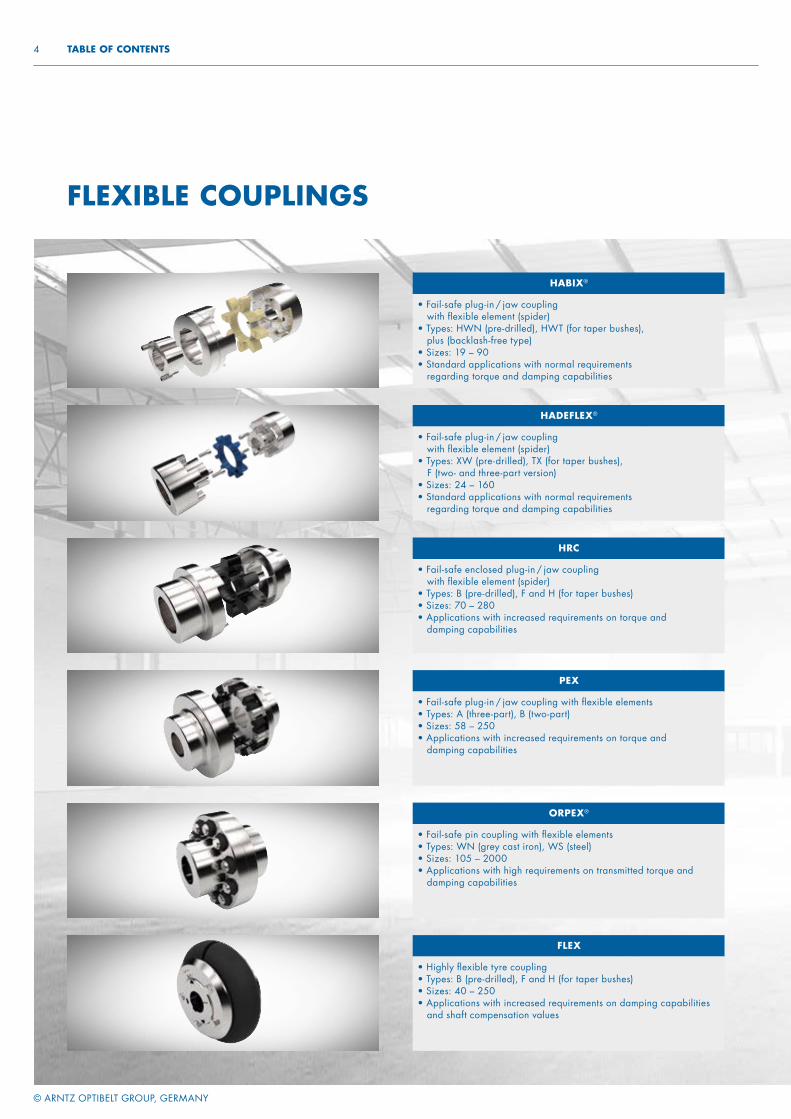
FLEXIBLE COUPLINGS
HADEFLEX®
• Fail-safe plug-in / jaw coupling with flexible element (spider)
• Types: XW (pre-drilled), TX (for taper bushes), F (two- and three-part version)
• Sizes: 24 – 160• Standard applications with normal requirements
regarding torque and damping capabilities
HABIX®
• Fail-safe plug-in / jaw coupling with flexible element (spider)
• Types: HWN (pre-drilled), HWT (for taper bushes), plus (backlash-free type)
• Sizes: 19 – 90• Standard applications with normal requirements
regarding torque and damping capabilities
FLEX
• Highly flexible tyre coupling• Types: B (pre-drilled), F and H (for taper bushes)• Sizes: 40 – 250• Applications with increased requirements on damping capabilities
and shaft compensation values
HRC
• Fail-safe enclosed plug-in / jaw coupling with flexible element (spider)
• Types: B (pre-drilled), F and H (for taper bushes)• Sizes: 70 – 280• Applications with increased requirements on torque and
damping capabilities
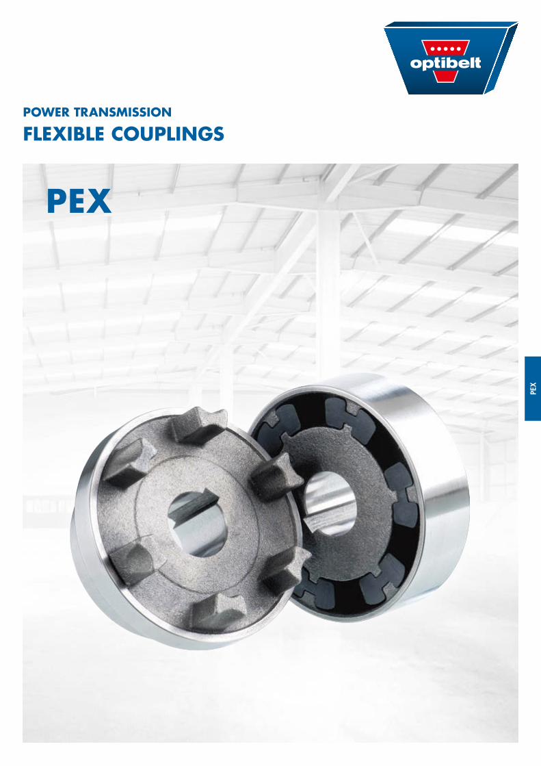
PEX
• Fail-safe plug-in / jaw coupling with flexible elements• Types: A (three-part), B (two-part)• Sizes: 58 – 250• Applications with increased requirements on torque and
damping capabilities
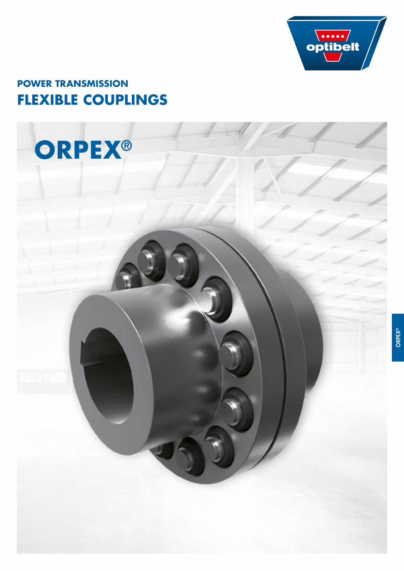
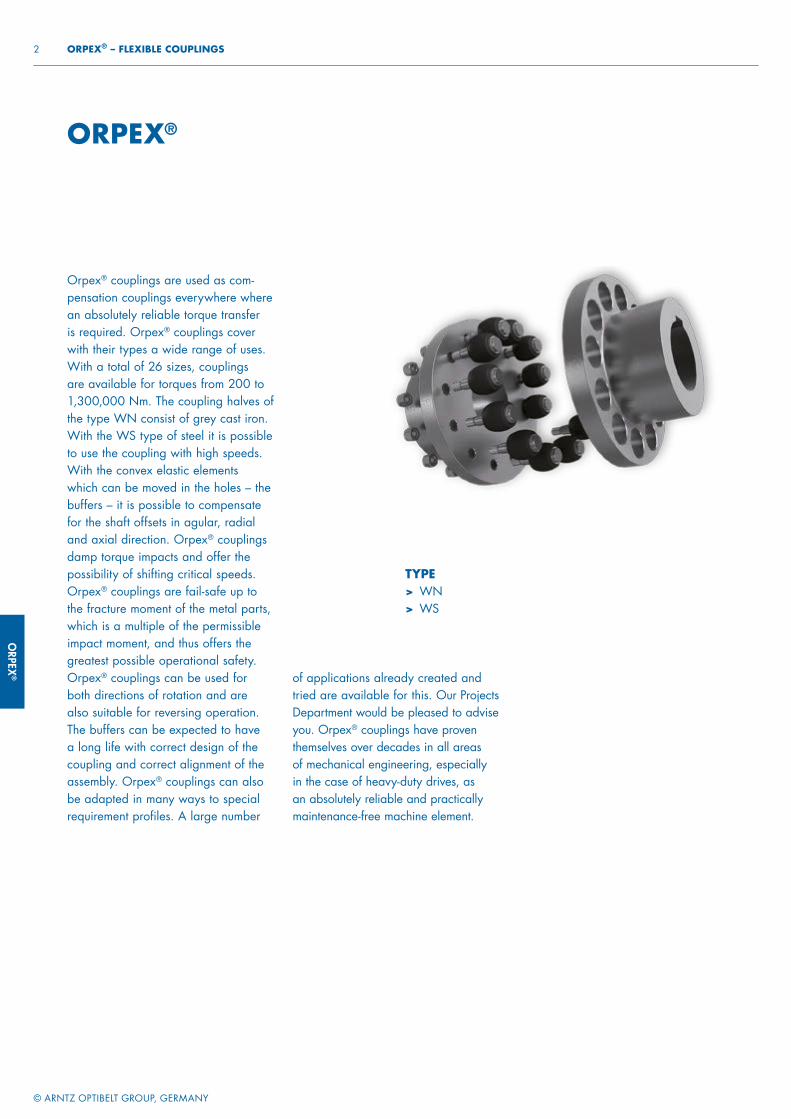
ORPEX®
• Fail-safe pin coupling with flexible elements• Types: WN (grey cast iron), WS (steel)• Sizes: 105 – 2000• Applications with high requirements on transmitted torque and
damping capabilities
4
© ARNTZ OPTIBELT GROUP, GERMANY
TABLE OF CONTENTS
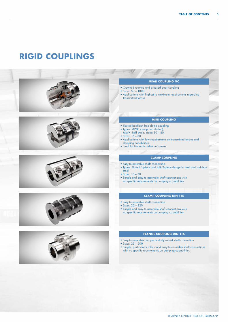
RIGID COUPLINGS
FLANGE COUPLING DIN 116
• Easy-to-assemble and particularly robust shaft connection• Sizes: 25 – 500• Simple, particularly robust and easy-to-assemble shaft connections
with no specific requirements on damping capabilities
CLAMP COUPLING
• Easy-to-assemble shaft connection• Types: Slotted 1-piece and split 2-piece design in steel and stainless
steel • Sizes: 10 – 30• Simple and easy-to-assemble shaft connections with
no specific requirements on damping capabilities
MINI COUPLING
• Slotted backlash-free clamp coupling• Types: MWK (clamp hub slotted),
MWH (half-shells, sizes: 30 – 80)• Sizes: 16 – 80• Applications with low requirements on transmitted torque and
damping capabilities • Ideal for limited installation spaces.
GEAR COUPLING GC
• Crowned toothed and greased gear coupling• Sizes: 50 – 1000• Applications with highest to maximum requirements regarding
transmitted torque
CLAMP COUPLING DIN 115
• Easy-to-assemble shaft connection• Sizes: 25 – 220• Simple and easy-to-assemble shaft connections with
no specific requirements on damping capabilities
5

HABI
X®
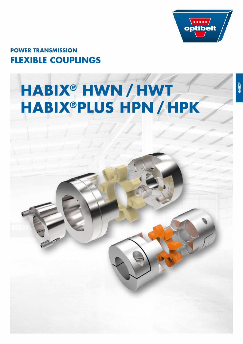
HABIX® HWN / HWTHABIX®PLUS HPN / HPK
POWER TRANSMISSION
FLEXIBLE COUPLINGS
HABIX®
© ARNTZ OPTIBELT GROUP, GERMANY
2 HABIX® – FLEXIBLE COUPLINGS
HABIX®
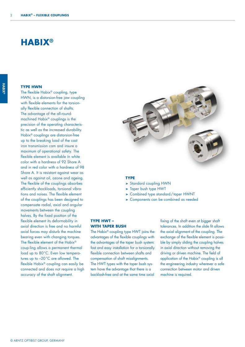
TYPE HWN The flexible Habix® coupling, type HWN, is a distorsion-free jaw coupling with flexible elements for the torsion-ally flexible connection of shafts. The advantage of the all-round-machined Habix® couplings is the precision of the operating characteris-tic as well as the increased durability. Habix® couplings are distorsion-free up to the breaking load of the cast iron transmission cam and insure a maximum of operational safety. The flexible element is available in white color with a hardness of 92 Shore A and in red color with a hardness of 98 Shore A. It is resistant against wear as well as against oil, ozone and ageing. The flexible of the couplings absorbes efficiently shockloads, torsional vibra-tions and noises. The flexible element of the couplings has been designed to compensate radial, axial and angular movements between the coupling halves. By the fixed position of the flexible element its deformability in axial direction is free and no harmful axial forces may disturb the machine bearing even with changing torques. The flexible element of the Habix® coup-ling allows a permanent thermal load up to 80 °C. Even low tempera-tures up to –20 °C are allowed. The flexible Habix® coupling can easily be connected and does not require a high accuracy of the shaft alignment.
TYPE HWT – WITH TAPER BUSHThe Habix® coupling type HWT joins the advantages of the flexible couplings with the advantages of the taper bush system: fast and easy installation for a torsionally flexible connection between shafts and compensation of shaft misalignments. The HWT types with the taper bush sys-tem have the advantage that there is a backlash-free and at the same time axial
TYPE> Standard coupling HWN> Taper bush type HWT> Combined type standard / taper HWNT> Components can be combined as needed
fixing of the shaft even at bigger shaft tolerances. In addition the slide fit allows the axial alignment of the coupling. The exchange of the flexible element is possi-ble by simply sliding the coupling halves in axial direction without removing the driving or driven machine. The field of application of the Habix® coupling is all the engineering industry wherever a safe connection between motor and driven machine is required.
HABI
X®
© ARNTZ OPTIBELT GROUP, GERMANY
3 FLEXIBLE COUPLINGS – HABIX®
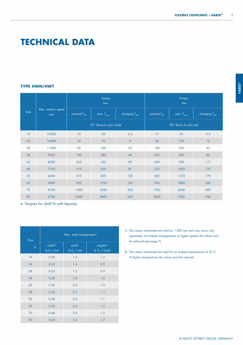
1) The values mentioned are valid for 1.500 rpm and may occur only
separately. At multiple misalignments or higher speeds the values must
be reduced (see page 7).
2) The values mentioned are valid for an ambient temperature of 30 °C.
At higher temperatures the values must be reduced.
Size
Max. shaft misalignment2)
radial1)
Kr / mm
axial1)
Ka / mm
angular1)
Kw / Grad
19 0.20 1.2 1.2
24 0.22 1.4 0.9
28 0.25 1.5 0.9
38 0.28 1.8 1.0
42 0.32 2.0 1.0
48 0.36 2.1 1.1
55 0.38 2.2 1.1
65 0.42 2.6 1.2
75 0.48 3.0 1.2
90 0.50 3.4 1.2
SizeMax. rotation speed
rpm
Torque
Nm
Torque
Nm
nominal TKN max. Tkmax changing TKW nominal TKN max. Tkmax changing TKW
92° Shore A color white 98° Shore A color red
19 19 000 10 20 2.6 17 34 4.4
24 14 000 35 70 9 60 120 16
28 11 800 95 190 25 160 320 42
38 9500 190 380 49 325 650 85
42 8000 265 530 69 450 900 117
48 7100 310 620 81 525 1050 137
55 6300 410 820 105 685 1370 178
65 5600 625 1250 163 940 1880 245
75 4750 1280 2560 333 1920 3840 499
90 3750 2400 4800 624 3600 7200 936
TECHNICAL DATA
TYPE HWN/HWT
> Torques for shaft fit with keyway

HABIX®
© ARNTZ OPTIBELT GROUP, GERMANY
4 HABIX® – FLEXIBLE COUPLINGS
TYPE HWNWITH KEYWAY MOUNTING
SizeWeight / kg
Moments of inertia
kgm2
Part 1 Part 2 Part 1 Part 2
19 0.16 0.21 0.00003 0.00005
24 0.40 0.40 0.00011 0.00015
28 0.52 0.76 0.00024 0.00049
38 1.1 1.4 0.00087 0.0013
42 1.7 2.3 0.0018 0.0031
48 2.8 3.1 0.0031 0.0052
55 3.7 4.6 0.062 0.010
65 5.7 7.0 0.013 0.019
75 8.8 11 0.027 0.041
90 15 15 0.068 0.090
> Drill holes H7 with keyway in accordance with DIN 6885/1; tolerance zone JS9 and set screws on the keyway; weight and moments of inertia valid for medium bore diameters
> Coupling half materials: EN-GJL-250 (GG-25) in accordance with DIN EN 1561
> Possible combination:1/11/22/2
> Can also be combined with type HWT
Size
Part 1
D1 d1 l1
Part 2
D2 d2 l2 da u s
Pre.
mm
max.
mm mm mm
Pre.
mm
max.
mm mm mm mm mm mm
19 – 19 32 25 17 24 39.5 25 40 5 16
24 – 24 40 30 22 28 48 30 55 6 18
28 – 28 48 35 26 38 64.5 35 65 7 20
38 10 38 66 45 36 45 78 45 80 8 24
42 12 42 75 50 40 55 94 50 95 10 26
48 13 48 85 56 46 60 104 56 105 11 28
55 18 55 98 65 53 70 118 65 120 13 30
65 20 65 115 75 63 75 134 75 135 14 35
75 28 75 135 85 73 90 158 85 160 16 40
90 38 90 160 100 88 100 180 100 200 19 45
l1 l2s
u u
D1
D2
d 2
d a
1 2
d 1
HABI
X®
© ARNTZ OPTIBELT GROUP, GERMANY
5 FLEXIBLE COUPLINGS – HABIX®
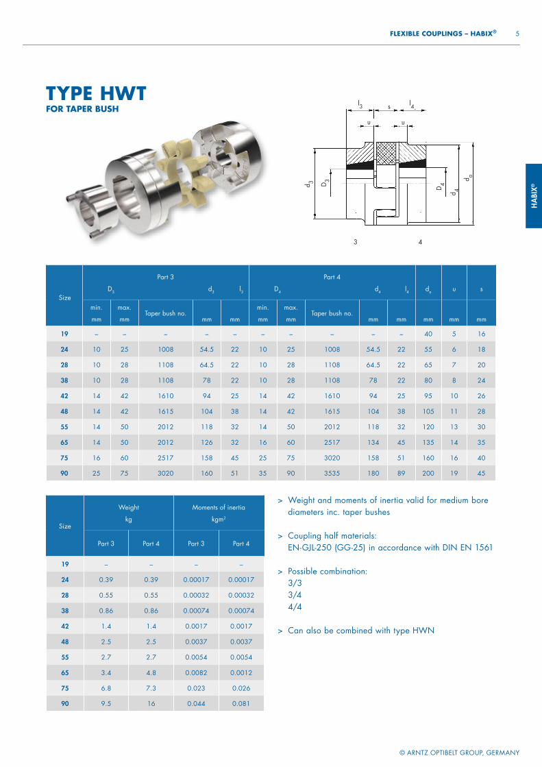
Size
Part 3
D3 d3 l3
Part 4
D4 d4 l4 da u s
min.
mm
max.
mmTaper bush no.
mm mm
min.
mm
max.
mmTaper bush no.
mm mm mm mm mm
19 – – – – – – – – – – 40 5 16
24 10 25 1008 54.5 22 10 25 1008 54.5 22 55 6 18
28 10 28 1108 64.5 22 10 28 1108 64.5 22 65 7 20
38 10 28 1108 78 22 10 28 1108 78 22 80 8 24
42 14 42 1610 94 25 14 42 1610 94 25 95 10 26
48 14 42 1615 104 38 14 42 1615 104 38 105 11 28
55 14 50 2012 118 32 14 50 2012 118 32 120 13 30
65 14 50 2012 126 32 16 60 2517 134 45 135 14 35
75 16 60 2517 158 45 25 75 3020 158 51 160 16 40
90 25 75 3020 160 51 35 90 3535 180 89 200 19 45
Size
Weight
kg
Moments of inertia
kgm2
Part 3 Part 4 Part 3 Part 4
19 – – – –
24 0.39 0.39 0.00017 0.00017
28 0.55 0.55 0.00032 0.00032
38 0.86 0.86 0.00074 0.00074
42 1.4 1.4 0.0017 0.0017
48 2.5 2.5 0.0037 0.0037
55 2.7 2.7 0.0054 0.0054
65 3.4 4.8 0.0082 0.0012
75 6.8 7.3 0.023 0.026
90 9.5 16 0.044 0.081
> Weight and moments of inertia valid for medium bore diameters inc. taper bushes
> Coupling half materials: EN-GJL-250 (GG-25) in accordance with DIN EN 1561
> Possible combination:3/33/44/4
> Can also be combined with type HWN
TYPE HWTFOR TAPER BUSH
l3 l4s
u u
d 3 D3
D4
d 4
d a
3 4
HABIX®
© ARNTZ OPTIBELT GROUP, GERMANY
6 HABIX® – FLEXIBLE COUPLINGS
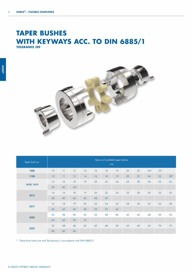
Taper bush no.Bore ø of available taper bushes
mm
1008 10 11 12 14 16 18 19 20 22 24* 25*
1108 10 11 12 14 16 18 19 20 22 24 25 28*
1610/ 161514 16 18 19 20 22 24 25 28 30 32 35
38 40 42*
201214 16 18 19 20 22 24 25 28 30 32 35
38 40 42 45 48 50
251716 18 19 20 22 24 25 28 30 32 35 38
40 42 45 48 50 55 60
302025 28 30 32 35 38 40 42 45 48 50 55
60 65 70 75
353535 38 40 42 45 48 50 55 60 65 70 75
80 85 90
* These bore holes are with flat keyway in accordance with DIN 6885/3.
TAPER BUSHES WITH KEYWAYS ACC. TO DIN 6885/1TOLERANCE JS9
HABI
X®
© ARNTZ OPTIBELT GROUP, GERMANY
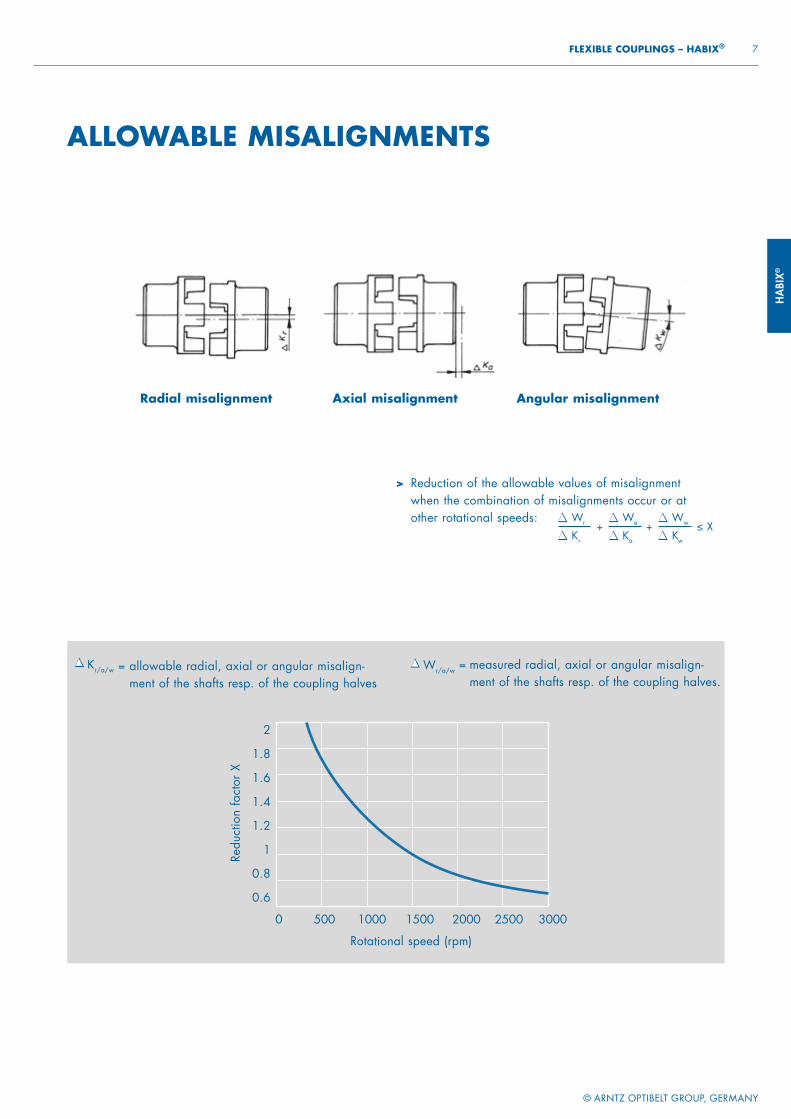
7 FLEXIBLE COUPLINGS – HABIX®
2
1.8
1.6
1.4
1.2
1
0.8
0.6
0 500 1000 1500 2000 2500 3000
Redu
ctio
n fa
ctor
X
Rotational speed (rpm)
= measured radial, axial or angular misalign-ment of the shafts resp. of the coupling halves.
= allowable radial, axial or angular misalign-ment of the shafts resp. of the coupling halves
Kr/a/w Wr/a/w
Radial misalignment Axial misalignment Angular misalignment
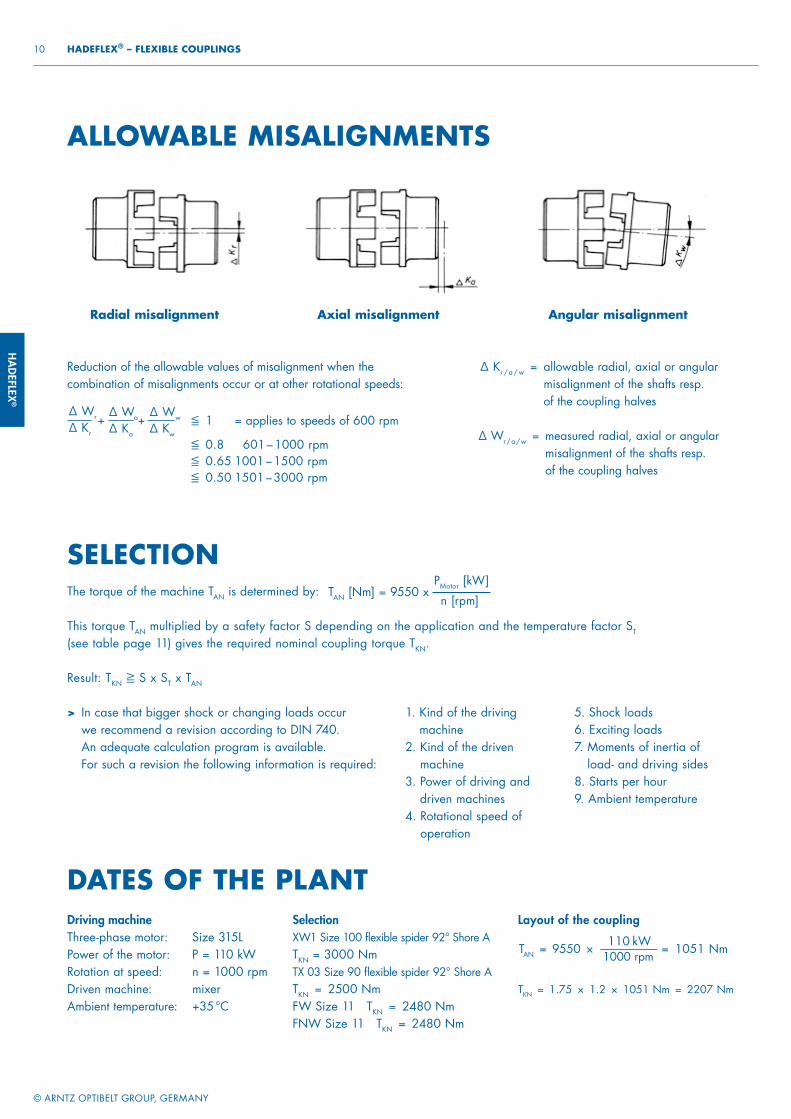
> Reduction of the allowable values of misalignment when the combination of misalignments occur or at other rotational speeds: Wr
Kr
Wa
Ka
+Ww
Kw
+ ≤ X
ALLOWABLE MISALIGNMENTS
HABIX®
© ARNTZ OPTIBELT GROUP, GERMANY
8 HABIX® – FLEXIBLE COUPLINGS
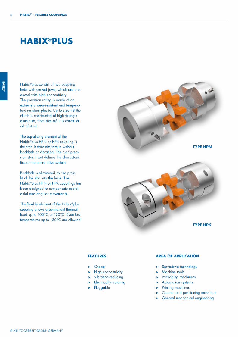
HABIX®PLUS
Habix®plus consist of two coupling hubs with curved jaws, which are pro-duced with high concentricity.The precision rating is made of an extremely wear-resistant and tempera-ture-resistant plastic. Up to size 48 the clutch is constructed of high-strength aluminum, from size 65 it is construct-ed of steel.
The equalizing element of the Habix®plus HPN or HPK coupling is the star. It transmits torque without backlash or vibration. The high-preci-sion star insert defines the characteris-tics of the entire drive system.
Backlash is eliminated by the press fit of the star into the hubs. The Habix®plus HPN or HPK couplings has been designed to compensate radial, axial and angular movements.
The flexible element of the Habix®plus coupling allows a permanent thermal load up to 100 °C or 120 °C. Even low temperatures up to –30 °C are allowed.
FEATURES
> Cheap> High concentricity> Vibration-reducing > Electrically isolating > Pluggable
AREA OF APPLICATION
> Servodrive technology> Machine tools> Packaging machinery> Automation systems> Printing machines> Control- and positioning technique> General mechanical engineering
TYPE HPN
TYPE HPK
HABI
X®
© ARNTZ OPTIBELT GROUP, GERMANY
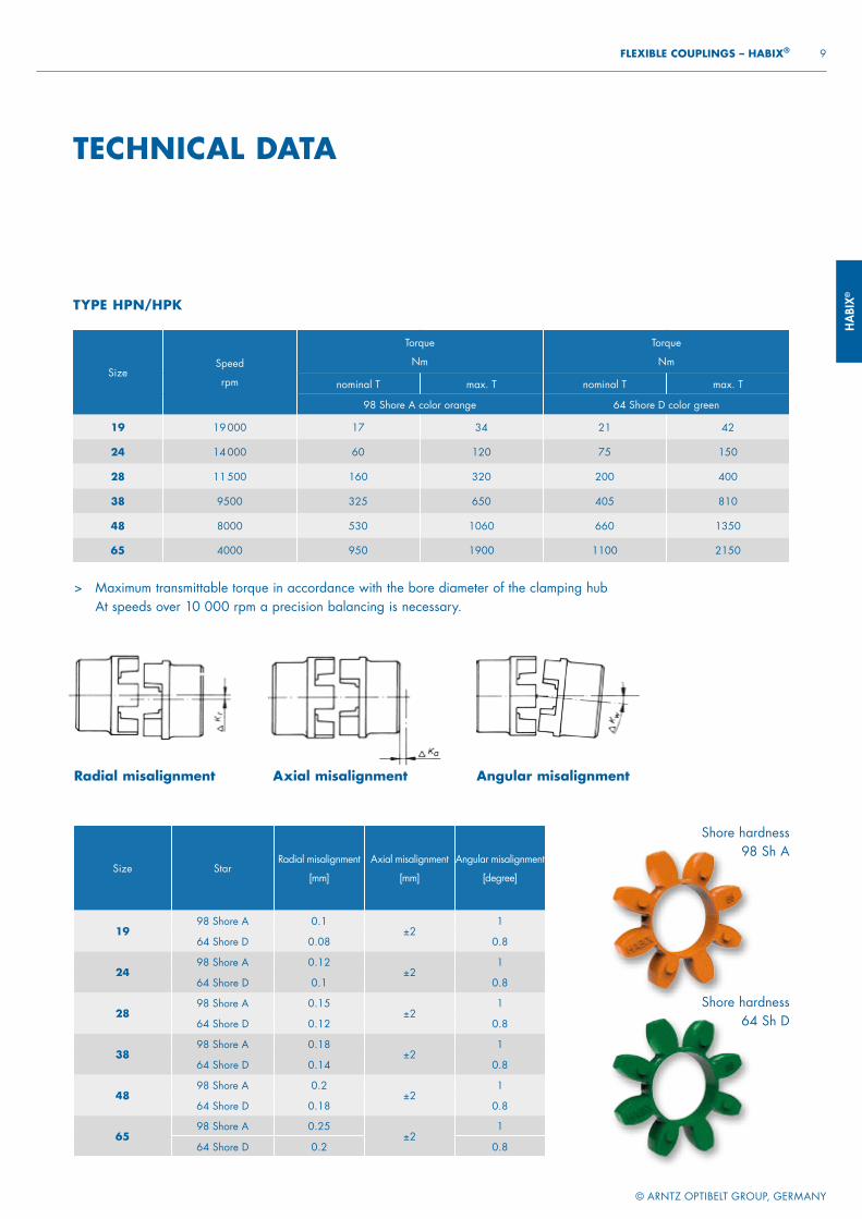
9 FLEXIBLE COUPLINGS – HABIX®
SizeSpeed
rpm
Torque
Nm
Torque
Nm
nominal T max. T nominal T max. T
98 Shore A color orange 64 Shore D color green
19 19 000 17 34 21 42
24 14 000 60 120 75 150
28 11 500 160 320 200 400
38 9500 325 650 405 810
48 8000 530 1060 660 1350
65 4000 950 1900 1100 2150
Size StarRadial misalignment
[mm]
Axial misalignment
[mm]
Angular misalignment
[degree]
1998 Shore A 0.1
±21
64 Shore D 0.08 0.8
2498 Shore A 0.12
±21
64 Shore D 0.1 0.8
2898 Shore A 0.15
±21
64 Shore D 0.12 0.8
3898 Shore A 0.18
±21
64 Shore D 0.14 0.8
4898 Shore A 0.2
±21
64 Shore D 0.18 0.8
6598 Shore A 0.25
±21
64 Shore D 0.2 0.8
> Maximum transmittable torque in accordance with the bore diameter of the clamping hub At speeds over 10 000 rpm a precision balancing is necessary.
Shore hardness98 Sh A
Shore hardness64 Sh D
Axial misalignment Angular misalignmentRadial misalignment
TECHNICAL DATA
TYPE HPN/HPK
HABIX®
© ARNTZ OPTIBELT GROUP, GERMANY
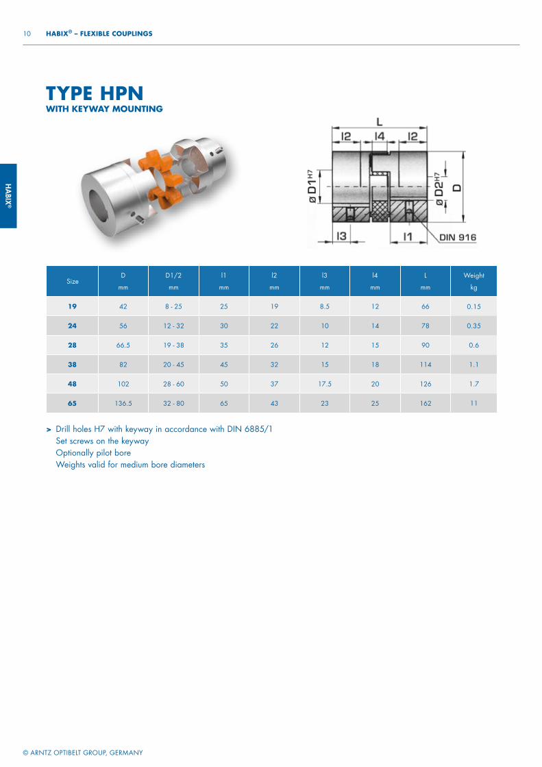
10 HABIX® – FLEXIBLE COUPLINGS
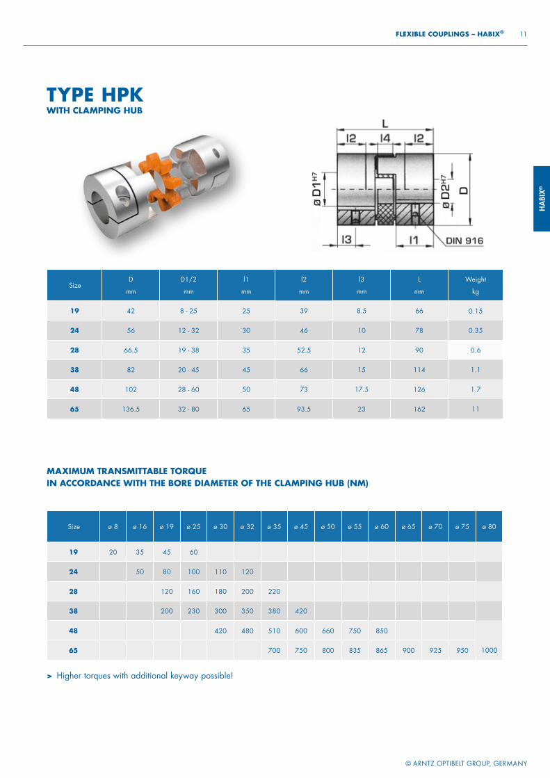
SizeD
mm
D1/2
mm
l1
mm
l2
mm
l3
mm
l4
mm
L
mm
Weight
kg
19 42 8 - 25 25 19 8.5 12 66 0.15
24 56 12 - 32 30 22 10 14 78 0.35
28 66.5 19 - 38 35 26 12 15 90 0.6
38 82 20 - 45 45 32 15 18 114 1.1
48 102 28 - 60 50 37 17.5 20 126 1.7
65 136.5 32 - 80 65 43 23 25 162 11
> Drill holes H7 with keyway in accordance with DIN 6885/1 Set screws on the keyway Optionally pilot boreWeights valid for medium bore diameters
TYPE HPNWITH KEYWAY MOUNTING
HABI
X®
© ARNTZ OPTIBELT GROUP, GERMANY
11 FLEXIBLE COUPLINGS – HABIX®
SizeD
mm
D1/2
mm
l1
mm
l2
mm
l3
mm
L
mm
Weight
kg
19 42 8 - 25 25 39 8.5 66 0.15
24 56 12 - 32 30 46 10 78 0.35
28 66.5 19 - 38 35 52.5 12 90 0.6
38 82 20 - 45 45 66 15 114 1.1
48 102 28 - 60 50 73 17.5 126 1.7
65 136.5 32 - 80 65 93.5 23 162 11
> Higher torques with additional keyway possible!
Size ø 8 ø 16 ø 19 ø 25 ø 30 ø 32 ø 35 ø 45 ø 50 ø 55 ø 60 ø 65 ø 70 ø 75 ø 80
19 20 35 45 60
24 50 80 100 110 120
28 120 160 180 200 220
38 200 230 300 350 380 420
48 420 480 510 600 660 750 850
65 700 750 800 835 865 900 925 950 1000
MAXIMUM TRANSMITTABLE TORQUE IN ACCORDANCE WITH THE BORE DIAMETER OF THE CLAMPING HUB (NM)
TYPE HPKWITH CLAMPING HUB
HABIX®
© ARNTZ OPTIBELT GROUP, GERMANY
12 HABIX® – FLEXIBLE COUPLINGS
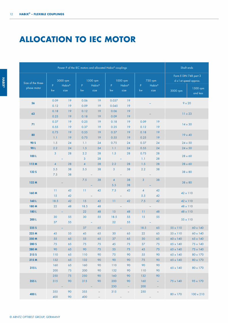
Power P of the IEC motors and allocated Habix® couplings Shaft ends
Size of the three-
phase motor
3000 rpm
P Habix®
kw size
1500 rpm
P Habix®
kw size
1000 rpm
P Habix®
kw size
750 rpm
P Habix®
kw size
Form E DIN 748 part 3
d x l at speed approx.
3000 rpm1500 rpm
and less
56 0.09 19 0.06 19 0.037 19
– 9 x 20 0.12 19 0.09 19 0.045 19
63 0.18 19 0.12 19 0.06 19
– 11 x 23 0.25 19 0.18 19 0.09 19
71 0.37 19 0.25 19 0.18 19 0.09 19
14 x 30 0.55 19 0.37 19 0.25 19 0.12 19
80 0.75 19 0.55 19 0.37 19 0.18 19
19 x 40 1.1 19 0.75 19 0.55 19 0.25 19
90 S 1.5 24 1.1 24 0.75 24 0.37 24 24 x 50
90 L 2.2 24 1.5 24 1.1 24 0.55 24 24 x 50
100 L 3 28 2.2 28 1.5 28 0.75 28
28 x 60 – 3 28 – 1.1 28
112 M 4 28 4 28 2.2 28 1.5 28 28 x 60
132 S 5.5 38 5.5 38 3 38 2.2 38
38 x 80 7.5 38 – – –
132 M – 7.5 38 4 38 3 38
38 x 80 – 5.5 38 –
160 M 11 42 11 42 7.5 42 4 42
42 x 110 15 42 – – 5.5 42
160 L 18.5 42 15 42 11 42 7.5 42 42 x 110
180 M 22 48 18.5 48 – – 48 x 110
180 L – 22 48 15 48 11 48 48 x 110
200 L 30 55 30 55 18.5 55 15 55
55 x 110 37 55 – 22 55 –
225 S – 37 65 – 18.5 65 55 x 110 60 x 140
225 M 45 55 45 65 30 65 22 65 55 x 110 60 x 140
250 M 55 65 55 65 37 65 30 65 60 x 140 65 x 140
280 S 75 65 75 75 45 75 37 75 65 x 140 75 x 140
280 M 90 65 90 75 55 75 45 75 65 x 140 75 x 140
315 S 110 65 110 90 75 90 55 90 65 x 140 80 x 170
315 M 132 65 132 90 90 90 75 90 65 x 140 80 x 170
315 L 160 65 160 90 110 90 90 90
65 x 140 80 x 170 200 75 200 90 132 90 110 90
ALLOCATION TO IEC MOTOR
355 L
250 75 250 90 160 90 132 90
75 x 140 95 x 170 315 90 315 90 200 90 160 –
– – 250 – 200 –
400 L 355 90 355 – 315 – 250 –
80 x 170 100 x 210 400 90 400 – – –
HABI
X®
© ARNTZ OPTIBELT GROUP, GERMANY
13 FLEXIBLE COUPLINGS – HABIX®
> As proposed in the table (page 12) for surface cooled three-phase motors with cage rotor acc. to DIN 42673, page 1 (data for motor 56, 63, 71, 80, 315 L, 355 L, 400 L, see catalogue Siemens).
This allocation is a preliminary selection for normal conditions of operation. For conditions of operation under shock and changing loads the selection must be made according to the following.
SELECTION> The torque of the machine TAN is determined by:
TAN [Nm] = 9550 xPMotor [kW]
n [rpm]
> This torque TAN multiplied by a safety factor S depending on the application and the temperature factor ST (see table page 14) gives the required nominal coupling torque TKN.
Result: TKN ≧ S x ST x TAN
DESIGN EXAMPLE FOR IEC STANDARD MOTORSDates of the plantDriving machine: three-phase motor 225 MPower of the motor: P = 45 kWRotation at speed: n = 1485 rpmDriven machine: mixerAmbient temperature: +50 °C
Layout of the coupling
TAN [Nm] = 9550 x45 kW
1485 rpm= 290 Nm
TKN = 1.25 x 1.5 x 290 Nm = 544 Nm
> Selection: Habix® size 65 flexible element 92° Shore A
TKN = 625 Nm
> In case that bigger shock or changing loads occur we recommend a revision according to DIN 740.
An adequate calculation program is available. For such a revision the following information is required:
1. Kind of the driving machine2. Kind of the driven machine3. Power of driving and driven machines4. Rotational speed of operation5. Shock loads6. Exciting loads7. Moments of inertia of load- and driving sides8. Starts per hour9. Ambient temperature
HABIX®
© ARNTZ OPTIBELT GROUP, GERMANY
14 HABIX® – FLEXIBLE COUPLINGS
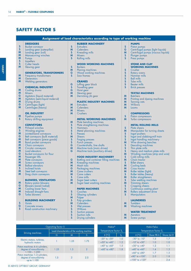
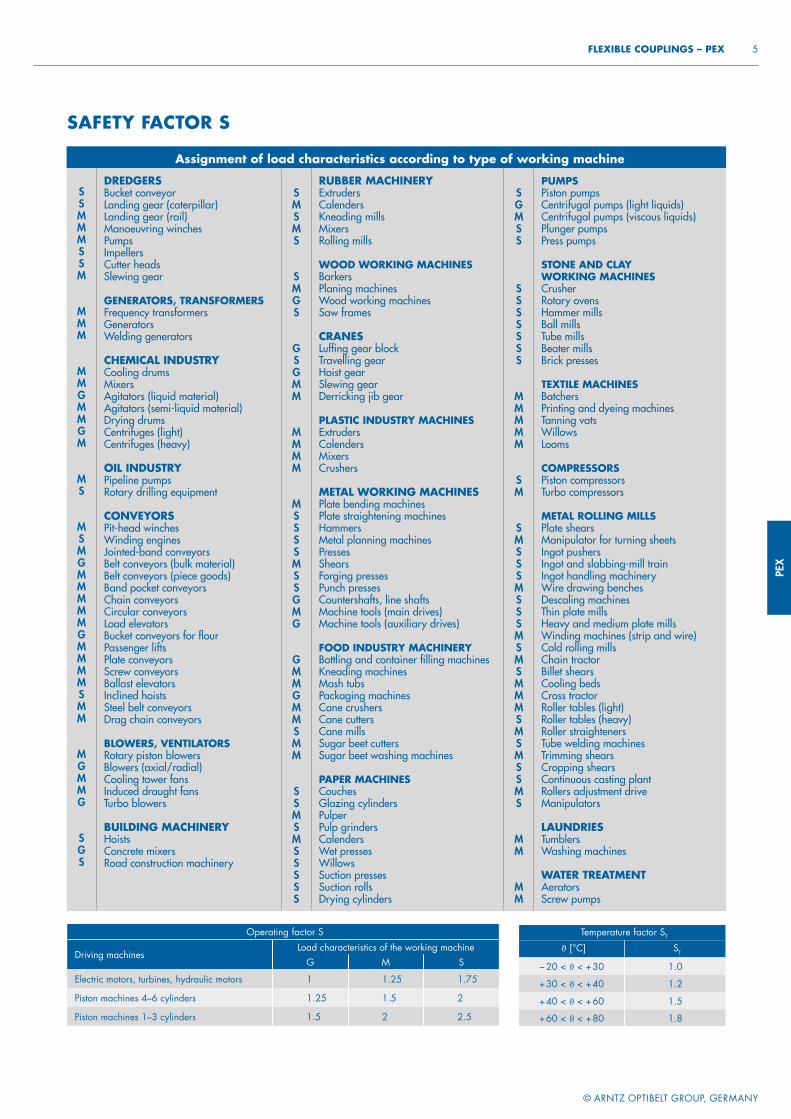
Assignment of load characteristics according to type of working machine
SSMMMSSM
MMM
MMGMMGM
MS
MSMGMMMMMGMMMMSMM
MGMMG
SGS
DREDGERSBucket conveyorLanding gear (caterpillar)Landing gear (rail)Manoeuvring winchesPumpsImpellers Cutter headsSlewing gear
GENERATORS, TRANSFORMERSFrequency transformersGeneratorsWelding generators
CHEMICAL INDUSTRYCooling drumsMixersAgitators (liquid material)Agitators (semi-liquid material)Drying drumsCentrifuges (light)Centrifuges (heavy)
OIL INDUSTRYPipeline pumpsRotary drilling equipment
CONVEYORSPit-head winchesWinding enginesJointed-band conveyorsBelt conveyors (bulk material)Belt conveyors (piece goods)Band pocket conveyorsChain conveyorsCircular conveyorsLoad elevatorsBucket conveyors for flourPassenger liftsPlate conveyorsScrew conveyorsBallast elevatorsInclined hoistsSteel belt conveyorsDrag chain conveyors
BLOWERS, VENTILATORSRotary piston blowersBlowers (axial/radial)Cooling tower fansInduced draught fansTurbo blowers
BUILDING MACHINERYHoistsConcrete mixersRoad construction machinery
SMSMS
SMGS
GSGMM
MMMM
MSSSSMSSGMG
GMMGMMSMM
SSMSMSSSSS
RUBBER MACHINERYExtrudersCalendersKneading millsMixersRolling mills
WOOD WORKING MACHINESBarkersPlaning machinesWood working machinesSaw frames
CRANESLuffi ng gear blockTravelling gearHoist gearSlewing gearDerricking jib gear
PLASTIC INDUSTRY MACHINESExtrudersCalendersMixersCrushers
METAL WORKING MACHINESPlate bending machinesPlate straightening machinesHammersMetal planning machinesPressesShearsForging pressesPunch pressesCountershafts, line shaftsMachine tools (main drives)Machine tools (auxiliary drives)
FOOD INDUSTRY MACHINERYBottling and container fi lling machinesKneading machinesMash tubsPackaging machinesCane crushersCane cuttersCane millsSugar beet cuttersSugar beet washing machines
PAPER MACHINESCouchesGlazing cylindersPulperPulp grindersCalendersWet pressesWillowsSuction pressesSuction rollsDrying cylinders
SGMSS
SSSSSSS
MMMMM
SM
SMSSSMSSSMSMSMMMSMSMSSMS
MM
MM
PUMPSPiston pumpsCentrifugal pumps (light liquids)Centrifugal pumps (viscous liquids)Plunger pumpsPress pumps
STONE AND CLAY WORKING MACHINESCrusherRotary ovensHammer millsBall millsTube millsBeater millsBrick presses
TEXTILE MACHINESBatchersPrinting and dyeing machinesTanning vatsWillowsLooms
COMPRESSORSPiston compressorsTurbo compressors
METAL ROLLING MILLSPlate shearsManipulator for turning sheetsIngot pushersIngot and slabbing-mill trainIngot handling machineryWire drawing benchesDescaling machinesThin plate millsHeavy and medium plate millsWinding machines (strip and wire)Cold rolling millsChain tractorBillet shearsCooling bedsCross tractorRoller tables (light)Roller tables (heavy)Roller straightenersTube welding machinesTrimming shearsCropping shearsContinuous casting plantRollers adjustment driveManipulators
LAUNDRIESTumblersWashing machines
WATER TREATMENTAeratorsScrew pumps
SAFETY FACTOR S
Operating factor S
Driving machinesLoad characteristics of the working machine
G M S
Electric motors, turbines, hydraulic motors 1 1.25 1.75
Piston machines 4–6 cylinders, degree of nonuniformity
1:100 – 1:2001.25 1.5 2
Piston machines 1–3 cylinders,degree of nonuniformity
up to 1:100 1.5 2 2.5
Habix®plus
Temperature factor ST
ϑ [°C] Shore 98 A Shore 64 D –30° to –10° 1.5 1.7–10° to +30° 1.0 1.0+30° to +40° 1.2 1.1+40° to +60° 1.4 1.3+60° to +80° 1.7 1.5
+80° to +100° 2.0 1.8+100° to +120° – 2.4
Habix®
Temperature factor ST
ϑ [°C] ST
–20° to +30° 1.0+30° to +40° 1.2+40° to +60° 1.5 +60° to +80° 1.8
HADE
FLEX
®
POWER TRANSMISSION
FLEXIBLE COUPLINGS
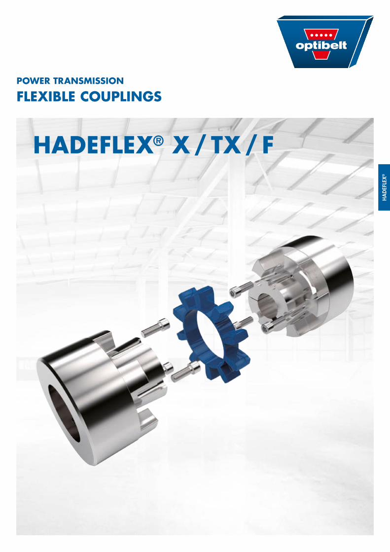
HADEFLEX® X / TX / F

HADEFLEX®
© ARNTZ OPTIBELT GROUP, GERMANY
2 HADEFLEX® – FLEXIBLE COUPLINGS
The flexible Hadeflex® couplings are claw couplings with a flexible element to provide a torsionally flexible con-nection for shafts. The flexible elements excel in their wear resistance, their oil, ozone and ageing resistance and their temperature resistance from –20 °C to +80 °C. Thanks to their flexibility, impacts, rotary vibrations and noises are effectively absorbed. The flexible elements are dimensioned such that radial, axial and angular movements between the two halves of the cou-pling are cancelled out. The flexible Hadeflex® couplings are of the plug-in type for installation and do not involve any particularly rigorous requirements with respect to alignment accuracy. Hadeflex® couplings can be used in the whole of machine construction wherever a reliable shaft connection is needed between motor and working machine.
TYPE XThe Hadeflex® version X coupling is fail-safe up to the fracture moment of the cast iron transmission cam and this provides maximum operational safety. The coupling star can be supplied with hardness 92 Shore A and 98 Shore A. With the fixed position of the coupling star its deformability in axial direction is free, and so no damaging axial forces can act on the machine bearing even with alternating torque.
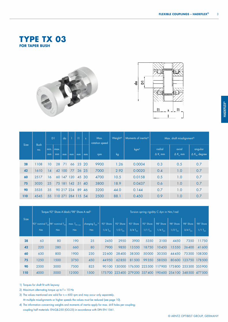
TYPE TX – WITH TAPER BUSHThe Hadeflex® version TX coupling com-bines the outstanding features of the flexible couplings with the advantages of the taper bush system: fast and easy installation for a torsionally flexible con-nection between shafts and elimination of shaft balancing errors. The TX type with taper bush has the advantage that even with greater shaft tolerances there is a backlash-free and at the same time axial fixing of the shaft. In addition the close sliding fit makes axial alignment of the coupling easier. The coupling star can be replaced by a simple axial
HADEFLEX®
displacement of the coupling halves without having to disassemble the machines connected.
TYPE FThe Hadeflex® version F coupling is manufactured in two-piece and three-piece variants. With the two-piece cou-pling (FW series) it is possible to install packages after axial displacement of the drive engines or working machines. With the three-piece coupling (FNW series) it is possible to install packages without axial displacement of the drive engine or working machine.
HADE
FLEX
®
l1s
da D1
l1
l
© ARNTZ OPTIBELT GROUP, GERMANY
3 FLEXIBLE COUPLINGS – HADEFLEX®
Size Bush
no.
D1 da l l1 s Max.
rotation speed
rpm
Weight4)
kg
Moments of inertia4)
kgm2
Max. shaft misalignment3)
min.
mm
max.
mm mm mm mm mm
radial
∆ Kr mm
axial
∆ Ka mm
angular
∆ KW degree
28 1108 10 28 71 66 23 20 9900 1.26 0.0004 0.3 0.5 0.7
42 1610 14 42 100 77 26 25 7000 2.92 0.0020 0.4 1.0 0.7
60 2517 16 60 147 120 45 30 4700 10.5 0.0158 0.5 1.0 0.7
75 3020 25 75 181 142 51 40 3800 18.9 0.0437 0.6 1.0 0.7
90 3535 35 90 217 224 89 46 3200 44.0 0.144 0.7 1.0 0.7
110 4545 55 110 271 284 115 54 2500 88.1 0.450 0.9 1.0 0.7
Size
Torque 92° Shore A black / 98° Shore A red1) Torsion spring rigidity C dyn in Nm / rad
92° nominal TKN
Nm
98° nominal TKN
Nm
max. TKN max
Nm
changing TKW 2)
Nm
92° Shore
1/4 TKN
92° Shore
1/2 TKN
92° Shore
3/4 TKN
92° Shore
1/1 TKN
98° Shore
1/4 TKN
98° Shore
1/2 TKN
98° Shore
3/4 TKN
98° Shore
1/1 TKN
28 63 80 190 25 2450 2950 3900 5350 3100 4450 7350 11 750
42 220 280 660 80 7900 9850 13 550 18 750 10 450 15 550 26 400 41 600
60 630 800 1900 230 22 600 28 400 38 300 50 000 30 350 44 450 73 300 108 300
75 1250 1500 3750 450 44 950 62 850 81 500 99 350 58 050 80 600 123 750 178 500
90 2500 3000 7500 825 90 100 130 000 176 500 223 500 117 900 173 800 253 300 355 900
110 4000 5000 12 000 1500 175 700 223 400 279 200 337 400 190 600 254 100 348 500 477 500
1) Torques for shaft fi t with keyway
2) Maximum alternating torque up to f = 10 Hz
3) The values mentioned are valid for n = 600 rpm and may occur only separately.
At multiple misalignments or higher speeds the values must be reduced (see page 10).
4) The information concerning weights and moments of inertia apply for max. drill holes per coupling;
coupling half materials: EN-GJL-250 (GG-25) in accordance with DIN EN 1561.
TYPE TX 03FOR TAPER BUSH
HADEFLEX®
© ARNTZ OPTIBELT GROUP, GERMANY
4 HADEFLEX® – FLEXIBLE COUPLINGS
* These bore holes are with fl at keyway in accordance with DIN 6885/3.
SizeTorque 92° Shore A nature / 98° Shore A blue1) Torsion spring rigidity C dyn in Nm / rad
92° nominal TKN
Nm
98° nominal TKN
Nm
max. TKN max
Nm
changing TKW 2)
Nm
92° Shore
1/4 TKN
92° Shore
1/2 TKN
92° Shore
3/4 TKN
92° Shore
1/1 TKN
98° Shore
1/4 TKN
98° Shore
1/2 TKN
98° Shore
3/4 TKN
98° Shore
1/1 TKN
24 40 52 120 15 2150 3300 4200 4800 5550 8650 16 600 29 400
28 63 80 190 25 2850 4300 6050 8100 7000 10 750 19 650 33 300
32 100 120 300 35 3700 6000 8500 11 100 8300 12 850 23 800 40 500
38 160 200 480 60 5800 8800 12 600 16 800 11 600 17 600 31 850 55 800
42 220 280 660 80 8100 11 600 17 400 25 200 14 250 22 500 42 000 75 400
48 320 400 960 120 10 400 16 800 24 800 34 700 16 400 28 700 49 950 79 200
55 450 600 1350 180 13 250 23 500 34 000 44 550 20 650 39 700 69 600 109 400
60 630 800 1900 230 17 600 32 600 46 800 55 900 24 900 50 800 90 250 140 700
65 900 1000 2700 300 29 200 46 800 66 400 85 600 35 500 72 500 120 400 174 800
75 1250 1500 3750 450 42 250 69 200 95 650 124 200 46 800 97 400 165 600 238 600
85 1800 2250 5400 675 55 900 94 450 135 450 177 000 61 100 120 400 222 300 350 300
100 3000 3800 9000 1125 110 600 166 100 220 400 268 900 93 600 192 500 330 000 482 600
110 4000 5000 12 000 1500 120 100 220 100 309 500 386 900 130 500 251 000 439 500 641 000
125 5600 7000 16 800 2200 220 500 331 700 446 000 548 600 229 700 358 000 616 500 821 000
140 8000 10 000 24 000 3000 292 200 430 100 602 400 723 500 255 200 465 100 785 200 1 192 600
160 12 500 15 000 37 500 4500 319 000 547 000 847 500 1 273 000 364 000 640 000 1 018 000 1 500 000
TECHNICAL DATA XW1
1) Torques for shaft fi t with keyway – 2) Maximum alternating torque up to f = 10 Hz – 3) The values mentioned are valid for n = 600 rpm and may occur only
separately. At multiple misalignments or higher speeds the values must be reduced (see page10).
SizeMax. shaft misalignment3)
radial ∆ Kr mm
axial∆ Ka mm
angular∆ Kw degree
24 0.3 1.2 0.728 0.3 1.2 0.732 0.3 1.2 0.738 0.4 1.5 0.742 0.4 1.5 0.748 0.4 1.5 0.755 0.5 1.8 0.760 0.5 1.8 0.7
SizeMax. shaft misalignment3)
radial ∆ Kr mm
axial∆ Ka mm
angular∆ Kw degree
65 0.5 1.8 0.775 0.6 2.1 0.785 0.7 2.1 0.7
100 0.8 2.4 0.7110 0.9 2.4 0.7125 1.0 3.0 0.7140 1.1 3.0 0.7160 1.2 3.0 0.7
Taper bush no.Bore ø of available taper bushes
mm
1108 10 11 12 14 16 18 19 20 22 24 25 28*
1610 14 16 18 19 20 22 24 25 28 30 32 3538 40 42*
2517 16 18 19 20 22 24 25 28 30 32 35 3840 42 45 48 50 55 60
3020 25 28 30 32 35 38 40 42 45 48 50 5560 65 70 75
3535 35 38 40 42 45 48 50 55 60 65 70 7580 85 90
4545 55 60 65 70 75 80 85 90 95 100 105 110
TAPER BUSHESWITH KEYWAY ACC. TO DIN 6885/1TOLERANCE JS9
HADE
FLEX
®
l2
s
d1 D1
daD1
l1 l1l
© ARNTZ OPTIBELT GROUP, GERMANY
5 FLEXIBLE COUPLINGS – HADEFLEX®
1) Drill holes H7 with keyway in accordance with DIN 6885/1; tolerance zone JS9 and set screws on the keyway
2) The information concerning weights and moments of inertia apply for max. drill holes per coupling;
coupling half materials: EN-GJL-250 (GG-25) in accordance with DIN EN 1561 or *aluminium.
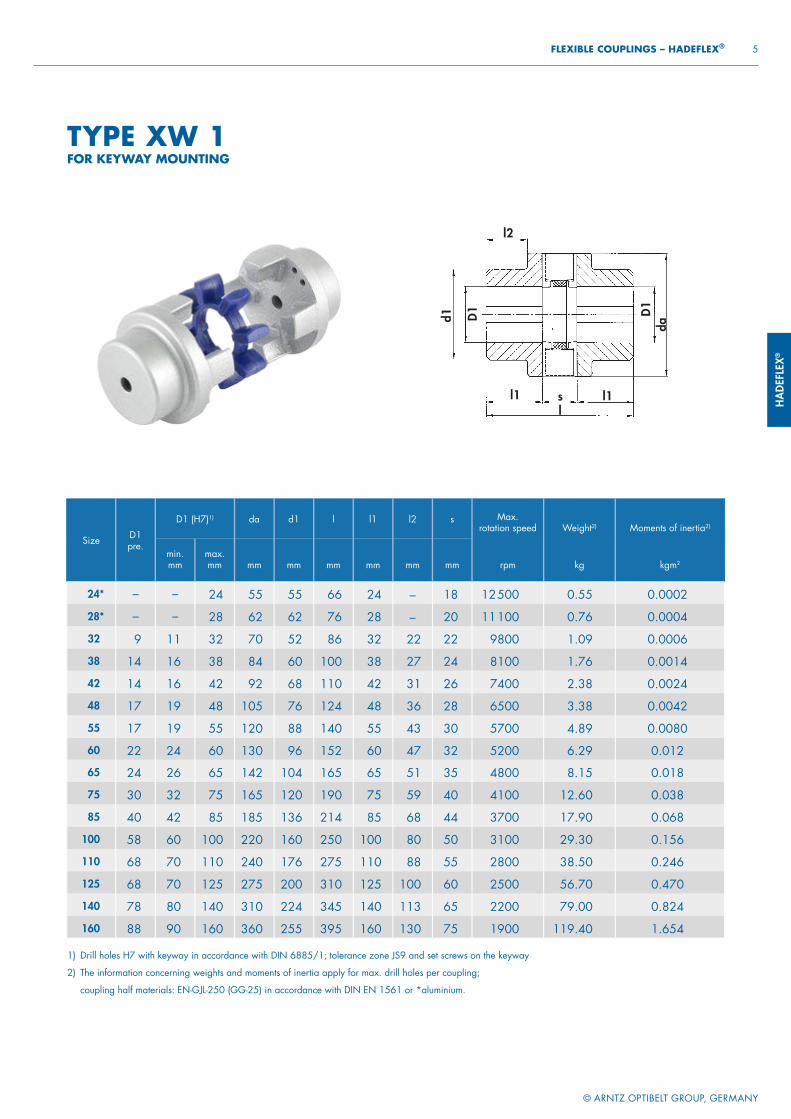
Size D1pre.
D1 (H7)1) da d1 l l1 l2 s Max.rotation speed
rpm
Weight2)
kg
Moments of inertia2)
kgm2min.mm
max.mm mm
mm
mm
mm mm mm
24* – – 24 55 55 66 24 – 18 12 500 0.55 0.0002
28* – – 28 62 62 76 28 – 20 11 100 0.76 0.0004
32 9 11 32 70 52 86 32 22 22 9800 1.09 0.0006
38 14 16 38 84 60 100 38 27 24 8100 1.76 0.0014
42 14 16 42 92 68 110 42 31 26 7400 2.38 0.0024
48 17 19 48 105 76 124 48 36 28 6500 3.38 0.0042
55 17 19 55 120 88 140 55 43 30 5700 4.89 0.0080
60 22 24 60 130 96 152 60 47 32 5200 6.29 0.012
65 24 26 65 142 104 165 65 51 35 4800 8.15 0.018
75 30 32 75 165 120 190 75 59 40 4100 12.60 0.038
85 40 42 85 185 136 214 85 68 44 3700 17.90 0.068
100 58 60 100 220 160 250 100 80 50 3100 29.30 0.156
110 68 70 110 240 176 275 110 88 55 2800 38.50 0.246
125 68 70 125 275 200 310 125 100 60 2500 56.70 0.470
140 78 80 140 310 224 345 140 113 65 2200 79.00 0.824
160 88 90 160 360 255 395 160 130 75 1900 119.40 1.654
TYPE XW 1FOR KEYWAY MOUNTING
HADEFLEX®
© ARNTZ OPTIBELT GROUP, GERMANY
6 HADEFLEX® – FLEXIBLE COUPLINGS
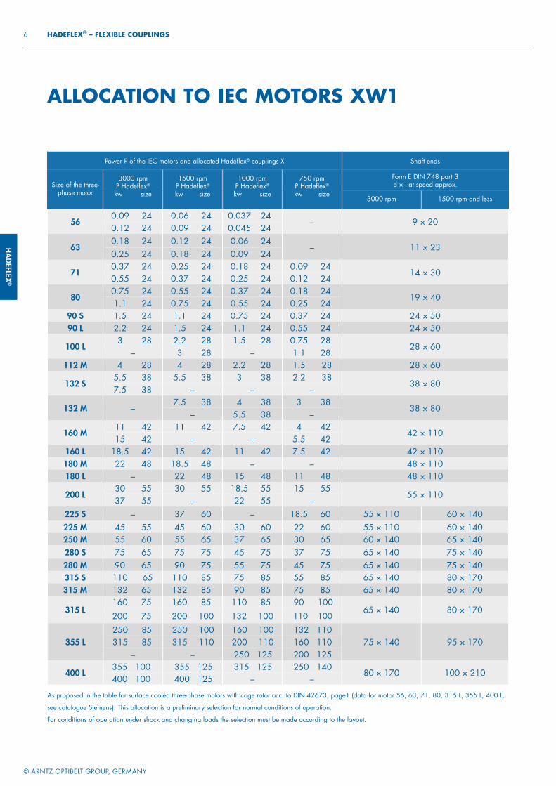
ALLOCATION TO IEC MOTORS XW1
Power P of the IEC motors and allocated Hadefl ex® couplings X Shaft ends
Size of the three- phase motor
3000 rpmP Hadefl ex®
kw size
1500 rpmP Hadefl ex®
kw size
1000 rpmP Hadefl ex®
kw size
750 rpmP Hadefl ex®
kw size
Form E DIN 748 part 3d × l at speed approx.
3000 rpm 1500 rpm and less
56 0.09 24 0.06 24 0.037 24
– 9 × 20 0.12 24 0.09 24 0.045 24
63 0.18 24 0.12 24 0.06 24
– 11 × 23 0.25 24 0.18 24 0.09 24
71 0.37 24 0.25 24 0.18 24 0.09 24
14 × 30 0.55 24 0.37 24 0.25 24 0.12 24
80 0.75 24 0.55 24 0.37 24 0.18 24
19 × 40 1.1 24 0.75 24 0.55 24 0.25 24
90 S 1.5 24 1.1 24 0.75 24 0.37 24 24 × 5090 L 2.2 24 1.5 24 1.1 24 0.55 24 24 × 50
100 L 3 28 2.2 28 1.5 28 0.75 28
28 × 60– 3 28 – 1.1 28
112 M 4 28 4 28 2.2 28 1.5 28 28 × 60
132 S 5.5 38 5.5 38 3 38 2.2 38
38 × 80 7.5 38 – – –
132 M – 7.5 38 4 38 3 38
38 × 80– 5.5 38 –
160 M 11 42 11 42 7.5 42 4 42
42 × 110 15 42 – – 5.5 42
160 L 18.5 42 15 42 11 42 7.5 42 42 × 110180 M 22 48 18.5 48 – – 48 × 110180 L – 22 48 15 48 11 48 48 × 110
200 L 30 55 30 55 18.5 55 15 55
55 × 110 37 55 – 22 55 –
225 S – 37 60 – 18.5 60 55 × 110 60 × 140225 M 45 55 45 60 30 60 22 60 55 × 110 60 × 140250 M 55 60 55 65 37 65 30 65 60 × 140 65 × 140280 S 75 65 75 75 45 75 37 75 65 × 140 75 × 140280 M 90 65 90 75 55 75 45 75 65 × 140 75 × 140315 S 110 65 110 85 75 85 55 85 65 × 140 80 × 170315 M 132 65 132 85 90 85 75 85 65 × 140 80 × 170
315 L 160 75 160 85 110 85 90 100
65 × 140 80 × 170 200 75 200 100 132 100 110 100
As proposed in the table for surface cooled three-phase motors with cage rotor acc. to DIN 42673, page1 (data for motor 56, 63, 71, 80, 315 L, 355 L, 400 L,
see catalogue Siemens). This allocation is a preliminary selection for normal conditions of operation.
For conditions of operation under shock and changing loads the selection must be made according to the layout.
355 L 250 85 250 100 160 100 132 110
75 × 140 95 × 170 315 85 315 110 200 110 160 110– – 250 125 200 125
400 L 355 100 355 125 315 125 250 140
80 × 170 100 × 210 400 100 400 125 – –
HADE
FLEX
®
© ARNTZ OPTIBELT GROUP, GERMANY
7 FLEXIBLE COUPLINGS – HADEFLEX®
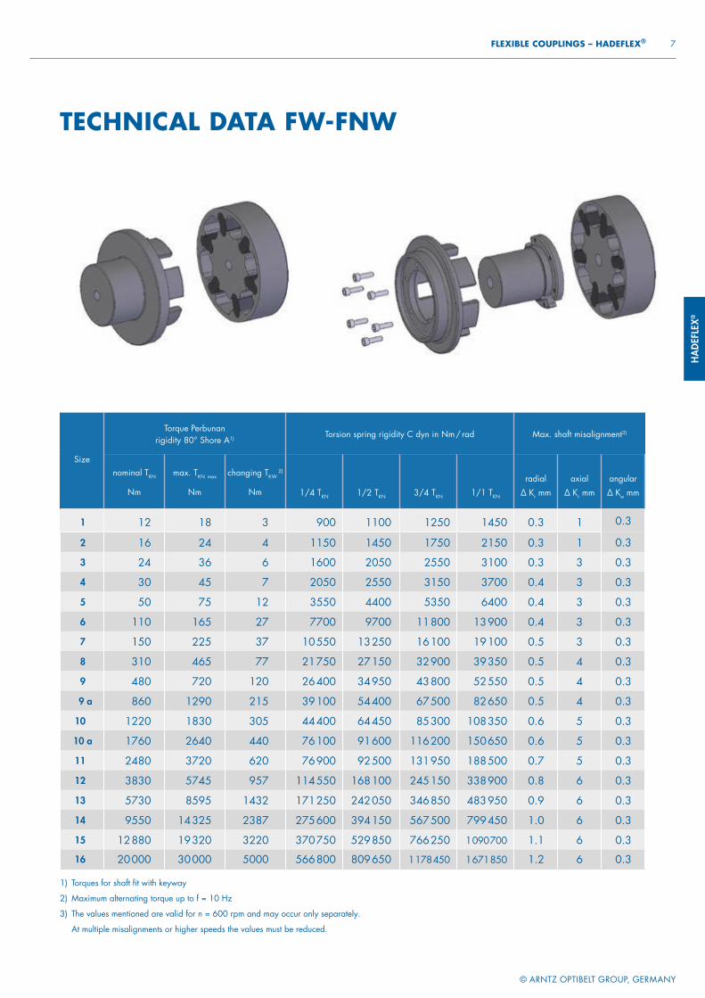
Size
Torque Perbunan rigidity 80° Shore A1) Torsion spring rigidity C dyn in Nm / rad Max. shaft misalignment3)
nominal TKN
Nm
max. TKN max
Nm
changing TKW 2)
Nm 1/4 TKN 1/2 TKN 3/4 TKN 1/1 TKN
radial
∆ Kr mm
axial
∆ Kr mm
angular
∆ Kw mm
1 12 18 3 900 1100 1250 1450 0.3 1 0.3
2 16 24 4 1150 1450 1750 2150 0.3 1 0.3
3 24 36 6 1600 2050 2550 3100 0.3 3 0.3
4 30 45 7 2050 2550 3150 3700 0.4 3 0.3
5 50 75 12 3550 4400 5350 6400 0.4 3 0.3
6 110 165 27 7700 9700 11 800 13 900 0.4 3 0.3
7 150 225 37 10 550 13 250 16 100 19 100 0.5 3 0.3
8 310 465 77 21 750 27 150 32 900 39 350 0.5 4 0.3
9 480 720 120 26 400 34 950 43 800 52 550 0.5 4 0.3
9 a 860 1290 215 39 100 54 400 67 500 82 650 0.5 4 0.3
10 1220 1830 305 44 400 64 450 85 300 108 350 0.6 5 0.3
10 a 1760 2640 440 76 100 91 600 116 200 150 650 0.6 5 0.3
11 2480 3720 620 76 900 92 500 131 950 188 500 0.7 5 0.3
12 3830 5745 957 114 550 168 100 245 150 338 900 0.8 6 0.3
13 5730 8595 1432 171 250 242 050 346 850 483 950 0.9 6 0.3
14 9550 14 325 2387 275 600 394 150 567 500 799 450 1.0 6 0.3
15 12 880 19 320 3220 370 750 529 850 766 250 1 090 700 1.1 6 0.3
16 20 000 30 000 5000 566 800 809 650 1 178 450 1 671 850 1.2 6 0.3
TECHNICAL DATA FW-FNW
1) Torques for shaft fi t with keyway
2) Maximum alternating torque up to f = 10 Hz
3) The values mentioned are valid for n = 600 rpm and may occur only separately.
At multiple misalignments or higher speeds the values must be reduced.
Power P of the IEC motors and allocated Hadefl ex® couplings X Shaft ends
Size of the three- phase motor
3000 rpmP Hadefl ex®
kw size
1500 rpmP Hadefl ex®
kw size
1000 rpmP Hadefl ex®
kw size
750 rpmP Hadefl ex®
kw size
Form E DIN 748 part 3d × l at speed approx.
3000 rpm 1500 rpm and less
56 0.09 24 0.06 24 0.037 24
– 9 × 20 0.12 24 0.09 24 0.045 24
63 0.18 24 0.12 24 0.06 24
– 11 × 23 0.25 24 0.18 24 0.09 24
71 0.37 24 0.25 24 0.18 24 0.09 24
14 × 30 0.55 24 0.37 24 0.25 24 0.12 24
80 0.75 24 0.55 24 0.37 24 0.18 24
19 × 40 1.1 24 0.75 24 0.55 24 0.25 24
90 S 1.5 24 1.1 24 0.75 24 0.37 24 24 × 5090 L 2.2 24 1.5 24 1.1 24 0.55 24 24 × 50
100 L 3 28 2.2 28 1.5 28 0.75 28
28 × 60– 3 28 – 1.1 28
112 M 4 28 4 28 2.2 28 1.5 28 28 × 60
132 S 5.5 38 5.5 38 3 38 2.2 38
38 × 80 7.5 38 – – –
132 M – 7.5 38 4 38 3 38
38 × 80– 5.5 38 –
160 M 11 42 11 42 7.5 42 4 42
42 × 110 15 42 – – 5.5 42
160 L 18.5 42 15 42 11 42 7.5 42 42 × 110180 M 22 48 18.5 48 – – 48 × 110180 L – 22 48 15 48 11 48 48 × 110
200 L 30 55 30 55 18.5 55 15 55
55 × 110 37 55 – 22 55 –
225 S – 37 60 – 18.5 60 55 × 110 60 × 140225 M 45 55 45 60 30 60 22 60 55 × 110 60 × 140250 M 55 60 55 65 37 65 30 65 60 × 140 65 × 140280 S 75 65 75 75 45 75 37 75 65 × 140 75 × 140280 M 90 65 90 75 55 75 45 75 65 × 140 75 × 140315 S 110 65 110 85 75 85 55 85 65 × 140 80 × 170315 M 132 65 132 85 90 85 75 85 65 × 140 80 × 170
315 L 160 75 160 85 110 85 90 100
65 × 140 80 × 170 200 75 200 100 132 100 110 100
HADEFLEX®
d1 D1
l
D1
l1
l2 l3
da
s
7 1 3 2 7
l1 d1
© ARNTZ OPTIBELT GROUP, GERMANY
8 HADEFLEX® – FLEXIBLE COUPLINGS
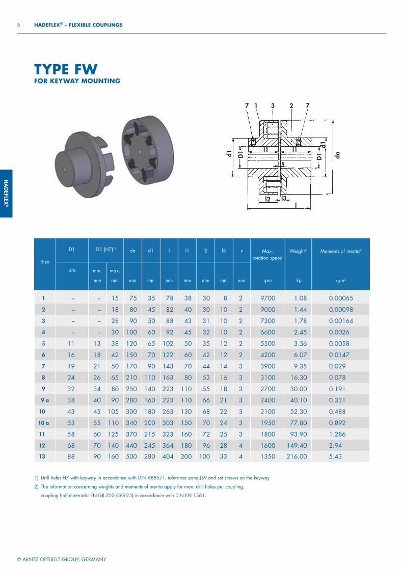
Size
D1 D1 (H7)1) da d1 l l1 l2 l3 s Max. rotation speed
rpm
Weight2)
kg
Moments of inertia2)
kgm2
pre. min.
mm
max.
mm mm mm
mm
mm
mm
mm
mm
1 – – 15 75 35 78 38 30 8 2 9700 1.08 0.00065
2 – – 18 80 45 82 40 30 10 2 9000 1.44 0.00098
3 – – 28 90 50 88 43 31 10 2 7300 1.78 0.00164
4 – – 30 100 60 92 45 32 10 2 6600 2.45 0.0026
5 11 13 38 120 65 102 50 35 12 2 5500 3.56 0.0058
6 16 18 42 150 70 122 60 42 12 2 4200 6.07 0.0147
7 19 21 50 170 90 143 70 44 14 3 3900 9.35 0.029
8 24 26 65 210 110 163 80 53 16 3 3100 16.30 0.078
9 32 34 80 250 140 223 110 55 18 3 2700 30.00 0.191
9 a 38 40 90 280 160 223 110 66 21 3 2400 40.10 0.331
10 43 45 105 300 180 263 130 68 22 3 2100 52.30 0.488
10 a 53 55 110 340 200 303 150 70 24 3 1950 77.80 0.892
11 58 60 125 370 215 323 160 72 25 3 1800 93.90 1.286
12 68 70 140 440 245 364 180 96 28 4 1600 149.40 2.94
13 88 90 160 500 280 404 200 100 33 4 1350 216.00 5.43
TYPE FWFOR KEYWAY MOUNTING
1) Drill holes H7 with keyway in accordance with DIN 6885/1; tolerance zone JS9 and set screws on the keyway
2) The information concerning weights and moments of inertia apply for max. drill holes per coupling;
coupling half materials: EN-GJL-250 (GG-25) in accordance with DIN EN 1561.
HADE
FLEX
®
l2
d1 D1
l
da
d2l1
l3 l4
s
7 1 3 5 7
D2
6 4
© ARNTZ OPTIBELT GROUP, GERMANY
9 FLEXIBLE COUPLINGS – HADEFLEX®
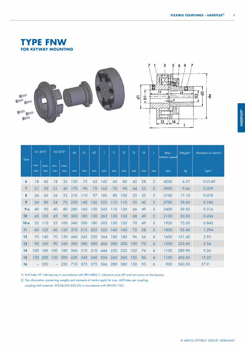
Size
D1 (H7)1) D2 (H7)1) da d1 d2 l l1 l2 l3 l4 s Max. rotation speed
rpm
Weight2)
kg
Moments of inertia2)
kgm2
min.
mm
max.
mm
min.
mm
max.
mm mm mm
mm
mm
mm
mm
mm
mm
mm
6 18 42 18 35 150 75 65 142 60 80 42 28 2 4200 6.57 0 .0149
7 21 50 21 45 170 90 72 163 70 90 44 35 3 3900 9.66 0 .029
8 26 65 26 55 210 110 97 183 80 100 53 35 3 3100 17.10 0 .078
9 34 80 34 75 250 140 126 223 110 110 55 42 3 2700 29.60 0 .186
9 a 40 90 40 80 280 160 130 243 110 130 66 49 3 2400 39.50 0 .316
10 45 105 45 90 300 180 150 263 130 130 68 49 3 2100 50.00 0 .456
10 a 55 110 55 100 340 200 180 303 150 150 70 49 3 1950 75.30 0 .843
11 60 125 60 120 370 215 205 323 160 160 72 58 3 1800 95.40 1 .294
12 70 140 70 130 440 245 230 364 180 180 96 64 4 1600 151.40 2 .93
13 90 160 90 160 500 280 280 404 200 200 100 70 4 1350 222.60 5 .54
14 100 180 100 180 560 310 310 444 220 220 102 76 4 1100 289.90 9 .26
15 130 200 130 200 620 340 340 524 260 260 105 86 4 1100 402.60 15 .23
16 – 220 – 220 710 375 375 566 280 280 130 93 6 900 560.50 27 .9
TYPE FNWFOR KEYWAY MOUNTING
1) Drill holes H7 with keyway in accordance with DIN 6885/1; tolerance zone JS9 and set screws on the keyway
2) The information concerning weights and moments of inertia apply for max. drill holes per coupling;
coupling half materials: EN-GJL-250 (GG-25) in accordance with DIN EN 1561.
HADEFLEX®
© ARNTZ OPTIBELT GROUP, GERMANY
10 HADEFLEX® – FLEXIBLE COUPLINGS
Radial misalignment Axial misalignment Angular misalignment
Reduction of the allowable values of misalignment when the combination of misalignments occur or at other rotational speeds:
ALLOWABLE MISALIGNMENTS
∆ Kr / a / w = allowable radial, axial or angular misalignment of the shafts resp. of the coupling halves
∆ Wr / a / w = measured radial, axial or angular misalignment of the shafts resp. of the coupling halves
≦ 1 = applies to speeds of 600 rpm
≦ 0.8 601 – 1000 rpm≦ 0.65 1001 – 1500 rpm≦ 0.50 1501 – 3000 rpm
∆ Wr
∆ Kr
∆ Wa
∆ Ka
∆ Ww
∆ Kw
+ +
Driving machineThree-phase motor: Size 315LPower of the motor: P = 110 kWRotation at speed: n = 1000 rpmDriven machine: mixer Ambient temperature: +35 °C
Selection XW1 Size 100 flexible spider 92° Shore A TKN = 3000 NmTX 03 Size 90 flexible spider 92° Shore A TKN = 2500 NmFW Size 11 TKN = 2480 NmFNW Size 11 TKN = 2480 Nm
DATES OF THE PLANTLayout of the coupling
TKN = 1.75 × 1.2 × 1051 Nm = 2207 Nm
TAN = 9550 × = 1051 Nm1000 rpm110 kW
SELECTIONThe torque of the machine TAN is determined by: TAN [Nm] = 9550 x
PMotor [kW]
n [rpm]
This torque TAN multiplied by a safety factor S depending on the application and the temperature factor ST (see table page 11) gives the required nominal coupling torque TKN.
Result: TKN ≧ S x ST x TAN
> In case that bigger shock or changing loads occur we recommend a revision according to DIN 740. An adequate calculation program is available. For such a revision the following information is required:
1. Kind of the driving machine
2. Kind of the driven machine
3. Power of driving and driven machines
4. Rotational speed of operation
5. Shock loads6. Exciting loads7. Moments of inertia of
load- and driving sides8. Starts per hour9. Ambient temperature
HADE
FLEX
®
© ARNTZ OPTIBELT GROUP, GERMANY
11 FLEXIBLE COUPLINGS – HADEFLEX®
Operating factor S
Driving machinesLoad characteristics of the working machine
G M S
Electric motors, turbines, hydraulic motors 1 1.25 1.75
Piston machines 4–6 cylinders, degree of nonuniformity
1:100 – 1:2001.25 1.5 2
Piston machines 1–3 cylinders,degree of nonuniformity
up to 1:100 1.5 2 2.5
Temperature factor ST
ϑ [°C] ST
− 20 < ϑ < + 30 1.0
+ 30 < ϑ < + 40 1.2
+ 40 < ϑ < + 60 1.5
+ 60 < ϑ < + 80 1.8
Assignment of load characteristics according to type of working machine
SSMMMSSM
MMM
MMGMMGM
MS
MSMGMMMMMGMMMMSMM
MGMMG
SGS
DREDGERSBucket conveyorLanding gear (caterpillar)Landing gear (rail)Manoeuvring winchesPumpsImpellers Cutter headsSlewing gear
GENERATORS, TRANSFORMERSFrequency transformersGeneratorsWelding generators
CHEMICAL INDUSTRYCooling drumsMixersAgitators (liquid material)Agitators (semi-liquid material)Drying drumsCentrifuges (light)Centrifuges (heavy)
OIL INDUSTRYPipeline pumpsRotary drilling equipment
CONVEYORSPit-head winchesWinding enginesJointed-band conveyorsBelt conveyors (bulk material)Belt conveyors (piece goods)Band pocket conveyorsChain conveyorsCircular conveyorsLoad elevatorsBucket conveyors for flourPassenger liftsPlate conveyorsScrew conveyorsBallast elevatorsInclined hoistsSteel belt conveyorsDrag chain conveyors
BLOWERS, VENTILATORSRotary piston blowersBlowers (axial/radial)Cooling tower fansInduced draught fansTurbo blowers
BUILDING MACHINERYHoistsConcrete mixersRoad construction machinery
SMSMS
SMGS
GSGMM
MMMM
MSSSSMSSGMG
GMMGMMSMM
SSMSMSSSSS
RUBBER MACHINERYExtrudersCalendersKneading millsMixersRolling mills
WOOD WORKING MACHINESBarkersPlaning machinesWood working machinesSaw frames
CRANESLuffi ng gear blockTravelling gearHoist gearSlewing gearDerricking jib gear
PLASTIC INDUSTRY MACHINESExtrudersCalendersMixersCrushers
METAL WORKING MACHINESPlate bending machinesPlate straightening machinesHammersMetal planning machinesPressesShearsForging pressesPunch pressesCountershafts, line shaftsMachine tools (main drives)Machine tools (auxiliary drives)
FOOD INDUSTRY MACHINERYBottling and container fi lling machinesKneading machinesMash tubsPackaging machinesCane crushersCane cuttersCane millsSugar beet cuttersSugar beet washing machines
PAPER MACHINESCouchesGlazing cylindersPulperPulp grindersCalendersWet pressesWillowsSuction pressesSuction rollsDrying cylinders
SGMSS
SSSSSSS
MMMMM
SM
SMSSSMSSSMSMSMMMSMSMSSMS
MM
MM
PUMPSPiston pumpsCentrifugal pumps (light liquids)Centrifugal pumps (viscous liquids)Plunger pumpsPress pumps
STONE AND CLAY WORKING MACHINESCrusherRotary ovensHammer millsBall millsTube millsBeater millsBrick presses
TEXTILE MACHINESBatchersPrinting and dyeing machinesTanning vatsWillowsLooms
COMPRESSORSPiston compressorsTurbo compressors
METAL ROLLING MILLSPlate shearsManipulator for turning sheetsIngot pushersIngot and slabbing-mill trainIngot handling machineryWire drawing benchesDescaling machinesThin plate millsHeavy and medium plate millsWinding machines (strip and wire)Cold rolling millsChain tractorBillet shearsCooling bedsCross tractorRoller tables (light)Roller tables (heavy)Roller straightenersTube welding machinesTrimming shearsCropping shearsContinuous casting plantRollers adjustment driveManipulators
LAUNDRIESTumblersWashing machines
WATER TREATMENTAeratorsScrew pumps
SAFETY FACTOR S

HRC
POWER TRANSMISSION
FLEXIBLE COUPLINGS
HRC
HRC
© ARNTZ OPTIBELT GROUP, GERMANY
2 HRC – FLEXIBLE COUPLINGS
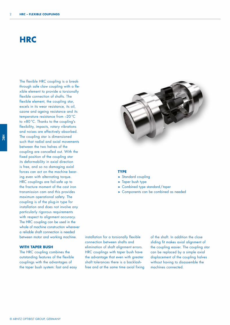
The flexible HRC coupling is a break-through safe claw coupling with a fle-xible element to provide a torsionally flexible connection of shafts. The flexible element, the coupling star, excels in its wear resistance, its oil, ozone and ageing resistance and its temperature resistance from –20 °C to +80 °C. Thanks to the coupling's flexibility, impacts, rotary vibrations and noises are effectively absorbed. The coupling star is dimensioned such that radial and axial movements between the two halves of the coupling are cancelled out. With the fixed position of the coupling star its deformability in axial direction is free, and so no damaging axial forces can act on the machine bear-ing even with alternating torque. HRC couplings are fail-safe up to the fracture moment of the cast iron transmission cam and this provides maximum operational safety. The coupling is of the plug-in type for installation and does not involve any particularly rigorous requirements with respect to alignment accuracy. The HRC coupling can be used in the whole of machine construction wherever a reliable shaft connection is needed between motor and working machine.
WITH TAPER BUSHThe HRC coupling combines the outstanding features of the flexible couplings with the advantages of the taper bush system: fast and easy
installation for a torsionally flexible connection between shafts and elimination of shaft alignment errors. HRC couplings with taper bush have the advantage that even with greater shaft tolerances there is a backlash-free and at the same time axial fixing
TYPE> Standard coupling> Taper bush type> Combined type standard / taper> Components can be combined as needed
HRC
of the shaft. In addition the close sliding fit makes axial alignment of the coupling easier. The coupling star can be replaced by a simple axial displacement of the coupling halves without having to disassemble the machines connected.
HRC
© ARNTZ OPTIBELT GROUP, GERMANY
3 FLEXIBLE COUPLINGS – HRC
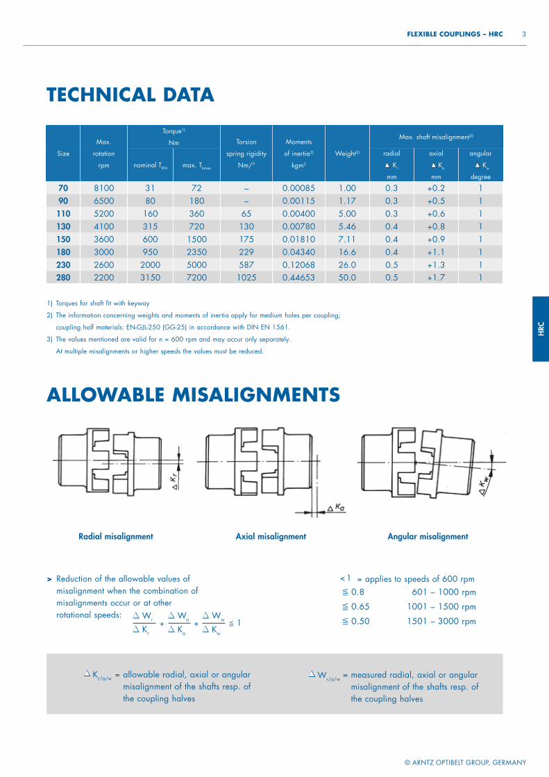
1) Torques for shaft fit with keyway
2) The information concerning weights and moments of inertia apply for medium holes per coupling;
coupling half materials: EN-GJL-250 (GG-25) in accordance with DIN EN 1561.
3) The values mentioned are valid for n = 600 rpm and may occur only separately.
At multiple misalignments or higher speeds the values must be reduced.
TECHNICAL DATA
Size
Max.
rotation
rpm
Torque1)
Nm Torsion
spring rigidity
Nm/°
Moments
of inertia2)
kgm2
Weight2)
Max. shaft misalignment3)
nominal TKN max. Tkmax
radial Kr
mm
axial
Ka
mm
angular
Kw
degree
70 8100 31 72 – 0.00085 1.00 0.3 +0.2 190 6500 80 180 – 0.00115 1.17 0.3 +0.5 1110 5200 160 360 65 0.00400 5.00 0.3 +0.6 1130 4100 315 720 130 0.00780 5.46 0.4 +0.8 1150 3600 600 1500 175 0.01810 7.11 0.4 +0.9 1180 3000 950 2350 229 0.04340 16.6 0.4 +1.1 1230 2600 2000 5000 587 0.12068 26.0 0.5 +1.3 1280 2200 3150 7200 1025 0.44653 50.0 0.5 +1.7 1
Radial misalignment
> Reduction of the allowable values of misalignment when the combination of misalignments occur or at other rotational speeds:
ALLOWABLE MISALIGNMENTS
≦ 0.8 601 – 1000 rpm
≦ 0.65 1001 – 1500 rpm
≦ 0.50 1501 – 3000 rpmWr
Kr
Wa
Ka
+Ww
Kw
+ ≦ 1
= applies to speeds of 600 rpm< 1
= allowable radial, axial or angular misalignment of the shafts resp. of the coupling halves
Kr/a/w = measured radial, axial or angular misalignment of the shafts resp. of the coupling halves
Wr/a/w
Axial misalignment Angular misalignment
HRC
© ARNTZ OPTIBELT GROUP, GERMANY
4 HRC – FLEXIBLE COUPLINGS
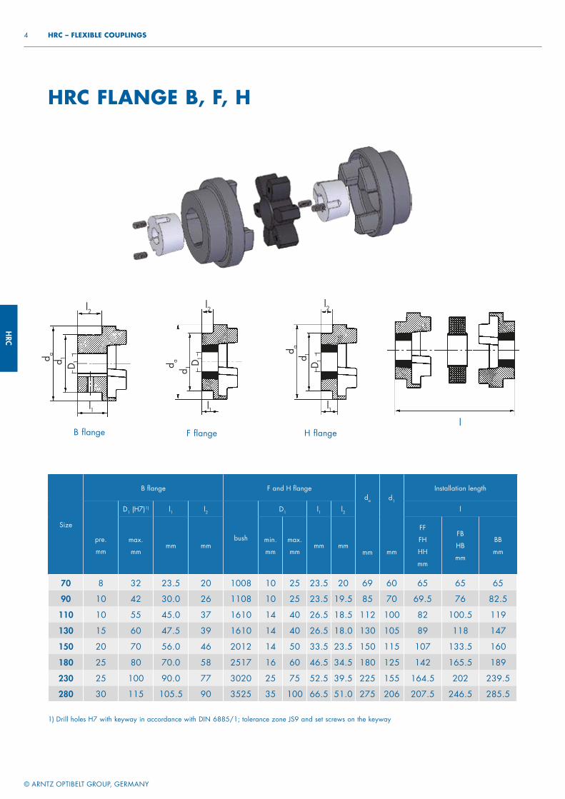
HRC FLANGE B, F, H
1) Drill holes H7 with keyway in accordance with DIN 6885/1; tolerance zone JS9 and set screws on the keyway
Size
B fl ange F and H fl ange da
mm
d1
mm
Installation length
pre.
mm
D1 (H7)1) l1 l2
bush
D1 l1 l2 l
max.
mmmm mm
min.
mm
max.
mmmm mm
FF
FH
HH
mm
FB
HB
mm
BB
mm
70 8 32 23.5 20 1008 10 25 23.5 20 69 60 65 65 65
90 10 42 30.0 26 1108 10 25 23.5 19.5 85 70 69.5 76 82.5
110 10 55 45.0 37 1610 14 40 26.5 18.5 112 100 82 100.5 119
130 15 60 47.5 39 1610 14 40 26.5 18.0 130 105 89 118 147
150 20 70 56.0 46 2012 14 50 33.5 23.5 150 115 107 133.5 160
180 25 80 70.0 58 2517 16 60 46.5 34.5 180 125 142 165.5 189
230 25 100 90.0 77 3020 25 75 52.5 39.5 225 155 164.5 202 239.5
280 30 115 105.5 90 3525 35 100 66.5 51.0 275 206 207.5 246.5 285.5
d ad 1
l1
l2
B flange F flange H flange
d a
d 1
l1
l2
d a
d 1
l1
l2
l
D 1 D 1
D 1
HRC
© ARNTZ OPTIBELT GROUP, GERMANY
5 FLEXIBLE COUPLINGS – HRC
* These bore holes are with flat keyway in accordance with DIN 6885/3.
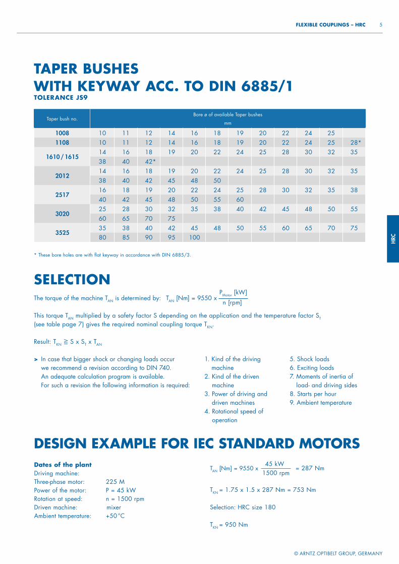
TAPER BUSHES WITH KEYWAY ACC. TO DIN 6885/1TOLERANCE JS9
Taper bush no.Bore ø of available Taper bushes
mm
1008 10 11 12 14 16 18 19 20 22 24 251108 10 11 12 14 16 18 19 20 22 24 25 28*
1610 / 161514 16 18 19 20 22 24 25 28 30 32 3538 40 42*
201214 16 18 19 20 22 24 25 28 30 32 3538 40 42 45 48 50
251716 18 19 20 22 24 25 28 30 32 35 3840 42 45 48 50 55 60
302025 28 30 32 35 38 40 42 45 48 50 5560 65 70 75
352535 38 40 42 45 48 50 55 60 65 70 7580 85 90 95 100
Dates of the plantDriving machine: Three-phase motor: 225 MPower of the motor: P = 45 kWRotation at speed: n = 1500 rpmDriven machine: mixerAmbient temperature: +50 °C
TAN [Nm] = 9550 x
TKN = 1.75 x 1.5 x 287 Nm = 753 Nm
Selection: HRC size 180
TKN = 950 Nm
45 kW1500 rpm
= 287 Nm
DESIGN EXAMPLE FOR IEC STANDARD MOTORS
SELECTIONThe torque of the machine TAN is determined by: TAN [Nm] = 9550 x
PMotor [kW]
n [rpm]
This torque TAN multiplied by a safety factor S depending on the application and the temperature factor ST (see table page 7) gives the required nominal coupling torque TKN.
Result: TKN ≧ S x ST x TAN
> In case that bigger shock or changing loads occur we recommend a revision according to DIN 740. An adequate calculation program is available. For such a revision the following information is required:
1. Kind of the driving machine
2. Kind of the driven machine
3. Power of driving and driven machines
4. Rotational speed of operation
5. Shock loads6. Exciting loads7. Moments of inertia of
load- and driving sides8. Starts per hour9. Ambient temperature

HRC
© ARNTZ OPTIBELT GROUP, GERMANY
6 HRC – FLEXIBLE COUPLINGS
As proposed in the table for surface cooled three-phase motors with cage rotor acc. to DIN 42673, page1 (data for motor 56, 63, 71, 80, 315 L, 355 L, 400 L, see catalogue Siemens). This allocation is a preliminary selection for normal conditions of operation. For conditions of operation under shock and changing loads the selection must be made according to the following.
ALLOCATION TO IEC MOTORS
Power P of the IEC motors and allocated HRC couplings Shaft ends
Size of the
three-phase motor
3000 rpm
P HRC
kw size
1500 rpm
P HRC
kw size
1000 rpm
P HRC
kw size
750 rpm
P HRC
kw size
Form E DIN 748 part 3
d x l at speed approx.
3000 rpm1500 rpm
and less
56 0.09 70 0.06 70 0.037 70
– 9 x 20 0.12 70 0.09 70 0.045 70
63 0.18 70 0.12 70 0.06 70
– 11 x 23 0.25 70 0.18 70 0.09 70
71 0.37 70 0.25 70 0.18 70 0.09 70
14 x 30 0.55 70 0.37 70 0.25 70 0.12 70
80 0.75 70 0.55 70 0.37 70 0.18 70
19 x 40 1.1 70 0.75 70 0.55 70 0.25 70
90 S 1.5 70 1.1 70 0.75 70 0.37 70 24 x 5090 L 2.2 70 1.5 70 1.1 70 0.55 70 24 x 50
100 L 3 90 2.2 90 1.5 90 0.75 90
28 x 60 – 3 90 – 1.1 90
112 M 4 90 4 90 2.2 90 1.5 90 28 x 60
132 S 5.5 110 5.5 110 3 110 2.2 110
38 x 80 7.5 110 – – –
132 M – 7.5 110 4 110 3 110
38 x 80 – 5.5 110 –
160 M 11 130 11 130 7.5 130 4 130
42 x 110 15 130 – – 5.5 130
160 L 18.5 130 15 130 11 130 7.5 130 42 x 110180 M 22 130 18.5 130 – – 48 x 110180 L – 22 130 15 130 11 130 48 x 110
200 L 30 150 30 150 18.5 150 15 150
55 x 110 37 150 – 22 150 –
225 S – 37 150 – 18.5 150 55 x 110 60 x 140225 M 45 150 45 150 30 150 22 150 55 x 110 60 x 140250 M 55 150 55 180 37 180 30 180 60 x 140 65 x 140280 S 75 180 75 230 45 230 37 230 65 x 140 75 x 140280 M 90 180 90 230 55 230 45 230 65 x 140 75 x 140315 S 110 180 110 280 75 280 55 280 65 x 140 80 x 170315 M 132 180 132 280 90 280 75 280 65 x 140 80 x 170
315 L 160 230 160 280 110 280 90 280
65 x 140 80 x 170 200 230 200 280 132 280 110 280
355 L 250 230 250 280 160 280 132 –
75 x 140 95 x 170 315 230 315 – 200 – 160 – – – 250 – 200 –
400 L 355 280 355 – 315 – 250 –
80 x 170 100 x 210 400 280 400 – -- --
HRC
© ARNTZ OPTIBELT GROUP, GERMANY
7 FLEXIBLE COUPLINGS – HRC
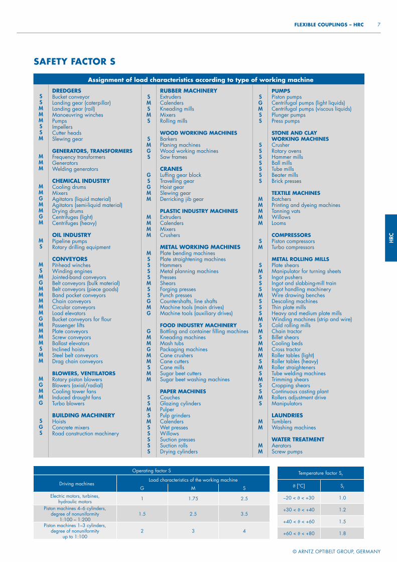
ALLOCATION TO IEC MOTORS
Operating factor S
Driving machinesLoad characteristics of the working machine
G M SElectric motors, turbines,
hydraulic motors 1 1.75 2.5
Piston machines 4–6 cylinders, degree of nonuniformity
1:100 – 1:2001.5 2.5 3.5
Piston machines 1–3 cylinders,degree of nonuniformity
up to 1:100 2 3 4
Temperature factor ST
ϑ [°C] ST
–20 < ϑ < +30 1.0
+30 < ϑ < +40 1.2
+40 < ϑ < +60 1.5
+60 < ϑ < +80 1.8
Assignment of load characteristics according to type of working machine
SSMMMSSM
MMM
MMGMMGM
MS
MSMGMMMMMGMMMMSMM
MGMMG
SGS
DREDGERSBucket conveyorLanding gear (caterpillar)Landing gear (rail)Manoeuvring winchesPumpsImpellers Cutter headsSlewing gear
GENERATORS, TRANSFORMERSFrequency transformersGeneratorsWelding generators
CHEMICAL INDUSTRYCooling drumsMixersAgitators (liquid material)Agitators (semi-liquid material)Drying drumsCentrifuges (light)Centrifuges (heavy)
OIL INDUSTRYPipeline pumpsRotary drilling equipment
CONVEYORSPit-head winchesWinding enginesJointed-band conveyorsBelt conveyors (bulk material)Belt conveyors (piece goods)Band pocket conveyorsChain conveyorsCircular conveyorsLoad elevatorsBucket conveyors for flourPassenger liftsPlate conveyorsScrew conveyorsBallast elevatorsInclined hoistsSteel belt conveyorsDrag chain conveyors
BLOWERS, VENTILATORSRotary piston blowersBlowers (axial/radial)Cooling tower fansInduced draught fansTurbo blowers
BUILDING MACHINERYHoistsConcrete mixersRoad construction machinery
SMSMS
SMGS
GSGMM
MMMM
MSSSSMSSGMG
GMMGMMSMM
SSMSMSSSSS
RUBBER MACHINERYExtrudersCalendersKneading millsMixersRolling mills
WOOD WORKING MACHINESBarkersPlaning machinesWood working machinesSaw frames
CRANESLuffi ng gear blockTravelling gearHoist gearSlewing gearDerricking jib gear
PLASTIC INDUSTRY MACHINESExtrudersCalendersMixersCrushers
METAL WORKING MACHINESPlate bending machinesPlate straightening machinesHammersMetal planning machinesPressesShearsForging pressesPunch pressesCountershafts, line shaftsMachine tools (main drives)Machine tools (auxiliary drives)
FOOD INDUSTRY MACHINERYBottling and container fi lling machinesKneading machinesMash tubsPackaging machinesCane crushersCane cuttersCane millsSugar beet cuttersSugar beet washing machines
PAPER MACHINESCouchesGlazing cylindersPulperPulp grindersCalendersWet pressesWillowsSuction pressesSuction rollsDrying cylinders
SGMSS
SSSSSSS
MMMMM
SM
SMSSSMSSSMSMSMMMSMSMSSMS
MM
MM
PUMPSPiston pumpsCentrifugal pumps (light liquids)Centrifugal pumps (viscous liquids)Plunger pumpsPress pumps
STONE AND CLAY WORKING MACHINESCrusherRotary ovensHammer millsBall millsTube millsBeater millsBrick presses
TEXTILE MACHINESBatchersPrinting and dyeing machinesTanning vatsWillowsLooms
COMPRESSORSPiston compressorsTurbo compressors
METAL ROLLING MILLSPlate shearsManipulator for turning sheetsIngot pushersIngot and slabbing-mill trainIngot handling machineryWire drawing benchesDescaling machinesThin plate millsHeavy and medium plate millsWinding machines (strip and wire)Cold rolling millsChain tractorBillet shearsCooling bedsCross tractorRoller tables (light)Roller tables (heavy)Roller straightenersTube welding machinesTrimming shearsCropping shearsContinuous casting plantRollers adjustment driveManipulators
LAUNDRIESTumblersWashing machines
WATER TREATMENTAeratorsScrew pumps
SAFETY FACTOR S

PEX
POWER TRANSMISSION
FLEXIBLE COUPLINGS
PEX
PEX
© ARNTZ OPTIBELT GROUP, GERMANY
2 PEX – FLEXIBLE COUPLINGS
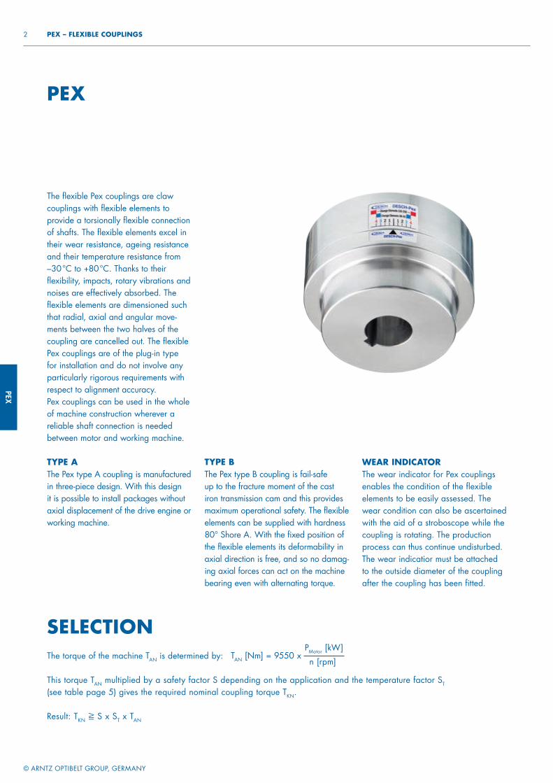
The flexible Pex couplings are claw couplings with flexible elements to provide a torsionally flexible connection of shafts. The flexible elements excel in their wear resistance, ageing resistance and their temperature resistance from –30 °C to +80 °C. Thanks to their flexibility, impacts, rotary vibrations and noises are effectively absorbed. The flexible elements are dimensioned such that radial, axial and angular move-ments between the two halves of the coupling are cancelled out. The flexible Pex couplings are of the plug-in type for installation and do not involve any particularly rigorous requirements with respect to alignment accuracy. Pex couplings can be used in the whole of machine construction wherever a reliable shaft connection is needed between motor and working machine.
TYPE AThe Pex type A coupling is manu fac tured in three-piece design. With this design it is possible to install packages without axial displacement of the drive engine or working machine.
TYPE BThe Pex type B coupling is fail-safe up to the fracture moment of the cast iron transmission cam and this provides maximum operational safety. The flexible elements can be supplied with hardness 80° Shore A. With the fixed position of the flexible elements its deformability in axial direction is free, and so no damag-ing axial forces can act on the machine bearing even with alternating torque.
PEX
SELECTIONTAN [Nm] = 9550 x
PMotor [kW]
n [rpm]
WEAR INDICATORThe wear indicator for Pex couplings enables the condition of the flexible elements to be easily assessed. The wear condition can also be ascertained with the aid of a stroboscope while the coupling is rotating. The production process can thus continue undisturbed. The wear indicatior must be attached to the outside diameter of the coupling after the coupling has been fitted.
The torque of the machine TAN is determined by:
This torque TAN multiplied by a safety factor S depending on the application and the temperature factor ST (see table page 5) gives the required nominal coupling torque TKN.
Result: TKN ≧ S x ST x TAN
PEX
© ARNTZ OPTIBELT GROUP, GERMANY
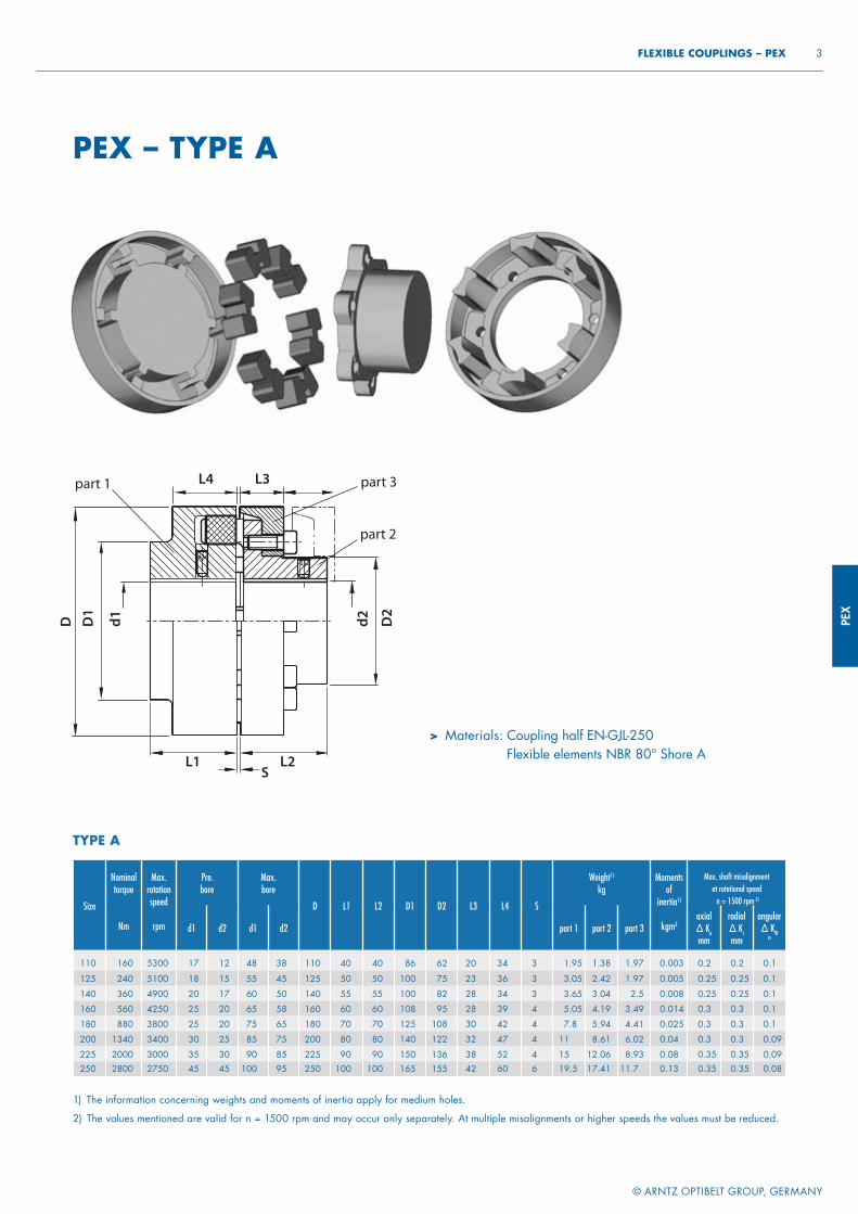
3 FLEXIBLE COUPLINGS – PEX
PEX – TYPE A
> Materials: Coupling half EN-GJL-250Flexible elements NBR 80° Shore A
1) The information concerning weights and moments of inertia apply for medium holes.
2) The values mentioned are valid for n = 1500 rpm and may occur only separately. At multiple misalignments or higher speeds the values must be reduced.
Size
Nominaltorque
Nm
Max.rotationspeed
rpm
Pre. bore
Max.bore
D L1 L2 D1 D2 L3 L4 S
Weight1)
kgMoments
of inertia1)
kgm2
Max. shaft misalignment at rotational speed n = 1500 rpm 2)
d1 d2 d1 d2 part 1 part 2 part 3axial∆ Kamm
radial∆ Krmm
angular∆ KW
°
110 160 5300 17 12 48 38 110 40 40 86 62 20 34 3 1.95 1.38 1.97 0.003 0.2 0.2 0.1
125 240 5100 18 15 55 45 125 50 50 100 75 23 36 3 3.05 2.42 1.97 0.005 0.25 0.25 0.1
140 360 4900 20 17 60 50 140 55 55 100 82 28 34 3 3.65 3.04 2.5 0.008 0.25 0.25 0.1
160 560 4250 25 20 65 58 160 60 60 108 95 28 39 4 5.05 4.19 3.49 0.014 0.3 0.3 0.1
180 880 3800 25 20 75 65 180 70 70 125 108 30 42 4 7.8 5.94 4.41 0.025 0.3 0.3 0.1
200 1340 3400 30 25 85 75 200 80 80 140 122 32 47 4 11 8.61 6.02 0.04 0.3 0.3 0.09
225 2000 3000 35 30 90 85 225 90 90 150 136 38 52 4 15 12.06 8.93 0.08 0.35 0.35 0.09250 2800 2750 45 45 100 95 250 100 100 165 155 42 60 6 19.5 17.41 11.7 0.13 0.35 0.35 0.08
TYPE A
L4 L3
SL1 L2
D D1
d1 d2 D2
part 1 part 3
part 2
PEX
© ARNTZ OPTIBELT GROUP, GERMANY
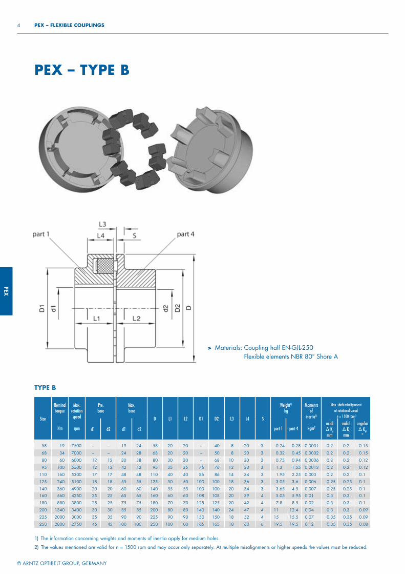
4 PEX – FLEXIBLE COUPLINGS
> Materials: Coupling half EN-GJL-250Flexible elements NBR 80° Shore A
PEX – TYPE B
Size
Nominaltorque
Nm
Max.rotationspeed
rpm
Pre. bore
Max.bore
D L1 L2 D1 D2 L3 L4 S
Weight1)
kgMoments
of inertia1)
kgm2
Max. shaft misalignment at rotational speed n = 1500 rpm2)
d1 d2 d1 d2 part 1 part 4axial∆ Kamm
radial∆ Krmm
angular∆ KW
°
58 19 7500 – – 19 24 58 20 20 – 40 8 20 3 0.24 0.28 0.0001 0.2 0.2 0.15
68 34 7000 – – 24 28 68 20 20 – 50 8 20 3 0.32 0.45 0.0002 0.2 0.2 0.15
80 60 6000 12 12 30 38 80 30 30 – 68 10 30 3 0.75 0.94 0.0006 0.2 0.2 0.12
95 100 5500 12 12 42 42 95 35 35 76 76 12 30 3 1.3 1.55 0.0013 0.2 0.2 0.12
110 160 5300 17 17 48 48 110 40 40 86 86 14 34 3 1.95 2.25 0.003 0.2 0.2 0.1
125 240 5100 18 18 55 55 125 50 50 100 100 18 36 3 3.05 3.6 0.006 0.25 0.25 0.1
140 360 4900 20 20 60 60 140 55 55 100 100 20 34 3 3.65 4.5 0.007 0.25 0.25 0.1160 560 4250 25 25 65 65 160 60 60 108 108 20 39 4 5.05 5.95 0.01 0.3 0.3 0.1
180 880 3800 25 25 75 75 180 70 70 125 125 20 42 4 7.8 8.5 0.02 0.3 0.3 0.1
200 1340 3400 30 30 85 85 200 80 80 140 140 24 47 4 11 12.4 0.04 0.3 0.3 0.09
225 2000 3000 35 35 90 90 225 90 90 150 150 18 52 4 15 15.5 0.07 0.35 0.35 0.09
250 2800 2750 45 45 100 100 250 100 100 165 165 18 60 6 19.5 19.5 0.12 0.35 0.35 0.08
TYPE B
1) The information concerning weights and moments of inertia apply for medium holes.
2) The values mentioned are valid for n = 1500 rpm and may occur only separately. At multiple misalignments or higher speeds the values must be reduced.
PEX
© ARNTZ OPTIBELT GROUP, GERMANY
5 FLEXIBLE COUPLINGS – PEX
Operating factor S
Driving machinesLoad characteristics of the working machine
G M S
Electric motors, turbines, hydraulic motors 1 1.25 1.75
Piston machines 4–6 cylinders 1.25 1.5 2
Piston machines 1–3 cylinders 1.5 2 2.5
Temperature factor ST
ϑ [°C] ST
− 20 < ϑ < + 30 1.0
+ 30 < ϑ < + 40 1.2
+ 40 < ϑ < + 60 1.5
+ 60 < ϑ < + 80 1.8
Assignment of load characteristics according to type of working machine
SSMMMSSM
MMM
MMGMMGM
MS
MSMGMMMMMGMMMMSMM
MGMMG
SGS
DREDGERSBucket conveyorLanding gear (caterpillar)Landing gear (rail)Manoeuvring winchesPumpsImpellers Cutter headsSlewing gear
GENERATORS, TRANSFORMERSFrequency transformersGeneratorsWelding generators
CHEMICAL INDUSTRYCooling drumsMixersAgitators (liquid material)Agitators (semi-liquid material)Drying drumsCentrifuges (light)Centrifuges (heavy)
OIL INDUSTRYPipeline pumpsRotary drilling equipment
CONVEYORSPit-head winchesWinding enginesJointed-band conveyorsBelt conveyors (bulk material)Belt conveyors (piece goods)Band pocket conveyorsChain conveyorsCircular conveyorsLoad elevatorsBucket conveyors for flourPassenger liftsPlate conveyorsScrew conveyorsBallast elevatorsInclined hoistsSteel belt conveyorsDrag chain conveyors
BLOWERS, VENTILATORSRotary piston blowersBlowers (axial/radial)Cooling tower fansInduced draught fansTurbo blowers
BUILDING MACHINERYHoistsConcrete mixersRoad construction machinery
SMSMS
SMGS
GSGMM
MMMM
MSSSSMSSGMG
GMMGMMSMM
SSMSMSSSSS
RUBBER MACHINERYExtrudersCalendersKneading millsMixersRolling mills
WOOD WORKING MACHINESBarkersPlaning machinesWood working machinesSaw frames
CRANESLuffi ng gear blockTravelling gearHoist gearSlewing gearDerricking jib gear
PLASTIC INDUSTRY MACHINESExtrudersCalendersMixersCrushers
METAL WORKING MACHINESPlate bending machinesPlate straightening machinesHammersMetal planning machinesPressesShearsForging pressesPunch pressesCountershafts, line shaftsMachine tools (main drives)Machine tools (auxiliary drives)
FOOD INDUSTRY MACHINERYBottling and container fi lling machinesKneading machinesMash tubsPackaging machinesCane crushersCane cuttersCane millsSugar beet cuttersSugar beet washing machines
PAPER MACHINESCouchesGlazing cylindersPulperPulp grindersCalendersWet pressesWillowsSuction pressesSuction rollsDrying cylinders
SGMSS
SSSSSSS
MMMMM
SM
SMSSSMSSSMSMSMMMSMSMSSMS
MM
MM
PUMPSPiston pumpsCentrifugal pumps (light liquids)Centrifugal pumps (viscous liquids)Plunger pumpsPress pumps
STONE AND CLAY WORKING MACHINESCrusherRotary ovensHammer millsBall millsTube millsBeater millsBrick presses
TEXTILE MACHINESBatchersPrinting and dyeing machinesTanning vatsWillowsLooms
COMPRESSORSPiston compressorsTurbo compressors
METAL ROLLING MILLSPlate shearsManipulator for turning sheetsIngot pushersIngot and slabbing-mill trainIngot handling machineryWire drawing benchesDescaling machinesThin plate millsHeavy and medium plate millsWinding machines (strip and wire)Cold rolling millsChain tractorBillet shearsCooling bedsCross tractorRoller tables (light)Roller tables (heavy)Roller straightenersTube welding machinesTrimming shearsCropping shearsContinuous casting plantRollers adjustment driveManipulators
LAUNDRIESTumblersWashing machines
WATER TREATMENTAeratorsScrew pumps
SAFETY FACTOR S

ORP
EX®
POWER TRANSMISSION
FLEXIBLE COUPLINGS
ORPEX®
ORPEX
®
© ARNTZ OPTIBELT GROUP, GERMANY
2 ORPEX® – FLEXIBLE COUPLINGS
ORPEX®
Orpex® couplings are used as com-pensation couplings everywhere where an absolutely reliable torque transfer is required. Orpex® couplings cover with their types a wide range of uses. With a total of 26 sizes, couplings are available for torques from 200 to 1,300,000 Nm. The coupling halves of the type WN consist of grey cast iron. With the WS type of steel it is possible to use the coupling with high speeds. With the convex elastic elements which can be moved in the holes – the buffers – it is possible to compensate for the shaft offsets in agular, radial and axial direction. Orpex® couplings damp torque impacts and offer the possibility of shifting critical speeds. Orpex® couplings are fail-safe up to the fracture moment of the metal parts, which is a multiple of the permissible impact moment, and thus offers the greatest possible operational safety. Orpex® couplings can be used for both directions of rotation and are also suitable for reversing operation. The buffers can be expected to have a long life with correct design of the coupling and correct alignment of the assembly. Orpex® couplings can also be adapted in many ways to special requirement profiles. A large number
TYPE> WN> WS
of applications already created and tried are available for this. Our Projects Department would be pleased to advise you. Orpex® couplings have proven themselves over decades in all areas of mechanical engineering, especially in the case of heavy-duty drives, as an absolutely reliable and practically maintenance-free machine element.
ORP
EX®
© ARNTZ OPTIBELT GROUP, GERMANY
3 FLEXIBLE COUPLINGS – ORPEX®
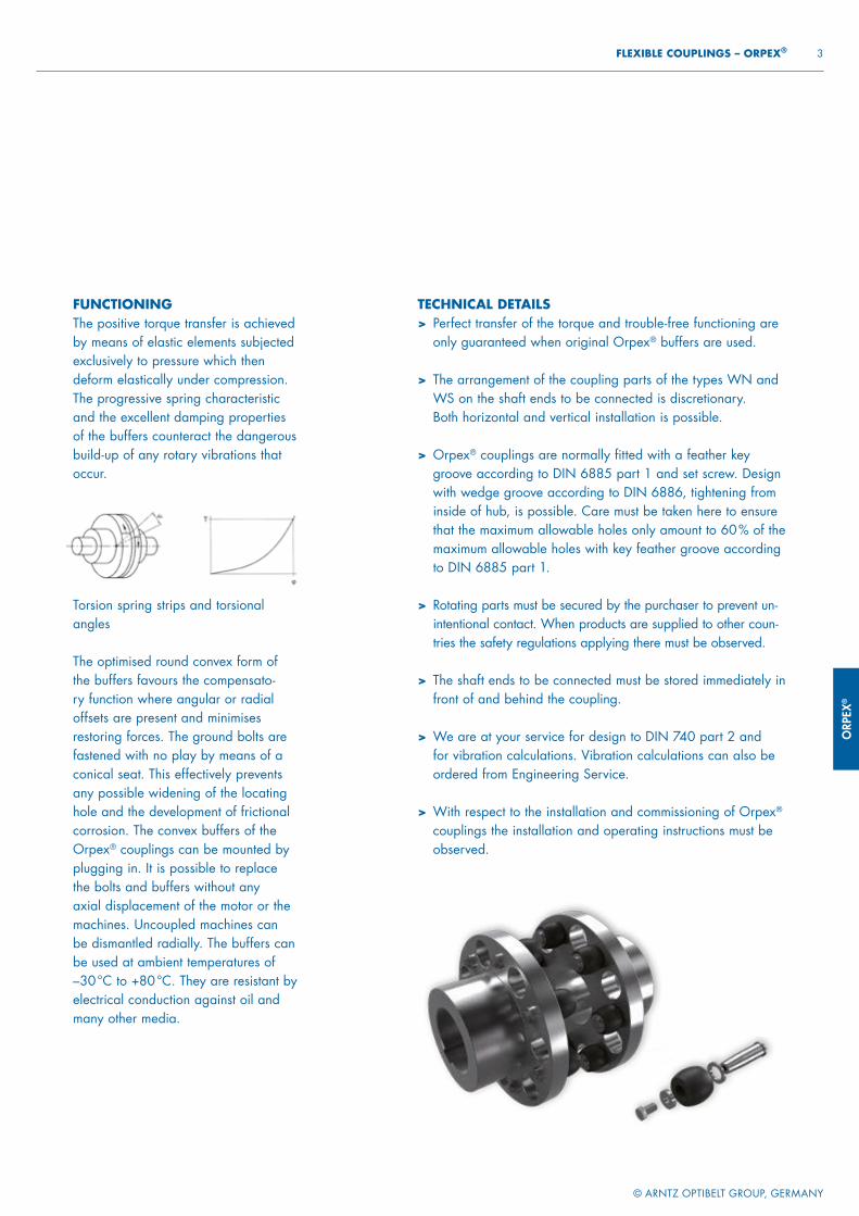
FUNCTIONINGThe positive torque transfer is achieved by means of elastic elements subjected exclusively to pressure which then deform elastically under compression. The progressive spring characteristic and the excellent damping properties of the buffers counteract the dangerous build-up of any rotary vibrations that occur.
Torsion spring strips and torsional angles
The optimised round convex form of the buffers favours the compensato-ry function where angular or radial offsets are present and minimises restoring forces. The ground bolts are fastened with no play by means of a conical seat. This effectively prevents any possible widening of the locating hole and the development of frictional corrosion. The convex buffers of the Orpex® couplings can be mounted by plugging in. It is possible to replace the bolts and buffers without any axial displacement of the motor or the machines. Uncoupled machines can be dismantled radially. The buffers can be used at ambient temperatures of –30 °C to +80 °C. They are resistant by electrical conduction against oil and many other media.
TECHNICAL DETAILS> Perfect transfer of the torque and trouble-free functioning are
only guaranteed when original Orpex® buffers are used.
> The arrangement of the coupling parts of the types WN and WS on the shaft ends to be connected is discretionary. Both horizontal and vertical installation is possible.
> Orpex® couplings are normally fitted with a feather key groove according to DIN 6885 part 1 and set screw. Design with wedge groove according to DIN 6886, tightening from inside of hub, is possible. Care must be taken here to ensure that the maximum allowable holes only amount to 60 % of the maximum allowable holes with key feather groove according to DIN 6885 part 1.
> Rotating parts must be secured by the purchaser to prevent un-intentional contact. When products are supplied to other coun-tries the safety regulations applying there must be observed.
> The shaft ends to be connected must be stored immediately in front of and behind the coupling.
> We are at your service for design to DIN 740 part 2 and for vibration calculations. Vibration calculations can also be ordered from Engineering Service.
> With respect to the installation and commissioning of Orpex®
couplings the installation and operating instructions must be observed.
ORPEX
®
© ARNTZ OPTIBELT GROUP, GERMANY
4 ORPEX® – FLEXIBLE COUPLINGS
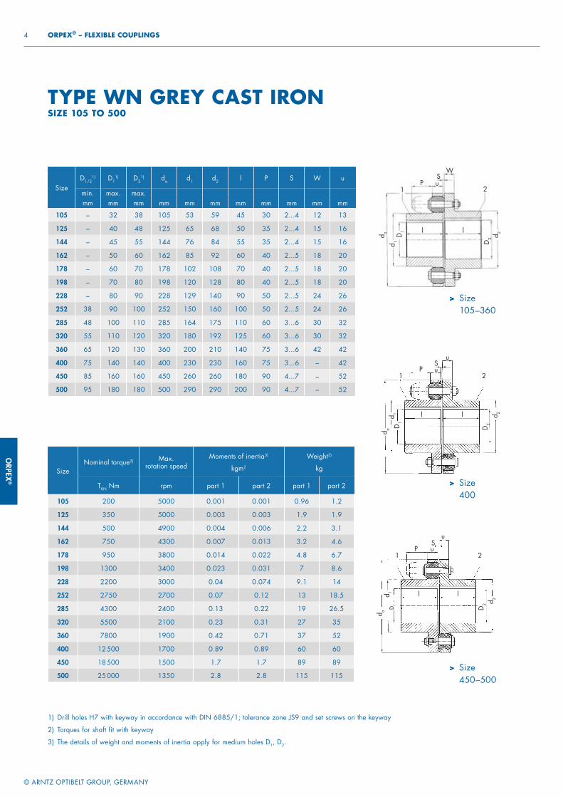
TYPE WN GREY CAST IRONSIZE 105 TO 500
> Size105–360
> Size400
> Size450–500
SizeNominal torque2) Max.
rotation speedMoments of inertia3)
kgm2
Weight3)
kg
TKN Nm rpm part 1 part 2 part 1 part 2
105 200 5000 0.001 0.001 0.96 1.2
125 350 5000 0.003 0.003 1.9 1.9
144 500 4900 0.004 0.006 2.2 3.1
162 750 4300 0.007 0.013 3.2 4.6
178 950 3800 0.014 0.022 4.8 6.7
198 1300 3400 0.023 0.031 7 8.6
228 2200 3000 0.04 0.074 9.1 14
252 2750 2700 0.07 0.12 13 18.5
285 4300 2400 0.13 0.22 19 26.5
320 5500 2100 0.23 0.31 27 35
360 7800 1900 0.42 0.71 37 52
400 12 500 1700 0.89 0.89 60 60
450 18 500 1500 1.7 1.7 89 89
500 25 000 1350 2.8 2.8 115 115
SizeD1/2
1) D11) D2
1) da d1 d2 l P S W u
min. max. max.mm mm mm mm mm mm mm mm mm mm mm
105 – 32 38 105 53 59 45 30 2...4 12 13
125 – 40 48 125 65 68 50 35 2...4 15 16
144 – 45 55 144 76 84 55 35 2...4 15 16
162 – 50 60 162 85 92 60 40 2...5 18 20
178 – 60 70 178 102 108 70 40 2...5 18 20
198 – 70 80 198 120 128 80 40 2...5 18 20
228 – 80 90 228 129 140 90 50 2...5 24 26
252 38 90 100 252 150 160 100 50 2...5 24 26
285 48 100 110 285 164 175 110 60 3...6 30 32
320 55 110 120 320 180 192 125 60 3...6 30 32
360 65 120 130 360 200 210 140 75 3...6 42 42
400 75 140 140 400 230 230 160 75 3...6 – 42
450 85 160 160 450 260 260 180 90 4...7 – 52
500 95 180 180 500 290 290 200 90 4...7 – 52
1) Drill holes H7 with keyway in accordance with DIN 6885/1; tolerance zone JS9 and set screws on the keyway
2) Torques for shaft fit with keyway
3) The details of weight and moments of inertia apply for medium holes D1, D2.
d ad 1
D1
d 2
D2
PS
u
u21
ll
d a
d 1 D
1
d2
D2
PS
W
u21
ll
d ad 1
D1 d 2
D2
PS
u
u21
l l
ORP
EX®
© ARNTZ OPTIBELT GROUP, GERMANY
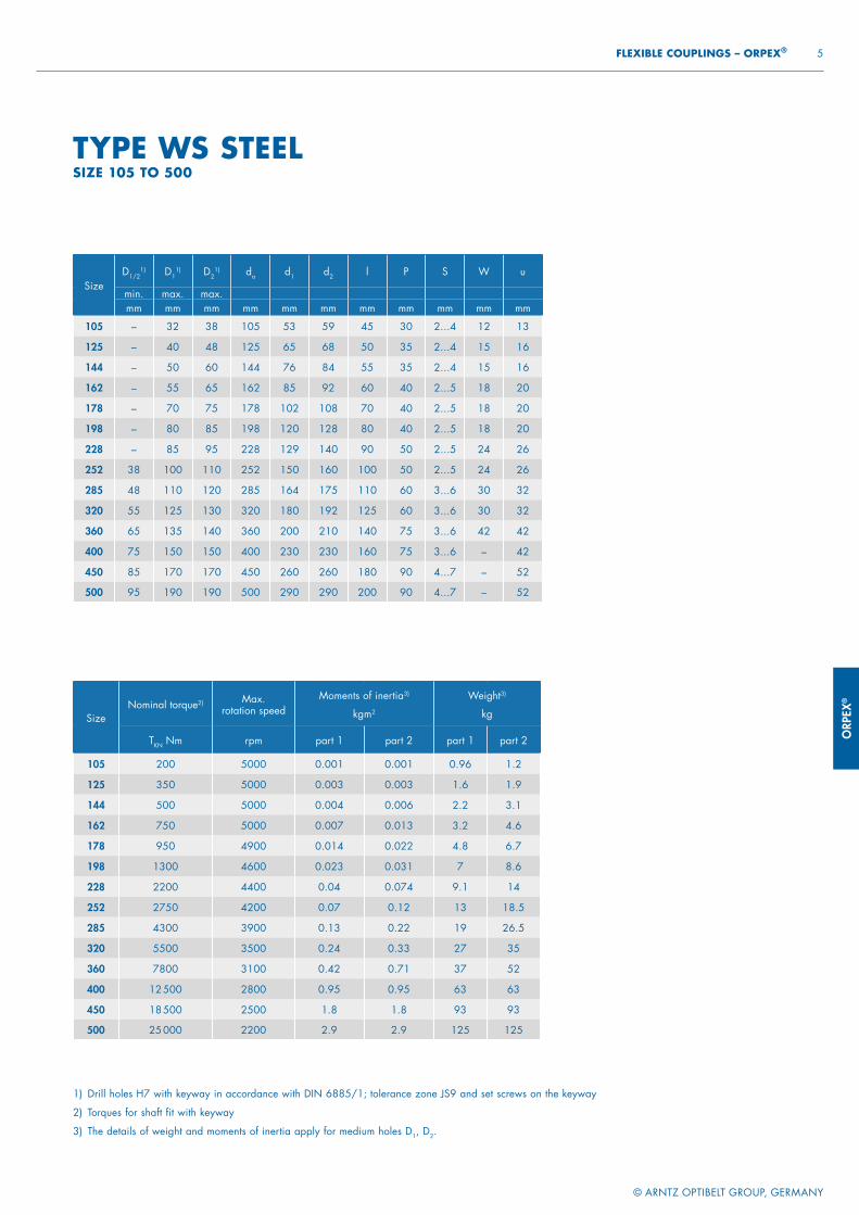
5 FLEXIBLE COUPLINGS – ORPEX®
SizeNominal torque2) Max.
rotation speedMoments of inertia3)
kgm2
Weight3)
kg
TKN Nm rpm part 1 part 2 part 1 part 2
105 200 5000 0.001 0.001 0.96 1.2
125 350 5000 0.003 0.003 1.6 1.9
144 500 5000 0.004 0.006 2.2 3.1
162 750 5000 0.007 0.013 3.2 4.6
178 950 4900 0.014 0.022 4.8 6.7
198 1300 4600 0.023 0.031 7 8.6
228 2200 4400 0.04 0.074 9.1 14
252 2750 4200 0.07 0.12 13 18.5
285 4300 3900 0.13 0.22 19 26.5
320 5500 3500 0.24 0.33 27 35
360 7800 3100 0.42 0.71 37 52
400 12 500 2800 0.95 0.95 63 63
450 18 500 2500 1.8 1.8 93 93
500 25 000 2200 2.9 2.9 125 125
SizeD1/2
1) D11) D2
1) da d1 d2 l P S W u
min. max. max.mm mm mm mm mm mm mm mm mm mm mm
105 – 32 38 105 53 59 45 30 2...4 12 13
125 – 40 48 125 65 68 50 35 2...4 15 16
144 – 50 60 144 76 84 55 35 2...4 15 16
162 – 55 65 162 85 92 60 40 2...5 18 20
178 – 70 75 178 102 108 70 40 2...5 18 20
198 – 80 85 198 120 128 80 40 2...5 18 20
228 – 85 95 228 129 140 90 50 2...5 24 26
252 38 100 110 252 150 160 100 50 2...5 24 26
285 48 110 120 285 164 175 110 60 3...6 30 32
320 55 125 130 320 180 192 125 60 3...6 30 32
360 65 135 140 360 200 210 140 75 3...6 42 42
400 75 150 150 400 230 230 160 75 3...6 – 42
450 85 170 170 450 260 260 180 90 4...7 – 52
500 95 190 190 500 290 290 200 90 4...7 – 52
TYPE WS STEELSIZE 105 TO 500
1) Drill holes H7 with keyway in accordance with DIN 6885/1; tolerance zone JS9 and set screws on the keyway
2) Torques for shaft fit with keyway
3) The details of weight and moments of inertia apply for medium holes D1, D2.

ORPEX
®
© ARNTZ OPTIBELT GROUP, GERMANY
6 ORPEX® – FLEXIBLE COUPLINGS
Size
D1/2 1) WN
WS
WN WS WN
WS
WN
WS
WN
WS
WN
WS
WN
WS
WN
min.
WN
max.
WS
min.
WS
max. da d1/2 d1/2 l v P S u
mm mm mm mm mm mm mm mm mm mm mm mm
560
100 140 100 165
560
250 250
220 70 120 4...8> 140 180 > 165 200 300 300 68
> 180 200 > 200 210 320 320
630
100 140 100 165
630
250 250
240 80 120 4...8> 140 180 > 165 200 300 300 68
> 180 200 > 200 235 355 355
710
110 160 110 190
710
290 290
260 80 140 5...9> 160 200 > 190 220 330 330 80
> 200 240 > 220 250 385 385
800
125 180 125 210
800
320 320
290 90 140 5...9> 180 220 > 210 240 360 360 80
> 220 260 > 240 280 420 420
900
140 210
900
325
320 100 160 5...10 90140 220 > 210 240 360 360
> 220 260 > 240 280 425 425
> 260 290 > 280 310 465 465
1000
150 230
1000
355
350 110 160 5...10 90150 240 > 230 260 395 395
> 240 280 > 260 300 460 460
> 280 320 > 300 340 515 515
1120
160 200 160 270
1120
360 360
380 120 180 6...11 100> 200 250 > 240 300 410 410
> 250 300 > 270 360 495 495
> 300 350 > 330 400 560 560
1250
180 230 180 270
1250
410 410
420 130 180 6...11 100> 230 280 > 270 300 460 460
> 280 330 > 300 360 540 540
> 330 380 > 360 400 610 610
1400
200 260 200 310
1400
465 465
480 145 210 6...12 120> 260 320 > 310 350 525 525
> 320 380 > 350 410 620 620
> 380 440 > 410 460 700 700
1600
260 320 260 370
1600
565 565
540 165 210 6...12 120> 320 380 > 370 410 625 625
> 380 440 > 410 480 720 720
> 440 480 > 480 510 770 770
1800
320 380 320 440
1800
660 660
600 185 240 8...16 140> 380 440 > 440 480 720 720
> 440 500 > 480 540 820 820
> 500 540 > 540 580 870 870
2000
380 440 380 500
2000
760 760
660 200 240 8...16 140> 440 500 > 500 540 820 820
> 500 560 > 540 610 920 920
> 560 600 > 610 640 960 960
> Size560–2000
SIZE 560 TO 2000
1) Drill holes H7 with keyway in accordance
with DIN 6885/1; tolerance zone JS9 and
set screws on the keyway
2) Torques for shaft fit with keyway
3) The details of weight and moments of inertia
apply for medium holes D1, D2.
d a
d 1D
1
d2
D2
PS1u
21
l
v v v v
l
u
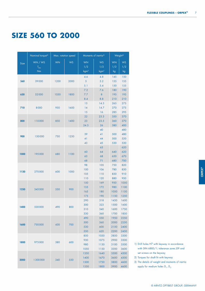
ORP
EX®
© ARNTZ OPTIBELT GROUP, GERMANY
7 FLEXIBLE COUPLINGS – ORPEX®
Size
Nominal torque2) Max. rotation speed Moments of inertia3) Weight3)
WN / WS
TKN
Nm
WN WS WN
1/2
kgm2
WS
1/2
kgm2
WN
1/2
kg
WS
1/2
kg
560 39 000 1200 2000
4.6 4.8 145 150
5 5.2 155 155
5.1 5.4 150 155
630 52 000 1050 1800
7.2 7.6 180 190
7.7 8 195 195
8.4 8.8 210 210
710 8 000 950 1600
13 14.3 265 275
14 14.7 270 275
15 16 285 295
800 110 000 850 1400
22 23.3 350 370
23 23.5 360 370
24.5 26 380 400
900 150 000 750 1250
40 480
39 41 500 480
41 44 500 520
43 45 530 530
1000 195 000 680 1100
63 620
60 64 640 620
63 68 650 670
68 71 680 700
1120 270 000 600 1000
98 105 750 820
100 106 780 830
105 110 830 910
110 120 880 950
1250 345 000 550 900
150 169 950 1050
155 172 980 1100
165 180 1050 1150
175 190 1150 1250
1400 530 000 490 800
290 318 1450 1600
300 323 1500 1600
310 340 1600 1750
330 360 1700 1850
1600 750 000 430 700
490 550 1950 2250
500 560 2000 2250
530 600 2150 2400
550 620 2200 2450
1800 975 000 380 600
850 1050 2850 3300
930 1075 2900 3300
980 1130 3100 3500
1050 1150 3200 3600
2000 1 300 000 340 550
1350 1640 3500 4300
1400 1670 3600 4300
1500 1750 3800 4600
1550 1800 3900 4600
SIZE 560 TO 2000
1) Drill holes H7 with keyway in accordance
with DIN 6885/1; tolerance zone JS9 and
set screws on the keyway
2) Torques for shaft fit with keyway
3) The details of weight and moments of inertia
apply for medium holes D1, D2.
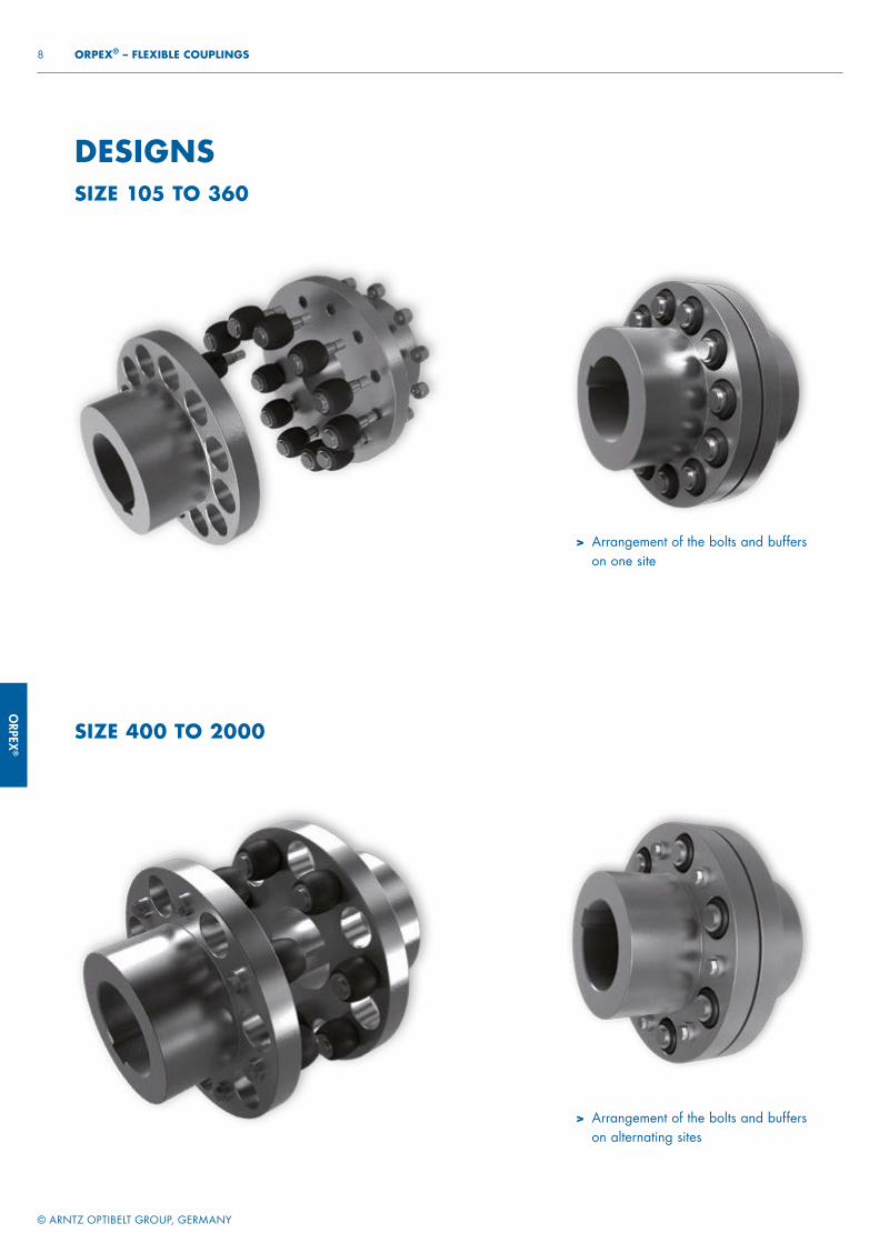
ORPEX
®
© ARNTZ OPTIBELT GROUP, GERMANY
8 ORPEX® – FLEXIBLE COUPLINGS
> Arrangement of the bolts and buffers on one site
> Arrangement of the bolts and buffers on alternating sites
SIZE 400 TO 2000
DESIGNSSIZE 105 TO 360
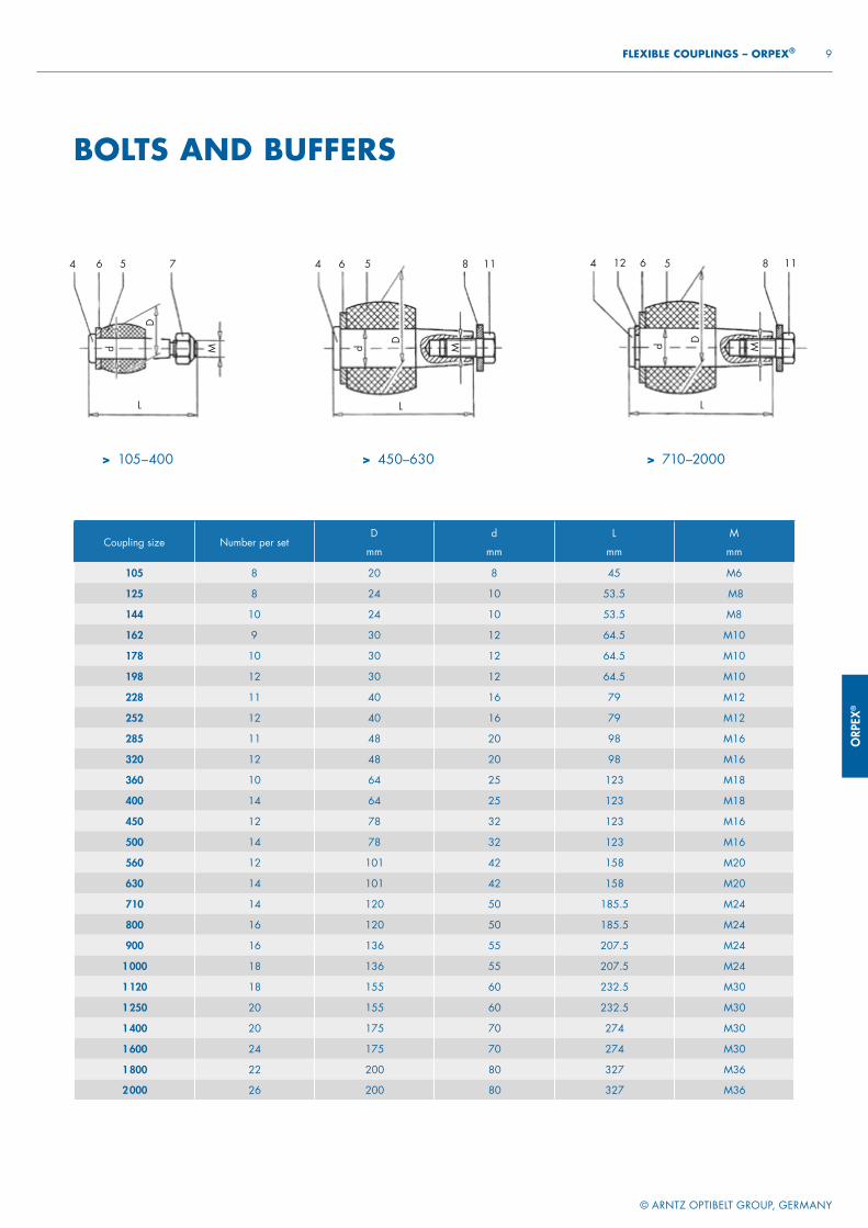
ORP
EX®
© ARNTZ OPTIBELT GROUP, GERMANY
9 FLEXIBLE COUPLINGS – ORPEX®
BOLTS AND BUFFERS
Coupling size Number per setD
mm
d
mm
L
mm
M
mm
105 8 20 8 45 M6
125 8 24 10 53.5 M8
144 10 24 10 53.5 M8
162 9 30 12 64.5 M10
178 10 30 12 64.5 M10
198 12 30 12 64.5 M10
228 11 40 16 79 M12
252 12 40 16 79 M12
285 11 48 20 98 M16
320 12 48 20 98 M16
360 10 64 25 123 M18
400 14 64 25 123 M18
450 12 78 32 123 M16
500 14 78 32 123 M16
560 12 101 42 158 M20
630 14 101 42 158 M20
710 14 120 50 185.5 M24
800 16 120 50 185.5 M24
900 16 136 55 207.5 M24
1 000 18 136 55 207.5 M24
1 120 18 155 60 232.5 M30
1 250 20 155 60 232.5 M30
1 400 20 175 70 274 M30
1 600 24 175 70 274 M30
1 800 22 200 80 327 M36
2 000 26 200 80 327 M36> Arrangement of the bolts and buffers
on alternating sites
4 6 5 7
L
Md
D
4 6 5 8
L
Md
D
11 4 12 6 8
L
Md D
115
> 105–400 > 450–630 > 710–2000
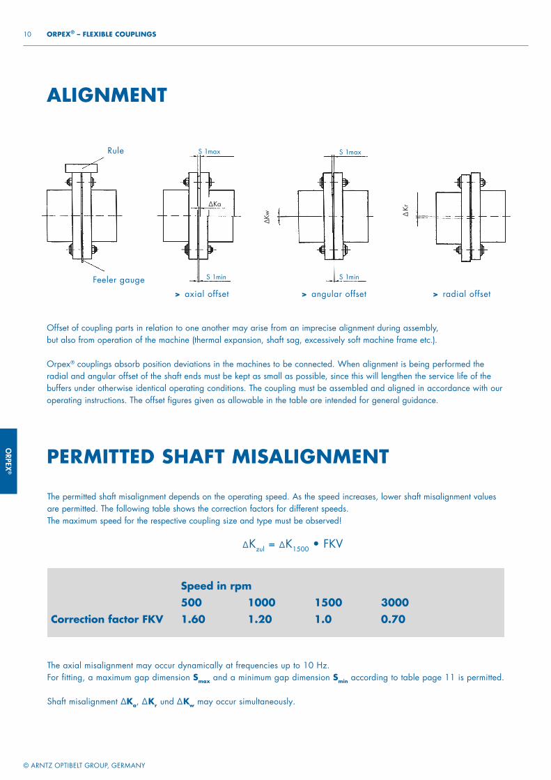
ORPEX
®
© ARNTZ OPTIBELT GROUP, GERMANY
10 ORPEX® – FLEXIBLE COUPLINGS
ALIGNMENT
Offset of coupling parts in relation to one another may arise from an imprecise alignment during assembly, but also from operation of the machine (thermal expansion, shaft sag, excessively soft machine frame etc.).
Orpex® couplings absorb position deviations in the machines to be connected. When alignment is being performed the radial and angular offset of the shaft ends must be kept as small as possible, since this will lengthen the service life of the buffers under otherwise identical operating conditions. The coupling must be assembled and aligned in accordance with our operating instructions. The offset figures given as allowable in the table are intended for general guidance.
Feeler gauge
Rule
> axial offset > angular offset > radial offset
S 1max
S 1min
S 1max
S 1min
Kr∆
∆Ka
Kw∆
PERMITTED SHAFT MISALIGNMENT
The permitted shaft misalignment depends on the operating speed. As the speed increases, lower shaft misalignment values are permitted. The following table shows the correction factors for different speeds.The maximum speed for the respective coupling size and type must be observed!
∆Kzul = ∆K1500 • FKV
The axial misalignment may occur dynamically at frequencies up to 10 Hz.For fitting, a maximum gap dimension Smax and a minimum gap dimension Smin according to table page 11 is permitted.
Shaft misalignment ∆Ka, ∆Kr und ∆Kw may occur simultaneously.
Speed in rpm 500 1000 1500 3000 Correction factor FKV 1.60 1.20 1.0 0.70
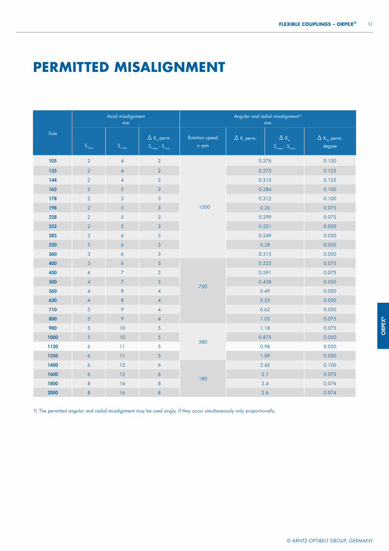
ORP
EX®
© ARNTZ OPTIBELT GROUP, GERMANY
11 FLEXIBLE COUPLINGS – ORPEX®
PERMITTED MISALIGNMENT
1) The permitted angular and radial misalignment may be used singly, if they occur simultaneously only proportionally.
Size
Axial misalignment mm
Angular and radial misalignment1)
mm
S1min S1max
∆ Ka perm.
S1max - S1min
Rotation speed
n rpm∆ Kr perm. ∆ Kw
S1max - S1min
∆ KW perm.
degree
105 2 4 2
1500
0.276 0.150
125 2 4 2 0.273 0.125
144 2 4 2 0.315 0.125
162 2 5 3 0.284 0.100
178 2 5 3 0.312 0.100
198 2 5 3 0.26 0.075
228 2 5 3 0.299 0.075
252 2 5 3 0.221 0.050
285 3 6 3 0.249 0.050
320 3 6 3 0.28 0.050
360 3 6 3 0.315 0.050
400 3 6 3
750
0.525 0.075
450 4 7 3 0.591 0.075
500 4 7 3 0.438 0.050
560 4 8 4 0.49 0.050
630 4 8 4 0.55 0.050
710 5 9 4 0.62 0.050
800 5 9 4 1.05 0.075
900 5 10 5
380
1.18 0.075
1000 5 10 5 0.875 0.050
1120 6 11 5 0.98 0.050
1250 6 11 5 1.09 0.050
1400 6 12 6
180
2.45 0.100
1600 6 12 6 2.1 0.075
1800 8 16 8 2.4 0.076
2000 8 16 8 2.6 0.074
The axial misalignment may occur dynamically at frequencies up to 10 Hz.For fitting, a maximum gap dimension Smax and a minimum gap dimension Smin according to table page 11 is permitted.
Shaft misalignment ∆Ka, ∆Kr und ∆Kw may occur simultaneously.

FLEX
POWER TRANSMISSION
FLEXIBLE COUPLINGS
FLEX
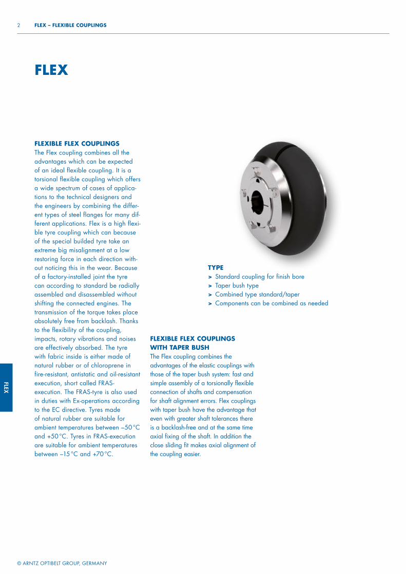
FLEX
© ARNTZ OPTIBELT GROUP, GERMANY
2 FLEX – FLEXIBLE COUPLINGS
FLEX
FLEXIBLE FLEX COUPLINGSThe Flex coupling combines all the advantages which can be expected of an ideal flexible coupling. It is a torsional flexible coupling which offers a wide spectrum of cases of applica-tions to the technical designers and the engineers by combining the differ-ent types of steel flanges for many dif-ferent applications. Flex is a high flexi-ble tyre coupling which can because of the special builded tyre take an extreme big misalignment at a low restoring force in each direction with-out noticing this in the wear. Because of a factory-installed joint the tyre can according to standard be radially assembled and disassembled without shifting the connected engines. The transmission of the torque takes place absolutely free from backlash. Thanks to the flexibility of the coupling, impacts, rotary vibrations and noises are effectively absorbed. The tyre with fabric inside is either made of natural rubber or of chloroprene in fire-resistant, antistatic and oil-resistant execution, short called FRAS-execution. The FRAS-tyre is also used in duties with Ex-operations according to the EC directive. Tyres made of natural rubber are suitable for ambient temperatures between –50 °C and +50 °C. Tyres in FRAS-execution are suitable for ambient temperatures between –15 °C and +70 °C.
FLEXIBLE FLEX COUPLINGSWITH TAPER BUSHThe Flex coupling combines the advantages of the elastic couplings with those of the taper bush system: fast and simple assembly of a torsionally flexible connection of shafts and compensation for shaft alignment errors. Flex couplings with taper bush have the advantage that even with greater shaft tolerances there is a backlash-free and at the same time axial fixing of the shaft. In addition the close sliding fit makes axial alignment of the coupling easier.
TYPE> Standard coupling for finish bore> Taper bush type> Combined type standard/taper> Components can be combined as needed
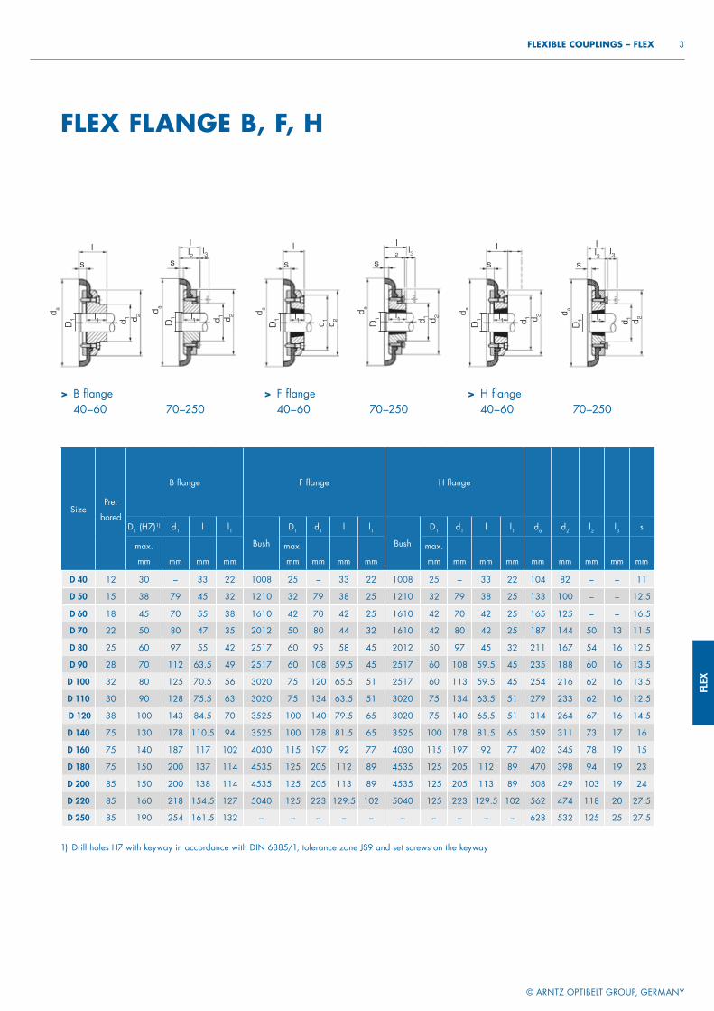
FLEX
© ARNTZ OPTIBELT GROUP, GERMANY
3 FLEXIBLE COUPLINGS – FLEX
1) Drill holes H7 with keyway in accordance with DIN 6885/1; tolerance zone JS9 and set screws on the keyway
SizePre.
bored
B fl ange F fl ange H fl ange
D1 (H7)1) d1 l l1Bush
D1 d1 l l1Bush
D1 d1 l l1 da d2 l2 l3 s
max.
mm mm mm mm
max.
mm mm mm mm
max.
mm mm mm mm mm mm mm mm mm
D 40 12 30 – 33 22 1008 25 – 33 22 1008 25 – 33 22 104 82 – – 11
D 50 15 38 79 45 32 1210 32 79 38 25 1210 32 79 38 25 133 100 – – 12.5
D 60 18 45 70 55 38 1610 42 70 42 25 1610 42 70 42 25 165 125 – – 16.5
D 70 22 50 80 47 35 2012 50 80 44 32 1610 42 80 42 25 187 144 50 13 11.5
D 80 25 60 97 55 42 2517 60 95 58 45 2012 50 97 45 32 211 167 54 16 12.5
D 90 28 70 112 63.5 49 2517 60 108 59.5 45 2517 60 108 59.5 45 235 188 60 16 13.5
D 100 32 80 125 70.5 56 3020 75 120 65.5 51 2517 60 113 59.5 45 254 216 62 16 13.5
D 110 30 90 128 75.5 63 3020 75 134 63.5 51 3020 75 134 63.5 51 279 233 62 16 12.5
D 120 38 100 143 84.5 70 3525 100 140 79.5 65 3020 75 140 65.5 51 314 264 67 16 14.5
D 140 75 130 178 110.5 94 3525 100 178 81.5 65 3525 100 178 81.5 65 359 311 73 17 16
D 160 75 140 187 117 102 4030 115 197 92 77 4030 115 197 92 77 402 345 78 19 15
D 180 75 150 200 137 114 4535 125 205 112 89 4535 125 205 112 89 470 398 94 19 23
D 200 85 150 200 138 114 4535 125 205 113 89 4535 125 205 113 89 508 429 103 19 24
D 220 85 160 218 154.5 127 5040 125 223 129.5 102 5040 125 223 129.5 102 562 474 118 20 27.5
D 250 85 190 254 161.5 132 – – – – – – – – – – 628 532 125 25 27.5
FLEX FLANGE B, F, H
> B flange 40–60 70–250
> F flange 40–60 70–250
> H flange 40–60 70–250
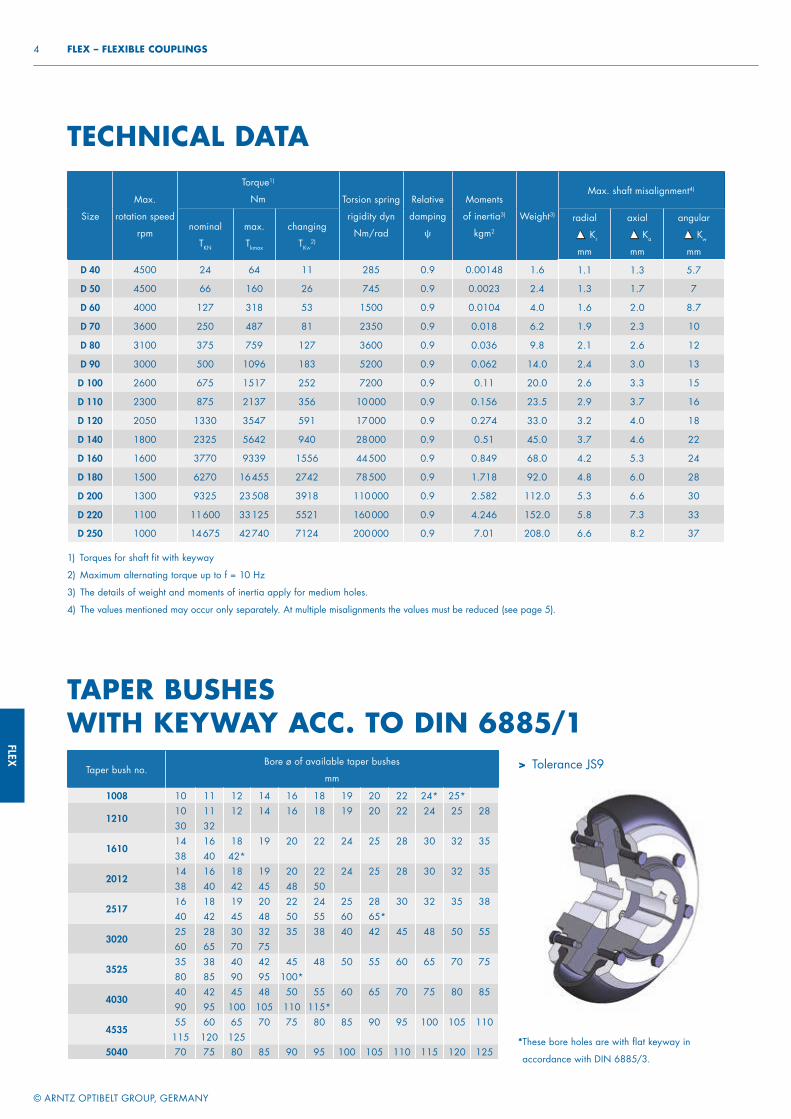
FLEX
© ARNTZ OPTIBELT GROUP, GERMANY
4 FLEX – FLEXIBLE COUPLINGS
* These bore holes are with flat keyway in
accordance with DIN 6885/3.
TAPER BUSHES WITH KEYWAY ACC. TO DIN 6885/1
TECHNICAL DATA
Size
Max.
rotation speed
rpm
Torque1)
Nm Torsion spring
rigidity dyn
Nm/rad
Relative
damping
ψ
Moments
of inertia3)
kgm2
Weight3)
Max. shaft misalignment4)
nominal
TKN
max.
Tkmax
changing
TKW2)
radial
Kr
mm
axial Ka
mm
angular Kw
mm
D 40 4500 24 64 11 285 0.9 0.00148 1.6 1.1 1.3 5.7
D 50 4500 66 160 26 745 0.9 0.0023 2.4 1.3 1.7 7
D 60 4000 127 318 53 1500 0.9 0.0104 4.0 1.6 2.0 8.7
D 70 3600 250 487 81 2350 0.9 0.018 6.2 1.9 2.3 10
D 80 3100 375 759 127 3600 0.9 0.036 9.8 2.1 2.6 12
D 90 3000 500 1096 183 5200 0.9 0.062 14.0 2.4 3.0 13
D 100 2600 675 1517 252 7200 0.9 0.11 20.0 2.6 3.3 15
D 110 2300 875 2137 356 10 000 0.9 0.156 23.5 2.9 3.7 16
D 120 2050 1330 3547 591 17 000 0.9 0.274 33.0 3.2 4.0 18
D 140 1800 2325 5642 940 28 000 0.9 0.51 45.0 3.7 4.6 22
D 160 1600 3770 9339 1556 44 500 0.9 0.849 68.0 4.2 5.3 24
D 180 1500 6270 16 455 2742 78 500 0.9 1.718 92.0 4.8 6.0 28
D 200 1300 9325 23 508 3918 110 000 0.9 2.582 112.0 5.3 6.6 30
D 220 1100 11 600 33 125 5521 160 000 0.9 4.246 152.0 5.8 7.3 33
D 250 1000 14 675 42 740 7124 200 000 0.9 7.01 208.0 6.6 8.2 37
Taper bush no.Bore ø of available taper bushes
mm
1008 10 11 12 14 16 18 19 20 22 24* 25*
121010 11 12 14 16 18 19 20 22 24 25 2830 32
161014 16 18 19 20 22 24 25 28 30 32 3538 40 42*
201214 16 18 19 20 22 24 25 28 30 32 3538 40 42 45 48 50
251716 18 19 20 22 24 25 28 30 32 35 3840 42 45 48 50 55 60 65*
302025 28 30 32 35 38 40 42 45 48 50 5560 65 70 75
352535 38 40 42 45 48 50 55 60 65 70 7580 85 90 95 100*
403040 42 45 48 50 55 60 65 70 75 80 8590 95 100 105 110 115*
453555 60 65 70 75 80 85 90 95 100 105 110
115 120 1255040 70 75 80 85 90 95 100 105 110 115 120 125
> Tolerance JS9
1) Torques for shaft fit with keyway
2) Maximum alternating torque up to f = 10 Hz
3) The details of weight and moments of inertia apply for medium holes.
4) The values mentioned may occur only separately. At multiple misalignments the values must be reduced (see page 5).
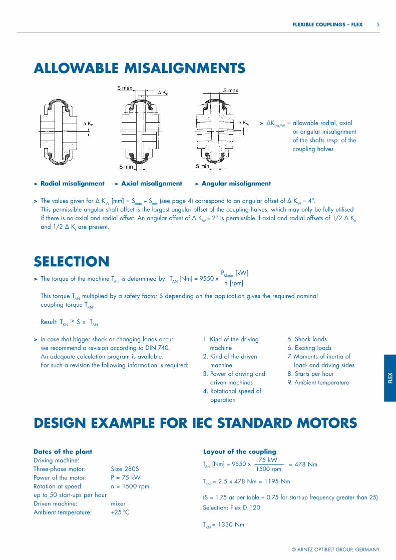
FLEX
© ARNTZ OPTIBELT GROUP, GERMANY
5 FLEXIBLE COUPLINGS – FLEX
ALLOWABLE MISALIGNMENTS
> Radial misalignment
> The values given for ∆ KW [mm] = Smax – Smin (see page 4) correspond to an angular offset of ∆ KW = 4°. This permissible angular shaft offset is the largest angular offset of the coupling halves, which may only be fully utilised if there is no axial and radial offset. An angular offset of ∆ KW = 2° is permissible if axial and radial offsets of 1/2 ∆ Ka and 1/2 ∆ Kr are present.
> ∆Kr/a/W = allowable radial, axial or angular misalignment of the shafts resp. of the coupling halves
> Axial misalignment > Angular misalignment
DESIGN EXAMPLE FOR IEC STANDARD MOTORS
Dates of the plantDriving machine: Three-phase motor: Size 280SPower of the motor: P = 75 kWRotation at speed: n = 1500 rpmup to 50 start-ups per hourDriven machine: mixerAmbient temperature: +25 °C
Layout of the coupling
TAN [Nm] = 9550 x75 kW
1500 rpm= 478 Nm
TKN = 2.5 x 478 Nm = 1195 Nm
(S = 1.75 as per table + 0.75 for start-up frequency greater than 25)
Selection: Flex D 120
TKN = 1330 Nm
SELECTION> The torque of the machine TAN is determined by: TAN [Nm] = 9550 x
PMotor [kW]
n [rpm]
> This torque TAN multiplied by a safety factor S depending on the application gives the required nominal coupling torque TKN.
> Result: TKN ≧ S x TAN
> In case that bigger shock or changing loads occur we recommend a revision according to DIN 740. An adequate calculation program is available. For such a revision the following information is required:
1. Kind of the driving machine
2. Kind of the driven machine
3. Power of driving and driven machines
4. Rotational speed of operation
5. Shock loads6. Exciting loads7. Moments of inertia of
load- and driving sides8. Starts per hour9. Ambient temperature
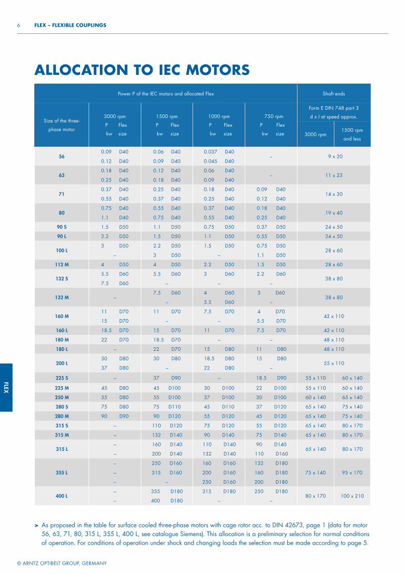
FLEX
© ARNTZ OPTIBELT GROUP, GERMANY
6 FLEX – FLEXIBLE COUPLINGS
ALLOCATION TO IEC MOTORS
> As proposed in the table for surface cooled three-phase motors with cage rotor acc. to DIN 42673, page 1 (data for motor 56, 63, 71, 80, 315 L, 355 L, 400 L, see catalogue Siemens). This allocation is a preliminary selection for normal conditions of operation. For conditions of operation under shock and changing loads the selection must be made according to page 5.
Power P of the IEC motors and allocated Flex Shaft ends
Size of the three-
phase motor
3000 rpm
P Flex
kw size
1500 rpm
P Flex
kw size
1000 rpm
P Flex
kw size
750 rpm
P Flex
kw size
Form E DIN 748 part 3
d x l at speed approx.
3000 rpm1500 rpm
and less
560.09 D40 0.06 D40 0.037 D40
– 9 x 200.12 D40 0.09 D40 0.045 D40
630.18 D40 0.12 D40 0.06 D40
– 11 x 230.25 D40 0.18 D40 0.09 D40
710.37 D40 0.25 D40 0.18 D40 0.09 D40
14 x 300.55 D40 0.37 D40 0.25 D40 0.12 D40
800.75 D40 0.55 D40 0.37 D40 0.18 D40
19 x 401.1 D40 0.75 D40 0.55 D40 0.25 D40
90 S 1.5 D50 1.1 D50 0.75 D50 0.37 D50 24 x 50
90 L 2.2 D50 1.5 D50 1.1 D50 0.55 D50 24 x 50
100 L3 D50 2.2 D50 1.5 D50 0.75 D50
28 x 60– 3 D50 – 1.1 D50
112 M 4 D50 4 D50 2.2 D50 1.5 D50 28 x 60
132 S5.5 D60 5.5 D60 3 D60 2.2 D60
38 x 807.5 D60 – – –
132 M –7.5 D60 4 D60 3 D60
38 x 80– 5.5 D60 –
160 M11 D70 11 D70 7.5 D70 4 D70
42 x 11015 D70 – – 5.5 D70
160 L 18.5 D70 15 D70 11 D70 7.5 D70 42 x 110
180 M 22 D70 18.5 D70 – – 48 x 110
180 L – 22 D70 15 D80 11 D80 48 x 110
200 L30 D80 30 D80 18.5 D80 15 D80
55 x 11037 D80 – 22 D80 –
225 S – 37 D90 – 18.5 D90 55 x 110 60 x 140
225 M 45 D80 45 D100 30 D100 22 D100 55 x 110 60 x 140
250 M 55 D80 55 D100 37 D100 30 D100 60 x 140 65 x 140
280 S 75 D80 75 D110 45 D110 37 D120 65 x 140 75 x 140
280 M 90 D90 90 D120 55 D120 45 D120 65 x 140 75 x 140
315 S – 110 D120 75 D120 55 D120 65 x 140 80 x 170
315 M – 132 D140 90 D140 75 D140 65 x 140 80 x 170
315 L– 160 D140 110 D140 90 D140
65 x 140 80 x 170– 200 D140 132 D140 110 D160
355 L
– 250 D160 160 D160 132 D180
75 x 140 95 x 170– 315 D160 200 D160 160 D180
– – 250 D160 200 D180
400 L– 355 D180 315 D180 250 D180
80 x 170 100 x 210– 400 D180 – –
FLEX
© ARNTZ OPTIBELT GROUP, GERMANY
7 FLEXIBLE COUPLINGS – FLEX
Assignment of load characteristics according to type of working machine
SSMMMSSM
MMM
MMGMMGM
MS
MSMGMMMMMGMMMMSMM
MGMMG
SGS
DREDGERSBucket conveyorLanding gear (caterpillar)Landing gear (rail)Manoeuvring winchesPumpsImpellers Cutter headsSlewing gear
GENERATORS, TRANSFORMERSFrequency transformersGeneratorsWelding generators
CHEMICAL INDUSTRYCooling drumsMixersAgitators (liquid material)Agitators (semi-liquid material)Drying drumsCentrifuges (light)Centrifuges (heavy)
OIL INDUSTRYPipeline pumpsRotary drilling equipment
CONVEYORSPit-head winchesWinding enginesJointed-band conveyorsBelt conveyors (bulk material)Belt conveyors (piece goods)Band pocket conveyorsChain conveyorsCircular conveyorsLoad elevatorsBucket conveyors for flourPassenger liftsPlate conveyorsScrew conveyorsBallast elevatorsInclined hoistsSteel belt conveyorsDrag chain conveyors
BLOWERS, VENTILATORSRotary piston blowersBlowers (axial/radial)Cooling tower fansInduced draught fansTurbo blowers
BUILDING MACHINERYHoistsConcrete mixersRoad construction machinery
SMSMS
SMGS
GSGMM
MMMM
MSSSSMSSGMG
GMMGMMSMM
SSMSMSSSSS
RUBBER MACHINERYExtrudersCalendersKneading millsMixersRolling mills
WOOD WORKING MACHINESBarkersPlaning machinesWood working machinesSaw frames
CRANESLuffi ng gear blockTravelling gearHoist gearSlewing gearDerricking jib gear
PLASTIC INDUSTRY MACHINESExtrudersCalendersMixersCrushers
METAL WORKING MACHINESPlate bending machinesPlate straightening machinesHammersMetal planning machinesPressesShearsForging pressesPunch pressesCountershafts, line shaftsMachine tools (main drives)Machine tools (auxiliary drives)
FOOD INDUSTRY MACHINERYBottling and container fi lling machinesKneading machinesMash tubsPackaging machinesCane crushersCane cuttersCane millsSugar beet cuttersSugar beet washing machines
PAPER MACHINESCouchesGlazing cylindersPulperPulp grindersCalendersWet pressesWillowsSuction pressesSuction rollsDrying cylinders
SGMSS
SSSSSSS
MMMMM
SM
SMSSSMSSSMSMSMMMSMSMSSMS
MM
MM
PUMPSPiston pumpsCentrifugal pumps (light liquids)Centrifugal pumps (viscous liquids)Plunger pumpsPress pumps
STONE AND CLAY WORKING MACHINESCrusherRotary ovensHammer millsBall millsTube millsBeater millsBrick presses
TEXTILE MACHINESBatchersPrinting and dyeing machinesTanning vatsWillowsLooms
COMPRESSORSPiston compressorsTurbo compressors
METAL ROLLING MILLSPlate shearsManipulator for turning sheetsIngot pushersIngot and slabbing-mill trainIngot handling machineryWire drawing benchesDescaling machinesThin plate millsHeavy and medium plate millsWinding machines (strip and wire)Cold rolling millsChain tractorBillet shearsCooling bedsCross tractorRoller tables (light)Roller tables (heavy)Roller straightenersTube welding machinesTrimming shearsCropping shearsContinuous casting plantRollers adjustment driveManipulators
LAUNDRIESTumblersWashing machines
WATER TREATMENTAeratorsScrew pumps
SAFETY FACTOR S
> The operating factor S takes account of up to 25 start-ups per hour.
> With up to 120 start-ups per hour the factor S must be increased by 0.75.
Operating factor S
Driving machinesLoad characteristics of the working machine
G M S
Electric motors, turbines, hydraulic motors 1 1.75 2.5
Piston machines 4–6 cylinders, degree of nonuniformity
1:100 – 1:2001.25 2 2.75
Piston machines 1–3 cylinders,degree of nonuniformity
up to 1:100 1.5 2.25 3

GC
POWER TRANSMISSION
RIGID COUPLINGS
GCGC-ECO
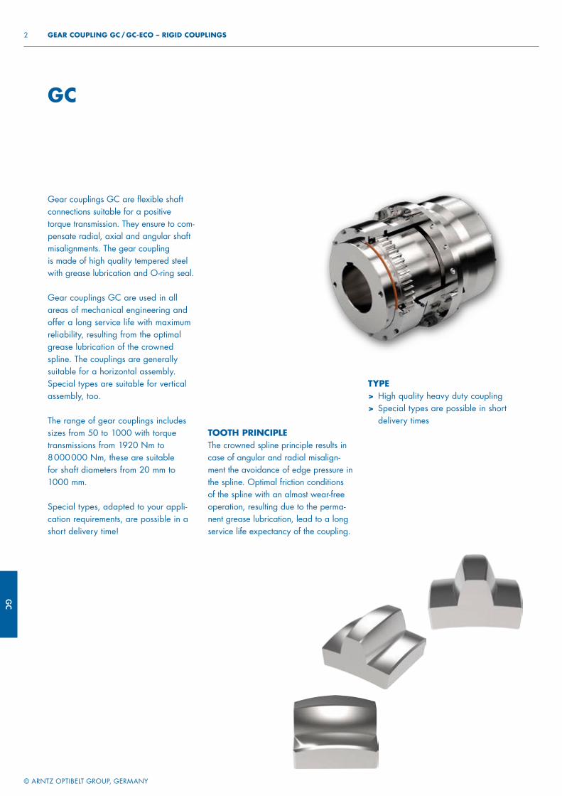
GC
© ARNTZ OPTIBELT GROUP, GERMANY
2 GEAR COUPLING GC / GC-ECO – RIGID COUPLINGS
GC
Gear couplings GC are flexible shaft connections suitable for a positive torque transmission. They ensure to com-pensate radial, axial and angular shaft misalignments. The gear couplingis made of high quality tempered steel with grease lubrication and O-ring seal.
Gear couplings GC are used in all areas of mechanical engineering and offer a long service life with maximum reliability, resulting from the optimal grease lubrication of the crowned spline. The couplings are generally suitable for a horizontal assembly. Special types are suitable for vertical assembly, too.
The range of gear couplings includes sizes from 50 to 1000 with torque transmissions from 1920 Nm to 8 000 000 Nm, these are suitable for shaft diameters from 20 mm to 1000 mm.
Special types, adapted to your appli-cation requirements, are possible in a short delivery time!
TOOTH PRINCIPLEThe crowned spline principle results in case of angular and radial misalign-ment the avoidance of edge pressure in the spline. Optimal friction conditions of the spline with an almost wear-free operation, resulting due to the perma-nent grease lubrication, lead to a long service life expectancy of the coupling.
TYPE> High quality heavy duty coupling> Special types are possible in short
delivery times
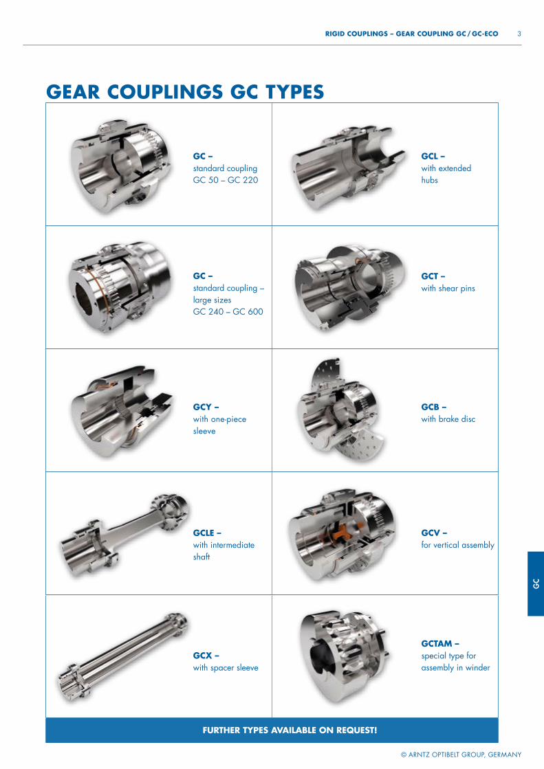
GC
© ARNTZ OPTIBELT GROUP, GERMANY
3 RIGID COUPLINGS – GEAR COUPLING GC / GC-ECO
FURTHER TYPES AVAILABLE ON REQUEST!
GCX – with spacer sleeve
GCLE – with intermediate shaft
GCY – with one-piece sleeve
GC – standard coupling –large sizes GC 240 – GC 600
GC – standard couplingGC 50 – GC 220
GCL – with extended hubs
GCT – with shear pins
GCB –with brake disc
GCV – for vertical assembly
GCTAM – special type for assembly in winder
GEAR COUPLINGS GC TYPES

GC
© ARNTZ OPTIBELT GROUP, GERMANY
4 GEAR COUPLING GC / GC-ECO – RIGID COUPLINGS
Size
D Dmax
mm
Dh
mm
Dn
mm
D1/D2 D1/D2
min. max.
mm
Lmin L Lmax
mm
Ln min Ln1/Ln2 Ln max
mm
S
mm
S1
mm
S2
mm
Dph
mm
M
mm
50 111 250 83 64 20 50 91 93 208 43 45 100 3 8 10 57 M5
65 148 250 105 83 20 65 131 136 316 50 65 150 6 20 26 72 M8
75 169 250 126 100 20 75 151 156 316 62 75 150 6 18 23 88 M8
100 209 300 162 135 30 100 171 176 316 76 85 150 6 17 23 120 M10
120 233 300 186 160 40 120 211 216 416 90 105 200 6 24 34 144 M10
135 254 300 204 175 40 135 231 236 418 100 115 200 6 24 44 156 M12
150 308 400 246 200 50 150 241 246 618 105 120 300 6 27 44 168 M16
165 336 500 262 220 60 165 301 310 628 120 150 300 10 58 83 196 M16
190 366 500 303 255 80 190 341 350 828 150 170 400 10 47 83 228 M20
220 428 600 345 290 80 220 401 410 828 175 200 400 10 50 94 246 M20
240 458 600 394 320 80 240 463 476 844 190 230 400 16 99 170 284 M20
270 490 600 436 360 120 270 503 516 844 220 250 400 16 94 162 314 M24
285 534 800 474 380 120 285 563 576 844 250 280 400 16 121 213 330 M24
330 580 800 518 431 160 330 603 616 844 280 300 400 16 101 173 390 M30
365 668 800 586 480 180 365 705 730 858 325 350 400 30 137 233 422 M30
400 730 1000 642 530 200 400 805 830 358 345 400 450 30 131 213 478 M30
450 830 1000 720 621 200 450 805 830 358 400 400 450 30 131 213 560 M30
500 882 1000 742 651 200 500 905 930 1058 410 450 500 30 141 230 600 M30
600 970 1000 867 761 300 600 1005 1030 1070 470 500 500 30 151 230 680 M30
700 1220 2000 1064 921 300 700 1405 1440 1710 580 700 800 40 – – 830 M42
800 1440 2000 1240 1061 300 800 1405 1440 1710 600 700 800 40 – – 920 M48
900 1600 2000 1416 1190 400 900 1505 1540 1710 680 750 800 40 – – 1100 M48
1000 1814 2000 1630 1350 500 1000 1660 1700 2380 740 800 1100 100 – – 1160 M48
The diameters Dn and Dh are locked.
Other dimensions can be chosen for special types according to the range given.
SIZE 50–220 SIZE 240–600
GEAR COUPLINGS GC
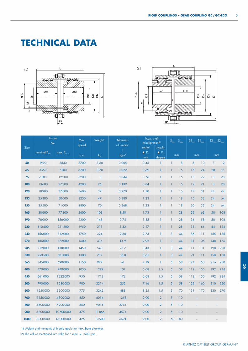
GC
© ARNTZ OPTIBELT GROUP, GERMANY
5 RIGID COUPLINGS – GEAR COUPLING GC / GC-ECO
1) Weight and moments of inertia apply for max. bore diameter.
2) The values mentioned are valid for n max. = 1500 rpm.
Size
Torque
NmMax.
speed
rpm
Weight1)
kg
Moments
of inertia1)
J
kgm2
Max. shaft misalignment2) Smin Smax S1min S1max S2min S2max
nominal TKN max. Tkmax
radial Kr
mm
angular
Kw
degreemm mm mm
50 1920 3840 8700 3.60 0.005 0.45 1 1 8 5 10 7 12
65 3550 7100 6700 8.70 0.022 0.69 1 1 16 15 24 20 32
75 6100 12 200 5200 13 0.044 0.76 1 1 16 13 22 18 28
100 13 600 27 200 4200 25 0.139 0.84 1 1 16 12 21 18 28
120 18 900 37 800 3600 37 0.270 1.10 1 1 16 17 31 24 44
135 25 300 50 600 3250 47 0.380 1.23 1 1 18 15 33 24 64
150 35 500 71 000 2800 70 0.868 1.23 1 1 18 20 33 24 64
165 38 600 77 200 2600 103 1.50 1.73 1 1 28 52 63 58 108
190 78 000 156 000 2200 148 2.74 1.85 1 1 28 36 58 58 108
220 110 600 221 200 1950 215 5.32 2.27 1 1 28 33 66 64 124
240 156 000 312 000 1750 324 9.68 2.73 1 3 44 86 111 155 185
270 186 000 372 000 1600 415 14.9 2.92 1 3 44 81 106 148 176
285 219 000 438 000 1450 540 23.7 3.43 1 3 44 111 131 198 228
330 250 500 501 000 1300 717 36.8 3.61 1 3 44 91 111 158 188
365 345 000 690 000 1150 927 61 4.19 1 5 58 124 150 216 250
400 470 000 940 000 1050 1299 102 6.68 1.5 5 58 112 150 192 234
450 661 000 1 322 000 950 1712 172 6.68 1.5 5 58 112 150 192 234
500 790 000 1 580 000 900 2214 252 7.46 1.5 5 58 122 160 210 250
600 1 250 000 2 500 000 775 3242 488 8.25 1.5 5 70 131 170 230 270
700 2 150 000 4 300 000 650 6054 1358 9.00 2 5 110 – –
800 3 600 000 7 200 000 550 9014 2744 9.00 2 5 110 – –
900 5 300 000 10 600 000 475 11 866 4574 9.00 2 5 110 – –
1000 8 000 000 16 000 000 425 13 500 6691 9.00 2 60 180 – –
The diameters Dn and Dh are locked.
Other dimensions can be chosen for special types according to the range given.
S2 S1
TECHNICAL DATA
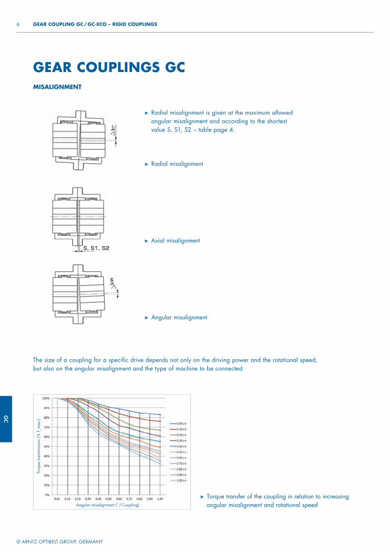
GC
© ARNTZ OPTIBELT GROUP, GERMANY
6 GEAR COUPLING GC / GC-ECO – RIGID COUPLINGS
GEAR COUPLINGS GC
> Radial misalignment
> Axial misalignment
> Angular misalignment
> Radial misalignment is given at the maximum allowed angular misalignment and according to the shortest value S, S1, S2 – table page 4.
The size of a coupling for a specific drive depends not only on the driving power and the rotational speed,but also on the angular misalignment and the type of machine to be connected.
> Torque transfer of the coupling in relation to increasing angular misalignment and rotational speed
MISALIGNMENT
Angular misalignment ( ° / Coupling)
Torq
ue tr
ansm
issi
on (
% T
n m
ax.)
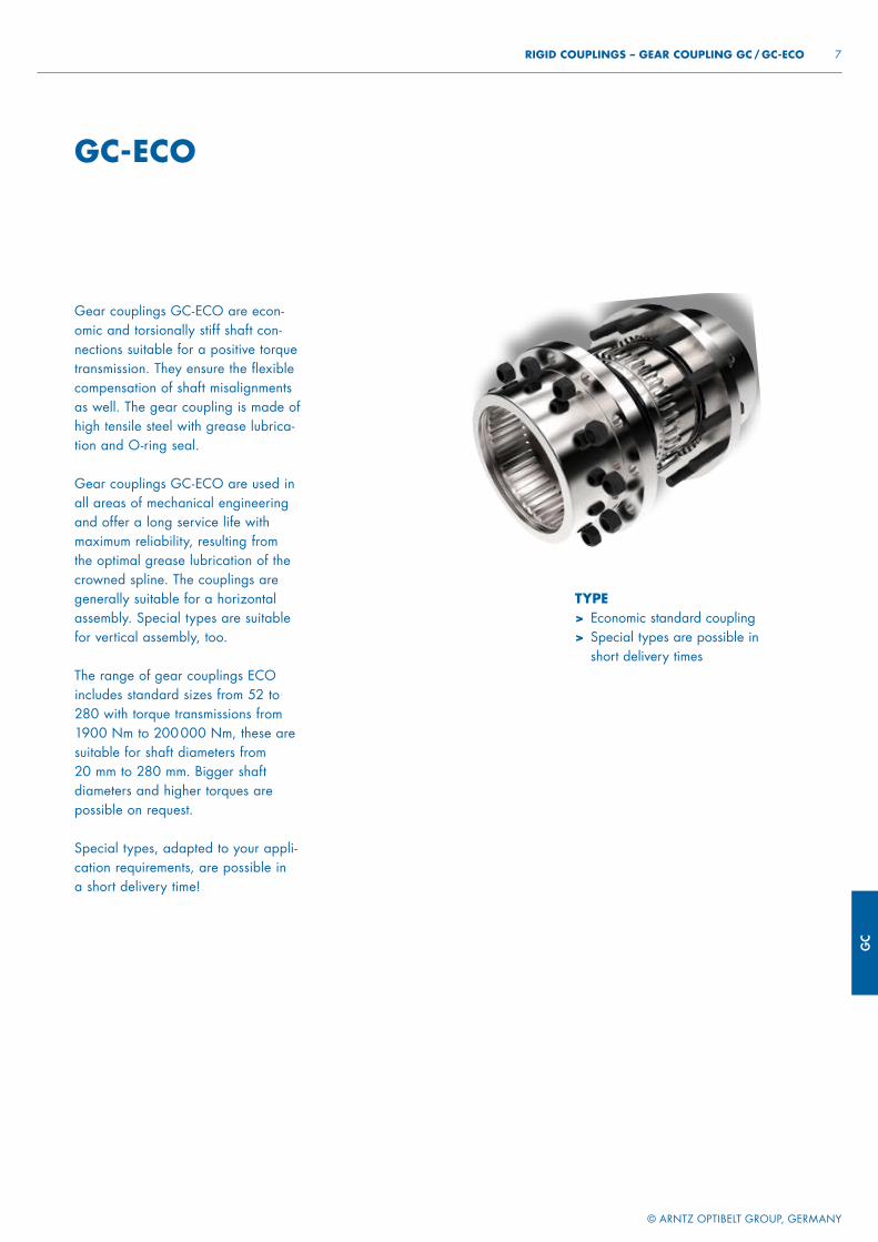
GC
© ARNTZ OPTIBELT GROUP, GERMANY
7 RIGID COUPLINGS – GEAR COUPLING GC / GC-ECO
GC-ECO
Gear couplings GC-ECO are econ-omic and torsionally stiff shaft con-nections suitable for a positive torque transmission. They ensure the flexible compensation of shaft misalignments as well. The gear coupling is made of high tensile steel with grease lubrica-tion and O-ring seal.
Gear couplings GC-ECO are used in all areas of mechanical engineering and offer a long service life with maximum reliability, resulting from the optimal grease lubrication of the crowned spline. The couplings are generally suitable for a horizontalassembly. Special types are suitable for vertical assembly, too.
The range of gear couplings ECO includes standard sizes from 52 to 280 with torque transmissions from 1900 Nm to 200 000 Nm, these are suitable for shaft diameters from 20 mm to 280 mm. Bigger shaft diameters and higher torques are possible on request.
Special types, adapted to your appli-cation requirements, are possible in a short delivery time!
TYPE> Economic standard coupling> Special types are possible in
short delivery times
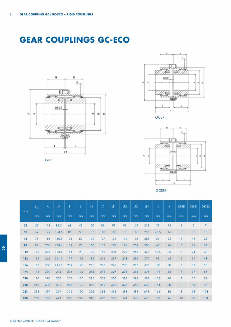
GC
© ARNTZ OPTIBELT GROUP, GERMANY
8 GEAR COUPLING GC / GC-ECO – RIGID COUPLINGS
GEAR COUPLINGS GC-ECO
Size
dmax
mm
A
mm
M
mm
B
mm
L
mm
L1
mm
LT
mm
LT1
mm
LT2
mm
LT3
mm
LT4
mm
N
mm
Y
mm
DBSE
mm
DBSE1
mm
DBSE2
mm
52 52 111 82.5 68 43 105 89 91 93 151 213 39 12 3 5 7
62 62 142 104.6 86 50 115 103 108 113 168 233 45.5 16 3 8 13
78 78 168 130.5 105 62 130 127 138 149 195 263 59 22 3 14 25
98 98 200 158.4 132 76 150 157 170 184 231 305 68 26 5 18 32
112 112 225 183.4 151 90 170 185 204 223 265 345 82.5 38 5 24 43
132 132 265 211.5 179 105 185 216 237 258 296 376 93 45 6 27 48
156 156 300 245.5 209 120 215 246 272 298 296 436 106 50 6 32 58
174 174 330 275 234 135 245 278 307 336 341 498 118 58 8 37 66
190 190 370 307 255 150 295 308 350 392 388 598 138 70 8 50 92
210 210 406 335 280 175 300 358 403 448 453 608 154 80 8 53 98
233 233 439 367 306 190 305 388 438 488 483 618 166 86 8 58 108
280 280 505 423 356 220 310 450 512 574 540 630 193 96 10 72 134
GCE
GCER
GCERR
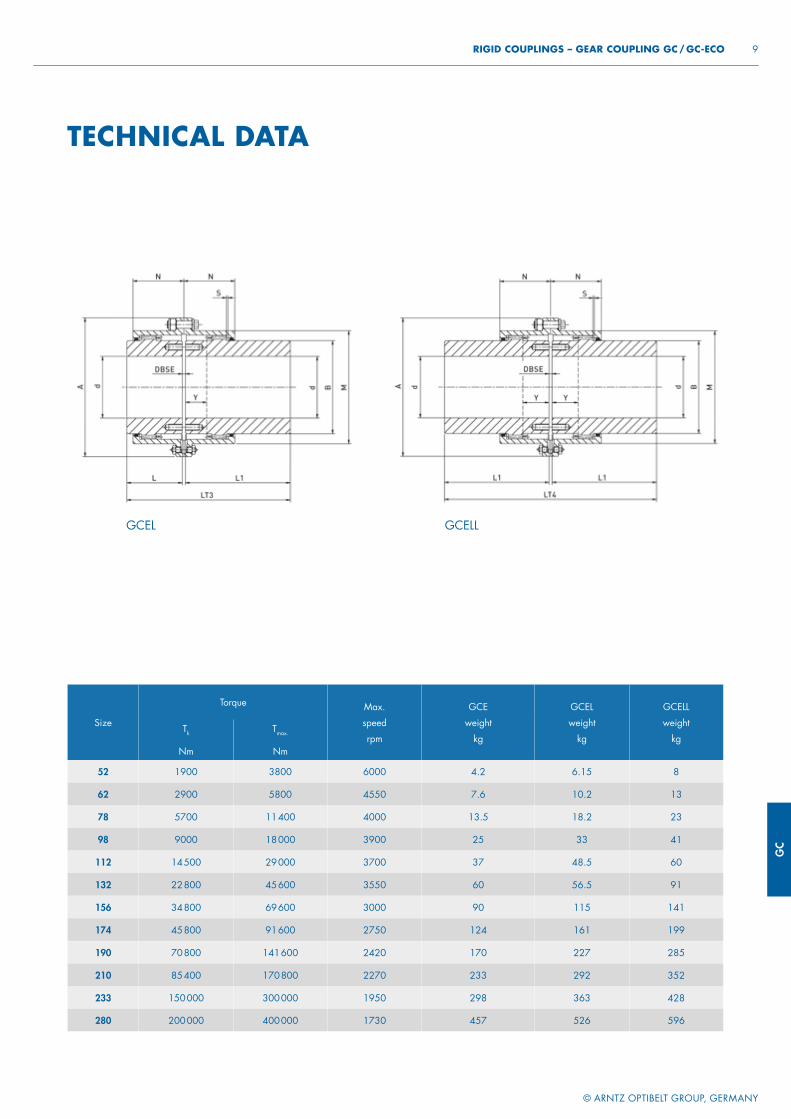
GC
© ARNTZ OPTIBELT GROUP, GERMANY
9 RIGID COUPLINGS – GEAR COUPLING GC / GC-ECO
TECHNICAL DATA
Size
Torque Max.
speed
rpm
GCE
weight
kg
GCEL
weight
kg
GCELL
weight
kgTk
Nm
Tmax.
Nm
52 1900 3800 6000 4.2 6.15 8
62 2900 5800 4550 7.6 10.2 13
78 5700 11 400 4000 13.5 18.2 23
98 9000 18 000 3900 25 33 41
112 14 500 29 000 3700 37 48.5 60
132 22 800 45 600 3550 60 56.5 91
156 34 800 69 600 3000 90 115 141
174 45 800 91 600 2750 124 161 199
190 70 800 141 600 2420 170 227 285
210 85 400 170 800 2270 233 292 352
233 150 000 300 000 1950 298 363 428
280 200 000 400 000 1730 457 526 596
GCEL GCELL
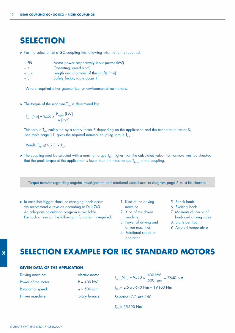
GC
© ARNTZ OPTIBELT GROUP, GERMANY
10 GEAR COUPLING GC / GC-ECO – RIGID COUPLINGS
GIVEN DATA OF THE APPLICATION
Driving machine: electric motor
Power of the motor: P = 400 kW
Rotation at speed: n = 500 rpm
Driven maschine: rotary furnace
TAN [Nm] = 9550 x
TKN = 2.5 x 7640 Nm = 19 100 Nm
Selection: GC size 150
TKN = 35 500 Nm
400 kW 500 rpm
= 7640 Nm
> The coupling must be selected with a nominal torque TKN higher than the calculated value. Furthermore must be checked that the peak torque of the application is lower than the max. torque TKmax of the coupling.
> For the selection of a GC coupling the following information is required:
– PN Motor power respectively input power (kW)– n Operating speed (rpm)– L, d Length and diameter of the shafts (mm)– S Safety factor, table page 11
Where required other geometrical or environmental restrictions.
SELECTION
Torque transfer regarding angular misalignment and rotational speed acc. to diagram page 6 must be checked.
SELECTION EXAMPLE FOR IEC STANDARD MOTORS
> The torque of the machine TAN is determined by:
TAN [Nm] = 9550 xPMotor [kW]
n [rpm]
> This torque TAN multiplied by a safety factor S depending on the application and the temperature factor ST
(see table page 11) gives the required nominal coupling torque TKN.
Result: TKN ≧ S x ST x TAN
> In case that bigger shock or changing loads occur we recommend a revision according to DIN 740.An adequate calculation program is available. For such a revision the following information is required:
1. Kind of the driving machine
2. Kind of the driven machine
3. Power of driving and driven machines
4. Rotational speed of operation
5. Shock loads6. Exciting loads7. Moments of inertia of
load- and driving sides8. Starts per hour9. Ambient temperature
GC
© ARNTZ OPTIBELT GROUP, GERMANY
11 RIGID COUPLINGS – GEAR COUPLING GC / GC-ECO
Operating factor S
Driving machines Load characteristics of the working machineG M S
Electric motors, turbines 1.5 2 2.5
Hydraulic motors 2 2.5 3
Combustion motors 2.5 3 3.5
Assignment of load characteristics according to type of working machine
SSMMMSSM
MMM
MMGMMGM
MS
MSMGMMMMMGMMMMSMM
MGMMG
SGS
DREDGERSBucket conveyorLanding gear (caterpillar)Landing gear (rail)Manoeuvring winchesPumpsImpellersCutter headsSlewing gear
BUILDING MACHINERYHoistsConcrete mixersRoad construction machinery
CHEMICAL INDUSTRYCooling drumsMixersAgitators (liquid material)Agitators (semi-liquid material)Drying drumsCentrifuges (light)Centrifuges (heavy)
OIL INDUSTRYPipeline pumpsRotary drilling equipment
CONVEYORSPit-head winchesWinding enginesJointed-band conveyorsBelt conveyors (bulk material)Belt conveyors (piece goods)Band pocket conveyorsChain conveyorsCircular conveyorsLoad elevatorsBucket conveyors for flourPassenger liftsPlate conveyorsScrew conveyorsBallast elevatorsInclined hoistsSteel belt conveyorsDrag chain conveyors
BLOWERS, VENTILATORSRotary piston blowersBlowers (axial/radial)Cooling tower fansInduced draught fansTurbo blowers
GENERATORS, TRANSFORMERSFrequency transformersGeneratorsWelding generators
SMSMS
SMGS
GSGMM
MMMM
MSSSSMSSGMG
GMMGMMSMM
SSMSMSSSSS
RUBBER MACHINERYExtrudersCalendersKneading millsMixersRolling mills
WOOD WORKING MACHINESBarkersPlaning machinesWood working machinesSaw frames
CRANESLuffi ng gear blockTravelling gearHoist gearSlewing gearDerricking jib gear
PLASTIC INDUSTRY MACHINESExtrudersCalendersMixersCrushers
METAL WORKING MACHINESPlate bending machinesPlate straightening machinesHammersMetal planning machinesPressesShearsForging pressesPunch pressesCountershafts, line shaftsMachine tools (main drives)Machine tools (auxiliary drives)
FOOD INDUSTRY MACHINERYBottling and container fi lling machinesKneading machinesMash tubsPackaging machinesCane crushersCane cuttersCane millsSugar beet cuttersSugar beet washing machines
PAPER MACHINESCouchesGlazing cylindersPulperPulp grindersCalendersWet pressesWillowsSuction pressesSuction rollsDrying cylinders
SGMSS
SSSSSSS
MMMMM
SM
SMSSSMSSSMSMSMMMSMSMSSMS
MM
MM
PUMPSPiston pumpsCentrifugal pumps (light liquids)Centrifugal pumps (viscous liquids)Plunger pumpsPress pumps
STONE AND CLAY WORKING MACHINESCrusherRotary furnaceHammer millsBall millsTube millsBeater millsBrick presses
TEXTILE MACHINESBatchersPrinting and dyeing machinesTanning vatsWillowsLooms
COMPRESSORSPiston compressorsTurbo compressors
METAL ROLLING MILLSPlate shearsManipulator for turning sheetsIngot pushersIngot and slabbing-mill trainIngot handling machineryWire drawing benchesDescaling machinesThin plate millsHeavy and medium plate millsWinding machines (strip and wire)Cold rolling millsChain tractorBillet shearsCooling bedsCross tractorRoller tables (light)Roller tables (heavy)Roller straightenersTube welding machinesTrimming shearsCropping shearsContinuous casting plantRollers adjustment driveManipulators
LAUNDRIESTumblersWashing machines
WATER TREATMENTAeratorsScrew pumps
SAFETY FACTOR S
SELECTION EXAMPLE FOR IEC STANDARD MOTORS

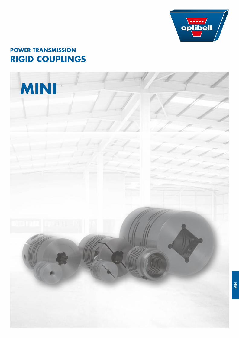
MIN
I
POWER TRANSMISSION
RIGID COUPLINGS
MINI
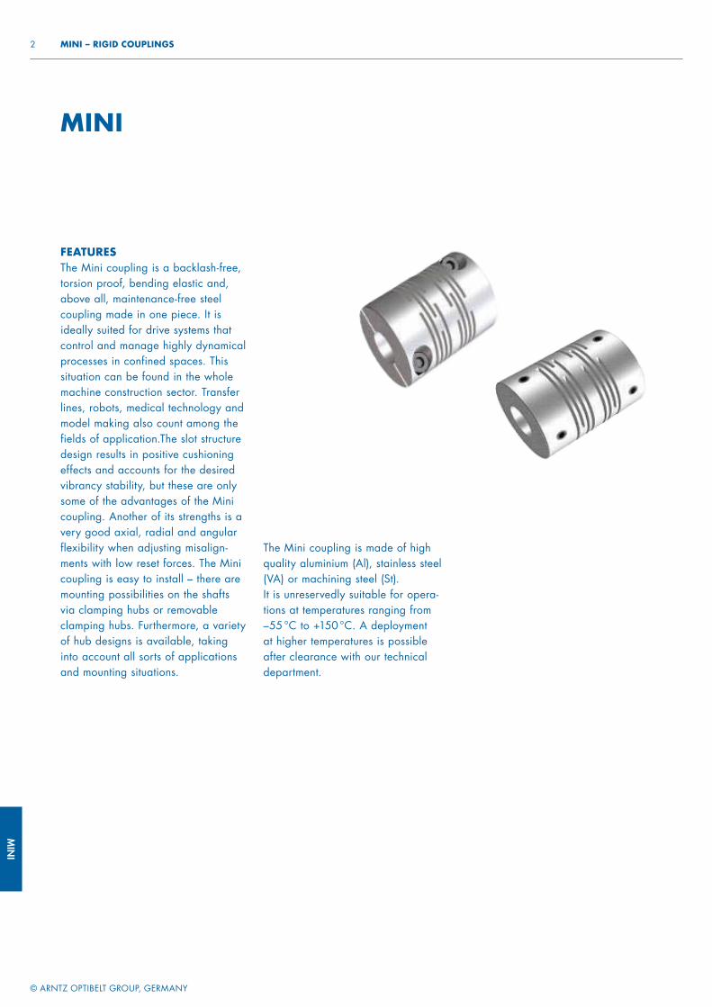
MIN
I
© ARNTZ OPTIBELT GROUP, GERMANY
2 MINI – RIGID COUPLINGS
FEATURES The Mini coupling is a backlash-free, torsion proof, bending elastic and, above all, maintenance-free steel coupling made in one piece. It is ideally suited for drive systems that control and manage highly dynamical processes in confined spaces. This situation can be found in the whole machine construction sector. Transfer lines, robots, medical technology and model making also count among the fields of application.The slot structure design results in positive cushioning effects and accounts for the desired vibrancy stability, but these are only some of the advantages of the Mini coupling. Another of its strengths is a very good axial, radial and angular flexibility when adjusting misalign-ments with low reset forces. The Mini coupling is easy to install – there are mounting possibilities on the shafts via clamping hubs or removable clamping hubs. Furthermore, a variety of hub designs is available, taking into account all sorts of applications and mounting situations.
MINI
The Mini coupling is made of high quality aluminium (Al), stainless steel (VA) or machining steel (St). It is unreservedly suitable for opera-tions at temperatures ranging from –55 °C to +150 °C. A deployment at higher temperatures is possible after clearance with our technical department.
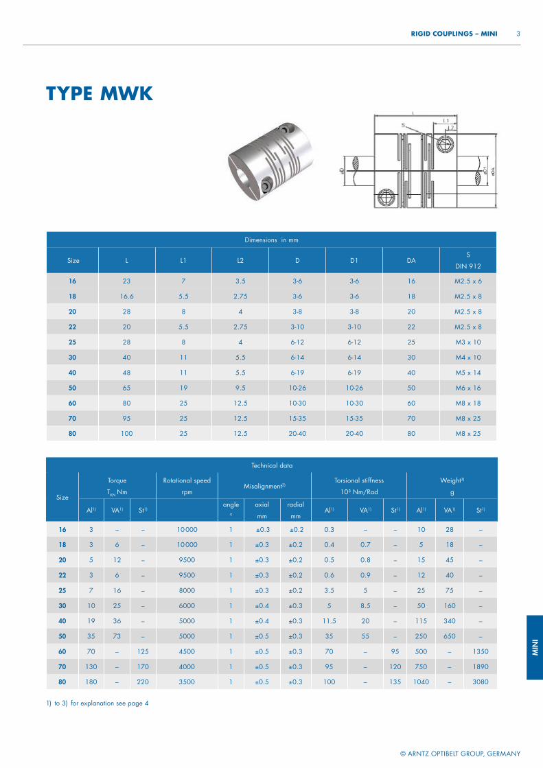
MIN
I
© ARNTZ OPTIBELT GROUP, GERMANY
3 RIGID COUPLINGS – MINI
TYPE MWK
Dimensions in mm
Size L L1 L2 D D1 DAS
DIN 912
16 23 7 3.5 3-6 3-6 16 M2.5 x 6
18 16.6 5.5 2.75 3-6 3-6 18 M2.5 x 8
20 28 8 4 3-8 3-8 20 M2.5 x 8
22 20 5.5 2.75 3-10 3-10 22 M2.5 x 8
25 28 8 4 6-12 6-12 25 M3 x 10
30 40 11 5.5 6-14 6-14 30 M4 x 10
40 48 11 5.5 6-19 6-19 40 M5 x 14
50 65 19 9.5 10-26 10-26 50 M6 x 16
60 80 25 12.5 10-30 10-30 60 M8 x 18
70 95 25 12.5 15-35 15-35 70 M8 x 25
80 100 25 12.5 20-40 20-40 80 M8 x 25
Technical data
Size
Torque
TKN Nm
Rotational speed
rpmMisalignment2)
Torsional stiffness
10³ Nm/Rad
Weight3)
g
Al1) VA1) St1)angle
°
axial
mm
radial
mmAl1) VA1) St1) Al1) VA1) St1)
16 3 – – 10 000 1 ±0.3 ±0.2 0.3 – – 10 28 –
18 3 6 – 10 000 1 ±0.3 ±0.2 0.4 0.7 – 5 18 –
20 5 12 – 9500 1 ±0.3 ±0.2 0.5 0.8 – 15 45 –
22 3 6 – 9500 1 ±0.3 ±0.2 0.6 0.9 – 12 40 –
25 7 16 – 8000 1 ±0.3 ±0.2 3.5 5 – 25 75 –
30 10 25 – 6000 1 ±0.4 ±0.3 5 8.5 – 50 160 –
40 19 36 – 5000 1 ±0.4 ±0.3 11.5 20 – 115 340 –
50 35 73 – 5000 1 ±0.5 ±0.3 35 55 – 250 650 –
60 70 – 125 4500 1 ±0.5 ±0.3 70 – 95 500 – 1350
70 130 – 170 4000 1 ±0.5 ±0.3 95 – 120 750 – 1890
80 180 – 220 3500 1 ±0.5 ±0.3 100 – 135 1040 – 3080
1) to 3) for explanation see page 4
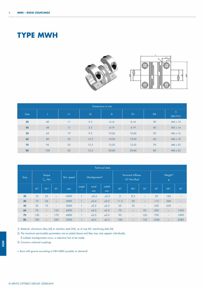
MIN
I
© ARNTZ OPTIBELT GROUP, GERMANY
4 MINI – RIGID COUPLINGS
1) Material: aluminium alloy (Al) or stainless steel (VA), as of size 60: machining steel (St)
2) The maximum permissible parameters are as stated above and they may only appear individually.
If multiple misalignments occur, a reduction has to be made.
3) Concerns unbored couplings
> Bore with groove according to DIN 6885 possible on demand!
Dimensions in mm
Size L L1 L2 D D1 DAS
DIN 912
30 40 11 5.5 6-14 6-14 30 M4 x 10
40 48 11 5.5 6-19 6-19 40 M5 x 14
50 65 19 9.5 10-26 10-26 50 M6 x 16
60 80 25 12.5 10-30 10-30 60 M8 x 18
70 95 25 12.5 15-35 15-35 70 M8 x 25
80 100 25 12.5 20-40 20-40 80 M8 x 25
Technical data
SizeTorque
TKN NmRot. speed Misalignment2)
Torsional stiffness
10³ Nm/Rad
Weight3)
g
Al1) VA1) St1) rpmangle
°
axial
mm
radial
mmAl1) VA1) St1) Al1) VA1) St1)
30 10 25 – 6000 1 ±0.4 ±0.3 5 8.5 – 50 160 –
40 19 36 – 5000 1 ±0.4 ±0.3 11.5 20 – 115 340 –
50 35 73 – 5000 1 ±0.5 ±0.3 35 55 – 250 650 –
60 70 – 125 4500 1 ±0.5 ±0.3 70 – 95 500 – 1350
70 130 – 170 4000 1 ±0.5 ±0.3 95 – 120 750 – 1890
80 180 – 220 3500 1 ±0.5 ±0.3 100 – 135 1040 – 3080
TYPE MWH
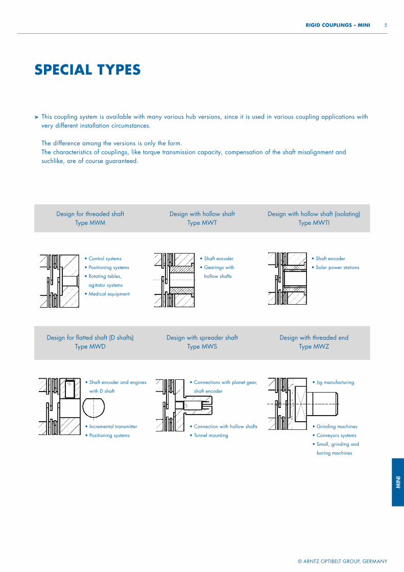
MIN
I
© ARNTZ OPTIBELT GROUP, GERMANY
5 RIGID COUPLINGS – MINI
> This coupling system is available with many various hub versions, since it is used in various coupling applications with very different installation circumstances.
The difference among the versions is only the form.The characteristics of couplings, like torque transmission capacity, compensation of the shaft misalignment and suchlike, are of course guaranteed.
SPECIAL TYPES
Design for threaded shaft Type MWM
Design with hollow shaft Type MWT
Design with hollow shaft (isolating)Type MWTI
Design for fl atted shaft (D shafts) Type MWD
Design with spreader shaftType MWS
Design with threaded endType MWZ
• Control systems
• Positioning systems
• Rotating tables,
agitator systems
• Medical equipment
• Shaft encoder
• Gearings with
hollow shafts
• Shaft encoder
• Solar power stations
• Shaft encoder and engines
with D shaft
• Incremental transmitter
• Positioning systems
• Connections with planet gear,
shaft encoder
• Connection with hollow shafts
• Tunnel mounting
• Jig manufacturing
• Grinding machines
• Conveyors systems
• Small, grinding and
boring machines
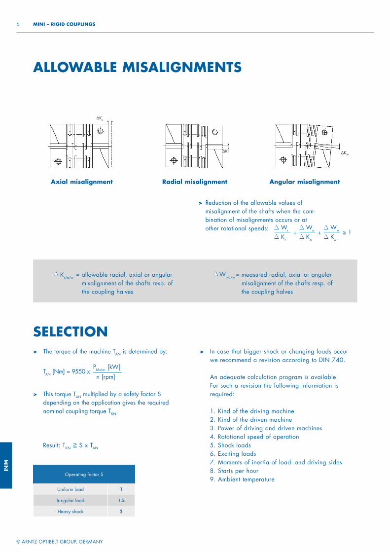
MIN
I
© ARNTZ OPTIBELT GROUP, GERMANY
6 MINI – RIGID COUPLINGS
Axial misalignment Radial misalignment Angular misalignment
ALLOWABLE MISALIGNMENTS
> Reduction of the allowable values of misalignment of the shafts when the com-bination of misalignments occurs or at other rotational speeds: Wr
Kr
Wa
Ka
+Ww
Kw
+ ≦ 1
= allowable radial, axial or angular misalignment of the shafts resp. of the coupling halves
Kr/a/w = measured radial, axial or angular misalignment of the shafts resp. of the coupling halves
Wr/a/w
Operating factor S
Uniform load 1
Irregular load 1.5
Heavy shock 2
SELECTION> The torque of the machine TAN is determined by:
TAN [Nm] = 9550 xPMotor [kW]
n [rpm]
> This torque TAN multiplied by a safety factor S depending on the application gives the required nominal coupling torque TKN.
Result: TKN ≧ S x TAN
> In case that bigger shock or changing loads occur we recommend a revision according to DIN 740.
An adequate calculation program is available. For such a revision the following information is required:
1. Kind of the driving machine2. Kind of the driven machine3. Power of driving and driven machines4. Rotational speed of operation5. Shock loads6. Exciting loads7. Moments of inertia of load- and driving sides8. Starts per hour9. Ambient temperature
∆Ka
∆KW∆Kr
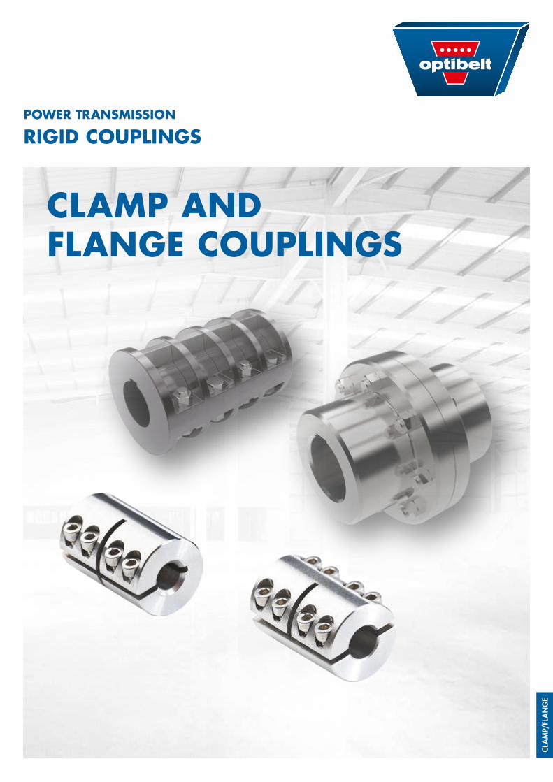
CLAM
P/FL
ANG
E
POWER TRANSMISSION
RIGID COUPLINGS
CLAMP AND FLANGE COUPLINGS
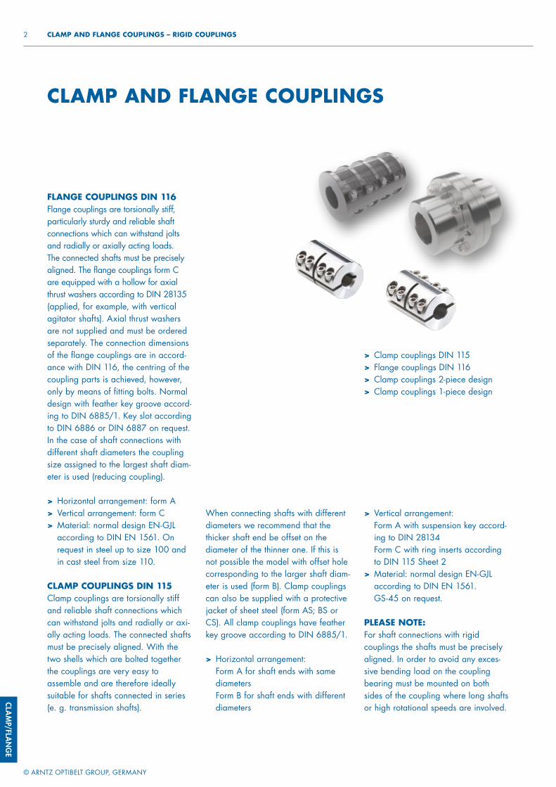
CLAMP/FLAN
GE
© ARNTZ OPTIBELT GROUP, GERMANY
2 CLAMP AND FLANGE COUPLINGS – RIGID COUPLINGS
> Clamp couplings DIN 115> Flange couplings DIN 116> Clamp couplings 2-piece design> Clamp couplings 1-piece design
> Vertical arrangement: Form A with suspension key accord-ing to DIN 28134Form C with ring inserts according to DIN 115 Sheet 2
> Material: normal design EN-GJL according to DIN EN 1561. GS-45 on request.
PLEASE NOTE:For shaft connections with rigid couplings the shafts must be precisely aligned. In order to avoid any exces-sive bending load on the coupling bearing must be mounted on both sides of the coupling where long shafts or high rotational speeds are involved.
When connecting shafts with different diameters we recommend that the thicker shaft end be offset on the diameter of the thinner one. If this is not possible the model with offset hole corresponding to the larger shaft diam-eter is used (form B). Clamp couplings can also be supplied with a protective jacket of sheet steel (form AS; BS or CS). All clamp couplings have feather key groove according to DIN 6885/1.
> Horizontal arrangement:Form A for shaft ends with same diametersForm B for shaft ends with different diameters
CLAMP AND FLANGE COUPLINGS
FLANGE COUPLINGS DIN 116Flange couplings are torsionally stiff, particularly sturdy and reliable shaft connections which can withstand jolts and radially or axially acting loads. The connected shafts must be precisely aligned. The flange couplings form C are equipped with a hollow for axial thrust washers according to DIN 28135 (applied, for example, with vertical agitator shafts). Axial thrust washers are not supplied and must be ordered separately. The connection dimensions of the flange couplings are in accord-ance with DIN 116, the centring of the coupling parts is achieved, however, only by means of fitting bolts. Normal design with feather key groove accord-ing to DIN 6885/1. Key slot according to DIN 6886 or DIN 6887 on request. In the case of shaft connections with different shaft diameters the coupling size assigned to the largest shaft diam-eter is used (reducing coupling).
> Horizontal arrangement: form A> Vertical arrangement: form C> Material: normal design EN-GJL
according to DIN EN 1561. On request in steel up to size 100 and in cast steel from size 110.
CLAMP COUPLINGS DIN 115Clamp couplings are torsionally stiff and reliable shaft connections which can withstand jolts and radially or axi-ally acting loads. The connected shafts must be precisely aligned. With the two shells which are bolted together the couplings are very easy to assemble and are therefore ideally suitable for shafts connected in series (e. g. transmission shafts).
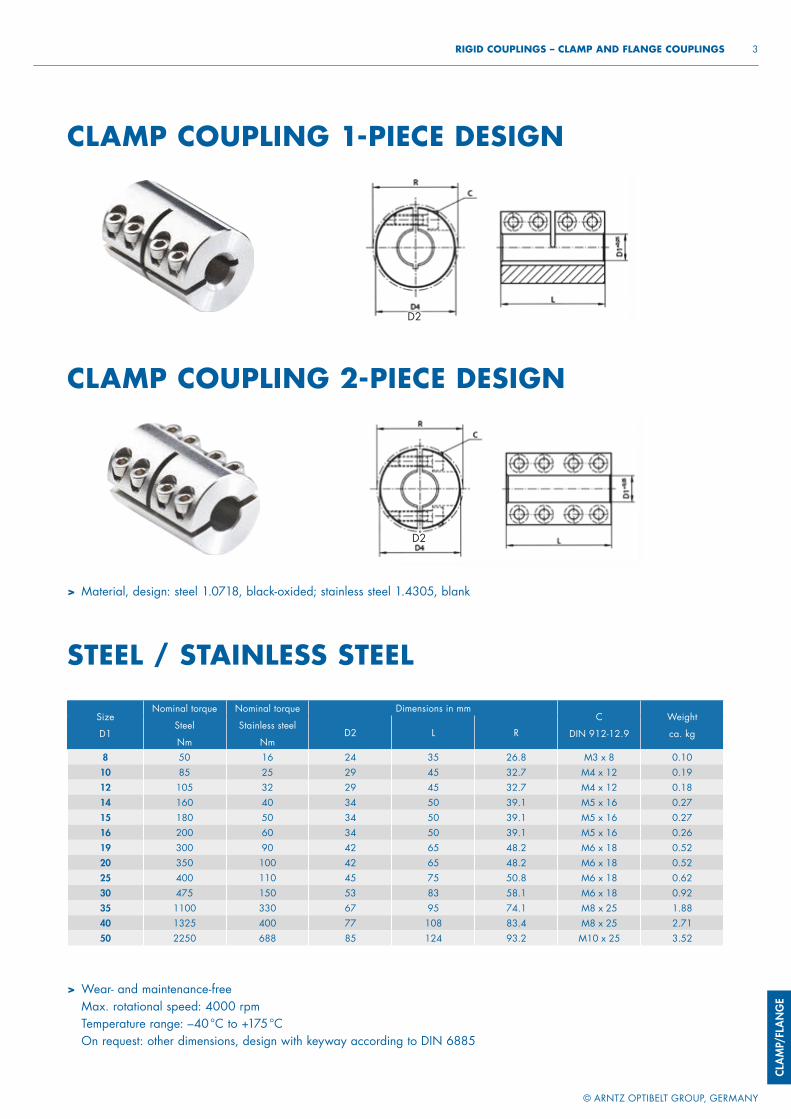
CLAM
P/FL
ANG
E
© ARNTZ OPTIBELT GROUP, GERMANY
3 RIGID COUPLINGS – CLAMP AND FLANGE COUPLINGS
> Material, design: steel 1.0718, black-oxided; stainless steel 1.4305, blank
STEEL / STAINLESS STEEL
CLAMP COUPLING 1-PIECE DESIGN
CLAMP COUPLING 2-PIECE DESIGN
Size
D1
Nominal torque
Steel
Nm
Nominal torque
Stainless steel
Nm
Dimensions in mmC
DIN 912-12.9
Weight
ca. kgD2 L R
8 50 16 24 35 26.8 M3 x 8 0.1010 85 25 29 45 32.7 M4 x 12 0.1912 105 32 29 45 32.7 M4 x 12 0.1814 160 40 34 50 39.1 M5 x 16 0.2715 180 50 34 50 39.1 M5 x 16 0.2716 200 60 34 50 39.1 M5 x 16 0.2619 300 90 42 65 48.2 M6 x 18 0.5220 350 100 42 65 48.2 M6 x 18 0.5225 400 110 45 75 50.8 M6 x 18 0.6230 475 150 53 83 58.1 M6 x 18 0.9235 1100 330 67 95 74.1 M8 x 25 1.8840 1325 400 77 108 83.4 M8 x 25 2.7150 2250 688 85 124 93.2 M10 x 25 3.52
> Wear- and maintenance-free Max. rotational speed: 4000 rpmTemperature range: –40 °C to +175 °COn request: other dimensions, design with keyway according to DIN 6885
D2
D2
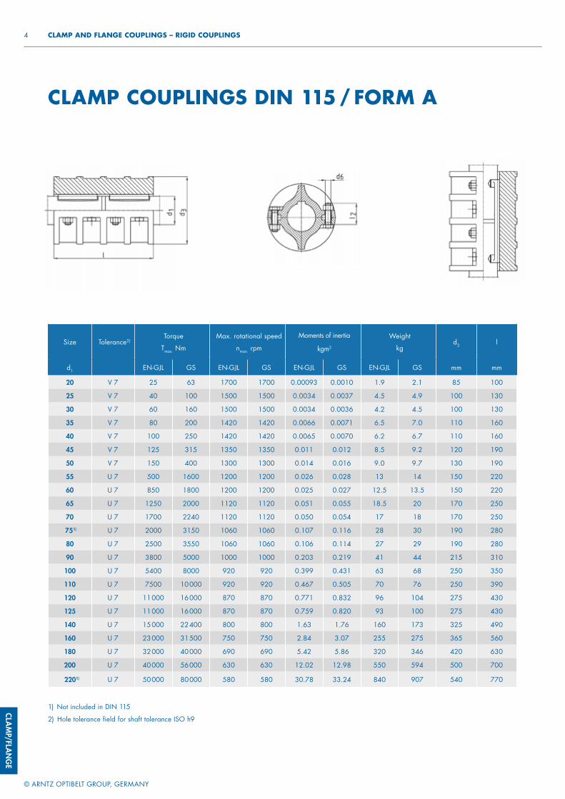
CLAMP/FLAN
GE
© ARNTZ OPTIBELT GROUP, GERMANY
4 CLAMP AND FLANGE COUPLINGS – RIGID COUPLINGS
CLAMP COUPLINGS DIN 115 / FORM A
Size Tolerance2)Torque
Tmax. Nm
Max. rotational speed
nmax. rpm
Moments of inertia
kgm2
Weight
kgd3 l
d1 EN-GJL GS EN-GJL GS EN-GJL GS EN-GJL GS mm mm
20 V 7 25 63 1700 1700 0.00093 0.0010 1.9 2.1 85 100
25 V 7 40 100 1500 1500 0.0034 0.0037 4.5 4.9 100 130
30 V 7 60 160 1500 1500 0.0034 0.0036 4.2 4.5 100 130
35 V 7 80 200 1420 1420 0.0066 0.0071 6.5 7.0 110 160
40 V 7 100 250 1420 1420 0.0065 0.0070 6.2 6.7 110 160
45 V 7 125 315 1350 1350 0.011 0.012 8.5 9.2 120 190
50 V 7 150 400 1300 1300 0.014 0.016 9.0 9.7 130 190
55 U 7 500 1600 1200 1200 0.026 0.028 13 14 150 220
60 U 7 850 1800 1200 1200 0.025 0.027 12.5 13.5 150 220
65 U 7 1250 2000 1120 1120 0.051 0.055 18.5 20 170 250
70 U 7 1700 2240 1120 1120 0.050 0.054 17 18 170 250
751) U 7 2000 3150 1060 1060 0.107 0.116 28 30 190 280
80 U 7 2500 3550 1060 1060 0.106 0.114 27 29 190 280
90 U 7 3800 5000 1000 1000 0.203 0.219 41 44 215 310
100 U 7 5400 8000 920 920 0.399 0.431 63 68 250 350
110 U 7 7500 10 000 920 920 0.467 0.505 70 76 250 390
120 U 7 11 000 16 000 870 870 0.771 0.832 96 104 275 430
125 U 7 11 000 16 000 870 870 0.759 0.820 93 100 275 430
140 U 7 15 000 22 400 800 800 1.63 1.76 160 173 325 490
160 U 7 23 000 31 500 750 750 2.84 3.07 255 275 365 560
180 U 7 32 000 40 000 690 690 5.42 5.86 320 346 420 630
200 U 7 40 000 56 000 630 630 12.02 12.98 550 594 500 700
2201) U 7 50 000 80 000 580 580 30.78 33.24 840 907 540 770
1) Not included in DIN 115
2) Hole tolerance field for shaft tolerance ISO h9
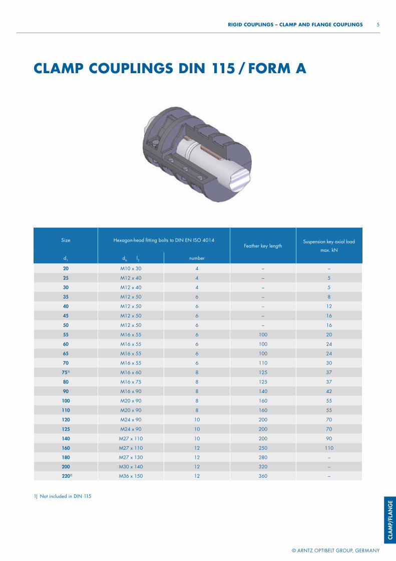
CLAM
P/FL
ANG
E
© ARNTZ OPTIBELT GROUP, GERMANY
5 RIGID COUPLINGS – CLAMP AND FLANGE COUPLINGS
CLAMP COUPLINGS DIN 115 / FORM A
Size Hexagon-head fi tting bolts to DIN EN ISO 4014Feather key length
Suspension key axial load
max. kN
d1 d6 l2 number
20 M10 x 30 4 – –
25 M12 x 40 4 – 5
30 M12 x 40 4 – 5
35 M12 x 50 6 – 8
40 M12 x 50 6 – 12
45 M12 x 50 6 – 16
50 M12 x 50 6 – 16
55 M16 x 55 6 100 20
60 M16 x 55 6 100 24
65 M16 x 55 6 100 24
70 M16 x 55 6 110 30
751) M16 x 60 8 125 37
80 M16 x 75 8 125 37
90 M16 x 90 8 140 42
100 M20 x 90 8 160 55
110 M20 x 90 8 160 55
120 M24 x 90 10 200 70
125 M24 x 90 10 200 70
140 M27 x 110 10 200 90
160 M27 x 110 12 250 110
180 M27 x 130 12 280 –
200 M30 x 140 12 320 –
2201) M36 x 150 12 360 –
1) Not included in DIN 115
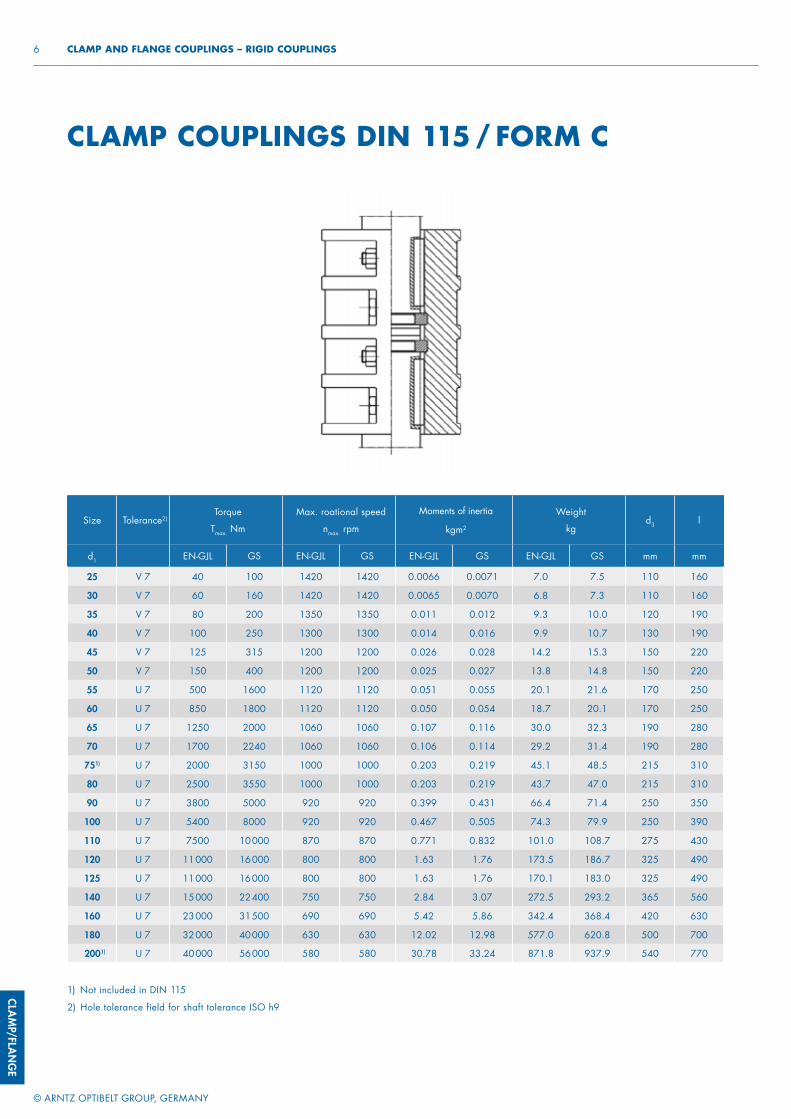
CLAMP/FLAN
GE
© ARNTZ OPTIBELT GROUP, GERMANY
6 CLAMP AND FLANGE COUPLINGS – RIGID COUPLINGS
CLAMP COUPLINGS DIN 115 / FORM C
1) Not included in DIN 115
2) Hole tolerance field for shaft tolerance ISO h9
Size Tolerance2)Torque
Tmax. Nm
Max. roational speed
nmax. rpm
Moments of inertia
kgm2
Weight
kgd3 l
d1 EN-GJL GS EN-GJL GS EN-GJL GS EN-GJL GS mm mm
25 V 7 40 100 1420 1420 0.0066 0.0071 7.0 7.5 110 160
30 V 7 60 160 1420 1420 0.0065 0.0070 6.8 7.3 110 160
35 V 7 80 200 1350 1350 0.011 0.012 9.3 10.0 120 190
40 V 7 100 250 1300 1300 0.014 0.016 9.9 10.7 130 190
45 V 7 125 315 1200 1200 0.026 0.028 14.2 15.3 150 220
50 V 7 150 400 1200 1200 0.025 0.027 13.8 14.8 150 220
55 U 7 500 1600 1120 1120 0.051 0.055 20.1 21.6 170 250
60 U 7 850 1800 1120 1120 0.050 0.054 18.7 20.1 170 250
65 U 7 1250 2000 1060 1060 0.107 0.116 30.0 32.3 190 280
70 U 7 1700 2240 1060 1060 0.106 0.114 29.2 31.4 190 280
751) U 7 2000 3150 1000 1000 0.203 0.219 45.1 48.5 215 310
80 U 7 2500 3550 1000 1000 0.203 0.219 43.7 47.0 215 310
90 U 7 3800 5000 920 920 0.399 0.431 66.4 71.4 250 350
100 U 7 5400 8000 920 920 0.467 0.505 74.3 79.9 250 390
110 U 7 7500 10 000 870 870 0.771 0.832 101.0 108.7 275 430
120 U 7 11 000 16 000 800 800 1.63 1.76 173.5 186.7 325 490
125 U 7 11 000 16 000 800 800 1.63 1.76 170.1 183.0 325 490
140 U 7 15 000 22 400 750 750 2.84 3.07 272.5 293.2 365 560
160 U 7 23 000 31 500 690 690 5.42 5.86 342.4 368.4 420 630
180 U 7 32 000 40 000 630 630 12.02 12.98 577.0 620.8 500 700
2001) U 7 40 000 56 000 580 580 30.78 33.24 871.8 937.9 540 770
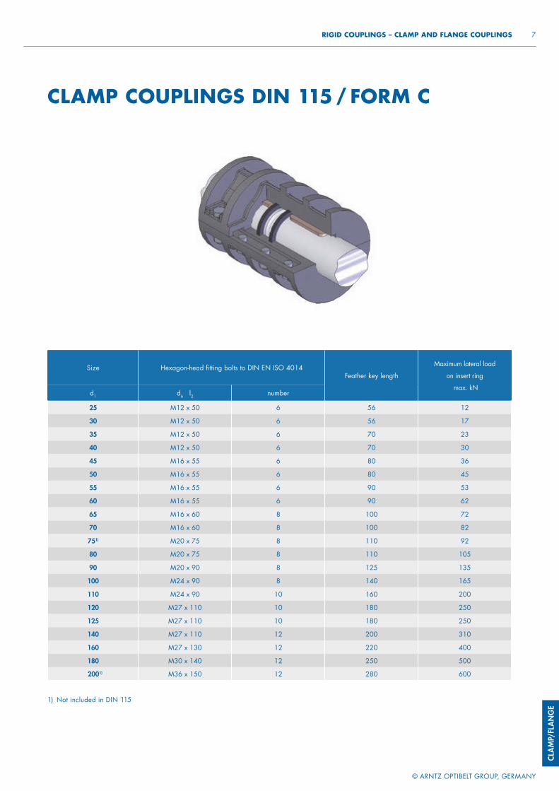
CLAM
P/FL
ANG
E
© ARNTZ OPTIBELT GROUP, GERMANY
7 RIGID COUPLINGS – CLAMP AND FLANGE COUPLINGS
CLAMP COUPLINGS DIN 115 / FORM C
1) Not included in DIN 115
Size Hexagon-head fi tting bolts to DIN EN ISO 4014Feather key length
Maximum lateral load
on insert ring
max. kNd1 d6 l2 number
25 M12 x 50 6 56 12
30 M12 x 50 6 56 17
35 M12 x 50 6 70 23
40 M12 x 50 6 70 30
45 M16 x 55 6 80 36
50 M16 x 55 6 80 45
55 M16 x 55 6 90 53
60 M16 x 55 6 90 62
65 M16 x 60 8 100 72
70 M16 x 60 8 100 82
751) M20 x 75 8 110 92
80 M20 x 75 8 110 105
90 M20 x 90 8 125 135
100 M24 x 90 8 140 165
110 M24 x 90 10 160 200
120 M27 x 110 10 180 250
125 M27 x 110 10 180 250
140 M27 x 110 12 200 310
160 M27 x 130 12 220 400
180 M30 x 140 12 250 500
2001) M36 x 150 12 280 600
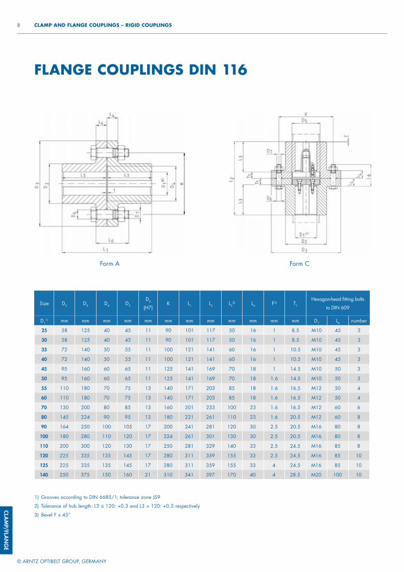
CLAMP/FLAN
GE
© ARNTZ OPTIBELT GROUP, GERMANY
8 CLAMP AND FLANGE COUPLINGS – RIGID COUPLINGS
1) Grooves according to DIN 6685/1; tolerance zone JS9
2) Tolerance of hub length: L3 ≤ 120: +0.3 and L3 > 120: +0.5 respectively
3) Bevel F x 45°
FLANGE COUPLINGS DIN 116
Size D2 D3 D4 D5
D6
(H7)K L1 L2 L3
2) L4 F3) T1
Hexagon-head fi tting bolts
to DIN 609
D11) mm mm mm mm mm mm mm mm mm mm mm mm D7 L6 number
25 58 125 40 45 11 90 101 117 50 16 1 8.5 M10 45 3
30 58 125 40 45 11 90 101 117 50 16 1 8.5 M10 45 3
35 72 140 50 55 11 100 121 141 60 16 1 10.5 M10 45 3
40 72 140 50 55 11 100 121 141 60 16 1 10.5 M10 45 3
45 95 160 60 65 11 125 141 169 70 18 1 14.5 M10 50 3
50 95 160 60 65 11 125 141 169 70 18 1.6 14.5 M10 50 3
55 110 180 70 75 13 140 171 203 85 18 1.6 16.5 M12 50 4
60 110 180 70 75 13 140 171 203 85 18 1.6 16.5 M12 50 4
70 130 200 80 85 13 160 201 233 100 23 1.6 16.5 M12 60 6
80 145 224 90 95 13 180 221 261 110 23 1.6 20.5 M12 60 8
90 164 250 100 105 17 200 241 281 120 30 2.5 20.5 M16 80 8
100 180 280 110 120 17 224 261 301 130 30 2.5 20.5 M16 80 8
110 200 300 120 130 17 250 281 329 140 33 2.5 24.5 M16 85 8
120 225 335 135 145 17 280 311 359 155 33 2.5 24.5 M16 85 10
125 225 335 135 145 17 280 311 359 155 33 4 24.5 M16 85 10
140 250 375 150 160 21 310 341 397 170 40 4 28.5 M20 100 10
Form A Form C
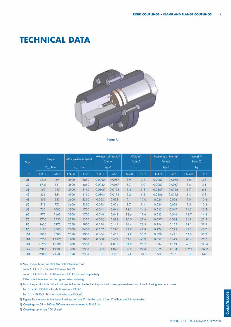
CLAM
P/FL
ANG
E
© ARNTZ OPTIBELT GROUP, GERMANY
9 RIGID COUPLINGS – CLAMP AND FLANGE COUPLINGS
Size D2 D3 D4 D5
D6
(H7)K L1 L2 L3
2) L4 F3) T1
Hexagon-head fi tting bolts
to DIN 609
D11) mm mm mm mm mm mm mm mm mm mm mm mm D7 L6 number
25 58 125 40 45 11 90 101 117 50 16 1 8.5 M10 45 3
30 58 125 40 45 11 90 101 117 50 16 1 8.5 M10 45 3
35 72 140 50 55 11 100 121 141 60 16 1 10.5 M10 45 3
40 72 140 50 55 11 100 121 141 60 16 1 10.5 M10 45 3
45 95 160 60 65 11 125 141 169 70 18 1 14.5 M10 50 3
50 95 160 60 65 11 125 141 169 70 18 1.6 14.5 M10 50 3
55 110 180 70 75 13 140 171 203 85 18 1.6 16.5 M12 50 4
60 110 180 70 75 13 140 171 203 85 18 1.6 16.5 M12 50 4
70 130 200 80 85 13 160 201 233 100 23 1.6 16.5 M12 60 6
80 145 224 90 95 13 180 221 261 110 23 1.6 20.5 M12 60 8
90 164 250 100 105 17 200 241 281 120 30 2.5 20.5 M16 80 8
100 180 280 110 120 17 224 261 301 130 30 2.5 20.5 M16 80 8
110 200 300 120 130 17 250 281 329 140 33 2.5 24.5 M16 85 8
120 225 335 135 145 17 280 311 359 155 33 2.5 24.5 M16 85 10
125 225 335 135 145 17 280 311 359 155 33 4 24.5 M16 85 10
140 250 375 150 160 21 310 341 397 170 40 4 28.5 M20 100 10
TECHNICAL DATA
SizeTorque Max. rotational speed
Moments of inertia3)
Form A
Weight3)
Form A
Moments of inertia3)
Form C
Weight3)
Form C
Tmax. Nm nmax. rpm kgm2 kg kgm2 kg
D14) EN-GJL1) GS2)5) EN-GJL GS5) EN-GJL GS5) EN-GJL GS5) EN-GJL GS5) EN-GJL GS5)
25 46.2 69 4600 6850 0.0062 0.0067 3.9 4.2 0.0063 0.0068 4.0 4.3
30 87.5 131 4600 6850 0.0062 0.0067 3.7 4.0 0.0062 0.0067 3.8 4.1
35 150 225 4100 6150 0.0105 0.0113 5.4 5.8 0.0107 0.0116 5.7 6.1
40 236 354 4100 6150 0.0104 0.0112 5.2 5.5 0.0106 0.0115 5.4 5.8
45 355 533 3600 5350 0.023 0.025 9.1 10.0 0.024 0.026 9.8 10.6
50 515 773 3600 5350 0.023 0.024 8.7 9.4 0.024 0.026 9.5 10.2
55 730 1095 3200 4750 0.041 0.044 13.1 14.2 0.043 0.047 14.3 15.5
60 975 1463 3200 4750 0.040 0.043 12.6 13.6 0.043 0.046 13.7 14.8
70 1700 2550 2850 4300 0.082 0.088 20.0 21.6 0.087 0.094 21.8 23.5
80 2650 3975 2550 3850 0.134 0.144 26.4 28.5 0.144 0.155 29.1 31.4
90 4120 6180 2300 3450 0.257 0.276 38.7 41.8 0.274 0.295 42.3 45.7
100 5800 8700 2050 3050 0.404 0.435 49.8 53.7 0.428 0.461 53.8 58.2
110 8250 12 375 1900 2850 0.608 0.652 64.1 68.9 0.652 0.699 70.4 75.7
120 11 200 16 800 1700 2550 1.011 1.085 88.2 94.7 1.084 1.163 96.3 103.4
125 12 800 19 200 1700 2550 1.003 1.076 86.0 92.4 1.075 1.154 102.1 109.7
140 19 000 28 500 1550 2300 1.81 1.93 121 130 1.93 2.07 133 142
1) Max. torque based on DIN 116 Hole tolerance zone:
Form A: ISO H7 – for shaft tolerance ISO h9
Form C: ISO N7 – for shaft tolerance ISO k6 and m6 respectively
Other hole tolerances can be agreed when ordering.
2) Max. torques (for hole D1) with allowable load on the feather key and with average overdimension of the following tolerance zones:
For D1 ≤ 50: ISO N7 – for shaft tolerance ISO k6
For D1 > 50: ISO N7 – for shaft tolerance ISO m6
3) Figures for moments of inertia and weights for hole D1 (in the case of form C without axial thrust washer)
4) Couplings for D1 = 260 to 500 mm are not included in DIN 116.
5) Couplings up to size 100 of steel
Form C
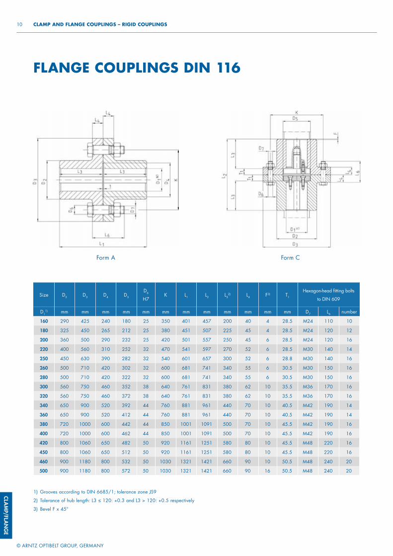
CLAMP/FLAN
GE
© ARNTZ OPTIBELT GROUP, GERMANY
10 CLAMP AND FLANGE COUPLINGS – RIGID COUPLINGS
FLANGE COUPLINGS DIN 116
Size D2 D3 D4 D5
D6
H7K L1 L2 L3
2) L4 F3) T1
Hexagon-head fi tting bolts
to DIN 609
D11) mm mm mm mm mm mm mm mm mm mm mm mm D7 L6 number
160 290 425 240 180 25 350 401 457 200 40 4 28.5 M24 110 10
180 325 450 265 212 25 380 451 507 225 45 4 28.5 M24 120 12
200 360 500 290 232 25 420 501 557 250 45 6 28.5 M24 120 16
220 400 560 310 252 32 470 541 597 270 52 6 28.5 M30 140 14
250 450 630 390 282 32 540 601 657 300 52 6 28.8 M30 140 16
260 500 710 420 302 32 600 681 741 340 55 6 30.5 M30 150 16
280 500 710 420 322 32 600 681 741 340 55 6 30.5 M30 150 16
300 560 750 460 352 38 640 761 831 380 62 10 35.5 M36 170 16
320 560 750 460 372 38 640 761 831 380 62 10 35.5 M36 170 16
340 650 900 520 392 44 760 881 961 440 70 10 40.5 M42 190 14
360 650 900 520 412 44 760 881 961 440 70 10 40.5 M42 190 14
380 720 1000 600 442 44 850 1001 1091 500 70 10 45.5 M42 190 16
400 720 1000 600 462 44 850 1001 1091 500 70 10 45.5 M42 190 16
420 800 1060 650 482 50 920 1161 1251 580 80 10 45.5 M48 220 16
450 800 1060 650 512 50 920 1161 1251 580 80 10 45.5 M48 220 16
460 900 1180 800 532 50 1030 1321 1421 660 90 10 50.5 M48 240 20
500 900 1180 800 572 50 1030 1321 1421 660 90 16 50.5 M48 240 20
Form A Form C
1) Grooves according to DIN 6685/1; tolerance zone JS9
2) Tolerance of hub length: L3 ≤ 120: +0.3 and L3 > 120: +0.5 respectively
3) Bevel F x 45°
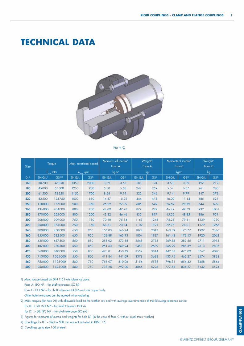
CLAM
P/FL
ANG
E
© ARNTZ OPTIBELT GROUP, GERMANY
11 RIGID COUPLINGS – CLAMP AND FLANGE COUPLINGS
SizeTorque Max. rotational speed
Moments of inertia3)
Form A
Weight3)
Form A
Moments of inertia3)
Form C
Weight3)
Form C
Tmax. Nm nmax. rpm kgm2 kg kgm2 kg
D14) EN-GJL1) GS2)5) EN-GJL GS5) EN-GJL GS5) EN-GJL GS5) EN-GJL GS5) EN-GJL GS5)
160 30 700 46 050 1350 2000 3.39 3.63 181 194 3.63 3.89 197 212
180 45 000 67 500 1250 1900 5.30 5.68 242 259 5.67 6.07 261 280
200 61 500 92 250 1150 1700 8.58 9.19 322 346 9.14 9.79 347 372
220 82 500 123 750 1000 1550 14.87 15.92 444 476 16.00 17.14 485 521
250 118 000 177 000 900 1350 25.29 27.09 605 649 26.69 28.59 644 692
260 136 000 204 000 800 1200 44.09 47.28 877 942 46.42 49.79 932 1001
280 170 000 255 000 800 1200 43.32 46.46 835 897 45.55 48.85 886 951
300 206 000 309 000 750 1150 70.10 75.14 1163 1248 74.26 79.61 1239 1330
320 250 000 375 000 750 1150 68.81 73.74 1109 1191 72.77 78.01 1179 1266
340 300 000 450 000 650 950 155.03 166.24 1874 2013 163.89 175.77 1997 2146
360 355 000 532 500 650 950 152.88 163.93 1804 1937 161.43 173.13 1920 2062
380 425 000 637 500 550 850 255.02 273.58 2545 2733 269.85 289.55 2711 2913
400 487 000 730 500 550 850 251.63 269.94 2457 2639 265.99 285.39 2613 2807
420 560 000 840 000 550 800 420.01 450.49 3552 3814 442.88 475.09 3762 4040
450 710 000 1 065 000 550 800 411.84 441.69 3378 3628 433.75 465.27 3574 3838
460 750 000 1 125 000 500 750 755.07 810.06 5156 5538 796.31 854.42 5458 5864
500 950 000 1 425 000 500 750 738.28 792.00 4866 5226 777.58 834.27 5142 5524
TECHNICAL DATA
Form C
1) Max. torque based on DIN 116 Hole tolerance zone:
Form A: ISO H7 – for shaft tolerance ISO h9
Form C: ISO N7 – for shaft tolerance ISO k6 and m6 respectively
Other hole tolerances can be agreed when ordering.
2) Max. torques (for hole D1) with allowable load on the feather key and with average overdimension of the following tolerance zones:
For D1 ≤ 50: ISO N7 – for shaft tolerance ISO k6
For D1 > 50: ISO N7 – for shaft tolerance ISO m6
3) Figures for moments of inertia and weights for hole D1 (in the case of form C without axial thrust washer)
4) Couplings for D1 = 260 to 500 mm are not included in DIN 116.
5) Couplings up to size 100 of steel
© ARNTZ OPTIBELT GROUP, GERMANY
NOTES
NOTES96

© ARNTZ OPTIBELT GROUP, GERMANY
NOTES 97

© ARNTZ OPTIBELT GROUP, GERMANY
NOTES
NOTES98


www.optibelt.com
Optibelt GmbH Corveyer Allee 1537671 Höxter GERMANY
T +49 (0) 52 71- 6 21F +49 (0) 52 71- 97 62 00E info @ optibelt.com
PT/K
OM
PAKT
KATA
LOG
KU
PPLU
NG
EN/G
B/01
18