Embed Size (px)
Citation preview

M-2911
COMPACT CAL

1
ForewordThank you for purchasing the OMEGA CA100 COMPACT CAL. This User's Manualcontains useful information regarding the instrument's functions and operatingprocedures as well as precautions that should be observed during use. To ensure properuse of the instrument, please read the manual thoroughly before operating it. Keep themanual in the carrying case for quick reference whenever a question arises.
Note• The contents of this manual are subject to change without prior notice as a result of
improvements in the instrument's performance and functions.• Every effort has been made in the preparation of this manual to ensure the accuracy of
its contents. However, should you have any questions or find any errors, pleasecontact your nearest representative.
• Copying or reproduction of any or all of the contents of this manual without Omega'spermission is strictly prohibited.
Trademarks• MS-DOS is a registered trademark of Microsoft Corporation.• Company names and product names which appear in this manual are the trademarks
or registered trademarks of the respective companies.
Revisions1st Edition: March 1999

2
Conventions Used in This Manual
Type Symbol Meaning
Cautionary note
To avoid injury, death of personnel ordamage to the instrument, the operator mustrefer to an explanation in the User's Manual.
Calls attention to a procedure, practice orcondition, which, if not correctly performed,adhered to, or maintained, could result ininjury or death.
Calls attention to a procedure, practice orcondition, which, if not correctly performed,adhered to, or maintained, could result indamage to, or destruction of part of theproduct.
Note Calls attention to information which isimportant in the operation of the instrument.
Key [ ] key Represents a key on the front panel.
Checking the Contents of the PackageUnpack the box and check the contents. If the product is not the one you ordered, anyitem is missing or damage to any item is found, contact the dealer from whom youpurchased the instrument.

3
Standard AccessoriesThe following standard accessories are supplied with the instrument. Make sure that allitems are present and undamaged. Note that the dry cell holder (B9914CV) comespreinstalled in the main unit.
Carrying case Battery holder
2 Measurement leads(CA100-ML)
User's Manual(M-2911)
8 Alkaline dry cells
2 Ferrite core(CA100-FC)
Fuse

4
Safety Precautions
Ths instrument is an IEC safety class I instrument (provided with a terminal forprotective grounding). The following general safety precautions must be observedduring all phases of operation, service and repair of this instrument. If this instrument isused in a manner not specified in this manual, the protection provided by the instrumentmay be impaired. Also, we assume no liability for the customer's failure to comply withthese requirements.
General definitions of safety symbols used on the instrument and in thismanual
To avoid injury, death of personnel or damage to the instrument, the operator must referto an explanation in the User's Manual.
This instrument is protected by double insulation.
DC (Direct current)
Ni-CdRecycle
Make sure to comply with the following safety precautions. Failure to do somight result in a fatality or injury to personnel from such hazards as electricalshock, or damage to the instrument.
WARNING
Prohibition of Using the Instrument in a Gaseous EnvironmentDo not operate the instrument in the presence of inflammable andexplosive gases or vapors. Operation of the instrument in such anenvironment constitutes a safety hazard.
Necessity of Protective GroundingNever cut off the internal or external protective grounding wire ordisconnect the wiring of protective grounding terminal. Doing soposes a potential shock hazard.
Defect in Protection FeatureDo not operate the instrument if there is a defect in protectivegrounding or fuses. Before commencing operation, always makesure that the protection feature is fault-free.
External ConnectionAfter making sure that grounding is properly carried out, connectthe protective grounding before connecting to the measurement orcontrol unit. If you need to touch the circuit, you must turn off theswitch and make sure that no voltage is generated.

5
FuseTo prevent a fire, be sure to use fuses with the specified ratings(voltage, current, type). Before replacing fuses, turn the power offand disconnect the power source if you are using an AC powersupply kit. Do not short-circuit the fuse holder.Removing CoversThere are some areas under high voltage. Do not remove thecover if the power supply is connected. The cover should beremoved by qualified personnel only.
To use the AC power supply kit (optional) safely, please comply with thefollowing precautions.
WARNING
Protective GroundingTo prevent electrical shock, be sure to connect the protectivegrounding before turning on the power.
Power Cord and PlugTo prevent electrical shock or fire, be sure to use the suppliedpower cord. The main power plug can only be plugged in an outletwith a protective grounding terminal. Do not invalidate protectionby using an extension cord without protective grounding.
Power SupplyEnsure that the source voltage matches the voltage of the powersupply before turning on the power.

6
Safety Precautions for Using Ni-Cd BatteryStorage• Please remove the Ni-Cd batteries from the main unit when storing.• Do not leave the batteries in a hot-temperature environment such as under direct sun
light, inside an automobile, or near fire, because this leads to leakage of the alkalineelectrolyte.
• For long-term storage (6 months to 2 years), select a location where the humidity islow and the temperature is in the range from 10 to 25 °C.
• When charging for the first time after long-term storage, deactivation of the reactantsmay have led to decreased battery capacity, but this problem is restored after severalcycles of charging and discharging.
• When storing the batteries for more than 6 months, please charge or discharge thenrecharge the batteries at least once per year to prevent leakage and the decline ofperformance.
Battery LifeThe time of operation of the batteries gradually decreases with repeated use, even whenthe batteries are fully charged. Though it depends on the condition of use, take 2 yearsor 500 times as a measure to have the batteries replaced. (A typical battery life is 2years or 500 times.) Please also note that prolonged storage leads to shortened batterylife.
Charging• Do not charge the batteries in any other instrument.• Only charge batteries that are completely discharged. Charging batteries that are
partially charged results in overcharging. This shortens battery life.• Avoid overcharging the batteries, because this leads to shortened battery life.• Charging the batteries for a long time may cause leakage of gases and electrolytes.
WARNING
• Do not disassemble or alter the batteries in any way.The electrolyte inside the batteries is strong alkaline which candamage skin and clothes. Be especially careful of the electrolyteentering the eye, because it may cause blindness.
• Never short the batteries. Heat generated by the batteries maycause burns.
• Never heat or throw the batteries into fire. The batteries canrupture or the electrolyte may spray out.
• Never put water on the batteries or immerse them in water.Such actions can cause heat to be generated or lead to rustingas well as the loss of ability to function.
• Do not use the batteries in any other instrument. The differencein the specification can cause damage to the other instrument.
• Do not pull the cable of Ni-Cd battery back or connector withexcessive force.

7
Contents
ForewordConventions Used in This ManualChecking the Contents of the PackageSafety Precautions
Components and Their FunctionsBlock Diagram .......................................................................................................................................... 9Functions ................................................................................................................................................... 9Front Panel .............................................................................................................................................. 10Side Panel ................................................................................................................................................ 12Rear Panel ............................................................................................................................................... 13
Before Starting Generation or MeasurementUsage Precautions ................................................................................................................................... 14Installation Conditions ............................................................................................................................ 15Installing Ferrite Core ............................................................................................................................. 15
! Installing Dry Cells ................................................................................................................................. 16! Supplying AC Power (Optional) ............................................................................................................. 17! Attaching and Charging Optional Ni-Cd Battery Pack ........................................................................... 18
Turning the Power Switch On and Off ................................................................................................... 20Turning Backlighting On and Off ........................................................................................................... 20Averaging, Key Type, International Temperature, Temperature Unit Settings ...................................... 21
Generation! Connecting the Output Terminal ............................................................................................................. 23
Before Generation ................................................................................................................................... 23DC Voltage, DC Current, Resistance ...................................................................................................... 24Thermocouple, Resistance Temperature Detector .................................................................................. 26Frequency, Pulse Signal .......................................................................................................................... 28
MeasurementConnecting the Input Terminal ............................................................................................................... 30Measuring the DC Voltage, DC Current, and Resistance ....................................................................... 31
24 V DC Power Supply! Connecting the Output Terminal ............................................................................................................. 32
Turning Output On and Off .................................................................................................................... 32
Using the RS-232-C InterfaceRS-232-C Interface functions ................................................................................................................. 33Specifications .......................................................................................................................................... 33Connecting the RS-232-C Interface Cable .............................................................................................. 34Settings for Communication ................................................................................................................... 35Before Programming ............................................................................................................................... 39Using Talk-Only or Printer Mode ........................................................................................................... 39
TroubleshootingItems to be Checked in the Case of an Abnormality ............................................................................... 40Error Codes and Corrective Actions ....................................................................................................... 40
MaintenanceCalibration ............................................................................................................................................... 41Replacing the Ni-Cd Batteries ................................................................................................................ 50Replacing the Backlighting EL ............................................................................................................... 50
! Replacing the Fuse .................................................................................................................................. 50

8
SpecificationsGeneration Functions .............................................................................................................................. 51Measurement Function ............................................................................................................................ 53Generation Section .................................................................................................................................. 54Measurement Section .............................................................................................................................. 5424 V DC Supply Section ......................................................................................................................... 54Communications Function ...................................................................................................................... 54Common Specifications .......................................................................................................................... 54External Dimensions ............................................................................................................................... 55
AppendixCommunication Commands .............................................................................................................. App-1Status Byte Format (for <ESC> command) ...................................................................................... App-5Output Format of Measured Data ..................................................................................................... App-5Output Format for Talk-Only or Printer Mode ................................................................................. App-6Output Format for Setting Information ............................................................................................. App-6Sample Program ................................................................................................................................ App-7
Index
Co
mp
on
ents an
d T
heir F
un
ction
s
9
Components and Their Functions
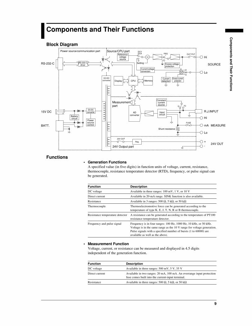
Block DiagramPower source/communication part Source/CPU part
24V Output part
Measurementpart
RS-232-C RS-232-Cdriver
DC/DCconverter
Reg.
Batterycircuit
Referencevoltagesource
Current/voltageconversion
Currentdetection
Constantcurrentsource
Inputcircuit
Excess voltageprotection
Excess currentprotection
Setting
Powersourcecontrol
ADconverter
Memory
Shunt resistance
DisplayDC/DC
converter CPU
DCVFRQ OUT PUT
Ω
Ω
Ω
DCA
DCV
TC
FUSE
24V OUT
DCA
SOURCE
Hi
Lo
Hi
R.J.INPUT
Lo
+
-
mA MEASURE
24V OUT
15V DC
BATT.
Functions• Generation Functions
A specified value (in five digits) in function units of voltage, current, resistance,thermocouple, resistance temperature detector (RTD), frequency, or pulse signal canbe generated.
Function Description
DC voltage Available in three ranges: 100 mV, 1 V, or 10 V
Direct current Available in 20-mA range. SINK function is also available.
Resistance Available in 3 ranges: 500 Ω, 5 kΩ, or 50 kΩ
Thermocouple Thermoelectromotive force can be generated according to thetemperature of type K, E, J, T, N, R or B thermocouple.
Resistance temperature detector A resistance can be generated according to the temperature of PT100resistance temperature detector.
Frequency and pulse signal Frequency is in four ranges: 100 Hz, 1000 Hz, 10 kHz, or 50 kHz.Voltage is in the same range as the 10 V range for voltage generation.Pulse signals with a specified number of bursts (1 to 60000) areavailable as well as the above.
• Measurement FunctionVoltage, current, or resistance can be measured and displayed in 4.5 digitsindependent of the generation function.
Function Description
DC voltage Available in three ranges: 500 mV, 5 V, 35 V
Direct current Available in two ranges: 20 mA, 100 mA. An overrange input protectionfuse comes built into the current-input terminal.
Resistance Available in three ranges: 500 Ω, 5 kΩ, or 50 kΩ
10
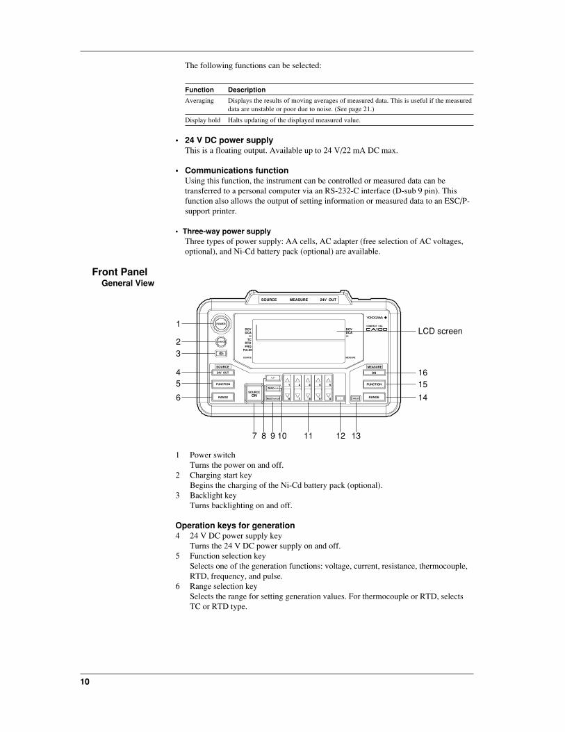
The following functions can be selected:
Function Description
Averaging Displays the results of moving averages of measured data. This is useful if the measureddata are unstable or poor due to noise. (See page 21.)
Display hold Halts updating of the displayed measured value.
• 24 V DC power supplyThis is a floating output. Available up to 24 V/22 mA DC max.
• Communications functionUsing this function, the instrument can be controlled or measured data can betransferred to a personal computer via an RS-232-C interface (D-sub 9 pin). Thisfunction also allows the output of setting information or measured data to an ESC/P-support printer.
• Three-way power supplyThree types of power supply: AA cells, AC adapter (free selection of AC voltages,optional), and Ni-Cd battery pack (optional) are available.
Front PanelGeneral View
SOURCE
POWER
DCV
TC Ω Ω
DCADCVDCA
RTDFRQ
PULSE
ON
1
6 7 8 9 0
2 3 4 5 FUNCTION
MEASURE
RANGE
COMPACT CAL
SOURCE
24V OUT
FUNCTION
RANGE
SOURCEZERO CLR
NEXTENTERON
CHARGE
SOURCE MEASURE
HOLD
MEASURE 24V OUT
LCD screen
16
6
54
32
1
1312111097 8
15
14
1 Power switchTurns the power on and off.
2 Charging start keyBegins the charging of the Ni-Cd battery pack (optional).
3 Backlight keyTurns backlighting on and off.
Operation keys for generation4 24 V DC power supply key
Turns the 24 V DC power supply on and off.5 Function selection key
Selects one of the generation functions: voltage, current, resistance, thermocouple,RTD, frequency, and pulse.
6 Range selection keySelects the range for setting generation values. For thermocouple or RTD, selectsTC or RTD type.

Co
mp
on
ents an
d T
heir F
un
ction
s
11
7 Output on and off keyTurns output on and off.
8 +/- keyToggles the polarity of the output value.
9 NEXT ENTER keyThis switches the associated settings when setting the output values for thefrequency and pulse signal. It also fixes the entered value when using the numerickeypad (refer to the following description).
10 ZERO CLR keyThis resets the output value set to zero when using the up/down key (refer to thefollowing description). When using the numeric keypad (refer to the followingdescription), the value being entered is canceled and the previous set value isrestored.
11 Output value setting keysThis sets the output value for the generation function. Either of the following twokey modes can be selected from the menu. The up/down key mode is selected as thefactory default setting.Up/down key: This increments or decrements the values by one count for each digitcorresponding to the [ ]/[ ]. If you try to increment or decrement using this keywith value 9 or 0, the current digit moves up or down by one digit.Numeric keypad: This enters numbers 0 to 9 directly from the keypad.
12 Decimal point keyThis enters the decimal point when using the numeric keypad (refer to the abovedescription). When this key is pressed, the digits to the left of the decimal pointmove to the positions specified on a range basis. When using the up/down key, thiskey is unavailable.
Operation keys for measurement13 Display hold key
This retains displayed values as they are.14 Range selection key
This selects the measurement range.15 Function selection key
This selects one of the measuring functions: voltage, current, or resistance.16 Measurement on and off key
This turns measurement on and off.
LCD Screen
DCV
Ω ΩΩHOLD
MEASURE
mV
mV
mA
mA
kHz
k C
k
SOURCE
AVERAGECHARGE END
TC
DCADCVDCA
RTDFRQ
PULSE ON
OFF
INT RJC BRKE JTN Pt100
24V OUTSOURCE
ITS-90 IPTS-68
MEASURE
12
3
4
5
6
8
1011
9
7
Ω
CYCLES
F
1 State-of-charge indicatorWhen using Ni-Cd batteries (optional), this indicates its charge status (CHARGEindicates charging is taking place and CHARGE END indicates charging hascompleted).
2 Low-battery indicatorThis lights up when the battery becomes weak.
12
3 Generation function indicator indicates the currently selected generation function. Each press of the
FUNCTION key changes the function from DCV to DCA, Ω, TC, RTD, FRQ, andPULSE in order.
4 Hold indicatorThis indicates the measured value is held.
5 Output on and off indicatorOn: indicates the output is turned on.Off: indicates the output is turned off.
6 24 V DC power supply indicatorThis indicates 24 V DC power is being supplied via the 24 V DC output terminal.
7 Generation range and output displayFor voltage, current, resistance, frequency, and pulse: This indicates the decimalplace and unit available for setting when selecting a range. Use the up/down key ornumeric keypad to specify a value.For thermocouple or resistance temperature detector: This indicates the type of TC,either thermocouple (TC) or resistance temperature detector (RTD), and thetemperature available for setting (e.g., ˚C), when selecting a range.Use the up/down key or numeric keypad to specify the temperature.
8 International temperature standard displayThis displays the international temperature standard currently selected.
9 Measurement function display displays the measuring function currently selected. Pressing the FUNCTION key
changes the function from DCV to DCA and Ω.10 Averaging indicator
This indicates that the averaging function is active.11 Measurement range and measured value display
This indicates the decimal place and unit available for setting when selecting arange. When the measuring function is activated, the measured value is displayed.
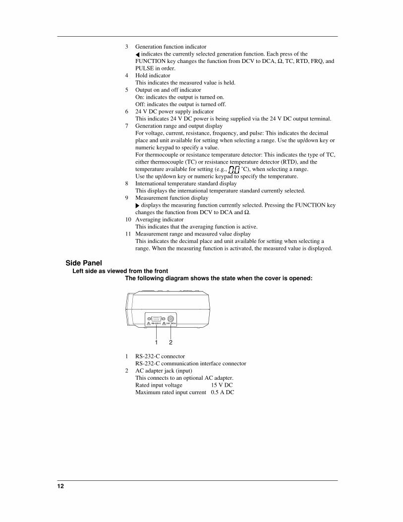
Side PanelLeft side as viewed from the front
The following diagram shows the state when the cover is opened:
RS-232-C 15V DC
1 2
1 RS-232-C connectorRS-232-C communication interface connector
2 AC adapter jack (input)This connects to an optional AC adapter.Rated input voltage 15 V DCMaximum rated input current 0.5 A DC

Co
mp
on
ents an
d T
heir F
un
ction
s
13
Terminal Side
R.J. INPUT
24V OUT SOURCE
HiHimA
22mA MAX
120mA MAXALL TERMINALS 42VPEAK MAX TO GND.
250V F 125mAFUSE MAX22mA42V MAX 28V
Lo Lo
MEASURE
1 2 4 53
1 RJC sensor input connectorThis connects to an RJC sensor (optional).
2 24 V output terminalThis supplies 24 V DC power.
3 Current input terminalThis is used when measuring current.
4 Voltage/resistance input terminalThis is used when measuring voltage or resistance.
5 Output terminalThis outputs the specified source.
This instrument falls under Overvoltage category II (CAT II). Overvoltage(installation) category indicates the impulse withstand voltage level which is regulatedby IEC1010-1.
Rear Panel
1
1 Battery storageThis holds the attached dry cells or the optional Ni-Cd battery pack.
CAUTION
• Before turning on the power switch, make sure the batteryhousing is shut with the cover on properly. Do not open thecover while the instrument is in operation.
14
Before Starting Generation or Measurement
Usage PrecautionsSafety Precautions
• Before using this instrument, thoroughly read the "Safety Precautions" on pages 4 and5.
• Do not remove the cover from the instrument.Some parts of the instrument use high voltage, which is extremely dangerous. Whenthe instrument needs an internal inspection or calibration, contact your nearestrepresentative.
• In case of abnormalityIf you notice smoke or the instrument seems to be acting abnormally, for example, itgenerates smoke or emits a strange odor, immediately turn the instrument off and, ifan AC power supply kit is in use, disconnect the power cord from the AC outlet. Alsoturn off the object connected to the input terminal. If the instrument seems to beabnormal, contact your nearest reperesentative.
• AC adapter and power cordUse the dedicated AC adapter. Nothing should be placed on the AC adapter or powercord; also, it should be kept away from any heat sources. When unplugging the powercord from the AC outlet, never pull the cord itself. Always hold the plug and pull it. Ifthe power cord is damaged, contact your dealer. Refer to page 3 for the part numberto use when placing an order.
General Precautions when Handling the Instrument• When moving the instrument
Turn off the power to the object connected to the instrument. Turn off the power tothis instrument and, if an AC power supply kit is in use, disconnect the power cordfrom the AC outlet. When carrying the instrument, always use the carrying case.
• Keep input terminals away from electrically charged articles as they may damage theinternal circuitry.
• Do not allow volatile chemicals to come into contact with the case or operation panel.Also do not leave them in contact with any rubber or vinyl products for prolongedperiods. The operation panel is made of thermoplastic resin, so take care to avoidcontact with any heated articles such as a soldering iron.
• Before cleaning the case and operation panel, make sure that the power cord isdisconnected from the AC outlet if the AC power supply kit is used. Dampen a cleansoft cloth with water and wipe the surface of the case and panel. Water that gets insidethe instrument may result in breakdown.
• If the AC power supply kit will not be used over a long period, unplug the power cordfrom the outlet.
• For handling dry cells, refer to the section, "Installing Dry Cells," on page 16.• Do not use the instrument with the cover for the battery housing left open.• Gently wipe the surface with a soft and dry cloth. Do not use chemicals such as
benzene or thinner, because these may cause discoloration and deformation.• Do not stack the instrument.

Befo
re Startin
g G
eneratio
n o
r Measu
remen
t
15
Installation ConditionsThe instrument must be installed in a place where the following conditions are met.
• Ambient temperature and humidityAmbient temperature: 5 to 40°C (5 to 30°C for charging during generation ormeasurement)Ambient humidity: 20 to 80% RH (no condensation)
• Flat horizontal locationSet the instrument in a level, stable place.
Never install the instrument.:• In direct sunlight or near sources of heat• Where the level of mechanical vibration is high• Near noise sources such as high-voltage equipment or power lines• Near strong magnetic field sources• Where an excessive amount of soot, steam, dust or corrosive gases are present.• In an unstable place• Where explosions caused by inflammable gases or the like are possible
Note• To ensure high measurement accuracy, the instrument should be used under the following
conditions:Ambient temperature: 23 ± 5°CAmbient humidity: 20 to 80% RH (no condensation)When using the instrument in temperature ranges of 5 to 18°C or 28 to 40°C, add the temperaturecoefficient specified in the "Specifications" on page 51 to the accuracy.
• If the ambient humidity of the installation site is 30% or below, use an anti-static mat to preventstatic electricity.
• Internal condensation may occur if the instrument is moved to another area where both the ambienttemperature and humidity are higher, or if the room temperature changes rapidly. In such cases,acclimatize the instrument to the new environment for at least one hour before starting operation.
Installing Ferrite CoreThis instrument is CE Mark compliant. When using the measurement lead, make sureto attach the accessory clamp filter on it according to the directions indicated below. Inaddition, when purchasing the optional measurement lead or RJC sensor, make sure topurchase the clamp filter also and attach it according to the directions indicated below.Note that if the clamp filter is not properly attached or used, the standard cannot besatisfied.
Installation
• Guide the cable through the clamp filter and lock the core.
• Thread the supplied band throughthe opening of the clamp filter tofasten the core, and then cut awayany extra length of the band.
Installation location
50 mm or less 50 mm or less
• Measurement lead • RJC sensor connection cable

16
Installing Dry Cells
CAUTION
When using dry cells, observe the following precautions:• The use of AA alkaline cells is recommended.• When inserting a battery, observe the polarity; otherwise, a liquid
spill or explosion may occur.• Before operating the instrument, make sure that the dry cell
holder is inserted into the body and the back cover is closed.• Do not disassemble, heat, or throw a battery into a fire.• Do not short out a cell.• Do not charge a dry cell.• Do not solder a line onto a dry cell.• Use new dry cells from the same manufacturer.• When dry cells become weak, replace all eight cells with new
ones.• If the instrument will not be used for a long time, remove the dry
cells.
Installation1 Make sure that the power switch on the front panel is turned off and no AC power
supply kit is connected..2 Remove the cover of the dry cell storage on the back of the body.3 Insert the eight dry cells into the dry cell holder. Make sure that they are seated in
the correct indicated direction of polarity (refer to the following diagram).4 Attach the dry cell holder to the body and push the connector until it hits the bottom
of the receiving side of the body (refer to the following diagram).5 Reassemble the cover.
Strap
Cable
To remove dry cells, pull the strap to unplug the connector from the dry cell storage andremove the dry cell holder. Do not pull on the cable of the connector.
Befo
re Startin
g G
eneratio
n o
r Measu
remen
t
17
Low-Battery IndicatorIf the dry cells become weak, appears in the upper-left of the display. When thishappens, immediately replace the old batteries with new eight alkaline batteries.
Life of Alkaline BatteriesThe life of alkaline batteries varies depending on the operating conditions. Refer to thefollowing table:
Generated Output Measurement 24 V DC Backlight Life (when used
Function Power Supply continuously)
20 mA (with 1 kΩ load) on on on Approx. 2 hours5 V DC (with 500 Ω load) on off off Approx. 10 hours
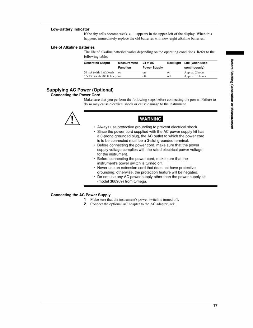
Supplying AC Power (Optional)Connecting the Power Cord
Make sure that you perform the following steps before connecting the power. Failure todo so may cause electrical shock or cause damage to the instrument.
WARNING
• Always use protective grounding to prevent electrical shock.• Since the power cord supplied with the AC power supply kit has
a 3-prong grounded plug, the AC outlet to which the power cordis to be connected must be a 3-slot grounded terminal.
• Before connecting the power cord, make sure that the powersupply voltage complies with the rated electrical power voltagefor the instrument.
• Before connecting the power cord, make sure that theinstrument's power switch is turned off.
• Never use an extension cord that does not have protectivegrounding; otherwise, the protection feature will be negated.
• Do not use any AC power supply other than the power supply kit(model 366969) from Omega.
Connecting the AC Power Supply1 Make sure that the instrument's power switch is turned off.2 Connect the optional AC adapter to the AC adapter jack.

18
AC adapter
AC adapter jack
3 Connect the power cord included in the AC power supply kit to the AC powersupply adapter.
4 Plug the other end of the power cord into an AC outlet that meets the followingconditions. The AC outlet must be a 3-slot grounded terminal.
3-prong AC outlet
Power cord
Power RatingRated supply voltage: 100 to 120 V AC/200 to 240 V ACPermitted supply voltage range: 90 to 132 V AC/180 to 264 V ACRated supply voltage frequency: 50/60 HzPermitted supply voltage frequency range: 48 to 62 HzMaximum power consumption: 60 VA or belowRated output voltage for AC adapter: 15 V DCMaximum rated output current for AC adapter: 1.33 A
Attaching and Charging Optional Ni-Cd Battery PackAttaching the Ni-Cd Battery Pack to the Main Unit
To attach the battery pack to the instrument, follow the next procedure:
WARNING
• Before replacing the Ni-Cd battery pack, be sure to turn off thepower switch on the front panel and remove the power cord fromthe AC outlet to avoid such possible hazards as short-circuitingin the battery-charging circuitry.
• Use only an Ni-Cd battery pack from Omega.

Befo
re Startin
g G
eneratio
n o
r Measu
remen
t
19
1 Make sure that the power switch on the front panel is turned off.2 Disconnect the power cord from the AC outlet.3 Remove the cover of the dry cell storage compartment on the back of the body.4 Insert the spacer on the cable side of the battery pack.5 Insert the connector of the attached Ni-Cd battery pack until it hits the bottom of the
receiving side of the body (refer to the following diagram).6 Reassemble the cover.
Be careful of the direction of the spacer.
Cable
Cover
Spacer
When removing the Ni-Cd battery pack, pull the strap to unplug the connector from thebattery housing. Do not pull on the cable of the connector.
Precautions in Charging• Since an optional Ni-Cd battery pack is not charged prior to shipment, fully charge
the battery pack before operating the instrument for the first time.• Before charging the battery pack, make sure that it is discharged completely. If
charging is started on a battery which has not been discharged completely or on abattery for which charging has been stopped halfway through, the life of the batterypack will be reduced.
• The internal temperature of the instrument rises during charging since the internalpower consumption increases. This may cause a degraded accuracy in generation ormeasurement compared with a normal condition. For accuracy, refer to the section,"Specifications," on page 51.
• This instrument allows charging during generation or measurement operations. In thiscase, keep the ambient temperature between 5 to 30°C, or the battery pack willbecome extremely degraded.
• If the AC power supply is interrupted during charging, the instrument waits up toabout 30 minutes for restoration of the AC power supply. If the power is not restoredby that time, the instrument aborts the charging sequence and automatically turns off.It resumes charging of the battery pack if the power is restored within the given time.
CAUTION
• Use only the AC power supply kit (model: 366969) from Omegafor charging.
• When charging, keep the instrument horizontal. Make sure thatthere is no obstruction around the instrument, so that heatgenerated in the instrument is properly dissipated.

20
Charging the Battery Pack1 Supply the instrument with AC power via the method described above.2 Turn on the power switch.3 Press the [CHARGE] key.
"CHARGE" is displayed. The instrument then momentarily shows the remainingtime every minute. The battery pack is fully charged in about 10 hours, and"CHARGE END" is displayed.
4 Turn off the power switch.5 Disconnect the power cord and the AC adapter from the instrument.
Display Indicating Low BatteryAfter a certain length of operation has passed and the battery power weakens, " "appears in the upper-left of the screen. When you see this display, immediately chargethe pack.
Guideline for continuous operating timeThe operating time of the Ni-Cd battery pack is approximately 7.5 hours when incontinuous use. Refer to the following table:
Generated Output Measurement 24 V DC Backlight Life (when used
Function Power Supply continuously)
20 mA (with 1 kΩ load) on on on Approx. 2.5 hr.5 V DC (with 500 Ω load) on off off Approx. 7.5 hr.
Turning the Power Switch On and OffBefore Turning On the Power
For driving this instrument, AA dry cells, an AC power supply (optional), or a Ni-Cdbattery pack (optional) is available. Before turning the instrument on, prepare theintended power supply following the above instructions.
NoteBefore operating the instrument using dry cells or the Ni-Cd battery pack (i.e., battery driving),disconnect the power cord and AC adapter. If the AC power source remains connected, theinstrument will operate on the AC power rather than on the batteries.
Turning the Power on and offPressing the power switch on the front panel alternates between on and off. Whenturning the power switch on, the self-diagnosis function runs, and "OFF" that indicatesthe output is turned off and " mV" appear on the lower line of the display.
Automatic Power OffIf the instrument has not received a key operation or sending/receiving request throughthe communication interface for approximately 30 minutes, the power supplyautomatically turns off. If necessary, turn the power switch back on.
Turning Backlighting On and OffBacklighting can be turned on so that it is easy to see the screen even if generation/measurement is done in a dark place. However, this will shorten the life of the batterieswhen the instrument is being operated by battery.1 Press the [ ] key.2 To turn backlighting off, press the [ ] key again.

Befo
re Startin
g G
eneratio
n o
r Measu
remen
t
21
NoteWhen backlighting the instrument, the internal power consumption increases, and the internaltemperature rises. This may cause a degraded accuracy in generation or measurement compared witha normal condition. For accuracy, refer to the section, "Specifications," on page 51.
Averaging, Key Type, International Temperature, Temperature Unit SettingsSettings
This instrument allows the setting of Averaging, Key Type, International Temperature,and Temperature Unit Settings from the maintenance menu.
Averaging setting: This specifies whether to enable (on) or disable (off) the movingaverage of the measured data. If the measured data displayfluctuates due to noise, set the averaging setting to on to performthe moving averages. The setting defaults to off.
Key-type selection: Either the up/down keys (UP-DN) or numeric keypad (TEN) isavailable for the output value setting key. The setting defaults to"UP-DN."
International temperature standard selection: Either of IPTS68 or ITS90 is available forthe international temperature standard. The setting defaults to"ITS90."
Selection of temperature unit: Either ˚C or ˚F can be selected as the temperature unit.The default setting is ˚C.
Setting1 Press the [NEXT ENTER] key and the [ZERO CLR] key at the same time.
[SP FC] and [End] are displayed.
2 Press the [ ] or [ ] key until [End] on the lower line of the display changes to [SetuP], and then press the [NEXT ENTER] key.
The setup menu is displayed.
3 Pressing the [ ] or [ ] key changes the bottom menu from [AVG] to [KEY] and [ttYPE]. To set the averaging function, display [AVG] and press the [NEXT ENTER]key.
4 Select [on] or [oFF] using [ ] or [ ] and press the [NEXT ENTER] key.
5 To specify the key type, display [KEY] using [ ] or [ ] and press the [NEXTENTER] key.
6 Select [uP-dn] or [tEn] using [ ] or [ ] and press the [NEXT ENTER] key.
7 To set the international temperature standard, display [t tYPE] using [ ] or [ ] andpress the [NEXT ENTER] key.
8 Select the [iPtS68] or [itS90] using the [ ] or [ ] and press the [NEXT ENTER]key.
9 To set the temperature unit, display [t unit] using the [ ] or [ ] and press the[NEXT ENTER] key.
10 Select [C] or [F] using the [ ] or [ ] and press the [NEXT ENTER] key.

22
11 Press the [ ] to display [Set uP] on the lower line of the display.
12 Press the [ ] or [ ] to display [End] and press the [NEXT ENTER] key.The measurement/generation screen is returned.
Gen
eration
23
Generation
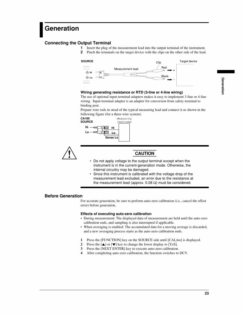
Connecting the Output Terminal1 Insert the plug of the measurement lead into the output terminal of the instrument.2 Pinch the terminals on the target device with the clips on the other side of the lead.
SOURCE
Red
Black
Target device
Measurement leadHi
Lo
HL
+
-
Clip
Wiring generating resistance or RTD (3-line or 4-line wiring)The use of optional input-terminal adapters makes it easy to implement 3-line or 4-linewiring. Input-terminal adapter is an adapter for conversion from safety terminal tobinding post.Prepare wire rods in stead of the typical measuring lead and connect it as shown in thefollowing figure (for a three-wire system).
MeasuringInstrumen
Hi
Lo
Sense Lo
Hi
Lo
CA100SOURCE
CAUTION
• Do not apply voltage to the output terminal except when theinstrument is in the current-generation mode. Otherwise, theinternal circuitry may be damaged.
• Since this instrument is calibrated with the voltage drop of themeasurement lead excluded, an error due to the resistance atthe measurement lead (approx. 0.08 Ω) must be considered.
Before GenerationFor accurate generation, be sure to perform auto-zero calibration (i.e., cancel the offseterror) before generation.
Effects of executing auto-zero calibration• During measurement: The displayed data of measurement are held until the auto-zero
calibration ends, and sampling is also interrupted if applicable.• When averaging is enabled: The accumulated data for a moving average is discarded,
and a new averaging process starts as the auto-zero calibration ends.
1 Press the [FUNCTION] key on the SOURCE side until [CAL/no] is displayed.2 Press the [ ] or [ ] key to change the lower display to [YeS].3 Press the [NEXT ENTER] key to execute auto-zero calibration.4 After completing auto-zero calibration, the function switches to DCV.

24
DC Voltage, DC Current, ResistanceThe output terminal generates voltage, current or resistance at the specified value.
1 Press the [FUNCTION] key on the SOURCE side to align with the [DCV],[DCA], or [Ω] that you want.
2 Press the [RANGE] key on the SOURCE side to select the generation range.
Type Generation Range Display Setting Range
DCV 100 mV
1 V
10 V
mV
V
V
-10 to 110 mV
-0.1 to 1.1 V
-1 to 11 V
DCA 20 mA mA 0 to 22 mA
Ω 500 Ω
5 kΩ
50 kΩ
Ω
kΩ
kΩ
0 to 550 Ω
0 to 5.5 kΩ
0 to 55 kΩ
3 To change the polarity, press the [+/-] key.Selecting "-" places a leading minus sign (-) before figures, while selecting "+"places no leading sign.
4 Specify the output value.• Using [ ] or [ ] (for initial setting)
Press [ ] or [ ] to specify the output value from the rightmost digit.To reset the value to zero, press the [ZERO CLR] key.
• Using the numeric keypad (refer to page 21)Enter an output value using the numeric keypad and the decimal point key, andpress the [NEXT ENTER]. The figure flickers when entering a value.When entering decimals, press the decimal point key first and then theappropriate key or keys on the numeric keypad.If a value out of the generation range is specified, an error occurs. In this case,press the [ZERO CLR] to reset to the previous value, and reenter a new value.
5 Press the [SOURCE ON] key to start generation.[ON] is displayed.To stop the output, press the [SOURCE ON] key again.[OFF] is displayed.[OFF]: Indicates that the relay on the output stage is open.
CA100
VVx Vx
Hi
LoVoltmeter
Voltage generation
Vx: Specified voltage
CA100
A
Hi
LoAmmeter
Current generation
Ix: Specified current
IxCA100
V
Hi
Lo
(Constantcurrentsource)
OhmmeterResistance generation
Ix: Current from the constant currentsource (measured current)
Rx:Specified value from thisinstrument
Vx: Generated voltage valuerepresented as Ix*Rx
* This function is unavailable for theconstant voltage source.
Ix
Gen
eration
25
Note• When outputting, if you change the generation function, generation range, or polarity (only for
current generation), output turns off automatically.• The resistance generation of this instrument employs an "active impedance" scheme in order to
provide a dummy resistance. This scheme generates a DC voltage appropriate for the current beingmeasured that is supplied by a resistance meter such as a multimeter. The scheme, therefore, cangenerate correct DC voltages only for the resistance meter used in the measuring method shown inthe figure on the previous page (i.e., the value of the supplied current being measured variesdepending on the range of resistance generation. For further details, see the specifications ofresistance on page 51). Note that connecting a low-impedance device (e.g., a voltage source,capacitor, or resistor) to the output during resistance generation may cause oscillation.
• In the case of the resistance generation function, it takes 10 ms in a 500 Ω range (refer to thespecifications for other ranges) for the instrument-detected resistance measurement current tosettle within the given accuracy range. This means that the connecting time must be no less than10 ms where a device that operates by electrically switching its signal input circuit is used.
• Providing any different type of setting with the [ZERO CLR] and [NEXT ENTER] keys duringresistance generation will abort the generation.
• Providing any different type of setting with the [ZERO CLR] and [NEXT ENTER] keys when thegeneration function is either TC, RTD, FRQ, or PULSE will change the function to DCV.
Output LimiterIf the load current when generating a voltage of 1 or 10 V range or the load voltagewhen generating a current of 20 mA range exceeds the maximum value in thespecifications, the protective limiter turns output off. To recover the output, correct theload to a normal state and press the [SOURCE ON] key to turn output on.
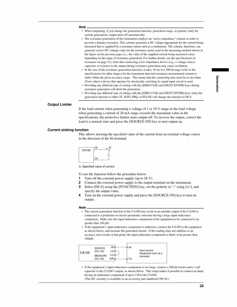
Current sinking functionThis allows drawing the specified value of the current from an external voltage sourcein the direction of the Hi terminal.
CA100Hi
Lo
Ix: Specified value of current
Ix
To use the function follow the procedure below:1 Turn off the external power supply (up to 28 V).2 Connect the external power supply to the output terminal on the instrument.3 Select [DCA] using the [FUNCTION] key, set the polarity to "-" using [+/-], and
specify the output value.4 Turn on the external power supply and press the [SOURCE ON] key to turn on
output.
Note• The current-generation function of the CA100 may result in an unstable output if the CA100 is
connected to a positioner or electro-pneumatic converter having a large input inductancecomponent. Make sure the input inductance component of the equipment to be connected is nogreater than 100 µH.
• If the equipment’s input inductance component is unknown, connect the CA100 to the equipmentas shown below, and measure the generated current. If the reading does not stabilize or anaccuracy error results at that point, the input inductance component is likely to be greater than100µH.
HiLoLo
mA
Hi
Lo
CA100
SOURCE(DC mA)
MEASURE(DC mA)
Input source:Equipment such as aconverter
• If the equipment’s input inductance component is too large, connect a 200-Ω resistor and a 1-µFcapacitor to the CA100’s output, as shown below. This setup makes it possible to connect an inputhaving an inductance component of up to 3 H to the CA100.(This RC circuitry is available as an accessory part numbered 990 20.)
26
HiLoLo
mA
Hi
LoC
RCA100
SOURCE(DC mA)
(99020)
MEASURE(DC mA)
Input source:Equipment such as aconverter
R: 200 Ω ±10%, 1/4 WC: 1 µF ±10%, 50 V(Equivalent to the 533M5002105K resistor from Matsuo Electric)
Note however that this additional circuitry reevaluates the CA100’s response specification as notedbelow.Response: 1 sec (at load resistances no greater than 2 kΩ)
Do not use this circuitry for purposes other than current generation; otherwise, it can producemeasurement errors.
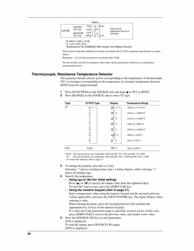
Thermocouple, Resistance Temperature DetectorThis generates thermo-electric power corresponding to the temperature of thermocouple(TC) or resistance corresponding to the temperature of resistance temperature detector(RTD) from the output terminal.
1 Press [FUNCTION] on the SOURCE side and align to [TC] or [RTD].2 Press [RANGE] on the SOURCE side to select TC type.
Type TC/RTD Type Display Temperature Range
TC K
E
J
T
N
B
R
˚C
˚C
˚C
˚C
˚C
˚C
˚C
-200.0 to +1372.0˚C
-250.0 to +1000.0˚C
-210.0 to +1200.0˚C
-250.0 to +400.0˚C
-200.0 to +1300.0˚C
+400 to +1820˚C
-40 to +1767˚C
RTD Pt100 ˚C -200 to +850˚C
* RTD : The specifications are compatible with both IEC 751-1983 and IEC 751-1995.TC : The specifications are compatible with both IEC 584-1-1989 and IEC 584-1-1995. To switch the standard, refer to page 21.
3 To change the polarity, press the [+/-] key.Selecting "-" places a leading minus sign (-) before figures, while selecting "+"places no leading sign.
4 Specify the temperature.• Using [ ] or [ ] (for initial setting)
Press [ ] or [ ] to specify the output value from the rightmost digit.To reset the value to zero, press the [ZERO CLR] key.
• Using the numeric keypad (refer to page 21)Enter a temperature value using the numeric keypad and the decimal point key(where applicable), and press the [NEXT ENTER] key. The figure flickers whenentering a value.When entering decimals, press the decimal point key first and then theappropriate key or keys on the numeric keypad.If a value out of the generation range is specified, an error occurs. In this case,press [ZERO CLR] to reset to the previous value, and reenter a new value.
5 Press the [SOURCE ON] key to start generation.[ON] is displayed.To stop the output, press [SOURCE ON] again.[OFF] is displayed.
Gen
eration
27
Note• When outputting, if you change the generation function or generation range, output turns off
automatically.• The generation of RTD-use signals in this instrument employs an "active impedance" scheme in
order to provide a dummy resistance. This scheme generates a DC voltage appropriate for thecurrent being measured that is supplied by a resistance meter such as a multimeter. The scheme,therefore, can generate correct DC voltages only when the value of the supplied current beingmeasured is 1 to 5 mA. Note that connecting a low-impedance device (e.g., a voltage source,capacitor, or resistor) to the output during resistance generation may cause oscillation.
• In the case of generating RTD-use signals, it takes 10 ms in a 500-Ω range (refer to thespecifications for other ranges) for the instrument-detected resistance measurement current tosettle within the given accuracy range. This means that the connecting time must be no less than10 ms where a device that operates by electrically switching its signal input circuit is used.
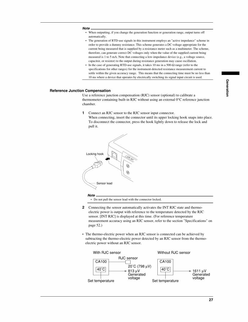
Reference Junction CompensationUse a reference junction compensation (RJC) sensor (optional) to calibrate athermometer containing built-in RJC without using an external 0°C reference junctionchamber.
1 Connect an RJC sensor to the RJC sensor input connector.When connecting, insert the connector until its upper locking hook snaps into place.To disconnect the connector, press the hook lightly down to release the lock andpull it.
Locking hook
Sensor lead
Note• Do not pull the sensor lead with the connector locked.
2 Connecting the sensor automatically activates the INT RJC state and thermo-electric power is output with reference to the temperature detected by the RJCsensor. [INT RJC] is displayed at this time. (For reference temperaturemeasurement accuracy using an RJC sensor, refer to the section "Specifications" onpage 52.)
• The thermo-electric power when an RJC sensor is connected can be achieved bysubtracting the thermo-electric power detected by an RJC sensor from the thermo-electric power without an RJC sensor.
RJC sensor
With RJC sensor Without RJC sensor
20˚C (798 µV)813 µVGeneratedvoltage
CA100
40˚C
CA100
1611 µVGeneratedvoltage
Set temperature
40˚C
Set temperature

28
• Compensating the output voltage using the temperature detected with the RJC sensoris executed on a sampling rate of approximately 10-second intervals. It means thatthere is a delay of up to 10 seconds before the first compensation starts.
• To perform accurate measurement, leave the instrument for a certain time (5 min. atroom temperature) before starting the measurement.
CAUTION
Be sure to disconnect the RJC sensor from the instrument when noreference junction compensation is required.
Frequency, Pulse SignalThis generates frequencies and pulse signals at specified values via the output terminal.
Frequencysignal
Frequency (1 Hz to 50 kHz)
Voltage (0 to 10 V)
Pulse signal
Frequency (1 Hz to 50 kHz)
Number of generated pulses(1 to 60000 cycles)
Voltage (0 to 10 V)
: One pulse
1 To generate frequencies, press [FUNCTION] on the SOURCE side to align with[FRQ]. [ Hz] is displayed. Jump to step 4.To generate pulse signals, align with [PULSE]. [ CYCLES] appears. Go tostep 2.
2 Specify the number of pulses to generate between 1 and 60,000.• Using [ ] or [ ] (for initial setting)
Press [ ] or [ ] to specify the number of pulses to be output.To reset the value to zero, press [ZERO CLR].
• Using the numeric keypad (refer to page 21)Enter the number of pulses to generate using the numeric keypad, and press the[NEXT ENTER] key. The figure flickers when entering a value. If a value outof the range of 1 to 60,000 is specified, an error occurs. In this case, press[ZERO CLR] to reset to the previous value, and reenter a new value.
3 Press [NEXT ENTER].[ Hz] is displayed.
4 Press [RANGE] on the SOURCE side to select the voltage frequency range.
Type Frequency Range Display Setting Range
FRQ/ 100 Hz Hz 1.0 to 110.0 HzPULSE
1000 Hz Hz 90 to 1100 Hz
10 kHz kHz 0.9 to 11.0 kHz
50 kHz kHz 9 to 50 kHz

Gen
eration
29
5 Specify the voltage frequency to generate.• Using [ ] or [ ]
Press [ ] or [ ] to specify the voltage frequency to generate from the rightmostdigit. To reset the value to zero, press [ZERO CLR].
• Using the numeric keypadEnter a voltage frequency to generate using the numeric keypad and the decimalpoint key (if applicable), and press the [NEXT ENTER] key. The figure flickerswhen entering a value.When entering decimals, press the decimal point key first and then theappropriate key or keys on the numeric keypad.If a value out of the voltage frequency range is specified, an error occurs. In thiscase, press [ZERO CLR] to reset to the previous value, and reenter a new value.
6 Press [NEXT ENTER].[ V] is displayed.
7 Specify a voltage to generate between 0 and 10 V.• Using [ ] or [ ]
Press [ ] or [ ] to specify the voltage to generate from the rightmost digit. Toreset the value to zero, press [ZERO CLR].
• Using the numeric keypadEnter a voltage generated using the numeric keypad and the decimal point key,and press the [NEXT ENTER] key. The figure flickers when entering a value.When entering decimals, press the decimal point key first and then theappropriate key or keys on the numeric keypad.If a value out of the 10 V range is specified, an error occurs. In this case, press[ZERO CLR] to reset to the previous value, and reenter a new value.
8 Press the [SOURCE ON] key to start generation.[ON] is displayed.To stop the generation, press [SOURCE ON] again.[OFF] is displayed.
Note• When outputting, if you change the generation function or generation range, output turns off
automatically.
30
Measurement
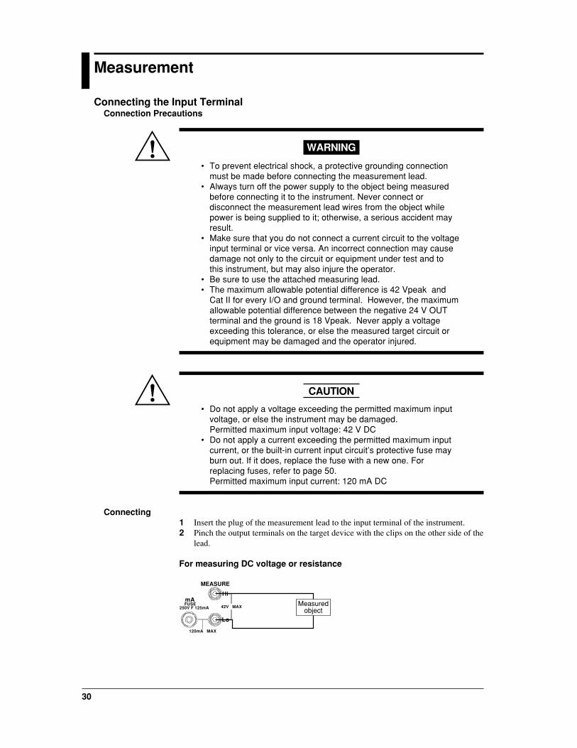
Connecting the Input TerminalConnection Precautions
WARNING
• To prevent electrical shock, a protective grounding connectionmust be made before connecting the measurement lead.
• Always turn off the power supply to the object being measuredbefore connecting it to the instrument. Never connect ordisconnect the measurement lead wires from the object whilepower is being supplied to it; otherwise, a serious accident mayresult.
• Make sure that you do not connect a current circuit to the voltageinput terminal or vice versa. An incorrect connection may causedamage not only to the circuit or equipment under test and tothis instrument, but may also injure the operator.
• Be sure to use the attached measuring lead.• The maximum allowable potential difference is 42 Vpeak and
Cat II for every I/O and ground terminal. However, the maximumallowable potential difference between the negative 24 V OUTterminal and the ground is 18 Vpeak. Never apply a voltageexceeding this tolerance, or else the measured target circuit orequipment may be damaged and the operator injured.
CAUTION
• Do not apply a voltage exceeding the permitted maximum inputvoltage, or else the instrument may be damaged.Permitted maximum input voltage: 42 V DC
• Do not apply a current exceeding the permitted maximum inputcurrent, or the built-in current input circuit’s protective fuse mayburn out. If it does, replace the fuse with a new one. Forreplacing fuses, refer to page 50.Permitted maximum input current: 120 mA DC
Connecting1 Insert the plug of the measurement lead to the input terminal of the instrument.2 Pinch the output terminals on the target device with the clips on the other side of the
lead.
For measuring DC voltage or resistance
HimA
120mA MAX
250V F 125mAFUSE
42V MAX
Lo
MEASURE
Measuredobject

Measu
remen
t
31
For measuring DC current
HimA
120mA MAX
250V F 125mAFUSE
42V MAX
Lo
MEASURE
Measuredobject
Measuring the DC Voltage, DC Current, and Resistance1 Press the [MEASURE ON] key.2 Press the [FUNCTION] key on the MEASURE side to align with the [DCV],
[DCA], or [Ω] that you want.3 Press the [RANGE] key on the MEASURE side to select the measuring range.
Type Measuring Range Display
DCV 35 V
5 V
500 mV
V
V
mV
DCA 100 mA
20 mA
mA
mA
Ω 50 kΩ
5 kΩ
500 Ω
kΩ
kΩ
Ω
The measured result is displayed. The displayed value is updated every second.
Note• Any data value being measured that exceeds the 120% of the measuring range will result in
overrange. The display then indicates [ ] (the position of the decimal point depends on therange used).
• If no measured data are present immediately after the MEASURE key is turned on or if themeasurement function or range is switched to change the data on the display, the reading changesto [ ].
• When you switch the MEASURE key from the off to on, the instrument begins measurement withthe settings given immediately before the key was turned off.
• Providing any different type of setting with the [ZERO CLR] and [NEXT ENTER] keys duringmeasurement will abort measurement.
Display Holding On and OffThis determines whether the updating of displayed measured data is halted.1 Press the [HOLD] key. "HOLD" is displayed.2 To disable the display holding, press [HOLD] again. "HOLD" disappears from the
display.
Note• The "HOLD" state only stops the updating of the display, but allows the instrument to continue
sampling data. This means that the measured data are updated through the communicationinterface even during the "HOLD" state.
• Holding the display is not allowed if the communication mode is “talk-only” or the “printer”mode.(See page 39.)

32
24 V DC Power Supply
Connecting the Output TerminalConnection Precautions
WARNING
The permitted maximum potential difference is 42 Vpeak and Cat IIfor every I/O and earth terminal. However, the permitted maximumpotential difference between the negative 24 V OUT terminal andthe ground is 18 Vpeak. Never apply a voltage exceeding thistolerance, or the measured object circuit or equipment may bedamaged and the operator injured.
CAUTION
• Do not apply a voltage to the 24 V DC output terminal externally,or else the instrument may be damaged.
• If the 24 V DC output terminal is short-circuited or the loadcurrent exceeds the range (24 to 30 mA), an error is displayedand the 24 V DC power supply is turned off. In this case, removethe cause of the short circuit or the overload completely and thenturn the 24 V DC power supply back on. Note that an overloadcannot be detected for the first 5 seconds or so after turning onthe 24 V DC power supply.
• When using batteries, continuous running of the instrument withthe load current of the 24 V DC power supply at more than 20mA shortens the operable time extremely.
Connecting1 Insert the plug of the measurement lead into the 24 V DC output terminal of the
instrument.2 Pinch the 24 V DC terminals on the target device with the clips on the other side of
the lead.
24V OUT
22mA MAX Suppliedobject
Turning Output On and Off1 Press the [24 V OUT].
[24 V OUT] appears on the screen and the 24 V DC power is supplied from theoutput terminal.
2 To stop the 24 V DC power supply, press [24 V OUT] again.[24 V OUT] disappears from the display.
Note• If the 24 V DC power supply becomes overloaded, the power supply turns off automatically. To
continue supplying 24 V DC power, remove the cause of the overload and then press the [24 VOUT] key again.

Usin
g th
e RS
-232-C In
terface
33
24 V D
C P
ow
er Su
pp
ly
Using the RS-232-C Interface
RS-232-C Interface FunctionsReception Function
Allows you to make the same settings (except for on and off of the power supply andthose related to communication) as those which can be made using the keys on the frontpanel. This function allows the instrument to receive a request for the output of agenerated set-up value, measured value, panel set-up information and error codes.
Transmission FunctionAllows the instrument to output a generated set-up value and measured value at aspecified cycle. The panel set-up information and status byte can also be output. Inaddition, error codes which occurred can be output.
Note• During the talk-only or printer mode (when the printer is connected), only output of the generated
set-up value and measured value at a specified cycle is available.• When using any source other than an AC power supply, the power supply to the circuit for the RS-
232-C is turned off to increase the operating time available with batteries or the like. Turn on thepower supply as necessary. (See page 37.)
Specifications
WARNING
When connecting the RS-232-C cable to the connector, makesure the power switch of the instrument is turned OFF. Connectthe RS-232-C connector to the remote instrument with the cablebefore starting the RS-232-C communication.
Electrical characteristics: Conforms to EIA RS-232-C.Connection: Point-to-pointCommunications: Full-duplexSynchronization: Start-stop systemBaud Rate: 150, 300, 600, 1200, 2400, 4800 and 9600Start Bit: 1 bit (fixed)Data Length: 7 or 8 bitsParity: Even, odd or no parityStop Bit: 1 or 2 bitsConnector: DELC-J9PAF-13L6 (JAE or equivalent)Hardware Handshaking: User can select whether RS and CS signals will always be
true, or be used for control.Software Handshaking: User can select whether to control only transmission or both
transmission and reception using X-on and X-off signals.X-on (ASCII 11H)X-off (ASCII 13H)
Receiver Buffer Size: 256 bytes

34
Connecting the RS-232-C Interface CableWhen connecting this instrument to a personal computer, make sure that thehandshaking, transmission rate and data format selected for the instrument match thoseselected for the computer. For details, refer to the following pages. Use an interfacecable that is shielded and meets the instrument's specifications requirements.
Connectors and Signals
RS-232-C connector
2 1 3 4 5
6 7 8 9
Note: The instrument side is provided with a male D-Sub 9 pin.
2 RD (Received Data): Data received from personal computerSignal direction: Input
3 SD (Send Data): Data transmitted to personal computerSignal direction: Output
5 SG (Signal Ground): Ground for signals7 RS (Request to Send): Signal used to handshake when receiving data from personal
computerSignal direction: Output
8 CS (Clear to Send): Signal used to handshake when transmitting data frompersonal computerSignal direction: Input
Pins 1, 4, 6, and 9 are not used. Make sure, however, that pin 1 (Frame Ground) of thecounterpart is grounded.
Signal DirectionThe figure below shows the direction of signals used by the RS-232-C interface.
Computer Thisinstrument
RS [ready for reception of request to send]
SD [Send data]
RD [Received data]
CS [clear to send ready]

Usin
g th
e RS
-232-C In
terface
35
RS-232-C Standard Signals and their JIS and CCITT AbbreviationsRS-232-C Standard Signals
Signals
Pin No.
Pin 9 connector
Abbreviation
RS-232-CName
CCITT JIS
5
3
2
7
8
Pin 25 connector
7
2
3
4
5
AB (GND)
BA (TXD)
BB (RXD)
CA (RTS)
CB (CTS)
102 SG
103
104
105
106
SD
RD
RS
CS
Ground for signal
Send data
Clear to send
Received data
Request to send
Notice on Connecting Printers• Printers which support ESC/P commands can be used.• When connecting a printer, refer to the printer specifications to ensure that a properly-
wired shielded cable is used.• For details on the cable's pin assignments for connection to the CA100 calibrator,
refer to this information for an RS-232-C connector.• Configure the baud rate, handshaking, and so on correctly, according to the
specifications of the printer being used.
Settings for CommunicationThe maintenance menu ([ZERO CLR] + [NEXT ENTER] keys) allows the setting ofcommunications functions.
SettingsPower source for communicationTurns the power supply to communications functions on and off. If this is disabled, nocommunications function is available.
36
Communications modesThe following communications modes are available.If the instrument continues providing output for more than two to three hours, it willstart delivering signals at an interval approximately one second longer than the presetinterval because of the characteristics of the internal clock.
Communication mode Description
Normal mode (nor) Allows operating normal communication functions.
Talk-only mode (tonLY) Outputs set generation value and measured value at specified interval (0*to 3,600 sec.).
Printer mode (Print) Outputs set generation value and measured value at specified interval (0*to 3,600 sec.) via a printer.
* If 0 is specified for the interval, one data item is output whenever the [HOLD] key is pressed.
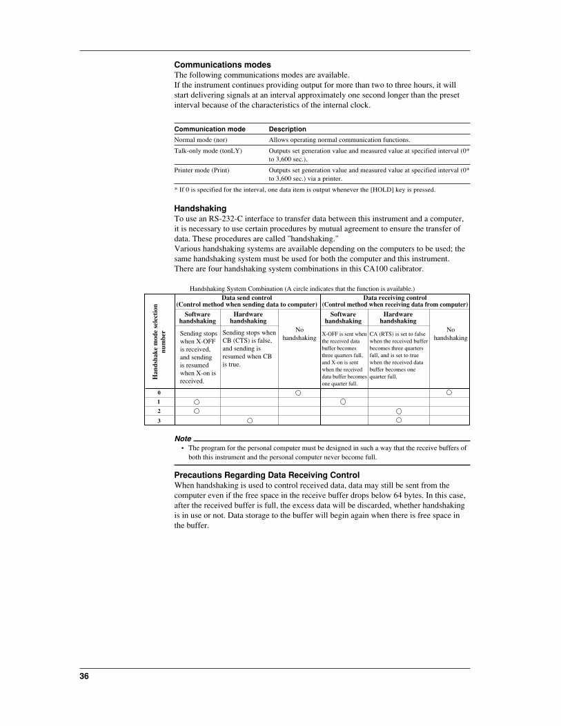
HandshakingTo use an RS-232-C interface to transfer data between this instrument and a computer,it is necessary to use certain procedures by mutual agreement to ensure the transfer ofdata. These procedures are called "handshaking."Various handshaking systems are available depending on the computers to be used; thesame handshaking system must be used for both the computer and this instrument.There are four handshaking system combinations in this CA100 calibrator.
Data send control(Control method when sending data to computer)
Data receiving control(Control method when receiving data from computer)
Softwarehandshaking
Softwarehandshaking
Handshaking System Combination (A circle indicates that the function is available.)
Sending stopswhen X-OFFis received,and sendingis resumedwhen X-on isreceived.
Sending stops whenCB (CTS) is false,and sending isresumed when CBis true.
Nohandshaking
Nohandshaking
Hardwarehandshaking
Hardwarehandshaking
0
1
2
3
Han
dsha
ke m
ode
sele
ctio
nnu
mbe
r X-OFF is sent when the received data buffer becomes three quarters full, and X-on is sent when the received data buffer becomes one quarter full.
CA (RTS) is set to false when the received buffer becomes three quarters full, and is set to true when the received data buffer becomes one quarter full.
Note• The program for the personal computer must be designed in such a way that the receive buffers of
both this instrument and the personal computer never become full.
Precautions Regarding Data Receiving ControlWhen handshaking is used to control received data, data may still be sent from thecomputer even if the free space in the receive buffer drops below 64 bytes. In this case,after the received buffer is full, the excess data will be discarded, whether handshakingis in use or not. Data storage to the buffer will begin again when there is free space inthe buffer.

Usin
g th
e RS
-232-C In
terface
37
256 bytes
Used Free, 64 bytes
When handshaking is in use, reception of data will stop when the free space in the buffer drops to 64 bytes since data cannot be passed to the main program fast enough to keep up with transmission.
Used Free, 192 bytes
After the reception of data stops, data continue to be passed to the internal program. Reception of data starts again when the free space in the buffer increases to 192 bytes.
Used
Whether handshaking is in use or not, if the buffer becomes full, any additional received data are no longer stored and are discarded.
Data Receiving Control in Handshaking Mode
Setting Data FormatThe RS-232-C interface of this instrument performs communications using start-stopsynchronization. In start-stop synchronization, one character at a time is transmitted.Each character consists of a start bit, data bits, parity bit, and stop bit. (Refer to thefigure below.)
Data bit(7 to 8 bits)
1 character
Stop bit
1
1 or 2 bits2
Start bit
Circuit idle state
Level returns to idle state (dotted line) or the start bit of the next new data item (solid line)
Parity bit: odd, even, or none
The table below shows the data format combinations supported by this instrument.
Setting
0
1
2
3
Start bit
1
1
1
1
Data length
8
7
7
7
Parity
No
Odd
Even
No
Stop Bit
1
1
1
2
Selecting the Baud RateThe following baud rates can be selected.150, 300, 600, 1200, 2400, 4800, 9600
Selecting the TerminatorThe following terminators can be selected.CR+LF, LF, CR

38
Setting1 Press the [NEXT ENTER] key with the [ZERO CLR] key pressed.
[SP FC] and [End] are displayed.
2 Press [ ] or [ ] until [End] on the lower line of the display changes to [Com], andthen press the [NEXT ENTER] key.
The communication menu appears.3 Press [ ] or [ ] to turn the communication power supply from [oFF] to [on], and
press the [NEXT ENTER] key. Selecting [oFF] disables the communicationfunction to be set.
4 Select a communication mode using [ ] or [ ] and press [NEXT ENTER].
5 If the Normal mode is selected, jump to step 6.If the talk-only mode or printer mode is selected, specify a cycle between 0 to 3,600seconds using [ ] or [ ] and press [NEXT ENTER].
6 Select handshaking using [ ] or [ ] and press [NEXT ENTER] (see page 36).
7 Select the data format using [ ] or [ ] and press [NEXT ENTER] (see page 37).
8 Select the baud rate using [ ] or [ ] and press [NEXT ENTER].
9 Select the terminator using [ ] or [ ] and press [NEXT ENTER].
The settings related to communication have been completed. The display returns tothe initial setting communication menu.
10 Display "End" using [ ] or [ ] and press [NEXT ENTER].This returns to the measurement/generation screen.

Usin
g th
e RS
-232-C In
terface
39
Before ProgrammingBefore Programming Format
The following shows the structure of program data.Command + Parameter + TerminatorASCII codes are used.Example SF 1 CRLF
Command Parameter Terminator
CommandPredefined string of 1 to 3 capital letters
ParameterNumeric values or character string (ASCII code)
TerminatorEither "CR + LF," "LF," or "CR"
Precautions when ProgrammingA single line can contain multiple commands. In this case, make sure that commandstatements (a command + parameters) are separated by semicolons (;).
Note• A space (or tab) between a command and parameter can be omitted.• Command statement lines must not exceed 50 characters. Anything after 50 will be truncated.
Sample ProgramOperating environment of sample programs:ComputerIBM PC/AT and compatible system
SoftwareQuick Basic version 4.0/4.5
Sample programs demonstrating the commands are given in the Appendix. Refer topage App-7.
Using Talk-Only or Printer ModeTo start output while in the talk-only or printer mode, press the [HOLD] key. The setgeneration values and measured values are output at the cycle predefined in thecommunications menu. During output, the character string "HOLD" blinks on thedisplay. For examples of output, see the section "Output Format for Talk-Only Modeand Printer Mode" on page App-6.
To stop outputting, press the [HOLD] key again.
40
Troubleshooting
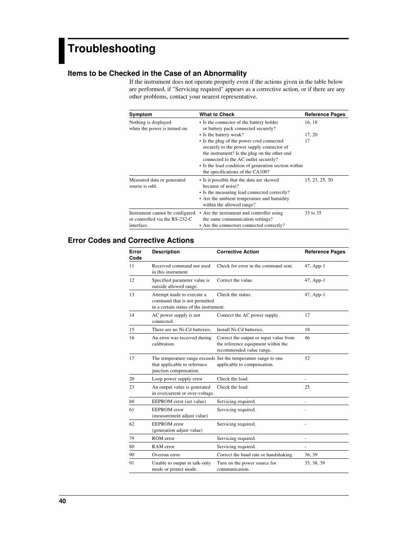
Items to be Checked in the Case of an AbnormalityIf the instrument does not operate properly even if the actions given in the table beloware performed, if "Servicing required" appears as a corrective action, or if there are anyother problems, contact your nearest representative.
Symptom What to Check Reference Pages
Nothing is displayed • Is the connector of the battery holder 16, 18when the power is turned on. or battery pack connected securely?
• Is the battery weak? 17, 20• Is the plug of the power cord connected 17
securely to the power supply connector ofthe instrument? Is the plug on the other endconnected to the AC outlet securely?
• Is the load condition of generation section withinthe specifications of the CA100?
Measured data or generated • Is it possible that the data are skewed 15, 23, 25, 30sourse is odd. because of noise?
• Is the measuring lead connected correctly?• Are the ambient temperature and humidity
within the allowed range?
Instrument cannot be configured • Are the instrument and controller using 33 to 35or controlled via the RS-232-C the same communication settings?interface. • Are the connectors connected correctly?
Error Codes and Corrective ActionsError Description Corrective Action Reference PagesCode
11 Received command not used Check for error in the command sent. 47, App-1in this instrument
12 Specified parameter value is Correct the value. 47, App-1outside allowed range.
13 Attempt made to execute a Check the status. 47, App-1command that is not permittedin a certain status of the instrument.
14 AC power supply is not Connect the AC power supply. 17connected.
15 There are no Ni-Cd batteries. Install Ni-Cd batteries. 18
16 An error was received during Correct the output or input value from 46calibration. the reference equipment within the
recommended value range.
17 The temperature range exceeds Set the temperature range to one 52that applicable to reference applicable to compensation.junction compensation.
20 Loop power supply error Check the load. -
23 An output value is generated Check the load. 25in overcurrent or over-voltage.
60 EEPROM error (set value) Servicing required. -
61 EEPROM error Servicing required. -(measurement adjust value)
62 EEPROM error Servicing required. -(generation adjust value)
79 ROM error Servicing required. -
80 RAM error Servicing required. -
90 Overrun error Correct the baud rate or handshaking. 36, 39
91 Unable to output in talk-only Turn on the power source for 35, 38, 39mode or printer mode. communication.

Main
tenan
ce
41
Tro
ub
lesho
otin
g
Maintenance
CalibrationTo maintain high accuracy, the instrument should be calibrated once every year.Calibration services are also available from your nearest representative. The followingexample of calibration using the standard equipment recommended in the section"Selecting the Standards" is described.
Selecting the StandardsGeneration Function
Item to be Standard Calibration Measurement Accuracycalibrated Range Range
DCV Digital 100 mV Max. 110 mV ±(10 ppm+1 µV)multimeter 1 V Max. 1.1 V ±(10 ppm+5 µV)
10 V Max. 11 V ±(10 ppm+50 µV)
DCA Digital 20 mA 22 mA ±(50 ppm+0.4 µA)multimeter
Ω Digital 500 Ω Max. 3 V ±(10 ppm+1 mV)multimeter 5 kΩ
50 kΩ
Measurement Function
Item to be Standard Calibration Generation Accuracycalibrated Range Range
DCV Standard DC 500 mV 500 mV ±(20 ppm+5 µV)voltage 5 V 5 V ±(20 ppm+50 µV)generator 35 V 35 V ±(20 ppm+300 µV)
DCA Standard DC 20 mA 20 mA ±(60 ppm+0.4 µA)current 100 mA 100 mA ±(40 ppm+1 µA)generator
Ω Precision- 500 Ω 500 Ω ±50 ppm(5 ppm/˚C)resistance 5 kΩ 5 kΩdigital 50 kΩ 50 kΩmultimeter
Required Environment during CalibrationAmbient temperature: 23±1˚CRelative humidity: 45% to 75% RHPower supply voltage: 100 V±5%Power supply frequency: (50/60 Hz)±1 HzWarm-up time: Before starting calibration, the standard equipment must be
warmed up for the specified time, and the instrument must bewarmed up for at least 4 hours.
Point to Note during CalibrationMake sure that the AC outlet to which this instrument is to be connected is a 3-slotoutlet with a grounding terminal.

42
Check Before Calibrating the Resistance Generation FunctionGenerate the one of the appropriate resistance values listed in the following table fromthe instrument, and measure the output voltage using a DMM. If the measured valuedeviates from the tolerance, calibration is unavailable when generating resistance.Contact your nearest representative.
Range Generated Resistance Tolerance
500 Ω 0.00 Ω ±20 µV or less5 kΩ 0.0000 kΩ ±20 µV or less50 kΩ 0.000 kΩ ±200 µV or less
Wiring
SOURCE
HiHimA
120mA MAXALL TERMINALS 42VPEAK MAX TO GND.
250V F 125mAFUSE MAX22mA42V MAX 28V
Lo Lo
MEASURE
I+ I-
Guard
Hi Lo
ΩGuard
Calibrated instrument
Measure DCV.
CAUTION
• Do not apply a voltage exceeding the maximum input voltage;otherwise, the input part may be damaged.
• Do not short-circuit or apply an external voltage to outputterminals of the instrument or standard equipment, or else theirinternal circuitry may be damaged.
Calibrating the Generation FunctionWiringDCV
SOURCE
HiHimA
120mA MAXALL TERMINALS 42VPEAK MAX TO GND.
250V F 125mAFUSE MAX22mA42V MAX 28V
Lo Lo
MEASURE
I+ I-
Guard
Hi Lo
ΩGuard
Calibrated instrument
Measure DCV.
DCA
SOURCE
HiHimA
120mA MAXALL TERMINALS 42VPEAK MAX TO GND.
250V F 125mAFUSE MAX22mA42V MAX 28V
Lo Lo
MEASURE
I+ I-
Guard
Hi Lo
ΩGuard
Calibrated instrument
Measure DCA.

Main
tenan
ce
43
Resistance
SOURCE
HiHimA
120mA MAXALL TERMINALS 42VPEAK MAX TO GND.
250V F 125mAFUSE MAX22mA42V MAX 28V
Lo Lo
MEASURE
I+ I-
Guard
Hi Lo
ΩGuard
Calibrated instrument
DANGER-HIGH VOLTAGE
I+ I-
Guard
Hi LoApplyDCA.
Measure DCV.
Procedure1 Before turning on the instrument, connect it and the standard equipment.2 Warm up the instrument and standard equipment.3 Press the [NEXT ENTER] key with the [ZERO CLR] key pressed.
"SP FC" and "End" are displayed.
4 Press [ ] or [ ] until "End" on the lower line changes to "SourCE."
5 Press [NEXT ENTER] to display the calibration screen for generation.
mVValuerecommendedfor the selectedrange
6 Select one of the generation functions (DCV, DCA, Ω) using the [FUNCTION] keyand press [RANGE] to select the range to calibrate (see page 24). Since each rangeis calibrated for two points, "FS" and "0" (for resistance, 4 points), 2 values (4 forresistance) must be output from this instrument. The recommended value for the"FS" calibration point appears at the lower line of the display first.
For DCV or DCA7 Press the [SOURCE ON] key to output the value from the instrument.
mVValuerecommendedfor "0" calibrationpoint
8 Read the output value from the instrument displayed on the standard equipment(DMM), and then input the value into the instrument, and press [NEXT ENTER] toconfirm it.
mVEnter thereadinggiven bythe standard
9 Press [24V OUT] to toggle the function from "FS" to "0," and repeat step 8 for theremaining calibration point referring to the recommended value shown on the lowerline.
10 Press the [HOLD] key to write the calibrated value to the EEPROM of theinstrument. Perform this operation for each range.
11 Repeat steps 6 to 10 for each range.For ΩΩΩΩΩ (Be sure to make a check of the resistance generation functionbefore calibration.)
ΩValuerecommendedfor the selectedrange
7 Press [SOURCE ON] to output the value from the instrument. Feed therecommended current (see page 46) from the standard equipment (generator).
Ω
Enter thecalculatedresistancevalue
8 Read the output voltage from the instrument displayed on the standard equipment(DMM), and then calculate V/I. Input the calculated result into the instrument, andpress the [NEXT ENTER] key to confirm it. To improve the accuracy ofcalculation, it is recommended that you use a DMM to measure the currentgenerated by the standard equipment.
Ω
9 Press [24V OUT] to switch the function from "FS" to one of the remainingadjustment points, "0," "-0," or "-FS," and repeat step 8 for each of them referringto the recommended value shown on the lower line.

44
10 Press the [HOLD] key to write the calibrated value to the EEPROM of theinstrument. Perform this operation for each range.
11 Repeat steps 6 to 10 for each range.Returning to the Measurement/Generation screen12 Press [ ] to display [SP FC].
Press [ ] or [ ] until [End] appears on the lower line of the display.13 Press the [NEXT ENTER] key to return to the Measurement/Generation screen.
Note• For resistance calibration, a correction is made on the value averaged from the standard current fed
in the normal and the reverse directions, that is, calibration points in the plus (+) and minus (-)directions are required; thus calibration is performed with 4 points.
• If you turn off the power before pressing the [HOLD] key, the set value is not stored.• The calibrated value is retained even after turning off the power.
Calibrating the Measurement FunctionWiringDCV
SOURCE
HiHimA
120mA MAXALL TERMINALS 42VPEAK MAX TO GND.
250V F 125mAFUSE MAX22mA42V MAX 28V
Lo Lo
MEASURE
Calibratedinstrument
DANGER-HIGH VOLTAGE
I+ I-
Guard
Hi Lo
Input DCV
DCA
SOURCE
HiHimA
120mA MAXALL TERMINALS 42VPEAK MAX TO GND.
250V F 125mAFUSE MAX22mA42V MAX 28V
Lo Lo
MEASURE
Calibrated instrumentDANGER-HIGH VOLTAGE
I+ I-
Guard
Hi Lo
Input DCA
Resistance
SOURCE
HiHimA
120mA MAXALL TERMINALS 42VPEAK MAX TO GND.
250V F 125mAFUSE MAX22mA42V MAX 28V
Lo Lo
MEASURE
Calibratedinstrument
High-accuracyresistance
SOURCE
HiHimA
120mA MAXALL TERMINALS 42VPEAK MAX TO GND.
250V F 125mAFUSE MAX22mA42V MAX 28V
Lo Lo
MEASURE
Calibratedinstrument
Calibration point "0" Calibration point "FS"
Procedure1 Before turning on the instrument, connect it and the standard equipment.2 Warm up the instrument and standard equipment.3 Press the [NEXT ENTER] key with the [ZERO CLR] key pressed.
The maintenance menu ("SP FC" and "End") is displayed.
Maintenance

Main
tenan
ce
45
4 Press [ ] or [ ] until "End" on the lower line changes to "mEAS."
5 Press [NEXT ENTER] to display the calibration screen for measurement.6 Select one of the measurement functions (DCV, DCA, Ω) using the [FUNCTION]
key and press [RANGE] to select the range to calibrate. Three values (two forresistance) must be entered into the instrument from the standard equipment tocalibrate one range.
The recommended value for the "FS" calibration point appears at the lower line ofthe display first.
For DCV or DCA
VMeasuredvalue
Recommendedvalue
7 Enter the value into the instrument from the standard equipment. (If therecommended value has not been entered, enter the value), and then press [NEXTENTER] for confirmation.
VMeasuredvalue
Recommendedvalue
8 Press [24V OUT] to switch the function from "FS" to one of the remainingadjustment points, "0," and "-FS," and repeat step 7 for each of them referring to therecommended value shown on the lower line.
9 Press [HOLD] to write the calibrated value into the EEPROM of the instrument.Perform this operation for each range.
10 Repeat steps 6 to 9 for each range.For ΩΩΩΩΩ
kΩ
kΩ
Measuredvalue
Recommendedvalue
Measuredvalue
Recommendedvalue
7 Connect a high-accuracy resistance of the specified value and measure theresistance. Correct the value of the calibration point and press [NEXT ENTER] toconfirm it.
8 Press the [24 V OUT] key and wire for the "0" calibration point and do thecalibration. The calibration point is toggled by pressing the [24 V OUT] keybetween [FS] and [0].
9 Press [HOLD] to write the calibrated value into the EEPROM of the instrument.Perform this operation for each range.
10 Repeat steps 6 to 9 for each range.Returning to the Measurement/Generation screen11 Press [ ] to display [SP FC].
Press [ ] or [ ] until [End] appears on the lower line of the display.12 Press the [NEXT ENTER] key to return to the Measurement/Generation screen.
Note• When calibrating the resistance measurement, if the resistance of the lead connecting terminals is
not negligible, measure the resistance through the lead, and enter the value for the "0" calibrationpoint into the instrument.
• When calibrating the resistance measurement, if an error in the value of precision resistance or theresistance of the wiring lead is not negligible, measure the resistance through the lead and high-accuracy resistance, and enter the value for the "FS" calibration point into the instrument.
• If you turn off the power before pressing the [HOLD] key, the set value is not stored.• The calibrated value is retained even after turning off the power.

46
Recommended Value for Calibration Ranges and PointsCalibrating the GenerationThe values of "FS" or "0" ("-FS," or "-0") vary depending on the object to measure.Send the appropriate value listed in the following table from the instrument to thestandard equipment, and enter the value measured using the standard equipment into theinstrument. If the entered value deviates from the one listed in the table by more than±20%, an error is assumed.
Function Range Unit 0 FS -0 -FS Remarks
DCV 100 mV 0.000 100.000 – –1 V 0.00000 1.00000 – –10 V 0.0000 10.0000 – –
DCA 20 mA 0.0000 20.0000 – –sink mA –0.0000 –20.0000 – –
Resistance 500(A1) Ω 0.000 500.000 0.000 500.000 I=±1 mA500(A2) Ω 0.000 500.000 0.000 500.000 I=±5 mA5(A1) kΩ 0.00000 5.00000 0.00000 5.00000 I=±0.1 mA5(A2) kΩ 0.00000 5.00000 0.00000 5.00000 I=±0.5 mA50(A) kΩ 0.0000 50.0000 0.0000 50.0000 I=±50 mA
I:Current fed when calibrating the resistance generation. Feed a plus (+) current for "FS" and "0," and aminus (-) current for "-FS" and "-0."
Calibrating the MeasurementThe values of "FS", "0", or "-FS" vary depending on the targets to measure. Enter anappropriate value listed in the table from the standard equipment into the instrument. Ifthe entered or specified value for "FS" or "-FS" deviates from the one listed in the tableby more than ±20% or the value for "0" deviates from the one listed in the table by morethan ±100 digits, an error is assumed.
Function Range Unit 0 FS -FS Remarks
DCV 500 mV 0.00 500.00 –500.005 V 0.0000 5.0000 –5.000035 V 0.000 35.000 –35.000
DCA 20 mA 0.000 20.000 –20.000100 mA 0.00 100.000 –100.000
Resistance 500 Ω 0.000 500.00 –5 kΩ 0.0000 5.0000 –50 kΩ 0.000 50.000 –

Main
tenan
ce
47
Commands for CalibrationThe following communications commands are available for calibration. Beforeexecuting these commands, see the descriptions on pages 41 to 46.
AGTurns the averaging function on and off/queries thecurrent setting.Syntax for setting AGm <terminator>
m=0: Averaging is off.1: Averaging is on.
Syntax of query AG? <terminator>Example of response AG1
CDSpecifies and queries the generation data.Syntax for setting CDm <terminator>
"m" represents the generationvalue of DCV, DCA, or resistance.
Syntax of query CD? <terminator>Example of response CD100.000Description • The generation value is
configurable within a range aswide as can be keyed in at eachrange. Set the value, however,within the recommended limitsof the given calibration point.Any setpoint exceeding theselimits will result in error code 16.Example: For a calibration pointof DCV 100 mV, the range is-999.999 to 999.999.
CLMakes calibration item setting/queries the currentsetting.Syntax for setting CLm <terminator>
m=3: Calibration of generation4: Calibration of measurement
Syntax of query CL? <terminator>Example of response CL3
CMFSpecifies the calibration function for measurement/queries the current setting.Syntax for setting CMFm <terminator>
m=0: DCV1: DCA2: Resistance
Syntax of query CMF? <terminator>Example of response CMF0
CPMakes calibration point setting/queries the currentsetting.Syntax for setting CPm <terminator>
Calibration for generation:DCV DCA* Resistance
m=0: FS (S)FS +FS1:0 (S)0 02:- - -FS3:- - -0*(S) is for SINK.
Calibration for measurement:DCV DCA Resistance
m=0:+FS +FS +FS1:0 0 02:-FS -FS -
Syntax of query CP? <terminator>Example of response CP0
CSConfirms the measured data when calibrating ameasurement, and inputs and queries the DMMmeasured values.Syntax for setting CSm <terminator>
"m" represents the measured valueof DMM.
Syntax of query CS? <terminator>Example of response CS1.00000Description • The measured value for a DMM
is configurable within a range aswide as can be keyed in at eachrange. Set the value, however,within the recommended limitsof the given calibration point.Any setpoint exceeding theselimits will result in error code 16.Example: For a calibration pointof DCV 10 V, the range is-99.9999 to 99.9999.
CSFSpecifies the calibration function for generation/queriesthe current setting.Syntax for setting CSFm <terminator>
m=0: DCV1: DCA2: Resistance
Syntax of query CSF? <terminator>Example of response CSF0Description • If the function is changed during
generation, the generation isturned off. To turn on thegeneration, issue an SOcommand again.

48
CWWrites the calibration data.Syntax for setting CW <terminator>Description • The result of calculation is
written to the EEPROM aftercompleting calibration.
• If the calibration point is not set,error 16 occurs indicating acalibration error.
ESC SOutputs a status byte.Syntax for setting ESC S <terminator>Description • This outputs the status byte (n=0
to 127, n represents the decimalnumber converted from thebinaries of bits 0 to 7) generatedby the instrument. For details onthe status byte, see page App-5.
HEnables/Disables the header addition to the output data/queries the current setting.Syntax for setting Hm <terminator>
m=0: Disabled1: Enabled
Syntax for query H? <terminator>Example of response H1Description For details on the header, see the
output format of measured valueson page App-5.
KTSelects the key type used and queries the current setting.Syntax for setting KTm <terminator>
m=0: Up/Down key1: Numeric keypad
Syntax of query KT? <terminator>Example of response KT0
MOStarts/stops measurement/queries the current setting.Syntax for setting MOm <terminator>
m=0: Stop measurement1: Start measurement
Syntax of query MO? <terminator>Example of response MO1
MRSpecifies the calibration range for measurement/queriesthe current setting.Syntax for setting MR m <terminator>
DCV DCA Resistancem=0:500 mV 20 mA 500 Ω
1:5 V 100 mA 5 kΩ2:35 V - 50 kΩ
Syntax of query MR? <terminator>Example of response MR0
ODOutputs measured data.Syntax for query OD <terminator>Description For the output format of the
measured data, see page App-5.
OEOutputs error information.Syntax for query OE <terminator>Example of response ERR11Description • Outputs a recently occurred
error.• For the meanings of error
numbers, see the troubleshootingsection (page 40).
SOStarts or ends generation/queries the current setting.Syntax for setting SOm <terminator>
m=0: Stop generation1: Start generation
Syntax of query SO? <terminator>Example of response SO1
SRSpecifies the calibration range for generation/queries thecurrent setting.Syntax for setting SRm <terminator>
DCV DCA Resistancem= 0: 100 mV 20 mA 500 Ω (1 mA)
1: 1 V - 5 kΩ (1 mA)2: 10 V SINK 50 kΩ3: - - 500 Ω (5 mA)4: - - 5 kΩ (5 mA)
Syntax of query SR? <terminator>Example of response SR0Description • If the range is changed during
generation, the generation isturned off. To turn on thegeneration, issue an SOcommand again.

Main
tenan
ce
49
SYSwitches between the normal and calibration modes/queries the current setting.Syntax for setting SYm <terminator>
m=0: Normal mode1: Calibration mode
Syntax of query SY? <terminator>Example of response SY1Description • If a communications command
for the normal mode is receivedduring the calibration mode,error 13 occurs.
TTSelects the international temperature standard/queriesthe current setting.Syntax for setting TTm <terminator>
m=0: IPTS-681: ITS-90
Syntax of query TT? <terminator>Example of response TT0
TUSelects the temperature unit/queries the current setting.Syntax for setting TUm<terminator>
m=0 : ˚C1 : ˚F
Syntax of query TU?<terminator>Example of response TU1

50
Replacing the Ni-Cd BatteriesThe service life of Ni-Cd batteries is reduced if they are used repeatedly, even if theyare completely charged. The interval between battery replacement differs depending onthe operating conditions, but you should replace them approximately every two years orafter recharging them 500 times. Battery pack replacement must be done as describedon page 18.
Replacing the Backlighting ELThe EL for backlighting is consumable. The EL can be used continuously forapproximately 5000 hours before its brightness falls by half. It is recommended that theEL be replaced after approximately 5000 hours of use (i.e., about 6 months at 24-hourcontinuous operation). It is not possible for user personnel to replace the EL, so pleasecontact your nearest representative.
Replacing the Fuse
WARNING
• The fuse used must be of the specified rating in order tominimize the risk of a fire hazard. Never use a fuse of any otherrating and never short-circuit the fuse holder to bypass the fuse.
• Before replacing the fuse, be sure to turn the power switch off,remove the connections from each input and output terminal andremove the power cord from the AC outlet.
Fuse Position and Replacement MethodThe current input terminal accommodates a built-in fuse. A fuse is contained in the fuseholder as shown below. To replace the fuse, turn the fuse holder counterclockwise withyour fingers to remove it, and then replace the fuse with a new one.
Fuse RatingsWhen you order a spare fuse, specify the following part number.
Ratings Part No.
250 V, 125mA, Quick acting A1501EF
The following fuses are used in the instrument. It is not possible for the user to replacethese fuses, so please contact your nearest representative.
Using place Ratings Part No.
Main board (F1) 250 V AC 315mA A1445EFMain board (F2) 250 V AC 1A A1432EF

51
Sp
ecification
s
Specifications
The accuracy specifications vary depending on usage. The following specificationsindicate the accuracy at an ambient temperature of 23°C ± 5°C, after performing auto-calibration, and are applicable for one year after calibration. They do not includemeasuring lead parts. The conditions for the temperature factors are 5°C or more butless than 18°C, and more than 28°C up to 40°C.
Generation FunctionsDCV
Range 100 mV 1 V 10 V
Displaying Resolution 100.000 mV 1.00000 V 10.0000 V
Generating Range –10 to 110 mV –0.1 to 1.1 V –1 to 11 V
Guaranteed Accuracy Range 0 to 100 mV 0 to 1 V 0 to 10 V
Accuracy (*1) ± (% of setting +% of range)With EL turned off, without charging 0.02 + 0.01 0.02 + 0.005 0.02 + 0.005With EL turned on, without charging 0.025 + 0.015 0.025 + 0.01 0.025 + 0.01With charging 0.04 + 0.025 0.035 + 0.01 0.035 + 0.01
Temperature Coefficient ± (% of setting +% of range)/°C 0.003 + 0.002 0.002 + 0.001 0.002 + 0.001
Maximum Output (*2) – 10 mA 10 mA
Output Resistance Approx. 6.5 Ω Approx. 30 mΩ Approx. 30 mΩ*1 If you turn off the EL or stop charging while the EL is on and charging is in progress at the same time, it takes two hours for the
accuracy in that condition to fall within the specified rating.*2 If the applied output exceeds the maximum output, the output limiter operates. (A manual reset is required.)
DCA
Range SOURCE 20 mA SINK 20 mA*1
Displaying Resolution 20.000 mA 20.000 mA
Generating Range 0 to 22 mA 0 to –22 mA
Guaranteed Accuracy Range 0 to 20 mA 0 to –20 mA
Accuracy (*2) ± (% of setting +% of range)With EL turned off, without charging 0.025 + 0.015 0.025 + 0.03With EL turned on, without charging 0.03 + 0.02 0.03 + 0.035With charging 0.04 + 0.035 0.045 + 0.05
Temperature Coefficient ± (% of setting +% of range)/°C 0.003 + 0.003 0.003 + 0.003
Maximum Output (*3) 24 V 28 V*1 SINK: A function extracts the current of the specified value in the direction of the Hi terminal from an external voltage generating
source (up to 28 V).*2 If you turn off the EL or stop charging while the EL is on and charging is in progress at the same time, it takes two hours for the
accuracy in that condition to fall within the specified rating.*3 If the applied output exceeds the maximum output, the output limiter operates. (A manual reset is required.)
Resistance (*1)
Range 500 Ω 5 kΩ 50 kΩDisplaying Resolution 500.00 Ω 5.0000 kΩ 50.000 kΩ
Generating Range 0 to 550 Ω 0 to 5.5 kΩ 0 to 55 kΩ
Guaranteed Accuracy Range 0 to 500 Ω 0 to 5 kΩ 0 to 50 kΩ
Accuracy (*2) ± (% of setting +% of range)With EL turned off, without charging 0.02 + 0.02 0.05 + 0.03 0.1 + 0.1With EL turned on, without charging 0.025 + 0.02 0.06 + 0.03 0.11 + 0.11With charging 0.035 + 0.1 0.065 + 0.1 0.12 + 0.3
Temperature Coefficient ± (% of setting +% of range)/°C 0.002 + 0.01 0.002 + 0.01 0.002 + 0.03
Maximum Output 2 V 2 V 2 V
Remarks 1 mA ≤ measuring current 0.1 mA ≤ measuring current 0.01 mA ≤ measuring current≤ 5 mA, and output voltage ≤ 1 mA, and output voltage ≤ 0.1 mA, and output voltageof 2 V or less of 2 V or less of 2 V or less
*1 Resistance Generation: The equivalent resistance generation system from detecting the resistance measurement current and thegenerating voltage drop. The specifications are valid within the measured current and voltage shown in the remarks column.
*2 If you turn off the EL or stop charging while the EL is on and charging is in progress at the same time, it takes two hours for theaccuracy in that condition to fall within the specified rating.

52
Thermocouple
Range (*1) K E J T N R B
Displaying 1000.0°C 1000.0°C 1000.0°C 100.0°C 1000.0°C 1000°C 1000°CResolution
Generating –200 to 1372°C –250 to 1000°C –210 to 1200°C –250 to 400°C –200 to 1300°C –40 to 1767°C 400 to 1820°CRange
Guaranteed Same as the generating rangeAccuracy Range
Accuracy (*2, *3)With EL –200 to –100°C:0.6°C –250 to –200°C:1.2°C –210 to –100°C:0.6°C –250 to –200°C:1.5°C –200 to –100°C:1.0°C –40 to 100°C:1.5°C 400 to 600°C:2.0°Cturned off, –100 to 400°C:0.5°C –200 to –100°C:0.6°C –100 to 800°C:0.5°C –200 to 400°C:0.5°C –100 to 900°C:0.7°C 100 to 1767°C:1.2°C 600 to 800°C:1.5°Cwithout 400 to 1200°C:0.7°C –100 to 600°C:0.5°C 800 to 1200°C:0.7°C 900 to 1300°C:0.8°C 800 to 1820°C:1.1°Ccharging 1200 to 1372°C:0.9°C 600 to 1000°C:0.6°C
With EL –200 to –100°C:0.7°C –250 to –200°C:1.4°C –210 to –100°C:0.7°C –250 to –200°C:1.9°C –200 to –100°C:1.2°C –40 to 100°C:1.9°C 400 to 600°C:2.4°Cturned on, –100 to 400°C:0.6°C –200 to –100°C:0.7°C –100 to 800°C:0.6°C –200 to 400°C:0.6°C –100 to 900°C:0.8°C 100 to 1767°C:1.6°C 600 to 800°C:1.9°Cwithout 400 to 1200°C:0.8°C –100 to 600°C:0.6°C 800 to 1200°C:0.8°C 900 to 1300°C:0.9°C 800 to 1820°C:1.5°Ccharging 1200 to 1372°C:1.0°C 600 to 1000°C:0.7°C
With –200 to –100°C:1.0°C –250 to –200°C:1.9°C –210 to –100°C:1.0°C –250 to –200°C:3.0°C –200 to –100°C:1.7°C –40 to 100°C:3.0°C 400 to 600°C:3.4°Ccharging –100 to 400°C:0.9°C –200 to –100°C:1.0°C –100 to 800°C:0.9°C –200 to 400°C:0.9°C –100 to 900°C:1.1°C 100 to 1767°C:2.6°C 600 to 800°C:3.0°C
400 to 1200°C:1.1°C –100 to 600°C:0.9°C 800 to 1200°C:1.1°C 900 to 1300°C:1.2°C 800 to 1820°C:2.5°C1200 to 1372°C:1.3°C 600 to 1000°C:1.0°C
Temperature 0.05°C –250 to –200°C:0.1°C 0.05°C –250 to –200°C:0.2°C –200 to –100°C:0.1°C 0.2°C 0.2°CCoefficient –200 to 1000°C:0.05°C –200 to 400°C:0.05°C–100 to 1300°C:0.05°C
ThermocoupleOutput Internal Approx. 6.5 ΩResistance
ReferenceJunction Compensation:Based on the optional RJC sensor. If the output correction is performed based on the reference contacttemperature, the accuracy of the sensor must be added. The output correction is performed every 10 seconds.Specifications of RJC sensor:Measuring range: -10 to 50°CAccuracy between 18 and 28°C: ±0.5°C (including the instrument)Accuracy between -10 and 18°C, 28 to 50°C: ±1°C (including the instrument)Length of the cord: Approx. 1.5 m
*1 Complies with both JIS-C1602-1981 and 1995*2 RJC accuracy is excluded*3 If you turn off the EL or stop charging while the EL is on and charging is in progress at the same time, it takes two hours for the accuracy
in that condition to fall within the specified rating.
Resistance Temperature Detector (*1)
Range PT100
Displaying Resolution 100.0°C
Generating Range –200 to 850°C
Guaranteed Accuracy Range Same as the generating range
Accuracy (*2)With EL turned off, –200 to 0°C:0.3°Cwithout charging 0 to 400°C:0.5°C
400 to 850°C:0.8°C
With EL turned on, –200 to 0°C:0.4°Cwithout charging 0 to 400°C:0.6°C
400 to 850°C:0.9°C
With charging –200 to 0°C:0.6°C0 to 400°C:0.8°C
400 to 850°C:1.1°C
Temperature Coefficient 0.04°C
*1 Resistance Generation: The equivalent resistance generation system from detecting the resistance measurement current and thegenerating voltage drop. The specifications are valid within the measured current and voltage shown in the remarks column. Theaccuracy is at measured current of 1 to 5 mA (PT100)
*2 If you turn off the EL or stop charging while the EL is on and charging is in progress at the same time, it takes two hours for theaccuracy in that condition to fall within the specified rating.

53
Sp
ecification
s
Frequency, Pulse Signal
Range 100 Hz 1000 Hz 10 kHz 50 kHz
Displaying Resolution 100.0 Hz 1000 Hz 10.0 kHz 50 kHz
Generating Range 1 to 110 Hz 90 to 1100 Hz 0.9 to 11.0 kHz 9 to 50 kHz
Guaranteed Accuracy Range 1 to 100 Hz 100 to 1000 Hz 1 to 10 kHz 10 to 50 kHz
Accuracy 1 digit 1 digit 1 digit 1 digit
Maximum Output 10 mA 10 mA 10 mA 10 mA
Waveform Rectangular wave approx. 50% of duty factor
Output Level 10 V DC range Output Level Accuracy ± (10% of setting + 10 mV)
Number of pulses 1 to 60000 cycles
Measurement FunctionDCV
Range 500 mV 5 V 35 V
Displaying Resolution 500.00 mV 5.0000 V 35.000 V
Displaying Range –599.99 to 599.99 mV –5.9999 to 5.9999 V –41.999 to 41.999 V
Guaranteed Accuracy Range –500.00 to 500.00 mV –5.0000 to 5.0000 V –35.000 to 35.000 V
Accuracy (*) ± (% of reading +% of range)With EL turned off, without charging 0.02 + 0.01 0.02 + 0.01 0.02 + 0.015With EL turned on, without charging 0.025 + 0.01 0.025 + 0.01 0.025 + 0.015With charging 0.035 + 0.02 0.035 + 0.02 0.035 + 0.02
Temperature Coefficient ± (% of reading +% of range)/°C 0.002 + 0.001 0.002 + 0.001 0.002 + 0.001
Input Resistance 1 GΩ or more Approx. 1 MΩ Approx. 1 MΩ
* If you turn off the EL or stop charging while the EL is on and charging is in progress at the same time, it takes two hours for theaccuracy in that condition to fall within the specified rating.
DCA
Range 20 mA 100 mA
Displaying Resolution 20.000 mA 100.00 mA
Displaying Range –23.999 to 23.999 mA –119.99 to 119.99 mA
Guaranteed Accuracy Range –20.000 to 20.000 mA –100.00 to 100.00 mA
Accuracy (*) ± (% of reading +% of range)With EL turned off, without charging 0.025+0.02 0.04+0.03With EL turned on, without charging 0.03+0.02 0.045+0.03With charging 0.04+0.03 0.055+0.04
Temperature Coefficient ± (% of reading +% of range)/°C 0.002+0.001 0.002+0.001
Input Resistance 20 Ω or less
* If you turn off the EL or stop charging while the EL is on and charging is in progress at the same time, it takes two hours for theaccuracy in that condition to fall within the specified rating.
Resistance
Range 500 Ω 5 kΩ 50 kΩDisplaying Resolution 500.00 Ω 5.0000 kΩ 50.000 kΩ
Displaying Range 0 to 599.99 Ω 0 to 5.9999 kΩ 0 to 59.999 kΩ
Guaranteed Accuracy Range 0 to 500.00 Ω 0 to 5.0000 kΩ 0 to 50.000 kΩ
Accuracy (*) ± (% of reading +% of range)With EL turned off, without charging 0.055+0.015 0.055+0.015 0.055+0.02With EL turned on, without charging 0.065+0.02 0.065+0.02 0.065+0.03With charging 0.09+0.03 0.09+0.03 0.09+0.04
Temperature Coefficient ± (% of reading +% of range)/°C 0.005+0.002 0.005+0.002 0.005+0.002
Measurement Current Approx. 1 mA Approx. 100 µA Approx. 10 µA
* If you turn off the EL or stop charging while the EL is on and charging is in progress at the same time, it takes two hours for theaccuracy in that condition to fall within the specified rating.

54
Generation SectionResponse Time
10 ms 1 V DC, 10 V DC ranges: The time necessary for the output to be settled withinthe accuracy range from when it started to vary.10 ms 500 Ω range: The time necessary for the output to be settled within theaccuracy from when the regulated current was fed.(Including RTD output)300 ms other than the above ranges: The time necessary for the output to be settledwithin the accuracy range from when it started to vary.
Voltage limiter 28.5 V or moreCurrent limiter 12 mA or more (only for functions of DCV, frequency, pulse)Load condition 0.01 µF or less (for DCV, Ω, TC, RTD, frequency, pulse), 100 µH or less (DC mA)Thermocouple generation Without external reference contact, zero-point reference output
With external reference contact (B9638CR), reference temperature measuringaccuracy±0.5°C (where the measured temperature is 23°C±5°C)±1.0°C (where the measured temperature is -10 to 18°C or 28 to 50°C)
Measurement SectionDisplay Update Time 1 sec.Max. Input Voltage, Current Voltage terminal 42 V, Current terminal 120 mACurrent Terminal Input Protection Fuse, Part No. A1501EF, 250 V, 125 mA, Quick actingCMRR 120 dB or more (50/60 Hz), RS = 1 kΩNMRR 60 dB or more (50/60 Hz)Release Voltage for Resistance Measurement max 4.5 VAverage Number for Moving Average 5 sampling data
24 V DC Supply SectionOutput Voltage 24 V DC ± 1 VMax. Output Current 22 mA DCOutput Protection Output is turned off at 30 mA or more
Communications FunctionRS-232-C Interface 9-pin D-SUB connectorTransfer Method Start-stop synchronization systemTransfer Rate 150, 300, 600, 1200, 2400, 4800, 9600 bits/sFunction Specifications Talk-only/Normal mode, Handshaking mode, data format selection available
Common SpecificationsComplying safety standard General safety: EN61010
· Overvoltage category II (CAT II)· Pollution degree 2
EMC : IEC1326-1:1997 DRAFT, IEC1326-10:1996 DRAFT· Except, use a double shielded cable for the RS-232-C cable and separate the RS-
232-C cable and the measuring lead by 50 mm or more.· The cable layout during the emission test was as follows. The output lead of the
generation section was bent perpendicularly to the left at 20 cm from the terminalsection. The output lead of 24VOUT was bent perpendicularly to the right at 20 cmfrom the terminal section. The cord from the AC adapter was bent perpendicularlytowards the front at 5 cm from the connector. The measuring lead, RJC sensor cableand the RS-232-C cable was positioned perpendicular to the terminal section and theconnector in a straight line.
· The output voltage range of the AC adapter is 15 V DC ±0.75 V.
The influence under the immunity environment is as follows
Function Test Condition
Range Setting Value Accuracy
Generation 1V 0.5V ±5% of range20mA 10mA ±5% of range50kΩ 10kΩ ±5% of range
Measurement 5V 1V ±20% of range20mA 0mA ±30% of range50kΩ 10kΩ ±20% of range

55
Sp
ecification
s
Power SupplyAC adapter, Ni-Cd battery pack, or commercially available AA alkaline cells; the Ni-Cdbattery pack can be recharged only within the instrument.
Charging the battery pack Timer charging by the instrument (approximately 10 hours)AC adapter (optional)
Input: 100 to 240 V AC, 50/60 Hz, 40 to 55 VAPermitted Input Voltage Range: 90 to 264 V ACPermitted Input Frequency Range: 48 to 62 Hz
Ni-Cd Battery Pack (optional) 1200 mAh, 9.6 V, recycle-designated part, service life of 2 years (varies according to theoperating conditions), part number B9914PSContinuous operating time for guidance:
With generating 5 V DC (with 500 Ω load), and operating measuring function:Approx. 7.5 hoursWith generating 20 mA (with 1 kΩ load), operating measuring function, 24 V DCpower supply, EL lit: Approx. 2.5 hours
AA Cells Eight AA alkaline cellsContinuous operating time for guidance:
With generating 5 V DC (with 500 Ω load), and operating measuring function:Approx. 10 hoursWith generating 20 mA (with 1 kΩ load), operating measuring function, 24 V DCpower supply, EL lit: Approx. 2 hours
Automatic Power Off: Approximately 30 minutes under the following conditions: No key or communicationoperation is performed while being run on batteries.
Display Backlighting Segmented LCD, EL backlighting
Warm-up Time Approx. 5 minutes
Power Consumption 55 VA or less
Insulation Resistance 20 MΩ or more for one minute at 500 V DC (between terminals/each terminal and ACadapter power line)
Withstanding Voltage 350 V AC for one minute (between terminals)1500 V AC for one minute (between each terminal and AC power line)
Operating Temperature/Humidity RangesFor generation or measurement (normal), or charging without generation or measurementrunning:5 to 40°C, 20 to 80% RH (no condensation)For charging with generation or measurement running:5 to 30°C, 20 to 80% RH (no condensation)
Storage Temperature/Humidity Range -20 to 45°C, 90% RH or less (No condensation allowed)
I/O terminals Maximum applied voltage is less than 42 Vpeak and CAT II between terminals/eachterminal and ground. Except, negative 24 VOUT terminal is 18 Vpeak or less.
Operating altitude Max. 2000 m
External Dimensions 237 x 137 x 63 mm (does not include projections)
Weight Approx. 1.2 kg (including 8 dry cells)
External DimensionsUnit:mm
63 237
137 14
7

Ap
pen
dix
App-1
Communication CommandsASMakes the current function setting/queries the currentsetting.Syntax for setting ASm <terminator>
m=0: Source1: SINK
Syntax for query AS? <terminator>Example of response AS0
BLTurns the backlighting on and off/queries the currentsetting.Syntax for setting BLm <terminator>
m=0: Off1: On
Syntax for query BL? <terminator>Example of response BL1
BTStarts charging the battery pack when being connectedto the AC power supply.Syntax for setting BT <terminator>Description • Issuing this command without
connecting to the AC powersupply results in error 14.
• Error code 15 occurs if there isno Ni-Cd battery connected.
DLSelects the terminator type used for output data/queriesthe current setting.Syntax for setting DLm <terminator>
m=0: CR + LF1: CR2: LF
Syntax for query DL? <terminator>Example of response DL0
DWMoves down the "m-th" digit of the generated value byone digit.Syntax for setting DWm <terminator>
m=1 to 5Description • This command has no query.
• This is valid only when the up/down key is selected.
ESC C or RCInitializes the set information of the instrument.Syntax for setting ESC C <terminator>
RC <terminator>Description • When initializing the information
using these commands, thefollowing are not initialized:
• Communication items• Key type• Average
• International temperaturestandard
• Temperature unit
ESC SOutputs a status byte.Syntax for setting ESC S <terminator>Description • This outputs the status byte (n=0
to 127, n represents the decimalnumber converted from thebinaries of bits 0 to 7) generatedby the instrument. For details onthe status byte, see page App-5.
HEnables/Disables the header addition to the output data/queries the current setting.Syntax for setting Hm <terminator>
m=0: Disabled1: Enabled
Syntax for query H? <terminator>Example of response H1Description • For details on the header, see the
output format of measured valueson page App-5.
HDEnables/Disables data hold/queries the current setting.Syntax for setting HDm <terminator>
m=0: Display update1: Display hold
Syntax for query HD? <terminator>Example of response HD0Description • Although the display is in "hold"
status, the system continuesupdating measurement data.
Appendix

App-2
IMMakes the status byte mask setting/queries the currentsetting.Syntax for setting IMm <terminator>
m=0 to 631: Measurement end2: Output change end4: Syntax error8: Overrange16: Loop power supply error32: Error on output
Syntax for query IM? <terminator>Example of response IM6Description: • Set the value representing the
information to be retrieved. Ifmore than one bit is to beretrieved, the sum of the numberof those bits must be set as "m."For instance, if 3 bits,"Measurement end," "Syntaxerror," and "Overrange," are tobe retrieved, set "m" to 13(1+4+8=13).
• For details on status bytes, seepage App-5.
MFSets the measuring function/queries the current setting.Syntax for setting MFm <terminator>
m=0: DCV1: DCA2: Resistance
Syntax for query MF? <terminator>Example of response MF1
MOStarts/Stops measurement/queries the current setting.Syntax for setting MOm <terminator>
m=0: Stop1: Start
Syntax for query MO? <terminator>Example of response MO1
MRSets the measurement range/queries the current setting.Syntax for setting MRm <terminator>
DCV DCA Resistancem=0:500 mV 20 mA 500 Ω
1:5V 100 mA 5 kΩ2:35 V - 50 kΩ
Syntax for query MR? <terminator>Example of response MR0
OBQueries the battery charge state.Syntax for query OB <terminator>Description The following are the responses:
0: Off1: Charging2: Charging completed
ODOutputs measured data.Syntax for query OD <terminator>Description For the output format of the
measured data, see page App-5.
OEOutputs error information.Syntax for query OE <terminator>Example of response ERR11Description • Outputs the most-recently-
generated error.• For the meanings of error
numbers, see the troubleshootingsection (page 40).
ORQueries whether an RJC sensor is connected.Syntax for query OR <terminator>Description The following are the responses:
0: Connected1: Not connected
OSOutputs the setting information.Syntax for query OS <terminator>Description • For the output format of the
measured data, see page App-5.
SCEnable/Disable auto-zero calibration/queries the currentsetting.Syntax for setting SCm <terminator>
m=0: Enable auto-zero calibration1: Disable auto-zero calibration
Syntax for query SC? <terminator>Example of response SC0

Ap
pen
dix
App-3
SDSets generated value/queries the current setting.Syntax for setting SDm <terminator>
DCV(100 mV) m = -10.000 to110.000(1 V) m = -0.10000 to 1.10000(10 V) m = -1.0000 to 11.0000
DCA(20 mA) m = 0.000 to 22.000(SINK) m = -22.000 to 0.000
Resistance(500 Ω) m = 0.00 to 550.000(5 kΩ) m = 0.0000 to 5.5000(50 kΩ) m = 0.0000 to 55.000
RTD(PT100) m = -200.0 to 850.0
TC(K) m = -200.0 to 1372.0(E) m = -250.0 to 1000.0(J) m = -210.0 to 1200.0(T) m = -250.0 to 400.0(R) m = -40.0 to 1767(N) m = -200.0 to 1300.0(B) m = 400.0 to 1820
Frequency/Pulse frequency(100 Hz) m = 1.0 to 110.0(1 kHz) m = 90 to 1100(10 kHz) m = 0.9 to 11.0(50 kHz) m = 9 to 50
Frequency DCV/Pulse DCV(10 V) m = -1.0000 to 11.0000
Pulsem=1 to 60000
Syntax for query SD? <terminator>Example of response SD100.000
SFSets the generated function/queries the current setting.Syntax for setting SFm <terminator>
m=0: DCV1: DCA2: Resistance3: TC (thermocouple)4: RTD (resistance temperature
detector)5: Frequency6: Frequency DCV7: Pulse8: Pulse DCV9: Pulse frequency
Syntax for query: SF? <terminator>Example of response SF0Description During generation, if the function
is changed, generation is turnedoff. The generated value is alsoreset to zero.
SOStarts/Stops generation/queries the current setting.Syntax for setting SOm <terminator>
m=0: Generation stop1: Generation start
Syntax for query SO? <terminator>Example of response SO1
SRSets the generation range/queries the current setting.Syntax for setting SRm <terminator>
DCV Resistancem=0:100 mV 500 Ω
1:1 V 5 kΩ2:10 V 50 kΩ
RTD TC Frequency/Pulsefrequency
m=0: - B 100Hz1: PT100 E 1 kHz2: - J 10 kHz3: - K 50 kHz4: - N -5: - R -6: - T -
Syntax for query SR? <terminator>Example of response SR1Description • Frequency DCV and pulse DCV
are fixed in a 10 V range. Thepulse function has no rangesetting, either.
• During generating, if the range ischanged, generation is turned off.The generated value is also resetto zero.
• SR command is unavailable forswitching the current functionsource/SINK. Use the AScommand.
SYSwitches between the normal and calibration modes/queries the current setting.Syntax for setting SYm <terminator>
m=0: Normal mode1: Calibration mode
Syntax for query SY? <terminator>Example of response SY1Description • If a command for the calibration
mode is received during thenormal mode, error 13 occurs.
UPMoves up the "m-th" digit of the generated value by onedigit.Syntax for setting UPm <terminator>
m=1 to 5Description: • This command has no query.
• This is valid only when the UP/DOWN key is selected.

App-4
VOStart/Stop the 24 V DC power supply/queries thecurrent setting.Syntax for setting VOm <terminator>
m=1: Stops supply0: Starts supply
Syntax for query VO? <terminator>Example of response VO1
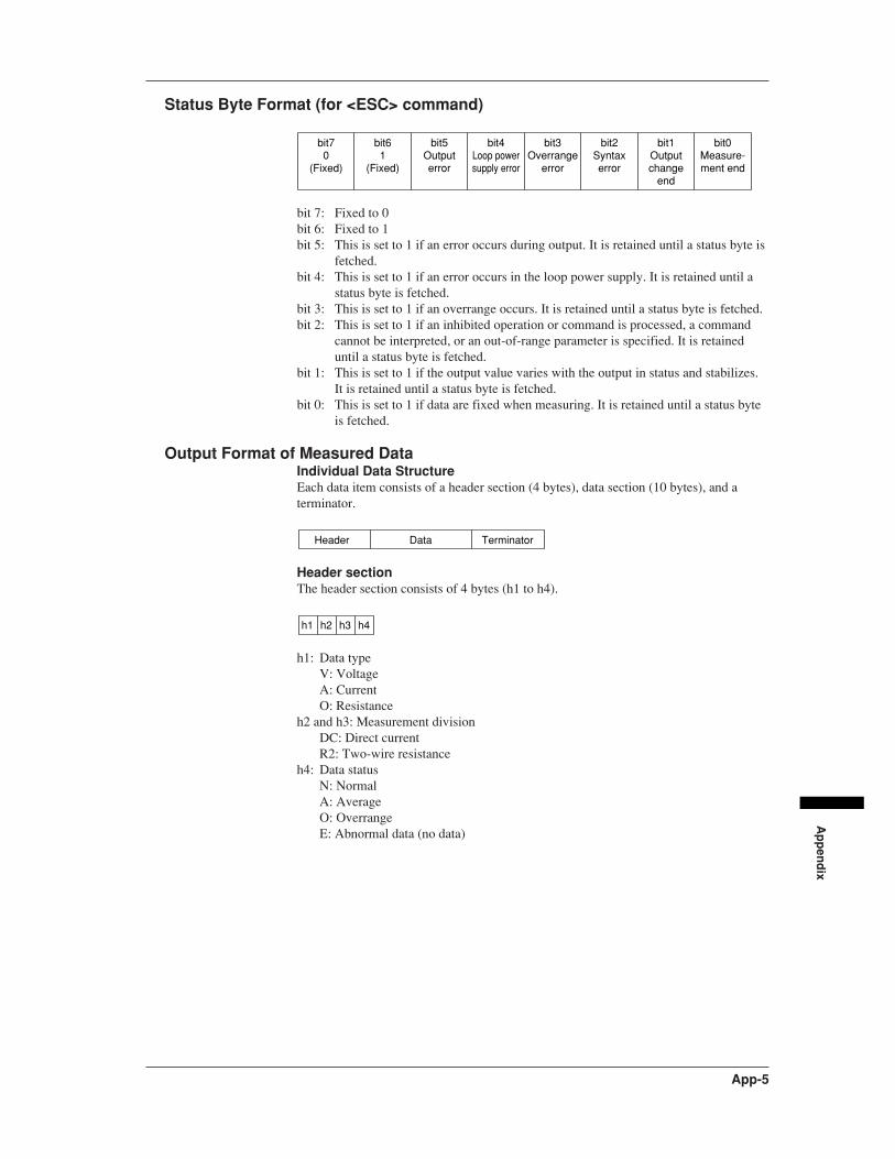
Ap
pen
dix
App-5
Status Byte Format (for <ESC> command)
bit70
(Fixed)
bit61
(Fixed)
bit5Output error
bit4Loop power supply error
bit3Overrange
error
bit2Syntax error
bit1Output change
end
bit0Measure-ment end
bit 7: Fixed to 0bit 6: Fixed to 1bit 5: This is set to 1 if an error occurs during output. It is retained until a status byte is
fetched.bit 4: This is set to 1 if an error occurs in the loop power supply. It is retained until a
status byte is fetched.bit 3: This is set to 1 if an overrange occurs. It is retained until a status byte is fetched.bit 2: This is set to 1 if an inhibited operation or command is processed, a command
cannot be interpreted, or an out-of-range parameter is specified. It is retaineduntil a status byte is fetched.
bit 1: This is set to 1 if the output value varies with the output in status and stabilizes.It is retained until a status byte is fetched.
bit 0: This is set to 1 if data are fixed when measuring. It is retained until a status byteis fetched.
Output Format of Measured DataIndividual Data StructureEach data item consists of a header section (4 bytes), data section (10 bytes), and aterminator.
Header Data Terminator
Header sectionThe header section consists of 4 bytes (h1 to h4).
h1 h2 h3 h4
h1: Data typeV: VoltageA: CurrentO: Resistance
h2 and h3: Measurement divisionDC: Direct currentR2: Two-wire resistance
h4: Data statusN: NormalA: AverageO: OverrangeE: Abnormal data (no data)
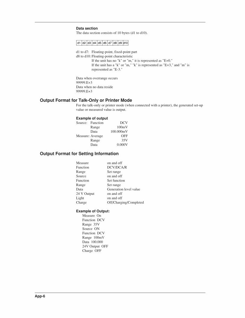
App-6
Data sectionThe data section consists of 10 bytes (d1 to d10).
d1 d2 d3 d4 d5 d6 d7 d8 d9 d10
d1 to d7: Floating-point, fixed-point partd8 to d10: Floating-point characteristic
If the unit has no "k" or "m," it is represented as "E+0."If the unit has a "k" or "m," "k" is represented as "E+3," and "m" isrepresented as "E-3."
Data when overrange occurs99999.E+3Data when no data reside99999.E+3
Output Format for Talk-Only or Printer ModeFor the talk-only or printer mode (when connected with a printer), the generated set-upvalue or measured value is output.
Example of outputSource: Function DCV
Range 100mVData 100.000mV
Measure: Average OFFRange 35VData 0.000V
Output Format for Setting Information
Measure on and offFunction DCV/DCA/RRange Set rangeSource on and offFunction Set functionRange Set rangeData Generation level value24 V Output on and offLight on and offCharge Off/Charging/Completed
Example of Output:Measure OnFunction DCVRange 35VSource ONFunction DCVRange 100mVData 100.00024V Output OFFCharge OFF

Ap
pen
dix
App-7
Sample Program
'*******************************************************************
'* *
'* CA100 COMAPCT CAL (RS-232-C) *
'* *
'* Output 50 mV in DCV 100 mV range *
'* *
'*******************************************************************
'
OPEN "COM1:9600,N,8,1,CS0,DS0,LF" FOR RANDOM AS 1 'Set communication mode
'
PRINT #1, "RC" 'Initialize settings
PRINT #1, "SF0" 'Set to DCV function
PRINT #1, "SR0" 'Set to 100 mV range
PRINT #1, "SD50.000" 'Set the generated value to 50 mV
PRINT #1, "SO1" 'Start generation
'
CLOSE #1
END
'*******************************************************************
'* *
'* CA100 COMAPCT CAL (RS-232-C) *
'* *
'* Make 100 measurements, determine the max. and min. values *
'* and display the result. *
'* *
'*******************************************************************
'
OPEN "COM1:9600,N,8,1,CS0,DS0,LF" FOR RANDOM AS 1 'Set communication mode
'
DIM RDATA$(100)
COUNT = 0: MAXNO = 0: MINNO = 0: ERRNO = 0: 'Initialize parameters
MCOUNT = 100: 'Set measurement count
LF$ = CHR$(&HA)
PRINT #1, "RC": 'Initialize settings
PRINT #1, "H1": 'Turn ON header
PRINT #1, "MO1": 'Start measurement
PRINT #1, "MF0": 'Set to DCV function
PRINT #1, "MR0": 'Set to 100 mV range
PRINT #1, CHR$(&H1B) + "S": 'Initialize status byte
LINE INPUT #1, STB$
CLS
' Main routine
LOOP1:
PRINT #1, CHR$(&H1B) + "S": 'Get status byte
LINE INPUT #1, STB$
IF LEFT$(STB$, 1) = LF$ THEN STB$ = MID$(STB$, 2)
SB = VAL(STB$)
IF (SB AND 8) <> 0 THEN GOTO ERRPROC: 'Over rangeÅH
IF (SB AND 1) <> 0 THEN GOSUB READM: 'Measurement complete?
LOCATE 1, 1: PRINT COUNT; "Samples"
IF COUNT = MCOUNT THEN GOTO MEASEND
FOR I = 0 TO 10000: NEXT I 'Wait

App-8
GOTO LOOP1
'
MEASEND:
CLS
FOR Y = 0 TO MCOUNT / 4 - 1
YPOS = CSRLIN
FOR X = 0 TO 3
XPOS = X * 20 + 1
LOCATE YPOS, XPOS
PRINT RDATA$(X + Y * 4) + "(" + STR$(X + Y * 4) + ")": 'Display measurement result
IF YPOS = 24 THEN YPOS = YPOS - 1
NEXT X
NEXT Y
PRINT "MAX=", RDATA$(MAXNO): 'Display max. value
PRINT "MIN=", RDATA$(MINNO): 'Display min. value
PRINT "ERR=", ERRNO:
'Display the number of occurrences of over range
CLOSE #1
END
' Routine to acquire measured data
READM:
PRINT #1, "OD": 'Get measured data
LINE INPUT #1, STRDATA$
IF LEFT$(STRDATA$, 1) = LF$ THEN STRDATA$ = MID$(STRDATA$, 2)
STS$ = MID$(STRDATA$, 4, 1)
IF STS$ = "E" THEN RETURN: 'Data abnormal?
IF STS$ = "O" THEN RETURN: 'Over rangeÅH
SDATA = VAL(MID$(STRDATA$, 5, 7)): 'Convert measured data
RDATA$(COUNT) = MID$(STRDATA$, 5, 10): 'Get numerical data section
IF COUNT = 0 THEN MAX = SDATA
IF COUNT = 0 THEN MIN = SDATA
IF MAX < SDATA THEN GOSUB GETMAX
IF MIN > SDATA THEN GOSUB GETMIN
COUNT = COUNT + 1
RETURN
' Routine to obtain the max. value
GETMAX:
MAX = SDATA
MAXNO = COUNT
RETURN
GETMIN:
' Routine to obtain the min. value
MIN = SDATA
MINNO = COUNT
RETURN
' Error routine
ERRPROC:
ERRNO = ERRNO + 1
GOTO LOOP1
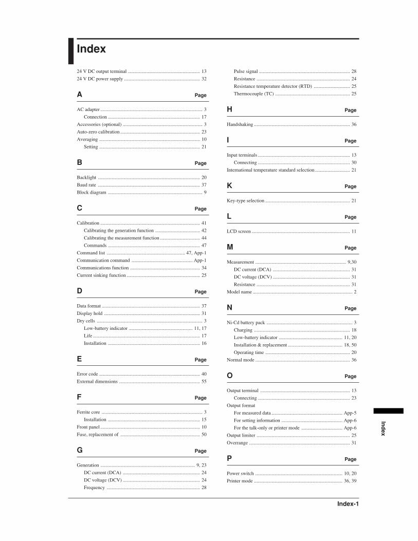
Ind
ex
Index-1
Index
24 V DC output terminal .......................................................... 13
24 V DC power supply ............................................................. 32
A Page
AC adapter .................................................................................. 3
Connection .......................................................................... 17
Accessories (optional) ................................................................ 3
Auto-zero calibration ................................................................ 23
Averaging ................................................................................. 10
Setting ................................................................................. 21
B Page
Backlight .................................................................................. 20
Baud rate .................................................................................. 37
Block diagram ............................................................................ 9
C Page
Calibration ................................................................................ 41
Calibrating the generation function .................................... 42
Calibrating the measurement function ................................ 44
Commands .......................................................................... 47
Command list ............................................................... 47, App-1
Communication command ................................................. App-1
Communications function ........................................................ 34
Current sinking function ........................................................... 25
D Page
Data format ............................................................................... 37
Display hold ............................................................................. 31
Dry cells ..................................................................................... 3
Low-battery indicator ................................................... 11, 17
Life ...................................................................................... 17
Installation .......................................................................... 16
E Page
Error code ................................................................................. 40
External dimensions ................................................................. 55
F Page
Ferrite core ................................................................................. 3
Installation .......................................................................... 15
Front panel ................................................................................ 10
Fuse, replacement of ................................................................ 50
G Page
Generation ............................................................................ 9, 23
DC current (DCA) .............................................................. 24
DC voltage (DCV) .............................................................. 24
Frequency ........................................................................... 28
Pulse signal ......................................................................... 28
Resistance ........................................................................... 24
Resistance temperature detector (RTD) ............................. 25
Thermocouple (TC) ............................................................ 25
H Page
Handshaking ............................................................................. 36
I Page
Input terminals .......................................................................... 13
Connecting .......................................................................... 30
International temperature standard selection ............................ 21
K Page
Key-type selection .................................................................... 21
L Page
LCD screen ............................................................................... 11
M Page
Measurement ......................................................................... 9,30
DC current (DCA) .............................................................. 31
DC voltage (DCV) .............................................................. 31
Resistance ........................................................................... 31
Model name ................................................................................ 2
N Page
Ni-Cd battery pack ..................................................................... 3
Charging ............................................................................. 18
Low-battery indicator ................................................... 11, 20
Installation & replacement ............................................ 18, 50
Operating time .................................................................... 20
Normal mode ............................................................................ 36
O Page
Output terminal ........................................................................ 13
Connecting .......................................................................... 23
Output format
For measured data ......................................................... App-5
For setting information ................................................. App-6
For the talk-only or printer mode ................................. App-6
Output limiter ........................................................................... 25
Overrange ................................................................................. 31
P Page
Power switch ...................................................................... 10, 20
Printer mode ....................................................................... 36, 39

Index-2
Index
R Page
Reference Junction Compensation ........................................... 27
RJC sensor ................................................................................ 27
RS-232-C interface ................................................................... 33
Baud rate ............................................................................. 37
Commands .............................................................. 47, App-1
Communications modes ..................................................... 36
Connector ...................................................................... 12, 34
Data format ......................................................................... 37
Handshaking ....................................................................... 36
Terminator .......................................................................... 37
S Page
Sample program ................................................................. App-7
Side panel ................................................................................. 12
Specifications ........................................................................... 51
Standard accessories ................................................................... 3
Status byte format ............................................................... App-5
Suffix code ................................................................................. 2
T Page
Talk-only mode .................................................................. 36, 39
Temperature unit selection ....................................................... 21
Terminator .......................................................................... 37, 39