Embed Size (px)
Citation preview
CompactLogix Performance and Capacity
2
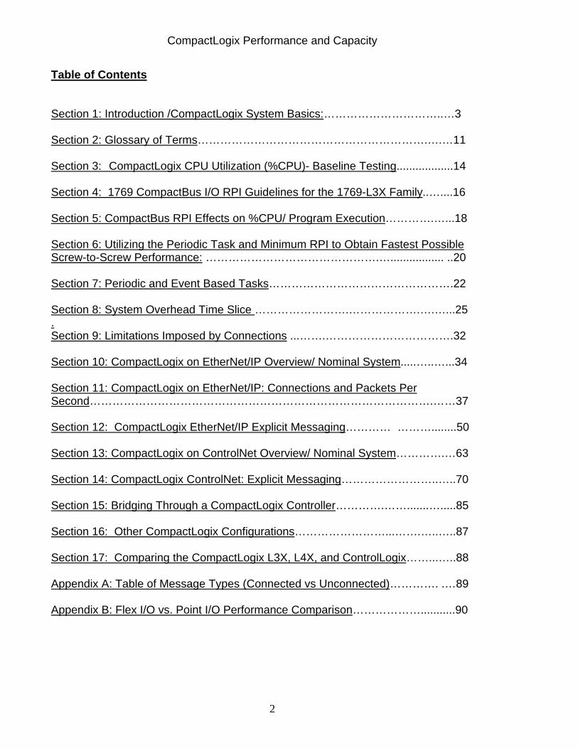
Table of Contents
Section 1: Introduction /CompactLogix System Basics:…………………………..…3 Section 2: Glossary of Terms…………………………………………………….….…11 Section 3: CompactLogix CPU Utilization (%CPU)- Baseline Testing..................14 Section 4: 1769 CompactBus I/O RPI Guidelines for the 1769-L3X Family..…....16 Section 5: CompactBus RPI Effects on %CPU/ Program Execution………….…...18 Section 6: Utilizing the Periodic Task and Minimum RPI to Obtain Fastest Possible Screw-to-Screw Performance: ……………………………………….…................. ..20 Section 7: Periodic and Event Based Tasks………………………………………….22 Section 8: System Overhead Time Slice …………………….……………….….…...25 . Section 9: Limitations Imposed by Connections ...…….…………………………….32 Section 10: CompactLogix on EtherNet/IP Overview/ Nominal System.....…..…...34 Section 11: CompactLogix on EtherNet/IP: Connections and Packets Per Second……………………………………………………………………………….……37 Section 12: CompactLogix EtherNet/IP Explicit Messaging………… ………........50 Section 13: CompactLogix on ControlNet Overview/ Nominal System………….…63 Section 14: CompactLogix ControlNet: Explicit Messaging……………………..…..70 Section 15: Bridging Through a CompactLogix Controller………….…….......….....85 Section 16: Other CompactLogix Configurations……………………...…….…..…..87 Section 17: Comparing the CompactLogix L3X, L4X, and ControlLogix……...…..88 Appendix A: Table of Message Types (Connected vs Unconnected)…………. .…89 Appendix B: Flex I/O vs. Point I/O Performance Comparison………………...........90
CompactLogix Performance and Capacity
3
Section 1: Introduction/ CompactLogix System Basics Section 1a: Introduction The purpose of this document is to provide CompactLogix system performance and capacity information, along with design considerations, that can be used to achieve optimized performance from a CompactLogix system. These recommendations may not be the best solution for all applications, but rather are guidelines and indications of performance. This document has had two revisions: IASIMP-QR007A-EN-P (August 2006) covered the 1769-L3X family of CompactLogix processors. IASIMP-QR007B-EN-P (March 2009) added the 1769-L4X family of CompactLogix processors. The CompactLogix family of processors are designed to provide a Logix solution for low-end to medium applications. Typically these applications are machine-level control applications that require limited I/O quantities and limited communications capabilities. The 1769-L3X family consists of the 1769-L31, the 1769-L32C, the 1769-L32CR, the 1769-L32E and the 1769-L35E. The 1768-L4X family consists of the 1768-L43 and the1768-L45. For a comparison of the 1769-L3X and 1768-L4X Family see Section 17.This section also compares the L4X with the ControlLogix family. Section 1b: 1769-L3x Family Basics The 1769-L31 has 2 serial ports. The 1769-L32C and 1769-L35CR have an integrated ControlNet port and 1 serial port. The 1769-L32E and1769-L35E controllers have an integrated EtherNet/IP port and 1 serial port.. The 1769-L3X controllers all use the 1769 CompactBus local I/O bus. Note- the first bank of I/O must contain the controller which must be in the leftmost slot.
CompactLogix Performance and Capacity
4
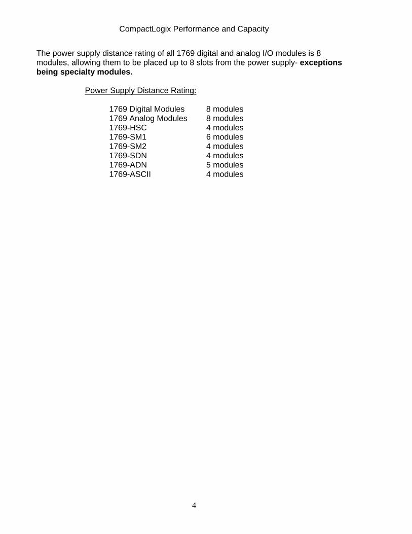
The power supply distance rating of all 1769 digital and analog I/O modules is 8 modules, allowing them to be placed up to 8 slots from the power supply- exceptions being specialty modules.
Power Supply Distance Rating: 1769 Digital Modules 8 modules 1769 Analog Modules 8 modules 1769-HSC 4 modules 1769-SM1 6 modules 1769-SM2 4 modules 1769-SDN 4 modules 1769-ADN 5 modules 1769-ASCII 4 modules
CompactLogix Performance and Capacity
5
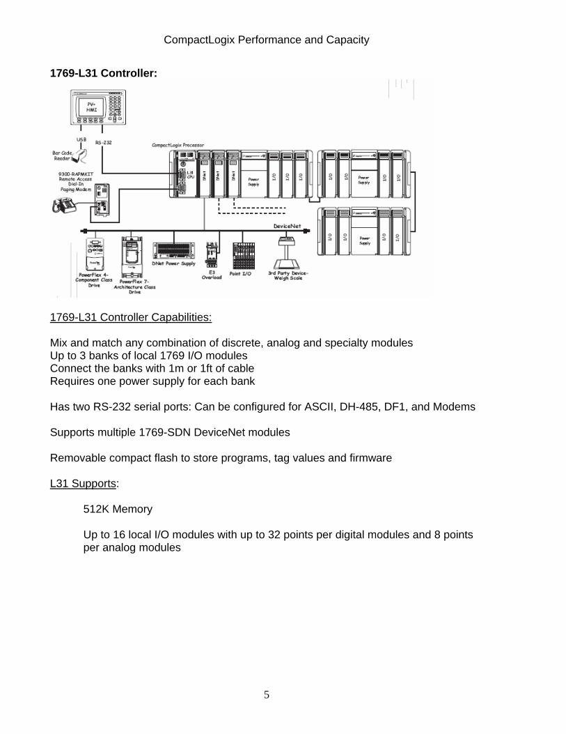
1769-L31 Controller:
1769-L31 Controller Capabilities: Mix and match any combination of discrete, analog and specialty modules Up to 3 banks of local 1769 I/O modules Connect the banks with 1m or 1ft of cable Requires one power supply for each bank Has two RS-232 serial ports: Can be configured for ASCII, DH-485, DF1, and Modems Supports multiple 1769-SDN DeviceNet modules Removable compact flash to store programs, tag values and firmware L31 Supports:
512K Memory
Up to 16 local I/O modules with up to 32 points per digital modules and 8 points per analog modules
CompactLogix Performance and Capacity
6
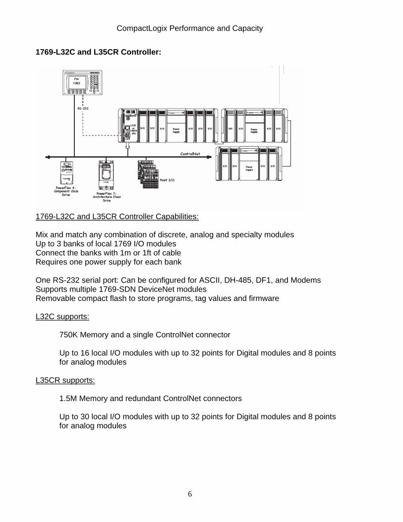
1769-L32C and L35CR Controller:
1769-L32C and L35CR Controller Capabilities: Mix and match any combination of discrete, analog and specialty modules Up to 3 banks of local 1769 I/O modules Connect the banks with 1m or 1ft of cable Requires one power supply for each bank One RS-232 serial port: Can be configured for ASCII, DH-485, DF1, and Modems Supports multiple 1769-SDN DeviceNet modules Removable compact flash to store programs, tag values and firmware L32C supports:
750K Memory and a single ControlNet connector Up to 16 local I/O modules with up to 32 points for Digital modules and 8 points for analog modules
L35CR supports:
1.5M Memory and redundant ControlNet connectors
Up to 30 local I/O modules with up to 32 points for Digital modules and 8 points for analog modules
CompactLogix Performance and Capacity
7
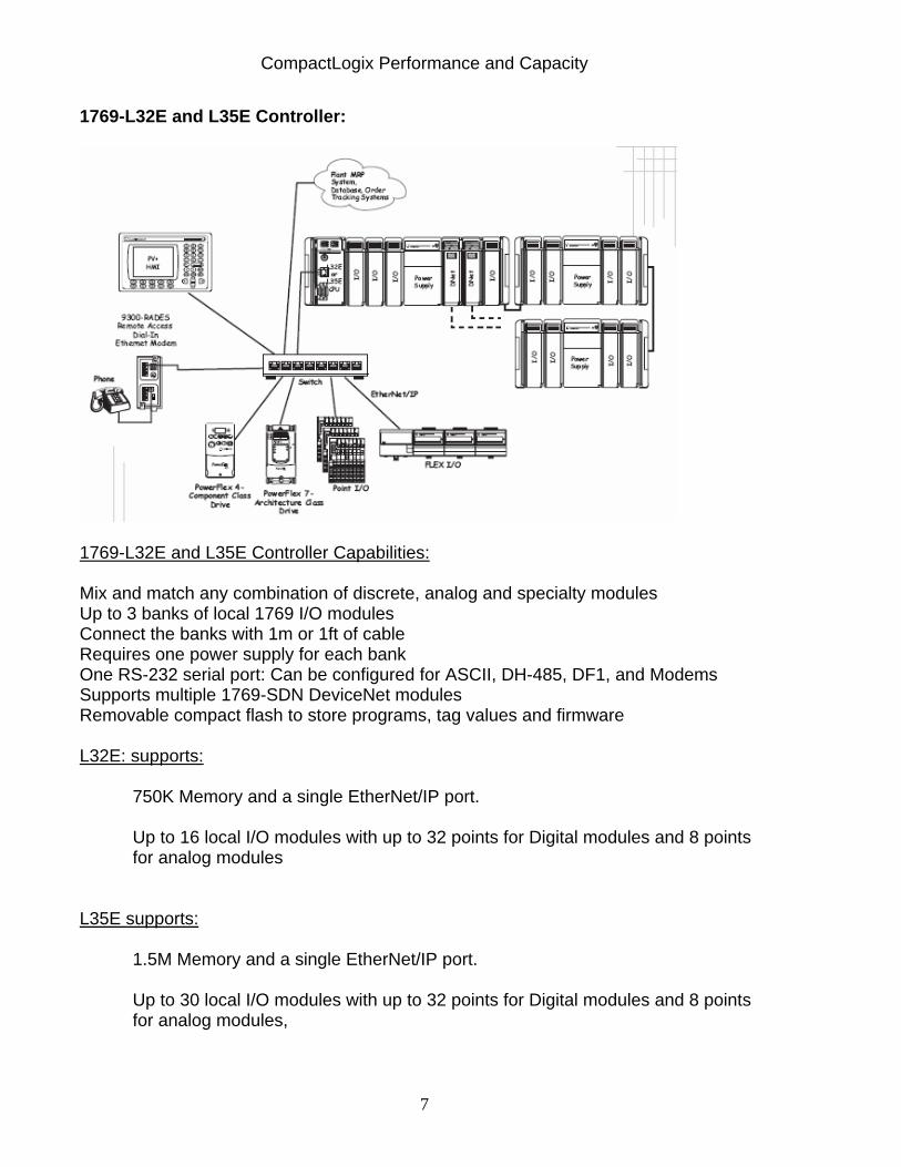
1769-L32E and L35E Controller:
1769-L32E and L35E Controller Capabilities: Mix and match any combination of discrete, analog and specialty modules Up to 3 banks of local 1769 I/O modules Connect the banks with 1m or 1ft of cable Requires one power supply for each bank One RS-232 serial port: Can be configured for ASCII, DH-485, DF1, and Modems Supports multiple 1769-SDN DeviceNet modules Removable compact flash to store programs, tag values and firmware L32E: supports:
750K Memory and a single EtherNet/IP port. Up to 16 local I/O modules with up to 32 points for Digital modules and 8 points for analog modules
L35E supports:
1.5M Memory and a single EtherNet/IP port. Up to 30 local I/O modules with up to 32 points for Digital modules and 8 points for analog modules,
CompactLogix Performance and Capacity
8
Section 1c:1768-L4X Family Basics The 1768-L43 and L45 processors are a modular platform consisting of:
The same1769 CompactBus local I/O bus used by the 1769-L3X to the right of the processor and; An enhanced 1768 bus to the left. This bus supports up to two 1768 modules and adds enhanced communications and motion capabilities to the L4X platform.
The following 1768 modules are available:
• The 1768-ENBT module provides EtherNet/IP connectivity • The 1768-CNB module provides ControlNet connectivity • The 1768-CNBR module provides redundant ControlNet connectivity • The 1768-M04SE SERCOS module.provides up to 4 Axis of Motion
capability. The CompactLogix 1768 power supply requires that a 1768 CompactLogix controller be installed to power the system. The power supply sends 24V dc to the controller located in slot 0. The controller converts the 24V dc to 5V dc and 24V dc and distributes it as needed.
– 5V and 24V power to 1769 I/O modules on the right side of the controller – 24V power to 1768 modules on the left side of the controller – Never put a 1769 power supply in the 1768 system. – Each additional 1769 I/O bank must have its own power supply. Use a
standard 1769 power supply, such as 1769-PA4. Since the 1768-L4X processors use the same 1769 CompactBus as the 1769-L3X processors, the same rules apply when using the L4X with this bus. The power supply distance rating of all 1769 digital and analog I/O modules is 8 modules, allowing them to be placed up to 8 slots from the power supply- exceptions being specialty modules.
Power Supply Distance Rating:
1769 Digital Modules 8 modules 1769 Analog Modules 8 modules 1769-HSC 4 modules 1769-SM1 6 modules 1769-SM2 4 modules 1769-SDN 4 modules 1769-ADN 5 modules 1769-ASCII 4 modules

CompactLogix Performance and Capacity
9
1768-L43 and L45 Controller:
1768-L43 and L45 Controller Capabilities: Mix and match any combination of 1769 discrete, analog and specialty modules Connect the banks with 1m or 1ft of cable Requires one power supply for each 1769 bank One RS-232 serial port: Can be configured for ASCII, DH-485, DF1, and Modems Supports multiple 1769-SDN DeviceNet modules Removable compact flash to store programs, tag values and firmware L43 supports:
2M Memory 16 I/O modules with up to 32 points for digital modules and 8 points for analog modules 2 1768 network communication modules 4 axis SERCOS system (one SERCOS card supported)
L45 supports: 3M Memory 30 I/O modules with up to 32 points for digital modules and 8 pionts for analog modules 2 1768 network communication modules 8 axis SERCOS system (two SERCOS cards supported)
CompactLogix Performance and Capacity
10
A 4-axis system with Kinetix drives supports: – execution of 4 axes per 1 ms – velocity bandwidth > 400 Hz and current loop bandwidth > 1000 Hz – high resolution, unlimited travel, and absolute feedback features – two feedback ports per Kinetix drive – optional 2094 Line Interface Module (LIM) as the incoming power source for an
entire control panel
CompactLogix Performance and Capacity
11
Section 2: Glossary of Terms Summary: This section defines terms and concepts important to understand the performance and capacity information provided in this document. Background Task: This happens during the System Overhead Time Slice. Communications, application messaging, I/O monitoring occur in this task.
Buffer: A register or group of registers used for temporary storage of data. Logix has these three buffer types: Outgoing Unconnected, Incoming Unconnected and Cached. Cached-This term applies to ladder logic message instructions or messages to HMIs. These messages are always connected (use an available connection). Therefore, they will use resources such as buffers, bandwidth and memory even when the message is done or not executing. 32 cached buffers are available on both the CompactLogix ControlNet and EtherNet/IP network ports.
Class 1 (Implicit)- refers to any connection that uses an RPI (Requested Packet Interval). These include I/O and produced/consumed connections. Another name for a class 1 message is “implicit”. Implicit refers to information (source address, data type, destination address, etc.) which is implied in the message but not contained in the message. Class 3 (Explicit) -refers to any connection that does not use an RPI. Class 3 connections are non time critical. Example: MSG instruction and program upload. Another name for a class 3 message is “explicit”. Explicit messages include basic information (source address, data type, destination address, etc.) in every message, hence they are explicit. Connected- A message that uses a connection to transfer data to a device. Once the connection is established, buffers and resources will remain allocated to the message. The connection will remain open even if the data does not change. When data does change, data transfer rates are faster since the connection has already been established. Connections- A connection is a communication path. Effectively, data passes through a connection. I/O, messaging, Produced/Consumed tags, RSLinx Connections to PCs or HMIs all use connections. The number of connections used in a Logix product must be considered since they take up buffers, resources and memory in both processors and network cards. Continuous Task- A task that runs through all its programs and routines continuously, from top to bottom, unless interrupted by another task. A project does not require a continuous task, however, you can only configure one per project. All CPU time not allocated to other operations such as motion, communications and periodic or event based tasks, is used to execute the programs within this task.
CompactLogix Performance and Capacity
12
CPU Utilization (%CPU)- The CPU utilization (%CPU) is a representation of how much time the controller is having to perform the sum total of all its functions in the Continuous Task, including ladder execution, task switching and communications. The lower the CPU%, the more logic, I/O and communications can be added for processing by the controller. Direct Connection- A communication connection used to communicate to I/O in a remote chassis, specifically analog modules. (Digital modules can also be configured for direct connections, but typically are configured for rack connections to conserve the number of connections used by the controller and network cards). Each module with a direct connection can be configured with its own RPI. Event Task- Is a user defined task that runs code based upon a trigger of a specific event. When the event is triggered it interrupts any lower priority tasks, executes one time, and returns control to the task that was interrupted, at the point it was interrupted. The trigger for the event based task can be:
• a change of a digital input • a new sample of analog data • a consumed tag • an EVENT instruction • certain motion operations
Inhibit- Inhibiting a module causes the connection to the module to be broken, and may result in the loss of data.
NUT -The Network Update Time is the smallest user configurable repetitive time cycle in milliseconds at which data can be sent on a ControlNet network. The range is 2 to 100 milliseconds and is configured in RSNetWorx for ControlNet. Periodic Task- Is a user defined task runs code at a user defined time period. When the end of the time period defined by the user is reached, the task is triggered and interrupts any lower priority task (either continuous, periodic, or event). All programs within that task are executed and scanned once, from top to bottom. After this single scan, an output update is triggered and control is returned to the task that was interrupted, at the point it was interrupted. Up to 7 periodic tasks can be configured, each with an interrupt priority and with independent rates. (Execution rate range (0.1ms-2,000s, in increments of 1ms)). Produced/Consumed- Type of data format. Each produced tag and each consumed tag uses a connection. With Produced/Consumed data multiple nodes can consume the same data at the same time from a single producer, resulting in more efficient use of bandwidth. Also, nodes can be synchronized.
CompactLogix Performance and Capacity
13
Benefits over Source/Destination methods:
• Highly Efficient- No wasted effort delivering data to those who do not require it.
• Accurate Data - Everyone receives the data at the same time.
• Deterministic - Length of time to deliver data is independent of the number of nodes
Rack Optimized Connection- A communication connection a user may choose to use when using digital I/O in a remote chassis. A rack connection uses only one connection to the digital I/O in the remote chassis, economizing connections. A rack connection is available only to digital I/O. (Analog modules use direct connections.) Only one RPI value can be set to all the modules configured to use the rack connection. (Note, if diagnostic digital modules are placed in a Rack Optimized Connection, the diagnostic information will be lost. Use a Direct Connection to save the diagnostic data.) RPI- Requested Packet Interval -The requested rate of data arrival to or from a module and a controller. The data will be sent at least this often or the connection will fail with the Connection Not Scheduled Fault. This value is configured in the properties for each module when added to the module configuration tree.
Scheduled Connection -allow you to send and to receive data repeatedly at a predetermined and configured rate on ControlNet. Produced/consumed tags, and scheduled I/O communication on ControlNet are scheduled connections A scheduled connection stays open as long as the network, the target, and the connection originator are alive. If either the target or originator drops off the link, then the connection is closed and periodically retried by the connection originator. System Overhead Time Slice-The system overhead time slice is the ratio of the amount of time spent running the continuous task versus the amount of time running the background task, which includes handling communication requests. Uncached- This terms applies to ladder logic message instructions. These messages use a connection when starting the message and then close the message when complete, therefore freeing up resources such as buffers, bandwidth and memory. Unconnected- A message that does not use a connection to transfer data to a device. Unconnected messages can not be cached. Unscheduled Connection - are used when data is being produced on demand by the user program or HMI on ControlNet. MSG instructions and RSLinx message are examples that use unscheduled connections.
Unscheduled connections can timeout if they are not used within the timeout interval. Network services will use an unconnected message to close the unscheduled connection
CompactLogix Performance and Capacity
14
Section 3: CompactLogix CPU Utilization (%CPU)- Baseline Testing Summary: This section describes the test run to provide a baseline of CompactLogix CPU usage that will be used as a comparison for the other tests in this document. Since the CompactLogix controller handles multiple tasks such as I/O, network communications and messaging, CPU Utilization (%CPU), will be used in this document to measure the load on the controller and to determine performance and capacity of the CompactLogix system. A baseline program was written to determine the CPU utilization percentage using a cross section of instructions. The program used:
• 1200 discrete instruction (XIC, XIO, OTE) • 50 counter instructions • 50 timer instructions • 50 multiple instructions • 50 add instructions • 100 move instructions • 50 compare instructions • 50 copy instructions • 50 FIFO instructions (FFL) • 12 JSR instructions
From this program, the CPU utilization (%CPU) was calculated. The %CPU is based on the number of times the baseline program is executed in 1 second. As the %CPU calculated increases the controller is having to perform more operations and is spending less time on ladder execution. A ladder program calculates the %CPU. This identical baseline program was run on both a 1769-L35CR processor to test the 1769-L3X platform and on a 1768-L43 to test the 1768-L4X platform. 1769-L35CR: The 1769-L35CR had the CompactBus Local I/O virtual backplane enabled with an RPI of 3ms, had no I/O or traffic configured for the 1769-L35CR ControlNet Port LocalCNB, had the System Overhead Time Slice (TS) set to 10%, and had no RS232 communications. In a CompactLogix controller inhibiting the CompactBus Local I/O does not actually disable the scanning of the CompactBus, so inhibiting it with a larger RPI uses less CPU than just inhibiting it alone. Test Results. The baseline results are: System Overhead Time Slice = 10% Memory used 89,232 bytes Memory Available 1,483,632 bytes Main Task Scan Times Max 4.982 ms Min 2.500 m
CompactLogix Performance and Capacity
15
%CPU processor used 1.0% (typical) 1768-L43: The 1768-L43 had no I/O or traffic configured for the 1768-L43 with the System Overhead Time Slice (TS) set to 20% and had no RS232 communications. Test Results. The baseline results are: System Overhead Time Slice = 20% I/O Memory used 17,736 bytes I/O Memory Available 488,120 bytes Data and Logic Memory Used 81,364 bytes Data and Logic Memory Available 2,016,904 bytes Main Task Scan Times Max 4.876 ms Min 4.262 ms %CPU processor used (typical) 0.7 %
CompactLogix Performance and Capacity
16
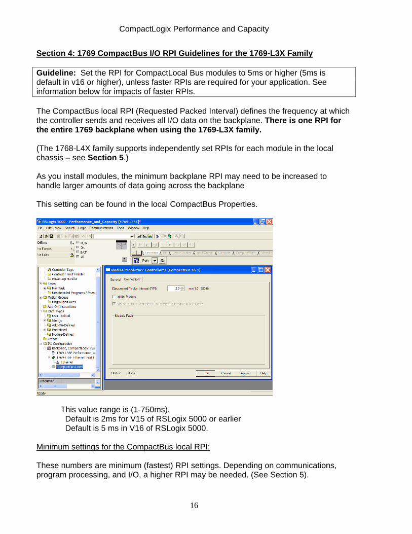
Section 4: 1769 CompactBus I/O RPI Guidelines for the 1769-L3X Family Guideline: Set the RPI for CompactLocal Bus modules to 5ms or higher (5ms is default in v16 or higher), unless faster RPIs are required for your application. See information below for impacts of faster RPIs. The CompactBus local RPI (Requested Packed Interval) defines the frequency at which the controller sends and receives all I/O data on the backplane. There is one RPI for the entire 1769 backplane when using the 1769-L3X family. (The 1768-L4X family supports independently set RPIs for each module in the local chassis – see Section 5.) As you install modules, the minimum backplane RPI may need to be increased to handle larger amounts of data going across the backplane This setting can be found in the local CompactBus Properties.
This value range is (1-750ms). Default is 2ms for V15 of RSLogix 5000 or earlier Default is 5 ms in V16 of RSLogix 5000.
Minimum settings for the CompactBus local RPI: These numbers are minimum (fastest) RPI settings. Depending on communications, program processing, and I/O, a higher RPI may be needed. (See Section 5).
CompactLogix Performance and Capacity
17
*Digital and Analog (any mix): 1-4 modules can be scanned in 1.0ms 5-16 modules can be scanned in 1.5ms 17-30 modules can be scanned in 2.0ms 1769-HSC (High Speed Counter): Add 0.5ms for each used 1769-SDN (DeviceNet Scanner): Add 1.5ms per module (*Note - Input modules defined with a “F” , ie 1769-IQ16F, at the end of the catalog number have user selectable filters that can be configured for faster filter rates (0.0msec- 2.0ms) and can provide faster throughput times. Those modules without the “F” have fixed 8ms filters, that is new data will only be transmitted every 8ms, even if the RPI is set lower.) Additional Notes:
These considerations show how fast modules can be scanned. They are not an indication of screw to screw performance.
The CompactBus Local scan is asynchronous to the program scan. Other factors, such as program execution duration, affect I/O throughput.
You can always select an RPI that is slower than your calculated minimum RPI
The RPI rule is a conservative benchmark. An RPI set below the recommended may result in task overruns and unpredictable I/O update behavior
Caution: When using the default RPI of 2ms (in v15 or earlier) be cautious going over 8 modules to assure that you do not slow down your program execution too much for your particular application.(see Section 5.)
CompactLogix Performance and Capacity
18
Section 5: CompactBus RPI Effects on %CPU /Program Execution
The CPU utilization (%CPU) is a representation of the load on the processor. It takes into account how much time the controller is having to perform its functions in the Continuous Task, including code execution and task switching. The lower the %CPU, the more logic, I/O and communications can be added. Too high a %CPU, then messaging, HMI communications, uploads and downloads may be slowed.
The %CPU increases as modules are added to the CompactBus, and slower RPI’s may need to be considered for your particular application.
Section 5a: 1769-L3X Family
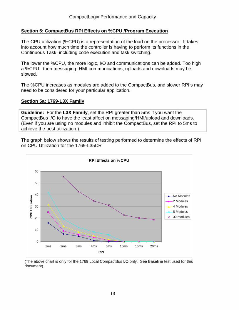
Guideline: For the L3X Family, set the RPI greater than 5ms if you want the CompactBus I/O to have the least affect on messaging/HMI/upload and downloads. (Even if you are using no modules and inhibit the CompactBus, set the RPI to 5ms to achieve the best utilization.) The graph below shows the results of testing performed to determine the effects of RPI on CPU Utilization for the 1769-L35CR
RPI Effects on %CPU
0
10
20
30
40
50
60
1ms 2ms 3ms 4ms 5ms 10ms 15ms 20ms
RPI
CPU
Utili
zatio
n No Modules2 Modules 4 Modules8 Modules30 modules
(The above chart is only for the 1769 Local CompactBus I/O only. See Baseline test used for this document).
CompactLogix Performance and Capacity
19
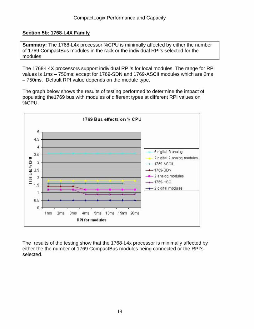
Section 5b: 1768-L4X Family Summary: The 1768-L4x processor %CPU is minimally affected by either the number of 1769 CompactBus modules in the rack or the individual RPI’s selected for the modules The 1768-L4X processors support individual RPI’s for local modules. The range for RPI values is 1ms – 750ms; except for 1769-SDN and 1769-ASCII modules which are 2ms – 750ms. Default RPI value depends on the module type. The graph below shows the results of testing performed to determine the impact of populating the1769 bus with modules of different types at different RPI values on %CPU.
The results of the testing show that the 1768-L4x processor is minimally affected by either the the number of 1769 CompactBus modules being connected or the RPI’s selected.
CompactLogix Performance and Capacity
20
Section 6: Utilizing the Periodic Task and Minimum RPI to Obtain Fastest Possible Screw-to-Screw Performance:
Some applications require not only a fast screw-to-screw update but also need to know screw-to-screw repeatability also known as “Screw-to-Screw Jitter” The CompactLogix backplane scan is asynchronous to the program execution. I/O updates can happen anytime throughout the program scan. Note: Your minimum screw-to-screw times will increase as you add modules to your system Section 6a: 1769-L3X Family
Summary: With 4 or less non-specialty modules, the system can handle a 1ms RPI and 1ms Periodic Task. Average screw-to-screw performance is 2ms. Repeatability or “Screw-to-Screw Jitter” is 3ms or less. Make sure you set the priority of the Periodic task greater than 6. The following shows the results of testing performed to determine min/ max/ typical screw to screw time possible with 1768-L3X platform. Only the local CompactBus was used with a 1769-IQ16F/A input module and a 1769-OB16/B output module. RPI was set to 1ms. 100 samples were taken of an output turning on an input.
Throughput Main Task Scan Time Task Priority Worse/Best Max/Min Continuous 16 2.1ms / 1.0ms 2.5ms / .4ms
-Average screw-to-screw performance is 2ms -Repeatability or “Screw-to-Screw Jitter” is 3ms or less Caution:
It is possible to starve the update of your I/O if you set the priority of a Periodic task higher than the Local CompactBus priority of 6. Higher priority tasks interrupt lower tasks.
CompactLogix Performance and Capacity
21
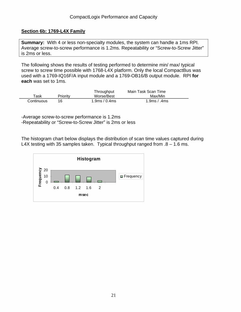
Section 6b: 1769-L4X Family
Summary: With 4 or less non-specialty modules, the system can handle a 1ms RPI. Average screw-to-screw performance is 1.2ms. Repeatability or “Screw-to-Screw Jitter” is 2ms or less. The following shows the results of testing performed to determine min/ max/ typical screw to screw time possible with 1768-L4X platform. Only the local CompactBus was used with a 1769-IQ16F/A input module and a 1769-OB16/B output module. RPI for each was set to 1ms.
Throughput Main Task Scan Time Task Priority Worse/Best Max/Min
Continuous 16 1.9ms / 0.4ms 1.9ms / .4ms -Average screw-to-screw performance is 1.2ms -Repeatability or “Screw-to-Screw Jitter” is 2ms or less
The histogram chart below displays the distribution of scan time values captured during L4X testing with 35 samples taken. Typical throughput ranged from .8 – 1.6 ms.
Histogram
01020
0.4 0.8 1.2 1.6 2
msec
Freq
uenc
y
Frequency
CompactLogix Performance and Capacity
22
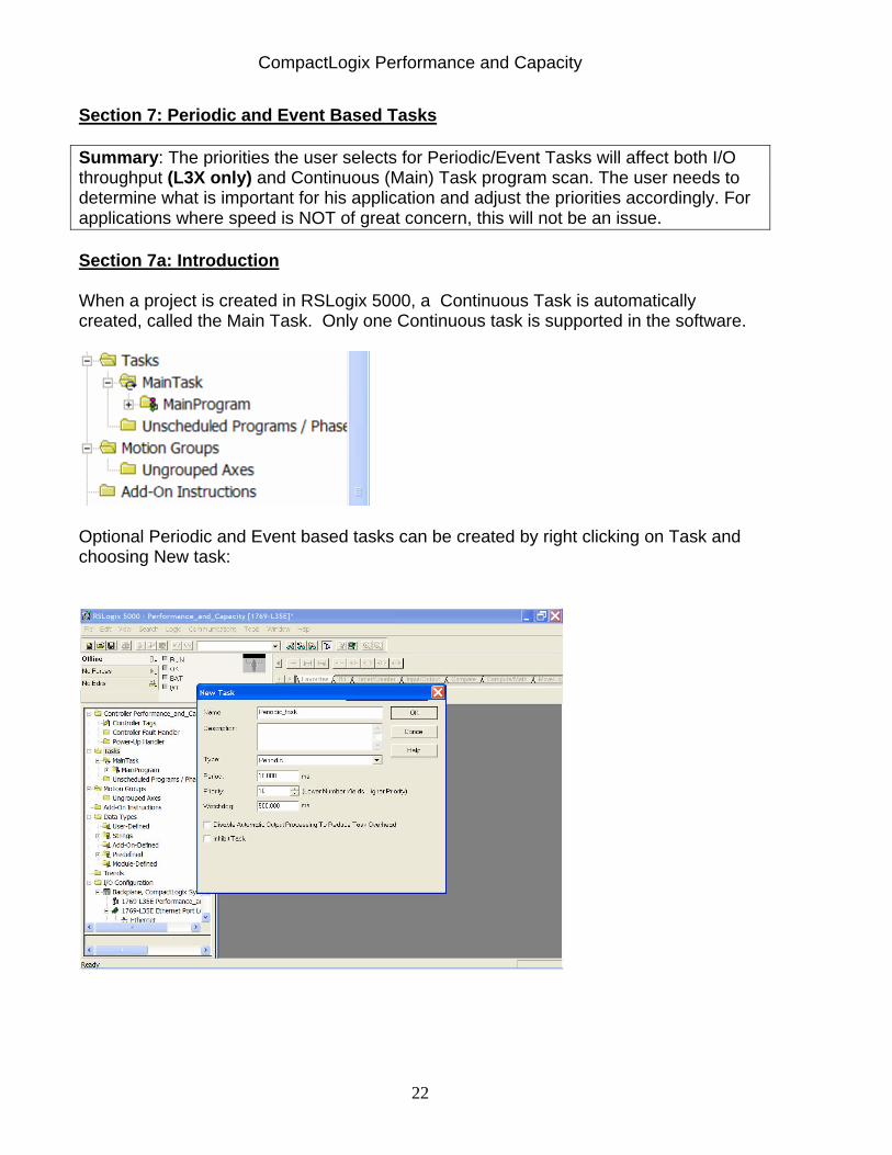
Section 7: Periodic and Event Based Tasks Summary: The priorities the user selects for Periodic/Event Tasks will affect both I/O throughput (L3X only) and Continuous (Main) Task program scan. The user needs to determine what is important for his application and adjust the priorities accordingly. For applications where speed is NOT of great concern, this will not be an issue. Section 7a: Introduction When a project is created in RSLogix 5000, a Continuous Task is automatically created, called the Main Task. Only one Continuous task is supported in the software.
Optional Periodic and Event based tasks can be created by right clicking on Task and choosing New task:
CompactLogix Performance and Capacity
23
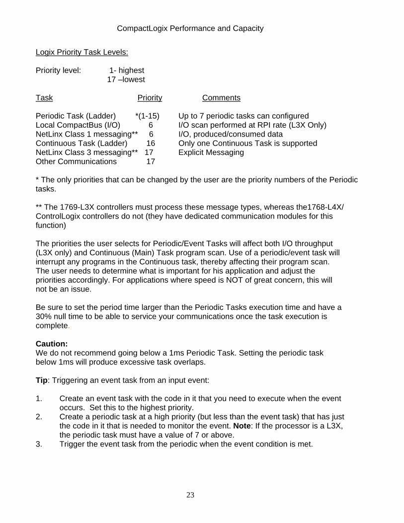
Logix Priority Task Levels: Priority level: 1- highest
17 –lowest
Task Priority Comments
Periodic Task (Ladder) *(1-15) Up to 7 periodic tasks can configured Local CompactBus (I/O) 6 I/O scan performed at RPI rate (L3X Only) NetLinx Class 1 messaging** 6 I/O, produced/consumed data Continuous Task (Ladder) 16 Only one Continuous Task is supported NetLinx Class 3 messaging** 17 Explicit Messaging Other Communications 17 * The only priorities that can be changed by the user are the priority numbers of the Periodic tasks.
** The 1769-L3X controllers must process these message types, whereas the1768-L4X/ ControlLogix controllers do not (they have dedicated communication modules for this function) The priorities the user selects for Periodic/Event Tasks will affect both I/O throughput (L3X only) and Continuous (Main) Task program scan. Use of a periodic/event task will interrupt any programs in the Continuous task, thereby affecting their program scan. The user needs to determine what is important for his application and adjust the priorities accordingly. For applications where speed is NOT of great concern, this will not be an issue. Be sure to set the period time larger than the Periodic Tasks execution time and have a 30% null time to be able to service your communications once the task execution is complete. Caution: We do not recommend going below a 1ms Periodic Task. Setting the periodic task below 1ms will produce excessive task overlaps. Tip: Triggering an event task from an input event: 1. Create an event task with the code in it that you need to execute when the event
occurs. Set this to the highest priority. 2. Create a periodic task at a high priority (but less than the event task) that has just
the code in it that is needed to monitor the event. Note: If the processor is a L3X, the periodic task must have a value of 7 or above.
3. Trigger the event task from the periodic when the event condition is met.
CompactLogix Performance and Capacity
24
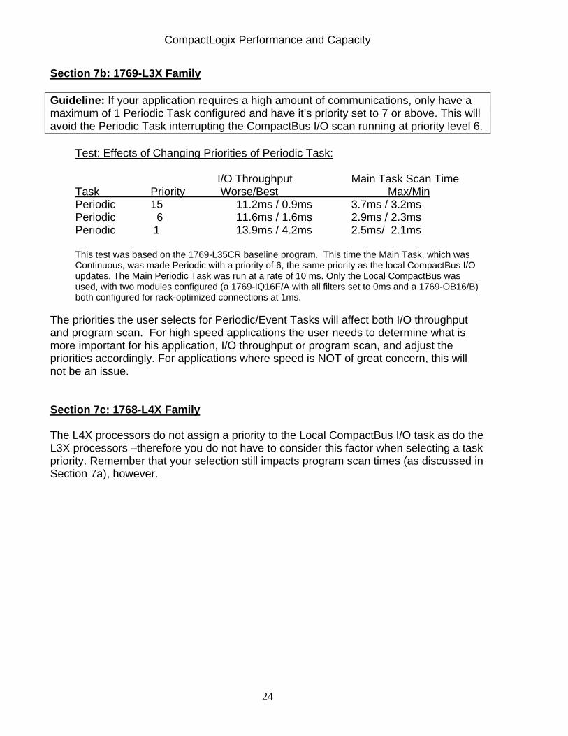
Section 7b: 1769-L3X Family Guideline: If your application requires a high amount of communications, only have a maximum of 1 Periodic Task configured and have it’s priority set to 7 or above. This will avoid the Periodic Task interrupting the CompactBus I/O scan running at priority level 6.
Test: Effects of Changing Priorities of Periodic Task: I/O Throughput Main Task Scan Time Task Priority Worse/Best Max/Min Periodic 15 11.2ms / 0.9ms 3.7ms / 3.2ms Periodic 6 11.6ms / 1.6ms 2.9ms / 2.3ms Periodic 1 13.9ms / 4.2ms 2.5ms/ 2.1ms This test was based on the 1769-L35CR baseline program. This time the Main Task, which was Continuous, was made Periodic with a priority of 6, the same priority as the local CompactBus I/O updates. The Main Periodic Task was run at a rate of 10 ms. Only the Local CompactBus was used, with two modules configured (a 1769-IQ16F/A with all filters set to 0ms and a 1769-OB16/B) both configured for rack-optimized connections at 1ms.
The priorities the user selects for Periodic/Event Tasks will affect both I/O throughput and program scan. For high speed applications the user needs to determine what is more important for his application, I/O throughput or program scan, and adjust the priorities accordingly. For applications where speed is NOT of great concern, this will not be an issue.
Section 7c: 1768-L4X Family
The L4X processors do not assign a priority to the Local CompactBus I/O task as do the L3X processors –therefore you do not have to consider this factor when selecting a task priority. Remember that your selection still impacts program scan times (as discussed in Section 7a), however.
CompactLogix Performance and Capacity
25
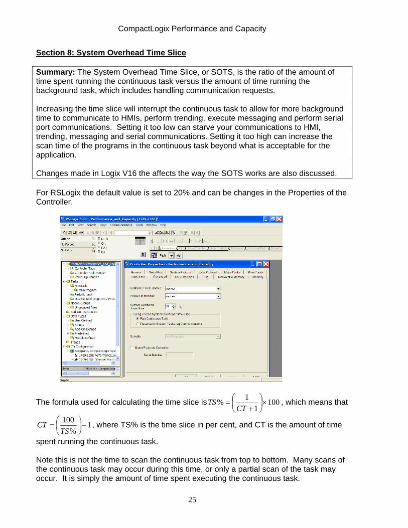
Section 8: System Overhead Time Slice Summary: The System Overhead Time Slice, or SOTS, is the ratio of the amount of time spent running the continuous task versus the amount of time running the background task, which includes handling communication requests. Increasing the time slice will interrupt the continuous task to allow for more background time to communicate to HMIs, perform trending, execute messaging and perform serial port communications. Setting it too low can starve your communications to HMI, trending, messaging and serial communications. Setting it too high can increase the scan time of the programs in the continuous task beyond what is acceptable for the application. Changes made in Logix V16 the affects the way the SOTS works are also discussed. For RSLogix the default value is set to 20% and can be changes in the Properties of the Controller.
The formula used for calculating the time slice is 1001
1% ×⎟⎠⎞
⎜⎝⎛
+=
CTTS , which means that
1%
100−⎟
⎠⎞
⎜⎝⎛=TS
CT , where TS% is the time slice in per cent, and CT is the amount of time
spent running the continuous task. Note this is not the time to scan the continuous task from top to bottom. Many scans of the continuous task may occur during this time, or only a partial scan of the task may occur. It is simply the amount of time spent executing the continuous task.
CompactLogix Performance and Capacity
26
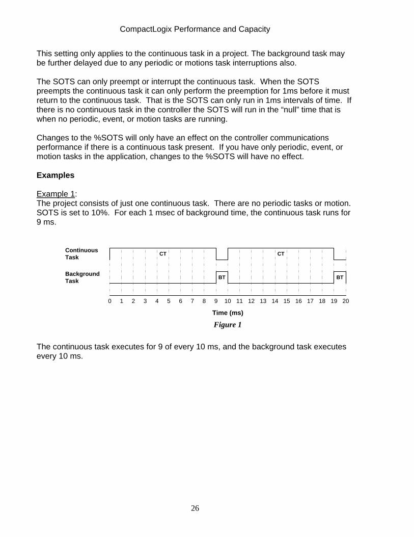
This setting only applies to the continuous task in a project. The background task may be further delayed due to any periodic or motions task interruptions also. The SOTS can only preempt or interrupt the continuous task. When the SOTS preempts the continuous task it can only perform the preemption for 1ms before it must return to the continuous task. That is the SOTS can only run in 1ms intervals of time. If there is no continuous task in the controller the SOTS will run in the “null” time that is when no periodic, event, or motion tasks are running. Changes to the %SOTS will only have an effect on the controller communications performance if there is a continuous task present. If you have only periodic, event, or motion tasks in the application, changes to the %SOTS will have no effect. Examples Example 1: The project consists of just one continuous task. There are no periodic tasks or motion. SOTS is set to 10%. For each 1 msec of background time, the continuous task runs for 9 ms.
Time (ms)
10 32 54 76 98 1110 1312 1514 1716 1918 20
CT CT
BT BT
ContinuousTask
BackgroundTask
Figure 1
The continuous task executes for 9 of every 10 ms, and the background task executes every 10 ms.
CompactLogix Performance and Capacity
27
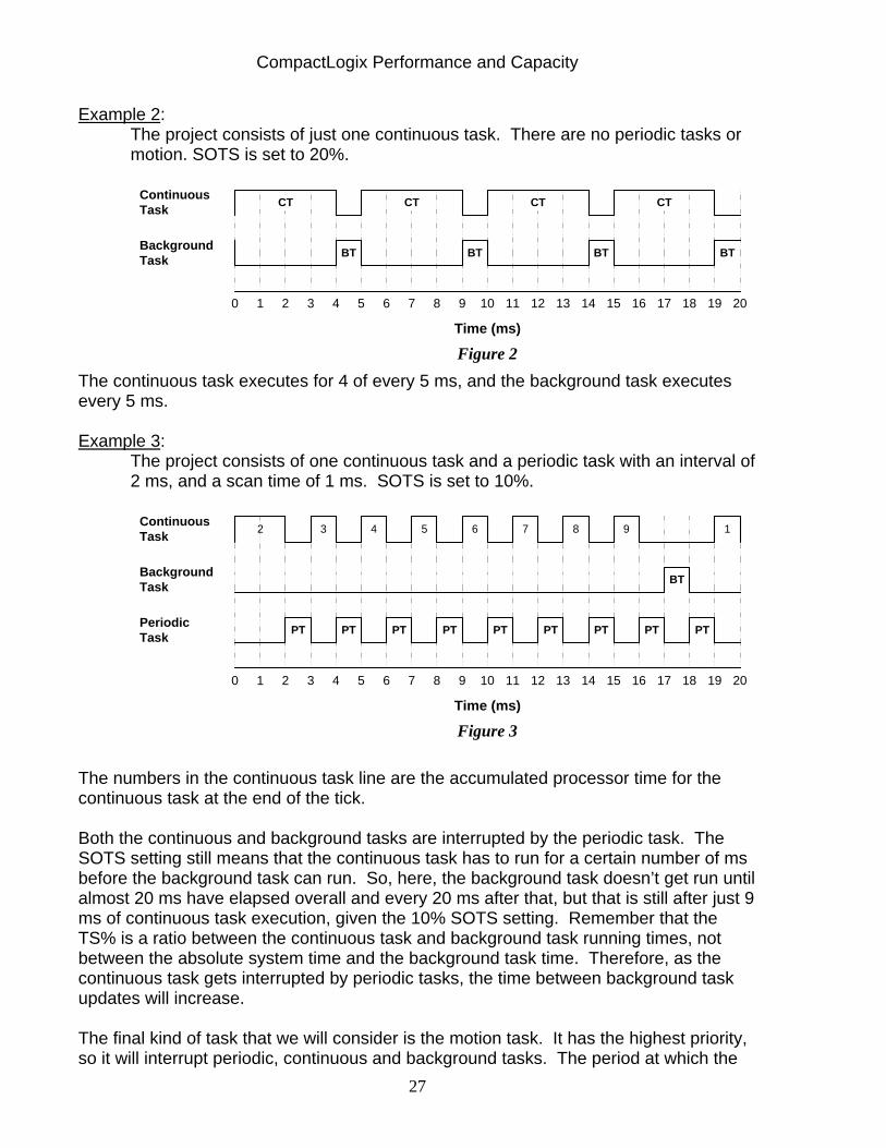
Example 2: The project consists of just one continuous task. There are no periodic tasks or motion. SOTS is set to 20%.
10 32 54 76 98 1110 1312 1514 1716 1918 20
Time (ms)
CT
BT
ContinuousTask
BackgroundTask
Figure 2
CT CT CT
BT BT BT
The continuous task executes for 4 of every 5 ms, and the background task executes every 5 ms. Example 3:
The project consists of one continuous task and a periodic task with an interval of 2 ms, and a scan time of 1 ms. SOTS is set to 10%.
10 32 54 76 98 1110 1312 1514 1716 1918 20
Time (ms)
BT
ContinuousTask
BackgroundTask
Figure 3
PeriodicTask
2 3 4 5 6 7 8 9
PT PT PT
1
PT PT PT PT PTPT
The numbers in the continuous task line are the accumulated processor time for the continuous task at the end of the tick.
Both the continuous and background tasks are interrupted by the periodic task. The SOTS setting still means that the continuous task has to run for a certain number of ms before the background task can run. So, here, the background task doesn’t get run until almost 20 ms have elapsed overall and every 20 ms after that, but that is still after just 9 ms of continuous task execution, given the 10% SOTS setting. Remember that the TS% is a ratio between the continuous task and background task running times, not between the absolute system time and the background task time. Therefore, as the continuous task gets interrupted by periodic tasks, the time between background task updates will increase. The final kind of task that we will consider is the motion task. It has the highest priority, so it will interrupt periodic, continuous and background tasks. The period at which the

CompactLogix Performance and Capacity
28
motion task runs is governed by the coarse update rate (CUR). As a rule of thumb, assume about ½ ms per axis for the actual calculations. Let’s see how it affects the previous setup.
Example 4:
The project consists of one continuous task and a periodic task with an interval of 2 ms, and a scan time of 1 ms. SOTS is set to 10%. There are 5 axes of motion with the L4x processor, with a CUR of 5 ms, and about 2.5 ms of calculation time (½ ms per axis * 5 axes).
From the numbers on the Periodic task above: 1. The periodic task’s first scheduled occurence at the 2 ms mark was delayed by 0.5 ms due to the motion task running. The second occurence at 4 ms ran as scheduled.
2. The periodic task’s third scheduled occurence at the 6 ms mark was delayed by 1.5 ms due to the motion task running. This caused the task to overlap with the 8 ms start of the next occurrence. An overlap error will be generated and the 8 ms occurrence will be missed. 3. The periodic task’s next scheduled occurrence at 10 ms was delayed by 2.5 ms due to the motion task running. This caused the start of the task to overlap with the 12 ms start of the next occurrence. An overlap error will be generated and the 10 ms occurrence will be missed. The task’s occurrence at 12ms is then delayed by an additional 0.5 ms due to the motion task running.
With motion added, by the end of our sample 20 ms run, the continuous task has only accumulated 4 ms of run time, and the background task has not run at all! Extrapolating, it will take about 45 ms before the background task gets to run.
1
ContinuousTask
BackgroundTask
PeriodicTask
Time (ms)
Figure 4
MotionTask
MT MT MT MT
CT CT CT CT
PT PT PT PT PT PT
0 1 2 3 4 5 6 7 8 9 10 11 12 13 14 15 16 17 18 19 20
3 2
CompactLogix Performance and Capacity
29
Another thing to note is that the 2 ms task does not actually run at 2 ms intervals. In some cases it gets delayed, and in other cases it does not run at all due to an overlap condition with the previous interval.
Note-If there is no continuous task, the time slice setting has no effect. All processor time not used for other tasks will be used for background operations.
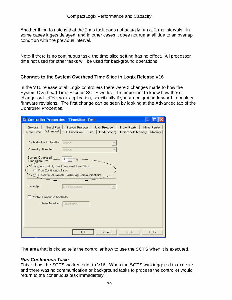
Changes to the System Overhead Time Slice in Logix Release V16 In the V16 release of all Logix controllers there were 2 changes made to how the System Overhead Time Slice or SOTS works. It is important to know how these changes will effect your application, specifically if you are migrating forward from older firmware revisions. The first change can be seen by looking at the Advanced tab of the Controller Properties.
The area that is circled tells the controller how to use the SOTS when it is executed. Run Continuous Task: This is how the SOTS worked prior to V16. When the SOTS was triggered to execute and there was no communication or background tasks to process the controller would return to the continuous task immediately.
CompactLogix Performance and Capacity
30
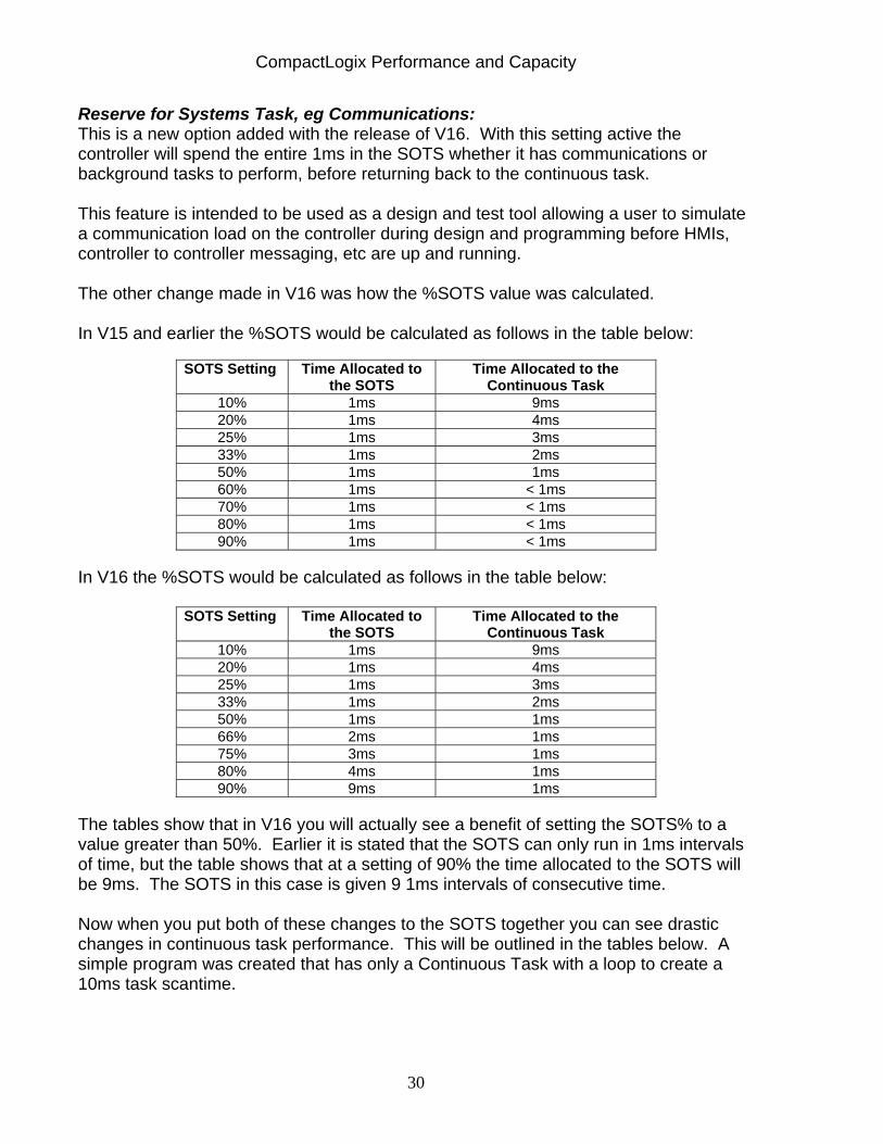
Reserve for Systems Task, eg Communications: This is a new option added with the release of V16. With this setting active the controller will spend the entire 1ms in the SOTS whether it has communications or background tasks to perform, before returning back to the continuous task. This feature is intended to be used as a design and test tool allowing a user to simulate a communication load on the controller during design and programming before HMIs, controller to controller messaging, etc are up and running. The other change made in V16 was how the %SOTS value was calculated. In V15 and earlier the %SOTS would be calculated as follows in the table below:
SOTS Setting Time Allocated to the SOTS
Time Allocated to the Continuous Task
10% 1ms 9ms 20% 1ms 4ms 25% 1ms 3ms 33% 1ms 2ms 50% 1ms 1ms 60% 1ms < 1ms 70% 1ms < 1ms 80% 1ms < 1ms 90% 1ms < 1ms
In V16 the %SOTS would be calculated as follows in the table below:
SOTS Setting Time Allocated to the SOTS
Time Allocated to the Continuous Task
10% 1ms 9ms 20% 1ms 4ms 25% 1ms 3ms 33% 1ms 2ms 50% 1ms 1ms 66% 2ms 1ms 75% 3ms 1ms 80% 4ms 1ms 90% 9ms 1ms
The tables show that in V16 you will actually see a benefit of setting the SOTS% to a value greater than 50%. Earlier it is stated that the SOTS can only run in 1ms intervals of time, but the table shows that at a setting of 90% the time allocated to the SOTS will be 9ms. The SOTS in this case is given 9 1ms intervals of consecutive time. Now when you put both of these changes to the SOTS together you can see drastic changes in continuous task performance. This will be outlined in the tables below. A simple program was created that has only a Continuous Task with a loop to create a 10ms task scantime.
CompactLogix Performance and Capacity
31
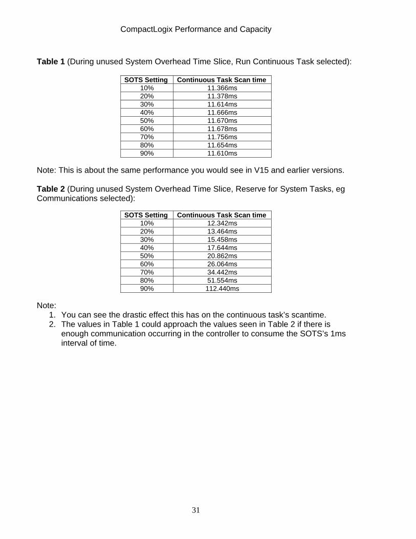
Table 1 (During unused System Overhead Time Slice, Run Continuous Task selected):
SOTS Setting Continuous Task Scan time 10% 11.366ms 20% 11.378ms 30% 11.614ms 40% 11.666ms 50% 11.670ms 60% 11.678ms 70% 11.756ms 80% 11.654ms 90% 11.610ms
Note: This is about the same performance you would see in V15 and earlier versions. Table 2 (During unused System Overhead Time Slice, Reserve for System Tasks, eg Communications selected):
SOTS Setting Continuous Task Scan time 10% 12.342ms 20% 13.464ms 30% 15.458ms 40% 17.644ms 50% 20.862ms 60% 26.064ms 70% 34.442ms 80% 51.554ms 90% 112.440ms
Note:
1. You can see the drastic effect this has on the continuous task’s scantime. 2. The values in Table 1 could approach the values seen in Table 2 if there is
enough communication occurring in the controller to consume the SOTS’s 1ms interval of time.
CompactLogix Performance and Capacity
32
Section 9: Limitations Imposed by Connections Summary: The CompactLogix system uses connections to establish a communication link between two devices. This includes controllers, communication modules, input/output modules, produced/consumed tags and messages. You indirectly determine the number of connections that the Logix controller requires when configuring the controller to communicate with other devices in the system. Each module in the CompactLogix system supports a limited number of active connections. Take these connection limits into account when designing your system. Section 9a: 1769-L3x Family
Example: To determine the total number of connections used on a CompactLogix processor use the following:
1. Count the number of produced tags ______ 2. Count the number of consumers for each produced tag ______ 3. Count the number of direct I/O connections ______ 4. Count the number of rack optimized connections ______ 5. Count the number of messages incoming or outgoing ______ 6. Count the number of programming terminals online and the number of RSLinx packages browsing over the network ______ 7. Count the number of HMI’s polling controller (typically 5 connections per HMI are used) ______
To get the total number of connections used in your controller: Add the individual results from steps 1 thru 7 Total Connections used by CompactLogix controller ______ Note: It is not recommended to use all 32 connections on the built in Network ports.
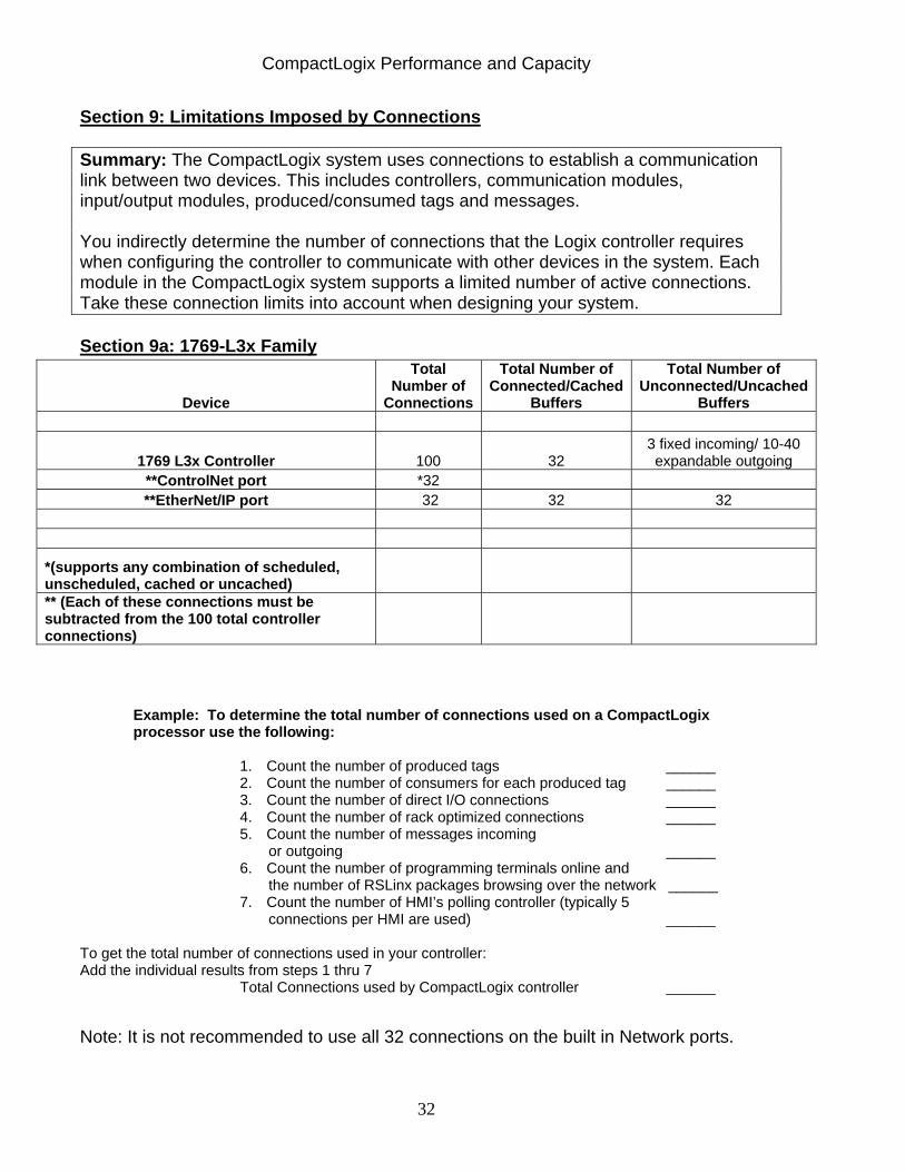
Device
Total Number of
Connections
Total Number of Connected/Cached
Buffers
Total Number of Unconnected/Uncached
Buffers
1769 L3x Controller 100 32 3 fixed incoming/ 10-40 expandable outgoing
**ControlNet port *32 **EtherNet/IP port 32 32 32
*(supports any combination of scheduled, unscheduled, cached or uncached) ** (Each of these connections must be subtracted from the 100 total controller connections)
CompactLogix Performance and Capacity
33
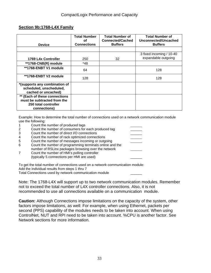
Section 9b:1768-L4X Family
Device
Total Number of
Connections
Total Number of Connected/Cached
Buffers
Total Number of Unconnected/Uncached
Buffers
1769 L4x Controller 250 32 3 fixed incoming / 10-40
expandable outgoing **1768-CNB(R) module *48
**1768-ENBT V1 module 64 128
**1768-ENBT V2 module 128 128
*(supports any combination of scheduled, unscheduled,
cached or uncached)
** (Each of these connections must be subtracted from the
250 total controller connections)
Example: How to determine the total number of connections used on a network communication module use the following: 1 Count the number of produced tags ______ 2 Count the number of consumers for each produced tag ______ 3 Count the number of direct I/O connections ______ 4 Count the number of rack optimized connections ______ 5 Count the number of messages incoming or outgoing ______ 6 Count the number of programming terminals online and the
number of RSLinx packages browsing over the network ______ 7 Count the number of HMI’s polling controller
(typically 5 connections per HMI are used) ______ To get the total number of connections used on a network communication module: Add the individual results from steps 1 thru 7 Total Connections used by network communication module ______ Note: The 1768-L4X will support up to two network communication modules. Remember not to exceed the total number of L4X controller connections. Also, it is not recommended to use all connections available on a communication module. Caution: Although Connections impose limitations on the capacity of the system, other factors impose limitations, as well: For example, when using Ethernet, packets per second (PPS) capability of the modules needs to be taken into account. When using ControlNet, NUT and RPI need to be taken into account. %CPU is another factor. See Network sections for more information.
CompactLogix Performance and Capacity
34
Section 10: CompactLogix on EtherNet/IP Overview/ Nominal System Guidelines: Performance of an EtherNet/IP network is based upon the following:
Identifying and counting the number of connections Calculating the Packets Per Second for loading. Estimating Maximum Input and Output times
Section 10a: 1769-L3x Family 1769-L3X EtherNet/IP Capacity and Performance
• 10/100 Megabits per Second, Full Duplex • Up to 4000 packets per second (Class 1, I/O, produced/consumed data) • Up to 760 packets per second (Class 3, Messaging, HMI, OPC combined) • Up to 32 CIP I/O connections • Up to 64 TCP connections • 2 millisecond minimum RPI • 512 Byte maximum packet size
EtherNet/IP Rules: – As the packet size increases the number of packets per second
decreases. – Producer/Consumer packets tend to be much larger than I/O packets and
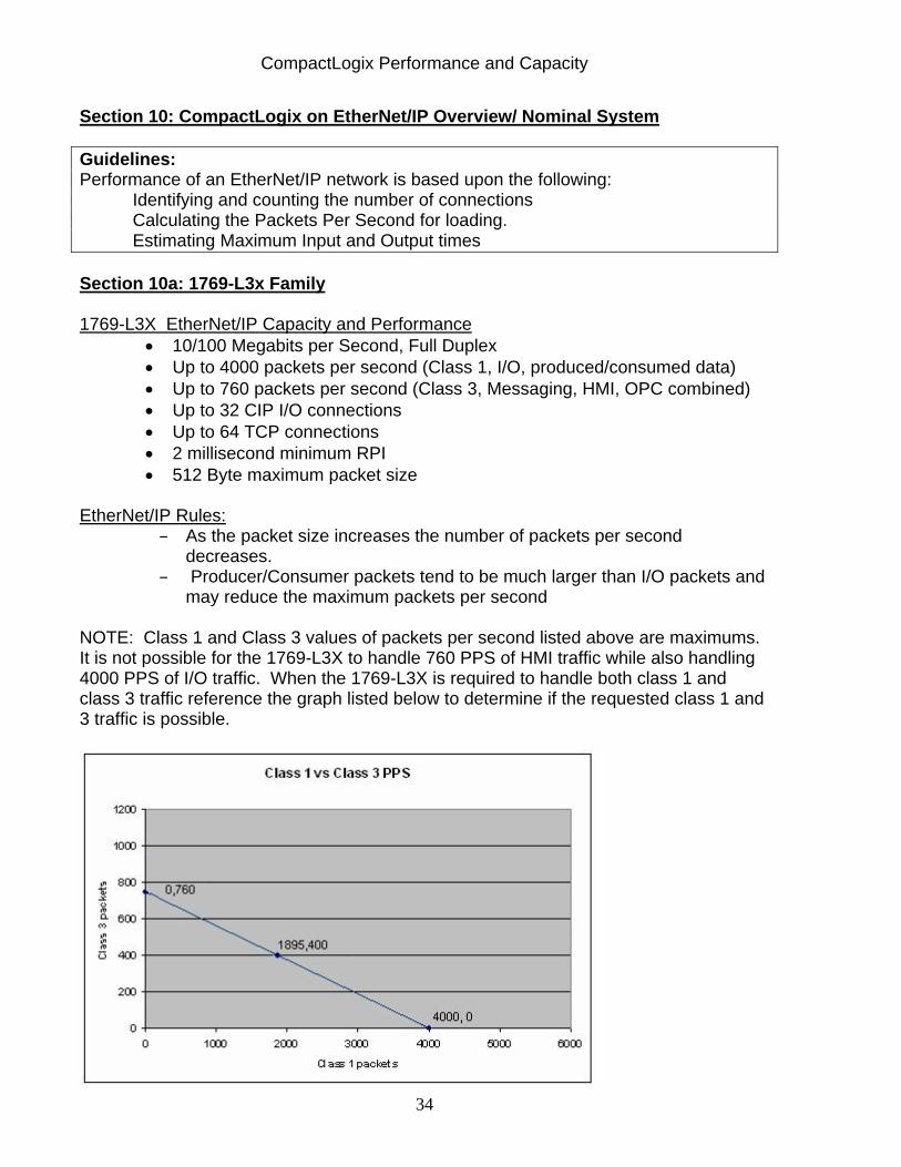
may reduce the maximum packets per second NOTE: Class 1 and Class 3 values of packets per second listed above are maximums. It is not possible for the 1769-L3X to handle 760 PPS of HMI traffic while also handling 4000 PPS of I/O traffic. When the 1769-L3X is required to handle both class 1 and class 3 traffic reference the graph listed below to determine if the requested class 1 and 3 traffic is possible.
CompactLogix Performance and Capacity
35
Section 10b:1768-L4X Family NOTE: 1768-L43, -L45 processors support a maximum of two 1768-ENBT cards; the following is the capabilities of one 1768-ENBT module: 1768-ENBT EtherNet/IP Capacity and Performance • 10/100 Megabits per Second, Full Duplex • Up to 5000 packets per second (Class 1, I/O, produced/consumed data
combined) • Up to 960 packets per second (Class 3, Messaging, HMI, OPC combined) • Up to 128 simultaneous CIP Message connections • Up to 128 CIP I/O connections (1768-ENBT V2) 64 CIP I/O connections (1768-ENBT V1) • Up to 64 TCP connections (1768-ENBT V2) 32 TCP Connections (1768-ENBT V1) • 2 millisecond minimum RPI • 512 Byte maximum packet size
EtherNet/IP Rules:
– As the packet size increases the number of packets per second decreases.
– Producer/Consumer packets tend to be much larger than I/O packets and may reduce the maximum packets per second
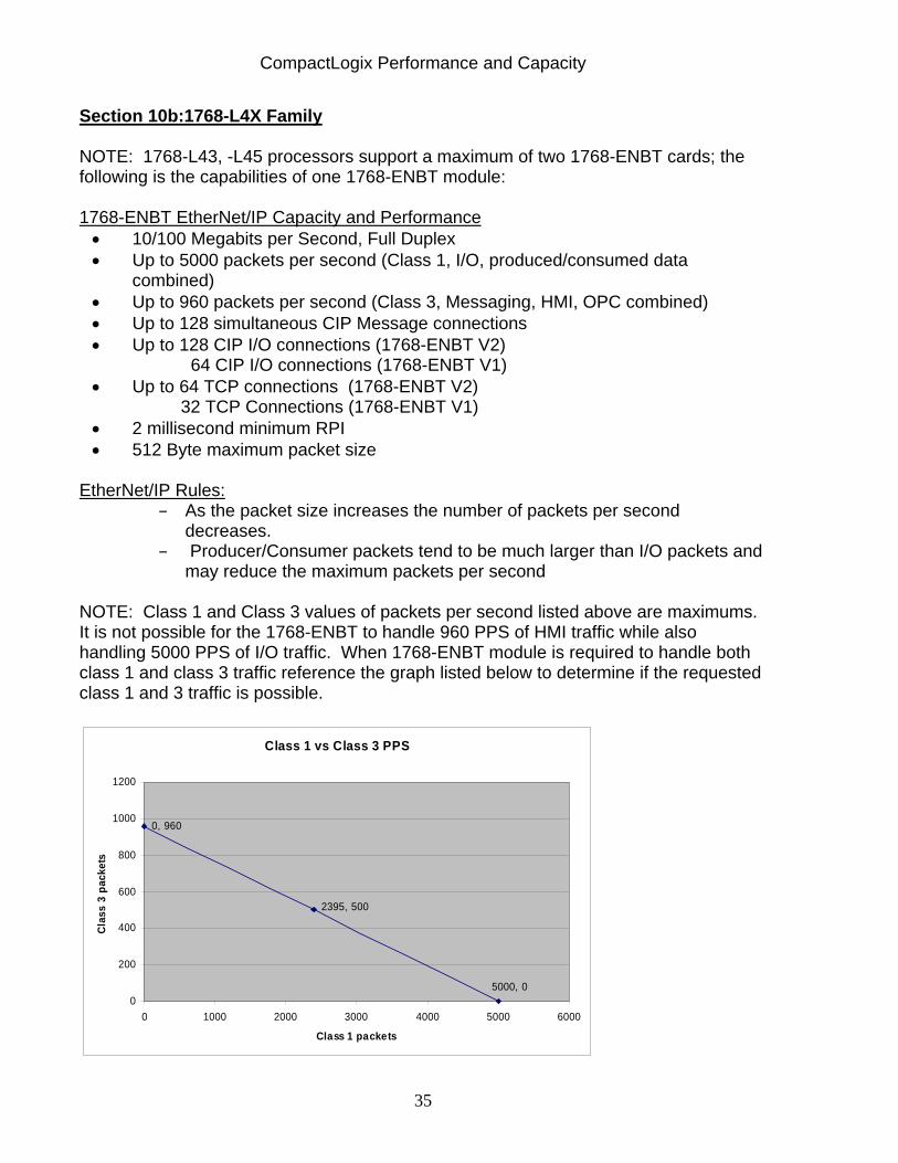
NOTE: Class 1 and Class 3 values of packets per second listed above are maximums. It is not possible for the 1768-ENBT to handle 960 PPS of HMI traffic while also handling 5000 PPS of I/O traffic. When 1768-ENBT module is required to handle both class 1 and class 3 traffic reference the graph listed below to determine if the requested class 1 and 3 traffic is possible.
Class 1 vs Class 3 PPS
0, 960
5000, 0
2395, 500
0
200
400
600
800
1000
1200
0 1000 2000 3000 4000 5000 6000
Class 1 packets
Clas
s 3
pack
ets
CompactLogix Performance and Capacity
36
– If all packets are completely full (512 bytes) the maximum packets per
second count is reduced to around 2600 Section 10c:Nominal System A nominal 1769-L3X on EtherNet/IP system can be comprised of:
7 chassis of discrete I/O at a RPI of 20ms 7 analog modules total located in any of the chassis at a RPI of 80ms 7 drives at a RPI of 40ms I/O cards in local chassis at a RPI of 5ms PV+ HMI and programming terminal
A nominal 1768-L4X on EtherNet/IP system (with one 1768-ENBT V1) can be comprised of:
14 chassis of discrete I/O at a RPI of 20ms 14 analog modules total located in any of the chassis in 80ms 7 drives at a RPI of 40ms I/O cards in local chassis at a RPI of 5ms PV+ HMI and programming terminal
CompactLogix Performance and Capacity
37
Section 11: CompactLogix on EtherNet/IP: Connections and Packets Per Second This section will document testing for both the 1769-L3X and 1768-L4X family to determine the maximum number of CIP connections recommended at different values of RPI.
It also will provide examples of how Packets Per Second (PPS) and max CIP connections can be estimated via calculation for a 1769-3X or 1768-L4X application.
Next, it will discuss how to estimate maximum input or output times for CIP connections.
Then, it will explain Logix V16 changes to the heartbeat rate for uni-directional connections and how this affects utilization resources.
Finally, there is an application example. Section 11a: 1769-L3x Family - Connections and PPS Testing Guideline: It is recommended that for most applications, all I/O RPI’s be set to 3ms or greater, the CompactBus RPI set to 5ms, System Overhead Time Slice set to 30% or greater and keep the EtherNet/IP port CPU% under 70% when only Class 1 connections are active. There are 32 Max CIP connections supported by the L3x EtherNet/IP port. However, here is a limit to how many CIP connections the controller can have for a given RPI. As the RPI is increased, the number connections supported also increases. Note that digital I/O (rack optimized connection), each analog module (direct connection) and each produced and each consumed tag each require a CIP connection.

CompactLogix Performance and Capacity
38
Test: Effects of RPI and Number EtherNet/IP Connections for 1769-L32E
(Baseline program used with EtherNet/IP I/O in the form of 1794-AENTs containing two discrete modules in a rack optimized connection with a size of 2. Local Compact Bus RPI set to 3ms. All Ethernet traffic was 100Mbps full duplex.) Test Results: Effects of RPI and Number EtherNet/IP Connections for 1769-L32E
Typical Maximum Recommended
ThruPut ENetPort ENetPort
RPI of all Connections
CPU% #Conn CPU% #Conn 4-12ms 3ms 84% 5 61% 3 9-14ms 5ms 86% 10 64% 7 8-23ms 10ms 86% 20 72% 15 12-36ms 16ms 85% 32 70% 23 15-42ms 26ms 73% 32
It is recommended that for most applications, all I/O RPI’s be set to 3ms or greater, the CompactBus RPI set to 5ms, System Overhead Time Slice set to 30% or greater and keep the EtherNet/IP port CPU% under 70% when only Class 1 connections are active.
EtherNet/IP I/O Connections
0
5
10
15
20
25
30
35
3ms 5ms 10ms 16ms 26ms
RPI of All Connections
Supp
orte
d C
onne
ctio
ns
MAX Connections
Recommended Connections
CompactLogix Performance and Capacity
39
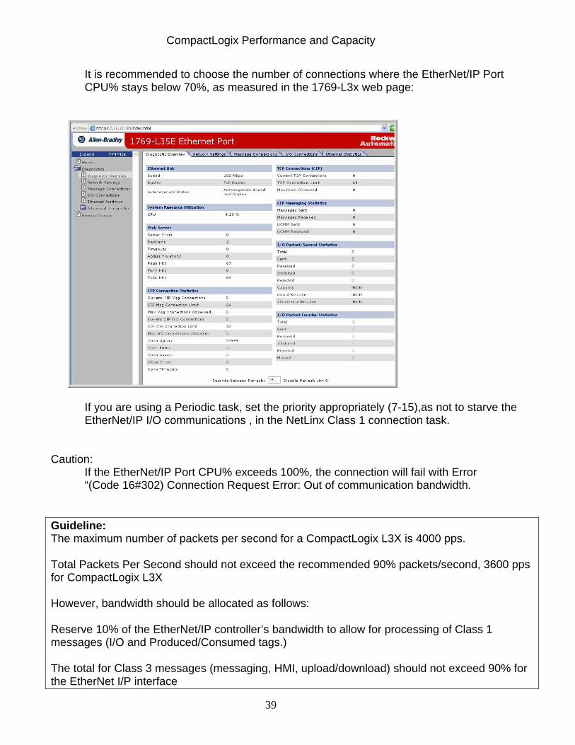
It is recommended to choose the number of connections where the EtherNet/IP Port CPU% stays below 70%, as measured in the 1769-L3x web page:
If you are using a Periodic task, set the priority appropriately (7-15),as not to starve the EtherNet/IP I/O communications , in the NetLinx Class 1 connection task.
Caution:
If the EtherNet/IP Port CPU% exceeds 100%, the connection will fail with Error “(Code 16#302) Connection Request Error: Out of communication bandwidth.
Guideline: The maximum number of packets per second for a CompactLogix L3X is 4000 pps. Total Packets Per Second should not exceed the recommended 90% packets/second, 3600 pps for CompactLogix L3X However, bandwidth should be allocated as follows: Reserve 10% of the EtherNet/IP controller’s bandwidth to allow for processing of Class 1 messages (I/O and Produced/Consumed tags.) The total for Class 3 messages (messaging, HMI, upload/download) should not exceed 90% for the EtherNet I/P interface
CompactLogix Performance and Capacity
40
Section 11b: 1769-L3X Family – Estimating PPS and Max RPI via Calculation Summary: You can estimate your PPS values using the formula’s and rules provided below. CIP connections are typically bidirectional – they require 2 packets per RPI. Using 2 packets/RPI/connection, the number of packets/second to or from each EtherNet/IP controller can be calculated as follows:
A. Rack Optimized: Packets/Second= (2 x connections)/RPI
B. Direct Connection: Packets/Second = (2 x connections)/RPI
C. Consumed Tag: producer and all consumers are in different chassis and are operating at a uniform RPI):
At Consumer: Packets/Second = 2/RPI for each consumed tag At Producer: See information below in Section 11f on changes to heartbeat rates
“Binary Multiple” Rule (CompactLogix 3X Family Only): The RPI you select for a given ethernet interface or tag translates into an actual packet interval (API) that is the “next lower” power of 2, such as 2, 4, 8, 16, etc. that is less than or equal to the RPI you configure. You should use this API value in place of RPI in the formulas above to calculate Packets/Second. Below is a table listing the API for a given RPI.
CompactLogix Performance and Capacity
41
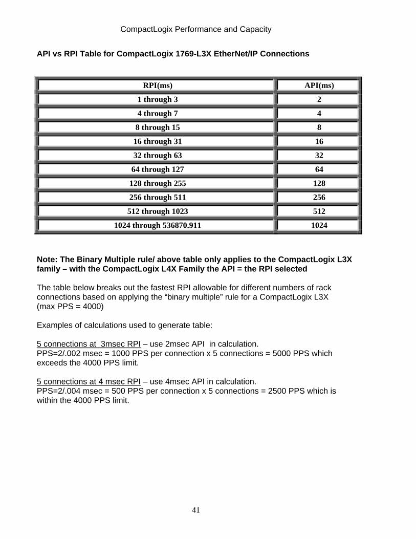
API vs RPI Table for CompactLogix 1769-L3X EtherNet/IP Connections
RPI(ms) API(ms)
1 through 3 2
4 through 7 4
8 through 15 8
16 through 31 16
32 through 63 32
64 through 127 64
128 through 255 128
256 through 511 256
512 through 1023 512
1024 through 536870.911 1024
Note: The Binary Multiple rule/ above table only applies to the CompactLogix L3X family – with the CompactLogix L4X Family the API = the RPI selected The table below breaks out the fastest RPI allowable for different numbers of rack connections based on applying the “binary multiple” rule for a CompactLogix L3X (max PPS = 4000) Examples of calculations used to generate table: 5 connections at 3msec RPI – use 2msec API in calculation. PPS=2/.002 msec = 1000 PPS per connection x 5 connections = 5000 PPS which exceeds the 4000 PPS limit. 5 connections at 4 msec RPI – use 4msec API in calculation. PPS=2/.004 msec = 500 PPS per connection x 5 connections = 2500 PPS which is within the 4000 PPS limit.

CompactLogix Performance and Capacity
42
Table: Fastest RPI for Various RPI/ API and Rack Connections Combinations Connections RPI (ms) API (ms) PPS Fastest RPI
5 2.0 2.0 5,000 Exceeds L3X PPS limit (4000) 5 3.0 2.0 5,000 Exceeds L3X PPS limit (4000) 5 4.0 4.0 2,500 5 connections at 4 ms 5 5.0 4.0 2,500 OK 5 6.0 4.0 2,500 OK 5 7.0 4.0 2,500 OK 5 8.0 8.0 1,250 OK 5 9.0 8.0 1,250 OK 5 10.0 8.0 1,250 OK 5 20.0 16.0 625 OK
10 2.0 2.0 10,000 Exceeds PPS limit 10 3.0 2.0 10,000 Exceeds PPS limit 10 4.0 4.0 5,000 Exceeds PPS limit 10 5.0 4.0 5,000 Exceeds PPS limit 10 6.0 4.0 5,000 Exceeds PPS limit 10 7.0 4.0 5,000 Exceeds PPS limit 10 8.0 8.0 2,500 10 connections at 8 ms 10 9.0 8.0 2,500 OK 10 10.0 8.0 2,500 OK 10 20.0 16.0 1,250 OK
20 2.0 2.0 20,000 Exceeds PPS limit 20 3.0 2.0 20,000 Exceeds PPS limit 20 4.0 4.0 10,000 Exceeds PPS limit 20 5.0 5.0 10,000 Exceeds PPS limit 20 6.0 6.0 10,000 Exceeds PPS limit 20 7.0 7.0 10,000 Exceeds PPS limit 20 8.0 8.0 5,000 Exceeds PPS limit 20 9.0 8.0 5,000 Exceeds PPS limit 20 10.0 8.0 5,000 Exceeds PPS limit 20 20.0 16.0 2,500 20 connections at 20 ms 30 20.0 16.0 3,750 Exceeds 90% Recommendation 30 32.0 32.0 1,875 30 connections at 32 ms
Section 11c: 1769-L4x Family - Connections and PPS Testing There are 64 Max CIP connections supported by the 1768-ENBT V1 and 128 Max CIP connections for the1768-ENBT V2. However, here is a limit to how many CIP connections the controller can have for a given RPI. As the RPI is increased, the number connections supported also increases. Note that digital I/O (rack optimized connection), each analog module (direct connection) and each produced and each consumed tag each require a CIP connection.
CompactLogix Performance and Capacity
43
Test: Effects of RPI and Number of ENet/IP connections for 1768-ENBT V1 (Baseline program used with EtherNet/IP I/O in the form of 1794-AENTs containing two discrete modules in a rack optimized connection with a size of 2. All Ethernet traffic was 100Mbps full duplex.)
Test Results: Effects of RPI and Number of EtherNet/IP Connections for 1768-ENBT V1 with 1768-L4x RPI of Connections (ms)
Typical Throughput (ms)
1768-ENBT %CPU w/ Max Connections %CPU #Cnxn
1768-ENBT %CPU w/ Recommended Connections %CPU #Cnxn
2 6.4 93 5 76 4 3 8 86 7 73 6 5 10.4 83 12 70 11 8 12.4 83 20 68 18
10 14 81 25 60 22 13 17.4 75 31 72 29
Notes: 1. There is a limit to how many class 1 CIP connections the 1768-L43 controller with
1768-ENBT can handle for a given RPI. The above table can help you decide if your desired RPI’s are within acceptable limits. There are other factors that can influence the above table such as amount of explicit or UCMM traffic, being online to the controller, System Overhead Time Slice, Periodic Task, Ethernet packets/second etc. you must consider these factors when applying the table recommendations.
2. 1768-L4x supports two 1768-ENBT modules; if a limitation is found in an application utilizing one 1768-ENBT module an additional one could be added to the system.
Ethernet I/O Connections vs RPI
0
5
10
15
20
25
30
35
2 3 5 8 10 13
RPI of all connections
Supp
orte
d #
of C
onne
ctio
ns
Maximum Connections
Recommended Connections
CompactLogix Performance and Capacity
44
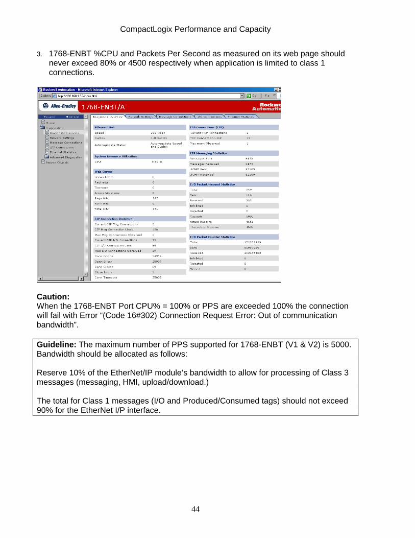
3. 1768-ENBT %CPU and Packets Per Second as measured on its web page should never exceed 80% or 4500 respectively when application is limited to class 1 connections.
Caution: When the 1768-ENBT Port CPU% = 100% or PPS are exceeded 100% the connection will fail with Error “(Code 16#302) Connection Request Error: Out of communication bandwidth”. Guideline: The maximum number of PPS supported for 1768-ENBT (V1 & V2) is 5000. Bandwidth should be allocated as follows: Reserve 10% of the EtherNet/IP module’s bandwidth to allow for processing of Class 3 messages (messaging, HMI, upload/download.) The total for Class 1 messages (I/O and Produced/Consumed tags) should not exceed 90% for the EtherNet I/P interface.

CompactLogix Performance and Capacity
45
Section 11d: 1769-L4X Family – Estimating PPS and Max RPI via Calculation Summary: You can estimate your PPS values using the formula’s and rules provided below. CIP connections are typically bidirectional – they require 2 packets per RPI. Using 2 packets/RPI/connection, the number of packets/second to or from each EtherNet/IP controller can be calculated as follows:
A. Rack Optimized: Packets/Second= (2 x connections)/RPI
B. Direct Connection: Packets/Second = (2 x connections)/RPI
C. Consumed Tag: producer and all consumers are in different chassis and are operating at a uniform RPI):
At Consumer: Packets/Second = 2/RPI for each consumed tag At Producer: See information below in Section 11f on changes to heartbeat rates
Unlike the 1769-L3X family, the ”Binary Multiple” rule does not apply to the L4X family. Simply use the selected RPI in the calculation. The table below breaks out the fastest RPI allowable for different numbers of rack connections for a CompactLogix L4X (max PPS = 5000) Examples of calculations used to generate table: 5 connections at 2msec RPI PPS=2/.002 msec = 1000 PPS per connection x 5 connections = 5000 PPS which exceeds 90% of the 5000 PPS limit. 5 connections at 3 msec RPI PPS=2/.003 msec = 667 PPS per connection x 5 connections = 3333 PPS which is within the 5000 PPS limit.
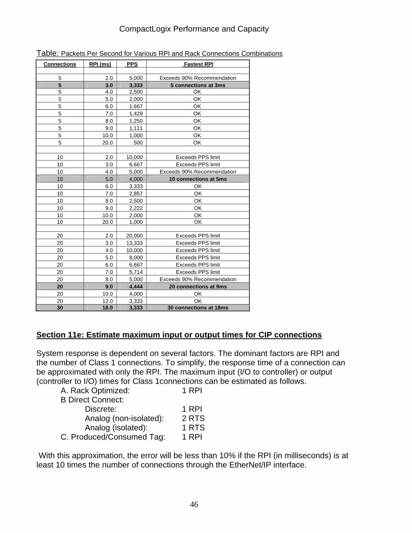
CompactLogix Performance and Capacity
46
Table: Packets Per Second for Various RPI and Rack Connections Combinations Connections RPI (ms) PPS Fastest RPI
5 2.0 5,000 Exceeds 90% Recommendation 5 3.0 3,333 5 connections at 3ms 5 4.0 2,500 OK 5 5.0 2,000 OK 5 6.0 1,667 OK 5 7.0 1,429 OK 5 8.0 1,250 OK 5 9.0 1,111 OK 5 10.0 1,000 OK 5 20.0 500 OK
10 2.0 10,000 Exceeds PPS limit 10 3.0 6,667 Exceeds PPS limit 10 4.0 5,000 Exceeds 90% Recommendation 10 5.0 4,000 10 connections at 5ms 10 6.0 3,333 OK 10 7.0 2,857 OK 10 8.0 2,500 OK 10 9.0 2,222 OK 10 10.0 2,000 OK 10 20.0 1,000 OK
20 2.0 20,000 Exceeds PPS limit 20 3.0 13,333 Exceeds PPS limit 20 4.0 10,000 Exceeds PPS limit 20 5.0 8,000 Exceeds PPS limit 20 6.0 6,667 Exceeds PPS limit 20 7.0 5,714 Exceeds PPS limit 20 8.0 5,000 Exceeds 90% Recommendation 20 9.0 4,444 20 connections at 9ms 20 10.0 4,000 OK 20 12.0 3,333 OK 30 18.0 3,333 30 connections at 18ms
Section 11e: Estimate maximum input or output times for CIP connections System response is dependent on several factors. The dominant factors are RPI and the number of Class 1 connections. To simplify, the response time of a connection can be approximated with only the RPI. The maximum input (I/O to controller) or output (controller to I/O) times for Class 1connections can be estimated as follows.
A. Rack Optimized: 1 RPI B Direct Connect:
Discrete: 1 RPI Analog (non-isolated): 2 RTS Analog (isolated): 1 RTS
C. Produced/Consumed Tag: 1 RPI
With this approximation, the error will be less than 10% if the RPI (in milliseconds) is at least 10 times the number of connections through the EtherNet/IP interface.
CompactLogix Performance and Capacity
47
Section 11f: Changes to Heartbeat rates in V16 For those CIP connections that are not bidirectional version 16 f/w in Logix controllers have implemented reduced heartbeat rates. This is important because all of the traffic, including heartbeats, through our EtherNet/IP modules contributes to the CPU utilization of those modules. The affect of reduced heartbeats is reduced utilization resources on EtherNet/IP bridge modules, Logix backplane, and Logix controller. This change did not affect the data gathered in the preceding test as Rack Connections are bidirectional. Overview For uni-directional connections that only send data in one direction a “heartbeat” is used to maintain the connection but does not include customer data. Heartbeat packets are generated for the following:
Produce tag I/O rack connection, listen-only I/O module input connection I/O module input connection, listen only I/O module output, listen only
For version 15 and earlier, heartbeats were sent at the same rate, the RPI rate, as the data. For example, if a produce tag was configured for 10ms, the heartbeat from each tag consumer was also sent at 10ms. However, with version 16, heartbeats are sent at a reduced rate and will correspondingly have a timeout different from the data timeout. In summary, each CIP connection that has a heartbeat, will have the following:
Data RPI Data timeout Heartbeat RPI Heartbeat timeout
Description You can use the provided tables that follow to view data and heartbeat packet rates. List of RPIs, Timeouts, and Packet Rates Note:
Each CIP connection timeout is 100 ms or more. The nominal heartbeat timeout is 2000 ms (2 seconds).
CompactLogix Performance and Capacity
48
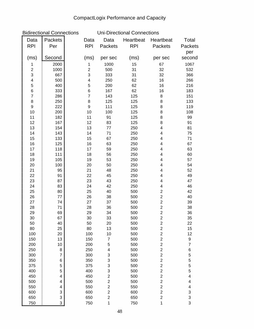
Bidirectional Connections Uni-Directional Connections Data Packets Data Data Heartbeat Heartbeat Total
RPI Per RPI Packets RPI Packets Packets
(ms) Second
(ms) per sec (ms) per sec per
second 1 2000 1 1000 15 67 1067 2 1000 2 500 31 32 532 3 667 3 333 31 32 366 4 500 4 250 62 16 266 5 400 5 200 62 16 216 6 333 6 167 62 16 183 7 286 7 143 125 8 151 8 250 8 125 125 8 133 9 222 9 111 125 8 119 10 200 10 100 125 8 108 11 182 11 91 125 8 99 12 167 12 83 125 8 91 13 154 13 77 250 4 81 14 143 14 71 250 4 75 15 133 15 67 250 4 71 16 125 16 63 250 4 67 17 118 17 59 250 4 63 18 111 18 56 250 4 60 19 105 19 53 250 4 57 20 100 20 50 250 4 54 21 95 21 48 250 4 52 22 91 22 45 250 4 49 23 87 23 43 250 4 47 24 83 24 42 250 4 46 25 80 25 40 500 2 42 26 77 26 38 500 2 40 27 74 27 37 500 2 39 28 71 28 36 500 2 38 29 69 29 34 500 2 36 30 67 30 33 500 2 35 50 40 50 20 500 2 22 80 25 80 13 500 2 15
100 20 100 10 500 2 12 150 13 150 7 500 2 9 200 10 200 5 500 2 7 250 8 250 4 500 2 6 300 7 300 3 500 2 5 350 6 350 3 500 2 5 375 5 375 3 500 2 5 400 5 400 3 500 2 5 450 4 450 2 500 2 4 500 4 500 2 500 2 4 550 4 550 2 550 2 4 600 3 600 2 600 2 3 650 3 650 2 650 2 3 750 3 750 1 750 1 3
CompactLogix Performance and Capacity
49
Section 11g: Example Application Calculation Question: An application has the following types of connections; what is the total PPS for the 1768-ENBT handling the connections? 5 Rack optimized connections RPI = 10 ms 4 Direct connections RPI = 30 ms 10 Consumed tags RPI = 100 ms 20 Produced tags RPI = 150 ms Answer: Total PPS = 5*(2/.01) + 4*(2/.03) + 10*(2/.1) + 20*(9) = 1000 + 267 + 200 + 180 = 1847 PPS Utilizing the Class 1 vs Class 3 PPS graph provided in Section 10b this leaves approximately 600 PPS available for Class 3 traffic. Total Packets Per Second is the sum of all the packets seen by the EtherNet/IP bridge module should not exceed the recommended 90% packets/second, 4500 PPS for 1768-ENBT.

CompactLogix Performance and Capacity
50
Section 12: CompactLogix EtherNet/IP Explicit Messaging This section discusses considerations when using explicit messaging on EtherNet/IP for both the 1769-L3X and 1768-L4X family of processors. Summary: When configuring a ladder message in Logix, the user may or may not have the availability to cache a message, depending on the type of message being configured. Cached and uncached messages consume a processor connection; however, cached messaging continues to use the connection, even when the message is completed, tying up buffers and resources. Uncached messages open a connection and then close the connection once the message is completed, freeing up the resources and buffers. Generally, you should use cached messaging for applications with less than 32 messages. If you have an application with more than 32 messages, you must use uncached messages after you exceed 32, but make sure you use message management in such a way that no more than 5 uncached messages are triggered at any given time.
EtherNet/IP I/O traffic is not affected by the addition of explicit messaging. However, the number of explicit messages supported decreases as EtherNet/IP I/O connections are added. Section 12a: Introduction This section will discuss EtherNet/IP Explicit Message capabilities of both the 1769-L3x and 1768-L4X CompactLogix platforms. Three tests will be run:
1) Cached Connected Messaging: Test results will show how many are possible and typical completion time for given number of cached connected EtherNet/IP messages.
2) Uncached Unconnected Messaging: Test results will show how many are possible and typical completion time for given number of uncached unconnected EtherNet/IP messages.
3) Cached Connected Messaging when I/O over EtherNet/IP traffic also exists: Test results will show how many cached connected messages are possible and typical completion time for given number of cached connected EtherNet/IP Messages when I/O is also present
CompactLogix Performance and Capacity
51
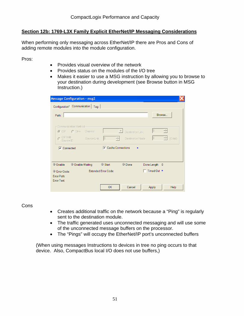
Section 12b: 1769-L3X Family Explicit EtherNet/IP Messaging Considerations When performing only messaging across EtherNet/IP there are Pros and Cons of adding remote modules into the module configuration. Pros:
• Provides visual overview of the network • Provides status on the modules of the I/O tree • Makes it easier to use a MSG instruction by allowing you to browse to
your destination during development (see Browse button in MSG Instruction.)
Cons
• Creates additional traffic on the network because a “Ping” is regularly sent to the destination module.
• The traffic generated uses unconnected messaging and will use some of the unconnected message buffers on the processor.
• The “Pings” will occupy the EtherNet/IP port’s unconnected buffers
(When using messages Instructions to devices in tree no ping occurs to that device. Also, CompactBus local I/O does not use buffers,)
CompactLogix Performance and Capacity
52
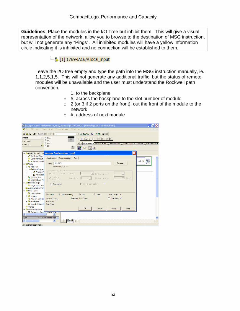
Guidelines: Place the modules in the I/O Tree but inhibit them. This will give a visual representation of the network, allow you to browse to the destination of MSG instruction, but will not generate any “Pings”. All inhibited modules will have a yellow information circle indicating it is inhibited and no connection will be established to them.
Leave the I/O tree empty and type the path into the MSG instruction manually, ie. 1,1,2,5,1,5. This will not generate any additional traffic, but the status of remote modules will be unavailable and the user must understand the Rockwell path convention.
1, to the backplane o #, across the backplane to the slot number of module o 2 (or 3 if 2 ports on the front), out the front of the module to the
network o #, address of next module
CompactLogix Performance and Capacity
53
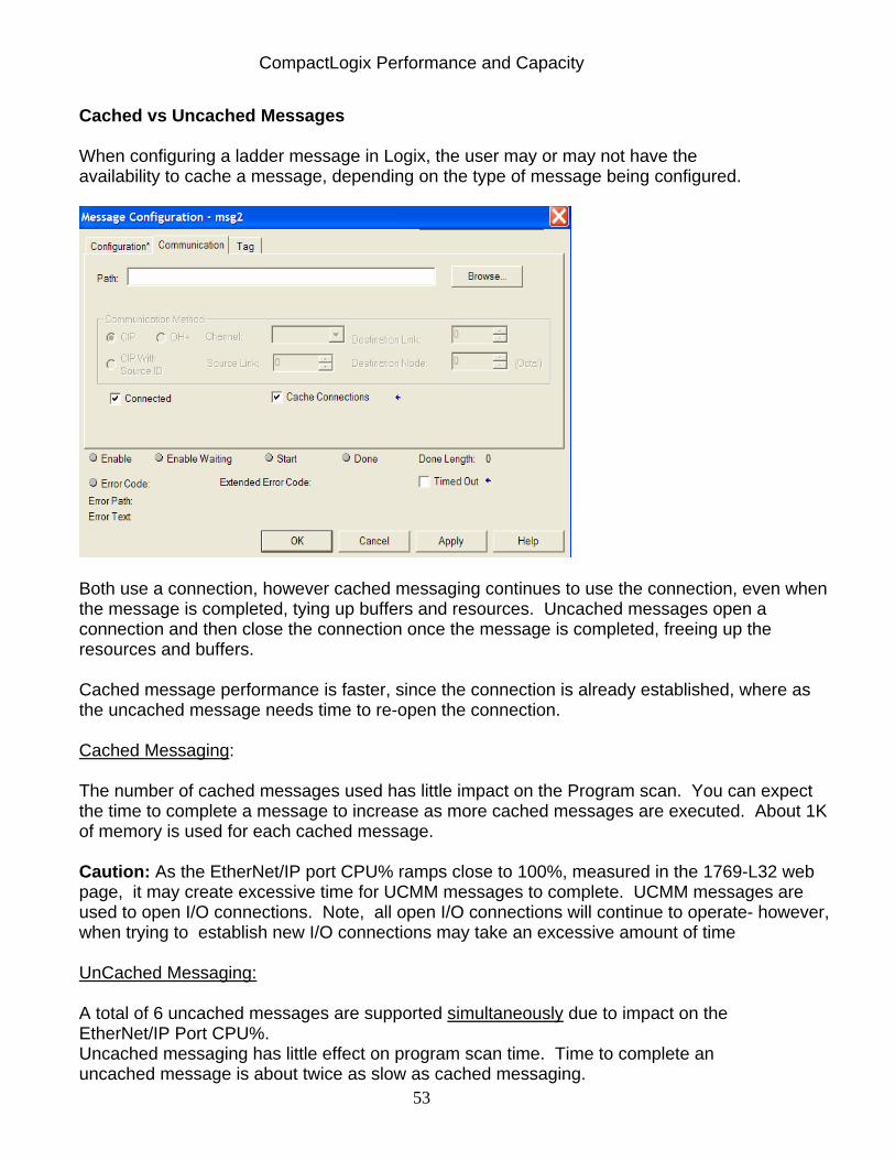
Cached vs Uncached Messages When configuring a ladder message in Logix, the user may or may not have the availability to cache a message, depending on the type of message being configured.
Both use a connection, however cached messaging continues to use the connection, even when the message is completed, tying up buffers and resources. Uncached messages open a connection and then close the connection once the message is completed, freeing up the resources and buffers. Cached message performance is faster, since the connection is already established, where as the uncached message needs time to re-open the connection. Cached Messaging: The number of cached messages used has little impact on the Program scan. You can expect the time to complete a message to increase as more cached messages are executed. About 1K of memory is used for each cached message. Caution: As the EtherNet/IP port CPU% ramps close to 100%, measured in the 1769-L32 web page, it may create excessive time for UCMM messages to complete. UCMM messages are used to open I/O connections. Note, all open I/O connections will continue to operate- however, when trying to establish new I/O connections may take an excessive amount of time
UnCached Messaging: A total of 6 uncached messages are supported simultaneously due to impact on the EtherNet/IP Port CPU%. Uncached messaging has little effect on program scan time. Time to complete an uncached message is about twice as slow as cached messaging.
CompactLogix Performance and Capacity
54
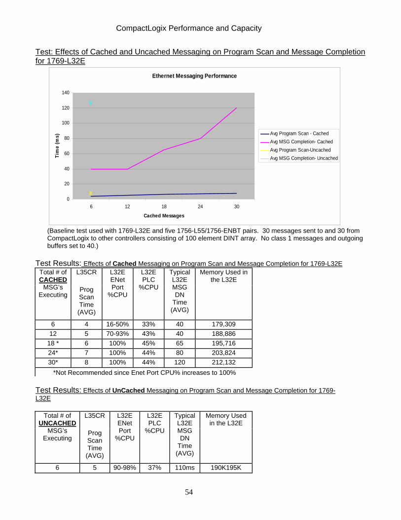
Test: Effects of Cached and Uncached Messaging on Program Scan and Message Completion for 1769-L32E
Ethernet Messaging Performance
0
20
40
60
80
100
120
140
6 12 18 24 30
Cached Messages
Tim
e (m
s) Avg Program Scan - CachedAvg MSG Completion- CachedAvg Program Scan-UncachedAvg MSG Completion- Uncached
X
X
(Baseline test used with 1769-L32E and five 1756-L55/1756-ENBT pairs. 30 messages sent to and 30 from CompactLogix to other controllers consisting of 100 element DINT array. No class 1 messages and outgoing buffers set to 40.)
Test Results: Effects of Cached Messaging on Program Scan and Message Completion for 1769-L32E
L35CR Total # of CACHED
MSG’s Executing
Prog Scan Time (AVG)
L32E ENet Port
%CPU
L32E PLC
%CPU
Typical L32E MSG DN
Time (AVG)
Memory Used in the L32E
6 4 16-50% 33% 40 179,309 12 5 70-93% 43% 40 188,886
18 * 6 100% 45% 65 195,716 24* 7 100% 44% 80 203,824 30* 8 100% 44% 120 212,132 *Not Recommended since Enet Port CPU% increases to 100%
Test Results: Effects of UnCached Messaging on Program Scan and Message Completion for 1769-L32E
L35CR Total # of UNCACHED
MSG’s Executing
Prog Scan Time
(AVG)
L32E ENet Port
%CPU
L32E PLC
%CPU
Typical L32E MSG DN
Time (AVG)
Memory Used in the L32E
6 5 90-98% 37% 110ms 190K195K
CompactLogix Performance and Capacity
55
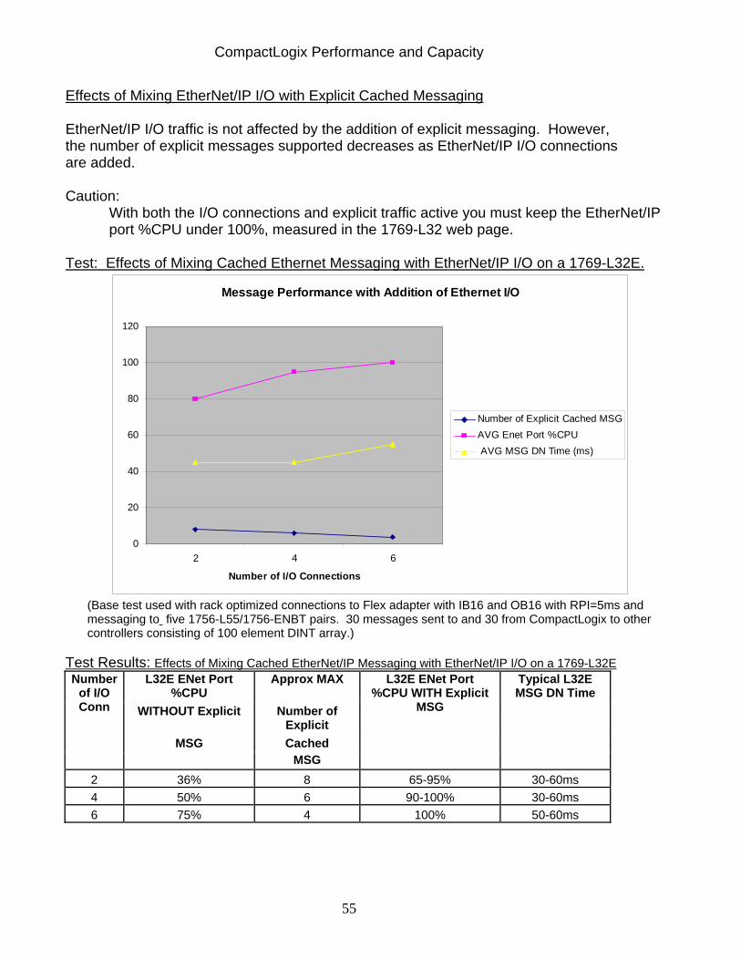
Effects of Mixing EtherNet/IP I/O with Explicit Cached Messaging EtherNet/IP I/O traffic is not affected by the addition of explicit messaging. However, the number of explicit messages supported decreases as EtherNet/IP I/O connections are added. Caution:
With both the I/O connections and explicit traffic active you must keep the EtherNet/IP port %CPU under 100%, measured in the 1769-L32 web page.
Test: Effects of Mixing Cached Ethernet Messaging with EtherNet/IP I/O on a 1769-L32E.
Message Performance with Addition of Ethernet I/O
0
20
40
60
80
100
120
2 4 6
Number of I/O Connections
Number of Explicit Cached MSGAVG Enet Port %CPU AVG MSG DN Time (ms)
(Base test used with rack optimized connections to Flex adapter with IB16 and OB16 with RPI=5ms and messaging to five 1756-L55/1756-ENBT pairs. 30 messages sent to and 30 from CompactLogix to other controllers consisting of 100 element DINT array.)
Test Results: Effects of Mixing Cached EtherNet/IP Messaging with EtherNet/IP I/O on a 1769-L32E L32E ENet Port
%CPU Approx MAX
WITHOUT Explicit Number of Explicit
MSG Cached
Number of I/O Conn
MSG
L32E ENet Port %CPU WITH Explicit
MSG
Typical L32E MSG DN Time
2 36% 8 65-95% 30-60ms 4 50% 6 90-100% 30-60ms 6 75% 4 100% 50-60ms
CompactLogix Performance and Capacity
56
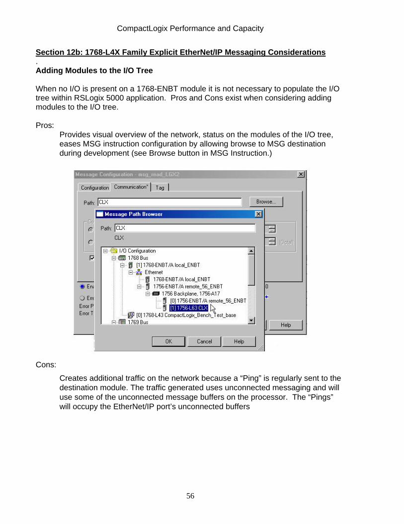
Section 12b: 1768-L4X Family Explicit EtherNet/IP Messaging Considerations . Adding Modules to the I/O Tree When no I/O is present on a 1768-ENBT module it is not necessary to populate the I/O tree within RSLogix 5000 application. Pros and Cons exist when considering adding modules to the I/O tree. Pros:
Provides visual overview of the network, status on the modules of the I/O tree, eases MSG instruction configuration by allowing browse to MSG destination during development (see Browse button in MSG Instruction.)
Cons:
Creates additional traffic on the network because a “Ping” is regularly sent to the destination module. The traffic generated uses unconnected messaging and will use some of the unconnected message buffers on the processor. The “Pings” will occupy the EtherNet/IP port’s unconnected buffers
CompactLogix Performance and Capacity
57
Guidelines: Place the modules in the I/O Tree but inhibit them. This will give a visual representation of the network, allow you to browse to the destination of MSG instruction, but will not generate any “Pings”. All inhibited modules will have a yellow information circle indicating it is inhibited and no connection will be established to them.
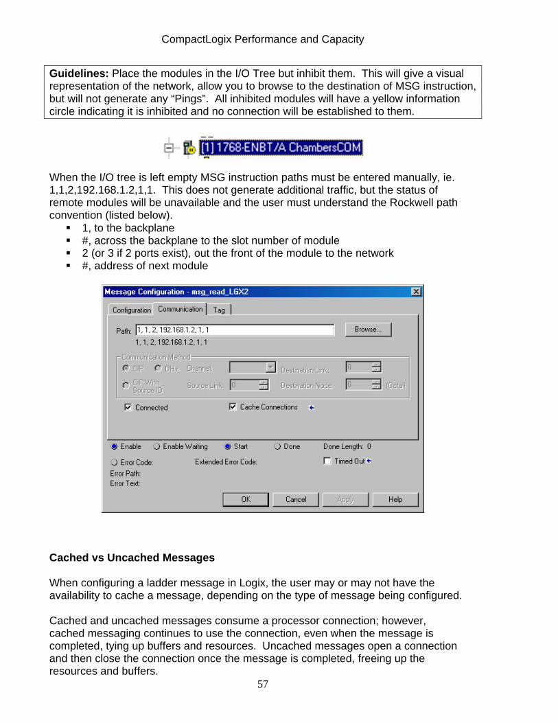
When the I/O tree is left empty MSG instruction paths must be entered manually, ie. 1,1,2,192.168.1.2,1,1. This does not generate additional traffic, but the status of remote modules will be unavailable and the user must understand the Rockwell path convention (listed below).
1, to the backplane #, across the backplane to the slot number of module 2 (or 3 if 2 ports exist), out the front of the module to the network #, address of next module
Cached vs Uncached Messages When configuring a ladder message in Logix, the user may or may not have the availability to cache a message, depending on the type of message being configured. Cached and uncached messages consume a processor connection; however, cached messaging continues to use the connection, even when the message is completed, tying up buffers and resources. Uncached messages open a connection and then close the connection once the message is completed, freeing up the resources and buffers.
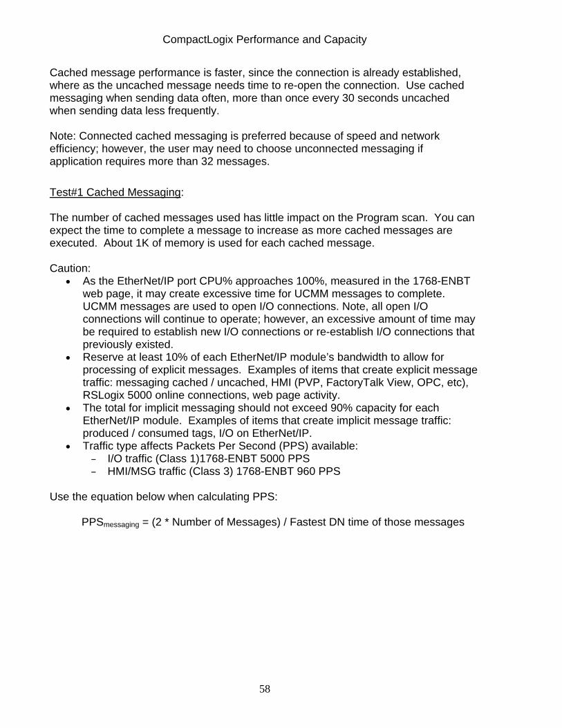
CompactLogix Performance and Capacity
58
Cached message performance is faster, since the connection is already established, where as the uncached message needs time to re-open the connection. Use cached messaging when sending data often, more than once every 30 seconds uncached when sending data less frequently.
Note: Connected cached messaging is preferred because of speed and network efficiency; however, the user may need to choose unconnected messaging if application requires more than 32 messages. Test#1 Cached Messaging:
The number of cached messages used has little impact on the Program scan. You can expect the time to complete a message to increase as more cached messages are executed. About 1K of memory is used for each cached message.
Caution: • As the EtherNet/IP port CPU% approaches 100%, measured in the 1768-ENBT
web page, it may create excessive time for UCMM messages to complete. UCMM messages are used to open I/O connections. Note, all open I/O connections will continue to operate; however, an excessive amount of time may be required to establish new I/O connections or re-establish I/O connections that previously existed.
• Reserve at least 10% of each EtherNet/IP module’s bandwidth to allow for processing of explicit messages. Examples of items that create explicit message traffic: messaging cached / uncached, HMI (PVP, FactoryTalk View, OPC, etc), RSLogix 5000 online connections, web page activity.
• The total for implicit messaging should not exceed 90% capacity for each EtherNet/IP module. Examples of items that create implicit message traffic: produced / consumed tags, I/O on EtherNet/IP.
• Traffic type affects Packets Per Second (PPS) available: – I/O traffic (Class 1)1768-ENBT 5000 PPS – HMI/MSG traffic (Class 3) 1768-ENBT 960 PPS
Use the equation below when calculating PPS:
PPSmessaging = (2 * Number of Messages) / Fastest DN time of those messages
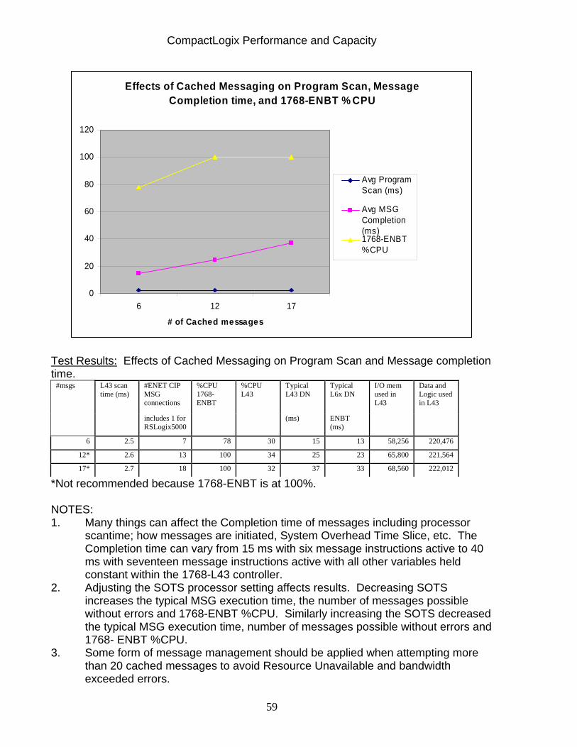
CompactLogix Performance and Capacity
59
Effects of Cached Messaging on Program Scan, Message Completion time, and 1768-ENBT % CPU
0
20
40
60
80
100
120
6 12 17
# of Cached messages
Avg ProgramScan (ms)
Avg MSGCompletion(ms)1768-ENBT%CPU
Test Results: Effects of Cached Messaging on Program Scan and Message completion time.
#ENET CIP MSG connections
Typical L43 DN
Typical L6x DN
#msgs L43 scan time (ms)
includes 1 for RSLogix5000
%CPU 1768-ENBT
%CPU L43
(ms) ENBT (ms)
I/O mem used in L43
Data and Logic used in L43
6 2.5 7 78 30 15 13 58,256 220,476
12* 2.6 13 100 34 25 23 65,800 221,564
17* 2.7 18 100 32 37 33 68,560 222,012
*Not recommended because 1768-ENBT is at 100%. NOTES: 1. Many things can affect the Completion time of messages including processor
scantime; how messages are initiated, System Overhead Time Slice, etc. The Completion time can vary from 15 ms with six message instructions active to 40 ms with seventeen message instructions active with all other variables held constant within the 1768-L43 controller.
2. Adjusting the SOTS processor setting affects results. Decreasing SOTS increases the typical MSG execution time, the number of messages possible without errors and 1768-ENBT %CPU. Similarly increasing the SOTS decreased the typical MSG execution time, number of messages possible without errors and 1768- ENBT %CPU.
3. Some form of message management should be applied when attempting more than 20 cached messages to avoid Resource Unavailable and bandwidth exceeded errors.
CompactLogix Performance and Capacity
60
4. Memory consumed due to messaging affects both I/O memory and Data & Logic memory reported on memory tab of processor properties. From monitoring the memory values reported a user can determine if too many cached messages are active. Changing processor memory usage values with purely cached message applications indicate too many cached messages are active. When cached messages are initiated processor memory is reserved and this accounts for the fluctuating processor memory when cached connections must be closed to allow another cached connection to be established.
5. Each cached message will consume approximately 1k of processor Data/Logic memory.
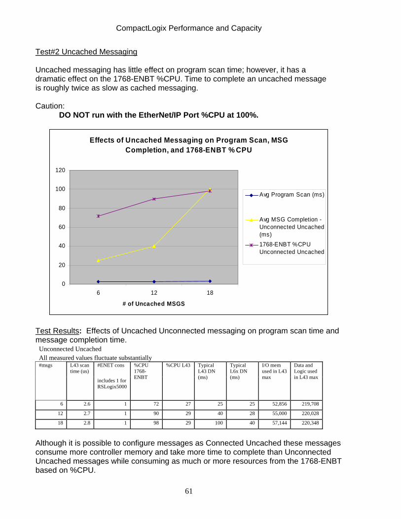
CompactLogix Performance and Capacity
61
Test#2 Uncached Messaging
Uncached messaging has little effect on program scan time; however, it has a dramatic effect on the 1768-ENBT %CPU. Time to complete an uncached message is roughly twice as slow as cached messaging.
Caution: DO NOT run with the EtherNet/IP Port %CPU at 100%.
Effects of Uncached Messaging on Program Scan, MSG Completion, and 1768-ENBT % CPU
0
20
40
60
80
100
120
6 12 18
# of Uncached MSGS
Avg Program Scan (ms)
Avg MSG Completion -Unconnected Uncached(ms)1768-ENBT %CPUUnconnected Uncached
Test Results: Effects of Uncached Unconnected messaging on program scan time and message completion time.
Unconnected Uncached All measured values fluctuate substantially
#ENET cons #msgs L43 scan time (us)
includes 1 for RSLogix5000
%CPU 1768-ENBT
%CPU L43 Typical L43 DN (ms)
Typical L6x DN (ms)
I/O mem used in L43 max
Data and Logic used in L43 max
6 2.6 1 72 27 25 25 52,856 219,708
12 2.7 1 90 29 40 28 55,000 220,028
18 2.8 1 98 29 100 40 57,144 220,348
Although it is possible to configure messages as Connected Uncached these messages consume more controller memory and take more time to complete than Unconnected Uncached messages while consuming as much or more resources from the 1768-ENBT based on %CPU.
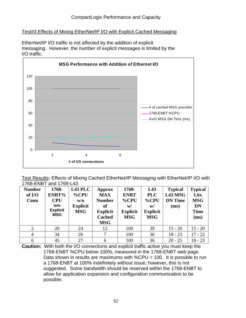
CompactLogix Performance and Capacity
62
Test#3 Effects of Mixing EtherNet/IP I/O with Explicit Cached Messaging EtherNet/IP I/O traffic is not affected by the addition of explicit messaging. However, the number of explicit messages is limited by the I/O traffic.
MSG Performance with Addition of Ethernet I/O
0
20
40
60
80
100
120
2 4 6
# of I/O connections
# of cached MSG possible1768-ENBT %CPUAVG MSG DN Time (ms)
Test Results: Effects of Mixing Cached EtherNet/IP Messaging with EtherNet/IP I/O with 1768-ENBT and 1768-L43 Number
of I/O Conn
1768-ENBT%
CPU w/o
Explicit MSG
L43 PLC %CPU
w/o Explicit
MSG
Approx MAX
Number of
Explicit Cached MSG
1768-ENBT %CPU
w/ Explicit
MSG
L43 PLC
%CPU w/
Explicit MSG
Typical L43 MSG DN Time
(ms)
Typical L6x
MSG DN
Time (ms)
2 20 24 12 100 39 15 - 20 15 - 20 4 34 26 7 100 36 18 - 23 17 - 22 6 45 27 6 100 36 20 - 25 18 - 23
Caution: With both the I/O connections and explicit traffic active you must keep the 1768-ENBT %CPU below 100%, measured in the 1768-ENBT web page. Data shown in results are maximums with %CPU = 100. It is possible to run a 1768-ENBT at 100% indefinitely without issue; however, this is not suggested. Some bandwidth should be reserved within the 1768-ENBT to allow for application expansion and configuration communication to be possible.
CompactLogix Performance and Capacity
63
Section 13: CompactLogix on ControlNet Overview/ Nominal System This section provides guidelines for the use of ControlNet for both the 1769-L3X and 1768-L4X family of processors. Summary: There is a limit to how many scheduled connections the ControlNet interfaces can handle for a given NUT/RPI combination. As the NUT is increased so is the number of connections supported. This section can help you decide if your desired NUT/RPI’s are within acceptable limits. There is a trade-off between the maximum number of connections that can be handled and the update rate or performance of the individual devices. As connections are added, the RPI needs to be increased to assure that the ControlNet Interface CPU is not over utilized.
As the NUT is increased so is the number of connections supported. There is a limit to how many scheduled connections the controller can handle for a given NUT/RPI combination.
Section 13a: 1769-L3X Family This section will determine the maximum number of connections possible at different combinations of values for Network Update Time (NUT) / Requested Packet Interval (RPI) for the 1769-L3X family.
The L3X ControlNet interface supports up to 32 Max connections. Network Update Times (NUT), above 4ms, has very little effect on ControlNet Interface CPU Utilization.
– RPI must be equal to or greater than the NUT
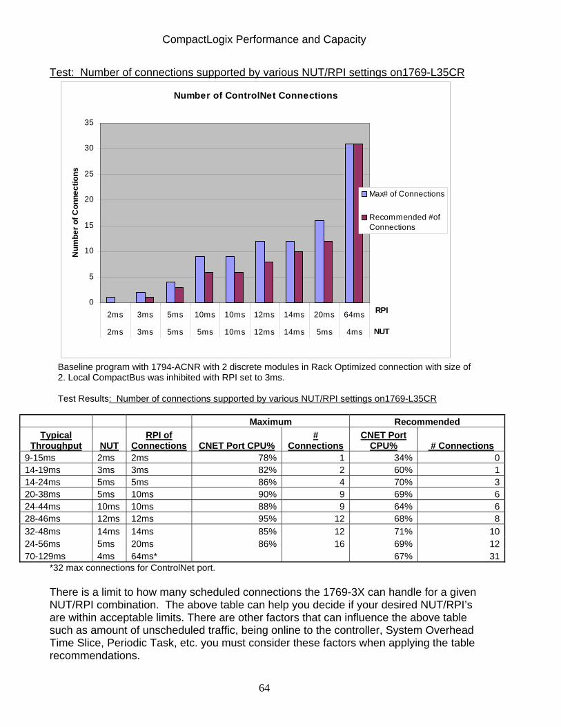
CompactLogix Performance and Capacity
64
Test: Number of connections supported by various NUT/RPI settings on1769-L35CR
Number of ControlNet Connections
0
5
10
15
20
25
30
35
2ms 3ms 5ms 10ms 10ms 12ms 14ms 20ms 64ms
2ms 3ms 5ms 5ms 10ms 12ms 14ms 5ms 4ms
RPI
NUT
Num
ber o
f Con
nect
ions
Max# of Connections
Recommended #ofConnections
Baseline program with 1794-ACNR with 2 discrete modules in Rack Optimized connection with size of 2. Local CompactBus was inhibited with RPI set to 3ms. Test Results: Number of connections supported by various NUT/RPI settings on1769-L35CR
Maximum Recommended Typical
Throughput NUT RPI of
Connections CNET Port CPU% #
Connections CNET Port
CPU% # Connections 9-15ms 2ms 2ms 78% 1 34% 014-19ms 3ms 3ms 82% 2 60% 114-24ms 5ms 5ms 86% 4 70% 320-38ms 5ms 10ms 90% 9 69% 624-44ms 10ms 10ms 88% 9 64% 628-46ms 12ms 12ms 95% 12 68% 832-48ms 14ms 14ms 85% 12 71% 1024-56ms 5ms 20ms 86% 16 69% 1270-129ms 4ms 64ms* 67% 31
*32 max connections for ControlNet port.
There is a limit to how many scheduled connections the 1769-3X can handle for a given NUT/RPI combination. The above table can help you decide if your desired NUT/RPI’s are within acceptable limits. There are other factors that can influence the above table such as amount of unscheduled traffic, being online to the controller, System Overhead Time Slice, Periodic Task, etc. you must consider these factors when applying the table recommendations.
CompactLogix Performance and Capacity
65
It is recommended that for most typical applications the NUT be set to 4ms or greater, the CompactBus RPI set to 5ms or greater, the System Overhead Time Slice be set at 30% or greater and you keep the ControlNet port CPU% under 70% with only scheduled connections active.
Tip: To determine worse case throughput use: Throughput= (2*NUT) +(2*RPI of module)+(2*Program Scan)
Note: The Local I/O is not burdened by the ControlNet connections Section 13b: 1768-L4X Family This section will determine the maximum number of connections possible at different combinations of values for Network Update Time (NUT) / Requested Packet Interval (RPI) for the CompactLogix L4X family.
Each 1768-L4X ControlNet interface (the 1768-CNB(R) module) supports up to 48 Max connections. The 1768-L4X CompactLogix platform supports the use of up to two 1768-CNB(R) modules in the same rack.
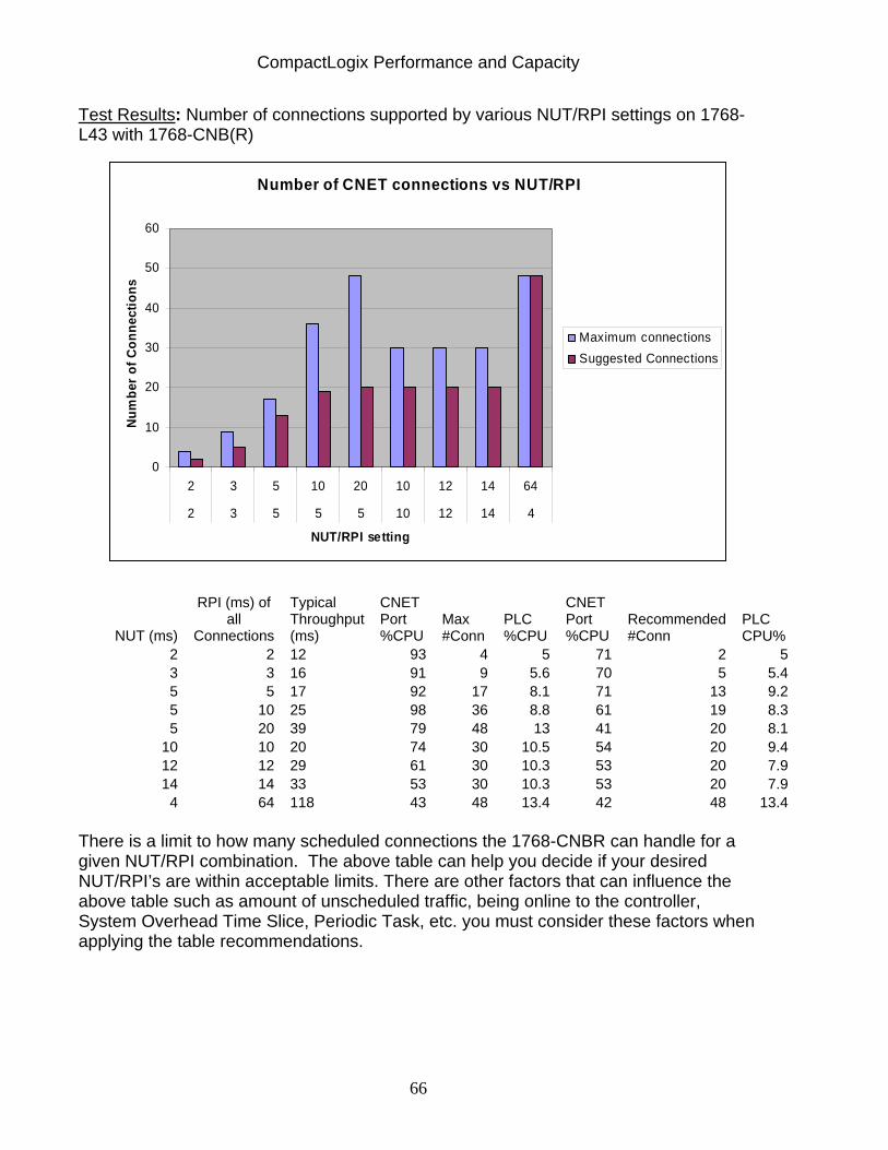
CompactLogix Performance and Capacity
66
Test Results: Number of connections supported by various NUT/RPI settings on 1768-L43 with 1768-CNB(R)
Number of CNET connections vs NUT/RPI
0
10
20
30
40
50
60
2 3 5 10 20 10 12 14 64
2 3 5 5 5 10 12 14 4
NUT/RPI setting
Num
ber
of C
onne
ctio
ns
Maximum connectionsSuggested Connections
NUT (ms)
RPI (ms) of all
Connections
Typical Throughput (ms)
CNET Port %CPU
Max #Conn
PLC %CPU
CNET Port %CPU
Recommended #Conn
PLC CPU%
2 2 12 93 4 5 71 2 53 3 16 91 9 5.6 70 5 5.45 5 17 92 17 8.1 71 13 9.25 10 25 98 36 8.8 61 19 8.35 20 39 79 48 13 41 20 8.1
10 10 20 74 30 10.5 54 20 9.412 12 29 61 30 10.3 53 20 7.914 14 33 53 30 10.3 53 20 7.9
4 64 118 43 48 13.4 42 48 13.4 There is a limit to how many scheduled connections the 1768-CNBR can handle for a given NUT/RPI combination. The above table can help you decide if your desired NUT/RPI’s are within acceptable limits. There are other factors that can influence the above table such as amount of unscheduled traffic, being online to the controller, System Overhead Time Slice, Periodic Task, etc. you must consider these factors when applying the table recommendations.
CompactLogix Performance and Capacity
67
13c General ControlNet Guidelines:
• It is recommended that the 1768-CNB(R) %CPU, as measured in RSLinx, under Module Statistics, should never go above 70% when only scheduled connections are active.
• To determine worse case throughput use: Throughputworst = (2*NUT) + (2*RPI of module)+(2*Program Scan)
Note: Local I/O is not burdened by the ControlNet connections
• If your application requires some I/O to updated faster than the typical I/O,
consider putting this I/O on the local 1769 bus. This bus offers a 1ms I/O update RPI.
• Always reserve some connections (2 or more) for network overhead, such and Programming using RSLogix5000, HMI, OPC topics, and data monitoring.
• Setup banks of all digital distributed I/O as Rack Optimized: Banks of all Digital I/O setup as rack optimized only consume (1) connection per bank instead of (1) connection per module
• Verify that the ’Unscheduled bytes per second” value displayed in RSNetWorx for ControlNet exceeds 400,000 bytes/second. If you do go below 400,000 bytes you run the risk of unscheduled data performance issues such as PanelViews displaying read time out errors, unscheduled messaging may become excessively slow or error, etc. Unscheduled bytes per second is directly associated with the Smax network parameter and the number of scheduled connections. The higher the Smax value and more scheduled connections active for a network configuration the lower the amount of unscheduled bytes per second available.
• Reduce the total number of unscheduled connections, i.e. MSG instructions by using an array of tags or User Defined Tags rather than individual tags.
• If sharing Produce/Consumed data between a ControlLogix and CompactLogix, set up the ControlLogix as the data Producer and the CompactLogix as the Consumer when ever possible. (Since the ControlLogix supports more connections than the CompactLogix)

CompactLogix Performance and Capacity
68
Section 13d: Nominal System Scheduled devices on the ControlNet Network should have RPI update rates that correspond to the type of data being transferred. Typically, Digital I/O has the fastest update rate and analog I/O has the lowest scheduled update rate Recommend using the following RPI’s based on the type of device used:
Analog I/O 80ms RPI Produced / Consumed Tags 40ms RPI PowerFlex Drives 40ms RPI
With an L4X the above system would be supported on each 1768-CNB(R) used, up to the maximum of two 1768-CNB(R)’s.
Nominal System - CompactLogix
...
3 scheduled connections per Bank
( 9 total scheduled connections)
• Each Bank has 6 digital and 2 analog module
Scheduled Connections Unscheduled Connections
Nominal System: 9 connections for I/O 3 Connections for Drives 4 Connections for P/C --------------------------------- 16 scheduled connect. 16 connections remain for unscheduled devices, i.e. - Panelview Plus - Explicit Messages - RSLogix 5000
• 16 Scheduled Connections
• 16 Unscheduled Connections
• 10 ms NUT
• < 70% CNET CPU Utilization
1 scheduled connection per Drive
( 3 total scheduled connections)
1 connection for each produced tag (array) 1 connection for each consumed tag (array) ( 4 total scheduled connections)
40ms RPI
10ms RPI Digital
40ms RPI
80ms RPI Analog
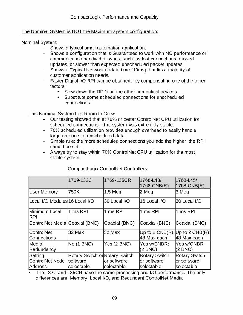
CompactLogix Performance and Capacity
69
The Nominal System is NOT the Maximum system configuration: Nominal System:
– Shows a typical small automation application. – Shows a configuration that is Guaranteed to work with NO performance or
communication bandwidth issues, such as lost connections, missed updates, or slower than expected unscheduled packet updates
– Shows a Typical Network update time (10ms) that fits a majority of customer application needs.
– Faster Digital I/O RPI can be obtained, -by compensating one of the other factors:
• Slow down the RPI’s on the other non-critical devices • Substitute some scheduled connections for unscheduled
connections
This Nominal System has Room to Grow: – Our testing showed that at 70% or better ControlNet CPU utilization for
scheduled connections – the system was extremely stable. – 70% scheduled utilization provides enough overhead to easily handle
large amounts of unscheduled data – Simple rule: the more scheduled connections you add the higher the RPI
should be set. – Always try to stay within 70% ControlNet CPU utilization for the most
stable system.
CompactLogix ControlNet Controllers:
1769-L32C 1769-L35CR 1768-L43/ 1768-CNB(R)
1768-L45/ 1768-CNB(R)
User Memory 750K 1.5 Meg 2 Meg 3 Meg
Local I/O Modules 16 Local I/O 30 Local I/O 16 Local I/O 30 Local I/O
Minimum Local RPI
1 ms RPI 1 ms RPI 1 ms RPI 1 ms RPI
ControlNet Media Coaxial (BNC) Coaxial (BNC) Coaxial (BNC) Coaxial (BNC)
ControlNet Connections
32 Max 32 Max Up to 2 CNB(R): 48 Max each
Up to 2 CNB(R): 48 Max each
Media Redundancy
No (1 BNC) Yes (2 BNC) Yes w/CNBR: (2 BNC)
Yes w/CNBR: (2 BNC)
Setting ControlNet Node Address
Rotary Switch or software selectable
Rotary Switch or software selectable
Rotary Switch or software selectable
Rotary Switch or software selectable
• The L32C and L35CR have the same processing and I/O performance. The only differences are: Memory, Local I/O, and Redundant ControlNet Media

CompactLogix Performance and Capacity
70
Section 14: CompactLogix ControlNet Messaging This section discusses considerations when using ControlNet messaging for both the 1769-L3X and 1768-L4X family of processors. Summary: When configuring a ladder message in Logix, the user may or may not have the availability to cache a message, depending on the type of message being configured. Cached and uncached messages consume a processor connection; however, cached messaging continues to use the connection, even when the message is completed, tying up buffers and resources. Uncached messages open a connection and then close the connection once the message is completed, freeing up the resources and buffers. Generally, you should use cached messaging for applications with less than 32 messages. If you have an application with more than 32 messages, you must use uncached messages after you exceed 32, but make sure you use message management in such a way that no more than 5 uncached messages are triggered at any given time.
ControlNet I/O traffic is not affected by the addition of explicit messaging. However, the number of explicit messages supported decreases as ControlNet I/O connections are added. Section14a: 1769-L3X ControlNet Messaging Considerations ControlNet connections can be scheduled or unscheduled.
A Scheduled connection lets you send and receive data repeatedly at a pre-determined interval (RPI)
Distributed I/O, HMI, Drives, Controller to Controller (Producer/Consumer), all use scheduled connections.
An unscheduled connection is a message transfer between a controller and a device that is triggered by a MSG instruction.
Unscheduled messages let you send and receive data when needed Peer to Peer messaging between controllers, Controller Programming, HMI/RSLinx all use unscheduled connections
Note: HMI devices, like Panelview Plus or RSView SE, can be setup to use both scheduled and unscheduled connections Unscheduled Data Explicit Messaging- message instructions in ladder and RSLinx communications to a HMI or PC is unscheduled. Note- Scheduled traffic is NEVER burdened by the addition of unscheduled traffic
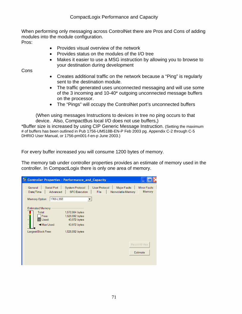
CompactLogix Performance and Capacity
71
When performing only messaging across ControlNet there are Pros and Cons of adding modules into the module configuration. Pros:
• Provides visual overview of the network • Provides status on the modules of the I/O tree • Makes it easier to use a MSG instruction by allowing you to browse to
your destination during development Cons
• Creates additional traffic on the network because a “Ping” is regularly sent to the destination module.
• The traffic generated uses unconnected messaging and will use some of the 3 incoming and 10-40* outgoing unconnected message buffers on the processor.
• The “Pings” will occupy the ControlNet port’s unconnected buffers
(When using messages Instructions to devices in tree no ping occurs to that device. Also, CompactBus local I/O does not use buffers,)
*Buffer size is increased by using CIP Generic Message Instruction. (Setting the maximum # of buffers has been outlined in Pub 1756-UM518B-EN-P Feb 2003 pg. Appendix C-2 through C-5 DHRIO User Manual, or 1756-pm001-f-en-p June 2003.) For every buffer increased you will consume 1200 bytes of memory. The memory tab under controller properties provides an estimate of memory used in the controller. In CompactLogix there is only one area of memory.
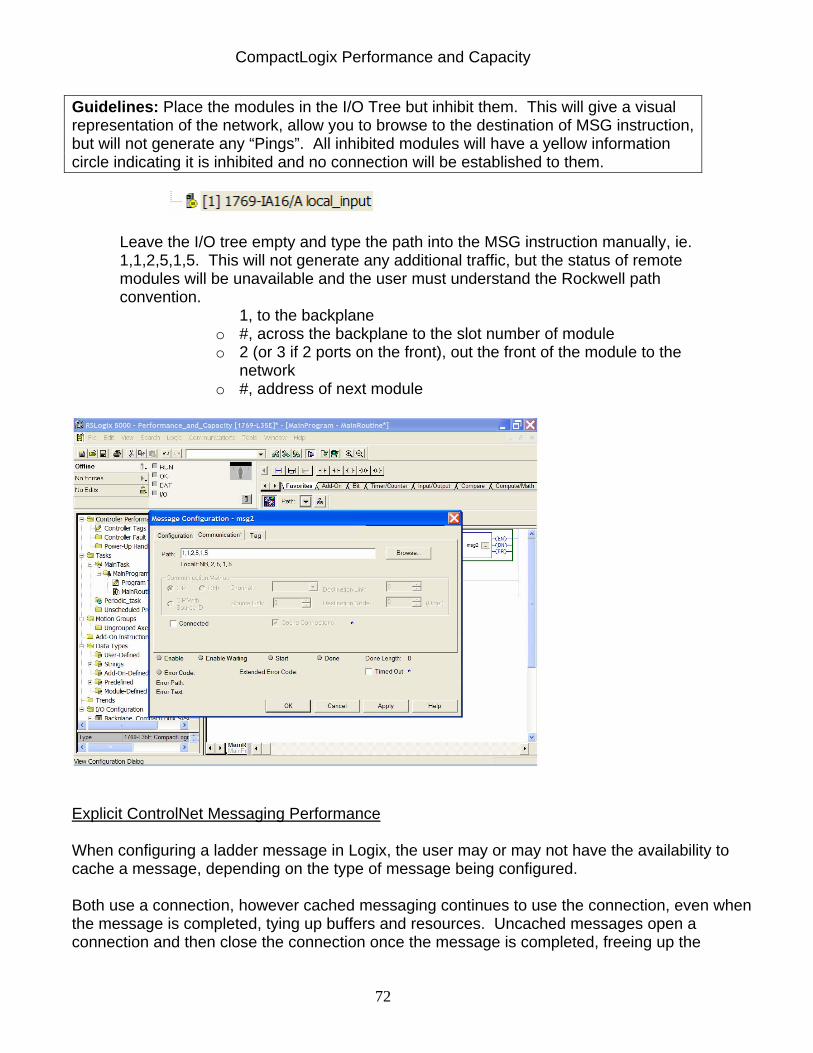
CompactLogix Performance and Capacity
72
Guidelines: Place the modules in the I/O Tree but inhibit them. This will give a visual representation of the network, allow you to browse to the destination of MSG instruction, but will not generate any “Pings”. All inhibited modules will have a yellow information circle indicating it is inhibited and no connection will be established to them.
Leave the I/O tree empty and type the path into the MSG instruction manually, ie. 1,1,2,5,1,5. This will not generate any additional traffic, but the status of remote modules will be unavailable and the user must understand the Rockwell path convention.
1, to the backplane o #, across the backplane to the slot number of module o 2 (or 3 if 2 ports on the front), out the front of the module to the
network o #, address of next module
Explicit ControlNet Messaging Performance When configuring a ladder message in Logix, the user may or may not have the availability to cache a message, depending on the type of message being configured. Both use a connection, however cached messaging continues to use the connection, even when the message is completed, tying up buffers and resources. Uncached messages open a connection and then close the connection once the message is completed, freeing up the
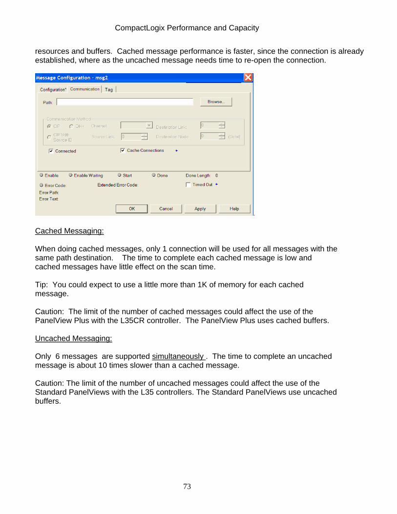
CompactLogix Performance and Capacity
73
resources and buffers. Cached message performance is faster, since the connection is already established, where as the uncached message needs time to re-open the connection.
. Cached Messaging: When doing cached messages, only 1 connection will be used for all messages with the same path destination. The time to complete each cached message is low and cached messages have little effect on the scan time. Tip: You could expect to use a little more than 1K of memory for each cached message. Caution: The limit of the number of cached messages could affect the use of the PanelView Plus with the L35CR controller. The PanelView Plus uses cached buffers. Uncached Messaging: Only 6 messages are supported simultaneously . The time to complete an uncached message is about 10 times slower than a cached message. Caution: The limit of the number of uncached messages could affect the use of the Standard PanelViews with the L35 controllers. The Standard PanelViews use uncached buffers.

CompactLogix Performance and Capacity
74
Test: Effects of Unscheduled Messaging on ControlNet on a 1769-L35CR
Unscheduled ControlNet MSG Performance
0
50
100
150
200
250
6 12 18 24 30
Total Number of Unscheduled MSG's
Tim
e(m
s) cached scan timecached MSG DN Timeuncached scan timeuncached MSG DN time
(The baseline test was used with 1 1769-L35CR and 5 pairs of 1756-L55/1756-CNBR pairs. No scheduled traffic. NUT=5ms. Number of outgoing message buffers was changed ot 40. All modules in I/O tree were inhibited. 30 messages sent to and 30 from CompactLogix to other controllers consisting of 100 element DINT array.)
Test Results: Effects of Unscheduled Messaging on ControlNet on a 1769-L35CR
Total Number of Cached MSG's
executing Program Scan Time
# Cnet Connections
used by Controller
Cnet Port
CPU% Controller
CPU%
Typical MSG DN
Time Memory
Used 6 3-9ms 7 85% 39% 23 155,620
12 3-9 ms 13 98% 44% 35 160,77218 3-9 ms 19 99% 43% 61 168,94024 3-10ms 26 99% 40% 81 177,10830 4-10ms 31 99% 40% 100 185,284

CompactLogix Performance and Capacity
75
Mixing Scheduled ControlNet I/O with Unscheduled Cached Messaging: Scheduled traffic, I/O and Produced/Consumed data, is not affected by addition of unscheduled messaging. Additional unscheduled traffic can be added to scheduled I/O on a network if CNet %CPU port stays below 70% with only scheduled communications first. (You only need to consider the ControlNet Interface CPU utilization. The CompactLogix Processor CPU utilization will NEVER be over taxed ahead of the Interface CPU.) The amount of unscheduled messaging is limited by the number of connections available on the L3x processor and the amount of time needed for the message to complete. Caution: If the CNet Port %CPU was over 70% with scheduled traffic only, as measured in RSLinx, under Module Statistics, then adding additional unscheduled traffic is not likely to be successful. Caution: A maximum of only 6 uncached messages is supported simultaneously, adding schedule data will cause the number to go down.
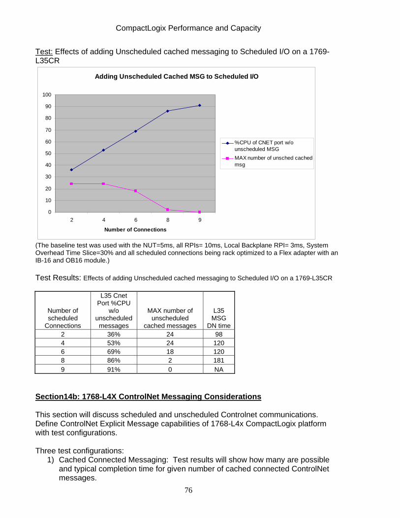
CompactLogix Performance and Capacity
76
Test: Effects of adding Unscheduled cached messaging to Scheduled I/O on a 1769-L35CR
Adding Unscheduled Cached MSG to Scheduled I/O
0
10
20
30
40
50
60
70
80
90
100
2 4 6 8 9
Number of Connections
%CPU of CNET port w/ounscheduled MSGMAX number of unsched cachedmsg
(The baseline test was used with the NUT=5ms, all RPIs= 10ms, Local Backplane RPI= 3ms, System Overhead Time Slice=30% and all scheduled connections being rack optimized to a Flex adapter with an IB-16 and OB16 module.) Test Results: Effects of adding Unscheduled cached messaging to Scheduled I/O on a 1769-L35CR
Number of scheduled
Connections
L35 Cnet Port %CPU
w/o unscheduled
messages
MAX number of unscheduled
cached messages
L35 MSG
DN time2 36% 24 98 4 53% 24 120 6 69% 18 120 8 86% 2 181 9 91% 0 NA
Section14b: 1768-L4X ControlNet Messaging Considerations This section will discuss scheduled and unscheduled Controlnet communications. Define ControlNet Explicit Message capabilities of 1768-L4x CompactLogix platform with test configurations. Three test configurations:
1) Cached Connected Messaging: Test results will show how many are possible and typical completion time for given number of cached connected ControlNet messages.
CompactLogix Performance and Capacity
77
2) Uncached Unconnected Messaging: Test results will show how many are possible and typical completion time for given number of uncached unconnected ControlNet messages.
3) Cached Connected Messaging when I/O over ControlNet also exists: Test results will show how many cached connected messages are possible and typical completion time for given number of cached connected ControlNet Messages when I/O is also present.
Two types of ControlNet communications:
Scheduled: send and receive data repeatedly at a predetermined interval (RPI): Distributed I/O, HMI, Drives, Controller to Controller (Producer/Consumer), all use scheduled connections. Scheduled traffic is GUARANTEED and is not affected by the addition of unscheduled traffic. Unscheduled: messages send and receive data when needed Peer to Peer messaging between controllers with MSG instruction, Controller Programming RSLogix 5000, HMI/RSLinx all use unscheduled connections
Note: HMI devices, like Panelview Plus or FactoryTalk View SE, can be setup to use either scheduled or unscheduled connections or both. When performing only messaging across ControlNet there are Pros and Cons of adding modules into the module configuration. Pros: Provides visual overview of the network Provides status on the
modules of the I/O tree Makes it easier to use a MSG instruction by allowing you to browse to your destination during development
Cons: Network traffic increased because a “Ping” is regularly sent to the destination module. The traffic generated uses unconnected messaging and requires unconnected message buffers on the processor. The “Pings” also consume the ControlNet port’s unconnected buffers
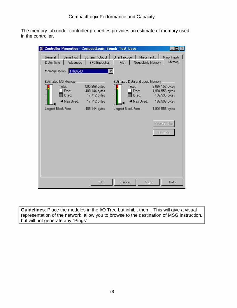
CompactLogix Performance and Capacity
78
The memory tab under controller properties provides an estimate of memory used in the controller.
Guidelines: Place the modules in the I/O Tree but inhibit them. This will give a visual representation of the network, allow you to browse to the destination of MSG instruction, but will not generate any “Pings”
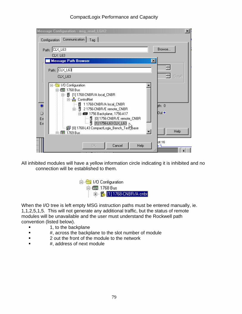
CompactLogix Performance and Capacity
79
All inhibited modules will have a yellow information circle indicating it is inhibited and no connection will be established to them.
When the I/O tree is left empty MSG instruction paths must be entered manually, ie. 1,1,2,5,1,5. This will not generate any additional traffic, but the status of remote modules will be unavailable and the user must understand the Rockwell path convention (listed below).
1, to the backplane #, across the backplane to the slot number of module 2 out the front of the module to the network #, address of next module
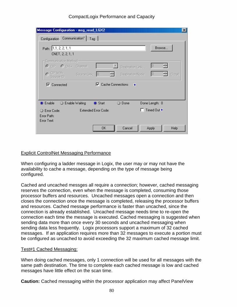
CompactLogix Performance and Capacity
80
Explicit ControlNet Messaging Performance
When configuring a ladder message in Logix, the user may or may not have the availability to cache a message, depending on the type of message being configured.
Cached and uncached messges all require a connection; however, cached messaging reserves the connection, even when the message is completed, consuming those processor buffers and resources. Uncached messages open a connection and then closes the connection once the message is completed, releasing the processor buffers and resources. Cached message performance is faster than uncached, since the connection is already established. Uncached message needs time to re-open the connection each time the message is executed. Cached messaging is suggested when sending data more than once every 30 seconds and uncached messaging when sending data less frequently. Logix processors support a maximum of 32 cached messages. If an application requires more than 32 messages to execute a portion must be configured as uncached to avoid exceeding the 32 maximum cached message limit. Test#1 Cached Messaging:
When doing cached messages, only 1 connection will be used for all messages with the same path destination. The time to complete each cached message is low and cached messages have little effect on the scan time.
Caution: Cached messaging within the processor application may affect PanelView
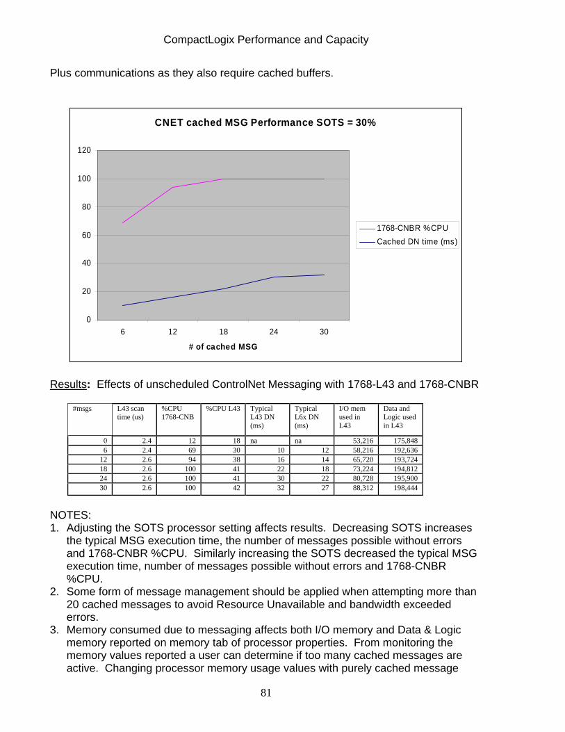
CompactLogix Performance and Capacity
81
Plus communications as they also require cached buffers.
CNET cached MSG Performance SOTS = 30%
0
20
40
60
80
100
120
6 12 18 24 30
# of cached MSG
1768-CNBR %CPUCached DN time (ms)
Results: Effects of unscheduled ControlNet Messaging with 1768-L43 and 1768-CNBR
#msgs L43 scan time (us)
%CPU 1768-CNB
%CPU L43 Typical L43 DN (ms)
Typical L6x DN (ms)
I/O mem used in L43
Data and Logic used in L43
0 2.4 12 18 na na 53,216 175,848 6 2.4 69 30 10 12 58,216 192,636
12 2.6 94 38 16 14 65,720 193,724 18 2.6 100 41 22 18 73,224 194,812 24 2.6 100 41 30 22 80,728 195,900 30 2.6 100 42 32 27 88,312 198,444
NOTES: 1. Adjusting the SOTS processor setting affects results. Decreasing SOTS increases
the typical MSG execution time, the number of messages possible without errors and 1768-CNBR %CPU. Similarly increasing the SOTS decreased the typical MSG execution time, number of messages possible without errors and 1768-CNBR %CPU.
2. Some form of message management should be applied when attempting more than 20 cached messages to avoid Resource Unavailable and bandwidth exceeded errors.
3. Memory consumed due to messaging affects both I/O memory and Data & Logic memory reported on memory tab of processor properties. From monitoring the memory values reported a user can determine if too many cached messages are active. Changing processor memory usage values with purely cached message
CompactLogix Performance and Capacity
82
applications indicate too many cached messages are active. When cached messages are initiated processor memory is reserved and this accounts for the fluctuating processor memory when cached connections must be closed to allow another cached connection to be established.
4. Each cached message will consume approximately 1k of processor Data/Logic memory.
Test#2 Uncached Messaging:
It was only possible to configure six uncached messages prior to errors occurring without message management in place. The time to complete uncached messages is substantially slower cached messages.
Caution: Uncached messaging within the processor application may affect Standard PanelView communication as they require uncached buffers. Results: Effects of Uncached Unconnected CNET Messaging with 1768-L43 with one 1768-CNBR
#msgs L43 scan time (us)
%CPU 1768-CNB
%CPU L43 Typical L43 DN (ms)
Typical L6x DN (ms)
I/O mem used in L43
Data and Logic used in L43
0 2.5 13 18 NA NA 50,712 220,612
6 2.6 99 30 21 21 52,856 220,932
NOTES: 1) There was no significant affect on L43 program scan time or L43 PLC CPU%.
However the 1768-CNB(R) %CPU is dramatically impacted with unscheduled messaging.
2) Some form of message management should be applied when attempting more than two uncached messages to avoid overloading the 1768-CNB as its %CPU is significantly affected by uncached messaging.
3) The time to complete the Unconnected Uncached messaging takes roughly twice as long as the cached messages.
4) With connections opening and closing both I/O and Data & Logic processor memory usage fluctuates.
Test#3 Mixing Scheduled ControlNet I/O with Unscheduled Cached Messaging:
Scheduled traffic, I/O and Produced/Consumed data, is not affected by addition of unscheduled messaging.
Additional unscheduled traffic can be added to scheduled I/O on a network if 1768-CNB(R) %CPU port is less than 70% with only scheduled communications active. The amount of unscheduled messaging is limited by the number of connections available on the 1768-L43 processor and 1768-CNB(R) module as well as the %CPU of the 1768-CNB(R) module.
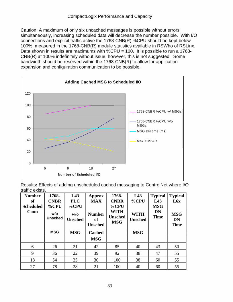
CompactLogix Performance and Capacity
83
Caution: A maximum of only six uncached messages is possible without errors simultaneously, increasing scheduled data will decrease the number possible. With I/O connections and explicit traffic active the 1768-CNB(R) %CPU should be kept below 100%, measured in the 1768-CNB(R) module statistics available in RSWho of RSLinx. Data shown in results are maximums with %CPU = 100. It is possible to run a 1768-CNB(R) at 100% indefinitely without issue; however, this is not suggested. Some bandwidth should be reserved within the 1768-CNB(R) to allow for application expansion and configuration communication to be possible.
Adding Cached MSG to Scheduled I/O
0
20
40
60
80
100
120
6 9 18 27
Number of Scheduled I/O
1768-CNBR %CPU w/ MSGs
1768-CNBR %CPU w/oMSGsMSG DN time (ms)
Max # MSGs
Results: Effects of adding unscheduled cached messaging to ControlNet where I/O traffic exists.
1768-CNBR %CPU
L43 PLC
%CPU
Approx MAX
L43 %CPU
Typical L6x
w/o Unsched
w/o Unsched
Number of
Unsched
WITH Unsched
MSG DN
Time MSG MSG Cached MSG
Number of
Scheduled Conn
MSG
1768-CNBR %CPU WITH
Unsched MSG
Typical L43
MSG DN
Time
6 26 21 42 85 40 43 50 9 36 22 39 92 38 47 55 18 54 25 30 100 38 60 55 27 78 28 21 100 40 60 55
CompactLogix Performance and Capacity
84
When performing explicit messaging, ie. ladder MSG instructions, choose:
Cached messaging when sending data more than once every 30 sec. or when communicating to a PanelView Plus Uncached when sending data infrequently, or when communicating to a Standard Panelview
Up to 30 simultaneous cached messages and 6 simultaneous uncached messages are supported by CompactLogix.
Scheduled traffic, I/O and Produced/Consumed data, is not affected by addition of unscheduled messaging. However, the number of explicit cached messages decreases as the number of ControlNet I/O connections increases.
CompactLogix Performance and Capacity
85
Section 15: Bridging Through a CompactLogix Controller The following recommendations apply to both the 1769-L3X and 1768-L4X families of CompactLogix processors. However, when using the 1768-L4X in a bridging application, make sure the controller is at revision V16.03 or later.
Recommended:
1) ControlNet to DeviceNet via the 1769-SDN. (For DeviceNet configuration only,
not data collection.) 2) EtherNet/IP to DeviceNet via the 1769-SDN. (For configuration only, not data
collection.) 3) Serial to DeviceNet via the 1769-SDN (For configuration only, not data
collection.)
NOTE: issues may exist in accessing DeviceNet network with bridged connection when explicit messaging is present in application.
Not Recommended:
1) Serial to ControlNet a. DO NOT configure ControlNet with RSNetworx for ControlNet by bridging through the serial port of the CompactLogix controller. a. DO NOT use this path to go online to other controllers
2) Serial to Ethernet a. DO NOT configure EtherNet/IP by bridging through the serial port of
the CompactLogix controller. b. DO NOT use this path to go online to other controllers
3) Serial to DeviceNet a. Bridging via this route is only recommended for simple tasks like
browsing DeviceNet or monitoring a single node via DeviceNet.
CompactLogix Performance and Capacity
86
Considerations when messaging in a bridging application
Keep these considerations in mind when developing an application that will have either bridged messages through the CompactLogix controller or messages that originate from the CompactLogix controller to the DeviceNet network.
The controller properly handles simultaneous messaging from message instructions and bridging messages from an EtherNet/IP or ControlNet connection. For example, RSLinx or RSNetWorx software bridging through the 1769-SDN to configure a device on a DeviceNet network.
The 1768-L43 and 1768-L45 controllers support as many as eight simultaneous messages to the CompactBus I/O subsystem and as many as four simultaneous messages to any one module in the Compact I/O configuration.
Write code to monitor for failed message delivery and to properly handle retries.
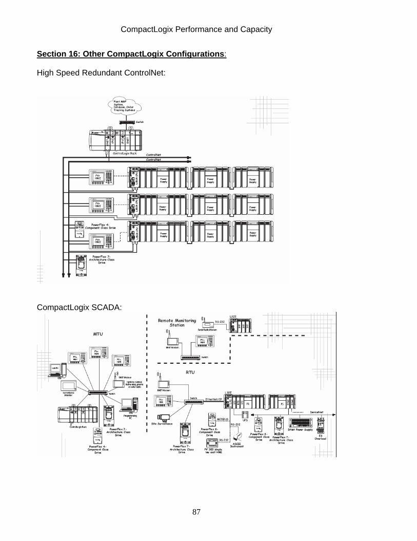
CompactLogix Performance and Capacity
87
Section 16: Other CompactLogix Configurations: High Speed Redundant ControlNet:
CompactLogix SCADA:
CompactLogix Performance and Capacity
88
Section 17: Comparing the CompactLogix L3X, CompactLogix L4X, and ControlLogix Families Many features and capabilities are shared in the Logix family of controllers. However, differences in hardware and firmware exist that can affect performance. This section describes the similarities and differences between the CompactLogix L3X, CompactLogix L4X, and the ControlLogix (1756-L6X) platforms.
• Similarities of L3X to L4X – Same “rackless” design – Native 1769 I/O with the same rules – Removal and Insertion Under Power not supported – Removable Media: Both have CompactFlash support – No support for DH+ or RIO legacy networks – Event task Module Input Data State Change trigger not supported
• Differences of L3X to L4X – L4x has two processors: one dedicated to application the other for I/O; L3x
has one processor to handle application and I/O – More processor memory available – Motion control support of L4x is not available in L3x platform. – The L3x uses a battery and the L4x has a special power supply that
negates the need for a battery. – RPI values for 1769 modules can be individually configured with the L4X;
with the L3x solution there is one common CompactBus RPI setting. Adding I/O modules at a given RPI has less of an impact on %CPU with the L4X family than the L3X family.
– L3x platform handles I/O updates as a prioritized task whereas the L4x handles them with a dedicated piece of hardware for all backplane communications. You need to consider this when setting the priority levels of Periodic tasks in the L3X, whereas it is not an issue in the L4X.
• Similarities of L4X to L6X
– Separate hardware dedicated for main processing duties and backplane communications.
– Communication module flexibility for EtherNet/IP and ControlNet expansion
– Memory: Both have the same physical amount of SDRAM and Flash – Removable Media: Both have CompactFlash support – NonVolatile Memory: Both have NAND Flash to hold program/data during
power down – I/O supports individually configured RPI values. – Motion support available – Motion event triggers supported for Event task

CompactLogix Performance and Capacity
89
• Differences of L4X to L6X – The L6x uses a battery and the L4x has a special power supply that
negates the need for a battery. – Removal and Insertion Under Power (RIUP): L4x platform does not
support this feature. – Chassis: The L4x has a “rackless” design L6x has a chassis in which
modules reside. – L4x does not offer DH+ or RIO connectivity – Event task Module Input Data State Change trigger not supported
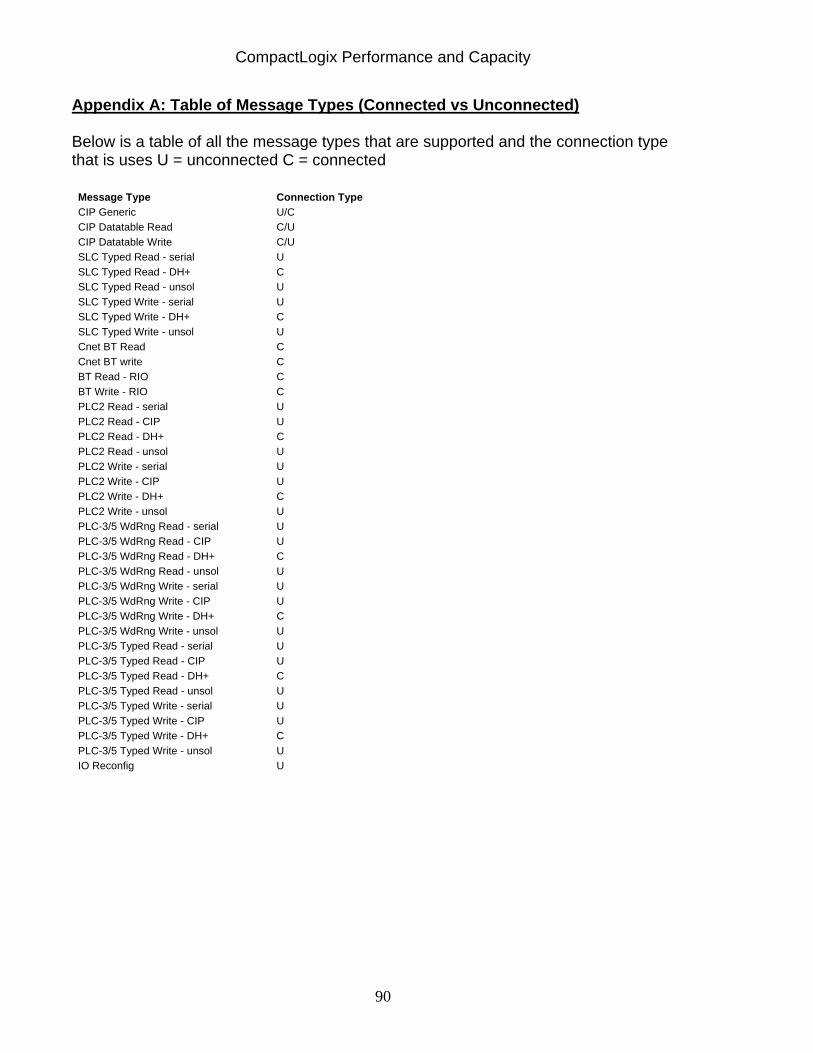
CompactLogix Performance and Capacity
90
Appendix A: Table of Message Types (Connected vs Unconnected) Below is a table of all the message types that are supported and the connection type that is uses U = unconnected C = connected
Message Type Connection Type CIP Generic U/C CIP Datatable Read C/U CIP Datatable Write C/U SLC Typed Read - serial U SLC Typed Read - DH+ C SLC Typed Read - unsol U SLC Typed Write - serial U SLC Typed Write - DH+ C SLC Typed Write - unsol U Cnet BT Read C Cnet BT write C BT Read - RIO C BT Write - RIO C PLC2 Read - serial U PLC2 Read - CIP U PLC2 Read - DH+ C PLC2 Read - unsol U PLC2 Write - serial U PLC2 Write - CIP U PLC2 Write - DH+ C PLC2 Write - unsol U PLC-3/5 WdRng Read - serial U PLC-3/5 WdRng Read - CIP U PLC-3/5 WdRng Read - DH+ C PLC-3/5 WdRng Read - unsol U PLC-3/5 WdRng Write - serial U PLC-3/5 WdRng Write - CIP U PLC-3/5 WdRng Write - DH+ C PLC-3/5 WdRng Write - unsol U PLC-3/5 Typed Read - serial U PLC-3/5 Typed Read - CIP U PLC-3/5 Typed Read - DH+ C PLC-3/5 Typed Read - unsol U PLC-3/5 Typed Write - serial U PLC-3/5 Typed Write - CIP U PLC-3/5 Typed Write - DH+ C PLC-3/5 Typed Write - unsol U IO Reconfig U
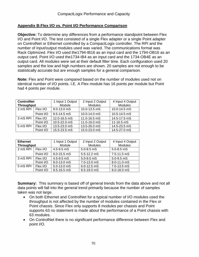
CompactLogix Performance and Capacity
91
Appendix B:Flex I/O vs. Point I/O Performance Comparison Objective: To determine any differences from a performance standpoint between Flex I/O and Point I/O. The test consisted of a single Flex adapter or a single Point adapter on ControlNet or Ethernet controlled by a CompactLogix controller. The RPI and the number of input/output modules used was varied. The communications format was Rack Optimized. Flex I/O used the1794-IB16 as an input card and the 1794-OB16 as an output card. Point I/O used the1734-IB4 as an input card and the 1734-OB4E as an output card. All modules were set at their default filter time. Each configuration used 20 samples and the low and high numbers are shown. 20 samples are not enough to be statistically accurate but are enough samples for a general comparison. Note: Flex and Point were compared based on the number of modules used not on identical number of I/O points. I.E. A Flex module has 16 points per module but Point had 4 points per module. ControlNet Throughput
1 Input 1 Output Module
2 Input 2 Output Modules
4 Input 4 Output Modules
Flex I/O 9.0-13.0 mS 10.0-13.5 mS 10.0-14.5 mS 2 mS RPI Point I/O 9.5-14.5 mS 10.0-14.0 mS 10.5-14.5 mS Flex I/O 12.0-16.5 mS 11.0-16.5 mS 14.5-17.5 mS 3 mS RPI Point I/O 10.5-22.0 mS 11.0-16.0 mS 11-16.5 mS Flex I/O 13.5-23.0 mS 13.5-26.0 mS 14.5-23.5 mS 5 mS RPI Point I/O 15.5-23.5 mS 15.0-23.0 mS 14.5-27.0 mS
Ethernet Throughput
1 Input 1 Output Module
2 Input 2 Output Modules
4 Input 4 Output Modules
Flex I/O 4.5-9.5 mS 5.0-8.5 mS 5.0-8.5 mS 2 mS RPI Point I/O 8.0-15.5 mS 5.5-12.2 mS 7.5-11.5 mS Flex I/O 4.5-9.5 mS 5.0-9.0 mS 5.0-9.5 mS 3 mS RPI Point I/O 8.0-13.0 mS 7.0-13.0 mS 8.0-11.0 mS Flex I/O 5.0-13.0 mS 6.0-12.5 mS 7.0-13.5 mS 5 mS RPI Point I/O 8.5-16.5 mS 8.5-19.0 mS 8.0-18.0 mS
Summary: This summary is based off of general trends from the data above and not all data points will fall into the general trend primarily because the number of samples taken was not large.
• On both Ethernet and ControlNet for a typical number of I/O modules used the throughput is not affected by the number of modules contained in the Flex or Point chassis. Since Flex only supports 8 modules per chassis and Point supports 63 no statement is made about the performance of a Point chassis with 63 modules.
• On ControlNet there is no significant performance difference between Flex and point I/O.

CompactLogix Performance and Capacity
92
www.rockwellautomation.com
ACIG – Logix Americas: Rockwell Automation, 1201 South Second Street, Milwaukee, WI 53204-2496 USA, Tel: (1) 414.382.2000, Fax: (1) 414.382.4444 Europe/Middle East/Africa: Rockwell Automation SA/NV, Vorstlaan/Boulevard du Souverain 36, 1170 Brussels, Belgium, Tel: (32) 2 663 0600, Fax: (32) 2 663 0640 Asia Pacific: Rockwell Automation, Level 14, Core F, Cyberport 3, 100 Cyberport Road, Hong Kong, Tel: (852) 2887 4788, Fax: (852) 2508 1846
Publication Number IASIMP-QR007B-EN-P – 3/09 Copyright © 2009 Rockwell Automation, Inc All Rights Reserved. Printed in USA