Embed Size (px)
Citation preview
Online version is available on http://research.guilan.ac.ir/cmce
Comp. Meth. Civil Eng., Vol. 3, 2 (2012) 15-28©Copyright by the University of Guilan, Printed in I.R. Iran
Composite piled raft foundation with intermediate cushion in layered soilunder seismic forces
V.J.Sharmaa, S.A.Vasanvalab, C.H.Solankic
Applied Mechanics Department, Sardar Vallabhai National Institute of Technology, Ichchhanath,Surat-395007, Gujarat, India
Received 5 November 2012; accepted in revised form 20 April 2013 31 March 2012
AbstractIn order to mobilize shallow soil to participate in the interaction of piled raft foundation sufficiently, the
concept of piled raft has been modified to new type of foundation named composite piled raft. In the system ofcomposite piled raft, the short piles made of flexible materials is used to strengthen the shallow soft soil, whilethe long piles made of relatively rigid materials is used to reduce the settlements and the cushion beneath the raftis used to redistribute and adjust the stress ratio of piles to subsoil. Finite element method is applied to study thebehaviour of this new type of foundation subjected to seismic forces. This paper focuses on behaviour of variouscomponents of foundation system such as long pile, short piles and subsoil under seismic force (T2-I-2(1995,HYOUGOKEN_South, EW)) in layered soil related to Surat city geological condition. A comparative study isdone to understand the effect of cushion on axial stresses, shear stresses and shear forces along piles and soilbeneath the raft.
Keywords: Piles, Raft, Foundation, Analysis.
1. Introduction
In traditional foundation design, it is customary to consider first the use of shallowfoundation such as a raft (possibly after some ground-improvement methodology performed).If it is not adequate, deep foundation such as a fully piled foundation is used instead. In theformer, it is assumed that load of superstructure is transmitted to the underlying grounddirectly by the raft. In the latter, the entire design loads are assumed to be carried by the piles.In recent decades, another alternative intermediate between shallow and deep foundation,what is called piled raft foundation or settlement reducing piles foundation, has beenrecognized by civil engineers. The concept of piled raft foundation was firstly proposed byDavis and Poulos [2], since then it has been described by many authors, including Burland etal. [3], Cooke [4], Chow [5], Randolph [6], Horikoshi and Randolph [7], Ta and Small [8],Kim et al. [9], Poulos [1], and many others . Now the piled raft concept has been usedextensively in Europe and Asia. In this concept, piles are provided to control settlement ratherthan carry the entire load. Piled raft foundation has been proved to be an economical way to
Corresponding author.E-mail address: [email protected]
CMCEComputational Methods in Civil Engineering
V.J. Sharma, S.A. Vasanvala, C.H. Solanki / Comp. Meth. Civil Eng., Vol. 3, 2 (2012) 15-28
16
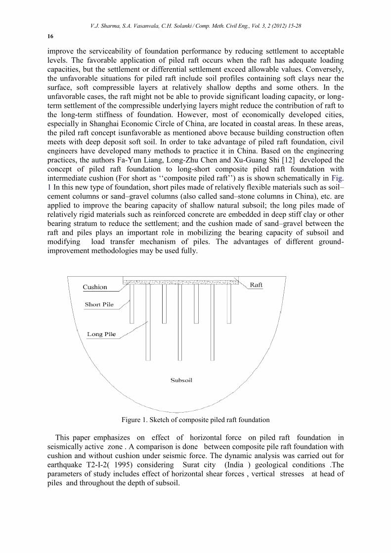
improve the serviceability of foundation performance by reducing settlement to acceptablelevels. The favorable application of piled raft occurs when the raft has adequate loadingcapacities, but the settlement or differential settlement exceed allowable values. Conversely,the unfavorable situations for piled raft include soil profiles containing soft clays near thesurface, soft compressible layers at relatively shallow depths and some others. In theunfavorable cases, the raft might not be able to provide significant loading capacity, or long-term settlement of the compressible underlying layers might reduce the contribution of raft tothe long-term stiffness of foundation. However, most of economically developed cities,especially in Shanghai Economic Circle of China, are located in coastal areas. In these areas,the piled raft concept isunfavorable as mentioned above because building construction oftenmeets with deep deposit soft soil. In order to take advantage of piled raft foundation, civilengineers have developed many methods to practice it in China. Based on the engineeringpractices, the authors Fa-Yun Liang, Long-Zhu Chen and Xu-Guang Shi [12] developed theconcept of piled raft foundation to long-short composite piled raft foundation withintermediate cushion (For short as ‘‘composite piled raft’’) as is shown schematically in Fig.1 In this new type of foundation, short piles made of relatively flexible materials such as soil–cement columns or sand–gravel columns (also called sand–stone columns in China), etc. areapplied to improve the bearing capacity of shallow natural subsoil; the long piles made ofrelatively rigid materials such as reinforced concrete are embedded in deep stiff clay or otherbearing stratum to reduce the settlement; and the cushion made of sand–gravel between theraft and piles plays an important role in mobilizing the bearing capacity of subsoil andmodifying load transfer mechanism of piles. The advantages of different ground-improvement methodologies may be used fully.
Figure 1. Sketch of composite piled raft foundation
This paper emphasizes on effect of horizontal force on piled raft foundation inseismically active zone . A comparison is done between composite pile raft foundation withcushion and without cushion under seismic force. The dynamic analysis was carried out forearthquake T2-I-2( 1995) considering Surat city (India ) geological conditions .Theparameters of study includes effect of horizontal shear forces , vertical stresses at head ofpiles and throughout the depth of subsoil.
V.J. Sharma, S.A. Vasanvala, C.H. Solanki / Comp. Meth. Civil Eng., Vol. 3, 2 (2012) 15-28
17
2. Method
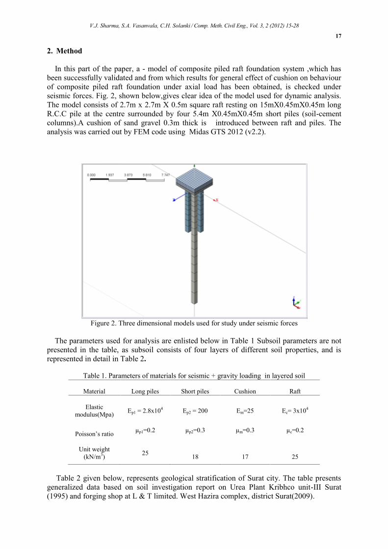
In this part of the paper, a - model of composite piled raft foundation system ,which hasbeen successfully validated and from which results for general effect of cushion on behaviourof composite piled raft foundation under axial load has been obtained, is checked underseismic forces. Fig. 2, shown below,gives clear idea of the model used for dynamic analysis.The model consists of 2.7m x 2.7m X 0.5m square raft resting on 15mX0.45mX0.45m longR.C.C pile at the centre surrounded by four 5.4m X0.45mX0.45m short piles (soil-cementcolumns).A cushion of sand gravel 0.3m thick is introduced between raft and piles. Theanalysis was carried out by FEM code using Midas GTS 2012 (v2.2).
Figure 2. Three dimensional models used for study under seismic forces
The parameters used for analysis are enlisted below in Table 1 Subsoil parameters are notpresented in the table, as subsoil consists of four layers of different soil properties, and isrepresented in detail in Table 2.
Table 1. Parameters of materials for seismic + gravity loading in layered soil
Material Long piles Short piles Cushion Raft
Elasticmodulus(Mpa) Ep1 = 2.8x10⁴ Ep2 = 200 Em=25 Ec= 3x10⁴
Poisson’s ratio µp1=0.2 µp2=0.3 µm=0.3 µc=0.2
Unit weight(kN/m3) 25 18 17 25
Table 2 given below, represents geological stratification of Surat city. The table presentsgeneralized data based on soil investigation report on Urea Plant Kribhco unit-III Surat(1995) and forging shop at L & T limited. West Hazira complex, district Surat(2009).
V.J. Sharma, S.A. Vasanvala, C.H. Solanki / Comp. Meth. Civil Eng., Vol. 3, 2 (2012) 15-28
18
The water table is encountered at 8-10m depth below ground level.
Table 2. Properties of stratified soil (Surat City)
Soil type Depth (m)Elastic
modulus(MPa) Poisson’s ratioUnit weight
(kN/m3)Clayey Soil(CH or CL) 0-5 5 0.40 14.0
Silty Sand (SM) 5-10 40 0.35 15.5Medium to fine wellgraded sand (SW) 10-17 50 0.35 17.0
Highly plastic clay(CH) 17-45 45 0.35 16.5
Before carrying out Time history analysis, eigen value analysis was done using MidasGTS tutorial. Sub grade reactions coefficients were calculated both in horizontal and verticaldirections. Only horizontal sub grade reactions coefficients are calculated for upper threelayers and applied along lateral boundary in both X and Y –direction. Both vertical reactioncoefficients and horizontal reaction coefficients are obtained for bottommost layer and areapplied along lateral and bottom boundary. The formulae used for the calculations of thehorizontal and vertical reaction coefficients were as follow:Vertical reaction coefficients: Kv =Kvo *(Bv/30)-3/4 (kgf/cm3) (1)Horizontal reaction coefficients: Kh = Kho *(Bh/30)-3/4 (kgf/cm3) (2)Here, Kvo =α Eo/30 =Kho , Bv = , Bh = (3)where α is scalar parameter depends on types of test conducted to find Eo.Av is area for which vertical reaction coefficient was calculated.Ah is area for which horizontal reaction coefficient was calculated.
The values of Kh and kv calculated from equations (1), (2) and ( 3) for different layers forno cushion case are tabulated below:
Table 3. Kv and Kh values for no cushion case.Soil layers Horizontal reaction coeff.(Kh)
(kN/m3)Vertical reaction coeff.(Kv)
(kN/m3)
Layer 1 1612.0 ----------
Layer 2 12645.0 ----------Layer 3 14850.5 ---------Layer 4 7607.3 5885.3
The horizontal reaction coefficient was applied along the vertical boundary of themodel whereas the vertical reaction coefficient was applied at the base of the model assurface springs and Eigen value analysis was carried out. There are no major changes incase of cushion except for Kh value in upper layer as cushion is introduced between piles andraft in upper subsoil layer. The value of Kh becomes 1578.1 KN/m3 whereas rest remains thesame.After Eigen value analysis dampers were applied to the model for which followingdamper calculation was done.About P-wave, C = ( + 2 ) (4)
S-wave, = ∗ (5)Here, λ = ν* E / (1+ν) (1-2ν) (6)
G= E/ (1+2ν) (7)
where λ =Volumetric elastic Modulus (tonf/m2)G= Shear Modulus (tonf/m2)E= Elastic Modulusν= Poisson’s ratio
V.J. Sharma, S.A. Vasanvala, C.H. Solanki / Comp. Meth. Civil Eng., Vol. 3, 2 (2012) 15-28
19
A= Cross -section area.
Using equations (4), (5), (6) and (7) dampers are calculated for different soil layers andapplied along lateral boundaries for upper three layers. For bottommost layer the dampers areapplied along lateral and bottom boundary as well. The values for damper calculation atdifferent soil layers are tabulated below.
Table 4. Cp and Cs values from damper calculationSoil layers Cp
(kNs/m)Cs
(kNs/m)
Layer 1 123.65 50.48
Layer 2 318.5 153.0Layer 3 372.8 179.1Layer 4 348.4 167.3
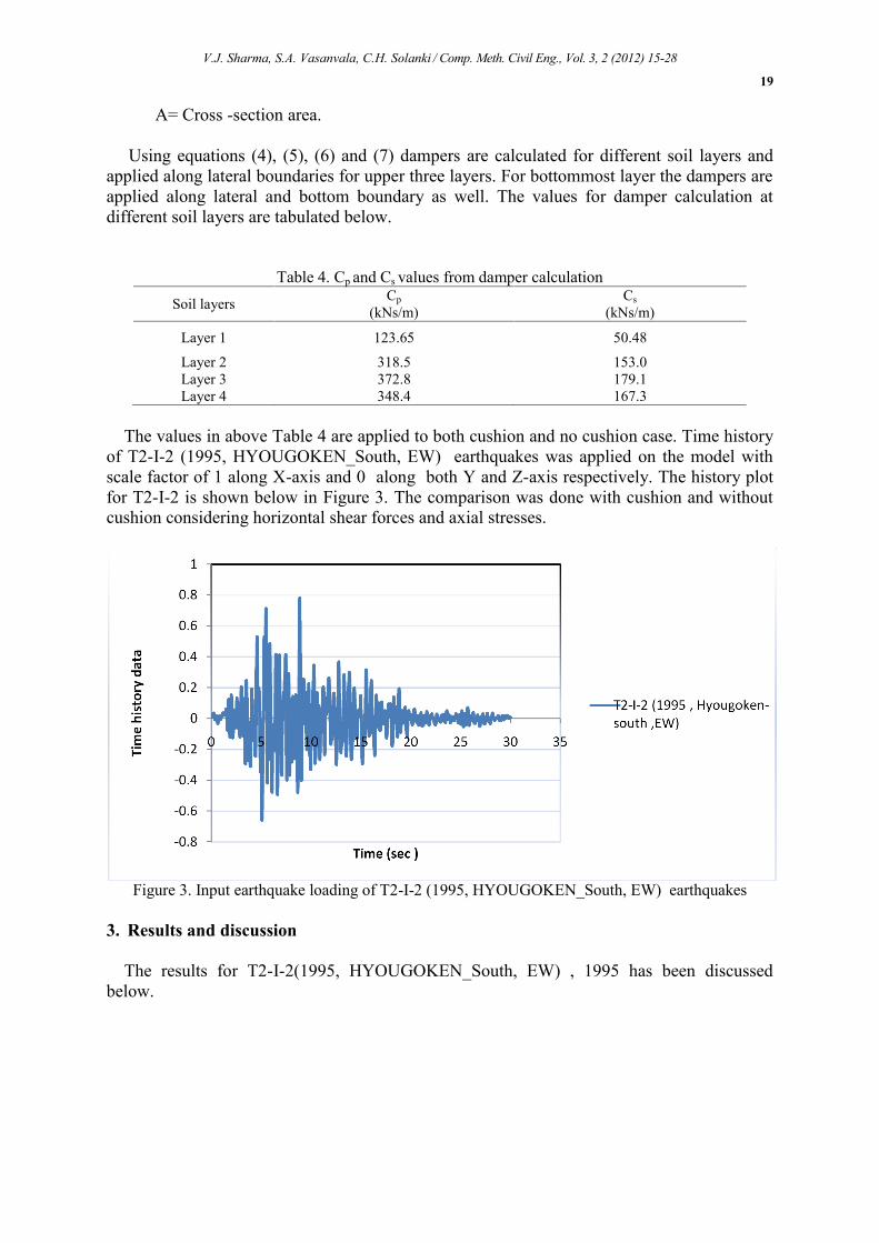
The values in above Table 4 are applied to both cushion and no cushion case. Time historyof T2-I-2 (1995, HYOUGOKEN_South, EW) earthquakes was applied on the model withscale factor of 1 along X-axis and 0 along both Y and Z-axis respectively. The history plotfor T2-I-2 is shown below in Figure 3. The comparison was done with cushion and withoutcushion considering horizontal shear forces and axial stresses.
Figure 3. Input earthquake loading of T2-I-2 (1995, HYOUGOKEN_South, EW) earthquakes
3. Results and discussion
The results for T2-I-2(1995, HYOUGOKEN_South, EW) , 1995 has been discussedbelow.
-0.8
-0.6
-0.4
-0.2
0
0.2
0.4
0.6
0.8
1
0 5 10 15 20 25 30 35
Tim
e hi
stor
y da
ta
Time (sec )
T2-I-2 (1995 , Hyougoken-south ,EW)
V.J. Sharma, S.A. Vasanvala, C.H. Solanki / Comp. Meth. Civil Eng., Vol. 3, 2 (2012) 15-28
20
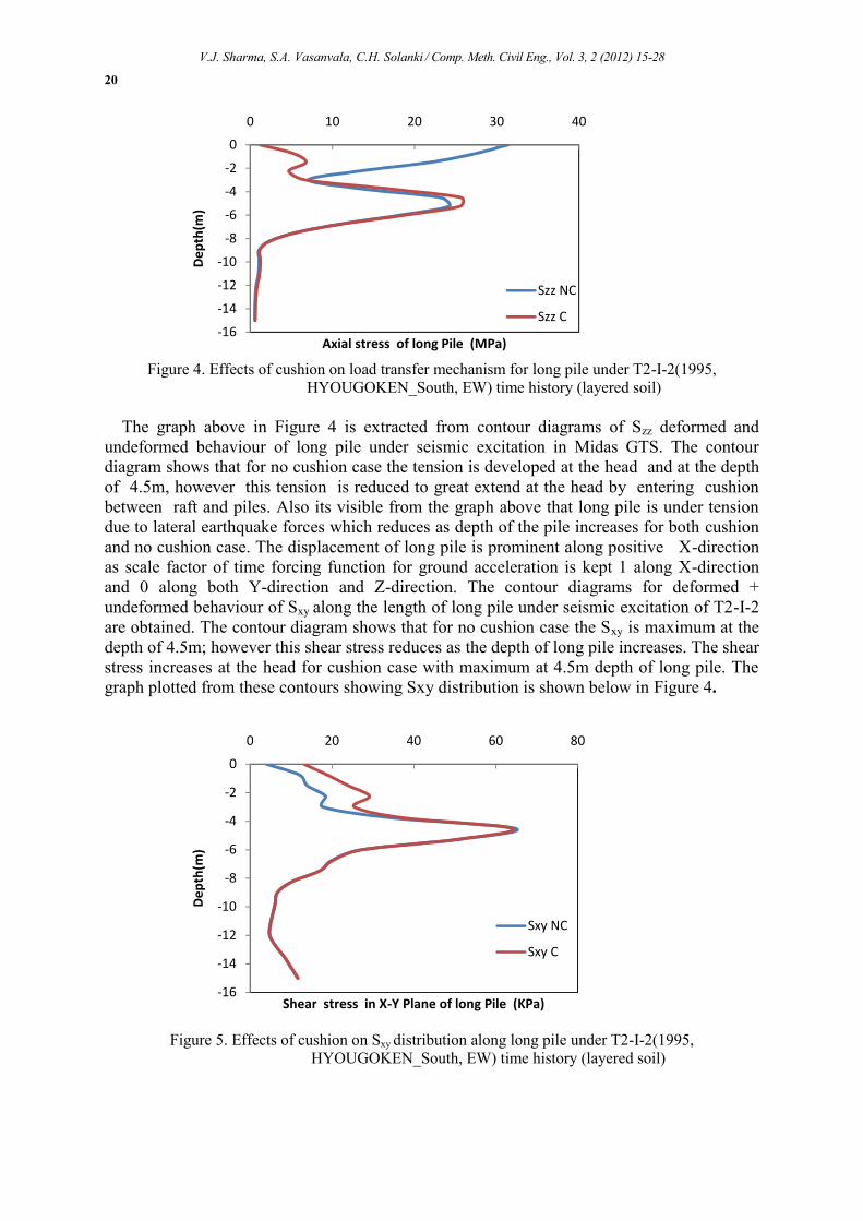
Figure 4. Effects of cushion on load transfer mechanism for long pile under T2-I-2(1995,HYOUGOKEN_South, EW) time history (layered soil)
The graph above in Figure 4 is extracted from contour diagrams of Szz deformed andundeformed behaviour of long pile under seismic excitation in Midas GTS. The contourdiagram shows that for no cushion case the tension is developed at the head and at the depthof 4.5m, however this tension is reduced to great extend at the head by entering cushionbetween raft and piles. Also its visible from the graph above that long pile is under tensiondue to lateral earthquake forces which reduces as depth of the pile increases for both cushionand no cushion case. The displacement of long pile is prominent along positive X-directionas scale factor of time forcing function for ground acceleration is kept 1 along X-directionand 0 along both Y-direction and Z-direction. The contour diagrams for deformed +undeformed behaviour of Sxy along the length of long pile under seismic excitation of T2-I-2are obtained. The contour diagram shows that for no cushion case the Sxy is maximum at thedepth of 4.5m; however this shear stress reduces as the depth of long pile increases. The shearstress increases at the head for cushion case with maximum at 4.5m depth of long pile. Thegraph plotted from these contours showing Sxy distribution is shown below in Figure 4.
Figure 5. Effects of cushion on Sxy distribution along long pile under T2-I-2(1995,HYOUGOKEN_South, EW) time history (layered soil)
-16
-14
-12
-10
-8
-6
-4
-2
0
0 10 20 30 40
Dep
th(m
)
Axial stress of long Pile (MPa)
Szz NC
Szz C
-16
-14
-12
-10
-8
-6
-4
-2
0
0 20 40 60 80
Dep
th(m
)
Shear stress in X-Y Plane of long Pile (KPa)
Sxy NC
Sxy C
V.J. Sharma, S.A. Vasanvala, C.H. Solanki / Comp. Meth. Civil Eng., Vol. 3, 2 (2012) 15-28
21
It is clear from the graph in Figure 5 that Sxy beyond 4.5 m reduces along the depth of pilewith slight increase at the bottom.
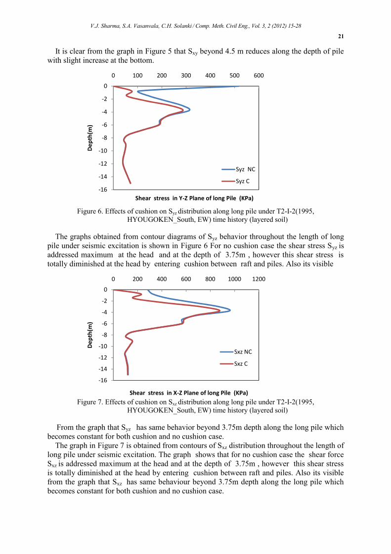
Figure 6. Effects of cushion on Syz distribution along long pile under T2-I-2(1995,HYOUGOKEN_South, EW) time history (layered soil)
The graphs obtained from contour diagrams of Syz behavior throughout the length of longpile under seismic excitation is shown in Figure 6 For no cushion case the shear stress Syz isaddressed maximum at the head and at the depth of 3.75m , however this shear stress istotally diminished at the head by entering cushion between raft and piles. Also its visible
Figure 7. Effects of cushion on Sxz distribution along long pile under T2-I-2(1995,HYOUGOKEN_South, EW) time history (layered soil)
From the graph that Syz has same behavior beyond 3.75m depth along the long pile whichbecomes constant for both cushion and no cushion case.
The graph in Figure 7 is obtained from contours of Sxz distribution throughout the length oflong pile under seismic excitation. The graph shows that for no cushion case the shear forceSxz is addressed maximum at the head and at the depth of 3.75m , however this shear stressis totally diminished at the head by entering cushion between raft and piles. Also its visiblefrom the graph that Sxz has same behaviour beyond 3.75m depth along the long pile whichbecomes constant for both cushion and no cushion case.
-16
-14
-12
-10
-8
-6
-4
-2
0
0 100 200 300 400 500 600
Dep
th(m
)
Shear stress in Y-Z Plane of long Pile (KPa)
Syz NC
Syz C
-16
-14
-12
-10
-8
-6
-4
-2
0
0 200 400 600 800 1000 1200
Dep
th(m
)
Shear stress in X-Z Plane of long Pile (KPa)
Sxz NC
Sxz C
V.J. Sharma, S.A. Vasanvala, C.H. Solanki / Comp. Meth. Civil Eng., Vol. 3, 2 (2012) 15-28
22
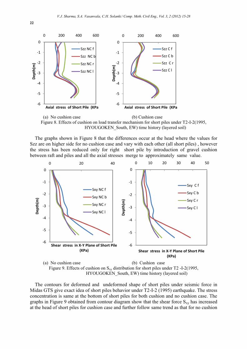
(a) No cushion case (b) Cushion caseFigure 8. Effects of cushion on load transfer mechanism for short piles under T2-I-2(1995,
HYOUGOKEN_South, EW) time history (layered soil)
The graphs shown in Figure 8 that the differences occur at the head where the values forSzz are on higher side for no cushion case and vary with each other (all short piles) , howeverthe stress has been reduced only for right short pile by introduction of gravel cushionbetween raft and piles and all the axial stresses merge to approximately same value.
(a) No cushion case (b) Cushion caseFigure 9. Effects of cushion on Sxy distribution for short piles under T2 -I-2(1995,
HYOUGOKEN_South, EW) time history (layered soil)
The contours for deformed and undeformed shape of short piles under seismic force inMidas GTS give exact idea of short piles behavior under T2-I-2 (1995) earthquake. The stressconcentration is same at the bottom of short piles for both cushion and no cushion case. Thegraphs in Figure 9 obtained from contour diagram show that the shear force Sxy has increasedat the head of short piles for cushion case and further follow same trend as that for no cushion
-6
-5
-4
-3
-2
-1
0
0 200 400 600D
epth
(m)
Axial stress of Short Pile (KPa
Szz NC f
Szz NC b
Szz NC r
Szz NC l
-6
-5
-4
-3
-2
-1
0
0 200 400 600
Dep
th(m
)Axial stress of Short Pile (KPa
Szz C f
Szz C b
Szz C r
Szz C l
-6
-5
-4
-3
-2
-1
0
0 20 40
Dep
th(m
)
Shear stress in X-Y Plane of Short Pile(KPa)
Sxy NC f
Sxy NC b
Sxy NC r
Sxy NC l
-6
-5
-4
-3
-2
-1
0
0 10 20 30 40 50
Dep
th(m
)
Shear stress in X-Y Plane of Short Pile(KPa)
Sxy C f
Sxy C b
Sxy C r
Sxy C l
V.J. Sharma, S.A. Vasanvala, C.H. Solanki / Comp. Meth. Civil Eng., Vol. 3, 2 (2012) 15-28
23
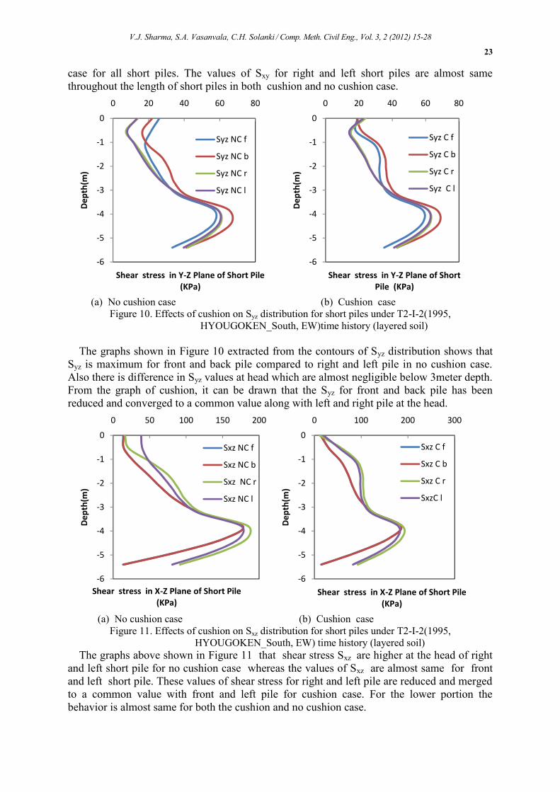
case for all short piles. The values of Sxy for right and left short piles are almost samethroughout the length of short piles in both cushion and no cushion case.
(a) No cushion case (b) Cushion caseFigure 10. Effects of cushion on Syz distribution for short piles under T2-I-2(1995,
HYOUGOKEN_South, EW)time history (layered soil)
The graphs shown in Figure 10 extracted from the contours of Syz distribution shows thatSyz is maximum for front and back pile compared to right and left pile in no cushion case.Also there is difference in Syz values at head which are almost negligible below 3meter depth.From the graph of cushion, it can be drawn that the Syz for front and back pile has beenreduced and converged to a common value along with left and right pile at the head.
(a) No cushion case (b) Cushion caseFigure 11. Effects of cushion on Sxz distribution for short piles under T2-I-2(1995,
HYOUGOKEN_South, EW) time history (layered soil)The graphs above shown in Figure 11 that shear stress Sxz are higher at the head of right
and left short pile for no cushion case whereas the values of Sxz are almost same for frontand left short pile. These values of shear stress for right and left pile are reduced and mergedto a common value with front and left pile for cushion case. For the lower portion thebehavior is almost same for both the cushion and no cushion case.
-6
-5
-4
-3
-2
-1
0
0 20 40 60 80
Dep
th(m
)
Shear stress in Y-Z Plane of Short Pile(KPa)
Syz NC f
Syz NC b
Syz NC r
Syz NC l
-6
-5
-4
-3
-2
-1
0
0 20 40 60 80
Dep
th(m
)
Shear stress in Y-Z Plane of ShortPile (KPa)
Syz C f
Syz C b
Syz C r
Syz C l
-6
-5
-4
-3
-2
-1
0
0 50 100 150 200
Dep
th(m
)
Shear stress in X-Z Plane of Short Pile(KPa)
Sxz NC f
Sxz NC b
Sxz NC r
Sxz NC l
-6
-5
-4
-3
-2
-1
0
0 100 200 300
Dep
th(m
)
Shear stress in X-Z Plane of Short Pile(KPa)
Sxz C f
Sxz C b
Sxz C r
SxzC l
V.J. Sharma, S.A. Vasanvala, C.H. Solanki / Comp. Meth. Civil Eng., Vol. 3, 2 (2012) 15-28
24
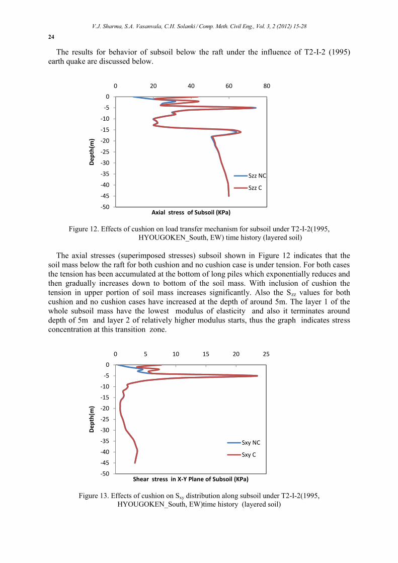
The results for behavior of subsoil below the raft under the influence of T2-I-2 (1995)earth quake are discussed below.
Figure 12. Effects of cushion on load transfer mechanism for subsoil under T2-I-2(1995,HYOUGOKEN_South, EW) time history (layered soil)
The axial stresses (superimposed stresses) subsoil shown in Figure 12 indicates that thesoil mass below the raft for both cushion and no cushion case is under tension. For both casesthe tension has been accumulated at the bottom of long piles which exponentially reduces andthen gradually increases down to bottom of the soil mass. With inclusion of cushion thetension in upper portion of soil mass increases significantly. Also the Szz values for bothcushion and no cushion cases have increased at the depth of around 5m. The layer 1 of thewhole subsoil mass have the lowest modulus of elasticity and also it terminates arounddepth of 5m and layer 2 of relatively higher modulus starts, thus the graph indicates stressconcentration at this transition zone.
Figure 13. Effects of cushion on Sxy distribution along subsoil under T2-I-2(1995,HYOUGOKEN_South, EW)time history (layered soil)
-50
-45
-40
-35
-30
-25
-20
-15
-10
-5
0
0 20 40 60 80D
epth
(m)
Axial stress of Subsoil (KPa)
Szz NC
Szz C
-50
-45
-40
-35
-30
-25
-20
-15
-10
-5
0
0 5 10 15 20 25
Dep
th(m
)
Shear stress in X-Y Plane of Subsoil (KPa)
Sxy NC
Sxy C
V.J. Sharma, S.A. Vasanvala, C.H. Solanki / Comp. Meth. Civil Eng., Vol. 3, 2 (2012) 15-28
25
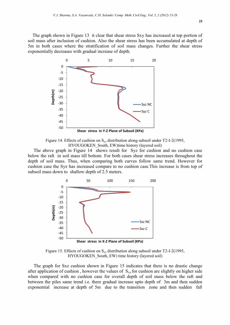
The graph shown in Figure 13 it clear that shear stress Sxy has increased at top portion ofsoil mass after inclusion of cushion. Also the shear stress has been accumulated at depth of5m in both cases where the stratification of soil mass changes. Further the shear stressexponentially decreases with gradual increase of depth.
Figure 14. Effects of cushion on Syz distribution along subsoil under T2-I-2(1995,HYOUGOKEN_South, EW)time history (layered soil)
The above graph in Figure 14 shows result for Syz for cushion and no cushion casebelow the raft in soil mass till bottom. For both cases shear stress increases throughout thedepth of soil mass. Thus, when comparing both curves follow same trend. However forcushion case the Syz has increased compare to no cushion case.This increase is from top ofsubsoil mass down to shallow depth of 2.5 meters.
Figure 15. Effects of cushion on Sxz distribution along subsoil under T2-I-2(1995,HYOUGOKEN_South, EW) time history (layered soil)
The graph for Sxz cushion shown in Figure 15 indicates that there is no drastic changeafter application of cushion , however the values of Sxz for cushion are slightly on higher sidewhen compared with no cushion case for overall depth of soil mass below the raft andbetween the piles same trend i.e. there gradual increase upto depth of 3m and then suddenexponential increase at depth of 5m due to the transition zone and then sudden fall
-50
-45
-40
-35
-30
-25
-20
-15
-10
-5
0
0 5 10 15 20
Dep
th(m
)
Shear stress in Y-Z Plane of Subsoil (KPa)
Syz NC
Syz C
-50-45-40-35-30-25-20-15-10
-50
0 50 100 150 200
Dep
th(m
)
Shear stress in X-Z Plane of Subsoil (KPa)
Sxz NC
Sxz C
V.J. Sharma, S.A. Vasanvala, C.H. Solanki / Comp. Meth. Civil Eng., Vol. 3, 2 (2012) 15-28
26
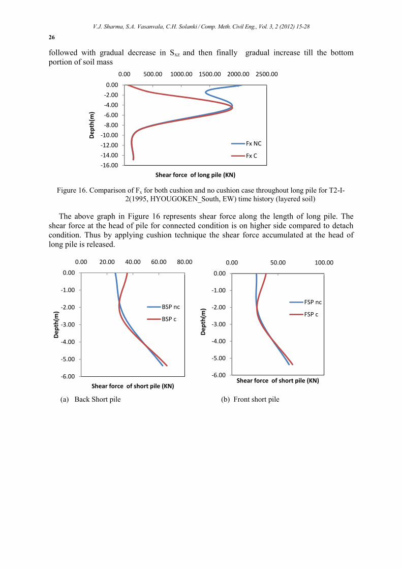
followed with gradual decrease in Sxz and then finally gradual increase till the bottomportion of soil mass
Figure 16. Comparison of Fx for both cushion and no cushion case throughout long pile for T2-I-2(1995, HYOUGOKEN_South, EW) time history (layered soil)
The above graph in Figure 16 represents shear force along the length of long pile. Theshear force at the head of pile for connected condition is on higher side compared to detachcondition. Thus by applying cushion technique the shear force accumulated at the head oflong pile is released.
(a) Back Short pile (b) Front short pile
-16.00
-14.00
-12.00
-10.00
-8.00
-6.00
-4.00
-2.00
0.00
0.00 500.00 1000.00 1500.00 2000.00 2500.00
Dep
th(m
)
Shear force of long pile (KN)
Fx NC
Fx C
-6.00
-5.00
-4.00
-3.00
-2.00
-1.00
0.00
0.00 20.00 40.00 60.00 80.00
Dep
th(m
)
Shear force of short pile (KN)
BSP nc
BSP c
-6.00
-5.00
-4.00
-3.00
-2.00
-1.00
0.00
0.00 50.00 100.00
Dep
th(m
)
Shear force of short pile (KN)
FSP nc
FSP c
V.J. Sharma, S.A. Vasanvala, C.H. Solanki / Comp. Meth. Civil Eng., Vol. 3, 2 (2012) 15-28
27
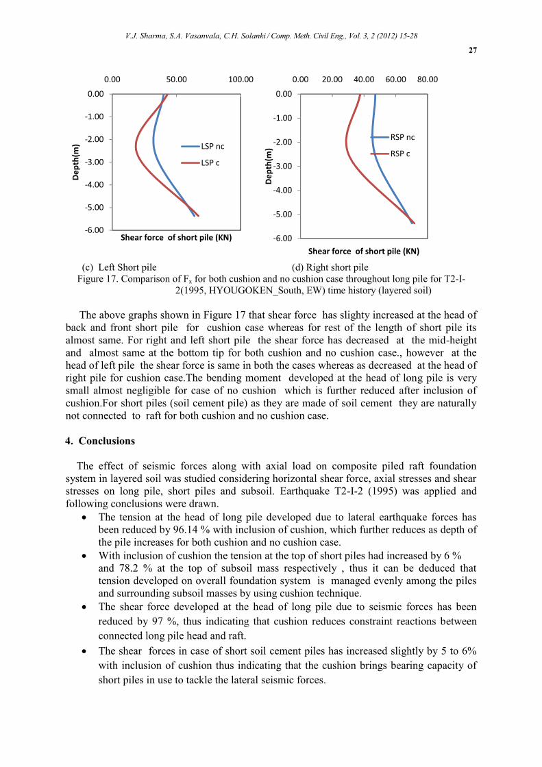
(c) Left Short pile (d) Right short pileFigure 17. Comparison of Fx for both cushion and no cushion case throughout long pile for T2-I-
2(1995, HYOUGOKEN_South, EW) time history (layered soil)
The above graphs shown in Figure 17 that shear force has slighty increased at the head ofback and front short pile for cushion case whereas for rest of the length of short pile itsalmost same. For right and left short pile the shear force has decreased at the mid-heightand almost same at the bottom tip for both cushion and no cushion case., however at thehead of left pile the shear force is same in both the cases whereas as decreased at the head ofright pile for cushion case.The bending moment developed at the head of long pile is verysmall almost negligible for case of no cushion which is further reduced after inclusion ofcushion.For short piles (soil cement pile) as they are made of soil cement they are naturallynot connected to raft for both cushion and no cushion case.
4. Conclusions
The effect of seismic forces along with axial load on composite piled raft foundationsystem in layered soil was studied considering horizontal shear force, axial stresses and shearstresses on long pile, short piles and subsoil. Earthquake T2-I-2 (1995) was applied andfollowing conclusions were drawn. The tension at the head of long pile developed due to lateral earthquake forces has
been reduced by 96.14 % with inclusion of cushion, which further reduces as depth ofthe pile increases for both cushion and no cushion case.
With inclusion of cushion the tension at the top of short piles had increased by 6 %and 78.2 % at the top of subsoil mass respectively , thus it can be deduced thattension developed on overall foundation system is managed evenly among the pilesand surrounding subsoil masses by using cushion technique.
The shear force developed at the head of long pile due to seismic forces has beenreduced by 97 %, thus indicating that cushion reduces constraint reactions betweenconnected long pile head and raft.
The shear forces in case of short soil cement piles has increased slightly by 5 to 6%with inclusion of cushion thus indicating that the cushion brings bearing capacity ofshort piles in use to tackle the lateral seismic forces.
-6.00
-5.00
-4.00
-3.00
-2.00
-1.00
0.00
0.00 50.00 100.00D
epth
(m)
Shear force of short pile (KN)
LSP nc
LSP c
-6.00
-5.00
-4.00
-3.00
-2.00
-1.00
0.00
0.00 20.00 40.00 60.00 80.00
Dep
th(m
)
Shear force of short pile (KN)
RSP nc
RSP c
V.J. Sharma, S.A. Vasanvala, C.H. Solanki / Comp. Meth. Civil Eng., Vol. 3, 2 (2012) 15-28
28
The shear stresses Sxy has increased with considerable amount at the head of long pile,short piles and top portion of subsoil with introduction of cushion, where as Syz hasreduced at the head of piles ,while Sxz has slighty increased in upper portion ofsubsoil mass.
References
[1] HG. Poulos, Pile raft foundations: design and applications. Geotechnique 2001;51(2):95–113.[2] EH. Davis, HG. Poulos, The analysis of piled raft systems. Australia Geotechnique Journal
1972;2:21–7.[3] JB. Burland, BB. Broms, et al, Behavior of foundations and structures. Proceeding 13th International
Conference on Soil Mechanics and Foundation Engineering, Tokyo 977;2:495–546.[4] RW. Cooke, Piled raft foundation on stiff clays—a contribution to design philosophy. Geotechnique
1986;36(2):169–203.[5] YK. Chow, V. Thevendran ,Optimisation of pile groups. Computers and Geotechnics 1987;4:43–58.[6] MF. Randolph, Design methods of pile group and piled rafts:state-of-the-art report. Proceeding 13th
International Conference on Soil Mechanics and Foundation Engineering, New Delhi 1994;2:61–82.[7] K. Horikoshi, MF. Randolph, Centrifuge modeling of piled raft foundation on clay. Geotechnique
1996;46(4):741–52. [8] Ta LD, Small JC. Analysis of piled raft systems in layered soils. InternationalJournal for Numerical and Analytical Method in Geomechanics 1996;20(1):57–72.
[8] KN. Kim, SH. Lee et al. Optimal pile arrangement for minimizing differential settlements in piled raftfoundation. Computers and Geotechnics 2001;28(2):235–53.
[9] A. Eslami, S. Salehi Malekshah, “Analysis of non-connected piled raft foundations (NCPRF) withcushion by finite element method”, Comp. Meth. Civil Eng., Vol. 2, 2 (2011) 153-168.
[10]A. Eslami, M. Veiskarami, M.M. Eslami, Piled-Raft Foundation (PRF) optimization design withconnected and disconnected piles, Proceedings of the 33rd Annual and 11th Int’l Conference on DeepFoundations, Deep Foundations Institute (DFI), New York, NY, U.S.A., (October 15-17, 2008), 201-211.
[11]F.Y. Liang, L.Z. Chen, Shi X.G. “Numerical analysis of composite piled raft with cushion subjected tovertical load”. Computers and Geotechnics 30 (2003) 443–453.
[12]Midas (2012), Midas GTS 2012, analysis user manual Version 2.2.[13]Midas (2012), Midas GTS 2012, Theory manual Version 2.2.
![midas DShop Auto-drafting Module for midas Gen 01 02admin.midasuser.com/UploadFiles2/84/Dshop_catalog.pdf · Auto-drafting Module for midas Gen [midas Gen Design Results] [midas DShop](https://img.pdfslide.us/doc/110x75/5ade06cd7f8b9a9a768db6e7/midas-dshop-auto-drafting-module-for-midas-gen-01-module-for-midas-gen-midas-gen.jpg)