Embed Size (px)
Citation preview

5/13/2018 Comp Let Ions and Workover Fluids PO Chapter 8 - slidepdf.com
http://slidepdf.com/reader/full/comp-let-ions-and-workover-fluids-po-chapter-8 1/21
Chapter 8 Completion and WorkoverFluids
Functions, requirements, selection criteria
Formation damage considerations
Oil fluids, practical applications
Clear-water fluids, practical applications
Clay, emulsion, and wettability problems
Viscosity, fluid loss, and density control
Maintenance of clean fluids
Conventional drilling fluids
Aerated fluids
Perforating fluids, packer fluids
High density brines .Filtration
Function-Requirements-Selection Criteria
By definition a completion or workover fluid is a
fluid placed against the producing formation while con-
ducting such operations as well killing, cleaning out,
drilling in, plugging back, controlling sand, or perforat-
ing. Frac fluids are sometimes considered to be work-
over fluids. Similar materials are used to build viscosity
and provide fluid loss control; however, frac fluid re-
quirements are significantly different than for workover
fluids. See Chapter 8, Volume 2, Fracturing, for a dis-
cussion of frac fluids. Packer fluids, discussed later in
this chapter, remain in the well for an extended period;
thus stability and corrosion are important concerns.
Basic completion and workover fluid functions are
to facilitate movement of treating fluids to a particular
point downhole, to remove solids from the well, and to
control formation pressures. Required fluid properties
vary depending on the operation-but the possibility of
formation damage should always be an important con-
cern. In certain operations, such as sand consolidation
or gravel packing, sandface or perforation plugging is a
prime concern.In recent years several new fluids and fluid han-
dling systems have appeared, most due to the recogni-
tion of the high risk of reducing the productivity, orcompletely plugging certain sections of the producingzone, through contact with a foreign fluid. In some
situations, a good question may be, "Is it reallynecessary to kill the well to accomplish the desired
operation?"
If it is necessary to kill the well, these points
should be considered in selecting a workover or com-pletion fluid:
Fluid Density-Fluid density should be no higher
than needed to control formation pressure. With reason-
able precautions a hydrostatic pressure of 100-200 psi.
over formation pressure should be adequate. Balanced
pressure workovers are ideal from the standpoint of
formation damage and, with proper equipment to con-tain the surface pressure, are practical for some opera-
tions.
Solids Content-Ideally, the fluid should containno solids to avoid formation and perforation plugging.
As a practical limit, so'lids content should be less than
25 ppm. Figure 8-1 shows plugging of Cypress sand-
stone (450-md brine permeability) with saltwater fluids
containing various sizes and concentrations of solids.
Particles greater than 5micron size caused significantly
more plugging than particles less than 2 micron size. In
both cases plugging occurred within the core pore chan-
nels.
Particles larger than about one-half the averagepore diameter should quickly bridge at the entrance to
the pore. These larger particles are probably not detri-:mental if they are removed by backflow or degraded byacid or crude oil.
Particles which plate out to plug the face of the
formation or a perforation obviously obstruct opera-

5/13/2018 Comp Let Ions and Workover Fluids PO Chapter 8 - slidepdf.com
http://slidepdf.com/reader/full/comp-let-ions-and-workover-fluids-po-chapter-8 2/21
8-2 PRODUCTIONOPERATIONSNOL.
Well Completions, Workover, and Stimulatio
Lagend
. .. . A Bay wate. f il te, ed through 2.6. a Bay wate, fllte",d through ,
o C Pl'<Mluc.dwater un" ' • • led
• II water unlrealedIO~--~-----L ~ ~ __-L__~
o 0.02 0.04 0.06 0.08 0.10
Volume Injected, gaVper f
o 100 200 300
Pore Volume
400 500
FIG. 8-1-Permeability reduction in Cypress sand-stone cores. 7 Permission to publish by The Society
of Petroleum Engineers.
tions, such as sand. consolidation, gravel packing, or
squeeze cementing.
Filtrate Characteristics-Characteristics of the
filtrate should be tailored to minimize formation dam-
age considering swelling or dispersion of clays, wetta-
bility changes, and emulsion stabilization. Many timesthis means that the fluid should contain the proper
surfactant as well as the proper electrolyte.
Fluid Loss-Fluid loss characteristics may have to
be tailored to prevent loss of excessive quantities offluid to the formation, or to permit application of "hy-
draulic stress" to an unconsolidated sand formation.
Bridging at the formation face by properly sized acid-soluble particles (calcium carbonate) is a desirable ap-
proach to fluid loss control. Sometimes, oil soluble resin
particles orwater soluble salt crystals may substitute for
the calcium carbonate. In either case colloidal particlesare also required for an effective seal.
Viscosity-Related Characteristics-Viscosity-re-lated characteristics, such as yield point, plastic viscos-
ity, and gel strength, may have to be tailored to providfluid lifting capacity required to bring sand or cutting
to the surface at reasonable circulating rates. Lab tesshow that many viscosity builders cause permanent r
duction in permeability. This can be minimized by car
ful polymer selection, hydration and filtration alonwith adequate fluid loss control, where necessary, t
limit invasion.
Corrosion Products-The fluid should be chem
cally stabI~ so that reaction of free oxygen with tubula
steels is minimized, and that iron in solution is seque
tered and not permitted to precipitate in the formation
A reasonable upper limit on corrosivity for a completioor workover fluid is 0.05 lb/rr (about 1 mil) per work
over. For a packer fluid, the corrosivity target should b
about 1 mil per year, but 5 mils per year is considere
to be an acceptable upper limit.
Mechanical Considerations-Rig equipment
available for mixing, storage, solids removal, and circulating is often a factor in fluid selection.
Economics-The most economical fluid commen
surate with the well's susceptibility to damage shoul
be selected.
Formation Damage Related to Solids
There are two basic approaches to minimize forma
tion damage due to solids entrained in the completionfluid.
Complete Solids ./:lemoval-To be effective, fluiin contact with the formation must not contain an
solids larger than 2 micron size. These points are in
volved:
• Eliminate solids to the greatest extent possible
through the use of 2-micron absolute rated sur
face filters, backed up by other measures to mini
mize solids pickup downstream from the filteri.e., control of oxygen to minimize iron oxide
careful use of thread dope, removal of rust, scaleetc. from downhole tubulars using Hel, IPA, o
sand scouring techniques.
• Accept loss of fluid to the formation and, as
practical matter, movement of very small fine
into the formation. The quantity of fines is lim
ited by minimizing differential pressure into thformation. Removal of fines from the pore sys
tem after the job is maximized by returning th
well to production through gradual increases i
flow rate.

5/13/2018 Comp Let Ions and Workover Fluids PO Chapter 8 - slidepdf.com
http://slidepdf.com/reader/full/comp-let-ions-and-workover-fluids-po-chapter-8 3/21
C omp le tio n a nd Work ov er F lu id s
• Accept possible difficulties in removing largeparticles from the hole due to low 'viscosity and
carrying capacity. Many times velocity can besubstituted for viscosity in lifting particles. A
rising velocity of 150 ftlmin should be sufficientto remove formation cuttings or sand even with
1.0 cp viscosity clear saltwater.
This velocity is within the limits of many workover
pumping systems: i.e., a circulating rate of 5 bbllmin
gives 150 ftlmin annular velocity with 27/S-in. tub-
ing inside 7-in. casing or 2 3/8-in. tubing inside 5
1/2-in. casing. A no-solids viscosity greater than 1.0 cp
may be possible with filtered crude oil or perhaps brine
viscosifiers having no residue.
Complete Fluid Loss Control-To be effective,particles must not be allowed to move past the face ofthe formation into the pore system. These points are
involved:
• Stop all solids at the formation face by carryingin the workover fluid solid particles properly
sized to bridge quickly, and colloids to maximizethe effectiveness of the seal.
• Remove formation-face plug after the job bybackflow-andlor by degradation of the calciumcarbonate solid particles and colloids with acid.With certain limitations resin solids dissolvable
in crude oil, or graded rock salt dissolvable in
unsaturated water, could be used rather than cal-cium carbonate.
• Accept the possibility that after the job pressuredifferential needed to unplug all sections of the
zone will not be available and that it will not be
possible to contact all the plugged section of the
formation with acid due to bypassing tendencies.
The optimum approach depends on specific well
conditions and operations. For certain critical opera-
tions such as sand consolidation and gravel packing
through. perforations, the "complete-solids-removal"
approach often provides highest productivity and mini-
mum cost.
Oil Fluids-Practical Application
Crude Oil-Availability makes crude oil a com-mon choice where low « 8.3 Ib/gal) density is required.
Density considerations may make it particularly desir-
able in low-pressure formations. A low-viscosity crude
has limited carrying capacity and no gel strength and
thus should drop out non-hydrocarbon solids in surface
pits. See Figure 2-11A, Chapter 2, Reservoir Considera-
tions inWell Completions, for correlation of oil viscos-
ity vs. API gravity and temperature. Crude obtainedfrom the stock tank has usually 'weathered enough to
reduce (but not eliminate) the fire hazard. Oil is not
recommended as a packer fluid except for special cases.
(See Packer Fluids discussed later in this chapter).
Loss of oil to the formation is usually not harmful
from the standpoint of clay disturbance or from satura-
tion effects, as might be the case with water in a low
pressure formation. Ithas no fluid loss control; thus, any
entrained fine solids could be carried into the pore
system.
Crude oil should always be checked for the pres-
ence of asphaltenes or paraffins that could plug theformation. This can be done in the field using API fluid
loss test equipment to observe the quantity of solidscollected on the filter paper.
Also, crude oil should be checked for possibility of
emulsions with formation water. Techniques of the API
RP 42 test (visual wettability and emulsion breakout)
are suitable for field use. If stable emulsions are formed,a suitable surfactant should be added.
Diesel Oil-This is often used where a low densityclean fluid is required. It may even be advantageous to
work under pressure at the surface where the density ofdiesel oil is not sufficient to overcome formation pres-
sure.
Depending on hauling and handling practices, die-
sel oil should also be checked for solids. Emulsion and
wettability problems should not be a factor if the diesel
is obtained at the refinery before certain motor fuel
additives are included. Diesel oil is quite expensive
compared to crude oil.
Clear Water Fluld-Practical Application
S ou rce of W ater
Formation Saltwater-When available, forma-tion saltwater isa common workover fluid since the cost
is low. Ifit is clean, formation saltwater should be ideal
from the standpoint of minimizing formation damage
due to swelling or dispersion of clays in sandstoneformations.
Although saltwater from surface separation facili-
ties is frequently considered to be natural water from the
formation, it often contains treating chemicals, fine
particles of oil, clay, silt, paraffin, asphaItene, or scale,

5/13/2018 Comp Let Ions and Workover Fluids PO Chapter 8 - slidepdf.com
http://slidepdf.com/reader/full/comp-let-ions-and-workover-fluids-po-chapter-8 4/21
8-4 PRODUCTION OPERATIONSNOL. 1
Well Completions, Workover, and Stimulation
and it therefore may cause appreciable formation
damage. (Fig. 8~1).
Even filtered formation saltwater may contain oil
treating surfactants (cationic emulsion breakers) which
may cause wettability or emulsion problems. Field
checks can be run using API RP 42 procedures.
Seawater or Bay Water-Due to availability, it is
often used in coastal areas. Again, it frequently contains
clays and other fines that cause plugging.
As shown in Figure 8~1, untreated bay water caused
serious plugging of Cypress sandstone cores. Depend-
ing on the salinity of bay water, it may be necessary to
add NaCl or KCl to prevent clay disturbance.
Prepared Saltwater-Fresh water is often desir~·able as a basic fluid due to the difficulty of obtaining
clean sea or formation water. Desired type and amount
of salt is then added. Where clean brine is available at
low cost, it may be preferable to purchase brine rather
than mix it on location.
Salt Type, Concentration for Prepared Fluid
Practicalities-From the standpoint of preventing
formation damage in sandstones due. to disturbance of
smectite or mixed-layer clays, the prepared saltwater
should, theoretically, match the formation water in cat-
ion type and concentration.
It is difficult to match formation brine, however,
and laboratory results show that 3% to 5% sodium
chloride, 1% calcium chloride, or 1% potassium chlo-
ride will limit swelling of clays in most formations. In
practice these concentrations are often doubled.
Limitation of CaCI2-In certain formations so-
dium smectite can be flocculated (shrunk) by contact
with calcium ions even in low concentrations. Thus, the
clay may become mobile, bridge in pore restrictions and
cause permeability reduction,
Where this is the case, 1% or 2% potassium chloride
should be used rather than calcium chloride since the
potassium ion will prevent swelling; in addition, low
concentrations will not flocculate the sodium smectite.
Additional objections to the use of calcium chloride
result from the observation that field mixed solutions of
CaC12 usually exhibit pH ofl o~10.5 which may disperse
formation clays. CaCI2. is also incompatible with some
viscosifiers and many formation saltwaters.
Extreme Water Sensitivity-In some very water
sensitive formations, 2% ammonium chloride brine
(while quite expensive) seems to stabilize formation
clays. Some small number of sand formations shouldnot be contacted by water of any ionic characteristics.
Emulsion-Wetfabillty Problems
When the brine fluid base is clean fresh water,
wettability and emulsion problems theoretically should
not be a concern. However, even here contamination
from anyone of many sources often occurs.
Field Checks-Best practice dictates that the ac-
tual work over fluid be checked to insure that it does not
form a stable emulsion with the reservoir oil or that it
does not oil-wet the reservoir rock.
This is particularly true where formation saltwateris used, or where corrosion inhibitors or biocides are
used. Field checks can be run using the simple tech-
niques of the API RP 42 Visual Wettability and Emul-
sion Breakout tests.
Prevention is the Key-,,-Usually an unsatisfactory
emulsifying or wettability situation can be corrected by
the addition of a small amount (0.1%) of the proper
surfactant.
As a general rule, workover fluids for sandstone
formations where productivity is important should con-
tain the proper surfactant to prevent any possibility of
emulsion in the formation and to leave the formation
around the wellbore strongly water-wet,
Viscosity Control-Fluid Loss Control
A number of additives are available to provide
"viscosity, " thereby increasing the lifting, carrying, and
suspending capacity of the fluid. In the Bingham plastic
representation of viscosity, "plasticviscosity" relates to
flow resistance between particles as well as the viscos-
ity of the continuous fluid phase; and "yield point"
relates to suspending capability when the fluid is at rest.
Completion fluid viscosity builders are all long
chain polymers or colloids. They also providefluid loss.
control by an indepth plugging mechanism which ex-
tends some distance back within the radial pore system.
Under high shear long polymer molecules straighten out
and can move some distance through the pore system.
However, as velocity decreases in the radial flow system
away from the wellbore, these molecules coil up, in-
creasing viscosity and apparently acting as much larger
molecules.Plugging is subsequently reduced by back-
flow and. degradation, but this process is usually not

5/13/2018 Comp Let Ions and Workover Fluids PO Chapter 8 - slidepdf.com
http://slidepdf.com/reader/full/comp-let-ions-and-workover-fluids-po-chapter-8 5/21
Completion and Workover Fluids 8-5
complete, and formation damage remains. Thus, any use
of viscosity builders must be carefully justified.
Ideally, fluid loss control should be obtained
strictly by a bridging mechanism at the face of theformation. This can be done effectively by use of prop-
erly sized particles. Particles larger than one-half the
pore size should bridge at the pore entrance. However,
a range of particle sizes is required to reduce bridgepermeability. Colloids or "plastic particles" are neededto complete the plug and further reduce permeability.
The bridge should form and stabilize quickly to mini-
mize movement of fines into the pore system. Again
fluid loss control materials obviously plug pore
spaces-and removal is not nearly 100% effective.
Thus, they must be carefully justified.'
Viscosity Builders
Both natural and processed polymers are used in
completion fluid formulations. Among them are: guar
gum, starch, hydroxyethyl cellulose (HEC), car-
boxymethyl cellulose (CMC), and biopolymer (xan-than). Appendix H of Chapter 8, Volume 2, Fracturing,
contains a detailed discussion of oilfield polymers.
Natural Polymers-Guar gum is a hydrocolloid
that swells on contact with water to provide viscosity
and fluid loss control. A filter cake is deposited, which
may interfere even with squeeze cementing. Figure 8-2
shows plugging resulting from injection of about twentypore volumes of unbroken guar gum into a sandstone
core. Permeability regain after backflow was only 25%.In a radial flow system, reduction in productivity would
I I II E I I ~
],000 t-=:~-l-i'o.1_l!l o~
f-;:;~~:t::~ ~'Et:> .1' ' '
500 - - - : a - + -aI : I
1 1I I i
25% of original
I I per~bjlily
glOO_! . . . . . .
i --
~ 50
o fI Ii
: I . Ir-~i ,---
._ _ - - _ -
II
~- -~0 =± -:-- 1-- -- '----
-=t. 1 1 :- - _ .~4- c : - - - : - - -5 1·.....
0 100 200 300
Cumulative injection, pv
FIG. 8-2-Unbroken gusr gum_8 Permission to pub-lish by The Society of Petroleum Engineers_
depend on the depth of the reduced permeability zone
back from the wellbore. If, for example, the depth of
damage was 12 in., productivity would be reduced to
about 65% of the undamaged productivity.
Guar gum usually contains from 5-15% impurities.
Guar gum stability is affected by changes in pH. It forms
an insoluble floc in contact with isopropyl alcohol.Currently guar gum is not recommended for workover'fluids. .
Starch primarily is used to provide fluid loss con-
trol. Other polymers may be needed for carrying capac-ity. Overall cost of starch fluids is significantly lower
than guar gum or other polymers, but higher concentra-
tions of starch are required. Starch has no inherent
bacterial control. Permeability loss due to plugging issignificant; thus starch is losing popularity.
Xanthan provides good carrying capacity and fluidloss control. Viscosity at low shear rates, less than 5sec'", is significantly better than HEC at similar poly-
mer loading. High temperature stability is also betterthan HEC. Gel strength properties provide stable sus-pensions of calcium carbonate bridging (or weighting)particles, but may make removal of undesirable fine
solids more difficult. Xanthan is not completely re-
moved by HCI acid. Recovery of coiled Xanthan mole-cules from the formation pore system is difficult, thus,
significant plugging may result.
Processed Natural Polymers-BEC(hydroxyethyl cellulose) has many desirable properties
and is currently a commonly used viscosifier-but it
must be properly hydrated. Itprovides:
• Good carrying capacity for hole cleaning.
• Good flUid loss control (in combination withbridging solids),
• Low gel strength to drop out undesirable solidsin surface pits.
• Is degradable in HCl-or with enzyme or oxi-dizing breakers.
Unbroken HEC (without bridging particles) causes
significant permeability reduction even after backflow.Damage is not asgreat aswith unbroken guar. Acid-bro-
ken HEC (Fig. 8-3) shows little fluid loss control (with-out bridging solids) but complete permeability regain.
CMC (carboxymethyl cellulose) of the commercial
grade used in drilling fluids should never be used incontact with aproducing zone, due to irreparable forma-
tion damage. Insoluble products are formed in contactwith trivalent ions.

5/13/2018 Comp Let Ions and Workover Fluids PO Chapter 8 - slidepdf.com
http://slidepdf.com/reader/full/comp-let-ions-and-workover-fluids-po-chapter-8 6/21
8-6 PRODUCTIONOPERATIONSNOL.1
We ll C omp le tio ns , Wo rk ov er , a nd S timu la tio n
ii'
Cumulative injection, pv
l 'OOO§~~~100% of original~ermeability
500~ ... .. .. ."";----f- ~ --:f I)
i\.. -;- .~ I ..-
: I---"'~ :1 1 i I
i 'i
I----i-----I-----.-+----+-+----t--rt---.-.-~
~-+·-----_l_-+--I +----++1--- f--+- ----
o~-~I~--_r--,,----~;__.+--oI-r--~
_.:---+.--_.+.---:r+-- rl-.. - -- t- ~ .~-" -.",.I I I I- - - - - - - r - : - - - - + - - - r _ . - - H E C I 7 d r · l < Y & r ' C . I I U ~ O · r - - - -
20~--~----L-~~--~~--~--~c-~o 100 200 300
FIG_ 8-3-Acid-broken HEC_B Permission to publishby The Society of Petroleum Engineers_
Fluid Loss Control
Due to unregained permeability loss, most currently
available viscosity builders should not be used withoutproper bridging particles to prevent movement of the
viscosity colloids into the formation pore system,Bridging particles must meet two criteria:
• Form a stable, low-permeability bridge quickly,
• Be removable by degradation or backflow.
Calcium Carbonate-This material is available in
several size ranges as shown in Table 8-1. For most
formation pore sizes "200 mesh" particle range should
be used. CaC03, if contacted by HCl, is completely
soluble.
.TABLE 8-1
Calcium Carbonate Particle Sizes
Diameter-Microns
Designation mean maximum
3_ 2 18
160
420
M ic ro (4 00 m e sh )
F in e ( 20 0 m e sh )
M e dium (7 0 m e sh )
60
213
Used in conjunction with HEC to provide colloids
for carrying capacity-and to further reduce the perme-
ability of the "bridge"--excellent fluid loss control isprovided with almost perfect permeability regain-if
particles are contacted with HCl acid.
Figure 8-4 shows results of lab tests using an unfil-tered bay water (136 ppm fine solids) with 5,%NaCl, 1.0
lb/bbl HEC and 10 lb/bbl CaC03. Bridging was almost
immediate, fluid loss control excellent, and after contact
with HCl acid regain was 93%.
It should be noted that in a field situation acid
contact with the bridged CaC03 cannot always be as~
sured, and some permeability loss may remain.
In gravel-packing at least partial backflow of "200
mesh" bridging solids through the pack is possible with10-20 mesh gravel. Backflow probably would not occur
through a tight pack of 20-40 mesh gravel.
Oil Soluble Resins-These are available in graded
size ranges needed for effective bridging action. While
quite effective in brine water fluids they are quickly
50 0
J = = t=t-~ ."
~~;;;; ~~~;;;:.;; ~.~i ~ EL-. ,~l m~"_
I - " "
. . . . . . -
! " I x "Completion fluid(composed of HEC,
unfiltered bay water,
and calcium carbonate)
0
1
~idtreati
1,000
100
5
o 10 0 200 300
Cumulative injectton. pv
FIG_ B-4-ldeal fluid loss control and permeabil ityregain in lab test. 8 Permission to publish by TheSociety of Petroleum Engineers_

5/13/2018 Comp Let Ions and Workover Fluids PO Chapter 8 - slidepdf.com
http://slidepdf.com/reader/full/comp-let-ions-and-workover-fluids-po-chapter-8 7/21
C omp le tio n a nd Wo rk ov er F lu id s 8- 7
removed by low oil concentrations (2%). Also, tempera-
ture stability is a concern since some resins tend to melt
even at relatively low temperature.Within these limitations, the use of oil soluble res-
ins appears to be a suitable approach to the problems of
effective fluid loss control with effective permeability
regain.
GradedRock Salt-Where saturated salt fluids are
used, graded rock salt with HEC can provide effective
fluid loss control.
Field Applications
To facilitate field use, several suppliers combine
polymer viscosifiers and graded calcium carbonate into
one-package completion fluid systems. Polybrine from
M-I and Solukleen from BrineAdd are typical of these
systems. Solukleen contains oil soluble resin rather than
CaC03. Usually 1-4 lbslbbl of these products are re-
quired to prepare a satisfactory fluid. HEC-I0 is avail-
able where solids are not desired for fluid loss control.
Polybrine is a prepared mixture of polymers with a
low concentration of 200-mesh calcium carbonate par-
ticles. All components are acid soluble. In 8.5-10.0
lb/gal brine (KCl, NaCl or CaCli! 1.0 to 4.0 lblbbl
Polybrine provides Marsh Funnel viscosity of 33 to 50
sec/qt and API fluid loss of 13-18 cc. Aluminum
stearate (0.25 to 0.50 lb/bbl) must be added to brineprior to mixing Polybrine to prevent foaming.
Mixing or hydrating polymers must be carefully
done to obtain reasonable viscosity and to avoid
microgels or fish eyes. See Appendix 4C, Chapter 4,
Sand Control, for detailed recommendations. Briefly.
starting with freshwater pH should be lowered to 4-5,
after which polymer should be added and dispersed
through about 10 circulation cycles. The pH can then be
increased to 8-10 to initiate the hydration process.
Shearing by circulating through a choke device, or com-
mercial shearing devices (again about 10 cycles ) should
complete the hydration. Over shearing will significantly
reduce viscosity, whereas, with under shearing, micro-gels will remain. Thus, the shearing period should be
monitored by filtration tests or other means.
A satisfactory calcium carbonate fluid can be pre-
pared by adding 5 to 15 lb/bbl of 200-mesh calcium
carbonate to solids-free salt solution containing 0.25 to
0.50 lb/bbl Xanvis. This should provide effective seep-
age control, and sufficient viscosity to circulate out sand
or silt. Higher concentrations of polymer may be re-
quired to lift large cuttings or shale if the rig circulatingcapacity is limited.
In well killing, an effective technique is to circulate
a "pill" (10-15 bbl) of fluid containing a high concen-
tration of polymer and calcium carbonate particles. This
establishes an initial bridge. Polymer and particle con-
centration can then be reduced. When and if additional
cleaning orchip lifting capacity is needed, another pill
can be circulated. .
Loss of circulation problems can usually be solved
by the pill technique using additional polymer for car-
rying capacity with a coarser grade of calcium carbonate
to bridge.
Salt Solutions if Increased Density is Needed
Table 8-2 shows the approximate density range of
solids-free salt solutions:
TABLE 8-2
Density Range of Salt Solutions
Dens it y ( Ib lg al ) Saft solutions
B.S. 9.78.S. 9.B
9.B-11.0
11.0-11.711.7-15.0
15.2-19.2
Po ta ss ium ch lo r id e
Sodi um ch lo r id e
Sodi um ch to r id e -c a lc lum chl or id e
Ca l ci um ch lo r ideC a lc ium c hlo rid !H :8 tc lum b rom id eC a lc ium c hlo rid e- ca lc ium b rom id e, z in c b rom id e
Potassium chloride can be mixed to provide den-
sities up to about 9.7 lb/gal at 85°F, as shown in Table
8-3.
TABLE 8-3
Density of KCI Fluids
%KCf fb Kef pe r bbf Sp Gr o f solution Dens it y I b lg a/
1 3.52 1.0046 8.37
2 7.03 1.0110 8.42
3 10.56 1.0175 8.48
4 14.08 1.0239 8.53
6 21.12 1.0369 B.64
8 2B.16 1.0500 8.75
10 35.20 1.0633 8.86
15 52.79 1.0966 9.15
20 70.39 1.1328 9.44
25 ~7.9B 1.1670 9.72

5/13/2018 Comp Let Ions and Workover Fluids PO Chapter 8 - slidepdf.com
http://slidepdf.com/reader/full/comp-let-ions-and-workover-fluids-po-chapter-8 8/21
8- 8 PRO DUCTIO N O PERATIO NSNO L. 1
W e ll C omp le tio ns , W o rk ov er , a nd S tim u la tio n
Sodium chloride can be mixed to provide densities
up to 9.8 lb/gal. Figure 8-5 shows quantities of water
and salt required for 100 barrels of solution. Sodium
chloride-calcium chloride mixtures can provide densi-
ties from 10.0 to 11.0 lb/gal. Calcium chloride could be
used alone, but addition of sodium chloride reducescost. Material requirements are shown in Figure S-6.
Calcium chloride can be used for weights up to
11.71b/gal with material requirements as shown in Fig-ure 8-7. Dry calcium chloride is available intwo grades,
77% and 95%. The 95% minimum is preferred since
fewer unidentified solids are included.
Formulations of calcium chloride and calciumbromide can provide solids-free fluid densities up to ,
15.0 lb/gal. Use of zinc bromide can increase solids-free fluid density to 19.2 lb/gal. Mixing tables for high
density brines are shown in Appendix SA.
10.000
Ii
I.500
i§
~z 5.000!l
2.500
. . . . . . . . . .- ..................ater
- . . . . . . . . . . . . . . . . . . .1"----
Sodium chloride /95% . . l t)
//
V
V
/8.0 8.5 9.0 9.5 10.0
105
s
i95 j
8
i:is
. 111
85
FIG. 8-5-Material requirements for preparing so-dium chloride solutions.
Solutiond.... ~y.Pili at 60 f
Formation Damage-Laboratory core flow testsapparently do not show unfavorable fluid/rock interac-
tions with heavy brines-CaCI2. CaBrv'ZnBr2 or
CaClvCaBr2"ZnBr2' Recovery of heavy brines can beslow due to high viscosity. Even though reaction with
formation materials does not appear to be a serious
problem, incompatibility between CaCl2 completionfluids and formation brine can result in damaging pre-
cipitates. This problem is more severe if the formation
brine contains significant sulfate or bicarbonate concen-
tration. Ca(OHh and CaC03 might be precipitated due
to a temperature increase. These salts are acid soluble,
thus, reduction of pH tends to prevent precipitation.
Mixing of high density brines with seawater (high in
804) should be avoided.
Crystallizatlon-Since salt solubility varies with
temperature, each brine formulation will have a mini-
mum temperature at which it can be used. This crystal-
300
--~-- _~r
High-test flake
/ calcium chlor ide[9S,,"C>CI)
/'/
Y
I "' - . . . . . . . . . .Sodium chloride
(lOO%NoCIj
100
50
o10.0 11.0 12.0
Solutiond.~.lty. PPlat 60 F
~~
40~1 1: g"l::S
30 3 !"iii
"
FIG. 8-B-Material requirements for preparing cal-cium chloride-sodium chloride solutions.

5/13/2018 Comp Let Ions and Workover Fluids PO Chapter 8 - slidepdf.com
http://slidepdf.com/reader/full/comp-let-ions-and-workover-fluids-po-chapter-8 9/21
Completion andWorkover Fluids 8-9
N
C 3(tI
Q
e f t .oo r §25f : : : g'0020.!:!~
-;;;.!:! 15'C.c
c:m 10:::Io
~
" ' " t-, . . . . . . . . . .~ . . . ~
J
1/'
/I
L
Jo8.0 10.0 12.0 14.0
100c:
800:;::::::I
60"0UJ
:: 0.!:!
00~I:::W
iii: =
: : ac o
W Uo 80:00«I "
-e 40J:::I
E-:::IE 0EW._ a.£E:2~
k4
~ -,. . .V<, . . . .
i " " ' I o o . . ~
~II'
V+-V/
/
c
120 : 8_':::I
100die-III«1-: = 0
90 :c:cm.!:!
8000~
Solution density, ppg at 60°F
20
15
10
5
o8.0 10.0 1 2.0 14.0
Solution density, ppg at 60°F
FIG. 8-7-Material requirements for calcium chloride solutions.
lization temperature (Fig. 8-8) is the temperature at
which salt crystals first form as the brine is cooled.
Lower crystallization temperatures can be obtained by
using higher percentages of the more soluble salt. Most
brines can be cooled to temperatures well below the
crystallization point before the quantity of precipitated
salt interferes with routine handling. Crystals redissolvewhen the brine is heated above the crystallization tem-
perature. Heating of some fluids in the surface storage
tanks may be necessary. .
Corrosivity-Toxicity~afety-When mixing
high concentrations of CaCI, CaBr2, or ZnBr2' precau-
tions should be taken to keep the dry chemical dust out
of eyes and lungs. Rubber protective clothing should be
worn to prevent skin damage. Considerable heat may be
generated, thus, precautions should be taken to prevent
bums. CaCIrCaBr2 brinetoxicity is low enough to
allow use of these solutions in marine waters. ZnBr2 can
be toxic to fish, which limits its use in offshore areas.
Onshore, precautions must be taken to avoid contami-
nation of water supplies. CaC12-CaBr2 brines are alka-
line, whereas ZnBr2 brines are slightly acidic and
therefore more corrosive. Figure 8-9 shows corrosion
rates of high weight brines inhibited with 0.4% Corban
333 (Dowell). Oxygen solubility decreases as brine den-
sity increases; thus, oxygen scavengers are not needed
in heavy brines.
Viscosity-Heavy brines have inherent viscosity
(3-20 cps). If more viscosity is needed HEC can be
~2 ! +2
: : : : I
~Q
EC IIt-
1~acf2jI d~\"", '1)
.
~r ,/v,f,;
o _ L ~ ro ' 1 \ I
\cacf2V
15
+60
+40
-20
-60
8 9 10 11 12 13 14
FIG. ~.8-Crystallization temperature of salt solu-tions. Permission to publish by Gulf Publishing Co.
Density, pp g
5/13/2018 Comp Let Ions and Workover Fluids PO Chapter 8 - slidepdf.com
http://slidepdf.com/reader/full/comp-let-ions-and-workover-fluids-po-chapter-8 10/21
8-10 PRODUCTIONOPERATIONSNOL.1
We ll C omp le tio ns , Wo rk ov er , a nd S timu la tio n
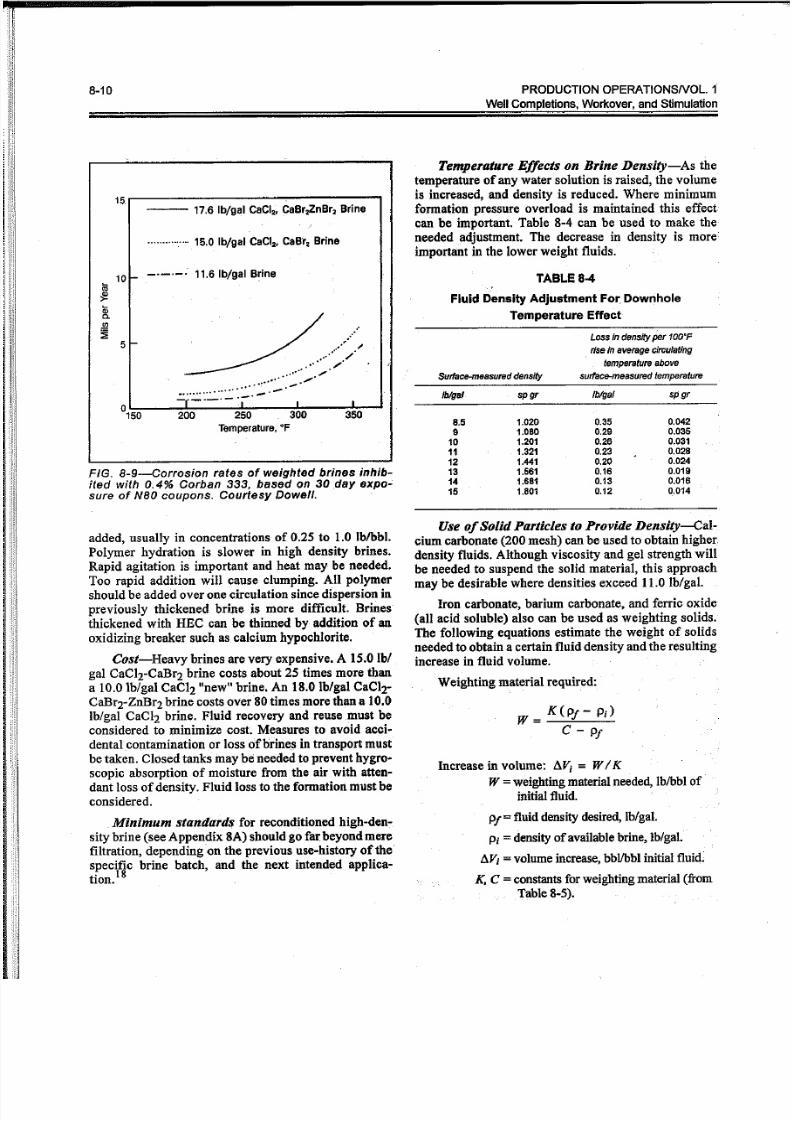
15r-------------------~--------~
----- 17.6 Ib /ga l CaCI2• CaBrz ,ZnBr2 Br ine
............... 15.0 Ib /g al C aC I2• CaBt2 Brine
-.-.~ : 11 .6 Ib /ga l B rine
. .'. . . •~/./
",. . . .~.. ",
. . . . . . . . . . . . . . . . ,. . . ~ - - . ~
Temperature , O F
FIG. 8-9-Corrosion rates of weighted brines inhib-ited with 0.4% Corban 333, based on 30 day expo-sure of NBOcoupons. Courtesy Dowell.
added, usually in concentrations of 0.25 to 1.0 lblbbJ.Polymer hydration is slower in high density brines.
Rapid agitation is important and heat may be needed.Too rapid addition will cause clumping. All polymer
should be added over one circulation since dispersion in
previously thickened brine is more difficult. Brines'
thickened with HEC can be thinned by addition of an
oxidizing breaker such as calcium hypochlorite.
Cost-Heavy brines are very expensive. A 15.0lb/gal CaCIrCaBr2 brine costs about 25 times more than
a 10.0 lb/gal CaCI2 "new" brine. An 18.0 Ib/gal CaC1r
CaBrrZnBr2 brine costs over 80 times more than a 10.0Iblgal CaCI2 brine. Fluid recovery and reuse must be
considered to minimize cost. Measures to avoid acci-
dental contamination or loss of brines in transport must
be taken. Closed tanks inay be needed to prevent hygro-scopic absorption of moisture from the air with atten-
dant loss of density. Fluid loss to the formation must be
considered.
.Minimum standards for reconditioned high-den-
sity brine (see Appendix SA) should go far:beyond merefiltration, depending on the previous use-history of the
specific brine batch, and the next intended applica-
tion.I8
, w! :i li ' · 1
, i i i
"
Iblgsl spgr /blgs/ spgr
8.5 1.020 0.35 0.042
9 1.080 0.29 0.035
10 1.201 0.26 0.031
11 1.321 0.23 0.028
12 1.441 0.20 0.024
13 1.561 0.16 0.019
14 1.681 0.13 0.D16
15 1.B01 0.12 0.014
Temperature Effects on Brine Density-As the
temperature of any water solution is raised, the volume
is increased, and density is reduced. Where minimum
formation pressure overload is maintained this effect
can be important. Table 8-4 can be used to make the
needed adjustment. The decrease in density is more
important in the lower weight fluids.
TABLE 8-4
Fluid Density Adjustment For.Downhole
Temperature Effect
Surface-messured density
L oss in d ens ity p er 1 00 'F
r ise i n a v er age c ir cu la ti ng
t emper at ur e a bove
sur fa ce-mea sur ed t empe re tu re
Use of Solid Particles to Provide Density-Cal-cium carbonate (200 mesh) can be used to obtain higher.
density fluids. Although viscosity and gel strength will
be needed to suspend the solid material, this approachmay be desirable where densities exceed 11.0 lb/gal.
Iron carbonate, barium carbonate, and ferric oxide
(all acid soluble) also can be used as weighting solids.
The following equations estimate the weight of solids
needed to obtain a certain fluid density and the resulting
increase in fluid volume.
Weighting material required:
W = K(Pj - Pi)
C - Pj
Increase involume: dVj = WI K
W =weighting material needed, lb/bbl of
initial fluid.
Pj=fluid density desired, lb/gal.
Pi =densityof available brine, lb/gal,
aVi =volume increase,bbllbbl initial fluid.
K, C =constants forweighting material (from
Table 8-5).

5/13/2018 Comp Let Ions and Workover Fluids PO Chapter 8 - slidepdf.com
http://slidepdf.com/reader/full/comp-let-ions-and-workover-fluids-po-chapter-8 11/21
Completion andWorkover Fluids 8-11
TABLE 8-5
Solid Particles to Provide Density Increase
Density
Speciflc increase Equation
W eighting Gravity obtainab le constants
material spgr IblgslK C
Ca lc ium ca rbona te 2.7 3.5 945 22.5
I ron ca rbona te 3.85 6.5 1348 32.1
Bar ium ca rbona te 4.43 8.0 1551 37.0
Fe rr ic o x id e 5.24 10.0 1.834 43.7
Based on the above relations, 11.5 lb/gal CaCl2
brine would require 150 lblbbl of calcium carbonate to
prepare a 13.0 lb/gal fluid. Volume increase would be
16 bblliOO bbl of initial brine. Adequate suspension
qualities would probably require 0.5 to 1.0 lb/bbl poly-
mer. Settling should be checked before putting fluid inthe hole. If settling occurs, more polymer is required.
For effective fluid loss control some of the calcium
carbonate should be larger than the 200-mesh size
range. Suspension improves, however, as particle size
decreases. As an alternate approach initial fluid loss
control could be established with a "pill" of gradedcalcium carbonate, after which 200-mesh size range
could be used for density requirements.
Care and Maintenance of Clean Saltwater
Fluids
These points are important in the care and mainte-
nance of clean saltwater fluids:
• Dirty mixing and storage tanks or dirty vacuum
tanks are a common source of contamination to
a clean workover fluid system. Tanks must be
thoroughly cleaned before use.
• Workover rig tanks should be equipped withsumps and bottom baffles to contain settlings.
Suction should be about 18in. offbottom. Tanks
should have easily accessible clean-out plates.
Rounded comers aid cleaning.
• Settlings in workover tanks should be checkedhourly and cleaned as needed. Samples from the
pump discharge are helpful in checking for unde-
sirable solids.
• Dirty tubing strings are often a source of rust,scale, pipe dope, etc. They can best be cleaned in
the well by setting a wireline plug at the bottom,running a string of l-in., or coiled tubing, and
circulating HCI, IPA or simply water with about
1 lblgal frac sand for scouring. Ifa sliding sleeveis available above the packer, HCI can be circu-
lated to the bottom of the tubing, then reversed
out; however, a bottom tubing plug is desirable.
• A 4-iu'. cone desilter properly operated shouldtake out a high percentage of solids down to
10-20 microns, with decreasing percentage re-
moval of solids down to 2-3 microns.
• For situations where clean no-solids fluids are
critical (i.e., sand control), filters should beused. Two filter systems are commonly avail-
able: Cartridge, or pot units; and diatomaceous
earth (DE), or filter press units. Cartridge filters
using absolute rated pleated cartridges can do an
excellent job of removing almost all solids « 10
ppm). However, they are most cost effective
when the starting fluid has nomore than 100 ppm
solids.
Filter press units can handle starting fluid with
significantly higher solids loading (> 5,000ppm), but have difficulty reducing solids to the
< 50 ppm range. Solids bleed-through can be a
problem.
An ideal setup would contain a filter press inseries with a cartridge system downstream. SeeAppendix 8B for details of filtering. . .
• Shell work has shown that surface filtration
alone is not enough to insure a no-solids fluid
at the bottom of the hole. Fluid previously fil-
tered through a 2-micron nominal unit was circu-
lated through a tubing string having additional
filters at the top and bottom. The top tubing filter
remained clean, but the bottom filter consistently
plugged with chemically formed iron oxide, and
particulate matter from the tubing,i.e., pipedope, scale, and rust. .
• Laboratory work by Union has emphasized the
point that iron oxide particles are a serious plug-
ging material. The reaction between oxygen and
iron can be prevented by addition of sodium
sulfite (and cobalt sulfate as a catalyst) to scav-enge the oxygen and sodium citrate to sequester
the iron.

5/13/2018 Comp Let Ions and Workover Fluids PO Chapter 8 - slidepdf.com
http://slidepdf.com/reader/full/comp-let-ions-and-workover-fluids-po-chapter-8 12/21
8-12 PRODUCTION OPERATIONSNOL.1
Well Completions, Workover, and Stimulation
Conventional Water-Base Mud
Economics and availability sometimes suggest use
ofwater-base mud rather than weighted saltwater where
weights above 11.5lb/gal are required. Water-base mud
contains clay thinners and dispersants and a high con-
centration of fine solids certain to cause irreparable
formation damage both in the pore system and on the
face of the formation,
Thus, water-base mud should never be used ex-
cept in zones to be abandoned.
In new wells the presence of mud can be avoided
economically by pumping the primary cement plug
down with saltwater or oil. Mud can be circulated out
before perforating using production tubing string; how-
ever, once mud solids are inside the production casingcomplete removal is difficult requiring long circulation
and filtering cycles and complex alternating pills of
surfactant and scouring fluids.
Oil~Baseor Invert-Emulsion Muds
These muds are usually less damaging from the
standpoint of clay problems than conventional water-
.base muds since filtrate is oil and very low filtration
rates can be obtained. Most oil-base systems contain
strong emulsifiers which may oil-wet the formation,
and blown asphalt which can plug the formation as well
as present an oil-wet surface. Thus; emulsion blockagecould be severe.
Some invert-emulsion systems utilize emulsifiers
chosen to minimize this problem. Perforating in
weighted oil muds could form mud plugs which would
not be removed by backflowing. The cost of oil-base
and invert-emulsion muds is relatively high, and usually
can be justified only in cases where formation clays
would be seriously damaged by conventional water-
base mud.
Foam
In low fluid level wells where circulation of solids-
free oil or water-base fluids would not be possible,
foams can be used for certain workover operations such
as washing out sand, drilling in or deepening. Depend-ing on the ratio of air to foam water circulated, flow
gradients as low as 0.1 to 0.2 psi/ft are possible.
Foam is a mechanical mixture of air or gas dis-
persed in clean fresh water or field brine containing a
small amount of surfactant. Surfactant type and concen-
tration should be selected to develop a stable foam with
the specific well fluids encountered.
Equipment requirements include an air compressor
or source of measured gas, mixing tanks for foamer
solution, a liquid pump, metering facilities for air andliquid volumes, and a foam generator to provide good
dispersion of the air in the foam solution.
Equipment needed to handle foam returns includes
a tubing rotating head or stripper assembly at the well-
head to divert the foam returns into a blooie line and to
a disposal pit. At the pit, a water spray system may berequired to break the foam. Aluminum Stearate acts as
a good defoamer.
Typical air compressor requirements are 500 to
1000 cfm at a pressure of about 500 psi. Water andfoaming agent are mixed and injected into the air stream
ata rate oflO to 20 gal/min. Foaming agent concentra-tions of 0.5 to 1.0% are typical. Bentonite or polymers
are added to the water to produce a "stiff foam" having
greater carrying capacity.
The prime advantage of foam is the combination of
low density and high lifting capacity at moderate flowvelocities. Bottomhole pressures as low as 50 psi have
been measured at 2,900 ft while circulating foam. Use
of foam in sand washing is justified on the basis of a
much faster operation and more complete sand removal.
Foam generated with natural gas or nitrogen has
been used in connection with coiled tubing or snubbing
equipment to clean out higher pressure wells without
killing them. Foam returns in these cases are directed
through the normal flowline system to production sepa-
ration facilities.
Being a compressible two-phase fluid, the rheology
of a foam system is complicated. Computer programs
are available to determine injection pressures, bottom-
hole circulating pressure, annular velocity, and. foam-lifting ability at various gas and foamer solution rates.
These programs consider liquid and gas entry from the
formation, temperature gradients, hole deviation, etc.
Perforating Fluids
Perforating fluids are not necessarily a distinct typeof fluid, but are distinguished here to emphasize the
importance of perforating in a no-solids fluid.
Saltwater or Oil-When absolutely clean, these do
not cause solids plugging of perforations, but if the
pressure differential is into the formation, fine particles
of charge debris will be carried into the perforation.
Acetic Acid-This is an excellent perforating fluid
for carbonates under most conditions. In the absence
ofH2S, acetic acid can be inhibited against any type of

5/13/2018 Comp Let Ions and Workover Fluids PO Chapter 8 - slidepdf.com
http://slidepdf.com/reader/full/comp-let-ions-and-workover-fluids-po-chapter-8 13/21
Completion and Workover Fluids
steel corrosion for long periods at high temperatures.
Normally a ten percent solution is used. Acetic acid plus
H2S is very difficult to inhibit against embrittlement.Acetic acid will put iron sulfide and mineral carbonate
in solution. These may result in added corrosion prob-
lems.
Nitrogen-A short fluid column with a long nitro-
gen column has advantages as a perforating fluid in low
pressure formations, or where rig time or swabbing
costs are very high, orwhere special test programs make
it imperative that formation contamination be avoided.
Gas Wells-These can be completed economically
in "clean fluid" by perforating one or two holes, bring-
ing the well in and cleaning to remove as much wellbore
fluid as possible, then perforating the remaining zoneswith only a short liquid column in the hole (to prevent
gun swelling).
Packer F,uids
Criteria-Water~base drilling muds as used today
are not good packer fluids. An acceptable packer fluid
must meet two major criteria:
• Limit settling of mud solids andlor development
of high gelation characteristics.
• Provide protection from corrosion or embrittle-
ment.
In most wells the preferred and recommended
packer fluid is an inhibited clean (solids-free)
saltwater. It is not necessary that the packer fluid have
sufficient density to control the formation pressure;
however, this is often desirable. If the formation pres-
sure gradient is less than 0.51 psi/ft (9.8 ppg), then clean
inhibited sodium chloride is recommended. Ifthe for-mation pressure gradient is no higher than 0.61 psi/ft
(11.7 ppg), then clean inhibited calcium chloride should
be used.
With formation pressure gradients higher than .61
psi/ft careful consideration of many factors, including
well supervision, is required. Use of clean inhibitedsodium chloride, potassium chloride, or calcium chlo-ride should be considered even though it will not over-
balance formation pressure. In the event of a problem,
the well can be killed by circulating an adequate density
fluid. Although expensive, calcium bromide may be thebest choice up to a density of. 78 psi/ft (15 ppg). A high
density oil-mud may be justified in some areas.
Biocides are not needed in saltwater packer fluids,as long as the water does not contain sulfates or poly-
mers. Biocides are poison and must be handled with
care. Oxygen scavengers are of little benefit. The oxy-gen will be quickly expended on the tubulars with only.
minor corrosion. A corrosion inhibitor is recom-mended. However, if the cationic inhibition enters a
sandstone formation, oil wetting may result. Keeping
the pH above 1O~10.5will minimize corrosion.
Crude oil and diesel are not recommended even
on low pressure wells. Both are relatively expensive and
may be more damaging than clean saltwater. Also theyare flammable and messy to handle. Extra care must be
taken to avoid spilling oil or diesel on the ground or
water.
Water-base muds (especially those with barites)
should never be used as packer fluids due to the prob-
ability that solids will settle out and stick the tubing.Unless subsequent well work can be done
through-tubing, the tubing will have to be cut or backed
offup hole, and an expensive and hazardous wash over
operations made to remove the tubing and packer. In
addition to causing formation damage the water-base
mud will provide little protection in killing the well
since the mud will not be pumpable.
Oil-base muds (oil-mud) should be used only in
special circumstances. A high pressure sour gas well
in a sensitive area could be justification for its use.
Where water contact with casing or tubing is eliminated,
local cell electrochemical actions cannot occur, thus
corrosion or embrittlement is negated.
Well Killing
Circulation rather than bullheading (pumping in
with no returns) is the preferable way to kill conven-
tional completions. An adjustable choke should be used
on the tubing outlet to hold a stable backpressure on theformation when killing a wen by reverse circulation.
For single completions on a packer, the recom-
mended procedure is as follows:
1.Fill the annulus, and tubing, if feasible.
2. Equalize tubing andannulus pressure. Open circulatingport in tubing or punch hole in tubing above packer.
3. Pump slowly down casing-tubing annulus (114to 112
bbls/min)as wireline tools are retrieved to build up a
backpressure on formation.
4. After wireline tools are retrieved, pump at a constantrate of2·3 bbls/min to build up 200~300psi on tubing.
5. Maintain a constant pump rate and manipulate the
adjustable choke, controlling tubing returns to keep
casing pressure constant.

5/13/2018 Comp Let Ions and Workover Fluids PO Chapter 8 - slidepdf.com
http://slidepdf.com/reader/full/comp-let-ions-and-workover-fluids-po-chapter-8 14/21
8·14 PRO DUCTIO N O PERAT IO NSNO L. 1
We ll C om p le tio ns , Wo rk ov er , a nd S tim ula tio n
· · · . l i .' . , . I .I , . .
; I T ;
:l H: x :~
I i i;
When circulation is not possible-bullheading a
non-damaging fluid is best if formation will take fluid
without fracturing. Here are three important points.
• For "bullhead" well killing the surface pressure
plus (fluid gradient times depth) should be less
than formation fracturing pressure.
• Itmay be necessary to have a surface pressureregulator to prevent over-pressuring.
• If it is necessary to fracture the formation, the
size of the resulting fracture can be minimized by
low injection rates and high fluid loss (no-solids
fluid).
:: i

5/13/2018 Comp Let Ions and Workover Fluids PO Chapter 8 - slidepdf.com
http://slidepdf.com/reader/full/comp-let-ions-and-workover-fluids-po-chapter-8 15/21
Completion and Workover Fluids 8-15
References
1. Glenn, E. E., and Slusser, M. L.: "Factors Affecting Well
Productivity: I, Drilling Fluid Filtration; and II, Drilling
Fluid Particle Invasion into Porous Media," Trans. AIME
(1957) 210, 126 and 132.
2 . Monaghan, P. H., Salathiel, R. A., Morgan, B. E., and
Kaiser, A. D., Jr.: "Laboratory Studies of Formation Dam-
age in Sands Containing Clays," Trans. AlME (1959) 216,
209.
3. Black, H. N., and Hower, W. F.: "Advantageous Use of
Potassium Chloride Water for Fracturing Water-Sensitive
Formations," API Paper 850-39-F (1965).
4. Simpson, J. P., and Barbee, R. D.: "Corrosivity of Water-Base Completion Fluids," 23rd Annual NACE Confer-
ence, Los Angeles, CA (March 3, 1967).
5. Hutchinson, S. 0.: "Foam Workovers Cut Costs 50%,"
World Oil (Nov. 1969).
6. Christensen, R. J., Connor, R. K., and Millhone, R. S.:
"Applications of Stable Foam in Canada," Oilweek (Sept.
20, 1971).
7. Bruist, E. H.: "Better Performance of Gulf Coast Wells,"
SPE No. 4777, New Orleans (Feb. 1974).
8. Tutt le, R. N., and Barkman, J. H.: "The Need for Non-Dam-
aging Drilling and Completion Fluids," JP T (Nov. 1974)
p. 1,221.
9. Suman, George 0., Jr.: Sand Control Handbook, Gulf
Publishing Company, Houston, TX (1975).
10. Sparlin, Derry, and Guidry, J. P.: "Study of Filters Used
for Filtering Work over Fluids," SPE Paper 7005, Third
Annual Formation Damage Symposium (Feb. 1978).
II. LIfrey, W. T.: "Recommended Procedures for Utilizing
High Cost Non-Damaging Fluids," SPE Paper No. 8794,
Fourth Annual Formation Damage Symposium (Jan.
1980).
12. Sharp, Keith W .: "Filtration of O il Field Brines-A Con-
ceptual Overview," SPE Paper No. 10657, Fifth SPE Sym-
posium on Formation Damage Control (March 1982).
13. Scheuerman, R. P.: "Guidelines for Using HEC Polymers
for Viscosifying Solids Free Completion and W orkover
Brines," SPE Paper No. 10666, Fifth SPE Symposium On
Formation Damage Control (March 1982).
14. Morganthaler, L. N.: "Formation Damage Tests of High-Density Brine Completion Fluids," SPE 14831 (Feb.
1986).
15. Parks, C. F., Clark, P. E., Barkat, Omar, and Halvaci, M.:.
"Characterizing Polymer Solutions by Viscosity and
Functional Testing," Amer. Chern Soc. (Sept. 1986).
16. Houchin, L. R., Hudson, L. M., Caothian, S., Daddazio,
G:, and Hashemi, R.: "Reducing Formation Damage
Through Two-Stage Polymer Filtration," SPE 15408 (Oct.
1986).
17. Nebmer, W. L.: "Viscoelastic Gravel-Pack Carrier Fluid,"
SPE 17168 (Feb. 1988).
18. Foxenberg, W. E., Houchin, L. R., and Javora, P. H.:
"Optimizing the Quality of High-Density Brines for Maxi-
mum Performance and Economic Value," SPE 24784,
Washington, D. C. (Oct. 1992).

5/13/2018 Comp Let Ions and Workover Fluids PO Chapter 8 - slidepdf.com
http://slidepdf.com/reader/full/comp-let-ions-and-workover-fluids-po-chapter-8 16/21
8-16 PRODUCTION OPERATIONSNOL.
WenCompletions,Workover, and Stimulatio
Appendix SA
High Density Brine Completion Fluids
Availability and use of high density brines in place
of drilling muds in completing and working over wells
in abnormally pressured formations has played a signifi-cant role in reducing formation damage. The cost of
these brines, however, dictate that after use in one well
application, the b~ine must be recovered, analyzed for
contaminants, and reconditioned for use in the next well
application. Filtration is a necessary-but usually not
sufficient-reconditioning procedure. "
The first step is to properly sample and analyze the
brine. Contaminants in a solids-free brine include any
foreign substance which may cause formation damage,
i.e., corrosion inhibitors, surfactants, chemical washes,
iron, fluid loss control agents, polymer viscosity build-
ers, drilling fluid constituents; as well as suspended
solids. All of these substances can be effectively re-moved.
Foxenberg, et al.,18 proposed the following mini-
mum quality standards for high density completion fluidbrine.
TABLE 8A~1
Minimum Quality Standards for High Densfty
Completion Fluids
Parameter Specification
color co lorless(1)
cla rity ctysta l clea r
odor none "
fore ign matter absent
NTU ( tu rb id i ty ) < 1 0 u nits
v i scos it y (y ie l d pt) :! > 1 1 b /1 00 s q It
iron <10ppm
zinc < 1 0 p pm
o th er h ea v y m e ta ls < 1 0 p pm (2 )
polysaccharides passes test (3)
compa tibility passes test (4)
a lka linity < 200 ppm as C03
sulfa te < 100 ppm
density as sp e ci fi ed ( 5 )
TCT /LCTD as specified (5)
sa lt assay as specified (5)
pH as spec if ied (6 )
calcium Imagnesium 100 ppm (7 )
( 1 )" B rf ne s c on ta in in g z in c s alt s ( zin c b rom id e) a re lig ht y e lJ ow -lo -am be r.
( 2) Z in c- fr ee b rin es .
( 3) A c id h yd ro ly sis f ollo w ed by c ol or d ev e lo pm e nt w it h d ip he ny lam in e
produces ho m or e th an a fig ht b lue color.
(4 ) C ald um c hlo rid e/b ro mid e b rin es m us t n ot p ro du ce p re Cip ita te u po n
5 0: 50 d ilu tio n w ith d is ti lle d ( or d eio niz e d) w a te r o r s to ck s pe cif ic at io n
f lu id s , I .e ., 1t.S p pg C aC Il; 1 5.1 p pg C aC I2; 1 9.2 C aB r2-Z nB r2.
(5 ) D en sity , T CT IlC TD (T ru e C ry sta lliz atio n T em pe ra tu re /L as t C ry sta l to
D is so lv e) a nd s alt a ss ay s pe Cif ic atio ns a re s et a t m in im um s ta nd ar ds
a cc or din g t o b rin e s p ec if ic f ormu la tio ns :
1 1.6 p pg C aC I2
%CaCb
TCT/Lcm
d en sit y :: 1t.6 p pg m in im um
38 w t % m in im um
34· F/ 45 "F m a xim um
1 4.2 p pg C aB r2
%CaBI '2
TCTI lCTD
density = 1 4. 2 p p g m in im um
51.5 W I % m in im um
O°F /S"F max imum
19 .2 p p g Zn -Ca lB r2
%ZnBr2
%CaBI2
remere
densi ty/BO° = 1 9 .2 p p g m in im um
52.80 w t % minimum
22.BO w t % maximum
10 "F /19 "F max imum
(6) The pH of a dense brine as measured by diese l immersion w ith a pH
me te r e le c tr od e Is s et a cc or din g to b rin e co mp os itio n a nd d en sity .
E xa mp le s o f s to ck flu id p H s pe cif ic atio ns a re g iv en :
10.0 PP 9 NaCI
12.5 pp g N aB r
1 1.6 p pg C aC I2
1 4.2 p pg C aB r2
1 9.2 p pg Z n~ Ca /B r2
1 7.0 p pg Z n-C a/B r:a -C I2 (8 0" T Cn
p H 6.5 -7.5
pH 6.5 -7.5
p H 6.5 -7.5
pH 8.5 - 7.5
pH 0.8 - 2.0
pH 3.0 -4.0
(7) S od iu m a nd p ota ss iu m b rin es .

5/13/2018 Comp Let Ions and Workover Fluids PO Chapter 8 - slidepdf.com
http://slidepdf.com/reader/full/comp-let-ions-and-workover-fluids-po-chapter-8 17/21
Completion and Workover Fluids 8-17
TABLE8A-2
Mixing Schedule; Calcium Chloride--Calcium Bromide Brine
Quan ti ti es f or 1bbllbrine
14 .2 1b1gal cal ci um b rom ide b ri ne
Br ine densi tyPelletized (95%) calcium chloride 11.S lb lgal calcium chloride brine
Iblgal at GO°FFlake (95%) calcium b romide Pe/{etfZed (95%) ca lc ium Ch lor ide
water CaCI:! CaBr CaBrbrine CaC /2brine CaCI: ! pe l letsCrystallization
bb l Ib Ib bb l bb l Ibtemp er at ur e OF
11.8 .8281 189.81 16.28 .0507 .9429 6.1 51
12.0 .8206 184.73 32.57 .1016 .8857 12.1 52
12.2 .8129 179.66 48.86 .1524 .8286 18.2- 54
12.4 .8053 174.58 65.15 .2032 .7715 24.2 54
12.6 .7977 169.51 81.43 .2540 .7143 30.3 55
12.8 .7901 164.43 9771 .3048 .6572 36.4 55
13.0 .7826 159.36 114.00 .3556 .6000 42.4 5713.2 .7749 154.29 130.28 . .4064 .5429 48.5 57
13.4 .7673 149.21 146.57 .4572 .4857 54.6 5B
13.6 .7597 144.14 162.86 .50BO .4286 60.6 58
13.8 .7522 139.06 179.14 .5589 .3714 66.7 58
14.0 .7446 133.99 195.43 .6069 .3143 72.8 58
14.2 .7369 128.92 211.71 .6604 .2572 78.8 59
14.4 .7293 123.84 228.00 .7113 .2000 84.9 61
14.6 .7217 118.77 244.28 .7620 .1429 90.9 63
14.8 .7142 113.69 280.57 .B128 .0858 97.0 65
15.0 .7066 108.62 276.86 .8637 .0286 103.0 66
N OT E: B rine s in this de ns ity ra ng e ca n b e m ixe d in s ev era l w ays a nd the for mula tio n liste d is n o! ne ce ssa rily th e p re fe rre d for mula tio n ..
TABLE8A-3
Mixing Schedule
Calcium Chloride--Calcium Bromide-Zinc Bromide Brine
Quan ti ti es f or 1b b l b ri ne
Br ine densi ty5 6. 7% z in c b romid e
Crystallizatfon19.7% ca/c/um bromide 53% calcium brom ide 9 5% cal cium c hl or id e
I blg al a t S O °Fbrlnebbl brine bbl pel/etslb
temperature O F
15.2 .024 .866 103.3 62
15.4 .071 .B26 9B.6 59
15.8 .119 .783 93.5 59
15.B .167 .741 88.4 57
16.0 .214 .699 83.4 54
16.2 .263 .656 78.3 52
16.4 .310 .613 73.2 50
16.6 .357 .572 68.2 47
16.8 .429 .508 60.6 4017.0 .442 .449 90.0 40
17.2 .495 .421 72.2 38
17.4 .561 .380 51.8 38
17.6 .619 .339 40.4 45
17.8 .667 .296 35.3 44
18.0 .714 .254 30.3 43
18.2 .762 .212 25.3 41
18.4 .810 .169 20.2 35
18.6 .857 .127 15.2 28
18.8 .905 .084 10.1 23
19.0 .952 .043 5.1 18
19.2 1.000 16
N OT E: B rine s in this d ens ity ra ng e ca n b e m ix ed in s ev era l w ay s a nd the fo rm ula tion lis te d is not ne ce ss arily the p re fe rre d form ula tion .

5/13/2018 Comp Let Ions and Workover Fluids PO Chapter 8 - slidepdf.com
http://slidepdf.com/reader/full/comp-let-ions-and-workover-fluids-po-chapter-8 18/21
8-18 PRODUCTION OPERATIONSNOL. 1
We ll C omple tio ns , Wo rk ov er , a n d S timu la tio n
Appendix 88
There are two basic filtration processes for remov-
ing solids from a liquid. Depth filtration removes solids
by causing them to plate-out within the filter media.Surface filtration causes solids to plate-out on the outer
face of the filter media. A third mechanism, cake filtra-
tion, results when the filter is fully loaded from either
of the first two mechanisms, and continues as long as
the buildup of solids or filter cake remains permeable.
Cartridge filters are designed to use either thedepth mechanism (wound cylindrical cartridge) or the
surface mechanism (pleated cartridge). Wound car-
tridges have a broad range of pore sizes, relatively small
surface area, and are given an arbitrary nominal ratingby their manufacturer. They consist of wound yarns or
resin-bonded fibers that increase in density, thus offer-
ing smaller pore openings, toward the center. Larger
solids are trapped in the outer layers and progressivelysmaller particles lodge nearer the center. Pleated car-
tridges are only a few layers thick, have a narrow range
of pore sizes, relatively large surface area, and are given
an absolute rating based on the diameter of the smallest
hard spherical particle that will be retained under speci-fied NFPA test conditions.
Beta ratio is defined as:
B = Influent Particle Count GreaterThan SpeciJiedSize
Effluent Particle Count Greater Than Spectfiedsize
Beta ratio is converted to removal efficiency as
RE % = 100 [B - I]
B
Beta Ratio Removal Efficiency %
10100
1,0005,00010,000
·m ln lm um r ec omm en de d
90.099.099.90*99.9899.99
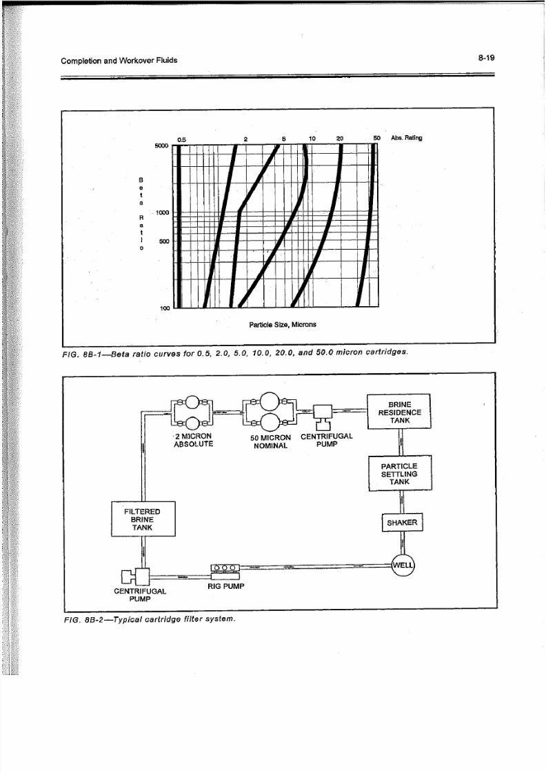
For a given pleated cartridge the Beta ratio varieswith particle size. Figure 8B-l shows Beta ratio curves
Filtration
for 0.5, 2.0, 5.0, 10.0,20.0, and 50.0 micron cartridges
from one manufacturer. Each cartridge has a different
Beta ratio for a given particle size, i.e., the 10 micron
absolute cartridge should remove 99% of the 2 micron
size particles.
Figure 8B-2 shows an ideal fluid cleaning system
wherein fluid returns from the well are taken over a
shale shaker, through a particle settling tank overflow-
ing into a residence tank, then pumped through thefiltration section, consisting of two banks each contain-
ing two filter pots. The first and second banks containnominal filter cartridges with 50micron ratings, and the
second contains 2 micron absolute rated cartridges. Thepots in each bank are manifolded such that one can betaken out of service to change filters while fluid contin-
ues to flow through the other.
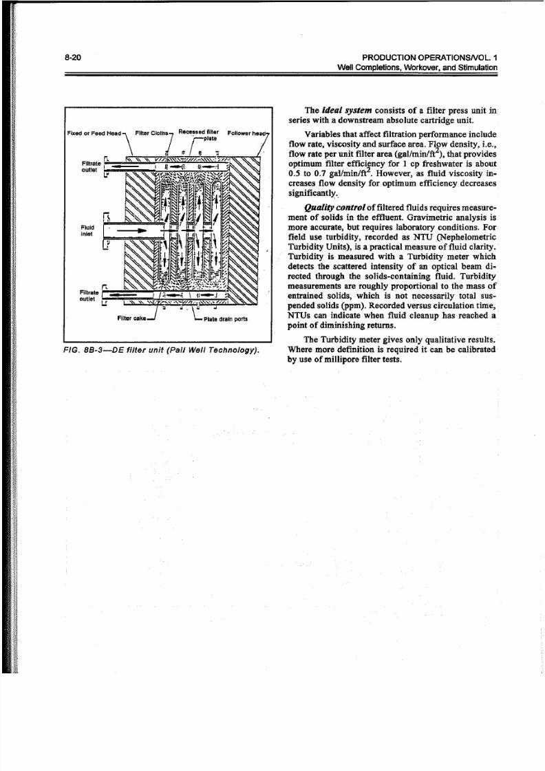
The diatomaceous earth (DE) filter, orfilter press,is designed as a cake filter. The cake consists of dia-
toms, skeletal remains of microscopic aquatic plants,
which are porous, rigid, chemically inert and insoluble
in oilfield completion fluids. Ideally, they form a highly
permeable stable incompressible filter cake. The DEfilter press contains a series of canvas covered plates,Figure 8B-3, which are precoated with the DE clay
(1I8-in. thick) by fluid circulation to form the initial
cake. When the filter is put in service to initiate thefiltering cycle, solids removed from dirty fluid become
part of the cake. DE is usually added continually to
maintain filter cake permeability. The filter cycle ends
when the cake builds up to the point where flow is
reduced or differential pressure increased to a limiting
level. The plates are then opened, the cake removed
from the canvas sleeves and the cycle begins again.
Solids loading inmost completion fluids is difficult
to predict beforehand, but usually is more than 100 ppmand may vary over a wide range depending on the nature
of the operation. This means that a cartridge filter sys-
tem alone may not be economic if a 2 micron output
fluid is desired.
Filter press systems are good for reducing solids
concentration to 50 ppm even though input solids may
be in the 1,000 ppm range with slugs carrying 10-20,000
ppm. They do not provide specific micron size cutoff,
i.e., 2 micron, and efficiency is operator dependent.
5/13/2018 Comp Let Ions and Workover Fluids PO Chapter 8 - slidepdf.com
http://slidepdf.com/reader/full/comp-let-ions-and-workover-fluids-po-chapter-8 19/21
Completion and Workover Fluids 8-19
B
et
a
R
a
t
I
o
05 10 20 50 Abs~Rating
FIG. 8B-1-Beta ratio curves for 0.5, 2.0, 5.0, 10.0, 20.0, and 50.0 micron cartridges.
5000 • ,~
J'
t l~
•~ •_ •_~ _I
"I
J,
1 1 -Jr ,
JIf
~~J
FILTEREDBRINE
TANK
CENTRIFUGALPUMP
1000
500
100
Pa rt ic le S iz e , M ic ro ns
2 MICRONABSOLUTE
50MICRON CENTRIFUGALNOMINAL PUMP
RIG PUMP
FIG. BB-2-Typical cartridge filter system.
BRINERESIDENCE
TANK
PARTICLESETTLING
TANK
5/13/2018 Comp Let Ions and Workover Fluids PO Chapter 8 - slidepdf.com
http://slidepdf.com/reader/full/comp-let-ions-and-workover-fluids-po-chapter-8 20/21
8-20 P RO DU CTIO N O PER AT IO NSN OL. 1
We ll C omple tio ns , Wo rk ov e r, a n d S timu la tio n
FIG, BB-3-DE filter unit (Pal/ Well Technology).
The ideal system consists of a filter press unit in
series with a downstream absolute cartridge unit.
Variables that affect filtration performance include
flow rate, viscosity and surface area. Flow density, i.e.,
flow rate per unit filter area (gal/minlft2), that provides
optimum filter efficiency for 1 cp freshwater is about0.5 to 0.7 gal/minlft2. However, as fluid viscosity in-
creases flow density for optimum efficiency decreases
significantly.
Quality control of filtered fluids requires measure-
ment of solids in the effluent. Gravimetric analysis ismore accurate, but requires laboratory conditions, For
field use turbidity, recorded as NTU (Nephelometric
Turbidity Units), is a practical measure of fluid clarity.
Turbidity is measured with a Turbidity meter whichdetects the scattered intensity of an optical beam di-
rected through the solids-containing fluid. Turbidity
measurements are roughly proportional to the mass of
entrained solids,which is not necessarily total sus-
pended solids (ppm). Recorded versus circulation time,
NTUs can indicate when fluid cleanup has reached apoint of diminishing returns.
The Turbidity meter gives only qualitative results.
Where more definition is required it can be calibrated
by use of millipore filter tests.

5/13/2018 Comp Let Ions and Workover Fluids PO Chapter 8 - slidepdf.com
http://slidepdf.com/reader/full/comp-let-ions-and-workover-fluids-po-chapter-8 21/21
Completion and Workover Fluids 8-21
Appendix B e
Commercial Completion Fluid Products
Listed below are products available from one service company (Dowell
Schlumberger) for use in completion, workover or gravel packing. Similar
materials are available from several other suppliers.
Product Name Description or Use
A-181-bisulfite oxygen scavenger
B-19-Xanvis gelling agentB-20-Xanvis breaker,. inorganic peroxide
D-47-defoamer '
F-68-Eze FloG-2--non-ionic surfactant foaming agent
H-15-15% HCl HEC breaker
J-164-HEC-IO gelling agentJ-168-soluble bridging material
J-211-lgs., CaC03
J-212-HEC, 19s., CaC03J-213-HEC, lgs., CaC031arge particles
J-214-CaC03J-218-ammonium persulfate HEC breakerJ-237 and J-275-liquid oil soluble fluid loss additive
J-285-ammonium chlorideJ-287-sodium bicarbonate, buffer
J-369, J-419-high weight brine thickenerJ-462-Pennpac gelling agent amine liquid
J-463-Pennpac gelling activatorL-I ~ritric acid, iron/pH control
L-62--nitrilotriacetic acid (NTA)-iron pH control
M-3-sodium carbonate, bufferM-76, M-133, M-155-water soluble, cationic bactericide
M-I17-potassium chloride
M-129--oxygen scavengerS-54, S-55~alcium bromide brine or dry sacked
Shellflo-S-liquid gelling agentDOWCIDE G-sodium pentachlorphenate bactericide