Embed Size (px)
Citation preview

COMOS
PlatformiDB Administration
Programming and Operating Manual
05/2016 V 10.2A5E37082937-AA
Objective and requirements 1Searching for objects and data in the iDB 2Standardized designations for folder objects 3Standardized designations for base objects 4Generally-applicable writing rules in standardized descriptions
5
Localization rules for iDB texts 6Generally applicable rules for base objects 7Administering "@10 Requirement objects" 8"@20 General base objects": Editing basic base objects 9"@30 Structures": Editing module-specific structures 10"@40 @Y Attribute catalog": Editing attributes and tabs 11"@50 Manufacturer devices": Editing the manufacturer catalogs
12
"@99 System settings": Editing default lists and settings
13
Administration of standard tables 14
Administering units 15Administration of the labeling system and ALIAS labeling system
16
Continued on next page

Siemens AGDivision Process Industries and DrivesPostfach 48 4890026 NÜRNBERGGERMANY
A5E37082937-AAⓅ 04/2016 Subject to change
Copyright © Siemens AG 2016.All rights reserved

PlatformiDB Administration
Programming and Operating Manual
Continuation
Classifying objects 17Administration of documents in the iDB 18
Developing scripts for the iDB 19
Editing project properties 20
Customer-specific additions 21iDB-specific rules for using external files 22Using case variants as design cases or editing them 23
Administration of templates 24
Database update 25

Legal informationWarning notice system
This manual contains notices you have to observe in order to ensure your personal safety, as well as to prevent damage to property. The notices referring to your personal safety are highlighted in the manual by a safety alert symbol, notices referring only to property damage have no safety alert symbol. These notices shown below are graded according to the degree of danger.
DANGERindicates that death or severe personal injury will result if proper precautions are not taken.
WARNINGindicates that death or severe personal injury may result if proper precautions are not taken.
CAUTIONindicates that minor personal injury can result if proper precautions are not taken.
NOTICEindicates that property damage can result if proper precautions are not taken.If more than one degree of danger is present, the warning notice representing the highest degree of danger will be used. A notice warning of injury to persons with a safety alert symbol may also include a warning relating to property damage.
Qualified PersonnelThe product/system described in this documentation may be operated only by personnel qualified for the specific task in accordance with the relevant documentation, in particular its warning notices and safety instructions. Qualified personnel are those who, based on their training and experience, are capable of identifying risks and avoiding potential hazards when working with these products/systems.
Proper use of Siemens productsNote the following:
WARNINGSiemens products may only be used for the applications described in the catalog and in the relevant technical documentation. If products and components from other manufacturers are used, these must be recommended or approved by Siemens. Proper transport, storage, installation, assembly, commissioning, operation and maintenance are required to ensure that the products operate safely and without any problems. The permissible ambient conditions must be complied with. The information in the relevant documentation must be observed.
TrademarksAll names identified by ® are registered trademarks of Siemens AG. The remaining trademarks in this publication may be trademarks whose use by third parties for their own purposes could violate the rights of the owner.
Disclaimer of LiabilityWe have reviewed the contents of this publication to ensure consistency with the hardware and software described. Since variance cannot be precluded entirely, we cannot guarantee full consistency. However, the information in this publication is reviewed regularly and any necessary corrections are included in subsequent editions.
Siemens AGDivision Process Industries and DrivesPostfach 48 4890026 NÜRNBERGGERMANY
A5E37082937-AAⓅ 04/2016 Subject to change
Copyright © Siemens AG 2016.All rights reserved

Table of contents
1 Objective and requirements........................................................................................................................13
2 Searching for objects and data in the iDB..................................................................................................15
2.1 Overview: Search techniques for the iDB..............................................................................15
2.2 Using "Attribute search" tab...................................................................................................17
2.3 Using "Attribute descriptions DE/EN" query...........................................................................19
3 Standardized designations for folder objects..............................................................................................21
3.1 Names and meaning of the main levels in the iDB................................................................21
3.2 Names of additional levels.....................................................................................................23
3.3 Special sub-branches with Y prefix........................................................................................24
3.4 The @Local branch for local base objects.............................................................................24
4 Standardized designations for base objects...............................................................................................27
4.1 Overview of the naming convention in the iDB......................................................................27
4.2 Uniqueness of names............................................................................................................27
4.3 System characters and special characters............................................................................28
4.4 Names of base object elements.............................................................................................29
4.5 Names in the labeling system................................................................................................29
4.6 Special cases when using letters...........................................................................................30
4.7 Base objects with fixed names...............................................................................................31
4.8 Entering norm-specific text masks.........................................................................................32
5 Generally-applicable writing rules in standardized descriptions.................................................................33
6 Localization rules for iDB texts...................................................................................................................35
7 Generally applicable rules for base objects................................................................................................37
7.1 "Object locking" and "System object" state............................................................................37
7.2 Creation option for base objects............................................................................................39
7.3 Adding tabs to base objects...................................................................................................39
7.4 Design guidelines for tabs......................................................................................................40
7.5 Creating elements at base objects.........................................................................................407.5.1 Administering properties of elements in the base object........................................................407.5.2 Constructing context menus via elements.............................................................................437.5.3 Constructing context menus via subelements........................................................................44
7.6 Forming a labeling system with elements..............................................................................45
7.7 Prohibited change for the target of cross-inheritances...........................................................45
iDB AdministrationProgramming and Operating Manual, 05/2016 V 10.2, A5E37082937-AA 5

7.8 Inserting customer-specific base objects in the iDB...............................................................46
7.9 Controlling base object links using dereferencing..................................................................46
7.10 Using or editing icons.............................................................................................................47
7.11 Overview for administration of symbols.................................................................................49
7.12 Drawing type-specific symbol display....................................................................................49
7.13 Preparing symbols for AutoCAD export.................................................................................51
7.14 Connector types in the iDB....................................................................................................517.14.1 Purpose of the connector types.............................................................................................517.14.2 Reference: Names of the connector types.............................................................................527.14.3 Connectors on EI&C reports..................................................................................................56
7.15 General object class...............................................................................................................56
7.16 Deleting objects......................................................................................................................57
8 Administering "@10 Requirement objects".................................................................................................59
8.1 Purpose of the "@10" node....................................................................................................59
8.2 Structure of the "@10" node..................................................................................................59
8.3 Editing options of the "@10" node.........................................................................................60
8.4 Use/expansion of the "@10" node.........................................................................................61
8.5 Notes on expansion of tabs....................................................................................................61
8.6 Example for use of the "@10" node.......................................................................................62
8.7 Notes on multiple use of "@10" objects.................................................................................63
9 "@20 General base objects": Editing basic base objects...........................................................................65
9.1 Purpose of @20.....................................................................................................................65
9.2 Interface objects for base data import (dynamic objects).......................................................66
9.3 Reference: "@20 General base objects"...............................................................................689.3.1 @20 > A10 Units....................................................................................................................689.3.2 @20 > A15 Categories...........................................................................................................699.3.3 @20 > A20 Locations.............................................................................................................699.3.4 @20 > A25 Positions.............................................................................................................709.3.5 @20 > A30 Functions............................................................................................................719.3.6 @20 > A40 Signals................................................................................................................719.3.7 @20 > A50 Project settings...................................................................................................719.3.8 @20 > A60 Documents..........................................................................................................729.3.9 @20 > A70 Queries...............................................................................................................729.3.10 @20 > A80 Scripts.................................................................................................................739.3.11 @20 > A90 Standard import objects......................................................................................749.3.12 @20 > B10 Decision tables....................................................................................................749.3.13 @20 > B20 Tasks..................................................................................................................749.3.14 @20 > B30 User administration.............................................................................................769.3.15 @20 > B40 Workflows...........................................................................................................769.3.16 @20 > B50 Expenses............................................................................................................769.3.17 @20 > B60 Configuration and mapping objects....................................................................779.3.18 @20 > B70 Installation...........................................................................................................77
Table of contents
iDB Administration6 Programming and Operating Manual, 05/2016 V 10.2, A5E37082937-AA

9.3.19 @20 > B80 Routing................................................................................................................779.3.20 @20 > B90 Risk-, safety evaluation.......................................................................................789.3.21 @20 > C10 Locking...............................................................................................................789.3.22 @20 > C30 Symbol construction...........................................................................................789.3.23 @20 > C40 Maintenance.......................................................................................................799.3.24 @20 > C50 General objects...................................................................................................799.3.25 @20 > C70 Automation objects.............................................................................................799.3.26 @20 > C80 SAP objects........................................................................................................809.3.27 @20 > C90 Objects for PipeSpec Designer...........................................................................809.3.28 @20 > D10 Axis definition......................................................................................................809.3.29 @20 > D20 Base objects from external CAE data imports....................................................809.3.30 @20 > D30 PDMS objects.....................................................................................................819.3.31 @20 > D40 Reserved object names......................................................................................819.3.32 @20 > Z10 Customer.............................................................................................................83
10 "@30 Structures": Editing module-specific structures................................................................................85
10.1 Purpose of the "@30" node....................................................................................................85
10.2 Basic rules in the "@30" node................................................................................................86
10.3 Specifying project structures as project setting......................................................................88
10.4 Overview of module-oriented first level..................................................................................91
10.5 Overview of the structure of @30 below the modules............................................................91
10.6 Designing project structures...................................................................................................93
10.7 Example for unit structure A30...............................................................................................96
10.8 Categories A35 below the modules.......................................................................................97
10.9 Device structure A50 below the modules...............................................................................99
10.10 Document structure A90 below the modules.......................................................................100
10.11 Information about labeling systems in the M00 branch........................................................102
11 "@40 @Y Attribute catalog": Editing attributes and tabs..........................................................................103
11.1 Overview of the administration of attributes and tabs..........................................................103
11.2 Uniqueness principle of attributes........................................................................................104
11.3 Editing "@40 > A10 Attribute catalog"..................................................................................10611.3.1 Overview of the nodes in "@40 > A10"................................................................................10611.3.2 Overview of the properties of catalog attributes...................................................................10611.3.3 "Attribute mapping table" tab................................................................................................10711.3.4 Storage structure and names of the catalog attributes........................................................10811.3.5 Basic rules for the "Description" field for catalog attributes..................................................11011.3.6 Supplementary rules for the "Description" field for catalog attributes..................................11111.3.7 Special attributes: Automation Interface (PCS 7).................................................................114
11.4 Editing "@40 > A20 Tabs"....................................................................................................11411.4.1 Overview of the nodes in "@40 > A20"................................................................................11411.4.2 Storage structure and names of the tabs ............................................................................11511.4.3 Change the sort sequence for the tabs................................................................................118
11.5 Placing catalog attributes on tabs (derived attributes).........................................................11911.5.1 Placing a catalog attribute on a tab......................................................................................119
Table of contents
iDB AdministrationProgramming and Operating Manual, 05/2016 V 10.2, A5E37082937-AA 7

11.5.2 Overview of the properties of the derived attribute..............................................................11911.5.3 General rules for the layout of tabs......................................................................................12111.5.4 Attributes with the "List" display type (list specs).................................................................12311.5.5 Attributes with the "Object query" display type (SUI query).................................................12411.5.6 Attributes with the "Button" display type...............................................................................12411.5.7 Attributes with the "Frame" or "Description" display type.....................................................12511.5.8 Placing attributes invisibly....................................................................................................12611.5.9 Placing a catalog attribute on a tab multiple times...............................................................126
11.6 Placing a tab on an object multiple times.............................................................................127
11.7 Dynamically created attributes.............................................................................................128
11.8 Dynamically created tabs.....................................................................................................129
12 "@50 Manufacturer devices": Editing the manufacturer catalogs............................................................131
12.1 Purpose of @50...................................................................................................................131
12.2 Classification in the iDB system...........................................................................................132
13 "@99 System settings": Editing default lists and settings.........................................................................135
13.1 Reference: "@99 System"...................................................................................................135
13.2 Administration of personal user settings (profile).................................................................137
13.3 Overview of status management A40..................................................................................139
13.4 Object-based status management in A40............................................................................14013.4.1 Creating status base objects................................................................................................14013.4.2 Status value defaults in base objects...................................................................................14113.4.3 Controlling the status through attributes..............................................................................14113.4.4 Controlling the status using scripts......................................................................................14213.4.5 Controlling Navigator commands via script..........................................................................142
13.5 Query-based status management in A40.............................................................................14313.5.1 Purpose of query-based status management......................................................................14313.5.2 Creating and administering a "Status" query.......................................................................14413.5.3 Hierarchical query-based status management.....................................................................14513.5.4 Background knowledge of XML storage of the status..........................................................14613.5.5 Query-based status management: Script examples............................................................14613.5.6 Attributes for query-based status management...................................................................148
14 Administration of standard tables.............................................................................................................149
14.1 Overview of standard tables in the iDB................................................................................149
14.2 "@40 Attribute catalog table"...............................................................................................149
14.3 Y10 System tables...............................................................................................................15114.3.1 Y10 Standard tables for line types.......................................................................................15214.3.2 Y10 Standard tables for connector subtypes.......................................................................152
14.4 Y30 Special standard tables................................................................................................152
14.5 Y40 Mapping tables.............................................................................................................153
14.6 Y60 NLS tables....................................................................................................................153
15 Administering units...................................................................................................................................155
15.1 Administering unit groups for the iDB...................................................................................155
Table of contents
iDB Administration8 Programming and Operating Manual, 05/2016 V 10.2, A5E37082937-AA

15.2 Using units in iDB attributes.................................................................................................155
16 Administration of the labeling system and ALIAS labeling system...........................................................157
16.1 Constructing the labeling system with base object elements...............................................157
16.2 Labeling systems in the M00 branch....................................................................................159
16.3 Purpose of ALIAS labeling systems.....................................................................................162
16.4 Administration of the ALIAS labeling system.......................................................................162
16.5 Using scripts to adjust ALIAS labeling.................................................................................164
17 Classifying objects....................................................................................................................................167
17.1 Purpose of classification......................................................................................................167
17.2 Structure of classifications...................................................................................................167
17.3 Performing the classification................................................................................................170
17.4 Classification of documents.................................................................................................171
18 Administration of documents in the iDB....................................................................................................175
18.1 Root nodes of the documents..............................................................................................175
18.2 Naming convention for report templates and document groups..........................................177
18.3 Using or editing subreports..................................................................................................178
18.4 Object queries for reports.....................................................................................................179
18.5 Base objects for documents and document groups.............................................................18118.5.1 @20 > A60 Documents........................................................................................................18118.5.2 Basic rules for documents and document groups in @30 > M00........................................18218.5.3 @30 > M00 > A80 > A10 Document base objects acc. IEC 61355.....................................18318.5.4 @30 > M00 > A90 Document groups...................................................................................18418.5.5 Managing documents without IEC 61355 labels (@30 > xxx > A80)...................................185
18.6 Classification of documents.................................................................................................185
18.7 Layout recommendations for report templates.....................................................................186
18.8 Using external document files..............................................................................................187
18.9 Company logos....................................................................................................................187
18.10 Displaying AutoCAD drawing in the report...........................................................................188
18.11 Creating headers and footers...............................................................................................189
18.12 Interaction of tabs and report templates...............................................................................190
18.13 Drawing type-specific symbol display..................................................................................190
18.14 Important information on reports..........................................................................................190
19 Developing scripts for the iDB..................................................................................................................191
19.1 Basic principles of scripts.....................................................................................................191
19.2 Script library.........................................................................................................................19219.2.1 Structure of the script library................................................................................................19219.2.2 Methods in the script library.................................................................................................193
Table of contents
iDB AdministrationProgramming and Operating Manual, 05/2016 V 10.2, A5E37082937-AA 9

19.2.3 Naming of script objects.......................................................................................................194
19.3 Structures/ conventions........................................................................................................19419.3.1 Overview of the structures and conventions........................................................................19419.3.2 Header block........................................................................................................................19519.3.3 Variable declaration.............................................................................................................19719.3.4 Variable initialization............................................................................................................19819.3.5 Assigning transfer parameters.............................................................................................19819.3.6 Return values of functions....................................................................................................19819.3.7 Calling central scripts...........................................................................................................19919.3.8 Comments in the script........................................................................................................20219.3.9 Formatting the script............................................................................................................20319.3.10 Use of parentheses for If…Then…Else instructions............................................................20519.3.11 Use of variants for If…Then…Else instructions...................................................................20519.3.12 Merging of character strings.................................................................................................206
19.4 Naming.................................................................................................................................20619.4.1 Naming for methods.............................................................................................................20619.4.2 Naming for variable names..................................................................................................20619.4.3 Variable types......................................................................................................................20719.4.4 Other properties...................................................................................................................20819.4.5 COMOS object types...........................................................................................................208
19.5 Incorporating COM components..........................................................................................20919.5.1 Overview of the technology in the COM components..........................................................20919.5.2 Declaration components of the method "CreateObject".......................................................20919.5.3 Memory storage management or cleaning with incorporated COM components................210
19.6 Avoiding runtime errors........................................................................................................210
19.7 Improve script performance.................................................................................................211
19.8 Localizing texts in scripts with NLS......................................................................................21219.8.1 Overview of the use of NLS texts.........................................................................................21219.8.2 Administering NLS texts in standard tables.........................................................................21319.8.3 Functions for localizing texts................................................................................................21619.8.4 Call example of an NLS text.................................................................................................218
19.9 Prevent pop-up window........................................................................................................218
19.10 Logging script actions..........................................................................................................219
19.11 Information about the Object Debugger...............................................................................220
19.12 Using hard-coded base objects in scripts............................................................................220
20 Editing project properties..........................................................................................................................221
20.1 Global project options..........................................................................................................221
20.2 Base references: References to database objects..............................................................221
20.3 Project properties reference.................................................................................................222
21 Customer-specific additions.....................................................................................................................223
21.1 General rules for customer-specific application cases.........................................................223
21.2 Inserting customer-specific base objects in the iDB.............................................................223
21.3 Creating customer-specific attributes and tabs....................................................................226
Table of contents
iDB Administration10 Programming and Operating Manual, 05/2016 V 10.2, A5E37082937-AA
21.4 Creating customer-specific documents................................................................................228
21.5 Customer-specific project properties....................................................................................231
22 iDB-specific rules for using external files..................................................................................................233
22.1 Using or editing external files...............................................................................................233
22.2 Physical storage of the report templates..............................................................................234
23 Using case variants as design cases or editing them...............................................................................237
24 Administration of templates......................................................................................................................239
25 Database update......................................................................................................................................241
Table of contents
iDB AdministrationProgramming and Operating Manual, 05/2016 V 10.2, A5E37082937-AA 11

Table of contents
iDB Administration12 Programming and Operating Manual, 05/2016 V 10.2, A5E37082937-AA

Objective and requirements 1Objective
This document contains guidelines for editing the base data and templates in "COMOS iDB (industrial data base)" COMOS databases. In this documentation, the abbreviation "iDB" is used for "COMOS iDB (industrial data base)".
Required expertiseKnowledge of the following manuals is required:
● COMOS Installation
● COMOS Operation
● COMOS Administration
COMOS versionThe following COMOS version is required:
● COMOS 10.2 or higher
Older COMOS versions cannot open the iDB since the current classification key and other new iDB features are only supported by the current COMOS version.
Using working layersDo not work in the released area.
Use working layers when you adapt the iDB. In a working layer, you can test the changes without obstructing COMOS users.
This also applies to correction of translation errors.
Consequences of deviations
CAUTION
Data loss and loss of performance possible
Any deviation from the guidelines described in this documentation can have the following consequences:● Loss of data due to inconsistencies● Increased expenditure for administering the database● Increased expenditure for using the database● Loss of update capability of the database through database update
iDB AdministrationProgramming and Operating Manual, 05/2016 V 10.2, A5E37082937-AA 13

If you are not sure which customizations you should make to the database, speak to COMOS support.
Objective and requirements
iDB Administration14 Programming and Operating Manual, 05/2016 V 10.2, A5E37082937-AA
Searching for objects and data in the iDB 22.1 Overview: Search techniques for the iDB
Overview: Identifying objectsThe following options are available for identifying objects in COMOS:
● NameSee chapter Standardized designations for folder objects (Page 21).See chapter Standardized designations for base objects (Page 27).
● Label
● DescriptionSee chapter Generally-applicable writing rules in standardized descriptions (Page 33).See chapter Localization rules for iDB texts (Page 35).
● Classification
– For engineering objects
– For documents
See chapter Classifying objects (Page 167).
Alternative 1: "Attribute search" tabIn the attribute search, you can specify one or more strings used to find attributes. The results list is optionally displayed in the tab or exported to an Excel list.
See chapter Using "Attribute search" tab (Page 17).
Alternative 2: Query "A10 Attribute descriptions DE/EN"The "Attribute descriptions DE/EN" query is the fastest way to find an attribute based on description in the attribute catalog. The description of the attribute contains a text for the attribute purpose.
See chapter Using "Attribute descriptions DE/EN" query (Page 19).
iDB AdministrationProgramming and Operating Manual, 05/2016 V 10.2, A5E37082937-AA 15

Alternative 3: Creating your own queryYou can find objects in the iDB using queries. Queries provide various search techniques:
● Recursive searchYou can find additional information on this topic in the "COMOS Administration" manual, keyword "Queries for engineering objects".The recursive search occurs starting from a start object via the collections of this object. This search procedure is suitable for searching in deeper structure levels with a manageable amount of objects. Example: Search for equipment of a pump station.
● Back pointer search You can find additional information on this topic in the "COMOS Administration" manual, keyword "Query for engineering objects".The back pointer search starts searching from the base object and finds all instances of this base object. The search via base object pointer in the properties of the base object is also supported. Example: Search for all occurrences of an object in a project.
● Reference specificationsThe search using reference specifications (also called link specifications) is a search in which a reference to a "common feature" (or a common object) is set in the project. This link must be provided in the data model. This search is fast and targeted. However, it requires that the project and engineering objects be created accordingly.Example: Process streams which are transferred from the PFD to one or more pipes or pipe segments.
● Database search (Search Manager)You can find additional information on this topic in the "COMOS Administration" manual, keyword "Database search".The Search Manager is used for searching on the database layer directly. A query is converted directly into an SQL query, which is able to search even larger object amounts very quickly. Note: For an object to be found, the information for which the search is being performed must be checked in at the object.There are two variants:
– Direct database searchA search for any properties in the complete database. Examples:Properties which are always checked in: name and label. Properties which can only be searched for if they have been checked in at the object: description and value.
– Specialized search for classification keys. Classification keys are always checked in at the object. This means that it is possible to search for objects across engineering projects.
● Scan ManagerThe Scan Manager is outdated and should no longer be used.
Alternative 4: Full-text search for documentsThe full-text search allows you to search within all documents on the file level. Both internal COMOS documents such as reports and revisions and external COMOS documents such as Word, Excel, or pdf files can be searched. In addition to this, metadata of objects can be searched.
Searching for objects and data in the iDB2.1 Overview: Search techniques for the iDB
iDB Administration16 Programming and Operating Manual, 05/2016 V 10.2, A5E37082937-AA
The full text search requires indexing per project. The search is very fast and can search 50,000 documents, for instance, in an extremely short amount time. A disadvantage is the large amount of data which arises through indexing.
You can find additional information on this topic in the "COMOS Administration" manual, keyword "Overview of the full text search".
2.2 Using "Attribute search" tab
Requirement● You are familiar with the overview of the search for objects and data.
See chapter Overview: Search techniques for the iDB (Page 15).
● You are familiar with the attribute catalog "@40".See chapter Overview of the administration of attributes and tabs (Page 103).
Searching for objects using the "Attribute search" tab1. Open the base project.
2. Select the following object:"@40 @Y > A10 Attribute catalog"
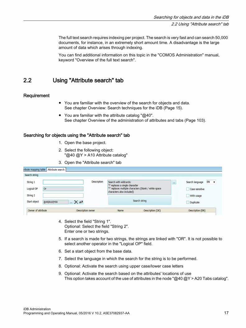
3. Open the "Attribute search" tab
4. Select the field "String 1".Optional: Select the field "String 2".Enter one or two strings.
5. If a search is made for two strings, the strings are linked with "OR". It is not possible to select another operator in the "Logical OP" field.
6. Set a start object from the base data.
7. Select the language in which the search for the string is to be performed.
8. Optional: Activate the search using upper case/lower case letters
9. Optional: Activate the search based on the attributes' locations of useThis option takes account of the use of attributes in the node "@40 @Y > A20 Tabs catalog".
Searching for objects and data in the iDB2.2 Using "Attribute search" tab
iDB AdministrationProgramming and Operating Manual, 05/2016 V 10.2, A5E37082937-AA 17

10.Optional: Activate the search based on the attributes' duplicatesRequirement: The "With usage" option is activated.This option takes account of the use of inherited attributes.
11.Click the "Search text" button
Searching for objects using "Attribute search" and a search listThe following procedure makes it possible for you to use more than two strings, unlike the simple attribute search.
1. Open the base project.
2. Select the following object:"@40 @Y > A10 Attribute catalog"
3. Open the Excel list "A10 Template COMOS attributes" created there.
4. Enter a string either in one of the two languages or in both languages.
5. Save the Excel list.
6. Open the "Attribute search" tab
7. In the "Template" field, select the edited Excel list.
8. In the "Log file" field, select the location where the results list is saved.
9. Optional: Activate the search based on the attributes' locations of use in the options below
10.Optional: Activate the search by upper case/lower case letters in the options below
11.Click on the "Excel export" button.
12.Optional: Delete the "Status" field if you perform several exports.
Searching for objects and data in the iDB2.2 Using "Attribute search" tab
iDB Administration18 Programming and Operating Manual, 05/2016 V 10.2, A5E37082937-AA

13.The "Link 1" and "Link 2" fields are for internal use and should not be edited. These fields control how the Excel list is set up for export.
14.Open the Excel list. The time and date are entered in the file name of the Excel file.
In the results list, the entries are black if:
● The string was found
● All other search conditions were met
In the results list, the entries are red if:
● The string was found
● At least one of the search conditions has not been met
In the results list, the entry "Not found" appears if:
● The string was not found
2.3 Using "Attribute descriptions DE/EN" query
Requirement● You are familiar with the overview of the search for objects and data.
See chapter Overview: Search techniques for the iDB (Page 15).
ProcedureThe "Attribute descriptions DE/EN" query is the fastest way to find an attribute based on description in the attribute catalog. The description of the attribute contains a text for the attribute purpose.
1. Open the "Base data" tab in the Navigator.
2. Find the following object:"@40 > A10 > Y00 @Y Attribute collection":
3. Open the tree structure below the object.You will find:
– Folder "A05 @Y Semantic attribute collection"
– Query "A10 attribute descriptions DE/EN"
4. Select the "Open (classic)" command in the shortcut menu of the "A10 Attribute descriptions DE/EN" query.
5. Set the following start object:"@40 > A10 > Y00 >A05 @Y Semantic attribute collection"
6. Click the "Search" button in the command bar of the query.
7. Select the "AutoSort" command in the column header of the query.
8. Sort either the "Description DE" or "Description EN" column.
Searching for objects and data in the iDB2.3 Using "Attribute descriptions DE/EN" query
iDB AdministrationProgramming and Operating Manual, 05/2016 V 10.2, A5E37082937-AA 19

9. Scroll in the list to the desired description.
10.Alternatively: Select the "Autofilter" command in the column header of the query.
11.Select the "Navigate > Attribute" command in the shortcut menu.
Searching for objects and data in the iDB2.3 Using "Attribute descriptions DE/EN" query
iDB Administration20 Programming and Operating Manual, 05/2016 V 10.2, A5E37082937-AA

Standardized designations for folder objects 33.1 Names and meaning of the main levels in the iDB
Relationship between the system types and the main nodesThe COMOS iDB is subdivided into main nodes:
The main nodes start with an @.
● @10 COMOS base objects
– Base objects
– Connectors
General base objects which are not dependent on particular standards. This is where you can edit settings of the base objects required for the COMOS basic functionalities. @10 is used in @30.On the lower levels, the basic objects are differentiated according to physical requirements and logical requirements.See chapter Structure of the "@10" node (Page 59).See chapter Use/expansion of the "@10" node (Page 61).
● @20 General objects, not dependent on engineering
– Base objects
– Connectors
General base objects which are not dependent on particular standards. That also includes base objects which are not part of a unit but which generally support the work in COMOS. Example: Decision tables, engineering tasks, workflow objects.See chapter "@20 General base objects": Editing basic base objects (Page 65).
iDB AdministrationProgramming and Operating Manual, 05/2016 V 10.2, A5E37082937-AA 21

● @30 Structures
– Base objects
– Connectors
– Base objects for documents
– Categories
– Labeling systems
– General base objects for structure objects (units, locations, folders)
The standard-specific or industry-specific base objects are not new creations, but are an expansion of @10.See chapter "@30 Structures": Editing module-specific structures (Page 85).
● @40 @Y Attributes and tabs
– Attributes
– Tabs
Root nodes for tabs and attributesThe name affix "@Y" must be retained for compatibility reasons.See chapter "@40 @Y Attribute catalog": Editing attributes and tabs (Page 103).
● @50 Manufacturer devices
– Base objects
– Connectors
Manufacturer device catalog that is an expansion of the objects in @30. See chapter "@50 Manufacturer devices": Editing the manufacturer catalogs (Page 131).
● @99 System settings
– Classifications
– Database-dependent user interfaces
– Document type mapping
– Revision base objects
– Status of objects
– Profile objects
– Working layers
– Layers of documents
System-related objectsSee chapter Reference: "@99 System" (Page 135).
● Standard tablesSee chapter Administration of standard tables (Page 149).
● TemplatesTemplates are not base data, but instead are engineering objects which are prepared so that they are ready for use. You can find additional information on this topic in the "COMOS Administration" manual, keyword "Administering templates".
Standardized designations for folder objects3.1 Names and meaning of the main levels in the iDB
iDB Administration22 Programming and Operating Manual, 05/2016 V 10.2, A5E37082937-AA

Connectors do not have their own main node. Instead, the connectors are prepared in nodes @10, @20, and @30. See chapter Connector types in the iDB (Page 51).
Documents do not have their own main node. Instead, base objects of documents are sorted in node @30. The template objects of the documents are on the "Documents" tab in the base project. See chapter Administration of documents in the iDB (Page 175).
3.2 Names of additional levels
Counting convention for namesThe following structure exists below the main nodes:
● Standardized counting with a capital letter and a two-digit numberExample: A10
● Counting in increments of five or ten (numbers in between as reserve)
● Lower levels, alternative 1: The first letter is incremented. Example: "A10 > B10".
● Lower levels, Alternative 2: The first letter is repeated:
● The identifier remains empty in principle. If additional identification is required for a base object due to software reasons, you can use the identifier in exceptional cases:
● If customer objects are to be integrated into existing structures, "Z" or "_Z" is used. See section Inserting customer-specific base objects in the iDB (Page 46).
See also chapter System characters and special characters (Page 28).
Standardized designations for folder objects3.2 Names of additional levels
iDB AdministrationProgramming and Operating Manual, 05/2016 V 10.2, A5E37082937-AA 23

See alsoGenerally-applicable writing rules in standardized descriptions (Page 33)
3.3 Special sub-branches with Y prefixSome areas below the main nodes are labeled with a Y prefix:
● Y00The general objects (catalog objects) are located in this area.
● Y10Objects with system access are located in this area.
● Y20The core objects are located in this area.
● Y30This area includes objects which require special attributes and tabs to support an interface and usually have a deviation from the standardized naming convention. The attributes and tabs are taken from the following nodes:
– "@40 > A10 > Y30 @Y Attribute catalog > Y30 @Y Special attributes collection" and
– "@40 > A20 @Y Tab catalog > Y30 @Y Special tab collection"
● Y40Objects for mapping objects to one another are located in this area.
You will find an example for the names based on the above list below "@20 > A70 Queries".
3.4 The @Local branch for local base objects
Global base objects versus local base objects● Global base objects
base objects created in the base project, which can only be modified there. You can find additional information on this topic in the "Operation" manual, keyword "Fundamental knowledge about objects".
● Local base objects Base objects that are created in the engineering project on the "Base objects" tab. The local base object is distinguished from the base objects of the base project by a blue globe.
Standardized designations for folder objects3.4 The @Local branch for local base objects
iDB Administration24 Programming and Operating Manual, 05/2016 V 10.2, A5E37082937-AA

Avoiding mixed structures1. A local base object should not be created below a global base object.
Failure to heed this recommendation causes the situation in which global base objects are regarded as owners of local base objects. In this case, the following applies:
– The "Copy structure" function generates new local base objects from the global base objects within the owner structure.
– The "Project: Export" function followed by the "Project: Import" function creates new local base objects from the global base objects within the owner structure.
In both cases, the database is expanded and contains many of the same base objects multiple times.
2. Mixed structure are technically prevented for documents.You can only create documents under a base object if the base object is located within the project that was just opened.
Recommendation:
● Create one or more branches for local base objects below the project root in the engineering project on the "Base data" tab. Create local base objects only in these branches.
● If you need parts of the global base objects in the local base objects, set a reference to a global base object in the "Reference" field in the properties of the local base object.
● Use @Local if possible.
@Local branch for preferential use of local base objectsTo automatically search for local base objects and use them instead of the base objects from the base project, proceed as follows:
1. Create a "@Local" node below the local base objects in the engineering project.
2. Create a new base object below "@Local".
3. In this new base object, set a base object reference to the original from the base project.
If you create an engineering object on the basis of an "original" from the base project, COMOS checks the following: Is there a "BackPointerCDevice" from the current engineering project for this "original" located under "@Local"? If yes, this local base object is used in the engineering object as the base object pointer.
This mechanism also works for elements. So you can use the above method to create a project-specific context menu.
Similar functionsYou can find additional information on this topic in the "COMOS Administration" manual, keyword "Objective of instantiation".
Standardized designations for folder objects3.4 The @Local branch for local base objects
iDB AdministrationProgramming and Operating Manual, 05/2016 V 10.2, A5E37082937-AA 25

Standardized designations for folder objects3.4 The @Local branch for local base objects
iDB Administration26 Programming and Operating Manual, 05/2016 V 10.2, A5E37082937-AA

Standardized designations for base objects 44.1 Overview of the naming convention in the iDB
The following provides an overview of how the names of the objects in the iDB are formed. Using these masks you can, for example, search for items specifically by name.
● Attribute:Y00A12345See chapter Storage structure and names of the catalog attributes (Page 108).
● Tab:Y00T12345See chapter Storage structure and names of the tabs (Page 115).
● Standard table:Y00MxxN12345See chapter "@40 Attribute catalog table" (Page 149).
● Reserved name:Y00R12345See chapter Base objects with fixed names (Page 31).
● Border on tab:FR001See chapters Design guidelines for tabs (Page 40) and Overview of the properties of catalog attributes (Page 106).
● Label on tab:LA001See chapters Design guidelines for tabs (Page 40) and Overview of the properties of catalog attributes (Page 106).
● Script in the script library:MxxS12345See chapter Naming of script objects (Page 194).
Explanation of the wildcards used in the name masks:
● Mxx corresponds to the module key with a two-digit count index (00-99)See chapter Special cases when using letters (Page 30).
● 12345 corresponds to a five-digit count index (00001-99999)
● 001 corresponds to a triple-digit count index (001-999)
4.2 Uniqueness of names
"Unique name across folders" optionObjects in COMOS are technically managed using an invisible "UID" (unique identifier). In the user interface, the name is the identification feature used first.
iDB AdministrationProgramming and Operating Manual, 05/2016 V 10.2, A5E37082937-AA 27

A name can be unique in two contexts:
● Unique in the entire projectIf a name is not unique across the project, the object is identified using the name and position. The name is then referred to as "SystemFullName".
● Unique within a hierarchical level.
You can specify this context in the properties of the project, "Options" tab, "Unique name across folders" option.
Checking of name masksIn the "@10" and "@20" branches, the checking of naming conventions is disabled for all objects in the COMOS iDB in the "System" tab.
4.3 System characters and special charactersThe following characters are used internally in COMOS:
● Pipe sign "|"Interpreted in the name as part of the Systemfullname.Interpreted in the description and other translatable fields as a delimiter for the translations of the entry.
● Period "."Interpreted in the name as structure information of potentials.
● @
– cDB: The name is only visible to administrators.
– iDB: No technical significance. Only used for main nodes in the delivery state.
Other conventions for entering strings also exist:
● Names of attributes
– cDB: May not start with a special character.
– iDB: For name template Y00A12345, see section Overview of the naming convention in the iDB (Page 27).
● The relevant manual sections contain descriptions of other conventions which are only valid in specific interfaces.
Standardized designations for base objects4.3 System characters and special characters
iDB Administration28 Programming and Operating Manual, 05/2016 V 10.2, A5E37082937-AA
The system characters and special characters must be considered in scripts and during imports. Errors may occur if an invalid system character is entered in a name or a description by a script or import.
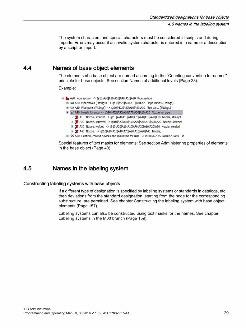
4.4 Names of base object elementsThe elements of a base object are named according to the "Counting convention for names" principle for base objects. See section Names of additional levels (Page 23).
Example:
Special features of text masks for elements: See section Administering properties of elements in the base object (Page 40).
4.5 Names in the labeling system
Constructing labeling systems with base objectsIf a different type of designation is specified by labeling systems or standards in catalogs, etc., then deviations from the standard designation, starting from the node for the corresponding substructure, are permitted. See chapter Constructing the labeling system with base object elements (Page 157).
Labeling systems can also be constructed using text masks for the names. See chapter Labeling systems in the M00 branch (Page 159).
Standardized designations for base objects4.5 Names in the labeling system
iDB AdministrationProgramming and Operating Manual, 05/2016 V 10.2, A5E37082937-AA 29

4.6 Special cases when using lettersThere are special letters in the COMOS iDB that are not used for counting and are skipped for this reason:
● "M"The letter M is reserved for COMOS modules.The list of current modules can be found in the iDB below "@30 Structures" The following list shows a snapshot as an example:
Area Number range Module Module numberPlatform M0x COMOS general M00 Basic M01 Enterprise Server M02 SAP M03 View/Web view M04 Interfaces M05 Teamcenter Interface M06 Process M2x Process general M20 FEED M21 P&ID M22 PipeSpec Designer M23 PipeSpec Manager M24 Isometrics M25 PlantModeler M26 PDMS Integration M27 MTO (Material management) M28 Automation M4x Automation general M40 EI&C M41 Logical M42 Fluidics M43 PCS7 AdvES
– omitted since V10.1.3.0.0M44
Automation Designer – omitted since V10.1.3.0.0
M45
Operations M6x Operations general M60 MRO M61 Shutdown M62 Portable & Direct M63 Inspection M64 PQM M65 PQM4RI M66
Standardized designations for base objects4.6 Special cases when using letters
iDB Administration30 Programming and Operating Manual, 05/2016 V 10.2, A5E37082937-AA

Customer Zxx Customer Z00 etc. Z..
● "W"The letter "W" identifies nodes and objects belonging to Siemens in-house topics.
● "X" in the "Documents" topic areaThe letter "X" designates object queries on report templates.Example: AB_A10_X10
● "X" in the "Database update / Database extension" topic areaThe letter "X" indicates nodes and objects that belong to the content layer.
● "Y"The letter "Y" is reserved for designating attributes, tabs, standard tables, and scripts.
● "C"The letter "Z" designates customer-specific nodes and objects.
4.7 Base objects with fixed namesThere are base objects in the database that must have a predetermined name and must be located at a predetermined location within the base object structure in order to be found and used. So these base objects have to be available at a particular location, under a particular name.
Names are reserved in the iDB for this reason and stored in the following node:
● @20 > D40See chapter@20 > D40 Reserved object names (Page 81)
– The "Y00" node stores objects with reserved names that belong to the delivery state of the iDB.
– The "Z10" node stores customer-specific objects with reserved names.
● In the other main nodes, base objects are created which have a base object pointer set to the base object with a reserved name created in the "@20 > D40". The reserved names are transferred through the base object pointer.
● The name template for reserved names is Y00R12345.
Connectors sometimes have fixed names too. See chapter Reference: Names of the connector types (Page 52).
Standardized designations for base objects4.7 Base objects with fixed names
iDB AdministrationProgramming and Operating Manual, 05/2016 V 10.2, A5E37082937-AA 31

4.8 Entering norm-specific text masks
ProcedureAfter the text fields for text masks and standard texts, there is a button labeled "...":
In the next dialog, you can enter the following text masks and standard values (or a @MASK entry):
● Default value This value is used if there is no entry available for the standard. The entry should be as neutral as possible so that it can be used universally.
● Standard-specific entries (list of standards is predefined)
● Company-specific entry
● User-specific entries
The usual rules for entering text masks apply. You can find more information on these by clicking on the "i" button next to the text fields:
Use of standard-specific text masksSee chapter Basic rules in the "@30" node (Page 86).
Standardized designations for base objects4.8 Entering norm-specific text masks
iDB Administration32 Programming and Operating Manual, 05/2016 V 10.2, A5E37082937-AA

Generally-applicable writing rules in standardized descriptions 5Capitalization
For all texts, use capitalization in accordance with the spelling rules for the relevant language. This also applies to the "Description" field for objects and attributes.
In English, this means that apart from recognized exceptions, only the first word in a sentence has a capital letter, e.g "Inner diameter".
Use of special characters● Use of hyphens
– Terminology (fixed terms, e.g. EN 1092-1): Hyphen without blank spaces
– Compounds (e.g. 3-pole): Hyphen without blank spaces For compounds, check whether a spelling without a hyphen is considered correct.
– Separating nouns and attributes (e.g. Ladder – neutral): A blank space before and after the hyphen
LabelObjects have no entry in the "Label" field in factory state. The only exception is when a label is required for technical reasons.
See alsoLocalization rules for iDB texts (Page 35)
iDB AdministrationProgramming and Operating Manual, 05/2016 V 10.2, A5E37082937-AA 33

Generally-applicable writing rules in standardized descriptions
iDB Administration34 Programming and Operating Manual, 05/2016 V 10.2, A5E37082937-AA

Localization rules for iDB texts 6Requirement
● You are familiar with the notation for iDB texts.See chapter Generally-applicable writing rules in standardized descriptions (Page 33).
Including texts which can be localizedAlways translate all texts which can be localized in order to avoid inconsistencies.
You can find additional information on this topic in the "COMOS Administration" manual, keyword "Application area of language management".
Default: German and EnglishPrimary language is English. If no entry is found in a language, the English text is displayed.
Always translate into the following languages:
● German
● English
– Preferred variant: US English
Do not use any foreign-language entries in the current input language. Example: Do not enter German text in an English field or vice versa.
Neutral namesThe names of engineering objects, attributes, and documents are untranslatable. Therefore:
● Never use language-dependent information in object names.
Neutral names usually consist of sequential alphanumeric characters. Translatable name elements must be entered in the description or tooltips.
Do not use country codesDo not use the country code for labeling translations. The country code is not a unique label for a language variant.
iDB AdministrationProgramming and Operating Manual, 05/2016 V 10.2, A5E37082937-AA 35

Supported localization tools● Alternative 1: Translate new
"Extra > Translation > Single translation", "Extra > Translation > Bulk translation"You can find additional information on this topic in the "COMOS Administration" manual, keyword "Using single translation: Translation of the description".You can find additional information on this topic in the "COMOS Administration" manual, keyword "Manual translation with bulk translation".
● Alternative 2: Check existing translations:"Extra > Translation > Translation search"
● Alternative 3: Automatically apply existing translations:"Extra > Translation > Bulk translation: "Database translation > Automatic translation" option
NoteImportant:
Use the translation tools even when you are only editing one language. If you enter translations directly into text fields, COMOS inserts the prefix "?0?" in front of texts in other languages as an inconsistency marker.
Error in delivery stateDo not correct the delivered database of the iDB. Local corrections can result in inconsistent translations.
Proceed as follows instead:
● Create a working layer in the base project.
● Correct the data in the working layer.
● Export the working layer.
● Send the exported working layer to the following address:[email protected]
● Use the next version of the iDB.
See alsoLocalizing texts in scripts with NLS (Page 212)
Localization rules for iDB texts
iDB Administration36 Programming and Operating Manual, 05/2016 V 10.2, A5E37082937-AA

Generally applicable rules for base objects 77.1 "Object locking" and "System object" state
Overview of the functions for protecting system-relevant objectsThe iDB contains system-related objects which must not be changed. The following functions are available to protect these objects:
● "Lock object"This function right can be set and also unlocked again by administrators. The "Lock object" function right has the states "Unlock" and "Lock".You can find additional information on this topic in the "COMOS Administration" manual, keyword "Function right "Lock object"".
● "Object locking"The "Object locking" function is available in two versions:
– Object locking in the delivery state (locking on the system side; SysLock)This function is only available for Siemens employees.
– Object locking after delivery of the iDB (locking by customer; AdminLock)This function can be used by administrators.
● "System object"For reasons of clarity, the "system object" status is also available. This status shows that the object is a system-related object. The status has no other implications. In practice, the "System object" status is often combined with the "Object locking" function.
Effect of the "Object locking" functionObjects which have been locked on the system side have the following properties:
● Locked against being changed, deleted, moved
● The following can be changed:
– Properties for user inputs ("Value", "XValue", "Unit", "Link objects")
– Description
● The creation of elements can be independently permitted or prohibited
● The creation of objects can be independently permitted or prohibited
The following object types can be locked on the system side:
● Base objects
● Attributes
● Attributes tab
● Connectors
● Standard table
iDB AdministrationProgramming and Operating Manual, 05/2016 V 10.2, A5E37082937-AA 37

● Standard table value
● Unit group
● Unit
● Document
● Engineering object
Inheriting of the "Object locking" functionThe "Object locking" property is inherited in the base data. In contrast to other properties it is not possible to see if the setting is inherited in the case of the "Object locking" property.
If the "lock-lock" property has been edited on a base object and thus the inheritance is interrupted, it is not possible to return to the inheritance.
Checking the state of the "Object locking" function (locking on system side)You can check the status of an object as follows:
● Properties of the object, menu bar of the tab
– An icon for the status regarding the object locking
– An icon for the status regarding the "system object" property.
● Window for the status of the object rights (Ctrl+A)
– "Status of the object locking" field
The object locking status can be as follows:
Unlocked
AdminLock (without creation of substructures)
AdminLock (with creation of substructures)
SysLock (without creation of substructures)
SysLock (with creation of substructures)
Objects with object locking are displayed in gray in the navigator.
Editing the "Object locking" stateWhen the object is unlocked, the object is switched over in the state "AdminLock (without creation of substructures)" or "SysLock (without creation of substructures)" with a click on the button.
Generally applicable rules for base objects7.1 "Object locking" and "System object" state
iDB Administration38 Programming and Operating Manual, 05/2016 V 10.2, A5E37082937-AA

When the object is in the state "AdminLock (without creation of substructures)" or "SysLock (without creation of substructures)", the following options are available:
● Clicking the icon againThe object is switched back to the "Unlocked" state.
● Selection via the menuAn arrow is displayed at the icon. It is then possible to switch between the states "without creation of substructures" and "with creation of substructures".
"System object" status
Object is not a system object.Object is a system object.
7.2 Creation option for base objectsProperties of a base object, "System" tab, "Creation option":
● Base objects for structuring the base data (folders)Creation option: "Structure"
● Base objects that form the basis for engineering objectsCreation option: "Normal"
7.3 Adding tabs to base objects
Procedure1. Optional: Edit the "@40" catalog
– Add missing tabs in the "@40" tab catalog.
– Edit tabs in the "@40" tab catalog.
2. Open the properties of a base object.
3. Select the "Attributes" tab.
4. Switch to design mode.
5. Move a tab from the "@40" tab catalog to the design area using drag&drop. No changes to the tab are allowed at the base object itself.
See alsoDesign guidelines for tabs (Page 40)
Generally applicable rules for base objects7.3 Adding tabs to base objects
iDB AdministrationProgramming and Operating Manual, 05/2016 V 10.2, A5E37082937-AA 39

7.4 Design guidelines for tabs
Requirement● You know how tabs are added.
See chapter Adding tabs to base objects (Page 39).
Specifications for frames on tabsUse the following default settings:
● Title visible: Switched on
● Frame type: Normal
● Font
– MS Sans Serif
– Normal
– 8
– Black
7.5 Creating elements at base objects
7.5.1 Administering properties of elements in the base object
Requirement● An element has been created.
See chapter Constructing the labeling system with base object elements (Page 157).You can find additional information on this topic in the "COMOS Administration" manual, keyword "Creating an element for the base object".
Creation modeYou can specify the creation mode at each base object.
The creation mode controls how the base objects and elements are created below the engineering object in the engineering view:
Free: All prepared objects are created in the engineering view. Element: Only the objects which are defined as elements for this object in the "Elements"
tab on the base data side are created in the engineering view.
Generally applicable rules for base objects7.5 Creating elements at base objects
iDB Administration40 Programming and Operating Manual, 05/2016 V 10.2, A5E37082937-AA

Subelement: Only engineering objects which are subelements (child objects) of the base object can be created in the engineering view.Cross-inherited elements cannot be created.NOTE: The "Subelements" option is not used in COMOS iDB. The "Extend subelements" option is used instead.
Extend subele‐ments:
Only engineering objects which are subelements (child objects) of the base object can be created in the engineering view.Cross-inherited subelements are also created.
"Dereference" settingIf the "Dereference" option is set to "Yes", then, when a new engineering object is created, right-clicking will set the base object (2) of the element as the base object of the new engineering object rather than setting the element (1) as this.
In such cases, only the following properties are applied from the element (1) (if they are checked in):
● Name
● Label
● Description
Do not check in any other properties from the element (1), in order to save memory space.
If the "Reference > Base object" field is empty, the "Dereference" option has no effect.
Special rules for labeling systems: See chapterControlling base object links using dereferencing (Page 46).
Generally applicable rules for base objects7.5 Creating elements at base objects
iDB AdministrationProgramming and Operating Manual, 05/2016 V 10.2, A5E37082937-AA 41

"Inheritance mode" setting
Value Description"Active" The element is inherited by the derived objects and by the base objects under the
element owner."Inactive" Inheritance is switched off completely.
You can use this inheritance mode to prepare multiple elements at one level of the structure tree and deactivate the elements which are no longer needed in the lower levels.
"Inactive for base objects"
Inheritance within the base data is deactivated.
Inheritance mode is also available for the following system types:
● "Specification"
● "Connector"
"Virtual" setting (for elements only)Only elements have this control group. It governs how often and when the element is created in the engineering project. Elements which have been prepared in the base data but have not yet been created in the engineering data are designated as "virtual".
The "Virtual" setting has the following options:
"[ ] times" The element can be inserted into the engineering project as often as specified and can be deleted. Once the maximum number is reached, the object is no longer offered in the context menu. The name template is taken into considera‐tion. The inheritance mode is not evaluated.
"N times" The element can be inserted into the engineering project any number of times and can be deleted. The name template is taken into consideration. The inheri‐tance mode is not evaluated.
"Off" The element is created automatically when the engineering object is created and cannot be deleted. The name template is not taken into consideration. In addition to this option, the inheritance mode is evaluated.
"Preselec‐tion"
The element is created automatically when the engineering object is created but can be subsequently deleted. After deletion it can be created again manually. The name template is taken into consideration.● Database of the type iDB: The name template is taken into consideration.● Database of the type cDB: The name template is not taken into consideration. In addition to this option, the inheritance mode is evaluated.
Note
For virtual "Off":
"Dereference" is automatically set to "No" internally (regardless of the setting in the "Reference" group)
Generally applicable rules for base objects7.5 Creating elements at base objects
iDB Administration42 Programming and Operating Manual, 05/2016 V 10.2, A5E37082937-AA

Additional informationYou can find additional information on this topic in the "COMOS Administration" manual, keyword ""Elements" tab for base objects".
7.5.2 Constructing context menus via elements
ProcedureA hierarchical structure is created from elements. Example:
● Base object A30 is inserted on the "Elements" tab of base object A20
● Base object A20 is inserted on the "Elements" tab of base object A10
Result in the context menuIf base object A10 is created as an engineering object, then (in this example) engineering object A1 is produced. Engineering object A1 has the following context menu:
If the element A20 is selected in the context menu of object A1, then engineering object "A01" is produced. The name change from "A20" to "A01" is compliant with the COMOS naming rules.
Object A01 has the following context menu:
Generally applicable rules for base objects7.5 Creating elements at base objects
iDB AdministrationProgramming and Operating Manual, 05/2016 V 10.2, A5E37082937-AA 43

7.5.3 Constructing context menus via subelements
ProcedureA hierarchical structure is created from base objects. The complete structure is used as an element via a root object.
Example:
● Base object A40 is created with the "Structure" creation option.
● Base object A10 is created below this, with the "Structure" creation option.
● Base object A10 is created below this, with the "Normal" creation option.
● Base object A40 is inserted on the "Elements" tab of base object A30.
Note
The creation options for base objects A40 and A10 must be set as a "Structure" in order that they are displayed via the context menu.
Result in the context menuIf base object A30 is created as an engineering object (with the name "Test1" in the following example), then this engineering object has the following context menu:
This results in the following structure in the engineering view:
Note that the intermediate layers have not been created as engineering objects.
Generally applicable rules for base objects7.5 Creating elements at base objects
iDB Administration44 Programming and Operating Manual, 05/2016 V 10.2, A5E37082937-AA

7.6 Forming a labeling system with elements
Aim of a labeling systemLabeling systems are a standard method for labeling all objects in a unit. In COMOS, labeling systems are constructed via the automatic assignment of names or labels for newly created engineering objects. In this case, the base data is prepared so that, when the engineering objects are created, the names are assigned according to the labeling system.
Standard-specific labeling systems are constructed with the help of base object structures.
See Chapter Administration of the labeling system and ALIAS labeling system (Page 157).
7.7 Prohibited change for the target of cross-inheritancesIn the following example, base object (target) has been produced from base object (source) by means of a cross-inheritance (reference in the "Base object" field).
Source:
Target:
The following rules apply:
● Do not change the base object (target).
● Create a child object below base object (target).
● Edit the base object (child object).
Generally applicable rules for base objects7.7 Prohibited change for the target of cross-inheritances
iDB AdministrationProgramming and Operating Manual, 05/2016 V 10.2, A5E37082937-AA 45

7.8 Inserting customer-specific base objects in the iDB
Independent structures in customer area ZYou can create and configure your own base objects below the customer nodes in accordance with the rules in this document. You can create more customer nodes within the existing COMOS iDB structures using the letter Z and COMOS iDB counting. See Chapter Customer-specific additions (Page 223).
7.9 Controlling base object links using dereferencing
AimThe "Dereference" option is displayed if the "Base object" field has been set. See chapter Administering properties of elements in the base object (Page 40).
● The fields "Name", "Label", and "Description" are applied to the engineering object from the base object from which it is derived. All other properties are applied from the base object entered in the "Base object" field as the base object.
● The information about which base object was used to derive the engineering object originally is lost. Instead, the connection to the base object referenced in the "Base object" field is saved at the engineering object.Any future changes to the base object from which an engineering object was originally derived have no effect on the engineering object. Changes to the base object referenced in the "Base object" field are applied.
The "Dereference" option is mainly used in the case of labeling systems. Labeling systems are constructed using base object links from other branches.
Using "dereferencing" in labeling systemsThe following rule applies when constructing labeling systems:
● If the base object in the "Reference > Base object" field is applied without changes, then:The "Dereference" option is activated. Effect:
– In the right mouse button context menu of the engineering object, the structure from the @30 node is provided first.
– However, the objects are created from the @10 node when they are created.
● If standard-specific customizations are made in the labeling system, then: The "Dereference" option is deactivated.
Generally applicable rules for base objects7.9 Controlling base object links using dereferencing
iDB Administration46 Programming and Operating Manual, 05/2016 V 10.2, A5E37082937-AA

Examples● Official labeling systems (KKS, RDS-PP, etc.)
For general objects, the "Dereference" option is set to "No" For device objects, the "Dereference" option is set to "Yes"
● General ET labeling"Dereference" option set to "No"
See alsoLabeling systems in the M00 branch (Page 159)
7.10 Using or editing icons
Default storage in the iDBDefault storage for icons:
● "<Database> SO1 > ICONS"
General specifications● 16x16 pixels
Only icons with the size 16x16 are officially supported. Other formats are not displayed in all parts of COMOS.
● 32-bit color depth Reason: Support for alternative displays (working layer display mode, status displays, base data display)
● 72 dpi
● Alpha
● Scaling The location being used in COMOS determines how the image is displayed
● Background: TransparentIn some cases, COMOS uses the color of the pixel in the bottom left corner as the transparency color. This also applies when the "Transparent" property is set in the icon.Exception: the color black
● Keep the number of different icons low, as the icons have an effect on storage management.
Generally applicable rules for base objects7.10 Using or editing icons
iDB AdministrationProgramming and Operating Manual, 05/2016 V 10.2, A5E37082937-AA 47

OverviewIcons are assigned in two different ways in COMOS:
● Assignment using the object classThe icon is read out from Picture.dll based on the object class. No path is entered in the "Manage icon" dialog:
● Assignment using an icon fileA selection is made at the base object:
The icons are stored in a file system which resembles the structure of the database:
Generally applicable rules for base objects7.10 Using or editing icons
iDB Administration48 Programming and Operating Manual, 05/2016 V 10.2, A5E37082937-AA

Outdated: Assignment using the "icon library"This variant only continues to be supported for compatibility reasons and is not permitted in the COMOS iDB.
7.11 Overview for administration of symbols● Interaction of symbols and drawing types
See chapter Drawing type-specific symbol display (Page 49).
● Information on export of symbols to AutoCadSee chapter Preparing symbols for AutoCAD export (Page 51).
● Storage of symbols in branch @20See chapter @20 > C30 Symbol construction (Page 78).
7.12 Drawing type-specific symbol display
AimThe aim in this case is to display objects differently for different drawing types. Module-specific display characteristics are created at the object for this purpose. Standard-specific displays are also possible.
ProcedureThe naming of the individual drawing types is divided into three blocks:
Generally applicable rules for base objects7.12 Drawing type-specific symbol display
iDB AdministrationProgramming and Operating Manual, 05/2016 V 10.2, A5E37082937-AA 49

SAMPLE: M20_P1
1. Three-digit module labelThe module letters are used here (e.g. M20). This name is also used here if you are dealing with a customer-owned module starting with a "Z". (e.g. Z00) If you are dealing with a drawing type that is used by several modules, it is assigned to the Basic module.
2. SeparatorsBlocks 1 and 2 are separated with the "_" separator.
3. One-digit sequence number with leading "P"This block uses a single-digit sequence number. Customer-specific symbols can be added by using the suffix "_Z" (e.g., P1_Z).
This means the following three cases apply:
M20_P1 Standard drawing typeZ00_P2 Customer drawing typeM20_P1_Z Customer-specific extension of a standard drawing type
Exception for the 3D area:
M20_P1_-XY
M20_P1_-XZ
M20_P1_-YZ
The respective module affiliation is described in the drawing type column:
This description is to be done in several languages.
Relationship with the drawing typesIf a module or an operation mode is to have its own display, a drawing type must be available for it.
Generally applicable rules for base objects7.12 Drawing type-specific symbol display
iDB Administration50 Programming and Operating Manual, 05/2016 V 10.2, A5E37082937-AA

Suppress placement of symbols on datasheetsIf you want to display notes on a datasheet, you need to create the document as an interactive report. If no further measures are taken, symbols are also be placed on datasheets.
To suppress the placement of symbols on datasheets, the undefined drawing type "DATASHEET" is entered on the datasheets.
7.13 Preparing symbols for AutoCAD exportIf a symbol contains white areas (filled hatching), no pure white may be used (255,255,255) as AutoCAD interprets this as transparent. A "semi-white" such as 250,250,250 must be used instead of this.
7.14 Connector types in the iDB
7.14.1 Purpose of the connector types
DefinitionConnectors are special objects in COMOS below an object. They represent the connection points of an object. Two objects can be connected with connectors this way. Examples include process engineering connectors for pumps and electrical connectors for motors.
Important properties of connectors● Name
See chapter Reference: Names of the connector types (Page 52).
● LabelA connector either has its own label or it takes on the label of the owner.
● DescriptionAllocating a description to a connector is not prescribed as mandatory but can be stated where required.Example: Module EI&C, Logical:
– Symbol graphics
– Connection list
– Signal list
Generally applicable rules for base objects7.14 Connector types in the iDB
iDB AdministrationProgramming and Operating Manual, 05/2016 V 10.2, A5E37082937-AA 51

● Input/OutputOne property of a connector is "I/O". This property identifies the connector as input, output or neutral (and also each version in "intrinsically safe"). You can also enter a type here. In this way, a connector of the "Single line" type cannot be connected with a connector of a different type. Furthermore, there are regulations defined for the permissible connections between connectors.
● Type/Subtype
LinksYou can find additional information on this topic in the "Administration" manual, keyword "Configuring connectors".
7.14.2 Reference: Names of the connector types
Naming system for connectorsThe name given is neutral and is assigned for each module.
Attention must be paid to the length of the name as the name will be displayed on different plans.
Connectors are generally independent of the drawing type, i.e. a connector may be displayed on different drawing types. In some cases connectors are only displayed on one drawing type or on no drawing type at all.
Structure of the name: 3 or 4 characters (the first two characters are letters; the following characters are figures with consecutive numbering):
Note
The consecutive numbering may have one or two digits.
1. Position 2. Position 3. Position 4. Position NoteLetter Letter Number Number A BasicB BasicC ProcessD ProcessE AutomationF AutomationG OperationsH Operations Z Often used for customer-specific connectors
Generally applicable rules for base objects7.14 Connector types in the iDB
iDB Administration52 Programming and Operating Manual, 05/2016 V 10.2, A5E37082937-AA

1. Position 2. Position 3. Position 4. Position NoteLetter Letter Number Number A Free naming within each module … Free naming within each module Z Free naming within each module 0 1 Consecutive numbering (one or two digits) 0 2 Consecutive numbering (one or two digits) … Consecutive numbering (one or two digits) 0 9 Consecutive numbering (one or two digits) 1 0 Consecutive numbering (one or two digits) … Consecutive numbering (one or two digits)
The first digit is for the purposes of assignment to the 4 higher-level areas in COMOS. The letter "Z" is reserved for customer-specific connectors. The second digit is assigned within an area. After this the number is consecutive (with one or two digits).
Fixed names in the Automation area
ET Multiline EAxxET Singleline EBxxET Bridge internal ECxxET Bridge external EDxxET Reserve EExx – EHxx (4 Reserve)IC Multiline EIxxIC Singleline EKxxIC Reserve ELxx – EOxx (4 Reserve, when J is not used)
Fluid Hydraulic FAxxFluid Pneumatic FBxxFluid Lubrication FCxxFluid Reserve FDxx-FHxx (5 Reserve)Logical FUP input FIxxLogical FUP output FKxxLogical Reserve FLxx
There are more exceptions in the area of automation for connector arrays and PE connectors.
Fixed names in the M20 Process area
Old name New name Note ModuleCX0 CX0 for origin connectors (never used in BaseProject) VIPERCX1 CX1 Viper ComosConnectors VIPERCX2 CX2 Viper ComosConnectors VIPER
Generally applicable rules for base objects7.14 Connector types in the iDB
iDB AdministrationProgramming and Operating Manual, 05/2016 V 10.2, A5E37082937-AA 53

Old name New name Note ModuleCX3 CX3 Viper ComosConnectors VIPERCX4 CX4 Viper ComosConnectors VIPERCA1 CA1 for actuator connectors VIPERCA2 CA2 for actuator connectors VIPERCA3 CA3 for actuator connectors VIPERCA4 CA4 for actuator connectors VIPERCAn CAn for actuator connectors VIPERCY1 CY1 for dynamic connectors (never used in BaseProject) VIPERCY2 CY2 for dynamic connectors (never used in BaseProject) VIPERCY3 CY3 for dynamic connectors (never used in BaseProject) VIPERCY4 CY4 for dynamic connectors (never used in BaseProject) VIPERCYn CYn for dynamic connectors (never used in BaseProject) VIPERCP1 CP1 for physical connectors (never used in BaseProject) VIPERCP2 CP2 for physical connectors (never used in BaseProject) VIPERCP3 CP3 for physical connectors (never used in BaseProject) VIPERCP4 CP4 for physical connectors (never used in BaseProject) VIPERCPn CPn for physical connectors (never used in BaseProject) VIPERCM1 CM1 for attachment connectors (for mounting parts like nuts or slip on
flanges)VIPER
CM2 CM2 for attachment connectors (for mounting parts like nuts or slip on flanges)
VIPER
CM3 CM3 for attachment connectors (for mounting parts like nuts or slip on flanges)
VIPER
CM4 CM4 for attachment connectors (for mounting parts like nuts or slip on flanges)
VIPER
CMn CMn for attachment connectors (for mounting parts like nuts or slip on flanges)
VIPER
C#1 C#1 for CP/CX in IsoSymbols. VIPERC#2 C#2 for CP/CX in IsoSymbols. VIPERC#3 C#3 for CP/CX in IsoSymbols. VIPERC#4 C#4 for CP/CX in IsoSymbols. VIPERC#n C#n for CP/CX in IsoSymbols. VIPERCX# CX# for connectionTypes in IsoSymbols VIPERCP# CP# for connectionTypes in IsoSymbols VIPERI1 CI1 input connector FEEDO1 CO1 output connector FEEDO2 CO2 output connector FEEDO3 CO3 output connector FEEDO4 CO4 output connector FEED001 CN1 dynamic and/or neutral connector FEED002 CN2 dynamic and/or neutral connector FEED003 CN3 dynamic and/or neutral connector FEED004 CN4 dynamic and/or neutral connector FEEDW CS1 signal line connector FEED
Generally applicable rules for base objects7.14 Connector types in the iDB
iDB Administration54 Programming and Operating Manual, 05/2016 V 10.2, A5E37082937-AA

Old name New name Note ModuleW1 CS2 signal line connector FEEDW2 CS3 signal line connector FEEDW3 CS4 signal line connector FEEDW4 CS5 signal line connector FEEDWn CSn signal line connector FEEDI1 DI1 input connector P&IDI2 DI2 input connector P&IDO1 DO1 output connector P&IDO2 DO2 output connector P&ID001 DN1 dynamic and/or neutral connector P&ID002 DN2 dynamic and/or neutral connector P&IDW DS1 signal line connector P&IDW1 DS2 signal line connector P&IDW2 DS3 signal line connector P&IDW3 DS4 signal line connector P&IDW4 DS5 signal line connector P&IDWn DSn signal line connector P&ID
Comparison of names in the old COMOS database and COMOS iDB
Old connector name in DB V10.0 and below New connector name in the COMOS iDBSLI EB01SLO EB02SL1 EB01SL EB01SL1 EB01SL11 EB02CPxx EAxxBI[1] EC[1]BI[2] EC[2]BE[1] ED[1]BE[2] ED[2]I II[3] I[3]I1 I1I2 I2IN1 EA01IN2 EA02O OO[1] O[1]O1 O1O2 O2
Generally applicable rules for base objects7.14 Connector types in the iDB
iDB AdministrationProgramming and Operating Manual, 05/2016 V 10.2, A5E37082937-AA 55

Old connector name in DB V10.0 and below New connector name in the COMOS iDBO3 O3OUT1 EA02 or EA03PE EE01
See alsoPurpose of the connector types (Page 51)
7.14.3 Connectors on EI&C reports
Dynamic connectors on EI&C reportsIf you move an object which does not have a symbol onto an EI&C report via drag&drop, a "black box" is created as the symbol for this object.
The following picture shows a black box:
A black box has dynamic connectors. You can use the dynamic connectors from all sides at the same time.
If you wire the black box, the connectors are created during runtime. To enable COMOS to assign the location, a distinction is made between X/Y and I/O. Because wiring of this type does not take place until the project planning stage, this naming does not exist in the base project.
7.15 General object class
The General object class (TopLevel)Background: When objects are displayed in the Navigator, these objects will be presented only on one tab in most cases. The tab "owns" the object. You can set a "reference" on the other tabs, but these references are not the original object.
In contrast to this, an object with the "General" class is always displayed on all tabs. The corresponding icon adjusts to the tabs in question. Technically, however, in spite of the different icons, this is always the same object.
Generally applicable rules for base objects7.15 General object class
iDB Administration56 Programming and Operating Manual, 05/2016 V 10.2, A5E37082937-AA

An object of the "General" class must be located below the project or below another object of the "General" class.
The objects are displayed in the Navigator depending on the following attributes of the "Check box" type:
● "SYS.InvisibleInUnitTree"
● "SYS.InvisibleInLocationTree"
● "SYS.InvisibleInDocumentTree"
The attribute has to be set at the base object, the setting at the engineering object is not evaluated.
7.16 Deleting objectsYou can find additional information on this topic in the "COMOS Administration" manual, keyword "Overview of deletion of objects".
Generally applicable rules for base objects7.16 Deleting objects
iDB AdministrationProgramming and Operating Manual, 05/2016 V 10.2, A5E37082937-AA 57

Generally applicable rules for base objects7.16 Deleting objects
iDB Administration58 Programming and Operating Manual, 05/2016 V 10.2, A5E37082937-AA

Administering "@10 Requirement objects" 88.1 Purpose of the "@10" node
The "@10" node includes the standard-neutral COMOS base objects and requirement objects. These objects are reduced to the permitted minimum.
For the general method of requirements refer to the "EI&C Administration" manual, keyword "Preparing requirements".
8.2 Structure of the "@10" nodeObjects are sorted by COMOS topic, COMOS module and object type in the "@10" node.
1. First level and possibly second level: Sorting by COMOS topic, then by COMOS module:
2. Second or third level: a distinction is made between the "Physical objects" and "Logical objects" nodes for all branches.This is where the requirement objects are sorted:
– "A10 Physical objects"
– "A20 Logical objects"
iDB AdministrationProgramming and Operating Manual, 05/2016 V 10.2, A5E37082937-AA 59

NOTICE
Rules for cross-inheritance
There may only be a cross-inheritance from the "@10" node to the "@20" or "@30" node. Cross-inheritance within the "@10" node is only permitted as an exception.
8.3 Editing options of the "@10" nodeAll settings of the base objects that are required for the basic functionalities are edited in the "@10" node:
● General information on the base object:
– Description
– Class / subclass
● Classification
● Tabs with system access (hardcoding)
● System-related tabs
● Graphic-related tabs
● Symbols of different drawing types (if available)
● Connectors (as required for basic functionalities)
● Elements (as required for basic functionalities)
Administering "@10 Requirement objects"8.3 Editing options of the "@10" node
iDB Administration60 Programming and Operating Manual, 05/2016 V 10.2, A5E37082937-AA

8.4 Use/expansion of the "@10" node
Node @10 Settings of base objects required for basic functionalities are edited here. See chapter Editing options of the "@10" node (Page 60).
@10 is used in:"@30" node Expansions for specific standards and topics:
● General information on the base object:– Description – Name template
● Expansions of the tabs:– Standard-specific forms– Example attribute (Technical data)– Device-specific forms
● Connectors● Elements / element structures● Symbols
@10 is used in:"@50" node Device-specific expansions:
● General information on the base object:– Name– Name template– Description
● Input of data in tabs● Connectors● Elements / element structures● Symbols
See alsoNames and meaning of the main levels in the iDB (Page 21)
8.5 Notes on expansion of tabs
Requirement● You are familiar with the use/expansion of the @10 node.
See chapter Use/expansion of the "@10" node (Page 61).
Administering "@10 Requirement objects"8.5 Notes on expansion of tabs
iDB AdministrationProgramming and Operating Manual, 05/2016 V 10.2, A5E37082937-AA 61

Criteria for the tabs
Node @10 Criteria for tabs and attributes:● With system access (hardcoding)● System-related● Graphic-related
@10 is used in:Node @30 Criteria for tabs and attributes:
● Standard-specific forms● Example attribute (Technical data)
Objects are only created with system-related information in the "@10" node. These objects are then used in standard-specific structures in the "@30" node and additional information is added.
8.6 Example for use of the "@10" nodeThe base object of a vessel is prepared in the "@10" node:
Base object 1 only has symbols, settings, attributes, and connectors that are independent of standards. Base object 1 is used in different device structures in the "@30" node (2 and 3):
Administering "@10 Requirement objects"8.6 Example for use of the "@10" node
iDB Administration62 Programming and Operating Manual, 05/2016 V 10.2, A5E37082937-AA

Base objects (2) and (3) are developed on a standard-specific basis. This involves, for example, inserting standard-specific elements which were not present for base object (1) (using base object 2 as example):
Standard-specific information is constructed in node @30, where (with reference to this example) it is used for base object (2) and base object (3). Because the objects in the standard-specific node of @30 have a reference to objects in the node in @10, the inheritance is interrupted at this point. This means it is not possible to prepare the manufacturer devices in node @30 at an upper node. Instead, the following applies to each base object with a reference to an @10 base object: The standard-specific elements and/or attributes must always be built into the @30 structure using a reference. See section Notes on multiple use of "@10" objects (Page 63).
See alsoDevice structure A50 below the modules (Page 99)
8.7 Notes on multiple use of "@10" objectsThe hierarchical inheritance is interrupted due to the cross-inheritance of the objects in the "@30" node. This means standard-specific elements and standard-specific attributes must be created new for each object in the "@30" node.
Example "@30 > M21 > A50 > A10 > A10 > A30 > A30":
Administering "@10 Requirement objects"8.7 Notes on multiple use of "@10" objects
iDB AdministrationProgramming and Operating Manual, 05/2016 V 10.2, A5E37082937-AA 63
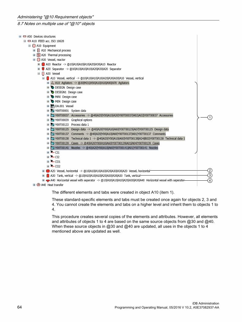
The different elements and tabs were created in object A10 (item 1).
These standard-specific elements and tabs must be created once again for objects 2, 3 and 4. You cannot create the elements and tabs on a higher level and inherit them to objects 1 to 4.
This procedure creates several copies of the elements and attributes. However, all elements and attributes of objects 1 to 4 are based on the same source objects from @30 and @40. When these source objects in @30 and @40 are updated, all uses in the objects 1 to 4 mentioned above are updated as well.
Administering "@10 Requirement objects"8.7 Notes on multiple use of "@10" objects
iDB Administration64 Programming and Operating Manual, 05/2016 V 10.2, A5E37082937-AA

"@20 General base objects": Editing basic base objects 99.1 Purpose of @20
Purpose of the "@20 General objects" nodeThis node contains base objects for logical objects such as units, functions, queries, etc. As with the @10 node there are no standard-specific structures here either.
Structure and order of the "@20 General objects" nodeDifferent sorting criteria are permitted for nodes below @20:
● Sorting according to COMOS object types with specified class/subclassExamples: Units, categories
● Sorting according to base objects related by topic with different object configurationExamples: SAP objects, PDMS objects
Additional subnodes for specific objects of the relevant COMOS modules can exist below the subnode for the "@20 General objects" node. Only the structures required for the COMOS modules are created at this stage in order to increase clarity. Missing nodes can be added, if necessary.
Example of a COMOS-module specific subnode structure:
iDB AdministrationProgramming and Operating Manual, 05/2016 V 10.2, A5E37082937-AA 65

Basic rules for all objects in the "@20 General objects" nodeThe sub nodes of the @20 "General objects" node may only be created with the "Structure" option. Class/subclass and classification are set at these structure objects. These structure objects may not have elements. General base objects are created below. The order and structure of the "General objects" are explained in the sections for the individual object groups. ##??
9.2 Interface objects for base data import (dynamic objects)
AimBase objects which change again and again when importing takes place are called dynamic base objects. Interface objects that create dynamic base objects (i.e. import base data) can be prepared in the database.
The interface objects are stored below the following nodes:
● @20 > A90 Standard import objects
● @20 > D20 Base objects from external CAE files
The nodes are explained in detail below.
@20 > A90 Standard import objectsGeneral import interfaces and module-specific import interfaces are stored in the "@20 > A90 Standard import objects" node. Only the interface objects are prepared in this node, base data are not imported into it.
● A90 > M00 > A10Excel import for manufacturer catalogs
● A90 > M40 > A10Import for Automation Hardware
"@20 General base objects": Editing basic base objects9.2 Interface objects for base data import (dynamic objects)
iDB Administration66 Programming and Operating Manual, 05/2016 V 10.2, A5E37082937-AA

@20 > D20 Base objects from external CAE filesThe dynamic objects from CAE data are stored in the "@20 > D20" node.
You can create a node for each import interface below the "@20 > D20 > Y30 Base objects from external CAE files" node.
The names of the nodes below the "@20 > D20 > Y30 Base objects from external CAE files" node should be based on the imported file extension:
● PDMS
● DXF
● DWG
● IDF
● XM plant
Example:
The name can also include specific extensions.
NoteNo maintenance of the Y30 node
Note that the contents of the "@20 > D20 > Y30 Base objects from external CAE files" node are not maintained by Siemens.
Some import interfaces are prepared in the COMOS iDB.
Tabs and attributes of the imported base objectsThe tabs and attributes of the imported base objects are created and adapted during the import. They are not known beforehand.
See section Dynamically created attributes (Page 128) and section Dynamically created tabs (Page 129).
"@20 General base objects": Editing basic base objects9.2 Interface objects for base data import (dynamic objects)
iDB AdministrationProgramming and Operating Manual, 05/2016 V 10.2, A5E37082937-AA 67

9.3 Reference: "@20 General base objects"
9.3.1 @20 > A10 Units
OverviewObjects below this node should have the class "Unit" and the subclass "(None)". This means the parameter settings for this node are as follows:
Class: UnitSubclass: (None)
The following three nodes exist below this node:
● A10 Units, general
● A20 Template objects
● A30 Categories
@20 > A10 Units > A10 Units, general:The following settings apply here:
Class: UnitSubclass: (None)
Base objects for units/subunits are created here which are then used in the specific tagging systems.
These base objects are stored specific to the COMOS module.
@20 > A10 Units > A20 Template objects:The following settings are made as of the Templates node:
Class: UnitSubclass: (None)Name template: "\@\T\e\m\p\l\a\t\e"Name template specified val‐ue:
"@Template"
"@20 General base objects": Editing basic base objects9.3 Reference: "@20 General base objects"
iDB Administration68 Programming and Operating Manual, 05/2016 V 10.2, A5E37082937-AA

The name template with the specified value "@Template" must be set so that the name @Template is guaranteed at the engineering end for certain software functions to work.
@20 > A10 Units > A30 Categories:The following settings apply here:
Class: UnitSubclass: Category
Here you create the category folder required for the "Units" tab.
The individual COMOS modules are located below the categories.
9.3.2 @20 > A15 Categories
OverviewThe following settings apply here:
Class: UnitSubclass: Category
The base objects for category folders are stored here. The base objects are sorted by COMOS modules.
9.3.3 @20 > A20 LocationsObjects below this node should have the "Location" class. The subclass depends on the use of the base object.
Class: LocationSubclass: (variable)
Both the following nodes exist below this node:
● A10 Locations, general
● A20 Template objects
"@20 General base objects": Editing basic base objects9.3 Reference: "@20 General base objects"
iDB AdministrationProgramming and Operating Manual, 05/2016 V 10.2, A5E37082937-AA 69

@20 > A20 Locations >A10 Locations, generalThe following settings apply here:
Class: LocationSubclass: (variable)
Underlying base objects are stored here specific to the COMOS module for engineering in the "Locations" tab. The base objects are sorted by COMOS modules:
@20 > A20 Locations >A20 Template objectsThe following settings apply here:
Class: LocationSubclass: CategoryName template: "\@\T\e\m\p\l\a\t\e"
The name template with the specified value "@Template" must be set so that the name @Template is guaranteed at the engineering end for certain software functions to work.
9.3.4 @20 > A25 PositionsThe base objects for the positions are stored here specific to the COMOS module.
The following settings apply here:
Class: PositionSubclass: (None)
"@20 General base objects": Editing basic base objects9.3 Reference: "@20 General base objects"
iDB Administration70 Programming and Operating Manual, 05/2016 V 10.2, A5E37082937-AA
An ALIAS node is prepared for positions. For more on the topic of ALIAS, see Chapter Administration of the ALIAS labeling system (Page 162).
9.3.5 @20 > A30 FunctionsThe base objects for the functions and function elements are stored here.
The following settings apply here:
Class: FunctionSubclass: (None)
The following nodes exist below this node:
● A10 Predefined functions
● A20 Structure elements for functions
9.3.6 @20 > A40 SignalsThe base objects for the signals are stored here.
The following settings apply here:
Class: SignalSubclass: (None)
The base object for the general signal is located below this node:
● A10 General signal
9.3.7 @20 > A50 Project settingsThe following settings apply here:
Class: DatasetSubclass: (None)
The following sub nodes exist below this node:
● A10 Project settings, general
@20 > A50 Project settings > A10 Project settings, generalThe project settings are stored here.
Note
It only includes the descriptive attributes.
"@20 General base objects": Editing basic base objects9.3 Reference: "@20 General base objects"
iDB AdministrationProgramming and Operating Manual, 05/2016 V 10.2, A5E37082937-AA 71

9.3.8 @20 > A60 DocumentsThe base objects for documents are stored here. You can find more detailed information on the base objects for the documents at "Base objects for documents and document groups (Page 181)".
The following settings apply here:
Class: DatasetSubclass: (None)
9.3.9 @20 > A70 Queries
OverviewThe following settings apply here:
Class: DatasetSubclass: (None)
Queries are stored here which are type-specific and specific to the COMOS module:
● A70 > Y10 System queries
● A70 > Y20 Core queries
● A70 > Y30 Customer queries for interfaces
● A70 > Z10 Customer queries
"@20 General base objects": Editing basic base objects9.3 Reference: "@20 General base objects"
iDB Administration72 Programming and Operating Manual, 05/2016 V 10.2, A5E37082937-AA

SubstructuresA distinction is made between the following types:
● Y10 System queriesSystem queries are stored here specific to the COMOS module.(Queries used by the software).
● Y20 Core queriesThe queries supplied by COMOS specific to the COMOS module are stored here:
– A70 > Y20 > M00Queries which are available in the COMOS menu
– A70 > Y20 > MxxQueries which are used by documents or objects. The meanings of these queries are described in the specialist COMOS manuals.
● Y30 Customer queries for interfacesThis is the storage location of queries that have fixed names due to an interface or use tabs and attributes, the names of which are not structured according to the existing guidelines.
– A70 > Y30 > M03 SAPQueries for SAP
● Z10 Customer queriesCustomer-specific queries are stored here.
– Z99 MenuThis is where queries for customer-specific expansions to the COMOS menu should be stored.The COMOS menu displays the content from both the "@99 > A20 > M00 > A40" node as well as the Z99 node. If the nodes do not exist or are empty, the COMOS "Extra > Query" menu at the corresponding locations is empty.
9.3.10 @20 > A80 ScriptsThe following settings apply here:
Class: ActionSubclass: Script
"@20 General base objects": Editing basic base objects9.3 Reference: "@20 General base objects"
iDB AdministrationProgramming and Operating Manual, 05/2016 V 10.2, A5E37082937-AA 73

Scripts are stored here specific to the COMOS module.
You can find more information on scripts under "Developing scripts for the iDB (Page 191)".
9.3.11 @20 > A90 Standard import objectsThe following settings apply here:
Class: DatasetSubclass: (None)
This is where the import interfaces are stored specific to the module.
See alsoInterface objects for base data import (dynamic objects) (Page 66)
9.3.12 @20 > B10 Decision tablesThe following settings apply here:
Class: DatasetSubclass: (None)
Decision tables are stored here specific to the COMOS module.
9.3.13 @20 > B20 TasksThe following settings apply here:
Class: DatasetSubclass: (None)
"@20 General base objects": Editing basic base objects9.3 Reference: "@20 General base objects"
iDB Administration74 Programming and Operating Manual, 05/2016 V 10.2, A5E37082937-AA

The engineering tasks (eBlocks) are sorted into module-specific folders:
● "B20 > Y10 > M00"The basic types of engineering tasks are sorted in the "M00" node.
1
2
3
① Task class② Engineering task③ Tab for controlling the engineering task
For administration of engineering tasks, see "Administration" manual, keyword "Preparing engineering tasks".For an overview of the basic tasks, see "Administration" manual, keyword "Reference of predefined task functions (basic types)".
● "B20 > Y10 > M40", "B20 > Y10 > M41" and moreBy means of cross-inheritance, a basic type is inherited in the module-specific folders and is adapted there (renamed, for example).Example:The engineering task "A10 Merge" from node M00 is inherited in node M41 at position (2) and is renamed there to "A20 Control loop":
1
Engineering tasks that do not rely on an object from M00 may also be created in the M40, M41, etc. nodes.
"@20 General base objects": Editing basic base objects9.3 Reference: "@20 General base objects"
iDB AdministrationProgramming and Operating Manual, 05/2016 V 10.2, A5E37082937-AA 75

9.3.14 @20 > B30 User administrationThe following settings apply here:
Class: DatasetSubclass: (None)
The base objects for user administration are stored here.
9.3.15 @20 > B40 WorkflowsThe following settings apply here:
Class: DatasetSubclass: (None)
The base objects for workflows are stored here.
The following sub nodes exist underneath the "M01 Basic" node:
● A10 Workflow TasksMaster objects for the individual tasks in a workflow.
● A20 WorkflowsBase objects objects for a workflow. The tasks in a workflow are inserted as elements.
● A30 @ProjectManagement Workflows in ProjectThe base object "A30 @ProjectManagement Workflows in Project" with the name "@ProjectManagement" must be inserted on the "Units" tab under the project in order to use workflows.
9.3.16 @20 > B50 ExpensesThe following settings apply here:
Class: CostsSubclass: (None)
Cost objects are stored here specific to the COMOS module. Example:
● B50 > M41 > A10 Expense example
"@20 General base objects": Editing basic base objects9.3 Reference: "@20 General base objects"
iDB Administration76 Programming and Operating Manual, 05/2016 V 10.2, A5E37082937-AA

Note
The maintenance costs are determined with a DLL.
9.3.17 @20 > B60 Configuration and mapping objectsThe following settings apply here:
Class: DatasetSubclass: (None)
Special import interfaces are constructed in this node. In contrast to A90, in node B60 several base objects are required which together form an import interface.
● B60 > M06The base objects for the Teamcenter interface are stored underneath this node.The following subnodes exist here:
– B60 > M06 > A10 Interface objectsHere you store the definitions of the configuration objects of the Teamcenter interface.
– B60 > M06 > A20 Object assignmentThe resources, attributes and units used in Teamcenter are imported here and mapped on base objects, attributes and units in COMOS.
9.3.18 @20 > B70 InstallationThe following settings apply here:
Class: MountingSubclass: (None)
The base objects for installation objects are stored here specific to the COMOS module. Example:
● B70 > M41Objects for hook-up reports
9.3.19 @20 > B80 RoutingThe following settings apply here:
Class: Line layoutSubclass: (None)
This is where the base objects are stored, specific to the module, for routing.
"@20 General base objects": Editing basic base objects9.3 Reference: "@20 General base objects"
iDB AdministrationProgramming and Operating Manual, 05/2016 V 10.2, A5E37082937-AA 77

Routing is currently only available for EI&C:
● B80 > M41 > A10Point to point connection
9.3.20 @20 > B90 Risk-, safety evaluationThe following settings apply here:
Class: DatasetSubclass: (None)
The base objects for "Risk-, safety evaluation" are stored here specific to the COMOS module.
9.3.21 @20 > C10 LockingThe following settings apply here:
Class: ModifySubclass: (None)
This is where the base objects are stored, specific to the module, for the interlock line.
The interlock list is currently only available for EI&C:
● C10 > M41 > A10 Locking
9.3.22 @20 > C30 Symbol constructionThe following settings apply here:
Class: ElementSubclass: Graphic
This is where the base objects are stored, specific to the module, for special symbols.
● C30 > M41
– Symbols in the style of the IEC 60617 standard
– Symbols which are used on control cabinet plans
● C30 > M65Symbols which are used for redlining revision files in PDF format
"@20 General base objects": Editing basic base objects9.3 Reference: "@20 General base objects"
iDB Administration78 Programming and Operating Manual, 05/2016 V 10.2, A5E37082937-AA

9.3.23 @20 > C40 MaintenanceComprehensive catalog with base objects for the "Maintenance" area.
The following settings apply here:
Class: DatasetSubclass: (None)
9.3.24 @20 > C50 General objectsThe following base object will be available here for future versions of the database:
● General object class (TopLevel)
The following settings apply here:
Class: GeneralSubclass: (None)
When objects are displayed in the Navigator, these objects will be presented only in one tab in most cases. The tab "owns" the object. You can set a "reference" on the other tabs, but these references are not the original object. In contrast to this, an object with the "General" class is always displayed on all tabs. The corresponding icon adjusts to the tabs in question. Technically, however, in spite of the different icons, this is always the same object.
An object of the "General" class must be located below the project or below another object of the "General" class. The objects are displayed in the Navigator depending on the following attributes:
● "InvisibleInUnitTree"
● "InvisibleInLocationTree"
● "InvisibleInDocumentTree"
The attributes have to be edited at the base object, because the settings are not evaluated at the engineering object.
9.3.25 @20 > C70 Automation objectsComprehensive catalog with base objects for PCS 7/Automation objects.
The following settings apply here:
Class: DatasetSubclass: (None)
"@20 General base objects": Editing basic base objects9.3 Reference: "@20 General base objects"
iDB AdministrationProgramming and Operating Manual, 05/2016 V 10.2, A5E37082937-AA 79

● C70 > A10Only available in COMOS for compatibility reasons.
● C70 > A20The objects that appear in the Automation Tree are created and stored here.
● C70 > A30 The automation objects are created and stored here. These are used by the PCS7 interface and the FUP objects and are required for a data comparison between PCS7 and Comos.
9.3.26 @20 > C80 SAP objectsComprehensive catalog with base objects for SAP objects.
The following settings apply here:
Class: DatasetSubclass: (None)
The SAP objects are used by the SAP import interface.
9.3.27 @20 > C90 Objects for PipeSpec DesignerComprehensive catalog with base objects for FEED, Viper, and pipe specs.
The following settings apply here:
Class: DatasetSubclass: (None)
9.3.28 @20 > D10 Axis definitionDefinition of the axes and the north arrow in isometrics.
The following settings apply here:
Class: DatasetSubclass: (None)
9.3.29 @20 > D20 Base objects from external CAE data importsThis is where base objects originating from imports can be stored.
"@20 General base objects": Editing basic base objects9.3 Reference: "@20 General base objects"
iDB Administration80 Programming and Operating Manual, 05/2016 V 10.2, A5E37082937-AA

The following settings apply here:
Class: DatasetSubclass: (None)
● D20 > Y30 > DGN
● D20 > Y30 > DXF
● D20 > Y30 > XMpLant
See alsoInterface objects for base data import (dynamic objects) (Page 66)
9.3.30 @20 > D30 PDMS objectsThis is where base objects which are required in PDMS can be stored.
The following settings apply here:
Class: DatasetSubclass: (None)
9.3.31 @20 > D40 Reserved object names
Base objectsObjects with fixed names are created below the "@20 > D40 Reserved object names" node.
The "D40 Reserved object names" node is divided into the following areas:
● Y00 Reserved object names from COMOSObjects in the COMOS iDB which require a fixed name
● Z10 Reserved object names of the customerCustomer-specific objects which require a fixed name
Below these, the objects are created in groups of 500; and below these, in groups of 25 for greater clarity.
Assigning namesThe name of an object with a reserved name is composed as follows:
● Name of the area: "Y00" or "Z10"
● Letter "R"
● Five-digit consecutive number
Example: Y00R00001
"@20 General base objects": Editing basic base objects9.3 Reference: "@20 General base objects"
iDB AdministrationProgramming and Operating Manual, 05/2016 V 10.2, A5E37082937-AA 81
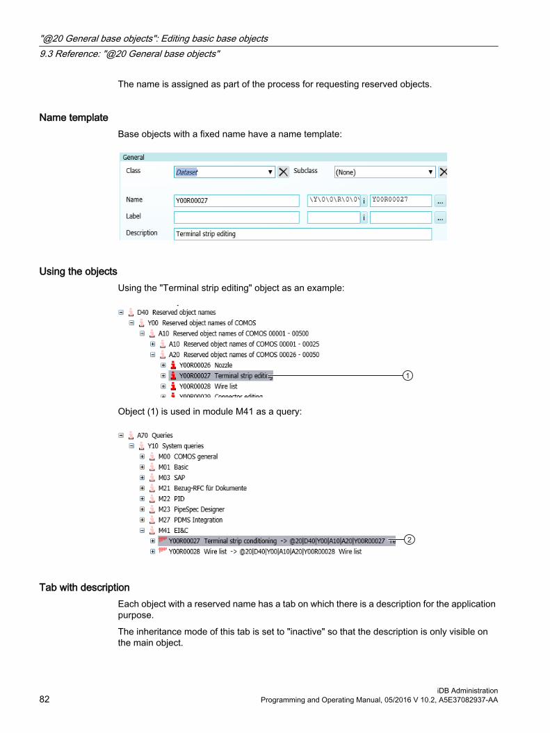
The name is assigned as part of the process for requesting reserved objects.
Name templateBase objects with a fixed name have a name template:
Using the objectsUsing the "Terminal strip editing" object as an example:
Object (1) is used in module M41 as a query:
Tab with descriptionEach object with a reserved name has a tab on which there is a description for the application purpose.
The inheritance mode of this tab is set to "inactive" so that the description is only visible on the main object.
"@20 General base objects": Editing basic base objects9.3 Reference: "@20 General base objects"
iDB Administration82 Programming and Operating Manual, 05/2016 V 10.2, A5E37082937-AA

Buttons with reserved namesIf you have to access the name of a button, create a button with a reserved name.
You can create attributes below a button with a reserved name.
See also section Attributes with the "Button" display type (Page 124).
9.3.32 @20 > Z10 CustomerAll base objects for customer-specific objects are stored here.
"@20 General base objects": Editing basic base objects9.3 Reference: "@20 General base objects"
iDB AdministrationProgramming and Operating Manual, 05/2016 V 10.2, A5E37082937-AA 83

"@20 General base objects": Editing basic base objects9.3 Reference: "@20 General base objects"
iDB Administration84 Programming and Operating Manual, 05/2016 V 10.2, A5E37082937-AA

"@30 Structures": Editing module-specific structures 1010.1 Purpose of the "@30" node
This node includes the standard-specific structures as they are used in the engineering objects. Whereas the "@10" and "@20" nodes contain the definitions of the base objects themselves, the "@30" node defines the relations between these objects as specified in the various standards. This means this node is responsible for the structures of the right mouse button, project presettings, labeling systems, position catalogs according to EN or ANSI, etc. for example.
There are no direct base object pointers to the objects in the "@10" and "@20" nodes from the engineering data. The objects are used as base objects in the "@30" node instead and the objects in the "@30" node have base object references to objects in the "@10" and "@20" nodes.
To create these structures, the required "subobjects" are defined as elements of the "main object" to enable the "subobjects" to be created below the "main object" using the right mouse button. Note that these relations must be defined in the "@30" node. This means it is necessary to use objects from the "@10" and "@20" nodes in the "@30" node and to create the structures with the objects in "@30".
The individual nodes for the base objects specific to the COMOS module are located below the "@30" node:
The structures that span all COMOS modules are saved in subnode M00. Nodes that start with a Z should be used for creating customer-specific structures. Existing structures can be expanded specific to a customer by supplementing the suffix "_Z".
See alsoBasic rules in the "@30" node (Page 86)
iDB AdministrationProgramming and Operating Manual, 05/2016 V 10.2, A5E37082937-AA 85

10.2 Basic rules in the "@30" node
Requirement● You are familiar with the purpose of the "@30" node.
See chapter Purpose of the "@30" node (Page 85).
Basic structure rules of the "@30" nodeThe "@30" node is structured according to the following rules:
● First level: Module-specific sortingSee chapter Overview of module-oriented first level (Page 91).
● Second level: There is always the same, topic-oriented basic structure in Mxx branches:
– A10 General structures
– A20 Project settings
– A30 Units
– A40 Locations
– A50 Device structures
– A60 Functions
– A70 Signals
– A80 Documents
– A90 Document groups
– B10 Templates/macros
See chapter Overview of the structure of @30 below the modules (Page 91).
"@30 Structures": Editing module-specific structures10.2 Basic rules in the "@30" node
iDB Administration86 Programming and Operating Manual, 05/2016 V 10.2, A5E37082937-AA

● The @30 structure is constructed below the topic-oriented basic structure using cross-inheritance. These structures are stored in corresponding nodes for the respective standard or topic structure.The topic-oriented basis structure in the "@30" node is constructed of objects of the "@10", "@20" and "@50" nodes. All objects (except for structure objects) must have a base object pointer to an object in the "@10", "@20" or "@50" nodes or must be derived from them using hierarchical inheritance.
● Structure objects (that were not created for engineering but are only used for structuring) may be changed in the "@30" node. See the following block "Permitted customized settings in the "@30" node".
Permitted customized settings in the "@30" node● The following customized settings can be made at objects in the "@30" node:
– NameSee chapter Entering norm-specific text masks (Page 32).
– Description
– Label
– Name template
– Adding tabs and overbooking tabs
– "Configuration" tab (e.g. engineering task)
– Checking in icons
– Creation mode
– Object behavior
– CDevice scripts
– Customer-specific tabs can also be added in subsequent customizing
– User classification (hierarchical & functional)
● The following properties cannot be customized:
– Class / subclass
– "Classification" subject card (hierarchical & functional)
– Adding tabs and overbooking tabs at objects in the "@20" node
● Icons may be customized at structure objects
"@30 Structures": Editing module-specific structures10.2 Basic rules in the "@30" node
iDB AdministrationProgramming and Operating Manual, 05/2016 V 10.2, A5E37082937-AA 87

10.3 Specifying project structures as project setting
Purpose of the "Project settings" nodeThe construction of structures that are required within projects takes place below the following node in the individual modules:
● Project settingsAll structures required for the COMOS module are assembled and thus documented by means of referenced objects below this node. The sources for these structures can be from the own module or from external modules. In the following example, you can recognize that object 2 is used in the project setting for FEED:
Differentiation of the different "Project settings" nodes Module structures are stored in two locations:
● In the Mxx node module as module documentation
● In the "@30 > M00 > A20 Project settings" node as a presetting for projects
The following figure shows the project structure for FEED, once below the "@30 > M00 > A20 Project settings" node and once in the "@30 > M21 > A20 Project settings" node:
"@30 Structures": Editing module-specific structures10.3 Specifying project structures as project setting
iDB Administration88 Programming and Operating Manual, 05/2016 V 10.2, A5E37082937-AA

Cross-module structures are developed in the module group or within M00. If a module does not need its own structure, the higher-level structure is used.
"@30 Structures": Editing module-specific structures10.3 Specifying project structures as project setting
iDB AdministrationProgramming and Operating Manual, 05/2016 V 10.2, A5E37082937-AA 89

Purpose of the "@30 > M00 > A20 Project settings" nodeThe "M00 > A20 Project settings" node has a special meaning. The structures are not only stored as documentation at this location, this node is also evaluated by COMOS in the "Project settings" field. Only the structures stored here are evaluated as project settings. The following figure shows that an object from "@30 > M00 > A20 Project settings" node is set as project setting for the "A1 ET" project:
"@30 Structures": Editing module-specific structures10.3 Specifying project structures as project setting
iDB Administration90 Programming and Operating Manual, 05/2016 V 10.2, A5E37082937-AA

10.4 Overview of module-oriented first level
OverviewThe "@30" node is sorted module-specifically:
The structures are then constructed in the respective category below the corresponding module within a standard node or topic node. See section Overview of the structure of @30 below the modules (Page 91) for more on this. The standard nodes or topic nodes can then be added as elements below "@30 > M00 > A20 Project settings". This means separate structures can be made available for different modules.
The structures that span all COMOS modules are saved in subnode M00. These are structures with properties from different modules. For structures that consist solely of components from one module or module group, these structures are stored at the corresponding module location. If these structures are required in other modules, they are linked to the respective module.
The storage of the structures in the respective module or module group depends on the origin of the used structure components. If a structure includes components that span modules, it is saved in M00.
If a module does not need separate structures, they remain empty. If a module does not need its own structure, the used structure is linked from another module to the project setting.
Nodes that start with a Z are used for creating customer-specific structures. Existing structures can be expanded specific to a customer by supplementing the suffix "_Z".
Below the COMOS module-specific nodes, the structures are sorted by topic.
The base objects used are cross-inherited from the @10, @20 and @50 nodes.
10.5 Overview of the structure of @30 below the modulesThe structures are divided into their respective topic below the module nodes.
A10 General structuresHere, you store general structures.
"@30 Structures": Editing module-specific structures10.5 Overview of the structure of @30 below the modules
iDB AdministrationProgramming and Operating Manual, 05/2016 V 10.2, A5E37082937-AA 91
A20 Project settingsThe structures for projects of the relevant COMOS module are stored here.
See section Specifying project structures as project setting (Page 88).
A30 UnitsThe structures for setting up the engineering in the "Units" tab are stored here. Unit structures are an important part of the project structure. You can find an example on the structure of a unit structure in section Designing project structures (Page 93).
A35 CategoriesThe category technique collects engineering objects in folders. For this purpose, the engineering objects are automatically moved to the category folders after they are created.
See section Categories A35 below the modules (Page 97).
A40 LocationsThe structures for the unit world are constructed at this location. This takes place analogous to the unit structure.
A50 Device structuresThe structures for devices and accessories are stored here.
See section Device structure A50 below the modules (Page 99).
A60 FunctionsThe structures for the functions are stored here.
A70 SignalsThe structures for signals are stored here.
A80 DocumentsThe structures for documents are stored here (see "@30 > M00 > A80 > A10 Document base objects acc. IEC 61355 (Page 183)" and "Managing documents without IEC 61355 labels (@30 > xxx > A80) (Page 185)").
A90 Document groupsThe structures for document groups are stored here (see "@30 > M00 > A90 Document groups (Page 184)").
"@30 Structures": Editing module-specific structures10.5 Overview of the structure of @30 below the modules
iDB Administration92 Programming and Operating Manual, 05/2016 V 10.2, A5E37082937-AA

B10 Templates/macrosThe structures for templates or macros are stored here.
10.6 Designing project structures
Overview of the project structuresThe project structures are designed in the module nodes (M00 and the Mxx nodes). The structures are divided and defined in hierarchy levels on a lower level below the module nodes:
● A10 Hierarchy levels
– A10 Level 1
– A20 Level 2
– A30 Level 3
– …
If there is only one level, the "A10 Level 1" node can be missing. The corresponding level is constructed from objects of the "@10", "@20", "@30" or "@50" nodes below each hierarchy level. This also includes that the respective subordinate hierarchy level is added as element. This means the different objects are combined into a structure and the complete structure is located on the first level.
The procedure is presented below based on a structure below "A30 Units". There are the following nodes below A30:
1. A node for the standard system
2. A collective node for the hierarchy levels below this node
3. Optional: One node each for the level below this collective node
4. A node for the merged structures below this node. The base objects in the "Elements" tab are used to merge the structures.
"@30 Structures": Editing module-specific structures10.6 Designing project structures
iDB AdministrationProgramming and Operating Manual, 05/2016 V 10.2, A5E37082937-AA 93
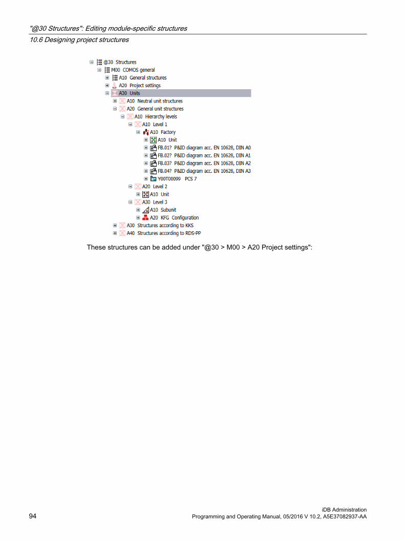
These structures can be added under "@30 > M00 > A20 Project settings":
"@30 Structures": Editing module-specific structures10.6 Designing project structures
iDB Administration94 Programming and Operating Manual, 05/2016 V 10.2, A5E37082937-AA

Ban on dereferencingThe "Dereference" object must be deactivated for all objects in the @30 branch, because the objects from the @10 branch would otherwise be used.
See chapter Controlling base object links using dereferencing (Page 46).
"@30 Structures": Editing module-specific structures10.6 Designing project structures
iDB AdministrationProgramming and Operating Manual, 05/2016 V 10.2, A5E37082937-AA 95
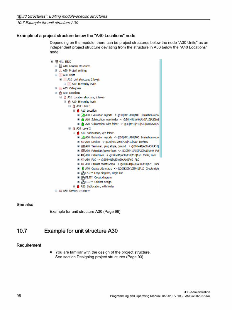
Example of a project structure below the "A40 Locations" nodeDepending on the module, there can be project structures below the node "A30 Units" as an independent project structure deviating from the structure in A30 below the "A40 Locations" node:
See alsoExample for unit structure A30 (Page 96)
10.7 Example for unit structure A30
Requirement● You are familiar with the design of the project structure.
See section Designing project structures (Page 93).
"@30 Structures": Editing module-specific structures10.7 Example for unit structure A30
iDB Administration96 Programming and Operating Manual, 05/2016 V 10.2, A5E37082937-AA

Example: Module node M21In the following figure, the base object (2) is created according to the rules for designing a project structure.
The standard system in this example is in the style of "ISO 10628".
The optional level is missing in this example.
The base object (2) is cross-inherited to base object (1) using a base object link.
The base object (1) is cross-inherited to base object (3) under "@30 > M00 > A20" using a base object link:
10.8 Categories A35 below the modules
Aim The category technique collects engineering objects in folders. For this purpose, the engineering objects are automatically moved to the category folders after they are created.
"@30 Structures": Editing module-specific structures10.8 Categories A35 below the modules
iDB AdministrationProgramming and Operating Manual, 05/2016 V 10.2, A5E37082937-AA 97
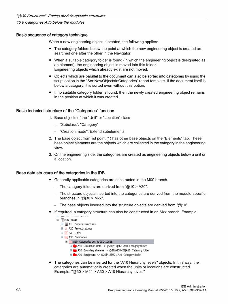
Basic sequence of category techniqueWhen a new engineering object is created, the following applies:
● The category folders below the point at which the new engineering object is created are searched one after the other in the Navigator.
● When a suitable category folder is found (in which the engineering object is designated as an element), the engineering object is moved into this folder. Engineering objects which already exist are not moved.
● Objects which are parallel to the document can also be sorted into categories by using the script option in the "SortNewObjectsInCategories" report template. If the document itself is below a category, it is sorted even without this option.
● If no suitable category folder is found, then the newly created engineering object remains in the position at which it was created.
Basic technical structure of the "Categories" function1. Base objects of the "Unit" or "Location" class
– "Subclass": "Category"
– "Creation mode": Extend subelements.
2. The base object from list point (1) has other base objects on the "Elements" tab. These base object elements are the objects which are collected in the category in the engineering view.
3. On the engineering side, the categories are created as engineering objects below a unit or a location.
Base data structure of the categories in the iDB● Generally applicable categories are constructed in the M00 branch.
– The category folders are derived from "@10 > A20".
– The structure objects inserted into the categories are derived from the module-specific branches in "@30 > Mxx".
– The base objects inserted into the structure objects are derived from "@10".
● If required, a category structure can also be constructed in an Mxx branch. Example:
● The categories can be inserted for the "A10 Hierarchy levels" objects. In this way, the categories are automatically created when the units or locations are constructed. Example: "@30 > M21 > A30 > A10 Hierarchy levels"
"@30 Structures": Editing module-specific structures10.8 Categories A35 below the modules
iDB Administration98 Programming and Operating Manual, 05/2016 V 10.2, A5E37082937-AA

10.9 Device structure A50 below the modules
OverviewThe structures for devices and accessories are stored standard-specific or devices-specific in the "A50" node. The nodes for a corresponding standard system or for a corresponding topic (devices-specific structures) are located below the "A50 Device structures" node:
● Standard-specific structure
● Devices-specific structure
The base objects originate from the "@10" node and are used standard-specific or topic-specific here.
Standard-specific structureThe following is a devices-specific structure using the example "@30 > M00 > A50":
See section Example for use of the "@10" node (Page 62).
"@30 Structures": Editing module-specific structures10.9 Device structure A50 below the modules
iDB AdministrationProgramming and Operating Manual, 05/2016 V 10.2, A5E37082937-AA 99

Devices-specific structureThe following is a devices-specific structure using the example "@30 > M40 > A50":
Interruption of hierarchical inheritance in the "@30" nodeBecause the objects in the "@30" node have a reference to objects in the "@10" node, the hierarchical inheritance is interrupted at this point. This means it is not possible to prepare the manufacturer devices in the "@30" node at an upper node. Instead, the following applies to each base object with a reference to an @10 base object: The standard-specific elements and/or attributes must always be built into the @30 structure using a reference. See section Notes on multiple use of "@10" objects (Page 63).For a distinction between cross-module devices and module-specific devices, see section Overview of module-oriented first level (Page 91).
10.10 Document structure A90 below the modules
OverviewThe structures for the document groups are stored here. The document groups are located in the M00 node as well as in the Mxx nodes. See section Specifying project structures as project setting (Page 88) for more on this.
"@30 Structures": Editing module-specific structures10.10 Document structure A90 below the modules
iDB Administration100 Programming and Operating Manual, 05/2016 V 10.2, A5E37082937-AA

Using document groups in the M00 node and the Mxx nodesIn the following example, the base object (1) is inherited from the M00 branch to the Mxx branch and is entered there as a base object reference for base object (2):
● Document structure according to IEC 61355The document structure generally used according to IEC 61355 is stored in M00:
● Context menu for the project object
"@30 Structures": Editing module-specific structures10.10 Document structure A90 below the modules
iDB AdministrationProgramming and Operating Manual, 05/2016 V 10.2, A5E37082937-AA 101

Using project structures as project settingThe distinction between documentary structures and structures that serve as project setting is explained in section Specifying project structures as project setting (Page 88).
See also@30 > M00 > A90 Document groups (Page 184)
10.11 Information about labeling systems in the M00 branch
Labeling systems in @30 > M00Because tagging systems are structural information, they are stored in node @30 Structures. The labeling systems are integrated into the normal subnodes in node "M00". There are no central root nodes below which all components of a labeling system would be available.
See Chapter Administration of the labeling system and ALIAS labeling system (Page 157).
"@30 Structures": Editing module-specific structures10.11 Information about labeling systems in the M00 branch
iDB Administration102 Programming and Operating Manual, 05/2016 V 10.2, A5E37082937-AA
"@40 @Y Attribute catalog": Editing attributes and tabs 1111.1 Overview of the administration of attributes and tabs
Requirement● You are familiar with the overview of the hierarchy of base data.
See chapter Standardized designations for folder objects (Page 21).
Step-wise definition of the attribute propertiesAn attribute is only created once in the attribute catalog. If you require attributes with the same content but with different display types, these attributes are derived from the same catalog attribute.
Basic properties such as "Name" and "Description" are entered in the catalog attribute. You set other properties such as the "Display type" for the derived attribute.
See chapter Uniqueness principle of attributes (Page 104).
See chapter Overview of the properties of catalog attributes (Page 106).
Storage location and name of catalog attributes and catalog tabsThe catalog attributes and catalog tabs are stored as follows:
● "@40 @Y Attributes and tabs"
See chapters Editing "@40 > A10 Attribute catalog" (Page 106) and Editing "@40 > A20 Tabs" (Page 114).
Placement of catalog attributes on the catalog tabs (derived attributes)The catalog attributes are placed on the catalog tabs. The attributes are now called derived attributes.
● See chapter Placing catalog attributes on tabs (derived attributes) (Page 119).
Catalog attributes and tabs can be placed multiple times, provided the name specifications are adhered to.
Use of the catalog tabs with base objectsThe base objects use the catalog tabs. There are various special features:
● Sorting tabs for the base objectSee chapter Change the sort sequence for the tabs (Page 118).
● Multiple placement of a tabSee chapter Placing a tab on an object multiple times (Page 127).
iDB AdministrationProgramming and Operating Manual, 05/2016 V 10.2, A5E37082937-AA 103

Dynamically created attributes and tabsSee chapter Dynamically created attributes (Page 128) and chapterDynamically created tabs (Page 129).
Attributes for third-party softwareIf third-party software (such as SAP or Teamcenter) places special requirements on the names of attributes, dedicated nodes for this are available in the attribute catalog and tab catalog. See chapter Overview of the nodes in "@40 > A10" (Page 106) and chapter Overview of the nodes in "@40 > A20" (Page 114).
Finding attributesSee chapter Using "Attribute search" tab (Page 17).
See chapter Using "Attribute descriptions DE/EN" query (Page 19).
11.2 Uniqueness principle of attributes
Requirement● You are familiar with the overview of the administration of attributes and tabs.
See chapter Overview of the administration of attributes and tabs (Page 103).
Definition of an iDB attributeAttributes in the COMOS iDB sense are value-saving objects. Attributes are managed in the attribute catalog.
Buttons, frames, and descriptions save no values and are therefore handled separately. See chapter Attributes with the "Button" display type (Page 124) and chapterAttributes with the "Frame" or "Description" display type (Page 125).
"@40 @Y Attribute catalog": Editing attributes and tabs11.2 Uniqueness principle of attributes
iDB Administration104 Programming and Operating Manual, 05/2016 V 10.2, A5E37082937-AA

Principle of uniquenessAn attribute is only created once in the attribute catalog. If you require attributes with the same content but with different display, these attributes are derived from the same catalog attribute.
Attributes collection
Catalog attribute
Example: "Current"
Place the catalog attribute on a tab in the tab collection
Derived attributeExample: "Current" attribute on the
"Technical data" tab
Using the tab on an object
Example: "Technical data" tab
with "Current" attribute on the "Motor" object
The derived attributes can also be placed multiple times on a tab.
Changes to catalog attributes prohibited
NoteNo changes to the catalog attributes in the attribute catalog
You may not change the catalog attributes in the attribute catalog.
See alsoOverview of the properties of catalog attributes (Page 106)
"@40 @Y Attribute catalog": Editing attributes and tabs11.2 Uniqueness principle of attributes
iDB AdministrationProgramming and Operating Manual, 05/2016 V 10.2, A5E37082937-AA 105

11.3 Editing "@40 > A10 Attribute catalog"
11.3.1 Overview of the nodes in "@40 > A10"
Requirement● You are familiar with the overview of the administration of attributes and tabs.
See chapter Overview of the administration of attributes and tabs (Page 103).
Three main nodes in the attribute catalogRoot nodes for all catalog attributes:
● "@40 > A10 @Y Attribute catalog" Generally applicable procedure for catalog attributes:See chapter Overview of the properties of catalog attributes (Page 106).See chapter "Attribute mapping table" tab (Page 107).
Below the root node, three different nodes are prepared:
● "Y00 @Y Attribute collection" (General catalog attributes)This area is used for managing the general catalog attributes for the delivered COMOS objects. This area is maintained by Siemens.See chapter Storage structure and names of the catalog attributes (Page 108).See chapter Basic rules for the "Description" field for catalog attributes (Page 110).The general catalog attributes can be locked to prevent changes by a "lock-lock" mechanism. This lock cannot be unlocked. See chapter "Object locking" and "System object" state (Page 37).
● "Y30 @Y Special attributes collection" (Special catalog attributes)This area contains attributes that deviate from the naming rules of the general catalog attributes. For example, some COMOS interfaces require attributes whose name is specified by the third-party software (e.g. SAP or Teamcenter). This area is maintained as an example by Siemens and can be supplemented by the customer.See chapter Storage structure and names of the catalog attributes (Page 108).See chapter Special attributes: Automation Interface (PCS 7) (Page 114).
● "Z10 @Y Customer attributes collection"This area is used for managing the customer catalog attributes and is maintained by the customer.See chapter Storage structure and names of the catalog attributes (Page 108).See chapter Customer-specific additions (Page 223).
11.3.2 Overview of the properties of catalog attributes
Requirement● You are familiar with the overview of the nodes in "@40 > A10".
See chapter Overview of the nodes in "@40 > A10" (Page 106).
"@40 @Y Attribute catalog": Editing attributes and tabs11.3 Editing "@40 > A10 Attribute catalog"
iDB Administration106 Programming and Operating Manual, 05/2016 V 10.2, A5E37082937-AA

Properties of the catalog attributeThe following table shows the properties that are provided when the catalog attribute is created:
Property Description"Name" Unique character string
See chapter Storage structure and names of the catalog attributes (Page 108).
"Description" As precise as possible description of the contents.See chapter Basic rules for the "Description" field for catalog attributes (Page 110).Description may be adapted to the derived attribute.
"Display type" Always: "Edit field"."Type" Always: "Alphanumeric"."Inheritance mode" Always: "Inactive".
You may make changes to all other properties only for the derived attribute on the tab.
Additional properties of the derived attributeSee chapter Overview of the properties of the derived attribute (Page 119).
11.3.3 "Attribute mapping table" tab
Requirement● You are familiar with the overview of the nodes in "@40 > A10".
See chapter Overview of the nodes in "@40 > A10" (Page 106).
Objective of the mapping table● "Calculation"
– Application 1: Link to an attribute that is also used for calculation of a value
– Application 2: Link to an attribute to which a conversion is madeExample: Mapping of rated voltage onto nominal voltage. In this case, the rated voltage can be used for calculation in a script instead of the nominal voltage.
● "Customer mapping"For free use.
"@40 @Y Attribute catalog": Editing attributes and tabs11.3 Editing "@40 > A10 Attribute catalog"
iDB AdministrationProgramming and Operating Manual, 05/2016 V 10.2, A5E37082937-AA 107

● Mapping of a standardOn the Y00A10 tab, entry fields are prepared for mapping to important standards.
– "eCl@ss"
– "ETIM"
– "ISO 15926"
Create further entry fields to support additional standards. You can store the "Identifiers" of the individual standard attributes that are to be mapped in the XML attributes. If a standard has several mapping options, enter the standard attribute.
● SIEMENSMapping to other Siemens attribute catalogs
● "COMOS classic"Mapping to the attribute with identical contents in the cDB.
Calling the "Attribute mapping table" tab"@40 > A10 > Y00A10 @Y Attribute mapping table"
This mapping table has an effect on the link to a product request. The attribute for a product request appears as follows in the iDB:
Attributes of the base object, "System data" tab: Attribute "Y00A04982 Link to product request"
This attribute for the product request is evaluated in the following cases:
● In the case of a change to the base objectThe new base object can have another device request.
● For the "Return to request" functionIn the case of an engineering object, this function sets the product request as the base object.
11.3.4 Storage structure and names of the catalog attributes
Requirement● You are familiar with the overview of the nodes in "@40 > A10".
See chapter Overview of the nodes in "@40 > A10" (Page 106).
"@40 @Y Attribute catalog": Editing attributes and tabs11.3 Editing "@40 > A10 Attribute catalog"
iDB Administration108 Programming and Operating Manual, 05/2016 V 10.2, A5E37082937-AA

"Y00 @Y Attribute collection" (General catalog attributes)
Object structure:● Collector node "A05 @Y Semantic attribute collection"
– Below are folders for grouping according to German description (semantic folders)Below that is a variable number of carrier objects. One carrier object each per catalog attribute.Example:
"Semantic folder" means that attributes having an identical substring in the German description are grouped. Example: "Performance level" (German: "Leistungsgrad") and "Efficiency level" (German: "Wirkungsgrad") are sorted into the shared "Y00A05246 Level" folder (German: "Grad").Attributes without shared semantic folders are grouped in the "Y00A04928 Miscellaneous" folder.
● Structure of the carrier objects
– The carrier object has the same name as the catalog attribute
– Catalog attribute with checked-in nameYou can place the catalog attributes on a tab. See chapter Placing catalog attributes on tabs (derived attributes) (Page 119).
– "Y00A10 Attribute mapping table" tab for mapping of the attribute to standard systemsSee chapter "Attribute mapping table" tab (Page 107).
Assigning names:● Name of the area: "Y00" + letter ("A", etc.) + 5-digit consecutive number + Variant label
("AB", etc.) (if required)
● Maximum number of catalog attributes: 99999
Example: "Y00A00003 Nominal size", "Y00A00003AB Nominal size for bolt point item"
Outdated: Variant of a catalog attributePrevious iDB versions had variant attributes that were identified using a variant suffix "AB", "AC", etc. in the name. Some attributes still have this variant suffix in their names. Example: "Y00A00417 Shaft power". This variant suffix is no longer relevant.
There continues to be variants for tabs.
"@40 @Y Attribute catalog": Editing attributes and tabs11.3 Editing "@40 > A10 Attribute catalog"
iDB AdministrationProgramming and Operating Manual, 05/2016 V 10.2, A5E37082937-AA 109

"Y30 @Y Special attributes collection" (Special catalog attributes)
Object structure:● Collector node based on module ("M03", etc.)
– Below are folders for 25 carrier objects eachOne carrier object each per special attribute
● Structure of the carrier objects
– The carrier object has the same name as the catalog attribute
– Catalog attribute with checked-in nameYou can place the special catalog attributes on a tab. See chapter Placing catalog attributes on tabs (derived attributes) (Page 119).
– "Y00A10 Attribute mapping table" tab for mapping of the attribute to standard systemsSee chapter "Attribute mapping table" tab (Page 107).
Assigning names:● Names are assigned by third-party software
Example: APPLICATION_ID
"Z10 @Y Customer attributes collection"Recommendation: Use the same rules as in the "Y00 @Y Attributes collection" area
Assigning names:● Name of the area: "Z10" + letter ("A", etc.) + 5-digit consecutive number
Example: Z10A00001
11.3.5 Basic rules for the "Description" field for catalog attributes
Requirement● You are familiar with the overview of the nodes in "@40 > A10".
See chapter Overview of the nodes in "@40 > A10" (Page 106).
"@40 @Y Attribute catalog": Editing attributes and tabs11.3 Editing "@40 > A10 Attribute catalog"
iDB Administration110 Programming and Operating Manual, 05/2016 V 10.2, A5E37082937-AA

General rulesYou must observe three basic rules for describing a general catalog attribute:
● No object reference in the descriptionExamples of prohibited object descriptions: Pipe inside diameter, motor power, pump operating pressure, etc.If you still need an object reference in the description, adapt the description of the derived attribute on the tab.
● Uniform writingConsistent writing in order to avoid duplicates
● Geometry mapping is permittedExamples: inside diameter, external diameter
See alsoSupplementary rules for the "Description" field for catalog attributes (Page 111)
11.3.6 Supplementary rules for the "Description" field for catalog attributes
Requirement● You are familiar with the general rules
See chapter Basic rules for the "Description" field for catalog attributes (Page 110).
"@40 @Y Attribute catalog": Editing attributes and tabs11.3 Editing "@40 > A10 Attribute catalog"
iDB AdministrationProgramming and Operating Manual, 05/2016 V 10.2, A5E37082937-AA 111

General linguistic rules● Abbreviations
– Permitted: fixed specialist abbreviationsAbbreviations without a period that are often written entirely in upper caseExamples: CPU, XML, TÜV, GmbH
– Allowed in exceptional casesPart descriptions in brackets
– Not allowed: Colloquial abbreviationsExamples: etc., e.g., max., min.
Incorrect Correctmax. current maximum currente. g. for example
● Abbreviations
– Permitted: For a derived attribute on a tab
● Compounds
– Allowed in exceptional casesSuffixes Prefixes
"@40 @Y Attribute catalog": Editing attributes and tabs11.3 Editing "@40 > A10 Attribute catalog"
iDB Administration112 Programming and Operating Manual, 05/2016 V 10.2, A5E37082937-AA

Writing of technical specification● Electrotechnical properties
– Permitted: CompoundsDescriptions of location, time and state are at the start of an attribute descriptionExample: inside, outside, input, output, start-up, shut-down, etc.
– Example of permitted writing for electrical currentOperating current, nominal current, rated current, switching current, control current, input current, output current, breaking current, leakage current, maximum current
– Example of permitted writing for electrical voltageOperating voltage, nominal voltage, rated voltage, switching voltage, control voltage, auxiliary voltage, input voltage, output voltage, maximum voltage
– Example of permitted writing for electrical powerNominal power, rated power, switching power, input power, output power, reactive power, apparent power, runtime power, runtime reactive power, nominal apparent power, power consumption, power factor
– Not allowed: "Voltage, input"
● Process-related properties
– PermittedAggregate states Medium (solid, liquid, light, fluid, powder, gas, etc.)Media groups (oil, acid, air, water, etc.)"Material"Supplement/refinement/revaluation
– Example of permitted writing for temperatureOperating temperature, design temperature, ambient temperature
– Example of permitted writing for pressureOperating pressure, design pressure, air pressure
– Other permitted examples:Molar enthalpy of heavy liquidLiquid, cover sideMass flow of the water upon dischargeWater hazard class at the outlet
Non-permitted combinations with process mediaExample:
● Methane gasCombination with:
● Temperature
In these cases you adapt the description of the derived attribute in the tab:
● "Temperature methane gas"
"@40 @Y Attribute catalog": Editing attributes and tabs11.3 Editing "@40 > A10 Attribute catalog"
iDB AdministrationProgramming and Operating Manual, 05/2016 V 10.2, A5E37082937-AA 113

11.3.7 Special attributes: Automation Interface (PCS 7)
Requirement● You are familiar with the overview of the nodes in "@40 > A10".
See chapter Overview of the nodes in "@40 > A10" (Page 106).
OverviewSpecial attributes with the CAX name from the transmission model are created for transmission of values using the Automation Interface.
These attributes are also made available for normal COMOS objects. This ensures that the PCS 7 data can be saved and transmitted in a way that is traceable within COMOS.
The PCS 7 attributes are prepared as follows:
● "@40 > A10 > Y30 > M40 > A10"
The attributes are collected in the "Y30T00001 Automation Standard" tab and made available under the general objects. Example:
● "@20 > A10 > A10 > M00 > A10 General unit"
11.4 Editing "@40 > A20 Tabs"
11.4.1 Overview of the nodes in "@40 > A20"
Requirement● You are familiar with the overview of the administration of attributes and tabs.
See chapter Overview of the administration of attributes and tabs (Page 103).
Core statementRoot nodes for all tabs:
● "@40 > A20 @Y Tab catalog" Generally applicable procedure for tabs:See chapter Change the sort sequence for the tabs (Page 118).
"@40 @Y Attribute catalog": Editing attributes and tabs11.4 Editing "@40 > A20 Tabs"
iDB Administration114 Programming and Operating Manual, 05/2016 V 10.2, A5E37082937-AA

Below the root node, three different nodes are prepared:
● "Y00 @Y Tab collection" (General tabs)This area is used for managing the general catalog attributes for the delivered COMOS objects. The catalog attributes from the attribute catalog are placed on these tabs. This area is maintained by Siemens.See chapter Storage structure and names of the tabs (Page 115).
● "Y30 @Y Special tab collection" (Special tabs)This area contains tabs that deviate from the naming rules of the general tab catalog. For example, some COMOS interfaces require tabs whose name is specified by the third-party software (e.g. SAP or Teamcenter). This area is maintained as an example by Siemens and can be supplemented by the customer.See chapter Storage structure and names of the tabs (Page 115).
● Customer tabs"Z10 @Y Customer tab collection"This area is used for managing the customer tabs and is maintained by the customer.See chapter Storage structure and names of the tabs (Page 115).
NoteCross-inheritance in the tab catalog
Not permitted: Cross-inheritance within the tab catalog.
Permitted: Inheritance from the "Y00 @Y Tab catalog" area in the "Z10 @Y Customer tab collection" customer area.
11.4.2 Storage structure and names of the tabs
Requirement● You are familiar with the overview of the nodes in "@40 > A20".
See chapter Overview of the nodes in "@40 > A20" (Page 114).
"@40 @Y Attribute catalog": Editing attributes and tabs11.4 Editing "@40 > A20 Tabs"
iDB AdministrationProgramming and Operating Manual, 05/2016 V 10.2, A5E37082937-AA 115

"Y00 @Y Tab catalog" (General catalog tabs)
Object structure: ● Collecting folders for 500 tabs each
– Subfolders for 25 tabs eachBelow that are one or more levels with folders for grouping according to German description.Below that is a variable number of carrier objects.
● Structure of the carrier objects
– A base object as carrier object of the tab.
– The carrier object has the same name and the same description as the tab.
– The tab must be empty at this position.
● Structure of the carrier object variants
– The variants of the tab
– A tab variant carrier object is created underneath the tab carrier object for every tab variant.
– In turn the tab variant is located under this tab variant carrier object.
– Tab Y00A20 for mapping of the tab to the COMOS modules.
Assigning names:● Carrier object: Name of the area: "Y00" + letter "T" + 5-digit consecutive number
Example: Y00T00001
● Carrier object variants: Letter of the hierarchy level ("A", "B", etc.) + 2-digit consecutive numberExample: A01
Inheritance:The content of the tab variants is inherited. You create generally used content at the top level You add specific content at the next level.
Example:
"@40 > A20 > Y00 > A10 > A10 > Y00T00001 > A06 > B01 > C01":
"@40 @Y Attribute catalog": Editing attributes and tabs11.4 Editing "@40 > A20 Tabs"
iDB Administration116 Programming and Operating Manual, 05/2016 V 10.2, A5E37082937-AA

"@40 > A20 > Y00 > A10 > A10 > Y00T00001 > A06 > B01 > C02":
The C02 object has the additional "Pipe section" option group on the "System data" tab.
Note that any changes to a tab variant affect all inheritance points.
"@40 @Y Attribute catalog": Editing attributes and tabs11.4 Editing "@40 > A20 Tabs"
iDB AdministrationProgramming and Operating Manual, 05/2016 V 10.2, A5E37082937-AA 117

"Y30 @Y Special tab collection" (Special tabs)
Object structure:● "@40 > A20 > Y30 @Y Special tab collection":
– Folders with 25 entries
● Structure below the last folder layer
– A base object as carrier object for the tab.
– The carrier object is always given the same name and same description as the tab itself.
● Structure of the carrier objects
– Tab
– Tab Y00A20 for mapping of the tab to the COMOS modules.
Assigning names:● Names are assigned by third-party software
Example: CL_CRUSHING_MACHINE
"Z10 @Y Customer tab collection"Recommendation: Use the same rules as in the "Y00 @Y Tab collection" area.
Assigning names:● Name of the area: "Z10" + letter "T" + 5-digit consecutive number
Example: Z10T00001
11.4.3 Change the sort sequence for the tabs
Requirement● You are familiar with the overview of the nodes in "@40 > A20".
See chapter Overview of the nodes in "@40 > A20" (Page 114).
ProcedureThe tabs below the "Attributes" tab are sorted alphabetically by name from left to right.
You change the order of the tabs at the base object that uses the tab. Changing the order of the tabs does not impair check-in or inheritance.
The only exception is the "Y00T00001 System data" tab, which is always to be sorted in the far left-hand column. The sort text "Y00" is therefore preset for this tab in the tab catalog.
1. In the Navigator open the path to the object whose tab you wish to resort.
2. Open the properties of the tab which you wish to resort.
"@40 @Y Attribute catalog": Editing attributes and tabs11.4 Editing "@40 > A20 Tabs"
iDB Administration118 Programming and Operating Manual, 05/2016 V 10.2, A5E37082937-AA

3. In the "Sort text" input box enter a text which should be used for sorting the tab instead of its name.Use the typical counting convention for the COMOS iDB as sort text: A10, A20, etc.
4. Confirm your entries.
11.5 Placing catalog attributes on tabs (derived attributes)
11.5.1 Placing a catalog attribute on a tab
Requirement● You are familiar with the overview of the administration of attributes and tabs.
See chapter Overview of the administration of attributes and tabs (Page 103).
Procedure1. Open the tab to which you wish to add a catalog attribute.
2. Select the "Design mode" command in the working area in the context menu of the tab.COMOS switches the tab to Design mode.
3. Select the catalog attribute to be placed below the "@40 > A10 @Y Attribute catalog" node.
4. Use drag&drop to move the required catalog attribute from the Navigator to the tab.
5. Where necessary change the properties and the display for the catalog attribute.More detailed information on the properties for an attribute can be found at Overview of the properties of the derived attribute (Page 119).
11.5.2 Overview of the properties of the derived attribute
OverviewFor the properties that are specified for the catalog attribute, see section Overview of the properties of catalog attributes (Page 106).
"@40 @Y Attribute catalog": Editing attributes and tabs11.5 Placing catalog attributes on tabs (derived attributes)
iDB AdministrationProgramming and Operating Manual, 05/2016 V 10.2, A5E37082937-AA 119

The following table shows the properties which you stipulate at the derived attribute on the tab:
Property Special feature"Name" Change is not permitted
Exception:Counter suffix when used multiple times on a tab. See chapterPlacing a catalog attribute on a tab multiple times (Page 126).
"Description" Recommendation: Include additional information. Example: Inside diameter becomes pipe inside diameterAbbreviations are also permitted for the derived attribute.See chapter Basic rules for the "Description" field for catalog attributes (Page 110).
"Unit" Currently, the reference unit is still used as the preferred unit, e.g. meter. In the future you will also be able to specify the preferred unit from the unit group here, e.g. millimeter.
"Display type" The following display types are created directly on the tab and are not derived from catalog attributes from the attribute catalog:● Description (LA001...)● Frame (FR001...)● Button (BU001...)
"Type" Permissible types:● "Text"
Values that are translatable in engineering projects and that also have to be translated in these projects.
● "Number" (numerical)Text box for numbers
● "Alphanumeric"Input box for texts that are not being translated.Examples: standard tables, checkboxes
● "Date"Date information
● "Signature"Digital signature (eSign)
"Standard table" Freely available"Case variants" Freely available"Value" You can provide a setpoint value for an attribute at the derived attribute on the tab or at
the base object."Decimal positions" Freely available"Formatting digits" Freely available"Format" Freely available"Length" Freely available"Working area" Freely available"Edit mode" Freely available"Catalog attribute" Here, at the derived attribute on the tab you set the associated catalog attribute from which
the attribute is derived from the attribute catalog.This entry is set automatically depending on the procedure when placing the catalog at‐tribute on the tab.
"Engineering object status" Freely available
"@40 @Y Attribute catalog": Editing attributes and tabs11.5 Placing catalog attributes on tabs (derived attributes)
iDB Administration120 Programming and Operating Manual, 05/2016 V 10.2, A5E37082937-AA

Property Special feature"Engineering object status val‐ue"
Freely available
"Inheritance mode" Freely availableScripts Freely availableInfo text Freely available
● The help text should take the context into account (tab and CDevice).Recommended help text for system attributes: Describe the type of software usage in multiple languages.
● "Tooltip" fieldRecommended tooltip for system attributes: Enter a corresponding label when an attribute is being used on the software end.
Tooltip entry with system attrib‐utes
If an attribute is being used on the software end, identify this attribute as a system attribute on the "Help" tab.Furthermore you can describe the software usage at this point in multiple languages.
Editing derived attributes of base object (CDevice)The properties of the derived attributes are defined in the tab catalog.
If the tab of a base object (CDevice) is used, the attributes may at most still be edited in the base object as follows:
1. Value
2. Preferred unit (°C or °F; m or km)
3. Mapping to other standards (e.g. eCl@ss)
11.5.3 General rules for the layout of tabs
OverviewObserve the following rules when creating tabs:
● Uniform configuration
● Group attributes that belong together and separate the groups by frames.
● The attributes in one column must have the same width as the description.The description must be wide enough to be able to display all the languages used, and at least English and German.
● All units on a tab should be of the same width and all the units that can be used must be capable of being displayed in full.
● Plan for sufficient space for attribute values.
● The sizes and the horizontal positions of the attributes in a column should be identical.
● The distances between the attributes of a summary block should be identical.
● The distance between attributes and frame should always be the same.
"@40 @Y Attribute catalog": Editing attributes and tabs11.5 Placing catalog attributes on tabs (derived attributes)
iDB AdministrationProgramming and Operating Manual, 05/2016 V 10.2, A5E37082937-AA 121

● Tabs should be capable of being displayed in full on the screen.Note: The resolution of COMOS in full screen mode is 1280x1024. The space for the Navigator still has to be subtracted from this maximum size.
● All attributes, including control elements such as check boxes and buttons, must have a description.Permitted: Description of multiple grouped attributes using a common attribute of "Description" display type.Example of a common description "Diameter inside/outside" for the "Inside diameter" and "Outside diameter" attributes.
Configuration examples● Example 1:
(1) Uniform alignment of texts(2) Uniform length of the text placeholder(3) Uniform length of the unit field(4) Uniform length of edit fields
● Example 2:
(5) Group titles for options of the same type(6) Individual labeling for identical checkboxes
"@40 @Y Attribute catalog": Editing attributes and tabs11.5 Placing catalog attributes on tabs (derived attributes)
iDB Administration122 Programming and Operating Manual, 05/2016 V 10.2, A5E37082937-AA

11.5.4 Attributes with the "List" display type (list specs)
Requirement● You are familiar with the overview of properties of derived attributes.
See chapter Overview of the properties of the derived attribute (Page 119).
Catalog attributes for list attributesThe following also applies to attributes with the "List" display type:
● One catalog attribute for the list attribute. Display type: "Edit field".
● One catalog attribute each for every row attribute or in the mirrored display for every column attribute. Display type: "Edit field".
One derived attribute each for the list attribute and every row attribute. The derived attributes retain the name from the attribute catalog. The properties of the derived attributes are edited as described.
The following figure shows the procedure in principle for configuring lists:
Example:
"@40 > A20 > Y00 > A10 > B30 > Y00T00277 > A01 > B01 > Y00T00277 Proteus > Y00A01109"
Below the attribute Y00A01109 are the associated attributes Y00A01139 and Y00A04280:
"@40 @Y Attribute catalog": Editing attributes and tabs11.5 Placing catalog attributes on tabs (derived attributes)
iDB AdministrationProgramming and Operating Manual, 05/2016 V 10.2, A5E37082937-AA 123

All three attributes are created in @40 as catalog attributes:
● Y00A01109Derived from "@40 > A10 > Y00 > A05 > Y00A00303 > Y00A01109 > Y00A01109"
● Y00A01139Derived from "@40 > A10 > Y00 > A05 > Y00A01154 > Y00A01139 > Y00A01139"
● Y00A04280Derived from "@40 > A10 > Y00 > A05 > Y00A01154 > Y00A04280 > Y00A04280"
Dynamic list attributesYou assign catalog attribute Y0003550 to dynamic list attributes as the base attribute.
Place the dynamic list attribute on a tab in the tab catalog. In the attribute properties of the placed list attribute, specify which catalog attributes are allowed as sub-attributes of the list. You must set the inheritance to "inactive" for the dynamic list attribute and the sub-attributes.
You may only create sub-attributes on the tab for an object if you have specified them on the tab in the tab catalog.
11.5.5 Attributes with the "Object query" display type (SUI query)
Requirement● You are familiar with the overview of properties of derived attributes.
See chapter Overview of the properties of the derived attribute (Page 119).
ProcedureThe following applies to attributes with the "Query" display type:
● The attributes are first created as catalog attributes with the display type "Edit field".
Attributes with the query attribute are configured at the derived query attribute on the tab.
11.5.6 Attributes with the "Button" display type
Requirement● You are familiar with the overview of properties of derived attributes.
See chapter Overview of the properties of the derived attribute (Page 119).
ProcedureYou do not create an attribute with the "Button" display type in the attribute catalog, but rather directly in the tab.
"@40 @Y Attribute catalog": Editing attributes and tabs11.5 Placing catalog attributes on tabs (derived attributes)
iDB Administration124 Programming and Operating Manual, 05/2016 V 10.2, A5E37082937-AA

Buttons are given the name BU00n.
Example:
"@40 > A20 > Y00 > A10 > A10 > Y00T00003 > A01 > B15 > C01 > Y00T003 > BU001"
Editing of "Value" field not permittedYou cannot save any values at a button. If you need a value, in the tab you must place a separate attribute at which you can save values.
Previous attributes below buttonsAttributes which had previously been created below a button are placed parallel to the button. Visible attributes are placed in the tab within a frame in order to display the relationships.
Visibility of attributes in the Navigator and in the tabSee chapter Placing attributes invisibly (Page 126).
11.5.7 Attributes with the "Frame" or "Description" display type
Requirement● You are familiar with the overview of properties of derived attributes.
See chapter Overview of the properties of the derived attribute (Page 119).
Impermissible actionsYou do not create an attribute with the "Frame" or "Description" display type in the attribute catalog, but rather directly on the tab.
The following actions are impermissible for attributes with the "Frame" or "Description" display type:
● Setting a value
● Hard-coded access
"@40 @Y Attribute catalog": Editing attributes and tabs11.5 Placing catalog attributes on tabs (derived attributes)
iDB AdministrationProgramming and Operating Manual, 05/2016 V 10.2, A5E37082937-AA 125

11.5.8 Placing attributes invisibly
Visibility of attributes in the Navigator and in the tab● Invisible attributes: "~" working area
If attributes in the engineering view are not to be visible either in the Navigator or in the tab, define this via the "~" working area (layers).In the base project, the attributes are still visible for the administrator.
● No visibility in the tab (only for dynamic attributes)In the case of dynamic attributes only, you can specify that these should be displayed only in the Navigator and not in the tab. To specify that dynamic attributes should only be displayed in the Navigator and not in the tab, set the ControlProperties to a zero string.Place these dynamic attributes on a tab inside a frame with an appropriate name, e.g. "Hidden system attributes for component lumping".For all attributes, select the "Not editable (value set by script)" entry from the "Edit mode" list in the attribute properties.
● Identifying invisible attributesPut a border around attributes that are to be invisible in engineering. In the description of the frame, specify that the attributes are to be invisible.Example: "Invisible system attributes""@40 > A20 > Y00 > A10 > A10 > Y00T00001 > A02 > B01 > C01 > Y00T00001 > FR099 Invisible system attributes"
11.5.9 Placing a catalog attribute on a tab multiple times
Placing attributes multiple times using counter in the nameYou can use multiple placement, for example, to create multiple attributes for user names on a tab.
The following rules apply to the allocation of names for placed attributes:
● Name of the first placed attribute: Name from the attribute catalog without any changes, e.g. "Y00A00001".The first attribute placed is not given a counting suffix as placing multiple times is not always required and any subsequent name change causes information to be lost.
● Name of additional attributes: Name + Counter suffix "AAnn"Start value: "AA02".
Example:
Name DescriptionY00A00001 User name 1Y00A00001AA02 User name 2Y00A00001AA03 User name 3
The count of the attributes in the attribute name does not have to be consecutive.
However, the count in the attribute name must agree with the count in the description.
"@40 @Y Attribute catalog": Editing attributes and tabs11.5 Placing catalog attributes on tabs (derived attributes)
iDB Administration126 Programming and Operating Manual, 05/2016 V 10.2, A5E37082937-AA

Example: Multiple placement with gap in the count
Name of the attribute Description of the attributeY00A00010 Temperature 1Y00A00010AA04 Temperature 4
Example: Single placement with counter in the description
Name of the attribute Description of the attributeY00A00025 Voltage 1
11.6 Placing a tab on an object multiple times
Requirement● You are familiar with the overview of the administration of attributes and tabs.
See chapter Overview of the administration of attributes and tabs (Page 103).
Placing a tab variantYou can place a tab on an object multiple times.
Since the name of any tab placed must be unique the following regulation applies to the name allocation when placing multiple times in this way:
For each tab placed multiple times for the object, you append the counting suffix "AAnn" additionally to the name, beginning with "AA01".
The following list shows an example for the names of the "Y00T00005" tab placed multiple times:
● Y00T00005AA01
● Y00T00005AA02
● Y00T00005AA03
● Y00T00005AA04
If the counting for the tags relates to counting objects such as connections for a device, the counting suffix for the tab must match the number counted for the connection.
Note
Gaps in the numbering are permitted for this.
"@40 @Y Attribute catalog": Editing attributes and tabs11.6 Placing a tab on an object multiple times
iDB AdministrationProgramming and Operating Manual, 05/2016 V 10.2, A5E37082937-AA 127

The following table illustrates this assignment:
Description NameTab for connection CX1 Y00T00005AA01Tab for connection CX3 Y00T00005AA03Tab for connection CX5 Y00T00005AA05
Placing different tab variantsYou can place different variants for a tab at an object. The different tab variants all have the same name in the tab catalog. Since the name for a placed tab must be unique, you attach the counting suffix "AAnn" to the name for all placed tab variants. Use of a different counting suffix is not permitted.
The same regulations apply when using the counting suffix "AAnn" as with the placing of a tab at an object multiple times.
11.7 Dynamically created attributes
Requirement● You are familiar with the overview of the administration of attributes and tabs.
See chapter Overview of the administration of attributes and tabs (Page 103).
DefinitionDynamic attributes are attributes created during runtime automatically or using a script.
RulesDynamic attributes receive a base attribute from the attribute catalog by a user input. The following attributes are permissible as a base attribute:
● General catalog attribute
● Special catalog attribute (from "Y30 @Y Y00A04928 Special attributes collection")
Use the name of the catalog attribute for the dynamic attribute with single use. When a dynamic attribute is used multiple times, you determine the name based on the same rules as when counting catalog attributes.
Example: Using a catalog attribute multiple times
Name of catalog attribute XY Name of dynamic attribute XY-DYNY00A00316 Y00A00316 Y00A00316AA02
"@40 @Y Attribute catalog": Editing attributes and tabs11.7 Dynamically created attributes
iDB Administration128 Programming and Operating Manual, 05/2016 V 10.2, A5E37082937-AA

Name of catalog attribute XY Name of dynamic attribute XY-DYN Y00A00316AA03 Y00A00316AAnn
As an option you can also name the first derivation as "…AA01".
If you use the dynamic attributes for counted objects (e.g. Temperature 1, Temperature 4), the count according to the name and the count according to the description must yield the same order.
Script for creating dynamic attributesThe script for creating dynamic attributes can be found in the database at the following location:
"@20 > A80 > M00 > A10 > M00S00009"
You must not create dynamic attributes directly under an object. The following tab becomes owner of the dynamic attributes at runtime:
Y00T00009 "Dynamic attributes"
The dynamic attributes do not have to be placed on the tab. It is sufficient to set the tab as owner in the object model.
Dynamic attributes created during runtimeDynamic attributes that are created at runtime and are thus unknown do not require a catalog attribute assigned by the user as a base attribute. Example: Dynamic attributes created when objects are imported.
See alsoInterface objects for base data import (dynamic objects) (Page 66)
Dynamically created tabs (Page 129)
11.8 Dynamically created tabs
Requirement● You are familiar with the overview of dynamically created attributes.
See chapter Dynamically created attributes (Page 128).
ProcedureIf tabs need to be created during runtime, you can implement this in exactly the same way as with the attributes with the tab count and a pointer in the tab catalog to the Y00T00009 tab.
You can create a variant of tab Y00T00009 in the tab catalog if this is required for an interface.
"@40 @Y Attribute catalog": Editing attributes and tabs11.8 Dynamically created tabs
iDB AdministrationProgramming and Operating Manual, 05/2016 V 10.2, A5E37082937-AA 129

See alsoInterface objects for base data import (dynamic objects) (Page 66)
"@40 @Y Attribute catalog": Editing attributes and tabs11.8 Dynamically created tabs
iDB Administration130 Programming and Operating Manual, 05/2016 V 10.2, A5E37082937-AA

"@50 Manufacturer devices": Editing the manufacturer catalogs 1212.1 Purpose of @50
The manufacturer catalogs are located under @50. The manufacturer catalogs are currently divided into two groups:
● A10 COMOSIncludes manufacturer catalogs for typical COMOS functions and workflows. Example: Manufacturer devices for the COMOS PipeSpec Designer function.
● A20 SIEMENS AGIncludes Siemens manufacturer catalogs.Example: Manufacturer devices for Siemens automation objects.
These catalogs include the base objects for the components which can be ordered such as devices (manufacturer devices) and accessories. For a base object to be considered a manufacturer device base object, a valid article number must exist in the "Order data" tab.
The branch @50 does not depend on a standard, which is why there are no standard-specific structures. Instead this branch @50 includes manufacturer-specific structures. All base objects from this node are derived from requirements from the @10 branch. This means that devices from different manufacturers can be derived from the same requirement from the @10 branch.
Creating base objects in @50The branches in @50 are mostly empty on the layer of the manufacturer devices. You first have to create the manufacturer device base objects. You can find more information on this topic in the respective manuals:
● Creating base objects for pipe spec catalogsThe following information refers to unchanged project properties for the PipeSpec Designer. You can find more information on this topic in the "PipeSpec Designer" manual, keyword "Creating new catalog".
● Creating base objects for PIAYou can find additional information on this topic in the "EI&C Administration" manual, keyword "Administering manufacturer catalogs".
● Base objects for SAP manufacturer devicesYou can find additional information on this topic in the "Platform Interfaces" manual, keyword "Importing manufacturer device catalog".
● Creating manufacturer devices for special componentsFind more information on this topic in the "EI&C Operation" manual, keyword "Special components: creating manufacturer devices from requests".
iDB AdministrationProgramming and Operating Manual, 05/2016 V 10.2, A5E37082937-AA 131

12.2 Classification in the iDB system
Derivative of @10The COMOS basic device objects for the manufacturer devices are defined in the @10 branch.
All base objects in the @50 branch are derived from requirements from the @10 branch. This means that devices from different manufacturers can be derived from the same requirement from the @10 branch.
Examples:
● COMOS base objects for automation objects"@10 > A60 > A10 > A10 Automation objects"
– Tabs are prepared in the COMOS base objects.
– Simplified symbols are prepared in the COMOS base objects.
– The COMOS base objects are identified with the "Request" option.
● COMOS base objects for logical automation objects"@10 > A60 > A20 > A20 Logical automation components"
Permissible structures in "@50 manufacturer devices"In the @50 branch, the COMOS basic device objects are expanded for the specific manufacturer device and grouped into a product catalog. The following options exist for the product catalog:
● General manufacturer devices plus specific manufacturer devices
– Initial structure of a manufacturer-specific catalog with general device objects. The general device objects reference requirements in the @10 branch.An "A00 General devices" branch is created below the corresponding manufacturer node for this. Example: "@50 > A20 > A00 > General devices for product catalog".
– Then, structure of the manufacturer-specific manufacturer device catalog with reference to the "A00 General devices" branch.
– This procedure is recommended when requirements from the @10 branch are used multiple time in the manufacturer device catalog.
● Manufacturer-specific manufacturer device catalog with direct reference to the @10 branch.Device objects with direct reference to the @10 branch are to be changed only minimally in the @50 branch. For example, an additional tab is permitted.
Example:
"@50 > A20 > A10 > A20 > A10 > A10 > A20 > A10 > A40 ET 200M"
Permitted customized settings in the @50 branchWhen a manufacturer-specific catalog with general device objects "A00 General devices" is used:
● All customized settings permittedThe inheritance from @10 is to be retained if possible
"@50 Manufacturer devices": Editing the manufacturer catalogs12.2 Classification in the iDB system
iDB Administration132 Programming and Operating Manual, 05/2016 V 10.2, A5E37082937-AA

When the requirements in the @10 branch are directly referenced:
● Name, description, name template
● Entry of attributes on the tabs
● Expansions of the connectors
Symbols and classifications should be created preferentially in the @10 branch.
Use of manufacturer devices in the @30 branchThe following options exist for use of the manufacturer device catalog:
● Reference to a root node of a manufacturer device catalogThe manufacturer device catalog is completely taken over from the @50 branch
● Occasional references to individual manufacturer devices from the @50 branch
Example:
● "@30 > M40 > A50 > A60 ET 200M".The references to the @50 branch are available on the last level of the object tree.
"@50 Manufacturer devices": Editing the manufacturer catalogs12.2 Classification in the iDB system
iDB AdministrationProgramming and Operating Manual, 05/2016 V 10.2, A5E37082937-AA 133

"@50 Manufacturer devices": Editing the manufacturer catalogs12.2 Classification in the iDB system
iDB Administration134 Programming and Operating Manual, 05/2016 V 10.2, A5E37082937-AA

"@99 System settings": Editing default lists and settings 1313.1 Reference: "@99 System"
"@99 > A10 Classification key"See chapter Classifying objects (Page 167).
"@99 > A20 User interface"Objects used to sort windows, tabs and menus in COMOS are sorted here.
Generally applicable user interfaces in "@99 > A20 > M00"● "A10 Mapping tables"
User interfaces for linking attributes to other attributes or Excel.
● "A20 Q-Signatures"This query displays the signatures of documents.
● "A30 Search/index object"This is where you make the settings for search and index objects.
● "A40 'Extra' menu entries"
– Node "@99 > A20 > M00 > A40 > A10 Query" creates the structure of the COMOS menu "Extra > Queries".You can find additional information on this topic in the "COMOS Administration" manual, keyword "Creating a query".
● "A50 Data import"
● "A60 'Documents' menu entries"The objects collected in this node control some entries in the "Documents" menu. Example: Print manager.
"@99 > A30 System data"Objects for system functions are stored here.
Generally applicable user interfaces in "@99 > A30 > M00"● "A10 Read processors"
Various import interfaces.
● "A20 Document type mapping"A list of objects that each represent the file extension of a document type. Depending on the document type, special import settings are available.
● "A30 ESign batch"Base objects for controlling the electronic signatures of documents.
iDB AdministrationProgramming and Operating Manual, 05/2016 V 10.2, A5E37082937-AA 135

● "A40 Link objects"The links specify standard objects. Example: A specification concerning which wire list should be used.
● "A50 Revision"Controls the base objects of the revisions. The revisions are used to identify editing states of an object and make them verifiable.
● "A60 XML connector data"Objects for administration of XML connectors.
– "A10 Query pointer"Carrier object for the "Y00T00034.Y00A00772 Query" attribute. The name of this attribute is hard-coded. If an XML connector detects an attribute of this name, the "Query pointer" functionality is activated.
● "A70 Working areas"Base objects that represent the working areas.
"@99 > A40 Status"See chapter Overview of status management A40 (Page 139).
"@99 > A50 Profiles/user settings"For each user there is an object in which the user settings are saved.
See chapter Administration of personal user settings (profile) (Page 137).
"@99 > A70 Working layers"Objects used to control working layers are sorted here.
The attributes of the working layer base objects are entered with the "~" working area and are therefore invisible for everyone except the administrators.
You can find additional information on this topic in the "COMOS Administration" manual, keyword "Administering working areas".
Keywords for the StandardDB: @WOLEVELS
"@99 System settings": Editing default lists and settings13.1 Reference: "@99 System"
iDB Administration136 Programming and Operating Manual, 05/2016 V 10.2, A5E37082937-AA

"@99 > A80 Graphical layers"Objects used to control graphical layers in interactive reports are sorted here:
You can find additional information on this topic in the "Operation" manual, keyword "Displaying/hiding or freezing content of a layer".
Keywords for the StandardDB: @GRAPHICS, @LAYERS
13.2 Administration of personal user settings (profile)
Requirement● You are familiar with saving personal user settings in profile objects.
You can find additional information on this topic in the "Operation" manual, keyword ""Save settings" window".
OverviewProfile objects behave like normal base objects and can also, for example, be copied and renamed. There is the following hierarchy:
Structure Description"@99 > A50" Only here are profile objects evaluated."@99 > A50 > @AllUs‐ers"
Root node for generally applicable profile objects.Some general profile objects are overwritten by user-specific profile objects.Some profile objects are only available in "@AllUsers".
"@99 System settings": Editing default lists and settings13.2 Administration of personal user settings (profile)
iDB AdministrationProgramming and Operating Manual, 05/2016 V 10.2, A5E37082937-AA 137

Structure Description"@99 > A50 > @SET‐UP"
User settings for the standard account "SETUP".
"@99 > A50 > <User name>"
User-specific settings. If you delete the user-specific profile object, "@AllUs‐ers" automatically applies.
Examples of profile objects
Profile object Description Effect"BulkCheckInOptions" Stores DQM options DQM options are selected in a DVM document."DQMUserSystem" Stores the settings of the query that form
the "User information" window.● "Plugins > PQM > User information"● Right-click the header of the query● In the context menu "Settings > Save"
"3D" Stores some settings of the "Viper op‐tions" window.
"Favorites" User-specific favorites "FTSearchAttributes" Profile object of the full-text search. If this object exists and has attributes, the search is
switched to the attributed search."FTSearchTemplates" User-specific variant of the attributed
search
"LanguagesProfile" If the user default is set differently to the project structure, this profile object is created.
● Project properties● "Languages" category > "User defaults" option
box."Layers" Layers
You can find additional information on this topic in the "Operation" manual, key‐word "Using layers".
This base object has effects on the interactive report, "Layers" button.
"MyLastDocs" Shows the last DVM documents with which the user worked
"NavigatorSearch" The settings are automatically stored in the profile base object specific to the user. The settings apply to all projects.
This base object has effects on searching in the Nav‐igator:● Right-click on an object● In the "Search" context menu● "Options" tab
"ProjectList" Project standard table Project selection (without the additional layers area)."PrjSplitterPos" Splitter position, project selection For project selection, stores how large the areas for
pure project selection and working layer selection are displayed. This setting is always saved and this takes place automatically.
"QueryUserSettings" Settings for queries "SpecColorSet" Profile for attribute colors You can define the attribute colors yourself:
● "Plugins > Basic > Define attribute color""StatusColorSet" Color setting of status management, for
working layers and histories● Navigator context menu > "Legend"See the "Properties" manual, "Legend" section. See the "Basic operation" manual, "Legend" section.
"@99 System settings": Editing default lists and settings13.2 Administration of personal user settings (profile)
iDB Administration138 Programming and Operating Manual, 05/2016 V 10.2, A5E37082937-AA

Profile object Description Effect"StatusProtocol_<N>" Status calculation protocol for status
<N>N stands for the status number
Query browser: Status calculation protocol For exam‐ple, check the status in the Navigator when the status is enabled.
"WOList" Working layers standard table ● Working layers selection in project selection or● context menu of the project root in the Navigator.
Local and global profile objectsProfile objects are stored in the system project, in the base project or in any engineering project. In the latter case you can store custom profile objects for each engineering project.
When you store profile objects on a project-specific basis, local base objects are created. In that case you can find a second local branch "@System" in the Navigator in the "Base data" tab, additional to the "@System" branch from the base data. The local branch has priority.
You must store profile objects for the working layer selection list in the base project.
13.3 Overview of status management A40
OverviewStatus management is used to manage and display the state of objects from the point of view of engineering.
● Object-based status management must be set up first. Up to 21 base objects are created for this purpose. Each base object manages a separate status. For example, a "consistency check" status can be set up and the user can switch between "consistent", "inconsistent", and other states for this status. The new status is written to the object, and the object thereby receives a new time stamp. See chapter Object-based status management in A40 (Page 140).
● The object-based status can be expanded using queries. The status is no longer saved at the object but in a separate XML file. If the status is changed, only the query changes. The object is unchanged. See chapter Query-based status management in A40 (Page 143).
You can specify for each status whether object-based or query-based status management is to be used:
● If the "Status" query is located below the status base object, the query-based status management is used.
● Otherwise, the object-based status management is used.
You can find additional information on the use of status management in the "Operation" manual, keyword "Managing object status".
"@99 System settings": Editing default lists and settings13.3 Overview of status management A40
iDB AdministrationProgramming and Operating Manual, 05/2016 V 10.2, A5E37082937-AA 139

13.4 Object-based status management in A40
13.4.1 Creating status base objects
Requirement● You are familiar with the status management overview.
See Chapter Overview of status management A40 (Page 139).
Root object of status managementAll templates for status management are controlled via base objects and collected below the following root: "@99 > A40 > Y10".
Up to 21 base objects can be created underneath this root object, whereby each represents a specific status. Elements representing the status values are created underneath the status base objects.
Properties of status base objects:
● Class: "Data set"
● Name: A number between 1 and 21. If there is a gap in the digits, a corresponding gap is displayed in the properties.
● Description: The status text that is visible to the user.
Properties of status value base objects:
● Created as elements on the "Elements" tab of the status base objects
● Class: "Element"
● Name: A number from 0 to 3. All four elements must be created.
● Description: The status value text that is visible to the user.
Please note: Only 13 status base objects can be created with purely object-based status. The other 8 status base objects up to the maximum limit of 21 status base objects must be combined with query-based status management.
See alsoControlling Navigator commands via script (Page 142)
Controlling the status through attributes (Page 141)
Attributes for query-based status management (Page 148)
Status value defaults in base objects (Page 141)
Controlling the status using scripts (Page 142)
"@99 System settings": Editing default lists and settings13.4 Object-based status management in A40
iDB Administration140 Programming and Operating Manual, 05/2016 V 10.2, A5E37082937-AA

13.4.2 Status value defaults in base objects
Requirement● The status base objects have been created.
See Chapter Creating status base objects (Page 140).
Default of object-based status1. Open the properties of a base object.
2. Go to the "System" tab.
3. Check the "Status" input group.Only the status of object-based status management is displayed. The number and position of the visible edit fields depend on which status objects have been created. The display can show a maximum of 13 object-based statuses. Gaps in the numbering of the names of status base objects result in gaps in the display on the "System" tab.
4. Enter one or more status values. The status value base objects have numbers as names. These numbers can be entered in the fields of the "Status" group. These entries control which status values are visible by default for engineering objects. The edit fields for the status value are jointly checked in. If you press the "X" button, all local inputs are deleted and all fields are inherited again.
13.4.3 Controlling the status through attributes
Requirement● The status base objects have been created.
See chapter Creating status base objects (Page 140).
Opening propertiesProperties of attributes, "General" tab
Field "Engineering object status"The created statuses for purely object-based status management are available in this field. The attribute can be allocated to exactly one status.
Field "Engineering object status value"A status value is determined for the above selected status. This status value is set in the event of an error.
The assignment of the attribute for status management can be removed again by pressing the "x" delete button.
"@99 System settings": Editing default lists and settings13.4 Object-based status management in A40
iDB AdministrationProgramming and Operating Manual, 05/2016 V 10.2, A5E37082937-AA 141

Effect for status management:The two details specified above are only evaluated when the user selects "Check" or "Set" in the planning object on the "Status" tab.
In the case of an engineering object this is followed by an evaluation of all attributes relating to this status. If an inconsistency is found in the attribute in question, the attribute is decreased to the selected status value. Attribute inconsistencies are highlighted in the properties of the engineering object using the color orange.
The following causes for inconsistency in an attribute may occur:
● A product data-related attribute infringes the template in the manufacturer device.
● A range attribute "Edit [Min Value Max]" infringes the checking of its own range. You can find additional information on this topic in the "Operation" manual, keyword "Checking via attributes".
● The value of the attribute does not correspond to that of the static link. You can find additional information on this topic in the "Operation" manual, keyword "Miscellaneous links".
If multiple status-related attributes exist in the object, the lowest status value is set for the object.
13.4.4 Controlling the status using scripts
Requirement● The status base objects have been created.
See Chapter Creating status base objects (Page 140).
OverviewThe script blocks "CheckStatus1" - "CheckStatus13" are located in the properties of a base object in the "Script" tab.
These functions are triggered if you click the "Check" or "Set" button in the "Status" tab of an engineering object for the relevant status. The "Check" or "Set" button is only available for states with object-based status management.
The text displayed in the "Info" column of the calculation log can be defined using "Workset.Lib.StatusInfo".
13.4.5 Controlling Navigator commands via script
Requirement● The status base objects have been created.
See Chapter Creating status base objects (Page 140).
"@99 System settings": Editing default lists and settings13.4 Object-based status management in A40
iDB Administration142 Programming and Operating Manual, 05/2016 V 10.2, A5E37082937-AA

PrincipleYou can generate the entries in the context menu of the Navigator individually. Only context menus for states based on object-based status management can be generated.
The component that controls the popup must have a global variable per class (in the case for "PPStatusCheck", "PPStatusSet") and the "Add" method must be run in "PopUp_Popup".
Example:' ' Global variables:Dim mPPStatusCheck As ComosPPGeneral.PPStatusCheckDim mPPStatusSet As ComosPPGeneral.PPStatusSet. . .Private Sub Popup1_Popup(). . . If mPPStatusCheck Is Nothing Then Set mPPStatusCheck = New ComosPPGeneral.PPStatusCheck End If mPPStatusCheck.Add Popup1, m_CurObject If mPPStatusSet Is Nothing Then Set mPPStatusSet = New ComosPPGeneral.PPStatusSet End If mPPStatusSet.Add Popup1, m_CurObject . . .End Sub. . .Public Sub Shutdown(). . .If Not mPPStatusCheck Is Nothing Then mPPStatusCheck.ShutdownSet mPPStatusCheck = Nothing If Not mPPStatusSet Is Nothing Then mPPStatusSet.ShutdownSet mPPStatusSet = Nothing. . .End Sub
13.5 Query-based status management in A40
13.5.1 Purpose of query-based status management
Requirement● You are familiar with the status management overview.
See chapter Overview of status management A40 (Page 139).
"@99 System settings": Editing default lists and settings13.5 Query-based status management in A40
iDB AdministrationProgramming and Operating Manual, 05/2016 V 10.2, A5E37082937-AA 143

OverviewThe query-based status is managed in an XML file that is located in the document directory. This file must not be deleted or locked.
Hierarchical query-based status management is an extended form of query-based status management. If the status of an object can be calculated, then hierarchical query-based status management works in the same manner as query-based status management. If the status cannot be calculated, then hierarchical query-based status management causes an object to be assigned the lowest status of all objects below it.
The following applies as well:
● Colors for status values: 1 - 10
ApplicationYou can find additional information on this topic in the "Operation" manual, keyword "Working with the query-based status".
See alsoCreating and administering a "Status" query (Page 144)
Hierarchical query-based status management (Page 145)
Query-based status management: Script examples (Page 146)
Background knowledge of XML storage of the status (Page 146)
13.5.2 Creating and administering a "Status" query
Requirement● You are familiar with the purpose of query-based status management.
See Chapter Purpose of query-based status management (Page 143).
Creating a "Status" queryThe existence of the "Status" query activates query-based status management for this status.
1. Select a status base object.
2. Select one of the two entries in the context menu:
– "New > New query > User-defined status > Calculation"The "Status" query is created.
– "New > New query > User-defined status > Display"The "StatusShow" query is created.
"@99 System settings": Editing default lists and settings13.5 Query-based status management in A40
iDB Administration144 Programming and Operating Manual, 05/2016 V 10.2, A5E37082937-AA

"@UserStatusValue" column This query must have a column with the key name "@UserStatusValue". The values of this column are the actual status values.
Note
In the initial state the query does not return a calculated status. A script for the "@UserStatusValue" column must first be written before you can use query-based status administration.
"@UserStatusInfo" columnAn additional special "@UserStatusInfo" column lists the additional information pertaining to the calculated values.
"@Filter" columnIf the status calculation query has columns that begin with "@Filter", these are offered later in the "Filter" window. Status values are always offered as filters.
Note
The column with the name "@FilterUser" is used for the "For current user" context menu.
If a filter is active, this applies not only to the display of icons but also to the "Display" query. In addition, it affects the calculation of status values that are determined by the system itself (the values: -2,-1,0).
13.5.3 Hierarchical query-based status management
Requirement● You are familiar with the purpose of query-based status management.
See Chapter Purpose of query-based status management (Page 143).
Activating hierarchical query-based status managementTo activate hierarchical query-based status management, select the option "Hierarchical query-based status management" for a status in the "Attributes > System data" tab in the base data.
"@99 System settings": Editing default lists and settings13.5 Query-based status management in A40
iDB AdministrationProgramming and Operating Manual, 05/2016 V 10.2, A5E37082937-AA 145

13.5.4 Background knowledge of XML storage of the status
Requirement● You are familiar with the purpose of query-based status management.
See Chapter Purpose of query-based status management (Page 143).
Storage of the XML fileIf you select the "Calculate status" command in the context menu while the status display is active, the query is calculated with the selected start object and written to the project directory (or the working layer directory) in the form of an XML file with the name "...\Status\<Status number>\1.xml".
Only those columns which begin with "@" are written. If an XML file already exists, it is updated. For that reason, it does not make any sense to change the calculation query in the meantime.
If a change to the query is unavoidable, first delete the corresponding XML file. Although the program checks the old file, it will only notice major changes to the query.
The GetStatus(...) COMOS method accesses values from this file during the calculation. Status values < 1 are not calculated in the file; they are calculated by the system itself.
The colors for the values up to status value 10 are reserved by the system.
The "Status per XML file" queryThe "Status per XML file" query shows the current status of the XML status file. It is based on TopQDevices with the "ComosStatusByQuery.StatusShow" extender.
If no start object has been set or if the project itself is the start object, all data is displayed. Otherwise, only the data located below the entered object is displayed. No references are taken into account here.
13.5.5 Query-based status management: Script examples
Requirement● You are familiar with the purpose of query-based status management.
See chapter Purpose of query-based status management (Page 143).
Example 1: Fixed object properties1. Create the "Status" query. The predefined columns are sufficient for this example.
2. Open the properties of the "@UserStatusValue > Status value" column.
3. Enter the following in the "Value calculation" tab:
"@99 System settings": Editing default lists and settings13.5 Query-based status management in A40
iDB Administration146 Programming and Operating Manual, 05/2016 V 10.2, A5E37082937-AA

Function ColumnValue(RefColObject, ColumnObject, BaseRowIndex, BaseColumnIndex) ColumnValue = 99 If Not ColumnObject Is Nothing Then TmpStr = ColumnObject.Label If Left(TmpStr,1) = "X" Then ColumnValue = 3 Else ColumnValue = 2 End If End IfEnd Function"ColumnValue" is the status value. Status value "99" is used by default for an unset status value.
"ColumnObject" fetches the current engineering object, as in this case the row object is the engineering object. Read the label from here. If there is an "X" in the first label position, status value 3 is set. All other objects get status value 2.
Example 2: Comparison of propertiesIn this example the system reacts to user actions.
Objective: To label all objects that were edited after a certain date. This is done by comparing the timestamp against a specified date.
1. Create the "Status" query.
2. In addition to the predefined columns, create the default column for the date to the right of the label:Select the "New > Timestamp > Date" command in the context menu of the label's table header. By default this column gets the name "Object_Date".
The status value is calculated as follows:Function ColumnValue(RefColObject, ColumnObject, BaseRowIndex, BaseColumnIndex) ColumnValue = 99 If Not ColumnObject Is Nothing Then CurDate = BaseCell(BaseRowIndex, "Object_Date").Value If DateDiff("d", CurDate, DateSerial(2006, 03, 07)) > 0 Then ColumnValue = 2 Else ColumnValue = 1 End If End IfEnd FunctionThe value of the "Object_Date" column is saved in variable "CurDate" (any desired name). This value is the timestamp.
The difference between the current timestamp and the specified date is calculated with the "DateDiff" VB standard function. If the difference is greater than zero, status 2 is assigned. All other objects get status 1.
"@99 System settings": Editing default lists and settings13.5 Query-based status management in A40
iDB AdministrationProgramming and Operating Manual, 05/2016 V 10.2, A5E37082937-AA 147

You can display the "complete status" with the above described procedure: Context menu of the white area of the Navigator, "Status display > <"Status"> > Complete".
To display your own status, change the "@FilterUser > User" default column in the status query as follows:
1. Properties, tab "Object evaluation": "Navigation library (short)": step "TimeStamp"; step "User".You can find additional information on this topic in the "COMOS Administration" manual, keyword ""Properties" shortcut menu: "Object evaluation" tab".
2. Tab "Value calculation", calculation mode "Standard property", displays: Name (Name).The "Status display > <"Status"> > For current user" command functions.
13.5.6 Attributes for query-based status management
Requirement● The status base objects have been created.
See Chapter Creating status base objects (Page 140).
OverviewThe following attributes can only be used in query-based status management.
Classification
Attribute DescriptionPipe spec mapping P&ID The status management checks whether objects have been placed
both in a P&ID report and also within Viper. You can find more in‐formation on this topic in the "P&ID" manual, keyword "Pipe spec mapping".
Screw calculation Used in conjunction with the "Status screw calculation" list.3D collision (ET mounting dia‐gram)
The status management checks whether objects are colliding in the control cabinet. You can find more information on this topic in the "EI&C Operation" manual, keyword "Performing collision check".
COMOS <- XML -> PDMS You can find more information on this topic in the "3D Integration Operation" manual, keyword ""Check status" operation".
Hierarchical query-based status managementSee Chapter Hierarchical query-based status management (Page 145).
Status screw calculationThis list can only be used in conjunction with the "Screw calculation" classification.
"@99 System settings": Editing default lists and settings13.5 Query-based status management in A40
iDB Administration148 Programming and Operating Manual, 05/2016 V 10.2, A5E37082937-AA

Administration of standard tables 1414.1 Overview of standard tables in the iDB
Main statementThere are five types of standard tables:
● "Attribute catalog"The standard tables that are used by attributes are stored together here.
● "System tables"These standard tables contain data that is used by the system.
● "Special standard tables"These standard tables contain data that is used by external applications.
● "Mapping tables"The various ways of searching for data or objects are mapped to each other in these standard tables.
● NLS tablesThis is where the data to be used for localizing is collected.
14.2 "@40 Attribute catalog table"
AimThe standard tables that are used by attributes are placed here. This node is divided into three areas:
● "Y00 Standard table for attributes"Standard tables of COMOS
● "Y30 Special standard tables collection"Selection list for specific subjects
● "Z10 Standard table for customer attributes"Freely available to customers
Storage and assigning names
Note
All standard tables that are assigned to attributes are only copied in the tab at the derived attribute.
iDB AdministrationProgramming and Operating Manual, 05/2016 V 10.2, A5E37082937-AA 149

● The name of a standard table is made up as follows: Y00N + consecutive five-digit number.Example: Y00N00001
● Special standard tables receive the prefix "Y20"Y30Nnnnnn (e.g. Y30N00001)
● Customer-specific standard tables receive the prefix "Z10"Z10Nnnnnn (e.g.: Z10N00001)
When standard tables belong together thematically, the variants are assembled together below a grouping standard table. Meaningful descriptions are used to distinguish the variants. The description is also selected based on the tab in which the standard table of attributes is opened. The variants receive a suffix, for example A01/A02:
The higher-level object (Y00N00048 in the above example) contains no values by definition. The subordinate standard tables contain the values.
Note
The search for standard tables takes place by means of queries. This search is textual and runs through the "Description" field of the respective standard table.
The standard tables are grouped in accordance with the same rules as with the attributes:
● Grouping in packages of 500
● Below grouping in packages of 25
Note
In the delivery state, COMOS iDB does not use standard tables that are checked in or created in the engineering project.
Administration of standard tables14.2 "@40 Attribute catalog table"
iDB Administration150 Programming and Operating Manual, 05/2016 V 10.2, A5E37082937-AA

14.3 Y10 System tables
AimThe standard tables that are only used by the COMOS software are placed here. These standard tables are not called by attributes. A standard table that is used by attributes may also be set up as a @40 standard table. This node is divided into the following areas:
● One node per COMOS moduleSee chapter Special cases when using letters (Page 30).
● "Z10 Customer system tables"Freely available to customers
Storage and assigning names● The name is made up as follows: Y10 + COMOS module number "Mxx" + "N" + consecutive
five-digit number starting at 00001.Example: Y10M00N00001
When standard tables belong together thematically, the variants are assembled together below a grouping standard table. Meaningful descriptions are used to distinguish the variants. The variants receive a suffix, for example "A0n". The suffixes "I" and "S" are used in the following example (for the drawing type identifier in each case):
Administration of standard tables14.3 Y10 System tables
iDB AdministrationProgramming and Operating Manual, 05/2016 V 10.2, A5E37082937-AA 151

14.3.1 Y10 Standard tables for line typesThere are three standard tables for line types in the COMOS iDB:
● Standard tables > Y10 > M00 > A10 > Y10M00N00002 Line typeThe COMOS line types (formerly: Logocad line types) are saved here.
● Standard tables > Y10 > M00 > A10 > Y10M00N00008 User-defined line types You can find additional information on this topic in the "Administration" manual, keyword "Structure of the standard table "User defined line types"".
● Standard tables > Y10 > M00 > A10 > Y10M00N00009 Drawing type specific line types You can find additional information on this topic in the "Administration" manual, keyword "Line types in the standard table "Drawing type specific line types"".To make a drawing type-specific addition, more standard tables with the name of the drawing type are created below the Y10M00N00009 standard table.
14.3.2 Y10 Standard tables for connector subtypesThe name of the standard table is composed of the name of the grouping system standard table and the connector type identifier.
The connector subtypes are created as standard table values.
14.4 Y30 Special standard tablesThis is where standard tables that are not iDB-compliant or only used by Y30 attributes are stored. The naming convention is analogous to the other standard tables. The prefix for special standard tables is "Y30".
Administration of standard tables14.4 Y30 Special standard tables
iDB Administration152 Programming and Operating Manual, 05/2016 V 10.2, A5E37082937-AA

14.5 Y40 Mapping tables
AimThis is where standard tables in which data is mapped to each other are stored. This node is divided into the following areas:
● One node per COMOS moduleSee chapter Special cases when using letters (Page 30).
● "Z10 Customer mapping tables"Freely available to customers
Storage and assigning names● The name is made up as follows: Y40 + COMOS module number "Mxx" + "N" + consecutive
five-digit number starting at 00001.Example: Y40M00N00001
Special standard tables● UnitMapping
You can find additional information on this topic in the "Administration" manual, keyword "Creating and editing units".
See alsoAdministering units (Page 155)
14.6 Y60 NLS tables
OverviewThis is where NLS (National Language Support) texts are stored and managed. This node is divided into the following areas:
● "Y00 COMOS NLS tables"Text supplied with COMOS.
● "Z10 Customer NLS tables"Freely available to customers
Administration of standard tables14.6 Y60 NLS tables
iDB AdministrationProgramming and Operating Manual, 05/2016 V 10.2, A5E37082937-AA 153

See section Administering NLS texts in standard tables (Page 213) for more on this.
Administration of standard tables14.6 Y60 NLS tables
iDB Administration154 Programming and Operating Manual, 05/2016 V 10.2, A5E37082937-AA

Administering units 1515.1 Administering unit groups for the iDB
Requirement● You are familiar with the basic technique for creating unit groups.
You can find additional information on this topic in the "Administration" manual, keyword "Creating and editing unit groups".
ProcedureThe unit system is structured in the style of the IEC 62720 standard.
The unit groups are named using the iDB count in increments of 5. Each unit group includes a number of units that can be converted into one another by means of a calculation. A unit is only assigned to one unit group. Example: The "Meter" unit only exists in one unit group.
Structure of unit names:
1. Prefix: Name of associated unit group followed by a period as separator
2. Main part: two letters followed by three numbers. The first letter indicates the unit system:
– A: Metric unit system
– B: Imperial unit system
– C: Chinese unit system
– D: Other unit system
The other places are counted in increments of 10 with iDB counting. Sorting is made according to the "size" of the unit, with the largest unit being indicated first.
Example: "B75.AA180 Meter" comes before "B75.AA210 Millimeter".
The associated conversion factors are configured. No decimal places are entered for the units.
See alsoUsing units in iDB attributes (Page 155)
15.2 Using units in iDB attributes
Requirement● You are familiar with the administration of the unit groups.
See section Administering unit groups for the iDB (Page 155).
iDB AdministrationProgramming and Operating Manual, 05/2016 V 10.2, A5E37082937-AA 155

Procedure● A unit is not entered at the attributes in the attribute catalog.
● The unit used is selected for the derived attributes in the tabs:
– To do this, in the "@40 > A20" node select a tab with an attribute that has a unit.
– Click the button with the three dots in the "Unit" field.
– The selection "Unit" is then determined in the window that opens, and the correct unit is given after selection of the unit group.
By determining the group the unit system can be switched from "Metric" to " British". If no group is selected at this point and instead the unit is selected directly, values that are not copied will not be converted.
Note
Unit groups should only be used for a good reason in exceptional cases.
There is no project-wide conversion of units for the iDB.
Administering units15.2 Using units in iDB attributes
iDB Administration156 Programming and Operating Manual, 05/2016 V 10.2, A5E37082937-AA

Administration of the labeling system and ALIAS labeling system 1616.1 Constructing the labeling system with base object elements
Purpose of a labeling systemLabeling systems are a standard method for labeling all objects in a unit. In COMOS, labeling systems are structured using two working techniques:
● Via the automatic assignment of names or labels for newly created engineering objects. In this case, the base data is prepared so that, when the engineering objects are created, the names are assigned according to the labeling system.
● Via the automatic sorting of documents into standard-specific document folders.
Controlling labeling systems using the "Virtual" option● The "Virtual 1-time" or "N-times" setting
The "Virtual" option determines how often the element can be created in the labeling system.
Controlling labeling systems using the "Dereferenced" optionThe "Dereferenced" option is only available if the base object has been created on the "Elements" tab of a different base object.
"Dereferenced" changes the inheritance structures: If an object is created in the engineering project on the basis of this base object, only the following fields are adopted:
● "Name"
● "Label"
● "Description"
● "Count"
When the engineering object is created, the information that it was derived from the dereferenced base object is lost. If a change is later made to one of these four properties in the engineering view, this only affects newly created engineering objects.
Instead, the connection between the engineering object and the base object refers to a layer: The base object which is created as a "reference" for the dereferenced base object becomes the new base object of the engineering object.
iDB AdministrationProgramming and Operating Manual, 05/2016 V 10.2, A5E37082937-AA 157

Standard-specific labeling systems for documentsStandard-specific labeling systems are constructed with the help of base object structures:
Controlling labeling system using text masksUse the following standard table:
"Standard tables > Y10 > M00 > A10 > Y10M00N00019 Masks (default)"
(Old: MASK)
The standard table contains the start value and mask (regular expression) for the text masks of objects that are used for unit labels.
● Name = FullName of the CDevice
● Value1 = Mask
● Value2 = Start value
The list can be adapted and used. The list is checked into the project and the values are modified accordingly.
More standard tables for masks can be prepared according to other naming systems. Example: "Y10M41N00016 Masks EIC".
See alsoLabeling systems in the M00 branch (Page 159)
Administration of the labeling system and ALIAS labeling system16.1 Constructing the labeling system with base object elements
iDB Administration158 Programming and Operating Manual, 05/2016 V 10.2, A5E37082937-AA
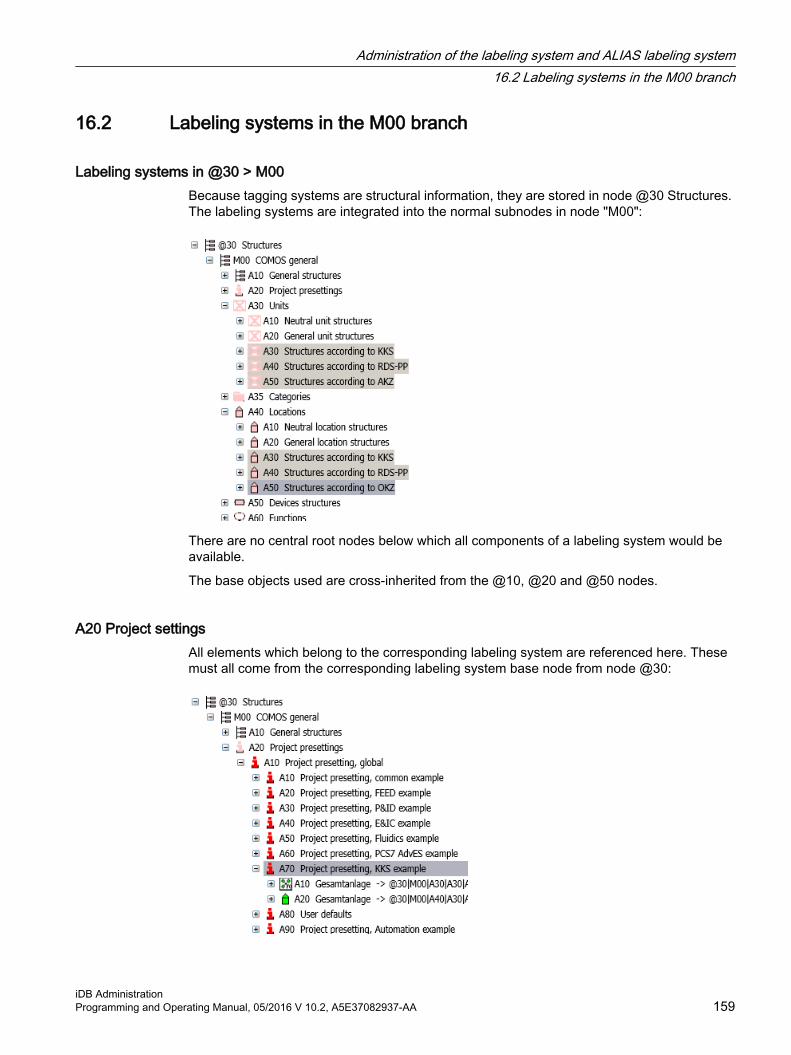
16.2 Labeling systems in the M00 branch
Labeling systems in @30 > M00Because tagging systems are structural information, they are stored in node @30 Structures. The labeling systems are integrated into the normal subnodes in node "M00":
There are no central root nodes below which all components of a labeling system would be available.
The base objects used are cross-inherited from the @10, @20 and @50 nodes.
A20 Project settingsAll elements which belong to the corresponding labeling system are referenced here. These must all come from the corresponding labeling system base node from node @30:
Administration of the labeling system and ALIAS labeling system16.2 Labeling systems in the M00 branch
iDB AdministrationProgramming and Operating Manual, 05/2016 V 10.2, A5E37082937-AA 159

A30 UnitsUnit structures for the labeling system:
● All objects from node @30 which can be created on the "Units" tab are derived from node @10. Example: "@30 > M00 > A30 > A30 > A40 > A > AA > A10"
● The unit structures are compiled into the desired structure using the base objects from node @20 as elements. This is achieved using cross-inheritance.
Administration of the labeling system and ALIAS labeling system16.2 Labeling systems in the M00 branch
iDB Administration160 Programming and Operating Manual, 05/2016 V 10.2, A5E37082937-AA

A40 LocationsLocation structures for the labeling system:
Constructing labeling systems with base objects1. Select the relevant root node for the units, locations, and so on.
2. Insert the base objects into the relevant root node as elements using drag&drop, or create them as new objects.The labeling system is structured using the elements. The elements can have elements of their own.
3. Optional: You can provide the alias structure as well as the normal structure in the root object of the project.
If a different type of designation is specified by labeling systems or standards in catalogs, etc., then deviations from the standard designation, starting from the node for the corresponding substructure, are permitted.
Naming conventions● Labeling systems can be prepared using an element structure.
● Labeling systems can be prepared using text masks.
See chapter Constructing the labeling system with base object elements (Page 157).
Controlling the creation of engineering objects using dereferencingThe objects in @30 are generated using cross-inheritance. The "Derefence" option therefore has special significance in branch @30. This option specifies that it is not the base object itself which is created, but rather the source of the base object reference. See chapter Controlling base object links using dereferencing (Page 46).
Administration of the labeling system and ALIAS labeling system16.2 Labeling systems in the M00 branch
iDB AdministrationProgramming and Operating Manual, 05/2016 V 10.2, A5E37082937-AA 161

16.3 Purpose of ALIAS labeling systems
Requirement● A basic labeling system has been set up.
See chapter Constructing the labeling system with base object elements (Page 157).
AimAn ALIAS labeling system is an alternative labeling system to the basic labeling system. You can switch between the two labeling systems at any time.
To achieve this, the object structure of the project is rebuilt in an @ALIAS branch. The objects in the @Alias branch get a pointer to the originals. Technically, the use of alias is a link of two devices. Only the original has the entire information (attributes, icons, etc.). The alias object only has a pointer to the original, its own labeling and another location in the object tree. If an alias device is opened and the properties are edited, then the original is edited.
See alsoAdministration of the ALIAS labeling system (Page 162)
Using scripts to adjust ALIAS labeling (Page 164)
Labeling systems in the M00 branch (Page 159)
16.4 Administration of the ALIAS labeling system
Requirement● You are familiar with the purpose of the alias labeling system.
See chapter Purpose of ALIAS labeling systems (Page 162).
Step 1: Labeling systemThe project is planned as usual, using the basic labeling system.
Step 2: Alias root objectCreate an @Alias branch in the engineering view:
● Tab: "Unit" and/or "Location", project root: "New > New unit" and/or "New > New location"Name of the new unit / new location: "@Alias" (mandatory name; not case-sensitive)All objects with system type "Device" automatically get an additional reference field.
– Name of the reference field for the objects in the @Alias branch: "Original"
– Name of the reference field for the originals: "Alias"
Administration of the labeling system and ALIAS labeling system16.4 Administration of the ALIAS labeling system
iDB Administration162 Programming and Operating Manual, 05/2016 V 10.2, A5E37082937-AA

Step 3: Alias objectsRebuild the object structure of the original data under the @Alias branch, and assign references to the original data:
1. Use "New > New unit" to create an alias unit "PA" for the original unit "W1".
2. Enter the tag from the alternative labeling system in the label property of the alias unit.
3. Set a pointer at the alias object, referencing the corresponding original. For that purpose, drag&drop the original unit onto the "Original" reference field of the alias unit:
In the properties of the original, a pointer to the alias object is automatically assigned to the "Alias" reference field:
The references appear in the Navigator and are identified by "~". As long as both objects reference each other in their "Alias" property, you can use the "Navigate > Alias" and "Navigate > Original" context menu commands to toggle between the two objects.All engineering-relevant information continues to be maintained at the originals. Thus, the alias objects only get a pointer and a different label.It depends on the respective requirements up to which level the original data is rebuilt in the @ALIAS branch (only units/ locations or also devices).
Administration of the labeling system and ALIAS labeling system16.4 Administration of the ALIAS labeling system
iDB AdministrationProgramming and Operating Manual, 05/2016 V 10.2, A5E37082937-AA 163

NoteNo bulk processing for an alias labeling system
Use the properties of an object (tab with the properties) to set or edit an alias pointer or a pointer to the original.
Step 4: Activating aliasActivate the Alias function using one of the two following options:
● By script"Workset.UseAliasForLabelFunctions =True"The AliasLabel script commands can only be executed if the value is True.
● Via the COMOS user interfaceIf an object named "@Alias" is located in the engineering data directly below the project root, the "A" button is displayed in the COMOS menu bar when the project is opened.Default when opening a project: "False".
See alsoUsing scripts to adjust ALIAS labeling (Page 164)
@20 > A25 Positions (Page 70)
16.5 Using scripts to adjust ALIAS labeling
Requirement● You are familiar with the administration of an ALIAS labeling system.
Administration of the ALIAS labeling system (Page 162)
Using scripts to activate the alias functionThe ALIAS system is deactivated by default. It can be activated on the menu bar using the icon or scripts:
Workset.UseAliasForLabelFunctions=TrueIf Workset.UseAliasForLabelFunctions == True applies, the name is structured using the Alias branch.
If Workset.UseAliasForLabelFunctions == False applies, the name is structured using the regular branch.
This makes it possible to switch the output during operation and applies to all objects.
Administration of the labeling system and ALIAS labeling system16.5 Using scripts to adjust ALIAS labeling
iDB Administration164 Programming and Operating Manual, 05/2016 V 10.2, A5E37082937-AA

Using AliasLabelEither the label or the AliasLabel can be queried at the objects.
If Workset.UseAliasForLabelFunctions = True, then:
● If one of the AliasLabel commands defined in the COMOS DLL is accessed for an object (Object_A), the Alias property of Object_A is evaluated.
● If the object referenced in this property (Object_B) in turn has an Alias reference to Object_A, the AliasLabel command is executed for Object_B.
● If the Alias property is empty or if Object_B does not reference Object_A, the method is conducted for Object_A instead.
Note
It may happen that you want to call an AliasLabel command for an original, but that you are already at the Alias object and thereby mistakenly retrieve the label of the original.
To avoid this error, call the IsAlias()function first. The function verifies whether an object is located in the @Alias branch.
You can find more information on this topic in the "Class Documentation COMOS_dll" manual, keyword "Alias".
SpecialtiesThe alias system does not influence the performance of COMOS.
If possible, the alias function should be used at the corresponding positions in scripts and also in the program.
For example: AliasFullLabel instead of SystemFullLabelIt is important to ensure that switching at the relevant positions is carried out correctly. Checking is carried out within the modules.
Administration of the labeling system and ALIAS labeling system16.5 Using scripts to adjust ALIAS labeling
iDB AdministrationProgramming and Operating Manual, 05/2016 V 10.2, A5E37082937-AA 165

Administration of the labeling system and ALIAS labeling system16.5 Using scripts to adjust ALIAS labeling
iDB Administration166 Programming and Operating Manual, 05/2016 V 10.2, A5E37082937-AA

Classifying objects 1717.1 Purpose of classification
Objectives of classificationClassification has the following objectives:
1. Search: The objective is to find a particular object or similar objects. You are supported by specialized queries when doing so.
2. Control: The objective is to assign similar reactions. In this case, either the objects themselves can react in the same way or else the environment treats all objects in the same way.
3. Standardization: The objective is to create uniform names for objects across databases and companies. This simplifies matching, exchange, and merging.
Application cases● Cross-project queries use the classification
You can find additional information on this topic in the "COMOS Administration" manual, keyword "Creating a query: Cross-project queries".
● Database search uses the classification.You can find additional information on this topic in the "COMOS Administration" manual, keyword "Overview of the database search".
No separate classification of engineering dataOnly the base data (base objects, document base object, etc.) is classified. The engineering objects and engineering documents apply the classifications from the base data.
See alsoStructure of classifications (Page 167)
Performing the classification (Page 170)
Classification of documents (Page 171)
17.2 Structure of classifications
Requirement● You are familiar with the purpose of classifications.
See chapter Purpose of classification (Page 167).
iDB AdministrationProgramming and Operating Manual, 05/2016 V 10.2, A5E37082937-AA 167

Root nodeThe classification keys are stored in "@99 > A10" system node.
Basic variants of classificationsCOMOS uses two types of classification keys:
● Hierarchical classificationFive hierarchically dependent fields with 1 to 4 characters each.In hierarchical classification, the subsequent layers (2, 3, etc.) can only be set in relation to the layers before them.Default in the iDB: The first layer of the hierarchical classification is a three-digit key for the module name (M00 for Basic, M20 for Process, M40 for Automation, and so on).
● Functional classificationFive independent fields with 1 to 4 characters each.You can assign any combination of functional classification keys.Default in the iDB: The first functional classification of all objects is a key made up of two digits twice. The first two digits are a key for the class. The following two digits are a key for the subclass.
Both the hierarchical classifications and the functional classifications exist separately for default objects and for customer objects. For this reason, four basic variants for classifications appear below "@99 > A10":
● Classification key 1: COMOS (hierarchic)
● Classification key 2: COMOS (functional)
● Classification key 3: Customer (hierarchic)
● Classification key 4: Customer (functional)
The hierarchic classification with prefix "Z" is no longer reserved for customer-specific classifications.
Classifying objects17.2 Structure of classifications
iDB Administration168 Programming and Operating Manual, 05/2016 V 10.2, A5E37082937-AA

It is permissible for the classification key to be set and inherited for an object with the "Structure" creation option.
NoteChanges are not permitted for classification key 1 and classification key 2
Classification key 1 and classification key 2 are created and delivered exclusively by Siemens. Classification key 1 and classification key 2 cannot be changed and are also constant in future iDB versions. The descriptions and information texts can be changed.
Classification key 1 and classification key 2 are protected with the "lock-lock" mechanism to protect them from changes. See chapter"Object locking" and "System object" state (Page 37).
NoteIncompatible classification keys of cDB and iDB
The components of the classification keys of the cDB consist of 2 digits.
The components of the classification keys of the iDB consist of 4 digits.
Therefore, the classification keys of cDB and iDB are incompatible. It is not possible to export objects from the cDB to the iDB without editing.
Use of the classification keys in script/memory method of the classificationsClassification keys 1 to 4 are each saved as a contiguous string. The components of the classification key are separated by a dot.
Engineering objects and engineering documents do not have their own classification key:
● Determining classification key for engineering objects (example: object debugger):a.CDevice.GetClassification(index)
● Determining classification key for engineering documents (example: object debugger): a.CDocument.GetClassification(index)
You can find additional information on this topic in the "Class Documentation COMOS_dll" manual, keywords:
● "GetClassification"
● "OwnerByClassification"
● "ClassificationExists"
Customer-specific classificationThe naming convention for classification code 3 takes place analogous to classification key 1 and the naming convention for classification key 4 takes place analogous to classification key 2.
Classifying objects17.2 Structure of classifications
iDB AdministrationProgramming and Operating Manual, 05/2016 V 10.2, A5E37082937-AA 169
Relationship between classifications and class/subclassThe "Class" and "Subclass" standard tables are set in the "System" tab in the properties of the base objects. The "Class" and "Subclass" properties are also reproduced in the iDB with the help of functional classifications.
● Reproduction of class and subclass by means of functional classificationFunctional classification "@99 > A10 > A20 > N1" and all subsequent classification keys up to "P8D3"
– Two characters for the class
– Two characters for the subclass
Example: N6 -> dataset, B4 -> component; B5 -> participant address
Class SubclassN6 N6 B4N6 B5
The "Class" and "Subclass" standard tables are still available for reasons of compatibility.
NoteClassifications and class/subclass must be consistent
When new base objects are created, the settings for classifications and class/subclass must be consistent.
The base objects supplied in the iDB are protected against accidental modification (and thus against inconsistency) using a lock-lock mechanism. See chapter "Object locking" and "System object" state (Page 37).
For objects you create yourself, you must check and match the classification and the setting for class and subclass. This applies in particular to importing/exporting objects.
Classification keys for documentsYou can find additional information on the classification keys for documents under Classification of documents (Page 171).
17.3 Performing the classification
Requirement● You are familiar with the purpose of classifications.
See chapter Purpose of classification (Page 167).
Classifying objects17.3 Performing the classification
iDB Administration170 Programming and Operating Manual, 05/2016 V 10.2, A5E37082937-AA

Classification of a base objectTo perform the classification follow these steps:
1. Open the "Base objects" tab in the base project in the Navigator.
2. Select the base object which you want to classify.
3. Right-click on the base object and select the "Properties" command.The properties of the base object are displayed.
4. In the properties, click on the "Classification" tab.
– Hierarchical classificationClick the button with the three dots.
– Functional classificationSelect the entry in the first drop-down list.The next drop-down list then becomes active.Select as many functional classifications as are required, one after the other.
Classification codes cannot be entered manually in the fields. You must select entries in the drop-down fields.
Update classificationTo perform a classification update, follow these steps:
1. Select one of the following options:
– If you only want to perform the classification update for the currently open project, click the "Administrator> Update classification > Current project" menu.
– If you want to perform the classification update for all projects in the open database, click the "Administrator> Update classification > All projects" menu.
17.4 Classification of documents
Requirement● You are familiar with the purpose of classifications.
See chapter Purpose of classification (Page 167).
● You are familiar with the document management overview.You can find additional information on this topic in the "COMOS Administration" manual, keyword "Overview of document management in COMOS".
Classifying objects17.4 Classification of documents
iDB AdministrationProgramming and Operating Manual, 05/2016 V 10.2, A5E37082937-AA 171

Overview of the classification for documentsDocument management consists of the following independent classified components:
1. The document base object.
2. For COMOS-internal documents: the report template to the engineering document
– Master reports
– Subreports
– Report templates in the style of IEC 61355 (main reports)
3. The engineering document
4. The document groups in which the report templates are sorted
For component 1: Prepared classification key for the document base objectsThe document base object is classified with the hierarchical classification key for documents according to IEC 61355.
● Hierarchical classification The hierarchical classification is below the node "@99 > A10 Classification key" in the Navigator.The general classification code for the document base object is: "A10 > M00 > A140 Documents acc. IEC 61355"
● The classification in the module-specific node is stored for a module-specific document base object. Example:Document base object: "@20 > A60 > A10 > A30 Document base objects for DVM"Classification: "@99 > A10 > A10 > M65 > A030 Document base objects for DMS"
● Functional classificationFunctional classification of documents: "N7 Document"
For component 2: Classification of report templates / document templatesThe following reports apply the hierarchical classification key according to IEC 61355 from the document base object:
● Master reports
● Headers and footers
● Subreports
Hierarchical classificationHierarchical classifications for document templates are formed in a DCC structure below the node "@99 > A10 > A10 > M00 > A140 Documents acc. IEC 61355" and set in the main report in accordance with your DCC structure:
● First key: Module; for most document templates: M00
● Second key: iDB count Axxx; in M00 module: "A140 Documents acc. IEC 61355"
Classifying objects17.4 Classification of documents
iDB Administration172 Programming and Operating Manual, 05/2016 V 10.2, A5E37082937-AA

● Third key: DCC key with two letters
● Fourth key: Matched to the name of the report template. Example: Name of the report template "FP_B02" - associated classification "B02".
The classification is set on the main report. Subreports obtain the hierarchical key for documents "M00 > A140 Documents acc. IEC 61355".
Functional classification● First functional classification
Classification according to the document properties, "Type" field in the "General" tab.Examples:
– "A040 Interactive report"
– "A050 Interactive report template"
– "A060 Evaluating report template"
– "A070 Evaluating report"
● Second functional classificationClassification according to the object of the document template in the iDB:
– Report templates in node "A10 Master reports": Classification with "B980 Master report"
– If the name has two components (for example FS_A20): Classification with "B990 Main report"
– If the name has three components (for example DA_A10_A10): Classification with "C010 Subreport"Example: Report templates in the node "A20 Header"
● Third functional classificationClassification according to COMOS function or COMOS moduleExample: "B100 Process flow diagram (PFD)"
For component 3: Structure of the document groups for storing the report templatesThe structure of the document groups for storing the report templates corresponds to a specific level of the structure of the hierarchical classification codes.
Example:
Documents tab: "A30 > A > *AA > AA_A10 > AA_A10"
Base objects tab: "@99 > A10 > A10 > M00 > A140 > *AA > A10"
In the two paths above, one node each is identified with an asterisk. The filing structure is the same as of this level.
Classification for documents under base objectsDocuments under base objects inherit their classification from the CDocument or the CObject rather than from the owner. See chapter Structure of classifications (Page 167), block "Use of the classification keys in script".
Classifying objects17.4 Classification of documents
iDB AdministrationProgramming and Operating Manual, 05/2016 V 10.2, A5E37082937-AA 173

Classification for engineering documentsEngineering documents adopt the classification of the document template. If no classification is set in the document template, the engineering documents adopt the classification of the base object.
Classifying objects17.4 Classification of documents
iDB Administration174 Programming and Operating Manual, 05/2016 V 10.2, A5E37082937-AA

Administration of documents in the iDB 1818.1 Root nodes of the documents
Relationship with external filesReports consist of a report object in COMOS and an external .CRp file.
See section Physical storage of the report templates (Page 234).
Overview of storageThe documents are made available in the "Documents" tab in the Navigator. The following nodes are here:
The templates for interactive reports and evaluating reports are located in the node A30 and are sorted according to IEC 61355.
A10 Master reportsThe master reports are arranged in accordance with their format. A master report is created for each format. They only contain one frame and are otherwise empty:
The "A10 Master reports" node is divided into DIN and ANSI formats. Sorting in the DIN area takes place in accordance with the ISO-5457 standard.
Example: The following 2 reports are below the A10 > A10 > A10 DIN A0 node:
● A10 Master report DIN A0 portrait
● A10 Master report DIN A0 landscape
The master reports are evaluating reports as standard. To use an interactive report, insert the base object of the corresponding evaluating report and change the type to interactive in the report properties.
A15 Master templatesThe master templates are the templates for evaluating reports. The master template is a combination of master report and header and/or footer.
iDB AdministrationProgramming and Operating Manual, 05/2016 V 10.2, A5E37082937-AA 175

This node is divided into the following areas:
● Data sheets
● Lists
The master reports in the nodes "A10 Data sheets" and "A20 Lists" are distinguished by the standard they use. Example: "COMOS iDB Standard", "PIP Standard".
For the COMOS iDB standard:
● All data sheets: DIN A4 portrait / ANSI A portrait
● All lists: DIN A3 landscape / ANSI B landscape
A20 HeaderThis node contains templates for headers and footers.
The header line reports are sorted in the style of the DIN and ANSI standards and the respective modules. The header line reports include a predefined document header:
A30 Template acc. IEC 61355The document templates are sorted in the style of the standard for classification and designation of documents (DCC) IEC 61355.
Each document template is grouped under a separate document folder.
● Templates for interactive reportsThe templates for interactive reports consist of master reports from the A10 node and header and footer bars from the A20 node.
● Templates for data sheets (evaluating reports)Templates for evaluating reports use a master template from the A15 node. The master templates consist of master reports from the A10 node and header and footer bars from the A20 node.
Administration of documents in the iDB18.1 Root nodes of the documents
iDB Administration176 Programming and Operating Manual, 05/2016 V 10.2, A5E37082937-AA

18.2 Naming convention for report templates and document groupsThe document templates are created in the structures of the node "A30 Templates acc. to IEC 61355". Each document template is grouped under a document folder which includes the main report, subreports and queries.
● The name of a document group is made up as follows: The first two letters of the DCC structure + "_" + COMOS iDB count.
● The main report has the same name as the document group.
● The name of a subreport and query is made up as follows: The first two letters of the DCC structure + "_" + COMOS iDB count + COMOS iDB count. Example: AB_A10_A10 Header. See chapter Using or editing subreports (Page 178).
Example AB_A10:
A subreport can call other subreports. The subordinate subreports in the calling subreport are stored in a separate folder.
In the following figure, you can see the base object for the above report:
The respective name templates in the style of IEC 61355 are set at the base objects of the documents:
Administration of documents in the iDB18.2 Naming convention for report templates and document groups
iDB AdministrationProgramming and Operating Manual, 05/2016 V 10.2, A5E37082937-AA 177

18.3 Using or editing subreports
AimSubreports make it possible to use information numerous times.
Name of the subreportSee chapter Naming convention for report templates and document groups (Page 177).
Storing the subreportSubreports are stored in a document folder together with the calling main report. The name of the folder corresponds to the name of the main report.
The description is used to indicate that it is a subreport.
Grouping of subreportsSubreports can be grouped in a separate subreport folder under a report folder.
The figure shows the grouping of subreports below the FB_B10_B10 folder:
Image 18-1 Subreport_Folder
Administration of documents in the iDB18.3 Using or editing subreports
iDB Administration178 Programming and Operating Manual, 05/2016 V 10.2, A5E37082937-AA

The structure in the file system is identical.
Dynamically selected subreportsVarious subreports are prepared for dynamic subreports and the user selects one of these in engineering project. The user selects an entry from a list for this. Example:
● Units tab, <Process>: "A70 Process units > FB.001 Process flow diagram"
● Open the properties of the process flow diagram, "Attributes > Material balance" tab
● "Design" list
The structure in the file system is identical.
Restricted multiple use for subreportsIf the content of a subreport is required in equal measure by several reports, the following applies:
● Recommendation:
– Do not use subreports repeatedly.
– Make a copy of the subreport for each calling report.
– Copy of the subreport is stored in a folder together with the calling report.
● Multiple use with customer-specific reports With customer-specific reports, a subreport can be called by several reports. Note that a change to the subreport which is being used multiple times affects all reports which call this subreport. Create a subreport used multiple times in a "A10 > A00" node.References (links) can be created under the reports which are calling the subreport, which enables you to track which report has called the subreport.
– Select the "Copy" command from the context menu of the desired subreport.
– From the context menu of the calling report, select the "Paste link" command.The references are stored in parallel to the calling report.
18.4 Object queries for reports
AimLists are displayed for object queries, in which an object query is called from a list field.
Name and storage location● Create a report template object for each created row.
● Create the report template object below the document group of the main report.
● Report templates can be stored and edited in working layers.
Administration of documents in the iDB18.4 Object queries for reports
iDB AdministrationProgramming and Operating Manual, 05/2016 V 10.2, A5E37082937-AA 179

Object queries are created under the main report to which they belong. The name is made up as follows:
● Name of the main report + "X" (reserved letter for object queries) + count in increments of 10.Example: AB_A30_X10
Example: AB_A10_X10
The base objects of the object queries are stored in the respective module node under "@20 > A70 > Y20 Core queries":
Configuring object queriesYou can find additional information on this topic in the "Administration" manual, keyword "Placing a list".
Administration of documents in the iDB18.4 Object queries for reports
iDB Administration180 Programming and Operating Manual, 05/2016 V 10.2, A5E37082937-AA
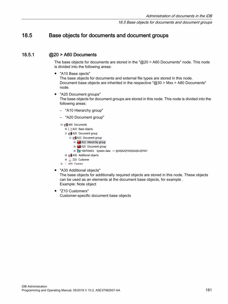
18.5 Base objects for documents and document groups
18.5.1 @20 > A60 DocumentsThe base objects for documents are stored in the "@20 > A60 Documents" node. This node is divided into the following areas:
● "A10 Base ojects"The base objects for documents and external file types are stored in this node.Document base objects are inherited in the respective "@30 > Mxx > A80 Documents" node.
● "A20 Document groups"The base objects for document groups are stored in this node. This node is divided into the following areas:
– "A10 Hierarchy group"
– "A20 Document group"
● "A30 Additional objects"The base objects for additionally required objects are stored in this node. These objects can be used as an elements at the document base objects, for example .Example: Note object
● "Z10 Customers"Customer-specific document base objects
Administration of documents in the iDB18.5 Base objects for documents and document groups
iDB AdministrationProgramming and Operating Manual, 05/2016 V 10.2, A5E37082937-AA 181

18.5.2 Basic rules for documents and document groups in @30 > M00
OverviewThe structures for the base objects of documents and document groups are stored in the "@30 M00 COMOS general" node:
The base objects are responsible for:
● Name masks
● Classification
● Automatic referencing
● Input / storage of revision data
● Insertion of tabs
● Elements
The reports used later in the planning process are mostly controlled by the report templates, and not by these base objects.
Administration of documents in the iDB18.5 Base objects for documents and document groups
iDB Administration182 Programming and Operating Manual, 05/2016 V 10.2, A5E37082937-AA

18.5.3 @30 > M00 > A80 > A10 Document base objects acc. IEC 61355The base object (1) for documents in the style of the IEC 61355 standard is cross-inherited from the "@20 > A60 > A10" node to the "@30 > M00 > A80 Documents" node:
All objects are now derived from this base object (1) from the @20 node. The structure in the style of the IEC 61355 standard is now constructed below object (2):
Base objects for specific documentsThe document templates for specific base objects are stored below the node according to the DCC keys of IEC61355. The following settings can be made at the base object here.
● Adaptation of the name masks
● Classification key
● Insertion of tabs
● Elements
The special document base objects that are used by the document templates are stored in these structures. The documents are named with the COMOS iDB count:
Administration of documents in the iDB18.5 Base objects for documents and document groups
iDB AdministrationProgramming and Operating Manual, 05/2016 V 10.2, A5E37082937-AA 183

If a more specific version of a document base object is required, only one new version may be created below it. Example: There might be another document base object below "A10 Component documentation".
See also@30 > M00 > A90 Document groups (Page 184)
18.5.4 @30 > M00 > A90 Document groupsThe structure below the "@30 > M00 > A90 Document groups" node is formed using the document group base objects from the "@20 > A60 > A20 > A10 Document groups" node.
The DCC structure according to IEC 61355 is displayed as elements from the following two base objects below the "@30 > A60 > A90 > A10" object:
● "@20 > A60 > A20 > A10 > A10 Hierarchy group"Source for the first level below "A90 > A10".
● "@20 > A60 > A20 > A10 > A20 Document group"Source of the second level below "A90 > A10".
The document groups are structured in accordance with the IEC 61355 standard.
See alsoDocument structure A90 below the modules (Page 100)
@30 > M00 > A80 > A10 Document base objects acc. IEC 61355 (Page 183)
Administration of documents in the iDB18.5 Base objects for documents and document groups
iDB Administration184 Programming and Operating Manual, 05/2016 V 10.2, A5E37082937-AA

18.5.5 Managing documents without IEC 61355 labels (@30 > xxx > A80)Document base objects used for documents which do not belong to the IEC 61355 structure are managed in the relevant module node (@30 > Mxx > A80). The relevant base object is cross-inherited to the module node from the "@20" node:
The specific base objects can then be constructed below this.
18.6 Classification of documentsClassification keys for documents are constructed in a DCC structure below the following node:
● "@99 > A10 > A10 > M00 > A140 Documents"
See section Classification of documents (Page 171).
Administration of documents in the iDB18.6 Classification of documents
iDB AdministrationProgramming and Operating Manual, 05/2016 V 10.2, A5E37082937-AA 185

18.7 Layout recommendations for report templates
Static versus dynamic textsUse dynamic texts preferably. To do this, you create COMOS attributes in which the texts are entered. In the report template, you display the value of the attribute.
Text fields● Text fields must be large enough to accommodate all languages.
● Abbreviations are practical for very long attribute descriptions.
● Abbreviations are not permitted in text fields that are not an attribute description.
● The text fields should have an identical text alignment. Default: Left center.
● Text alignment for numbers: Default: Right-aligned
● Select identical display. Default: "Fit oversized texts".
"Text parameters" for texts● All fields must have a uniform font, font size and a uniform font style (for example, Arial 8
normal).
● "Bold" font type is permitted.
● "Bold" is required for structure elements.
● The "Italic" font type is not permitted. This font type is reserved for revised text.
● Display: Default: "Show texts unchanged"
Lines and borders● Line width: 0.35 mm to 0.7 mm.
Headers● Text alignment for headers: Left-aligned
● Row height: 5 mm
● Font in cells: "Arial"
● Font size: "8"
Text fields for min/max valuesThe "Min/Max" text fields should have the following settings:
● Type: "Item property"
● The suffix "item (0)" for the Min text field.
Administration of documents in the iDB18.7 Layout recommendations for report templates
iDB Administration186 Programming and Operating Manual, 05/2016 V 10.2, A5E37082937-AA

● The suffix "item (1)" for the Max text field.
● Property: "Value"
Text parameters for revision fieldsRevision fields are text fields that display revision texts.
● There is exactly one revision field per attribute.
● Type: "Script"
● Script: "MaxRevisionIndexOf"
● Text alignment: Left-aligned
● Font size: "7"
Page numbers● The page numbering should be the same for data sheets and lists.
● Use PageNo and MaxPageNo
Using physical units of measure● Data sheets
Create fields for physical units. The fields should not be operable.The default physical unit is read by the attribute.
● ListsPhysical units are selected with queries.
18.8 Using external document filesSee Chapter iDB-specific rules for using external files (Page 233).
18.9 Company logos
PrincipleAll company logos used on a report must have a reference to an external file.
Administration of documents in the iDB18.9 Company logos
iDB AdministrationProgramming and Operating Manual, 05/2016 V 10.2, A5E37082937-AA 187

Set this reference as follows:
● Project properties: "General settings > Project"
– Company logoThe assigned company.
– Customer logo The assigning company.
Calling in the scriptYou get the file name for these logo files via Project.GetDocumentDirectory + "\" + Project.Spec(ATT_NAME).DisplayValue, where ATT_NAME is "COM01.COM0004" for the company logo and "COM01.COM0010" for the customer logo.
18.10 Displaying AutoCAD drawing in the report
ObjectiveA dxf file belonging to a component is displayed in a data sheet (an evaluating report) The following steps are required for this:
● Base project: Preparation of the report template
● Engineering project
– Import of the dxf file below the data sheet
– Set imported dxf file as reference in an attribute of the pump
Example in the iDB● Component: "@30 > M00 > A50 > A10 > A20 > A10 > A10 Pump, general"
Data sheet is prepared.
● Data sheet: "A30 > D > DA > DA_D04 > DA_D04 Data sheet pump" Picture box and script prepared
Base project: Preparation of the report template1. Open the base project.
2. Open the report template of the evaluating report.
3. Create a picture box.In the above-indicated example, the picture box is on page 3 of the report template. Use "Page" to navigate to page 3.
Administration of documents in the iDB18.10 Displaying AutoCAD drawing in the report
iDB Administration188 Programming and Operating Manual, 05/2016 V 10.2, A5E37082937-AA

4. Open the properties of the picture box.
5. Use the following script:Sub OnCreate()FileName = ""Set objCatalog = Document.ownerIf Not objCatalog Is Nothing Then Set objAtt = objCatalog.Spec("Y00T00156.Y00A01111") If Not objAtt Is Nothing Then Set objDoc = objAtt.LinkObject If Not objDoc Is Nothing Then FileName = objDoc.FullFilename End If End If End If End Sub
The script queries the "Y00A01111" attribute of the pump in the engineering project and displays the dxf file entered there.
Creating engineering data1. Change to an engineering project.
2. Create a pump.
3. Create the data sheet below the pump.
4. Find the dxf file belonging to this pump in the file explorer.
5. Using drag&drop, move the dxf file from the file explorer below the data sheet.The "Choose a document import mode" window appears.
6. Select the "Create copy" option.
7. Open the properties of the pump.
8. Select the "Attributes > General information" tab.
9. Drag&drop the imported dxf file from the Navigator into the "Sketch AutoCad" field.
Additional informationPreparing symbols for AutoCAD export: See chapter Preparing symbols for AutoCAD export (Page 51).
18.11 Creating headers and footersHeaders and footers can be created as a subreport. To store the files, see chapter Using or editing subreports (Page 178). You can find additional information on editing subreports in the report template in the "Administration" manual, keyword "Placing a subreport".
Administration of documents in the iDB18.11 Creating headers and footers
iDB AdministrationProgramming and Operating Manual, 05/2016 V 10.2, A5E37082937-AA 189

18.12 Interaction of tabs and report templates
Dynamic content in data sheetsData sheets are divided into areas. Example:
● Header
● General information
● Process data
● Design data
● Footer
Information for the header and footer is created as attribute base object for the report template.
The other areas take their information from tabs. There is a "Process data" tab for the "Process data" report area. If the attributes in the tab are divided into groups, the area on the report template is divided further.
When you display a comment field in the data sheet, create a comment field on each tab.
The order of the tabs at the engineering object must be identical to the order of the fields on the report template. The "Sorting text" field is used in the properties of the tabs for this.
Use of VSUI attributesCheck the VSUI attributes after changes are made to the names of the tabs.
Example: Properties of a function below a position: "Attributes > System data", "VSUI attributes" field
18.13 Drawing type-specific symbol displaySee Chapter Drawing type-specific symbol display (Page 49).
18.14 Important information on reportsCreate all reports under the corresponding device/equipment.
Select the names for all reports according to the names of the report templates.
Administration of documents in the iDB18.14 Important information on reports
iDB Administration190 Programming and Operating Manual, 05/2016 V 10.2, A5E37082937-AA

Developing scripts for the iDB 1919.1 Basic principles of scripts
DefinitionsThis section contains guidelines and recommendations for creating scripts when using the script language Microsoft Visual Basic Script VBS or VB Script for short).
These guidelines and recommendations apply to scripts within the COMOS iDB, but they also form the basis for scripts that are created as part of customer-specific COMOS-Customizing in COMOS databases.
Any deviations from the guidelines defined in this section are only permissible where customer-specific guidelines are prescribed for scripts within their COMOS database(s).
We make a distinction between the following terms within this document:
● Method:The term "method" is used in this document as a collective term for functions and procedures. Explicit reference is provided where certain conventions only apply to one function or procedure.
● Function:The term "function" is used in this document for methods that provide a return value.
● Procedure:The term "procedure" is used in this document for methods that do not provide a return value.
Personal information in the headerThe iDB does not contain example names in scripts and examples. The fields "Changed by:" and "Created by:" are empty or removed. In practice, we recommend that you use this information.
Additional informationYou can find additional information on this topic in the "COMOS Administration" manual, keyword "Developing scripts".
You can find additional information on this topic in the "COMOS Administration" manual, keyword "Script editor".
iDB AdministrationProgramming and Operating Manual, 05/2016 V 10.2, A5E37082937-AA 191

19.2 Script library
19.2.1 Structure of the script library
Exceptions from central storageAll scripts must be stored at a central location so that they can be called by the corresponding usage points.
The following scripts may be exceptions:
● Script calls
● DLL calls
● Setting constants
● Manageable scripts with only a few rows of instructions
● Scripts in object queries
● Option scripts in reports
● Symbol scripts
● Scripts in standard tables
Root node of the scripts (@20 > A80)The scripts are saved in script objects below the @20 > A80 node. Sub nodes exist below this node for the different modules and module groups. The script objects are collated under structure objects for 50 script objects in each case under this node for improved manageability.
A script object is a base object with the class set as "Action " and subclass set as "Script".
The structure objects receive their name in accordance with the COMOS iDB count (A10, A20, Ann, etc.):
Up to 9 UserScriptBlocks can be defined at a script object. The method which is called via CallScriptLib at the object is called the main method. The Main Method is saved in UserScriptBlock1 and the sub-methods are saved in the further UserScriptBlocks:
Developing scripts for the iDB19.2 Script library
iDB Administration192 Programming and Operating Manual, 05/2016 V 10.2, A5E37082937-AA

Note
Each method is saved in its own UserScriptBlock.
19.2.2 Methods in the script libraryIn order to identify the name of the method within the "Script" tab this should be added to the first row of commentary separated by a colon and a space. Below is the example "Function GetPagePathLib":
Script example' UserScriptBlock1: Function GetPagePathLib(PARAMS)Function GetPagePathLib(PARAMS)' ########################################################################' ### ' ### Header' ### ' ########################################################################
Main methods must supply a return value. Main methods must therefore be declared to be functions (Main function).
Public methods are called via CallScriptLib and they only have one transfer parameter, which is called "PARAMS" (see Assigning transfer parameters (Page 198)). Private methods are called within the same script object and they are not suitable for CallScriptLib. Only one public method (main function) should generally be present for each script object.
Note
Only functions should be used to process status information on the execution of methods as procedures do not supply a return value.
Developing scripts for the iDB19.2 Script library
iDB AdministrationProgramming and Operating Manual, 05/2016 V 10.2, A5E37082937-AA 193

19.2.3 Naming of script objectsThe name of the object is composed as follows:
● Module number <Mxx>
● Letter "S"
● five-digit number
The description corresponds with the name of the main function.
19.3 Structures/ conventions
19.3.1 Overview of the structures and conventionsThe source text for a script should be well structured so as to increase legibility and therefore facilitate a user's understanding of the source text and guarantee improved maintainability.
Note
If conventions mention methods then these rules relate both the functions (function) as well as to procedures (sub). This is unless explicit reference is made to the fact that they only apply to one or the other.
Note
The following conventions are derived from Microsoft's programming guidelines from 2011 and they have been adapted to COMOS.
The source text for a script must be structured as follows:
● Header block
● Variable declarations
● Variable initialization
● Implementation
Developing scripts for the iDB19.3 Structures/ conventions
iDB Administration194 Programming and Operating Manual, 05/2016 V 10.2, A5E37082937-AA

See alsoHeader block (Page 195)
Variable declaration (Page 197)
Variable initialization (Page 198)
Assigning transfer parameters (Page 198)
19.3.2 Header block
Header blockAll methods must start with a header block which must be inserted directly under the first row of the method. The header block contains descriptive information on the functionality of the method and on the change history in implementation.
With this the header block for a method must contain the following information:
● Description of the method
● Information on the method variables
● Information on the method return value
● Information on changes with implementing the method
Developing scripts for the iDB19.3 Structures/ conventions
iDB AdministrationProgramming and Operating Manual, 05/2016 V 10.2, A5E37082937-AA 195

The description of the method should only contain the purpose of the method (i.e. what the method does, not how it does it – as the implementation may change with time):
Header block' #############################################################################' ### ' ### Description: <description of the method (function/procedure)>' ### Variables: <variable name>: <description of the variable>' ### ...' ' ### Returns: <description of the return value>' ### Changed by: <yyyy-mm-dd> - <surname, first name> (<company short name>)' ### <description of the changes>' ### ...' ' ### Created by: <yyyy-mm-dd> - <surname, first name> (<company short name>)' ### ' ############################################################################# ' ### Declaration of the variables: Dim <variable name> ... ' ' ### Initialization of the variables: Set <variable name> = ... ... <variable name> = ... ... ' ' ### Get parameters: Set <variable name> = PARAMS(<Index>) ... <variable name> = PARAMS(<Index>) ...
When creating the method the header block must be supplemented with the following information on creation:
● Date created
● First name and surname of the creatorA name is not entered in scripts of the iDB.
● Company short name
The header block must be supplemented by the following change information following each change in the method implementation:
● Date changed
● First name and surname of the creatorA name is not entered in scripts of the iDB.
● Company short name
● Description of change
Developing scripts for the iDB19.3 Structures/ conventions
iDB Administration196 Programming and Operating Manual, 05/2016 V 10.2, A5E37082937-AA

Note
The abbreviation "(iDB)" must be provided as the company short name within the iDB to document that this is the delivery status.
Script example for creation information
' UserScriptBlock1: Function GetPagePathLib(PARAMS)Function GetPagePathLib(PARAMS)' #############################################################################' ### ' ### Description: Creates a text containing page and path of the given device' ### Variables: PARAMS(1): Calling device as object' ### PARAMS(2): Concerned document as object' ### PARAMS(3): Helper DLL as object' ### Returns: Reference string (page and path) between device and document' ### Created by: 2011-11-30 - iDB' ### ' #############################################################################
Script example for change information
' UserScriptBlock1: Function GetPagePathLib(PARAMS)Function GetPagePathLib(PARAMS)' #############################################################################' ### ' ### Description: Creates a text containing page and path of the given device' ### Variables: PARAMS(1): Calling device as object' ### PARAMS(2): Concerned document as object' ### PARAMS(3): Helper DLL as object' ### Returns: Reference string (page and path) between device and document' ### Changed by: 2011-12-02 - iDB' ### Added checks on Nothing' ### Created by: 2011-11-30 - iDB' ### ' #############################################################################
19.3.3 Variable declarationThe variable declaration should join the header block directly with a space separating the two.
Variable declaration' ### Declaration of the variables: Dim <variable name> ...
Inserting just one declaration is recommended for each row. Each additional declaration should be inserted accordingly in the subsequent rows.
Developing scripts for the iDB19.3 Structures/ conventions
iDB AdministrationProgramming and Operating Manual, 05/2016 V 10.2, A5E37082937-AA 197

19.3.4 Variable initializationThe variable initialization should join the variable declaration directly with a space separating the two.
Variable initialization' ### Initialization of the variables: Set <variable name> = ... ... <variable name> = ... ...
19.3.5 Assigning transfer parametersAll main methods in the script objects of the central script library must feature one transfer parameter precisely known as "PARAMS" in the declaration. This is a field which contains all transfer parameters which have been transferred when calling the method.
' UserScriptBlock1: Function GetPagePathLib(PARAMS)Function GetPagePathLib(PARAMS)' #############################################################################' ### ' ### Description: Creates a text containing page and path of the given device' ### Variables: PARAMS(1): Calling device as object' ### PARAMS(2): Concerned document as object' ### PARAMS(3): Helper DLL as object' ### Returns: Reference string (page and path) between device and document' ### Created by: 2011-11-30 - iDB' ### ' #############################################################################
These transfer parameters should first of all be assigned to a previously declared variable before they are used:
Assignment' ### Get parameters: Set <variable name> = PARAMS(<Index>) ... <variable name> = PARAMS(<Index>) ...
19.3.6 Return values of functionsFunctions should always supply an explicitly defined return value.
Background: Standard return values which have been used with no explicit return value assigned should not be accessed.
Developing scripts for the iDB19.3 Structures/ conventions
iDB Administration198 Programming and Operating Manual, 05/2016 V 10.2, A5E37082937-AA

If no value or object were to be assigned to the function name within the source text then standard return values would be used which are defined as follows:
● A numerical function returns a 0
● A character string function returns a string of zero length ("")
● A function that returns an object returns "Nothing".
In order to return a value or an object explicitly from a function then a value or an object is assigned to the function name (by Set <Function name> = …). Within the function there can be any desired number of these assignments at any desired points in the source text.
In the event of an error the point up to which a function was completed or what the result of calling the function was can both be determined via the return value for a function.
19.3.7 Calling central scripts
Call of UserScript blocks The scripts that are located in the UserScript blocks of the script objects are called via a CallScriptLib call at the usage points.
Example: Script call to a function eventExample of a script call to a function event at the object
Function GetConnectorSpecification(objDevice, strConnectorName, strAttName)' #############################################################################' ### ' ### Description: Gives the attribute object of a connection depending on' ### its linked attribute.' ' ### Variables: objDevice: Owner of the connected connector' ### strConnectorName: Name of the connected connector' ### strAttName: Name of the linked attribute' ### Returns: Attribute object of the connection.' ' ### Created by: 2012-01-30 - iDB' ### ' ############################################################################# ' ### Get corresponding connector specification Set GetConnectorSpecification = Project.Workset.Lib.CallScriptLib( _ "@20|A80|M22|A10|M22S00002", _ "GetConnectorLinkedAttribute3Way", _ objDevice, strConnectorName, _ strAttName, ThisObj) End Function
Developing scripts for the iDB19.3 Structures/ conventions
iDB AdministrationProgramming and Operating Manual, 05/2016 V 10.2, A5E37082937-AA 199

Example: Scripts in UserScript blockExample of a calling script in the UserScript block at a script object
Developing scripts for the iDB19.3 Structures/ conventions
iDB Administration200 Programming and Operating Manual, 05/2016 V 10.2, A5E37082937-AA

' UserScriptBlock1: Function GetPagePathLib(PARAMS)Function GetPagePathLib(PARAMS)' #############################################################################' ### ' ### Description: Creates a text containing page and path of the given device' ### Variables: PARAMS(1): Calling device as object' ### PARAMS(2): Concerned document as object' ### PARAMS(3): Helper DLL as object' ### Returns: Reference string (page and path) between device and document' ### Created by: 2011-11-30 - iDB' ### ' ############################################################################# ' ### Declaration of the variables: Dim colObjDocObjects Dim intDocObjCnt Dim objDev Dim objDoc Dim objDocCurrent Dim objDocObjCurrent Dim strReference ' ### Initialization of the variables: intDocObjCnt = 0 strReference = "" ' ### Get parameters: Set objDev = PARAMS(1) Set objDoc = PARAMS(2) Set objGlbDll = PARAMS(3) ' ### Get all DocObjs Set colObjDocObjects = objDev.BackPointerDocObjs If Not colObjDocObjects Is Nothing Then intDocObjCnt = colObjDocObjects.Count For intI = 1 To intDocObjCnt Set objDocObjCurrent = colObjDocObjects.Item(intI) Set objDocCurrent = objDocObjCurrent.owner ' ### Check SymbolType of the corresponding document If objDocCurrent.SymbolType = "M41_P2" Then strReference = objGlbDll.GU_BuildReferenceString(objDocObjCurrent, _ objDocCurrent, 0) End If Next 'intI End If ' ### Return reference string Set GetPagePathLib = strReference End Function
Developing scripts for the iDB19.3 Structures/ conventions
iDB AdministrationProgramming and Operating Manual, 05/2016 V 10.2, A5E37082937-AA 201

19.3.8 Comments in the script
Syntax of the commentsThe general comments in the script begin as follows:' ### ...The source text for a method should indeed be documented and this can be achieved by way of comments. All comments must be in English. Care should be taken here that comments are informative but are not too lengthy.
This is how comments are provided on the general sequence for the method, in particular for each start of large sections of the method (e.g. "Building the object collection", "Processing all objects in the object collection"). Furthermore, comments should be provided for particularly complex portions of the source text (e.g. "This loop processes all rows in the table while the sub-loop enters the attribute values of the devices into the right columns").
Commenting on each individual portion of the source text must be avoided.
As well as the addition of change information to the header block, the source text where the changes took place must also be commented on as follows:
Commenting on a change at a single instruction row:At this point, the comment row inserted inside the header block, which contains the change date, the first and last name of the person who made the change, and the company short name, is copied in front of the instruction row which is to be changed.
The change is then described in a subsequent comment row.
Example 1' ### Changed by: <yyyy-mm-dd> - <surname, first name> (<company short name>)' ### <description of the change> <source code>
Commenting on a change at a block of instruction rows:At this point, the comment row inserted inside the header block, which contains the change date, the first and last name of the person who made the change, and the company short name, is copied in front of the first instruction row which is to be changed and after the last instruction row which is to be changed.
The words "Start" and "End" are then added to the "Changed by:" text to show the beginning and end of the change.
Developing scripts for the iDB19.3 Structures/ conventions
iDB Administration202 Programming and Operating Manual, 05/2016 V 10.2, A5E37082937-AA

The change is then described in one of the comment rows following the first change comment row.
Example 2' ### Start Changed by: <yyyy-mm-dd> - <surname, first name> (<company short name>)' ### <description of the changes> <source code> <source code> <source code>' ### End Changed by: <yyyy-mm-dd> - <surname, first name> (<company short name>)
19.3.9 Formatting the script
Row length and breaksRows should not be so long that they require a horizontal scroll bar. Rows should generally have a maximum of 80 characters so that new lines and indentations that are motivated semantically are also retained in the printout (limited to the safe printable area).
If a row is too long it should be broken up in accordance with the following rules:
● Break following a comma (e.g. with parameter lists)
● Break after operator
● The text in the new row should be indented in such a way that similar source text points are at the same level in both rows
It must be ensured that any instructions which cover multiple rows must be separated by an underscore (with a preceding space in all cases). This demonstrates that the instruction continues in the subsequent rows, as VBScript separates commands with spaces and not with special characters such as a semi-colon (;).
Line breaks – exampleFunction ShowSampleOfMultiLineCommands(intInputValue1, _ intInputValue2, _ intInputValue3, _ intInputValue4) intOutputValue = intInputValue1 ^4 + _ 4 * intInputValue2 ^3 + _ 12 * intInputValue3 ^2 + _ 24 * intInputValue4 ShowSampleOfMultiLineCommands = intOutputValue End Function
Note
Error messages with script errors may point to an incorrect row as this type of row continuation is interpreted as a row by the Interpreter.
Developing scripts for the iDB19.3 Structures/ conventions
iDB AdministrationProgramming and Operating Manual, 05/2016 V 10.2, A5E37082937-AA 203

Indenting the source textBlocks of source text (contents of a method, a loop, an If...Then...Else instruction, etc.) must be indented. This makes it clear to the reader which parts of the source text belong to which control structures (loops/branchings). Comments should be indented in exactly the same way as the source text which is being commented on. The standard indentation depth is one tab. A tab increment of 2 is recommended for indentations using the tab key.
Indentation – exampleSub ShowIndentationSample(intInputValue) blnStop = False While (blnStop = False) intInputValue = intInputValue / 2 If intInputValue < 10 Then Output "Done" blnStop = True Else Output "Not done yet: " & intInputValue End If Wend End Sub
Blank spacesUsing blank spaces and line breaks considerably improves the legibility of the source text. Blank spaces are created using the space bar and tab key, line breaks using the enter key. Blank spaces and line breaks help to create a meaningful structure and facilitate the reader's understanding of the source text.
Blank spaces should be used:
● Between a key word and the left bracket which belongs to it.This applies to If, ElseIf, For, While, etc.
● Between the right bracket and the key word following it
● Before and after an operator
Blank spaces should not be used:
● Between a method name and the following left bracket for the arguments
● After a left bracket
● Before a right bracket
ExamplesintTotalQuantity = intTotalQuantity + intCurrentQuantityIf (intTotalQuantity < 10) Then Exit SubFunction GetObject(PARAMS)
Developing scripts for the iDB19.3 Structures/ conventions
iDB Administration204 Programming and Operating Manual, 05/2016 V 10.2, A5E37082937-AA

19.3.10 Use of parentheses for If…Then…Else instructionsIf there are multiple operators in a printout, each part is evaluated in a pre-defined sequence. This evaluation sequence is known as operator precedence.
In order to simplify the readability of the source text in control structures in the form of If…Then…Else instructions, the operator precedence should be bypassed by enclosing individual operations in brackets. Operations in brackets are always executed before operations outside of brackets. However, the normal operator precedence applies within the brackets.
ExamplesIf (dblNominalCurrent * dblConcurrencyFactor) < dblMaximumCurrent Then ...End If dblTotalWeight = dblUnitWeight * intQuantitydblAllowedWeight = dblMaximumWeight - dblEmptyWeight If (dblTotalWeight > dblAllowedWeight) OR _ (dblTotalWeight > dblMaximumTensileLoad) Then ...End If
19.3.11 Use of variants for If…Then…Else instructionsDifferent syntax variants (single and multiple rows) are possible for control structures in the form of If…Then…Else instructions. The following syntax should be used – depending on the usage case – in order to guarantee manageability and to be able to react with greater flexibility to subsequent source text changes:
Single-row variantIf in the source text additional source text follows on from the key word "Then" in the same source text row (excluding comments) then this is a single-row If instruction.
The single-row variant should only then be used if an Exit instruction follows the key word "Then" which directly terminates any further execution of a method or loop.
ExamplesIf intFuseCnt = 0 Then Exit Function If objDevFuse Is Nothing Then Exit Function If Not objDevFuse.IsSuccessorOf(objDevCabinet) Then Exit Function If Not ((intVoltageLevel = 230) AND (intFrequency = 50)) Then Exit Function
Multiple-row variant (block variant)If in the source text no more additional source text follows on from the key word "Then" in the same source text row (excluding comments) then this is a multiple-row If instruction which must be terminated with an End If instruction.
Developing scripts for the iDB19.3 Structures/ conventions
iDB AdministrationProgramming and Operating Manual, 05/2016 V 10.2, A5E37082937-AA 205

The multiple-row variant should always then be used if further instructions follow the key word "Then" which do not directly terminate further execution of a method or loop.
ExamplesIf (intVoltageLevel = 230) AND (intFrequency = 50) Then lngFuseSubSymbol = 1ElseIf (intVoltageLevel = 400) AND (intFrequency = 50) Then lngFuseSubSymbol = 2Else lngFuseSubSymbol = 0End If
19.3.12 Merging of character stringsMerging character strings is known as concatenation and it should generally be implemented with a "&" instead of a "+". When the operator "+" is used VB Script converts numerical values to a plus.
19.4 Naming
19.4.1 Naming for methodsThe name for a method should be meaningful so that the purpose can be deduced from the name. Methods are given English names.
Note
Method names may not include any spaces.
The method name should being with a verb as they execute an action. The first letter for the method name must be written in upper case. If the method name consists of individual words written together then the relevant first letter of a word must be written in upper case (Camel Case).
Example:CloseDialog, SearchPositionsBelowUnit
19.4.2 Naming for variable namesThe name for a variable should be meaningful so that the purpose can be deduced from the name. With this the variable name must start with a prefix as described under variable types. Names for variables must be in English. The first letter for the variable name must be written in lower case. If the variable name consists of individual words written together then the relevant first letter of a word must be written in upper case (Camel Case).
Developing scripts for the iDB19.4 Naming
iDB Administration206 Programming and Operating Manual, 05/2016 V 10.2, A5E37082937-AA
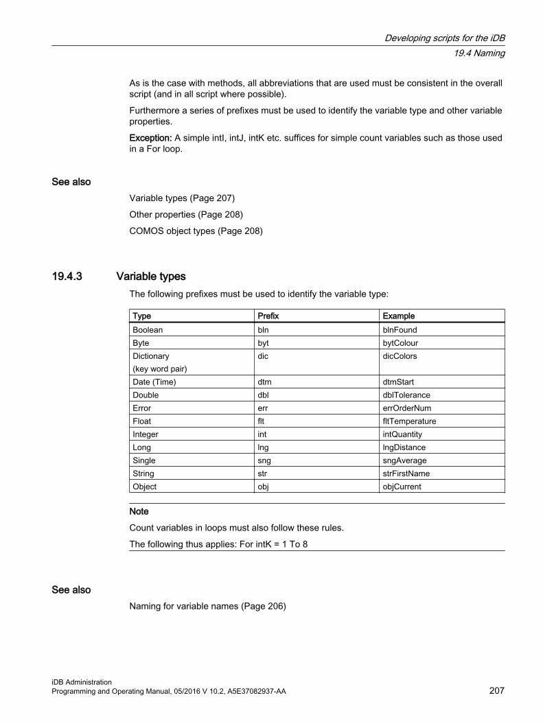
As is the case with methods, all abbreviations that are used must be consistent in the overall script (and in all script where possible).
Furthermore a series of prefixes must be used to identify the variable type and other variable properties.
Exception: A simple intI, intJ, intK etc. suffices for simple count variables such as those used in a For loop.
See alsoVariable types (Page 207)
Other properties (Page 208)
COMOS object types (Page 208)
19.4.3 Variable typesThe following prefixes must be used to identify the variable type:
Type Prefix ExampleBoolean bln blnFoundByte byt bytColourDictionary(key word pair)
dic dicColors
Date (Time) dtm dtmStartDouble dbl dblToleranceError err errOrderNumFloat flt fltTemperatureInteger int intQuantityLong lng lngDistanceSingle sng sngAverageString str strFirstNameObject obj objCurrent
Note
Count variables in loops must also follow these rules.
The following thus applies: For intK = 1 To 8
See alsoNaming for variable names (Page 206)
Developing scripts for the iDB19.4 Naming
iDB AdministrationProgramming and Operating Manual, 05/2016 V 10.2, A5E37082937-AA 207

19.4.4 Other propertiesThe following prefixes are used for other variable properties. Where possible they should be used in addition to the prefixes for variable types.
Type Prefix ExampleArray(Field)
arr arrStrNames
Collection(Collection)
col colObjFuses
Constant(Constant)
const constIntDefaultValue
Global variables must be used with caution. Where global variables are required they must be declared in the "ScriptBlockParameter" Scriptblock.
See alsoNaming for variable names (Page 206)
19.4.5 COMOS object typesThe following prefixes must be used in addition to the variable type prefix "obj" in order to identify COMOS object types:
COMOS object type Prefix ExampleAttributes(Attribute)
Att objAttTemperature
CDevice(Base object)
CDev objCDevPump
CDocument(Report template)
CDoc objCDocPID
Connector(Connector)
Con objConSLI
Device(Engineering object)
Dev objDevCurrent
Document(Document)
Doc objDocPID
Query(Object query)
Qry objQryPartslist
Standard table(Standard table)
StdT objStdTBridgeType
Standard value(Standard table value)
StdV objStdVCableBridge
Developing scripts for the iDB19.4 Naming
iDB Administration208 Programming and Operating Manual, 05/2016 V 10.2, A5E37082937-AA

COMOS object type Prefix ExampleTab(Tab)
Tab objTabTechnicalData
Working overlay(Working layer)
WoO objWoOReleaseOverlay
See alsoNaming for variable names (Page 206)
19.5 Incorporating COM components
19.5.1 Overview of the technology in the COM componentsCOM components are understood as a collection of one or more COM classes. A COM component is generally a binary file (.dll, .ocx, .exe). However, there are also COM components in the form of source text files known as Windows Script Components.
Each COM class provides an interface which following successful instantiation can be used to implement the methods and properties offered by the COM classes.
The "Component Object Model" ("COM" for short) is not location-dependent, meaning that the COM components can be accessed independently of their actual location.
Once a COM component has been identified by the operating system it can be incorporated within the source text with the following instruction:Set <ObjectInstanceName> = CreateObject(<ObjectClassName>[, <ServerName>])
Note
The method "CreateObject" returns an object reference which must be assigned to a variable.
Only COM-enabled components can be incorporated with the method "CreateObject". COM-enabled components are COM components and .NET components which are defined as COM visible.
19.5.2 Declaration components of the method "CreateObject"● <ObjectClassName>:
The ObjectClassName of the object to be created is made up of the <ComponentName>.<ClassName>.
● <ServerName>:Optional parameter. The name of the network server on which the object is to be created. If <ServerName> is an empty string ("") the local computer is used.
Developing scripts for the iDB19.5 Incorporating COM components
iDB AdministrationProgramming and Operating Manual, 05/2016 V 10.2, A5E37082937-AA 209

19.5.3 Memory storage management or cleaning with incorporated COM componentsThe COMOS Script Engine should be supported with memory storage management or cleaning where instances of COM classes have been produced from incorporated COM components.
If instances of COM classes have been produced from incorporated COM components then the memory assigned to these instances should be released where the instances are no longer being used.
The following instruction must be used to release the memory assigned:Set <ObjectInstanceName> = Nothing
NOTICE
Instances
The instance of the COM components must be cleaned before a method is left.
19.6 Avoiding runtime errors
ProcedureThe following steps help to avoid runtime errors:
● Validity check of input variablesAll input variables transferred to the method using transfer parameters should be checked for validity. This also ensures that, during further processing of the input variables, no runtime errors can occur due to missing input variable types or input variable values.
● Checking for the existence of objectsBefore accessing the properties of an object (for example, the description of an attribute or the name of a device), a check must be performed first to determine whether the object exists. Only then is access permitted.Example:If Not objDevThermometer Is Nothing Then Set objAttTemperature = objDevThermometer.spec("Y00T00005.Y00A07285") If Not objAttTemperature Is Nothing Then intTemperature = objAttTemperature.value End IfEnd If
Developing scripts for the iDB19.6 Avoiding runtime errors
iDB Administration210 Programming and Operating Manual, 05/2016 V 10.2, A5E37082937-AA

19.7 Improve script performanceThe following fundamental rules should be observed in order to improve script performance and thereby reduce the runtimes.
● Define objects which are used frequently as variables beforehandExample:Set objWorkset = Project.Workset
● Define a collection as a variable before accessing its elementsExample:Set colObjDevTerminals = objDevTerminalStrip.EnObs("E")
● Define the number of elements in a collection before iteration as a variableExample:
intFuseCnt = colObjDevFuses.CountFor intI = 1 To intFuseCnt ...Next 'intI
● Define the current object as a variable with multiple access to different properties of an object in iteration (For loops, etc.)Example:
For intI = 1 To intFuseCnt Set objDevActualFuse = colObjDevFuses.Item(intI) Set objAttFrequency = objDevActualFuse.Spec("Y00T00003.Y00A00363") Set objAttManufacturer = objDevActualFuse.Spec(Y00T00025.Y00A00370") If Not objAttFrequency Is Nothing Then intFrequency = objAttFrequency.Value End If If Not objAttManufacturer Is Nothing Then strManufacturer = objAttManufacturer.Value End If Next 'intI
● Define attributes as a variable for a check for their existenceExample:
Set objAttNominalVoltage = objDevFuse.Spec("Y00T00003.Y00A00837") If Not objAttNominalVoltage Is Nothing Then ...End If
● Define a tab as a variable prior to querying multiple attributes of a tabExample:
Developing scripts for the iDB19.7 Improve script performance
iDB AdministrationProgramming and Operating Manual, 05/2016 V 10.2, A5E37082937-AA 211

Set objAttTabTechnicalData = objDevFuse.Spec("Y00T00003")Set objAttFrequency = objAttTabTechnicalData.Spec("Y00A00363")Set objAttNominalVoltage = objAttTabTechnicalData.Spec("Y00A00837")Set objAttNominalCurrent = objAttTabTechnicalData.Spec("Y00A00838")
● Limit the search quantity as far as possible (define classes and base objects and leave out recurrent search procedures) and do not generally use the Devices Collection when searching for certain engineering objects within a node.Examples:Instead of a search using the methods "Devices", use methods such as OwnElements, EnObs, ScanDevices, ScanDevicesWithXObject, Scan etc. Stop classes should be defined where possible when using recurrent searches.
● Where possible execute comparisons based on object and not on string operations.Examples:
<Object A> Is <Object B><Object A>.IsSuccessorFrom(<Object B>)<Object A>.IsInheritSuccessorFrom(<Object B>)
19.8 Localizing texts in scripts with NLS
19.8.1 Overview of the use of NLS texts
AimYou can create text and messages in COMOS using script; for example, you can create notes for the user by means of "Messagebox". With the technique described below, you can create such text and messages in more than one language. To do so, you use NLS (National Language Support).
Developing scripts for the iDB19.8 Localizing texts in scripts with NLS
iDB Administration212 Programming and Operating Manual, 05/2016 V 10.2, A5E37082937-AA

ProcedureMultilingual text is administered as follows:
1. The text to be translated is collected in standard tables. Each separate text to be translated has its own entry.See section Administering NLS texts in standard tables (Page 213).
2. The entries in the standard table are translated.See section Administering NLS texts in standard tables (Page 213).
3. An entry is accessed from the standard table in the script and it is determined which translation is to be used. The following options are available:
– Opening in the script delivers the text in the language that is currently set as the project language (database language).
– Opening in the script delivers the text in the language that is currently set as the interface language.
– Opening in the script delivers the text in the language that is found by means of an ID provided.
See section Functions for localizing texts (Page 216).
See alsoCall example of an NLS text (Page 218)
19.8.2 Administering NLS texts in standard tables
Requirement● You are familiar with the overview of using NLS texts.
See chapter Overview of the use of NLS texts (Page 212).
Developing scripts for the iDB19.8 Localizing texts in scripts with NLS
iDB AdministrationProgramming and Operating Manual, 05/2016 V 10.2, A5E37082937-AA 213

Storage and assigning namesThe texts are administered in standard tables under the node "Y60 NLS tables":
It is essential to observe the following structure:
Y60 NLS tables: Shared folder for all NLS tables
● Y00: Branch with the text supplied. These objects cannot be edited.
– "A10 NLS tables 00001 - 00025": First sub-folder for up to 25 standard tables- "Y60Y00N00001 NLS Text 00001 - 00050": First standard table with up to 50 entries
● "Z10 Customer NLS tables": Branch with the customer-specific text.
– "A10 NLS tables customer 00001 - 00025": First customer sub-folder for up to 25 standard tables- "Y60Z10N00001 NLS Text Customer 00001 - 00050": First customer standard table with up to 50 entries
Developing scripts for the iDB19.8 Localizing texts in scripts with NLS
iDB Administration214 Programming and Operating Manual, 05/2016 V 10.2, A5E37082937-AA

The standard tables with the text are identified by their name. Every standard table under "Y60 NLS tables" must therefore have a unique name. The following name conventions apply:
● Standard tablesThe structure is used as a prefix in the name.
– COMOS standard tablesPrefix for the folder "Y60" + subfolder "Y00" + "N" + five-digit consecutive number starting at "00001"Example: "Y60Y00N00001"
– Customer standard table Prefix for the folder "Y60" + subfolder "Z10" + "N" + five-digit consecutive number starting at "00001"Example: "Y60Z10N00001"
● Standard table values
– Standard name: Capital letter "A" + three-digit number.Example: A010
– The names are incremented in tens, with only 50 standard table values permitted for each standard table.
– The text to be translated is entered in the "Description" column in multiple languages.
– Optional: Customer-specific entries in a COMOS standard table:Prefix "Z" followed by a number with at least two numerical values or a "_Z" suffix
– Value 1: The value in this column is the attribute value (as compared to the display value). You need to ensure that this entry is unique and that the numerical value is correct.
You can find additional information on this topic in the "COMOS Administration" manual, keyword "Administration of selection lists".
Translate NLS texts1. Open the function "Extra > Translation > Bulk translation".
2. Drag the NLS table from the Navigator into the "Start object" field.
3. Set the "Search technique" option to "Recursive".The list contains the entries from the standard table.
4. Edit the entries in the language columns "German", "English (USA)", and so on.
5. Recommendation: Value 1 should be unique and not have any special meaning.Value 1 is internally a buffer to store the value at the attribute. The correct content for the attribute (e.g. "Yes") is stored in value 2. This way you can change value 2 without losing the selected information (entries) of the standard tables.
6. Recommendation: Each standard table should contain a "Not defined" value. The first name of the list is "A000" and value 1 should be "0".
7. Confirm your entries.
You can find additional information on this topic in the "COMOS Administration" manual, keyword "Manual translation with bulk translation".
Developing scripts for the iDB19.8 Localizing texts in scripts with NLS
iDB AdministrationProgramming and Operating Manual, 05/2016 V 10.2, A5E37082937-AA 215

See alsoY60 NLS tables (Page 153)
19.8.3 Functions for localizing texts
Requirement● You are familiar with the overview of using NLS texts.
See section Overview of the use of NLS texts (Page 212).
CallAn NLS text is created with one of these functions:
● GetInternationalTextFromNLSByProjectLanguage
● GetInternationalTextFromNLSByGUILanguage
● GetInternationalTextFromNLSByLanguageID
Explanations for function GetInternationalTextFromNLSByProjectLanguagePublic Function GetInternationalTextFromNLSByProjectLanguage(ByVal NLSStdTableName As String, ByVal NLSTextID As String, ParamArray PlaceholderValues()) As String● Parameter 1
The first parameter provides the name of the associated NLS table. (The system full name of the standard table is not specified here.)
● Parameter 2The second parameter provides the name of the associated standard table value.
● Parameter 3The third parameter provides a list of strings that replace placeholders within the tests. An example is given later.
The result is the selected text in the project language. If the text was not translated into this language, then the process for all translatable COMOS texts applies.
Explanations for function GetInternationalTextFromNLSByGUILanguagePublic Function GetInternationalTextFromNLSByGUILanguage(ByVal NLSStdTableName As String, ByVal NLSTextID As String, ParamArray PlaceholderValues()) As String● Parameter 1
The first parameter provides the name of the associated NLS table. (The system full name of the standard table is not specified here.)
● Parameter 2The second parameter provides the name of the associated standard table value.
● Parameter 3The third parameter provides a list of strings that replace placeholders within the tests. An example is given later.
Developing scripts for the iDB19.8 Localizing texts in scripts with NLS
iDB Administration216 Programming and Operating Manual, 05/2016 V 10.2, A5E37082937-AA

The result is the selected text in the language of the user interface. If the text was not translated into this language, then the process for all translatable COMOS texts applies.
Explanations for function GetInternationalTextFromNLSByLanguageIDPublic Function GetInternationalTextFromNLSByLanguageID(ByVal NLSStdTableName As String, ByVal NLSTextID As String, ByVal LanguageID As Integer, ParamArray PlaceholderValues()) As String● Parameter 1
The first parameter provides the name of the associated NLS table. (The system full name of the standard table is not specified here.)
● Parameter 2The second parameter provides the name of the associated standard table value.
● Parameter 3The third parameter provides the number of the required language as string. (Example: "1" for German and "2" for English.)
● Parameter 4The fourth parameter provides a list of strings that replace placeholders within the tests. An example is given later.
The result is the selected text in the language of the specified number. If the text was not translated into this language, then the process for all translatable COMOS texts applies.
Placeholders for text using "PlaceholderValues"Explanation for optional parameter "ParamArray PlaceholderValues()":
The placeholders %0%, %1%, …, %n% can be entered in texts for NLS texts. The values that are later specified in these placeholders are administered as a list of strings.
NLS text in the description at the standard table value "A010" at the standard table "Y60Z10N00001":"Name: %0% Systemfullname: %1%"The following call in the object debugger for any object "a":Output Project.Workset.Lib.GetInternationalTextFromNLSByProjectLanguage("Y60Z10N00001", "A010", a.Name, a.SystemFullName)"a" is the object in this case: @20|A80|M00|A10|M00S00001.The call has the following result:"Name: M00S00001 Systemfullname: @20|A80|M00|A10|M00S00001"This method is defined this way for all three functions for the last parameter.
ExampleProject.Workset.Lib.GetInternationalTextFromNLSByProjectLanguage("<NLSStdTableName>","<NLSTextID>")Example for a MessageBox:strBox = Project.Workset.Lib.GetInternationalTextFromNLSByProjectLanguage("<N
Developing scripts for the iDB19.8 Localizing texts in scripts with NLS
iDB AdministrationProgramming and Operating Manual, 05/2016 V 10.2, A5E37082937-AA 217
LSStdTableName>","<NLSTextID-MsgBox>")strHeader = Project.Workset.Lib.GetInternationalTextFromNLSByProjectLanguage("<NLSStdTableName>","<NLSTextID-MsgBoxHeader>")Project.Workset.Lib.ComosMsgBox strBox, , strHeaderComments and parameters for example:
● <NLSStdTableName>:Name of the NLS standard table (e.g. "Y60Y00N00001")
● <NLSTextID-MsgBox>:Name of the message text to be addressed (e.g. "A010") This value is output in the Messagebox text area.
● <NLSTextID-MsgBoxHeader>:Name of the message text to be addressed (e.g. "A020") This value is output in the Messagebox header.
19.8.4 Call example of an NLS text
Requirement● You are familiar with the overview of using NLS texts.
See section Overview of the use of NLS texts (Page 212).
ExamplesCall examples from the object debugger:
● Project.Workset.Lib.GetInternationalTextFromNLSByProjectLanguage("Y60Y00N00001","A030")
● Project.Workset.Lib.GetInternationalTextFromNLSByGUILanguage("Y60Z10N90001","A010", a.SystemFullName) (Note: A matching NLS text must first be created for this example in the database and "a" must be a matching object.)
● Project.Workset.Lib.GetInternationalTextFromNLSByLanguageID("Y60Y00N00001","A030","1")In this example, the value "1" corresponds to the first language column, i.e. German.
19.9 Prevent pop-up windowAny parts of the program which use pop-up windows should only be used where absolutely necessary. This includes message boxes (MsgBox), input boxes (InputBox), progress bars (ProgressBar). These control elements interrupt the program flow and may therefore lead to errors in COMOS.
There is a separate function for message boxes in COMOS which should be used where a pop-up message is unavoidable.
Developing scripts for the iDB19.9 Prevent pop-up window
iDB Administration218 Programming and Operating Manual, 05/2016 V 10.2, A5E37082937-AA

The COMOS-specific function is called with the Project.Workset.Lib.ComosMsgBox command, with the transfer parameters being identical to the classic "MsgBox" function.
Contrary to the classic "MsgBox" function the "ComosMsgBox" can be suppressed by the COMOS Enterprise Server (execution in silent mode) and it does not therefore wait for an answer from the user, e.g. when importing files.
19.10 Logging script actionsWhen you write scripts, you have the following options for logging the sequence of the script:
"OutputDebugString" methodOutputs can be created via script from COMOS using the following instruction:Project.Workset.Lib.Output(<Text to be output>)A program such as the Microsoft program "DBMon.exe" (DBMon - Debugging Monitor), which is available in the "Current\BIN" subdirectory of the COMOS installation, can be used to view all logged execution information.
The messages displayed using DBMon.exe comprise both local error messages as well as information exchanged among other COMOS users via CVS (Cache Validation Service). In general, all messages which are produced by a program using the "OutputDebugString" method are displayed by DBMon.exe.
The "Output" method to be used in COMOS for outputting relevant messages produces an output via the "OutputDebugString" method defined inside kernel32.dll.
"Object test" tabThe "Object test" tool can be used to provide the user with execution information at the COMOS user interface stage.
The user can make outputs and inputs within the "Object Test" tool on a certain object using the following instructions:
Error outputs<Object>.AddToErrorObjects(<ErrorCode of the ErrorObject>, <Error description of the ErrorObject>)
Additional handling of ErrorObjects is described in the COMOS help guide.
Note
Management of ErrorObjects that are displayed in the "Object Test" tool is implemented per user and per project.
The user cannot influence the "degree of problem" property for the corresponding input in the Object Test.
The user cannot influence the ErrorObjectMode for the corresponding input in the Object Test tool. The inputs created by the user using the methods stated above are always given the definition "3 - external" by the system for the ErrorObjectMode
Developing scripts for the iDB19.10 Logging script actions
iDB AdministrationProgramming and Operating Manual, 05/2016 V 10.2, A5E37082937-AA 219

19.11 Information about the Object DebuggerThe Object Debugger (Menu "Options > Object Debugger") can be used to test scripts that have been created or to query information on the available methods and properties for an object.
The object debugger is used to act directly on objects by means of a script.
If the "Activate point operator for interface assistance" checkbox is selected, then a list of all subsequent available commands is displayed in the "Printout" field after the first command which has been input correctly.
A detailed description of the Object Debugger can be found in the "COMOS-Administration" COMOS manual in Chapter 15: "Object Debugger".
19.12 Using hard-coded base objects in scripts
Hard coding for block base objects"@30 > M40 > A50 > A10 > A10 > A10 Automation objects"
The hard coding for these base objects is managed in the standard table "Y40 > M00 > A10 > Y40M00N00001 > Y40M00N00001M40".
This standard table contains the changeable Name and the SystemFullName in each case. The "-" character is used as the delimiter.
The SystemFullName of a base object is retrieved from the standard table in which the value in the "Name" column is passed to the HardcodingMapper function (here with the example value "A010"):Set mapper = CreateObject("Comos.SolidBaseUtilities.HardcodingMapper")Dim mapping
mapping = mapper.GetMappingFromStandardTable("Y40|M00|A10|Y40M00N00001|Y40M00N00001M40", "A010")
Developing scripts for the iDB19.12 Using hard-coded base objects in scripts
iDB Administration220 Programming and Operating Manual, 05/2016 V 10.2, A5E37082937-AA

Editing project properties 2020.1 Global project options
Global optionsThe properties of the object are saved in an XML file which can only be changed by Siemens.
You have the following options for specifying templates for a COMOS project:
● Project properties, "General settings > Project > Links > Project structure"
● Creating attributes for the released area of the working layers and processing them using scripts
Specifying the scope for the option ● Database scope
Edit mode of the attribute set to "Editable - only on base data side".
● Project scope Edit mode of the attribute set to "Editable - normal".
See alsoCustomer-specific project properties (Page 231)
20.2 Base references: References to database objects
AimBase references determine the base objects or root objects used for certain tasks. Example: The "Cable catalog" base reference specifies the base object below which the the cable objects are located. Base references save you from having to enter specific path details in scripts. Customizations are easy to make as they involve changing the base reference.
Example:
"@99 > A30 > M00 > A40 > A10 Link object"
Using the FullNameBase references are created as reference attributes. The display should be set to "FullName of the linked object" in the attribute display.
iDB AdministrationProgramming and Operating Manual, 05/2016 V 10.2, A5E37082937-AA 221

20.3 Project properties referenceYou can find the reference of the project properties in the "COMOS Administration" manual, keyword "Overview of the project properties".
Editing project properties20.3 Project properties reference
iDB Administration222 Programming and Operating Manual, 05/2016 V 10.2, A5E37082937-AA
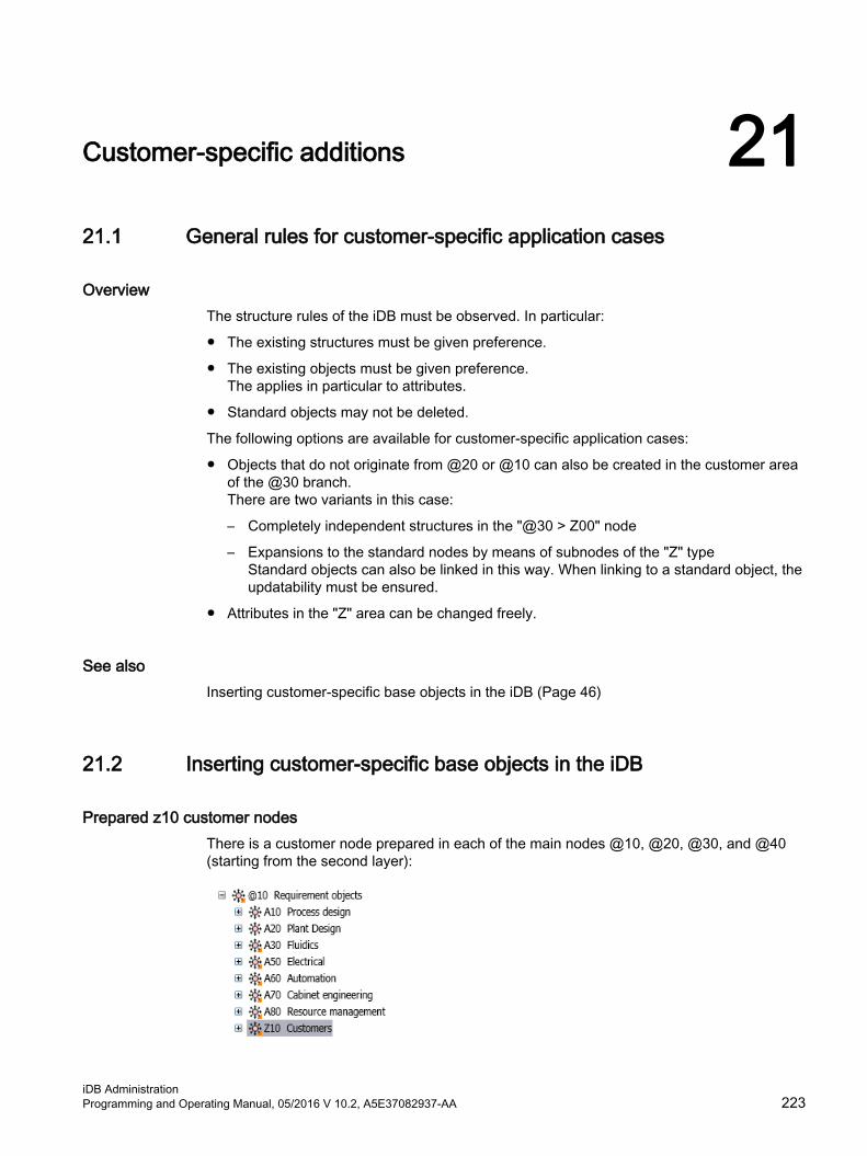
Customer-specific additions 2121.1 General rules for customer-specific application cases
OverviewThe structure rules of the iDB must be observed. In particular:
● The existing structures must be given preference.
● The existing objects must be given preference. The applies in particular to attributes.
● Standard objects may not be deleted.
The following options are available for customer-specific application cases:
● Objects that do not originate from @20 or @10 can also be created in the customer area of the @30 branch. There are two variants in this case:
– Completely independent structures in the "@30 > Z00" node
– Expansions to the standard nodes by means of subnodes of the "Z" type Standard objects can also be linked in this way. When linking to a standard object, the updatability must be ensured.
● Attributes in the "Z" area can be changed freely.
See alsoInserting customer-specific base objects in the iDB (Page 46)
21.2 Inserting customer-specific base objects in the iDB
Prepared z10 customer nodesThere is a customer node prepared in each of the main nodes @10, @20, @30, and @40 (starting from the second layer):
iDB AdministrationProgramming and Operating Manual, 05/2016 V 10.2, A5E37082937-AA 223

You can create more customer nodes within the existing COMOS iDB structures using the letter Z and COMOS iDB counting.
Creating base objects in a "Z10" customer nodeYou have the following options below a customer node:
1. Own base object The base object can also be a modified copy of a standard object from the COMOS iDB.
2. Derived base object from a cross-inherited object from the COMOS iDB
(1) Standard object in COMOS iDB(2) Cross-inherited base object (reference in the "Base object" field)(3) Child object of base object (2)
3. Change to standard objectWith this method, the changes are lost each time the iDB is updated.
Customer-specific additions21.2 Inserting customer-specific base objects in the iDB
iDB Administration224 Programming and Operating Manual, 05/2016 V 10.2, A5E37082937-AA

Alternative: Customer nodes with suffix "_Z" It is possible to insert customer nodes labeled with the suffix "_Z" into the standard structures. The following options are available:
1. Creating a copy that is parallel to the standard object and entering the suffix "_Z":
2. Creating a child object below the standard object and entering the suffix "_Z":
Customer-specific attributes The attributes of the customer-specific objects are not created at the base object, but instead in the customer area of @40. See Chapter Creating customer-specific attributes and tabs (Page 226).
Customer-specific connectors and elements● Editing at the base object (checking in)
Connectors which are checked in and edited can be overwritten by changes to the iDB supplied by Siemens. Therefore, checked-in and edited connectors must be checked after each update to the iDB.
● Newly inheritedNew connectors which have been created by inheritance can lead to duplicate connectors with identical names after the iDB is updated. These connectors must be merged or synchronized after each update to the iDB.
Customization of descriptions, symbols, and scriptsThese customizations can be resolved by the object matcher when the iDB is updated.
Customer-specific additions21.2 Inserting customer-specific base objects in the iDB
iDB AdministrationProgramming and Operating Manual, 05/2016 V 10.2, A5E37082937-AA 225

21.3 Creating customer-specific attributes and tabs
Customer attributes and customer tabsThe customer attributes are created in the Z area with the same structure as in the iDB. The concept of carrier attributes is used:
On request, Siemens will provide a script which can take the attributes from an Excel table and create them in the iDB.
These customer attributes can now supplement existing tabs. Customer tab variants are created for this purpose:
Customer-specific additions21.3 Creating customer-specific attributes and tabs
iDB Administration226 Programming and Operating Manual, 05/2016 V 10.2, A5E37082937-AA

This can happen in two ways:
● Creating a copy and customizing it
● Creating a subvariant and customizing it
The customizations remain unchanged when the iDB is updated.
Using customer-specific tabsThe tabs are now attached to the objects.
The following alternatives are available:
● Attached to a standard object
● Attached to an object copy
● Attached to a derived object
Customer-specific additions21.3 Creating customer-specific attributes and tabs
iDB AdministrationProgramming and Operating Manual, 05/2016 V 10.2, A5E37082937-AA 227

21.4 Creating customer-specific documents
Customer-specific connectorsThe following alternatives are available for creating customer-specific documents:
● Copying
● Changing the actual object With this procedure, customer-specific changes may be lost when the iDB is updated.
Procedure:
● The standard examples of reports are copied and stored in the customer areas
● A customer layer is created in the structure in the style of IEC 61355, parallel to the structure keys
● The customer reports are located below the customer layer
● The customer reports use unmodified standard master reports and customized headers where possible
Customer-specific additions21.4 Creating customer-specific documents
iDB Administration228 Programming and Operating Manual, 05/2016 V 10.2, A5E37082937-AA

● The customer headers are created in their own customer area in the header node.
● All other customizations are set at the customer reports in the structure in the style of IEC 61355. Customer subreports are also created at this position.Example:
The directory structure is created in the same way:
Customer-specific additions21.4 Creating customer-specific documents
iDB AdministrationProgramming and Operating Manual, 05/2016 V 10.2, A5E37082937-AA 229

Using a report template on the document:
1. Enter the path in the Z10 area in this field. The document name is DA_Z10, for example, but it can also be expanded.
Document base objects are extended in the same way:
Customer-specific additions21.4 Creating customer-specific documents
iDB Administration230 Programming and Operating Manual, 05/2016 V 10.2, A5E37082937-AA

For changes to tabs, a customer variant is created and this is copied at the document base object. See section Creating customer-specific attributes and tabs (Page 226).
21.5 Customer-specific project properties
OverviewThe customer-specific "Customer settings" category is invisible in the project properties in the delivery state. The "Customer settings" category only becomes visible when at least one customer-specific tab has been created in the project properties.
In order to create customer-specific project properties, proceed as follows:
1. Switch to the base project.
2. Select the "@30 > M00 > A20 > A10 Project presetting, global" base object.
3. Open the properties of "A10 Project presetting, global".
4. Change to the "Attributes" tab.
5. Create a new tab.
Customer-specific additions21.5 Customer-specific project properties
iDB AdministrationProgramming and Operating Manual, 05/2016 V 10.2, A5E37082937-AA 231

6. Create whichever attributes you choose on this tab.
7. Confirm your entries.The "Customer settings" category appears in the project settings with a subcategory that has the same name as the tab. The attributes created on the tab are available in the subcategory.
Customer-specific additions21.5 Customer-specific project properties
iDB Administration232 Programming and Operating Manual, 05/2016 V 10.2, A5E37082937-AA
iDB-specific rules for using external files 2222.1 Using or editing external files
Definition of the term "external file"Every file that is saved in the document directory is an external file. Examples:
● .CRp files for report templates
● Other document templates
● .bmp bitmaps
● DLLs
General conditions● Fields, scripts and report options are stored in report templates.
● Except for .crp files, external files are not taken into account by the working layer management in COMOS. Changes to the external file affect not only the current working layer but also the entire database. These external files are not exported when a working layer is exported.
● The .crp files are working layer-dependent in the iDB. For this reason, every .crp file must reference a COMOS object.
Special characters forbidden in names of external filesFile names of external files must not contain language-specific special characters such as é, ö, ß, ø, etc. Umlauts (ä, ö, ü) are, as usual, replaced by the regular character followed by an e and a corresponding character is used for all other special characters.
Examples:
Störung > StoerungStraße > StrasseBjørn > Bjorn
École > Ecole
"Revision" file name not permittedThe file name "Revision" is not permitted for pictures that are loaded into reports as follows:
● Report designer > Place picture box
● Move the image file (JPG, BMP) from the Navigator or Windows Explorer to the report using drag-and-drop.
iDB AdministrationProgramming and Operating Manual, 05/2016 V 10.2, A5E37082937-AA 233

Background:
The "Revision" file name for integrated pictures is reserved exclusively for redlining documents.
See alsoPhysical storage of the report templates (Page 234)
22.2 Physical storage of the report templates
Requirement● You are familiar with the general information for using external files.
See chapter Using or editing external files (Page 233).
● You are familiar with the working layer dependent creation of template files.You can find additional information on this topic in the "COMOS Administration" manual, keyword "Creating a working layer-dependent template file in COMOS".
OverviewThere is a structure with document groups on the "Documents" tab:
The external report files are stored project-specifically in a matching directory structure.
ImplementationThe following structure exists in the physical document folder for each project folder:
iDB-specific rules for using external files22.2 Physical storage of the report templates
iDB Administration234 Programming and Operating Manual, 05/2016 V 10.2, A5E37082937-AA

Project folder\...
● Overlays
– WOXXXXThis folder represents the working layer "MRA".
– WOYYYYThis folder represents the working layer "UCL".
● ReportsThis folder represents the working layer "CRA".
You can find additional information on the terms MRA, UCL and CRA in the "COMOS Administration" manual, keyword "Layer concept of base objects of working layers".
The files are sorted as follows in these folders:
● All report templates are available in the delivery state in the project-specific folder "WOXXXX ". Example: "SO1\Overlays\WOXXXX".
● The directory structure under SO1 / Reports is empty.
● If a report template is modified in the CRA, this modified report template is stored automatically in the SO1/Reports directory. The original remains in the WOXXXX folder.
● COMOS automatically uses the new modified template even if, for example, the main report is still located in the WOXXXX folder.
● All customer-specific templates continue to be stored in the SO1 / Reports directory.
● No manual interventions are allowed in the WOXXXX directories of MRA and UCL.
iDB-specific rules for using external files22.2 Physical storage of the report templates
iDB AdministrationProgramming and Operating Manual, 05/2016 V 10.2, A5E37082937-AA 235

iDB-specific rules for using external files22.2 Physical storage of the report templates
iDB Administration236 Programming and Operating Manual, 05/2016 V 10.2, A5E37082937-AA

Using case variants as design cases or editing them 23Objective
A unit can have various statuses. The statuses can be defined and rated using different design cases. You can only access one value per design case directly in the user interface. You can access all values in scripts.
ProcedureThere are two different views of a unit:
● Operator view (Owner/Operator (OO)) The OO talks about run cases.
● Scheduler view (Engineering, Procurement, and Construction (EPC)). The EPC designs a unit for different design cases.
In each individual case, the attributes of an object can take on different values. Depending on the task, only individual values or the values for each design case of an attribute are to be displayed.
There are two approaches to design cases in COMOS:
● Managing the case variants using simulation case objectsMain application: FEED moduleYou can find additional information on this topic in the "FEED Operation" manual, keyword "Managing design cases".Simulation case objects are created under an object with the names of the individual design cases. The attributes that are relevant at this object for a design case exist at all simulation case objects. The software creates a fully dynamic linking between the attribute at the object and the attribute at the active simulation case object. An individual tab at the FEED objects is responsible for switching between the design cases at the individual object or across areas. This means all values of the design cases are available at the same time with direct access and can be easily reached with object queries.
● Managing case variants using project properties and by switching the attributesObsolete. Only continues to be available for compatibility reasons.Design cases can be defined in the project settings. You can store information on whether each attribute can take different design cases into consideration on the attribute itself. An individual value can be stored for each design case and for each attribute. If you have defined design cases in the table, a list is displayed in the toolbar in which you select the design case that is to be in effect for the entire project. The design cases are switched throughout the entire project for all attributes.
iDB AdministrationProgramming and Operating Manual, 05/2016 V 10.2, A5E37082937-AA 237

Using case variants as design cases or editing them
iDB Administration238 Programming and Operating Manual, 05/2016 V 10.2, A5E37082937-AA

Administration of templates 24Requirement
● You are familiar with the general chapter on administering templates.You can find additional information on this topic in the "COMOS Administration" manual, keyword "Administering templates".
Overview Templates for iDB are in preparation.
iDB AdministrationProgramming and Operating Manual, 05/2016 V 10.2, A5E37082937-AA 239

Administration of templates
iDB Administration240 Programming and Operating Manual, 05/2016 V 10.2, A5E37082937-AA

Database update 25A database of the iDB type can be updated using an COMOS database update.
You can find additional information on this topic in the "COMOS Administration" manual, keyword "Objective and general conditions of database update".
iDB AdministrationProgramming and Operating Manual, 05/2016 V 10.2, A5E37082937-AA 241

Database update
iDB Administration242 Programming and Operating Manual, 05/2016 V 10.2, A5E37082937-AA


![Presentation idb[1]](https://img.pdfslide.us/doc/110x75/5477df3db4af9f54028b48b8/presentation-idb1.jpg)