Embed Size (px)
Citation preview

Community Hospital of Lancaster Warwick Township, Pennsylvania
Robert J. Egan The Pennsylvania State University Architectural Engineering Mechanical
Senior Thesis Final Report Spring 2004

Multi−tier three story structure Glass and red brick façade 114,000 sq. healthcare facility
Architecture
Slab on grade foundation Continuous perimeter footing Spot footings at framing base Steel framing with Curtain and load bearing walls
Structural Systems
Central Energy plant system set for future expansion Six air handling units ranging from 5,065 − 13,980 CFM VAV with hot water terminal reheat Electric Radiant Heat Panels Two 450 ton centrifugal chillers Two 450 ton open cell cooling towers Two 300 HP gas/oil fired boilers
Mechanical Systems Hospital Service − 4000A 480Y/277V, 3ø Energy Plant Service − 3000A 480Y/277V, 3ø Emergency Generator − 1250kW/1562 kVA providing 480Y/277V Lighting − Mainly 2 x 4 fluorescent lay−in ceiling fixtures Specialty lighting for O.R. and I.C.U. suites Some wall sconce and canister ceiling down lighting
Electrical / Lighting Systems
Construction dates Start − October 2001
End − June 2004 Approx. total cost (not including furniture or medical equip.) $41 million Building Cost $37 million Design Fees $3.5 million Additional Medical Equipment and Furniture Cost $14.4 million
Construction Data
Owner − Health Management Associates, Naples FL Architect − Helman Hurley Charvat Peacock, Maitland FL MEPFP − GRG Consulting Engineers, Maitland FL Structural − Stanley D. Lindsey & Assoc., Nashville TN Primary Contractor − Turner Construction, New York NY
Design and Construction Team
Lancaster is home to a high concentration of Amish residents. The hospital design includes some features that comply with the simple life of the Amish including: areas designated for horse and buggies hitching posts shed specifically for the Amish
Building height limited due to close proximity of Lancaster Airport
Very large entry canopy
Memorial garden outside administration area
Waterside economizer on chilled water plant
Special Design Features
New Replacement Facility
Community Hospital of LancasterCommunity Hospital of LancasterCommunity Hospital of Lancaster Warwick Township, PA
Robert J. Egan Mechanical Design Option Faculty Consultant − James Freihaut
CPEP web address: http://www.arche.psu.edu/thesis/2004/rje129

Community Hospital of Lancaster Warwick Township, PA __________________________________________________________
1 Robert J. Egan Mechanical
Executive Summary To receive a Bachelor’s of Architectural Engineering degree from The Pennsylvania State University, the candidate must write a Thesis and defend it in a presentation before a jury of his / her faculty, members of industry and peers. In the fall semester, the prospective candidate chooses a recently built or renovated building to research throughout that semester. The student learns all aspects of the building including architecture, electrical services, mechanical building systems, structure, delivery method, zoning issues and costs. Throughout the semester the student also submits technical assignments concerning his or her option. These assignments help the student learn the intricacies of the building with respect to their chosen field. At the end of the semester, a proposal is submitted by the student for review by the faculty. This is a proposal for a redesign of the student’s building. The redesign consists of a depth in the student’s option and at least two breadths in other option areas. The redesign takes the entire spring semester at the end of which all the research, information and results are gathered together and submitted in a Thesis. This is my 5th year senior design thesis. Community Hospital of Lancaster is in the final stages of construction and will open in the next few months. Over the last eight months I have been studying all aspects of the facilities design, paying particular attention to the mechanical building systems, which is my option. I proposed to incorporate a ground coupled heat pump system to study the feasibility and performance of such a system. The mechanical redesign of Community Hospital of Lancaster is restricted to the patient rooms on the second and third floors of the south west wing of the building. These rooms are served by a 100% O.A. unit with no energy recovery. 4 pipe fan coils serve each room and are controlled individually by room thermostats. The chilled water cooled 100% O.A. unit conditions the ventilation air down to 54 °F which is then supplied to the Fan coil units in each room. The air is terminally conditioned at the room and mixed with room air. My redesign utilizes a total energy recovery wheel to precondition the ventilation air using energy harvested from the exhaust air. Just adding the wheel alone reduced energy consumption significantly. Water Source Heat Pumps replaced the 4 pipe Fan Coil Units and a ground water loop circulated through the building. The 200 bore well field is under the adjacent parking lot and provides the necessary heat sink for the WSHPs.

Community Hospital of Lancaster Warwick Township, PA __________________________________________________________
2 Robert J. Egan Mechanical
First costs were determined and then compared to annual energy savings to calculate a pay back period for the new system. The period was less than 5 years which is usually a cut off point for many owners. The building was simulated in HAP both before and after the redesign to ensure an unbiased and accurate comparison of the systems. The results were very promising and showed energy costs dropping over 50%. RS Means was used to compare the new and old systems as well to provide accuracy. The new system cost over 20% more than the original design. Some free demo software was used as well to simulate the bore field and estimate the cost of installing the ground loop. The new WSHPs were selected and their performance data was used to determine the electrical load required by each. Conductors were sized to provide power from the designated panel and the panel was analyzed before and after the redesign. It was determined that WSHPs have a higher electrical demand than fan coils, most like due to the compressor that pumps the heat from one medium to the other. Since it was determined that the new WSHP would not weigh much different than the fan coils they were replacing, a typical composite floor structure was analyzed instead. A simple redesign of the bay by adding an additional composite beam allowed for the selection of a shallower beam. This structural analysis and the previous electrical analysis are the breadth work of the thesis. This thesis signifies the culmination of a year long educational project and a six year learning experience.

Community Hospital of Lancaster Warwick Township, PA __________________________________________________________
3 Robert J. Egan Mechanical
Table of Contents
Page Introduction 4 Project Team 5 Site and Architecture 6 Site History and Zoning 8 Major Model Codes 8 Existing Building Systems 9 Thesis Goals 13 Mechanical Redesign and Analysis 14 Energy Consumption Comparison 25 First Cost and Operating Cost 26 Electrical Analysis 29 Structural Analysis 36 Summary and Conclusions 40 Acknowledgments 41 References 42 Appendix 43

Community Hospital of Lancaster Warwick Township, PA __________________________________________________________
4 Robert J. Egan Mechanical
Introduction The Community Hospital of Lancaster is a brand new replacement healthcare facility located in Warwick Township, Lancaster County, Pennsylvania. This new, state of the art hospital is located on a 43 acre parcel of land and is to be constructed on some 18 acres of that land. The main hospital structure is approximately 114,000 square feet, with a 3 story, multi-tiered structural design. The hospital will facilitate a multitude of healthcare functions including MRI, Radiology, Pharmacy, Cardiology, and Neonatal care. The main building also is equipped with Emergency, Intensive care; Operation and Isolation areas. As with most hospitals, administration and in-patient rooms are also part of the facility’s function. An attached single story structure is home specifically to Women’s Healthcare. The Mechanical system redesign of the Community Hospital of Lancaster includes utilization of high efficiency geothermal (ground coupled) heat pump systems. A central loop to circulate heat within the hospital building from which unitary room heat pumps will extract and reject heat will also be analyzed. The main electrical panel serving the mechanical systems will be resized (including feeders) to compliment the lower demand due to the higher efficiency of the equipment. An independent structural analysis will determine if beam depth can be reduced significantly by addition of a single member.

Community Hospital of Lancaster Warwick Township, PA __________________________________________________________
5 Robert J. Egan Mechanical
Project Team
Owner Health Management Associates Architect Helman Hurley Charvat Peacock / Architects, P.A. Mechanical, Electrical, Plumbing & Fire Protection
GRG Consulting Engineers, Inc.
Structural Stanley D. Lindsey & Associates, LTD. Primary Contractor Turner Construction Company Landscape Architect ECOS Environmental Design, Inc. Civil Engineer Rettew Associates, Inc.

Community Hospital of Lancaster Warwick Township, PA __________________________________________________________
6 Robert J. Egan Mechanical
Site and Architecture
Community Hospital of Lancaster is located on a 43 acre plot of land in Warwick Township, Pennsylvania. The building site is located off of Millport Road, less than a mile NW of Lancaster Airport on PA Route 501 (Lilitz Pike). The airport proximity placed some constraints on the building height and architecture. The new 114,000 ft2 facility is virtually inline with the small landing strip at the airport. The rest of the site is surrounded with vast open fields of farming land,
including that of the local Amish farmers, as well as some residential homes. Some businesses are within eyesight of the hospital as well as a small industrial park less than a mile to the south. The Architecture of Community Hospital of Lancaster is a simple, yet attractive red brick façade with highly reflective glazing. The structure is multi-tiered and is three (3) stories tall at the highest tier. The second and third floor of the south and west wings house semi-private patient rooms including three (3) isolation rooms per wing per floor. The first floor of these wings contains administrative facilities including offices, classrooms; file storage and conference rooms. The hospital is a full service medical facility and is equipped with an Intensive Care Unit, Emergency Room, Operating Rooms, Radiology, CATH Labs, MRI, CAT scan and an entire centre for Women’s Healthcare including Neonatal care. Plans for future phases of expansion include more floor space added to existing construction as well as two separate 20,000 ft2 Medical Office Buildings. One of the most striking architectural features of the building is the large entry canopy, which is noticeable immediately. Emergency ambulance vehicles have a separate entry canopy and the Woman’s Centre also has its own entrance canopy as well. The highly reflective blue glass façade helps lower solar gain in the large south facing windows as well as provide a striking contrast to the red brick exterior walls. A memorial garden enhances the grounds to the west of the main building (north side of the west wing) just outside the dining and lounge areas.

Community Hospital of Lancaster Warwick Township, PA __________________________________________________________
7 Robert J. Egan Mechanical
Additional noteworthy features of the design are specifically intended to cater to the simple lifestyle of the local Amish population. They include areas designated solely for horse and buggy parking, hitching posts and a shed specifically for the Amish.

Community Hospital of Lancaster Warwick Township, PA __________________________________________________________
8 Robert J. Egan Mechanical
Site History and Zoning The 43 acre site on which CHOL is being built is formerly used for farming. Agricultural use of the land is apparent due to the large number of farms within eyesight of the construction. The site is currently Zoned I-2 Campus Industrial because of the hospital construction and has to meet the local Warwick Township Zoning Ordinance. Community Hospital of Lancaster is designed to be a replacement facility for the aging CHOL located in downtown Lancaster City.
Major Model Codes AIA Hospital + Healthcare Facilities - 2001 BOCA - 1996 International Mechanical Code - 1996 International Plumbing Code - 1995 National Fire Protection Agency - 2002 National Electric Code - 2002

Community Hospital of Lancaster Warwick Township, PA __________________________________________________________
9 Robert J. Egan Mechanical
Existing Building Systems Mechanical The existing (designed) mechanical system for the Community Hospital of Lancaster consists of a centralized cooling and heating system. During the cooling season, heat is rejected from the
hospital campus via secondary chilled water loop which is pumped from the central energy plant (CEP) building. Two (2) 450 nominal ton centrifugal chillers extract the heat from the chilled water loop and reject it through two (2) 450 ton open cell cooling
towers via the condenser loop. The system is also set up to take advantage of low temperatures by use of a 300 ton (3600 MBH) plate frame heat exchanger. The heat exchanger is designed to bypass the chillers when outdoor air temperatures fall below 55°F, thereby saving energy. Heating is provided by the CEP as well, which utilizes two (2) 300 HP gas / oil fired boilers. A separate hot water loop on which the boilers are set in parallel to provides the necessary heating, reheat and terminal heating.
Six (6) chilled water air handling units (AHUs) and twelve (12) chilled water rooftop units (RTUs) supply a total of 175,000 CFM re-circulated and conditioned fresh air to all the spaces of Community Hospital of Lancaster. All of the AHUs and RTUs (with the exception of AHU 5) precondition ventilation air with return air before entering the cooling and heating coils. A “Mee Fog” system is incorporated into some of the air systems to increase the humidity of the conditioned supply air in dry winter months. AHU 1 serves a VAV system which supplies air to the Administration, business and educational areas of the hospital. AHU 2
serves the Pharmacy and nearby open areas. AHU 3 serves the 2nd floor nurse station as well as open areas including second floor hallways. AHU 4 provides air for the Intensive Care unit on the 2nd floor. AHU 6 supplies the 3rd floor nurse station and open areas including hallways. AHU 5 is a 100% O.A. unit that serves Patient and Isolation rooms on the 2nd and 3rd floors of the south west

Community Hospital of Lancaster Warwick Township, PA __________________________________________________________
10 Robert J. Egan Mechanical
wing. Each room served by AHU 5 has a 4-pipe fan coil unit (FCU) which mixes the supply air with room air and is controlled by an individual thermostat in each room.
The RTUs serve the rest of the hospital spaces. RTU 1 serves Outpatient Holding while nearby RTU 2 supplies air to the Emergency Room. RTUs 3 and 4 are paired together to serve the Radiology Department. RTUs 5 and 6 are similarly paired together to serve the Operating Room. The Clinical Labs & Offices, General Storage, Kitchen and Restaurant are individually served by RTUs 7 thru 10 respectively. RTUs 11 and 12 are paired and serve the Women’s Centre.

Community Hospital of Lancaster Warwick Township, PA __________________________________________________________
11 Robert J. Egan Mechanical
Electrical Two main panels draw from the local utility, one at 4000A 480Y/277V 3ø the other at 3000A 480Y/277 3ø. The first panel is dedicated to the main hospital building, which includes the Woman’s Pavilion. The second serves the central energy plant building and off its equipment including the cooling towers. The main hospital panel serves 10 separate panels without stepping down in voltage. From those 10 distribution
panels, the power is then distributed and stepped down as needed via dry type transformers. The central energy plant panel serves a multitude of mechanical and life safety systems. The plants main panel serves a multitude of secondary panels and is stepped down as needed for specific apparatus. Both the hospital panel and the energy plant panels are tied together and are set to receive emergency power from a 1250kW/1562kVA Diesel Generator to keep life support systems functioning at all times. Multiple surge suppression devices are located on each major panel to ensure safety of the system from overload.
Lighting Lighting mainly consists of 2x4 ceiling inlay fluorescent light fixtures with 32W lamps. This lighting is present in virtually all spaces of the hospital however wall sconces and directional ceiling canister lighting is used to highlight certain wall areas or desk areas. The lighting becomes very specialized in the surgery, intensive care and neonatal care zones of the hospital. This type of lighting was not within the specs of the MEPFP engineer and is under the design of a healthcare facility specialist.
Structural Main hospital building has rigid frame construction with 8 inch slab on grade concrete. Steel structural columns are supported by rectangular concrete footings. Wide flange structural steel, beams, girders and columns with some load bearing concrete and masonry walls. Floor framing consists of 5 ¼ inch lightweight concrete slab resting on composite metal deck supported by wide flange steel beams. Fenestration is curtain wall construction tied into steel framing.

Community Hospital of Lancaster Warwick Township, PA __________________________________________________________
12 Robert J. Egan Mechanical
Project Delivery Method The Community Hospital of Lancaster used the traditional Design - Bid - Build method.
Fire Protection Passive fire protection systems include spray on fire proofing of all steel structure, fire retardant paint and fire rated doors and finishes. Active fire protection consists of a wet and dry pipe sprinkler system. Water is supplied from local utility and is boosted by a 1000 GPM electric fire pump. Fire pull alarms are located throughout facility and smoke and heat sensors monitor conditions as part of a pre-action suppression system. Transportation The building is multi-tiered, with the largest tier standing at 3 stories. 4 independent piston driven elevators allow ADA passage between all floors. Stair wells provide access and egress from each floor.
Telecommunications Community Hospital of Lancaster utilizes intercom and P.A. systems as well as inside/outside line phone systems. Data, T.V. and voice ports are present in every patient room and at all nurse and office stations. Monitoring systems for patient rooms as well as security are present throughout the facility. Medical gas pressure monitors, water pressure monitors and I.A.Q. (CO2, CO etc...) monitors are located in all zones where applicable. Fire safety monitors and alarms (including pull stations and strobes for the visually impaired) are installed to work with the pre-action fire suppression system and alert local fire departments.
Special Systems Specialized patient monitoring systems including biological (heart, kidney …etc) as well as security monitoring systems (electronic and magnetic door locking, key card readers, etc…) are installed in CHOL. Medical Gas and air flow sensors and monitors are also included. There are also specialized monitors for Radiology, neonatal care, Magnetic Resonance Imaging and similar equipment.

Community Hospital of Lancaster Warwick Township, PA __________________________________________________________
13 Robert J. Egan Mechanical
Thesis Goals The goals of my 5th year Architectural Engineering Senior Thesis are as follows:
√ Apply the knowledge, experience and skills I have learned and acquired during my studies at The Pennsylvania State University as well as summer internships.
√ Illustrate my understanding of building mechanical systems, their design, function and
use.
√ Illustrate my understanding of other building systems including structural, electrical and construction management.
√ Learn useful knowledge from my research about ground coupled heat-pumps, including
how they function, proper application and efficient design.
√ Apply the knowledge gained from my thesis research and combine it with previous knowledge to design an efficient mechanical system for the Community Hospital of Lancaster which utilizes the beneficial features of ground coupled heat pump loop systems.

Community Hospital of Lancaster Warwick Township, PA __________________________________________________________
14 Robert J. Egan Mechanical
Mechanical Depth
Redesign and Analysis
Community Hospital of Lancaster Warwick Township, PA __________________________________________________________
15 Robert J. Egan Mechanical
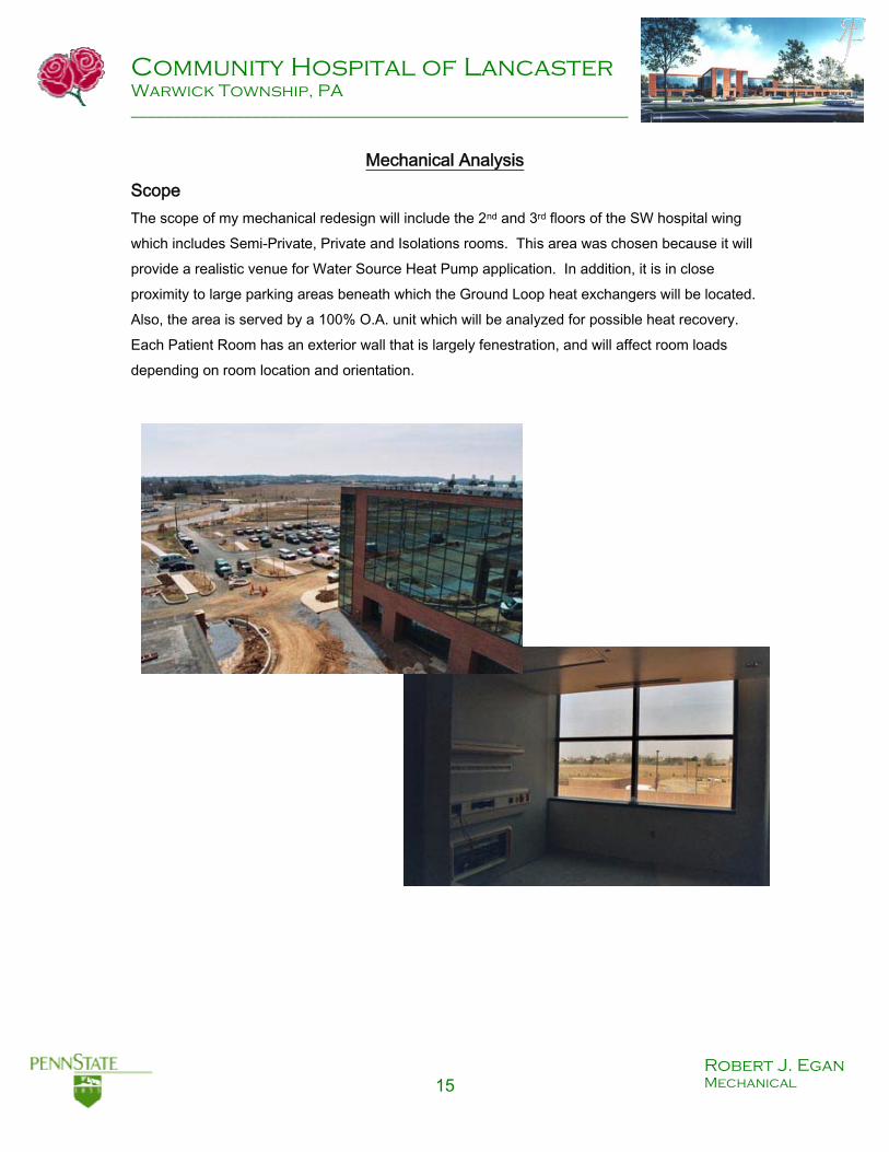
Mechanical Analysis Scope The scope of my mechanical redesign will include the 2nd and 3rd floors of the SW hospital wing which includes Semi-Private, Private and Isolations rooms. This area was chosen because it will provide a realistic venue for Water Source Heat Pump application. In addition, it is in close proximity to large parking areas beneath which the Ground Loop heat exchangers will be located. Also, the area is served by a 100% O.A. unit which will be analyzed for possible heat recovery. Each Patient Room has an exterior wall that is largely fenestration, and will affect room loads depending on room location and orientation.

Community Hospital of Lancaster Warwick Township, PA __________________________________________________________
16 Robert J. Egan Mechanical
Introduction The scope of my mechanical redesign and analysis includes only the 2nd and 3rd floors of the SW wing of Community Hospital of Lancaster. Specifically, it will include 60 semi-private and private patient rooms. The isolations rooms are left out of the analysis because they require direct exhaust and therefore cannot participate in the energy recovery analysis. The 60 spaces total 19,380 ft2 or approximately 17% of the total hospital floor area.
The current design includes a chilled water cooled 100% O.A. unit which supplies conditioned ventilation air only, at 54°F which is ducted to each room’s 4-pipe fan coil unit (FCU). The FCU combines room air with the supply air and terminally conditions it via cooling and heating coils to the room set point. Each FCU is governed by a thermostat located in its respective room. Room air is removed via the room’s negatively charged toilet exhaust which is ducted to a roof mounted exhaust fan. The air is not re-circulated to prevent the
possibility of cross contamination. The existing design will deliver fresh conditioned air to each space effectively and properly. The goal of the redesign is to utilize the efficiency of Water Source Heat Pumps (WSHP), in addition to an Energy Recovery wheel, and to reject / harvest the heat energy to / from the constant ground temperatures of the earth. It is anticipated that proper use of these systems will result in considerable energy savings and reduce operating costs.
Design Requirements Patient rooms must be kept at an acceptable temperature and humidity 24 hours a day, 7 days a week, 52 weeks a year. It is imperative that adequate fresh air is brought into each room and additionally that room air not be returned to the supply ducts to prevent any possibilities of cross contamination of spaces. Each room must have the ability to control the room air temperature. Ventilation air must be properly filtered to prevent against outside contaminants being introduced into the patient rooms.
Community Hospital of Lancaster Warwick Township, PA __________________________________________________________
17 Robert J. Egan Mechanical
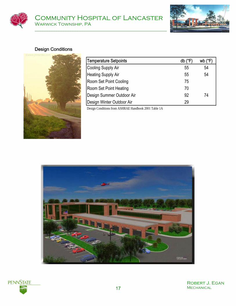
Design Conditions
Temperature Setpoints db (°F) wb (°F)Cooling Supply Air 55 54Heating Supply Air 55 54Room Set Point Cooling 75Room Set Point Heating 70Design Summer Outdoor Air 92 74Design Winter Outdoor Air 29Design Conditions from ASHRAE Handbook 2001 Table 1A

Community Hospital of Lancaster Warwick Township, PA __________________________________________________________
18 Robert J. Egan Mechanical
Design Concept My design concept follows a simple proceedure. First use a total energy recovery wheel (also called enthalpy wheel) to transfer heat and moisture between the exhausted room air and the incoming ventilation air, thus preconditioning it and lowering the load on the cooling and heating coils. This simple change can have a large effect on the energy consumption of the 100% O.A. unit. Secondly, replace each room 4-piple FCU with a water source heat pump (WSHP). The WSHP will reject and harvest heat energy from a water loop which is to be installed in place of the 4-pipe chilled water / hot water loop. Lastly, install a field of vertical ground heat exchangers under the nearby parking area to reject / harvest heat energy from the earth. The WSHP and water loop system will have a much higher efficiency than the traditional terminal FCUs. The new mechanical equipment consists of a 30 Ton 100% O.A. AHU equip with an enthalpy wheel, sixty (60) one ton WSHP and a 200 bore closed ground loop heat exchanger (including all the piping associated with it). Mechanical equipment removed from the previous design will include the simulated original 50 ton 100% O.A. unit, sixty (60) one ton 4-pipe FCUs (including the chilled and hot water piping).
Three scenarios will be simulated by Carriers Hourly Analysis Program (HAP 4.2). The first simulation will be run of the existing system only including the 60 private and semi-private rooms. The second simulation will consist of the simulated original system, with the inclusion of an enthalpy wheel. The third and final simulation will be of the new design which will include the use of an enthalpy wheel and sixty (60) WSHP units.
The results of the three energy analysis will be compared for energy savings. A first cost analysis of each of the three scenarios will follow.

Community Hospital of Lancaster Warwick Township, PA __________________________________________________________
19 Robert J. Egan Mechanical
Energy Recovery Wheels (Enthalpy Wheels) Energy recovery wheels are usually associated with 100% O.A. units because of the wasted heat energy from exhausting air instead of re-circulating it to precondition the ventilation air. When exhaust is passed through the energy wheel, heat and moisture can be extracted a liquid desiccant that covers fins inside the wheel (or deposited depending on the season) and then deposited (or extracted) into the incoming stream of outdoor ventilation air. It’s a simple concept that can save considerable energy. Community of Hospital of Lancaster does not use this energy saving device despite having ducted exhaust air from the patient rooms. Oddly enough, the vertical exhaust ducting to the roof is very close to the 100% O.A. AHU. Upon further investigation, I was informed by the MEP that the system was originally designed to support an energy wheel; however the Owner chose not to use the device fearing cross contamination. This is not a new concern when dealing with energy recovery wheels. To combat any possibility of cross contamination, a purge cycle has been introduced. The purge cycle is a small wedge of
the wheel that takes fresh incoming outdoor air and “purges” the section of the wheel that is about rotate into the supply air stream. This ensures that the supply side of the wheel is always uncontaminated.
Water Source Heat Pumps (WSHP) Water source heat pumps are not new in the HVAC industry. They have been around for nearly 40 years and continue to be made more efficient and effective. WSHP consist simply of a fan, a coil, a refrigerant loop, a compressor and are connected to building water loop. The fan coil units that are currently installed in CHOL have a 4-pipe system. This means that there are two (2) coils, one for heating and one for cooling. Those coils are fed by hot water (heating coil) and chilled water (cooling coil) and condition the air using one or the other (sometimes both). A WSHP has only one coil and uses only one water loop to perform the necessary conditioning. If heating is called for, the WSHP will extract heat from the building water loop using an evaporation cycle and then condense the refrigerant in the coil to reject the heat into the air stream. If cooling

Community Hospital of Lancaster Warwick Township, PA __________________________________________________________
20 Robert J. Egan Mechanical
is called for, the process is exactly opposite and heat is rejected into the water loop. It’s a simple process and is very efficient.
Ground Coupled Water Loop In many WSHP building water loops, heat is rejected / extracted from the outside air using a cooling tower. In a growing number of other cases, the water loop exchanges heat with the earth. There are essentially two (2) ways the water loop can do this. One is the water loop can exchange with a surface body of water, like a spring fed lake or a river / stream. Even the ocean can be used. The other is with ground water. The ground water can either be an underground aquifer or the water inside the pores of the surrounding soils. An open loop can be used when dealing with bodies of water and underground aquifers. This loop draws water from one area, passes it through the building directly or uses a heat exchanger of some type (plate frame, water to water heat pump, etc…) and then deposits the rejected water at a different location. A closed loop can also be used with these bodies of water, but it is the only system that can be used with a horizontal or vertical system. A closed system uses the same water in a continuous loop. Heat is exchanged to the earth via horizontal or vertical bore fields of heat exchangers.

Community Hospital of Lancaster Warwick Township, PA __________________________________________________________
21 Robert J. Egan Mechanical
The benefits of these systems include relatively constant ground temperatures, unlike outdoor air which can vary greatly throughout the year. Also the systems can be far more efficient than traditional rejection systems if designed properly. They require just enough energy to pump the water through the loop. In the past, first costs have been prohibitive; however in recent years the cost has dropped substantially and systems have been designed to be even more efficient. In some cases there is virtually no first cost difference between ground loop systems and traditional HVAC systems. Energy cost savings can be substantial.
Design Procedure In order to compare the existing system with the proposed system, I chose to model them utilizing Carriers Hourly Analysis Program (HAP). I was able to obtain much of the design data used by the MEP engineer and entered it into HAP so that I could simulate the existing design accurately. Because my redesign does not include the isolations rooms, I had to simulate the loads of the 100% O.A. unit and FCUs in only those 60 spaces. I chose not to include the isolation rooms for the simple reason that the exhaust from these rooms is directly ejected outside because of the potentially harmful contaminated and disease that might be present in the room air. Therefore, I only sized and simulated the system for what it would be if it only served the 60 spaces included in the analysis. Therefore, I simulated 60 individual zones on the system and my original design 100% O.A. unit sized at 50 tons and my ventilation air is 5981 CFM. This system had a max heating load of 280 MBH. The first redesign step was quite simply to add an energy recovery wheel to the existing system. I was curious how much load would be taken off of the system with this simple addition. I choose a wheel, using SEMCO’s Wheel selection procedure, with an effectiveness of 84% and .41 in. wg. pressure loss. With the energy wheel, the cooling coil load dropped to 41.4 tons and the heating load dropped to 86.6 MBH. This means with a simple energy wheel addition, cooling and heating loads on the 100% O.A. unit dropped 17% and 70% respectively. In the energy cost analysis we will see that this wheel alone pays for itself in less than one year.

Community Hospital of Lancaster Warwick Township, PA __________________________________________________________
22 Robert J. Egan Mechanical
For my ultimate redesign, I inputted a WSHP in each zone and was sure to set the supply air temperature to the same 55°F that was supplied by the original FCUs. The energy recovery wheel was used as well to maximize the efficiency of the design. Since HAP does not have a specific analysis for a Ground Coupled heat loop, I chose to use the open loop surface water option for analysis. In doing so, I was able to input a water loop temperature for each month of the year. This temperature affects the efficiency of the heat pumps and is very important to get an accurate simulation. To choose the temperatures I assumed that the water temperature would fluctuate between 40 and 95°F between the heating and cooling seasons respectively. The bottom of the sine curve occurs just after the peak of the heating season (40°F) and the top of the curve occurs just after the peak of the cooling season (95°F).
To determine the loop temperature I used HAP load outputs to determine the heat energy range between the largest cooling month and the largest heating month. Every month in between those two peaks is a percentage of that range. The temperature would be proportional to that month’s percentage of the range.
Ground Loop Conditions
-250000
-200000
-150000
-100000
-50000
0
50000
100000
Janu
ary
Februa
ry
March
April
MayJu
ne July
Augus
t
Septem
ber
Octobe
r
Novembe
r
Decembe
r
Months
kBTU
010
20304050
607080
90100
Deg
rees
Fah
renh
eit

Community Hospital of Lancaster Warwick Township, PA __________________________________________________________
23 Robert J. Egan Mechanical
Loop Temp (°F)
January 49.2 February 45.0 March 48.6 April 57.9 May 70.5 June 83.3 July 88.0 August 95.0 September 88.7 October 83.9 November 74.0 December 57.9
Using these temperatures, HAP can account for the change in efficiency due to the swing in loop water temperature. The simulation showed a considerable drop in the cooling coil load to 27.5 tons, which is 45% smaller than that of the original design. This will allow for a smaller 100% O.A. unit to be chosen as well as increase the overall efficiency of the entire system. Each WSHP was sized at just over ½ ton. Due to the CFM requirements, I chose a 1 ton Trane unit for each of the spaces. To size the vertical ground loop exchanger, I utilized free software found on the Geothermal Heat Pump Consortium website. The program called GS Heat Pump Design KISS (keep it simple & solid). It is found as a demo version on www.geokiss.com. The program allowed me to use block loads from my design cooling and heating days in combination with Annual Equivalent Full Load Hours to determine the necessary performance of the field. I was also able to determine the shape of my field (L x W) as well as the configuration for my ground loops. Soil conductivity and ground water temperature were also parameters that could be set by the user. For my exchanger field I chose 5 inch diameter wells in a 20 by 10 pattern. My exchanger pipes will be 2 ¼” in diameter. The 200 well exchanger field will be located in close proximity to CHOL’s south west wing, where the Patient rooms are located. The bores will be spaced 20 ft apart and have a duel exchanger per loop configuration. This means that loop water will travel into the ground twice before entering the return (building supply) header pipe. The ground temperature was set at the researched value of 52°F.

Community Hospital of Lancaster Warwick Township, PA __________________________________________________________
24 Robert J. Egan Mechanical
According to the GSHPD my well will have to be 752 ft deep per bore. This is a total of 150360 ft of bore. This is based on the worst case scenario for cooling. The necessary length of exchanger is determined by the following two equations. Length required for cooling
qaRga + (qlc-3.41*Wc)(Rb + PLFmRgm + RgdFsc) Lc =
Tg - ((twi + two)/2) -tp Length required for heating
qaRga + (qlh-3.41*Wh)(Rb + PLFmRgm + RgdFsc) Lh =
Tg - ((twi + two)/2) -tp These formulas were found in the 2000 ASHRAE System and Equipment Handbook
The larger of the two values governs the bore length. Divide the total bore length by the number of bores to determine how deep each bore must be. This value is given by the program as a worst case scenario, meaning little ground water movement. A second value is given if the ground water movement is considerable to high. In this particular case, the bore length dropped to 76410 ft of bore or 383 ft per bore. This is a 50% drop in bore length. A third value given is the hybrid bore value. A hybrid system would make use of both ground coupled heat exchangers as well as water to air cooling towers. Essentially, this system would reject and harvest the same amount of heat energy per year. This would prevent soil temperatures from rising over time. All of the excess heat from the loop would be rejected via the cooling tower. The bore length for a hybrid system is 21870 ft. or 109 ft. per bore. Of course in a system like this you would vastly decrease the size of the vertical loop field. The field could be realistically downsized to 40 bores.
Community Hospital of Lancaster Warwick Township, PA __________________________________________________________
25 Robert J. Egan Mechanical
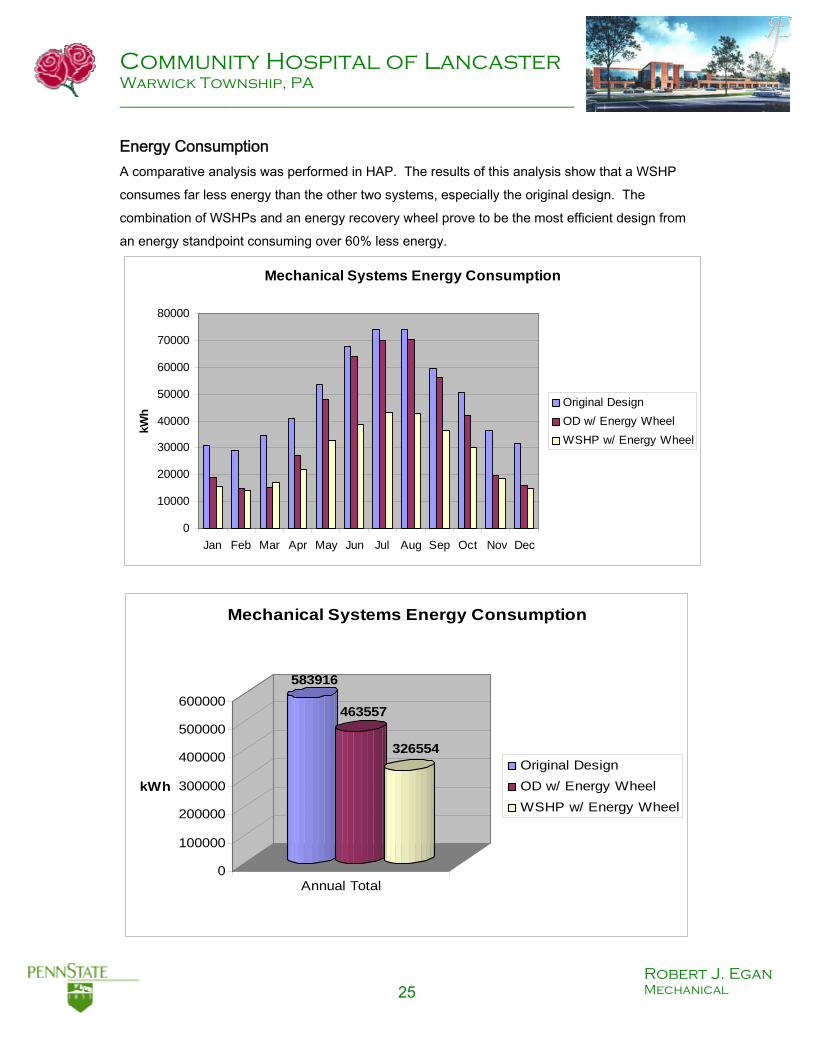
Energy Consumption A comparative analysis was performed in HAP. The results of this analysis show that a WSHP consumes far less energy than the other two systems, especially the original design. The combination of WSHPs and an energy recovery wheel prove to be the most efficient design from an energy standpoint consuming over 60% less energy.
Mechanical Systems Energy Consumption
0
10000
20000
30000
40000
50000
60000
70000
80000
Jan Feb Mar Apr May Jun Jul Aug Sep Oct Nov Dec
kWh
Original DesignOD w/ Energy WheelWSHP w/ Energy Wheel
583916
463557
326554
0
100000
200000
300000
400000
500000
600000
kWh
Annual Total
Mechanical Systems Energy Consumption
Original DesignOD w/ Energy WheelWSHP w/ Energy Wheel

Community Hospital of Lancaster Warwick Township, PA __________________________________________________________
26 Robert J. Egan Mechanical
First Cost and Operating Costs Analysis The two major costs associated with mechanical systems are first cost and operating costs. Using the 2003 Mechanical Cost Data edition of RSMeans, I estimated what the current system components would cost and then estimated the installed components for the new WSHP and ground loop. Since RSMeans does not specifically address ground loop systems, I utilized a program written by the University of Alabama call the Geothermal System cost estimator. This includes all HDPE piping, headers as well as drilling and back filling costs. The pump, which was sized by the GS Heat Pump Design (geokiss.com) was priced using RSMeans and will circulate the loop water.
50 Ton 100% O.A.unit 140,600$ 30 Ton 100% O.A. unit 126,600$ Enthalpy 10,200
60 Fan Coil Units 91,578 60 WSHP 138,00030 HP ground loop pump 18,600
Stainless Steel Piping 113,380 Estimated ground loop field 125,000Used Geothermal Systems Cost estimator
Total 345,558$ 418,400$
Original Design WSHP with Energy Wheel
It’s obvious from the above table that a WSHP system utilizing a ground loop is still quite expensive. The difference between the two first costs is approximately $73000 which is a hefty 21% increase over the original design. While this is a considerable amount of money, it would be wise first to check the cost break down of the energy analysis simulation. The WSHP system and accompanying ground loop should be very efficient and cut the operating costs considerably.

Community Hospital of Lancaster Warwick Township, PA __________________________________________________________
27 Robert J. Egan Mechanical
Operating Costs Utilizing Carriers Hourly Analysis Program (HAP) I was able to obtain a cost breakdown for the three different designs. The original design had Mechanical Operating costs of around $32,000 dollars. With the addition of the Energy wheel, the costs dropped dramatically to around $21,000 dollars. Because of the efficiency of reclaiming the heat and moisture from the exhaust, there was incredible savings in the cooling months of the year. When compared with the cost of the enthalpy wheel ($10,200) we see that the payback is one year, after which the savings can accrue. In all cases the WSHP and Energy wheel fell well below the operating costs of the other two systems.
Mechanical Systems Operating Cost
0500
1,0001,5002,0002,5003,0003,5004,0004,5005,000
Janu
ary
Februa
ry
March
April
MayJu
ne July
Augus
t
Septem
ber
Octobe
r
Novembe
r
Decembe
r
$ US
D Original DesignOD w/ Energy WheelWSHP w/ Energy Wheel
Community Hospital of Lancaster Warwick Township, PA __________________________________________________________
28 Robert J. Egan Mechanical
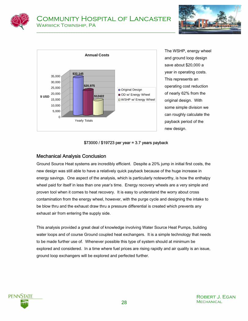
The WSHP, energy wheel and ground loop design save about $20,000 a year in operating costs. This represents an operating cost reduction of nearly 62% from the original design. With some simple division we can roughly calculate the payback period of the new design.
$73000 / $19723 per year = 3.7 years payback
Mechanical Analysis Conclusion Ground Source Heat systems are incredibly efficient. Despite a 20% jump in initial first costs, the new design was still able to have a relatively quick payback because of the huge increase in energy savings. One aspect of the analysis, which is particularly noteworthy, is how the enthalpy wheel paid for itself in less than one year’s time. Energy recovery wheels are a very simple and proven tool when it comes to heat recovery. It is easy to understand the worry about cross contamination from the energy wheel, however, with the purge cycle and designing the intake to be blow thru and the exhaust draw thru a pressure differential is created which prevents any exhaust air from entering the supply side. This analysis provided a great deal of knowledge involving Water Source Heat Pumps, building water loops and of course Ground coupled heat exchangers. It is a simple technology that needs to be made further use of. Whenever possible this type of system should at minimum be explored and considered. In a time where fuel prices are rising rapidly and air quality is an issue, ground loop exchangers will be explored and perfected further.
$32,145
$20,975
$12422
0
5,000
10,000
15,000
20,000
25,000
30,000
35,000
$ USD
Yearly Totals
Annual Costs
Original DesignOD w/ Energy WheelWSHP w/ Energy Wheel

Community Hospital of Lancaster Warwick Township, PA __________________________________________________________
29 Robert J. Egan Mechanical
Electrical Breadth
Redesign and Analysis

Community Hospital of Lancaster Warwick Township, PA __________________________________________________________
30 Robert J. Egan Mechanical
Electrical Analysis Scope The scope of electrical analysis is the electrical service to the water source heat pumps. Two sub panels (2Q/A and 3Q/A) currently serve the existing Fan coil units. Panel 2Q/A serves the 30 FCUs on the second floor and panel 3Q/A serves the 30 FCUs on the third floor. The analysis will examine how the new WSHPs affect the loads on each panel. The use of Water Source Heat Pumps in place of the 4-pipe fan coils will vary the power requirement for each space. Fan coils draw load for the delivery fan inside the unit. A Water source heat pump has a fan as well as a compressor to run the evaporation and compression cycle which “pumps” heat from either the air, or the building water loop. Since WSHP were not part of the original design, we will need to incorporate them into the power supply. I have selected a Trane heat pump model number GEH 012. According to the manufacturer’s Electrical performance data, this model has a Total Full Load Ampacity of 12.2, when drawing from a 115 V power supply at 60 Hz and single phase. The National Electric Code, the governing electrical code for the Community Hospital of Lancaster, specifies that a “branch circuit conductor that supplies a single motor in a continuous duty application must have a rating of 125% of the full load current. This percentage rating will be used as the design ampacity. NEC 310-16 was used to size the conductors. Copper thermoplastic wire (THW) was chosen for the conductor and size kcmil 14 was selected. Conduit sizing was obtained from NEC Table C1. Metallic tubing was chosen as the material for the conduit and size 16 (1/2” dia) was selected. Circuit breaker maximum sizes were specified as 25 amps in the manufacturer’s data. However a simple calculation yielded 20 amps as an appropriate size. 12.2 * 1.25 = 15.25 A 12.2 * 1.75 = 21.35 A The breaker has to be larger than 125% but less than 175% of the rated capacity. = 20 A

Community Hospital of Lancaster Warwick Township, PA __________________________________________________________
31 Robert J. Egan Mechanical
The following table provides all of the values for the Typical WSHP included in this design.
Voltage HP Full Load Current VA 125% Amperage
115/60/1 1/6 12.2 1753.75 15
175 % Amperage Circuit Breaker Conductor Conduit Size
21.35 20 #14 THW 16 (1/2”)
Panel Boards The two panel boards directly affected by the new mechanical systems are panels 2Q/A and 3Q/A. They are each fed by panel 2PQ/A and 3PQ/A respectively. Prior to the redesign, each panel had relatively low loads on them. Panel 2Q/A read 79 adjusted amps and panel 3Q/A showed 64 adjusted amps. The panel schematics follow, first with each original design and then with the redesign. The existing design combined two Fan Coil units on to many of the breakers. The breakers were sized at 15 Amps single phase. Each FCU had a 696 VA load. Many of the breakers served a circuit in which two fan coils were present. From the table above, it is apparent that the WSHPs are drawing much more load. Each WSHP has a 1753 VA design load. This is well over twice the previous design. Due to this, there is no opportunity to pair up circuits as was possible with the FCUs. In addition, the fault protection had to be upgraded to a 20 Amp breaker. Panel 2Q/A now shows a load of 159 adjusted amps and like wise Panel 3Q/A now show a load of 151 adjusted amps. This is a substantial increase from the previous design, however each panel has a BUS Rating of 225 A. I was unable to determine what the design conductors were for the panel however I would assume that they are sized for 225 A. Using THW as the conductor wire, the necessary size would be 4/0 kcmil.
Electrical Analysis Conclusion As expected, the Water Source heat pumps put a greater load on the local panel. Due to the larger draw of the new equipment, I would suggest that another panel be added if possible to support specifically the function of the heat pumps. The panels appeared to be quite maxed out and would realistically need to be made larger if this system were to be put in place.

Community Hospital of Lancaster Warwick Township, PA __________________________________________________________
32 Robert J. Egan Mechanical
Original Design

Community Hospital of Lancaster Warwick Township, PA __________________________________________________________
33 Robert J. Egan Mechanical
Original Design

Community Hospital of Lancaster Warwick Township, PA __________________________________________________________
34 Robert J. Egan Mechanical
Redesigned to include WSHP

Community Hospital of Lancaster Warwick Township, PA __________________________________________________________
35 Robert J. Egan Mechanical
Redesigned to include WSHP

Community Hospital of Lancaster Warwick Township, PA __________________________________________________________
36 Robert J. Egan Mechanical
Structural Breadth
Redesign and Analysis

Community Hospital of Lancaster Warwick Township, PA __________________________________________________________
37 Robert J. Egan Mechanical
Structural Analysis Scope The scope of the structural analysis is independent from both the Mechanical and Electrical analysis. It includes a typical bay of composite beam construction located on the second floor of Community Hospital of Lancaster. The hospital is built utilizing the strength of the composite beam structure which is essentially a beam and poured concrete bonded together using shear studs.
This structural redesign is quite simple yet effective. The typical bay on the left is the original design with two equally spaced beams in conjunction with the floor slab above. The number in parenthesis after the beam shape and strength is the number of shear studs on each beam of the system. In the original design the beams were spaced at 8’-8” O.C. and were sized at W16x26 composite beam with 29 shear studs per beam. The goal is to determine how much a composite beam depth would be shortened if an additional beam were placed into the bay. A shorter beam sometimes means more room for mechanical designers to place their systems, and would prevent having to change floor to ceiling height or adjust plenum depth. Therefore one beam was added to the bay. The three beams were equally spaced at 6.5’ O.C.

Community Hospital of Lancaster Warwick Township, PA __________________________________________________________
38 Robert J. Egan Mechanical
The live loads and dead loads were found on the cover page to the structural drawings. Concrete slab information was also located here. Loads: Live Loads 60 psf Dead Loads 90 psf Uniform factored load Wu = 1.2 (90) (6.5’) + 1.6 (80) (6.5’) = 1534 lb/ft = 1.534 kip/ft Mu = Wu l2 / 8 1.534 kip/ft (26’)2 /8 = 129.62 kip/ft
Assume a = 1” Y2 = 5 ¼” - ½” = 4.75” Δ allow = L/360 26 * 12 / 360 = 0.87 inches
5(Wu) (L)4 Δ =
(384 EI))*1728 I = 211
W10x15 ΦMp = 60, ΦMn = 127, Qn = 140
ΣQn 140 areq =
.85*4*((26/4) * 12) = .53 < 1.0
5*1.75685*264
Δ = 384 (29000) I
= .87
I = 695 W14x30 I = 704 Use W14x30

Community Hospital of Lancaster Warwick Township, PA __________________________________________________________
39 Robert J. Egan Mechanical
Using the LRFD Manual of Steel Construction Table 5 -14 Composite W Shapes Design strength in flexure ΦbMn, kip-ft and Table 5 -14 Lower Bound Elastic Moments of Inertia Ilb for plastic composite sections, I was able to determine that 3, 26 foot W14x30 shape beams spaced 6.5’ O.C. apart can withstand the loads of the 5 ¼” LW structural concrete slab. The beams are two inches shallower than those of the existing design. Deflection was too large on the W10x15 beam and thus the W14x30 was chosen.
Structural Analysis Conclusion The structural design, while seemingly simple, actually required some research to complete. It is a useful knowledge to have, especially when you need to explore other means of gaining those precious inches in your mechanical plenums. The span for this analysis was rather short, only 26’, however over a larger span or different loading conditions the results could vary. It is also useful to know when moving large mechanical equipment around such as RTUs or AHUs. Utilizing composite beam construction, the mechanical designer can double check to be sure the structure will hold the heavy mechanical equipment.
Community Hospital of Lancaster Warwick Township, PA __________________________________________________________
40 Robert J. Egan Mechanical
Summary & Conclusions The implementation of Water Source Heat Pumps on a geothermal water loop greatly increases heating and cooling efficiency. With the addition of a total energy recovery wheel, the savings grow. These systems can cost more than a conventional system, however it is possible to recover the investment in an acceptable amount of time. Geothermal technology is making advances and is incorporated in more designs as time goes by. It might be beneficial to instruct future engineers about the realistic uses of this energy saving method, especially in times where energy is expensive. The research involved in this thesis was extensive and very useful. Many agencies and organizations are more than happy to assist engineers who are in pursuit of more environmentally friendly design. The programs that are available are functional, however are rudimentary. Nevertheless, they were incredibly useful within the scope of my analysis. The results of my research have shown that use of ground loop exchangers is very efficient. Once a ground loop is installed, it is virtually maintenance free for up to 50 years or more. The major costs involved with ground coupled heat pumps are initial costs and pumping costs. Energy consumption is dropped considerably across the board. The simulations prove that something as simple as an energy recovery wheel can have drastic implications on heating and cooling loads. It is important that energy saving technology is implemented as much as possible. This hospital analysis is a text book example of unnecessarily wasted energy. I believe that technology like this can be pushed further and made even more efficient so that excluding it from a design will not be an option.

Community Hospital of Lancaster Warwick Township, PA __________________________________________________________
41 Robert J. Egan Mechanical
Acknowledgements
I would first like to thank God for the incredible life He has been so generous to give me. Out of His love, I have the greatest family in the world and have been blessed with many great friends. I would also like to thank: Dr. Moses Ling - Friend and consul to all AE students Dr. Stanley Mumma - Primary Faculty Consultant for Thesis The lovely Sharron Williams - always there for the student who can’t schedule a class, everyone knows she is really who’s in charge of the AE Department Ari Tinkoff, John Schneider & Eric Serrano of GRG Consulting Engineers - without their help, I would probably be doing thesis again. Sam Snyder and Joe Firrantello - for always answering my dumb questions Brent Ellman and Lincoln Harberger - Structural consultants Lastly, I would like to thank all of the many great people who made my times here at PSU so great, that I put off graduation as long as I could, just so I could stay. A special acknowledgment to the Mick, Olly & Gavin at the Brickies in Leeds, UK. Olly, thanks for letting me sleep in the pub all those times, I owe you.
Disclaimer: I do not claim ownership of all the pictures included in this thesis. All logos, renderings and photos are property of their respective owners and are only borrowed for enrichment of this Thesis.
Community Hospital of Lancaster Warwick Township, PA __________________________________________________________
42 Robert J. Egan Mechanical
References AIA Guidelines for Design and Construction of Hospital and Health Care Facilities. 7.31 and 7.32 Mechanical and Electrical Standards for a General Hospital. American Society for Hospital Engineering of the American Hospital Association. Mechanical Systems, Volume 8. ASHRAE Handbook. HVAC Applications 1995. Chapter 7, Health Care Facilites ASHRAE Handbook, Fundamentals. 2001. American Society of Heating, Refridgeration, and Air-Conditioning Engineers, Inc. National Electric Code. 2003 RS Means Mechanical Cost Data. 2003 Online Sources Carrier Corporation - http://www.carrier.com Energy Efficiency and Renewable Energy Network - http://www.eere.energy.gov/geothermal/ Geothermal Heat Pump Consortium - http://www.geoexchange.org/ Ground Source Heat Pump Design - http://www.geokiss.com IEA Heat Pump Centre - http://www.heatpumpcentre.org/ McQuay International - http://www.mcquay.com Pennsylvania Public Utilities Commission Online - http://puc.paonline.com/ The Trane Company - http://www.trane.com/TraneHomePage.asp Water Furnace Incorporated - http://www.waterfurnace.com

Community Hospital of Lancaster Warwick Township, PA __________________________________________________________
43 Robert J. Egan Mechanical
Appendix

Annual Cost Summary20254.02 Community of Lancaster WSHP 04/02/2004 psuae 11:15PM
Table 1. Annual Costs
Component
CHOL Existing Conditions
($)Air System Fans 601
Cooling 12,940
Heating 8,973
Pumps 9,632
Cooling Tower Fans 0
HVAC Sub-Total 32,145Lights 13,468
Electric Equipment 3,117
Misc. Electric 0
Misc. Fuel Use 0
Non-HVAC Sub-Total 16,585Grand Total 48,730
Table 2. Annual Cost per Unit Floor Area
Component
CHOL Existing Conditions
($/ft²)Air System Fans 0.031
Cooling 0.668
Heating 0.463
Pumps 0.497
Cooling Tower Fans 0.000
HVAC Sub-Total 1.659Lights 0.695
Electric Equipment 0.161
Misc. Electric 0.000
Misc. Fuel Use 0.000
Non-HVAC Sub-Total 0.856Grand Total 2.515
Gross Floor Area (ft²) 19380.0
Conditioned Floor Area (ft²) 19380.0Note: Values in this table are calculated using the Gross Floor Area.
Table 3. Component Cost as a Percentage of Total Cost
Component
CHOL Existing Conditions
( % )Air System Fans 1.2
Cooling 26.6
Heating 18.4
Pumps 19.8
Cooling Tower Fans 0.0
HVAC Sub-Total 66.0Lights 27.6
Electric Equipment 6.4
Misc. Electric 0.0
Misc. Fuel Use 0.0
Non-HVAC Sub-Total 34.0Grand Total 100.0
Hourly Analysis Program v.4.2 Page 1 of 1

Annual Cost Summary20254.02 Community of Lancaster WSHP Final 04/05/2004 psuae 08:53AM
Table 1. Annual Costs
ComponentCHOL WSHP TER
($)Air System Fans 1,534
Cooling 6,457
Heating 349
Pumps 4,082
Cooling Tower Fans 0
HVAC Sub-Total 12,422Lights 13,854
Electric Equipment 3,207
Misc. Electric 0
Misc. Fuel Use 0
Non-HVAC Sub-Total 17,061Grand Total 29,483
Table 2. Annual Cost per Unit Floor Area
ComponentCHOL WSHP TER
($/ft²)Air System Fans 0.079
Cooling 0.333
Heating 0.018
Pumps 0.211
Cooling Tower Fans 0.000
HVAC Sub-Total 0.641Lights 0.715
Electric Equipment 0.166
Misc. Electric 0.000
Misc. Fuel Use 0.000
Non-HVAC Sub-Total 0.880Grand Total 1.521
Gross Floor Area (ft²) 19380.0
Conditioned Floor Area (ft²) 19380.0Note: Values in this table are calculated using the Gross Floor Area.
Table 3. Component Cost as a Percentage of Total Cost
ComponentCHOL WSHP TER
( % )Air System Fans 5.2
Cooling 21.9
Heating 1.2
Pumps 13.8
Cooling Tower Fans 0.0
HVAC Sub-Total 42.1Lights 47.0
Electric Equipment 10.9
Misc. Electric 0.0
Misc. Fuel Use 0.0
Non-HVAC Sub-Total 57.9Grand Total 100.0
Hourly Analysis Program v.4.2 Page 1 of 1

Annual Cost Summary20254.02 Community of Lancaster WSHP 04/02/2004 psuae 11:17PM
Table 1. Annual Costs
ComponentCHOL WSHP TER
($)Air System Fans 1,542
Cooling 6,483
Heating 351
Pumps 0
Cooling Tower Fans 0
HVAC Sub-Total 8,375Lights 13,931
Electric Equipment 3,225
Misc. Electric 0
Misc. Fuel Use 0
Non-HVAC Sub-Total 17,156Grand Total 25,532
Table 2. Annual Cost per Unit Floor Area
ComponentCHOL WSHP TER
($/ft²)Air System Fans 0.080
Cooling 0.335
Heating 0.018
Pumps 0.000
Cooling Tower Fans 0.000
HVAC Sub-Total 0.432Lights 0.719
Electric Equipment 0.166
Misc. Electric 0.000
Misc. Fuel Use 0.000
Non-HVAC Sub-Total 0.885Grand Total 1.318
Gross Floor Area (ft²) 19380.0
Conditioned Floor Area (ft²) 19380.0Note: Values in this table are calculated using the Gross Floor Area.
Table 3. Component Cost as a Percentage of Total Cost
ComponentCHOL WSHP TER
( % )Air System Fans 6.0
Cooling 25.4
Heating 1.4
Pumps 0.0
Cooling Tower Fans 0.0
HVAC Sub-Total 32.8Lights 54.6
Electric Equipment 12.6
Misc. Electric 0.0
Misc. Fuel Use 0.0
Non-HVAC Sub-Total 67.2Grand Total 100.0
Hourly Analysis Program v.4.2 Page 1 of 1


GchpCalc Software - Version 4.0Energy Information Services
Design Lengths *** Heat Pump Series: Trane (Standard Efficiency) ***
Required BORE length with minimal groundwater movement = 150360 ft (752 ft/bore)(Design based on COOLING mode - net annual heat rejection to ground)
Required BORE lengths with high rates of groundwater movement (or year 1)Cooling: L= 76410 ft (382 ft/bore), Heating: L= 21850 ft (109 ft/bore)
Unit Inlet (cooling) = 85.0 degrees F Unit Outlet (cooling) = 95.4 degrees F Unit Inlet (heating) = 50.0 degrees F Unit Outlet (heating) = 44.1 degrees F Normal ground temp = 52.0 degrees F
Cooling Load/Demand = 5631 MBtuh / 491 kWHeating Load/Demand = 1014 MBtuh / 78 kWCooling EER (Ht Pump/Sys) = 11.5 / 10.9Heating COP (Ht Pump/Sys) = 3.8 / 2.8Loop Pump Head/Flow Rate = 60 ft / 1408 gpmLoop Pump Power/Demand = 30.5 hp / 26.7 kW
Total Heat Pump Capacity = 5647.4 Mbtuh (cooling)Total Heat Pump Capacity = 5741.6 Mbtuh (heating)
U-tube Diameter = 1.25 inchSeparation dist. = 20.0 ftGrid = 20 wide by 10 deepGrout Conductivity = 1.50 Btu/hr-ft- degrees F Bore Diameter = 5.00 inches
Bore Resistance = 0.102 hr-ft-F/BtuGround Resistance (Cooling) = 0.343 hr-ft-F/BtuGround Resistance (Heating) = 0.334 hr-ft-F/Btu
Long Term Ground Temperature Rise = 3.7 degrees F (Center of Loop Field)
Thermal Conductivity = 1.40 Btu/hr-ft-degrees F Thermal Diffusivity = 0.93 ft^2/day
Ground Temperature = 52.0 degrees F

GchpCalc Software - Version 4.0Energy Information Services
Hybrid Design Lengths *** Heat Pump Series: Trane (High Efficiency) ***
Required BORE length for heating, L = 21870 ft (109 ft/bore)
Tower Size for Downsized Ground LoopFlow = 1455 gpm, Condenser Capacity = 7539 MBtuh, Range = 10.4 degrees F
Tower Size for Balanced Ground Heat LoadFlow = 1474 gpm, Condenser Capacity = 7641 MBtuh, Range = 10.4 degrees F Required operating hours @ 10 degrees F Range = 7920 hrs/yr @ 20 degrees F Range = 3960 hrs/yr @ 30 degrees F Range = 2640 hrs/yr
Unit Inlet (cooling) = 85.0 degrees F Unit Outlet (cooling) = 95.4 degrees F Unit Inlet (heating) = 50.0 degrees F Unit Outlet (heating) = 44.1 degrees F Normal ground temp = 52.0 degrees F
Cooling Load/Demand = 5631 MBtuh / 488 kWHeating Load/Demand = 1014 MBtuh / 78 kW
Cooling EER (Ht Pump/Sys) = 11.5/10.3Heating COP (Ht Pump/Sys) = 3.8 / 2.8
Pump/Cooling Tower Demand = 26.7/31.9 kWSystem Liquid Flow Rate = 1408 gpm


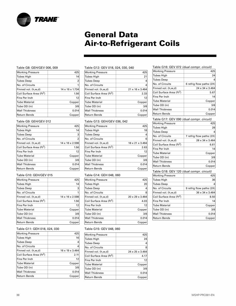
36 WSHP-PRC001-EN
Table G1: General data about the units
Table G2: General data about the units (continued)
Table G3: General data about the units (continued)
Model GEH 006 009 012 015Unit Size Length (in) 40 40 40 40
Height (in) 15 15 15 15Width (in) 20 20 20 20
Compressor Type Rotary Rotary Rotary RotaryApproximate Weight with Pallet (lb) 188 188 188 188Approximate Weight without Pallet (lb) 158 158 158 158
Filter Size Actual (in) 14 5/8 x 20 1/4 14 5/8 x 20 1/4 14 5/8 x 20 1/4 14 5/8 x 20 1/4Water in/out size (FPT) inches 1/2 1/2 1/2 1/2Condensate size (NPTI) inches 3/4 3/4 3/4 3/4
Blower Wheel Size Direct Drive (in) 9 x 4 9 x 4 9 x 4 9 x 4
Model GEH 018 024 030 036Unit Size Length (in) 46 46 46 50
Height (in) 17 17 17 19Width (in) 23 23 23 25
Compressor Type Rotary Reciprocating Reciprocating ReciprocatingApproximate Weight with Pallet (lb) 278 278 278 318Approximate Weight without Pallet (lb) 248 248 248 288
Filter Size Actual (in) 16 3/8 x 23 5/8 16 3/8 x 23 5/8 16 3/8 x 23 5/8 18 5/8 x 25 3/8Water in/out size (FPT) inches 3/4 3/4 3/4 3/4Condensate size (NPTI) inches 3/4 3/4 3/4 3/4
Blower Wheel Size Direct Drive (in) 9 x 6 10 x 6 10 x 6 12 x 8
Model GEH 042 048 060Unit Size Length (in) 50 58 58
Height (in) 19 21 21Width (in) 25 33 33
Compressor Type Reciprocating Reciprocating ScrollApproximate Weight with Pallet (lb) 318 428 428Approximate Weight without Pallet (lb) 288 398 398
Filter Size Actual (in) 18 5/8 x 25 3/8 20 5/8 x 29 3/4 20 5/8 x 29 3/4Water in/out size (FPT) inches 1 1 1Condensate size (NPTI) inches 3/4 3/4 3/4
Blower Wheel Size Direct Drive (in) 12 x 8 12 x 11 12 x 11
GeneralData

WSHP-PRC001-EN 37
Table G4: General data about the units
Table G5: General data about the units (continued)
Table G6: General data about the units (continued)
Table G7: General data about the units (continued)
Model GEV 006 009 012 015 018Unit Size Length (in) 21 1/2 21 1/2 21 1/2 21 1/2 21 1/2
Height (in) 31 1/4 31 1/4 31 1/4 31 1/4 39 1/4Width (in) 19 1/2 19 1/2 19 1/2 19 1/2 21 1/2
Compressor Type Rotary Rotary Rotary Rotary ReciprocatingApproximate Weight with Pallet (lb) 178 178 178 178 268Approximate Weight without Pallet (lb) 158 158 158 158 248
Filter Size Actual (in) 15 7/8 x 19 7/8 15 7/8 x 19 7/8 15 7/8 x 19 7/8 15 7/8 x 19 7/8 17 7/8 x 24 7/8Water in/out size (FPT) inches 1/2 1/2 1/2 1/2 3/4Condensate size (NPTI) inches 3/4 3/4 3/4 3/4 3/4
Blower Wheel Size Direct Drive (in) 9 x 4 9 x 4 9 x 4 9 x 4 10 x 6
Model GEV 024 030 036 040 042Unit Size Length (in) 21 1/2 21 1/2 26 1/2 21 1/2 26 1/2
Height (in) 39 1/4 39 1/4 41 7/8 39 1/4 41 7/8Width (in) 21 1/2 21 1/2 24 1/2 21 1/2 24 1/2
Compressor Type Reciprocating Reciprocating Reciprocating Reciprocating ReciprocatingApproximate Weight with Pallet (lb) 268 268 308 268 308Approximate Weight without Pallet (lb) 248 248 288 248 288
Filter Size Actual (in) 17 7/8 x 24 7/8 17 7/8 x 24 7/8 19 7/8 x 24 7/8 17 7/8 x 24 7/8 19 7/8 x 24 7/8Water in/out size (FPT) inches 3/4 3/4 3/4 3/4 3/4Condensate size (NPTI) inches 3/4 3/4 3/4 3/4 3/4
Blower Wheel Size Direct Drive (in) 10 x 6 10 x 6 10 x 6 10 x 6 12 x 8
Model GEV 048 060 072 090 120Unit Size Length (in) 30 1/2 30 1/2 42 42 42
Height (in) 46 7/8 46 7/8 62 5/8 62 5/8 62 5/8Width (in) 26 1/2 26 1/2 36 1/4 36 1/4 36 1/4
Compressor Type Reciprocating Scroll Recip (2) Recip (2) Scroll (2)Approximate Weight with Pallet (lb) 396 396 617 648 861Approximate Weight without Pallet (lb) 348 348 577 608 821
Filter Size Actual (in) 27 7/8 x 29 7/8 27 7/8 x 29 7/8 20 x 20 (4) 20 x 20 (4) 20 x 20 (4)Water in/out size inches 1 FPT 1 FPT 1 1/4 FPT 1 1/4 FPT 1 1/2 FPT
Condensate size (NPTI) inches 3/4 3/4 3/4 3/4 3/4Blower Wheel Size and quantity 12 x 11 (DD) 12 x 11 (DD) 12.62 x 12.62 12.62 x 12.62 12.62 x 12.62
Model GEV 150 180 240 300Unit Size Length (in) 81 5/8 81 5/8 81 5/8 81 5/8
Height (in) 68 68 68 68Width (in) 36 1/4 36 1/4 36 1/4 36 1/4
Compressor Type Scroll (2) Scroll (2) Scroll (2) Scroll (2)Approximate Weight with Pallet (lb) 1215 1225 1615 1665Approximate Weight without Pallet (lb) 1170 1180 1580 1640
Filter Size Actual (in) 19 5/8 x 24 5/8 (6) 19 5/8 x 24 5/8 (6) 19 5/8 x 24 5/8 (6) 19 5/8 x 24 5/8 (6)Water in/out size (sweat) inches 1 1/2 FPT 1 1/2 FPT 2 FPT 2 FPTCondensate size (NPTI) inches 3/4 3/4 3/4 3/4
Blower Wheel Size and quantity (regular-low static/high static)
15 x 15 15 x 15 (2) 12 x 12 (2) 15 x 11 / (2) 12 x 12
GeneralData
38 WSHP-PRC001-EN
Table G8: GEH/GEV 006, 009
Table G9: GEH/GEV 012
Table G10: GEH/GEV 015
Table G11: GEH 018, 024, 030
Working Pressure 425
Tubes High 14
Tubes Deep 2
No. of Circuits 1
Finned vol. (h,w,d) 14 x 16 x 1.734
Coil Surface Area (Ft2) 1.56
Fins Per Inch 12
Tube Material Copper
Tube OD (in) 3/8
Wall Thickness 0.014
Return Bends Copper
Working Pressure 425
Tubes High 14
Tubes Deep 3
No. of Circuits 2
Finned vol. (h,w,d) 14 x 16 x 2.598
Coil Surface Area (Ft2) 1.56
Fins Per Inch 12
Tube Material Copper
Tube OD (in) 3/8
Wall Thickness 0.014
Return Bends Copper
Working Pressure 425
Tubes High 14
Tubes Deep 3
No. of Circuits 1
Finned vol. (h,w,d) 14 x 16 x 2.598
Coil Surface Area (Ft2) 1.56
Fins Per Inch 12
Tube Material Copper
Tube OD (in) 3/8
Wall Thickness 0.014
Return Bends Copper
Working Pressure 425
Tubes High 16
Tubes Deep 4
No. of Circuits 4
Finned vol. (h,w,d) 16 x 19 x 3.464
Coil Surface Area (Ft2) 2.11
Fins Per Inch 12
Tube Material Copper
Tube OD (in) 3/8
Wall Thickness 0.014
Return Bends Copper
Table G12: GEV 018, 024, 030, 040
Table G13: GEH/GEV 036, 042
Table G14: GEH 048, 060
Table G15: GEV 048, 060
Working Pressure 425
Tubes High 21
Tubes Deep 4
No. of Circuits 4
Finned vol. (h,w,d) 21 x 16 x 3.464
Coil Surface Area (Ft2) 2.33
Fins Per Inch 12
Tube Material Copper
Tube OD (in) 3/8
Wall Thickness 0.014
Return Bends Copper
Working Pressure 425
Tubes High 18
Tubes Deep 4
No. of Circuits 6
Finned vol. (h,w,d) 18 x 21 x 3.464
Coil Surface Area (Ft2) 2.63
Fins Per Inch 12
Tube Material Copper
Tube OD (in) 3/8
Wall Thickness 0.014
Return Bends Copper
Working Pressure 425
Tubes High 20
Tubes Deep 4
No. of Circuits 8
Finned vol. (h,w,d) 20 x 29 x 3.464
Coil Surface Area (Ft2) 4.03
Fins Per Inch 12
Tube Material Copper
Tube OD (in) 3/8
Wall Thickness 0.014
Return Bends Copper
Working Pressure 425
Tubes High 24
Tubes Deep 4
No. of Circuits 8
Finned vol. (h,w,d) 24 x 25 x 3.464
Coil Surface Area (Ft2) 4.17
Fins Per Inch 12
Tube Material Copper
Tube OD (in) 3/8
Wall Thickness 0.014
Return Bends Copper
Table G16: GEV 072 (dual compr. circuit)
Table G17: GEV 090 (dual compr. circuit)
Table G18: GEV 120 (dual compr. circuit)
Working Pressure 425
Tubes High 24
Tubes Deep 4
No. of Circuits 6 refrig flow paths (2X)
Finned vol. (h,w,d) 24 x 34 x 3.464
Coil Surface Area (Ft2) 5.67
Fins Per Inch 14
Tube Material Copper
Tube OD (in) 3/8
Wall Thickness 0.014
Return Bends Copper
Working Pressure 425
Tubes High 28
Tubes Deep 4
No. of Circuits 7 refrig flow paths (2X)
Finned vol. (h,w,d) 28 x 34 x 3.464
Coil Surface Area (Ft2) 6.61
Fins Per Inch 14
Tube Material Copper
Tube OD (in) 3/8
Wall Thickness 0.014
Return Bends Copper
Working Pressure 425
Tubes High 36
Tubes Deep 4
No. of Circuits 9 refrig flow paths (2X)
Finned vol. (h,w,d) 36 x 34 x 3.464
Coil Surface Area (Ft2) 8.50
Fins Per Inch 14
Tube Material Copper
Tube OD (in) 3/8
Wall Thickness 0.014
Return Bends Copper
General DataAir-to-Refrigerant Coils

WSHP-PRC001-EN 39
Table G19: GEV 150 (dual compr. circuit)Working Pressure 425
Tubes High 28
Tubes Deep 2
No. of Circuits 7 refrig flow paths (2X)
Finned vol. (h,w,d) 28 x 73 x 1.734
Coil Surface Area (Ft2) 14.19
Fins Per Inch 14
Tube Material Copper
Tube OD (in) 3/8
Wall Thickness 0.014
Return Bends Copper
Table G20: GEV 180 (dual compr. circuit) Working Pressure 425
Tubes High 32
Tubes Deep 3
No. of Circuits 9 refrig flow paths (2X)
Finned vol. (h,w,d) 32 x 73 x 2.598
Coil Surface Area (Ft2) 16.22
Fins Per Inch 14
Tube Material Copper
Tube OD (in) 3/8
Wall Thickness 0.014
Return Bends Copper
Table G21: GEV 240, 300 (dual compr. circuit)
Working Pressure 425
Tubes High 36
Tubes Deep 4
No. of Circuits 18 refrig flow paths (2X)
Finned vol. (h,w,d) 36x 73 x 3.464
Coil Surface Area (Ft2) 18.25
Fins Per Inch 14
Tube Material Copper
Tube OD (in) 3/8
Wall Thickness 0.014
Return Bends Copper
Performance DataARI-ISO (WLHP/GLHP)
Table P1: ARI-ISO WLHP and GLHP Performance
Rated in accordance with ISO Standard 13256-1: 1998 (Water Loop Heat Pumps and Ground Loop Heat Pumps).
Models with capacities greater than 135,000 BTUH are not included in the ARI water-to-air and brine-to-air heat pump certification program.
Unit Size Rated WaterFlow
(GPM)
Rated AirFlow
(SCFM)
CoolingCapacity
WLHP(BTUH)
EERWLHP
HeatingCapacity
WLHP(BTUH)
COPWLHP
CoolingCapacity
GLHP(BTUH)
EERGLHP
HeatingCapacity
GLHP(BTUH)
COPGLHP
006 1.5 190 7060 13.0 8160 4.3 6980 14.4 4690 3.1009 2.1 285 8760 12.85 10900 4.6 8710 14.5 6100 3.1012 2.8 380 12500 13.15 13200 4.35 12400 14.2 8700 3.2015 3.5 460 14100 14.0 17200 4.8 14200 16.0 10200 3.45018 4.2 570 19100 13.5 21600 4.45 18900 14.9 13000 3.15024 5.5 760 25800 12.6 30400 4.35 26000 13.8 17800 3.25030 6.9 900 28500 12.5 33100 4.25 28700 13.5 19800 3.1036 8.3 1140 36000 13.7 41800 4.7 35200 14.5 22200 3.25
GEV 040 9.2 1200 38500 12.75 44200 4.2 38500 13.6 26100 3.1042 9.7 1330 40200 12.05 47500 4.2 41700 13.4 27400 3.1048 11.0 1520 49000 12.75 55300 4.25 49000 13.65 32000 3.1060 14.5 1900 59300 12.8 72300 4.4 58500 13.75 43300 3.1
GEV 072 18.0 2400 72900 13.7 85100 4.8 72600 14.8 51600 3.5GEV 090 22.5 3000 90300 13.0 104300 4.5 89800 14.0 63200 3.2GEV 120 30.0 4000 120200 12.7 142800 4.4 118000 13.5 86400 3.2GEV 150 37.5 5000 144000 15.5 171400 5.5 148100 17.3 105400 3.9GEV 180 45.0 6000 173600 13.0 209800 4.8 178900 14.5 128700 3.5GEV 240 60.0 8000 250300 13.1 276800 4.3 257200 14.5 186600 3.4GEV 300 75.0 10000 282900 12.1 339400 4.2 291700 13.2 220900 3.3
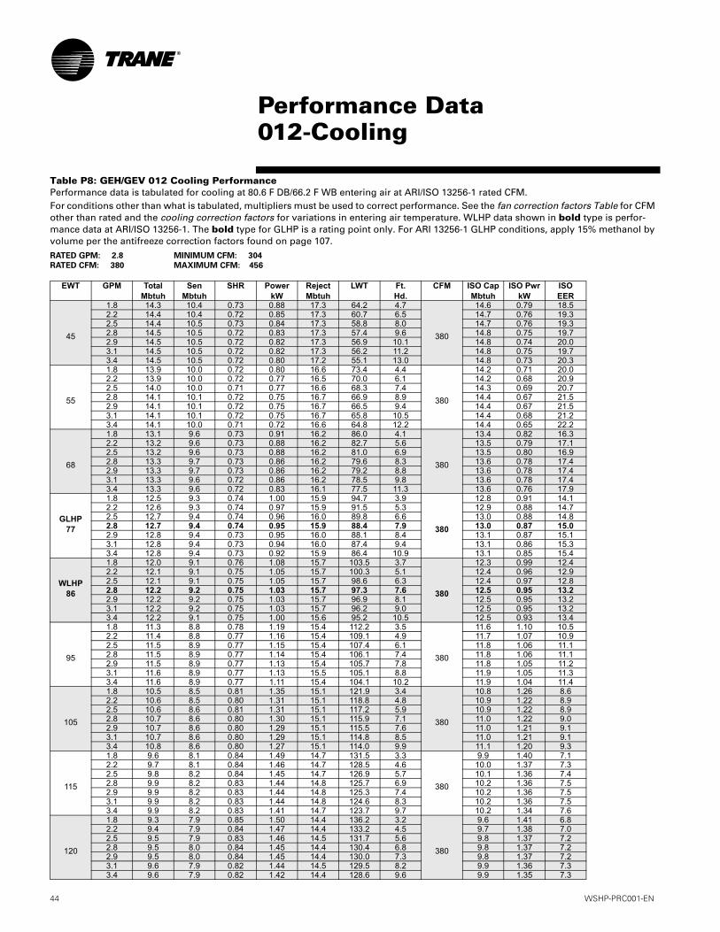
44 WSHP-PRC001-EN
Performance Data012-Cooling
Table P8: GEH/GEV 012 Cooling PerformancePerformance data is tabulated for cooling at 80.6 F DB/66.2 F WB entering air at ARI/ISO 13256-1 rated CFM.For conditions other than what is tabulated, multipliers must be used to correct performance. See the fan correction factors Table for CFM other than rated and the cooling correction factors for variations in entering air temperature. WLHP data shown in bold type is perfor-mance data at ARI/ISO 13256-1. The bold type for GLHP is a rating point only. For ARI 13256-1 GLHP conditions, apply 15% methanol by volume per the antifreeze correction factors found on page 107.RATED GPM: 2.8 MINIMUM CFM: 304
RATED CFM: 380 MAXIMUM CFM: 456
EWT GPM TotalMbtuh
SenMbtuh
SHR PowerkW
RejectMbtuh
LWT Ft.Hd.
CFM ISO CapMbtuh
ISO Pwr kW
ISOEER
45
1.8 14.3 10.4 0.73 0.88 17.3 64.2 4.7
380
14.6 0.79 18.52.2 14.4 10.4 0.72 0.85 17.3 60.7 6.5 14.7 0.76 19.32.5 14.4 10.5 0.73 0.84 17.3 58.8 8.0 14.7 0.76 19.32.8 14.5 10.5 0.72 0.83 17.3 57.4 9.6 14.8 0.75 19.72.9 14.5 10.5 0.72 0.82 17.3 56.9 10.1 14.8 0.74 20.03.1 14.5 10.5 0.72 0.82 17.3 56.2 11.2 14.8 0.75 19.73.4 14.5 10.5 0.72 0.80 17.2 55.1 13.0 14.8 0.73 20.3
55
1.8 13.9 10.0 0.72 0.80 16.6 73.4 4.4
380
14.2 0.71 20.02.2 13.9 10.0 0.72 0.77 16.5 70.0 6.1 14.2 0.68 20.92.5 14.0 10.0 0.71 0.77 16.6 68.3 7.4 14.3 0.69 20.72.8 14.1 10.1 0.72 0.75 16.7 66.9 8.9 14.4 0.67 21.52.9 14.1 10.1 0.72 0.75 16.7 66.5 9.4 14.4 0.67 21.53.1 14.1 10.1 0.72 0.75 16.7 65.8 10.5 14.4 0.68 21.23.4 14.1 10.0 0.71 0.72 16.6 64.8 12.2 14.4 0.65 22.2
68
1.8 13.1 9.6 0.73 0.91 16.2 86.0 4.1
380
13.4 0.82 16.32.2 13.2 9.6 0.73 0.88 16.2 82.7 5.6 13.5 0.79 17.12.5 13.2 9.6 0.73 0.88 16.2 81.0 6.9 13.5 0.80 16.92.8 13.3 9.7 0.73 0.86 16.2 79.6 8.3 13.6 0.78 17.42.9 13.3 9.7 0.73 0.86 16.2 79.2 8.8 13.6 0.78 17.43.1 13.3 9.6 0.72 0.86 16.2 78.5 9.8 13.6 0.78 17.43.4 13.3 9.6 0.72 0.83 16.1 77.5 11.3 13.6 0.76 17.9
GLHP77
1.8 12.5 9.3 0.74 1.00 15.9 94.7 3.9
380
12.8 0.91 14.12.2 12.6 9.3 0.74 0.97 15.9 91.5 5.3 12.9 0.88 14.72.5 12.7 9.4 0.74 0.96 16.0 89.8 6.6 13.0 0.88 14.82.8 12.7 9.4 0.74 0.95 15.9 88.4 7.9 13.0 0.87 15.02.9 12.8 9.4 0.73 0.95 16.0 88.1 8.4 13.1 0.87 15.13.1 12.8 9.4 0.73 0.94 16.0 87.4 9.4 13.1 0.86 15.33.4 12.8 9.4 0.73 0.92 15.9 86.4 10.9 13.1 0.85 15.4
WLHP86
1.8 12.0 9.1 0.76 1.08 15.7 103.5 3.7
380
12.3 0.99 12.42.2 12.1 9.1 0.75 1.05 15.7 100.3 5.1 12.4 0.96 12.92.5 12.1 9.1 0.75 1.05 15.7 98.6 6.3 12.4 0.97 12.82.8 12.2 9.2 0.75 1.03 15.7 97.3 7.6 12.5 0.95 13.22.9 12.2 9.2 0.75 1.03 15.7 96.9 8.1 12.5 0.95 13.23.1 12.2 9.2 0.75 1.03 15.7 96.2 9.0 12.5 0.95 13.23.4 12.2 9.1 0.75 1.00 15.6 95.2 10.5 12.5 0.93 13.4
95
1.8 11.3 8.8 0.78 1.19 15.4 112.2 3.5
380
11.6 1.10 10.52.2 11.4 8.8 0.77 1.16 15.4 109.1 4.9 11.7 1.07 10.92.5 11.5 8.9 0.77 1.15 15.4 107.4 6.1 11.8 1.06 11.12.8 11.5 8.9 0.77 1.14 15.4 106.1 7.4 11.8 1.06 11.12.9 11.5 8.9 0.77 1.13 15.4 105.7 7.8 11.8 1.05 11.23.1 11.6 8.9 0.77 1.13 15.5 105.1 8.8 11.9 1.05 11.33.4 11.6 8.9 0.77 1.11 15.4 104.1 10.2 11.9 1.04 11.4
105
1.8 10.5 8.5 0.81 1.35 15.1 121.9 3.4
380
10.8 1.26 8.62.2 10.6 8.5 0.80 1.31 15.1 118.8 4.8 10.9 1.22 8.92.5 10.6 8.6 0.81 1.31 15.1 117.2 5.9 10.9 1.22 8.92.8 10.7 8.6 0.80 1.30 15.1 115.9 7.1 11.0 1.22 9.02.9 10.7 8.6 0.80 1.29 15.1 115.5 7.6 11.0 1.21 9.13.1 10.7 8.6 0.80 1.29 15.1 114.8 8.5 11.0 1.21 9.13.4 10.8 8.6 0.80 1.27 15.1 114.0 9.9 11.1 1.20 9.3
115
1.8 9.6 8.1 0.84 1.49 14.7 131.5 3.3
380
9.9 1.40 7.12.2 9.7 8.1 0.84 1.46 14.7 128.5 4.6 10.0 1.37 7.32.5 9.8 8.2 0.84 1.45 14.7 126.9 5.7 10.1 1.36 7.42.8 9.9 8.2 0.83 1.44 14.8 125.7 6.9 10.2 1.36 7.52.9 9.9 8.2 0.83 1.44 14.8 125.3 7.4 10.2 1.36 7.53.1 9.9 8.2 0.83 1.44 14.8 124.6 8.3 10.2 1.36 7.53.4 9.9 8.2 0.83 1.41 14.7 123.7 9.7 10.2 1.34 7.6
120
1.8 9.3 7.9 0.85 1.50 14.4 136.2 3.2
380
9.6 1.41 6.82.2 9.4 7.9 0.84 1.47 14.4 133.2 4.5 9.7 1.38 7.02.5 9.5 7.9 0.83 1.46 14.5 131.7 5.6 9.8 1.37 7.22.8 9.5 8.0 0.84 1.45 14.4 130.4 6.8 9.8 1.37 7.22.9 9.5 8.0 0.84 1.45 14.4 130.0 7.3 9.8 1.37 7.23.1 9.6 7.9 0.82 1.44 14.5 129.5 8.2 9.9 1.36 7.33.4 9.6 7.9 0.82 1.42 14.4 128.6 9.6 9.9 1.35 7.3

WSHP-PRC001-EN 45
Performance Data012-Heating
Table P9: GEH/GEV 012 Heating PerformancePerformance data is tabulated for heating at 68 F DB entering air at ARI/ISO 13256-1 rated CFM.For conditions other than what is tabulated, multipliers must be used to correct performance. See the fan correction factors Table for CFM other than rated and the heating correction factors for variations in entering air temperature. WLHP data shown in bold type is perfor-mance data at ARI/ISO 13256-1. The bold type for GLHP is a rating point only. For ARI 13256-1 GLHP conditions, apply 15% methanol by volume per the antifreeze correction factors found on page 107.
RATED GPM: 2.8 MINIMUM CFM: 304
RATED CFM: 380 MAXIMUM CFM: 456
EWT GPM Htg CapMbtuh
AbsorbMbtuh
PowerkW
LWT Ft.Hd.
CFM ISO CapMbtuh
ISO Pwr kW
ISO COP
25
1.8 8.0 5.2 0.83 19.2 5.6
380
7.7 0.74 3.02.2 8.2 5.4 0.83 20.1 7.7 7.9 0.74 3.12.5 8.3 5.4 0.84 20.7 9.4 8.0 0.76 3.12.8 8.4 5.5 0.84 21.1 11.2 8.1 0.76 3.12.9 8.4 5.5 0.84 21.2 11.8 8.1 0.77 3.13.1 8.5 5.6 0.84 21.4 13.1 8.2 0.77 3.13.4 8.5 5.6 0.84 21.7 15.0 8.2 0.77 3.1
GLHP32
1.8 9.2 6.3 0.85 25.0 5.3
380
8.9 0.76 3.42.2 9.3 6.4 0.86 26.2 7.3 9.0 0.78 3.42.5 9.4 6.5 0.86 26.8 8.9 9.1 0.78 3.42.8 9.5 6.6 0.86 27.3 10.6 9.2 0.78 3.42.9 9.6 6.7 0.86 27.4 11.2 9.3 0.79 3.43.1 9.6 6.7 0.86 27.7 12.4 9.3 0.79 3.43.4 9.7 6.7 0.87 28.0 14.3 9.4 0.81 3.4
45
1.8 11.0 7.9 0.90 36.2 4.7
380
10.7 0.81 3.92.2 11.2 8.1 0.91 37.6 6.5 10.9 0.82 3.92.5 11.3 8.2 0.92 38.4 8.0 11.0 0.84 3.82.8 11.4 8.3 0.92 39.1 9.6 11.1 0.84 3.92.9 11.4 8.3 0.92 39.3 10.1 11.1 0.84 3.93.1 11.4 8.3 0.92 39.6 11.2 11.1 0.85 3.83.4 11.5 8.4 0.92 40.1 13.0 11.2 0.85 3.9
55
1.8 12.1 8.9 0.93 45.1 4.4
380
11.8 0.84 4.12.2 12.3 9.1 0.93 46.7 6.1 12.0 0.84 4.22.5 12.4 9.2 0.94 47.6 7.4 12.1 0.85 4.22.8 12.4 9.2 0.94 48.4 8.9 12.1 0.86 4.12.9 12.5 9.3 0.94 48.6 9.4 12.2 0.86 4.23.1 12.5 9.3 0.94 49.0 10.5 12.2 0.86 4.23.4 12.6 9.4 0.94 49.5 12.2 12.3 0.87 4.1
WLHP68
1.8 13.2 10.0 0.95 56.9 4.1
380
12.900 0.86 4.42.2 13.4 10.1 0.96 58.8 5.6 13.100 0.87 4.42.5 13.5 10.2 0.96 59.8 6.9 13.200 0.87 4.52.8 13.5 10.2 0.96 60.7 8.3 13.200 0.88 4.42.9 13.6 10.3 0.96 60.9 8.8 13.300 0.88 4.43.1 13.6 10.3 0.96 61.3 9.8 13.300 0.88 4.43.4 13.7 10.4 0.97 61.9 11.3 13.400 0.90 4.4
75
1.8 13.7 10.4 0.97 63.4 3.9
380
13.4 0.88 4.52.2 13.9 10.6 0.97 65.3 5.4 13.6 0.88 4.52.5 14.0 10.7 0.98 66.4 6.6 13.7 0.89 4.52.8 14.1 10.8 0.98 67.3 8.0 13.8 0.90 4.52.9 14.1 10.8 0.98 67.5 8.5 13.8 0.90 4.53.1 14.2 10.9 0.98 68.0 9.5 13.9 0.90 4.53.4 14.3 10.9 0.99 68.6 11.0 14.0 0.92 4.5
86
1.8 14.6 11.2 0.99 73.5 3.7
380
14.3 0.90 4.72.2 14.8 11.4 1.00 75.6 5.1 14.5 0.91 4.72.5 14.9 11.5 1.01 76.8 6.3 14.6 0.92 4.62.8 14.9 11.5 1.01 77.8 7.6 14.6 0.93 4.62.9 15.0 11.6 1.01 78.0 8.1 14.7 0.93 4.63.1 15.0 11.6 1.00 78.5 9.0 14.7 0.92 4.73.4 15.1 11.7 1.01 79.1 10.5 14.8 0.94 4.6
Table P10: 012 Fan Correction FactorsEntering
CFMCoolingCapacity
SensibleCapacity
CoolingInputWatts
HeatingCapacity
HeatingInputWatts
304 0.974 0.892 0.965 0.972 1.032323 0.980 0.919 0.973 0.979 1.024342 0.987 0.945 0.981 0.986 1.016361 0.993 0.972 0.990 0.993 1.008380 1.000 1.000 1.000 1.000 1.000418 1.012 1.051 1.020 1.013 0.984437 1.019 1.078 1.030 1.020 0.976456 1.025 1.105 1.042 1.027 0.968

WSHP-PRC001-EN 79
E1-Electrical performance Model
No.Volts Total
FLACompRLA(ea)
CompLRA(ea)
No. ofCom-pres.
CmpMCC
BlowerMotorFLA
BlowerMotor
HP
FanMotorNum
MinimumCircuit
Ampacity
MaximumOvercur-
rentProtective
Device
ElectricHeatkW
ElectricHeat
Amps
006 115/60/1 6.8 5.70 36.2 1 9.1 1.20 1/12 1 8.3 15 0 0208/60/1 3.4 2.80 17.7 1 4.6 0.60 1/12 1 4.1 15 0 0208/60/1 4.48 2.8 17.7 1 4.6 0.60 1/12 1 5.6 15 0.82 3.9230/60/1 3.4 2.80 17.7 1 4.6 0.60 1/12 1 4.1 15 0 0230/60/1 4.88 2.8 17.7 1 4.6 0.60 1/12 1 6.1 15 1.00 4.3
220-240/50/1 3.6 3.10 18.8 1 5.2 0.52 1/12 1 4.4 15 0 0220-240/50/1 7.3 3.1 18.8 1 5.2 0.52 1/12 1 9.2 15 1.64 6.8
265/60/1 3.0 2.45 15.0 1 3.9 0.52 1/12 1 3.6 15 0 0265/60/1 5.5 2.5 15.0 1 3.9 0.52 1/12 1 6.9 15 1.33 5.0
009 115/60/1 8.3 7.20 45.6 1 10.9 1.20 1/12 1 10.2 15 0 0208/60/1 4.0 3.40 22.2 1 6.4 0.60 1/12 1 4.9 15 0 0208/60/1 6.48 3.4 22.2 1 6.4 0.60 1/12 1 8.1 15 1.23 5.9230/60/1 4.0 3.40 22.2 1 6.4 0.60 1/12 1 4.9 15 0 0230/60/1 7.08 3.4 22.2 1 6.4 0.60 1/12 1 8.9 15 1.50 6.5
220-240/50/1 5.0 4.30 22.2 1 6.6 0.72 1/8 1 6.1 15 0 0220-240/50/1 9.72 4.3 22.2 1 6.6 0.72 1/8 1 12.2 15 2.17 9.0
265/60/1 3.6 3.10 18.8 1 5.2 0.52 1/12 1 4.4 15 0 0265/60/1 8.0 3.1 18.8 1 5.2 0.52 1/12 1 10.0 15 2.00 7.5
012 115/60/1 12.2 10.60 56.7 1 16.0 1.57 1/8 1 14.8 25 0 0208/60/1 5.7 5.00 27.9 1 8.3 0.70 1/8 1 7.0 15 0 0208/60/1 8.5 5.0 27.9 1 8.3 0.70 1/8 1 10.6 15 1.63 7.8230/60/1 5.7 5.00 27.9 1 8.3 0.70 1/8 1 7.0 15 0 0230/60/1 9.4 5.0 27.9 1 8.3 0.70 1/8 1 11.8 15 2.00 8.7
220-240/50/1 5.5 4.80 27.0 1 8.5 0.72 1/8 1 6.7 15 0 0220-240/50/1 12.02 4.8 27.0 1 8.5 0.72 1/8 1 15.0 15 2.70 11.3
265/60/1 5.0 4.30 22.2 1 6.6 0.72 1/8 1 6.1 15 0 0265/60/1 10.72 4.3 22.2 1 6.6 0.72 1/8 1 13.4 15 2.65 10.0
015 208/60/1 6.1 5.40 29.0 1 9.2 0.70 1/8 1 7.5 15 0 0208/60/1 10.3 5.4 29.0 1 9.2 0.70 1/8 1 12.9 15 2.00 9.6230/60/1 6.1 5.40 29.0 1 9.2 0.70 1/8 1 7.5 15 0 0230/60/1 11.6 5.4 29.0 1 9.2 0.70 1/8 1 14.5 15 2.50 10.9
220-240/50/1 7.8 6.30 32.0 1 10.0 1.53 1/3 1 9.4 15 0 0220-240/50/1 15.23 6.3 32.0 1 10.0 1.53 1/3 1 19.0 20 3.28 13.7
265/60/1 5.5 4.80 27.0 1 8.5 0.72 1/8 1 6.7 15 0 0265/60/1 13.22 4.8 27.0 1 8.5 0.72 1/8 1 16.5 20 3.30 12.5
018 208/60/1 9.4 7.60 45.0 1 13.0 2.10 1/3 1 11.6 15 0 0208/60/1 13.6 7.6 45.0 1 13.0 2.10 1/3 1 17.4 20 2.46 11.8230/60/1 9.4 7.60 45.0 1 13.0 2.10 1/3 1 11.6 15 0 0230/60/1 14.8 7.6 45.0 1 13.0 2.10 1/3 1 18.9 20 3.00 13.0
220-240/50/1 11.4 9.90 55.0 1 13.8 1.53 1/3 1 13.9 20 0 0220-240/50/1 19.63 9.9 55.0 1 13.8 1.53 1/3 1 24.5 25 4.35 18.1
265/60/1 7.8 6.30 32.0 1 10.0 1.53 1/3 1 9.4 15 0 0265/60/1 16.63 6.3 32.0 1 10.0 1.53 1/3 1 20.8 25 4.00 15.1
380-415/50/3 4.9 3.90 25.0 1 5.4 0.95 1/3 1 5.8 15 0 0380-415/50/3 11.45 3.9 25.0 1 5.4 0.95 1/3 1 14.3 15 4.35 10.5
024 208/60/1 12.7 10.90 56.0 1 15.3 2.10 1/3 1 15.7 25 0 0208/60/1 17.5 10.9 56.0 1 15.3 2.10 1/3 1 22.3 25 3.26 15.7230/60/1 12.7 10.90 56.0 1 15.3 2.10 1/3 1 15.7 25 0 0230/60/1 19.2 10.9 56.0 1 15.3 2.10 1/3 1 24.0 25 4.00 17.4
220-240/50/1 12.4 10.90 58.0 1 15.3 1.53 1/3 1 15.2 25 0 0220-240/50/1 24.03 10.9 58.0 1 15.3 1.53 1/3 1 30.0 35 5.40 22.5
265/60/1 11.4 9.90 55.0 1 13.8 1.53 1/3 1 13.9 20 0 0265/60/1 21.53 9.9 55.0 1 13.8 1.53 1/3 1 26.9 30 5.30 20.0208/60/3 9.3 7.50 51.0 1 10.5 2.10 1/3 1 11.5 15 0 0208/60/3 10.8 7.5 51.0 1 10.5 2.10 1/3 1 13.9 15 3.26 9.0230/60/3 9.3 7.50 51.0 1 10.5 2.10 1/3 1 11.5 15 0 0230/60/3 11.8 7.5 51.0 1 10.5 2.10 1/3 1 15.1 15 4.00 10.0
380-415/50/3 5.0 4.00 28.0 1 5.6 0.95 1/3 1 6.0 15 0 0380-415/50/3 8.45 4.0 28.0 1 5.6 0.95 1/3 1 10.6 15 5.40 7.5
460/60/3 4.9 3.90 25.0 1 5.4 0.95 1/3 1 5.8 15 0 0460/60/3 7.65 3.9 25.0 1 5.4 0.95 1/3 1 9.6 15 5.30 6.7
Performance DataElectrical

VOLTAGE: 208Y/120V,3PH,4W 10k AIC RATINGBUS RATING: 225 A. 4/5/2004MAIN: 150 A. MCB 1:48 AM
C N CB CB C NK O K O
LTG REC MOTOR HEAT T AMP/P A B C AMP/P T LTG REC MOTOR HEAT1392 1 FCU 15/1 * - - 15/1 FCU 2 13921392 3 FCU 15/1 - * - 15/1 FCU 4 13921392 5 FCU 15/1 - - * 15/1 FCU 6 13921392 7 FCU 15/1 * - - 15/1 FCU 8 1392696 9 FCU 15/1 - * - 15/1 FCU 10 1392
1392 11 FCU 15/1 - - * 15/1 FCU 12 13921392 13 FCU 15/1 * - - 15/1 FCU 14 13921392 15 FCU 15/1 - * - 20/1 SPARE 16
17 SPARE 15/1 - - * 20/1 SPARE 18696 19 EF-15 15/1 * - - 15/1 FCU-8 20 696696 21 EF-16 15/1 - * - 15/1 EF-9 22 528
23 SPARE 15/1 - - * --- SPACE 24696 25 EF-40 15/1 * - - 15/1 EF-50 26 864864 27 EF-48 15/1 - * - 15/1 EF-51 28 864864 29 EF-49 15/1 - - * 15/1 EF-52 30 696696 31 EF-54 15/1 * - - 20/1 SPARE 32
33 SPARE 20/1 - * - 20/1 SPARE 3435 SPARE 20/1 - - * 20/1 SPARE 3637 SPARE 20/1 * - - SPACE 3839 SPARE 20/1 - * - SPACE 4041 SPARE 20/1 - - * SPACE 42
FEEDER SIZE: SEE ONE LINE DIAGRAMmark with an X as appropriate:
FED FROM: ISOLATION GROUND BUSPANEL 2PQ/A 200 % NEUTRAL
MOUNTING: FEED-THRU LUGSSURFACE SHUNT TRIP MAIN CB
LOCATION: OUTDOOR ENCLOSUREELEC. EQUIP. 258 STAINLESS STEEL COVER
FOOTNOTES:(1) = SHUNT TRIP CB(2) = GROUND FAULT CB 0 0 28344 0(3) = DEMAND FACTOR FROM NEC 70, ARTICLE 220 LTG REC MOTOR HEAT
LTG REC MOTOR HEAT 0.00 0.00 28.34 0.000 0 12000 0 1.25 (3) 1.00 1.000 0 9216 0 0.00 0.00 28.34 0.000 0 7128 0 28.34
A B C 28.3412000 9216 7128 208
PHASE C
TOTALS
TOTAL CONNECTED KVA
TOTAL PANEL ADJUSTED AMPERAGE
LANCASTER C.H.20254.00
THREE PHASE VOLTAGEProject Name:
Project Number:
CONNECTED KVA TOTALS
79
TOTAL ADJUSTED KVA
14952 0
DEMAND FACTORADJUSTED KVA TOTALS
PHASE APHASE B
PHASE LOADING
LOAD SERVEDLOAD SERVEDLOAD (VOLT AMPS)
PHASE
0 0
PANEL 2Q/A
0SUB TOTALSSUB TOTALS
13392 0
LOAD (VOLT AMPS)
0
PANEL TOTALS
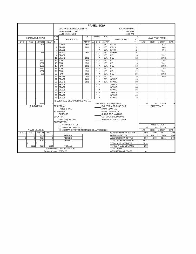
VOLTAGE: 208Y/120V,3PH,4W 10k AIC RATINGBUS RATING: 225 A. 4/5/2004MAIN: 150 A. MCB 1:48 AM
C N CB CB C NK O K O
LTG REC MOTOR HEAT T AMP/P A B C AMP/P T LTG REC MOTOR HEAT696 1 FCU-9 15/1 * - - 15/1 EF-28 2 528
3 SPARE 20/1 - * - 15/1 EF-29 4 8645 SPACE - - * 15/1 EF-30 6 696
864 7 EF-32 15/1 * - - 15/1 SPARE 89 SPACE - * - 15/1 FCU 10 139211 SPARE 15/1 - - * 15/1 FCU 12 1392
1392 13 FCU 15/1 * - - 15/1 FCU 14 13921392 15 FCU 15/1 - * - 15/1 FCU 16 13921392 17 FCU 15/1 - - * 15/1 FCU 18 13921392 19 FCU 15/1 * - - 15/1 FCU 20 13921392 21 FCU 15/1 - * - 15/1 FCU 22 1392696 23 FCU 15/1 - - * 15/1 FCU 24 1392
25 SPARE 20/1 * - - 15/1 FCU 26 69627 SPARE 20/1 - * - 20/1 SPARE 2829 SPARE 20/1 - - * 20/1 SPARE 3031 SPACE * - - SPACE 3233 SPACE - * - SPACE 3435 SPACE - - * SPACE 3637 SPACE * - - SPACE 3839 SPACE - * - SPACE 4041 SPACE - - * SPACE 42
FEEDER SIZE: SEE ONE LINE DIAGRAMmark with an X as appropriate:
FED FROM: ISOLATION GROUND BUSPANEL 3PQ/A 200 % NEUTRAL
MOUNTING: FEED-THRU LUGSSURFACE SHUNT TRIP MAIN CB
LOCATION: OUTDOOR ENCLOSUREELEC. EQUIP. 360 STAINLESS STEEL COVER
FOOTNOTES:(1) = SHUNT TRIP CB(2) = GROUND FAULT CB 0 0 23136 0(3) = DEMAND FACTOR FROM NEC 70, ARTICLE 220 LTG REC MOTOR HEAT
LTG REC MOTOR HEAT 0.00 0.00 23.14 0.000 0 8352 0 1.25 (3) 1.00 1.000 0 7824 0 0.00 0.00 23.14 0.000 0 6960 0 23.14
A B C 23.148352 7824 6960 208
PHASE C
TOTALS
TOTAL CONNECTED KVA
TOTAL PANEL ADJUSTED AMPERAGE
LANCASTER C.H.20254.00
THREE PHASE VOLTAGEProject Name:
Project Number:
CONNECTED KVA TOTALS
64
TOTAL ADJUSTED KVA
9216 0
DEMAND FACTORADJUSTED KVA TOTALS
PHASE APHASE B
PHASE LOADING
LOAD SERVEDLOAD SERVEDLOAD (VOLT AMPS)
PHASE
0 0
PANEL 3Q/A
0SUB TOTALSSUB TOTALS
13920 0
LOAD (VOLT AMPS)
0
PANEL TOTALS
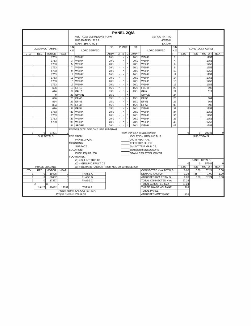
VOLTAGE: 208Y/120V,3PH,4W 10k AIC RATINGBUS RATING: 225 A. 4/5/2004MAIN: 150 A. MCB 1:43 AM
C N CB CB C NK O K O
LTG REC MOTOR HEAT T AMP/P A B C AMP/P T LTG REC MOTOR HEAT1753 1 WSHP 20/1 * - - 20/1 WSHP 2 17531753 3 WSHP 20/1 - * - 20/1 WSHP 4 17531753 5 WSHP 20/1 - - * 20/1 WSHP 6 17531753 7 WSHP 20/1 * - - 20/1 WSHP 8 17531753 9 WSHP 20/1 - * - 20/1 WSHP 10 17531753 11 WSHP 20/1 - - * 20/1 WSHP 12 17531753 13 WSHP 20/1 * - - 20/1 WSHP 14 17531753 15 WSHP 20/1 - * - 20/1 WSHP 16 17531753 17 WSHP 20/1 - - * 20/1 WSHP 18 1753696 19 EF-15 15/1 * - - 15/1 FCU-8 20 696696 21 EF-16 15/1 - * - 15/1 EF-9 22 528
0 23 SPARE 15/1 - - * --- SPACE 24696 25 EF-40 15/1 * - - 15/1 EF-50 26 864864 27 EF-48 15/1 - * - 15/1 EF-51 28 864864 29 EF-49 15/1 - - * 15/1 EF-52 30 696696 31 EF-54 15/1 * - - 20/1 WSHP 32 1753
1753 33 WSHP 20/1 - * - 20/1 WSHP 34 17531753 35 WSHP 20/1 - - * 20/1 WSHP 36 17531753 37 WSHP 20/1 * - - 20/1 WSHP 38 17531753 39 WSHP 20/1 - * - 20/1 WSHP 40 1753
41 SPARE 20/1 - - * 20/1 WSHP 42 1753FEEDER SIZE: SEE ONE LINE DIAGRAM
mark with an X as appropriate:FED FROM: ISOLATION GROUND BUS
PANEL 2PQ/A 200 % NEUTRALMOUNTING: FEED-THRU LUGS
SURFACE SHUNT TRIP MAIN CBLOCATION: OUTDOOR ENCLOSURE
ELEC. EQUIP. 258 STAINLESS STEEL COVERFOOTNOTES:
(1) = SHUNT TRIP CB(2) = GROUND FAULT CB 0 0 57244 0(3) = DEMAND FACTOR FROM NEC 70, ARTICLE 220 LTG REC MOTOR HEAT
LTG REC MOTOR HEAT 0.00 0.00 57.24 0.000 0 19425 0 1.25 (3) 1.00 1.000 0 20482 0 0.00 0.00 57.24 0.000 0 17337 0 57.24
A B C 57.2419425 20482 17337 208
PHASE C
TOTALS
TOTAL CONNECTED KVA
TOTAL PANEL ADJUSTED AMPERAGE
LANCASTER C.H.20254.00
THREE PHASE VOLTAGEProject Name:
Project Number:
CONNECTED KVA TOTALS
159
TOTAL ADJUSTED KVA
27301 0
DEMAND FACTORADJUSTED KVA TOTALS
PHASE APHASE B
PHASE LOADING
LOAD SERVEDLOAD SERVEDLOAD (VOLT AMPS)
PHASE
0 0
PANEL 2Q/A
0SUB TOTALSSUB TOTALS
29943 0
LOAD (VOLT AMPS)
0
PANEL TOTALS

VOLTAGE: 208Y/120V,3PH,4W 10k AIC RATINGBUS RATING: 225 A. 4/5/2004MAIN: 150 A. MCB 1:43 AM
C N CB CB C NK O K O
LTG REC MOTOR HEAT T AMP/P A B C AMP/P T LTG REC MOTOR HEAT696 1 FCU-9 15/1 * - - 15/1 EF-28 2 528
3 SPARE 20/1 - * - 15/1 EF-29 4 8645 SPACE - - * 15/1 EF-30 6 696
864 7 EF-32 15/1 * - - 15/1 SPARE 89 SPACE - * - 20/1 WSHP 10 175311 SPARE 15/1 - - * 20/1 WSHP 12 1753
1753 13 WSHP 20/1 * - - 20/1 WSHP 14 17531753 15 WSHP 20/1 - * - 20/1 WSHP 16 17531753 17 WSHP 20/1 - - * 20/1 WSHP 18 17531753 19 WSHP 20/1 * - - 20/1 WSHP 20 17531753 21 WSHP 20/1 - * - 20/1 WSHP 22 17531753 23 WSHP 20/1 - - * 20/1 WSHP 24 17531753 25 WSHP 20/1 * - - 20/1 WSHP 26 17531753 27 WSHP 20/1 - * - 20/1 WSHP 28 17531753 29 WSHP 20/1 - - * 20/1 WSHP 30 17531753 31 WSHP 20/1 * - - 20/1 WShp 32 17531753 33 WSHP 20/1 - * - 20/1 WSHP 34 17531753 35 WSHP 20/1 - - * 20/1 WSHP 36 17531753 37 WSHP 20/1 * - - 20/1 WSHP 38 17531753 39 WSHP 20/1 - * - SPACE 40
41 SPACE - - * SPACE 42FEEDER SIZE: SEE ONE LINE DIAGRAM
mark with an X as appropriate:FED FROM: ISOLATION GROUND BUS
PANEL 3PQ/A 200 % NEUTRALMOUNTING: FEED-THRU LUGS
SURFACE SHUNT TRIP MAIN CBLOCATION: OUTDOOR ENCLOSURE
ELEC. EQUIP. 360 STAINLESS STEEL COVERFOOTNOTES:
(1) = SHUNT TRIP CB(2) = GROUND FAULT CB 0 0 54485 0(3) = DEMAND FACTOR FROM NEC 70, ARTICLE 220 LTG REC MOTOR HEAT
LTG REC MOTOR HEAT 0.00 0.00 54.49 0.000 0 19618 0 1.25 (3) 1.00 1.000 0 18394 0 0.00 0.00 54.49 0.000 0 16473 0 54.49
A B C 54.4919618 18394 16473 208
PHASE C
TOTALS
TOTAL CONNECTED KVA
TOTAL PANEL ADJUSTED AMPERAGE
LANCASTER C.H.20254.00
THREE PHASE VOLTAGEProject Name:
Project Number:
CONNECTED KVA TOTALS
151
TOTAL ADJUSTED KVA
26102 0
DEMAND FACTORADJUSTED KVA TOTALS
PHASE APHASE B
PHASE LOADING
LOAD SERVEDLOAD SERVEDLOAD (VOLT AMPS)
PHASE
0 0
PANEL 3Q/A
0SUB TOTALSSUB TOTALS
28383 0
LOAD (VOLT AMPS)
0
PANEL TOTALS