Embed Size (px)
Citation preview

COMMUNITY-BASED BIO-ENGINEERING
FOR ECO-SAFE ROADSIDES IN NEPAL

3
PREF
ACE
2
Prefaceby Department of Soil Conservation and Watershed Management, Government of Nepal
Roads are critical lifelines, connecting our rural population with other villages and urban centers for transporting goods to markets, schools, health centers. They form the basis of our
country’s economic development and social mobility. Over the past decade, the number of roads has increased exponentially from 7330 km in 1990 to 51,000 km in 2013 (DoR, 2013). The total amount spent on rural road construction amounts to NPR 56 billion annually, with communities contributing an estimated 12 % of this total amount (Government of Nepal, 2012). The high amount demonstrates the significance and priority given to connectivity.
The Government of Nepal plan is to expand the road network from 9 km to 15 km per 10,000 people (DoR, 2013). A majority of these roads are constructed using heavy construction equipment with little technical expertise or design. Such roads are commonly wiped out during heavy monsoon rains, requiring costly clearing with heavy equipment. Less known are the environmental, economic and social costs of the “ conventionally constructed roads ”, using bulldozers with few or no protection or drainage measures. The environmental costs include accelerated sedimentation of river ways and lakes, reducing water quality ; the economic costs are due to the high loss of agri-cultural land and damage to infrastructure ; and the social costs en-sue directly from families losing their agricultural lands. These costs could be significantly reduced by constructing roads using low-cost eco-engineering technology, which combines simple civil engineering structures with the use of locally available deep-rooted grasses and shrubs. Savings from improved rural earthen roads could instead be used for education or livelihoods improvements. However, the bottom line fact is that most community people have little access to knowledge about low-cost bio-engineering practices in rural areas.The Department of Watershed Management and Soil Conservation has over three decades of expertise and experience with bio-enginee-ring practices in Nepal. Our District Soil Conservation Offices (DSCO) are important extension agents for transmitting this expertise to rural communities. Every year, our District Soil Conservation Offices organize local workshops, training hundreds of community people on how to better manage the negative effects of rural road
construction and best practices for soil conservation. This publication, “ Community-based Bio-Engineering for Eco-Safe Roads in Nepal ” is an important contribution to explaining low cost bio-engineering practices for communities, roads committees and citizen groups. It will be used to support our DSCO officers’ on-going extension work to improve the safety and quality of rural earthen roads in Nepal. We are convinced that it will be a well-read addition to our expanding extension materials in this field.
Pem Narayan KandelDirector GeneralDepartment of Soil Conservation and Watershed Management

4 5
Figure 1
Phewa Lake, Kaski District. The lake is threatened due to high rates of sedimentation which have considerably reduced the lake’s surface area. Photo credit : K. Sudmeier-Rieux, 2013.
Should be cited as : Devkota, S., Sudmeier-Rieux, K., Penna, I., Eberle, S., Jaboyedoff, M., Adhikari, A. and R. Khanal (2014) Community-based bio-engi-neering for eco-safe roadsides in Nepal. Lausanne : University of Lausanne, International Union for Conservation of Nature, Nepal and Department of Soil Conservation and Watershed Management, Government of Nepal.
Layout, design and illustrations : Sandrine Eberle, University of Lausanne, Switzerland

6 7
Table of contents1. About the manual 9
2. Introduction 122.1 Cost of building rural earthen roads : the conventional way versus “ eco-safe roads ” 152.2 Identifying problems related to road construction on slopes 16
3. Diagnosing the problem 193.1 Landslides 203.2 Shallow landslides - earthflows 223.3 Rock falls 243.4 Debris flows 263.5 Water induced (fluvial) erosion 28 3.5.1 Gullying 283.6 Secondary impacts to waterways 30 3.6.1 River bank erosion 30
4. Determining solutions 32
5. Identifying solutions 365.1 Bio-engineering Techniques for Slope and Soil Protection 365.2 Bio-engineering techniques to control water run-off 40Surface erosion - control of run off 44 Method 1.1. Turfing 44 Method 1.2. Jute netting along with seedlings 46 Method 1.3. Grass plantations 48 Method 1.4. Facines 50Gullies 52 Method 2.1. Live Check Dams 52 Method 2.2. Vegetative stone pitching 54Shallow landslides 56 Method 3.1. Palisades 56 Method 3.2. Brush Layering 58 Method 3.3. Gabion wall combined with vegetation 60 Method 3.4. Dry stone walls combined with vegetation 62
Secondary impacts on waterways from road construction 64 Method 4.1.Live check dams 64River bank protection 66 Method 5.1. Sandbags, Bamboo Vans & Vegetation. 66
6. Conclusions 69
7. References 70
Annexes 74Annex I : Diagnostic tool for roadside slope failures 74Annex II : Recommended bio-engineering techniques and timing of implementation 78Annex III : Popular bioengineering methods in Nepal and their effectiveness in different environment 82Annex IV : Comparison of Different Vegetation and Engineering Functions 85Annex V : List of plants for Bio-Engineering, Altitude, Propagation and Period for Seed Collection 86Annex VI : Landslide Inventory Report 94

98
1. About the manual
This manual provides guidance to communities and local government agencies on the occurrence, assessment
and mitigation of road construction-induced landslides and erosion. By better understanding the interaction between human activity and natural phenomena we are better able to find solutions and increase our coping capacities to face threats. In Nepal, the number of rural roads has quadrupled over the past two decades as many communities are prioritizing access to markets, health care and education. We know that haphazard rural road construction in Nepal is one of the leading causes of slope instabilities and severe erosion, leading to the destruction of agricultural land, loss of lives and property. The current way of building roads requires frequent clearing of roads
Figure 1A
Comparison of relative strength of civil engineering versus soil bio-en-gineering structures for slope stabilisation. Modified from Cesvi, 2013.
Acknowledgements
We would especially like to thank Mr. Pierre Raymond, Terra Erosion, France, Dr. Alexia Stokes, CIRAD, France for their inputs and Dr. John Howell, a well-recognized bio-engineering expert in Nepal for his extensive comments and for granting copyright permission to reproduce several of his excellent summary tables.
The Ecosystems Protecting Infrastructure and Communities is part of the International Climate Initiative (IKI). The German Federal Ministry for the Environment, Nature Conservation, Building and Nuclear Safety (BMUB) supports this initiative on the basis of a decision adopted by the German Bundestag.
1110
after each monsoon and is much less cost-effective as compared to a road constructed with proper drainage and low-cost vegetative stabilisation, or bio-engineering. It is true that bio-engineering alone may not suffice to stabilise certain road side failures, while civil engineering alone and especially - improper civil engineering - may also be prone to failure. For small failures, appropriately-scaled civil engineering structures may be required as reinforcement to vegetative stabilization to anchor the soil (e.g. stone walls for reinforcing slope toes with vegetation on slopes). The two are most often very complementary since civil engineering structures often need to be replaced or strengthened after 10 - 15 years, while bio-engineering benefits accrue over time. This manual will only consider small slope failures along roadsides as large failures require large and costly civil engineering structures, which fall outside the scope of community-based stabilisation possibilities.The practice of bio-engineering is not new in Nepal and in fact many very good manuals exist on this topic [1, 2, 3]. This manual is however intended for local stakeholders,
Figure 1B
Bulging gabion walls six months after construction. Dolakha District. Photo credit : K. Sudmeier-Rieux, 2010.
including communities, civil society groups, NGOs and local government actors and those who are involved in or initiating rural road construction in Nepal. Its purpose is to better understand the processes and factors leading to common, small slope instabilities caused by road construction and low-cost and appropriate solutions. This manual is intended as a “ how to guide ” to resolving common small-scale slope failures, using a combination of vegetation and simple civil engineering, or bio-engineering alone. The manual will answer the following questions :
• What are common slope-stability problems linked to road construction ?• What locally appropriate bio-engineering solutions are available for reducing the negative impacts of rural road construction ?
These are questions that we intend to answer in an easy-to-read language, focusing mostly on visual content. We have developed a useful roadside slope failure diagnosis tool and bio-engineering checklist (see Annex I) that can be used by local government and communities for better understanding roadside failure issues and possible, locally appropriate solutions.
13
INTR
ODUC
TION
12
2. introductionroad construction - human activity in a fragile landscape
Steep slopes and weak rocks are subject to erosion and landslides that degrade land and are often caused by heavy
rainfall and aggravated by human activities, such as improper terrace building or road construction. The direct effects might be the creation of landslides and gullying, and secondary effects, such as an increase in sediments transported down slopes and in streams should not be neglected (Figure 2). The consequence on water quality of surface reservoirs and on the effectiveness of hydropower plants can be considerable in the near future (e.g. siltation, fish habitats degradation) (Figure 3). Therefore, these problems should not be considered isolated, but need to be part of integrated watershed management strategies.
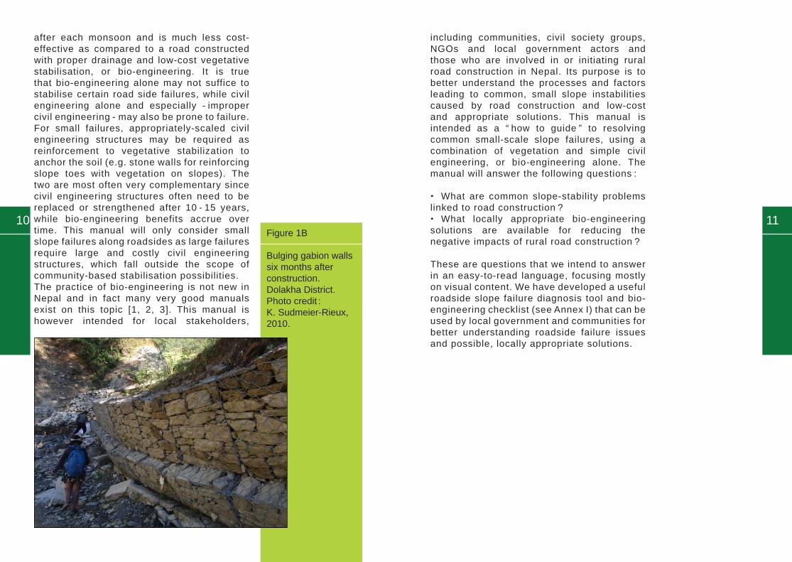
Figure 2
Landscape view of a rural road construction causing significant slope destablization and reactivation of former slope instabilities. This is leading to debris transported downslope and burying agricultural land in Syangja District, Nepal. Photo credit : I. Penna, 2013.
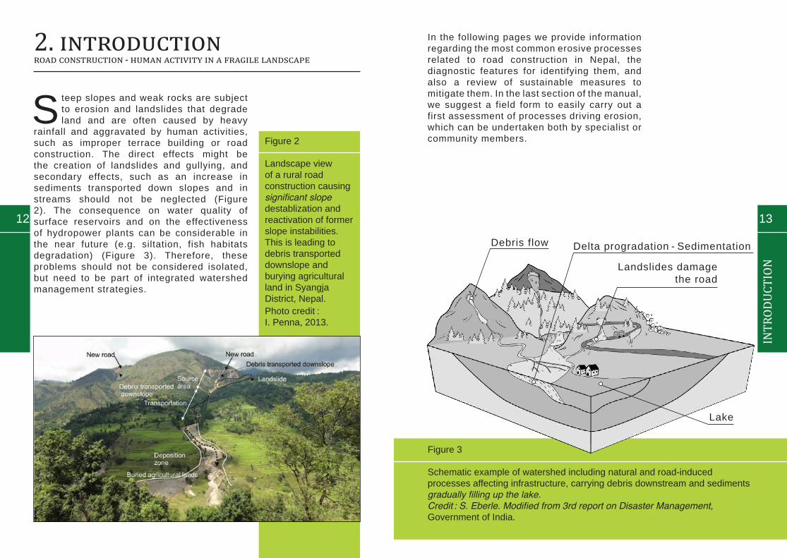
Figure 3
Schematic example of watershed including natural and road-induced processes affecting infrastructure, carrying debris downstream and sediments gradually filling up the lake. Credit : S. Eberle. Modified from 3rd report on Disaster Management, Government of India.
In the following pages we provide information regarding the most common erosive processes related to road construction in Nepal, the diagnostic features for identifying them, and also a review of sustainable measures to mitigate them. In the last section of the manual, we suggest a field form to easily carry out a first assessment of processes driving erosion, which can be undertaken both by specialist or community members.
Debris flow
Landslides damage the road
Delta progradation - Sedimentation
Lake

Table 1
Average cost of conventionally constructed rural earthen roads versus eco-safe roads over 20 years in Nepal Middle Hills. Assuming NPR 2013 rates.1 USD = 97.00 NPR (2013). Based on calculations from UNDP, 2011.
15
INTR
ODUC
TION
14
2.1 Cost of building rural earthen roads : the conventional way versus “ eco-safe roads ”
The total amount spent on rural road construction amounts to NPR 56 billion annually, with com-munities contributing an estima-ted 12 % of this total amount [4]. The high amount demonstrates the significance and priority given to connectivity. Less known are the environmental, economic and social costs of the “ conventionally constructed ” earthen rural roads, meaning with the use of bulldozers with no consideration for simple
1 For estimate - out of 20 years it is assumed 5 years of extreme monsoon and the cost has been generalized to fit in all conditions in Nepal
Average cost NPRs per km
Conventional earthen roads
Eco-safe roads
Initial construction 800,000 - 1,500,000 1,500,000 - 2,000,000
Annual mainte-nance in normal monsoon year
175,000 - 300,000 50,000 - 75,000
Annual mainte-nance with heavy monsoon conditions
300,000 - 500,000 100,000 - 200,000
20 year (mainte-nance cost) 1
4,125,000 - 7,000,000 1,250,000 - 4,000,000
Total (initial costs + 20 year mainte-nance costs)
4,925,000 - 8,500,000 2,750,000 - 6,000,000
bio-engineering techniques.Over 20 years, the maintenance costs of such roads make their construction more expensive than eco-safe roads, not including the additional damage to agricultu-ral lands by roadsides, which has not been included in this calcula-tion. Table 1 gives average costs of a conventionally constructed earthen road versus an eco-safe road in the middle hills of Nepal, assuming not very rocky soils.

17
INTR
ODUC
TION
16
2.2 Identifying problems related to road construction on slopes
The following section will focus on diagnosing the cause of the roadside slope failure, which should follow these main steps (Box 1).
Box 1 : Steps for diagnosis of roadside slope fai-lures and identifying solutions
I. Diagnose the problem
1. Does the road traverse a landslide area ? If there are signs of slope movement, STOP and seek exper-tise ! Bio-engineering methods described in this manual may not suffice !
2. Is it hill road or valley road ?• bio-engineering methods can be considered useful for both hill and valley roads that are prone to erosion, keep reading !
3. How was the road constructed ? What is the road gradient ? How steep and how long is it ?
• if it is considered prone to erosion, then you need to consider bio-engineering methods, keep reading !
4. What is the land-use of the area where the road runs through ?
• if there are houses or fields nearby, that can be damaged by erosion, then you need to consider bio-engineering methods, keep reading !
II. Do a site assessment
5. How deep are the soils ? What is the soil moisture ?
• if very deep and moist, your road may be especially subject to failure, keep reading !
6. Are there any water sources (springs, streams, seepage water, etc.) along the road ?
• if yes, they need to be checked in case they cause erosion, keep reading !
7. Is there any road side drainage system ? Where does the drainage go ?
• if no, then lack of drainage can cause many problems, keep reading !
8. Does the road pass through old landslide or visible unstable location (bent trees, cracks in ground) ?
• if yes, your road may be especially subject to failure, keep reading !
III. Identifying solutions
9. Have any road side protection measures been applied ?
• if no protection measures have been applied but you observe any of the above pro-blems, keep reading, we have designed this manual to address many of the above issues.

18
3. Diagnosing the problemNatural processes aggravated by road construction
“ Ideally, the causes of slope instability would be well understood and appropriate
solutions would be easy to select. However, this is rarely the case and field workers must make assumptions about the causes of slope instability, based on their knowledge and experience of the terrain. This is particularly true in Nepal, where slopes tend to be long and steep, and the climatic variables are as yet poorly understood. Every slope has a different variety of erosion and failure processes at work on it ; often, there will be more than one process affecting each part of a slope. These erosion and failure processes must be identified before remedial work can be started ” [1].
Road construction can have a number of (geomorphic) problems and impacts :
• Slope destabilisation : slope cuts which make the slope weaker and create free faces. Removing material from the toe of a past landslide or a creeping area might lead to reactivations or accelerate instabilities.
19
DIAG
NOS
ING
• Increase of sediment loads downstream : Resulting from materials caused from landslides or erosion, but also because of materials removed during the slope cut, deposited down slope, and wash-out of road fills.
• Increase of run-off : Due to removal of vegetation during road construction.
• Creation of new drainage : Road cutting of a slope might act as new waterway by trapping the run-off and diverting drainage from its natural path. Gully erosion can result from this drainage alteration.

3.1 Landslides
21
DIAG
NOS
ING
20
Figure 4B
Schematic illustra-tion of deep-seated slump-earth flow landslide. Credit : S. Eberle. Modified from Cruden and Varnes, 1996 [5].
Landslides are downslope movements of rock, debris or soil, moving up to tens of meters per second, and involving from a single boulder up to thousands of cubic metersof materials [5]. They are commonly triggered by prolonged or intense rainfall, snow melting or earthquakes, but human activities also contribute to their occurrence by changing slope gradients such as when we construct a road or deforesting areas for house construction [6, 7]. Landslides can be deep-seated or shallow. Deep-seated landslides require much more structural engineering to be stabilized [6] and will not be covered by this manual (Figure 4A and B).
Figure 4A
Khariswara lands-lide, triggered by high rainfall event in Dolakha District, Nepal Photo credit : S. Devkota, 2011.
Scarp
Main body
Tension crack
Toe
Surface of rupture

3.2 Shallow landslides - earthflows
22 23
DIAG
NOS
ING
Shallow landslides, involving the first 2 m [8] below the surface (commonly soil or the weathering area of outcrops), are very frequent phenomena in the hillslopes of Nepal. They are mostly triggered by heavy and prolonged rainfall events, [6, 9] and often have additionally been aggravated by some human activity which further fragilised the slope [7, 10]. Initial signs of instability are marked by cracks in the soil or a spring [11, 12, 13]. They can be identified by the presence of a headscarp in the upper part where materials are detached, cracks in the area of transport and a bulge form in the toe of the deposit (Figure 5A and B).
Figure 5A
Roadside instabilities along rural road in Basantapur, Tehrathum District, Nepal. Photo credit : K. Sudmeier-Rieux, 2009.
Figure 5B
Schematic illustration of shallow landslide caused by road construction. Credit : S. Eberle
Slope failure
Terraces
Headscarp
Instabilities creating erosion

25
DIAG
NOS
ING
Figure 6B
Schematic illustration of Boulder / Rock fallCredit : S. Eberle
24
Rock fall involves the detachment from a steep wall of rocks, or slopearea. Preceding the detachment, fractures bounding the blocks start to open, and small blocks might also detach until a major failure occurs [7]. Once the blocks are detached, they move rapidly downslope due to free fall, but also bouncing and rolling [7, 14]. Fractured or block deposits with free faces or “ hanging blocks ” can be areas of potential rock falls (Figure 6A and B).
Figure 6A
Boulders rolling down from the steep slope, Jiri-Namadi Road, Ramechhap District Nepal.Photo credit : S. Devkota, 2013.
3.3 Rock falls
Boulders rolling down from the unprotected slope

3.4 Debris flows
26 27
DIAG
NOS
ING
Debris flow involve downslope movements at very high velocities (channelized or not) of debris and water [5, 7]. They occur due to the accumulation of sediments in a source area, which are later remobilized during strong or prolonged rainfall events [15]. They commonly trap material during displacements, for which it is common also to find of the remains of trees in their deposit. They are highly destructive and damages occur due to erosion and burial due to depositional [15]. A debris flow prone area can be recognized by observing how sediments have accumulated, such as a bulge, and whether there are landforms such as lateral levees along channels or rugged fans (Figure 7A and B).
Figure 7A
View of debris flow on steep slope Sindhupalchok District Nepal. Photo credit : S. Devkota, 2013.
Figure 7B
Schematic illustration of debris flow. Credit : S. Eberle
Debris blocking the road
Source of debris
Levees

28 29
DIAG
NOS
ING
3.5.1 Gullying
Concentration of run-off on a surface promotes the development of drainage lines called rills. Evolution of erosion along rills gives place to gullies. Generally they show a sharp V- to U-shape profile [16]. The sides of roads and culvert outlets can concentrate large amounts of water leading to gullies if they are not well-designed (Figure 8A and B).
Figure 8B
Schematic illustration of road side gully erosion. Credit : S. Eberle
Figure 8A
Gully erosion in Syangja District, Nepal. Photo credit : S. Devkota, 2014.
3.5 Water induced (fluvial) erosion
Water flows
Gullies are forming due to poor drainage
Roadside drainage blocked
Slope without any vegetation

31
DIAG
NOS
ING
30
3.6.1 River bank erosion
When there is higher rainfall and more sediment flowing down, a stream has to adjust to new conditions. One of the adjustments involves the increase of channel width, which may impact agricultural land. River bankerosion therefore should be controlled (Figure 9A and B).
Figure 9A
Lateral erosion of a waterway partially due to road construc-tion in Syangja District, Nepal.Photo credit : S. Devkota, 2014.
Figure 9B
Schematic illustration lateral erosion & fluvial process. Credit : S. Eberle
3.6 Secondary impacts to waterways
Erosion
Deposits
Erosion
Deposits

4. Determining solutionsdoing a site assessment
33
SITE
ASS
ESSM
ENT
32
Once you have identified the main problems creating the roadside failures the next step is to do a site assessment to better
understand the following :
Box 2
a. Slope angle(s). 3 classes : < 30º, 30 – 45º, or > 45º.
b. Slope length. 2 classes : < 15 metres or > 15 metres.
c. Material drainage. 2 classes : good or poor.
d. Site moisture. 4 classes : wet, moist, dry or very dry.
e. Altitude. Determine : use an altimeter, map or site drawing.
Source : Modified from Howell, 1999
a. Slope angles. Record the slope angles and assign each segment to one of three classes : < 30º, 30 – 45º, or > 45º. Slopes of less than 30º will need only mild treatment. Those falling in the other two classes will require more substantial stabilization. As slope increases, instability also increases so the understanding of slope steepness is important. A soil slope which is less than 35° is mostly stable unless it is disturbed. However slopes above 35° need precaution and protection from failure. A 35° slope is a medium type slope where people and animal can walk easily. A 50° slope is quite steep as people cannot easily walk across such a steep slope.
b. Slope length can be measured using a tape measure or manually. Longer than 15 me-ters is considered long and prone to greater risks.
c. Material drainage. Soils with more clay and silts, mudflows (ratomato) slowly draining will be prone to poor drainage.
d. The moisture regime of the entire site must be considered although, in the field, this can only be estimated. In assessing sites, it is necessary to determine into which of four categories each segment falls (See Table 2).Wet : permanently damp sites (e.g. north-fa-cing gully sites).Moist : sites that are reasonably well shaded or moist for some other reason.Dry : generally dry sites.Very dry : sites that are very dry ; these are usually quite hot as well (e.g. south-facing cut slopes at low altitudes).
e. Altitude. This is an important determinant of temperature ranges for planting of various bio-engineering plant species in Nepal and should always be checked.
Source : Modified from Howell, 1999
See Figure 10 for an overview of the different determinants for deciding on which bio-enginee-ring method to use. See also Annex I.

35
Table 2
Environmental factors indicating site moisture characteristics (Source : Howell, 1999)
34
Site moisture factor Tendency towards Damp sites
Tendency towards DRY sites
Aspect Facing N, NW, NE and E
Facing S, SW, SE and W
Altitude Above 1500 metres ; particularly above 1800 metres
Below 1500 metres ; deep river valleys surrounded by ridges
Topographical location
Gullies ; lower slopes ; moisture accumulation and seepage areas
Upper slopes ; spurs and ridges ; steep rocky slopes
Regional rain effects Eastern Nepal in general ; the southern flanks of the Annapurna Himal
Most of Mid Western and Far Western Nepal
Rain shadow effect Sides of major ridges exposed to the monsoon rain-bearing wind
Deep inner valleys ; slopes sheltered from the monsoon by higher ridges to the south
Stoniness and soil moisture holding capacity
Few stones ; deep loamy and silty soils
Materials with a high percentage volume of stones ; sandy soils and gravels
Winds Sites not exposed to winds
Large river valleys and the Terai
Dominant vegetation e.g. amliso, nigalo, bans, chilaune, katus, laligurans, utis
e.g. babiyo, khar, dhanyero, imili, kettuke, khayer, salla
Figure 10
All the above techniques are described in section 5. Identifying solutions. (Source : Howell et al., 1999) * Chevron is a zigzag pattern.** Herringbone is a diagonal pattern.
SITE
ASS
ESSM
ENT
*
**

36 37
SOLU
TION
S
5. Identifying solutionsLow cost community based solutions for roadside stabilization
Figure 11A
Bio-engineering along roadside in Parbat District, Nepal. Photo credit :S. Devkota, 2014.
Bio-engineering, or the use of vegetation for slope stabilisation, and control of run off and their effects (soil erosion
and transportation of sediments), is a cost-effective and locally adapted method along road side slopes, river banks or on cultivated terraces. Bio-engineering methods range from the very simple plantation of appropriate deep-rooted species, to a combination of vegetation and more elaborate civil engineering [17]. Examples include : planting grass lines along contours, vertically or diagonally, turfing, jute netting together with seedling, brush layering, fascines, palisades, wattling, live check dams, bamboo fencing and vegetated stone pitching. In addition to cost effectiveness, advantages beyond slope stabilisation include benefits obtained
Figure 11B
Schematic illustration of brush layering. Credit : S. Eberle
from vegetation for livelihoods, and inter-cropping. Some of the main requirements for successful bio-engineering include proper roadside drainage to divert heavy run-off from fragile slopes to a safer place, early plantation maintenance to keep weeds from competing with plants and keeping livestock away from slopes [17] (Figure 11A). As there are many different solutions to the various roadside slope failures or to control water run-off, we start by giving some general guidelines for finding solutions, followed by detailed steps for each solution below. If possible, it is best to construct a drainage dike that runs alongside the road while ensuring that the water accumulated here is disposed in a safe place such as a natural waterway (Figure 11B).
Disposal of drainage in safe place
Brush layering
Toe protection
5.1 Bio-engineering Techniques for Slope and Soil Protection

39
SOLU
TION
S
38
Figure 12A and B illustrate two common and low cost methods for enabling safe disposal of drainage water. The Figure 12A shows how water can be diverted across the road when there is no possibility of creating drainage ditch along the roadside.The Figure 12B shows how water should be diverted away from a landslide area, or cracked area to avoid triggering the landslide or making it worse. This is known as a stone causeway.
Figure 12A
Simple drainage using rocks for safe disposal of water across road.Credit : S. Eberle
Figure 12B
Drainage above shallow landslide or above lands-lide prone area for shallow landslides and traversing road to divert water away from landslide area. Credit : S. Eberle
Tree and grass plantation
Stone pitching channel
Tree and grass plantation
Channel to divert water away from landslide

4140
SOLU
TION
S
As vehicles compact road surfaces, they become impermeable, thereby accumulating the quantity and velocity of water. Accumulation of water on roads is the primary cause of gully erosion. The first and most important step of any landslide stabilisation project - especially when using bio-engineering along roads - is to see where water is coming from and where it can safely cross a road in order not to create more problems below and above the road. Most common measures include creating small drainage rills across the road while ensuring that there is a stabilised drainage below the road or creating drainage parallel to the roadside and channelizing water to a safer or natural stream downslope (Figure 13A and B). Drainage works can be constructed in a low cost manner using flatter stones or more expensively by cementing drainage areas or by using pipes crossing under roads. Usually
it is no use undertaking other measures unless drainage problems have first been resolved. Once the drainage works have been constructed, maintaining the drainage (e.g. removal of debris and sediments) is essential. This includes regular checking of the drainage outlet to ensure that water exiting the drainage is not creating new problems below the outlet.
The next section gives “ how-to ” guidance of the most common problems caused by rural road construction of earthen roads and a number of low-cost bio-engineering solutions (Table 3).
Figure 13A
Cemented drainage channel, with cemented stone walls to ensure longer lasting drainage.Photo credit : S. Devkota, 2014.
5.2 Bio-engineering techniques to control water run-off (Source : Howell, 1999)
Tree and grass plantation
Safe disposal of drainage
Figure 13B
Schematic illustra-tions of drainage works. Credit : S. Eberle

4342
SOLU
TION
S
Table 3
Rural earthen road common problems and low cost bio-engineering methods described.
Problems Solutions
1. Surface erosion Control of run-off
DRAINAGE techniques
+
Method 1.1. Turfing
Method 1.2. Jute netting along with seedlings
Method 1.3. Grass plantations
Method 1.4. Facines
2. Gullies
Method 2.1. Live check dams
Method 2.2. Vegetative stone pitching
3. Shallow landslides
Method 3.1. Palisades
Method 3.2. Brush layering
Method 3.3. Gabion walls combi-ned with vegetation
Method 3.4. Dry stone walls combined with vegetation
4. Secondary impacts on waterways from road construction
Method 4.1. Live check dams combined with vegetation and boulders
5. River bank protection
Method 5.1. Sandbags, bamboo vans & vegetation, if the problem is bigger gabion or stone / boul-der retaining wall might be good
The following section gives an overview of most common bio-engineering techniques, the advantages and disadvantages of each, their requirements and suggested plant species. Figure 14 explains the decision-making process for selecting plant species for bio-engineering species. It is especially important to consider “ what the people want ” and it may
be necessary to combine some species that are good for livelihoods (e.g. fodder species) with species that are especially good for bio-engineering and have deep roots. Fortunately in Nepal there are many species that can do both : especially broom grass (amriso / Thysanolaena maxima) and bamboo (baas / Bambusa vulgaris). See also Annex II.
Figure 14
Diagram explaining the process of selecting species for bio-engineering. Source : Modified from Howell, 1999.

44 45
SOLU
TION
S
Surface erosion – control of run off (Source : Howell, 1999)
Method 1.1. Turfing : Shallow rooting grass and the soil it is growing in, is placed on the slope. It is normally used on well-drained materials, where there is a minimal risk of slumping [1] (Figure 15).
Figure 15
Schematic illustration ofturfing in patches for immediate protection of excavated surfaces. Credit : S. Eberle
Advantage• Useful for newly excavated slope or back fill slopes and embankments to protect from immediate flow of top soil in the presence of water
Requirements• If the slope or the embank-ment is gravel filled 50 mm layer of top soil should be laid and compacted [18]• Slope should be < 30°, for slope > 25° require pegs to an-chor the turf (hammer wooden pegs of 300 mm long & 30 mm diameter) in the middle of each turf• Soil shall be well drained with minimal risk of slumping• Protect from animals and grass cutting and remove unne-cessary weeds• As far as possible turf should be cut in the same day as it is to be placed ; if this is not possible, it should be kept very moist in a shady place [18]• Turf shall be of 300 mm square is easy to handle• Once the slope is covered, compact the turf with wooden
How-to-steps1. Check your drainage2. Check the slope angle (see requirements)3. Make sure the soil is well-drained 4. Identify a safe place for turf storage before plantation5. Check available budget6. Level the surface of the slope / embankment before placing the turf
Function• Armor, gives a complete ins-tant surface cover
Disadvantages• Relatively costly• Creates equal bare areas at the source• Discontinuity between turf and underlying materials which in extreme conditions can give rise to gradual creep or shallow pla-ner failure• Chances of animal tramping and grazing
Turf
Vegetative slopeSafe disposal of drainage
hammer and water the turf tho-roughly• For larger area surface drai-nage (both horizontal and verti-cal) channel is required
Species : Bermuda Grass(Dubo) : Cynodondactylon (L.) Pers.

46
Figure 16
Schematic illustration of jute netting interspersed with deep-rooted vegetation. Credit : S. Eberle
47
SOLU
TION
S
Method 1.2. Jute netting along with seedlings : Locally made geo-textile of woven jute netting of standard mesh size 40 x 40 mm to protect slope surface and allowing seeds to hold and germinate (Figure 16).
Surface erosion – control of run off(Source : Howell, 1999)
How-to-steps1. Check your drainage2. Check the slope angle & length (see requirements)3. Make sure the soil is well-drained 4. Identify a safe place for drainage disposal5. Check available budget6. Level the surface of the slope/embankment before applying the method
Advantages (mesh - 40 mm x 40 mm)• Suitable for steep, hard slopes where existing conditions are too harsh for vegetation & slope angles of 45° to 60°• Effective to establish perma-nent grass cover on steep cut slope
Functions• Allows seeds to hold and ger-minate• Protects surface, armor against erosion, catch small de-bris• Improves microclimate on the surface• Helps to establish a perma-nent grass cover on steep cut slopes• Jute, being a biological pro-duct, decomposes into the soil & acts as a mulch
Disadvantages • It does not protect the surface for more than 1 or 2 monsoon seasons [1] so should be used with bio-engineering techniques e.g. grass slips, and seedlings• Jute could raise the moisture content in the soil which might be a problem where there is poor internal drainage
Requirements • Slope should be of hard sur-face, should not be less than 45° and well-drained• Better when slope is exposed to sun • Slope must be trimmed to have even surface• Hard wood pegs must be ham-mered to keep the net in proper position and to ensure that the net is not in tension and covers whole surface• Plant seedlings shall be spread randomly over the net-ting surface just before the pre-monsoon• Jute net does not require any maintenance however vegeta-tion initially requires weeding and watering• Drainage management – buil-ding horizontal & vertical channel to catch the surface flow
Jute net of mesh 40 mm x 40 mm
Grass species
Stone rip-rap vertical channel
Safe disposal of drainage
Catch drain dispose in safe place
Species : grass species - Thatch Grass (Khar) - Cymbopogon-microtheca, Bigcord grass ( K u s h ) - V e t i v e r i a l a w s o n i , Sabai Grass (Babiyo) - Eula-liopsisbinata, and hedge type species - Broom Grass (Amri-so) - Thysanolaena maxima, Simali - Vitexnegundo, Bhuje-tro - Butea minor

48 49
SOLU
TION
S
Figure 17
Schematic illustration of three different types of grass plantation (modified from Howell, 1999). Credit : S. Eberle
Surface erosion – control of run off(Source : Howell, 1999)
Method 1.3. Grass plantations : Rooted stem cuttings or clumps grown from seeds are planted over the slope in different ways (e.g. along contour lines, vertically, diagonally or randomly). They protect the slope with their roots and provide surface cover, reduce surface runoff and catch the debris (Figure 17).
How-to-steps1. Check your drainage & place for safe disposal2. Check the slope angle & length (see requirements)3. Investigate the type of soil (e.g. well drained, poorly drained, etc.)4. Identify the plant / grass species & required numbers5. Check available budget6. Level the surface of the slope / embankment before applying the method
Advantages • Suitable for large slope angles (soil slope of less than 65°)• Different plantation tech-niques for different soils (e.g. horizontal for dry soil, vertical for poorly drained soil and dia-gonal if there is doubt about soil properties)
Functions• Reinforce the slope as root growth • Cover surface and catch small debris • Conserve moisture
Disadvantages • Difficult on steep slopes• Horizontal plantation - might increase infiltration on poorly drained soils• With vertical plantations - in-creases runoff, rills can develop in weak soils• With diagonal plantation - rills can develop in very weak soil• Watering is necessary early establishment of the planted plant
the shoots at about 10 - 15 cm above ground• Compost of animal manure is required for stony soil • Watering & protection from animals is necessary for early establishment
Species : grass species - Thatch G r a s s ( K h a r ) - C y m b o p o g o n -microtheca, Bigcord grass ( K u s h ) - V e t i v e r i a l a w s o n i , Sabai Grass (Babiyo) - Eula-liopsisbinata, and hedge type species - Broom Grass (Amri-so) - Thysanolaena maxima, Simali - Vitexnegundo, Bhuje-tro - Butea minor, Nigalo - Dre-panosachyumfalcatum
Requirements• Land development - remove debris, level the slope • Backfill sites require some compaction• Spacing of the line increases as slope increased (1 m for slope < 30°, 1 m - 1.5 m for slope > 30° & < 45°, 1.5 m - 2 m for slope > 45°). This also depends on root system of the plant to be used• Spacing of plants is usually 10 cm for grass type species and may go to 20 - 30 cm for he-dge type species (e.g. Amriso)• Plantation shall start before monsoon such that the plant root system can develop & can hold the soil• Trimming of long root and cut
Diagonal plantation
Vertical plantation
Coutour plantation
Safe disposal of drainage

50 51
SOLU
TION
S
Figure 18
Schematic illustration of grass plantations and facines for shallow slope failures.Credit : S. Eberle
Surface erosion – control of run off(Source : Howell, 1999)
Method 1.4. Facines : Bundles of live branches are laid in shallow trenches later put out roots and shoots forming a strong line of vegetation. It is sometimes also called live contour wattling [1]. They can be established alongcontours or diagonally depending on the drainage requirement (Figure 18).
How-to-steps1. Check your drainage & place for safe disposal2. Check any springs & permanent or monsoon season spring on the slope3. Check the slope angle (see requirements)4. Investigate the type of soil (e.g. well drain, poorly drain, etc.) & soil depth5. Identify suitable woody cuttings6. Check available budget7. Level the surface, remove the loose materials & mark for facine trench excavation
Advantages• They form strong & low cost barrier against soil loss in va-riety of soil slopes• Low cost & does not require much attention
Function• Armor & reinforced the slope, catch debris & if placed in angle provides efficient drainage
Disadvantages / Limitations• Slow growth of physical barrier• Construction could cause dis-turbance in the slope • Soil slope of 45° maximum is suitable
Requirements• Place where immediate pro-tection is not required• Spacing of fascines increases as the slope increases (maxi-mum spacing of 4 meter for slope < 30°)• Woody cuttings of suitable species at least 1 meter long & 20 - 40 mm diameter (remem-ber such cuttings must be kept moist before planting)• Trenches of 15 cm deep & 20 cm wide where fascines are placed & backfill the trench as soon as possible• Fascines ends must over laps such that they behave as a single cable• In case of slope angle > 25°
Grass plantation
Bundle of live branches
Safe disposal of drainage
additional reinforcement by peg-ging the fascine at right angle to the fascine is helpful to keep it intact• Maintenance of fascines through weeding which is ne-cessary during post monsoon
Species : Assuro - Adhatodavas-cia, Dabdabe - Gerugapinnata Roxb. Simali - Vitex negundo, Bainsh - Salixtetraspermo, etc.

52 53
SOLU
TION
S
Gullies(Source : Howell, 1999)
Method 2.1. Live Check Dams : Woody cuttings of shrubs or large tree species are planted across a gully, usually following the contours [1]. These form a strong barrier and trap sediments moving downwards. As time passes a small step-like terrace will develop in the floor of the gully (Figure 19).
How-to-steps1. Check your drainage & type of gully (depth, width, etc.)2. Check any springs & permanent or monsoon season spring on the slope3. Check the slope angle (see requirements)4. Investigate the type of soil (e.g. well drain, poorly drain, etc) & soil depth5. Identify the suitable woody cuttings6. Level the surface, remove the debris and mark for check dam locations
Figure 19
Schematic illustration of live check dams (modified from Howell, 1999). The illustration shows a damaged road which will need to be repaired to avoid further damage. Credit : S. Eberle
Advantages• Effectively protects the slope and stabilises gully at low cost• Can be used in between ma-sonry check dams• Flexible in nature so it work even if there are some distur-bances
Functions• A strong barrier is formed that traps materials moving downwards• Catches debris, reinforce the gully and armor the slope• Small step will develop in the gully floor in long run
Disadvantages / Limitations• For large & active gullies re-quire stronger measures which cannot be provided by vegeta-tion alone
of the vertical stakes and key the horizontal members into the wall of the gully • Backfill is and compaction by foot is necessary around the check dam• Some maintenance is required in case of monsoon damage du-ring & after monsoon
Species : vertical cutting - D a b d a b e - G e r u g a p i n n a t a -Roxb, Coral Tree (Phaledo) - ErythrinastrictaRoxb. Horizon-tal cutting - Simali - Vitexnegun-do, Assuro - Adhatodavasica, Bainsh - Salix tetrasperma, Ni-ga lo - Drepanosachyumfa lca -tum, etc.
Requirements • Maximum slope of the gully is 45°• Drainage management along the road• Gully requires modification of its side slope and floor before establishment of live check dams• Spacing of live check dams is between 3 to 5 meters [18] de-pending on the slope profile & severity of the gully• Careful positing of vertical hard wood cuttings (like pole) of largest size available & 2 meter long are to be used at 1 - 1.5 meters apart• Place fascines or long hard-wood cuttings on the uphill side
Grass plantation
Live check dams
Safe disposal of drainage

54 55
SOLU
TION
S
Gullies(Source : Howell, 1999)
Method 2.2. Vegetative stone pitching : Strengthening of slopes by combination of dry stone walling or cobbling and vegetation planted in the gaps between the stones. It is a stronger form of normal stone pitching (Figure 20).
How-to-steps1. Check your drainage & type of gully (depth, width, etc.)2. Check any springs & permanent or monsoon season spring on the slope3. Check the slope angle (see requirements)4. Investigate the type of soil (e.g. well drain, poorly drain, etc.) & soil depth5. Identify the suitable plant species6. Level the surface, remove the debris (if any) & placed the boulder vertically, keep space between the boulder (see requirement)
Figure 20
Schematic illustration of vegetative stone pitching. Credit : S. Eberle
Advantages• Provides efficient protection of the drainage line from further eroding the bed at low cost• Useful both for shallow and long gully & toe protection of cut slope or embankment
Functions• Immediate protection of gully floor• Vegetation further reinforced the slope as time passes
Disadvantages / Limitations • It might be costly where there is not enough boulder / stone available (in case of larger area)• The toe wall height is limited to 2 meters only beyond this height gabion or masonry wall is required
red during monsoon if there is any damage (e.g. dislocation of the stone) due to the surface flow• Roadside drainage manage-ment is important
Species : grass specie - Thatch Grass (Khar) - Cymbopo-gonmicrotheca, Bigcord Grass (Kush) - Vetiverialaw-soni, Sabai Grass (Babiyo) - Eulaliopsisbinata, and hedge type species - Broom Grass (Amriso) - Thysanolaena maxi-ma, Simali - Vitexnegundo, Bhujetro - Butea minor, Nigalo - Drepanosachyumfalca-tum
Requirements• Gully floor with shallow depth of 45° maximum slope & shallow small slope failure where imme-diate protection is required• Grass slips, or seeds of sui-table shrubs are suitable but not the tree species• Gully floor needs to be cleared until the firm base is exposed• Stone pavement shall be made keeping the flat surface on top & maintaining uniform minimum gap (< 5 cm) which later fill out the gaps with soil• The pavement shall be of U-shape in cross section• Grass plantation is good for main channel and shrubs are for sides• Maintenance might be requi-
Vegetative stone pitching channel
Grass plantation
Safe disposal of catch drain
Safe disposal of drainage

56 57
SOLU
TION
S
Shallow landslides (Source : Howell, 1999)
Method 3.1. Palisades : Woody cuttings planted in lines across the slope following the contour. These cuttings form a strong barrier and trap earth materials moving down the slope. In the long run, a small terrace will develop and stabilise the slope. Palisades can also be installed atan angle if drainage is a problem (Figure 21).
How-to-steps1. Check your drainage & type of slope failure (depth, width, length etc.)2. Check any springs & permanent or seasonal springs on the slope3. Check the slope angle (see requirements)4. Investigate the type of soil (e.g. cohesive, sandy, gravelly, etc.) & soil depth5. Identify the suitable woody cuttings6. Level the surface, remove the debris and mark foundation trench for palisade
Figure 21
Illustrative scheme of palisades (modified from Howell, 1999). The above illustration shows a damaged road which needs to be repaired to avoid further damage.Credit : S. Eberle
Advantages• A strong barrier is formed which in turn develops into a small terrace in the long run• Low cost, efficient, less time consuming & can be used on a wide range of slopes of about 60° [1]
Functions• The main engineering function is to catch (reinforce, armor) ; they can be angled to give a drainage function where neces-sary• They cause minimum distur-bance to the slope & particularly effective for steep landslides and debris slopes protection
in bigger hole than the cuttings & deep enough to cover at least 2 / 3 of its length• The ideal condition is only one node of the cutting or about 10 cm should protrude from the soil (however for this above ground protrude could be more in steeper slope as it helps to retain soil mass as well as raise new shoots & catch more debris)• Maintenance is necessary du-ring and after monsoon in the initial period• Roadside drainage manage-ment
Species : Assuro - Adhatodavas-cia, Broom Grass (Amriso) - Thy-sanoaenamaxima, Simali - Vitex-
Requirements• The slope needs to be cleared, removing irregularities & loose materials before implementation of the scheme• Woody cuttings of 6 - 18 months old plant species should be used [1]• The cuttings of 2 - 4 cm in dia-meter and 30 - 50 cm long are suitable planted densely in ver-tical fashion to form the barrier• Spacing - 1 meter for the slope < 30° & 1.5 - 2 meter for slope > 30° to 60° shall be maintained• Cuttings shall be prepared in the same day otherwise the cut-tings must be kept in moist area till the plantation starts• The cuttings shall be placed
Grass plantation
Palisade
Safe disposal of drainage
negundo, Bhujetro - Buteaminor, Nigalo - Drepanosachyumfalca-tum, Bainsh - Salixtetrasperma, etc.
Disadvantage / Limitation • These are not strong as brush layering [1]

58 59
SOLU
TION
S
Shallow landslides(Source : Howell, 1999)
Method 3.2. Brush Layering : Woody cuttings are laid in lines across the slope following the contour. It can be used for the slope of less than 45° and the slope shall be well-drained. The technique is effective for debris flows, to fill slopes and high embankments [18]. A strong barrier is formed preventing the slope from rill formations while trapping materials moving down the slope (Figure 22).
How-to-steps1. Check your drainage & type of failure (depth, width & length)2. Check any springs - permanent or monsoon season spring on the slope3. Check the slope angle (see requirements)4. Investigate the type of soil (e.g. well drain, poorly drain, etc) & soil depth5. Identify the suitable woody cuttings6. Level the surface, remove the debris & mark for brush layering
Figure 22
Schematic illustration of brush layering.Credit : S. Eberle
Advantage • Provides a very strong barrier especially on debris slopes at low cost [1]
Functions• The main engineering function is to catch debris, reinforce the slope, and armors the surface• If in angled it helps to drain the slope
Disadvantages / Limitations• Construction activity may considerably disturb the slope• Not effective on poorly drained slopes
40 - 50 cm wide with 20 % fall back into the slope• Partially backfill (< 5 cm thick) the terrace with excavated ma-terials• Plantation shall start from the bottom of the slope & proceed upwards • Toe protection is necessary if the slope ends up along the streams• Maintenance during monsoon is necessary in the initial stage• Protect from animals• If it is by road side, proper drainage management is neces-sary
Species : Assuro - Adhatoda-vascia, Simali - Vitexnegundo,
Requirements• The method can be used on a wide range of sites up to 45° slope [1] and effective in debris sites, fill & high embankments• The woody cuttings should be 6 - 18 months old having diame-ter of 2 - 4 cm & 40 - 60 cm long inserted mostly along contour line (it can be in angle if drai-nage is required)• If possible cuttings should be prepared the same day othe-rwise keep the cuttings moist until planting• Spacing of each layer shall be 1 meter in general & the spacing between the woody cuttings 5 cm• Small terraces of about
Bhujetro - Buteaminor, Niga-lo - Drepanosachyumfalcatum , Bainsh - Salixtetrasperma, Coral Tree (Phaledo) - Erythrinastric-taRoxb.etc.
Disposal of drainage in safe place
Brush layering
Toe protection

60 61
SOLU
TION
S
Shallow landslides(Source : Howell, 1999)
Method 3.3. Gabion wall combined with vegetation : Stone filled gabion walls have special properties of strength, flexibility and free drainage. It can be used up to 10 meters of height for retaining walls, cascade channels and check dams. Gabions can allow protection for vegetation and vegetation may provide additional stability once gabion walls begin to deteriorate (Figure 23).
How-to-steps1. Check your drainage & type of failure (depth, width, etc.)2. Check any water sources on the failed slope & surroundings3. Check the slope angle & length (see requirements)4. Investigate the type of soil (e.g. well-drained, poorly drained), the soil depth and depth of landslide. Note : some landslides may be too large for the techniques described here !5. Prepare estimate for gabion boxes & boulders6. Remove the debris & loose materials, prepare foundation7. Well-drained gravelly materials shall be used as backfill
Figure 23
Schematic illustration of gabion wall interspersed with vegetation. Credit : S. Eberle
Functions• Provide stability to the slope where passive support is lost • Catch debris• As vegetation grows, stability of the slope increases
Disadvantages / Limitations• Costly where stone / boulders are not sufficient• Requires skilled workmanship
Requirements• Proper understanding of the slope & underneath soil• Type of failure-slope length, height, causes of failure springs & drainage line• In general height of the slope should govern the height of the gabion wall (Hgw = 0.4 to 0.6 x height of slope)• Depending on the slope type, cascade structures (gabion check dams) are also appro-priate (e.g. long slope but nar-row drainage system - debris flow line)• Foundation for the gabion boxes shall be prepared 10 % back slope such that the wall outer face shall make angle of
10 % with the vertical plane• Special attention should be made to binding the boxes to-gether• Back of the gabion should be filled with gravel materials or geo-textiles to keep the voids open & drain out the ground water• In cascade type gabion check dams the distance between the two check dams should be pro-tected in combination with boul-der riprap & vegetation on either side of the slope• Woody cuttings of shrubs & hedge type grass species are suitable for additional strength
Vegetative slope
Gabion wall
Drainage channel
Back fill by well-drained materials
Species : grass species - Thatch Grass (Khar) - Cymbopogon-microtheca, Bigcord Grass ( K u s h ) - V e t i v e r i a l a w s o n i , Sabai Grass (Babiyo) - Eula-liopsisbinata, and hedge type species - Broom Grass (Amri-so) - Thysanoaena maxima, Simali - Vitexnegundo, Bhu-jetro - Butea minor, Niga-lo - Drepanosachyum falcatum, Bainsh - Salix tetrasperma, Co-ral Tree (Phaledo) - Erythrinas-trictaRoxb.
Advantages• Effective for significant shal-low landslides where ground water is a problem• More cost effective than concrete retaining walls

62 63
SOLU
TION
S
Shallow landslides(Source : Howell, 1999)
Method 3.4. Dry stone walls combined with vegetation : Dry stone walls are low cost options for slope and road side slope protection. They can be used up to 2 meters high as retaining walls, cascade channels and check dams. Dry walls are for immediate protection of shallow slopes whereas vegetation provides additional stability as time passes (Figure 24).
How-to-steps1. Check your drainage & type of failure (depth, width, length, etc.)2. Check any springs & permanent or seasonal spring on the slope3. Check the slope angle & length (see requirements)4. Investigate the type of soil (e.g. well drain, poorly drain, etc.) & soil depth5. Identify the suitable plant species & volume of boulders6. Level the surface, remove the debris & prepare foundation for dry stone wall
Figure 24
Schematic view of dry stone wall with vegetation. Credit : S. Eberle
Advantage• Low cost (as compared to ga-bion wall) and effective for shal-low slope failure and gully pro-tection
Functions• Provide stability to the slope where passive support is lost • Catch debris and drainage• As vegetation grows, stability of the slope increases
Requirements• Proper understanding of the slope & soil conditions - type of failure, slope length, height, causes of failure, springs & drai-nage lines, etc.• In general height of the slope governs the height of the wall (Hw = 0.6 to 0.75 x height of slope)• Removal of loose materials & debris is necessary to set up the foundation• Depending on the slope type, cascade structure (check dams) also appropriate (e.g. long & shallow drainage system - de-bris flow line)• Foundation for the wall shall be prepared with 10 % back
slope such that the wall outer face shall make angle of 10 % with the vertical plane• Back of the wall should be fil-led with gravel materials to keep the voids open to drain out the ground water• In cascade type check dams the distance between the two dams should be protected by boulder riprap & vegetation on either side of walls• Woody cuttings of shrubs & hedge type grass species are suitable for long term & additio-nal strength
Plantation area
Dry stone wall
Vegetative slope
Safe disposal of drainage
Species : grass species - Thatch Grass (Khar) - Cymbopogon-microtheca, Bigcord Grass ( K u s h ) - V e t i v e r i a l a w s o n i , Sabai Grass (Babiyo) - Eula-liopsisbinata, and hedge type species - Broom Grass (Amri-so) - Thysanoaena maxima, Simali - Vitexnegundo, Bhu-jetro - Butea minor, Niga-lo - Drepanosachyumfalcatum , Bainsh - Salix tetrasperma, Co-ral Tree (Phaledo) - Erythrinas-trictaRoxb.
Disadvantages / Limitations• Costly where stone / boulders are not sufficient• Not suitable for deeper and wider gullies

64 65
SOLU
TION
S
Secondary impacts on waterways from road construction (Source : Howell, 1999)
Method 4.1. Live check dams combined with vegetation and boulders : As described in the introduction, degraded watersheds due to soil erosion, landslides, poorly constructed roads and accumulation of roadside water, lead to transportation of sediments downstream - and often - reduced water quality and quantity. The situation can be improved by applying bioengineering and simple civil engineering structures. It is extension of “ live check dams ” discussed in method 5 above. Live check dams are further reinforced by vegetation on either side of the failure or gully slope. Sometimes if the gully or the slope is shallow and the slope is less steep, dry stone check dams with vegetation alone is also effective (e.g. check dams) (Figure 25).
Figure 25
Schematic illustration of live check dam (can also be dry stone or gabion).Credit : S. Eberle
How-to-steps1. Check your drainage, sources of water & type of gully (depth, width, etc.)2. Check any springs & permanent or monsoon season spring on the slope3. Check the slope angle (see requirements)4. Investigate the type of soil (e.g. well drain, poorly drain, etc.) & soil depth5. Identify safe disposal of drainage6. Level the surface, remove the debris and mark for check dams
Advantages• Low cost, less time consuming & provides immediate protection• Does not require high skill, lo-cal plant species is useful
Function• Catch the debris, provides sufficient drainage for surface runoff, anchor the slope
Disadvantages / Limitations• Not suitable for wider & dee-per gullies as it become more flexible• Not effective where ground water or springs is presents
tings keeping the lower end into the groove• Longer cutting of 1.5 - 2 meter in length is to be placed hori-zontally to further reinforce the fence• Keep the height of the fence around 50 cm and anchor the horizontal cuttings into the side wall of the slope• If stone sufficiently available the live fence can be replaced by building dry stone check dams
Requirements• Soil slope should not be more than 30° & the failure is less than 2 meters in width• Spacing of the check dams should be maintained between 3 - 4 meters• Large woody cuttings of 3 - 5 cms in diameter are to be placed vertically at an interval of about 0.5 meter interval• Dig out a groove of about 10 cm deep along the contour between the pegs & placed smaller cut-
• Additional plantation should be made along the edge of the gully or slope• Regular monitoring & mainte-nance is require during & after monsoon
Species : grass species - Thatch Grass (Khar) - Cymbopogon-microtheca, Bigcord Grass ( K u s h ) - V e t i v e r i a l a w s o n i , Sabai Grass (Babiyo) - Eula-liopsisbinata, and hedge type species - Broom Grass (Amri-so) - Thysanoaena maxima, Simali - Vitexnegundo, Bhuje-tro - Butea minor, Nigalo - Dre-panosachyumfalcatum, Bainsh (Salix tetrasperma)
Live check dams
Vegetative slope

66 67
SOLU
TION
S
River bank protection(Source : Howell, 1999)
Method 5.1. Sandbags, Bamboo Vans & Vegetation : This is most the simple and low cost method for bank protection in the plain area, mostly for meandering rivers in the Nepal Terai (Figure 26). It can also be used in the inner river valley basin where flash floods are common and where stone / boulders are not easily available.
Figure 26
Schematic view of bamboo vans and sandbags for river bank protection. The zoomed image illustrates overlapping blocks or sandbags as an alternative technique for reinforcing river banks.Credit : S. Eberle
How-to-steps1. Check your river system - is it meandering ?2. Examine high flood level & volume of flood water3. Check the depth of bank and slope angle4. Investigate the type of soil on slope & river bed (e.g. gravelly, sandy, silty, etc.)5. Check availability of construction materials (e.g. bamboos)6. Level the bank slope (should be less than 75°), & start pegging bamboo vans. Tie the vans across7. Place the sand bags in-between the bamboo van
Advantages• Low cost & provide immediate protection• Use of local construction ma-terials and local knowledge
Disadvantages / Limitations• Require understanding of river morphology & flood water• Not suitable for stream / rivers with high gradient• Proper selection of plant is necessary, those plant having long root system & grows fast are suitable
Function• Protect the river bank from under cutting, & enhance sedi-mentation
wall & the bamboo vans is go-vern by the type & nature of the river course (where active under cutting is in progress)• Plantation of grass species having long root system & grow fast is always good over the sand bags and in upper slope of the bank• Plantation are should be pro-tected from animals & regular monitoring & maintenance is require during & after monsoon
Plant Species : grass spe-cies - Thatch Grass (Khar) - Cym-bopogonmicrotheca, Bigcord Grass (Kush) - Vetiverialawsoni, Wild Sugarcane (Kans) - Sac-charumspontaneum, Veti-ver - Chrysopogonzizanioideand
Requirements• In general rivers having mean-dering characteristic can be treated applying this method• Excavation is needed for ver-tical river bank to have some slope (< 75°), to make ease in plantation• At least three tiers of vertical bamboo vans along the river bank (1 - 2 meter apart) & one in water, one in the slope should be hammered by wooden ham-mer and tied with the GI wire• The toe of the bank where ex-cessive under cutting is going need staggered sand bags up to the normal flood level (this can be done by stone if available) are to be placed• The length of the sand bag
Vegetative slope
Grass plantation
Bamboo vans
River
Safe disposal of drainage
Blocks
Sand bags
River
hedge type species - Broom Grass (Amriso) - Thysanoaena maxima, Simali - Vitexnegundo, Bhujetro - Butea minor, Niga-lo - Drepanosachyumfalcatum , Bainsh - Salix tetrasperma

68 69
CON
CLUS
ION
S
6. Conclusions
With greater climatic uncertainty and increasing numbers of extreme events, local capacity to prepare
for and recover from the impacts of climate change is diminishing. Large and small landslide events are a main cause of mortality in Nepal (after epidemics) for mountain populations and present a major impediment to rural development [19]. In parallel, rural road construction by local stakeholders and communities is considered a necessary coping strategy for improving rural livelihoods, yet many rural roads are creating unnecessary environmental damage to fields, waterways, water quality and hydropower dams. Bio-engineering measures, which are cost-effective and locally adapted, could significantly reduce severe erosion and landslides along roads but are rarely incorporated as part of road construction activities. Currently rural roads are constructed in a quick, “ cut and dump ” and unsustainable manner and require costly maintenance work after every monsoon season. What is needed is a change in mindsets toward more sustainable road constructions “ cut, fill, ensure drainage, then plant ”, or “ eco-safe roads ”, which take a bit longer to construct and have slightly higher initial costs but will be more cost effective over several years and safer for communities. We hope that this manual has contributed in a practical way toward this change in mindsets and practices.

70 71
REFE
REN
CES
7. References[1] Howell, J. (Ed) 1999. Roadside Bio-engineering, site handbook. Department of Roads Kathmandu, Nepal
[2] JICA. 2006. ‘ Technical guidance for landslide analysis and landslide mitigation measures in Nepal. ’ In Collection of guidelines regarding the project period of DPTC/DMSP. Kathmandu, Nepal : Department of Water Induced Disaster Prevention (DWIDP), Disaster Mitigation Sup-port Programme Project (DMSP) ; JICA
[3] ICIMOD. 2007. Good practices in watershed management. Kath-mandu, Nepal : ICIMOD
[4] Government of Nepal. 2012. Nepal Road Sector Assessment Re-port, Main report. 53 pp. http://www.rapnepal.com/sites/default/files/report-publ icat ion/Road%20Sector%20Assessment%20Study%20-%20Main%20report%20(FINAL%2030MAY2013).pdf
[5] Cruden, D. M., and Varnes, D. J. 1996. Landslide Types and Pro-cess. Book Chapter 3 Investigation and Mitigation (36-75), Transport Research Board, Special Report.
[6] Dai, F. C., Lee, C. F., and Ngai, Y. Y., 2002. Landslide risk assess-ment and management; an overview.Engineering Geology 64 : 65-87.
[7] USGS. 2008 The Landslide Handbook – A Guide to understanding Landslides, Circular 1325, U.S. Department of the Interior, U.S. Geo-logical Survey, Virginia : 2008
[8] Rickli, C., and Graf, F. 2009. Effects of forests on shallow lands-lides – case studies in Switzerland, Snow Landsc. Res. 82, 1 : 33 – 44.
[9] Guzzetti, F., Ardizzone, F., Cardinali, M., Galli, M., and Reichen-bach, P. 2008. Distribution of landslide in Upper iber River basin, Cen-tral Italy, Geomorphology, 96 105 - 122
[10] Barnard, P. L., Owen, L. A., Sharma, M. C., and Finkel, R. C. 2001. Natural and Human-induced landsliding in the Grawal Himalaya of nothern India. Geomorphology 40 : 21 - 35
[11] Aleotti, P. 2004. A warning system for rainfall-induced shallow fai-lures. Engineering Geology 73. 2004. 247 – 265
[12] Borga, M., Dalla, D. G., Fontana, Ros D. D., and Marchi, L. 1998. Shallow landslide hazard assessment using a physically based model and digital elevation data. Environmental Geology 35 (2 - 3), 81 - 88.
[13] Sidle, R. C., and Ochial, H. 2006. Landslides Processes, Predic-tion, and Land Use, American Geophysical Union [14] Dorren, K. A. 2003. A review of rockfall mechanics and modelling approaches. Progress in Physical Geography 27, 1 69 - 87.
[15] Rotaru, A., Oajdea, D., and Raileanu, P. 2007. Analysis of the Landsldie Movement. International Journal of Geology, Issue 3, Vo-lume 1, 2007.
[16] Casasnovas, M. J. A. 2003. A spatial information technology ap-proach for the mapping and quantification of gully erosion. CATENA 50 : 293 - 308
[17] Deoja, B. B., Dhital, M., Thapa, B., Wagner, A. 1991. Mountain risk engineering handbook. International Centre for Integrated Moun-tain Development (ICIMOD), Kathmandu, p 875
[18] DoR [Department of Roads] 2009. Road side Bioengineering, NaubiseMugling Road Project Report, Geo-environmental unit, De-partment of Roadd, Government of Nepal. 2009.
[19] MoH [Ministry of Home Affairs]. 2013. Nepal Disaster Report, 2013. Kathmandu: Government of Nepal, Ministry of Home Affairs and Disaster Preparedness Network, Nepal. 108pp.

72 73
REFE
REN
CES
Other references cited
CESVI. 2013. Soil Bio-engineering techniques for slope protection and stabilisation, Natural Resources management Hand Book, Kujand, Ta-jikistan
DSCWM [Department of Soil Conservation and Watershed Manage-ment]. 2013. Popular Bioengineering Methods in Nepal and Their Ef-fectiveness in Different Environments. Brochure. Kathmandu : Govern-ment of Nepal
Howell, J., Clark, J., Lawrance, C. and I. Sunwar. 1991. Vegetation Structures for Stabilising Highway Slopes, A Manual for Nepal. UK/Nepal Eastern Region Interim Project of the Maintenance and Rehabi-litation Co-ordinating Unit, Department of Roads, Kathmandu, In colla-boration with the Government of Nepal, Overseas Development Admi-nistration (U.K), Transport and Road Research Laboratora, Roughton and Partners.
UNDP. 2011. Economic Analysis of Local Government Investment in Rural Roads in Nepal
Additional readings
Agrawal, D.K., 1999. Hill Slope Instabilities and Role of Mountain Risk Engineering. Environmental Information System (ENVIS) Bulletin of G.B. Pant Institute of Himalayan Environment and Development, 7(1) : 1 - 6.
Brooks, K.N., P.F. Ffolliot, P.F., H.M. Gregerson, H.M., and J.L. Thames J.L. 1991.Hydrology and the Management of Watersheds.Iowa State University Press.
Cruden, D. M. 1991. A simple definition of a landslide.Bulletin of the International Association of Engineering Geology, No. 43, PP.27 - 29.
Jomard, H. Lebourg, T. Binet, S., Tric, E., and Hermandez, M. 2007. Characterization of an internal slope movement structure by hydro-geophysical surveying. Terra Nova 19, 1 48 - 75.
Julien, Pierre Y. 2010. Sedimentation - Occational paper Cambridge University Press.p. 1.
Valentin, C., Poesen, J., and Li, Y. 2005. Gully erosion : Impacts fac-tors and control. CATENA 63 : 132 - 153

75
ANN
EXES
74
Anne
x I
Diag
nost
ic t
ool
for
road
side
slo
pe fa
ilur
es
Ch
oic
e o
f b
io-e
ng
ine
eri
ng
te
chn
iqu
e a
cco
rdin
g t
o s
ite
(S
ou
rce
: H
ow
ell,
19
99
)F
irst
ca
rry
ou
t a
sit
e a
sse
ssm
en
t (s
ee
pa
ge
s 3
2-2
5).
Slo
pe
an
gle
Slo
pe
le
ng
thM
ate
ria
l d
rain
ag
eS
ite
mo
istu
reT
ec
hn
iqu
e(s
)
> 4
5º
> 1
5 m
etr
es
Go
od
Da
mp
Dia
go
na
l g
ras
s l
ine
sD
ryC
on
tou
r g
ras
s l
ine
s
Po
or
Da
mp
1.
Do
wn
slo
pe
gra
ss
lin
es
an
d v
eg
eta
ted
s
ton
e p
itc
he
d r
ills
or
2.
Ch
evr
on
gra
ss l
ine
s a
nd
ve
ge
tate
d st
on
e p
itch
ed
rills
Dry
Dia
go
na
l g
ras
s l
ine
s
<
15
me
tre
s
Go
od
An
y1
. D
iag
on
al
gra
ss
lin
es
or
2.
Jute
ne
ttin
g a
nd
ra
nd
om
ly p
lan
ted
gra
ss
Po
or
Da
mp
1.
Do
wn
slo
pe
gra
ss
lin
es
or
2.
Dia
go
na
l g
rass
lin
es
Dry
1.
Ju
te n
ett
ing
an
d r
an
do
mly
pla
nte
d
gra
ss
or
2.
Co
nto
ur
gra
ss l
ine
s o
r3
. D
iag
on
al
gra
ss l
ine
s
30
º - 4
5º
> 1
5 m
etr
es
Go
od
An
y
1.
Ho
rizo
nta
l b
ols
ter
cy
lin
de
rs a
nd
s
hru
b /
tre
e p
lan
tin
g o
r2
. D
ow
nsl
op
e g
rass
lin
es
an
d v
eg
eta
ted
sto
ne
pit
che
dri
lls o
r3
. S
ite
gra
ss s
ee
din
g,
mu
lch
an
d w
ide
me
sh j
ute
ne
ttin
g
Po
or
An
y
1.
He
rrin
gb
on
e b
ols
ter
cy
lin
de
rs &
s
hru
b /
tre
e p
lan
tin
g o
r2
. A
no
the
r d
rain
ag
e s
yste
m a
nd
shru
b /
tre
e p
lan
tin
g
< 1
5 m
etr
es
Go
od
An
y
1.
Bru
sh
la
ye
rs o
f w
oo
dy
cu
ttin
gs
or
2.
Co
nto
ur
gra
ss l
ine
s o
r3
. C
on
tou
r fa
scin
es
or
4.
Pa
lisa
de
s o
f w
oo
dy
cutt
ing
s o
r5
. S
ite
gra
ss s
ee
din
g,
mu
lch
an
d w
ide
me
sh j
ute
ne
ttin
g
Po
or
An
y
1.
Dia
go
na
l g
ras
s l
ine
s o
r2
. D
iag
on
al
bru
sh l
aye
rs o
r3
. H
err
ing
bo
ne
fa
scin
es
an
d s
hru
b /
tre
e p
lan
tin
g o
r4
. H
err
ing
bo
ne
bo
lste
r cy
lind
ers
&
shru
b /
tre
e p
lan
tin
g o
r5
. A
no
the
r d
rain
ag
e s
yste
m a
nd
shru
b /
tre
e p
lan
tin
g

76 77
ANN
EXES
Slo
pe
an
gle
Slo
pe
le
ng
thM
ate
ria
l d
rain
ag
eS
ite
mo
istu
reT
ec
hn
iqu
e(s
)
< 3
0º
An
y
Go
od
An
y1
. S
ite
se
ed
ing
of
gra
ss
an
d
sh
rub
/ tr
ee
pla
nti
ng
or
2.
Sh
rub
an
d t
ree
pla
nti
ng
Po
or
An
y1
. D
iag
on
al
lin
es
of
gra
ss
an
d
sh
rub
s /
tre
es
or
2.
Sh
rub
an
d t
ree
pla
nti
ng
< 1
5 m
etr
es
An
yT
urf
ing
an
d s
hru
b /
tre
e p
lan
tin
g
Ba
se o
f a
ny
slo
pe
1.
La
rge
ba
mb
oo
pla
nti
ng
or
2.
La
rge
tre
e p
lan
tin
g
Sp
ec
ial
ma
teri
als
(in
pla
ce o
f th
e m
ea
sure
s
de
scri
be
d i
n t
he
ro
ws
ab
ove
)
> 3
0º
An
yA
ny
ro
ck
y m
ate
ria
lS
ite
se
ed
ing
of
sh
rub
s /
sm
all
tre
es
An
y lo
ose
sa
nd
Go
od
An
yJ
ute
ne
ttin
g a
nd
ra
nd
om
ly p
lan
ted
g
ras
sA
ny
ra
tom
ato
Po
or
An
yD
iag
on
al
lin
es
of
gra
ss
an
d
sh
rub
s /
tre
es
Anne
x I
Diag
nost
ic t
ool
for
road
side
slo
pe fa
ilur
es
No
tes
for
“ C
ho
ice
of
bio
-en
gin
ee
rin
g t
ech
niq
ue
” t
ab
le.
‘ Any
roc
ky m
ater
ial ’
is d
efin
ed a
s m
ater
ial
into
whi
ch r
oote
d p
lan
ts c
an
no
t b
e p
lan
ted
, b
ut
see
ds
can
be
in
sert
ed
in
ho
les
ma
de
wit
h a
ste
el
ba
r.‘ A
ny lo
ose
sand
’ is
def
ined
as
any
slop
e in
a w
eak,
unc
onso
lida-
ted
sa
nd
y m
ate
ria
l. S
uch
ma
teri
als
are
no
rma
lly r
ive
r d
ep
osi
ts o
f re
cen
t g
eo
log
ica
l o
rig
in.
‘ Any
rat
omat
o ’ i
s de
fined
as
a re
d so
il w
ith a
hig
h cl
ay c
onte
nt.
It i
s n
orm
ally
of
cla
y lo
am
te
xtu
re,
an
d f
orm
ed
fro
m p
rolo
ng
ed
we
ath
eri
ng
. It
ca
n b
e c
on
sid
ere
d s
em
i-la
teri
tic.
Tech
niq
ue
s in
bo
ld t
yp
e a
re p
refe
rre
d.
Che
vron
pat
tern
: <<
<<<
(like
a s
erge
ant’s
str
ipes
).H
err
ing
bo
ne
pa
tte
rn :
(lik
e t
he
bo
ne
s o
f a
fis
h).
So
urc
e :
Ho
we
ll, 1
99
9
➔ ➔
➔ ➔
➔
Gu
llie
s ≤
45º
An
y g
ully
1.
La
rge
ba
mb
oo
pla
nti
ng
or
2.
Liv
e c
he
ck d
am
s o
r3
. V
eg
eta
ted
sto
ne
pit
chin
g

78 79
ANN
EXES
Anne
x II
Reco
mm
ende
d Bi
o-en
gine
erin
g Te
chni
ques
and
Tim
ing
of Im
plem
enta
tion
(Sou
rce
: How
ell,
199
9)
Sit
e t
yp
eM
ate
ria
ls
an
d
dra
ina
ge
As
pe
ct
(ori
en
tati
on
)R
ec
om
me
nd
ed
te
ch
niq
ue
*T
imin
g o
f s
ite
wo
rks
Cu
t sl
op
es
in
un
dis
turb
ed
gro
un
d(U
sua
lly
> 3
5°)
Po
orl
y d
rai-
ne
d m
ate
-ri
als
lia
ble
to
sa
tura
ted
slu
mp
ing
No
rth
an
d e
ast
Gra
ss l
ine
s (d
iag
on
al)
Win
ter
ab
ove
18
00
mM
on
soo
n b
elo
w 1
80
0 m
So
uth
an
d w
est
Gra
ss l
ine
s (d
iag
on
al)
Mo
nso
on
Oth
er
m
ate
ria
ls
No
rth
an
d e
ast
Gra
ss l
ine
s (d
iag
on
al)
Win
ter
ab
ove
18
00
mM
on
soo
n b
elo
w 1
80
0 m
So
uth
an
d w
est
Gra
ss l
ine
s (c
on
tou
r)M
on
soo
n
Cu
t sl
op
es
in
loo
se c
ollu
-vi
al
de
bri
s(U
sua
lly
< 3
5°)
All
ma
teri
als
No
rth
an
d e
ast
Bru
sh l
aye
rin
gW
inte
r a
bo
ve 1
80
0 m
Mo
nso
on
be
low
18
00
m
So
uth
an
d w
est
Gra
ss l
ine
s (c
on
tou
r)M
on
soo
n
Fill
slo
pe
s in
m
ixe
d d
eb
ris
• U
ncon
soli-
da
ted
la
nd
s-lid
e d
eb
ris
• Ti
pped
de-
bri
s m
ass
es
(Alw
ays
<
35
°)
Fin
e-t
ext
ure
d m
atr
ix w
ith
imp
ed
ed
d
rain
ag
e
All
Fa
scin
e o
r ve
ge
tate
d st
on
e-p
itch
ed
slo
pe
dra
in w
ith
dia
go
na
l b
rush
la
yeri
ng
, p
lus
gra
ss l
ine
s (d
iag
on
al)
w
ith
in 5
m o
f ro
ad
Win
ter
ab
ove
18
00
mM
on
soo
n b
elo
w 1
80
0 m
Co
ars
e
an
gu
lar
d
eb
ris
All
Bru
sh l
aye
rin
g (c
on
tou
r),
plu
s g
rass
lin
es
(dia
go
na
l) w
ith
in
5 m
of
roa
d
Mo
nso
on
Ve
ry r
ock
y d
eb
ris
wit
h n
o fi
ne
sA
llP
alis
ad
es
Mo
nso
on
Ba
ckfi
ll a
bo
ve a
nd
aro
un
d f
ou
n-
da
tio
ns
of
stru
ctu
res
(Alw
ays
<
35
°)
Fin
e-t
ext
ure
d m
atr
ix w
ith
imp
ed
ed
d
rain
ag
e
No
rth
an
d e
ast
Gra
ss l
ine
s (d
iag
on
al)
Win
ter
ab
ove
18
00
mM
on
soo
n b
elo
w 1
80
0 m
So
uth
an
d w
est
Gra
ss l
ine
s (c
on
tou
r)M
on
soo
n
Co
ars
e
an
gu
lar
d
eb
ris
No
rth
an
d e
ast
Gra
ss l
ine
s (c
on
tou
r)W
inte
r a
bo
ve 1
80
0 m
Mo
nso
on
be
low
18
00
m
So
uth
an
d w
est
Gra
ss l
ine
s (c
on
tou
r)M
on
soo
n
*Re
qu
ire
s ve
rifi
cati
on
th
rou
gh
in
div
idu
al
site
ass
ess
me
nt.

80 81
ANN
EXES
Anne
x II
Reco
mm
ende
d Bi
o-en
gine
erin
g Te
chni
ques
and
Tim
ing
of Im
plem
enta
tion
(Sou
rce
: How
ell,
199
9)
Sit
e t
yp
eM
ate
ria
ls
an
d
dra
ina
ge
As
pe
ct
(ori
en
tati
on
)R
ec
om
me
nd
ed
te
ch
niq
ue
*T
imin
g o
f s
ite
wo
rks
La
nd
slid
e h
ea
d s
cars
(Usu
ally
>
45
°)
Slo
pe
s le
ss
tha
n 5
0°
in
ma
teri
als
th
at
can
be
exc
a-
vate
d b
y h
an
d
All
Gra
ss l
ine
s (c
on
tou
r)M
on
soo
n
All
oth
er
site
sA
llS
hru
b s
ee
din
gA
ny
tim
e
Gu
lly b
ed
s(U
sua
lly
15
- 3
5°)
Da
mp
, sh
ad
y si
tes
All
Liv
e c
he
ck d
am
sB
am
bo
o p
lan
tin
gW
inte
r a
bo
ve 1
80
0 m
Mo
nso
on
be
low
18
00
m
All
oth
er
site
sA
llL
ive
ch
eck
da
ms
Ba
mb
oo
pla
nti
ng
Mo
nso
on
Lo
we
r si
de
en
gin
ee
red
roa
d
sho
uld
ers
An
yA
llG
rass
lin
es
(co
nto
ur)
Mo
nso
on
*Re
qu
ire
s ve
rifi
cati
on
th
rou
gh
in
div
idu
al
site
ass
ess
me
nt.
Sp
ec
ial
Sit
ua
tio
ns
Su
pp
lem
en
tary
Te
ch
niq
ue
Lo
ng
slo
pe
s in
an
gu
lar,
we
ll-d
rain
ed
an
d u
nco
nso
lida
ted
de
bri
s w
he
re t
he
slo
pe
an
gle
do
es
no
t e
xce
ed
35
° a
nd
the
re i
s se
ep
ag
e o
r m
on
soo
n f
low
, b
ut
no
co
nce
ntr
ate
d to
rre
nt
of
wa
ter.
Ch
oo
se t
ech
niq
ue
to
su
it t
he
ava
ilab
ility
o
f lo
cal,
ch
ea
p m
ate
ria
ls.
Ba
mb
oo
cri
b w
alli
ng
Ve
ge
tate
d d
ry s
ton
e w
alli
ng
Na
rro
w c
ha
nn
els
in
la
nd
slid
es
an
d g
ulli
es
wh
ere
th
ere
is
pe
rio
dic
co
nce
ntr
ate
d w
ate
r fl
ow
.L
ive
ch
eck
da
ms
Ch
an
ne
ls a
nd
dra
ins
be
low
sp
rin
gs
an
d i
n g
ulli
es
wh
ere
si
gn
ific
an
t w
ate
r fl
ow
is
com
mo
n.
Ve
ge
tate
d s
ton
e p
itch
ing
Ste
ep
(>
45
°) c
ut
slo
pe
s in
fin
e-t
ext
ure
d,
con
solid
ate
d m
ate
ria
ls s
uch
as
resi
du
al
soils
, b
ut
no
t o
n n
ort
h-f
aci
ng
slo
pe
s o
r n
ea
r se
ep
ag
e l
ine
s.
Jute
or
coir
ne
ttin
g w
ith
ra
nd
om
g
rass
pla
nti
ng
Ba
re,
un
ve-
ge
tate
d sl
op
es
ab
ove
cu
ts a
nd
be
low
fill
sl
op
es
An
yA
llT
ree
an
d s
hru
b
pla
nti
ng
Mo
nso
on
[W
inte
r, f
or
no
rth
- a
nd
ea
st -f
aci
ng
site
s a
bo
ve 1
80
0 m
]

82 83
ANN
EXES
Anne
x III
Popu
lar
bioe
ngin
eeri
ng m
etho
ds in
Nep
al a
nd t
heir
eff
ecti
vene
ss in
dif
fere
nt e
nvir
onm
ent
(mod
ifie
d fr
om D
SCW
M, 2
013)
S.N
.S
ys
tem
sL
oc
ati
on
Ma
in f
un
cti
on
sO
the
r fu
nc
tio
ns
1G
rass
pla
nta
tio
n (v
ert
ica
l)
Lo
ose
so
il,
em
ba
nkm
en
t a
nd
fill
sl
op
es
Dra
in,
Arm
ou
rA
rmo
ur
2G
rass
pla
nta
tio
n (d
iag
on
al)
Lo
ose
so
il,
em
ba
nkm
en
t a
nd
fill
sl
op
es
Ca
tch
Arm
ou
r
3G
rass
pla
nta
tio
n (h
ori
zon
tal)
Lo
ose
so
il,
em
ba
nkm
en
t a
nd
fill
sl
op
es
Arm
ou
rC
atc
h,
Dra
in
4R
an
do
m p
lan
tati
on
Ve
ry s
tee
p (3
0 -
40
de
gre
e)
Arm
ou
r,
an
cho
rin
gC
atc
h,
Dra
in
5G
rass
se
ed
so
win
gN
ew
Lo
ose
so
il, s
tee
p a
nd
re
lati
vely
dry
Arm
ou
r,
rein
forc
em
en
tC
atc
h
6T
urf
ing
Ne
w d
ep
osi
ted
so
il,
em
ba
nkm
en
tA
rmo
ur
-
7B
rush
la
yeri
ng
Lo
ose
so
il, s
ha
llow
sl
op
e p
rote
ctio
nC
arc
h,
arm
ou
r,
rein
fore
me
nt
-
8P
alis
ad
eL
oo
se s
oil,
sl
op
e p
rote
ctio
n,
gu
lly p
rote
ctio
n
Ca
rch
, a
rmo
ur,
re
info
rce
me
nt
-
9F
asc
ine
Gu
lly p
rote
ctio
n,
sha
llow
slo
pe
pro
tect
ion
Su
pp
ort
Ca
tch
, re
info
rce
10
Tre
e,
shru
b p
lan
tati
on
-R
ein
forc
em
en
tA
nch
ori
ng
, su
pp
ort
11T
ree
an
d S
hru
b se
ed
pla
nta
tio
nV
ery
ste
ep
, ro
ck,
inst
ab
le s
lop
eR
ein
forc
em
en
tA
nch
ori
ng
12
Ba
mb
oo
pla
nta
tio
nR
ive
r b
an
k a
nd
slo
pe
pro
tect
ion
Ca
tch
, re
info
rce
me
nt
-
13
Liv
e C
he
ckd
am
Gu
lly a
nd
sh
allo
w
slo
pe
pro
tect
ion
Ca
tch
, a
rmo
ur,
re
info
rce
me
nt
-

85
ANN
EXES
84
Annex IVComparison of Different Vegetation and Engineering Functions (Source : modified from Howell, 1999)
Engineering Function
Woody vegetationsTrees Shrubs Bamboos
Catch ✽ ✽✽✽ ✽✽✽
Armour ✽ ✽ ✽
Reinforce ✽✽ ✽✽✽ ✽
Anchor ✽✽✽ ✽✽ ☉
Support ✽✽✽ ✽✽ ✽✽✽
Drain ☉ ☉ ☉
Symbols : ✽✽✽ Excellent ✽✽ Good ✽ Moderately useful ☉ Not useful at all
Engineering Function
Non Woody vegetationsClumping Grasses
Matting Grasses
Other Herbs
Catch ✽✽ ✽ ☉
Armour ✽✽✽ ✽✽✽ ✽
Reinforce ✽✽ ✽ ☉
Anchor ☉ ☉ ☉
Support ☉ ☉ ☉
Drain ✽✽✽ ✽ ☉

86 87
ANN
EXES
Anne
x V
List
of
plan
ts f
or B
io-E
ngin
eeri
ng, A
ltit
ude
and
Prop
agat
ion
(S
ourc
e : H
owel
l, 1
999)
Lo
ca
l N
am
e:y
flgo g
fdB
ota
nic
al
na
me
Alt
itu
de
Sit
es
Be
st
Pro
po
ga
tio
nS
ee
d
co
lle
cti
on
Lis
t o
f B
am
bo
o S
pe
cie
s fo
r B
io-E
ng
ine
eri
ng
in
th
e R
oa
d S
ect
or
Ch
oya
/
Tam
a b
an
srf]o
f/tfd
f afF;
De
nd
roca
lam
us
ha
mit
on
i3
00
-20
00
mT
hin
cu
lm,
he
avy
b
ran
chin
gM
ois
tC
ulm
cu
ttin
gs
Dh
an
u b
an
swg' a
f;B
am
bu
sa
ba
lco
oa
Tara
i 1
60
0 m
Th
ick
culm
, h
ea
vy
bh
an
chin
g
Va
rie
dC
ulm
cu
ttin
gs
Ka
lo b
an
ssfn
f] afF;
De
nd
roca
mu
s h
oo
keri
12
00
-25
00
m
He
avy
b
ran
chin
g,
bro
wn
ha
irs
Va
rie
dC
ulm
cu
ttin
gs
Ma
l b
an
sdfn
afF;
Ba
mb
usa
n
uta
ns
Tara
i 1
50
0 m
Str
on
g,
stra
igh
t cu
lms
Dry
/ va
rie
dT
rad
itio
na
l m
eth
od
No
bh
a /
Gh
op
i /L
yas
ba
ns
lgef af;
Am
pe
loca
mu
s
pa
tella
ris
12
00
-20
00
mS
ma
ller,
b
luis
h cu
lms
Va
rie
dT
rad
itio
na
l m
eth
od
Th
aru
na
bs
yf?
afF;
Ba
mb
usa
n
uta
ns
Tara
i 1
50
0 m
Str
on
g,
stra
igh
t cu
lms
Va
rie
dT
rad
itio
na
l m
eth
od
Lis
t o
f S
hru
bs
Sp
eci
es
for
Bio
-En
gin
ee
rin
g i
n t
he
Ro
ad
Se
cto
r
Aa
kcfFs
Ca
latr
op
ha
gig
an
teu
mTe
rai-
10
00
mH
ot
an
d D
ry ;
Ha
rsh
Se
ed
s /
po
lyp
ots
Fe
b-M
ar
Ain
selu
P};]n'
Ru
bu
s e
llip
ticu
s1
00
0-2
50
0 m
Va
rie
dS
ee
ds
/ ro
ot
cutt
ing
No
v-D
ec
Ala
inch
icn}r
LE
lett
ari
a co
rdo
mo
mu
m1
00
0-2
00
0 m
Mo
ist
Se
ed
s /
po
lyp
ots
-
Am
ala
cdnf
Ph
ylla
nth
us
em
blic
aTe
rai-
15
00
mH
ot
an
d D
ry ;
Ha
rsh
Se
ed
s /
po
lyp
ots
Se
p-J
an
Am
ba
/a
mb
ak
cDa
fP
sid
ium
g
ua
java
Tera
i-2
00
0 m
Va
rie
d /
an
d d
ryS
ee
ds
/p
oly
po
tsA
ug
-Oct
Ap
ara
jita
ck/f
lhtf
Clit
ori
a te
rna
ted
Tera
i-1
50
0 m
Va
rie
d /
an
d d
ryS
ee
ds
/ p
oly
po
ts-
Ass
uro
c;'/f
]A
dh
ato
da
vasi
caTe
rai-
10
00
mV
ari
ed
Ha
rdw
oo
d C
utt
ing
sU
se
cutt
ing
Ba
insh
a};
Sa
lix
tetr
asp
erm
aTe
rai-
27
00
mM
ois
tH
ard
wo
od
Cu
ttin
gs
Use
cu
ttin
g

88 89
ANN
EXES
Anne
x V
List
of
plan
ts f
or B
io-E
ngin
eeri
ng, A
ltit
ude
and
Prop
agat
ion
(Sou
rce
: How
ell,
199
9)
Lo
ca
l N
am
e:y
flgo g
fdB
ota
nic
al
na
me
Alt
itu
de
Sit
es
Be
st
Pro
po
ga
tio
nS
ee
d
co
lle
cti
on
Ba
ga
nb
eli
aufg
a]nL
Bo
ug
ain
ville
a sp
ect
ab
ilis
Tera
i-1
50
0 m
Va
rie
d /
an
d d
ryS
tem
Cu
ttin
gU
se
cutt
ing
Ba
n c
hu
tro
ag r
'qf]
Be
rbe
ris
ari
sta
ta1
50
0-3
00
0 m
Va
rie
d /
an
d d
ryS
ee
ds
/p
oly
po
ts-
Ba
n s
ilam
ag l;nfd
Els
ho
ltzi
a b
lan
da
Tera
i-1
50
0 m
Va
rie
d-
-
Ba
yer
ao/
Ziz
yph
us
ma
uri
tia
na
Tera
i-1
20
0 m
Ho
t a
nd
Dry
; H
ars
hS
ee
ds
/ p
oly
po
tsD
ec-
Ma
r
Bh
imse
np
ati
led;]gkft
LB
ud
dle
ja
asi
ati
ca6
00
-18
00
mH
ot
an
d D
ry ;
Ha
rsh
Se
ed
s /
ha
rdw
oo
d cu
ttin
g
Use
cu
ttin
g
Bh
ui
kata
ha
re'O[ s
^x/
An
an
as
com
osu
sTe
rai-
16
00
mH
ot
an
d D
ry ;
Ha
rsh
Ste
m C
utt
ing
Use
cu
ttin
g
Bh
uje
tro
e'h
]qf]
Bu
tea
min
or
50
0-1
50
0 m
Ho
t a
nd
Dry
; H
ars
hD
ire
ct
see
din
gN
ov-
Jan
Ch
iya
lrof
Ca
me
llia
sin
en
sis
(an
d o
the
r sp
eci
es)
Tera
i-2
00
0 m
Va
rie
d a
nd
mo
ist
Ha
rdw
oo
d C
utt
ing
sU
se
cutt
ing
Ch
utr
or'qf]
Be
rbe
ris
asi
ati
ca1
00
0-2
50
0 m
Va
rie
d /
an
d d
ryS
ee
ds
/ p
oly
po
tsM
ar-
Ap
r
Co
ffe
eslk
mC
off
ea
ara
bic
aTe
rai-
20
00
mV
ari
ed
Se
ed
s /
po
lyp
ots
Au
g
Dh
an
yero
wP/f
]W
oo
dfo
rdia
fr
uti
cosa
Tera
i-1
50
0 m
Ho
t a
nd
Dry
; H
ars
hS
ee
ds
/ p
oly
po
tsM
ar-
Ap
r
Gh
an
ga
ru#+u?
Pya
can
tha
cre
nu
lata
15
00
-25
00
mV
ari
ed
Ha
rdw
oo
d C
utt
ing
sU
se
cutt
ing
Gh
urm
iso
#'ld
;f|]
Le
uco
sce
ptr
um
ca
nu
n1
00
0-2
50
0 m
Va
rie
dH
ard
wo
od
Cu
ttin
gs
/se
ed
s
Use
cu
ttin
g
Ka
nd
a p
hu
lsfF*
f km'n
La
nta
na
cam
ara
Tera
i-1
75
0 m
Ho
t a
nd
dry
Ha
rdw
oo
d C
utt
ing
sU
se
cutt
ing
Ke
ttu
kes]t's
]A
ga
ve
am
eri
can
aTe
rai-
24
00
mH
ot
an
d D
ryR
oo
t S
uck
ers
Use
cu
ttin
g
Kim
bu
lsDa
'M
oru
s a
lba
Tera
i-2
00
0 m
Va
rie
d /
an
d d
ry
Ha
rdw
oo
d C
utt
ing
s /
see
ds
Use
cu
ttin
g

90 91
ANN
EXES
Anne
x V
List
of
plan
ts f
or B
io-E
ngin
eeri
ng, A
ltit
ude
and
Prop
agat
ion
(Sou
rce
: How
ell,
199
9)
Lo
ca
l N
am
e:y
flgo g
fdB
ota
nic
al
na
me
Alt
itu
de
Sit
es
Be
st
Pro
po
ga
tio
nS
ee
d
co
lle
cti
on
La
lup
ate
nfn
'kft
]P
oin
sett
ia
pu
lch
err
ima
Tera
i-1
50
0 m
Va
rie
dH
ard
wo
od
Cu
ttin
gs
/se
ed
s
Use
cu
ttin
g
Nil
kan
da
lgnsG&
Du
ran
ta r
ep
en
sTe
rai-
15
00
m-
--
Pa
te S
iuli
kf^
] l;pnL
Op
un
tia
fic
us
ind
ica
Tera
i 1
80
0 m
--
-
Ra
ha
r/x
/C
aja
nu
s ca
jan
Tera
i-1
50
0 m
Va
rie
d /
an
d d
ryS
ee
ds
-
Sa
jiwa
n (K
ad
am
in
the
Te
rai)
;lh
jg/s
bdJa
tro
ph
a cu
rca
sTe
rai-
10
00
mH
ard
wo
od
cutt
ing
Use
d c
utt
ing
-
Sim
ali
l;dnL
Vit
ex
ne
gu
nd
oTe
rai-
17
50
mH
ot
an
d D
ry ;
vari
ed
Use
d c
utt
ing
-
Siu
li /
Sih
un
di
l;pnL/
l;x'*L
Eu
ph
orb
ia
royl
ea
na
90
0 -
18
00
mV
ari
ed
--
Lis
t o
f G
rass
Sp
eci
es
for
Bio
-En
gin
ee
rin
g i
n t
he
Ro
ad
Se
cto
r
Am
liso
cdnL;
f]T
hys
an
ola
en
a m
axi
ma
Tera
i-2
00
0 m
V
ari
ed
Slip
cu
ttin
gs
Ma
r-A
pr
Ba
biy
oaflaof]
Eu
lalio
psi
s b
ina
taTa
rai
15
00
mH
ot
an
d d
ryS
lip c
utt
ing
s/se
ed
sJa
n-F
eb
Da
ng
re k
ha
r*+u|L
v/
Cym
bo
po
go
n p
en
du
lus
Tara
i 1
20
0 m
Va
rie
dS
ee
ds
De
c-Ja
n
Du
bo
b'af]
Cyn
od
on
da
ctyl
on
Tara
i 1
80
0 m
Va
rie
dS
tem
C
utt
ing
sU
se
cutt
ing
s
Ka
ga
ti G
ha
ns
sfu
tL #f
F;C
ymb
op
og
on
citr
ate
sTa
rai
15
00
mV
ari
ed
Slip
cu
ttin
gs/
see
ds
No
v-D
ec
Ka
ns
sf+;
Sa
cch
aru
m
spo
nta
ne
um
Tara
i 2
00
0 m
Ho
t a
nd
dry
to
mo
ist
Slip
cu
ttin
gs
No
v-D
ec
Ka
tara
kh
ar
s^/
f v/
Th
em
ed
a sp
eci
es
Tara
i 2
00
0 m
Va
rie
dS
lip c
utt
ing
s/se
ed
Oct
-No
v
Kh
ar
v/
Cym
bo
po
go
n m
icro
the
ca5
00
-20
00
mH
ot
an
d d
ry ;
vari
ed
Slip
cu
ttin
gs/
see
ds
De
c-Ja
n
Kh
us
v;
Ve
tive
ria
law
son
iTa
rai
15
00
mV
ari
ed
Slip
cu
ttin
gs
Se
p-N
ov
Kik
iyu
Th
ulo
d
ub
ols
lso' &
'nf]
b'af]
Pe
nn
ise
tum
cl
an
de
stin
um
Tara
i 1
80
0 m
Va
rie
dS
tem
/slip
C
utt
ing
sU
se
cutt
ing
s

92 93
ANN
EXES
Anne
x V
List
of
plan
ts f
or B
io-E
ngin
eeri
ng, A
ltit
ude
and
Prop
agat
ion
(Sou
rce
: How
ell,
199
9)
Lo
ca
l N
am
e:y
flgo g
fdB
ota
nic
al
na
me
Alt
itu
de
Sit
es
Be
st
Pro
po
ga
tio
nS
ee
d
co
lle
cti
on
Na
pie
rg]lk
o/
Pe
nn
ise
tum
p
urp
ure
um
Tara
i 1
75
0 m
Va
rie
d ;
ne
ed
s fe
rtile
so
il
Ste
am
cu
ttin
gs
Use
cu
ttin
gs
Na
rka
tg/s
^A
run
do
clo
nTa
rai
15
00
mH
ot
an
d d
ry ;
vari
ed
Ste
m /s
lip
Cu
ttin
gs
No
v-D
ec
Ph
urk
ekm's
]{ #f
F;A
run
du
ella
n
ep
ale
sis
70
0 -
20
00
mV
ari
ed
; st
on
yS
lip c
utt
ing
s/se
ed
sD
ec-
Jan
Ra
to k
an
s/f
tf]
sfF;
Fri
an
thu
s ru
fip
ilus
90
0 -
22
00
mV
ari
ed
Slip
cu
ttin
gs/
see
ds
De
c-Ja
n
Sa
limo
Kh
ar
;flndf]
v/
Ch
ryso
po
go
n g
ryllu
s8
00
- 2
00
0 m
Va
rie
dS
lip c
utt
ing
s/se
ed
sD
ec-
Jan
Sty
lo:^
fonf]
Sty
losa
nth
es
gu
ian
en
sis
50
0 -
15
00
mV
ari
ed
Ste
am
/slip
cu
ttin
gs
Use
cu
ttin
gs
Th
ulo
K
ha
ruki
&'nf]
v?s
LC
ap
ipe
diu
m
ass
imile
60
0 -
20
00
mV
ari
ed
Slip
cu
ttin
gs/
see
ds
De
c-Ja
n

94
Anne
x VI
Land
slid
e In
vent
ory
Repo
rt
Fo
rm -
La
nd
sli
de
Re
po
rt
1.
Inve
nto
ry n
um
be
r
2.
Ph
oto
Nu
mb
ers
3.
Na
me
of
visi
tor
Da
te o
f V
isit
:
4.
Da
te o
f la
nd
slid
es
occ
urr
en
ceT
rig
ge
rin
g F
act
ors
:
5.
Na
me
of
roa
d (
villa
ge
s co
nn
ect
ing
)
6.
La
nd
slid
e l
oca
tio
n (V
DC
, W
ard
No
& V
illa
ge
)
7.
Wh
en
wa
s th
e r
oa
d co
nst
ruct
ed
Sta
rt D
ate
:E
nd
Da
te :
8. L
ands
lide
Rep
orte
r’s
na
me
& a
dd
ress
(in
ca
se
rep
ort
ed
by
……
..)
Na
me
& A
dd
ress
:L
an
dsl
ide
lo
cati
on
:
9.
Ph
on
e &
aff
ilia
ted
In
sti-
tuti
on
(if
an
y)E
ma
il :
10
. G
eo
gra
ph
ica
l L
oca
tio
n &
de
scri
pti
on
of
lan
dsl
ide
11.
GP
S p
oin
t n
am
eL
ati
tud
e (
dm
s) :
Lo
ng
itu
de
(d
ms)
:E
leva
tio
n (
m a
.s.l
.) :
95
ANN
EXES
Na
ture
of
Fa
ilure
Sh
allo
wD
eb
ris
flo
wD
ee
pO
the
rs
Le
ng
th (
m) :
Wid
th (
m) :
De
pth
(m
) :
12
. E
vid
en
ce o
f a
ctiv
ity
He
ad
sca
rp w
ell
de
velo
pe
d a
nd
pre
serv
ed
?Y
es
No
Cra
cks
in t
he
Slo
pe
?Y
es
No
Cra
cks
in t
he
ro
ad
?Y
es
No
Ro
ad
dra
ina
ge
aff
ect
ed
?Y
es
No
13
. D
eg
ree
of
Da
ma
ge
Pro
pe
rty
:1
. H
ou
se D
am
ag
ed
(N
os.
) :
2.
Ho
use
Pa
rtia
lly d
am
ag
ed
(No
s) :
3.
Cro
pla
nd
Da
ma
ge
d (
Are
a)
:4
. F
ore
st (
Are
a) :
5
. O
the
r :
Ro
ad
:1
. R
oa
d d
am
ag
ed
(L
en
gth
) :
2.
Ro
ad
blo
cke
d :
3.
Ro
ad
pa
rtia
l d
am
ag
ed
:4
. D
rain
ag
e D
am
ag
ed
:5
. O
the
r :

96
Anne
x VI
Land
slid
e In
vent
ory
Repo
rt
Fo
rm -
La
nd
sli
de
Re
po
rt
14
. W
ha
t is
mo
st s
uit
ab
le m
eth
od
fo
r a
d-
dre
ssin
g t
he
pro
ble
m?
15
. P
lea
se m
ake
a s
ketc
h o
f th
e l
an
dsl
ide
s w
ith
yo
ur
ob
serv
ati
on
s. P
lea
se,
incl
ud
e a
lso
a l
ist
of
spe
cie
s o
f tr
ee
s a
nd
ve
ge
tati
on
yo
u r
eco
gn
ize
in
th
e s
urr
ou
nd
ing
are
a.
97
ANN
EXES


![Forgiving roadsides design guide Safety...Forgiving roadsides design guide 1.3 Definition of roadside According to the RISER project [1], a roadside is defined as the area beyond the](https://img.pdfslide.us/doc/110x75/5eb64f15b6c86f25f35e1eb8/forgiving-roadsides-design-guide-safety-forgiving-roadsides-design-guide-13.jpg)