Embed Size (px)
Citation preview
Communication Server 1000ESoftware Upgrades
Avaya Communication Server 1000 Release 7.6
Document Status: Standard
Document Version: 06.01
Document Number: NN43041-458
Date: March 2013
© 2013 Avaya Inc. All Rights Reserved.
Notice
While reasonable efforts have been made to ensure that the information in this document is complete and accurate at the time of printing, Avaya assumes no liability for any errors. Avaya reserves the right to make changes and corrections to the information in this document without the obligation to notify any person or organization of such changes.
Documentation disclaimer
“Documentation” means information published by Avaya in varying mediums which may include product information, operating instructions and performance specifications that Avaya generally makes available to users of its products. Documentation does not include marketing materials. Avaya shall not be responsible for any modifications, additions, or deletions to the original published version of documentation unless such modifications, additions, or deletions were performed by Avaya. End User agrees to indemnify and hold harmless Avaya, Avaya's agents, servants and employees against all claims,
lawsuits, demands and judgments arising out of, or in connection with, subsequent modifications, additions or deletions to this documentation, to the extent made by End User.
Link disclaimer
Avaya is not responsible for the contents or reliability of any linked websites referenced within this site or documentation provided by Avaya. Avaya is not responsible for the accuracy of any information, statement or content provided on these sites and does not necessarily endorse the products, services, or information described or offered within them. Avaya does not guarantee that these links will work all the time and has no control over the availability of the linked pages.
Warranty
Avaya provides a limited warranty on its hardware and Software (“Product(s)”). Refer to your sales agreement to establish the terms of the limited warranty. In addition, Avaya’s standard warranty language, as well as information regarding support for this Product while under warranty is available to Avaya customers and other parties through the Avaya Support website:
http://support.avaya.com
Please note that if you acquired the Product(s) from an authorized Avaya reseller outside of the United States and Canada, the warranty is provided to you by said Avaya reseller and not by Avaya. “Software” means computer programs in object code, provided by Avaya or an Avaya Channel Partner, whether as stand-alone products or pre-installed on hardware products, and any upgrades, updates, bug fixes, or modified versions thereto.
Licenses
THE SOFTWARE LICENSE TERMS AVAILABLE ON THE AVAYA WEBSITE, HTTP://SUPPORT.AVAYA.COM/LICENSEINFO ARE APPLICABLE TO ANYONE WHO DOWNLOADS, USES AND/OR INSTALLS AVAYA SOFTWARE, PURCHASED FROM AVAYA INC., ANY AVAYA AFFILIATE, OR AN AUTHORIZED AVAYA RESELLER (AS APPLICABLE) UNDER A COMMERCIAL AGREEMENT WITH AVAYA OR AN AUTHORIZED AVAYA RESELLER. UNLESS OTHERWISE AGREED TO BY AVAYA IN WRITING, AVAYA DOES NOT EXTEND THIS LICENSE IF THE SOFTWARE WAS OBTAINED FROM ANYONE OTHER THAN AVAYA, AN AVAYA AFFILIATE OR AN AVAYA AUTHORIZED RESELLER; AVAYA RESERVES THE RIGHT TO TAKE LEGAL ACTION AGAINST YOU AND ANYONE ELSE USING OR SELLING THE SOFTWARE WITHOUT A LICENSE. BY
INSTALLING, DOWNLOADING OR USING THE SOFTWARE, OR AUTHORIZING OTHERS TO DO SO, YOU, ON BEHALF OF YOURSELF AND THE ENTITY FOR WHOM YOU ARE INSTALLING, DOWNLOADING OR USING THE SOFTWARE (HEREINAFTER REFERRED TO INTERCHANGEABLY AS “YOU” AND “END USER”), AGREE TO THESE TERMS AND CONDITIONS AND CREATE A BINDING CONTRACT BETWEEN YOU AND AVAYA INC. OR THE APPLICABLE AVAYA AFFILIATE ( “AVAYA”).
Heritage Nortel Software
“Heritage Nortel Software” means the software that was acquired by Avaya as part of its purchase of the Nortel Enterprise Solutions Business in December 2009. The Heritage Nortel Software currently available for license from Avaya is the software contained within the list of Heritage Nortel Products located at http://support.avaya.com/licenseinfo under the link “Heritage Nortel Products”. For Heritage Nortel Software, Avaya grants Customer a license to use Heritage Nortel Software provided hereunder solely to the extent of the authorized activation or authorized usage level, solely for the purpose specified in the Documentation, and solely as embedded in, for execution on, or (in the event the applicable Documentation permits installation on non-Avaya equipment) for communication with Avaya equipment. Charges for Heritage Nortel Software may be based on extent of activation or use authorized as specified in an order or invoice.
Copyright
Except where expressly stated otherwise, no use should be made of materials on this site, the Documentation, Software, or hardware provided by Avaya. All content on this site, the documentation and the Product provided by Avaya including the selection, arrangement and design of the content is owned either by Avaya or its licensors and is protected by copyright and other intellectual property laws including the sui generis rights relating to the protection of databases. You may not modify, copy, reproduce, republish, upload, post, transmit or distribute in any way any content, in whole or in part, including any code and software unless expressly authorized by Avaya. Unauthorized reproduction, transmission, dissemination, storage, and or use without the express written consent of Avaya can be a criminal, as well as a civil offense under the applicable law.
Third-party components
“Third Party Components” mean certain software programs or portions thereof included in the Software that may contain software (including open source software) distributed under third party agreements (“Third Party Components”), which contain terms regarding the rights to use certain portions of the Software (“Third Party Terms”). Information regarding distributed Linux OS source code (for those Products that have distributed Linux OS source code) and identifying the copyright holders of the Third Party Components and the Third Party Terms that apply is available in the Documentation or on Avaya’s website at: http://support.avaya.com/Copyright. You agree to the Third Party Terms for any such Third Party Components.
Note to Service Provider
The Product may use Third Party Components that have Third Party Terms that do not allow hosting and may need to be independently licensed for such purpose.
Preventing Toll Fraud
“Toll Fraud” is the unauthorized use of your telecommunications system by an unauthorized party (for example, a person who is not a corporate employee, agent, subcontractor, or is not working on your company's behalf). Be aware that there can be a risk of Toll
Fraud associated with your system and that, if Toll Fraud occurs, it can result in substantial additional charges for your telecommunications services.
Avaya Toll Fraud intervention
If you suspect that you are being victimized by Toll Fraud and you need technical assistance or support, call Technical Service Center Toll Fraud Intervention Hotline at +1-800-643-2353 for the United States and Canada. For additional support telephone numbers, see the Avaya Support website: http://support.avaya.com.Suspected security vulnerabilities with Avaya products should be reported to Avaya by sending mail to: [email protected].
Trademarks
The trademarks, logos and service marks (“Marks”) displayed in this site, the Documentation and Product(s) provided by Avaya are the registered or unregistered Marks of Avaya, its affiliates, or other third parties. Users are not permitted to use such Marks without prior written consent from Avaya or such third party which may own the Mark. Nothing contained in this site, the Documentation and Product(s) should be construed as granting, by implication, estoppel, or otherwise, any license or right in and to the Marks without the express written permission of Avaya or the applicable third party.
Avaya is a registered trademark of Avaya Inc.
All non-Avaya trademarks are the property of their respective owners, and “Linux” is a registered trademark of Linus Torvalds.
Downloading documents
For the most current versions of documentation, see the Avaya Support website:
http://support.avaya.com
Contact Avaya Support
See the Avaya Support website: http://support.avaya.com for product notices and articles, or to report a problem with your Avaya product.
For a list of support telephone numbers and contact addresses, go to the Avaya Support website: http://support.avaya.com, scroll to the bottom of the page, and select Contact Avaya Support.
Page 4 of 219
Software Upgrades
9
Contents
List of procedures . . . . . . . . . . . . . . . . . . . . . . . . . . 10
New in this release . . . . . . . . . . . . . . . . . . . . . . . . . 14Features . . . . . . . . . . . . . . . . . . . . . . . . . . . . . . . . . . . . . . . . . . . . . . . . . 14
Customer information questionnaire . . . . . . . . . . . . . . . . . . . . . . . . 14High level view of tasks and sequence for an upgrade . . . . . . . . . . 14Site Specific Specification Work Book . . . . . . . . . . . . . . . . . . . . . . 14
Other . . . . . . . . . . . . . . . . . . . . . . . . . . . . . . . . . . . . . . . . . . . . . . . . . . . 15There have been no other updates to the feature descriptions in this document. . . . . . . . . . . . . . . . . . . . . . . . . . . . . . . . . . . . . . . . . . . . . . 15Revision History . . . . . . . . . . . . . . . . . . . . . . . . . . . . . . . . . . . . . . . . 15
Customer service . . . . . . . . . . . . . . . . . . . . . . . . . . 20Navigation . . . . . . . . . . . . . . . . . . . . . . . . . . . . . . . . . . . . . . . . . . . . . . . 20
Getting technical documentation .. . . . . . . . . . . . . . . . . . . . . . . . . . . . . 20
Getting product training . . . . . . . . . . . . . . . . . . . . . . . . . . . . . . . . . . . . 20
Getting help from a distributor or reseller .. . . . . . . . . . . . . . . . . . . . . . 20
Getting technical support from the Avaya Web site . . . . . . . . . . . . . . . 21
System Information . . . . . . . . . . . . . . . . . . . . . . . . . 22Subject . . . . . . . . . . . . . . . . . . . . . . . . . . . . . . . . . . . . . . . . . . . . . . . . . . 22
Applicable systems . . . . . . . . . . . . . . . . . . . . . . . . . . . . . . . . . . . . . . . . 22
Intended audience . . . . . . . . . . . . . . . . . . . . . . . . . . . . . . . . . . . . . . . . . 22
Conventions .. . . . . . . . . . . . . . . . . . . . . . . . . . . . . . . . . . . . . . . . . . . . . 23
Related information .. . . . . . . . . . . . . . . . . . . . . . . . . . . . . . . . . . . . . . . 24
Page 5 of 219 Contents
NN43041-458 Standard 06.01 March 2013
Overview . . . . . . . . . . . . . . . . . . . . . . . . . . . . . . . . . 26Contents . . . . . . . . . . . . . . . . . . . . . . . . . . . . . . . . . . . . . . . . . . . . . . . . 26
Upgrade and New Install Wizards . . . . . . . . . . . . . . . . . . . . . . . . . . . . 27
Avaya Communication Server 1000 task flow . . . . . . . . . . . . . . . . . . . 28
Co-resident Call Server and Signaling Server . . . . . . . . . . . . . . . . . . . 30
References in preparation for an upgrade . . . . . . . . . . . . . . . . . . . . . . . 30CS 1000 Release 7.6 software upgrades . . . . . . . . . . . . . . . . . . . . . 31System types . . . . . . . . . . . . . . . . . . . . . . . . . . . . . . . . . . . . . . . . . . 31
Backwards/forwards compatibility . . . . . . . . . . . . . . . . . . . . . . . . . . . . 32
MG 1000T upgrade and migration options .. . . . . . . . . . . . . . . . . . . . . 32Option 1 . . . . . . . . . . . . . . . . . . . . . . . . . . . . . . . . . . . . . . . . . . . . . . 33Option 2 (recommended) . . . . . . . . . . . . . . . . . . . . . . . . . . . . . . . . . 33
Conversion and mapping information . . . . . . . . . . . . . . . . . . . . . . . . . 33Cabinet or Chassis to IPMG mapping . . . . . . . . . . . . . . . . . . . . . . . 34TN mapping . . . . . . . . . . . . . . . . . . . . . . . . . . . . . . . . . . . . . . . . . . . 34XNET and XPEC conversion . . . . . . . . . . . . . . . . . . . . . . . . . . . . . 41TTY conversion . . . . . . . . . . . . . . . . . . . . . . . . . . . . . . . . . . . . . . . . 41Tone Receiver Conversion .. . . . . . . . . . . . . . . . . . . . . . . . . . . . . . . 42Conference and Tone Generator conversion . . . . . . . . . . . . . . . . . . 44IPMG Configuration . . . . . . . . . . . . . . . . . . . . . . . . . . . . . . . . . . . . 44DSP Resources for IPMGs .. . . . . . . . . . . . . . . . . . . . . . . . . . . . . . . 44Deleted information . . . . . . . . . . . . . . . . . . . . . . . . . . . . . . . . . . . . . 45
Campus Redundancy (High Availability) Package Support .. . . . . . . . 45
Additional factors for consideration . . . . . . . . . . . . . . . . . . . . . . . . . . . 46SSC Security Device (dongle) considerations . . . . . . . . . . . . . . . . . 46NARS/BARS/Trunking Considerations . . . . . . . . . . . . . . . . . . . . . 46Media Gateway considerations . . . . . . . . . . . . . . . . . . . . . . . . . . . . 47NRS considerations . . . . . . . . . . . . . . . . . . . . . . . . . . . . . . . . . . . . . 47Signaling Server considerations .. . . . . . . . . . . . . . . . . . . . . . . . . . . 48ELAN, TLAN and IP considerations . . . . . . . . . . . . . . . . . . . . . . . . 48
Estimating installation time . . . . . . . . . . . . . . . . . . . . . . . . . . . . . . . . . 48
Administration tools . . . . . . . . . . . . . . . . . . . . . . . . . . . . . . . . . . . . . . . 50Element Manager . . . . . . . . . . . . . . . . . . . . . . . . . . . . . . . . . . . . . . . 51Network Time Protocol (NTP) . . . . . . . . . . . . . . . . . . . . . . . . . . . . 53
Contents Page 6 of 219
Software Upgrades
Simple Network Management Protocol (SNMP) .. . . . . . . . . . . . . . 53
Upgrading the Signaling Server . . . . . . . . . . . . . . . . . . . . . . . . . . . . . . 53
Recorded Announcement and Music . . . . . . . . . . . . . . . . . . . . . . . . . . 53
H.323 Gatekeeper database migration . . . . . . . . . . . . . . . . . . . . . . . . . 53
Passwords . . . . . . . . . . . . . . . . . . . . . . . . . . . . . . . . . . . . . . . . . . . . . . . 54
First steps . . . . . . . . . . . . . . . . . . . . . . . . . . . . . . . . 56Contents .. . . . . . . . . . . . . . . . . . . . . . . . . . . . . . . . . . . . . . . . . . . . . . . . 56
Things to know . . . . . . . . . . . . . . . . . . . . . . . . . . . . . . . . . . . . . . . . . . . 57Avaya Communication Server 1000 Release 7.6 product compatibility .57Software requirements . . . . . . . . . . . . . . . . . . . . . . . . . . . . . . . . . . . 64Keycodes . . . . . . . . . . . . . . . . . . . . . . . . . . . . . . . . . . . . . . . . . . . . . 64
What to have ready . . . . . . . . . . . . . . . . . . . . . . . . . . . . . . . . . . . . . . . . 65Data checklist . . . . . . . . . . . . . . . . . . . . . . . . . . . . . . . . . . . . . . . . . . 65Customer information questionnaire . . . . . . . . . . . . . . . . . . . . . . . . 66Readiness checklist .. . . . . . . . . . . . . . . . . . . . . . . . . . . . . . . . . . . . . 68
First steps .. . . . . . . . . . . . . . . . . . . . . . . . . . . . . . . . . . . . . . . . . . . . . . . 70
High level view of tasks and sequence for an upgrade 74Contents .. . . . . . . . . . . . . . . . . . . . . . . . . . . . . . . . . . . . . . . . . . . . . . . . 74
Procedures . . . . . . . . . . . . . . . . . . . . . . . . . . . . . . . . . . . . . . . . . . . . . . . 74
Site specific network parameters and system element configuration settings . . . . . . . . . . . . . . . . . . . . . . . 82Contents .. . . . . . . . . . . . . . . . . . . . . . . . . . . . . . . . . . . . . . . . . . . . . . . . 82
Prerequisites . . . . . . . . . . . . . . . . . . . . . . . . . . . . . . . . . . . . . . . . . . . . . 82
Co-resident Call Server and Signaling Server . . . 96Contents .. . . . . . . . . . . . . . . . . . . . . . . . . . . . . . . . . . . . . . . . . . . . . . . . 96
Overview . . . . . . . . . . . . . . . . . . . . . . . . . . . . . . . . . . . . . . . . . . . . . . . . 96
Supported configurations . . . . . . . . . . . . . . . . . . . . . . . . . . . . . . . . . . . 97Co-res CS and SS based CS 1000E system . . . . . . . . . . . . . . . . . . . 98
Page 7 of 219 Contents
NN43041-458 Standard 06.01 March 2013
Co-res CS and SS based Branch Office Media Gateway .. . . . . . . . 99Communication Server 1000E TDM . . . . . . . . . . . . . . . . . . . . . . . . 99High Availability (HA) support . . . . . . . . . . . . . . . . . . . . . . . . . . . . 100
Co-res CS and SS upgrade paths . . . . . . . . . . . . . . . . . . . . . . . . . . . . . 100
Hardware .. . . . . . . . . . . . . . . . . . . . . . . . . . . . . . . . . . . . . . . . . . . . . . . 101CP PM upgrade kit . . . . . . . . . . . . . . . . . . . . . . . . . . . . . . . . . . . . . . 101CP PM media storage .. . . . . . . . . . . . . . . . . . . . . . . . . . . . . . . . . . . 101CP MG, CP DC, and COTS2 media storage . . . . . . . . . . . . . . . . . . 102
Software applications . . . . . . . . . . . . . . . . . . . . . . . . . . . . . . . . . . . . . . 102
Element Manager . . . . . . . . . . . . . . . . . . . . . . . . . . . . . . . . . . . . . . . . . 103
Upgrading Call Server software (CP PIV, CP PM) . . . . . . . . . . . . . . . . . . . . . . . . . . . 104Contents . . . . . . . . . . . . . . . . . . . . . . . . . . . . . . . . . . . . . . . . . . . . . . . . 104
Introduction .. . . . . . . . . . . . . . . . . . . . . . . . . . . . . . . . . . . . . . . . . . . . . 104
Software pre-conversion . . . . . . . . . . . . . . . . . . . . . . . . . . . . . . . . . . . . 105
Preparing for the upgrade . . . . . . . . . . . . . . . . . . . . . . . . . . . . . . . . . . . 105Planning . . . . . . . . . . . . . . . . . . . . . . . . . . . . . . . . . . . . . . . . . . . . . . 106Upgrade Checklists . . . . . . . . . . . . . . . . . . . . . . . . . . . . . . . . . . . . . 107Preparing . . . . . . . . . . . . . . . . . . . . . . . . . . . . . . . . . . . . . . . . . . . . . 107Pre-upgrade checklists . . . . . . . . . . . . . . . . . . . . . . . . . . . . . . . . . . . 108Pre-upgrade checklists for Geographic Redundant Survivable sites . 112Making a bootable RMD . . . . . . . . . . . . . . . . . . . . . . . . . . . . . . . . . 116Connecting a terminal . . . . . . . . . . . . . . . . . . . . . . . . . . . . . . . . . . . 125Printing site data .. . . . . . . . . . . . . . . . . . . . . . . . . . . . . . . . . . . . . . . 126Performing a template audit . . . . . . . . . . . . . . . . . . . . . . . . . . . . . . . 129Backing up the database (CP PIV and CP PM data dump) . . . . . . . 130
Performing the upgrade . . . . . . . . . . . . . . . . . . . . . . . . . . . . . . . . . . . . 132Reviewing upgrade requirements .. . . . . . . . . . . . . . . . . . . . . . . . . . 132Software Install Kits .. . . . . . . . . . . . . . . . . . . . . . . . . . . . . . . . . . . . 132Splitting the Call Servers . . . . . . . . . . . . . . . . . . . . . . . . . . . . . . . . . 133Upgrading to CS 1000E Release 7.6 (CP PIV or CP PM) .. . . . . . . 135Verifying the upgraded database . . . . . . . . . . . . . . . . . . . . . . . . . . . 153Reconfiguring I/O parameters and call registers . . . . . . . . . . . . . . . 157Switching call processing to Call Server 1 . . . . . . . . . . . . . . . . . . . 158
Contents Page 8 of 219
Software Upgrades
Upgrade the Voice Gateway Media Card loadware . . . . . . . . . . . . . 159Upgrading the software on Call Server 0 . . . . . . . . . . . . . . . . . . . . . 159Making the system redundant .. . . . . . . . . . . . . . . . . . . . . . . . . . . . . 160Register the Call Server to the security domain . . . . . . . . . . . . . . . . 160Logoff and login to the Call Server . . . . . . . . . . . . . . . . . . . . . . . . . 160
Completing the upgrade . . . . . . . . . . . . . . . . . . . . . . . . . . . . . . . . . . . . 161Testing the Call Servers . . . . . . . . . . . . . . . . . . . . . . . . . . . . . . . . . . 161Switching call processing . . . . . . . . . . . . . . . . . . . . . . . . . . . . . . . . . 164
Upgrading Voice Gateway Media Cards . . . . . . . . 166Contents .. . . . . . . . . . . . . . . . . . . . . . . . . . . . . . . . . . . . . . . . . . . . . . . . 166
Things to know . . . . . . . . . . . . . . . . . . . . . . . . . . . . . . . . . . . . . . . . . . . 166Gateway Controller loadware .. . . . . . . . . . . . . . . . . . . . . . . . . . . . . 168
Task summary . . . . . . . . . . . . . . . . . . . . . . . . . . . . . . . . . . . . . . . . . . . . 169
Verify current loadware versions . . . . . . . . . . . . . . . . . . . . . . . . . . . . . 170Determine Voice Gateway Media Card loadware version . . . . . . . . 170
Obtain and upload loadware files . . . . . . . . . . . . . . . . . . . . . . . . . . . . . 174
Upgrade the Voice Gateway Media Card loadware . . . . . . . . . . . . . . . 177
Upgrade loadware using a Software Delivery card .. . . . . . . . . . . . . . . 181
Upgrading the Signaling Server . . . . . . . . . . . . . . . 184Contents .. . . . . . . . . . . . . . . . . . . . . . . . . . . . . . . . . . . . . . . . . . . . . . . . 184
Taskflow . . . . . . . . . . . . . . . . . . . . . . . . . . . . . . . . . . . . . . . . . . . . . . . . 185
Supported hardware .. . . . . . . . . . . . . . . . . . . . . . . . . . . . . . . . . . . . . . . 187
IP subnet configuration . . . . . . . . . . . . . . . . . . . . . . . . . . . . . . . . . . . . . 187
ISP1100 migration .. . . . . . . . . . . . . . . . . . . . . . . . . . . . . . . . . . . . . . . . 187
Upgrading and reconfiguring the software . . . . . . . . . . . . . . . . . . . . . . 187NRS . . . . . . . . . . . . . . . . . . . . . . . . . . . . . . . . . . . . . . . . . . . . . . . . . 187Determining the IP Phone firmware version . . . . . . . . . . . . . . . . . . 188Performing the software upgrade . . . . . . . . . . . . . . . . . . . . . . . . . . . 188
Upgrading and distributing IP Phone firmware . . . . . . . . . . . . . . . . . . 188
Page 9 of 219 Contents
NN43041-458 Standard 06.01 March 2013
Installing a new keycode . . . . . . . . . . . . . . . . . . . . 190Contents . . . . . . . . . . . . . . . . . . . . . . . . . . . . . . . . . . . . . . . . . . . . . . . . 190
Introduction .. . . . . . . . . . . . . . . . . . . . . . . . . . . . . . . . . . . . . . . . . . . . . 190
Feature operation . . . . . . . . . . . . . . . . . . . . . . . . . . . . . . . . . . . . . . . . . 191Co-resident Call Server and Signaling Server keycode validation and pre-configuration . . . . . . . . . . . . . . . . . . . . . . . . . . . . . . . . . . . . . . . 192Feature and License parameter upgrade using a keycode delivered on a CF card . . . . . . . . . . . . . . . . . . . . . 193Feature and License parameter upgrade using HyperTerminal® . . 198Feature and License parameter upgrade entered manually . . . . . . . 200
Reverting to the previous keycode with the KRVR command .. . . . . . 202
Upgrade checklists . . . . . . . . . . . . . . . . . . . . . . . . . 206Contents . . . . . . . . . . . . . . . . . . . . . . . . . . . . . . . . . . . . . . . . . . . . . . . . 206
Introduction .. . . . . . . . . . . . . . . . . . . . . . . . . . . . . . . . . . . . . . . . . . . . . 206Technical Support . . . . . . . . . . . . . . . . . . . . . . . . . . . . . . . . . . . . . . 206
Site details . . . . . . . . . . . . . . . . . . . . . . . . . . . . . . . . . . . . . . . . . . . . . . . 207
Upgrade details . . . . . . . . . . . . . . . . . . . . . . . . . . . . . . . . . . . . . . . . . . . 207
Pre-upgrade checklists . . . . . . . . . . . . . . . . . . . . . . . . . . . . . . . . . . . . . 208Software Upgrade . . . . . . . . . . . . . . . . . . . . . . . . . . . . . . . . . . . . . . 208Hardware Upgrade . . . . . . . . . . . . . . . . . . . . . . . . . . . . . . . . . . . . . . 214
Pre-conversion steps . . . . . . . . . . . . . . . . . . . . . . . . . . . . . . . . . . . . . . . 214
Post-conversion checks .. . . . . . . . . . . . . . . . . . . . . . . . . . . . . . . . . . . . 216
Appendix A: Supported media and memory sizes. 218
Page 10 of 219
Software Upgrades
13
List of proceduresProcedure 1Preparing for upgrade . . . . . . . . . . . . . . . . . . . . . . . . . . . . . . . . . . . . . . . . . . . . 70
Procedure 2Pre-installation requirements for a CS1000E SA/HA upgrade. . . . . . . . . . . . 74
Procedure 3Linux server pre-installation requirements . . . . . . . . . . . . . . . . . . . . . . . . . . . 76
Procedure 4Unified Communications Manager (UCM) Primary Security Server workflow 76
Procedure 5Install/upgrade Linux Base for Network Routing Service (NRS) . . . . . . . . . . 77
Procedure 6CS1000E upgrade workflow . . . . . . . . . . . . . . . . . . . . . . . . . . . . . . . . . . . . . . . 78
Procedure 7Site specific network parameters and system element configuration settings 94
Procedure 8Pre-upgrade activites . . . . . . . . . . . . . . . . . . . . . . . . . . . . . . . . . . . . . . . . . . . . 108
Procedure 9Pre-upgrade activities for GR Survivable sites . . . . . . . . . . . . . . . . . . . . . . . . 114
Procedure 10Upgrading a GR Survivable system . . . . . . . . . . . . . . . . . . . . . . . . . . . . . . . . . 114
Procedure 11Creating a bootable Call Server software CF card . . . . . . . . . . . . . . . . . . . . . 117
Procedure 12Connecting a terminal . . . . . . . . . . . . . . . . . . . . . . . . . . . . . . . . . . . . . . . . . . . . 125
Procedure 13Performing a data dump to backup the customer database: . . . . . . . . . . . . 130
Procedure 14Checking that Call Server 0 is active . . . . . . . . . . . . . . . . . . . . . . . . . . . . . . . . 134
Page 11 of 219 List of procedures
NN43041-458 Standard 06.01 March 2013
Procedure 15Splitting the Call Servers . . . . . . . . . . . . . . . . . . . . . . . . . . . . . . . . . . . . . . . . . 135
Procedure 16Upgrading the software (CP PIV or CP PM) . . . . . . . . . . . . . . . . . . . . . . . . . . 135
Procedure 17Verifying the upgraded database . . . . . . . . . . . . . . . . . . . . . . . . . . . . . . . . . . 153
Procedure 18Reconfiguring I/O ports and call registers . . . . . . . . . . . . . . . . . . . . . . . . . . . 157
Procedure 19Switching call processing . . . . . . . . . . . . . . . . . . . . . . . . . . . . . . . . . . . . . . . . 159
Procedure 20Making the system redundant . . . . . . . . . . . . . . . . . . . . . . . . . . . . . . . . . . . . . 160
Procedure 21Registering the Call Server to the security domain . . . . . . . . . . . . . . . . . . . 160
Procedure 22Testing Call Server 0 . . . . . . . . . . . . . . . . . . . . . . . . . . . . . . . . . . . . . . . . . . . . 161
Procedure 23Switching call processing . . . . . . . . . . . . . . . . . . . . . . . . . . . . . . . . . . . . . . . 162
Procedure 24Testing the Call Server . . . . . . . . . . . . . . . . . . . . . . . . . . . . . . . . . . . . . . . . . . . 163
Procedure 25Switching call processing . . . . . . . . . . . . . . . . . . . . . . . . . . . . . . . . . . . . . . . 164
Procedure 26Performing a data dump to backup the customer database: . . . . . . . . . . . . 164
Procedure 27Determining loadware version during boot sequence . . . . . . . . . . . . . . . . . 170
Procedure 28Determining the loadware version through Element Manager . . . . . . . . . . 170
Procedure 29Determining the loadware version through the CLI . . . . . . . . . . . . . . . . . . . 173
Procedure 30Obtaining and uploading loadware and firmware . . . . . . . . . . . . . . . . . . . . . 175
Procedure 31Upgrading Voice Gateway Media Card loadware . . . . . . . . . . . . . . . . . . . . . 177
Procedure 32Upgrading loadware using a Software Delivery card . . . . . . . . . . . . . . . . . . 182
List of procedures Page 12 of 219
Software Upgrades
Procedure 33Performing a feature and License parameter upgrade using a keycode delivered on a CF card. . . . . . . . . . . . . . . . . . . . . . . . . . . . . 193
Procedure 34Performing a feature and License parameter upgrade . . . . . . . . . . . . . . . . . . . . . . . . . . . . . . . . . . . . . . . . . . . . . . . . . . . . . . . . 198
Procedure 35Performing a feature and License parameter upgrade manually . . . . . . . . . 200
Procedure 36Revert to old keycode . . . . . . . . . . . . . . . . . . . . . . . . . . . . . . . . . . . . . . . . . . . . 202
Procedure 37Parallel reload for CP PIV and CP PM . . . . . . . . . . . . . . . . . . . . . . . . . . . . . . . 203
Page 13 of 219 List of procedures
NN43041-458 Standard 06.01 March 2013
Page 14 of 219
Software Upgrades
19
New in this release
Features
Customer information questionnaire
Commissioning of a CS 1000E relies on customer specific settings dependent on the network and options deployed. Complete a Customer Information Questionnaire before configuring and engineering a system. Expand the Customer Information Questionnaire data to create a Site Specific Specification Work Book with detailed entries summarizing information requred to configure and deploy the CS 1000E system. See “Customer information questionnaire” on page 66.
High level view of tasks and sequence for an upgrade
See “High level view of tasks and sequence for an upgrade” on page 74, for a high level overview of the procedures to prepare for and initiate an upgrade to the CS 1000 Release 7.6 software.
Site Specific Specification Work Book
Create a Site Specific Specification Work Book, based on the Customer Information Query and engineering parameters, before installing and configuring the system. See “Site specific network parameters and system element configuration settings” on page 82.
Page 15 of 219 New in this release
NN43041-458 Standard 06.01 March 2013
Other
There have been no other updates to the feature descriptions in this document.
Revision History
March 2013Standard 06.01. This document is up-issued to support Avaya Communication Server 1000 Release 7.6.
April 2012Standard 05.05. This document is up-issued to support Avaya Communication Server 1000 Release 7.5.
August 2011Standard 05.04. This document is up-issued to support Avaya Communication Server 1000 Release 7.5.
May 2011Standard 05.03. This document is up-issued to include an update to the Upgrading Voice Media Gateways chapter.
November 2010Standard 05.02. This document is published to support Avaya Communication Server 1000 Release 7.5.
November 2010Standard 05.01. This document was issued to support Avaya Communication Server 1000 Release 7.5.
July 2010Standard 04.03. This document is up-issued to revise the command to join a Call Server to the UCM Security Domain.
June 2010Standard 04.02. This document is up-issued to include an Avaya CS 1000E task flow and CP PM version 2 content.
New in this release Page 16 of 219
Software Upgrades
June 2010Standard 04.01. This document is issued to support Avaya Communication Server 1000 Release 7.0.
February 2010Standard 03.12. This document is up-issued to support Avaya Communication Server 1000 Release 6.0
January 2010Standard 03.11. This document is up-issued to support Avaya Communication Server 1000 Release 6.0
January 2010 Standard 03.10. This document is up-issued to support Avaya Communication Server 1000 Release 6.0
December 2009Standard 03.09. This document is up-issued to support Communication Server 1000 Release 6.0
December 2009Standard 03.08. This document is up-issued to support Communication Server 1000 Release 6.0.
December 2009Standard 03.07. This document is up-issued to support Communication Server 1000 Release 6.0.
October 2009Standard 03.06. This document is up-issued to support the Media Gateway Extended Peripheral Equipment Controller (MG XPEC) card.
September 2009Standard 03.05. This document is up-issued to support the Media Gateway 1010.
June 2009Standard 03.04. This document is up-issued for Communication Server 1000 Release 6.0.
Page 17 of 219 New in this release
NN43041-458 Standard 06.01 March 2013
June 2009Standard 03.03. This document is up-issued for Communication Server 1000 Release 6.0.
May 2009Standard 03.02. This document is up-issued for Communication Server 1000 Release 6.0.
May 2009Standard 03.01. This document is up-issued for Communication Server 1000 Release 6.0.
September 2008Standard 02.04. This document is up-issued for Communication Server 1000 Release 5.5.
April 2008Standard 02.03. This document is up-issued for Communication Server 1000 Release 5.5.
March 2008Standard 02.02. This document is up-issued for Communication Server 1000 Release 5.5.
December 2007Standard 02.01. This document is up-issued for Communication Server 1000 Release 5.5.
July 2007Standard 01.06. This document is up-issued for Communication Server 1000 Release 5.0.
June 2007Standard 01.05. This document is up-issued with corrections from CR Q001597896.
June 2007Standard 01.04. This document is up-issued with corrections from CR Q001597896.
New in this release Page 18 of 219
Software Upgrades
June 2007Standard 01.03. This document is up-issued with corrections from CR Q001620560.
June 2007Standard 01.02. This document is up-issued with corrections from CR Q001650872.
May 2007Standard 01.01. This document is up-issued for Communication Server 1000 Release 5.0. This document contains information previously contained in the following legacy document, now retired: Avaya Communication Server 1000E: Upgrade Procedures (553-3041-258).
August 2005Standard 2.00. This document is up-issued to support CP PIV and Communication Server 1000 Release 4.5.
September 2004Standard 1.00. This document is issued for Communication Server 1000 Release 4.0.

Page 19 of 219 New in this release
NN43041-458 Standard 06.01 March 2013
Page 20 of 219
Software Upgrades
21
Customer service
Visit the Avaya Web site to access the complete range of services and support that Avaya provides. Go to www.avaya.com or go to one of the pages listed in the following sections.
Navigation
• “Getting technical documentation” on page 20
• “Getting product training” on page 20
• “Getting help from a distributor or reseller” on page 20
• “Getting technical support from the Avaya Web site” on page 21
Getting technical documentation
To download and print selected technical publications and release notes directly from the Internet, go to www.avaya.com/support.
Getting product training
Ongoing product training is available. For more information or to register, you can access the Web site at www.avaya.com/support. From this Web site, you can locate the Training contacts link on the left-hand navigation pane.
Getting help from a distributor or reseller
If you purchased a service contract for your Avaya product from a distributor or authorized reseller, contact the technical support staff for that distributor or reseller for assistance.
Page 21 of 219 Customer service
NN43041-458 Standard 06.01 March 2013
Getting technical support from the Avaya Web site
The easiest and most effective way to get technical support for Avaya products is from the Avaya Technical Support Web site at www.avaya.com/support.
Page 22 of 219
Software Upgrades
25
System InformationThis document is a global document. Contact your system supplier or an Avaya representative to verify that the hardware and software described are supported in your area.
SubjectThis document provides procedures for upgrading an Avaya Communication Server 1000E (Avaya CS 1000E) system to Avaya Communication Server Release 7.6 software.
Note on legacy products and releases
This document contains information about systems, components, and features that are compatible with Avaya Communication Server 1000 Release 7.6 software. For more information on legacy products and releases, click the Technical Documentation link under Support on the Avaya home page:
www.avaya.com
Applicable systemsThis document applies to Avaya CS 1000E systems.
Intended audienceThis guide is intended for system installers and administrators with a strong understanding of CS 1000E equipment and operation. Contact Avaya Training Centers for information on installation courses.
Page 23 of 219 System Information
NN43041-458 Standard 06.01 March 2013
ConventionsIn this document, CS 1000E systems are referred to generically as system.
The following systems are referred to generically as Small system:
• Meridian 1 PBX 11C Cabinet
• Meridian 1 PBX 11C Chassis
• Communication Server 1000S (CS 1000S)
The following hardware is referred to generically as Media Gateway:
• Option 11C Mini Chassis (NTDK91) and Expander chassis (NTDK92)
• Option 11C Cabinet (NTAK11)
• MG 1000E Chassis (NTDU14) and Expander chassis (NTDU15)
• MG 1010 Chassis (NTC310)
• IPE module (NT8D37) with MG XPEC card (NTDW20)
The following cards are referred to generically as Gateway Controller:
• Media Gateway Controller (MGC) card (NTDW60 or NTDW98)
• Common Processor Media Gateway (CP MG) card (NTDW56 or NTDW59)
• Media Gateway Extended Peripheral Equipment Controller (MG XPEC) card (NTDW20)
In this document the following hardware platforms are referred to generically as Server.
• Call Processor Pentium IV (CP PIV)
• Common Processor Pentium Mobile (CP PM)
• Common Processor Media Gateway (CP MG)
• Common Processor Dual Core (CP DC)
• Commercial off-the-shelf (COTS) servers
System Information Page 24 of 219
Software Upgrades
— IBM x306m server (COTS1)
— HP DL320 G4 server (COTS1)
— IBM x3350 server (COTS2)
— Dell R300 server (COTS2)
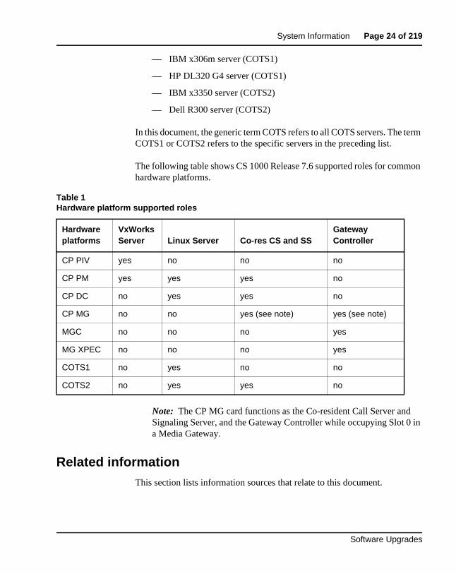
In this document, the generic term COTS refers to all COTS servers. The term COTS1 or COTS2 refers to the specific servers in the preceding list.
The following table shows CS 1000 Release 7.6 supported roles for common hardware platforms.
Note: The CP MG card functions as the Co-resident Call Server and Signaling Server, and the Gateway Controller while occupying Slot 0 in a Media Gateway.
Related informationThis section lists information sources that relate to this document.
Table 1Hardware platform supported roles
Hardware platforms
VxWorks Server Linux Server Co-res CS and SS
Gateway Controller
CP PIV yes no no no
CP PM yes yes yes no
CP DC no yes yes no
CP MG no no yes (see note) yes (see note)
MGC no no no yes
MG XPEC no no no yes
COTS1 no yes no no
COTS2 no yes yes no
Page 25 of 219 System Information
NN43041-458 Standard 06.01 March 2013
Documentation
The following documents are referenced in this document:
• Avaya Communication Server 1000E Hardware Upgrade Procedures (NN43041-464)
• Avaya Converging the Data Network with VoIP (NN43001-260)
• Avaya Signaling Server IP Line Application Fundamentals (NN43001-125)
• Avaya IP Peer Networking: Installation and Commissioning (NN43001-313)
• Avaya Branch Office: Installation and Commissioning (NN43001-314)
• Avaya Element Manager: System Administration (NN43001-632)
• Avaya IP Phones Fundamentals (NN43001-368)
• Avaya Communication Server 1000E: Overview (NN43041-110)
• Avaya Communication Server 1000E: Planning and Engineering (NN43041-220)
• Avaya Communication Server 1000E: Installation and Commissioning (NN43041-310)
• Avaya Network Routing Service Fundamentals (NN43001-130)
Online
To access Avaya documentation online, click the Documentation link under Support on the Avaya home page:
www.avaya.com
CD-ROM
To obtain Avaya documentation on CD-ROM, contact your Avaya customer representative.
Page 26 of 219
Software Upgrades
55
Overview
ContentsThis section contains information on the following topics:
Upgrade and New Install Wizards . . . . . . . . . . . . . . . . . . . . . . . . . . . . 27
Avaya Communication Server 1000 task flow . . . . . . . . . . . . . . . . . . . 28
Co-resident Call Server and Signaling Server. . . . . . . . . . . . . . . . . . . . 30
References in preparation for an upgrade . . . . . . . . . . . . . . . . . . . . . . . 30
Backwards/forwards compatibility . . . . . . . . . . . . . . . . . . . . . . . . . . . . 32
CS 1000 Release 7.6 software upgrades . . . . . . . . . . . . . . . . . . . . . . . . 31
Backwards/forwards compatibility . . . . . . . . . . . . . . . . . . . . . . . . . . . . 32
Conversion and mapping information. . . . . . . . . . . . . . . . . . . . . . . . . . 33
Campus Redundancy (High Availability) Package Support . . . . . . . . . 45
Additional factors for consideration . . . . . . . . . . . . . . . . . . . . . . . . . . . 46
Estimating installation time. . . . . . . . . . . . . . . . . . . . . . . . . . . . . . . . . . 48
Administration tools . . . . . . . . . . . . . . . . . . . . . . . . . . . . . . . . . . . . . . . 50
Upgrading the Signaling Server . . . . . . . . . . . . . . . . . . . . . . . . . . . . . . 53
Recorded Announcement and Music . . . . . . . . . . . . . . . . . . . . . . . . . . 53
H.323 Gatekeeper database migration . . . . . . . . . . . . . . . . . . . . . . . . . 53
Passwords . . . . . . . . . . . . . . . . . . . . . . . . . . . . . . . . . . . . . . . . . . . . . . . 54
Page 27 of 219 Overview
NN43041-458 Standard 06.01 March 2013
Upgrade and New Install WizardsThe Upgrade and New Install Wizards, components of the Health Check Tool, are introduced in Communication Server Release 7.6 to provide guidance through the major steps of the upgrade and new installation processes. The Health Check tool is a PC based GUI application available for download from the Avaya Support portal.
The upgrade wizard does not change the installation programs of the various system elements. It simply guides the user through each process by identifying the required tasks and recommending best practices, such as capturing critical pre-upgrade information.
The actual installation/upgrade tasks are performed manually under the direction of the appropriate Wizard.
The Wizard provides the user with an estimated completion time for each task and references to proper documentation and/or a best practices checklists.
For more information on the Upgrade and New Install Wizards, see Avaya Upgrades Guide (NN43001-408).
Overview Page 28 of 219
Software Upgrades
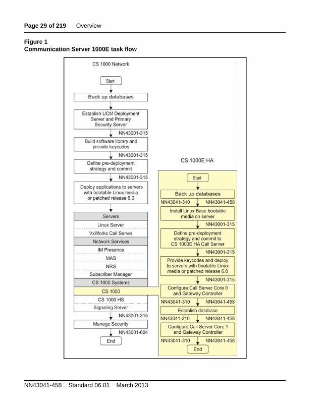
Avaya Communication Server 1000 task flowThis section provides a high-level task flow for the installation or upgrade of an Avaya Communication Server 1000 system. The task flow indicates the recommended sequence of events to follow when configuring a system and provides the document number that contains the detailed procedures required for the task.
For more information refer to the following documents, which are referenced in Figure 1 on page 29:
• Avaya Linux Platform Base and Applications Installation and Commissioning (NN43001-315)
• Avaya Communication Server 1000E: Installation and Commissioning (NN43041-310)
• Avaya Security Management (NN43001-604)
Page 29 of 219 Overview
NN43041-458 Standard 06.01 March 2013
Figure 1Communication Server 1000E task flow
Overview Page 30 of 219
Software Upgrades
Co-resident Call Server and Signaling ServerA CS 1000 system consists of two major functional components: a Call Server and a Signaling Server. These two components have historically run on separate Intel Pentium processor-based hardware platforms operating under the VxWorks Operating System.
The Co-resident Call Server and Signaling Server (Co-res CS and SS) can run the Call Server software, the Signaling Server software, and System Management software together on one hardware platform running the Linux Base Operating System. Various hardware platforms support the Co-res CS and SS configuration. For more information on supported hardware platforms, see Table 1: “Hardware platform supported roles” on page 24.
References in preparation for an upgradeTo plan the network, see Avaya Communication Server 1000E: Planning and Engineering (553-3041-120) and Converging the Data Network with VoIP (553-3001-160).
To read about installing, configuring, and managing Voice Gateway Media Cards and IP Phones, see Avaya Signaling Server IP Line Application Fundamentals (NN43001-125) and IP Phones Fundamentals (NN43001-368).
For detailed information about installing and configuring new components, see Avaya Communication Server 1000E: Installation and Configuration (553-3041-210) and Avaya Linux Platform Base and Applications Installation and Commissioning (NN43001-315).
To read about virtual trunking and the Network Routing Service (NRS), see Avaya Network Routing Service Fundamentals (NN43001-130), Avaya
Page 31 of 219 Overview
NN43041-458 Standard 06.01 March 2013
IP Peer Networking: Installation and Configuration (553-3001-213) and Avaya Communication Server 1000E: Overview (553-3041-010).
CS 1000 Release 7.6 software upgrades
This document provides information on Communication Server 1000E Release 7.6 local VxWorks software upgrades for CP PIV and CP PM based systems.
For information on local Linux Base software upgrades, or Deployment Manager upgrades, see Avaya Linux Platform Base and Applications Installation and Commissioning (NN43001-315)
For detailed information about Co-resident Call Server and Signaling Server supported upgrade paths, see “Co-resident Call Server and Signaling Server” on page 96.
If you are upgrading from a system that is not supported in CS 1000 Release 7.6, see the appropriate legacy documentation.
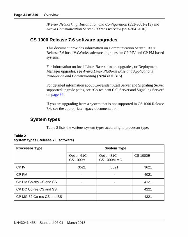
System types
Table 2 lists the various system types according to processor type.
Table 2System types (Release 7.6 software)
Processor Type System Type
Option 61C CS 1000M
Option 81CCS 1000M MG
CS 1000E
CP IV 3521 3621 3621
CP PM - - 4021
CP PM Co-res CS and SS - - 4121
CP DC Co-res CS and SS 4221
CP MG 32 Co-res CS and SS 4321
Overview Page 32 of 219
Software Upgrades
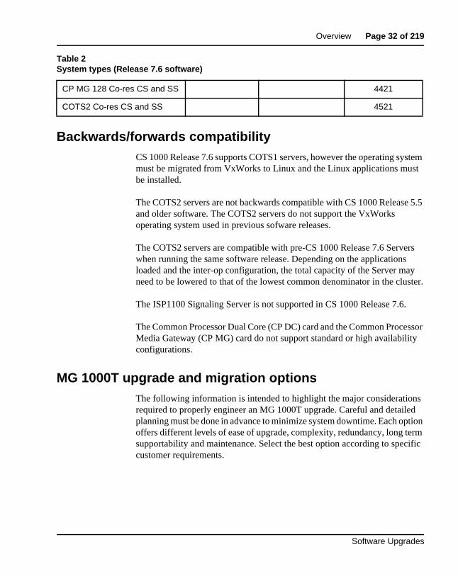
Backwards/forwards compatibilityCS 1000 Release 7.6 supports COTS1 servers, however the operating system must be migrated from VxWorks to Linux and the Linux applications must be installed.
The COTS2 servers are not backwards compatible with CS 1000 Release 5.5 and older software. The COTS2 servers do not support the VxWorks operating system used in previous sofware releases.
The COTS2 servers are compatible with pre-CS 1000 Release 7.6 Servers when running the same software release. Depending on the applications loaded and the inter-op configuration, the total capacity of the Server may need to be lowered to that of the lowest common denominator in the cluster.
The ISP1100 Signaling Server is not supported in CS 1000 Release 7.6.
The Common Processor Dual Core (CP DC) card and the Common Processor Media Gateway (CP MG) card do not support standard or high availability configurations.
MG 1000T upgrade and migration optionsThe following information is intended to highlight the major considerations required to properly engineer an MG 1000T upgrade. Careful and detailed planning must be done in advance to minimize system downtime. Each option offers different levels of ease of upgrade, complexity, redundancy, long term supportability and maintenance. Select the best option according to specific customer requirements.
CP MG 128 Co-res CS and SS 4421
COTS2 Co-res CS and SS 4521
Table 2System types (Release 7.6 software)
Page 33 of 219 Overview
NN43041-458 Standard 06.01 March 2013
Option 1
Upgrade the MG 1000T to a CS 1000E and maintain it as an autonomous node
Option 1 involves upgrading the MG 1000T to a CS 1000E, using either CP PIV or CP PM Call Servers. Each existing MG 1000T chassis requires an MGC. The current PRI and media cards in the MG 1000T are maintained. The upgraded CS 1000E can still be used as a PRI gateway and contains all of the functionality of an existing CS 1000E.
Option 2 (recommended)
Migrate the functionality and PRI hardware of the MG 1000T into the CS 1000E
This option involves migrating the MG 1000T functions into a CS 1000E system. Each existing MG 1000T chassis requires an MGC. The current PRI and media cards in the MG1000T are maintained. All MG 1000T chassis are added to the CS 1000E as new MG 1000Es, and all PRI loops and DSP resources have to be added to the CS 1000E database. The NARS/BARS database on the MG 1000T must be replicated on the CS 1000E. MG 1000T Signaling Server NRS functionality can be moved to the CS 1000E node or remain as is. The NRS dialing plan must be changed accordingly.
Note 1: An MG 1000E has specific network requirments for connecting to the Call Server in terms of round trip delay and packet loss. Please see Avaya Communication Server 1000E: Planning and Engineering (NN43041-220).
Note 2: NRS database synchronization is not supported between Signaling Servers running different releases.
Conversion and mapping informationThe following information is required for the database conversion that must be performed as part of the CS 1000 Release 7.6 software installation.
Overview Page 34 of 219
Software Upgrades
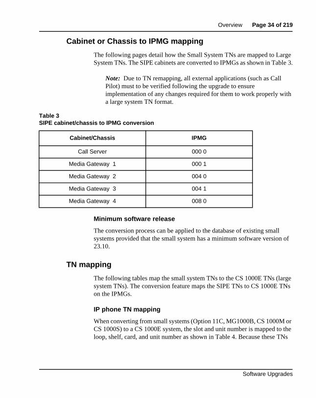
Cabinet or Chassis to IPMG mapping
The following pages detail how the Small System TNs are mapped to Large System TNs. The SIPE cabinets are converted to IPMGs as shown in Table 3.
Note: Due to TN remapping, all external applications (such as Call Pilot) must to be verified following the upgrade to ensure implementation of any changes required for them to work properly with a large system TN format.
Minimum software release
The conversion process can be applied to the database of existing small systems provided that the small system has a minimum software version of 23.10.
TN mapping
The following tables map the small system TNs to the CS 1000E TNs (large system TNs). The conversion feature maps the SIPE TNs to CS 1000E TNs on the IPMGs.
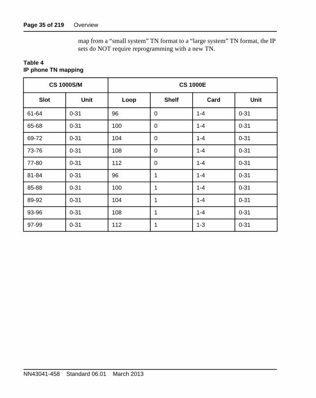
IP phone TN mapping
When converting from small systems (Option 11C, MG1000B, CS 1000M or CS 1000S) to a CS 1000E system, the slot and unit number is mapped to the loop, shelf, card, and unit number as shown in Table 4. Because these TNs
Table 3SIPE cabinet/chassis to IPMG conversion
Cabinet/Chassis IPMG
Call Server 000 0
Media Gateway 1 000 1
Media Gateway 2 004 0
Media Gateway 3 004 1
Media Gateway 4 008 0
Page 35 of 219 Overview
NN43041-458 Standard 06.01 March 2013
map from a “small system” TN format to a “large system” TN format, the IP sets do NOT require reprogramming with a new TN.
Table 4IP phone TN mapping
CS 1000S/M CS 1000E
Slot Unit Loop Shelf Card Unit
61-64 0-31 96 0 1-4 0-31
65-68 0-31 100 0 1-4 0-31
69-72 0-31 104 0 1-4 0-31
73-76 0-31 108 0 1-4 0-31
77-80 0-31 112 0 1-4 0-31
81-84 0-31 96 1 1-4 0-31
85-88 0-31 100 1 1-4 0-31
89-92 0-31 104 1 1-4 0-31
93-96 0-31 108 1 1-4 0-31
97-99 0-31 112 1 1-3 0-31
Overview Page 36 of 219
Software Upgrades
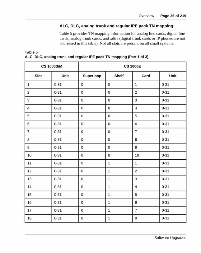
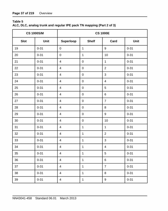
ALC, DLC, analog trunk and regular IPE pack TN mapping
Table 5 provides TN mapping information for analog line cards, digital line cards, analog trunk cards, and xdtrs (digital trunk cards or IP phones are not addressed in this table). Not all slots are present on all small systems.
Table 5ALC, DLC, analog trunk and regular IPE pack TN mapping (Part 1 of 3)
CS 1000S/M CS 1000E
Slot Unit Superloop Shelf Card Unit
1 0-31 0 0 1 0-31
2 0-31 0 0 2 0-31
3 0-31 0 0 3 0-31
4 0-31 0 0 4 0-31
5 0-31 0 0 5 0-31
6 0-31 0 0 6 0-31
7 0-31 0 0 7 0-31
8 0-31 0 0 8 0-31
9 0-31 0 0 9 0-31
10 0-31 0 0 10 0-31
11 0-31 0 1 1 0-31
12 0-31 0 1 2 0-31
13 0-31 0 1 3 0-31
14 0-31 0 1 4 0-31
15 0-31 0 1 5 0-31
16 0-31 0 1 6 0-31
17 0-31 0 1 7 0-31
18 0-31 0 1 8 0-31
Page 37 of 219 Overview
NN43041-458 Standard 06.01 March 2013
19 0-31 0 1 9 0-31
20 0-31 0 1 10 0-31
21 0-31 4 0 1 0-31
22 0-31 4 0 2 0-31
23 0-31 4 0 3 0-31
24 0-31 4 0 4 0-31
25 0-31 4 0 5 0-31
26 0-31 4 0 6 0-31
27 0-31 4 0 7 0-31
28 0-31 4 0 8 0-31
29 0-31 4 0 9 0-31
30 0-31 4 0 10 0-31
31 0-31 4 1 1 0-31
32 0-31 4 1 2 0-31
33 0-31 4 1 3 0-31
34 0-31 4 1 4 0-31
35 0-31 4 1 5 0-31
36 0-31 4 1 6 0-31
37 0-31 4 1 7 0-31
38 0-31 4 1 8 0-31
39 0-31 4 1 9 0-31
Table 5ALC, DLC, analog trunk and regular IPE pack TN mapping (Part 2 of 3)
CS 1000S/M CS 1000E
Slot Unit Superloop Shelf Card Unit
Overview Page 38 of 219
Software Upgrades
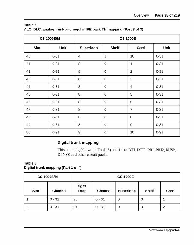
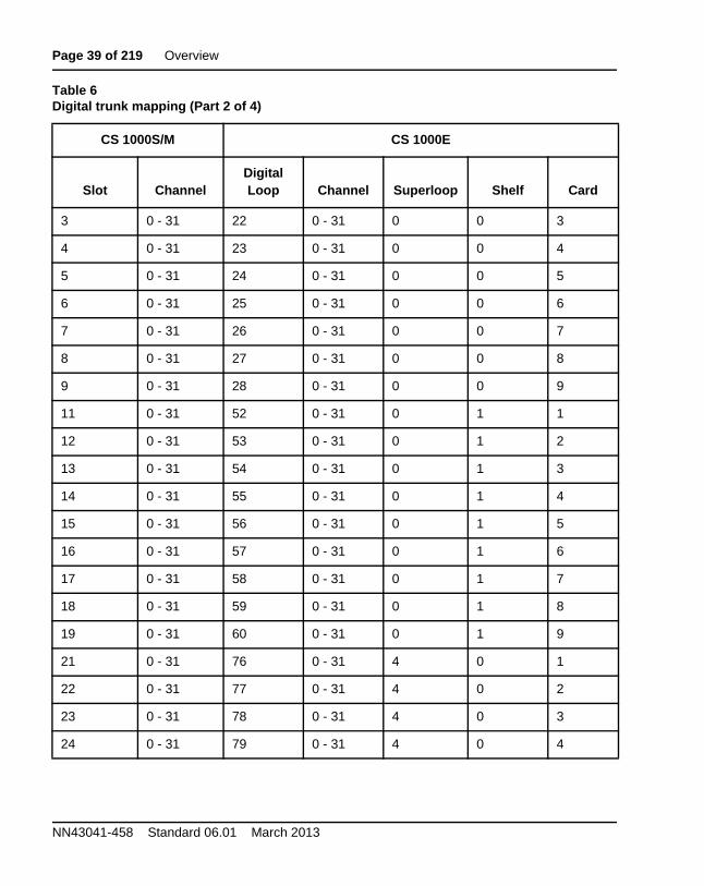
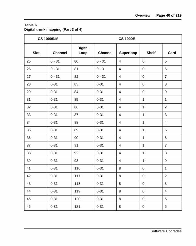
Digital trunk mapping
This mapping (shown in Table 6) applies to DTI, DTI2, PRI, PRI2, MISP, DPNSS and other circuit packs.
40 0-31 4 1 10 0-31
41 0-31 8 0 1 0-31
42 0-31 8 0 2 0-31
43 0-31 8 0 3 0-31
44 0-31 8 0 4 0-31
45 0-31 8 0 5 0-31
46 0-31 8 0 6 0-31
47 0-31 8 0 7 0-31
48 0-31 8 0 8 0-31
49 0-31 8 0 9 0-31
50 0-31 8 0 10 0-31
Table 6Digital trunk mapping (Part 1 of 4)
CS 1000S/M CS 1000E
Slot ChannelDigital Loop Channel Superloop Shelf Card
1 0 - 31 20 0 - 31 0 0 1
2 0 - 31 21 0 - 31 0 0 2
Table 5ALC, DLC, analog trunk and regular IPE pack TN mapping (Part 3 of 3)
CS 1000S/M CS 1000E
Slot Unit Superloop Shelf Card Unit
Page 39 of 219 Overview
NN43041-458 Standard 06.01 March 2013
3 0 - 31 22 0 - 31 0 0 3
4 0 - 31 23 0 - 31 0 0 4
5 0 - 31 24 0 - 31 0 0 5
6 0 - 31 25 0 - 31 0 0 6
7 0 - 31 26 0 - 31 0 0 7
8 0 - 31 27 0 - 31 0 0 8
9 0 - 31 28 0 - 31 0 0 9
11 0 - 31 52 0 - 31 0 1 1
12 0 - 31 53 0 - 31 0 1 2
13 0 - 31 54 0 - 31 0 1 3
14 0 - 31 55 0 - 31 0 1 4
15 0 - 31 56 0 - 31 0 1 5
16 0 - 31 57 0 - 31 0 1 6
17 0 - 31 58 0 - 31 0 1 7
18 0 - 31 59 0 - 31 0 1 8
19 0 - 31 60 0 - 31 0 1 9
21 0 - 31 76 0 - 31 4 0 1
22 0 - 31 77 0 - 31 4 0 2
23 0 - 31 78 0 - 31 4 0 3
24 0 - 31 79 0 - 31 4 0 4
Table 6Digital trunk mapping (Part 2 of 4)
CS 1000S/M CS 1000E
Slot ChannelDigital Loop Channel Superloop Shelf Card
Overview Page 40 of 219
Software Upgrades
25 0 - 31 80 0 - 31 4 0 5
26 0 - 31 81 0 - 31 4 0 6
27 0 - 31 82 0 - 31 4 0 7
28 0-31 83 0-31 4 0 8
29 0-31 84 0-31 4 0 9
31 0-31 85 0-31 4 1 1
32 0-31 86 0-31 4 1 2
33 0-31 87 0-31 4 1 3
34 0-31 88 0-31 4 1 4
35 0-31 89 0-31 4 1 5
36 0-31 90 0-31 4 1 6
37 0-31 91 0-31 4 1 7
38 0-31 92 0-31 4 1 8
39 0-31 93 0-31 4 1 9
41 0-31 116 0-31 8 0 1
42 0-31 117 0-31 8 0 2
43 0-31 118 0-31 8 0 3
44 0-31 119 0-31 8 0 4
45 0-31 120 0-31 8 0 5
46 0-31 121 0-31 8 0 6
Table 6Digital trunk mapping (Part 3 of 4)
CS 1000S/M CS 1000E
Slot ChannelDigital Loop Channel Superloop Shelf Card
Page 41 of 219 Overview
NN43041-458 Standard 06.01 March 2013
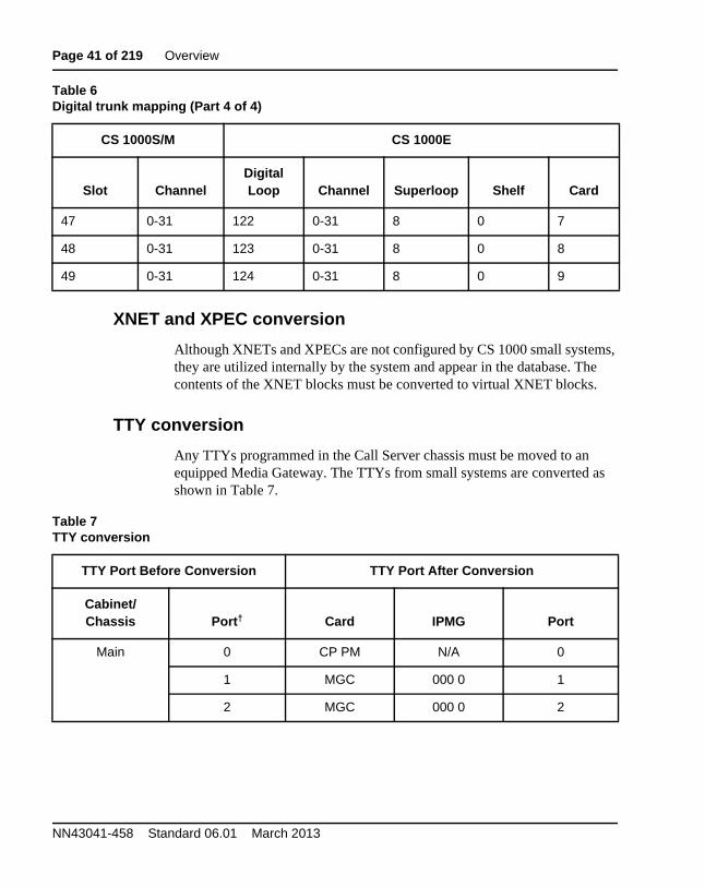
XNET and XPEC conversion
Although XNETs and XPECs are not configured by CS 1000 small systems, they are utilized internally by the system and appear in the database. The contents of the XNET blocks must be converted to virtual XNET blocks.
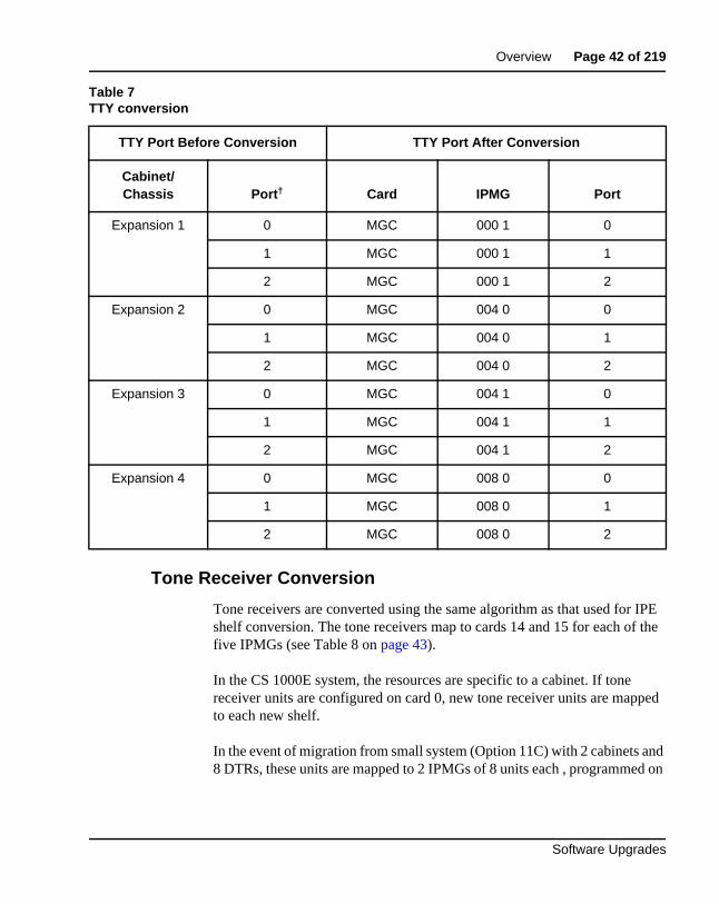
TTY conversion
Any TTYs programmed in the Call Server chassis must be moved to an equipped Media Gateway. The TTYs from small systems are converted as shown in Table 7.
47 0-31 122 0-31 8 0 7
48 0-31 123 0-31 8 0 8
49 0-31 124 0-31 8 0 9
Table 7TTY conversion
TTY Port Before Conversion TTY Port After Conversion
Cabinet/Chassis Port† Card IPMG Port
Main 0 CP PM N/A 0
1 MGC 000 0 1
2 MGC 000 0 2
Table 6Digital trunk mapping (Part 4 of 4)
CS 1000S/M CS 1000E
Slot ChannelDigital Loop Channel Superloop Shelf Card
Overview Page 42 of 219
Software Upgrades
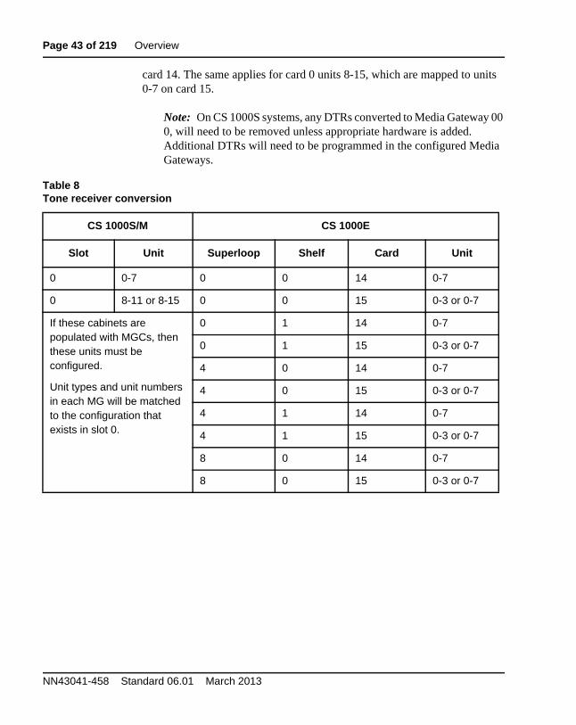
Tone Receiver Conversion
Tone receivers are converted using the same algorithm as that used for IPE shelf conversion. The tone receivers map to cards 14 and 15 for each of the five IPMGs (see Table 8 on page 43).
In the CS 1000E system, the resources are specific to a cabinet. If tone receiver units are configured on card 0, new tone receiver units are mapped to each new shelf.
In the event of migration from small system (Option 11C) with 2 cabinets and 8 DTRs, these units are mapped to 2 IPMGs of 8 units each , programmed on
Expansion 1 0 MGC 000 1 0
1 MGC 000 1 1
2 MGC 000 1 2
Expansion 2 0 MGC 004 0 0
1 MGC 004 0 1
2 MGC 004 0 2
Expansion 3 0 MGC 004 1 0
1 MGC 004 1 1
2 MGC 004 1 2
Expansion 4 0 MGC 008 0 0
1 MGC 008 0 1
2 MGC 008 0 2
Table 7TTY conversion
TTY Port Before Conversion TTY Port After Conversion
Cabinet/Chassis Port† Card IPMG Port
Page 43 of 219 Overview
NN43041-458 Standard 06.01 March 2013
card 14. The same applies for card 0 units 8-15, which are mapped to units 0-7 on card 15.
Note: On CS 1000S systems, any DTRs converted to Media Gateway 00 0, will need to be removed unless appropriate hardware is added. Additional DTRs will need to be programmed in the configured Media Gateways.
Table 8Tone receiver conversion
CS 1000S/M CS 1000E
Slot Unit Superloop Shelf Card Unit
0 0-7 0 0 14 0-7
0 8-11 or 8-15 0 0 15 0-3 or 0-7
If these cabinets are populated with MGCs, then these units must be configured.
Unit types and unit numbers in each MG will be matched to the configuration that exists in slot 0.
0 1 14 0-7
0 1 15 0-3 or 0-7
4 0 14 0-7
4 0 15 0-3 or 0-7
4 1 14 0-7
4 1 15 0-3 or 0-7
8 0 14 0-7
8 0 15 0-3 or 0-7
Overview Page 44 of 219
Software Upgrades
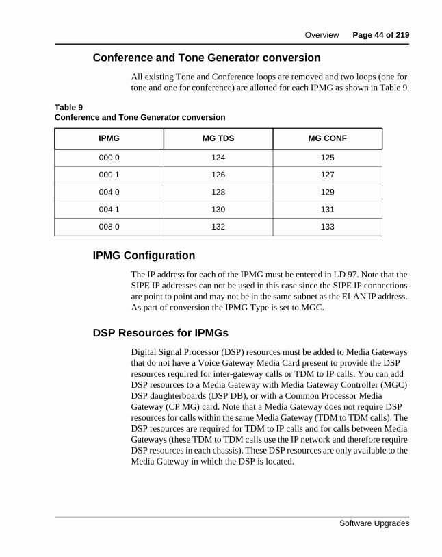
Conference and Tone Generator conversion
All existing Tone and Conference loops are removed and two loops (one for tone and one for conference) are allotted for each IPMG as shown in Table 9.
IPMG Configuration
The IP address for each of the IPMG must be entered in LD 97. Note that the SIPE IP addresses can not be used in this case since the SIPE IP connections are point to point and may not be in the same subnet as the ELAN IP address. As part of conversion the IPMG Type is set to MGC.
DSP Resources for IPMGs
Digital Signal Processor (DSP) resources must be added to Media Gateways that do not have a Voice Gateway Media Card present to provide the DSP resources required for inter-gateway calls or TDM to IP calls. You can add DSP resources to a Media Gateway with Media Gateway Controller (MGC) DSP daughterboards (DSP DB), or with a Common Processor Media Gateway (CP MG) card. Note that a Media Gateway does not require DSP resources for calls within the same Media Gateway (TDM to TDM calls). The DSP resources are required for TDM to IP calls and for calls between Media Gateways (these TDM to TDM calls use the IP network and therefore require DSP resources in each chassis). These DSP resources are only available to the Media Gateway in which the DSP is located.
Table 9Conference and Tone Generator conversion
IPMG MG TDS MG CONF
000 0 124 125
000 1 126 127
004 0 128 129
004 1 130 131
008 0 132 133
Page 45 of 219 Overview
NN43041-458 Standard 06.01 March 2013
Once conversion is complete, the DSP resources that were previously configured are now available to the gateway where the DSP resources are located. DSP resources are required in all gateways in order to support inter-gateway calls and TDM to IP calls. The configuration required for the new DSP resources must be performed manually, as it is not part of the conversion process.
Deleted information
The following information is removed during the conversion process:
• SIPE IP addresses (deleted from the database)
• TDS and Conference configuration
• Redundant serial port information
• Meridian Mail LSL, AML and other TNs.
Note: ACD queues are not deleted. They must be manually deleted following the conversion process.
Note: Although the above items are removed during the conversion process, the data in the compact flash remains intact with the small system database.
Campus Redundancy (High Availability) Package SupportFor systems that require HA configuration, the VxWorks-based Call Server software must be deployed.
In CS 1000 Release 7.6, the Co-res CS and SS does not support an HA configuration (dual core with either Active or Inactive role). For more information see Avaya Co-resident Call Server and Signaling Server Fundamentals (NN43001-509).
Overview Page 46 of 219
Software Upgrades
Additional factors for consideration
SSC Security Device (dongle) considerations
When upgrading an existing system to Release 7.6 with a CP PM Call Server, the following actions are required:
• For SSC system conversions to CS 1000E, you must destroy or return the SSC security device to your local Avaya Repair/Returns center
• The CP PM Security Device provided with the software kit must be placed on the CP PM Call Server
NARS/BARS/Trunking Considerations
Impacts on customer trunking must be evaluated when designing and planning an upgrade. The MG 1000T is a tandem endpoint that may provide PRI PSTN access to a standalone CS 1000E and satellite locations. Each upgrade option impacts customer trunking in the following ways:
• Option 1 - Trunking is out of service for the time it takes to upgrade and transition the Call Server, Media Gateways and Signaling Server to a CS 1000E
IMPORTANT!
Continued use of decommissioned software is in violation of the Avaya Software Licensing Agreement and is not allowed. No further orders will be accepted for the serial number since it is decommissioned and tracked in Avaya’s database. The Avaya Software Licensing Agreement details can be found in the Policy and Procedures section of the Enterprise Voice product catalogue.
Page 47 of 219 Overview
NN43041-458 Standard 06.01 March 2013
• Option 2 - Trunking must be transitioned (both hardware and software) to the CS 1000E. A high level of ESN and PRI programming knowledge is required to move the trunking functions from the MG 1000T to the CS 1000E during both the planning and implementation phases of the upgrade. Typically the bulk of ESN programming is done on the MG 1000T and SPN's are used to steer PSTN calls between nodes. The NRS dialing plan entries also must be changed during the upgrade to move existing numbers associated with the MG 1000T endpoint to the CS 1000E endpoint. Special care must be taken to ensure 911 service functions as expected post-upgrade. The out of service time for the trunks vary site to site. Inbound DID/COT/TIE trunk routes could be split and cut over to the CS 1000E in a phased approach. Outbound DOD/COT/TIE trunks could be split and cutover using temporary RLIs to steer NPA, NXX and SPN calls (including 911). Tie routes that are H323/SIP can be redirected in the NRS assuming the ISM parameters have been moved to the CS 1000E and the ESN programming is in place.
Media Gateway considerations
For Options 1 and 2, each existing Media Gateway chassis in the MG 1000T must be upgraded to a MG 1000E or MG 1010. The new Media Gateway must be reprogrammed and joined to the corresponding CS 1000E node. Ethernet connections and IP configurations must be identified prior to conversion.
NRS considerations
If the Primary NRS resides within the original MG 1000T node, the NRS functionality can be moved to the CS 1000E or maintained as a standalone NRS.
NRS Servers must be upgraded to CS 1000 Release 7.6 prior to upgrading the first CS 1000 system to CS 1000 Release 7.6. The NRS must operate on the same software release as the system with the highest software release on the network.
Overview Page 48 of 219
Software Upgrades
Signaling Server considerations
If the MG 1000T is upgraded to a CS 1000E, the Signaling Servers can continue to function and are supported. If the MG 1000T is migrated to the CS 1000E the Signaling Servers can be re-deployed or used as spares.
ISP1100
ISP1100 Signaling Servers are not supported in CS 1000 Release 7.6 and must be replaced with a supported hardware platform.
CP PM BIOS requirements
The CP PM version 1 card requires BIOS Release 18 or later to be supported as a Signaling Server. The CP PM version 2 card (NTDW66CAE5/E6, NTDW99CAE5/E6) does not require a BIOS update. To upgrade the CP PM version 1 BIOS, see Avaya Communication Server 1000E Hardware Upgrade Procedures (NN43041-464).
ELAN, TLAN and IP considerations
If upgrading Media Gateways, the ELAN IP, TLAN IP addresses and switch ports can be re-used.
If you are replacing an SSC with a Gateway Controller, you require TLAN IP addresses and Layer 2 switch ports. If introducing a Co-res CS and SS you will need ELAN and TLAN IP addresses and Layer 2 switch ports. For more information, see Avaya Communication Server 1000E: Installation and Commissioning (NN43041-310).
Estimating installation timeThere are periods of service outages during the upgrade. The service outages are dependent on the configuration of the system being upgraded. (SA, HA, Signaling Server and NRS Server redundancy.)
Page 49 of 219 Overview
NN43041-458 Standard 06.01 March 2013
When all equipment and software is available, Avaya recommends planning a two to four hour period in which to perform the upgrade. Service interruptions can occur during this period.
Installation of Unified Communications Manager (UCM) - no service impact.
Upgrade of NRS/GateKeeper - no service impact if there is an NRS Alternate/backup server running in the network.
Upgrade of the Call Server and SSC to MGC cards - there is a service outage of approximately one to two hours dependent on the number of IPMGs and MGs that need to be upgraded.
Note: If converting MG1000T Media Gateways to MG1000E off the upgraded main, there will be additional down time required to reprogram the trunk facilities and routing tables which is not covered in this document.
Upgrade of the Leader Signaling Server - there is a service outage of approximately one hour while configuring and upgrading system Media Cards.
Upgrade of Alternate NRS - no service impact.
Upgrade of Follower Signaling Server - there is a service impact of ten to fifteen minutes to restart all Signaling Servers after Followers have been configured and synchronized.
System expansions and additional installations require additional time. See Avaya Communication Server 1000E: Installation and Configuration (553-3041-210) for details.
Making IP Peer Networking modifications also requires additional time beyond that of an upgrade. It can be performed after completing a standalone configuration upgrade. IP Peer Networking changes can involve interruption of call processing. See Avaya IP Peer Networking: Installation and Configuration (553-3001-213) for details.
Overview Page 50 of 219
Software Upgrades
Upgrade and installation times depend on the following criteria:
• number and availability of technicians
• familiarity with CS 1000E
• physical location of hardware components
• interoperability products (Messaging Server 500, Symposium,)
• unit testing and system testing
• unforeseen issues
Administration tools
Avaya Unified Communications Management (UCM)
The Avaya Unified Communications Management (UCM) solution provides you with an intuitive, common interface to manage and run managed elements. UCM is a container that stores several system management elements in a single repository. You have access to all network system management elements under the Unified Communications Management solution. You need to sign in only once to access the elements. A single sign-in eliminates the need for you to reauthenticate when a system management application starts.
UCM Security Services simplifies security control for managed elements and system management applications. UCM Security services manages secure access to Web applications and provides authentication andauthorization with a single unified Common Service. UCM secures the delivery of essential identity and application information.
With UCM Common Services, administrators can control which users have access to specific managed elements. They can assign users to roles and map the permissions to those roles to control which operations a user can perform on an assigned managed element. Users can access only assigned elements and perform only the tasks specific to their assigned role and permissions for an element.
With UCM Common Services, the integration of managed elements within a single container provides users with centralized security, user access control,
Page 51 of 219 Overview
NN43041-458 Standard 06.01 March 2013
simplified management tasks, improved workflow efficiency, convenience, and time-saving advantages.
System data backup including application data
UCM can be used to back up and restore application data for Linux Base and applications. The type of data backed up is dependant on the applications running on the host server. For detailed information, see Avaya Linux Platform Base and Applications Installation and Commissioning (NN43001-315).
For detailed UCM information see Avaya Unified Communications Management Common Services Fundamentals (NN43001-116).
Element Manager
Element Manager (EM) is no longer present on a Signaling Server by default. It is no longer bundled in the Signaling Server application. You must manually select this option from UCM to deploy the EM application. Before installing or upgrading your system you must determine which Signaling Server will have Element Manager deployed.
Note: For each Call Server there must be at least 1 Signaling Server deployed with Element Manager.
Element Manager increases the speed and efficiency of system management by organizing parameters in logical groups, where single web pages provide access to information that was traditionally spread across multiple overlays. The ability of Element Manager to “hide or show information” helps the user focus on specific information, avoiding the distraction of multiple parameters.
Element Manager reduces configuration errors by providing a full text description of each parameter and acronym. It also reduces errors by simplifying parameter value selection through the use of pre-selected default values and drop-down lists.
Overview Page 52 of 219
Software Upgrades
The following management tasks can be performed using Element Manager:
• System StatusEnables users to perform maintenance actions on Call Server components (D-channel, MSDL, TMDI, Digital Trunk, Clock Controller, Network and Peripheral, Trunk diagnostic) and IP Telephony.
• ConfigurationEnables users to configure customer data, trunks and routes (traditionally done in LD 14, 15, and 16), D-channel and Common Equipment data (LD 17), digital trunk interface (LD 73), Flexible Code Restriction and Incoming Digit conversion (LD 49), and the IP telephony node.
• Network Numbering PlanEnables users to configure the Network Routing Service, and ESN data blocks for the Call Server (LD 86).
• Software UpgradeEnables users to obtain Call Server software version, License parameters, and packages list. Users can also upgrade Voice Gateway Media Card loadware and IP Phone firmware.
• PatchingThe existing Call Server and Voice Gateway Media Card patching still function within Element Manager, however the UCM Patching Manager provides centralized patch management to upload, install and maintain patches
• System UtilitiesEnables users to backup and restore databases, set time and date, and upload software files and patches to a directory on the Signaling Server.
Configuration procedures for these tasks are in Avaya Communication Server 1000E: Installation and Configuration (553-3041-210), and Avaya System Management (553-3001-300).
For upgrade and configuration procedures that use Element Manager, see “Upgrading Voice Gateway Media Cards” on page 166.
Page 53 of 219 Overview
NN43041-458 Standard 06.01 March 2013
Network Time Protocol (NTP)
Network Time Protocol (NTP) is a feature used to synchronize local clocks across the network to a single, accurate, third-party Network Time Protocol server (typically a radio clock, atomic clock, or other Coordinated Universal Time (UTC) source).
For information on NTP configuration see Avaya Linux Platform Base and Applications Installation and Commissioning (NN43001-315).
Simple Network Management Protocol (SNMP)
For information on the configuration of SNMP on Linux base see Avaya Communication Server 1000 Fault Management — SNMP (NN43001-719). For information on Enterprise Common Manager (ECM) and SNMP on Linux base see Avaya Unified Communications Management Common Services Fundamentals (NN43001-116).
Upgrading the Signaling ServerTo upgrade the Signaling Server to Communication Server 1000 Release 7.6, see “Upgrading the Signaling Server” on page 184.
Recorded Announcement and Music
H.323 Gatekeeper database migrationTo migrate an H.323 Gatekeeper database to a Communication Server 1000 (CS 1000) Release 7.6 Network Routing Service (NRS) database, see Avaya Signaling Server IP Line Application Fundamentals (NN43001-125).
IMPORTANT!
Currently, the CS 1000E only supports Recorded Announcement Broadcast and Music Broadcast.
Overview Page 54 of 219
Software Upgrades
PasswordsTwo login passwords are key to the upgrade process:
1 PWD1
2 Limited Access Password (LAPW)
You must configure the UCM security server to have the same usernames and passwords before you join the security domain. These passwords are only valid until you join the security domain in UCM.
PWD1
PWD1 is the central login defined at the Call Server. If the system is fully functional (that is, the connection is active) between the Call Server, Signaling Server, MG 1000E Expansions, and Voice Gateway Media Cards, the PWD1 login grants access to all Command Line Interfaces (CLIs) and Element Manager. If the link is not active, the specific login configured for each component must be used.
LAPW
Limited Access Password (LAPW) login can be configured on the Call Server to provide limited access to specified overlays. LAPWs can be used to log into the Call Server or to Element Manager. For more information, see Avaya System Management (553-3001-300).

Page 55 of 219 Overview
NN43041-458 Standard 06.01 March 2013
Page 56 of 219
Software Upgrades
73
First steps
ContentsThis section contains information on the following topics:
Things to know . . . . . . . . . . . . . . . . . . . . . . . . . . . . . . . . . . . . . . . . . . . 57Avaya Communication Server 1000 Release 7.6 product compatibility 57Software requirements . . . . . . . . . . . . . . . . . . . . . . . . . . . . . . . . . . . 64Keycodes . . . . . . . . . . . . . . . . . . . . . . . . . . . . . . . . . . . . . . . . . . . . . 64
What to have ready . . . . . . . . . . . . . . . . . . . . . . . . . . . . . . . . . . . . . . . . 65Data checklist . . . . . . . . . . . . . . . . . . . . . . . . . . . . . . . . . . . . . . . . . . 65Customer information questionnaire . . . . . . . . . . . . . . . . . . . . . . . . 66Readiness checklist. . . . . . . . . . . . . . . . . . . . . . . . . . . . . . . . . . . . . . 68
First steps. . . . . . . . . . . . . . . . . . . . . . . . . . . . . . . . . . . . . . . . . . . . . . . . 70
Page 57 of 219 First steps
NN43041-458 Standard 06.01 March 2013
Things to know
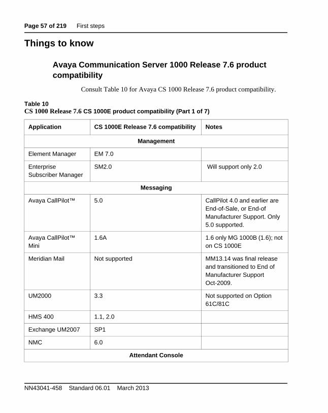
Avaya Communication Server 1000 Release 7.6 product compatibility
Consult Table 10 for Avaya CS 1000 Release 7.6 product compatibility.
Table 10CS 1000 Release 7.6 CS 1000E product compatibility (Part 1 of 7)
Application CS 1000E Release 7.6 compatibility Notes
Management
Element Manager EM 7.0
Enterprise Subscriber Manager
SM2.0 Will support only 2.0
Messaging
Avaya CallPilot™ 5.0 CallPilot 4.0 and earlier are End-of-Sale, or End-of Manufacturer Support. Only 5.0 supported.
Avaya CallPilot™ Mini
1.6A 1.6 only MG 1000B (1.6); not on CS 1000E
Meridian Mail Not supported MM13.14 was final release and transitioned to End of Manufacturer Support Oct-2009.
UM2000 3.3 Not supported on Option 61C/81C
HMS 400 1.1, 2.0
Exchange UM2007 SP1
NMC 6.0
Attendant Console
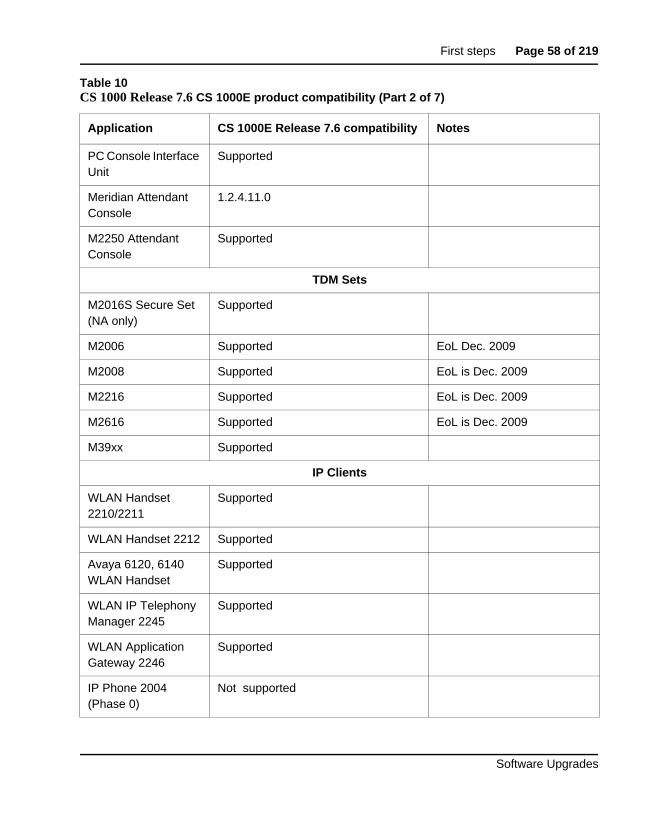
First steps Page 58 of 219
Software Upgrades
PC Console Interface Unit
Supported
Meridian Attendant Console
1.2.4.11.0
M2250 Attendant Console
Supported
TDM Sets
M2016S Secure Set (NA only)
Supported
M2006 Supported EoL Dec. 2009
M2008 Supported EoL is Dec. 2009
M2216 Supported EoL is Dec. 2009
M2616 Supported EoL is Dec. 2009
M39xx Supported
IP Clients
WLAN Handset 2210/2211
Supported
WLAN Handset 2212 Supported
Avaya 6120, 6140 WLAN Handset
Supported
WLAN IP Telephony Manager 2245
Supported
WLAN Application Gateway 2246
Supported
IP Phone 2004 (Phase 0)
Not supported
Table 10CS 1000 Release 7.6 CS 1000E product compatibility (Part 2 of 7)
Application CS 1000E Release 7.6 compatibility Notes
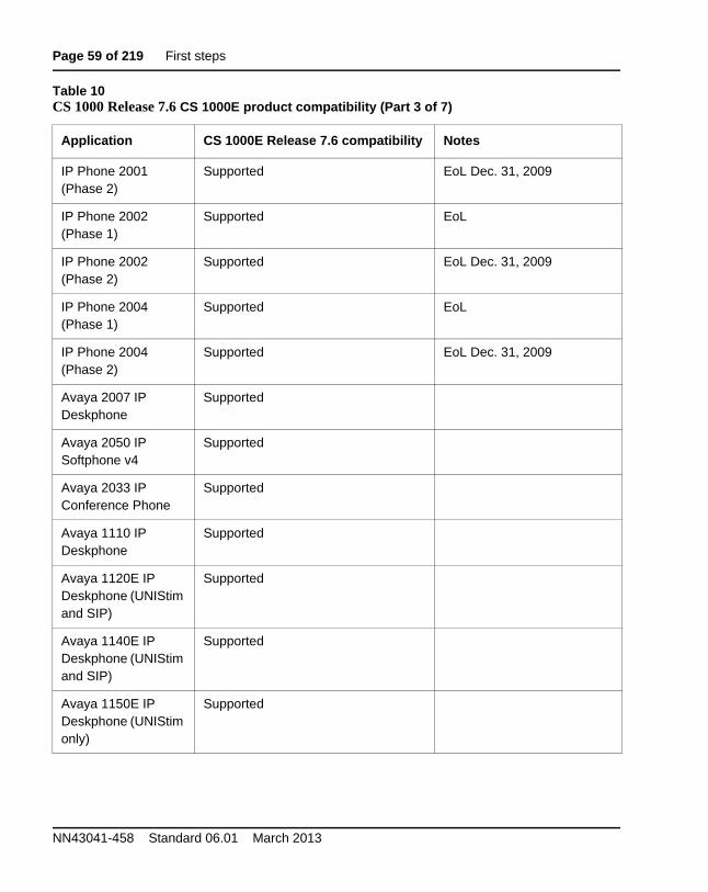
Page 59 of 219 First steps
NN43041-458 Standard 06.01 March 2013
IP Phone 2001 (Phase 2)
Supported EoL Dec. 31, 2009
IP Phone 2002 (Phase 1)
Supported EoL
IP Phone 2002 (Phase 2)
Supported EoL Dec. 31, 2009
IP Phone 2004 (Phase 1)
Supported EoL
IP Phone 2004 (Phase 2)
Supported EoL Dec. 31, 2009
Avaya 2007 IP Deskphone
Supported
Avaya 2050 IP Softphone v4
Supported
Avaya 2033 IP Conference Phone
Supported
Avaya 1110 IP Deskphone
Supported
Avaya 1120E IP Deskphone (UNIStim and SIP)
Supported
Avaya 1140E IP Deskphone (UNIStim and SIP)
Supported
Avaya 1150E IP Deskphone (UNIStim only)
Supported
Table 10CS 1000 Release 7.6 CS 1000E product compatibility (Part 3 of 7)
Application CS 1000E Release 7.6 compatibility Notes
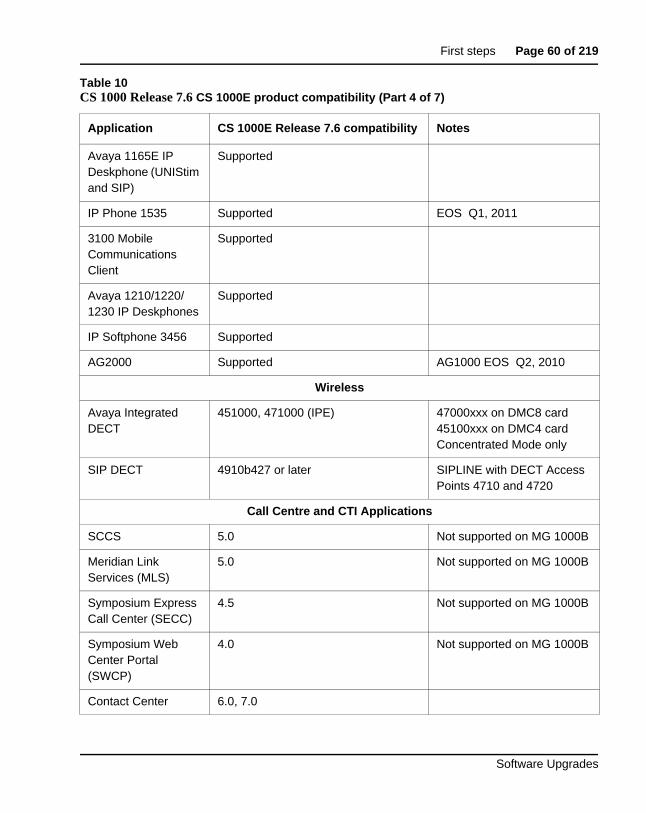
First steps Page 60 of 219
Software Upgrades
Avaya 1165E IP Deskphone (UNIStim and SIP)
Supported
IP Phone 1535 Supported EOS Q1, 2011
3100 Mobile Communications Client
Supported
Avaya 1210/1220/1230 IP Deskphones
Supported
IP Softphone 3456 Supported
AG2000 Supported AG1000 EOS Q2, 2010
Wireless
Avaya Integrated DECT
451000, 471000 (IPE) 47000xxx on DMC8 card 45100xxx on DMC4 card Concentrated Mode only
SIP DECT 4910b427 or later SIPLINE with DECT Access Points 4710 and 4720
Call Centre and CTI Applications
SCCS 5.0 Not supported on MG 1000B
Meridian Link Services (MLS)
5.0 Not supported on MG 1000B
Symposium Express Call Center (SECC)
4.5 Not supported on MG 1000B
Symposium Web Center Portal (SWCP)
4.0 Not supported on MG 1000B
Contact Center 6.0, 7.0
Table 10CS 1000 Release 7.6 CS 1000E product compatibility (Part 4 of 7)
Application CS 1000E Release 7.6 compatibility Notes
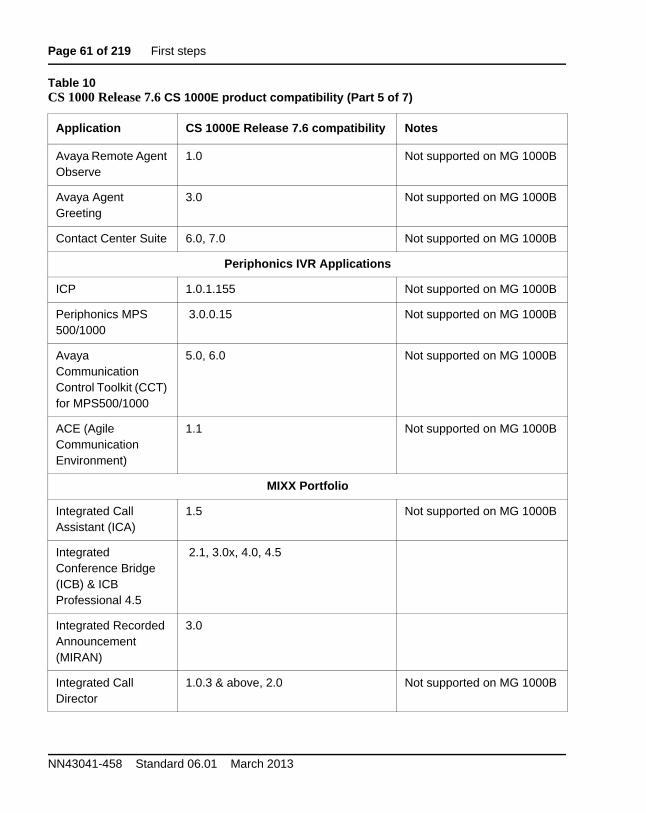
Page 61 of 219 First steps
NN43041-458 Standard 06.01 March 2013
Avaya Remote Agent Observe
1.0 Not supported on MG 1000B
Avaya Agent Greeting
3.0 Not supported on MG 1000B
Contact Center Suite 6.0, 7.0 Not supported on MG 1000B
Periphonics IVR Applications
ICP 1.0.1.155 Not supported on MG 1000B
Periphonics MPS 500/1000
3.0.0.15 Not supported on MG 1000B
Avaya Communication Control Toolkit (CCT) for MPS500/1000
5.0, 6.0 Not supported on MG 1000B
ACE (Agile Communication Environment)
1.1 Not supported on MG 1000B
MIXX Portfolio
Integrated Call Assistant (ICA)
1.5 Not supported on MG 1000B
Integrated Conference Bridge (ICB) & ICB Professional 4.5
2.1, 3.0x, 4.0, 4.5
Integrated Recorded Announcement (MIRAN)
3.0
Integrated Call Director
1.0.3 & above, 2.0 Not supported on MG 1000B
Table 10CS 1000 Release 7.6 CS 1000E product compatibility (Part 5 of 7)
Application CS 1000E Release 7.6 compatibility Notes
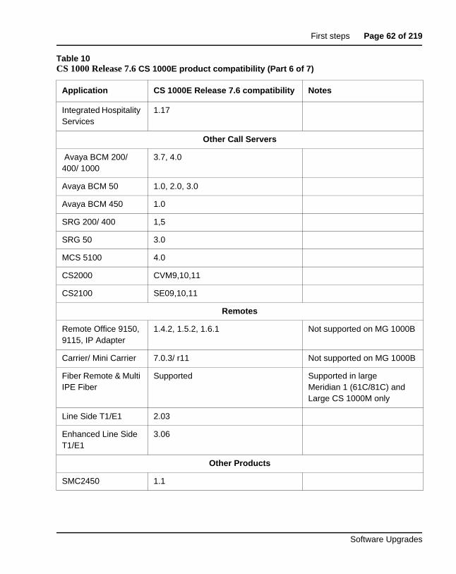
First steps Page 62 of 219
Software Upgrades
Integrated Hospitality Services
1.17
Other Call Servers
Avaya BCM 200/ 400/ 1000
3.7, 4.0
Avaya BCM 50 1.0, 2.0, 3.0
Avaya BCM 450 1.0
SRG 200/ 400 1,5
SRG 50 3.0
MCS 5100 4.0
CS2000 CVM9,10,11
CS2100 SE09,10,11
Remotes
Remote Office 9150, 9115, IP Adapter
1.4.2, 1.5.2, 1.6.1 Not supported on MG 1000B
Carrier/ Mini Carrier 7.0.3/ r11 Not supported on MG 1000B
Fiber Remote & Multi IPE Fiber
Supported Supported in large Meridian 1 (61C/81C) and Large CS 1000M only
Line Side T1/E1 2.03
Enhanced Line Side T1/E1
3.06
Other Products
SMC2450 1.1
Table 10CS 1000 Release 7.6 CS 1000E product compatibility (Part 6 of 7)
Application CS 1000E Release 7.6 compatibility Notes
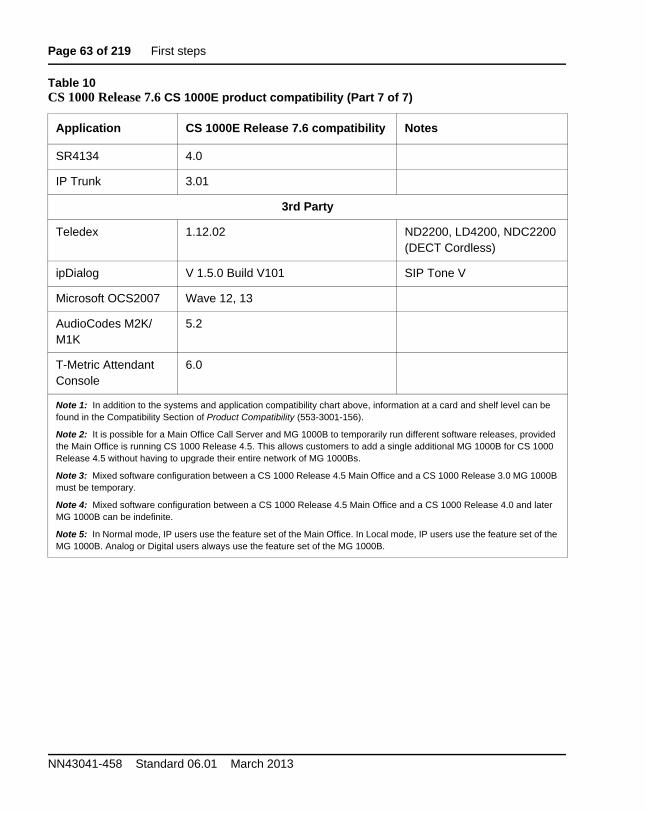
Page 63 of 219 First steps
NN43041-458 Standard 06.01 March 2013
SR4134 4.0
IP Trunk 3.01
3rd Party
Teledex 1.12.02 ND2200, LD4200, NDC2200 (DECT Cordless)
ipDialog V 1.5.0 Build V101 SIP Tone V
Microsoft OCS2007 Wave 12, 13
AudioCodes M2K/M1K
5.2
T-Metric Attendant Console
6.0
Note 1: In addition to the systems and application compatibility chart above, information at a card and shelf level can be found in the Compatibility Section of Product Compatibility (553-3001-156).
Note 2: It is possible for a Main Office Call Server and MG 1000B to temporarily run different software releases, provided the Main Office is running CS 1000 Release 4.5. This allows customers to add a single additional MG 1000B for CS 1000 Release 4.5 without having to upgrade their entire network of MG 1000Bs.
Note 3: Mixed software configuration between a CS 1000 Release 4.5 Main Office and a CS 1000 Release 3.0 MG 1000B must be temporary.
Note 4: Mixed software configuration between a CS 1000 Release 4.5 Main Office and a CS 1000 Release 4.0 and later MG 1000B can be indefinite.
Note 5: In Normal mode, IP users use the feature set of the Main Office. In Local mode, IP users use the feature set of the MG 1000B. Analog or Digital users always use the feature set of the MG 1000B.
Table 10CS 1000 Release 7.6 CS 1000E product compatibility (Part 7 of 7)
Application CS 1000E Release 7.6 compatibility Notes
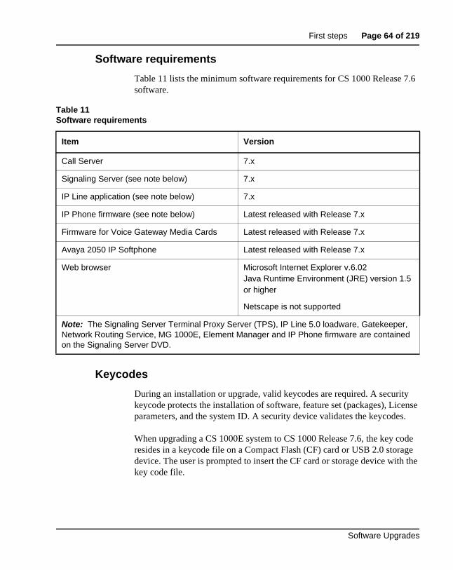
First steps Page 64 of 219
Software Upgrades
Software requirements
Table 11 lists the minimum software requirements for CS 1000 Release 7.6 software.
Keycodes
During an installation or upgrade, valid keycodes are required. A security keycode protects the installation of software, feature set (packages), License parameters, and the system ID. A security device validates the keycodes.
When upgrading a CS 1000E system to CS 1000 Release 7.6, the key code resides in a keycode file on a Compact Flash (CF) card or USB 2.0 storage device. The user is prompted to insert the CF card or storage device with the key code file.
Table 11Software requirements
Item Version
Call Server 7.x
Signaling Server (see note below) 7.x
IP Line application (see note below) 7.x
IP Phone firmware (see note below) Latest released with Release 7.x
Firmware for Voice Gateway Media Cards Latest released with Release 7.x
Avaya 2050 IP Softphone Latest released with Release 7.x
Web browser Microsoft Internet Explorer v.6.02Java Runtime Environment (JRE) version 1.5 or higher
Netscape is not supported
Note: The Signaling Server Terminal Proxy Server (TPS), IP Line 5.0 loadware, Gatekeeper, Network Routing Service, MG 1000E, Element Manager and IP Phone firmware are contained on the Signaling Server DVD.
Page 65 of 219 First steps
NN43041-458 Standard 06.01 March 2013
If the entered keycode does not validate, take one of the following actions:
• Check the keycodes and make sure the correct keycodes have been entered.
• Check the software and make sure that it is the correct version for this site.
• Check the feature set and make sure the correct data has been entered.
• Check the License parameters and make sure the correct data has been entered.
• End the installation and contact your Avaya service team.
The system limits the validation of keycodes to three consecutive attempts. After the third unsuccessful attempt, the Software Installation Program returns to the main menu. Any data entered during the session is lost.
Note: If an invalid keycode is entered, the software and databases on the present system are not affected.
When the keycode validation passes, the software is installed on the system.
What to have readyThis section contains the following topics:
• “Data checklist” on page 65
• “Customer information questionnaire” on page 66
• “Readiness checklist” on page 68
Data checklist
Data network planning is crucial to obtain good voice quality. For important information regarding the data and IP telephony network configuration needs, consult Avaya Converging the Data Network with VoIP (553-3001-160) and Avaya IP Peer Networking: Installation and Configuration (553-3001-213).
First steps Page 66 of 219
Software Upgrades
The following data is required:
• IP addresses for system components. Refer to Avaya Communication Server 1000E: Installation and Configuration (553-3041-210) for more information.
• IP addresses for the IP Phones. DHCP can be used to distribute IP addresses and network information to the IP Phones. Refer to Avaya Signaling Server IP Line Application Fundamentals (NN43001-125) for more detail.
• Trunk, routing, and network zone data (numbering plan, standard and IP trunks, Network Routing Service data).Refer to Avaya IP Peer Networking: Installation and Configuration (553-3001-213) for more detail.
• System, telephony and voice data (customer configuration, virtual loop and TN assignments, feature data).
Note 1: If there are BRI in the system, ensure that the MISP and SILC/UILC are located in the same cabinet or chassis prior to the small system to large system upgrade. The only supported configuration requires that the MISP and SILC/UILC are provisioned in the same IPMG following the upgrade.
Note 2: If there are MFC cards in the system, it is recommended that the MFC card reside in the same cabinet or chassis as the TDM trunk card.
Customer information questionnaire
Commissioning of a CS 1000E relies on customer specific settings dependent on the network and options deployed. A completed Customer Information Questionnaire is required to configure and engineer a system. The Customer Information Questionnaire data is expanded to create the Site Specific Specification Work Book with detailed entries to configure and deploy the CS 1000E system. In the Customer Information Questionnaire, cover the types of data outlined in Table 12: “Information Collected in the Customer Information Questionnaire” on page 67.
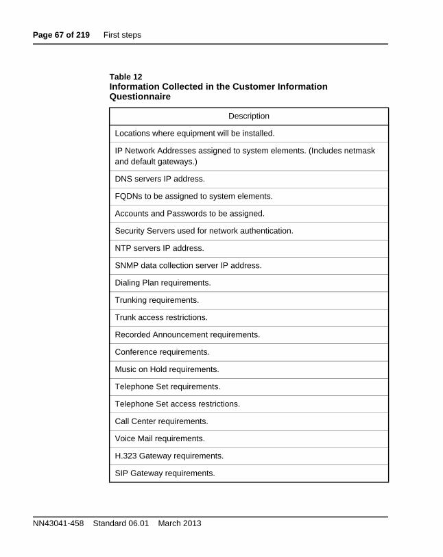
Page 67 of 219 First steps
NN43041-458 Standard 06.01 March 2013
Table 12Information Collected in the Customer Information Questionnaire
Description
Locations where equipment will be installed.
IP Network Addresses assigned to system elements. (Includes netmask and default gateways.)
DNS servers IP address.
FQDNs to be assigned to system elements.
Accounts and Passwords to be assigned.
Security Servers used for network authentication.
NTP servers IP address.
SNMP data collection server IP address.
Dialing Plan requirements.
Trunking requirements.
Trunk access restrictions.
Recorded Announcement requirements.
Conference requirements.
Music on Hold requirements.
Telephone Set requirements.
Telephone Set access restrictions.
Call Center requirements.
Voice Mail requirements.
H.323 Gateway requirements.
SIP Gateway requirements.
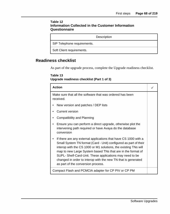
First steps Page 68 of 219
Software Upgrades
Readiness checklist
As part of the upgrade process, complete the Upgrade readiness checklist.
SIP Telephone requirements.
Soft Client requirements.
Table 13Upgrade readiness checklist (Part 1 of 3)
Action
Make sure that all the software that was ordered has been received.
• New version and patches / DEP lists
• Current version
• Compatibility and Planning
• Ensure you can perform a direct upgrade, otherwise plot the intervening path required or have Avaya do the database conversion
• If there are any external applications that have CS 1000 with a Small System TN format (Card - Unit) configured as part of their interop with the CS 1000 or M1 solutions, the existing TNs will map to new Large System based TNs that are in the format of SUPL- Shelf-Card-Unit. These applications may need to be changed in order to interop with the new TN that is generated as part of the conversion process.
Compact Flash and PCMCIA adapter for CP PIV or CP PM
Table 12Information Collected in the Customer Information Questionnaire
Description
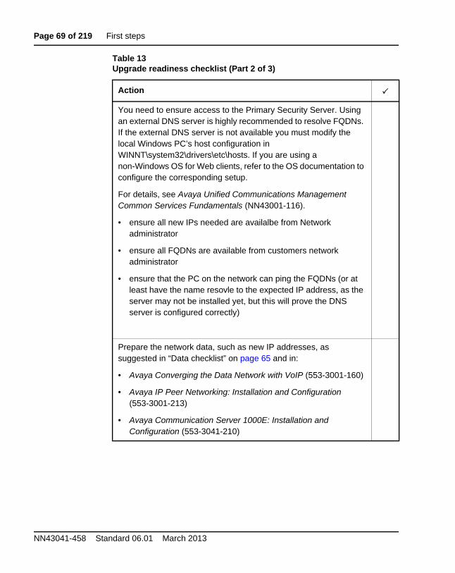
Page 69 of 219 First steps
NN43041-458 Standard 06.01 March 2013
You need to ensure access to the Primary Security Server. Using an external DNS server is highly recommended to resolve FQDNs. If the external DNS server is not available you must modify the local Windows PC’s host configuration in WINNT\system32\drivers\etc\hosts. If you are using a non-Windows OS for Web clients, refer to the OS documentation to configure the corresponding setup.
For details, see Avaya Unified Communications Management Common Services Fundamentals (NN43001-116).
• ensure all new IPs needed are availalbe from Network administrator
• ensure all FQDNs are available from customers network administrator
• ensure that the PC on the network can ping the FQDNs (or at least have the name resovle to the expected IP address, as the server may not be installed yet, but this will prove the DNS server is configured correctly)
Prepare the network data, such as new IP addresses, as suggested in “Data checklist” on page 65 and in:
• Avaya Converging the Data Network with VoIP (553-3001-160)
• Avaya IP Peer Networking: Installation and Configuration (553-3001-213)
• Avaya Communication Server 1000E: Installation and Configuration (553-3041-210)
Table 13Upgrade readiness checklist (Part 2 of 3)
Action
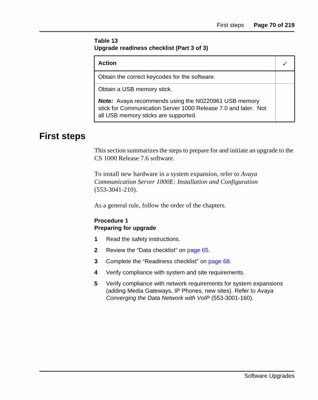
First steps Page 70 of 219
Software Upgrades
First stepsThis section summarizes the steps to prepare for and initiate an upgrade to the CS 1000 Release 7.6 software.
To install new hardware in a system expansion, refer to Avaya Communication Server 1000E: Installation and Configuration (553-3041-210).
As a general rule, follow the order of the chapters.
Procedure 1Preparing for upgrade
1 Read the safety instructions.
2 Review the “Data checklist” on page 65.
3 Complete the “Readiness checklist” on page 68.
4 Verify compliance with system and site requirements.
5 Verify compliance with network requirements for system expansions (adding Media Gateways, IP Phones, new sites). Refer to Avaya Converging the Data Network with VoIP (553-3001-160).
Obtain the correct keycodes for the software.
Obtain a USB memory stick.
Note: Avaya recommends using the N0220961 USB memory stick for Communication Server 1000 Release 7.0 and later. Not all USB memory sticks are supported.
Table 13Upgrade readiness checklist (Part 3 of 3)
Action
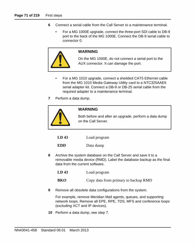
Page 71 of 219 First steps
NN43041-458 Standard 06.01 March 2013
6 Connect a serial cable from the Call Server to a maintenance terminal.
• For a MG 1000E upgrade, connect the three-port SDI cable to DB-9 port to the back of the MG 1000E. Connect the DB-9 serial cable to connector 0.
• For a MG 1010 upgrade, connect a sheilded CAT5 Ethernet cable from the MG 1010 Media Gateway Utility card to a NTC325AAE6 serial adapter kit. Connect a DB-9 or DB-25 serial cable from the required adapter to a maintenance terminal.
7 Perform a data dump.
8 Archive the system database on the Call Server and save it to a removable media device (RMD). Label the database backup as the final data from the current software.
9 Remove all obsolete data configurations from the system.
For example, remove Meridian Mail agents, queues, and supporting network loops. Remove all EPE, RPE, TDS, MFS and conference loops (excluding XCT and IP devices).
10 Perform a data dump, see step 7.
WARNING
On the MG 1000E, do not connect a serial port to the AUX connector. It can damage the port.
WARNING
Both before and after an upgrade, perform a data dump on the Call Server.
LD 43 Load program
EDD Data dump
LD 43 Load program
BKO Copy data from primary to backup RMD
First steps Page 72 of 219
Software Upgrades
11 Archive the system database on the Call Server and save it to an RMD, see step 8. Label the database backup as the data to be upgraded.
12 Upgrade the software on the system, see “Upgrading Call Server software (CP PIV, CP PM)” on page 104. Use the data to be upgraded backup if you are upgrading the Call Server hardware.
13 Once the upgrade is complete and the system is stable, perform a data dump, see step 7.
14 Cold start the system (sysload) to verify that the system can reload sucessfully with the upgraded database.
Note: System error messages are printed during sysload if the database contains obsolete data. Perform EDD CLR to save the database.
End of Procedure

Page 73 of 219 First steps
NN43041-458 Standard 06.01 March 2013
Page 74 of 219
Software Upgrades
81
High level view of tasks and sequence for an upgrade
ContentsThis section contains information on the following topic:
Procedures . . . . . . . . . . . . . . . . . . . . . . . . . . . . . . . . . . . . . . . . . 74
ProceduresThis section summarizes the procedures to prepare for and initiate an upgrade to the CS 1000E Release 7.6 software.
Procedure 2Pre-installation requirements for a CS1000E SA/HA upgrade.
1 If Telephony Manager is being used to administer the system, upgrade to Release 4.0.
2 Check the CS1000E Release 7.6 General Release Bulletin for compatibility of application servers, such as CallPilot and Contact Center. Upgrade these systems to a compatible release.
3 Check the Call Server for Product Improvement ACT/PI patches. Failure to obtain required Product Improvement ACT/PI patches. may result in loss of required functionality.
4 Obtain latest version of CS1000 documentation.
Page 75 of 219 High level view of tasks and sequence for an upgrade
NN43041-458 Standard 06.01 March 2013
5 Ensure you have Compact Flash Cards for backups as applicable for the type of Call Server.
• CP PII, Floppy Disks for backup and 2 (128 MBps) Compact Flash cards for data conversion of system backups to Compact Flash.
• CP PIV, 2 (128 MBps) Compact Flash cards for data backups.
• CP PM, 2 (128 MBps) Compact Flash cards for data backups.
6 Obtain the CS1000 Release 7.6 software with an upgrade kit or download the software.
• CS1000E CP PIV Call Server installation image, if applicable.
• CP PM V18 BIOS upgrade. (Linux Base has been updated to provide BIOS upgrade during installation.)
• CS1000E CP PM Call Server installation image (VxWorks on Compact Flash).
• CS1000E CP PM Linux Base image (Linux on Compact Flash).
• CS1000E COTS Linux Base image (Linux on DVD).
• CS1000E Application image file (.nai file on DVD).
7 Obtain the appropriate keycodes.
• Verify the keycode packages and license.
• Verify new keycode for correct packages and ISM (LD 143 KDIF command).
8 Obtain the latest CS1000 Call Server patches.
9 Obtain the latest CS1000E Linux Service Pack.
10 Note the ELAN IP and TID (Tape ID) of the Call Servers that will be upgraded. ELAN IP is displayed from LD 117, prt, hosts and Tape ID is displayed in LD 22, prt, tid.
11 Create a backup from all CS1000E Elements, (example: SPS, NRS, ECM, Call Servers, PD (Personal Directory)).
12 Ensure serial CLI access is available to all elements that will be upgraded. Avaya recommends that you capture CLI entries to a file.
End of Procedure
High level view of tasks and sequence for an upgrade Page 76 of 219
Software Upgrades
Procedure 3Linux server pre-installation requirements
1 Hostname, ELAN IP, TLAN IP, subnet mask, and default gateway IP.
2 Fully Qualified Domain Name (FQDN) defined on DNS server.
3 DNS IP address(s).
4 NTP time servers IP address.
5 Password assignments for root and admin2 Linux Base accounts.
Password Requirements
• 1 capital letter
• 1 lower case letter
• 1 special character
• Minimum of 8 characters
• First and last characters are not considered against password strength
Example: CS1000_Rel7.6
End of Procedure
Procedure 4Unified Communications Manager (UCM) Primary Security Server workflow
1 Backup UCM by running the sysbackup command. Install UCM and migrate user accounts and certificates with the sysrestore command.
2 Install the Linux Base software to the UCM server.
3 Login as admin2 to http://<FQDN>\local-login and configure as the Primary Security Server.
4 After the initial reboot, login to http://<FQDN> with the admin account.
5 Restore user accounts and certificates by running the sysrestore command on the UCM server.
6 Configure additional administration accounts.
Page 77 of 219 High level view of tasks and sequence for an upgrade
NN43041-458 Standard 06.01 March 2013
7 Configure external authentication (RADIUS, LDAP, KERBOS), if available.
8 Install the application software.
9 Deploy UCM applications as applicable (for example: NRS, Subscriber Manager).
10 Install the latest Service Pack for Linux Base and applications.
End of Procedure
Procedure 5Install/upgrade Linux Base for Network Routing Service (NRS)
1 Disconnect the Primary NRS from the network to allow the Alternate NRS to route calls. (If there is no Alternate NRS, there will be a service outage while you install and upgrade the Primary NRS.)
2 Install Release 7.6 Linux Base on the Primary NRS Server.
3 Login as admin2 to http://<FQDN>\local-login and configure the server as a member of the security domain.
4 Monitor UCM for registration of the member server. which will become the NRS.
5 From UCM Deployment Manager, deploy the NRS application (and any other aplications, as required).
6 Install the latest patches for Linux Base and applications.
7 Launch the NRS Manager from UCM and restore the backup file. Confirm that the data is restored to the NRS.
8 Confirm that the upgraded Primary NRS is processing call requests.
End of Procedure
High level view of tasks and sequence for an upgrade Page 78 of 219
Software Upgrades
Procedure 6CS1000E upgrade workflow
1 Determine which Signaling Server to use as Element Manager. For upgrades, use the Leader Signaling Server. Install Linux Base on the server and assign the server to the security domain in preparation for the Call Server upgrade. Upgrade the Call Server before you install the applications.
• Upgrade/Install Linux Base for this Signaling Server.
• Join the server to the UCM security domain.
2 Upgrade the Call Server
• Split the cores, as applicable. (If this is not a dual core system, there will be a service outage while you upgrade the Call Server and Media Gateway Controllers.)
• Upgrade the CP PII Call Server to the CP PM Call Server, as applicable.
• Upgrade the inactive core.
• Monitor for database conversion system messages and investigate if any display.
• Install the Call Server Deplist.
• Backup the upgraded Call Server to Compact Flash.
• Shut down Core 0 and initialize Core 1, which has been upgraded to Release 7.6.
• Test the system and call flow. The system should be fully functional.
3 Login to the Call Server, LD 117 reg ucm cs. This registers the Call Server with UCM.
4 From UCM monitor the CS1000 registration under Elements.
ATTENTION
There is a service interruption of 30 to 60 minutes during the following procedure.
Page 79 of 219 High level view of tasks and sequence for an upgrade
NN43041-458 Standard 06.01 March 2013
5 From UCM Deployment Manager deploy the Signaling Server and Element Manager applications to the Signaling Server platform that you prepared prior to the Call Server upgrade.
6 Install the latest patches for the Linux Base and applications on the Signaling Server.
7 Replace the SSC controllers with MGC cards, as applicable.
Note: If you convert MG1000T to Media Gateway on Release 7.6, manually program the trunk data and routing tables on the main. This process is not covered in this document. MG1000T still functions as a trunk gateway as it did in Release 4.x.
8 Configure DSPs on the newly installed MGC controller cards.
9 Configure the Signaling Server as leader; restore PD files, if applicable; Save and Synchronize.
10 Upgrade Loadware on MC32sa and MC32s cards.
• From UCM Launch Element Manager.
• Perform a loadware upgrade for the Voice Gateway Media Cards and reboot.
11 From the Call Server, LD 117 reg ucm system. This registers all CS1000 Elements including MGCs with the UCM Security Domain.
12 From UCM monitor the CS1000 registration under Elements.
13 From UCM Elements, edit the Element and verify that the configuration (IP address) data is correct for MC32 and MC32S. Correct the data if required.
ATTENTION
There is a 10 minute service interruption for each SSC that you replace.
ATTENTION
There is a service interruption of 30 to 60 minutes during the following procedure.
High level view of tasks and sequence for an upgrade Page 80 of 219
Software Upgrades
14 From UCM launch Element Manager and from IP Telephony Manager, Save and Transfer.
• Restart applications on the Signaling Server.
15 Test the system for call processing. The system should be in full service.
16 Upgrade the inactive core.
17 LD 135 JOIN - to Join the Call Server cores, test and swap CPUs.
18 From the upgraded Call Server CS - LD117 reg ucm cs. This registers the inactive core.
19 Install/Upgrade the follower Signaling Server.
20 Install the UCM Backup Security Server.
21 Install/Upgrade the Alternate NRS Server.
End of Procedure
Page 81 of 219 High level view of tasks and sequence for an upgrade
NN43041-458 Standard 06.01 March 2013
Page 82 of 219
Software Upgrades
95
Site specific network parameters and system element configuration settings
ContentsThis section contains information on the following topic:
Prerequisites . . . . . . . . . . . . . . . . . . . . . . . . . . . . . . . . . . . . . . . . 82
Convert the engineering parameters obtained in the Customer Information Query into a Site Specific Specification Work Book. Use the Site Specific Specification Work Book to install and configure the system.
Prerequisites1 Site Job Specification Book:
Summarize details of all current system elements, hostnames, IP addresses, subnet mask, default gateway IP, user accounts, passwords and application base configuration settings.
List the new system elements that you plan to install. List any obsolete or unsupported platforms. (Include, for example, hostnames, FQDN, IP addresses, user accounts, passwords and application base configuration settings)
2 Site FTP server:
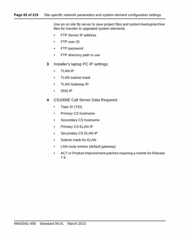
Page 83 of 219 Site specific network parameters and system element configuration settings
NN43041-458 Standard 06.01 March 2013
Use an on site ftp server to save project files and system backup/archive files for transfer to upgraded system elements.
• FTP Server IP address
• FTP user ID
• FTP password
• FTP directory path to use
3 Installer’s laptop PC IP settings:
• TLAN IP
• TLAN subnet mask
• TLAN Gateway IP
• DNS IP
4 CS1000E Call Server Data Required:
• Tape ID (TID)
• Primary CS hostname
• Secondary CS hostname
• Primary CS ELAN IP
• Secondary CS ELAN IP
• Subnet mask for ELAN
• LAN route entries (default gateway)
• ACT or Product Improvement patches requiring a rewrite for Release 7.6.
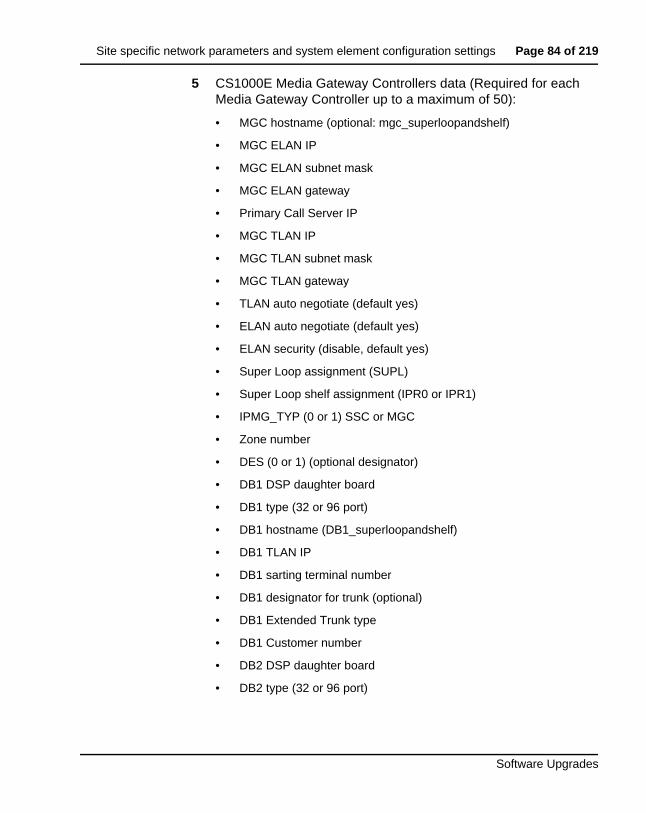
Site specific network parameters and system element configuration settings Page 84 of 219
Software Upgrades
5 CS1000E Media Gateway Controllers data (Required for each Media Gateway Controller up to a maximum of 50):
• MGC hostname (optional: mgc_superloopandshelf)
• MGC ELAN IP
• MGC ELAN subnet mask
• MGC ELAN gateway
• Primary Call Server IP
• MGC TLAN IP
• MGC TLAN subnet mask
• MGC TLAN gateway
• TLAN auto negotiate (default yes)
• ELAN auto negotiate (default yes)
• ELAN security (disable, default yes)
• Super Loop assignment (SUPL)
• Super Loop shelf assignment (IPR0 or IPR1)
• IPMG_TYP (0 or 1) SSC or MGC
• Zone number
• DES (0 or 1) (optional designator)
• DB1 DSP daughter board
• DB1 type (32 or 96 port)
• DB1 hostname (DB1_superloopandshelf)
• DB1 TLAN IP
• DB1 sarting terminal number
• DB1 designator for trunk (optional)
• DB1 Extended Trunk type
• DB1 Customer number
• DB2 DSP daughter board
• DB2 type (32 or 96 port)
Page 85 of 219 Site specific network parameters and system element configuration settings
NN43041-458 Standard 06.01 March 2013
• DB2 hostname (DB2_superloopandshelf)
• DB2 TLAN IP
• DB2 starting terminal number
• DB2 designator for trunk (optional)
• DB2 Extended Trunk type
• DB2 Customer number
• MGTDS Loops
• MGCONF Loops
6 Release 7.6 Linux Application Server inputs for each server:
• Hostname
• TLAN port domain name
• FQDN (Fully Qualified Domain Name)
• TLAN IP
• TLAN subnet mask
• TLAN default gateway
• ELAN IP
• ELAN subnet mask
• ELAN default gateway
• Default NIC card (ELAN 0 or TLAN 1)
• Regional Time Zone Number or Time Base to GMT (for example, -5 GMT) UNTP time server IP
• DNS IP
• Root password
• admin2 password
• Security Domain (Primary, Member, Backup)
7 Release 7.6 Linux Primary Security Server:
Administrator password
Site specific network parameters and system element configuration settings Page 86 of 219
Software Upgrades
Certificate information:
• Friendly name
• Bit length
• Organization
• Organizational unit
• Common name
• Country/Region
• State/Province
• City/locality
New administrative user accounts:
• User ID
• Authentication (local or external)
• User name
• Temporary password
• Roles assigned (Member Registrar, Network Administrator)
External identity repositories:
• External LDAP user then local users
• External RADIUS users then local users
• External LDAP users, then RADIUS, then local users
• Local users
• External RADIUS users, then LDAP users, then local users
Page 87 of 219 Site specific network parameters and system element configuration settings
NN43041-458 Standard 06.01 March 2013
Provision LDAP server:
• IP or DNS
• TCP port
• Base Distinguished Name
• SSL/TLS Mode (yes or no)
• Is Active Directory (yes or no)
• Distinguished Name for root binding
• Password for root binding
Provision Radius Server:
• IP or DNS
• UDP port
• Shared Secret
Provision Kerberos Server:
• DC Host Name (FQDN)
• DC Computer Domain
• Keytab File
8 NRS Migration to Release 7.6 NRS:
Service Domain Name
L1 Domain Name
Site specific network parameters and system element configuration settings Page 88 of 219
Software Upgrades
NRS settings:
• Primary NRS hostname
• Primary TLAN IP
• Secondary NRS TLAN
• Secondary NRS hostname
• Control priority
• Server mate comm. port
• Realm name
• Server role
H.323 Gatekeeper settings:
• Local request response time out
SIP server settings:
• Public name for non-trusted networks
• Public number for non-trusted networks
• UDP transport enabled
• Primary Server UDP IP
• Primary Server UDP port
• Secondary Server UDP IP
• Secondary Server UDP port
• TCP Transport enabled
• Primary Server TCP IP
• Primary Server TCP port
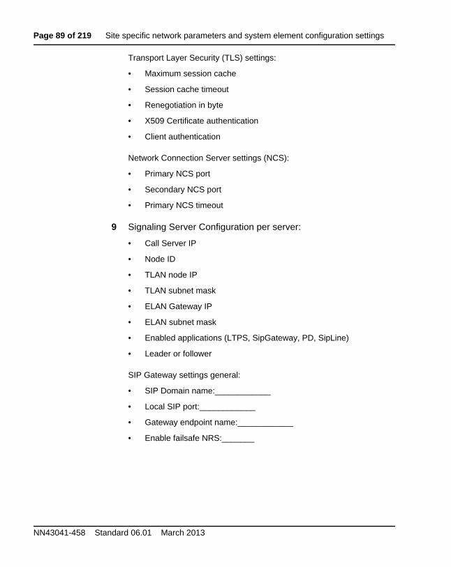
Page 89 of 219 Site specific network parameters and system element configuration settings
NN43041-458 Standard 06.01 March 2013
Transport Layer Security (TLS) settings:
• Maximum session cache
• Session cache timeout
• Renegotiation in byte
• X509 Certificate authentication
• Client authentication
Network Connection Server settings (NCS):
• Primary NCS port
• Secondary NCS port
• Primary NCS timeout
9 Signaling Server Configuration per server:
• Call Server IP
• Node ID
• TLAN node IP
• TLAN subnet mask
• ELAN Gateway IP
• ELAN subnet mask
• Enabled applications (LTPS, SipGateway, PD, SipLine)
• Leader or follower
SIP Gateway settings general:
• SIP Domain name:____________
• Local SIP port:____________
• Gateway endpoint name:____________
• Enable failsafe NRS:_______
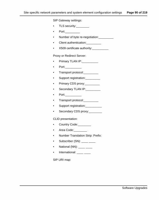
Site specific network parameters and system element configuration settings Page 90 of 219
Software Upgrades
SIP Gateway settings:
• TLS security:________
• Port:_________
• Number of byte re-negotiation:_________
• Client authentication:_________
• X509 certificate authority:__________
Proxy or Redirect Server:
• Primary TLAN IP:__________
• Port:__________
• Transport protocol:_________
• Support registration:_________
• Primary CDS proxy:_________
• Secondary TLAN IP:_________
• Port:__________
• Transport protocol:_________
• Support registration:__________
• Secondary CDS proxy:________
CLID presentation:
• Country Code:________
• Area Code:________
• Number Translation Strip: Prefix:
• Subscriber (SN): ____ ____
• National (NN): ____ ____
• International: ____ ____
SIP URI map:
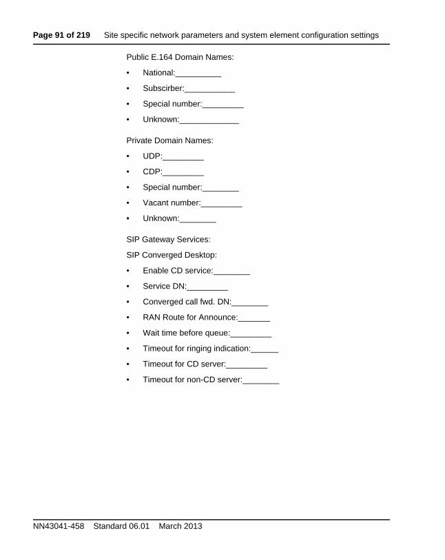
Page 91 of 219 Site specific network parameters and system element configuration settings
NN43041-458 Standard 06.01 March 2013
Public E.164 Domain Names:
• National:__________
• Subscirber:___________
• Special number:_________
• Unknown:_____________
Private Domain Names:
• UDP:_________
• CDP:_________
• Special number:________
• Vacant number:_________
• Unknown:________
SIP Gateway Services:
SIP Converged Desktop:
• Enable CD service:________
• Service DN:_________
• Converged call fwd. DN:________
• RAN Route for Announce:_______
• Wait time before queue:_________
• Timeout for ringing indication:______
• Timeout for CD server:_________
• Timeout for non-CD server:________
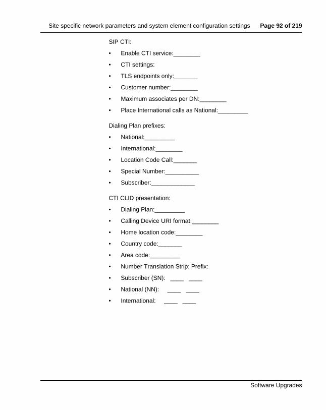
Site specific network parameters and system element configuration settings Page 92 of 219
Software Upgrades
SIP CTI:
• Enable CTI service:________
• CTI settings:
• TLS endpoints only:_______
• Customer number:________
• Maximum associates per DN:________
• Place International calls as National:_________
Dialing Plan prefixes:
• National:_________
• International:________
• Location Code Call:_______
• Special Number:__________
• Subscriber:_____________
CTI CLID presentation:
• Dialing Plan:_________
• Calling Device URI format:________
• Home location code:________
• Country code:_______
• Area code:_________
• Number Translation Strip: Prefix:
• Subscriber (SN): ____ ____
• National (NN): ____ ____
• International: ____ ____
Page 93 of 219 Site specific network parameters and system element configuration settings
NN43041-458 Standard 06.01 March 2013
Microsoft Unified Messaging:
• MWI Application DN:_______
• MWI Dialing Plan:______
• Enable Softkeys:_______
• Enable Secure Media:_____
H.323Gw settings
• H.323 ID: __________
• Enable failsafe NRS: _________
• Primary Gatekeeper (TLAN) IP:_____________
• Alternate Gatekeeper (TLAN) IP:____________
• Primary NCS port number:________________
• Alternate NCS (TLAN) IP:_____________
• Alternate NCS port number:___________
• Primary NCS timeout:___________
Site specific network parameters and system element configuration settings Page 94 of 219
Software Upgrades
10 VGMC media card configuration per card:
• Hostname
• Card Type
• Card TN
• Card MAC Address
• TLAN IP Address
• TLAN Subnet Mask
• TLAN Gateway IP
• DSP IP Address
• ELAN IP Address
• ELAN Subnet Mask
• ELAN Gateway IP
• Alternate Call Server 1 (if applicable)
• Alternate Call Server 2 (if applicable)
Procedure 7Site specific network parameters and system element configuration settings
1 Verify contents of the Site Specific Specification Work Book details as defined in “Prerequisites” on page 82.
Data required depends on configuration and features implemented on a site by site basis.
End of Procedure
Page 95 of 219 Site specific network parameters and system element configuration settings
NN43041-458 Standard 06.01 March 2013
Page 96 of 219
Software Upgrades
103
Co-resident Call Server and Signaling Server
ContentsOverview . . . . . . . . . . . . . . . . . . . . . . . . . . . . . . . . . . . . . . . . . . . . . . . . 96Supported configurations . . . . . . . . . . . . . . . . . . . . . . . . . . . . . . . . . . . 97
Co-res CS and SS upgrade paths. . . . . . . . . . . . . . . . . . . . . . . . . . . . . . 100Hardware . . . . . . . . . . . . . . . . . . . . . . . . . . . . . . . . . . . . . . . . . . . . . . . . 101
Software applications . . . . . . . . . . . . . . . . . . . . . . . . . . . . . . . . . . . . . . 102
Element Manager . . . . . . . . . . . . . . . . . . . . . . . . . . . . . . . . . . . . . . . . . 103
OverviewAn Avaya Communication Server 1000 system consists of two major functional components, a Call Server and a Signaling Server. These two components have historically been running on separate Intel Pentium processor-based hardware platforms operating under the VxWorks Operating System.
The Co-resident Call Server and Signaling Server (Co-res CS and SS) runs the Call Server software, Signaling Server software, and System Management software on one hardware platform running the Linux Base Operating System. For Communication Server 1000 Release 7.6, the Co-res CS and SS is supported on various hardaware platforms, see Table 1: “Hardware platform supported roles” on page 24.
Page 97 of 219 Co-resident Call Server and Signaling Server
NN43041-458 Standard 06.01 March 2013
The Co-res CS and SS provides a cost effective solution for Communication Server 1000 system installations that do not require a high user capacity or the need for a redundant Call Server.
This chapter provides a high level overview only. For more information about Co-res CS and SS, see Avaya Co-resident Call Server and Signaling Server Fundamentals (NN43001-509).
Supported configurationsYou require a Media Gateway, Gateway Controller, and Server to deploy the Co-resident Call Server and Signaling Server in the following configurations:
• Avaya Communication Server 1000E (Avaya CS 1000E)
• Branch Office Media Gateway (MG 1000B)
• Survivable Media Gateway (SMG)
• Communication Server 1000E Survivable SIP Media Gateway (Survivable SIP MG)
• Avaya Communication Server 1000E TDM (CS 1000E TDM)
For details on the Avaya CS 1000E TDM system, see Avaya CP PM Co-resident Call Server and Signaling Server Fundamentals (NN43001-509).
You can deploy a Co-res CS and SS as a Main Office, Branch Office, SMG or Survivable SIP MG.
For information about installing an SMG or Survivable SIP MG, see Avaya Communication Server 1000 System Redundancy Fundamentals (NN43001-507).
For information about CS 1000E capacity limitations, see Avaya Communication Server 1000E: Planning and Engineering (NN43041-220).
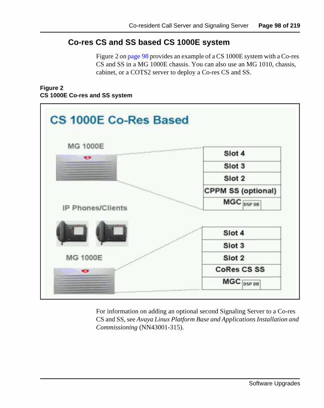
Co-resident Call Server and Signaling Server Page 98 of 219
Software Upgrades
Co-res CS and SS based CS 1000E system
Figure 2 on page 98 provides an example of a CS 1000E system with a Co-res CS and SS in a MG 1000E chassis. You can also use an MG 1010, chassis, cabinet, or a COTS2 server to deploy a Co-res CS and SS.
Figure 2CS 1000E Co-res and SS system
For information on adding an optional second Signaling Server to a Co-res CS and SS, see Avaya Linux Platform Base and Applications Installation and Commissioning (NN43001-315).
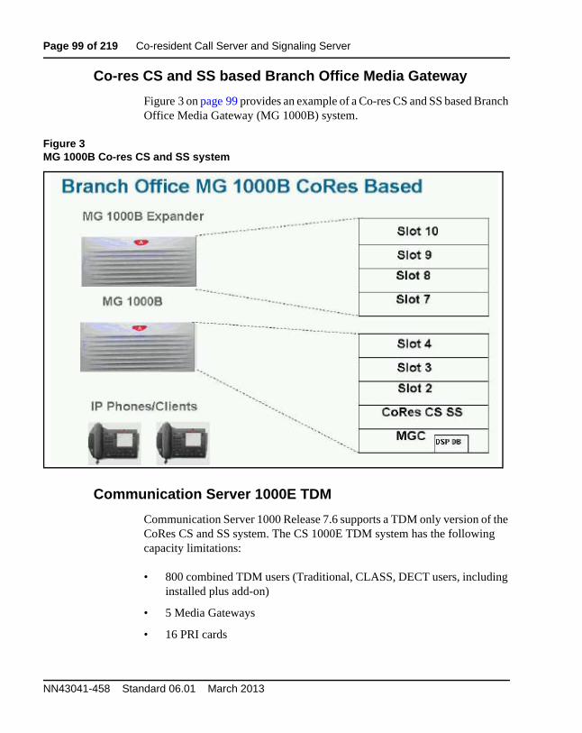
Page 99 of 219 Co-resident Call Server and Signaling Server
NN43041-458 Standard 06.01 March 2013
Co-res CS and SS based Branch Office Media Gateway
Figure 3 on page 99 provides an example of a Co-res CS and SS based Branch Office Media Gateway (MG 1000B) system.
Figure 3MG 1000B Co-res CS and SS system
Communication Server 1000E TDM
Communication Server 1000 Release 7.6 supports a TDM only version of the CoRes CS and SS system. The CS 1000E TDM system has the following capacity limitations:
• 800 combined TDM users (Traditional, CLASS, DECT users, including installed plus add-on)
• 5 Media Gateways
• 16 PRI cards
Co-resident Call Server and Signaling Server Page 100 of 219
Software Upgrades
• 200 ACD Agents
• 0 IP Phones (no UNIStim, no SIP Line, no SIP DECT)
• 0 Virtual Trunks
The CS 1000E TDM system does not support NRS.
High Availability (HA) support
In CS 1000 Release 7.6, the Co-res CS and SS does not support an HA configuration (dual core with either Active or Inactive role). For systems that require HA configuration, you must deploy a VxWorks-based Communication Server 1000 system.
Co-res CS and SS upgrade pathsThe following upgrade paths are supported for Communication Server 1000 systems.
• CS 1000 Release 7.0 or earlier Communication Server 1000E Call Server with Standard Availability (SA) to a Communication Server 1000 Release 7.6 Co-resident Call Server and Signaling Server
If you upgrade from a non-CP PM based Communication Server 1000E Call Server, you must replace your old Call Server hardware with either a CP PM card, CP MG card, CP DC card, or COTS2 server and upgrade the software.
• CS 1000 Release 7.0 or earlier Communication Server 1000E Signaling Server to Communication Server 1000 Release 7.6 Co-resident Call Server and Signaling Server
• Meridian 1 Option 11C, CS 1000M, or CS 1000S Call Server to Communication Server 1000 Release 7.6 Co-resident Call Server and Signaling Server
• Meridian 1 Option 11C Call Server to Communication Server 1000 Release 7.6 CS 1000E TDM.
The minimum CS 1000 Release for Small System migration to a Co-resident Call Server and Signaling Server is Release 23.10
Page 101 of 219 Co-resident Call Server and Signaling Server
NN43041-458 Standard 06.01 March 2013
HardwareThe Communication Server 1000 Release 7.6 Co-resident Call Server and Signaling Server is supported on CP PM cards, CP MG cards, CP DC cards, and COTS2 servers running the Linux Base Operating System.
The Co-res CS and SS can run on the CP PM hardware platform introduced in Communication Server 1000 Release 5.0, however the software changes from VxWorks to Linux, and a CP PM Linux upgrade kit is required.
The CP PM card requires 2 GB memory, and a 40 GB hard drive to support the Co-res CS and SS configuration. CP PM version 1 cards require BIOS version 18 or higher to support the Co-res CS and SS configuration.
All other platforms require 4 GB of memory. You must upgrade CP DC and CP MG hardware from 2 GB of memory to 4 GB of memory using a Linux Upgrade Kit.
CP PM upgrade kit
The CP PM Signaling Server Linux Upgrade kit includes the following items:
• 2 GB Compact Flash (CF) with Linux base installation software
• 1 GB DDR SO-DIMM memory upgrade (Optional, Enterprise Configurator includes if required)
• 40 GB ATA Hard Drive (Optional, Enterprise Configurator includes if required)
CP PM media storage
The CP PM card for a Co-res CS and SS requires a 40 GB internal Fixed Media Drive (FMD). You must ensure switch S5 on the CP PM card is in position 2 to enable the system to boot from the hard drive FMD. Switch S5 in position 1 configures the CP PM card to boot from an internal Compact Flash (CF) FMD.
The CP PM card supports two types of Removable Media Drives (RMD)
• CF card, supports the installation of Linux Base and Linux applications
Co-resident Call Server and Signaling Server Page 102 of 219
Software Upgrades
• USB memory stick device, supports the installation of Linux applications (cannot use to install Linux Base)
For more information about supported media for Linux-based Co-resident Call Server and Signaling Server installations, see Avaya Linux Platform Base and Applications Installation and Commissioning (NN43001-315).
CP MG, CP DC, and COTS2 media storage
The CP MG card, CP DC card, and COTS2 servers all require an internal Fixed Media Drive (FMD) loaded with the Linux Base Operating System.
The CP MG and CP DC cards support USB 2.0 storage devices as Removable Media Drives (RMD). A bootable USB 2.0 storage device can be used to install or patch the Linux Base Operating System. The COTS servers support bootable DVD. CF cards are not supported on CP MG, CP DC or COTS2 hardware.
Software applicationsThe Co-res CS and SS does not directly support SIP Line Gateway and SIP DECT. You must provision an additional stand-alone Signaling Server for this software.
The Co-res CS and SS supports the following software applications
• Linux Call Server
• Line Telephony Proxy Server (LTPS)
• Unicode Name Directory (UND)
• Signaling Server Gateway including H.323 Gateway and SIP Gateway
• Failsafe SIP Proxy service, Gatekeeper
• Personal Directory (PD)
• Network Routing Service (NRS)
— You can configure the NRS as a Primary, however you can only configure NRS as a Secondary if the Primary is also running on a Co-res CS and SS.
Page 103 of 219 Co-resident Call Server and Signaling Server
NN43041-458 Standard 06.01 March 2013
— The CP PM Co-res CS and SS does not support a Secondary or backup NRS to a capacity higher than the Primary NRS due to the small disk size and low call rates on a CP PM Co-res CS and SS system.
• Element Manager (EM)
• Unified Communications Management (UCM) Primary Security Server in limited deployment. For more information about UCM Primary Security Server procedures, see Avaya Linux Platform Base and Applications Installation and Commissioning (NN43001-315).
Element ManagerThe Element Manager (EM) interface includes the configuration and enabling of Signaling Server application services such as UNIStim, LTPS, SIP Gateway, H.323 Gateway, and SIP Line.
For more information about EM, see Avaya Element Manager: System Administration (NN43001-632).
Page 104 of 219
Software Upgrades
165
Upgrading Call Server software (CP PIV, CP PM)
ContentsThis section contains information on the following topics::
Introduction . . . . . . . . . . . . . . . . . . . . . . . . . . . . . . . . . . . . . . . . . . . . . . 104
Software pre-conversion . . . . . . . . . . . . . . . . . . . . . . . . . . . . . . . . . . . . 105
Preparing for the upgrade . . . . . . . . . . . . . . . . . . . . . . . . . . . . . . . . . . . 105
Performing the upgrade. . . . . . . . . . . . . . . . . . . . . . . . . . . . . . . . . . . . . 132
Completing the upgrade . . . . . . . . . . . . . . . . . . . . . . . . . . . . . . . . . . . . 161
IntroductionThis section provides instructions for a VxWorks-based local upgrade to Avaya Communication Server 1000 Release 7.6 software on a Call Processor Pentium IV (CP PIV) or Common Processor Pentium Mobile (CP PM) Avaya CS 1000E system. This technical publication assumes all appropriate hardware has been upgraded according to procedures in Avaya Communication Server 1000E Hardware Upgrade Procedures (NN43041-464).
Have the following items available before proceeding
• Software Install Kits (see page 132)
• required Dependency list patches for the target system
A capture file should be maintained during all processes.
Page 105 of 219 Upgrading Call Server software (CP PIV, CP PM)
NN43041-458 Standard 06.01 March 2013
Software pre-conversion
Preparing for the upgradeThis document implements a “source- to-target” approach to performing an upgrade. It is important to correctly identify the source platform, target platform, and maintenance window required to perform the upgrade.
This chapter features check boxes indicating what condition the system should be in at that stage of the upgrade. If the system is not in the proper condition steps should be taken to correct this.
This section is written to maintain Dial Tone where possible and limit service interruptions.
IMPORTANT!
Upgrades to Avaya CS 1000 Release 7.6 are supported on Release 23 or later.
Database conversion for Meridian 1 Options 21E, 51, 61,71, STE, NT and XT must be completed by Avaya Software Conversion Lab. Consult the current Avaya price book for cost and contact information.
If the system is equipped with IOP/CMDU cards the database must be converted with the Database Transfer utility.
All systems can be converted by Avaya in the software conversion lab.
IMPORTANT!
Database backup information should be preserved for a minimum of 5 days.
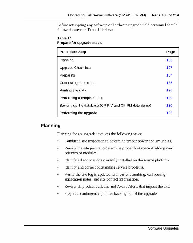
Upgrading Call Server software (CP PIV, CP PM) Page 106 of 219
Software Upgrades
Before attempting any software or hardware upgrade field personnel should follow the steps in Table 14 below:
Planning
Planning for an upgrade involves the following tasks:
• Conduct a site inspection to determine proper power and grounding.
• Review the site profile to determine proper foot space if adding new columns or modules.
• Identify all applications currently installed on the source platform.
• Identify and correct outstanding service problems.
• Verify the site log is updated with current trunking, call routing, application notes, and site contact information.
• Review all product bulletins and Avaya Alerts that impact the site.
• Prepare a contingency plan for backing out of the upgrade.
Table 14Prepare for upgrade steps
Procedure Step Page
Planning 106
Upgrade Checklists 107
Preparing 107
Connecting a terminal 125
Printing site data 126
Performing a template audit 129
Backing up the database (CP PIV and CP PM data dump) 130
Performing the upgrade 132
Page 107 of 219 Upgrading Call Server software (CP PIV, CP PM)
NN43041-458 Standard 06.01 March 2013
Upgrade Checklists
Upgrade checklists can be found in the “Upgrade checklists” chapter on page 206. Engineers may print this section in order to facilitate the upgrade.
Preparing
Preparing for an upgrade involves the following tasks:
• Identify and become familiar with all procedures.
• Verify that all installed applications meet the minimum software requirements for the target platform.
• Determine and note current patch or Dep lists installed at the source platform.
• Determine required patch or Dep lists at the target platform for all system-patchable components (Call Server, Voice Gateway Media Cards, Signaling Servers and so on).
• Determine the required patches or DEP lists installed on all applications (Avaya CallPilot, Symposium Call Center Server, and so on).
• Determine and communicate the required maintenance window, contingency plan and the impact to the customer to complete the procedure.
• Determine if all additional LAN connections are present.
• Verify that all IP addresses and FQDNs are available. An FQDN is required for each Linux Element. Ping the FQDN to confirm it is available. If using external DNS servers (highly recommended) confirm that the DNS server resolves the FQDN to the expected IP address.
• Perform an inventory on required software and hardware.
IMPORTANT!
In a Campus configuration, as both cores may be physically separate, it is important to plan for required attendance at both core sites at some point in the upgrade.
Upgrading Call Server software (CP PIV, CP PM) Page 108 of 219
Software Upgrades
• Secure the source software and key code.
• Secure the target software and key code.
• Verify the new key code using the DKA program.
• Print site data.
Pre-upgrade checklists
Perform the following pre-upgrade checklist procedures before upgrading a CS 1000E system.
Procedure 8Pre-upgrade activites
Perform the following activities 5 to 7 days prior to the night of the software upgrade.
1 Verify that you have the latest version of this document.
2 Verify Hardware compatibility prior to upgrade and upgrade any hardware that does not meet the minimum requirements for CS 1000 Release 7.6. Please refer to the Communication Server 1000 Release 7.6 Product Bulletin.
3 Verify the system meets the Memory Requirements for CS 1000 Release 7.6 as specified in the Communication Server 1000 Release 7.6 Product Bulletin.
4 Verify that a functioning spare CPU is available on site during upgrade.
5 Verify that there is a pre-tested working core modem with a direct line connected for Remote Technical Support.
IMPORTANT!
Do not continue with the upgrade if any of the preupgrade checks below fails. Please contact your next level of support. Upgrade pre-checks involving system maintenance will need to be performed during the maintenance window.
Page 109 of 219 Upgrading Call Server software (CP PIV, CP PM)
NN43041-458 Standard 06.01 March 2013
6 Verify that all software necessary for the source and target release for all systems to be upgraded is available. Before the upgrade, check that all items on the order form are also on the packing slip. Check that all items been received. If any items are missing, contact your supplier for replacements before you begin the upgrade. See “Software Install Kits” on page 132.
7 Review Keycode Data Sheet - (SDID, PKGS, License, TID) and ensure that you have all the necessary Keycodes for both the source and target software. See “Keycodes” on page 64.
8 Verify that system is patched current for all patchable elements on the system using the "Upgrades" - Meridian ISSP Report and Conflict Checker (MIRCC) Tool, paste in an ISSP (MDP ISSP) Output and get a Detailed Patch Report.
Note 1: Upgrades MIRCC TOOL is available via Enterprise Solutions Patch Library (ESPL).**Access to the Enterprise Solutions Patch Library requires a Distributor account and password.**.Once logged onto ESPL, go to: "Upgrades" - Meridian ISSP Report and Conflict Checker (MIRCC).
Note 2: Please refer to Bulletin: 2006007126 available on the Avaya Technical Support Portal for further details on the use of the Upgrades MIRCC Tool. Apply any missing Patches and remove any Obsolete Patches.
9 Verify that all required patches at the target platform as generated by the Upgrades MIRCC for all system-patchable components (Call Server, Voice Gateway Media Cards, Signaling Servers and so on) are available on site.
10 Print Site Data – See “Printing site data” on page 65.
11 Perform a Template Audit - See“Performing a template audit” on page 68.
12 Perform midnight test routines and ensure any errors addressed prior to upgrade. Verify that 5 days prior to the upgrade there are not:
a. Any type of system triggered restart (Warm, Cold, or Sysload).
b. Swd watchdog timouts (e.g. BUG7058 SWD: Swd watchdog timer expired on task tSL1).
c. Semtake memory issues (e.g. BUG0584 SeaWeed memory library semTake failed memory).
d. Hardware Watchdog Interrupts (e.g.BUG7060 SWD: HARDWARE WATCHDOG INTERRUPT EVENT).
Upgrading Call Server software (CP PIV, CP PM) Page 110 of 219
Software Upgrades
e. Disk Cache Errors (e.g. 0x22bb3dd8 (tSysPhase1): disk cache error: device 371ab80 block 1279235 errno c0003, disk read failed).
f. ELAN issues (e.g. ELAN009 ELAN 0 host IP=10.60.78.4 disabled, write to socket fail due to far end disconnect or Ethernet problems, ELAN0028 The following server failed to register it's pbxLink).
g. Hardware Diag Failures (e.g. DIAG0002 Diagnostic: Faulty Hardware watchdog diag).
h. IP Link Failures to MGCs (e.g. SRPT0016 OMM: IP link is DOWN between Call Server and Media Gateway, GC0018 MGC ELAN heart-beat connection to Call Server is down. Switching to alternate - port number, SRPT0016 OMM: IP link is DOWN between Alternate Call Server 1 and IPMG[0 0]).
i. QoS errors (e.g QOS0019 QoS unacceptable packet loss: [98.5] % in zone [1]).
j. CMDU Failures (e.g. BUG7339 ROM OS 0: ERROR "CMDU VOL Init". Restarting with code: 52).
If you encounter any of the above errors or failures, contact your next level of support to ensure that these problems are resolved prior to any upgrade activity.
13 Enable System monitoring tool (AHST) in Overlay 22. This task will collect the following system outputs (they are not enabled by default):
— Configuration changes
— Alarms reports (AUD, SSH)
— Error reports
— BUG captures
14 Enter STAT LOOP X commands in Overlay 32 to ensure system physical and Virtual TNS are idle:
— Enter STAT command in Overlay 60 to get status of all loops to ensure what loops are idle.
— Enter ssck 0 and 1 for status of system clocks.
— Enter lcnt for status of span errors.
— Enter STAT DCH command in Overlay 96 to get status of of DCH channels to ensure they are active.
Page 111 of 219 Upgrading Call Server software (CP PIV, CP PM)
NN43041-458 Standard 06.01 March 2013
— Enter STAT ELNKcommand in Overyay 137 to get status of ELNK to ensure ELNK is link is up.
For details see Avaya Software Input Output Reference - Maintenance (NN43001-711).
15 Test the System Utility card.
16 Print the history file.
17 Prior to System Upgrade, make two current backups to external media:
18 Avaya recommends you to have two bootable removable media devices (RMD) for site upgrades. See “Making a bootable RMD” on page 116.
19 Perform a sysload and verify no abnormal messages appear before the upgrade.
End of Procedure
LD 135 Load program
STAT CPU Get the status of the System Utility card
STAT CNI Test the System Utility card
STAT HEALTH Display the Call Server health count status
LD 17
REQ PRT
TYPE ADAN
ADAN NEW HST
SIZE (0)–65534
USER When ADAN = HST, users can be BUG, MCT, MTC, SCH and TRF.
LD 43 Load program
BKO Copy data from primary to backup device
Upgrading Call Server software (CP PIV, CP PM) Page 112 of 219
Software Upgrades
Pre-upgrade checklists for Geographic Redundant Survivable sites
If you have a system with a Geographic Redundant (GR) Primary site and N-way Survivable Secondary sites, Avaya recommends you to upgrade the Survivable Secondary sites before upgrading the Primary site. For more information on GR systems, see Avaya System Redundancy Fundamentals (NN43001-507).
A typical Survivable Secondary site contains the following components:
• Gateway Controller with DSP resources in a Media Gateway
• IPE equipment (Line and Trunk cards) in a Media Gateway
• Media Cards in a Media Gateway
• Survivable Servers
The applications running on a Survivable Server can include Call Server (equipped with GR Secondary Server package), Terminal Proxy Server (TPS), Virtual Trunk (Vtrk), Element Manager (EM), and failsafe Network Routing Service (NRS).
During a Survivable site upgrade, your focus is to upgrade the software running onthe Survivable Servers. Before you begin upgrading the Survivable Server software, you must prepare the network and equipment.
The following lists describes the pre-upgrade activities required during a GR Survivable site upgrade.
• The Unified Communication Manager (UCM) Primary and Backup Servers in the CS 1000E network must be upgraded to the latest CS 1000 software.
— UCM member Servers running a previous software release are supported.
— UCM member Servers running a newer software release than the UCM Primary and Backup Servers are not supported.
• The Network Routing Service (NRS) Primary and Secondary Servers in the CS 1000E network must be upgraded to the latest CS 1000 software.
Page 113 of 219 Upgrading Call Server software (CP PIV, CP PM)
NN43041-458 Standard 06.01 March 2013
— Failsafe NRS Servers running a previous software release are supported.
— Failsafe NRS Servers running a newer software release than the NRS Primary Server are not supported.
• All Gateway Controllers must be upgraded to the latest CS 1000 software release loadware. The Gateway Controller loadware is provided by the Call Server software.
— Gateway Controller software is backwards compatible with previous CS 1000 Call Server software.
— Gateway Controllers running older loadware than the CS 1000 Call Server are not supported.
• All Media Cards must be upgraded to Release 6.0 or newer software.
— Media Cards running Release 5.5 and older software are not supported.
• Digital telephone and peripheral equipment must be running the same software release as the Call Server.
— The Call Server software can automatically upgrade TMDI card loadware.
— Other card loadwares are not automatically upgraded.
• IP Phone firmware must be upgraded.
— The IP Phone firmware is bundled in the Signaling Server TPS application.
— The firmware is upgraded automatically if the TPS detects an older version running on an IP Phone.
Perform the following procedure to prepare the system for a Secondary site upgrade.
Upgrading Call Server software (CP PIV, CP PM) Page 114 of 219
Software Upgrades
Procedure 9Pre-upgrade activities for GR Survivable sites
1 Remove all IP Phone firmware on the TPS Servers at the Secondary sites. For IP Phone firmware removal procedures, see Avaya Signaling Server IP Line Application Fundamentals (NN43001-125).
Note: You must perform IP Phone firmware upgrades from the TPS Servers at the Primary site.
2 Disable the automatic Gateway Controller upgrade option on the Secondary Call Servers.
3 Ensure all IP Phones are running the latest firmware. If new firmware is available, upgrade the firmware from the TPS Primary site. For IP Phone firmware upgrade procedures, see Avaya Signaling Server IP Line Application Fundamentals (NN43001-125).
4 Ensure all digital telephones and TMDI packs are running the latest PSDL firmware. If new PSDL firmware is available, install the new firmware on the Primary Call Server. Upgrade the digital telephones and TMDI packs with the new firmware.
5 Ensure the Gateway Controllers are running the latest loadware. If new MGC loadware is available, upgrade the Gateway Controller from the Primary Call Server.
End of Procedure
Once the pre-upgrade preparation is complete, perform the network wide upgrade for a GR Survivable system.
Procedure 10Upgrading a GR Survivable system
1 Upgrade the UCM Primary and Backup Servers.
2 Upgrade the NRS Primary and Secondary Servers.
3 Upgrade the Survivable Servers at the GR Secondary sites.
— Backup all data and upgrade the Servers at each Secondary site. See “Performing the upgrade” on page 132, and Avaya
LD 143 Load program
DIS AUTOUPGMG Disable Gateway Controller auto upgrades
Page 115 of 219 Upgrading Call Server software (CP PIV, CP PM)
NN43041-458 Standard 06.01 March 2013
Signaling Server IP Line Application Fundamentals (NN43001-125).
— For Co-resident Call Server and Signaling Servers at Secondary sites, upgrade the GR Secondary Call Server first. Proceed with upgrading the remaining Linux-based Servers, see Avaya Linux Platform Base and Applications Installation and Commissioning (NN43001-315).
— During the GR Secondary Call Server upgrade, Avaya recommends you disable the Gateway Controller automatic upgrade option.
4 Ensure the Survivable Servers upgraded sucessfully and that the database converted sucessfully.
5 Once all Secondary site Server upgrades are complete, proceed with upgrading the Servers at the Primary site.
End of Procedure
If you performed all the GR Secondary site checks and procedures, and the upgraded Survivable Servers are called into service (WAN outage) before you complete the Primary Server upgrades, the following events occur:
• The Gateway Controllers successfully register to the GR Secondary Call Server. The Gateway Controllers are running the latest loadware, and the MGC automatic upgrade option is disabled on the Secondary Call Server.
• The Media Cards successfully register to the GR Secondary Call Server. The Media Cards are running Release 6.0 or newer software.
• The IP Phones successfully register with the TPS application on the Survivable Signaling Server. No firmware upgrades are necessary since the IP Phones are currently running the latest firmware.
• The digital telephones and TMDI cards are operational once the Gateway Controller registers to the Secondary Call Server. No firmware upgrades are necessary since the digital telephones and TMDI cards are currently running the latest firmware.
• The Virtual Trunk Gateway and the Failsafe NRS on the Survivable Server route SIP trunk calls.
Upgrading Call Server software (CP PIV, CP PM) Page 116 of 219
Software Upgrades
Once service is restored to the Primary site (WAN connection online), the following events occur:
• The Gateway Controllers successfully re-register to the GR Primary Call Server.
• The Media Cards successfully re-register to the GR Primary Call Server.
• The IP Phones successfully re-register with the TPS application on the Primary Signaling Server.
• The digital telephones and TMDI cards are operational once the Gateway Controller re-registers to the Primary Call Server.
• The Virtual Trunk Gateway at the Primary site and the Primary NRS route SIP trunk calls.
Making a bootable RMD
The RMD installation CF card ships pre-formatted and bootable from Avaya. If the Avaya CF card does not boot, you can make it bootable by performing Procedure 11 on page 117.
For VxWorks based CP PIV and CP PM cards, see Appendix A: “Supported media and memory sizes.” on page 218 for supported media and memory sizes. USB devices are not supported.
Note: Avaya does not provide technical support for customer provided CF cards.
Page 117 of 219 Upgrading Call Server software (CP PIV, CP PM)
NN43041-458 Standard 06.01 March 2013
Perform the following procedure to create a bootable Call Server software CF card.
Procedure 11Creating a bootable Call Server software CF card
1 Download the latest software load zip file for your platform type (CP PIV, CP PM) from the Avaya website to a folder on your PC.
2 Navigate to the folder on your PC where you downloaded the file.
3 Extract all files to a temporary folder. Unzip the Call Server software load zip file to create the following six directories:
• \backup
• \install
• \keycode
• \licenses
• \swload
• \utilities
4 Insert the CF card into the PC.
5 Click on My Computer icon to verify the drive letter assigned to the CF drive, see Figure 4 on page 118.
In this example, the CF card is assigned to drive letter F.
CAUTION — Data Loss
The PC utility used in the following procedure (mkbootrmd.bat) does not validate whether the drive letter entered is a valid RMD or the size of the media. You must enter the correct drive letter when prompted or risk formatting the incorrect drive.
Note: This utility is supported by all versions of Microsoft Windows.
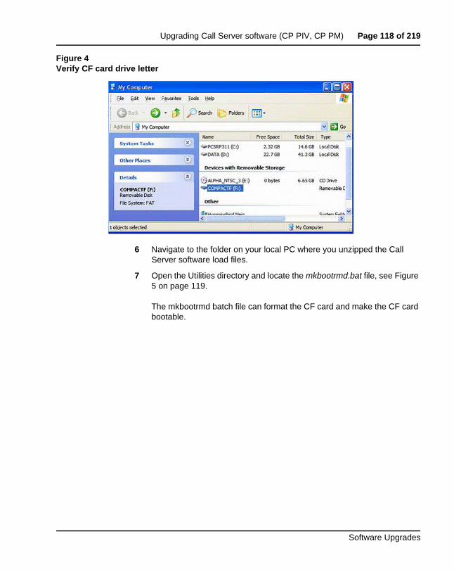
Upgrading Call Server software (CP PIV, CP PM) Page 118 of 219
Software Upgrades
Figure 4Verify CF card drive letter
6 Navigate to the folder on your local PC where you unzipped the Call Server software load files.
7 Open the Utilities directory and locate the mkbootrmd.bat file, see Figure 5 on page 119.
The mkbootrmd batch file can format the CF card and make the CF card bootable.
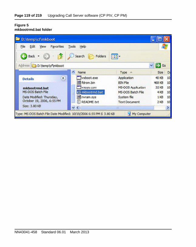
Page 119 of 219 Upgrading Call Server software (CP PIV, CP PM)
NN43041-458 Standard 06.01 March 2013
Figure 5mkbootrmd.bat folder
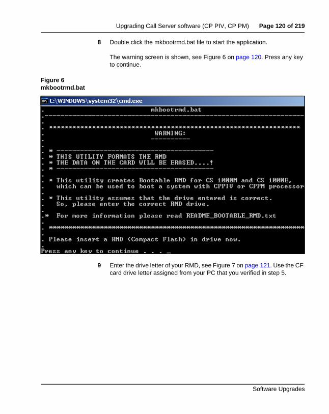
Upgrading Call Server software (CP PIV, CP PM) Page 120 of 219
Software Upgrades
8 Double click the mkbootrmd.bat file to start the application.
The warning screen is shown, see Figure 6 on page 120. Press any key to continue.
Figure 6mkbootrmd.bat
9 Enter the drive letter of your RMD, see Figure 7 on page 121. Use the CF card drive letter assigned from your PC that you verified in step 5.
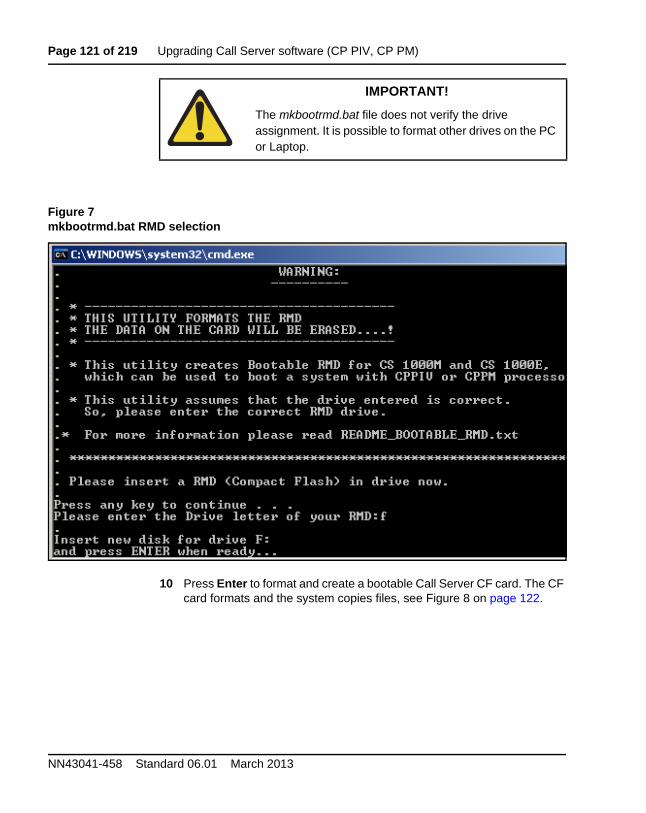
Page 121 of 219 Upgrading Call Server software (CP PIV, CP PM)
NN43041-458 Standard 06.01 March 2013
Figure 7mkbootrmd.bat RMD selection
10 Press Enter to format and create a bootable Call Server CF card. The CF card formats and the system copies files, see Figure 8 on page 122.
IMPORTANT!
The mkbootrmd.bat file does not verify the drive assignment. It is possible to format other drives on the PC or Laptop.
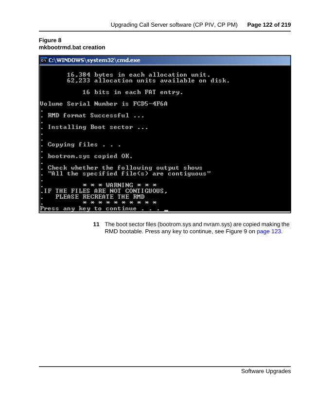
Upgrading Call Server software (CP PIV, CP PM) Page 122 of 219
Software Upgrades
Figure 8mkbootrmd.bat creation
11 The boot sector files (bootrom.sys and nvram.sys) are copied making the RMD bootable. Press any key to continue, see Figure 9 on page 123.
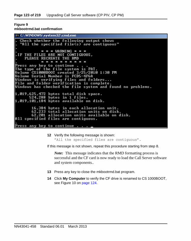
Page 123 of 219 Upgrading Call Server software (CP PIV, CP PM)
NN43041-458 Standard 06.01 March 2013
Figure 9mkbootrmd.bat confirmation
12 Verify the following message is shown:”All the specified files are contiguous”.
If this message is not shown, repeat this procedure starting from step 8.
Note: This message indicates that the RMD formatting process is successful and the CF card is now ready to load the Call Server software and system components..
13 Press any key to close the mkbootrmd.bat program.
14 Click My Computer to verify the CF drive is renamed to CS 1000BOOT, see Figure 10 on page 124.
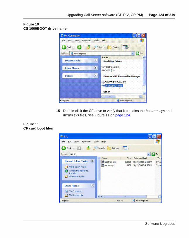
Upgrading Call Server software (CP PIV, CP PM) Page 124 of 219
Software Upgrades
Figure 10CS 1000BOOT drive name
15 Double-click the CF drive to verify that it contains the bootrom.sys and nvram.sys files, see Figure 11 on page 124.
Figure 11CF card boot files
Page 125 of 219 Upgrading Call Server software (CP PIV, CP PM)
NN43041-458 Standard 06.01 March 2013
16 Navigate the folder on your PC that contains the Call Server software load folders and files.
17 Copy all the folders to the CF card.
Note: This can take up to 12 minutes depending on the speed of the computer. The files are copied from the hard drive on the local PC to the CF card in the CF drive.
When all subfolders and files are copied successfully to the CF card, it can be used to install or upgrade the software on a Call Server.
18 Copy the keycode file to be used for installing or upgrading the keycode directories to the CF card.
19 Remove the CF card from the CF drive and label it appropriately.
An example for a label is, Call Processor, CS-x.xx.xx, where x.xx.xx represents the Call Server software version.
End of Procedure
Connecting a terminal
Procedure 12Connecting a terminal
A maintenance terminal is required to access the Call Servers during the upgrade procedure.
1 Connect a terminal to the COM 1 port on the faceplate of the CP PIV card or the Serial Port 0 on the CP PM card of the Call Server.
Note: In case of HA, connect to inactive Call Server.
2 The settings for the terminal are:
a. Terminal type: VT100
b. 9600 Baud
c. Data bits: 8
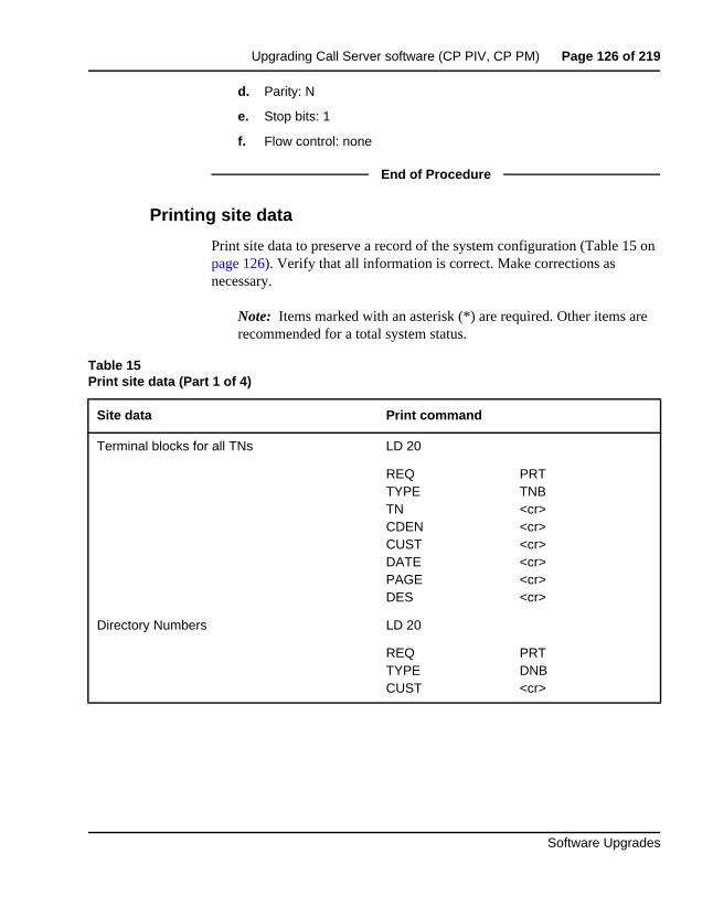
Upgrading Call Server software (CP PIV, CP PM) Page 126 of 219
Software Upgrades
d. Parity: N
e. Stop bits: 1
f. Flow control: none
End of Procedure
Printing site data
Print site data to preserve a record of the system configuration (Table 15 on page 126). Verify that all information is correct. Make corrections as necessary.
Note: Items marked with an asterisk (*) are required. Other items are recommended for a total system status.
Table 15Print site data (Part 1 of 4)
Site data Print command
Terminal blocks for all TNs LD 20
REQTYPETNCDENCUST DATEPAGEDES
PRTTNB<cr><cr><cr><cr><cr><cr>
Directory Numbers LD 20
REQTYPECUST
PRTDNB<cr>
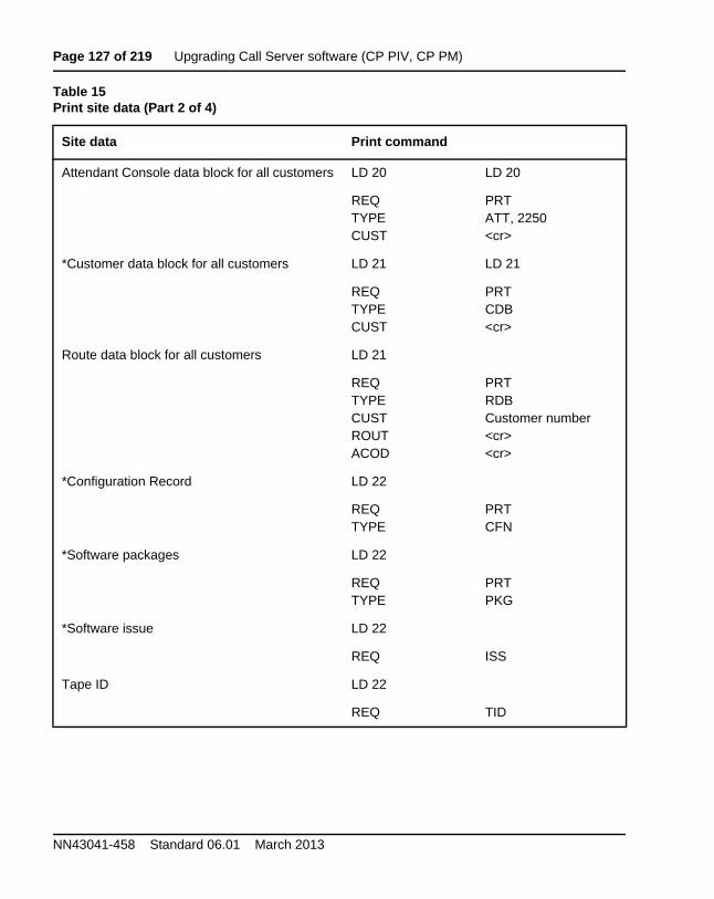
Page 127 of 219 Upgrading Call Server software (CP PIV, CP PM)
NN43041-458 Standard 06.01 March 2013
Attendant Console data block for all customers LD 20 LD 20
REQTYPECUST
PRTATT, 2250<cr>
*Customer data block for all customers LD 21 LD 21
REQTYPECUST
PRTCDB<cr>
Route data block for all customers LD 21
REQTYPECUSTROUTACOD
PRTRDBCustomer number<cr><cr>
*Configuration Record LD 22
REQTYPE
PRTCFN
*Software packages LD 22
REQTYPE
PRTPKG
*Software issue LD 22
REQ ISS
Tape ID LD 22
REQ TID
Table 15Print site data (Part 2 of 4)
Site data Print command
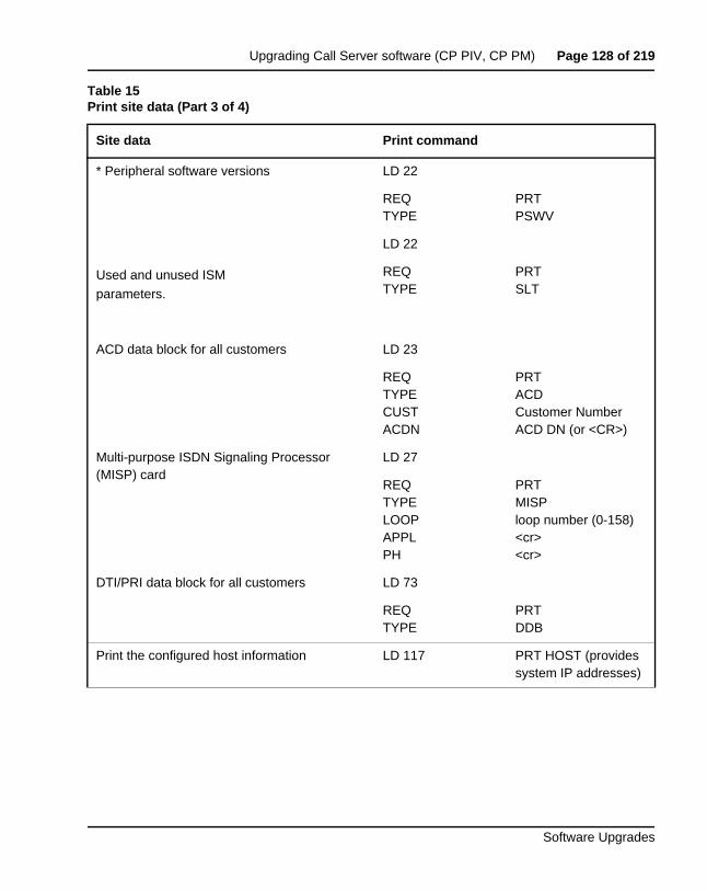
Upgrading Call Server software (CP PIV, CP PM) Page 128 of 219
Software Upgrades
* Peripheral software versions LD 22
REQTYPE
PRTPSWV
LD 22
Used and unused ISM
parameters.
REQTYPE
PRTSLT
ACD data block for all customers LD 23
REQTYPECUSTACDN
PRTACDCustomer NumberACD DN (or <CR>)
Multi-purpose ISDN Signaling Processor (MISP) card
LD 27
REQTYPELOOPAPPLPH
PRTMISPloop number (0-158)<cr><cr>
DTI/PRI data block for all customers LD 73
REQTYPE
PRTDDB
Print the configured host information LD 117 PRT HOST (provides system IP addresses)
Table 15Print site data (Part 3 of 4)
Site data Print command
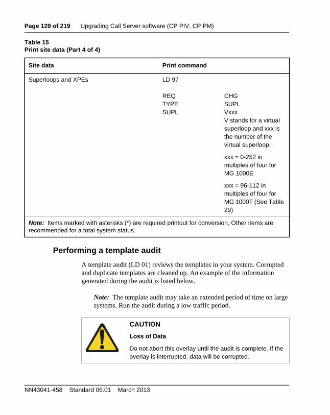
Page 129 of 219 Upgrading Call Server software (CP PIV, CP PM)
NN43041-458 Standard 06.01 March 2013
Performing a template audit
A template audit (LD 01) reviews the templates in your system. Corrupted and duplicate templates are cleaned up. An example of the information generated during the audit is listed below.
Note: The template audit may take an extended period of time on large systems. Run the audit during a low traffic period.
Superloops and XPEs LD 97
REQTYPESUPL
CHGSUPLVxxxV stands for a virtual superloop and xxx is the number of the virtual superloop.
xxx = 0-252 in multiples of four for MG 1000E
xxx = 96-112 in multiples of four for MG 1000T (See Table 29)
Note: Items marked with asterisks (*) are required printout for conversion. Other items are recommended for a total system status.
CAUTION
Loss of Data
Do not abort this overlay until the audit is complete. If the overlay is interrupted, data will be corrupted.
Table 15Print site data (Part 4 of 4)
Site data Print command
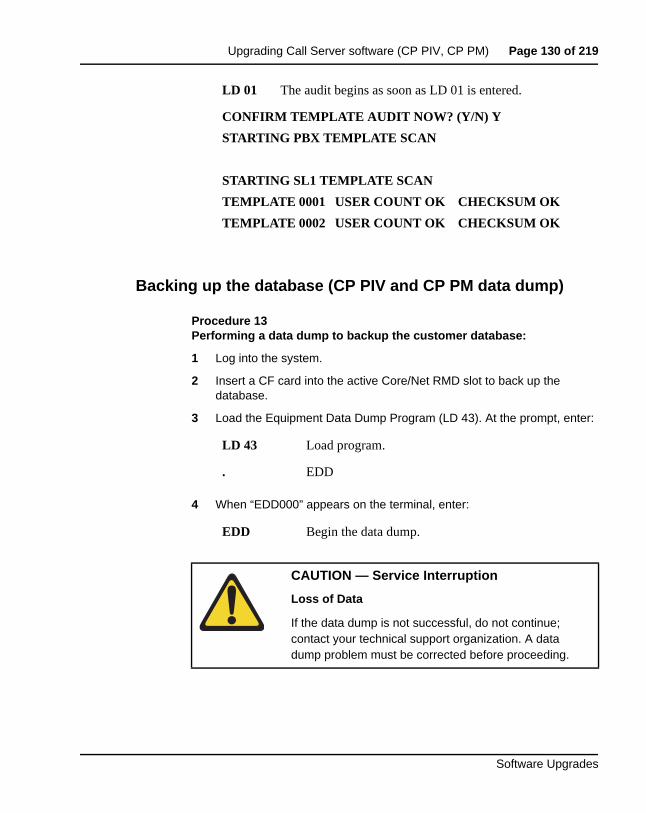
Upgrading Call Server software (CP PIV, CP PM) Page 130 of 219
Software Upgrades
Backing up the database (CP PIV and CP PM data dump)
Procedure 13Performing a data dump to backup the customer database:
1 Log into the system.
2 Insert a CF card into the active Core/Net RMD slot to back up the database.
3 Load the Equipment Data Dump Program (LD 43). At the prompt, enter:
4 When “EDD000” appears on the terminal, enter:
LD 01 The audit begins as soon as LD 01 is entered.
CONFIRM TEMPLATE AUDIT NOW? (Y/N) Y
STARTING PBX TEMPLATE SCAN
STARTING SL1 TEMPLATE SCAN
TEMPLATE 0001 USER COUNT OK CHECKSUM OK
TEMPLATE 0002 USER COUNT OK CHECKSUM OK
LD 43 Load program.
. EDD
EDD Begin the data dump.
CAUTION — Service Interruption
Loss of Data
If the data dump is not successful, do not continue; contact your technical support organization. A data dump problem must be corrected before proceeding.
Page 131 of 219 Upgrading Call Server software (CP PIV, CP PM)
NN43041-458 Standard 06.01 March 2013
5 When “DATADUMP COMPLETE” and “DATABASE BACKUP COMPLETE” will appear once the data dump is complete.
6 The message “Backup process to local Removable Media Device ended successfully” appears. Remove and label the CF card.
End of Procedure
**** Exit program
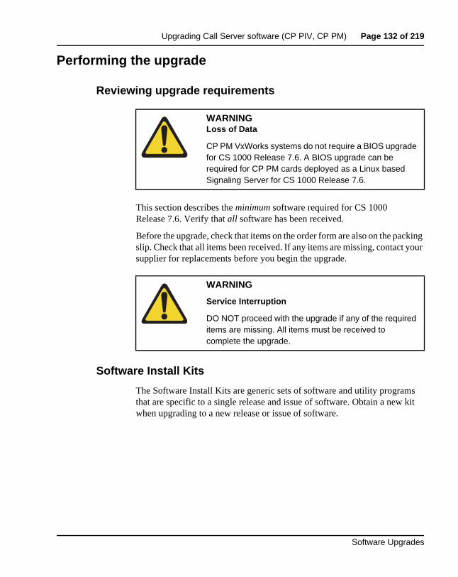
Upgrading Call Server software (CP PIV, CP PM) Page 132 of 219
Software Upgrades
Performing the upgrade
Reviewing upgrade requirements
This section describes the minimum software required for CS 1000 Release 7.6. Verify that all software has been received.
Before the upgrade, check that items on the order form are also on the packing slip. Check that all items been received. If any items are missing, contact your supplier for replacements before you begin the upgrade.
Software Install Kits
The Software Install Kits are generic sets of software and utility programs that are specific to a single release and issue of software. Obtain a new kit when upgrading to a new release or issue of software.
WARNINGLoss of Data
CP PM VxWorks systems do not require a BIOS upgrade for CS 1000 Release 7.6. A BIOS upgrade can be required for CP PM cards deployed as a Linux based Signaling Server for CS 1000 Release 7.6.
WARNING
Service Interruption
DO NOT proceed with the upgrade if any of the required items are missing. All items must be received to complete the upgrade.
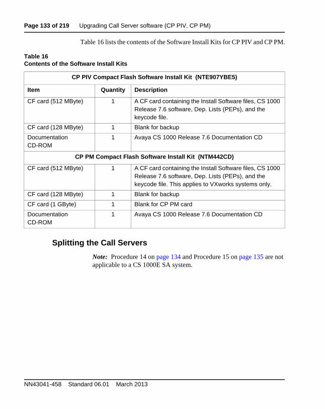
Page 133 of 219 Upgrading Call Server software (CP PIV, CP PM)
NN43041-458 Standard 06.01 March 2013
Table 16 lists the contents of the Software Install Kits for CP PIV and CP PM.
Splitting the Call Servers
Note: Procedure 14 on page 134 and Procedure 15 on page 135 are not applicable to a CS 1000E SA system.
Table 16Contents of the Software Install Kits
CP PIV Compact Flash Software Install Kit (NTE907YBE5)
Item Quantity Description
CF card (512 MByte) 1 A CF card containing the Install Software files, CS 1000 Release 7.6 software, Dep. Lists (PEPs), and the keycode file.
CF card (128 MByte) 1 Blank for backup
Documentation CD-ROM
1 Avaya CS 1000 Release 7.6 Documentation CD
CP PM Compact Flash Software Install Kit (NTM442CD)
CF card (512 MByte) 1 A CF card containing the Install Software files, CS 1000 Release 7.6 software, Dep. Lists (PEPs), and the keycode file. This applies to VXworks systems only.
CF card (128 MByte) 1 Blank for backup
CF card (1 GByte) 1 Blank for CP PM card
Documentation CD-ROM
1 Avaya CS 1000 Release 7.6 Documentation CD
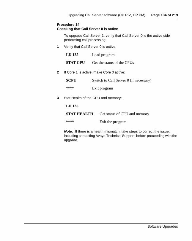
Upgrading Call Server software (CP PIV, CP PM) Page 134 of 219
Software Upgrades
Procedure 14Checking that Call Server 0 is active
To upgrade Call Server 1, verify that Call Server 0 is the active side performing call processing:
1 Verify that Call Server 0 is active.
2 If Core 1 is active, make Core 0 active:
3 Stat Health of the CPU and memory:
Note: If there is a health mismatch, take steps to correct the issue, including contacting Avaya Technical Support, before proceeding with the upgrade.
LD 135 Load program
STAT CPU Get the status of the CPUs
SCPU Switch to Call Server 0 (if necessary)
**** Exit program
LD 135
STAT HEALTH Get status of CPU and memory
**** Exit the program
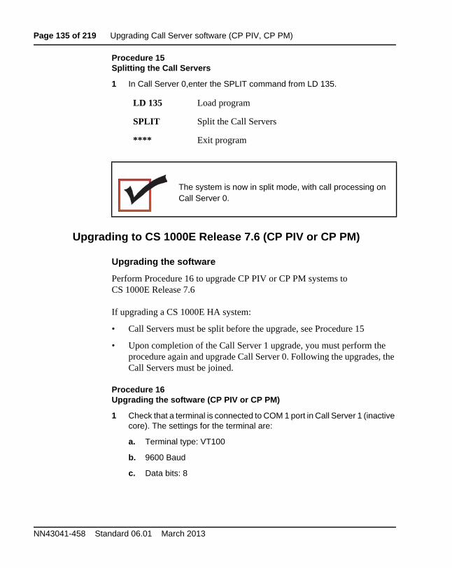
Page 135 of 219 Upgrading Call Server software (CP PIV, CP PM)
NN43041-458 Standard 06.01 March 2013
Procedure 15Splitting the Call Servers
1 In Call Server 0,enter the SPLIT command from LD 135.
Upgrading to CS 1000E Release 7.6 (CP PIV or CP PM)
Upgrading the software
Perform Procedure 16 to upgrade CP PIV or CP PM systems to CS 1000E Release 7.6
If upgrading a CS 1000E HA system:
• Call Servers must be split before the upgrade, see Procedure 15
• Upon completion of the Call Server 1 upgrade, you must perform the procedure again and upgrade Call Server 0. Following the upgrades, the Call Servers must be joined.
Procedure 16Upgrading the software (CP PIV or CP PM)
1 Check that a terminal is connected to COM 1 port in Call Server 1 (inactive core). The settings for the terminal are:
a. Terminal type: VT100
b. 9600 Baud
c. Data bits: 8
LD 135 Load program
SPLIT Split the Call Servers
**** Exit program
The system is now in split mode, with call processing on Call Server 0.
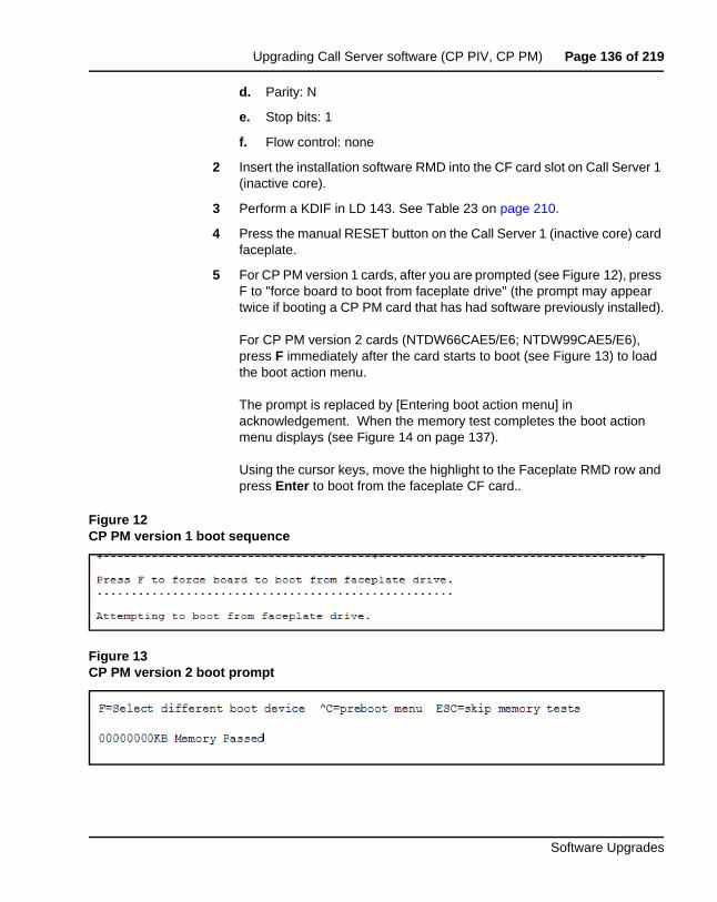
Upgrading Call Server software (CP PIV, CP PM) Page 136 of 219
Software Upgrades
d. Parity: N
e. Stop bits: 1
f. Flow control: none
2 Insert the installation software RMD into the CF card slot on Call Server 1 (inactive core).
3 Perform a KDIF in LD 143. See Table 23 on page 210.
4 Press the manual RESET button on the Call Server 1 (inactive core) card faceplate.
5 For CP PM version 1 cards, after you are prompted (see Figure 12), press F to "force board to boot from faceplate drive" (the prompt may appear twice if booting a CP PM card that has had software previously installed).
For CP PM version 2 cards (NTDW66CAE5/E6; NTDW99CAE5/E6), press F immediately after the card starts to boot (see Figure 13) to load the boot action menu.
The prompt is replaced by [Entering boot action menu] in acknowledgement. When the memory test completes the boot action menu displays (see Figure 14 on page 137).
Using the cursor keys, move the highlight to the Faceplate RMD row and press Enter to boot from the faceplate CF card..
Figure 12CP PM version 1 boot sequence
Figure 13CP PM version 2 boot prompt
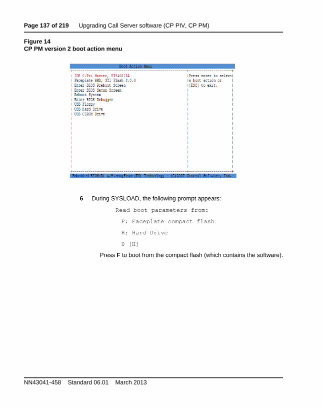
Page 137 of 219 Upgrading Call Server software (CP PIV, CP PM)
NN43041-458 Standard 06.01 March 2013
Figure 14CP PM version 2 boot action menu
6 During SYSLOAD, the following prompt appears:
Read boot parameters from:
F: Faceplate compact flash
H: Hard Drive
0 [H]
Press F to boot from the compact flash (which contains the software).
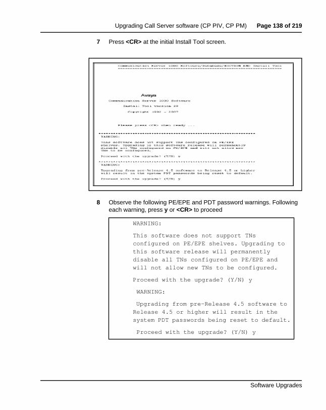
Upgrading Call Server software (CP PIV, CP PM) Page 138 of 219
Software Upgrades
7 Press <CR> at the initial Install Tool screen.
8 Observe the following PE/EPE and PDT password warnings. Following each warning, press y or <CR> to proceed
WARNING:
This software does not support TNs
configured on PE/EPE shelves. Upgrading to
this software release will permanently
disable all TNs configured on PE/EPE and
will not allow new TNs to be configured.
Proceed with the upgrade? (Y/N) y
WARNING:
Upgrading from pre-Release 4.5 software to
Release 4.5 or higher will result in the
system PDT passwords being reset to default.
Proceed with the upgrade? (Y/N) y
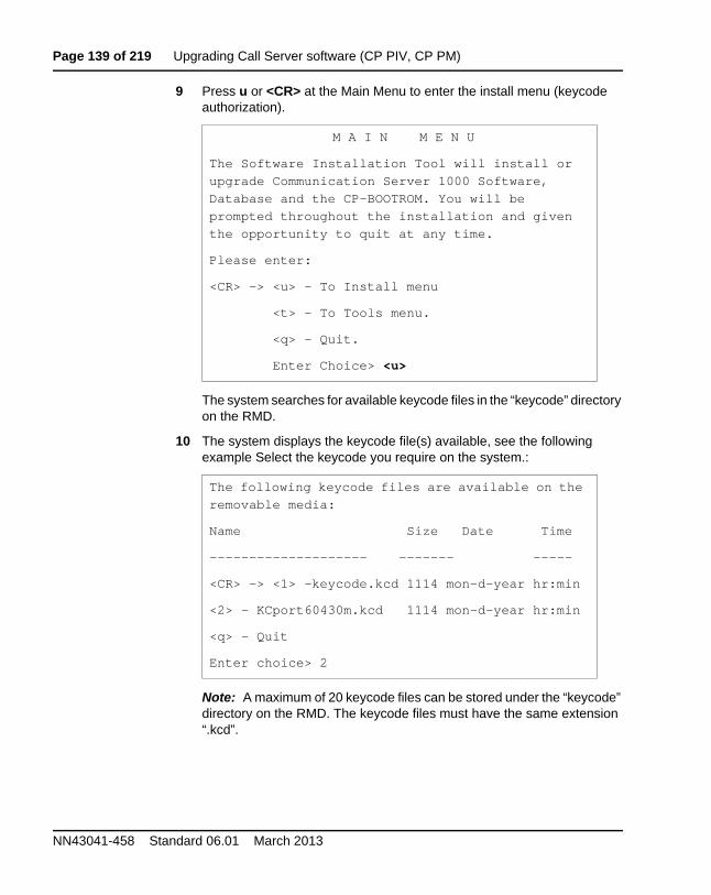
Page 139 of 219 Upgrading Call Server software (CP PIV, CP PM)
NN43041-458 Standard 06.01 March 2013
9 Press u or <CR> at the Main Menu to enter the install menu (keycode authorization).
The system searches for available keycode files in the “keycode” directory on the RMD.
10 The system displays the keycode file(s) available, see the following example Select the keycode you require on the system.:
Note: A maximum of 20 keycode files can be stored under the “keycode” directory on the RMD. The keycode files must have the same extension “.kcd”.
M A I N M E N U
The Software Installation Tool will install or
upgrade Communication Server 1000 Software,
Database and the CP-BOOTROM. You will be
prompted throughout the installation and given
the opportunity to quit at any time.
Please enter:
<CR> -> <u> - To Install menu
<t> - To Tools menu.
<q> - Quit.
Enter Choice> <u>
The following keycode files are available on the
removable media:
Name Size Date Time
-------------------- ------- -----
<CR> -> <1> -keycode.kcd 1114 mon-d-year hr:min
<2> - KCport60430m.kcd 1114 mon-d-year hr:min
<q> - Quit
Enter choice> 2
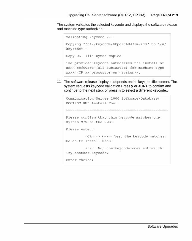
Upgrading Call Server software (CP PIV, CP PM) Page 140 of 219
Software Upgrades
The system validates the selected keycode and displays the software release and machine type authorized.
11 The software release displayed depends on the keycode file content. The system requests keycode validation Press y or <CR> to confirm and continue to the next step, or press n to select a different keycode..
Validating keycode ...
Copying "/cf2/keycode/KCport60430m.kcd" to "/u/
keycode" -
Copy OK: 1114 bytes copied
The provided keycode authorizes the install of
xxxx software (all subissues) for machine type
xxxx (CP xx processor on <system>).
Communication Server 1000 Software/Database/
BOOTROM RMD Install Tool
================================================
Please confirm that this keycode matches the
System S/W on the RMD.
Please enter:
<CR> -> <y> - Yes, the keycode matches.
Go on to Install Menu.
<n> - No, the keycode does not match.
Try another keycode.
Enter choice>
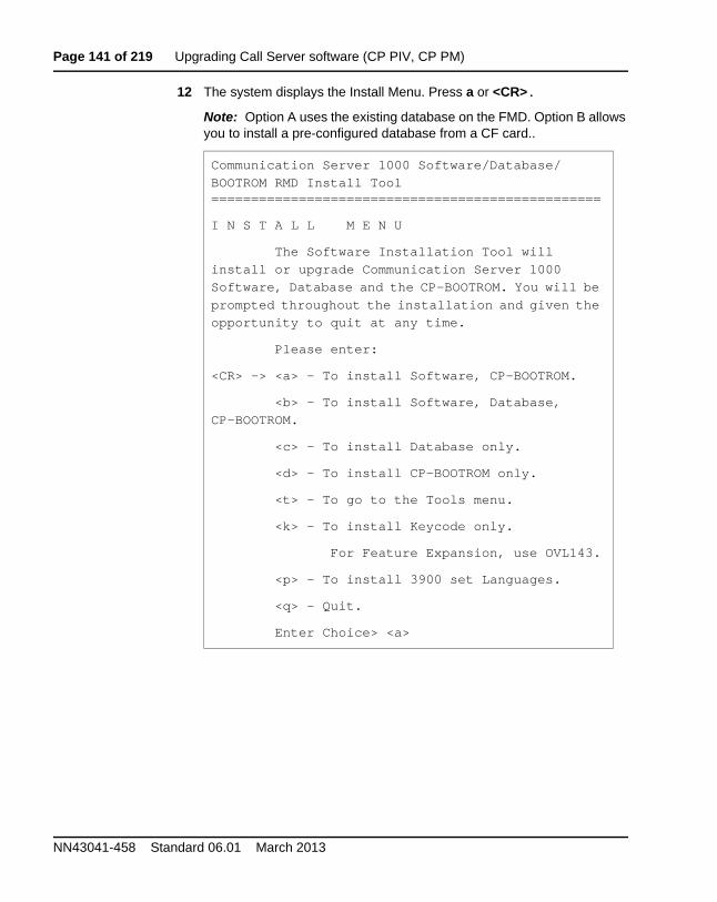
Page 141 of 219 Upgrading Call Server software (CP PIV, CP PM)
NN43041-458 Standard 06.01 March 2013
12 The system displays the Install Menu. Press a or <CR>.
Note: Option A uses the existing database on the FMD. Option B allows you to install a pre-configured database from a CF card..
Communication Server 1000 Software/Database/
BOOTROM RMD Install Tool=================================================
I N S T A L L M E N U
The Software Installation Tool will
install or upgrade Communication Server 1000
Software, Database and the CP-BOOTROM. You will be
prompted throughout the installation and given the
opportunity to quit at any time.
Please enter:
<CR> -> <a> - To install Software, CP-BOOTROM.
<b> - To install Software, Database,
CP-BOOTROM.
<c> - To install Database only.
<d> - To install CP-BOOTROM only.
<t> - To go to the Tools menu.
<k> - To install Keycode only.
For Feature Expansion, use OVL143.
<p> - To install 3900 set Languages.
<q> - Quit.
Enter Choice> <a>
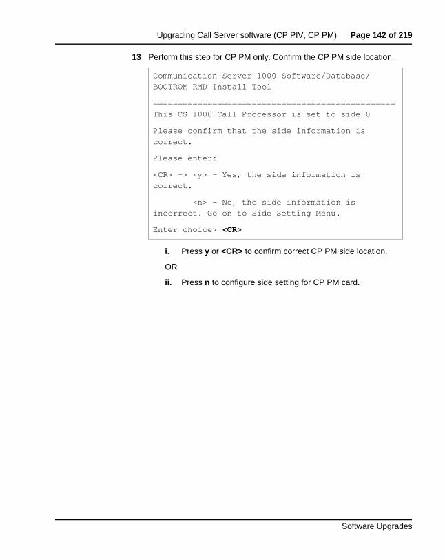
Upgrading Call Server software (CP PIV, CP PM) Page 142 of 219
Software Upgrades
13 Perform this step for CP PM only. Confirm the CP PM side location.
i. Press y or <CR> to confirm correct CP PM side location.
OR
ii. Press n to configure side setting for CP PM card.
Communication Server 1000 Software/Database/
BOOTROM RMD Install Tool
=================================================
This CS 1000 Call Processor is set to side 0
Please confirm that the side information is
correct.
Please enter:
<CR> -> <y> - Yes, the side information is
correct.
<n> - No, the side information is
incorrect. Go on to Side Setting Menu.
Enter choice> <CR>
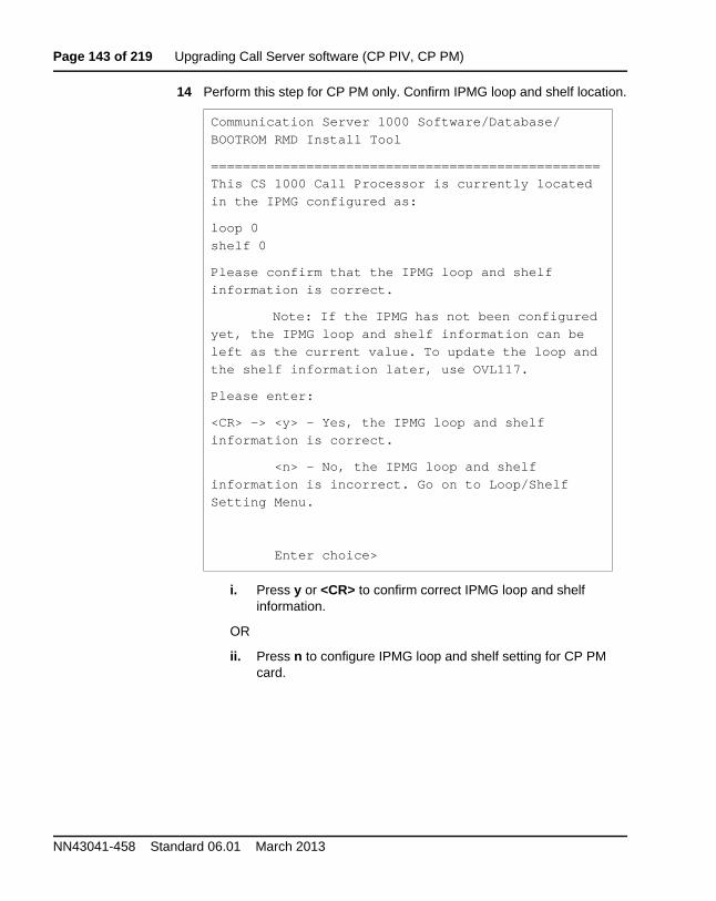
Page 143 of 219 Upgrading Call Server software (CP PIV, CP PM)
NN43041-458 Standard 06.01 March 2013
14 Perform this step for CP PM only. Confirm IPMG loop and shelf location.
i. Press y or <CR> to confirm correct IPMG loop and shelf information.
OR
ii. Press n to configure IPMG loop and shelf setting for CP PM card.
Communication Server 1000 Software/Database/
BOOTROM RMD Install Tool
=================================================
This CS 1000 Call Processor is currently located
in the IPMG configured as:
loop 0
shelf 0
Please confirm that the IPMG loop and shelf
information is correct.
Note: If the IPMG has not been configured
yet, the IPMG loop and shelf information can be
left as the current value. To update the loop and
the shelf information later, use OVL117.
Please enter:
<CR> -> <y> - Yes, the IPMG loop and shelf
information is correct.
<n> - No, the IPMG loop and shelf
information is incorrect. Go on to Loop/Shelf
Setting Menu.
Enter choice>
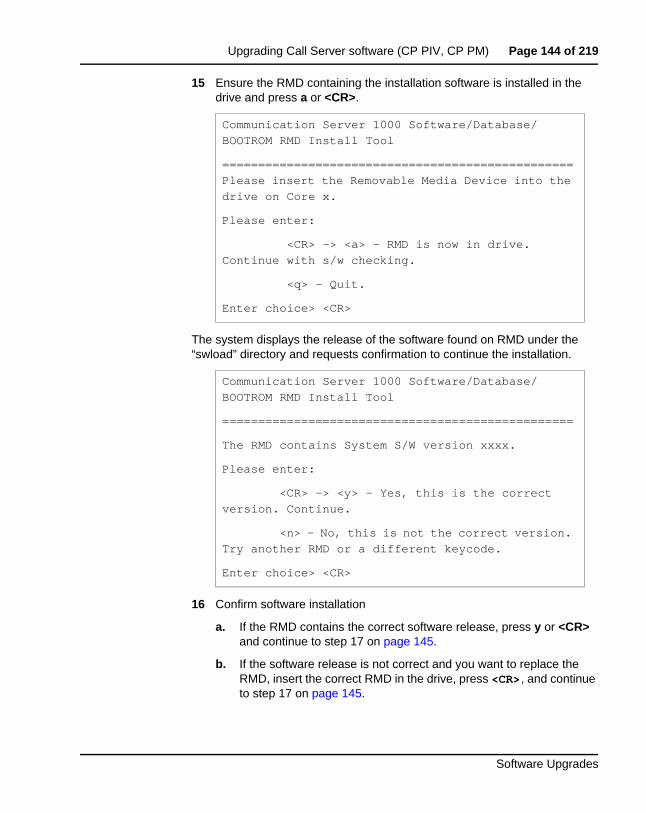
Upgrading Call Server software (CP PIV, CP PM) Page 144 of 219
Software Upgrades
15 Ensure the RMD containing the installation software is installed in the drive and press a or <CR>.
The system displays the release of the software found on RMD under the “swload” directory and requests confirmation to continue the installation.
16 Confirm software installation
a. If the RMD contains the correct software release, press y or <CR> and continue to step 17 on page 145.
b. If the software release is not correct and you want to replace the RMD, insert the correct RMD in the drive, press <CR>,and continue to step 17 on page 145.
Communication Server 1000 Software/Database/
BOOTROM RMD Install Tool
=================================================
Please insert the Removable Media Device into the
drive on Core x.
Please enter:
<CR> -> <a> - RMD is now in drive.
Continue with s/w checking.
<q> - Quit.
Enter choice> <CR>
Communication Server 1000 Software/Database/
BOOTROM RMD Install Tool
=================================================
The RMD contains System S/W version xxxx.
Please enter:
<CR> -> <y> - Yes, this is the correct
version. Continue.
<n> - No, this is not the correct version.
Try another RMD or a different keycode.
Enter choice> <CR>
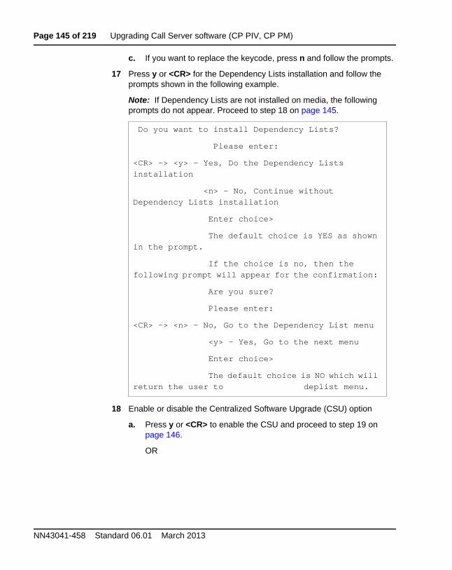
Page 145 of 219 Upgrading Call Server software (CP PIV, CP PM)
NN43041-458 Standard 06.01 March 2013
c. If you want to replace the keycode, press n and follow the prompts.
17 Press y or <CR> for the Dependency Lists installation and follow the prompts shown in the following example.
Note: If Dependency Lists are not installed on media, the following prompts do not appear. Proceed to step 18 on page 145.
18 Enable or disable the Centralized Software Upgrade (CSU) option
a. Press y or <CR> to enable the CSU and proceed to step 19 on page 146.
OR
Do you want to install Dependency Lists?
Please enter:
<CR> -> <y> - Yes, Do the Dependency Lists
installation
<n> - No, Continue without
Dependency Lists installation
Enter choice>
The default choice is YES as shown
in the prompt.
If the choice is no, then the
following prompt will appear for the confirmation:
Are you sure?
Please enter:
<CR> -> <n> - No, Go to the Dependency List menu
<y> - Yes, Go to the next menu
Enter choice>
The default choice is NO which will
return the user to deplist menu.
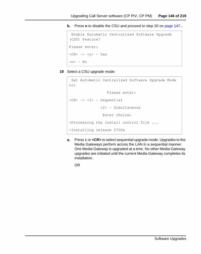
Upgrading Call Server software (CP PIV, CP PM) Page 146 of 219
Software Upgrades
b. Press n to disable the CSU and proceed to step 20 on page 147..
19 Select a CSU upgrade mode:
a. Press 1 or <CR> to select sequential upgrade mode. Upgrades to the Media Gateways perform across the LAN in a sequential manner. One Media Gateway is upgraded at a time. No other Media Gateway upgrades are initiated until the current Media Gateway completes its installation.
OR
Enable Automatic Centralized Software Upgrade
(CSU) Feature?
Please enter:
<CR> -> <y> - Yes
<n> - No
Set Automatic Centralized Software Upgrade Mode
to:
Please enter:
<CR> -> <1> - Sequential
<2> - Simultaneous
Enter choice>
>Processing the install control file ...
>Installing release 0700x
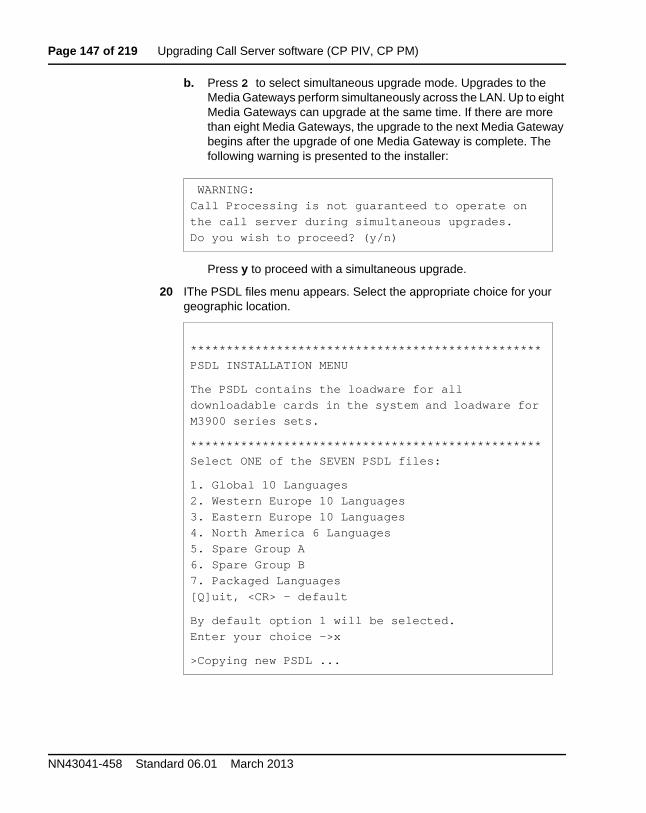
Page 147 of 219 Upgrading Call Server software (CP PIV, CP PM)
NN43041-458 Standard 06.01 March 2013
b. Press 2 to select simultaneous upgrade mode. Upgrades to the Media Gateways perform simultaneously across the LAN. Up to eight Media Gateways can upgrade at the same time. If there are more than eight Media Gateways, the upgrade to the next Media Gateway begins after the upgrade of one Media Gateway is complete. The following warning is presented to the installer:
Press y to proceed with a simultaneous upgrade.
20 IThe PSDL files menu appears. Select the appropriate choice for your geographic location.
WARNING:
Call Processing is not guaranteed to operate on
the call server during simultaneous upgrades.
Do you wish to proceed? (y/n)
*************************************************
PSDL INSTALLATION MENU
The PSDL contains the loadware for all
downloadable cards in the system and loadware for
M3900 series sets.
*************************************************
Select ONE of the SEVEN PSDL files:
1. Global 10 Languages
2. Western Europe 10 Languages
3. Eastern Europe 10 Languages
4. North America 6 Languages
5. Spare Group A
6. Spare Group B
7. Packaged Languages
[Q]uit, <CR> - default
By default option 1 will be selected.
Enter your choice ->x
>Copying new PSDL ...
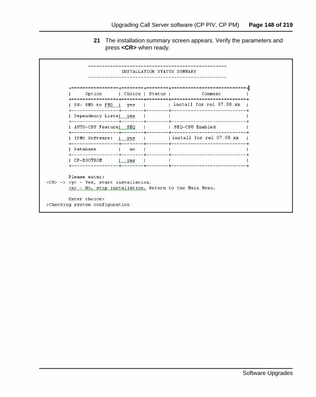
Upgrading Call Server software (CP PIV, CP PM) Page 148 of 219
Software Upgrades
21 The installation summary screen appears. Verify the parameters and press <CR> when ready.
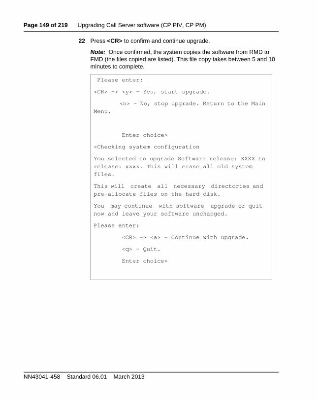
Page 149 of 219 Upgrading Call Server software (CP PIV, CP PM)
NN43041-458 Standard 06.01 March 2013
22 Press <CR> to confirm and continue upgrade.
Note: Once confirmed, the system copies the software from RMD to FMD (the files copied are listed). This file copy takes between 5 and 10 minutes to complete.
Please enter:
<CR> -> <y> - Yes, start upgrade.
<n> - No, stop upgrade. Return to the Main
Menu.
Enter choice>
>Checking system configuration
You selected to upgrade Software release: XXXX to
release: xxxx. This will erase all old system
files.
This will create all necessary directories and
pre-allocate files on the hard disk.
You may continue with software upgrade or quit
now and leave your software unchanged.
Please enter:
<CR> -> <a> - Continue with upgrade.
<q> - Quit.
Enter choice>
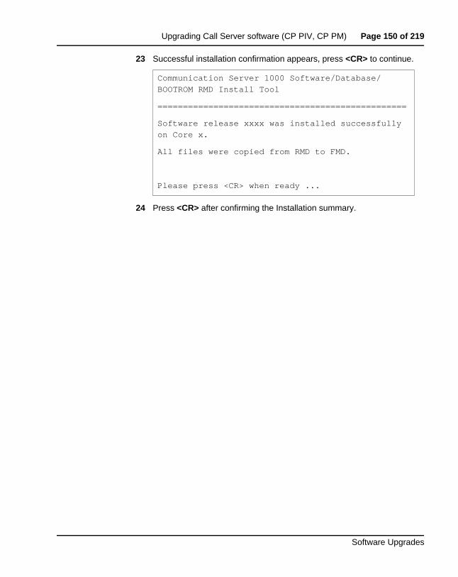
Upgrading Call Server software (CP PIV, CP PM) Page 150 of 219
Software Upgrades
23 Successful installation confirmation appears, press <CR> to continue.
24 Press <CR> after confirming the Installation summary.
Communication Server 1000 Software/Database/
BOOTROM RMD Install Tool
=================================================
Software release xxxx was installed successfully
on Core x.
All files were copied from RMD to FMD.
Please press <CR> when ready ...
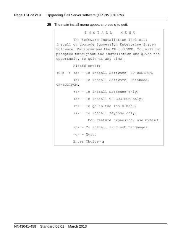
Page 151 of 219 Upgrading Call Server software (CP PIV, CP PM)
NN43041-458 Standard 06.01 March 2013
25 The main install menu appears, press q to quit.
I N S T A L L M E N U
The Software Installation Tool will
install or upgrade Succession Enterprise System
Software, Database and the CP-BOOTROM. You will be
prompted throughout the installation and given the
opportunity to quit at any time.
Please enter:
<CR> -> <a> - To install Software, CP-BOOTROM.
<b> - To install Software, Database,
CP-BOOTROM.
<c> - To install Database only.
<d> - To install CP-BOOTROM only.
<t> - To go to the Tools menu.
<k> - To install Keycode only.
For Feature Expansion, use OVL143.
<p> - To install 3900 set Languages.
<q> - Quit.
Enter Choice> q
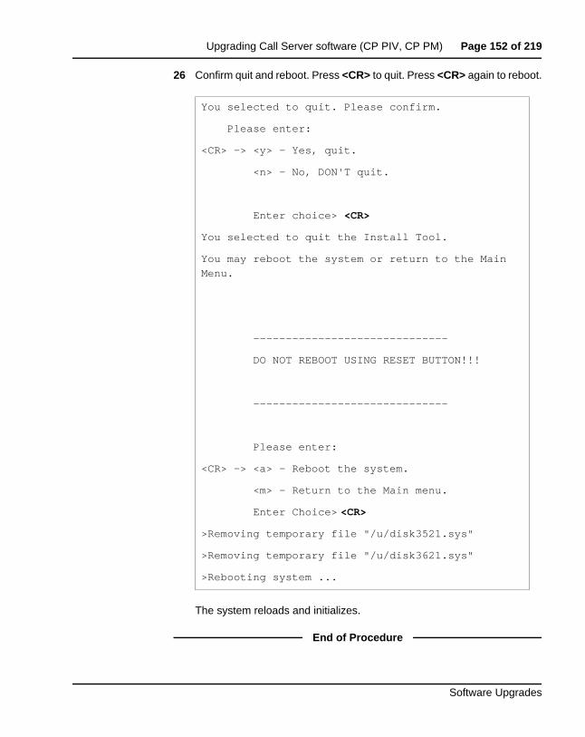
Upgrading Call Server software (CP PIV, CP PM) Page 152 of 219
Software Upgrades
26 Confirm quit and reboot. Press <CR> to quit. Press <CR> again to reboot.
The system reloads and initializes.
End of Procedure
You selected to quit. Please confirm.
Please enter:
<CR> -> <y> - Yes, quit.
<n> - No, DON'T quit.
Enter choice> <CR>
You selected to quit the Install Tool.
You may reboot the system or return to the Main
Menu.
------------------------------
DO NOT REBOOT USING RESET BUTTON!!!
------------------------------
Please enter:
<CR> -> <a> - Reboot the system.
<m> - Return to the Main menu.
Enter Choice> <CR>
>Removing temporary file "/u/disk3521.sys"
>Removing temporary file "/u/disk3621.sys"
>Rebooting system ...
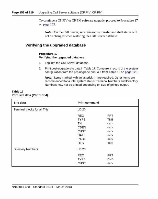
Page 153 of 219 Upgrading Call Server software (CP PIV, CP PM)
NN43041-458 Standard 06.01 March 2013
To continue a CP PIV or CP PM software upgrade, proceed to Procedure 17 on page 153.
Note: On the Call Server, secure/insecure transfer and shell status will not be changed when restoring the Call Server database.
Verifying the upgraded database
Procedure 17Verifying the upgraded database
1 Log into the Call Server database.
2 Print post-upgrade site data in Table 17. Compare a record of the system configuration from the pre-upgrade print out from Table 15 on page 126.
Note: Items marked with an asterisk (*) are required. Other items are recommended for a total system status. Terminal Numbers and Directory Numbers may not be printed depending on size of printed output.
Table 17Print site data (Part 1 of 4)
Site data Print command
Terminal blocks for all TNs LD 20
REQTYPETNCDENCUST DATEPAGEDES
PRTTNB<cr><cr><cr><cr><cr><cr>
Directory Numbers LD 20
REQTYPECUST
PRTDNB<cr>

Upgrading Call Server software (CP PIV, CP PM) Page 154 of 219
Software Upgrades
Attendant Console data block for all customers LD 20 LD 20
REQTYPECUST
PRTATT, 2250<cr>
*Customer data block for all customers LD 21 LD 21
REQTYPECUST
PRTCDB<cr>
Route data block for all customers LD 21
REQTYPECUSTROUTACOD
PRTRDBCustomer number<cr><cr>
*Configuration Record LD 22
REQTYPE
PRTCFN
*Software packages LD 22
REQTYPE
PRTPKG
*Software issue and tape ID LD 22
REQREQ
ISSTID
* Peripheral software versions LD 22
REQTYPE
PRTPSWV
LD 22
Table 17Print site data (Part 2 of 4)
Site data Print command
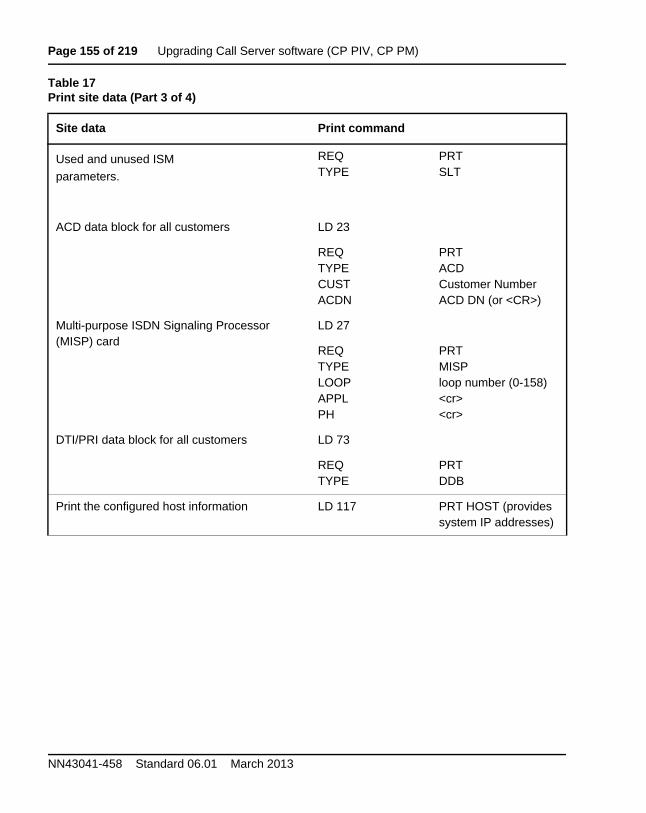
Page 155 of 219 Upgrading Call Server software (CP PIV, CP PM)
NN43041-458 Standard 06.01 March 2013
Used and unused ISM
parameters.
REQTYPE
PRTSLT
ACD data block for all customers LD 23
REQTYPECUSTACDN
PRTACDCustomer NumberACD DN (or <CR>)
Multi-purpose ISDN Signaling Processor (MISP) card
LD 27
REQTYPELOOPAPPLPH
PRTMISPloop number (0-158)<cr><cr>
DTI/PRI data block for all customers LD 73
REQTYPE
PRTDDB
Print the configured host information LD 117 PRT HOST (provides system IP addresses)
Table 17Print site data (Part 3 of 4)
Site data Print command
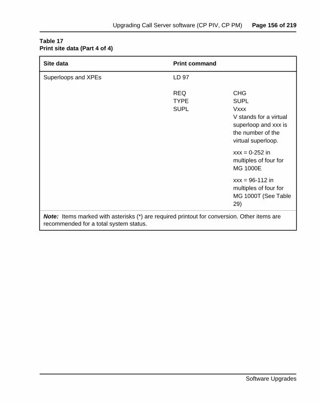
Upgrading Call Server software (CP PIV, CP PM) Page 156 of 219
Software Upgrades
Superloops and XPEs LD 97
REQTYPESUPL
CHGSUPLVxxxV stands for a virtual superloop and xxx is the number of the virtual superloop.
xxx = 0-252 in multiples of four for MG 1000E
xxx = 96-112 in multiples of four for MG 1000T (See Table 29)
Note: Items marked with asterisks (*) are required printout for conversion. Other items are recommended for a total system status.
Table 17Print site data (Part 4 of 4)
Site data Print command
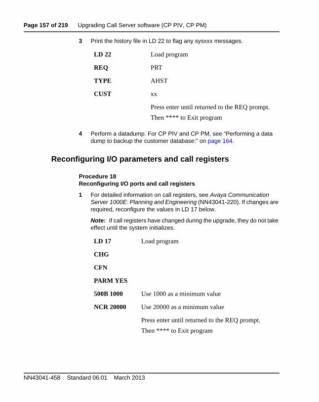
Page 157 of 219 Upgrading Call Server software (CP PIV, CP PM)
NN43041-458 Standard 06.01 March 2013
3 Print the history file in LD 22 to flag any sysxxx messages.
4 Perform a datadump. For CP PIV and CP PM, see “Performing a data dump to backup the customer database:” on page 164.
Reconfiguring I/O parameters and call registers
Procedure 18Reconfiguring I/O ports and call registers
1 For detailed information on call registers, see Avaya Communication Server 1000E: Planning and Engineering (NN43041-220). If changes are required, reconfigure the values in LD 17 below.
Note: If call registers have changed during the upgrade, they do not take effect until the system initializes.
LD 22 Load program
REQ PRT
TYPE AHST
CUST xx
Press enter until returned to the REQ prompt.
Then **** to Exit program
LD 17 Load program
CHG
CFN
PARM YES
500B 1000 Use 1000 as a minimum value
NCR 20000 Use 20000 as a minimum value
Press enter until returned to the REQ prompt.
Then **** to Exit program
Upgrading Call Server software (CP PIV, CP PM) Page 158 of 219
Software Upgrades
2 Print the Configuration Record to confirm the changes made above:
End of Procedure
Switching call processing to Call Server 1
Note: For network planning best practices refer to Avaya Planning the Network-wide upgrade (NN43001-406).
LD 22 Load program
REQ PRT Set the print Option
TYPE CFN Print the configuration
Press enter until returned to the REQ prompt.
Then **** to Exit program
At this point, all-processing dependent associated applications must be shut down.
Page 159 of 219 Upgrading Call Server software (CP PIV, CP PM)
NN43041-458 Standard 06.01 March 2013
Procedure 19Switching call processing
1 Enter LD 135 on Call Server 0 and issue the CUTOVR command. Call processing switches to Call Server 1 and service is interrupted.
2 After Call Server 1 initializes, use the local UCM Administrator account to logon to Call Server 1. Verify that the cutover was successful and that all hardware is operational. Perform acceptance testing as required.
End of Procedure
Upgrade the Voice Gateway Media Card loadware
See “Upgrade the Voice Gateway Media Card loadware” on page 177. Generally, it takes up to 5 minutes to upgrade each Voice Gateway Media Card. A completion message appears for each card when the loadware upgrade is complete.
Upgrading the software on Call Server 0
To upgrade the software on Call Server 0 for CP PIV or CP PM, complete Procedure 16 on page 135 (assume all references to Call Server 1 are now Call Server 0).
LD 135
CUTOVR Transfer call processing from active Call Server to standby Call Server
**** Exit program
Call Server 1 is now the active CP.
Upgrading Call Server software (CP PIV, CP PM) Page 160 of 219
Software Upgrades
Making the system redundant
Procedure 20Making the system redundant
Register the Call Server to the security domain
Perform the following procedure to register the Call Server to the security domain. Security domain registration is required if you are upgrading from CS 1000 Release 5.5 or lower, or if the system is not already registered to the UCM security domain.
Procedure 21Registering the Call Server to the security domain
You can register and unregister a Call Server with the [REGISTER / UNREGISTER] UCMSECURITY SYSTEM FORCE command. For more information, see Avaya Security Management (NN43001-604).
Logoff and login to the Call Server
You must logoff and login to the Call Server using the UCM account that was created when UCM was configured. For details, see Avaya Unified Communications Management Common Services Fundamentals (NN43001-116).
LD 135 Load program
JOIN Join the 2 CPUs together to become redundant
LD 117 Load program
REGISTER UCMSECURITY SYSTEM FORCE
Registers the Call Server to the security domain
Page 161 of 219 Upgrading Call Server software (CP PIV, CP PM)
NN43041-458 Standard 06.01 March 2013
Completing the upgrade
Testing the Call Servers
Procedure 22Testing Call Server 0
At this point in the upgrade, the inactive Call Server is tested from the active Call Server. Upon successful completion of these tests, call processing is switched and the same tests are performed again.
From the active Call Server , perform the following tests on the inactive Call Server:
1 Perform a redundancy sanity test:
2 Check the LCD states
a. Perform a visual check of the LCDs.
b. Test and LCDs:
c. Check that the LCD display matches the software check.
3 Test the System Utility card
LD 135
STAT CPU Get status of CPU and memory
TEST CPU Test the CPU
LD 135
DSPL ALL
LD 135 Load program
STAT SUTL Get the status of the System Utility card
TEST SUTL Test the System Utility card
Upgrading Call Server software (CP PIV, CP PM) Page 162 of 219
Software Upgrades
4 Check the system health.
5 Test system redundancy and media devices:
6 Clear the display and minor alarms on both Call Servers:
7 Check dial tone.
8 Check applications (CallPilot, Symposium, Meridian Mail, etc.)
End of Procedure
Switch call processing
Procedure 23Switching call processing
End of Procedure
LD 135 Load program
STAT HEALTH Check system health
LD 137 Load program
TEST RDUN Test redundancy
LD 135 Load program
CDSP Clear the displays on the cores
CMAJ Clear major alarms
CMIN ALL Clear minor alarms
LD 135 Load program
SCPU Switch call processing from Call Server x to Call Server x
Page 163 of 219 Upgrading Call Server software (CP PIV, CP PM)
NN43041-458 Standard 06.01 March 2013
Procedure 24Testing the Call Server
From the active Call Server , perform these tests on the inactive Call Server:
1 Perform a redundancy sanity test:
2 Check the LCD states.
a. Perform a visual check of the LCDs.
b. Test LCDs:
c. Check that the LCD display matches the software check.
3 Test the System Utility card:
4 Test system redundancy and media devices:
5 Clear the display and minor alarms on both Call Servers:
LD 135 Load program
STAT CPU Get status of CPU and memory
TEST CPU Test the CPU
LD 135 Load program
DSPL ALL
LD 135 Load program
STAT SUTL Get the status of the System Utility card
TEST SUTL Test the System Utility card
LD 137 Load program
TEST RDUN Test redundancy
**** Exit the program
LD 135 Load program
CDSP Clear the displays on the Call Servers
Upgrading Call Server software (CP PIV, CP PM) Page 164 of 219
Software Upgrades
6 Check dial tone.
7 Check applications (CallPilot, Symposium, Meridian Mail, etc.)
End of Procedure
Switching call processing
Procedure 25Switching call processing
End of Procedure
Performing a customer backup CP PIV/CP PM data dump (upgraded release)
Procedure 26Performing a data dump to backup the customer database:
1 Log into the system.
2 Insert a CF card into the active Call Server RMD slot to back up the database.
3 Load the Equipment Data Dump Program (LD 43). At the prompt, enter:
4 When “EDD000” appears on the terminal, enter:
CMAJ Clear major alarms
CMIN ALL Clear minor alarms
LD 135 Load program
SCPU Switch call processing from the active Call Server the inactive Call Server
LD 43 Load program.
. EDD
EDD Begin the data dump.
Page 165 of 219 Upgrading Call Server software (CP PIV, CP PM)
NN43041-458 Standard 06.01 March 2013
5 When “DATADUMP COMPLETE” and “DATABASE BACKUP COMPLETE” appear on the terminal, enter:
End of Procedure
CAUTION
Loss of Data
If the data dump is not successful, do not continue; contact your technical support organization. A data dump problem must be corrected before proceeding.
**** Exit program
The upgrade is now complete.
Page 166 of 219
Software Upgrades
183
Upgrading Voice Gateway Media Cards
ContentsThis section contains information on the following topics:
Things to know . . . . . . . . . . . . . . . . . . . . . . . . . . . . . . . . . . . . . . . . . . . 166
Task summary . . . . . . . . . . . . . . . . . . . . . . . . . . . . . . . . . . . . . . . . . . . . 169
Verify current loadware versions . . . . . . . . . . . . . . . . . . . . . . . . . . . . . 170Determine Voice Gateway Media Card loadware version . . . . . . . . 170
Obtain and upload loadware files . . . . . . . . . . . . . . . . . . . . . . . . . . . . . 174
Upgrade the Voice Gateway Media Card loadware . . . . . . . . . . . . . . . 177
Upgrade loadware using a Software Delivery card. . . . . . . . . . . . . . . . 181
Note: You must use Element Manager to add Media Cards and Media Gateway Controllers to Communication Server 1000 or Communication Server 1000 HS systems. If you use CLI to configure these elements, you must save the configurations again using Element Manager. If you upgrade a system to Communication Server 1000 Release 7.0 from an older release you must use EM to save the existing Media Card and Media Gateway Controller configurations. Otherwise, the elements do not appear in the IPSec targets list.
Things to knowThe Line Terminal Proxy Server (LTPS) portion of the Voice Gateway Media Card application is not supported in Avaya Communication Server 1000 Release 7.6. Only the Voice Gateway (VGW) application is supported on all Voice Gateway Media Cards.
Page 167 of 219 Upgrading Voice Gateway Media Cards
NN43041-458 Standard 06.01 March 2013
During the Signaling Server upgrade, the Install Tool copies Voice Gateway Media Card loadware files to the Signaling Server. Element Manager uses these files to upgrade the Voice Gateway Media Cards to the other components in the IP Telephony nodes.
Before you perform a Voice Gateway Media Card upgrade, verify that the Call Server and Voice Gateway Media Cards are registered to the Security Domain. Avaya recommends you register all Voice Gateway Media Cards to the same Security Domain as the Call Server.
Secure Shell (SSH) Secure File Transfer Protocol (SFTP) is installed and enabled on Avaya CS 1000 Release 7.6 systems by default. This secure protocol replaces regular File Transfer Protocol (FTP) and other insecure data transfer protocols for several CS 1000 applications.
For Voice Gateway Media Cards that cannot be registered to the same Security Domain as the Call Server, you must enable FTP insecure file transfers on the system before performing the upgrade. To support FTP transfers, you must enable FTP on the Call Server, enable FTP on the Voice Gateway Media Cards, and disable SFTP on the Voice Gateway Media Cards. For more information on FTP and SFTP, see Avaya Security Management (NN43001-604).
For more information about telephone operation during firmware download, see Avaya Signaling Server IP Line Application Fundamentals (NN43001-125) or Avaya Branch Office: Installation and Configuration (553-3001-214).
To upgrade loadware and software, be sure to have the Signaling Server Media from the Upgrades kit on hand.
If an Upgrade kit was not purchased, refer to Avaya Signaling Server IP Line Application Fundamentals (NN43001-125) for information on how to create a Signaling Server Media.
Alternatively, download the software from the Avaya web site and upload new loadware and firmware from the management workstation to Element Manager. Refer to “Obtain and upload loadware files” on page 174.
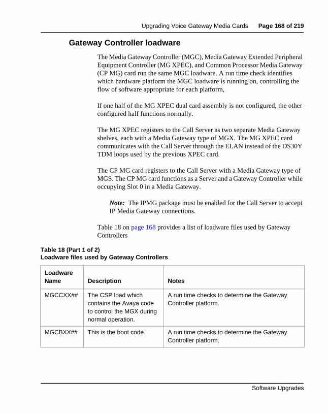
Upgrading Voice Gateway Media Cards Page 168 of 219
Software Upgrades
Gateway Controller loadware
The Media Gateway Controller (MGC), Media Gateway Extended Peripheral Equipment Controller (MG XPEC), and Common Processor Media Gateway (CP MG) card run the same MGC loadware. A run time check identifies which hardware platform the MGC loadware is running on, controlling the flow of software appropriate for each platform,
If one half of the MG XPEC dual card assembly is not configured, the other configured half functions normally.
The MG XPEC registers to the Call Server as two separate Media Gateway shelves, each with a Media Gateway type of MGX. The MG XPEC card communicates with the Call Server through the ELAN instead of the DS30Y TDM loops used by the previous XPEC card.
The CP MG card registers to the Call Server with a Media Gateway type of MGS. The CP MG card functions as a Server and a Gateway Controller while occupying Slot 0 in a Media Gateway.
Note: The IPMG package must be enabled for the Call Server to accept IP Media Gateway connections.
Table 18 on page 168 provides a list of loadware files used by Gateway Controllers
Table 18 (Part 1 of 2)Loadware files used by Gateway Controllers
Loadware Name Description Notes
MGCCXX## The CSP load which contains the Avaya code to control the MGX during normal operation.
A run time checks to determine the Gateway Controller platform.
MGCBXX## This is the boot code. A run time checks to determine the Gateway Controller platform.
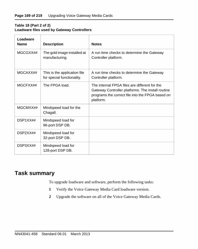
Page 169 of 219 Upgrading Voice Gateway Media Cards
NN43041-458 Standard 06.01 March 2013
Task summaryTo upgrade loadware and software, perform the following tasks:
1 Verify the Voice Gateway Media Card loadware version.
2 Upgrade the software on all of the Voice Gateway Media Cards.
MGCGXX## The gold image installed at manufacturing.
A run time checks to determine the Gateway Controller platform.
MGCAXX## This is the application file for special functionality.
A run time checks to determine the Gateway Controller platform.
MGCFXX## The FPGA load. The internal FPGA files are different for the Gateway Controller platforms. The install routine programs the correct file into the FPGA based on platform.
MGCMXX## Mindspeed load for the Chagall.
DSP1XX## Mindspeed load for 96-port DSP DB.
DSP2XX## Mindspeed load for 32-port DSP DB.
DSP3XX## Mindspeed load for 128-port DSP DB.
Table 18 (Part 2 of 2)Loadware files used by Gateway Controllers
Loadware Name Description Notes
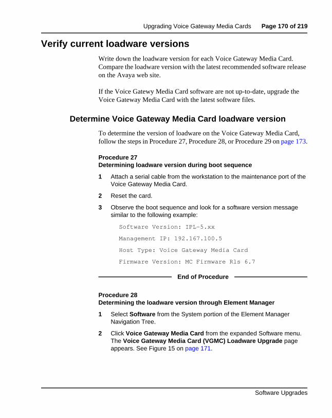
Upgrading Voice Gateway Media Cards Page 170 of 219
Software Upgrades
Verify current loadware versionsWrite down the loadware version for each Voice Gateway Media Card. Compare the loadware version with the latest recommended software release on the Avaya web site.
If the Voice Gatewy Media Card software are not up-to-date, upgrade the Voice Gateway Media Card with the latest software files.
Determine Voice Gateway Media Card loadware version
To determine the version of loadware on the Voice Gateway Media Card, follow the steps in Procedure 27, Procedure 28, or Procedure 29 on page 173.
Procedure 27Determining loadware version during boot sequence
1 Attach a serial cable from the workstation to the maintenance port of the Voice Gateway Media Card.
2 Reset the card.
3 Observe the boot sequence and look for a software version message similar to the following example:
Software Version: IPL-5.xx
Management IP: 192.167.100.5
Host Type: Voice Gateway Media Card
Firmware Version: MC Firmware Rls 6.7
End of Procedure
Procedure 28Determining the loadware version through Element Manager
1 Select Software from the System portion of the Element Manager Navigation Tree.
2 Click Voice Gateway Media Card from the expanded Software menu. The Voice Gateway Media Card (VGMC) Loadware Upgrade page appears. See Figure 15 on page 171.
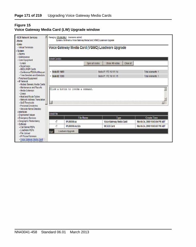
Page 171 of 219 Upgrading Voice Gateway Media Cards
NN43041-458 Standard 06.01 March 2013
Figure 15Voice Gateway Media Card (LW) Upgrade window
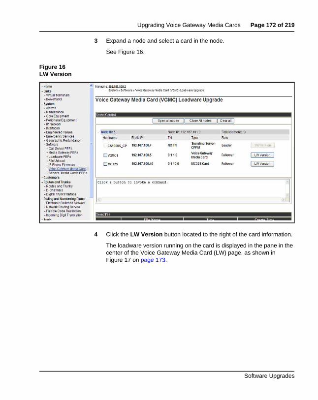
Upgrading Voice Gateway Media Cards Page 172 of 219
Software Upgrades
3 Expand a node and select a card in the node.
See Figure 16.
Figure 16LW Version
4 Click the LW Version button located to the right of the card information.
The loadware version running on the card is displayed in the pane in the center of the Voice Gateway Media Card (LW) page, as shown in Figure 17 on page 173.
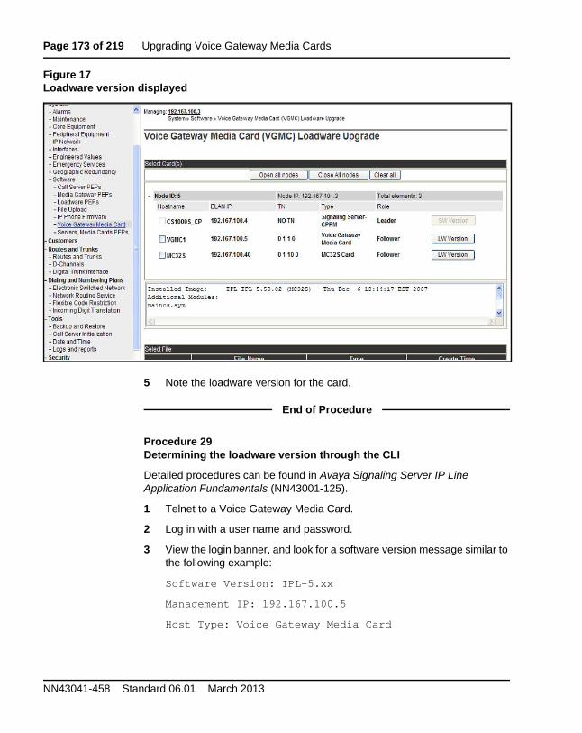
Page 173 of 219 Upgrading Voice Gateway Media Cards
NN43041-458 Standard 06.01 March 2013
Figure 17Loadware version displayed
5 Note the loadware version for the card.
End of Procedure
Procedure 29Determining the loadware version through the CLI
Detailed procedures can be found in Avaya Signaling Server IP Line Application Fundamentals (NN43001-125).
1 Telnet to a Voice Gateway Media Card.
2 Log in with a user name and password.
3 View the login banner, and look for a software version message similar to the following example:
Software Version: IPL-5.xx
Management IP: 192.167.100.5
Host Type: Voice Gateway Media Card
Upgrading Voice Gateway Media Cards Page 174 of 219
Software Upgrades
Firmware Version: MC Firmware Rls 6.7
4 Alternatively, view the syslog and look for a software version message.
Note: The Voice Gateway Media Card syslog is also available for viewing from Element Manager.
End of Procedure
Obtain and upload loadware filesThis information is provided in the event that the Signaling Server Media is not available. It provides information on how to download the necessary files from the Avaya Software Download web site to a management workstation, and how to upload the Voice Gateway Media Card loadware and IP Phone upgrade firmware from the management workstation to the Signaling Server.
Procedure 30 on page 175 describes how to upload the Voice Gateway Media Card loadware and IP Phone firmware from the management workstation to the Signaling Server. Firmware and loadware upgrade files come with the Signaling Server Media included in the Upgrade kit, or from the Avaya Software Download web site.
If the latest Voice Gateway Media Card loadware and IP Phone firmware files were copied from the CD to the Signaling Server hard drive during the Signaling Server installation, there is no need to follow Procedure 30. If the latest versions of the loadware and firmware are already installed on the Signaling Server, then go to “Upgrading Voice Gateway Media Card loadware” on page 177.
Follow the steps in Procedure 30 to upload the Voice Gateway Media Card loadware and IP Phone firmware from the management workstation to the Signaling Server.
To complete this procedure, use a management PC that is on the same network as the Signaling Server for Element Manager.
Page 175 of 219 Upgrading Voice Gateway Media Cards
NN43041-458 Standard 06.01 March 2013
Procedure 30Obtaining and uploading loadware and firmware
1 Obtain the latest software installation files for the Voice Gateway Media Card loadware and IP Phone firmware. Download the files from www.avaya.com/support to the management PC. Choose the product from the alphabetical list and click Downloads. Follow the instructions on the screen.
2 Locate the saved files and double-click the *.zip file.
The zipped file opens in a compression utility program and the decompressed files are listed.
For Phase 1 IP Phone 2004, the IP Phone firmware files have the format ‘0602BNN.BIN’
For Phase 1 IP Phone 2002, the IP Phone firmware files have the format ‘0603BNN.BIN’
For Phase 2 IP Phones 2001, 2002 and 2004, the IP Phone firmware files have the format ‘0604DNN.BIN’
where:
06 is the design site location code
02 or 03 is the IP Phone type:
B is the release: {B = 1, C = 2, D = 3 ...}
xx is the firmware version
The Voice Gateway Media Card loadware files have the format ‘IPL500xx.mc32s’ and ‘IPL600xx.sa’.
3 Log into Element Manager.
4 Using Software> File upload (see Figure 18 on page 176), browse to the software files on the workstation and upload them to the Signaling Server.
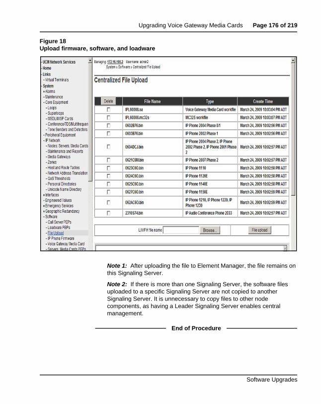
Upgrading Voice Gateway Media Cards Page 176 of 219
Software Upgrades
Figure 18Upload firmware, software, and loadware
Note 1: After uploading the file to Element Manager, the file remains on this Signaling Server.
Note 2: If there is more than one Signaling Server, the software files uploaded to a specific Signaling Server are not copied to another Signaling Server. It is unnecessary to copy files to other node components, as having a Leader Signaling Server enables central management.
End of Procedure
Page 177 of 219 Upgrading Voice Gateway Media Cards
NN43041-458 Standard 06.01 March 2013
Upgrade the Voice Gateway Media Card loadware This section describes how to upgrade Voice Gateway Media Card loadware from 3.x to a later version using Element Manager. The cards obtain their loadware from the Signaling Server.
Follow the steps in Procedure 31 to upgrade Voice Gateway Media Card loadware.
This procedure assumes the Voice Gateway Media Card upgrade loadware has already been uploaded to the Signaling Server. See “Obtain and upload loadware files” on page 174.
Procedure 31Upgrading Voice Gateway Media Card loadware
1 Log into Element Manager.
2 For the remote Voice Gateway Media Card upgrade, choose Software> Voice Gateway Media Card
3 The Voice Gateway Media Card (VGMC) Loadware Upgrade window opens. See Figure 19 on page 178.
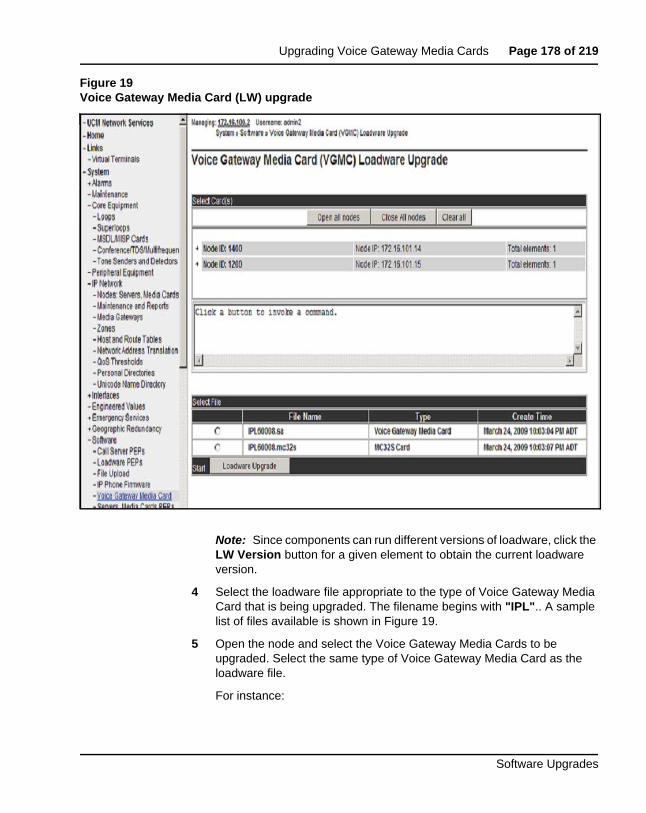
Upgrading Voice Gateway Media Cards Page 178 of 219
Software Upgrades
Figure 19Voice Gateway Media Card (LW) upgrade
Note: Since components can run different versions of loadware, click the LW Version button for a given element to obtain the current loadware version.
4 Select the loadware file appropriate to the type of Voice Gateway Media Card that is being upgraded. The filename begins with "IPL".. A sample list of files available is shown in Figure 19.
5 Open the node and select the Voice Gateway Media Cards to be upgraded. Select the same type of Voice Gateway Media Card as the loadware file.
For instance:
Page 179 of 219 Upgrading Voice Gateway Media Cards
NN43041-458 Standard 06.01 March 2013
a. If the loadware file has the extension “.sa”, only select Media Cards to upgrade.
b. If the loadware file has the extension ".mc32s", only select MC32S cards to upgrade.
Note: The maximum number of Voice Gateway Media Cards or other components that can be upgraded at a time is four, as all files are simultaneously transferred by FTP.
6 Click the Loadware Upgrade button on the bottom of the Voice Gateway Media Card (LW) Upgrade window.
7 Click OK for the confirmation messages.
A Loadware Upgrade Progress page is displayed. When the loadware upgrade is complete, a completion message appears. Generally, it takes up to 5 minutes for each Media Card.
8 If the card did not successfully receive the loadware, return to step 2 on page 177. If the upgrade was successful, proceed to step 9.
9 Click IP Network > Maintenance and Reports. The Node Maintenance and Reports window opens. See Figure 20.
10 Click the node to expand it.
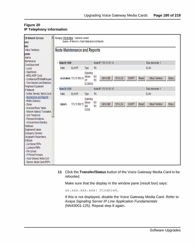
Upgrading Voice Gateway Media Cards Page 180 of 219
Software Upgrades
Figure 20IP Telephony information
11 Click the Transfer/Status button of the Voice Gateway Media Card to be rebooted.
Make sure that the display in the window pane (result box) says:
xx.xxx.xxx.xxx: Disabled.
If this is not displayed, disable the Voice Gateway Media Card. Refer to Avaya Signaling Server IP Line Application Fundamentals (NN43001-125). Repeat step 8 again.
Page 181 of 219 Upgrading Voice Gateway Media Cards
NN43041-458 Standard 06.01 March 2013
12 Reboot the card by clicking the Reset button for the Voice Gateway Media Card in the Node Maintenance and Reports window (System > IP Network > Maintenance and Reports).
See Figure 20 on page 180.
13 Look at the faceplate display to determine when the card is finished booting.
14 Click the Status button for the Voice Gateway Media Card in the IP Telephony Information window and make sure that the message in the window pane (result box) says:
xx.xxx.xxx.xxx: Enabled.
15 Enable SFTP on the Call Server. For information about enabling SFTP, refer to Avaya Security Management (NN43001-604).
16 Register the Call Server to the security domain by following the steps in “Register the Call Server to the security domain” on page 160.
a. If this fails, register the Voice Gateway Media Card to the security domain using the SEC_ADMIN command. For more information, refer to Avaya Security Management (NN43001-604).
17 Repeat from step 9 on page 179 to step 16 for each Voice Gateway Media Card that received the loadware upgrade.
After the card reboots, transfer IP Telephony node information using Element Manager. Refer to Avaya Signaling Server IP Line Application Fundamentals (NN43001-125).
End of Procedure
Upgrade loadware using a Software Delivery cardAn alternative procedure to using Element Manager for the Voice Gateway Media Card loadware upgrade is using the advanced Command Line Interface (CLI) procedure to upload the files from a Software Delivery Card. For more detailed information, refer to Avaya Signaling Server IP Line Application Fundamentals (NN43001-125).
Follow the steps in Procedure 32 on page 182 to upgrade the loadware using a Software Delivery Card.
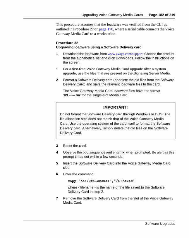
Upgrading Voice Gateway Media Cards Page 182 of 219
Software Upgrades
This procedure assumes that the loadware was verified from the CLI as outlined in Procedure 27 on page 170, where a serial cable connects the Voice Gateway Media Card to a workstation.
Procedure 32Upgrading loadware using a Software Delivery card
1 Download the loadware from www.avaya.com/support. Choose the product from the alphabetical list and click Downloads. Follow the instructions on the screen.
1 For a first-time Voice Gateway Media Card upgrade after a system upgrade, use the files that are present on the Signaling Server Media.
2 Format a Software Delivery card (or delete the old files from the Software Delivery Card) and save the relevant loadware files to the card.
The Voice Gateway Media Card loadware files have the format ‘IPL-----.sa’ for the single-slot Media Card.
3 Reset the card.
4 Observe the boot sequence and enter jkl when prompted. Be alert as this prompt times out within a few seconds.
5 Insert the Software Delivery Card into the Voice Gateway Media Card slot.
6 Enter the command:
copy “/A:/<filename>”,”/C:/exec”
where <filename> is the name of the file saved to the Software Delivery Card in step 2.
7 Remove the Software Delivery Card from the slot of the Voice Gateway Media Card.
IMPORTANT!
Do not format the Software Delivery card through Windows or DOS. The file allocation size does not match that of the Voice Gateway Media Card. Use the operating system of the card itself to format the Software Delivery card. Alternatively, simply delete the old files on the Software Delivery Card.
Page 183 of 219 Upgrading Voice Gateway Media Cards
NN43041-458 Standard 06.01 March 2013
8 Reset the card.
9 Watch the boot messages to confirm the loadware version. Check the release notes to confirm it is the initial version or later.
End of Procedure
Once the Voice Gateway Media Card loadware has been upgraded, verify whether or not the IP Phone firmware also requires an upgrade. Check the loadware release notes to determine which IP Phone firmware versions are compatible with the Voice Gateway Media Cards. If an upgrade is required, refer to “Upgrading and distributing IP Phone firmware” on page 188.
Page 184 of 219
Software Upgrades
189
Upgrading the Signaling Server
ContentsTaskflow . . . . . . . . . . . . . . . . . . . . . . . . . . . . . . . . . . . . . . . . . . . . . . . . 185
Supported hardware. . . . . . . . . . . . . . . . . . . . . . . . . . . . . . . . . . . . . . . . 187
IP subnet configuration . . . . . . . . . . . . . . . . . . . . . . . . . . . . . . . . . . . . . 187
ISP1100 migration. . . . . . . . . . . . . . . . . . . . . . . . . . . . . . . . . . . . . . . . . 187
Upgrading and reconfiguring the software . . . . . . . . . . . . . . . . . . . . . . 187NRS . . . . . . . . . . . . . . . . . . . . . . . . . . . . . . . . . . . . . . . . . . . . . . . . . 187Determining the IP Phone firmware version . . . . . . . . . . . . . . . . . . 188Performing the software upgrade . . . . . . . . . . . . . . . . . . . . . . . . . . . 188
Upgrading and distributing IP Phone firmware . . . . . . . . . . . . . . . . . . 188
Page 185 of 219 Upgrading the Signaling Server
NN43041-458 Standard 06.01 March 2013
TaskflowAvaya Linux Platform Base and Applications Installation and Commissioning (NN43001-315) provides installation and upgrade information for the Linux base and applications. You must follow the proper sequence of events to correctly install or upgrade the Linux base and applications. Use the task flow information below to determine the proper steps for the installation or upgrade of the Linux base and applications.
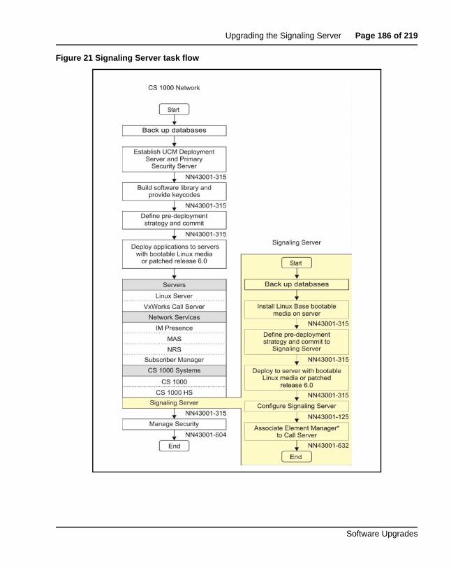
Upgrading the Signaling Server Page 186 of 219
Software Upgrades
Figure 21 Signaling Server task flow
Page 187 of 219 Upgrading the Signaling Server
NN43041-458 Standard 06.01 March 2013
Supported hardwareAvaya Communication Server 1000 Release 7.6 supports the following Signaling Servers:
• Common Processor Pentium Mobile (CP PM) card
• Common Processor Dual Core (CP DC) card
• Commercial off-the-shelf (COTS) servers
— IBM X306m server (COTS1)
— HP DL320 G4 server (COTS1)
— IBM x3350 server (COTS2)
— Dell R300 server (COTS2)
IP subnet configurationIf the Signaling Server and Call Server reside in different IP subnets, you must manually add a route from Base Manager in order for Element Manager to communicate and interact with the Call Server. See Avaya Linux Platform Base and Applications Installation and Commissioning (NN43001-315) for details.
ISP1100 migrationAvaya CS 1000 Release 7.6 does not support ISP1100 Signaling Servers. To migrate an ISP1100 Signaling Server to a CS 1000 Release 7.6 platform, see Avaya Signaling Server IP Line Application Fundamentals (NN43001-125).
Upgrading and reconfiguring the software
NRS
If you do not know whether the Signaling Server being upgraded has an NRS, follow the procedure in Avaya Signaling Server IP Line Application Fundamentals (NN43001-125) to make this determination.
Upgrading the Signaling Server Page 188 of 219
Software Upgrades
NRS Servers must be upgraded to CS 1000 Release 7.6 prior to upgrading the first CS 1000 system to CS 1000 Release 7.6. The NRS must operate on the same software release as the system with the highest software release on the network.
If you have an NRS database on the Signaling Server and wish to back it up prior to the upgrade, you must use the back up tool in NRS Manager. It is recommended that you download the backup file to your local PC after the back up. After the Signaling Server is upgraded, NRS Manager is used to restore the NRS database (from your local PC) and activate it for use by the NRS. For instructions on backing up and restoring an NRS database and IP Phone database, refer to Avaya Signaling Server IP Line Application Fundamentals (NN43001-125).
Determining the IP Phone firmware version
To determine the version of IP Phone firmware, refer to Avaya Signaling Server IP Line Application Fundamentals (NN43001-125).
Performing the software upgrade
Signaling Servers run the Linux Base Operating System. This document does not provide information on upgrading Linux Base. For instructions on performing a Signaling Server software upgrade, see Avaya Linux Platform Base and Applications Installation and Commissioning (NN43001-315) and Avaya Signaling Server IP Line Application Fundamentals (NN43001-125).
Upgrading and distributing IP Phone firmwareFor detailed instructions on how to upgrade and IP Phone firmware to the Signaling Server(s), refer to Avaya Signaling Server IP Line Application Fundamentals (NN43001-125),
Note: When a firmware upgrade is required for a Branch Office Media Gateway system, install the firmware to the Branch Office TPS before the Main Office TPS. Refer to Avaya Branch Office: Installation and Configuration (553-3001-214) for more information.

Page 189 of 219 Upgrading the Signaling Server
NN43041-458 Standard 06.01 March 2013
Page 190 of 219
Software Upgrades
205
Installing a new keycode
Contents This section contains information on the following topics:
Introduction . . . . . . . . . . . . . . . . . . . . . . . . . . . . . . . . . . . . . . . . . . . . . . 190
Feature operation. . . . . . . . . . . . . . . . . . . . . . . . . . . . . . . . . . . . . . . . . . 191Feature and License parameter upgrade using a keycode delivered on a CF card . . . . . . . . . . . . . . . . . . . . . . . . . . . . . . . . . . . . . . . . . . . . . . . . . . 193Feature and License parameter upgrade using HyperTerminal®. . . 198Feature and License parameter upgrade entered manually . . . . . . . 200
Reverting to the previous keycode with the KRVR command . . . . . . . 202
IntroductionAdding new features and/or modifying License limits requires the installation of a new keycode. Keycodes are delivered by a portable media appropriate for the processor type or electronic file transfer. Keycodes can also be manually entered. They are installed using the keycode management commands in LD 143 or the Software Installation Tool.
The following procedures outline the steps to install a new keycode (using the keycode commands in LD 143) that can be activated “instantly” or that requires a Sysload (Cold Restart). More information on the “Instant License” feature can be found in Avaya Features and Services (553-3001-306).
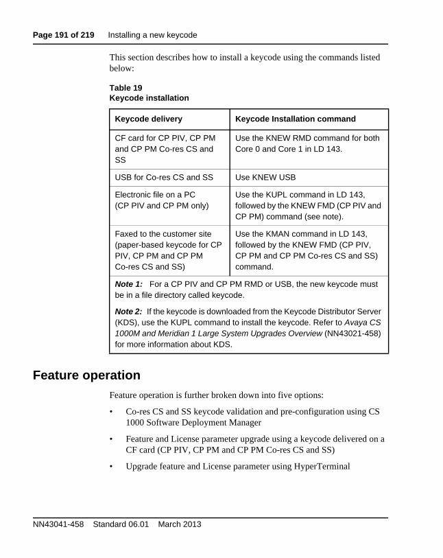
Page 191 of 219 Installing a new keycode
NN43041-458 Standard 06.01 March 2013
This section describes how to install a keycode using the commands listed below:
Feature operationFeature operation is further broken down into five options:
• Co-res CS and SS keycode validation and pre-configuration using CS 1000 Software Deployment Manager
• Feature and License parameter upgrade using a keycode delivered on a CF card (CP PIV, CP PM and CP PM Co-res CS and SS)
• Upgrade feature and License parameter using HyperTerminal
Table 19Keycode installation
Keycode delivery Keycode Installation command
CF card for CP PIV, CP PM and CP PM Co-res CS and SS
Use the KNEW RMD command for both Core 0 and Core 1 in LD 143.
USB for Co-res CS and SS Use KNEW USB
Electronic file on a PC (CP PIV and CP PM only)
Use the KUPL command in LD 143, followed by the KNEW FMD (CP PIV and CP PM) command (see note).
Faxed to the customer site (paper-based keycode for CP PIV, CP PM and CP PM Co-res CS and SS)
Use the KMAN command in LD 143, followed by the KNEW FMD (CP PIV, CP PM and CP PM Co-res CS and SS) command.
Note 1: For a CP PIV and CP PM RMD or USB, the new keycode must be in a file directory called keycode.
Note 2: If the keycode is downloaded from the Keycode Distributor Server (KDS), use the KUPL command to install the keycode. Refer to Avaya CS 1000M and Meridian 1 Large System Upgrades Overview (NN43021-458) for more information about KDS.
Installing a new keycode Page 192 of 219
Software Upgrades
• Upgrade feature and License parameter entered manually
• Revert to the previous keycode with the KRVR command
Co-resident Call Server and Signaling Server keycode validation and pre-configuration
The Avaya Communication Server 1000 Software Deployment Manager provides the following menus and pages specific to Call Server installation and deployment:
• Keycode Validation
• Call Server Database Selection
• Call Server PSDL Language Selection
Prior to deploying the application software to the Co-res CS and SS, the Deployment Manager performs the Call Server keycode validation to ensure that the keycode file used matches the software version and the security device on the target server.
You can use the Deployment Manager to select default, existing, or customer database. The existing database selection does not apply to new installations - only to upgrades. The customer database selection allows the user to upload a Call Server database that has been backed up using the LD 43 EDD command.
Note: After performing the LD 43 EDD command the Co-res CS and SS Call Server database is stored in the backup/single folder on the RMD. Click the browse tab and select the backup folder under the Customer Database option from Deployment Manager.
The Deployment Manager provides a menu to select the PSDL languages. For a detailed Deployment Manager keycode validation procedure, see Avaya Linux Platform Base and Applications Installation and Commissioning (NN43001-315).
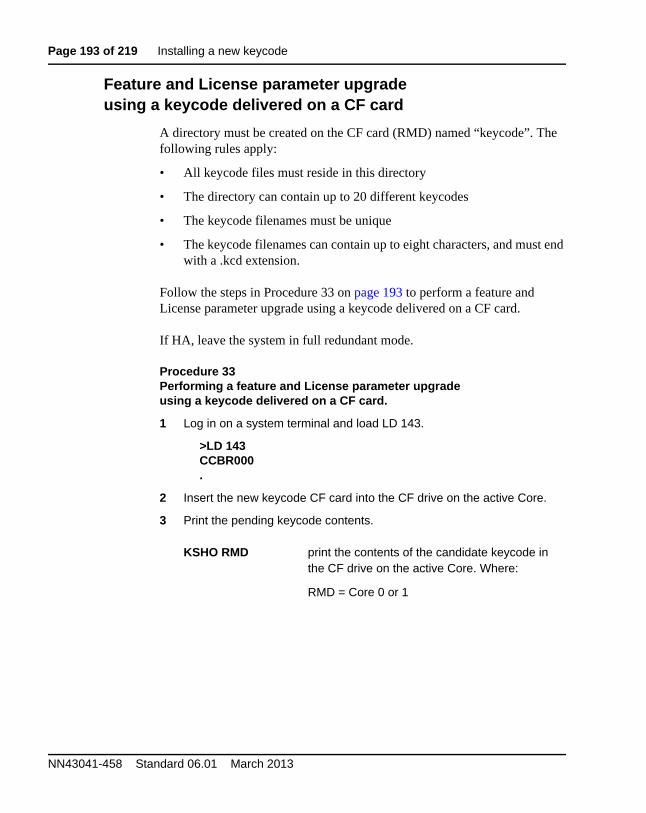
Page 193 of 219 Installing a new keycode
NN43041-458 Standard 06.01 March 2013
Feature and License parameter upgrade using a keycode delivered on a CF card
A directory must be created on the CF card (RMD) named “keycode”. The following rules apply:
• All keycode files must reside in this directory
• The directory can contain up to 20 different keycodes
• The keycode filenames must be unique
• The keycode filenames can contain up to eight characters, and must end with a .kcd extension.
Follow the steps in Procedure 33 on page 193 to perform a feature and License parameter upgrade using a keycode delivered on a CF card.
If HA, leave the system in full redundant mode.
Procedure 33Performing a feature and License parameter upgrade using a keycode delivered on a CF card.
1 Log in on a system terminal and load LD 143.
>LD 143CCBR000.
2 Insert the new keycode CF card into the CF drive on the active Core.
3 Print the pending keycode contents.
KSHO RMD print the contents of the candidate keycode in the CF drive on the active Core. Where:
RMD = Core 0 or 1
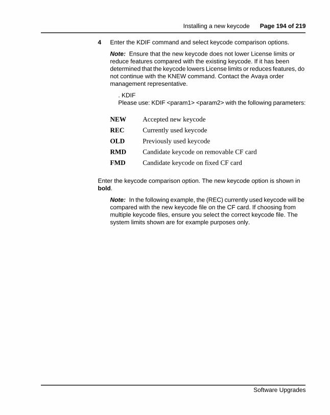
Installing a new keycode Page 194 of 219
Software Upgrades
4 Enter the KDIF command and select keycode comparison options.
Note: Ensure that the new keycode does not lower License limits or reduce features compared with the existing keycode. If it has been determined that the keycode lowers License limits or reduces features, do not continue with the KNEW command. Contact the Avaya order management representative.
. KDIFPlease use: KDIF <param1> <param2> with the following parameters:
Enter the keycode comparison option. The new keycode option is shown in bold.
Note: In the following example, the (REC) currently used keycode will be compared with the new keycode file on the CF card. If choosing from multiple keycode files, ensure you select the correct keycode file. The system limits shown are for example purposes only.
NEW Accepted new keycode
REC Currently used keycode
OLD Previously used keycode
RMD Candidate keycode on removable CF card
FMD Candidate keycode on fixed CF card
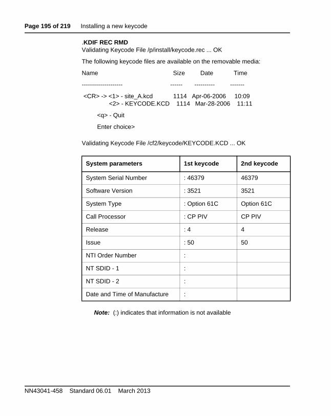
Page 195 of 219 Installing a new keycode
NN43041-458 Standard 06.01 March 2013
.KDIF REC RMDValidating Keycode File /p/install/keycode.rec ... OK
The following keycode files are available on the removable media:
Name Size Date Time
-------------------- ------ ---------- -------
<CR> -> <1> - site_A.kcd 1114 Apr-06-2006 10:09<2> - KEYCODE.KCD 1114 Mar-28-2006 11:11
<q> - Quit
Enter choice>
Validating Keycode File /cf2/keycode/KEYCODE.KCD ... OK
Note: (:) indicates that information is not available
System parameters 1st keycode 2nd keycode
System Serial Number : 46379 46379
Software Version : 3521 3521
System Type : Option 61C Option 61C
Call Processor : CP PIV CP PIV
Release : 4 4
Issue : 50 50
NTI Order Number :
NT SDID - 1 :
NT SDID - 2 :
Date and Time of Manufacture :
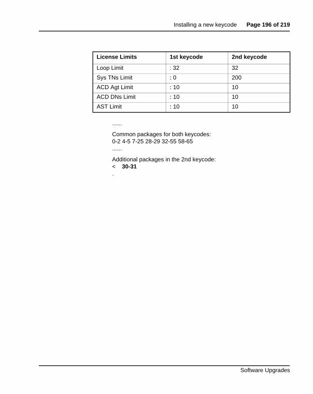
Installing a new keycode Page 196 of 219
Software Upgrades
......
Common packages for both keycodes:0-2 4-5 7-25 28-29 32-55 58-65......
Additional packages in the 2nd keycode:< 30-31 .
License Limits 1st keycode 2nd keycode
Loop Limit : 32 32
Sys TNs Limit : 0 200
ACD Agt Limit : 10 10
ACD DNs Limit : 10 10
AST Limit : 10 10
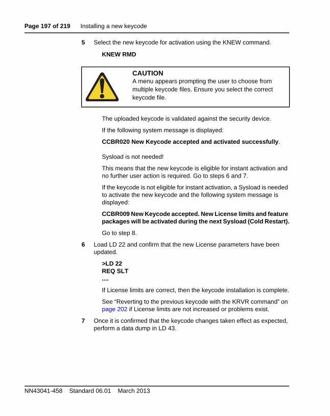
Page 197 of 219 Installing a new keycode
NN43041-458 Standard 06.01 March 2013
5 Select the new keycode for activation using the KNEW command.
KNEW RMD
The uploaded keycode is validated against the security device.
If the following system message is displayed:
CCBR020 New Keycode accepted and activated successfully.
Sysload is not needed!
This means that the new keycode is eligible for instant activation and no further user action is required. Go to steps 6 and 7.
If the keycode is not eligible for instant activation, a Sysload is needed to activate the new keycode and the following system message is displayed:
CCBR009 New Keycode accepted. New License limits and feature packages will be activated during the next Sysload (Cold Restart).
Go to step 8.
6 Load LD 22 and confirm that the new License parameters have been updated.
>LD 22REQ SLT....
If License limits are correct, then the keycode installation is complete.
See “Reverting to the previous keycode with the KRVR command” on page 202 if License limits are not increased or problems exist.
7 Once it is confirmed that the keycode changes taken effect as expected, perform a data dump in LD 43.
CAUTIONA menu appears prompting the user to choose from multiple keycode files. Ensure you select the correct keycode file.
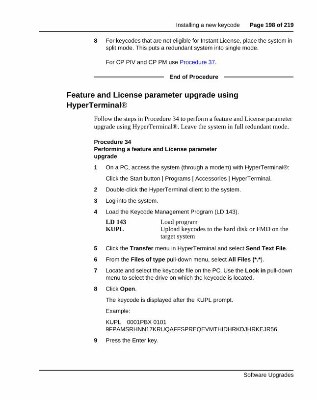
Installing a new keycode Page 198 of 219
Software Upgrades
8 For keycodes that are not eligible for Instant License, place the system in split mode. This puts a redundant system into single mode.
For CP PIV and CP PM use Procedure 37.
End of Procedure
Feature and License parameter upgrade using HyperTerminal®
Follow the steps in Procedure 34 to perform a feature and License parameter upgrade using HyperTerminal®. Leave the system in full redundant mode.
Procedure 34Performing a feature and License parameter upgrade
1 On a PC, access the system (through a modem) with HyperTerminal®:
Click the Start button | Programs | Accessories | HyperTerminal.
2 Double-click the HyperTerminal client to the system.
3 Log into the system.
4 Load the Keycode Management Program (LD 143).
5 Click the Transfer menu in HyperTerminal and select Send Text File.
6 From the Files of type pull-down menu, select All Files (*.*).
7 Locate and select the keycode file on the PC. Use the Look in pull-down menu to select the drive on which the keycode is located.
8 Click Open.
The keycode is displayed after the KUPL prompt.
Example:
KUPL 0001PBX 0101 9FPAMSRHNN17KRUQAFFSPREQEVMTHIDHRKDJHRKEJR56
9 Press the Enter key.
LD 143 Load programKUPL Upload keycodes to the hard disk or FMD on the
target system
Page 199 of 219 Installing a new keycode
NN43041-458 Standard 06.01 March 2013
The Keycode is checked for CRC errors and is uploaded to the hard disk or Fixed Media Device (FMD).
Enter the following command:
Ensure that the new keycode does not lower License limits or reduce features compared with the existing keycode. If it is determined that the keycode lowers License limits or reduces features, do not continue with the KNEW command. Contact the Avaya order management representative.
10 Select the new keycode for activation using the KNEW command.
KNEW (refer to Table 19 on page 191 for correct command syntax)
The uploaded keycode is validated against the security device.
If the following system message is displayed:
CCBR020 New Keycode accepted and activated successfully. Sysload is NOT needed!
This means that the new keycode is eligible for instant activation and no further user action is required. Go to steps 11 and 12.
If the keycode is not eligible for instant activation, a Sysload is needed to activate the new keycode. The following system message is displayed:
CCBR009 New Keycode accepted. New License limits and feature packages will be activated during the next Sysload (Cold Restart).
Go to step 13.
11 Load LD 22 and confirm that the new License parameters have been updated.
>LD 22REQ SLT....
If License limits are correct, then the keycode installation is complete.
See “Reverting to the previous keycode with the KRVR command” on page 202 if License limits are not increased or problems exist.
KDIF REC HD Compare the existing keycode with the new keycode on the hard disk
KDIF REC FMD Compare the existing keycode with the new keycode on the FMD
Installing a new keycode Page 200 of 219
Software Upgrades
12 Once it is confirmed that the keycode changes taken effect as expected, perform a data dump in LD 43.
13 For keycodes that are not eligible for Instant License, place the system in split mode. This puts a redundant system into single mode. See Procedure 37.
End of Procedure
Feature and License parameter upgrade entered manually
Before beginning this procedure, obtain a copy of the keycode. The keycode can reside on paper or as an electronic file. To enter the keycode manually, type the keycode in LD 143 as 21 lines, 16 characters per line.
Follow the steps in Procedure 35 on page 200 to perform a feature and License parameter upgrade manually.
Procedure 35Performing a feature and License parameter upgrade manually
1 Log into the system.
2 Load the Keycode Management Program (LD 143).
3 Type the keycode file, 21 lines of 16 characters each. Press Return to go to the next line.
Note: When entering the keycode, do not enter the header information that proceeds the keycode.
4 Type “end” at line 22 to end the process.
5 Press Enter. The new keycode file is saved on the hard disk or FMD.
Enter the following command:
LD 143 Load program
KMAN Manually enter the keycode to the target system
KDIF REC HD Compare the existing keycode with the new keycode on the hard disk.
KDIF REC FMD Compare the existing keycode with the new keycode on the FMD
Page 201 of 219 Installing a new keycode
NN43041-458 Standard 06.01 March 2013
Ensure that the new keycode does not lower License limits or reduce features compared with the existing keycode. If it is determined that the keycode lowers License limits or reduces features, do not continue with the KNEW command. Contact the Avaya order management representative.
6 Select the new keycode for activation using the KNEW command.
KNEW (refer to Table 19 on page 191 for correct command syntax)
The uploaded keycode is validated against the security device.
If the following system message is displayed:
CCBR020 New Keycode accepted and activated successfully. Sysload is NOT needed!
This implies that the new keycode is eligible for instant activation and no further user action is required. Go to step 7 and 8.
If the keycode is not eligible for instant activation, a Sysload is needed to activate the new keycode. The following system message is displayed:
CCBR009 New Keycode accepted. New License limits and feature packages will be activated during the next Sysload (Cold Restart).
Go to step 9.
7 Load LD 22 and confirm that the new License parameters have been updated.
>LD 22REQ SLT....
If License limits are correct, then the keycode installation is complete.
See “Reverting to the previous keycode with the KRVR command” on page 202 if License limits are not increased or problems exist.
8 Once it is confirmed that the keycode changes have taken effect as expected, perform a data dump in LD 43.
9 For keycodes that are not eligible for Instant License, place the system in split mode. This puts a redundant system into single mode. See Procedure 37.
End of Procedure
Installing a new keycode Page 202 of 219
Software Upgrades
Reverting to the previous keycode with the KRVR command
The terms “old” and “new” keycode, as discussed here, refer to the most recent previous KNEW command. The “old” keycode is the former keycode, prior to the KNEW command. The “new” keycode is the keycode that was activated by the KNEW command. Use KRVR command (as shown in Procedure 36) to revert to the old keycode.
Procedure 36Revert to old keycode
1 Log in to the system.
2 Load the Keycode Management Program (LD 143).
The old keycode is eligible for instant activation with the KRVR command if the only difference between the old keycode and the new keycode is that some or all of the License parameters in the old keycode are higher.
If the old keycode is eligible for instant activation, it is activated without further user action. The following system message is displayed:
CCBR020 New Keycode accepted and activated successfully. Sysload is NOT needed!
If the keycode is not eligible for instant activation, a Sysload is needed to activate the old keycode and the following system message is displayed:
CCBR009 New Keycode accepted. New License limits and feature packages will be activated during the next Sysload (Cold Restart).
Go to step 5.
3 Load LD 22 and confirm that the new License parameters have been updated.
>LD 22REQ SLT....
If License limits are correct, then the keycode installation is complete.
LD 143 Load programKRVR Replaces the keycode.rec with the keycode.old
file.
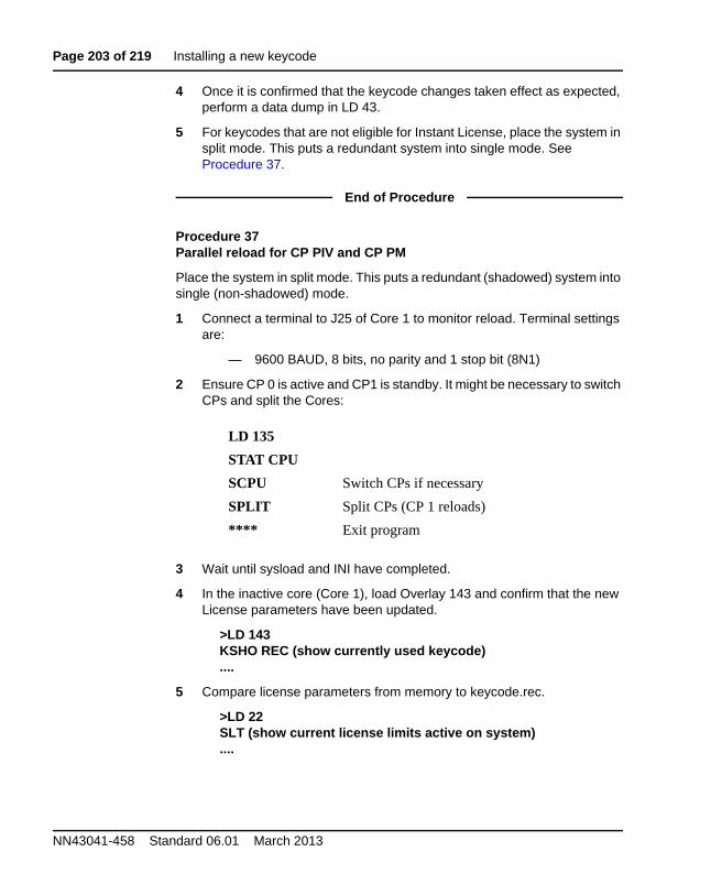
Page 203 of 219 Installing a new keycode
NN43041-458 Standard 06.01 March 2013
4 Once it is confirmed that the keycode changes taken effect as expected, perform a data dump in LD 43.
5 For keycodes that are not eligible for Instant License, place the system in split mode. This puts a redundant system into single mode. See Procedure 37.
End of Procedure
Procedure 37Parallel reload for CP PIV and CP PM
Place the system in split mode. This puts a redundant (shadowed) system into single (non-shadowed) mode.
1 Connect a terminal to J25 of Core 1 to monitor reload. Terminal settings are:
— 9600 BAUD, 8 bits, no parity and 1 stop bit (8N1)
2 Ensure CP 0 is active and CP1 is standby. It might be necessary to switch CPs and split the Cores:
3 Wait until sysload and INI have completed.
4 In the inactive core (Core 1), load Overlay 143 and confirm that the new License parameters have been updated.
>LD 143KSHO REC (show currently used keycode)....
5 Compare license parameters from memory to keycode.rec.
>LD 22SLT (show current license limits active on system)....
LD 135
STAT CPU
SCPU Switch CPs if necessary
SPLIT Split CPs (CP 1 reloads)
**** Exit program
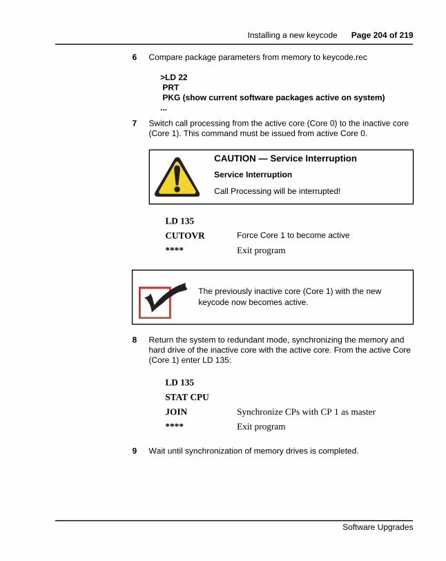
Installing a new keycode Page 204 of 219
Software Upgrades
6 Compare package parameters from memory to keycode.rec
>LD 22PRTPKG (show current software packages active on system)
...
7 Switch call processing from the active core (Core 0) to the inactive core (Core 1). This command must be issued from active Core 0.
8 Return the system to redundant mode, synchronizing the memory and hard drive of the inactive core with the active core. From the active Core (Core 1) enter LD 135:
9 Wait until synchronization of memory drives is completed.
CAUTION — Service Interruption
Service Interruption
Call Processing will be interrupted!
LD 135
CUTOVR Force Core 1 to become active
**** Exit program
The previously inactive core (Core 1) with the new keycode now becomes active.
LD 135
STAT CPU
JOIN Synchronize CPs with CP 1 as master
**** Exit program
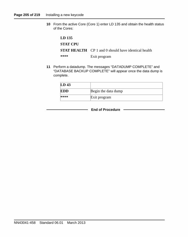
Page 205 of 219 Installing a new keycode
NN43041-458 Standard 06.01 March 2013
10 From the active Core (Core 1) enter LD 135 and obtain the health status of the Cores:
11 Perform a datadump. The messages “DATADUMP COMPLETE” and “DATABASE BACKUP COMPLETE” will appear once the data dump is complete.
End of Procedure
LD 135
STAT CPU
STAT HEALTH CP 1 and 0 should have identical health
**** Exit program
LD 43
EDD Begin the data dump
**** Exit program
Page 206 of 219
Software Upgrades
217
Upgrade checklists
Contents This section contains information on the following topics:
Introduction . . . . . . . . . . . . . . . . . . . . . . . . . . . . . . . . . . . . . . . . . . . . . . 206
Site details . . . . . . . . . . . . . . . . . . . . . . . . . . . . . . . . . . . . . . . . . . . . . . . 207
Upgrade details . . . . . . . . . . . . . . . . . . . . . . . . . . . . . . . . . . . . . . . . . . . 207
Pre-upgrade checklists. . . . . . . . . . . . . . . . . . . . . . . . . . . . . . . . . . . . . . 208
Pre-conversion steps . . . . . . . . . . . . . . . . . . . . . . . . . . . . . . . . . . . . . . . 214
Post-conversion checks . . . . . . . . . . . . . . . . . . . . . . . . . . . . . . . . . . . . . 216
IntroductionThe following section provides upgrade checklists.
Technical Support
Avaya can provide an Installation and Upgrade Support team to assist with PBX upgrades on a scheduled bases. This service is billable and a purchase order is required. Please refer to current price book for rates.
Note: This service requires that a service request be opened in advance of the upgrade.
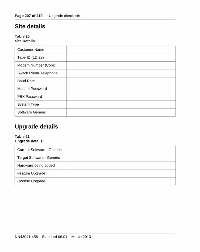
Page 207 of 219 Upgrade checklists
NN43041-458 Standard 06.01 March 2013
Site details
Upgrade details
Table 20Site Details
Customer Name
Tape ID (LD 22)
Modem Number (Core)
Switch Room Telephone
Baud Rate
Modem Password
PBX Password
System Type
Software Generic
Table 21Upgrade details
Current Software - Generic
Target Software - Generic
Hardware being added
Feature Upgrade
License Upgrade
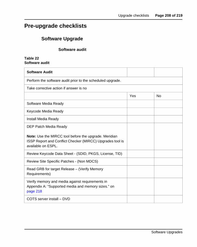
Upgrade checklists Page 208 of 219
Software Upgrades
Pre-upgrade checklists
Software Upgrade
Software audit
Table 22Software audit
Software Audit
Perform the software audit prior to the scheduled upgrade.
Take corrective action if answer is no
Yes No
Software Media Ready
Keycode Media Ready
Install Media Ready
DEP Patch Media Ready
Note: Use the MIRCC tool before the upgrade. Meridian ISSP Report and Conflict Checker (MIRCC) Upgrades tool is available on ESPL.
Review Keycode Data Sheet - (SDID, PKGS, License, TID)
Review Site Specific Patches - (Non MDCS)
Read GRB for target Release – (Verify Memory Requirements)
Verify memory and media against requirements in Appendix A: “Supported media and memory sizes.” on page 218
COTS server install – DVD
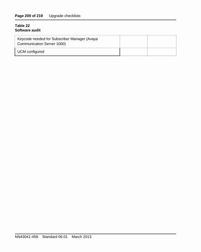
Page 209 of 219 Upgrade checklists
NN43041-458 Standard 06.01 March 2013
Keycode needed for Subscriber Manager (Avaya Communication Server 1000)
UCM configured
Table 22Software audit
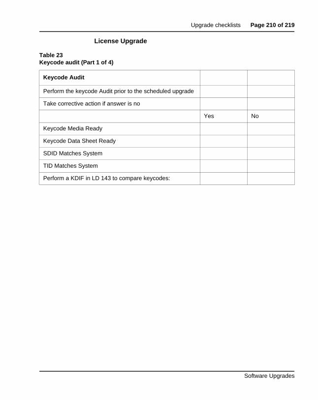
Upgrade checklists Page 210 of 219
Software Upgrades
License Upgrade
Table 23Keycode audit (Part 1 of 4)
Keycode Audit
Perform the keycode Audit prior to the scheduled upgrade
Take corrective action if answer is no
Yes No
Keycode Media Ready
Keycode Data Sheet Ready
SDID Matches System
TID Matches System
Perform a KDIF in LD 143 to compare keycodes:
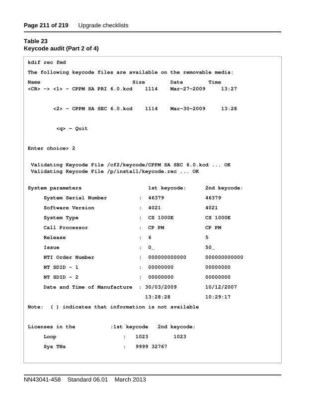
Page 211 of 219 Upgrade checklists
NN43041-458 Standard 06.01 March 2013
kdif rec fmd
The following keycode files are available on the removable media:
Name Size Date Time<CR> -> <1> - CPPM SA PRI 6.0.kcd 1114 Mar-27-2009 13:27
<2> - CPPM SA SEC 6.0.kcd 1114 Mar-30-2009 13:28
<q> - Quit
Enter choice> 2
Validating Keycode File /cf2/keycode/CPPM SA SEC 6.0.kcd ... OKValidating Keycode File /p/install/keycode.rec ... OK
System parameters 1st keycode: 2nd keycode:
System Serial Number : 46379 46379
Software Version : 4021 4021
System Type : CS 1000E CS 1000E
Call Processor : CP PM CP PM
Release : 6 5
Issue : 0_ 50_
NTI Order Number : 000000000000 000000000000
NT SDID - 1 : 00000000 00000000
NT SDID - 2 : 00000000 00000000
Date and Time of Manufacture : 30/03/2009 10/12/2007
13:28:28 10:29:17
Note: ( ) indicates that information is not available
Licenses in the :1st keycode 2nd keycode:
Loop : 1023 1023
Sys TNs : 9999 32767
Table 23Keycode audit (Part 2 of 4)
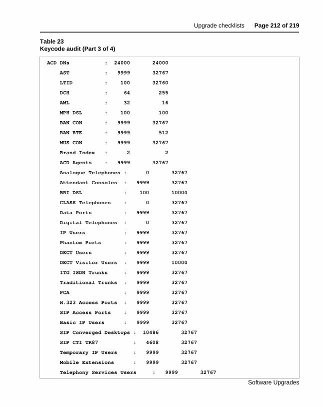
Upgrade checklists Page 212 of 219
Software Upgrades
ACD DNs : 24000 24000
AST : 9999 32767
LTID : 100 32760
DCH : 64 255
AML : 32 16
MPH DSL : 100 100
RAN CON : 9999 32767
RAN RTE : 9999 512
MUS CON : 9999 32767
Brand Index : 2 2
ACD Agents : 9999 32767
Analogue Telephones : 0 32767
Attendant Consoles : 9999 32767
BRI DSL : 100 10000
CLASS Telephones : 0 32767
Data Ports : 9999 32767
Digital Telephones : 0 32767
IP Users : 9999 32767
Phantom Ports : 9999 32767
DECT Users : 9999 32767
DECT Visitor Users : 9999 10000
ITG ISDN Trunks : 9999 32767
Traditional Trunks : 9999 32767
PCA : 9999 32767
H.323 Access Ports : 9999 32767
SIP Access Ports : 9999 32767
Basic IP Users : 9999 32767
SIP Converged Desktops : 10486 32767
SIP CTI TR87 : 4608 32767
Temporary IP Users : 9999 32767
Mobile Extensions : 9999 32767
Telephony Services Users : 9999 32767
Table 23Keycode audit (Part 3 of 4)
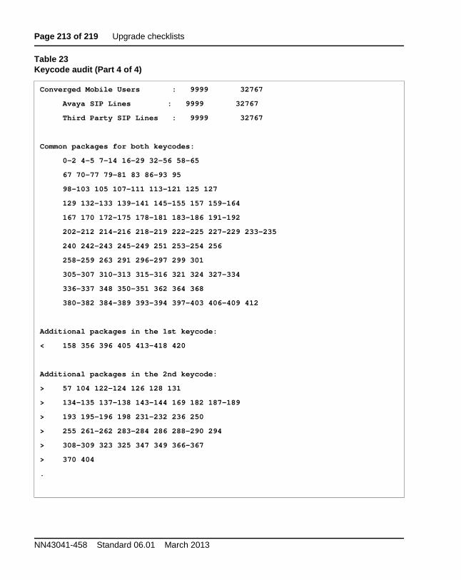
Page 213 of 219 Upgrade checklists
NN43041-458 Standard 06.01 March 2013
Converged Mobile Users : 9999 32767
Avaya SIP Lines : 9999 32767
Third Party SIP Lines : 9999 32767
Common packages for both keycodes:
0-2 4-5 7-14 16-29 32-56 58-65
67 70-77 79-81 83 86-93 95
98-103 105 107-111 113-121 125 127
129 132-133 139-141 145-155 157 159-164
167 170 172-175 178-181 183-186 191-192
202-212 214-216 218-219 222-225 227-229 233-235
240 242-243 245-249 251 253-254 256
258-259 263 291 296-297 299 301
305-307 310-313 315-316 321 324 327-334
336-337 348 350-351 362 364 368
380-382 384-389 393-394 397-403 406-409 412
Additional packages in the 1st keycode:
< 158 356 396 405 413-418 420
Additional packages in the 2nd keycode:
> 57 104 122-124 126 128 131
> 134-135 137-138 143-144 169 182 187-189
> 193 195-196 198 231-232 236 250
> 255 261-262 283-284 286 288-290 294
> 308-309 323 325 347 349 366-367
> 370 404
.
Table 23Keycode audit (Part 4 of 4)
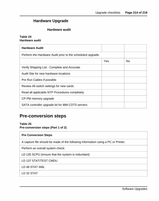
Upgrade checklists Page 214 of 219
Software Upgrades
Hardware Upgrade
Hardware audit
Pre-conversion steps
Table 24Hardware audit
Hardware Audit
Perform the Hardware Audit prior to the scheduled upgrade.
Yes No
Verify Shipping List - Complete and Accurate
Audit Site for new hardware locations
Pre Run Cables if possible
Review All switch settings for new cards
Read all applicable NTP Procedures completely
CP PM memory upgrade
SATA controller upgrade kit for IBM COTS servers
Table 25Pre-conversion steps (Part 1 of 2)
Pre Conversion Steps
A capture file should be made of the following information using a PC or Printer.
Perform an overall system check:
LD 135 SCPU (ensure that the system is redundant)
LD 137 STAT/TEST CMDU
LD 48 STAT AML
LD 32 STAT
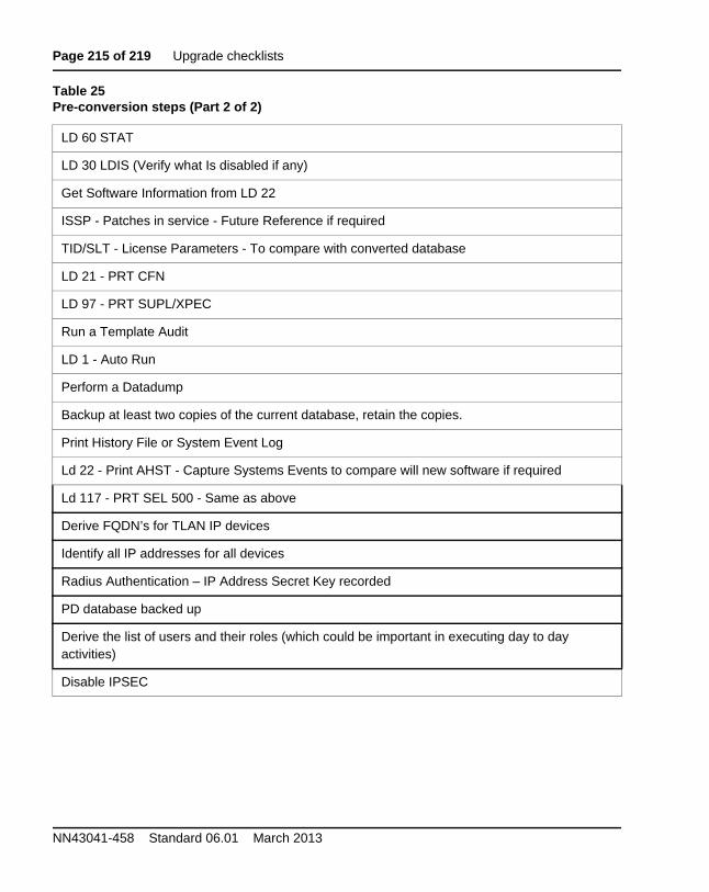
Page 215 of 219 Upgrade checklists
NN43041-458 Standard 06.01 March 2013
LD 60 STAT
LD 30 LDIS (Verify what Is disabled if any)
Get Software Information from LD 22
ISSP - Patches in service - Future Reference if required
TID/SLT - License Parameters - To compare with converted database
LD 21 - PRT CFN
LD 97 - PRT SUPL/XPEC
Run a Template Audit
LD 1 - Auto Run
Perform a Datadump
Backup at least two copies of the current database, retain the copies.
Print History File or System Event Log
Ld 22 - Print AHST - Capture Systems Events to compare will new software if required
Ld 117 - PRT SEL 500 - Same as above
Derive FQDN’s for TLAN IP devices
Identify all IP addresses for all devices
Radius Authentication – IP Address Secret Key recorded
PD database backed up
Derive the list of users and their roles (which could be important in executing day to day activities)
Disable IPSEC
Table 25Pre-conversion steps (Part 2 of 2)
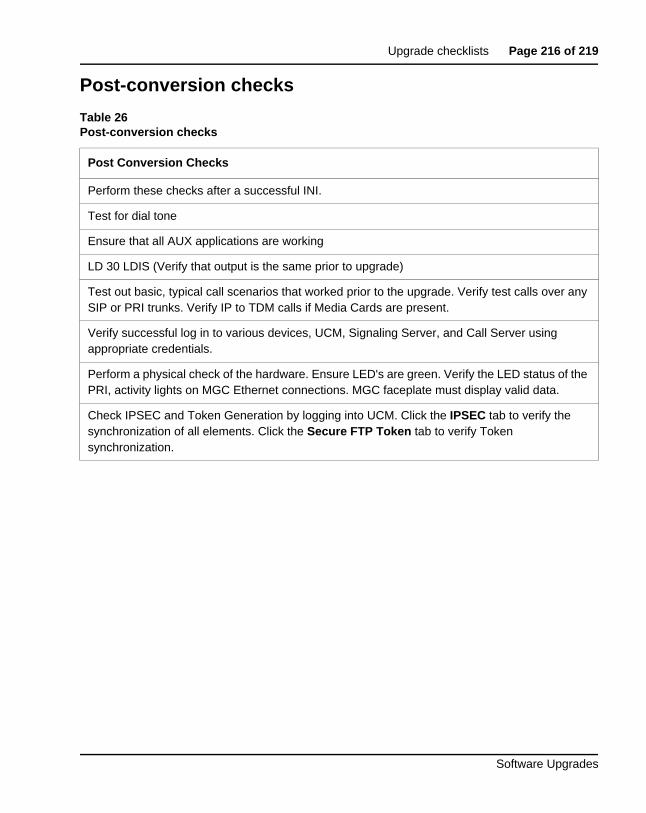
Upgrade checklists Page 216 of 219
Software Upgrades
Post-conversion checks
Table 26Post-conversion checks
Post Conversion Checks
Perform these checks after a successful INI.
Test for dial tone
Ensure that all AUX applications are working
LD 30 LDIS (Verify that output is the same prior to upgrade)
Test out basic, typical call scenarios that worked prior to the upgrade. Verify test calls over any SIP or PRI trunks. Verify IP to TDM calls if Media Cards are present.
Verify successful log in to various devices, UCM, Signaling Server, and Call Server using appropriate credentials.
Perform a physical check of the hardware. Ensure LED's are green. Verify the LED status of the PRI, activity lights on MGC Ethernet connections. MGC faceplate must display valid data.
Check IPSEC and Token Generation by logging into UCM. Click the IPSEC tab to verify the synchronization of all elements. Click the Secure FTP Token tab to verify Token synchronization.

Page 217 of 219 Upgrade checklists
NN43041-458 Standard 06.01 March 2013
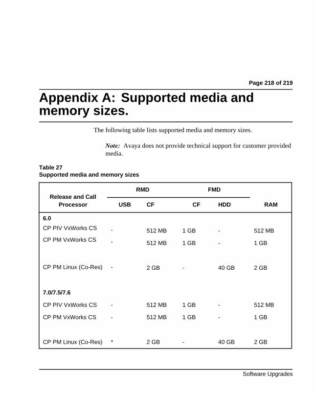
Page 218 of 219
Software Upgrades
219
Appendix A: Supported media and memory sizes.
The following table lists supported media and memory sizes.
Note: Avaya does not provide technical support for customer provided media.
Table 27Supported media and memory sizes
Release and Call Processor
RMD FMD
RAMUSB CF CF HDD
6.0
CP PIV VxWorks CS
CP PM VxWorks CS
-
-
512 MB 1 GB - 512 MB
512 MB 1 GB - 1 GB
CP PM Linux (Co-Res) - 2 GB - 40 GB 2 GB
7.0/7.5/7.6
CP PIV VxWorks CS - 512 MB 1 GB - 512 MB
CP PM VxWorks CS - 512 MB 1 GB - 1 GB
CP PM Linux (Co-Res) * 2 GB - 40 GB 2 GB
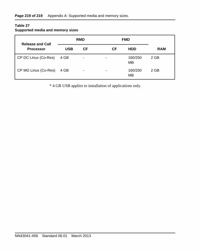
Page 219 of 219 Appendix A: Supported media and memory sizes.
NN43041-458 Standard 06.01 March 2013
* 4 GB USB applies to installation of applications only.
CP DC Linux (Co-Res) 4 GB - - 160/250 MB
2 GB
CP MG Linux (Co-Res) 4 GB - - 160/250 MB
2 GB
Table 27Supported media and memory sizes
Release and Call Processor
RMD FMD
RAMUSB CF CF HDD


![Customer Programming Software RG-1000e (CPS RG-1000e) User ...support.smartptt.com/hc/en-us/article_attachments/360026136773/CPS_RG... · 192.168.200.1[51130] 192.168.100.1[30010]](https://img.pdfslide.us/doc/110x75/5e819e496d283477b76cdd83/customer-programming-software-rg-1000e-cps-rg-1000e-user-192168200151130.jpg)