Embed Size (px)
Citation preview
Communication Notation
Part V
Chapter 15, 16, 18 and 19.

Today….
Introduction Diagrams
– Data flow Diagrams– Architecture Diagrams
Guidelines– Context modeling– Architectural design
Break….

Communication Notation
ServicesBehaviorCommunication

Modeling Communication
Context Models (Analyses)– Communication in environment– Communication between environment and SuD
Architectural Models (Design)– Communication between components
Stimulus / response pairs
– Communication between components and entities in the environment

Requirements-level Architecture
Environment and requirementsNot software platformNot physical system

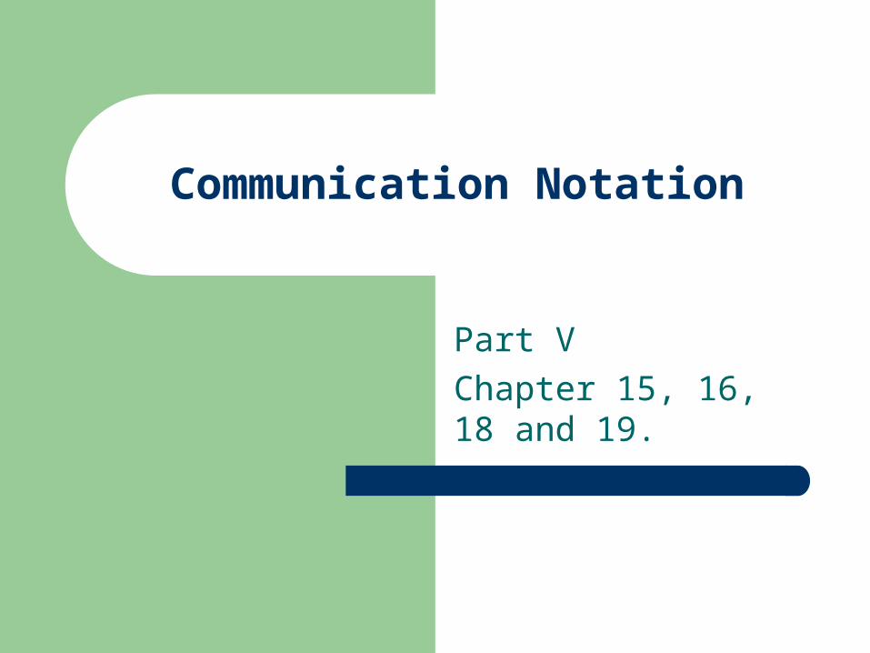
Physical Network Architecture
Refining the Physical Architecture
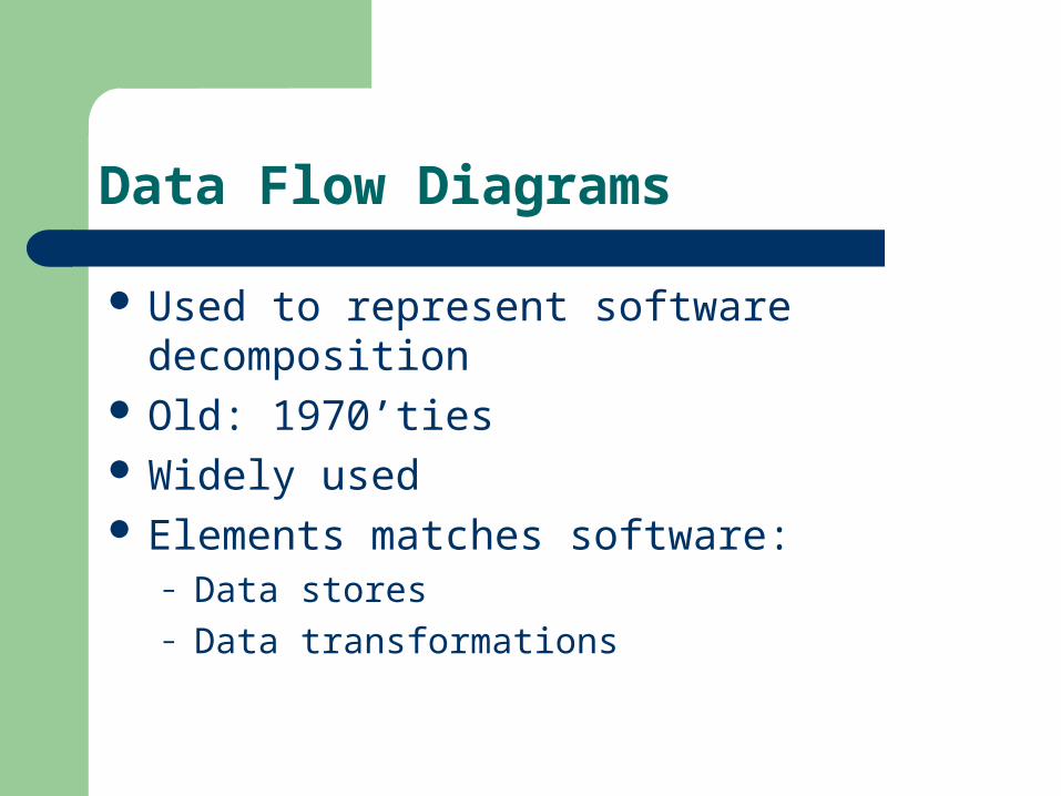
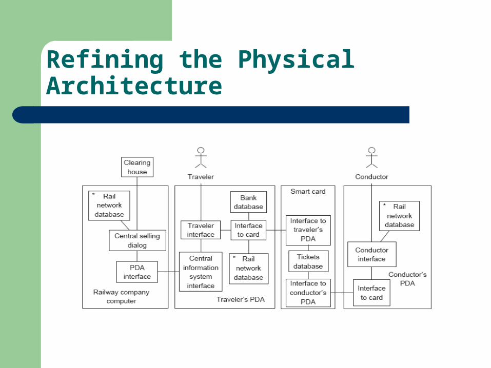
Data Flow Diagrams
Used to represent software decomposition Old: 1970’ties Widely used Elements matches software:
– Data stores– Data transformations

Architecture of Training Information System
Data storesData transformationsFragment corresponding to a function of the SuD

Requirement-level architecture of the heating controller

Tank Controller
Control System Architecture: Control processes Interface shown on lower level
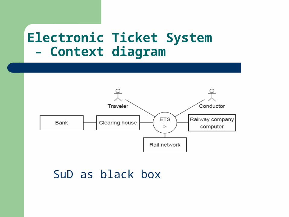
Electronic Ticket System – Context diagram
SuD as black box

Representation of SuD Elements
Data flow diagrams: No boxesArchitecture diagrams: All icons

Representing External Entities
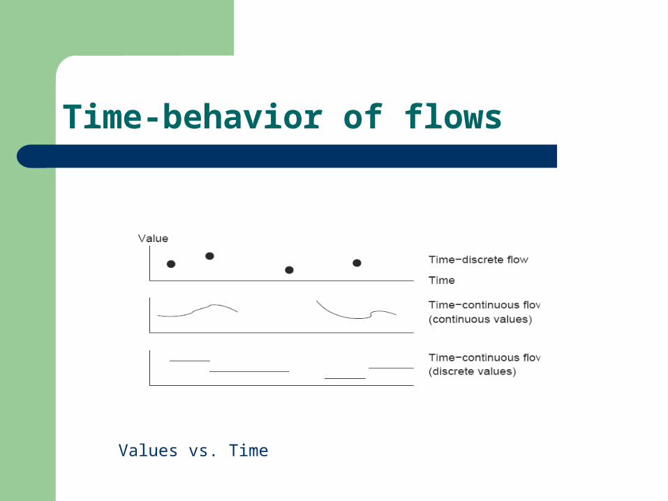
Time-behavior of flows
Values vs. Time

Representing Flows
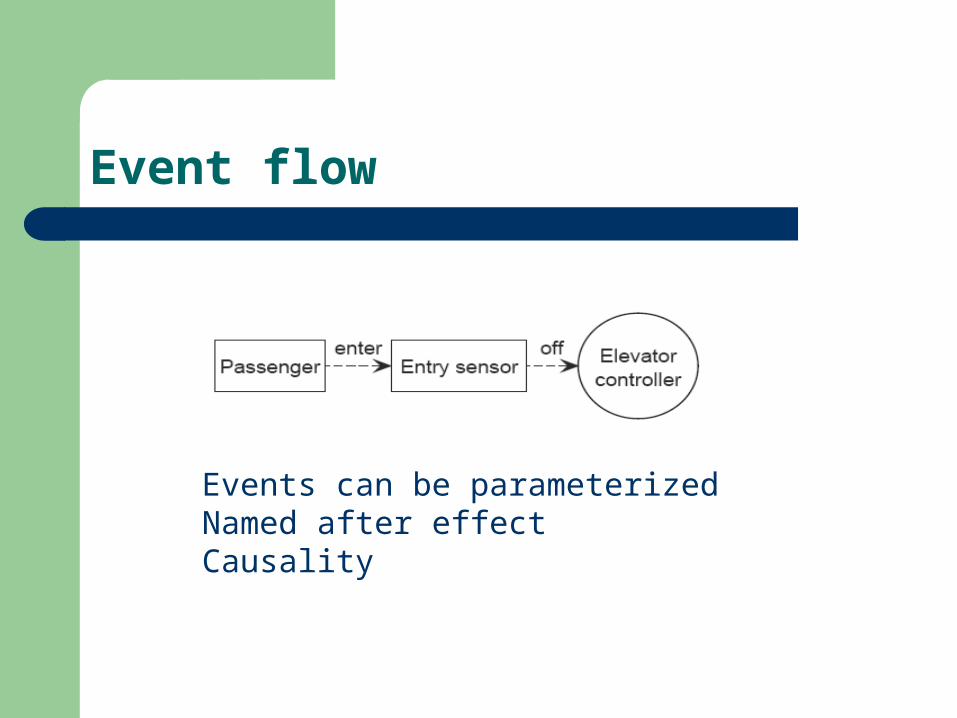
Event flow
Events can be parameterizedNamed after effectCausality

Semantics of flows
Flows are instantaneous and reliableAbstraction of real systems
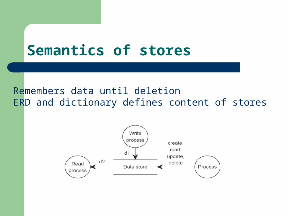
Semantics of stores
Remembers data until deletionERD and dictionary defines content of stores

Semantics of processes
Input → Output, Events Specified by STT or STD
Input → Output, Data Stateless: Triggered by T Stateful: Enable/Disable by E/D
Specified by lower level DFD

Parameterized DFDs
Process names can be combined with process identifiers– Flow names will also carry the process identifiers
We can use special notation, e.g., double circles.– But not that easy…

Data Flow Diagrams
Collection of data stores and processes connected by flows
Several kinds of processes– Details can be specified
Several kinds of flows– Details can be specified
Hierarchy of DFDs
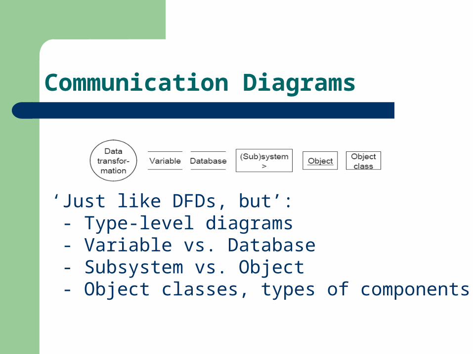
Communication Diagrams
‘Just like DFDs, but’: - Type-level diagrams - Variable vs. Database - Subsystem vs. Object - Object classes, types of components

Requirement-level Communication Diagram of Heating Controller

Instance Diagram of Heating Controller in context

Elements of Communication Diagrams
Components:– part of SuD that deliver services
Data transformation, no state Data store
– Variable, single values– Database, collection of values
Subsystem, represents lower level communication diag. Object, DFD: Stateful data process Object Class, Objects can be created and removed

Communication Channels
Like DFDs– Event Channels– Data Channels
Addressing:– Channel Addressing, like DFDs– Destination Addressing, like UML

Decomposition of systems
Channels address all components of S
AND-Components, synchronize by broadcast of events

Example of AND-component

Function Allocation Table

Function Flowdown table
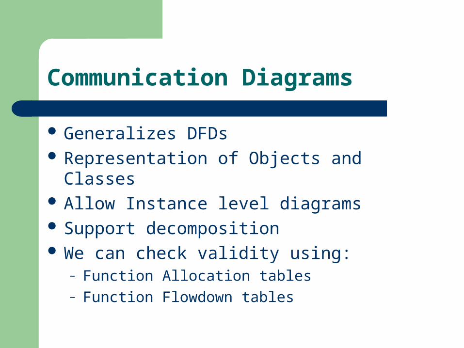
Communication Diagrams
Generalizes DFDs Representation of Objects and Classes Allow Instance level diagrams Support decomposition We can check validity using:
– Function Allocation tables– Function Flowdown tables
Break...
Short or long???

Guidelines for Context Modeling
Modeling, analysis not designSuD is a black box

Finding the System Boundaries:
Use function refinement tree– Implementation-independent description
Use list of stimuli and response– Behavioral description

Environment or SuD???
A and S entails E
Environment and SuD implements the Desired System
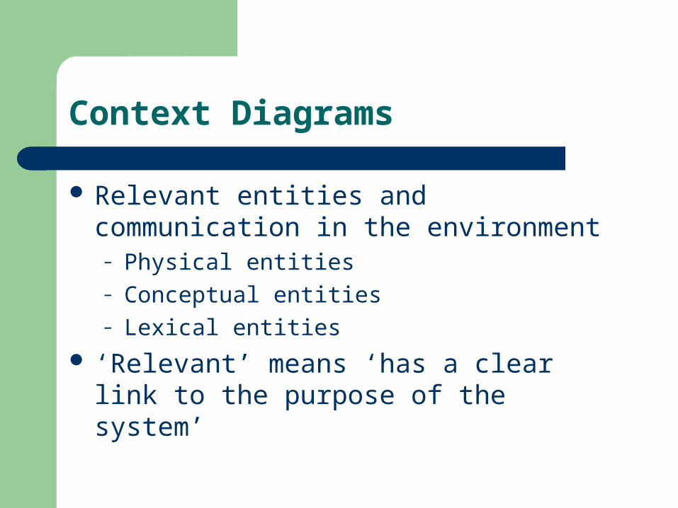
Context Diagrams
Relevant entities and communication in the environment– Physical entities– Conceptual entities– Lexical entities
‘Relevant’ means ‘has a clear link to the purpose of the system’

Context Diagram

Context Diagram
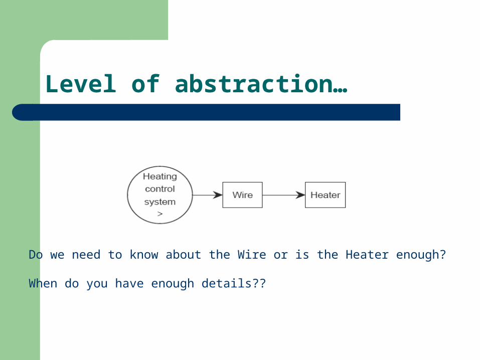
Level of abstraction…
Do we need to know about the Wire or is the Heater enough?
When do you have enough details??

Finding the Context Boundaries:
SuD goals should be achieved– SuD needs information from the entity– SuD has an effect on the entity
Ignore other entities– Effect of SuD is irrelevant– Effect on SuD is irrelevant

Structure of the context
Provide information about the subject domain– Answer questions, produce reports, …
Direct the subject domain– Control, guide, …
Manipulate lexical items in the subject domain– Create, change, display, …

Example: Information System

Example: Directive System
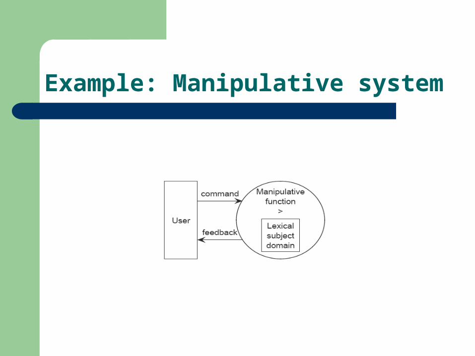
Example: Manipulative system

Context Modeling
Modeling, not design System boundaries
– Trade-off
Context boundaries– Relevance
Typical structures:– Information, directive, or manipulative
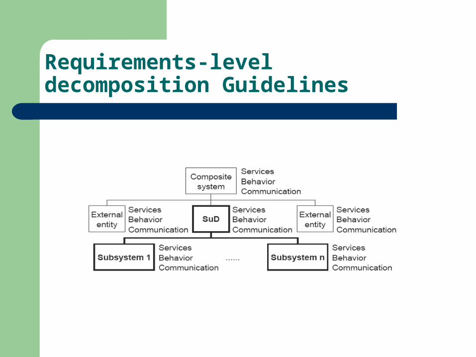
Requirements-level decomposition Guidelines
What is ‘Architecture’?
‘A structure of elements and their properties, and the interaction between these elements that realizes system-level properties’– Many levels of architectures for a SuD– Elements must have synergy– An architectural style implies a set of constraints

Encapsulation vs. Layering
Encapsulation and Service deliveryLayering and encapsulation can be mixed on different levelsLayering can be strict or loose
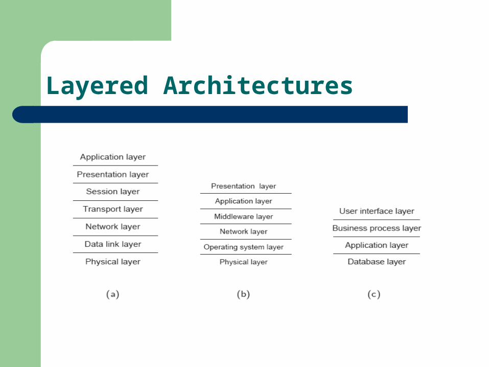
Layered Architectures
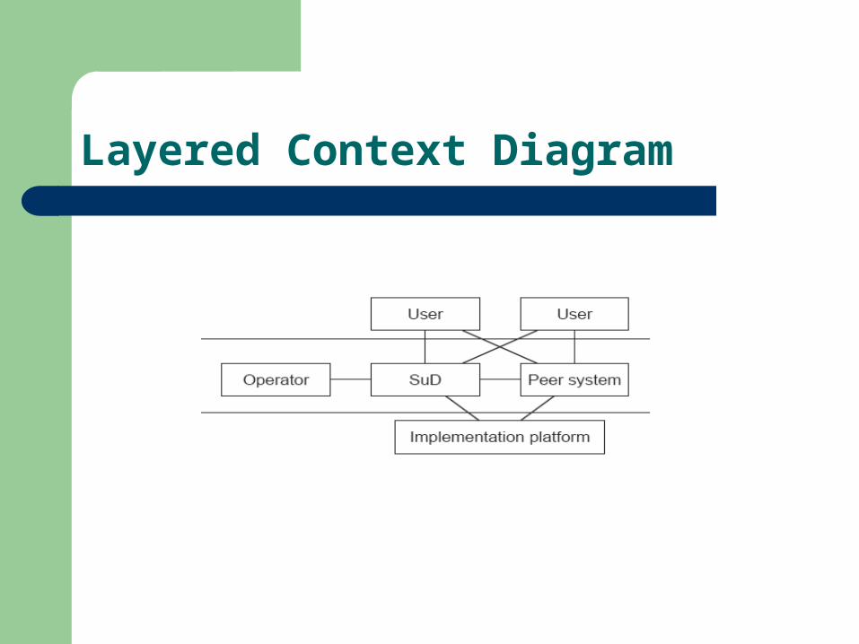
Layered Context Diagram

Guidelines
Choose a structure that reflects the structure of the problem
Choose a structure which is robust– Keep related data together– Keep related functions together

Architectural styles
Data flow style:– Not applicable
Von Neumann style– Database and
applicationprograms
Object-oriented style– All components are objects,
usually destination addressing
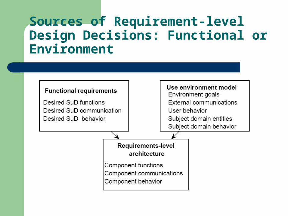
Sources of Requirement-level Design Decisions: Functional or Environment
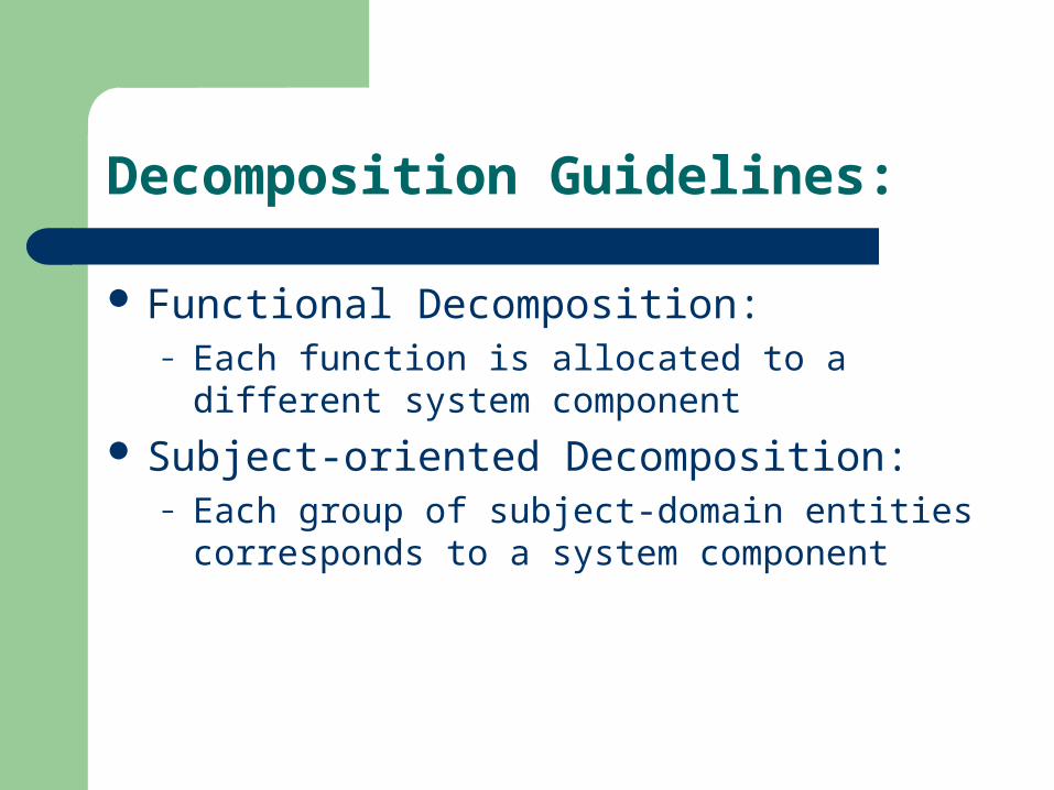
Decomposition Guidelines:
Functional Decomposition:– Each function is allocated to a different system
component
Subject-oriented Decomposition:– Each group of subject-domain entities
corresponds to a system component

Pure Functional Style
- Data encapsulated as functions - Inefficient - Hard to relate to subject domain entities

Pure Subject-oriented Style
- Functions encapsulated as data - Inefficient - Hard to relate to subject domain entities
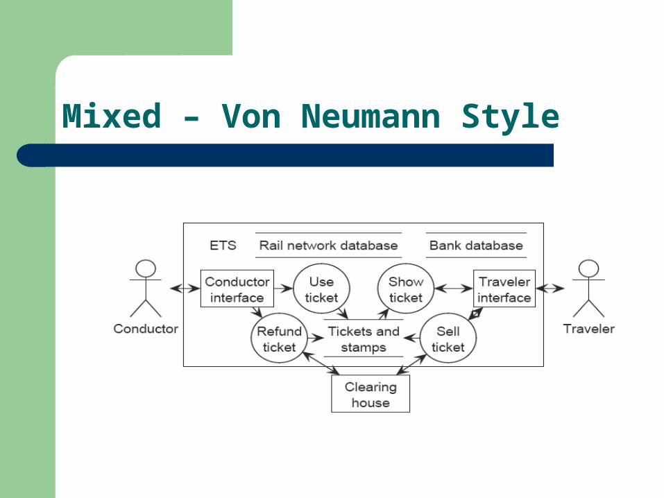
Mixed – Von Neumann Style

Decomposition styles
Event-oriented Decomposition Device-oriented Decomposition User-oriented Decomposition
Behavior-oriented Decomposition
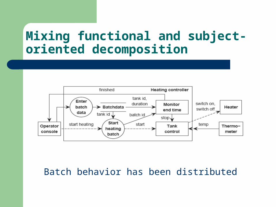
Mixing functional and subject-oriented decomposition
Batch behavior has been distributed

Including Behavior-oriented decomposition

Evaluation of Decomposition
Realize the system Reason about the models
– All data is created, used and deleted– Execute the model– Correctness argument:
C1 and … and Cn entails S
– Check that quality attributes are realized– Build a prototype, and test it.
Requirements-level Modeling
Layering or Encapsulation Styles:
– Data Flow, Von Neumann or Object-oriented Requirements-level decomposition must correspond
to major system aspects and the subject domain:– Functional decomposition – Subject-oriented decomposition – Communication-oriented, event – devices – users,
decomposition – Behavior-oriented decomposition