Embed Size (px)
Citation preview
Universite de Nice - Sophia Antipolis – UFR SciencesEcole Doctorale STIC
THESE
Presentee pour obtenir le titre de :
Docteur en Sciences de l’Universite de Nice - Sophia Antipolis
Specialite : INFORMATIQUE
par
*Rao Naveed Bin RAIS*
Equipe d’accueil : Projet-Equipe Planete – INRIA Sophia Antipolis
*COMMUNICATION MECHANISMS FOR MESSAGE DELIVERY
IN HETEROGENEOUS NETWORKS PRONE TO EPISODIC
CONNECTIVITY*
These dirigee par *Thierry TURLETTI* et *Katia OBRACZKA*
Soutenance a l’INRIA le 02 Fevrier, 2011, devant le jury compose de :
President : Prof. Michel RIVIELL University of Nice, Sophia Antipolis, France
Directeurs : Dr. Thierry TURLETTI INRIA, Sophia Antipolis, France
Prof. Katia OBRACZKA University of California at Santa Cruz, USA
Rapporteurs : Prof. Isabelle GUERIN-LASSOUS ENS Lyon/INRIA, France
Prof. Joerg OTT Aalto University, Finland
Prof. Marco CONTI IIT-CNR, Italy
Examinateurs : Dr. Franck LEGENDRE ETH Zurich, Switzerland

COMMUNICATION MECHANISMS FOR MESSAGE DELIVERY IN
HETEROGENEOUS NETWORKS PRONE TO EPISODIC CONNECTIVITYby
*Rao Naveed Bin Rais*Thesis Advisors: Thierry Tuletti (INRIA, Sophia Antipolis), Katia Obraczka (University
of California at Santa Cruz)Planete, INRIA Sophia Antipolis, France
ABSTRACT
Today’s Internet is characterized by heterogeneity, both at node– (e.g., smart phones, PDAs) andnetwork level (e.g., wired/wireless infrastructure-based and ad-hoc networks, cellular-based networks).As the networks are becoming increasingly heterogeneous, it is expected that future internetworks willinterconnect different types of network including wired, infrastructure-based wireless and infrastructure-less wireless networks including multi-hop mobile ad-hoc networks (or MANETs). Additionally, a numberof emerging applications such as environmental or habitat monitoring, emergency response, vehicularcommunication, to name a few, require that future internetworks be tolerant to frequent or long-livedconnectivity disruptions. This connectivity disruption is the inherent property of Delay or DisruptionTolerant Networks (DTNs). Interconnecting these heterogeneous networks poses several challengesdue to heterogeneity of nodes and networks. These challenges include seamless message delivery andidentification of nodes especially when the nodes are mobile. We target these issues in this thesis.
The contributions of this thesis are three fold. First, we present a classification of existing DTNrouting protocols by breaking up existing routing strategies into tunable routing modules (forwarding,replication, coding). Then, we identify a set of useful design guidelines to show how and when a givenrouting module should be used, depending on the set of network characteristics exhibited by the wirelessapplication. Second, we propose a new framework called MeDeHa to provide message delivery acrossheterogeneous networks prone to intermittent connectivity. MeDeHa is able to bridge infrastructure-based and infrastructure-less networks and makes them inter-operate seamlessly, through devices car-rying multiple interfaces or part of several networks and by the integration of existing protocols (e.g.,MANET protocols). We evaluate MeDeHa through extensive simulations using realistic synthetic andreal mobility traces, and by performing hybrid experiments which run partly on simulator and partlyon real machines. Third, we propose a naming mechanism called HeNNA for heterogeneous networksprone to connectivity disruptions which aims to provide message delivery to nodes irrespective of theircurrent IP addresses. Henna can accommodate nodes equipped with multiple network interfaces and iscompatible with the status-quo Internet routing. We also implement HeNNA within the MeDeHa frame-work and conduct experiments to showcase the operation of the complete message delivery and namingprotocol suite.

iv

TO MY PARENTS, WIFE AND DAUGHTER

ACKNOWLEDGMENTS
This thesis would not have been completed without the help and contributions from a num-
ber of people who provided me their support both at technical and moral levels. Thus, I would
like to take the opportunity to express my gratitude in order to thank them all here. I can-
not possibly thank my thesis advisors Dr. Thierry Turletti (INRIA, Sophia Antiplis) and Prof.
Katia Obraczka (UCSC, USA) for their continuous guidance, support and invaluable feedback
on my work. They really helped me a lot in making the progress in my research, and I have
learnt a lot while working under their supervision. I would also like to thank my colleagues in
the Planete team at INRIA, Sophia Antipolis, especially Dr. Walid Dabbous, Dr. Chadi Barakat
and Dr. Arnaud Legout who repeatedly provided their feedback on my work and helped me
in improving it technically. Working in the Planete team at INRIA, Sophia Antipolis has been
an unforgettable and very pleasant experience of my life, and I am going to miss the working
environment here. Besides, I thank all my friends and colleagues who helped me in improving
the thesis manuscript by providing their valuable feedback.
I would particularly like to express my gratitude to a number of colleagues who techni-
cally contributed in this thesis. Especially, I have had the honor to work with Dr. Thrasyvoulos
Spyropoulos for the taxonomy part of this thesis. His valuable comments and input in the work
has really been very helpful. Besides, Marc Mendonca from University of California at Santa
Cruz helped me in implementing the MeDeHa framework on Linux machines and to perform
hybrid experiments, while Mariem Abdelmoula assisted me in implementing the HeNNA archi-
tecture.
Nobody in this world can pay back for the love, affection and support of parents, and I am
no exception. I would really like to thank my parents for extending their financial and moral
support to me throughout my life. Their prayers and guidance have enabled me to achieve
whatever I have attained in my life. Moreover, I would also want to mention the support and
love that I have been receiving from my wife Huma, who has been very understanding and
her support helped me in a great way to complete my thesis successfully in time. She has been
tolerating to live away from me for the past two years, and I thank her for all her understanding.
In the end, I would also like to thank the Higher Eduction Commission (HEC), Govern-
ment of Pakistan who provided me the opportunity to come to France in order to get this thesis
done. They have been providing me financial support for the last 4 years.
vii

viii
CONTENTS
Abstract iii
Acknowledgements vii
Tables xv
Figures xx
I Introduction and Background 1
1 Introduction 3
1.1 Resume de these . . . . . . . . . . . . . . . . . . . . . . . . . . . . . . . . . . . . 3
1.2 Context . . . . . . . . . . . . . . . . . . . . . . . . . . . . . . . . . . . . . . . . . 4
1.2.1 L’architecture de l’Internet . . . . . . . . . . . . . . . . . . . . . . . . . . . 4
1.2.2 Le besoin de la connectivite universelle . . . . . . . . . . . . . . . . . . . . 5
1.2.3 L’heterogeneite de reseau et de noeud . . . . . . . . . . . . . . . . . . . . 5
1.2.4 L’interconnection de reseau . . . . . . . . . . . . . . . . . . . . . . . . . . 6
1.2.5 Le probleme de l’identification de noeuds mobiles . . . . . . . . . . . . . . 7
1.2.6 La classification des protocoles DTN . . . . . . . . . . . . . . . . . . . . . 8
1.3 Contributions . . . . . . . . . . . . . . . . . . . . . . . . . . . . . . . . . . . . . . 8
1.4 La liste de publications reliees a la these . . . . . . . . . . . . . . . . . . . . . . . 9
1.5 Apercu de la these . . . . . . . . . . . . . . . . . . . . . . . . . . . . . . . . . . . 10
1 Introduction 13
1.1 Problem Statement . . . . . . . . . . . . . . . . . . . . . . . . . . . . . . . . . . . 13
1.2 Context . . . . . . . . . . . . . . . . . . . . . . . . . . . . . . . . . . . . . . . . . 14
1.2.1 Background on the Internet Architecture . . . . . . . . . . . . . . . . . . . 14
1.2.2 Universal Connectivity Requirement . . . . . . . . . . . . . . . . . . . . . 15
1.2.3 Nodes and Network Heterogeneity . . . . . . . . . . . . . . . . . . . . . . 16
ix
x CONTENTS
1.2.4 Networks interconnection . . . . . . . . . . . . . . . . . . . . . . . . . . . 17
1.2.5 Node Identification and Mobility Problem . . . . . . . . . . . . . . . . . . 17
1.2.6 DTN Routing Protocols . . . . . . . . . . . . . . . . . . . . . . . . . . . . . 18
1.3 Summary of Motivations . . . . . . . . . . . . . . . . . . . . . . . . . . . . . . . . 18
1.4 Contributions . . . . . . . . . . . . . . . . . . . . . . . . . . . . . . . . . . . . . . 19
1.4.1 DTN Routing Taxonomy . . . . . . . . . . . . . . . . . . . . . . . . . . . . 20
1.4.2 The Message Delivery Framework . . . . . . . . . . . . . . . . . . . . . . . 20
1.4.3 The Naming Architecture . . . . . . . . . . . . . . . . . . . . . . . . . . . 21
1.5 Publications Related to Thesis . . . . . . . . . . . . . . . . . . . . . . . . . . . . . 22
1.6 Outline of the Thesis . . . . . . . . . . . . . . . . . . . . . . . . . . . . . . . . . . 23
2 Communication in Heterogeneous Networks: A Background 25
2.1 Heterogeneity . . . . . . . . . . . . . . . . . . . . . . . . . . . . . . . . . . . . . . 27
2.1.1 Inter-operation of infrastructure-based and ad-hoc networks . . . . . . . . 27
2.1.2 Networks with Gateway Connectivity . . . . . . . . . . . . . . . . . . . . . 28
2.2 Disconnection . . . . . . . . . . . . . . . . . . . . . . . . . . . . . . . . . . . . . . 29
2.2.1 Delay/Disruption Tolerant Networks (DTNs) . . . . . . . . . . . . . . . . . 29
2.2.1.1 Deterministic or Scheduled Forwarding . . . . . . . . . . . . . . 30
2.2.1.2 Enforced Forwarding . . . . . . . . . . . . . . . . . . . . . . . . 31
2.2.1.3 Opportunistic Forwarding . . . . . . . . . . . . . . . . . . . . . . 31
2.2.2 MANETs with Disconnections . . . . . . . . . . . . . . . . . . . . . . . . . 31
2.3 Node Identification . . . . . . . . . . . . . . . . . . . . . . . . . . . . . . . . . . . 32
2.4 New Communication Architectures . . . . . . . . . . . . . . . . . . . . . . . . . . 33
2.4.1 Content Centric Naming (CCN) . . . . . . . . . . . . . . . . . . . . . . . . 33
2.4.2 Pocket Switched Networks (PSN) . . . . . . . . . . . . . . . . . . . . . . . 34
2.4.3 Data Oriented Network Architecture (DONA) . . . . . . . . . . . . . . . . 34
2.4.4 A Layered Architecture for the Internet . . . . . . . . . . . . . . . . . . . . 34
2.4.5 Persistent Connectivity Management Protocol (PCMP) . . . . . . . . . . . 35
2.4.6 Opportunistic Connection Management Protocol (OCMP) . . . . . . . . . 35
2.4.7 Unmanaged Internet Architecture (UIA) . . . . . . . . . . . . . . . . . . . 35
2.5 Design Objectives . . . . . . . . . . . . . . . . . . . . . . . . . . . . . . . . . . . . 35
2.5.1 Assumptions and Limitations . . . . . . . . . . . . . . . . . . . . . . . . . 36
II Taxonomy of Routing in Disruption Tolerant Networks 37
3 DTN Routing Taxonomy 39
3.1 Introduction . . . . . . . . . . . . . . . . . . . . . . . . . . . . . . . . . . . . . . . 39
CONTENTS xi
3.2 Opportunistic Routing Primitives . . . . . . . . . . . . . . . . . . . . . . . . . . . 41
3.2.1 Routing as Opportunistic Forwarding . . . . . . . . . . . . . . . . . . . . . 41
3.2.2 Message Replication . . . . . . . . . . . . . . . . . . . . . . . . . . . . . . 42
3.2.2.1 Greedy Replication . . . . . . . . . . . . . . . . . . . . . . . . . . 43
3.2.2.2 Controlled Replication . . . . . . . . . . . . . . . . . . . . . . . . 43
3.2.2.3 Utility-Based Replication . . . . . . . . . . . . . . . . . . . . . . 44
3.2.3 Message Forwarding . . . . . . . . . . . . . . . . . . . . . . . . . . . . . . 45
3.2.4 Message Coding . . . . . . . . . . . . . . . . . . . . . . . . . . . . . . . . 46
3.2.5 Routing as Resource Allocation . . . . . . . . . . . . . . . . . . . . . . . . 47
3.2.6 Examples of DTN Routing Protocols . . . . . . . . . . . . . . . . . . . . . 48
3.3 DTN Routing Utility Functions . . . . . . . . . . . . . . . . . . . . . . . . . . . . . 49
3.3.1 Destination Dependent (DD) Utility . . . . . . . . . . . . . . . . . . . . . . 49
3.3.2 Destination Independent (DI) Utility . . . . . . . . . . . . . . . . . . . . . 52
3.3.3 Additional Considerations . . . . . . . . . . . . . . . . . . . . . . . . . . . 53
3.4 A Taxonomy of DTNs . . . . . . . . . . . . . . . . . . . . . . . . . . . . . . . . . . 54
3.4.1 Connectivity . . . . . . . . . . . . . . . . . . . . . . . . . . . . . . . . . . 54
3.4.2 Mobility . . . . . . . . . . . . . . . . . . . . . . . . . . . . . . . . . . . . . 57
3.4.3 Node Resources . . . . . . . . . . . . . . . . . . . . . . . . . . . . . . . . . 59
3.4.4 Application Requirements . . . . . . . . . . . . . . . . . . . . . . . . . . . 60
3.5 DTN Routing Design Guidelines . . . . . . . . . . . . . . . . . . . . . . . . . . . . 61
3.6 Concluding Remarks . . . . . . . . . . . . . . . . . . . . . . . . . . . . . . . . . . 63
III MeDeHa - A Message Delivery Framework 65
4 MeDeHa Framework 67
4.1 Introduction . . . . . . . . . . . . . . . . . . . . . . . . . . . . . . . . . . . . . . . 67
4.2 Related Work . . . . . . . . . . . . . . . . . . . . . . . . . . . . . . . . . . . . . . 70
4.3 Design Principle . . . . . . . . . . . . . . . . . . . . . . . . . . . . . . . . . . . . . 72
4.4 MeDeHa Overview . . . . . . . . . . . . . . . . . . . . . . . . . . . . . . . . . . . 73
4.4.1 Functional Components . . . . . . . . . . . . . . . . . . . . . . . . . . . . 74
4.4.2 Integration of Existing Protocols . . . . . . . . . . . . . . . . . . . . . . . 76
4.4.3 Multi-hop Connectivity . . . . . . . . . . . . . . . . . . . . . . . . . . . . . 76
4.5 MeDeHa’s Operation . . . . . . . . . . . . . . . . . . . . . . . . . . . . . . . . . . 77
4.5.1 MeDeHa State Diagram . . . . . . . . . . . . . . . . . . . . . . . . . . . . 77
4.5.2 Receive Operation . . . . . . . . . . . . . . . . . . . . . . . . . . . . . . . 78
4.5.3 Relay/Forward Operation . . . . . . . . . . . . . . . . . . . . . . . . . . . 79
4.5.4 Buffer Operation . . . . . . . . . . . . . . . . . . . . . . . . . . . . . . . . 81
xii CONTENTS
4.6 MeDeHa Design Details . . . . . . . . . . . . . . . . . . . . . . . . . . . . . . . . 82
4.6.1 The Notification Protocol . . . . . . . . . . . . . . . . . . . . . . . . . . . 82
4.6.1.1 Neighbor Sensing . . . . . . . . . . . . . . . . . . . . . . . . . . 83
4.6.1.2 Neighborhood Information Exchange . . . . . . . . . . . . . . . 85
4.6.2 Routing and Contact Table Management . . . . . . . . . . . . . . . . . . . 88
4.6.3 Relay Node Selection and Forwarding . . . . . . . . . . . . . . . . . . . . 89
4.7 Interaction with MANETs . . . . . . . . . . . . . . . . . . . . . . . . . . . . . . . 91
4.7.1 MANET Information Exchange . . . . . . . . . . . . . . . . . . . . . . . . 91
4.7.2 Gateway Discovery in MANETs . . . . . . . . . . . . . . . . . . . . . . . . 92
4.7.3 Proactive vs. Reactive MANET Routing . . . . . . . . . . . . . . . . . . . . 92
4.7.4 Message Delivery to MANETs . . . . . . . . . . . . . . . . . . . . . . . . . 93
4.7.5 Message Delivery across MANETs . . . . . . . . . . . . . . . . . . . . . . . 93
4.8 Message Delivery in MeDeHa: An Overall Picture . . . . . . . . . . . . . . . . . . 94
4.9 Design Assumptions and Limitations . . . . . . . . . . . . . . . . . . . . . . . . . 96
4.9.1 Node Identification . . . . . . . . . . . . . . . . . . . . . . . . . . . . . . . 96
4.9.2 Security Issues . . . . . . . . . . . . . . . . . . . . . . . . . . . . . . . . . 97
4.10 Concluding Remarks . . . . . . . . . . . . . . . . . . . . . . . . . . . . . . . . . . 97
5 MeDeHa Implementation and Performance Evaluation 99
5.1 Implementation Approaches . . . . . . . . . . . . . . . . . . . . . . . . . . . . . . 99
5.2 Evaluation Platforms . . . . . . . . . . . . . . . . . . . . . . . . . . . . . . . . . . 101
5.2.1 Simulator Experimentation . . . . . . . . . . . . . . . . . . . . . . . . . . 101
5.2.2 Real Experimentation . . . . . . . . . . . . . . . . . . . . . . . . . . . . . 102
5.2.3 Hybrid Experimentation . . . . . . . . . . . . . . . . . . . . . . . . . . . . 103
5.3 Simulator Implementation . . . . . . . . . . . . . . . . . . . . . . . . . . . . . . . 103
5.3.1 NS-3 Implementation . . . . . . . . . . . . . . . . . . . . . . . . . . . . . 106
5.4 Implementation on Real Machines . . . . . . . . . . . . . . . . . . . . . . . . . . 107
5.4.1 Stations Implementation . . . . . . . . . . . . . . . . . . . . . . . . . . . . 109
5.4.2 AP Implementation . . . . . . . . . . . . . . . . . . . . . . . . . . . . . . . 110
5.4.3 Intercepting Messages . . . . . . . . . . . . . . . . . . . . . . . . . . . . . 110
5.5 Hybrid Experiments . . . . . . . . . . . . . . . . . . . . . . . . . . . . . . . . . . 111
5.5.1 Experimental Setup . . . . . . . . . . . . . . . . . . . . . . . . . . . . . . 111
5.6 Performance Evaluation . . . . . . . . . . . . . . . . . . . . . . . . . . . . . . . . 112
5.6.1 Performance Metrics . . . . . . . . . . . . . . . . . . . . . . . . . . . . . . 113
5.6.2 Wireless Configuration Parameters . . . . . . . . . . . . . . . . . . . . . . 115
5.6.3 Mobility Model . . . . . . . . . . . . . . . . . . . . . . . . . . . . . . . . . 115
5.6.4 Link-Layer Implementation Results . . . . . . . . . . . . . . . . . . . . . . 115
CONTENTS xiii
5.6.4.1 Uniform and Non-uniform AP Distribution . . . . . . . . . . . . . 116
5.6.4.2 Buffers Size . . . . . . . . . . . . . . . . . . . . . . . . . . . . . . 119
5.6.5 NS-3 Results . . . . . . . . . . . . . . . . . . . . . . . . . . . . . . . . . . 121
5.6.5.1 Relay Selection Strategies . . . . . . . . . . . . . . . . . . . . . . 122
5.6.5.2 Case 1: Convention Center Type Scenario . . . . . . . . . . . . . 123
5.6.5.3 Case 2: Communication between Clusters of Nodes . . . . . . . . 127
5.6.5.4 Case 3: Communication between Students across Campuses . . . 133
5.6.5.5 Case 4: Convention Center Type Scenario . . . . . . . . . . . . . 136
5.6.5.6 Case 5: Community Intercommunication with MANETs . . . . . 139
5.6.6 Real Mobility Traces . . . . . . . . . . . . . . . . . . . . . . . . . . . . . . 143
5.6.6.1 MeDeHa with Infrastructure-based and 2-hop Infrastructure-less
Networks (Second Phase) . . . . . . . . . . . . . . . . . . . . . . 144
5.6.6.2 MeDeHa with Infrastructure-based and Multi-hop Infrastructure-
less Networks (Third Phase) . . . . . . . . . . . . . . . . . . . . 144
5.6.7 Hybrid Experiment Results . . . . . . . . . . . . . . . . . . . . . . . . . . . 146
5.7 Concluding Remarks . . . . . . . . . . . . . . . . . . . . . . . . . . . . . . . . . . 147
IV HeNNA - A Naming Mechanism for Heterogeneous Networks 149
6 Naming for Heterogeneous Networks 151
6.1 Introduction . . . . . . . . . . . . . . . . . . . . . . . . . . . . . . . . . . . . . . . 151
6.2 Design Guidelines . . . . . . . . . . . . . . . . . . . . . . . . . . . . . . . . . . . . 153
6.3 Analysis of Existing Naming Schemes . . . . . . . . . . . . . . . . . . . . . . . . . 154
6.3.1 Region-based Naming . . . . . . . . . . . . . . . . . . . . . . . . . . . . . 154
6.3.1.1 Interplanetary Internet Naming and Addressing . . . . . . . . . . 154
6.3.1.2 EDIFY . . . . . . . . . . . . . . . . . . . . . . . . . . . . . . . . . 155
6.3.2 Content-based Naming . . . . . . . . . . . . . . . . . . . . . . . . . . . . . 155
6.3.2.1 Content Centric Networking (CCN) . . . . . . . . . . . . . . . . 156
6.3.2.2 A Layered Architecture for the Internet . . . . . . . . . . . . . . 156
6.3.2.3 Data Oriented Network Architecture (DONA) . . . . . . . . . . . 156
6.3.3 Intentional Naming . . . . . . . . . . . . . . . . . . . . . . . . . . . . . . . 157
6.3.4 Host-based Naming . . . . . . . . . . . . . . . . . . . . . . . . . . . . . . . 157
6.3.4.1 Locator/ID Separation Protocol (LISP) . . . . . . . . . . . . . . . 157
6.3.4.2 Node Identity Internetworking Architecture . . . . . . . . . . . . 158
6.3.4.3 Host Identity Protocol (HIP) . . . . . . . . . . . . . . . . . . . . 158
6.3.4.4 MobileIP . . . . . . . . . . . . . . . . . . . . . . . . . . . . . . . 158
6.3.4.5 Dynamic DNS . . . . . . . . . . . . . . . . . . . . . . . . . . . . 158
xiv CONTENTS
6.4 The HeNNA Naming Mechanism . . . . . . . . . . . . . . . . . . . . . . . . . . . 159
6.4.1 HeNNA Operation . . . . . . . . . . . . . . . . . . . . . . . . . . . . . . . 160
6.4.2 Location and Management Server (LMS) . . . . . . . . . . . . . . . . . . . 161
6.4.3 Local Network Operation . . . . . . . . . . . . . . . . . . . . . . . . . . . 164
6.4.4 Ad-hoc Network Operation . . . . . . . . . . . . . . . . . . . . . . . . . . 166
6.4.5 GUID as Content Identifiers . . . . . . . . . . . . . . . . . . . . . . . . . . 166
6.4.6 GUID format . . . . . . . . . . . . . . . . . . . . . . . . . . . . . . . . . . 166
6.4.7 Scalability and Security Issues . . . . . . . . . . . . . . . . . . . . . . . . . 167
6.5 HeNNA Implementation . . . . . . . . . . . . . . . . . . . . . . . . . . . . . . . . 168
6.5.1 Modifications in MeDeHa implementation . . . . . . . . . . . . . . . . . . 169
6.6 Results . . . . . . . . . . . . . . . . . . . . . . . . . . . . . . . . . . . . . . . . . . 169
6.6.1 Case 1: File Download Across Campuses . . . . . . . . . . . . . . . . . . . 169
6.6.2 Case 2: File Transfer across Campuses with Mobile Sources . . . . . . . . 173
6.7 Concluding Remarks . . . . . . . . . . . . . . . . . . . . . . . . . . . . . . . . . . 174
V Conclusion and Future Work 175
7 Conclusions and Future Research Perspectives 177
7.1 Opportunistic DTN Routing Taxonomy . . . . . . . . . . . . . . . . . . . . . . . . 177
7.2 Message Delivery in Heterogeneous Networks . . . . . . . . . . . . . . . . . . . . 178
7.3 Naming for Heterogeneous Networks . . . . . . . . . . . . . . . . . . . . . . . . . 182
7 Les Conclusions et les travaux de recherche future 183
7.1 Une taxonomie des protocoles routage DTN . . . . . . . . . . . . . . . . . . . . . 183
7.2 La livraison des messages dans les reseaux heterogenes . . . . . . . . . . . . . . . 184
7.3 L’identification des noeuds dans les reseaux heterogenes . . . . . . . . . . . . . . 188
A Glossary 191
A.1 List of Acronyms and Abbreviations . . . . . . . . . . . . . . . . . . . . . . . . . . 191
A.2 Basic Definitions . . . . . . . . . . . . . . . . . . . . . . . . . . . . . . . . . . . . 193
Bibliography 195
TABLES
3.1 DTN Routing primitives and their use by existing DTN routing protocols . . . . . 49
3.2 Routing Module Applicability . . . . . . . . . . . . . . . . . . . . . . . . . . . . . 62
4.1 The Notification Information Exchanged for Ad-hoc Networks . . . . . . . . . . . 87
4.2 The Infrastructure-based Notification Protocol Messages . . . . . . . . . . . . . . 89
xv

xvi TABLES
FIGURES
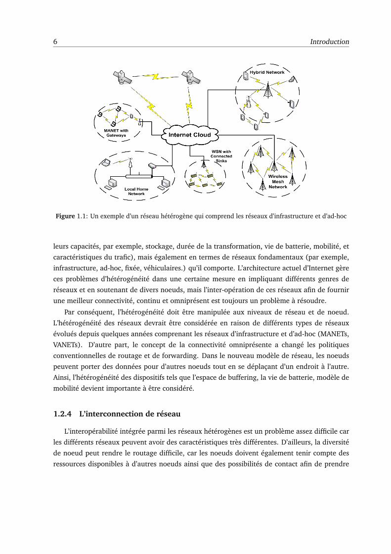
1.1 Un exemple d’un reseau heterogene qui comprend les reseaux d’infrastructure et
d’ad-hoc . . . . . . . . . . . . . . . . . . . . . . . . . . . . . . . . . . . . . . . . . 6
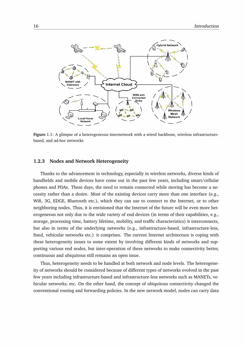
1.1 A glimpse of a heterogeneous internetwork with a wired backbone, wireless
infrastructure-based, and ad-hoc networks . . . . . . . . . . . . . . . . . . . . . . 16
3.1 Expected percentage of total nodes in largest connected component, as a func-
tion of the number of nodes (M) and transmission range (K) (200× 200 grid). . . 55
4.1 An example of a heterogeneous internetwork with a wired backbone, wireless
infrastructure-based, and ad-hoc networks prone to episodic connectivity. Node13
is disconnected, whereas Node5, Node6, Node8 and Node12 are indirectly con-
nected to the backbone network via the corresponding associated nodes. . . . . . 68
4.2 GW nodes connecting two different MANETs . . . . . . . . . . . . . . . . . . . . . 76
4.3 MDH-2 is able to communicate with MDH-1 by traversing through MANET using
GW-1 and GW-2 . . . . . . . . . . . . . . . . . . . . . . . . . . . . . . . . . . . . . 77
4.4 State diagram showing MeDeHa’s overall operation. A MeDeHa-capable node
can be in one of the four states, Idle, Receive, Forward, and Buffer . . . . . . . . . 78
4.5 Receive Operation of a MeDeHa-capable Node . . . . . . . . . . . . . . . . . . . . 80
4.6 Forward/Relay Operation of a MeDeHa-capable Node . . . . . . . . . . . . . . . . 80
4.7 Buffer Operation of a MeDeHa-capable Node . . . . . . . . . . . . . . . . . . . . 83
4.8 Multi-hop message delivery involving infrastructure-based and “ad hoc” nodes
that may be intermittently connected. Source S wants to send a message to
destination D. This is made possible with the help of node G that acts as gateway
between the two networks. S and D do not need to be connected to more than
one network nor be part of the same network in order to send or receive messages. 84
4.9 Hello handshake mechanism between node 10 and node 12. Node 10 wins and
sends the NEIGHBOR INFO notification before Node 12. . . . . . . . . . . . . . . 85
xvii
xviii FIGURES
4.10 The GW node acts as a bridge to provide communication between MANET nodes
and MDH nodes . . . . . . . . . . . . . . . . . . . . . . . . . . . . . . . . . . . . . 94
4.11 An example of message delivery in heterogeneous networks . . . . . . . . . . . . 96
5.1 Total and Effective Coverage Areas of an AP represented respectively by circle
with continuous line (green) and circle with dotted line (gray). Node B is at the
edge of the dotted line circle and eventually sends the disassociation frame to the
AP, while Node A is still associated. . . . . . . . . . . . . . . . . . . . . . . . . . . 105
5.2 MeDeHa’s implementation in Linux as a user-space daemon. Both Incoming and
Outgoing messages are intercepted for processing before being passed to Linux
kernel . . . . . . . . . . . . . . . . . . . . . . . . . . . . . . . . . . . . . . . . . . 108
5.3 MeDeHa notification header implemented as IP option header . . . . . . . . . . . 109
5.4 Configuration of bridge node using tap-bridge to inter-connect simulated and
real networks. . . . . . . . . . . . . . . . . . . . . . . . . . . . . . . . . . . . . . . 112
5.5 Hybrid experimentation setup involving real machines acting as APs and stations,
and virtual machines running in the NS-3 simulator . . . . . . . . . . . . . . . . . 113
5.6 Hybrid experimentation setup as demonstrated at ACM Mobicom 2010. . . . . . . 114
5.7 Uniform Deployment of 9 APs (28 Attraction Points). . . . . . . . . . . . . . . . . 117
5.8 CDF of Nodes with Uniform APs Distribution. . . . . . . . . . . . . . . . . . . . . 117
5.9 Non-Uniform Deployment of 9 APs (28 Attraction Points). . . . . . . . . . . . . . 118
5.10 CDF of Nodes with Non-Uniform APs Distribution. . . . . . . . . . . . . . . . . . . 118
5.11 CDF of Nodes with Mobile Sources. Message rate: 5 messages/s . . . . . . . . . . 119
5.12 Buffer Size Impact on MDR (Non-uniform APs deployment). . . . . . . . . . . . . 120
5.13 Buffer Size Impact on MDR (Uniform APs deployment). . . . . . . . . . . . . . . 121
5.14 Fraction of Nodes vs. Delivery Ratio for uniform deployment of APs . . . . . . . . 125
5.15 Delay vs. message rates for uniform deployment of APs . . . . . . . . . . . . . . . 125
5.16 Fraction of Nodes vs. Delivery Ratio for non-uniform deployment of APs . . . . . 126
5.17 Delay vs. message rates for non-uniform deployment of APs . . . . . . . . . . . . 126
5.18 Impact of varying buffer sizes on Delivery Ratio for high and low priority mes-
sages (message rate: 2 messages/s) . . . . . . . . . . . . . . . . . . . . . . . . . . 127
5.19 Deployment of APs and attraction points in a scenario with 3 disconnected clusters.128
5.20 CDF of fraction of nodes vs. delivery ratio showing the comparison between
forwarding and 2-copy replication for inter-cluster and intra-cluster traffic. Mes-
sages rate is set to 1 message/s . . . . . . . . . . . . . . . . . . . . . . . . . . . . 129
5.21 CDF of nodes vs. Delivery Ratio for 2-copy Encounter Replication (ER), Social
Affiliation Replication (SAR) and Encounter and Social Affiliation-based Replica-
tion schemes - (1 message/s) . . . . . . . . . . . . . . . . . . . . . . . . . . . . . 130
FIGURES xix
5.22 Impact of using different number of copies per message on the average MDR of
the nodes using ER and SAR relay selection strategies - (1 message/s) . . . . . . . 132
5.23 CDF of fraction of nodes vs. delivery ratio showing the comparison between for-
warding and 2-copy replication for inter-campus and intra-campus traffic. Mes-
sage rate is set to 1 message/s . . . . . . . . . . . . . . . . . . . . . . . . . . . . . 134
5.24 CDF of nodes vs. Delivery Ratio for 2-copy Encounter Replication (ER) and Social
Affiliation Replication (SAR) - (1 message/s) . . . . . . . . . . . . . . . . . . . . . 135
5.25 CDF of nodes vs. Delivery Ratio using 2-copy Community-and-Encounter Repli-
cation (ESAR) - (1 message/s) . . . . . . . . . . . . . . . . . . . . . . . . . . . . . 136
5.26 Types and distribution of nodes used in Case 4 . . . . . . . . . . . . . . . . . . . . 137
5.27 Forwarding vs. 2-copy Replication using ER scheme for 1st part of Case 4 (30
MDH, 30 GW, 30 OLSR visitors) . . . . . . . . . . . . . . . . . . . . . . . . . . . . 138
5.28 Comparison between ER and SAR schemes using 2-copy replication for 1st part
of Case 4 (30 MDH, 30 GW, 30 OLSR visitors) . . . . . . . . . . . . . . . . . . . . 139
5.29 Forwarding vs. 2-copy Replication using ER and SAR schemes for 2nd part of
Case 4 (60 GW, 30 OLSR visitors) . . . . . . . . . . . . . . . . . . . . . . . . . . . 140
5.30 Comparison between ER and SAR schemes using 2-copy replication for 2nd part
of Case 4 (60 GW, 30 OLSR visitors) . . . . . . . . . . . . . . . . . . . . . . . . . 140
5.31 Case 5: Three communities with the GW nodes are joined by three “transit
MANETs”. . . . . . . . . . . . . . . . . . . . . . . . . . . . . . . . . . . . . . . . . 141
5.32 Forwarding vs. 2-copy Replication using ER scheme for Case 5 . . . . . . . . . . . 142
5.33 Impact of different encounter parameters on fraction of nodes while comparing
forwarding and replication for Case 5 . . . . . . . . . . . . . . . . . . . . . . . . . 142
5.34 Impact of using different number of copies on delivery ratio using ER. . . . . . . 143
5.35 CDF of nodes vs. Delivery Ratio for KAIST Campus Traces for two hours using IS
only and IS+Adhoc modes (message rate: 1 message/s) . . . . . . . . . . . . . . 145
5.36 Forwarding vs. 2-copy Replication showing a comparison between the second
phase and the third phase of the MeDeHa’s implementation using KAIST mobility
traces for 40 nodes . . . . . . . . . . . . . . . . . . . . . . . . . . . . . . . . . . . 146
5.37 Forwarding vs. 2-copy Replication comparison resulting from a hybrid scenario
involving real and simulated stations. . . . . . . . . . . . . . . . . . . . . . . . . . 147
6.1 Operation of a node running HeNNA mechanism when the node has a message
to send. . . . . . . . . . . . . . . . . . . . . . . . . . . . . . . . . . . . . . . . . . 162
6.2 An example of message delivery using HeNNA. S which knows GUID(D) sends a
message to D by first contacting LMS(D). . . . . . . . . . . . . . . . . . . . . . . 163
6.3 LMS Operation in HeNNA. . . . . . . . . . . . . . . . . . . . . . . . . . . . . . . . 164

xx FIGURES
6.4 NGW Operation in HeNNA. . . . . . . . . . . . . . . . . . . . . . . . . . . . . . . 165
6.5 Composition of a GUID. . . . . . . . . . . . . . . . . . . . . . . . . . . . . . . . . 167
6.6 GUID header in the protocol stack. . . . . . . . . . . . . . . . . . . . . . . . . . . 167
6.7 Three campuses are connected to the Internet via NGWs. . . . . . . . . . . . . . . 170
6.8 Comparison of using MeDeHa with HeNNA functionality and regular MeDeHa
framework by showing the percentage of messages received in each campus. . . . 171
6.9 Percentage of messages received in both infrastructure-based and ad-hoc networks.172
6.10 Percentage of messages received in each campus for the case of file transfer with
mobile sources. . . . . . . . . . . . . . . . . . . . . . . . . . . . . . . . . . . . . . 173

Part I
Introduction and Background
1

1
INTRODUCTION
1.1 Resume de these
Au cours de ces dernieres annees, les differents types de reseaux et d’applications ont
evolue et l’Internet actuel est fortement heterogene au niveau de reseaux qu’il comporte, ainsi
qu’au niveau de noeuds qu’il relie. Egalement, il est prevue que l’Internet du futur sera plus
heterogene. Cette heterogeneite existe au niveau de noeud – (par exemple, les ressources,
la batterie, les caracteristiques de mobilite) et au niveau de reseau (par exemple, les reseaux
sans fil infrastructure et ad-hoc mobiles). D’ailleurs, la tendance des utilisateurs d’etre con-
necte tout le temps necessite l’existence d’un reseau omnipresente ou les utilisateurs mobiles
profitent de tous les opportunites de connexion meme lorsque qu’ils deplacent. Comme la con-
nectivite ne peut pas etre garantie partout, il est souhaitable que l’Internet du futur gere la
perte de connectivite de noeuds intrinsequement, quand les noeuds se deplacent. Par ailleurs,
l’intercommunication de ces differents reseaux pose de nombreux defis scientifiques comme la
gestion de la session de communication et l’identite de noeuds mobiles. Malheureusement,
l’Internet actuel peut gerer la perte de connectivite de tres courte duree. En plus, il n’est pas
possible de garder la session de communication dans l’Internet actuel quand les noeuds se
deplacent et changent leurs points de connectivite avec du reseau.
Les “Delay/Disruption Tolerant Networks” ont ete proposee pour adresser le probleme des
ruptures frequentes de connectivite. Plusieurs propositions ont ete presentees qui visent prin-
cipalement des mecanismes de routing/forwarding pour DTNs, mais il n’y a aucun consen-
sus sur des mecanismes specifiques pour les applications specifiques. Dans cette these, nous
presentons d’abord une taxonomie des protocoles existants de DTN afin d’assister aux con-
3
4 Introduction
cepteurs de protocole pour choisir une approche particuliere de routing/forwarding pour une
application specifique. Deuxiemement, nous adressons le probleme de la livraison de message
dans les reseaux heterogenes a connectivite intermittente, et proposons un framework appele
MeDeHa. Le MeDeHa framework permet a des noeuds mobiles de gerer les ruptures de con-
nectivite et de profiter de la connectivite a differents types de reseaux incluant les reseaux
d’infrastructure et ad-hoc afin d’augmenter la possibilite de livraison de message. MeDeHa
integre egalement des protocoles MANET existants sans n’exiger aucune modification. Nous
presentons l’evaluation etendue de MeDeHa en utilisant les traces mobilite des noeuds qui
sont synthetique ainsi que reels. Aussi, nous implementons MeDeHa sur Linux et faisons
des experimentes hybrides. Troisiemement, nous proposons un mecanisme d’identification,
appele HeNNA pour les reseaux heterogenes aux ruptures de connectivite qui permet a des
noeuds mobiles de communiquer avec d’autres noeuds meme lorsqu’ils changent leurs points
d’attachement. Le mecanisme separe l’identification de noeuds de leurs positions et permet la
livraison de message dans l’Internet actuel. Nous prouvons egalement que HeNNA complete
le framework MeDeHa en permettant aux noeuds de MeDeHa de changer leurs adresses IP
dynamiquement.
1.2 Context
1.2.1 L’architecture de l’Internet
L’architecture originale d’Internet a ete developpee pour fournir la communication de bout-
en-bout entre un ensemble de noeuds, tout en assumant les routes fixees de reseau entre la
source et la destination. Cependant, la conception de l’architecture d’Internet n’a pas con-
sidere l’extensibilite que l’Internet a eprouvee. Le but primaire de l’Internet etait la pouvoir
de transferer des donnees a partir d’une machine a l’autre sur un reseau, mais l’Internet a
change son role beaucoup de fois depuis son emergence. Par exemple, au debut du siecle,
presque la moitie du trafic d’Internet a comporte le contenu d’application de pair-a-pair (P2P).
Aujourd’hui, la partie la plus signifiante du trafic d’Internet est orientee vers les services de
donnees (services d’enchaınement comprenant audio et visuel) [1].
Grace a certaines propositions tres innovatrices telles que le “Domain Name System” (DNS),
le “Classless Interdomain Routing” (CIDR), le “Network Address Translation” (NAT) et le “Dy-
namic Configuration Control Protocol” (DHCP), l’Internet a survecu des nouvelles applications
et leur besoin. En particulier, l’augmentation en service des communications sans fil a fonda-
mentalement doute l’architecture de l’Internet, car elle apporte implicitement la mobilite de
noeuds ce qui doit etre gere par le reseau. Il y a egalement quelques autres problemes que la
communication sans fil introduit dans l’Internet. Par exemple, le protocole original de controle
1.2 Context 5
de congestion de TCP’s traite la perte de paquets comme signe de congestion, supposant qu’un
routeur intermediaire a jete le paquet du au debordement de tampon. Cependant, la perte de
paquet est la norme dans la communication sans fil due a l’affaiblissement ou aux collisions de
canal. Tout en faisant face a ces defis, l’Internet a fondamentalement change depuis sa nais-
sance. Par ailleurs, beaucoup de differents reseaux et applications ont evolue avec des besoins
et des caracteristiques specifiques.
De plus, l’Internet actuel est base sur le principe de la presence d’un chemin de bout-en-
bout entre une paire de noeuds pour la communication, qui n’est pas toujours possible. Ce
principe elimine egalement l’integration des reseaux (ou des noeuds) dans l’Internet ou la con-
nectivite peut etre de courte duree, et les noeuds communiquent dans une maniere oppor-
tuniste plutot que dans une maniere deterministe, et ou les delais de la communication sont
tres longtemps. Ce dispositif sporadique de connectivite est une caracteristique inherente de
beaucoup d’application actuelle telle que la reponse de secours, reseaux sous-marins, habitat
et environnement surveillant, et reseaux vehiculaires. Par ailleurs, les reseaux ad-hoc mobiles
(MANET) sont vulnerables aux ruptures de connectivite meme si les protocoles conventionnel
de MANET (par exemple, AODV [33], DSDV [34], OLSR [32]) sont bases sur l’hypothese forte
de la presence du chemin de bout-en-bout entre tous les noeuds participants pour que la session
de communication fonctionne.
1.2.2 Le besoin de la connectivite universelle
Le desir d’un reseau omnipresent ce qui a semble tout a fait futuriste il y a une decennie,
devient de plus en plus une realite. Ce desir comprend la creation d’un Inter-network qui
relie les differents types de reseaux (par exemple, les reseaux filaire et sans-fil infrastructure
et ad-hoc). Cet Inter-network inclura probablement de nouveaux paradigmes de gestion de
reseau tels que les reseaux tolerants de deconnection (DTNs) et le reseau commute par poche
(PSN) [47, 133] en tant que son composant integral. Un apercu de l’heterogeneite de reseau
est montre dans le Fig. 1.1.
1.2.3 L’heterogeneite de reseau et de noeud
Grace a l’avancement en technologie, particulierement dans les reseaux sans fil, des gen-
res des dispositifs mobiles sont disponibles aujourd’hui pour les utilisateurs, y compris des
telephones cellulaires et PDAs. Aujourd’hui, la necessite de rester connecte en se deplacant est
devenu une necessite plutot qu’un desir. La plupart des dispositifs actuels portent plus d’une
interface (par exemple, Wifi, 3G, EDGE, Bluetooth etc.), que les utilisateurs peuvent utiliser
pour se relier a l’Internet, ou a d’autres noeuds voisins. D’ailleurs, il est envisage que l’Internet
du futur sera non seulement plus heterogene du a la grande variete de dispositifs (en termes de
6 Introduction
Figure 1.1: Un exemple d’un reseau heterogene qui comprend les reseaux d’infrastructure et d’ad-hoc
leurs capacites, par exemple, stockage, duree de la transformation, vie de batterie, mobilite, et
caracteristiques du trafic), mais egalement en termes de reseaux fondamentaux (par exemple,
infrastructure, ad-hoc, fixee, vehiculaires.) qu’il comporte. L’architecture actuel d’Internet gere
ces problemes d’heterogeneite dans une certaine mesure en impliquant differents genres de
reseaux et en soutenant de divers noeuds, mais l’inter-operation de ces reseaux afin de fournir
une meilleur connectivite, continu et omnipresent est toujours un probleme a resoudre.
Par consequent, l’heterogeneite doit etre manipulee aux niveaux de reseau et de noeud.
L’heterogeneite des reseaux devrait etre consideree en raison de differents types de reseaux
evolues depuis quelques annees comprenant les reseaux d’infrastructure et d’ad-hoc (MANETs,
VANETs). D’autre part, le concept de la connectivite omnipresente a change les politiques
conventionnelles de routage et de forwarding. Dans le nouveau modele de reseau, les noeuds
peuvent porter des donnees pour d’autres noeuds tout en se deplacant d’un endroit a l’autre.
Ainsi, l’heterogeneite des dispositifs tels que l’espace de buffering, la vie de batterie, modele de
mobilite devient importante a etre considere.
1.2.4 L’interconnection de reseau
L’interoperabilite integree parmi les reseaux heterogenes est un probleme assez difficile car
les differents reseaux peuvent avoir des caracteristiques tres differentes. D’ailleurs, la diversite
de noeud peut rendre le routage difficile, car les noeuds doivent egalement tenir compte des
ressources disponibles a d’autres noeuds ainsi que des possibilites de contact afin de prendre
1.2 Context 7
des decisions correctes de routage (etant donne que les liens changent avec du temps a cause de
la possibilite de connectivite intermittente). Par exemple, dans un reseau qui a un contraint sur
le tampon ou les noeuds participants peuvent avoir differentes possibilites de buffering, il est
inutile d’expedier un message a un noeud voisin, si le dernier manque de l’espace de tampon.
De nombreuses propositions ont vise la livraison de message dans les reseaux heterogenes,
mais il n’y a aucune solution complete disponible, jusqu’ici. Nous pouvons classifier les solutions
existantes dans quatre categories differentes.
� MANETs avec support de la connectivite episodique. Les exemples comprennent “Island
Hopping” [2], “DTN-MANET Integration” [3], “Epidemic Routing” [7], et ”Spray-and-
Wait” [29].
� Augmentation de la region de connectivite de l’AP dans les reseaux sans fil infrastructure
pour prolonger la connectivite, par exemple, se servant des radios multi-canales ou com-
mutant entre differents modes d’IEEE 802.11 (WIANI [8], MMWLAN [9], Flex-Wifi [10],
Multinet [11]).
� Fournissant a MANETs la connectivite de backbone (Internet) avec l’aide des noeuds
speciaux (passerelles), et de proposer des mecanismes de decouvrir ces passerelles (par
exemple, AODV+ [14]).
1.2.5 Le probleme de l’identification de noeuds mobiles
Dans le modele de communication de l’Internet, les adresses IP des noeuds changent avec
la mobilite et leurs points d’attachement dans le reseau. Ceci remette les sessions de communi-
cation a zero car ces sessions sont lies aux noeuds specifiques et aux endroits specifiques iden-
tifies par les adresses IP. D’ailleurs, les protocoles de la couche transport et de l’application se
relient typiquement avec des adresses IP pour definir des points de communication. Ce modele
de communication n’est pas approprie aux scenarios ou les noeuds sont mobiles et changent
frequemment leurs endroits. Par consequent, il est necessaire que les architectures du futur
doivent considerer la distinction entre l’identification de noeuds et leurs localisations. Il y a une
longue discussion connue pour separer l’identification de noeuds de leur locations [94], et des
travaux assez considerable ont ete deja effectuee pour realiser cet separation [84, 80, 82].
D’ailleurs, dans un environnement d’un reseau heterogene ou les dispositifs mobiles peuvent
employer les interfaces multiples pour la connectivite, il devient impraticable que les applica-
tions emploient les adresses IP pour la communication avec des autre noeuds. La raison est
que le modele actuel de communication exige des noeuds d’acquerir l’adresse IP d’un autre
noeud avant de commencer la communication. Avec la mobilite de noeuds, il n’y a aucune
8 Introduction
garantie que l’adresse du noeud demeure accessible avant que le paquet approche une destina-
tion, particulierement en cas d’expedition opportuniste. C’est encore vrai avec l’utilisation des
mecanismes comme le protocole dynamique de configuration des adresses (DHCP) qui font des
discours d’IP meme moins stables, car un noeud peut changer son adresse IP du a etre eteint
ou etre temporairement debranche meme si il ne s’est pas physiquement deplace.
Les propositions existantes qui visent separer l’identification de noeuds avec leurs endroits
peuvent etre classifiees dans deux groupes: (1) les approches clean-slate se rapportent a pro-
poser les mecanismes tout a fait nouveaux pour l’identification de noeuds, qui ne fonctionnent
pas dans l’architecture actuel de l’Internet. Les exemples incluent Intentional Naming[79], ED-
IFY [55], and CCN [56]). (2) les approches status-quo proposent des mecanismes pour separer
l’identification et la localisation de noeuds dans l’architecture d’Internet tels que les decisions
de routage sont encore prises en utilisant des adresses d’IP des noeuds. Les exemples notables
sont LISP[82], layered Internet architecture [80], DONA [81], and HIP [84]. Dans cette these,
nous nous concentrons sur l’approche de statut-quo, car l’objectif est de trouver une solution
de nommage qui est realisable dans le cadre de l’architecture actuel de l’Internet.
1.2.6 La classification des protocoles DTN
Depuis le materialisation des reseaux DTNs [17], une quantite significative de travaux de
recherches a ete mise dans le domaine, visant la plupart du temps le routage ou les mecanismes
de expedition dans DTNs. Malgre l’existence d’un grand nombre des protocoles opportunistes
de DTN tels que “Epidemic” [7] ou “Spray-and-Wait” [29], il ya peu ou pas de consensus sur
quelle protocole convient mieux a quel environnement. Une des raisons est l’existance de la
grande diversite des applications sans fil et des reseaux montrant la connectivite episodique.
Ces reseaux ont souvent des caracteristiques tres differentes, qui rendent tres difficile, si pas
impossible, pour concevoir une solution de routage qui adapte tous.
1.3 Contributions
Les contributions de cette these sont presentees ci-dessous:
1. Nous passons en revue les protocoles existants de routage DTN et definissons les trois
primitifs de base de routage: “forwarding”, “replication” et “coding”. Puis, nous placons
chacun des protocoles existants de routage DTN en termes de ces primitifs. Nous visons le
routage opportuniste dans les reseaux DTNs et fournissons une classification (taxonomie)
des protocoles de routage proposes dans la litterature. Ceci est fait en definissant des
categories de differentes approches de routage et en placant des protocoles existants de
routage dans chacune de ces categories. Nous fournissons alors quelques directives de
1.4 La liste de publications reliees a la these 9
conception basees sur notre analyse des protocoles existants de routage DTN qui aident
des concepteurs de protocole de routage a choisir une categorie particuliere de routage
basees sur l’environnement dans lequel le protocole doit fonctionner.
2. Nous developpons un framework appele MeDeHa pour livraison de message, qui permet
l’inter-operation de differents reseaux heterogenes comprenant les reseaux ad-hoc mo-
biles et infrastructure. Le framework MeDeHa se sert comme un pont pour les reseaux
d’infrastructure et d’ad-hoc et permet egalement l’integration des protocoles existants de
routage MANET dans le framework. Il fournit egalement des mecanismes a la connec-
tivite intermittente de noeuds en reseau. Les dispositifs qui se relient a differents reseaux
par les interfaces multiples se profitent de cette heterogeneite pour prolonger la livrai-
son de message et pour transmettre par relais le trafic entre differents reseaux, alors que
le support des deconnections temporaires ou longevitaux. Nous implementons le frame-
work MeDeHa a l’aide du simulateur NS-3 aussi bien qu’avec Linux 2.6. Nous evaluons
le framework de la livraison de message avec des simulations etendues en utilisant les
scenarios realistes aussi bien qu’employer de vraies traces de mobilite. En conclusion,
nous executons egalement quelques experiences hybrides ou une partie de l’experience
fonctionne sur de vraies machines et partie sur des noeuds de simulateur.
3. Nous proposons un mecanisme d’identification, appele HeNNA, pour permettre la livrai-
son de message dans les reseaux heterogenes a connectivite intermittente meme lorsque
les noeuds changent leurs adresses de routage ou leurs points d’attachement en reseau.
Le but est de concevoir un mecanisme de nommage qui separe l’identification de noeuds
avec l’endroit et qui est realisable avec le routage actuel de l’Internet. C’est essentiel
pour les environnements dans lesquels les noeuds possedent les interfaces multiples ou
lorsque les noeuds ont une mobilite elevee tels qu’ils continuent a changer leurs en-
droits (et adresses IP). Dans le mecanisme propose, les applications se lient aux mar-
ques de noeuds au lieu de leurs endroits. Ceci permet aux noeuds de traverser plusieurs
reseaux. L’architecture proposee complement notre framework de la livraison de message
et augmente son extensibilite et fonctionnalite. Par consequent, nous implementons ce
mecanisme d’identification sur notre framework de la livraison de message et le validons
employant quelques scenarios realistes de simulation.
1.4 La liste de publications reliees a la these
Notre travaux dans cette these nous a permit de publier les papiers ci-dessous:
1. T. Spyropoulos, R.N.B. Rais, T. Turletti, K. Obraczka, and A. Vasilakos, DTN Routing:
10 Introduction
Taxonomy and Design, to appear in Delay Tolerant Networks: Protocols and Applications,
CRC Press, ISBN: 978-1-4398110-8-5, May 2011.
2. R.N.B. Rais, M. Abdelmoula, T. Turletti, and K. Obraczka, Naming for Heterogeneous Net-
works prone to Episodic Connectivity, to appear in the IEEE WCNC Conference, Mexico,
March 2011.
3. R.N.B. Rais, M. Mendonca, T. Turletti, and K. Obraczka, Towards Truly Heterogeneous
Networks: Bridging Infrastructure-based and Infrastructure-less Networks, to appear in the
IEEE/ACM 3rd International Conference on Communication Systems and Networks (COM-
SNETS), India, January 2011.
4. R.N.B. Rais, T. Turletti, and K. Obraczka, Message Delivery in Heterogeneous Networks
prone to Episodic Connectivity, ACM/Springer Wireless Networks (WINET), under revision,
2010.
5. T. Spyropoulos, R.N.B. Rais, T. Turletti, K. Obraczka, and A. Vasilakos, Routing for Disrup-
tion Tolerant Networks: Taxonomy and Design, ACM/Springer Wireless Networks, Vol. 16,
No. 8, pages 2349-2370, November 2010.
6. M. Mendonca, R.N.B. Rais, T. Turletti, and K. Obraczka, Message Delivery in Heterogeneous
Disruption-prone Networks, demo presentation in ACM Mobicom, USA, September 2010.
7. M. Mendonca, R.N.B. Rais, T. Turletti, and K. Obraczka, Message Delivery in Heterogeneous
Disruption-prone Networks, demo presentation in ACM S3 Workshop, USA, September
2010.
8. R.N.B. Rais, T. Turletti, and K. Obraczka, MeDeHa - Efficient Message Delivery in Het-
erogeneous Networks with Intermittent Connectivity, INRIA Research Report No. 7227,
inria-00464085, March 2010.
9. R.N.B. Rais, T. Turletti, and K. Obraczka, Coping with Episodic Connectivity in Heteroge-
neous Networks, In Proceedings of the 11th International Symposium on Modeling, Anal-
ysis and Simulation of Wireless and Mobile Systems (MSWiM), pp. 211-219, Canada,
2008.
1.5 Apercu de la these
L’organisation de cette these est la suivante. Dans le chapitre 2, nous presentons un back-
ground sur l’etat de l’art impliquant les matieres couvertes dans la these. Le chapitre 3 fournit
une taxonomie des protocoles de routage DTN et presente un ensemble de directives a l’aide

1.5 Apercu de la these 11
en concevant un protocole de routage pour une application et environnement particuliere.
Le framework MeDeHa pour viser la livraison de message dans les reseaux heterogenes est
presente dans le chapitre 4, alors que des details sur l’execution et son evaluation sont fournis
dans le chapitre 5. Dans le chapitre 6, nous presentons un nouveau mecanisme de nommage
(HeNNA) pour les reseaux heterogenes qui considere la mobilite de noeuds et les debranchages
temporaires du reseau. A la fin, nous recapitulons les resultats et les contributions principaux
de cette these dans le chapitre 7 avec quelques directions pour la recherche du futur dans le
domaine.

12 Introduction
1
INTRODUCTION
1.1 Problem Statement
Over the past few years, different types of networks and applications have evolved and
the current Internet is highly heterogeneous not only in terms of the networks it comprises,
but also the nodes it interconnects. Thus, i t is envisioned that the future Internet will be
even more heterogeneous. This heterogeneity exists at both node- (e.g., resources, battery,
mobility characteristics) and network level (e.g., wired and wireless infrastructure-based and
infrastructure-less mobile networks). Moreover, tendency of users to be connected “anytime,
anywhere” gives birth to the ubiquitous networking where users want to take advantage of any
available connection opportunity even when moving, including cellular based networks, Wifi
etc. As connectivity cannot be guaranteed everywhere, it is desirable that the future Internet
inherently supports disruptions in connectivity when nodes move and change their locations.
Also, interconnection of these different networks presents several challenges as users may want
to get a continuation of connectivity even using different network interfaces so as to maintain
the communication session. Unfortunately, the current Internet architecture can only cope with
very short-lived connectivity disruptions and the communication is delay-bound. Furthermore,
it is not possible to maintain the communication session in the current architecture when the
nodes move and change their locations (and eventually change their IP addresses).
Delay or Disruption Tolerant Networking (DTN) has been proposed to address the problem
of frequent or long-lived connectivity disruptions. Several proposals have been presented which
mainly target routing/forwarding mechanisms for DTNs, but there is no consensus on which ap-
proach suits which scenario or application. In this thesis, we first present a taxonomy of existing
13
14 Introduction
DTN routing protocols to help DTN routing designers choose a particular routing/forwarding
approach for a specific application in hand. Second, we address the problem of seamless mes-
sage delivery in heterogeneous networks prone to intermittent connectivity, and propose a mes-
sage delivery framework called MeDeHa (Message Delivery in Heterogeneous Disruption-prone
Networks) for such environments. The MeDeHa framework allows mobile nodes to cope with
connectivity disruptions and to take advantage of connectivity to different types of networks
including infrastructure-based and infrastructure-less networks in order to enhance message
delivery. The framework also seamlessly integrates existing MANET routing protocols without
requiring any modifications. We present extensive evaluation of the MeDeHa framework us-
ing synthetic but realistic mobility models and real mobility traces, and by implementing the
framework on Linux as a user-space daemon. Third, we propose a naming mechanism, named
HeNNA (Heterogeneous Networks Naming Architecture), for heterogeneous networks prone
to connectivity disruptions which allows mobile nodes to communicate with other nodes even
when they change their locations. The mechanism separates node identification from their lo-
cations and allows message delivery in the current Internet architecture. We also show that
HeNNA complements the MeDeHa framework by allowing the MeDeHa nodes to change their
IP addresses dynamically.
1.2 Context
1.2.1 Background on the Internet Architecture
Since its emergence, the Internet has experienced tremendous growth. The original Inter-
net architecture was developed to provide end-to-end communication between a set of nodes,
while assuming static or rather fixed network routes between a pair of source and destination.
However, the design of the original Internet architecture did not consider the scalability that the
Internet has experienced. The primary purpose of the Internet was the ability to transfer data
from one machine to another over a network, but the Internet has changed its role many times
since then. For instance, at the start of the decade, peer-to-peer (P2P) traffic came into action
and almost half the Internet traffic comprised P2P application contents. These days, most of the
Internet traffic is oriented towards data services (Web services including audio and video) as
presented in [1], where the authors found that more than 57% of the Internet traffic comprises
HTTP (Web).
The Internet has faced a number of challenges as its growth occurred. Thanks to some
very innovative proposals such as Domain Name System (DNS), Classless Inter Domain Rout-
ing (CIDR), Network Address Translation (NAT), and Dynamic Host Configuration Protocol
(DHCP), the Internet has been living up to the expectations of the emerging applications and
the increasing worldwide demand. Especially, the increase in use of wireless communications
1.2 Context 15
has fundamentally questioned the architecture of the Internet, as it implicitly brings the node
mobility which the network has to cope with. There are also some other problems that the wire-
less communication brings into the Internet. For instance, the original TCP’s congestion control
protocol inherently treats loss of packets as a sign of congestion, assuming that an intermedi-
ate router has dropped the packet due to buffer overflow. However, packet loss is the norm
in wireless communication due to channel impairment or collisions. While coping with these
challenges, the Internet has fundamentally changed since its birth. Besides, many different
networks and applications have evolved with specific requirements and characteristics.
Furthermore, the current Internet architecture is based on the principle that a contem-
poraneous delay-bound end-to-end path exists between a pair of nodes for communication,
which may not always be possible. This principle also rules out the integration of networks
(or nodes) in the Internet where connectivity can be short-lived, and nodes communicate op-
portunistically rather than in a deterministic way (e.g., mobile wireless nodes), and where
communication delays are very long (e.g., communication between satellites). This sporadic
connectivity feature is an inherent characteristic of many recently emerged applications such
as emergency response, underwater networks, habitat and environment monitoring, smart en-
vironments (e.g., smart offices, homes, museums, etc.), and vehicular networks, to name a few.
Besides, regular mobile ad-hoc networks (MANET) are vulnerable to connectivity disruptions
even though conventional MANET routing protocols (e.g., AODV [33], DSDV [34], OLSR [32])
are based on the strong assumption of a network with connected graph and on the presence of
contemporaneous end-to-end path between all participating nodes for communication session
to operate.
1.2.2 Universal Connectivity Requirement
The desire of ubiquitous networking which seemed quite futuristic a decade or so ago, is
becoming more and more a reality. One of the critical enabling technologies for this “universal
connectivity” is the emergence of an internetwork that interconnects different types of net-
works, ranging from wired, infrastructure-based wireless (e.g., cellular-based networks, wire-
less mesh networks) to infrastructure-less wireless networks (e.g., mobile ad hoc networks,
or MANETs, vehicular networks, or VANETs1). This internetwork will likely include new net-
working paradigms such as disruption/delay tolerant networks (DTNs) and Pocket Switched
Network (PSN) [47, 133] as its integral component. A glimpse of the network heterogeneity is
shown in Fig. 1.1.
1While VANETs are generally used for safety purposes to prevent accidents, it is also desirable that vehicles on
roads have an Internet connectivity while moving.
16 Introduction
Figure 1.1: A glimpse of a heterogeneous internetwork with a wired backbone, wireless infrastructure-
based, and ad-hoc networks
1.2.3 Nodes and Network Heterogeneity
Thanks to the advancement in technology, especially in wireless networks, diverse kinds of
handhelds and mobile devices have come out in the past few years, including smart/cellular
phones and PDAs. These days, the need to remain connected while moving has become a ne-
cessity rather than a desire. Most of the existing devices carry more than one interface (e.g.,
Wifi, 3G, EDGE, Bluetooth etc.), which they can use to connect to the Internet, or to other
neighboring nodes. Thus, it is envisioned that the Internet of the future will be even more het-
erogeneous not only due to the wide variety of end devices (in terms of their capabilities, e.g.,
storage, processing time, battery lifetime, mobility, and traffic characteristics) it interconnects,
but also in terms of the underlying networks (e.g., infrastructure-based, infrastructure-less,
fixed, vehicular networks etc.) it comprises. The current Internet architecture is coping with
these heterogeneity issues to some extent by involving different kinds of networks and sup-
porting various end nodes, but inter-operation of these networks to make connectivity better,
continuous and ubiquitous still remains an open issue.
Thus, heterogeneity needs to be handled at both network and node levels. The heterogene-
ity of networks should be considered because of different types of networks evolved in the past
few years including infrastructure-based and infrastructure-less networks such as MANETs, ve-
hicular networks, etc. On the other hand, the concept of ubiquitous connectivity changed the
conventional routing and forwarding policies. In the new network model, nodes can carry data
1.2 Context 17
for other nodes while moving from one place to another. Thus, the heterogeneity of devices
such as buffering space, battery life, mobility pattern comes into consideration.
1.2.4 Networks interconnection
Seamless interoperability among heterogeneous networks is a challenging problem as dif-
ferent networks may have very different characteristics. Also, node diversity may make routing
difficult, as nodes must also take into account available resources at other nodes along with con-
tact opportunities in order to make correct routing decisions (given that links are time-varying
due the possibility of intermittent connectivity). For instance, in a buffer-constrained network
where participating nodes may have different buffering capabilities, it is useless to forward a
message to a neighboring node, if the latter is running out of buffer space.2
A few proposals have targeted message delivery in heterogeneous networks, but there are
no comprehensive solutions available, to date. We can classify the existing solutions into four
different categories.
� Extend MANETs to handle episodic connectivity. Examples include Island hopping [2],
DTN-MANET Integration [3], Epidemic Routing [7], and Spray-and-Wait [29].
� Augment the coverage area of APs in infrastructure-based wireless networks to extend
connectivity, for example, making use of multi-channel radios or switching between dif-
ferent modes of IEEE 802.11 (WIANI [8], MMWLAN [9], Flex-Wifi [10], Multinet [11]).
� Provide MANETs with backbone (Internet) connectivity with the help of special purpose
gateway nodes, and proposing mechanisms to discover these gateways (e.g., AODV+ [14]).
1.2.5 Node Identification and Mobility Problem
In the Internet communication model, IP addresses of nodes generally change with mobility
and their points of attachment to the network. This makes the communication sessions to
be reset as these sessions are bound to specific hosts and specific locations identified by the
IP addresses. Moreover, transport and application protocols typically rely on IP addresses to
define communication endpoints. This communication model is not suitable for the scenarios
where nodes are mobile and frequently change their locations. Therefore, it is required that the
future communication architectures should consider the distinction between node identification
and their locations. There is a long known debate of separating node identification from their
locations [94], and significant amount of work has been done to realize this [84, 80, 82].
2Though today’s devices may have large storage space thanks to the cheap memories availability, buffer con-
straints and issues still need to be considered because nodes may not be willing to contribute whole of their available
buffer space.
18 Introduction
Besides, in a heterogeneous network environment where mobile devices may use multiple
interfaces for network connectivity, it becomes unfeasible for applications to use IP address for
communication with peer devices. This is due to the fact that the current communication model
requires the nodes to acquire IP address of a peer node before starting the communication. With
nodes mobility, there is no guarantee that the IP address of a peer node remains reachable by
the time the packet approaches a destination, especially in case of opportunistic forwarding.
This is even more true with the use of mechanisms like Dynamic Host Configuration Protocol
(DHCP) which make IP addresses even less stable, as a node may change its IP address due to
being turned off or temporarily disconnected even if it has not physically moved.
The existing proposals that target separating node identification from locations can be clas-
sified into two groups: (1) clean-slate approaches refer to proposing altogether new mechanisms
for node identification, which do not work in the current Internet architecture. Examples in-
clude Intentional Naming[79], EDIFY [55], and CCN [56]). (2) status-quo approaches propose
mechanisms to separate node identification and location within the Internet architecture such
that the routing/forwarding decisions are still made using IP addresses of nodes. Notable ex-
amples are LISP[82], layered Internet architecture [80], DONA [81], and HIP [84]. These
mechanisms propose patches to the current Internet architecture. In this thesis, we focus on
the status-quo approach, as the objective is to find a naming solution that is workable within
the framework of the current Internet architecture.
1.2.6 DTN Routing Protocols
Since the materialization of the delay or disruption tolerance networks (DTNs) [17], a
significant amount of research effort has been put in the domain, mostly targeting routing or
forwarding mechanisms in DTNs. Despite the existence of a large number of opportunistic DTN
routing protocols such as Epidemic [7] or Spray-and-Wait [29], there is little or no consensus
on which routing protocol is suitable for which environment. One of the reasons is the large
diversity of evolving wireless applications and networks exhibiting episodic connectivity. These
networks often have very different characteristics and requirements, making it very difficult, if
not impossible, to design a routing/forwarding solution that fits all.
1.3 Summary of Motivations
In the light of the context presented in the previous section, we summarize the main moti-
vations behind the work presented in this thesis as:
1. Classification of existing DTN routing protocols and presentation of a set of guidelines for
DTN routing designers.
1.4 Contributions 19
2. Seamless inter-operation of heterogeneous networks (including infrastructure-based and
infrastructure-less networks) in the face of connectivity disruptions.
3. Decoupling node identification from their locations in heterogeneous networks prone to
episodic connectivity.
1.4 Contributions
The contributions of this thesis are three fold.
1. We review the existing DTN routing protocols and define basic routing primitives: for-
warding, replication and coding. Then, we place each of the existing DTN routing proto-
cols in terms of these routing primitives. We target opportunistic routing in disruption
tolerant networks (DTN) and provide a classification (taxonomy) of the routing proto-
cols proposed in the literature. This is done by defining categories of different routing
approaches and placing existing routing protocols in each of these categories. We then
provide some design guidelines based on our analysis of the existing DTN routing proto-
cols that help routing protocol designers choose a particular category of routing policies
based on the environment in which the protocol needs to function.
2. We develop a message delivery framework called MeDeHa, which allows seamless inter-
operation of different heterogeneous networks including infrastructure-based and multi-
hop mobile ad-hoc networks. The MeDeHa framework bridges infrastructure-based and
infrastructure-less networks and also allows the integration of existing MANET routing
protocols within the framework. It also provides mechanisms to support nodes intermit-
tent connectivity with the network. Devices that connect to different networks through
multiple interfaces take advantage of this heterogeneity to extend the message delivery
and relay the traffic between different networks, while supporting temporary or long-lived
disconnections of nodes and long communication delays. We implement the MeDeHa
framework using the NS-3 simulator as well as on a real testbed using Linux 2.6 kernel.
We evaluate the message delivery framework with extensive simulations using realistic
scenarios as well as using real mobility traces. Finally, we also perform some hybrid ex-
periments where part of the experiment runs on real machines and part on simulator
nodes.
3. We propose a naming mechanism, named HeNNA, to allow message delivery in disruption-
prone heterogeneous networks even when nodes change their routing addresses or their
points of attachment to the network. The purpose is to design a naming mechanism that
20 Introduction
separates node identification from location and that is workable with the status-quo In-
ternet routing. This is essential for the environments in which nodes possess multiple
interfaces or where nodes have high mobility such that they keep on changing their lo-
cations (and IP addresses). In the proposed mechanism, applications bind themselves to
node identifiers instead of their locations. This allows seamless roaming of nodes across
several networks. The proposed naming architecture complement our message delivery
framework and enhances its scalability and functionality. Hence, we implement this nam-
ing scheme on top of our message delivery framework and validate it using some realistic
simulation scenarios.
We briefly describe each of these contributions in the following.
1.4.1 DTN Routing Taxonomy
We present a classification of existing opportunistic DTN routing protocols by breaking up
existing routing strategies into a small number of common and tunable routing modules (e.g.
message forwarding, replication, coding, etc.), and then show how and when a given routing
module should be used, depending on the set of network characteristics exhibited by the wire-
less application and environment. We further attempt to create a taxonomy for intermittently
connected networks. We try to identify generic network characteristics that are relevant to the
routing process (e.g., network density, node heterogeneity, mobility patterns) and dissect dif-
ferent challenged wireless networks or applications based on these characteristics. The main
goal is to identify a set of useful design guidelines that will enable one to choose an appropri-
ate routing protocol for the application or network in hand. Details on this classification are
presented in Chapter 3.
1.4.2 The Message Delivery Framework
We call our message delivery framework MeDeHa which incorporates node and network
heterogeneity and tries to make use of it whenever possible. The framework offers the following
advantages:
� Bridging infrastructure-based and infrastructure-less networks.
� Seamless message delivery across heterogeneous networks.
� Ability to work with existing MANET routing protocols without modifying them.
� Ability to work with existing DTN routing mechanisms.
� Partition mending through multi-hop ad-hoc (MANET) “transit networks”.

1.4 Contributions 21
� Flexibility to operate at different layers of the protocol stack.
The framework design is based on the principle that in order to join two networks, there
must be a node that understands the traffic on both networks and acts as a gateway to pass
the traffic. In MeDeHa, any node can serve as the gateway node, as long as it has multiple
interfaces (e.g., Wifi and 3G on a cellular/smart phone) or it is able to connect to multiple
networks simultaneously with a single interface card by, for example, switching frequencies to
connect to different networks [11].
A notification protocol has been designed for the MeDeHa framework which plays a key role
in seamless message delivery across multiple heterogeneous interconnected networks (includ-
ing infrastructure-based and infrastructure-less networks). This notification protocol enables
the integration of existing MANET routing protocols in the framework. The protocol performs
this functionality through neighborhood information exchange across all networks including
infrastructure-based and infrastructure-less networks. Using the information obtained from
neighborhood information exchange, the nodes are able to build their routing and contact ta-
bles. The routing tables are used for nodes that are directly accessible, while the contact tables
are used to manage heuristics about nodes (e.g., number of encounters) that are used in relay
node selection.
We implemented the MeDeHa framework on NS-3, and conducted extensive simulations us-
ing a number of scenarios with synthetic but realistic mobility models and real mobility traces.
Furthermore, we implemented the framework as a user-space daemon in Linux and conducted
experiments on a real testbed. We then performed some hybrid experiments, in which part of
the experiment ran on NS-3 simulator and part of the experiment executed on real machines.
These hybrid experiments involved the inter-communication of real machines and simulator
nodes, which implicitly validates the simulation implementation. The design of the MeDeHa
framework is provided in Chapter 4, whereas the framework’s evaluation is presented in Chap-
ter 5.
1.4.3 The Naming Architecture
A heterogeneous network comprises nodes that carry devices with multiple interfaces (e.g.,
a smart phone with Wifi and 3G interface). Hence, while providing message delivery in an en-
vironment where nodes are able to connect simultaneously to multiple networks, identification
of nodes becomes a challenge, as the sender cannot send a message destined to a particular
IP address of a destination. This is especially true in an environment where nodes are highly
mobile and remain disconnected for long periods of time; hence, they keep on changing their
points of attachment to the networks and eventually their IP addresses. This means that a
naming mechanism is indispensable for such networks so that the sender of a message use the
22 Introduction
destination identifier to send messages, and the network locates the destination and delivers
the message at any interface the destination is using. For this purpose, we propose the HeNNA
naming for heterogeneous disruption-prone networks, which allows participating nodes to own
a globally unique identifier (GUID), and applications use the GUID to communicate with peer
applications.
HeNNA complements the MeDeHa framework and enables the MeDeHa-capable nodes to
exchange messages with other nodes in the Internet. For this purpose, we showcased the
HeNNA’s functionality with the MeDeHa framework. We implemented HeNNA on NS-3 with
an extended version of MeDeHa such that the MeDeHa nodes use the GUIDs of peer nodes
to communicate instead of their IP addresses. We conducted experiments using some realistic
scenarios, and show the effectiveness of HeNNA in practice for delivering messages to mobile
nodes despite the change of their IP addresses and the change in their points of attachment to
the network. Chapter 6 provides more details on this naming architecture.
1.5 Publications Related to Thesis
The work presented in this thesis has resulted in the following publications in international
journals and conferences:
1. T. Spyropoulos, R.N.B. Rais, T. Turletti, K. Obraczka, and A. Vasilakos, DTN Routing:
Taxonomy and Design, to appear in Delay Tolerant Networks: Protocols and Applications,
CRC Press, ISBN: 978-1-4398110-8-5, May 2011.
2. R.N.B. Rais, M. Abdelmoula, T. Turletti, and K. Obraczka, Naming for Heterogeneous Net-
works prone to Episodic Connectivity, to appear in the IEEE WCNC Conference, Mexico,
March 2011.
3. R.N.B. Rais, M. Mendonca, T. Turletti, and K. Obraczka, Towards Truly Heterogeneous
Networks: Bridging Infrastructure-based and Infrastructure-less Networks, to appear in the
IEEE/ACM 3rd International Conference on Communication Systems and Networks (COM-
SNETS), India, January 2011.
4. R.N.B. Rais, T. Turletti, and K. Obraczka, Message Delivery in Heterogeneous Networks
prone to Episodic Connectivity, ACM/Springer Wireless Networks (WINET), under revision,
2010.
5. T. Spyropoulos, R.N.B. Rais, T. Turletti, K. Obraczka, and A. Vasilakos, Routing for Disrup-
tion Tolerant Networks: Taxonomy and Design, ACM/Springer Wireless Networks, Vol. 16,
No. 8, pages 2349-2370, November 2010.
1.6 Outline of the Thesis 23
6. M. Mendonca, R.N.B. Rais, T. Turletti, and K. Obraczka, Message Delivery in Heterogeneous
Disruption-prone Networks, demo presentation in ACM Mobicom, USA, September 2010.
7. M. Mendonca, R.N.B. Rais, T. Turletti, and K. Obraczka, Message Delivery in Heterogeneous
Disruption-prone Networks, demo presentation in ACM S3 Workshop, USA, September
2010.
8. R.N.B. Rais, T. Turletti, and K. Obraczka, MeDeHa - Efficient Message Delivery in Het-
erogeneous Networks with Intermittent Connectivity, INRIA Research Report No. 7227,
inria-00464085, March 2010.
9. R.N.B. Rais, T. Turletti, and K. Obraczka, Coping with Episodic Connectivity in Heteroge-
neous Networks, In Proceedings of the 11th International Symposium on Modeling, Anal-
ysis and Simulation of Wireless and Mobile Systems (MSWiM), pp. 211-219, Canada,
2008.
1.6 Outline of the Thesis
This thesis is organized as follows. In Chapter 2, we present some background of the related
work involving the topics covered in the thesis. Chapter 3 provides a taxonomy of DTN routing
protocols and presents a set of guidelines to help in designing a routing protocol for a particular
environment application. The MeDeHa framework to target message delivery in heterogeneous
networks is presented in Chapter 4, while details on MeDeHa’s implementation and its evalua-
tion are provided in Chapter 5. In Chapter 6, we present a new naming mechanism (HeNNA)
for heterogeneous networks that considers nodes mobility and temporary disconnections from
the network. At the end, we summarize the main findings and contributions of this thesis in
Chapter 7 along with some future directions.

24 Chapter 1: Introduction
2
COMMUNICATION IN HETEROGENEOUS
NETWORKS: A BACKGROUND
Thanks to the evolution of the communication technology, the Internet has experienced in-
credible growth in the past few years, yet it has been living up to the expectations and the
requirements of emerging applications most of the time. The initial idea of the Internet was
to provide a communication model for end-to-end connectivity between two endpoint nodes
assuming primarily a static network between these nodes. Though, it remains the premier ser-
vice offered by the today’s Internet architecture, the Internet has been evolved enough to cope
with some new applications (e.g., peer-to-peer, multi-casting, social network applications) and
networks (e.g., vehicular networks, sensor networks). Especially, the introduction of the wire-
less networks (most specifically mobile) challenged the existing Internet architecture because
of the existence of unpredictable and ever changing connection opportunities. Also, in mobile
wireless networks, nodes are assumed to provide the routing facilities to the packets which is
in contrast to the traditional viewpoint of the Internet architecture, where dedicated machines
(nodes) are generally used to serve as routers. While it is acceptable to assume that a path
between two endpoint nodes remain persistent during a communication session in case of the
traditional Internet backbone, it becomes a very strong assumption if the network involves mo-
bile nodes. This is especially true when the infrastructure network is absent (e.g., MANETs)
as there is no guarantee that a contemporaneous path exists between two nodes all the time.
MANET routing protocols are generally based on this strong assumption.
These days, users can connect to infrastructure-based networks using portable devices even
when moving from one place to another. One of the critical enabling technologies of this ubiq-
uitous connectivity is the realization of an internet that attempts to bridge together different
25
26 Chapter 2: Communication in Heterogeneous Networks: A Background
types of networks ranging from infrastructure-based wired and wireless to infrastructure-less
networks. This ubiquitous connectivity requirement and interconnection of networks of diverse
characteristics introduce several challenges such as seamless message delivery, network scala-
bility, continuous connectivity, session persistence identification of nodes and security, to name
a few. Moreover, other challenges include heterogeneity of nodes and networks, and nodes
temporary or long-lived disconnection from the infrastructure-based network and from each
other. In this thesis, we target three main challenges related to the ubiquitous connectivity and
inter-operation of heterogeneous nodes and networks, which we describe in the following:
1. Heterogeneity: The term heterogeneity needs to be carefully defined as it has been used by
the research community for different purposes. In the thesis, the term heterogeneous net-
works refers to the heterogeneity both at the network and at the node level. Heterogeneity
of networks means that different types of networks with diverse characteristics co-exist
in the internetwork and we are interested in their inter-operation to provide ubiquitous
connectivity, which is an important issue to be considered. For instance, communicating
nodes may be member of different types of infrastructure-based and infrastructure-less
networks. By heterogeneity of nodes, we mean that the participating nodes can have dif-
ferent and distinct capabilities in terms of their resources (e.g., processing power, memory,
battery life) and other characteristics such as mobility or connectivity pattern. Thus the
participation of each node to provide connectivity is not homogeneous and depends upon
its resources and characteristics. What is more, the participating nodes can use multiple
interfaces to connect to the network simultaneously, either to balance the network load
or to increase the chances of message delivery. We discuss these issues related to nodes
heterogeneity in detail in Chapter 3.
2. Disconnection: Another issue to be considered is the nodes temporary or long-lived dis-
connection from the network. The Internet is not originally designed to handle long-lived
disconnections, and even temporary disconnections may break the existing communica-
tion sessions. However, this case can often occur especially when the participating nodes
are mobile and use wireless connectivity. Besides, it is also important that the network
includes the support of storing messages for unavailable (disconnected) destinations, and
nodes also carry messages for these unavailable destinations.
Note that we can differentiate between disconnection and disruption in connectivity [4].
The disconnection in connectivity means that the user intentionally leaves the network or
shuts down the mobile device she is using, while the disruption in connectivity refers to the
unintentional loss of connectivity (for instance due to change in network neighborhood,
or when the battery of a mobile device is drained). In the thesis, we use the two terms
interchangeably and we do not generally distinguish between the them.
2.1 Heterogeneity 27
3. Node Identification: Unique identification of participating nodes is crucial especially
when the nodes are multi-homed and mobile. Identifying nodes using their IP addresses
may cause the termination of communication sessions as nodes change their points of
attachment to the network. In case of multi-homing, nodes can have more than one IP
address representing each of their interfaces; thus, using one of the node’s IP addresses to
communicate, limits the communication to the availability of that particular interface. In
case of mobility, solutions like MobileIP [77, 78] only provide partial support for change
in IP addresses, and require proper configuration, maintenance and management of the
IP addresses of different entities such as home and foreign agents. Moreover, MobileIP
suffers from the problem of address spoofing or ingress filtering in which packets com-
ing from a local mobile node are discarded by the border router as the source address
of the packet does not belong to the subnet to which the router belongs. On the other
hand, some networks may not allow a home agent to intercept packets on behalf of the
mobile nodes (by replying to ARP requests). What is more, each node should be assigned
a globally routeable permanent address in MobileIP, which is clearly unfeasible for the
IPv4 address space.
In the following sections, we describe some existing proposals that have been presented to
target each of these challenges.
2.1 Heterogeneity
There have been a number of attempts to target heterogeneity partially, each directing to-
wards a specific aspect of network heterogeneity. We present a summary of the existing solu-
tions for heterogeneous networks in the following subsections.
2.1.1 Inter-operation of infrastructure-based and ad-hoc networks
In the context of IEEE 802.11 networks, there exists a number of proposals that try to make
infrastructure-based and ad-hoc networks inter-operate either by using multiple interface cards
or different frequency channels of a single interface card. The aim is either (1) to extend the
coverage area (connectivity region) of the infrastructure-based networks (as in Flex-Wifi [10]
and WIANI [8], (2) to increase the network capacity by performing load-balancing between
stations and APs such that stations may exchange their messages directly (as in MMWLAN [9],
IEEE 802.11e [12], and NUMI [13], or (3) to use single wireless interface card to connect to
multiple networks using infrastructure-based and ad-hoc modes of IEEE 802.11 [11].
Flex-Wifi [10] is aimed at enhancing the coverage area of IEEE 802.11 infrastructure-based
networks and augmenting the network capacity by allowing nodes to communicate directly us-
ing ad-hoc mode. The study proposes modifications to IEEE 802.11e Direct Link Session (DLS)
28 Chapter 2: Communication in Heterogeneous Networks: A Background
mechanism [12]. By default, the DLS mechanism allows the participating stations to exchange
messages directly without traversing through the AP. Flex-Wifi modifies the DLS mechanism by
using a different wireless channel for direct communication of stations and by making stations
work in ad-hoc mode. The stations use the Power Saving Mode (PSM) functionality of IEEE
802.11 standard while switching modes in order to remain connected to both infrastructure-
based and ad-hoc networks.
Wireless Infrastructure and Ad-hoc Network Integration (WIANI) [8] proposes a hybrid
communication mechanism between infrastructure and ad-hoc modes of IEEE 802.11 based
networks. In WIANI, only the APs communicate with each other in the infrastructure mode
over the backbone network, while all other communication is performed using the ad-hoc mode,
including the communication even between APs and stations. Thus, the stations can have access
to the APs (and ultimately to the backbone) through relaying, even when they are outside the
coverage range of the APs. The main goal of this study is to enhance network range beyond the
connectivity areas of APs.
In Mixed-Mode Wireless LAN (MMWLAN) [9], the stations communicate with the APs in the
infrastructure mode and may communicate with each other in the ad-hoc mode, but only under
the supervision and direction of the APs. The purpose is to offer some load-balancing to the APs,
as well as to improve network capacity by allowing connected nodes to communicate with each
other directly, thereby reducing the traffic burden at the APs. While this proposal offers load-
balancing to some extent, it does not provide network extension as the participating stations
have to be present within the coverage area of the APs. On the other hand, NUMI [13] has been
proposed to target data management in heterogeneous networks to improve the efficiency of
the network.
Multinet [11] is a software-based solution that facilitates seamless simultaneous connectiv-
ity to both infrastructure-based and ad-hoc networks using single interface wireless card. This
is done by introducing an intermediate layer between IP and MAC layers of the communication
stack. Again, the switching between different modes is performed using the Power Saving Mode
(PSM) of IEEE 802.11 standard. This solution requires changes to the data link layer or to the
interface driver in the kernel.
2.1.2 Networks with Gateway Connectivity
While the absence of infrastructure enables MANETs to be deployed on-the-fly without re-
quiring any centralized configuration, it becomes almost unfeasible for the participating nodes
to enjoy any backbone (e.g., the Internet) connectivity. Hence, some efforts have been made to
provide backbone connectivity to MANETs. A notable study is AODV+ [14], which is an exten-
sion to the Adaptive On-demand Distance Vector (AODV) protocol and proposes a scheme for
the backbone connectivity to MANETs by introducing gateway discovering mechanisms in the
2.2 Disconnection 29
AODV protocol. Thus, there are one or more gateways in the network and nodes communicate
with these gateways in order to access the backbone network. The authors have proposed three
methods of discovering gateways: reactive discovery, proactive discovery and hybrid discovery.
Besides, some other MANET routing protocols, such as the Optimized Link State Routing
(OLSR) [32] protocol, provide implicit support for the gateway discovery. In OLSR, the nodes
that have connectivity to other networks (including the backbone) may broadcast the Host
and Network Association (HNA) control messages in order to announce the networks that are
reachable through them. In this way, the participating nodes can reach other networks by
contacting the nodes that advertise these HNA announcements. Besides, the Dynamic MANET
On-demand (DYMO) routing protocol [35] allows gateways in the network but requires that
each node in the MANET belongs to a common subnet.
2.2 Disconnection
Many recent emerging applications such as Interplanetary networks, habitat or ecological
monitoring, and underwater networks require that the network is tolerant to frequent and
long-lived disruptions in connectivity. Even MANETs can be vulnerable to frequent connectivity
disruptions due to node mobility and wireless impairments. This has not been under consid-
eration in the era when wireless networks rarely existed and the communication was mostly
performed using fixed wired networks infrastructure. The requirement to tolerate long-lived
delays or disruptions gave birth to a new type of network, a.k.a. Delay or Disruption Toler-
ant Networks (DTN) [98]. In the following subsections, we describe DTN networks and their
variants that have been proposed in the literature, while Chapter 3 details the state-of-the-art
related to the DTN routing protocols.
2.2.1 Delay/Disruption Tolerant Networks (DTNs)
Routing or forwarding in DTNs does not assume an end-to-end path between two com-
municating nodes. These networks also incorporate long communication delays for sending a
message from a source (e.g., a node at Earth) to a destination (e.g., another node at Mars).
Hence, protocols like TCP do not work (or under-perform) on such networks. These types
of networks are first proposed for Interplanetary communication [92], which later applied to
other networks such as mobile ad-hoc networks.
The DTN Bundle Architecture [17] employs the store-carry-and-forward paradigm which is
a diversion from the conventional store-and-forward Internet architecture. This architecture
(and protocol suite) is intended for networks that are tolerant to disruptions and in which in-
termittent connectivity is a norm rather than the exception. The DTN Bundle Protocol is mainly
suited for asynchronous applications where the source and the destination do not need to have
30 Chapter 2: Communication in Heterogeneous Networks: A Background
an end-to-end path for communication and the bundles are forwarded by taking advantage of
the hop-by-hop contacts that nodes experience. Also, it is applicable to scenarios and applica-
tions that are subject to long delays. The Bundle Protocol [16] is intended to be compatible
with different types of networks through the convergence layer adapters. In this way, the pro-
tocol supports internetworking by allowing multiple convergence layers to be used for different
networks. Moreover, the protocol is generally considered to be running on top of different
transport layers.
A bundle is a higher layer data unit and is comprised of a number of concatenated blocks.
The peer applications register with the bundle agents and pass the data to the bundle agents
which then form bundles and transmit them on behalf of the applications. The bundle agents
forward the bundles to other bundle agents using the hop-by-hop reliable custody transfer [16].
Note that the bundle agents are considered as the endpoints which act as gateways for different
networks and these endpoints may form an overlay over different networks. The Bundle pro-
tocol uses Endpoint Identifiers (EIDs) as routing identifier for bundle forwarding. These EIDs
are mapped to local network routing addresses (e.g., IP address) via late-binding. Forwarding
in the Bundle Protocol is based on late-binding of all identifiers and the DTN architecture does
not differentiate between host and content identifiers. Moreover, the custody transfer is the
only reliability mechanism present so far in the DTN Bundle Architecture, and the end-to-end
reliability and error control mechanisms are not supported [18]. What is more, a consensus
on using same format of EIDs is required but the DTN Research Group (DTNRG) has not yet
agreed upon this.
DTN Bundle Architecture still has some unresolved issues and design considerations. In [18],
the author discussed some issues with the architecture and suggested some guidelines to cope
with them, while in [4], the author presented a few issues with the architecture along with its
position in the future Internet.
A notable amount of research effort has been put to address the efficient forwarding prob-
lems in DTNs. Mainly, there are three forwarding variants in DTNs, which we described below:
2.2.1.1 Deterministic or Scheduled Forwarding
Deterministic or scheduled forwarding algorithms can be employed in the presence of lit-
tle or complete information about the location or mobility of the destination nodes. One of
the most significant examples of deterministic forwarding is the Interplanetary networks [92],
which is aimed to offer communication between different planets. Generally, the encounter
time and duration between two planets can easily be estimated as we have the information
about their orbits and speed. The same principle can also be applied for routing in urban bus
networks [114]. A few algorithms for deterministic DTN forwarding are presented in [97]. The
performance of deterministic forwarding mechanisms can significantly suffer if the schedule of
2.2 Disconnection 31
contacts is changed or disturbed. For instance, a traffic jam may prevent two buses to encounter
each other in an urban transport network.
2.2.1.2 Enforced Forwarding
In Enforced forwarding algorithms, special-purpose nodes are employed in the network to
increase connection opportunities, which are either fixed or follow specific paths. For example,
a bus can be used to carry traffic from one village to another and vice versa while these villages
may not be connected otherwise [43]. These special purpose nodes can either be mobile or
are fixed at specific places. Examples of enforced DTN routing/forwarding algorithms using
mobile nodes include Message Ferries [19] and Data Mules [20], while Throwbox [21] is an
example of using static special-purpose nodes for enforced forwarding. Placement of static nodes
in the network to maximize efficiency, planning of routes for mobile ferries, and number of
special purpose nodes in the network are among the main challenges with enforced forwarding
algorithms.
2.2.1.3 Opportunistic Forwarding
Opportunistic DTN forwarding refers to the case when no information about node encoun-
ters is present and these encounters are not deterministic. Moreover, message forwarding is
not aided by special-purpose nodes. This is the most challenging DTN environment as no infor-
mation about nodes location or mobility is known a priori and forwarding decisions are either
made in an epidemic manner [7], or are based on the context information that the nodes learn
with the passage of time (e.g., encounter-based routing [48]). In this thesis, we consider only
the case of opportunistic forwarding when handling disconnections or disruptions of nodes.
2.2.2 MANETs with Disconnections
As described earlier, depending upon the density of nodes, MANETs are vulnerable to fre-
quent connectivity disruptions. These disruptions are not handled by the conventional MANET
routing protocols, as they require a contemporaneous end-to-end path between a pair of source
and destination before any message could be sent. The efficiency of MANET routing protocols
can be improved by taking advantage of the opportunistic contacts between nodes, and the con-
text information that nodes compute and exchange about other nodes. Efforts have been made
to cope with connectivity disruptions in MANETs. Context-Aware Routing (CAR) [15] algo-
rithm is one of the premier solutions to handle disruptions in MANETs, which uses DSDV [34]
as the MANET protocol. In CAR, all nodes implement the CAR algorithm along with DSDV
protocol and exchange both DSDV control information and CAR context information. A more
efficient scheme to handle connectivity disruptions in MANETs has been proposed in [3], which
employs AODV [33] as the MANET routing protocol. The main advantage of this scheme is that
32 Chapter 2: Communication in Heterogeneous Networks: A Background
the disruption tolerance capability does not need to be implemented at each node; rather, this
functionality is performed by special-purpose DTN-capable endpoint nodes.
What is more, Island Hopping [2] is based on the heterogeneous mobility patterns of the
nodes to form Concentration Points (CP). Thus within a CP, messages may be forwarded either
directly or via multiple hops using any routing protocol, while messages are forwarded between
disconnected CPs using the mobility of the nodes that move between those CPs. SCaTR [37]
is another attempt to combine on-demand multi-hop routing with opportunistic forwarding.
Nodes in SCaTR attempt to deliver messages using the AODV routing protocol and if a desti-
nation is not found, they try to find a suitable proxy within their cluster that may carry mes-
sages to the destination. A recent similar approach to integrate DTN and MANET routing is
HYMAD [38], which periodically scans the network to identify disjoint groups of nodes and
topological changes; thus, a conventional MANET routing is used within each disjoint group
while a DTN protocol is employed to enable communication between disjoint groups.
A different approach to use DTN and MANET networks together is presented in PreDA [39],
which uses the underlying MANET routing protocol control messages to exchange DTN control
information between DTN endpoint nodes that may be multiple hops away. In other words,
PreDA provides support for DTN overlay routing control over multi-hop ad-hoc networks. The
authors used AODV as the default MANET routing protocol in PreDA.
2.3 Node Identification
These days, devices do not usually own permanent IP address and they are assigned a dy-
namic IP address by a DHCP server (e.g., nodes in a local network behind a firewall, nodes
connected to a cellular-based network, nodes using a dial-up connection). Thus, it is not feasi-
ble to use devices’ IP addresses for communication especially in an environment where nodes
are mobile and disconnections are norm rather than the exception. Solutions like MobileIP [77]
and HIP [84] cope with change in IP addresses of mobile nodes but they do not work well when
mobile nodes are mostly disconnected or only opportunistically connected [41], and solutions
like MobileIP still require that each mobile node must have a permanent IP address.
Besides, a significant amount of work has been proposed to separate location of nodes from
their identification, and this is a long known problem [94]. In the Internet architecture, appli-
cations are supposed to be bound to specific hosts at specific locations, at least for the duration
of the session1. Thus, the applications use IP addresses of the peer nodes to communicate with
them. This is an architectural flaw of the Internet because it makes the applications dependent
upon the physical location of the node hosting the content, and eventually upon an IP address
of one of the node’s interfaces. In contrast, an application should only be concerned about
1Of course, before the start of a session, an application can learn the current IP address of the endpoint hosting
the content using, for example, a DNS lookup against the hostname of the content.
2.4 New Communication Architectures 33
the data content and not the identifier of the endpoint who currently holds the content, and
also not on the location of that endpoint. Consequently, the transport layer should only be
concerned about the endpoint node and not on its current location (IP address) [80].
While both node and content identification are important for communication in a mobile
intermittently connected network, we only consider the problem of node identification in this
thesis. However, an analysis of the existing naming schemes is presented in Chapter 6.
2.4 New Communication Architectures
A number of new communication architectures for challenged networks have been proposed
in relevance to the three challenges mentioned above, heterogeneity, disconnection and node
identification. In this section, we provide an overview of some of these architectures.
2.4.1 Content Centric Naming (CCN)
The recently proposed Content Centric Naming (CCN) Architecture [56] is built around
naming data instead of naming hosts. In CCN, the routing is performed based on the content
and not on where the content resides, i.e., the CCN packets name the content and not the hosts.
The architecture is based on the client/server communication model in which the host that
needs a particular content has to request for the content by sending an interest packet, which
followed by a data packet containing the requested content from a host that has possession of
the content. CCN can take advantage of multiple simultaneous connections through different
interfaces by broadcasting an interest to all available interfaces. Each CCN node keeps three
data structures, the forwarding information base (FIB), the content store, and the pending
interest table (PIT). The lookup for a content is performed in the following order: (1) Content
Store, (2) PIT, (3) FIB.
One important feature of CCN is that only interest packets are routed. The data packets
follow the path taken by the corresponding interest packets to reach the holder of the content.
For a network where the routes are persistent and do not change very frequently, this works
fine. Though, this feature may present a few problems when the environment is highly mobile
and nodes change their location frequently. In this case, a node may have to send a number
of interest packets before it gets the data packet because it may have changed its location or
neighborhood due to mobility during the time while the node was waiting for the requested
content2. Moreover, the architecture is based on the assumption that all nodes are willing to
cooperate and offer buffer space for holding all the content. In this way, it is assumed that
a copy of a data content is stored at a node through which a data packet passes. While this
2This assumes that the time spent at a given location is smaller than the time required to download the content.
Also note that a node itself may not change its location but its neighborhood may have changed due to mobility.
34 Chapter 2: Communication in Heterogeneous Networks: A Background
increases the content availability and reachability, it raises some privacy concerns and also it
may have scalability issues if a lot of data is requested.
2.4.2 Pocket Switched Networks (PSN)
Pocket Switched Networks (PSN) [133] have been proposed to take advantage of con-
nection opportunities that mobile users experience. The Haggle architecture [47] presents a
clean-slate design for nodes communication in the PSN. The architecture enables nodes to ben-
efit from different data transfer opportunities including infrastructure-based connectivity and
nodes mobility. It decouples node identification with location and allows the integration of
different naming schemes based on the environment. However, the Haggle architecture does
not discuss multi-hop communication in infrastructure-less networks, and the inter-operation
of different networks.
2.4.3 Data Oriented Network Architecture (DONA)
Data Oriented Network Architecture (DONA) [81] is another architecture that proposed a
service-oriented communication architecture as opposed to the current host-oriented Internet
architecture. DONA proposes a different naming and resolution mechanism than what the
Internet currently offers. The resolution process is handled by a hierarchy of resolution handlers
(RHs) and it is based on the FIND and REGISTER primitives. However, the architecture does not
provide a comprehensive solution in case of nodes intermittent connectivity. It also requires a
lot of management and configuration at the RH level. In case of continuous (or frequent) nodes
mobility, DONA does not have a good performance as nodes have to wait till the expiry of the
their previous REGISTER primitives before registering their new locations.
2.4.4 A Layered Architecture for the Internet
Balakrishnan et al. [80] proposed a novel naming architecture for the Internet that is based
on a hierarchical resolution of names. The architecture differentiates between content and host
identifiers from their locations (i.e., IP addresses) by providing a series of name resolution,
i.e., from a user-level descriptor (ULD) to a session identifier (SID), from a SID to an endpoint
identifier (EID), and from an EID to an IP address. The resolution from the ULD to SID is
supposed to be performed by lookup operation at a centralized server, whereas the application
layer performs the resolution from the SID to EID. Consequently, the transport layer resolves
the EID to an IP address. The basic assumption of this architecture is that a node always has
access to all resolution handlers, but again this may not be true for DTNs and MANETs.
2.5 Design Objectives 35
2.4.5 Persistent Connectivity Management Protocol (PCMP)
Persistent Connectivity Management Protocol [5] is designed for the Drive-thru Internet
architecture [73]. The protocol maintains session persistence for TCP-oriented applications
that run on mobile nodes, vehicles or pedestrians, even when they experience connectivity
disruptions. This is done using the Drive-thru proxies that are present in the Internet and have
persistent connectivity. These proxies are responsible for maintaining sessions with peers in
the absence of the Drive-thru clients. The data is delivered to the clients as soon as they are
connected to the Internet.
2.4.6 Opportunistic Connection Management Protocol (OCMP)
Opportunistic Connection Management Protocol (OCMP) [44] follows the same principle
as PCMP in order to provide session persistence to mobile nodes. Besides, OCMP also takes
advantage of multiple connection opportunities of a node through its multiple interfaces (e.g.,
Wifi, 3G etc.). It defines policies for data communication such that data is forwarded based
on its urgency to be delivered and underlying connectivity bandwidth. For example, the bulk
of data may be forwarded only on the availability of a Wifi interface while urgent messages
could be forwarded using a cellular interface. Proxies are used to collect data on behalf of
mobile nodes when they are disconnected, and these nodes gather data from their respective
proxies when they re-connect. Like PCMP, this proposal only deals with the infrastructure-based
networks and does not handle communication in the infrastructure-less networks.
2.4.7 Unmanaged Internet Architecture (UIA)
Unmanaged Internet Architecture (UIA) [45] targets communication between personal de-
vices. UIA presents architectural changes at three functional areas of the Internet, i.e., naming,
transport and routing. It allows devices to communicate without requiring prior configuration
and set-up and even without the availability of an infrastructure-based network. It also allows
mobile nodes to securely connect to other nodes in their personal groups using the persistent
location-independent identifiers that are different from the existing DNS based names. This al-
lows the participating nodes to communication with other personal nodes even in the presence
of NAT or by traversing ad-hoc networks.
2.5 Design Objectives
In general, following are our main design considerations for transparent message delivery
in heterogeneous networks that we target in this thesis:
1. Mobility Transparency: Nodes should be able to communicate with each other despite
their mobility and change in points of attachment to the network (e.g., IP addresses).
36 Chapter 2: Communication in Heterogeneous Networks: A Background
2. Disconnection Transparency: The network and the communication architecture should
be able to cope with frequent and long-lived connectivity disruptions of nodes.
3. Internet compatibility: The architecture should be able to fit in the current Internet
architecture such that the status-quo routing should be maintained. This will help in
quick deployment and an adaptation of the proposed architecture.
4. Heterogeneity support: Nodes should be able to successfully use multiple interfaces for
communication simultaneously. The architecture should allow multi-homing at nodes
while coping with mobility and disruptions in connectivity.
2.5.1 Assumptions and Limitations
As the MeDeHa framework can be implemented at different layers of the communication
stack, the data unit at each layer can be different (e.g., datagram at transport layer, packet at
network layer, frame at link layer). But for consistency, we use the term “message” throughout
the thesis, which refers to the application-level data unit (ADU). However, We also assume
that all the information that helps the MeDeHa module in routing/forwarding decisions (e.g.,
number of copies, message priority etc.) is part of the ADU.
Furthermore, we generally consider applications that are asynchronous in nature and in-
herently provide tolerance to connectivity disruptions, or are able to cope with long end-to-end
delays. Examples include email, file transfer, SMS, and chat applications3, instant messaging,
connectivity to remote villages [43]. Of course, real-time delay-bound applications such as
audio chat or video conferencing cannot be used in a disruption-prone network.
However, we do not consider transport layer issues including end-to-end reliability and flow
control in this thesis, though the transport related issues are equally important from an appli-
cation perspective. The application-level session persistence is very important when end-to-end
communication is considered. Though, there are TCP alternatives to cope with disconnections
such as TCP Migrate [40], we believe that more sophisticated solutions could be used for ses-
sion persistence such as PCMP [5] and OCMP [42]. This is because solutions like TCP Migrate
only handle end-to-end connectivity resumption from disruptions but still require the presence
of a contemporaneous end-to-end path between a source and a destination for any communi-
cation to take place. On the other hand, we handle the case of opportunistic data forwarding
even in environments where no end-to-end path exists between a pair of source and destination.
3Though the chat applications are interactive but they can afford connectivity disruptions
Part II
Taxonomy of Routing in Disruption
Tolerant Networks
37

3
DTN ROUTING TAXONOMY
3.1 Introduction
Traditionally, communication networks, regardless of whether they are wired or wireless,
have always been assumed to be connected almost all the time.1 When partitions occur, they are
considered transitory failures and core network functions such as routing react to these failures
by attempting to find alternate paths. However, for some emerging applications like emergency
response, special operations, smart environments, habitat monitoring, and VANETs, which are
motivated by advances in wireless communications as well as ubiquity of portable computing
devices, the assumption of “universal connectivity” among all participating nodes no longer
holds. In fact, for some of those scenarios or applications, the network may be disconnected
most of the time.
Networked environments which operate under such intermittent connectivity are also re-
ferred to as episodically connected, delay tolerant, or disruption tolerant networks (or DTNs).
Clearly, traditional routing, including MANET routing protocols like OLSR [32], AODV [96],
and DSDV [96] cannot deliver adequate performance in DTNs. Consequently, a number of new
routing approaches have been proposed to cope with frequent, arbitrarily long-lived connectiv-
ity disruptions. They can be classified into three categories: deterministic or scheduled, enforced,
and opportunistic routing. Deterministic routing solutions are used when contact information
is known a priori. Jain et al. [97] showed how little or full information about contacts, queues,
and traffic can be utilized to route messages from a source to a destination in the case of disrup-
1Here, by connected networks, we mean that there exists at least one end-to-end path between every pair of
nodes in the network.
39
40 Chapter 3: DTN Routing Taxonomy
tions. They have presented a modified Dijkstra algorithm based upon information on scheduled
contacts and compared the proposed approach against an optimal LP formulation. In order to
deliver messages to otherwise disconnected parts of network (islands), enforced routing solu-
tions like message ferries [19] and data mules [20] can be employed, where special-purpose
mobile devices move over predefined paths in order to provide connectivity. Epidemic dis-
semination [7] is the basic form of opportunistic routing and works as follows. When node A
encounters node B, it passes to B replicas of messages A is carrying which B does not have.
In other words, epidemic routing is to episodically connected environments what flooding is
to “traditional”, well-connected networks. While on one hand epidemic routing offers mini-
mum delivery delay, it may be prohibitively expensive since it consumes considerable network
resources due to the excessive amount of message duplicates generated.
Our focus here is on opportunistic approaches to DTN routing, i.e., where no contact in-
formation is known a priori and no network infrastructure (e.g., special-purpose nodes with
controlled trajectories) exists to provide connectivity. Besides the question of when contact
opportunities happen between nodes, a number of other factors also affect data forwarding,
including available storage at peering nodes, contact duration, available bandwidth, message
priority or expiration time, etc.
An ever growing number of protocols addressing these “opportunistic” DTN scenarios have
been proposed. However, it is not at all clear how existing solutions can be applied to a vari-
ety of DTN applications given their requirements and underlying network characteristics (e.g.,
connectivity, node mobility and capability).
In this chapter, we address this question and thus help map the design space of opportunistic
DTN routing. We can summarize the contributions of this work as follows:
� First, we dissect opportunistic routing solutions identifying their basic building blocks in
terms of the forwarding scheme employed, namely message replication, forwarding, and
(source and network) coding (Section 3.2).
� We also identify a number of features that can be used to classify DTNs. Classifying
DTNs according to their connectivity, mobility, and capability (i.e., storage, battery life,
processing) of the participating nodes will be key to deciding what routing mechanism(s)
to use in order to achieve adequate application-level performance (Section 3.4).
� Finally, we proceed to map the opportunistic routing design space by drawing the cor-
respondence between the proposed DTN taxonomy and the basic opportunistic routing
building blocks (Section 3.5).
The remainder of this chapter is organized as follows. Section 3.2 discusses the routing
strategies in intermittently connected network by dissecting the existing solutions into a small
3.2 Opportunistic Routing Primitives 41
number of common and tunable routing primitives. Important utility functions for routing
decisions are described in Section 3.3. Section 3.4 presents a DTN taxonomy by detailing the
network characteristics that are important in designing a routing protocol. In the end, DTN
routing design guidelines and a discussion are presented in Section 3.5. More details on the
work presented in this chapter can be found in [27].2
3.2 Opportunistic Routing Primitives
The basic principle governing opportunistic routing is that when two nodes meet one an-
other, they must decide whether to forward a message, or to carry it further. It represents a shift
from basic store-and-forward to the so-called store-carry-and-forward [17]. Due to its inherent
characteristic of running without a priori knowledge, opportunistic routing is quite general and
is also applicable to both scheduled and enforced connectivity scenarios since they may suffer
from some non-determinism and uncertainty. For example, a bus that is scheduled to reach a
bus stop at a certain instant may get stuck in a traffic jam, causing a deviation in its schedule,
which may ultimately affect deterministic routing. Also, there can be other factors affecting
scheduled behavior like weather, radio interference, and system failure.
Even though our focus is on networks or applications exhibiting frequent and long-lasting
disruptions in connectivity, we should point out that node mobility has been shown to increase
capacity of connected wireless networks [116]. Thus, DTN routing approaches can be employed
in connected networks to harness node mobility for capacity reasons.
3.2.1 Routing as Opportunistic Forwarding
In a DTN-like environment, it is possible that a path may never be available between source-
destination pairs. Hence, the store-carry-and-forward routing paradigm is utilized in such sce-
narios; this means that a set of independent, opportunistic3 forwarding decisions will attempt to
eventually deliver messages to destinations.
In the following, we define opportunistic routing based on the evolution of the message
vectors at nodes as they encounter other nodes. It is important to note that as energy is a
precious resource in mobile nodes, any node can turn to sleep mode to conserve battery lifetime.
Thus, it is possible that two nodes are within communication range of each other but are
unable to exchange any information, if one of them is in sleep mode. For clarity, we define the
“encounter of two nodes” for the case when two nodes are within communication range of each
other and are in power on mode.
2This work has been done in cooperation with Dr. Thrasyvoulos Spyropoulos.3Opportunistic means that there is no certainty about whether there will ever be a path to destination, and the
forwarding is generally performed by taking advantage the available information.
42 Chapter 3: DTN Routing Taxonomy
Definition: If node A with a set of messages S(A)msg(t) and a set of context information4,
S(A)ctxt(t) at time t, encounters nodes B1, . . . , Bn, each with message vectors S
(i)msg(t), i ∈ [1, n]
and context information S(i)ctxt(t), i ∈ [1, n]. Then opportunistic routing does the following:
� S(i)msg(t+ ∆t) = f(S
(A)msg(t), S
(1)msg(t), . . . , S
(n)msg(t),
S(1)ctxt(t), . . . , S
(n)ctxt(t)), ∀i ∈ {A, 1, . . . , n},
� S(i)ctxt(t+ ∆t) = f(S
(A)ctxt(t), S
(1)ctxt(t), . . . , S
(n)ctxt(t)), ∀i ∈ {A, 1, . . . , n},
where ∆t is a random variable and is the time it takes to forward a message (medium access,
transmission and propagation delay, etc.), and f(.) denotes a function that will be applied to
the message– and context vectors at the time of the encounter. The function f(.) will depend
on the type of routing primitive, e.g., replication, forwarding, etc.
We use the same notation to define three basic building blocks5 of mobility-assisted oppor-
tunistic routing, namely replication, forwarding, and coding, based upon which, every oppor-
tunistic routing protocol can be constructed.
Next, we look into these three primitives in more detail, providing also specific examples.
Let us assume that a node A which has a set of neighbors Bj encounters node Bi, j 6= i. A has
then to decide whether to forward message m to Bi.
3.2.2 Message Replication
A relay A carrying a copy of m can decide to spawn a new copy of m and forward it to
a newly encountered node, (B). This decision will depend on the message vectors of the two
nodes (e.g., if the new neighbor does not have a copy of the message in question) as well as
on the “context” of the two nodes (e.g., the new neighbor tends to see the message destination
often). In other words, if nodes have infinite buffer space and if m /∈ S(B)msg(t), then
S(B)msg(t+ ∆t) = S(B)
msg(t) ∪ frep(S(A)ctxt(t), S
(B)ctxt(t)),
S(A)msg(t+ ∆t) = S(A)
msg(t),
where frep(·) is either {m} or {∅} (the empty set). Several studies such as [29, 117, 112]
have reported the benefits of replication for DTN routing. Note that in case where more than
two nodes encounter each other at the same time, frep(·) would contain context information of
all the nodes that meet each other at that time.
4The context information comprise of nodes utilities that they keep for other nodes or their own affiliation/status.
A number of possible DTN utility functions are described in detail in Section 3.3.5We will use the terms building blocks and primitives interchangeably throughout the chapter.
3.2 Opportunistic Routing Primitives 43
3.2.2.1 Greedy Replication
The simplest version of copy replication is performed in a “greedy” manner. When node A
encounters any node, say B, and B does not have a copy of m, A will spawn and forward a copy
of m to B; that is, frep(S(A)ctxt(t), S
(B)ctxt(t)) = {m}:
If nodes have infinite buffer space and if m /∈ S(B)msg(t) then
S(B)msg(t+ ∆t) = S
(B)msg(t) ∪ {m},
S(A)msg(t+ ∆t) = S
(A)msg(t).
This is a fast and robust method to distribute copies, creating a number of “copy custodians”
that will look for the destination concurrently. Greedy replication is the basic primitive used by
epidemic routing [7]. Epidemic routing has many variants and has been used by researchers
as a baseline to evaluate DTN routing protocols, as it offers minimum average message delay
at the cost of consuming maximum network resources. Prioritized Epidemic Routing (PREP)
[137] is a recent greedy replication based protocol, where the stored bundles are prioritized
based upon their expiry time and distance to destination in order to better utilize resources.
Generating and passing a new copy to every node encountered may produce considerably
high overhead in terms of buffer space for storage and energy spent on transmission and re-
ception. Variants of replication that control the number of copies or custodians of a message
circulating in the network at any given point are quite effective in reducing overhead and still
achieving adequate performance. They are described below.
3.2.2.2 Controlled Replication
In the controlled replication, some context is associated with each given message m. This
context keeps track of the number of copies that have been created for m. If the perceived
number of generated copies is smaller than some desired value L, then frep(m,S(A)ctxt(t)) = {m}.
Otherwise, frep(m,S(A)ctxt(t)) = {∅}. Below are some examples of controlled replication strategies:
� In copy-limited replication, each message copy generated is accompanied by a number of
forwarding tokens (fwd(m) ≥ 1). This number indicates how many extra copies of the
message the new node can further create itself and replicate.
fwd(m) > 1 ⇒ S(B)msg(t+ ∆t) = S
(B)msg(t) ∪ {m},
fwd(m) = 1 ⇒ S(B)msg(t+ ∆t) = S
(B)msg(t).
� In time-limited replication, each new message generated (say at time Ts) may be further
replicated to nodes other than the destination, only for an amount of time Trep. If t is the
44 Chapter 3: DTN Routing Taxonomy
time a node B is encountered and B is not the message destination, then
t ≤ Ts + Trep ⇒ S(B)msg(t+ ∆t) = S
(B)msg(t) ∪ {m},
t > Ts + Trep ⇒ S(B)msg(t+ ∆t) = S
(B)msg(t).
� In probability-limited replication [113], a node decides to forward a copy of a message to
any node it encounters with a specific probability pi, where i indicates the service class to
which the message belongs.
Controlled replication has been shown to attain competitive delays with only a small fraction
of the copies used by uncontrolled replication policies such as epidemic routing [7]. It is the
strategy used in protocols like Spray and Wait [29, 112], more specifically the copy-limited
version.
Controlled replication performs especially well when nodes are homogeneous and move
frequently around the network. However, if candidate relays have very different capabilities,
greedy– and even controlled replication may waste valuable message copies by forwarding
them to nodes that are of little use in the delivery process.
3.2.2.3 Utility-Based Replication
In the utility-based replication scheme, the forwarding decision depends on the context
of the current custodian and that of the candidate relay. Specifically, we assume that a set of
parameters related to the nodes in question are evaluated to estimate the nodes’ utility or fitness
as a relay for a given message bound to a certain destination. This utility may correspond, for
example, to the probability of the new node encountering the destination in the future. This
and other utility functions will be discussed in detail in Section 3.3.
There are basically two variants of utility-based replication, namely uncontrolled and con-
trolled replication, both of which are described below using our message vector notation:
� Uncontrolled utility-based replication: If m /∈ S(B)msg(t) AND frep(S
(A)ctxt(t), S
(B)ctxt(t)) = {m} ⇒
S(B)msg(t+ ∆t) = S
(B)msg(t) ∪ {m}.
� Controlled utility-based replication: If m /∈ S(B)msg(t) AND frep(S
(A)ctxt(t), S
(B)ctxt(t)) = {m} AND
fwd(m) > 1 ⇒ S(B)msg(t+ ∆t) = S
(B)msg(t) ∪ {m}.
Uncontrolled utility-based replication has been used to reduce the overhead of epidemic
routing [109, 104]. As an example, rather than handing over a copy to every new node en-
countered, each node maintains a probability measure of future encounters using the history of
past encounters; based on this probability, a node forwards a new copy to a new neighbor only
3.2 Opportunistic Routing Primitives 45
if the neighbor has a high enough (or higher than the current relay’s) probability of a future
encounter with the destination.
On the other hand, controlled utility-based replication has been proposed in [28] to improve
the quality of forwarding decisions made by Spray and Wait [29] in heterogeneous environ-
ments. Encounter-Based Routing (EBR) [136] is another example of controlled, utility-based
replication, in which future rate of node encounters is predicted using number of past encoun-
ters with nodes, and encounter metric is computed locally at each node. The number of replicas
of a message, delivered to a relay node depends upon the ratio of encounter value that the relay
advertises.
3.2.3 Message Forwarding
Unlike replication, under copy forwarding, a relay A carrying a message m may decide to
hand that message over to a node B it encounters; by doing so, A relinquishes its copy of m
and ceases to be one of its custodians. Clearly, forwarding incurs minimal message duplication
overhead. It is beneficial when the initial relay(s) chosen is(are) not the best one(s). Using our
message vector evolution notation, we can define forwarding as follows.
If m /∈ S(B)msg(t), then
S(B)msg(t+ ∆t) = S(B)
msg(t) ∪ ffwd(S(A)ctxt(t), S
(B)ctxt(t)),
S(A)msg(t+ ∆t) = S(A)
msg(t) − ffwd(S(A)ctxt(t), S
(B)ctxt(t)),
where ffwd(·) takes values either {m} or {∅} (the empty set).
Forwarding a message can be performed either using a utility function or in a probabilistic
manner (e.g., tossing a coin to decide, at each contact, if a message should be forwarded or
not). If a utility function approach is used, each node i maintains a value for the utility function
Ui(j) for every other node j in the network. Ui(j) which can be interpreted as the probability
that node i will forward a message to node j, may be based on a number of different parameters
(e.g., encounter history, mobility, friendship index with j, etc.). In general, Ui(d) is a function
of the context S(i)ctxt(t) of node i, and possibly of that of node d, the destination, S
(d)ctxt(t). Hence,
Ui(d) = g(S(i)ctxt(t), S
(d)ctxt(t)).
If a node i carrying a message copy for a destination d encounters a node j with no copy of
the message, then
� Rule 1: Absolute utility criterion If Uj(d) > Uth for some Uth threshold value OR
46 Chapter 3: DTN Routing Taxonomy
� Rule 2: Relative utility criterion If Uj(d) > Ui(d) (relative utility criterion), then
S(B)msg(t+ ∆t) = S
(B)msg(t) ∪ {m}
S(A)msg(t+ ∆t) = S
(A)msg(t) − {m}
Scale Free Routing (SFR) [135] is an example of a routing protocol that is based on message
forwarding, where single copy per message is used, and there is no replication. Forwarding is
based upon some utility function, but if the utility function is lower than a certain threshold,
the nodes with the highest mobility are chosen as relays and message is forwarded to these
relay, which are called Ballistic Nodes.
3.2.4 Message Coding
Messages may be coded and processed at the source, i.e., source coding or as they traverse
the network, i.e., network coding. In the following subsections, both of these coding variants
are presented.
Source Coding: Source coding aims at increasing delivery reliability and reducing worst-case
delay. A notable example is erasure coding [118], in which the coding is performed by the
source, a coded part of a message is further treated as any other message in the network, and
there is no specific implications on routing and forwarding.
A variation of source coding known as distributed source coding tries to minimize propagat-
ing redundant information in the network, and thus reduce overhead. Sensor networks, which
are aimed at a variety of monitoring applications (e.g., environmental and habitat monitoring),
are the typical target scenario for distributed source coding [119]. The basic idea behind dis-
tributed source coding is to take advantage of the data’s inherent spatial and temporal locality
to suppress propagation of unnecessary information. For example, in a sensor network tasked
to measure the temperature field of a given region, nodes that are in close proximity to one
another are expected to report similar temperature values. Through DSC strategies, nodes can
identify such redundancies and perform in-network aggregation to reduce the volume of data
transmitted in the network [120]. Another example of DSC is growth codes [121], which use
coding redundancy at neighbors to avoid the impact of loss.
Network Coding: Network coding has been proposed as a way to increase the capacity of
wireless network [122], [102]. The main idea behind network coding is to allow mixing of
messages at intermediate nodes in the network. In this way, a receiver reconstructs original
message, once it receives enough encoded messages. Linear network coding has been shown
to achieve the capacity of information networks [123]. This coding scheme permits a node to
apply a linear transformation to a vector (a block of messages over a certain base field) before
passing it further in the network. It can be used to reduce the time to deliver a given flow,
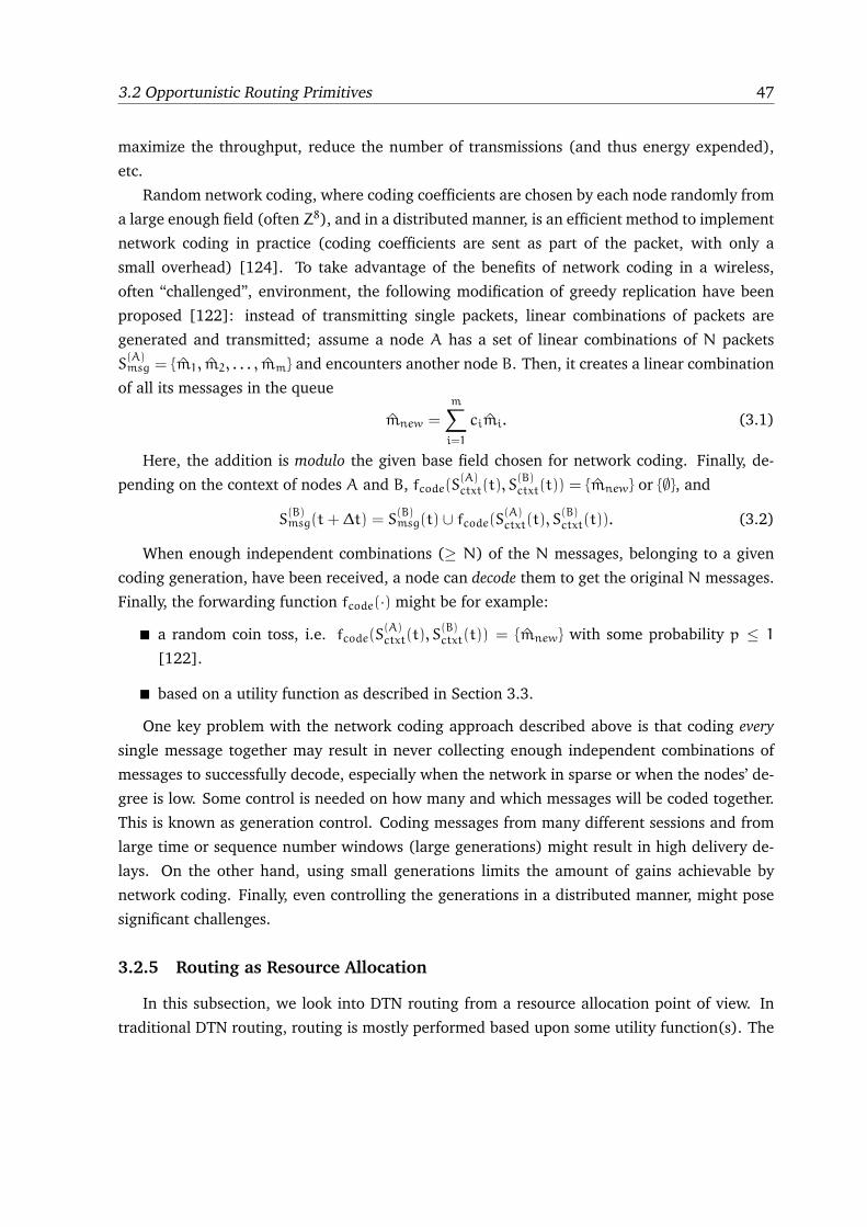
3.2 Opportunistic Routing Primitives 47
maximize the throughput, reduce the number of transmissions (and thus energy expended),
etc.
Random network coding, where coding coefficients are chosen by each node randomly from
a large enough field (often Z8), and in a distributed manner, is an efficient method to implement
network coding in practice (coding coefficients are sent as part of the packet, with only a
small overhead) [124]. To take advantage of the benefits of network coding in a wireless,
often “challenged”, environment, the following modification of greedy replication have been
proposed [122]: instead of transmitting single packets, linear combinations of packets are
generated and transmitted; assume a node A has a set of linear combinations of N packets
S(A)msg = {m1, m2, . . . , mm} and encounters another node B. Then, it creates a linear combination
of all its messages in the queue
mnew =
m∑
i=1
cimi. (3.1)
Here, the addition is modulo the given base field chosen for network coding. Finally, de-
pending on the context of nodes A and B, fcode(S(A)ctxt(t), S
(B)ctxt(t)) = {mnew} or {∅}, and
S(B)msg(t+ ∆t) = S
(B)msg(t) ∪ fcode(S
(A)ctxt(t), S
(B)ctxt(t)). (3.2)
When enough independent combinations (≥ N) of the N messages, belonging to a given
coding generation, have been received, a node can decode them to get the original N messages.
Finally, the forwarding function fcode(·) might be for example:
� a random coin toss, i.e. fcode(S(A)ctxt(t), S
(B)ctxt(t)) = {mnew} with some probability p ≤ 1
[122].
� based on a utility function as described in Section 3.3.
One key problem with the network coding approach described above is that coding every
single message together may result in never collecting enough independent combinations of
messages to successfully decode, especially when the network in sparse or when the nodes’ de-
gree is low. Some control is needed on how many and which messages will be coded together.
This is known as generation control. Coding messages from many different sessions and from
large time or sequence number windows (large generations) might result in high delivery de-
lays. On the other hand, using small generations limits the amount of gains achievable by
network coding. Finally, even controlling the generations in a distributed manner, might pose
significant challenges.
3.2.5 Routing as Resource Allocation
In this subsection, we look into DTN routing from a resource allocation point of view. In
traditional DTN routing, routing is mostly performed based upon some utility function(s). The
48 Chapter 3: DTN Routing Taxonomy
main aim is always to find a path to a destination with the available information. Almost all
routing strategies are no exception to this, and thus they have an incidental effect on routing
metrics (maximizing average delay or delivery ratio). Another angle to look at DTN routing
is to treat it as a resource allocation problem. The purpose is to have an intentional effect
on the DTN routing, rather than an incidental one, in order to maximize the performance of
specific routing metrics. The idea is to forward or replicate a message to a relay, based upon the
available resources in order to maximum the likelihood of message delivery, when two nodes
meet. Note that resource allocation based routing is not a basic primitive of DTN routing, and
can use any of the three basic primitives described in the previous subsections.
RAPID [132] is the first protocol which treats DTN routing as a resource allocation prob-
lem. In RAPID, messages are ordered with respect to their utilities, keeping in view the goal of
maximizing specific metrics (e.g. delay), which allows computation of more sophisticated and
desired metrics such as worst-case delivery delay and packet delivery ratio. The protocol trans-
lates a routing metric to per-packet utilities, and at every transfer opportunity, it is verified if
the marginal utility of replication justifies the resources used. In a way, it is a replication-based
protocol, but what differs it with the traditional replication scheme is resource allocation.
Erramilli et al. [138] have done a study that is based upon prioritizing messages to better
manage network resources in a resource-constrained environment, where they use delegation
forwarding [141] as their forwarding algorithm. ORWAR (Opportunistic Routing with Window-
Aware Replication) [139] is another protocol based upon the resource allocation concept that
uses message utility based differentiation mechanism. This allows allocation of more resources
for messages with high utilities. Thus, it replicates messages in order of high utilities first, and
removes messages in the reverse order, if needed. Again, this is a replication routing scheme,
but the delivery of number of copies depends upon evaluation of the contact window.
3.2.6 Examples of DTN Routing Protocols
In Section 3.2, we have described three basic primitives based on which DTN routing can
be built. We now proceed to identify the use of these primitives in some existing DTN rout-
ing protocols. Table 3.1 summarizes this correspondence between DTN building blocks, their
variants and existing DTN solutions. The table shows examples of DTN-routing protocols and
categorizes them in terms of the three main building blocks (i.e., replication, forwarding and
coding). The first column represents the properties based on which the routing protocols are
built, and the second column shows the routing protocol examples.
Take for example Epidemic Routing [7]: it is a typical case of “uncontrolled”, i.e., with no
constraints on the number of copies generated, message replication using a greedy approach;
on the other hand, Spray and Wait [29] is an example of “controlled” greedy replication as
it limits the number of copies for each message. Replication can also be made “smart” by
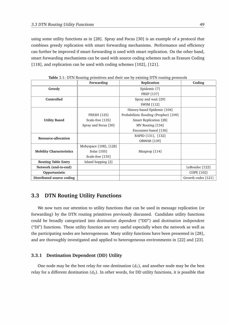
3.3 DTN Routing Utility Functions 49
using some utility functions as in [28]. Spray and Focus [30] is an example of a protocol that
combines greedy replication with smart forwarding mechanisms. Performance and efficiency
can further be improved if smart forwarding is used with smart replication. On the other hand,
smart forwarding mechanisms can be used with source coding schemes such as Erasure Coding
[118], and replication can be used with coding schemes [102], [121].
Table 3.1: DTN Routing primitives and their use by existing DTN routing protocols
Forwarding Replication Coding
Greedy Epidemic [7]
PREP [137]
Controlled Spray and wait [29]
SWIM [112]
Utility Based
History-based Epidemic [104]
FRESH [125] Probabilistic flooding (Prophet) [109]
Scale-free [135] Smart Replication [28]
Spray and Focus [30] MV Routing [134]
Encounter-based [136]
Resource-allocationRAPID [131], [132]
ORWAR [139]
Mobility Characteristics
Mobyspace [108], [128]
Solar [105] Maxprop [114]
Scale-free [135]
Routing Table Entry Island hopping [2]
Network (end-to-end) LeBoudec [122]
Opportunistic COPE [102]
Distributed source coding Growth codes [121]
3.3 DTN Routing Utility Functions
We now turn our attention to utility functions that can be used in message replication (or
forwarding) by the DTN routing primitives previously discussed. Candidate utility functions
could be broadly categorized into destination dependent (“DD”) and destination independent
(“DI”) functions. These utility function are very useful especially when the network as well as
the participating nodes are heterogeneous. Many utility functions have been presented in [28],
and are thoroughly investigated and applied to heterogeneous environments in [22] and [23].
3.3.1 Destination Dependent (DD) Utility
One node may be the best relay for one destination (d1), and another node may be the best
relay for a different destination (d2). In other words, for DD utility functions, it is possible that
50 Chapter 3: DTN Routing Taxonomy
the following is true:
Ui(d1) > Uj(d1) but Ui(d2) < Uj(d2), d1 6= d2. (3.3)
Below we describe a number of parameters that can be used to build destination dependent
utility functions.
� Age of Last Encounter: It has been suggested that keeping track of past encounters with
a given node can be helpful in successfully predicting future encounters. For example,
each node could maintain a timer for every other node in the network that records the
time elapsed since the two nodes last “saw” each other [125]. These timers could then act
as indirect location information. Additionally, a node can keep a record of its encounters
with another node by noting the last encounter time and the node’s position at the time
of encounter [36]. Although keeping the last encounter time for nodes does not provide
any guarantee that a node would meet a destination in the future, yet it can be useful in
predicting the current location of a destination.
Because, nodes tend to move in a continuous manner (i.e., they don’t ordinarily perform
jumps in space), often, a smaller timer value implies a smaller distance to the destination,
if we assume that the average speed of nodes does not vary too much. In case nodes are
heterogeneous in terms of their characteristics and capabilities, some other parameters
should be used in combination with age of last encounter in order to choose a “suitable”
relay node. Note that the age of last encounter with a destination is related to the instan-
taneous fitness of a node as a candidate relay for that destination.
� History of Past Encounters: The age of last encounter is only a single “snapshot” of the
history of past encounters and may not necessarily predict future encounters successfully.
Instead, a node could maintain a “richer” set of information about past encounters with
another node, like frequency of encounters, average inter-encounter time, higher moments
of inter-encounter time, average encounter duration, etc. Such information could help
identify more accurately good candidate next hops; on the other hand, keeping more
information about encounters increases the overhead in terms of context data that needs
to be stored. Also, depending upon the application requirements, a combination of past
encounter parameters can be used to choose the best possible relay for a destination.
Another consideration is how long to keep this history about a certain destination at
a node as it may not be useful, or even misleading after a certain threshold of time
depending upon the dynamics and mobility pattern of participating nodes. An example
of this kind of utility function is Encounter Based Routing (EBR) [136], in which future
rate of node encounter is predicted using information about past encounters with node.
3.3 DTN Routing Utility Functions 51
� Pattern of Locations Visited: In the real world, mobile users move with certain purposes
in mind (e.g., going to work, going to a class, going from work to lunch, etc.). Addi-
tionally, they may follow specific paths in between these locations due to geographical
constraints. As a result, people tend to follow a movement pattern in their daily activities.
These patterns are a function of a variety of parameters including professional activity,
work and home location, etc. What is more, most people also tend to spend the major-
ity of their time in a small subset of preferred locations, as opposed to indiscriminately
roaming everywhere (unless, this is part of their job, e.g., taxi driver, salesman, etc). “Lo-
cation preference” as well as the periodic nature of human mobility (diurnal and weekly
patterns) have been consistently demonstrated in a variety of real mobility traces [103].
Mobility patterns (known a priori or “learned” online by collecting appropriate statistics)
could help identify a profile for a given node; nodes with a matching or similar mobility
profile as the destination could be considered good candidate relays for messages to that
destination [108], [128], [105].
� Social Networks: Humans are involved in complex social relationships (networks), and
people who are socially-related to each other (e.g. friends, students in the same class,
and colleagues in the same department) are expected to interact more often with each
other. These social features can have important implications for networks formed by
communication devices operated or carried by humans (e.g., vehicles, PDAs, laptops).
Knowledge about existing social links could allow one to choose a “data relay” that has
a much better chance of encountering the destination soon. Note that one way to gather
information about social networks is by keeping a history of past encounters. However,
there is additional data that is relevant in the context of social networks. For example,
suppose that it is known a priori that A is a good friend of D, but B hardly knows D;
then, even with no past encounter information of D at A or B, A can be considered
a better relay for D than B. The social network information about nodes can also be
gathered by observing and estimating their mobility pattern.
Bubble [140] is one of the recent social-based forwarding protocol, in which forwarding
is based upon identifying “hubs” and “centrality points” in the network. Having no in-
formation about a destination, a message is forwarded towards a more “popular” area or
node, and then the forwarding mechanism tries to find the destination itself, or a node
having the same “community” as the destination node. The logic behind finding a popular
node first is that in a social network, some nodes tend to see other nodes more often than
others.
52 Chapter 3: DTN Routing Taxonomy
3.3.2 Destination Independent (DI) Utility
In case of Destination Independent (DI) utility, the utility of a given node is independent of
any destination; rather, it depends on some characteristic(s) exhibited by a node. This implies
that one node may be the best relay for most or all destinations. In other words, for DI functions
it holds in general that:
Ui(d1) ≥ Uj(d1) ⇒ Ui(d) ≥ Uj(d), for most or all j, d. (3.4)
Examples of nodes which are highly preferable as relays for any destination could be nodes
with high and frequent mobility (e.g., vehicles), nodes with many “friends” (e.g., hubs [140]
in scale-free networks), nodes with more resources (e.g., buses [114]), or nodes with high
cooperative behavior (e.g., APs, routers or gateways, ferries). Below, we describe in more detail
some destination independent parameters that should be considered when making forwarding
decisions.
� Amount of Mobility: In some wireless network deployments, some nodes might be more
mobile than others. In the case of a campus environment, nodes carried by humans may
tend to be more static, while nodes attached to campus transportation vehicles (e.g.,
[114]) move around the campus periodically, some of which following regular trajecto-
ries. These more mobile nodes tend to traverse a wider portion of the network in the same
amount of time than the more static nodes, and thus encounter a larger subset of other
wireless nodes. As a result, they represent highly desirable relays, if a DTN-like routing
strategy is employed. One way to identify such relays could be, for example, to use labels
that represent the type of mobility exhibited by nodes, e.g. “BUS”,“TAXI”, “PEDESTRIAN”,
“BASE STATION”, etc. In some scenarios, it would not be too burdensome to manually
configure a label (e.g., by setting some software parameter when installing a radio, say, on
the top of a bus). Nevertheless, algorithms that estimate the “degree of mobility” online
could also be deployed in self-organized, more dynamic environments [28].
� Node Resources: When forwarding a message to a node, the resources and capabilities of
that node should be considered. Even if a certain node has some ties to the destination
(e.g., close friendship), giving a message copy to that node might be a waste of resources,
if it is almost out of battery. Chances are it will either turn itself off or run out of battery
before it gets a chance of delivering the message. Similarly, if a candidate relay has its
buffer almost full, it might be more prudent to prefer another node instead. This may
not only result in smaller queuing delays, but may also reduce the probability of the
message getting dropped later. Consequently, nodes may maintain the current status of
their resources, which can be used to identify nodes that are “good” (or “bad”) relays
independent of the destination.
3.3 DTN Routing Utility Functions 53
� Cooperative Behavior: Message forwarding is not free and consumes node resources
including battery life and buffer space. So, it is possible that some nodes refuse to for-
ward messages on behalf of others because either they have limited resources, or they are
pre-configured with specific forwarding policies, or because they have been either com-
promised or are owned by an attacker. So, forwarding a message to such nodes would
be disadvantageous. Consequently, forwarding decisions should also consider how coop-
erative nodes are in forwarding messages. Approaches to boosting cooperation among
nodes include offering incentives to cooperating nodes, or penalizing non-cooperative
ones. This has also implications in building trust among participating nodes, which is the
topic of the DI parameter discussed below.
� Trustworthiness: Securing communication is among the biggest challenges in wireless
networks. This is due to a number of factors notably the shared, uncoordinated access
to the wireless medium, as well as its inherent unreliability and non-determinism. The
peer-to-peer, non-hierarchical nature of many emerging wireless applications requires col-
laboration among participating nodes so that data delivery can be accomplished. Mali-
cious peers could exploit this to intervene with the network’s normal operation or extract
sensitive information, such as passwords, credit card numbers, etc., from packet streams.
In other cases, malicious users could pretend to carry and forward other nodes’ traffic,
while in fact, they don’t do so, which may create drastic forwarding problem. Thus, non-
malicious yet selfish users might be tempted to refuse carrying other’s traffic. For these
reasons, the utility of a node as a message relay might also be a function of the trust other
nodes have in it, a trust which could be based on signed certificates, PGP-like architectures
[129], reputation systems [130], etc.
3.3.3 Additional Considerations
It is certainly possible (and probably desirable) to define utility functions that take into ac-
count both the general, destination independent fitness of a node as well as destination specific
information. For example, we can combine history of past encounters (DD utility) with nodes’
mobility patterns, or their resources (DI utility) in order to define a hybrid utility function that
is able to deliver messages to destinations more efficiently.
Most utility functions discussed above are based solely on a snapshot of the past (e.g., the
last time node X encountered node Y). However, in real life scenarios node interactions may
exhibit rich and intricate structure; it would thus be beneficial to explore learning techniques
that try to use history over a window of time or feedback (e.g., from the destination) to make
better routing decisions.
54 Chapter 3: DTN Routing Taxonomy
3.4 A Taxonomy of DTNs
In this section, we classify DTNs according to a set of characteristics relevant to routing. For
example, a well-connected network whose nodes exhibit little or no mobility would imply that
traditional MANET routing algorithms (e.g. OLSR [32], AODV [96], etc.) might be appropriate.
Similarly, a network where nodes have little or no energy limitations (e.g., vehicles) would
likely render routing protocols that focus on minimizing energy consumption inadequate. We
start by describing the network features used in our DTN taxonomy.
3.4.1 Connectivity
Connectivity is an important characteristic of wireless networks. Two well-known defini-
tions of network connectivity are (i) the probability that a path exists between two randomly
chosen nodes [99], or (ii) the percentage of nodes connected to the largest connected compo-
nent [99]. Although these two definitions are slightly different, they have similar implications
from a macroscopic point of view.
In multi-hop wireless ad-hoc networks, or MANETs, due to node mobility, wireless channel
impairments, limited node capabilities, etc, the assumption that the network is always con-
nected no longer holds and routing had to be re-thought. However, partitions are still consid-
ered exceptions to normal operation and routing reacts by trying to find alternate paths. In fact,
it is well-known that the so-called reactive (or on-demand) routing protocols such as DSR [96]
and AODV [96] perform poorly when disconnections are frequent and persist for arbitrarily
long periods of time.
It is well-known from percolation theory that, in networks consisting of randomly placed (or
randomly moving) nodes, connectivity exhibits a phase transition behavior [100] as depicted
in Fig. 3.1.6 Specifically, if connectivity is scaled by changing the nodes’ transmission range,
then the following can be observed [101]: (i) for (a large number of) low transmission range
values, connectivity values are quite low: no large cluster exists, but rather very small clusters
(few with 1 node), whose sizes are exponentially distributed, are found; (ii) when transmission
range crosses some threshold value, connectivity starts increasing rapidly and quickly enters a
region where a giant component is formed containing a large percentage of nodes, while the
rest of the nodes form smaller clusters (again of exponentially distributed size).
This phase transition behavior has some important implications: random networks, i.e.,
those formed by randomly placing nodes (e.g., sensors scattered uniformly in the field) or
randomly moving nodes (e.g., random direction), will be either sparse or almost connected, in
6Note that in DTNs, connectivity will be consistently below 1 (or 100%). As a result, the whole spectrum of pos-
sible connectivity values all the way from 0 (very sparse networks) to 1 (connected networks) need to be considered
when designing routing algorithms.
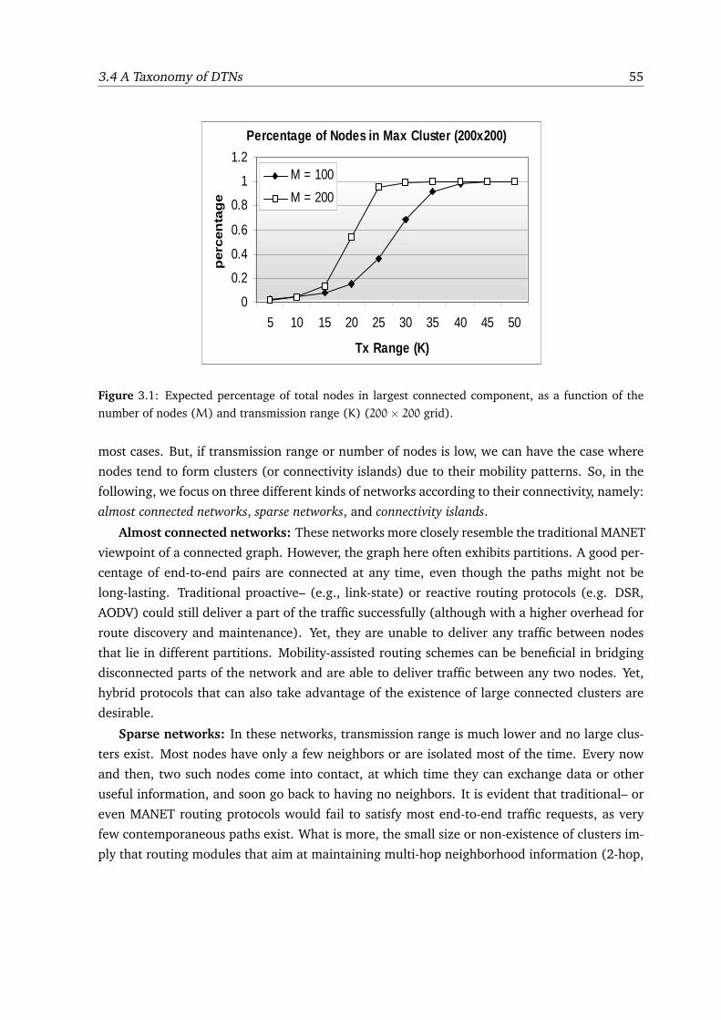
3.4 A Taxonomy of DTNs 55
Percentage of Nodes in Max Cluster (200x200)
0
0.2
0.4
0.6
0.8
1
1.2
5 10 15 20 25 30 35 40 45 50
Tx Range (K)
perc
en
tag
e
M = 100
M = 200
Figure 3.1: Expected percentage of total nodes in largest connected component, as a function of the
number of nodes (M) and transmission range (K) (200× 200 grid).
most cases. But, if transmission range or number of nodes is low, we can have the case where
nodes tend to form clusters (or connectivity islands) due to their mobility patterns. So, in the
following, we focus on three different kinds of networks according to their connectivity, namely:
almost connected networks, sparse networks, and connectivity islands.
Almost connected networks: These networks more closely resemble the traditional MANET
viewpoint of a connected graph. However, the graph here often exhibits partitions. A good per-
centage of end-to-end pairs are connected at any time, even though the paths might not be
long-lasting. Traditional proactive– (e.g., link-state) or reactive routing protocols (e.g. DSR,
AODV) could still deliver a part of the traffic successfully (although with a higher overhead for
route discovery and maintenance). Yet, they are unable to deliver any traffic between nodes
that lie in different partitions. Mobility-assisted routing schemes can be beneficial in bridging
disconnected parts of the network and are able to deliver traffic between any two nodes. Yet,
hybrid protocols that can also take advantage of the existence of large connected clusters are
desirable.
Sparse networks: In these networks, transmission range is much lower and no large clus-
ters exist. Most nodes have only a few neighbors or are isolated most of the time. Every now
and then, two such nodes come into contact, at which time they can exchange data or other
useful information, and soon go back to having no neighbors. It is evident that traditional– or
even MANET routing protocols would fail to satisfy most end-to-end traffic requests, as very
few contemporaneous paths exist. What is more, the small size or non-existence of clusters im-
ply that routing modules that aim at maintaining multi-hop neighborhood information (2-hop,
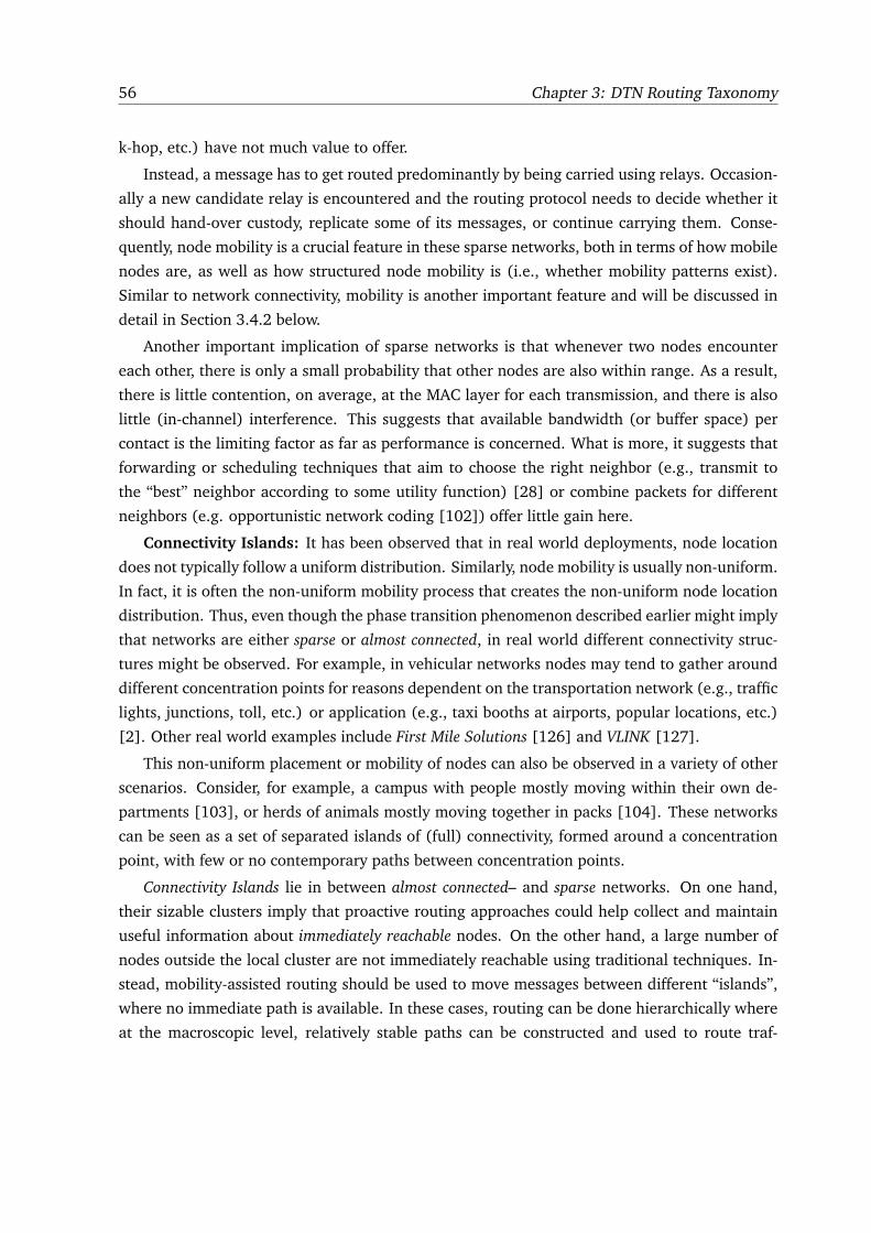
56 Chapter 3: DTN Routing Taxonomy
k-hop, etc.) have not much value to offer.
Instead, a message has to get routed predominantly by being carried using relays. Occasion-
ally a new candidate relay is encountered and the routing protocol needs to decide whether it
should hand-over custody, replicate some of its messages, or continue carrying them. Conse-
quently, node mobility is a crucial feature in these sparse networks, both in terms of how mobile
nodes are, as well as how structured node mobility is (i.e., whether mobility patterns exist).
Similar to network connectivity, mobility is another important feature and will be discussed in
detail in Section 3.4.2 below.
Another important implication of sparse networks is that whenever two nodes encounter
each other, there is only a small probability that other nodes are also within range. As a result,
there is little contention, on average, at the MAC layer for each transmission, and there is also
little (in-channel) interference. This suggests that available bandwidth (or buffer space) per
contact is the limiting factor as far as performance is concerned. What is more, it suggests that
forwarding or scheduling techniques that aim to choose the right neighbor (e.g., transmit to
the “best” neighbor according to some utility function) [28] or combine packets for different
neighbors (e.g. opportunistic network coding [102]) offer little gain here.
Connectivity Islands: It has been observed that in real world deployments, node location
does not typically follow a uniform distribution. Similarly, node mobility is usually non-uniform.
In fact, it is often the non-uniform mobility process that creates the non-uniform node location
distribution. Thus, even though the phase transition phenomenon described earlier might imply
that networks are either sparse or almost connected, in real world different connectivity struc-
tures might be observed. For example, in vehicular networks nodes may tend to gather around
different concentration points for reasons dependent on the transportation network (e.g., traffic
lights, junctions, toll, etc.) or application (e.g., taxi booths at airports, popular locations, etc.)
[2]. Other real world examples include First Mile Solutions [126] and VLINK [127].
This non-uniform placement or mobility of nodes can also be observed in a variety of other
scenarios. Consider, for example, a campus with people mostly moving within their own de-
partments [103], or herds of animals mostly moving together in packs [104]. These networks
can be seen as a set of separated islands of (full) connectivity, formed around a concentration
point, with few or no contemporary paths between concentration points.
Connectivity Islands lie in between almost connected– and sparse networks. On one hand,
their sizable clusters imply that proactive routing approaches could help collect and maintain
useful information about immediately reachable nodes. On the other hand, a large number of
nodes outside the local cluster are not immediately reachable using traditional techniques. In-
stead, mobility-assisted routing should be used to move messages between different “islands”,
where no immediate path is available. In these cases, routing can be done hierarchically where
at the macroscopic level, relatively stable paths can be constructed and used to route traf-
3.4 A Taxonomy of DTNs 57
fic between “islands”, while store-carry-and-forward is used on a microscopic level to forward
messages when no routes exist, likely between “islands” [2]. Moreover, if the nodes that are
associated with a given concentration point are stable over time (e.g. nodes affiliated with a
given department), macroscopic information about the mobility pattern [105] or community
structure [106] between nodes could be used to route traffic across disconnected parts.
3.4.2 Mobility
Node mobility is another important factor to be considered when choosing adequate rout-
ing approaches, especially as the network becomes sparser. In particular, we will discuss two
aspects related to node mobility as follows:
Amount of Mobility: The “amount of mobility” of a node can be defined as the percentage
of the network traversed or “covered” by the node within a given amount of time. Alternately,
it can also be expressed as the number of new nodes (and thus either destinations or candidate
relays) a given node encounters within a given time window. The following characteristics are
needed to quantify mobility.
� Node Speed: Intuitively, the faster a node is moving, the more new area it should cover
in a given amount of time, all other parameters unchanged. Additionally, if nodes move
fast, they would have more chances to meet more nodes, thus increasing the number
of contacts. On the other hand, if node speed is too high, contact duration is reduced,
directly affecting routing protocol performance.
� Pause Time and Frequency: Depending upon the environment and the application, mo-
bile nodes may tend to stay at a particular position for extended periods of time. We call
this duration as the pause time. For example, in an exposition hall, nodes may move from
one place to another and stay at the other place for some time before moving further.
Again depending upon the application, the pause time may be used to deliver messages
to destinations as it increases the contact duration when the node is in static position, as it
has been shown that in some cases, the nodes that are static are more useful to relay mes-
sages because of their placement in the area (e.g., throwboxes[21], bus stops etc.). On
the other hand, depending upon the scenario, the nodes that have longer pause times may
not be as useful in the delivery process as mobile nodes. The nodes’ periodicity of visiting
places, or their frequency can also be exploited in the delivery process of messages.
� Integration Time: This is essentially the time it takes a node, starting at a given state of a
mobility structure, to arrive to its stationary distribution; the higher the integration time,
the more time it takes the average node to reach a randomly chosen destination.
58 Chapter 3: DTN Routing Taxonomy
In general, the larger the amount of average node mobility, the better the performance of
routing protocols that rely on such mobility. Furthermore, in a number of situations it holds
that the higher the average node mobility, the less sophisticated the design of a protocol needs
to be. This seems to be in contrast with the traditional viewpoint that node mobility has a
negative effect on routing protocol performance.
Structure of Mobility: The structure of the nodes mobility is equally important, and be-
comes significantly more important for sparser and “less mobile” networks. The following infor-
mation about the structure of a node’s mobility pattern is particularly important from a routing
protocol’s perspective:
� Homogeneous vs. Heterogeneous Mobility: Depending on a particular DTN application,
participating nodes may all have the same capabilities and behavior. Conversely, in a het-
erogeneous deployment, nodes mobility may differ from one another. For example, one
could reasonably assume that nodes in a sensor network have homogeneous capabilities
and behavior (e.g., duty cycle operation). However, people forming a Pocket Switched
Network [107] might have largely different mobility patterns from one another.
Nodes heterogeneous mobility affects protocol design in a number of ways. For example,
some nodes will be better relays than others for delivering traffic. Some relays might
be preferable for any destination7, as in the case of nodes that move fast and frequently
around the networks (e.g. vehicles). Protocols that are “smart” enough to discover and
pick such advantageous relays are expected to perform better the more heterogeneous
a network is. Attention is needed though to make sure not to overload a few nodes
with relaying responsibilities; this will possibly have detrimental effects due to congestion
or battery drainage. Alternatively, if the network is homogeneous, then simple greedy
solutions may be adequate to achieve good performance.
� Spatial and Temporal Correlation: In addition to differences in the mobility pattern
between nodes, individual nodes may exhibit specific mobility patterns which could be
leverage to improve routing performance. For instance, a given node may visit some
locations (e.g., a person’s home or office) often which exemplifies spatial correlation of
movement. Also, a given node may exhibit different mobility behaviors depending on
the time of day (temporal correlation). For example, most employees might head to
the company’s cafeteria between 12 − 1p.m. Finally, there might also exist correlations
between the mobility of different nodes both in space (e.g., nodes that tend to visit the
same locations [108]) and time (e.g., nodes that leave their “home” location at around
the same times). In such cases, good relays may be destination specific, that is, a given
7There are also cases where some nodes are better relays for certain destinations. Destination dependent and
destination independent choice of relays is discussed in detail in Section 3.3.
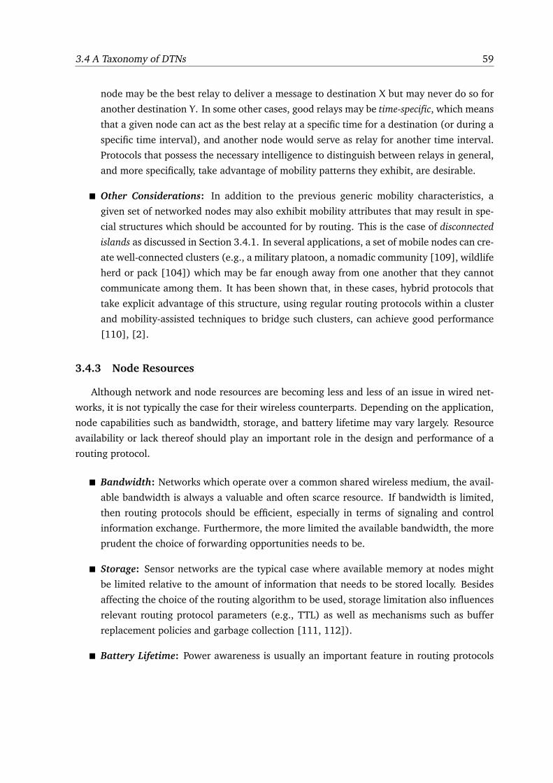
3.4 A Taxonomy of DTNs 59
node may be the best relay to deliver a message to destination X but may never do so for
another destination Y. In some other cases, good relays may be time-specific, which means
that a given node can act as the best relay at a specific time for a destination (or during a
specific time interval), and another node would serve as relay for another time interval.
Protocols that possess the necessary intelligence to distinguish between relays in general,
and more specifically, take advantage of mobility patterns they exhibit, are desirable.
� Other Considerations: In addition to the previous generic mobility characteristics, a
given set of networked nodes may also exhibit mobility attributes that may result in spe-
cial structures which should be accounted for by routing. This is the case of disconnected
islands as discussed in Section 3.4.1. In several applications, a set of mobile nodes can cre-
ate well-connected clusters (e.g., a military platoon, a nomadic community [109], wildlife
herd or pack [104]) which may be far enough away from one another that they cannot
communicate among them. It has been shown that, in these cases, hybrid protocols that
take explicit advantage of this structure, using regular routing protocols within a cluster
and mobility-assisted techniques to bridge such clusters, can achieve good performance
[110], [2].
3.4.3 Node Resources
Although network and node resources are becoming less and less of an issue in wired net-
works, it is not typically the case for their wireless counterparts. Depending on the application,
node capabilities such as bandwidth, storage, and battery lifetime may vary largely. Resource
availability or lack thereof should play an important role in the design and performance of a
routing protocol.
� Bandwidth: Networks which operate over a common shared wireless medium, the avail-
able bandwidth is always a valuable and often scarce resource. If bandwidth is limited,
then routing protocols should be efficient, especially in terms of signaling and control
information exchange. Furthermore, the more limited the available bandwidth, the more
prudent the choice of forwarding opportunities needs to be.
� Storage: Sensor networks are the typical case where available memory at nodes might
be limited relative to the amount of information that needs to be stored locally. Besides
affecting the choice of the routing algorithm to be used, storage limitation also influences
relevant routing protocol parameters (e.g., TTL) as well as mechanisms such as buffer
replacement policies and garbage collection [111, 112]).
� Battery Lifetime: Power awareness is usually an important feature in routing protocols
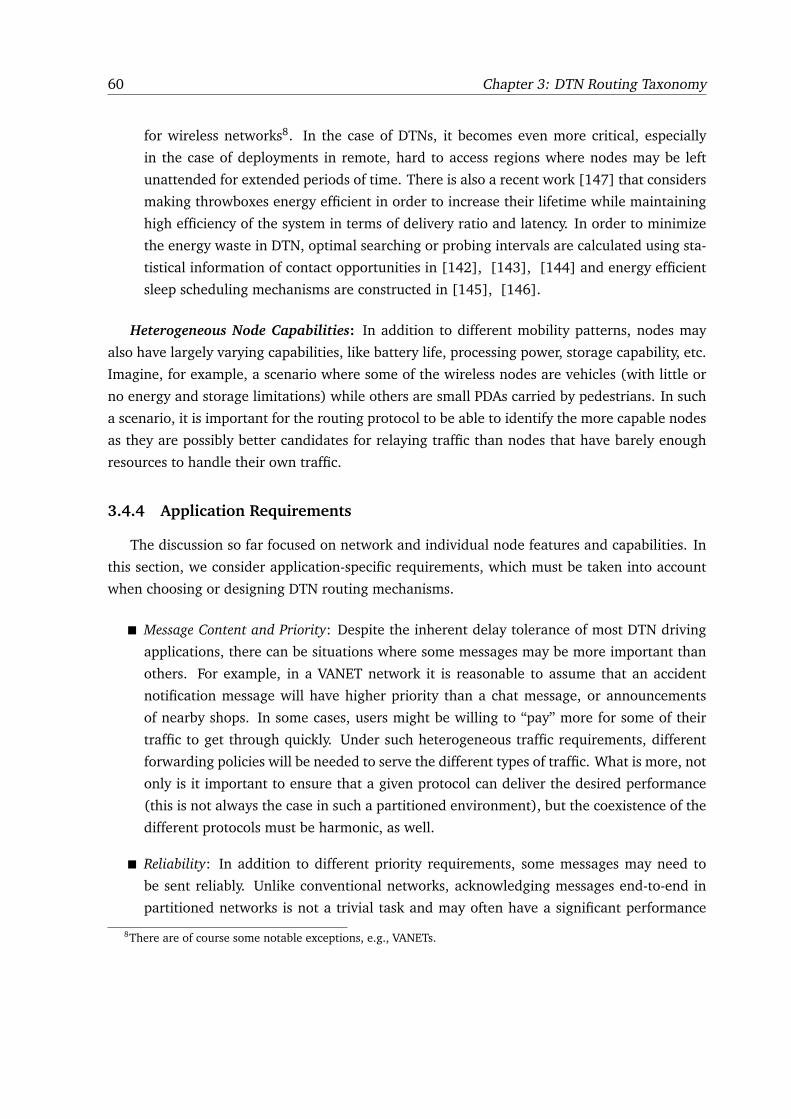
60 Chapter 3: DTN Routing Taxonomy
for wireless networks8. In the case of DTNs, it becomes even more critical, especially
in the case of deployments in remote, hard to access regions where nodes may be left
unattended for extended periods of time. There is also a recent work [147] that considers
making throwboxes energy efficient in order to increase their lifetime while maintaining
high efficiency of the system in terms of delivery ratio and latency. In order to minimize
the energy waste in DTN, optimal searching or probing intervals are calculated using sta-
tistical information of contact opportunities in [142], [143], [144] and energy efficient
sleep scheduling mechanisms are constructed in [145], [146].
Heterogeneous Node Capabilities: In addition to different mobility patterns, nodes may
also have largely varying capabilities, like battery life, processing power, storage capability, etc.
Imagine, for example, a scenario where some of the wireless nodes are vehicles (with little or
no energy and storage limitations) while others are small PDAs carried by pedestrians. In such
a scenario, it is important for the routing protocol to be able to identify the more capable nodes
as they are possibly better candidates for relaying traffic than nodes that have barely enough
resources to handle their own traffic.
3.4.4 Application Requirements
The discussion so far focused on network and individual node features and capabilities. In
this section, we consider application-specific requirements, which must be taken into account
when choosing or designing DTN routing mechanisms.
� Message Content and Priority: Despite the inherent delay tolerance of most DTN driving
applications, there can be situations where some messages may be more important than
others. For example, in a VANET network it is reasonable to assume that an accident
notification message will have higher priority than a chat message, or announcements
of nearby shops. In some cases, users might be willing to “pay” more for some of their
traffic to get through quickly. Under such heterogeneous traffic requirements, different
forwarding policies will be needed to serve the different types of traffic. What is more, not
only is it important to ensure that a given protocol can deliver the desired performance
(this is not always the case in such a partitioned environment), but the coexistence of the
different protocols must be harmonic, as well.
� Reliability: In addition to different priority requirements, some messages may need to
be sent reliably. Unlike conventional networks, acknowledging messages end-to-end in
partitioned networks is not a trivial task and may often have a significant performance
8There are of course some notable exceptions, e.g., VANETs.
3.5 DTN Routing Design Guidelines 61
overhead (e.g., flooding an ACK message after successful reception at the destination).
Furthermore, if a whole session of messages needs to be sent reliably, the considerably
large delays of the loosely closed feedback loop may significantly reduce the ability to
“pipeline” data through the network. What is more difficult in terms of reliability in
a disruption-tolerant kind of network, is the ability to reliably deliver data in a certain
order.
3.5 DTN Routing Design Guidelines
In the previous three sections, we have discussed different properties of DTNs such as con-
nectivity, mobility and node resources, and have dissected DTN-based routing solutions with
respect to their characteristics (replication, forwarding and coding). Now, we try to summarize
the discussion by providing a correspondence between DTN-based routing solutions and the
characteristics of different networks or applications. Having known, a priori, a given set of
application characteristics and requirements, we can choose or build a specific kind of routing
solution. For example, where connectivity and mobility are low, but the nodes have enough
resources in terms of energy, bandwidth, and buffering, and we need a reliable solution, the
epidemic routing or any of its variant such as Spray and Wait [29] can be employed. On the
other hand, if the connectivity is low in an environment where nodes are highly mobile and
nodes’ resources are restricted and expensive (in terms of energy, buffering or processing),
message replication schemes are better candidates to be utilized. If reliability is needed by a
routing solution, only epidemic routing or message coding can be employed.
Table 3.2 aims at summarizing the correspondence between network characteristics and
DTN routing solutions. The rows in the table represents the properties of networks (or appli-
cations), whereas each column provides a different routing solution. If read line-by-line (hor-
izontally), it states which routing modules may be useful or necessary to cope with the given
characteristic (one per line). If read column-by-column (vertically), then it describes particular
scenarios where the given protocol (one per column) is a better choice. We do not intend that
this table is all-inclusive or without exceptions. It is only rather an indication of which rout-
ing strategies might match better which DTN environments. It is also important to note that
this table characterizes the suitability of a routing solution according to the set of network or
application characteristics that we have presented in Section 3.4.
In the following, we take up a few exemplary networks, summarize their characteristics and
describe what kind of routing protocol is suitable for each network.
1. A typical Vehicular Ad hoc Network (VANET), where vehicles exchange information when
they come into contact of each other. In such a network, at some places the network may
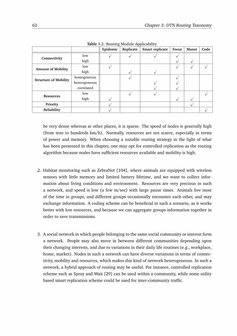
62 Chapter 3: DTN Routing Taxonomy
Table 3.2: Routing Module Applicability
Epidemic Replicate Smart replicate Focus Manet Code
Connectivitylow
√ √ √ √
high√ √
Amount of Mobilitylow
√ √ √ √
high√ √
Structure of Mobilityhomogeneous
√ √
heterogeneous√ √
correlated√ √
Resourceslow
√ √ √
high√ √ √
Priority√ √
Reliability√ √
be very dense whereas at other places, it is sparse. The speed of nodes is generally high
(from tens to hundreds km/h). Normally, resources are not scarce, especially in terms
of power and memory. When choosing a suitable routing strategy in the light of what
has been presented in this chapter, one may opt for controlled replication as the routing
algorithm because nodes have sufficient resources available and mobility is high.
2. Habitat monitoring such as ZebraNet [104], where animals are equipped with wireless
sensors with little memory and limited battery lifetime, and we want to collect infor-
mation about living conditions and environment. Resources are very precious in such
a network, and speed is low (a few m/sec) with large pause times. Animals live most
of the time in groups, and different groups occasionally encounter each other, and may
exchange information. A coding scheme can be beneficial in such a scenario, as it works
better with low resources, and because we can aggregate groups information together in
order to save transmissions.
3. A social network in which people belonging to the same social community or interest form
a network. People may also move in between different communities depending upon
their changing interests, and due to variations in their daily life routines (e.g., workplace,
home, market). Nodes in such a network can have diverse variations in terms of connec-
tivity, mobility and resources, which makes this kind of network heterogeneous. In such a
network, a hybrid approach of routing may be useful. For instance, controlled replication
scheme such as Spray and Wait [29] can be used within a community, while some utility
based smart replication scheme could be used for inter-community traffic.
3.6 Concluding Remarks 63
3.6 Concluding Remarks
In this chapter, we have presented a taxonomy of opportunistic routing protocols for DTNs.
One of the main goals of our taxonomy is to have it serve as a set of guidelines for routing
protocol designers and developers. The chapter starts by defining basic building blocks used
by existing DTN opportunistic routing schemes. Then, we create a taxonomy for intermittently
connected networks based on network characteristics and application requirements, and finally
we presented some design guidelines that allows one to choose an appropriate routing protocol
based on network characteristics and application in hand. Besides, we have also conducted a
few case studies to validate the design principles that can be found in [27].

64 Chapter 3: DTN Routing Taxonomy
Part III
MeDeHa - A Message Delivery
Framework
65

4
MEDEHA FRAMEWORK
4.1 Introduction
With the advancement of technology, nodes and networks are becoming more and more
heterogeneous. Today, a number of devices are available with diverse capabilities and people
use these devices in order to stay connected with each other and to enjoy services offered by
the backbone (Internet). Examples include laptops, netbooks, tablet PCs, PDAs, smart phones
etc. Thus, willingness to be connected “anytime-anywhere” has also increased, as people want
to remain connected using these smart portable devices (e.g., users may enjoy connectivity via
the 3G interface or may connect to a Wifi network for high data rate whenever available). On
the other hand, different types of networks exist ranging from wired- and wireless backbones
to wireless infrastructure-based and ad-hoc networks (for instance, MANETs, VANETs, etc.). A
glimpse of network heterogeneity is illustrated in Figure 4.1. Despite the existence of these
different networks for a long time, not much has been done to make them inter-operate and
allow users to take advantage of all the available networks (interfaces) simultaneously, while
offering seamless interoperability. Thus, one of the goals is to provide seamless message deliv-
ery to users independent of which network they are part of and where they are while taking
benefit from connectivity over multiple interfaces. Another goal is to integrate multi-hop mo-
bile ad-hoc networks (or MANETs) to infrastructure-based networks (wired or wireless) that
allows network coverage to be extended to regions where infrastructure deployment is sparse
or nonexistent as well as a way to cope with intermittent connectivity.
In order to target these challenges, we designed an efficient message delivery mechanism
that enables distribution or dissemination of messages in an internet connecting heterogeneous
67
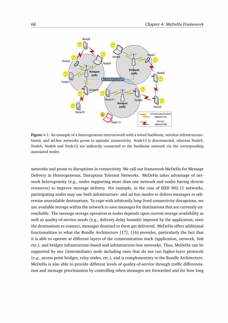
68 Chapter 4: MeDeHa Framework
Figure 4.1: An example of a heterogeneous internetwork with a wired backbone, wireless infrastructure-
based, and ad-hoc networks prone to episodic connectivity. Node13 is disconnected, whereas Node5,
Node6, Node8 and Node12 are indirectly connected to the backbone network via the corresponding
associated nodes.
networks and prone to disruptions in connectivity. We call our framework MeDeHa for Message
Delivery in Heterogeneous, Disruption Tolerant Networks. MeDeHa takes advantage of net-
work heterogeneity (e.g., nodes supporting more than one network and nodes having diverse
resources) to improve message delivery. For example, in the case of IEEE 802.11 networks,
participating nodes may use both infrastructure- and ad hoc modes to deliver messages to oth-
erwise unavailable destinations. To cope with arbitrarily long-lived connectivity disruptions, we
use available storage within the network to save messages for destinations that are currently un-
reachable. The message storage operation at nodes depends upon current storage availability as
well as quality-of-service needs (e.g., delivery delay bounds) imposed by the application; once
the destinations re-connect, messages destined to them get delivered. MeDeHa offers additional
functionalities to what the Bundle Architecture [17], [16] provides, particularly the fact that
it is able to operate at different layers of the communication stack (application, network, link
etc.), and bridges infrastructure-based and infrastructure-less networks. Thus, MeDeHa can be
supported by any (intermediate) node including ones that do not run higher-layer protocols
(e.g., access point bridges, relay nodes, etc.), and is complementary to the Bundle Architecture.
MeDeHa is also able to provide different levels of quality-of-service through traffic differentia-
tion and message prioritization by controlling when messages are forwarded and for how long
4.1 Introduction 69
they are stored.
We use opportunistic routing approach in MeDeHa, i.e., make a best effort to carry messages
towards the destination based on the contact opportunities that a message carrier experiences.
Also, any node in MeDeHa can act as a relay for any destination, and can serve as a gateway
to bridge different networks that it is capable to connect. In MeDeHa, any node can provide
backbone connectivity too, and we do not need any special purpose gateway or node to provide
this feature. Note that there is a difference between introducing special-purpose nodes in the
network to perform the task of relaying (like message ferries [19], data mules [20], and throw-
boxes [21]) and making use of existing nodes with special capabilities (e.g., access points, or
APs in the case of infrastucture-based wireless networks) that are an integral part of the un-
derlying network. Of course, whenever available, MeDeHa utilizes nodes with more resources
and capabilities like APs to perform message delivery more efficiently, but does not count on
them. Furthermore, we take advantage of the underlying heterogeneity (e.g., in the context of
IEEE 802.11 networks, a node’s ability to operate in infrastructure or ad-hoc modes) to enable
message delivery across different networks.
MeDeHa allows seamless integration of existing multi-hop (or MANET) routing protocols as
well as DTN based forwarding mechanisms, without requiring any modification. It also helps
in bridging together the infrastructure-based and the infrastructure-less networks even under
intermittent connectivity. In this way, multi-hop MANET connectivity is used to fill in connectiv-
ity gaps left by infrastructure-based networks. Moreover, as we show in Chapter 5 (MeDeHa’s
evaluation), acceptable performance of the MeDeHa framework in terms of message delivery
ratio can be achieved (close to 100%) with very few copies per message in the network, unlike
conventional DTN routing (forwarding) solutions where more copies of a message increases the
message delivery ratio. This helps in reducing control overhead and saving network resources.
To summarize, the MeDeHa framework is design to offer the following advantages:
� Seamless message delivery across heterogeneous networks.
� Ability to run at different layers of the protocol stack.
� Bridging infrastructure-based and infrastructure-less networks.
� Seamless integration of existing MANET routing protocols without requiring modifica-
tions.
� Ability to incorporate with existing DTN forwarding mechanisms.
� Partition mending through multi-hop ad-hoc (MANET) “transit networks”.
70 Chapter 4: MeDeHa Framework
4.2 Related Work
Most efforts that target heterogeneity in 802.11 networks aim towards extending network
coverage and thus increasing network capacity. To extend network connectivity beyond re-
gions covered by APs, these proposals employ different mechanisms such as: (1) the use of
different frequencies in Flex-Wifi [10], and (2) a new layer between IP and link layer in Multi-
Net [11]. Flex-Wifi [10] proposes the enhancement of the coverage area of the IEEE 802.11
infrastructure-based networks as well as the increase in the capacity of the network by allow-
ing nodes to communicate directly in ad-hoc mode using IEEE 802.11e Direct Link Session
(DLS) mechanism [12]. Flex-Wifi modifies the DLS mechanism by using a different wireless
channels for direct communication of stations. The stations use Power Saving Mode (PSM) of
IEEE 802.11 standard to switch modes in order to remain connected to both infrastructure-
based and ad-hoc networks. On the other hand, Multinet [11] is a software based solution that
allows seamless simultaneous connections to both infrastructure-based and infrastructure-less
networks using a single interface card. Again, switching between different modes is performed
using the PSM of IEEE 802.11 standard. Multinet requires changes to the data link layer or to
the interface driver in the kernel. Besides, there are some other studies that target enhance-
ment in network capacity and coverage area. Examples include WIANI [8], NUMI [13] and
MMWLAN [9]. All these proposals target specific aspects of network heterogeneity, i.e., either
enhancement of network coverage area or increase in network capacity. However, they do not
consider nodes intermittent connectivity with the network.
Mobile Ad-hoc Networks (MANETs) are generally considered as lacking an infrastructure;
thus, the backbone connectivity in MANETs is not provided by default. Efforts have been made
to providing backbone connectivity to MANETs such as AODV+ [14]. AODV+ proposes a
scheme to connect MANETs to the backbone by introducing gateway discovering mechanisms.
Besides, some MANET routing protocols such as the Optimized Link State Routing (OLSR) [32]
and the Dynamic MANET On-demand (DYMO) [35] protocols provide support for gateway
discovery. OLSR performs this task by making nodes listen to the Host and Network Association
(HNA) control messages announced by the potential gateways to declare the networks that
are reachable through these gateways. DYMO provides Internet connectivity by the Internet
DYMO Router (IDR), which intercepts route requests for nodes in the Internet and responds
on behalf of them. This requires that all DYMO nodes behind IDR must have a common local
network prefix, thereby elevating the need of an explicit gateway discovery mechanism. Again,
these MANET routing protocols fail to deliver messages in the presence of frequent network
partitioning.
The seminal work of the IRTF’s Delay-Tolerant Networking Research Group (DTNRG) pio-
neered research on DTNs with their delay-tolerant network architecture [17] a.k.a. the Bundle
4.2 Related Work 71
Architecture. Their proposal is based on bundle switching with the ability to store bundles
in transit for arbitrarily long periods of time. This is referred to as store-carry-and-forward.
Storage is generally performed above the transport layer to provide interoperability among net-
works that support different types of transport layers. The Bundle Protocol [16] is intended to
be compatible with different types of networks through the convergence layer adapters. In this
way, the protocol supports internetworking by allowing multiple convergence layers to be used
for different networks.
Several studies have been proposed in the past to make MANETs impermeable to connec-
tivity disruptions, which either propose a completely new protocol [2], [50], [51], or patch
existing MANET protocols [3], [52], [53]. Ott et al. [3] introduce specialized DTN-capable
end point nodes to bridge islands of networks, but this solution doesn’t provide backbone con-
nectivity. Natasa et al. [2] use the mobility patterns of the nodes over time to make nodes
communicate in between different islands, but the proposal is based on the assumption of the
existence of concentration points (CP). Besides, Context-Aware Routing (CAR) [15] protocol
is another routing algorithm that aims at providing disruption tolerance to mobile ad-hoc net-
works (MANETs) using the Destination Sequenced Distance Vector (DSDV) protocol. In CAR, all
the participating nodes exchange context information on other nodes along with DSDV control
messages. The context information is based on the transmitting node’s encounters with other
nodes as well as the current battery status of the node. CAR requires all participating nodes
to implement the CAR algorithm along with the support of the DSDV protocol. Also, it does
not provide a way to connect to the backbone. Other notable examples that targets towards
integration of DTNs and MANETs include SCaTR [37], HYMAD [38], and PreDA [39]. While
all these solutions offer some disruption tolerance support to MANETs, they do not deal with
network heterogeneity, nor they provide backbone connectivity.
Besides, some studies use the concept of node relaying in order to bridge otherwise parti-
tioned networks. These propositions include message ferries [19], throwboxes [21], and use
of data mules [20]. They suggest the use of specialized nodes, fixed or mobile that are used as
message carriers or forwarders. These specialized nodes are resourceful entities (storage space,
battery power etc). The concept is very fruitful in increasing the delivery ratio, and in some
cases, reducing the overall delay, but the problem of number of these special-purpose nodes,
planning of their routes, and their placement in the network is not trivial.
Some initiatives target relay node selection in a disruption tolerant environment. One no-
table example is [28], which presents different utility functions to be utilized for intermittently
connected networks with different characteristics. Exponential Age Search (EASE) algorithm
is presented in [36], where a destination location is estimated using the encounter database
maintained locally by each node for every other node. A similar approach is presented in
Encounter-based Routing (EBR) [48] where future rate of node encounters is predicted using
72 Chapter 4: MeDeHa Framework
number of past encounters with nodes. For this purpose, an encounter metric is computed lo-
cally by each node, and is used as utility metric when choosing a relay for a message. Details
on utility-based mechanisms in challenged networks have already been presented in Chapter 3.
There are a few architectures that address message delivery in heterogeneous networks.
Notable examples include EDIFY [55] and CCN [56]. While EDIFY mainly targets the identifi-
cation problem in a disruption tolerant environment, and CCN deals with naming the content
rather than nodes, both lack true heterogeneous support (treating some specific networks in
specific environments). Episodic connectivity and infrastructure supports in EDIFY are pro-
vided by mobile message ferries that carry traffic for other nodes, whereas the performance
of CCN may suffer in an environment where routes are not persistent and change frequently.
This is because in CCN, data messages are not routed (only interests are routed). So, data mes-
sages may not reach, if the route to the interested peer changes; hence the interest has to be
resent. This may be due to the continuous movement of the interested node or the mobility of
its neighbors.
4.3 Design Principle
We base our design on the principle that in order to join more than one network, there must
be a gateway that is able to understand the traffic on all the networks to which it is a member.
This gateway node learns the traffic on all connected networks and may pass each network’s
information to other networks. This node can either have multiple interfaces (e.g., a cellular
phone with a 3G and a Wifi interface), or it can use the same interface card to join more
than one network by using different frequency bands to communicate [11]. In the MeDeHa
framework, we define gateway nodes (GW) to be MeDeHa nodes (MDH) with interfaces to
multiple networks.
For instance, when involving MANETs, the GW is a node that runs the MeDeHa software and
is configured with a MANET routing protocol. Thus, when this GW node hears a “hello” message
from a MANET node, it learns about the presence of the MANET and passes this information
to other connected networks (ad-hoc or infrastructure-based). In this way, nodes in the other
networks are able to forward messages to the MANET nodes via the GW node. In a scenario
such as Figure 4.1, Node2, Node3, Node7, Node9 and Node10 are examples of the GW nodes.
We define that there are two types of nodes in the networks, MeDeHa (MDH) nodes and
non-MeDeHa (regular) nodes. MDH nodes run the MeDeHa framework and support all its
functionalities, while non-MeDeHa regular nodes do not implement our framework. We assume
that the participating nodes do not know about their own geographical locations and that of
other nodes; rather, they can only have information about their logical connectivity. Moreover,
we assume that the MeDeHa nodes are willing to cooperate in the network they are connected
4.4 MeDeHa Overview 73
to, and that they are able to store and carry network traffic for other MeDeHa or non-MeDeHa
nodes. The participating nodes have limited storage capacity except the more resourceful nodes
(such as base stations or access points). In this way, when forwarding a message to a relay, a
node gives priority to a node with better resources over other nodes.
4.4 MeDeHa Overview
MeDeHa allows message delivery across heterogeneous networks by accommodating a di-
verse set of nodes characteristics in terms of mobility, connectivity, and resources. MeDeHa em-
braces node- (e.g., in terms of battery power, buffering or mobility characteristics) and network
(e.g., co-existence of different types of infrastructure-based and infrastructure-less networks)
heterogeneity and tries to make use of it whenever possible. For example, MeDeHa tries to take
advantage of more resourceful nodes (e.g., APs in IEEE 802.11 infrastructure-based networks)
whenever possible and feasible. Additionally, a node that participates in multiple networks will
attempt to find a path (or a suitable relay) to a destination in all networks of which the node is
a member. With the use of network heterogeneity, only few copies of a message are sufficient to
provide acceptable delivery ratios, especially in the presence of infrastructure-based networks.
This is in compliance with the observations found in [115], and we demonstrate this capability
of the MeDeHa framework in Chapter 5.
To facilitate message delivery, MeDeHa nodes have several responsibilities:
� Find paths (or suitable relays) to a destination across all connected networks.
� Act as a relay for other nodes to forward or buffer messages.
� Exchange topological and routing information to aid in relay selection.
The MeDeHa framework involves a notification protocol [23] that plays a key role in seam-
less message delivery across multiple heterogeneous interconnected networks. The notification
protocol collects information about a node and its neighborhood and shares that information
with other nodes by exchanging the notification messages. Neighborhood information is then
used by MeDeHa nodes to construct their routing and contact tables. We can describe the
MeDeHa’s protocol both in terms of functionality and network operation. With respect to func-
tionality, the MeDeHa’s notification protocol has two main components:
� Neighborhood sensing is used to detect immediate neighbors, and is performed using pe-
riodic broadcast of the HELLO notifications (e.g., in ad-hoc networks or MANETs), or us-
ing underlying network information (e.g., association information in infrastructure-based
networks).
74 Chapter 4: MeDeHa Framework
� Neighborhood information exchange is performed to pass information collected via
neighbor sensing to currently encountered neighbors.
With respect to network operation, the notification protocol can also be divided into two
components:
� Infrastructure-based network operation involves collection of nodes’ connectivity in-
formation (association or disassociation). This information can be exchanged between
infrastructure-based nodes connected in local network, which are also able to act as re-
lays to store messages for unavailable destinations.
� Infrastructure-less (ad-hoc) network operation is based on gathering network informa-
tion from neighboring nodes (using the protocol messages)1, and passing this information
to an infrastructure-based network through the GW nodes, if possible. A key benefit of
ad-hoc networks is the ability to extend the coverage area or act as a “transit” networks
to link two disjoint infrastructure network segments.
Using the information obtained from the neighborhood exchange, the MeDeHa nodes build
their routing and contact tables. The routing tables contain information of currently reachable
nodes, while the contact tables are used to manage heuristics about nodes encounters.
4.4.1 Functional Components
MeDeHa’s main functional components are:
Message Relaying and Forwarding: In MeDeHa, any node in the network can relay mes-
sages under the store-carry-and-forward paradigm [17], and can be used to connect to the
backbone network. We thus avoid using any explicit discovery mechanism for finding special-
ized nodes (e.g., gateway to the backbone). Message delivery is improved by taking advantage
of network heterogeneity. This is achieved with the help of the GW nodes that are able to
connect simultaneously to more than one network. The GW nodes may also switch between
multiple networks using the same interface card. For example, 802.11-capable nodes may join
different networks by switching between infrastructure- and ad hoc modes by using different
frequencies (this can be done, e.g., using the PSM of IEEE 802.11 standard [11]).
Buffering: In an environment with intermittent connectivity, it is necessary to use network
nodes to store messages if a route to the intended destination(s) is not available. An important
question is where to buffer these messages. In MeDeHa any node can act as a relay and there-
fore store messages whose destination(s) is(are) not available. However, we again try to take
advantage of network heterogeneity. For example, Access Points (APs) in infrastructure-based
1The protocol messages are defined in Section 4.6.1 and are also presented in [23] and [25].
4.4 MeDeHa Overview 75
wireless networks or mesh routers in the case of wireless mesh networks, are usually good can-
didates to serve as temporary storage for undelivered messages as they exhibit higher resource
availability2. Another advantage of storing messages at these more resourceful backbone nodes
(such as APs) is that it increases the probability of message delivery, as the stored message(s)
can be delivered to a destination as soon as it connects to any backbone node if the backbone
nodes share connectivity information.
As we will show in Chapter 5, in MeDeHa, buffering can be done at different layers of the
communication stack, which enables almost any network-enabled device to relay and buffer
messages. This feature allows MeDeHa to be implemented on nodes that run only the lower two
or three protocol layers (e.g., AP bridges and routers). This also makes MeDeHa complementary
to the Bundle Architecture [16] as MeDeHa can operate on the nodes that do not implement
the Bundle Architecture. Moreover, in MeDeHa, quality-of-service is supported by enforcing
application specific requirements at the message forwarding and storage level. For instance,
data belonging to real-time flows would be discarded after a pre-defined time interval specified
by the application.
Topology and Content Information Exchange: Nodes periodically exchange information
that is used in building their routing and contact tables. This information includes a node’s
knowledge about the topology (e.g., its own neighborhood as well as what it knows about
other nodes). Routing tables are used to keep information on the connected nodes, whereas
contact tables are maintained to keep a history of nodes encounters for a pre-defined period of
time that may be used in the relay selection process. Entries in the contact tables are removed
when expired. Nodes also exchange a summary of their message buffer and their current state
in terms of resources (e.g., how much storage left, remaining battery lifetime, etc.). All this
information is used in the relay selection process [28], [36], [48], [49] and contributes to the
overhead incurred by MeDeHa. Clearly, there is a tradeoff between the overhead incurred by
the framework, how fresh paths are, and how well the relay selection performs. Note that if
neighborhood information is already made available by the underlying layer-2 protocol (e.g.,
beaconing, AP association or disassociation in IEEE 802.11 infrastructure mode), MeDeHa sim-
ply makes use of it.
Traffic Differentiation: In order to satisfy application specific needs, MeDeHa uses message
tags to carry information such as message priority, time-to-live (or TTL, which is the maximum
amount of time the message should remain in the network), etc. Besides performing traffic
differentiation and supporting quality-of-service, message tags are also used for buffer manage-
2It is true that most current off-the-shelf APs do not typically come equipped with mass storage. We argue that
adding this capability to next-generation APs is viable and will not considerably impact cost, especially if there is
market demand. Furthermore, co-locating a general-purpose computing device with APs is another alternative given
current AP technology.
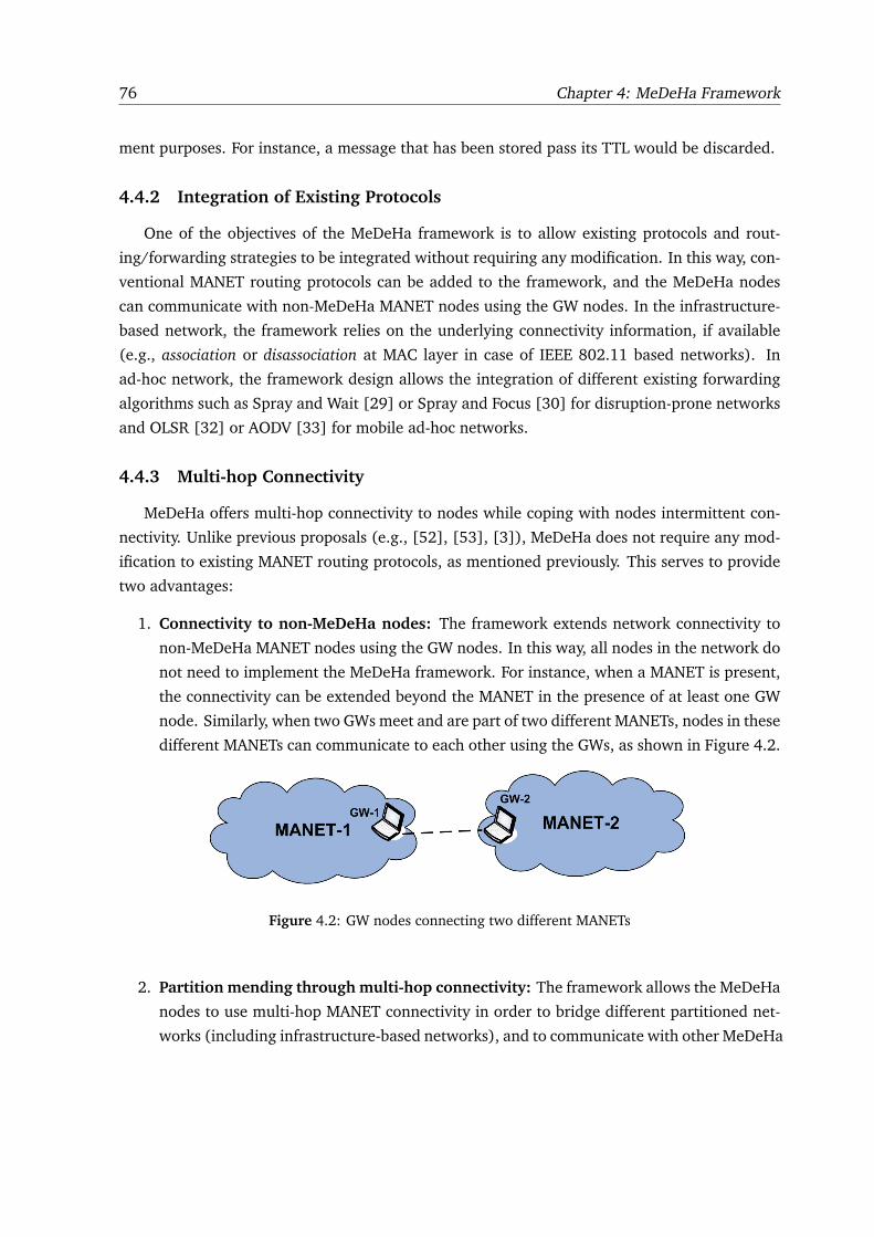
76 Chapter 4: MeDeHa Framework
ment purposes. For instance, a message that has been stored pass its TTL would be discarded.
4.4.2 Integration of Existing Protocols
One of the objectives of the MeDeHa framework is to allow existing protocols and rout-
ing/forwarding strategies to be integrated without requiring any modification. In this way, con-
ventional MANET routing protocols can be added to the framework, and the MeDeHa nodes
can communicate with non-MeDeHa MANET nodes using the GW nodes. In the infrastructure-
based network, the framework relies on the underlying connectivity information, if available
(e.g., association or disassociation at MAC layer in case of IEEE 802.11 based networks). In
ad-hoc network, the framework design allows the integration of different existing forwarding
algorithms such as Spray and Wait [29] or Spray and Focus [30] for disruption-prone networks
and OLSR [32] or AODV [33] for mobile ad-hoc networks.
4.4.3 Multi-hop Connectivity
MeDeHa offers multi-hop connectivity to nodes while coping with nodes intermittent con-
nectivity. Unlike previous proposals (e.g., [52], [53], [3]), MeDeHa does not require any mod-
ification to existing MANET routing protocols, as mentioned previously. This serves to provide
two advantages:
1. Connectivity to non-MeDeHa nodes: The framework extends network connectivity to
non-MeDeHa MANET nodes using the GW nodes. In this way, all nodes in the network do
not need to implement the MeDeHa framework. For instance, when a MANET is present,
the connectivity can be extended beyond the MANET in the presence of at least one GW
node. Similarly, when two GWs meet and are part of two different MANETs, nodes in these
different MANETs can communicate to each other using the GWs, as shown in Figure 4.2.
Figure 4.2: GW nodes connecting two different MANETs
2. Partition mending through multi-hop connectivity: The framework allows the MeDeHa
nodes to use multi-hop MANET connectivity in order to bridge different partitioned net-
works (including infrastructure-based networks), and to communicate with other MeDeHa
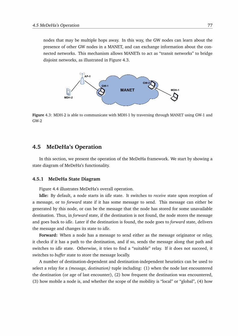
4.5 MeDeHa’s Operation 77
nodes that may be multiple hops away. In this way, the GW nodes can learn about the
presence of other GW nodes in a MANET, and can exchange information about the con-
nected networks. This mechanism allows MANETs to act as “transit networks” to bridge
disjoint networks, as illustrated in Figure 4.3.
Figure 4.3: MDH-2 is able to communicate with MDH-1 by traversing through MANET using GW-1 and
GW-2
4.5 MeDeHa’s Operation
In this section, we present the operation of the MeDeHa framework. We start by showing a
state diagram of MeDeHa’s functionality.
4.5.1 MeDeHa State Diagram
Figure 4.4 illustrates MeDeHa’s overall operation.
Idle: By default, a node starts in idle state. It switches to receive state upon reception of
a message, or to forward state if it has some message to send. This message can either be
generated by this node, or can be the message that the node has stored for some unavailable
destination. Thus, in forward state, if the destination is not found, the node stores the message
and goes back to idle. Later if the destination is found, the node goes to forward state, delivers
the message and changes its state to idle.
Forward: When a node has a message to send either as the message originator or relay,
it checks if it has a path to the destination, and if so, sends the message along that path and
switches to idle state. Otherwise, it tries to find a “suitable” relay. If it does not succeed, it
switches to buffer state to store the message locally.
A number of destination-dependent and destination-independent heuristics can be used to
select a relay for a (message, destination) tuple including: (1) when the node last encountered
the destination (or age of last encounter), (2) how frequent the destination was encountered,
(3) how mobile a node is, and whether the scope of the mobility is “local” or “global”, (4) how
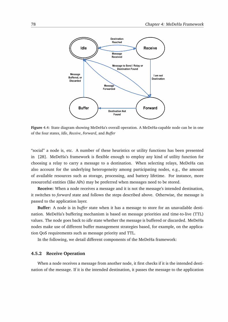
78 Chapter 4: MeDeHa Framework
Figure 4.4: State diagram showing MeDeHa’s overall operation. A MeDeHa-capable node can be in one
of the four states, Idle, Receive, Forward, and Buffer
“social” a node is, etc. A number of these heuristics or utility functions has been presented
in [28]. MeDeHa’s framework is flexible enough to employ any kind of utility function for
choosing a relay to carry a message to a destination. When selecting relays, MeDeHa can
also account for the underlying heterogeneity among participating nodes, e.g., the amount
of available resources such as storage, processing, and battery lifetime. For instance, more
resourceful entities (like APs) may be preferred when messages need to be stored.
Receive: When a node receives a message and it is not the message’s intended destination,
it switches to forward state and follows the steps described above. Otherwise, the message is
passed to the application layer.
Buffer: A node is in buffer state when it has a message to store for an unavailable desti-
nation. MeDeHa’s buffering mechanism is based on message priorities and time-to-live (TTL)
values. The node goes back to idle state whether the message is buffered or discarded. MeDeHa
nodes make use of different buffer management strategies based, for example, on the applica-
tion QoS requirements such as message priority and TTL.
In the following, we detail different components of the MeDeHa framework:
4.5.2 Receive Operation
When a node receives a message from another node, it first checks if it is the intended desti-
nation of the message. If it is the intended destination, it passes the message to the application
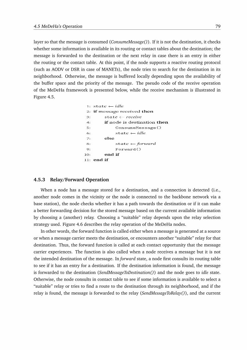
4.5 MeDeHa’s Operation 79
layer so that the message is consumed (ConsumeMessage()). If it is not the destination, it checks
whether some information is available in its routing or contact tables about the destination; the
message is forwarded to the destination or the next relay in case there is an entry in either
the routing or the contact table. At this point, if the node supports a reactive routing protocol
(such as AODV or DSR in case of MANETs), the node tries to search for the destination in its
neighborhood. Otherwise, the message is buffered locally depending upon the availability of
the buffer space and the priority of the message. The pseudo code of the receive operation
of the MeDeHa framework is presented below, while the receive mechanism is illustrated in
Figure 4.5.
4.5.3 Relay/Forward Operation
When a node has a message stored for a destination, and a connection is detected (i.e.,
another node comes in the vicinity or the node is connected to the backbone network via a
base station), the node checks whether it has a path towards the destination or if it can make
a better forwarding decision for the stored message based on the current available information
by choosing a (another) relay. Choosing a “suitable” relay depends upon the relay selection
strategy used. Figure 4.6 describes the relay operation of the MeDeHa nodes.
In other words, the forward function is called either when a message is generated at a source
or when a message carrier meets the destination, or encounters another “suitable” relay for that
destination. Thus, the forward function is called at each contact opportunity that the message
carrier experiences. The function is also called when a node receives a message but it is not
the intended destination of the message. In forward state, a node first consults its routing table
to see if it has an entry for a destination. If the destination information is found, the message
is forwarded to the destination (SendMessageToDestination()) and the node goes to idle state.
Otherwise, the node consults in contact table to see if some information is available to select a
“suitable” relay or tries to find a route to the destination through its neighborhood, and if the
relay is found, the message is forwarded to the relay (SendMessageToRelay()), and the current
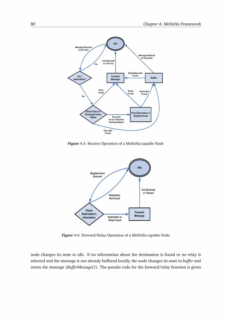
80 Chapter 4: MeDeHa Framework
Figure 4.5: Receive Operation of a MeDeHa-capable Node
Figure 4.6: Forward/Relay Operation of a MeDeHa-capable Node
node changes its state to idle. If no information about the destination is found or no relay is
selected and the message is not already buffered locally, the node changes its state to buffer and
stores the message (BufferMessage()). The pseudo code for the forward/relay function is given
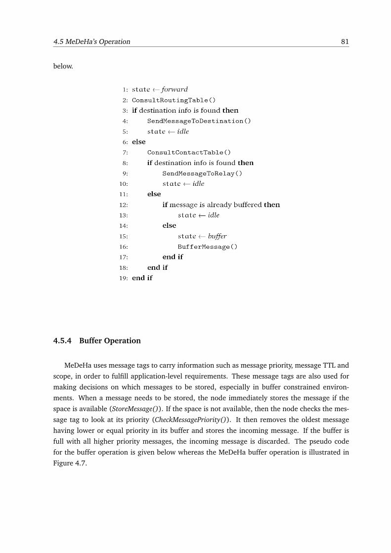
4.5 MeDeHa’s Operation 81
below.
4.5.4 Buffer Operation
MeDeHa uses message tags to carry information such as message priority, message TTL and
scope, in order to fulfill application-level requirements. These message tags are also used for
making decisions on which messages to be stored, especially in buffer constrained environ-
ments. When a message needs to be stored, the node immediately stores the message if the
space is available (StoreMessage()). If the space is not available, then the node checks the mes-
sage tag to look at its priority (CheckMessagePriority()). It then removes the oldest message
having lower or equal priority in its buffer and stores the incoming message. If the buffer is
full with all higher priority messages, the incoming message is discarded. The pseudo code
for the buffer operation is given below whereas the MeDeHa buffer operation is illustrated in
Figure 4.7.
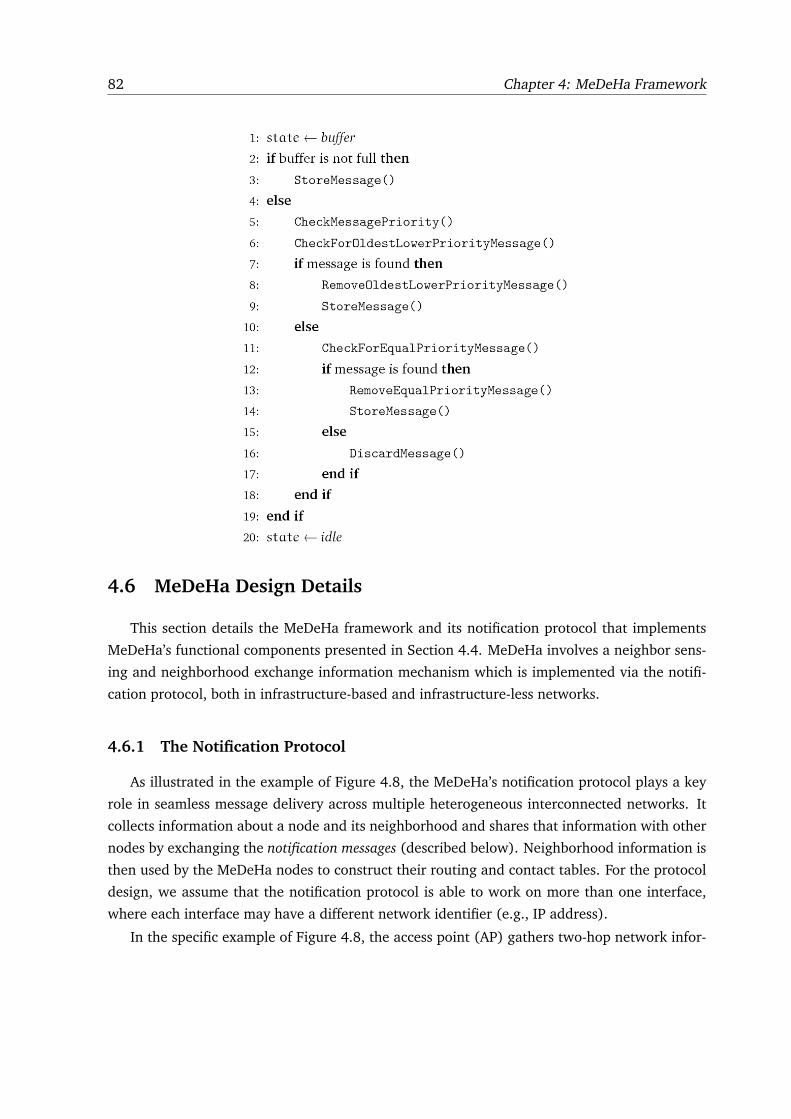
82 Chapter 4: MeDeHa Framework
4.6 MeDeHa Design Details
This section details the MeDeHa framework and its notification protocol that implements
MeDeHa’s functional components presented in Section 4.4. MeDeHa involves a neighbor sens-
ing and neighborhood exchange information mechanism which is implemented via the notifi-
cation protocol, both in infrastructure-based and infrastructure-less networks.
4.6.1 The Notification Protocol
As illustrated in the example of Figure 4.8, the MeDeHa’s notification protocol plays a key
role in seamless message delivery across multiple heterogeneous interconnected networks. It
collects information about a node and its neighborhood and shares that information with other
nodes by exchanging the notification messages (described below). Neighborhood information is
then used by the MeDeHa nodes to construct their routing and contact tables. For the protocol
design, we assume that the notification protocol is able to work on more than one interface,
where each interface may have a different network identifier (e.g., IP address).
In the specific example of Figure 4.8, the access point (AP) gathers two-hop network infor-
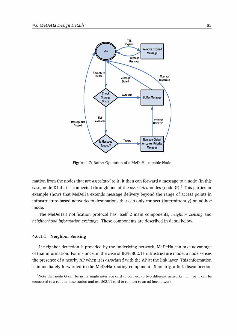
4.6 MeDeHa Design Details 83
Figure 4.7: Buffer Operation of a MeDeHa-capable Node
mation from the nodes that are associated to it; it then can forward a message to a node (in this
case, node D) that is connected through one of the associated nodes (node G).3 This particular
example shows that MeDeHa extends message delivery beyond the range of access points in
infrastructure-based networks to destinations that can only connect (intermittently) on ad-hoc
mode.
The MeDeHa’s notification protocol has itself 2 main components, neighbor sensing and
neighborhood information exchange. These components are described in detail below.
4.6.1.1 Neighbor Sensing
If neighbor detection is provided by the underlying network, MeDeHa can take advantage
of that information. For instance, in the case of IEEE 802.11 infrastructure mode, a node senses
the presence of a nearby AP when it is associated with the AP at the link layer. This information
is immediately forwarded to the MeDeHa routing component. Similarly, a link disconnection
3Note that node G can be using single interface card to connect to two different networks [11], or it can be
connected to a cellular base station and use 802.11 card to connect to an ad-hoc network.
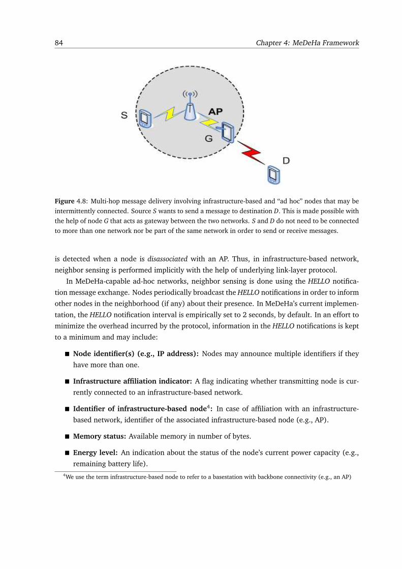
84 Chapter 4: MeDeHa Framework
Figure 4.8: Multi-hop message delivery involving infrastructure-based and “ad hoc” nodes that may be
intermittently connected. Source S wants to send a message to destination D. This is made possible with
the help of node G that acts as gateway between the two networks. S and D do not need to be connected
to more than one network nor be part of the same network in order to send or receive messages.
is detected when a node is disassociated with an AP. Thus, in infrastructure-based network,
neighbor sensing is performed implicitly with the help of underlying link-layer protocol.
In MeDeHa-capable ad-hoc networks, neighbor sensing is done using the HELLO notifica-
tion message exchange. Nodes periodically broadcast the HELLO notifications in order to inform
other nodes in the neighborhood (if any) about their presence. In MeDeHa’s current implemen-
tation, the HELLO notification interval is empirically set to 2 seconds, by default. In an effort to
minimize the overhead incurred by the protocol, information in the HELLO notifications is kept
to a minimum and may include:
� Node identifier(s) (e.g., IP address): Nodes may announce multiple identifiers if they
have more than one.
� Infrastructure affiliation indicator: A flag indicating whether transmitting node is cur-
rently connected to an infrastructure-based network.
� Identifier of infrastructure-based node4: In case of affiliation with an infrastructure-
based network, identifier of the associated infrastructure-based node (e.g., AP).
� Memory status: Available memory in number of bytes.
� Energy level: An indication about the status of the node’s current power capacity (e.g.,
remaining battery life).
4We use the term infrastructure-based node to refer to a basestation with backbone connectivity (e.g., an AP)
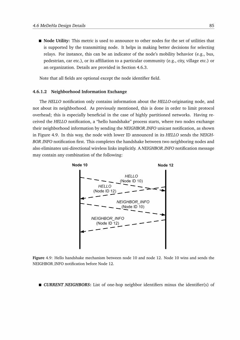
4.6 MeDeHa Design Details 85
� Node Utility: This metric is used to announce to other nodes for the set of utilities that
is supported by the transmitting node. It helps in making better decisions for selecting
relays. For instance, this can be an indicator of the node’s mobility behavior (e.g., bus,
pedestrian, car etc.), or its affiliation to a particular community (e.g., city, village etc.) or
an organization. Details are provided in Section 4.6.3.
Note that all fields are optional except the node identifier field.
4.6.1.2 Neighborhood Information Exchange
The HELLO notification only contains information about the HELLO-originating node, and
not about its neighborhood. As previously mentioned, this is done in order to limit protocol
overhead; this is especially beneficial in the case of highly partitioned networks. Having re-
ceived the HELLO notification, a “hello handshake” process starts, where two nodes exchange
their neighborhood information by sending the NEIGHBOR INFO unicast notification, as shown
in Figure 4.9. In this way, the node with lower ID announced in its HELLO sends the NEIGH-
BOR INFO notification first. This completes the handshake between two neighboring nodes and
also eliminates uni-directional wireless links implicitly. A NEIGHBOR INFO notification message
may contain any combination of the following:
Figure 4.9: Hello handshake mechanism between node 10 and node 12. Node 10 wins and sends the
NEIGHBOR INFO notification before Node 12.
� CURRENT NEIGHBORS: List of one-hop neighbor identifiers minus the identifier(s) of
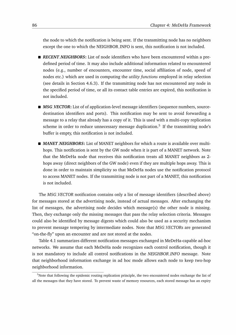
86 Chapter 4: MeDeHa Framework
the node to which the notification is being sent. If the transmitting node has no neighbors
except the one to which the NEIGHBOR INFO is sent, this notification is not included.
� RECENT NEIGHBORS: List of node identifiers who have been encountered within a pre-
defined period of time. It may also include additional information related to encountered
nodes (e.g., number of encounters, encounter time, social affiliation of node, speed of
nodes etc.) which are used in computing the utility functions employed in relay selection
(see details in Section 4.6.3). If the transmitting node has not encountered any node in
the specified period of time, or all its contact table entries are expired, this notification is
not included.
� MSG VECTOR: List of of application-level message identifiers (sequence numbers, source-
destination identifiers and ports). This notification may be sent to avoid forwarding a
message to a relay that already has a copy of it. This is used with a multi-copy replication
scheme in order to reduce unnecessary message duplication.5 If the transmitting node’s
buffer is empty, this notification is not included.
� MANET NEIGHBORS: List of MANET neighbors for which a route is available over multi-
hops. This notification is sent by the GW node when it is part of a MANET network. Note
that the MeDeHa node that receives this notification treats all MANET neighbors as 2-
hops away (direct neighbors of the GW node) even if they are multiple hops away. This is
done in order to maintain simplicity so that MeDeHa nodes use the notification protocol
to access MANET nodes. If the transmitting node is not part of a MANET, this notification
is not included.
The MSG VECTOR notification contains only a list of message identifiers (described above)
for messages stored at the advertising node, instead of actual messages. After exchanging the
list of messages, the advertising node decides which message(s) the other node is missing.
Then, they exchange only the missing messages that pass the relay selection criteria. Messages
could also be identified by message digests which could also be used as a security mechanism
to prevent message tempering by intermediate nodes. Note that MSG VECTORs are generated
“on-the-fly” upon an encounter and are not stored at the nodes.
Table 4.1 summarizes different notification messages exchanged in MeDeHa-capable ad-hoc
networks. We assume that each MeDeHa node recognizes each control notification, though it
is not mandatory to include all control notifications in the NEIGHBOR INFO message. Note
that neighborhood information exchange in ad hoc mode allows each node to keep two-hop
neighborhood information.
5Note that following the epidemic routing replication principle, the two encountered nodes exchange the list of
all the messages that they have stored. To prevent waste of memory resources, each stored message has an expiry
4.6 MeDeHa Design Details 87
Table 4.1: The Notification Information Exchanged for Ad-hoc NetworksNotification
Name
Includes Contents Description
HELLO
Node IDs Broadcasted by each node periodically to
flagAssociated inform neighboring nodes about its IDs
Affiliated infrastructure
node’s ID
Buffer level
Energy level
NEIGHBOR INFO
CURRENT NEIGHBORS IDs of neighbors Sent in order to inform receiving node
about other neighboring nodes
IDs of encountered nodes Sent to inform receiving node about the
RECENT NEIGHBORS Encounter time nodes recently seen by the transmitting
Number of encounters node
Any other heuristic
Sequence no. of messages Contains sequence numbers of messages
MSG VECTOR Source of messages stored at transmitting node
Destination of messages
MANET NEIGHBORS IDs of MANET neighbors Sent by a MeDeHa-capable MANET node to
inform about the connected MANET nodes
In case of infrastructure-based networks, neighborhood information is exchanged between
a node and its associated infrastructure-based node (e.g., AP) and among infrastructure-based
nodes that are connected within a local scope (either wired or wireless). The notification mes-
sages between infrastructure-based nodes are triggered on the reception of a connection or a
disconnection event (e.g., NODE PRESENT, NODE LEAVE etc.).6 The notification messages be-
tween a node and its associated infrastructure-based node may result from a link layer associa-
tion of the node, or based on sensing a neighboring node in ad hoc mode. Nodes that pass their
ad-hoc one-hop neighborhood information to their associated infrastructure-based nodes act
as gateways to connect nodes in infrastructure-based networks with nodes in ad-hoc networks.
The notification messages that are exchanged in the infrastructure-based network are presented
in Table 4.2. In the specific case of IEEE 802.11, the notification protocol messages exchanged
amongst APs are broadcasted but confined to APs within an Extended Service Set (ESS). Simi-
time associated to it.6These notifications are defined in Table 4.2.
88 Chapter 4: MeDeHa Framework
larly, there are two other notification messages named as MANET PRESENT and LEAVE MANET
that could be sent by the GW node to its corresponding associated infrastructure-based node.
MANET PRESENT is sent as soon as the GW node joins a new MANET or when there is a change
in its MANET routing table (addition or removal of routes to other MANET nodes), whereas
LEAVE MANET is sent to inform the associated infrastructure-based node that the GW node is
no longer part of the MANET.
4.6.2 Routing and Contact Table Management
Each MeDeHa node maintains routing and contact tables which are built using informa-
tion collected from the “hello handshake”. MeDeHa routing tables contain forwarding infor-
mation for nodes that are currently accessible. Using information from the HELLO and CUR-
RENT NEIGHBORS messages allows nodes to maintain 2-hop routing information. Routing
information is updated after each “hello handshake”. If a node does not hear an update from
a neighboring node (for which it has a routing entry) for as long as two times the period of
HELLO exchange, it removes the routing entry from its routing table7 and stops propagating
the node’s availability in the subsequent CURRENT NEIGHBORS notifications. All entries in the
routing table for which the departed node was a gateway are also removed at this point. As
soon as the entries from the routing table are removed, the corresponding entries in the contact
table are updated so that they can be used in the RECENT NEIGHBORS notifications.
Routes are calculated in such a way that the routing loops are avoided. In this way, a direct
hop to a node always has a priority over a 2-hop route to the node. Moreover, as nodes may use
multiple interface identifiers (e.g., IP address), the routing table considers the ad-hoc interface
identifier of a node as direct hop, and use all its other interfaces as accessible via the ad-hoc
identifier of the node.
A node’s contact table comprises information about other nodes that are encountered by
this node over a pre-defined period of time. The contact table information is then propagated
via the RECENT NEIGHBORS notifications. The information about a “contact” is entered into
the contact table of a node when the node received a HELLO notification from a newly con-
nected neighbor. This information contains the time at which the contact occurred as well as
an encounter counter. This counter is only incremented once during a contact duration (even
if nodes exchange more than one HELLO notification), and is an indicator of the number of
contact opportunities the two nodes have had with each other. Contact table entries of a node
are removed when they time out. This timeout period is configurable, and depends on how
long an information remains useful about a “contact” in a specific environment. A node stops
propagating a contact information after this timeout.
7The node does not remove the neighboring node’s entry from its contact table.
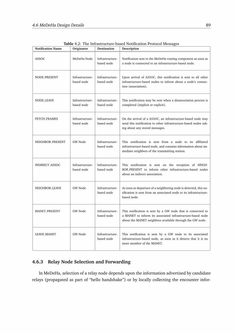
4.6 MeDeHa Design Details 89
Table 4.2: The Infrastructure-based Notification Protocol MessagesNotification Name Originator Destination Description
ASSOC MeDeHa Node Infrastructure-
based node
Notification sent to the MeDeHa routing component as soon as
a node is connected to an infrastructure-based node.
NODE PRESENT Infrastructure-
based node
Infrastructure-
based node
Upon arrival of ASSOC, this notification is sent to all other
infrastructure-based nodes to inform about a node’s connec-
tion (association).
NODE LEAVE Infrastructure-
based node
Infrastructure-
based node
This notification may be sent when a disassociation process is
completed (implicit or explicit).
FETCH FRAMES Infrastructure-
based node
Infrastructure-
based node
On the arrival of a ASSOC, an infrastructure-based node may
send this notification to other infrastructure-based nodes ask-
ing about any stored messages.
NEIGHBOR PRESENT GW Node Infrastructure-
based node
This notification is sent from a node to its affiliated
infrastructure-based node, and contains information about im-
mediate neighbors of the transmitting station.
INDIRECT ASSOC Infrastructure-
based node
Infrastructure-
based node
This notification is sent on the reception of NEIGH-
BOR PRESENT to inform other infrastructure-based nodes
about an indirect association.
NEIGHBOR LEAVE GW Node Infrastructure-
based node
As soon as departure of a neighboring node is detected, this no-
tification is sent from an associated node to its infrastructure-
based node.
MANET PRESENT GW Node Infrastructure-
based node
This notification is sent by a GW node that is connected to
a MANET to inform its associated infrastructure-based node
about the MANET neighbors available through the GW node.
LEAVE MANET GW Node Infrastructure-
based node
This notification is sent by a GW node to its associated
infrastructure-based node, as soon as it detects that it is no
more member of the MANET.
4.6.3 Relay Node Selection and Forwarding
In MeDeHa, selection of a relay node depends upon the information advertised by candidate
relays (propagated as part of “hello handshake”) or by locally collecting the encounter infor-
90 Chapter 4: MeDeHa Framework
mation with other nodes. This information is used to compute the utility of the node as a relay.
The choice of utility metrics for relay selection also depends upon the network environment,
node heterogeneity, as well as application’s specific requirements.
For instance with IEEE 802.11, considering all APs within an ESS are connected to each
other, providing an “almost connected” network, APs may have high utility as relays when
compared to other nodes. This is because in such environments handing over a copy of a
message to an AP means that the network contains the number of message copies equal to
the total number of neighboring APs within the ESS, even though only one AP has stored the
message. This increases the probability of message delivery to a destination. Another advantage
is that APs are expected to be more resourceful entities in terms of battery and storage space.
Now consider an example where connectivity between different villages is only provided using
buses that move between them. In this case, buses would be given priority as relays to carry
inter-village traffic. The affiliation to a particular community (e.g., village in this case) can also
be used to choose a relay for carrying the traffic. The nodes detect the presence of these relays
(such as buses) by the utility advertised by the relays in the HELLO notifications under the field
of Node Utility. The field Node Utility can also include information about the trust rating of
the advertising node. This rating may be assigned by a central entity, and helps in avoiding
malicious nodes.
Another important parameter in choosing a “suitable” relay is the buffer capacity (e.g. in
bytes) advertised by a candidate relay. If a node has more messages to send than the messages
that can be accommodated by a candidate relay, it could only forward a subset of stored message
to the latter and must look for another relay to carry the other remaining messages. Similarly, a
node’s energy level is another parameter to be considered when choosing relay nodes as it may
be useless to forward messages to a node who is going to die soon.
Two nodes may also exchange a summary of their stored application-level messages (in-
stead of actual messages) using the MSG VECTOR notification as part of their NEIGHBOR INFO
message exchange. Furthermore, before forwarding a message (or a set of messages) to a relay,
the corresponding route for the destination is entered in the routing table of the node that is
forwarding the message with next hop set as the chosen relay. This route remains in the node’s
routing table until it times out, or the relay becomes unfeasible for carrying messages for the
destination (for instance, if the relay runs out of buffer or another more suitable relay is found).
To perform data forwarding, MeDeHa employs the hop-by-hop reliability mechanism as
specified by the reference DTN architecture [17] which works as follows. When a message car-
rier encounters a destination or a relay, it forwards the messages and considers that a message
is successfully received by the latter when it receives an acknowledgment. This makes sure
that the message is transfered reliably and that the number of messages transfered are propor-
tional to the contact duration, thus avoiding any unnecessary message loss. This is even more
4.7 Interaction with MANETs 91
beneficial for the scenarios where only one copy of a message exist in the network, as losing
the only copy has more drastic effect on the performance as compared to the scenario where
multiple copies of a message co-exist in the network. This could also be served as a flow control
mechanism.
4.7 Interaction with MANETs
As previously mentioned, MeDeHa allows integration of MANET routing protocols without
requiring any modification. In this way, the GW nodes get multi-hop connectivity information
about MANET nodes when they are connected to a MANET. The GW nodes are also capable of
using the multi-hop node information to discover other GW nodes in the MANET and to use the
underlying MANET network as a bridge to connect networks that are otherwise disconnected.
The GW node when member of a MANET, can be connected to other infrastructure-based or
ad-hoc networks, and learns about the presence of the MANET nodes and passes this informa-
tion to other connected networks. In this way, nodes in the other networks gather the MANET
nodes information and are able to forward messages to the MANET nodes via the GW node.
In the following subsections, the framework functionality with MANETs is described.
4.7.1 MANET Information Exchange
The presence of a MANET at the GW node is detected by neighbor sensing procedures of the
MANET routing protocols (e.g., receiving a “hello” broadcast), and is notified to the MeDeHa
routing component, which starts looking up the MANET routing table to get the information
about the available MANET neighbors. Also, each time that the MANET routing table is changed
at the GW node, a notification is sent to the routing component. Thus, the GW node consults the
MANET routing table to keep information about all available MANET nodes, and treats them as
immediate neighbors. Note that nodes form a MANET whenever two or more MANET-capable
nodes approach each other.
The GW node sends the MANET NEIGHBORS notifications to other encountered MeDeHa
nodes that are not participating in the MANET. In this way, the MeDeHa’s 2-hop ad-hoc protocol
is utilized, and MeDeHa nodes assume that all MANET nodes announced by the GW node are
2-hop away. Thus, they are able to forward any stored messages for MANET nodes via the GW
node (e.g., MDH-1 in Fig. 4.10 considers MANET-3 as 2-hop away via GW-1).
Furthermore, the GW node keeps track of history of past encounters for MANET nodes over
a period of time and passes this information to other MeDeHa nodes when it meets them using
the RECENT NEIGHBORS notification. This helps the MeDeHa nodes to choose the advertising
GW as a relay for stored messages, and forward the messages to the GW node if the latter fulfills
92 Chapter 4: MeDeHa Framework
a particular utility function being used as relay selection strategy (e.g., if the GW node has seen
a MANET node a specific number of times).
As soon as the GW node is associated to an infrastructure-based node (e.g., an AP), it passes
information about all MANET nodes to the AP using the MANET PRESENT notification. As a
result, the AP forwards stored messages to the MANET nodes via the GW node, and also sends
the INDIRECT ASSOC notification to all connected APs within the ESS. Moreover, the GW node
also sends the LEAVE MANET notification to the AP, when it leaves a MANET network, so that
the AP removes route information of the MANET nodes. When a GW node leaves, the AP will
remove routes for all nodes that were accessible through the departed GW node.
4.7.2 Gateway Discovery in MANETs
The GW nodes use the MANET nodes connectivity information to discover other GW nodes,
and exchange data and control information about other networks. This helps in treating
MANETs as “transit networks” to transfer the MeDeHa protocol information across different
networks. The discovery is performed by sending the MeDeHa HELLO messages periodically
to the MANET nodes to inquire if any node supports MeDeHa8, and is done on the top of the
MANET protocol, so the routing protocol does not require to be modified. Once a GW node
discovers another GW, the two GW nodes can talk to each other to exchange other nodes infor-
mation (e.g., current and past neighbors, messages stored) over multiple hops as if they were
direct neighbors, using regular MeDeHa protocol. Exchange of data messages between two GW
nodes that are multi-hop away in a MANET cloud is performed using IP encapsulation.
4.7.3 Proactive vs. Reactive MANET Routing
A MANET routing protocol does not require any modification while working with MeDeHa,
though the performance of the MeDeHa framework may vary with the choice of a particular
MANET routing protocol. The MANET routing protocols are generally divided into reactive
(such as AODV and DSR) and proactive (e.g., DSDV and OLSR) routing protocols. The reactive
protocols attempt to find a route to a destination when there is a message to send to the des-
tination. On the other hand, nodes running the proactive protocols generally keep an updated
view of the whole network all the time.
Thus, in the context of MeDeHa, the GW node running a reactive routing protocol such
as AODV, may not have complete information about all MANET nodes, at the time when it
encounters a MeDeHa node. It only has information about the nodes for which a route request
8In MANET routing protocols where a mechanism to discover a gateway joining more than one network is already
present (e.g., Host and Network Association (HNA) control messages in OLSR, gateways in DYMO [35]), GW
discovery overhead can be reduced by contacting only the gateway nodes to check whether they support MeDeHa.
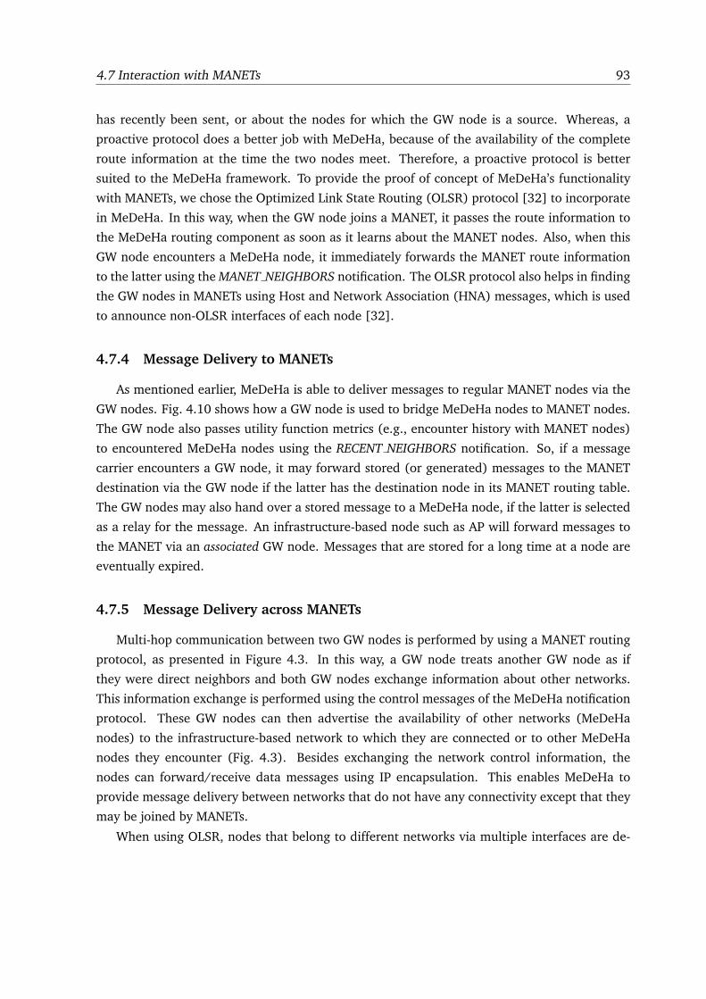
4.7 Interaction with MANETs 93
has recently been sent, or about the nodes for which the GW node is a source. Whereas, a
proactive protocol does a better job with MeDeHa, because of the availability of the complete
route information at the time the two nodes meet. Therefore, a proactive protocol is better
suited to the MeDeHa framework. To provide the proof of concept of MeDeHa’s functionality
with MANETs, we chose the Optimized Link State Routing (OLSR) protocol [32] to incorporate
in MeDeHa. In this way, when the GW node joins a MANET, it passes the route information to
the MeDeHa routing component as soon as it learns about the MANET nodes. Also, when this
GW node encounters a MeDeHa node, it immediately forwards the MANET route information
to the latter using the MANET NEIGHBORS notification. The OLSR protocol also helps in finding
the GW nodes in MANETs using Host and Network Association (HNA) messages, which is used
to announce non-OLSR interfaces of each node [32].
4.7.4 Message Delivery to MANETs
As mentioned earlier, MeDeHa is able to deliver messages to regular MANET nodes via the
GW nodes. Fig. 4.10 shows how a GW node is used to bridge MeDeHa nodes to MANET nodes.
The GW node also passes utility function metrics (e.g., encounter history with MANET nodes)
to encountered MeDeHa nodes using the RECENT NEIGHBORS notification. So, if a message
carrier encounters a GW node, it may forward stored (or generated) messages to the MANET
destination via the GW node if the latter has the destination node in its MANET routing table.
The GW nodes may also hand over a stored message to a MeDeHa node, if the latter is selected
as a relay for the message. An infrastructure-based node such as AP will forward messages to
the MANET via an associated GW node. Messages that are stored for a long time at a node are
eventually expired.
4.7.5 Message Delivery across MANETs
Multi-hop communication between two GW nodes is performed by using a MANET routing
protocol, as presented in Figure 4.3. In this way, a GW node treats another GW node as if
they were direct neighbors and both GW nodes exchange information about other networks.
This information exchange is performed using the control messages of the MeDeHa notification
protocol. These GW nodes can then advertise the availability of other networks (MeDeHa
nodes) to the infrastructure-based network to which they are connected or to other MeDeHa
nodes they encounter (Fig. 4.3). Besides exchanging the network control information, the
nodes can forward/receive data messages using IP encapsulation. This enables MeDeHa to
provide message delivery between networks that do not have any connectivity except that they
may be joined by MANETs.
When using OLSR, nodes that belong to different networks via multiple interfaces are de-
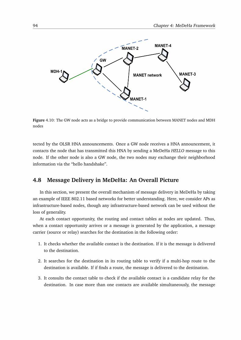
94 Chapter 4: MeDeHa Framework
Figure 4.10: The GW node acts as a bridge to provide communication between MANET nodes and MDH
nodes
tected by the OLSR HNA announcements. Once a GW node receives a HNA announcement, it
contacts the node that has transmitted this HNA by sending a MeDeHa HELLO message to this
node. If the other node is also a GW node, the two nodes may exchange their neighborhood
information via the “hello handshake”.
4.8 Message Delivery in MeDeHa: An Overall Picture
In this section, we present the overall mechanism of message delivery in MeDeHa by taking
an example of IEEE 802.11 based networks for better understanding. Here, we consider APs as
infrastructure-based nodes, though any infrastructure-based network can be used without the
loss of generality.
At each contact opportunity, the routing and contact tables at nodes are updated. Thus,
when a contact opportunity arrives or a message is generated by the application, a message
carrier (source or relay) searches for the destination in the following order:
1. It checks whether the available contact is the destination. If it is the message is delivered
to the destination.
2. It searches for the destination in its routing table to verify if a multi-hop route to the
destination is available. If if finds a route, the message is delivered to the destination.
3. It consults the contact table to check if the available contact is a candidate relay for the
destination. In case more than one contacts are available simultaneously, the message
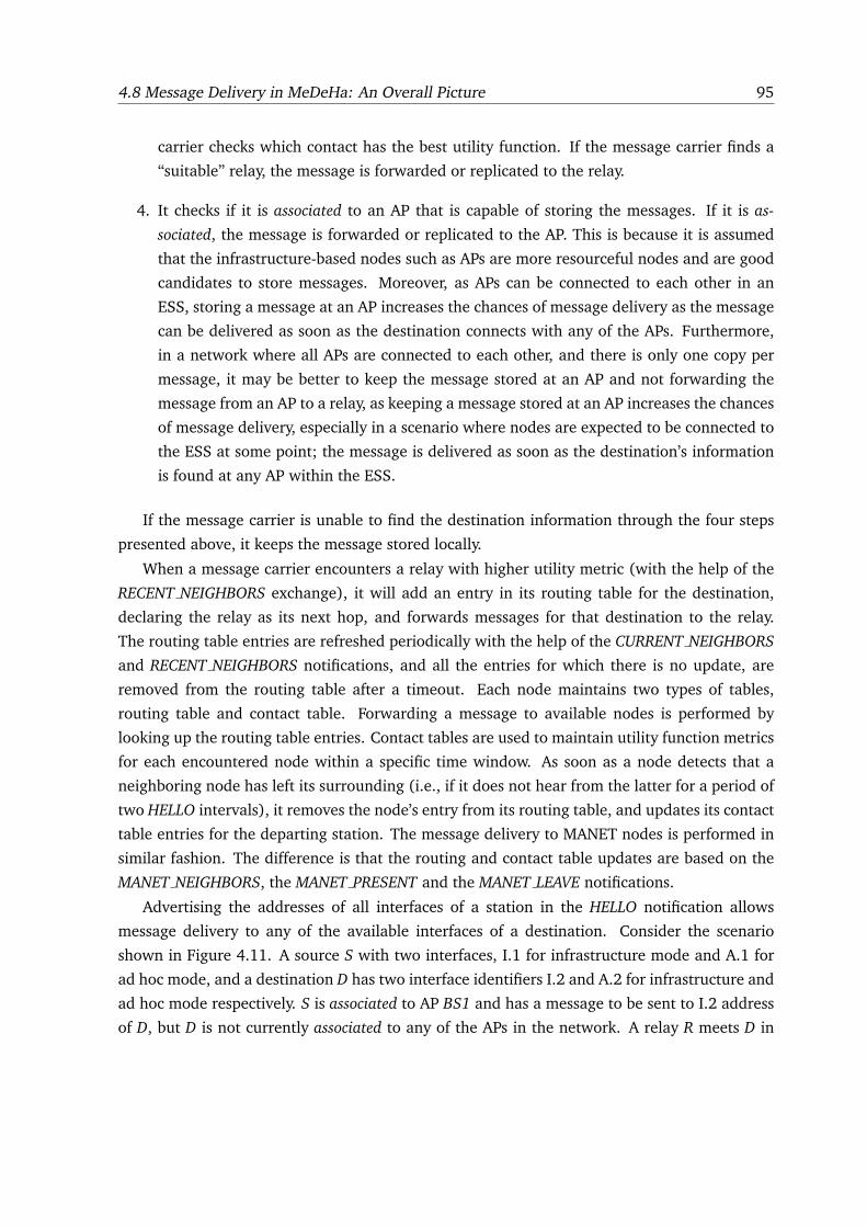
4.8 Message Delivery in MeDeHa: An Overall Picture 95
carrier checks which contact has the best utility function. If the message carrier finds a
“suitable” relay, the message is forwarded or replicated to the relay.
4. It checks if it is associated to an AP that is capable of storing the messages. If it is as-
sociated, the message is forwarded or replicated to the AP. This is because it is assumed
that the infrastructure-based nodes such as APs are more resourceful nodes and are good
candidates to store messages. Moreover, as APs can be connected to each other in an
ESS, storing a message at an AP increases the chances of message delivery as the message
can be delivered as soon as the destination connects with any of the APs. Furthermore,
in a network where all APs are connected to each other, and there is only one copy per
message, it may be better to keep the message stored at an AP and not forwarding the
message from an AP to a relay, as keeping a message stored at an AP increases the chances
of message delivery, especially in a scenario where nodes are expected to be connected to
the ESS at some point; the message is delivered as soon as the destination’s information
is found at any AP within the ESS.
If the message carrier is unable to find the destination information through the four steps
presented above, it keeps the message stored locally.
When a message carrier encounters a relay with higher utility metric (with the help of the
RECENT NEIGHBORS exchange), it will add an entry in its routing table for the destination,
declaring the relay as its next hop, and forwards messages for that destination to the relay.
The routing table entries are refreshed periodically with the help of the CURRENT NEIGHBORS
and RECENT NEIGHBORS notifications, and all the entries for which there is no update, are
removed from the routing table after a timeout. Each node maintains two types of tables,
routing table and contact table. Forwarding a message to available nodes is performed by
looking up the routing table entries. Contact tables are used to maintain utility function metrics
for each encountered node within a specific time window. As soon as a node detects that a
neighboring node has left its surrounding (i.e., if it does not hear from the latter for a period of
two HELLO intervals), it removes the node’s entry from its routing table, and updates its contact
table entries for the departing station. The message delivery to MANET nodes is performed in
similar fashion. The difference is that the routing and contact table updates are based on the
MANET NEIGHBORS, the MANET PRESENT and the MANET LEAVE notifications.
Advertising the addresses of all interfaces of a station in the HELLO notification allows
message delivery to any of the available interfaces of a destination. Consider the scenario
shown in Figure 4.11. A source S with two interfaces, I.1 for infrastructure mode and A.1 for
ad hoc mode, and a destination D has two interface identifiers I.2 and A.2 for infrastructure and
ad hoc mode respectively. S is associated to AP BS1 and has a message to be sent to I.2 address
of D, but D is not currently associated to any of the APs in the network. A relay R meets D in
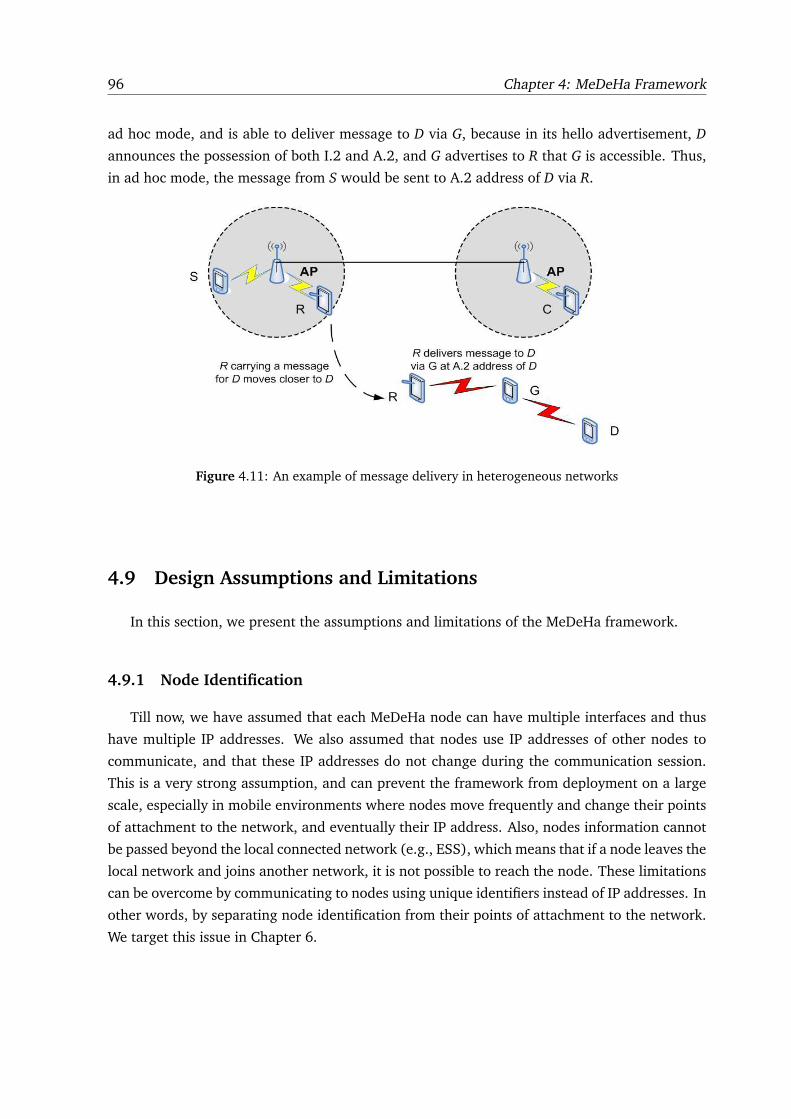
96 Chapter 4: MeDeHa Framework
ad hoc mode, and is able to deliver message to D via G, because in its hello advertisement, D
announces the possession of both I.2 and A.2, and G advertises to R that G is accessible. Thus,
in ad hoc mode, the message from S would be sent to A.2 address of D via R.
Figure 4.11: An example of message delivery in heterogeneous networks
4.9 Design Assumptions and Limitations
In this section, we present the assumptions and limitations of the MeDeHa framework.
4.9.1 Node Identification
Till now, we have assumed that each MeDeHa node can have multiple interfaces and thus
have multiple IP addresses. We also assumed that nodes use IP addresses of other nodes to
communicate, and that these IP addresses do not change during the communication session.
This is a very strong assumption, and can prevent the framework from deployment on a large
scale, especially in mobile environments where nodes move frequently and change their points
of attachment to the network, and eventually their IP address. Also, nodes information cannot
be passed beyond the local connected network (e.g., ESS), which means that if a node leaves the
local network and joins another network, it is not possible to reach the node. These limitations
can be overcome by communicating to nodes using unique identifiers instead of IP addresses. In
other words, by separating node identification from their points of attachment to the network.
We target this issue in Chapter 6.
4.10 Concluding Remarks 97
4.9.2 Security Issues
Securing information is an important component of wireless communication. While applica-
tion level messages can be secured using end-to-end security mechanisms such as encryption,
it is also important to secure routing information exchange(e.g., HELLO advertisements and
neighborhood information). Although we do not currently have any explicit security mecha-
nisms in place, the MeDeHa framework is flexible and extensible enough that security-related
mechanisms can be easily added. For example, using message digests to ensure message in-
tegrity and authenticity (as mentioned in Section 4.6.1.2), adding security-specific criteria to
the utility function (e.g., the trustworthiness of a node assigned by a trusted authority).
4.10 Concluding Remarks
In this chapter, we have presented our message delivery framework MeDeHa that helps
in bridging infrastructure-less and infrastructure-based networks while tolerating nodes tem-
porary or long-lived disruptions. The framework is flexible enough to incorporate different
forwarding mechanisms and MANET routing protocols. We have also presented the detailed
design of the MeDeHa framework and its operation in different types of networks including
infrastructure-based networks, ad-hoc networks and networks with intermittent connectivity.
In the next chapter, we will provide the implementation of MeDeHa and a thorough evaluation
using synthetic and real mobility traces using simulations, as well as on a real testbed.

98 Chapter 4: MeDeHa Framework
5
MEDEHA IMPLEMENTATION AND
PERFORMANCE EVALUATION
In Chapter 4, we described the MeDeHa framework, which has been designed to provide
seamless message delivery across heterogeneous, disruption-prone networks. In this chap-
ter, we focus on the implementation of the framework, and its performance evaluation. We
start with presenting different implementation approaches that we took in order to implement
MeDeHa both on simulators as well as on real machines. We then present the performance
evaluation of MeDeHa by demonstrating the simulation results, results obtained from the real
experiments, as well as some hybrid experiments that involve experiments partly running on a
simulator and partly on real machines.
5.1 Implementation Approaches
As described earlier in Chapter 4, one of the key features of the MeDeHa framework is
the ability to work at different layers of the communication stack. To validate this claim, we
implemented the framework on different layers of the communication stack, where each imple-
mentation approach offers its own advantages and brings in some disadvantages as well. In this
section, we will highlight different implementation approaches that we have used to implement
MeDeHa as well as present the pros and cons associated with each.
The implementation of MeDeHa was incremental. The initial implementation the frame-
work included infrastructure-based wired and wireless networks while supporting nodes con-
nectivity disruptions (i.e., infrastructure-based nodes buffer messages for unavailable nodes and
as soon as a node is connected to an infrastructure-based node, the messages are delivered).
99
100 Chapter 5: MeDeHa Implementation and Performance Evaluation
Later, we added support for infrastructure-less networks including mobile ad-hoc networks
(MANET) in the framework.
For an implementation that comprises the infrastructure-based networks, a link-layer imple-
mentation approach was the obvious choice. This is because the infrastructure-based network
mechanism is based on the link-layer connectivity information of nodes (association and dis-
association). We used IEEE 802.11 [60] as the link-layer wireless technology because it is the
most widely used wireless local area network (LAN) standard these days. Hence, the link-
layer implementation involved only infrastructure-based wireless and wired networks. The
advantage of implementing the framework at the link layer is that the solution could be im-
plemented on nodes that only run two layers of the communication stack (e.g., AP bridges).
Furthermore, in an internet involving infrastructure-based networks (e.g., an ESS), it is easy
to collect nodes connectivity information (association or disassociation) at infrastructure-based
nodes (e.g., APs). This information can then be exchanged between the infrastructure-based
nodes to provide message delivery. The main disadvantage of this approach is that message
routing in infrastructure-less networks becomes very challenging. This is because the routing is
generally performed at the network layer and nodes do not generally have a multi-hop network
view at link layers. Moreover, this requires modifications at the hardware level (at least at the
device driver level). These modifications involve maintaining routing information over multi-
ple networks as well as implementing a buffering mechanism at the link-layer, which may not
be feasible. As the link-layer is generally specific to a particular interface, a node cannot have
access to other interfaces at the link-layer, which is required when the nodes have multiple in-
terfaces. To summarize, the link-layer solution is suitable for infrastructure-based wireless and
backbone networks while supporting disruptions in connectivity, but (1) it cannot be extended
to infrastructure-less multi-hop networks, and (2) it cannot be incorporated on nodes that run
multiple interfaces.
In order to add the support for the infrastructure-less networks in the MeDeHa framework,
a network layer implementation was required, as a network layer implementation facilitates
the development of the routing function. Moreover, with this implementation approach, it is
easy to make the framework communicate with the existing routing protocols (such as MANET
routing protocols). Thus, as the next step, we implemented the framework at the network layer.
This implementation comprised diverse types of networks including infrastructure-based wired
and wireless networks, infrastructure-less networks including MANETs, and while coping with
connectivity disruptions. The disadvantage of this approach is that it makes collection of the
underlying connectivity information difficult, because the information has to be available to the
network layer. To solve this issue, we used a cross-layer approach so that the link layer con-
nection information is passed to the network layer module of MeDeHa, as a connection event
(association or disassociation) is detected. On the other hand, the network layer implementa-
5.2 Evaluation Platforms 101
tion approach requires that all nodes in the network must include network layer. For instance,
AP routers can be used, but not AP bridges. Of course, the network can still include AP bridges,
but the functionality of the MeDeHa framework is implemented only at AP routers.
A compromised approach is to implement the MeDeHa framework at a new sublayer be-
tween the link- and the network layers (as layer 2.5 or the bridge layer). The advantage for this
approach is that the MAC layer implementation does not need to be modified while the collec-
tion of the link layer connectivity information is easy. Moreover, handling multiple interfaces
at the bridge layer is also possible which helps in collecting multi-hop routing information in
the infrastructure-less networks. While this approach seems to solve many drawbacks of the
link- or the network layer implementations, it poses several other problems and complexities,
as a completely new sublayer needs to be designed and should be supported by all participating
nodes; thus, nodes cannot communicate with other nodes in the Internet. Another problem
is the identification of nodes at the bridge level as neither the MAC level address nor the IP
address of a node can be used for this purpose. Hence, a new identification scheme is required
for such a scheme, and it will increase the overhead of the framework. For these reasons, we
decided not to use this implementation approach.
Note that an application-layer solution is also possible where application level (overlay)
routing could be performed between MeDeHa nodes in infrastructure-less networks, whereas
the association (and disassociation) information could be passed from the link-layer to the appli-
cation layer, in infrastructure-based networks. Implementing the framework at the application
layer is one of the future tasks that we plan to do.
Besides, in order to validate the performance of the framework with real-world scenarios,
we have also implemented MeDeHa on Linux machines as a user space daemon. Details on this
implementation are presented in Section 5.4.
5.2 Evaluation Platforms
In order to implement the MeDeHa framework, we used different evaluation strategies
involving different platforms. They are described in the following subsections:
5.2.1 Simulator Experimentation
Implementing a new solution in a simulator is generally considered to be the first step
towards the performance evaluation of the proposed solution as simulators allow reproduction
of experiments. Also, the simulator experiments are flexible in terms of creating scenarios
and users mobility. Hence, we implemented the MeDeHa framework in different open-source
simulators (OMNET++ [58] and NS-3 [59]). The reason to implement in different simulators
102 Chapter 5: MeDeHa Implementation and Performance Evaluation
is discussed in Section 5.3. In order to validate the performance of the framework, we carried
out experiments using conventional synthetic mobility models (e.g., Random Waypoint Mobility
Model [61]), and real mobility traces.
� Synthetic Mobility Models: Nodes mobility pattern affects the outcome of an experiment
and different scenarios require different mobility patterns for the participating nodes. This
is very important for the networks where message forwarding depends upon the contact
opportunities of mobile nodes. To simulate nodes mobility, a number of synthetic mobility
models have been used by the researchers including Random Walk Mobility Model [62]
and Random Waypoint Mobility Model [61, 63]. Among the available mobility models,
the RWP model is the most commonly used mobility model as movements of the nodes
following the RWP mobility model do not depend upon the movements of other nodes.
But it is believed that the RWP model does not provide a realistic mobility behavior be-
cause of the fact that in reality, users do not randomly choose their destination point and
also that nodes do not generally move independent of one another [133]. Hence, we
used a variation of the RWP mobility model known as BonnMotion Mobility Model [65],
in which nodes move using the RWP mobility model, but their movements are not pure
random. Rather, the movements are based on the attraction points such that nodes choose
their next destination among one of the attraction points with a certain specified proba-
bility instead of choosing a destination randomly. The attraction points are assigned to
the potential destinations for nodes such that mobile nodes move only between these at-
traction points. The BonnMotion Model is a very simple variation of the RWP model but
significantly adds reality of the mobility traces. More details on this model are presented
in Section 5.6.3.
� Real Mobility Traces: Synthetic mobility models, no matter how well they are defined,
do not depict the real mobility pattern of nodes. Hence, to validate the MeDeHa frame-
work against the scenarios where the participating nodes have real connections or discon-
nections, encounter and inter-contact times, we used real mobility traces acquired from
CRAWDAD [67] for the KAIST campus [66]. This data set provides students mobility
traces carrying GPS devices across the campus.
5.2.2 Real Experimentation
Simulator-based scenarios are normally not equivalent to the real world scenarios, as there
are many factors that are generally ignored while performing experiments using simulators.
For instance, when wireless networks are involved, parameters such as signal attenuation and
communication range are not the same in the simulator as in real scenarios because simulator-
based implementations are usually based on simplistic models. Due to these reasons, it is very
5.3 Simulator Implementation 103
important to validate the performance of a proposed solution against its implementation on real
machines. Hence, we implemented the MeDeHa framework on real machines as a user-space
daemon using Linux kernel 2.6. This implementation enables us to validate the functionality of
the framework without modifying the kernel implementation of Linux.
5.2.3 Hybrid Experimentation
Although real implementation has many advantages, in practice experimental scenarios are
limited by many factors, including size, cost, and limited mobility of the participating nodes.
While simulated scenarios do not have these constraints, they allow the reproducibility of the
experiment results and provide increased scalability, it is not guaranteed that the simulation
results are a representation of what would have happened on real hardware. The advantages
of the simulator- and the real implementation can be combined by performing the hybrid ex-
perimentation such that the experiments run partly on real machines and partly on simulator.
This provides validation of the solution on real machines besides demonstrating the scalability
of the solution to some extent. This also validates the simulator implementation as in order
to perform such experiments, it is necessary that simulator nodes and real machines are able
to communicate with each other. Hence, we have done some experimentation with a hybrid
experimental setup involving both simulator nodes and real machines. In Section 5.5, we pro-
vide details on the hybrid experimental setup, whereas the experimental results are presented
in Section 5.6.7.
In the following sections, we present these different evaluation strategies, and the frame-
work implementation in detail.
5.3 Simulator Implementation
As mentioned earlier, we implemented the MeDeHa framework on different simulators (OM-
NET++ [58] and NS-3 [59]). To start with, we tried implementing the framework in the NS-
2 [57] simulator, as NS-2 has been a widely used open-source network simulator. But NS-2
misses out many basic functionalities that are required for the framework’s implementation
such as roaming capability (hand-off support) of nodes in IEEE 802.11 infrastructure-based
network within an ESS and support of multiple interfaces per node.
OMNET++ [58] is another open-source network simulator that provides basic roaming
support1 for IEEE 802.11 infrastructure-based networks through the INET framework. It also
provides the possibility to use external mobility traces. We implemented the MeDeHa frame-
1This roaming support includes active scanning of nodes to search for beacons at different communication chan-
nels. It does not include comparing power levels of different APs in order to select the AP with stronger signal.
104 Chapter 5: MeDeHa Implementation and Performance Evaluation
work using the INET framework (version INET-20061020) of the OMNET++ simulator. As
explained in Section 5.1, this implementation was done at the link-layer and only included
infrastructure-based wireless and wired networks with disruption tolerance support. To imple-
ment the framework, we had to modify the link layer code of OMNET++.2
Although IEEE 802.11 standard [60] defines the disassociation management frame, it does
not precise when a station or an AP should send this frame. In MeDeHa, infrastructure-based
nodes (e.g., APs) need to know the up-to-date state of the connected nodes, and the perfor-
mance of MeDeHa in infrastructure-based networks depends upon the accuracy of this infor-
mation. To maintain this connectivity information accurately, it is required that a node sends
a disassociation frame before leaving the network in the infrastructure-based networks. On the
other hand, an AP should also send a disassociation frame to an associated node that remains
inactive for a specific period of time. This is necessary to allow the AP to start storing data on
behalf of the node that has left without informing the AP (e.g., the device is off due to bat-
tery drainage or the AP does not receive its disassociation frame). However, the disassociation
mechanism was missing in the regular OMNET++ simulator which means that a disassociation
frame was never sent from a station or an AP. Hence, in order to implement MeDeHa in the
simulator, we added an explicit disassociation mechanism in the OMNET++ simulator. In this
way, before leaving the coverage area of an AP, a station explicitly sends a disassociation frame
to its corresponding AP indicating that it is going to leave the AP. A station can detect that it
is at the border of an AP’s connectivity region by comparing the received power level in the
beacons from the AP with a power threshold; as soon as the station’s received power level falls
within 10% of the threshold, the disassociation frame is sent. While this mechanism reduces the
effective coverage area of the APs by 10%, it makes sure that the station sends a disassociation
frame before leaving, see Figure 5.1.
Then, we extended the OMNET++ simulator to support the passive scanning mechanism
in order to allow nodes to search a nearby AP over multiple channels. Specifically, a node can
select a more suitable AP by comparing the received power levels of the beacon frames. This
was also not provided in the base implementation of the OMNET++ simulator, and helps in
selecting an AP which has a strong connectivity signal. It also allows a smoother hand-off of a
node between two APs (reassociation mechanism), as based on the received power level of the
two APs, a station may decide to switch to another AP in order to get better connectivity. Some
of the results obtained with this implementation were presented in [22], and will be described
in Section 5.6.4.
However, as many other contemporary open-source network simulators, the OMNET++
simulator still lacks the support of multiple interfaces per node. Recently, a new network sim-
2The modified version of the INET Framework of OMNET++ can be found at
http://planete.inria.fr/software/MeDeHa. Several scripts are also available at this URL.
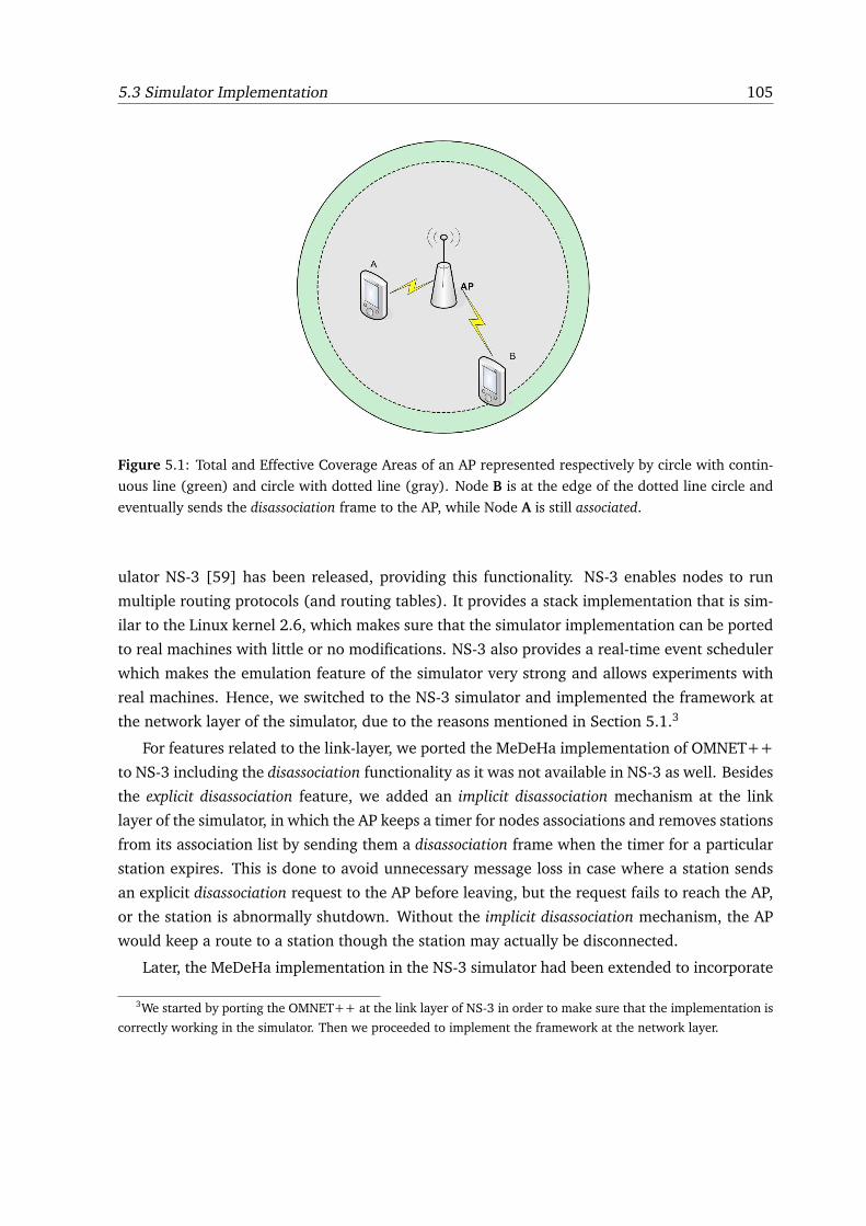
5.3 Simulator Implementation 105
Figure 5.1: Total and Effective Coverage Areas of an AP represented respectively by circle with contin-
uous line (green) and circle with dotted line (gray). Node B is at the edge of the dotted line circle and
eventually sends the disassociation frame to the AP, while Node A is still associated.
ulator NS-3 [59] has been released, providing this functionality. NS-3 enables nodes to run
multiple routing protocols (and routing tables). It provides a stack implementation that is sim-
ilar to the Linux kernel 2.6, which makes sure that the simulator implementation can be ported
to real machines with little or no modifications. NS-3 also provides a real-time event scheduler
which makes the emulation feature of the simulator very strong and allows experiments with
real machines. Hence, we switched to the NS-3 simulator and implemented the framework at
the network layer of the simulator, due to the reasons mentioned in Section 5.1.3
For features related to the link-layer, we ported the MeDeHa implementation of OMNET++
to NS-3 including the disassociation functionality as it was not available in NS-3 as well. Besides
the explicit disassociation feature, we added an implicit disassociation mechanism at the link
layer of the simulator, in which the AP keeps a timer for nodes associations and removes stations
from its association list by sending them a disassociation frame when the timer for a particular
station expires. This is done to avoid unnecessary message loss in case where a station sends
an explicit disassociation request to the AP before leaving, but the request fails to reach the AP,
or the station is abnormally shutdown. Without the implicit disassociation mechanism, the AP
would keep a route to a station though the station may actually be disconnected.
Later, the MeDeHa implementation in the NS-3 simulator had been extended to incorporate
3We started by porting the OMNET++ at the link layer of NS-3 in order to make sure that the implementation is
correctly working in the simulator. Then we proceeded to implement the framework at the network layer.
106 Chapter 5: MeDeHa Implementation and Performance Evaluation
the infrastructure-less networks, including support for existing MANET routing protocols (as
explained in Section 4.6). In order to validate MeDeHa’s functionality with existing MANET
routing protocols, we integrated the Optimized Link State Routing (OLSR) protocol imple-
mentation with the framework’s implementation. The choice of the OLSR routing protocol is
discussed in Section 4.7.3.
In the following subsection, we provide some details on the MeDeHa’s implementation over
NS-3, while the performance evaluation is presented in Section 5.6.5.
5.3.1 NS-3 Implementation
As the implementation is done at the network layer, a mechanism is necessary to notify
the MeDeHa module at the network layer about nodes’ associations and disassociations. The
association and disassociation information is generally available at the link-layer. Hence, we
modified the IEEE 802.11 code in NS-3 for both AP and stations in order to send a notification
from the link layer to the MeDeHa module at the network layer, as soon as an association or
disassociation event is detected.4
Besides, we developed two main modules in the NS-3 simulator, the infrastructure-based
wireless network module and the infrastructure-less wireless network module.
� The infrastructure-based network module is responsible for operations related to man-
aging nodes associations and disassociations with the backbone network, and exchanging
this information among APs within an ESS.
� The infrastructure-less network module handles MeDeHa’s operations in ad-hoc net-
works, and implements the ad-hoc component of the Notification protocol described in
Section 4.6.1, including detection of neighborhood, exchange of neighborhood informa-
tion and relay selection process.
Both of these modules maintain interfaces to the OLSR routing module, and they share
some common functions such as buffer management. The buffer module implements the buffer
management strategy described in Section 4.5. Another module is implemented to prepare and
parse the notification protocol headers which are used in the information exchange.
Besides, the Inverse Address Resolution Protocol (InARP) [68] mechanism has been added
to the NS-3 simulator which is used to get the IP address of a station from its MAC address.
This mechanism is needed when a station wants to associate to an AP, and only knows the MAC
address of the AP. At this point, the station uses InARP mechanism to get the IP address of the
4The link-layer implementation generates an event whenever an association or a disassociation occur. Any module
in the NS-3 simulator can bind itself to this event in order to receive this notification. This allows the link-layer
connectivity information to be passed to any layer of the communication stack.

5.4 Implementation on Real Machines 107
AP before sending a MeDeHa’s ASSOC notification to the AP. The ASSOC notification needs to
be sent by the station and includes all IP addresses of the station.
5.4 Implementation on Real Machines
Figure 5.2 shows the development approach we chose to implement MeDeHa for the phys-
ical testbed. To achieve high portability and compatibility with the existing infrastructure, the
MeDeHa framework is implemented at the network layer as a user-space daemon in Linux
with kernel 2.6.5 We call this the MeDeHa daemon as represented in Figure 5.2. All required
MeDeHa information is included as part of the IP header (as an IP option, illustrated in Fig-
ure 5.3) and no transport or application data is modified. This allows MeDeHa nodes to function
over any network with unmodified existing protocols.
In Figure 5.2, all the blocks that are bounded by the dashed rectangle are part of the Linux
kernel, and we do not modify their implementation; rather, the MeDeHa daemon only uses
these blocks. On the other hand, the blocks that are illustrated outside the dashed rectangle
represent user-space daemons (MeDeHa daemon, olsrd, hostapd). In the following, we describe
each of these blocks:
� MeDeHa Daemon: This daemon comprises the MeDeHa’s implementation. It interacts
with the routing tables in the Linux kernel, and with netfilter [69] modules.
� Hostapd Daemon[70]: This daemon implements the IEEE 802.11 access points, and is
used to notify the MeDeHa daemon about the connectivity of stations (associations or
disassociations). It also directly interacts with the input and output device modules of the
kernel in order to send and receive frames.
� OLSR Daemon: The OLSR daemon interacts with the routing table module of the kernel
to update the routing information of the MANET nodes. This information is used by the
MeDeHa daemon.
� Routing Tables: This module is managed by the Linux kernel and maintains the routing
tables for all the routing protocols (including MeDeHa and MANET routing protocols.
� Netfilter Pre-Routing Hook: This module is kept in the Linux kernel and is used to inter-
cept the incoming messages in order to make a decision whether the messages need to be
stored (if the destination is not available). In this way, a copy of the incoming message is
5The implementation of the MeDeHa framework on Linux machines has been done in cooperation with Marc
Mendonca at University of California at Santa Cruz, USA who is a graduate student and working under the supervi-
sion of Prof. Katia Obraczka.
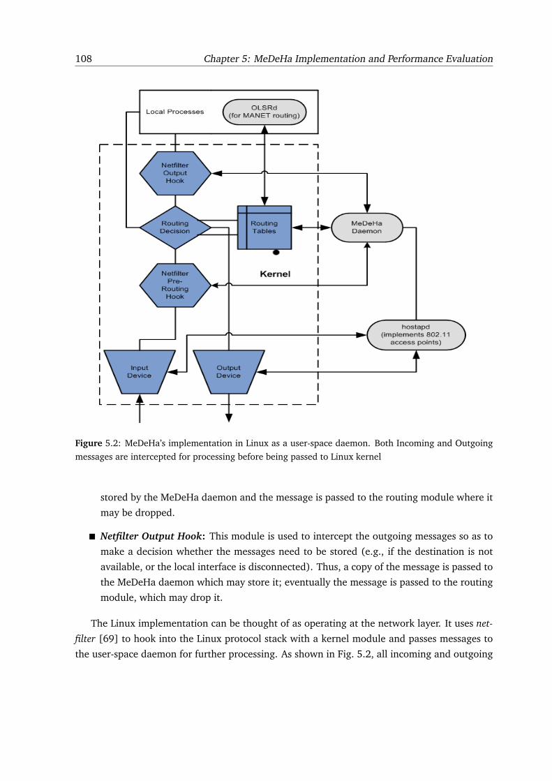
108 Chapter 5: MeDeHa Implementation and Performance Evaluation
Figure 5.2: MeDeHa’s implementation in Linux as a user-space daemon. Both Incoming and Outgoing
messages are intercepted for processing before being passed to Linux kernel
stored by the MeDeHa daemon and the message is passed to the routing module where it
may be dropped.
� Netfilter Output Hook: This module is used to intercept the outgoing messages so as to
make a decision whether the messages need to be stored (e.g., if the destination is not
available, or the local interface is disconnected). Thus, a copy of the message is passed to
the MeDeHa daemon which may store it; eventually the message is passed to the routing
module, which may drop it.
The Linux implementation can be thought of as operating at the network layer. It uses net-
filter [69] to hook into the Linux protocol stack with a kernel module and passes messages to
the user-space daemon for further processing. As shown in Fig. 5.2, all incoming and outgoing
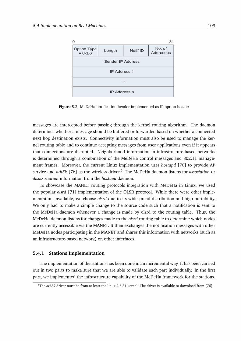
5.4 Implementation on Real Machines 109
Figure 5.3: MeDeHa notification header implemented as IP option header
messages are intercepted before passing through the kernel routing algorithm. The daemon
determines whether a message should be buffered or forwarded based on whether a connected
next hop destination exists. Connectivity information must also be used to manage the ker-
nel routing table and to continue accepting messages from user applications even if it appears
that connections are disrupted. Neighborhood information in infrastructure-based networks
is determined through a combination of the MeDeHa control messages and 802.11 manage-
ment frames. Moreover, the current Linux implementation uses hostapd [70] to provide AP
service and ath5k [76] as the wireless driver.6 The MeDeHa daemon listens for association or
disassociation information from the hostapd daemon.
To showcase the MANET routing protocols integration with MeDeHa in Linux, we used
the popular olsrd [71] implementation of the OLSR protocol. While there were other imple-
mentations available, we choose olsrd due to its widespread distribution and high portability.
We only had to make a simple change to the source code such that a notification is sent to
the MeDeHa daemon whenever a change is made by olsrd to the routing table. Thus, the
MeDeHa daemon listens for changes made to the olsrd routing table to determine which nodes
are currently accessible via the MANET. It then exchanges the notification messages with other
MeDeHa nodes participating in the MANET and shares this information with networks (such as
an infrastructure-based network) on other interfaces.
5.4.1 Stations Implementation
The implementation of the stations has been done in an incremental way. It has been carried
out in two parts to make sure that we are able to validate each part individually. In the first
part, we implemented the infrastructure capability of the MeDeHa framework for the stations.
6The ath5k driver must be from at least the linux 2.6.31 kernel. The driver is available to download from [76].
110 Chapter 5: MeDeHa Implementation and Performance Evaluation
In this way, nodes choose their affiliated AP as their default route and forward all messages
they have to their respective APs, when associated. When they are disconnected, they store the
messages in the local buffer.
In the second part, the GW functionality of the stations has been added so that the stations
are able to act as a bridge between infrastructure-based networks and OLSR-based MANETs. To
learn the information about the nodes present in the MANET, the GW nodes listen for changes
made to the MANET routing table by the olsrd daemon. These changes are shared by the
MeDeHa daemon to other MeDeHa nodes via the notification messages (as described in Sec-
tion 4.6.1). This allowed the MeDeHa framework to use connectivity information in deciding
when and where to forward and buffer messages.
5.4.2 AP Implementation
As messages arrive, they are intercepted before the routing table is consulted, and delivered
to the MeDeHa daemon. This daemon determines whether the messages should be buffered
or forwarded. If they have to be forwarded, the daemon makes necessary modifications to
the messages or the routing table before letting the messages continue on their path. If the
messages have to be buffered, then all pertinent information is saved before the messages are
silently dropped. If the messages are MeDeHa notification messages, then the appropriate
action is taken.
While the above is occurring, another process receives information from hostapd about as-
sociations or disassociations. When a new station joins or leaves, the appropriate MeDeHa
notification messages are sent to other APs and modifications to the routing table are made.
5.4.3 Intercepting Messages
The entire implementation of MeDeHa exists outside the Linux kernel in user-space. This is
possible through the use of netfilter/iptables/libipq [69], which provide a series of hooks into the
IP protocol stack as well as a method of controlling these hooks from the user-space. Although
it is traditionally used for security purposes, it can also be used to implement our protocol
without kernel modification. A brief introduction to the various hooks can be found at [75].
For our implementation, we have utilized hook 1 (pre-routing) for all incoming messages as
well as hook 5 (local out) for all outgoing messages.
All messages (incoming/outgoing) have their destination checked against the local routing
table prior to passing it on. If the destination does not exist, then the message is saved to the
buffer and it is “dropped” by netfilter. All incoming messages are also checked for MeDeHa
notification headers that are attached as IP-header options.
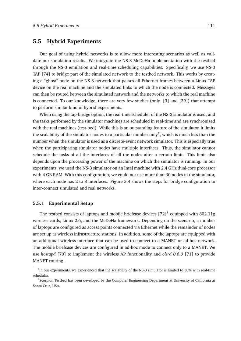
5.5 Hybrid Experiments 111
5.5 Hybrid Experiments
Our goal of using hybrid networks is to allow more interesting scenarios as well as vali-
date our simulation results. We integrate the NS-3 MeDeHa implementation with the testbed
through the NS-3 emulation and real-time scheduling capabilities. Specifically, we use NS-3
TAP [74] to bridge part of the simulated network to the testbed network. This works by creat-
ing a “ghost” node on the NS-3 network that passes all Ethernet frames between a Linux TAP
device on the real machine and the simulated links to which the node is connected. Messages
can then be routed between the simulated network and the networks to which the real machine
is connected. To our knowledge, there are very few studies (only [3] and [39]) that attempt
to perform similar kind of hybrid experiments.
When using the tap-bridge option, the real-time scheduler of the NS-3 simulator is used, and
the tasks performed by the simulator machines are scheduled in real-time and are synchronized
with the real machines (test-bed). While this is an outstanding feature of the simulator, it limits
the scalability of the simulator nodes to a particular number only7, which is much less than the
number when the simulator is used as a discrete-event network simulator. This is especially true
when the participating simulator nodes have multiple interfaces. Thus, the simulator cannot
schedule the tasks of all the interfaces of all the nodes after a certain limit. This limit also
depends upon the processing power of the machine on which the simulator is running. In our
experiments, we used the NS-3 simulator on an Intel machine with 2.4 GHz dual-core processor
with 4 GB RAM. With this configuration, we could not use more than 30 nodes in the simulator,
where each node has 2 to 3 interfaces. Figure 5.4 shows the steps for bridge configuration to
inter-connect simulated and real networks.
5.5.1 Experimental Setup
The testbed consists of laptops and mobile briefcase devices [72]8 equipped with 802.11g
wireless cards, Linux 2.6, and the MeDeHa framework. Depending on the scenario, a number
of laptops are configured as access points connected via Ethernet while the remainder of nodes
are set up as wireless infrastructure stations. In addition, some of the laptops are equipped with
an additional wireless interface that can be used to connect to a MANET or ad-hoc network.
The mobile briefcase devices are configured in ad-hoc mode to connect only to a MANET. We
use hostapd [70] to implement the wireless AP functionality and olsrd 0.6.0 [71] to provide
MANET routing.
7In our experiments, we experienced that the scalability of the NS-3 simulator is limited to 30% with real-time
schedular.8Scorpion Testbed has been developed by the Computer Engineering Department at University of California at
Santa Cruz, USA.
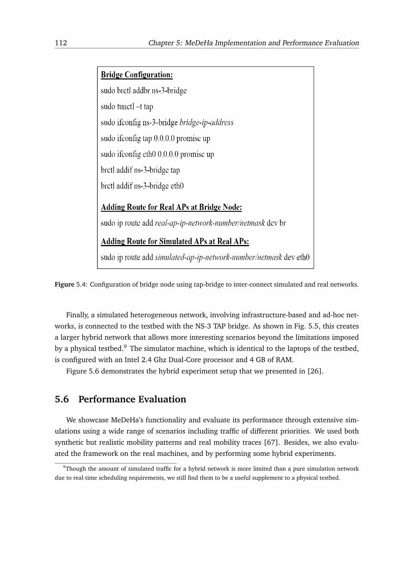
112 Chapter 5: MeDeHa Implementation and Performance Evaluation
Figure 5.4: Configuration of bridge node using tap-bridge to inter-connect simulated and real networks.
Finally, a simulated heterogeneous network, involving infrastructure-based and ad-hoc net-
works, is connected to the testbed with the NS-3 TAP bridge. As shown in Fig. 5.5, this creates
a larger hybrid network that allows more interesting scenarios beyond the limitations imposed
by a physical testbed.9 The simulator machine, which is identical to the laptops of the testbed,
is configured with an Intel 2.4 Ghz Dual-Core processor and 4 GB of RAM.
Figure 5.6 demonstrates the hybrid experiment setup that we presented in [26].
5.6 Performance Evaluation
We showcase MeDeHa’s functionality and evaluate its performance through extensive sim-
ulations using a wide range of scenarios including traffic of different priorities. We used both
synthetic but realistic mobility patterns and real mobility traces [67]. Besides, we also evalu-
ated the framework on the real machines, and by performing some hybrid experiments.
9Though the amount of simulated traffic for a hybrid network is more limited than a pure simulation network
due to real-time scheduling requirements, we still find them to be a useful supplement to a physical testbed.
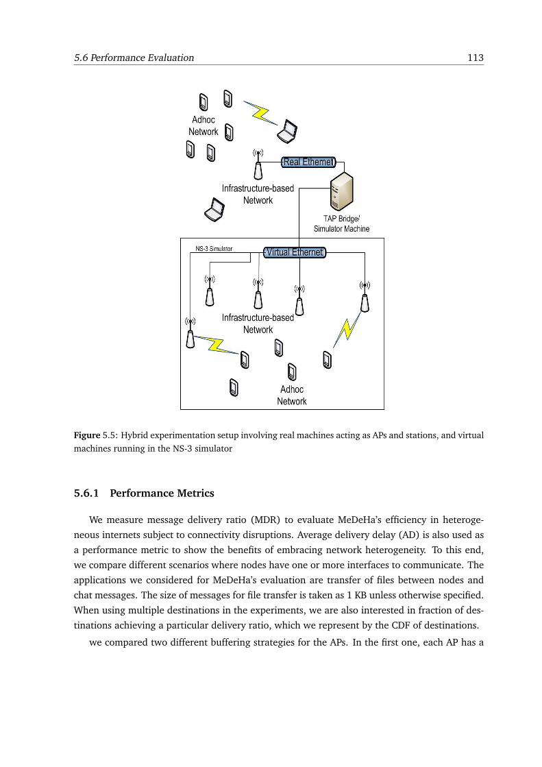
5.6 Performance Evaluation 113
Figure 5.5: Hybrid experimentation setup involving real machines acting as APs and stations, and virtual
machines running in the NS-3 simulator
5.6.1 Performance Metrics
We measure message delivery ratio (MDR) to evaluate MeDeHa’s efficiency in heteroge-
neous internets subject to connectivity disruptions. Average delivery delay (AD) is also used as
a performance metric to show the benefits of embracing network heterogeneity. To this end,
we compare different scenarios where nodes have one or more interfaces to communicate. The
applications we considered for MeDeHa’s evaluation are transfer of files between nodes and
chat messages. The size of messages for file transfer is taken as 1 KB unless otherwise specified.
When using multiple destinations in the experiments, we are also interested in fraction of des-
tinations achieving a particular delivery ratio, which we represent by the CDF of destinations.
we compared two different buffering strategies for the APs. In the first one, each AP has a
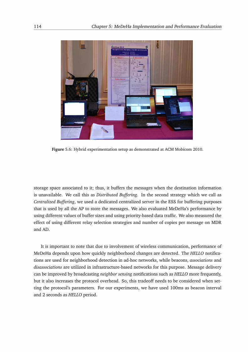
114 Chapter 5: MeDeHa Implementation and Performance Evaluation
Figure 5.6: Hybrid experimentation setup as demonstrated at ACM Mobicom 2010.
storage space associated to it; thus, it buffers the messages when the destination information
is unavailable. We call this as Distributed Buffering. In the second strategy which we call as
Centralized Buffering, we used a dedicated centralized server in the ESS for buffering purposes
that is used by all the AP to store the messages. We also evaluated MeDeHa’s performance by
using different values of buffer sizes and using priority-based data traffic. We also measured the
effect of using different relay selection strategies and number of copies per message on MDR
and AD.
It is important to note that due to involvement of wireless communication, performance of
MeDeHa depends upon how quickly neighborhood changes are detected. The HELLO notifica-
tions are used for neighborhood detection in ad-hoc networks, while beacons, associations and
disassociations are utilized in infrastructure-based networks for this purpose. Message delivery
can be improved by broadcasting neighbor sensing notifications such as HELLO more frequently,
but it also increases the protocol overhead. So, this tradeoff needs to be considered when set-
ting the protocol’s parameters. For our experiments, we have used 100ms as beacon interval
and 2 seconds as HELLO period.
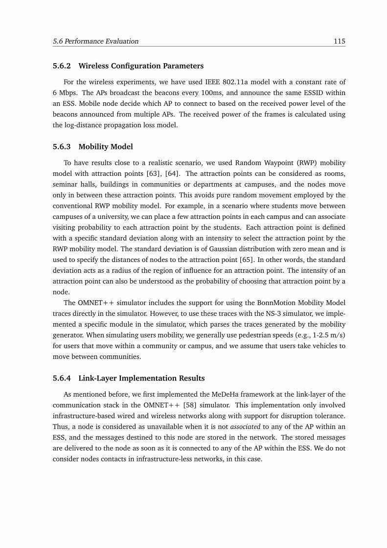
5.6 Performance Evaluation 115
5.6.2 Wireless Configuration Parameters
For the wireless experiments, we have used IEEE 802.11a model with a constant rate of
6 Mbps. The APs broadcast the beacons every 100ms, and announce the same ESSID within
an ESS. Mobile node decide which AP to connect to based on the received power level of the
beacons announced from multiple APs. The received power of the frames is calculated using
the log-distance propagation loss model.
5.6.3 Mobility Model
To have results close to a realistic scenario, we used Random Waypoint (RWP) mobility
model with attraction points [63], [64]. The attraction points can be considered as rooms,
seminar halls, buildings in communities or departments at campuses, and the nodes move
only in between these attraction points. This avoids pure random movement employed by the
conventional RWP mobility model. For example, in a scenario where students move between
campuses of a university, we can place a few attraction points in each campus and can associate
visiting probability to each attraction point by the students. Each attraction point is defined
with a specific standard deviation along with an intensity to select the attraction point by the
RWP mobility model. The standard deviation is of Gaussian distribution with zero mean and is
used to specify the distances of nodes to the attraction point [65]. In other words, the standard
deviation acts as a radius of the region of influence for an attraction point. The intensity of an
attraction point can also be understood as the probability of choosing that attraction point by a
node.
The OMNET++ simulator includes the support for using the BonnMotion Mobility Model
traces directly in the simulator. However, to use these traces with the NS-3 simulator, we imple-
mented a specific module in the simulator, which parses the traces generated by the mobility
generator. When simulating users mobility, we generally use pedestrian speeds (e.g., 1-2.5 m/s)
for users that move within a community or campus, and we assume that users take vehicles to
move between communities.
5.6.4 Link-Layer Implementation Results
As mentioned before, we first implemented the MeDeHa framework at the link-layer of the
communication stack in the OMNET++ [58] simulator. This implementation only involved
infrastructure-based wired and wireless networks along with support for disruption tolerance.
Thus, a node is considered as unavailable when it is not associated to any of the AP within an
ESS, and the messages destined to this node are stored in the network. The stored messages
are delivered to the node as soon as it is connected to any of the AP within the ESS. We do not
consider nodes contacts in infrastructure-less networks, in this case.
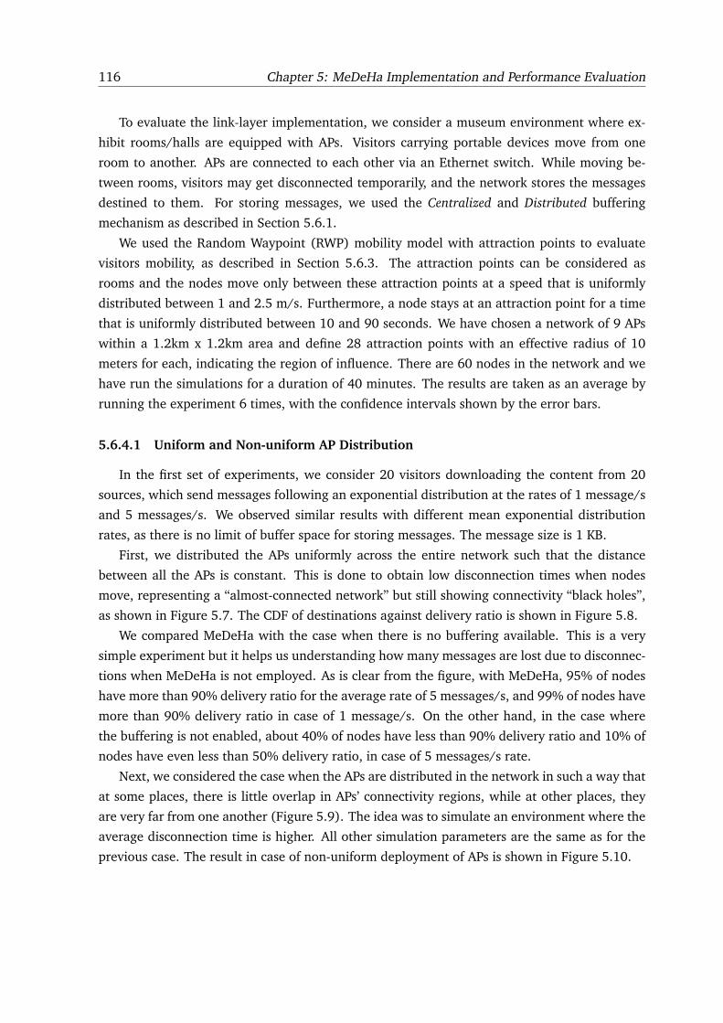
116 Chapter 5: MeDeHa Implementation and Performance Evaluation
To evaluate the link-layer implementation, we consider a museum environment where ex-
hibit rooms/halls are equipped with APs. Visitors carrying portable devices move from one
room to another. APs are connected to each other via an Ethernet switch. While moving be-
tween rooms, visitors may get disconnected temporarily, and the network stores the messages
destined to them. For storing messages, we used the Centralized and Distributed buffering
mechanism as described in Section 5.6.1.
We used the Random Waypoint (RWP) mobility model with attraction points to evaluate
visitors mobility, as described in Section 5.6.3. The attraction points can be considered as
rooms and the nodes move only between these attraction points at a speed that is uniformly
distributed between 1 and 2.5 m/s. Furthermore, a node stays at an attraction point for a time
that is uniformly distributed between 10 and 90 seconds. We have chosen a network of 9 APs
within a 1.2km x 1.2km area and define 28 attraction points with an effective radius of 10
meters for each, indicating the region of influence. There are 60 nodes in the network and we
have run the simulations for a duration of 40 minutes. The results are taken as an average by
running the experiment 6 times, with the confidence intervals shown by the error bars.
5.6.4.1 Uniform and Non-uniform AP Distribution
In the first set of experiments, we consider 20 visitors downloading the content from 20
sources, which send messages following an exponential distribution at the rates of 1 message/s
and 5 messages/s. We observed similar results with different mean exponential distribution
rates, as there is no limit of buffer space for storing messages. The message size is 1 KB.
First, we distributed the APs uniformly across the entire network such that the distance
between all the APs is constant. This is done to obtain low disconnection times when nodes
move, representing a “almost-connected network” but still showing connectivity “black holes”,
as shown in Figure 5.7. The CDF of destinations against delivery ratio is shown in Figure 5.8.
We compared MeDeHa with the case when there is no buffering available. This is a very
simple experiment but it helps us understanding how many messages are lost due to disconnec-
tions when MeDeHa is not employed. As is clear from the figure, with MeDeHa, 95% of nodes
have more than 90% delivery ratio for the average rate of 5 messages/s, and 99% of nodes have
more than 90% delivery ratio in case of 1 message/s. On the other hand, in the case where
the buffering is not enabled, about 40% of nodes have less than 90% delivery ratio and 10% of
nodes have even less than 50% delivery ratio, in case of 5 messages/s rate.
Next, we considered the case when the APs are distributed in the network in such a way that
at some places, there is little overlap in APs’ connectivity regions, while at other places, they
are very far from one another (Figure 5.9). The idea was to simulate an environment where the
average disconnection time is higher. All other simulation parameters are the same as for the
previous case. The result in case of non-uniform deployment of APs is shown in Figure 5.10.
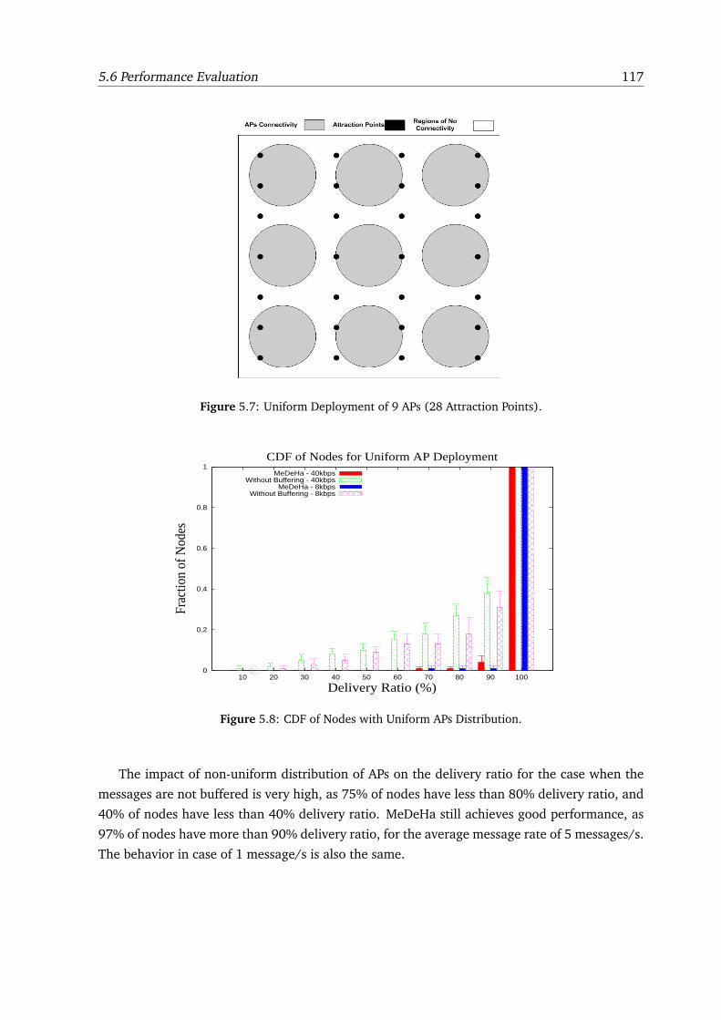
5.6 Performance Evaluation 117
Figure 5.7: Uniform Deployment of 9 APs (28 Attraction Points).
0
0.2
0.4
0.6
0.8
1
10 20 30 40 50 60 70 80 90 100
Frac
tion
of N
odes
Delivery Ratio (%)
CDF of Nodes for Uniform AP DeploymentMeDeHa - 40kbps
Without Buffering - 40kbpsMeDeHa - 8kbps
Without Buffering - 8kbps
Figure 5.8: CDF of Nodes with Uniform APs Distribution.
The impact of non-uniform distribution of APs on the delivery ratio for the case when the
messages are not buffered is very high, as 75% of nodes have less than 80% delivery ratio, and
40% of nodes have less than 40% delivery ratio. MeDeHa still achieves good performance, as
97% of nodes have more than 90% delivery ratio, for the average message rate of 5 messages/s.
The behavior in case of 1 message/s is also the same.
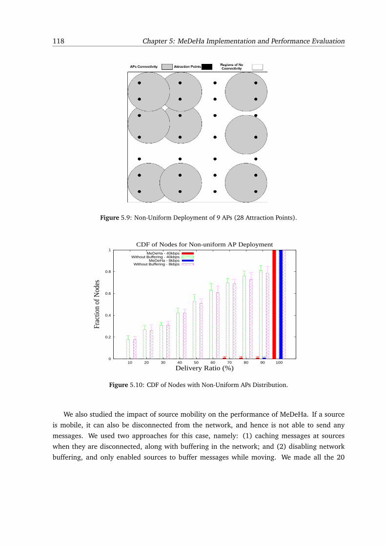
118 Chapter 5: MeDeHa Implementation and Performance Evaluation
Figure 5.9: Non-Uniform Deployment of 9 APs (28 Attraction Points).
0
0.2
0.4
0.6
0.8
1
10 20 30 40 50 60 70 80 90 100
Frac
tion
of N
odes
Delivery Ratio (%)
CDF of Nodes for Non-uniform AP DeploymentMeDeHa - 40kbps
Without Buffering - 40kbpsMeDeHa - 8kbps
Without Buffering - 8kbps
Figure 5.10: CDF of Nodes with Non-Uniform APs Distribution.
We also studied the impact of source mobility on the performance of MeDeHa. If a source
is mobile, it can also be disconnected from the network, and hence is not able to send any
messages. We used two approaches for this case, namely: (1) caching messages at sources
when they are disconnected, along with buffering in the network; and (2) disabling network
buffering, and only enabled sources to buffer messages while moving. We made all the 20
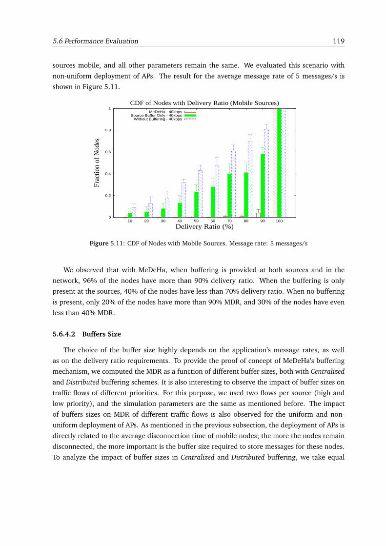
5.6 Performance Evaluation 119
sources mobile, and all other parameters remain the same. We evaluated this scenario with
non-uniform deployment of APs. The result for the average message rate of 5 messages/s is
shown in Figure 5.11.
0
0.2
0.4
0.6
0.8
1
10 20 30 40 50 60 70 80 90 100
Frac
tion
of N
odes
Delivery Ratio (%)
CDF of Nodes with Delivery Ratio (Mobile Sources)MeDeHa - 40kbps
Source Buffer Only - 40kbpsWithout Buffering - 40kbps
Figure 5.11: CDF of Nodes with Mobile Sources. Message rate: 5 messages/s
We observed that with MeDeHa, when buffering is provided at both sources and in the
network, 96% of the nodes have more than 90% delivery ratio. When the buffering is only
present at the sources, 40% of the nodes have less than 70% delivery ratio. When no buffering
is present, only 20% of the nodes have more than 90% MDR, and 30% of the nodes have even
less than 40% MDR.
5.6.4.2 Buffers Size
The choice of the buffer size highly depends on the application’s message rates, as well
as on the delivery ratio requirements. To provide the proof of concept of MeDeHa’s buffering
mechanism, we computed the MDR as a function of different buffer sizes, both with Centralized
and Distributed buffering schemes. It is also interesting to observe the impact of buffer sizes on
traffic flows of different priorities. For this purpose, we used two flows per source (high and
low priority), and the simulation parameters are the same as mentioned before. The impact
of buffers sizes on MDR of different traffic flows is also observed for the uniform and non-
uniform deployment of APs. As mentioned in the previous subsection, the deployment of APs is
directly related to the average disconnection time of mobile nodes; the more the nodes remain
disconnected, the more important is the buffer size required to store messages for these nodes.
To analyze the impact of buffer sizes in Centralized and Distributed buffering, we take equal
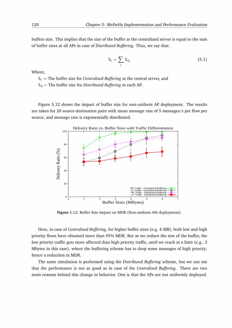
120 Chapter 5: MeDeHa Implementation and Performance Evaluation
buffers size. This implies that the size of the buffer at the centralized server is equal to the sum
of buffer sizes at all APs in case of Distributed Buffering. Thus, we say that:
Sc =∑
i
Sdi(5.1)
Where,
Sc = The buffer size for Centralized Buffering at the central server, and
Sd = The buffer size for Distributed Buffering at each AP.
Figure 5.12 shows the impact of buffer size for non-uniform AP deployment. The results
are taken for 20 source-destination pairs with mean message rate of 5 messages/s per flow per
source, and message rate is exponentially distributed.
0
20
40
60
80
100
0 1 2 3 4 5 6 7
Del
iver
y R
atio
(%)
Buffer Sizes (MBytes)
Delivery Ratio vs. Buffer Sizes with Traffic Differentiation
HP Traffic - Centralized BufferingLP Traffic - Centralized BufferingHP Traffic - Distributed BufferingLP Traffic - Distributed Buffering
Figure 5.12: Buffer Size Impact on MDR (Non-uniform APs deployment).
Here, in case of Centralized Buffering, for higher buffer sizes (e.g. 6 MB), both low and high
priority flows have obtained more than 95% MDR. But as we reduce the size of the buffer, the
low priority traffic gets more affected than high priority traffic, until we reach at a limit (e.g., 3
Mbytes in this case), where the buffering scheme has to drop some messages of high priority;
hence a reduction in MDR.
The same simulation is performed using the Distributed Buffering scheme, but we can see
that the performance is not as good as in case of the Centralized Buffering. There are two
main reasons behind this change in behavior. One is that the APs are not uniformly deployed.
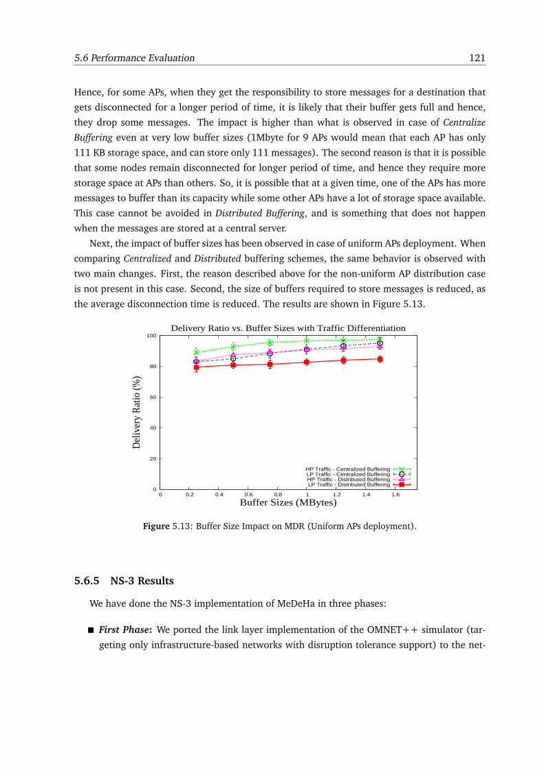
5.6 Performance Evaluation 121
Hence, for some APs, when they get the responsibility to store messages for a destination that
gets disconnected for a longer period of time, it is likely that their buffer gets full and hence,
they drop some messages. The impact is higher than what is observed in case of Centralize
Buffering even at very low buffer sizes (1Mbyte for 9 APs would mean that each AP has only
111 KB storage space, and can store only 111 messages). The second reason is that it is possible
that some nodes remain disconnected for longer period of time, and hence they require more
storage space at APs than others. So, it is possible that at a given time, one of the APs has more
messages to buffer than its capacity while some other APs have a lot of storage space available.
This case cannot be avoided in Distributed Buffering, and is something that does not happen
when the messages are stored at a central server.
Next, the impact of buffer sizes has been observed in case of uniform APs deployment. When
comparing Centralized and Distributed buffering schemes, the same behavior is observed with
two main changes. First, the reason described above for the non-uniform AP distribution case
is not present in this case. Second, the size of buffers required to store messages is reduced, as
the average disconnection time is reduced. The results are shown in Figure 5.13.
0
20
40
60
80
100
0 0.2 0.4 0.6 0.8 1 1.2 1.4 1.6
Del
iver
y R
atio
(%)
Buffer Sizes (MBytes)
Delivery Ratio vs. Buffer Sizes with Traffic Differentiation
HP Traffic - Centralized BufferingLP Traffic - Centralized BufferingHP Traffic - Distributed BufferingLP Traffic - Distributed Buffering
Figure 5.13: Buffer Size Impact on MDR (Uniform APs deployment).
5.6.5 NS-3 Results
We have done the NS-3 implementation of MeDeHa in three phases:
� First Phase: We ported the link layer implementation of the OMNET++ simulator (tar-
geting only infrastructure-based networks with disruption tolerance support) to the net-
122 Chapter 5: MeDeHa Implementation and Performance Evaluation
work layer. This allows maintaining multiple interfaces of the participating nodes and
offers the possibility to integrate existing routing protocols with the framework, as ex-
plained in Section 5.1. Thus, we added the MeDeHa’s notification protocol module to the
network layer, and design a cross-layer approach to notify the network layer implemen-
tation about the link layer connection events (associations and disassociations). We then
proceeded to test the validity of the implementation using a similar scenario that we used
to validate the OMNET++ implementation (Case 1 below).
� Second Phase: We added the ad-hoc notification protocol to the implementation, in which
messages are forwarded towards the intended destinations opportunistically using differ-
ent relay selection strategies. Thus, MeDeHa nodes are able to store-and-carry messages
for other nodes, and forward these messages as soon as they meet a suitable relay or the
destination nodes. Besides, the infrastructure-based nodes (e.g., APs) also store messages
for the destinations, as they do in the first phase. The relay selection strategies that we
employed are described in the next subsection.
� Third Phase: The multi-hop infrastructure-less network support has been added to the
simulator. In this way, the existing MANET routing protocols are made to seamless work
with the MeDeHa framework. Also, MeDeHa nodes are able to exchange messages with
non-MeDeHa MANET nodes via the potential the GW nodes that implement both the
MeDeHa framework and the MANET routing protocols. For the MANET routing protocol,
we used the OLSR protocol implementation, as it is a proactive routing protocol (see
Section 4.7). The GW nodes use the underlying multi-hop connectivity to search for other
GW nodes in the MANETs so that the connectivity can be extended using the MANETs as
“transit networks”.
5.6.5.1 Relay Selection Strategies
Selecting a suitable relay to carry messages is an important component of MeDeHa and
can have considerable effect on the performance of the protocol. One can employ different
relay selection strategies depending upon a number of factors including network-, node-, and
application characteristics as described in Section 4.4. In order to evaluate MeDeHa, we defined
and used three relay selection strategies which are described in the following:
1. Encounter-based Replication (ER): This strategy is similar in approach to the Last-Seen
First (LSF) scheme presented in [28], and falls in the category of the Destination Depen-
dent (DD) utility functions (Section 3.3.1). Following ER, a message carrier hands over a
message to a node only if the latter has already encountered a destination at least a num-
ber of times, and it has seen the destination more recently. The number of encounters
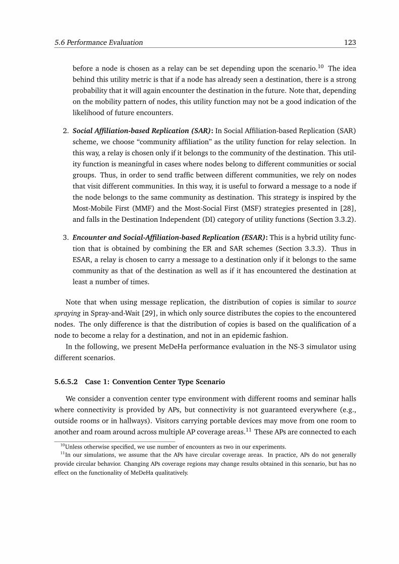
5.6 Performance Evaluation 123
before a node is chosen as a relay can be set depending upon the scenario.10 The idea
behind this utility metric is that if a node has already seen a destination, there is a strong
probability that it will again encounter the destination in the future. Note that, depending
on the mobility pattern of nodes, this utility function may not be a good indication of the
likelihood of future encounters.
2. Social Affiliation-based Replication (SAR): In Social Affiliation-based Replication (SAR)
scheme, we choose “community affiliation” as the utility function for relay selection. In
this way, a relay is chosen only if it belongs to the community of the destination. This util-
ity function is meaningful in cases where nodes belong to different communities or social
groups. Thus, in order to send traffic between different communities, we rely on nodes
that visit different communities. In this way, it is useful to forward a message to a node if
the node belongs to the same community as destination. This strategy is inspired by the
Most-Mobile First (MMF) and the Most-Social First (MSF) strategies presented in [28],
and falls in the Destination Independent (DI) category of utility functions (Section 3.3.2).
3. Encounter and Social-Affiliation-based Replication (ESAR): This is a hybrid utility func-
tion that is obtained by combining the ER and SAR schemes (Section 3.3.3). Thus in
ESAR, a relay is chosen to carry a message to a destination only if it belongs to the same
community as that of the destination as well as if it has encountered the destination at
least a number of times.
Note that when using message replication, the distribution of copies is similar to source
spraying in Spray-and-Wait [29], in which only source distributes the copies to the encountered
nodes. The only difference is that the distribution of copies is based on the qualification of a
node to become a relay for a destination, and not in an epidemic fashion.
In the following, we present MeDeHa performance evaluation in the NS-3 simulator using
different scenarios.
5.6.5.2 Case 1: Convention Center Type Scenario
We consider a convention center type environment with different rooms and seminar halls
where connectivity is provided by APs, but connectivity is not guaranteed everywhere (e.g.,
outside rooms or in hallways). Visitors carrying portable devices may move from one room to
another and roam around across multiple AP coverage areas.11 These APs are connected to each
10Unless otherwise specified, we use number of encounters as two in our experiments.11In our simulations, we assume that the APs have circular coverage areas. In practice, APs do not generally
provide circular behavior. Changing APs coverage regions may change results obtained in this scenario, but has no
effect on the functionality of MeDeHa qualitatively.
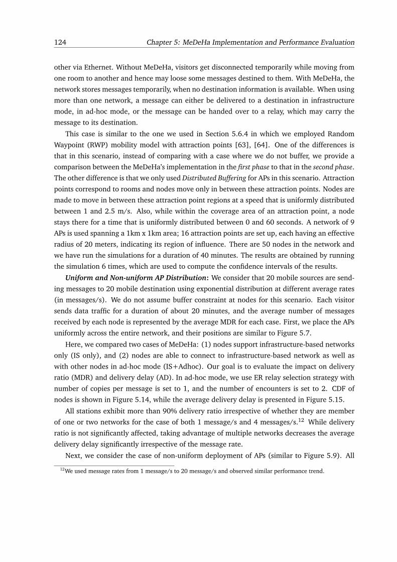
124 Chapter 5: MeDeHa Implementation and Performance Evaluation
other via Ethernet. Without MeDeHa, visitors get disconnected temporarily while moving from
one room to another and hence may loose some messages destined to them. With MeDeHa, the
network stores messages temporarily, when no destination information is available. When using
more than one network, a message can either be delivered to a destination in infrastructure
mode, in ad-hoc mode, or the message can be handed over to a relay, which may carry the
message to its destination.
This case is similar to the one we used in Section 5.6.4 in which we employed Random
Waypoint (RWP) mobility model with attraction points [63], [64]. One of the differences is
that in this scenario, instead of comparing with a case where we do not buffer, we provide a
comparison between the MeDeHa’s implementation in the first phase to that in the second phase.
The other difference is that we only used Distributed Buffering for APs in this scenario. Attraction
points correspond to rooms and nodes move only in between these attraction points. Nodes are
made to move in between these attraction point regions at a speed that is uniformly distributed
between 1 and 2.5 m/s. Also, while within the coverage area of an attraction point, a node
stays there for a time that is uniformly distributed between 0 and 60 seconds. A network of 9
APs is used spanning a 1km x 1km area; 16 attraction points are set up, each having an effective
radius of 20 meters, indicating its region of influence. There are 50 nodes in the network and
we have run the simulations for a duration of 40 minutes. The results are obtained by running
the simulation 6 times, which are used to compute the confidence intervals of the results.
Uniform and Non-uniform AP Distribution: We consider that 20 mobile sources are send-
ing messages to 20 mobile destination using exponential distribution at different average rates
(in messages/s). We do not assume buffer constraint at nodes for this scenario. Each visitor
sends data traffic for a duration of about 20 minutes, and the average number of messages
received by each node is represented by the average MDR for each case. First, we place the APs
uniformly across the entire network, and their positions are similar to Figure 5.7.
Here, we compared two cases of MeDeHa: (1) nodes support infrastructure-based networks
only (IS only), and (2) nodes are able to connect to infrastructure-based network as well as
with other nodes in ad-hoc mode (IS+Adhoc). Our goal is to evaluate the impact on delivery
ratio (MDR) and delivery delay (AD). In ad-hoc mode, we use ER relay selection strategy with
number of copies per message is set to 1, and the number of encounters is set to 2. CDF of
nodes is shown in Figure 5.14, while the average delivery delay is presented in Figure 5.15.
All stations exhibit more than 90% delivery ratio irrespective of whether they are member
of one or two networks for the case of both 1 message/s and 4 messages/s.12 While delivery
ratio is not significantly affected, taking advantage of multiple networks decreases the average
delivery delay significantly irrespective of the message rate.
Next, we consider the case of non-uniform deployment of APs (similar to Figure 5.9). All
12We used message rates from 1 message/s to 20 message/s and observed similar performance trend.
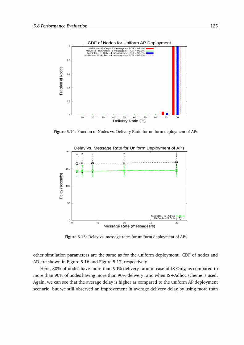
5.6 Performance Evaluation 125
0
0.2
0.4
0.6
0.8
1
10 20 30 40 50 60 70 80 90 100
Frac
tion
of N
odes
Delivery Ratio (%)
CDF of Nodes for Uniform AP DeploymentMeDeHa - IS Only - 1 message/s - PDR = 98.4%
MeDeHa - IS+Adhoc - 1 message/s - PDR = 99.6%MeDeHa - IS Only - 4 messages/s - PDR = 98.5%
MeDeHa - IS+Adhoc - 4 messages/s - PDR = 99.3%
Figure 5.14: Fraction of Nodes vs. Delivery Ratio for uniform deployment of APs
0
50
100
150
200
0 5 10 15 20
Del
ay (s
econ
ds)
Message Rate (messages/s)
Delay vs. Message Rate for Uniform Deployment of APs
MeDeHa - IS+AdhocMeDeHa - IS Only
Figure 5.15: Delay vs. message rates for uniform deployment of APs
other simulation parameters are the same as for the uniform deployment. CDF of nodes and
AD are shown in Figure 5.16 and Figure 5.17, respectively.
Here, 80% of nodes have more than 90% delivery ratio in case of IS-Only, as compared to
more than 90% of nodes having more than 90% delivery ratio when IS+Adhoc scheme is used.
Again, we can see that the average delay is higher as compared to the uniform AP deployment
scenario, but we still observed an improvement in average delivery delay by using more than
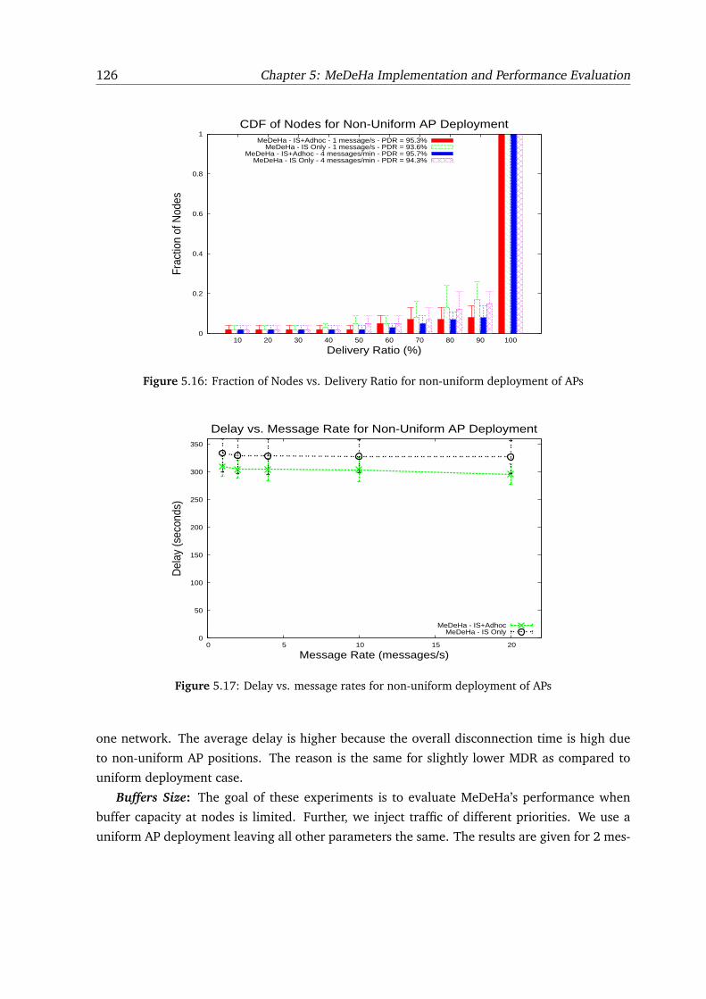
126 Chapter 5: MeDeHa Implementation and Performance Evaluation
0
0.2
0.4
0.6
0.8
1
10 20 30 40 50 60 70 80 90 100
Frac
tion
of N
odes
Delivery Ratio (%)
CDF of Nodes for Non-Uniform AP DeploymentMeDeHa - IS+Adhoc - 1 message/s - PDR = 95.3%
MeDeHa - IS Only - 1 message/s - PDR = 93.6%MeDeHa - IS+Adhoc - 4 messages/min - PDR = 95.7%
MeDeHa - IS Only - 4 messages/min - PDR = 94.3%
Figure 5.16: Fraction of Nodes vs. Delivery Ratio for non-uniform deployment of APs
0
50
100
150
200
250
300
350
0 5 10 15 20
Del
ay (s
econ
ds)
Message Rate (messages/s)
Delay vs. Message Rate for Non-Uniform AP Deployment
MeDeHa - IS+AdhocMeDeHa - IS Only
Figure 5.17: Delay vs. message rates for non-uniform deployment of APs
one network. The average delay is higher because the overall disconnection time is high due
to non-uniform AP positions. The reason is the same for slightly lower MDR as compared to
uniform deployment case.
Buffers Size: The goal of these experiments is to evaluate MeDeHa’s performance when
buffer capacity at nodes is limited. Further, we inject traffic of different priorities. We use a
uniform AP deployment leaving all other parameters the same. The results are given for 2 mes-
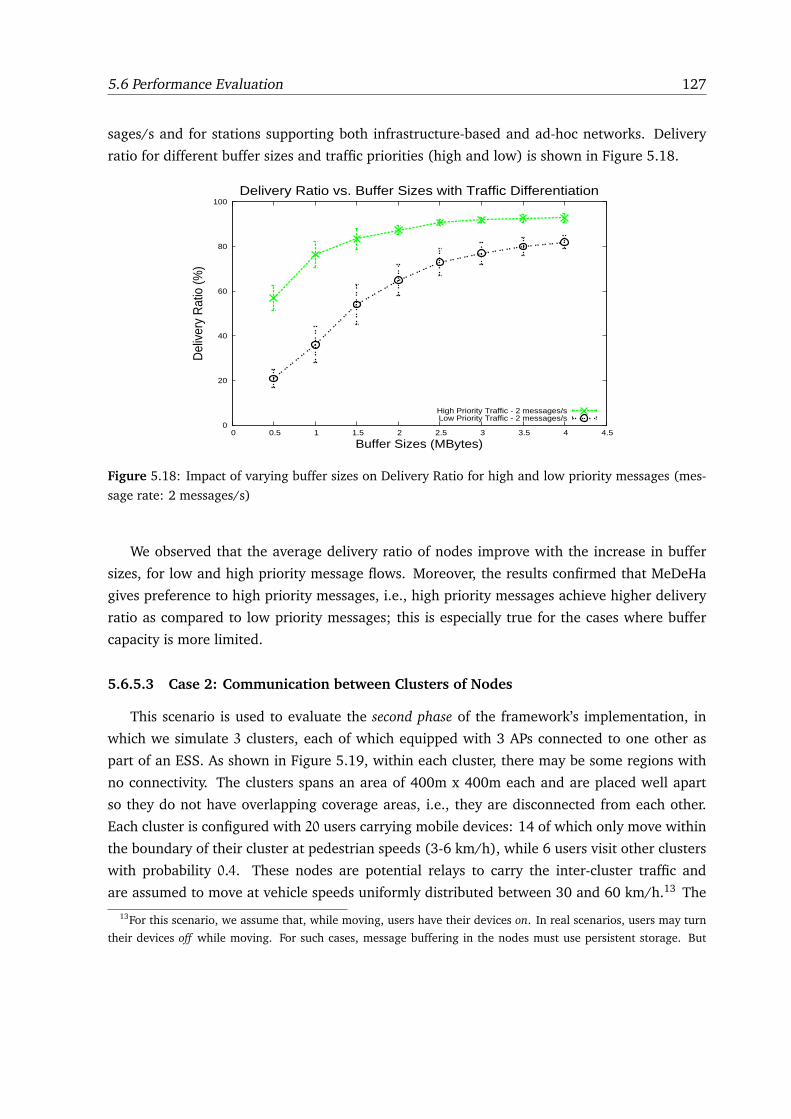
5.6 Performance Evaluation 127
sages/s and for stations supporting both infrastructure-based and ad-hoc networks. Delivery
ratio for different buffer sizes and traffic priorities (high and low) is shown in Figure 5.18.
0
20
40
60
80
100
0 0.5 1 1.5 2 2.5 3 3.5 4 4.5
Del
iver
y R
atio
(%)
Buffer Sizes (MBytes)
Delivery Ratio vs. Buffer Sizes with Traffic Differentiation
High Priority Traffic - 2 messages/sLow Priority Traffic - 2 messages/s
Figure 5.18: Impact of varying buffer sizes on Delivery Ratio for high and low priority messages (mes-
sage rate: 2 messages/s)
We observed that the average delivery ratio of nodes improve with the increase in buffer
sizes, for low and high priority message flows. Moreover, the results confirmed that MeDeHa
gives preference to high priority messages, i.e., high priority messages achieve higher delivery
ratio as compared to low priority messages; this is especially true for the cases where buffer
capacity is more limited.
5.6.5.3 Case 2: Communication between Clusters of Nodes
This scenario is used to evaluate the second phase of the framework’s implementation, in
which we simulate 3 clusters, each of which equipped with 3 APs connected to one other as
part of an ESS. As shown in Figure 5.19, within each cluster, there may be some regions with
no connectivity. The clusters spans an area of 400m x 400m each and are placed well apart
so they do not have overlapping coverage areas, i.e., they are disconnected from each other.
Each cluster is configured with 20 users carrying mobile devices: 14 of which only move within
the boundary of their cluster at pedestrian speeds (3-6 km/h), while 6 users visit other clusters
with probability 0.4. These nodes are potential relays to carry the inter-cluster traffic and
are assumed to move at vehicle speeds uniformly distributed between 30 and 60 km/h.13 The
13For this scenario, we assume that, while moving, users have their devices on. In real scenarios, users may turn
their devices off while moving. For such cases, message buffering in the nodes must use persistent storage. But
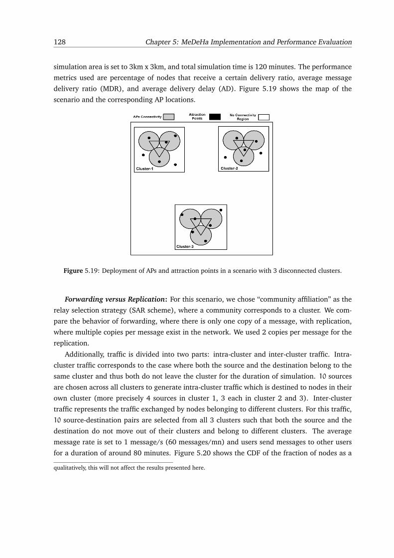
128 Chapter 5: MeDeHa Implementation and Performance Evaluation
simulation area is set to 3km x 3km, and total simulation time is 120 minutes. The performance
metrics used are percentage of nodes that receive a certain delivery ratio, average message
delivery ratio (MDR), and average delivery delay (AD). Figure 5.19 shows the map of the
scenario and the corresponding AP locations.
Figure 5.19: Deployment of APs and attraction points in a scenario with 3 disconnected clusters.
Forwarding versus Replication: For this scenario, we chose “community affiliation” as the
relay selection strategy (SAR scheme), where a community corresponds to a cluster. We com-
pare the behavior of forwarding, where there is only one copy of a message, with replication,
where multiple copies per message exist in the network. We used 2 copies per message for the
replication.
Additionally, traffic is divided into two parts: intra-cluster and inter-cluster traffic. Intra-
cluster traffic corresponds to the case where both the source and the destination belong to the
same cluster and thus both do not leave the cluster for the duration of simulation. 10 sources
are chosen across all clusters to generate intra-cluster traffic which is destined to nodes in their
own cluster (more precisely 4 sources in cluster 1, 3 each in cluster 2 and 3). Inter-cluster
traffic represents the traffic exchanged by nodes belonging to different clusters. For this traffic,
10 source-destination pairs are selected from all 3 clusters such that both the source and the
destination do not move out of their clusters and belong to different clusters. The average
message rate is set to 1 message/s (60 messages/mn) and users send messages to other users
for a duration of around 80 minutes. Figure 5.20 shows the CDF of the fraction of nodes as a
qualitatively, this will not affect the results presented here.
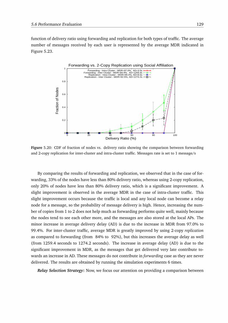
5.6 Performance Evaluation 129
function of delivery ratio using forwarding and replication for both types of traffic. The average
number of messages received by each user is represented by the average MDR indicated in
Figure 5.23.
0
0.2
0.4
0.6
0.8
1
0 20 40 60 80 100
Frac
tion
of N
odes
Delivery Ratio (%)
Forwarding vs. 2-Copy Replication using Social AffiliationForwarding - Intra Cluster - MDR=97.0%, AD=3.5s
Forwarding - Inter Cluster - MDR=84.9%, AD=1259.4sReplication - Intra Cluster - MDR=99.4%, AD=8.5s
Replication - Inter Cluster - MDR=92.5%, AD=1274.2s
Figure 5.20: CDF of fraction of nodes vs. delivery ratio showing the comparison between forwarding
and 2-copy replication for inter-cluster and intra-cluster traffic. Messages rate is set to 1 message/s
By comparing the results of forwarding and replication, we observed that in the case of for-
warding, 33% of the nodes have less than 80% delivery ratio, whereas using 2-copy replication,
only 20% of nodes have less than 80% delivery ratio, which is a significant improvement. A
slight improvement is observed in the average MDR in the case of intra-cluster traffic. This
slight improvement occurs because the traffic is local and any local node can become a relay
node for a message, so the probability of message delivery is high. Hence, increasing the num-
ber of copies from 1 to 2 does not help much as forwarding performs quite well, mainly because
the nodes tend to see each other more, and the messages are also stored at the local APs. The
minor increase in average delivery delay (AD) is due to the increase in MDR from 97.0% to
99.4%. For inter-cluster traffic, average MDR is greatly improved by using 2-copy replication
as compared to forwarding (from 84% to 92%), but this increases the average delay as well
(from 1259.4 seconds to 1274.2 seconds). The increase in average delay (AD) is due to the
significant improvement in MDR, as the messages that get delivered very late contribute to-
wards an increase in AD. These messages do not contribute in forwarding case as they are never
delivered. The results are obtained by running the simulation experiments 6 times.
Relay Selection Strategy: Now, we focus our attention on providing a comparison between
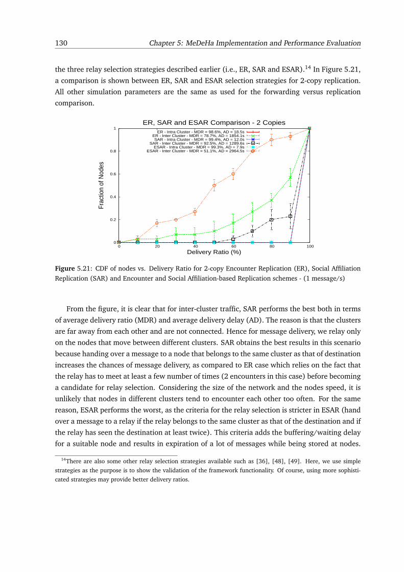
130 Chapter 5: MeDeHa Implementation and Performance Evaluation
the three relay selection strategies described earlier (i.e., ER, SAR and ESAR).14 In Figure 5.21,
a comparison is shown between ER, SAR and ESAR selection strategies for 2-copy replication.
All other simulation parameters are the same as used for the forwarding versus replication
comparison.
0
0.2
0.4
0.6
0.8
1
0 20 40 60 80 100
Frac
tion
of N
odes
Delivery Ratio (%)
ER, SAR and ESAR Comparison - 2 CopiesER - Intra Cluster - MDR = 98.6%, AD = 18.5s
ER - Inter Cluster - MDR = 78.7%, AD = 1854.1sSAR - Intra Cluster - MDR = 99.4%, AD = 12.0s
SAR - Inter Cluster - MDR = 92.5%, AD = 1289.6sESAR - Intra Cluster - MDR = 99.3%, AD = 7.9s
ESAR - Inter Cluster - MDR = 51.1%, AD = 2964.5s
Figure 5.21: CDF of nodes vs. Delivery Ratio for 2-copy Encounter Replication (ER), Social Affiliation
Replication (SAR) and Encounter and Social Affiliation-based Replication schemes - (1 message/s)
From the figure, it is clear that for inter-cluster traffic, SAR performs the best both in terms
of average delivery ratio (MDR) and average delivery delay (AD). The reason is that the clusters
are far away from each other and are not connected. Hence for message delivery, we relay only
on the nodes that move between different clusters. SAR obtains the best results in this scenario
because handing over a message to a node that belongs to the same cluster as that of destination
increases the chances of message delivery, as compared to ER case which relies on the fact that
the relay has to meet at least a few number of times (2 encounters in this case) before becoming
a candidate for relay selection. Considering the size of the network and the nodes speed, it is
unlikely that nodes in different clusters tend to encounter each other too often. For the same
reason, ESAR performs the worst, as the criteria for the relay selection is stricter in ESAR (hand
over a message to a relay if the relay belongs to the same cluster as that of the destination and if
the relay has seen the destination at least twice). This criteria adds the buffering/waiting delay
for a suitable node and results in expiration of a lot of messages while being stored at nodes.
14There are also some other relay selection strategies available such as [36], [48], [49]. Here, we use simple
strategies as the purpose is to show the validation of the framework functionality. Of course, using more sophisti-
cated strategies may provide better delivery ratios.
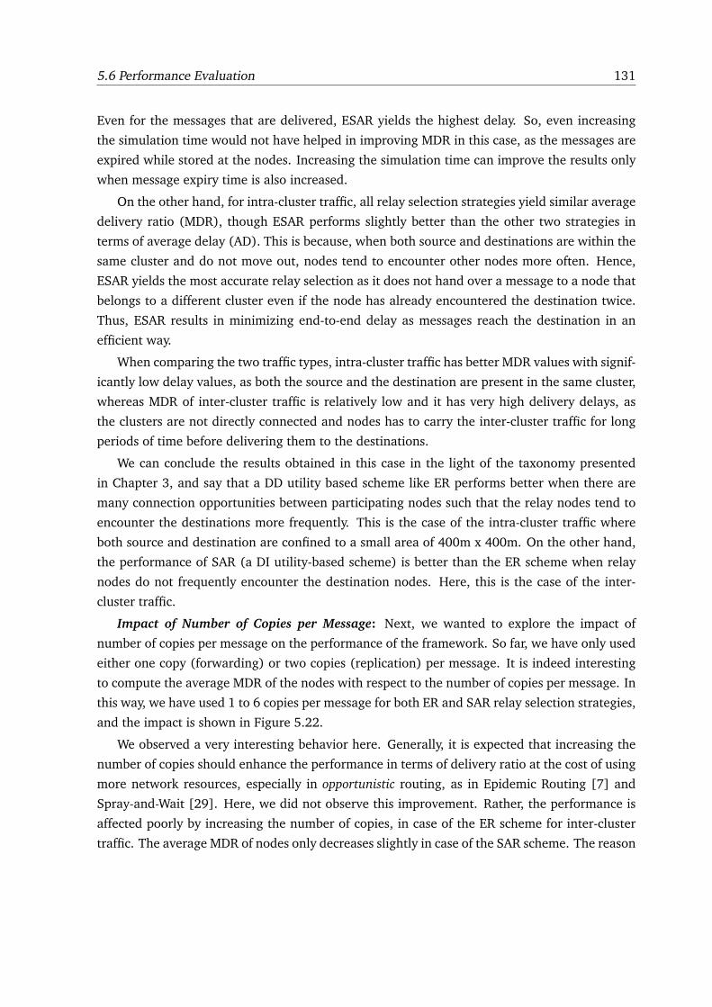
5.6 Performance Evaluation 131
Even for the messages that are delivered, ESAR yields the highest delay. So, even increasing
the simulation time would not have helped in improving MDR in this case, as the messages are
expired while stored at the nodes. Increasing the simulation time can improve the results only
when message expiry time is also increased.
On the other hand, for intra-cluster traffic, all relay selection strategies yield similar average
delivery ratio (MDR), though ESAR performs slightly better than the other two strategies in
terms of average delay (AD). This is because, when both source and destinations are within the
same cluster and do not move out, nodes tend to encounter other nodes more often. Hence,
ESAR yields the most accurate relay selection as it does not hand over a message to a node that
belongs to a different cluster even if the node has already encountered the destination twice.
Thus, ESAR results in minimizing end-to-end delay as messages reach the destination in an
efficient way.
When comparing the two traffic types, intra-cluster traffic has better MDR values with signif-
icantly low delay values, as both the source and the destination are present in the same cluster,
whereas MDR of inter-cluster traffic is relatively low and it has very high delivery delays, as
the clusters are not directly connected and nodes has to carry the inter-cluster traffic for long
periods of time before delivering them to the destinations.
We can conclude the results obtained in this case in the light of the taxonomy presented
in Chapter 3, and say that a DD utility based scheme like ER performs better when there are
many connection opportunities between participating nodes such that the relay nodes tend to
encounter the destinations more frequently. This is the case of the intra-cluster traffic where
both source and destination are confined to a small area of 400m x 400m. On the other hand,
the performance of SAR (a DI utility-based scheme) is better than the ER scheme when relay
nodes do not frequently encounter the destination nodes. Here, this is the case of the inter-
cluster traffic.
Impact of Number of Copies per Message: Next, we wanted to explore the impact of
number of copies per message on the performance of the framework. So far, we have only used
either one copy (forwarding) or two copies (replication) per message. It is indeed interesting
to compute the average MDR of the nodes with respect to the number of copies per message. In
this way, we have used 1 to 6 copies per message for both ER and SAR relay selection strategies,
and the impact is shown in Figure 5.22.
We observed a very interesting behavior here. Generally, it is expected that increasing the
number of copies should enhance the performance in terms of delivery ratio at the cost of using
more network resources, especially in opportunistic routing, as in Epidemic Routing [7] and
Spray-and-Wait [29]. Here, we did not observe this improvement. Rather, the performance is
affected poorly by increasing the number of copies, in case of the ER scheme for inter-cluster
traffic. The average MDR of nodes only decreases slightly in case of the SAR scheme. The reason
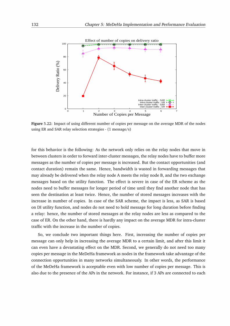
132 Chapter 5: MeDeHa Implementation and Performance Evaluation
0
20
40
60
80
100
0 1 2 3 4 5 6 7
Del
iver
y R
atio
(%)
Number of Copies per Message
Effect of number of copies on delivery ratio
Intra-cluster traffic - SARIntra-cluster traffic - ER
Inter-cluster traffic - SARInter-cluster traffic - ER
Figure 5.22: Impact of using different number of copies per message on the average MDR of the nodes
using ER and SAR relay selection strategies - (1 message/s)
for this behavior is the following: As the network only relies on the relay nodes that move in
between clusters in order to forward inter-cluster messages, the relay nodes have to buffer more
messages as the number of copies per message is increased. But the contact opportunities (and
contact duration) remain the same. Hence, bandwidth is wasted in forwarding messages that
may already be delivered when the relay node A meets the relay node B, and the two exchange
messages based on the utility function. The effect is severe in case of the ER scheme as the
nodes need to buffer messages for longer period of time until they find another node that has
seen the destination at least twice. Hence, the number of stored messages increases with the
increase in number of copies. In case of the SAR scheme, the impact is less, as SAR is based
on DI utility function, and nodes do not need to hold message for long duration before finding
a relay: hence, the number of stored messages at the relay nodes are less as compared to the
case of ER. On the other hand, there is hardly any impact on the average MDR for intra-cluster
traffic with the increase in the number of copies.
So, we conclude two important things here. First, increasing the number of copies per
message can only help in increasing the average MDR to a certain limit, and after this limit it
can even have a devastating effect on the MDR. Second, we generally do not need too many
copies per message in the MeDeHa framework as nodes in the framework take advantage of the
connection opportunities in many networks simultaneously. In other words, the performance
of the MeDeHa framework is acceptable even with low number of copies per message. This is
also due to the presence of the APs in the network. For instance, if 3 APs are connected to each
5.6 Performance Evaluation 133
other and a message is stored at one of the APs, it is considered as if 3 copies of the message
are stored because the message is delivered to the destination as soon as it is connected to any
of the APs. Similar observation regarding message delivery has been made by authors in [115].
5.6.5.4 Case 3: Communication between Students across Campuses
This scenario is similar to the case 2 presented above with the difference that we consider
a shorter network area (1km x 1km), and instead of 3 communities, we consider that students
move between three campuses of a university. Each campus spans over an area of 400m x
400m, and 20 students belong to each campus, in which 14 move only within their respective
campus. Six other students move out of their campuses to visit the other two campuses with
a probability of 0.4. We assume that while moving from one campus to another, students take
university shuttles that move at a speed uniformly distributed between 30 and 60 km/h. On the
other hand, pedestrian students move at a speed that is uniformly distributed between 3 and
6 km/h. The other parameters remain the same as described in Case 2 including the message
rates and number of destinations. The traffic is classified into inter-campus traffic and intra-
campus traffic, and the duration of the simulation is set to 1 hour, and the results are obtained
by taking the average of 6 simulation runs.
Forwarding versus Replication: Again, we used SAR as the relay selection strategy, where
a community corresponds to a campus. Students advertise the campus they belong to using the
HELLO notifications. Similar to what we did for Case 2, we compare the behavior of forwarding
with 2-copy replication. Figure 5.23 shows the CDF of the fraction of nodes as a function of
delivery ratio using forwarding and replication for both kinds of traffic.
By comparing the results of forwarding and replication, we can see that in the case of for-
warding, 63% of the nodes have less than 80% delivery ratio, whereas using 2-copy replication,
only 33% of nodes have less than 80% delivery ratio, which is a significant improvement. The
overall average delivery ratio (MDR) of all the nodes is also greatly improved using replication
as compared to forwarding in the case of inter-cluster traffic (from 64% to 82%), and a slight
improvement is observed in the MDR in the case of intra-cluster traffic. This improvement is
because the traffic is local and any local node can become a relay node for a message, so the
probability of message delivery is high. The minor increase in average delivery delay (AD)
is due to the increase in MDR from 97.4% to 98.2%. For inter-campus traffic, average MDR
is greatly improved by using 2-copy replication, but increases the average delay by 9% as well
(from 419 seconds to 488 seconds). This increase in average delay (AD) is due to the significant
improvement in MDR, as the messages that get delivered very late contribute towards increase
in AD. These messages do not contribute in forwarding case as they are never delivered.
The results discussed above are for a duration of 60 minutes. We observed that increasing
the simulation time to 90 minutes increase the average delivery ratio (MDR) of nodes for inter-
134 Chapter 5: MeDeHa Implementation and Performance Evaluation
0
0.2
0.4
0.6
0.8
1
0 20 40 60 80 100
Frac
tion
of N
odes
Delivery Ratio (%)
Forwarding vs. 2-Copy Replication using Social AffiliationForwarding - Intra Campus - MDR=97.4%, AD=3.52s
Forwarding - Inter Campus - MDR=63.9%, AD=419.66sReplication - Intra Campus - MDR=98.2%, AD=8.16s
Replication - Inter Campus - MDR=81.3%, AD=488.66s
Figure 5.23: CDF of fraction of nodes vs. delivery ratio showing the comparison between forwarding
and 2-copy replication for inter-campus and intra-campus traffic. Message rate is set to 1 message/s
campus traffic from 81.3% to 98.4% in case of replication, but also increases the average delay
(AD) by 68% (from 488 seconds to 712 seconds). This is because more messages are delivered
to the destinations by increasing the simulation time to 90 minutes; these messages were unde-
livered but stored at nodes for the 60-minute case. The increase in MDR also causes the delay
(AD) to increase. On the other hand, for forwarding, increasing simulation time improves the
MDR from 63.9% to 90.3%, as well as increases the AD from 419 seconds to 822 seconds.
Relay Selection Strategy: As in Case 2, we performed simulations to compare ER, SAR and
ESAR relay selection strategies. In Figure 5.24, a comparison is shown between ER and SAR
selection strategies for 2-copy replication.
From the figure, it is clear that ER performs well in terms of delivery ratio (MDR) while SAR
provides lower average delay. The reason for this is that ER only hands over a message to a relay
if the relay has seen the destination at least twice. While this adds the buffering/waiting delay
for a suitable relay, thereby increasing the overall average delay, it may increase the message
delivery because if a node has already encountered a destination twice, it is more probable that
it is going to encounter the destination again in the future. The results obtained also favor
this principle as is clear from increase in average MDR (from 81.3% to 85.2%). On the other
hand, the decrease in average MDR in case of SAR is due to the fact that the “community-based
affiliation” metric chooses a relay node only based upon a node’s affiliation with a particular
community (campus here). It is not certain that every relay node will encounter a destination
when it goes back to its parent campus.
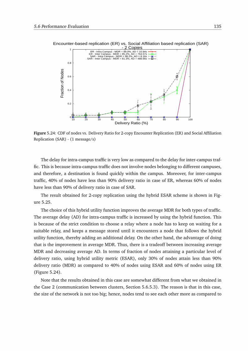
5.6 Performance Evaluation 135
0
0.2
0.4
0.6
0.8
1
10 20 30 40 50 60 70 80 90 100
Frac
tion
of N
odes
Delivery Ratio (%)
Encounter-based replication (ER) vs. Social Affiliation based replication (SAR) - 2 Copies
ER - Intra Campus - MDR = 99.0%, AD = 10.94sER - Inter Campus - MDR = 85.2%, AD = 764.57sSAR - Intra Campus - MDR = 98.2%, AD = 8.16s
SAR - Inter Campus - MDR = 81.3%, AD = 488.66s
Figure 5.24: CDF of nodes vs. Delivery Ratio for 2-copy Encounter Replication (ER) and Social Affiliation
Replication (SAR) - (1 message/s)
The delay for intra-campus traffic is very low as compared to the delay for inter-campus traf-
fic. This is because intra-campus traffic does not involve nodes belonging to different campuses,
and therefore, a destination is found quickly within the campus. Moreover, for inter-campus
traffic, 40% of nodes have less than 90% delivery ratio in case of ER, whereas 60% of nodes
have less than 90% of delivery ratio in case of SAR.
The result obtained for 2-copy replication using the hybrid ESAR scheme is shown in Fig-
ure 5.25.
The choice of this hybrid utility function improves the average MDR for both types of traffic.
The average delay (AD) for intra-campus traffic is increased by using the hybrid function. This
is because of the strict condition to choose a relay where a node has to keep on waiting for a
suitable relay, and keeps a message stored until it encounters a node that follows the hybrid
utility function, thereby adding an additional delay. On the other hand, the advantage of doing
that is the improvement in average MDR. Thus, there is a tradeoff between increasing average
MDR and decreasing average AD. In terms of fraction of nodes attaining a particular level of
delivery ratio, using hybrid utility metric (ESAR), only 30% of nodes attain less than 90%
delivery ratio (MDR) as compared to 40% of nodes using ESAR and 60% of nodes using ER
(Figure 5.24).
Note that the results obtained in this case are somewhat different from what we obtained in
the Case 2 (communication between clusters, Section 5.6.5.3). The reason is that in this case,
the size of the network is not too big; hence, nodes tend to see each other more as compared to
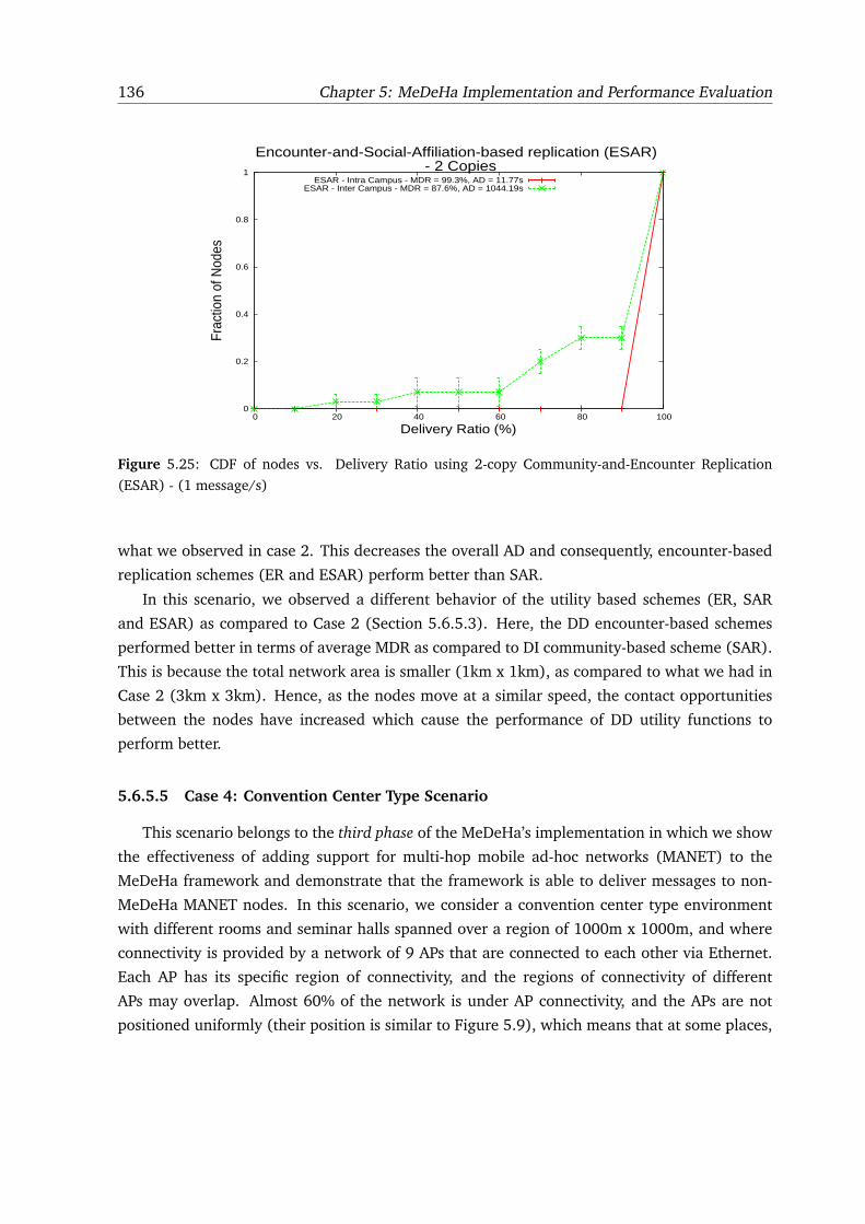
136 Chapter 5: MeDeHa Implementation and Performance Evaluation
0
0.2
0.4
0.6
0.8
1
0 20 40 60 80 100
Frac
tion
of N
odes
Delivery Ratio (%)
Encounter-and-Social-Affiliation-based replication (ESAR) - 2 Copies
ESAR - Intra Campus - MDR = 99.3%, AD = 11.77sESAR - Inter Campus - MDR = 87.6%, AD = 1044.19s
Figure 5.25: CDF of nodes vs. Delivery Ratio using 2-copy Community-and-Encounter Replication
(ESAR) - (1 message/s)
what we observed in case 2. This decreases the overall AD and consequently, encounter-based
replication schemes (ER and ESAR) perform better than SAR.
In this scenario, we observed a different behavior of the utility based schemes (ER, SAR
and ESAR) as compared to Case 2 (Section 5.6.5.3). Here, the DD encounter-based schemes
performed better in terms of average MDR as compared to DI community-based scheme (SAR).
This is because the total network area is smaller (1km x 1km), as compared to what we had in
Case 2 (3km x 3km). Hence, as the nodes move at a similar speed, the contact opportunities
between the nodes have increased which cause the performance of DD utility functions to
perform better.
5.6.5.5 Case 4: Convention Center Type Scenario
This scenario belongs to the third phase of the MeDeHa’s implementation in which we show
the effectiveness of adding support for multi-hop mobile ad-hoc networks (MANET) to the
MeDeHa framework and demonstrate that the framework is able to deliver messages to non-
MeDeHa MANET nodes. In this scenario, we consider a convention center type environment
with different rooms and seminar halls spanned over a region of 1000m x 1000m, and where
connectivity is provided by a network of 9 APs that are connected to each other via Ethernet.
Each AP has its specific region of connectivity, and the regions of connectivity of different
APs may overlap. Almost 60% of the network is under AP connectivity, and the APs are not
positioned uniformly (their position is similar to Figure 5.9), which means that at some places,
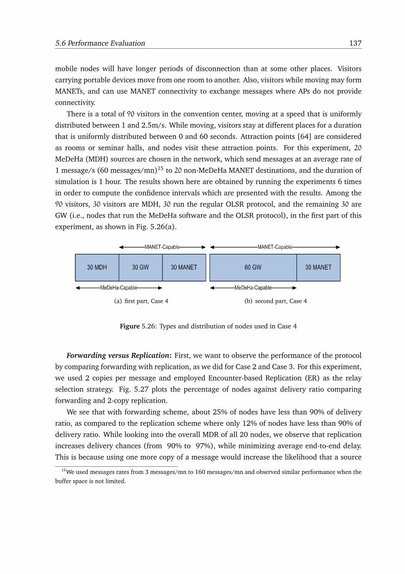
5.6 Performance Evaluation 137
mobile nodes will have longer periods of disconnection than at some other places. Visitors
carrying portable devices move from one room to another. Also, visitors while moving may form
MANETs, and can use MANET connectivity to exchange messages where APs do not provide
connectivity.
There is a total of 90 visitors in the convention center, moving at a speed that is uniformly
distributed between 1 and 2.5m/s. While moving, visitors stay at different places for a duration
that is uniformly distributed between 0 and 60 seconds. Attraction points [64] are considered
as rooms or seminar halls, and nodes visit these attraction points. For this experiment, 20
MeDeHa (MDH) sources are chosen in the network, which send messages at an average rate of
1 message/s (60 messages/mn)15 to 20 non-MeDeHa MANET destinations, and the duration of
simulation is 1 hour. The results shown here are obtained by running the experiments 6 times
in order to compute the confidence intervals which are presented with the results. Among the
90 visitors, 30 visitors are MDH, 30 run the regular OLSR protocol, and the remaining 30 are
GW (i.e., nodes that run the MeDeHa software and the OLSR protocol), in the first part of this
experiment, as shown in Fig. 5.26(a).
(a) first part, Case 4 (b) second part, Case 4
Figure 5.26: Types and distribution of nodes used in Case 4
Forwarding versus Replication: First, we want to observe the performance of the protocol
by comparing forwarding with replication, as we did for Case 2 and Case 3. For this experiment,
we used 2 copies per message and employed Encounter-based Replication (ER) as the relay
selection strategy. Fig. 5.27 plots the percentage of nodes against delivery ratio comparing
forwarding and 2-copy replication.
We see that with forwarding scheme, about 25% of nodes have less than 90% of delivery
ratio, as compared to the replication scheme where only 12% of nodes have less than 90% of
delivery ratio. While looking into the overall MDR of all 20 nodes, we observe that replication
increases delivery chances (from 90% to 97%), while minimizing average end-to-end delay.
This is because using one more copy of a message would increase the likelihood that a source
15We used messages rates from 3 messages/mn to 160 messages/mn and observed similar performance when the
buffer space is not limited.
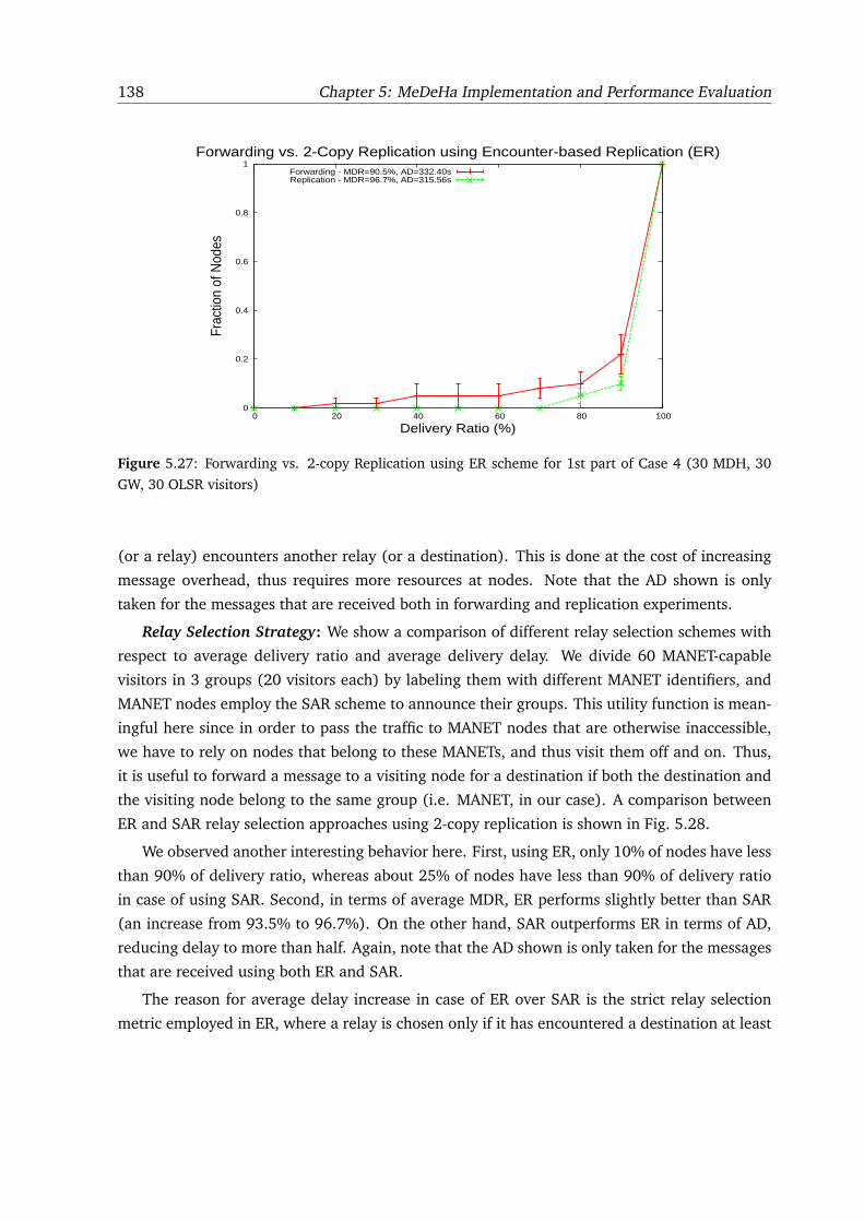
138 Chapter 5: MeDeHa Implementation and Performance Evaluation
0
0.2
0.4
0.6
0.8
1
0 20 40 60 80 100
Frac
tion
of N
odes
Delivery Ratio (%)
Forwarding vs. 2-Copy Replication using Encounter-based Replication (ER)Forwarding - MDR=90.5%, AD=332.40sReplication - MDR=96.7%, AD=315.56s
Figure 5.27: Forwarding vs. 2-copy Replication using ER scheme for 1st part of Case 4 (30 MDH, 30
GW, 30 OLSR visitors)
(or a relay) encounters another relay (or a destination). This is done at the cost of increasing
message overhead, thus requires more resources at nodes. Note that the AD shown is only
taken for the messages that are received both in forwarding and replication experiments.
Relay Selection Strategy: We show a comparison of different relay selection schemes with
respect to average delivery ratio and average delivery delay. We divide 60 MANET-capable
visitors in 3 groups (20 visitors each) by labeling them with different MANET identifiers, and
MANET nodes employ the SAR scheme to announce their groups. This utility function is mean-
ingful here since in order to pass the traffic to MANET nodes that are otherwise inaccessible,
we have to rely on nodes that belong to these MANETs, and thus visit them off and on. Thus,
it is useful to forward a message to a visiting node for a destination if both the destination and
the visiting node belong to the same group (i.e. MANET, in our case). A comparison between
ER and SAR relay selection approaches using 2-copy replication is shown in Fig. 5.28.
We observed another interesting behavior here. First, using ER, only 10% of nodes have less
than 90% of delivery ratio, whereas about 25% of nodes have less than 90% of delivery ratio
in case of using SAR. Second, in terms of average MDR, ER performs slightly better than SAR
(an increase from 93.5% to 96.7%). On the other hand, SAR outperforms ER in terms of AD,
reducing delay to more than half. Again, note that the AD shown is only taken for the messages
that are received using both ER and SAR.
The reason for average delay increase in case of ER over SAR is the strict relay selection
metric employed in ER, where a relay is chosen only if it has encountered a destination at least
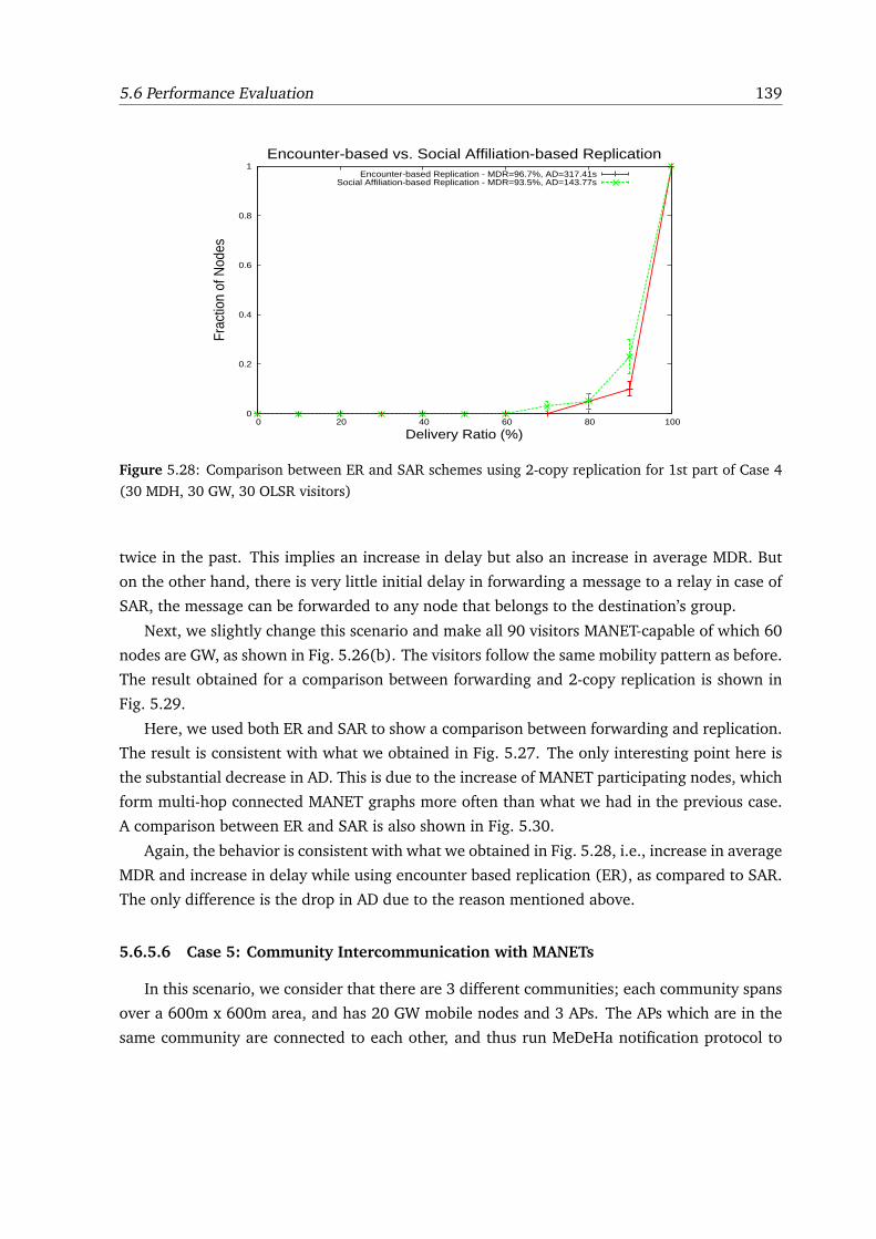
5.6 Performance Evaluation 139
0
0.2
0.4
0.6
0.8
1
0 20 40 60 80 100
Frac
tion
of N
odes
Delivery Ratio (%)
Encounter-based vs. Social Affiliation-based ReplicationEncounter-based Replication - MDR=96.7%, AD=317.41s
Social Affiliation-based Replication - MDR=93.5%, AD=143.77s
Figure 5.28: Comparison between ER and SAR schemes using 2-copy replication for 1st part of Case 4
(30 MDH, 30 GW, 30 OLSR visitors)
twice in the past. This implies an increase in delay but also an increase in average MDR. But
on the other hand, there is very little initial delay in forwarding a message to a relay in case of
SAR, the message can be forwarded to any node that belongs to the destination’s group.
Next, we slightly change this scenario and make all 90 visitors MANET-capable of which 60
nodes are GW, as shown in Fig. 5.26(b). The visitors follow the same mobility pattern as before.
The result obtained for a comparison between forwarding and 2-copy replication is shown in
Fig. 5.29.
Here, we used both ER and SAR to show a comparison between forwarding and replication.
The result is consistent with what we obtained in Fig. 5.27. The only interesting point here is
the substantial decrease in AD. This is due to the increase of MANET participating nodes, which
form multi-hop connected MANET graphs more often than what we had in the previous case.
A comparison between ER and SAR is also shown in Fig. 5.30.
Again, the behavior is consistent with what we obtained in Fig. 5.28, i.e., increase in average
MDR and increase in delay while using encounter based replication (ER), as compared to SAR.
The only difference is the drop in AD due to the reason mentioned above.
5.6.5.6 Case 5: Community Intercommunication with MANETs
In this scenario, we consider that there are 3 different communities; each community spans
over a 600m x 600m area, and has 20 GW mobile nodes and 3 APs. The APs which are in the
same community are connected to each other, and thus run MeDeHa notification protocol to
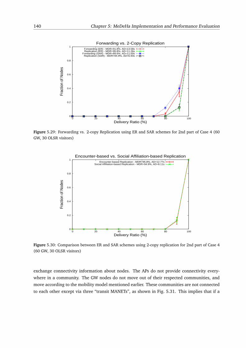
140 Chapter 5: MeDeHa Implementation and Performance Evaluation
0
0.2
0.4
0.6
0.8
1
0 20 40 60 80 100
Frac
tion
of N
odes
Delivery Ratio (%)
Forwarding vs. 2-Copy ReplicationForwarding (ER) - MDR=91.8%, AD=13.58sReplication (ER) - MDR=95.8%, AD=11.26s
Forwarding (SAR) - MDR=89.6%, AD=11.00sReplication (SAR) - MDR=94.9%, AD=6.93s
Figure 5.29: Forwarding vs. 2-copy Replication using ER and SAR schemes for 2nd part of Case 4 (60
GW, 30 OLSR visitors)
0
0.2
0.4
0.6
0.8
1
0 20 40 60 80 100
Frac
tion
of N
odes
Delivery Ratio (%)
Encounter-based vs. Social Affiliation-based ReplicationEncounter-based Replication - MDR=95.8%, AD=12.77s
Social Affiliation-based Replication - MDR=94.9%, AD=8.11s
Figure 5.30: Comparison between ER and SAR schemes using 2-copy replication for 2nd part of Case 4
(60 GW, 30 OLSR visitors)
exchange connectivity information about nodes. The APs do not provide connectivity every-
where in a community. The GW nodes do not move out of their respected communities, and
move according to the mobility model mentioned earlier. These communities are not connected
to each other except via three “transit MANETs”, as shown in Fig. 5.31. This implies that if a
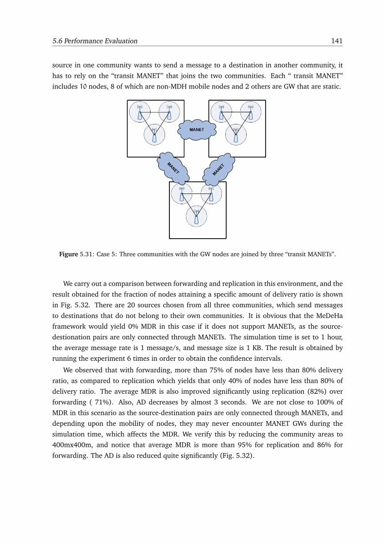
5.6 Performance Evaluation 141
source in one community wants to send a message to a destination in another community, it
has to rely on the “transit MANET” that joins the two communities. Each “ transit MANET”
includes 10 nodes, 8 of which are non-MDH mobile nodes and 2 others are GW that are static.
Figure 5.31: Case 5: Three communities with the GW nodes are joined by three “transit MANETs”.
We carry out a comparison between forwarding and replication in this environment, and the
result obtained for the fraction of nodes attaining a specific amount of delivery ratio is shown
in Fig. 5.32. There are 20 sources chosen from all three communities, which send messages
to destinations that do not belong to their own communities. It is obvious that the MeDeHa
framework would yield 0% MDR in this case if it does not support MANETs, as the source-
destionation pairs are only connected through MANETs. The simulation time is set to 1 hour,
the average message rate is 1 message/s, and message size is 1 KB. The result is obtained by
running the experiment 6 times in order to obtain the confidence intervals.
We observed that with forwarding, more than 75% of nodes have less than 80% delivery
ratio, as compared to replication which yields that only 40% of nodes have less than 80% of
delivery ratio. The average MDR is also improved significantly using replication (82%) over
forwarding ( 71%). Also, AD decreases by almost 3 seconds. We are not close to 100% of
MDR in this scenario as the source-destination pairs are only connected through MANETs, and
depending upon the mobility of nodes, they may never encounter MANET GWs during the
simulation time, which affects the MDR. We verify this by reducing the community areas to
400mx400m, and notice that average MDR is more than 95% for replication and 86% for
forwarding. The AD is also reduced quite significantly (Fig. 5.32).
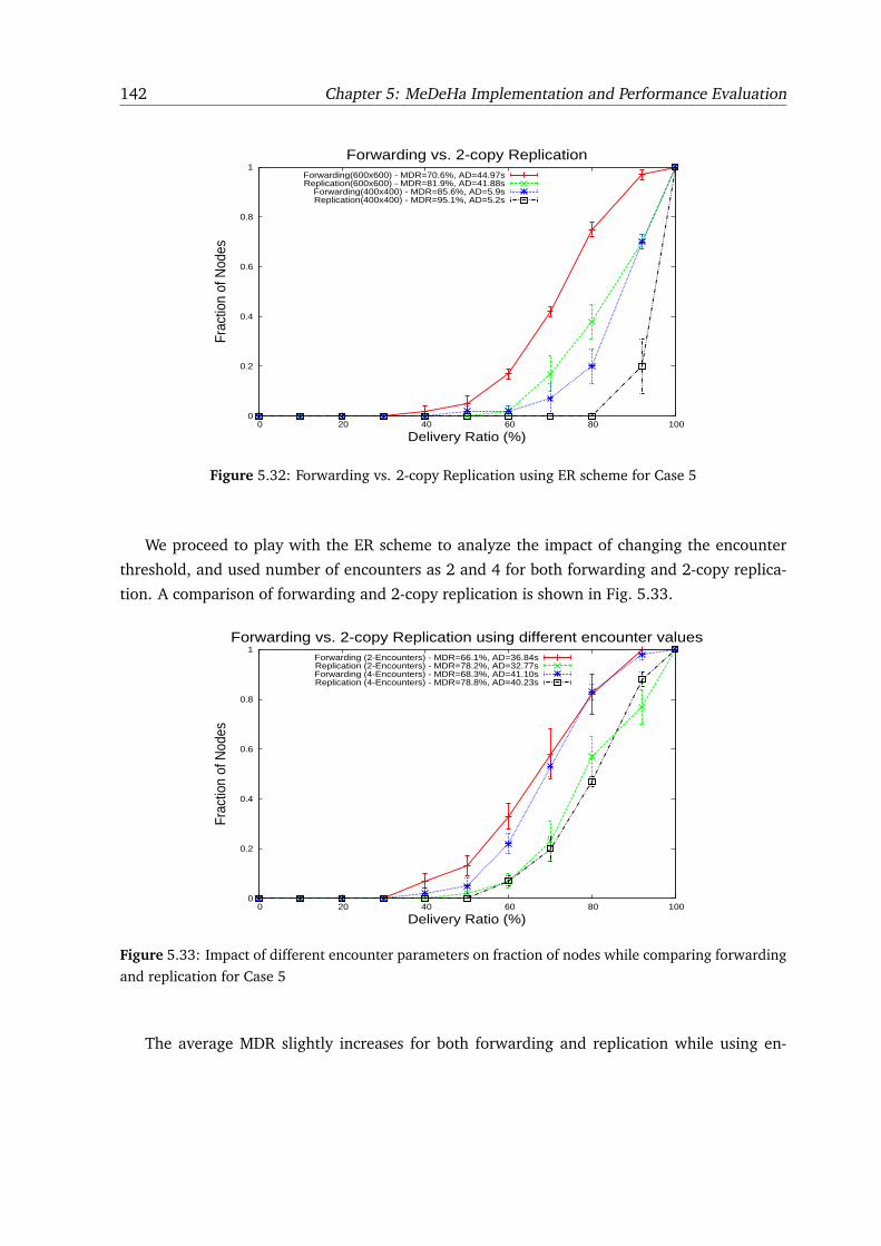
142 Chapter 5: MeDeHa Implementation and Performance Evaluation
0
0.2
0.4
0.6
0.8
1
0 20 40 60 80 100
Frac
tion
of N
odes
Delivery Ratio (%)
Forwarding vs. 2-copy ReplicationForwarding(600x600) - MDR=70.6%, AD=44.97sReplication(600x600) - MDR=81.9%, AD=41.88s
Forwarding(400x400) - MDR=85.6%, AD=5.9sReplication(400x400) - MDR=95.1%, AD=5.2s
Figure 5.32: Forwarding vs. 2-copy Replication using ER scheme for Case 5
We proceed to play with the ER scheme to analyze the impact of changing the encounter
threshold, and used number of encounters as 2 and 4 for both forwarding and 2-copy replica-
tion. A comparison of forwarding and 2-copy replication is shown in Fig. 5.33.
0
0.2
0.4
0.6
0.8
1
0 20 40 60 80 100
Frac
tion
of N
odes
Delivery Ratio (%)
Forwarding vs. 2-copy Replication using different encounter valuesForwarding (2-Encounters) - MDR=66.1%, AD=36.84sReplication (2-Encounters) - MDR=78.2%, AD=32.77sForwarding (4-Encounters) - MDR=68.3%, AD=41.10sReplication (4-Encounters) - MDR=78.8%, AD=40.23s
Figure 5.33: Impact of different encounter parameters on fraction of nodes while comparing forwarding
and replication for Case 5
The average MDR slightly increases for both forwarding and replication while using en-
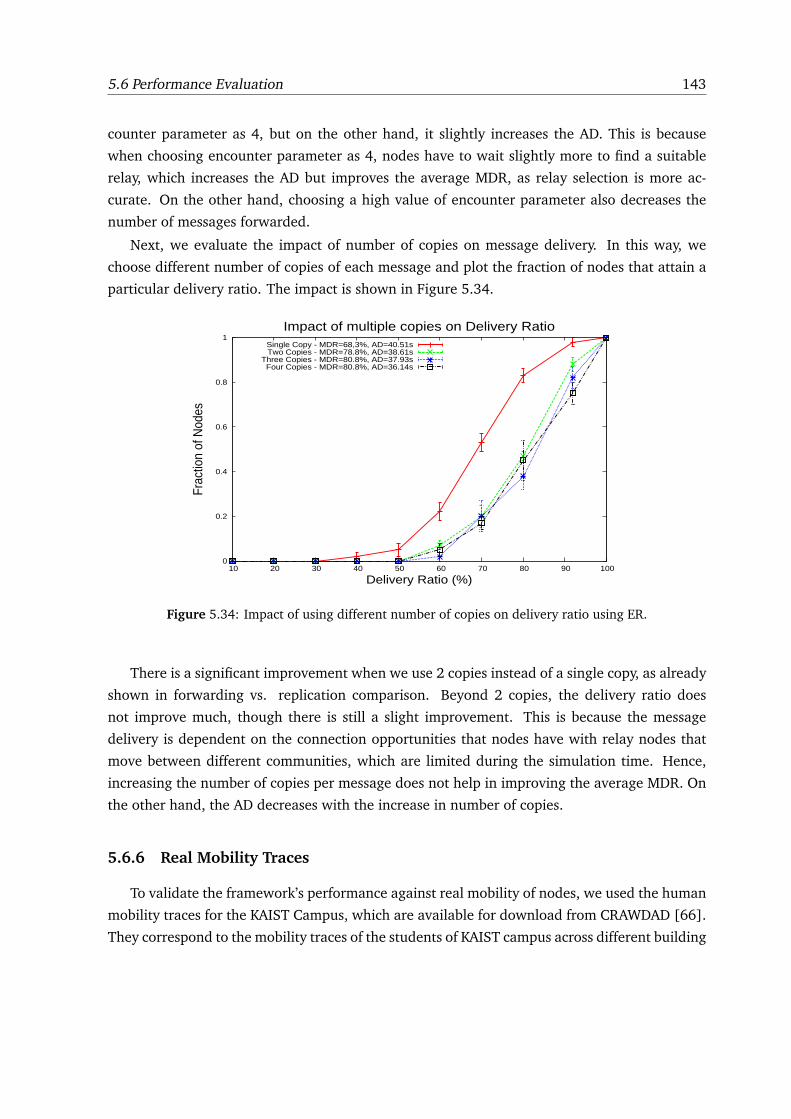
5.6 Performance Evaluation 143
counter parameter as 4, but on the other hand, it slightly increases the AD. This is because
when choosing encounter parameter as 4, nodes have to wait slightly more to find a suitable
relay, which increases the AD but improves the average MDR, as relay selection is more ac-
curate. On the other hand, choosing a high value of encounter parameter also decreases the
number of messages forwarded.
Next, we evaluate the impact of number of copies on message delivery. In this way, we
choose different number of copies of each message and plot the fraction of nodes that attain a
particular delivery ratio. The impact is shown in Figure 5.34.
0
0.2
0.4
0.6
0.8
1
10 20 30 40 50 60 70 80 90 100
Frac
tion
of N
odes
Delivery Ratio (%)
Impact of multiple copies on Delivery RatioSingle Copy - MDR=68,3%, AD=40.51sTwo Copies - MDR=78.8%, AD=38.61s
Three Copies - MDR=80.8%, AD=37.93sFour Copies - MDR=80.8%, AD=36.14s
Figure 5.34: Impact of using different number of copies on delivery ratio using ER.
There is a significant improvement when we use 2 copies instead of a single copy, as already
shown in forwarding vs. replication comparison. Beyond 2 copies, the delivery ratio does
not improve much, though there is still a slight improvement. This is because the message
delivery is dependent on the connection opportunities that nodes have with relay nodes that
move between different communities, which are limited during the simulation time. Hence,
increasing the number of copies per message does not help in improving the average MDR. On
the other hand, the AD decreases with the increase in number of copies.
5.6.6 Real Mobility Traces
To validate the framework’s performance against real mobility of nodes, we used the human
mobility traces for the KAIST Campus, which are available for download from CRAWDAD [66].
They correspond to the mobility traces of the students of KAIST campus across different building
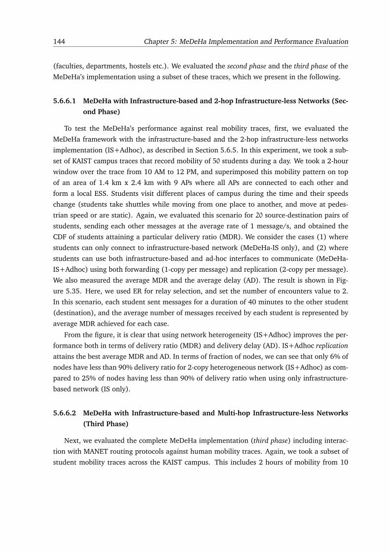
144 Chapter 5: MeDeHa Implementation and Performance Evaluation
(faculties, departments, hostels etc.). We evaluated the second phase and the third phase of the
MeDeHa’s implementation using a subset of these traces, which we present in the following.
5.6.6.1 MeDeHa with Infrastructure-based and 2-hop Infrastructure-less Networks (Sec-
ond Phase)
To test the MeDeHa’s performance against real mobility traces, first, we evaluated the
MeDeHa framework with the infrastructure-based and the 2-hop infrastructure-less networks
implementation (IS+Adhoc), as described in Section 5.6.5. In this experiment, we took a sub-
set of KAIST campus traces that record mobility of 50 students during a day. We took a 2-hour
window over the trace from 10 AM to 12 PM, and superimposed this mobility pattern on top
of an area of 1.4 km x 2.4 km with 9 APs where all APs are connected to each other and
form a local ESS. Students visit different places of campus during the time and their speeds
change (students take shuttles while moving from one place to another, and move at pedes-
trian speed or are static). Again, we evaluated this scenario for 20 source-destination pairs of
students, sending each other messages at the average rate of 1 message/s, and obtained the
CDF of students attaining a particular delivery ratio (MDR). We consider the cases (1) where
students can only connect to infrastructure-based network (MeDeHa-IS only), and (2) where
students can use both infrastructure-based and ad-hoc interfaces to communicate (MeDeHa-
IS+Adhoc) using both forwarding (1-copy per message) and replication (2-copy per message).
We also measured the average MDR and the average delay (AD). The result is shown in Fig-
ure 5.35. Here, we used ER for relay selection, and set the number of encounters value to 2.
In this scenario, each student sent messages for a duration of 40 minutes to the other student
(destination), and the average number of messages received by each student is represented by
average MDR achieved for each case.
From the figure, it is clear that using network heterogeneity (IS+Adhoc) improves the per-
formance both in terms of delivery ratio (MDR) and delivery delay (AD). IS+Adhoc replication
attains the best average MDR and AD. In terms of fraction of nodes, we can see that only 6% of
nodes have less than 90% delivery ratio for 2-copy heterogeneous network (IS+Adhoc) as com-
pared to 25% of nodes having less than 90% of delivery ratio when using only infrastructure-
based network (IS only).
5.6.6.2 MeDeHa with Infrastructure-based and Multi-hop Infrastructure-less Networks
(Third Phase)
Next, we evaluated the complete MeDeHa implementation (third phase) including interac-
tion with MANET routing protocols against human mobility traces. Again, we took a subset of
student mobility traces across the KAIST campus. This includes 2 hours of mobility from 10
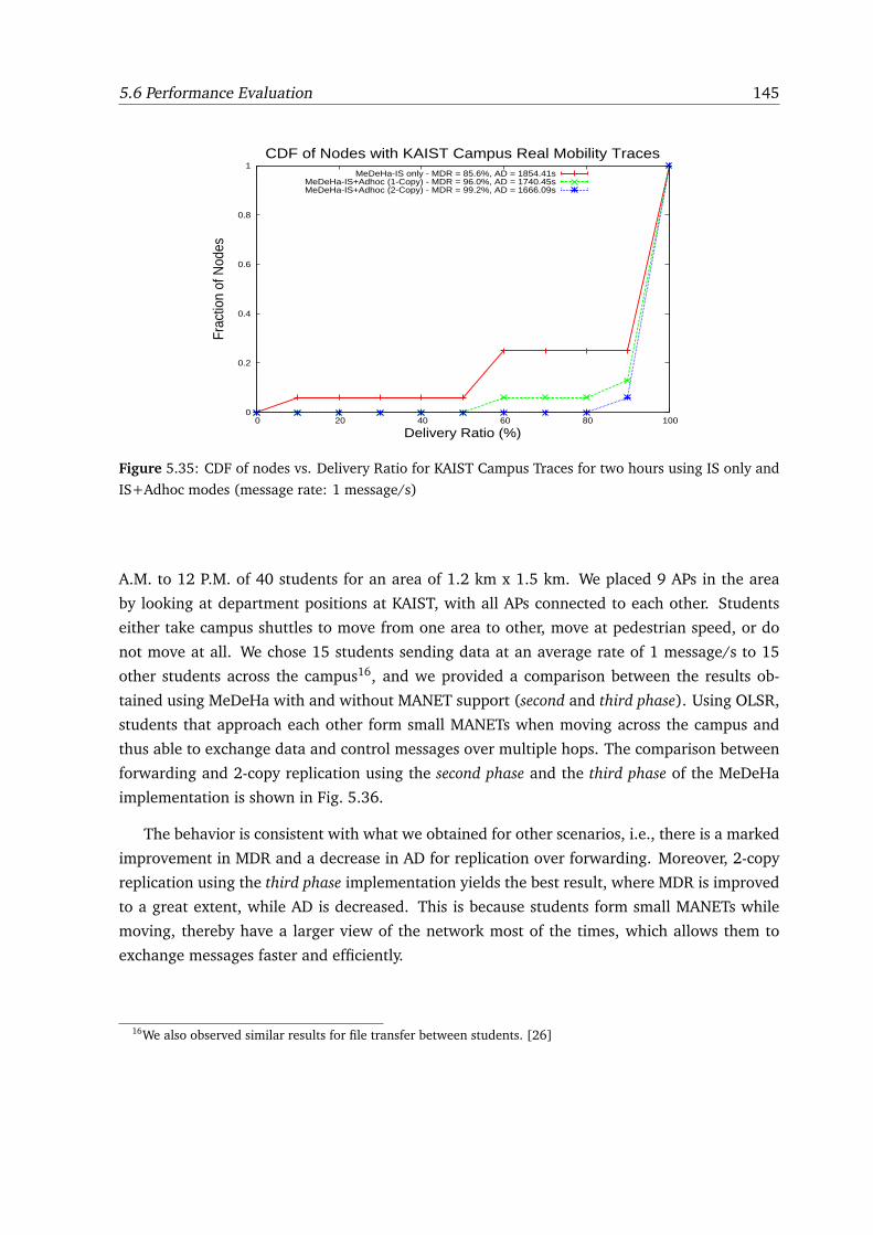
5.6 Performance Evaluation 145
0
0.2
0.4
0.6
0.8
1
0 20 40 60 80 100
Frac
tion
of N
odes
Delivery Ratio (%)
CDF of Nodes with KAIST Campus Real Mobility TracesMeDeHa-IS only - MDR = 85.6%, AD = 1854.41s
MeDeHa-IS+Adhoc (1-Copy) - MDR = 96.0%, AD = 1740.45sMeDeHa-IS+Adhoc (2-Copy) - MDR = 99.2%, AD = 1666.09s
Figure 5.35: CDF of nodes vs. Delivery Ratio for KAIST Campus Traces for two hours using IS only and
IS+Adhoc modes (message rate: 1 message/s)
A.M. to 12 P.M. of 40 students for an area of 1.2 km x 1.5 km. We placed 9 APs in the area
by looking at department positions at KAIST, with all APs connected to each other. Students
either take campus shuttles to move from one area to other, move at pedestrian speed, or do
not move at all. We chose 15 students sending data at an average rate of 1 message/s to 15
other students across the campus16, and we provided a comparison between the results ob-
tained using MeDeHa with and without MANET support (second and third phase). Using OLSR,
students that approach each other form small MANETs when moving across the campus and
thus able to exchange data and control messages over multiple hops. The comparison between
forwarding and 2-copy replication using the second phase and the third phase of the MeDeHa
implementation is shown in Fig. 5.36.
The behavior is consistent with what we obtained for other scenarios, i.e., there is a marked
improvement in MDR and a decrease in AD for replication over forwarding. Moreover, 2-copy
replication using the third phase implementation yields the best result, where MDR is improved
to a great extent, while AD is decreased. This is because students form small MANETs while
moving, thereby have a larger view of the network most of the times, which allows them to
exchange messages faster and efficiently.
16We also observed similar results for file transfer between students. [26]
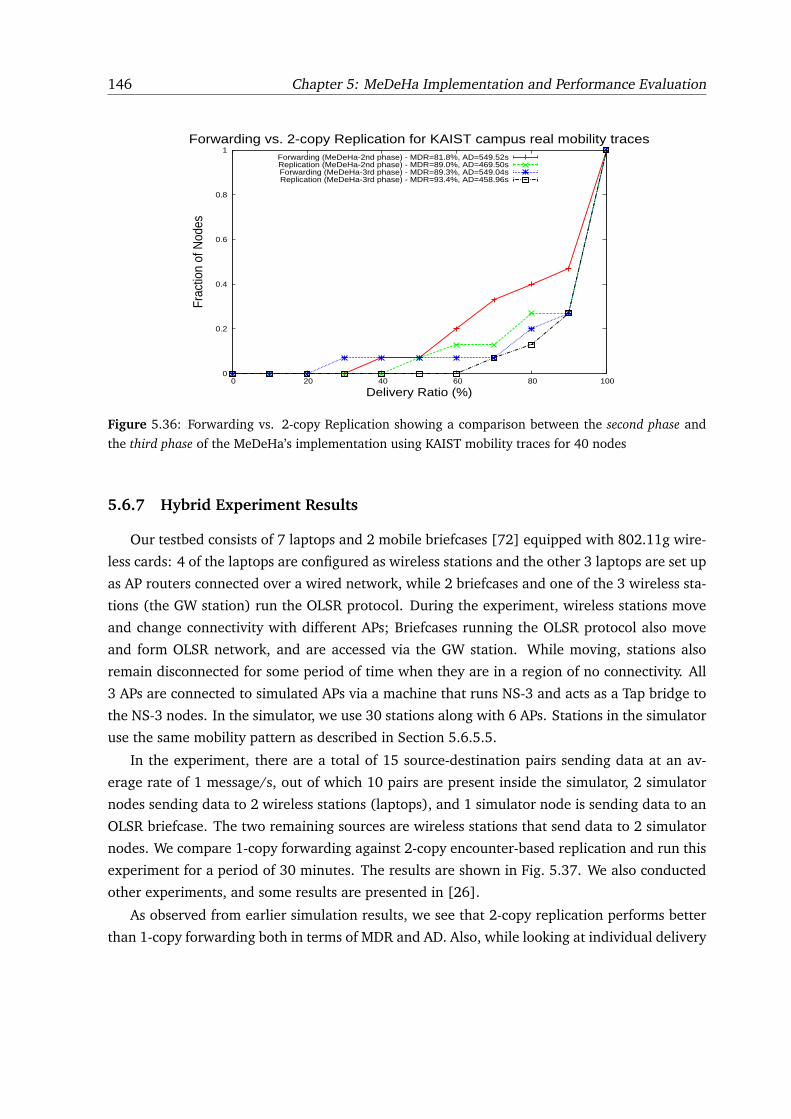
146 Chapter 5: MeDeHa Implementation and Performance Evaluation
0
0.2
0.4
0.6
0.8
1
0 20 40 60 80 100
Frac
tion
of N
odes
Delivery Ratio (%)
Forwarding vs. 2-copy Replication for KAIST campus real mobility tracesForwarding (MeDeHa-2nd phase) - MDR=81.8%, AD=549.52sReplication (MeDeHa-2nd phase) - MDR=89.0%, AD=469.50sForwarding (MeDeHa-3rd phase) - MDR=89.3%, AD=549.04sReplication (MeDeHa-3rd phase) - MDR=93.4%, AD=458.96s
Figure 5.36: Forwarding vs. 2-copy Replication showing a comparison between the second phase and
the third phase of the MeDeHa’s implementation using KAIST mobility traces for 40 nodes
5.6.7 Hybrid Experiment Results
Our testbed consists of 7 laptops and 2 mobile briefcases [72] equipped with 802.11g wire-
less cards: 4 of the laptops are configured as wireless stations and the other 3 laptops are set up
as AP routers connected over a wired network, while 2 briefcases and one of the 3 wireless sta-
tions (the GW station) run the OLSR protocol. During the experiment, wireless stations move
and change connectivity with different APs; Briefcases running the OLSR protocol also move
and form OLSR network, and are accessed via the GW station. While moving, stations also
remain disconnected for some period of time when they are in a region of no connectivity. All
3 APs are connected to simulated APs via a machine that runs NS-3 and acts as a Tap bridge to
the NS-3 nodes. In the simulator, we use 30 stations along with 6 APs. Stations in the simulator
use the same mobility pattern as described in Section 5.6.5.5.
In the experiment, there are a total of 15 source-destination pairs sending data at an av-
erage rate of 1 message/s, out of which 10 pairs are present inside the simulator, 2 simulator
nodes sending data to 2 wireless stations (laptops), and 1 simulator node is sending data to an
OLSR briefcase. The two remaining sources are wireless stations that send data to 2 simulator
nodes. We compare 1-copy forwarding against 2-copy encounter-based replication and run this
experiment for a period of 30 minutes. The results are shown in Fig. 5.37. We also conducted
other experiments, and some results are presented in [26].
As observed from earlier simulation results, we see that 2-copy replication performs better
than 1-copy forwarding both in terms of MDR and AD. Also, while looking at individual delivery
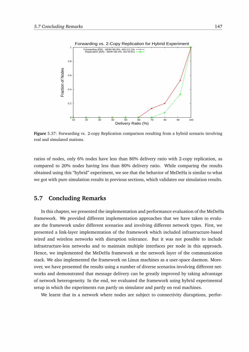
5.7 Concluding Remarks 147
0
0.2
0.4
0.6
0.8
1
10 20 30 40 50 60 70 80 90 100
Frac
tion
of N
odes
Delivery Ratio (%)
Forwarding vs. 2-Copy Replication for Hybrid ExperimentForwarding (ER) - MDR=90.8%, AD=12.13s
Replication (ER) - MDR=95.0%, AD=8.91s
Figure 5.37: Forwarding vs. 2-copy Replication comparison resulting from a hybrid scenario involving
real and simulated stations.
ratios of nodes, only 6% nodes have less than 80% delivery ratio with 2-copy replication, as
compared to 20% nodes having less than 80% delivery ratio. While comparing the results
obtained using this “hybrid” experiment, we see that the behavior of MeDeHa is similar to what
we got with pure simulation results in previous sections, which validates our simulation results.
5.7 Concluding Remarks
In this chapter, we presented the implementation and performance evaluation of the MeDeHa
framework. We provided different implementation approaches that we have taken to evalu-
ate the framework under different scenarios and involving different network types. First, we
presented a link-layer implementation of the framework which included infrastructure-based
wired and wireless networks with disruption tolerance. But it was not possible to include
infrastructure-less networks and to maintain multiple interfaces per node in this approach.
Hence, we implemented the MeDeHa framework at the network layer of the communication
stack. We also implemented the framework on Linux machines as a user-space daemon. More-
over, we have presented the results using a number of diverse scenarios involving different net-
works and demonstrated that message delivery can be greatly improved by taking advantage
of network heterogeneity. In the end, we evaluated the framework using hybrid experimental
setup in which the experiments run partly on simulator and partly on real machines.
We learnt that in a network where nodes are subject to connectivity disruptions, perfor-
148 Chapter 5: MeDeHa Implementation and Performance Evaluation
mance of a particular forwarding approach depends upon a number of factors including nodes
mobility and relay selection strategies. For instance, in some case, we observed that desti-
nation independent (DI) utility functions performed better than destination dependent (DD)
utility functions, while the reverse is true in other cases. This is in compliance with what we
proposed in Chapter 3. Also, we experienced that in a framework like MeDeHa, where both
infrastructure-based and infrastructure-less networks are involved, high message delivery can
be achieved only with a few message copies by taking advantage of the availability of the
infrastructure-based networks. Similar observation are found by authors in [115]. Moreover,
we found out that encounter-based replication schemes such as ER perform better in terms of
delivery ratio, while community affiliation-based replication schemes such as SAR provide bet-
ter results in terms of delivery delay.
Part IV
HeNNA - A Naming Mechanism for
Heterogeneous Networks
149

6
NAMING FOR HETEROGENEOUS
NETWORKS
6.1 Introduction
In an environment where devices are highly mobile and want to remain connected while
moving, mobility poses quite a few challenges, as IP address for nodes generally changes with
the change in nodes points of attachment to the network. Hence, communication sessions need
to be reset, and data that is sent while the nodes move between the two points of attachment
is vulnerable to be lost. This is because, in traditional Internet communication model, data is
assumed to be bound to specific hosts at specific locations, identified by IP addresses. Hence,
transport and application protocols typically rely on IP addresses to define end-to-end com-
munication endpoints. Conversely, an application should only be concerned about a particular
data content, and a transport layer should only know an endpoint host rather than one of in-
terface addresses of a peer host [80]. Unfortunately, this is not the case in the current Internet
architecture.
What is more, in a heterogeneous network, where mobile devices may be multi-homed
since they possess multiple interfaces for network connectivity (e.g., PDAs, smart phones may
use Wifi and 3G for connectivity), applications can no longer use IP address to communicate
with these devices. This is because at the time of packet transmission, a sender does not know
which IP address of a node is currently available, and even if a specific IP address is known a
priori, there is no guarantee that it remains reachable by the time the packet approaches a des-
tination, especially in case of opportunistic forwarding. New communication architectures such
151
152 Chapter 6: Naming for Heterogeneous Networks
as Haggle [47] and CCN [56] are based on taking advantage of different connection opportu-
nities using multiple interfaces, and allow applications to use location-independent identifiers
instead of IP addresses. Furthermore, while mechanisms like Dynamic Host Configuration Pro-
tocol (DHCP) simplify the administration of private IP address spaces, they make IP addresses
even less stable, in that a host may change its IP address because of being turned off or a
temporary disconnection even if it has not physically moved.
MobileIP [77], [78] targets “last hop” mobility by allocating a globally routeable address to
each mobile node (MN), which may not be feasible in many cases (e.g., allocating a routeable
IPv4 address to each MN). On the other hand, Shim6 [90] provides mobility solution for multi-
homed devices by differentiating upper layer identifiers (ULID) from locators, but requires
pre-configuration of all interface addresses of the devices. Moreover, both MobileIP and Shim6
suffer from the very basic problem where endpoints are named using topological identifiers
(i.e., IP addresses), so applications have to rely on IP addresses to communicate with peers.
Proposals like [80] and DONA [81] advocate decoupling identification from location so that,
instead of an IP address, applications bind to a location-transparent identifier and the network
uses this identifier to find the object, e.g., irrespective of the current network interface of the
host at the time the request for the object was issued. As described in more detail in Section 6.3,
some of the proposed approaches that try to separate object identification from location employ
a “clean-slate” design philosophy ([79, 55, 56]), whereas others propose patches to current
Internet routing ([82], [80], [81], [84]). Here, we adopt the latter approach; and our aim is to
propose a naming solution that accommodates intermittent connectivity. To our knowledge, this
is the first proposal that tries to operate with status-quo Internet routing and still accommodates
intermittent connectivity.
In this chapter, we present a new naming mechanism, HeNNA (Heterogenous Networks
Naming Architecture) for heterogeneous disruption-prone networks.1 HeNNA decouples ob-
ject identification from their location, enabling applications to use “universal object identifiers”
independent to where the object may be located. It is designed to be used with the current
Internet routing, while accommodating node mobility, address changes, as well as temporary
or long-lived disconnections. We implemented HeNNA with our framework MeDeHa (Mes-
sage Delivery in Heterogeneous, Disruption-prone Networks [23], [22]), which allows message
delivery across an internet consisting of different networks and involving diverse node capa-
bilities. In MeDeHa, nodes use IP addresses to communicate, which becomes unfeasible when
devices are multi-homed and are capable to connect to multiple networks. HeNNA targets this
problem of node identification and internetwork communication in MeDeHa by taking care of
the change of IP addresses of nodes. We show that HeNNA augments MeDeHa to use location-
transparent naming and thus makes MeDeHa better equipped to support network and node
1This work is published in [24].
6.2 Design Guidelines 153
heterogeneity.
The rest of the chapter is organized as follows. First, we present some design guidelines
that lead us to develop the HeNNA mechanism in Section 6.2. An analysis of existing naming
architectures and proposal is provided in Section 6.3. HeNNA and details on its operation are
presented in Section 6.4. Section 6.5 presents the current implementation of HeNNA and its
interoperability with the MeDeHa framework. At the end, a simulation-based evaluation of
HeNNA is presented in Section 6.6.
6.2 Design Guidelines
The design on HeNNA is motivated by a set of design guidelines, which we describe in the
following:
1. Decouple identification from location: Ideally, applications should only be concerned
about service or session identifiers (SID) instead of specific IP addresses, unlike todays
TCP/IP architecture. The transport layer should in turn be responsible for communication
with endpoints rather than one of the interface addresses of an endpoint. This is a long
known problem and recognized by the Internet Engineering Task Force [94]. Clearly,
solutions like MobileIP do not serve this purpose.
2. Manage connectivity disruptions: The naming mechanism should provide a way to
handle temporary or long-lived connectivity disruptions of the participating nodes. This
involves caching data for nodes in the network or at nodes, when route information is
unavailable. Besides, communications between two endpoint nodes should be possible
even if there is no contemporaneous end-to-end path available between these nodes.
3. Maintain status-quo for routing: It is preferable that the naming scheme should not
propose changes to how packets are routed in the current Internet (i.e., packets should
be routed using IP addresses of the nodes). This would make a naming scheme workable
in the existing Internet without requiring a significant change. It should also work with
the support of only a few Internet routers.
4. Support of heterogeneous networks: A node can have more than one interface con-
nected to the backbone, resulting in multiple IP addresses per node. The naming mech-
anism should be able to cope with this heterogeneity. Moreover, it should also support
both infrastructure-based and infrastructure-less networks.
154 Chapter 6: Naming for Heterogeneous Networks
6.3 Analysis of Existing Naming Schemes
We start with an analysis of the existing naming proposals, and then we describe how they
relate to the design guidelines. We also provide the pros and cons of each proposal.
We classify the existing naming proposals into four main groups based upon their function-
ality:
1. Region-based Naming
2. Content-based Naming
3. Intentional Naming
4. Host-based Naming
In the following subsections, we present an analysis of each of these groups and the propos-
als that fit into each group. Besides, each naming proposal can be categorized as either being
a clean-slate or a conventional approach. The clean-slate approaches propose a completely new
architecture that involves new routing mechanism and thus, they are not workable with the
current Internet architecture. This is in contrast to the design guideline 3 presented in 6.2. The
conventional approaches present patches to the status-quo Internet architecture and propose
mechanisms to separate node identification from location in the Internet. As our focus is to
find a solution for naming that is workable in the current Internet, we are mostly concerned
with the conventional naming approaches. When describing a naming proposal in the following
subsections, we will indicate whether it is a clean-slate or a conventional approach.
6.3.1 Region-based Naming
Region-based naming schemes refer to the mechanisms in which nodes are identified by
their respective regions. Thus, each node’s identifier has two main parts, region-ID and personal-
ID. While this makes routing easy and scalable, it requires proper definition and management of
regions, and the schemes may suffer when nodes are mobile. Examples include Interplanetary
Internet naming and addressing [91] and EDIFY [55].
6.3.1.1 Interplanetary Internet Naming and Addressing
Interplanetary Internet Naming and Addressing [91] is a clean-slate naming proposal. It
extends the original Interplanetary Internet design proposed in [17] and [92], which focused
6.3 Analysis of Existing Naming Schemes 155
primarily on deep-space communication issues susceptible to very long delays, and where com-
munication endpoints are named by Endpoint Identifier (EIDs) [6]. The scheme proposes two-
level hierarchical addressing using absolute Universal Resource Identifiers (URIs) [93] which
signifies the EIDs. The DTN EIDs has the following form:
region-name:region-specific-part
In this way, the routing between regions is performed by simply looking at the region-name
of the EID, whereas any other routing scheme can be used for region-specific-part. However, the
design does not consider nodes mobility between regions.
6.3.1.2 EDIFY
EDIFY [55] is also a region-based naming scheme and is counterpart of Interplanetary In-
ternet naming and addressing scheme for regular networks. It defines groups of nodes and
each node has an EID that is a tuple of group ID (GID) and its personal ID (PID). The mobility
management of nodes is provided similar to what MobileIP [77] offers, where a node visiting
another group informs its home group’s DTN Name Registrar (DNR) about its new location.
Moreover, when visiting other groups, a node changes its PID but its group ID remains the
same. When making temporary ad-hoc networks while moving, nodes do not use their (GID,
PID) tuple to communicate. Instead a temporary group ID (TGID) and temporary personal ID
(TPID) tuple is created on-the-fly and nodes use this new tuple for communication. EDIFY is a
clean-slate naming proposal.
While EDIFY tries to solve the mobility issue in the Interplanetary naming scheme, it does so
by introducing a lot of complexity where each node may have to maintain multiple identifiers
including (GID, PID) tuple, (TGID, TPID) tuple, and a visiting identifier. Also, infrastructure-
based support provided by the scheme is only based on message ferries that provides connec-
tivity between different groups. Moreover, the definition of the group is not properly provided,
and it is assumed that each group has at least one gateway node to which every member has
an access. In an intermittently connected environment, this is a very strong assumption.
6.3.2 Content-based Naming
In conventional Internet communication model, data is assumed to be bound to specific
hosts at specific locations, identified by IP addresses most of the time. Hence, application layer
typically relies on IP addresses of peer nodes to define end-to-end communication endpoints,
whereas an application should should not care where the data content is currently located.
Content-based naming architectures are based on this principle, unlike the current Internet
156 Chapter 6: Naming for Heterogeneous Networks
architecture. Examples include Content Centric Networking (CCN [56]) and a layered archi-
tecture for the Internet presented in [80], which we highlight in the following subsections.
6.3.2.1 Content Centric Networking (CCN)
CCN [56] is a clean-slate communication architecture based on naming content such that a
data content or a service is identified by a name that is independent from the host that currently
owns (hosts) the content. The architecture is based upon two packet types, Interest and Data.
Interests are issued to request (find) a particular content and contains the name of the required
content. Any node that possesses the content responds with the Data packet containing the re-
quired content. In CCN, only Interest packets are routed, and Data packets follow a predefined
path that the Interest packet used to reach the node that hosts the content. The architecture of-
fers many benefits including scalability, security, support for nodes disconnections and allowing
nodes to issue Interests over multiple interfaces. On the other hand, the performance of the CCN
architecture is questionable in mobile wireless ad-hoc networks which are usually vulnerable to
changing routes frequently. For instance, if the initiator of an Interest packet is moving, it may
not get the requested Data packet all the time, and may have to issue many Interest packets
before receiving the desired content, because the Data packets are supposed to follow the same
route as their Interest packets have taken.
6.3.2.2 A Layered Architecture for the Internet
In [80], authors presented a new layered architecture for the Internet that is based on
naming the content and endpoints. The proposed architecture is conventional and separates
content and endpoint identifiers from their locations. The authors proposed this architecture
by introducing multiple layers of identification in the communication stack, which requires
multiple resolutions of identifiers. More precisely, a user-level descriptor (ULD) is translated
into a Session Identifier (SID). This SID is then resolved into Endpoint Identifier (EID) which is
eventually translated into IP address. The proposal is very good and can be used as a baseline
for naming schemes, but it is a little complex as the resolution process from a ULD to an IP
address is very long. The architecture is also based on the assumption that a source has access
to all resolvers all the time, which may not always be possible especially in mobile wireless
ad-hoc networks. Moreover, support for nodes intermittent connectivity is not discussed.
6.3.2.3 Data Oriented Network Architecture (DONA)
Data Oriented Network Architecture (DONA) [81] is also aimed at naming the content
instead of naming the content holder, as service-oriented applications are usually interested in
the content only. DONA proposes a clean-slate design of the Internet naming and addressing,
6.3 Analysis of Existing Naming Schemes 157
and nodes in DONA use flat, self-certifying names for service (or content) identification. The
resolution process is handled by a hierarchy of resolution handlers (RHs) and it is based on the
FIND and REGISTER primitives. However, the architecture does not provide a comprehensive
solution in the case of nodes intermittent connectivity. It also requires a lot of management and
configuration at the RH level. Moreover, DONA generally suffers from the scalability problem
as each resolution handler has to maintain a forwarding table for each content in the network.
6.3.3 Intentional Naming
Intentional naming [79] aims at naming a destination by predicting its attributes (e.g.,
membership to a group, employee of an organization, spatial coordinates, etc.) instead of its
unique personal identifier (EIDs). It is designed to be used for Disruption Tolerant Networks
(DTNs). Resolving a destination’s name in such a way comes in the category of late binding,
in which a source may not know a destination’s identifier before sending a message, and the
destination identifier in a bundle may change as the bundle approaches the destination. This
makes the routing easy but the solution is very specific to cases where a source must have some
hint about the destination’s attributes in advance. The proposed solution also does not define
how EID of a destination eventually resolved as the bundle approaches the destination. This is
a clean-slate naming appraoch.
6.3.4 Host-based Naming
Host-based naming schemes target unique identification of endpoints by separating their
identification from locations. This is very important (and becomes essential) when nodes fre-
quently change their IP addresses due to mobility, and when devices use multiple interfaces for
network connectivity. In the following subsections, we present and analyze different host-based
naming schemes.
6.3.4.1 Locator/ID Separation Protocol (LISP)
LISP [82] presents a naming architecture that separates identification from location by us-
ing two different naming identifiers, Routing Locators (RLOC) and Endpoint Identifiers (EID).
RLOCs are used to route packets in the backbone and routing is performed by tunneling the
packets (containing EIDs) in RLOCs between Egress Tunnel Router (ETR) and Ingress Tunnel
Router (ITR) of different domains. EIDs are used to identify nodes and routing is performed
within a domain using nodes’ EIDs. LSIP does not provide a specific mapping system between
Endpoint Identifiers (EID) and Routing Locators (RLOC). Also, it does not properly define nodes
mobility between domains, though it can be used with MobileIP but it is problematic due to
158 Chapter 6: Naming for Heterogeneous Networks
overhead caused by MobileIP [83]. LISP is categorized as a conventional naming approach,
though routing in LISP is based on both EIDs and RLOCs.
6.3.4.2 Node Identity Internetworking Architecture
Node Identity Internetworking Architecture [87] is a clean-slate naming approach and pro-
vides an infrastructure-based solution to separate identification from location by defining loca-
tor domains (LD). However, it does not explain the operation in ad-hoc networks and networks
with disruptions. The architecture is based on routing hints that are resolved at LDs and serve
as source routing. It means that source is responsible for adding the routing hints when sending
a message and if the destination moves and changes its LD, the messages are lost.
6.3.4.3 Host Identity Protocol (HIP)
Host Identity Protocol (HIP) [84] is a conventional naming approach that uses flat, self-
certifying names for identification which are called Host Identifiers (HI). It is designed to be
used in the Internet, and enables host mobility and multi-homing across different address fam-
ilies (IPv4 and IPv6). In HIP, both transport and application layers use HI of peer nodes to
communicate, and two nodes must establish a HIP association before communication, which is
known as the HIP Base Exchange (BEX). This is a strong compulsion of the protocol as it may
not be feasible in many scenarios, especially when there is no end-to-end contemporaneous
path between the two nodes.
6.3.4.4 MobileIP
MobileIP [77], [78] solves the mobility problem by assigning persistent home address to
nodes, but this solution requires that each node has a globally routeable IP address. In Mo-
bileIP, a permanent routeable address is assigned to each node, and the Home Agent (HA)
implicitly intercepts the messages sent to a MN which means that both HA address and MN
home address must belong to the same subnet. Moreover, the MobileIP approach fundamen-
tally differs from the design guideline 1 defined in Section 6.2 where endpoints are named by
topological identifiers. MobileIP is categorized as a conventional solution to nodes mobility and
naming.
6.3.4.5 Dynamic DNS
Dynamic DNS (DynDNS) [88] allows hosts to cope with the problem of changing their IP
addresses by dynamically updating its name record (hostname to IP address mapping) with the
service provider whenever hosts change their IP address. But the existing transport sessions still
6.4 The HeNNA Naming Mechanism 159
break at this point, and the host generally remains unreachable whenever it is behind a firewall
or NAT. This is because the DynDNS client softwares report the actual interface IP address to the
DNS server, and as the IP address is not routeable if it is from a private address space, the DNS
server does not know where to route packets. Moreover, the update mechanism for DynDNS
is not very efficient and an IP change update may take a few minutes (and sometimes a few
hours), as the update needs to be propagated across all DNS servers. Also, frequent updates
from a client may be considered as abusive and are not permitted [89]. Thus, it is also not very
efficient in case where IP address of hosts change frequently. DynDNS is a conventional naming
solution to cater for nodes IP address change and mobility.
As our focus is to find a solution for naming that is workable in the current Internet, we are
concerned with the conventional naming approahces. But none of the conventional approaches
supports network heterogeneity (design guideline 4) and nodes temporary or long-lived discon-
nections from the network (design guideline 2).
6.4 The HeNNA Naming Mechanism
HeNNA decouples node identification from location and allows message delivery across
heterogeneous networks, including infrastructure-based and ad-hoc networks, while coping
with nodes intermittent connectivity. In this way, the source does not have to care about the
current location of the destination that may be connected using any interface at the time of
message arrival. For this purpose, applications bind to nodes identifier instead of IP addresses
to communicate and nodes location information is maintained by their corresponding Location
and Management Server (LMS) nodes. The LMS is a node with a globally reachable address and
it maintains location information about the registered nodes. It is also responsible for storing
messages on behalf of the nodes when they are unavailable. Details on the functionality of the
LMS are presented in Section 6.4.2. The idea is that nodes contact the LMS of other nodes
to locate them. Nodes in ad-hoc network can also be reached via neighboring gateways that
are connected to the infrastructure; this extends message delivery beyond infrastructure-based
networks.
In HeNNA, each node has a globally unique identifier (GUID), and we assume that the users
will learn about these GUIDs via a variety of ways such as search engines, private communi-
cation etc. Otherwise, a global DNS-like service can also be present with which nodes register
their GUIDs against their hostnames. This DNS-like service can either have the normal DNS
functionality or a Dynamic DNS service [88], except that nodes are registered with their GUIDs
instead of their IP address. We do not consider the hostname to GUID resolution.2 On the
2A source which has a hostname for a destination can contact the DNS service (distributed or central) to get the
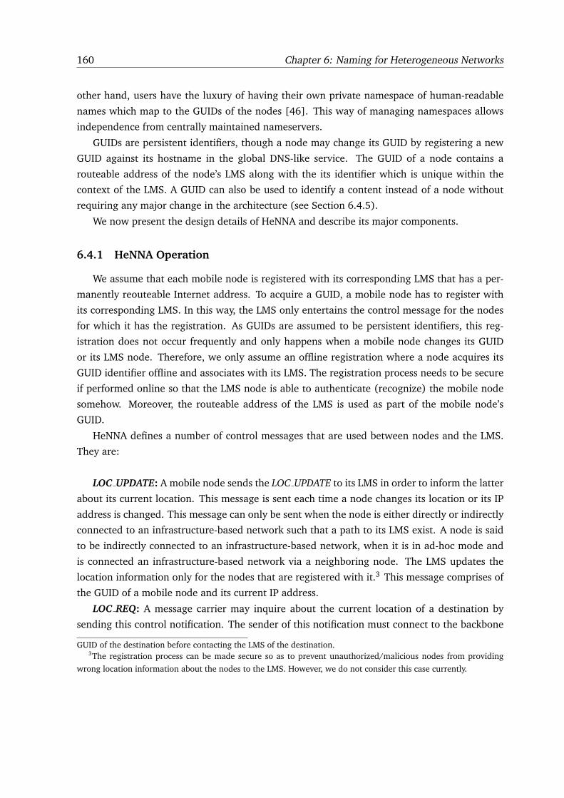
160 Chapter 6: Naming for Heterogeneous Networks
other hand, users have the luxury of having their own private namespace of human-readable
names which map to the GUIDs of the nodes [46]. This way of managing namespaces allows
independence from centrally maintained nameservers.
GUIDs are persistent identifiers, though a node may change its GUID by registering a new
GUID against its hostname in the global DNS-like service. The GUID of a node contains a
routeable address of the node’s LMS along with the its identifier which is unique within the
context of the LMS. A GUID can also be used to identify a content instead of a node without
requiring any major change in the architecture (see Section 6.4.5).
We now present the design details of HeNNA and describe its major components.
6.4.1 HeNNA Operation
We assume that each mobile node is registered with its corresponding LMS that has a per-
manently reouteable Internet address. To acquire a GUID, a mobile node has to register with
its corresponding LMS. In this way, the LMS only entertains the control message for the nodes
for which it has the registration. As GUIDs are assumed to be persistent identifiers, this reg-
istration does not occur frequently and only happens when a mobile node changes its GUID
or its LMS node. Therefore, we only assume an offline registration where a node acquires its
GUID identifier offline and associates with its LMS. The registration process needs to be secure
if performed online so that the LMS node is able to authenticate (recognize) the mobile node
somehow. Moreover, the routeable address of the LMS is used as part of the mobile node’s
GUID.
HeNNA defines a number of control messages that are used between nodes and the LMS.
They are:
LOC UPDATE: A mobile node sends the LOC UPDATE to its LMS in order to inform the latter
about its current location. This message is sent each time a node changes its location or its IP
address is changed. This message can only be sent when the node is either directly or indirectly
connected to an infrastructure-based network such that a path to its LMS exist. A node is said
to be indirectly connected to an infrastructure-based network, when it is in ad-hoc mode and
is connected an infrastructure-based network via a neighboring node. The LMS updates the
location information only for the nodes that are registered with it.3 This message comprises of
the GUID of a mobile node and its current IP address.
LOC REQ: A message carrier may inquire about the current location of a destination by
sending this control notification. The sender of this notification must connect to the backbone
GUID of the destination before contacting the LMS of the destination.3The registration process can be made secure so as to prevent unauthorized/malicious nodes from providing
wrong location information about the nodes to the LMS. However, we do not consider this case currently.
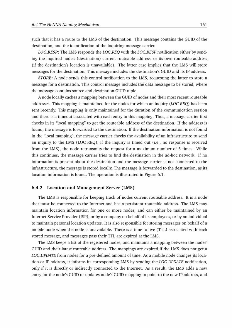
6.4 The HeNNA Naming Mechanism 161
such that it has a route to the LMS of the destination. This message contains the GUID of the
destination, and the identification of the inquiring message carrier.
LOC RESP: The LMS responds the LOC REQ with the LOC RESP notification either by send-
ing the inquired node’s (destination) current routeable address, or its own routeable address
(if the destination’s location is unavailable). The latter case implies that the LMS will store
messages for the destination. This message includes the destination’s GUID and its IP address.
STORE: A node sends this control notification to the LMS, requesting the latter to store a
message for a destination. This control message includes the data message to be stored, where
the message contains source and destination GUID tuple.
A node locally caches a mapping between the GUID of nodes and their most recent routeable
addresses. This mapping is maintained for the nodes for which an inquiry (LOC REQ) has been
sent recently. This mapping is only maintained for the duration of the communication session
and there is a timeout associated with each entry in this mapping. Thus, a message carrier first
checks in its “local mapping” to get the routeable address of the destination. If the address is
found, the message is forwarded to the destination. If the destination information is not found
in the “local mapping”, the message carrier checks the availability of an infrastructure to send
an inquiry to the LMS (LOC REQ). If the inquiry is timed out (i.e., no response is received
from the LMS), the node retransmits the request for a maximum number of 5 times. While
this continues, the message carrier tries to find the destination in the ad-hoc network. If no
information is present about the destination and the message carrier is not connected to the
infrastructure, the message is stored locally. The message is forwarded to the destination, as its
location information is found. The operation is illustrated in Figure 6.1.
6.4.2 Location and Management Server (LMS)
The LMS is responsible for keeping track of nodes current routeable address. It is a node
that must be connected to the Internet and has a persistent routeable address. The LMS may
maintain location information for one or more nodes, and can either be maintained by an
Internet Service Provider (ISP), or by a company on behalf of its employees, or by an individual
to maintain personal location updates. It is also responsible for storing messages on behalf of a
mobile node when the node is unavailable. There is a time to live (TTL) associated with each
stored message, and messages pass their TTL are expired at the LMS.
The LMS keeps a list of the registered nodes, and maintains a mapping between the nodes’
GUID and their latest routeable address. The mappings are expired if the LMS does not get a
LOC UPDATE from nodes for a pre-defined amount of time. As a mobile node changes its loca-
tion or IP address, it informs its corresponding LMS by sending the LOC UPDATE notification,
only if it is directly or indirectly connected to the Internet. As a result, the LMS adds a new
entry for the node’s GUID or updates node’s GUID mapping to point to the new IP address, and
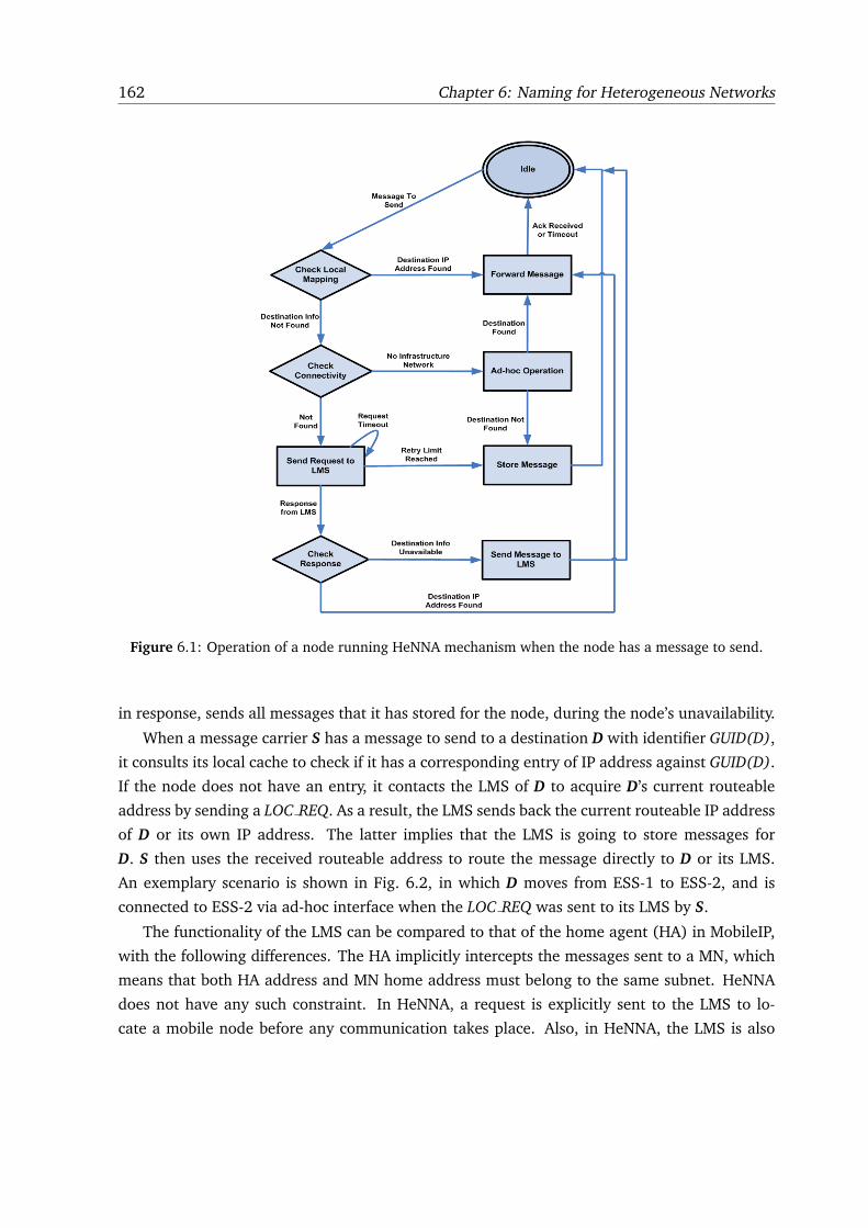
162 Chapter 6: Naming for Heterogeneous Networks
Figure 6.1: Operation of a node running HeNNA mechanism when the node has a message to send.
in response, sends all messages that it has stored for the node, during the node’s unavailability.
When a message carrier S has a message to send to a destination D with identifier GUID(D),
it consults its local cache to check if it has a corresponding entry of IP address against GUID(D).
If the node does not have an entry, it contacts the LMS of D to acquire D’s current routeable
address by sending a LOC REQ. As a result, the LMS sends back the current routeable IP address
of D or its own IP address. The latter implies that the LMS is going to store messages for
D. S then uses the received routeable address to route the message directly to D or its LMS.
An exemplary scenario is shown in Fig. 6.2, in which D moves from ESS-1 to ESS-2, and is
connected to ESS-2 via ad-hoc interface when the LOC REQ was sent to its LMS by S.
The functionality of the LMS can be compared to that of the home agent (HA) in MobileIP,
with the following differences. The HA implicitly intercepts the messages sent to a MN, which
means that both HA address and MN home address must belong to the same subnet. HeNNA
does not have any such constraint. In HeNNA, a request is explicitly sent to the LMS to lo-
cate a mobile node before any communication takes place. Also, in HeNNA, the LMS is also
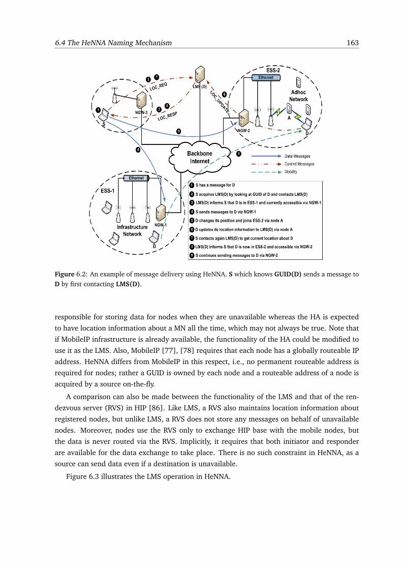
6.4 The HeNNA Naming Mechanism 163
Figure 6.2: An example of message delivery using HeNNA. S which knows GUID(D) sends a message to
D by first contacting LMS(D).
responsible for storing data for nodes when they are unavailable whereas the HA is expected
to have location information about a MN all the time, which may not always be true. Note that
if MobileIP infrastructure is already available, the functionality of the HA could be modified to
use it as the LMS. Also, MobileIP [77], [78] requires that each node has a globally routeable IP
address. HeNNA differs from MobileIP in this respect, i.e., no permanent routeable address is
required for nodes; rather a GUID is owned by each node and a routeable address of a node is
acquired by a source on-the-fly.
A comparison can also be made between the functionality of the LMS and that of the ren-
dezvous server (RVS) in HIP [86]. Like LMS, a RVS also maintains location information about
registered nodes, but unlike LMS, a RVS does not store any messages on behalf of unavailable
nodes. Moreover, nodes use the RVS only to exchange HIP base with the mobile nodes, but
the data is never routed via the RVS. Implicitly, it requires that both initiator and responder
are available for the data exchange to take place. There is no such constraint in HeNNA, as a
source can send data even if a destination is unavailable.
Figure 6.3 illustrates the LMS operation in HeNNA.
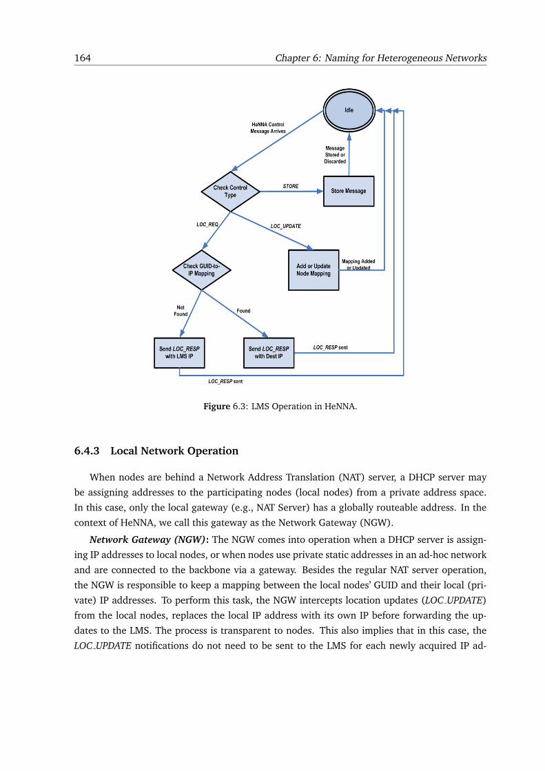
164 Chapter 6: Naming for Heterogeneous Networks
Figure 6.3: LMS Operation in HeNNA.
6.4.3 Local Network Operation
When nodes are behind a Network Address Translation (NAT) server, a DHCP server may
be assigning addresses to the participating nodes (local nodes) from a private address space.
In this case, only the local gateway (e.g., NAT Server) has a globally routeable address. In the
context of HeNNA, we call this gateway as the Network Gateway (NGW).
Network Gateway (NGW): The NGW comes into operation when a DHCP server is assign-
ing IP addresses to local nodes, or when nodes use private static addresses in an ad-hoc network
and are connected to the backbone via a gateway. Besides the regular NAT server operation,
the NGW is responsible to keep a mapping between the local nodes’ GUID and their local (pri-
vate) IP addresses. To perform this task, the NGW intercepts location updates (LOC UPDATE)
from the local nodes, replaces the local IP address with its own IP before forwarding the up-
dates to the LMS. The process is transparent to nodes. This also implies that in this case, the
LOC UPDATE notifications do not need to be sent to the LMS for each newly acquired IP ad-
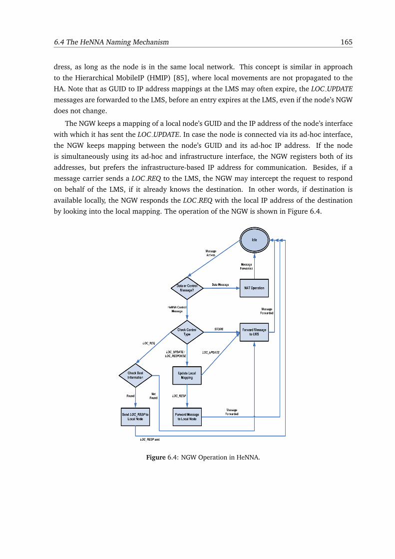
6.4 The HeNNA Naming Mechanism 165
dress, as long as the node is in the same local network. This concept is similar in approach
to the Hierarchical MobileIP (HMIP) [85], where local movements are not propagated to the
HA. Note that as GUID to IP address mappings at the LMS may often expire, the LOC UPDATE
messages are forwarded to the LMS, before an entry expires at the LMS, even if the node’s NGW
does not change.
The NGW keeps a mapping of a local node’s GUID and the IP address of the node’s interface
with which it has sent the LOC UPDATE. In case the node is connected via its ad-hoc interface,
the NGW keeps mapping between the node’s GUID and its ad-hoc IP address. If the node
is simultaneously using its ad-hoc and infrastructure interface, the NGW registers both of its
addresses, but prefers the infrastructure-based IP address for communication. Besides, if a
message carrier sends a LOC REQ to the LMS, the NGW may intercept the request to respond
on behalf of the LMS, if it already knows the destination. In other words, if destination is
available locally, the NGW responds the LOC REQ with the local IP address of the destination
by looking into the local mapping. The operation of the NGW is shown in Figure 6.4.
Figure 6.4: NGW Operation in HeNNA.
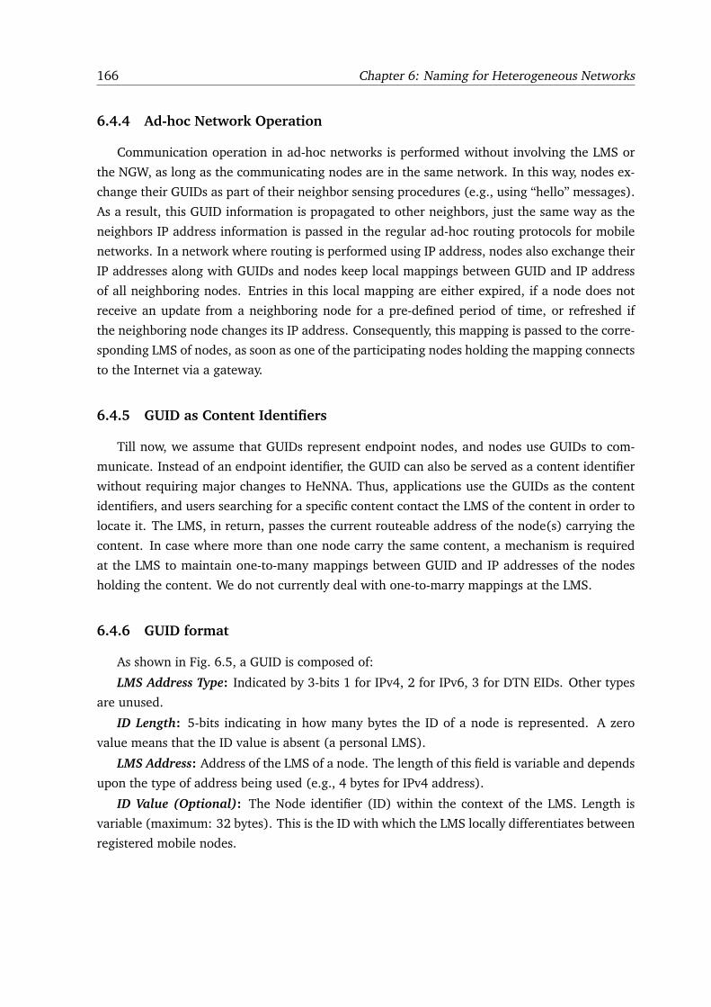
166 Chapter 6: Naming for Heterogeneous Networks
6.4.4 Ad-hoc Network Operation
Communication operation in ad-hoc networks is performed without involving the LMS or
the NGW, as long as the communicating nodes are in the same network. In this way, nodes ex-
change their GUIDs as part of their neighbor sensing procedures (e.g., using “hello” messages).
As a result, this GUID information is propagated to other neighbors, just the same way as the
neighbors IP address information is passed in the regular ad-hoc routing protocols for mobile
networks. In a network where routing is performed using IP address, nodes also exchange their
IP addresses along with GUIDs and nodes keep local mappings between GUID and IP address
of all neighboring nodes. Entries in this local mapping are either expired, if a node does not
receive an update from a neighboring node for a pre-defined period of time, or refreshed if
the neighboring node changes its IP address. Consequently, this mapping is passed to the corre-
sponding LMS of nodes, as soon as one of the participating nodes holding the mapping connects
to the Internet via a gateway.
6.4.5 GUID as Content Identifiers
Till now, we assume that GUIDs represent endpoint nodes, and nodes use GUIDs to com-
municate. Instead of an endpoint identifier, the GUID can also be served as a content identifier
without requiring major changes to HeNNA. Thus, applications use the GUIDs as the content
identifiers, and users searching for a specific content contact the LMS of the content in order to
locate it. The LMS, in return, passes the current routeable address of the node(s) carrying the
content. In case where more than one node carry the same content, a mechanism is required
at the LMS to maintain one-to-many mappings between GUID and IP addresses of the nodes
holding the content. We do not currently deal with one-to-marry mappings at the LMS.
6.4.6 GUID format
As shown in Fig. 6.5, a GUID is composed of:
LMS Address Type: Indicated by 3-bits 1 for IPv4, 2 for IPv6, 3 for DTN EIDs. Other types
are unused.
ID Length: 5-bits indicating in how many bytes the ID of a node is represented. A zero
value means that the ID value is absent (a personal LMS).
LMS Address: Address of the LMS of a node. The length of this field is variable and depends
upon the type of address being used (e.g., 4 bytes for IPv4 address).
ID Value (Optional): The Node identifier (ID) within the context of the LMS. Length is
variable (maximum: 32 bytes). This is the ID with which the LMS locally differentiates between
registered mobile nodes.
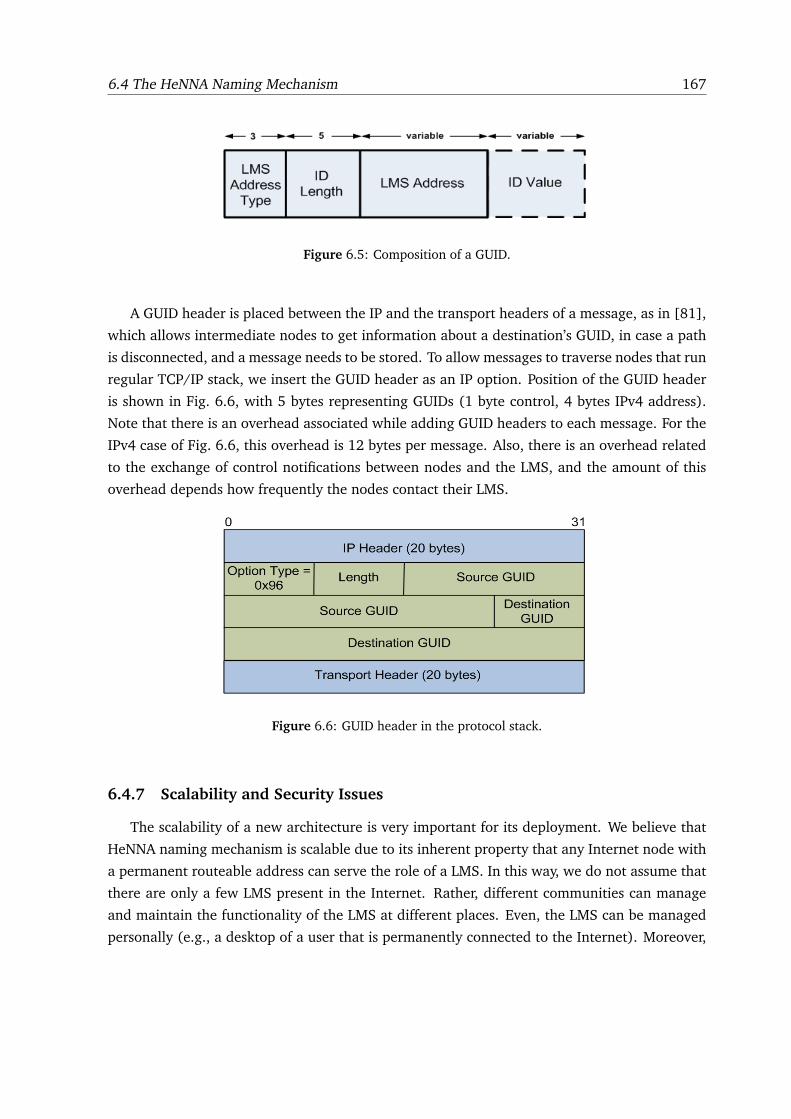
6.4 The HeNNA Naming Mechanism 167
Figure 6.5: Composition of a GUID.
A GUID header is placed between the IP and the transport headers of a message, as in [81],
which allows intermediate nodes to get information about a destination’s GUID, in case a path
is disconnected, and a message needs to be stored. To allow messages to traverse nodes that run
regular TCP/IP stack, we insert the GUID header as an IP option. Position of the GUID header
is shown in Fig. 6.6, with 5 bytes representing GUIDs (1 byte control, 4 bytes IPv4 address).
Note that there is an overhead associated while adding GUID headers to each message. For the
IPv4 case of Fig. 6.6, this overhead is 12 bytes per message. Also, there is an overhead related
to the exchange of control notifications between nodes and the LMS, and the amount of this
overhead depends how frequently the nodes contact their LMS.
Figure 6.6: GUID header in the protocol stack.
6.4.7 Scalability and Security Issues
The scalability of a new architecture is very important for its deployment. We believe that
HeNNA naming mechanism is scalable due to its inherent property that any Internet node with
a permanent routeable address can serve the role of a LMS. In this way, we do not assume that
there are only a few LMS present in the Internet. Rather, different communities can manage
and maintain the functionality of the LMS at different places. Even, the LMS can be managed
personally (e.g., a desktop of a user that is permanently connected to the Internet). Moreover,
168 Chapter 6: Naming for Heterogeneous Networks
if anycast addressing is used for the LMS, a number of LMS nodes can be used to maintain
the location information for a set of nodes, and a LOC REQ can be routed to and responded by
the nearest LMS available. This could also provide load-balancing and resistance to the LMS
failures.
However, there are some security issues related to the HeNNA mechanism that, unless re-
solved, may prevent the scalable deployment of the architecture. We do not treat the security
issues in this thesis but we point of a few of them. For instance, the exchange of control mes-
sages (e.g., LOC UPDATE, LOC REQ, LOC RESP) is not secure. Any node can use the GUID
of a mobile node to misinform the corresponding LMS about the current location of the mo-
bile node. Moreover, the end-to-end communication between a source and a destination using
GUIDs needs to be secure.
6.5 HeNNA Implementation
In the previous two chapters, we presented MeDeHa – a framework to provide message de-
livery across heterogeneous networks with diverse nodes capabilities while considering nodes
intermittent connectivity. While MeDeHa provides a flexible mechanism for seamless message
delivery across heterogeneous networks, it is based on two strong assumptions, (1) a sender
knows one of the IP addresses of a destination before sending a message, and (2) the IP address
of the destination does not change during the communication session. This limits the applica-
tion of the MeDeHa framework only to networks with local scope and to networks where nodes
IP addresses are static. In practice, this case is not common as mobile nodes change their IP
addresses with the change in their network point of attachment. Hence, the communication
between two nodes is vulnerable to change in IP addresses of the nodes. Moreover, nodes
generally use private address spaces when they are behind a firewall or a NAT server. Thus,
their IP addresses are not routeable in the Internet and are assigned temporarily. The MeDeHa
framework does not handle this issue.
For all these reasons, an identification based naming mechanism is indispensable for the
deployment of the MeDeHa framework, such that the communication between two nodes is
independent of their points of connection with the network. Using location-independent iden-
tifiers for communication in HeNNA is in contrast to the current Internet architecture in which
applications are bound to nodes IP addresses and these IP addresses needs to be acquired before
any communication takes place.
We implement HeNNA in the NS-3 [59] simulator and combine it with an extended version
of the MeDeHa framework [22], [25]4. The modifications that are made to make the MeDeHa
framework workable with HeNNA are described in the following subsection.4The implementation of HeNNA in NS-3 can be downloaded from http://planete.inria.fr/software/MeDeHa.
6.6 Results 169
6.5.1 Modifications in MeDeHa implementation
When operating with HeNNA, the MeDeHa nodes use location-independent GUID as nodes
identifiers for communication. A MeDeHa node sends the LOC UPDATE to its LMS, when it is
associated to an infrastructure-based node (e.g., an AP or base station), or when it is indirectly
connected via a neighboring node that is associated to an infrastructure-based network. Besides,
the MeDeHa notification protocol [23] has been extended so that APs exchange GUIDs of the
associated MeDeHa nodes instead of their IP addresses in the Extended Service Set (ESS). In
this way, all the notifications, presented in Section 4.6.1, comprise GUID of nodes instead of
the IP addresses. Besides in ad-hoc mode, the MeDeHa nodes exchange both their GUIDs and
IP addresses using the “hello handshake” (comprising of the HELLO and the NEIGHBOR INFO
notifications). In this way, the MeDeHa nodes maintain GUID to IP address mappings of all
other neighboring MeDeHa nodes. Besides, nodes also exchange GUID of the nodes that they
encountered within a pre-defined period of time. This is done using the RECENT NEIGHBORS
notifications and the information is used in the relay selection process.
When a MeDeHa node S wants to send a message to a destination D, it first checks D’s
location information in its cache. The local information about location may be present either
because (1) a LOC REQ notification has recently been sent for D, or (2) the information is
collected using the neighborhood information exchange mechanism of MeDeHa. If the infor-
mation is not found locally, S checks about D’s location using the information collected by the
APs within the ESS. If no information is available in the ESS, the LMS of D is consulted (con-
tacted by sending a LOC REQ control message) to get the current location of D. Messages are
forwarded based on the MeDeHa nodes’ GUID rather than their IP addresses in the original
MeDeHa framework. This enables the MeDeHa nodes to receive their messages even if their
IP addresses are changed due to temporary disconnection or joining a new network. APs may
store messages for temporary unavailable destinations within an ESS, but if a destination is
not connected to the ESS for a long time, APs transfer the stored messages to destinations’
corresponding LMS.
6.6 Results
6.6.1 Case 1: File Download Across Campuses
We show how HeNNA helps in message delivery to mobile nodes irrespective of their points
of attachment to the network and IP addresses. In this scenario, we consider that 40 students
move within and between 3 campuses of a university. These campuses do not belong to the same
subnet, and are not directly connected, as shown in Figure 6.7. Students carry portable devices
that run MeDeHa framework and HeNNA. While traveling between campuses, they remain
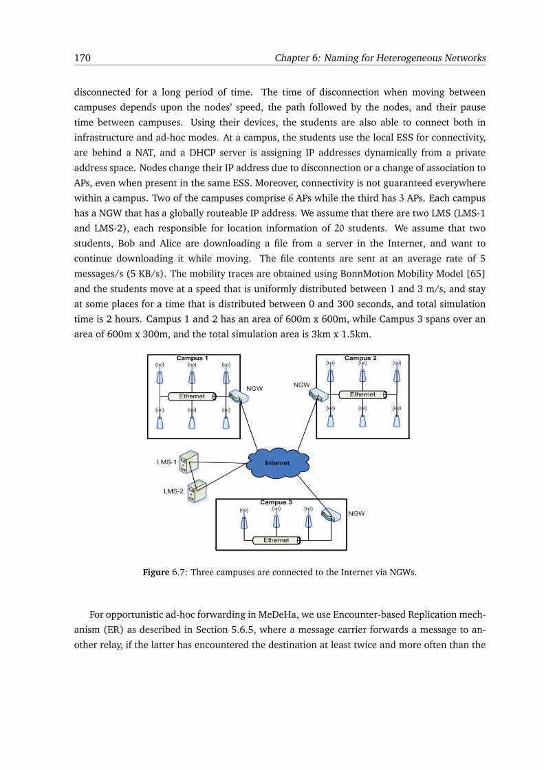
170 Chapter 6: Naming for Heterogeneous Networks
disconnected for a long period of time. The time of disconnection when moving between
campuses depends upon the nodes’ speed, the path followed by the nodes, and their pause
time between campuses. Using their devices, the students are also able to connect both in
infrastructure and ad-hoc modes. At a campus, the students use the local ESS for connectivity,
are behind a NAT, and a DHCP server is assigning IP addresses dynamically from a private
address space. Nodes change their IP address due to disconnection or a change of association to
APs, even when present in the same ESS. Moreover, connectivity is not guaranteed everywhere
within a campus. Two of the campuses comprise 6 APs while the third has 3 APs. Each campus
has a NGW that has a globally routeable IP address. We assume that there are two LMS (LMS-1
and LMS-2), each responsible for location information of 20 students. We assume that two
students, Bob and Alice are downloading a file from a server in the Internet, and want to
continue downloading it while moving. The file contents are sent at an average rate of 5
messages/s (5 KB/s). The mobility traces are obtained using BonnMotion Mobility Model [65]
and the students move at a speed that is uniformly distributed between 1 and 3 m/s, and stay
at some places for a time that is distributed between 0 and 300 seconds, and total simulation
time is 2 hours. Campus 1 and 2 has an area of 600m x 600m, while Campus 3 spans over an
area of 600m x 300m, and the total simulation area is 3km x 1.5km.
Figure 6.7: Three campuses are connected to the Internet via NGWs.
For opportunistic ad-hoc forwarding in MeDeHa, we use Encounter-based Replication mech-
anism (ER) as described in Section 5.6.5, where a message carrier forwards a message to an-
other relay, if the latter has encountered the destination at least twice and more often than the
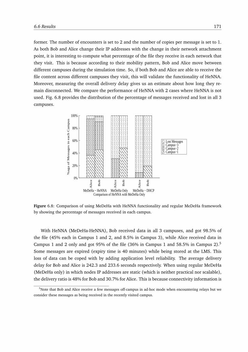
6.6 Results 171
former. The number of encounters is set to 2 and the number of copies per message is set to 1.
As both Bob and Alice change their IP addresses with the change in their network attachment
point, it is interesting to compute what percentage of the file they receive in each network that
they visit. This is because according to their mobility pattern, Bob and Alice move between
different campuses during the simulation time. So, if both Bob and Alice are able to receive the
file content across different campuses they visit, this will validate the functionality of HeNNA.
Moreover, measuring the overall delivery delay gives us an estimate about how long they re-
main disconnected. We compare the performance of HeNNA with 2 cases where HeNNA is not
used. Fig. 6.8 provides the distribution of the percentage of messages received and lost in all 3
campuses.
0%
20%
40%
60%
80%
100%
Bob
Ali
ce
Bob
Ali
ce
Bob
Ali
ce
%aga o
f M
ess
ages
in e
ach C
am
pus
Comparison of HeNNA with MeDeHa OnlyMeDeHa − HeNNA MeDeHa Only MeDeHa − DHCP
Lost MessagesCampus−3Campus−2Campus−1
Figure 6.8: Comparison of using MeDeHa with HeNNA functionality and regular MeDeHa framework
by showing the percentage of messages received in each campus.
With HeNNA (MeDeHa-HeNNA), Bob received data in all 3 campuses, and got 98.5% of
the file (45% each in Campus 1 and 2, and 8.5% in Campus 3), while Alice received data in
Campus 1 and 2 only and got 95% of the file (36% in Campus 1 and 58.5% in Campus 2).5
Some messages are expired (expiry time is 40 minutes) while being stored at the LMS. This
loss of data can be coped with by adding application level reliability. The average delivery
delay for Bob and Alice is 242.3 and 233.6 seconds respectively. When using regular MeDeHa
(MeDeHa only) in which nodes IP addresses are static (which is neither practical nor scalable),
the delivery ratio is 48% for Bob and 30.7% for Alice. This is because connectivity information is
5Note that Bob and Alice receive a few messages off-campus in ad-hoc mode when encountering relays but we
consider these messages as being received in the recently visited campus.
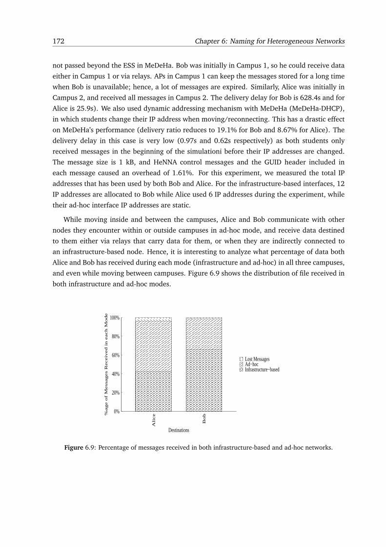
172 Chapter 6: Naming for Heterogeneous Networks
not passed beyond the ESS in MeDeHa. Bob was initially in Campus 1, so he could receive data
either in Campus 1 or via relays. APs in Campus 1 can keep the messages stored for a long time
when Bob is unavailable; hence, a lot of messages are expired. Similarly, Alice was initially in
Campus 2, and received all messages in Campus 2. The delivery delay for Bob is 628.4s and for
Alice is 25.9s). We also used dynamic addressing mechanism with MeDeHa (MeDeHa-DHCP),
in which students change their IP address when moving/reconnecting. This has a drastic effect
on MeDeHa’s performance (delivery ratio reduces to 19.1% for Bob and 8.67% for Alice). The
delivery delay in this case is very low (0.97s and 0.62s respectively) as both students only
received messages in the beginning of the simulationi before their IP addresses are changed.
The message size is 1 kB, and HeNNA control messages and the GUID header included in
each message caused an overhead of 1.61%. For this experiment, we measured the total IP
addresses that has been used by both Bob and Alice. For the infrastructure-based interfaces, 12
IP addresses are allocated to Bob while Alice used 6 IP addresses during the experiment, while
their ad-hoc interface IP addresses are static.
While moving inside and between the campuses, Alice and Bob communicate with other
nodes they encounter within or outside campuses in ad-hoc mode, and receive data destined
to them either via relays that carry data for them, or when they are indirectly connected to
an infrastructure-based node. Hence, it is interesting to analyze what percentage of data both
Alice and Bob has received during each mode (infrastructure and ad-hoc) in all three campuses,
and even while moving between campuses. Figure 6.9 shows the distribution of file received in
both infrastructure and ad-hoc modes.
0%
20%
40%
60%
80%
100%
Bo
b
Alice%
ag
e o
f M
essa
ge
s R
ece
ive
d in
ea
ch
Mo
de
Destinations
Lost MessagesAd−hocInfrastructure−based
Figure 6.9: Percentage of messages received in both infrastructure-based and ad-hoc networks.
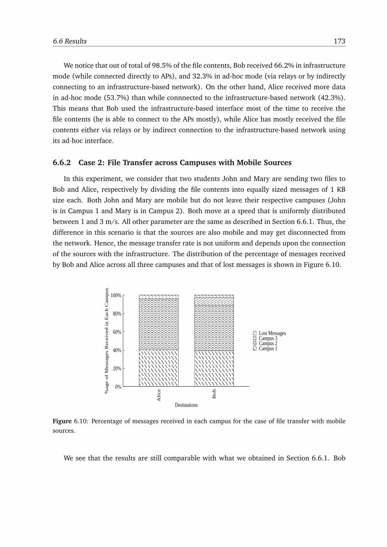
6.6 Results 173
We notice that out of total of 98.5% of the file contents, Bob received 66.2% in infrastructure
mode (while connected directly to APs), and 32.3% in ad-hoc mode (via relays or by indirectly
connecting to an infrastructure-based network). On the other hand, Alice received more data
in ad-hoc mode (53.7%) than while connnected to the infrastructure-based network (42.3%).
This means that Bob used the infrastructure-based interface most of the time to receive the
file contents (he is able to connect to the APs mostly), while Alice has mostly received the file
contents either via relays or by indirect connection to the infrastructure-based network using
its ad-hoc interface.
6.6.2 Case 2: File Transfer across Campuses with Mobile Sources
In this experiment, we consider that two students John and Mary are sending two files to
Bob and Alice, respectively by dividing the file contents into equally sized messages of 1 KB
size each. Both John and Mary are mobile but do not leave their respective campuses (John
is in Campus 1 and Mary is in Campus 2). Both move at a speed that is uniformly distributed
between 1 and 3 m/s. All other parameter are the same as described in Section 6.6.1. Thus, the
difference in this scenario is that the sources are also mobile and may get disconnected from
the network. Hence, the message transfer rate is not uniform and depends upon the connection
of the sources with the infrastructure. The distribution of the percentage of messages received
by Bob and Alice across all three campuses and that of lost messages is shown in Figure 6.10.
0%
20%
40%
60%
80%
100%
Bob
Ali
ce%age o
f M
ess
ages
Receiv
ed i
n E
ach C
am
pus
Destinations
Lost MessagesCampus 3Campus 2Campus 1
Figure 6.10: Percentage of messages received in each campus for the case of file transfer with mobile
sources.
We see that the results are still comparable with what we obtained in Section 6.6.1. Bob
174 Chapter 6: Naming for Heterogeneous Networks
received 97.5% of the file contents across all three campuses (39% in Campus 1, 50% in Campus
2 and 8.5% in Campus 3), while Alice received 96% of the file contents (40.5% in Campus 1
and 55.5% in Campus 2). On the other hand, the case of mobile sources reduced the average
delivery delay to some extent (210.87s for Bob and 216.54s for Alice), which means that there
is a 13% decrease in delay for Bob and 8% decrease in delay for Alice. This is because the
contact opportunities are increased as the sources are mobile, which caused the delivery delay
to decrease slighly.
6.7 Concluding Remarks
We have proposed a naming mechanism HeNNA that decouples node identification from
location. HeNNA is designed to operate with status-quo Internet routing while coping with
nodes temporary disconnections and change of IP address during communication sessions. The
proposed mechanism also provides NAT traversal and allows mobile nodes to use private-space
IP addresses in local networks. We run experiments to show a proof-of-concept of HeNNA’s ef-
fectiveness by running it using our framework MeDeHa via simulations in NS-3, and observed
that it is able to deliver messages to nodes even with frequent nodes mobility.
Part V
Conclusion and Future Work
175

7
CONCLUSIONS AND FUTURE RESEARCH
PERSPECTIVES
During the past few years, the current Internet architecture has consistently been challenged
by the heterogeneity of emerging smart devices and networks (or applications), and the users
eagerness to remain connected all the time. Especially the emergence of the wireless commu-
nications has jolted various aspects of the existing communication architecture, as it allows
nodes to communicate despite their mobility. The ubiquitous connectivity requirement gives
birth to an internetwork that connects different networks together and provides seamless inter-
operation. Notable challenges related to inter-operation of different networks include session
persistence, seamless message delivery across multiple heterogeneous networks and identifica-
tion of mobile nodes, which are the three challenges we targeted in this thesis.
The contributions of this thesis can be divided into three parts: (1) DTN routing taxonomy
for opportunistic networks, (2) Message delivery framework for heterogeneous networks, and
(3) Naming mechanism for heterogeneous networks. In the following subsections, we summa-
rize these contributions. We also provide some possible research perspectives of each part.
7.1 Opportunistic DTN Routing Taxonomy
In the first part, we provided a taxonomy of DTN routing protocols by breaking up the ex-
isting opportunistic DTN routing protocols into a set of small and tunable routing modules. We
identified three main routing modules as forwarding, replication, and source or network cod-
ing. We showed in which scenario a given routing module is the most suitable depending upon
the network characteristics and environment. We also identified a set of utility functions based
177
178 Chapter 7: Conclusions and Future Research Perspectives
on which forwarding decisions can be made in an opportunistic networking environment. We
highlighted two types of utility functions that can be used in DTNs as destination dependent (DD)
and destination independent (DI) utility functions, and showed when a specific utility function
should be used. We further provided a classification of opportunistic networks by identifying a
set of network characteristics (such as connectivity, mobility and nodes heterogeneity informa-
tion). This classification and the tunable routing modules help the opportunistic DTN routing
designers to choose a specific routing/forwarding approach for a problem in hand, for which
we also provided some design guidelines. To our knowledge, no similar work has been done
before despite the large number of DTN routing protocols that have been proposed in the past
few years.
While presenting a classification on the existing DTN routing protocols, we focused only
on the opportunistic routing protocols for delay or disruption tolerant networks. But other
types of DTN routing exist as well, as pointed out in Chapter 2: (1) deterministic or scheduled
routing and (2) enforced routing. We believe that the classification can further be extended
to include these two types of DTN routing protocols in the future. Even the insight of the
work we presented can be applicable to these types. For instance, when dealing with enforced
routing, a network may have a number of message ferries [19] where each ferry follows a
specific route and visits some places. In such scenario, the insight from utility functions can be
used to choose a suitable message ferry for a particular destination. In case of scheduled and
deterministic DTN routing, the time and duration of node contacts are generally known a priori
and the forwarding decisions are scheduled based on this information (e.g., the communication
between two satellites or planets can be scheduled at the time of their contact which is normally
known due to the orbits they follow). However, there can be some cases even in the scheduled
routing where opportunistic routing can be employed. For example, the contact between two
buses can be predetermined based on their pre-defined routes, but two buses may not encounter
each other due to traffic conditions on roads. Thus, the scheduled routing would fail in that
case. Hence, we believe that the DTN routing classification that we presented in the thesis can
be used even in scenarios where routing is generally deterministic or enforced.
7.2 Message Delivery in Heterogeneous Networks
In the second part of the thesis, we provided a message delivery framework which we
named as MeDeHa for Message Delivery in Heterogeneous Disruption-prone Networks. The
MeDeHa framework is an attempt to provide seamless inter-operation of infrastructure-based
and infrastructure-less networks, while coping with nodes intermittent and sporadic network
connectivity. The framework is applicable to scenarios where applications are not strictly delay-
bound and where nodes prefer late delivery of messages over complete loss of information
7.2 Message Delivery in Heterogeneous Networks 179
due to nodes intermittent connectivity. With more investigation, the framework can serve as a
building block for coping with network heterogeneity in future internetworks. MeDeHa nodes
act as relays to carry traffic for other nodes in a store-carry-and-forward manner, as opposed
to the conventional store-and-forward Internet model. Thus, the framework is able to deliver
messages to destinations across multiple hops even if there is no contemporaneous end-to-end
path between a pair of source and destination. This is done by taking advantage of opportunistic
contacts that nodes experience while moving.
MeDeHa nodes also take advantage of different destination dependent and destination inde-
pendent utility functions (such as history of past encounters, number of encounters, and nodes
community or social affiliation), which helps in choosing a suitable relay and making forward-
ing decisions in an opportunistic way. The framework is also able to integrate existing MANET
routing protocols so that message delivery is extended to MANET nodes which do not run the
MeDeHa software. This is made possible by the gateway nodes that run the MeDeHa frame-
work and a MANET routing protocol. The multi-hop connectivity information of MANETs is
also used to connect two infrastructure-based networks that are otherwise disconnected. In
this way, MANETs act as transit networks to bridge these disconnected networks. Moreover, the
flexible design of MeDeHa allows it to be implemented at different layers of the communication
stack.
We implemented and evaluated the MeDeHa framework at link and network layers using
the OMNET++ and the NS-3 simulators. We used realistic synthetic mobility models and
real mobility traces to show the effectiveness of the framework in diverse set of scenarios and
environments with mobile nodes. We also implemented the framework on Linux machines as
a user-space daemon and evaluated it. Finally, we have performed some hybrid experiments
where both simulator nodes and real machines inter-communicate and are part of a single
experiment. On one hand, it allows the evaluation of the scalability of the framework by
having more nodes on the simulator side, while on the other hand, it validates the framework’s
implementation in the NS-3 simulator. Following are the main findings of the framework’s
evaluation:
1. Network heterogeneity and nodes cooperation help in increasing the message delivery
ratio of mobile nodes. In this way, nodes ability to simultaneously connect to different
infrastructure-based and infrastructure-less networks improve the message delivery.
2. Using more copies per message help in reducing the average end-to-end delay at the cost
of using more network resources.
3. Using the MeDeHa framework, only a few copies per message (normally 2) are sufficient
to provide almost 100% of delivery ratio. This enables the nodes using the framework to
achieve acceptable delivery ratios with low overhead.
180 Chapter 7: Conclusions and Future Research Perspectives
4. DD utility functions such as ER perform better than DI utility functions when nodes have
more contact opportunities (i.e., they encounter each other more often).
5. Encounter-based replication schemes offer better average delivery ratios while community
affiliation-based schemes provide better average delivery delays.
Moreover, we evaluated the MeDeHa framework using traffic involving different priority of
flows, and showed the basic buffer management performed by the nodes that implement the
framework. We have also learnt a few important lessons specific to the hybrid experimenta-
tion. The hybrid experiments allow the inter-operation of simulator nodes and real machines,
and helps in verifying the simulation implementation as real machines inter-communicate with
simulator nodes. On the other hand, due to the real-time scheduler of the NS-3 simulator, the
hybrid experiments limit the number of simulator nodes to a certain number, and this number
depends upon the processing and scheduling capability of the machine on which we run the
simulator. In our hybrid experiments, we could not use more than 30 nodes in the simula-
tor using Intel dual-core with 2.4 GHz processor and 4 GB RAM, where each node has 2 to 3
interfaces.
To conclude, the MeDeHa framework offers the following main advantages:
� Bridge heterogeneous networks involving nodes with diverse set of capabilities and net-
work with different characteristics.
� Provide Seamless message delivery across multiple networks despite nodes mobility.
� Capability to work at different layers of the communication stack.
� Integration of existing MANET routing protocols to provide multi-hop communication
whenever possible.
� Integration of existing forwarding/routing mechanisms for opportunistic networks.
However, the MeDeHa framework uses IP address of nodes for communication, and the
communication is based on the assumption that IP addresses of the nodes do not change during
the communication session. Whereas, IP addresses of the nodes are impermeable to change
especially when nodes are mobile and change their points of attachment to the network. Also,
when nodes are multihomed, they may possess multiple IP addresses; thus, IP addresses of
nodes are not a good candidate to be used for communication with mobile nodes. We addressed
this issue in the last part of the thesis.
The current design of the framework only considers point-to-point message delivery to des-
tinations. There may be environments where multi-destination message delivery is required.
For instance, in a convention center, an organizer may want to disseminate text, audio or video
7.2 Message Delivery in Heterogeneous Networks 181
messages to the participants. In the future, it will be interesting to explore the capability and
feasibility of the MeDeHa framework to provide multi-destination (point-to-multipoint) mes-
sage delivery. The framework design can be reviewed from a content dissemination point of
view to employ content dissemination strategies such as ContentPlace [95] in heterogeneous
networks.
Moreover, in the thesis, we put aside the transport layer issues of communication in hetero-
geneous networks. These issues include flow control, congestion control and reliability. In a
way, these issues are handled hop-by-hop at the network layer of the nodes, as the forwarding
of messages from one node to another node is performed based on the buffer space available
at the latter. Moreover, all the messages are acknowledged when forwarded from one node to
another – thus providing hop-by-hop reliability, as in the DTN Bundle Architecture [17]. But we
believe that efforts need to be made to handle these transport layer issues end-to-end in hetero-
geneous disruption-prone networks. Very little effort has been made to address the transport
layer issues in DTNs, with notable examples include [148] and [149].
MeDeHa’s current buffering mechanism is based on message priorities, and when a message
arrives to the MeDeHa module and there is no space available, messages with lower priorities
may be dropped. Message priorities can also be used to provide some flow control mechanism
such that before exchanging messages, two nodes order the messages based on their priorities.
Besides providing flow control, this will also help in quick dissemination for high priority traffic,
and is useful when the average contact duration of nodes is lower than average number of
messages nodes have to replicate, for instance, due to high speeds. A similar approach for
managing buffers in this way is presented in [31] for opportunistic networks.
Another important future research direction for the MeDeHa framework is its interaction
with the DTN Bundle Architecture [17]. As already stated in Chapter 4, the MeDeHa frame-
work is complementary to the Bundle Architecture, but we can see that providing support of
disruption tolerance is not the only goal of the MeDeHa framework. When working with the
DTN Bundle Architecture, a DTN overlay network can be formed where DTN endpoint nodes
use bundles as communication data unit to exchange data between them. DTN endpoint nodes
in this overlay network can use the MeDeHa-capable nodes to traverse multiple hops in order to
communicate with other DTN endpoint nodes. A similar approach has already been proposed in
PreDA [39] where DTN endpoint nodes use underlying AODV network to communicate. Con-
versely, MeDeHa-capable networks can be made to operate with DTN-capable networks. Work
is in progress in order to realize this inter-operation.
182 Chapter 7: Conclusions and Future Research Perspectives
7.3 Naming for Heterogeneous Networks
In the third and last part of the thesis, we presented a naming mechanism, called Hetero-
geneous Networks Naming Architecture (HeNNA), which decouples node identification with
their locations. This allows nodes to roam and to be part of networks with different subnet IP
addresses while maintaining their communication session. The MeDeHa framework does not
inherently allow this functionality. HeNNA is complementary to the MeDeHa framework and
can be used in cooperation with the framework. In Chapter 6, we showed this cooperation of
HeNNA and MeDeHa using simulations performed in the NS-3 simulator. HeNNA also allows
NAT traversal and enables mobile nodes to use dynamically assigned IP addresses from private
address space. Another feature of HeNNA is its ability to work with the status-quo Internet rout-
ing, which makes the naming mechanism ready to be deployed and used in the Internet. The
mechanism also inherently copes with the disconnection of mobile nodes with the network. In
this way, nodes with permanent IP addresses in the Internet, called Location and Management
Server (LMS), are responsible for keeping the most recent location information of the mobile
nodes and for storing messages on behalf of the unavailable nodes.
We have only presented the proof-of-concept of the naming mechanism. Detailed evalua-
tion of the protocol especially with respect to nodes mobility and its comparison with existing
naming schemes is part of the future work. Another future direction is the deployment of the
scheme on a real test-bed so that the performance of HeNNA with the actual Internet architec-
ture can be evaluated. Using a mechanism like HeNNA to integrate the Internet with the DTN
Bundle architecture [17] is another research direction.
While HeNNA may serve as a building block for communication of mobile nodes in hetero-
geneous disruption-prone networks, security aspects related to the scheme must be addressed
before it is actually deployed in the Internet. The security concerns are mainly related to how
control notifications are exchanged between the mobile nodes and the LMS nodes so that the
location information present at the LMS nodes is accurate.
7
LES CONCLUSIONS ET LES TRAVAUX DE
RECHERCHE FUTURE
Pendant les annees recentes, l’architecture actuel de l’Internet a ete uniformement defiee
par l’heterogeneite des dispositifs et les nouveaux reseaux (ou les applications), et par le desir
d’utilisateurs d’etre connecte tout le temps. Particulierement l’apparition des communications
sans fil a secoue de divers aspects de l’architecture actuelle de communication, car elle permet a
des noeuds de communiquer meme avec la mobilite. Le besoin d’une connectivite omnipresente
necessite un inter-reseau qui relie differents reseaux ensemble et fournit leur inter-operation.
Les defis notables lies a l’inter-operation de differents reseaux comprennent la persistance de
session, la livraison de message a travers les reseaux heterogenes multiples et l’identification
des noeuds mobiles, qui sont les trois defis que nous avons vises dans cette these.
Les contributions de cette these peuvent etre divisees en trois parties : (1) une taxonomie
de routage DTN pour les reseaux opportuniste, (2) un framework de la livraison de message
pour les reseaux heterogenes, et (3) un mecanisme d’identification des noeuds pour les reseaux
heterogenes. Dans les sous-sections suivantes, nous recapitulons ces contributions. Nous four-
nissons egalement quelques perspectives possibles de recherches de chaque partie.
7.1 Une taxonomie des protocoles routage DTN
Dans la premiere partie, nous avons fourni une taxonomie des protocoles de routage DTN
en divisant les protocoles existants en ensemble de petits et reglables modules de routage.
Nous avons identifie trois modules principaux de routage comme forwarding, replication, et
coding (source ou reseau). Nous avons montre dans quel scenario un module donne est le
183
184 Chapter 7: Les Conclusions et les travaux de recherche future
plus approprie perennant en compte des caracteristiques de reseau et l’environnement. Nous
avons egalement identifie un ensemble de fonctions d’utilite (utility function) basees sur quelles
decisions de forwarding peuvent etre prises dans un environnement de reseau opportuniste. En-
suite, nous avons souligne deux types de fonctions d’utilite qui peuvent etre employees dans
DTNs comme destination dependent (DD) et destination independant (DI) fonctions d’utilite, et
montre quand une fonction specifique devrait etre employee. De plus, nous avons fourni une
classification des reseaux opportuniste en identifiant un ensemble de caracteristiques de reseau
(comme l’information de connectivite, de mobilite et d’heterogeneite de noeuds). Cette classi-
fication et les modules reglables de routage aident les concepteurs des protocoles de routage
DTN a choisir une approche specifique de routage pour un probleme a disposition, pour lequel
nous avons egalement fourni quelques directives de conception. A notre connaissance, aucun
travail similaire n’a ete effectue qui ont ete proposes jusqu’a aujourd’hui.
Tout en presentant une classification sur les protocoles actuels de routage DTN, nous nous
sommes concentres seulement sur les protocoles opportunistes de routage pour DTNs. Mais
d’autres types de routage DTN existent aussi bien, comme precise dans le chapitre 2: (1)“
deterministic” ou “scheduled” et (2) “enforced”. Nous croyons que la classification que nous
avons presentee dans cette these peut etre prolongee pour inclure ces deux types de protocoles
de routage DTN a l’avenir. Meme la classification que nous avons presentee peut etre applicable
a ces types actuellement. Par exemple, quand traiter le routage “enforced”, un reseau peut avoir
un certain nombre de message ferries [19] ou chaque ferry suit un itineraire specifique et visite
quelques endroits. Dans un tel scenario, les fonctions de utilite peut etre employe pour choisir
un ferry qui est convient pour une destination particuliere. En cas du routage scheduled ou
deterministic, la periode et la duree des contacts de noeud sont generalement connus a priori et
les decisions de expedition ont base sur cette information (par exemple, la communication entre
deux satellites ou planetes peut etre programmee a l’heure de leur contact qui est normalement
du connu aux orbites qu’ils suivent). Cependant, il peut y avoir quelques cas meme dans le
routage scheduled ou le routage opportuniste peut etre utilise. Par exemple, le contact entre
deux bus peut etre predetermine a base sur leurs itineraires predefinis, mais deux bus peuvent
ne pas se rencontrer du aux conditions du trafic sur des routes. Ainsi, le routage scheduled
echouerait dans ce cas. Par consequent, nous croyons que la classification de routage DTN que
nous avons presentee dans la these peut etre employee meme dans les scenarios ou le routage
est generalement deterministic ou enforced.
7.2 La livraison des messages dans les reseaux heterogenes
Dans la deuxieme partie de la these, nous avons fourni un framework pour la livraison de
message dans les reseaux heterogenes que nous avons appele MeDeHa. Le framework MeDeHa
7.2 La livraison des messages dans les reseaux heterogenes 185
est une essaie de fournir l’interoperation des reseaux infrastructure et ad-hoc, avec les reseaux
qui sont tolerants a la connectivite sporadique. Le framework est applicable aux scenarios ou
les applications ne manquent pas lorsque les retards sont tres eleves et ou les noeuds preferent
la livraison tardive a la perte complete de messages due a la connectivite intermittente de
noeuds. Avec plus de recherche, le framework peut servir de module de base pour les reseaux
heterogenes dans les inter-networks de future. Les noeuds de MeDeHa agissent en tant que
relais pour porter le trafic pour d’autres noeuds d’une facon “store-carry-and-forward” par op-
position au modele “store-and-forward” dans l’Internet actuel. Ainsi, le framework peut fournir
des messages aux destinations a travers les sauts multiples meme s’il n’y a aucun chemin bout-
en-bout entre une paire de source et la destination. Ceci est fait en profitant des contacts
opportuniste des noeuds quand ils se deplacent.
Les noeuds de MeDeHa profitent egalement des differents fonctions d’utilite (telles que
l’histoire de la rencontre passee, le nombre de rencontre, et la communaute de noeuds ou
l’affiliation sociale), qui aident en choisissant un mieux relais et en prenant des decisions de
expedition d’une maniere opportuniste. Le framework peut egalement integrer des proto-
coles existants de routage MANET de sorte que la livraison de message soit prolongee aux
noeuds de MANET qui ne courent pas le logiciel de MeDeHa. Ceci est rendu possible par les
noeuds passerelles qui courent le framework de MeDeHa et un protocole de routage MANET.
L’information de connectivite de multi-saute de MANETs est egalement employee pour re-
lier deux reseaux infrastructure qui sont autrement deconnectes. De cette facon, les reseaux
MANETs se servent comme des reseaux de transits afin de fournir un pont sur ces reseaux
deconnectes. D’ailleurs, la conception flexible de MeDeHa lui permet d’etre implemente sur
differentes couches de la pile de communication (protocol stack).
Nous avons implemente et avons evalue le framework MeDeHa a la couche lien et a la
couche reseau en utilisant les simulateurs OMNET++ et NS-3. Nous avons employe les modeles
synthetiques realistes de mobilite et la vraie trace de mobilite pour montrer l’efficacite du frame-
work dans l’ensemble divers de scenarios et d’environnements avec des noeuds mobiles. Nous
avons egalement implemente le framework sur des machines de Linux et l’avons evalue. En
conclusion, nous avons execute quelques experiences hybrides ou les noeuds de simulateur
et les vraies machines inter-communiquent et font partie d’une experience. D’une part, elle
permet l’evaluation de l’extensibilite du framework en ayant plus de noeuds du cote de simula-
teur; bien que d’autre part, elle valide l’execution du framework dans le simulateur NS-3. Les
resultats principaux de l’evaluation du framework sont les suivants:
1. L’heterogeneite de reseau et la cooperation de noeuds aident en augmentant le rapport de
la livraison de message des noeuds mobiles. De cette facon, la capacite de noeuds de se
relier simultanement a differents reseaux infrastructure et ad-hoc ameliorent la livraison
de message.
186 Chapter 7: Les Conclusions et les travaux de recherche future
2. Le delais moyen de bout-en-bout se reduit en augmentant les nombres de copies par
message au cout d’employer plus de ressources de reseau.
3. Seulement quelques copies par message (normalement 2) sont suffisantes pour fournir
presque 100% du rapport de la livraison de messages en utilisant le framework MeDeHa.
Ceci permet aux noeuds de MeDeHa de realiser des rapports acceptables de la livraison
avec une surcharge faible.
4. Les fonctions d’utilite comme DD executent mieux que des fonctions DI quand les noeuds
ont plus d’occasions de contact (Quand ils se rencontrent plus souvent).
5. Les mecanismes qui sont bases sur les contacts des noeuds offrent de meilleurs rapports
moyens de la livraison, tandis que les mecanismes qui sont bases sur l’affiliation d’une
communaute fournissent le meilleur delai moyen.
D’ailleurs, nous avons evalue le framework MeDeHa en utilisant le trafic impliquant la
priorite differente, et nous avons montre la gestion de tampon executee par les noeuds qui
implementent le framework. Nous avons egalement appris quelques lecons importantes specifiques
a l’experimentation hybride. Les experiences hybrides permettent l’interoperation des noeuds
de simulateur et de vraies machines, et aident en verifiant l’implementation de simulation pen-
dant lesquelles les vraies machines inter-communiquent avec des noeuds de simulateur. D’autre
part, en raison de l’execution en temps reel du simulateur NS-3, les experiences hybrides limi-
tent le nombre de noeuds de simulateur a un certain nombre, et ce nombre depend des capacites
de traitement et d’etablissement du programme de la machine sur laquelle nous executons le
simulateur. Dans nos experimentes hybrides, nous ne pourrions pas employer plus de 30 noeuds
dans le simulateur en utilisant le dual-core Intel avec le processeur de 2.4 gigahertz et la RAM
de 4 gigaoctets, ou chaque noeud a 2 a 3 interfaces.
Pour conclure, le framework MeDeHa offre les avantages principaux suivants:
� Le framework se sert comme un pont entre les reseaux heterogenes comprenant des
noeuds de capacite divers et de reseau avec differentes caracteristiques.
� Il fournit la livraison de message a travers les reseaux multiples meme dans la presence
de la mobilite de noeuds.
� MeDeHa est capable de fonctionner sur des differentes couches de la pile de communica-
tion.
� Il est possible d’integrer des protocoles existant de routage MANET afin de fournir la
communication de multi-saute autant que possible.
7.2 La livraison des messages dans les reseaux heterogenes 187
� Le framework integre des mecanismes existants de routage DTN.
Cependant, le framework MeDeHa emploie l’adresse IP des noeuds pour la communication,
et la communication est fondee sur l’hypothese que les adresses IP des noeuds ne changent pas
pendant la session de communication. En fait, les adresses IP des noeuds sont impermeables a
changer, particulierement quand les noeuds sont mobiles et changent leurs points d’attachement
en reseau. En plus, quand les noeuds sont multihomed, ils peuvent posseder plusieurs adresses
IP; ainsi, les adresses IP des noeuds ne sont pas un bon candidat a employer pour la communi-
cation avec des noeuds mobiles. Nous avons aborde cette question dans la derniere partie de la
these.
La conception actuelle du framework considere seulement la livraison de message aux des-
tinations point-a-point. Il peut y avoir des environnements ou la livraison de message de multi-
destination est exigee. Par exemple, dans un centre de convention, un organisateur peut vouloir
disseminer des messages des textes, d’acoustique ou de video aux participants. Dans le futur, il
sera interessant d’explorer les possibilites et la praticabilite du framework MeDeHa pour fournir
la livraison de message de multi-destination (point-a-multipoint). La conception de framework
peut etre passee en revue d’un point de vue de diffusion de contenu pour utiliser des strategies
telles que ContentPlace [95] dans les reseaux heterogenes.
D’ailleurs, dans cette these, nous avons mis de cote les problemes de couche transport de
communication dans les reseaux heterogenes. Ces issues incluent le flow control, le congestion
control et la fiabilite. D’une certaine maniere, ces issues sont manipule a la couche reseau des
noeuds, comme expedition des messages d’un noeud a un autre noeud est executees base sur
l’espace de tampon disponible au dernier. En plus, tous les messages sont acquittes une fois
expedies d’un noeud a l’autre – de ce fait fournissant la fiabilite de saute au saute, comme
dans l’Architecture Bundle de DTN [17]. Mais nous croyons que des efforts doivent etre faits
pour manipuler ces issues de couche transport bout-en-bout dans les reseaux heterogenes a
connectivite episodique.
Le mecanisme actuel du buffering dans le framework MeDeHa est base sur des priorites de
message. Quand un message arrive au module de MeDeHa et il n’y a aucun espace disponible,
des messages avec des priorites inferieures peuvent etre laches. Des priorites de message
peuvent egalement etre employees pour fournir un certain mecanisme du “flow control” tels
qu’avant d’echanger des messages, deux noeuds trient les messages bases sur leurs priorites.
En plus de fournir le controle de flux (le “flow control”), ceci aidera egalement dans la diffusion
rapide pour le trafic prioritaire eleve, et c’est tres utile quand la duree moyenne de contact
des noeuds est inferieure que le nombre moyen de messages les noeuds doivent echanger, par
exemple, en raison des vitesses elevees. Une approche similaire pour la gestion de tampon de
cette facon est presentee dans [31] pour les reseaux opportuniste.
Une autre direction importante de future recherches pour le framework MeDeHa est son
188 Chapter 7: Les Conclusions et les travaux de recherche future
interaction avec l’architecture Bundle de DTN [17]. Comme deja indique dans le Chapitre 4, le
framework MeDeHa est complementaire a l’architecture de Bundle, mais nous pouvons noter
que fournir la tolerance de deconnection n’est pas le seul but du framework MeDeHa. En tra-
vaillant avec l’architecture Bundle de DTN, un reseau de recouvrement de DTN peut etre forme
ou les “DTN endpoint nodes” emploient des bundles en tant qu’unite de donnees de commu-
nication pour echanger des donnees entre eux. Les DTN endpoint noeuds dans ce reseau de
recouvrement peuvent employer les noeuds MeDeHa pour traverser les plusieurs sauts afin de
communiquer avec d’autres DTN endpoint noeuds. Une approche similaire a ete deja proposee
dans laquelle le protocole AODV est utilises pour la communications entre les DTN endpoint
noeuds (PreDA [39]). Reciproquement, des reseaux MeDeHa peuvent etre faits pour fonction-
ner avec les reseaux DTN. Le travail est en cours afin de realiser cette interoperation.
7.3 L’identification des noeuds dans les reseaux heterogenes
Dans la troisieme et la derniere partie de la these, nous avons presente un mecanisme
d’identification, appele HeNNA, qui decouple l’identification de noeuds avec leurs positions
dans le reseau. Ceci permet a des noeuds de changer leurs points d’attachement avec le reseau
tout en maintenant leur session de communication. Le framework MeDeHa ne comprend pas
cette fonctionnalite. HeNNA est complementaire au framework MeDeHa et peut etre employe
en cooperation avec le framework. Dans le chapitre 6, nous avons montre cette cooperation
de HeNNA et MeDeHa en utilisant des simulations effectuees dans le simulateur NS-3. HeNNA
egalement permet a traverser le NAT et permet a des noeuds mobiles d’employer des adresses IP
dynamiquement assignees parmi l’espace adresse privee. Un autre dispositif de HeNNA est son
capacite de fonctionner avec le routage de l’Internet d’aujourd’hui, qui permet au mecanisme
HeNNA d’etre deploye et utilise dans l’Internet actuel. Le mecanisme support egalement le
deconnection des noeuds mobiles avec le reseau. De cette facon, les noeuds avec des adresses
IP permanentes dans l’Internet, appele le Location and Management Server (LMS), sont respon-
sables de garder l’information de position la plus recente des noeuds mobiles et de stocker des
messages des noeuds qui sont indisponibles.
Dans cette these, nous avons seulement presente le proof-of-concept du mecanisme HeNNA.
L’evaluation detaillee du protocole particulierement en ce qui concerne la mobilite de noeuds
et sa comparaison avec des mecanismes de nommage existants fait partie des travaux futurs.
Une autre direction de future est le deploiement du mecanisme sur un vrai test-bed de sorte
que l’execution de HeNNA avec l’architecture de l’Internet puisse etre evaluee. L’utilisation d’un
mecanisme comme HeNNA pour integrer l’Internet avec l’architecture Bundle de DTN [17] est
une autre direction de recherches.
Tandis que HeNNA peut servir de module a la communication des noeuds mobiles dans les

7.3 L’identification des noeuds dans les reseaux heterogenes 189
reseaux heterogenes a connectivite intermittente, des aspects de securite lies a HeNNA doivent
etre adresses avant qu’il soit deploye reellement dans l’Internet. Les soucis de securite sont
principalement lies a la facon dont des messages de controle sont echanges entre les noeuds
mobiles et les noeuds LMS de sorte que l’information d’endroit actuelle aux noeuds de LMS soit
precise.

190 Chapter : Les Conclusions et les travaux de recherche future
Appendix A
Glossary
A.1 List of Acronyms and Abbreviations
AD:
Average Delivery Delay
AP:
Access Point
CCN:
Content Centric Networking
CDF:
Cumulative Distribution Function
DHCP:
Dynamic Host Configuration Protocol
DNS:
Domain Name System
DONA:
Data Oriented Network Architecture
DTN:
Delay or Disruption Tolerant Networks
DYMO:
Dynamic MANET On-demand Routing Protocol
EID:
Endpoint Identifier
191
192 Chapter A: Glossary
ER:
Encounter-based Replication
ESAR:
Encounter and Social Affiliation-based Replication
ESS:
Extended Service Set
GUID:
Globally Unique Identifier
GW:
Gateway
HA:
Home Agent
HeNNA:
Heterogeneous Networks Naming Architecture
HIP:
Host Identity Protocol
HNA:
Host and Network Association
LISP:
Locator/Identifier Separation Protocol
MANET:
Mobile Ad-hoc Networks
MDR:
Message Delivery Ratio
MeDeHa:
Message Delivery in Heterogeneous Disruption-prone Networks
MN:
Mobile Node
NAT:
Network Address Translation
A.2 Basic Definitions 193
OLSR:
Optimized Link State Routing Protocol
P2P:
Peer-to-Peer
PDA:
Personal Digital Assistant
PSM:
Power Saving Mode
RWP:
Random Waypoint Mobility Model
SAR:
Social Affiliation-based Replication
SID:
Session Identifier
VANET:
Vehicular Ad-hoc Networks
A.2 Basic Definitions
Association:
Connection of a node with an infrastructure-based network.
Delay/Disruption Tolerant Networks:
Networks that tolerate nodes intermittent connectivity and are not based on end-to-end
Internet principle.
Deterministic Routing:
The encounters between two nodes can be determined based on their route information.
Disassociation:
Disconnection of a node from an infrastructure-based network.
Enforced Routing:
Special-purpose nodes are added to the network to enhanced routing.
194 Chapter A: Glossary
Forwarding:
Only one copy of a message exists in the network.
Gateway (GW):
A node that runs the MeDeHa software and has the capability to connect to multiple
networks simultaneously.
Handoff:
Connection transfer of a mobile node from one AP to another within an ESS.
Hello Handshake:
Neighbor sensing mechanism of MeDeHa for ad-hoc networks.
Hop-by-hop Reliability:
The data transfer between two neighboring nodes is reliable.
Infrastructure-based Networks:
Networks with fixed infrastructure and connectivity to the backbone. Examples include
Wifi, WiMax, cellular-based networks.
Infrastructure-based Node:
A basestation or an AP providing the backbone connectivity to wireless nodes.
Infrastructure-less Networks:
Ad-hoc Networks without any fixed infrastructure including multi-hop mobile ad-hoc net-
works or MANETs.
Late Binding:
The process of acquiring the routing address of a destination from its application-level
identifier while the packet is being routed.
Opportunistic Routing:
The encounters between two nodes are not known a priori.
Replication:
Multiple copies per message exist in the network.
Ubiquitous Networks:
Networks that provide continuous connectivity everywhere.
BIBLIOGRAPHY
[1] G. Maier, A. Feldmann, V. Paxson, and M. Allman, On Dominant Characteristics of Residential
Broadband Internet Traffic, in Proceedings of the Internet Measurement Conference (IMC),
Chicago, November 2009. 4, 14
[2] N. Sarafijanovic-Djukic, M. Piorkowski, and M. Grossglauser, Island Hopping: Efficient
Mobility-Assisted Forwarding in Partitioned Networks, In Proceedings of IEEE SECON’06, pp.
226-235, 2006. 7, 17, 32, 49, 56, 57, 59, 71
[3] J. Ott, D. Kutscher, and C. Dwertmann, Integrating DTN and MANET Routing, In Proceedings
of ACM 3 workshop on Challenged Networks (CHANTS), pp. 221-228, Pisa, Italy, 2006. 7,
17, 31, 71, 76, 111
[4] J. Ott, Delay Tolerance and The Future Internet, In Proceedings of the 11th International
Symposium on Wireless Personal Multimedia Communications (WPMC), 2008. 26, 30
[5] J. Ott and D. Kutscher, A Disconnection-Tolerant Transport for Drive-thru Internet Environ-
ments, in Proceedings of IEEE Infocom 2005, Miami, March, 2005. 35, 36
[6] K. Fall, S. Burleigh, A. Doria, J. Ott, and D. Young, The DTN URI Scheme, DTNRG Internet
draft, 2009. 155
[7] A. Vahdat and D. Becker, Epidemic Routing for Partially Connected Ad Hoc Networks, Techni-
cal Report CS-200006, Duke University, 2000. 7, 8, 17, 18, 31, 40, 43, 44, 48, 49, 131
[8] J.-C. Chen, S. Li, S.-H. Chan, and J.-Y. He, WIANI: Wireless Infrastructure and Ad-Hoc
Network Integration, In Proceedings of IEEE International Conference on Communications
(ICC), pp. 3623-3627, Seoul, Korea, 2005. 7, 17, 27, 28, 70
[9] J He J. Chen, S.-H. G. Chan, and S.-C. Liew, Mixed-mode Wlan: The Integration of Ad Hoc
Mode with Wireless LAN Infrastructure, In Proceedings of IEEE Globecom, pp. 231-235, 2003.
7, 17, 27, 28, 70
[10] C. Parata, G. Convertino, and V. Scarpa, Flex-WiFi: A Mixed Infrastructure and Ad-Hoc
IEEE 802.11 Network for Data Traffic in a Home Environment, In Proceedings of the First
195
196 Chapter A: BIBLIOGRAPHY
IEEE WoWMoM Workshop on Autonomic and Opportunistic Communications (AOC), pp.
1-6, Finland, 2007. 7, 17, 27, 70
[11] R. Chandra, P. Bahl, and P. Bahl, MultiNet: Connecting to Multiple IEEE 802.11 Networks
Using a SingleWireless Card, In Proceedings of IEEE Infocom, pp. 882-893, Hong Kong, 2004.
7, 17, 21, 27, 28, 70, 72, 74, 83
[12] IEEE-802.11e-2005, IEEE Standard for Information Technology-Telecommunications and
Information Exchange between Systems - Local and Metropolitan Area Networks, ISBN:
0738147885, November, 2005. 27, 28, 70
[13] O.V. Ratsimor, S.B. Kodeswaran, T. Finin, A. Joshi, and Y. Yesha, Combining Infrastructure
and Ad-hoc Collaboration for Data Management in Mobile Wireless Networks, In Proceedings
of The Workshop on Ad hoc Communications and Collaboration in Ubiquitous Computing
Environments (CSCW’2002), Seattle, Washington, USA, 2003. 27, 28, 70
[14] A. Hamidian, U. Korner, and A. Nilsson, Performance of Internet Access Solutions in Mobile
Ad Hoc Networks, Wireless Systems and Mobility in Next Generation Internet, pp. 189-201,
Springer Berlin, 2005. 7, 17, 28, 70
[15] M. Musolesi, S. Hailes, and C. Mascolo, Adaptive Routing for Intermittently Connected
Mobile Ad Hoc Networks, In Proceedings of the sixth IEEE International Symposium on a
World of Wireless Mobile and Multimedia Networks (WoWMoM), 2005. 31, 71
[16] K. Scott and S. Burleigh, RFC 5050, Bundle Protocol Specifications, IRTF DTN Research
Group, November 2007. 30, 68, 71, 75
[17] V. Cerf, S. Burleigh, A. Hooke, L. Torgerson, R. Durst, K. Scott, K. Fall, and H. Weiss, RFC
4838, Delay-Tolerant Networking Architecture, IRTF DTN Research Group, April 2007. 8, 18,
29, 41, 68, 70, 74, 90, 154, 181, 182, 187, 188
[18] L. Wood, W.M. Eddy, and P. Holliday, A Bundle of Problems, In Proceedings of IEEE
Aerospace Conference, pages 1-17, March 2009. 30
[19] W. Zhao, M. Ammar, and E. Zegura, A Message Ferrying Approach for Data Delivery in
Sparse Mobile Ad Hoc Networks, In Proceedings of ACM/IEEE MOBIHOC, pp. 187-198, Japan,
2004. 31, 40, 69, 71, 178, 184
[20] R. Shah, S. Roy, S. Jain, and W. Brunette, Data MULEs: Modeling a Three-tier Architecture
for Sparse Sensor Networks, In Proceedings of IEEE Workshop on Sensor Network Protocols
and Applications (SNPA), pp. 30-41, Seattle, WA, 2003. 31, 40, 69, 71
BIBLIOGRAPHY 197
[21] W. Zhao, Y. Chen, M. Ammar, M. Corner, B.N. Levine, and E. Zegura, Capacity Enhance-
ment using Throwboxes in DTNs, In Proceedings of IEEE International Conference on Mobile
Ad hoc and Sensor Systems (MASS), pp. 31-40, Canada, 2006. 31, 57, 69, 71
[22] R.N.B. Rais, T. Turletti, and K. Obraczka, Coping with Episodic Connectivity in Heteroge-
neous Networks, In Proceedings of the 11th International Symposium on Modeling, Analysis
and Simulation of Wireless and Mobile Systems (MSWiM), pp. 211-219, Canada, October
2008. 49, 104, 152, 168
[23] R.N.B. Rais, T. Turletti, and K. Obraczka, MeDeHa - Efficient Message Delivery in Hetero-
geneous Networks with Intermittent Connectivity, INRIA Research Report No. 7227, inria-
00464085, March 2010. 49, 73, 74, 152, 169
[24] R.N.B. Rais, M. Abdelmoula, T. Turletti, and K. Obraczka, Naming for Heterogeneous Net-
works prone to Episodic Connectivity, to appear in the IEEE WCNC Conference, Cancun, Mex-
ico, March 2011. 152
[25] R.N.B. Rais, M. Mendonca, T. Turletti, and K. Obraczka, Towards Truly Heterogeneous
Networks: Bridging Infrastructure-based and Infrastructure-less Networks, to appear in the
IEEE/ACM 3rd International Conference on Communication Systems and Networks (COM-
SNETS), Bangalore, India, January 2011. 74, 168
[26] M. Mendonca, R.N.B. Rais, T. Turletti, and K. Obraczka, Message Delivery in Heterogeneous
Disruption-prone Networks, demo presentation in ACM Mobicom, Chicago, September 2010.
112, 145, 146
[27] T. Spyropoulos, R.N.B. Rais, T. Turletti, K. Obraczka, and A. Vasilakos, Routing for Dis-
ruption Tolerant Networks: Taxonomy and Design, ACM/Springer Wireless Networks, Vol. 16,
No. 8, DOI: 10.1007/s11276-010-0276-9, pages 2349-2370, November 2010. 41, 63
[28] T. Spyropoulos, T. Turletti, and K. Obraczka, Routing in Delay Tolerant Networks Compris-
ing Heterogeneous Node Populations, IEEE Transactions on Mobile Computing (TMC) Vol. 8,
No. 8, pp. 1132-1147, August 2009. 45, 49, 52, 56, 71, 75, 78, 122, 123
[29] T. Spyropoulos, K. Psounis, and C.S. Raghavendra, Spray and Wait: Efficient Routing in
Intermittently Connected Mobile Networks, In Proceedings of ACM SIGCOMM workshop on
Delay Tolerant Networking (WDTN), 2005. 7, 8, 17, 18, 42, 44, 45, 48, 49, 61, 62, 76, 123,
131
[30] T. Spyropoulos, K. Psounis, and C.S. Raghavendra, Spray and Focus: Efficient Mobility-
Assisted Routing for Heterogeneous and Correlated Mobility, In Proceedings of IEEE Percom
198 Chapter A: BIBLIOGRAPHY
International Workshop on the Intermittently Connected Mobile Ad-hoc Networks (ICMAN),
March 2007. 49, 76
[31] A. Krifa, C. Barakat, and T. Spyropoulos, Optimal Buffer Management Policies for Delay
Tolerant Networks, in Proceedings of IEEE SECON conference, San Francisco, June 2008.
181, 187
[32] T. Clausen and P. Jacquet, Optimized Link State Routing Protocol (OLSR), IETF RFC 3626,
2003. 5, 15, 29, 39, 54, 70, 76, 93
[33] C. Perkins, E. Belding-Royer, and S. Das, Ad hoc On-Demand Distance Vector (AODV) Rout-
ing, IETF RFC 3561, 2003. 5, 15, 31, 76
[34] C. Perkins and P. Bhagwat, Highly Dynamic Destination-Sequenced Distance-Vector routing
(DSDV) for Mobile Computers, In Proceedings of ACM SIGCOMM, 1994. 5, 15, 31
[35] I. Chakerens and C. Perkins, Dynamic MANET On-demand (DYMO) Routing, IETF Internet
draft (Work in Progress), draft-ietf-manet-dymo-20, July 2010. 29, 70, 92
[36] M. Grossglauser and M. Vetterli, Locating Mobile Nodes with EASE: Learning Efficient Routes
from Encounter Histories Alone, IEEE/ACM Transactions on Networking, Vol. 14, No. 3, pp.
457-469, June 2006. 50, 71, 75, 130
[37] J. Boice, J.J. Garcia-Luna-Aceves, and K. Obraczka, Combining On-demand and Oppor-
tunistic Routing for Intermittently Connected Networks, Ad Hoc Networks, Vol. 7, No. 1, pages
201-218, January 2009. 32, 71
[38] J. Whitbeck and V. Conan, HYMAD: Hybrid DTN-MANET Routing for Dense and Highly
Dynamic Wireless Networks, Computer Communications, Vol. 33, No. 13, pages 1483-1492,
August 2010. 32, 71
[39] F. Esposito and I. Matta, PreDA: Predicate Routing for DTN Architectures over MANET, In
Proceedings of IEEE Globecom, Honolulu, USA, December 2009. 32, 71, 111, 181, 188
[40] A. Snoeren and H. Balakrishnan, An End-to-End Approach to Host Mobility, In Proceedings
of ACM Mobicom, 2000. 36
[41] A. Seth, P. Darragh, S. Liang, Y. Lin, and S. Keshav, An Architecture for Tetherless Commu-
nication, In DTN Workshop, July 2005. 32
[42] S. Bhattacharyya, S. Keshav, and A. Seth, Opportunistic Data Trans-
fer over Heterogeneous Wireless Networks, US Patent No. 7769887,
“http://www.freepatentsonline.com/7769887.html”, August 2010. 36
BIBLIOGRAPHY 199
[43] A. Seth, D. Kroeker, M. Zaharia, S. Guo, and S. Keshav, Low-cost Communication for Rural
Internet Kiosks using Mechanical Backhaul, In Proceedings of ACM Mobicom, 2006. 31, 36
[44] A. Seth, S. Bhattacharyya, and S. Keshav, Application Support for Op-
portunistic Communication on Multiple Wireless Networks, Manuscript,
“http://blizzard.cs.uwaterloo.ca/keshav/home/Papers/data/05/ocmp.pdf”, November
2005. 35
[45] B.A. Ford, Unmanaged Internet Architecture (UIA), PhD Thesis, MIT, September 2008. 35
[46] B.A. Ford, J. Strauss, C. Lesniewski-Laas, S. Rhea, F. Kaashoek, and R. Morris, Persistent
Personal Names for Globally Connected Mobile Devices, In Proceedings of OSDI, pages 233-
248, Seattle, USA, November, 2006. 160
[47] J. Scott, J. Crowcroft, P. Hui, and C. Diot, Haggle: a Networking Architecture Designed
Around Mobile Users, in Proceedings of the Third Annual Conference on Wireless On-demand
Network Systems and Services, January 2006. 5, 15, 34, 152
[48] S. Nelson, M. Bakht, and R. Kravets, Encounter-Based Routing in DTNs, In Proceedings of
IEEE Infocom’09, Brazil, 2009. 31, 71, 75, 130
[49] A. Lindgren, A. Doria, and O. Schelen, Probabilistic Routing in Intermittently Connected
Networks, Lecture Notes in Computer Science, Vol. 3126, pp. 239-254, January 2004. 75,
130
[50] Y. Zhu and X. Wu, Mobility Assisted Routing Strategy (MARS) for Hybrid Ad Hoc Networks,
in Proceedings of 4th International Wireless Communications and Mobile Computing Con-
ference (IWCMC), 2008. 71
[51] L. Ding, B. Gu, and X. Hong, Routing Across Colonies in Delay Tolerant Networks, Technical
Report No. TR-2009-02, Computer Science, University of Alabama, 2009. 71
[52] C. Liu and J. Wu, Efficient Adaptive Routing in Delay Tolerant Networks, in Proceedings of
IEEE International Conference of Communications (ICC), 2009. 71, 76
[53] C. Kretschmer, S. Rı¿ 12hrup, and C. Schindelhauer, DT-DYMO: Delay-tolerant Dynamic
MANET On-demand Routing, in Proceedings of 29th IEEE International Conference on Dis-
tributed Computing Systems Workshops, 2009. 71, 76
[54] T. Matsuda, H. Nakayama, X. Shen, Y. Nemoto, and N. Kato, Gateway Selection Protocol
in Hybrid MANET using DYMO Routing, Mobile Networks and Applications, Vol. 15, No. 2,
pages 205-215, 2010.
200 Chapter A: BIBLIOGRAPHY
[55] M. Chuah, L. Cheng, and B. Davison, Enhanced Disruption and Fault Tolerant Network
Architecture for Bundle Delivery, in Proceedings of IEEE Globecom, 2005. 8, 18, 72, 152,
154, 155
[56] V. Jacobson, D.K. Smetters, J.D. Thornton, M. Plass, N. Briggs, and R.L. Braynard, Net-
working Named Content, in Proceedings of ACM CoNext, 2009. 8, 18, 33, 72, 152, 156
[57] Network Simulator and Network Animator Project (NSNAM), Network Simulator 2 (NS-
2), http://nsnam.isi.edu/nsnam/index.php. 103
[58] The OMNET++ Network Simulation Framework, http://www.omnetpp.org. 101, 103, 115
[59] Network Simulator and Network Animator Project (NSNAM), Network Simulator 3 (NS-
3), http://www.nsnam.org. 101, 103, 105, 168
[60] IEEE Communications Society, IEEE 802.11: Wireless LAN Medium Access Control
(MAC) and Physical Layer (PHY) Specifications, (2007 revision). IEEE-SA. 12 June 2007.
doi:10.1109/IEEESTD.2007.373646. 100, 104
[61] C. Bettstetter, Smooth is Better than Sharp: A Random Mobility Model for Simulation of
Wireless Networks, In Proceedings of the 4th ACM International Symposium on Modeling,
Analysis and Simulation of Wireless and Mobile Systems (MSWiM), pages 19-27, Italy, 2001.
102
[62] T. Camp, J. Boleng, and V. Davies, A Survey of Mobility Models for Ad Hoc Network Re-
search, Wireless Communications and Mobile Computing (WCMC), Special Issue on Mobile
Ad-hoc Networking, Vol. 2, pages 483-502, 2002. 102
[63] C. Bettstetter and C. Wagner, The Spatial Node Distribution of the Random Waypoint Mo-
bility Model, In Proceedings of the First German Workshop on Mobile Ad-Hoc Networks
(WMAN), GI Lecture Notes in Informatics, Vol. 11, pp. 41-58, 2002. 102, 115, 124
[64] M. Feeley, N. Hutchinson, and S. Ray, Realistic Mobility for Mobile Ad Hoc Network Simula-
tion, Ad-Hoc, Mobile, and Wireless Networks, Lecture Notes in Computer Science Vol. 3158,
Springer Berlin, 2004. 115, 124, 137
[65] BonnMotion, Univerysity of Bonn, A Mobility Scenario Generation and Analysis Tool,
http://web.informatik.uni-bonn.de/IV/Mitarbeiter/dewaal/BonnMotion. 102, 115, 170
[66] I. Rhee, M. Shin, S. Hong, K. Lee, S. Kim, and S.
Chong, CRAWDAD Data Set ncsu/mobilitymodels (v. 2009-07-23),
http://crawdad.cs.dartmouth.edu/ncsu/mobilitymodels, July 2009. 102, 143
BIBLIOGRAPHY 201
[67] Community Resource for Archiving Wireless Data At Dartmouth (CRAWDAD) Mobility
Traces, http://www.crawdad.org. 102, 112
[68] T. Bradley, C. Brown, and A. Malis, Inverse Address Resolution Protocol (InARP), IETF RFC
2390, 1998. 106
[69] Netfilter, http://www.netfilter.org/. 107, 108, 110
[70] Hostapd, http://hostap.epitest.fi/hostapd/. 107, 109, 111
[71] olsrd, http://www.olsr.org/?q=about. 109, 111
[72] S. Bromage, J. Koshimoto, C. Engstrom, M. Bromage, V. Petkov, B. Nunes, H. Taylor, K.
Obraczka, S. Dabideen, M. Hu, R. Menchaca-Mendez, D. Nguyen, D. Sampath, JJ. Garcia-
Luna-Aceves, H. Sadjadpour, and B. Smith, SCORPION: A Heterogeneous Wireless Networking
Testbed, ACM SIGMOBILE Mobile Computing and Communications Review, 2009. 111, 146
[73] Drive-thru Internet Project, http://www.drive-thru-internet.org/. 35
[74] NS-3 Tap Bridge, http://www.nsnam.org/doxygen-release/group tap bridge model.html.
111
[75] Netfilter Hacking HowTo, http://www.iptables.org/documentation/HOWTO/netfilter-
hacking-HOWTO-3.html. 110
[76] Ath5k Wireless Driver, http://linuxwireless.org/en/users/Download. 109
[77] C. Perkins, IP Mobility Support for IPv4, RFC 3344, 2002. 27, 32, 152, 155, 158, 163
[78] D. Johnson, C. Perkins, and J. Arkko, Mobility Support in IPv6, IETF 3775, 2004. 27, 152,
158, 163
[79] P. Basu, D. Brown, S. Polit, and R. Krishnan, Intentional Naming in DTN, DTNRG Internet
draft, 2009. 8, 18, 152, 157
[80] H. Balakrishnan, K. Lakshminarayanan, S. Ratnasamy, S. Shenker, I. Stoica, and M. Wal-
fish, A Layered Naming Architecture for the Internet, In Proceedings of ACM SIGCOMM, 2004.
7, 8, 17, 18, 33, 34, 151, 152, 156
[81] T. Koponen, M. Chawla, B-G Chun, A. Ermolinskiy, K. Kim, S. Shenker, and I. Stoica, A
Data-Oriented (and Beyond) Network Architecture, In Proceedings of ACM SIGCOMM, 2007.
8, 18, 34, 152, 156, 167
[82] D. Farinacci, V. Fuller, D. Meyefr, and D. Lewis, Locator/ID Separation Protocol, Internet
Draft, Network Working Group, August 2010. 7, 8, 17, 18, 152, 157
202 Chapter A: BIBLIOGRAPHY
[83] D. Meyer, The Locator/Identifier Separation Protocol, The Internet Protocol Journal Vol.11,
N.1, 2008. 158
[84] R. Moskowitz and P. Nikander, Host Identity Protocol Architecture, RFC 4423, 2006. 7, 8,
17, 18, 32, 152, 158
[85] H. Soliman, C. Castelluccia, K. ElMalki, and L. Bellier, Hierarchical Mobile IPv6 Mobility
Management, RFC 5380, 2008. 165
[86] J. Laganier and L. Eggert, Host Identitiy Protocol (HIP) Rendezvous Extension, RFC 5204,
2008. 163
[87] S. Schutzb, H. Abrahamssona, B. Ahlgrena, and M. Brunnerb, Design and Implementation
of the Node Identity Internetworking Architecture, Computer Networks, 54(7), pages 1142-
1154, 2010. 158
[88] P. Vixie, S. Thomson, Y. Rekhter, and J. Bound, Dynamic Updates in the Domain Name
System (DNS UPDATE), RFC 2136, 1997. 158, 159
[89] DynDNS.com Support, http://www.dyndns.com/support/abuse.html. 159
[90] E. Nordmark and M. Bagnulo, Shim6: Level 3 Multihoming Shim Protocol for IPv6, RFC
5533, 2009. 152
[91] L. Clare, S. Burleigh, and K. Scott, Endpoint Naming for Space Delay/Disruption Tolerant
Networking, IEEE Aerospace Conference, 2010. 154
[92] S. Burleigh, A. Hooke, L. Torgerson, K. Fall, V. Cerf, B. Durst, K. Scott, and H. Weiss,
Delay-Tolerant Networking: An Approach to Interplanetary Internet, in IEEE Communications
Magazine, Vol. 41, Issue 6, June 2003. 29, 30, 154
[93] T. Berners-Lee, R. Fielding, and L. Masinter, Universal Resource Identifier (URI): Generic
Syntax, IETF RFC 3986, 2005. 155
[94] J. Saltzer, On The Naming and Binding of Network Destinations, IETF RFC 1498, September
1992. 7, 17, 32, 153
[95] C. Boldrini, M. Conti, and A. Passarella, Design and Performance Evaluation of Content-
Place, a Social-Aware Data Dissemination System for Opportunistic Networks, Computer Net-
works, 2009, doi: 10.1016/j.comnet.2009.09.001. 181, 187
[96] J. Broch, D.A. Maltz, D.B. Johnson, Y-C. Hu, and J. Jetcheva, A Performance Comparison of
Multi-Hop Wireless Ad Hoc Network Routing Protocols, In Proceedings of Mobile Computing
and Networking, 1998. 39, 54
BIBLIOGRAPHY 203
[97] S. Jain, K. Fall, and R. Patra, Routing in a Delay Tolerant Network, In Proceedings of ACM
SIGCOMM, 2004. 30, 39
[98] K. Fall, A Delay-Tolerant Network Architecture for Challenged Internets. In Proceedings of
ACM SIGCOMM, August 2003. 29
[99] D. Yu and H. Li, On the Definition of Ad Hoc Network Connectivity, In Proceedings of
International Conference on Communications Technologies (ICCT), 2003, pages 990-994.
54
[100] B. Krishnamachari, S.B. Wicker, and R. Bejar, Phase Transition Phenomena in Wireless Ad
Hoc Networks, In Proceedings of IEEE Globecom, 2001, pages 2921-2925. 54
[101] B. Krishnamachari, S.B. Wicker, R. Bejar, and M. Pearlman, Critical Density Threholds in
Distributed Wireless Networks, In Proceedings of Communications, Information and Network
Security, 2002, pages 1-15. 54
[102] S. Katti, H. Rahul, W. Hu, D. Katabi, M. Medard, and J. Crowcroft, XORs In The Air:
Practical Wireless Network Coding, In Proceedings of ACM SIGCOMM, 2006. 46, 49, 56
[103] T. Henderson, D. Kotz, and I. Abyzov, The Changing Usage of a Mature Campus-wide
Wireless Network, In Proceedings of the 10th annual international conference on Mobile
computing and networking, 2004. 51, 56
[104] P. Juang, H. Oki, Y. Wang, M. Martonosi, L.S. Peh, and D. Rubenstein, Energy-efficient
Computing for Wildlife Tracking: Design Tradeoffs and Early Experiences with ZebraNet, In
Proceedings of ACM ASPLOS, 2002. 44, 49, 56, 59, 62
[105] J. Ghosh, S.J. Philip, and C. Qiao, Sociological Orbit Aware Location Approximation and
Routing in MANET, In Proceedings of 2nd International Conference on Broadband Networks,
2005. 49, 51, 57
[106] M. Musolesi and C. Mascolo, A Community Based Mobility Model for Ad Hoc Network
Research, In Proceedings of ACM REALMAN, 2006. 57
[107] J. Scott, P. Hui, J. Crowcroft, and C. Diot, Haggle: A Networking Architecture Designed
Around Mobile Users, In Proceedings of IFIP Conference on Wireless On-demand Network
Systems and Services (WONS), 2006. 58
[108] J. Leguay, T. Friedman, and V. Conan, DTN Routing in a Mobility Pattern Space, In Pro-
ceedings of ACM SIGCOMM workshop on Delay Tolerant Networking (WDTN), 2005. 49,
51, 58
204 Chapter A: BIBLIOGRAPHY
[109] A. Lindgren, A. Doria, and O. Schelen, Probabilistic routing in intermittently connected
networks, Lecture Notes in Computer Science, Vol. 3126, pages 239-254, January 2004. 44,
49, 59
[110] J. Boice, J.J. Garcia-Luna-Aceves, and K. Obraczka, Disruption-Tolerant Routing with
Scoped Propagation of Control Information, In Proceedings of International Conference on
Communications (ICC), 2007, pages 3114-3121. 59
[111] X. Zhang, G. Neglia, J. Kurose, and D. Towsley, Performance Modeling of Epidemic Routing,
In Proceedings of IFIP Networking, 2006. 59
[112] T. Small and Z. Haas, Resource and Performance Tradeoffs in Delay-Tolerant Wireless Net-
works, In Proceedings of ACM SIGCOMM workshop on Delay Tolerant Networking (WDTN),
2005. 42, 44, 49, 59
[113] P. Ramanathan and A. Singh, Delay Differentiated Gossiping in Delay Tolerant Networks,
In Proceedings of International Conference on Communications (ICC), 2008, pages 3291-
3295. 44
[114] J. Burgess, B. Gallagher, D. Jensen, and B.N. Levine, MaxProp: Routing for Vehicle-Based
Disruption-Tolerant Networks, In Proceedings of IEEE Infocom, April 2006. 30, 49, 52
[115] N. Banerjee, M.D. Corner, D. Towsley, and B.N. Levine, Relays, Base Stations and Meshes:
Enhancing Mobile Networks with Infrastructure, In Proceedings of ACM Mobicom, September
2008. 73, 133, 148
[116] M. Grossglauser and D. Tse, Mobility Increases the Capacity of Ad Hoc Wireless Networks,
IEEE/ACM Transactions on Networking, vol 10, no 4, pages 1360-1369, August 2002. 41
[117] G. Neglia and X. Zhang, Optimal Delay-Power Tradeoff in Sparse Delay Tolerant Networks:
A Preliminary Study, In Proceedings of ACM SIGCOMM workshop on Challenged Networks
(CHANTS’06), 2006. 42
[118] Y. Wang, S. Jain, M. Martonosi, and K. Fall, Erasure Coding Based Routing for Opportunis-
tic Networks, In Proceedings of ACM SIGCOMM workshop on Delay Tolerant Networking
(WDTN), 2005. 46, 49
[119] X. Zixiang, A.D. Liveris, and S. Cheng, Distributed Source Coding for Sensor Networks,
IEEE Signal Processing Magazine, Vol. 21, Issue 5, pages 80-94, September 2004. 46
[120] I. Solis and K. Obraczka, Efficient Continuous Mapping in Sensor Networks Using Isolines,
In Proceedings of MobiQuitous, 2005, pages 325-332. 46
BIBLIOGRAPHY 205
[121] A. Kamra, V. Misra, J. Feldman, and D. Rubenstein, Growth Codes: Maximizing Sensor
Network Data Persistence, In Proceedings of ACM SIGCOMM, 2006. 46, 49
[122] J. Widmer and J-Y. Le Boudec, Network Coding for Efficient Communication in Extreme
Networks, In Proceedings of ACM SIGCOMM workshop on Delay Tolerant Networking
(WDTN), 2005. 46, 47, 49
[123] S-Y. R. Li, R.W. Yeung, and N. Cai, Linear Network Coding, IEEE Transactions on Infor-
mation Theory, February 2003, Vol. 49, pages 371-381. 46
[124] S. Deb, C. Choute, M. Medard, and R. Koetter, Data Harvesting: A Random Coding Ap-
proach to Rapid Dissemination and Efficient Storage of Data, In Proceedings of the IEEE Info-
com, March 2005. 47
[125] H. Dubois-Ferriere, M. Grossglauser, and M. Vetterli, Age Matters: Efficient Route Discov-
ery in Mobile Ad Hoc Networks using Encounter Ages, In Proceedings of ACM MobiHoc, 2003.
49, 50
[126] First Mile Solutions, http://www.firstmilesolutions.com. 56
[127] KioskNet (VLINK), University of Waterloo, Canada,
http://blizzard.cs.uwaterloo.ca/tetherless/index.php. 56
[128] J. Leguay, V. Conan, and T. Friedman, Evaluating MobySpace-based Routing Strategies in
Delay-Tolerant Networks, Wireless Communications and Mobile Computing, May 2007. 49,
51
[129] S. Capkun, L. Buttyan, and J. Hubaux, Self-Organized Public Key Management for Mobile
Ad Hoc Networks, IEEE Transactions on Mobile Computing, Vol. 1, No. 1, pages 52-64, 2002.
53
[130] P. Resnick, R. Zeckhauser, E. Friedman, and K. Kuwabara, Reputation Systems, Facilitating
Trust in Internet Interactions, In Proceedings of Communications of the ACM, December
2000, pages 45-48. 53
[131] A. Balasubramanian, B.N. Levine, and A. Venkataramani, DTN Routing as a Resource
Allocation Problem, In Proceedings of the ACM SIGCOMM, August 2007. 49
[132] A. Balasubramanian, B.N. Levine, and A. Venkataramani, Replication Routing in DTNs: A
Resource Allocation Approach, IEEE/ACM Transactions on Networking, Vol. 18 Issue 2, pages
596-609, 2010. 48, 49
206 Chapter A: BIBLIOGRAPHY
[133] P. Hui, A. Chaintreau, J. Scott, R. Gass, J. Crowcroft, and C. Diot, Pocket Switched Net-
works and Human Mobility in Conference Environments, In Proceedings of ACM SIGCOMM
workshop on Delay Tolerant Networking (WDTN), 2005. 5, 15, 34, 102
[134] B. Burns, O. Brock, and B.N. Levine, MV Routing and Capacity Building in Disruption
Tolerant Networks, In Proceedings of the IEEE Infocom, March 2005. 49
[135] M. Shiny, S. Hongyy, and I. Rhee, DTN Routing Strategies using Optimal Search Patterns,
In Proceedings of the third ACM Workshop on Challenged Networks (CHANTS), September
15, 2008, San Francisco, California, USA. 46, 49
[136] S.C. Nelson, M. Bakht, and R. Kravets, Encounter-Based Routing in DTNs, In Proceedings
of the IEEE Infocom, Rio de Janerio, Brazil, April 2009. 45, 49, 50
[137] R. Ramanathan, R. Hansen, P. Basu, R. Rosales-Hain, and R. Krishnan, Prioritized Epi-
demic Routing for Opportunistic Networks, In Proceedings of the 1st International MobiSys
Workshop on Mobile Opportunistic Networking, Puerto Rico, 2007. 43, 49
[138] V. Erramilli and M. Crovella, Forwarding in Opportunistic Networks with Resource Con-
straints, In Proceedings of third ACM Workshop on Challenged Networks (CHANTS),
September 15, 2008, San Francisco, CA, USA. 48
[139] G. Sandulescu and S. Nadjm-Tehrani, Opportunistic DTN routing with Window-Aware
Adaptive Replication, In Proceedings of the ACM 4th Asian Conference on Internet Engineer-
ing (AINTEC), Bangkok, Thailand, November 2008. 48, 49
[140] P. Hui, J. Crowcroft, and E. Yoneki, BUBBLE Rap: Social-based Forwarding in Delay Toler-
ant Networks, In Proceedings of ACM MobiHoc’08, Hong Kong, May 2008. 51, 52
[141] V. Erramilli, M. Crovella, A. Chaintreau, and C. Diot, Delegation Forwarding, In Proceed-
ings of ACM MobiHoc’08, Hong Kong, May 2008. 48
[142] H. Jun, M.H. Ammar, and E.W. Zegura, Power Management in Delay Tolerant Networks:
A Framework and Knowledge-Based Mechanisms, In Proceedings of IEEE SECON, 2005. 60
[143] W. Wang, V. Srinivasan, and M. Motani, Adaptive Contact Probing Mechanisms for Delay
Tolerant Applications, In Proceedings of ACM Mobicom, 2007. 60
[144] E. Altman, A.P. Azad, T. Basar, and F. Pellegrini, Optimal Activation and Transmission
Control in Delay Tolerant Networks, In Proceedings of IEEE Infocom, 2010. 60
[145] Y. Xi, M. Chuah, and K. Chang, Performance Evaluation of a Power Management Scheme
for Disruption Tolerant Network, Lecture Notes in Computer Science, vol. 12, no. 5.6, pages
370-380, December 2007. 60

BIBLIOGRAPHY 207
[146] B.J. Choi and X. Shen, Adaptive Asynchronous Clock based Power Saving Protocols for Delay
Tolerant Networks, In Proceedings of IEEE Globecom’09, Honolulu, Hawaii, USA, 2009. 60
[147] N. Banerjee, M.D. Corner, and B.N. Levine, Design and Field Experimentation of an Energy-
Efficient Architecture for DTN Throwboxes, IEEE/ACM Transactions on Networking, Vol. 18
Issue 2, pages 554-567, 2010. 60
[148] P.U. Tournoux, E. Lochin, J. Leguay, and J. Lacan, Robust Streaming in Delay Tolerant
Networks, In Proceedings of IEEE ICC Conference, May 2010. 181
[149] K.A. Harras and K.C. Almeroth, Transport Layer Issues in Delay Tolerant Mobile Networks,
In Proceedings of IFIP Networking, May 2006. 181
RESUME
Il est tres probable que l’Internet de futur interconnectera des reseaux encore plus heterogenes qu’ils
ne le sont aujourd’hui. Aussi, les nouvelles applications incluant la surveillance de l’environnement,
l’intervention d’urgence et la communication vehiculaire necessitent une plus grande tolerance aux delais
ainsi qu’aux pertes de connectivite. L’interconnexion des reseaux heterogenes robustes aux coupures
de connectivite pose de nombreux defis scientifiques. Dans cette these nous proposons trois contribu-
tions principales dans ce domaine. Premierement, nous presentons une classification des protocoles de
routage DTN qui se base sur les strategies de routage. Nous proposons des heuristiques pour choisir
le meilleur module de routage a utiliser. Deuxiemement, nous proposons un nouveau protocole, ap-
pele MeDeHa, pour disseminer des messages dans les reseaux heterogenes a connectivite intermit-
tente. MeDeHa permet d’interconnecter des reseaux infrastructures avec des reseaux ad-hoc, en util-
isant plusieurs interfaces reseaux et il permet d’utiliser des protocoles de routage existants comme OLSR
pour les reseaux MANETs. Nous evaluons MeDeHa par des simulations utilisant des traces de mobilites
synthetiques et reelles, mais aussi en effectuant des experimentations hybrides fonctionnant en partie
sur simulateur et en partie sur des machines reelles. Troisiemement, nous proposons un mecanisme
de nommage appele HeNNA pour des reseaux heterogenes a connectivite episodique. Ce mecanisme
permet de transmettre des messages aux noeuds independamment de leurs adresses IP et donc de leur
localite. HeNNA est compatible avec le routage actuel de l’Internet. Enfin, nous avons integre HeNNA
dans le protocole MeDeHa afin d’illustrer le fonctionnement de l’ensemble de la pile de communication.
Mots-cles: Reseaux heterogenes, connnectivite intermittente, identification de neoud, taxonomie
ABSTRACT
As the networks are becoming increasingly heterogeneous, it is expected that future internetworks will
interconnect different types of network including infrastructure-based and ad-hoc wireless networks in-
cluding MANETs. Additionally, a number of emerging applications such as environmental monitoring,
emergency response, require that future internetworks be tolerant to connectivity disruptions. Inter-
connecting these heterogeneous networks poses several challenges including seamless message delivery
and identification of mobile nodes. The contributions of this thesis are three fold. First, we present a
classification of existing DTN routing protocols by breaking up existing routing strategies into tunable
routing modules. Then, we identify some design guidelines to show how and when a given routing
module should be used. Second, we propose a new framework called MeDeHa to provide message de-
livery across heterogeneous networks prone to intermittent connectivity. MeDeHa is able to seamlessly
bridge infrastructure-based and ad-hoc networks, through devices carrying multiple interfaces and by
the integration of existing protocols. We evaluate MeDeHa through extensive simulations using realistic
synthetic and real mobility traces, and by performing hybrid experiments which run partly on simulator
and partly on real machines. Third, we propose a naming mechanism called HeNNA for heterogeneous
networks prone to connectivity disruptions, which provides message delivery to nodes irrespective of
their IP addresses. Henna is compatible with the status-quo Internet routing. We also implement HeNNA
within MeDeHa to showcase the operation of complete message delivery protocol suite.
Keywords: Heterogeneous networks, Intermittent connectivity, Node identification, Routing taxonomy