Embed Size (px)
Citation preview

Communication Channels
I wires (PCB trace or conductor on IC)
I optical fiber (attenuation 4dB/km)
I broadcast TV (50 kW transmit)
I voice telephone line (under -9 dbm or 110 µW)
I walkie-talkie: 500 mW, 467 MHz
I Bluetooth: 20 dBm, 4 dBm, 0 dBm
I Voyager: X band transmitter, 160 bit/s, 23 W, 34m dish antenna
http://science.time.com/2013/03/20/humanity-leaves-the-solar-system
-35-years-later-voyager-offically-exits-the-heliosphere/
Communication Channel Distortion
The linear description of a channel is its impulse response h(t) orequivalently its transfer function H(f).
y(t) = h(t) ∗ x(t) ⇐⇒ Y (f) = H(f)X(f)
Note that H(f) both attenuates (|H(f)|) and phase shifts (∠H(f)).
Channels are subject to impairments:
I Nonlinear distortion (e.g., clipping)
I Random noise (independent or signal dependent)
I Interference from other transmitters
I Self interference (reflections or multipath)
Channel Equalization
Linear distortion can be compensated for by equalization.
Heq(f) =1
H(f)⇒ X̂(f) = Heq(f)Y (f) = X(f)
The equalization filter accentuates frequencies attenuated by channel.
However, if y(t) includes noise or interference,
y(t) = x(t) + z(t)
then
Heq(f)Y (f) = X(f) +Z(f)
H(f)
Equalization may accentuate noise!

Channel Equalization Example
h(t) = u(t)e−t, x(t) is square wave, y(t) = h(t) ∗ x(t).
0 2 4 60
0.2
0.4
0.6
0.8
1
0 1 2 3 4 5
−1
−0.5
0
0.5
1
−50 0 50−2
−1
0
1
2
0 2 4 6−0.6
−0.4
−0.2
0
0.2
0.4
0.6
0.8

Channel Equalization Example (cont.)
Equalizing filter has transfer function 1 + j2πf , approximates differentiator.
−50 0 500
50
100
150
200
250
300
350
0 2 4 6−2
−1
0
1
2
0 2 4 60
20
40
60
80
100
120
0 2 4 6−1.5
−1
−0.5
0
0.5
1
1.5
Signal Energy and Energy Spectral Density
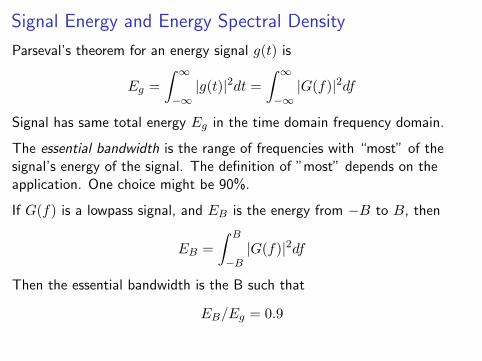
Parseval’s theorem for an energy signal g(t) is
Eg =
∫ ∞
−∞|g(t)|2dt =
∫ ∞
−∞|G(f)|2df
Signal has same total energy Eg in the time domain frequency domain.
The essential bandwidth is the range of frequencies with “most” of thesignal’s energy of the signal. The definition of ”most” depends on theapplication. One choice might be 90%.
If G(f) is a lowpass signal, and EB is the energy from −B to B, then
EB =
∫ B
−B|G(f)|2df
Then the essential bandwidth is the B such that
EB/Eg = 0.9
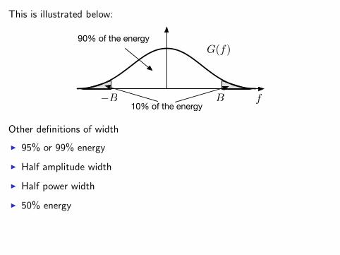
This is illustrated below:
−B B f
G(f)
10% of the energy
90% of the energy
Other definitions of width
I 95% or 99% energy
I Half amplitude width
I Half power width
I 50% energy

Autocorrelation and Energy Spectral Density
The autocorrelation of a signal g(t) is
ψg(t) =
∫ ∞
−∞g(τ)g∗(t+ τ) dτ
You’ll show in your homework that
F {ψg(t)} = |G(f)|2 = Ψ(f)
This is the energy spectral density or ESD. It reflects where the energy ofthe signal is located.
f
|G(f)|2|G(f)|2df
Note that
Eg =
∫ ∞
−∞|G(f)|2df =
∫ ∞
−∞Ψ(f)df

Energy Spectral Density Example
Let g(t) = Π(2t)
t0 1−1−2 2
g(t) = Π(2t)
The autocorrelation ψ(t) is
t0 1−1−2 2
ψg(t) =1
2∆(t)
The energy spectral density is then
0−2 2 f4−4
Ψ(f) =1
4sinc2
(π2f)

Autocorrelation and Power Spectral Density
For power signals, we normalize the ESD by the duration, to produce thepower spectral density or PSD.
The autocorrelation for a power signal g(t) is defined as
Rg(t) = limT→∞
1
T
∫ T/2
T/2g(τ)g∗(t+ τ)dτ
This has the Fourier transform
F {Rg(t)} = limT→∞
1
TΨg,T (f) = Sg(f)
Sg(f) is the power spectral density, PSD.
Again, this shows the frequency distribution of the power of the signal.

Power Spectral Density Example
Let g(t) be a random binary sequence of rectangle pulses g1(t) = Π(2t)
t0 1−1−2 2
g1(t) = Π(2t)g(t) =
∑
n
ang1(t− n)
For small displacements, the autocorrelation looks like
t0 1−1−2 2
After normalizing by the interval T , this is the same a for a single pulse.
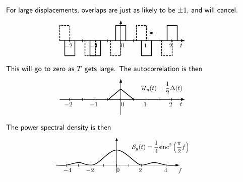
For large displacements, overlaps are just as likely to be ±1, and will cancel.
t0 1−1−2 2
This will go to zero as T gets large. The autocorrelation is then
t0 1−1−2 2
Rg(t) =1
2∆(t)
The power spectral density is then
0−2 2 f4−4
Sg(t) =1
4sinc2
(π2f)
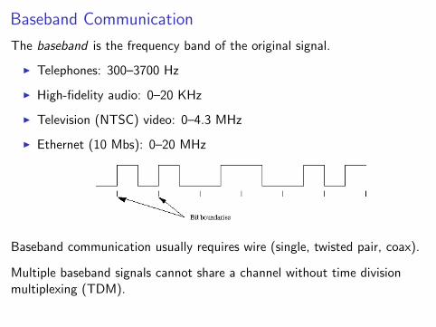
Baseband Communication
The baseband is the frequency band of the original signal.
I Telephones: 300–3700 Hz
I High-fidelity audio: 0–20 KHz
I Television (NTSC) video: 0–4.3 MHz
I Ethernet (10 Mbs): 0–20 MHz
Baseband communication usually requires wire (single, twisted pair, coax).
Multiple baseband signals cannot share a channel without time divisionmultiplexing (TDM).

Carrier Communication
Carrier communication uses modulation to shift spectrum of signal.
I Wireless communication requires frequencies higher than baseband
I Multiple signals can be sent at same time using different frequencies:frequency division multiplexing (FDM)
In carrier communication, the signal modulates a sinusoidal carrier.The signal modifies the amplitude, frequency, or phase of carrier.
s(t) = A(t) cos(2πfc(t)t+ φ(t)
)
I amplitude modulation: A(t) is proportional to m(t)
I frequency modulation: fc(t) is proportional to m(t)
I phase modulation: φ(t) is proportional to m(t)
Frequency and phase modulation are called angle modulation.
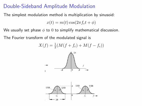
Double-Sideband Amplitude Modulation
The simplest modulation method is multiplication by sinusoid:
x(t) = m(t) cos(2πfct+ φ)
We usually set phase φ to 0 to simplify mathematical discussion.
The Fourier transform of the modulated signal is
X(f) = 12(M(f + fc) +M(f − fc))
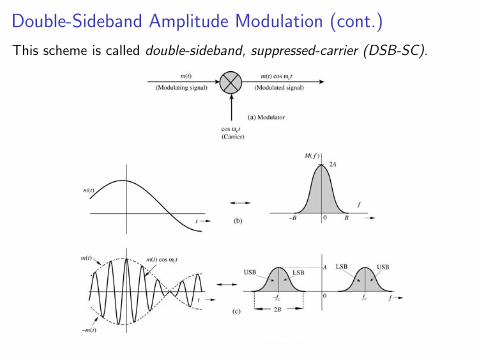
Double-Sideband Amplitude Modulation (cont.)
This scheme is called double-sideband, suppressed-carrier (DSB-SC).

Signal Bandwidth vs. Carrier Frequency
Transmitters can radiate only a narrow band without distortion. Thus wechoose the carrier frequency such that
fcB� 1 ⇐⇒ B
fc� 1
Examples:
I AM radio: B = 5 KHz, 550 ≤ fc ≤ 1600 KHz
⇒ 100 < fc/B < 320
I FM: B = 200 KHz, 87.7 ≤ fc ≤ 108.0 MHz
⇒ 43 < fc/B < 54
I US television: B = 6 MHz, 54 ≤ fc ≤ 862 MHz
⇒ 9 ≤ fc/B ≤ 142
Digital TV uses the same frequency bands as analog TV.

Demodulation of DSB-SC Signals
Demodulation uses a multiplier and a low-pass filter.
e(t) = x(t) cos(2πfct) = m(t) cos2(2πfct) = 12m(t) + 1
2 cos(4πfct)
The low pass filter does not have to be very sharp. But it should be flatover the signal baseband.

DSB-SC Example
Modulating a sinusoid is an important way to test the system. Let
m(t) = cos(2πfmt)
ThenM(f) = 1
2δ(f + fm) + 12δ(f − fm)
and
ϕDSB-SC(t) = m(t) cos(2πfct) = cos(2πfmt) cos(2πfct)
= 12
(cos((fc + fm)t) + cos((fc − fm)t)
)
The transform of the modulated signal contains two impulse pairs separatedby 2fc.

DSB-SC Example: Frequency Domain
Modulation and demodulation of cosine.

DSB-SC Example: Time Domain
0 0.5 1 1.5 2 2.5 3 3.5 4 4.5 5−1
−0.5
0
0.5
1x(t) = m(t) * cos(2*pi*fc*t)
0 0.5 1 1.5 2 2.5 3 3.5 4 4.5 5−1
−0.5
0
0.5
1e(t) = x(t) * cos(2*pi*fc*t)
0 0.5 1 1.5 2 2.5 3 3.5 4 4.5 5
−0.5
0
0.5
e(t) low−pass filtered

Types of Modulators
I Multiplier modulators using variable gain amplifiers.
I Nonlinear modulator. Suppose the input-output characteristic is
y(t) = ax(t) + bx2(t)
Let
x1(t) = cos(2πfct) +m(t)
x2(t) = cos(2πfct)−m(t)
It we apply x1(t) and x2(t) to the nonlinear modulator and look at thedifference
y1(t)− y2(t) = a(cos(2πfct) +m(t)) + b(cos(2πfct) +m(t))2
− a(cos(2πfct)−m(t))− b(cos(2πfct)−m(t))2
= 2am(t) + 4bm(t) cos(2πfct)
Convince yourself this is true!

Types of Modulators (cont.)
From the previous page
y1(t)− y2(t) = 2am(t) + 4bm(t) cos(2πfct)
This has the term we want at ωc = 2πfc, plus another copy of the messageat baseband.
The unwanted baseband component is blocked by bandpass filter. Thiscould be the antenna or the amplifier.
Or we can just forget about the baseband signal, it won’t propagate!

Types of Modulators (cont.)
Switching modulator: multiply message by a simple periodic function.
Suppose w(t) is periodic with a fundament frequency fc:
w(t) =
∞∑
n=−∞Dne
j2πfcnt
This weighted sum of complex exponentials that are impulses at allmultiples of fc. Then
m(t)w(t) =
∞∑
n=−∞Dnm(t)ej2πfcnt
By the convolution theorem, the spectrum of m(t)w(t) consists of M(f)shifted to ±fc,±2fc,±3fc, . . . Suppose w(t) is a square wave centered att = 0. Then from Lecture 3,
w(t) =1
2+
1
π
∞∑
n=−∞
1
nej2πfcnt , n odd
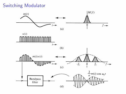
Switching Modulator

Ring Modulator

Frequency Converter
Multiplying a modulated signal by a sinusoidal moves the frequency band tosum and difference frequencies.
Super-heterodyning: ωmix = ωc + ωI .
Sub-heterodyning: ωmix = ωc − ωI .

Demodulation of DSB-SC Signals
Both modulator and demodulator use a multiplier by carrier signal.
I Modulator uses bandpass filter
I Demodulator uses lowpass filter
The carrier used by the demodulator must be in phase with the transmittercarrier (taking into account transmission delay).
Such a receiver is called synchronous, coherent, homodyne.
The receiver has a local oscillator that must be adjusted to stay in phasewith the received signal.
A voltage-controlled oscillator (VCO) that is controlled by a phase-lockedloop (PLL) is commonly used.
The phase of the carrier in the received signal must be extracted.

Demodulation of DSB-SC Signals (cont.)
Suppose that the signal is not ideal,
r(t) = Acm(t− t0) cos(2πfc(t− t0)
)
= Acm(t− t0) cos(2πfct− θd
)
where θd = 2πfct0.
0 0.5 1 1.5 2 2.5 3 3.5 4 4.5 5−0.5
0
0.5e2(t) = x(t) * sin(2*pi*fc*t)
0 0.5 1 1.5 2 2.5 3 3.5 4 4.5 5−0.1
−0.05
0
0.05
0.1e2(t) low−pass filtered
We can end up transmitting with a cosine, and receiving with a sine. Theseare orthogonal, and we get nothing!

Commercial AM
I If the goal is cheap receivers, then we can eliminate the PLL bytransmitting the carrier signal along with the modulated message.
ϕAM(t) = A cos(2πfct) +m(t) cos(2πfct)
= (A+m(t)) cos(2πfct)
I The tone A cos(2πfct) contains the desired carrier in correct phase.
I As long as A is larger than |m(t)|, then we can recover m(t) fromϕAM(t), as we will show next time.

Next time
I Commercial AM, and power
I Single Sideband AM (SSB)
I Vestigial Sideband AM (VSB)
I Quadrature Amplitude Modulation (QAM)