Embed Size (px)
DESCRIPTION
communication gatway of substation automation
Citation preview
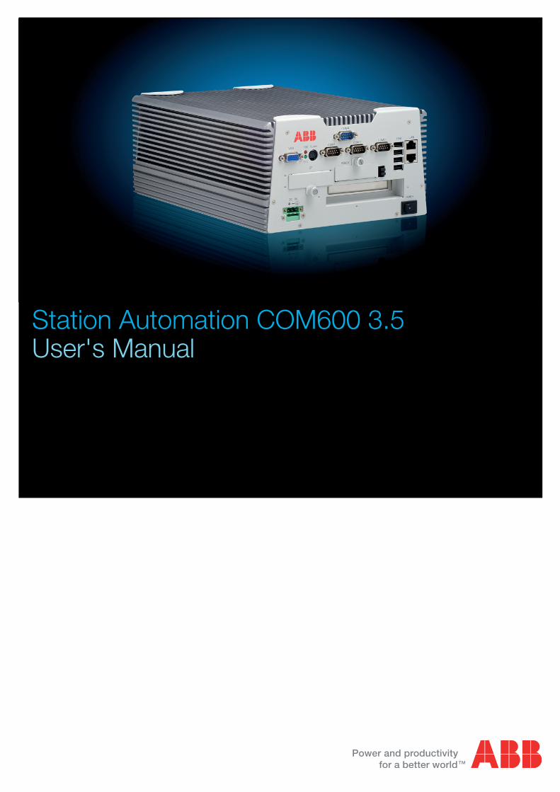
Station Automation COM600 3.5User's Manual

Contents:
1. About this manual .................................................................................. 7
1.1. Copyrights ...................................................................................... 71.2. Trademarks .................................................................................... 71.3. General .......................................................................................... 71.4. Document conventions .................................................................. 71.5. Use of symbols .............................................................................. 81.6. Terminology .................................................................................... 91.7. Abbreviations ............................................................................... 101.8. Related documents ...................................................................... 111.9. Document revisions ..................................................................... 12
2. Introduction ........................................................................................... 13
2.1. Overview of COM600 ................................................................... 13
3. Features ................................................................................................. 15
3.1. Gateway functionality ................................................................... 153.2. HMI .............................................................................................. 16
3.2.1. HMI functions ................................................................ 163.2.2. Predefined user account ............................................... 17
3.3. OPC server .................................................................................. 173.4. OPC client .................................................................................... 183.5. Logic Processor ........................................................................... 193.6. Data Historian .............................................................................. 203.7. IEC 61850 data modeling ............................................................ 213.8. Station/Remote switch function .................................................... 233.9. COM600 Watchdog ..................................................................... 243.10. External watchdog for COM600 ................................................... 243.11. Network Fault Tolerance for COM600 ......................................... 243.12. Queuing of Process Data Updates .............................................. 253.13. Event Printer ................................................................................ 26
4. Technical data ....................................................................................... 28
4.1. Mechanical properties .................................................................. 284.2. Software properties ...................................................................... 324.3. Mounting of COM600 computer ................................................... 344.4. Setting up the COM2 port for RS-232/RS-485 ........................... 354.5. Disposing of COM600 .................................................................. 36
5. Installation ............................................................................................. 37
5.1. About this section ......................................................................... 375.2. Requirements for SAB600 ........................................................... 375.3. Installing SAB600 ......................................................................... 375.4. Updating SAB600 ........................................................................ 38
3
Station Automation COM600 3.51MRS756125
User's ManualIssued: 16.10.2006Version: H/30.6.2011
5.5. License ......................................................................................... 395.6. Setting up the COM600 computer ............................................... 40
5.6.1. Accessing the COM600 computer ................................ 405.7. Uninstalling SAB600 .................................................................... 435.8. Turning off COM600 computer ..................................................... 44
6. Configuration ........................................................................................ 45
6.1. Opening a project in Station Automation Builder 600 ................. 456.2. Configuration and maintenance ................................................... 456.3. Configuration process .................................................................. 46
6.3.1. Overview of configuration process ................................ 466.3.2. Building and configuring object structures .................... 47
6.3.2.1. OPC servers ............................................... 476.3.2.2. Substation structure for HMI ...................... 486.3.2.3. OPC clients ................................................ 486.3.2.4. Configuring object properties ..................... 496.3.2.5. SCL Import function .................................... 516.3.2.6. System Consistency Check ........................ 566.3.2.7. Cross-References function ......................... 58
6.3.3. Configuration of Station/Remote switch ........................ 596.3.4. Event definitions ............................................................ 60
6.3.4.1. Creating event definitions ........................... 606.3.4.2. Configuring event definitions ..................... 61
6.3.5. Configuring Alarm groups ............................................. 626.3.6. Configuring COM600 event printer ............................... 646.3.7. Using scales .................................................................. 65
6.3.7.1. General about using scales ........................ 656.3.7.2. Creating scales ........................................... 656.3.7.3. Configuring scales ..................................... 66
6.4. Backing up and restoring ............................................................. 686.5. Retrieving previous configuration ................................................ 686.6. SCL Export ................................................................................... 696.7. Configuring external watchdog for COM600 ................................ 706.8. Installing and configuring Duo Driver ........................................... 706.9. Installing Intel Teaming feature to COM600 ................................. 716.10. Configuring Data historian ........................................................... 74
6.10.1. Preparing COM600 for Data Historian .......................... 746.10.2. Configuring Data Historian measurements and
signals ........................................................................... 76
7. Operation ............................................................................................... 78
7.1. Activating COM600 with new configurations ............................... 787.2. License handling .......................................................................... 787.3. Using web site security certificates .............................................. 79
7.3.1. Creating self-signed certificates .................................... 797.3.2. Using self-signed certificates with Internet Explorer
7 .................................................................................... 80
4
1MRS756125Station Automation COM600 3.5
User's Manual

7.3.3. Using self-signed certificates with Internet Explorer 8(Windows 7) ................................................................. 80
7.3.4. Using self-signed certificates with Mozilla Firefox3.6.3 .............................................................................. 80
7.4. Diagnostics .................................................................................. 817.4.1. General about diagnostics ............................................ 817.4.2. Data object diagnostics ................................................. 827.4.3. Diagnostic services of OPC servers and clients ........... 837.4.4. Signal diagnostics ......................................................... 847.4.5. Diagnostic Web Server ................................................. 85
Index .............................................................................................................. 87
5
Station Automation COM600 3.51MRS756125
User's Manual

6
About this manual1.
Copyrights1.1.
The information in this document is subject to change without notice and should not beconstrued as a commitment by ABB Oy. ABB Oy assumes no responsibility for anyerrors that may appear in this document.
In no event shall ABB Oy be liable for direct, indirect, special, incidental, or consequentialdamages of any nature or kind arising from the use of this document, nor shall ABB Oybe liable for incidental or consequential damages arising from use of any software orhardware described in this document.
This document and parts thereof must not be reproduced or copied without written per-mission from ABB Oy, and the contents thereof must not be imparted to a third partynor used for any unauthorized purpose.
The software or hardware described in this document is furnished under a license andmay be used, copied, or disclosed only in accordance with the terms of such license.
© Copyright 2011 ABB. All rights reserved.
Trademarks1.2.
ABB is a registered trademark of ABB Group. All other brand or product names men-tioned in this document may be trademarks or registered trademarks of their respectiveholders.
General1.3.
This manual provides thorough information on Station Automation COM600 (laterreferred to as COM600) and the central concepts related to it. The manual providesinformation about COM600 features, installation and unistallation instructions for theStation Automation Builder 600 (SAB600), and configuration and operation instructionsfor SAB600. For more information on each topic related to a specific protocol, refer tothe list of related documents in 1.8, Related documents.
Document conventions1.4.
The following conventions are used for the presentation of material:• The words in names of screen elements (for example, the title in the title bar of a
window, the label for a field of a dialog box) are initially capitalized.
7
Station Automation COM600 3.51MRS756125
User's Manual

• Capital letters are used for the name of a keyboard key if it is labeled on the keyboard.For example, press the ENTER key.
• Lowercase letters are used for the name of a keyboard key that is not labeled on thekeyboard. For example, the space bar, comma key, and so on.
• Press CTRL+C indicates that you must hold down the CTRL key while pressingthe C key (to copy a selected object in this case).
• Press ESC E C indicates that you press and release each key in sequence (to copya selected object in this case).
• The names of push and toggle buttons are boldfaced. For example, click OK.• The names of menus and menu items are boldfaced. For example, the File menu.
• The following convention is used for menu operations: MenuName > Menu-Item > CascadedMenuItem. For example: select File > New > Type.
• The Start menu name always refers to the Start menu on the Windows taskbar.• System prompts/messages and user responses/input are shown in the Courier font.
For example, if you enter a value out of range, the following message is displayed:
Entered value is not valid. The value must be 0 - 30 .
• You can be asked to enter the string MIF349 in a field. The string is shown as followsin the procedure:
MIF349• Variables are shown using lowercase letters:
sequence name
Use of symbols1.5.
This publication includes warning, caution, and information icons that point out safety-related conditions or other important information. It also includes tip icons to point outuseful information to the reader. The corresponding icons should be interpreted as follows.
The electrical warning icon indicates the presence of a hazardwhich could result in electrical shock.
The warning icon indicates the presence of a hazard whichcould result in personal injury.
The caution icon indicates important information or warningrelated to the concept discussed in the text. It may indicatethe presence of a hazard which could result in corruption ofsoftware or damage to equipment or property.
8
1MRS756125Station Automation COM600 3.5
User's Manual

The information icon alerts the reader to relevant facts andconditions.
The tip icon indicates advice on, for example, how to designyour project or how to use a certain function.
Terminology1.6.
The following is a list of terms associated with COM600 that you should be familiarwith. The list contains terms that are unique to ABB or have a usage or definition thatis different from standard industry usage.
DescriptionTerm
An abnormal state of a condition.Alarm
An OPC service for providing information about alarms andevents to OPC clients.
Alarms and Events; AE
An OPC service for providing information about process data toOPC clients.
Data Access; DA
Part of a logical node object representing specific information,for example, status, or measurement. From an object-orientedpoint of view, a data object is an instance of a class data object.DOs are normally used as transaction objects; that is, they aredata structures.
Data Object; DO
The data set is the content basis for reporting and logging. Thedata set contains references to the data and data attribute val-ues.
Data Set
A physical device that behaves as its own communication nodein the network, for example, protection relay.
Device
Change of process data or an OPC internal value. Normally, anevent consists of value, quality, and timestamp.
Event
A physical IEC 61850 device that behaves as its own commu-nication node in the IEC 61850 protocol.
Intelligent Electronic Device
Representation of a group of functions. Each function is definedas a logical node. A physical device consists of one or severalLDs.
Logical Device; LD
The smallest part of a function that exchanges data. An LN isan object defined by its data and methods.
Logical Node; LN
A communication protocol developed by Echelon.LON
A proprietary method of ABB on top of the standard LON pro-tocol.
LON Application Guideline forsubstation automation; LAG
9
Station Automation COM600 3.51MRS756125
User's Manual
DescriptionTerm
Series of standards specifications aiming at open connectivityin industrial automation and the enterprise systems that supportindustry.
OPC
Representation of a connection to the data source within theOPC server. An OPC item is identified by a string <objectpath>:<property name>. Associated with each OPC item areValue, Quality, and Time Stamp.
OPC item
Named data item.Property
The report control block controls the reporting processes forevent data as they occur. The reporting process continues aslong as the communication is available.
Report Control Block
ABB proprietary communication protocol used in substationautomation.
SPA
Protection and/or Control Product supporting the SPA protocolversion 2.5 or earlier.
SPA device
XML-based description language for configurations of electricalsubstation IEDs. Defined in IEC 61850 standard.
Substation Configuration Lan-guage; SCL
Abbreviations1.7.
The following is a list of abbreviations associated with COM600 that you should befamiliar with. See also 1.6, Terminology.
DescriptionAbbreviation
Alarms and EventsAE
Application Service Data UnitASDU
Buffered Report Control BlockBRCB
Data AccessDA
Data Message Code DefinitionDMCD
Data ObjectDO
Gateway, component connecting two communication networks togetherGW
Human Machine InterfaceHMI
International Electrotechnical CommissionIEC
Intelligent Electronic DeviceIED
LON Application Guideline for substation automationLAG
Local Area NetworkLAN
Logical DeviceLD
10
1MRS756125Station Automation COM600 3.5
User's Manual
DescriptionAbbreviation
LonMark interoperable device communicating in LonWorks network. Inthis document, the term is used for devices that do not support the ABBLON/LAG communication.
LMK
Logical NodeLN
LON SPA GatewayLSG
Network Control CenterNCC
Norwegian User ConventionNUC
Network VariableNV
Object Linking and EmbeddingOLE
OLE for Process ControlOPC
Protection & ControlP&C
Request To SendRTS
Substation AutomationSA
Station Automation Builder 600SAB600
Substation Configuration LanguageSCL
Single Line DiagramSLD
Simple Network Management ProtocolSNMP
Simple Network Time ProtocolSNTP
Simple Object Access ProtocolSOAP
Report Control BlockRCB
Unbuffered Report Control BlockURCB
eXtended Markup LanguageXML
Related documents1.8.
MRS numberName of the manual
1MRS756125COM600 User’s Manual
1MRS756705COM600 Operator's Manual
1MRS756740COM600 HMI Configuration Manual
1MRS756739COM600 Data Historian Operator's Manual
1MRS756566DNP LAN/WAN Master (OPC)
1MRS756567DNP Serial Master (OPC)
1MRS755496DNP LAN/WAN Slave (OPC)
1MRS755495DNP Serial Slave (OPC)
11
Station Automation COM600 3.51MRS756125
User's Manual

MRS numberName of the manual
1MRS755564External OPC Client Access
1MRS755382IEC 60870-5-101 Slave (OPC)
1MRS756703IEC 60870-5-101 Master (OPC)
1MRS752278IEC 60870-5-103 Master (OPC)
1MRS755384IEC 60870-5-104 Slave (OPC)
1MRS756704IEC 60870-5-104 Master (OPC)
1MRS755321IEC 61850 Master (OPC)
1MRS756738Logic Processor User's Manual
1MRS755284LON-LAG Master (OPC)
1MRS756569MNS iS Connectivity (OPC)
1MRS756126Modbus Serial Master (OPC)
1MRS756913Modbus Serial Slave (OPC)
1MRS756445Modbus TCP Master (OPC)
1MRS756914Modbus TCP Slave (OPC)
1MRS752275SPA Master (OPC)
1MRS755497SPA Router (OPC)
Document revisions1.9.
HistoryProduct revisionDocument version/date
Document created3.0A/16.10.2006
Document revised3.0B/22.1.2007
Document revised3.0C/8.6.2007
Document revised3.1D/21.12.2007
Document revised3.2E/17.6.2008
Document revised3.3F/13.2.1009
Document revised3.4G/06.11.2009
Document revised3.5H/30.06.2011
12
1MRS756125Station Automation COM600 3.5
User's Manual
Introduction2.
Overview of COM6002.1.
COM600 provides gateway functions for mapping signals between protection and controlIEDs in industrial or utility substations and higher-level systems. It further includes anoptional HMI that provides data and information from the substation to the users.
COM600 gathers data from protection and control IEDs and from process devices usingdifferent communication protocols. The supported protocols can be combined freely inone station computer, limited only by the number of hardware interfaces and the license.COM600 uses web technology to display data to different users in a professional anduser-friendly manner. The web technology is further used to transfer information to anetwork control centre (NCC) or distributed control system (DCS).
COM600 benefits from the potential of the IEC 61850 standard by using the IEC 61850-6 substation configuration language (SCL) and IEC 61850 -7 communications modelingregardless of protocol used. As the IEC 61850 data modeling is used for all communic-ation protocols the gateway cross-reference is done in the same way regardless of theprotocol, for example IEC 61850-8-1 or DNP3.
With the optional web HMI, COM600 can be used for efficient substation visualization,monitoring, and control. The supported browsers are Microsoft Internet Explorer (requiresAdobe SVG viewer 3.03), Mozilla Firefox®, and Opera. Measured values from processdevices are displayed on the HMI. Single-line diagrams can be used to view any availablemeasured values from the process devices.
13
Station Automation COM600 3.51MRS756125
User's Manual

Product ordering codes
COM600_product_codes.jpg
Figure 2.1-1 COM600 product ordering codes
14
1MRS756125Station Automation COM600 3.5
User's Manual

Features3.
Gateway functionality3.1.
The Gateway functionality provides a framework that enables the use of OPC server andclient components, such as OPC Client for IEC 60870-5-101 and OPC Server for LONLAG 1.4. This manual presents the principles that are common to the protocols availableat the moment as well as to those that will be applicable in the future. For protocol-specificinformation , refer to the respective client and server user’s manuals.
COM600Inside.jpg
Figure 3.1-1 Conceptual view of COM600 Gateway
1. Network Control Center (NCC)2. Engineering PC with Station Automation Builder 600 (SAB600)3. COM600 with embedded operation system, OPC client(s) for NCC connection(s),
OPC server(s) for process connection4. Protection and control devices
Normally, there is one OPC client per NCC connection. If you want to create severalNCC connections with the same protocol, use multiple instances.
COM600 consists of OPC Data Access (DA) server and client components. OPC Serversare used mainly for master/client protocol stacks to provide access to the data in thedevices in the protocol. OPC Clients are used for slave/server protocol stacks to enableexternal systems to access data available in the OPC Servers.
15
Station Automation COM600 3.51MRS756125
User's Manual

GWComponents.jpg
Figure 3.1-2 Example of COM600 Gateway components
HMI3.2.
HMI functions3.2.1.
The HMI enables the user to access the COM600 computer via a web browser.
The features of HMI include:• Single Line Diagram• Busbar coloring• Event lists• Alarm lists• Parameter settings• Disturbance data upload• System supervision• Breaker and switch control• Measurement display• User management• Data historian (optional feature)
16
1MRS756125Station Automation COM600 3.5
User's Manual

sld_example.png
Figure 3.2.1-1 Example view of the COM600 HMI
The HMI can be accessed:
• locally via an optional local HMI screen• locally by connecting your laptop to COM600 via LAN• remotely through the internet or over LAN/WAN
Predefined user account3.2.2.
HMI has a predefined user account with administrator rights.
• User name: admin• Password: adminadmin
When you log in for the first time as an administrator, change the password before youproceed using HMI. If you forget the new password, restore the factory settings with theManagement tool in SAB600. After the factory settings have been restored, you can onlylog in with the predefined administrator password mentioned above.
OPC server3.3.
The OPC server component consists of a Master/Client Protocol Stack, OPC DA/AEServer, and Configuration SCL.
17
Station Automation COM600 3.51MRS756125
User's Manual
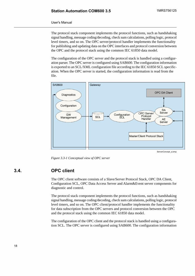
The protocol stack component implements the protocol functions, such as handshakingsignal handling, message coding/decoding, check sum calculations, polling logic, protocollevel timers, and so on. The OPC server/protocol handler implements the functionalityfor publishing and updating data on the OPC interfaces and protocol conversion betweenthe OPC and the protocol stack using the common IEC 61850 data model.
The configuration of the OPC server and the protocol stack is handled using a configur-ation parser. The OPC server is configured using SAB600. The configuration informationis exported to an SCL/XML configuration file according to the IEC 61850 SCL specific-ation. When the OPC server is started, the configuration information is read from thefile.
ServerConcept_a.bmp
Figure 3.3-1 Conceptual view of OPC server
OPC client3.4.
The OPC client software consists of a Slave/Server Protocol Stack, OPC DA Client,Configuration SCL, OPC Data Access Server and Alarm&Event server components fordiagnostic and control.
The protocol stack component implements the protocol functions, such as handshakingsignal handling, message coding/decoding, check sum calculations, polling logic, protocollevel timers, and so on. The OPC client/protocol handler implements the functionalityfor data subscription from the OPC servers and protocol conversion between the OPCand the protocol stack using the common IEC 61850 data model.
The configuration of the OPC client and the protocol stack is handled using a configura-tion SCL. The OPC server is configured using SAB600. The configuration information
18
1MRS756125Station Automation COM600 3.5
User's Manual
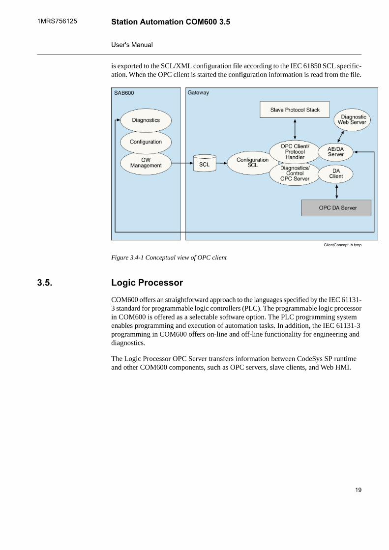
is exported to the SCL/XML configuration file according to the IEC 61850 SCL specific-ation. When the OPC client is started the configuration information is read from the file.
ClientConcept_b.bmp
Figure 3.4-1 Conceptual view of OPC client
Logic Processor3.5.
COM600 offers an straightforward approach to the languages specified by the IEC 61131-3 standard for programmable logic controllers (PLC). The programmable logic processorin COM600 is offered as a selectable software option. The PLC programming systemenables programming and execution of automation tasks. In addition, the IEC 61131-3programming in COM600 offers on-line and off-line functionality for engineering anddiagnostics.
The Logic Processor OPC Server transfers information between CodeSys SP runtimeand other COM600 components, such as OPC servers, slave clients, and Web HMI.
19
Station Automation COM600 3.51MRS756125
User's Manual
Logic Processor.bmp
Figure 3.5-1 Functional overview of Logic Processor
CoDeSys SP runtime system is manufactured by 3S-Smart Software Solutions GmbH(www.3s-software.com).
Data Historian3.6.
The COM600 data historian is a real-time database designed and optimized for processinformation management and extensive history recording. The data historian is basedon ABB’s cpmPlus Knowledge Manager software. It combines the benefits of an easy-to-use real-time database with industrial reliability, performance, and real-time function-ality to provide an excellent platform for process information management.
20
1MRS756125Station Automation COM600 3.5
User's Manual
The data historian can be used for accurate process performance monitoring by followingprocess and equipment performance calculations with real-time and history values.Better understanding of the process behaviour by joining time-based process measure-ments with production and maintenance events helps the user to understand the processdynamics. It further provides required information for learning how to keep the processrunning. High performance and reliability, together with maintenance-free operation,provide a solid platform for trending.
The optional data historian functionality offers means of storing, analyzing andpresenting process data.
IEC 61850 data modeling3.7.
To simplify protocol conversion and signal mapping in the gateway, each componentuses a common data model. The data model is based on common data classes and servicesspecified in the IEC 61850 standard. Each client and server component is a separateprogram. The components interact with each other only via OPC interfaces. This meansthat they can be developed and used independently as a part of the gateway as long asthey conform with the OPC DA and common data model specifications.
Protection and control products are connected to the gateway via OPC interfaces. AlthoughOPC provides means to access data on devices, it does not specify the semantics of thedata. This means that the same information is available in different formats dependingon which device and communication protocol is used. In addition, services, such asbreaker operation, vary among devices and protocols.
These differences complicate the reuse of gateway applications. To overcome thisproblem, all the applicable data and services are remodeled in OPC servers accordingto the data and service model specified in the IEC 61850 standard. This provides a pro-tocol and device independent interface between the applications and the process. Fig-ure 3.7-1 presents an overview of the IEC 61850 model usage.
21
Station Automation COM600 3.51MRS756125
User's Manual

IECmodelling.jpg
Figure 3.7-1 Overview of IEC 61850 model usage
The smallest unit in the IEC 61850 modeling is a data attribute which is linked to anOPC item in the OPC server. A data attribute can be, for instance, the state value of adouble point object (stVal), quality information (q), or timestamp (t). In the OPC server,some of the services are also mapped to the same level as the attributes. This means that,for example, control services (such as ctlOperOn, ctlOperOff) for operating a doublepoint object are available as OPC items.
For different types of data, the IEC 61850 standard defines over 30 common data classesincluding a set of mandatory and optional attributes and services. For example, commondata classes are defined for Controllable double point (DPC), Single point status (SPS)and Measured value (MV).
Furthermore, the standard defines approximately 90 functional groups of data, based oncommon data classes. These groups are called logical nodes. Examples of logical nodesare controllable switch (CSWI) and distance protection (PDIS).
Logical nodes can be further grouped under logical devices (LD), forming logical groupswithin a physical device (IED), see Figure 3.7-2.
22
1MRS756125Station Automation COM600 3.5
User's Manual

LONNamespace.jpg
Figure 3.7-2 LON OPC Server name space in relation to IEC 61850 model
Station/Remote switch function3.8.
The COM600 gateway provides a common Station/Remote (S/R) switch functionalityfor OPC servers and clients. The S/R switch is used to determine whether the objects ina logical device of an IED can be controlled within the station, or remotely via a gateway.
A station can have one or more S/R switches. The switches are either physical switchesor software switches in a simulated IED of an OPC server. The S/R switches are modeledusing the IEC 61850 SPS, SPC, DPS, DPC, INS, or INC data class.
Each IED or logical device in an IED is linked with an S/R switch during the configurationprocess. If a logical device has no linking information configured, the linking informationof the IED is used instead. At runtime, an OPC server publishes the logical device S/Rswitch linking information for the OPC clients of the COM600 gateway. Each time anOPC client sends a command to a device, it first checks the S/R switch position todetermine whether the operation is allowed or not. The COM600 gateway OPC clientis allowed to operate only if the S/R switch is in remote position.
A COM600 gateway OPC client has the operation modes disabled and enabled for S/Rswitch handling. When the switch is in the enabled mode, the values for S/R switchposition failures are Allow controls if position unknown and Reject controls if positionunknown.
HMI is considered a local station HMI, if it uses the local display of the COM600 com-puter, or if the IP address of the HMI client is in the range specified with a Station IP
23
Station Automation COM600 3.51MRS756125
User's Manual
Address Filter property in the Gateway object. Otherwise HMI is considered a remoteHMI. The state of the station/remote switch controls whether the operations are allowedfrom HMI or not.
The station/remote switch for the HMI is configured with the SLD editor by insertingthe Station Switch Indicator symbol to the substation SLD and specifying the data objectfor the position information. If a real switch indication is not available, it is possible touse a simulated data from a virtual IED. This can be done by creating an IED configurationin the communication structure and setting the simulation mode of the IED to true.
COM600 Watchdog3.9.
The COM600 computer has a built-in hardware watchdog function. The function can beenabled with SAB600 from the Gateway object properties. When enabled, the watchdogmonitors the COM600 software. If the COM600 software fails to send the keep-alivetriggering to the watchdog within a certain time, the watchdog restarts the COM600computer.
External watchdog for COM6003.10.
COM600 can be configured to send periodically a command to an IED connected toCOM600. This function can be used to monitor the health of COM600. For example,SACO 16D2 can be connected with SPA protocol to COM600 and configured to createan alarm if no command from COM600 is received within specified time. Configurationof an external watchdog device is described in 6.7, Configuring external watchdog forCOM600.
Network Fault Tolerance for COM6003.11.
COM600 can be configured to provide a certain level of tolerance against network failureby using either the ABB DuoDriver feature or the Intel Teaming Feature, Switch FaultTolerance. These features are available when the optional dual port PCI Ethernet networkadapter is used.
DuoDriver
DuoDriver implements the Parallel Redundancy Protocol (PRP) for Ethernet as specifiedin IEC 62439 DIS. PRP is based on duplicated networks, where each message is sentvia both networks, the receiver node accepts the first received message and discard theduplicate. Message replication and discard function is done by the DuoDriver and ithides the two networks from the upper level applications. In PRP there is practically noswitch over time in the case of one of the network fails as every message is always sentto both networks. DuoDriver has diagnostic data, which can be read with IEC61850 OPC
24
1MRS756125Station Automation COM600 3.5
User's Manual
server. The diagnostic data can be further used on COM600 HMI and gateway applica-tions. See 6.8, Installing and configuring Duo Driver for installation and configurationdetails.
Switch Fault Tolerance
The Switch Fault Tolerance feature of the Intel network adapter requires the TeamingFeature to be enabled.
Teaming Features include Failover protection, increased bandwidth through aggregation,and balancing of traffic among team members. Teaming Modes are AFT, SFT, ALB,RLB, and EtherChannel*/3ad (LA/FEC/GEC/3ad). Only Failover protection using SFTis supported by COM600.
Queuing of Process Data Updates3.12.
This section describes the common queue mechanism for OPC Clients (slave protocols)in COM600. There can be additional queuing mechanisms on different levels of theprotocol stacks, that are specific for the protocol, which are not described here.
Process data updates are queued in the OPC Clients of COM600. Each OPC Client hasits own queues independent from other clients, which prevents disturbances on one clientconnection from interfering with other connections. There are four separate queues fordifferent type of data with configurable length.
• High Priority• command replies/confirms• internal protocol stack control commands• protocol stack database initialization commands
• State Indications• binary data and other state indications
• Measurements• analog data
• Interrogated• interrogation-related data and commands
Queue logic
For high priority and interrogated queues the oldest message is skipped when the queuesfill up. Generally these queues should never fill up since they contain a limited numberof updates (proportional to the number of OPC items).
When the state indication queue is full, the new updates are always skipped until thereis free space in the queue.
25
Station Automation COM600 3.51MRS756125
User's Manual

When the measurement queue is full, an older update is always skipped when a newupdate is pushed the queue.
The updates are skipped according to the following logic:• If an item has two or more updates, the oldest update is skipped• If no item has two or more updates, the oldest update in the queue is skipped.
For measurements, older updates for an item are also skipped when the queue reachesa configurable percent of the maximum capacity (but only if there is an item with multipleoutstanding updates to send).
Queue priorities
If a high priority queue contains an update, it is always sent first. After that, the interrog-ated queue is checked. If none of these queues has updates, the state indications andmeasurements are checked in round-robin fashion.
Queue capacities
The capacity (maximum size) of each queue is independently configured. If one queuefills up, capacity from another, possibly non-full queue is not used.
Event Printer3.13.
COM600 Event Printer enables printing of events as they arrive to COM600. The sameevent information is presented on the COM600 HMI event list and printed on the eventprinter. It is possible to customize the printout, for example, by selecting the printedcolumns and their lengths. Alarming events can be marked with a configurable symbol.For more information about the configuration of the Event Printer, see 6.3.6, ConfiguringCOM600 event printer.
Currently supported printer models are Fujitsu DL3750+ andDL3850+. Any dot matrix printer should work, but theircompatibility with COM600 cannot be guaranteed. If localspecial characters are needed, check that the printer characterset supports them.
Event Printer is connected to a serial communication port (RS-232) of COM600 with anull-modem cable (to be purchased separately).
For diagnostic purposes, Event Printer generates the following non-printable supervisionevents to the HMI event list.
26
1MRS756125Station Automation COM600 3.5
User's Manual
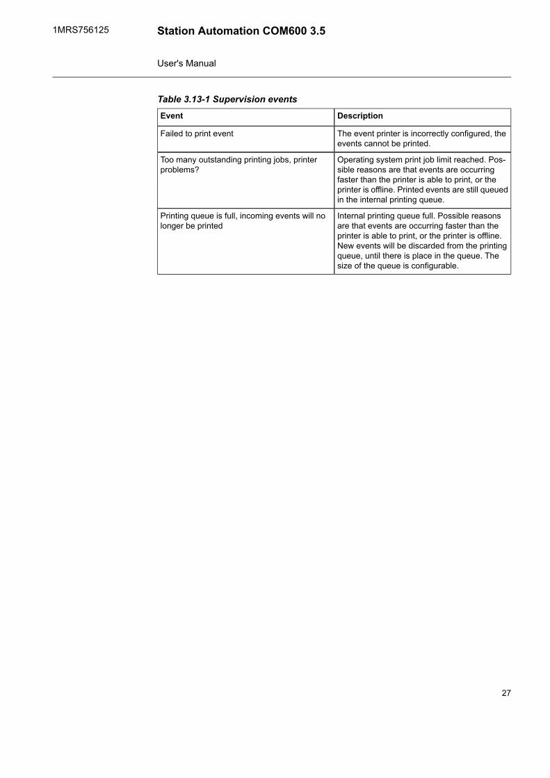
Table 3.13-1 Supervision eventsDescriptionEvent
The event printer is incorrectly configured, theevents cannot be printed.
Failed to print event
Operating system print job limit reached. Pos-sible reasons are that events are occurringfaster than the printer is able to print, or theprinter is offline. Printed events are still queuedin the internal printing queue.
Too many outstanding printing jobs, printerproblems?
Internal printing queue full. Possible reasonsare that events are occurring faster than theprinter is able to print, or the printer is offline.New events will be discarded from the printingqueue, until there is place in the queue. Thesize of the queue is configurable.
Printing queue is full, incoming events will nolonger be printed
27
Station Automation COM600 3.51MRS756125
User's Manual
Technical data4.
Mechanical properties4.1.
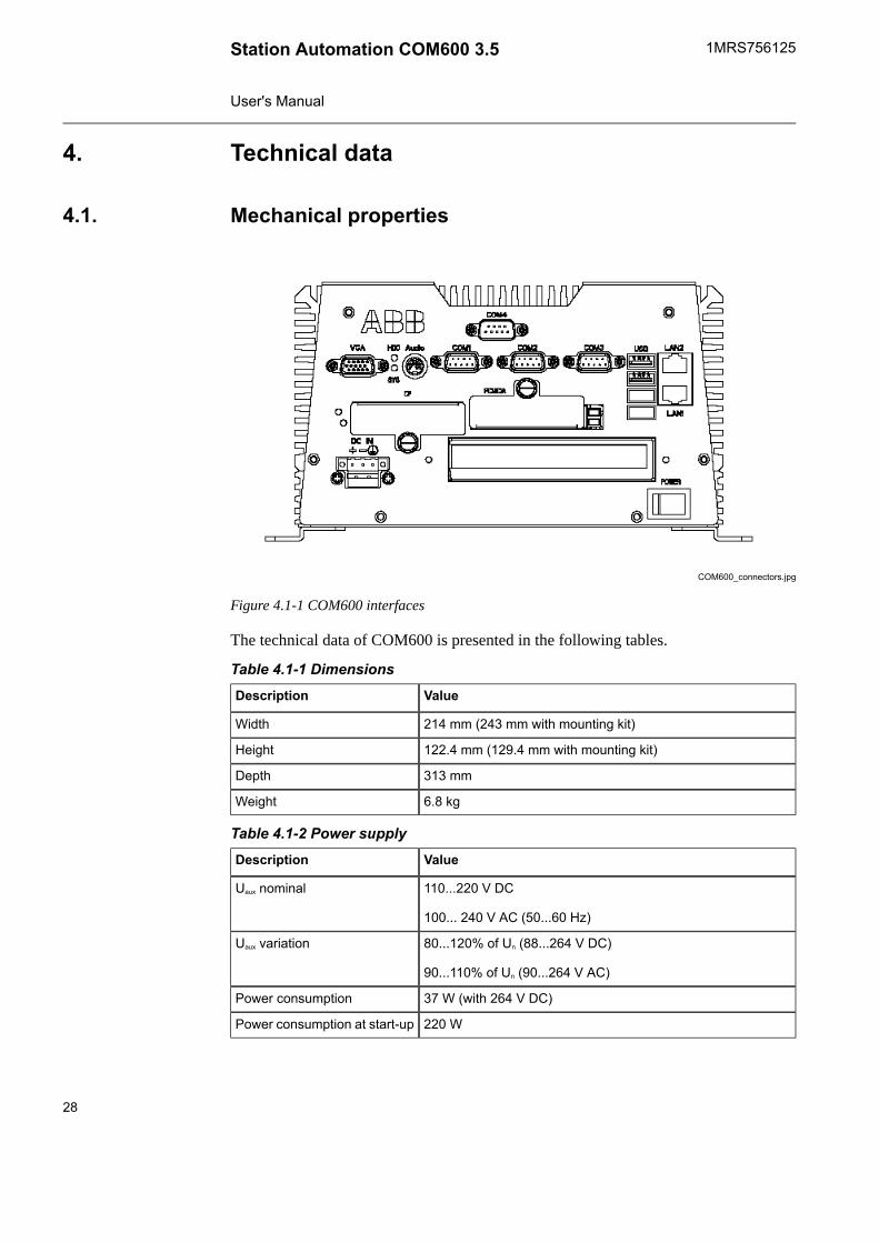
COM600_connectors.jpg
Figure 4.1-1 COM600 interfaces
The technical data of COM600 is presented in the following tables.
Table 4.1-1 DimensionsValueDescription
214 mm (243 mm with mounting kit)Width
122.4 mm (129.4 mm with mounting kit)Height
313 mmDepth
6.8 kgWeight
Table 4.1-2 Power supplyValueDescription
110...220 V DC
100... 240 V AC (50...60 Hz)
Uaux nominal
80...120% of Un (88...264 V DC)
90...110% of Un (90...264 V AC)
Uaux variation
37 W (with 264 V DC)Power consumption
220 WPower consumption at start-up
28
1MRS756125Station Automation COM600 3.5
User's Manual
Table 4.1-3 HardwareValueDescription
Intel® Pentium M 1.6 GHzProcessor
1 GB SDRAMSystem memory
8 GB industrial SSDCompact flash memory
Table 4.1-4 InterfacesValueDescription
3 x RS-232 interfacesSerial interfaces
1 x RS-232/485 serial interfaceSerial interface
2 x 10/100Base-TX RJ-45 interfacesEthernet interfaces
4 x USB 2.0 interfacesUSB
Table 4.1-5 Optional PCI extensionsValueDescription
1 x 1 LON interfaceLON interface 1)
8 x RS-232/485 serial interfacesSerial interfaces 2)
2 x 10BASE-T/100BASE-TX/1000BASE-T RJ-45 interfacesEthernet interfaces 3)
1) Operating temperature 0° C - +70° C
2) Operating temperature 0° C - +55° C
3) Operating temperature 0° C - +55° C
Table 4.1-6 Inspection of mechanical structureStandardDescription
According to IEC 60255-5, -6Markings and mechanicalstructure
According to IEC 60529Degree of protection byenclosure
According to IEC 60255-5Clearance and creepage dis-tances
Table 4.1-7 Power supply and module testsStandardDescription
According to IEC 60255-6Auxiliary voltage
According to IEC 60255-11Aux. voltage interruptions
According to IEC 60255-11 12%, f = 2 x fnRipple in auxiliary DC voltage
According to CE EN 61010Power consumption
29
Station Automation COM600 3.51MRS756125
User's Manual
Table 4.1-8 Insulation testsStandardDescription
According to IEC 60255-5 2 kV, 50 Hz for 1 minuteDielectric test
According to IEC 60255-5 5 kV, 1.2/50 μs, 0.5 JImpulse voltage test
According to IEC 60255-5 >100 MΩ, 500 VdcInsulation resistance
According to IEC 60255-27 <0.1 Ω.Protective bonding impedance
The EMC immunity test level meets the requirements listed below:
Table 4.1-9 Electromagnetic compatibility testsStandardDescription
According to IEC 61000-4-18 and IEC 60255-22-1
• 2.5 kV• 1.0 kV
1 MHz burst disturbance test
• Common mode• Differential mode
According to IEC 61000-4-2, IEC 60255-22-2
• 6 kV• 8 kV
Electrostatic discharge test
• Contact discharge• Air discharge
According to IEC 61000-4-3 and IEC 60255-22-3
• 10 V/m (80% amp.mod.)• f=80...1000 MHz• 10 V/m (pulse mod.) f=900 MHz
Radio frequency field immunity
According to IEC 61000-4-4 and IEC 60255-22-4
• 2 kV• 1 kV
Fast transient
• Power supply• RJ-45 port
According to IEC 61000-4-5 and IEC 60255-22-5
• 2 kV line-to-earth, 1 kV line-to-line
Surge immunity
• Power supply
According to IEC 61000-4-6 and IEC 60255-22-6
• 10 V (80% ampl. mod.)• f= 150 kHz...80 MHz
Conducted radio frequencydisturbance
According to IEC 61000-4-8, 300 A/m, continuousPower frequency (50 Hz) mag-netic field
According to IEC 61000-4-11
• 30% reduction for 10 ms• 60% reduction for 100 ms• 60% reduction for 1000 ms• >95% reduction for 5000 ms
Voltage dips and short interrup-tions
According to EN 55011, and IEC60255-25, class AEmission tests
30
1MRS756125Station Automation COM600 3.5
User's Manual
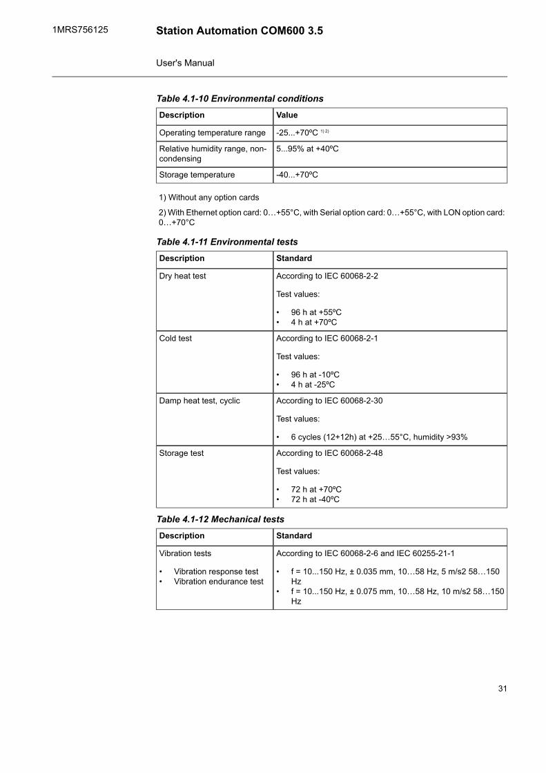
Table 4.1-10 Environmental conditionsValueDescription
-25...+70ºC 1) 2)Operating temperature range
5...95% at +40ºCRelative humidity range, non-condensing
-40...+70ºCStorage temperature
1) Without any option cards
2) With Ethernet option card: 0…+55°C, with Serial option card: 0…+55°C, with LON option card:0…+70°C
Table 4.1-11 Environmental testsStandardDescription
According to IEC 60068-2-2
Test values:
• 96 h at +55ºC• 4 h at +70ºC
Dry heat test
According to IEC 60068-2-1
Test values:
• 96 h at -10ºC• 4 h at -25ºC
Cold test
According to IEC 60068-2-30
Test values:
• 6 cycles (12+12h) at +25…55°C, humidity >93%
Damp heat test, cyclic
According to IEC 60068-2-48
Test values:
• 72 h at +70ºC• 72 h at -40ºC
Storage test
Table 4.1-12 Mechanical testsStandardDescription
According to IEC 60068-2-6 and IEC 60255-21-1
• f = 10...150 Hz, ± 0.035 mm, 10…58 Hz, 5 m/s2 58…150Hz
• f = 10...150 Hz, ± 0.075 mm, 10…58 Hz, 10 m/s2 58…150Hz
Vibration tests
• Vibration response test• Vibration endurance test
31
Station Automation COM600 3.51MRS756125
User's Manual

StandardDescription
According to IEC 60068-2-27 , IEC 60068-2-29 and IEC 60255-21-2
• peak acceleration = 5 x gn, pulse duration = 11 ms, numbersof pulses in each diretion = 3
• peak acceleration = 15 x gn, pulse duration = 11 ms, numberof pulses in each direction = 3
• peak acceleration = 10 x gn, pulse duration = 16 ms, numberof pulses in each direction = 1000
Shock and bump tests
• Shock response test• Shock withstand test• Bump test
According to IEC 60255-21-3 test method B
• 2 x gn in horizontal direction, 1 x gn in vertical direction
Seismic test
• biaxial multi-frequencyrandom seismic test
Table 4.1-13 EMC complianceComplies with the EMC direct-ive 2004/108/EC
EN 50263 (2000),
EN 60255-26 (2007),
EN 61000-6-2 (2005),
EN 61000-6-4 (2007)
Standards
Table 4.1-14 Product safetyComplies with the LV directive2006/95/EC
EN 60255-27 (2005),
EN 60255-6 (1994)
Standards
Table 4.1-15 RoHS complianceComplies with the RoHS directive 2002/95/EC
Software properties4.2.
The software properties of COM600 are presented in the following tables.
Table 4.2-1 Communication protocolsSlave protocolMaster protocol
DNP3 LAN/WANDNP3 LAN/WAN
DNP3 SerialDNP3 Serial
External OPC
IEC 60870-5-101IEC 60870-5-101
IEC 60870-5-103
32
1MRS756125Station Automation COM600 3.5
User's Manual
Slave protocolMaster protocol
IEC 60870-5-104IEC 60870-5-104
IEC 61850-8-1 (MMS & GOOSE)IEC 61850-8-1 (MMS &GOOSE)
LON – LAG
MNS iS Connectivity
Modbus SerialModbus Serial
Modbus TCPModbus TCP
SNMP
SNTPSNTP
SPA RouterSPA
Table 4.2-2 IEDs with connectivity packages supporting COM600615 series IEDs
610 series relays
Feeder Protection Relay REF 610
Motor Protection Relay REM 610
Voltage Protection Relay REU 610
Feeder Protection Relay REX 521
SPAJ 140 series relays
Combined Overcurrent and Earth-fault Relay SPAJ 140 C
Combined Overcurrent and Earth-fault Relay SPAJ 141 C
Combined Overcurrent and Earth-fault Relay SPAJ 142 C
Combined Phase and Neutral Overcurrent Relay SPAJ 144 C
Stabilized Differential Relay SPAD 346 C
SACO 16D series units
Digital Annunciator Unit SACO 16D1
Digital Annunciator Unit SACO 16D3
Digital Annunciator Unit SACO 64D4
RE 500 series terminals
Feeder Terminal REF 541 / 543 / 545
Transformer Terminal RET 541/ 543 / 545
Motor and Generator Terminal REM 543 / 545
Feeder Terminal REF 542plus
33
Station Automation COM600 3.51MRS756125
User's Manual
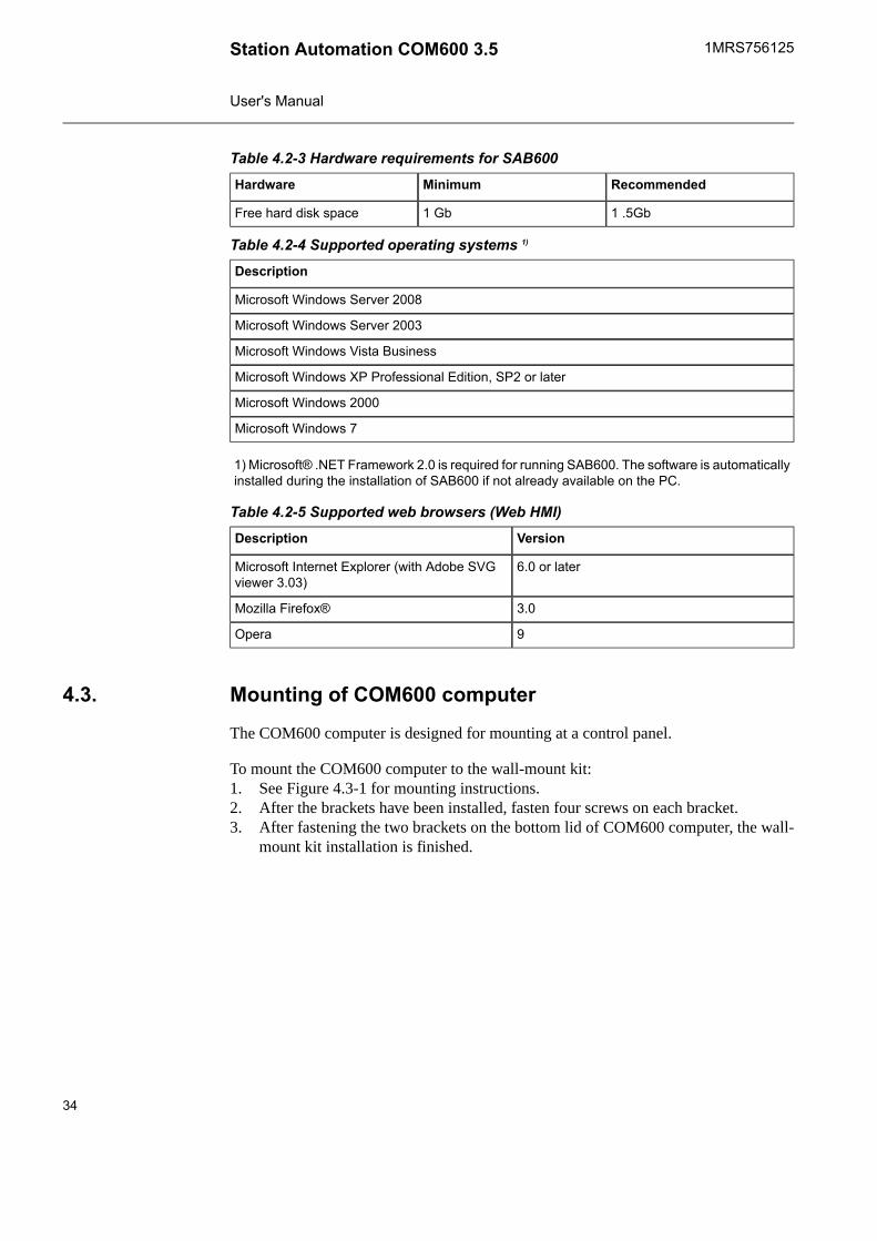
Table 4.2-3 Hardware requirements for SAB600RecommendedMinimumHardware
1 .5Gb1 GbFree hard disk space
Table 4.2-4 Supported operating systems 1)
Description
Microsoft Windows Server 2008
Microsoft Windows Server 2003
Microsoft Windows Vista Business
Microsoft Windows XP Professional Edition, SP2 or later
Microsoft Windows 2000
Microsoft Windows 7
1) Microsoft® .NET Framework 2.0 is required for running SAB600. The software is automaticallyinstalled during the installation of SAB600 if not already available on the PC.
Table 4.2-5 Supported web browsers (Web HMI)VersionDescription
6.0 or laterMicrosoft Internet Explorer (with Adobe SVGviewer 3.03)
3.0Mozilla Firefox®
9Opera
Mounting of COM600 computer4.3.
The COM600 computer is designed for mounting at a control panel.
To mount the COM600 computer to the wall-mount kit:1. See Figure 4.3-1 for mounting instructions.2. After the brackets have been installed, fasten four screws on each bracket.3. After fastening the two brackets on the bottom lid of COM600 computer, the wall-
mount kit installation is finished.
34
1MRS756125Station Automation COM600 3.5
User's Manual

COM600_mounting.jpg
Figure 4.3-1 Mounting diagram of the COM600 computer
For mechanical properties of the COM600 computer, see 4.1, Mechanical properties.
Setting up the COM2 port for RS-232/RS-4854.4.
By default the COM2 port is configured to RS-232 mode. The mode of the port (RS-232/RS-485) can be changed via the BIOS setup of the computer.
COM2 port in RS-485 mode can only be used with Modbusprotocol. For more information on configuration settings, seeModbus Master User's Manual.
To change the mode of the port:1. Connect a local keyboard and display to the COM600 computer.2. Restart the computer and press the Del key during restart to access the BIOS setup.3. Select Integrated Peripherals from the main SETUP menu. Use the cursor keys
for moving and enter key for selection.4. Select SuperIO Device from the next menu.
35
Station Automation COM600 3.51MRS756125
User's Manual

5. On the SuperIO Device configuration page, go to the COM2 Select parameterand press ENTER. Now you can choose between RS-232 and RS-485.
6. Press the F10 key to save the changes and exit the BIOS setup.
Pinout of COM2 port when RS-485 mode is used:
DB9 connector:1. TX-/RX-2. N/A3. TX+/RX+4. N/A5. GND6. N/A7. N/A8. N/A9. N/A
Disposing of COM6004.5.
Definitions and regulations of hazardous materials are country-specific and change whenthe knowledge of materials increases. The materials used in this product are typical forelectric and electronic devices.
All parts used in this product are recyclable. When disposing of cast-off COM600 or itsparts, contact the local entrepreneurs who are authorized and specialized in handlingelectrical/electronic waste. These partners can sort the material by using dedicated sortingprocesses and dispose of the product according to the local requirements.
Table 4.5-1 Materials of COM600 partsMaterialPartCOM600
Aluminium
Steel (SECC)
PC2, PP3
Top cover, heat sink
Other covers, screws
Plastic parts
Case
Various
Various
Compact flash disk
Modules inside the case
Modules
CardboardBoxPackage
Steel (SECC), PBT1
PC2, PP3
Accessory kit
DVD
Attached material
1. Polybutylene terephthalate2. Polycarbonate3. Polypropene
36
1MRS756125Station Automation COM600 3.5
User's Manual
Installation5.
About this section5.1.
This section describes the installation and uninstallation of SAB600, the installation ofthe touch screen, and modifying and setting up of the COM600 computer. For moredetailed instructions on installation of the gateway components, refer to the 1.8, Relateddocuments.
Requirements for SAB6005.2.
The hardware requirements for SAB600 and supported operating systems are listed in4.2, Software properties.
Installing SAB6005.3.
The SAB600 installation DVD includes the SAB600 software and different versions ofthe CoDeSys programming environment dependent to the COM600 version. In theinstallation wizard you can select, which software you want to install. For installationof the CoDeSys programming environment, see Installing CoDeSys programmingenvironment.
To install SAB600:
1. Close all open programs and insert the SAB600 installation DVD to the CD-ROMdrive of your PC.
2. The installation program should start automatically. If the installation does not start,open the program by browsing to the DVD drive, and start COM_600.exe. Theinstallation wizard includes the options to install the SAB600 software and differentversions of the CoDeSys programming environment. Select the software that youwant to install.
3. Wait for the Wise Installation Wizard to extract the installation files to your PC.4. The SAB600 installation program opens. Click Next.
At any stage of the installation, you can return to the previous window by clickingBack, or exit the Installation Wizard by clicking Cancel.
5. Read the License Agreement, then check the option I accept the license agreementand click Next to continue the installation.If you check the option I do not accept the license agreement, the Next button isnot available and you cannot continue the installation.
6. Select the folder where you want to install SAB600.• To select the default folder shown at the bottom of the window, click Next.• To select another folder, click Browse, select a new the folder, and click Next.
The default installation folder is C:\Program Files\ABB\COM600.7. Select the desired installation type.
37
Station Automation COM600 3.51MRS756125
User's Manual

• Typical: This option is recommended for most users.• Complete: All SAB600 features are installed.• Custom: Use this option to choose which SAB600 features you want to be
installed.8. Click Next to start the installation.
You can follow the progress of the installation in a window that also shows the dir-ectory path where the files are copied. At this point, you can still cancel the install-ation by clicking Cancel.
9. A window opens showing that SAB600 has been successfully installed. Close thewindow and finish the installation by clicking Finish.
10. The installation wizard will next install the Microsoft SQL Server, if it is not alreadyinstalled on your PC.
11. Restart your computer.
Start SAB600 by selecting Start > Programs > ABB > Station Automation Builder600 > SAB600 from the Windows task bar.
Installing CoDeSys programming environment
The SAB600 installation DVD includes also the CoDeSys programming environment.In the installation wizard you can select, which software version you want to install.
1. Close all open programs and insert the SAB600 installation DVD to the CD-ROMdrive of your PC.
2. The installation wizard includes the options to install the SAB600 software andCoDeSys programming environment. To install the CoDeSys programming envir-onment, select the correct version and continue with the installation by clickingNext.The installation program should start automatically. If the installation does not start,open the program by browsing to the DVD drive, and start setup.exe.
3. Continue with the installation by clicking Next on every page of the wizard.4. When the installation wizard asks for the folder where to install the CoDeSys pro-
gramming environment, select C:\Program Files\3S CoDeSys.5. It is recommended to install all the features listed on the opening page.6. Continue the installation and when completed, click Finish.
Updating SAB6005.4.
If you have replaced an old COM600 with newer version, update your project that containsthat Gateway object. The project is updated by a conversion wizard. The conversion canbe activated in two ways after you have installed the latest SAB600 software.
Converting a project1. Open the old project in the new SAB600. The conversion wizard is launched auto-
matically. Follow the wizard instructions.
38
1MRS756125Station Automation COM600 3.5
User's Manual
2. If the conversion wizard was canceled, you can run the conversion by right-clickingon the Gateway object and selecting Convert project. Follow the wizard instructions.
3. Check the Gateway object properties to see if the COM600 version is the latestversion to confirm the conversion.
You can use SAB600 to configure versions 3.3 and 3.4 ofCOM600.
License5.5.
A free Basic License can be downloaded from the ABB Substation Automation SoftwareLibrary.
The license is PC-specific and cannot be moved to anotherPC.
SAB600 should be activated within 30 days. Activating a license requires Internet accessto ABB Substation Automation Software Library. The PC that has SAB600 installeddoes not require an Internet connection.
To retrieve a license and activate SAB600:1. Start SAB600 on the PC where you want to activate the license. Select Help ->
License Activation to open the License activation dialog.2. Click Request to create a Request file (C2V file) and save it to your hard disk or
transfer it to a PC with an Internet connection.3. Click the User registration link. If the PC does not have an Internet connection,
use a web browser on another PC and go to the addresshttp://www143.abb.com/SoftwareLibrary. Follow the instructions to create anaccount.
4. Acquire a Product Key by clicking Request License.5. After acquiring the Product Key, go to the Activate page in the Software Library
and enter your Product key.6. Browse to the C2V file created in step 2 and upload it. An Activation file (V2C file)
is generated. Save the Activation file to your hard drive or transfer it to the PC tobe activated.
7. In SAB600, click the Activate in the License Activation dialog and browse to theV2C file received from the Software Library. The license is now activated and theactivation status is shown in the dialog.
39
Station Automation COM600 3.51MRS756125
User's Manual
Setting up the COM600 computer5.6.
Accessing the COM600 computer5.6.1.
Local and Remote LAN ports
The COM600 computer has by default two LAN ports, a local (LAN 1) and a remoteport (LAN 2). See Figure 4.1-1. The local port is used for local connection in a securenetwork within the substation, for example for engineering and process communicationwith the IEDs. The local port has no firewall configured and it allows complete accessto the COM600 computer. The remote port is used for communication outside the sub-station. It has a firewall pre-configured to allow communication only with web clientsand remote communication using protocols for example IEC 870-5-104 and DNP 3.0LAN/WAN.
By default, response to the ping command is blocked by thefirewall. To allow ping response, change the Allow incomingecho requests configuration setting in the firewall's AdvancedICMP Settings.
Table 5.6.1-1 shows the default IP addresses for the LAN ports.
Table 5.6.1-1 Default IP addresses for the LAN portsIP AddressMaskGatewayLAN Port
Local Area Con-nection (Local)
192.168.2.11255.255.255.0Not definedLAN 1
Local Area Con-nection (Remote)
10.0.0.11255.255.255.0Not definedLAN 2
Some tasks, for example changing the IP addresses or adding users, require access directlyto the COM600 computer either locally or via the remote desktop software.
Accessing the COM600 computer:• Locally by connecting a USB keyboard, a USB mouse, and a display to the computer.• Remotely with the remote desktop program via LAN. By default the security settings
allow the remote desktop connection only via the interface reserved for the localuse.
Regional settings
The default regional setting is English (United States).
40
1MRS756125Station Automation COM600 3.5
User's Manual

Remote desktop
You can use the COM600 computer as a local console from an engineering computerwith remote desktop.
The COM600 computer can be restarted remotely by running restart.bat command fromthe root of C drive.
Due to security reasons, the remote desktop access to COM600 computer is by defaultdisabled. To allow remote desktop access, you must enable and configure the settingsin the COM600 computer.
To allow remote desktop access:1. In COM600 computer select Start -> Control Panel -> System.2. In the System Properties dialog, select Remote tab page.3. Select the Remote desktop access check-box.
Built-in user accounts
Two user accounts are predefined in the COM600 computer:• Username: Administrator• Password: pwd2004
This account is disabled by default for security reasons. Youcan enable the account manually from the COM600 computeruser settings. If you enable the account, remember to enter anew secure password for the Administrator user.
• Username: COM600• Password: aEc2006rs
This is the main account of the COM600 computer. It is used for configuration purposes.Processes of the COM600 computer are run under this account.
Connecting configuration computer with SAB600 to COM600 computer
With COM600 version 3.4 or newer the COM600 user is notanymore required in the SAB600 computer. Also the commu-nication between SAB600 and COM600 computer is nowbased on .NET remoting, which uses fewer ports to enableeasier access through firewalls.
For improved security, disable access from SAB600 to COM600 after the configurationwork is finished by disabling the port used by SAB600 in COM600 firewall exception
41
Station Automation COM600 3.51MRS756125
User's Manual
settings, or by disabling the remoting service in the COM600 computer (if firewall isnot used).
To disable access using firewall configuration:1. Select Control Panel -> Windows Firewall -> Exceptions and clear the COM600
Management Remoting check-box.
To disable access by disabling the remoting service:1. Select Control Panel -> Administrative Tools -> Services -> ABB COM600
Remoting Server.2. Right-click and select Properties.3. Stop the service and change the startup type to Disabled.
To configure the network settings:1. Configure the network settings of the configuration computer and the COM600
computer to allow them to communicate with each other. This is done by configuringthe IP addresses of the computers into the same subnetwork. By default, the commu-nication from SAB600 to the COM600 computer will use TCP port 8080. Makesure that the port is opened in the firewall of the SAB600 computer. For callbacksfrom COM600 computer another port is required. This is used by the spontaneousupdates in the online diagnostic tools. By default, the software reserves a free portfor the callbacks automatically.
2. Connect either a crossover LAN cable between the computers or connect bothcomputers to a network switch. Use the LAN port used for local use in COM600computer.
3. Create a project and add the Gateway object to the communication structure.4. Type the IP address of the COM600 computer LAN port used for configuration to
the IP address property of the Gateway object.5. Right-click the Gateway object and select Management. Verify that the communic-
ation with the COM600 computer is working properly. The first time you open themanagement tool, you are required to change the COM600 user password. ClickChange password to change the password in the COM600 computer.
The COM600 user password must always be changed asdescribed above to ensure that the password is changed cor-rectly for each component in the COM600 computer.
If you lose the password, you cannot access the COM600computer either locally or remotely.
Setting the remoting communication parameters
To change the port number used for the communication from SAB600 to the COM600computer:1. Modify the Port Number property of the Gateway object in the SAB600 project.
42
1MRS756125Station Automation COM600 3.5
User's Manual

2. In COM600 computer, select Start -> All Programs -> Set Remoting Parameters.3. Set the port number in Set Remoting Parameters utility.4. Click Apply.
If multiple network adapters are used in COM600, you must specify the one used forthe SAB600 communication. In the Set Remoting Parameters utility, select the IP addressof the COM600 network adapter used for the SAB600 communication.
To change the port number used for the callbacks from COM600:1. Close the SAB600 program.2. In SAB600 computer, select Start -> Programs -> ABB -> Station Automation
Builder 600 -> Set Remoting Parameters.3. Set the port number in the Set Remoting Parameters utility.4. Click Apply.5. Restart the SAB600 program.
If multiple network adapters are used in SAB600 computer, you must specify the onethat is used for the COM600 communication. In the Set Remoting Parameters utility,select the IP address of the SAB600 network adapter used for the COM600 communic-ation.
Set Remoting Parameters SAB600.png
Figure 5.6.1-1 Setting Remoting Parameters in SAB600
Uninstalling SAB6005.7.
To uninstall SAB600:
43
Station Automation COM600 3.51MRS756125
User's Manual

1. Open the Add or Remove Programs dialog by selecting Start > Settings > ControlPanel > Add or Remove Programs in the Windows task bar.
2. Select SAB600 and click Remove.
The uninstallation only removes SAB600 so that you caninstall a new version and update the software. It does notremove the Microsoft SQL Server and .Net Framework.Removing these programs may infect the functionality of otherABB applications installed on your PC.
Uninstalling CoDeSys v3.2 SP2
1. To open the Add or Remove Programs dialog, select Start > Settings > ControlPanel > Add or Remove Programs in the Windows task bar.
2. Select CoDeSys and click Remove.
Turning off COM600 computer5.8.
If a local display, keyboard, and mouse are connected to the COM600 computer:1. If COM600 browser is used, login as a user that has administrator privileges to the
COM600 HMI.2. Press CTRL+ALT+DEL and choose Shutdown from the dialog.3. Wait until the following message appears in the display:It is now safe to turn off
your computer.4. Press and hold the front panel power button for a few seconds until the SYS led on
the front panel turns off.
If the remote desktop session is active:1. Run the shutdown.bat located in the C:\ of the COM600 computer.2. Wait for about 30 s. Then keep the front panel power button pressed for a few
seconds until the SYS led on the front panel turns off.
If no desktop is available, keep the front panel power button pressed for a few secondsuntil the SYS led on the front panel turns off.
To turn on the COM600 computer, press the power button briefly.
44
1MRS756125Station Automation COM600 3.5
User's Manual
Configuration6.
Opening a project in Station Automation Builder 6006.1.
This section describes the configuration tasks common to all OPC servers, and gives anoverview of the configuration tasks related to OPC clients.
All the possible configuration scenarios are not included inthis manual. Refer to the corresponding user’s manuals listedin 1.8, Related documents for more detailed instructions.
Configuration and maintenance6.2.
SAB600 is used to configure and maintain COM600. Communication networks aredescribed in the Communication structure of the Project Explorer window. The structureis built using OPC server/client, communication channel/subnetwork, and device objects.These objects have communication properties that can be accessed via the Object Prop-erties window. The properties define for example the communication port, bit rate, timingparameters, unit addresses, and so on .
The substation structure of SAB600 is used to configure the HMI functions of theCOM600 products. The substation structure presents the functional view of the substation.It includes substation, voltage level, bay, busbar, and conducting equipment objects.
The Single line diagram is a graphical presentation of the process objects in the substation.The Single line diagram can be edited on different levels. The bay layout can be con-figured by opening the SLD Editor from a bay object. When the SLD Editor is openedfrom a voltage level object, it is possible to assign the positions of the bays within avoltage level. The position of the voltage levels in the complete substation single linediagram is done by opening the SLD editor from the substation object.
Substation objects are linked to communication structure objects by using the DataConnection tool. For example, the circuit breaker object in the substation structure islinked to the CSWI logical node in the communication structure. The link between thestructures is also used on the event list, to present the events using the names accordingthe substation structure.
Process data accessible on the devices is modeled according to the IEC 61850 standard.In the communication structure this is seen as logical devices (LD), logical nodes (LN)and data objects (DO). It is possible to insert an empty device into the structure and thenmanually add and configure LD, LN, and DO objects. It is also possible to use pre-con-figured object types of the devices, which have the objects defined and configured toadd efficiency. The device configuration can also be imported from an IED SCL
45
Station Automation COM600 3.51MRS756125
User's Manual

description. Data objects include configuration properties, that contain cross-referencinginformation between protocol and the OPC/IEC 61850.
Process data is connected to a Gateway client using a Cross-References function availablein the client IED object. Data objects that are transferred to the client are dragged fromthe servers on the structure to the function tool. Cross-referencing information is filledin the function window. The Cross-References function supports import and export withMicrosoft Excel.
When the structure is complete and all the objects have been set up properly the config-uration is downloaded to COM600 using the Gateway Management function availableon the Gateway object.
The Logic Processor function is programmed with a separate programming editor.
Configuration process6.3.
Overview of configuration process6.3.1.
Before you can start using COM600, build and configure the communication and substa-tion structure of your project in SAB600.
Start SAB600 and open and name a project.
1. Select File > Open/Manage Project....2. In the Open/Manage Project dialog, select the required location for the project:
• Projects on my computer• Projects on network
3. Select New Project on the left.• Enter a Project Name. The Description is optional.
4. Click Create.5. Click Open Project.
A project can have only one COM600 configuration.
Figure 5.6.1-1 shows an example view of SAB600 including an object tree in the Com-munication structure on the left and property window displaying the object propertieson the right.
46
1MRS756125Station Automation COM600 3.5
User's Manual

IECSAB600Main.bmp
Figure 6.3.1-1 Example view of SAB600
The configuration can be divided into three tasks:
1. Building the object tree and configuring the object properties for OPC servers(process communication).
2. Building the substation object tree and configuring the object properties for HMIfunctions.
3. Activating COM600 with a new configuration.
First, build an object tree by adding objects to the object tree. For more information referto the respective user’s manual listed in 1.8, Related documents. Connectivity packagesfor certain protection and control products usually contain preconfigurations and toolsto facilitate the building of the object tree.
Building and configuring object structures6.3.2.
OPC servers6.3.2.1.
Start the configuration work from the server objects. Before an OPC client can be takeninto use, configure an OPC server for the process communication.
47
Station Automation COM600 3.51MRS756125
User's Manual
The object tree is built in the communication tab of SAB600. There are several possibleways to build an object tree. One of them is to build the object tree by adding objects inlogical order starting from the OPC server object. You can either use basic or pre-definedobjects. Using basic objects means that you have to configure the objects manually. Ifobjects are pre-defined, they are preliminary configured and all the necessary childobjects are automatically added.
Add the objects in the following order:1. OPC server object2. Channel/Subnetwork object depending on protocol3. Device object4. Logical device object(s)5. Logical node object(s)6. Data objects.
If you want to connect events or scales to data objects ordevice connection status event classes to device objects at thispoint, make sure that you have already created and configuredthe event and scale objects.
For more detailed information on adding objects to the object tree, refer to the appropriateprotocol manual (see 1.8, Related documents).
Substation structure for HMI6.3.2.2.
Configuring the substation is the main task in configuring HMI functionality. If connectiv-ity packages or IED SCL description files with substation structure information are used,most of the substation structure can be built automatically when the IEDs are added tothe communication structure. If no substation structure information is available thestructure must be built manually.
Before you can create a substation structure, you have to createa communication structure with OPC Server and communica-tion channel objects, IEDs, Logical Devices, Logical Nodesand Data objects.
For more detailed information, see COM600 HMI Configuration Manual.
OPC clients6.3.2.3.
The object tree is built in the communication structure. Before an OPC client can betaken into use, confgure an OPC server for the process communication.
48
1MRS756125Station Automation COM600 3.5
User's Manual

ClientComStruc.jpg
Figure 6.3.2.3-1 Example of OPC client communication structure
The OPC client object is added to the same hierarchy level as the OPC server, see Fig-ure 6.3.2.3-1. Below the OPC client object, you can add only channel and device objects.The data objects are linked using the Cross-References function from the servers to theclient and further to the NCC. The Cross-References function can be also used to con-figure the parameters of the data objects.
Add the objects in the following order:1. OPC client object2. Channel/Subnetwork object depending on protocol3. Device object.
Configuring object properties6.3.2.4.
After the objects have been added, configure the object properties.
To configure an object:1. Select an object in the object tree of the Communication structure.2. The object properties appear now in the Object Properties window, see Figure 6.3.2.4-
1. You can see the selected object on the left and the available properties on theright.
49
Station Automation COM600 3.51MRS756125
User's Manual

ObjProp.png
Figure 6.3.2.4-1 Example of object properties
3. Select the property you want to configure. Depending on the property value type,configuring is always done either by• selecting a predefined value from a drop-down combo box, or• entering a text string or a numerical value in a text field.
With SCL import function, you can import new objects with configurations from anexisting file. Right-click the device and select SCL Import from the shortcut menu.
To import a new configuration file:1. Click Choose File.
50
1MRS756125Station Automation COM600 3.5
User's Manual
2. Browse to a new configuration file from the appearing dialog.3. Select the file and click Open.4. Select the device to import from the drop-down list. You can preview the configur-
ation on the right.5. Click Import.
The new preconfigured objects appear in the object tree. If the configuration file is largethe import can take time. To import a configuration file for a different device, right-clickthe device, select SCL Import again and repeat the steps.
For detailed information about the SCL Import function, see 6.3.2.5, SCL Import function.
SCL Import function6.3.2.5.
You can import the communication structure under a Gateway, OPC Server or OPCClient, and IED object with configurations from an existing file. Using the SCL importfunction to import the structure. If an OPC Server or client configuration file is used,then the whole communication structure is imported. Configurations can be importedfor single IEDs by selecting an IED object.
The file extensions for the import files can be .icd, .cid, .scd or .xml.
To import a configuration file:1. Right-click the OPC Server or IED and select SCL Import from the shortcut menu.2. Click Select File.3. Browse for a new configuration file from the opening dialog.4. Select the file and click Open.5. Select the device to import from the drop-down menu. You can preview the config-
uration from the Objects tab.6. Click Import.
The new preconfigured objects appear in the object tree. If the configuration file is large,the import may take time.
All options in the SCL Import function are not available forall protocols.
51
Station Automation COM600 3.51MRS756125
User's Manual

SCLImport.bmp
Figure 6.3.2.5-1 Example of IEC 61850 OPC Server SCL Import
SCL Import options from the Gateway, OPC Server or OPC Client, and IED level arepresented in the following.
SCL Import from Gateway level
The Gateway level import creates configurations for OPC Servers and OPC Clientsaccording to the importable SCL file.
SCLImportGW.bmp
Figure 6.3.2.5-2 SCL Import from the Gateway level
52
1MRS756125Station Automation COM600 3.5
User's Manual
SCL Import from OPC Server level
The OPC Server level import creates configurations for the selected OPC Serveraccording to the importable SCL file.
SCLImportServer.bmp
Figure 6.3.2.5-3 SCL Import from the OPC Server level
Description for the option:• Filter DOs that don’t belong to DataSet: This option limits the amount of data
objects being imported. If a data object does not belong to any data set, it is notimported. Some IEDs can provide huge amounts of data that is not reported, that is,not updated in COM600 HMI. Performance can be enhanced by checking this option.
• Overwrite existing descriptions: This option overwrites all existing descriptionson objects affected by the import operation. Select this option only if you know thatthe importable file contains better descriptions than your current configuration.
• Do not import substation information: This option does not update the substationstructure. It can be used if you only must update the communication configuration.
• Import substation information from a separate template: This option allows youto select a template that provides the substation configuration. It is useful, if thereare several identical configurations and you have created a good template for thesubstation information.
• Import protocol configuration (sAddr): Imports the protocol-specific information.If this option is selected, both the object tree and protocol configuration are done.If this is not selected, only the object tree structure is created.
53
Station Automation COM600 3.51MRS756125
User's Manual
• Do not import DO's without protocol configuration (sAddr): If this option isselected, none of the data objects without protocol configuration information arecreated to the object tree.
• Check RCBs for Client Identity: Imports IEDs from the given file where ReportControl Blocks client identity matches the selected OPC Server.
SCL Import from IED level
The IED level import creates configurations for the selected IED according to theimportable SCL file.
SCLImportIED.bmp
Figure 6.3.2.5-4 SCL Import from the IED level
Description for the different options:• Alarm and Event Template: Select one of the predefined templates for setting
Alarm and Event handling for the objects that the import operation affects. Thereare two template options:• General Phase Tripping: by selecting this template, protection functions are
configured to send general alarms and events, regardless on whichever phase
54
1MRS756125Station Automation COM600 3.5
User's Manual

is activated. It depends on the device, whether phase-specific information isprovided.
• Single Phase Tripping: by selecting this template, protection functions areconfigured to send phase A-, B-, or C-specific alarms and events, if the deviceprovides phase-specific information.If you are familiar with the issue, you can also create your own template bycopy-pasting existing templates. Browse to the current SAB600 installationdirectory and find the \bin\Tools\SCLImport directory underneath it. Copy thephasetrippingmapping.xml file and paste it to the directory and give it a mean-ingful name. Open the file with an XML editor. Enter the name of the newtemplate to the AETemplateName element. Add or modify mappings in theLNClass and DO elements. Use the information in the file as a guide.
• Communication Options• Filter DOs that don’t belong to the DataSet: This option limits the amount
of data objects being imported. If a data object does not belong to any data set,it is not imported. Some IEDs can provide huge amounts of data that is notreported, that is, not updated in COM600 HMI. Performance can be enhancedby checking this option.
• Overwrite existing descriptions: This option overwrites all existing descriptionson objects affected by the import operation. Select this option only if you knowthat the importable file contains better descriptions than your current configur-ation.
• Import protocol configuration (sAddr): Imports the protocol-specificinformation. If this is selected, both the object tree and protocol configurationare done. If this is not selected, only the object tree structure is created.
• Overwrite Alarm and Event settings: This option overwrites all configuredalarm and event settings and assigns default settings to them. Select this optiononly when you have customized alarm and event settings on your current con-figuration.
• Do not import DO's without protocol configuration (sAddr): If this optionis selected, none of the data objects without protocol configuration informationare created to the object tree.
• Substation Options• Do not import substation information: This option does not update the sub-
station structure. It can be used if you only must update the communicationconfiguration.
• Import substation information from a separate template: This option allowsyou to select a template that provides the substation configuration. It is useful,if there are several identical configurations and you have created a good templatefor the substation information.
These options are not available for OPC Client level or OPCClient IED level imports.
55
Station Automation COM600 3.51MRS756125
User's Manual
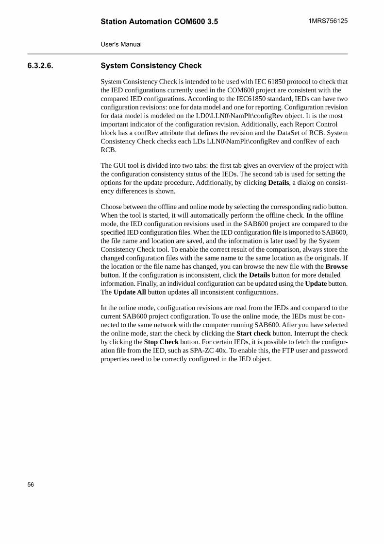
System Consistency Check6.3.2.6.
System Consistency Check is intended to be used with IEC 61850 protocol to check thatthe IED configurations currently used in the COM600 project are consistent with thecompared IED configurations. According to the IEC61850 standard, IEDs can have twoconfiguration revisions: one for data model and one for reporting. Configuration revisionfor data model is modeled on the LD0\LLN0\NamPlt\configRev object. It is the mostimportant indicator of the configuration revision. Additionally, each Report Controlblock has a confRev attribute that defines the revision and the DataSet of RCB. SystemConsistency Check checks each LDs LLN0\NamPlt\configRev and confRev of eachRCB.
The GUI tool is divided into two tabs: the first tab gives an overview of the project withthe configuration consistency status of the IEDs. The second tab is used for setting theoptions for the update procedure. Additionally, by clicking Details, a dialog on consist-ency differences is shown.
Choose between the offline and online mode by selecting the corresponding radio button.When the tool is started, it will automatically perform the offline check. In the offlinemode, the IED configuration revisions used in the SAB600 project are compared to thespecified IED configuration files. When the IED configuration file is imported to SAB600,the file name and location are saved, and the information is later used by the SystemConsistency Check tool. To enable the correct result of the comparison, always store thechanged configuration files with the same name to the same location as the originals. Ifthe location or the file name has changed, you can browse the new file with the Browsebutton. If the configuration is inconsistent, click the Details button for more detailedinformation. Finally, an individual configuration can be updated using the Update button.The Update All button updates all inconsistent configurations.
In the online mode, configuration revisions are read from the IEDs and compared to thecurrent SAB600 project configuration. To use the online mode, the IEDs must be con-nected to the same network with the computer running SAB600. After you have selectedthe online mode, start the check by clicking the Start check button. Interrupt the checkby clicking the Stop Check button. For certain IEDs, it is possible to fetch the configur-ation file from the IED, such as SPA-ZC 40x. To enable this, the FTP user and passwordproperties need to be correctly configured in the IED object.
56
1MRS756125Station Automation COM600 3.5
User's Manual
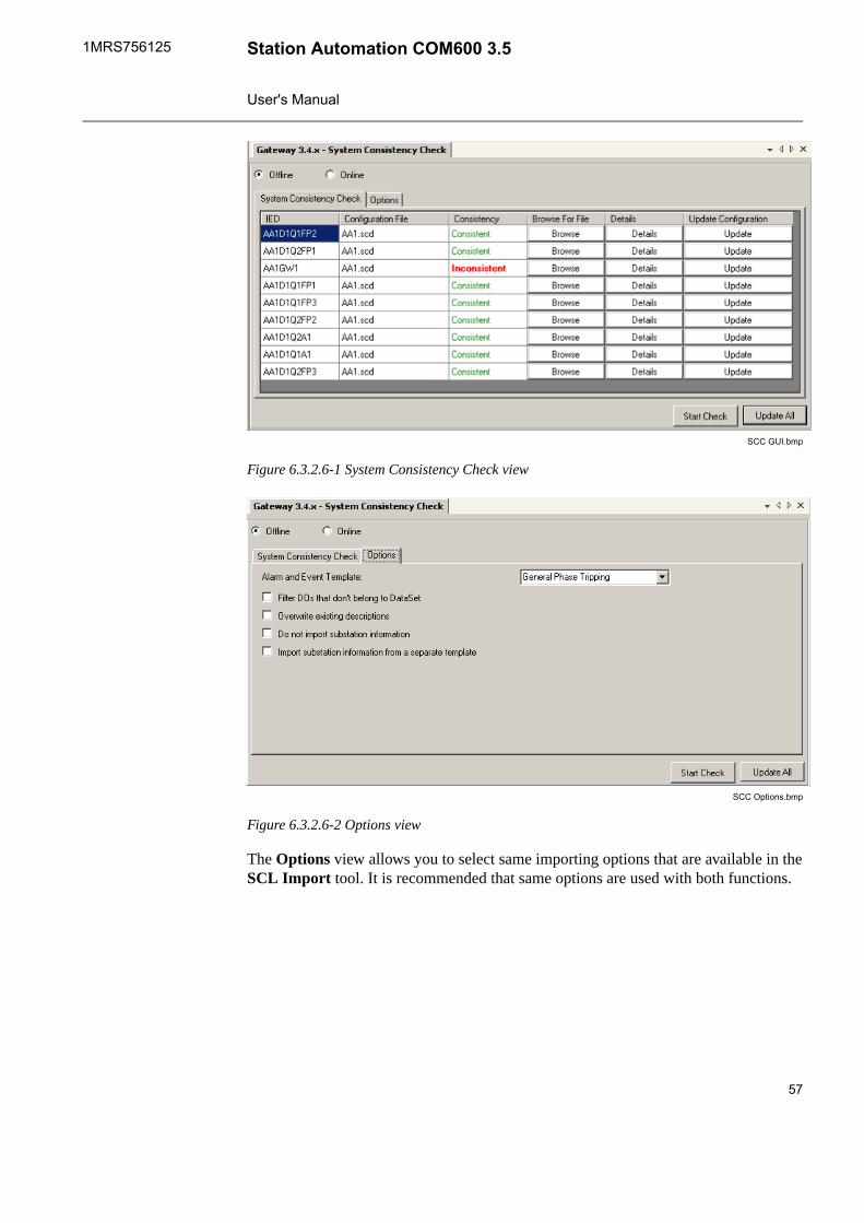
SCC GUI.bmp
Figure 6.3.2.6-1 System Consistency Check view
SCC Options.bmp
Figure 6.3.2.6-2 Options view
The Options view allows you to select same importing options that are available in theSCL Import tool. It is recommended that same options are used with both functions.
57
Station Automation COM600 3.51MRS756125
User's Manual

SCC details.bmp
Figure 6.3.2.6-3 Details view
The Details view shows added or deleted LDs and RCBs. Additionally, it shows themodifications to the content of LD or RCB.
Cross-References function6.3.2.7.
Data objects are added differently for OPC clients than for the upper level objects. Dragand drop the data objects you need from an OPC server to the slave. You also can selectan upper level (server, channel, and so on) object and drag and drop it into the Cross-References function. As a result, all the data objects within the selected object appearin the Cross-References function and can be connected to the slave OPC client.
58
1MRS756125Station Automation COM600 3.5
User's Manual
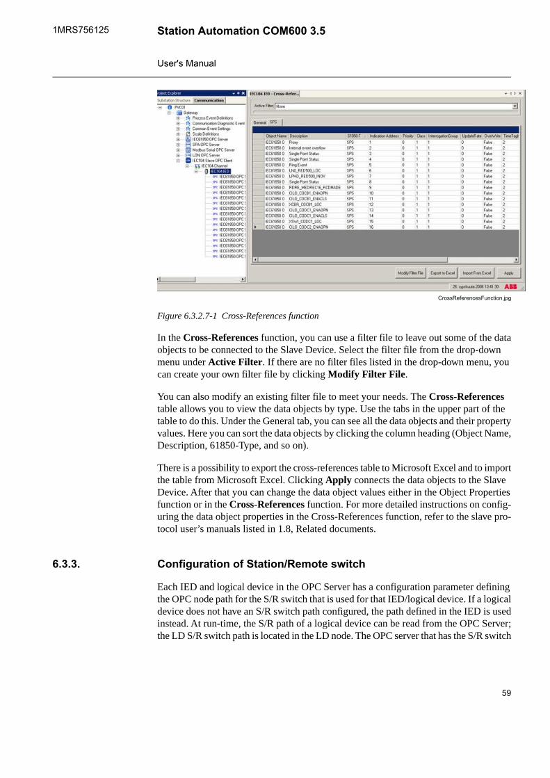
CrossReferencesFunction.jpg
Figure 6.3.2.7-1 Cross-References function
In the Cross-References function, you can use a filter file to leave out some of the dataobjects to be connected to the Slave Device. Select the filter file from the drop-downmenu under Active Filter. If there are no filter files listed in the drop-down menu, youcan create your own filter file by clicking Modify Filter File.
You can also modify an existing filter file to meet your needs. The Cross-Referencestable allows you to view the data objects by type. Use the tabs in the upper part of thetable to do this. Under the General tab, you can see all the data objects and their propertyvalues. Here you can sort the data objects by clicking the column heading (Object Name,Description, 61850-Type, and so on).
There is a possibility to export the cross-references table to Microsoft Excel and to importthe table from Microsoft Excel. Clicking Apply connects the data objects to the SlaveDevice. After that you can change the data object values either in the Object Propertiesfunction or in the Cross-References function. For more detailed instructions on config-uring the data object properties in the Cross-References function, refer to the slave pro-tocol user’s manuals listed in 1.8, Related documents.
Configuration of Station/Remote switch6.3.3.
Each IED and logical device in the OPC Server has a configuration parameter definingthe OPC node path for the S/R switch that is used for that IED/logical device. If a logicaldevice does not have an S/R switch path configured, the path defined in the IED is usedinstead. At run-time, the S/R path of a logical device can be read from the OPC Server;the LD S/R switch path is located in the LD node. The OPC server that has the S/R switch
59
Station Automation COM600 3.51MRS756125
User's Manual
position information must have at least one signal mapped to the OPC client using thisinformation.
With IEC 61850, the control commands from COM600 HMIand from slave protocols are always sent using the fixed ori-ginator category configured in the Server Originator Categoryproperty of the IEC 61850 OPC Server object. Due to thissome IEDs (e.g. REF615) need to be configured with StationAuthority check disabled to allow controls with the originatorcategory used by COM600.
The S/R switch OPC path points to an OPC node modeled according to one of the sup-ported IEC 61850 data classes. The stVal OPC item of the S/R object presents the stateof the S/R switch, 1 = station and 0 = remote. If the stVal item has the vartype VT_BOOL,VARIANT_TRUE is interpreted as 1 and VARIANT_FALSE as 0.
Several IEDs/LDs can share the same S/R switch OPC path, or each IED/LD can havean own S/R switch OPC path. The OPC node pointed by the path can be located in anOPC server providing the S/R information from a physical switch or from a simulatedsoftware switch.
The web HMI is considered to be local or remote based on the IP-address of the webclient. The gateway object has a configuration property which defines the addresses thatare handled as local. It can be either a single IP address or using wild cards a range ofIP addresses.
Event definitions6.3.4.
Creating event definitions6.3.4.1.
To create event classes:1. Right-click the Events group in SAB600, see Figure 6.3.4.1-1.2. Select New -> Event classes.3. Select the event class you want to add.4. The new event class appears in the Process Definitions below the selected event
group. Enter a unique name for the event class by right-clicking it and selectingRename. The new event class can be configured and connected to a data object.
60
1MRS756125Station Automation COM600 3.5
User's Manual
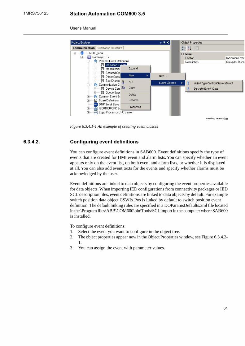
creating_events.jpg
Figure 6.3.4.1-1 An example of creating event classes
Configuring event definitions6.3.4.2.
You can configure event definitions in SAB600. Event definitions specify the type ofevents that are created for HMI event and alarm lists. You can specify whether an eventappears only on the event list, on both event and alarm lists, or whether it is displayedat all. You can also add event texts for the events and specify whether alarms must beacknowledged by the user.
Event definitions are linked to data objects by configuring the event properties availablefor data objects. When importing IED configurations from connectivity packages or IEDSCL description files, event definitions are linked to data objects by default. For exampleswitch position data object CSWIx.Pos is linked by default to switch position eventdefinition. The default linking rules are specified in a DOParamsDefaults.xml file locatedin the \Program files\ABB\COM600\bin\Tools\SCLImport in the computer where SAB600is installed.
To configure event definitions:1. Select the event you want to configure in the object tree.2. The object properties appear now in the Object Properties window, see Figure 6.3.4.2-
1.3. You can assign the event with parameter values.
61
Station Automation COM600 3.51MRS756125
User's Manual
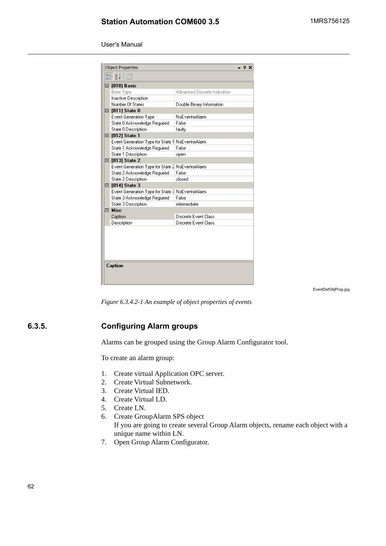
EventDefObjProp.jpg
Figure 6.3.4.2-1 An example of object properties of events
Configuring Alarm groups6.3.5.
Alarms can be grouped using the Group Alarm Configurator tool.
To create an alarm group:
1. Create virtual Application OPC server.2. Create Virtual Subnetwork.3. Create Virtual IED.4. Create Virtual LD.5. Create LN.6. Create GroupAlarm SPS object
If you are going to create several Group Alarm objects, rename each object with aunique name within LN.
7. Open Group Alarm Configurator.
62
1MRS756125Station Automation COM600 3.5
User's Manual

Drag and drop the data objects, which shall belong to the alarm group to Group AlarmConfigurator tool. You can use data objects from any of the OPC servers of COM600.The data objects of following types can be used as a member of alarm group: ACD,ACT, SPS, SPC, DPS, DPC, INS, or INC. When the objects are inserted to the tool, theyhave by default the alarming states configured according the event definition linked tothe object. If no event definition is linked to an object, it does not have any of the statesas alarming. Alarming states can be manually specified in the tool by checking the cor-responding check box of the state.
When the objects have been added and the alarm states are configured, accept the con-figuration by clicking apply.
The logic of the alarm group is configured with the Group Alarm Logic Property of theobject. There are three choices:
• ANDAlarm group is active if all signals belonging to the alarm group are active. Signalchanges which does not change alarm group state or quality does not cause an updatein the alarm group object.
• Dynamic ORGroup alarm is active if any of the signals belonging to the alarm group is active.Any signal state change causes an update of the alarm group object even if the stateor quality of the alarm group does not change.
• Static ORGroup alarm is active if any of the signals belonging to the alarm group is active.Signal changes, which do not change the alarm group state or quality, does not causean update in the alarm group object.
The handling of the source signal quality is configured with the Signal Handling property.There are three choices:
• Group Quality Follows Signal QualityGroup alarm is calculated using only the signals with good/known quality. Thegroup alarm has the quality of the signal with the worst quality in the group.
• Unknown Signal StatesTreated As AlarmingIf the alarm group contains any signal with bad or unknown quality then the alarmgroup is active. The quality of the group alarm is always good.
• Unknown Signal States IgnoredGroup alarm is calculated using only the signals with good/known quality. If nosignals have good/known quality then the group alarm is inactive. The quality ofthe group alarm is always good.
Group Alarm object is an SPS data object, which has value true when the group alarmis active and value false when it is inactive. The object can be further used in the COM600HMI or it can be forwarded to external systems using the slave protocol cross-referencetool.
63
Station Automation COM600 3.51MRS756125
User's Manual
Configuring COM600 event printer6.3.6.
To configure Event Printer in COM600 computer:1. Open Control Panel -> Printers and Faxes.2. Select Add a printer. Configure a local printer connected to a serial port. Select
the "Generic / Text Only" printer model. Follow instructions in the dialogs.3. To change the printer and serial port configuration after the printer has been added,
right-click the printer icon and select properties. In the serial port configuration, itis recommended to change the Flow control setting to "Xon /Xoff".
To configure Event Printer in SAB600:1. Click the Gateway object in the communication tree.2. In the Object properties window, change the Event Printer Enabled value to True.3. Configure the event printer values shown in the following table.
Table 6.3.6-1 Event printer valuesDescriptionValueProperty
Text displayed in columns 1 -7.
Date
Time
BayDevice
ObjectText
EventText
Quality
AlarmIndicator
Column Name
Specifies whether columnshould be truncated if actualvalue overflows width.
False
True
Column Truncate
Width of columns 1 - 70...1000Column Width
Defines the string which identi-fies alarms.
*Event Printer Alarm Indicator
Specifies the code page that isused to convert strings (event)to be printed into bytes that aresent to the printer.
Event Printer Code Page
Specifies whether the eventprinter functionality is in use.
False
True
Event Printer Enabled
The name of the printer usedby the COM600 operating sys-tem. The name is specified,when the printer is configuredin the COM600 computer.
Event Printer Name
64
1MRS756125Station Automation COM600 3.5
User's Manual
DescriptionValueProperty
Specifies the maximum numberof events in the print queue thatare waiting to print.
0...1000Max Printing Queue Size
Specifies the maximum numberof characters printed to oneline.
1...180Maximum Line Length
The configured string is split bya space and each individualnumber (0 - 127) is convertedto the corresponding ASCIIcharacter.
0 - 127Printer Init Command
Specifies how the line overflowis handled. If the value is True,the extra characters are leftout. Otherwise, the extra char-acters are printed on the nextline.
False
True
Truncate Lines
Using scales6.3.7.
General about using scales6.3.7.1.
You have to use scaling if a measurement value provided by the device is not as suchsuitable for the applications, and you need to change the provided value to another.
With a scale you can convert one value to another by using a scaling algorithm. OPCservers support two types of scales: Stepwise Linear and Look-up Table. The StepwiseLinear scale multiplies the value to be converted with a scale factor and adds an offsetvalue to the result, and the Look-up Table scale uses a look-up table to find the requiredvalue.
Before you can connect a scale to a data object, add and con-figure the scale in SAB600. Add and configure the scalesbefore adding and configuring any other objects.
Creating scales6.3.7.2.
To create scales:1. Right-click Scale Definitions in SAB600, see Figure 6.3.7.2-1.2. Select New -> Scales.
65
Station Automation COM600 3.51MRS756125
User's Manual

3. Select the scale to add (a Look-up Table or Stepwise Linear).4. The new scale appears in the Scale Definitions. Enter a unique name for the scale
by right-clicking it and selecting Rename. It can be configured and connected to adata object.
creating_scales.jpg
Figure 6.3.7.2-1 Creating scales
Configuring scales6.3.7.3.
To configure scales:1. Select the scale you want to configure in the object tree.2. The object properties appear now in the Object Properties window, see Figure 6.3.4.2-
1.3. You can assign the scale with parameter values.
66
1MRS756125Station Automation COM600 3.5
User's Manual
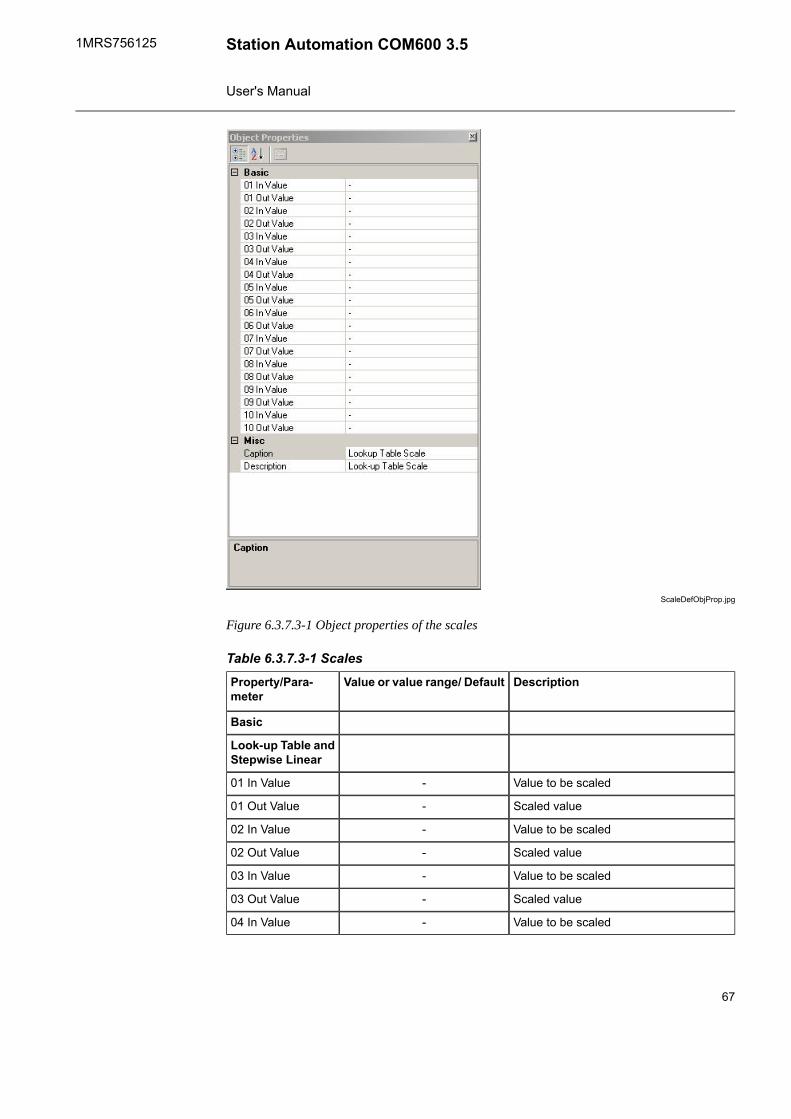
ScaleDefObjProp.jpg
Figure 6.3.7.3-1 Object properties of the scales
Table 6.3.7.3-1 ScalesDescriptionValue or value range/ DefaultProperty/Para-
meter
Basic
Look-up Table andStepwise Linear
Value to be scaled-01 In Value
Scaled value-01 Out Value
Value to be scaled-02 In Value
Scaled value-02 Out Value
Value to be scaled-03 In Value
Scaled value-03 Out Value
Value to be scaled-04 In Value
67
Station Automation COM600 3.51MRS756125
User's Manual

DescriptionValue or value range/ DefaultProperty/Para-meter
Scaled value-04 Out Value
Value to be scaled-05 In Value
Scaled value-05 Out Value
Value to be scaled-06 In Value
Scaled value-06 Out Value
Value to be scaled-07 In Value
Scaled value-07 Out Value
Value to be scaled-08 In Value
Scaled value-08 Out Value
Value to be scaled-09 In Value
Scaled value-09 Out Value
Value to be scaled-10 In Value
Scaled value-10 Out Value
After you have performed all the necessary configurations, see 7.1, Activating COM600with new configurations.
Backing up and restoring6.4.
To back up the SAB600 project:1. Select File > Open/Manage Project.2. Select the project you want to back up.3. Select Export Project on the left.4. The File dialog opens. Select the location where to export the database.
To restore your backup:1. Select File > Open/Manage Project.2. Select Projects on my computer.3. Select Import Project on the left.4. The File dialog opens. Choose the exported database you want to import.
Retrieving previous configuration6.5.
An existing configuration can be downloaded from COM600 to SAB600 using theManagement tool under the Communication view.
To retrieve and existing configuration:1. Right click the Gateway object in the Communication view.2. Select Management.
68
1MRS756125Station Automation COM600 3.5
User's Manual
3. From Configuration control, click Retrieve COM600 Configuration.4. In the file view, browse to the location of the required configuration file.5. Click Open.
This functionality can only be used with an empty Gateway object of version 3.2 ornewer. For older versions of the Gateway object, or if there are server or client objectsunder the Gateway object, the functionality is disabled.
SCL Export6.6.
Export the configuration files of the COM600 OPC Servers and Clients in SCL formatusing the SCL Export function in the Gateway object. This function can be used totransfer the configuration information to other systems and tools.
To export configuration files in SCL format:1. Right-click the server object in the Communication tree and select SCD Export.2. The SCD Export window opens.3. Click Export and select the location where you want to save the SCL file. Click
OK.
Both the communication view and substation view configurations are exported.
To export just the communication view:1. Right-click the Gateway object in the Communication tree and select SCL Export.2. The SCL Export window opens. Select whether you want to export all configurations
or a certain OPC Server or Client configuration.3. Click Export and select the location where you want to save the SCL file. Click
OK.
CID Export
Export the configuration files of IEDs in CID format.
To export configuration files in CID format:1. Right-click the IED in the Communication tree and select CID Export.2. A Windows Explorer window opens. Rename the file, if necessary, and browse to
the location where you want to save to file.3. Click Save.
Both the communication view and substation view configurations are exported.
69
Station Automation COM600 3.51MRS756125
User's Manual

Configuring external watchdog for COM6006.7.
The communication to the IED used as a watchdog is configured as with any IEDs usingSAB600. The IED is configured with SPC or INC type of data object to which the cyclicalcommand is sent.
To configure COM600 to use an IED as an external watchdog:
1. Right-click on the Gateway object and select Properties.2. Enter the Command OPC Item Path in the following format:
Node#ProgID For OPC Server#Channel Name\IED Name\Logical DeviceName\Logical Node Name\Data Object Name\Data Attribute Name
Other properties are set according to the preference of the user, but they can be left asthey are by default. These are:
• Command Write ValueThe value that is written to the command OPC item. The default value is 1.
• Command Write IntervalHow often the command is sent. The default value is 5 seconds.
Installing and configuring Duo Driver6.8.
Duo Driver is available when the optional LAN card is installed in COM600.
Before the installation, it is recommended to rename Intel(R) PRO/1000 MT Dual PortServer Adapter ports to DUO Line A and DUO Line B. Open the Network Connectionsdialog and select the Properties for the Duo Driver devices. Configure static IP addresson DUO Line A and a dummy IP address on DUO Line B. The IP address of the DUOLine A is used for the pair.
To install the Duo Driver:1. Run the Duo Driver Setup Wizard file, C:\DuoDriver\setup.exe (in the COM600
computer).2. Click Next.3. In the Select Installation Folder dialog, click Install.4. Before the installation is completed, a notice stating that the software has not passed
Windows Logo testing is displayed. This is normal.Click Continue Anyway.
5. Setup for Duo Driver 2.3 dialog opens. Enter a name for the Duo Driver Instance.Choose network adapters to be used in the pair with the Adapter A and Adapter Bselection. Select or enter the common MAC address to be used with the adapters.After configuring the options, click Pair to accept the configuration.
6. In the following dialogs, click Next and Finish to finalize the installation. If youneed to modify the configuration, re-install the Duo Driver.
70
1MRS756125Station Automation COM600 3.5
User's Manual
Installing Intel Teaming feature to COM6006.9.
The Teaming feature is available only if a LAN optional card has been installed inCOM600.
Teaming Features include Failover protection, increased bandwidth through aggregation,and balancing of traffic among team members. Teaming Modes are AFT, SFT, ALB,RLB, and EtherChannel*/3ad (LA/FEC/GEC/3ad). However, only Failover protectionusing SFT is supported by COM600. SFT uses two (total) adapters connected to twodevices (that is, switches) to provide a fault tolerant network connection if the firstadapter, its cabling or the device (switch) fail. This is determined by a link failure.
To use the SFT connect Intel(R) PRO/1000 MT Dual Port Server Adapter network portsto two devices (that is, switches). Spanning tree protocol must be switched on in thedevices (switches). Do not put clients on the link partner switches, as they do not passto the partner switch at fail.
To install the Intel(R) PRO/1000 MT Dual Port Server Adapter:1. Open Control Panel.2. Double-click System.3. Click the Hardware tab and select Device Manager.4. Expand Network adapters and double-click Intel(R) PRO/1000 MT Dual Port
Server Adapter.There are two adapters with the same name, select one of them.
5. The Properties windows appear. Select the Teaming tab.
71
Station Automation COM600 3.51MRS756125
User's Manual
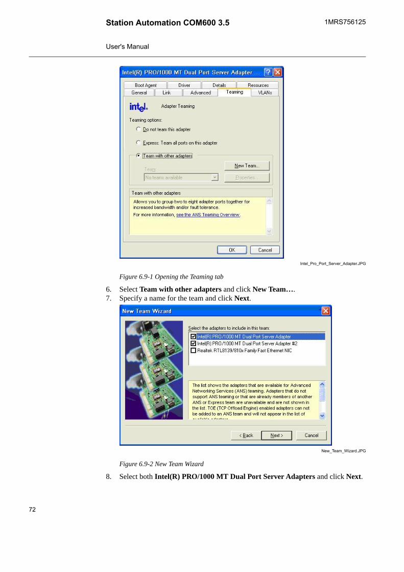
Intel_Pro_Port_Server_Adapter.JPG
Figure 6.9-1 Opening the Teaming tab
6. Select Team with other adapters and click New Team….7. Specify a name for the team and click Next.
New_Team_Wizard.JPG
Figure 6.9-2 New Team Wizard
8. Select both Intel(R) PRO/1000 MT Dual Port Server Adapters and click Next.
72
1MRS756125Station Automation COM600 3.5
User's Manual
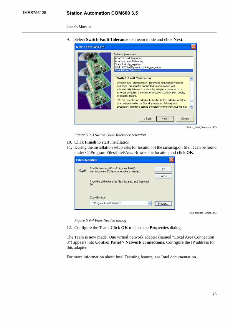
9. Select Switch Fault Tolerance to a team mode and click Next.
Switch_Fault_Tolerance.JPG
Figure 6.9-3 Switch Fault Tolerance selection
10. Click Finish to start installation11. During the installation setup asks for location of the iansmsg.dll file. It can be found
under C:\Program Files\Intel\Ans. Browse the location and click OK.
Files_Needed_Dialog.JPG
Figure 6.9-4 Files Needed dialog
12. Configure the Team. Click OK to close the Properties dialogs.
The Team is now made. One virtual network adapter (named “Local Area Connection3”) appears into Control Panel > Network connections. Configure the IP address forthis adapter.
For more information about Intel Teaming feature, see Intel documentation.
73
Station Automation COM600 3.51MRS756125
User's Manual
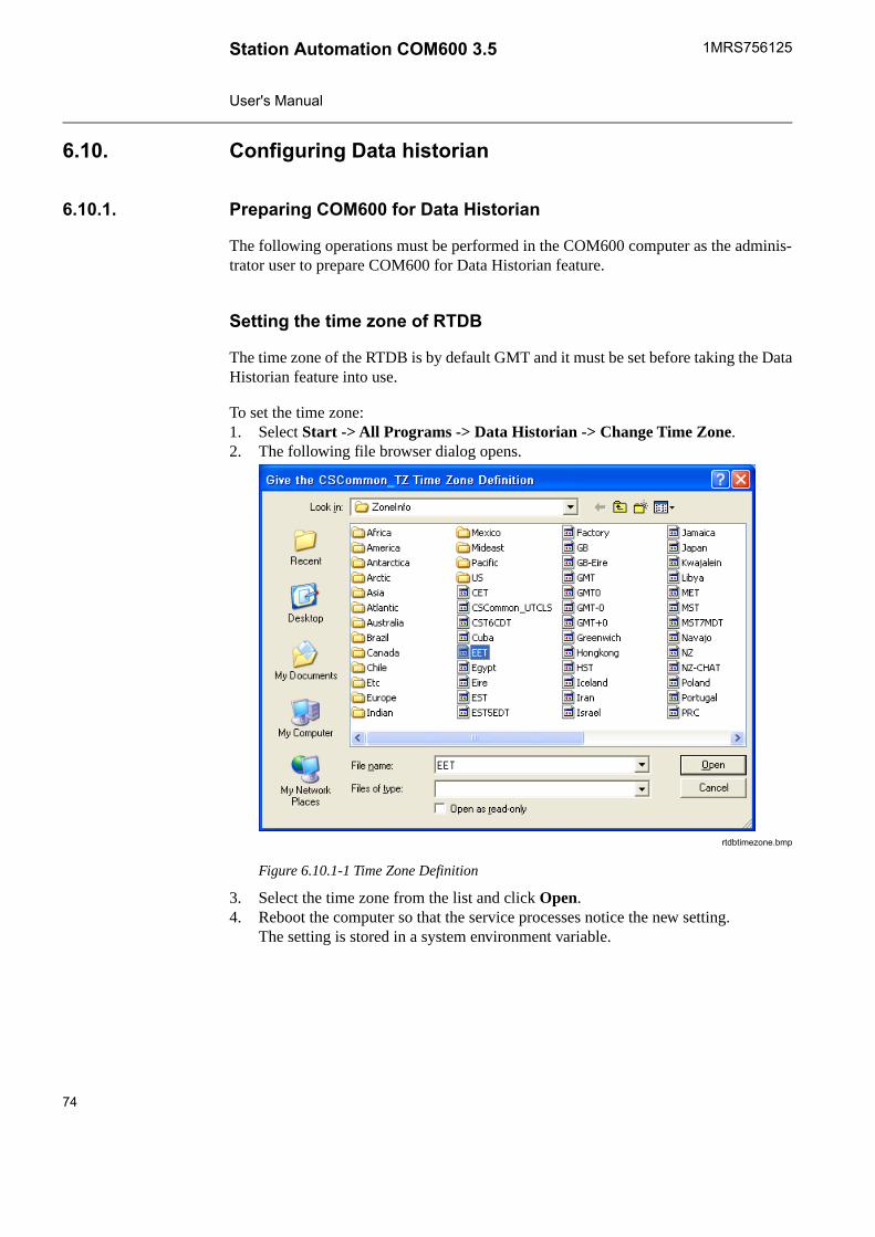
Configuring Data historian6.10.
Preparing COM600 for Data Historian6.10.1.
The following operations must be performed in the COM600 computer as the adminis-trator user to prepare COM600 for Data Historian feature.
Setting the time zone of RTDB
The time zone of the RTDB is by default GMT and it must be set before taking the DataHistorian feature into use.
To set the time zone:1. Select Start -> All Programs -> Data Historian -> Change Time Zone.2. The following file browser dialog opens.
rtdbtimezone.bmp
Figure 6.10.1-1 Time Zone Definition
3. Select the time zone from the list and click Open.4. Reboot the computer so that the service processes notice the new setting.
The setting is stored in a system environment variable.
74
1MRS756125Station Automation COM600 3.5
User's Manual
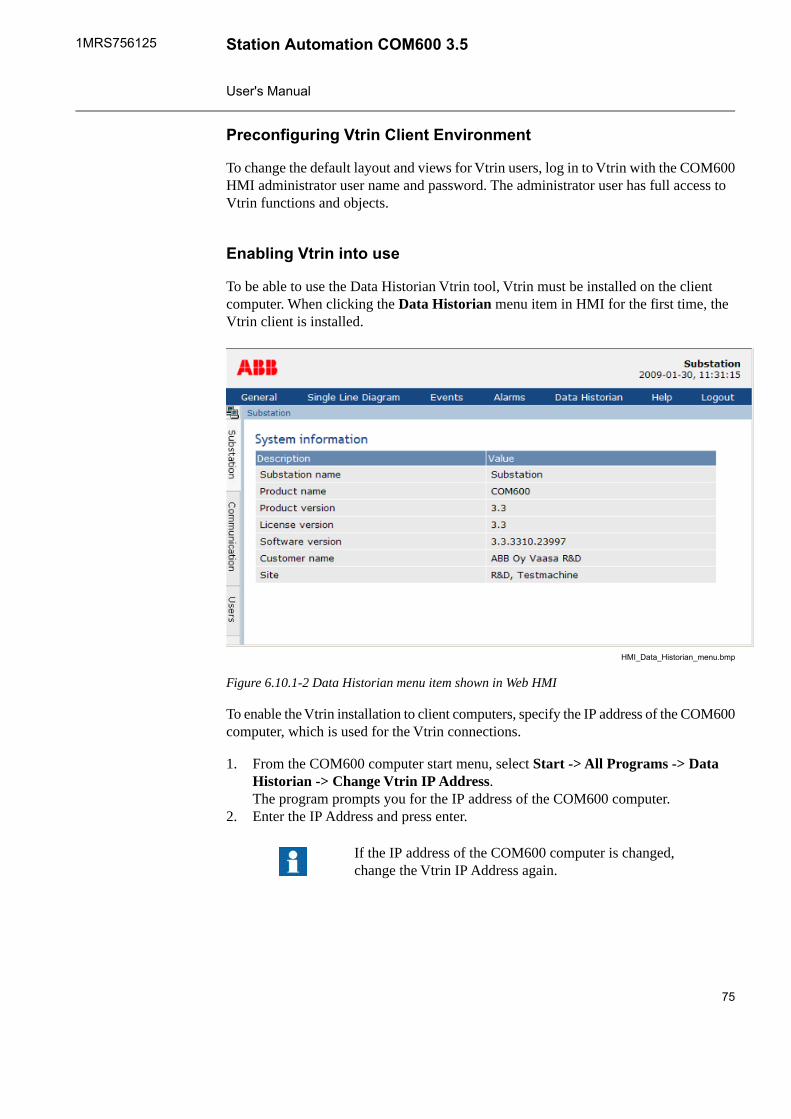
Preconfiguring Vtrin Client Environment
To change the default layout and views for Vtrin users, log in to Vtrin with the COM600HMI administrator user name and password. The administrator user has full access toVtrin functions and objects.
Enabling Vtrin into use
To be able to use the Data Historian Vtrin tool, Vtrin must be installed on the clientcomputer. When clicking the Data Historian menu item in HMI for the first time, theVtrin client is installed.
HMI_Data_Historian_menu.bmp
Figure 6.10.1-2 Data Historian menu item shown in Web HMI
To enable the Vtrin installation to client computers, specify the IP address of the COM600computer, which is used for the Vtrin connections.
1. From the COM600 computer start menu, select Start -> All Programs -> DataHistorian -> Change Vtrin IP Address.The program prompts you for the IP address of the COM600 computer.
2. Enter the IP Address and press enter.
If the IP address of the COM600 computer is changed,change the Vtrin IP Address again.
75
Station Automation COM600 3.51MRS756125
User's Manual
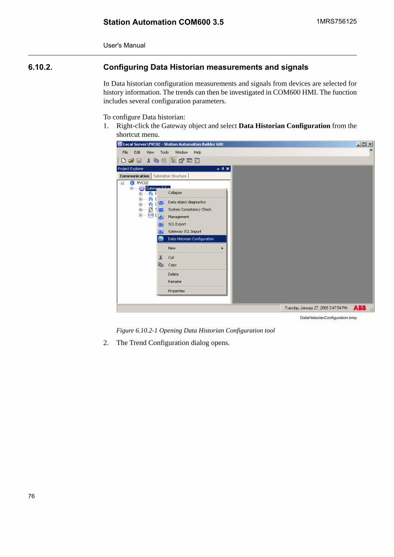
Configuring Data Historian measurements and signals6.10.2.
In Data historian configuration measurements and signals from devices are selected forhistory information. The trends can then be investigated in COM600 HMI. The functionincludes several configuration parameters.
To configure Data historian:1. Right-click the Gateway object and select Data Historian Configuration from the
shortcut menu.
DataHistorianConfiguration.bmp
Figure 6.10.2-1 Opening Data Historian Configuration tool
2. The Trend Configuration dialog opens.
76
1MRS756125Station Automation COM600 3.5
User's Manual
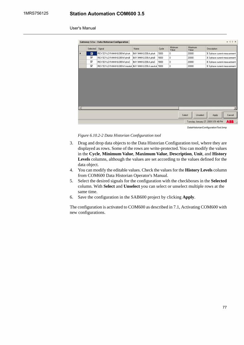
DataHistorianConfigurationTool.bmp
Figure 6.10.2-2 Data Historian Configuration tool
3. Drag and drop data objects to the Data Historian Configuration tool, where they aredisplayed as rows. Some of the rows are write-protected. You can modify the valuesin the Cycle, Minimum Value, Maximum Value, Description, Unit, and HistoryLevels columns, although the values are set according to the values defined for thedata object.
4. You can modify the editable values. Check the values for the History Levels columnfrom COM600 Data Historian Operator's Manual.
5. Select the desired signals for the configuration with the checkboxes in the Selectedcolumn. With Select and Unselect you can select or unselect multiple rows at thesame time.
6. Save the configuration in the SAB600 project by clicking Apply.
The configuration is activated to COM600 as described in 7.1, Activating COM600 withnew configurations.
77
Station Automation COM600 3.51MRS756125
User's Manual
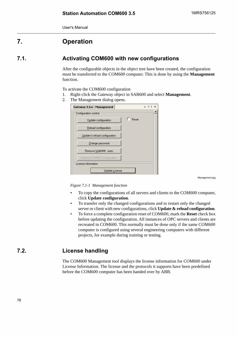
Operation7.
Activating COM600 with new configurations7.1.
After the configurable objects in the object tree have been created, the configurationmust be transferred to the COM600 computer. This is done by using the Managementfunction.
To activate the COM600 configuration1. Right-click the Gateway object in SAB600 and select Management.2. The Management dialog opens.
Management.jpg
Figure 7.1-1 Management function
• To copy the configurations of all servers and clients to the COM600 computer,click Update configuration.
• To transfer only the changed configurations and to restart only the changedserver or client with new configurations, click Update & reload configuration.
• To force a complete configuration reset of COM600, mark the Reset check boxbefore updating the configuration. All instances of OPC servers and clients arerecreated in COM600. This normally must be done only if the same COM600computer is configured using several engineering computers with differentprojects, for example during training or testing.
License handling7.2.
The COM600 Management tool displays the license information for COM600 underLicense Information. The license and the protocols it supports have been predefinedbefore the COM600 computer has been handed over by ABB.
78
1MRS756125Station Automation COM600 3.5
User's Manual
The following information is shown in the window:• owner of the license• product revision• protocols supported by the license.• number of servers supported by the license.• number of clients supported by the license.• if WebHMI is enabled.
To update the license with a new set of protocols, order a new license from ABB andupdate it to COM600 with SAB600.
To update the license:1. Open the Management tool from the Gateway object in SAB600.2. Click Update License.3. Browse for the new license file and click Open.
The license is COM600 specific and the COM600 computer verifies the compatibilityof the license. Also the servers and clients verify the license.
Using web site security certificates7.3.
Creating self-signed certificates7.3.1.
By default, COM600 has a certificate tied to the factory defaultcomputer name. You must create a self-signed certificate onlyif the id of the COM600 computer changes.
To create a self-signed certificate:1. In the COM600 computer, select Start > Control Panel > System > Computer
Name.2. Change the computer name by clicking Change and by typing the new name in the
Computer Name Changes dialog.
Do not use the underscore character '_' in the computername.
3. In the COM600 computer, open the command prompt and go to directory C:\ProgramFiles\IIS Resources\SelfSSL
4. Create and install a new certificate with command selfssl /T /V:36500 /Q5. Add the COM600 computer to the same domain as the client computer (in the
Computer Name Changes dialog), or add the COM600 computer information to theclient computer hosts file ((...\system32\drivers\etc\hosts).
79
Station Automation COM600 3.51MRS756125
User's Manual
Using self-signed certificates with Internet Explorer 77.3.2.
To use a self-signed certificate with Internet Explorer (IE) 7:1. Export the certificate from the COM600 computer.
a. Select Start > Control Panel > Administrative Tools > Internet InformationServices.
b. In the tree view, select the computer and then Web Sites.c. Right-click Default Web Site and select Properties.d. In the Properties dialog, select Directory Security > View Certificate > Details
> Copy to File.e. Click Next > No, do not export private key > DER encoded binary X.509
(.crt) > Next.f. Type the file name.
2. Copy the exported certificate file to the client computer running IE.3. In the client computer, start IE.4. Select Tools > Internet Options > Content > Certificates.5. Select Trusted Root Certification Authorities > Import.6. Select the previously exported certificate file from COM600.7. Place the certificate to Trusted Root Certification Authorities as suggested.8. Use the COM600 computer name to access COM600 HMI from IE7.
Using self-signed certificates with Internet Explorer 8(Windows 7)
7.3.3.
To use self-signed certificates with IE8 (Windows 7):1. In the client computer, start IE8 with Run as Administrator.2. Browse to the COM600 computer with the computer name.
Ignore the certificate warnings.3. Click Certificate Error at the top of the screen and select View certificates.4. In the Certificate dialog, click Install Certificate > Next.5. Select Place all certificates in the following store > Browse.6. Select the Show Physical Stores checkbox.7. Select Trusted Root Certificate Authorities > Local Computer.8. Click OK > Next > Finish > OK.9. Restart IE8.
Using self-signed certificates with Mozilla Firefox 3.6.37.3.4.
To use self-signed certificates with Mozilla Firefox 3.6.31. Start the Firefox browser.2. Browse tot he COM600 computer with the computer name.
Firefox warns that the connection is untrusted.3. Click Add Exception.4. Click Confirm Security Exception.
80
1MRS756125Station Automation COM600 3.5
User's Manual
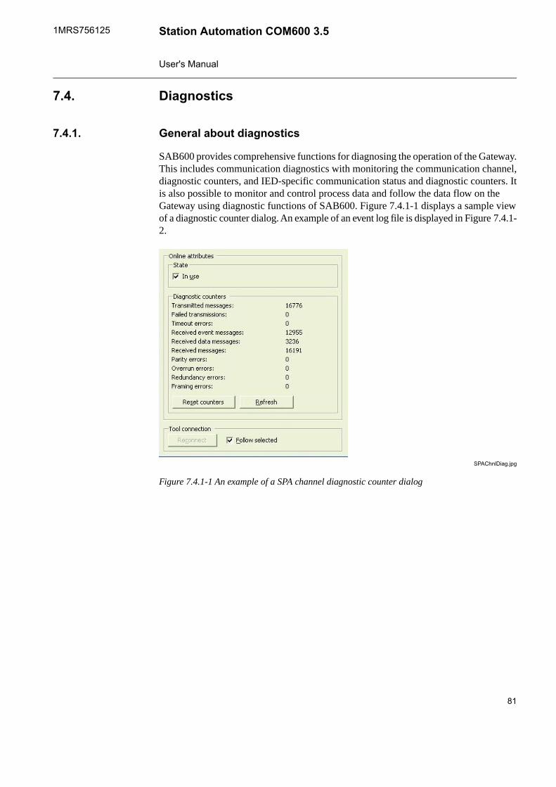
Diagnostics7.4.
General about diagnostics7.4.1.
SAB600 provides comprehensive functions for diagnosing the operation of the Gateway.This includes communication diagnostics with monitoring the communication channel,diagnostic counters, and IED-specific communication status and diagnostic counters. Itis also possible to monitor and control process data and follow the data flow on theGateway using diagnostic functions of SAB600. Figure 7.4.1-1 displays a sample viewof a diagnostic counter dialog. An example of an event log file is displayed in Figure 7.4.1-2.
SPAChnlDiag.jpg
Figure 7.4.1-1 An example of a SPA channel diagnostic counter dialog
81
Station Automation COM600 3.51MRS756125
User's Manual
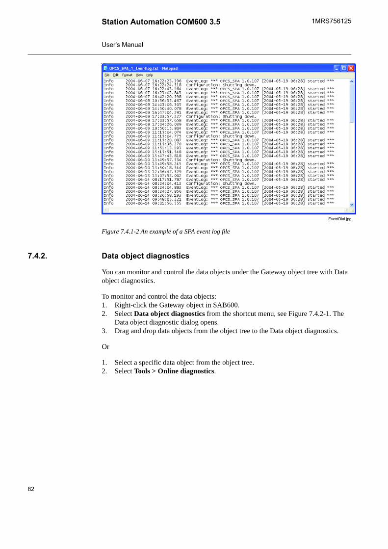
EventDial.jpg
Figure 7.4.1-2 An example of a SPA event log file
Data object diagnostics7.4.2.
You can monitor and control the data objects under the Gateway object tree with Dataobject diagnostics.
To monitor and control the data objects:1. Right-click the Gateway object in SAB600.2. Select Data object diagnostics from the shortcut menu, see Figure 7.4.2-1. The
Data object diagnostic dialog opens.3. Drag and drop data objects from the object tree to the Data object diagnostics.
Or
1. Select a specific data object from the object tree.2. Select Tools > Online diagnostics.
82
1MRS756125Station Automation COM600 3.5
User's Manual
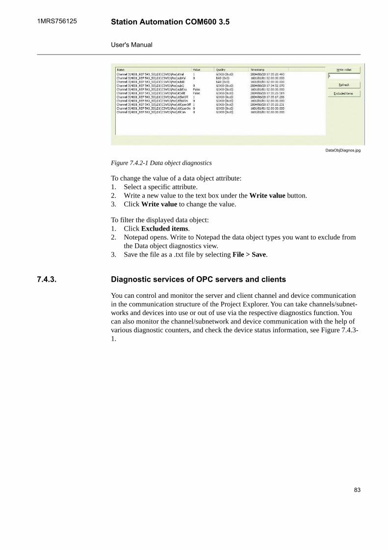
DataObjDiagnos.jpg
Figure 7.4.2-1 Data object diagnostics
To change the value of a data object attribute:1. Select a specific attribute.2. Write a new value to the text box under the Write value button.3. Click Write value to change the value.
To filter the displayed data object:1. Click Excluded items.2. Notepad opens. Write to Notepad the data object types you want to exclude from
the Data object diagnostics view.3. Save the file as a .txt file by selecting File > Save.
Diagnostic services of OPC servers and clients7.4.3.
You can control and monitor the server and client channel and device communicationin the communication structure of the Project Explorer. You can take channels/subnet-works and devices into use or out of use via the respective diagnostics function. Youcan also monitor the channel/subnetwork and device communication with the help ofvarious diagnostic counters, and check the device status information, see Figure 7.4.3-1.
83
Station Automation COM600 3.51MRS756125
User's Manual
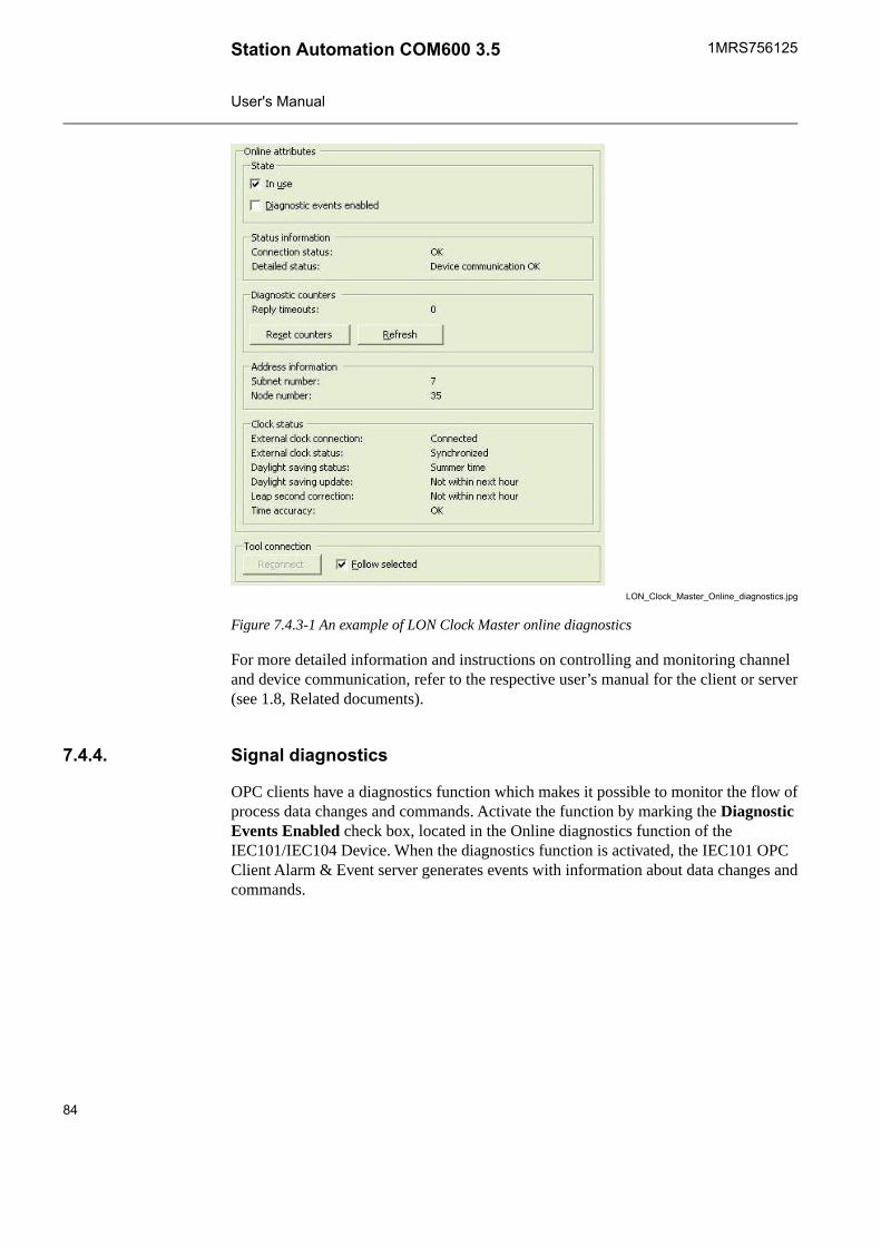
LON_Clock_Master_Online_diagnostics.jpg
Figure 7.4.3-1 An example of LON Clock Master online diagnostics
For more detailed information and instructions on controlling and monitoring channeland device communication, refer to the respective user’s manual for the client or server(see 1.8, Related documents).
Signal diagnostics7.4.4.
OPC clients have a diagnostics function which makes it possible to monitor the flow ofprocess data changes and commands. Activate the function by marking the DiagnosticEvents Enabled check box, located in the Online diagnostics function of theIEC101/IEC104 Device. When the diagnostics function is activated, the IEC101 OPCClient Alarm & Event server generates events with information about data changes andcommands.
84
1MRS756125Station Automation COM600 3.5
User's Manual
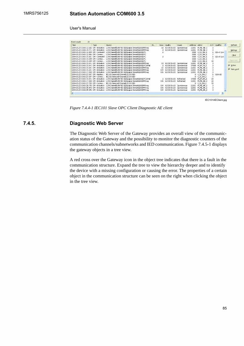
IEC101AEClient.jpg
Figure 7.4.4-1 IEC101 Slave OPC Client Diagnostic AE client
Diagnostic Web Server7.4.5.
The Diagnostic Web Server of the Gateway provides an overall view of the communic-ation status of the Gateway and the possibility to monitor the diagnostic counters of thecommunication channels/subnetworks and IED communication. Figure 7.4.5-1 displaysthe gateway objects in a tree view.
A red cross over the Gateway icon in the object tree indicates that there is a fault in thecommunication structure. Expand the tree to view the hierarchy deeper and to identifythe device with a missing configuration or causing the error. The properties of a certainobject in the communication structure can be seen on the right when clicking the objectin the tree view.
85
Station Automation COM600 3.51MRS756125
User's Manual
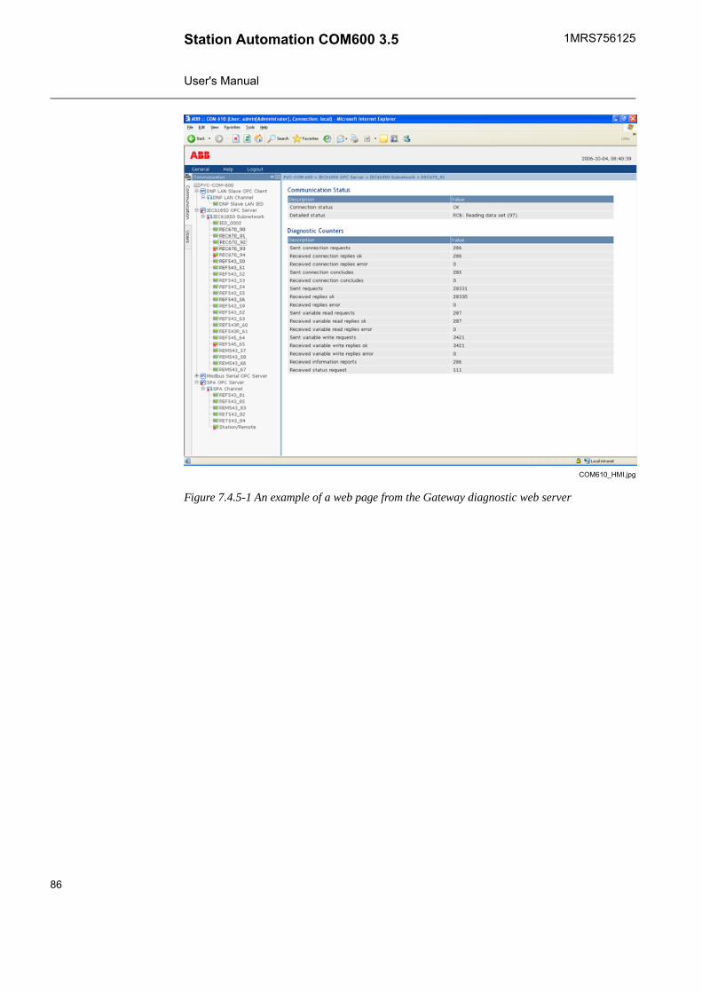
COM610_HMI.jpg
Figure 7.4.5-1 An example of a web page from the Gateway diagnostic web server
86
1MRS756125Station Automation COM600 3.5
User's Manual
Index
AActivating COM600 ............................................................................................. 78
Bbackup ............................................................................................................... 68building
object tree ...................................................................................................... 48
CCID export .......................................................................................................... 69COM600 computer
accessing ....................................................................................................... 40mounting ........................................................................................................ 34remote desktop ............................................................................................... 41user accounts ................................................................................................. 41
configuration ................................................................................................. 45, 47general ..................................................................................................... 45–46object properties ............................................................................................. 49server objects ................................................................................................. 47Station/Remote switch .................................................................................... 59
connectionsmechanics ...................................................................................................... 28
creatingsubstation structure ........................................................................................ 48
cross-references ................................................................................................. 58
DData Historian .................................................................................................... 20data historian ................................................................................................ 74, 76data object
attributes ........................................................................................................ 83diagnostics ..................................................................................................... 82filtering ........................................................................................................... 83
Diagnostic Web Server ....................................................................................... 85diagnostics
data object ..................................................................................................... 82general .......................................................................................................... 81server ............................................................................................................ 83signal ............................................................................................................. 84
Duo Driver .......................................................................................................... 70
87
Station Automation COM600 3.51MRS756125
User's Manual
Eevent definitions
configuring ..................................................................................................... 61creating .......................................................................................................... 60
event printer ....................................................................................................... 26configuring ..................................................................................................... 64
exportingconfiguration files ............................................................................................ 69project ............................................................................................................ 68
Ffunctionality
Gateway ........................................................................................................ 15HMI ............................................................................................................... 16
GGateway
functionality .................................................................................................... 15Grouping Alarms
alarms ............................................................................................................ 62
HHMI
accessing ....................................................................................................... 17functionality .................................................................................................... 16
IIEC 61850 data modeling .................................................................................... 21importing
configuration file ............................................................................................. 51project ............................................................................................................ 68
Llicense ............................................................................................................... 39Logic Processor
CoDeSys SP runtime ...................................................................................... 19
Mmaintenance ...................................................................................................... 45management
license handling .............................................................................................. 78
88
1MRS756125Station Automation COM600 3.5
User's Manual
Oobject properties
configuration .................................................................................................. 49object tree .......................................................................................................... 46
building .......................................................................................................... 48OPC client
adding ........................................................................................................... 48structure ......................................................................................................... 18
OPC serverstructure ......................................................................................................... 17
Pprocess data ...................................................................................................... 45project
exporting ........................................................................................................ 68project conversion .............................................................................................. 38
Qqueuing
capacities ....................................................................................................... 26logic ............................................................................................................... 25priorities ......................................................................................................... 26process data updates ...................................................................................... 25
Rregional settings ................................................................................................. 40restore ............................................................................................................... 68
SSAB600
installing ......................................................................................................... 37uninstalling ..................................................................................................... 43
scalesconfiguring ..................................................................................................... 66creating .......................................................................................................... 65using .............................................................................................................. 65
SCL export ......................................................................................................... 69SCL import ......................................................................................................... 51software
properties ....................................................................................................... 32Station Automation Builder 600
starting ........................................................................................................... 46Station/Remote switch ........................................................................................ 23structure
89
Station Automation COM600 3.51MRS756125
User's Manual

OPC client ...................................................................................................... 18OPC server .................................................................................................... 17
substation structurecreating .......................................................................................................... 48
system consistencyconsistency .................................................................................................... 56
Uupdating license ................................................................................................. 79
90
1MRS756125Station Automation COM600 3.5
User's Manual


Contact us
1MR
S75
6125
H/3
0.6.
2011
© C
opyr
ight
201
0 A
BB
. All
right
s re
serv
ed.
ABB OyDistribution AutomationP.O. Box 699FI-65101 VAASA, FINLANDTel. +358 10 22 11Fax. +358 10 224 1094
ABB Inc.Distribution Automation655 Century PointLake Mary, FL 32746, USATel: +1 407 732 2000Fax: +1 407 732 2335
www.abb.com/substationautomation