Embed Size (px)
Citation preview

8/9/2019 Communication 1 1559
http://slidepdf.com/reader/full/communication-1-1559 1/6
TH
3.3 SUBJECT TITLE : COMMUNICATION SYSTEMS - I (1559)
• Year : Third Year
• Teaching and Examination Scheme:
TEACHING SCHEME EXAM SCHEME & MAXIMUM MARKS
THEORY
HRS/WEEK
PRACTICAL
HRS/WEEK
PAPER
HRS.TH PR OR TW SW
2 2 3 100 50 - - 50
• RATIONALE :
To teach the students facts, concepts, principles, procedures of communicationsystems, so that students can use the knowledge to install & troubleshoot the different
audio & video communication systems.
8/9/2019 Communication 1 1559
http://slidepdf.com/reader/full/communication-1-1559 2/6
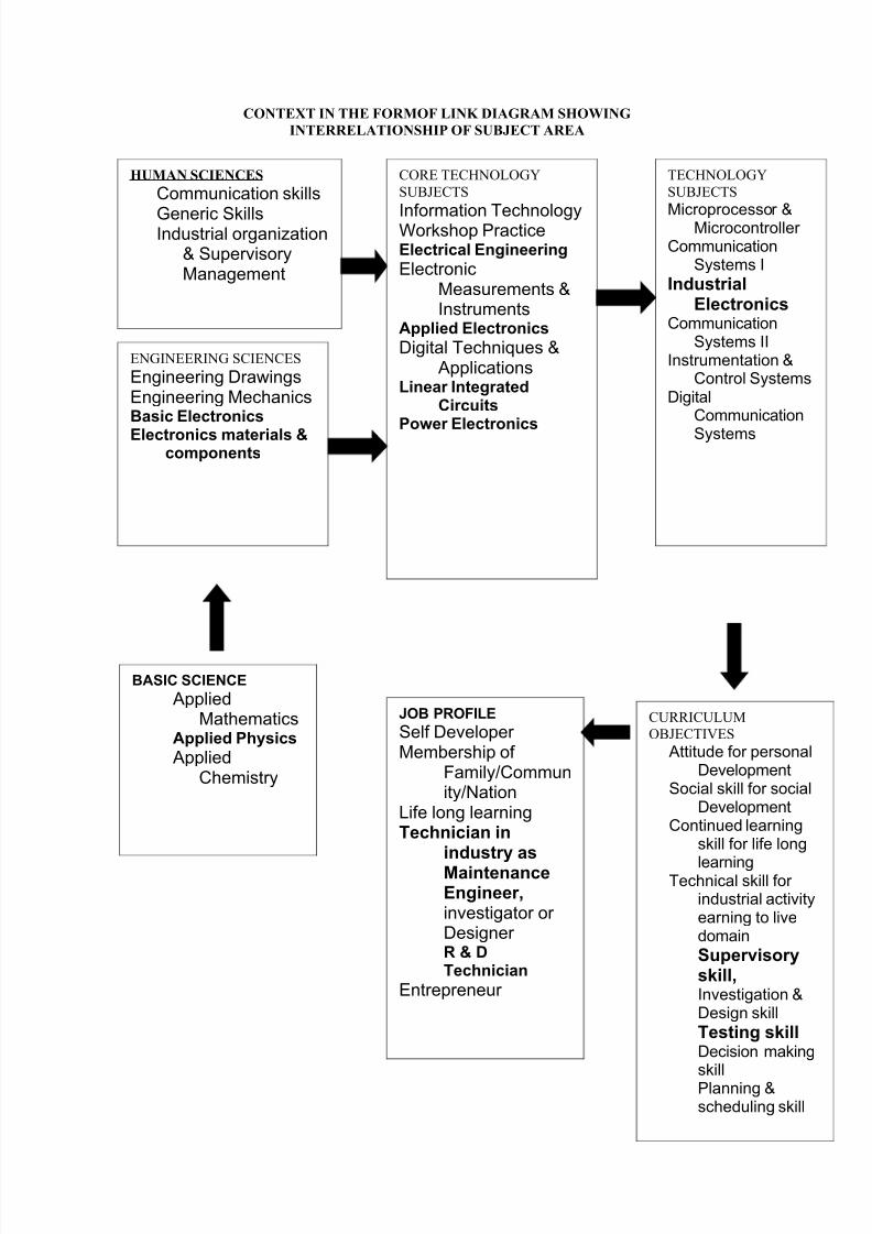
CONTEXT IN THE FORMOF LINK DIAGRAM SHOWING
INTERRELATIONSHIP OF SUBJECT AREA
HUMAN SCIENCES
Communication skills
Generic SkillsIndustrial organization
& SupervisoryManagement
ENGINEERING SCIENCES
Engineering DrawingsEngineering MechanicsBasic Electronics
Electronics materials &components
CORE TECHNOLOGY
SUBJECTS
Information TechnologyWorkshop PracticeElectrical Engineering
ElectronicMeasurements &Instruments
Applied Electronics
Digital Techniques &Applications
Linear IntegratedCircuits
Power Electronics
TECHNOLOGY
SUBJECTS
Microprocessor &Microcontroller Communication
Systems I
IndustrialElectronics
CommunicationSystems II
Instrumentation &Control Systems
DigitalCommunication
Systems
BASIC SCIENCE
AppliedMathematics
Applied Physics
AppliedChemistry
JOB PROFILE
Self Developer Membership of
Family/Community/Nation
Life long learningTechnician in
industry asMaintenanceEngineer,investigator or Designer R & DTechnician
Entrepreneur
CURRICULUM
OBJECTIVES
Attitude for personalDevelopment
Social skill for socialDevelopment
Continued learningskill for life long
learningTechnical skill for
industrial activityearning to livedomain
Supervisoryskill,Investigation &Design skill
Testing skillDecision makingskillPlanning &scheduling skill
8/9/2019 Communication 1 1559
http://slidepdf.com/reader/full/communication-1-1559 3/6
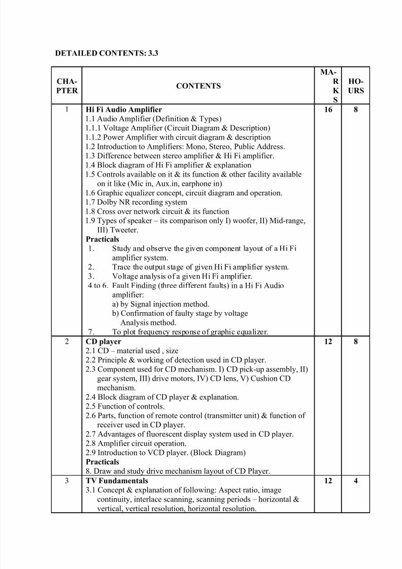
DETAILED CONTENTS: 3.3
CHA-
PTER CONTENTS
MA-
R
K
S
HO-
URS
1 Hi Fi Audio Amplifier
1.1 Audio Amplifier (Definition & Types)
1.1.1 Voltage Amplifier (Circuit Diagram & Description)
1.1.2 Power Amplifier with circuit diagram & description
1.2 Introduction to Amplifiers: Mono, Stereo, Public Address.
1.3 Difference between stereo amplifier & Hi Fi amplifier.
1.4 Block diagram of Hi Fi amplifier & explanation
1.5 Controls available on it & its function & other facility available
on it like (Mic in, Aux.in, earphone in)
1.6 Graphic equalizer concept, circuit diagram and operation.
1.7 Dolby NR recording system1.8 Cross over network circuit & its function
1.9 Types of speaker – its comparison only I) woofer, II) Mid-range,
III) Tweeter.
Practicals
1. Study and observe the given component layout of a Hi Fi
amplifier system.
2. Trace the output stage of given Hi Fi amplifier system.
3. Voltage analysis of a given Hi Fi amplifier.
4 to 6. Fault Finding (three different faults) in a Hi Fi Audio
amplifier:
a) by Signal injection method.
b) Confirmation of faulty stage by voltage
Analysis method.
7. To plot frequency response of graphic equalizer.
16 8
2 CD player
2.1 CD – material used , size
2.2 Principle & working of detection used in CD player.
2.3 Component used for CD mechanism. I) CD pick-up assembly, II)
gear system, III) drive motors, IV) CD lens, V) Cushion CD
mechanism.
2.4 Block diagram of CD player & explanation.2.5 Function of controls.
2.6 Parts, function of remote control (transmitter unit) & function of
receiver used in CD player.
2.7 Advantages of fluorescent display system used in CD player.
2.8 Amplifier circuit operation.
2.9 Introduction to VCD player. (Block Diagram)
Practicals
8. Draw and study drive mechanism layout of CD Player.
12 8
3 TV Fundamentals
3.1 Concept & explanation of following: Aspect ratio, image
continuity, interlace scanning, scanning periods – horizontal &vertical, vertical resolution, horizontal resolution.
12 4
8/9/2019 Communication 1 1559
http://slidepdf.com/reader/full/communication-1-1559 4/6
CHA-
PTER CONTENTS
MA-
R
K
S
HO-
URS
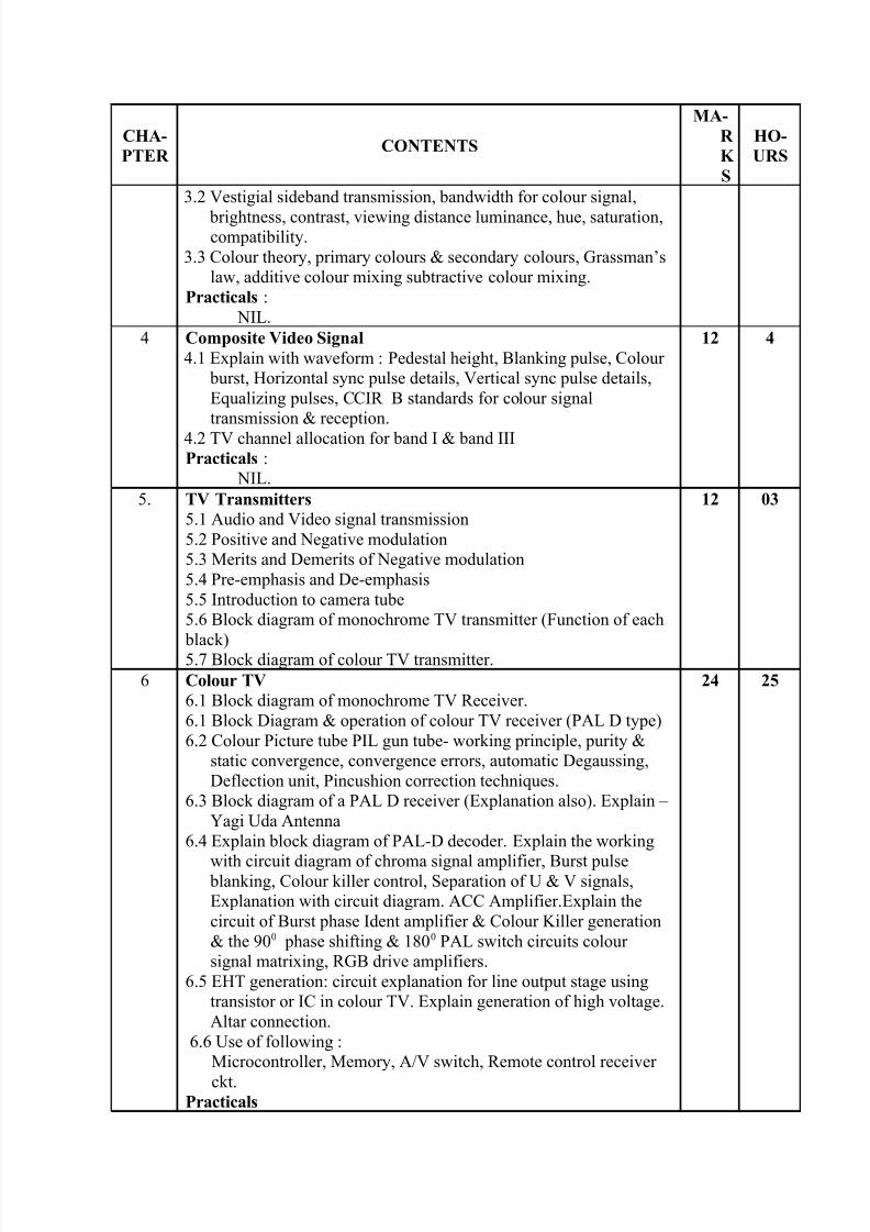
3.2 Vestigial sideband transmission, bandwidth for colour signal,
brightness, contrast, viewing distance luminance, hue, saturation,compatibility.
3.3 Colour theory, primary colours & secondary colours, Grassman’s
law, additive colour mixing subtractive colour mixing.
Practicals :
NIL.
4 Composite Video Signal
4.1 Explain with waveform : Pedestal height, Blanking pulse, Colour
burst, Horizontal sync pulse details, Vertical sync pulse details,
Equalizing pulses, CCIR B standards for colour signal
transmission & reception.
4.2 TV channel allocation for band I & band III
Practicals :
NIL.
12 4
5. TV Transmitters
5.1 Audio and Video signal transmission
5.2 Positive and Negative modulation
5.3 Merits and Demerits of Negative modulation
5.4 Pre-emphasis and De-emphasis
5.5 Introduction to camera tube
5.6 Block diagram of monochrome TV transmitter (Function of each
black)5.7 Block diagram of colour TV transmitter.
12 03
6 Colour TV
6.1 Block diagram of monochrome TV Receiver.
6.1 Block Diagram & operation of colour TV receiver (PAL D type)
6.2 Colour Picture tube PIL gun tube- working principle, purity &
static convergence, convergence errors, automatic Degaussing,
Deflection unit, Pincushion correction techniques.
6.3 Block diagram of a PAL D receiver (Explanation also). Explain –
Yagi Uda Antenna
6.4 Explain block diagram of PAL-D decoder. Explain the working
with circuit diagram of chroma signal amplifier, Burst pulse blanking, Colour killer control, Separation of U & V signals,
Explanation with circuit diagram. ACC Amplifier.Explain the
circuit of Burst phase Ident amplifier & Colour Killer generation
& the 900 phase shifting & 1800 PAL switch circuits colour
signal matrixing, RGB drive amplifiers.
6.5 EHT generation: circuit explanation for line output stage using
transistor or IC in colour TV. Explain generation of high voltage.
Altar connection.
6.6 Use of following :
Microcontroller, Memory, A/V switch, Remote control receiver
ckt.Practicals
24 25

8/9/2019 Communication 1 1559
http://slidepdf.com/reader/full/communication-1-1559 5/6
CHA-
PTER CONTENTS
MA-
R
K
S
HO-
URS
9. Tracing of chroma section in given TV receiver.
10. Tracing of picture tube and video amplifier in given TVreceiver with multimeter.
11. Tracing of horizontal section in given TV receiver with
multimeter.
12. Voltage analysis of picture tube, chroma section and
horizontal section.
13 to 18. Fault finding in given colour TV :
13. a) No colour
b) Red colour only.
14. a) Blue colour only.
b) Green colour only.
15. a) Magentena colour only. b) Cyan only.
16. a) Yellow only.
b) No raster.
17. a) Fault in HSYNC section.
b) Fault in VSYNC section.
18. Fault in SYNC seperator.
7 Cable Television
7.1 Working principle & specification of following components.
1. Dish antenna
2. LNA (Low Noise Amplifier)3. Multiplexer (used for different signal to transmit, like – any
note below the picture scene.)
4. Attenuator
5. Connector (two way, three way)
6. Amplifier
7. Cable.
7.2 Design concepts for cable T.V. N/W
7.3 Block diagram & working principle of dB meter.
7.4 Block diagram of satellite TV receiver (earth station) & operation
of each block.
Practicals19. Draw and study layout diagram for distribution of cable
connection for master antenna TV.
20. Study of satellite TV antenna.
12
12
IMPLEMENTATION STRATEGIES :
1. Conduct practicals after theory covered in class.
2. Conduct minimum 18 experiments.
8/9/2019 Communication 1 1559
http://slidepdf.com/reader/full/communication-1-1559 6/6
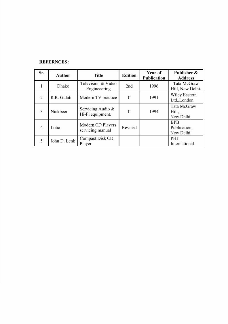
REFERNCES :
Sr.Author Title Edition
Year of
Publication
Publisher &
Address
1 DhakeTelevision & Video
Engineeering2nd 1996
Tata McGraw
Hill, New Delhi.
2 R.R. Gulati Modern TV practice 1st 1991Wiley Eastern
Ltd.,London
3 Nickbeer
Servicing Audio &
Hi-Fi equipment. 1
st
1994
Tata McGraw
Hill, New Delhi
4 LotiaModern CD Players
servicing manualRevised
BPB
Publication,
New Delhi.
5 John D. Lenk Compact Disk CD
Player
PHI
International