Embed Size (px)
Citation preview
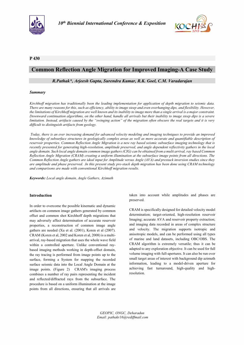
GEOPIC, ONGC, Deharadun
Email: [email protected]
10th Biennial International Conference & Exposition
P 430
Common Reflection Angle Migration for Improved Imaging-A Case Study
R.Pathak*, Arjeesh Gupta, Surendra Kumar, R.K. Goel, C.M. Varadarajan
Summary
Kirchhoff migration has traditionally been the leading implementation for application of depth migration to seismic data.
There are many reasons for this, such as efficiency, ability to image steep and even overhanging dips, and flexibility. However,
the limitations of Kirchhoff migration are well known and its inability to image more than a single arrival is a major constraint.
Downward continuation algorithms, on the other hand, handle all arrivals but their inability to image steep dips is a severe
limitation. Instead, artifacts caused by the “swinging action” of the migration often obscure the real targets and it is very
difficult to distinguish artifacts from geology.
Today, there is an ever increasing demand for advanced velocity modeling and imaging techniques to provide an improved
knowledge of subsurface structures in geologically complex areas as well as more accurate and quantifiable description of
reservoir properties. Common Reflection Angle Migration is a new ray based seismic subsurface imaging technology that is
recently presented for generating high-resolution, amplitude preserved, and angle dependent reflectivity gathers in the local
angle domain. Such local angle domain common image gathers (CIG) can be obtained from a multi arrival, ray based Common
Reflection Angle Migration (CRAM) creating a uniform illumination at the subsurface image points from all directions. The
Common Reflection Angle gathers are ideal input for Amplitude versus Angle (AVA) and prestack inversion studies since they
are amplitude and phase preserved. .In this present study pre-stack depth migration has been done using CRAM technology
and comparisons are made with conventional Kirchhoff migration results.
Keywords: Local angle domain, Angle Gathers, Azimuth
Introduction
In order to overcome the possible kinematic and dynamic
artifacts on common image gathers generated by common
offset and common shot Kirchhoff depth migrations that
may adversely affect determination of accurate reservoir
properties, a reconstruction of common image angle
gathers are needed (Xu et al. (2001), Koren et al (2007).
CRAM (Koren et al, 2002 and Koren et al, 2008) is a multi-
arrival, ray-based migration that uses the whole wave field
within a controlled aperture. Unlike conventional ray-
based imaging methods working in depth-offset domain,
the ray tracing is performed from image points up to the
surface, forming a System for mapping the recorded
surface seismic data into the Local Angle Domain at the
image points. (Figure 2) CRAM's imaging process
combines a number of ray pairs representing the incident
and reflected/diffracted rays from the subsurface. The
procedure is based on a uniform illumination at the image
points from all directions, ensuring that all arrivals are
taken into account while amplitudes and phases are
preserved.
CRAM is specifically designed for detailed velocity model
determination; target-oriented, high-resolution reservoir
Imaging; accurate AVA and reservoir property extraction;
and imaging data recorded in areas of complex structure
and velocity. The migration supports isotropic and
anisotropic models, and can be performed using all types
of marine and land datasets, including OBC/OBS. The
CRAM algorithm is extremely versatile; thus it can be
adapted to any exploration objective. It can be used for full
volume imaging with full-apertures. It can also be run over
small target areas of interest with background dip azimuth
information, leading to a model-driven aperture for
achieving fast turnaround, high-quality and high-
resolution.
2
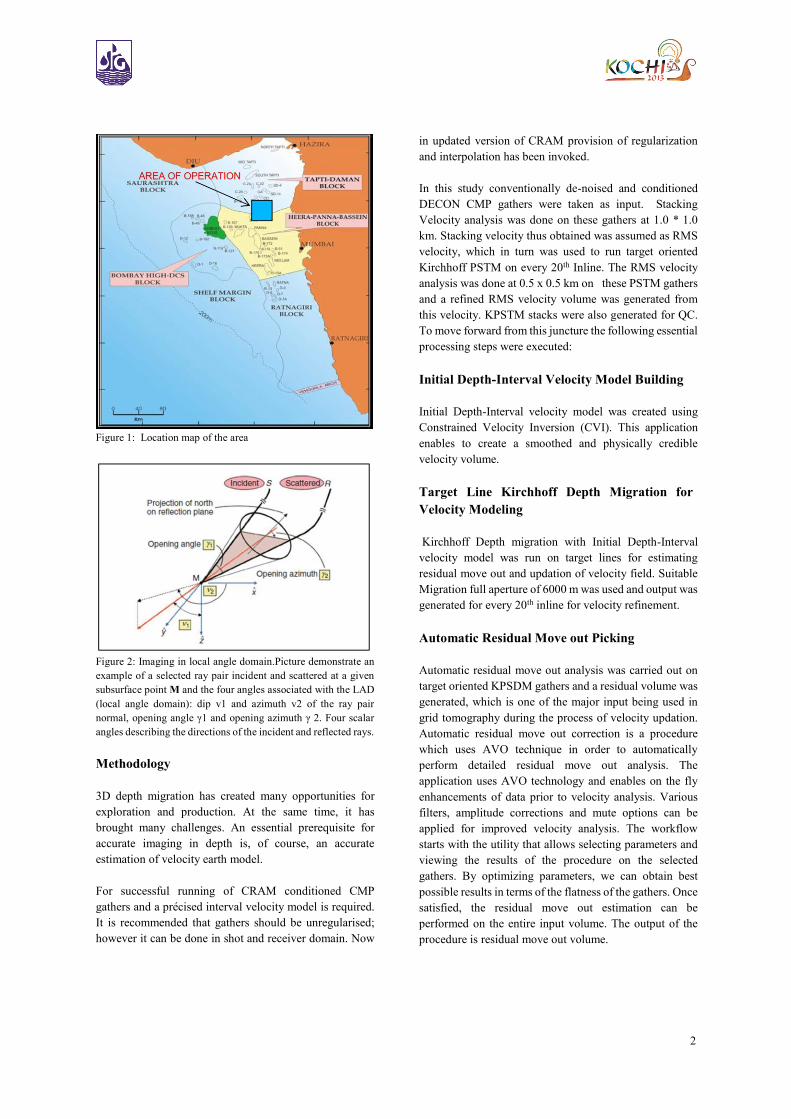
Figure 1: Location map of the area
Figure 2: Imaging in local angle domain.Picture demonstrate an
example of a selected ray pair incident and scattered at a given
subsurface point M and the four angles associated with the LAD
(local angle domain): dip v1 and azimuth v2 of the ray pair
normal, opening angle γ1 and opening azimuth γ 2. Four scalar
angles describing the directions of the incident and reflected rays.
Methodology
3D depth migration has created many opportunities for
exploration and production. At the same time, it has
brought many challenges. An essential prerequisite for
accurate imaging in depth is, of course, an accurate
estimation of velocity earth model.
For successful running of CRAM conditioned CMP
gathers and a précised interval velocity model is required.
It is recommended that gathers should be unregularised;
however it can be done in shot and receiver domain. Now
in updated version of CRAM provision of regularization
and interpolation has been invoked.
In this study conventionally de-noised and conditioned
DECON CMP gathers were taken as input. Stacking
Velocity analysis was done on these gathers at 1.0 * 1.0
km. Stacking velocity thus obtained was assumed as RMS
velocity, which in turn was used to run target oriented
Kirchhoff PSTM on every 20th Inline. The RMS velocity
analysis was done at 0.5 x 0.5 km on these PSTM gathers
and a refined RMS velocity volume was generated from
this velocity. KPSTM stacks were also generated for QC.
To move forward from this juncture the following essential
processing steps were executed:
Initial Depth-Interval Velocity Model Building
Initial Depth-Interval velocity model was created using
Constrained Velocity Inversion (CVI). This application
enables to create a smoothed and physically credible
velocity volume.
Target Line Kirchhoff Depth Migration for
Velocity Modeling
Kirchhoff Depth migration with Initial Depth-Interval
velocity model was run on target lines for estimating
residual move out and updation of velocity field. Suitable
Migration full aperture of 6000 m was used and output was
generated for every 20th inline for velocity refinement.
Automatic Residual Move out Picking
Automatic residual move out analysis was carried out on
target oriented KPSDM gathers and a residual volume was
generated, which is one of the major input being used in
grid tomography during the process of velocity updation.
Automatic residual move out correction is a procedure
which uses AVO technique in order to automatically
perform detailed residual move out analysis. The
application uses AVO technology and enables on the fly
enhancements of data prior to velocity analysis. Various
filters, amplitude corrections and mute options can be
applied for improved velocity analysis. The workflow
starts with the utility that allows selecting parameters and
viewing the results of the procedure on the selected
gathers. By optimizing parameters, we can obtain best
possible results in terms of the flatness of the gathers. Once
satisfied, the residual move out estimation can be
performed on the entire input volume. The output of the
procedure is residual move out volume.
3
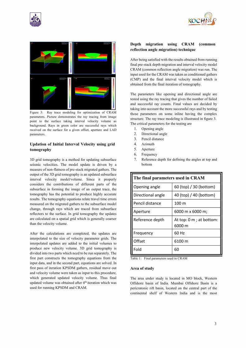
Figure 3: Ray trace modeling for optimization of CRAM
parameters. Picture demonstrates the ray tracing from image
point to the surface taking interval velocity volume as
background. Rays in green color are successful rays which
received on the surface for a given offset, aperture and LAD
parameters.
Updation of Initial Interval Velocity using grid
tomography
3D grid tomography is a method for updating subsurface
seismic velocities. The model update is driven by a
measure of non-flatness of pre-stack migrated gathers. The
output of the 3D grid tomography is an updated subsurface
interval velocity model/volume. Since it properly
considers the contributions of different parts of the
subsurface in forming the image of an output trace, the
tomography has the potential to produce highly accurate
results. The tomography equations relate travel time errors
measured on the migrated gathers to the subsurface model
change, through rays which are traced from subsurface
reflectors to the surface. In grid tomography the updates
are calculated on a spatial grid which is generally coarser
than the velocity volume.
After the calculations are completed, the updates are
interpolated to the size of velocity parameter grids. The
interpolated updates are added to the initial volumes to
produce new velocity volume. 3D grid tomography is
divided into two parts which need to be run separately. The
first part constructs the tomography equations from the
input data, and in the second part, equations are solved. In
first pass of iteration KPSDM gathers, residual move out
and velocity volume were taken as input to this procedure,
which generated updated velocity volume. Thus final
updated volume was obtained after 4th iteration which was
used for running KPSDM and CRAM.
Depth migration using CRAM (common
reflection angle migration) technique
After being satisfied with the results obtained from running
final pre-stack depth migration and interval velocity model
CRAM (common reflection angle migration) was run. The
input used for the CRAM was taken as conditioned gathers
(CMP) and the final interval velocity model which is
obtained from the final iteration of tomography.
The parameters like opening and directional angle are
tested using the ray tracing that gives the number of failed
and successful ray counts. Final values are decided by
taking into account the more successful rays and by testing
those parameters on some inline having the complex
structure. The ray trace modeling is illustrated in figure 3.
The critical parameters for the testing are
1. Opening angle
2. Directional angle
3. Pencil distance
4. Azimuth
5. Aperture
6. Frequency
7. Reference depth for defining the angles at top and
bottom
The final parameters used in CRAM
Opening angle 60 (top) / 30 (bottom)
Directional angle 40 (top) / 40 (bottom)
Pencil distance 100 m
Aperture 6000 m x 6000 m;
Reference depth At top: 0 m ; at bottom:
6000 m
Frequency 60 Hz
Offset 6100 m
Fold 60
Table 1: Final parameters used in CRAM
Area of study
The area under study is located in MO block, Western
Offshore basin of India. Mumbai Offshore Basin is a
pericratonic rift basin, located on the central part of the
continental shelf of Western India and is the most
4
prominent of all the west coast offshore basins. (Figure
1)The basin is delimited by Deccan trap outcrops to its
north as well as east, west margin basement arch to its west
and Vengurla arch to its south. To its northwest, the
boundary between Bombay offshore and Saurashtra
offshore has been considered along the westward
extrapolation of Landsat lineament, which roughly
coincides with the limit of Neogene sediment exposures on
the southern part of Saurashtra Peninsula. Mumbai
Offshore Basin is an extensional passive margin basin,
with its genesis linked to the break-up of Madagascar from
the Indian plate in Cretaceous, about 88 ma. The basin is
contiguous with the petroliferous onland Cambay Basin,
through the Gulf of Cambay in the northeast.
The study pertains to the Pre Stack Depth Migration of 360
sq. km 3D seismic data, using Common Reflection Angle
Migration (CRAM) technology. The 60 fold 3D data was
acquired using six steamers with group interval 25 m and
shot interval 50 m during 2004 by an offshore vessel using
240 channels.The minimum offset is 100 m and the
maximum far offset is 6100 m .Record length of data is 6.0
sec. sampling interval 2.0 ms. The dimension of bin size
is12.5 x 25 m. The main objective of processing was to
improve subsurface imaging in depth domain using
CRAM technology in a zone of 1500-4500m depth.
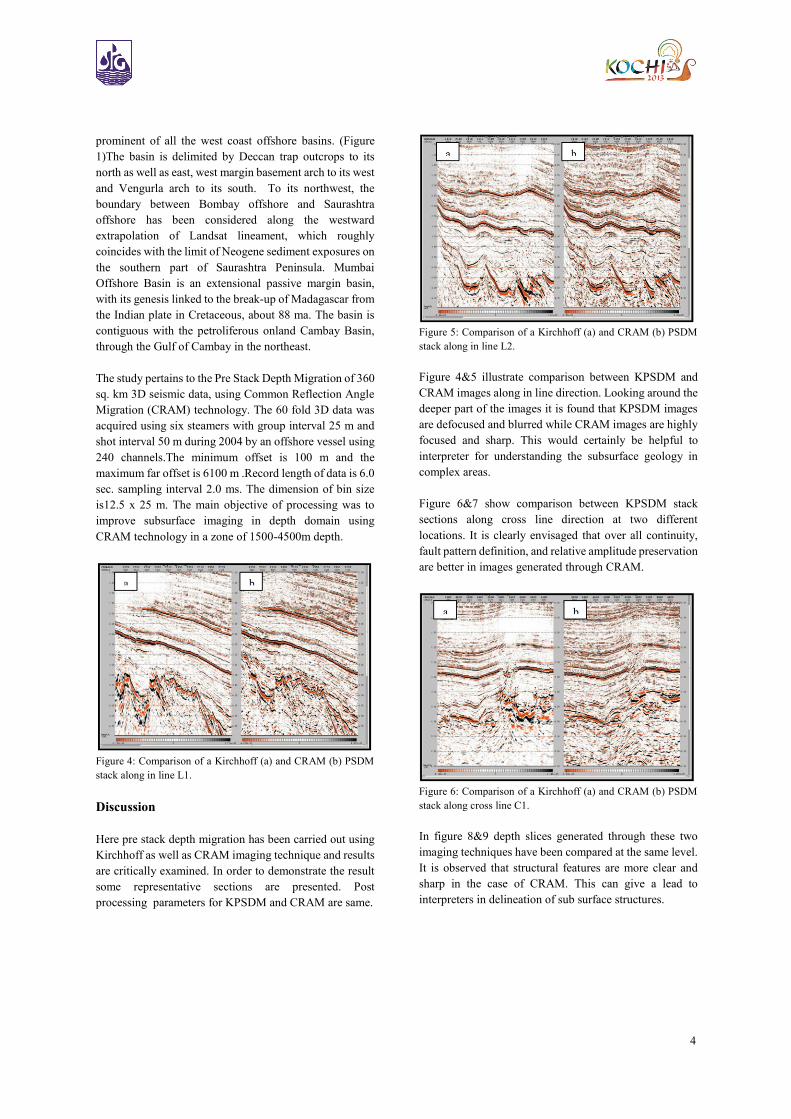
Figure 4: Comparison of a Kirchhoff (a) and CRAM (b) PSDM
stack along in line L1.
Discussion
Here pre stack depth migration has been carried out using
Kirchhoff as well as CRAM imaging technique and results
are critically examined. In order to demonstrate the result
some representative sections are presented. Post
processing parameters for KPSDM and CRAM are same.
Figure 5: Comparison of a Kirchhoff (a) and CRAM (b) PSDM
stack along in line L2.
Figure 4&5 illustrate comparison between KPSDM and
CRAM images along in line direction. Looking around the
deeper part of the images it is found that KPSDM images
are defocused and blurred while CRAM images are highly
focused and sharp. This would certainly be helpful to
interpreter for understanding the subsurface geology in
complex areas.
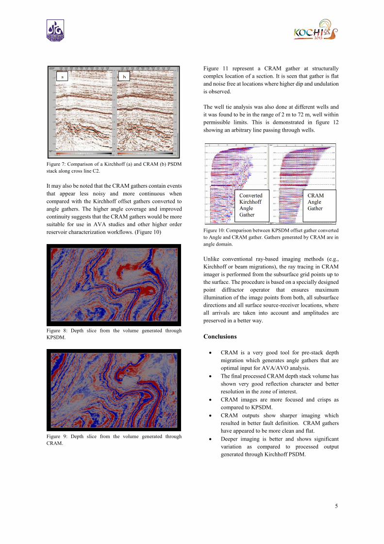
Figure 6&7 show comparison between KPSDM stack
sections along cross line direction at two different
locations. It is clearly envisaged that over all continuity,
fault pattern definition, and relative amplitude preservation
are better in images generated through CRAM.
Figure 6: Comparison of a Kirchhoff (a) and CRAM (b) PSDM
stack along cross line C1.
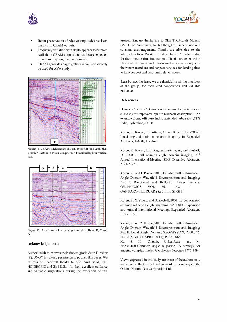
In figure 8&9 depth slices generated through these two
imaging techniques have been compared at the same level.
It is observed that structural features are more clear and
sharp in the case of CRAM. This can give a lead to
interpreters in delineation of sub surface structures.
5
Figure 7: Comparison of a Kirchhoff (a) and CRAM (b) PSDM
stack along cross line C2.
It may also be noted that the CRAM gathers contain events
that appear less noisy and more continuous when
compared with the Kirchhoff offset gathers converted to
angle gathers. The higher angle coverage and improved
continuity suggests that the CRAM gathers would be more
suitable for use in AVA studies and other higher order
reservoir characterization workflows. (Figure 10)
Figure 8: Depth slice from the volume generated through
KPSDM.
Figure 9: Depth slice from the volume generated through
CRAM.
Figure 11 represent a CRAM gather at structurally
complex location of a section. It is seen that gather is flat
and noise free at locations where higher dip and undulation
is observed.
The well tie analysis was also done at different wells and
it was found to be in the range of 2 m to 72 m, well within
permissible limits. This is demonstrated in figure 12
showing an arbitrary line passing through wells.
Figure 10: Comparison between KPSDM offset gather converted
to Angle and CRAM gather. Gathers generated by CRAM are in
angle domain.
Unlike conventional ray-based imaging methods (e.g.,
Kirchhoff or beam migrations), the ray tracing in CRAM
imager is performed from the subsurface grid points up to
the surface. The procedure is based on a specially designed
point diffractor operator that ensures maximum
illumination of the image points from both, all subsurface
directions and all surface source-receiver locations, where
all arrivals are taken into account and amplitudes are
preserved in a better way.
Conclusions
CRAM is a very good tool for pre-stack depth
migration which generates angle gathers that are
optimal input for AVA/AVO analysis.
The final processed CRAM depth stack volume has
shown very good reflection character and better
resolution in the zone of interest.
CRAM images are more focused and crisps as
compared to KPSDM.
CRAM outputs show sharper imaging which
resulted in better fault definition. CRAM gathers
have appeared to be more clean and flat.
Deeper imaging is better and shows significant
variation as compared to processed output
generated through Kirchhoff PSDM.
6
Better preservation of relative amplitudes has been
claimed in CRAM outputs.
Frequency variation with depth appears to be more
realistic in CRAM outputs and results are expected
to help in mapping the gas chimney.
CRAM generates angle gathers which can directly
be used for AVA study.
Figure 11: CRAM stack section and gather in complex geological
situation .Gather is shown at a position P marked by blue vertical
line.
Figure 12: An arbitrary line passing through wells A, B, C and
D.
Acknowledgements
Authors wish to express their sincere gratitude to Director
(E), ONGC for giving permission to publish this paper. We
express our heartfelt thanks to Shri Anil Sood, ED-
HOIGEOPIC and Shri D.Sar, for their excellent guidance
and valuable suggestions during the execution of this
project. Sincere thanks are to Shri T.R.Murali Mohan,
GM- Head Processing, for his thoughtful supervision and
constant encouragement. Thanks are also due to the
interpreters from Western offshore basin, Mumbai India,
for their time to time interactions. Thanks are extended to
Heads of Software and Hardware Divisions along with
their team members and support services for lending time
to time support and resolving related issues.
Last but not the least; we are thankful to all the members
of the group, for their kind cooperation and valuable
guidance.
References
Dean K. Clark et al., Common Reflection Angle Migration
(CRAM) for improved input to reservoir description – An
example from, offshore India. Extended Abstracts ,SPG
India,Hyderabad,20010.
Koren, Z., Ravve, I., Barttana, A., and Kosloff, D., (2007),
Local angle domain in seismic imaging, In Expanded
Abstracts, EAGE, London.
Koren, Z., Ravve, I., E. Ragoza Barttana, A., and Kosloff,
D., (2008), Full azimuth angle domain imaging, 78th
Annual International Meeting, SEG, Expanded Abstracts,
2221-2225.
Koren, Z., and I. Ravve, 2010, Full-Azimuth Subsurface
Angle Domain Wavefield Decomposition and Imaging;
Part I: Directional and Reflection Image Gathers;
GEOPHYSICS, VOL. 76, NO. 1
(JANUARY- FEBRUARY),2011; P. S1-S13
Koren, Z., X. Sheng, and D. Kosloff, 2002, Target-oriented
common reflection angle migration: 72nd SEG Exposition
and Annual International Meeting, Expanded Abstracts,
1196-1199.
Ravve, I., and Z. Koren, 2010, Full-Azimuth Subsurface
Angle Domain Wavefield Decomposition and Imaging;
Part II: Local Angle Domain; GEOPHYSICS, VOL. 76,
NO. 2 (MARCH-APRIL 2011); P. S51-S64
Xu, S. H., Chauris, G.,Lambare, and M.
Noble,2001;Common angle migration :A strategy for
imaging complex media; Geophysics 66,pages 1877-1894.
Views expressed in this study are those of the authors only
and do not reflect the official views of the company i.e. the
Oil and Natural Gas Corporation Ltd.