Embed Size (px)
DESCRIPTION
manual de errores y soluciones para geely mk
Citation preview
Common Malfunction Diagnosis Flow of Geely Automobile
GEELY INTERNATIONAL CORPORATION
JUN. 2008
Common Malfunction Diagnosis Flow of Geely Automobile
Common Malfunction Diagnosis Flow Content of Geely Automobile
Engine.......................................................................................................................................1
No.001 Engine shuts off abnormally when driving.....................................................................1
No.002 Engine surging ..............................................................................................................3
No.003 Over idle speed when warm-up ....................................................................................5
No.004 Idle speed fluctuation ....................................................................................................7
No.005 Idle speed unstable or engine shut-off when opening AC or steering ...........................9
No.006 Engine shuts off intermittently ..................................................................................... 11
No.007 Poor accelerating performance in cold condition ........................................................13
No.008 Spark plug non-sparking .............................................................................................15
No.009 Low idle speed during engine heating in cold condition ..............................................17
No.010 Canister oil leaking......................................................................................................19
No.011 Fuel smells in vehicle ..................................................................................................20
No.012 Engine vibration when operating.................................................................................22
No.013 Engine noise over normal level ...................................................................................24
No.014 Water temperature over normal value after AC activated............................................26
No.015 Oil pan leak .................................................................................................................27
No.016 Distributor oil leaking...................................................................................................29
No.017 JL376/378 engine shut-off when sliding at neutral gear..............................................30
No.018 High idle speed when sliding at neutral gear, MK .......................................................32
No.019 Engine vibration ..........................................................................................................33
No.020 Exhaust pipe pours black smoke ................................................................................34
No.021 Engine idle speed decreases when activating head beam or fan ...............................36
No.022 Exhaust pipe blows water ...........................................................................................38
No.023 Engine shuts off when accelerating ............................................................................39
No.024 Oil indicator is always on ............................................................................................41
No.025 Water temperature is over normal value when engine running with large load ...........42
No.026 Canister electromagnetic valve sounds abnormal.......................................................44
No.027 Engine fails to start .....................................................................................................45
No.028 Hard to start in cold condition......................................................................................47
No.029 Hard to stard engine when heating .............................................................................49
No.030 Idle speed unstable.....................................................................................................51
Common Malfunction Diagnosis Flow of Geely Automobile
No.031 Non-idle speed............................................................................................................54
No.032 Idle speed over normal value......................................................................................56
No.033 Engine accelerates abnormal......................................................................................58
No.034 Water temperature over normal value.........................................................................60
No.035 Oil existing in the water tank .......................................................................................62
No.036 There is water in the oil ...............................................................................................64
No.037 Abnormal sound of crankshaft bearing .......................................................................65
No.038 Abnormal sound of connecting rod bush.....................................................................67
No.039 Camshaft with abnormal sound...................................................................................69
No.040 Camshaft driving gear with abnormal sound ...............................................................70
No.041 Cylinder knocking sound.............................................................................................71
No.042 Oil pump with abnormal sound....................................................................................73
No.043 Crankshaft thrust piece with abnormal sound .............................................................74
No.044 Valve with abnormal sound .........................................................................................75
No.045 Engine with insufficient power.....................................................................................76
No.046 Oil consumption too large ...........................................................................................78
No.047 Intake tempering .........................................................................................................83
No.048 Exhaust pipe bombs ...................................................................................................85
No.049 Engine knocking..........................................................................................................86
No.050 Engine burning oil .......................................................................................................88
No.051 Cooling water unusually consumed ............................................................................89
No.052 Low engine oil pressure ..............................................................................................90
No.053 Quick diagnosis for ECU.............................................................................................91
No.054 Quick diagnosis for idling-speed governor EWD.........................................................93
No.055 Quick diagnosis for knocking sensor...........................................................................94
No.056 Quick diagnosis for stepper motor ..............................................................................96
No.057 Quick diagnosis for ignition coil.................................................................................100
No.058 Quick diagnosis for throttle valve position sensor .....................................................102
No.059 Quick diagnosis for inlet pressure temperature sensor .............................................104
No.060 Quick diagnosis for water temperature sensor..........................................................107
No.061 Quick diagnosis for canister solenoid valve ..............................................................109
No.062 Fuel injector EV......................................................................................................... 111
No.063 Quick diagnosis for Hall sensor................................................................................. 113
Common Malfunction Diagnosis Flow of Geely Automobile
No.064 Electric fuel pump EKP ............................................................................................. 115
No.065 Fuel pressure regulator DR....................................................................................... 117
No.066 Oxygen sensor LSH.................................................................................................. 119
No.067 JL376/378QE engine’s electric control system check ...............................................121
No.068 Diagnosis and solution of common malfunctions of JL376/378QE engine’s electric control system..........................................................................................................129
No.069 Flashing code list of M1.5.4 series............................................................................130
No.070 Malfunction code: P0107 "voltage of intake pressure sensor circuit too low"............132
No.071 Malfunction code: P0108 "voltage of intake pressure sensor circuit too high"........133
No.072 Malfunction code: P0112 "temperature indicated by intake temperature sensor too low" ..........................................................................................................................133
No.073 Malfunction code: P0113 "temperature indicated by intake temperature sensor too high".........................................................................................................................134
No.074 Malfunction code: P0117 "temperature indicated by cooling liquid temperature sensor too low" ....................................................................................................................134
No.075 Malfunction code: P0118 "temperature indicated by cooling liquid temperature sensor too high"...................................................................................................................135
No.076 Malfunction code: P0122 "voltage of throttle valve position sensor circuit too low"...135
No.077 Malfunction code: P0123 "voltage of throttle valve position sensor circuit too high" .136
No.078 Malfunction code: P0130 "signal circuit of upstream oxygen sensor malfunction" ....137
No.079 Malfunction code: P0132 "voltage of upstream oxygen sensor circuit too high" .......137
No.080 Malfunction code: P0134 "upstream oxygen sensor signal malfunction" ..................137
No.081 Malfunction code: P0135 "heating circuit of upstream oxygen sensor malfunction"..138
No.082 Malfunction code: P0171 “self-adapting of closed-loop control of air fuel ratio shall exceed upper part”...................................................................................................138
No.083 Malfunction code: P0172 “self-adapting of closed-loop control of air fuel ratio shall exceed lower part” ...................................................................................................139
No.084 Malfunction code: P0201 "one-cylinder oil injector circuit malfunction".....................140
No.085 Malfunction code: P0202 "two-cylinder oil injector circuit malfunction" .....................140
No.086 Malfunction code: P0203 "three-cylinder oil injector circuit malfunction"...................141
No.087 Malfunction code: P0204 "four-cylinder oil injector circuit malfunction".....................141
No.088 Malfunction code: P0230 "oil pump control circuit malfunction" ................................142
No.089 Malfunction code: P0325 "knock sensor circuit malfunction" ....................................142
No.090 Malfunction code: P0335 “crankshaft position sensor signal malfunction” ................143
Common Malfunction Diagnosis Flow of Geely Automobile
No.091 Malfunction code: P0336 “crankshaft position sensor signal with unreasonable malfunction” .............................................................................................................143
No.092 Malfunction code: P0340 “Phase sensor signal malfunction”....................................144
No.093 Malfunction code: P0342 “circuit voltage of phase sensor too low”...........................144
No.094 Malfunction code: P0343 “circuit voltage of phase sensor too high” .........................145
No.095 Malfunction code: P0443 "Malfunction of control circuit of driver stage of canister control valve" ...........................................................................................................146
No.096 Malfunction code: P0444 "voltage of control circuit of driver stage of canister control valve too low"...........................................................................................................146
No.097 Malfunction code: P0445 "voltage of control circuit of driver stage of canister control valve too high" .........................................................................................................147
No.098 Malfunction code: P0480 "malfunction control circuit of cooling fan relay of AC condenser"...............................................................................................................148
No.099 Malfunction code: P0500 "unreasonable malfunction of speed signal" .....................148
No.100 Malfunction code: P0506 "idling speed lower than target speed value" ....................149
No.101 Malfunction code: P0507 "idling speed higher than target speed value"...................149
No.102 Malfunction code: P0508 "voltage of control circuit of idling speed governor too low".................................................................................................................................149
No.103 Malfunction code: P0509 "voltage of control circuit of idling speed governor too high".................................................................................................................................150
No.104 Malfunction code: P0511 "malfunction control circuit of idling speed governor"........150
No.105 Malfunction code: P0560 "unreasonable system voltage signal" ..............................150
No.106 Malfunction code: P0562 "system voltage too low"...................................................151
No.107 Malfunction code: P0563 "system voltage too high" .................................................151
No.108 Malfunction code: P0601 "error of check code of electronic control unit"..................152
No.109 Malfunction code: P0602 "error of identification code of diagnosis data of electronic control unit" ..............................................................................................................152
No.110 Malfunction code: P0645 "malfunction of relay control circuit of AC compressor".....152
No.111 Malfunction code: P0646 "voltage of relay control circuit of AC compressor too low"153
No.112 Malfunction code: P0647 "voltage of relay control circuit of AC compressor too high".................................................................................................................................154
No.113 Malfunction code: P1508 "voltage of control circuit of idling speed governor too high".................................................................................................................................155
No.114 Malfunction code: P1651 "malfunction of control circuit of engine malfunction lamp (SVS)" ......................................................................................................................155
Common Malfunction Diagnosis Flow of Geely Automobile
No.115 Engine not running or slowly running while startup ...................................................157
No.116 While startup, engine running, but unable to start .....................................................158
No.117 Difficult to start for hot startup....................................................................................159
No.118 Difficult to start for cold startup ..................................................................................160
No.119 Difficulty startup at any time though with normal speed ............................................161
No.120 Normal startup with instable idling speed at any time ...............................................162
No.121 Normal startup, with instable idling speed during warming up ..................................163
No.122 Normal startup, with instable idling speed after warming up .....................................164
No.123 Normal startup, idling speed is instable or the vehicle will flame out when partially loaded (such as: when air conditioner is on) ............................................................165
No.124 Normal startup, the idling speed is too high ..............................................................166
No.125 Unable to rotating speed or flameout while accelerating...........................................167
No.126 Slow reaction while accelerating ...............................................................................168
No.127 Weak with poor performance while accelerating.......................................................169
No.128 Malfunction code with EOBD system........................................................................170
No.129 Malfunction code without EOBD system ...................................................................174
Transmission ..................................................................................................... 176
No.130 Transmission hard to put into gear............................................................................176
No.131 Park position fails......................................................................................................177
No.132 Gear indicator lamp off sometimes ...........................................................................178
No.133 Auto transmission with abnormal sound ...................................................................179
No.134 Transmission shaking during driving.........................................................................181
No.135 Auto transmission case oil temperature rises, reverse gear fails ..............................183
No.136 Auto transmission upshifts too late............................................................................184
No.137 Auto transmission unable to upshift ..........................................................................186
No.138 Auto transmission unable to force downshift.............................................................187
No.139 Engine shuts down after putting into gear .................................................................188
No.140 No forward gear ........................................................................................................189
No.141 Transmission oil easily deteriorate............................................................................190
No.142 Auto transmission oil easily deteriorate.....................................................................191
No.143 No reversing gear .....................................................................................................192
No.144 Trip stop of fourth gear of transmission case ............................................................193
Common Malfunction Diagnosis Flow of Geely Automobile
No.145 Transmission with abnormal sound...........................................................................195
No.146 Gear shifting lever swinging, hard to shift .................................................................197
No.147 Sounding when releasing throttle of third, fourth gears and decelerating .................198
No.148 Fifth gear not easily shifted up ..................................................................................199
No.149 Fifth gear, first gear blocks, relieved only when the vehicle stops.............................200
No.150 Hiss sound when put into gear during driving ...........................................................201
No.151 Transmission gear runout .........................................................................................203
No.152 Hiss sound when second, third, fourth gear upshift ..................................................204
No.153 Chug sound in transmission case at idling speed .....................................................205
No.154 Da-da sound in transmission at idling speed ............................................................206
No.155 Buzz sound during driving at high speed ..................................................................208
No.156 Transmission with abnormal sound while shifting .....................................................210
No.157 Transmission gear disorder....................................................................................... 211
No.158 Shaking startup .........................................................................................................213
Chassis.................................................................................................................................215
No.159 Shaking startup .........................................................................................................215
No.160 Clutch slipping...........................................................................................................217
No.161 Heavy clutch .............................................................................................................218
No.162 Not fully separated ....................................................................................................219
No.163 Clutch with abnormal sound......................................................................................221
No.164 Shock absorber with abnormal sound.......................................................................223
No.165 Front wheel with abnormal sound when turning........................................................225
No.166 Heavy steering ..........................................................................................................227
No.167 Steering wheel not well back to original position.......................................................229
No.170 Steering power insufficient (hydraulic) ......................................................................232
No.171 Power-assisted pump with abnormal sound .............................................................233
No.172 Direction running out.................................................................................................235
No.173 Steering wander during normal driving......................................................................237
No.174 Front wheel tire abnormally worn ..............................................................................239
No.175 Normally when driving straightly, but with abnormal sound while turning..................241
No.176 Braking wandering ....................................................................................................242
No.177 Braking dragging.......................................................................................................244
No.178 Braking with abnormal sound....................................................................................246
Common Malfunction Diagnosis Flow of Geely Automobile
No.179 Braking sideslipping, swerving ..................................................................................248
No.180 Braking intermittently stiffening ...............................................................................249
No.181 Braking ineffective.....................................................................................................251
No.182 Brake fails .................................................................................................................253
No.183 Steering wheel with too large free stroke ..................................................................255
No.184 Buzzing noise at rear wheel while driving at high speed...........................................257
No.185 Braking force of brake master cylinder insufficient....................................................258
No.186 Stepping on pedal too heavily ...................................................................................259
No.187 Common malfunction diagnosis and Solution for Geely automobile tire ...................260
No.188 Causes analysis for common manufacturing defects of Geely automobile tire .........262
Electrics ...............................................................................................................................263
No.189 CD-player disk boot malfunction (without MP3) ........................................................263
No.190 CD-player fails to work when activating ....................................................................265
No.191 CD-player keeps soundless under all modes............................................................265
No.192 CD-player/radio gains no power................................................................................267
No.193 A loudspeaker of CD-player/radio is soundless.........................................................268
No.194 Onboard hand-free phone has no sound output (MK)...............................................269
No.195 CD-player/radio button out of control ........................................................................271
No.196 CD-player/radio button indicator malfunction ............................................................271
No.197 CD-player/radio memory function malfunction ..........................................................273
No.198 CD-player/radio no signal .........................................................................................273
No.199 CD-player/radio sound distortion at large volume .....................................................274
No.200 CD-player/radio tuner can’t stop ...............................................................................275
No.201 CD-player/radio has noise when receiving signal .....................................................276
No.202 CD-player fails to insert disk .....................................................................................277
No.203 CD-player fails to popup disk ....................................................................................279
No.204 CD-player with poor vibration resistance performance .............................................280
No.205 USB interface of CD –player malfunction (U-disk) (MK) ...........................................281
No.206 CD-player burns out when connecting power source................................................283
No.207 CD-player consists back drop ...................................................................................284
No.208 Cassette stuck or failed to popup..............................................................................286
No.209 Cassette speed abnormal, turned over automatically and chewed...........................287
No.210 Poor timbre, low volume or noise jump when playing CD .........................................289
Common Malfunction Diagnosis Flow of Geely Automobile
No.211 Low loudspeaker volume...........................................................................................291
No.212 Large loudspeaker noise...........................................................................................293
No.213 Loudspeaker susurrates when pressing horn ...........................................................295
No.214 Speedometer non-display .........................................................................................297
No.215 Freedom ship speedometer malfunction, indicates automatically when pressing horn.................................................................................................................................................299
No.216 Incorrect indication of speedometer ..........................................................................301
No.217 Kilometrage on LCD of odometer will accumulate automatically after the engine starts.................................................................................................................................................303
No.218 Automatic movement of odometer pointer after start-up of engine ...........................305
No.219 Incorrect indication or no indication of engine tachometer ........................................307
No.220 Incorrect indication (or no indication) of fuel gauge...................................................309
No.221 No indication of water temperature gauge ................................................................ 311
No.222 Electric mirror can’t work...........................................................................................313
No.223 Always-On or failure of water temperature alarm indicator .......................................314
No.224 Safety & alarm indicator is always on or not on ........................................................315
No.225 Brake fluid level alarm indicator is always on or can’t alarm.....................................316
No.226 Oil alarm indicator is always on.................................................................................317
No.227 Headlight is always on or not on ...............................................................................318
No.228 Weak running of starter.............................................................................................319
No.229 Starter can’t work ......................................................................................................320
No.230 Idling of starter ..........................................................................................................322
No.231 Abnormal sound during start-up of starter.................................................................323
No.232 Over-high or over-low recharging voltage from generator.........................................324
No.233 Generator can’t work.................................................................................................326
No.234 Charging indicator of generator is always on or not on .............................................328
No.235 Flashing of charging indicator of generator ...............................................................329
No.236 Abnormal sound of generator....................................................................................331
No.237 Failure of battery storage ..........................................................................................332
No.238 Weak running of blower ............................................................................................333
No.239 Blower can’t work......................................................................................................334
No.240 Abnormal sound of blower ........................................................................................335
No.241 Continuous running of cooling fan.............................................................................336
No.242 Cooling fan can’t work...............................................................................................337
No.243 Weak running of cooling fan......................................................................................338
Common Malfunction Diagnosis Flow of Geely Automobile
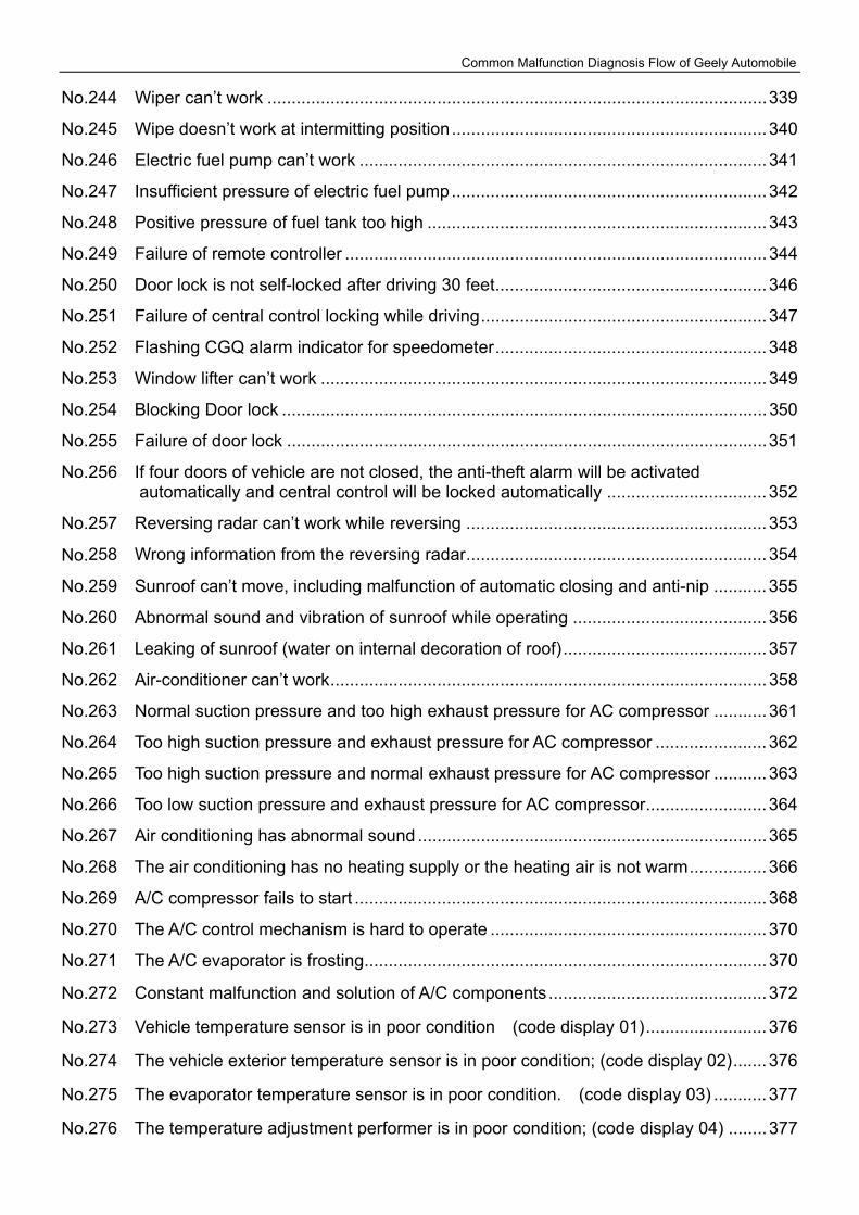
No.244 Wiper can’t work .......................................................................................................339
No.245 Wipe doesn’t work at intermitting position.................................................................340
No.246 Electric fuel pump can’t work ....................................................................................341
No.247 Insufficient pressure of electric fuel pump.................................................................342
No.248 Positive pressure of fuel tank too high ......................................................................343
No.249 Failure of remote controller .......................................................................................344
No.250 Door lock is not self-locked after driving 30 feet........................................................346
No.251 Failure of central control locking while driving...........................................................347
No.252 Flashing CGQ alarm indicator for speedometer........................................................348
No.253 Window lifter can’t work ............................................................................................349
No.254 Blocking Door lock ....................................................................................................350
No.255 Failure of door lock ...................................................................................................351
No.256 If four doors of vehicle are not closed, the anti-theft alarm will be activated automatically and central control will be locked automatically .................................352
No.257 Reversing radar can’t work while reversing ..............................................................353
No.258 Wrong information from the reversing radar..............................................................354
No.259 Sunroof can’t move, including malfunction of automatic closing and anti-nip ...........355
No.260 Abnormal sound and vibration of sunroof while operating ........................................356
No.261 Leaking of sunroof (water on internal decoration of roof)..........................................357
No.262 Air-conditioner can’t work..........................................................................................358
No.263 Normal suction pressure and too high exhaust pressure for AC compressor ...........361
No.264 Too high suction pressure and exhaust pressure for AC compressor .......................362
No.265 Too high suction pressure and normal exhaust pressure for AC compressor ...........363
No.266 Too low suction pressure and exhaust pressure for AC compressor.........................364
No.267 Air conditioning has abnormal sound ........................................................................365
No.268 The air conditioning has no heating supply or the heating air is not warm................366
No.269 A/C compressor fails to start .....................................................................................368
No.270 The A/C control mechanism is hard to operate .........................................................370
No.271 The A/C evaporator is frosting...................................................................................370
No.272 Constant malfunction and solution of A/C components.............................................372
No.273 Vehicle temperature sensor is in poor condition (code display 01).........................376
No.274 The vehicle exterior temperature sensor is in poor condition; (code display 02).......376
No.275 The evaporator temperature sensor is in poor condition. (code display 03) ...........377
No.276 The temperature adjustment performer is in poor condition; (code display 04) ........377
Common Malfunction Diagnosis Flow of Geely Automobile
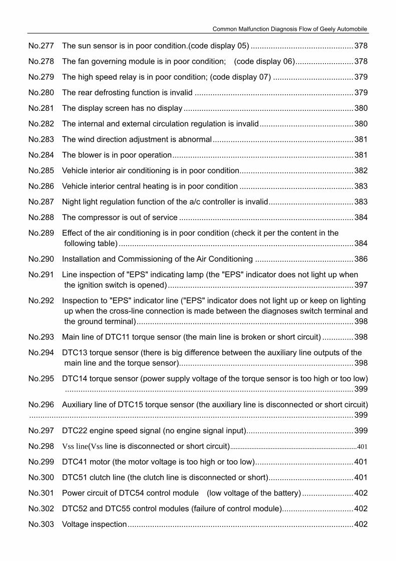
No.277 The sun sensor is in poor condition.(code display 05) ..............................................378
No.278 The fan governing module is in poor condition; (code display 06)..........................378
No.279 The high speed relay is in poor condition; (code display 07) ....................................379
No.280 The rear defrosting function is invalid .......................................................................379
No.281 The display screen has no display ............................................................................380
No.282 The internal and external circulation regulation is invalid..........................................380
No.283 The wind direction adjustment is abnormal...............................................................381
No.284 The blower is in poor operation.................................................................................381
No.285 Vehicle interior air conditioning is in poor condition...................................................382
No.286 Vehicle interior central heating is in poor condition ...................................................383
No.287 Night light regulation function of the a/c controller is invalid......................................383
No.288 The compressor is out of service ..............................................................................384
No.289 Effect of the air conditioning is in poor condition (check it per the content in the following table) .........................................................................................................384
No.290 Installation and Commissioning of the Air Conditioning ............................................386
No.291 Line inspection of "EPS" indicating lamp (the "EPS" indicator does not light up when the ignition switch is opened) ...................................................................................397
No.292 Inspection to "EPS" indicator line ("EPS" indicator does not light up or keep on lighting up when the cross-line connection is made between the diagnoses switch terminal and the ground terminal).................................................................................................398
No.293 Main line of DTC11 torque sensor (the main line is broken or short circuit) ..............398
No.294 DTC13 torque sensor (there is big difference between the auxiliary line outputs of the main line and the torque sensor)..............................................................................398
No.295 DTC14 torque sensor (power supply voltage of the torque sensor is too high or too low).................................................................................................................................399
No.296 Auxiliary line of DTC15 torque sensor (the auxiliary line is disconnected or short circuit).................................................................................................................................................399
No.297 DTC22 engine speed signal (no engine signal input)................................................399
No.298 Vss line(Vss line is disconnected or short circuit) ........................................................................401
No.299 DTC41 motor (the motor voltage is too high or too low)............................................401
No.300 DTC51 clutch line (the clutch line is disconnected or short)......................................401
No.301 Power circuit of DTC54 control module (low voltage of the battery) .......................402
No.302 DTC52 and DTC55 control modules (failure of control module)................................402
No.303 Voltage inspection.....................................................................................................402
Common Malfunction Diagnosis Flow of Geely Automobile
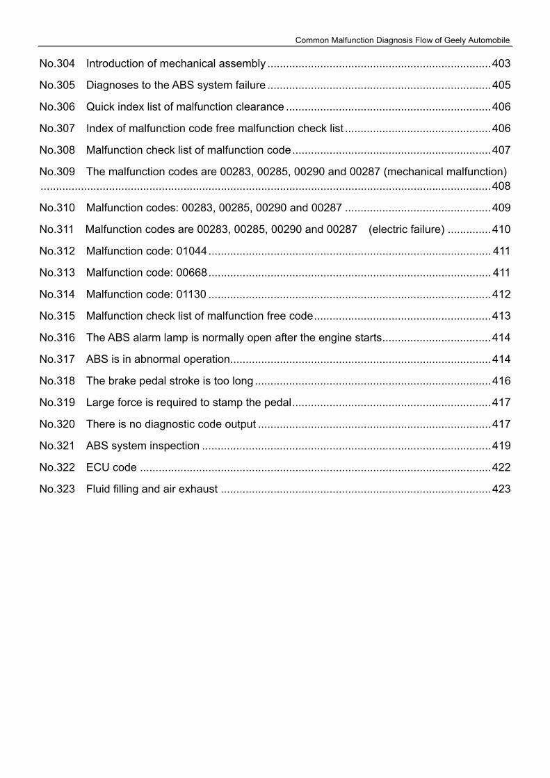
No.304 Introduction of mechanical assembly ........................................................................403
No.305 Diagnoses to the ABS system failure ........................................................................405
No.306 Quick index list of malfunction clearance ..................................................................406
No.307 Index of malfunction code free malfunction check list ...............................................406
No.308 Malfunction check list of malfunction code................................................................407
No.309 The malfunction codes are 00283, 00285, 00290 and 00287 (mechanical malfunction).................................................................................................................................................408
No.310 Malfunction codes: 00283, 00285, 00290 and 00287 ...............................................409
No.311 Malfunction codes are 00283, 00285, 00290 and 00287 (electric failure) ..............410
No.312 Malfunction code: 01044........................................................................................... 411
No.313 Malfunction code: 00668........................................................................................... 411
No.314 Malfunction code: 01130 ...........................................................................................412
No.315 Malfunction check list of malfunction free code.........................................................413
No.316 The ABS alarm lamp is normally open after the engine starts...................................414
No.317 ABS is in abnormal operation....................................................................................414
No.318 The brake pedal stroke is too long ............................................................................416
No.319 Large force is required to stamp the pedal................................................................417
No.320 There is no diagnostic code output ...........................................................................417
No.321 ABS system inspection .............................................................................................419
No.322 ECU code .................................................................................................................422
No.323 Fluid filling and air exhaust .......................................................................................423
Common Malfunction Diagnosis Flow of Geely Automobile
1
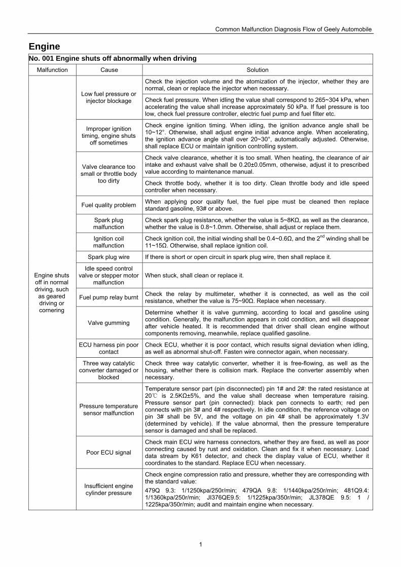
Engine No. 001 Engine shuts off abnormally when driving
Malfunction Cause Solution
Check the injection volume and the atomization of the injector, whether they are normal, clean or replace the injector when necessary.
Low fuel pressure or injector blockage Check fuel pressure. When idling the value shall correspond to 265~304 kPa, when
accelerating the value shall increase approximately 50 kPa. If fuel pressure is too low, check fuel pressure controller, electric fuel pump and fuel filter etc.
Improper ignition timing, engine shuts
off sometimes
Check engine ignition timing. When idling, the ignition advance angle shall be 10~12°. Otherwise, shall adjust engine initial advance angle. When accelerating, the ignition advance angle shall over 20~30°, automatically adjusted. Otherwise, shall replace ECU or maintain ignition controlling system.
Check valve clearance, whether it is too small. When heating, the clearance of air intake and exhaust valve shall be 0.20±0.05mm, otherwise, adjust it to prescribed value according to maintenance manual.
Valve clearance too small or throttle body
too dirty Check throttle body, whether it is too dirty. Clean throttle body and idle speed controller when necessary.
Fuel quality problem When applying poor quality fuel, the fuel pipe must be cleaned then replace standard gasoline, 93# or above.
Spark plug malfunction
Check spark plug resistance, whether the value is 5~8KΩ, as well as the clearance, whether the value is 0.8~1.0mm. Otherwise, shall adjust or replace them.
Ignition coil malfunction
Check ignition coil, the initial winding shall be 0.4~0.6Ω, and the 2nd winding shall be 11~15Ω. Otherwise, shall replace ignition coil.
Spark plug wire If there is short or open circuit in spark plug wire, then shall replace it.
Idle speed control valve or stepper motor
malfunction When stuck, shall clean or replace it.
Fuel pump relay burnt Check the relay by multimeter, whether it is connected, as well as the coil resistance, whether the value is 75~90Ω. Replace when necessary.
Valve gumming
Determine whether it is valve gumming, according to local and gasoline using condition. Generally, the malfunction appears in cold condition, and will disappear after vehicle heated. It is recommended that driver shall clean engine without components removing, meanwhile, replace qualified gasoline.
ECU harness pin poor contact
Check ECU, whether it is poor contact, which results signal deviation when idling, as well as abnormal shut-off. Fasten wire connector again, when necessary.
Three way catalytic converter damaged or
blocked
Check three way catalytic converter, whether it is free-flowing, as well as the housing, whether there is collision mark. Replace the converter assembly when necessary.
Pressure temperature sensor malfunction
Temperature sensor part (pin disconnected) pin 1# and 2#: the rated resistance at 20 is 2.5KΩ±5%, and the value shall decrease when temperature raising. Pressure sensor part (pin connected): black pen connects to earth; red pen connects with pin 3# and 4# respectively. In idle condition, the reference voltage on pin 3# shall be 5V, and the voltage on pin 4# shall be approximately 1.3V (determined by vehicle). If the value abnormal, then the pressure temperature sensor is damaged and shall be replaced.
Poor ECU signal
Check main ECU wire harness connectors, whether they are fixed, as well as poor connecting caused by rust and oxidation. Clean and fix it when necessary. Load data stream by K61 detector, and check the display value of ECU, whether it coordinates to the standard. Replace ECU when necessary.
Engine shuts off in normal driving, such
as geared driving or cornering
Insufficient engine cylinder pressure
Check engine compression ratio and pressure, whether they are corresponding with the standard value: 479Q 9.3: 1/1250kpa/250r/min; 479QA 9.8: 1/1440kpa/250r/min; 481Q9.4: 1/1360kpa/250r/min; JI376QE9.5: 1/1225kpa/350r/min; JL378QE 9.5: 1 / 1225kpa/350r/min; audit and maintain engine when necessary.
Common Malfunction Diagnosis Flow of Geely Automobile
2
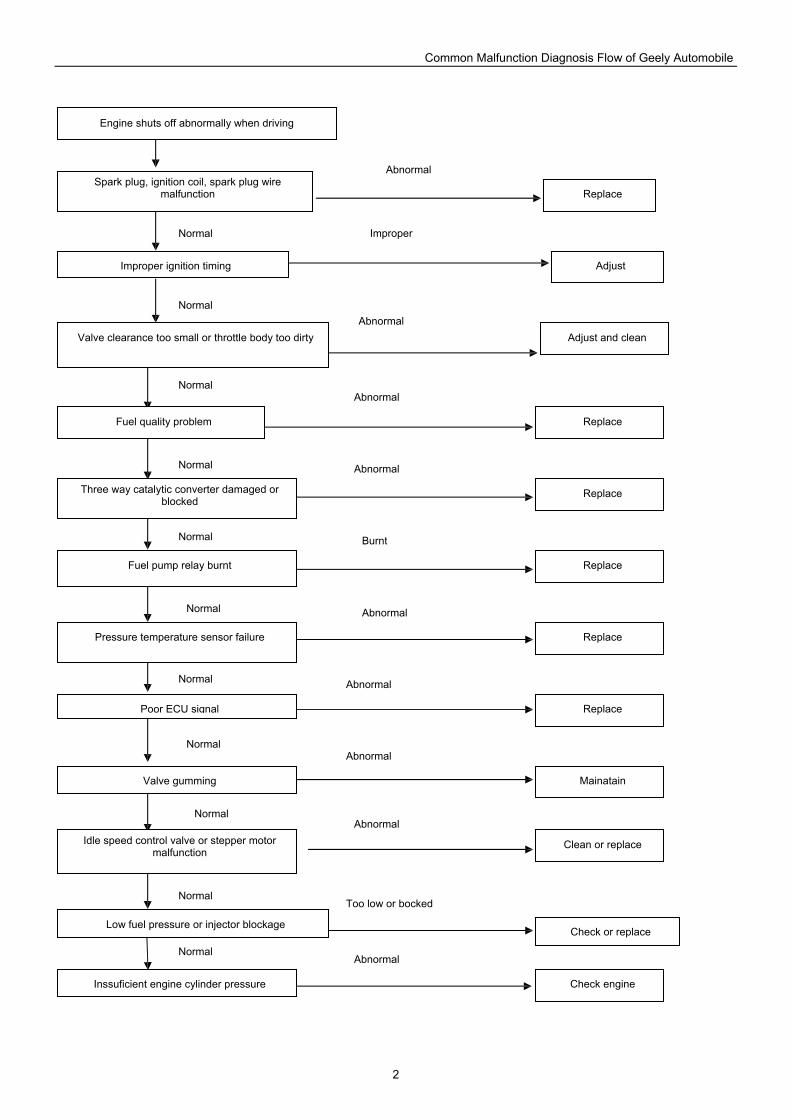
Engine shuts off abnormally when driving
Spark plug, ignition coil, spark plug wire malfunction Replace
Improper ignition timing
Valve clearance too small or throttle body too dirty
Fuel quality problem
Three way catalytic converter damaged or blocked
Fuel pump relay burnt
Pressure temperature sensor failure
Poor ECU signal
Valve gumming
Idle speed control valve or stepper motor malfunction
Low fuel pressure or injector blockage
Inssuficient engine cylinder pressure
Adjust
Adjust and clean
Replace
Replace
Replace
Replace
Replace
Mainatain
Clean or replace
Check or replace
Check engine
Abnormal
Abnormal
Abnormal
Abnormal
Burnt
Abnormal
Abnormal
Too low or bocked
Abnormal
Abnormal
Abnormal
Improper
Normal
Normal
Normal
Normal
Normal
Normal
Normal
Normal
Normal
Normal
Normal
Common Malfunction Diagnosis Flow of Geely Automobile
3
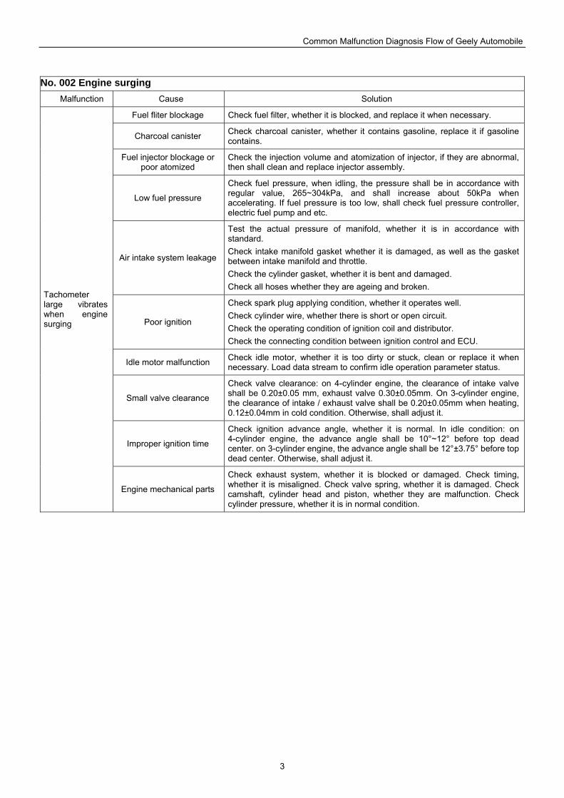
No. 002 Engine surging Malfunction Cause Solution
Fuel fliter blockage Check fuel filter, whether it is blocked, and replace it when necessary.
Charcoal canister Check charcoal canister, whether it contains gasoline, replace it if gasoline contains.
Fuel injector blockage or poor atomized
Check the injection volume and atomization of injector, if they are abnormal, then shall clean and replace injector assembly.
Low fuel pressure
Check fuel pressure, when idling, the pressure shall be in accordance with regular value, 265~304kPa, and shall increase about 50kPa when accelerating. If fuel pressure is too low, shall check fuel pressure controller, electric fuel pump and etc.
Air intake system leakage
Test the actual pressure of manifold, whether it is in accordance with standard. Check intake manifold gasket whether it is damaged, as well as the gasket between intake manifold and throttle. Check the cylinder gasket, whether it is bent and damaged. Check all hoses whether they are ageing and broken.
Poor ignition
Check spark plug applying condition, whether it operates well. Check cylinder wire, whether there is short or open circuit. Check the operating condition of ignition coil and distributor. Check the connecting condition between ignition control and ECU.
Idle motor malfunction Check idle motor, whether it is too dirty or stuck, clean or replace it when necessary. Load data stream to confirm idle operation parameter status.
Small valve clearance
Check valve clearance: on 4-cylinder engine, the clearance of intake valve shall be 0.20±0.05 mm, exhaust valve 0.30±0.05mm. On 3-cylinder engine, the clearance of intake / exhaust valve shall be 0.20±0.05mm when heating, 0.12±0.04mm in cold condition. Otherwise, shall adjust it.
Improper ignition time
Check ignition advance angle, whether it is normal. In idle condition: on 4-cylinder engine, the advance angle shall be 10°~12° before top dead center. on 3-cylinder engine, the advance angle shall be 12°±3.75° before top dead center. Otherwise, shall adjust it.
Tachometer large vibrates when engine surging
Engine mechanical parts
Check exhaust system, whether it is blocked or damaged. Check timing, whether it is misaligned. Check valve spring, whether it is damaged. Check camshaft, cylinder head and piston, whether they are malfunction. Check cylinder pressure, whether it is in normal condition.
Common Malfunction Diagnosis Flow of Geely Automobile
4
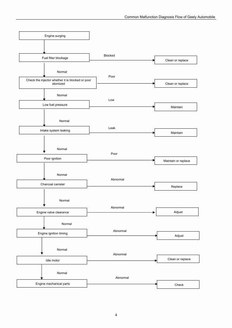
Engine surging
Fuel fliter blockage Blocked
Check the injector whether it is blocked or poor atomized
Clean or replace
Clean or replace
Low fuel pressure
Intake system leaking
Poor ignition
Charcoal canister
Engine valve clearance
Engine ignition timing
Idle motor
Engine mechanical parts
Maintain
Maintain
Maintain or replace
Adjust
Adjust
Check
Clean or replace
Replace
Poor
Low
Leak
Poor
Abnormal
Abnormal
Abnormal
Abnormal
Abnormal
Normal
Normal
Normal
Normal
Normal
Normal
Normal
Normal
Normal
Common Malfunction Diagnosis Flow of Geely Automobile
5
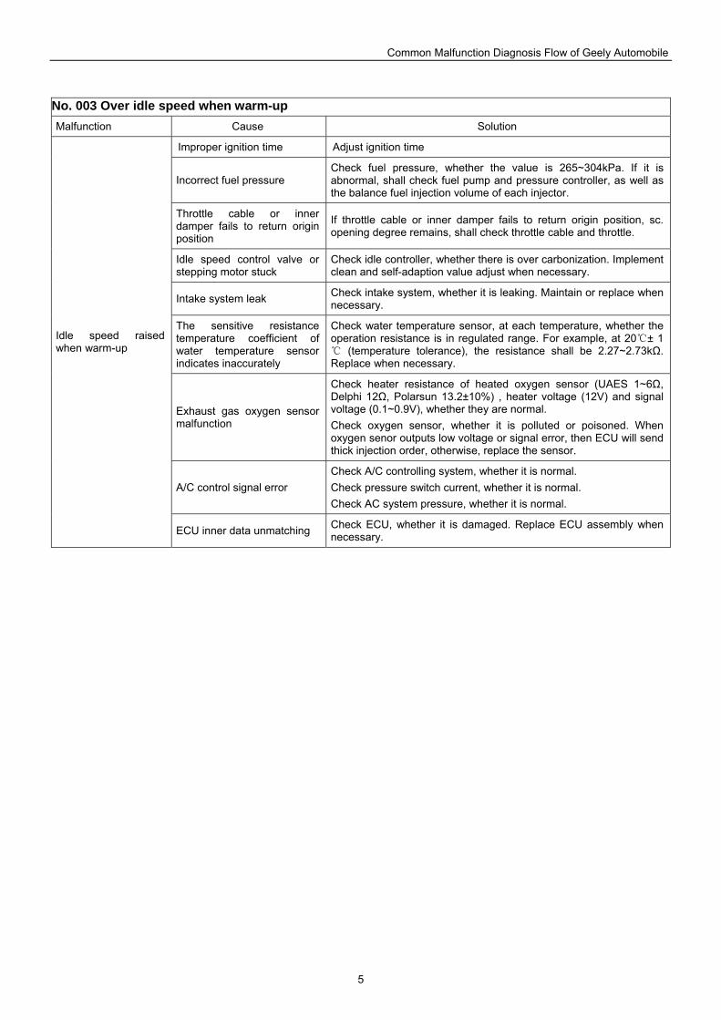
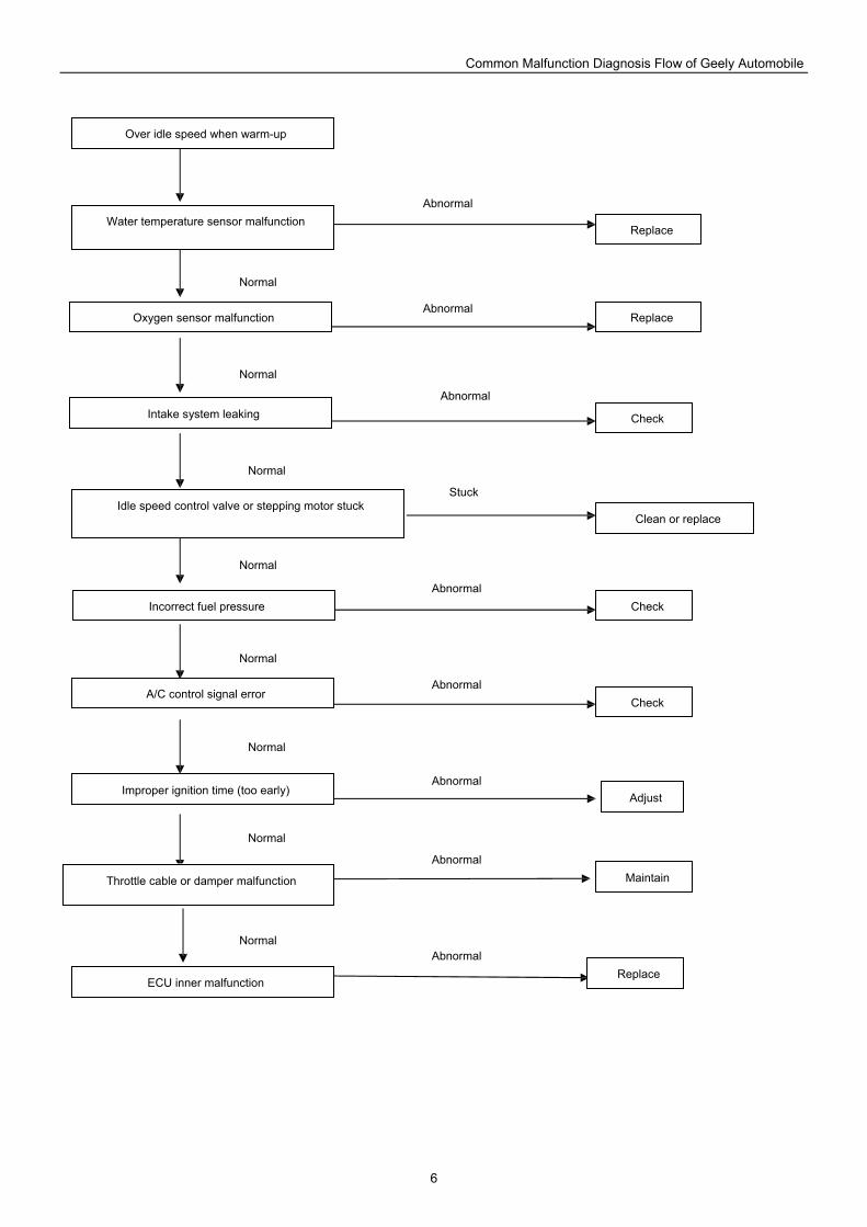
No. 003 Over idle speed when warm-up Malfunction Cause Solution
Improper ignition time Adjust ignition time
Incorrect fuel pressure Check fuel pressure, whether the value is 265~304kPa. If it is abnormal, shall check fuel pump and pressure controller, as well as the balance fuel injection volume of each injector.
Throttle cable or inner damper fails to return origin position
If throttle cable or inner damper fails to return origin position, sc. opening degree remains, shall check throttle cable and throttle.
Idle speed control valve or stepping motor stuck
Check idle controller, whether there is over carbonization. Implement clean and self-adaption value adjust when necessary.
Intake system leak Check intake system, whether it is leaking. Maintain or replace when necessary.
The sensitive resistance temperature coefficient of water temperature sensor indicates inaccurately
Check water temperature sensor, at each temperature, whether the operation resistance is in regulated range. For example, at 20 ± 1
(temperature tolerance), the resistance shall be 2.27~2.73kΩ. Replace when necessary.
Exhaust gas oxygen sensor malfunction
Check heater resistance of heated oxygen sensor (UAES 1~6Ω, Delphi 12Ω, Polarsun 13.2±10%) , heater voltage (12V) and signal voltage (0.1~0.9V), whether they are normal. Check oxygen sensor, whether it is polluted or poisoned. When oxygen senor outputs low voltage or signal error, then ECU will send thick injection order, otherwise, replace the sensor.
A/C control signal error Check A/C controlling system, whether it is normal. Check pressure switch current, whether it is normal. Check AC system pressure, whether it is normal.
Idle speed raised when warm-up
ECU inner data unmatching Check ECU, whether it is damaged. Replace ECU assembly when necessary.
Common Malfunction Diagnosis Flow of Geely Automobile
6
Over idle speed when warm-up
Water temperature sensor malfunction
Oxygen sensor malfunction
Intake system leaking
Idle speed control valve or stepping motor stuck
Incorrect fuel pressure
A/C control signal error
Improper ignition time (too early)
Throttle cable or damper malfunction
ECU inner malfunction
Normal
Normal
Normal
Normal
Normal
Normal
Normal
Normal
Abnormal
Abnormal
Abnormal
Abnormal
Abnormal
Stuck
Abnormal
Abnormal
Abnormal
Replace
Replace
Check
Check
Adjust
Check
Replace
Clean or replace
Maintain
Common Malfunction Diagnosis Flow of Geely Automobile
7
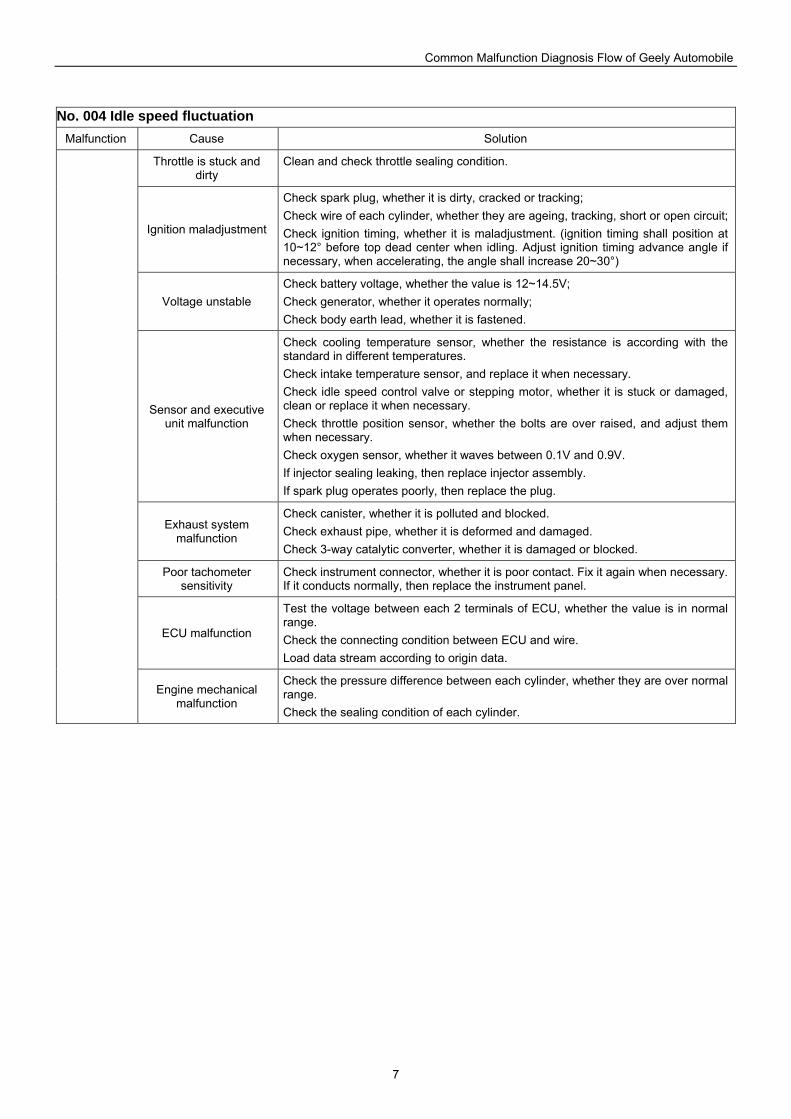
No. 004 Idle speed fluctuation Malfunction Cause Solution
Throttle is stuck and dirty
Clean and check throttle sealing condition.
Ignition maladjustment
Check spark plug, whether it is dirty, cracked or tracking; Check wire of each cylinder, whether they are ageing, tracking, short or open circuit;Check ignition timing, whether it is maladjustment. (ignition timing shall position at 10~12° before top dead center when idling. Adjust ignition timing advance angle if necessary, when accelerating, the angle shall increase 20~30°)
Voltage unstable Check battery voltage, whether the value is 12~14.5V; Check generator, whether it operates normally; Check body earth lead, whether it is fastened.
Sensor and executive unit malfunction
Check cooling temperature sensor, whether the resistance is according with the standard in different temperatures. Check intake temperature sensor, and replace it when necessary. Check idle speed control valve or stepping motor, whether it is stuck or damaged, clean or replace it when necessary. Check throttle position sensor, whether the bolts are over raised, and adjust them when necessary. Check oxygen sensor, whether it waves between 0.1V and 0.9V. If injector sealing leaking, then replace injector assembly. If spark plug operates poorly, then replace the plug.
Exhaust system malfunction
Check canister, whether it is polluted and blocked. Check exhaust pipe, whether it is deformed and damaged. Check 3-way catalytic converter, whether it is damaged or blocked.
Poor tachometer sensitivity
Check instrument connector, whether it is poor contact. Fix it again when necessary. If it conducts normally, then replace the instrument panel.
ECU malfunction
Test the voltage between each 2 terminals of ECU, whether the value is in normal range. Check the connecting condition between ECU and wire. Load data stream according to origin data.
Engine mechanical malfunction
Check the pressure difference between each cylinder, whether they are over normal range. Check the sealing condition of each cylinder.
Common Malfunction Diagnosis Flow of Geely Automobile
8
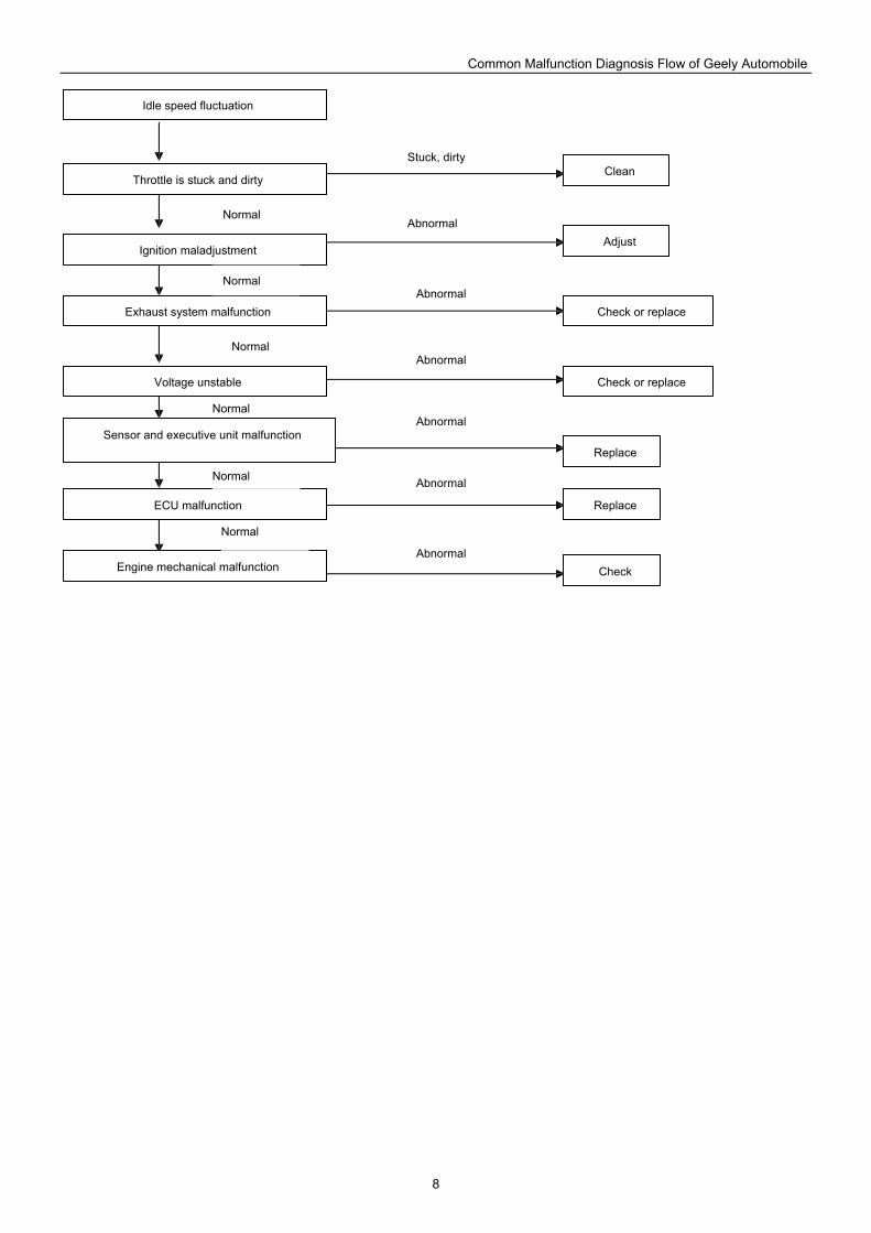
Idle speed fluctuation
Throttle is stuck and dirty
Ignition maladjustment
Exhaust system malfunction
Voltage unstable
Sensor and executive unit malfunction
ECU malfunction
Engine mechanical malfunction
Normal
Normal
Normal
Normal
Normal
Normal
Abnormal
Abnormal
Abnormal
Abnormal
Abnormal
Abnormal
Stuck, dirty Clean
Adjust
Check or replace
Check
Replace
Check or replace
Replace
Common Malfunction Diagnosis Flow of Geely Automobile
9
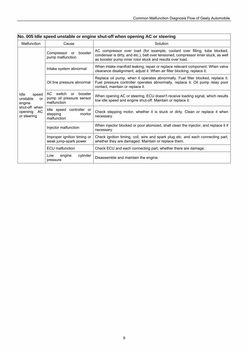
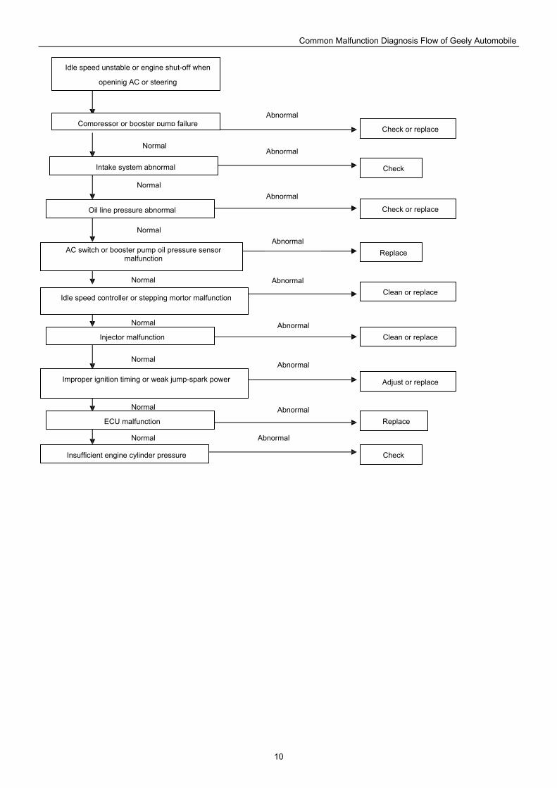
No. 005 Idle speed unstable or engine shut-off when opening AC or steering Malfunction Cause Solution
Compressor or booster pump malfunction
AC compressor over load (for example, coolant over filling, tube blocked, condenser is dirty, and etc.), belt over tensioned, compressor inner stuck, as well as booster pump inner rotor stuck and results over load.
Intake system abnormal When intake manifold leaking, repair or replace relevant component. When valve clearance disalignment, adjust it. When air filter blocking, replace it.
Oil line pressure abnormal Replace oil pump, when it operates abnormally. Fuel filter blocked, replace it. Fuel pressure controller operates abnormally, replace it. Oil pump relay poor contact, maintain or replace it.
AC switch or booster pump oil pressure sensor malfunction
When opening AC or steering, ECU doesn't receive loading signal, which results low idle speed and engine shut-off. Maintain or replace it.
Idle speed controller or stepping mortor malfunction
Check stepping motor, whether it is stuck or dirty. Clean or replace it when necessary.
Injector malfunction When injector blocked or poor atomized, shall clean the injector, and replace it if necessary.
Improper ignition timing or weak jump-spark power
Check ignition timing, coil, wire and spark plug etc. and each connecting part, whether they are damaged. Maintain or replace them.
ECU malfunction Check ECU and each connecting part, whether there are damage.
Idle speed unstable or engine shut-off when openinig AC or steering
Low engine cylinder pressure Disassemble and maintain the engine.
Common Malfunction Diagnosis Flow of Geely Automobile
10
Idle speed unstable or engine shut-off when
openinig AC or steering
Compressor or booster pump failure
Intake system abnormal
Oil line pressure abnormal
AC switch or booster pump oil pressure sensor malfunction
Idle speed controller or stepping mortor malfunction
Injector malfunction
Improper ignition timing or weak jump-spark power
ECU malfunction
Insufficient engine cylinder pressure
Normal
Normal
Normal
Normal
Normal
Normal
Normal
Normal
Abnormal
Abnormal
Abnormal
Abnormal
Abnormal
Abnormal
Abnormal
Abnormal
Abnormal
Replace
Check or replace
Check
Replace
Check or replace
Check
Clean or replace
Clean or replace
Adjust or replace
Common Malfunction Diagnosis Flow of Geely Automobile
11
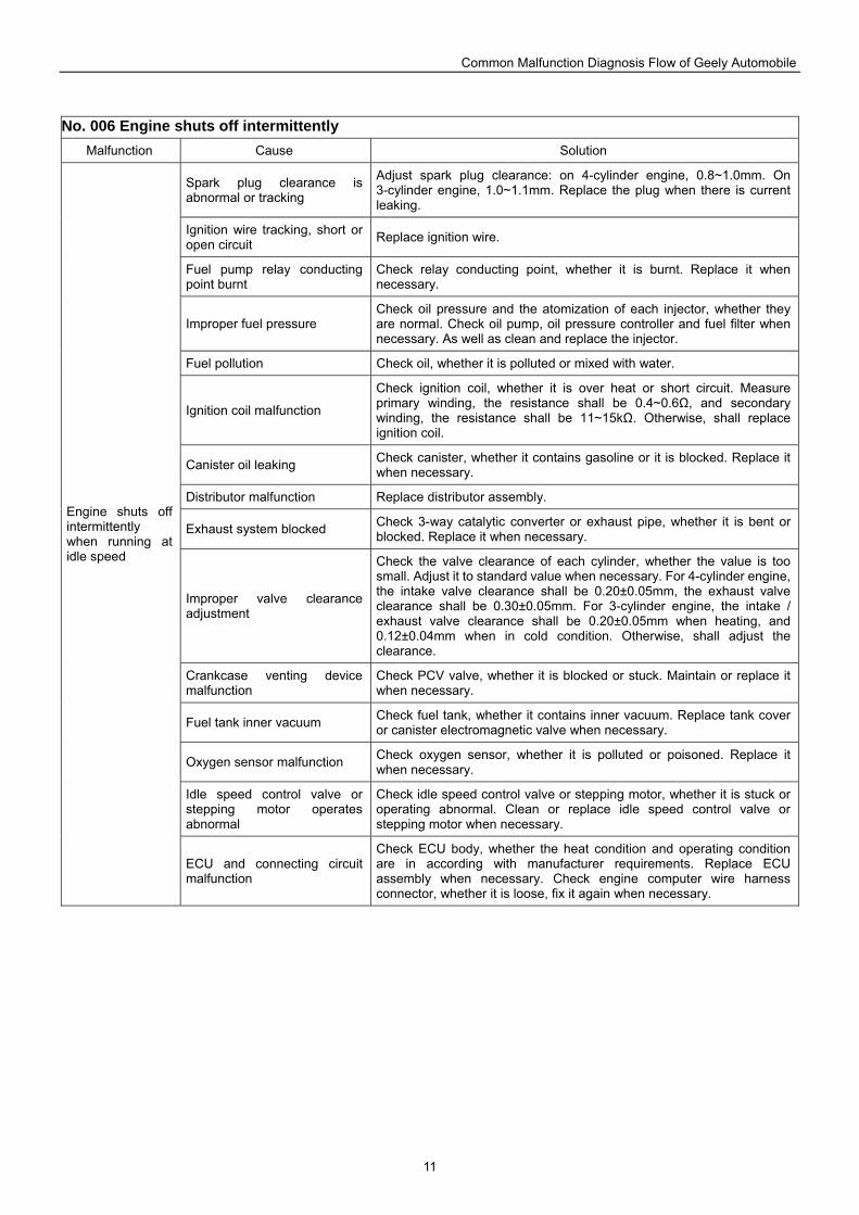
No. 006 Engine shuts off intermittently Malfunction Cause Solution
Spark plug clearance is abnormal or tracking
Adjust spark plug clearance: on 4-cylinder engine, 0.8~1.0mm. On 3-cylinder engine, 1.0~1.1mm. Replace the plug when there is current leaking.
Ignition wire tracking, short or open circuit Replace ignition wire.
Fuel pump relay conducting point burnt
Check relay conducting point, whether it is burnt. Replace it when necessary.
Improper fuel pressure Check oil pressure and the atomization of each injector, whether they are normal. Check oil pump, oil pressure controller and fuel filter when necessary. As well as clean and replace the injector.
Fuel pollution Check oil, whether it is polluted or mixed with water.
Ignition coil malfunction
Check ignition coil, whether it is over heat or short circuit. Measure primary winding, the resistance shall be 0.4~0.6Ω, and secondary winding, the resistance shall be 11~15kΩ. Otherwise, shall replace ignition coil.
Canister oil leaking Check canister, whether it contains gasoline or it is blocked. Replace it when necessary.
Distributor malfunction Replace distributor assembly.
Exhaust system blocked Check 3-way catalytic converter or exhaust pipe, whether it is bent or blocked. Replace it when necessary.
Improper valve clearance adjustment
Check the valve clearance of each cylinder, whether the value is too small. Adjust it to standard value when necessary. For 4-cylinder engine, the intake valve clearance shall be 0.20±0.05mm, the exhaust valve clearance shall be 0.30±0.05mm. For 3-cylinder engine, the intake / exhaust valve clearance shall be 0.20±0.05mm when heating, and 0.12±0.04mm when in cold condition. Otherwise, shall adjust the clearance.
Crankcase venting device malfunction
Check PCV valve, whether it is blocked or stuck. Maintain or replace it when necessary.
Fuel tank inner vacuum Check fuel tank, whether it contains inner vacuum. Replace tank cover or canister electromagnetic valve when necessary.
Oxygen sensor malfunction Check oxygen sensor, whether it is polluted or poisoned. Replace it when necessary.
Idle speed control valve or stepping motor operates abnormal
Check idle speed control valve or stepping motor, whether it is stuck or operating abnormal. Clean or replace idle speed control valve or stepping motor when necessary.
Engine shuts off intermittently when running at idle speed
ECU and connecting circuit malfunction
Check ECU body, whether the heat condition and operating condition are in according with manufacturer requirements. Replace ECU assembly when necessary. Check engine computer wire harness connector, whether it is loose, fix it again when necessary.
Common Malfunction Diagnosis Flow of Geely Automobile
12
Engine shuts off intermittently
Improper fuel pressure
Fuel pump relay conducting point burnt
Idle speed control valve or stepping motor is dirty or stuck
Fuel pollution
Ignition coil malfunction
Canister oil leaking
Exhaust system blocked
Oxygen sensor malfunction
Improper valve clearance
Crankcase venting device malfunction
Fuel tank inner vacuum
Spark plug and ignition wire malfunction
ECU and connecting circuit malfunction
Replace
Check or replace
Check
Replace
Maintain or replace
Check
Replace
Adjust
Replace
Replace
Check or replace
Check or replace
Check or replace
Abnormal
Burnt
Abnormal
Abnormal
Abnormal
Abnormal
Blocked
Abnormal
Abnormal
Abnormal
Abnormal
Abnormal
Abnormal
Normal
Normal
Normal
Normal
Normal
Normal
Normal
Normal
Normal
Normal
Normal
Normal
Common Malfunction Diagnosis Flow of Geely Automobile
13
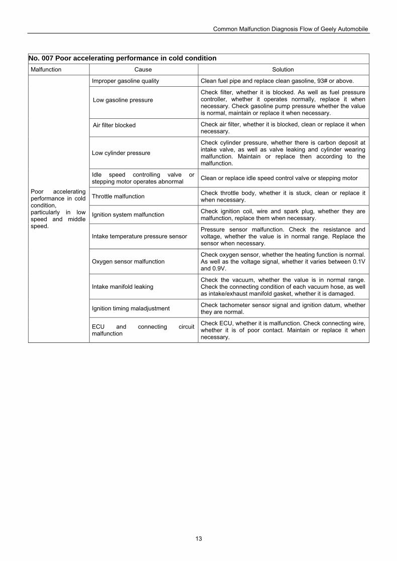
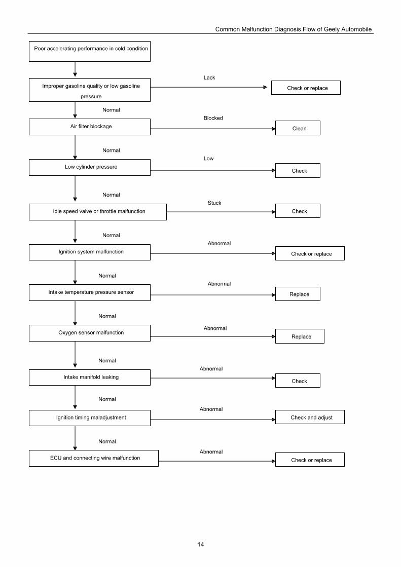
No. 007 Poor accelerating performance in cold condition Malfunction Cause Solution
Improper gasoline quality Clean fuel pipe and replace clean gasoline, 93# or above.
Low gasoline pressure Check filter, whether it is blocked. As well as fuel pressure controller, whether it operates normally, replace it when necessary. Check gasoline pump pressure whether the value is normal, maintain or replace it when necessary.
Air filter blocked Check air filter, whether it is blocked, clean or replace it when necessary.
Low cylinder pressure
Check cylinder pressure, whether there is carbon deposit at intake valve, as well as valve leaking and cylinder wearing malfunction. Maintain or replace then according to the malfunction.
Idle speed controlling valve or stepping motor operates abnormal Clean or replace idle speed control valve or stepping motor
Throttle malfunction Check throttle body, whether it is stuck, clean or replace it when necessary.
Ignition system malfunction Check ignition coil, wire and spark plug, whether they are malfunction, replace them when necessary.
Intake temperature pressure sensor Pressure sensor malfunction. Check the resistance and voltage, whether the value is in normal range. Replace the sensor when necessary.
Oxygen sensor malfunction Check oxygen sensor, whether the heating function is normal. As well as the voltage signal, whether it varies between 0.1V and 0.9V.
Intake manifold leaking Check the vacuum, whether the value is in normal range. Check the connecting condition of each vacuum hose, as well as intake/exhaust manifold gasket, whether it is damaged.
Ignition timing maladjustment Check tachometer sensor signal and ignition datum, whether they are normal.
Poor accelerating performance in cold condition, particularly in low speed and middle speed.
ECU and connecting circuit malfunction
Check ECU, whether it is malfunction. Check connecting wire, whether it is of poor contact. Maintain or replace it when necessary.
Common Malfunction Diagnosis Flow of Geely Automobile
14
Poor accelerating performance in cold condition
Improper gasoline quality or low gasoline
pressure
Air filter blockage
Low cylinder pressure
Idle speed valve or throttle malfunction
Ignition system malfunction
Intake temperature pressure sensor
Oxygen sensor malfunction
Intake manifold leaking
Ignition timing maladjustment
ECU and connecting wire malfunction
Replace
Check or replace
Check
Clean
Check or replace
Replace
Check or replace
Check and adjust
Check
Check
Abnormal
Abnormal
Abnormal
Abnormal
Abnormal
Abnormal
Stuck
Low
Blocked
Lack
Normal
Normal
Normal
Normal
Normal
Normal
Normal
Normal
Normal
Common Malfunction Diagnosis Flow of Geely Automobile
15
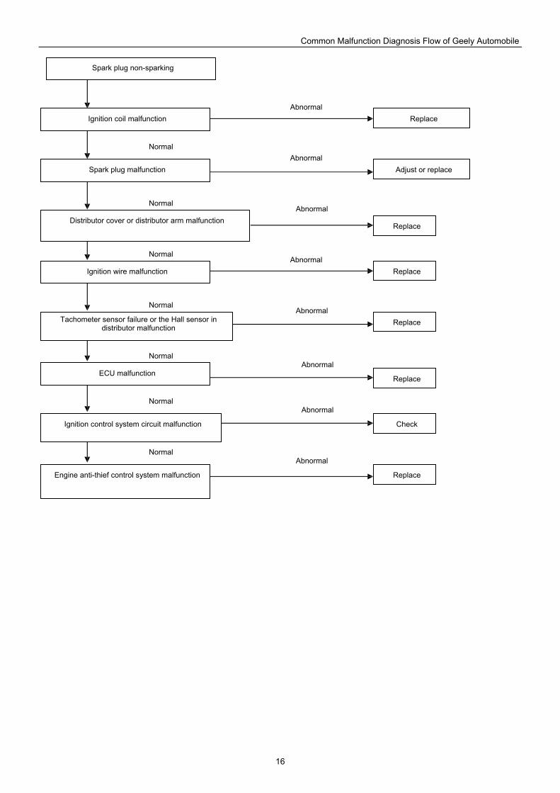
No. 008 Spark plug non-sparking Malfunction Cause Solution
Ignition coil malfunction
Measure the primary winding, the resistance shall be 0.4~0.6Ω, and the secondary winding, the resistance shall be 11~15kΩ. Otherwise shall replace ignition coil. Check the coil, whether there is short or open circuit. Replace it when necessary.
Spark plug malfunction Check spark plug, whether it is leaking current, as well as the clearance of electrode.
Distributor cover or distributor arm malfunction
Check cover or distributor arm, whether there is current leaking, dielectric puncture or damage. Replace it when necessary.
Ignition wire malfunction Check ignition wire, whether it is leaking current or open circuit. Replace it when necessary.
Tachometer sensor malfunction or the Hall sensor in distributor malfunction
Measure sensor resistance (UAES 4-cylinder engine tacho sensor resistance shall be 770~950Ω, Delphi 540Ω, Polarsun 530±50Ω), as well as the signal output and ECU wire, whether they are operating normally. Maintain it when necessary.
EFI fuse and relay malfunction Check EFI fuse, whether it is burnt or poor contact. Check main relay, whether it is burnt. Check the circuit, whether it is poor contact. Maintain them when necessary.
ECU malfunction Check terminal input and output signal, whether they are normal.
Ignition control system circuit malfunction
Check all connecting wires, whether they are poor contact or open circuit. Maintain it when necessary.
Engine has no start symptom and spark plug non-sparking
Engine anti-thief control system malfunction
Check anti-thief controller and all connecting wires, whether they are normal connected, as well as the anti-thief status activated.
Common Malfunction Diagnosis Flow of Geely Automobile
16
Spark plug non-sparking
Ignition coil malfunction
Spark plug malfunction
Distributor cover or distributor arm malfunction
Ignition wire malfunction
Tachometer sensor failure or the Hall sensor in distributor malfunction
ECU malfunction
Ignition control system circuit malfunction
Engine anti-thief control system malfunction
Adjust or replace
Replace
Check
Replace
Replace
Replace
Replace
Replace
Abnormal
Abnormal
Abnormal
Abnormal
Abnormal
Abnormal
Abnormal
Abnormal
Normal
Normal
Normal
Normal
Normal
Normal
Normal
Common Malfunction Diagnosis Flow of Geely Automobile
17
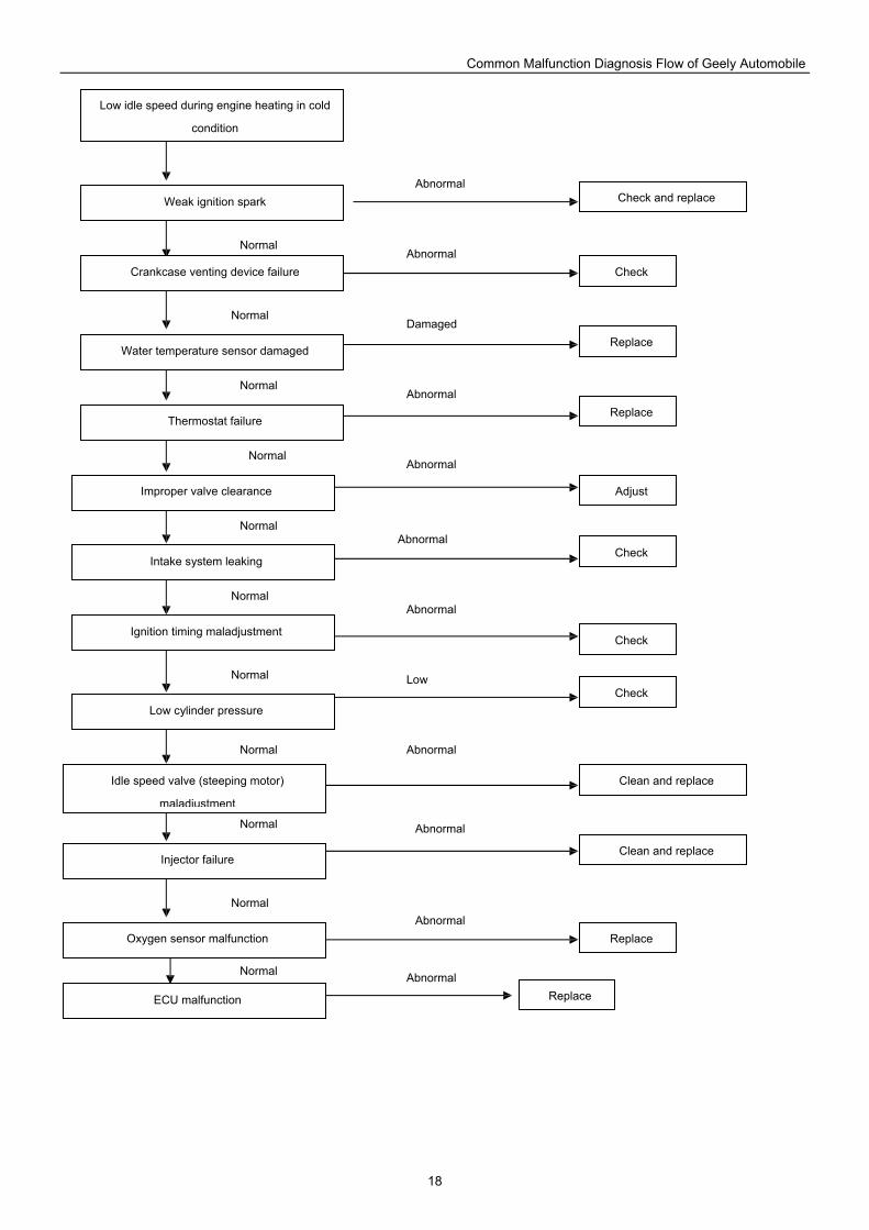
No. 009 Low idle speed during engine heating in cold condition Malfunction Cause Solution
Weak ignition spark Check ignition coil, wire and spark plug, whether they are normal. Adjust or replace them when necessary.
Crankcase venting device fails
Check PCV valve, whether it is normal. Replace crankcase venting device when necessary.
Intake system leaking Measure vacuum, check the connecting condition of manifold gasket, throttle gasket, and all vacuum pipes.
Thermostat malfunction Check thermostat, whether it is leaking, which results warm-up period over normal value. Replace thermostat when necessary.
Idle speed valve (steeping motor) maladjustment
Measure the resistance (UAES idle speed valve 17.6Ω, Delphi motor 53Ω, Polarsun motor 48±2.4Ω) and voltage of idle motor, whether they are normal. Check idle speed motor, whether it is dirty and stuck. Maintain and replace it when necessary.
Improper valve clearance
Adjust valve clearance: on 4-cylinder engine, the intake valve clearance shall be 0.20±0.05 mm, the exhaust valve clearance shall be 0.30±0.05mm. On 3-cylinder engine, the intake/exhaust valve clearance shall be 0.20±0.05mm when warming-up, and 0.12±0.04mm in cold condition.
Low cylinder pressure
Check engine compression ratio and pressure, whether they are in accordance with standard value. 479Q 9.3: 1/1250kpa/250r/min; 479QA 9.8: 1/1440kpa/250r/min; 481Q 9.4: 1/1360kpa/250r/min; JI376QE 9.5: 1/1225kpa/350r/min; JL378QE 9.5: 1 / 1225kpa/350r/min; Inspemction the cause, whether valve leaking or piston ring and cylinder wearing. Disassembly and maintain the engine when necessary.
Water temperature sensor damaged
Check the resistance of water temperature sensor in cold condition (UAES 2.5kΩ, at 20 ; Delphi 3.56~2.26kΩ, at 20~30 ; Polarsun 2.5kΩ, at 20 ), whether they are in accordance with standard. Or measure the temperature of cold vehicle by scanner, whether it is in accordance with actual engine temperature. Replace coolant fluid temperature sensor when necessary.
Injector malfunction Check injector, whether it is blocked or stuck. Check atomization and implement leak test. Clean or replace injector.
Oxygen sensor malfunction
Check heat-type oxygen sensor heater resistance (UAES 1~6Ω, Delphi 12Ω, Polarsun 13.2Ω±10%), as well as heater voltage, 12V, and signal voltage, 0.1~0.9V, whether they are in normal range. Check sensor surface, whether it is dirty and results voltage over normal value, as well as the fuel-air mixture is too thin.
Ignition timing maladjustment
Check ignition time and calibrate ignition timing, in idle condition: on 4-cylinder engine, the ignition advance angle shall be 10°~12° before top dead center. On 3-cylinder engine, the value shall be 12°±3.75° before top dead center.
Low idle speed during engine heating in cold condition
ECU malfunction Check connecting conditions of ECU and all wires.
Common Malfunction Diagnosis Flow of Geely Automobile
18
Low idle speed during engine heating in cold
condition
Weak ignition spark
Crankcase venting device failure
Water temperature sensor damaged
Thermostat failure
Improper valve clearance
Intake system leaking
Ignition timing maladjustment
Low cylinder pressure
Idle speed valve (steeping motor)
maladjustment
Injector failure
Oxygen sensor malfunction
ECU malfunction
Adjust
Replace
Check
Check and replace
Replace
Replace
Replace
Check
Check
Clean and replace
Check
Clean and replace
Abnormal
Abnormal
Abnormal
Abnormal
Low
Abnormal
Abnormal
Abnormal
Abnormal
Damaged
Abnormal
Abnormal
Normal
Normal
Normal
Normal
Normal
Normal
Normal
Normal
Normal
Normal
Normal
Common Malfunction Diagnosis Flow of Geely Automobile
19
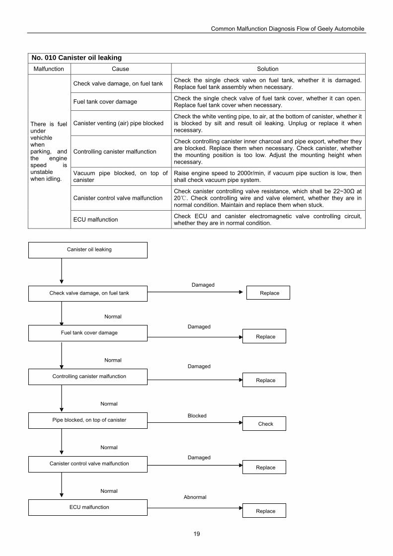
No. 010 Canister oil leaking Malfunction Cause Solution
Check valve damage, on fuel tank Check the single check valve on fuel tank, whether it is damaged. Replace fuel tank assembly when necessary.
Fuel tank cover damage Check the single check valve of fuel tank cover, whether it can open. Replace fuel tank cover when necessary.
Canister venting (air) pipe blocked Check the white venting pipe, to air, at the bottom of canister, whether it is blocked by silt and result oil leaking. Unplug or replace it when necessary.
Controlling canister malfunction
Check controlling canister inner charcoal and pipe export, whether they are blocked. Replace them when necessary. Check canister, whether the mounting position is too low. Adjust the mounting height when necessary.
Vacuum pipe blocked, on top of canister
Raise engine speed to 2000r/min, if vacuum pipe suction is low, then shall check vacuum pipe system.
Canister control valve malfunction Check canister controlling valve resistance, which shall be 22~30Ω at 20 . Check controlling wire and valve element, whether they are in normal condition. Maintain and replace them when stuck.
There is fuel under vehichle when parking, and the engine speed is unstable when idling.
ECU malfunction Check ECU and canister electromagnetic valve controlling circuit, whether they are in normal condition.
Canister oil leaking
Check valve damage, on fuel tank
Fuel tank cover damage
Controlling canister malfunction
Pipe blocked, on top of canister
Canister control valve malfunction
ECU malfunction
Replace
Replace
Replace
Replace
Check
Replace
Abnormal
Damaged
Blocked
Damaged
Damaged
Damaged
Normal
Normal
Normal
Normal
Normal
Common Malfunction Diagnosis Flow of Geely Automobile
20
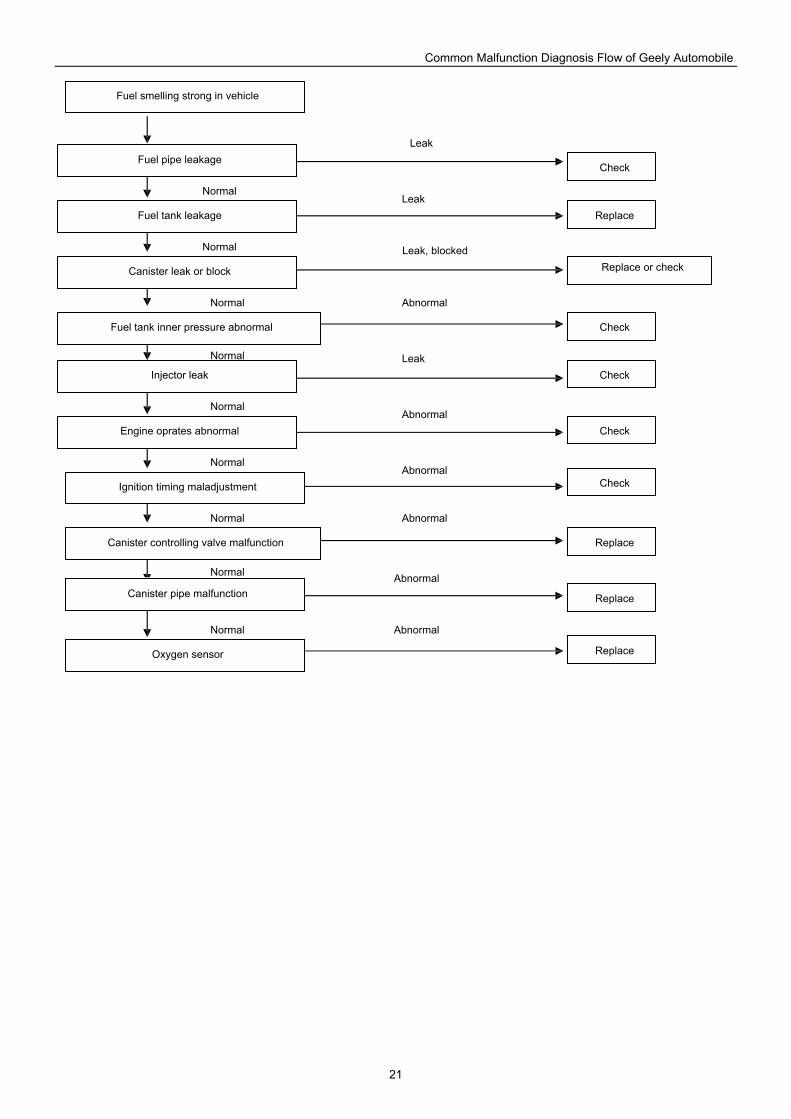
No. 011 Fuel smells in vehicle Malfunction Cause Solution
Gas station man-made malfunction When filling, fuel dropped around tank filling port and cover, then flows into vehicle. Clean vehicle.
Fuel tank filling port and port cover leaking
Check or replace fuel tank filling port and cover.
Fuel pipe leak Check or replace leaking fuel pipe.
Fuel tank cracked and leaking Check fuel tank, whether it is leaking. Replace it when necessary.
Canister leak Check canister controlling system and venting system.
Fuel tank inner pressure abnormal Replace fuel tank, check valve and fuel filling port cover etc.
Controlling canister pipe malfunction Check canister pipe, whether it is dropped.
Canister controlling valve malfunction
Check canister controlling valve, whether it is blocked, as well as the suction capacity, whether it is poor or fails to open.
Fuel pump and fuel sensor mountinggasket leaking
Check or replace fuel pump and fuel sensor mounting sealing.
Ignition timing maladjustment Maintain ignition timing, whether it is delayed.
Injector leak Check sealing of injector and pipe.
Engine operates abnormal Check engine operation, whether there is unavailable cylinder.
Fuel smells in vehicle, when opening window, it smells even worse
Oxygen sensor Measure the voltage of sensor, whether it is too low, as well as the fuel-air ratio, whether it is over normal value.
Common Malfunction Diagnosis Flow of Geely Automobile
21
Fuel smelling strong in vehicle
Fuel pipe leakage
Fuel tank leakage
Canister leak or block
Fuel tank inner pressure abnormal
Injector leak
Engine oprates abnormal
Ignition timing maladjustment
Canister controlling valve malfunction
Canister pipe malfunction
Oxygen sensor
Replace
Replace
Replace
Check
Replace
Check
Check
Check
Check
Replace or check
Abnormal
Leak
Leak, blocked
Leak
Leak
Abnormal
Abnormal
Abnormal
Abnormal
Abnormal
Normal
Normal
Normal
Normal
Normal
Normal
Normal
Normal
Normal
Common Malfunction Diagnosis Flow of Geely Automobile
22
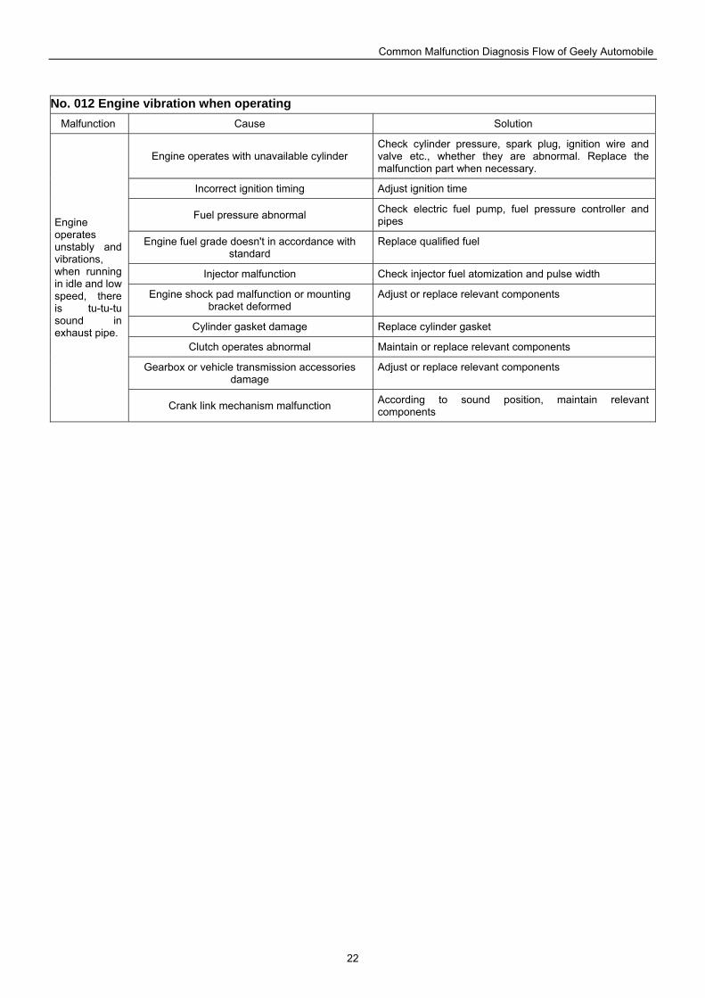
No. 012 Engine vibration when operating Malfunction Cause Solution
Engine operates with unavailable cylinder Check cylinder pressure, spark plug, ignition wire and valve etc., whether they are abnormal. Replace the malfunction part when necessary.
Incorrect ignition timing Adjust ignition time
Fuel pressure abnormal Check electric fuel pump, fuel pressure controller and pipes
Engine fuel grade doesn't in accordance with standard
Replace qualified fuel
Injector malfunction Check injector fuel atomization and pulse width
Engine shock pad malfunction or mounting bracket deformed
Adjust or replace relevant components
Cylinder gasket damage Replace cylinder gasket
Clutch operates abnormal Maintain or replace relevant components
Gearbox or vehicle transmission accessories damage
Adjust or replace relevant components
Engine operates unstably and vibrations, when running in idle and low speed, there is tu-tu-tu sound in exhaust pipe.
Crank link mechanism malfunction According to sound position, maintain relevant components
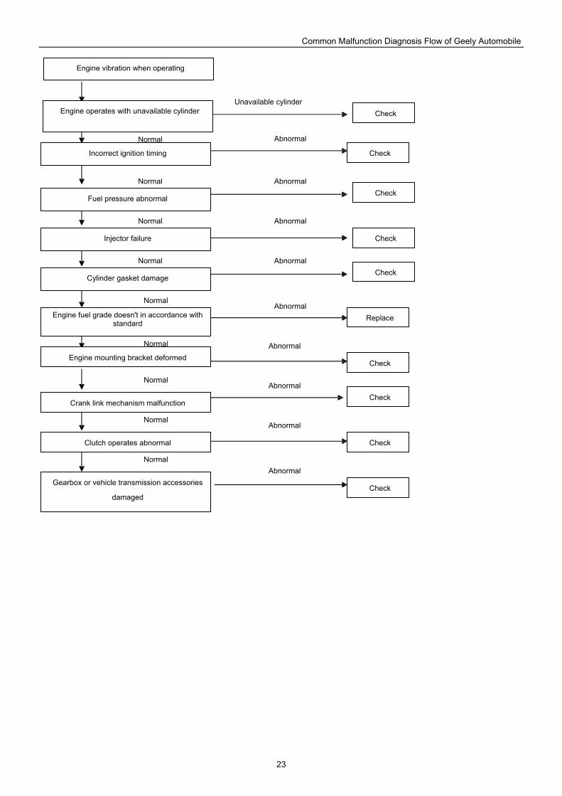
Common Malfunction Diagnosis Flow of Geely Automobile
23
Engine vibration when operating
Engine operates with unavailable cylinder
Incorrect ignition timing
Fuel pressure abnormal
Injector failure
Cylinder gasket damage
Engine fuel grade doesn't in accordance with standard
Engine mounting bracket deformed
Crank link mechanism malfunction
Clutch operates abnormal
Gearbox or vehicle transmission accessories
damaged
Replace
Check
Check
Check
Check
Check
Check
Check
Check
Check
Abnormal
Abnormal
Abnormal
Abnormal
Abnormal
Abnormal
Abnormal
Abnormal
Abnormal
Unavailable cylinder
Normal
Normal
Normal
Normal
Normal
Normal
Normal
Normal
Normal
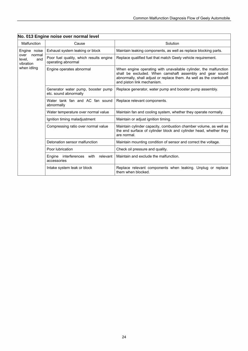
Common Malfunction Diagnosis Flow of Geely Automobile
24
No. 013 Engine noise over normal level Malfunction Cause Solution
Exhaust system leaking or block Maintain leaking components, as well as replace blocking parts.
Poor fuel quality, which results engine operating abnormal
Replace qualified fuel that match Geely vehicle requirement.
Engine operates abnormal When engine operating with unavailable cylinder, the malfunction shall be excluded. When camshaft assembly and gear sound abnormally, shall adjust or replace them. As well as the crankshaft and piston link mechanism.
Generator water pump, booster pump etc. sound abnormally
Replace generator, water pump and booster pump assembly.
Water tank fan and AC fan sound abnormally
Replace relevant components.
Water temperature over normal value Maintain fan and cooling system, whether they operate normally.
Ignition timing maladjustment Maintain or adjust ignition timing.
Compressing ratio over normal value Maintain cylinder capacity, combustion chamber volume, as well as the end surface of cylinder block and cylinder head, whether they are normal.
Detonation sensor malfunction Maintain mounting condition of sensor and correct the voltage.
Poor lubrication Check oil pressure and quality.
Engine interferences with relevant accessories
Maintain and exclude the malfunction.
Engine noise over normal level, and vibration when idling
Intake system leak or block Replace relevant components when leaking. Unplug or replace them when blocked.
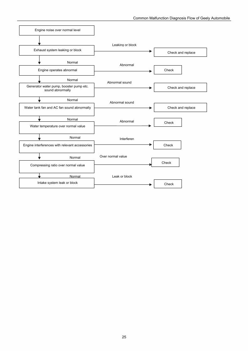
Common Malfunction Diagnosis Flow of Geely Automobile
25
Engine noise over normal level
Exhaust system leaking or block
Intake system leak or block
Generator water pump, booster pump etc. sound abnormally
Water tank fan and AC fan sound abnormally
Water temperature over normal value
Engine interferences with relevant accessories
Compressing ratio over normal value
Engine operates abnormal
Check
Check and replace
Check
Check
Check
Check and replace
Check and replace
Check
Normal
Normal
Normal
Normal
Normal
Normal
Normal
Leak or block
Over normal value
Interferen
Abnormal
Abnormal sound
Abnormal sound
Leaking or block
Abnormal
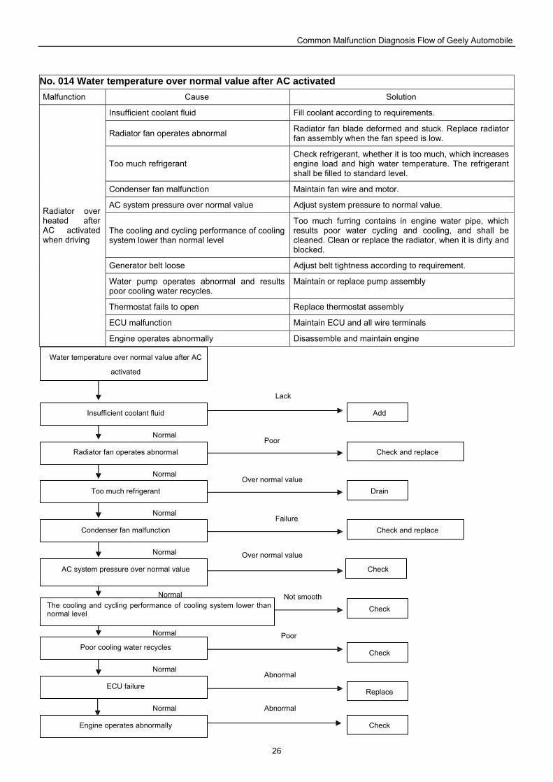
Common Malfunction Diagnosis Flow of Geely Automobile
26
No. 014 Water temperature over normal value after AC activated Malfunction Cause Solution
Insufficient coolant fluid Fill coolant according to requirements.
Radiator fan operates abnormal Radiator fan blade deformed and stuck. Replace radiator fan assembly when the fan speed is low.
Too much refrigerant Check refrigerant, whether it is too much, which increases engine load and high water temperature. The refrigerant shall be filled to standard level.
Condenser fan malfunction Maintain fan wire and motor.
AC system pressure over normal value Adjust system pressure to normal value.
The cooling and cycling performance of cooling system lower than normal level
Too much furring contains in engine water pipe, which results poor water cycling and cooling, and shall be cleaned. Clean or replace the radiator, when it is dirty and blocked.
Generator belt loose Adjust belt tightness according to requirement.
Water pump operates abnormal and results poor cooling water recycles.
Maintain or replace pump assembly
Thermostat fails to open Replace thermostat assembly
ECU malfunction Maintain ECU and all wire terminals
Radiator over heated after AC activated when driving
Engine operates abnormally Disassemble and maintain engine
Water temperature over normal value after AC
activated
Insufficient coolant fluid
Radiator fan operates abnormal
Too much refrigerant
Condenser fan malfunction
AC system pressure over normal value
The cooling and cycling performance of cooling system lower than normal level
Poor cooling water recycles
ECU failure
Engine operates abnormally
Drain
Add
Check
Check and replace
Check and replace
Check
Check
Check
Replace
Abnormal
Over normal value
Abnormal
Poor
Not smooth
Over normal value
Poor
Lack
Failure
Normal
Normal
Normal
Normal
Normal
Normal
Normal
Normal

Common Malfunction Diagnosis Flow of Geely Automobile
27
No. 015 Oil pan leak Malfunction Cause Solution
Too much oil Fill oil according to standard. For 4-cylinder engine, dry, 3.5L; wet, 3.0L. For 4G18 engine, with oil filter, 4.0L; without oil filter, 3.8L. For 3-cylinder engine, 3.0L.
Oil pan gasket damage Replace oil pan gasket; tighten the bolts after sealant coated.
Rear end cover gasket leak Replace rear end cover gasket and coat with sealant.
Rear oil pipe capping leak Replace or maintain rear main oil pipe capping.
There is blow hole on rear end Maintain the blow hole on rear end.
Oil pan bolt loose Tighten oil pan retaining bolt or replace damaged bolt.
Oil pan damaged or deformed Maintain or replace oil pan.
Oil pan retaining bolt adjust to 4.9NM, evenly. Irregular assembly procedure
Coat sealant with proper quantity, otherwise, the gasket may slid and move.
Unplug or replace gas exhaust system (PCV valve) Inner engine pressure over normal value Engine cylinder, piston ring and piston worn out. Maintain or replace
relevant component when necessary.
Oil leak at rear end of oil pan after vehicle parked.
Crankshaft rear oil seal ageing or damage
Replace crankshaft rear oil seal.
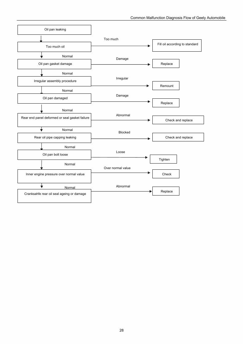
Common Malfunction Diagnosis Flow of Geely Automobile
28
Oil pan leaking
Too much oil
Oil pan gasket damage
Irregular assembly procedure
Oil pan damaged
Rear end panel deformed or seal gasket failure
Rear oil pipe capping leaking
Oil pan bolt loose
Inner engine pressure over normal value
Cranksahfe rear oil seal ageing or damage
Remount
Fill oil according to standard
Check
Check and replace
Check and replace
Tighten
Replace
Replace
Replace Abnormal
Over normal value
Blocked
Too much
Damage
Irregular
Damage
Abnormal
Loose
Normal
Normal
Normal
Normal
Normal
Normal
Normal
Normal
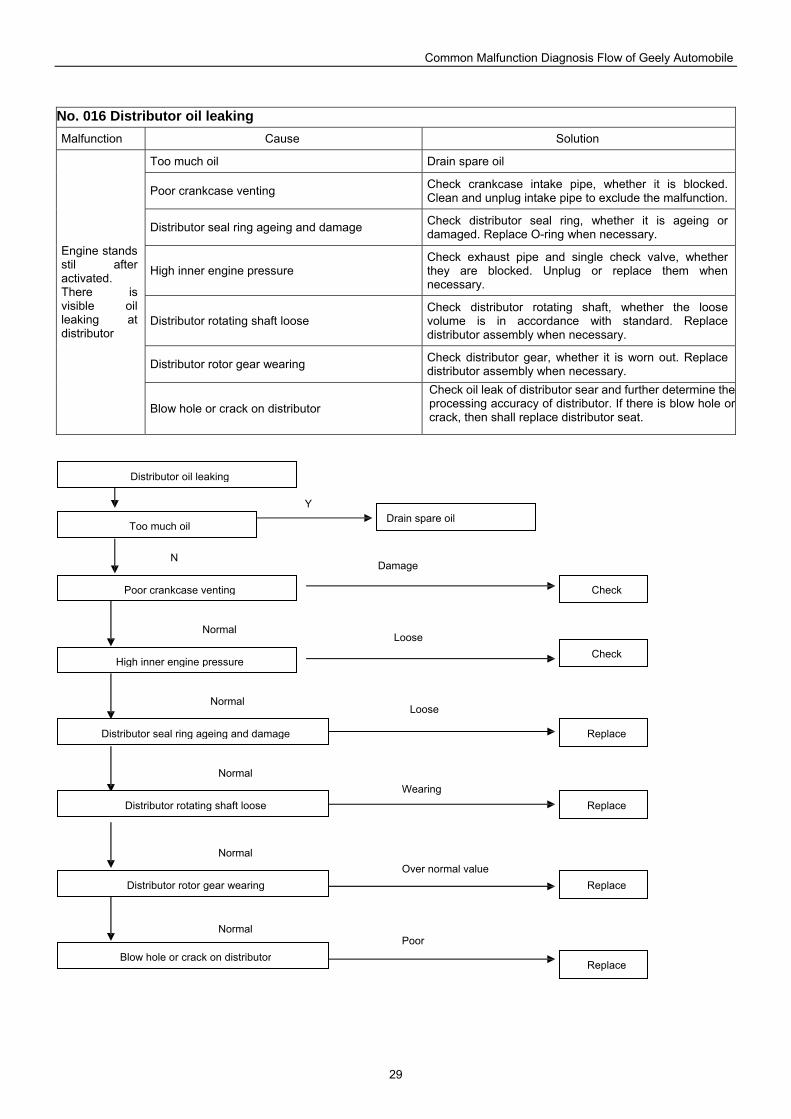
Common Malfunction Diagnosis Flow of Geely Automobile
29
No. 016 Distributor oil leaking Malfunction Cause Solution
Too much oil Drain spare oil
Poor crankcase venting Check crankcase intake pipe, whether it is blocked. Clean and unplug intake pipe to exclude the malfunction.
Distributor seal ring ageing and damage Check distributor seal ring, whether it is ageing or damaged. Replace O-ring when necessary.
High inner engine pressure Check exhaust pipe and single check valve, whether they are blocked. Unplug or replace them when necessary.
Distributor rotating shaft loose Check distributor rotating shaft, whether the loose volume is in accordance with standard. Replace distributor assembly when necessary.
Distributor rotor gear wearing Check distributor gear, whether it is worn out. Replace distributor assembly when necessary.
Engine stands stil after activated. There is visible oil leaking at distributor
Blow hole or crack on distributor Check oil leak of distributor sear and further determine the processing accuracy of distributor. If there is blow hole or crack, then shall replace distributor seat.
Distributor oil leaking
Too much oil
Poor crankcase venting
High inner engine pressure
Distributor seal ring ageing and damage
Distributor rotating shaft loose
Distributor rotor gear wearing
Blow hole or crack on distributor
Drain spare oil
Check
Replace
Replace
Replace
Check
Replace
Poor
Over normal value
Wearing
Loose
Loose
Damage
Y
Normal
Normal
Normal
Normal
Normal
N
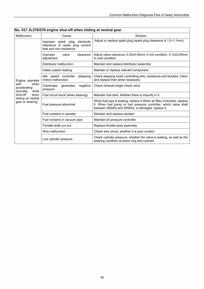
Common Malfunction Diagnosis Flow of Geely Automobile
30
No. 017 JL376/378 engine shut-off when sliding at neutral gear Malfunction Cause Solution
Improper spark plag electrode clearance or spark plug current leak and non-resistance
Adjust or replace spark plug (spark plug clearance is 1.0~1.1mm)
Improper valve clearance adjustment
Adjust valve clearance, 0.20±0.05mm in hot condition, 0.12±0.05mm in cold condition
Distributor malfunction Maintain and replace distributor assembly
Intake system leaking Maintain or replace relevant component;
Idle speed controller (stepping motor) malfunction
Check stepping motor controlling wire, resistance and blocked. Clean and replace then when necessary.
Crankcase generates negative pressure
Check exhaust single check valve
Fuel circuit stuck (when steering) Maintain fuel tank, whether there is impurity in it.
Fuel pressure abnormal When fuel pipe is leaking, replace it When air filter is blocked, replace it. When fuel pump or fuel pressure controller, which value shall between 264kPa and 305kPa, is damaged, replace it.
Fuel contains in canister Maintain and replace canister
Fuel contains in vacuum pipe Maintain oil pressure controller
Throttle shaft run-out Replace throttle body assembly
Wire malfunction Check wire circuit, whether it is poor contact.
Engine operates well when accelerating normally, while shut-off when sliding at neutral gear or steering.
Low cylinder pressure Check cylinder pressure, whether the valve is leaking, as well as the wearing condition of piston ring and cylinder.
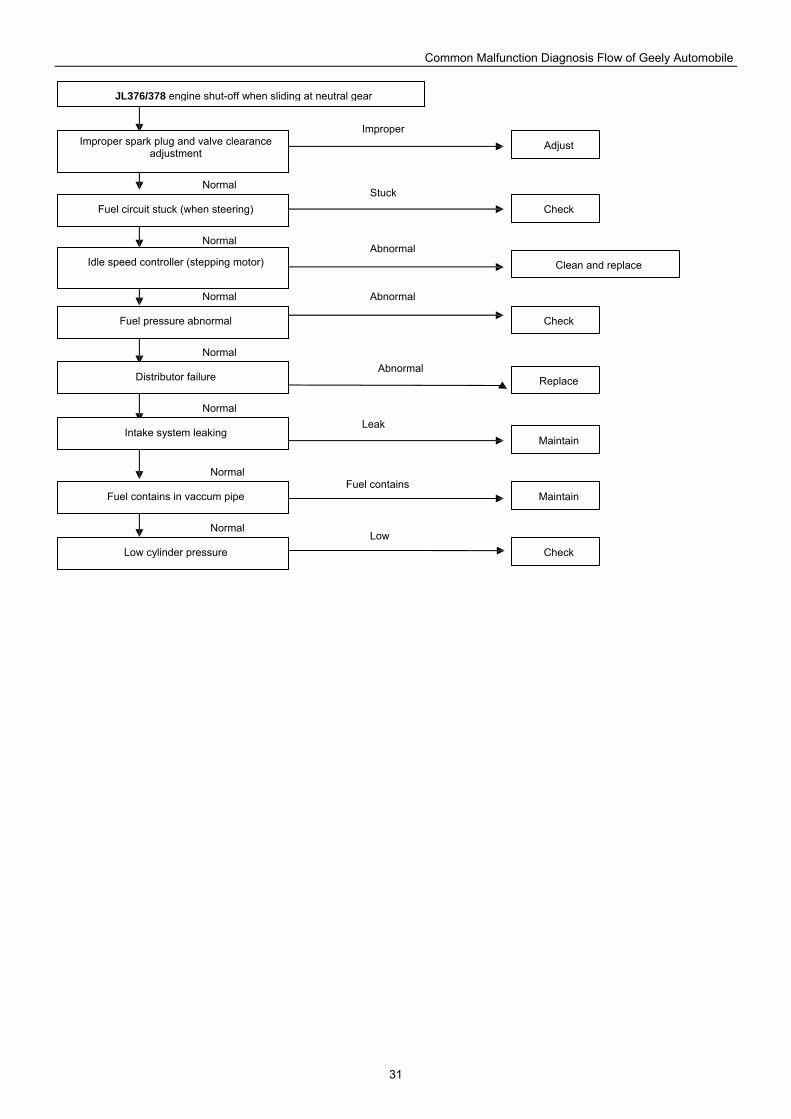
Common Malfunction Diagnosis Flow of Geely Automobile
31
JL376/378 engine shut-off when sliding at neutral gear
Improper spark plug and valve clearance adjustment
Fuel circuit stuck (when steering)
Idle speed controller (stepping motor)
Fuel pressure abnormal
Distributor failure
Intake system leaking
Fuel contains in vaccum pipe
Low cylinder pressure
Adjust
Maintain
Check
Clean and replace
Maintain
Check
Replace
Check
Normal
Normal
Normal
Normal
Normal
Normal
Normal
Low
Fuel contains
Leak
Stuck
Improper
Abnormal
Abnormal
Abnormal
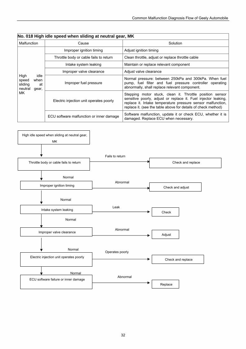
Common Malfunction Diagnosis Flow of Geely Automobile
32
No. 018 High idle speed when sliding at neutral gear, MK Malfunction Cause Solution
Improper ignition timing Adjust ignition timing
Throttle body or cable fails to return Clean throttle, adjust or replace throttle cable
Intake system leaking Maintain or replace relevant component
Improper valve clearance Adjust valve clearance
Improper fuel pressure Normal pressure: between 250kPa and 300kPa. When fuel pump, fuel filter and fuel pressure controller operating abnormally, shall replace relevant component.
Electric injection unit operates poorly
Stepping motor stuck, clean it. Throttle position sensor sensitive poorly, adjust or replace it. Fuel injector leaking, replace it. Intake temperature pressure sensor malfunction, replace it. (see the table above for details of check method)
High idle speed when sliding at neutral gear, MK
ECU software malfunction or inner damage Software malfunction, update it or check ECU, whether it is damaged. Replace ECU when necessary.
High idle speed when sliding at neutral gear,
MK
Throttle body or cable fails to return
Improper ignition timing
Intake system leaking
Improper valve clearance
Electric injection unit operates poorly
ECU software failure or inner damage
Check
Check and replace
Check and adjust
Replace
Check and replace
Adjust
Operates poorly
Leak
Abnormal
Fails to return
Abnormal
Abnormal Normal
Normal
Normal
Normal
Normal
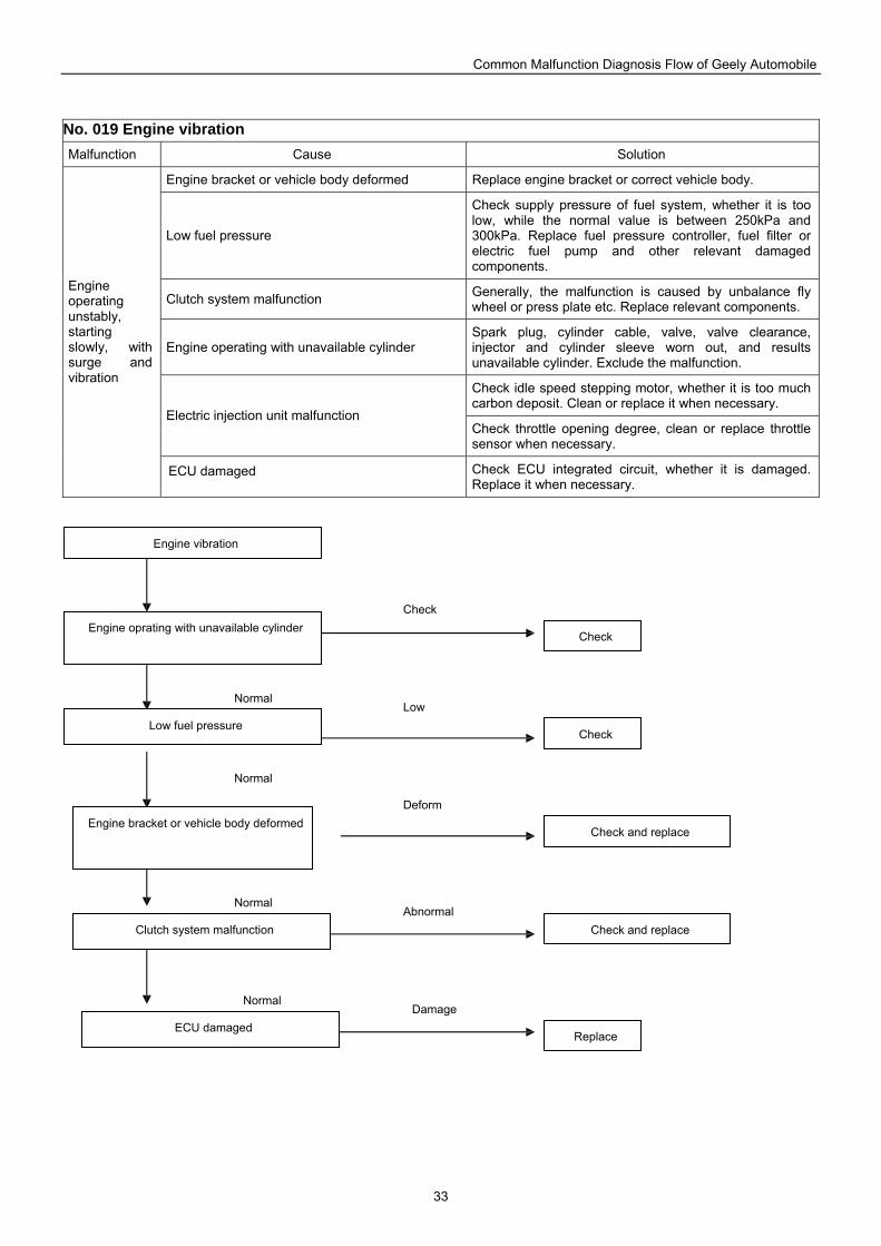
Common Malfunction Diagnosis Flow of Geely Automobile
33
No. 019 Engine vibration Malfunction Cause Solution
Engine bracket or vehicle body deformed Replace engine bracket or correct vehicle body.
Low fuel pressure
Check supply pressure of fuel system, whether it is too low, while the normal value is between 250kPa and 300kPa. Replace fuel pressure controller, fuel filter or electric fuel pump and other relevant damaged components.
Clutch system malfunction Generally, the malfunction is caused by unbalance fly wheel or press plate etc. Replace relevant components.
Engine operating with unavailable cylinder Spark plug, cylinder cable, valve, valve clearance, injector and cylinder sleeve worn out, and results unavailable cylinder. Exclude the malfunction.
Check idle speed stepping motor, whether it is too much carbon deposit. Clean or replace it when necessary.
Electric injection unit malfunction Check throttle opening degree, clean or replace throttle sensor when necessary.
Engine operating unstably, starting slowly, with surge and vibration
ECU damaged Check ECU integrated circuit, whether it is damaged. Replace it when necessary.
Engine vibration
Engine oprating with unavailable cylinder
Low fuel pressure
Engine bracket or vehicle body deformed
Clutch system malfunction
ECU damaged
Check
Check and replace
Replace
Check and replace
Check
Normal
Normal
Normal
Normal
Damage
Abnormal
Deform
Low
Check
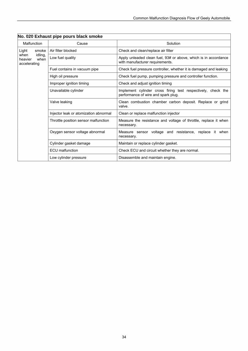
Common Malfunction Diagnosis Flow of Geely Automobile
34
No. 020 Exhaust pipe pours black smoke Malfunction Cause Solution
Air filter blocked Check and clean/replace air filter
Low fuel quality Apply unleaded clean fuel, 93# or above, which is in accordance with manufacturer requirements.
Fuel contains in vacuum pipe Check fuel pressure controller, whether it is damaged and leaking
High oil pressure Check fuel pump, pumping pressure and controller function.
Improper ignition timing Check and adjust ignition timing
Unavailable cylinder Implement cylinder cross firing test respectively, check the performance of wire and spark plug.
Valve leaking Clean combustion chamber carbon deposit. Replace or grind valve.
Injector leak or atomization abnormal Clean or replace malfunction injector
Throttle position sensor malfunction Measure the resistance and voltage of throttle, replace it when necessary.
Oxygen sensor voltage abnormal Measure sensor voltage and resistance, replace it when necessary.
Cylinder gasket damage Maintain or replace cylinder gasket.
ECU malfunction Check ECU and circuit whether they are normal.
Light smoke when idling, heavier when accelerating
Low cylinder pressure Disassemble and maintain engine.
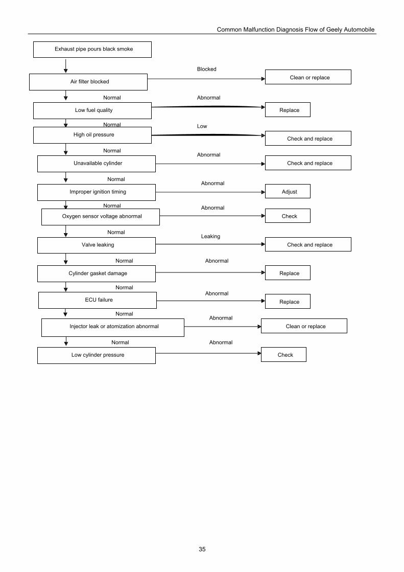
Common Malfunction Diagnosis Flow of Geely Automobile
35
Exhaust pipe pours black smoke
Air filter blocked
Low fuel quality
High oil pressure
Unavailable cylinder
Improper ignition timing
Oxygen sensor voltage abnormal
Valve leaking
Cylinder gasket damage
ECU failure
Injector leak or atomization abnormal
Low cylinder pressure
Check
Clean or replace
Replace
Check and replace
Check
Check and replace
Check and replace
Replace
Replace
Clean or replace
Adjust
Abnormal
Low
Blocked
Abnormal
Abnormal
Abnormal
Leaking
Abnormal
Abnormal
Abnormal
Abnormal
Normal
Normal
Normal
Normal
Normal
Normal
Normal
Normal
Normal
Normal
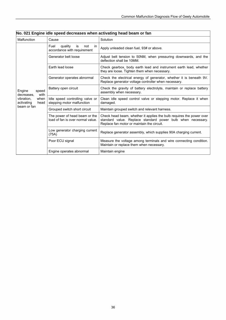
Common Malfunction Diagnosis Flow of Geely Automobile
36
No. 021 Engine idle speed decreases when activating head beam or fan Malfunction Cause Solution
Fuel quality is not in accordance with requirement Apply unleaded clean fuel, 93# or above.
Generator belt loose Adjust belt tension to 50NM, when pressuring downwards, and the deflection shall be 10MM.
Earth lead loose Check gearbox, body earth lead and instrument earth lead, whether they are loose. Tighten them when necessary.
Generator operates abnormal Check the electrical energy of generator, whether it is beneath 9V. Replace generator voltage controller when necessary.
Battery open circuit Check the gravity of battery electrolyte, maintain or replace battery assembly when necessary.
Idle speed controlling valve or stepping motor malfunction
Clean idle speed control valve or stepping motor. Replace it when damaged.
Grouped switch short circuit Maintain grouped switch and relevant harness.
The power of head beam or the load of fan is over normal value.
Check head beam, whether it applies the bulb requires the power over standard value. Replace standard power bulb when necessary. Replace fan motor or maintain the circuit.
Low generator charging current (75A) Replace generator assembly, which supplies 90A charging current.
Poor ECU signal Measure the voltage among terminals and wire connecting condition. Maintain or replace them when necessary.
Engine speed decreases, with vibration, when activating head beam or fan
Engine operates abnormal Maintain engine
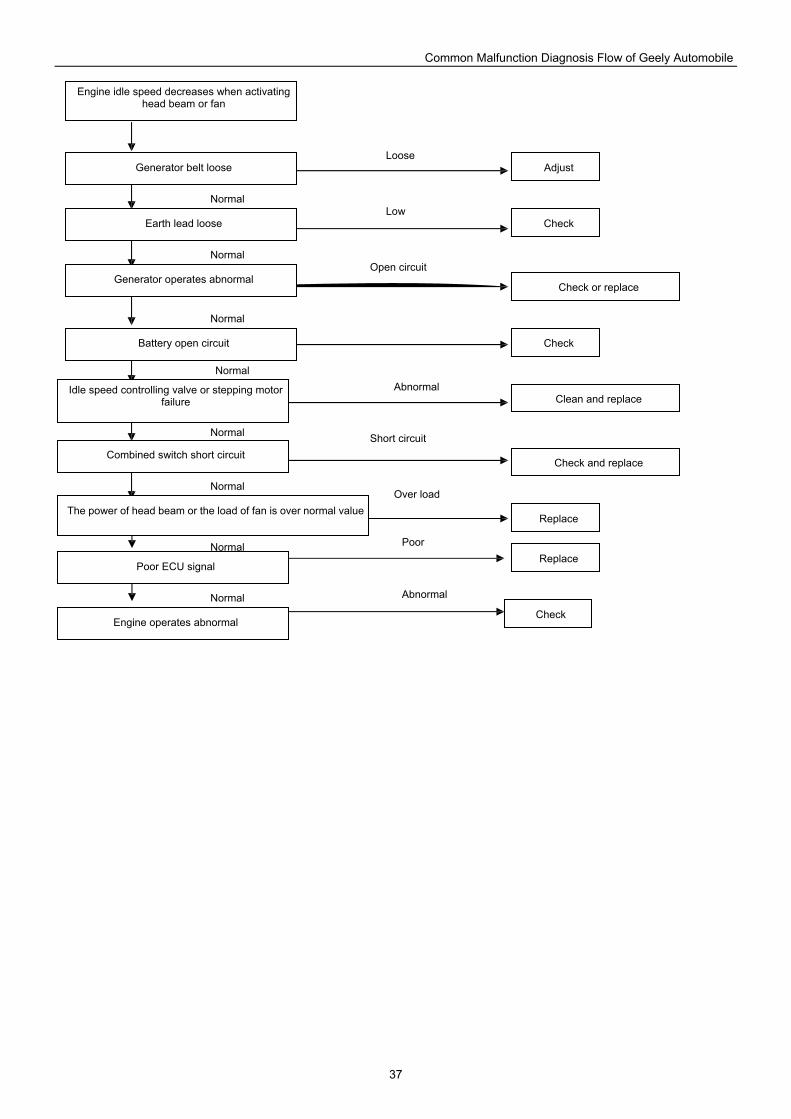
Common Malfunction Diagnosis Flow of Geely Automobile
37
Engine idle speed decreases when activating head beam or fan
Generator belt loose
Earth lead loose
Generator operates abnormal
Battery open circuit
Idle speed controlling valve or stepping motor failure
Combined switch short circuit
The power of head beam or the load of fan is over normal value
Poor ECU signal
Engine operates abnormal
Check
Clean and replace
Check
Check or replace
Check and replace
Replace
Replace
Adjust
Check
Open circuit
Loose
Poor
Low
Short circuit
Over load
Abnormal
Abnormal
Normal
Normal
Normal
Normal
Normal
Normal
Normal
Normal
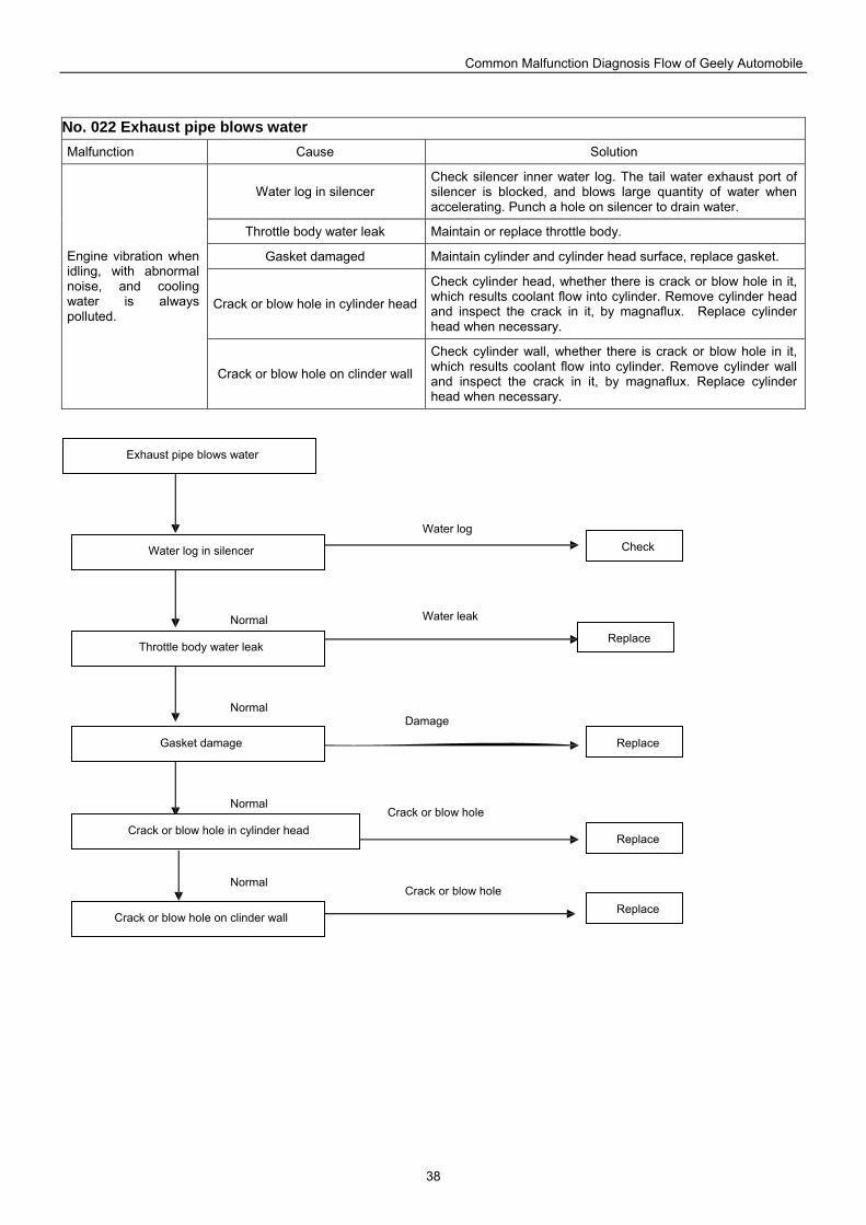
Common Malfunction Diagnosis Flow of Geely Automobile
38
No. 022 Exhaust pipe blows water Malfunction Cause Solution
Water log in silencer Check silencer inner water log. The tail water exhaust port of silencer is blocked, and blows large quantity of water when accelerating. Punch a hole on silencer to drain water.
Throttle body water leak Maintain or replace throttle body.
Gasket damaged Maintain cylinder and cylinder head surface, replace gasket.
Crack or blow hole in cylinder head
Check cylinder head, whether there is crack or blow hole in it, which results coolant flow into cylinder. Remove cylinder head and inspect the crack in it, by magnaflux. Replace cylinder head when necessary.
Engine vibration when idling, with abnormal noise, and cooling water is always polluted.
Crack or blow hole on clinder wall
Check cylinder wall, whether there is crack or blow hole in it, which results coolant flow into cylinder. Remove cylinder wall and inspect the crack in it, by magnaflux. Replace cylinder head when necessary.
Exhaust pipe blows water
Water log in silencer
Throttle body water leak
Gasket damage
Crack or blow hole in cylinder head
Crack or blow hole on clinder wall
Check
Replace
Replace
Replace
Replace
Damage
Water log
Water leak
Crack or blow hole
Crack or blow hole Normal
Normal
Normal
Normal
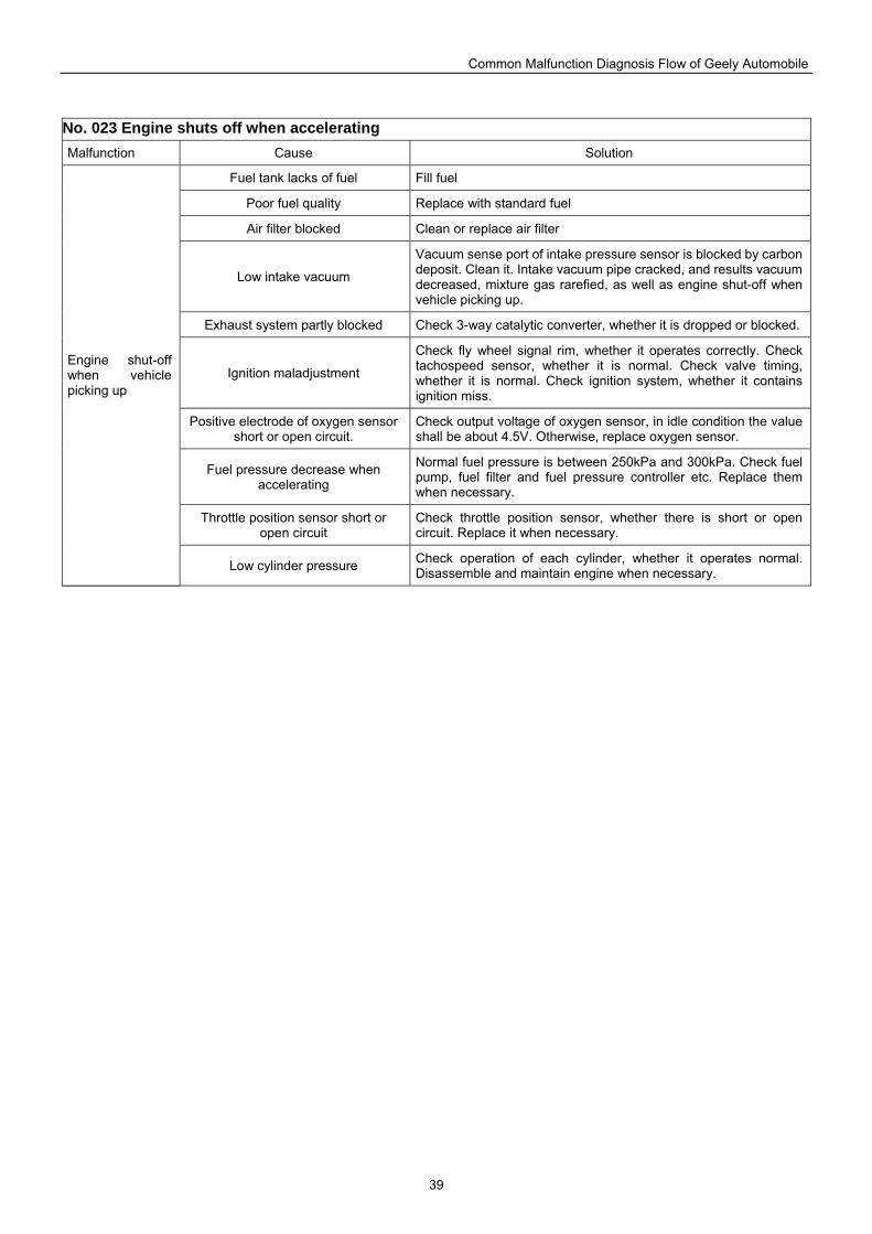
Common Malfunction Diagnosis Flow of Geely Automobile
39
No. 023 Engine shuts off when accelerating Malfunction Cause Solution
Fuel tank lacks of fuel Fill fuel
Poor fuel quality Replace with standard fuel
Air filter blocked Clean or replace air filter
Low intake vacuum
Vacuum sense port of intake pressure sensor is blocked by carbon deposit. Clean it. Intake vacuum pipe cracked, and results vacuum decreased, mixture gas rarefied, as well as engine shut-off when vehicle picking up.
Exhaust system partly blocked Check 3-way catalytic converter, whether it is dropped or blocked.
Ignition maladjustment
Check fly wheel signal rim, whether it operates correctly. Check tachospeed sensor, whether it is normal. Check valve timing, whether it is normal. Check ignition system, whether it contains ignition miss.
Positive electrode of oxygen sensor short or open circuit.
Check output voltage of oxygen sensor, in idle condition the value shall be about 4.5V. Otherwise, replace oxygen sensor.
Fuel pressure decrease when accelerating
Normal fuel pressure is between 250kPa and 300kPa. Check fuel pump, fuel filter and fuel pressure controller etc. Replace them when necessary.
Throttle position sensor short or open circuit
Check throttle position sensor, whether there is short or open circuit. Replace it when necessary.
Engine shut-off when vehicle picking up
Low cylinder pressure Check operation of each cylinder, whether it operates normal. Disassemble and maintain engine when necessary.
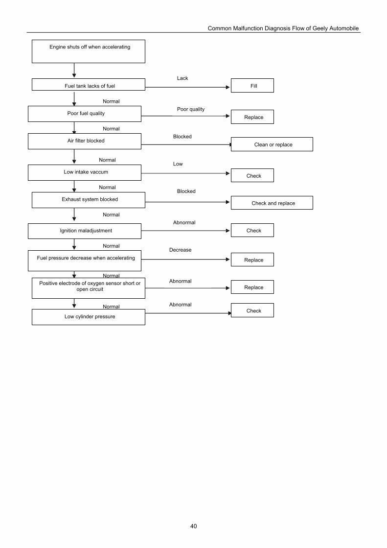
Common Malfunction Diagnosis Flow of Geely Automobile
40
Engine shuts off when accelerating
Fuel tank lacks of fuel
Poor fuel quality
Air filter blocked
Low intake vaccum
Exhaust system blocked
Ignition maladjustment
Fuel pressure decrease when accelerating
Positive electrode of oxygen sensor short or open circuit
Low cylinder pressure
Replace
Replace
Check
Check
Check
Replace
Fill
Clean or replace
Check and replace
Blocked
Lack
Poor quality
Low
Blocked
Abnormal
Abnormal
Abnormal
Decrease
Normal
Normal
Normal
Normal
Normal
Normal
Normal
Normal
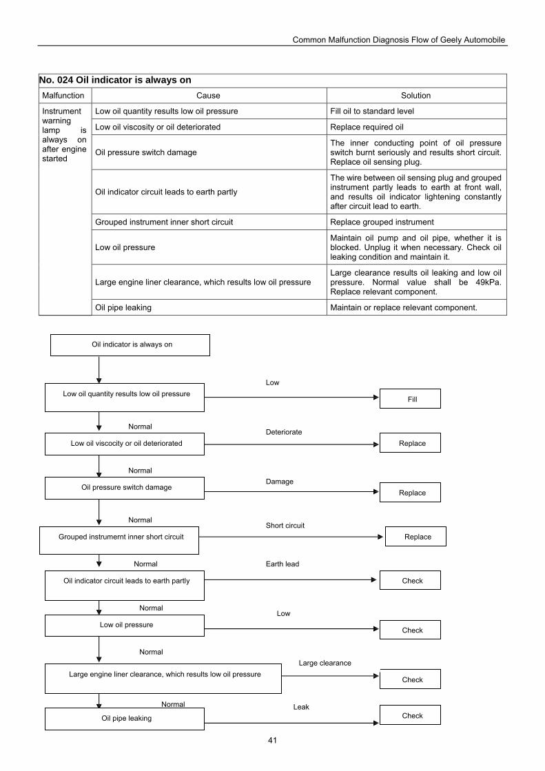
Common Malfunction Diagnosis Flow of Geely Automobile
41
No. 024 Oil indicator is always on Malfunction Cause Solution
Low oil quantity results low oil pressure Fill oil to standard level
Low oil viscosity or oil deteriorated Replace required oil
Oil pressure switch damage The inner conducting point of oil pressure switch burnt seriously and results short circuit. Replace oil sensing plug.
Oil indicator circuit leads to earth partly
The wire between oil sensing plug and grouped instrument partly leads to earth at front wall, and results oil indicator lightening constantly after circuit lead to earth.
Grouped instrument inner short circuit Replace grouped instrument
Low oil pressure Maintain oil pump and oil pipe, whether it is blocked. Unplug it when necessary. Check oil leaking condition and maintain it.
Large engine liner clearance, which results low oil pressure Large clearance results oil leaking and low oil pressure. Normal value shall be 49kPa. Replace relevant component.
Instrument warning lamp is always on after engine started
Oil pipe leaking Maintain or replace relevant component.
Oil indicator is always on
Low oil quantity results low oil pressure
Low oil viscocity or oil deteriorated
Oil pressure switch damage
Grouped instrumernt inner short circuit
Oil indicator circuit leads to earth partly
Low oil pressure
Large engine liner clearance, which results low oil pressure
Oil pipe leaking Check
Check
Check
Replace
Fill
Replace
Replace
Check
Low
Earth lead
Short circuit
Damage
Deteriorate
Large clearance
Leak
Low
Normal
Normal
Normal
Normal
Normal
Normal
Normal
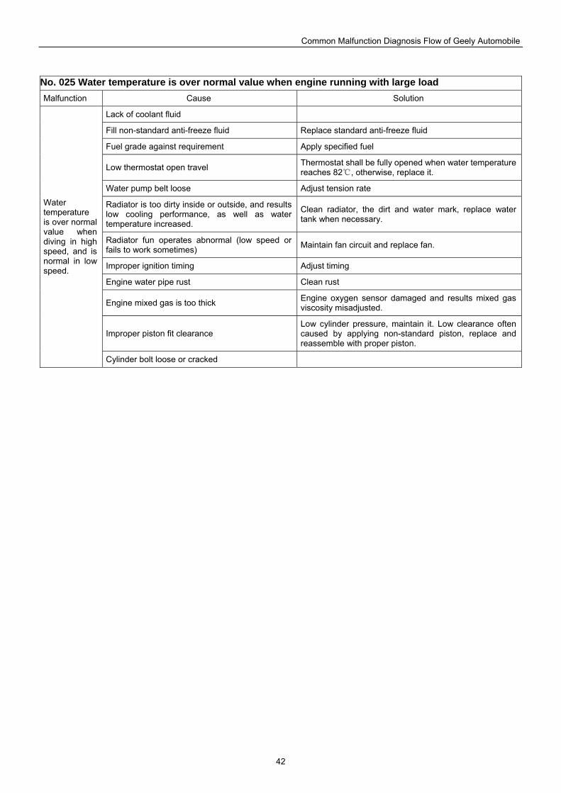
Common Malfunction Diagnosis Flow of Geely Automobile
42
No. 025 Water temperature is over normal value when engine running with large load Malfunction Cause Solution
Lack of coolant fluid
Fill non-standard anti-freeze fluid Replace standard anti-freeze fluid
Fuel grade against requirement Apply specified fuel
Low thermostat open travel Thermostat shall be fully opened when water temperature reaches 82 , otherwise, replace it.
Water pump belt loose Adjust tension rate
Radiator is too dirty inside or outside, and results low cooling performance, as well as water temperature increased.
Clean radiator, the dirt and water mark, replace water tank when necessary.
Radiator fun operates abnormal (low speed or fails to work sometimes) Maintain fan circuit and replace fan.
Improper ignition timing Adjust timing
Engine water pipe rust Clean rust
Engine mixed gas is too thick Engine oxygen sensor damaged and results mixed gas viscosity misadjusted.
Improper piston fit clearance Low cylinder pressure, maintain it. Low clearance often caused by applying non-standard piston, replace and reassemble with proper piston.
Water temperature is over normal value when diving in high speed, and is normal in low speed.
Cylinder bolt loose or cracked
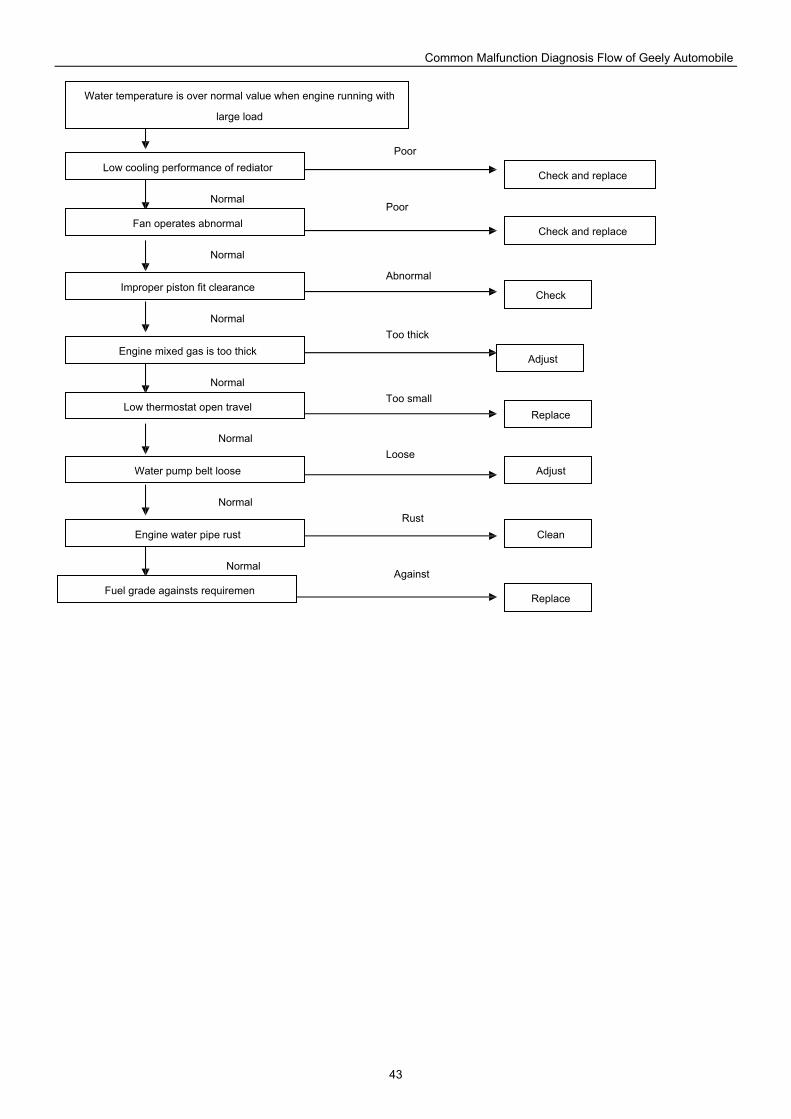
Common Malfunction Diagnosis Flow of Geely Automobile
43
Water temperature is over normal value when engine running with
large load
Low cooling performance of rediator
Fan operates abnormal
Improper piston fit clearance
Engine mixed gas is too thick
Low thermostat open travel
Water pump belt loose
Engine water pipe rust
Fuel grade againsts requiremen
Check
Check and replace
Replace
Clean
Check and replace
Adjust
Replace
Adjust
Poor
Loose
Too small
Too thick
Abnormal
Rust
Poor
Against Normal
Normal
Normal
Normal
Normal
Normal
Normal
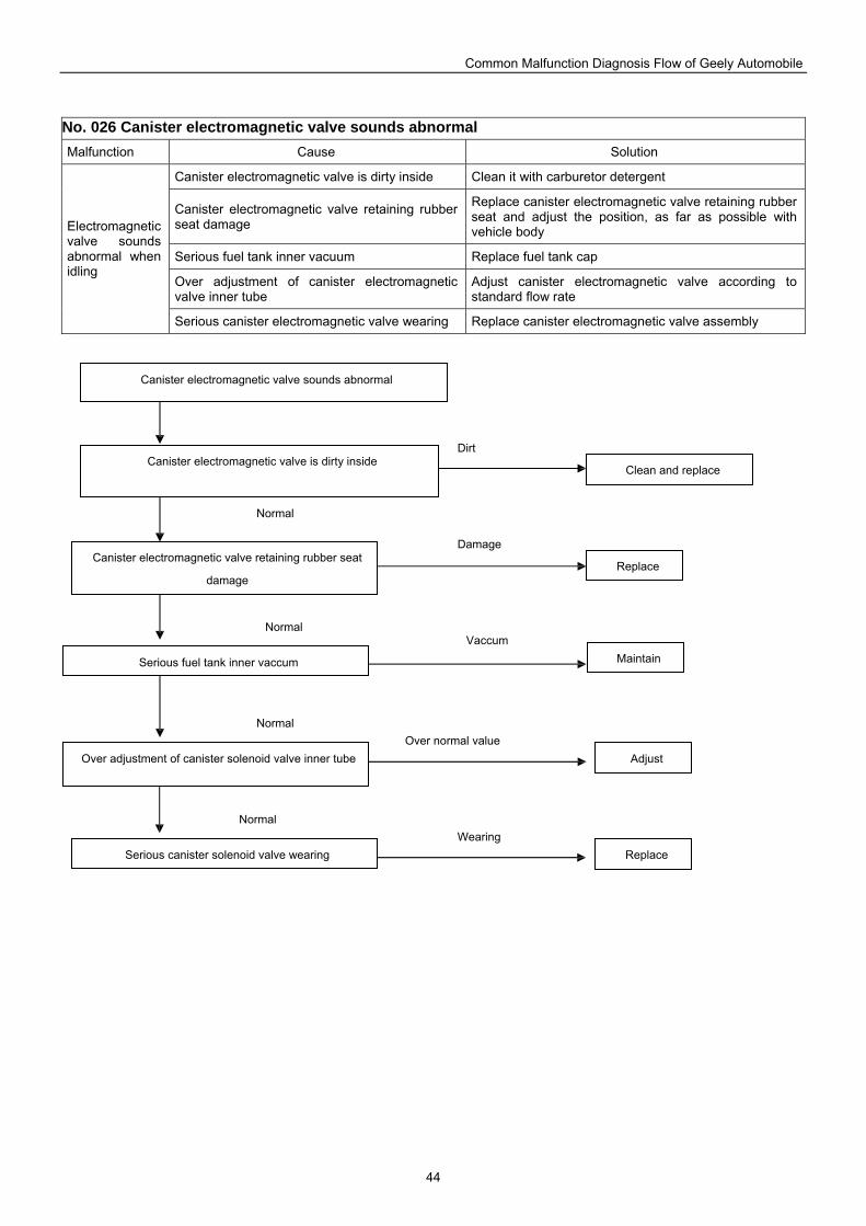
Common Malfunction Diagnosis Flow of Geely Automobile
44
No. 026 Canister electromagnetic valve sounds abnormal Malfunction Cause Solution
Canister electromagnetic valve is dirty inside Clean it with carburetor detergent
Canister electromagnetic valve retaining rubber seat damage
Replace canister electromagnetic valve retaining rubber seat and adjust the position, as far as possible with vehicle body
Serious fuel tank inner vacuum Replace fuel tank cap
Over adjustment of canister electromagnetic valve inner tube
Adjust canister electromagnetic valve according to standard flow rate
Electromagnetic valve sounds abnormal when idling
Serious canister electromagnetic valve wearing Replace canister electromagnetic valve assembly
Canister electromagnetic valve sounds abnormal
Canister electromagnetic valve is dirty inside
Canister electromagnetic valve retaining rubber seat
damage
Serious fuel tank inner vaccum
Over adjustment of canister solenoid valve inner tube
Serious canister solenoid valve wearing Replace
Replace
Adjust
Clean and replace
Maintain
Damage
Dirt
Over normal value
Vaccum
Wearing
Normal
Normal
Normal
Normal
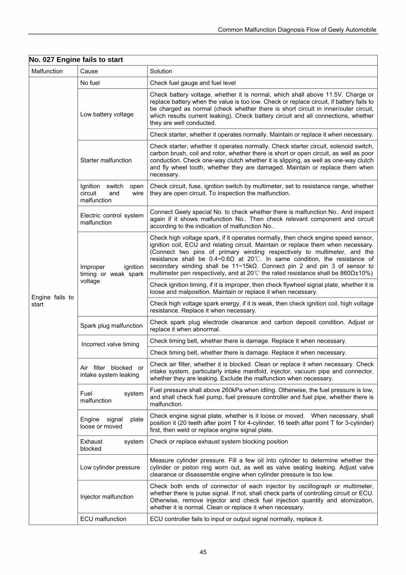
Common Malfunction Diagnosis Flow of Geely Automobile
45
No. 027 Engine fails to start Malfunction Cause Solution
No fuel Check fuel gauge and fuel level
Check battery voltage, whether it is normal, which shall above 11.5V. Charge or replace battery when the value is too low. Check or replace circuit, if battery fails to be charged as normal (check whether there is short circuit in inner/outer circuit, which results current leaking). Check battery circuit and all connections, whether they are well conducted.
Low battery voltage
Check starter, whether it operates normally. Maintain or replace it when necessary.
Starter malfunction
Check starter, whether it operates normally. Check starter circuit, solenoid switch, carbon brush, coil and rotor, whether there is short or open circuit, as well as poor conduction. Check one-way clutch whether it is slipping, as well as one-way clutch and fly wheel tooth, whether they are damaged. Maintain or replace them when necessary.
Ignition switch open circuit and wire malfunction
Check circuit, fuse, ignition switch by multimeter, set to resistance range, whether they are open circuit. To inspection the malfunction.
Electric control system malfunction
Connect Geely special No. to check whether there is malfunction No.. And inspect again if it shows malfunction No.. Then check relevant component and circuit according to the indication of malfunction No..
Check high voltage spark, if it operates normally, then check engine speed sensor, ignition coil, ECU and relating circuit. Maintain or replace them when necessary. (Connect two pins of primary winding respectively to multimeter, and the resistance shall be 0.4~0.6Ω at 20 . In same condition, the resistance of secondary winding shall be 11~15kΩ. Connect pin 2 and pin 3 of sensor to multimeter pen respectively, and at 20 the rated resistance shall be 860Ω±10%)
Check ignition timing, if it is improper, then check flywheel signal plate, whether it is loose and malposition. Maintain or replace it when necessary.
Improper ignition timing or weak spark voltage
Check high voltage spark energy, if it is weak, then check ignition coil, high voltage resistance. Replace it when necessary.
Spark plug malfunction Check spark plug electrode clearance and carbon deposit condition. Adjust or replace it when abnormal.
Check timing belt, whether there is damage. Replace it when necessary. Incorrect valve timing Check timing belt, whether there is damage. Replace it when necessary.
Air filter blocked or intake system leaking
Check air filter, whether it is blocked. Clean or replace it when necessary. Check intake system, particularly intake manifold, injector, vacuum pipe and connector, whether they are leaking. Exclude the malfunction when necessary.
Fuel system malfunction
Fuel pressure shall above 260kPa when idling. Otherwise, the fuel pressure is low, and shall check fuel pump, fuel pressure controller and fuel pipe, whether there is malfunction.
Engine signal plate loose or moved
Check engine signal plate, whether is it loose or moved. When necessary, shall position it (20 teeth after point T for 4-cylinder, 16 teeth after point T for 3-cylinder) first, then weld or replace engine signal plate.
Exhaust system blocked
Check or replace exhaust system blocking position
Low cylinder pressure Measure cylinder pressure. Fill a few oil into cylinder to determine whether the cylinder or piston ring worn out, as well as valve sealing leaking. Adjust valve clearance or disassemble engine when cylinder pressure is too low.
Injector malfunction
Check both ends of connector of each injector by oscillograph or multimeter, whether there is pulse signal. If not, shall check parts of controlling circuit or ECU. Otherwise, remove injector and check fuel injection quantity and atomization, whether it is normal. Clean or replace it when necessary.
Engine fails to start
ECU malfunction ECU controller fails to input or output signal normally, replace it.
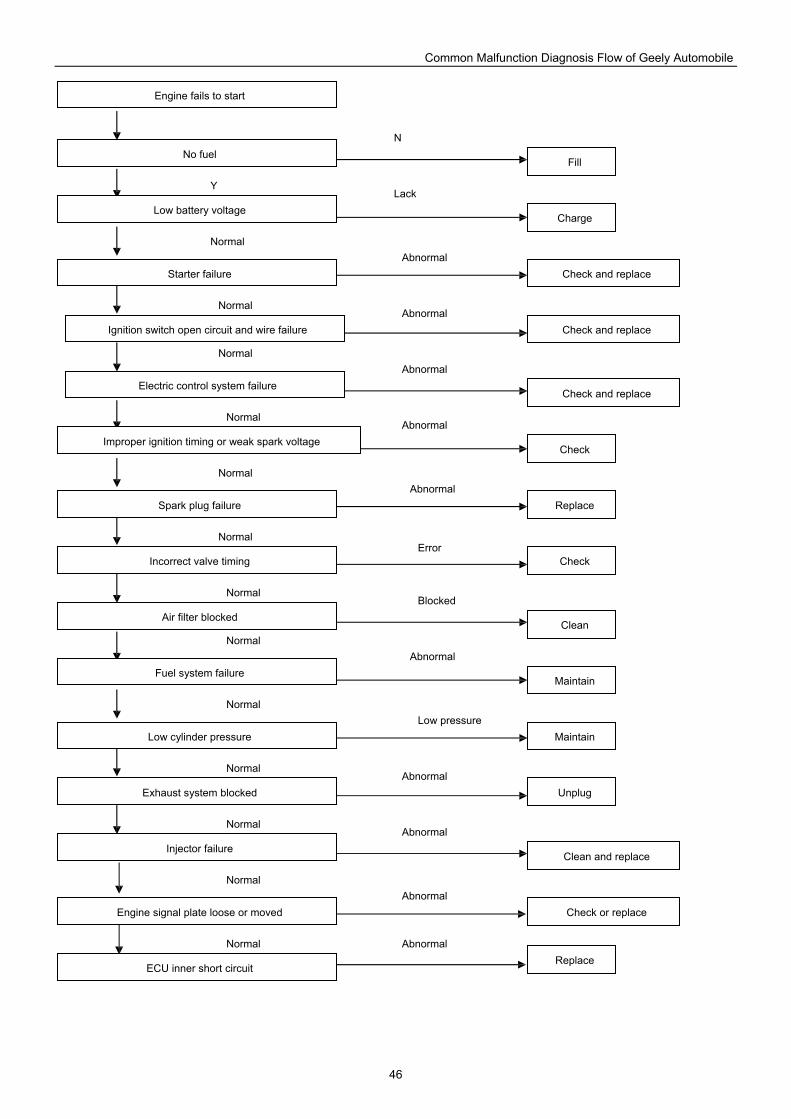
Common Malfunction Diagnosis Flow of Geely Automobile
46
Engine fails to start
No fuel
Low battery voltage
Starter failure
Ignition switch open circuit and wire failure
Electric control system failure
Improper ignition timing or weak spark voltage
Spark plug failure
Incorrect valve timing
Air filter blocked
Fuel system failure
Low cylinder pressure
Exhaust system blocked
Injector failure
Engine signal plate loose or moved
ECU inner short circuit Replace
Replace
Unplug
Clean and replace
Check
Charge
Fill
Check and replace
Check and replace
Check and replace
Check
Clean
Maintain
Maintain
Check or replace
Error
Abnormal
Blocked
Low pressure
N
Lack
Abnormal
Abnormal
Abnormal
Abnormal
Abnormal
Abnormal
Abnormal
Abnormal
Abnormal Normal
Normal
Normal
Normal
Normal
Normal
Normal
Normal
Normal
Normal
Normal
Normal
Y
Normal
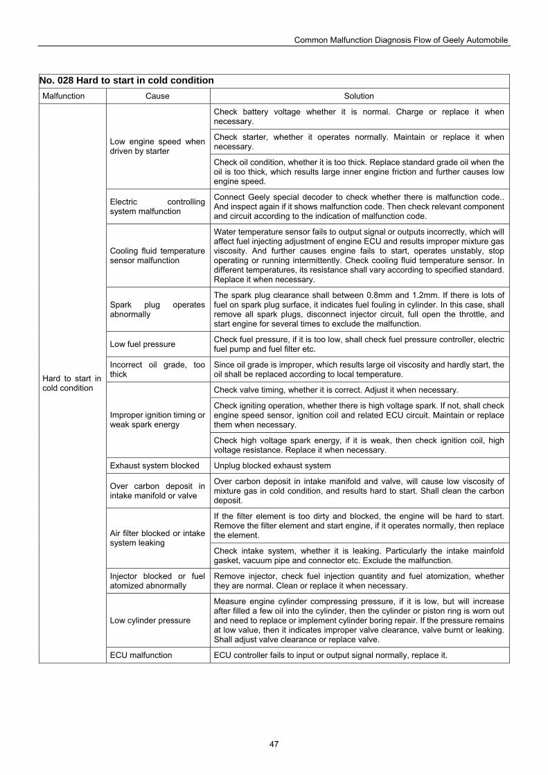
Common Malfunction Diagnosis Flow of Geely Automobile
47
No. 028 Hard to start in cold condition Malfunction Cause Solution
Check battery voltage whether it is normal. Charge or replace it when necessary.
Check starter, whether it operates normally. Maintain or replace it when necessary. Low engine speed when
driven by starter Check oil condition, whether it is too thick. Replace standard grade oil when the oil is too thick, which results large inner engine friction and further causes low engine speed.
Electric controlling system malfunction
Connect Geely special decoder to check whether there is malfunction code.. And inspect again if it shows malfunction code. Then check relevant component and circuit according to the indication of malfunction code.
Cooling fluid temperature sensor malfunction
Water temperature sensor fails to output signal or outputs incorrectly, which will affect fuel injecting adjustment of engine ECU and results improper mixture gas viscosity. And further causes engine fails to start, operates unstably, stop operating or running intermittently. Check cooling fluid temperature sensor. In different temperatures, its resistance shall vary according to specified standard. Replace it when necessary.
Spark plug operates abnormally
The spark plug clearance shall between 0.8mm and 1.2mm. If there is lots of fuel on spark plug surface, it indicates fuel fouling in cylinder. In this case, shall remove all spark plugs, disconnect injector circuit, full open the throttle, and start engine for several times to exclude the malfunction.
Low fuel pressure Check fuel pressure, if it is too low, shall check fuel pressure controller, electric fuel pump and fuel filter etc.
Incorrect oil grade, too thick
Since oil grade is improper, which results large oil viscosity and hardly start, the oil shall be replaced according to local temperature.
Check valve timing, whether it is correct. Adjust it when necessary.
Check igniting operation, whether there is high voltage spark. If not, shall check engine speed sensor, ignition coil and related ECU circuit. Maintain or replace them when necessary.
Improper ignition timing or weak spark energy
Check high voltage spark energy, if it is weak, then check ignition coil, high voltage resistance. Replace it when necessary.
Exhaust system blocked Unplug blocked exhaust system
Over carbon deposit in intake manifold or valve
Over carbon deposit in intake manifold and valve, will cause low viscosity of mixture gas in cold condition, and results hard to start. Shall clean the carbon deposit.
If the filter element is too dirty and blocked, the engine will be hard to start. Remove the filter element and start engine, if it operates normally, then replace the element. Air filter blocked or intake
system leaking Check intake system, whether it is leaking. Particularly the intake mainfold gasket, vacuum pipe and connector etc. Exclude the malfunction.
Injector blocked or fuel atomized abnormally
Remove injector, check fuel injection quantity and fuel atomization, whether they are normal. Clean or replace it when necessary.
Low cylinder pressure
Measure engine cylinder compressing pressure, if it is low, but will increase after filled a few oil into the cylinder, then the cylinder or piston ring is worn out and need to replace or implement cylinder boring repair. If the pressure remains at low value, then it indicates improper valve clearance, valve burnt or leaking. Shall adjust valve clearance or replace valve.
Hard to start in cold condition
ECU malfunction ECU controller fails to input or output signal normally, replace it.
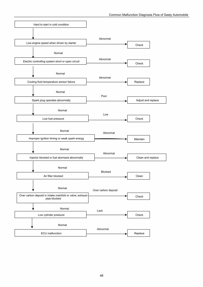
Common Malfunction Diagnosis Flow of Geely Automobile
48
Hard to start in cold condition
Low engine speed when driven by starter
Electric controlling system short or open circuit
Cooling fluid temperature sensor failure
Spark plug operates abnormally
Low fuel pressure
Improper ignition timing or weak spark energy
Injector blocked or fuel atomized abnormally
Air filter blocked
Over carbon deposit in intake mainfold or valve; exhaust pipe blocked
Low cylinder pressure
ECU malfunction Replace
Replace
Clean and replace
Check
Adjust and replace
Check
Clean
Maintain
Check
Check
Check
Poor
Low
Abnormal
Blocked
Over carbon deposit
Lack
Abnormal
Abnormal
Abnormal
Abnormal
Abnormal
Normal
Normal
Normal
Normal
Normal
Normal
Normal
Normal
Normal
Normal
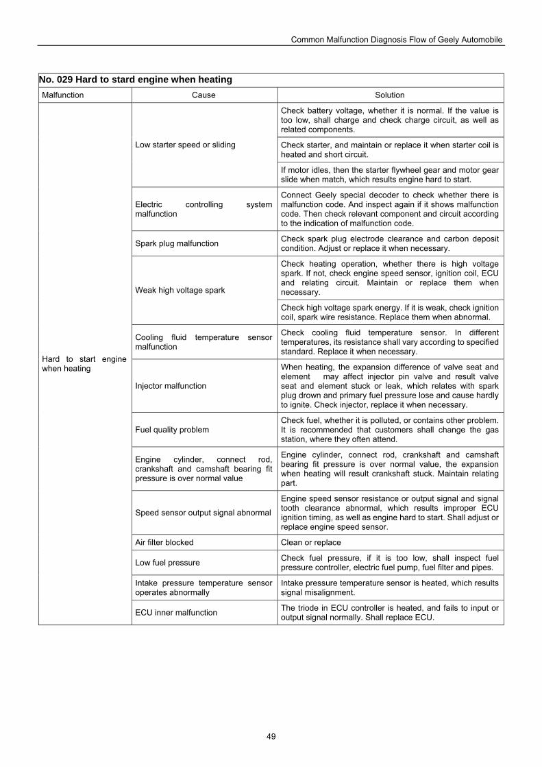
Common Malfunction Diagnosis Flow of Geely Automobile
49
No. 029 Hard to stard engine when heating Malfunction Cause Solution
Check battery voltage, whether it is normal. If the value is too low, shall charge and check charge circuit, as well as related components.
Check starter, and maintain or replace it when starter coil is heated and short circuit.
Low starter speed or sliding
If motor idles, then the starter flywheel gear and motor gear slide when match, which results engine hard to start.
Electric controlling system malfunction
Connect Geely special decoder to check whether there is malfunction code. And inspect again if it shows malfunction code. Then check relevant component and circuit according to the indication of malfunction code.
Spark plug malfunction Check spark plug electrode clearance and carbon deposit condition. Adjust or replace it when necessary.
Check heating operation, whether there is high voltage spark. If not, check engine speed sensor, ignition coil, ECU and relating circuit. Maintain or replace them when necessary. Weak high voltage spark
Check high voltage spark energy. If it is weak, check ignition coil, spark wire resistance. Replace them when abnormal.
Cooling fluid temperature sensor malfunction
Check cooling fluid temperature sensor. In different temperatures, its resistance shall vary according to specified standard. Replace it when necessary.
Injector malfunction
When heating, the expansion difference of valve seat and element may affect injector pin valve and result valve seat and element stuck or leak, which relates with spark plug drown and primary fuel pressure lose and cause hardly to ignite. Check injector, replace it when necessary.
Fuel quality problem Check fuel, whether it is polluted, or contains other problem. It is recommended that customers shall change the gas station, where they often attend.
Engine cylinder, connect rod, crankshaft and camshaft bearing fit pressure is over normal value
Engine cylinder, connect rod, crankshaft and camshaft bearing fit pressure is over normal value, the expansion when heating will result crankshaft stuck. Maintain relating part.
Speed sensor output signal abnormal
Engine speed sensor resistance or output signal and signal tooth clearance abnormal, which results improper ECU ignition timing, as well as engine hard to start. Shall adjust or replace engine speed sensor.
Air filter blocked Clean or replace
Low fuel pressure Check fuel pressure, if it is too low, shall inspect fuel pressure controller, electric fuel pump, fuel filter and pipes.
Intake pressure temperature sensor operates abnormally
Intake pressure temperature sensor is heated, which results signal misalignment.
Hard to start engine when heating
ECU inner malfunction The triode in ECU controller is heated, and fails to input or output signal normally. Shall replace ECU.
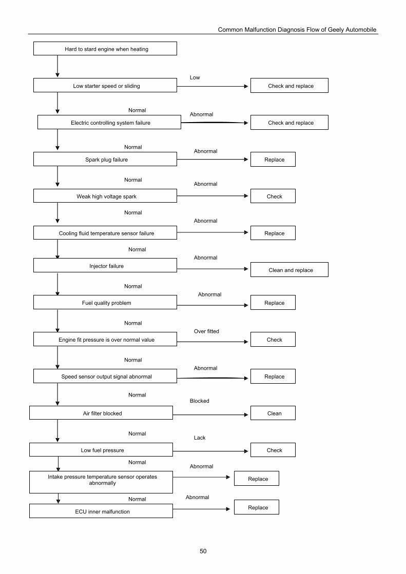
Common Malfunction Diagnosis Flow of Geely Automobile
50
Intake pressure temperature sensor operates abnormally
ECU inner malfunction
Low fuel pressure
Air filter blocked
Speed sensor output signal abnormal
Engine fit pressure is over normal value
Fuel quality problem
Injector failure
Cooling fluid temperature sensor failure
Weak high voltage spark
Spark plug failure
Electric controlling system failure
Low starter speed or sliding
Hard to stard engine when heating
Replace
Check and replace
Clean
Check
Check
Check
Check and replace
Replace
Clean and replace
Replace
Replace
Replace
Replace
Blocked
Low
Lack
Abnormal
Abnormal
Abnormal
Abnormal
Over fitted
Abnormal
Abnormal
Abnormal
Abnormal
Abnormal
Normal
Normal
Normal
Normal
Normal
Normal
Normal
Normal
Normal
Normal
Normal
Normal
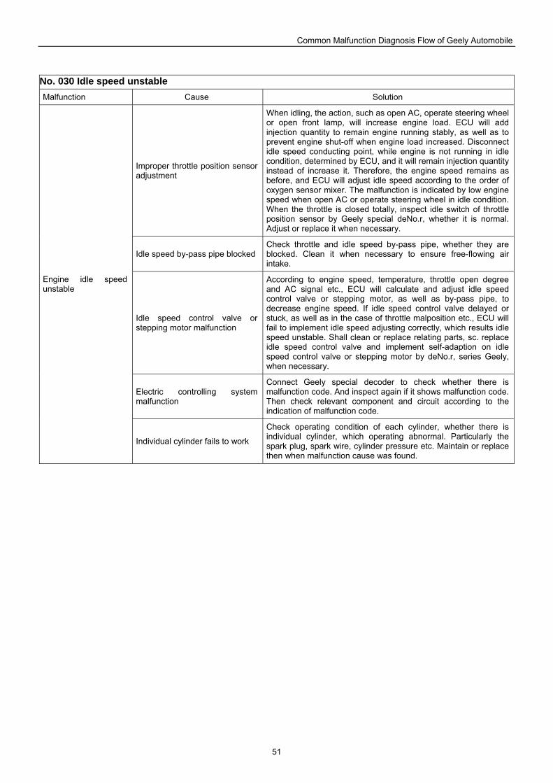
Common Malfunction Diagnosis Flow of Geely Automobile
51
No. 030 Idle speed unstable Malfunction Cause Solution
Improper throttle position sensor adjustment
When idling, the action, such as open AC, operate steering wheel or open front lamp, will increase engine load. ECU will add injection quantity to remain engine running stably, as well as to prevent engine shut-off when engine load increased. Disconnect idle speed conducting point, while engine is not running in idle condition, determined by ECU, and it will remain injection quantity instead of increase it. Therefore, the engine speed remains as before, and ECU will adjust idle speed according to the order of oxygen sensor mixer. The malfunction is indicated by low engine speed when open AC or operate steering wheel in idle condition. When the throttle is closed totally, inspect idle switch of throttle position sensor by Geely special deNo.r, whether it is normal. Adjust or replace it when necessary.
Idle speed by-pass pipe blockedCheck throttle and idle speed by-pass pipe, whether they are blocked. Clean it when necessary to ensure free-flowing air intake.
Idle speed control valve or stepping motor malfunction
According to engine speed, temperature, throttle open degree and AC signal etc., ECU will calculate and adjust idle speed control valve or stepping motor, as well as by-pass pipe, to decrease engine speed. If idle speed control valve delayed or stuck, as well as in the case of throttle malposition etc., ECU will fail to implement idle speed adjusting correctly, which results idle speed unstable. Shall clean or replace relating parts, sc. replace idle speed control valve and implement self-adaption on idle speed control valve or stepping motor by deNo.r, series Geely, when necessary.
Electric controlling system malfunction
Connect Geely special decoder to check whether there is malfunction code. And inspect again if it shows malfunction code. Then check relevant component and circuit according to the indication of malfunction code.
Engine idle speed unstable
Individual cylinder fails to work
Check operating condition of each cylinder, whether there is individual cylinder, which operating abnormal. Particularly the spark plug, spark wire, cylinder pressure etc. Maintain or replace then when malfunction cause was found.
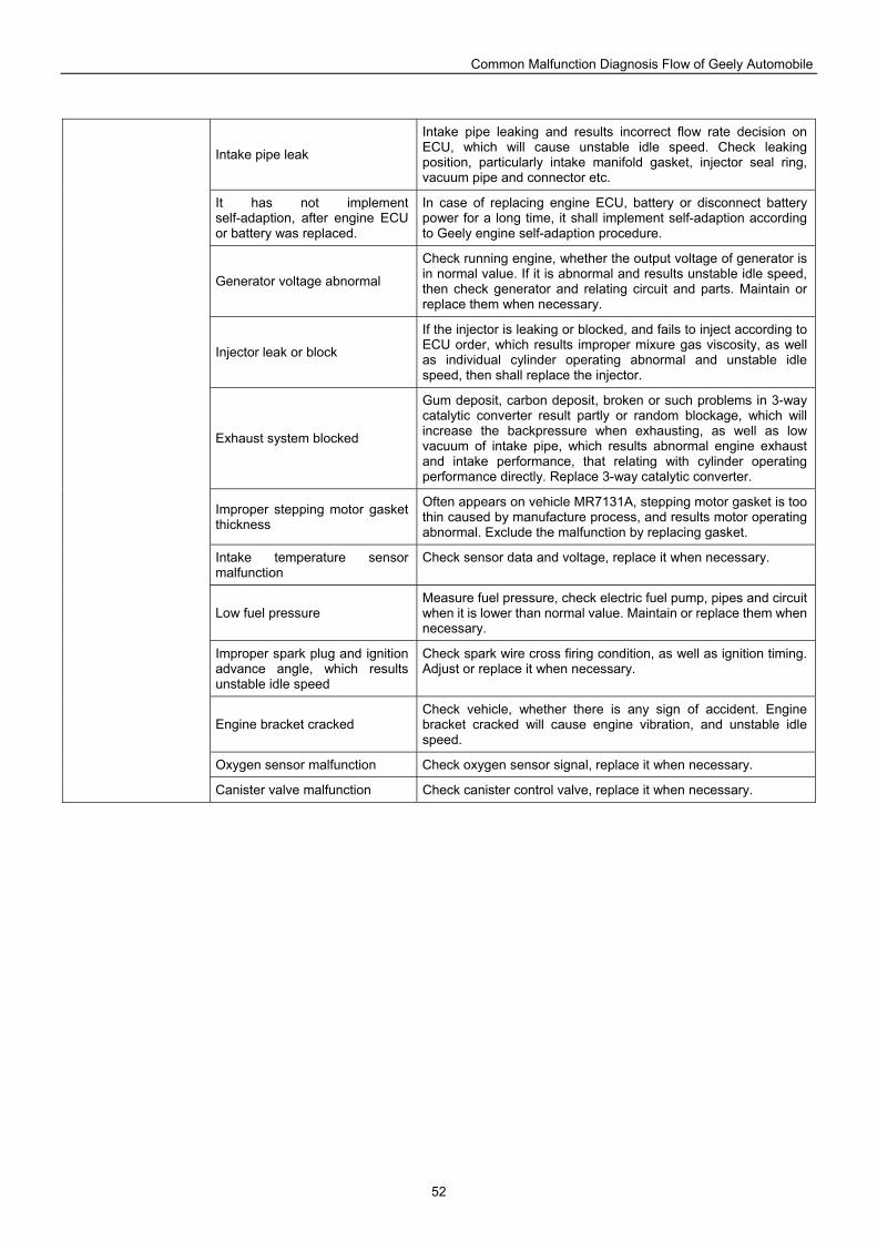
Common Malfunction Diagnosis Flow of Geely Automobile
52
Intake pipe leak
Intake pipe leaking and results incorrect flow rate decision on ECU, which will cause unstable idle speed. Check leaking position, particularly intake manifold gasket, injector seal ring, vacuum pipe and connector etc.
It has not implement self-adaption, after engine ECU or battery was replaced.
In case of replacing engine ECU, battery or disconnect battery power for a long time, it shall implement self-adaption according to Geely engine self-adaption procedure.
Generator voltage abnormal
Check running engine, whether the output voltage of generator is in normal value. If it is abnormal and results unstable idle speed, then check generator and relating circuit and parts. Maintain or replace them when necessary.
Injector leak or block
If the injector is leaking or blocked, and fails to inject according to ECU order, which results improper mixure gas viscosity, as well as individual cylinder operating abnormal and unstable idle speed, then shall replace the injector.
Exhaust system blocked
Gum deposit, carbon deposit, broken or such problems in 3-way catalytic converter result partly or random blockage, which will increase the backpressure when exhausting, as well as low vacuum of intake pipe, which results abnormal engine exhaust and intake performance, that relating with cylinder operating performance directly. Replace 3-way catalytic converter.
Improper stepping motor gasket thickness
Often appears on vehicle MR7131A, stepping motor gasket is too thin caused by manufacture process, and results motor operating abnormal. Exclude the malfunction by replacing gasket.
Intake temperature sensor malfunction
Check sensor data and voltage, replace it when necessary.
Low fuel pressure Measure fuel pressure, check electric fuel pump, pipes and circuit when it is lower than normal value. Maintain or replace them when necessary.
Improper spark plug and ignition advance angle, which results unstable idle speed
Check spark wire cross firing condition, as well as ignition timing. Adjust or replace it when necessary.
Engine bracket cracked Check vehicle, whether there is any sign of accident. Engine bracket cracked will cause engine vibration, and unstable idle speed.
Oxygen sensor malfunction Check oxygen sensor signal, replace it when necessary.
Canister valve malfunction Check canister control valve, replace it when necessary.
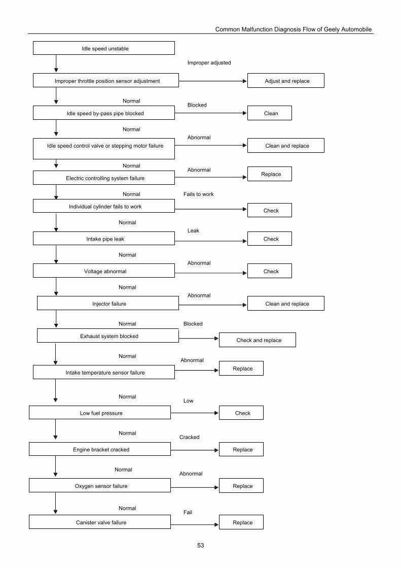
Common Malfunction Diagnosis Flow of Geely Automobile
53
Canister valve failure
Oxygen sensor failure
Engine bracket cracked
Low fuel pressure
Intake temperature sensor failure
Exhaust system blocked
Injector failure
Voltage abnormal
Intake pipe leak
Individual cylinder fails to work
Electric controlling system failure
Idle speed control valve or stepping motor failure
Idle speed by-pass pipe blocked
Improper throttle position sensor adjustment
Idle speed unstable
Clean
Check
Check
Clean and replace
Replace
Replace
Replace
Replace
Replace
Check and replace
Check
Check
Clean and replace
Adjust and replace
Low
Cracked
Fail
Abnormal
Abnormal
Abnormal
Blocked
Abnormal
Abnormal
Abnormal
Improper adjusted
Blocked
Fails to work
Leak
Normal
Normal
Normal
Normal
Normal
Normal
Normal
Normal
Normal
Normal
Normal
Normal
Normal
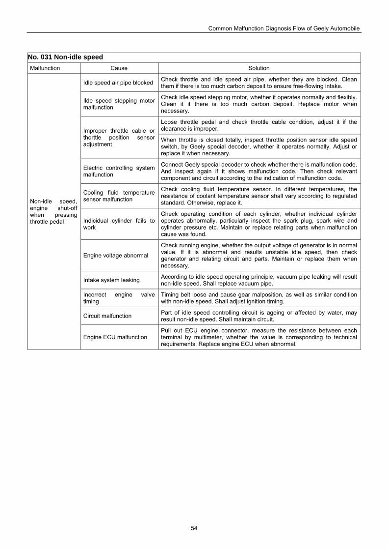
Common Malfunction Diagnosis Flow of Geely Automobile
54
No. 031 Non-idle speed Malfunction Cause Solution
Idle speed air pipe blocked Check throttle and idle speed air pipe, whether they are blocked. Clean them if there is too much carbon deposit to ensure free-flowing intake.
Ilde speed stepping motor malfunction
Check idle speed stepping motor, whether it operates normally and flexibly. Clean it if there is too much carbon deposit. Replace motor when necessary.
Loose throttle pedal and check throttle cable condition, adjust it if the clearance is improper. Improper throttle cable or
thorttle position sensor adjustment
When throttle is closed totally, inspect throttle position sensor idle speed switch, by Geely special decoder, whether it operates normally. Adjust or replace it when necessary.
Electric controlling system malfunction
Connect Geely special decoder to check whether there is malfunction code. And inspect again if it shows malfunction code. Then check relevant component and circuit according to the indication of malfunction code.
Cooling fluid temperature sensor malfunction
Check cooling fluid temperature sensor. In different temperatures, the resistance of coolant temperature sensor shall vary according to regulated standard. Otherwise, replace it.
Indicidual cylinder fails to work
Check operating condition of each cylinder, whether individual cylinder operates abnormally, particularly inspect the spark plug, spark wire and cylinder pressure etc. Maintain or replace relating parts when malfunction cause was found.
Engine voltage abnormal
Check running engine, whether the output voltage of generator is in normal value. If it is abnormal and results unstable idle speed, then check generator and relating circuit and parts. Maintain or replace them when necessary.
Intake system leaking According to idle speed operating principle, vacuum pipe leaking will result non-idle speed. Shall replace vacuum pipe.
Incorrect engine valve timing
Timing belt loose and cause gear malposition, as well as similar condition with non-idle speed. Shall adjust ignition timing.
Circuit malfunction Part of idle speed controlling circuit is ageing or affected by water, may result non-idle speed. Shall maintain circuit.
Non-idle speed, engine shut-off when pressing throttle pedal
Engine ECU malfunction Pull out ECU engine connector, measure the resistance between each terminal by multimeter, whether the value is corresponding to technical requirements. Replace engine ECU when abnormal.
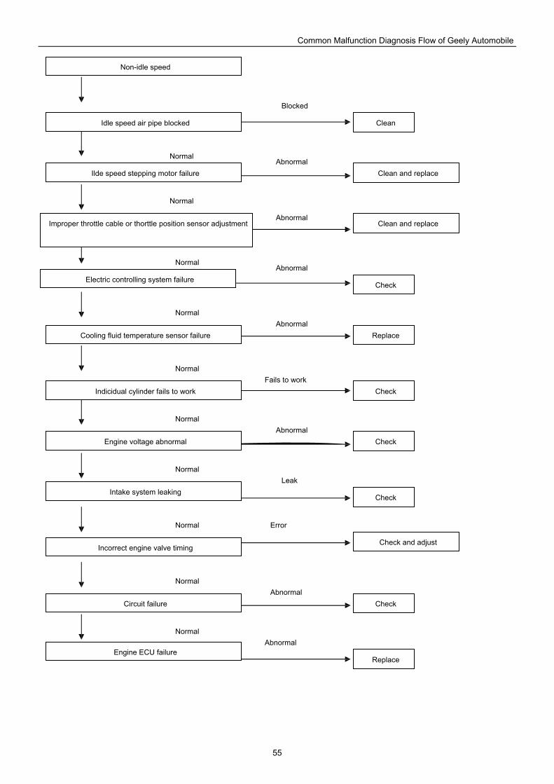
Common Malfunction Diagnosis Flow of Geely Automobile
55
Engine ECU failure
Circuit failure
Incorrect engine valve timing
Intake system leaking
Engine voltage abnormal
Indicidual cylinder fails to work
Cooling fluid temperature sensor failure
Electric controlling system failure
Improper throttle cable or thorttle position sensor adjustment
Ilde speed stepping motor failure
Idle speed air pipe blocked
Non-idle speed
Check
Check
Clean and replace
Replace
Replace
Check and adjust
Check
Check
Check
Clean and replace
Clean
Leak
Error
Fails to work
Abnormal
Abnormal
Abnormal
Abnormal
Abnormal
Abnormal
Abnormal
Blocked
Normal
Normal
Normal
Normal
Normal
Normal
Normal
Normal
Normal
Normal
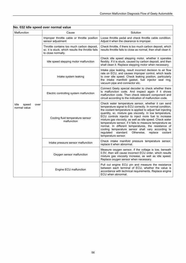
Common Malfunction Diagnosis Flow of Geely Automobile
56
No. 032 Idle speed over normal value Malfunction Cause Solution
Improper throttle cable or throttle position sensor adjustment
Loose throttle pedal and check throttle cable condition. Adjust it when the clearance is improper.
Throttle contains too much carbon deposit, sc. it is stuck, which results the throttle fails to close normally.
Check throttle, if there is too much carbon deposit, which results throttle fails to close as normal, then shall clean it.
Idle speed stepping motor malfunction Check idle speed stepping motor, whether it operates flexibly. If it is stuck, caused by carbon deposit, and then shall clean it. Replace stepping motor when necessary.
Intake system leaking
Intake pipe leaking, result incorrect decision to air flow rate on ECU, and causes improper control, which leads to over idle speed. Check leaking position, particularly the intake manifold gasket, fuel injector seal ring, vacuum pipe and connector etc.
Electric controlling system malfunction
Connect Geely special decoder to check whether there is malfunction code. And inspect again if it shows malfunction code. Then check relevant component and circuit according to the indication of malfunction code.
Cooling fluid temperature sensor malfunction
Check water temperature sensor, whether it can send temperature signal to ECU correctly. In normal condition, the coolant temperature is applied to adjust fuel injecting quantity, sc. mixture gas viscosity. In low temperature, ECU controls injector to inject more fuel to increase mixture gas viscosity, as well as idle speed. Check water temperature sensor, if it fails to measure temperature as normal. In different temperatures, the resistance of cooling temperature sensor shall vary according to regulated standard. Otherwise, replace coolant temperature sensor.
Intake pressure sensor malfunction Check intake manifold pressure temperature sensor, replace it when abnormal.
Oxygen sensor malfunction
Measure oxygen sensor, if the voltage is low, beneath 0.5V, then will cause incorrect ECU order, which results mixture gas viscosity increase, as well as idle speed. Replace oxygen sensor when necessary.
Idle speed over normal value
Engine ECU malfunction
Pull out engine ECU pin and measure the resistance between each terminal of ECU, whether the value is accordance with technical requirements. Replace engine ECU when abnormal.
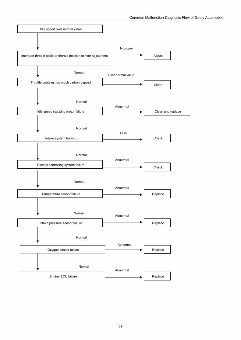
Common Malfunction Diagnosis Flow of Geely Automobile
57
Engine ECU failure
Oxygen sensor failure
Intake pressure sensor failure
Temperature sensor failure
Electric controlling system failure
Intake system leaking
Idle speed stepping motor failure
Throttle contains too much carbon deposit
Improper throttle cable or thorttle position sensor adjustment
Idle speed over normal value
Check
Clean and replace
Adjust
Replace
Clean
Check
Replace
Replace
Replace
Leak
Improper
Over normal value
Abnormal
Abnormal
Abnormal
Abnormal
Abnormal
Abnormal
Normal
Normal
Normal
Normal
Normal
Normal
Normal
Normal
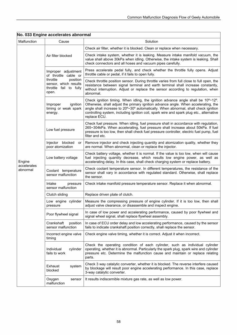
Common Malfunction Diagnosis Flow of Geely Automobile
58
No. 033 Engine accelerates abnormal Malfunction Cause Solution
Check air filter, whether it is blocked. Clean or replace when necessary.
Air filter blocked Check intake system, whether it is leaking. Measure intake manifold vacuum, the value shall above 30kPa when idling. Otherwise, the intake system is leaking. Shall check connectors and all hoses and vacuum pipes carefully.
Press accelerate pedal fully, and check whether the throttle fully opens. Adjust throttle cable or pedal, if it fails to open fully.
Improper adjustment of throttle cable or throttle position sensor, which results throttle fail to fully open.
Check throttle position sensor. During throttle varies from full close to full open, the resistance between signal terminal and earth terminal shall increase constantly, without interruption. Adjust or replace the sensor according to regulation, when abnormal.
Improper ignition timing or weak spark energy.
Check ignition timing. When idling, the ignition advance angle shall be 10º~12º. Otherwise, shall adjust the primary ignition advance angle. When accelerating, the angle shall increase to 20º~30º automatically. When abnormal, shall check ignition controlling system, including ignition coil, spark wire and spark plug etc., alternative replace ECU.
Low fuel pressure
Check fuel pressure. When idling, fuel pressure shall in accordance with regulation, 265~304kPa. When accelerating, fuel pressure shall increase about 50kPa. If fuel pressure is too low, then shall check fuel pressure controller, electric fuel pump, fuel filter and etc.
Injector blocked or poor atomization
Remove injector and check injecting quantity and atomization quality, whether they are normal. When abnormal, clean or replace the injector.
Low battery voltage Check battery voltage, whether it is normal. If the value is too low, when will cause fuel injecting quantity decrease, which results low engine power, as well as accelerating delay. In this case, shall check charging system or replace battery.
Coolant temperature sensor malfunction
Check coolant temperature sensor. In different temperatures, the resistance of the sensor shall vary in accordance with regulated standard. Otherwise, shall replace the sensor.
Intake pressure sensor malfunction
Check intake manifold pressure temperature sensor. Replace it when abnormal.
Clutch sliding Replace driven plate of clutch.
Low engine cylinder pressure
Measure the compressing pressure of engine cylinder. If it is too low, then shall adjust valve clearance, or disassemble and inspect engine.
Poor flywheel signal In case of low power and accelerating performance, caused by poor flywheel and signal wheel signal, shall replace flywheel assembly.
Crankshaft position sensor malfunction
In case of ECU order delay and low accelerating performance, caused by the sensor fails to indicate crankshaft position correctly, shall replace the sensor.
Incorrect engine valve timing
Check engine valve timing, whether it is correct. Adjust it when incorrect.
Individual cylinder fails to work
Check the operating condition of each cylinder, such as individual cylinder operating, whether it is abnormal. Particularly the spark plug, spark wire and cylinder pressure etc. Determine the malfunction cause and maintain or replace relating parts.
Exhaust system blocked
Check 3 way catalytic converter, whether it is blocked. The reverse interfere caused by blockage will result poor engine accelerating performance. In this case, replace 3-way catalytic converter.
Engine accelerates abnormal
Oxygen sensor malfunction
It results indiscernible mixture gas rate, as well as low power.
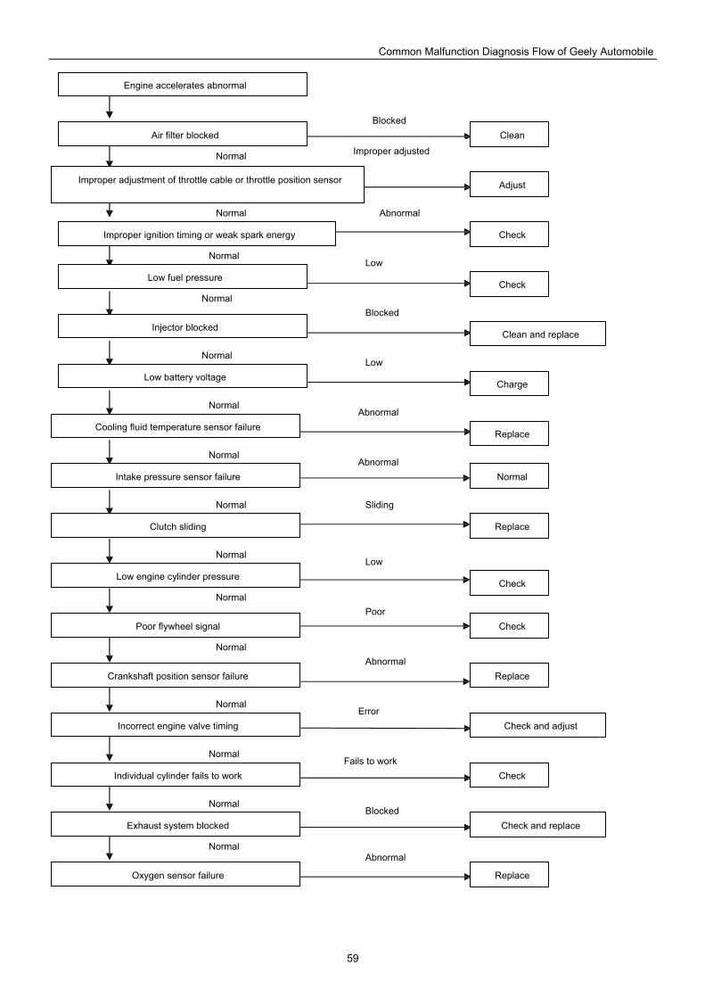
Common Malfunction Diagnosis Flow of Geely Automobile
59
Oxygen sensor failure
Exhaust system blocked
Individual cylinder fails to work
Incorrect engine valve timing
Crankshaft position sensor failure
Poor flywheel signal
Low engine cylinder pressure
Clutch sliding
Intake pressure sensor failure
Cooling fluid temperature sensor failure
Low battery voltage
Injector blocked
Low fuel pressure
Improper ignition timing or weak spark energy
Air filter blocked
Engine accelerates abnormal
Improper adjustment of throttle cable or throttle position sensor
Check
Clean and replace
Adjust
Replace
Clean
Check
Normal
Replace
Charge
Replace
Check
Check
Check and adjust
Check
Replace
Check and replace Blocked
Abnormal
Abnormal
Fails to work
Abnormal
Abnormal
Error
Poor
Low
Sliding
Low
Blocked
Low
Abnormal
Blocked
Improper adjusted
Normal
Normal
Normal
Normal
Normal
Normal
Normal
Normal
Normal
Normal
Normal
Normal
Normal
Normal
Normal
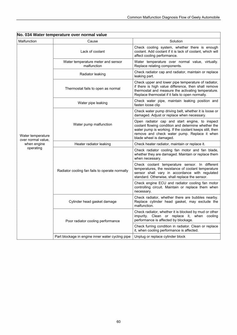
Common Malfunction Diagnosis Flow of Geely Automobile
60
No. 034 Water temperature over normal value Malfunction Cause Solution
Lack of coolant Check cooling system, whether there is enough coolant. Add coolant if it is lack of coolant, which will affect cooling performance.
Water temperature meter and sensor malfunction
Water temperature over normal value, virtually. Replace relating components.
Radiator leaking Check radiator cap and radiator, maintain or replace leaking part.
Thermostat fails to open as normal
Check upper and lower pipe temperature of radiator, if there is high value difference, then shall remove thermostat and measure the activating temperature. Replace thermostat if it fails to open normally.
Water pipe leaking Check water pipe, maintain leaking position and fasten loose clip
Check water pump driving belt, whether it is loose or damaged. Adjust or replace when necessary.
Water pump malfunction Open radiator cap and start engine, to inspect coolant flowing condition and determine whether the water pump is working. If the coolant keeps still, then remove and check water pump. Replace it when blade wheel is damaged.
Heater radiator leaking Check heater radiator, maintain or replace it.
Check radiator cooling fan motor and fan blade, whether they are damaged. Maintain or replace them when necessary.
Check coolant temperature sensor. In different temperatures, the resistance of coolant temperature sensor shall vary in accordance with regulated standard. Otherwise, shall replace the sensor.
Radiator cooling fan fails to operate normally
Check engine ECU and radiator cooling fan motor controlling circuit. Maintain or replace them when necessary.
Cylinder head gasket damage Check radiator, whether there are bubbles nearby. Replace cylinder head gasket, may exclude the malfunction.
Check radiator, whether it is blocked by mud or other impurity. Clean or replace it, when cooling performance is affected by blockage. Poor radiator cooling performance Check furring condition in radiator. Clean or replace it, when cooling performance is affected.
Water temperature over normal value,
when engine operating
Part blockage in engine inner water cycling pipe Unplug or replace cylinder block
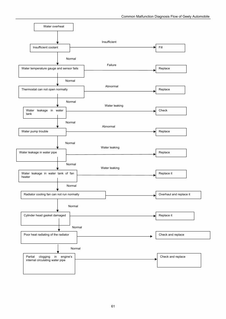
Common Malfunction Diagnosis Flow of Geely Automobile
61
Fill
Water overheat
Insufficient coolant
Water temperature gauge and sensor fails
Thermostat can not open normally
Water leakage in water tank
Water pump trouble
Water leakage in water pipe
Water leakage in water tank of fan heater
Radiator cooling fan can not run normally
Cylinder head gasket damaged
Replace
Replace
Replace
Check
Replace
Overhaul and replace it
Replace it
Replace it
Poor heat radiating of the radiator Check and replace
Partial clogging in engine’s internal circulating water pipe
Check and replace
Insufficient
Failure
Abnormal
Water leaking
Abnormal
Water leaking
Water leaking
Normal
Normal
Normal
Normal
Normal
Normal
Normal
Normal
Normal
Normal
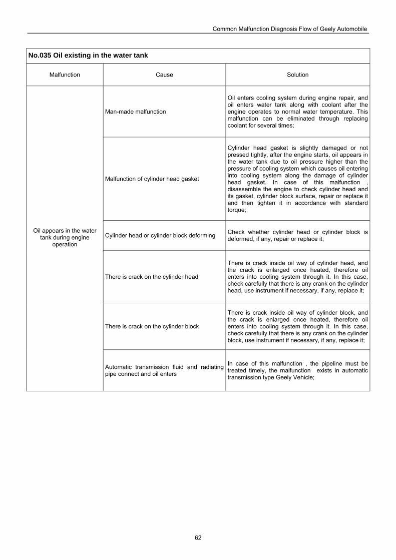
Common Malfunction Diagnosis Flow of Geely Automobile
62
No.035 Oil existing in the water tank
Malfunction Cause Solution
Man-made malfunction
Oil enters cooling system during engine repair, and oil enters water tank along with coolant after the engine operates to normal water temperature. This malfunction can be eliminated through replacing coolant for several times;
Malfunction of cylinder head gasket
Cylinder head gasket is slightly damaged or not pressed tightly, after the engine starts, oil appears in the water tank due to oil pressure higher than the pressure of cooling system which causes oil entering into cooling system along the damage of cylinder head gasket. In case of this malfunction , disassemble the engine to check cylinder head and its gasket, cylinder block surface, repair or replace it and then tighten it in accordance with standard torque;
Cylinder head or cylinder block deforming Check whether cylinder head or cylinder block is deformed, if any, repair or replace it;
There is crack on the cylinder head
There is crack inside oil way of cylinder head, and the crack is enlarged once heated, therefore oil enters into cooling system through it. In this case, check carefully that there is any crank on the cylinder head, use instrument if necessary, if any, replace it;
There is crack on the cylinder block
There is crack inside oil way of cylinder block, and the crack is enlarged once heated, therefore oil enters into cooling system through it. In this case, check carefully that there is any crank on the cylinder block, use instrument if necessary, if any, replace it;
Oil appears in the water tank during engine
operation
Automatic transmission fluid and radiating pipe connect and oil enters
In case of this malfunction , the pipeline must be treated timely, the malfunction exists in automatic transmission type Geely Vehicle;
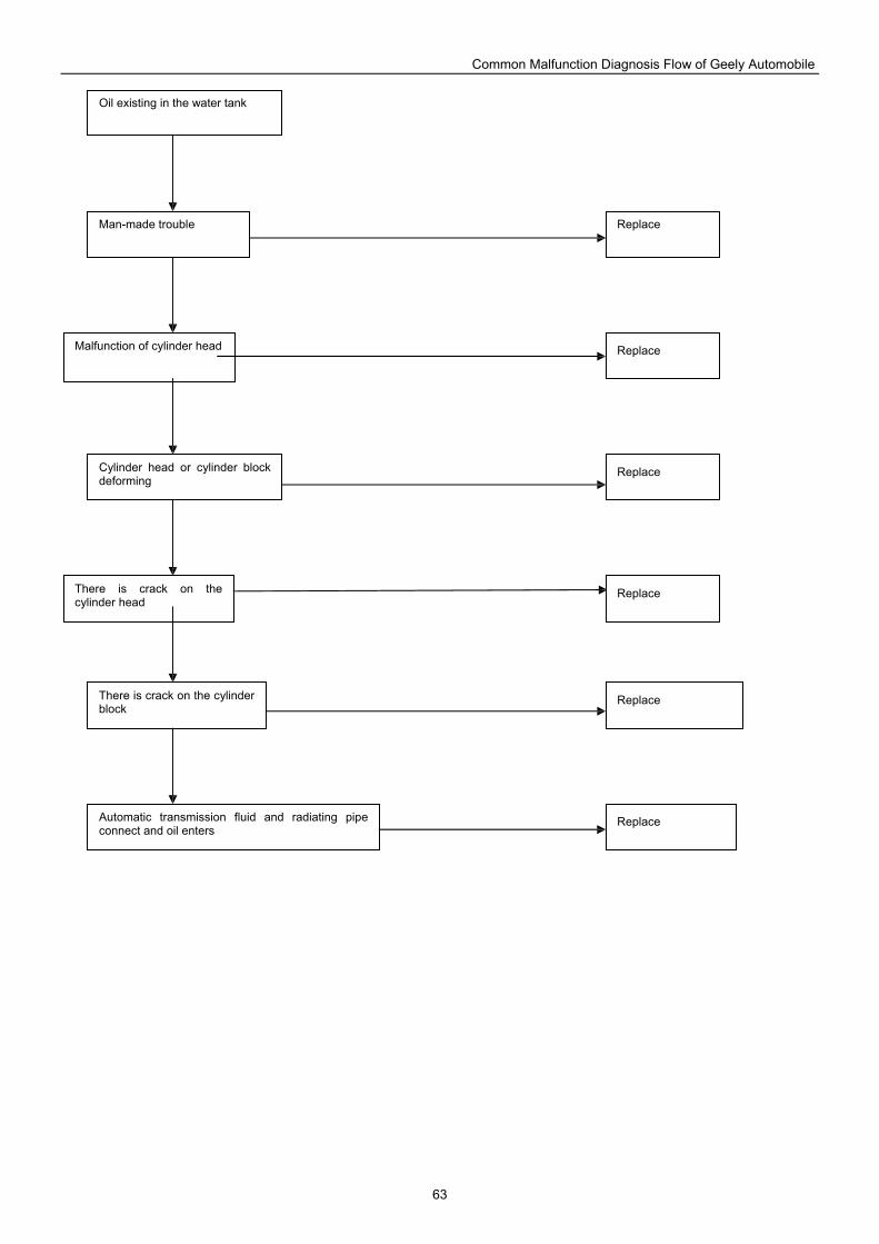
Common Malfunction Diagnosis Flow of Geely Automobile
63
Replace
Oil existing in the water tank
Man-made trouble
Malfunction of cylinder head
Cylinder head or cylinder block deforming
There is crack on the cylinder head
There is crack on the cylinder block
Automatic transmission fluid and radiating pipe connect and oil enters
Replace
Replace
Replace
Replace
Replace
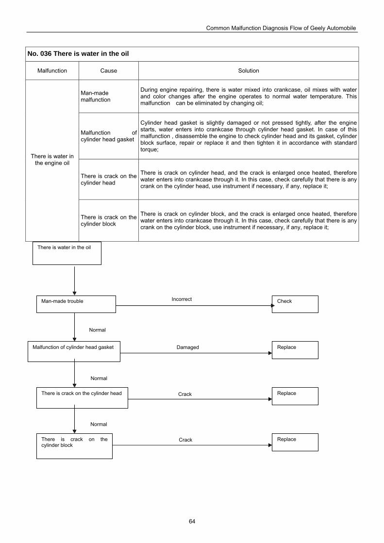
Common Malfunction Diagnosis Flow of Geely Automobile
64
No. 036 There is water in the oil
Malfunction Cause Solution
Man-made malfunction
During engine repairing, there is water mixed into crankcase, oil mixes with water and color changes after the engine operates to normal water temperature. This malfunction can be eliminated by changing oil;
Malfunction of cylinder head gasket
Cylinder head gasket is slightly damaged or not pressed tightly, after the engine starts, water enters into crankcase through cylinder head gasket. In case of this malfunction , disassemble the engine to check cylinder head and its gasket, cylinder block surface, repair or replace it and then tighten it in accordance with standard torque;
There is crack on the cylinder head
There is crack on cylinder head, and the crack is enlarged once heated, therefore water enters into crankcase through it. In this case, check carefully that there is any crank on the cylinder head, use instrument if necessary, if any, replace it;
There is water in the engine oil
There is crack on the cylinder block
There is crack on cylinder block, and the crack is enlarged once heated, therefore water enters into crankcase through it. In this case, check carefully that there is any crank on the cylinder block, use instrument if necessary, if any, replace it;
Check
There is water in the oil
Man-made trouble
Malfunction of cylinder head gasket
There is crack on the cylinder head
There is crack on the cylinder block
Replace
Replace
Replace
Normal
Normal
Normal
Incorrect
Damaged
Crack
Crack
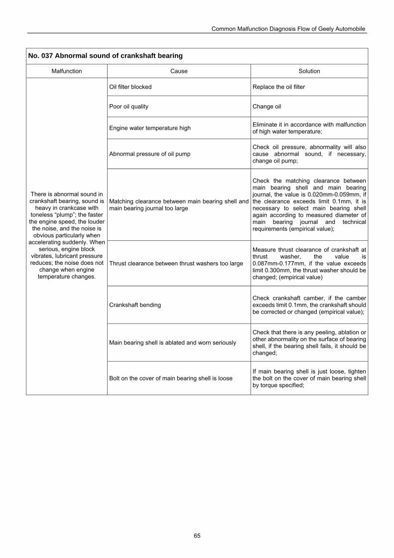
Common Malfunction Diagnosis Flow of Geely Automobile
65
No. 037 Abnormal sound of crankshaft bearing
Malfunction Cause Solution
Oil filter blocked Replace the oil filter
Poor oil quality Change oil
Engine water temperature high Eliminate it in accordance with malfunction of high water temperature;
Abnormal pressure of oil pump Check oil pressure, abnormality will also cause abnormal sound, if necessary, change oil pump;
Matching clearance between main bearing shell and main bearing journal too large
Check the matching clearance between main bearing shell and main bearing journal, the value is 0.020mm-0.059mm, if the clearance exceeds limit 0.1mm, it is necessary to select main bearing shell again according to measured diameter of main bearing journal and technical requirements (empirical value);
Thrust clearance between thrust washers too large
Measure thrust clearance of crankshaft at thrust washer, the value is 0.087mm-0.177mm, if the value exceeds limit 0.300mm, the thrust washer should be changed; (empirical value)
Crankshaft bending Check crankshaft camber, if the camber exceeds limit 0.1mm, the crankshaft should be corrected or changed (empirical value);
Main bearing shell is ablated and worn seriously
Check that there is any peeling, ablation or other abnormality on the surface of bearing shell, if the bearing shell fails, it should be changed;
There is abnormal sound in crankshaft bearing, sound is
heavy in crankcase with toneless “plump”; the faster
the engine speed, the louder the noise, and the noise is obvious particularly when
accelerating suddenly. When serious, engine block
vibrates, lubricant pressure reduces; the noise does not
change when engine temperature changes.
Bolt on the cover of main bearing shell is loose If main bearing shell is just loose, tighten the bolt on the cover of main bearing shell by torque specified;
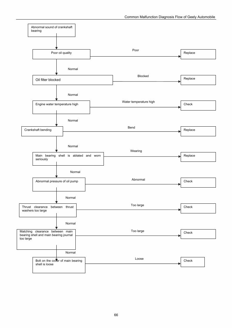
Common Malfunction Diagnosis Flow of Geely Automobile
66
Replace
Abnormal sound of crankshaft bearing
Poor oil quality
Oil filter blocked
Engine water temperature high
Crankshaft bending
Main bearing shell is ablated and worn seriously
Abnormal pressure of oil pump
Thrust clearance between thrust washers too large
Matching clearance between main bearing shell and main bearing journal too large
Bolt on the cover of main bearing shell is loose
Replace
Check
Replace
Replace
Check
Check
Check
Check
Poor
Blocked
Water temperature high
Bend
Wearing
Abnormal
Too large
Too large
Loose
Normal
Normal
Normal
Normal
Normal
Normal
Normal
Normal
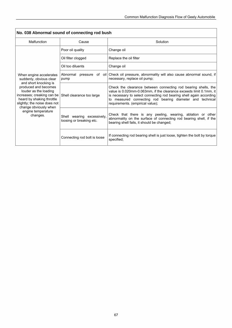
Common Malfunction Diagnosis Flow of Geely Automobile
67
No. 038 Abnormal sound of connecting rod bush
Malfunction Cause Solution
Poor oil quality Change oil
Oil filter clogged Replace the oil filter
Oil too diluents Change oil
Abnormal pressure of oil pump
Check oil pressure, abnormality will also cause abnormal sound, if necessary, replace oil pump;
Shell clearance too large
Check the clearance between connecting rod bearing shells, the value is 0.020mm-0.063mm, if the clearance exceeds limit 0.1mm, it is necessary to select connecting rod bearing shell again according to measured connecting rod bearing diameter and technical requirements. (empirical value);
Shell wearing excessively, loosing or breaking etc.
Check that there is any peeling, wearing, ablation or other abnormality on the surface of connecting rod bearing shell, if the bearing shell fails, it should be changed;
When engine accelerates suddenly, obvious clear and short knocking is
produced and becomes louder as the loading
increases; creaking can be heard by shaking throttle
slightly; the noise does not change obviously when
engine temperature changes.
Connecting rod bolt is loose If connecting rod bearing shell is just loose, tighten the bolt by torque specified;
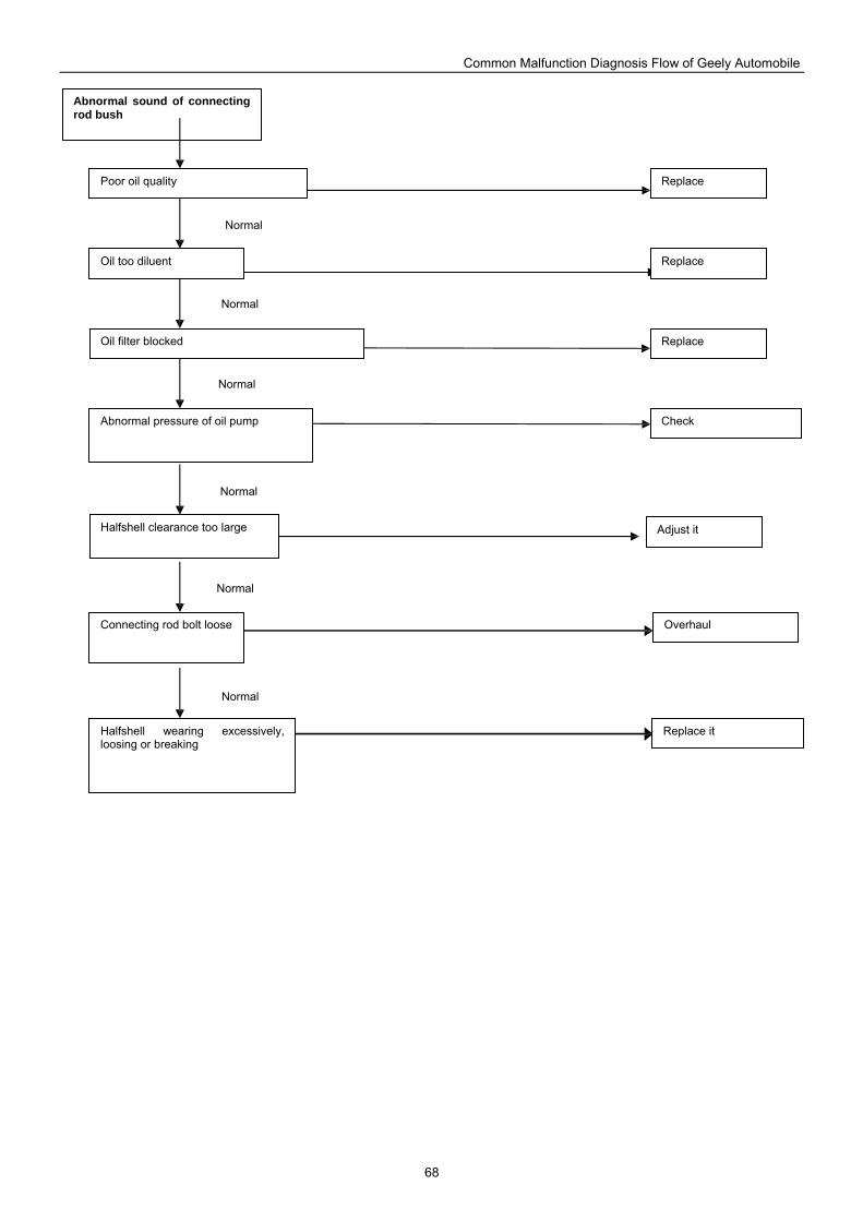
Common Malfunction Diagnosis Flow of Geely Automobile
68
Replace
Abnormal sound of connecting rod bush
Poor oil quality
Oil too diluent
Abnormal pressure of oil pump
Halfshell clearance too large
Connecting rod bolt loose
Halfshell wearing excessively, loosing or breaking
Overhaul
Replace
Check
Replace it
Adjust it
Normal
Normal
Normal
Normal
Normal
Normal
Oil filter blocked Replace
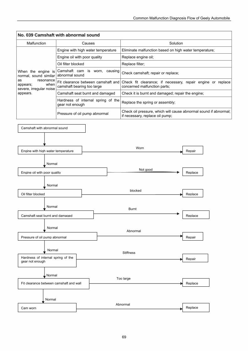
Common Malfunction Diagnosis Flow of Geely Automobile
69
No. 039 Camshaft with abnormal sound
Malfunction Causes Solution
Engine with high water temperature Eliminate malfunction based on high water temperature;
Engine oil with poor quality Replace engine oil;
Oil filter blocked Replace filter;
Camshaft cam is worn, causing abnormal sound Check camshaft; repair or replace;
Fit clearance between camshaft and camshaft bearing too large
Check fit clearance; if necessary, repair engine or replace concerned malfunction parts;
Camshaft seat burnt and damaged Check it is burnt and damaged; repair the engine;
Hardness of internal spring of the gear not enough Replace the spring or assembly;
When the engine is normal, sound similar as resonance appears; when severe, irregular noise appears.
Pressure of oil pump abnormal Check oil pressure, which will cause abnormal sound if abnormal; if necessary, replace oil pump;
Fit clearance between camshaft and wall
Hardness of internal spring of the gear not enough
Pressure of oil pump abnormal
Camshaft seat burnt and damaged
Engine oil with poor quality
Oil filter blocked
Engine with high water temperature
Camshaft with abnormal sound
Repair
Repair
Repair
Replace
Replace
Replace
Replace
Cam worn Replace
Normal
Normal
Normal
Normal
Normal
Normal
Normal
Worn
Not good
blocked
Burnt
Abnormal
Stiffness
Too large
Abnormal
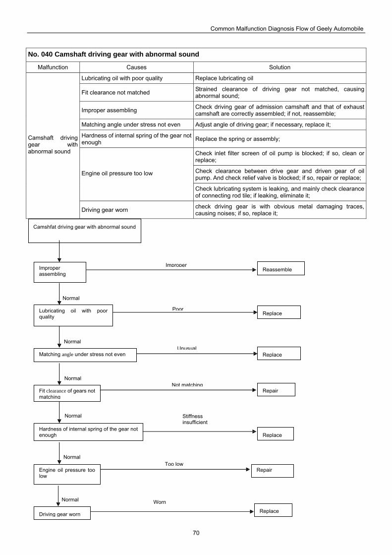
Common Malfunction Diagnosis Flow of Geely Automobile
70
No. 040 Camshaft driving gear with abnormal sound
Malfunction Causes Solution
Lubricating oil with poor quality Replace lubricating oil
Fit clearance not matched Strained clearance of driving gear not matched, causing abnormal sound;
Improper assembling Check driving gear of admission camshaft and that of exhaust camshaft are correctly assembled; if not, reassemble;
Matching angle under stress not even Adjust angle of driving gear; if necessary, replace it;
Hardness of internal spring of the gear not enough Replace the spring or assembly;
Check inlet filter screen of oil pump is blocked; if so, clean or replace;
Check clearance between drive gear and driven gear of oil pump. And check relief valve is blocked; if so, repair or replace;
Engine oil pressure too low
Check lubricating system is leaking, and mainly check clearance of connecting rod tile; if leaking, eliminate it;
Camshaft driving gear with abnormal sound
Driving gear worn check driving gear is with obvious metal damaging traces, causing noises; if so, replace it;
Reassemble
Camshfat driving gear with abnormal sound
Improper assembling
Lubricating oil with poor quality
Matching angle under stress not even
Fit clearance of gears not matching
Hardness of internal spring of the gear not enough
Engine oil pressure too low
Driving gear worn
Replace
Repair
Replace
Repair
Replace
Replace
Normal Worn
Normal
Normal
Normal
Normal
Normal
Too low
Stiffness insufficient
Not matching
Unusual
Poor
Improper
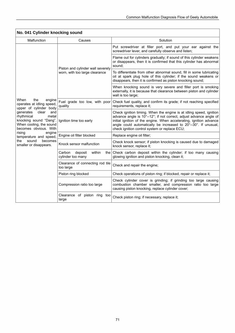
Common Malfunction Diagnosis Flow of Geely Automobile
71
No. 041 Cylinder knocking sound
Malfunction Causes Solution
Put screwdriver at filler port, and put your ear against the screwdriver lever, and carefully observe and listen;
Flame out for cylinders gradually; if sound of this cylinder weakens or disappears, then it is confirmed that this cylinder has abnormal sound;
To differentiate from other abnormal sound, fill in some lubricating oil at spark plug hole of this cylinder; if the sound weakens or disappears, then it is confirmed as piston knocking sound;
Piston and cylinder wall severely worn, with too large clearance
When knocking sound is very severe and filler port is smoking externally, it is because that clearance between piston and cylinder wall is too large;
Fuel grade too low, with poor quality
Check fuel quality, and confirm its grade; if not reaching specified requirements, replace it;
Ignition time too early
Check ignition timing. When the engine is at idling speed, ignition advance angle is 10°--12°; if not correct, adjust advance angle of initial ignition of the engine. When accelerating, ignition advance angle could automatically be increased to 20°--30°. If unusual, check ignition control system or replace ECU;
Engine oil filter blocked Replace engine oil filter;
Knock sensor malfunction Check knock sensor; if piston knocking is caused due to damaged knock sensor, replace it;
Carbon deposit within the cylinder too many
Check carbon deposit within the cylinder; if too many causing glowing ignition and piston knocking, clean it;
Clearance of connecting rod tile too large Check and repair the engine;
Piston ring blocked Check operations of piston ring; if blocked, repair or replace it;
Compression ratio too large Check cylinder cover is grinding; if grinding too large causing combustion chamber smaller, and compression ratio too large causing piston knocking, replace cylinder cover;
When the engine operates at idling speed, upper of cylinder body generates clear and rhythmical metal knocking sound “Dang”. When cooling, the sound becomes obvious. With rising engine temperature and speed, the sound becomes smaller or disappears.
Clearance of piston ring too large Check piston ring; if necessary, replace it;
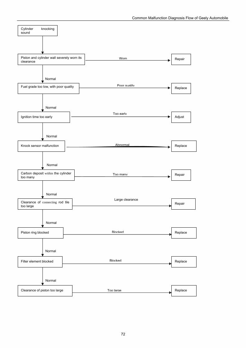
Common Malfunction Diagnosis Flow of Geely Automobile
72
Fuel grade too low, with poor quality
Ignition time too early
Clearance of connecting rod tile too large
Piston ring blocked
Filter element blocked
Clearance of piston too large
Carbon deposit within the cylinder too many
Knock sensor malfunction
Piston and cylinder wall severely worn its clearance
Cylinder knocking sound
Repair
Repair
Repair
Replace
Replace
Adjust
Replace
Replace
Replace
Normal
Too large
Normal
Normal
Normal
Normal
Normal
Normal
Normal
Blocked
Blocked
Large clearance
Too many
Abnormal
Too early
Poor quality
Worn
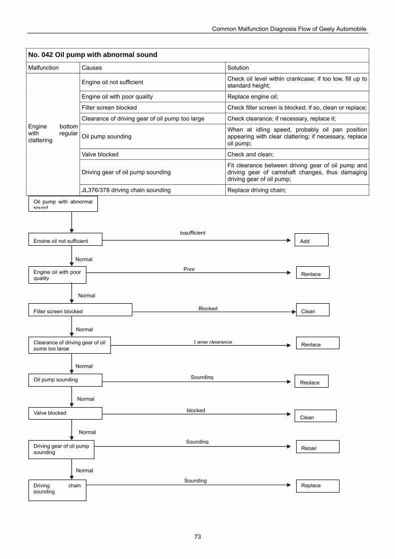
Common Malfunction Diagnosis Flow of Geely Automobile
73
No. 042 Oil pump with abnormal sound
Malfunction Causes Solution
Engine oil not sufficient Check oil level within crankcase; if too low, fill up to standard height;
Engine oil with poor quality Replace engine oil;
Filter screen blocked Check filter screen is blocked; if so, clean or replace;
Clearance of driving gear of oil pump too large Check clearance; if necessary, replace it;
Oil pump sounding When at idling speed, probably oil pan position appearing with clear clattering; if necessary, replace oil pump;
Valve blocked Check and clean;
Driving gear of oil pump sounding Fit clearance between driving gear of oil pump and driving gear of camshaft changes, thus damaging driving gear of oil pump;
Engine bottom with regular clattering
JL376/378 driving chain sounding Replace driving chain;
Add
Oil pump with abnormal sound
Engine oil not sufficient
Engine oil with poor quality
Filter screen blocked
Clearance of driving gear of oil pump too large
Oil pump sounding
Valve blocked
Driving gear of oil pump sounding
Driving chain sounding
Replace
Replace
Clean
Replace
Repair
Replace
Clean
Normal
Insufficient
Normal
Normal
Normal
Normal
Normal
Normal
Poor
Blocked
Large clearance
Sounding
blocked
Sounding
Sounding
Common Malfunction Diagnosis Flow of Geely Automobile
74
No. 043 Crankshaft thrust piece with abnormal sound
Malfunction Causes Solution
Engine oil not sufficient Check oil level within crankcase; if too low, fill up to standard height;
Engine oil with poor quality Replace engine oil;
②Check filter screen is blocked; if so, clean or replace; Engine oil with too low pressure C③ heck clearance between drive gear and driven gear of oil pump.
And check relief valve is blocked; if so, repair or replace;
Crankshaft and thrust piece severely worn
Crankshaft and thrust piece severely worn, causing too large axial play, and abnormal sound; disassemble the engine and repair;
Thrust piece burnt and damaged Check it is burnt and damaged; if necessary, replace thrust piece;
Crankshaft thrust piece with abnormal sound
Thrust clearance too large Measure thrust clearance at thrust piece, with standard value as 0.087mm-0.177mm; if exceeding limit value 0.300mm, replace thrust piece. (empirical value)
Replace
Crankshaft thrust piece with unusual noise
Engine oil not sufficient
Engine oil with poor quality
Engine oil with too low pressure
Crankshaft and thrust piece severely worn
Thrust piece burnt and damaged
Thrust clearance too large
Repair
Replace
Replace
Repair
Add
Normal
Large clearance
Normal
Normal
Normal
Normal
Burnt and damaged
Worn
Too large
Poor
Insufficient
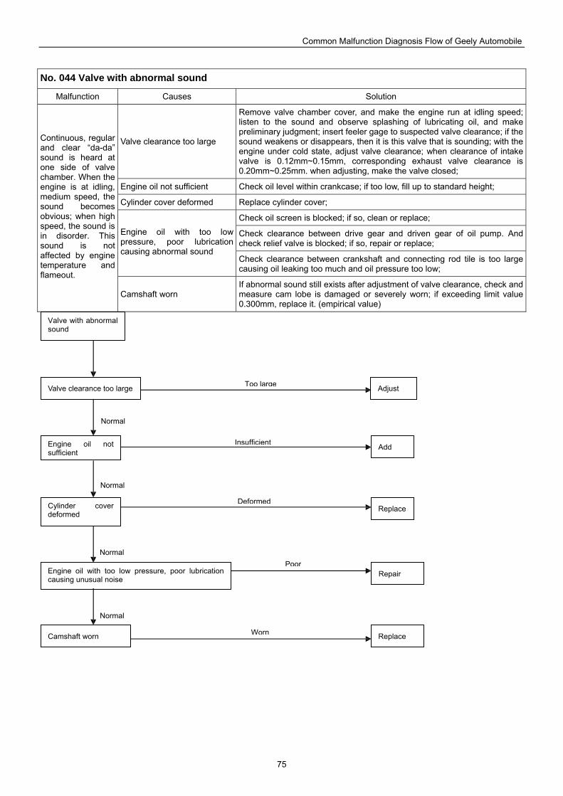
Common Malfunction Diagnosis Flow of Geely Automobile
75
No. 044 Valve with abnormal sound
Malfunction Causes Solution
Valve clearance too large
Remove valve chamber cover, and make the engine run at idling speed; listen to the sound and observe splashing of lubricating oil, and make preliminary judgment; insert feeler gage to suspected valve clearance; if the sound weakens or disappears, then it is this valve that is sounding; with the engine under cold state, adjust valve clearance; when clearance of intake valve is 0.12mm~0.15mm, corresponding exhaust valve clearance is 0.20mm~0.25mm. when adjusting, make the valve closed;
Engine oil not sufficient Check oil level within crankcase; if too low, fill up to standard height;
Cylinder cover deformed Replace cylinder cover;
Check oil screen is blocked; if so, clean or replace;
Check clearance between drive gear and driven gear of oil pump. And check relief valve is blocked; if so, repair or replace;
Engine oil with too low pressure, poor lubrication causing abnormal sound
Check clearance between crankshaft and connecting rod tile is too large causing oil leaking too much and oil pressure too low;
Continuous, regular and clear “da-da” sound is heard at one side of valve chamber. When the engine is at idling, medium speed, the sound becomes obvious; when high speed, the sound is in disorder. This sound is not affected by engine temperature and flameout.
Camshaft worn If abnormal sound still exists after adjustment of valve clearance, check and measure cam lobe is damaged or severely worn; if exceeding limit value 0.300mm, replace it. (empirical value)
Valve clearance too large
Engine oil not sufficient
Cylinder cover deformed
Engine oil with too low pressure, poor lubrication causing unusual noise
Camshaft worn
Valve with abnormal sound
Adjust
Replace
Add
Repair
Replace
Normal
Worn
Normal
Normal
Normal
Poor
Deformed
Insufficient
Too large
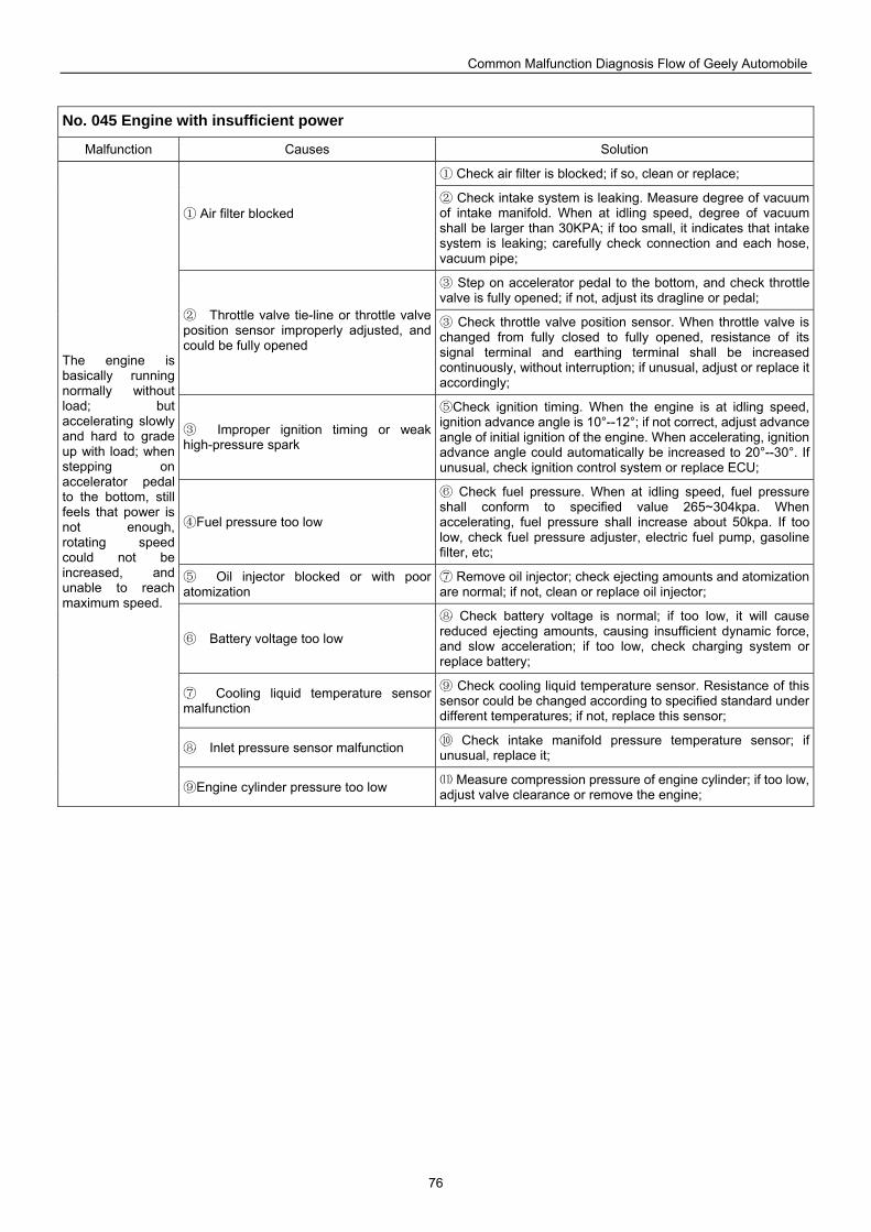
Common Malfunction Diagnosis Flow of Geely Automobile
76
No. 045 Engine with insufficient power
Malfunction Causes Solution
Check air filter is blocked; if so, clean or replace; ①
Air filter blocked ① Check intake system is leaking. Measure degree of vacuum ②
of intake manifold. When at idling speed, degree of vacuum shall be larger than 30KPA; if too small, it indicates that intake system is leaking; carefully check connection and each hose, vacuum pipe;
Step on accelerator pedal to the bottom, and check throttl③ e valve is fully opened; if not, adjust its dragline or pedal;
② Throttle valve tie-line or throttle valve position sensor improperly adjusted, and could be fully opened
Check throttle valve position sensor. When throttle valve is ③changed from fully closed to fully opened, resistance of its signal terminal and earthing terminal shall be increased continuously, without interruption; if unusual, adjust or replace it accordingly;
③ Improper ignition timing or weak high-pressure spark
⑤Check ignition timing. When the engine is at idling speed, ignition advance angle is 10°--12°; if not correct, adjust advance angle of initial ignition of the engine. When accelerating, ignition advance angle could automatically be increased to 20°--30°. If unusual, check ignition control system or replace ECU;
Fuel pressure too low④
Check fuel pressure. When at idling s⑥ peed, fuel pressure shall conform to specified value 265~304kpa. When accelerating, fuel pressure shall increase about 50kpa. If too low, check fuel pressure adjuster, electric fuel pump, gasoline filter, etc;
⑤ Oil injector blocked or with poor atomization
Remove oil injector; check ejecting amounts and atomization ⑦are normal; if not, clean or replace oil injector;
⑥ Battery voltage too low
Check battery voltage is normal; if too low, it will cause ⑧reduced ejecting amounts, causing insufficient dynamic force, and slow acceleration; if too low, check charging system or replace battery;
⑦ Cooling liquid temperature sensor malfunction
Check cooling liquid temperature sensor. Resistance of this ⑨sensor could be changed according to specified standard under different temperatures; if not, replace this sensor;
⑧ Inlet pressure sensor malfunction Check intake manifold pressure temperature sensor; if ⑩unusual, replace it;
The engine is basically running normally without load; but accelerating slowly and hard to grade up with load; when stepping on accelerator pedal to the bottom, still feels that power is not enough, rotating speed could not be increased, and unable to reach maximum speed.
Engine cylinder pressure too low⑨ Measure compression pressure of e⑾ ngine cylinder; if too low, adjust valve clearance or remove the engine;
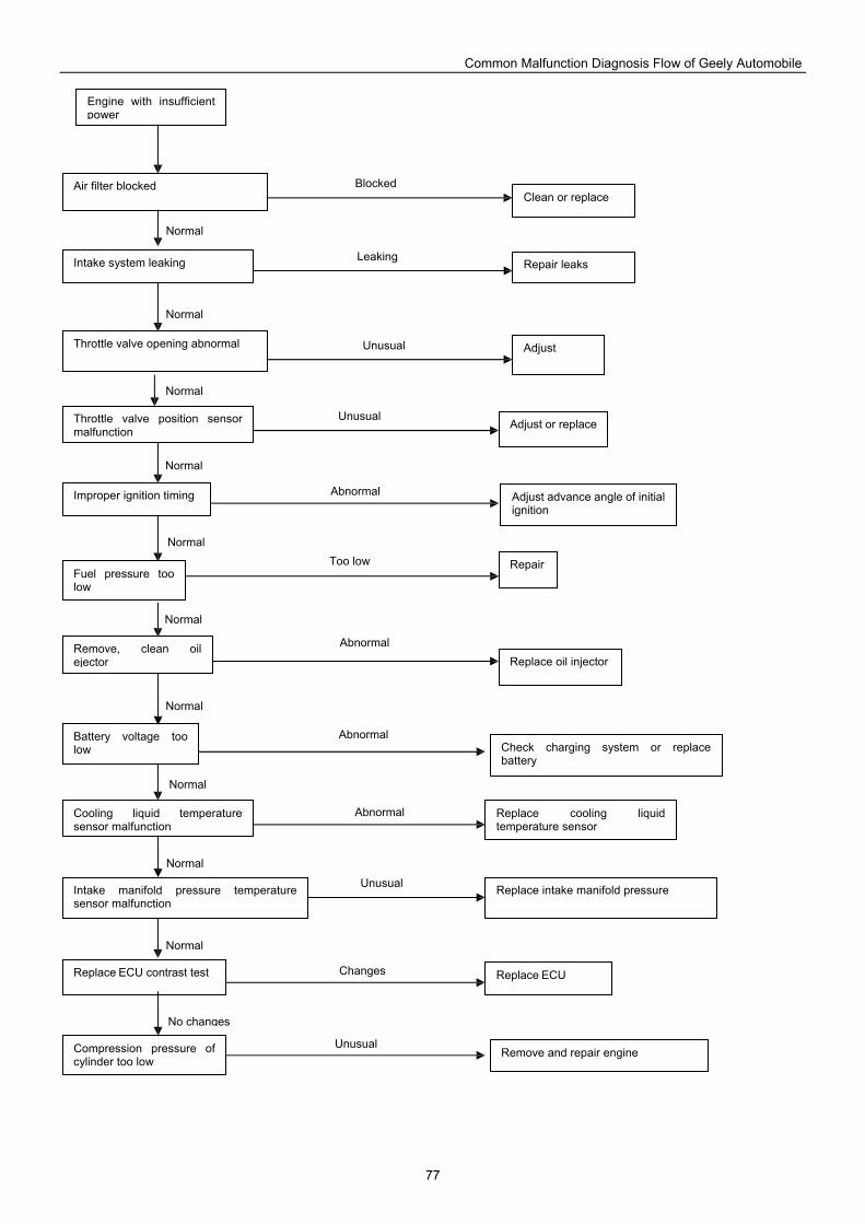
Common Malfunction Diagnosis Flow of Geely Automobile
77
Throttle valve opening abnormal Adjust
Engine with insufficient power
Clean or replace Air filter blocked
Intake system leaking Repair leaks
Improper ignition timing
Throttle valve position sensor malfunction
Adjust or replace
Adjust advance angle of initial ignition
Fuel pressure too low
Repair
Remove, clean oil ejector Replace oil injector
Replace cooling liquid temperature sensor
Battery voltage too low Check charging system or replace
battery
Cooling liquid temperature sensor malfunction
Intake manifold pressure temperature sensor malfunction
Replace intake manifold pressure
Replace ECU contrast test Replace ECU
Compression pressure of cylinder too low
Remove and repair engine
No changes
Unusual
Normal
Normal
Normal
Normal
Normal
Normal
Normal
Normal
Normal
Normal
Changes
Unusual
Abnormal
Abnormal
Abnormal
Too low
Abnormal
Unusual
Unusual
Leaking
Blocked
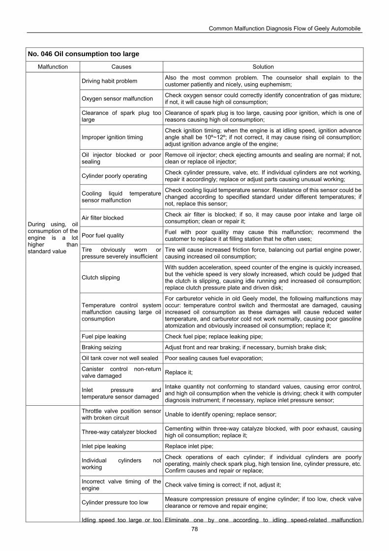
Common Malfunction Diagnosis Flow of Geely Automobile
78
No. 046 Oil consumption too large
Malfunction Causes Solution
Driving habit problem Also the most common problem. The counselor shall explain to the customer patiently and nicely, using euphemism;
Oxygen sensor malfunction Check oxygen sensor could correctly identify concentration of gas mixture; if not, it will cause high oil consumption;
Clearance of spark plug too large
Clearance of spark plug is too large, causing poor ignition, which is one of reasons causing high oil consumption;
Improper ignition timing Check ignition timing; when the engine is at idling speed, ignition advance angle shall be 10º~12º; if not correct, it may cause rising oil consumption; adjust ignition advance angle of the engine;
Oil injector blocked or poor sealing
Remove oil injector; check ejecting amounts and sealing are normal; if not, clean or replace oil injector;
Cylinder poorly operating Check cylinder pressure, valve, etc. If individual cylinders are not working, repair it accordingly; replace or adjust parts causing unusual working;
Cooling liquid temperature sensor malfunction
Check cooling liquid temperature sensor. Resistance of this sensor could be changed according to specified standard under different temperatures; if not, replace this sensor;
Air filter blocked Check air filter is blocked; if so, it may cause poor intake and large oil consumption; clean or repair it;
Poor fuel quality Fuel with poor quality may cause this malfunction; recommend the customer to replace it at filling station that he often uses;
Tire obviously worn or pressure severely insufficient
Tire will cause increased friction force, balancing out partial engine power, causing increased oil consumption;
Clutch slipping
With sudden acceleration, speed counter of the engine is quickly increased, but the vehicle speed is very slowly increased, which could be judged that the clutch is slipping, causing idle running and increased oil consumption; replace clutch pressure plate and driven disk;
Temperature control system malfunction causing large oil consumption
For carburetor vehicle in old Geely model, the following malfunctions may occur: temperature control switch and thermostat are damaged, causing increased oil consumption as these damages will cause reduced water temperature, and carburetor cold not work normally, causing poor gasoline atomization and obviously increased oil consumption; replace it;
Fuel pipe leaking Check fuel pipe; replace leaking pipe;
Braking seizing Adjust front and rear braking; if necessary, burnish brake disk;
Oil tank cover not well sealed Poor sealing causes fuel evaporation;
Canister control non-return valve damaged Replace it;
During using, oil consumption of the engine is a lot higher than standard value
Inlet pressure and temperature sensor damaged
Intake quantity not conforming to standard values, causing error control, and high oil consumption when the vehicle is driving; check it with computer diagnosis instrument; if necessary, replace inlet pressure sensor;
Throttle valve position sensor with broken circuit Unable to identify opening; replace sensor;
Three-way catalyzer blocked Cementing within three-way catalyze blocked, with poor exhaust, causing high oil consumption; replace it;
Inlet pipe leaking Replace inlet pipe;
Individual cylinders not working
Check operations of each cylinder; if individual cylinders are poorly operating, mainly check spark plug, high tension line, cylinder pressure, etc. Confirm causes and repair or replace;
Incorrect valve timing of the engine Check valve timing is correct; if not, adjust it;
Cylinder pressure too low Measure compression pressure of engine cylinder; if too low, check valve clearance or remove and repair engine;
Idling speed too large or too Eliminate one by one according to idling speed-related malfunction
Common Malfunction Diagnosis Flow of Geely Automobile
79
small template, making idling speed reach normal state;
Water temperature abnormal Eliminate one by one according to water temperature-related malfunction template, making water temperature reach normal state;
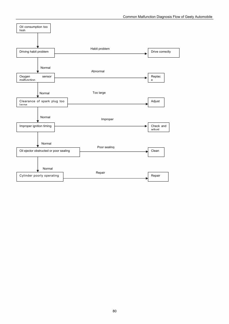
Common Malfunction Diagnosis Flow of Geely Automobile
80
Drive correctly
Oil consumption too high
Driving habit problem
Oxygen sensor malfunction
Clearance of spark plug too large
Improper ignition timing
Oil ejector obstructed or poor sealing
Cylinder poorly operating
Clean
Repair
Replace
Check and adjust
Adjust
Normal
Poor sealingNormal
Normal
Normal
Normal
Improper
Too large
Abnormal
Habit problem
Repair
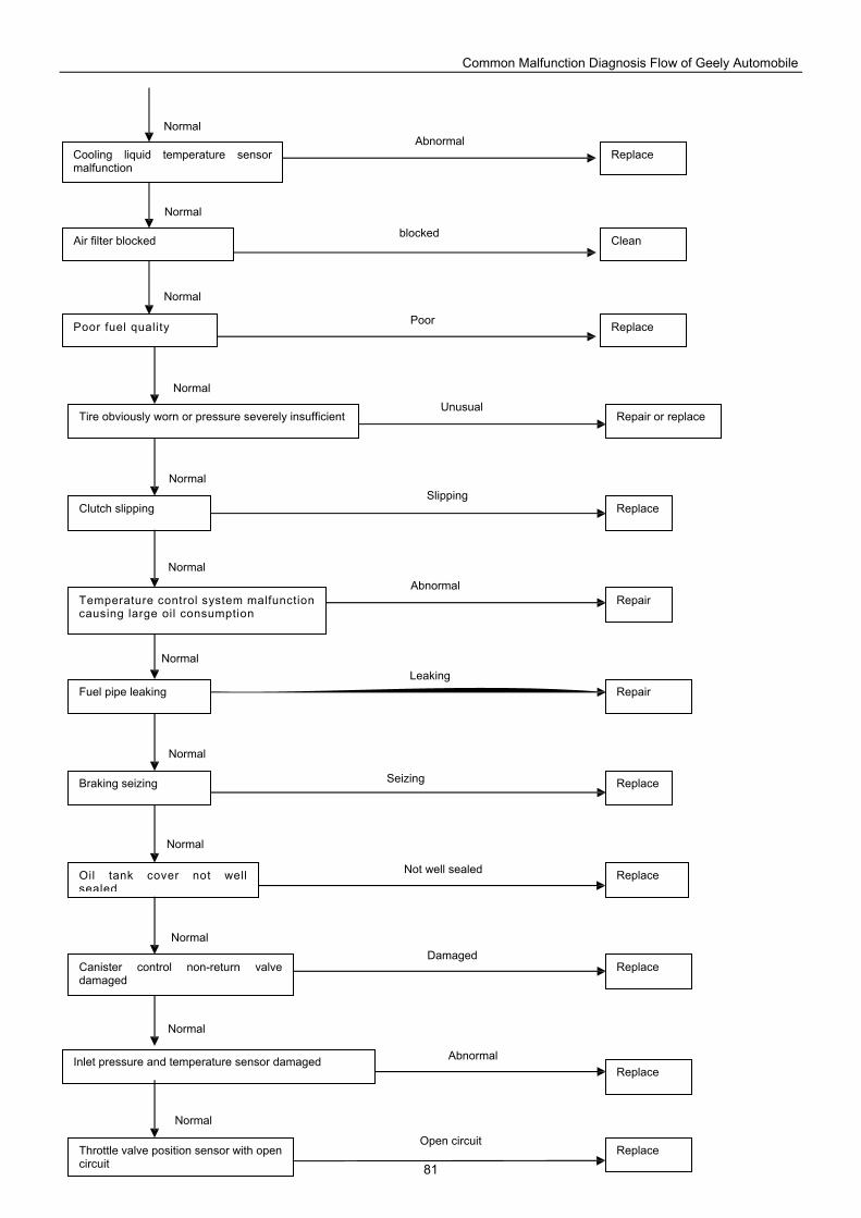
Common Malfunction Diagnosis Flow of Geely Automobile
81
Cooling liquid temperature sensor malfunction
Air filter blocked
Poor fuel quality
Clean
Replace
Replace
Tire obviously worn or pressure severely insufficient
Clutch slipping
Temperature control system malfunction causing large oil consumption
Fuel pipe leaking
Braking seizing
Oil tank cover not well sealed
Canister control non-return valve damaged
Inlet pressure and temperature sensor damaged
Throttle valve position sensor with open circuit
Repair or replace
Replace
Replace
Replace
Repair
Repair
Replace
Replace
Replace
Normal
Open circuit
Normal
Abnormal
Normal
Normal
Normal
Normal
Normal
Normal
Normal
Normal
Normal
Normal
Normal
Damaged
Not well sealed
Seizing
Leaking
Abnormal
Slipping
Unusual
Poor
blocked
Abnormal
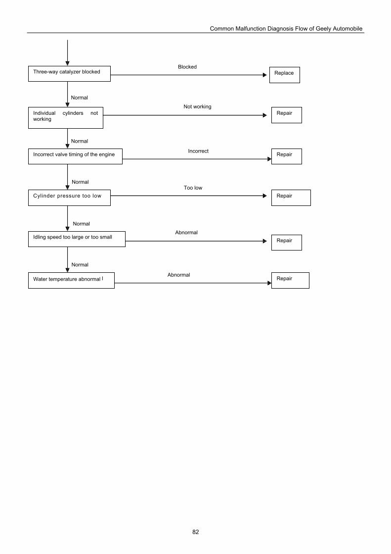
Common Malfunction Diagnosis Flow of Geely Automobile
82
Replace
Individual cylinders not working
Incorrect valve timing of the engine
Cylinder pressure too low
Idling speed too large or too small
Water temperature abnormal l
Three-way catalyzer blocked
Repair
Repair
Repair
Repair
Repair
Normal
Abnormal
Normal
Normal
Normal
Normal
Abnormal
Too low
Incorrect
Not working
Blocked
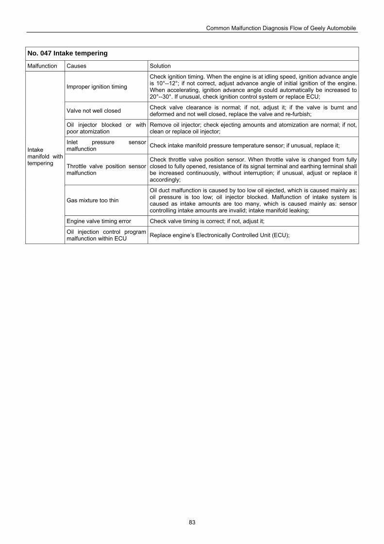
Common Malfunction Diagnosis Flow of Geely Automobile
83
No. 047 Intake tempering
Malfunction Causes Solution
Improper ignition timing
Check ignition timing. When the engine is at idling speed, ignition advance angle is 10°--12°; if not correct, adjust advance angle of initial ignition of the engine. When accelerating, ignition advance angle could automatically be increased to 20°--30°. If unusual, check ignition control system or replace ECU;
Valve not well closed Check valve clearance is normal; if not, adjust it; if the valve is burnt and deformed and not well closed, replace the valve and re-furbish;
Oil injector blocked or with poor atomization
Remove oil injector; check ejecting amounts and atomization are normal; if not, clean or replace oil injector;
Inlet pressure sensor malfunction Check intake manifold pressure temperature sensor; if unusual, replace it;
Throttle valve position sensor malfunction
Check throttle valve position sensor. When throttle valve is changed from fully closed to fully opened, resistance of its signal terminal and earthing terminal shall be increased continuously, without interruption; if unusual, adjust or replace it accordingly;
Gas mixture too thin
Oil duct malfunction is caused by too low oil ejected, which is caused mainly as: oil pressure is too low; oil injector blocked. Malfunction of intake system is caused as intake amounts are too many, which is caused mainly as: sensor controlling intake amounts are invalid; intake manifold leaking;
Engine valve timing error Check valve timing is correct; if not, adjust it;
Intake manifold with tempering
Oil injection control program malfunction within ECU Replace engine’s Electronically Controlled Unit (ECU);
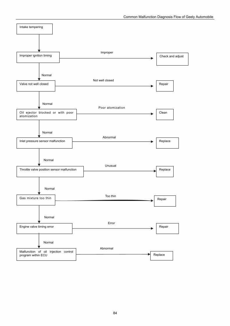
Common Malfunction Diagnosis Flow of Geely Automobile
84
Check and adjust
Replace
Intake tempering
Improper ignition timing
Valve not well closed
Oil ejector blocked or with poor atomization
Inlet pressure sensor malfunction
Throttle valve position sensor malfunction
Gas mixture too thin
Engine valve timing error
Repair
Replace
Clean
Repair
Malfunction of oil injection control program within ECU Replace
Repair
Normal
Abnormal
Normal
Normal
Normal
Normal
Normal
Normal
Improper
Not well closed
Poor atomization
Abnormal
Unusual
Too thin
Error
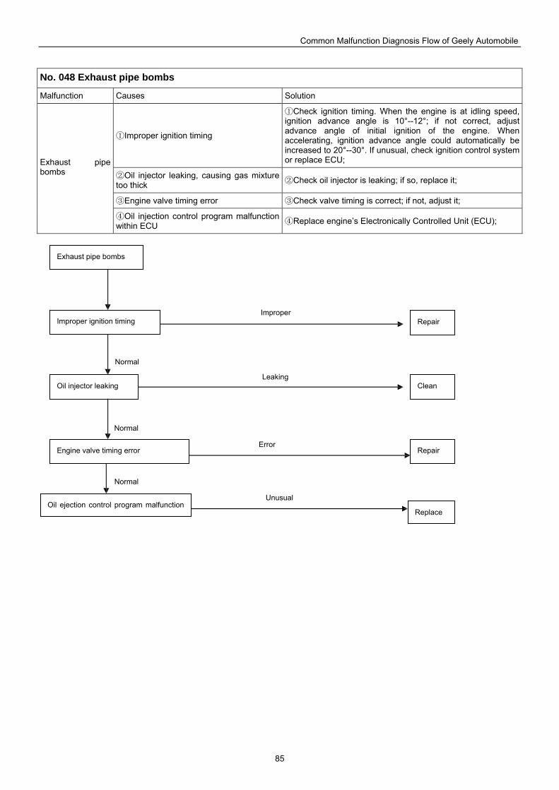
Common Malfunction Diagnosis Flow of Geely Automobile
85
No. 048 Exhaust pipe bombs
Malfunction Causes Solution
①Improper ignition timing
①Check ignition timing. When the engine is at idling speed, ignition advance angle is 10°--12°; if not correct, adjust advance angle of initial ignition of the engine. When accelerating, ignition advance angle could automatically be increased to 20°--30°. If unusual, check ignition control system or replace ECU;
②Oil injector leaking, causing gas mixture too thick ②Check oil injector is leaking; if so, replace it;
③Engine valve timing error ③Check valve timing is correct; if not, adjust it;
Exhaust pipe bombs
④Oil injection control program malfunction within ECU ④Replace engine’s Electronically Controlled Unit (ECU);
Repair
Exhaust pipe bombs
Improper ignition timing
Oil injector leaking
Engine valve timing error
Clean
Repair
Oil ejection control program malfunction Replace
Normal
Unusual
Normal
Normal
Improper
Leaking
Error
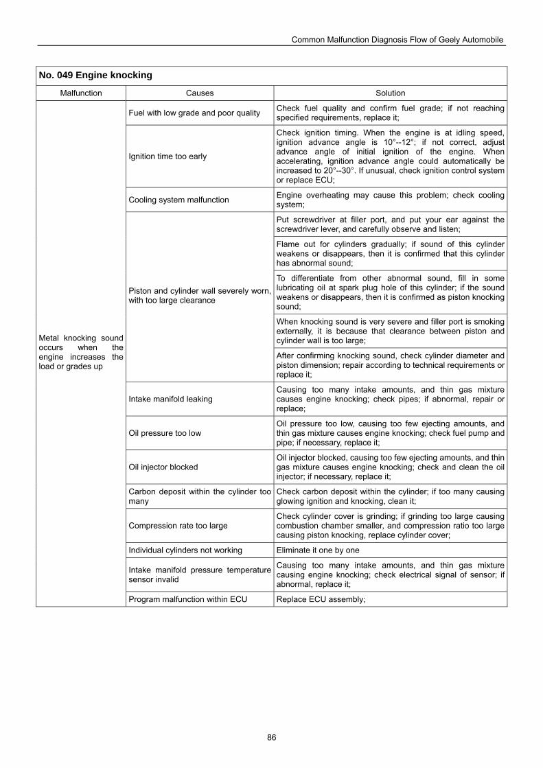
Common Malfunction Diagnosis Flow of Geely Automobile
86
No. 049 Engine knocking
Malfunction Causes Solution
Fuel with low grade and poor quality Check fuel quality and confirm fuel grade; if not reaching specified requirements, replace it;
Ignition time too early
Check ignition timing. When the engine is at idling speed, ignition advance angle is 10°--12°; if not correct, adjust advance angle of initial ignition of the engine. When accelerating, ignition advance angle could automatically be increased to 20°--30°. If unusual, check ignition control system or replace ECU;
Cooling system malfunction Engine overheating may cause this problem; check cooling system;
Put screwdriver at filler port, and put your ear against the screwdriver lever, and carefully observe and listen;
Flame out for cylinders gradually; if sound of this cylinder weakens or disappears, then it is confirmed that this cylinder has abnormal sound;
To differentiate from other abnormal sound, fill in some lubricating oil at spark plug hole of this cylinder; if the sound weakens or disappears, then it is confirmed as piston knocking sound;
When knocking sound is very severe and filler port is smoking externally, it is because that clearance between piston and cylinder wall is too large;
Piston and cylinder wall severely worn, with too large clearance
After confirming knocking sound, check cylinder diameter and piston dimension; repair according to technical requirements or replace it;
Intake manifold leaking Causing too many intake amounts, and thin gas mixture causes engine knocking; check pipes; if abnormal, repair or replace;
Oil pressure too low Oil pressure too low, causing too few ejecting amounts, and thin gas mixture causes engine knocking; check fuel pump and pipe; if necessary, replace it;
Oil injector blocked Oil injector blocked, causing too few ejecting amounts, and thin gas mixture causes engine knocking; check and clean the oil injector; if necessary, replace it;
Carbon deposit within the cylinder too many
Check carbon deposit within the cylinder; if too many causing glowing ignition and knocking, clean it;
Compression rate too large Check cylinder cover is grinding; if grinding too large causing combustion chamber smaller, and compression ratio too large causing piston knocking, replace cylinder cover;
Individual cylinders not working Eliminate it one by one
Intake manifold pressure temperature sensor invalid
Causing too many intake amounts, and thin gas mixture causing engine knocking; check electrical signal of sensor; if abnormal, replace it;
Metal knocking sound occurs when the engine increases the load or grades up
Program malfunction within ECU Replace ECU assembly;
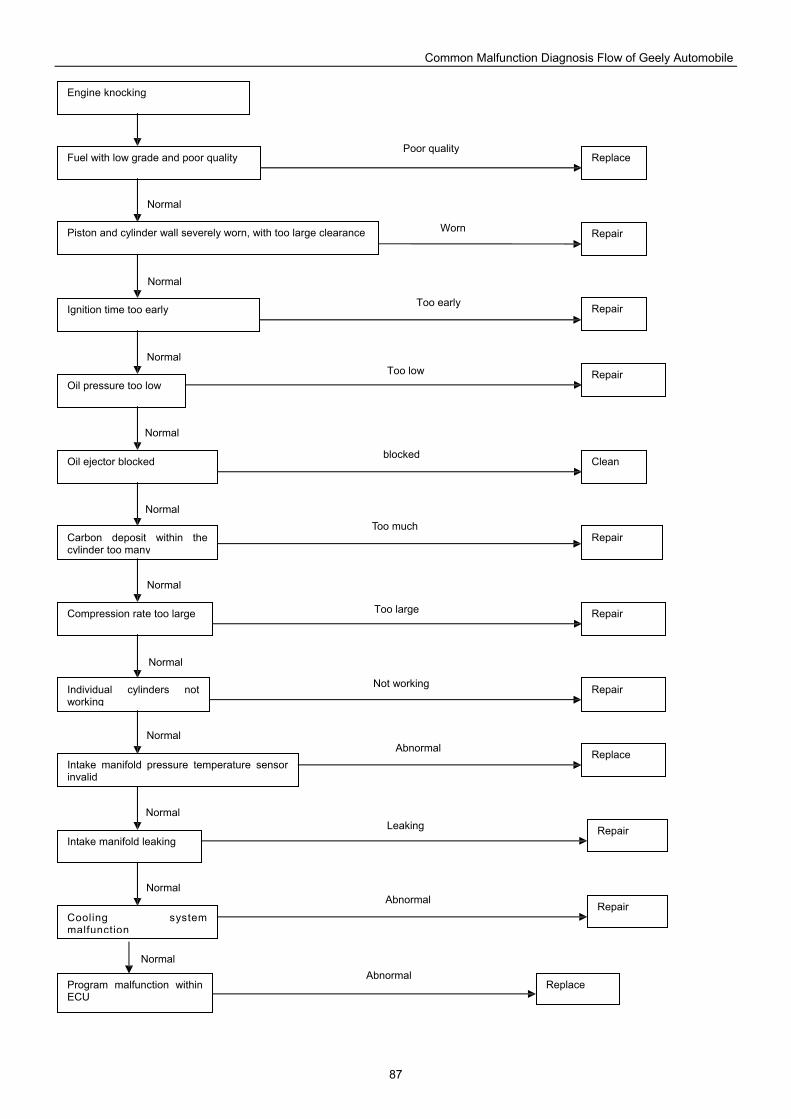
Common Malfunction Diagnosis Flow of Geely Automobile
87
Repair Carbon deposit within the cylinder too many
Compression rate too large
Individual cylinders not working
Intake manifold pressure temperature sensor invalid
Oil ejector blocked
Oil pressure too low
Piston and cylinder wall severely worn, with too large clearance
Ignition time too early
Fuel with low grade and poor quality
Engine knocking
Replace
Clean
Repair
Repair
Repair
Repair
Repair
Replace
Intake manifold leaking
Cooling system malfunction
Repair
Repair
Program malfunction within ECU
Replace
Normal
Poor quality
Normal
Normal
Normal
Normal
Normal
Normal
Normal
Normal
Normal
Normal
Worn
Too early
Too low
blocked
Too much
Too large
Not working
Abnormal
Leaking
Abnormal
Abnormal
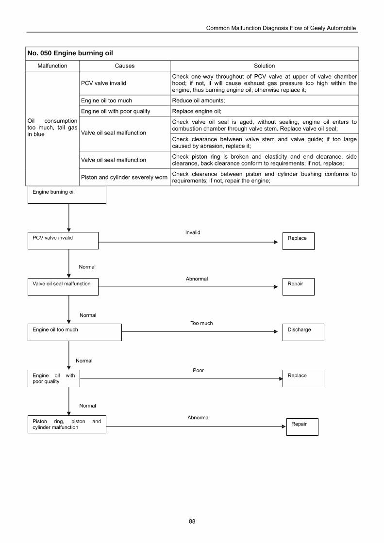
Common Malfunction Diagnosis Flow of Geely Automobile
88
No. 050 Engine burning oil
Malfunction Causes Solution
PCV valve invalid Check one-way throughout of PCV valve at upper of valve chamber hood; if not, it will cause exhaust gas pressure too high within the engine, thus burning engine oil; otherwise replace it;
Engine oil too much Reduce oil amounts;
Engine oil with poor quality Replace engine oil;
Check valve oil seal is aged, without sealing, engine oil enters to combustion chamber through valve stem. Replace valve oil seal;
Valve oil seal malfunction Check clearance between valve stem and valve guide; if too large caused by abrasion, replace it;
Valve oil seal malfunction Check piston ring is broken and elasticity and end clearance, side clearance, back clearance conform to requirements; if not, replace;
Oil consumption too much, tail gas in blue
Piston and cylinder severely worn Check clearance between piston and cylinder bushing conforms to requirements; if not, repair the engine;
Replace
Repair
Engine burning oil
PCV valve invalid
Valve oil seal malfunction
Engine oil too much
Engine oil with poor quality
Piston ring, piston and cylinder malfunction
Repair
Replace
Discharge
Normal
Abnormal
Normal
Normal
Normal
Invalid
Abnormal
Too much
Poor
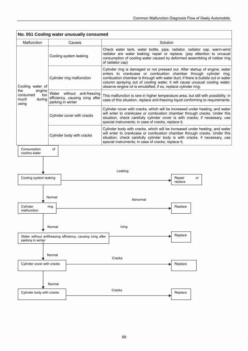
Common Malfunction Diagnosis Flow of Geely Automobile
89
No. 051 Cooling water unusually consumed
Malfunction Causes Solution
Cooling system leaking
Check water tank, water bottle, pipe, radiator, radiator cap, warm-wind radiator are water leaking; repair or replace. (pay attention to unusual consumption of cooling water caused by deformed assembling of rubber ring of radiator cap)
Cylinder ring malfunction
Cylinder ring is damaged or not pressed out. After startup of engine, water enters to crankcase or combustion chamber through cylinder ring; combustion chamber is through with water duct; if there is bubble out or water column spraying out of cooling water, it will cause unusual cooling water; observe engine oil is emulsified; if so, replace cylinder ring;
Water without anti-freezing efficiency, causing icing after parking in winter
This malfunction is rare in higher temperature area, but still with possibility; in case of this situation, replace anti-freezing liquid conforming to requirements;
Cylinder cover with cracks
Cylinder cover with cracks, which will be increased under heating, and water will enter to crankcase or combustion chamber through cracks. Under this situation, check carefully cylinder cover is with cracks; if necessary, use special instruments; in case of cracks, replace it;
Cooling water of the engine consumed too much during using
Cylinder body with cracks
Cylinder body with cracks, which will be increased under heating, and water will enter to crankcase or combustion chamber through cracks. Under this situation, check carefully cylinder body is with cracks; if necessary, use special instruments; in case of cracks, replace it;
Repair or replace
Cooling system leaking
Cylinder ring malfunction
Water without antifreezing efficiency, causing icing after parking in winter
Cylinder cover with cracks
Cylinder body with cracks
Consumption of cooling water
Replace
Replace
Replace
Replace
Normal
Cracks Normal
Normal
Normal
Icing
Abnormal
Leaking
Cracks
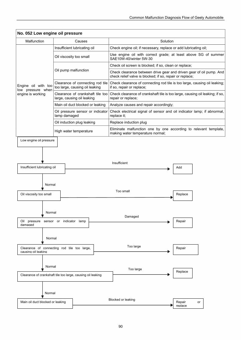
Common Malfunction Diagnosis Flow of Geely Automobile
90
No. 052 Low engine oil pressure
Malfunction Causes Solution
Insufficient lubricating oil Check engine oil; if necessary, replace or add lubricating oil;
Oil viscosity too small Use engine oil with correct grade; at least above SG of summer SAE10W-40/winter 5W-30
Check oil screen is blocked; if so, clean or replace; Oil pump malfunction Check clearance between drive gear and driven gear of oil pump. And
check relief valve is blocked; if so, repair or replace;
Clearance of connecting rod tile too large, causing oil leaking
Check clearance of connecting rod tile is too large, causing oil leaking; if so, repair or replace;
Clearance of crankshaft tile too large, causing oil leaking
Check clearance of crankshaft tile is too large, causing oil leaking; if so, repair or replace;
Main oil duct blocked or leaking Analyze causes and repair accordingly;
Oil pressure sensor or indicator lamp damaged
Check electrical signal of sensor and oil indicator lamp; if abnormal, replace it;
Oil induction plug leaking Replace induction plug
Engine oil with too low pressure when engine is working
High water temperature Eliminate malfunction one by one according to relevant template, making water temperature normal;
Add
Repair or replace
Low engine oil pressure
Insufficient lubricating oil
Oil viscosity too small
Oil pressure sensor or indicator lamp damaged
Clearance of connecting rod tile too large, causing oil leaking
Clearance of crankshaft tile too large, causing oil leaking
Main oil duct blocked or leaking
Replace
Repair
Repair
Replace
Normal
Insufficient
Normal
Normal
Normal
Normal
Too small
Damaged
Too large
Too large
Blocked or leaking
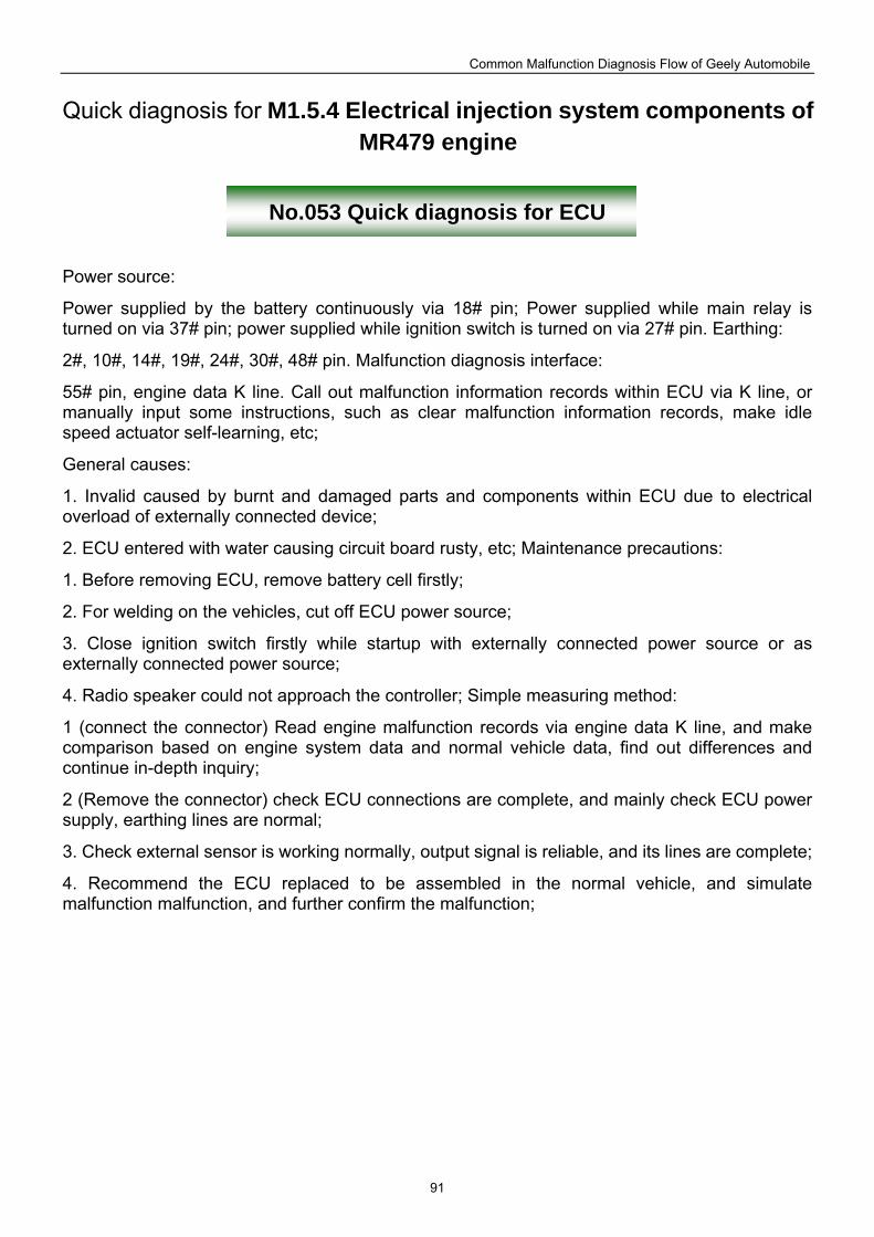
Common Malfunction Diagnosis Flow of Geely Automobile
91
Quick diagnosis for M1.5.4 Electrical injection system components of MR479 engine
No.053 Quick diagnosis for ECU
Power source:
Power supplied by the battery continuously via 18# pin; Power supplied while main relay is turned on via 37# pin; power supplied while ignition switch is turned on via 27# pin. Earthing:
2#, 10#, 14#, 19#, 24#, 30#, 48# pin. Malfunction diagnosis interface:
55# pin, engine data K line. Call out malfunction information records within ECU via K line, or manually input some instructions, such as clear malfunction information records, make idle speed actuator self-learning, etc;
General causes:
1. Invalid caused by burnt and damaged parts and components within ECU due to electrical overload of externally connected device;
2. ECU entered with water causing circuit board rusty, etc; Maintenance precautions:
1. Before removing ECU, remove battery cell firstly;
2. For welding on the vehicles, cut off ECU power source;
3. Close ignition switch firstly while startup with externally connected power source or as externally connected power source;
4. Radio speaker could not approach the controller; Simple measuring method:
1 (connect the connector) Read engine malfunction records via engine data K line, and make comparison based on engine system data and normal vehicle data, find out differences and continue in-depth inquiry;
2 (Remove the connector) check ECU connections are complete, and mainly check ECU power supply, earthing lines are normal;
3. Check external sensor is working normally, output signal is reliable, and its lines are complete;
4. Recommend the ECU replaced to be assembled in the normal vehicle, and simulate malfunction malfunction, and further confirm the malfunction;
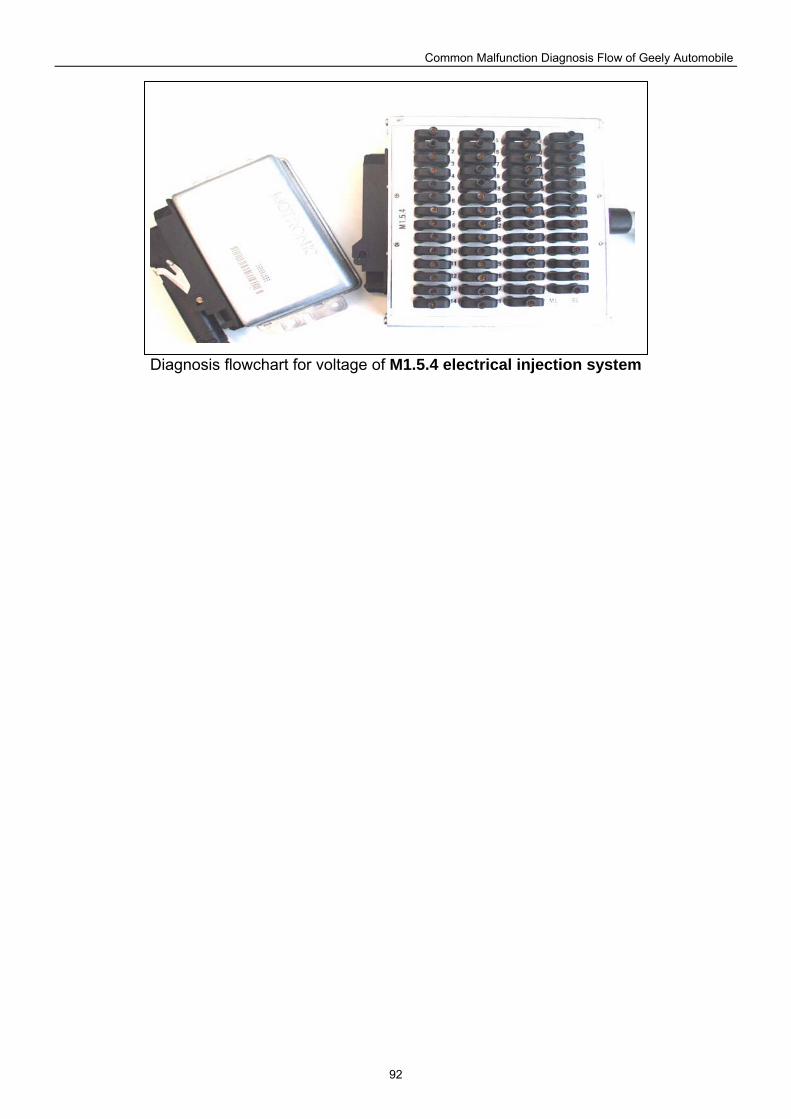
Common Malfunction Diagnosis Flow of Geely Automobile
92
Diagnosis flowchart for voltage of M1.5.4 electrical injection system
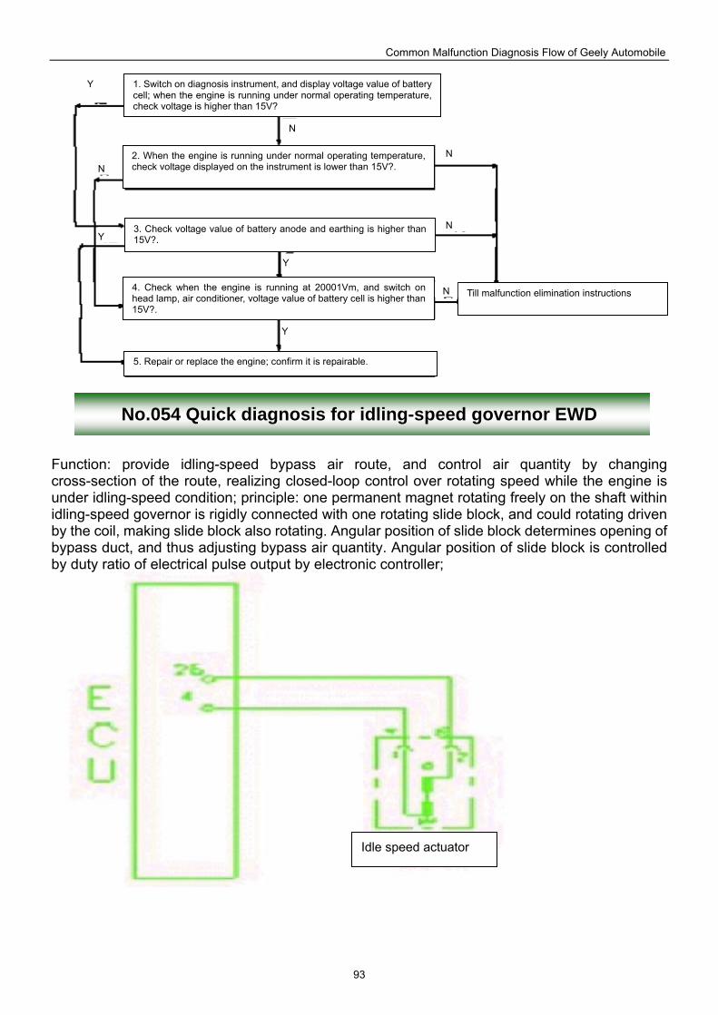
Common Malfunction Diagnosis Flow of Geely Automobile
93
No.054 Quick diagnosis for idling-speed governor EWD
Function: provide idling-speed bypass air route, and control air quantity by changing cross-section of the route, realizing closed-loop control over rotating speed while the engine is under idling-speed condition; principle: one permanent magnet rotating freely on the shaft within idling-speed governor is rigidly connected with one rotating slide block, and could rotating driven by the coil, making slide block also rotating. Angular position of slide block determines opening of bypass duct, and thus adjusting bypass air quantity. Angular position of slide block is controlled by duty ratio of electrical pulse output by electronic controller;
Idle speed actuator
3. Check voltage value of battery anode and earthing is higher than 15V?.
1. Switch on diagnosis instrument, and display voltage value of battery cell; when the engine is running under normal operating temperature, check voltage is higher than 15V?
2. When the engine is running under normal operating temperature, check voltage displayed on the instrument is lower than 15V?.
5. Repair or replace the engine; confirm it is repairable.
4. Check when the engine is running at 20001Vm, and switch on head lamp, air conditioner, voltage value of battery cell is higher than 15V?.
Till malfunction elimination instructions
Y
Y
Y
Y
N N
N
N
N
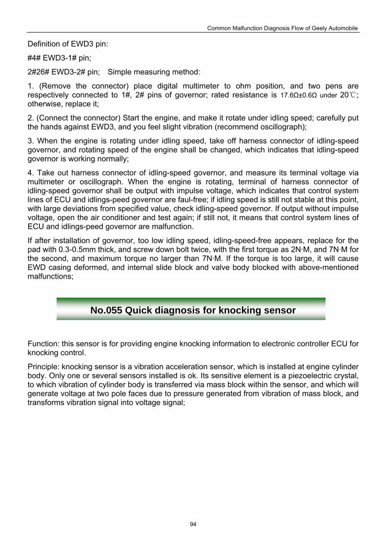
Common Malfunction Diagnosis Flow of Geely Automobile
94
Definition of EWD3 pin:
#4# EWD3-1# pin;
2#26# EWD3-2# pin; Simple measuring method:
1. (Remove the connector) place digital multimeter to ohm position, and two pens are respectively connected to 1#, 2# pins of governor; rated resistance is 17.6Ω±0.6Ω under 20 ; otherwise, replace it;
2. (Connect the connector) Start the engine, and make it rotate under idling speed; carefully put the hands against EWD3, and you feel slight vibration (recommend oscillograph);
3. When the engine is rotating under idling speed, take off harness connector of idling-speed governor, and rotating speed of the engine shall be changed, which indicates that idling-speed governor is working normally;
4. Take out harness connector of idling-speed governor, and measure its terminal voltage via multimeter or oscillograph. When the engine is rotating, terminal of harness connector of idling-speed governor shall be output with impulse voltage, which indicates that control system lines of ECU and idlings-peed governor are faul-free; if idling speed is still not stable at this point, with large deviations from specified value, check idling-speed governor. If output without impulse voltage, open the air conditioner and test again; if still not, it means that control system lines of ECU and idlings-peed governor are malfunction.
If after installation of governor, too low idling speed, idling-speed-free appears, replace for the pad with 0.3-0.5mm thick, and screw down bolt twice, with the first torque as 2N·M, and 7N·M for the second, and maximum torque no larger than 7N·M. If the torque is too large, it will cause EWD casing deformed, and internal slide block and valve body blocked with above-mentioned malfunctions;
No.055 Quick diagnosis for knocking sensor
Function: this sensor is for providing engine knocking information to electronic controller ECU for knocking control.
Principle: knocking sensor is a vibration acceleration sensor, which is installed at engine cylinder body. Only one or several sensors installed is ok. Its sensitive element is a piezoelectric crystal, to which vibration of cylinder body is transferred via mass block within the sensor, and which will generate voltage at two pole faces due to pressure generated from vibration of mass block, and transforms vibration signal into voltage signal;
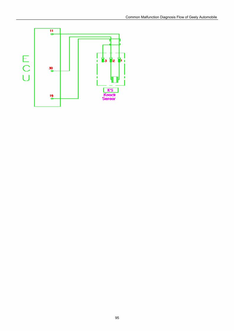
Common Malfunction Diagnosis Flow of Geely Automobile
95
Common Malfunction Diagnosis Flow of Geely Automobile
96
Definition of sensor pin:
1#11# Knocking signal output;
2#30# Earthing;
3#19# Earthing (shielded)
Simple measuring method:
1. (Remove the connector) place digital multimeter to ohm position, and two pens are respectively connected to 1#, 2# and 1#, 3# pins of sensor; resistance under normal temperature shall be larger than 1MΩ;
2. Place digital multimeter to MV position, and knock at knocking sensor slightly with a small hammer; at this point, voltage signal shall be output;
Note: please check 3# shielded line is well earthed.
3. Communicate diagnosis instrument specified by complete vehicle plant with electrical injection ECU, and read malfunction data within ECU, thus making judgment over throttle valve position sensor;
No.056 Quick diagnosis for stepper motor
Function: provide idling-speed bypass air route, and control air quantity by changing cross-section of the route, realizing closed-loop control over rotating speed while the engine is under idling-speed condition;
Principle: stepper motor is actuall a miniature motor, and its stator is polyphase coil winding and rotor is permanent magnet, through which one spiral axis is threaded, and these two are contacted with thread. When stator coil is switched with current, the rotor will rotate towards corresponding directions. As rotor and spiral axis are contacted with thread, angular displacement of rotor is transformed into linear displacement of spiral axis. Bypass cross-section could be changed by front and rear moving of spiral axis. If the rotor rotates fixed angle each time, spiral axis will move a certain displacement, i.e. one step. Electronic controller could control moving steps of stepper motor by changing coil energization phase to obtain corresponding bypass air flow.
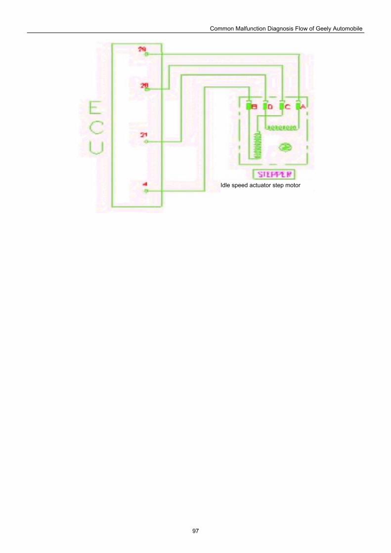
Common Malfunction Diagnosis Flow of Geely Automobile
97
Idle speed actuator step motor
Common Malfunction Diagnosis Flow of Geely Automobile
98
Maintenance precautions:
1. Do not apply any forces axially to press down or take out the axle;
Before idle speed governor with stepper motor is installed within throttle valve body, the axle must be at completely holdback position;
3. Pay attention to cleaning of bypass air route;
4. After removing battery cell, manually trigger self-learning function of stepper motor duly by using K line for malfunction diagnosis for earthing with three times, and earthing time equaling to and larger than 2.5s each time, or self-learning by using diagnosis instrument;
Simple measuring method:
1. (Remove the connector) place digital multimeter to ohm position, and two pens are respectively connected into AD, BC pins of regovernor, and rated resistance under 25 is 53±5.3Ω; otherwise, replace it;
2. (Connect the connector) Start the engine, and make it rotate under idling speed; put hands slightly against stepper motor, and you feel slight vibration at this point;
3. Read amount of step of idle speed stepper motor out of engine parameter with diagnosis instrument, and start the air conditioner, and amount of step will increase. If rotating speed of the engine is kept at 3000rpm for a certain time, check amount of step will continue to rise, till to maximum opening value, which indicates that stepper motor is working normally;
4. If you cannot make judgment, recommend malfunction recurrence testing on malfunction-free vehicle;
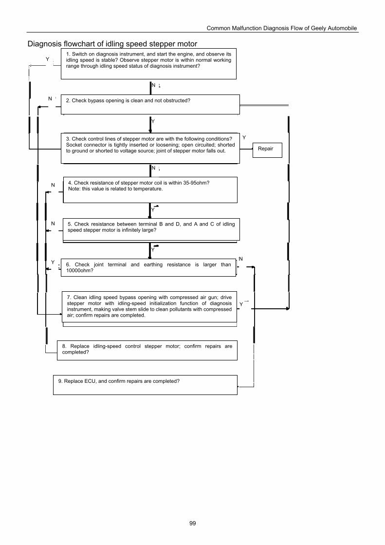
Common Malfunction Diagnosis Flow of Geely Automobile
99
Diagnosis flowchart of idling speed stepper motor
1. Switch on diagnosis instrument, and start the engine, and observe its idling speed is stable? Observe stepper motor is within normal working range through idling speed status of diagnosis instrument?
3. Check control lines of stepper motor are with the following conditions? Socket connector is tightly inserted or loosening; open circuited; shorted to ground or shorted to voltage source; joint of stepper motor falls out.
2. Check bypass opening is clean and not obstructed?
4. Check resistance of stepper motor coil is within 35-95ohm? Note: this value is related to temperature.
5. Check resistance between terminal B and D, and A and C of idling speed stepper motor is infinitely large?
6. Check joint terminal and earthing resistance is larger than 10000ohm?
7. Clean idling speed bypass opening with compressed air gun; drive stepper motor with idling-speed initialization function of diagnosis instrument, making valve stem slide to clean pollutants with compressed air; confirm repairs are completed.
8. Replace idling-speed control stepper motor; confirm repairs are completed?
9. Replace ECU, and confirm repairs are completed?
Repair
Y
Y
Y
Y
Y
Y
Y
N
N
N
N
N
N
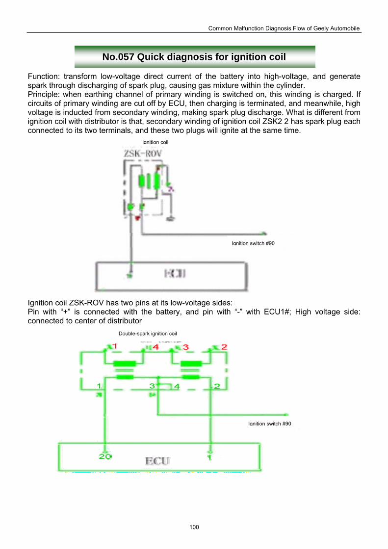
Common Malfunction Diagnosis Flow of Geely Automobile
100
No.057 Quick diagnosis for ignition coil
Function: transform low-voltage direct current of the battery into high-voltage, and generate spark through discharging of spark plug, causing gas mixture within the cylinder. Principle: when earthing channel of primary winding is switched on, this winding is charged. If circuits of primary winding are cut off by ECU, then charging is terminated, and meanwhile, high voltage is inducted from secondary winding, making spark plug discharge. What is different from ignition coil with distributor is that, secondary winding of ignition coil ZSK2 2 has spark plug each connected to its two terminals, and these two plugs will ignite at the same time.
Ignition coil ZSK-ROV has two pins at its low-voltage sides: Pin with “+” is connected with the battery, and pin with “-” with ECU1#; High voltage side: connected to center of distributor
Double-spark ignition coil
Ignition switch #90
Ignition switch #90
ignition coil
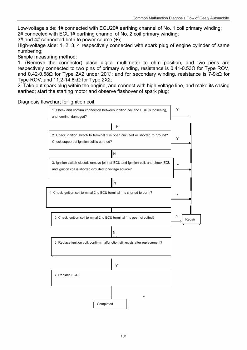
Common Malfunction Diagnosis Flow of Geely Automobile
101
Low-voltage side: 1# connected with ECU20# earthing channel of No. 1 coil primary winding; 2# connected with ECU1# earthing channel of No. 2 coil primary winding; 3# and 4# connected both to power source (+); High-voltage side: 1, 2, 3, 4 respectively connected with spark plug of engine cylinder of same numbering; Simple measuring method: 1. (Remove the connector) place digital multimeter to ohm position, and two pens are respectively connected to two pins of primary winding, resistance is 0.41-0.53Ω for Type ROV, and 0.42-0.58Ω for Type 2X2 under 20; and for secondary winding, resistance is 7-9kΩ for Type ROV, and 11.2-14.8kΩ for Type 2X2; 2. Take out spark plug within the engine, and connect with high voltage line, and make its casing earthed; start the starting motor and observe flashover of spark plug; Diagnosis flowchart for ignition coil
1. Check and confirm connection between ignition coil and ECU is loosening,
and terminal damaged?
2. Check ignition switch to terminal 1 is open circuited or shorted to ground?
Check support of ignition coil is earthed?
3. Ignition switch closed; remove joint of ECU and ignition coil; and check ECU
and ignition coil is shorted circuited to voltage source?
4. Check ignition coil terminal 2 to ECU terminal 1 is shorted to earth?
5. Check ignition coil terminal 2 to ECU terminal 1 is open circuited?
6. Replace ignition coil; confirm malfunction still exists after replacement?
7. Replace ECU
Completed
Repair
Y
Y
Y
Y
Y
Y
Y
N
N
N
N
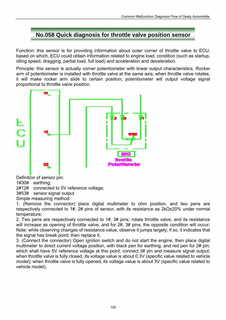
Common Malfunction Diagnosis Flow of Geely Automobile
102
No.058 Quick diagnosis for throttle valve position sensor
Function: this sensor is for providing information about outer corner of throttle valve to ECU, based on which, ECU could obtain information related to engine load, condition (such as startup, idling speed, dragging, partial load, full load) and acceleration and deceleration.
Principle: this sensor is actually corner potentiometer with linear output characteristics. Rocker arm of potentiometer is installed with throttle valve at the same axis; when throttle valve rotates, it will make rocker arm slide to certain position; potentiometer will output voltage signal proportional to throttle valve position.
Definition of sensor pin: 1#30# earthing; 2#12# connected to 5V reference voltage; 3#53# sensor signal output Simple measuring method: 1. (Remove the connector) place digital multimeter to ohm position, and two pens are respectively connected to 1#, 2# pins of sensor, with its resistance as 2kΩ±20% under normal temperature; 2. Two pens are respectively connected to 1#, 3# pins; rotate throttle valve, and its resistance will increase as opening of throttle valve, and for 2#, 3# pins, the opposite condition will occur; Note: while observing changes of resistance value, observe it jumps largely; if so, it indicates that the signal has break point; then replace it; 3. (Connect the connector) Open ignition switch and do not start the engine, then place digital multimeter to direct current voltage position, with black pen for earthing, and red pen for 2# pin; which shall have 5V reference voltage at this point; connect 3# pin and measure signal output; when throttle valve is fully closed, its voltage value is about 0.3V (specific value related to vehicle model); when throttle valve is fully opened, its voltage value is about 3V (specific value related to vehicle model).
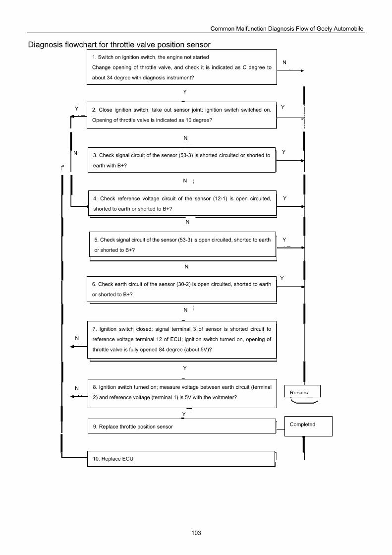
Common Malfunction Diagnosis Flow of Geely Automobile
103
Diagnosis flowchart for throttle valve position sensor
1. Switch on ignition switch, the engine not started
Change opening of throttle valve, and check it is indicated as C degree to
about 34 degree with diagnosis instrument?
2. Close ignition switch; take out sensor joint; ignition switch switched on.
Opening of throttle valve is indicated as 10 degree?
3. Check signal circuit of the sensor (53-3) is shorted circuited or shorted to
earth with B+?
4. Check reference voltage circuit of the sensor (12-1) is open circuited,
shorted to earth or shorted to B+?
5. Check signal circuit of the sensor (53-3) is open circuited, shorted to earth
or shorted to B+?
6. Check earth circuit of the sensor (30-2) is open circuited, shorted to earth
or shorted to B+?
7. Ignition switch closed; signal terminal 3 of sensor is shorted circuit to
reference voltage terminal 12 of ECU; ignition switch turned on, opening of
throttle valve is fully opened 84 degree (about 5V)?
8. Ignition switch turned on; measure voltage between earth circuit (terminal
2) and reference voltage (terminal 1) is 5V with the voltmeter?
9. Replace throttle position sensor
10. Replace ECU
Completed
Repairs
Y
Y
Y
Y
Y
Y
Y
Y
Y
N
N
N
N
N
N
N
N
N
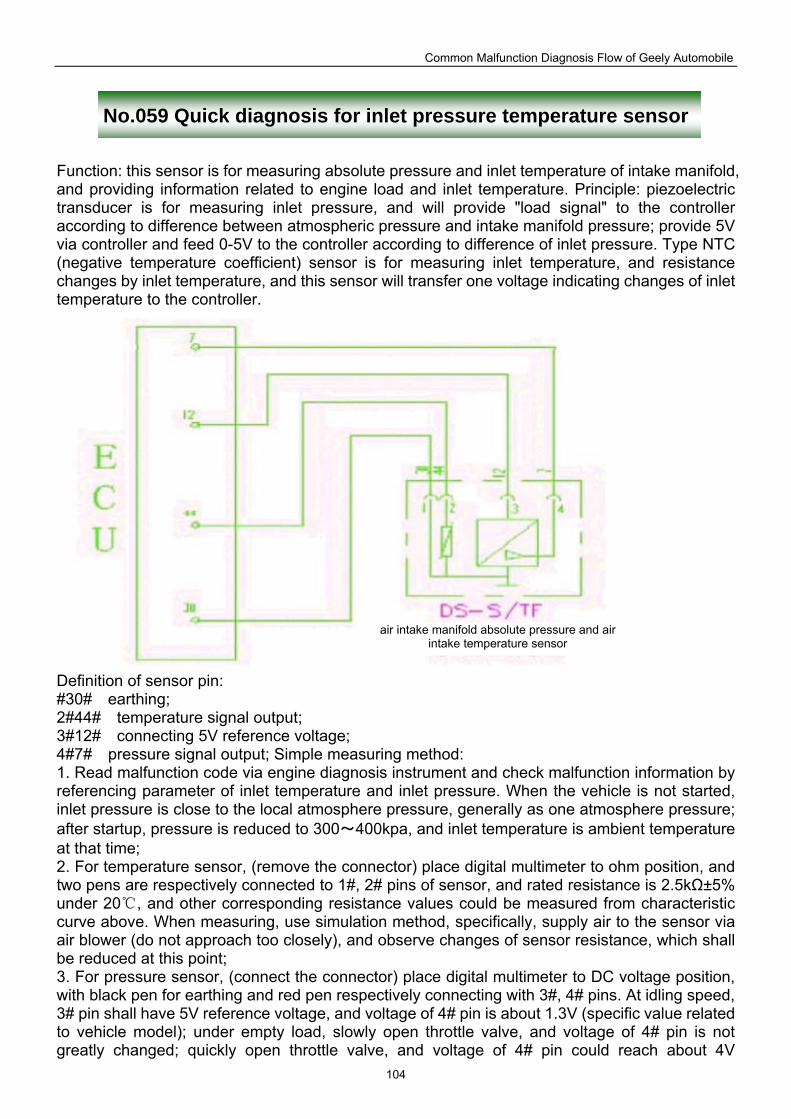
Common Malfunction Diagnosis Flow of Geely Automobile
104
No.059 Quick diagnosis for inlet pressure temperature sensor
Function: this sensor is for measuring absolute pressure and inlet temperature of intake manifold, and providing information related to engine load and inlet temperature. Principle: piezoelectric transducer is for measuring inlet pressure, and will provide "load signal" to the controller according to difference between atmospheric pressure and intake manifold pressure; provide 5V via controller and feed 0-5V to the controller according to difference of inlet pressure. Type NTC (negative temperature coefficient) sensor is for measuring inlet temperature, and resistance changes by inlet temperature, and this sensor will transfer one voltage indicating changes of inlet temperature to the controller.
Definition of sensor pin: #30# earthing; 2#44# temperature signal output; 3#12# connecting 5V reference voltage; 4#7# pressure signal output; Simple measuring method: 1. Read malfunction code via engine diagnosis instrument and check malfunction information by referencing parameter of inlet temperature and inlet pressure. When the vehicle is not started, inlet pressure is close to the local atmosphere pressure, generally as one atmosphere pressure; after startup, pressure is reduced to 300~400kpa, and inlet temperature is ambient temperature at that time; 2. For temperature sensor, (remove the connector) place digital multimeter to ohm position, and two pens are respectively connected to 1#, 2# pins of sensor, and rated resistance is 2.5kΩ±5% under 20 , and other corresponding resistance values could be measured from characteristic curve above. When measuring, use simulation method, specifically, supply air to the sensor via air blower (do not approach too closely), and observe changes of sensor resistance, which shall be reduced at this point; 3. For pressure sensor, (connect the connector) place digital multimeter to DC voltage position, with black pen for earthing and red pen respectively connecting with 3#, 4# pins. At idling speed, 3# pin shall have 5V reference voltage, and voltage of 4# pin is about 1.3V (specific value related to vehicle model); under empty load, slowly open throttle valve, and voltage of 4# pin is not greatly changed; quickly open throttle valve, and voltage of 4# pin could reach about 4V
air intake manifold absolute pressure and air intake temperature sensor
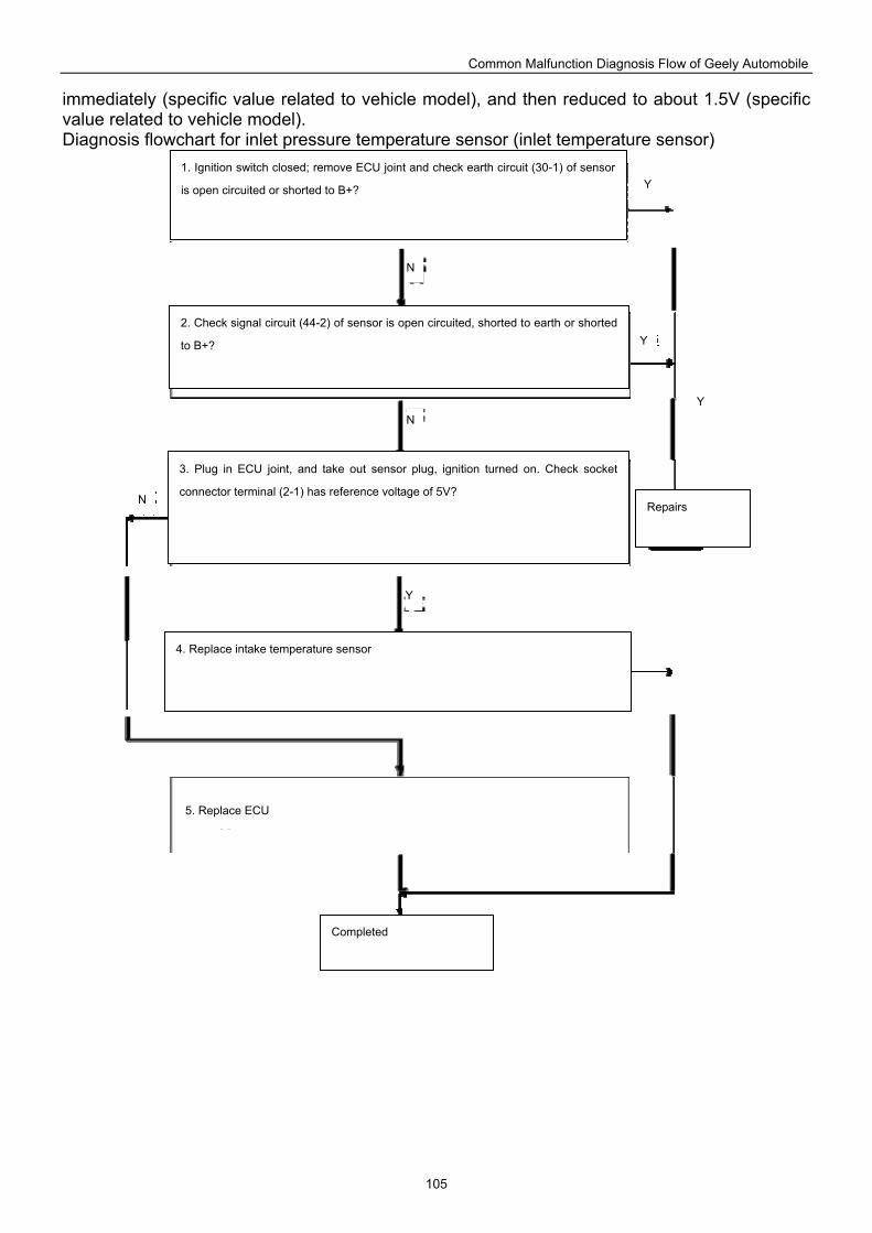
Common Malfunction Diagnosis Flow of Geely Automobile
105
immediately (specific value related to vehicle model), and then reduced to about 1.5V (specific value related to vehicle model). Diagnosis flowchart for inlet pressure temperature sensor (inlet temperature sensor)
1. Ignition switch closed; remove ECU joint and check earth circuit (30-1) of sensor
is open circuited or shorted to B+?
2. Check signal circuit (44-2) of sensor is open circuited, shorted to earth or shorted
to B+?
3. Plug in ECU joint, and take out sensor plug, ignition turned on. Check socket
connector terminal (2-1) has reference voltage of 5V?
4. Replace intake temperature sensor
5. Replace ECU
Completed
Repairs
Y
Y
Y
Y
N
N
N
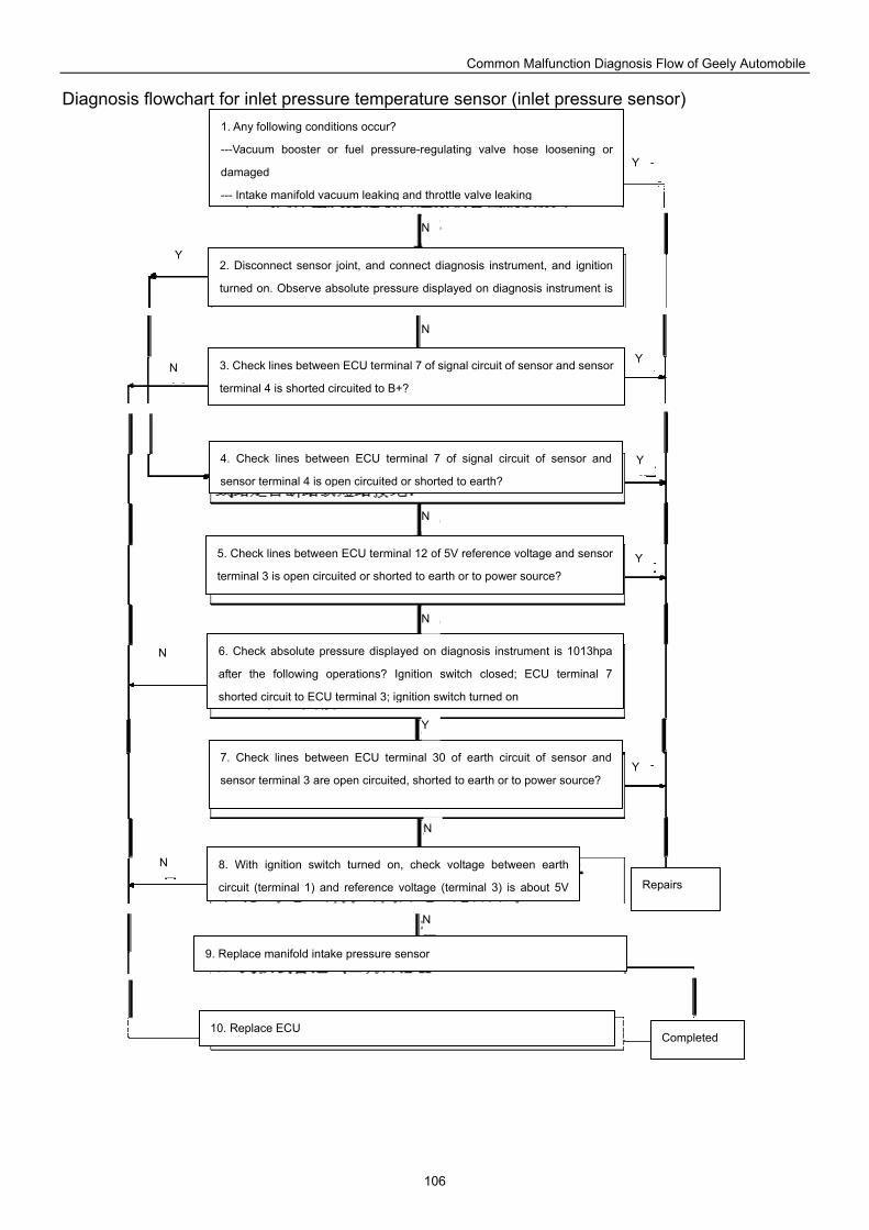
Common Malfunction Diagnosis Flow of Geely Automobile
106
Diagnosis flowchart for inlet pressure temperature sensor (inlet pressure sensor)
1. Any following conditions occur?
---Vacuum booster or fuel pressure-regulating valve hose loosening or
damaged
--- Intake manifold vacuum leaking and throttle valve leaking
2. Disconnect sensor joint, and connect diagnosis instrument, and ignition
turned on. Observe absolute pressure displayed on diagnosis instrument is
3. Check lines between ECU terminal 7 of signal circuit of sensor and sensor
terminal 4 is shorted circuited to B+?
4. Check lines between ECU terminal 7 of signal circuit of sensor and
sensor terminal 4 is open circuited or shorted to earth?
5. Check lines between ECU terminal 12 of 5V reference voltage and sensor
terminal 3 is open circuited or shorted to earth or to power source?
6. Check absolute pressure displayed on diagnosis instrument is 1013hpa
after the following operations? Ignition switch closed; ECU terminal 7
shorted circuit to ECU terminal 3; ignition switch turned on
7. Check lines between ECU terminal 30 of earth circuit of sensor and
sensor terminal 3 are open circuited, shorted to earth or to power source?
8. With ignition switch turned on, check voltage between earth
circuit (terminal 1) and reference voltage (terminal 3) is about 5V
9. Replace manifold intake pressure sensor
10. Replace ECU Completed
Repairs
Y
Y
Y
Y
Y
Y
N
N
N
N
N
N
N
N
N
Y
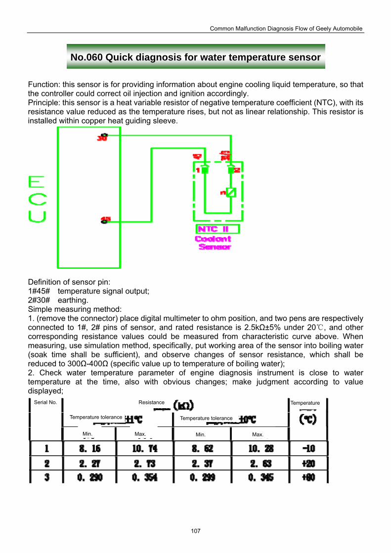
Common Malfunction Diagnosis Flow of Geely Automobile
107
No.060 Quick diagnosis for water temperature sensor
Function: this sensor is for providing information about engine cooling liquid temperature, so that the controller could correct oil injection and ignition accordingly. Principle: this sensor is a heat variable resistor of negative temperature coefficient (NTC), with its resistance value reduced as the temperature rises, but not as linear relationship. This resistor is installed within copper heat guiding sleeve.
Definition of sensor pin: 1#45# temperature signal output; 2#30# earthing. Simple measuring method: 1. (remove the connector) place digital multimeter to ohm position, and two pens are respectively connected to 1#, 2# pins of sensor, and rated resistance is 2.5kΩ±5% under 20 , and other corresponding resistance values could be measured from characteristic curve above. When measuring, use simulation method, specifically, put working area of the sensor into boiling water (soak time shall be sufficient), and observe changes of sensor resistance, which shall be reduced to 300Ω-400Ω (specific value up to temperature of boiling water); 2. Check water temperature parameter of engine diagnosis instrument is close to water temperature at the time, also with obvious changes; make judgment according to value displayed;
Serial No. Resistance
Max.
Temperature tolerance Temperature tolerance
Min. Min. Max.
Temperature
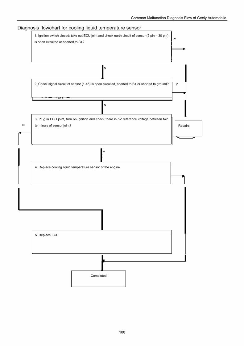
Common Malfunction Diagnosis Flow of Geely Automobile
108
Diagnosis flowchart for cooling liquid temperature sensor
1. Ignition switch closed: take out ECU joint and check earth circuit of sensor (2 pin – 30 pin)
is open circuited or shorted to B+?
2. Check signal circuit of sensor (1-45) is open circuited, shorted to B+ or shorted to ground?
3. Plug in ECU joint, turn on ignition and check there is 5V reference voltage between two
terminals of sensor joint?
4. Replace cooling liquid temperature sensor of the engine
Repairs
5. Replace ECU
Completed
Y
Y
Y
Y
N
N
N
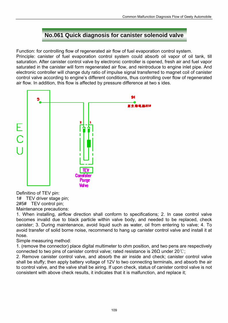
Common Malfunction Diagnosis Flow of Geely Automobile
109
No.061 Quick diagnosis for canister solenoid valve
Function: for controlling flow of regenerated air flow of fuel evaporation control system. Principle: canister of fuel evaporation control system could absorb oil vapor of oil tank, till saturation. After canister control valve by electronic controller is opened, fresh air and fuel vapor saturated in the canister will form regenerated air flow, and reintroduce to engine inlet pipe. And electronic controller will change duty ratio of impulse signal transferred to magnet coil of canister control valve according to engine’s different conditions, thus controlling over flow of regenerated air flow. In addition, this flow is affected by pressure difference at two s ides.
Definitino of TEV pin: 1# TEV driver stage pin; 2#5# TEV control pin; Maintenance precautions: 1. When installing, airflow direction shall conform to specifications; 2. In case control valve becomes invalid due to black particle within valve body, and needed to be replaced, check canister; 3. During maintenance, avoid liquid such as water, oil from entering to valve; 4. To avoid transfer of solid borne noise, recommend to hang up canister control valve and install it at hose. Simple measuring method: 1. (remove the connector) place digital multimeter to ohm position, and two pens are respectively connected to two pins of canister control valve; rated resistance is 26Ω under 20 ; 2. Remove canister control valve, and absorb the air inside and check; canister control valve shall be stuffy; then apply battery voltage of 12V to two connecting terminals, and absorb the air to control valve, and the valve shall be airing. If upon check, status of canister control valve is not consistent with above check results, it indicates that it is malfunction, and replace it;
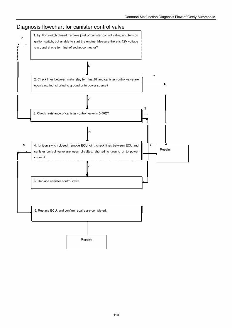
Common Malfunction Diagnosis Flow of Geely Automobile
110
Diagnosis flowchart for canister control valve
1. Ignition switch closed: remove joint of canister control valve, and turn on
ignition switch, but unable to start the engine. Measure there is 12V voltage
to ground at one terminal of socket connector?
2. Check lines between main relay terminal 87 and canister control valve are
open circuited, shorted to ground or to power source?
3. Check resistance of canister control valve is 5-50Ω?
4. Ignition switch closed: remove ECU joint: check lines between ECU and
canister control valve are open circuited, shorted to ground or to power
source?
5. Replace canister control valve
6. Replace ECU, and confirm repairs are completed.
Repairs
Repairs
Y
Y
Y
Y
N
N
N
N
Y
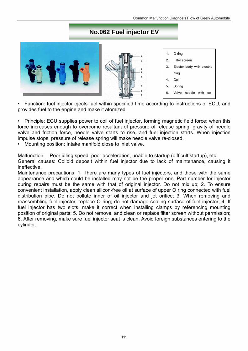
Common Malfunction Diagnosis Flow of Geely Automobile
111
No.062 Fuel injector EV
• Function: fuel injector ejects fuel within specified time according to instructions of ECU, and provides fuel to the engine and make it atomized. • Principle: ECU supplies power to coil of fuel injector, forming magnetic field force; when this force increases enough to overcome resultant of pressure of release spring, gravity of needle valve and friction force, needle valve starts to rise, and fuel injection starts. When injection impulse stops, pressure of release spring will make needle valve re-closed. • Mounting position: Intake manifold close to inlet valve. Malfunction: Poor idling speed, poor acceleration, unable to startup (difficult startup), etc. General causes: Colloid deposit within fuel injector due to lack of maintenance, causing it ineffective. Maintenance precautions: 1. There are many types of fuel injectors, and those with the same appearance and which could be installed may not be the proper one. Part number for injector during repairs must be the same with that of original injector. Do not mix up; 2. To ensure convenient installation, apply clean silicon-free oil at surface of upper O ring connected with fuel distribution pipe. Do not pollute inner of oil injector and jet orifice; 3. When removing and reassembling fuel injector, replace O ring; do not damage sealing surface of fuel injector; 4. If fuel injector has two slots, make it correct when installing clamps by referencing mounting position of original parts; 5. Do not remove, and clean or replace filter screen without permission; 6. After removing, make sure fuel injector seat is clean. Avoid foreign substances entering to the cylinder.
1. O ring
2. Filter screen
3. Ejector body with electric
plug
4. Coil
5. Spring
6. Valve needle with coil
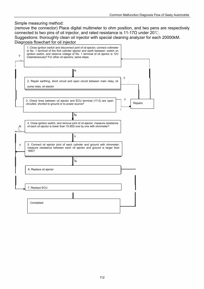
Common Malfunction Diagnosis Flow of Geely Automobile
112
Simple measuring method: (remove the connector) Place digital multimeter to ohm position, and two pens are respectively connected to two pins of oil injector, and rated resistance is 11-17Ω under 20 . Suggestions: thoroughly clean oil injector with special cleaning analyzer for each 20000kM. Diagnosis flowchart for oil injector
1. Close ignition switch and disconnect joint of oil ejector; connect voltmeter to No. 1 terminal of the first cylinder ejector and earth between; switch on ignition switch, and observe voltage of No. 1 terminal of oil ejector is 12V instantaneously? For other oil ejectors, same steps.
2. Repair earthing, short circuit and open circuit between main relay, oil
pump relay, oil ejector
3. Check lines between oil ejector and ECU terminal (17-2) are open circuited, shorted to ground or to power source?
4. Close ignition switch, and remove joint of oil ejector: measure resistance of each oil ejector is lower than 15.95Ω one by one with ohmmeter?
5. Connect oil ejector joint of each cylinder and ground with ohmmeter; measure resistance between each oil ejector and ground is larger than 1MΩ?
6. Replace oil ejector
7. Replace ECU
Completed
Repairs
Y
Y
Y
Y
N
N
N
N
Y
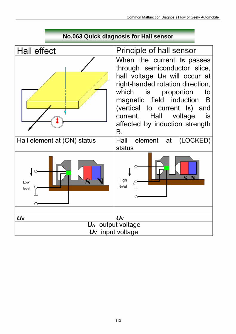
Common Malfunction Diagnosis Flow of Geely Automobile
113
No.063 Quick diagnosis for Hall sensor
Hall effect Principle of hall sensor When the current IS passes through semiconductor slice, hall voltage UH will occur at right-handed rotation direction, which is proportion to magnetic field induction B (vertical to current IS) and current. Hall voltage is affected by induction strength B.
Hall element at (ON) status Hall element at (LOCKED) status
UV UV
UA output voltage
UV input voltage
Low
level
High level
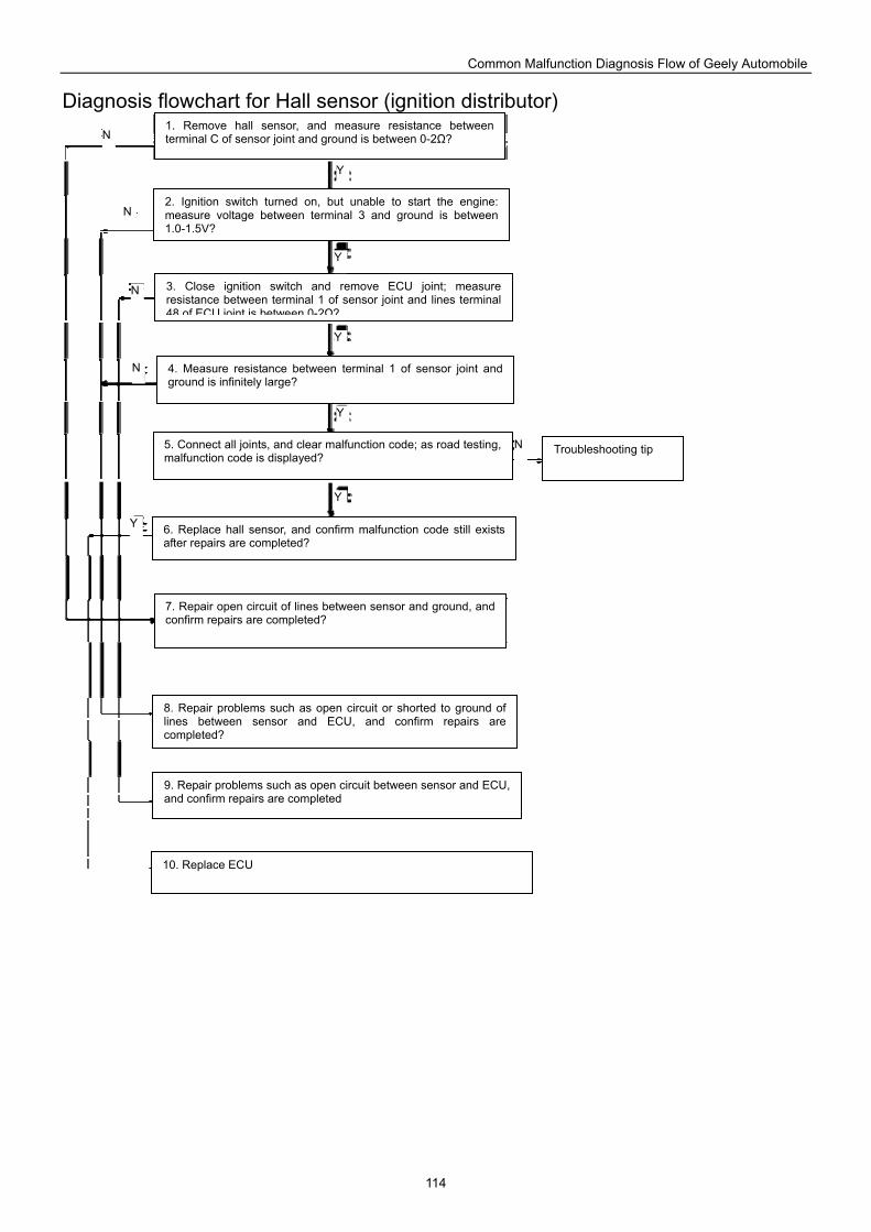
Common Malfunction Diagnosis Flow of Geely Automobile
114
Diagnosis flowchart for Hall sensor (ignition distributor)
1. Remove hall sensor, and measure resistance between terminal C of sensor joint and ground is between 0-2Ω?
2. Ignition switch turned on, but unable to start the engine: measure voltage between terminal 3 and ground is between 1.0-1.5V?
3. Close ignition switch and remove ECU joint; measure resistance between terminal 1 of sensor joint and lines terminal 48 of ECU joint is between 0-2Ω?
4. Measure resistance between terminal 1 of sensor joint and ground is infinitely large?
5. Connect all joints, and clear malfunction code; as road testing, malfunction code is displayed?
6. Replace hall sensor, and confirm malfunction code still exists after repairs are completed?
7. Repair open circuit of lines between sensor and ground, and confirm repairs are completed?
8. Repair problems such as open circuit or shorted to ground of lines between sensor and ECU, and confirm repairs are completed?
9. Repair problems such as open circuit between sensor and ECU, and confirm repairs are completed
10. Replace ECU
Troubleshooting tip
Y
Y
Y
Y
Y
Y
N
N
N
N
N
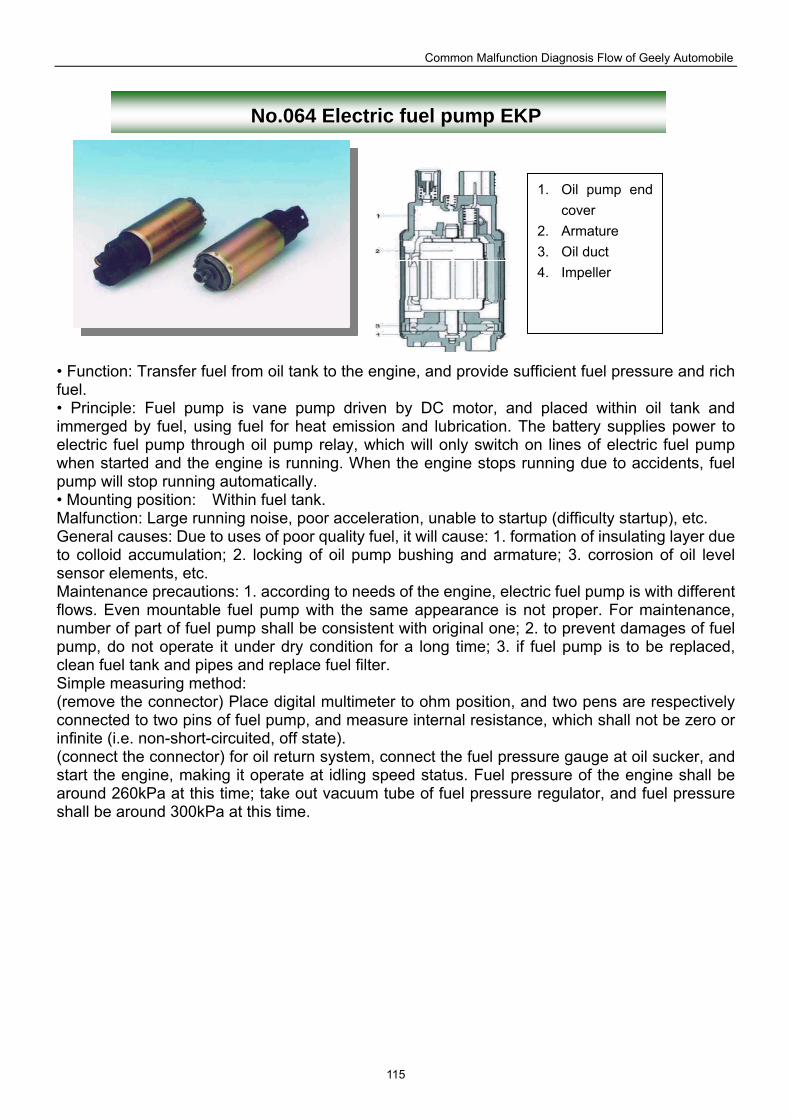
Common Malfunction Diagnosis Flow of Geely Automobile
115
No.064 Electric fuel pump EKP
• Function: Transfer fuel from oil tank to the engine, and provide sufficient fuel pressure and rich fuel. • Principle: Fuel pump is vane pump driven by DC motor, and placed within oil tank and immerged by fuel, using fuel for heat emission and lubrication. The battery supplies power to electric fuel pump through oil pump relay, which will only switch on lines of electric fuel pump when started and the engine is running. When the engine stops running due to accidents, fuel pump will stop running automatically. • Mounting position: Within fuel tank. Malfunction: Large running noise, poor acceleration, unable to startup (difficulty startup), etc. General causes: Due to uses of poor quality fuel, it will cause: 1. formation of insulating layer due to colloid accumulation; 2. locking of oil pump bushing and armature; 3. corrosion of oil level sensor elements, etc. Maintenance precautions: 1. according to needs of the engine, electric fuel pump is with different flows. Even mountable fuel pump with the same appearance is not proper. For maintenance, number of part of fuel pump shall be consistent with original one; 2. to prevent damages of fuel pump, do not operate it under dry condition for a long time; 3. if fuel pump is to be replaced, clean fuel tank and pipes and replace fuel filter. Simple measuring method: (remove the connector) Place digital multimeter to ohm position, and two pens are respectively connected to two pins of fuel pump, and measure internal resistance, which shall not be zero or infinite (i.e. non-short-circuited, off state). (connect the connector) for oil return system, connect the fuel pressure gauge at oil sucker, and start the engine, making it operate at idling speed status. Fuel pressure of the engine shall be around 260kPa at this time; take out vacuum tube of fuel pressure regulator, and fuel pressure shall be around 300kPa at this time.
1. Oil pump end cover
2. Armature 3. Oil duct 4. Impeller
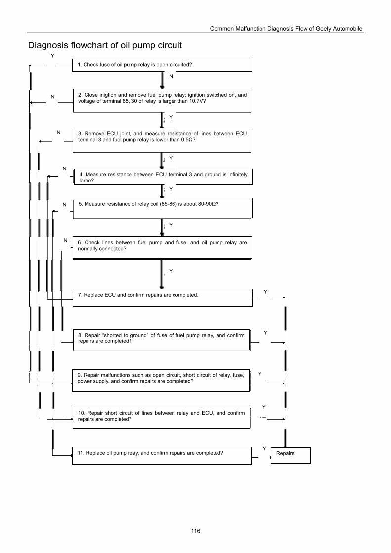
Common Malfunction Diagnosis Flow of Geely Automobile
116
Diagnosis flowchart of oil pump circuit
1. Check fuse of oil pump relay is open circuited?
2. Close inigtion and remove fuel pump relay: ignition switched on, and voltage of terminal 85, 30 of relay is larger than 10.7V?
3. Remove ECU joint, and measure resistance of lines between ECU terminal 3 and fuel pump relay is lower than 0.5Ω?
4. Measure resistance between ECU terminal 3 and ground is infinitely large?
5. Measure resistance of relay coil (85-86) is about 80-90Ω?
6. Check lines between fuel pump and fuse, and oil pump relay are normally connected?
7. Replace ECU and confirm repairs are completed.
8. Repair “shorted to ground” of fuse of fuel pump relay, and confirm repairs are completed?
9. Repair malfunctions such as open circuit, short circuit of relay, fuse, power supply, and confirm repairs are completed?
10. Repair short circuit of lines between relay and ECU, and confirm repairs are completed?
11. Replace oil pump reay, and confirm repairs are completed? Repairs
Y
Y
Y
Y
Y
Y
Y
Y
Y
Y
N
N
N
N
N
N
Y
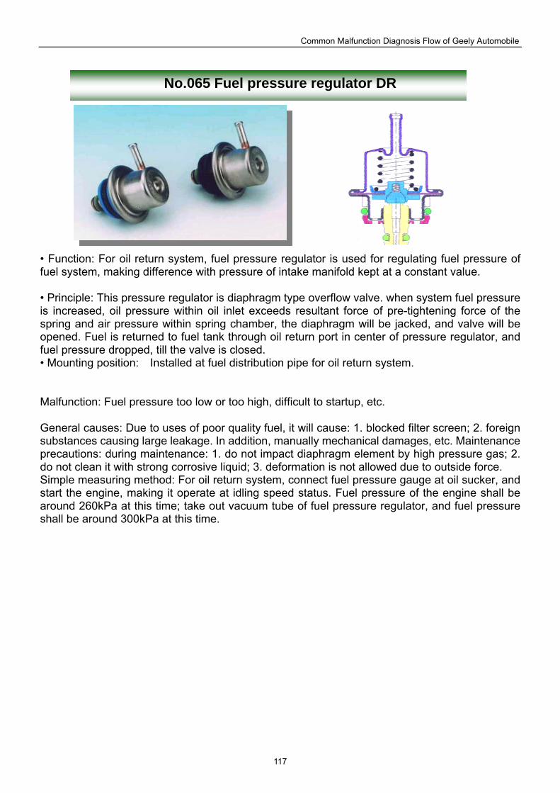
Common Malfunction Diagnosis Flow of Geely Automobile
117
No.065 Fuel pressure regulator DR
• Function: For oil return system, fuel pressure regulator is used for regulating fuel pressure of fuel system, making difference with pressure of intake manifold kept at a constant value. • Principle: This pressure regulator is diaphragm type overflow valve. when system fuel pressure is increased, oil pressure within oil inlet exceeds resultant force of pre-tightening force of the spring and air pressure within spring chamber, the diaphragm will be jacked, and valve will be opened. Fuel is returned to fuel tank through oil return port in center of pressure regulator, and fuel pressure dropped, till the valve is closed. • Mounting position: Installed at fuel distribution pipe for oil return system. Malfunction: Fuel pressure too low or too high, difficult to startup, etc. General causes: Due to uses of poor quality fuel, it will cause: 1. blocked filter screen; 2. foreign substances causing large leakage. In addition, manually mechanical damages, etc. Maintenance precautions: during maintenance: 1. do not impact diaphragm element by high pressure gas; 2. do not clean it with strong corrosive liquid; 3. deformation is not allowed due to outside force. Simple measuring method: For oil return system, connect fuel pressure gauge at oil sucker, and start the engine, making it operate at idling speed status. Fuel pressure of the engine shall be around 260kPa at this time; take out vacuum tube of fuel pressure regulator, and fuel pressure shall be around 300kPa at this time.
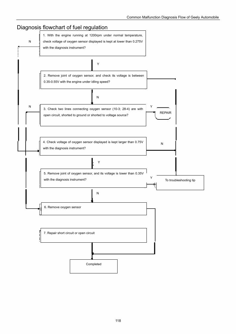
Common Malfunction Diagnosis Flow of Geely Automobile
118
Diagnosis flowchart of fuel regulation
1. With the engine running at 1200rpm under normal temperature,
check voltage of oxygen sensor displayed is kept at lower than 0.275V
with the diagnosis instrument?
2. Remove joint of oxygen sensor, and check its voltage is between
0.35-0.55V with the engine under idling speed?
3. Check two lines connecting oxygen sensor (10-3; 28-4) are with
open circuit, shorted to ground or shorted to voltage source?
4. Check voltage of oxygen sensor displayed is kept larger than 0.75V
with the diagnosis instrument?
5. Remove joint of oxygen sensor, and its voltage is lower than 0.35V
with the diagnosis instrument?
6. Remove oxygen sensor
7. Repair short circuit or open circuit
Completed
To troubleshooting tip
Y
Y
Y
Y
N
N
N
N
N
REPAIR
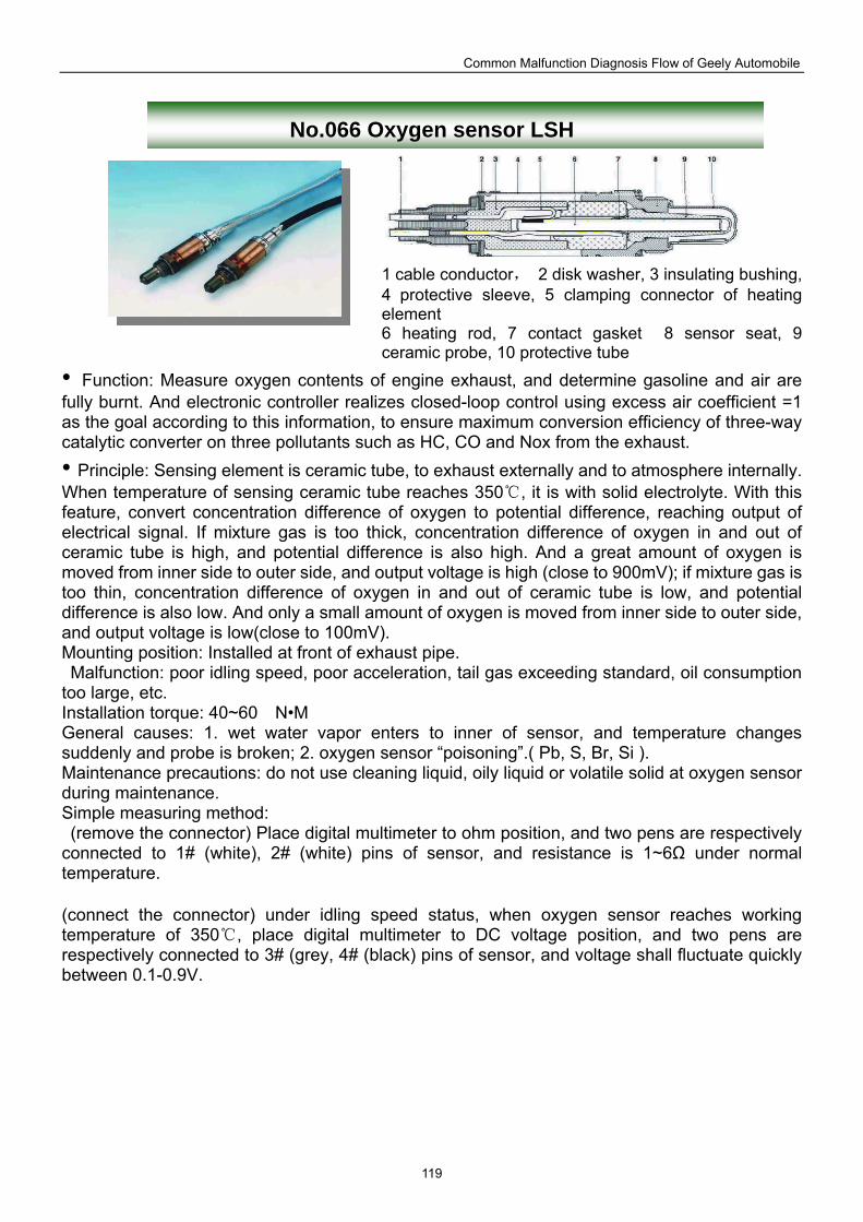
Common Malfunction Diagnosis Flow of Geely Automobile
119
No.066 Oxygen sensor LSH
1 cable conductor, 2 disk washer, 3 insulating bushing, 4 protective sleeve, 5 clamping connector of heating element 6 heating rod, 7 contact gasket 8 sensor seat, 9 ceramic probe, 10 protective tube
• Function: Measure oxygen contents of engine exhaust, and determine gasoline and air are fully burnt. And electronic controller realizes closed-loop control using excess air coefficient =1 as the goal according to this information, to ensure maximum conversion efficiency of three-way catalytic converter on three pollutants such as HC, CO and Nox from the exhaust. • Principle: Sensing element is ceramic tube, to exhaust externally and to atmosphere internally. When temperature of sensing ceramic tube reaches 350 , it is with solid electrolyte. With this feature, convert concentration difference of oxygen to potential difference, reaching output of electrical signal. If mixture gas is too thick, concentration difference of oxygen in and out of ceramic tube is high, and potential difference is also high. And a great amount of oxygen is moved from inner side to outer side, and output voltage is high (close to 900mV); if mixture gas is too thin, concentration difference of oxygen in and out of ceramic tube is low, and potential difference is also low. And only a small amount of oxygen is moved from inner side to outer side, and output voltage is low(close to 100mV). Mounting position: Installed at front of exhaust pipe. Malfunction: poor idling speed, poor acceleration, tail gas exceeding standard, oil consumption too large, etc. Installation torque: 40~60 N•M General causes: 1. wet water vapor enters to inner of sensor, and temperature changes suddenly and probe is broken; 2. oxygen sensor “poisoning”.( Pb, S, Br, Si ). Maintenance precautions: do not use cleaning liquid, oily liquid or volatile solid at oxygen sensor during maintenance. Simple measuring method: (remove the connector) Place digital multimeter to ohm position, and two pens are respectively connected to 1# (white), 2# (white) pins of sensor, and resistance is 1~6Ω under normal temperature. (connect the connector) under idling speed status, when oxygen sensor reaches working temperature of 350 , place digital multimeter to DC voltage position, and two pens are respectively connected to 3# (grey, 4# (black) pins of sensor, and voltage shall fluctuate quickly between 0.1-0.9V.
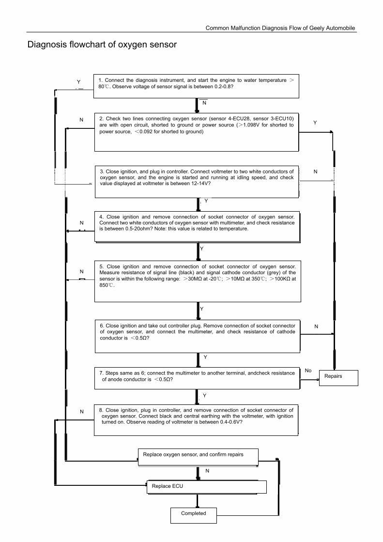
Common Malfunction Diagnosis Flow of Geely Automobile
120
Diagnosis flowchart of oxygen sensor
1. Connect the diagnosis instrument, and start the engine to water temperature >80. Observe voltage of sensor signal is between 0.2-0.8?
2. Check two lines connecting oxygen sensor (sensor 4-ECU28, sensor 3-ECU10) are with open circuit, shorted to ground or power source (>1.098V for shorted to power source, <0.092 for shorted to ground)
3. Close ignition, and plug in controller. Connect voltmeter to two white conductors of oxygen sensor, and the engine is started and running at idling speed, and check value displayed at voltmeter is between 12-14V?
4. Close ignition and remove connection of socket connector of oxygen sensor. Connect two white conductors of oxygen sensor with multimeter, and check resistance is between 0.5-20ohm? Note: this value is related to temperature.
5. Close ignition and remove connection of socket connector of oxygen sensor. Measure resistance of signal line (black) and signal cathode conductor (grey) of the sensor is within the following range: >30MΩ at -20; >10MΩ at 350; >100KΩ at 850.
6. Close ignition and take out controller plug. Remove connection of socket connector of oxygen sensor, and connect the multimeter, and check resistance of cathode conductor is <0.5Ω?
7. Steps same as 6; connect the multimeter to another terminal, andcheck resistance of anode conductor is <0.5Ω?
8. Close ignition, plug in controller, and remove connection of socket connector of oxygen sensor. Connect black and central earthing with the voltmeter, with ignition turned on. Observe reading of voltmeter is between 0.4-0.6V?
Replace oxygen sensor, and confirm repairs
Replace ECU
Completed
Repairs
Y
Y
Y
Y
Y
Y
Y
N
N
N
N
N
N
N
N
No
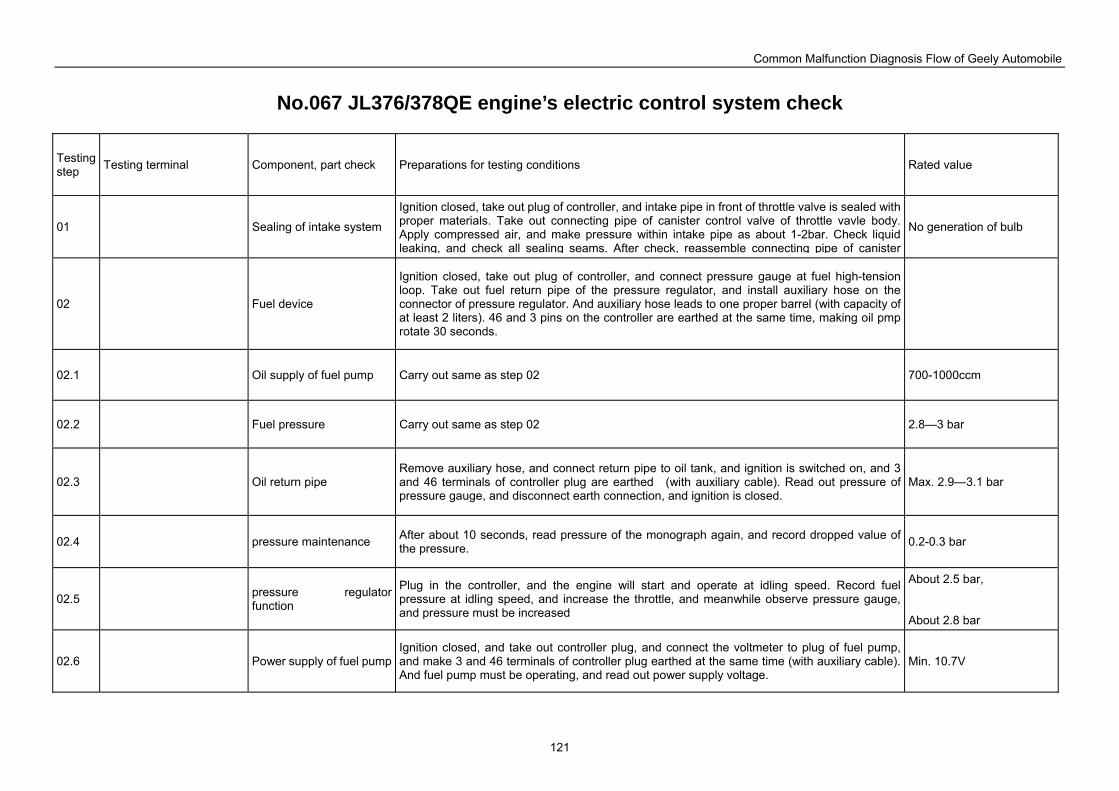
Common Malfunction Diagnosis Flow of Geely Automobile
121
No.067 JL376/378QE engine’s electric control system check
Testing step Testing terminal Component, part check Preparations for testing conditions Rated value
01 Sealing of intake system
Ignition closed, take out plug of controller, and intake pipe in front of throttle valve is sealed with proper materials. Take out connecting pipe of canister control valve of throttle vavle body. Apply compressed air, and make pressure within intake pipe as about 1-2bar. Check liquid leaking, and check all sealing seams. After check, reassemble connecting pipe of canister
No generation of bulb
02 Fuel device
Ignition closed, take out plug of controller, and connect pressure gauge at fuel high-tension loop. Take out fuel return pipe of the pressure regulator, and install auxiliary hose on the connector of pressure regulator. And auxiliary hose leads to one proper barrel (with capacity of at least 2 liters). 46 and 3 pins on the controller are earthed at the same time, making oil pmp rotate 30 seconds.
02.1 Oil supply of fuel pump Carry out same as step 02 700-1000ccm
02.2 Fuel pressure Carry out same as step 02 2.8—3 bar
02.3 Oil return pipe Remove auxiliary hose, and connect return pipe to oil tank, and ignition is switched on, and 3 and 46 terminals of controller plug are earthed (with auxiliary cable). Read out pressure of pressure gauge, and disconnect earth connection, and ignition is closed.
Max. 2.9—3.1 bar
02.4 pressure maintenance After about 10 seconds, read pressure of the monograph again, and record dropped value of the pressure. 0.2-0.3 bar
02.5 pressure regulator function
Plug in the controller, and the engine will start and operate at idling speed. Record fuel pressure at idling speed, and increase the throttle, and meanwhile observe pressure gauge, and pressure must be increased
About 2.5 bar, About 2.8 bar
02.6 Power supply of fuel pumpIgnition closed, and take out controller plug, and connect the voltmeter to plug of fuel pump, and make 3 and 46 terminals of controller plug earthed at the same time (with auxiliary cable). And fuel pump must be operating, and read out power supply voltage.
Min. 10.7V
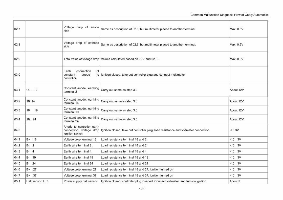
Common Malfunction Diagnosis Flow of Geely Automobile
122
02.7 Voltage drop of anode side Same as description of 02.6, but multimeter placed to another terminal. Max. 0.5V
02.8 Voltage drop of cathode side Same as description of 02.6, but multimeter placed to another terminal. Max. 0.5V
02.9 Total value of voltage drop Values calculated based on 02.7 and 02.8. Max. 0.8V
03.0 Earth connection of constant anode to controller
Ignition closed, take out controller plug and connect multimeter
03.1 18...2 Constant anode, earthing terminal 2 Carry out same as step 3.0 About 12V
03.2 18. 14 Constant anode, earthing terminal 14 Carry out same as step 3.0 About 12V
03.3 18. 19 Constant anode, earthing terminal 19 Carry out same as step 3.0 About 12V
03.4 18…24 Constant anode, earthing terminal 24 Carry out same as step 3.0 About 12V
04.0 Anode to controller earth connection, voltage drop ignition switch
Ignition closed, take out controller plug, load resistance and voltmeter connection <0.3V
04.1 B+ 18 Voltage drop terminal 18 Load resistance terminal 18 and 2 <0.3V
04.2 B- 2 Earth wire terminal 2 Load resistance terminal 18 and 2 <0.3V
04.3 B- 4 Earth wire terminal 4 Load resistance terminal 18 and 4 <0.3V
04.4 B- 19 Earth wire terminal 19 Load resistance terminal 18 and 19 <0.3V
04.5 B- 24 Earth wire terminal 24 Load resistance terminal 18 and 24 <0.3V
04.6 B+ 27 Voltage drop terminal 27 Load resistance terminal 18 and 27, ignition turned on <0.3V
04.7 B+ 37 Voltage drop terminal 37 Load resistance terminal 18 and 37, ignition turned on <0.3V
05.1 Hall sensor 1...3 Power supply hall sensor Ignition closed, controller plug inserted. Connect voltmeter, and turn on ignition. About 5
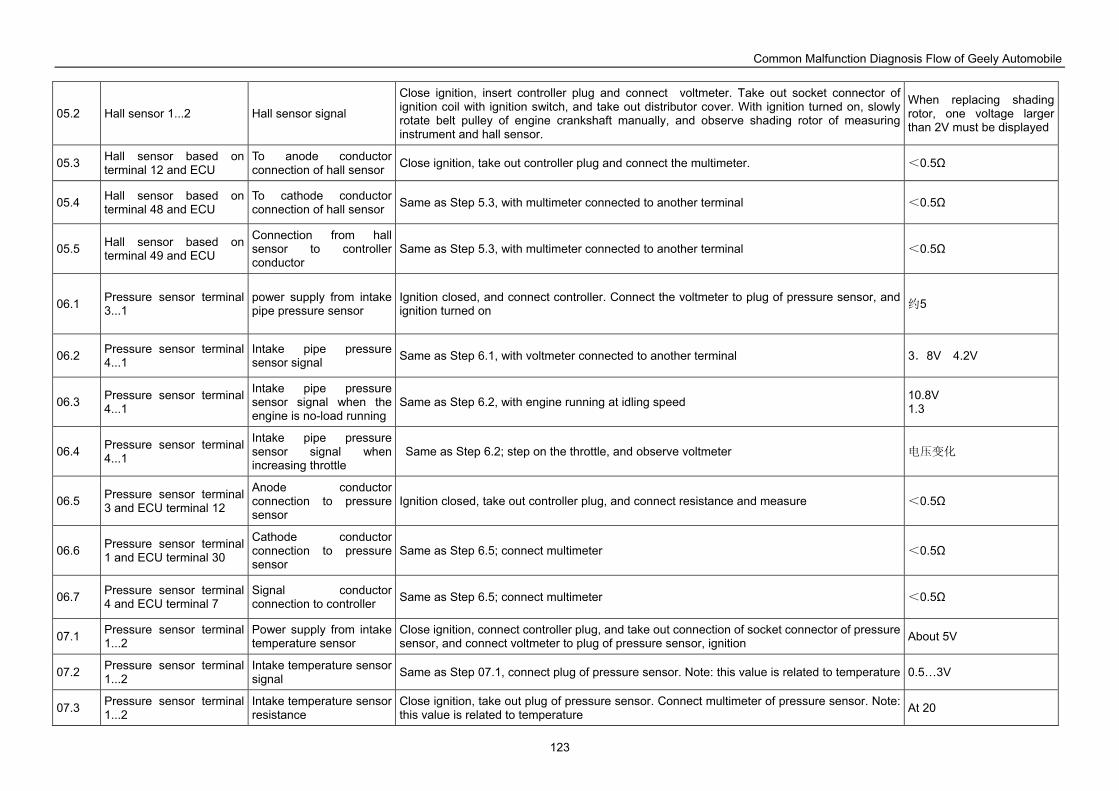
Common Malfunction Diagnosis Flow of Geely Automobile
123
05.2 Hall sensor 1...2 Hall sensor signal
Close ignition, insert controller plug and connect voltmeter. Take out socket connector of ignition coil with ignition switch, and take out distributor cover. With ignition turned on, slowly rotate belt pulley of engine crankshaft manually, and observe shading rotor of measuring instrument and hall sensor.
When replacing shading rotor, one voltage larger than 2V must be displayed
05.3 Hall sensor based on terminal 12 and ECU
To anode conductor connection of hall sensor Close ignition, take out controller plug and connect the multimeter. <0.5Ω
05.4 Hall sensor based on terminal 48 and ECU
To cathode conductor connection of hall sensor Same as Step 5.3, with multimeter connected to another terminal <0.5Ω
05.5 Hall sensor based on terminal 49 and ECU
Connection from hall sensor to controller conductor
Same as Step 5.3, with multimeter connected to another terminal <0.5Ω
06.1 Pressure sensor terminal 3...1
power supply from intake pipe pressure sensor
Ignition closed, and connect controller. Connect the voltmeter to plug of pressure sensor, and ignition turned on 约5
06.2 Pressure sensor terminal 4...1
Intake pipe pressure sensor signal Same as Step 6.1, with voltmeter connected to another terminal 3.8V 4.2V
06.3 Pressure sensor terminal 4...1
Intake pipe pressure sensor signal when the engine is no-load running
Same as Step 6.2, with engine running at idling speed 10.8V 1.3
06.4 Pressure sensor terminal 4...1
Intake pipe pressure sensor signal when increasing throttle
Same as Step 6.2; step on the throttle, and observe voltmeter 电压变化
06.5 Pressure sensor terminal 3 and ECU terminal 12
Anode conductor connection to pressure sensor
Ignition closed, take out controller plug, and connect resistance and measure <0.5Ω
06.6 Pressure sensor terminal 1 and ECU terminal 30
Cathode conductor connection to pressure sensor
Same as Step 6.5; connect multimeter <0.5Ω
06.7 Pressure sensor terminal 4 and ECU terminal 7
Signal conductor connection to controller Same as Step 6.5; connect multimeter <0.5Ω
07.1 Pressure sensor terminal 1...2
Power supply from intake temperature sensor
Close ignition, connect controller plug, and take out connection of socket connector of pressure sensor, and connect voltmeter to plug of pressure sensor, ignition About 5V
07.2 Pressure sensor terminal 1...2
Intake temperature sensor signal Same as Step 07.1, connect plug of pressure sensor. Note: this value is related to temperature 0.5…3V
07.3 Pressure sensor terminal 1...2
Intake temperature sensor resistance
Close ignition, take out plug of pressure sensor. Connect multimeter of pressure sensor. Note: this value is related to temperature At 20
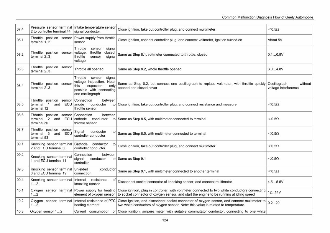
Common Malfunction Diagnosis Flow of Geely Automobile
124
07.4 Pressure sensor terminal 2 to controller terminal 44
Intake temperature sensor signal conductor Close ignition, take out controller plug, and connect multimeter <0.5Ω
08.1 Throttle position sensor terminal 1..2
Power supply from throttle sensor Close ignition, connect controller plug, and connect voltmeter, ignition turned on About 5V
08.2 Throttle position sensor terminal 2..3
Throttle sensor signal voltage, throttle closed, throttle sensor signal voltage
Same as Step 8.1, voltmeter connected to throttle, closed 0.1…0.9V
08.3 Throttle position sensor terminal 2..3 Throttle all opened Same as Step 8.2, whole throttle opened 3.0…4.8V
08.4 Throttle position sensor terminal 2..3
Throttle sensor signal voltage inspection. Note: this inspection only possible with connecting one oscillograph
Same as Step 8.2, but connect one oscillograph to replace voltmeter, with throttle quickly opened and closed sever
Oscillograph without voltage interference
08.5 Throttle position sensor terminal 1 and ECU terminal 12
Connection between anode conductor to throttle sensor
Close ignition, take out controller plug, and connect resistance and measure <0.5Ω
08.6 Throttle position sensor terminal 2 and ECU terminal 30
Connection between cathode conductor to throttle sensor
Same as Step 8.5, with multimeter connected to terminal <0.5Ω
08.7 Throttle position sensor terminal 3 and ECU terminal 53
Signal conductor to controller conductor Same as Step 8.5, with multimeter connected to terminal <0.5Ω
09.1 Knocking sensor terminal 2 and ECU terminal 30
Cathode conductor to controller conductor Close ignition, take out controller plug, and connect multimeter <0.5Ω
09.2 Knocking sensor terminal 1 and ECU terminal 11
Connection between signal conductor to controller
Same as Step 9.1 <0.5Ω
09.3 Knocking sensor terminal 3 and ECU terminal 19
Shielded conductor connection Same as Step 9.1, with multimeter connected to another terminal <0.5Ω
09.4 Knocking sensor terminal 1…2
Internal resistance of knocking sensor Disconnect socket connector of knocking sensor, and connect multimeter 4.5…5.5V
10.1 Oxygen sensor terminal 1…2
Power supply for heating element of oxygen sensor
Close ignition, plug in controller, with voltmeter connected to two white conductors connecting to socket connector of oxygen sensor, and start the engine to be running at idling speed 12...14V
10.2 Oxygen sensor terminal 1…2
Internal resistance of PTC heating element
Close ignition, and disconnect socket connector of oxygen sensor, and connect multimeter to two white conductors of oxygen sensor. Note: this value is related to temperature. 0.2...20
10.3 Oxygen sensor 1…2 Current consumption of Close ignition, ampere meter with suitable commutator conductor, connecting to one white
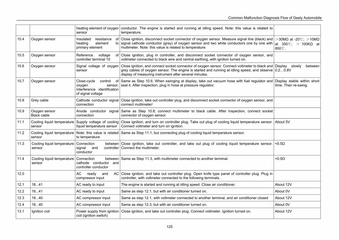
Common Malfunction Diagnosis Flow of Geely Automobile
125
heating element of oxygen sensor
conductor. The engine is started and running at idling speed. Note: this value is related to temperature.
10.4 Oxygen sensor Insulated resistance of heating element to primary element
Close ignition, disconnect socket connector of oxygen sensor. Measure signal line (black) and signal cathode conductor (grey) of oxygen sensor and two white conductors one by one with multimeter. Note: this value is related to temperature.
>30MΩ at -20 ; >10MΩ at 350 ; > 100KΩ at 850 .
10.5 Oxygen sensor Reference voltage of controller terminal 10
Close ignition, plug in controller, and disconnect socket connector of oxygen sensor, and voltmeter connected to black wire and central earthing, with ignition turned on.
10.6 Oxygen sensor Signal voltage of oxygen sensor
Close ignition, and connect socket connector of oxygen sensor. Connect voltmeter to black and grey cables of oxygen sensor. The engine is started and running at idling speed, and observe display of measuring instrument after several minutes.
Display slowly between 0.2…0.8V
10.7 Oxygen sensor Close-cycle control of oxygen sensor, interference identification of signal voltage
Same as Step 10.6. When swinging at display, take out vacuum hose with fuel regulator and seal it. After inspection, plug in hose at pressure regulator.
Display stable within short time. Then re-swing.
10.8 Grey cable Cathode conductor signal connection
Close ignition, take out controller plug, and disconnect socket connector of oxygen sensor, and connect multimeter/
10.9 Oxygen sensor Black cable
Anode conductor signal connection
Same as Step 10.8; connect multimeter to black cable. After inspection, connect socket connector of oxygen sensor.
11.1 Cooling liquid temperature sensor
Supply voltage of cooling liquid temperature sensor
Close ignition, and turn on controller plug. Take out plug of cooling liquid temperature sensor. Connect voltmeter and turn on ignition.
About 5V
11.2 Cooling liquid temperature sensor
Note: this value is related to temperature
Same as Step 11.1, but connecting plug of cooling liquid temperature sensor.
11.3 Cooling liquid temperature sensor
Connection between signal and controller conductor
Close ignition, take out controller, and take out plug of cooling liquid temperature sensor. Connect the multimeter.
<0.5Ω
11.4 Cooling liquid temperature sensor
Connection between cathode conductor and controller conductor
Same as Step 11.3, with multimeter connected to another terminal. <0.5Ω
12.0 AC ready and AC compressor input
Close ignition, and take out controller plug. Open knife type panel of controller plug. Plug in controller, with voltmeter connected to the following terminals.
12.1 18...41 AC ready to input The engine is started and running at idling speed. Close air conditioner. About 12V
12.2 18...41 AC ready to input Same as step 12.1, but with air conditioner turned on. About 0V
12.3 18...40 AC compressor input Same as step 12.1, with voltmeter connected to another terminal, and air conditioner closed About 12V
12.4 18...40 AC compressor input Same as step 12.3, but with air conditioner turned on. About 0V
13.1 Ignition coil Power supply from ignition coil (ignition switch)
Close ignition, and take out controller plug. Connect voltmeter. Ignition turned on. About 12V
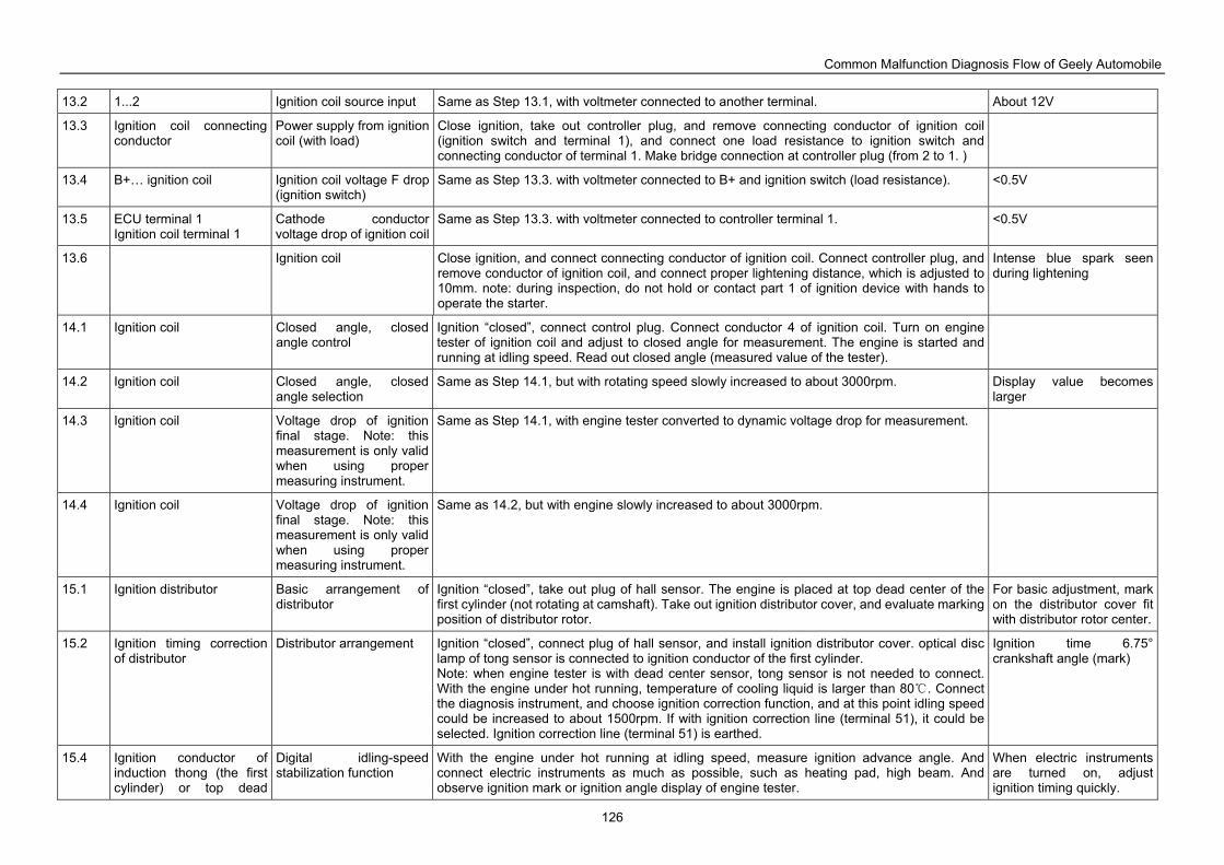
Common Malfunction Diagnosis Flow of Geely Automobile
126
13.2 1...2 Ignition coil source input Same as Step 13.1, with voltmeter connected to another terminal. About 12V
13.3 Ignition coil connecting conductor
Power supply from ignition coil (with load)
Close ignition, take out controller plug, and remove connecting conductor of ignition coil (ignition switch and terminal 1), and connect one load resistance to ignition switch and connecting conductor of terminal 1. Make bridge connection at controller plug (from 2 to 1. )
13.4 B+… ignition coil Ignition coil voltage F drop (ignition switch)
Same as Step 13.3. with voltmeter connected to B+ and ignition switch (load resistance). <0.5V
13.5 ECU terminal 1 Ignition coil terminal 1
Cathode conductor voltage drop of ignition coil
Same as Step 13.3. with voltmeter connected to controller terminal 1. <0.5V
13.6 Ignition coil Close ignition, and connect connecting conductor of ignition coil. Connect controller plug, and remove conductor of ignition coil, and connect proper lightening distance, which is adjusted to 10mm. note: during inspection, do not hold or contact part 1 of ignition device with hands to operate the starter.
Intense blue spark seen during lightening
14.1 Ignition coil Closed angle, closed angle control
Ignition “closed”, connect control plug. Connect conductor 4 of ignition coil. Turn on engine tester of ignition coil and adjust to closed angle for measurement. The engine is started and running at idling speed. Read out closed angle (measured value of the tester).
14.2 Ignition coil Closed angle, closed angle selection
Same as Step 14.1, but with rotating speed slowly increased to about 3000rpm. Display value becomes larger
14.3 Ignition coil Voltage drop of ignition final stage. Note: this measurement is only valid when using proper measuring instrument.
Same as Step 14.1, with engine tester converted to dynamic voltage drop for measurement.
14.4 Ignition coil Voltage drop of ignition final stage. Note: this measurement is only valid when using proper measuring instrument.
Same as 14.2, but with engine slowly increased to about 3000rpm.
15.1 Ignition distributor Basic arrangement of distributor
Ignition “closed”, take out plug of hall sensor. The engine is placed at top dead center of the first cylinder (not rotating at camshaft). Take out ignition distributor cover, and evaluate marking position of distributor rotor.
For basic adjustment, mark on the distributor cover fit with distributor rotor center.
15.2 Ignition timing correction of distributor
Distributor arrangement Ignition “closed”, connect plug of hall sensor, and install ignition distributor cover. optical disc lamp of tong sensor is connected to ignition conductor of the first cylinder. Note: when engine tester is with dead center sensor, tong sensor is not needed to connect. With the engine under hot running, temperature of cooling liquid is larger than 80 . Connect the diagnosis instrument, and choose ignition correction function, and at this point idling speed could be increased to about 1500rpm. If with ignition correction line (terminal 51), it could be selected. Ignition correction line (terminal 51) is earthed.
Ignition time 6.75° crankshaft angle (mark)
15.4 Ignition conductor of induction thong (the first cylinder) or top dead
Digital idling-speed stabilization function
With the engine under hot running at idling speed, measure ignition advance angle. And connect electric instruments as much as possible, such as heating pad, high beam. And observe ignition mark or ignition angle display of engine tester.
When electric instruments are turned on, adjust ignition timing quickly.
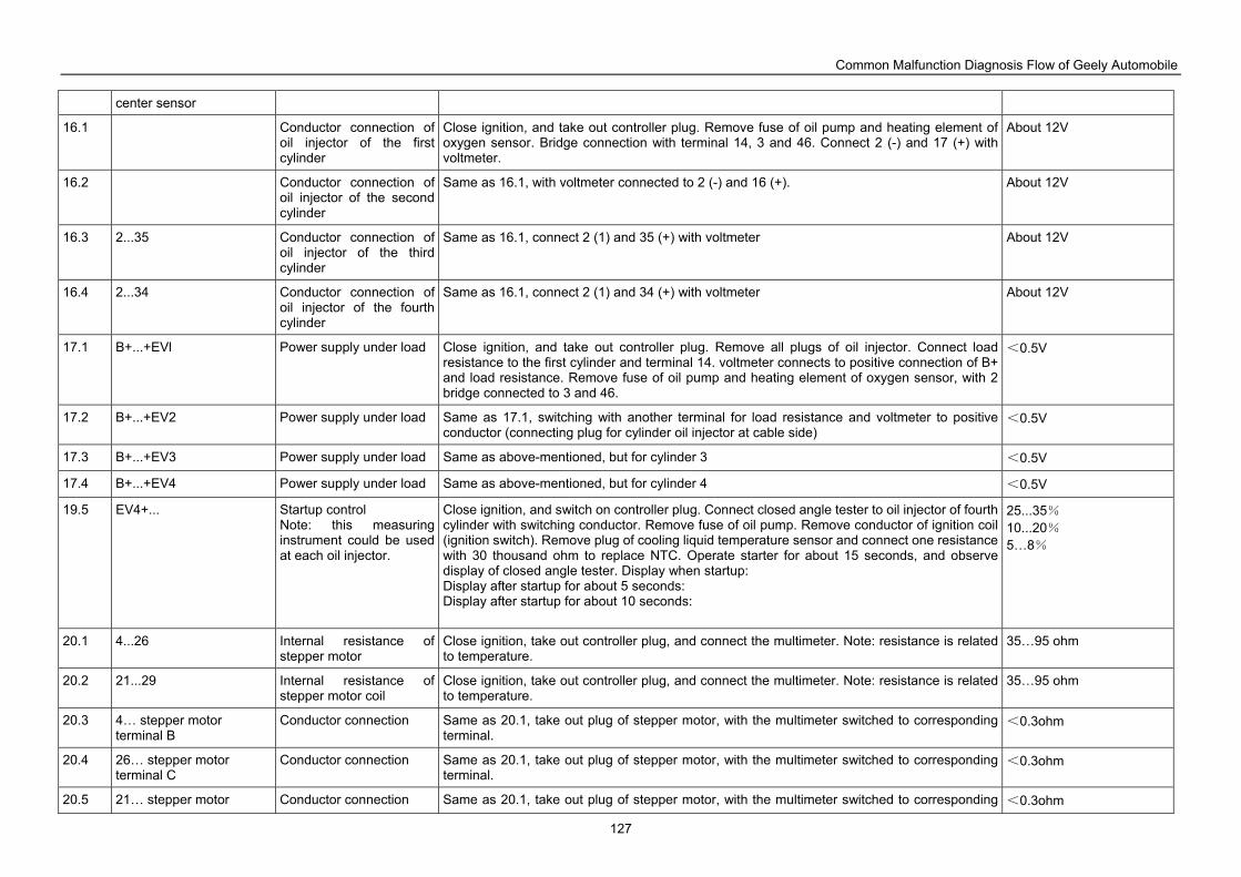
Common Malfunction Diagnosis Flow of Geely Automobile
127
center sensor
16.1 Conductor connection of oil injector of the first cylinder
Close ignition, and take out controller plug. Remove fuse of oil pump and heating element of oxygen sensor. Bridge connection with terminal 14, 3 and 46. Connect 2 (-) and 17 (+) with voltmeter.
About 12V
16.2 Conductor connection of oil injector of the second cylinder
Same as 16.1, with voltmeter connected to 2 (-) and 16 (+). About 12V
16.3 2...35 Conductor connection of oil injector of the third cylinder
Same as 16.1, connect 2 (1) and 35 (+) with voltmeter About 12V
16.4 2...34 Conductor connection of oil injector of the fourth cylinder
Same as 16.1, connect 2 (1) and 34 (+) with voltmeter About 12V
17.1 B+...+EVl Power supply under load Close ignition, and take out controller plug. Remove all plugs of oil injector. Connect load resistance to the first cylinder and terminal 14. voltmeter connects to positive connection of B+ and load resistance. Remove fuse of oil pump and heating element of oxygen sensor, with 2 bridge connected to 3 and 46.
<0.5V
17.2 B+...+EV2 Power supply under load Same as 17.1, switching with another terminal for load resistance and voltmeter to positive conductor (connecting plug for cylinder oil injector at cable side)
<0.5V
17.3 B+...+EV3 Power supply under load Same as above-mentioned, but for cylinder 3 <0.5V
17.4 B+...+EV4 Power supply under load Same as above-mentioned, but for cylinder 4 <0.5V
19.5 EV4+... Startup control Note: this measuring instrument could be used at each oil injector.
Close ignition, and switch on controller plug. Connect closed angle tester to oil injector of fourth cylinder with switching conductor. Remove fuse of oil pump. Remove conductor of ignition coil (ignition switch). Remove plug of cooling liquid temperature sensor and connect one resistance with 30 thousand ohm to replace NTC. Operate starter for about 15 seconds, and observe display of closed angle tester. Display when startup: Display after startup for about 5 seconds: Display after startup for about 10 seconds:
25...35% 10...20% 5…8%
20.1 4...26 Internal resistance of stepper motor
Close ignition, take out controller plug, and connect the multimeter. Note: resistance is related to temperature.
35…95 ohm
20.2 21...29 Internal resistance of stepper motor coil
Close ignition, take out controller plug, and connect the multimeter. Note: resistance is related to temperature.
35…95 ohm
20.3 4… stepper motor terminal B
Conductor connection Same as 20.1, take out plug of stepper motor, with the multimeter switched to corresponding terminal.
<0.3ohm
20.4 26… stepper motor terminal C
Conductor connection Same as 20.1, take out plug of stepper motor, with the multimeter switched to corresponding terminal.
<0.3ohm
20.5 21… stepper motor Conductor connection Same as 20.1, take out plug of stepper motor, with the multimeter switched to corresponding <0.3ohm
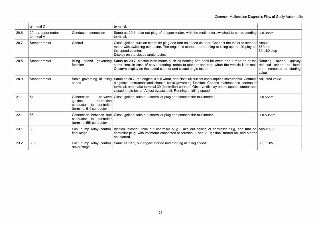
Common Malfunction Diagnosis Flow of Geely Automobile
128
terminal D terminal.
20.6 29… stepper motor terminal A
Conductor connection Same as 20.1, take out plug of stepper motor, with the multimeter switched to corresponding terminal.
<0.3ohm
20.7 Stepper motor Control Close ignition, turn on controller plug and turn on speed counter. Connect the tester to stepper motor with switching conductor. The engine is started and running at idling speed. Display on the speed counter: Display on the closed angle tester:
About 850rpm 60…80 step
20.8 Stepper motor Idling speed governing function
Same as 20.7, electric instruments such as heating pad shall be exact and turned on at the same time. In case of servo steering, rotate to stopper and stop when the vehicle is at rest. Observe display on the speed counter and closed angle tester.
Rotating speed quickly reduced under the load, then increased to starting value
20.9 Stepper motor Basic governing of idling speed
Same as 20.7, the engine is still warm, and close all current consumption instruments. Connect diagnosis instrument and choose basic governing function. Choose maintenance connector terminal. and make terminal 39 (controller) earthed. Observe display on the speed counter and closed angle tester. Adjust bypass bolt. Running at idling speed.
Adjusted value
21.1 51... Connection between ignition correction conductor to controller (terminal 51) conductor
Close ignition, take out controller plug and connect the multimeter. <0.5ohm
22.1 55... Connection between fuel conductor to controller (terminal 55) conductor
Close ignition, take out controller plug and connect the multimeter. <0.50ohm
23.1 3...2 Fuel pump relay control, final stage
Ignition “closed”, take out controller plug. Take out casing of controller plug, and turn on controller plug, with voltmeter connected to terminal 1 and 2. “ignition” turned on, and starter not started.
About 12V
23.2 3...2 Fuel pump relay control, driver stage
Same as 23.1, but engine started and running at idling speed. 0.5...2.0V
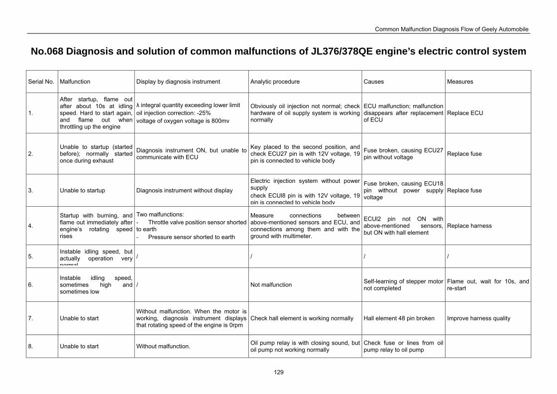
Common Malfunction Diagnosis Flow of Geely Automobile
129
No.068 Diagnosis and solution of common malfunctions of JL376/378QE engine’s electric control system
Serial No. Malfunction Display by diagnosis instrument Analytic procedure Causes Measures
1.
After startup, flame out after about 10s at idling speed. Hard to start again, and flame out when throttling up the engine
λ integral quantity exceeding lower limit oil injection correction: -25% voltage of oxygen voltage is 800mv
Obviously oil injection not normal; check hardware of oil supply system is working normally
ECU malfunction; malfunction disappears after replacement of ECU
Replace ECU
2. Unable to startup (started before); normally started once during exhaust
Diagnosis instrument ON, but unable to communicate with ECU
Key placed to the second position, and check ECU27 pin is with 12V voltage, 19 pin is connected to vehicle body
Fuse broken, causing ECU27 pin without voltage Replace fuse
3. Unable to startup Diagnosis instrument without display Electric injection system without power supply check ECUl8 pin is with 12V voltage, 19 pin is connected to vehicle body
Fuse broken, causing ECU18 pin without power supply voltage
Replace fuse
4.
Startup with burning, and flame out immediately after engine’s rotating speed rises
Two malfunctions: - Throttle valve position sensor shorted to earth - Pressure sensor shorted to earth
Measure connections between above-mentioned sensors and ECU, and connections among them and with the ground with multimeter.
ECUl2 pin not ON with above-mentioned sensors, but ON with hall element
Replace harness
5. Instable idling speed, but actually operation very normal
/ / / /
6. Instable idling speed, sometimes high and sometimes low
/ Not malfunction Self-learning of stepper motor not completed
Flame out, wait for 10s, and re-start
7. Unable to start Without malfunction. When the motor is working, diagnosis instrument displays that rotating speed of the engine is 0rpm
Check hall element is working normally Hall element 48 pin broken Improve harness quality
8. Unable to start Without malfunction. Oil pump relay is with closing sound, but oil pump not working normally
Check fuse or lines from oil pump relay to oil pump
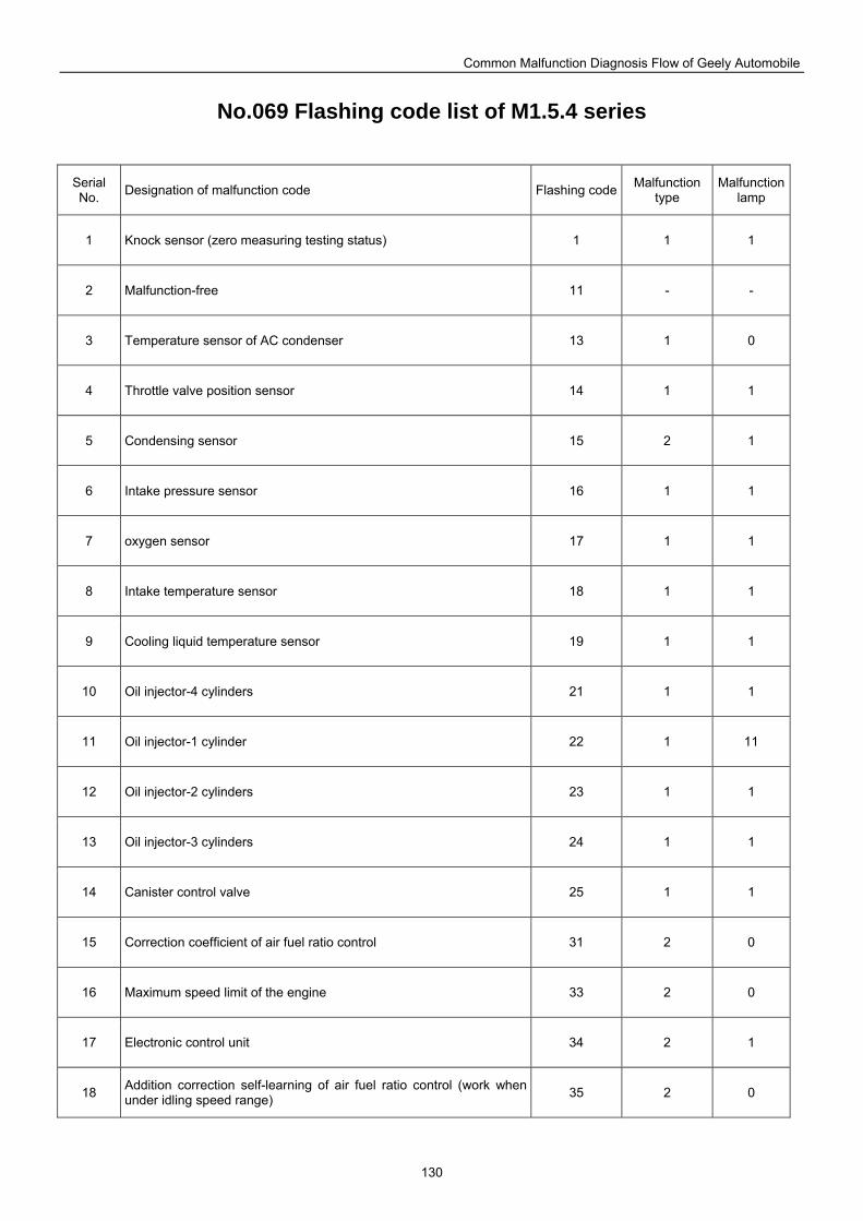
Common Malfunction Diagnosis Flow of Geely Automobile
130
No.069 Flashing code list of M1.5.4 series
Serial No. Designation of malfunction code Flashing code Malfunction
type Malfunction
lamp
1 Knock sensor (zero measuring testing status) 1 1 1
2 Malfunction-free 11 - -
3 Temperature sensor of AC condenser 13 1 0
4 Throttle valve position sensor 14 1 1
5 Condensing sensor 15 2 1
6 Intake pressure sensor 16 1 1
7 oxygen sensor 17 1 1
8 Intake temperature sensor 18 1 1
9 Cooling liquid temperature sensor 19 1 1
10 Oil injector-4 cylinders 21 1 1
11 Oil injector-1 cylinder 22 1 11
12 Oil injector-2 cylinders 23 1 1
13 Oil injector-3 cylinders 24 1 1
14 Canister control valve 25 1 1
15 Correction coefficient of air fuel ratio control 31 2 0
16 Maximum speed limit of the engine 33 2 0
17 Electronic control unit 34 2 1
18 Addition correction self-learning of air fuel ratio control (work when under idling speed range) 35 2 0
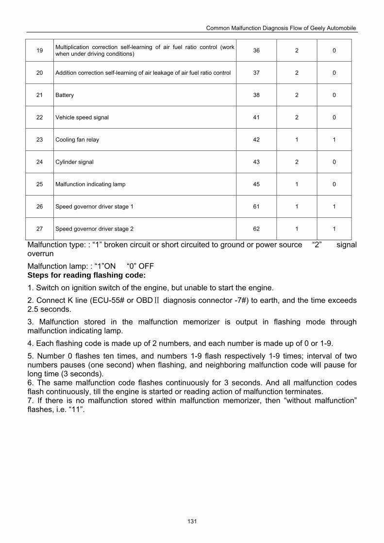
Common Malfunction Diagnosis Flow of Geely Automobile
131
19 Multiplication correction self-learning of air fuel ratio control (work when under driving conditions) 36 2 0
20 Addition correction self-learning of air leakage of air fuel ratio control 37 2 0
21 Battery 38 2 0
22 Vehicle speed signal 41 2 0
23 Cooling fan relay 42 1 1
24 Cylinder signal 43 2 0
25 Malfunction indicating lamp 45 1 0
26 Speed governor driver stage 1 61 1 1
27 Speed governor driver stage 2 62 1 1
Malfunction type: : “1” broken circuit or short circuited to ground or power source “2” signal overrun
Malfunction lamp: : “1”ON “0” OFF Steps for reading flashing code:
1. Switch on ignition switch of the engine, but unable to start the engine.
2. Connect K line (ECU-55# or OBD diagnosis connector Ⅱ -7#) to earth, and the time exceeds 2.5 seconds.
3. Malfunction stored in the malfunction memorizer is output in flashing mode through malfunction indicating lamp.
4. Each flashing code is made up of 2 numbers, and each number is made up of 0 or 1-9.
5. Number 0 flashes ten times, and numbers 1-9 flash respectively 1-9 times; interval of two numbers pauses (one second) when flashing, and neighboring malfunction code will pause for long time (3 seconds). 6. The same malfunction code flashes continuously for 3 seconds. And all malfunction codes flash continuously, till the engine is started or reading action of malfunction terminates. 7. If there is no malfunction stored within malfunction memorizer, then “without malfunction” flashes, i.e. “11”.
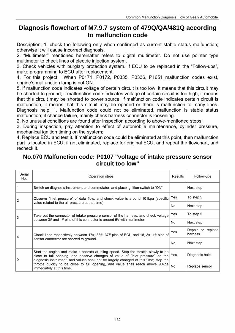
Common Malfunction Diagnosis Flow of Geely Automobile
132
Diagnosis flowchart of M7.9.7 system of 479Q/QA/481Q according to malfunction code
Description: 1. check the following only when confirmed as current stable status malfunction; otherwise it will cause incorrect diagnosis. 2. “Multimeter” mentioned hereinafter refers to digital multimeter. Do not use pointer type multimeter to check lines of electric injection system. 3. Check vehicles with burglary protection system. If ECU to be replaced in the “Follow-ups”, make programming to ECU after replacement. 4. For this project: When P0171, P0172, P0335, P0336, P1651 malfunction codes exist, engine’s malfunction lamp is not ON. 5. If malfunction code indicates voltage of certain circuit is too low, it means that this circuit may be shorted to ground; if malfunction code indicates voltage of certain circuit is too high, it means that this circuit may be shorted to power source; if malfunction code indicates certain circuit is malfunction, it means that this circuit may be opened or there is malfunction to many lines. Diagnosis help: 1. Malfunction code could not be eliminated, malfunction is stable status malfunction; if chance failure, mainly check harness connector is loosening. 2. No unusual conditions are found after inspection according to above-mentioned steps; 3. During inspection, pay attention to effect of automobile maintenance, cylinder pressure, mechanical ignition timing on the system; 4. Replace ECU and test it. If malfunction code could be eliminated at this point, then malfunction part is located in ECU; if not eliminated, replace for original ECU, and repeat the flowchart, and recheck it.
No.070 Malfunction code: P0107 "voltage of intake pressure sensor circuit too low"
Serial No. Operation steps Results Follow-ups
1 Switch on diagnosis instrument and commutator, and place ignition switch to “ON”. Next step
Yes To step 5 2 Observe “inlet pressure” of data flow, and check value is around 101kpa (specific
value related to the air pressure at that time). No Next step
Yes To step 5 3 Take out the connector of intake pressure sensor of the harness, and check voltage
between 3# and 1# pins of this connector is around 5V with multimeter. No Next step
Yes Repair or replace harness
4 Check lines respectively between 17#, 33#, 37# pins of ECU and 1#, 3#, 4# pins of sensor connector are shorted to ground.
No Next step
Yes Diagnosis help 5
Start the engine and make it operate at idling speed. Step the throttle slowly to be close to full opening, and observe changes of value of “inlet pressure” on the diagnosis instrument, and values shall not be largely changed at this time; step the throttle quickly to be close to full opening, and value shall reach above 90kpa immediately at this time. No Replace sensor
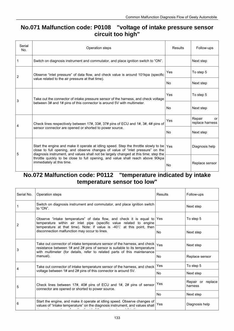
Common Malfunction Diagnosis Flow of Geely Automobile
133
No.071 Malfunction code: P0108 "voltage of intake pressure sensor circuit too high"
Serial No. Operation steps Results Follow-ups
1 Switch on diagnosis instrument and commutator, and place ignition switch to “ON”. Next step
Yes To step 5 2 Observe “inlet pressure” of data flow, and check value is around 101kpa (specific
value related to the air pressure at that time). No Next step
Yes To step 5
3 Take out the connector of intake pressure sensor of the harness, and check voltage between 3# and 1# pins of this connector is around 5V with multimeter.
No Next step
Yes Repair or replace harness
4 Check lines respectively between 17#, 33#, 37# pins of ECU and 1#, 3#, 4# pins of sensor connector are opened or shorted to power source.
No Next step
Yes Diagnosis help
5
Start the engine and make it operate at idling speed. Step the throttle slowly to be close to full opening, and observe changes of value of “inlet pressure” on the diagnosis instrument, and values shall not be largely changed at this time; step the throttle quickly to be close to full opening, and value shall reach above 90kpa immediately at this time.
No Replace sensor
No.072 Malfunction code: P0112 "temperature indicated by intake temperature sensor too low"
Serial No. Operation steps Results Follow-ups
1 Switch on diagnosis instrument and commutator, and place ignition switch to “ON”. Next step
Yes To step 5
2
Observe “intake temperature” of data flow, and check it is equal to temperature within air inlet pipe (specific value related to engine temperature at that time). Note: if value is -40 at this point, then disconnection malfunction may occur to lines. No Next step
Yes Next step 3
Take out connector of intake temperature sensor of the harness, and check resistance between 1# and 2# pins of sensor is suitable to its temperature with multimeter (for details, refer to related parts of this maintenance manual). No Replace sensor
Yes To step 5 4 Take out connector of intake temperature sensor of the harness, and check
voltage between 1# and 2# pins of this connector is around 5V. No Next step
Yes Repair or replace harness 5 Check lines between 17#, 40# pins of ECU and 1#, 2# pins of sensor
connector are opened or shorted to power source. No Next step
6 Start the engine, and make it operate at idling speed. Observe changes of values of “intake temperature” on the diagnosis instrument, and values shall rise as temperature of cooling liquid of the engine rises at this time
Yes Diagnosis help
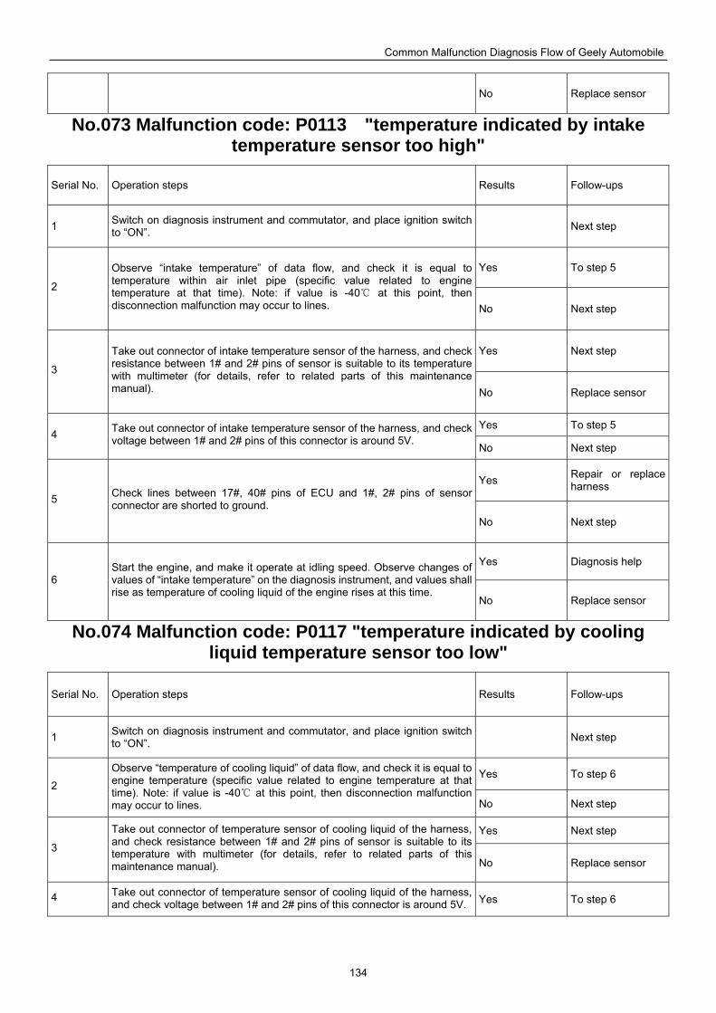
Common Malfunction Diagnosis Flow of Geely Automobile
134
No Replace sensor
No.073 Malfunction code: P0113 "temperature indicated by intake temperature sensor too high"
Serial No. Operation steps Results Follow-ups
1 Switch on diagnosis instrument and commutator, and place ignition switch to “ON”. Next step
Yes To step 5
2
Observe “intake temperature” of data flow, and check it is equal to temperature within air inlet pipe (specific value related to engine temperature at that time). Note: if value is -40 at this point, then disconnection malfunction may occur to lines. No Next step
Yes Next step
3
Take out connector of intake temperature sensor of the harness, and check resistance between 1# and 2# pins of sensor is suitable to its temperature with multimeter (for details, refer to related parts of this maintenance manual). No Replace sensor
Yes To step 5 4 Take out connector of intake temperature sensor of the harness, and check
voltage between 1# and 2# pins of this connector is around 5V. No Next step
Yes Repair or replace harness
5 Check lines between 17#, 40# pins of ECU and 1#, 2# pins of sensor connector are shorted to ground.
No Next step
Yes Diagnosis help
6 Start the engine, and make it operate at idling speed. Observe changes of values of “intake temperature” on the diagnosis instrument, and values shall rise as temperature of cooling liquid of the engine rises at this time.
No Replace sensor
No.074 Malfunction code: P0117 "temperature indicated by cooling liquid temperature sensor too low"
Serial No. Operation steps Results Follow-ups
1 Switch on diagnosis instrument and commutator, and place ignition switch to “ON”. Next step
Yes To step 6 2
Observe “temperature of cooling liquid” of data flow, and check it is equal to engine temperature (specific value related to engine temperature at that time). Note: if value is -40 at this point, then disc onnection malfunction may occur to lines. No Next step
Yes Next step 3
Take out connector of temperature sensor of cooling liquid of the harness, and check resistance between 1# and 2# pins of sensor is suitable to its temperature with multimeter (for details, refer to related parts of this maintenance manual). No Replace sensor
4 Take out connector of temperature sensor of cooling liquid of the harness, and check voltage between 1# and 2# pins of this connector is around 5V. Yes To step 6
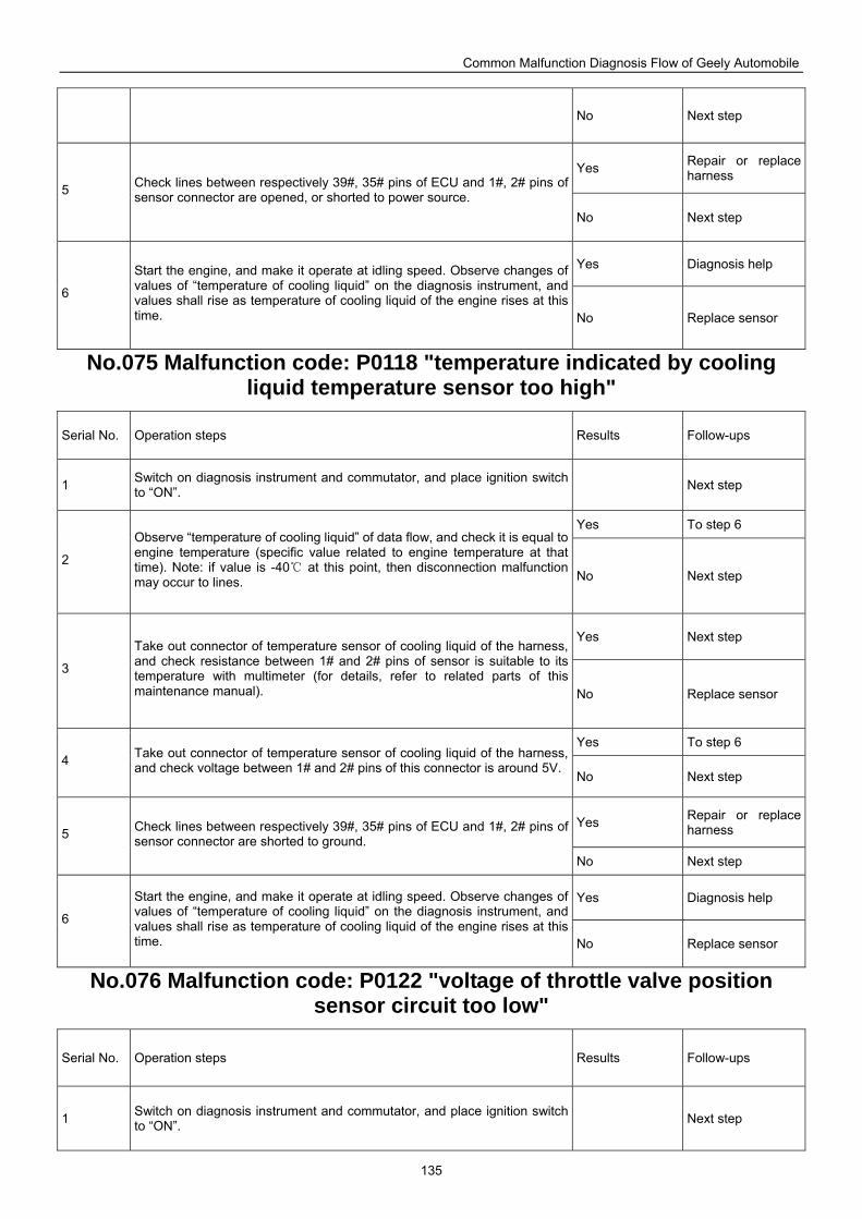
Common Malfunction Diagnosis Flow of Geely Automobile
135
No Next step
Yes Repair or replace harness
5 Check lines between respectively 39#, 35# pins of ECU and 1#, 2# pins of sensor connector are opened, or shorted to power source.
No Next step
Yes Diagnosis help
6
Start the engine, and make it operate at idling speed. Observe changes of values of “temperature of cooling liquid” on the diagnosis instrument, and values shall rise as temperature of cooling liquid of the engine rises at this time. No Replace sensor
No.075 Malfunction code: P0118 "temperature indicated by cooling liquid temperature sensor too high"
Serial No. Operation steps Results Follow-ups
1 Switch on diagnosis instrument and commutator, and place ignition switch to “ON”. Next step
Yes To step 6
2
Observe “temperature of cooling liquid” of data flow, and check it is equal to engine temperature (specific value related to engine temperature at that time). Note: if value is -40 at this point, then disconnection malfunction may occur to lines. No Next step
Yes Next step
3
Take out connector of temperature sensor of cooling liquid of the harness, and check resistance between 1# and 2# pins of sensor is suitable to its temperature with multimeter (for details, refer to related parts of this maintenance manual). No Replace sensor
Yes To step 6 4 Take out connector of temperature sensor of cooling liquid of the harness,
and check voltage between 1# and 2# pins of this connector is around 5V.No Next step
Yes Repair or replace harness 5 Check lines between respectively 39#, 35# pins of ECU and 1#, 2# pins of
sensor connector are shorted to ground. No Next step
Yes Diagnosis help 6
Start the engine, and make it operate at idling speed. Observe changes of values of “temperature of cooling liquid” on the diagnosis instrument, and values shall rise as temperature of cooling liquid of the engine rises at this time. No Replace sensor
No.076 Malfunction code: P0122 "voltage of throttle valve position sensor circuit too low"
Serial No. Operation steps Results Follow-ups
1 Switch on diagnosis instrument and commutator, and place ignition switch to “ON”. Next step
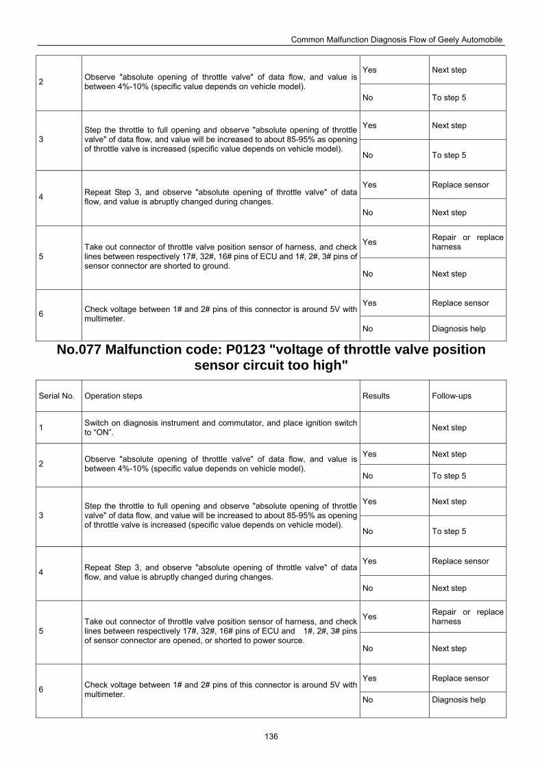
Common Malfunction Diagnosis Flow of Geely Automobile
136
Yes Next step 2 Observe "absolute opening of throttle valve" of data flow, and value is
between 4%-10% (specific value depends on vehicle model). No To step 5
Yes Next step
3 Step the throttle to full opening and observe "absolute opening of throttle valve" of data flow, and value will be increased to about 85-95% as opening of throttle valve is increased (specific value depends on vehicle model).
No To step 5
Yes Replace sensor 4 Repeat Step 3, and observe "absolute opening of throttle valve" of data
flow, and value is abruptly changed during changes. No Next step
Yes Repair or replace harness
5 Take out connector of throttle valve position sensor of harness, and check lines between respectively 17#, 32#, 16# pins of ECU and 1#, 2#, 3# pins of sensor connector are shorted to ground.
No Next step
Yes Replace sensor 6 Check voltage between 1# and 2# pins of this connector is around 5V with
multimeter. No Diagnosis help
No.077 Malfunction code: P0123 "voltage of throttle valve position sensor circuit too high"
Serial No. Operation steps Results Follow-ups
1 Switch on diagnosis instrument and commutator, and place ignition switch to “ON”. Next step
Yes Next step 2 Observe "absolute opening of throttle valve" of data flow, and value is
between 4%-10% (specific value depends on vehicle model). No To step 5
Yes Next step
3 Step the throttle to full opening and observe "absolute opening of throttle valve" of data flow, and value will be increased to about 85-95% as opening of throttle valve is increased (specific value depends on vehicle model).
No To step 5
Yes Replace sensor 4 Repeat Step 3, and observe "absolute opening of throttle valve" of data
flow, and value is abruptly changed during changes. No Next step
Yes Repair or replace harness
5 Take out connector of throttle valve position sensor of harness, and check lines between respectively 17#, 32#, 16# pins of ECU and 1#, 2#, 3# pins of sensor connector are opened, or shorted to power source.
No Next step
Yes Replace sensor 6 Check voltage between 1# and 2# pins of this connector is around 5V with
multimeter. No Diagnosis help
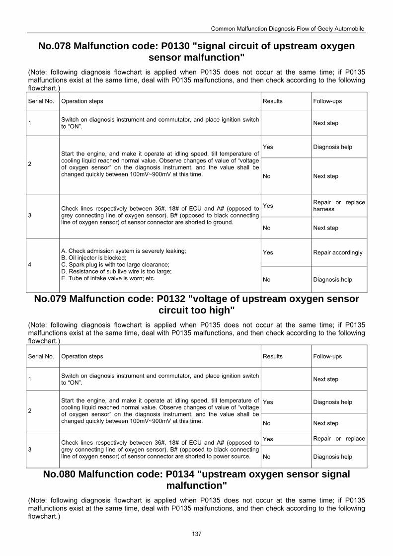
Common Malfunction Diagnosis Flow of Geely Automobile
137
No.078 Malfunction code: P0130 "signal circuit of upstream oxygen sensor malfunction"
(Note: following diagnosis flowchart is applied when P0135 does not occur at the same time; if P0135 malfunctions exist at the same time, deal with P0135 malfunctions, and then check according to the following flowchart.)
Serial No. Operation steps Results Follow-ups
1 Switch on diagnosis instrument and commutator, and place ignition switch to “ON”. Next step
Yes Diagnosis help
2
Start the engine, and make it operate at idling speed, till temperature of cooling liquid reached normal value. Observe changes of value of “voltage of oxygen sensor” on the diagnosis instrument, and the value shall be changed quickly between 100mV~900mV at this time. No Next step
Yes Repair or replace harness
3 Check lines respectively between 36#, 18# of ECU and A# (opposed to grey connecting line of oxygen sensor), B# (opposed to black connecting line of oxygen sensor) of sensor connector are shorted to ground.
No Next step
Yes Repair accordingly
4
A. Check admission system is severely leaking; B. Oil injector is blocked; C. Spark plug is with too large clearance; D. Resistance of sub live wire is too large; E. Tube of intake valve is worn; etc. No Diagnosis help
No.079 Malfunction code: P0132 "voltage of upstream oxygen sensor circuit too high"
(Note: following diagnosis flowchart is applied when P0135 does not occur at the same time; if P0135 malfunctions exist at the same time, deal with P0135 malfunctions, and then check according to the following flowchart.)
Serial No. Operation steps Results Follow-ups
1 Switch on diagnosis instrument and commutator, and place ignition switch to “ON”. Next step
Yes Diagnosis help 2
Start the engine, and make it operate at idling speed, till temperature of cooling liquid reached normal value. Observe changes of value of “voltage of oxygen sensor” on the diagnosis instrument, and the value shall be changed quickly between 100mV~900mV at this time. No Next step
Yes Repair or replace
3 Check lines respectively between 36#, 18# of ECU and A# (opposed to grey connecting line of oxygen sensor), B# (opposed to black connecting line of oxygen sensor) of sensor connector are shorted to power source. No Diagnosis help
No.080 Malfunction code: P0134 "upstream oxygen sensor signal malfunction"
(Note: following diagnosis flowchart is applied when P0135 does not occur at the same time; if P0135 malfunctions exist at the same time, deal with P0135 malfunctions, and then check according to the following flowchart.)
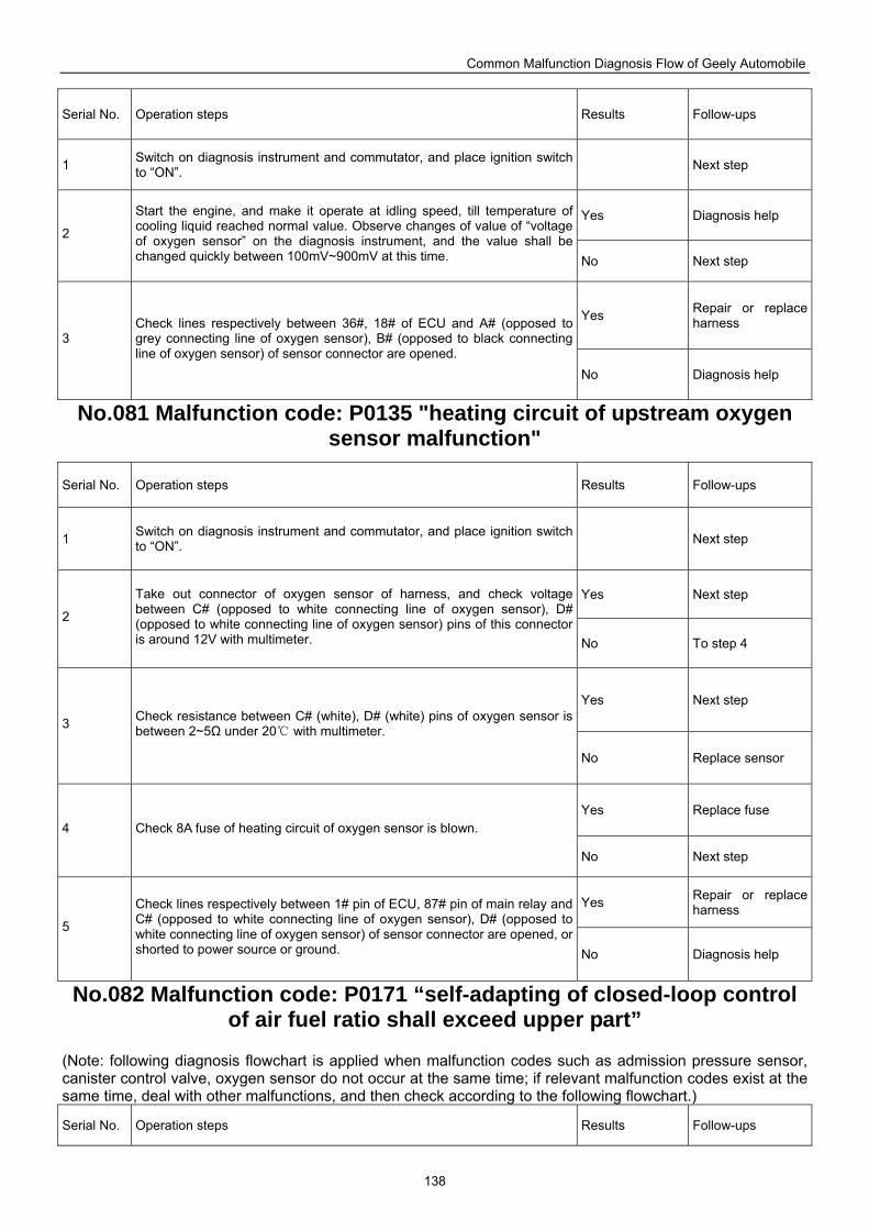
Common Malfunction Diagnosis Flow of Geely Automobile
138
Serial No. Operation steps Results Follow-ups
1 Switch on diagnosis instrument and commutator, and place ignition switch to “ON”. Next step
Yes Diagnosis help 2
Start the engine, and make it operate at idling speed, till temperature of cooling liquid reached normal value. Observe changes of value of “voltage of oxygen sensor” on the diagnosis instrument, and the value shall be changed quickly between 100mV~900mV at this time. No Next step
Yes Repair or replace harness
3 Check lines respectively between 36#, 18# of ECU and A# (opposed to grey connecting line of oxygen sensor), B# (opposed to black connecting line of oxygen sensor) of sensor connector are opened.
No Diagnosis help
No.081 Malfunction code: P0135 "heating circuit of upstream oxygen sensor malfunction"
Serial No. Operation steps Results Follow-ups
1 Switch on diagnosis instrument and commutator, and place ignition switch to “ON”. Next step
Yes Next step
2
Take out connector of oxygen sensor of harness, and check voltage between C# (opposed to white connecting line of oxygen sensor), D# (opposed to white connecting line of oxygen sensor) pins of this connector is around 12V with multimeter. No To step 4
Yes Next step
3 Check resistance between C# (white), D# (white) pins of oxygen sensor is between 2~5Ω under 20 with multimeter.
No Replace sensor
Yes Replace fuse 4 Check 8A fuse of heating circuit of oxygen sensor is blown.
No Next step
Yes Repair or replace harness
5
Check lines respectively between 1# pin of ECU, 87# pin of main relay and C# (opposed to white connecting line of oxygen sensor), D# (opposed to white connecting line of oxygen sensor) of sensor connector are opened, or shorted to power source or ground. No Diagnosis help
No.082 Malfunction code: P0171 “self-adapting of closed-loop control of air fuel ratio shall exceed upper part”
(Note: following diagnosis flowchart is applied when malfunction codes such as admission pressure sensor, canister control valve, oxygen sensor do not occur at the same time; if relevant malfunction codes exist at the same time, deal with other malfunctions, and then check according to the following flowchart.)
Serial No. Operation steps Results Follow-ups
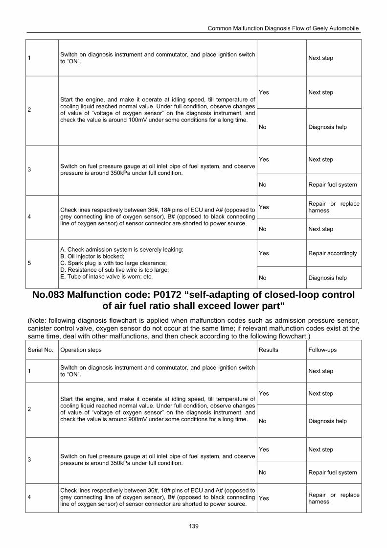
Common Malfunction Diagnosis Flow of Geely Automobile
139
1 Switch on diagnosis instrument and commutator, and place ignition switch to “ON”. Next step
Yes Next step
2
Start the engine, and make it operate at idling speed, till temperature of cooling liquid reached normal value. Under full condition, observe changes of value of “voltage of oxygen sensor” on the diagnosis instrument, and check the value is around 100mV under some conditions for a long time.
No Diagnosis help
Yes Next step
3 Switch on fuel pressure gauge at oil inlet pipe of fuel system, and observe pressure is around 350kPa under full condition.
No Repair fuel system
Yes Repair or replace harness
4 Check lines respectively between 36#, 18# pins of ECU and A# (opposed to grey connecting line of oxygen sensor), B# (opposed to black connecting line of oxygen sensor) of sensor connector are shorted to power source.
No Next step
Yes Repair accordingly
5
A. Check admission system is severely leaking; B. Oil injector is blocked; C. Spark plug is with too large clearance; D. Resistance of sub live wire is too large; E. Tube of intake valve is worn; etc. No Diagnosis help
No.083 Malfunction code: P0172 “self-adapting of closed-loop control of air fuel ratio shall exceed lower part”
(Note: following diagnosis flowchart is applied when malfunction codes such as admission pressure sensor, canister control valve, oxygen sensor do not occur at the same time; if relevant malfunction codes exist at the same time, deal with other malfunctions, and then check according to the following flowchart.)
Serial No. Operation steps Results Follow-ups
1 Switch on diagnosis instrument and commutator, and place ignition switch to “ON”. Next step
Yes Next step
2
Start the engine, and make it operate at idling speed, till temperature of cooling liquid reached normal value. Under full condition, observe changes of value of “voltage of oxygen sensor” on the diagnosis instrument, and check the value is around 900mV under some conditions for a long time. No Diagnosis help
Yes Next step
3 Switch on fuel pressure gauge at oil inlet pipe of fuel system, and observe pressure is around 350kPa under full condition.
No Repair fuel system
4 Check lines respectively between 36#, 18# pins of ECU and A# (opposed to grey connecting line of oxygen sensor), B# (opposed to black connecting line of oxygen sensor) of sensor connector are shorted to power source.
Yes Repair or replace harness
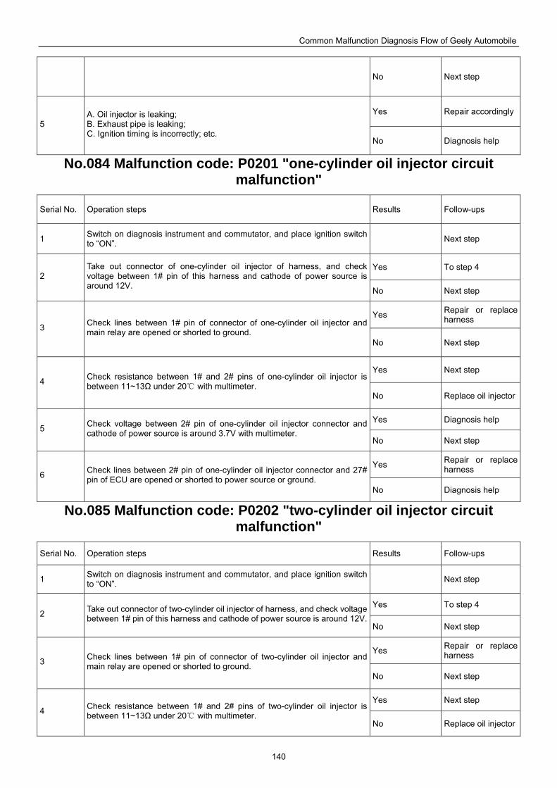
Common Malfunction Diagnosis Flow of Geely Automobile
140
No Next step
Yes Repair accordingly5
A. Oil injector is leaking; B. Exhaust pipe is leaking; C. Ignition timing is incorrectly; etc.
No Diagnosis help
No.084 Malfunction code: P0201 "one-cylinder oil injector circuit malfunction"
Serial No. Operation steps Results Follow-ups
1 Switch on diagnosis instrument and commutator, and place ignition switch to “ON”. Next step
Yes To step 4 2
Take out connector of one-cylinder oil injector of harness, and check voltage between 1# pin of this harness and cathode of power source is around 12V. No Next step
Yes Repair or replace harness
3 Check lines between 1# pin of connector of one-cylinder oil injector and main relay are opened or shorted to ground.
No Next step
Yes Next step 4 Check resistance between 1# and 2# pins of one-cylinder oil injector is
between 11~13Ω under 20 with multimeter. No Replace oil injector
Yes Diagnosis help 5 Check voltage between 2# pin of one-cylinder oil injector connector and
cathode of power source is around 3.7V with multimeter. No Next step
Yes Repair or replace harness 6 Check lines between 2# pin of one-cylinder oil injector connector and 27#
pin of ECU are opened or shorted to power source or ground. No Diagnosis help
No.085 Malfunction code: P0202 "two-cylinder oil injector circuit malfunction"
Serial No. Operation steps Results Follow-ups
1 Switch on diagnosis instrument and commutator, and place ignition switch to “ON”. Next step
Yes To step 4 2 Take out connector of two-cylinder oil injector of harness, and check voltage
between 1# pin of this harness and cathode of power source is around 12V.No Next step
Yes Repair or replace harness
3 Check lines between 1# pin of connector of two-cylinder oil injector and main relay are opened or shorted to ground.
No Next step
Yes Next step 4 Check resistance between 1# and 2# pins of two-cylinder oil injector is
between 11~13Ω under 20 with multimeter. No Replace oil injector
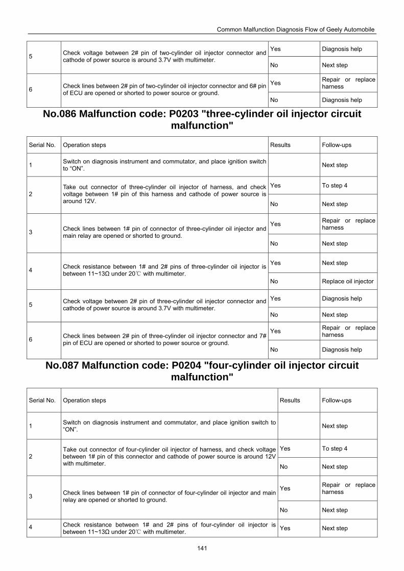
Common Malfunction Diagnosis Flow of Geely Automobile
141
Yes Diagnosis help 5 Check voltage between 2# pin of two-cylinder oil injector connector and
cathode of power source is around 3.7V with multimeter. No Next step
Yes Repair or replace harness 6 Check lines between 2# pin of two-cylinder oil injector connector and 6# pin
of ECU are opened or shorted to power source or ground. No Diagnosis help
No.086 Malfunction code: P0203 "three-cylinder oil injector circuit malfunction"
Serial No. Operation steps Results Follow-ups
1 Switch on diagnosis instrument and commutator, and place ignition switch to “ON”. Next step
Yes To step 4 2
Take out connector of three-cylinder oil injector of harness, and check voltage between 1# pin of this harness and cathode of power source is around 12V. No Next step
Yes Repair or replace harness
3 Check lines between 1# pin of connector of three-cylinder oil injector and main relay are opened or shorted to ground.
No Next step
Yes Next step 4 Check resistance between 1# and 2# pins of three-cylinder oil injector is
between 11~13Ω under 20 with multimeter. No Replace oil injector
Yes Diagnosis help 5 Check voltage between 2# pin of three-cylinder oil injector connector and
cathode of power source is around 3.7V with multimeter. No Next step
Yes Repair or replace harness
6 Check lines between 2# pin of three-cylinder oil injector connector and 7# pin of ECU are opened or shorted to power source or ground.
No Diagnosis help
No.087 Malfunction code: P0204 "four-cylinder oil injector circuit malfunction"
Serial No. Operation steps Results Follow-ups
1 Switch on diagnosis instrument and commutator, and place ignition switch to “ON”. Next step
Yes To step 4 2
Take out connector of four-cylinder oil injector of harness, and check voltage between 1# pin of this connector and cathode of power source is around 12V with multimeter. No Next step
Yes Repair or replace harness
3 Check lines between 1# pin of connector of four-cylinder oil injector and main relay are opened or shorted to ground.
No Next step
4 Check resistance between 1# and 2# pins of four-cylinder oil injector is between 11~13Ω under 20 with multimeter.
Yes Next step
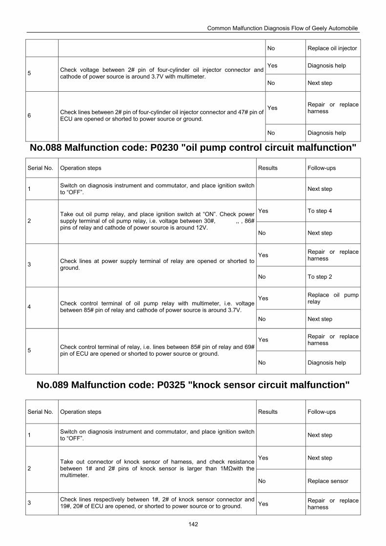
Common Malfunction Diagnosis Flow of Geely Automobile
142
No Replace oil injector
Yes Diagnosis help 5 Check voltage between 2# pin of four-cylinder oil injector connector and
cathode of power source is around 3.7V with multimeter. No Next step
Yes Repair or replace harness
6 Check lines between 2# pin of four-cylinder oil injector connector and 47# pin of ECU are opened or shorted to power source or ground.
No Diagnosis help
No.088 Malfunction code: P0230 "oil pump control circuit malfunction"
Serial No. Operation steps Results Follow-ups
1 Switch on diagnosis instrument and commutator, and place ignition switch to “OFF”. Next step
Yes To step 4
2 Take out oil pump relay, and place ignition switch at “ON”. Check power supply terminal of oil pump relay, i.e. voltage between 30#, ,, , 86# pins of relay and cathode of power source is around 12V.
No Next step
Yes Repair or replace harness
3 Check lines at power supply terminal of relay are opened or shorted to ground.
No To step 2
Yes Replace oil pump relay
4 Check control terminal of oil pump relay with multimeter, i.e. voltage between 85# pin of relay and cathode of power source is around 3.7V.
No Next step
Yes Repair or replace harness
5 Check control terminal of relay, i.e. lines between 85# pin of relay and 69# pin of ECU are opened or shorted to power source or ground.
No Diagnosis help
No.089 Malfunction code: P0325 "knock sensor circuit malfunction"
Serial No. Operation steps Results Follow-ups
1 Switch on diagnosis instrument and commutator, and place ignition switch to “OFF”. Next step
Yes Next step
2 Take out connector of knock sensor of harness, and check resistance between 1# and 2# pins of knock sensor is larger than 1MΩwith the multimeter.
No Replace sensor
3 Check lines respectively between 1#, 2# of knock sensor connector and 19#, 20# of ECU are opened, or shorted to power source or to ground. Yes Repair or replace
harness
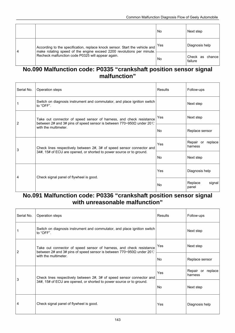
Common Malfunction Diagnosis Flow of Geely Automobile
143
No Next step
Yes Diagnosis help
4 According to the specification, replace knock sensor. Start the vehicle and make rotating speed of the engine exceed 2200 revolutions per minute. Recheck malfunction code P0325 will appear again.
No Check as chance failure
No.090 Malfunction code: P0335 “crankshaft position sensor signal malfunction”
Serial No. Operation steps Results Follow-ups
1 Switch on diagnosis instrument and commutator, and place ignition switch to “OFF”. Next step
Yes Next step
2 Take out connector of speed sensor of harness, and check resistance between 2# and 3# pins of speed sensor is between 770~950Ω under 20 with the multimeter.
No Replace sensor
Yes Repair or replace harness
3 Check lines respectively between 2#, 3# of speed sensor connector and 34#, 15# of ECU are opened, or shorted to power source or to ground.
No Next step
Yes Diagnosis help
4 Check signal panel of flywheel is good.
No Replace signal panel
No.091 Malfunction code: P0336 “crankshaft position sensor signal with unreasonable malfunction”
Serial No. Operation steps Results Follow-ups
1 Switch on diagnosis instrument and commutator, and place ignition switch to “OFF”. Next step
Yes Next step
2 Take out connector of speed sensor of harness, and check resistance between 2# and 3# pins of speed sensor is between 770~950Ω under 20 with the multimeter.
No Replace sensor
Yes Repair or replace harness
3 Check lines respectively between 2#, 3# of speed sensor connector and 34#, 15# of ECU are opened, or shorted to power source or to ground.
No Next step
4 Check signal panel of flywheel is good. Yes Diagnosis help
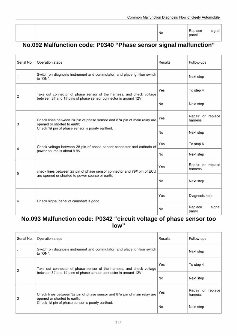
Common Malfunction Diagnosis Flow of Geely Automobile
144
No Replace signal panel
No.092 Malfunction code: P0340 “Phase sensor signal malfunction”
Serial No. Operation steps Results Follow-ups
1 Switch on diagnosis instrument and commutator, and place ignition switch to “ON”. Next step
Yes To step 4
2 Take out connector of phase sensor of the harness, and check voltage between 3# and 1# pins of phase sensor connector is around 12V.
No Next step
Yes Repair or replace harness
3 Check lines between 3# pin of phase sensor and 87# pin of main relay are opened or shorted to earth; Check 1# pin of phase sensor is poorly earthed.
No Next step
Yes To step 6 4 Check voltage between 2# pin of phase sensor connector and cathode of
power source is about 9.9V. No Next step
Yes Repair or replace harness
5 check lines between 2# pin of phase sensor connector and 79# pin of ECU are opened or shorted to power source or earth;
No Next step
Yes Diagnosis help 6 Check signal panel of camshaft is good.
No Replace signal panel
No.093 Malfunction code: P0342 “circuit voltage of phase sensor too low”
Serial No. Operation steps Results Follow-ups
1 Switch on diagnosis instrument and commutator, and place ignition switch to “ON”. Next step
Yes To step 4
2 Take out connector of phase sensor of the harness, and check voltage between 3# and 1# pins of phase sensor connector is around 12V.
No Next step
Yes Repair or replace harness
3 Check lines between 3# pin of phase sensor and 87# pin of main relay are opened or shorted to earth; Check 1# pin of phase sensor is poorly earthed.
No Next step
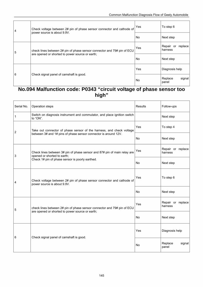
Common Malfunction Diagnosis Flow of Geely Automobile
145
Yes To step 6 4 Check voltage between 2# pin of phase sensor connector and cathode of
power source is about 9.9V. No Next step
Yes Repair or replace harness
5 check lines between 2# pin of phase sensor connector and 79# pin of ECU are opened or shorted to power source or earth;
No Next step
Yes Diagnosis help
6 Check signal panel of camshaft is good.
No Replace signal panel
No.094 Malfunction code: P0343 “circuit voltage of phase sensor too high”
Serial No. Operation steps Results Follow-ups
1 Switch on diagnosis instrument and commutator, and place ignition switch to “ON”. Next step
Yes To step 4
2 Take out connector of phase sensor of the harness, and check voltage between 3# and 1# pins of phase sensor connector is around 12V.
No Next step
Yes Repair or replace harness
3 Check lines between 3# pin of phase sensor and 87# pin of main relay are opened or shorted to earth; Check 1# pin of phase sensor is poorly earthed.
No Next step
Yes To step 6 4 Check voltage between 2# pin of phase sensor connector and cathode of
power source is about 9.9V.
No Next step
Yes Repair or replace harness
5 check lines between 2# pin of phase sensor connector and 79# pin of ECU are opened or shorted to power source or earth;
No Next step
Yes Diagnosis help
6 Check signal panel of camshaft is good.
No Replace signal panel
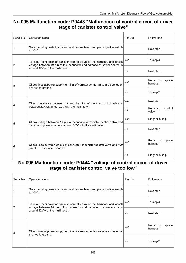
Common Malfunction Diagnosis Flow of Geely Automobile
146
No.095 Malfunction code: P0443 "Malfunction of control circuit of driver stage of canister control valve"
Serial No. Operation steps Results Follow-ups
1 Switch on diagnosis instrument and commutator, and place ignition switch to “ON”. Next step
Yes To step 4
2 Take out connector of canister control valve of the harness, and check voltage between 1# pin of this connector and cathode of power source is around 12V with the multimeter.
No Next step
Yes Repair or replace harness
3 Check lines at power supply terminal of canister control valve are opened or shorted to ground.
No To step 2
Yes Next step 4 Check resistance between 1# and 2# pins of canister control valve is
between 22~30Ω under 20with the multimeter. No Replace control
valve
Yes Diagnosis help
5 Check voltage between 1# pin of connector of canister control valve and cathode of power source is around 3.7V with the multimeter.
No Next step
Yes Repair or replace harness
6 Check lines between 2# pin of connector of canister control valve and 46# pin of ECU are open shorted.
No Diagnosis help
No.096 Malfunction code: P0444 "voltage of control circuit of driver stage of canister control valve too low"
Serial No. Operation steps Results Follow-ups
1 Switch on diagnosis instrument and commutator, and place ignition switch to “ON”. Next step
Yes To step 4
2 Take out connector of canister control valve of the harness, and check voltage between 1# pin of this connector and cathode of power source is around 12V with the multimeter.
No Next step
Yes Repair or replace harness
3 Check lines at power supply terminal of canister control valve are opened or shorted to ground.
No To step 2
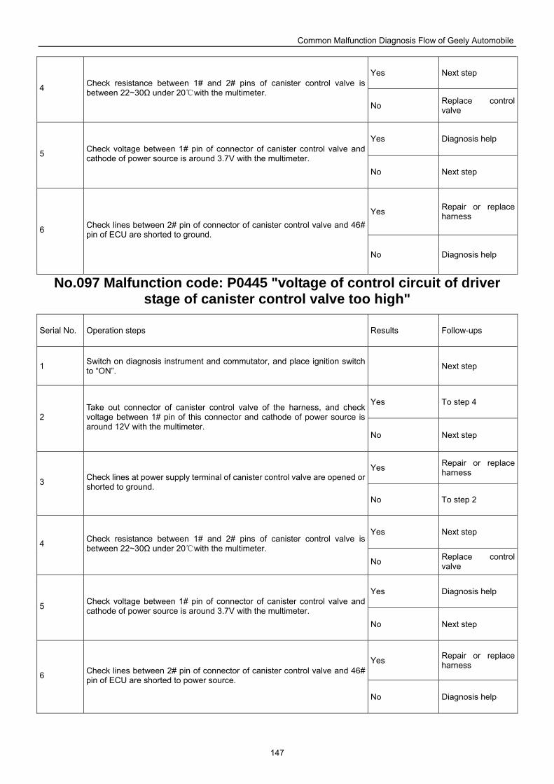
Common Malfunction Diagnosis Flow of Geely Automobile
147
Yes Next step
4 Check resistance between 1# and 2# pins of canister control valve is between 22~30Ω under 20with the multimeter.
No Replace control valve
Yes Diagnosis help
5 Check voltage between 1# pin of connector of canister control valve and cathode of power source is around 3.7V with the multimeter.
No Next step
Yes Repair or replace harness
6 Check lines between 2# pin of connector of canister control valve and 46# pin of ECU are shorted to ground.
No Diagnosis help
No.097 Malfunction code: P0445 "voltage of control circuit of driver stage of canister control valve too high"
Serial No. Operation steps Results Follow-ups
1 Switch on diagnosis instrument and commutator, and place ignition switch to “ON”. Next step
Yes To step 4
2 Take out connector of canister control valve of the harness, and check voltage between 1# pin of this connector and cathode of power source is around 12V with the multimeter.
No Next step
Yes Repair or replace harness
3 Check lines at power supply terminal of canister control valve are opened or shorted to ground.
No To step 2
Yes Next step 4 Check resistance between 1# and 2# pins of canister control valve is
between 22~30Ω under 20with the multimeter. No Replace control
valve
Yes Diagnosis help
5 Check voltage between 1# pin of connector of canister control valve and cathode of power source is around 3.7V with the multimeter.
No Next step
Yes Repair or replace harness
6 Check lines between 2# pin of connector of canister control valve and 46# pin of ECU are shorted to power source.
No Diagnosis help
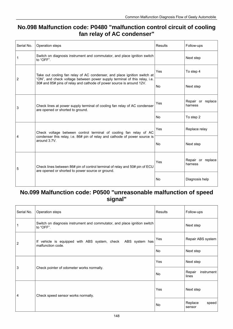
Common Malfunction Diagnosis Flow of Geely Automobile
148
No.098 Malfunction code: P0480 "malfunction control circuit of cooling fan relay of AC condenser"
Serial No. Operation steps Results Follow-ups
1 Switch on diagnosis instrument and commutator, and place ignition switch to “OFF”. Next step
Yes To step 4
2 Take out cooling fan relay of AC condenser, and place ignition switch at “ON”, and check voltage between power supply terminal of this relay, i.e. 30# and 85# pins of relay and cathode of power source is around 12V.
No Next step
Yes Repair or replace harness
3 Check lines at power supply terminal of cooling fan relay of AC condenser are opened or shorted to ground.
No To step 2
Yes Replace relay
4 Check voltage between control terminal of cooling fan relay of AC condenser this relay, i.e. 86# pin of relay and cathode of power source is around 3.7V.
No Next step
Yes Repair or replace harness
5 Check lines between 86# pin of control terminal of relay and 50# pin of ECU are opened or shorted to power source or ground.
No Diagnosis help
No.099 Malfunction code: P0500 "unreasonable malfunction of speed signal"
Serial No. Operation steps Results Follow-ups
1 Switch on diagnosis instrument and commutator, and place ignition switch to “OFF”. Next step
Yes Repair ABS system2 If vehicle is equipped with ABS system, check ABS system has
malfunction code. No Next step
Yes Next step
3 Check pointer of odometer works normally.
No Repair instrument lines
Yes Next step
4 Check speed sensor works normally.
No Replace speed sensor
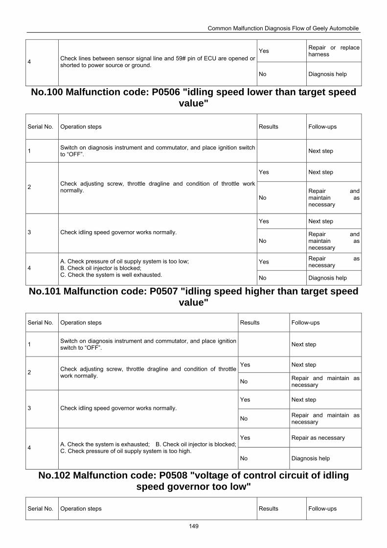
Common Malfunction Diagnosis Flow of Geely Automobile
149
Yes Repair or replace harness
4 Check lines between sensor signal line and 59# pin of ECU are opened or shorted to power source or ground.
No Diagnosis help
No.100 Malfunction code: P0506 "idling speed lower than target speed value"
Serial No. Operation steps Results Follow-ups
1 Switch on diagnosis instrument and commutator, and place ignition switch to “OFF”. Next step
Yes Next step
2 Check adjusting screw, throttle dragline and condition of throttle work normally.
No Repair and maintain as necessary
Yes Next step
3 Check idling speed governor works normally. No
Repair and maintain as necessary
Yes Repair as necessary 4
A. Check pressure of oil supply system is too low; B. Check oil injector is blocked; C. Check the system is well exhausted. No Diagnosis help
No.101 Malfunction code: P0507 "idling speed higher than target speed value"
Serial No. Operation steps Results Follow-ups
1 Switch on diagnosis instrument and commutator, and place ignition switch to “OFF”. Next step
Yes Next step 2 Check adjusting screw, throttle dragline and condition of throttle
work normally. No Repair and maintain as
necessary
Yes Next step 3 Check idling speed governor works normally.
No Repair and maintain as necessary
Yes Repair as necessary
4 A. Check the system is exhausted; B. Check oil injector is blocked; C. Check pressure of oil supply system is too high.
No Diagnosis help
No.102 Malfunction code: P0508 "voltage of control circuit of idling speed governor too low"
Serial No. Operation steps Results Follow-ups
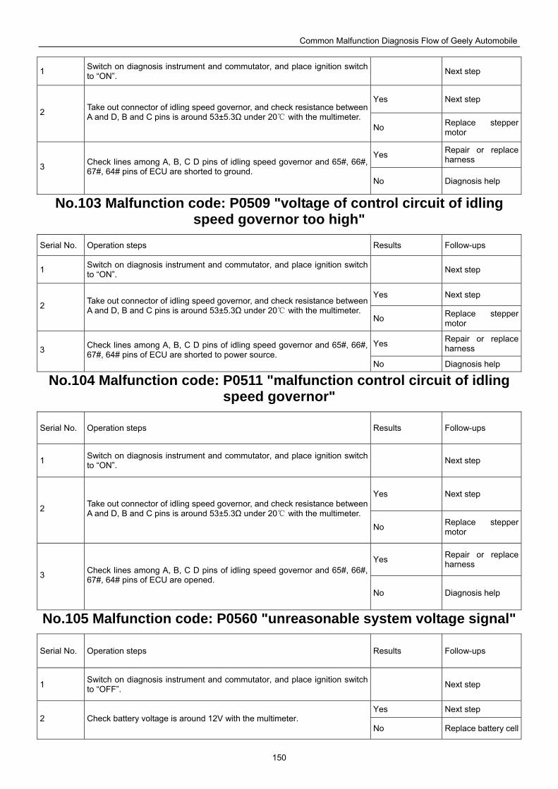
Common Malfunction Diagnosis Flow of Geely Automobile
150
1 Switch on diagnosis instrument and commutator, and place ignition switch to “ON”. Next step
Yes Next step 2 Take out connector of idling speed governor, and check resistance between
A and D, B and C pins is around 53±5.3Ω under 20 with the multimeter. No Replace stepper
motor
Yes Repair or replace harness
3 Check lines among A, B, C D pins of idling speed governor and 65#, 66#, 67#, 64# pins of ECU are shorted to ground.
No Diagnosis help
No.103 Malfunction code: P0509 "voltage of control circuit of idling speed governor too high"
Serial No. Operation steps Results Follow-ups
1 Switch on diagnosis instrument and commutator, and place ignition switch to “ON”. Next step
Yes Next step 2 Take out connector of idling speed governor, and check resistance between
A and D, B and C pins is around 53±5.3Ω under 20 with the multimeter. No Replace stepper
motor
Yes Repair or replace harness 3 Check lines among A, B, C D pins of idling speed governor and 65#, 66#,
67#, 64# pins of ECU are shorted to power source. No Diagnosis help
No.104 Malfunction code: P0511 "malfunction control circuit of idling speed governor"
Serial No. Operation steps Results Follow-ups
1 Switch on diagnosis instrument and commutator, and place ignition switch to “ON”. Next step
Yes Next step
2 Take out connector of idling speed governor, and check resistance between A and D, B and C pins is around 53±5.3Ω under 20 with the multimeter.
No Replace stepper motor
Yes Repair or replace harness
3 Check lines among A, B, C D pins of idling speed governor and 65#, 66#, 67#, 64# pins of ECU are opened.
No Diagnosis help
No.105 Malfunction code: P0560 "unreasonable system voltage signal"
Serial No. Operation steps Results Follow-ups
1 Switch on diagnosis instrument and commutator, and place ignition switch to “OFF”. Next step
Yes Next step 2 Check battery voltage is around 12V with the multimeter.
No Replace battery cell
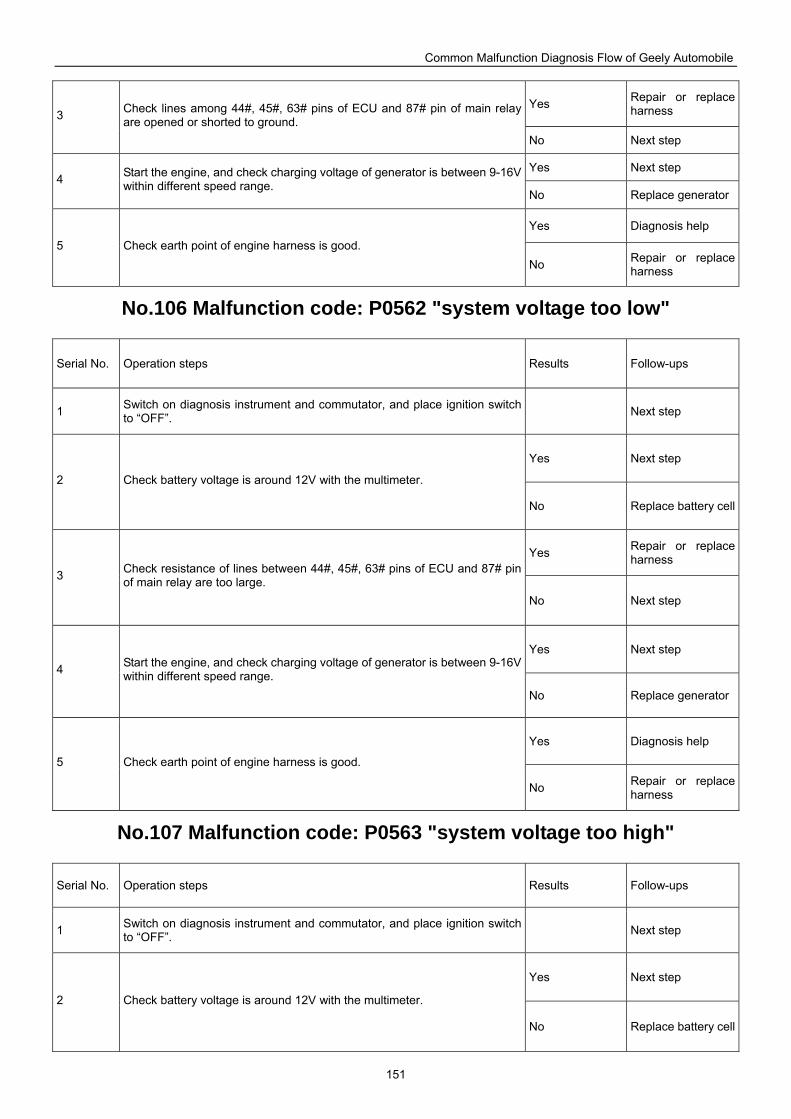
Common Malfunction Diagnosis Flow of Geely Automobile
151
Yes Repair or replace harness 3 Check lines among 44#, 45#, 63# pins of ECU and 87# pin of main relay
are opened or shorted to ground. No Next step
Yes Next step 4 Start the engine, and check charging voltage of generator is between 9-16V
within different speed range. No Replace generator
Yes Diagnosis help 5 Check earth point of engine harness is good.
No Repair or replace harness
No.106 Malfunction code: P0562 "system voltage too low"
Serial No. Operation steps Results Follow-ups
1 Switch on diagnosis instrument and commutator, and place ignition switch to “OFF”. Next step
Yes Next step
2 Check battery voltage is around 12V with the multimeter.
No Replace battery cell
Yes Repair or replace harness
3 Check resistance of lines between 44#, 45#, 63# pins of ECU and 87# pin of main relay are too large.
No Next step
Yes Next step
4 Start the engine, and check charging voltage of generator is between 9-16V within different speed range.
No Replace generator
Yes Diagnosis help
5 Check earth point of engine harness is good.
No Repair or replace harness
No.107 Malfunction code: P0563 "system voltage too high"
Serial No. Operation steps Results Follow-ups
1 Switch on diagnosis instrument and commutator, and place ignition switch to “OFF”. Next step
Yes Next step
2 Check battery voltage is around 12V with the multimeter.
No Replace battery cell
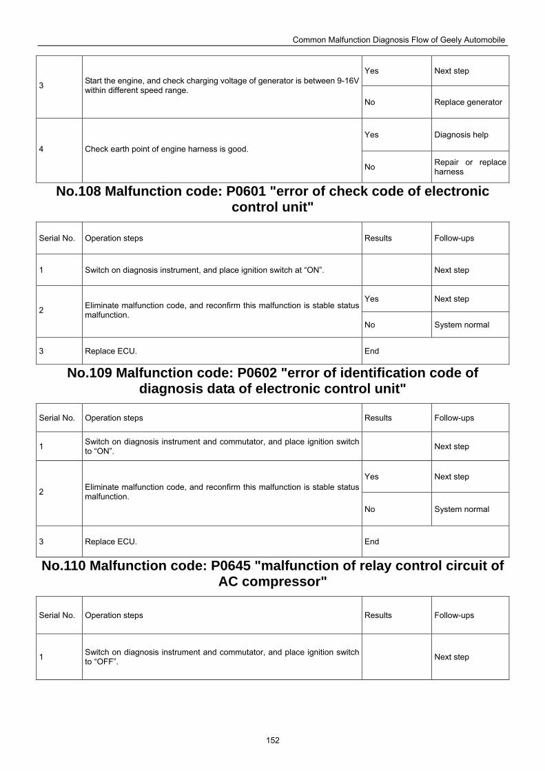
Common Malfunction Diagnosis Flow of Geely Automobile
152
Yes Next step
3 Start the engine, and check charging voltage of generator is between 9-16V within different speed range.
No Replace generator
Yes Diagnosis help
4 Check earth point of engine harness is good.
No Repair or replace harness
No.108 Malfunction code: P0601 "error of check code of electronic control unit"
Serial No. Operation steps Results Follow-ups
1 Switch on diagnosis instrument, and place ignition switch at “ON”. Next step
Yes Next step 2 Eliminate malfunction code, and reconfirm this malfunction is stable status
malfunction. No System normal
3 Replace ECU. End
No.109 Malfunction code: P0602 "error of identification code of diagnosis data of electronic control unit"
Serial No. Operation steps Results Follow-ups
1 Switch on diagnosis instrument and commutator, and place ignition switch to “ON”. Next step
Yes Next step
2 Eliminate malfunction code, and reconfirm this malfunction is stable status malfunction.
No System normal
3 Replace ECU. End
No.110 Malfunction code: P0645 "malfunction of relay control circuit of AC compressor"
Serial No. Operation steps Results Follow-ups
1 Switch on diagnosis instrument and commutator, and place ignition switch to “OFF”. Next step
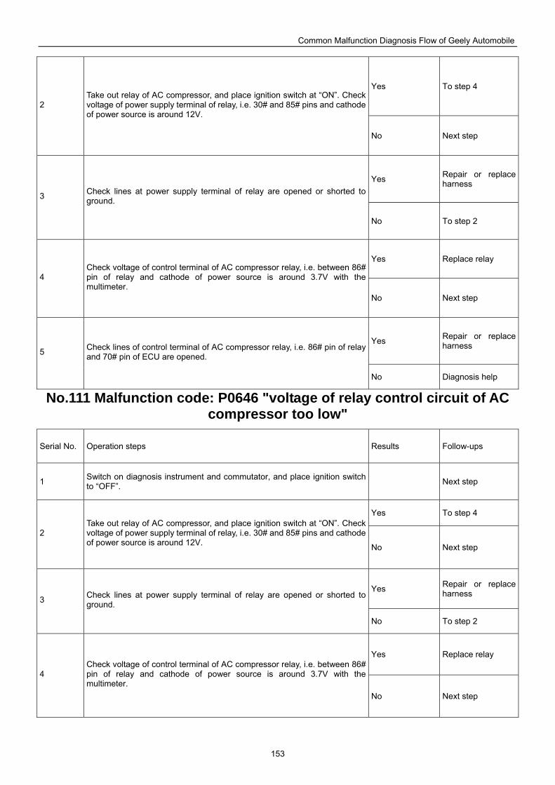
Common Malfunction Diagnosis Flow of Geely Automobile
153
Yes To step 4
2 Take out relay of AC compressor, and place ignition switch at “ON”. Check voltage of power supply terminal of relay, i.e. 30# and 85# pins and cathode of power source is around 12V.
No Next step
Yes Repair or replace harness
3 Check lines at power supply terminal of relay are opened or shorted to ground.
No To step 2
Yes Replace relay
4 Check voltage of control terminal of AC compressor relay, i.e. between 86# pin of relay and cathode of power source is around 3.7V with the multimeter.
No Next step
Yes Repair or replace harness
5 Check lines of control terminal of AC compressor relay, i.e. 86# pin of relay and 70# pin of ECU are opened.
No Diagnosis help
No.111 Malfunction code: P0646 "voltage of relay control circuit of AC compressor too low"
Serial No. Operation steps Results Follow-ups
1 Switch on diagnosis instrument and commutator, and place ignition switch to “OFF”. Next step
Yes To step 4
2 Take out relay of AC compressor, and place ignition switch at “ON”. Check voltage of power supply terminal of relay, i.e. 30# and 85# pins and cathode of power source is around 12V. No Next step
Yes Repair or replace harness
3 Check lines at power supply terminal of relay are opened or shorted to ground.
No To step 2
Yes Replace relay
4 Check voltage of control terminal of AC compressor relay, i.e. between 86# pin of relay and cathode of power source is around 3.7V with the multimeter.
No Next step
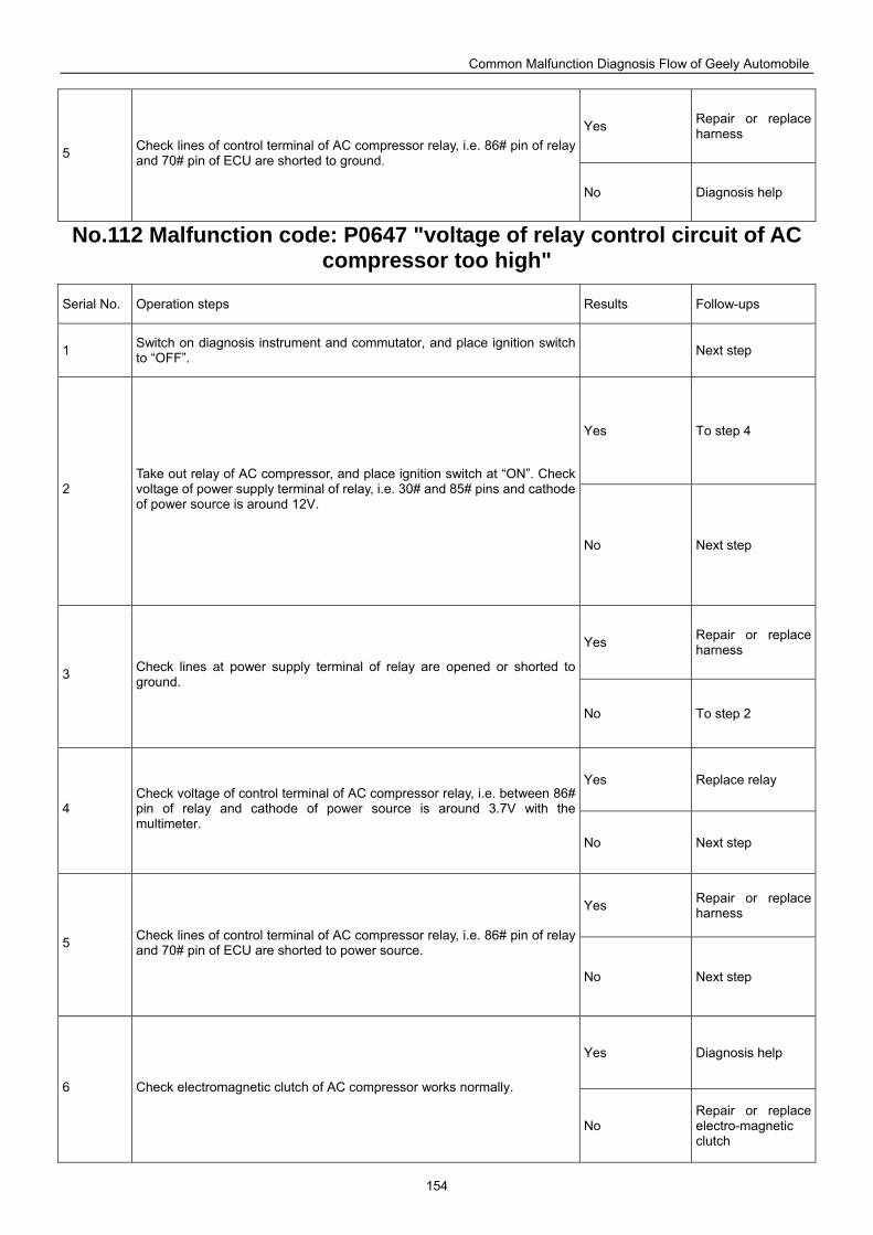
Common Malfunction Diagnosis Flow of Geely Automobile
154
Yes Repair or replace harness
5 Check lines of control terminal of AC compressor relay, i.e. 86# pin of relay and 70# pin of ECU are shorted to ground.
No Diagnosis help
No.112 Malfunction code: P0647 "voltage of relay control circuit of AC compressor too high"
Serial No. Operation steps Results Follow-ups
1 Switch on diagnosis instrument and commutator, and place ignition switch to “OFF”. Next step
Yes To step 4
2 Take out relay of AC compressor, and place ignition switch at “ON”. Check voltage of power supply terminal of relay, i.e. 30# and 85# pins and cathode of power source is around 12V.
No Next step
Yes Repair or replace harness
3 Check lines at power supply terminal of relay are opened or shorted to ground.
No To step 2
Yes Replace relay
4 Check voltage of control terminal of AC compressor relay, i.e. between 86# pin of relay and cathode of power source is around 3.7V with the multimeter.
No Next step
Yes Repair or replace harness
5 Check lines of control terminal of AC compressor relay, i.e. 86# pin of relay and 70# pin of ECU are shorted to power source.
No Next step
Yes Diagnosis help
6 Check electromagnetic clutch of AC compressor works normally.
No Repair or replace electro-magnetic clutch
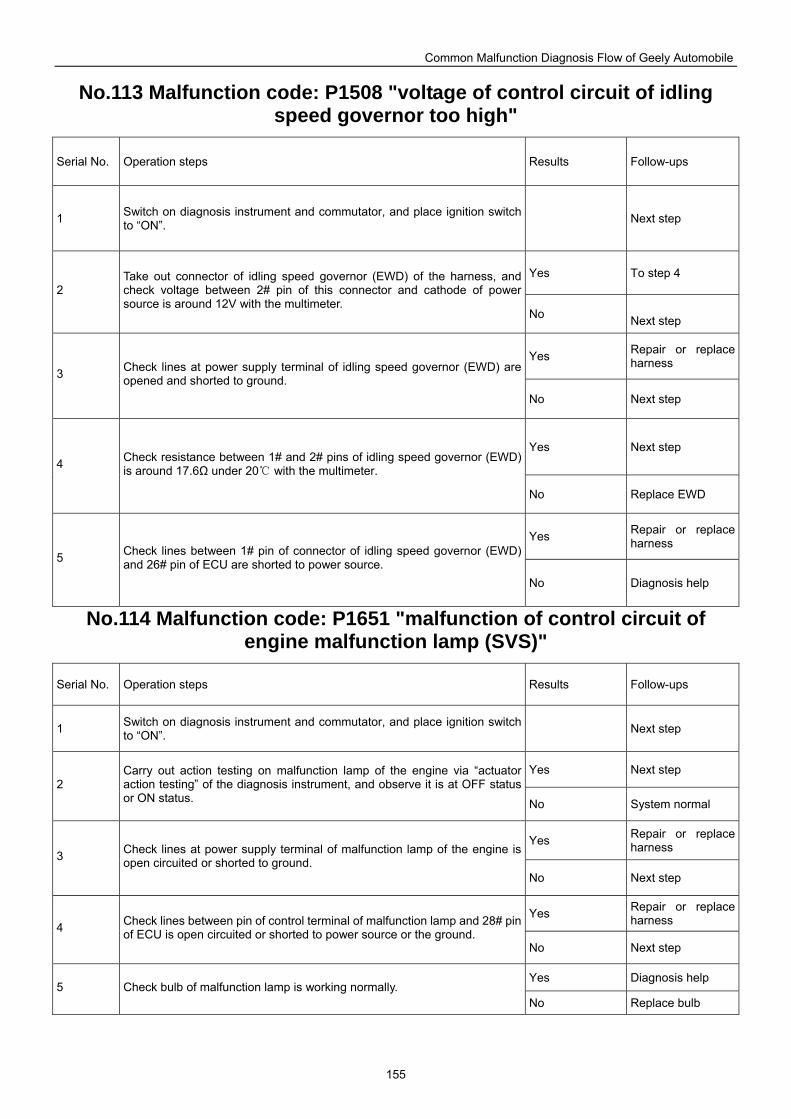
Common Malfunction Diagnosis Flow of Geely Automobile
155
No.113 Malfunction code: P1508 "voltage of control circuit of idling speed governor too high"
Serial No. Operation steps Results Follow-ups
1 Switch on diagnosis instrument and commutator, and place ignition switch to “ON”. Next step
Yes To step 4 2
Take out connector of idling speed governor (EWD) of the harness, and check voltage between 2# pin of this connector and cathode of power source is around 12V with the multimeter.
No Next step
Yes Repair or replace harness
3 Check lines at power supply terminal of idling speed governor (EWD) are opened and shorted to ground.
No Next step
Yes Next step 4 Check resistance between 1# and 2# pins of idling speed governor (EWD)
is around 17.6Ω under 20 with the multimeter.
No Replace EWD
Yes Repair or replace harness
5 Check lines between 1# pin of connector of idling speed governor (EWD) and 26# pin of ECU are shorted to power source.
No Diagnosis help
No.114 Malfunction code: P1651 "malfunction of control circuit of engine malfunction lamp (SVS)"
Serial No. Operation steps Results Follow-ups
1 Switch on diagnosis instrument and commutator, and place ignition switch to “ON”. Next step
Yes Next step 2
Carry out action testing on malfunction lamp of the engine via “actuator action testing” of the diagnosis instrument, and observe it is at OFF status or ON status. No System normal
Yes Repair or replace harness
3 Check lines at power supply terminal of malfunction lamp of the engine is open circuited or shorted to ground.
No Next step
Yes Repair or replace harness 4 Check lines between pin of control terminal of malfunction lamp and 28# pin
of ECU is open circuited or shorted to power source or the ground. No Next step
Yes Diagnosis help 5 Check bulb of malfunction lamp is working normally.
No Replace bulb
Common Malfunction Diagnosis Flow of Geely Automobile
156
Diagnosis flowchart of M7 system based on malfunction Before executing steps of malfunction diagnosis based on malfunction of the engine, carry out preliminary inspection: 1. Confirm malfunction indicator lamp of the engine is working normally; 2. Check and confirm there is no malfunction information recorded with the malfunction diagnosis instrument; 3. Confirm malfunction claimed by the vehicle owner exists and confirm conditions why this malfunction appears. Appearance inspection: (1)Check fuel pipe is leaking; (2)Check vacuum pipe is broken, kinked, or correctly connected; (3)Check inlet pipe is blocked, air leaking, squashed or damaged; (4)Check high tension line of ignition system is broken, aging, and ignition sequence is correct; (5)Check earthing location of harness is clean, firm; (6)Check connector of each sensor, actuator is loosening or poorly contacted. Important: in case of above-mentioned malfunctions, carry out care and maintenance accordingly, otherwise it will affect following malfunction diagnosis and maintenance. Diagnosis help: 1. Confirm the engine is free of malfunction records; 2. Confirm malfunction that is claimed exists; 3. Carry out according to above-mentioned steps and find out nothing unusual; 4. Pay attention to the effect of automobile maintenance, cylinder pressure, mechanical ignition timing, fuel conditions on the system during inspection; 5. Replace ECU and test it. If malfunction is eliminated at this time, then malfunction part is in ECU; if malfunction still exists at this point, replace for original ECU, and repeat the flowchart, and re-inspect.
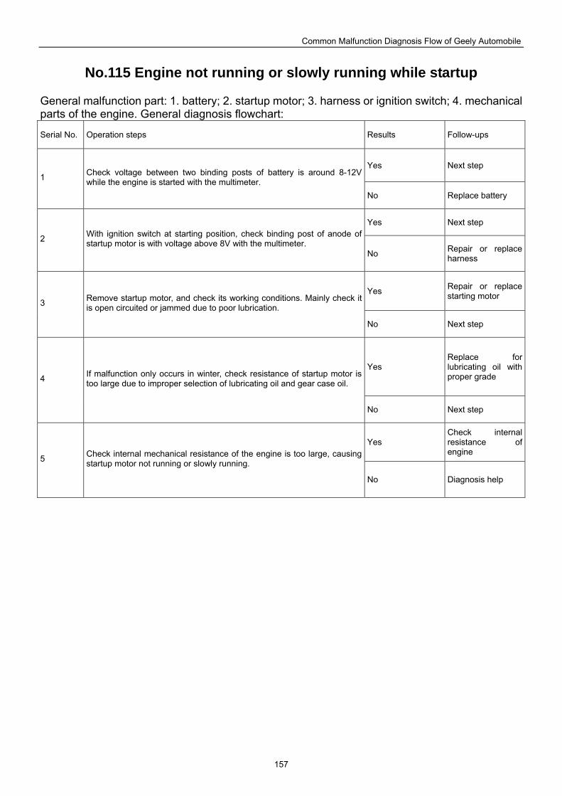
Common Malfunction Diagnosis Flow of Geely Automobile
157
No.115 Engine not running or slowly running while startup
General malfunction part: 1. battery; 2. startup motor; 3. harness or ignition switch; 4. mechanical parts of the engine. General diagnosis flowchart:
Serial No. Operation steps Results Follow-ups
Yes Next step 1 Check voltage between two binding posts of battery is around 8-12V
while the engine is started with the multimeter. No Replace battery
Yes Next step
2 With ignition switch at starting position, check binding post of anode of startup motor is with voltage above 8V with the multimeter.
No Repair or replace harness
Yes Repair or replace starting motor
3 Remove startup motor, and check its working conditions. Mainly check it is open circuited or jammed due to poor lubrication.
No Next step
Yes Replace for lubricating oil with proper grade 4 If malfunction only occurs in winter, check resistance of startup motor is
too large due to improper selection of lubricating oil and gear case oil.
No Next step
Yes Check internal resistance of engine
5 Check internal mechanical resistance of the engine is too large, causing startup motor not running or slowly running.
No Diagnosis help
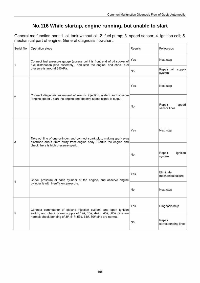
Common Malfunction Diagnosis Flow of Geely Automobile
158
No.116 While startup, engine running, but unable to start
General malfunction part: 1. oil tank without oil; 2. fuel pump; 3. speed sensor; 4. ignition coil; 5. mechanical part of engine. General diagnosis flowchart:
Serial No. Operation steps Results Follow-ups
Yes Next step
1 Connect fuel pressure gauge (access point is front end of oil sucker of fuel distribution pipe assembly), and start the engine, and check fuel pressure is around 350kPa.
No Repair oil supply system
Yes Next step
2 Connect diagnosis instrument of electric injection system and observe “engine speed”. Start the engine and observe speed signal is output.
No Repair speed sensor lines
Yes Next step
3 Take out line of one cylinder, and connect spark plug, making spark plug electrode about 5mm away from engine body. Startup the engine and check there is high pressure spark.
No Repair ignition system
Yes Eliminate mechanical failure
4 Check pressure of each cylinder of the engine, and observe engine cylinder is with insufficient pressure.
No Next step
Yes Diagnosis help
5 Connect commutator of electric injection system, and open ignition switch, and check power supply of 12#, 13#, 44#, 45#, ,63# pins are normal; check bonding of 3#, 51#, 53#, 61#, 80# pins are normal.
No Repair corresponding lines
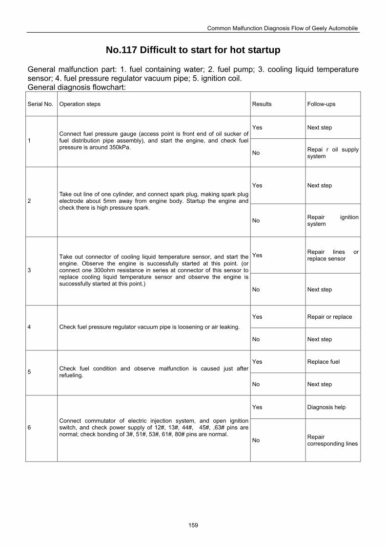
Common Malfunction Diagnosis Flow of Geely Automobile
159
No.117 Difficult to start for hot startup
General malfunction part: 1. fuel containing water; 2. fuel pump; 3. cooling liquid temperature sensor; 4. fuel pressure regulator vacuum pipe; 5. ignition coil. General diagnosis flowchart:
Serial No. Operation steps Results Follow-ups
Yes Next step
1 Connect fuel pressure gauge (access point is front end of oil sucker of fuel distribution pipe assembly), and start the engine, and check fuel pressure is around 350kPa.
No Repai r oil supply system
Yes Next step
2 Take out line of one cylinder, and connect spark plug, making spark plug electrode about 5mm away from engine body. Startup the engine and check there is high pressure spark.
No Repair ignition system
Yes Repair lines or replace sensor
3
Take out connector of cooling liquid temperature sensor, and start the engine. Observe the engine is successfully started at this point. (or connect one 300ohm resistance in series at connector of this sensor to replace cooling liquid temperature sensor and observe the engine is successfully started at this point.)
No Next step
Yes Repair or replace
4 Check fuel pressure regulator vacuum pipe is loosening or air leaking.
No Next step
Yes Replace fuel
5 Check fuel condition and observe malfunction is caused just after refueling.
No Next step
Yes Diagnosis help
6 Connect commutator of electric injection system, and open ignition switch, and check power supply of 12#, 13#, 44#, 45#, ,63# pins are normal; check bonding of 3#, 51#, 53#, 61#, 80# pins are normal.
No Repair corresponding lines
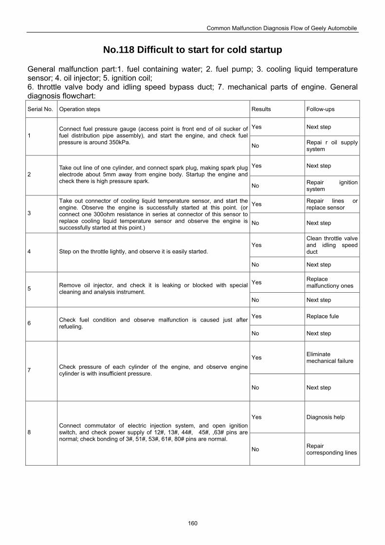
Common Malfunction Diagnosis Flow of Geely Automobile
160
No.118 Difficult to start for cold startup
General malfunction part:1. fuel containing water; 2. fuel pump; 3. cooling liquid temperature sensor; 4. oil injector; 5. ignition coil; 6. throttle valve body and idling speed bypass duct; 7. mechanical parts of engine. General diagnosis flowchart: Serial No. Operation steps Results Follow-ups
Yes Next step 1
Connect fuel pressure gauge (access point is front end of oil sucker of fuel distribution pipe assembly), and start the engine, and check fuel pressure is around 350kPa. No Repai r oil supply
system
Yes Next step 2
Take out line of one cylinder, and connect spark plug, making spark plug electrode about 5mm away from engine body. Startup the engine and check there is high pressure spark.
No Repair ignition system
Yes Repair lines or replace sensor
3
Take out connector of cooling liquid temperature sensor, and start the engine. Observe the engine is successfully started at this point. (or connect one 300ohm resistance in series at connector of this sensor to replace cooling liquid temperature sensor and observe the engine is successfully started at this point.)
No Next step
Yes Clean throttle valve and idling speed duct 4 Step on the throttle lightly, and observe it is easily started.
No Next step
Yes Replace malfunctiony ones 5 Remove oil injector, and check it is leaking or blocked with special
cleaning and analysis instrument. No Next step
Yes Replace fule 6 Check fuel condition and observe malfunction is caused just after
refueling. No Next step
Yes Eliminate mechanical failure
7 Check pressure of each cylinder of the engine, and observe engine cylinder is with insufficient pressure.
No Next step
Yes Diagnosis help
8 Connect commutator of electric injection system, and open ignition switch, and check power supply of 12#, 13#, 44#, 45#, ,63# pins are normal; check bonding of 3#, 51#, 53#, 61#, 80# pins are normal.
No Repair corresponding lines
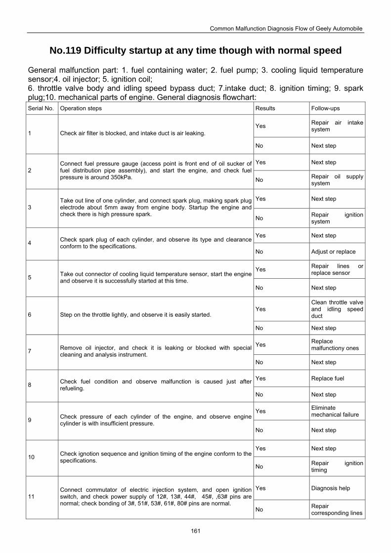
Common Malfunction Diagnosis Flow of Geely Automobile
161
No.119 Difficulty startup at any time though with normal speed
General malfunction part: 1. fuel containing water; 2. fuel pump; 3. cooling liquid temperature sensor;4. oil injector; 5. ignition coil; 6. throttle valve body and idling speed bypass duct; 7.intake duct; 8. ignition timing; 9. spark plug;10. mechanical parts of engine. General diagnosis flowchart: Serial No. Operation steps Results Follow-ups
Yes Repair air intake system 1 Check air filter is blocked, and intake duct is air leaking.
No Next step
Yes Next step 2
Connect fuel pressure gauge (access point is front end of oil sucker of fuel distribution pipe assembly), and start the engine, and check fuel pressure is around 350kPa. No Repair oil supply
system
Yes Next step 3
Take out line of one cylinder, and connect spark plug, making spark plug electrode about 5mm away from engine body. Startup the engine and check there is high pressure spark.
No Repair ignition system
Yes Next step 4 Check spark plug of each cylinder, and observe its type and clearance
conform to the specifications. No Adjust or replace
Yes Repair lines or replace sensor
5 Take out connector of cooling liquid temperature sensor, start the engine and observe it is successfully started at this time.
No Next step
Yes Clean throttle valve and idling speed duct 6 Step on the throttle lightly, and observe it is easily started.
No Next step
Yes Replace malfunctiony ones 7 Remove oil injector, and check it is leaking or blocked with special
cleaning and analysis instrument. No Next step
Yes Replace fuel 8 Check fuel condition and observe malfunction is caused just after
refueling. No Next step
Yes Eliminate mechanical failure
9 Check pressure of each cylinder of the engine, and observe engine cylinder is with insufficient pressure.
No Next step
Yes Next step 10 Check ignotion sequence and ignition timing of the engine conform to the
specifications. No Repair ignition
timing
Yes Diagnosis help 11
Connect commutator of electric injection system, and open ignition switch, and check power supply of 12#, 13#, 44#, 45#, ,63# pins are normal; check bonding of 3#, 51#, 53#, 61#, 80# pins are normal.
No Repair corresponding lines
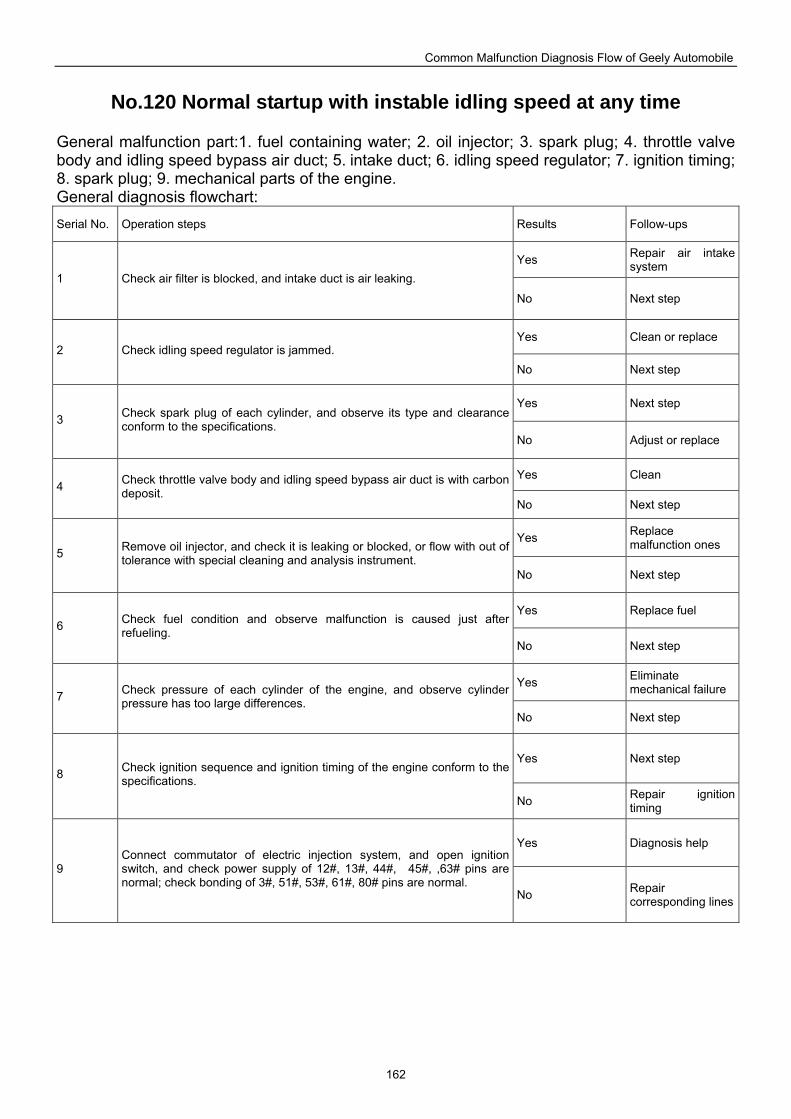
Common Malfunction Diagnosis Flow of Geely Automobile
162
No.120 Normal startup with instable idling speed at any time
General malfunction part:1. fuel containing water; 2. oil injector; 3. spark plug; 4. throttle valve body and idling speed bypass air duct; 5. intake duct; 6. idling speed regulator; 7. ignition timing; 8. spark plug; 9. mechanical parts of the engine. General diagnosis flowchart: Serial No. Operation steps Results Follow-ups
Yes Repair air intake system
1 Check air filter is blocked, and intake duct is air leaking.
No Next step
Yes Clean or replace 2 Check idling speed regulator is jammed.
No Next step
Yes Next step 3 Check spark plug of each cylinder, and observe its type and clearance
conform to the specifications. No Adjust or replace
Yes Clean 4 Check throttle valve body and idling speed bypass air duct is with carbon
deposit. No Next step
Yes Replace malfunction ones
5 Remove oil injector, and check it is leaking or blocked, or flow with out of tolerance with special cleaning and analysis instrument.
No Next step
Yes Replace fuel 6 Check fuel condition and observe malfunction is caused just after
refueling. No Next step
Yes Eliminate mechanical failure 7 Check pressure of each cylinder of the engine, and observe cylinder
pressure has too large differences. No Next step
Yes Next step 8 Check ignition sequence and ignition timing of the engine conform to the
specifications.
No Repair ignition timing
Yes Diagnosis help
9 Connect commutator of electric injection system, and open ignition switch, and check power supply of 12#, 13#, 44#, 45#, ,63# pins are normal; check bonding of 3#, 51#, 53#, 61#, 80# pins are normal.
No Repair corresponding lines
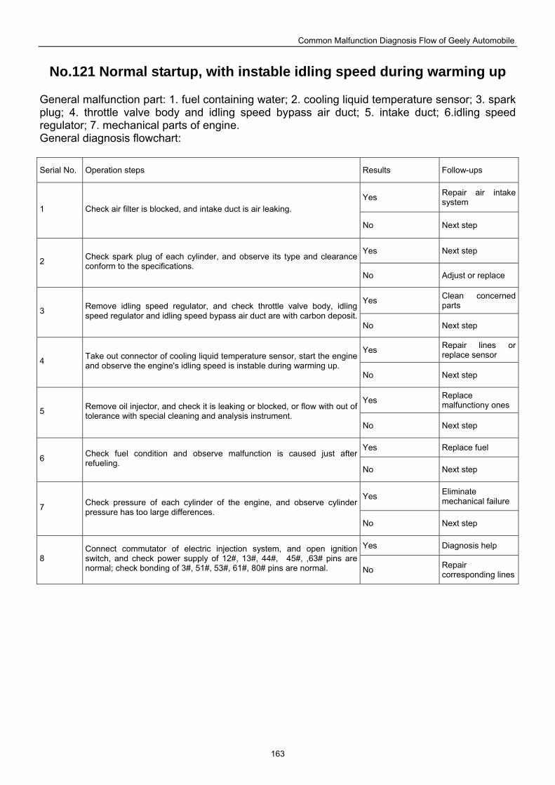
Common Malfunction Diagnosis Flow of Geely Automobile
163
No.121 Normal startup, with instable idling speed during warming up
General malfunction part: 1. fuel containing water; 2. cooling liquid temperature sensor; 3. spark plug; 4. throttle valve body and idling speed bypass air duct; 5. intake duct; 6.idling speed regulator; 7. mechanical parts of engine. General diagnosis flowchart: Serial No. Operation steps Results Follow-ups
Yes Repair air intake system
1 Check air filter is blocked, and intake duct is air leaking.
No Next step
Yes Next step 2 Check spark plug of each cylinder, and observe its type and clearance
conform to the specifications. No Adjust or replace
Yes Clean concerned parts 3 Remove idling speed regulator, and check throttle valve body, idling
speed regulator and idling speed bypass air duct are with carbon deposit. No Next step
Yes Repair lines or replace sensor
4 Take out connector of cooling liquid temperature sensor, start the engine and observe the engine's idling speed is instable during warming up.
No Next step
Yes Replace malfunctiony ones
5 Remove oil injector, and check it is leaking or blocked, or flow with out of tolerance with special cleaning and analysis instrument.
No Next step
Yes Replace fuel 6 Check fuel condition and observe malfunction is caused just after
refueling. No Next step
Yes Eliminate mechanical failure
7 Check pressure of each cylinder of the engine, and observe cylinder pressure has too large differences.
No Next step
Yes Diagnosis help 8
Connect commutator of electric injection system, and open ignition switch, and check power supply of 12#, 13#, 44#, 45#, ,63# pins are normal; check bonding of 3#, 51#, 53#, 61#, 80# pins are normal. No Repair
corresponding lines
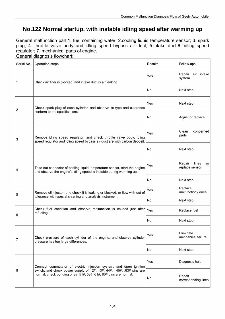
Common Malfunction Diagnosis Flow of Geely Automobile
164
No.122 Normal startup, with instable idling speed after warming up
General malfunction part:1. fuel containing water; 2.cooling liquid temperature sensor; 3. spark plug; 4. throttle valve body and idling speed bypass air duct; 5.intake duct;6. idling speed regulator; 7. mechanical parts of engine. General diagnosis flowchart: Serial No. Operation steps Results Follow-ups
Yes Repair air intake system
1 Check air filter is blocked, and intake duct is air leaking.
No Next step
Yes Next step
2 Check spark plug of each cylinder, and observe its type and clearance conform to the specifications.
No Adjust or replace
Yes Clean concerned parts
3 Remove idling speed regulator, and check throttle valve body, idling speed regulator and idling speed bypass air duct are with carbon deposit.
No Next step
Yes Repair lines or replace sensor
4 Take out connector of cooling liquid temperature sensor, start the engine and observe the engine's idling speed is instable during warming up.
No Next step
Yes Replace malfunctiony ones
5 Remove oil injector, and check it is leaking or blocked, or flow with out of tolerance with special cleaning and analysis instrument.
No Next step
Yes Replace fuel 6
Check fuel condition and observe malfunction is caused just after refueling. No Next step
Yes Eliminate mechanical failure
7 Check pressure of each cylinder of the engine, and observe cylinder pressure has too large differences.
No Next step
Yes Diagnosis help
8 Connect commutator of electric injection system, and open ignition switch, and check power supply of 12#, 13#, 44#, 45#, ,63# pins are normal; check bonding of 3#, 51#, 53#, 61#, 80# pins are normal.
No Repair corresponding lines
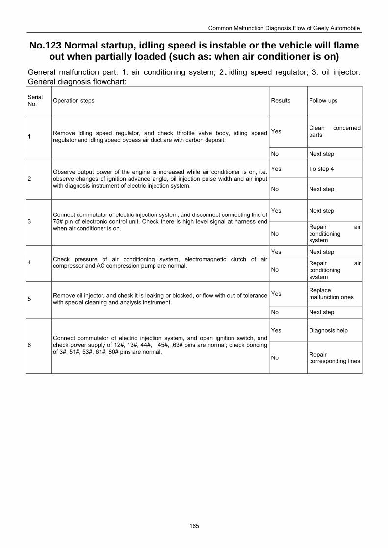
Common Malfunction Diagnosis Flow of Geely Automobile
165
No.123 Normal startup, idling speed is instable or the vehicle will flame out when partially loaded (such as: when air conditioner is on)
General malfunction part: 1. air conditioning system; 2、idling speed regulator; 3. oil injector. General diagnosis flowchart:
Serial No. Operation steps Results Follow-ups
Yes Clean concerned parts 1 Remove idling speed regulator, and check throttle valve body, idling speed
regulator and idling speed bypass air duct are with carbon deposit.
No Next step
Yes To step 4
2 Observe output power of the engine is increased while air conditioner is on, i.e. observe changes of ignition advance angle, oil injection pulse width and air input with diagnosis instrument of electric injection system. No Next step
Yes Next step
3 Connect commutator of electric injection system, and disconnect connecting line of 75# pin of electronic control unit. Check there is high level signal at harness end when air conditioner is on.
No Repair air conditioning system
Yes Next step
4 Check pressure of air conditioning system, electromagnetic clutch of air compressor and AC compression pump are normal. No
Repair air conditioning system
Yes Replace malfunction ones 5 Remove oil injector, and check it is leaking or blocked, or flow with out of tolerance
with special cleaning and analysis instrument.
No Next step
Yes Diagnosis help
6 Connect commutator of electric injection system, and open ignition switch, and check power supply of 12#, 13#, 44#, 45#, ,63# pins are normal; check bonding of 3#, 51#, 53#, 61#, 80# pins are normal.
No Repair corresponding lines
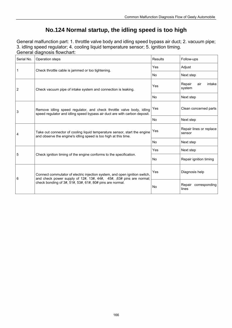
Common Malfunction Diagnosis Flow of Geely Automobile
166
No.124 Normal startup, the idling speed is too high
General malfunction part: 1. throttle valve body and idling speed bypass air duct; 2. vacuum pipe; 3. idling speed regulator; 4. cooling liquid temperature sensor; 5. ignition timing. General diagnosis flowchart: Serial No. Operation steps Results Follow-ups
Yes Adjust 1 Check throttle cable is jammed or too tightening.
No Next step
Yes Repair air intake system 2 Check vacuum pipe of intake system and connection is leaking.
No Next step
Yes Clean concerned parts3 Remove idling speed regulator, and check throttle valve body, idling
speed regulator and idling speed bypass air duct are with carbon deposit.
No Next step
Yes Repair lines or replace sensor 4 Take out connector of cooling liquid temperature sensor, start the engine
and observe the engine's idling speed is too high at this time.
No Next step
Yes Next step 5 Check ignition timing of the engine conforms to the specification.
No Repair ignition timing
Yes Diagnosis help
6 Connect commutator of electric injection system, and open ignition switch, and check power supply of 12#, 13#, 44#, 45#, ,63# pins are normal; check bonding of 3#, 51#, 53#, 61#, 80# pins are normal.
No Repair corresponding lines
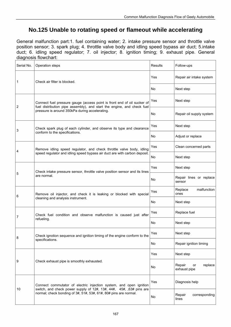
Common Malfunction Diagnosis Flow of Geely Automobile
167
No.125 Unable to rotating speed or flameout while accelerating
General malfunction part:1. fuel containing water; 2. intake pressure sensor and throttle valve position sensor; 3. spark plug; 4. throttle valve body and idling speed bypass air duct; 5.intake duct; 6. idling speed regulator; 7. oil injector; 8. ignition timing; 9. exhaust pipe. General diagnosis flowchart: Serial No. Operation steps Results Follow-ups
Yes Repair air intake system1 Check air filter is blocked.
No Next step
Yes Next step
2 Connect fuel pressure gauge (access point is front end of oil sucker of fuel distribution pipe assembly), and start the engine, and check fuel pressure is around 350kPa during accelerating.
No Repair oil supply system
Yes Next step 3 Check spark plug of each cylinder, and observe its type and clearance
conform to the specifications. No Adjust or replace
Yes Clean concerned parts 4 Remove idling speed regulator, and check throttle valve body, idling
speed regulator and idling speed bypass air duct are with carbon deposit.No Next step
Yes Next step
5 Check intake pressure sensor, throttle valve position sensor and its lines are normal.
No Repair lines or replace sensor
Yes Replace malfunction ones
6 Remove oil injector, and check it is leaking or blocked with special cleaning and analysis instrument.
No Next step
Yes Replace fuel 7 Check fuel condition and observe malfunction is caused just after
refueling. No Next step
Yes Next step 8 Check ignotion sequence and ignition timing of the engine conform to the
specifications. No Repair ignition timing
Yes Next step
9 Check exhaust pipe is smoothly exhausted.
No Repair or replace exhaust pipe
Yes Diagnosis help
10 Connect commutator of electric injection system, and open ignition switch, and check power supply of 12#, 13#, 44#, 45#, ,63# pins are normal; check bonding of 3#, 51#, 53#, 61#, 80# pins are normal.
No Repair corresponding lines
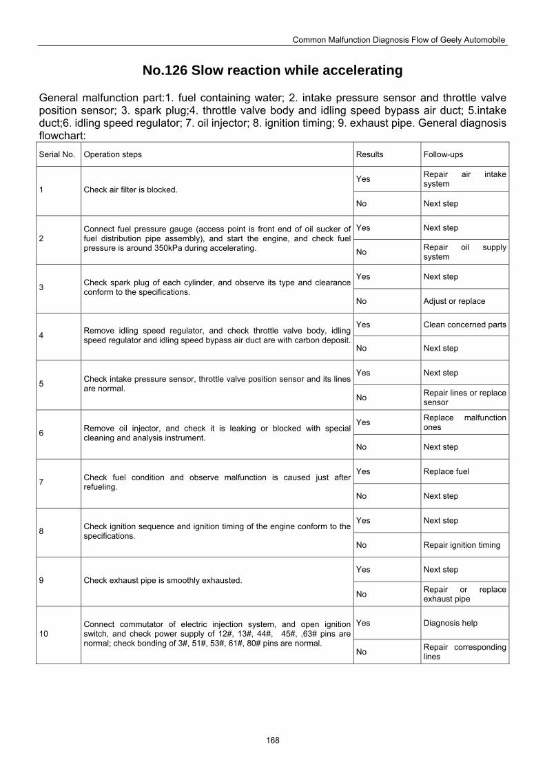
Common Malfunction Diagnosis Flow of Geely Automobile
168
No.126 Slow reaction while accelerating
General malfunction part:1. fuel containing water; 2. intake pressure sensor and throttle valve position sensor; 3. spark plug;4. throttle valve body and idling speed bypass air duct; 5.intake duct;6. idling speed regulator; 7. oil injector; 8. ignition timing; 9. exhaust pipe. General diagnosis flowchart: Serial No. Operation steps Results Follow-ups
Yes Repair air intake system
1 Check air filter is blocked.
No Next step
Yes Next step 2
Connect fuel pressure gauge (access point is front end of oil sucker of fuel distribution pipe assembly), and start the engine, and check fuel pressure is around 350kPa during accelerating. No Repair oil supply
system
Yes Next step 3 Check spark plug of each cylinder, and observe its type and clearance
conform to the specifications. No Adjust or replace
Yes Clean concerned parts4 Remove idling speed regulator, and check throttle valve body, idling
speed regulator and idling speed bypass air duct are with carbon deposit.No Next step
Yes Next step 5 Check intake pressure sensor, throttle valve position sensor and its lines
are normal. No Repair lines or replace
sensor
Yes Replace malfunction ones
6 Remove oil injector, and check it is leaking or blocked with special cleaning and analysis instrument.
No Next step
Yes Replace fuel 7 Check fuel condition and observe malfunction is caused just after
refueling. No Next step
Yes Next step 8 Check ignition sequence and ignition timing of the engine conform to the
specifications. No Repair ignition timing
Yes Next step 9 Check exhaust pipe is smoothly exhausted.
No Repair or replace exhaust pipe
Yes Diagnosis help 10
Connect commutator of electric injection system, and open ignition switch, and check power supply of 12#, 13#, 44#, 45#, ,63# pins are normal; check bonding of 3#, 51#, 53#, 61#, 80# pins are normal.
No Repair corresponding lines
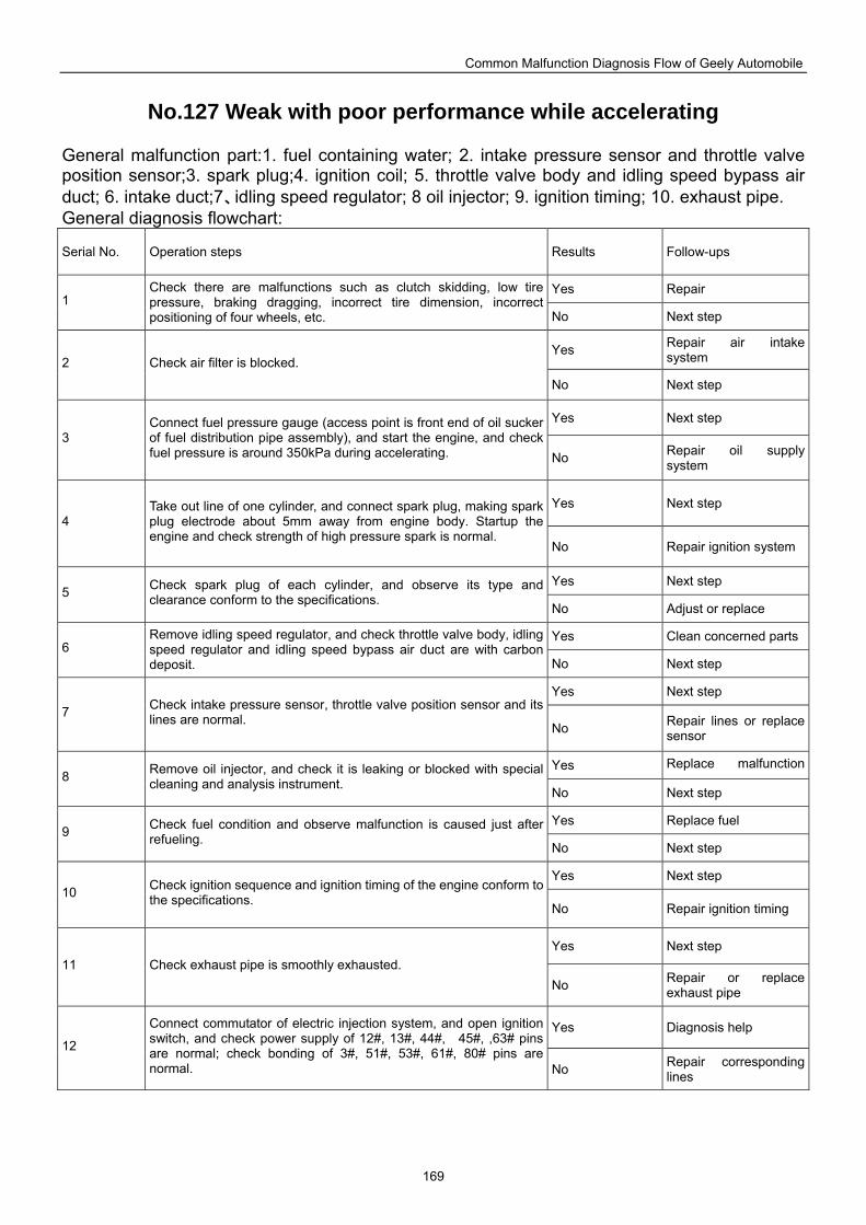
Common Malfunction Diagnosis Flow of Geely Automobile
169
No.127 Weak with poor performance while accelerating
General malfunction part:1. fuel containing water; 2. intake pressure sensor and throttle valve position sensor;3. spark plug;4. ignition coil; 5. throttle valve body and idling speed bypass air duct; 6. intake duct;7、idling speed regulator; 8 oil injector; 9. ignition timing; 10. exhaust pipe. General diagnosis flowchart:
Serial No. Operation steps Results Follow-ups
Yes Repair 1
Check there are malfunctions such as clutch skidding, low tire pressure, braking dragging, incorrect tire dimension, incorrect positioning of four wheels, etc. No Next step
Yes Repair air intake system 2 Check air filter is blocked.
No Next step
Yes Next step 3
Connect fuel pressure gauge (access point is front end of oil sucker of fuel distribution pipe assembly), and start the engine, and check fuel pressure is around 350kPa during accelerating. No Repair oil supply
system
Yes Next step 4
Take out line of one cylinder, and connect spark plug, making spark plug electrode about 5mm away from engine body. Startup the engine and check strength of high pressure spark is normal.
No Repair ignition system
Yes Next step 5 Check spark plug of each cylinder, and observe its type and
clearance conform to the specifications. No Adjust or replace
Yes Clean concerned parts6
Remove idling speed regulator, and check throttle valve body, idling speed regulator and idling speed bypass air duct are with carbon deposit. No Next step
Yes Next step 7 Check intake pressure sensor, throttle valve position sensor and its
lines are normal. No Repair lines or replace
sensor
Yes Replace malfunction 8 Remove oil injector, and check it is leaking or blocked with special
cleaning and analysis instrument. No Next step
Yes Replace fuel 9 Check fuel condition and observe malfunction is caused just after
refueling. No Next step
Yes Next step 10 Check ignition sequence and ignition timing of the engine conform to
the specifications. No Repair ignition timing
Yes Next step 11 Check exhaust pipe is smoothly exhausted.
No Repair or replace exhaust pipe
Yes Diagnosis help 12
Connect commutator of electric injection system, and open ignition switch, and check power supply of 12#, 13#, 44#, 45#, ,63# pins are normal; check bonding of 3#, 51#, 53#, 61#, 80# pins are normal. No Repair corresponding
lines
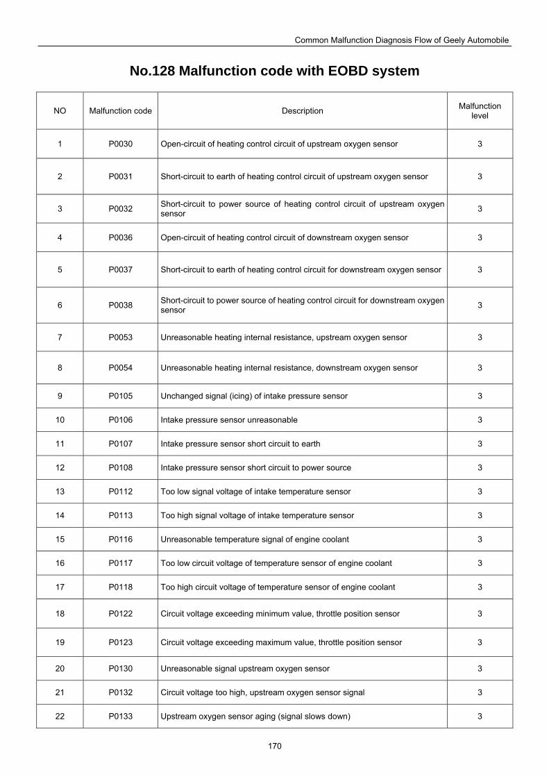
Common Malfunction Diagnosis Flow of Geely Automobile
170
No.128 Malfunction code with EOBD system
NO Malfunction code Description Malfunction level
1 P0030 Open-circuit of heating control circuit of upstream oxygen sensor 3
2 P0031 Short-circuit to earth of heating control circuit of upstream oxygen sensor 3
3 P0032 Short-circuit to power source of heating control circuit of upstream oxygen sensor 3
4 P0036 Open-circuit of heating control circuit of downstream oxygen sensor 3
5 P0037 Short-circuit to earth of heating control circuit for downstream oxygen sensor 3
6 P0038 Short-circuit to power source of heating control circuit for downstream oxygen sensor 3
7 P0053 Unreasonable heating internal resistance, upstream oxygen sensor 3
8 P0054 Unreasonable heating internal resistance, downstream oxygen sensor 3
9 P0105 Unchanged signal (icing) of intake pressure sensor 3
10 P0106 Intake pressure sensor unreasonable 3
11 P0107 Intake pressure sensor short circuit to earth 3
12 P0108 Intake pressure sensor short circuit to power source 3
13 P0112 Too low signal voltage of intake temperature sensor 3
14 P0113 Too high signal voltage of intake temperature sensor 3
15 P0116 Unreasonable temperature signal of engine coolant 3
16 P0117 Too low circuit voltage of temperature sensor of engine coolant 3
17 P0118 Too high circuit voltage of temperature sensor of engine coolant 3
18 P0122 Circuit voltage exceeding minimum value, throttle position sensor 3
19 P0123 Circuit voltage exceeding maximum value, throttle position sensor 3
20 P0130 Unreasonable signal upstream oxygen sensor 3
21 P0132 Circuit voltage too high, upstream oxygen sensor signal 3
22 P0133 Upstream oxygen sensor aging (signal slows down) 3
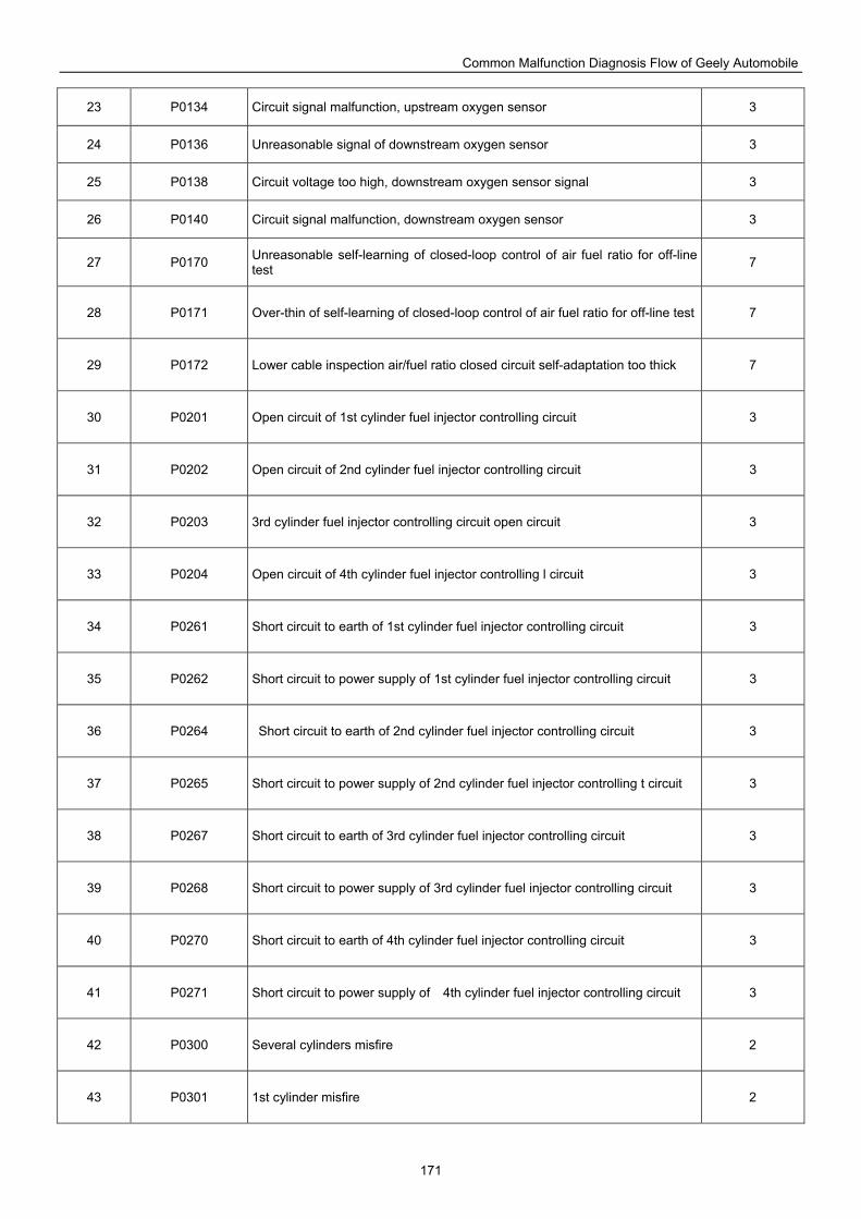
Common Malfunction Diagnosis Flow of Geely Automobile
171
23 P0134 Circuit signal malfunction, upstream oxygen sensor 3
24 P0136 Unreasonable signal of downstream oxygen sensor 3
25 P0138 Circuit voltage too high, downstream oxygen sensor signal 3
26 P0140 Circuit signal malfunction, downstream oxygen sensor 3
27 P0170 Unreasonable self-learning of closed-loop control of air fuel ratio for off-line test 7
28 P0171 Over-thin of self-learning of closed-loop control of air fuel ratio for off-line test 7
29 P0172 Lower cable inspection air/fuel ratio closed circuit self-adaptation too thick 7
30 P0201 Open circuit of 1st cylinder fuel injector controlling circuit 3
31 P0202 Open circuit of 2nd cylinder fuel injector controlling circuit 3
32 P0203 3rd cylinder fuel injector controlling circuit open circuit 3
33 P0204 Open circuit of 4th cylinder fuel injector controlling l circuit 3
34 P0261 Short circuit to earth of 1st cylinder fuel injector controlling circuit 3
35 P0262 Short circuit to power supply of 1st cylinder fuel injector controlling circuit 3
36 P0264 Short circuit to earth of 2nd cylinder fuel injector controlling circuit 3
37 P0265 Short circuit to power supply of 2nd cylinder fuel injector controlling t circuit 3
38 P0267 Short circuit to earth of 3rd cylinder fuel injector controlling circuit 3
39 P0268 Short circuit to power supply of 3rd cylinder fuel injector controlling circuit 3
40 P0270 Short circuit to earth of 4th cylinder fuel injector controlling circuit 3
41 P0271 Short circuit to power supply of 4th cylinder fuel injector controlling circuit 3
42 P0300 Several cylinders misfire 2
43 P0301 1st cylinder misfire 2
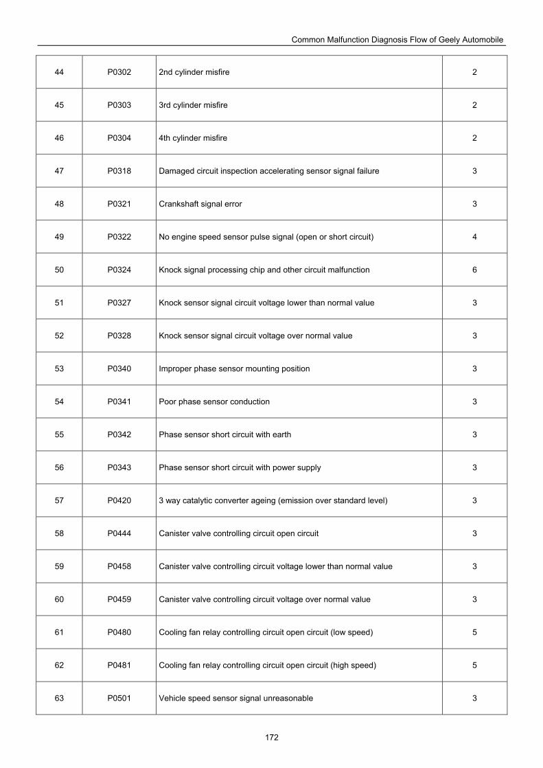
Common Malfunction Diagnosis Flow of Geely Automobile
172
44 P0302 2nd cylinder misfire 2
45 P0303 3rd cylinder misfire 2
46 P0304 4th cylinder misfire 2
47 P0318 Damaged circuit inspection accelerating sensor signal failure 3
48 P0321 Crankshaft signal error 3
49 P0322 No engine speed sensor pulse signal (open or short circuit) 4
50 P0324 Knock signal processing chip and other circuit malfunction 6
51 P0327 Knock sensor signal circuit voltage lower than normal value 3
52 P0328 Knock sensor signal circuit voltage over normal value 3
53 P0340 Improper phase sensor mounting position 3
54 P0341 Poor phase sensor conduction 3
55 P0342 Phase sensor short circuit with earth 3
56 P0343 Phase sensor short circuit with power supply 3
57 P0420 3 way catalytic converter ageing (emission over standard level) 3
58 P0444 Canister valve controlling circuit open circuit 3
59 P0458 Canister valve controlling circuit voltage lower than normal value 3
60 P0459 Canister valve controlling circuit voltage over normal value 3
61 P0480 Cooling fan relay controlling circuit open circuit (low speed) 5
62 P0481 Cooling fan relay controlling circuit open circuit (high speed) 5
63 P0501 Vehicle speed sensor signal unreasonable 3
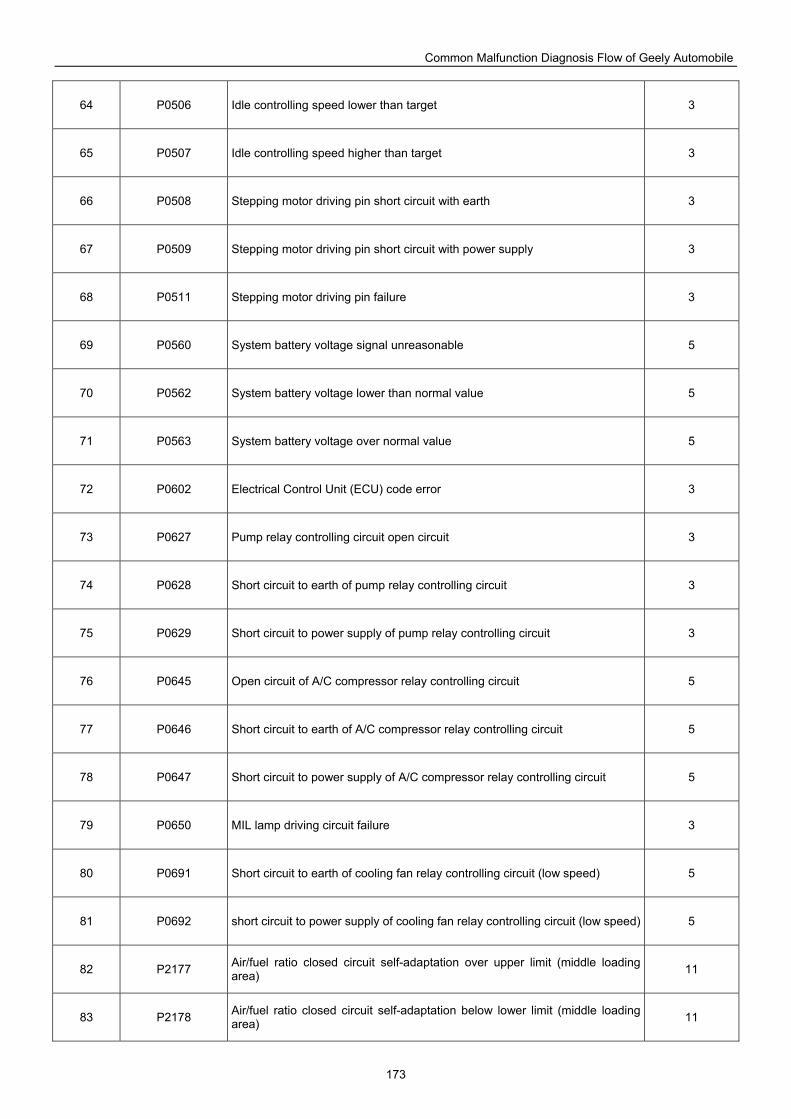
Common Malfunction Diagnosis Flow of Geely Automobile
173
64 P0506 Idle controlling speed lower than target 3
65 P0507 Idle controlling speed higher than target 3
66 P0508 Stepping motor driving pin short circuit with earth 3
67 P0509 Stepping motor driving pin short circuit with power supply 3
68 P0511 Stepping motor driving pin failure 3
69 P0560 System battery voltage signal unreasonable 5
70 P0562 System battery voltage lower than normal value 5
71 P0563 System battery voltage over normal value 5
72 P0602 Electrical Control Unit (ECU) code error 3
73 P0627 Pump relay controlling circuit open circuit 3
74 P0628 Short circuit to earth of pump relay controlling circuit 3
75 P0629 Short circuit to power supply of pump relay controlling circuit 3
76 P0645 Open circuit of A/C compressor relay controlling circuit 5
77 P0646 Short circuit to earth of A/C compressor relay controlling circuit 5
78 P0647 Short circuit to power supply of A/C compressor relay controlling circuit 5
79 P0650 MIL lamp driving circuit failure 3
80 P0691 Short circuit to earth of cooling fan relay controlling circuit (low speed) 5
81 P0692 short circuit to power supply of cooling fan relay controlling circuit (low speed) 5
82 P2177 Air/fuel ratio closed circuit self-adaptation over upper limit (middle loading area) 11
83 P2178 Air/fuel ratio closed circuit self-adaptation below lower limit (middle loading area) 11
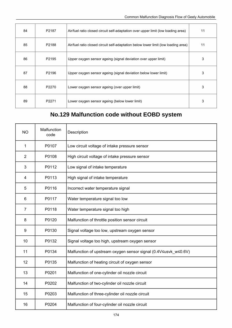
Common Malfunction Diagnosis Flow of Geely Automobile
174
84 P2187 Air/fuel ratio closed circuit self-adaptation over upper limit (low loading area) 11
85 P2188 Air/fuel ratio closed circuit self-adaptation below lower limit (low loading area) 11
86 P2195 Upper oxygen sensor ageing (signal deviation over upper limit) 3
87 P2196 Upper oxygen sensor ageing (signal deviation below lower limit) 3
88 P2270 Lower oxygen sensor ageing (over upper limit) 3
89 P2271 Lower oxygen sensor ageing (below lower limit) 3
No.129 Malfunction code without EOBD system
NO Malfunction code Description
1 P0107 Low circuit voltage of intake pressure sensor
2 P0108 High circuit voltage of intake pressure sensor
3 P0112 Low signal of intake temperature
4 P0113 High signal of intake temperature
5 P0116 Incorrect water temperature signal
6 P0117 Water temperature signal too low
7 P0118 Water temperature signal too high
8 P0120 Malfunction of throttle position sensor circuit
9 P0130 Signal voltage too low, upstream oxygen sensor
10 P0132 Signal voltage too high, upstream oxygen sensor
11 P0134 Malfunction of upstream oxygen sensor signal (0.4V≤usvk_w≤0.6V)
12 P0135 Malfunction of heating circuit of oxygen sensor
13 P0201 Malfunction of one-cylinder oil nozzle circuit
14 P0202 Malfunction of two-cylinder oil nozzle circuit
15 P0203 Malfunction of three-cylinder oil nozzle circuit
16 P0204 Malfunction of four-cylinder oil nozzle circuit
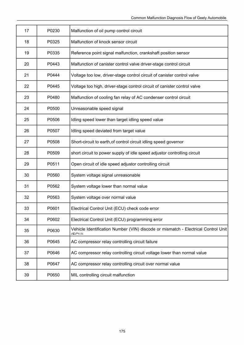
Common Malfunction Diagnosis Flow of Geely Automobile
175
17 P0230 Malfunction of oil pump control circuit
18 P0325 Malfunction of knock sensor circuit
19 P0335 Reference point signal malfunction, crankshaft position sensor
20 P0443 Malfunction of canister control valve driver-stage control circuit
21 P0444 Voltage too low, driver-stage control circuit of canister control valve
22 P0445 Voltage too high, driver-stage control circuit of canister control valve
23 P0480 Malfunction of cooling fan relay of AC condenser control circuit
24 P0500 Unreasonable speed signal
25 P0506 Idling speed lower than target idling speed value
26 P0507 Idling speed deviated from target value
27 P0508 Short-circuit to earth,of control circuit idling speed governor
28 P0509 short circuit to power supply of idle speed adjustor controlling circuit
29 P0511 Open circuit of idle speed adjustor controlling circuit
30 P0560 System voltage signal unreasonable
31 P0562 System voltage lower than normal value
32 P0563 System voltage over normal value
33 P0601 Electrical Control Unit (ECU) check code error
34 P0602 Electrical Control Unit (ECU) programming error
35 P0630 Vehicle Identification Number (VIN) discode or mismatch - Electrical Control Unit (ECU)
36 P0645 AC compressor relay controlling circuit failure
37 P0646 AC compressor relay controlling circuit voltage lower than normal value
38 P0647 AC compressor relay controlling circuit over normal value
39 P0650 MIL controlling circuit malfunction
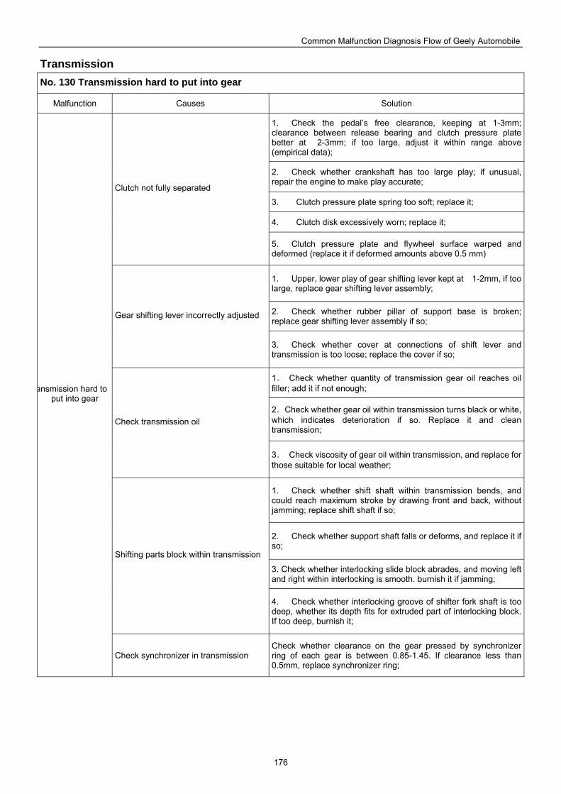
Common Malfunction Diagnosis Flow of Geely Automobile
176
Transmission No. 130 Transmission hard to put into gear
Malfunction Causes Solution
1. Check the pedal’s free clearance, keeping at 1-3mm; clearance between release bearing and clutch pressure plate better at 2-3mm; if too large, adjust it within range above (empirical data);
2. Check whether crankshaft has too large play; if unusual, repair the engine to make play accurate;
3. Clutch pressure plate spring too soft; replace it;
4. Clutch disk excessively worn; replace it;
Clutch not fully separated
5. Clutch pressure plate and flywheel surface warped and deformed (replace it if deformed amounts above 0.5 mm)
1. Upper, lower play of gear shifting lever kept at 1-2mm, if too large, replace gear shifting lever assembly;
2. Check whether rubber pillar of support base is broken; replace gear shifting lever assembly if so;
Gear shifting lever incorrectly adjusted
3. Check whether cover at connections of shift lever and transmission is too loose; replace the cover if so;
1. Check whether quantity of transmission gear oil reaches oil filler; add it if not enough;
2.Check whether gear oil within transmission turns black or white, which indicates deterioration if so. Replace it and clean transmission;
Check transmission oil
3. Check viscosity of gear oil within transmission, and replace for those suitable for local weather;
1. Check whether shift shaft within transmission bends, and could reach maximum stroke by drawing front and back, without jamming; replace shift shaft if so;
2. Check whether support shaft falls or deforms, and replace it if so;
3. Check whether interlocking slide block abrades, and moving left and right within interlocking is smooth. burnish it if jamming;
Shifting parts block within transmission
4. Check whether interlocking groove of shifter fork shaft is too deep, whether its depth fits for extruded part of interlocking block. If too deep, burnish it;
ansmission hard to put into gear
Check synchronizer in transmission Check whether clearance on the gear pressed by synchronizer ring of each gear is between 0.85-1.45. If clearance less than 0.5mm, replace synchronizer ring;
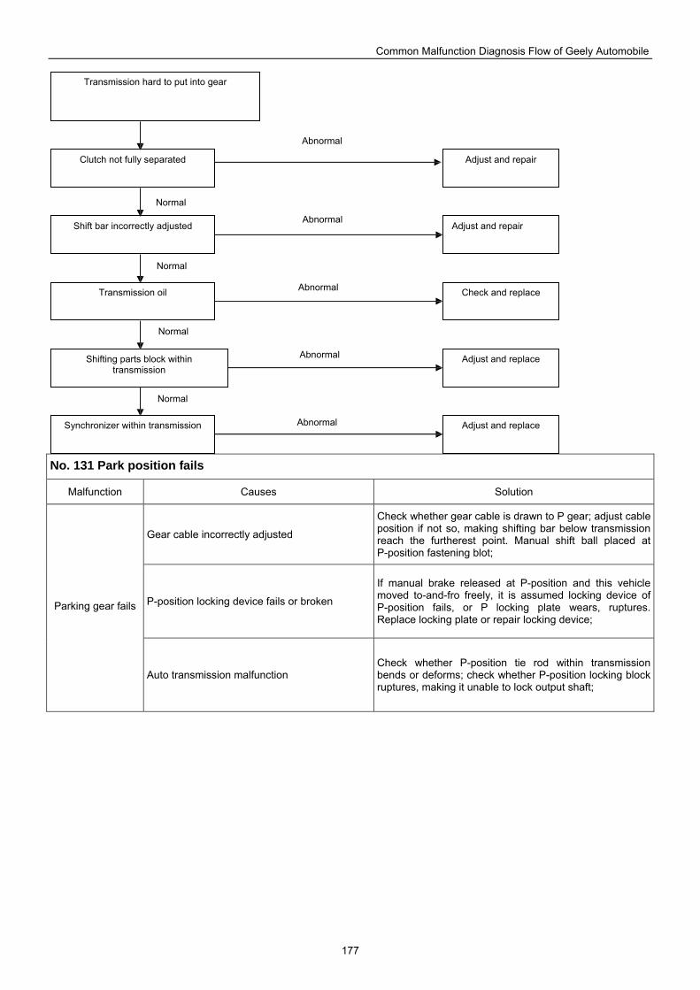
Common Malfunction Diagnosis Flow of Geely Automobile
177
No. 131 Park position fails
Malfunction Causes Solution
Gear cable incorrectly adjusted
Check whether gear cable is drawn to P gear; adjust cable position if not so, making shifting bar below transmission reach the furtherest point. Manual shift ball placed at P-position fastening blot;
P-position locking device fails or broken
If manual brake released at P-position and this vehicle moved to-and-fro freely, it is assumed locking device of P-position fails, or P locking plate wears, ruptures. Replace locking plate or repair locking device;
Parking gear fails
Auto transmission malfunction Check whether P-position tie rod within transmission bends or deforms; check whether P-position locking block ruptures, making it unable to lock output shaft;
Clutch not fully separated Adjust and repair
Transmission hard to put into gear
Shift bar incorrectly adjusted Adjust and repair
Transmission oil Check and replace
Shifting parts block within transmission
Adjust and replace
Synchronizer within transmission Adjust and replace
Abnormal
Normal
Normal
Normal
Normal
Abnormal
Abnormal
Abnormal
Abnormal
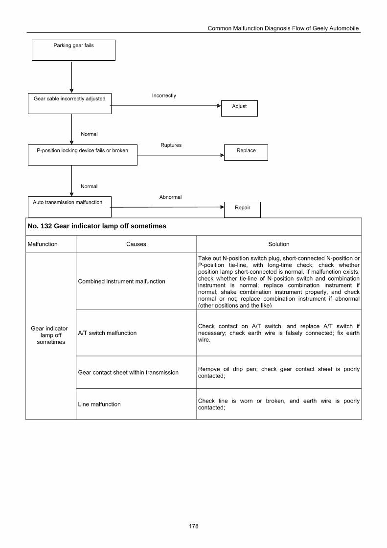
Common Malfunction Diagnosis Flow of Geely Automobile
178
No. 132 Gear indicator lamp off sometimes
Malfunction Causes Solution
Combined instrument malfunction
Take out N-position switch plug, short-connected N-position or P-position tie-line, with long-time check; check whether position lamp short-connected is normal. If malfunction exists, check whether tie-line of N-position switch and combination instrument is normal; replace combination instrument if normal; shake combination instrument properly, and check normal or not; replace combination instrument if abnormal (other positions and the like)
A/T switch malfunction Check contact on A/T switch, and replace A/T switch if necessary; check earth wire is falsely connected; fix earth wire.
Gear contact sheet within transmission Remove oil drip pan; check gear contact sheet is poorly contacted;
Gear indicator lamp off
sometimes
Line malfunction Check line is worn or broken, and earth wire is poorly contacted;
Parking gear fails
Gear cable incorrectly adjusted
P-position locking device fails or broken
Auto transmission malfunction
Replace
Adjust
Repair
Normal
Normal
Incorrectly
Ruptures
Abnormal
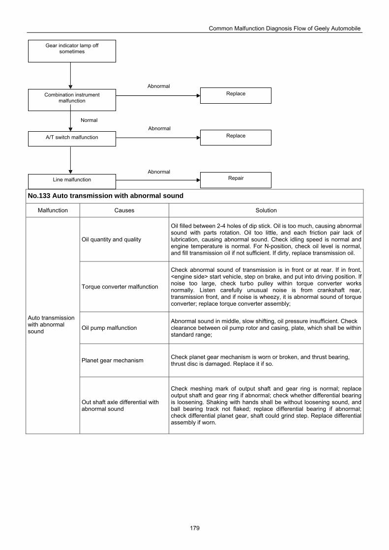
Common Malfunction Diagnosis Flow of Geely Automobile
179
No.133 Auto transmission with abnormal sound
Malfunction Causes Solution
Oil quantity and quality
Oil filled between 2-4 holes of dip stick. Oil is too much, causing abnormal sound with parts rotation. Oil too little, and each friction pair lack of lubrication, causing abnormal sound. Check idling speed is normal and engine temperature is normal. For N-position, check oil level is normal, and fill transmission oil if not sufficient. If dirty, replace transmission oil.
Torque converter malfunction
Check abnormal sound of transmission is in front or at rear. If in front, <engine side> start vehicle, step on brake, and put into driving position. If noise too large, check turbo pulley within torque converter works normally. Listen carefully unusual noise is from crankshaft rear, transmission front, and if noise is wheezy, it is abnormal sound of torque converter; replace torque converter assembly;
Oil pump malfunction Abnormal sound in middle, slow shifting, oil pressure insufficient. Check clearance between oil pump rotor and casing, plate, which shall be within standard range;
Planet gear mechanism Check planet gear mechanism is worn or broken, and thrust bearing, thrust disc is damaged. Replace it if so.
Auto transmission with abnormal sound
Out shaft axle differential with abnormal sound
Check meshing mark of output shaft and gear ring is normal; replace output shaft and gear ring if abnormal; check whether differential bearing is loosening. Shaking with hands shall be without loosening sound, and ball bearing track not flaked; replace differential bearing if abnormal; check differential planet gear, shaft could grind step. Replace differential assembly if worn.
Replace
Gear indicator lamp off sometimes
Combination instrument malfunction
A/T switch malfunction
Line malfunction
Replace
Repair
Abnormal
Normal Abnormal
Abnormal
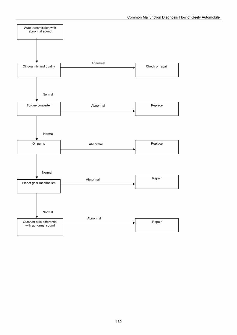
Common Malfunction Diagnosis Flow of Geely Automobile
180
Auto transmission with abnormal sound
Oil quantity and quality Check or repair
Torque converter Replace
Oil pump Replace
Planet gear mechanism Repair
Outshaft axle differential with abnormal sound
Repair
Abnormal
Normal
Normal
Normal
Normal
Abnormal
Abnormal
Abnormal
Abnormal
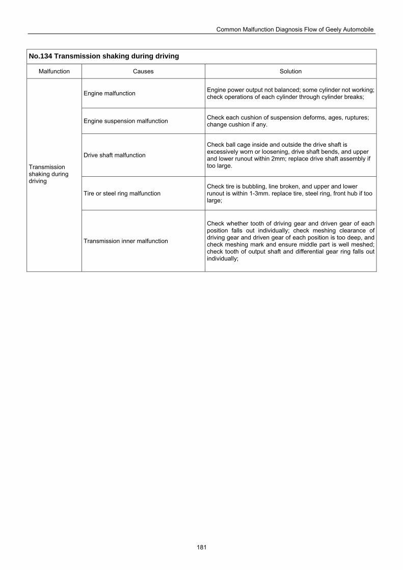
Common Malfunction Diagnosis Flow of Geely Automobile
181
No.134 Transmission shaking during driving
Malfunction Causes Solution
Engine malfunction Engine power output not balanced; some cylinder not working; check operations of each cylinder through cylinder breaks;
Engine suspension malfunction Check each cushion of suspension deforms, ages, ruptures; change cushion if any.
Drive shaft malfunction
Check ball cage inside and outside the drive shaft is excessively worn or loosening, drive shaft bends, and upper and lower runout within 2mm; replace drive shaft assembly if too large.
Tire or steel ring malfunction Check tire is bubbling, line broken, and upper and lower runout is within 1-3mm. replace tire, steel ring, front hub if too large;
Transmission shaking during driving
Transmission inner malfunction
Check whether tooth of driving gear and driven gear of each position falls out individually; check meshing clearance of driving gear and driven gear of each position is too deep, and check meshing mark and ensure middle part is well meshed; check tooth of output shaft and differential gear ring falls out individually;
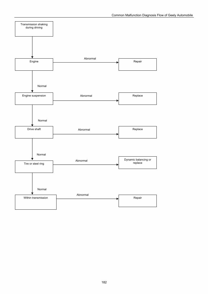
Common Malfunction Diagnosis Flow of Geely Automobile
182
Transmission shaking during driving
Engine Repair
Engine suspension Replace
Drive shaft Replace
Tire or steel ring Dynamic balancing or
replace
Within transmission Repair
Abnormal
Normal
Normal
Normal
Normal
Abnormal
Abnormal
Abnormal
Abnormal
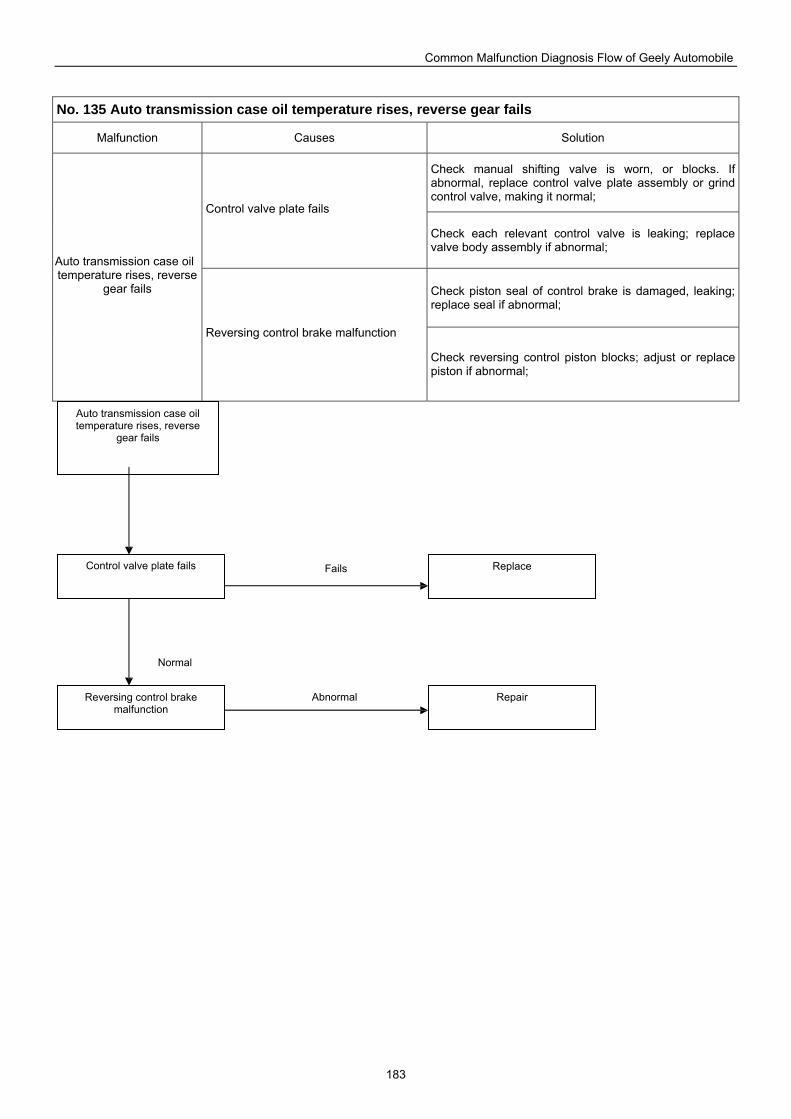
Common Malfunction Diagnosis Flow of Geely Automobile
183
No. 135 Auto transmission case oil temperature rises, reverse gear fails
Malfunction Causes Solution
Check manual shifting valve is worn, or blocks. If abnormal, replace control valve plate assembly or grind control valve, making it normal;
Control valve plate fails
Check each relevant control valve is leaking; replace valve body assembly if abnormal;
Check piston seal of control brake is damaged, leaking; replace seal if abnormal;
Auto transmission case oil temperature rises, reverse
gear fails
Reversing control brake malfunction
Check reversing control piston blocks; adjust or replace piston if abnormal;
Reversing control brake malfunction
Repair
Control valve plate fails Replace
Auto transmission case oil temperature rises, reverse
gear fails
Fails
Normal
Abnormal
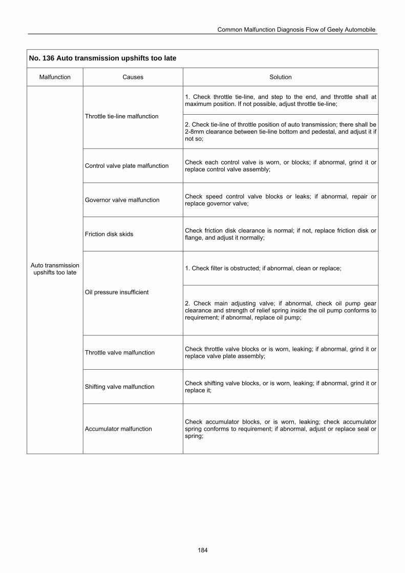
Common Malfunction Diagnosis Flow of Geely Automobile
184
No. 136 Auto transmission upshifts too late
Malfunction Causes Solution
1. Check throttle tie-line, and step to the end, and throttle shall at maximum position. If not possible, adjust throttle tie-line;
Throttle tie-line malfunction 2. Check tie-line of throttle position of auto transmission; there shall be 2-8mm clearance between tie-line bottom and pedestal, and adjust it if not so;
Control valve plate malfunction Check each control valve is worn, or blocks; if abnormal, grind it or replace control valve assembly;
Governor valve malfunction Check speed control valve blocks or leaks; if abnormal, repair or replace governor valve;
Friction disk skids Check friction disk clearance is normal; if not, replace friction disk or flange, and adjust it normally;
1. Check filter is obstructed; if abnormal, clean or replace;
Oil pressure insufficient
2. Check main adjusting valve; if abnormal, check oil pump gear clearance and strength of relief spring inside the oil pump conforms to requirement; if abnormal, replace oil pump;
Throttle valve malfunction Check throttle valve blocks or is worn, leaking; if abnormal, grind it or replace valve plate assembly;
Shifting valve malfunction Check shifting valve blocks, or is worn, leaking; if abnormal, grind it or replace it;
Auto transmission upshifts too late
Accumulator malfunction Check accumulator blocks, or is worn, leaking; check accumulator spring conforms to requirement; if abnormal, adjust or replace seal or spring;
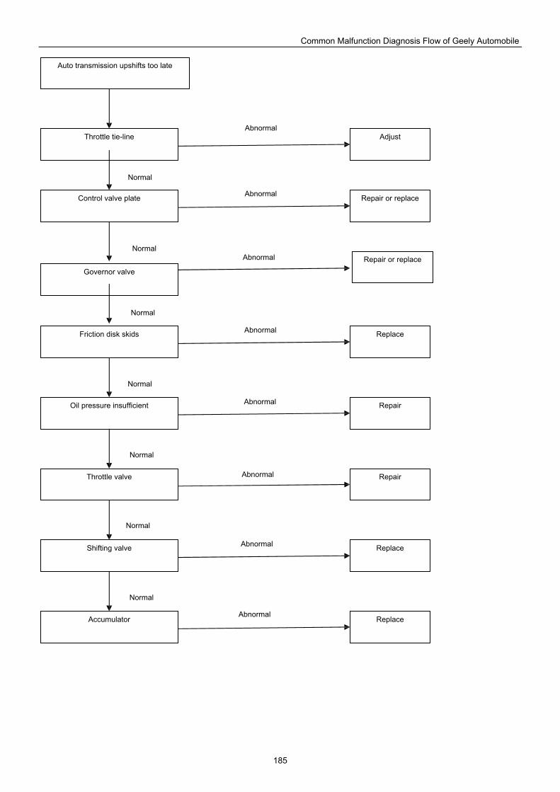
Common Malfunction Diagnosis Flow of Geely Automobile
185
Shifting valve
Replace
Repair
Control valve plate
Throttle tie-line
Auto transmission upshifts too late
Throttle valve
Oil pressure insufficient
Friction disk skids
Governor valve
Accumulator
Repair or replace
Repair or replace
Adjust
Repair
Replace
Replace
Abnormal
Normal
Normal
Normal
Normal
Normal
Normal
Normal
Abnormal
Abnormal
Abnormal
Abnormal
Abnormal
Abnormal
Abnormal
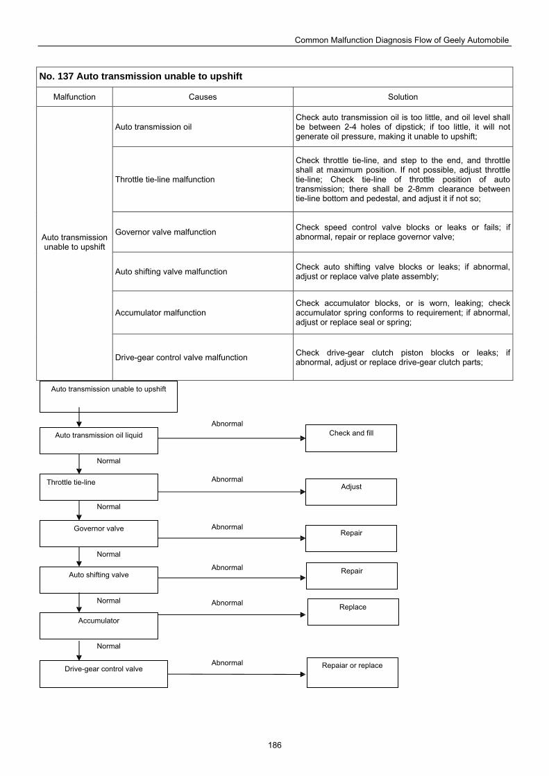
Common Malfunction Diagnosis Flow of Geely Automobile
186
No. 137 Auto transmission unable to upshift
Malfunction Causes Solution
Auto transmission oil Check auto transmission oil is too little, and oil level shall be between 2-4 holes of dipstick; if too little, it will not generate oil pressure, making it unable to upshift;
Throttle tie-line malfunction
Check throttle tie-line, and step to the end, and throttle shall at maximum position. If not possible, adjust throttle tie-line; Check tie-line of throttle position of auto transmission; there shall be 2-8mm clearance between tie-line bottom and pedestal, and adjust it if not so;
Governor valve malfunction Check speed control valve blocks or leaks or fails; if abnormal, repair or replace governor valve;
Auto shifting valve malfunction Check auto shifting valve blocks or leaks; if abnormal, adjust or replace valve plate assembly;
Accumulator malfunction Check accumulator blocks, or is worn, leaking; check accumulator spring conforms to requirement; if abnormal, adjust or replace seal or spring;
Auto transmission unable to upshift
Drive-gear control valve malfunction Check drive-gear clutch piston blocks or leaks; if abnormal, adjust or replace drive-gear clutch parts;
Auto transmission unable to upshift
Auto transmission oil liquid
Throttle tie-line
Governor valve
Auto shifting valve
Accumulator
Drive-gear control valve Repaiar or replace
Replace
Repair
Repair
Adjust
Check and fill Abnormal
Normal
Abnormal
Abnormal
Abnormal
Abnormal
Abnormal
Normal
Normal
Normal
Normal
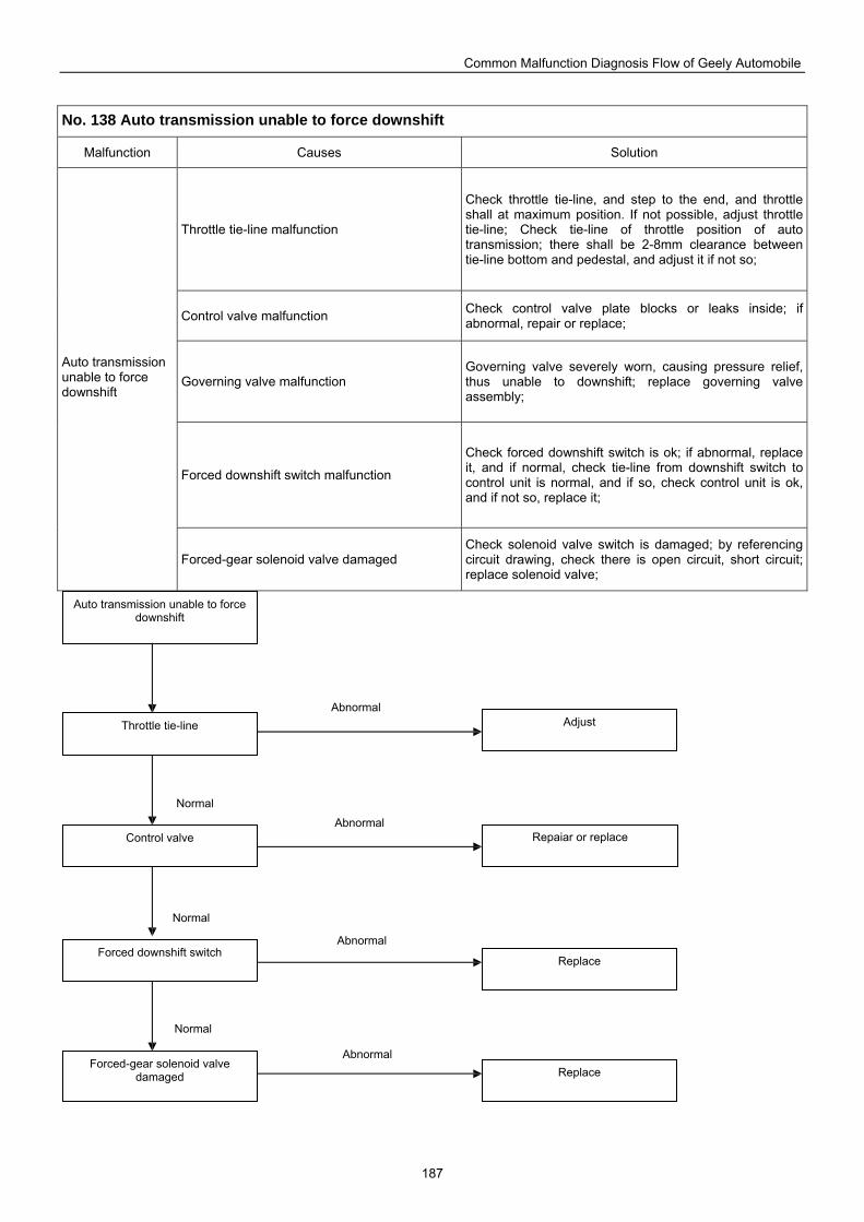
Common Malfunction Diagnosis Flow of Geely Automobile
187
No. 138 Auto transmission unable to force downshift
Malfunction Causes Solution
Throttle tie-line malfunction
Check throttle tie-line, and step to the end, and throttle shall at maximum position. If not possible, adjust throttle tie-line; Check tie-line of throttle position of auto transmission; there shall be 2-8mm clearance between tie-line bottom and pedestal, and adjust it if not so;
Control valve malfunction Check control valve plate blocks or leaks inside; if abnormal, repair or replace;
Governing valve malfunction Governing valve severely worn, causing pressure relief, thus unable to downshift; replace governing valve assembly;
Forced downshift switch malfunction
Check forced downshift switch is ok; if abnormal, replace it, and if normal, check tie-line from downshift switch to control unit is normal, and if so, check control unit is ok, and if not so, replace it;
Auto transmission unable to force downshift
Forced-gear solenoid valve damaged Check solenoid valve switch is damaged; by referencing circuit drawing, check there is open circuit, short circuit; replace solenoid valve;
Auto transmission unable to force downshift
Throttle tie-line
Control valve
Forced downshift switch
Forced-gear solenoid valve damaged
Repaiar or replace
Adjust
Replace
Replace
Abnormal
Normal
Normal
Normal
Abnormal
Abnormal
Abnormal
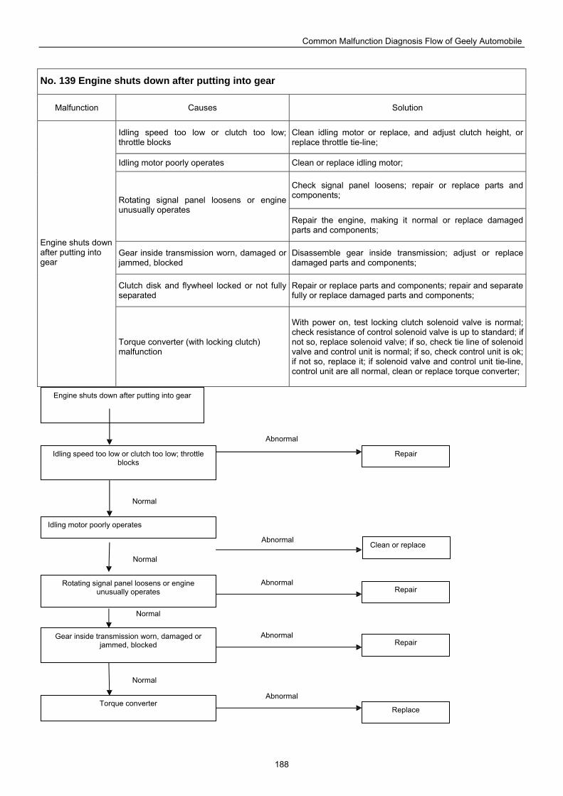
Common Malfunction Diagnosis Flow of Geely Automobile
188
No. 139 Engine shuts down after putting into gear
Malfunction Causes Solution
Idling speed too low or clutch too low; throttle blocks
Clean idling motor or replace, and adjust clutch height, or replace throttle tie-line;
Idling motor poorly operates Clean or replace idling motor;
Check signal panel loosens; repair or replace parts and components; Rotating signal panel loosens or engine
unusually operates Repair the engine, making it normal or replace damaged parts and components;
Gear inside transmission worn, damaged or jammed, blocked
Disassemble gear inside transmission; adjust or replace damaged parts and components;
Clutch disk and flywheel locked or not fully separated
Repair or replace parts and components; repair and separate fully or replace damaged parts and components;
Engine shuts down after putting into gear
Torque converter (with locking clutch) malfunction
With power on, test locking clutch solenoid valve is normal; check resistance of control solenoid valve is up to standard; if not so, replace solenoid valve; if so, check tie line of solenoid valve and control unit is normal; if so, check control unit is ok; if not so, replace it; if solenoid valve and control unit tie-line, control unit are all normal, clean or replace torque converter;
Engine shuts down after putting into gear
Idling speed too low or clutch too low; throttle blocks
Idling motor poorly operates
Rotating signal panel loosens or engine unusually operates
Gear inside transmission worn, damaged or jammed, blocked
Torque converter
Clean or replace
Replace
Repair
Repair
Repair
Abnormal
Normal
Normal
Normal
Normal
Abnormal
Abnormal
Abnormal
Abnormal
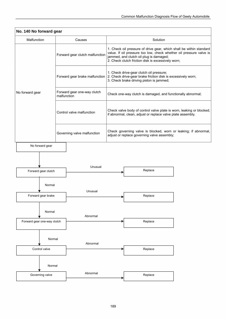
Common Malfunction Diagnosis Flow of Geely Automobile
189
No. 140 No forward gear
Malfunction Causes Solution
Forward gear clutch malfunction
1. Check oil pressure of drive gear, which shall be within standard value. If oil pressure too low, check whether oil pressure valve is jammed, and clutch oil plug is damaged; 2. Check clutch friction disk is excessively worn;
Forward gear brake malfunction1. Check drive-gear clutch oil pressure; 2. Check drive-gear brake friction disk is excessively worn; 3. Check brake driving piston is jammed;
Forward gear one-way clutch malfunction Check one-way clutch is damaged, and functionally abnormal;
Control valve malfunction Check valve body of control valve plate is worn, leaking or blocked; if abnormal, clean, adjust or replace valve plate assembly.
No forward gear
Governing valve malfunction Check governing valve is blocked, worn or leaking; if abnormal, adjust or replace governing valve assembly;
Governing valve Replace
No forward gear
Forward gear clutch
Forward gear brake
Forward gear one-way clutch
Control valve
Replace
Replace
Replace
Replace
Normal
Unusual
Normal
Normal
Normal
Unusual
Abnormal
Abnormal
Abnormal
Common Malfunction Diagnosis Flow of Geely Automobile
190
No. 141 Transmission oil easily deteriorate
Malfunction Causes Solution
Transmission oil quality problem Transmission must be filled with qualified gear oil (degree of API GL-4, SAE 80W-85 viscosity);
Transmission oil severely insufficient
Oil level flush with lower plane of oil filler bolt; quality of gear oil not good, and its quantity severely insufficient, causing poor heat emission and excessive wearing of the bearing. Mating surface of constant meshing gear falls out due to high temperature causing transmission oil turning black and deteriorating; replace damaged parts and components and clean transmission, and replace gear oil;
Transmission vent hole falls out Vent hole falls out, causing entry of dust and moisture from the atmosphere, and turning transmission oil white or dirty;
Transmission inner malfunction
Check meshing clearance of each gear pair within transmission is too small, which shall be between 0.1-0.35. If too small, it will cause transmission oil temperature too high, thus facilitating gear oil deteriorating;
Transmission oil easily deteriorate
Gear oil not replaced according to specified time for a long time causing too much oil sludge, and oil easily deteriorates
Disassemble transmission, and remove oil sludge and foreign substance. Clean scraps on the gear and bearing thoroughly. Refill gear oil with specified model, and replace it according to specified time and mileage.
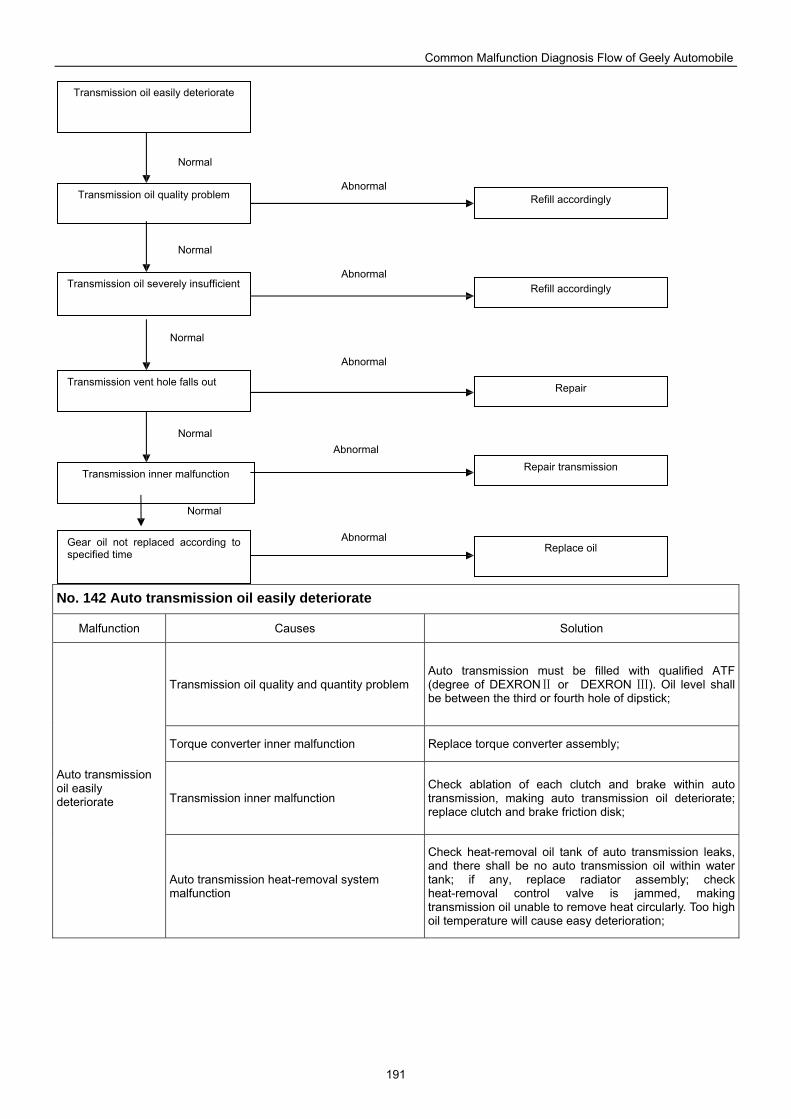
Common Malfunction Diagnosis Flow of Geely Automobile
191
No. 142 Auto transmission oil easily deteriorate
Malfunction Causes Solution
Transmission oil quality and quantity problem Auto transmission must be filled with qualified ATF (degree of DEXRON or DEXRON ). Oil level shall Ⅱ Ⅲbe between the third or fourth hole of dipstick;
Torque converter inner malfunction Replace torque converter assembly;
Transmission inner malfunction Check ablation of each clutch and brake within auto transmission, making auto transmission oil deteriorate; replace clutch and brake friction disk;
Auto transmission oil easily deteriorate
Auto transmission heat-removal system malfunction
Check heat-removal oil tank of auto transmission leaks, and there shall be no auto transmission oil within water tank; if any, replace radiator assembly; check heat-removal control valve is jammed, making transmission oil unable to remove heat circularly. Too high oil temperature will cause easy deterioration;
Transmission inner malfunction
Transmission oil easily deteriorate
Transmission oil quality problem
Transmission oil severely insufficient
Transmission vent hole falls out
Refill accordingly
Refill accordingly
Repair transmission
Repair
Gear oil not replaced according to specified time Replace oil
Normal
Abnormal
Abnormal
Abnormal
Abnormal
Abnormal
Normal
Normal
Normal
Normal
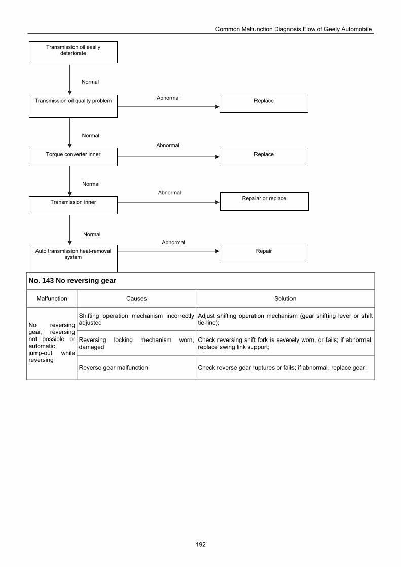
Common Malfunction Diagnosis Flow of Geely Automobile
192
No. 143 No reversing gear
Malfunction Causes Solution
Shifting operation mechanism incorrectly adjusted
Adjust shifting operation mechanism (gear shifting lever or shift tie-line);
Reversing locking mechanism worn, damaged
Check reversing shift fork is severely worn, or fails; if abnormal, replace swing link support;
No reversing gear, reversing not possible or automatic jump-out while reversing
Reverse gear malfunction Check reverse gear ruptures or fails; if abnormal, replace gear;
Transmission oil easily deteriorate
Transmission oil quality problem
Torque converter inner
Transmission inner
Auto transmission heat-removal system
Replace
Replace
Repair
Repaiar or replace
Normal Abnormal
Normal
Normal
Normal
Abnormal
Abnormal
Abnormal
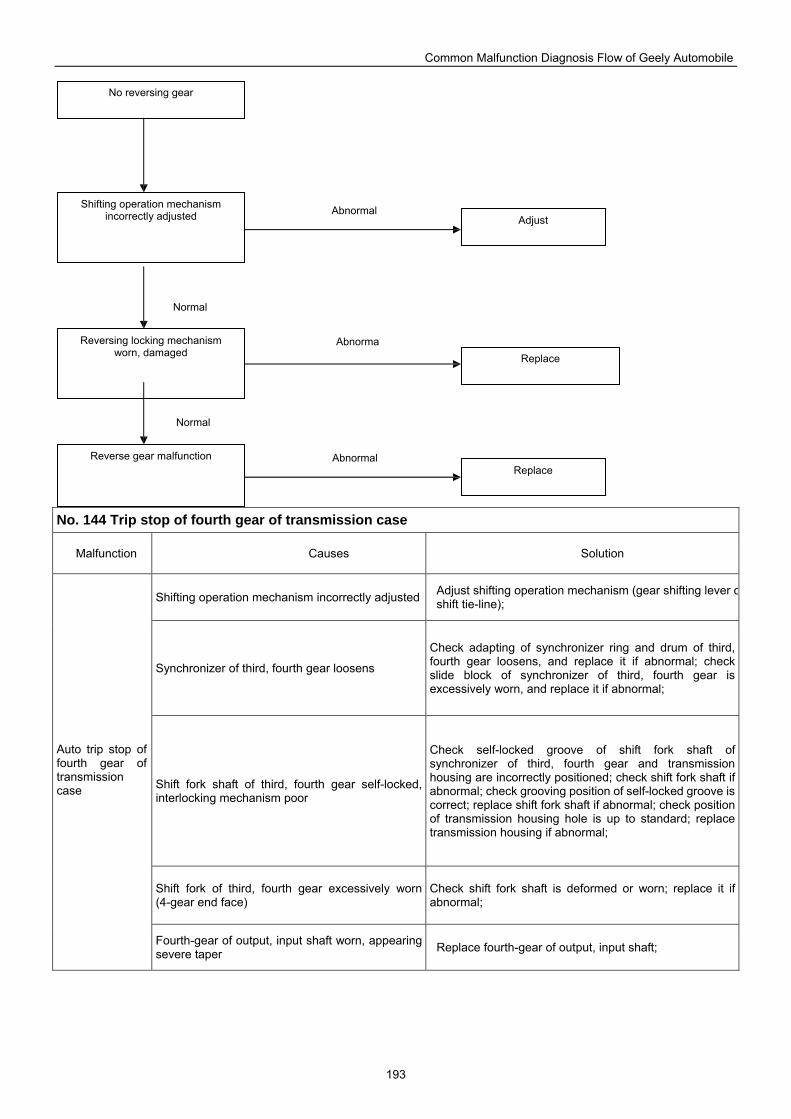
Common Malfunction Diagnosis Flow of Geely Automobile
193
No. 144 Trip stop of fourth gear of transmission case
Malfunction Causes Solution
Shifting operation mechanism incorrectly adjusted Adjust shifting operation mechanism (gear shifting lever oshift tie-line);
Synchronizer of third, fourth gear loosens
Check adapting of synchronizer ring and drum of third, fourth gear loosens, and replace it if abnormal; check slide block of synchronizer of third, fourth gear is excessively worn, and replace it if abnormal;
Shift fork shaft of third, fourth gear self-locked, interlocking mechanism poor
Check self-locked groove of shift fork shaft of synchronizer of third, fourth gear and transmission housing are incorrectly positioned; check shift fork shaft if abnormal; check grooving position of self-locked groove is correct; replace shift fork shaft if abnormal; check position of transmission housing hole is up to standard; replace transmission housing if abnormal;
Shift fork of third, fourth gear excessively worn (4-gear end face)
Check shift fork shaft is deformed or worn; replace it if abnormal;
Auto trip stop of fourth gear of transmission case
Fourth-gear of output, input shaft worn, appearing severe taper Replace fourth-gear of output, input shaft;
No reversing gear
Shifting operation mechanism incorrectly adjusted
Reversing locking mechanism worn, damaged
Reverse gear malfunction
Replace
Adjust
Replace
Normal
Abnormal
Normal
Abnorma
Abnormal
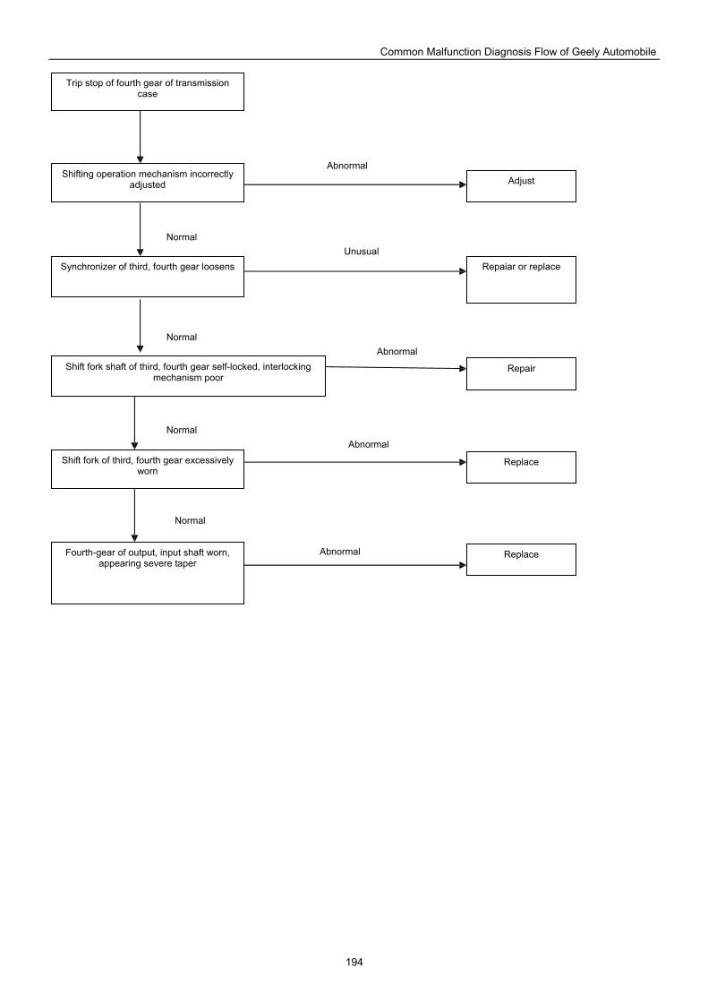
Common Malfunction Diagnosis Flow of Geely Automobile
194
Trip stop of fourth gear of transmission case
Shifting operation mechanism incorrectly adjusted
Synchronizer of third, fourth gear loosens
Shift fork shaft of third, fourth gear self-locked, interlocking mechanism poor
Shift fork of third, fourth gear excessively worn
Fourth-gear of output, input shaft worn, appearing severe taper
Repaiar or replace
Replace
Adjust
Replace
Repair
Normal
Abnormal
Abnormal
Abnormal
Unusual
Abnormal
Normal
Normal
Normal
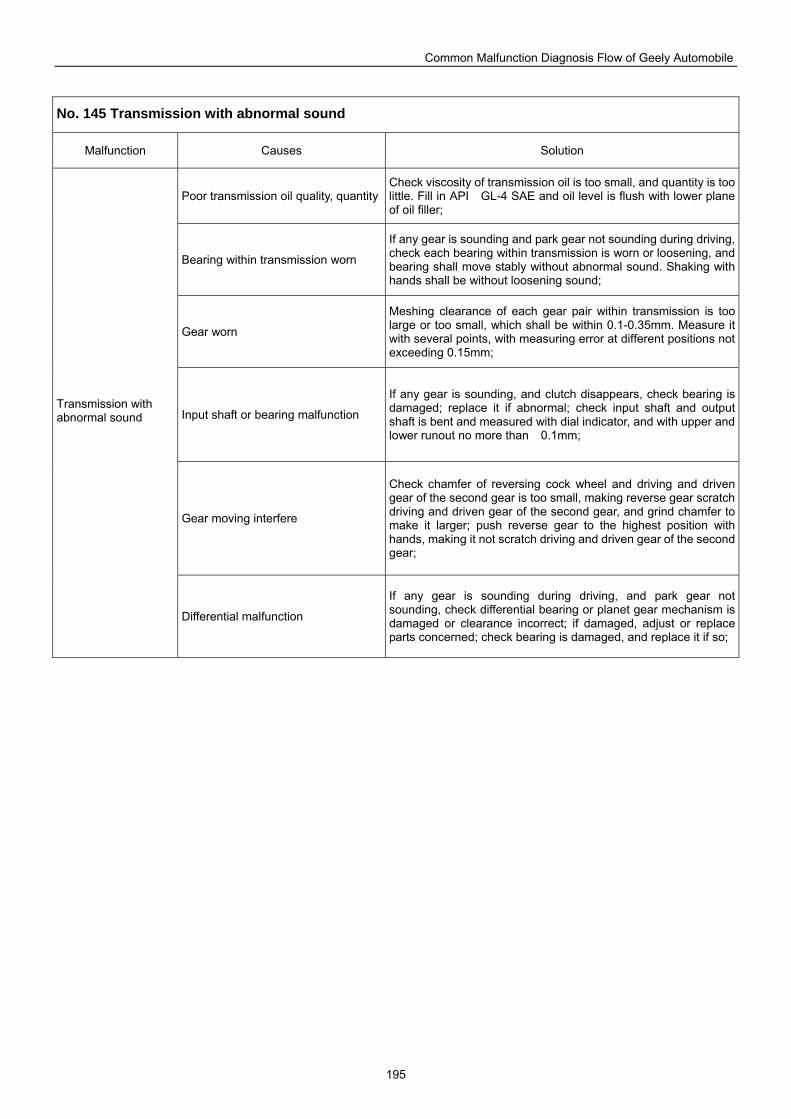
Common Malfunction Diagnosis Flow of Geely Automobile
195
No. 145 Transmission with abnormal sound
Malfunction Causes Solution
Poor transmission oil quality, quantity Check viscosity of transmission oil is too small, and quantity is too little. Fill in API GL-4 SAE and oil level is flush with lower plane of oil filler;
Bearing within transmission worn
If any gear is sounding and park gear not sounding during driving, check each bearing within transmission is worn or loosening, and bearing shall move stably without abnormal sound. Shaking with hands shall be without loosening sound;
Gear worn
Meshing clearance of each gear pair within transmission is too large or too small, which shall be within 0.1-0.35mm. Measure it with several points, with measuring error at different positions not exceeding 0.15mm;
Input shaft or bearing malfunction
If any gear is sounding, and clutch disappears, check bearing is damaged; replace it if abnormal; check input shaft and output shaft is bent and measured with dial indicator, and with upper and lower runout no more than 0.1mm;
Gear moving interfere
Check chamfer of reversing cock wheel and driving and driven gear of the second gear is too small, making reverse gear scratch driving and driven gear of the second gear, and grind chamfer to make it larger; push reverse gear to the highest position with hands, making it not scratch driving and driven gear of the second gear;
Transmission with abnormal sound
Differential malfunction
If any gear is sounding during driving, and park gear not sounding, check differential bearing or planet gear mechanism is damaged or clearance incorrect; if damaged, adjust or replace parts concerned; check bearing is damaged, and replace it if so;
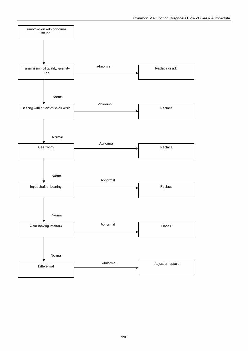
Common Malfunction Diagnosis Flow of Geely Automobile
196
Transmission with abnormal sound
Transmission oil quality, quantity poor
Bearing within transmission worn
Gear worn
Input shaft or bearing
Gear moving interfere
Replace
Repair
Replace or add
Replace
Replace
Differential Adjust or replace
Normal
Abnormal
Abnormal
Abnormal
Abnormal
Abnormal
Abnormal
Normal
Normal
Normal
Normal
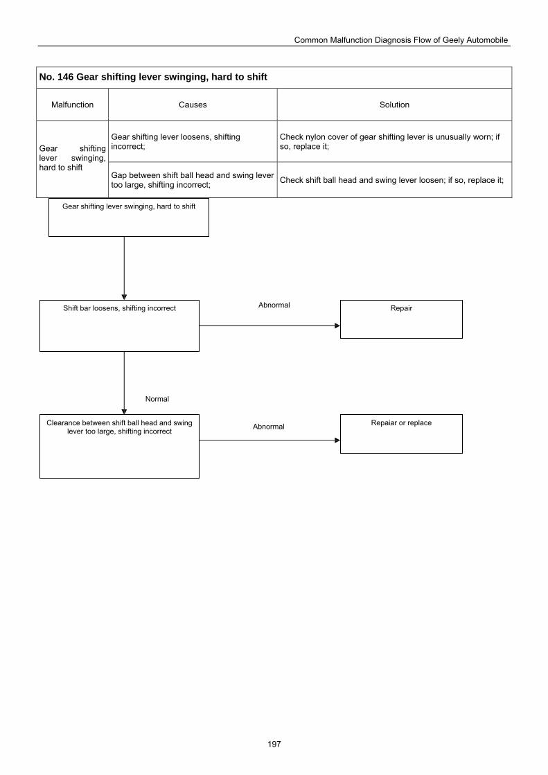
Common Malfunction Diagnosis Flow of Geely Automobile
197
No. 146 Gear shifting lever swinging, hard to shift
Malfunction Causes Solution
Gear shifting lever loosens, shifting incorrect;
Check nylon cover of gear shifting lever is unusually worn; if so, replace it; Gear shifting
lever swinging, hard to shift
Gap between shift ball head and swing lever too large, shifting incorrect; Check shift ball head and swing lever loosen; if so, replace it;
Gear shifting lever swinging, hard to shift
Shift bar loosens, shifting incorrect
Clearance between shift ball head and swing lever too large, shifting incorrect
Repaiar or replace
Repair
Normal
Abnormal
Abnormal
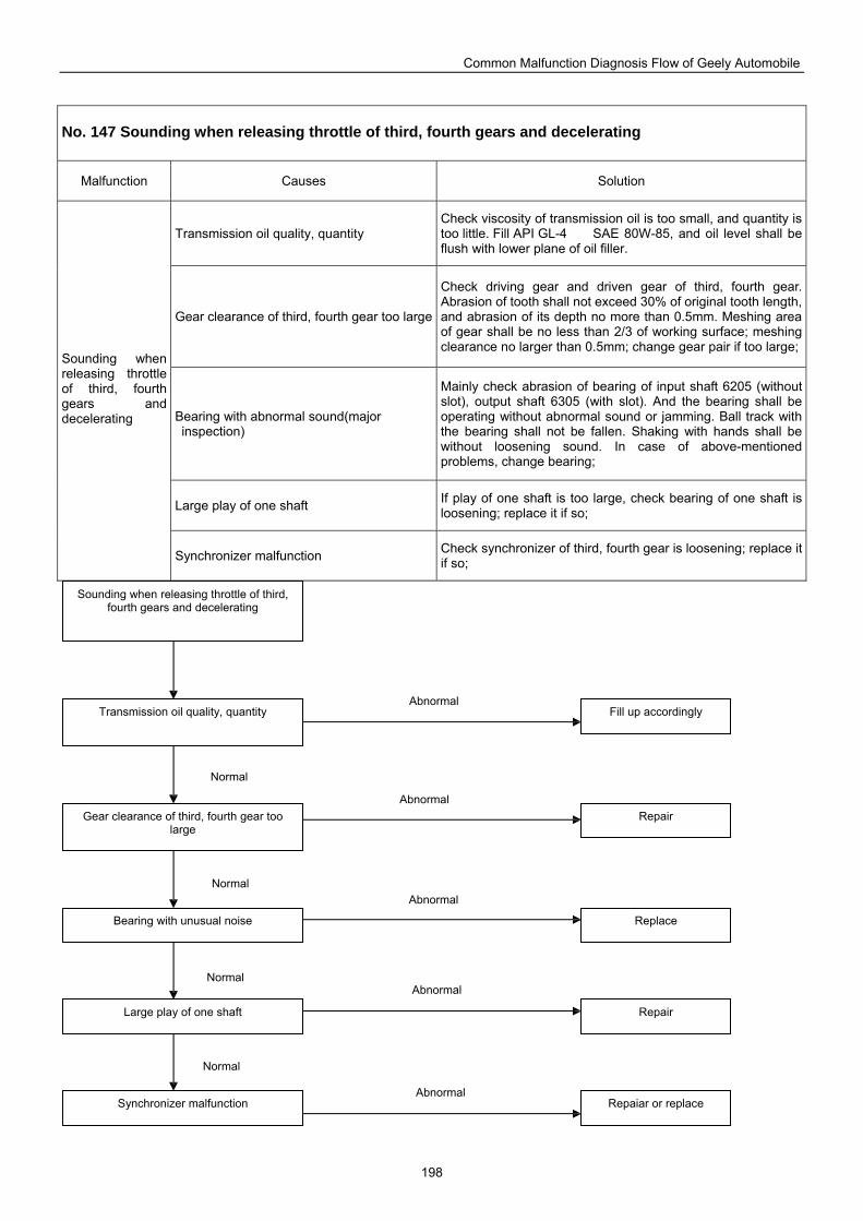
Common Malfunction Diagnosis Flow of Geely Automobile
198
No. 147 Sounding when releasing throttle of third, fourth gears and decelerating
Malfunction Causes Solution
Transmission oil quality, quantity Check viscosity of transmission oil is too small, and quantity is too little. Fill API GL-4 SAE 80W-85, and oil level shall be flush with lower plane of oil filler.
Gear clearance of third, fourth gear too large
Check driving gear and driven gear of third, fourth gear. Abrasion of tooth shall not exceed 30% of original tooth length, and abrasion of its depth no more than 0.5mm. Meshing area of gear shall be no less than 2/3 of working surface; meshing clearance no larger than 0.5mm; change gear pair if too large;
Bearing with abnormal sound(major inspection)
Mainly check abrasion of bearing of input shaft 6205 (without slot), output shaft 6305 (with slot). And the bearing shall be operating without abnormal sound or jamming. Ball track with the bearing shall not be fallen. Shaking with hands shall be without loosening sound. In case of above-mentioned problems, change bearing;
Large play of one shaft If play of one shaft is too large, check bearing of one shaft is loosening; replace it if so;
Sounding when releasing throttle of third, fourth gears and decelerating
Synchronizer malfunction Check synchronizer of third, fourth gear is loosening; replace it if so;
Sounding when releasing throttle of third, fourth gears and decelerating
Transmission oil quality, quantity
Gear clearance of third, fourth gear too large
Bearing with unusual noise
Large play of one shaft
Synchronizer malfunction
Repair
Repaiar or replace
Fill up accordingly
Repair
Replace
Normal
Abnormal
Abnormal
Abnormal
Abnormal
Abnormal
Normal
Normal
Normal
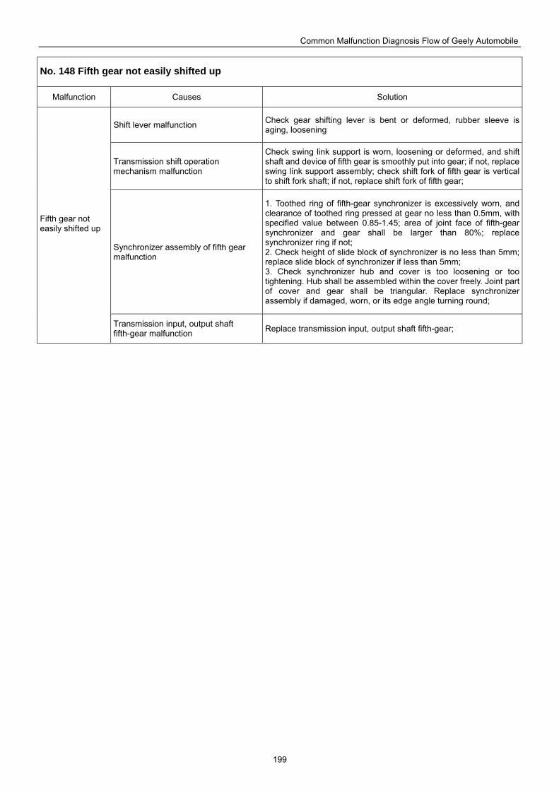
Common Malfunction Diagnosis Flow of Geely Automobile
199
No. 148 Fifth gear not easily shifted up
Malfunction Causes Solution
Shift lever malfunction Check gear shifting lever is bent or deformed, rubber sleeve is aging, loosening
Transmission shift operation mechanism malfunction
Check swing link support is worn, loosening or deformed, and shift shaft and device of fifth gear is smoothly put into gear; if not, replace swing link support assembly; check shift fork of fifth gear is vertical to shift fork shaft; if not, replace shift fork of fifth gear;
Synchronizer assembly of fifth gear malfunction
1. Toothed ring of fifth-gear synchronizer is excessively worn, and clearance of toothed ring pressed at gear no less than 0.5mm, with specified value between 0.85-1.45; area of joint face of fifth-gear synchronizer and gear shall be larger than 80%; replace synchronizer ring if not; 2. Check height of slide block of synchronizer is no less than 5mm; replace slide block of synchronizer if less than 5mm; 3. Check synchronizer hub and cover is too loosening or too tightening. Hub shall be assembled within the cover freely. Joint part of cover and gear shall be triangular. Replace synchronizer assembly if damaged, worn, or its edge angle turning round;
Fifth gear not easily shifted up
Transmission input, output shaft fifth-gear malfunction Replace transmission input, output shaft fifth-gear;
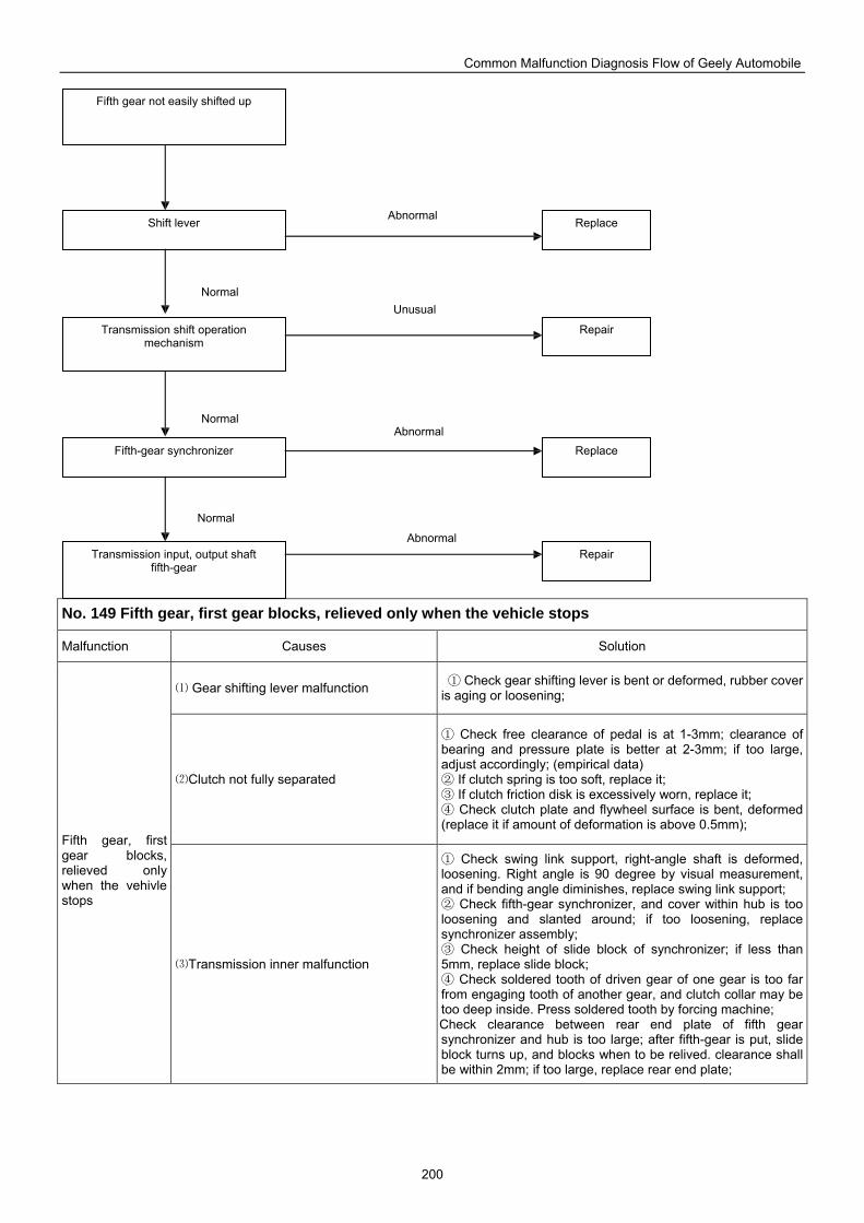
Common Malfunction Diagnosis Flow of Geely Automobile
200
No. 149 Fifth gear, first gear blocks, relieved only when the vehicle stops
Malfunction Causes Solution
Gear shifting lever malfunction⑴ Check gear shifting lever is bent or deformed, rubber cover ①is aging or loosening;
Clutch not fully separated ⑵
Check free clearance of pedal is at 1① -3mm; clearance of bearing and pressure plate is better at 2-3mm; if too large, adjust accordingly; (empirical data)
If clutch spring is too soft, replace it; ② If clutch friction disk is excessively worn, replace it;③ Check clutch plate and flywheel surface is bent, deformed ④
(replace it if amount of deformation is above 0.5mm); Fifth gear, first gear blocks, relieved only when the vehivle stops
Transmission inner malfunction⑶
Check swing link support, right① -angle shaft is deformed, loosening. Right angle is 90 degree by visual measurement, and if bending angle diminishes, replace swing link support;
Check fifth② -gear synchronizer, and cover within hub is too loosening and slanted around; if too loosening, replace synchronizer assembly;
Check height of slide block of synchronizer; if less than ③5mm, replace slide block;
Check soldered tooth of driven gear of one gear is too④ far from engaging tooth of another gear, and clutch collar may be too deep inside. Press soldered tooth by forcing machine; Check clearance between rear end plate of fifth gear synchronizer and hub is too large; after fifth-gear is put, slide block turns up, and blocks when to be relived. clearance shall be within 2mm; if too large, replace rear end plate;
Fifth gear not easily shifted up
Shift lever
Transmission shift operation mechanism
Fifth-gear synchronizer
Transmission input, output shaft fifth-gear
Repair
Replace
Repair
Replace
Normal
Abnormal
Normal
Normal
Abnormal
Unusual
Abnormal
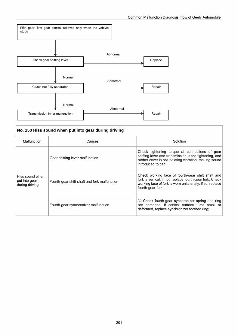
Common Malfunction Diagnosis Flow of Geely Automobile
201
No. 150 Hiss sound when put into gear during driving
Malfunction Causes Solution
Gear shifting lever malfunction
Check tightening torque at connections of gear shifting lever and transmission is too tightening, and rubber cover is not isolating vibration, making sound introduced to cab;
Fourth-gear shift shaft and fork malfunction
Check working face of fourth-gear shift shaft and fork is vertical; if not, replace fourth-gear fork. Check working face of fork is worn unilaterally; if so, replace fourth-gear fork;
Hiss sound when put into gear during driving
Fourth-gear synchronizer malfunction Check fourth② -gear synchronizer spring and ring
are damaged; if conical surface turns small or deformed, replace synchronizer toothed ring;
Fifth gear, first gear blocks, relieved only when the vehivle stops
Check gear shifting lever
Clutch not fully separated
Transmission inner malfunction
Repair
Replace
Repair Abnormal
Normal Abnormal
Abnormal
Normal
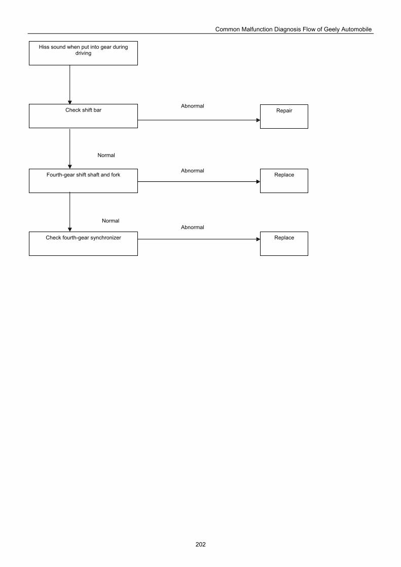
Common Malfunction Diagnosis Flow of Geely Automobile
202
Hiss sound when put into gear during driving
Check shift bar
Fourth-gear shift shaft and fork
Check fourth-gear synchronizer
Replace
Repair
Replace
Abnormal Normal
Abnormal
Abnormal
Normal
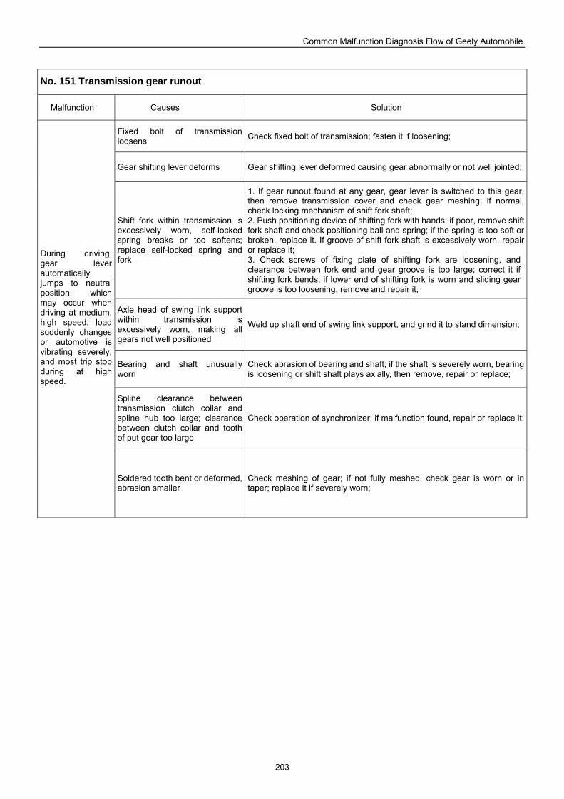
Common Malfunction Diagnosis Flow of Geely Automobile
203
No. 151 Transmission gear runout
Malfunction Causes Solution
Fixed bolt of transmission loosens Check fixed bolt of transmission; fasten it if loosening;
Gear shifting lever deforms Gear shifting lever deformed causing gear abnormally or not well jointed;
Shift fork within transmission is excessively worn, self-locked spring breaks or too softens; replace self-locked spring and fork
1. If gear runout found at any gear, gear lever is switched to this gear, then remove transmission cover and check gear meshing; if normal, check locking mechanism of shift fork shaft; 2. Push positioning device of shifting fork with hands; if poor, remove shift fork shaft and check positioning ball and spring; if the spring is too soft or broken, replace it. If groove of shift fork shaft is excessively worn, repair or replace it; 3. Check screws of fixing plate of shifting fork are loosening, and clearance between fork end and gear groove is too large; correct it if shifting fork bends; if lower end of shifting fork is worn and sliding gear groove is too loosening, remove and repair it;
Axle head of swing link support within transmission is excessively worn, making all gears not well positioned
Weld up shaft end of swing link support, and grind it to stand dimension;
Bearing and shaft unusually worn
Check abrasion of bearing and shaft; if the shaft is severely worn, bearing is loosening or shift shaft plays axially, then remove, repair or replace;
Spline clearance between transmission clutch collar and spline hub too large; clearance between clutch collar and tooth of put gear too large
Check operation of synchronizer; if malfunction found, repair or replace it;
During driving, gear lever automatically jumps to neutral position, which may occur when driving at medium, high speed, load suddenly changes or automotive is vibrating severely, and most trip stop during at high speed.
Soldered tooth bent or deformed, abrasion smaller
Check meshing of gear; if not fully meshed, check gear is worn or in taper; replace it if severely worn;
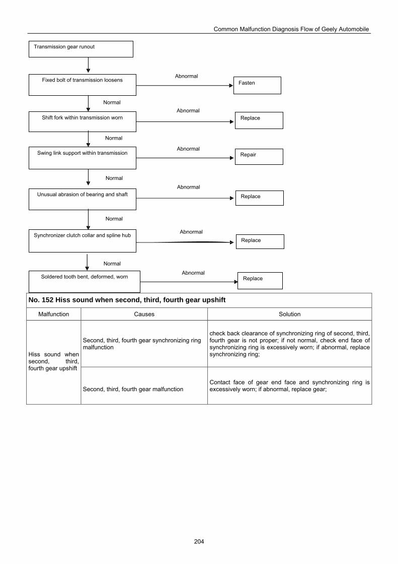
Common Malfunction Diagnosis Flow of Geely Automobile
204
No. 152 Hiss sound when second, third, fourth gear upshift
Malfunction Causes Solution
Second, third, fourth gear synchronizing ring malfunction
check back clearance of synchronizing ring of second, third, fourth gear is not proper; if not normal, check end face of synchronizing ring is excessively worn; if abnormal, replace synchronizing ring; Hiss sound when
second, third, fourth gear upshift
Second, third, fourth gear malfunction
Contact face of gear end face and synchronizing ring is excessively worn; if abnormal, replace gear;
Transmission gear runout
Fixed bolt of transmission loosens
Shift fork within transmission worn
Swing link support within transmission
Unusual abrasion of bearing and shaft
Synchronizer clutch collar and spline hub
Replace
Replace
Replace
Repair
Soldered tooth bent, deformed, worn Replace
Fasten
Abnormal
Normal
Normal
Normal
Normal
Normal
Abnormal
Abnormal
Abnormal
Abnormal
Abnormal
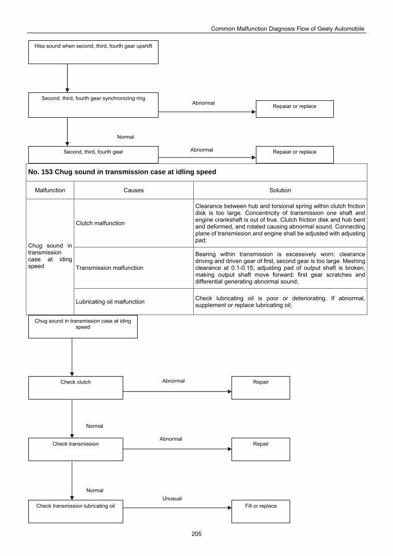
Common Malfunction Diagnosis Flow of Geely Automobile
205
No. 153 Chug sound in transmission case at idling speed
Malfunction Causes Solution
Clutch malfunction
Clearance between hub and torsional spring within clutch friction disk is too large. Concentricity of transmission one shaft and engine crankshaft is out of true. Clutch friction disk and hub bent and deformed, and rotated causing abnormal sound. Connecting plane of transmission and engine shall be adjusted with adjusting pad;
Transmission malfunction
Bearing within transmission is excessively worn; clearance driving and driven gear of first, second gear is too large. Meshing clearance at 0.1-0.15; adjusting pad of output shaft is broken, making output shaft move forward; first gear scratches and differential generating abnormal sound;
Chug sound in transmission case at iding speed
Lubricating oil malfunction Check lubricating oil is poor or deteriorating. If abnormal, supplement or replace lubricating oil;
Hiss sound when second, third, fourth gear upshift
Second, third, fourth gear synchronizing ring
Second, third, fourth gear Repaiar or replace
Repaiar or replace
Normal
Abnormal
Abnormal
Chug sound in transmission case at iding speed
Check clutch
Check transmission
Check transmission lubricating oil
Repair
Repair
Fill or replace
Normal
Abnormal
Normal Unusual
Abnormal
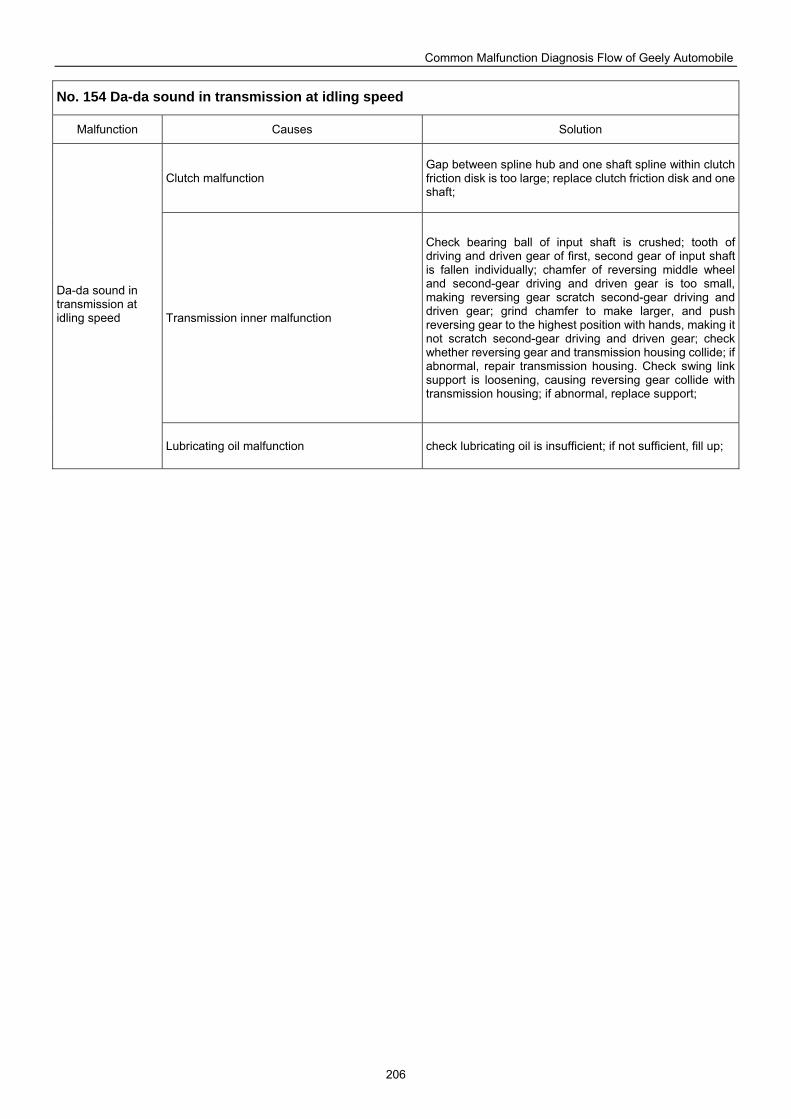
Common Malfunction Diagnosis Flow of Geely Automobile
206
No. 154 Da-da sound in transmission at idling speed
Malfunction Causes Solution
Clutch malfunction Gap between spline hub and one shaft spline within clutch friction disk is too large; replace clutch friction disk and one shaft;
Transmission inner malfunction
Check bearing ball of input shaft is crushed; tooth of driving and driven gear of first, second gear of input shaft is fallen individually; chamfer of reversing middle wheel and second-gear driving and driven gear is too small, making reversing gear scratch second-gear driving and driven gear; grind chamfer to make larger, and push reversing gear to the highest position with hands, making it not scratch second-gear driving and driven gear; check whether reversing gear and transmission housing collide; if abnormal, repair transmission housing. Check swing link support is loosening, causing reversing gear collide with transmission housing; if abnormal, replace support;
Da-da sound in transmission at idling speed
Lubricating oil malfunction check lubricating oil is insufficient; if not sufficient, fill up;
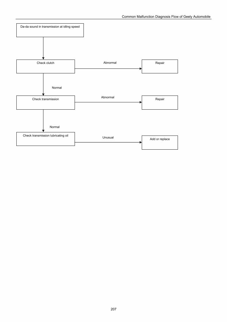
Common Malfunction Diagnosis Flow of Geely Automobile
207
Da-da sound in transmission at idling speed
Check clutch
Check transmission
Check transmission lubricating oil
Repair
Repair
Add or replace
Abnormal
Normal
Normal
Abnormal
Unusual
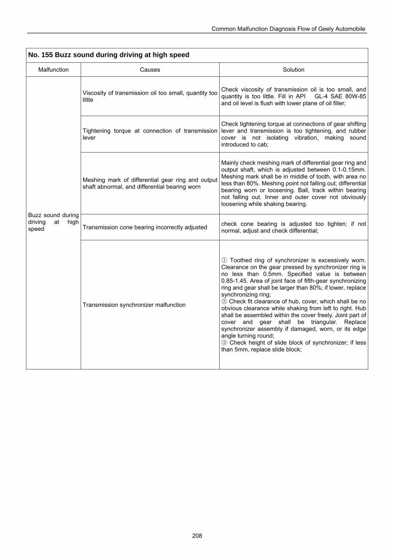
Common Malfunction Diagnosis Flow of Geely Automobile
208
No. 155 Buzz sound during driving at high speed
Malfunction Causes Solution
Viscosity of transmission oil too small, quantity too little
Check viscosity of transmission oil is too small, and quantity is too little. Fill in API GL-4 SAE 80W-85 and oil level is flush with lower plane of oil filler;
Tightening torque at connection of transmission lever
Check tightening torque at connections of gear shifting lever and transmission is too tightening, and rubber cover is not isolating vibration, making sound introduced to cab;
Meshing mark of differential gear ring and output shaft abnormal, and differential bearing worn
Mainly check meshing mark of differential gear ring and output shaft, which is adjusted between 0.1-0.15mm. Meshing mark shall be in middle of tooth, with area no less than 80%. Meshing point not falling out; differential bearing worn or loosening. Ball, track within bearing not falling out. Inner and outer cover not obviously loosening while shaking bearing.
Transmission cone bearing incorrectly adjusted check cone bearing is adjusted too tighten; if not normal, adjust and check differential;
Buzz sound during driving at high speed
Transmission synchronizer malfunction
Toothed ring of synchronizer is excessively worn. ①Clearance on the gear pressed by synchronizer ring is no less than 0.5mm. Specified value is between 0.85-1.45. Area of joint face of fifth-gear synchronizing ring and gear shall be larger than 80%; if lower, replace synchronizing ring;
② Check fit clearance of hub, cover, which shall be no obvious clearance while shaking from left to right. Hub shall be assembled within the cover freely. Joint part of cover and gear shall be triangular. Replace synchronizer assembly if damaged, worn, or its edge angle turning round;
Check height of slide block of synchronizer; if less ③than 5mm, replace slide block;
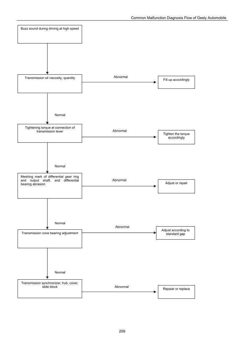
Common Malfunction Diagnosis Flow of Geely Automobile
209
Fill up accordingly
Tighten the torque accordingly
Buzz sound during driving at high speed
Transmission oil viscosity, quantity
Tightening torque at connection of transmission lever
Meshing mark of differential gear ring and output shaft, and differential bearing abrasion
Transmission cone bearing adjustment
Transmission synchronizer, hub, cover, slide block
Adjust according to standard gap
Adjust or repair
Repaiar or replace
Normal
Abnormal
Abnormal
Abnormal
Abnormal
Abnormal
Normal
Normal
Normal
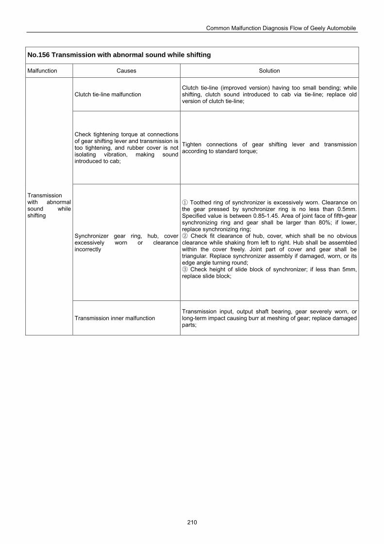
Common Malfunction Diagnosis Flow of Geely Automobile
210
No.156 Transmission with abnormal sound while shifting
Malfunction Causes Solution
Clutch tie-line malfunction Clutch tie-line (improved version) having too small bending; while shifting, clutch sound introduced to cab via tie-line; replace old version of clutch tie-line;
Check tightening torque at connections of gear shifting lever and transmission is too tightening, and rubber cover is not isolating vibration, making sound introduced to cab;
Tighten connections of gear shifting lever and transmission according to standard torque;
Synchronizer gear ring, hub, cover excessively worn or clearance incorrectly
Toothed ring of synchronizer is excessively worn. Clearance on ①the gear pressed by synchronizer ring is no less than 0.5mm. Specified value is between 0.85-1.45. Area of joint face of fifth-gear synchronizing ring and gear shall be larger than 80%; if lower, replace synchronizing ring;
② Check fit clearance of hub, cover, which shall be no obvious clearance while shaking from left to right. Hub shall be assembled within the cover freely. Joint part of cover and gear shall be triangular. Replace synchronizer assembly if damaged, worn, or its edge angle turning round;
Check height of slide block of synchronizer; if less than 5mm, ③replace slide block;
Transmission with abnormal sound while shifting
Transmission inner malfunction Transmission input, output shaft bearing, gear severely worn, or long-term impact causing burr at meshing of gear; replace damaged parts;
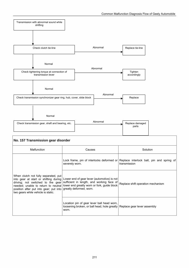
Common Malfunction Diagnosis Flow of Geely Automobile
211
No. 157 Transmission gear disorder
Malfunction Causes Solution
Lock frame, pin of interlocks deformed or severely worn.
Replace interlock ball, pin and spring of transmission
Lower end of gear lever (automotive) is not sufficient in length, and working face of lower end greatly worn or fork, guide block greatly deformed, worn.
Replace shift operation mechanism
When clutch not fully separated, put into gear at start or shifting during driving; not switched to the gear needed; unable to return to neutral position after put into gear; put into two gears while vehicle is static.
Location pin of gear lever ball head worn, loosening broken, or ball head, hole greatly worn.
Replace gear lever assembly
Transmission with abnormal sound while shifting
Check clutch tie-line
Check tightening torque at connection of transmission lever
Check transmission synchronizer gear ring, hub, cover, slide block
Check transmission gear, shaft and bearing, etc.
Tighten accordingly
Replace tie-line
Replace damaged parts
Replace
Abnormal
Normal
Normal
Normal
Abnormal
Abnormal
Abnormal
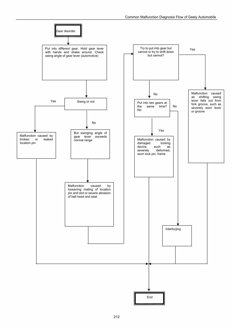
Common Malfunction Diagnosis Flow of Geely Automobile
212
Gear disorder
Try to put into gear but cannot or try to shift down
but cannot?
Put into two gears at the same time? No
Malfunction caused as shifting swing lever falls out from fork groove, such as severely worn lever or groove
Malfunction caused by damaged locking device, such as severely deformed, worn lock pin, frame
Interlocjing
Put into different gear. Hold gear lever with hands and shake around. Check swing angle of gear lever (automotive)
Swing or not
But swinging angle of gear lever exceeds normal range
Malfunction caused by broken or leaked location pin
Malfunction caused by loosening mating of location pin and slot or severe abrasion of ball head and seat
End
Yes
No
No
Yes
Yes
No
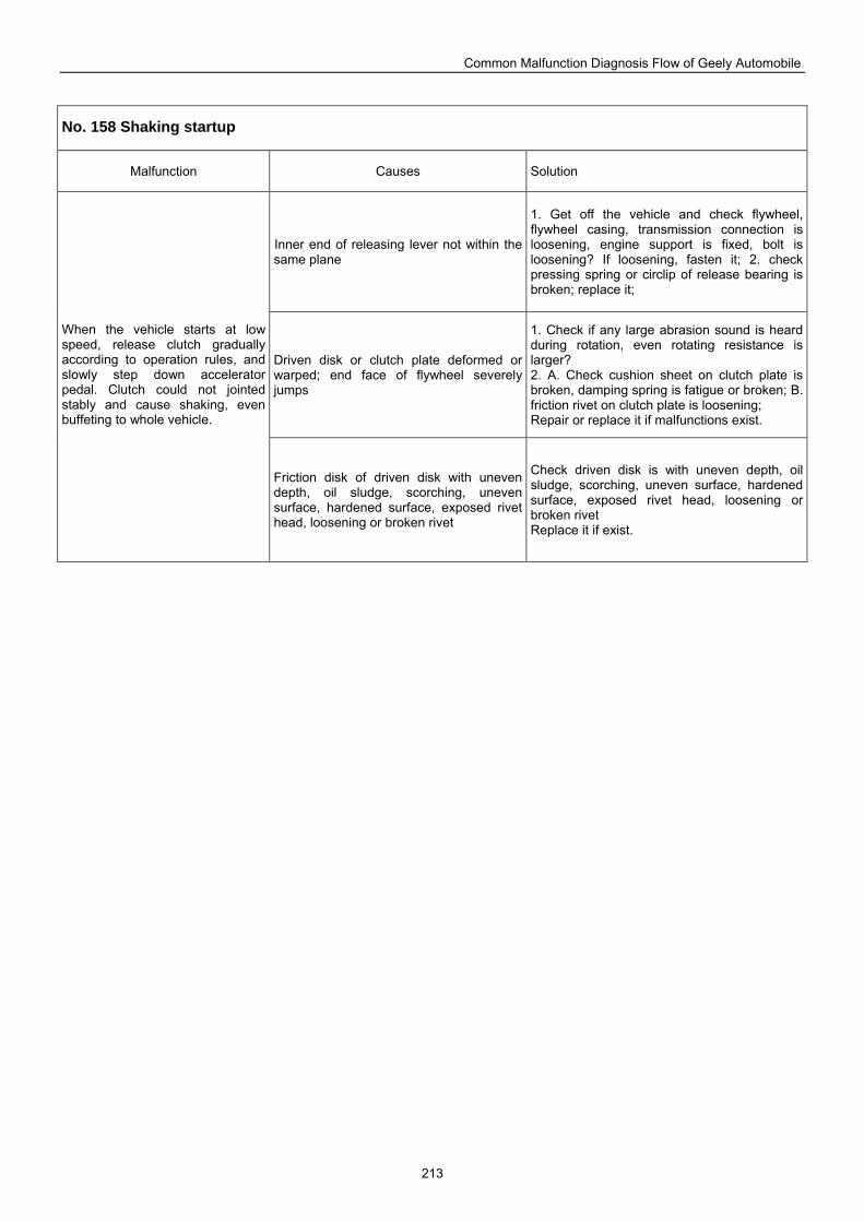
Common Malfunction Diagnosis Flow of Geely Automobile
213
No. 158 Shaking startup
Malfunction Causes Solution
Inner end of releasing lever not within the same plane
1. Get off the vehicle and check flywheel, flywheel casing, transmission connection is loosening, engine support is fixed, bolt is loosening? If loosening, fasten it; 2. check pressing spring or circlip of release bearing is broken; replace it;
Driven disk or clutch plate deformed or warped; end face of flywheel severely jumps
1. Check if any large abrasion sound is heard during rotation, even rotating resistance is larger? 2. A. Check cushion sheet on clutch plate is broken, damping spring is fatigue or broken; B. friction rivet on clutch plate is loosening; Repair or replace it if malfunctions exist.
When the vehicle starts at low speed, release clutch gradually according to operation rules, and slowly step down accelerator pedal. Clutch could not jointed stably and cause shaking, even buffeting to whole vehicle.
Friction disk of driven disk with uneven depth, oil sludge, scorching, uneven surface, hardened surface, exposed rivet head, loosening or broken rivet
Check driven disk is with uneven depth, oil sludge, scorching, uneven surface, hardened surface, exposed rivet head, loosening or broken rivet Replace it if exist.
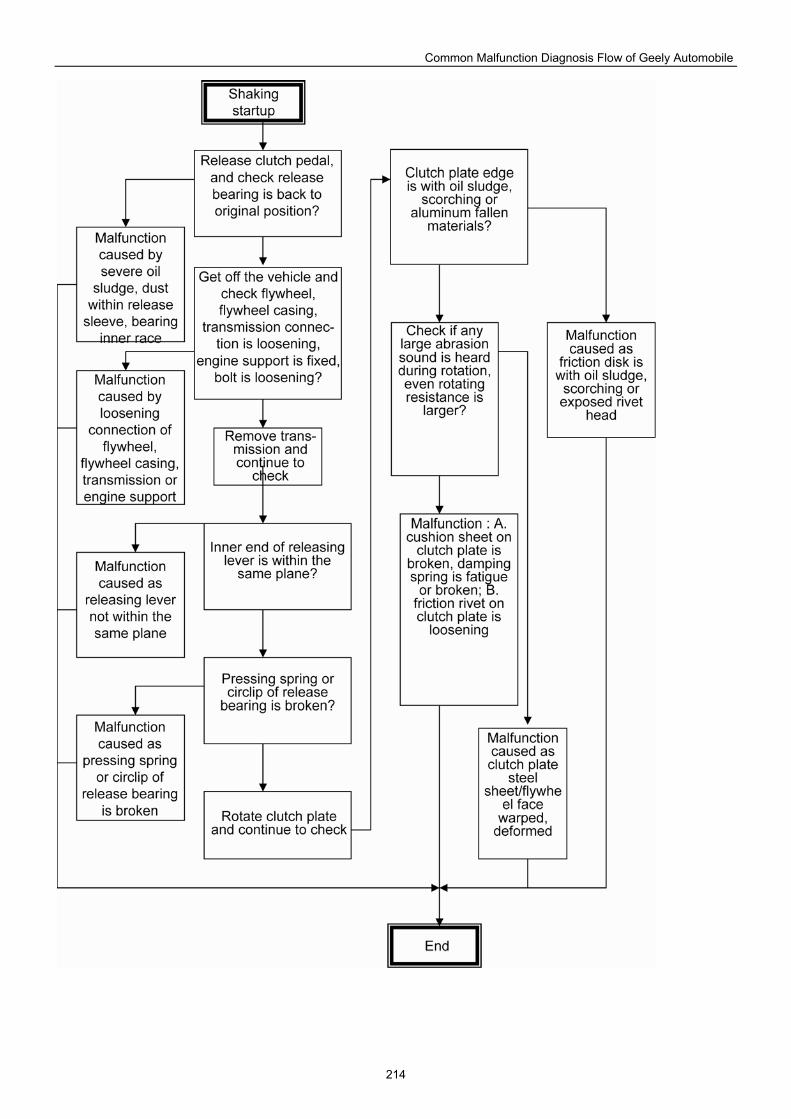
Common Malfunction Diagnosis Flow of Geely Automobile
214
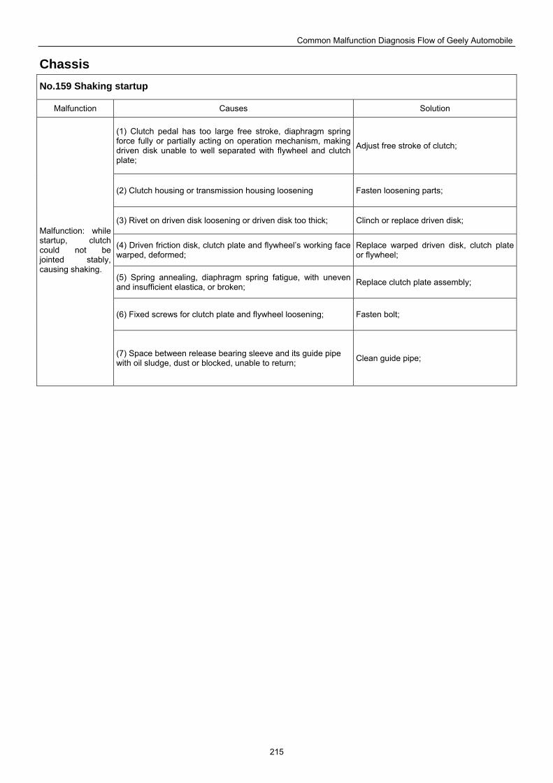
Common Malfunction Diagnosis Flow of Geely Automobile
215
Chassis No.159 Shaking startup
Malfunction Causes Solution
(1) Clutch pedal has too large free stroke, diaphragm spring force fully or partially acting on operation mechanism, making driven disk unable to well separated with flywheel and clutch plate;
Adjust free stroke of clutch;
(2) Clutch housing or transmission housing loosening Fasten loosening parts;
(3) Rivet on driven disk loosening or driven disk too thick; Clinch or replace driven disk;
(4) Driven friction disk, clutch plate and flywheel’s working face warped, deformed;
Replace warped driven disk, clutch plate or flywheel;
(5) Spring annealing, diaphragm spring fatigue, with uneven and insufficient elastica, or broken; Replace clutch plate assembly;
(6) Fixed screws for clutch plate and flywheel loosening; Fasten bolt;
Malfunction: while startup, clutch could not be jointed stably, causing shaking.
(7) Space between release bearing sleeve and its guide pipe with oil sludge, dust or blocked, unable to return; Clean guide pipe;
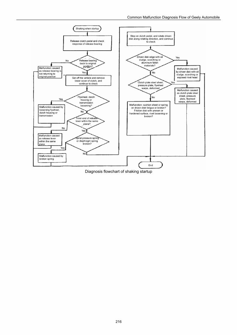
Common Malfunction Diagnosis Flow of Geely Automobile
216
Diagnosis flowchart of shaking startup
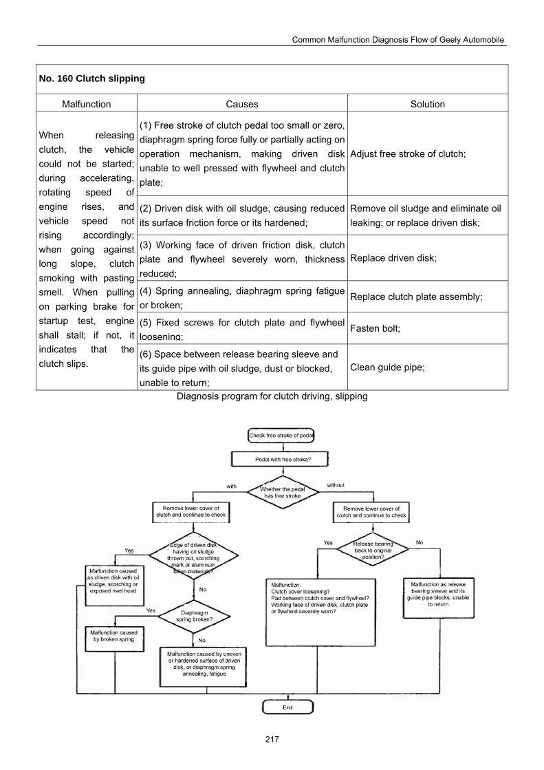
Common Malfunction Diagnosis Flow of Geely Automobile
217
No. 160 Clutch slipping
Malfunction Causes Solution
(1) Free stroke of clutch pedal too small or zero, diaphragm spring force fully or partially acting on operation mechanism, making driven disk unable to well pressed with flywheel and clutch plate;
Adjust free stroke of clutch;
(2) Driven disk with oil sludge, causing reduced its surface friction force or its hardened;
Remove oil sludge and eliminate oil leaking; or replace driven disk;
(3) Working face of driven friction disk, clutch plate and flywheel severely worn, thickness reduced;
Replace driven disk;
(4) Spring annealing, diaphragm spring fatigue or broken;
Replace clutch plate assembly;
(5) Fixed screws for clutch plate and flywheel loosening;
Fasten bolt;
When releasing clutch, the vehicle could not be started; during accelerating, rotating speed of engine rises, and vehicle speed not rising accordingly; when going against long slope, clutch smoking with pasting smell. When pulling on parking brake for startup test, engine shall stall; if not, it indicates that the clutch slips.
(6) Space between release bearing sleeve and its guide pipe with oil sludge, dust or blocked, unable to return;
Clean guide pipe;
Diagnosis program for clutch driving, slipping
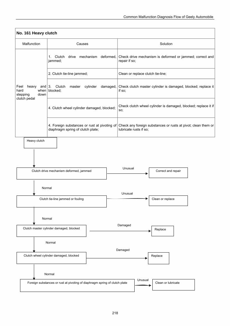
Common Malfunction Diagnosis Flow of Geely Automobile
218
No. 161 Heavy clutch
Malfunction Causes Solution
1. Clutch drive mechanism deformed, jammed;
Check drive mechanism is deformed or jammed; correct and repair if so;
2. Clutch tie-line jammed; Clean or replace clutch tie-line;
3. Clutch master cylinder damaged, blocked;
Check clutch master cylinder is damaged, blocked; replace it if so;
4. Clutch wheel cylinder damaged, blocked; Check clutch wheel cylinder is damaged, blocked; replace it if so;
Feel heavy and hard when stepping down clutch pedal
4. Foreign substances or rust at pivoting of diaphragm spring of clutch plate;
Check any foreign substances or rusts at pivot; clean them or lubricate rusts if so;
Heavy clutch
Correct and repair Clutch drive mechanism deformed, jammed
Foreign substances or rust at pivoting of diaphragm spring of clutch plate
Clutch master cylinder damaged, blocked
Clutch wheel cylinder damaged, blocked
Clean or lubricate
Clean or replace Clutch tie-line jammed or fouling
Replace
Replace
Normal
Unusual
Normal
Normal
Normal
Unusual
Damaged
Damaged
Unusual
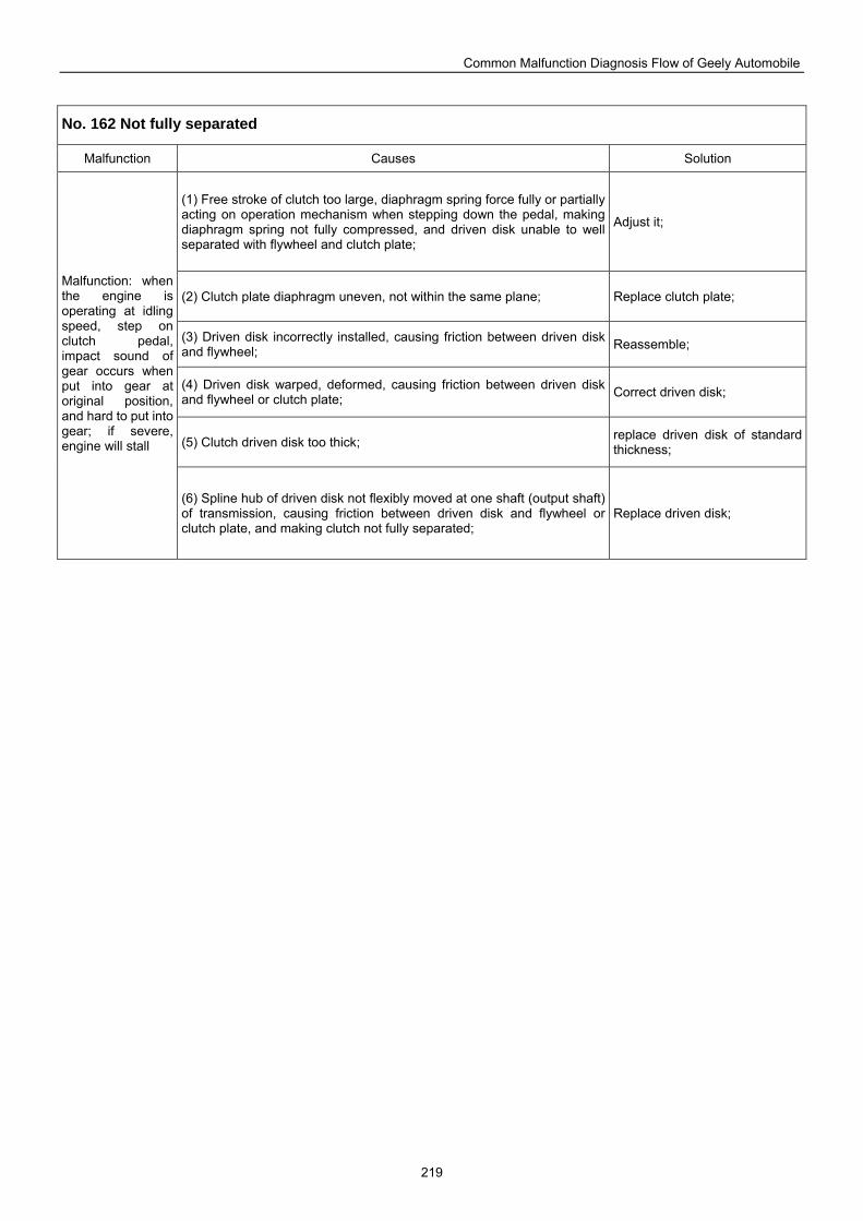
Common Malfunction Diagnosis Flow of Geely Automobile
219
No. 162 Not fully separated
Malfunction Causes Solution
(1) Free stroke of clutch too large, diaphragm spring force fully or partially acting on operation mechanism when stepping down the pedal, making diaphragm spring not fully compressed, and driven disk unable to well separated with flywheel and clutch plate;
Adjust it;
(2) Clutch plate diaphragm uneven, not within the same plane; Replace clutch plate;
(3) Driven disk incorrectly installed, causing friction between driven disk and flywheel; Reassemble;
(4) Driven disk warped, deformed, causing friction between driven disk and flywheel or clutch plate; Correct driven disk;
(5) Clutch driven disk too thick; replace driven disk of standard thickness;
Malfunction: when the engine is operating at idling speed, step on clutch pedal, impact sound of gear occurs when put into gear at original position, and hard to put into gear; if severe, engine will stall
(6) Spline hub of driven disk not flexibly moved at one shaft (output shaft) of transmission, causing friction between driven disk and flywheel or clutch plate, and making clutch not fully separated;
Replace driven disk;
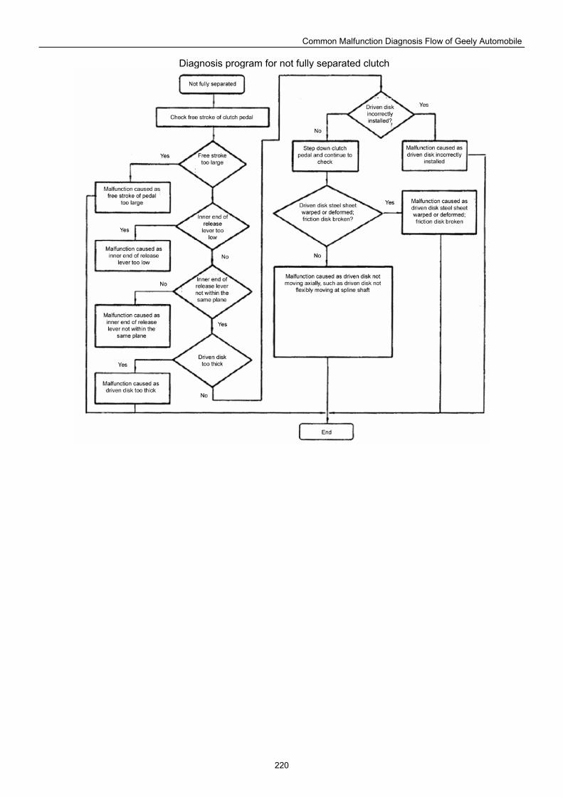
Common Malfunction Diagnosis Flow of Geely Automobile
220
Diagnosis program for not fully separated clutch
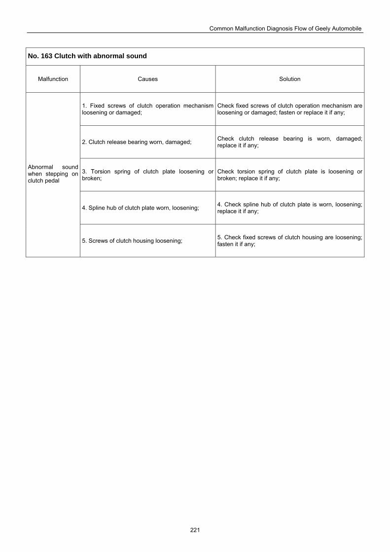
Common Malfunction Diagnosis Flow of Geely Automobile
221
No. 163 Clutch with abnormal sound
Malfunction Causes Solution
1. Fixed screws of clutch operation mechanism loosening or damaged;
Check fixed screws of clutch operation mechanism are loosening or damaged; fasten or replace it if any;
2. Clutch release bearing worn, damaged; Check clutch release bearing is worn, damaged; replace it if any;
3. Torsion spring of clutch plate loosening or broken;
Check torsion spring of clutch plate is loosening or broken; replace it if any;
4. Spline hub of clutch plate worn, loosening; 4. Check spline hub of clutch plate is worn, loosening; replace it if any;
Abnormal sound when stepping on clutch pedal
5. Screws of clutch housing loosening; 5. Check fixed screws of clutch housing are loosening; fasten it if any;
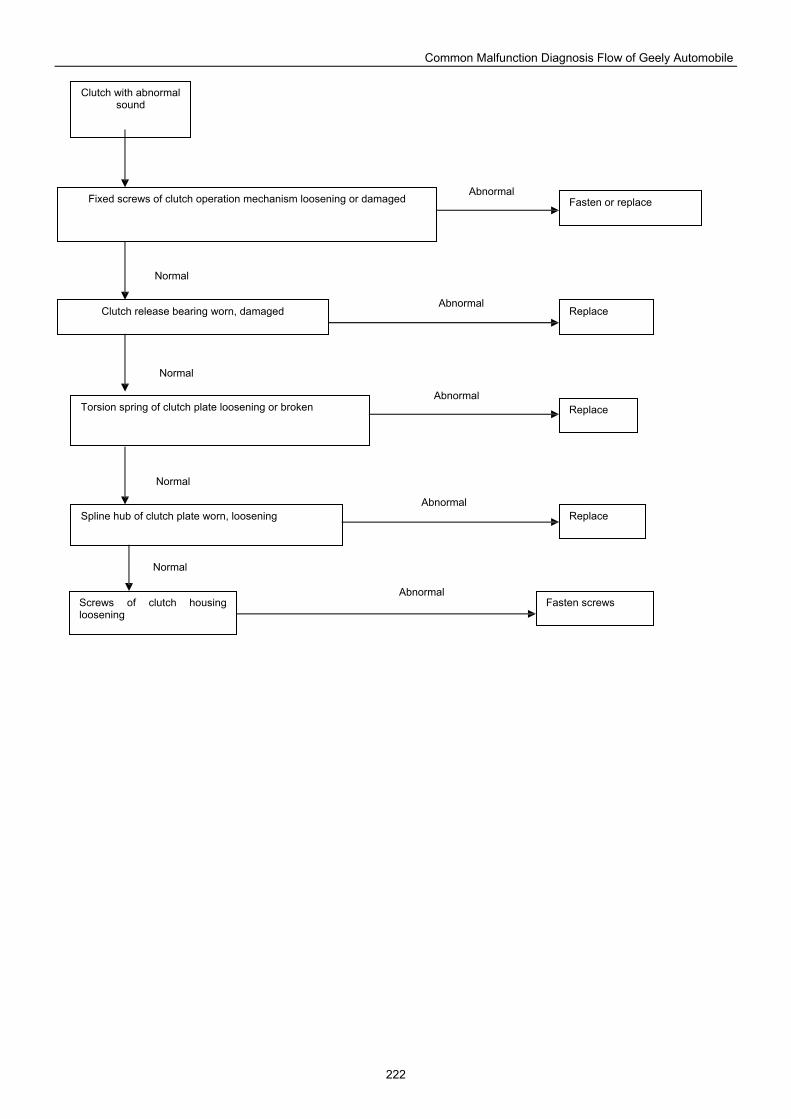
Common Malfunction Diagnosis Flow of Geely Automobile
222
Clutch with abnormal sound
Fasten or replace Fixed screws of clutch operation mechanism loosening or damaged
Clutch release bearing worn, damaged Replace
Replace Torsion spring of clutch plate loosening or broken
Spline hub of clutch plate worn, loosening Replace
Screws of clutch housing loosening
Fasten screws
Abnormal
Normal
Normal
Normal
Normal
Abnormal
Abnormal
Abnormal
Abnormal
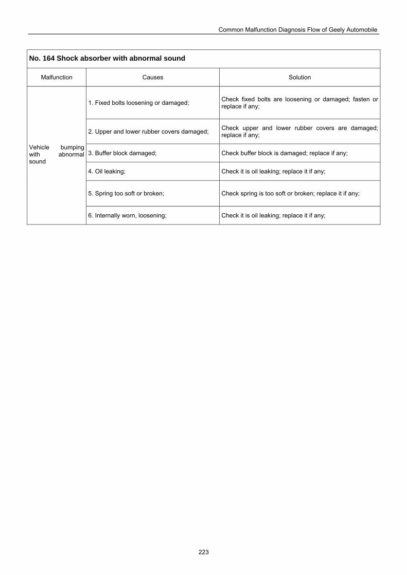
Common Malfunction Diagnosis Flow of Geely Automobile
223
No. 164 Shock absorber with abnormal sound
Malfunction Causes Solution
1. Fixed bolts loosening or damaged; Check fixed bolts are loosening or damaged; fasten or replace if any;
2. Upper and lower rubber covers damaged; Check upper and lower rubber covers are damaged; replace if any;
3. Buffer block damaged; Check buffer block is damaged; replace if any;
4. Oil leaking; Check it is oil leaking; replace it if any;
5. Spring too soft or broken; Check spring is too soft or broken; replace it if any;
Vehicle bumping with abnormal sound
6. Internally worn, loosening; Check it is oil leaking; replace it if any;
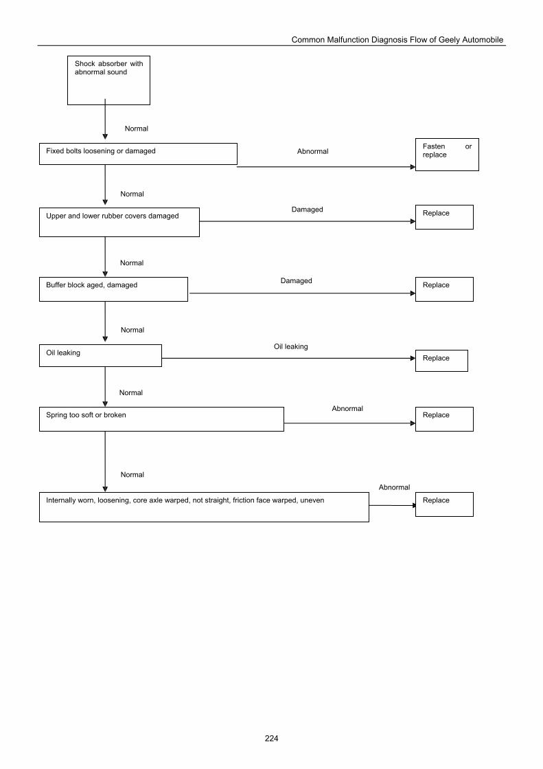
Common Malfunction Diagnosis Flow of Geely Automobile
224
Replace
Shock absorber with abnormal sound
Fasten or replace Fixed bolts loosening or damaged
Upper and lower rubber covers damaged
Replace Buffer block aged, damaged
Oil leaking Replace
Spring too soft or broken Replace
Internally worn, loosening, core axle warped, not straight, friction face warped, uneven Replace
Normal
Abnormal
Damaged
Damaged
Oil leaking
Abnormal
Abnormal
Normal
Normal
Normal
Normal
Normal
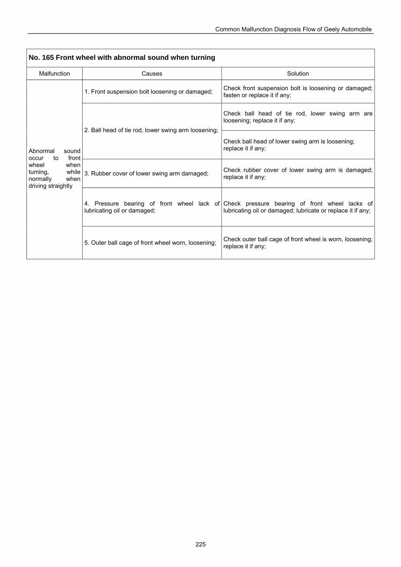
Common Malfunction Diagnosis Flow of Geely Automobile
225
No. 165 Front wheel with abnormal sound when turning
Malfunction Causes Solution
1. Front suspension bolt loosening or damaged; Check front suspension bolt is loosening or damaged; fasten or replace it if any;
Check ball head of tie rod, lower swing arm are loosening; replace it if any;
2. Ball head of tie rod, lower swing arm loosening;
Check ball head of lower swing arm is loosening; replace it if any;
3. Rubber cover of lower swing arm damaged; Check rubber cover of lower swing arm is damaged; replace it if any;
4. Pressure bearing of front wheel lack of lubricating oil or damaged;
Check pressure bearing of front wheel lacks of lubricating oil or damaged; lubricate or replace it if any;
Abnormal sound occur to front wheel when turning, while normally when driving straightly
5. Outer ball cage of front wheel worn, loosening; Check outer ball cage of front wheel is worn, loosening; replace it if any;
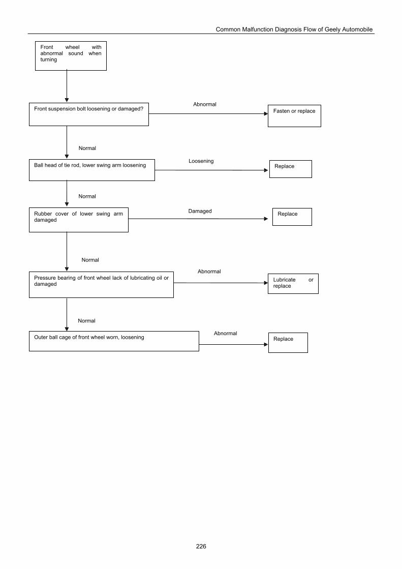
Common Malfunction Diagnosis Flow of Geely Automobile
226
Front wheel with abnormal sound when turning
Fasten or replace Front suspension bolt loosening or damaged?
Ball head of tie rod, lower swing arm loosening Replace
Rubber cover of lower swing arm damaged
Pressure bearing of front wheel lack of lubricating oil or damaged
Lubricate or replace
Replace
Replace Outer ball cage of front wheel worn, loosening
Abnormal
Loosening
Damaged
Abnormal
Abnormal
Normal
Normal
Normal
Normal
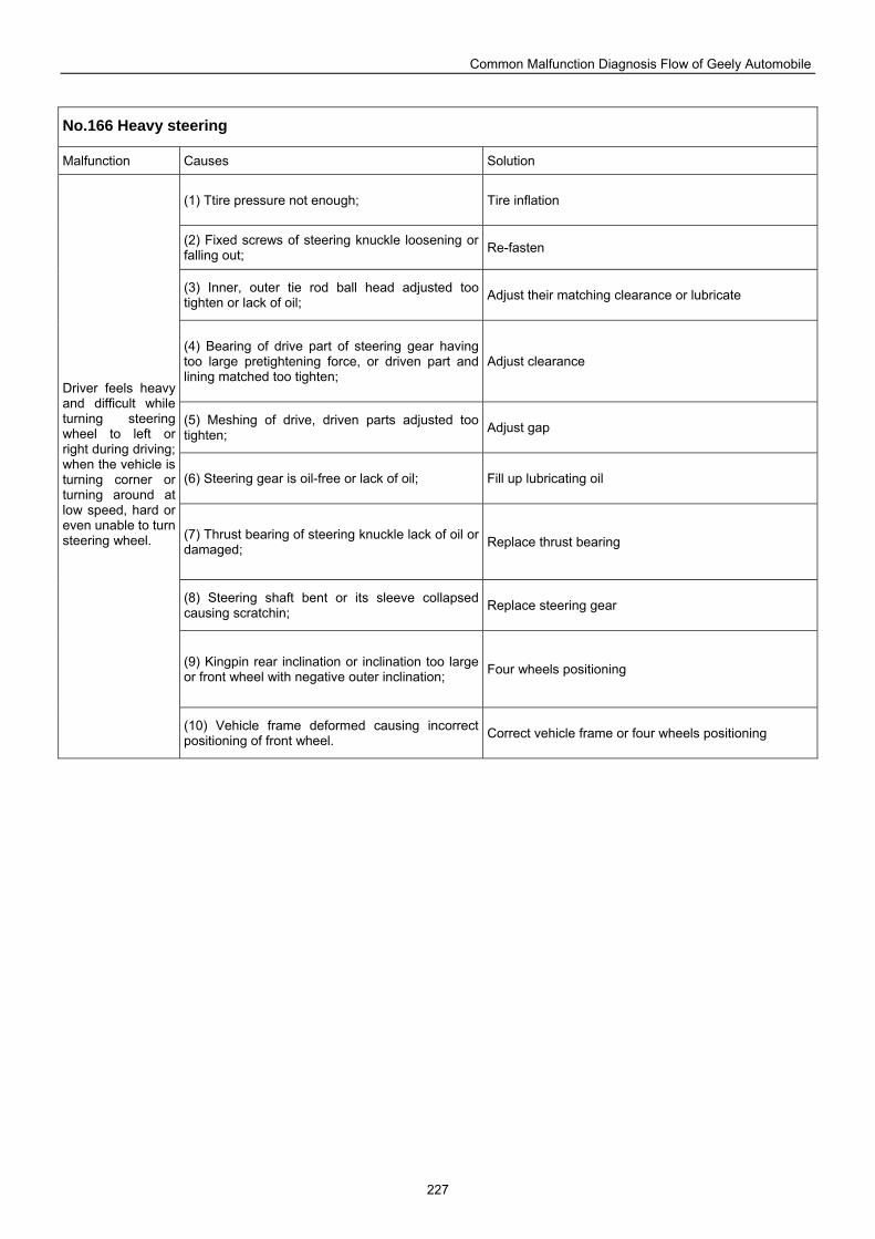
Common Malfunction Diagnosis Flow of Geely Automobile
227
No.166 Heavy steering
Malfunction Causes Solution
(1) Ttire pressure not enough; Tire inflation
(2) Fixed screws of steering knuckle loosening or falling out; Re-fasten
(3) Inner, outer tie rod ball head adjusted too tighten or lack of oil; Adjust their matching clearance or lubricate
(4) Bearing of drive part of steering gear having too large pretightening force, or driven part and lining matched too tighten;
Adjust clearance
(5) Meshing of drive, driven parts adjusted too tighten; Adjust gap
(6) Steering gear is oil-free or lack of oil; Fill up lubricating oil
(7) Thrust bearing of steering knuckle lack of oil or damaged; Replace thrust bearing
(8) Steering shaft bent or its sleeve collapsed causing scratchin; Replace steering gear
(9) Kingpin rear inclination or inclination too large or front wheel with negative outer inclination; Four wheels positioning
Driver feels heavy and difficult while turning steering wheel to left or right during driving; when the vehicle is turning corner or turning around at low speed, hard or even unable to turn steering wheel.
(10) Vehicle frame deformed causing incorrect positioning of front wheel. Correct vehicle frame or four wheels positioning
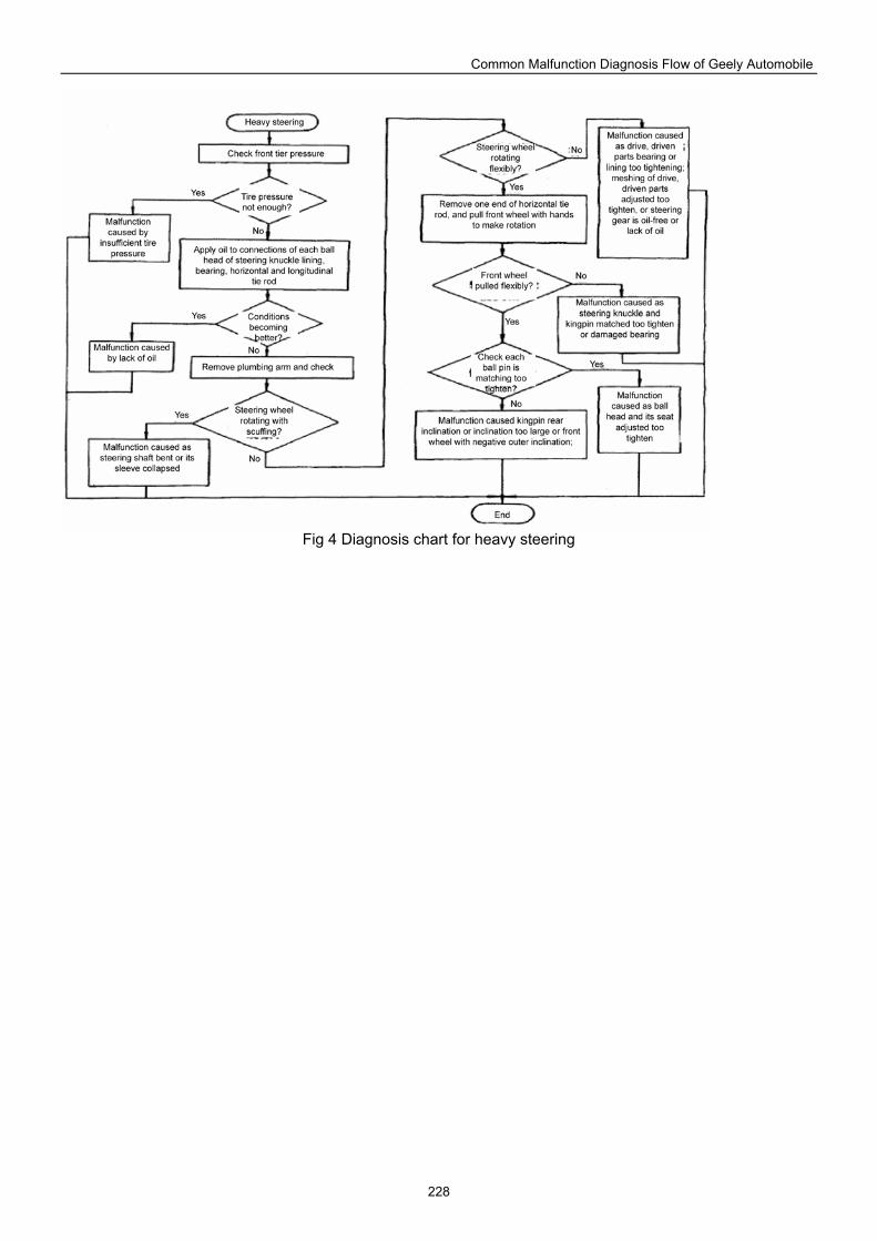
Common Malfunction Diagnosis Flow of Geely Automobile
228
Fig 4 Diagnosis chart for heavy steering
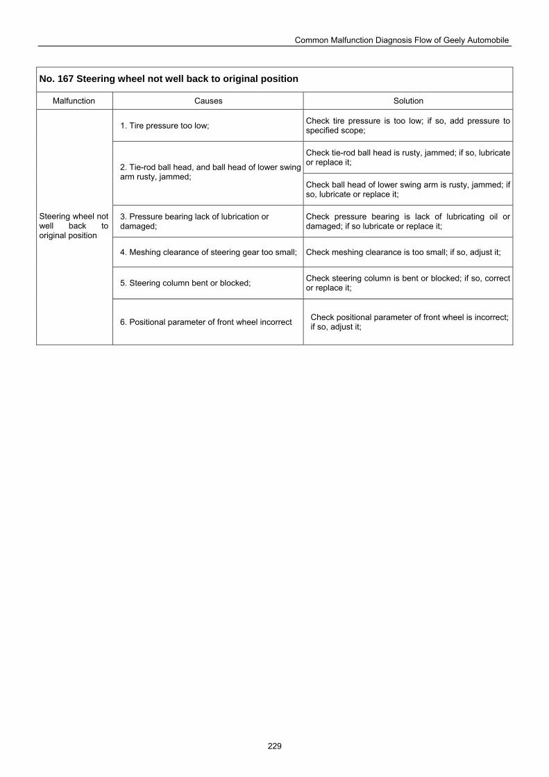
Common Malfunction Diagnosis Flow of Geely Automobile
229
No. 167 Steering wheel not well back to original position
Malfunction Causes Solution
1. Tire pressure too low; Check tire pressure is too low; if so, add pressure to specified scope;
Check tie-rod ball head is rusty, jammed; if so, lubricate or replace it; 2. Tie-rod ball head, and ball head of lower swing
arm rusty, jammed; Check ball head of lower swing arm is rusty, jammed; if so, lubricate or replace it;
3. Pressure bearing lack of lubrication or damaged;
Check pressure bearing is lack of lubricating oil or damaged; if so lubricate or replace it;
4. Meshing clearance of steering gear too small; Check meshing clearance is too small; if so, adjust it;
5. Steering column bent or blocked; Check steering column is bent or blocked; if so, correct or replace it;
Steering wheel not well back to original position
6. Positional parameter of front wheel incorrect Check positional parameter of front wheel is incorrect; if so, adjust it;
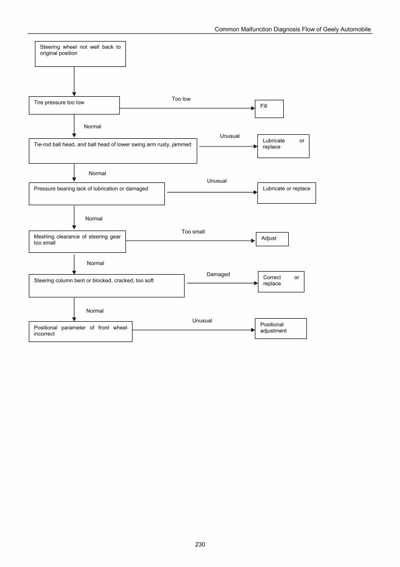
Common Malfunction Diagnosis Flow of Geely Automobile
230
Steering wheel not well back to original position
Fill Tire pressure too low
Tie-rod ball head, and ball head of lower swing arm rusty, jammed Lubricate or replace
Lubricate or replace Pressure bearing lack of lubrication or damaged
Meshing clearance of steering gear too small
Adjust
Steering column bent or blocked, cracked, too soft Correct or replace
Positional parameter of front wheel incorrect
Positional adjustment
Too low
Unusual
Unusual
Too small
Damaged
Unusual
Normal
Normal
Normal
Normal
Normal
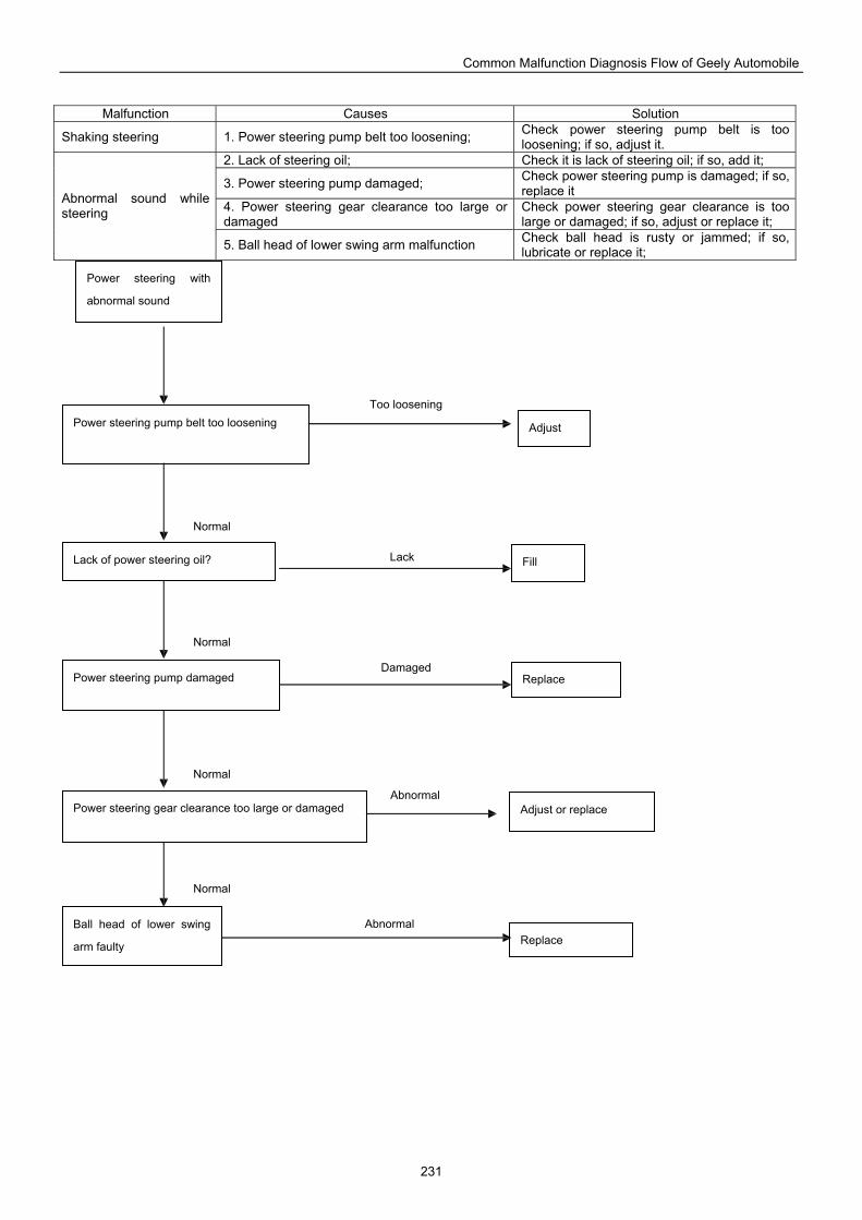
Common Malfunction Diagnosis Flow of Geely Automobile
231
Malfunction Causes Solution
Shaking steering 1. Power steering pump belt too loosening; Check power steering pump belt is too loosening; if so, adjust it.
2. Lack of steering oil; Check it is lack of steering oil; if so, add it;
3. Power steering pump damaged; Check power steering pump is damaged; if so, replace it
4. Power steering gear clearance too large or damaged
Check power steering gear clearance is too large or damaged; if so, adjust or replace it;
Abnormal sound while steering
5. Ball head of lower swing arm malfunction Check ball head is rusty or jammed; if so, lubricate or replace it;
Power steering with
abnormal sound
Adjust Power steering pump belt too loosening
Lack of power steering oil? Fill
Replace Power steering pump damaged
Power steering gear clearance too large or damaged
Ball head of lower swing
arm faulty
Adjust or replace
Replace
Too loosening
Lack
Damaged
Abnormal
Abnormal
Normal
Normal
Normal
Normal
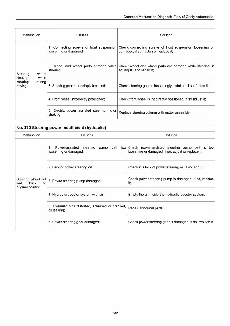
Common Malfunction Diagnosis Flow of Geely Automobile
232
Malfunction Causes Solution
1. Connecting screws of front suspension loosening or damaged;
Check connecting screws of front suspension loosening or damaged; if so, fasten or replace it;
2. Wheel and wheel parts abraded while steering
Check wheel and wheel parts are abraded while steering; if so, adjust and repair it;
3. Steering gear looseningly installed; Check steering gear is looseningly installed; if so, fasten it;
4. Front wheel incorrectly positioned; Check front wheel is incorrectly positioned; if so adjust it;
Steering wheel shaking while steering during driving
5. Electric power assisted steering motor shaking Replace steering column with motor assembly;
No. 170 Steering power insufficient (hydraulic)
Malfunction Causes Solution
1. Power-assisted steering pump belt too loosening or damaged;
Check power-assisted steering pump belt is too loosening or damaged; if so, adjust or replace it;
2. Lack of power steering oil; Check it is lack of power steering oil; if so, add it;
3. Power steering pump damaged; Check power steering pump is damaged; if so, replace it;
4. Hydraulic booster system with air Empty the air inside the hydraulic booster system;
5. Hydraulic pipe distorted, scrimped or cracked, oil leaking; Repair abnormal parts;
Steering wheel not well back to original position
6. Power steering gear damaged; Check power steering gear is damaged; if so, replace it;
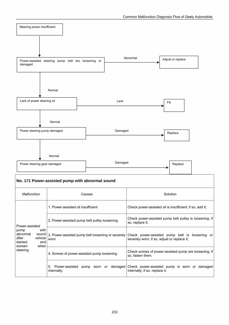
Common Malfunction Diagnosis Flow of Geely Automobile
233
No. 171 Power-assisted pump with abnormal sound
Malfunction Causes Solution
1. Power-assisted oil insufficient Check power-assisted oil is insufficient; if so, add it;
2. Power-assisted pump belt pulley loosening Check power-assisted pump belt pulley is loosening; if so, replace it;
3. Power-assisted pump belt loosening or severely worn
Check power-assisted pump belt is loosening or severely worn; if so, adjust or replace it;
4. Screws of power-assisted pump loosening Check screws of power-assisted pump are loosening; if so, fasten them.
Power-assisted pump with abnormal sound after vehicle started; and worsen when steering
5. Power-assisted pump worn or damaged internally;
Check power-assisted pump is worn or damaged internally; if so, replace it.
Steering power insufficient
Adjust or replace Power-assisted steering pump belt too loosening or damaged
Lack of power steering oil Fill
Power steering pump damaged
Power steering gear damaged Replace
Replace
Abnormal
Lack
Damaged
Damaged
Normal
Normal
Normal
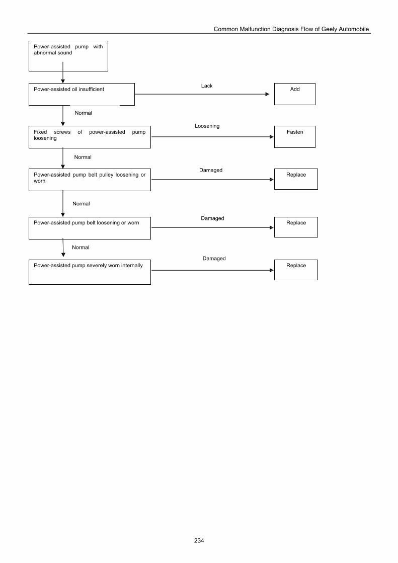
Common Malfunction Diagnosis Flow of Geely Automobile
234
Add
Power-assisted pump with abnormal sound
Power-assisted oil insufficient
Fixed screws of power-assisted pump loosening
Fasten
Replace Power-assisted pump belt pulley loosening or worn
Replace Power-assisted pump belt loosening or worn
Replace Power-assisted pump severely worn internally
Lack
Damaged
Damaged
Damaged
Loosening
Normal
Normal
Normal
Normal
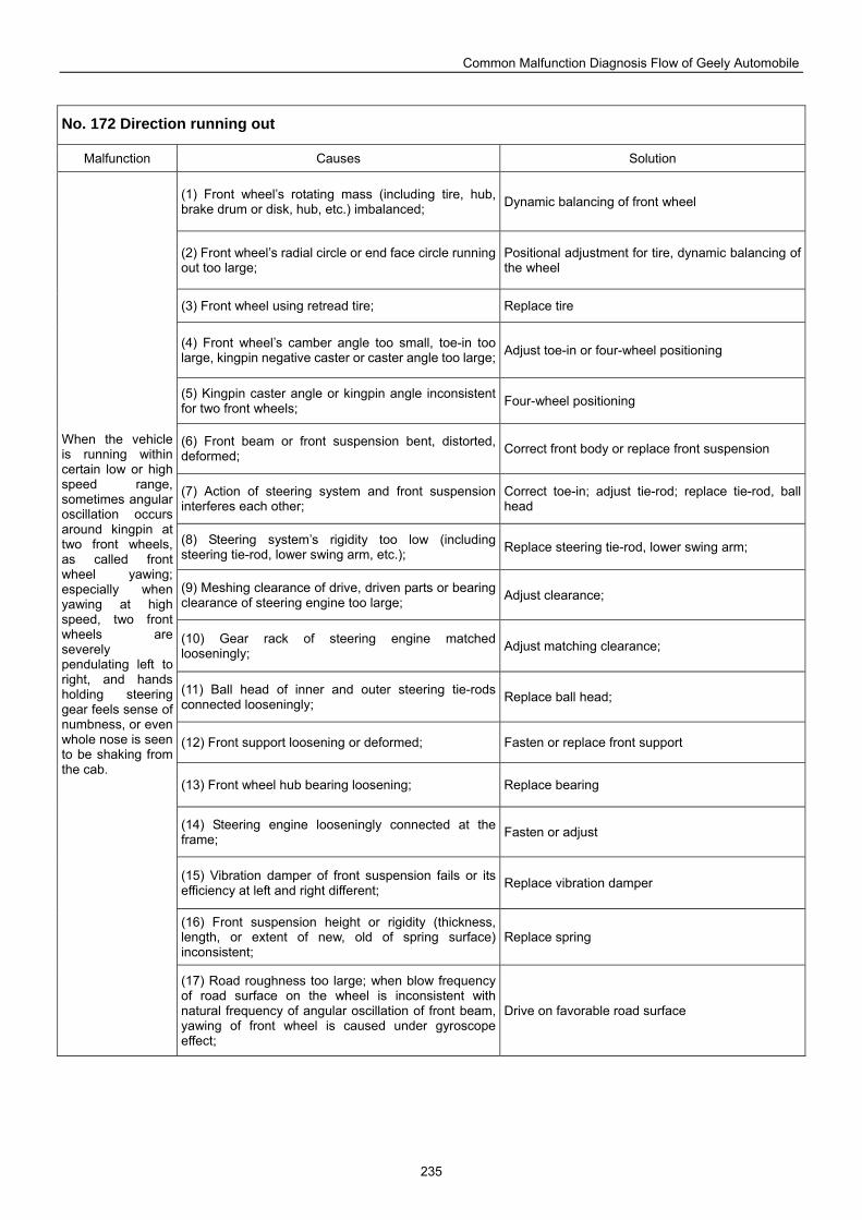
Common Malfunction Diagnosis Flow of Geely Automobile
235
No. 172 Direction running out
Malfunction Causes Solution
(1) Front wheel’s rotating mass (including tire, hub, brake drum or disk, hub, etc.) imbalanced; Dynamic balancing of front wheel
(2) Front wheel’s radial circle or end face circle running out too large;
Positional adjustment for tire, dynamic balancing of the wheel
(3) Front wheel using retread tire; Replace tire
(4) Front wheel’s camber angle too small, toe-in too large, kingpin negative caster or caster angle too large; Adjust toe-in or four-wheel positioning
(5) Kingpin caster angle or kingpin angle inconsistent for two front wheels; Four-wheel positioning
(6) Front beam or front suspension bent, distorted, deformed; Correct front body or replace front suspension
(7) Action of steering system and front suspension interferes each other;
Correct toe-in; adjust tie-rod; replace tie-rod, ball head
(8) Steering system’s rigidity too low (including steering tie-rod, lower swing arm, etc.); Replace steering tie-rod, lower swing arm;
(9) Meshing clearance of drive, driven parts or bearing clearance of steering engine too large; Adjust clearance;
(10) Gear rack of steering engine matched looseningly; Adjust matching clearance;
(11) Ball head of inner and outer steering tie-rods connected looseningly; Replace ball head;
(12) Front support loosening or deformed; Fasten or replace front support
(13) Front wheel hub bearing loosening; Replace bearing
(14) Steering engine looseningly connected at the frame; Fasten or adjust
(15) Vibration damper of front suspension fails or its efficiency at left and right different; Replace vibration damper
(16) Front suspension height or rigidity (thickness, length, or extent of new, old of spring surface) inconsistent;
Replace spring
When the vehicle is running within certain low or high speed range, sometimes angular oscillation occurs around kingpin at two front wheels, as called front wheel yawing; especially when yawing at high speed, two front wheels are severely pendulating left to right, and hands holding steering gear feels sense of numbness, or even whole nose is seen to be shaking from the cab.
(17) Road roughness too large; when blow frequency of road surface on the wheel is inconsistent with natural frequency of angular oscillation of front beam, yawing of front wheel is caused under gyroscope effect;
Drive on favorable road surface
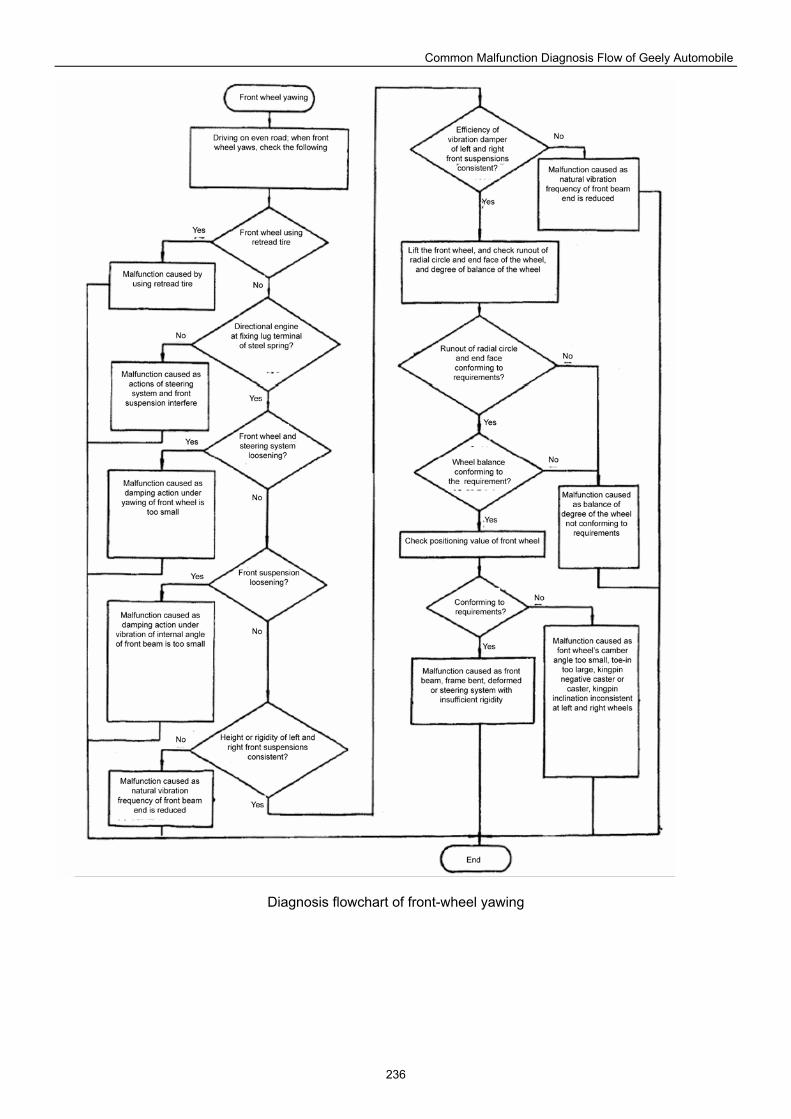
Common Malfunction Diagnosis Flow of Geely Automobile
236
Diagnosis flowchart of front-wheel yawing
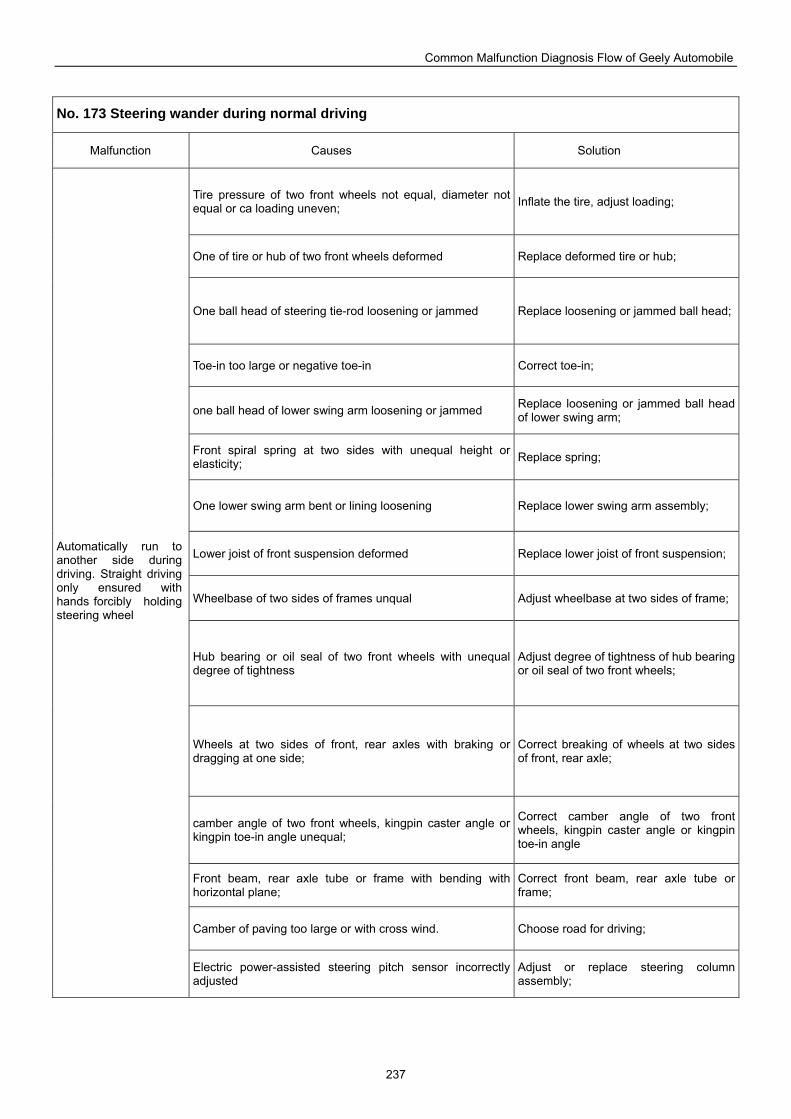
Common Malfunction Diagnosis Flow of Geely Automobile
237
No. 173 Steering wander during normal driving
Malfunction Causes Solution
Tire pressure of two front wheels not equal, diameter not equal or ca loading uneven; Inflate the tire, adjust loading;
One of tire or hub of two front wheels deformed Replace deformed tire or hub;
One ball head of steering tie-rod loosening or jammed Replace loosening or jammed ball head;
Toe-in too large or negative toe-in Correct toe-in;
one ball head of lower swing arm loosening or jammed Replace loosening or jammed ball head of lower swing arm;
Front spiral spring at two sides with unequal height or elasticity; Replace spring;
One lower swing arm bent or lining loosening Replace lower swing arm assembly;
Lower joist of front suspension deformed Replace lower joist of front suspension;
Wheelbase of two sides of frames unqual Adjust wheelbase at two sides of frame;
Hub bearing or oil seal of two front wheels with unequal degree of tightness
Adjust degree of tightness of hub bearing or oil seal of two front wheels;
Wheels at two sides of front, rear axles with braking or dragging at one side;
Correct breaking of wheels at two sides of front, rear axle;
camber angle of two front wheels, kingpin caster angle or kingpin toe-in angle unequal;
Correct camber angle of two front wheels, kingpin caster angle or kingpin toe-in angle
Front beam, rear axle tube or frame with bending with horizontal plane;
Correct front beam, rear axle tube or frame;
Camber of paving too large or with cross wind. Choose road for driving;
Automatically run to another side during driving. Straight driving only ensured with hands forcibly holding steering wheel
Electric power-assisted steering pitch sensor incorrectly adjusted
Adjust or replace steering column assembly;
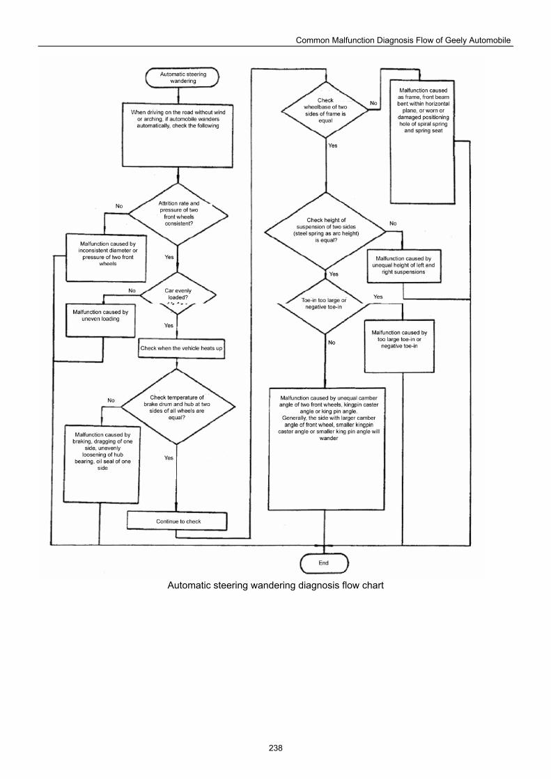
Common Malfunction Diagnosis Flow of Geely Automobile
238
Automatic steering wandering diagnosis flow chart
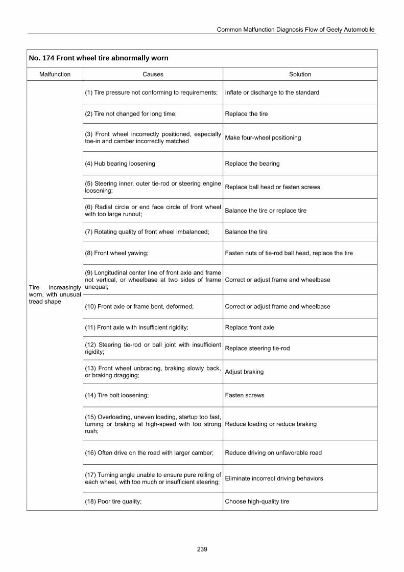
Common Malfunction Diagnosis Flow of Geely Automobile
239
No. 174 Front wheel tire abnormally worn
Malfunction Causes Solution
(1) Tire pressure not conforming to requirements; Inflate or discharge to the standard
(2) Tire not changed for long time; Replace the tire
(3) Front wheel incorrectly positioned, especially toe-in and camber incorrectly matched Make four-wheel positioning
(4) Hub bearing loosening Replace the bearing
(5) Steering inner, outer tie-rod or steering engine loosening; Replace ball head or fasten screws
(6) Radial circle or end face circle of front wheel with too large runout; Balance the tire or replace tire
(7) Rotating quality of front wheel imbalanced; Balance the tire
(8) Front wheel yawing; Fasten nuts of tie-rod ball head, replace the tire
(9) Longitudinal center line of front axle and frame not vertical, or wheelbase at two sides of frame unequal;
Correct or adjust frame and wheelbase
(10) Front axle or frame bent, deformed; Correct or adjust frame and wheelbase
(11) Front axle with insufficient rigidity; Replace front axle
(12) Steering tie-rod or ball joint with insufficient rigidity; Replace steering tie-rod
(13) Front wheel unbracing, braking slowly back, or braking dragging; Adjust braking
(14) Tire bolt loosening; Fasten screws
(15) Overloading, uneven loading, startup too fast, turning or braking at high-speed with too strong rush;
Reduce loading or reduce braking
(16) Often drive on the road with larger camber; Reduce driving on unfavorable road
(17) Turning angle unable to ensure pure rolling of each wheel, with too much or insufficient steering; Eliminate incorrect driving behaviors
Tire increasingly worn, with unusual tread shape
(18) Poor tire quality; Choose high-quality tire
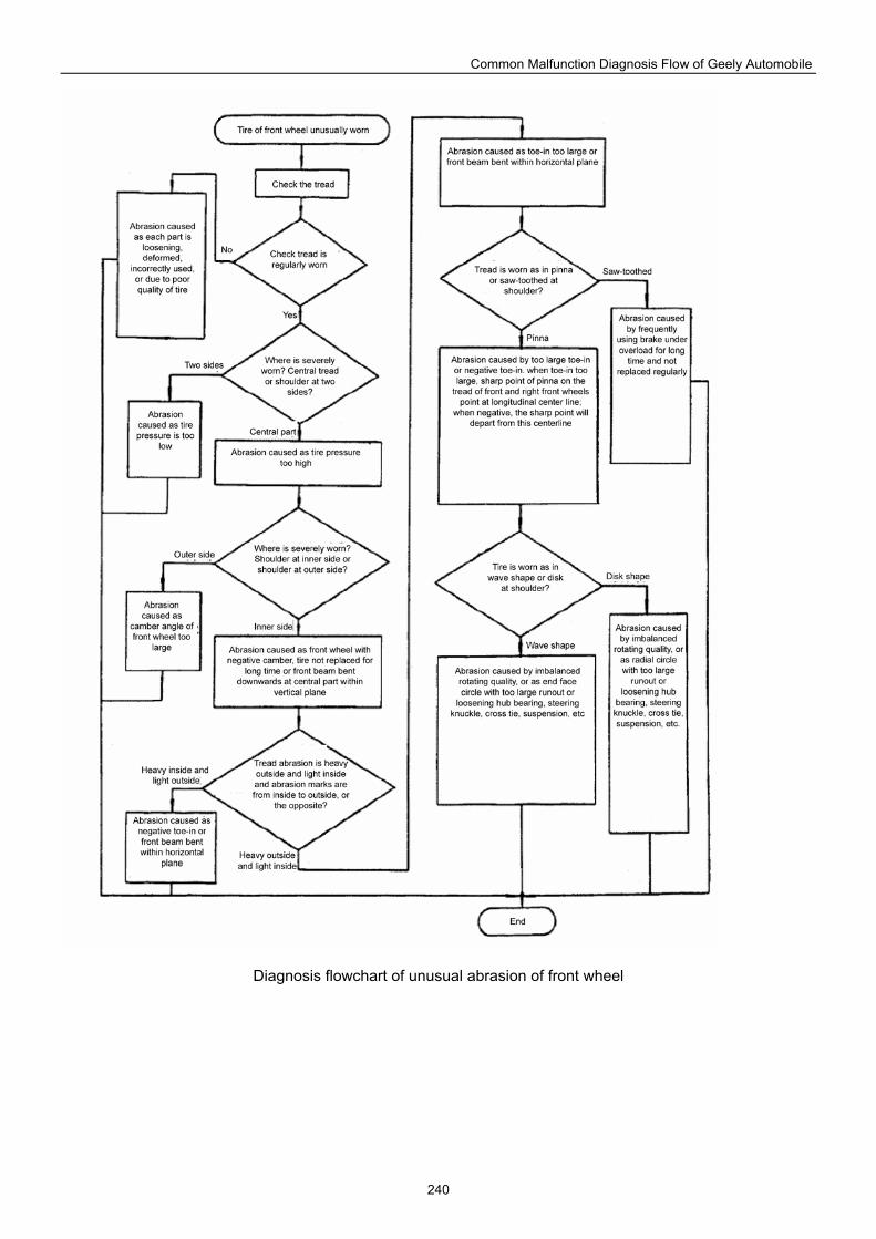
Common Malfunction Diagnosis Flow of Geely Automobile
240
Diagnosis flowchart of unusual abrasion of front wheel
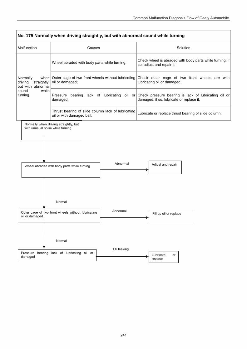
Common Malfunction Diagnosis Flow of Geely Automobile
241
No. 175 Normally when driving straightly, but with abnormal sound while turning
Malfunction Causes Solution
Wheel abraded with body parts while turning; Check wheel is abraded with body parts while turning; if so, adjust and repair it;
Outer cage of two front wheels without lubricating oil or damaged;
Check outer cage of two front wheels are with lubricating oil or damaged;
Pressure bearing lack of lubricating oil or damaged;
Check pressure bearing is lack of lubricating oil or damaged; if so, lubricate or replace it;
Normally when driving straightly, but with abnormal sound while turning
Thrust bearing of slide column lack of lubricating oil or with damaged ball; Lubricate or replace thrust bearing of slide column;
Normally when driving straightly, but with unusual noise while turning
Adjust and repair Wheel abraded with body parts while turning
Outer cage of two front wheels without lubricating oil or damaged
Fill up oil or replace
Lubricate or replace
Pressure bearing lack of lubricating oil or damaged
Abnormal
Abnormal
Oil leaking
Normal
Normal
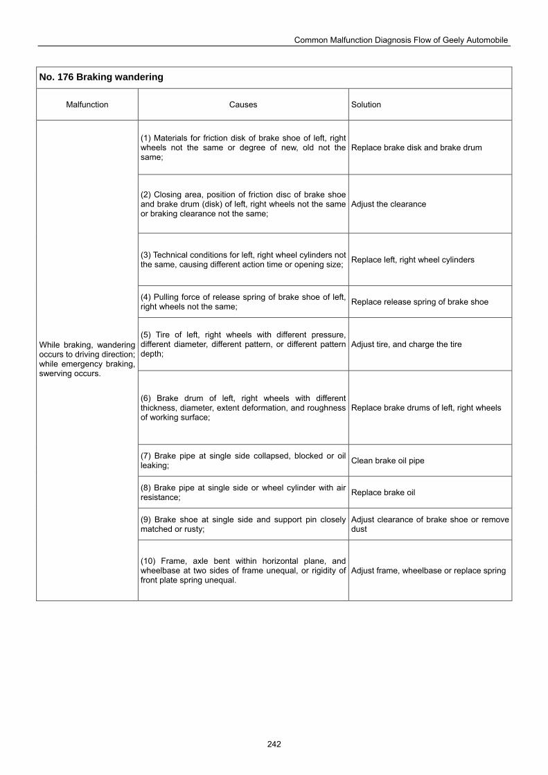
Common Malfunction Diagnosis Flow of Geely Automobile
242
No. 176 Braking wandering
Malfunction Causes Solution
(1) Materials for friction disk of brake shoe of left, right wheels not the same or degree of new, old not the same;
Replace brake disk and brake drum
(2) Closing area, position of friction disc of brake shoe and brake drum (disk) of left, right wheels not the same or braking clearance not the same;
Adjust the clearance
(3) Technical conditions for left, right wheel cylinders not the same, causing different action time or opening size; Replace left, right wheel cylinders
(4) Pulling force of release spring of brake shoe of left, right wheels not the same; Replace release spring of brake shoe
(5) Tire of left, right wheels with different pressure, different diameter, different pattern, or different pattern depth;
Adjust tire, and charge the tire
(6) Brake drum of left, right wheels with different thickness, diameter, extent deformation, and roughness of working surface;
Replace brake drums of left, right wheels
(7) Brake pipe at single side collapsed, blocked or oil leaking; Clean brake oil pipe
(8) Brake pipe at single side or wheel cylinder with air resistance; Replace brake oil
(9) Brake shoe at single side and support pin closely matched or rusty;
Adjust clearance of brake shoe or remove dust
While braking, wandering occurs to driving direction; while emergency braking, swerving occurs.
(10) Frame, axle bent within horizontal plane, and wheelbase at two sides of frame unequal, or rigidity of front plate spring unequal.
Adjust frame, wheelbase or replace spring
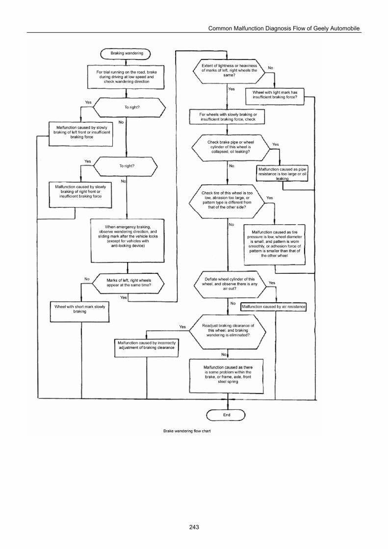
Common Malfunction Diagnosis Flow of Geely Automobile
243
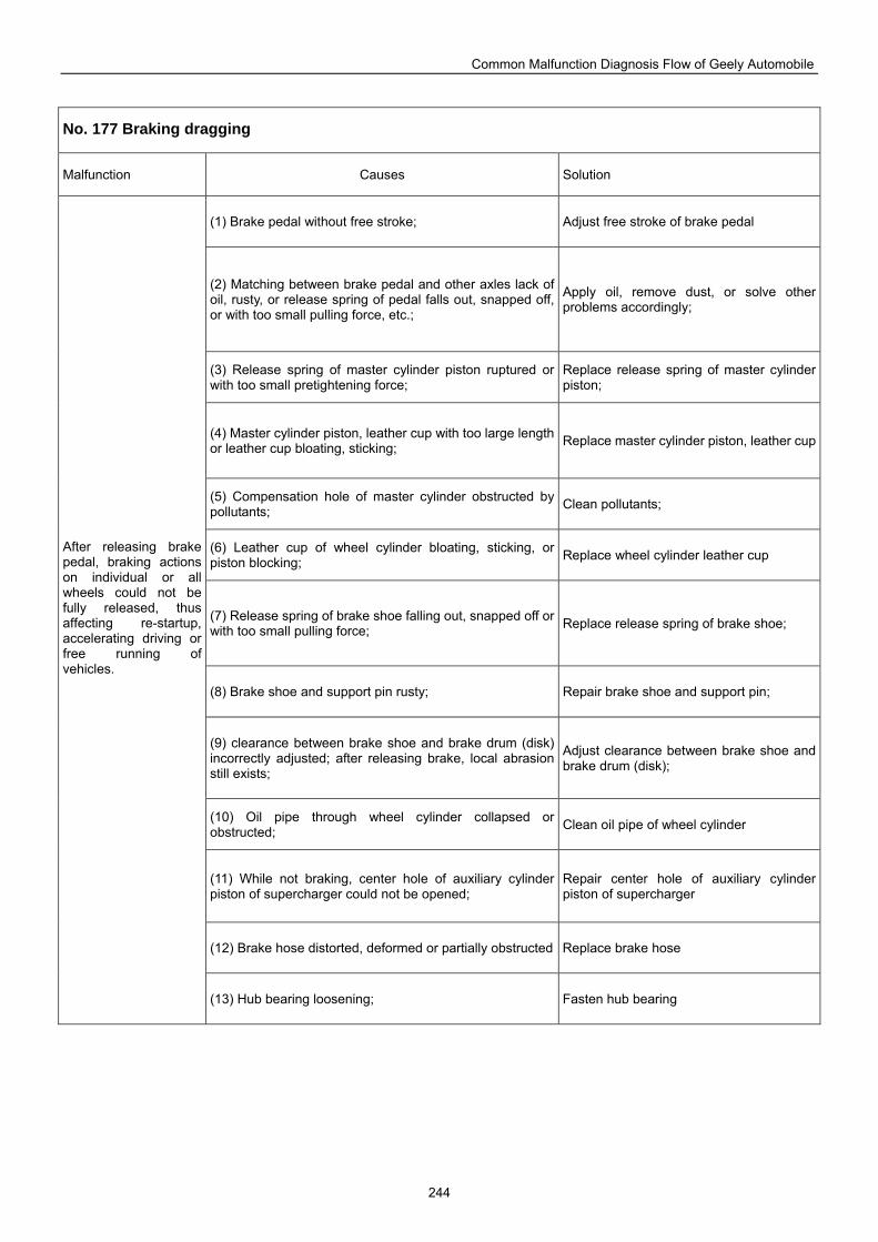
Common Malfunction Diagnosis Flow of Geely Automobile
244
No. 177 Braking dragging
Malfunction Causes Solution
(1) Brake pedal without free stroke; Adjust free stroke of brake pedal
(2) Matching between brake pedal and other axles lack of oil, rusty, or release spring of pedal falls out, snapped off, or with too small pulling force, etc.;
Apply oil, remove dust, or solve other problems accordingly;
(3) Release spring of master cylinder piston ruptured or with too small pretightening force;
Replace release spring of master cylinder piston;
(4) Master cylinder piston, leather cup with too large length or leather cup bloating, sticking; Replace master cylinder piston, leather cup
(5) Compensation hole of master cylinder obstructed by pollutants; Clean pollutants;
(6) Leather cup of wheel cylinder bloating, sticking, or piston blocking; Replace wheel cylinder leather cup
(7) Release spring of brake shoe falling out, snapped off or with too small pulling force; Replace release spring of brake shoe;
(8) Brake shoe and support pin rusty; Repair brake shoe and support pin;
(9) clearance between brake shoe and brake drum (disk) incorrectly adjusted; after releasing brake, local abrasion still exists;
Adjust clearance between brake shoe and brake drum (disk);
(10) Oil pipe through wheel cylinder collapsed or obstructed; Clean oil pipe of wheel cylinder
(11) While not braking, center hole of auxiliary cylinder piston of supercharger could not be opened;
Repair center hole of auxiliary cylinder piston of supercharger
(12) Brake hose distorted, deformed or partially obstructed Replace brake hose
After releasing brake pedal, braking actions on individual or all wheels could not be fully released, thus affecting re-startup, accelerating driving or free running of vehicles.
(13) Hub bearing loosening; Fasten hub bearing
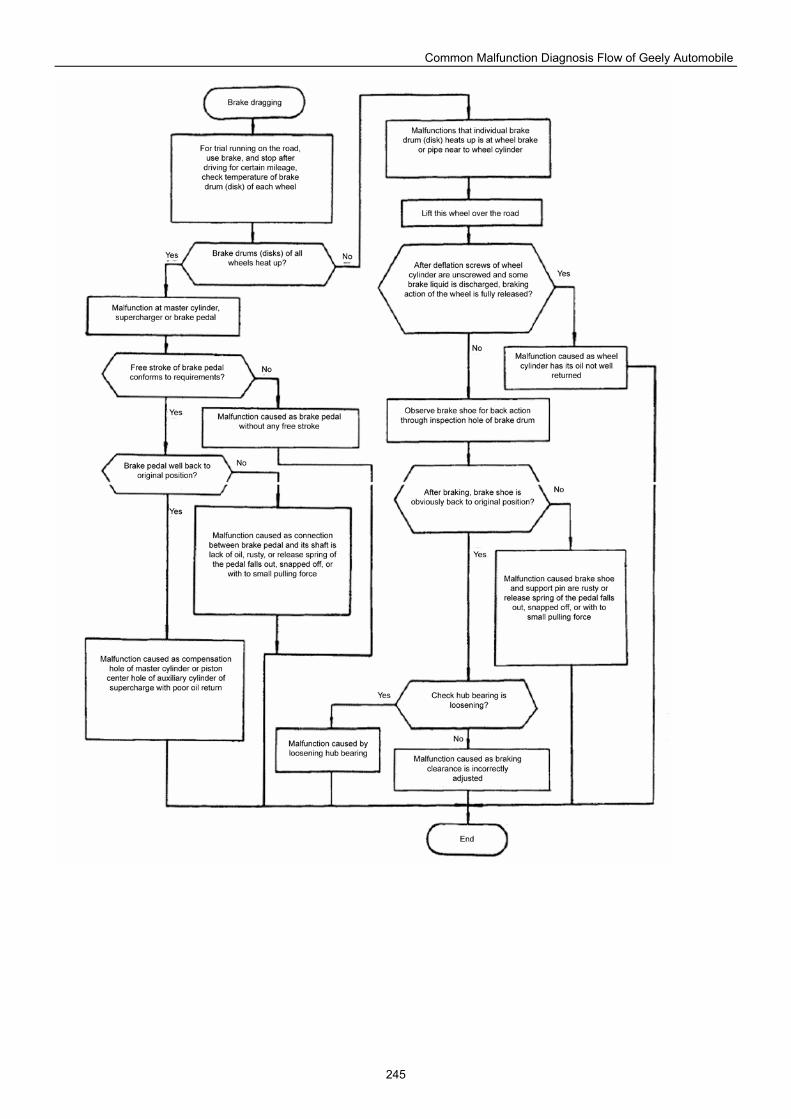
Common Malfunction Diagnosis Flow of Geely Automobile
245
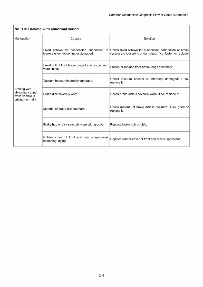
Common Malfunction Diagnosis Flow of Geely Automobile
246
No. 178 Braking with abnormal sound
Malfunction Causes Solution
Fixed screws for suspension connection of brake system loosening or damaged;
Check fixed screws for suspension connection of brake system are loosening or damaged; if so, fasten or replace;
Fixed bolt of front brake tongs loosening or with worn lining; Fasten or replace front brake tongs assembly;
Vacuum booster internally damaged; Check vacuum booster is internally damaged; if so, replace it;
Brake disk severely worn; Check brake disk is severely worn; if so, replace it;
Material of brake disk too hard; Check material of brake disk is too hard; if so, grind or replace it;
Brake hub or disk severely worn with groove; Replace brake hub or disk;
Braking with abnormal sound while vehicle is driving normally
Rubber cover of front and rear suspensions loosening, aging; Replace rubber cover of front and rear suspensions;
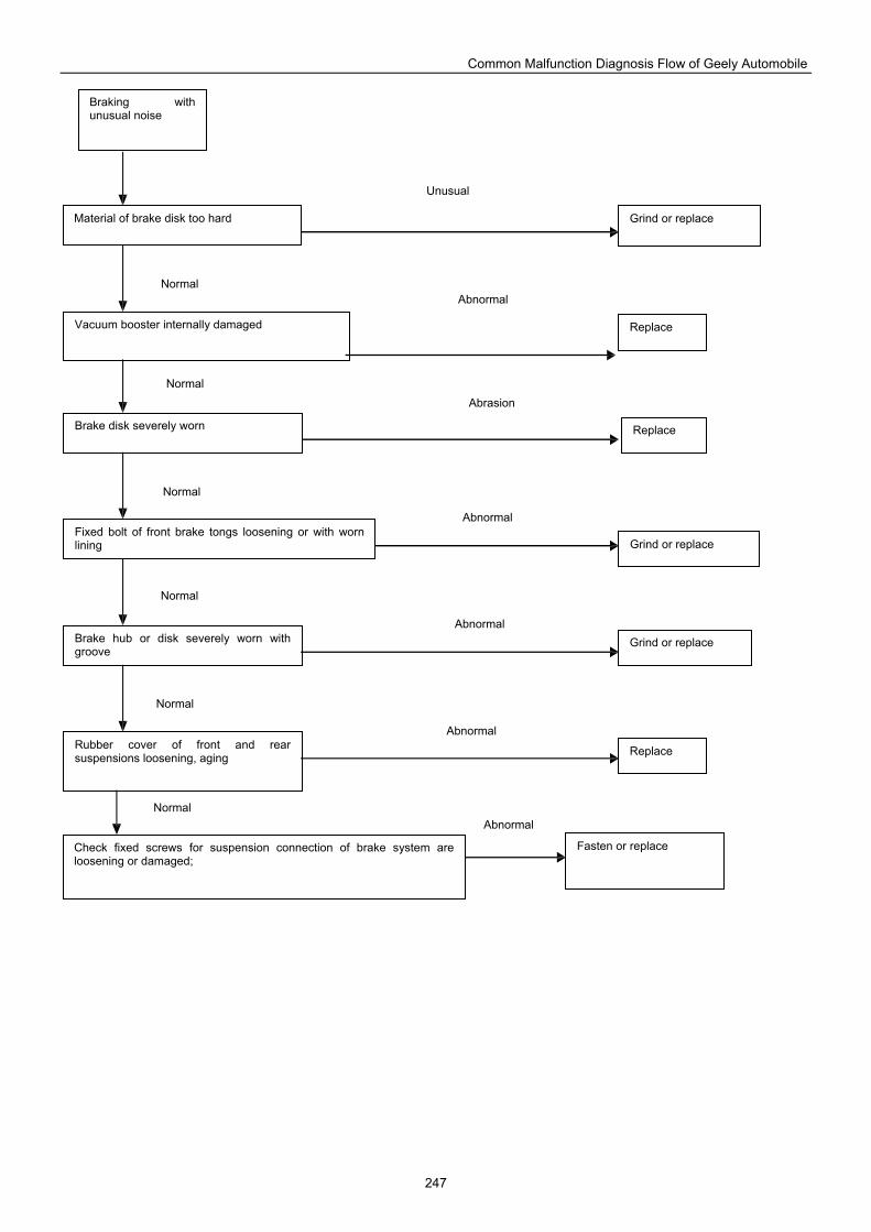
Common Malfunction Diagnosis Flow of Geely Automobile
247
Grind or replace
Replace
Fasten or replace Check fixed screws for suspension connection of brake system are loosening or damaged;
Rubber cover of front and rear suspensions loosening, aging
Vacuum booster internally damaged
Brake disk severely worn
Fixed bolt of front brake tongs loosening or with worn lining
Brake hub or disk severely worn with groove
Grind or replace
Replace
Braking with unusual noise
Material of brake disk too hard
Grind or replace
Replace
Unusual
Abnormal
Abrasion
Abnormal
Abnormal
Abnormal
Abnormal
Normal
Normal
Normal
Normal
Normal
Normal
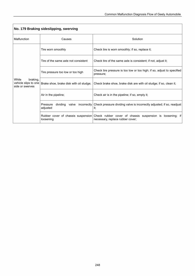
Common Malfunction Diagnosis Flow of Geely Automobile
248
No. 179 Braking sideslipping, swerving
Malfunction Causes Solution
Tire worn smoothly Check tire is worn smoothly; if so, replace it;
Tire of the same axle not consistent Check tire of the same axle is consistent; if not, adjust it;
Tire pressure too low or too high Check tire pressure is too low or too high; if so, adjust to specified pressure;
Brake shoe, brake disk with oil sludge; Check brake shoe, brake disk are with oil sludge; if so, clean it;
Air in the pipeline; Check air is in the pipeline; if so, empty it;
Pressure dividing valve incorrectly adjusted
Check pressure dividing valve is incorrectly adjusted; if so, readjust it;
While braking, vehicle slips to one side or swerves
Rubber cover of chassis suspension loosening
Check rubber cover of chassis suspension is loosening; if necessary, replace rubber cover;
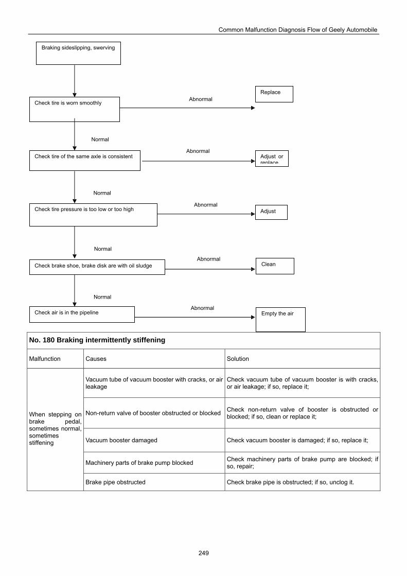
Common Malfunction Diagnosis Flow of Geely Automobile
249
No. 180 Braking intermittently stiffening
Malfunction Causes Solution
Vacuum tube of vacuum booster with cracks, or air leakage
Check vacuum tube of vacuum booster is with cracks, or air leakage; if so, replace it;
Non-return valve of booster obstructed or blocked Check non-return valve of booster is obstructed or blocked; if so, clean or replace it;
Vacuum booster damaged Check vacuum booster is damaged; if so, replace it;
Machinery parts of brake pump blocked Check machinery parts of brake pump are blocked; if so, repair;
When stepping on brake pedal, sometimes normal, sometimes stiffening
Brake pipe obstructed Check brake pipe is obstructed; if so, unclog it.
Braking sideslipping, swerving
Replace
Check tire is worn smoothly
Check tire of the same axle is consistent Adjust or replace
Adjust Check tire pressure is too low or too high
Check air is in the pipeline
Check brake shoe, brake disk are with oil sludge Clean
Empty the air
Abnormal
Normal
Abnormal
Abnormal
Abnormal
Abnormal
Normal
Normal
Normal
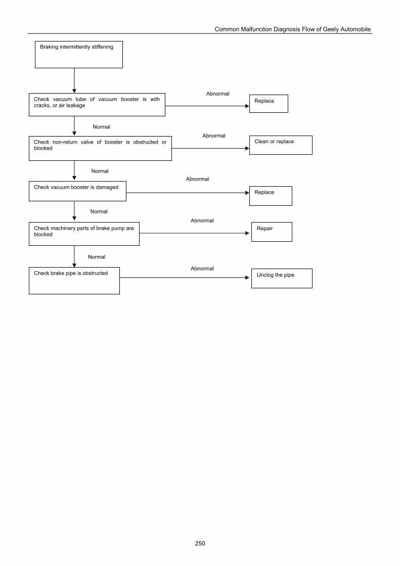
Common Malfunction Diagnosis Flow of Geely Automobile
250
Braking intermittently stiffening
Replace Check vacuum tube of vacuum booster is with cracks, or air leakage
Check non-return valve of booster is obstructed or blocked
Clean or replace
Replace Check vacuum booster is damaged
Check machinery parts of brake pump are blocked
Check brake pipe is obstructed Unclog the pipe
Repair
Abnormal
Normal
Abnormal
Abnormal
Abnormal
Abnormal
Normal
Normal
Normal
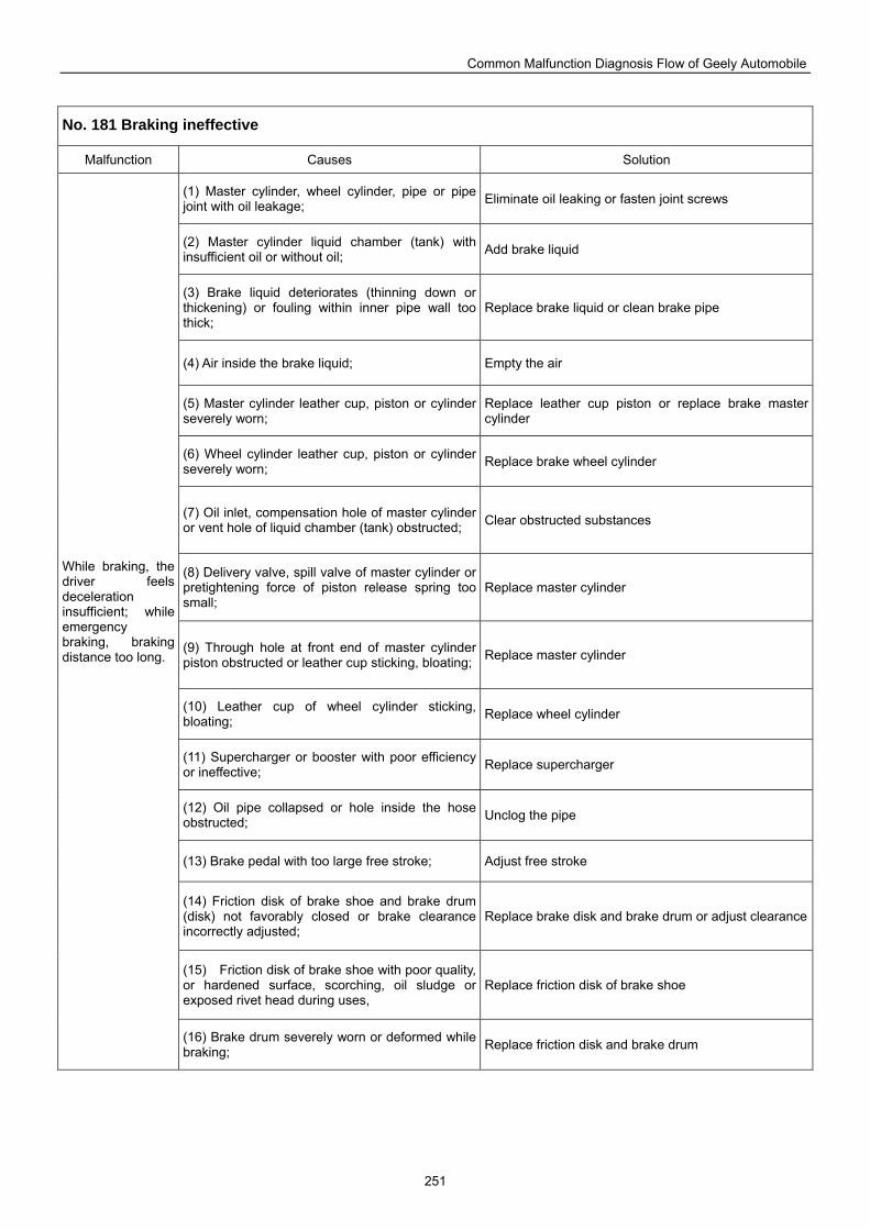
Common Malfunction Diagnosis Flow of Geely Automobile
251
No. 181 Braking ineffective
Malfunction Causes Solution
(1) Master cylinder, wheel cylinder, pipe or pipe joint with oil leakage; Eliminate oil leaking or fasten joint screws
(2) Master cylinder liquid chamber (tank) with insufficient oil or without oil; Add brake liquid
(3) Brake liquid deteriorates (thinning down or thickening) or fouling within inner pipe wall too thick;
Replace brake liquid or clean brake pipe
(4) Air inside the brake liquid; Empty the air
(5) Master cylinder leather cup, piston or cylinder severely worn;
Replace leather cup piston or replace brake master cylinder
(6) Wheel cylinder leather cup, piston or cylinder severely worn; Replace brake wheel cylinder
(7) Oil inlet, compensation hole of master cylinder or vent hole of liquid chamber (tank) obstructed; Clear obstructed substances
(8) Delivery valve, spill valve of master cylinder or pretightening force of piston release spring too small;
Replace master cylinder
(9) Through hole at front end of master cylinder piston obstructed or leather cup sticking, bloating; Replace master cylinder
(10) Leather cup of wheel cylinder sticking, bloating; Replace wheel cylinder
(11) Supercharger or booster with poor efficiency or ineffective; Replace supercharger
(12) Oil pipe collapsed or hole inside the hose obstructed; Unclog the pipe
(13) Brake pedal with too large free stroke; Adjust free stroke
(14) Friction disk of brake shoe and brake drum (disk) not favorably closed or brake clearance incorrectly adjusted;
Replace brake disk and brake drum or adjust clearance
(15) Friction disk of brake shoe with poor quality, or hardened surface, scorching, oil sludge or exposed rivet head during uses,
Replace friction disk of brake shoe
While braking, the driver feels deceleration insufficient; while emergency braking, braking distance too long.
(16) Brake drum severely worn or deformed while braking; Replace friction disk and brake drum
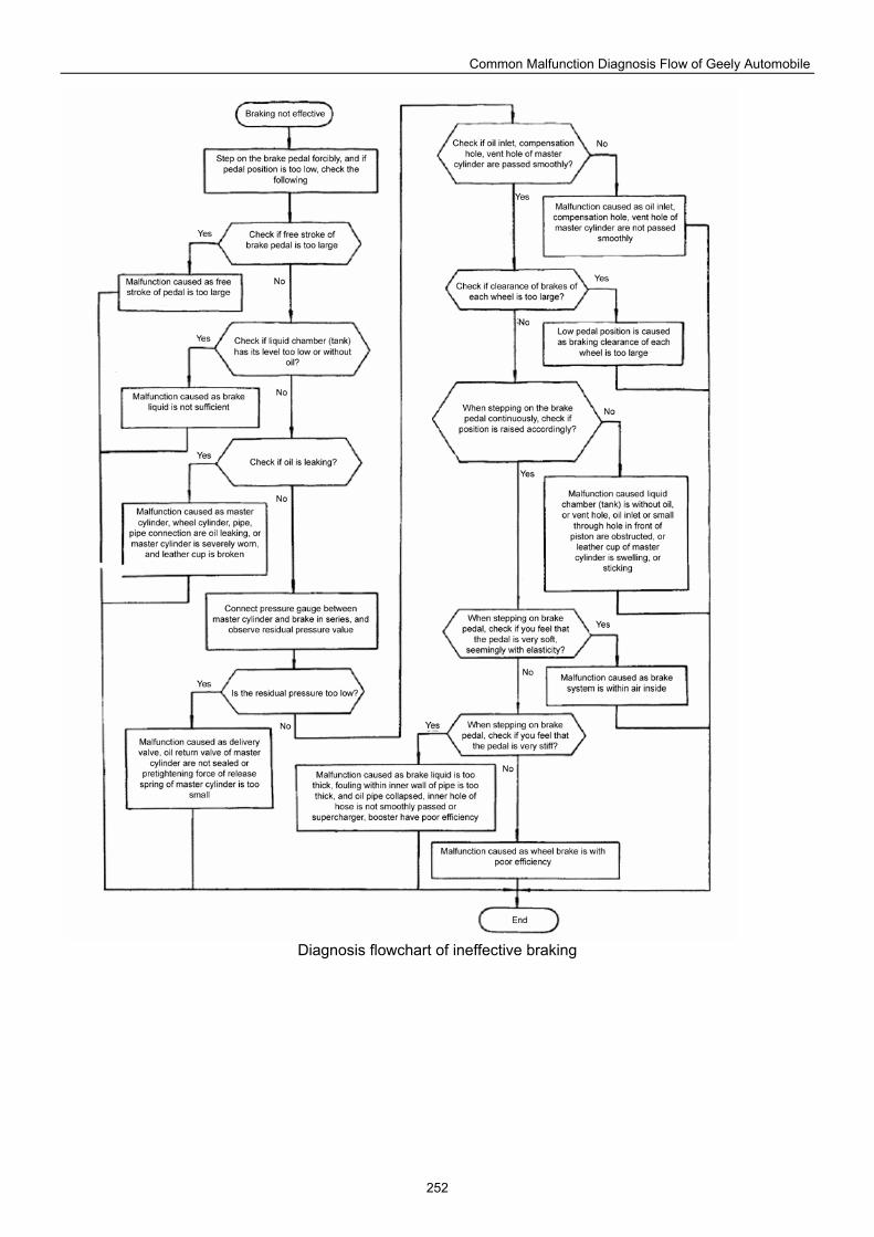
Common Malfunction Diagnosis Flow of Geely Automobile
252
Diagnosis flowchart of ineffective braking
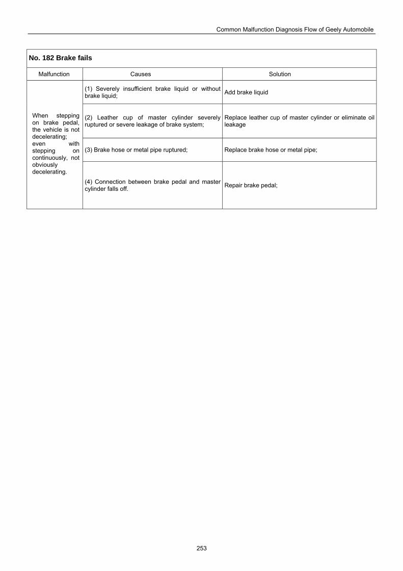
Common Malfunction Diagnosis Flow of Geely Automobile
253
No. 182 Brake fails
Malfunction Causes Solution
(1) Severely insufficient brake liquid or without brake liquid; Add brake liquid
(2) Leather cup of master cylinder severely ruptured or severe leakage of brake system;
Replace leather cup of master cylinder or eliminate oil leakage
(3) Brake hose or metal pipe ruptured; Replace brake hose or metal pipe;
When stepping on brake pedal, the vehicle is not decelerating; even with stepping on continuously, not obviously decelerating.
(4) Connection between brake pedal and master cylinder falls off. Repair brake pedal;
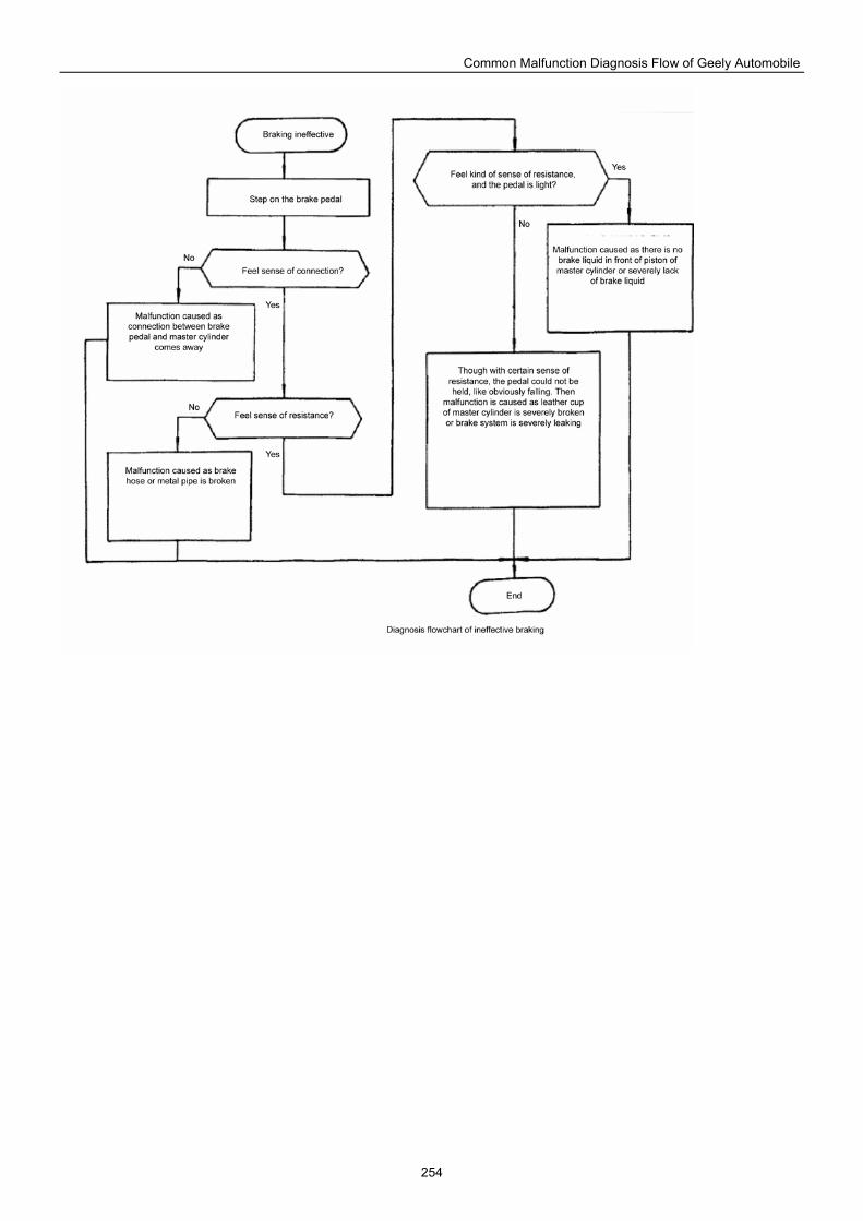
Common Malfunction Diagnosis Flow of Geely Automobile
254
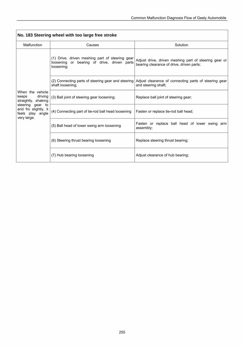
Common Malfunction Diagnosis Flow of Geely Automobile
255
No. 183 Steering wheel with too large free stroke
Malfunction Causes Solution
(1) Drive, driven meshing part of steering gear loosening or bearing of drive, driven parts loosening;
Adjust drive, driven meshing part of steering gear or bearing clearance of drive, driven parts;
(2) Connecting parts of steering gear and steering shaft loosening;
Adjust clearance of connecting parts of steering gear and steering shaft;
(3) Ball joint of steering gear loosening; Replace ball joint of steering gear;
(4) Connecting part of tie-rod ball head loosening Fasten or replace tie-rod ball head;
(5) Ball head of lower swing arm loosening Fasten or replace ball head of lower swing arm assembly;
(6) Steering thrust bearing loosening Replace steering thrust bearing;
When the vehicle keeps driving straightly, shaking steering gear to and fro slightly, it feels play angle very large.
(7) Hub bearing loosening Adjust clearance of hub bearing;
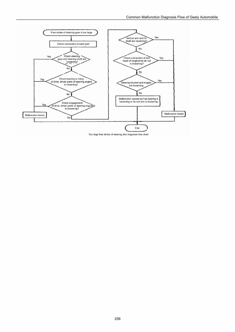
Common Malfunction Diagnosis Flow of Geely Automobile
256
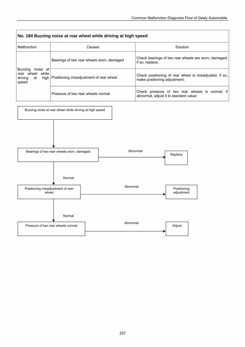
Common Malfunction Diagnosis Flow of Geely Automobile
257
No. 184 Buzzing noise at rear wheel while driving at high speed
Malfunction Causes Solution
Bearings of two rear wheels worn, damaged Check bearings of two rear wheels are worn, damaged; if so, replace;
Positioning misadjustment of rear wheel Check positioning of rear wheel is misadjusted; if so, make positioning adjustment;
Buzzing noise at rear wheel while driving at high speed
Pressure of two rear wheels normal Check pressure of two rear wheels is normal; if abnormal, adjust it to standard value;
Buzzing noise at rear wheel while driving at high speed
Replace Bearings of two rear wheels worn, damaged
Positioning misadjustment of rear wheel
Positioning adjustment
Adjust Pressure of two rear wheels normal Abnormal
Normal
Abnormal
Abnormal
Normal
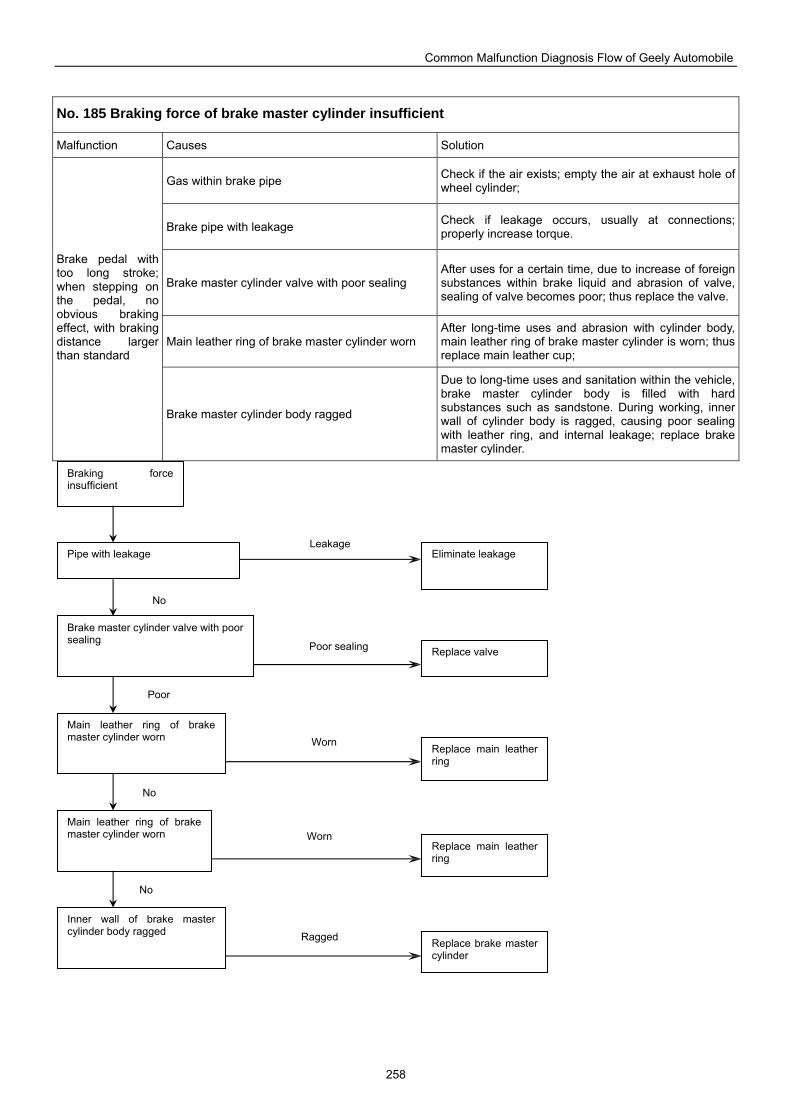
Common Malfunction Diagnosis Flow of Geely Automobile
258
No. 185 Braking force of brake master cylinder insufficient
Malfunction Causes Solution
Gas within brake pipe Check if the air exists; empty the air at exhaust hole of wheel cylinder;
Brake pipe with leakage Check if leakage occurs, usually at connections; properly increase torque.
Brake master cylinder valve with poor sealing After uses for a certain time, due to increase of foreign substances within brake liquid and abrasion of valve, sealing of valve becomes poor; thus replace the valve.
Main leather ring of brake master cylinder worn After long-time uses and abrasion with cylinder body, main leather ring of brake master cylinder is worn; thus replace main leather cup;
Brake pedal with too long stroke; when stepping on the pedal, no obvious braking effect, with braking distance larger than standard
Brake master cylinder body ragged
Due to long-time uses and sanitation within the vehicle, brake master cylinder body is filled with hard substances such as sandstone. During working, inner wall of cylinder body is ragged, causing poor sealing with leather ring, and internal leakage; replace brake master cylinder.
Braking force insufficient
Pipe with leakage Eliminate leakage
Brake master cylinder valve with poor sealing
Replace valve
Main leather ring of brake master cylinder worn
Replace main leather ring
Main leather ring of brake master cylinder worn
Replace main leather ring
Inner wall of brake master cylinder body ragged
Replace brake master cylinder
Leakage
No
Poor sealing
Worn
Worn
Ragged
No
No
Poor
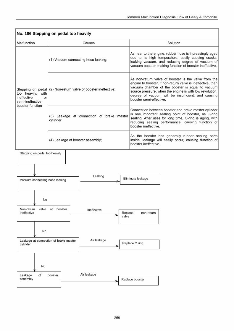
Common Malfunction Diagnosis Flow of Geely Automobile
259
No. 186 Stepping on pedal too heavily
Malfunction Causes Solution
(1) Vacuum connecting hose leaking;
As near to the engine, rubber hose is increasingly aged due to its high temperature, easily causing cracks, leaking vacuum, and reducing degree of vacuum of vacuum booster, making function of booster ineffective.
(2) Non-return valve of booster ineffective;
As non-return valve of booster is the valve from the engine to booster, if non-return valve is ineffective, then vacuum chamber of the booster is equal to vacuum source pressure, when the engine is with low revolution, degree of vacuum will be insufficient, and causing booster semi-effective.
(3) Leakage at connection of brake master cylinder
Connection between booster and brake master cylinder is one important sealing point of booster, as O-ring sealing. After uses for long time, O-ring is aging, with reducing sealing performance, causing function of booster ineffective.
Stepping on pedal too heavily, with ineffective or semi-ineffective booster function
(4) Leakage of booster assembly; As the booster has generally rubber sealing parts inside, leakage will easily occur, causing function of booster ineffective.
Stepping on pedal too heavily
Vacuum connecting hose leaking Eliminate leakage
Non-return valve of booster ineffective Replace non-return
valve
Leakage at connection of brake master cylinder Replace O ring
Leakage of booster assembly Replace booster
Air leakage
No
Air leakage
Ineffective
Leaking
No
No
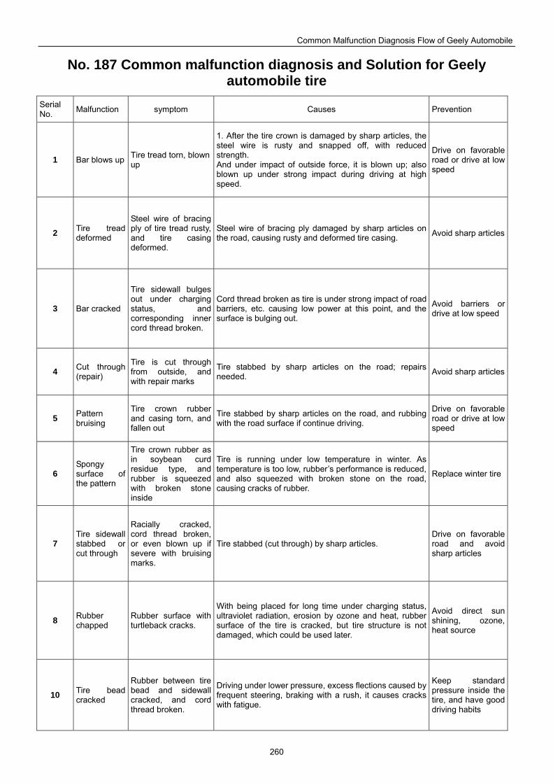
Common Malfunction Diagnosis Flow of Geely Automobile
260
No. 187 Common malfunction diagnosis and Solution for Geely automobile tire
Serial No. Malfunction symptom Causes Prevention
1 Bar blows up Tire tread torn, blown up
1. After the tire crown is damaged by sharp articles, the steel wire is rusty and snapped off, with reduced strength. And under impact of outside force, it is blown up; also blown up under strong impact during driving at high speed.
Drive on favorable road or drive at low speed
2 Tire tread deformed
Steel wire of bracing ply of tire tread rusty, and tire casing deformed.
Steel wire of bracing ply damaged by sharp articles on the road, causing rusty and deformed tire casing. Avoid sharp articles
3 Bar cracked
Tire sidewall bulges out under charging status, and corresponding inner cord thread broken.
Cord thread broken as tire is under strong impact of road barriers, etc. causing low power at this point, and the surface is bulging out.
Avoid barriers or drive at low speed
4 Cut through (repair)
Tire is cut through from outside, and with repair marks
Tire stabbed by sharp articles on the road; repairs needed. Avoid sharp articles
5 Pattern bruising
Tire crown rubber and casing torn, and fallen out
Tire stabbed by sharp articles on the road, and rubbing with the road surface if continue driving.
Drive on favorable road or drive at low speed
6 Spongy surface of the pattern
Tire crown rubber as in soybean curd residue type, and rubber is squeezed with broken stone inside
Tire is running under low temperature in winter. As temperature is too low, rubber’s performance is reduced, and also squeezed with broken stone on the road, causing cracks of rubber.
Replace winter tire
7 Tire sidewall stabbed or cut through
Racially cracked, cord thread broken, or even blown up if severe with bruising marks.
Tire stabbed (cut through) by sharp articles. Drive on favorable road and avoid sharp articles
8 Rubber chapped
Rubber surface with turtleback cracks.
With being placed for long time under charging status, ultraviolet radiation, erosion by ozone and heat, rubber surface of the tire is cracked, but tire structure is not damaged, which could be used later.
Avoid direct sun shining, ozone, heat source
10 Tire bead cracked
Rubber between tire bead and sidewall cracked, and cord thread broken.
Driving under lower pressure, excess flections caused by frequent steering, braking with a rush, it causes cracks with fatigue.
Keep standard pressure inside the tire, and have good driving habits
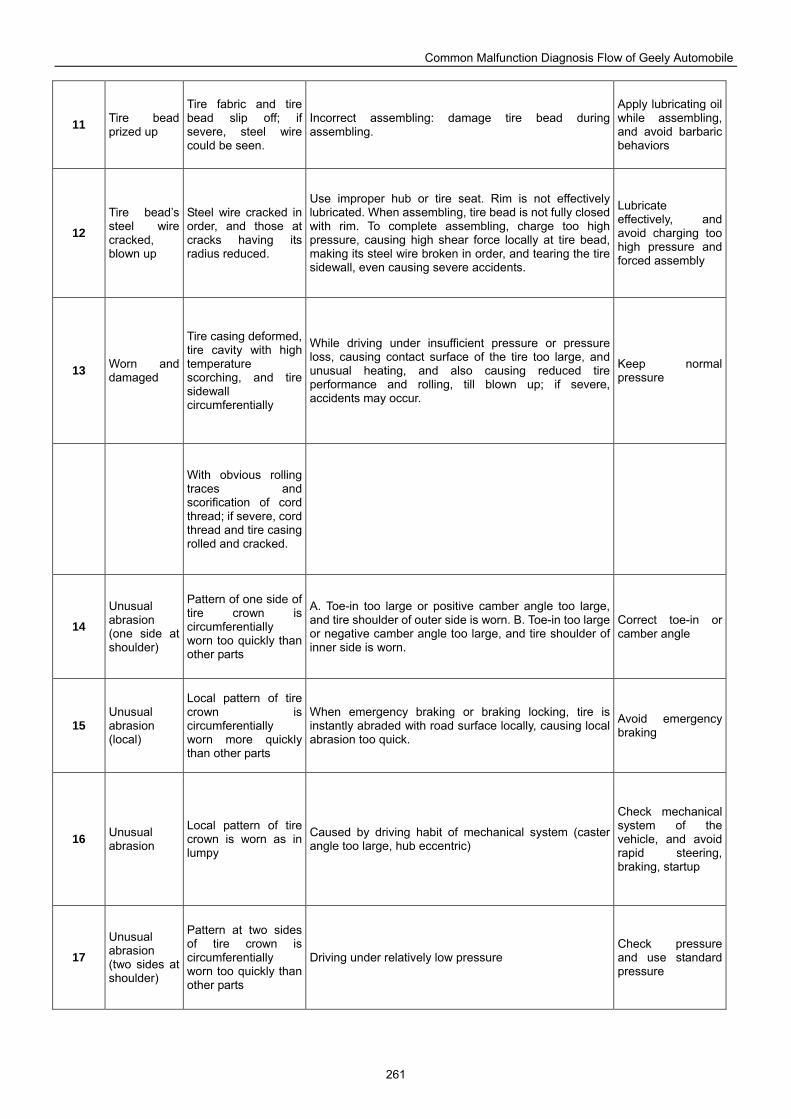
Common Malfunction Diagnosis Flow of Geely Automobile
261
11 Tire bead prized up
Tire fabric and tire bead slip off; if severe, steel wire could be seen.
Incorrect assembling: damage tire bead during assembling.
Apply lubricating oil while assembling, and avoid barbaric behaviors
12
Tire bead’s steel wire cracked, blown up
Steel wire cracked in order, and those at cracks having its radius reduced.
Use improper hub or tire seat. Rim is not effectively lubricated. When assembling, tire bead is not fully closed with rim. To complete assembling, charge too high pressure, causing high shear force locally at tire bead, making its steel wire broken in order, and tearing the tire sidewall, even causing severe accidents.
Lubricate effectively, and avoid charging too high pressure and forced assembly
13 Worn and damaged
Tire casing deformed, tire cavity with high temperature scorching, and tire sidewall circumferentially
While driving under insufficient pressure or pressure loss, causing contact surface of the tire too large, and unusual heating, and also causing reduced tire performance and rolling, till blown up; if severe, accidents may occur.
Keep normal pressure
With obvious rolling traces and scorification of cord thread; if severe, cord thread and tire casing rolled and cracked.
14
Unusual abrasion (one side at shoulder)
Pattern of one side of tire crown is circumferentially worn too quickly than other parts
A. Toe-in too large or positive camber angle too large, and tire shoulder of outer side is worn. B. Toe-in too large or negative camber angle too large, and tire shoulder of inner side is worn.
Correct toe-in or camber angle
15 Unusual abrasion (local)
Local pattern of tire crown is circumferentially worn more quickly than other parts
When emergency braking or braking locking, tire is instantly abraded with road surface locally, causing local abrasion too quick.
Avoid emergency braking
16 Unusual abrasion
Local pattern of tire crown is worn as in lumpy
Caused by driving habit of mechanical system (caster angle too large, hub eccentric)
Check mechanical system of the vehicle, and avoid rapid steering, braking, startup
17
Unusual abrasion (two sides at shoulder)
Pattern at two sides of tire crown is circumferentially worn too quickly than other parts
Driving under relatively low pressure Check pressure and use standard pressure
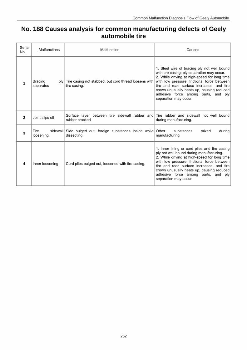
Common Malfunction Diagnosis Flow of Geely Automobile
262
No. 188 Causes analysis for common manufacturing defects of Geely automobile tire
Serial No. Malfunctions Malfunction Causes
1 Bracing ply separates
Tire casing not stabbed, but cord thread loosens with tire casing.
1. Steel wire of bracing ply not well bound with tire casing; ply separation may occur. 2. While driving at high-speed for long time with low pressure, frictional force between tire and road surface increases, and tire crown unusually heats up, causing reduced adhesive force among parts, and ply separation may occur.
2 Joint slips off Surface layer between tire sidewall rubber and rubber cracked
Tire rubber and sidewall not well bound during manufacturing.
3 Tire sidewall loosening
Side bulged out; foreign substances inside while dissecting.
Other substances mixed during manufacturing
4 Inner loosening Cord plies bulged out, loosened with tire casing.
1. Inner lining or cord plies and tire casing ply not well bound during manufacturing. 2. While driving at high-speed for long time with low pressure, frictional force between tire and road surface increases, and tire crown unusually heats up, causing reduced adhesive force among parts, and ply separation may occur.
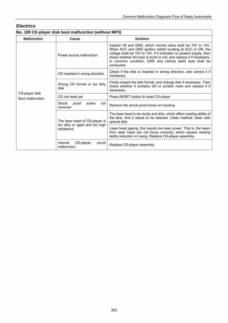
Common Malfunction Diagnosis Flow of Geely Automobile
263
Electrics No. 189 CD-player disk boot malfunction (without MP3)
Malfunction Cause Solution
Power source malfunction
Inspect +B and GND, which normal value shall be 10V to 14V. When ACC and GND ignition switch locating at ACC or ON, the voltage shall be 10V to 14V. If it indicates no powers supply, then check whether the fuse is burnt or not, and replace it if necessary. In common condition, GND and vehicle earth lead shall be conducted.
CD inserted in wrong direction Check if the disk is inserted in wrong direction, and correct it if necessary.
Wrong CD format or too dirty disk
Firstly inspect the disk format, and change disk if necessary. Then check whether it contains dirt or scratch mark and replace it if necessary.
CD not reset yet Press RESET button to reset CD-player
Shock proof screw not removed Remove the shock proof screw on housing
The laser head is too dusty and dirty, which affect reading ability of the lens. And it needs to be cleaned. Clean method: clean with special disk. The laser head of CD-player is
too dirty or aged and too high resistance Laser head ageing, this results low laser power. That is, the beam
from laser head can not focus correctly, which causes reading ability reduction or losing. Replace CD-player assembly.
CD-player disk Boot malfunction
Internal CD-player circuit malfunction Replace CD-player assembly.
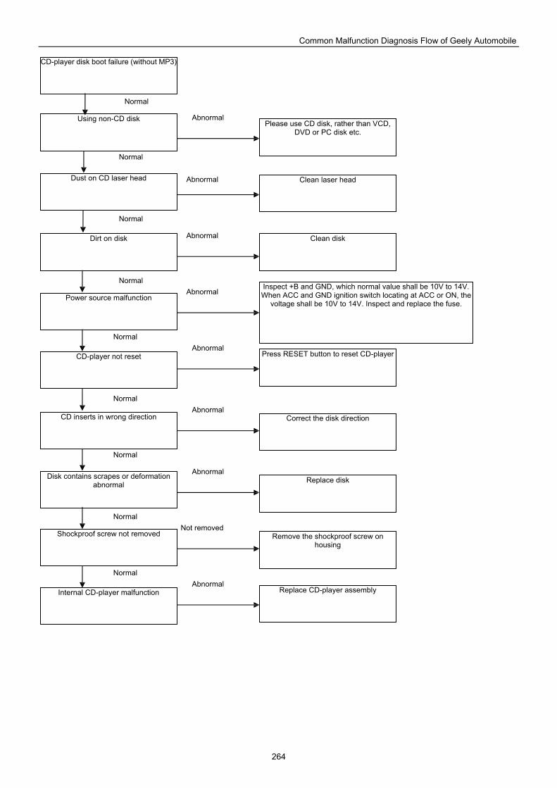
Common Malfunction Diagnosis Flow of Geely Automobile
264
CD-player disk boot failure (without MP3)
Using non-CD disk
Dust on CD laser head
Dirt on disk
Power source malfunction
CD-player not reset
CD inserts in wrong direction
Disk contains scrapes or deformation abnormal
Shockproof screw not removed
Internal CD-player malfunction
Please use CD disk, rather than VCD, DVD or PC disk etc.
Clean laser head
Clean disk
Inspect +B and GND, which normal value shall be 10V to 14V. When ACC and GND ignition switch locating at ACC or ON, the
voltage shall be 10V to 14V. Inspect and replace the fuse.
Press RESET button to reset CD-player
Correct the disk direction
Replace disk
Remove the shockproof screw on housing
Replace CD-player assembly
Abnormal
Abnormal
Abnormal
Abnormal
Abnormal
Abnormal
Abnormal
Not removed
Abnormal
Normal
Normal
Normal
Normal
Normal
Normal
Normal
Normal
Normal
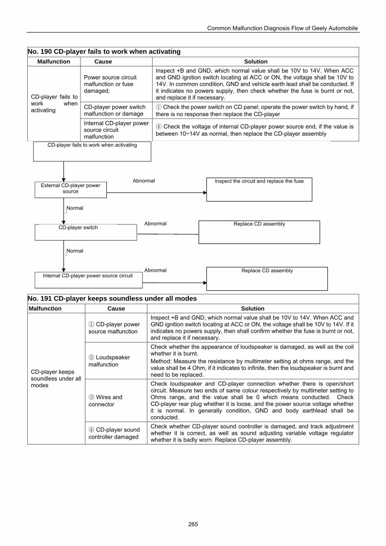
Common Malfunction Diagnosis Flow of Geely Automobile
265
No. 190 CD-player fails to work when activating
Malfunction Cause Solution
Power source circuit malfunction or fuse damaged;
Inspect +B and GND, which normal value shall be 10V to 14V. When ACC and GND ignition switch locating at ACC or ON, the voltage shall be 10V to 14V. In common condition, GND and vehicle earth lead shall be conducted. If it indicates no powers supply, then check whether the fuse is burnt or not, and replace it if necessary.
CD-player power switch malfunction or damage
① Check the power switch on CD panel; operate the power switch by hand, if there is no response then replace the CD-player
CD-player fails to work when activating
Internal CD-player power source circuit malfunction
④ Check the voltage of internal CD-player power source end, if the value is between 10~14V as normal, then replace the CD-player assembly
No. 191 CD-player keeps soundless under all modes Malfunction Cause Solution
① CD-player power source malfunction
Inspect +B and GND, which normal value shall be 10V to 14V. When ACC and GND ignition switch locating at ACC or ON, the voltage shall be 10V to 14V. If it indicates no powers supply, then shall confirm whether the fuse is burnt or not, and replace it if necessary.
② Loudspeaker malfunction
Check whether the appearance of loudspeaker is damaged, as well as the coil whether it is burnt. Method: Measure the resistance by multimeter setting at ohms range, and the value shall be 4 Ohm, if it indicates to infinite, then the loudspeaker is burnt and need to be replaced.
③ Wires and connector
Check loudspeaker and CD-player connection whether there is open/short circuit. Measure two ends of same colour respectively by multimeter setting to Ohms range, and the value shall be 0 which means conducted. Check CD-player rear plug whether it is loose, and the power source voltage whether it is normal. In generally condition, GND and body earthlead shall be conducted.
CD-player keeps soundless under all modes
④ CD-player sound controller damaged
Check whether CD-player sound controller is damaged, and track adjustment whether it is correct, as well as sound adjusting variable voltage regulator whether it is badly worn. Replace CD-player assembly.
CD-player fails to work when activating
External CD-player power source
CD-player switch
Internal CD-player power source circuit
Abnormal
Abnormal
Abnormal
Inspect the circuit and replace the fuse
Replace CD assembly
Replace CD assembly
Normal
Normal
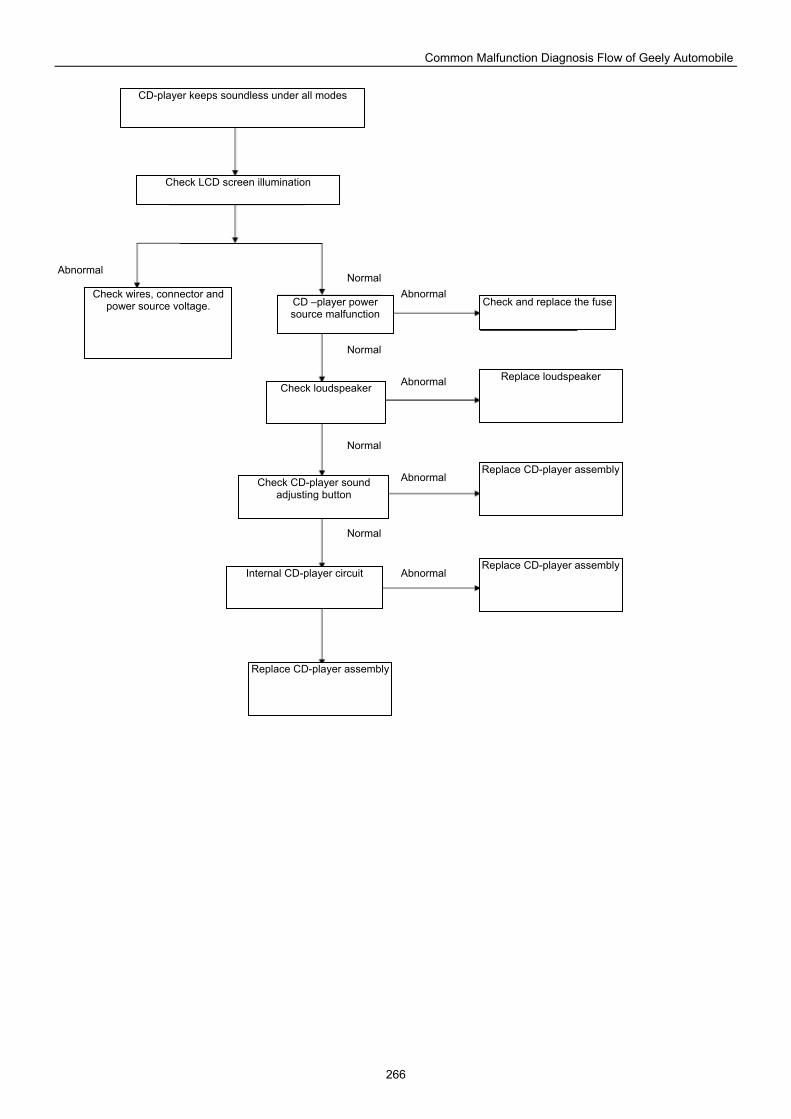
Common Malfunction Diagnosis Flow of Geely Automobile
266
CD-player keeps soundless under all modes
Check wires, connector and power source voltage.
Check LCD screen illumination
CD –player power source malfunction
Check and replace the fuse
Check loudspeaker Replace loudspeaker
Replace CD-player assembly
Replace CD-player assembly
Check CD-player sound adjusting button
Internal CD-player circuit
Normal
Normal
Normal
Normal
Abnormal
Abnormal
Abnormal
Abnormal
Abnormal
Replace CD-player assembly
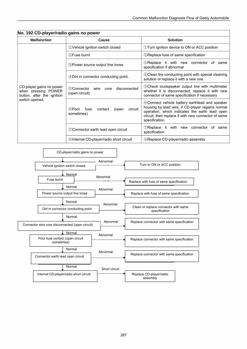
Common Malfunction Diagnosis Flow of Geely Automobile
267
No. 192 CD-player/radio gains no power
Malfunction Cause Solution
①Vehicle ignition switch closed ①Turn ignition device to ON or ACC position
②Fuse burnt ②Replace fuse of same specification
③Power source output line loose ③Replace it with new connector of same specification if abnormal
④Dirt in connector conducting point. ④Clean the conducting point with special cleaning solution or replace it with a new one.
⑤Connector wire core disconnected (open circuit)
⑤Check loudspeaker output line with multimeter whether it is disconnected, replace it with new connector of same specification if necessary
⑥Poor fuse contact (open circuit sometimes)
⑥Connect vehicle battery earthlead and speaker housing by lead wire, if CD-player regains normal operation, which indicates the earth lead open circuit, then replace it with new connector of same specification.
⑦Connector earth lead open circuit ⑦Replace it with new connector of same specification
CD-player gains no power when pressing POWER button, after the ignition switch opened,
⑧Internal CD-player/radio short circuit ⑧Replace CD-player/radio assembly
Replace with fuse of same specification
CD-player/radio gains no power
Vehicle ignition switch closed Turn to ON or ACC position
Fuse burnt Replace with fuse of same specification
Power source output line loose
Replace connector with same specification
Dirt in connector conducting point Clean or replace connector with same specification
Connector wire core disconnected (open circuit)
Poor fuse contact (open circuit sometimes)
Replace connector with same specification
Replace connector with same specification
Replace CD-player/radio assembly
Internal CD-player/radio short circuit
Connector earth lead open circuit
Normal
Normal
Normal
Normal
Normal
Normal
Normal
Abnormal
Abnormal
Abnormal
Abnormal
Abnormal
Abnormal
Abnormal
Short circuit
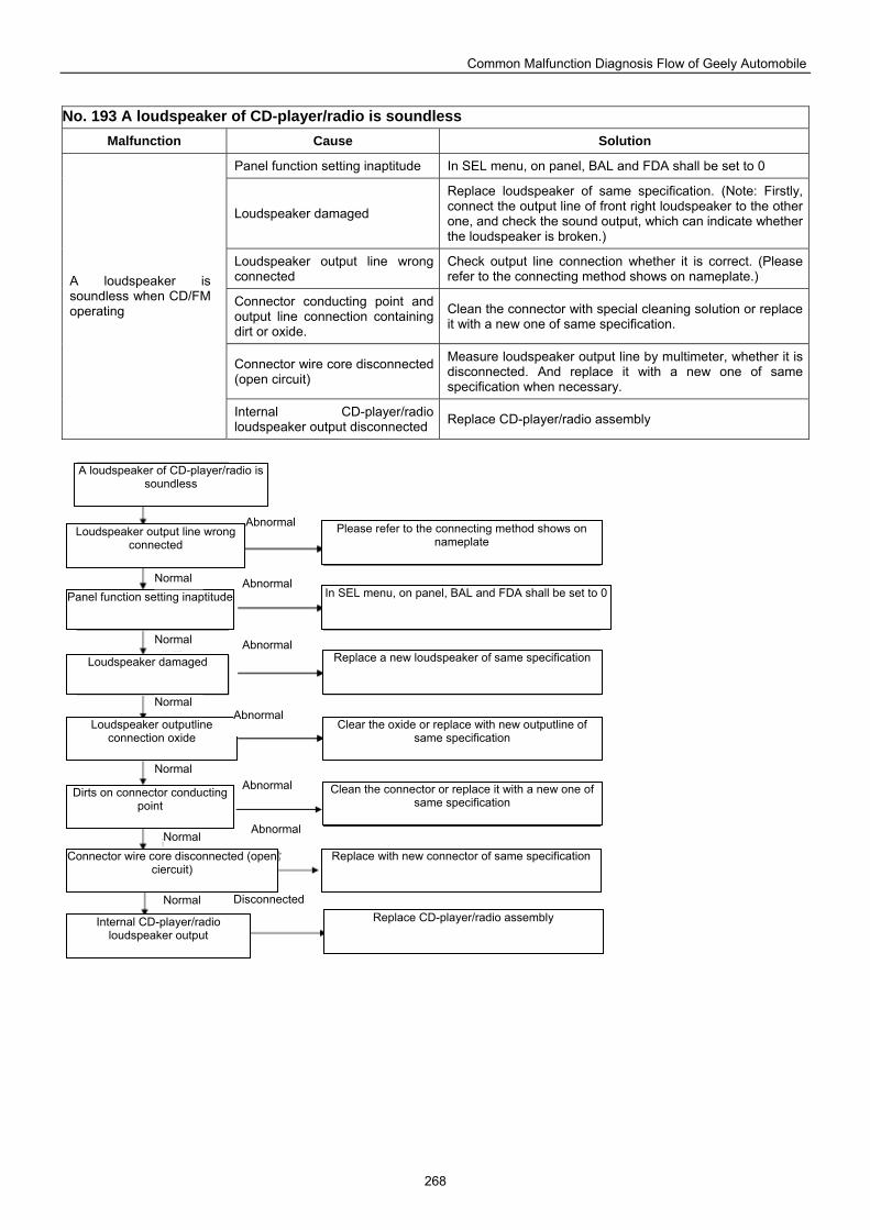
Common Malfunction Diagnosis Flow of Geely Automobile
268
No. 193 A loudspeaker of CD-player/radio is soundless
Malfunction Cause Solution
Panel function setting inaptitude In SEL menu, on panel, BAL and FDA shall be set to 0
Loudspeaker damaged
Replace loudspeaker of same specification. (Note: Firstly, connect the output line of front right loudspeaker to the other one, and check the sound output, which can indicate whether the loudspeaker is broken.)
Loudspeaker output line wrong connected
Check output line connection whether it is correct. (Please refer to the connecting method shows on nameplate.)
Connector conducting point and output line connection containing dirt or oxide.
Clean the connector with special cleaning solution or replace it with a new one of same specification.
Connector wire core disconnected (open circuit)
Measure loudspeaker output line by multimeter, whether it is disconnected. And replace it with a new one of same specification when necessary.
A loudspeaker is soundless when CD/FM operating
Internal CD-player/radio loudspeaker output disconnected Replace CD-player/radio assembly
Loudspeaker outputline connection oxide
A loudspeaker of CD-player/radio is soundless
Loudspeaker output line wrong connected
Panel function setting inaptitude
Loudspeaker damaged
Dirts on connector conducting point
Replace a new loudspeaker of same specification
Connector wire core disconnected (openciercuit)
Internal CD-player/radio loudspeaker output
Please refer to the connecting method shows on nameplate
In SEL menu, on panel, BAL and FDA shall be set to 0
Clear the oxide or replace with new outputline of same specification
Clean the connector or replace it with a new one of same specification
Replace with new connector of same specification
Replace CD-player/radio assembly
Abnormal
Abnormal
Abnormal
Abnormal
Abnormal
Normal
Normal
Normal
Normal
Normal
Normal
Abnormal
Disconnected
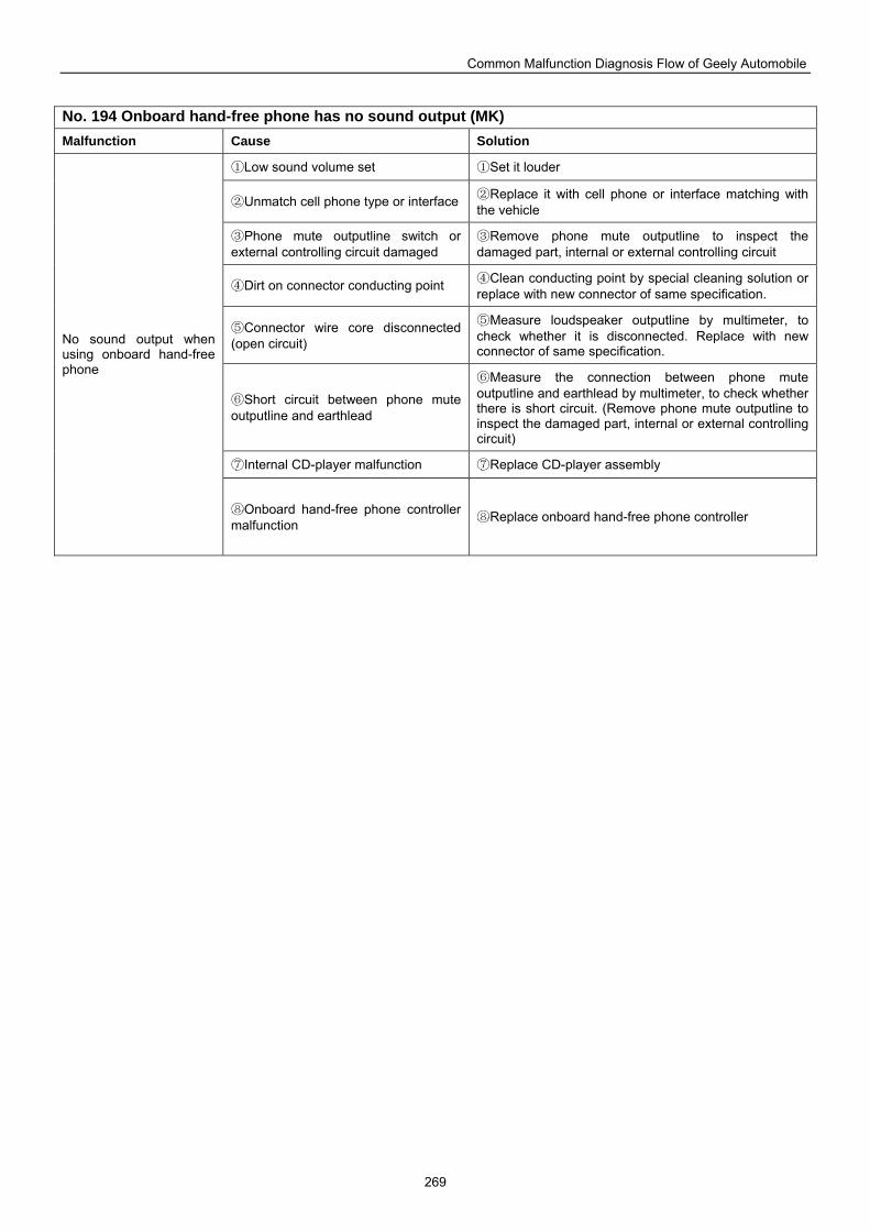
Common Malfunction Diagnosis Flow of Geely Automobile
269
No. 194 Onboard hand-free phone has no sound output (MK) Malfunction Cause Solution
①Low sound volume set ①Set it louder
②Unmatch cell phone type or interface ②Replace it with cell phone or interface matching with the vehicle
③Phone mute outputline switch or external controlling circuit damaged
③Remove phone mute outputline to inspect the damaged part, internal or external controlling circuit
④Dirt on connector conducting point ④Clean conducting point by special cleaning solution or replace with new connector of same specification.
⑤Connector wire core disconnected (open circuit)
⑤Measure loudspeaker outputline by multimeter, to check whether it is disconnected. Replace with new connector of same specification.
⑥Short circuit between phone mute outputline and earthlead
⑥Measure the connection between phone mute outputline and earthlead by multimeter, to check whether there is short circuit. (Remove phone mute outputline to inspect the damaged part, internal or external controlling circuit)
⑦Internal CD-player malfunction ⑦Replace CD-player assembly
No sound output when using onboard hand-free phone
⑧Onboard hand-free phone controller malfunction ⑧Replace onboard hand-free phone controller
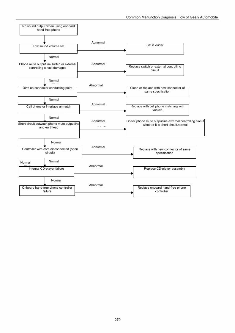
Common Malfunction Diagnosis Flow of Geely Automobile
270
Cell phone or interface unmatch
No sound output when using onboard hand-free phone
Low sound volume set
Phone mute outputline switch or external controlling circuit damaged
Dirts on connector conducting point
Short circuit between phone mute outputlineand earthlead
Controller wire core disconnected (open circuit)
Internal CD-player failure
Onboard hand-free phone controller failure
Set it louder
Replace switch or external controlling circuit
Clean or replace with new connector of same specification
Replace with cell phone matching with vehicle
Check phone mute outputline external controlling circuit whether it is short circuit.normal
Replace with new connector of same specification
Replace CD-player assembly
Replace onboard hand-free phone controller
Abnormal
Normal
Normal Normal
Normal
Normal
Normal
Normal
Abnormal
Abnormal
Abnormal
Abnormal
Abnormal
Abnormal
Abnormal
Normal
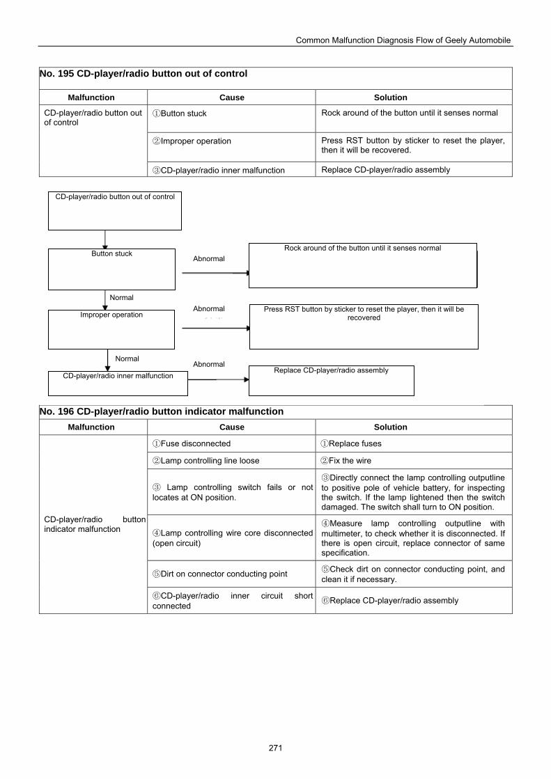
Common Malfunction Diagnosis Flow of Geely Automobile
271
No. 195 CD-player/radio button out of control
Malfunction Cause Solution
①Button stuck Rock around of the button until it senses normal
②Improper operation Press RST button by sticker to reset the player, then it will be recovered.
CD-player/radio button out of control
③CD-player/radio inner malfunction Replace CD-player/radio assembly
No. 196 CD-player/radio button indicator malfunction
Malfunction Cause Solution
①Fuse disconnected ①Replace fuses
②Lamp controlling line loose ②Fix the wire
③ Lamp controlling switch fails or not locates at ON position.
③Directly connect the lamp controlling outputline to positive pole of vehicle battery, for inspecting the switch. If the lamp lightened then the switch damaged. The switch shall turn to ON position.
④Lamp controlling wire core disconnected (open circuit)
④Measure lamp controlling outputline with multimeter, to check whether it is disconnected. If there is open circuit, replace connector of same specification.
⑤Dirt on connector conducting point ⑤Check dirt on connector conducting point, and clean it if necessary.
CD-player/radio button indicator malfunction
⑥CD-player/radio inner circuit short connected ⑥Replace CD-player/radio assembly
Rock around of the button until it senses normal
CD-player/radio button out of control
Button stuck
Improper operation
CD-player/radio inner malfunction
Press RST button by sticker to reset the player, then it will be recovered
Replace CD-player/radio assembly Abnormal
Abnormal
Abnormal
Normal
Normal
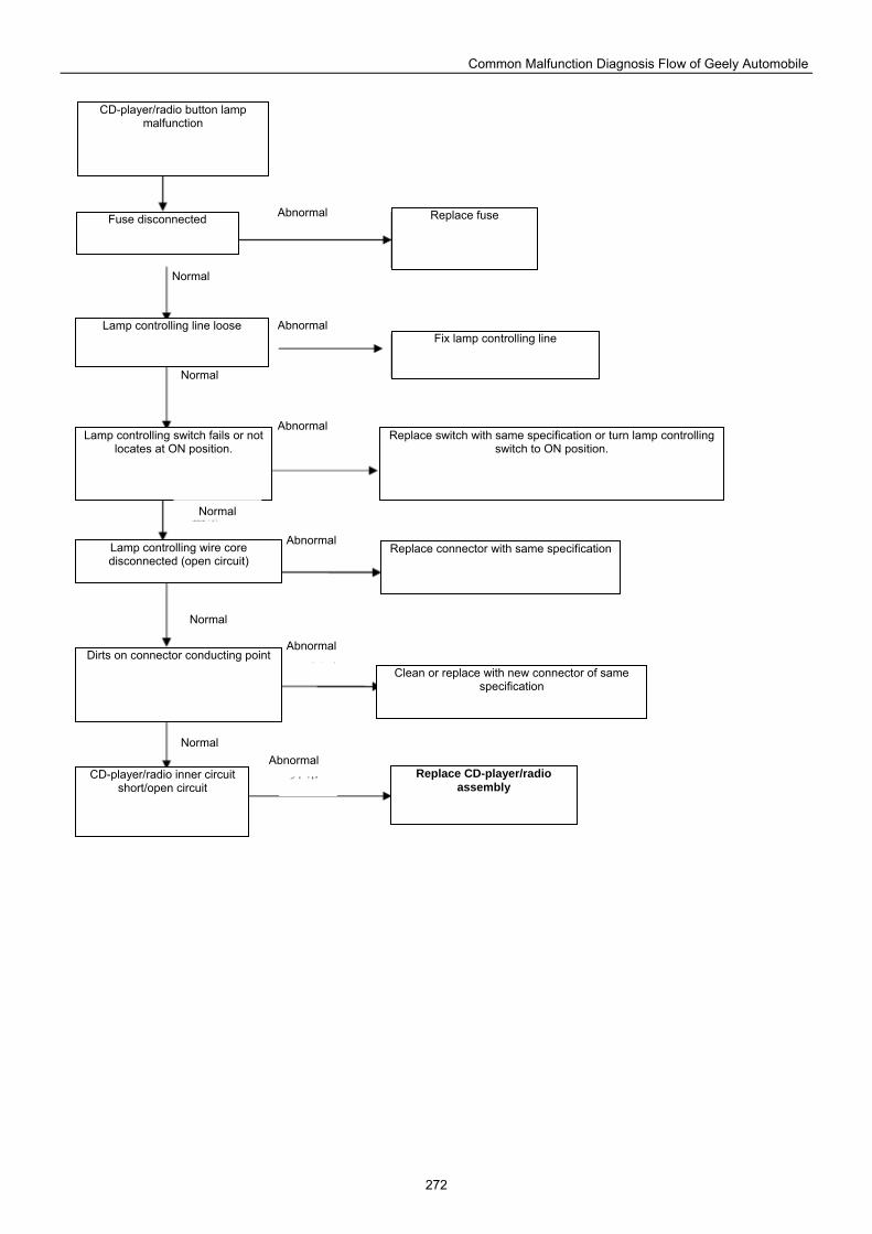
Common Malfunction Diagnosis Flow of Geely Automobile
272
CD-player/radio button lamp malfunction
Fuse disconnected Replace fuse
Lamp controlling line loose
Lamp controlling switch fails or not locates at ON position.
Lamp controlling wire core disconnected (open circuit)
Dirts on connector conducting point
CD-player/radio inner circuit short/open circuit
Fix lamp controlling line
Replace switch with same specification or turn lamp controlling switch to ON position.
Replace connector with same specification
Clean or replace with new connector of same specification
Replace CD-player/radio assembly
Normal
Normal
Normal
Normal
Abnormal
Abnormal
Abnormal
Abnormal
Abnormal
Abnormal
Normal
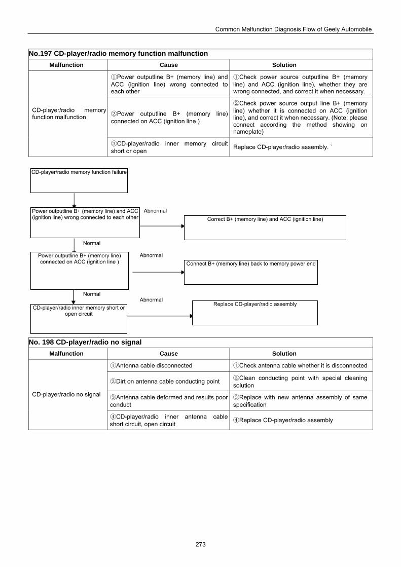
Common Malfunction Diagnosis Flow of Geely Automobile
273
No.197 CD-player/radio memory function malfunction
Malfunction Cause Solution
①Power outputline B+ (memory line) and ACC (ignition line) wrong connected to each other
①Check power source outputline B+ (memory line) and ACC (ignition line), whether they are wrong connected, and correct it when necessary.
②Power outputline B+ (memory line) connected on ACC (ignition line )
②Check power source output line B+ (memory line) whether it is connected on ACC (ignition line), and correct it when necessary. (Note: please connect according the method showing on nameplate)
CD-player/radio memory function malfunction
③CD-player/radio inner memory circuit short or open Replace CD-player/radio assembly. `
No. 198 CD-player/radio no signal
Malfunction Cause Solution
①Antenna cable disconnected ①Check antenna cable whether it is disconnected
②Dirt on antenna cable conducting point ②Clean conducting point with special cleaning solution
③Antenna cable deformed and results poor conduct
③Replace with new antenna assembly of same specification
CD-player/radio no signal
④CD-player/radio inner antenna cable short circuit, open circuit ④Replace CD-player/radio assembly
Connect B+ (memory line) back to memory power end
CD-player/radio memory function failure
Power outputline B+ (memory line) and ACC (ignition line) wrong connected to each other
Power outputline B+ (memory line) connected on ACC (ignition line )
CD-player/radio inner memory short or open circuit
Correct B+ (memory line) and ACC (ignition line)
Replace CD-player/radio assembly
Normal
Normal Abnormal
Abnormal
Abnormal
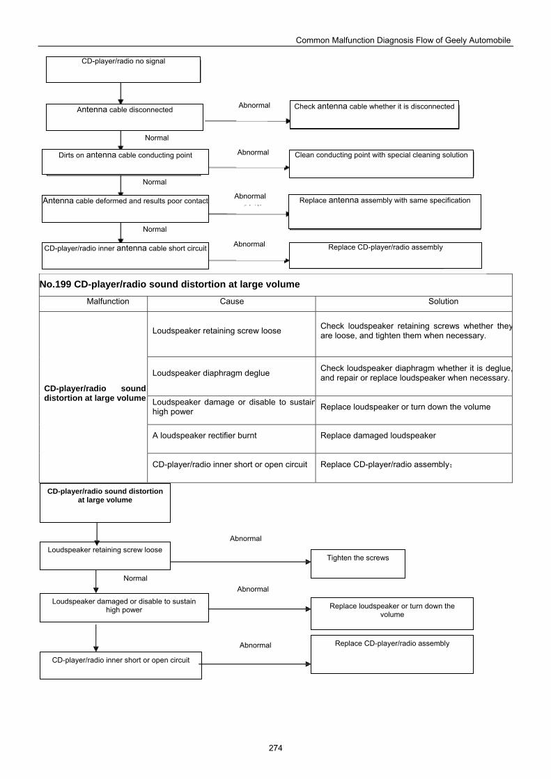
Common Malfunction Diagnosis Flow of Geely Automobile
274
No.199 CD-player/radio sound distortion at large volume
Malfunction Cause Solution
Loudspeaker retaining screw loose Check loudspeaker retaining screws whether theyare loose, and tighten them when necessary.
Loudspeaker diaphragm deglue Check loudspeaker diaphragm whether it is deglue,and repair or replace loudspeaker when necessary.
Loudspeaker damage or disable to sustainhigh power Replace loudspeaker or turn down the volume
A loudspeaker rectifier burnt Replace damaged loudspeaker
CD-player/radio sound distortion at large volume
CD-player/radio inner short or open circuit Replace CD-player/radio assembly;
Abnormal
CD-player/radio no signal
Antenna cable disconnected
Dirts on antenna cable conducting point
Antenna cable deformed and results poor contact
CD-player/radio inner antenna cable short circuit
Check antenna cable whether it is disconnected
Clean conducting point with special cleaning solution
Normal
Normal
Normal
Abnormal
Abnormal
Abnormal
Replace antenna assembly with same specification
Replace CD-player/radio assembly
Loudspeaker retaining screw loose
CD-player/radio sound distortion at large volume
Loudspeaker damaged or disable to sustain high power Replace loudspeaker or turn down the
volume
Tighten the screws
CD-player/radio inner short or open circuit
Replace CD-player/radio assembly
Normal
Abnormal
Abnormal
Abnormal
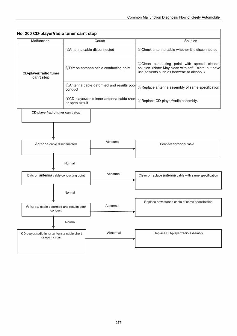
Common Malfunction Diagnosis Flow of Geely Automobile
275
No. 200 CD-player/radio tuner can’t stop
Malfunction Cause Solution
①Antenna cable disconnected ①Check antenna cable whether it is disconnected
②Dirt on antenna cable conducting point Clean conducting point with special cleaning②
solution. (Note: May clean with soft cloth, but neveuse solvents such as benzene or alcohol )
③Antenna cable deformed and results poorconduct Replace ③ antenna assembly of same specification
CD-player/radio tuner can’t stop
④CD-player/radio inner antenna cable shortor open circuit Replace CD④ -player/radio assembly。
Antenna cable disconnected
CD-player/radio tuner can’t stop
Dirts on antenna cable conducting point Clean or replace antenna cable with same specification
Connect antenna cable
Antenna cable deformed and results poor conduct
Replace new atenna cable of same specification
CD-player/radio inner antenna cable short or open circuit
Replace CD-player/radio assembly
Normal
Normal
Normal
Abnormal
Abnormal
Abnormal
Abnormal
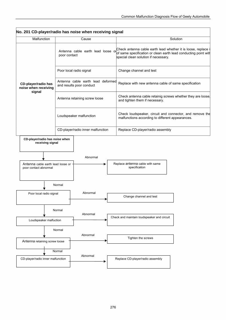
Common Malfunction Diagnosis Flow of Geely Automobile
276
No. 201 CD-player/radio has noise when receiving signal
Malfunction Cause Solution
Antenna cable earth lead loose orpoor contact
Check antenna cable earth lead whether it is loose, replace iof same specification or clean earth lead conducting point withspecial clean solution if necessary.
Poor local radio signal Change channel and test
Antenna cable earth lead deformedand results poor conduct Replace with new antenna cable of same specification
Antenna retaining screw loose Check antenna cable retainig screws whether they are loose,and tighten them if necessary.
Loudspeaker malfunction Check loudspeaker, circuit and connector, and remove themalfunctions according to different appearances.
CD-player/radio has noise when receiving
signal
CD-player/radio inner malfunction Replace CD-player/radio assembly
Replace antenna cable with same specification
Antenna cable earth lead loose or poor contact abnormal
CD-player/radio has noise when receiving signal
Poor local radio signal
Loudspeaker malfuction
Antenna retaining screw loose
Change channel and test
Check and maintain loudspeaker and circuit
Tighten the screws
CD-player/radio inner malfunction Replace CD-player/radio assembly
Normal
Normal
Normal
Normal
Abnormal
Abnormal
Abnormal
Abnormal
Abnormal
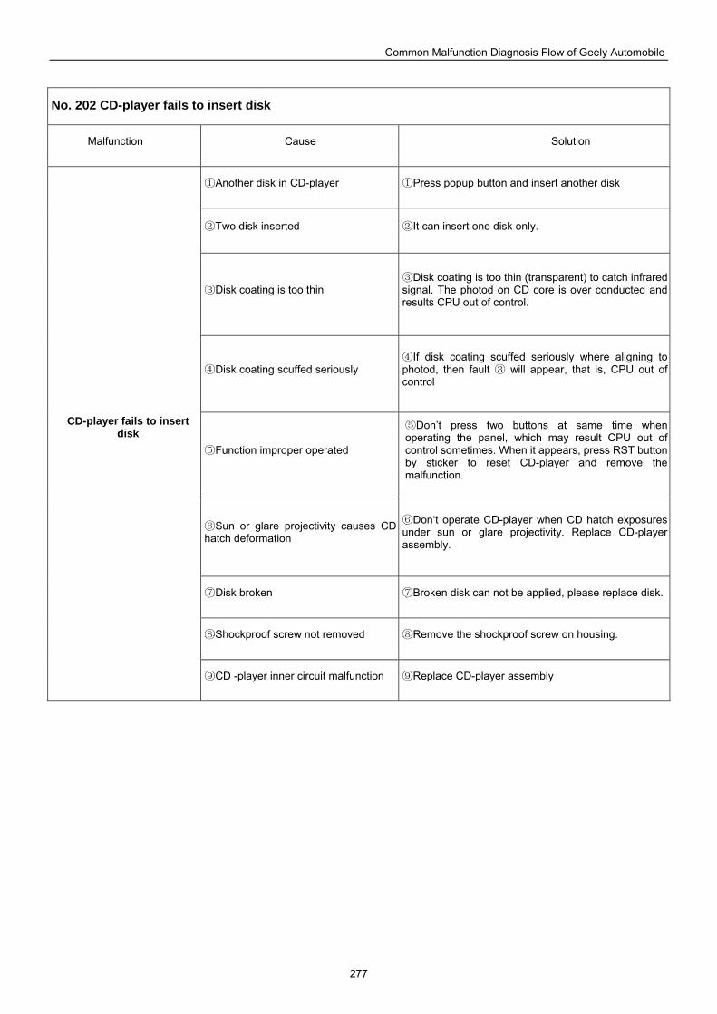
Common Malfunction Diagnosis Flow of Geely Automobile
277
No. 202 CD-player fails to insert disk
Malfunction Cause Solution
Another disk in CD① -player Press popup button and insert another disk①
Two disk inserted② It can insert one disk only.②
Disk coating is too thin③ Disk coating is too thin (③ transparent) to catch infrared
signal. The photod on CD core is over conducted and results CPU out of control.
Disk coating scuffed seriously④ If disk coating scuffed seriously where aligning to ④
photod, then fault will appear, that is, CPU out of ③control
Function improper operated⑤
Don’t press two buttons at same time when ⑤operating the panel, which may result CPU out of control sometimes. When it appears, press RST button by sticker to reset CD-player and remove the malfunction.
Sun or glare projectivity causes CD ⑥hatch deformation
Don‘t operate CD⑥ -player when CD hatch exposures under sun or glare projectivity. Replace CD-player assembly.
Disk broken⑦ ⑦Broken disk can not be applied, please replace disk.
Shockproof screw not removed⑧ Remove the shockproof screw on housing.⑧
CD-player fails to insert disk
CD ⑨ -player inner circuit malfunction Repl⑨ ace CD-player assembly
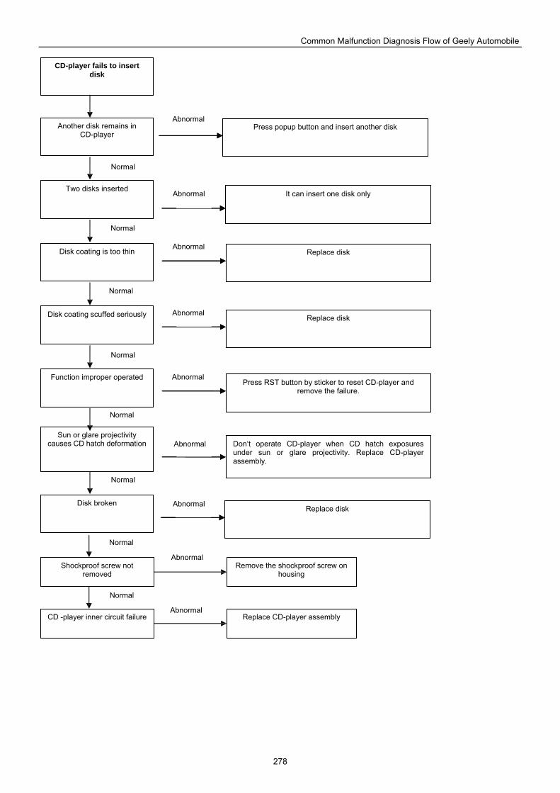
Common Malfunction Diagnosis Flow of Geely Automobile
278
It can insert one disk only
Replace disk
Replace disk
Another disk remains in CD-player
CD-player fails to insert disk
Two disks inserted
Disk coating is too thin
Disk coating scuffed seriously
Function improper operated
Sun or glare projectivity causes CD hatch deformation
Disk broken
Shockproof screw not removed
Remove the shockproof screw on housing
CD -player inner circuit failure Replace CD-player assembly
Press popup button and insert another disk
Press RST button by sticker to reset CD-player and remove the failure.
Don‘t operate CD-player when CD hatch exposures under sun or glare projectivity. Replace CD-player assembly.
Replace disk
Normal
Abnormal
Normal
Normal
Normal
Normal
Normal
Normal
Normal
Abnormal
Abnormal
Abnormal
Abnormal
Abnormal
Abnormal
Abnormal
Abnormal
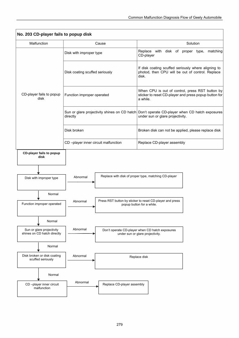
Common Malfunction Diagnosis Flow of Geely Automobile
279
No. 203 CD-player fails to popup disk
Malfunction Cause Solution
Disk with improper type Replace with disk of proper type, matching CD-player
Disk coating scuffed seriously If disk coating scuffed seriously where aligning to photod, then CPU will be out of control. Replace disk.
Function improper operated When CPU is out of control, press RST button by sticker to reset CD-player and press popup button for a while.
Sun or glare projectivity shines on CD hatch directly
Don‘t operate CD-player when CD hatch exposures under sun or glare projectivity.
Disk broken Broken disk can not be applied, please replace disk
CD-player fails to popup disk
CD –player inner circuit malfunction Replace CD-player assembly
Press RST button by sticker to reset CD-player and press popup button for a while.
Don‘t operate CD-player when CD hatch exposures under sun or glare projectivity.
Disk with improper type
CD-player fails to popup disk
Function improper operated
Sun or glare projectivity shines on CD hatch directly
Disk broken or disk coating scuffed seriously
CD –player inner circuit malfunction
Replace CD-player assembly
Replace disk
Replace with disk of proper type, matching CD-player
Normal
Abnormal
Abnormal
Abnormal
Abnormal
Abnormal
Normal
Normal
Normal
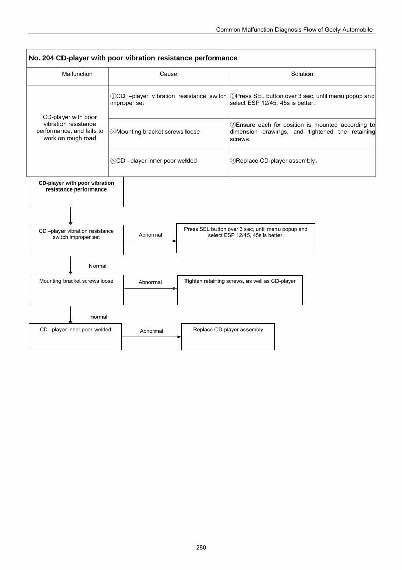
Common Malfunction Diagnosis Flow of Geely Automobile
280
No. 204 CD-player with poor vibration resistance performance
Malfunction Cause Solution
CD ① –player vibration resistance switch improper set
Press SEL butt① on over 3 sec, until menu popup and select ESP 12/45, 45s is better.
Mounting bracket screws loose② Ensure each fix position is mounted according to ②
dimension drawings, and tightened the retaining screws.
CD-player with poor vibration resistance
performance, and fails to work on rough road
CD ③ –player inner poor welded Replace CD③ -player assembly。
Press SEL button over 3 sec, until menu popup and select ESP 12/45, 45s is better.
Replace CD-player assembly
CD –player vibration resistance switch improper set
CD-player with poor vibration resistance performance
Mounting bracket screws loose
CD –player inner poor welded
Tighten retaining screws, as well as CD-player
Normal
Abnormal
Abnormal
Abnormal
normal
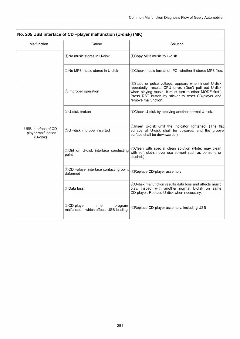
Common Malfunction Diagnosis Flow of Geely Automobile
281
No. 205 USB interface of CD –player malfunction (U-disk) (MK)
Malfunction Cause Solution
N① o music stores in U-disk Copy MP3 music to U① -disk
No MP3 music stores in U② -disk Check music format on PC, whether it stores MP3 files.②
Improper operation③
Static or pulse voltage, appears when insert U③ -disk repeatedly, results CPU error. (Don't pull out U-disk when playing music. It must turn to other MODE first.) Press RST button by sticker to reset CD-player and remove malfunction.
U④ -disk broken Check U④ -disk by applying another normal U-disk.
U ⑤ –disk improper inserted Insert U⑤ -disk until the indicator lightened. (The flat
surface of U-disk shall be upwards, and the groove surface shall be downwards.)
⑥Dirt on U-disk interface conducting point
Clean with special clean solution (Note: may clean ⑥with soft cloth, never use solvent such as benzene or alcohol.)
CD ⑦ –player interface contacting point deformed Replace CD⑦ -player assembly
Data loss⑧ U⑧ -disk malfunction results data loss and affects music
play, inspect with another normal U-disk on same CD-player. Replace U-disk when necessary.
USB interface of CD –player malfunction
(U-disk)
CD⑨ -player inner program malfunction, which affects USB loading Replace CD⑨ -player assembly, including USB
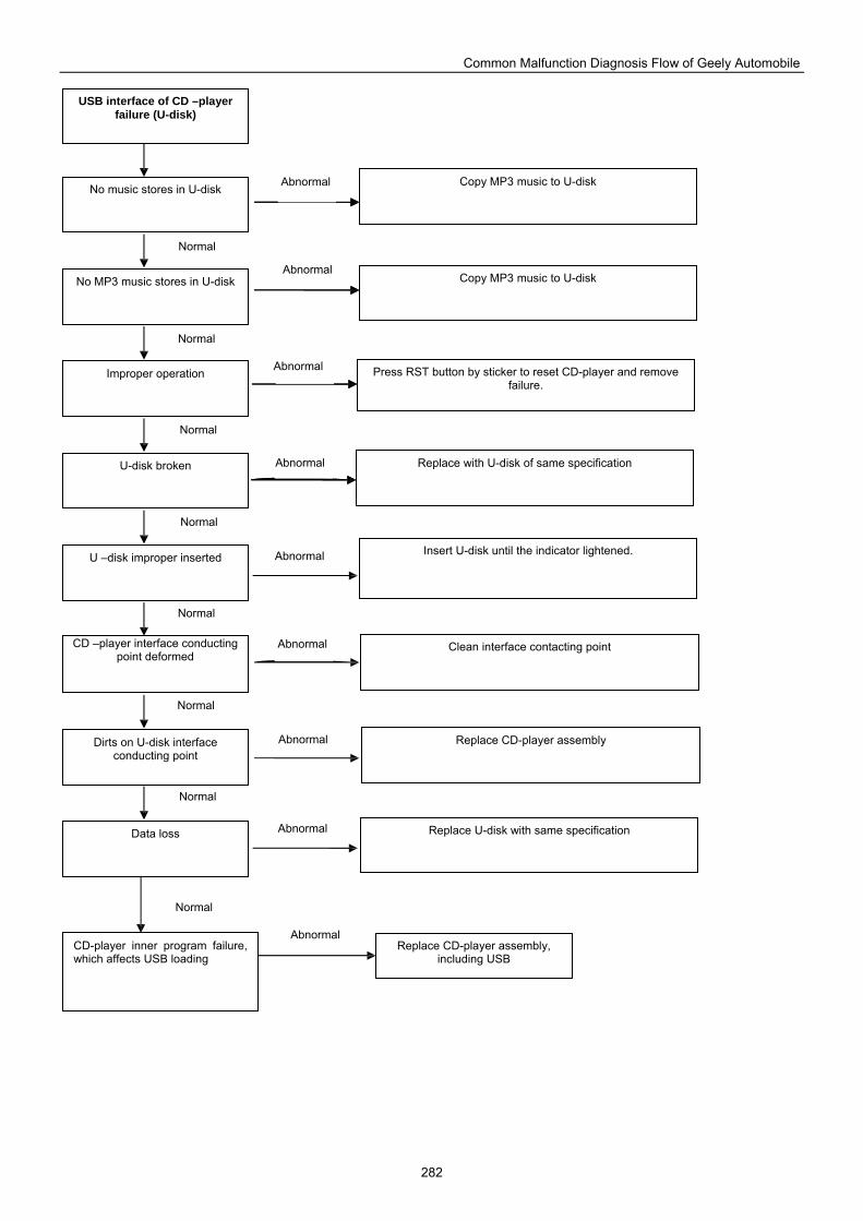
Common Malfunction Diagnosis Flow of Geely Automobile
282
Copy MP3 music to U-disk
Copy MP3 music to U-disk
Press RST button by sticker to reset CD-player and remove failure.
No music stores in U-disk
USB interface of CD –player failure (U-disk)
No MP3 music stores in U-disk
Improper operation
U-disk broken
U –disk improper inserted
CD –player interface conducting point deformed
Dirts on U-disk interface conducting point
Replace with U-disk of same specification
Insert U-disk until the indicator lightened.
Clean interface contacting point
Replace CD-player assembly
Data loss
CD-player inner program failure, which affects USB loading
Replace CD-player assembly, including USB
Replace U-disk with same specification
Normal
Abnormal
Normal
Normal
Normal
Normal
Normal
Normal
Abnormal
Abnormal
Abnormal
Abnormal
Abnormal
Abnormal
Abnormal
Normal
Abnormal
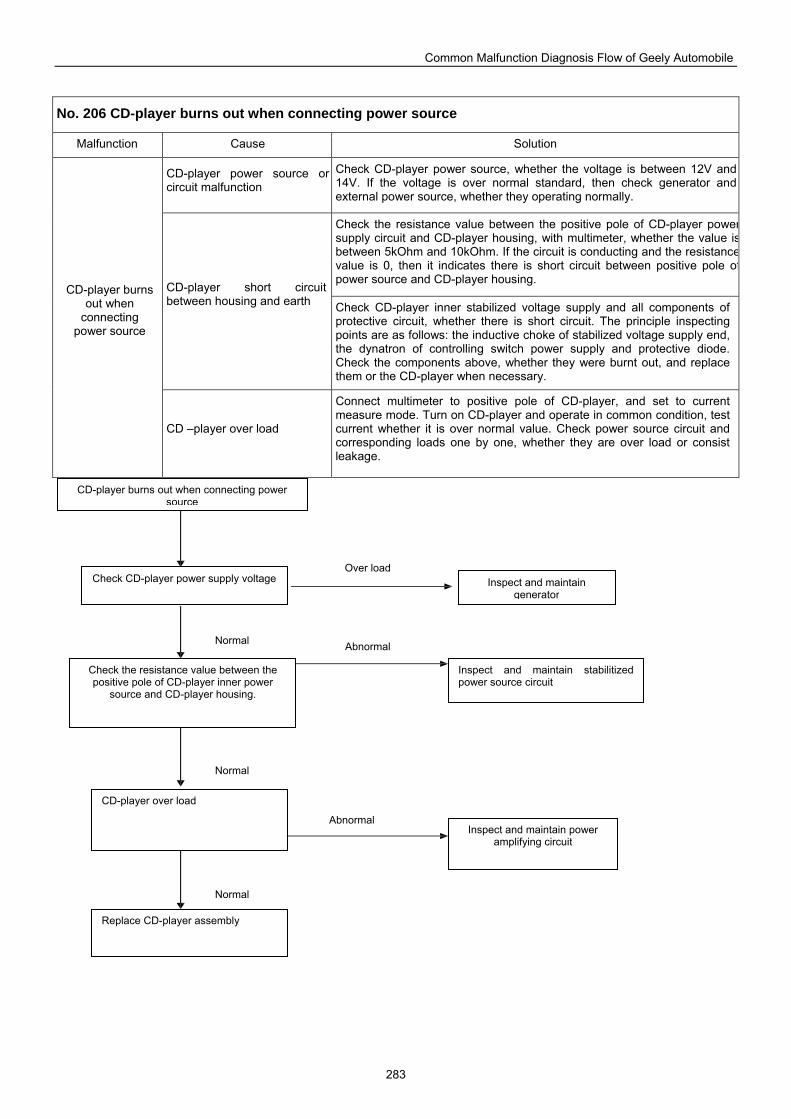
Common Malfunction Diagnosis Flow of Geely Automobile
283
No. 206 CD-player burns out when connecting power source
Malfunction Cause Solution
CD-player power source or circuit malfunction
Check CD-player power source, whether the voltage is between 12V and 14V. If the voltage is over normal standard, then check generator and external power source, whether they operating normally.
Check the resistance value between the positive pole of CD-player powersupply circuit and CD-player housing, with multimeter, whether the value isbetween 5kOhm and 10kOhm. If the circuit is conducting and the resistancevalue is 0, then it indicates there is short circuit between positive pole ofpower source and CD-player housing.
CD-player short circuit between housing and earth Check CD-player inner stabilized voltage supply and all components of
protective circuit, whether there is short circuit. The principle inspecting points are as follows: the inductive choke of stabilized voltage supply end, the dynatron of controlling switch power supply and protective diode. Check the components above, whether they were burnt out, and replace them or the CD-player when necessary.
CD-player burns out when
connecting power source
CD –player over load
Connect multimeter to positive pole of CD-player, and set to current measure mode. Turn on CD-player and operate in common condition, test current whether it is over normal value. Check power source circuit and corresponding loads one by one, whether they are over load or consist leakage.
Check CD-player power supply voltage Inspect and maintain generator
CD-player burns out when connecting power source
Check the resistance value between the positive pole of CD-player inner power
source and CD-player housing.
Inspect and maintain stabilitized power source circuit
CD-player over load
Replace CD-player assembly
Inspect and maintain power amplifying circuit
Normal
Over load
Abnormal
Abnormal
Normal
Normal
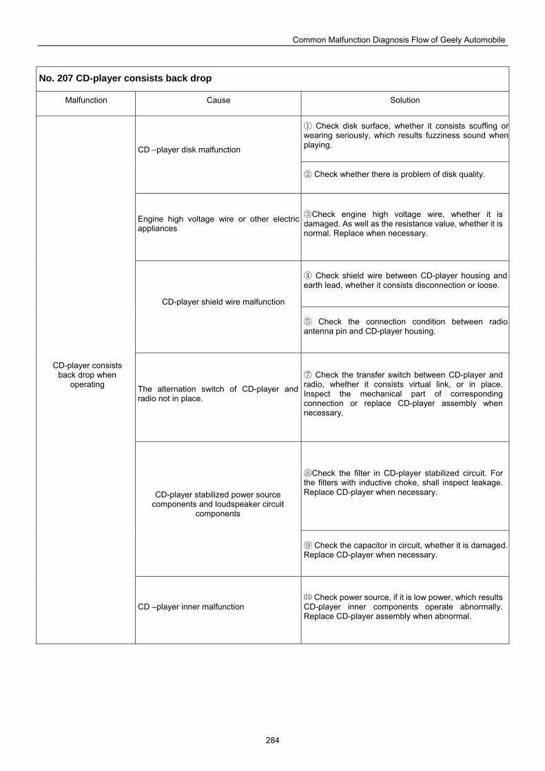
Common Malfunction Diagnosis Flow of Geely Automobile
284
No. 207 CD-player consists back drop
Malfunction Cause Solution
Check disk surface, whether it consists scuffing or ①wearing seriously, which results fuzziness sound when playing. CD –player disk malfunction
Check whether there is problem of disk quality.②
Engine high voltage wire or other electric appliances
Check ③ engine high voltage wire, whether it is damaged. As well as the resistance value, whether it is normal. Replace when necessary.
Check shield wire between CD④ -player housing and earth lead, whether it consists disconnection or loose.
CD-player shield wire malfunction
⑤ Check the connection condition between radio antenna pin and CD-player housing.
The alternation switch of CD-player and radio not in place.
Check the transfer switch between CD⑦ -player and radio, whether it consists virtual link, or in place. Inspect the mechanical part of corresponding connection or replace CD-player assembly when necessary.
Check the filter in CD⑧ -player stabilized circuit. For the filters with inductive choke, shall inspect leakage. Replace CD-player when necessary. CD-player stabilized power source
components and loudspeaker circuit components
Check the capacitor in circuit, whether it is damaged. ⑨Replace CD-player when necessary.
CD-player consists back drop when
operating
CD –player inner malfunction Check power source, if it is low power, which results ⑾
CD-player inner components operate abnormally. Replace CD-player assembly when abnormal.
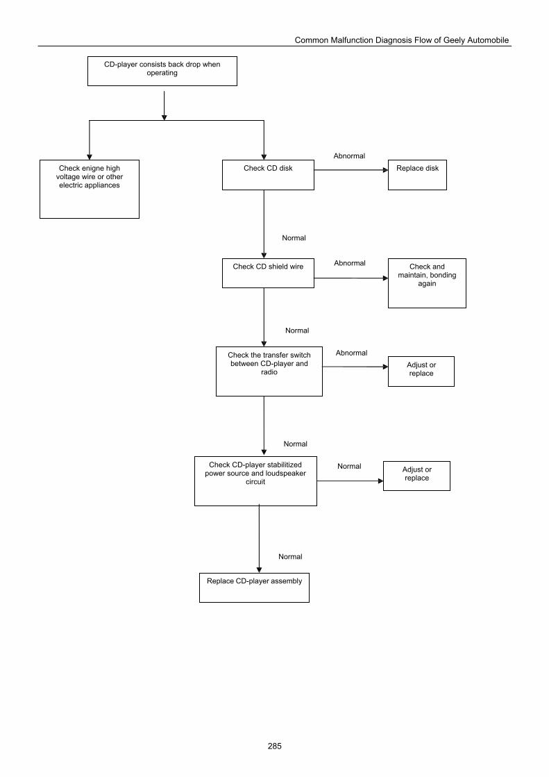
Common Malfunction Diagnosis Flow of Geely Automobile
285
Check CD shield wire
Check enigne high voltage wire or other electric appliances
CD-player consists back drop when operating
Check CD disk
Check the transfer switch between CD-player and
radio
Replace disk
Check and maintain, bonding
again
Adjust or replace
Check CD-player stabilitized power source and loudspeaker
circuit
Replace CD-player assembly
Adjust or replace
Normal
Abnormal
Abnormal
Abnormal
Normal
Normal
Normal
Normal
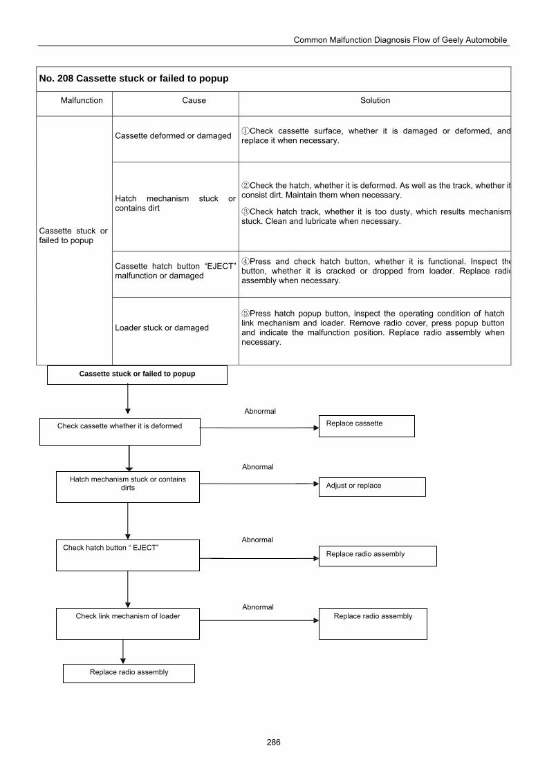
Common Malfunction Diagnosis Flow of Geely Automobile
286
No. 208 Cassette stuck or failed to popup
Malfunction Cause Solution
Cassette deformed or damaged Check c① assette surface, whether it is damaged or deformed, andreplace it when necessary.
Hatch mechanism stuck or contains dirt
Check the ② hatch, whether it is deformed. As well as the track, whether itconsist dirt. Maintain them when necessary.
Check hatch ③ track, whether it is too dusty, which results mechanismstuck. Clean and lubricate when necessary.
Cassette hatch button “EJECT” malfunction or damaged
Press and check hatch button, whether it is functional. Inspect the④button, whether it is cracked or dropped from loader. Replace radioassembly when necessary.
Cassette stuck or failed to popup
Loader stuck or damaged
Press hatch popup button, inspect the operating condition of hatch ⑤link mechanism and loader. Remove radio cover, press popup button and indicate the malfunction position. Replace radio assembly when necessary.
Replace radio assembly
Check link mechanism of loader
Check hatch button “ EJECT”
Check cassette whether it is deformed
Cassette stuck or failed to popup
Hatch mechanism stuck or contains dirts
Replace radio assembly
Adjust or replace
Replace cassette
Replace radio assembly
Abnormal
Abnormal
Abnormal
Abnormal
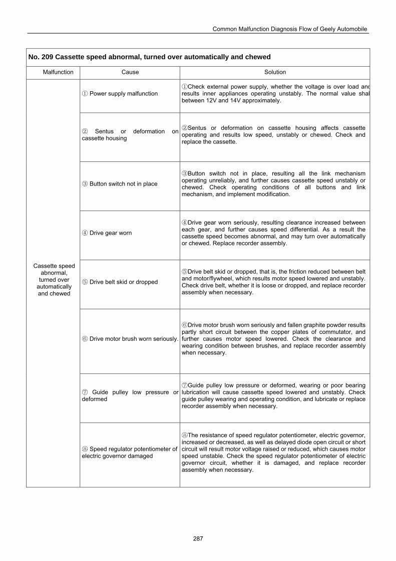
Common Malfunction Diagnosis Flow of Geely Automobile
287
No. 209 Cassette speed abnormal, turned over automatically and chewed
Malfunction Cause Solution
Power supply malfu① nction Check external power supply, whether the voltage is over load and①
results inner appliances operating unstably. The normal value shalbetween 12V and 14V approximately.
Sentus or deformation on ②cassette housing
Sentus or deformation on cassett② e housing affects cassette operating and results low speed, unstably or chewed. Check and replace the cassette.
Button switch not in place③
Button switch not in place, resulting all the link mechanism ③operating unreliably, and further causes cassette speed unstably or chewed. Check operating conditions of all buttons and link mechanism, and implement modification.
Drive gear worn④
Drive gear worn seriously, resulting clearance increased between ④each gear, and further causes speed differential. As a result the cassette speed becomes abnormal, and may turn over automatically or chewed. Replace recorder assembly.
Drive belt skid or dropped⑤
Drive belt skid or dropped, that is, the friction reduced between belt ⑤and motor/flywheel, which results motor speed lowered and unstably. Check drive belt, whether it is loose or dropped, and replace recorder assembly when necessary.
Drive motor brush worn seriously.⑥
Drive motor brush worn seriously and fallen graphite powder results ⑥partly short circuit between the copper plates of commutator, and further causes motor speed lowered. Check the clearance and wearing condition between brushes, and replace recorder assembly when necessary.
Guide pulley low pressure or ⑦deformed
Guide pulley low pressure or d⑦ eformed, wearing or poor bearing lubrication will cause cassette speed lowered and unstably. Check guide pulley wearing and operating condition, and lubricate or replace recorder assembly when necessary.
Cassette speed abnormal,
turned over automatically and chewed
Speed regulator potentiometer of ⑧electric governor damaged
The resistance of speed regulator potentiometer, electric governor, ⑧increased or decreased, as well as delayed diode open circuit or short circuit will result motor voltage raised or reduced, which causes motor speed unstable. Check the speed regulator potentiometer of electric governor circuit, whether it is damaged, and replace recorder assembly when necessary.
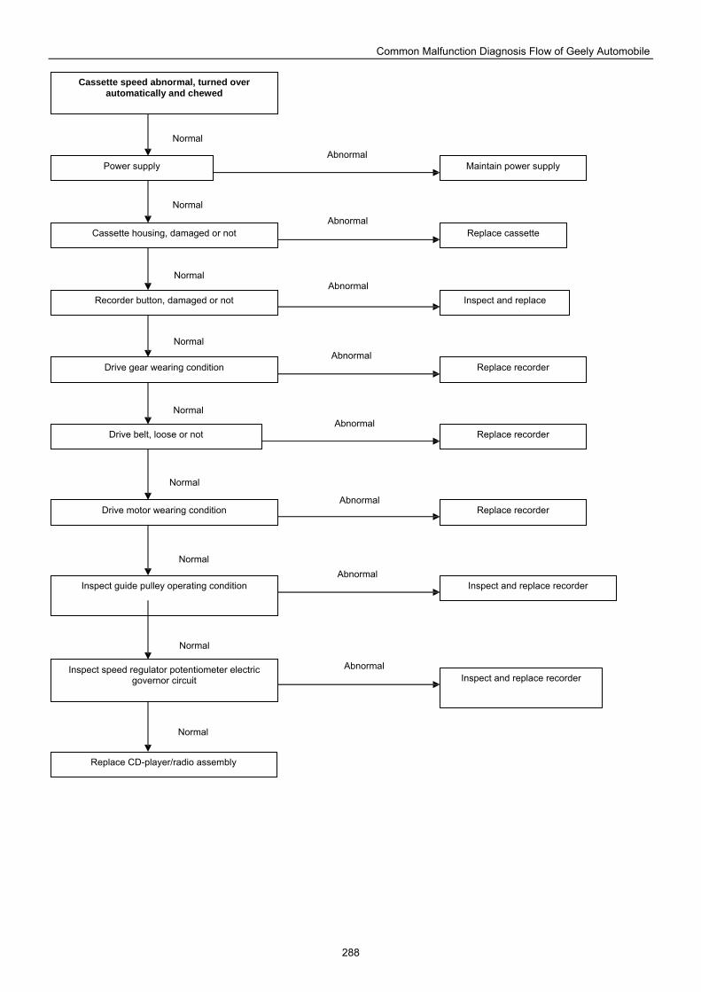
Common Malfunction Diagnosis Flow of Geely Automobile
288
Inspect and replace
Replace cassette
Maintain power supply
Replace CD-player/radio assembly
Inspect speed regulator potentiometer electric governor circuit
Inspect guide pulley operating condition
Drive motor wearing condition
Drive gear wearing condition
Recorder button, damaged or not
Cassette housing, damaged or not
Power supply
Cassette speed abnormal, turned over automatically and chewed
Drive belt, loose or not
Replace recorder
Replace recorder
Replace recorder
Inspect and replace recorder
Inspect and replace recorder
Abnormal
Abnormal
Abnormal
Abnormal
Abnormal
Abnormal
Abnormal
Abnormal
Normal
Normal
Normal
Normal
Normal
Normal
Normal
Normal
Normal
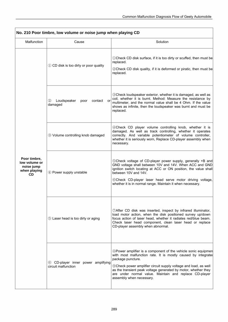
Common Malfunction Diagnosis Flow of Geely Automobile
289
No. 210 Poor timbre, low volume or noise jump when playing CD
Malfunction Cause Solution
CD disk is too dirty or poor quality①
Check CD disk surface, if it is too dirty or scuffed, then must be ①replaced.
Check CD disk quality, if it is deformed or piratic, then must be ②replaced.
Loudspeaker poor contact or ②damaged
Check loudspeaker ext③ erior, whether it is damaged, as well as coil, whether it is burnt. Method: Measure the resistance by multimeter, and the normal value shall be 4 Ohm. If the value shows as infinite, then the loudspeaker was burnt and must be replaced.
Volume controlli③ ng knob damaged
Check CD player volume controlling knob, whether it is ④damaged. As well as track controlling, whether it operates correctly. And variable potentiometer of volume controller, whether it is seriously worn, Replace CD-player assembly when necessary.
Power supply unstable④
Check voltage of CD⑤ -player power supply, generally +B and GND voltage shall between 10V and 14V. When ACC and GND ignition switch locating at ACC or ON position, the value shall between 10V and 14V.
Check CD⑥ -player laser head serve motor driving voltage, whether it is in normal range. Maintain it when necessary.
Laser head is too dirty or aging⑤
After CD disk was inserted, inspect by infrared illuminator, ⑦load motor action, when the disk positioned survey up/down focus action of laser head, whether it radiates red/blue beam. Check laser head component, clean laser head or replace CD-player assembly when abnormal.
Poor timbre, low volume or
noise jump when playing
CD
CD⑥ -player inner power amplifying circuit malfunction
Power amplifier is a component of the vehicle son⑧ ic equipmenwith most malfunction rate. It is mostly caused by integratedpackage puncture.
Check power amplifier circuit supply voltage and load, as well ⑨as the transient peak voltage generated by motor, whether they are under normal value. Maintain and replace CD-player assembly when necessary.
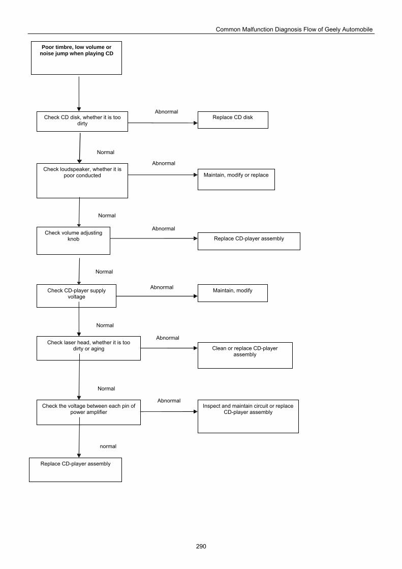
Common Malfunction Diagnosis Flow of Geely Automobile
290
Check laser head, whether it is too dirty or aging
Check volume adjusting knob
Check loudspeaker, whether it is poor conducted
Poor timbre, low volume or noise jump when playing CD
Check CD disk, whether it is too dirty
Check CD-player supply voltage
Check the voltage between each pin of power amplifier
Replace CD-player assembly
Inspect and maintain circuit or replace CD-player assembly
Clean or replace CD-player assembly
Maintain, modify
Replace CD-player assembly
Maintain, modify or replace
Replace CD disk
Normal
Abnormal
Abnormal
Abnormal
Abnormal
Abnormal
Abnormal
Normal
Normal
Normal
Normal
normal
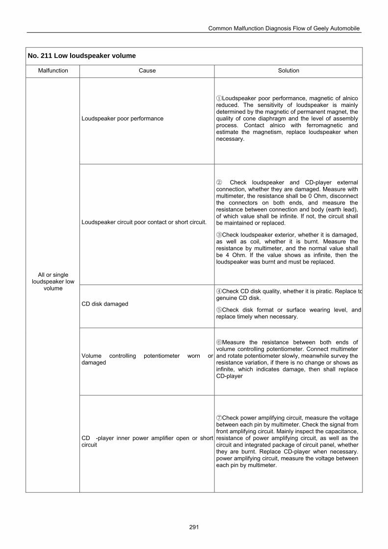
Common Malfunction Diagnosis Flow of Geely Automobile
291
No. 211 Low loudspeaker volume
Malfunction Cause Solution
Loudspeaker poor performance
Loudspeaker poor performance, magnetic of alnico ①reduced. The sensitivity of loudspeaker is mainly determined by the magnetic of permanent magnet, the quality of cone diaphragm and the level of assembly process. Contact alnico with ferromagnetic and estimate the magnetism, replace loudspeaker when necessary.
Loudspeaker circuit poor contact or short circuit.
② Check loudspeaker and CD-player external connection, whether they are damaged. Measure with multimeter, the resistance shall be 0 Ohm, disconnect the connectors on both ends, and measure the resistance between connection and body (earth lead), of which value shall be infinite. If not, the circuit shall be maintained or replaced.
Check loudspeaker exterior, whether it is damaged, ③as well as coil, whether it is burnt. Measure the resistance by multimeter, and the normal value shall be 4 Ohm. If the value shows as infinite, then the loudspeaker was burnt and must be replaced.
CD disk damaged
Check CD disk ④ quality, whether it is piratic. Replace togenuine CD disk.
Check disk format or surface wearing level, and ⑤replace timely when necessary.
Volume controlling potentiometer worn or damaged
Measure the resistance between both ends of ⑥volume controlling potentiometer. Connect multimeter and rotate potentiometer slowly, meanwhile survey the resistance variation, if there is no change or shows as infinite, which indicates damage, then shall replace CD-player
All or single loudspeaker low
volume
CD -player inner power amplifier open or short circuit
Check power amplifying circuit, measure the voltage ⑦between each pin by multimeter. Check the signal from front amplifying circuit. Mainly inspect the capacitance, resistance of power amplifying circuit, as well as the circuit and integrated package of circuit panel, whether they are burnt. Replace CD-player when necessary. power amplifying circuit, measure the voltage between each pin by multimeter.
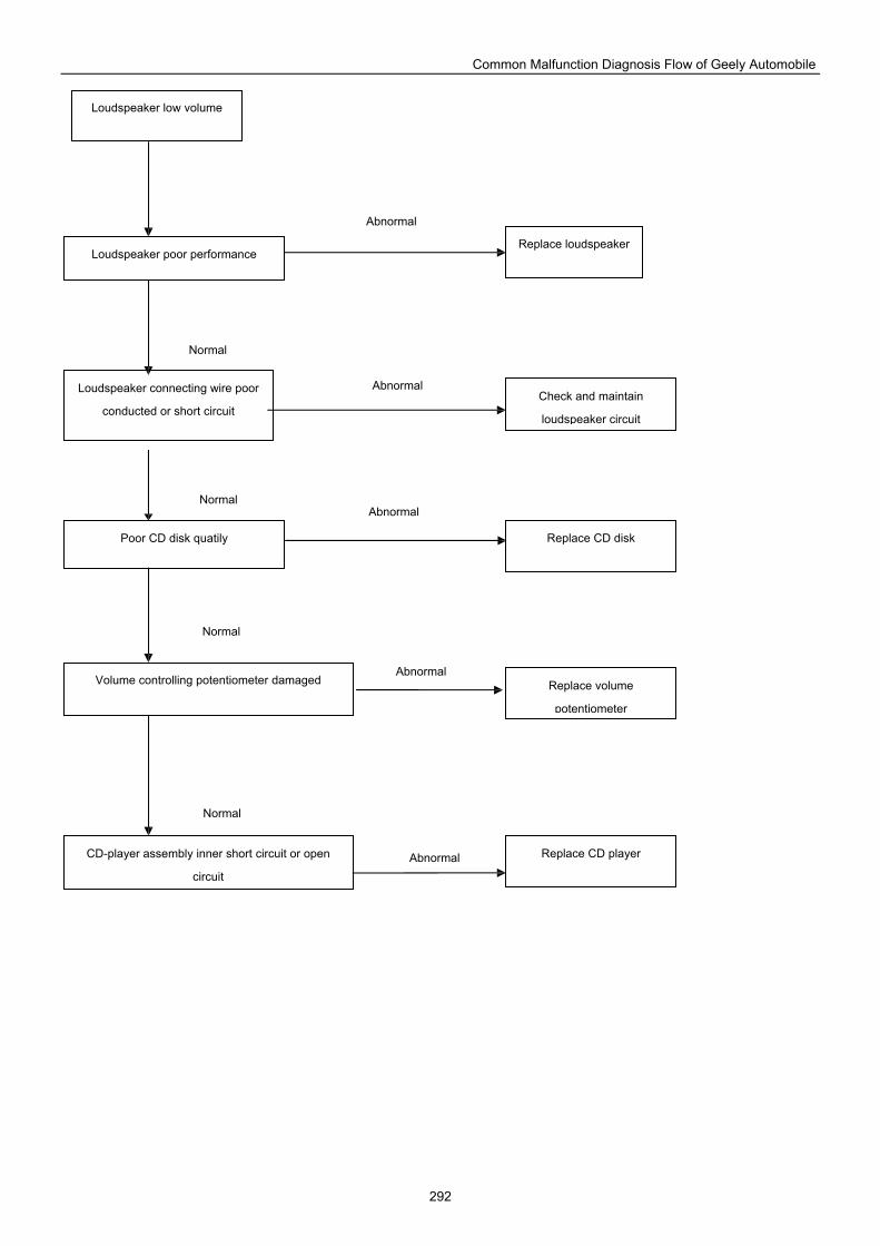
Common Malfunction Diagnosis Flow of Geely Automobile
292
Volume controlling potentiometer damaged
Poor CD disk quatily
Loudspeaker poor performance
Loudspeaker low volume
Loudspeaker connecting wire poor
conducted or short circuit
CD-player assembly inner short circuit or open
circuit
Replace volume
potentiometer
Check and maintain
loudspeaker circuit
Replace CD disk
Replace loudspeaker
Replace CD player
Normal
Abnormal
Abnormal
Abnormal
Abnormal
Abnormal
Normal
Normal
Normal
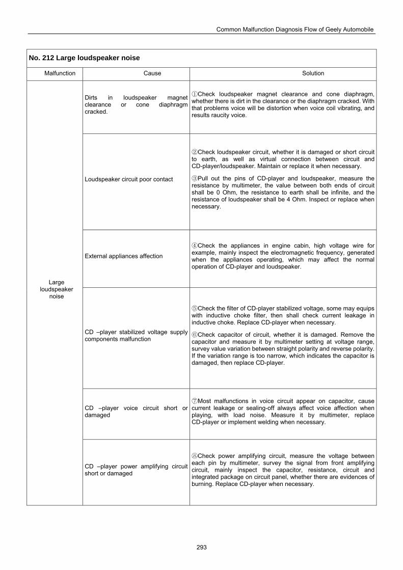
Common Malfunction Diagnosis Flow of Geely Automobile
293
No. 212 Large loudspeaker noise
Malfunction Cause Solution
Dirts in loudspeaker magnet clearance or cone diaphragm cracked.
Check loudspeaker magnet clearance and cone ① diaphragm, whether there is dirt in the clearance or the diaphragm cracked. With that problems voice will be distortion when voice coil vibrating, and results raucity voice.
Loudspeaker circuit poor contact
C② heck loudspeaker circuit, whether it is damaged or short circuit to earth, as well as virtual connection between circuit and CD-player/loudspeaker. Maintain or replace it when necessary.
Pull out the pins of CD③ -player and loudspeaker, measure the resistance by multimeter, the value between both ends of circuit shall be 0 Ohm, the resistance to earth shall be infinite, and the resistance of loudspeaker shall be 4 Ohm. Inspect or replace when necessary.
External appliances affection
Check the appliances i④ n engine cabin, high voltage wire for example, mainly inspect the electromagnetic frequency, generated when the appliances operating, which may affect the normal operation of CD-player and loudspeaker.
CD –player stabilized voltage supply components malfunction
Check the filter of CD⑤ -player stabilized voltage, some may equips with inductive choke filter, then shall check current leakage in inductive choke. Replace CD-player when necessary.
Check capacitor of circuit, whether it is damaged. Remove the ⑥capacitor and measure it by multimeter setting at voltage range, survey value variation between straight polarity and reverse polarity. If the variation range is too narrow, which indicates the capacitor is damaged, then replace CD-player.
CD –player voice circuit short or damaged
Most malfunctions ⑦ in voice circuit appear on capacitor, cause current leakage or sealing-off always affect voice affection when playing, with load noise. Measure it by multimeter, replace CD-player or implement welding when necessary.
Large loudspeaker
noise
CD –player power amplifying circuit short or damaged
Check power ⑧ amplifying circuit, measure the voltage between each pin by multimeter, survey the signal from front amplifying circuit, mainly inspect the capacitor, resistance, circuit and integrated package on circuit panel, whether there are evidences of burning. Replace CD-player when necessary.
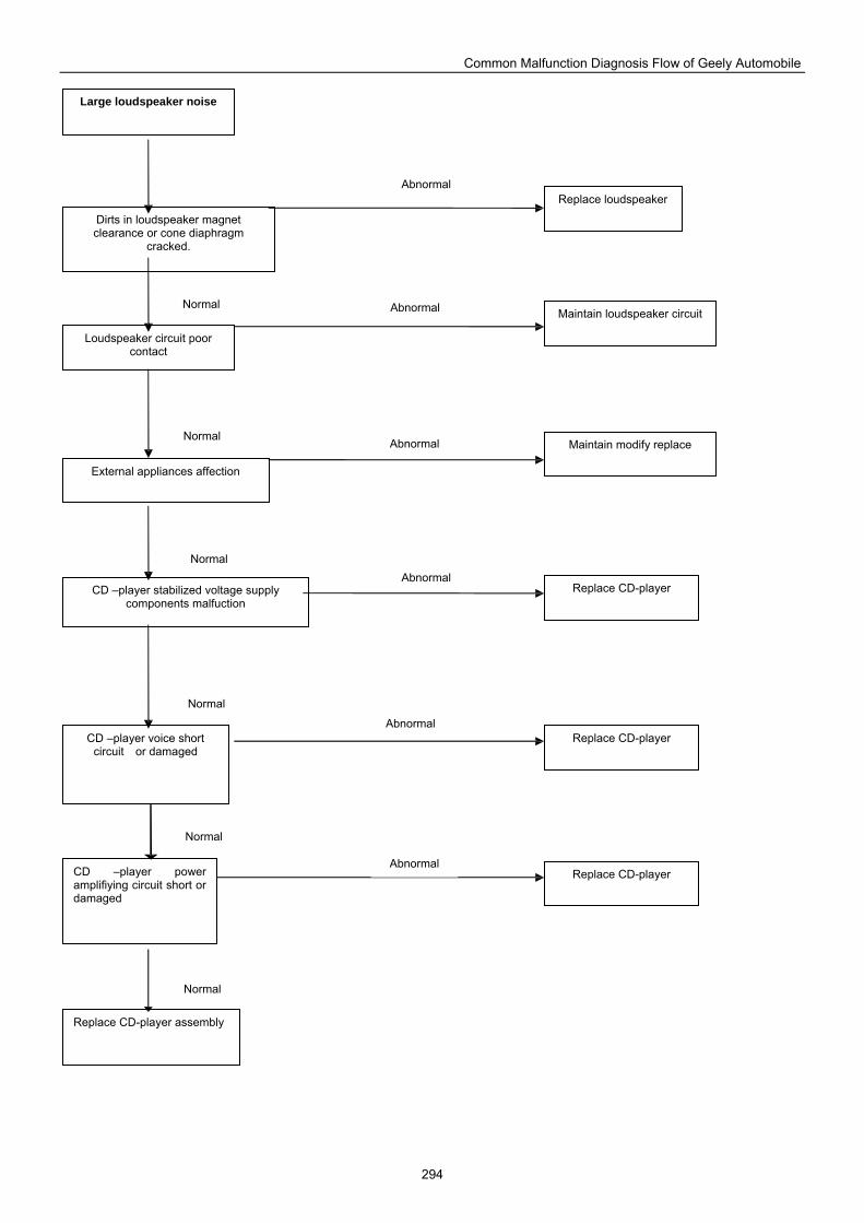
Common Malfunction Diagnosis Flow of Geely Automobile
294
Replace CD-player assembly
CD –player power amplifiying circuit short or damaged
CD –player voice short circuit or damaged
CD –player stabilized voltage supply components malfuction
External appliances affection
Loudspeaker circuit poor contact
Dirts in loudspeaker magnet clearance or cone diaphragm
cracked.
Large loudspeaker noise
Replace loudspeaker
Maintain loudspeaker circuit
Maintain modify replace
Replace CD-player
Replace CD-player
Replace CD-player
Normal
Abnormal
Abnormal
Abnormal
Abnormal
Abnormal
Abnormal
Normal
Normal
Normal
Normal
Normal
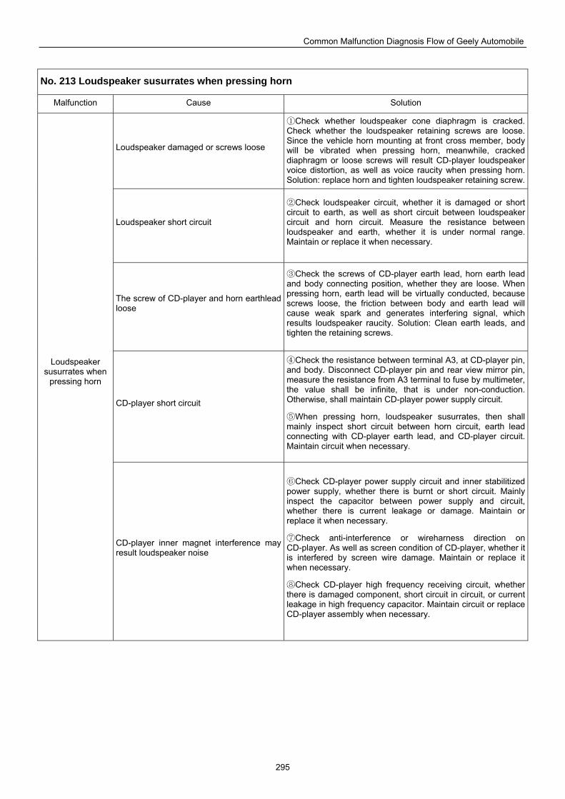
Common Malfunction Diagnosis Flow of Geely Automobile
295
No. 213 Loudspeaker susurrates when pressing horn
Malfunction Cause Solution
Loudspeaker damaged or screws loose
Check whether loudspeaker cone diaphragm is cracked. ①Check whether the loudspeaker retaining screws are loose. Since the vehicle horn mounting at front cross member, body will be vibrated when pressing horn, meanwhile, cracked diaphragm or loose screws will result CD-player loudspeaker voice distortion, as well as voice raucity when pressing horn. Solution: replace horn and tighten loudspeaker retaining screw.
Loudspeaker short circuit
Check loudspeaker circuit, whether it is damaged or short ②circuit to earth, as well as short circuit between loudspeaker circuit and horn circuit. Measure the resistance between loudspeaker and earth, whether it is under normal range. Maintain or replace it when necessary.
The screw of CD-player and horn earthlead loose
Check the screws of CD③ -player earth lead, horn earth lead and body connecting position, whether they are loose. When pressing horn, earth lead will be virtually conducted, because screws loose, the friction between body and earth lead will cause weak spark and generates interfering signal, which results loudspeaker raucity. Solution: Clean earth leads, and tighten the retaining screws.
CD-player short circuit
Check the resistance between terminal A3, at CD④ -player pin, and body. Disconnect CD-player pin and rear view mirror pin, measure the resistance from A3 terminal to fuse by multimeter, the value shall be infinite, that is under non-conduction. Otherwise, shall maintain CD-player power supply circuit.
When pressing horn, loudspeaker susurrates, then ⑤ shall mainly inspect short circuit between horn circuit, earth lead connecting with CD-player earth lead, and CD-player circuit. Maintain circuit when necessary.
Loudspeaker susurrates when
pressing horn
CD-player inner magnet interference may result loudspeaker noise
Check CD⑥ -player power supply circuit and inner stabilitized power supply, whether there is burnt or short circuit. Mainly inspect the capacitor between power supply and circuit, whether there is current leakage or damage. Maintain or replace it when necessary.
Check anti⑦ -interference or wireharness direction on CD-player. As well as screen condition of CD-player, whether it is interfered by screen wire damage. Maintain or replace it when necessary.
Check CD⑧ -player high frequency receiving circuit, whether there is damaged component, short circuit in circuit, or current leakage in high frequency capacitor. Maintain circuit or replace CD-player assembly when necessary.
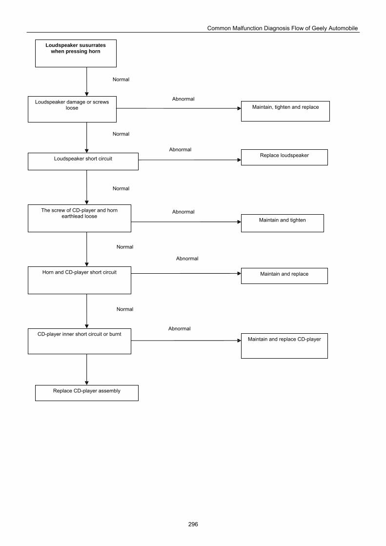
Common Malfunction Diagnosis Flow of Geely Automobile
296
Replace loudspeaker
Loudspeaker damage or screws loose
Loudspeaker susurrates when pressing horn
Loudspeaker short circuit
The screw of CD-player and horn earthlead loose
Horn and CD-player short circuit
CD-player inner short circuit or burnt
Replace CD-player assembly
Maintain and replace CD-player
Maintain and replace
Maintain and tighten
Maintain, tighten and replace
Abnormal
Abnormal
Abnormal
Abnormal
Abnormal
Normal
Normal
Normal
Normal
Normal
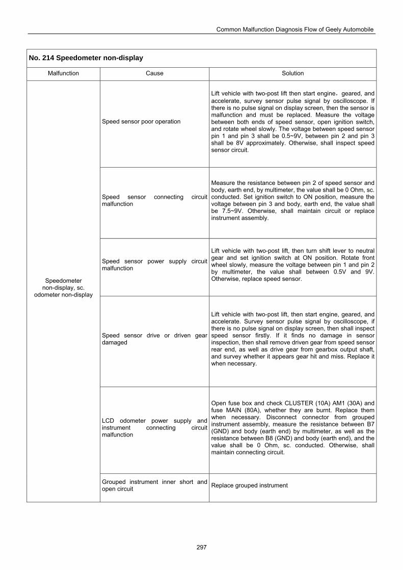
Common Malfunction Diagnosis Flow of Geely Automobile
297
No. 214 Speedometer non-display
Malfunction Cause Solution
Speed sensor poor operation
Lift vehicle with two-post lift then start engine,geared, and accelerate, survey sensor pulse signal by oscilloscope. If there is no pulse signal on display screen, then the sensor is malfunction and must be replaced. Measure the voltage between both ends of speed sensor, open ignition switch, and rotate wheel slowly. The voltage between speed sensor pin 1 and pin 3 shall be 0.5~9V, between pin 2 and pin 3 shall be 8V approximately. Otherwise, shall inspect speed sensor circuit.
Speed sensor connecting circuit malfunction
Measure the resistance between pin 2 of speed sensor and body, earth end, by multimeter, the value shall be 0 Ohm, sc. conducted. Set ignition switch to ON position, measure the voltage between pin 3 and body, earth end, the value shall be 7.5~9V. Otherwise, shall maintain circuit or replace instrument assembly.
Speed sensor power supply circuit malfunction
Lift vehicle with two-post lift, then turn shift lever to neutral gear and set ignition switch at ON position. Rotate front wheel slowly, measure the voltage between pin 1 and pin 2 by multimeter, the value shall between 0.5V and 9V. Otherwise, replace speed sensor.
Speed sensor drive or driven gear damaged
Lift vehicle with two-post lift, then start engine, geared, and accelerate. Survey sensor pulse signal by oscilloscope, if there is no pulse signal on display screen, then shall inspect speed sensor firstly. If it finds no damage in sensor inspection, then shall remove driven gear from speed sensor rear end, as well as drive gear from gearbox output shaft, and survey whether it appears gear hit and miss. Replace it when necessary.
LCD odometer power supply and instrument connecting circuit malfunction
Open fuse box and check CLUSTER (10A) AM1 (30A) and fuse MAIN (80A), whether they are burnt. Replace them when necessary. Disconnect connector from grouped instrument assembly, measure the resistance between B7 (GND) and body (earth end) by multimeter, as well as the resistance between B8 (GND) and body (earth end), and the value shall be 0 Ohm, sc. conducted. Otherwise, shall maintain connecting circuit.
Speedometer non-display, sc.
odometer non-display
Grouped instrument inner short and open circuit Replace grouped instrument
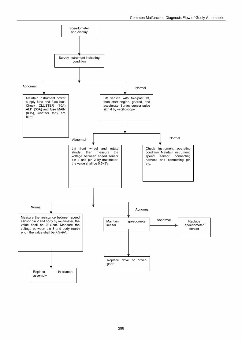
Common Malfunction Diagnosis Flow of Geely Automobile
298
Maintain speedometer sensor
Lift front wheel and rotate slowly, then measure the voltage between speed sensor pin 1 and pin 2 by multimeter, the value shall be 0.5~9V.
Replace drive or driven gear
Lift vehicle with two-post lift, then start engine, geared, and accelerate. Survey sensor pulse signal by oscilloscope
Survey instrument indicating condition
Speedometer non-display
Check instrument operating condition. Maintain instrument, speed sensor connecting harness and connecting pin etc.
Maintain instrument power supply fuse and fuse box. Check CLUSTER (10A) AM1 (30A) and fuse MAIN (80A), whether they are burnt.
Measure the resistance between speed sensor pin 2 and body by multimeter, the value shall be 0 Ohm. Measure the voltage between pin 3 and body (earth end), the value shall be 7.5~9V.
Replace instrument assembly
Replace speedometer
sensor
Normal Abnormal
Abnormal
Abnormal
Abnormal
Normal
Normal
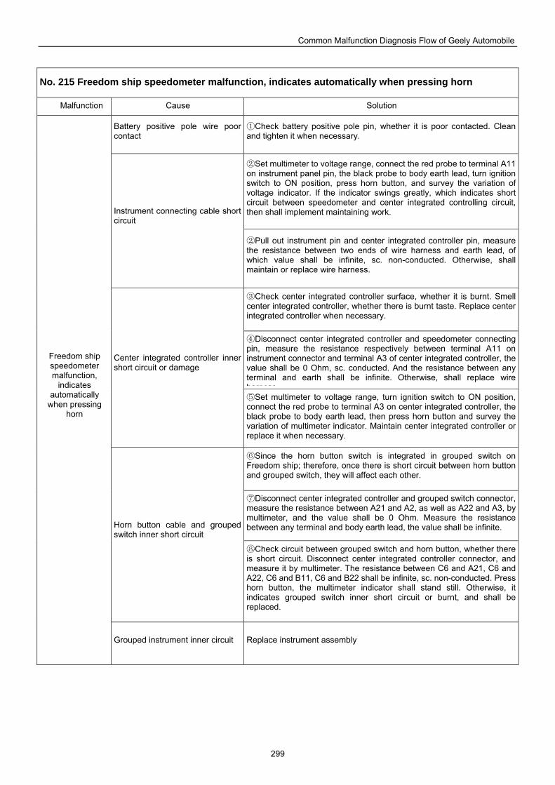
Common Malfunction Diagnosis Flow of Geely Automobile
299
No. 215 Freedom ship speedometer malfunction, indicates automatically when pressing horn
Malfunction Cause Solution
Battery positive pole wire poor contact
Check battery positive pole pin, whether it is poor contacted. Clean ①and tighten it when necessary.
Set multimeter to voltage range, connect the red probe to terminal A11 ②on instrument panel pin, the black probe to body earth lead, turn ignition switch to ON position, press horn button, and survey the variation of voltage indicator. If the indicator swings greatly, which indicates short circuit between speedometer and center integrated controlling circuit, then shall implement maintaining work. Instrument connecting cable short
circuit
Pull out instrument pin and center integrated controller pin, measure ②the resistance between two ends of wire harness and earth lead, of which value shall be infinite, sc. non-conducted. Otherwise, shall maintain or replace wire harness.
Check center integrated controller surface, whether it ③ is burnt. Smell center integrated controller, whether there is burnt taste. Replace center integrated controller when necessary.
Disconnect center integrated controller and speedometer connecting ④pin, measure the resistance respectively between terminal A11 on instrument connector and terminal A3 of center integrated controller, the value shall be 0 Ohm, sc. conducted. And the resistance between any terminal and earth shall be infinite. Otherwise, shall replace wire harness
Center integrated controller inner short circuit or damage
Set multimeter to voltag⑤ e range, turn ignition switch to ON position, connect the red probe to terminal A3 on center integrated controller, the black probe to body earth lead, then press horn button and survey the variation of multimeter indicator. Maintain center integrated controller or replace it when necessary.
Since the horn button switch is integrated in grouped switch on ⑥Freedom ship; therefore, once there is short circuit between horn button and grouped switch, they will affect each other.
Disconnect center integrated controller and grouped switch connec⑦ tor, measure the resistance between A21 and A2, as well as A22 and A3, by multimeter, and the value shall be 0 Ohm. Measure the resistance between any terminal and body earth lead, the value shall be infinite. Horn button cable and grouped
switch inner short circuit
Check circuit between grouped switch and h⑧ orn button, whether there is short circuit. Disconnect center integrated controller connector, and measure it by multimeter. The resistance between C6 and A21, C6 and A22, C6 and B11, C6 and B22 shall be infinite, sc. non-conducted. Press horn button, the multimeter indicator shall stand still. Otherwise, it indicates grouped switch inner short circuit or burnt, and shall be replaced.
Freedom ship speedometer malfunction,
indicates automatically
when pressing horn
Grouped instrument inner circuit Replace instrument assembly
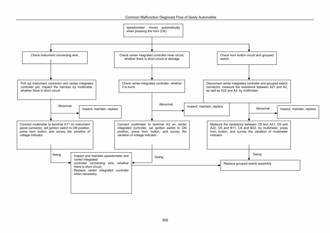
Common Malfunction Diagnosis Flow of Geely Automobile
300
Pull out instrument connector and center integrated controller pin; inspect the harness by multimeter, whether there is short circuit.
Check center integrated controller inner circuit, whether there is short circuit or damage
Check instrument connecting wire. Check horn button circuit and grouped switch.
Check center integrated controller, whether it is burnt.
Connect multimeter to terminal A11 on instrument panel connector, set ignition switch to ON position, press horn button, and survey the variation of voltage indicator.
Inspect, maintain, replace
Connect multimeter to terminal A3 on center integrated controller, set ignition switch to ON position, press horn button, and survey the variation of voltage indicator.
Measure the resistance between C6 and A21, C6 and A22, C6 and B11, C6 and B22, by multimeter, press horn button, and survey the variation of multimeter indicator.
Inspect and maintain speedometer and center integrated controller connecting wire, whether there is short circuit. Replace center integrated controller when necessary.
Inspect, maintain, replace
Disconnect center integrated controller and grouped switch connector, measure the resistance between A21 and A2, as well as A22 and A3, by multimeter.
Replace grouped switch assembly
Inspect, maintain, replace Abnormal Abnormal
Abnormal
Swing Swing
Swing
speedometer moves automatically when pressing the horn (CK)
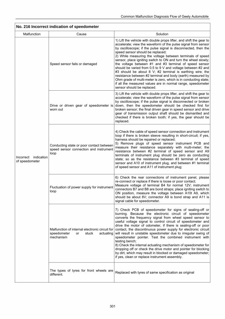
Common Malfunction Diagnosis Flow of Geely Automobile
301
No. 216 Incorrect indication of speedometer
Malfunction Cause Solution
Speed sensor fails or damaged
1) Lift the vehicle with double props lifter, and shift the gear to accelerate; view the waveform of the pulse signal from sensor by oscilloscope; if the pulse signal is disconnected, then the speed sensor should be replaced; 2) While measuring the voltage between terminals of speed sensor, place igniting switch to ON and turn the wheel slowly; the voltage between #1 and #3 terminal of speed sensor should be varied from 0.5 to 9 V and voltage between #2 and #3 should be about 8 V; #2 terminal is earthing wire; the resistance between #2 terminal and body (earth) measured by Ohm grade of multi-meter is zero, which is in conducting state; if all the measured values are in normal range, speedometer sensor should be replaced.
Drive or driven gear of speedometer is worn out
3) Lift the vehicle with double props lifter, and shift the gear to accelerate; view the waveform of the pulse signal from sensor by oscilloscope; if the pulse signal is disconnected or broken down, then the speedometer should be checked first for broken sensor; the final driven gear in speed sensor and drive gear of transmission output shaft should be dismantled and checked if there is broken tooth; if yes, the gear should be replaced.
Conducting state or poor contact between speed sensor connection and instrument loop
4) Check the cable of speed sensor connection and instrument loop if there is broken sleeve resulting in short-circuit; if yes, harness should be repaired or replaced; 5) Remove plugs of speed sensor instrument PCB and measure their resistance separately with multi-meter; the resistance between #2 terminal of speed sensor and A9 terminals of instrument plug should be zero as conducting state; so as the resistance between #3 terminal of speed sensor and A10 of instrument plug, and between #1 terminal of speed sensor and A11 of instrument plug;
Fluctuation of power supply for instrument loop
6) Check the rear connections of instrument panel, please re-connect or replace if there is loose or poor contact; Measure voltage of terminal B4 for normal 12V; instrument connectors B7 and B8 are bond straps; place igniting switch to ON position, measure the voltage between A10t A9, which should be about 8V; connector A9 is bond strap and A11 is signal cable for speedometer.
Malfunction of internal electronic circuit for speedometer or stuck actuating mechanism
7) Check PCB of speedometer for signs of sealing-off or burning. Because the electronic circuit of speedometer converts the frequency signal from wheel speed sensor to useful voltage signal to control circuit of speedometer and drive the motor of odometer, if there is sealing-off or poor contact, the discontinuous power supply for electronic circuit will result in unstable speedometer due to irregular swing of speedometer pointer. Test the combined instrument with testing bench; 8) Check the internal actuating mechanism of speedometer for dropping off or check the drive motor and pointer for blocking by dirt, which may result in blocked or damaged speedometer; if yes, clean or replace instrument assembly.
Incorrect indication of speedometer
The types of tyres for front wheels are different. Replaced with tyres of same specification as original
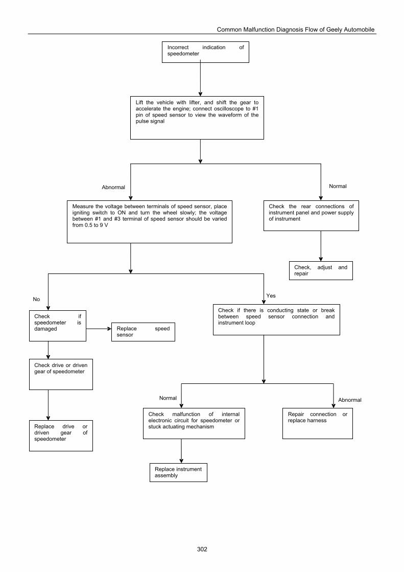
Common Malfunction Diagnosis Flow of Geely Automobile
302
Lift the vehicle with lifter, and shift the gear to accelerate the engine; connect oscilloscope to #1 pin of speed sensor to view the waveform of the pulse signal
Incorrect indication of speedometer
Measure the voltage between terminals of speed sensor, place igniting switch to ON and turn the wheel slowly; the voltage between #1 and #3 terminal of speed sensor should be varied from 0.5 to 9 V
Check the rear connections of instrument panel and power supply of instrument
Check, adjust and repair
Check if there is conducting state or break between speed sensor connection and instrument loop
Repair connection or replace harness
Check malfunction of internal electronic circuit for speedometer or stuck actuating mechanism
Replace instrument assembly
Check if speedometer is damaged Replace speed
sensor
Replace drive or driven gear of speedometer
Check drive or driven gear of speedometer
Abnormal Normal
No Yes
Normal Abnormal
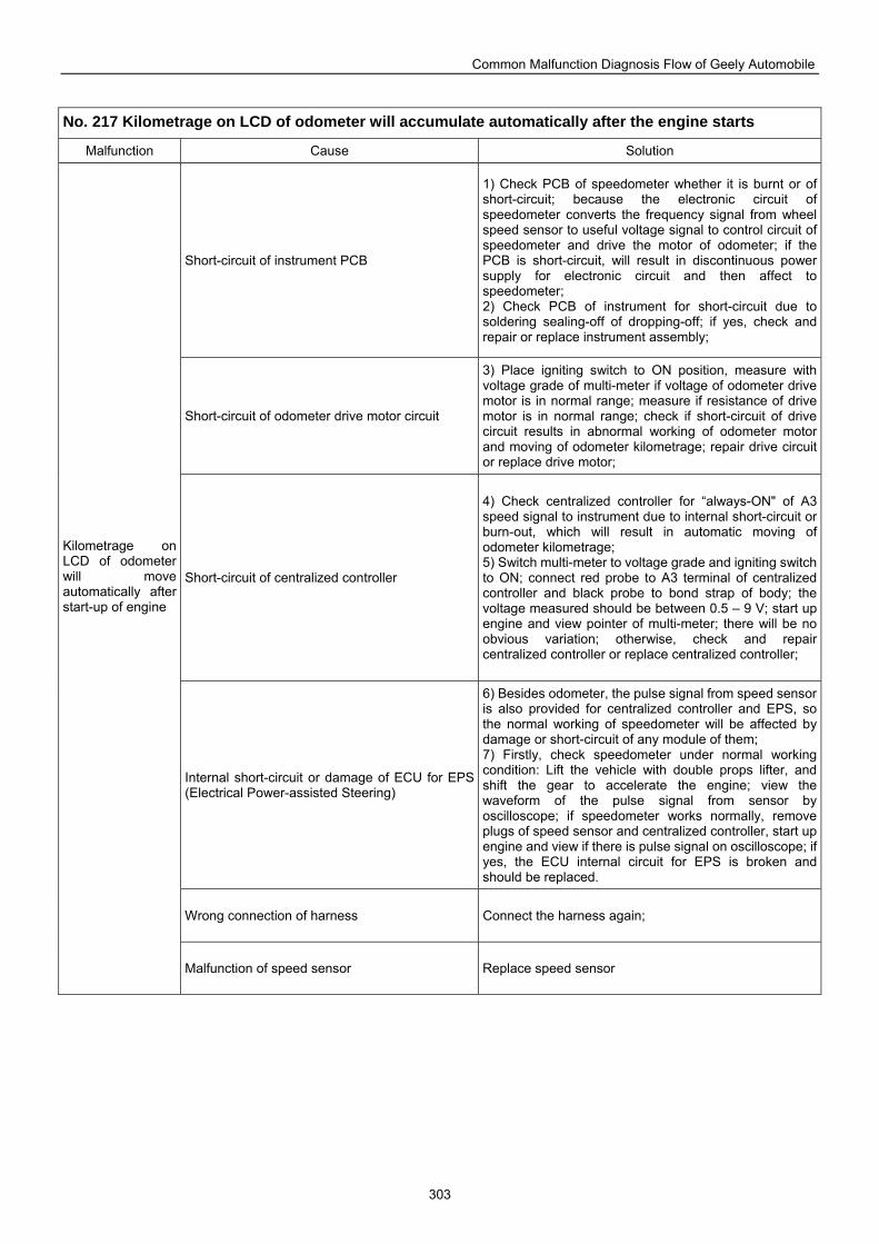
Common Malfunction Diagnosis Flow of Geely Automobile
303
No. 217 Kilometrage on LCD of odometer will accumulate automatically after the engine starts
Malfunction Cause Solution
Short-circuit of instrument PCB
1) Check PCB of speedometer whether it is burnt or of short-circuit; because the electronic circuit of speedometer converts the frequency signal from wheel speed sensor to useful voltage signal to control circuit of speedometer and drive the motor of odometer; if the PCB is short-circuit, will result in discontinuous power supply for electronic circuit and then affect to speedometer; 2) Check PCB of instrument for short-circuit due to soldering sealing-off of dropping-off; if yes, check and repair or replace instrument assembly;
Short-circuit of odometer drive motor circuit
3) Place igniting switch to ON position, measure with voltage grade of multi-meter if voltage of odometer drive motor is in normal range; measure if resistance of drive motor is in normal range; check if short-circuit of drive circuit results in abnormal working of odometer motor and moving of odometer kilometrage; repair drive circuit or replace drive motor;
Short-circuit of centralized controller
4) Check centralized controller for “always-ON" of A3 speed signal to instrument due to internal short-circuit or burn-out, which will result in automatic moving of odometer kilometrage; 5) Switch multi-meter to voltage grade and igniting switch to ON; connect red probe to A3 terminal of centralized controller and black probe to bond strap of body; the voltage measured should be between 0.5 – 9 V; start up engine and view pointer of multi-meter; there will be no obvious variation; otherwise, check and repair centralized controller or replace centralized controller;
Internal short-circuit or damage of ECU for EPS (Electrical Power-assisted Steering)
6) Besides odometer, the pulse signal from speed sensor is also provided for centralized controller and EPS, so the normal working of speedometer will be affected by damage or short-circuit of any module of them; 7) Firstly, check speedometer under normal working condition: Lift the vehicle with double props lifter, and shift the gear to accelerate the engine; view the waveform of the pulse signal from sensor by oscilloscope; if speedometer works normally, remove plugs of speed sensor and centralized controller, start up engine and view if there is pulse signal on oscilloscope; if yes, the ECU internal circuit for EPS is broken and should be replaced.
Wrong connection of harness Connect the harness again;
Kilometrage on LCD of odometer will move automatically after start-up of engine
Malfunction of speed sensor Replace speed sensor
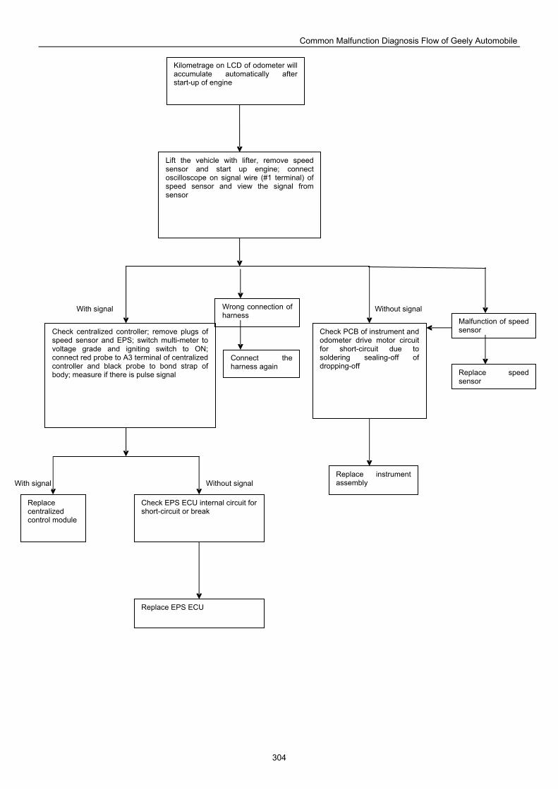
Common Malfunction Diagnosis Flow of Geely Automobile
304
Replace centralized control module
Kilometrage on LCD of odometer will accumulate automatically after start-up of engine
Lift the vehicle with lifter, remove speed sensor and start up engine; connect oscilloscope on signal wire (#1 terminal) of speed sensor and view the signal from sensor
Check centralized controller; remove plugs of speed sensor and EPS; switch multi-meter to voltage grade and igniting switch to ON; connect red probe to A3 terminal of centralized controller and black probe to bond strap of body; measure if there is pulse signal
Check PCB of instrument and odometer drive motor circuit for short-circuit due to soldering sealing-off of dropping-off
Replace instrument assembly
Check EPS ECU internal circuit for short-circuit or break
Replace EPS ECU
Wrong connection of harness
Malfunction of speed sensor
Connect the harness again
Replace speed sensor
Without signal
Without signal
With signal
With signal
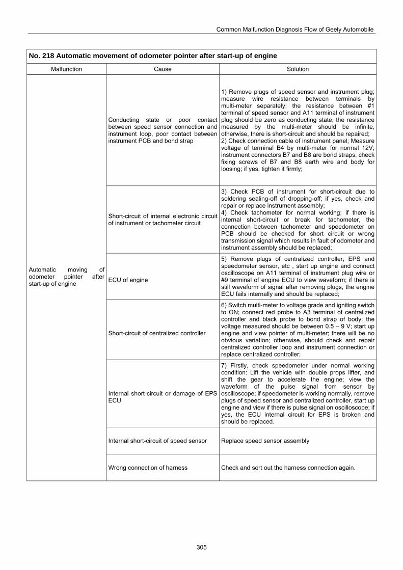
Common Malfunction Diagnosis Flow of Geely Automobile
305
No. 218 Automatic movement of odometer pointer after start-up of engine
Malfunction Cause Solution
Conducting state or poor contact between speed sensor connection and instrument loop, poor contact between instrument PCB and bond strap
1) Remove plugs of speed sensor and instrument plug; measure wire resistance between terminals by multi-meter separately; the resistance between #1 terminal of speed sensor and A11 terminal of instrument plug should be zero as conducting state; the resistance measured by the multi-meter should be infinite, otherwise, there is short-circuit and should be repaired; 2) Check connection cable of instrument panel; Measure voltage of terminal B4 by multi-meter for normal 12V; instrument connectors B7 and B8 are bond straps; check fixing screws of B7 and B8 earth wire and body for loosing; if yes, tighten it firmly;
Short-circuit of internal electronic circuit of instrument or tachometer circuit
3) Check PCB of instrument for short-circuit due to soldering sealing-off of dropping-off; if yes, check and repair or replace instrument assembly; 4) Check tachometer for normal working; if there is internal short-circuit or break for tachometer, the connection between tachometer and speedometer on PCB should be checked for short circuit or wrong transmission signal which results in fault of odometer and instrument assembly should be replaced;
ECU of engine
5) Remove plugs of centralized controller, EPS and speedometer sensor, etc , start up engine and connect oscilloscope on A11 terminal of instrument plug wire or #9 terminal of engine ECU to view waveform; if there is still waveform of signal after removing plugs, the engine ECU fails internally and should be replaced;
Short-circuit of centralized controller
6) Switch multi-meter to voltage grade and igniting switch to ON; connect red probe to A3 terminal of centralized controller and black probe to bond strap of body; the voltage measured should be between 0.5 – 9 V; start up engine and view pointer of multi-meter; there will be no obvious variation; otherwise, should check and repair centralized controller loop and instrument connection or replace centralized controller;
Internal short-circuit or damage of EPS ECU
7) Firstly, check speedometer under normal working condition: Lift the vehicle with double props lifter, and shift the gear to accelerate the engine; view the waveform of the pulse signal from sensor by oscilloscope; if speedometer is working normally, remove plugs of speed sensor and centralized controller, start up engine and view if there is pulse signal on oscilloscope; if yes, the ECU internal circuit for EPS is broken and should be replaced.
Internal short-circuit of speed sensor Replace speed sensor assembly
Automatic moving of odometer pointer after start-up of engine
Wrong connection of harness Check and sort out the harness connection again.
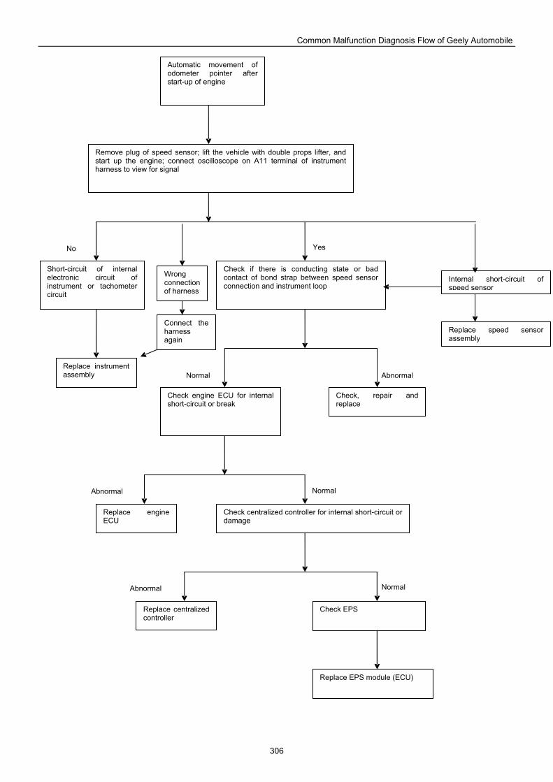
Common Malfunction Diagnosis Flow of Geely Automobile
306
Short-circuit of internal electronic circuit of instrument or tachometer circuit
Check if there is conducting state or bad contact of bond strap between speed sensor connection and instrument loop
Automatic movement of odometer pointer after start-up of engine
Remove plug of speed sensor; lift the vehicle with double props lifter, and start up the engine; connect oscilloscope on A11 terminal of instrument harness to view for signal
Check engine ECU for internal short-circuit or break
Check, repair and replace
Replace engine ECU
Check centralized controller for internal short-circuit or damage
Replace instrument assembly
Replace centralized controller
Check EPS
Replace EPS module (ECU)
Internal short-circuit of speed sensor
Replace speed sensor assembly
Connect the harness again
Wrong connection of harness
Yes
Normal Abnormal
Normal
Normal
Abnormal
Abnormal
No
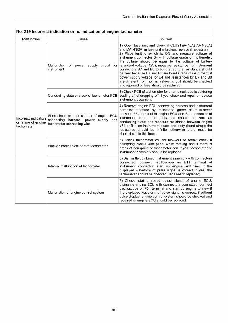
Common Malfunction Diagnosis Flow of Geely Automobile
307
No. 219 Incorrect indication or no indication of engine tachometer
Malfunction Cause Solution
Malfunction of power supply circuit for instrument
1) Open fuse unit and check if CLUSTER(10A) AM1(30A) and MAIN(80A) in fuse unit is broken; replace if necessary; 2) Place igniting switch to ON and measure voltage of instrument connector B4 with voltage grade of multi-meter; the voltage should be equal to the voltage of battery (standard voltage: 12V); measure resistance of instrument connectors B7 and B8 to bond strap; the resistance should be zero because B7 and B8 are bond straps of instrument; if power supply voltage for B4 and resistances for B7 and B8 are different from normal values, circuit should be checked and repaired or fuse should be replaced;
Conducting state or break of tachometer PCB 3) Check PCB of tachometer for short-circuit due to soldering sealing-off of dropping-off; if yes, check and repair or replace instrument assembly;
Short-circuit or poor contact of engine ECU connecting harness, power supply and tachometer connecting wire
4) Remove engine ECU connecting harness and instrument harness; measure by resistance grade of multi-meter between #54 terminal or engine ECU and B11 connector of instrument board; the resistance should be zero as conducting state; and measure resistance between engine #54 or B11 on instrument board and body (bond strap); the resistance should be infinite, otherwise there must be short-circuit in this loop.
Blocked mechanical part of tachometer
5) Check tachometer coil for blow-out or break; check if hairspring blocks with panel while rotating and if there is break of hairspring of tachometer coil; if yes, tachometer or instrument assembly should be replaced;
Internal malfunction of tachometer
6) Dismantle combined instrument assembly with connectors connected; connect oscilloscope on B11 terminal of instrument connector; start up engine and view if the displayed waveform of pulse signal is correct; if yes, the tachometer should be checked, repaired or replaced;
Incorrect indication or failure of engine tachometer
Malfunction of engine control system
7) Check rotating speed output signal of engine ECU; dismantle engine ECU with connectors connected; connect oscilloscope on #54 terminal and start up engine to view if the displayed waveform of pulse signal is correct; if without pulse display, engine control system should be checked and repaired or engine ECU should be replaced;
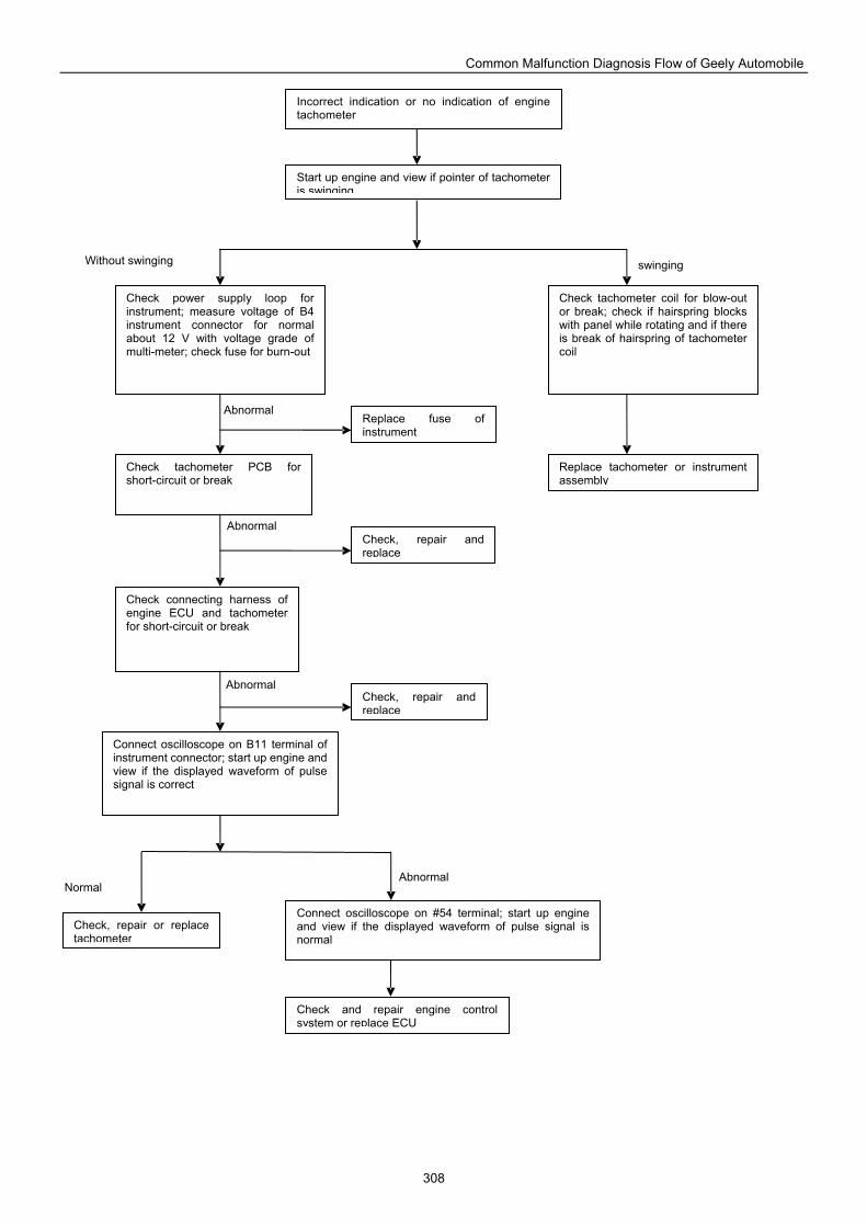
Common Malfunction Diagnosis Flow of Geely Automobile
308
Replace fuse of instrument
Connect oscilloscope on #54 terminal; start up engine and view if the displayed waveform of pulse signal is normal
Check tachometer PCB for short-circuit or break
Check connecting harness of engine ECU and tachometer for short-circuit or break
Check, repair and replace
Connect oscilloscope on B11 terminal of instrument connector; start up engine and view if the displayed waveform of pulse signal is correct
Check, repair and replace
Check power supply loop for instrument; measure voltage of B4 instrument connector for normal about 12 V with voltage grade of multi-meter; check fuse for burn-out
Check and repair engine control system or replace ECU
Check, repair or replace tachometer
Replace tachometer or instrument assembly
Check tachometer coil for blow-out or break; check if hairspring blocks with panel while rotating and if there is break of hairspring of tachometer coil
Start up engine and view if pointer of tachometer is swinging
Incorrect indication or no indication of engine tachometer
Without swinging swinging
Abnormal
Abnormal
Abnormal
Abnormal Normal
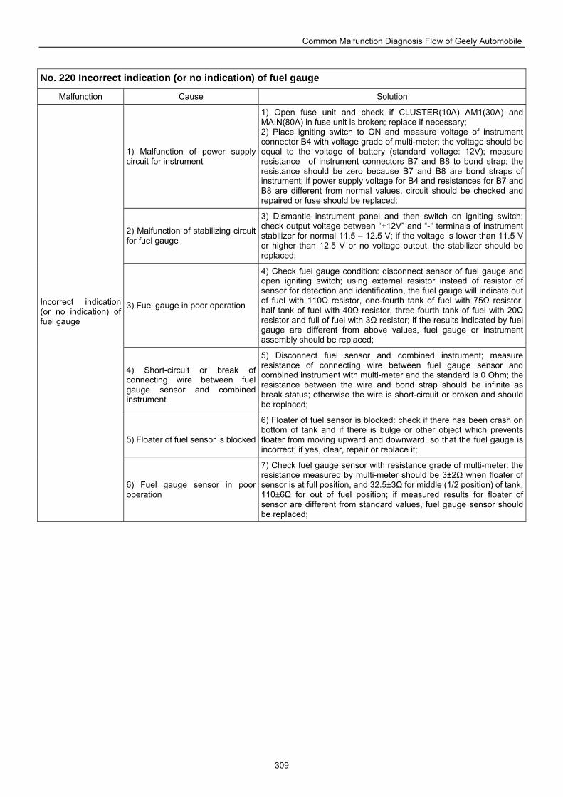
Common Malfunction Diagnosis Flow of Geely Automobile
309
No. 220 Incorrect indication (or no indication) of fuel gauge
Malfunction Cause Solution
1) Malfunction of power supply circuit for instrument
1) Open fuse unit and check if CLUSTER(10A) AM1(30A) and MAIN(80A) in fuse unit is broken; replace if necessary; 2) Place igniting switch to ON and measure voltage of instrument connector B4 with voltage grade of multi-meter; the voltage should be equal to the voltage of battery (standard voltage: 12V); measure resistance of instrument connectors B7 and B8 to bond strap; the resistance should be zero because B7 and B8 are bond straps of instrument; if power supply voltage for B4 and resistances for B7 and B8 are different from normal values, circuit should be checked and repaired or fuse should be replaced;
2) Malfunction of stabilizing circuit for fuel gauge
3) Dismantle instrument panel and then switch on igniting switch; check output voltage between “+12V” and “-“ terminals of instrument stabilizer for normal 11.5 – 12.5 V; if the voltage is lower than 11.5 V or higher than 12.5 V or no voltage output, the stabilizer should be replaced;
3) Fuel gauge in poor operation
4) Check fuel gauge condition: disconnect sensor of fuel gauge and open igniting switch; using external resistor instead of resistor of sensor for detection and identification, the fuel gauge will indicate out of fuel with 110Ω resistor, one-fourth tank of fuel with 75Ω resistor, half tank of fuel with 40Ω resistor, three-fourth tank of fuel with 20Ω resistor and full of fuel with 3Ω resistor; if the results indicated by fuel gauge are different from above values, fuel gauge or instrument assembly should be replaced;
4) Short-circuit or break of connecting wire between fuel gauge sensor and combined instrument
5) Disconnect fuel sensor and combined instrument; measure resistance of connecting wire between fuel gauge sensor and combined instrument with multi-meter and the standard is 0 Ohm; the resistance between the wire and bond strap should be infinite as break status; otherwise the wire is short-circuit or broken and should be replaced;
5) Floater of fuel sensor is blocked
6) Floater of fuel sensor is blocked: check if there has been crash on bottom of tank and if there is bulge or other object which prevents floater from moving upward and downward, so that the fuel gauge is incorrect; if yes, clear, repair or replace it;
Incorrect indication (or no indication) of fuel gauge
6) Fuel gauge sensor in poor operation
7) Check fuel gauge sensor with resistance grade of multi-meter: the resistance measured by multi-meter should be 3±2Ω when floater of sensor is at full position, and 32.5±3Ω for middle (1/2 position) of tank, 110±6Ω for out of fuel position; if measured results for floater of sensor are different from standard values, fuel gauge sensor should be replaced;
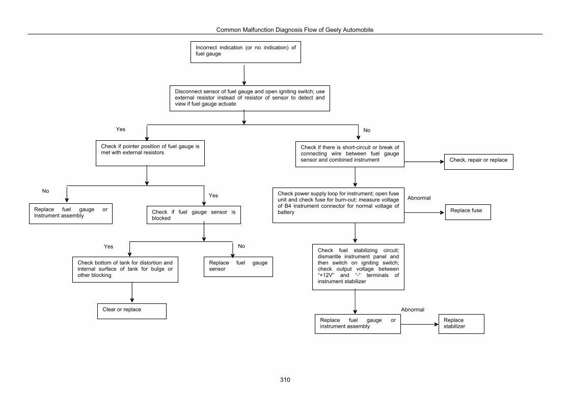
Common Malfunction Diagnosis Flow of Geely Automobile
310
Check if fuel gauge sensor is blocked
Check bottom of tank for distortion and internal surface of tank for bulge or other blocking
Check fuel stabilizing circuit; dismantle instrument panel and then switch on igniting switch; check output voltage between “+12V” and “-“ terminals of instrument stabilizer
Replace fuse
Replace fuel gauge sensor
Replace stabilizer
Replace fuel gauge or instrument assembly
Disconnect sensor of fuel gauge and open igniting switch; use external resistor instead of resistor of sensor to detect and view if fuel gauge actuate
Check if there is short-circuit or break of connecting wire between fuel gauge sensor and combined instrument
Replace fuel gauge or instrument assembly
Incorrect indication (or no indication) of fuel gauge
Check if pointer position of fuel gauge is met with external resistors
Check, repair or replace
Check power supply loop for instrument; open fuse unit and check fuse for burn-out; measure voltage of B4 instrument connector for normal voltage of battery
Clear or replace Abnormal
Abnormal
Yes No
No Yes
Yes No

Common Malfunction Diagnosis Flow of Geely Automobile
311
No. 221 No indication of water temperature gauge
Malfunction Cause Solution
Water temperature gauge in poor operation
Check water temperature gauge condition: disconnect sensor of water temperature gauge and open igniting switch; using external resistor instead of resistor of sensor for detection and identification, the water temperature gauge will indicate around “C” area with 165Ω resistor, around “1/2 C” area with 56Ω resistor, around “H” area with 28.7Ω resistor; if the results indicated by water temperature gauge are different from above values, water temperature gauge or instrument assembly should be replaced;
Place igniting switch to ON and measure voltage of instrument connector B4 with voltage grade of multi-meter; the voltage should be equal to the voltage of battery (standard voltage: 12V); measure resistance of instrument connectors B7 and B8 to bond strap; the resistance should be zero because B7 and B8 are bond straps of instrument; if power supply voltage for B4 and resistances for B7 and B8 are different from normal values, circuit should be checked and repaired or fuse should be replaced;
Malfunction of power supply circuit for instrument
Dismantle instrument panel and then switch on igniting switch; check output voltage between “+12V” and “-“ terminals of instrument stabilizer for normal 11.5 – 12.5 V; if the voltage is lower than 11.5 V or higher than 12.5 V or no voltage output, the stabilizer should be replaced;
Water temperature gauge sensor in poor operation
5) While checking water temperature sensor, the sensor can be dismantled from engine and put into coolant or water with certain temperature, in the meantime, check if the resistance value is met with standard value. When temperature of coolant is 60 , the resistance of water temperature sensor is 164.5±5Ω; and when temperature of coolant is 90 , the resistance of water temperature sensor is 56±3Ω; when temperature of coolant is 115 , the resistance of water temperature sensor is 28.7±2Ω; if measured resistance values of water temperature sensor are different from standard values, water temperature sensor should be replaced;
No indication of water temperature gauge
Short-circuit or open-circuit of connecting wire between water temperature gauge sensor and combined instrument
4) Disconnect water temperature sensor and combined instrument; measure resistance of connecting wire between water temperature gauge sensor and combined instrument with multi-meter and the standard is 0 Ohm; the resistance between the wire and bond strap should be infinite as break status; otherwise the wire is short-circuit or broken and should be replaced;
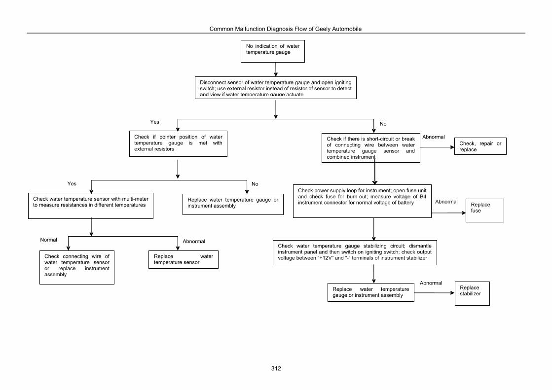
Common Malfunction Diagnosis Flow of Geely Automobile
312
Replace water temperature sensor
Disconnect sensor of water temperature gauge and open igniting switch; use external resistor instead of resistor of sensor to detect and view if water temperature gauge actuate
No indication of water temperature gauge
Check power supply loop for instrument; open fuse unit and check fuse for burn-out; measure voltage of B4 instrument connector for normal voltage of battery
Replace water temperature gauge or instrument assembly
Replace stabilizer
Check, repair or replace
Check if there is short-circuit or break of connecting wire between water temperature gauge sensor and combined instrument
Check connecting wire of water temperature sensor or replace instrument assembly
Replace fuse
Check if pointer position of water temperature gauge is met with external resistors
Check water temperature sensor with multi-meter to measure resistances in different temperatures
Replace water temperature gauge or instrument assembly
Check water temperature gauge stabilizing circuit; dismantle instrument panel and then switch on igniting switch; check output voltage between “+12V” and “-“ terminals of instrument stabilizer
Yes No
Yes No
Normal Abnormal
Abnormal
Abnormal
Abnormal
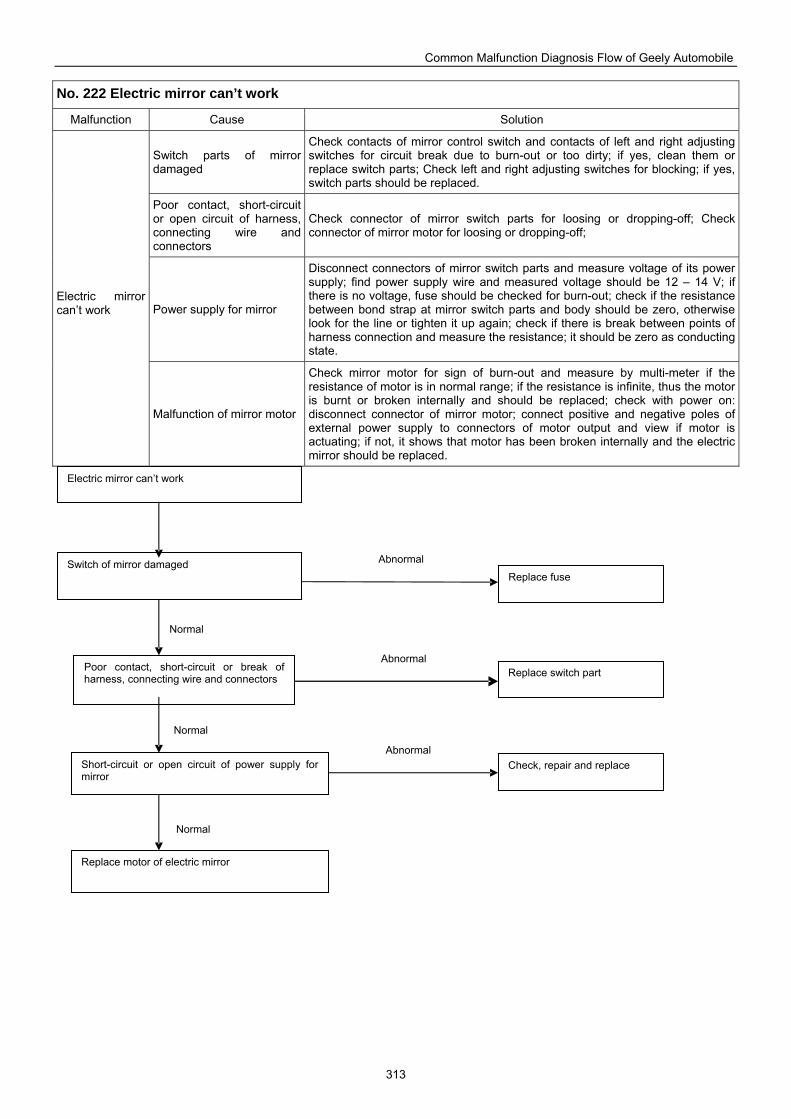
Common Malfunction Diagnosis Flow of Geely Automobile
313
No. 222 Electric mirror can’t work
Malfunction Cause Solution
Switch parts of mirror damaged
Check contacts of mirror control switch and contacts of left and right adjusting switches for circuit break due to burn-out or too dirty; if yes, clean them or replace switch parts; Check left and right adjusting switches for blocking; if yes, switch parts should be replaced.
Poor contact, short-circuit or open circuit of harness, connecting wire and connectors
Check connector of mirror switch parts for loosing or dropping-off; Check connector of mirror motor for loosing or dropping-off;
Power supply for mirror
Disconnect connectors of mirror switch parts and measure voltage of its power supply; find power supply wire and measured voltage should be 12 – 14 V; if there is no voltage, fuse should be checked for burn-out; check if the resistance between bond strap at mirror switch parts and body should be zero, otherwise look for the line or tighten it up again; check if there is break between points of harness connection and measure the resistance; it should be zero as conducting state.
Electric mirror can’t work
Malfunction of mirror motor
Check mirror motor for sign of burn-out and measure by multi-meter if the resistance of motor is in normal range; if the resistance is infinite, thus the motor is burnt or broken internally and should be replaced; check with power on: disconnect connector of mirror motor; connect positive and negative poles of external power supply to connectors of motor output and view if motor is actuating; if not, it shows that motor has been broken internally and the electric mirror should be replaced.
Electric mirror can’t work
Switch of mirror damaged
Poor contact, short-circuit or break of harness, connecting wire and connectors
Short-circuit or open circuit of power supply for mirror
Check, repair and replace
Replace motor of electric mirror
Replace switch part
Replace fuse
Normal
Abnormal
Abnormal
Abnormal
Normal
Normal
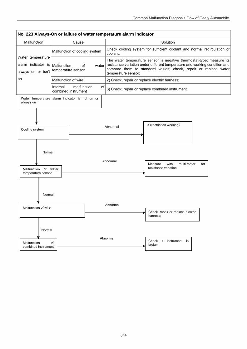
Common Malfunction Diagnosis Flow of Geely Automobile
314
No. 223 Always-On or failure of water temperature alarm indicator
Malfunction Cause Solution
Malfunction of cooling system Check cooling system for sufficient coolant and normal recirculation of coolant;
Malfunction of water temperature sensor
The water temperature sensor is negative thermostat-type; measure its resistance variation under different temperature and working condition and compare them to standard values; check, repair or replace water temperature sensor;
Malfunction of wire 2) Check, repair or replace electric harness;
Water temperature
alarm indicator is
always on or isn’t
on
Internal malfunction of combined instrument 3) Check, repair or replace combined instrument;
Water temperature alarm indicator is not on or always on
Is electric fan working? Cooling system
Measure with multi-meter for resistance variation Malfunction of water
temperature sensor
Malfunction of wire Check, repair or replace electric harness;
Malfunction of combined instrument
Check if instrument is broken
Abnormal
Normal
Normal
Normal
Abnormal
Abnormal
Abnormal
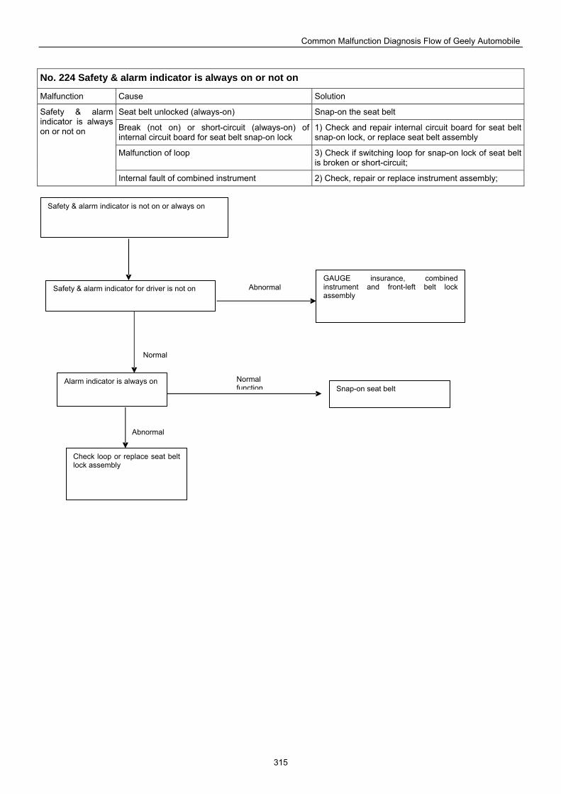
Common Malfunction Diagnosis Flow of Geely Automobile
315
No. 224 Safety & alarm indicator is always on or not on
Malfunction Cause Solution
Seat belt unlocked (always-on) Snap-on the seat belt
Break (not on) or short-circuit (always-on) of internal circuit board for seat belt snap-on lock
1) Check and repair internal circuit board for seat belt snap-on lock, or replace seat belt assembly
Malfunction of loop 3) Check if switching loop for snap-on lock of seat belt is broken or short-circuit;
Safety & alarm indicator is always on or not on
Internal fault of combined instrument 2) Check, repair or replace instrument assembly;
Safety & alarm indicator is not on or always on
GAUGE insurance, combined instrument and front-left belt lock assembly
Safety & alarm indicator for driver is not on
Alarm indicator is always on Snap-on seat belt
Check loop or replace seat belt lock assembly
Normal
Abnormal
Abnormal
Normal function
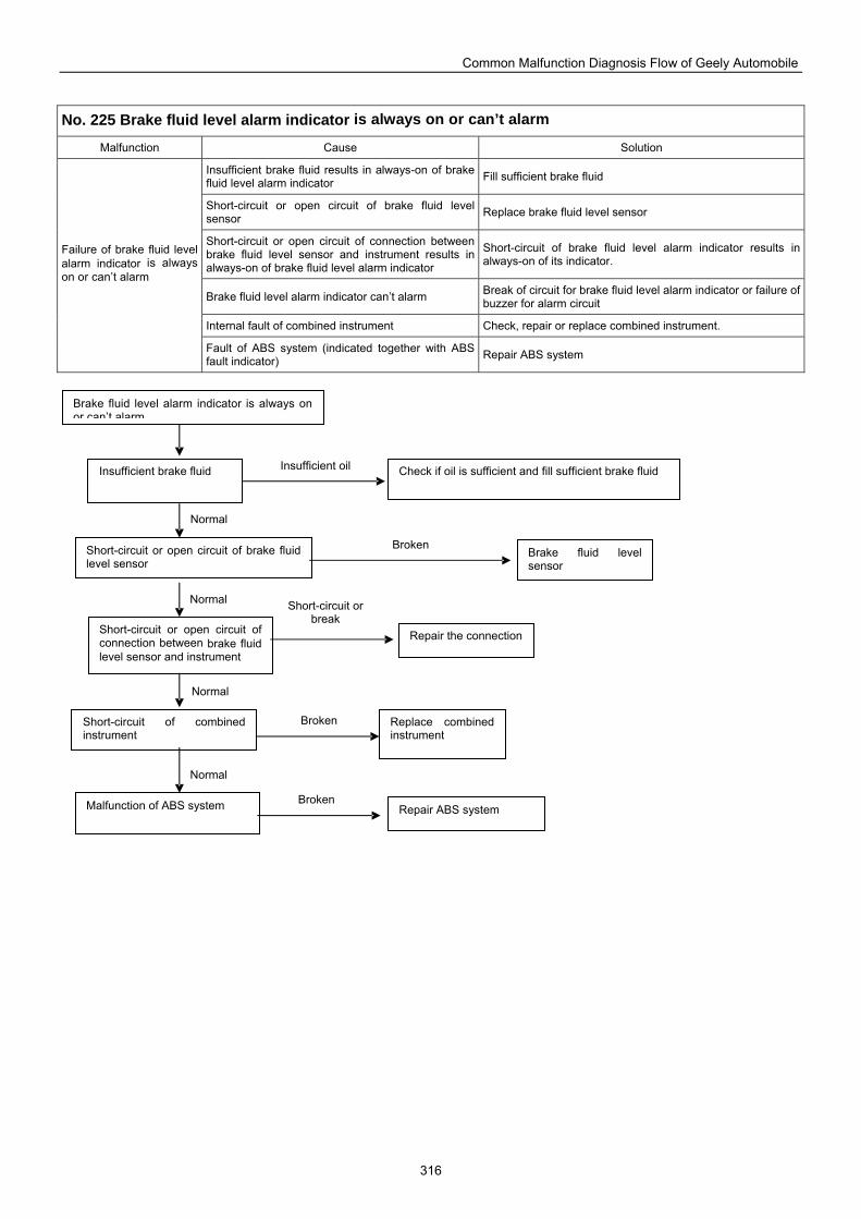
Common Malfunction Diagnosis Flow of Geely Automobile
316
No. 225 Brake fluid level alarm indicator is always on or can’t alarm
Malfunction Cause Solution
Insufficient brake fluid results in always-on of brake fluid level alarm indicator Fill sufficient brake fluid
Short-circuit or open circuit of brake fluid level sensor Replace brake fluid level sensor
Short-circuit or open circuit of connection between brake fluid level sensor and instrument results in always-on of brake fluid level alarm indicator
Short-circuit of brake fluid level alarm indicator results in always-on of its indicator.
Brake fluid level alarm indicator can’t alarm Break of circuit for brake fluid level alarm indicator or failure of buzzer for alarm circuit
Internal fault of combined instrument Check, repair or replace combined instrument.
Failure of brake fluid level alarm indicator is always on or can’t alarm
Fault of ABS system (indicated together with ABS fault indicator) Repair ABS system
Brake fluid level alarm indicator is always on or can’t alarm
Check if oil is sufficient and fill sufficient brake fluid Insufficient brake fluid
Short-circuit or open circuit of brake fluid level sensor
Short-circuit of combined instrument
Replace combined instrument
Malfunction of ABS system
Short-circuit or open circuit of connection between brake fluid level sensor and instrument
Brake fluid level sensor
Repair the connection
Repair ABS system
Normal
Normal
Normal
Normal
Insufficient oil
Broken
Short-circuit or break
Broken
Broken
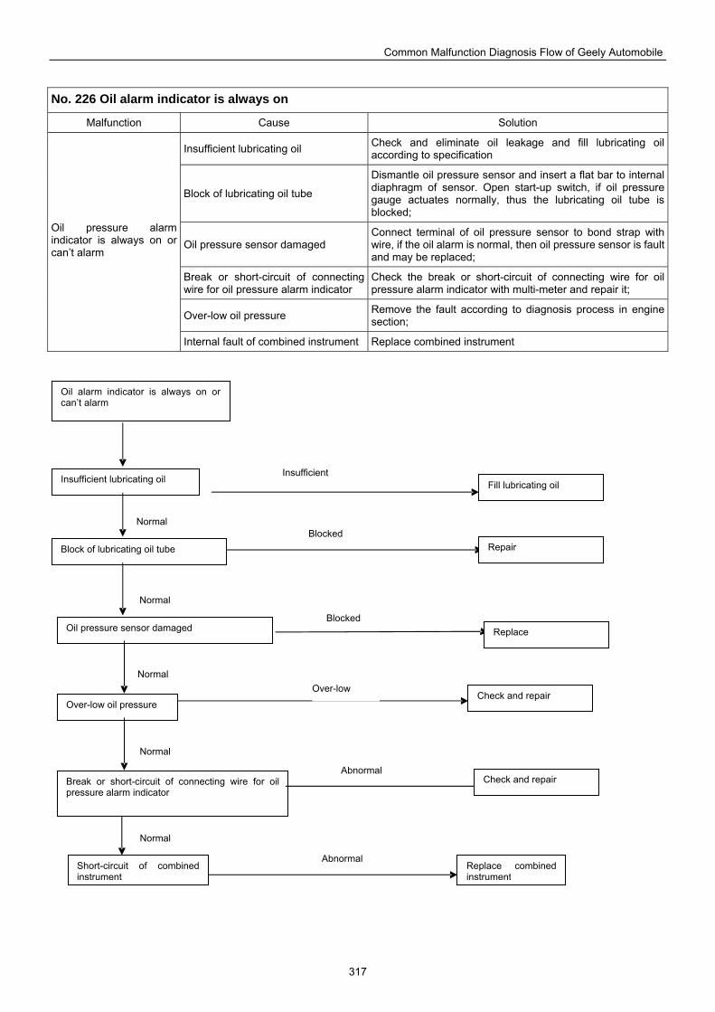
Common Malfunction Diagnosis Flow of Geely Automobile
317
No. 226 Oil alarm indicator is always on
Malfunction Cause Solution
Insufficient lubricating oil Check and eliminate oil leakage and fill lubricating oil according to specification
Block of lubricating oil tube
Dismantle oil pressure sensor and insert a flat bar to internal diaphragm of sensor. Open start-up switch, if oil pressure gauge actuates normally, thus the lubricating oil tube is blocked;
Oil pressure sensor damaged Connect terminal of oil pressure sensor to bond strap with wire, if the oil alarm is normal, then oil pressure sensor is fault and may be replaced;
Break or short-circuit of connecting wire for oil pressure alarm indicator
Check the break or short-circuit of connecting wire for oil pressure alarm indicator with multi-meter and repair it;
Over-low oil pressure Remove the fault according to diagnosis process in engine section;
Oil pressure alarm indicator is always on or can’t alarm
Internal fault of combined instrument Replace combined instrument
Oil alarm indicator is always on or can’t alarm
Insufficient lubricating oil
Block of lubricating oil tube Repair
Oil pressure sensor damaged Replace
Over-low oil pressure
Break or short-circuit of connecting wire for oil pressure alarm indicator
Check and repair
Short-circuit of combined instrument
Replace combined instrument
Fill lubricating oil
Check and repair
Normal
Normal
Normal
Normal
Normal
Insufficient
Blocked
Blocked
Over-low
Abnormal
Abnormal
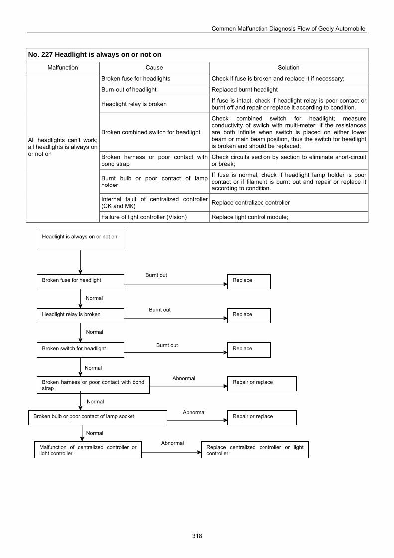
Common Malfunction Diagnosis Flow of Geely Automobile
318
No. 227 Headlight is always on or not on
Malfunction Cause Solution
Broken fuse for headlights Check if fuse is broken and replace it if necessary;
Burn-out of headlight Replaced burnt headlight
Headlight relay is broken If fuse is intact, check if headlight relay is poor contact or burnt off and repair or replace it according to condition.
Broken combined switch for headlight
Check combined switch for headlight; measure conductivity of switch with multi-meter; if the resistances are both infinite when switch is placed on either lower beam or main beam position, thus the switch for headlight is broken and should be replaced;
Broken harness or poor contact with bond strap
Check circuits section by section to eliminate short-circuit or break;
Burnt bulb or poor contact of lamp holder
If fuse is normal, check if headlight lamp holder is poor contact or if filament is burnt out and repair or replace it according to condition.
Internal fault of centralized controller (CK and MK) Replace centralized controller
All headlights can’t work; all headlights is always on or not on
Failure of light controller (Vision) Replace light control module;
Broken bulb or poor contact of lamp socket
Headlight is always on or not on
Broken fuse for headlight
Headlight relay is broken
Broken switch for headlight
Broken harness or poor contact with bond strap
Repair or replace
Replace
Replace
Replace
Repair or replace
Malfunction of centralized controller or light controller
Replace centralized controller or light controller
Normal
Normal
Normal
Normal
Normal
Burnt out
Burnt out
Burnt out
Abnormal
Abnormal
Abnormal
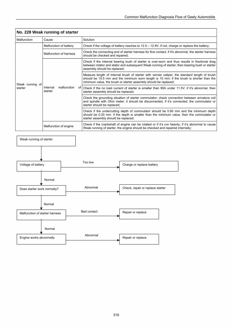
Common Malfunction Diagnosis Flow of Geely Automobile
319
No. 228 Weak running of starter
Malfunction Cause Solution
Malfunction of battery Check if the voltage of battery reaches to 12.5 – 12.9V, if not, charge or replace the battery;
Malfunction of harness Check the connecting end of starter harness for fine contact, if it's abnormal, the starter harness should be checked and repaired;
Check if the internal bearing bush of starter is over-worn and thus results in fractional drag between rotator and stator and subsequent Weak running of starter; then bearing bush or starter assembly should be replaced;
Measure length of internal brush of starter with vernier caliper; the standard length of brush should be 15.5 mm and the minimum worn length is 10 mm; if the brush is shorter than the minimum value, the brush or starter assembly should be replaced;
Check if the no load current of starter is smaller than 90A under 11.5V; if it's abnormal, then starter assembly should be replaced;
Check the grounding situation of starter commutator; check connection between armature coil and spindle with Ohm meter; it should be disconnected, if it’s connected, the commutator or starter should be replaced;
Internal malfunction of starter
Check if the undercutting depth of commutator should be 0.60 mm and the minimum depth should be 0.20 mm. if the depth is smaller than the minimum value, then the commutator or starter assembly should be replaced;
Weak running of starter
Malfunction of engine Check if the crankshaft of engine can be rotated or if it’s run heavily, if it’s abnormal to cause Weak running of starter, the engine should be checked and repaired internally;
Weak running of starter
Voltage of battery
Does starter work normally?
Malfunction of starter harness
Engine works abnormally
Charge or replace battery
Check, repair or replace starter
Repair or replace
Repair or replace
Normal
Normal
Normal
Too low
Abnormal
Bad contact
Abnormal
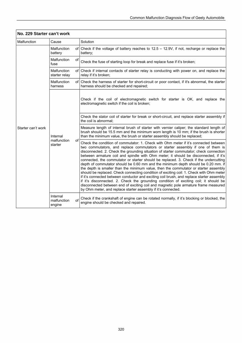
Common Malfunction Diagnosis Flow of Geely Automobile
320
No. 229 Starter can’t work
Malfunction Cause Solution
Malfunction of battery
Check if the voltage of battery reaches to 12.5 – 12.9V, if not, recharge or replace the battery;
Malfunction of fuse Check the fuse of starting loop for break and replace fuse if it’s broken;
Malfunction of starter relay
Check if internal contacts of starter relay is conducting with power on, and replace the relay if it’s broken;
Malfunction of harness
Check the harness of starter for short-circuit or poor contact, if it's abnormal, the starter harness should be checked and repaired;
Check if the coil of electromagnetic switch for starter is OK, and replace the electromagnetic switch if the coil is broken;
Check the stator coil of starter for break or short-circuit, and replace starter assembly if the coil is abnormal;
Measure length of internal brush of starter with vernier caliper; the standard length of brush should be 15.5 mm and the minimum worn length is 10 mm; if the brush is shorter than the minimum value, the brush or starter assembly should be replaced; Internal
malfunction of starter Check the condition of commutator: 1. Check with Ohm meter if it’s connected between
two commutators, and replace commutators or starter assembly if one of them is disconnected. 2. Check the grounding situation of starter commutator; check connection between armature coil and spindle with Ohm meter; it should be disconnected, if it’s connected, the commutator or starter should be replaced. 3. Check if the undercutting depth of commutator should be 0.60 mm and the minimum depth should be 0.20 mm. if the depth is smaller than the minimum value, then the commutator or starter assembly should be replaced. Check connecting condition of exciting coil: 1. Check with Ohm meter if it’s connected between conductor and exciting coil brush, and replace starter assembly if it’s disconnected. 2. Check the grounding condition of exciting coil; it should be disconnected between end of exciting coil and magnetic pole armature frame measured by Ohm meter, and replace starter assembly if it’s connected.
Starter can’t work
Internal malfunction of engine
Check if the crankshaft of engine can be rotated normally, if it’s blocking or blocked, the engine should be checked and repaired.
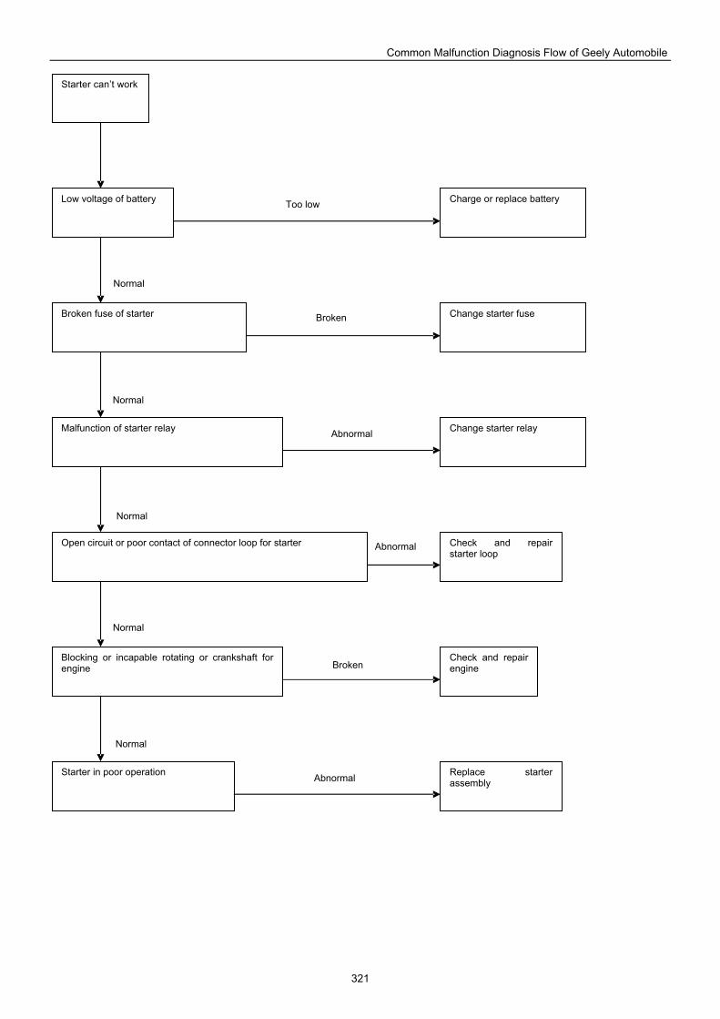
Common Malfunction Diagnosis Flow of Geely Automobile
321
Starter can’t work
Low voltage of battery Charge or replace battery
Broken fuse of starter Change starter fuse
Malfunction of starter relay Change starter relay
Open circuit or poor contact of connector loop for starter
Blocking or incapable rotating or crankshaft for engine
Check and repair starter loop
Check and repair engine
Starter in poor operation Replace starter assembly
Normal
Abnormal
Normal
Normal
Normal
Normal
Broken
Abnormal
Abnormal
Broken
Too low
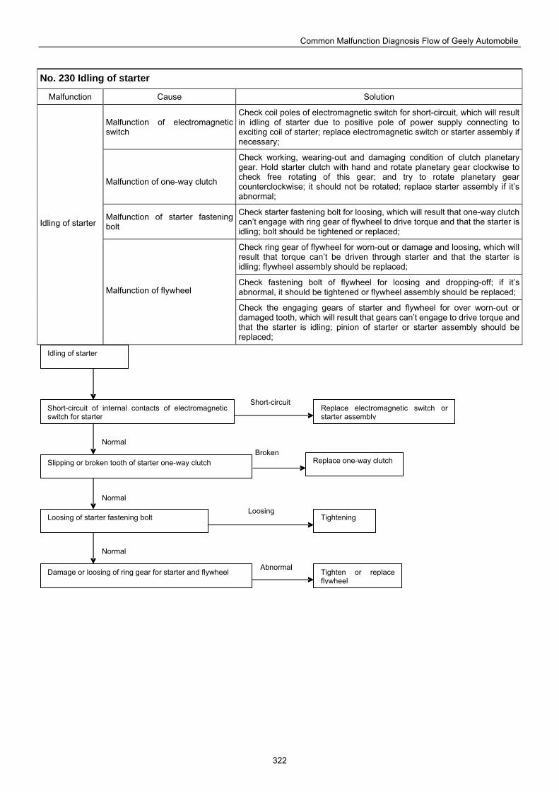
Common Malfunction Diagnosis Flow of Geely Automobile
322
No. 230 Idling of starter
Malfunction Cause Solution
Malfunction of electromagnetic switch
Check coil poles of electromagnetic switch for short-circuit, which will result in idling of starter due to positive pole of power supply connecting to exciting coil of starter; replace electromagnetic switch or starter assembly if necessary;
Malfunction of one-way clutch
Check working, wearing-out and damaging condition of clutch planetary gear. Hold starter clutch with hand and rotate planetary gear clockwise to check free rotating of this gear; and try to rotate planetary gear counterclockwise; it should not be rotated; replace starter assembly if it’s abnormal;
Malfunction of starter fastening bolt
Check starter fastening bolt for loosing, which will result that one-way clutch can’t engage with ring gear of flywheel to drive torque and that the starter is idling; bolt should be tightened or replaced;
Check ring gear of flywheel for worn-out or damage and loosing, which will result that torque can’t be driven through starter and that the starter is idling; flywheel assembly should be replaced;
Check fastening bolt of flywheel for loosing and dropping-off; if it’s abnormal, it should be tightened or flywheel assembly should be replaced;
Idling of starter
Malfunction of flywheel
Check the engaging gears of starter and flywheel for over worn-out or damaged tooth, which will result that gears can’t engage to drive torque and that the starter is idling; pinion of starter or starter assembly should be replaced;
Idling of starter
Short-circuit of internal contacts of electromagnetic switch for starter
Replace electromagnetic switch or starter assembly
Slipping or broken tooth of starter one-way clutch
Loosing of starter fastening bolt Tightening
Damage or loosing of ring gear for starter and flywheel Tighten or replace flywheel
Replace one-way clutch
Normal
Abnormal
Normal
Normal
Loosing
Broken
Short-circuit
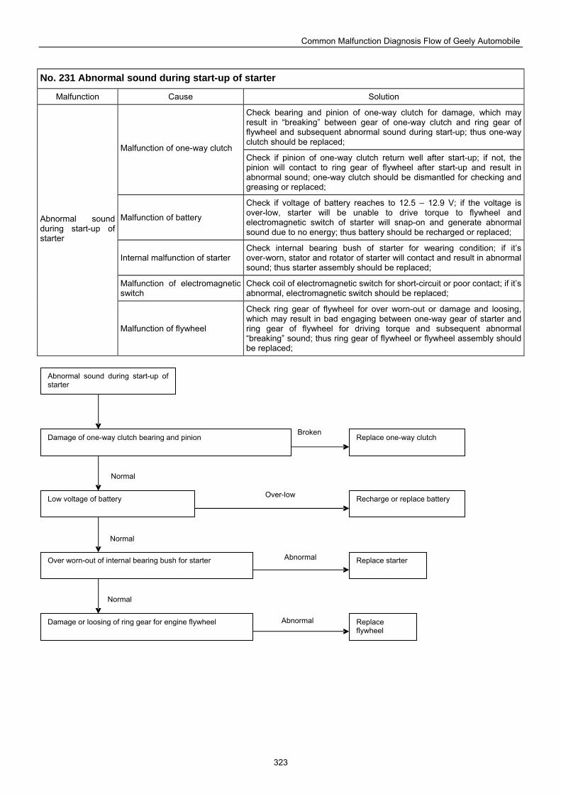
Common Malfunction Diagnosis Flow of Geely Automobile
323
No. 231 Abnormal sound during start-up of starter
Malfunction Cause Solution
Check bearing and pinion of one-way clutch for damage, which may result in “breaking” between gear of one-way clutch and ring gear of flywheel and subsequent abnormal sound during start-up; thus one-way clutch should be replaced;
Malfunction of one-way clutch Check if pinion of one-way clutch return well after start-up; if not, the pinion will contact to ring gear of flywheel after start-up and result in abnormal sound; one-way clutch should be dismantled for checking and greasing or replaced;
Malfunction of battery
Check if voltage of battery reaches to 12.5 – 12.9 V; if the voltage is over-low, starter will be unable to drive torque to flywheel and electromagnetic switch of starter will snap-on and generate abnormal sound due to no energy; thus battery should be recharged or replaced;
Internal malfunction of starter Check internal bearing bush of starter for wearing condition; if it’s over-worn, stator and rotator of starter will contact and result in abnormal sound; thus starter assembly should be replaced;
Malfunction of electromagnetic switch
Check coil of electromagnetic switch for short-circuit or poor contact; if it’s abnormal, electromagnetic switch should be replaced;
Abnormal sound during start-up of starter
Malfunction of flywheel
Check ring gear of flywheel for over worn-out or damage and loosing, which may result in bad engaging between one-way gear of starter and ring gear of flywheel for driving torque and subsequent abnormal “breaking” sound; thus ring gear of flywheel or flywheel assembly should be replaced;
Replace one-way clutch Damage of one-way clutch bearing and pinion
Abnormal sound during start-up of starter
Low voltage of battery Recharge or replace battery
Over worn-out of internal bearing bush for starter Replace starter
Damage or loosing of ring gear for engine flywheel Replace flywheel
Normal
Abnormal
Normal
Normal
Abnormal
Over-low
Broken
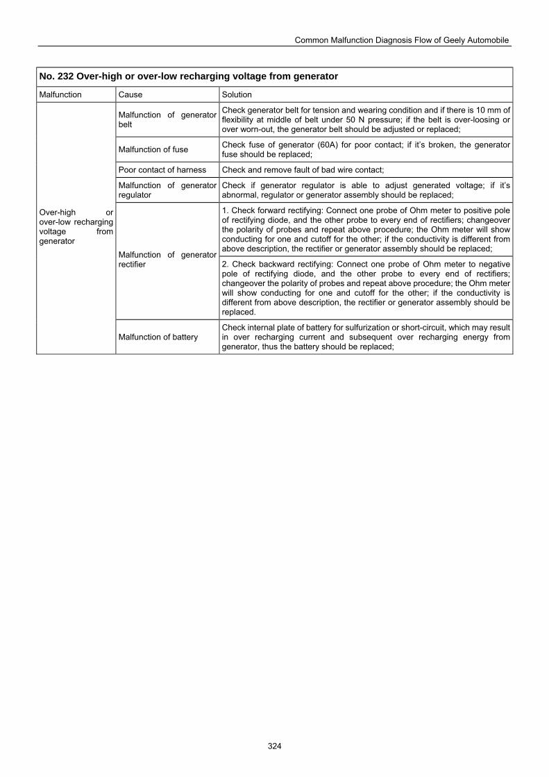
Common Malfunction Diagnosis Flow of Geely Automobile
324
No. 232 Over-high or over-low recharging voltage from generator
Malfunction Cause Solution
Malfunction of generator belt
Check generator belt for tension and wearing condition and if there is 10 mm of flexibility at middle of belt under 50 N pressure; if the belt is over-loosing or over worn-out, the generator belt should be adjusted or replaced;
Malfunction of fuse Check fuse of generator (60A) for poor contact; if it’s broken, the generator fuse should be replaced;
Poor contact of harness Check and remove fault of bad wire contact;
Malfunction of generator regulator
Check if generator regulator is able to adjust generated voltage; if it’s abnormal, regulator or generator assembly should be replaced;
1. Check forward rectifying: Connect one probe of Ohm meter to positive pole of rectifying diode, and the other probe to every end of rectifiers; changeover the polarity of probes and repeat above procedure; the Ohm meter will show conducting for one and cutoff for the other; if the conductivity is different from above description, the rectifier or generator assembly should be replaced;
Malfunction of generator rectifier 2. Check backward rectifying: Connect one probe of Ohm meter to negative
pole of rectifying diode, and the other probe to every end of rectifiers; changeover the polarity of probes and repeat above procedure; the Ohm meter will show conducting for one and cutoff for the other; if the conductivity is different from above description, the rectifier or generator assembly should be replaced.
Over-high or over-low recharging voltage from generator
Malfunction of battery Check internal plate of battery for sulfurization or short-circuit, which may result in over recharging current and subsequent over recharging energy from generator, thus the battery should be replaced;
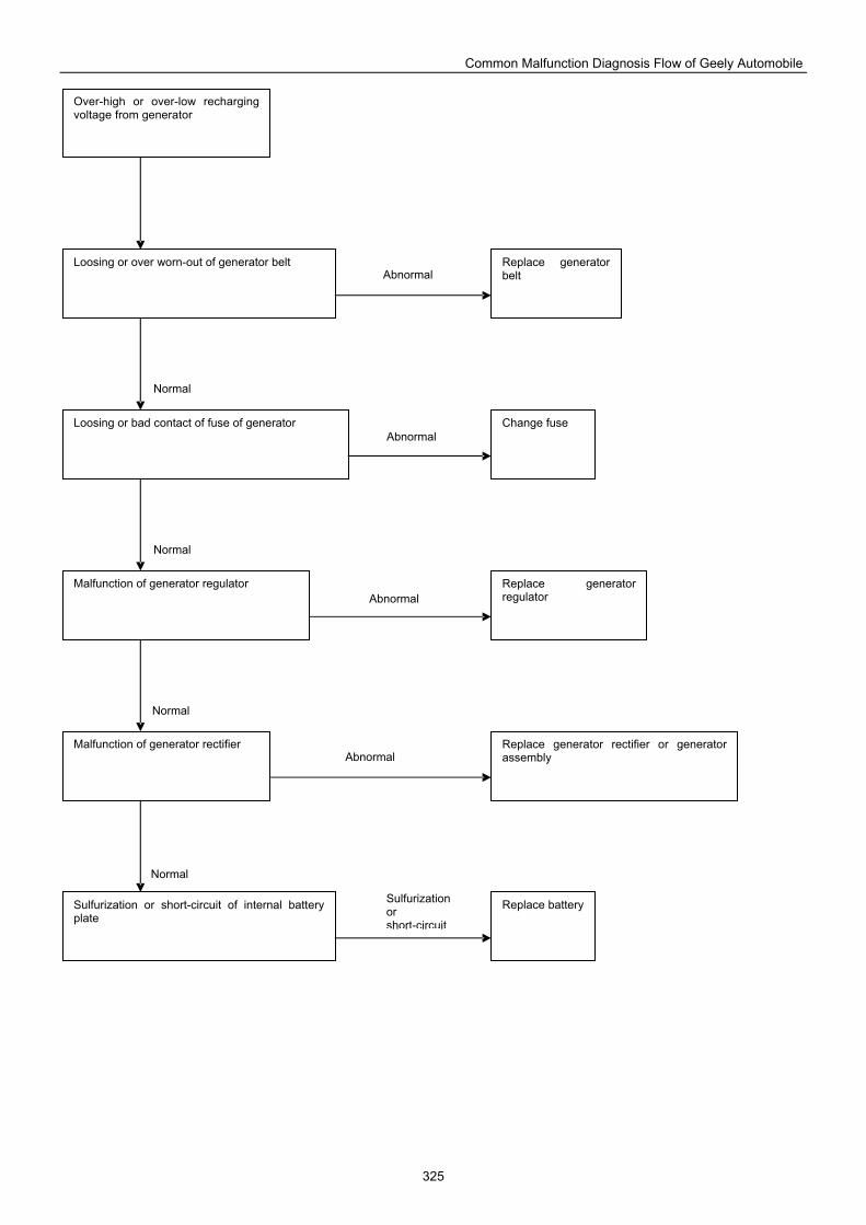
Common Malfunction Diagnosis Flow of Geely Automobile
325
Over-high or over-low recharging voltage from generator
Loosing or over worn-out of generator belt Replace generator belt
Loosing or bad contact of fuse of generator Change fuse
Malfunction of generator regulator Replace generator regulator
Malfunction of generator rectifier
Sulfurization or short-circuit of internal battery plate
Replace generator rectifier or generator assembly
Replace battery
Normal
Sulfurization or short-circuit
Normal
Normal
Normal
Abnormal
Abnormal
Abnormal
Abnormal
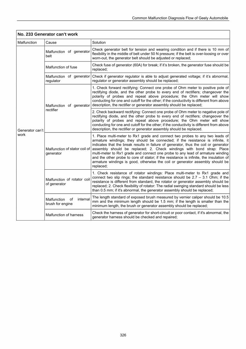
Common Malfunction Diagnosis Flow of Geely Automobile
326
No. 233 Generator can’t work
Malfunction Cause Solution
Malfunction of generator belt
Check generator belt for tension and wearing condition and if there is 10 mm of flexibility in the middle of belt under 50 N pressure; if the belt is over-loosing or over worn-out, the generator belt should be adjusted or replaced;
Malfunction of fuse Check fuse of generator (60A) for break; if it’s broken, the generator fuse should be replaced;
Malfunction of generator regulator
Check if generator regulator is able to adjust generated voltage; if it’s abnormal, regulator or generator assembly should be replaced;
1. Check forward rectifying: Connect one probe of Ohm meter to positive pole of rectifying diode, and the other probe to every end of rectifiers; changeover the polarity of probes and repeat above procedure; the Ohm meter will show conducting for one and cutoff for the other; if the conductivity is different from above description, the rectifier or generator assembly should be replaced; Malfunction of generator
rectifier 2. Check backward rectifying: Connect one probe of Ohm meter to negative pole of rectifying diode, and the other probe to every end of rectifiers; changeover the polarity of probes and repeat above procedure; the Ohm meter will show conducting for one and cutoff for the other; if the conductivity is different from above description, the rectifier or generator assembly should be replaced.
Malfunction of stator coil of generator
1. Place multi-meter to Rx1 grade and connect two probes to any two leads of armature windings; they should be connected; if the resistance is infinite, it indicates that the break results in failure of generator, thus the coil or generator assembly should be replaced; 2. Check windings with bond strap: Place multi-meter to Rx1 grade and connect one probe to any lead of armature winding and the other probe to core of stator; if the resistance is infinite, the insulation of armature windings is good, otherwise the coil or generator assembly should be replaced;
Malfunction of rotator coil of generator
1. Check resistance of rotator windings: Place multi-meter to Rx1 grade and connect two slip rings; the standard resistance should be 2.7 – 3.1 Ohm; if the resistance is different from standard, the rotator or generator assembly should be replaced; 2. Check flexibility of rotator: The radial swinging standard should be less than 0.5 mm; if it's abnormal, the generator assembly should be replaced;
Malfunction of internal brush for engine
The length standard of exposed brush measured by vernier caliper should be 10.5 mm and the minimum length should be 1.5 mm; if the length is smaller than the minimum length, the brush or generator assembly should be replaced;
Generator can’t work
Malfunction of harness Check the harness of generator for short-circuit or poor contact, if it's abnormal, the generator harness should be checked and repaired;
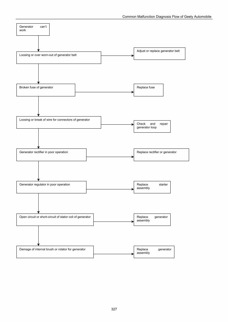
Common Malfunction Diagnosis Flow of Geely Automobile
327
Generator can’t work
Loosing or over worn-out of generator belt Adjust or replace generator belt
Broken fuse of generator Replace fuse
Generator regulator in poor operation Replace starter assembly
Open circuit or short-circuit of stator coil of generator Replace generator assembly
Damage of internal brush or rotator for generator Replace generator assembly
Generator rectifier in poor operation Replace rectifier or generator
Check and repair generator loop
Loosing or break of wire for connectors of generator
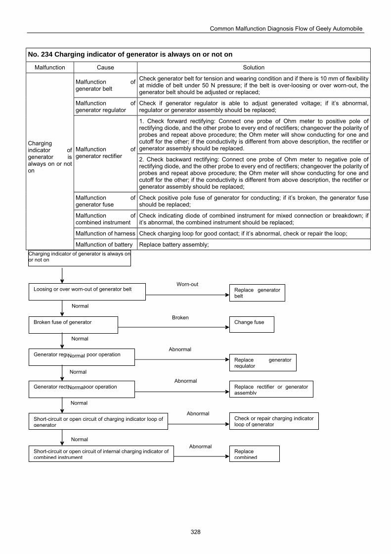
Common Malfunction Diagnosis Flow of Geely Automobile
328
No. 234 Charging indicator of generator is always on or not on
Malfunction Cause Solution
Malfunction of generator belt
Check generator belt for tension and wearing condition and if there is 10 mm of flexibility at middle of belt under 50 N pressure; if the belt is over-loosing or over worn-out, the generator belt should be adjusted or replaced;
Malfunction of generator regulator
Check if generator regulator is able to adjust generated voltage; if it’s abnormal, regulator or generator assembly should be replaced;
1. Check forward rectifying: Connect one probe of Ohm meter to positive pole of rectifying diode, and the other probe to every end of rectifiers; changeover the polarity of probes and repeat above procedure; the Ohm meter will show conducting for one and cutoff for the other; if the conductivity is different from above description, the rectifier or generator assembly should be replaced. Malfunction of
generator rectifier 2. Check backward rectifying: Connect one probe of Ohm meter to negative pole of rectifying diode, and the other probe to every end of rectifiers; changeover the polarity of probes and repeat above procedure; the Ohm meter will show conducting for one and cutoff for the other; if the conductivity is different from above description, the rectifier or generator assembly should be replaced;
Malfunction of generator fuse
Check positive pole fuse of generator for conducting; if it’s broken, the generator fuse should be replaced;
Malfunction of combined instrument
Check indicating diode of combined instrument for mixed connection or breakdown; if it’s abnormal, the combined instrument should be replaced;
Malfunction of harness Check charging loop for good contact; if it’s abnormal, check or repair the loop;
Charging indicator of generator is always on or not on
Malfunction of battery Replace battery assembly;
Replace generator belt
Loosing or over worn-out of generator belt
Check or repair charging indicator loop of generator
Short-circuit or open circuit of charging indicator loop of generator
Replace generator regulator
Generator regulator in poor operation
Change fuse Broken fuse of generator
Replace rectifier or generator assembly
Generator rectifier in poor operation
Replace combined
Short-circuit or open circuit of internal charging indicator of combined instrument
Charging indicator of generator is always onor not on
Abnormal
Normal
Normal
Normal
Normal
Normal
Abnormal
Abnormal
Abnormal
Broken
Worn-out
Normal
Normal
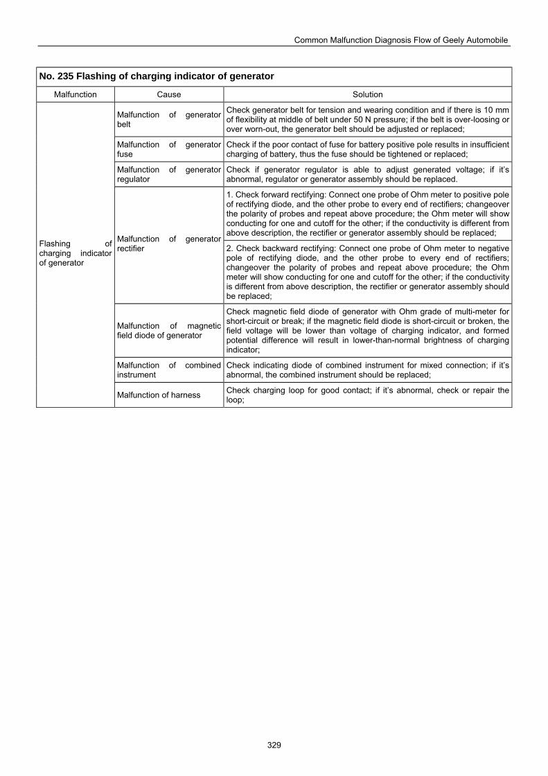
Common Malfunction Diagnosis Flow of Geely Automobile
329
No. 235 Flashing of charging indicator of generator
Malfunction Cause Solution
Malfunction of generator belt
Check generator belt for tension and wearing condition and if there is 10 mm of flexibility at middle of belt under 50 N pressure; if the belt is over-loosing or over worn-out, the generator belt should be adjusted or replaced;
Malfunction of generator fuse
Check if the poor contact of fuse for battery positive pole results in insufficient charging of battery, thus the fuse should be tightened or replaced;
Malfunction of generator regulator
Check if generator regulator is able to adjust generated voltage; if it’s abnormal, regulator or generator assembly should be replaced.
1. Check forward rectifying: Connect one probe of Ohm meter to positive pole of rectifying diode, and the other probe to every end of rectifiers; changeover the polarity of probes and repeat above procedure; the Ohm meter will show conducting for one and cutoff for the other; if the conductivity is different from above description, the rectifier or generator assembly should be replaced;
Malfunction of generator rectifier 2. Check backward rectifying: Connect one probe of Ohm meter to negative
pole of rectifying diode, and the other probe to every end of rectifiers; changeover the polarity of probes and repeat above procedure; the Ohm meter will show conducting for one and cutoff for the other; if the conductivity is different from above description, the rectifier or generator assembly should be replaced;
Malfunction of magnetic field diode of generator
Check magnetic field diode of generator with Ohm grade of multi-meter for short-circuit or break; if the magnetic field diode is short-circuit or broken, the field voltage will be lower than voltage of charging indicator, and formed potential difference will result in lower-than-normal brightness of charging indicator;
Malfunction of combined instrument
Check indicating diode of combined instrument for mixed connection; if it’s abnormal, the combined instrument should be replaced;
Flashing of charging indicator of generator
Malfunction of harness Check charging loop for good contact; if it’s abnormal, check or repair the loop;
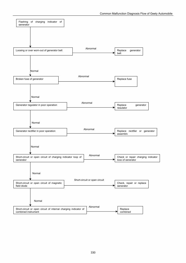
Common Malfunction Diagnosis Flow of Geely Automobile
330
Flashing of charging indicator of generator
Loosing or over worn-out of generator belt Replace generator belt
Broken fuse of generator Replace fuse
Generator regulator in poor operation
Replace generator regulator
Generator rectifier in poor operation
Short-circuit or open circuit of charging indicator loop of generator
Replace rectifier or generator assembly
Check or repair charging indicator loop of generator
Check, repair or replace generator
Short-circuit or open circuit of magnetic field diode
Short-circuit or open circuit of internal charging indicator of combined instrument
Replace combined
Normal
Abnormal
Normal
Normal
Normal
Normal
Normal
Short-circuit or open circuit
Abnormal
Abnormal
Abnormal
Abnormal
Abnormal
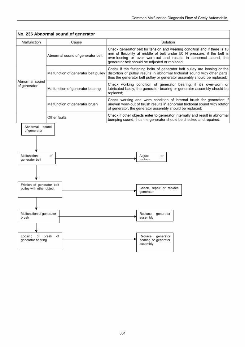
Common Malfunction Diagnosis Flow of Geely Automobile
331
No. 236 Abnormal sound of generator
Malfunction Cause Solution
Abnormal sound of generator belt
Check generator belt for tension and wearing condition and if there is 10 mm of flexibility at middle of belt under 50 N pressure; if the belt is over-loosing or over worn-out and results in abnormal sound, the generator belt should be adjusted or replaced;
Malfunction of generator belt pulley Check if the fastening bolts of generator belt pulley are loosing or the distortion of pulley results in abnormal frictional sound with other parts; thus the generator belt pulley or generator assembly should be replaced;
Malfunction of generator bearing Check working condition of generator bearing; if it’s over-worn or lubricated badly, the generator bearing or generator assembly should be replaced;
Malfunction of generator brush Check working and worn condition of internal brush for generator; if uneven worn-out of brush results in abnormal frictional sound with rotator of generator, the generator assembly should be replaced;
Abnormal sound of generator
Other faults Check if other objects enter to generator internally and result in abnormal bumping sound, thus the generator should be checked and repaired;
Replace generator bearing or generator assembly
Loosing of break of generator bearing
Friction of generator belt pulley with other object Check, repair or replace
generator
Abnormal sound of generator
Malfunction of generator belt
Malfunction of generator brush
Adjust or replace
Replace generator assembly
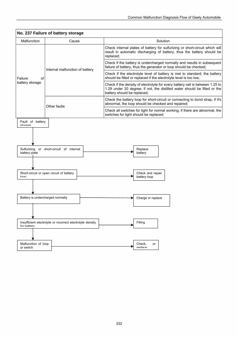
Common Malfunction Diagnosis Flow of Geely Automobile
332
No. 237 Failure of battery storage
Malfunction Cause Solution
Check internal plates of battery for sulfurizing or short-circuit which will result in automatic discharging of battery, thus the battery should be replaced;
Check if the battery is undercharged normally and results in subsequent failure of battery, thus the generator or loop should be checked;
Check if the electrolyte level of battery is met to standard; the battery should be filled or replaced if the electrolyte level is too low;
Internal malfunction of battery
Check if the density of electrolyte for every battery cell is between 1.25 to 1.29 under 20 degree; if not, the distilled water should be filled or the battery should be replaced;
Check the battery loop for short-circuit or connecting to bond strap, if it's abnormal, the loop should be checked and repaired;
Failure of battery storage
Other faults Check all switches for light for normal working; if there are abnormal, the switches for light should be replaced;
Fault of battery storage
Sulfurizing or short-circuit of internal battery plate
Replace battery
Short-circuit or open circuit of battery loop
Check and repair battery loop
Battery is undercharged normally Charge or replace
Insufficient electrolyte or incorrect electrolyte density for battery
Filling
Check, or replace
Malfunction of loop or switch
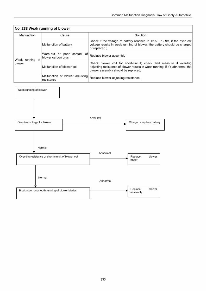
Common Malfunction Diagnosis Flow of Geely Automobile
333
No. 238 Weak running of blower
Malfunction Cause Solution
Malfunction of battery Check if the voltage of battery reaches to 12.5 – 12.9V, if the over-low voltage results in weak running of blower, the battery should be charged or replaced ;
Worn-out or poor contact of blower carbon brush Replace blower assembly
Malfunction of blower coil Check blower coil for short-circuit; check and measure if over-big adjusting resistance of blower results in weak running; if it’s abnormal, the blower assembly should be replaced;
Weak running of blower
Malfunction of blower adjusting resistance Replace blower adjusting resistance;
Over-big resistance or short-circuit of blower coil Replace blower motor
Blocking or unsmooth running of blower blades Replace blower assembly
Weak running of blower
Over-low voltage for blower Charge or replace battery
AbnormalNormal
Normal
Abnormal
Over-low
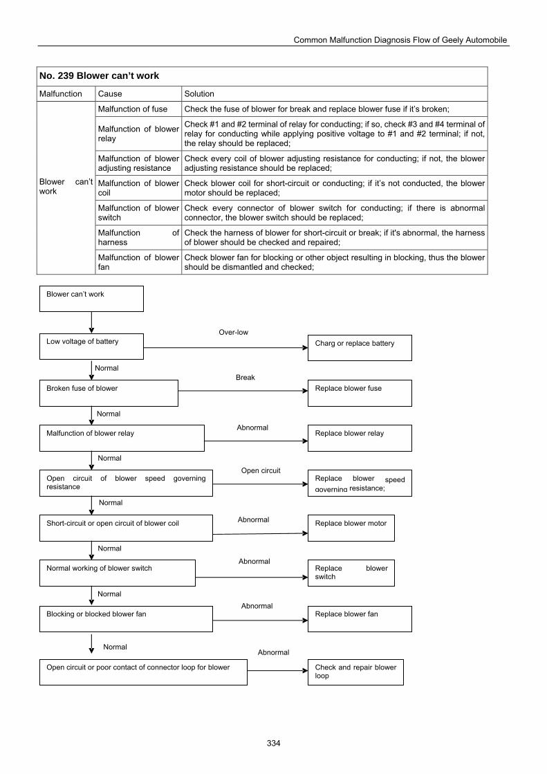
Common Malfunction Diagnosis Flow of Geely Automobile
334
No. 239 Blower can’t work
Malfunction Cause Solution
Malfunction of fuse Check the fuse of blower for break and replace blower fuse if it’s broken;
Malfunction of blower relay
Check #1 and #2 terminal of relay for conducting; if so, check #3 and #4 terminal of relay for conducting while applying positive voltage to #1 and #2 terminal; if not, the relay should be replaced;
Malfunction of blower adjusting resistance
Check every coil of blower adjusting resistance for conducting; if not, the blower adjusting resistance should be replaced;
Malfunction of blower coil
Check blower coil for short-circuit or conducting; if it’s not conducted, the blower motor should be replaced;
Malfunction of blower switch
Check every connector of blower switch for conducting; if there is abnormal connector, the blower switch should be replaced;
Malfunction of harness
Check the harness of blower for short-circuit or break; if it's abnormal, the harness of blower should be checked and repaired;
Blower can’t work
Malfunction of blower fan
Check blower fan for blocking or other object resulting in blocking, thus the blower should be dismantled and checked;
Blower can’t work
Low voltage of battery
Broken fuse of blower
Malfunction of blower relay
Open circuit of blower speed governing resistance
Short-circuit or open circuit of blower coil Replace blower motor
Normal working of blower switch
Blocking or blocked blower fan Replace blower fan
Replace blower switch
Replace blower speed governing resistance;
Replace blower relay
Charg or replace battery
Replace blower fuse
Open circuit or poor contact of connector loop for blower Check and repair blower loop
AbnormalNormal
Normal
Normal
Normal
Normal
Normal
Normal
Abnormal
Abnormal
Abnormal
Open circuit
Abnormal
Break
Over-low
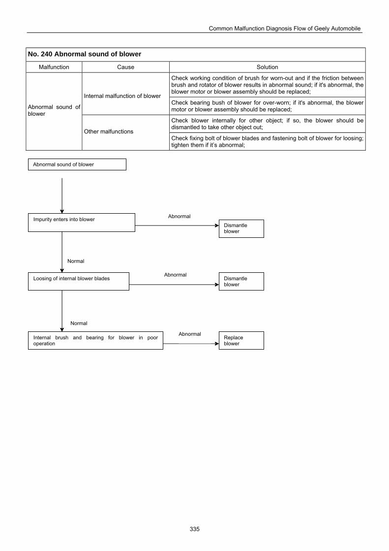
Common Malfunction Diagnosis Flow of Geely Automobile
335
No. 240 Abnormal sound of blower
Malfunction Cause Solution
Check working condition of brush for worn-out and if the friction between brush and rotator of blower results in abnormal sound; if it's abnormal, the blower motor or blower assembly should be replaced;
Internal malfunction of blower Check bearing bush of blower for over-worn; if it's abnormal, the blower motor or blower assembly should be replaced;
Check blower internally for other object; if so, the blower should be dismantled to take other object out;
Abnormal sound of blower
Other malfunctions Check fixing bolt of blower blades and fastening bolt of blower for loosing; tighten them if it’s abnormal;
Dismantle blower
Impurity enters into blower
Loosing of internal blower blades Dismantle blower
Internal brush and bearing for blower in poor operation
Replace blower
Abnormal sound of blower
Abnormal
Normal
Abnormal
Abnormal
Normal
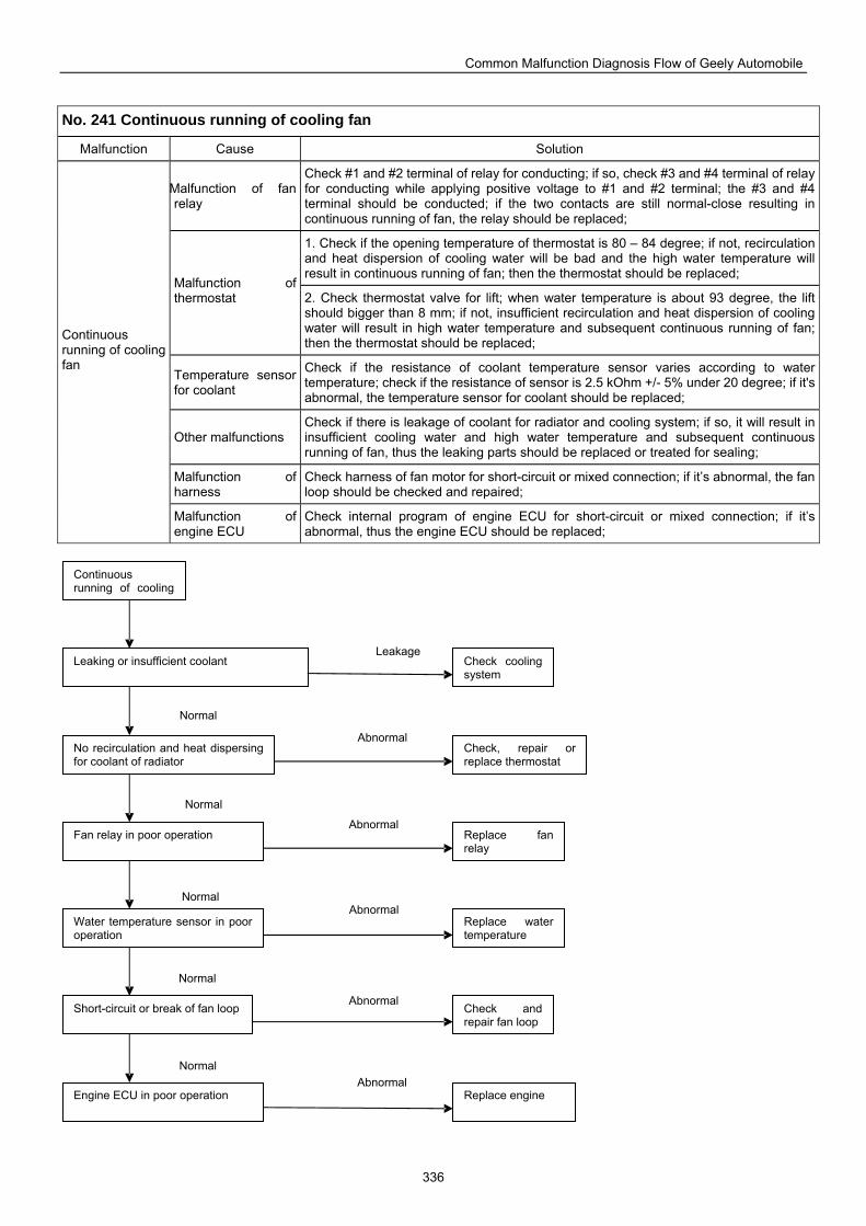
Common Malfunction Diagnosis Flow of Geely Automobile
336
No. 241 Continuous running of cooling fan
Malfunction Cause Solution
Malfunction of fan relay
Check #1 and #2 terminal of relay for conducting; if so, check #3 and #4 terminal of relay for conducting while applying positive voltage to #1 and #2 terminal; the #3 and #4 terminal should be conducted; if the two contacts are still normal-close resulting in continuous running of fan, the relay should be replaced;
1. Check if the opening temperature of thermostat is 80 – 84 degree; if not, recirculation and heat dispersion of cooling water will be bad and the high water temperature will result in continuous running of fan; then the thermostat should be replaced;
Malfunction of thermostat 2. Check thermostat valve for lift; when water temperature is about 93 degree, the lift
should bigger than 8 mm; if not, insufficient recirculation and heat dispersion of cooling water will result in high water temperature and subsequent continuous running of fan; then the thermostat should be replaced;
Temperature sensor for coolant
Check if the resistance of coolant temperature sensor varies according to water temperature; check if the resistance of sensor is 2.5 kOhm +/- 5% under 20 degree; if it's abnormal, the temperature sensor for coolant should be replaced;
Other malfunctions Check if there is leakage of coolant for radiator and cooling system; if so, it will result in insufficient cooling water and high water temperature and subsequent continuous running of fan, thus the leaking parts should be replaced or treated for sealing;
Malfunction of harness
Check harness of fan motor for short-circuit or mixed connection; if it’s abnormal, the fan loop should be checked and repaired;
Continuous running of cooling fan
Malfunction of engine ECU
Check internal program of engine ECU for short-circuit or mixed connection; if it’s abnormal, thus the engine ECU should be replaced;
Continuous running of cooling
Leaking or insufficient coolant Check cooling system
No recirculation and heat dispersing for coolant of radiator
Check, repair or replace thermostat
Fan relay in poor operation Replace fan relay
Water temperature sensor in poor operation
Short-circuit or break of fan loop
Replace water temperature
Check and repair fan loop
Engine ECU in poor operation Replace engine Abnormal
Normal
Abnormal
Abnormal
Abnormal
Abnormal
Leakage
Normal
Normal
Normal
Normal
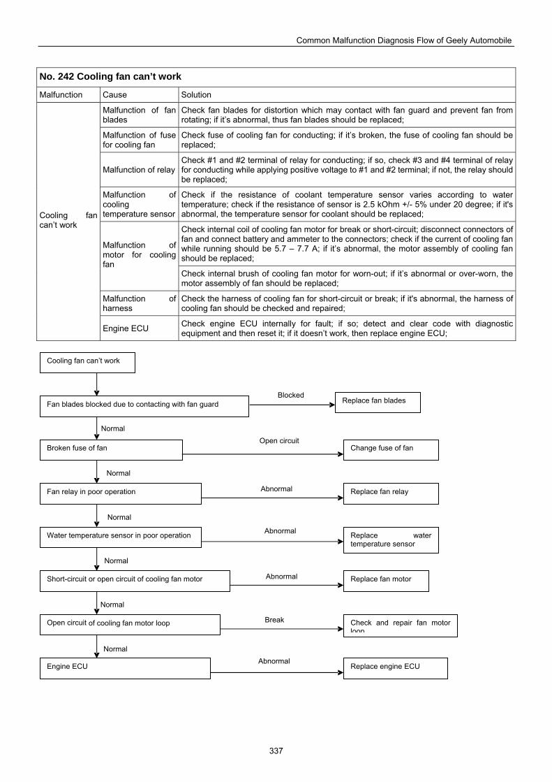
Common Malfunction Diagnosis Flow of Geely Automobile
337
No. 242 Cooling fan can’t work
Malfunction Cause Solution
Malfunction of fan blades
Check fan blades for distortion which may contact with fan guard and prevent fan from rotating; if it’s abnormal, thus fan blades should be replaced;
Malfunction of fuse for cooling fan
Check fuse of cooling fan for conducting; if it’s broken, the fuse of cooling fan should be replaced;
Malfunction of relay Check #1 and #2 terminal of relay for conducting; if so, check #3 and #4 terminal of relay for conducting while applying positive voltage to #1 and #2 terminal; if not, the relay should be replaced;
Malfunction of cooling temperature sensor
Check if the resistance of coolant temperature sensor varies according to water temperature; check if the resistance of sensor is 2.5 kOhm +/- 5% under 20 degree; if it's abnormal, the temperature sensor for coolant should be replaced;
Check internal coil of cooling fan motor for break or short-circuit; disconnect connectors of fan and connect battery and ammeter to the connectors; check if the current of cooling fan while running should be 5.7 – 7.7 A; if it’s abnormal, the motor assembly of cooling fan should be replaced;
Malfunction of motor for cooling fan
Check internal brush of cooling fan motor for worn-out; if it’s abnormal or over-worn, the motor assembly of fan should be replaced;
Malfunction of harness
Check the harness of cooling fan for short-circuit or break; if it's abnormal, the harness of cooling fan should be checked and repaired;
Cooling fan can’t work
Engine ECU Check engine ECU internally for fault; if so; detect and clear code with diagnostic equipment and then reset it; if it doesn’t work, then replace engine ECU;
Cooling fan can’t work
Fan blades blocked due to contacting with fan guard
Broken fuse of fan Change fuse of fan
Fan relay in poor operation Replace fan relay
Water temperature sensor in poor operation
Short-circuit or open circuit of cooling fan motor
Replace water temperature sensor
Replace fan motor
Open circuit of cooling fan motor loop Check and repair fan motor loop
Engine ECU Replace engine ECU
Replace fan blades
Abnormal
Normal
Normal
Normal
Normal
Normal
Normal
Break
Abnormal
Abnormal
Abnormal
Open circuit
Blocked
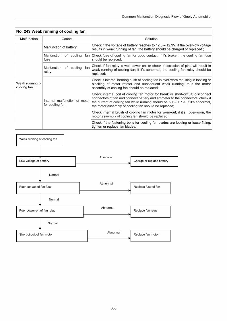
Common Malfunction Diagnosis Flow of Geely Automobile
338
No. 243 Weak running of cooling fan
Malfunction Cause Solution
Malfunction of battery Check if the voltage of battery reaches to 12.5 – 12.9V, if the over-low voltage results in weak running of fan, the battery should be charged or replaced ;
Malfunction of cooling fan fuse
Check fuse of cooling fan for good contact; if it’s broken, the cooling fan fuse should be replaced;
Malfunction of cooling fan relay
Check if fan relay is well power-on; or check if corrosion of pins will result in weak running of cooling fan; if it’s abnormal, the cooling fan relay should be replaced;
Check if internal bearing bush of cooling fan is over-worn resulting in loosing or blocking of motor rotator and subsequent weak running; thus the motor assembly of cooling fan should be replaced;
Check internal coil of cooling fan motor for break or short-circuit; disconnect connectors of fan and connect battery and ammeter to the connectors; check if the current of cooling fan while running should be 5.7 – 7.7 A; if it’s abnormal, the motor assembly of cooling fan should be replaced;
Check internal brush of cooling fan motor for worn-out; if it’s over-worn, the motor assembly of cooling fan should be replaced;
Weak running of cooling fan
Internal malfunction of motor for cooling fan
Check if the fastening bolts for cooling fan blades are loosing or loose fitting; tighten or replace fan blades;
Weak running of cooling fan
Low voltage of battery Charge or replace battery
Poor contact of fan fuse Replace fuse of fan
Poor power-on of fan relay Replace fan relay
Short-circuit of fan motor Replace fan motor Abnormal
Normal
Normal
Normal
Abnormal
Abnormal
Over-low
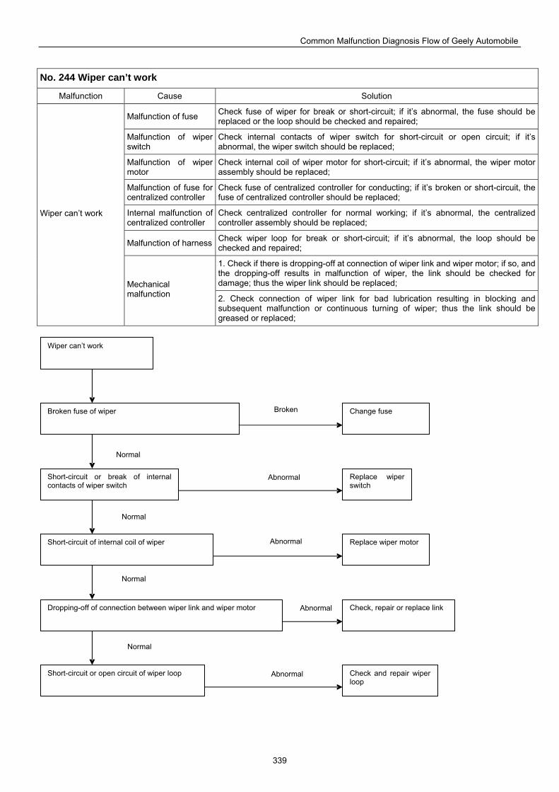
Common Malfunction Diagnosis Flow of Geely Automobile
339
No. 244 Wiper can’t work
Malfunction Cause Solution
Malfunction of fuse Check fuse of wiper for break or short-circuit; if it’s abnormal, the fuse should be replaced or the loop should be checked and repaired;
Malfunction of wiper switch
Check internal contacts of wiper switch for short-circuit or open circuit; if it’s abnormal, the wiper switch should be replaced;
Malfunction of wiper motor
Check internal coil of wiper motor for short-circuit; if it’s abnormal, the wiper motor assembly should be replaced;
Malfunction of fuse for centralized controller
Check fuse of centralized controller for conducting; if it’s broken or short-circuit, the fuse of centralized controller should be replaced;
Internal malfunction of centralized controller
Check centralized controller for normal working; if it’s abnormal, the centralized controller assembly should be replaced;
Malfunction of harness Check wiper loop for break or short-circuit; if it’s abnormal, the loop should be checked and repaired;
1. Check if there is dropping-off at connection of wiper link and wiper motor; if so, and the dropping-off results in malfunction of wiper, the link should be checked for damage; thus the wiper link should be replaced;
Wiper can’t work
Mechanical malfunction 2. Check connection of wiper link for bad lubrication resulting in blocking and
subsequent malfunction or continuous turning of wiper; thus the link should be greased or replaced;
Wiper can’t work
Broken fuse of wiper Change fuse
Short-circuit or break of internal contacts of wiper switch
Replace wiper switch
Short-circuit of internal coil of wiper Replace wiper motor
Dropping-off of connection between wiper link and wiper motor
Short-circuit or open circuit of wiper loop
Check, repair or replace link
Check and repair wiper loop
Abnormal
Normal
Normal
Normal
Normal
Abnormal
Abnormal
Abnormal
Broken
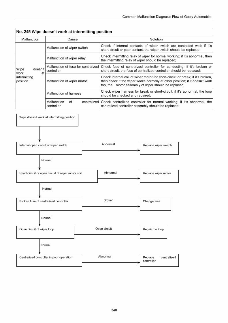
Common Malfunction Diagnosis Flow of Geely Automobile
340
No. 245 Wipe doesn’t work at intermitting position
Malfunction Cause Solution
Malfunction of wiper switch Check if internal contacts of wiper switch are contacted well; if it’s short-circuit or poor contact, the wiper switch should be replaced;
Malfunction of wiper relay Check intermitting relay of wiper for normal working; if it’s abnormal, then the intermitting relay of wiper should be replaced;
Malfunction of fuse for centralized controller
Check fuse of centralized controller for conducting; if it’s broken or short-circuit, the fuse of centralized controller should be replaced;
Malfunction of wiper motor Check internal coil of wiper motor for short-circuit or break; if it’s broken, then check if the wiper works normally at other position; if it doesn't work too, the motor assembly of wiper should be replaced;
Malfunction of harness Check wiper harness for break or short-circuit; if it’s abnormal, the loop should be checked and repaired;
Wipe doesn’t work at intermitting position
Malfunction of centralized controller
Check centralized controller for normal working; if it’s abnormal, the centralized controller assembly should be replaced;
Wipe doesn’t work at intermitting position
Internal open circuit of wiper switch Replace wiper switch
Short-circuit or open circuit of wiper motor coil Replace wiper motor
Broken fuse of centralized controller Change fuse
Open circuit of wiper loop
Centralized controller in poor operation
Repair the loop
Replace centralized controller
Abnormal
Normal
Normal
Normal
Normal
Abnormal
Abnormal
Open circuit
Broken
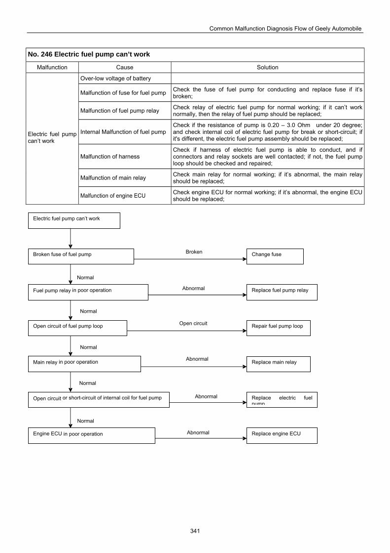
Common Malfunction Diagnosis Flow of Geely Automobile
341
No. 246 Electric fuel pump can’t work
Malfunction Cause Solution
Over-low voltage of battery
Malfunction of fuse for fuel pump Check the fuse of fuel pump for conducting and replace fuse if it’s broken;
Malfunction of fuel pump relay Check relay of electric fuel pump for normal working; if it can’t work normally, then the relay of fuel pump should be replaced;
Internal Malfunction of fuel pump Check if the resistance of pump is 0.20 – 3.0 Ohm under 20 degree; and check internal coil of electric fuel pump for break or short-circuit; if it's different, the electric fuel pump assembly should be replaced;
Malfunction of harness Check if harness of electric fuel pump is able to conduct, and if connectors and relay sockets are well contacted; if not, the fuel pump loop should be checked and repaired;
Malfunction of main relay Check main relay for normal working; if it’s abnormal, the main relay should be replaced;
Electric fuel pump can’t work
Malfunction of engine ECU Check engine ECU for normal working; if it’s abnormal, the engine ECU should be replaced;
Electric fuel pump can’t work
Broken fuse of fuel pump Change fuse
Fuel pump relay in poor operation Replace fuel pump relay
Open circuit of fuel pump loop Repair fuel pump loop
Main relay in poor operation
Open circuit or short-circuit of internal coil for fuel pump
Replace main relay
Replace electric fuel pump
Engine ECU in poor operation Replace engine ECU Abnormal
Normal
Normal
Normal
Normal
Normal
Abnormal
Abnormal
Open circuit
Abnormal
Broken
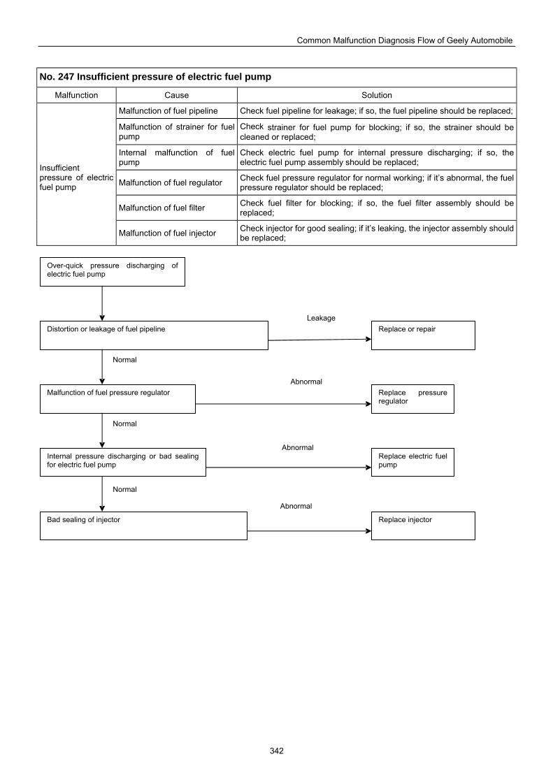
Common Malfunction Diagnosis Flow of Geely Automobile
342
No. 247 Insufficient pressure of electric fuel pump
Malfunction Cause Solution
Malfunction of fuel pipeline Check fuel pipeline for leakage; if so, the fuel pipeline should be replaced;
Malfunction of strainer for fuel pump
Check strainer for fuel pump for blocking; if so, the strainer should be cleaned or replaced;
Internal malfunction of fuel pump
Check electric fuel pump for internal pressure discharging; if so, the electric fuel pump assembly should be replaced;
Malfunction of fuel regulator Check fuel pressure regulator for normal working; if it’s abnormal, the fuel pressure regulator should be replaced;
Malfunction of fuel filter Check fuel filter for blocking; if so, the fuel filter assembly should be replaced;
Insufficient pressure of electric fuel pump
Malfunction of fuel injector Check injector for good sealing; if it’s leaking, the injector assembly should be replaced;
Over-quick pressure discharging of electric fuel pump
Distortion or leakage of fuel pipeline Replace or repair
Malfunction of fuel pressure regulator Replace pressure regulator
Internal pressure discharging or bad sealing for electric fuel pump
Replace electric fuel pump
Bad sealing of injector Replace injector
Abnormal
Normal
Abnormal
Abnormal
Leakage
Normal
Normal
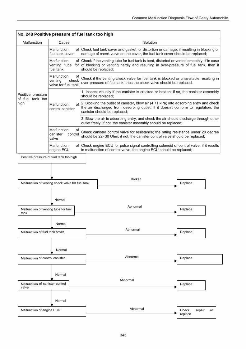
Common Malfunction Diagnosis Flow of Geely Automobile
343
No. 248 Positive pressure of fuel tank too high
Malfunction Cause Solution
Malfunction of fuel tank cover
Check fuel tank cover and gasket for distortion or damage; if resulting in blocking or damage of check valve on the cover, the fuel tank cover should be replaced;
Malfunction of venting tube for fuel tank
Check if the venting tube for fuel tank is bent, distorted or vented smoothly; if in case of blocking or venting hardly and resulting in over-pressure of fuel tank, then it should be replaced;
Malfunction of venting check valve for fuel tank
Check if the venting check valve for fuel tank is blocked or unavailable resulting in over-pressure of fuel tank, thus the check valve should be replaced.
1. Inspect visually if the canister is cracked or broken; if so, the canister assembly should be replaced;
2. Blocking the outlet of canister, blow air (4.71 kPa) into adsorbing entry and check the air discharged from desorbing outlet; if it doesn’t conform to regulation, the canister should be replaced;
Malfunction of control canister
3. Blow the air to adsorbing entry, and check the air should discharge through other outlet freely; if not, the canister assembly should be replaced;
Malfunction of canister control valve
Check canister control valve for resistance; the rating resistance under 20 degree should be 22- 30 Ohm; if not, the canister control valve should be replaced;
Positive pressure of fuel tank too high
Malfunction of engine ECU
Check engine ECU for pulse signal controlling solenoid of control valve; if it results in malfunction of control valve, the engine ECU should be replaced;
Malfunction of control canister
Malfunction of canister control valve
Malfunction of fuel tank cover
Positive pressure of fuel tank too high
Malfunction of venting check valve for fuel tank
Malfunction of venting tube for fuel tank
Malfunction of engine ECU
Replace
Replace
Replace
Check, repair or replace
Replace
Replace
Abnormal
Normal
Normal
Normal
Normal
Normal
Abnormal
Abnormal
Abnormal
Abnormal
Broken
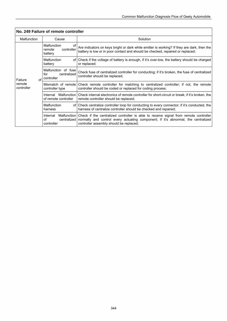
Common Malfunction Diagnosis Flow of Geely Automobile
344
No. 249 Failure of remote controller
Malfunction Cause Solution
Malfunction of remote controller battery
Are indicators on keys bright or dark while emitter is working? If they are dark, then the battery is low or in poor contact and should be checked, repaired or replaced;
Malfunction of battery
Check if the voltage of battery is enough, if it’s over-low, the battery should be charged or replaced;
Malfunction of fuse for centralized controller
Check fuse of centralized controller for conducting; if it’s broken, the fuse of centralized controller should be replaced;
Mismatch of remote controller type
Check remote controller for matching to centralized controller; if not, the remote controller should be coded or replaced for coding process;
Internal Malfunction of remote controller
Check internal electronics of remote controller for short-circuit or break; if it’s broken, the remote controller should be replaced;
Malfunction of harness
Check centralize controller loop for conducting to every connector; if it’s conducted, the harness of centralize controller should be checked and repaired;
Failure of remote controller
Internal Malfunction of centralized controller
Check if the centralized controller is able to receive signal from remote controller normally and control every actuating component; if it’s abnormal, the centralized controller assembly should be replaced;
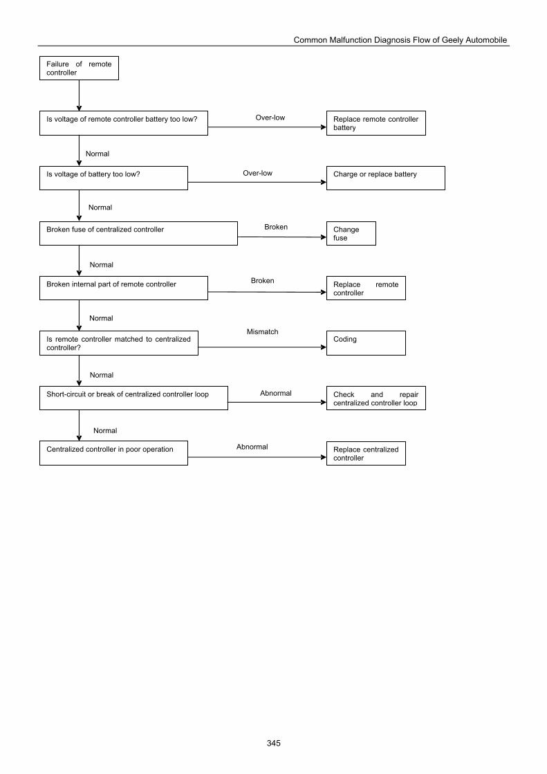
Common Malfunction Diagnosis Flow of Geely Automobile
345
Failure of remote controller
Is voltage of remote controller battery too low? Replace remote controller battery
Is voltage of battery too low? Charge or replace battery
Broken fuse of centralized controller Change fuse
Broken internal part of remote controller
Is remote controller matched to centralized controller?
Replace remote controller
Coding
Short-circuit or break of centralized controller loop Check and repair centralized controller loop
Centralized controller in poor operation Replace centralized controller
Normal
Abnormal
Normal
Normal
Normal
Normal
Normal
Over-low
Over-low
Broken
Broken
Mismatch
Abnormal
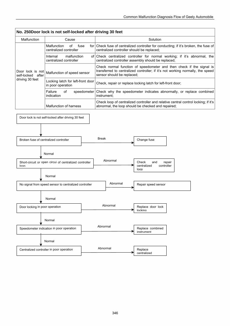
Common Malfunction Diagnosis Flow of Geely Automobile
346
No. 250Door lock is not self-locked after driving 30 feet
Malfunction Cause Solution
Malfunction of fuse for centralized controller
Check fuse of centralized controller for conducting; if it’s broken, the fuse of centralized controller should be replaced;
Internal malfunction of centralized controller
Check centralized controller for normal working; if it’s abnormal, the centralized controller assembly should be replaced;
Malfunction of speed sensor
Check normal function of speedometer and then check if the signal is transferred to centralized controller; if it’s not working normally, the speed sensor should be replaced;
Locking latch for left-front door in poor operation Check, repair or replace locking latch for left-front door;
Failure of speedometer indication
Check why the speedometer indicates abnormally, or replace combined instrument;
Door lock is not self-locked after driving 30 feet
Malfunction of harness
Check loop of centralized controller and relative central control locking; if it’s abnormal, the loop should be checked and repaired;
Change fuse Broken fuse of centralized controller
Door lock is not self-locked after driving 30 feet
Short-circuit or open circui of centralized controller loop
Check and repair centralized controller loop
Repair speed sensor No signal from speed sensor to centralized controller
Door locking in poor operation Replace door lock locking
Speedometer indication in poor operation Replace combined instrument
Centralized controller in poor operation Replace centralized
Normal
Abnormal
Normal
Normal
Normal
Normal
Abnormal
Abnormal
Abnormal
Abnormal
Break
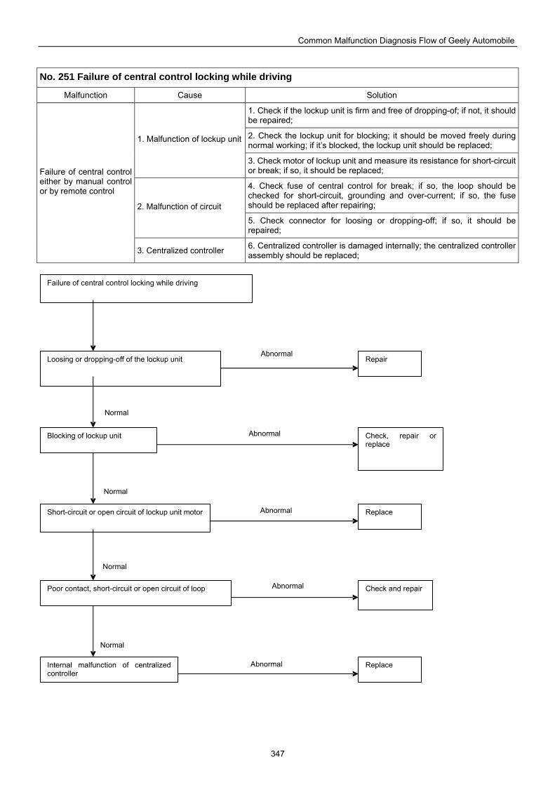
Common Malfunction Diagnosis Flow of Geely Automobile
347
No. 251 Failure of central control locking while driving
Malfunction Cause Solution
1. Check if the lockup unit is firm and free of dropping-of; if not, it should be repaired; 2. Check the lockup unit for blocking; it should be moved freely during normal working; if it’s blocked, the lockup unit should be replaced;
1. Malfunction of lockup unit
3. Check motor of lockup unit and measure its resistance for short-circuit or break; if so, it should be replaced;
4. Check fuse of central control for break; if so, the loop should be checked for short-circuit, grounding and over-current; if so, the fuse should be replaced after repairing; 2. Malfunction of circuit
5. Check connector for loosing or dropping-off; if so, it should be repaired;
Failure of central control either by manual control or by remote control
3. Centralized controller 6. Centralized controller is damaged internally; the centralized controller assembly should be replaced;
Failure of central control locking while driving
Loosing or dropping-off of the lockup unit
Blocking of lockup unit
Short-circuit or open circuit of lockup unit motor
Poor contact, short-circuit or open circuit of loop
Internal malfunction of centralized controller
Repair
Check, repair or replace
Replace
Check and repair
Replace
Normal
Abnormal
Abnormal
Normal
Normal
Abnormal
Abnormal
Abnormal
Normal
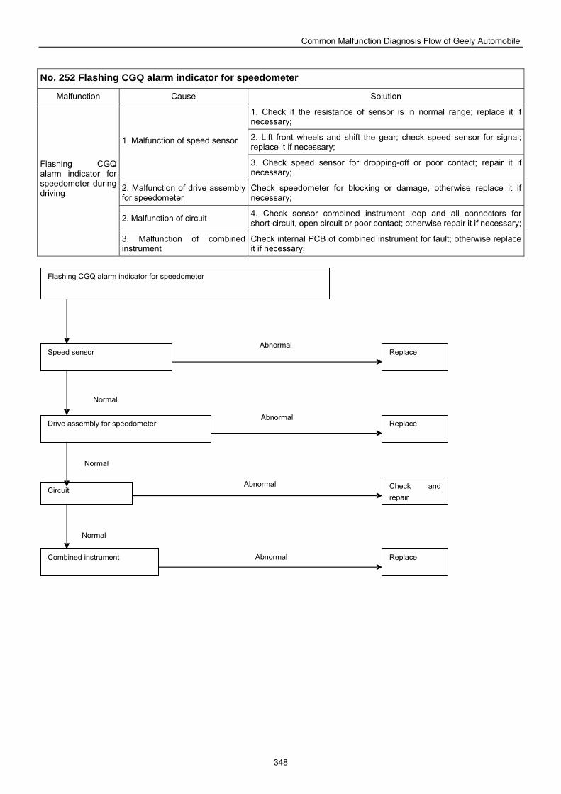
Common Malfunction Diagnosis Flow of Geely Automobile
348
No. 252 Flashing CGQ alarm indicator for speedometer
Malfunction Cause Solution
1. Check if the resistance of sensor is in normal range; replace it if necessary;
2. Lift front wheels and shift the gear; check speed sensor for signal; replace it if necessary;
1. Malfunction of speed sensor
3. Check speed sensor for dropping-off or poor contact; repair it if necessary;
2. Malfunction of drive assembly for speedometer
Check speedometer for blocking or damage, otherwise replace it if necessary;
2. Malfunction of circuit 4. Check sensor combined instrument loop and all connectors for short-circuit, open circuit or poor contact; otherwise repair it if necessary;
Flashing CGQ alarm indicator for speedometer during driving
3. Malfunction of combined instrument
Check internal PCB of combined instrument for fault; otherwise replace it if necessary;
Flashing CGQ alarm indicator for speedometer
Drive assembly for speedometer
Combined instrument
Circuit
Speed sensor
Replace
Replace
Replace
Check and repair
Normal
Abnormal
Normal
Abnormal
Normal
Abnormal
Abnormal
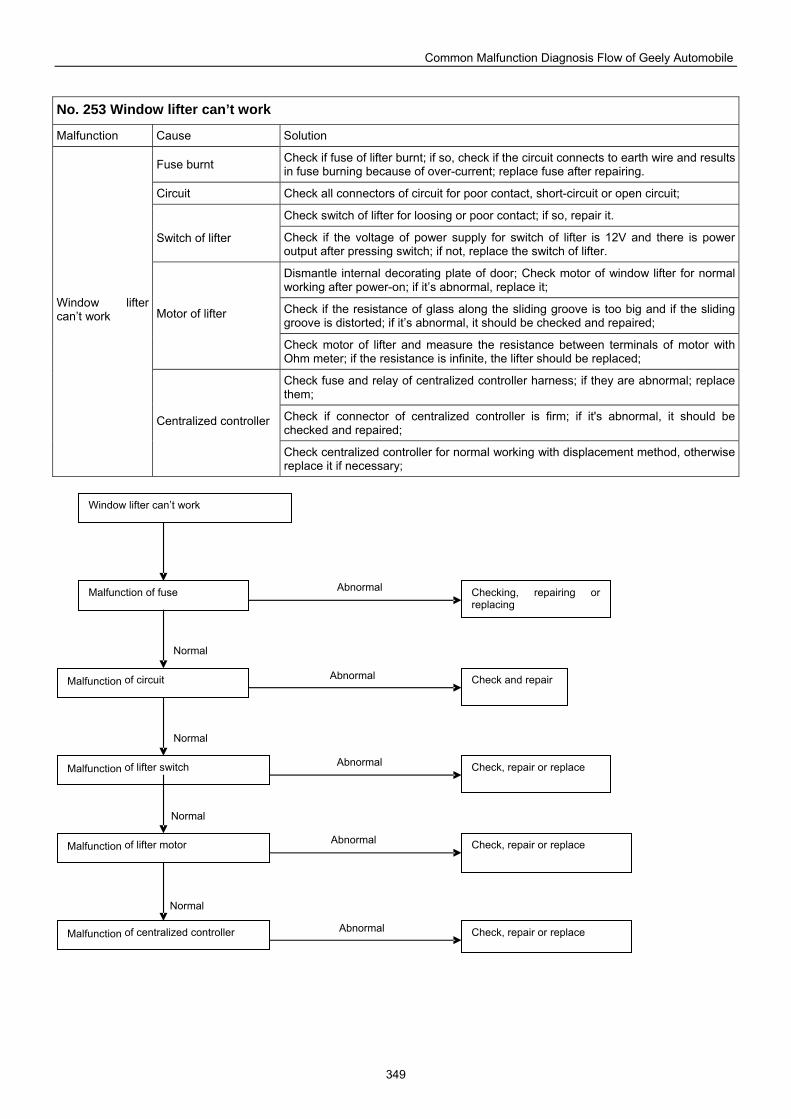
Common Malfunction Diagnosis Flow of Geely Automobile
349
No. 253 Window lifter can’t work
Malfunction Cause Solution
Fuse burnt Check if fuse of lifter burnt; if so, check if the circuit connects to earth wire and results in fuse burning because of over-current; replace fuse after repairing.
Circuit Check all connectors of circuit for poor contact, short-circuit or open circuit;
Check switch of lifter for loosing or poor contact; if so, repair it. Switch of lifter Check if the voltage of power supply for switch of lifter is 12V and there is power
output after pressing switch; if not, replace the switch of lifter.
Dismantle internal decorating plate of door; Check motor of window lifter for normal working after power-on; if it’s abnormal, replace it;
Check if the resistance of glass along the sliding groove is too big and if the sliding groove is distorted; if it’s abnormal, it should be checked and repaired;
Motor of lifter
Check motor of lifter and measure the resistance between terminals of motor with Ohm meter; if the resistance is infinite, the lifter should be replaced;
Check fuse and relay of centralized controller harness; if they are abnormal; replace them;
Check if connector of centralized controller is firm; if it's abnormal, it should be checked and repaired;
Window lifter can’t work
Centralized controller
Check centralized controller for normal working with displacement method, otherwise replace it if necessary;
Checking, repairing or replacing
Malfunction of fuse
Window lifter can’t work
Malfunction of circuit Check and repair
Malfunction of lifter switch Check, repair or replace
Malfunction of lifter motor Check, repair or replace
Malfunction of centralized controller Check, repair or replace
Normal
Abnormal
Normal
Normal
Normal
Abnormal
Abnormal
Abnormal
Abnormal
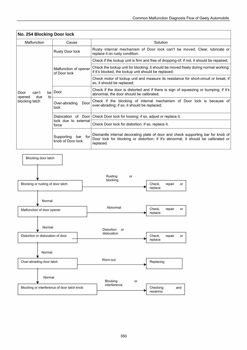
Common Malfunction Diagnosis Flow of Geely Automobile
350
No. 254 Blocking Door lock
Malfunction Cause Solution
Rusty Door lock Rusty internal mechanism of Door lock can't be moved. Clear, lubricate or replace it on rusty condition.
Check if the lockup unit is firm and free of dropping-of; if not, it should be repaired;
Check the lockup unit for blocking; it should be moved freely during normal working; if it’s blocked, the lockup unit should be replaced;
Malfunction of opener of Door lock
Check motor of lockup unit and measure its resistance for short-circuit or break; if so, it should be replaced;
Door Check if the door is distorted and if there is sign of squeezing or bumping; if it’s abnormal, the door should be calibrated;
Over-abrading Door lock
Check if the blocking of internal mechanism of Door lock is because of over-abrading; if so, it should be replaced;
Check Door lock for loosing; if so, adjust or replace it. Dislocation of Door lock due to external force Check Door lock for distortion; if so, replace it.
Door can’t be opened due to blocking latch
Supporting bar for knob of Door lock
Dismantle internal decorating plate of door and check supporting bar for knob of Door lock for blocking or distortion; if it's abnormal, it should be calibrated or replaced.
Blocking door latch
Blocking or rusting of door latch
Malfunction of door opener
Distortion or dislocation of door
Over-abrading door latch
Blocking or interference of door latch knob
Check, repair or replace
Check, repair or replace
Replacing
Check, repair or replace
Checking and repairing
Normal Blocking or interference
Normal
Normal
Normal
Rusting or blocking
Abnormal
Distortion or dislocation
Worn-out
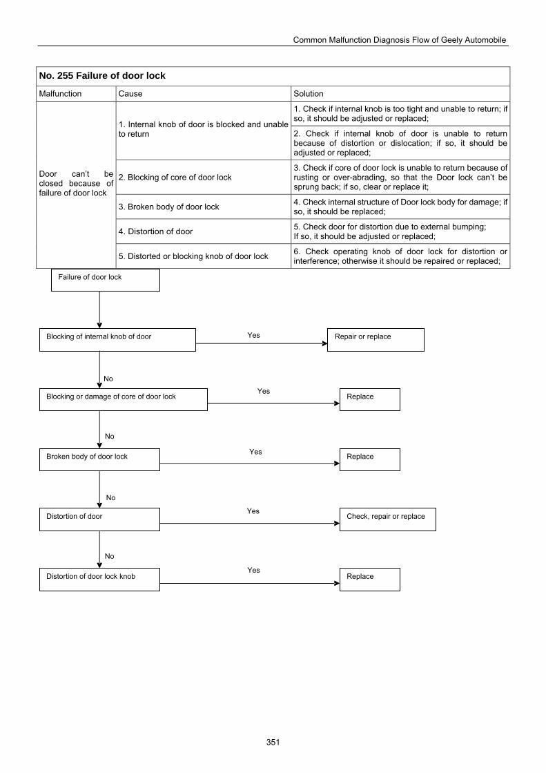
Common Malfunction Diagnosis Flow of Geely Automobile
351
No. 255 Failure of door lock
Malfunction Cause Solution
1. Check if internal knob is too tight and unable to return; if so, it should be adjusted or replaced;
1. Internal knob of door is blocked and unable to return 2. Check if internal knob of door is unable to return
because of distortion or dislocation; if so, it should be adjusted or replaced;
2. Blocking of core of door lock 3. Check if core of door lock is unable to return because of rusting or over-abrading, so that the Door lock can’t be sprung back; if so, clear or replace it;
3. Broken body of door lock 4. Check internal structure of Door lock body for damage; if so, it should be replaced;
4. Distortion of door 5. Check door for distortion due to external bumping; If so, it should be adjusted or replaced;
Door can’t be closed because of failure of door lock
5. Distorted or blocking knob of door lock 6. Check operating knob of door lock for distortion or interference; otherwise it should be repaired or replaced;
Failure of door lock
Blocking of internal knob of door
Blocking or damage of core of door lock
Broken body of door lock
Distortion of door
Distortion of door lock knob
Repair or replace
Replace
Replace
Check, repair or replace
Replace
No
No
No
No
Yes
Yes
Yes
Yes
Yes
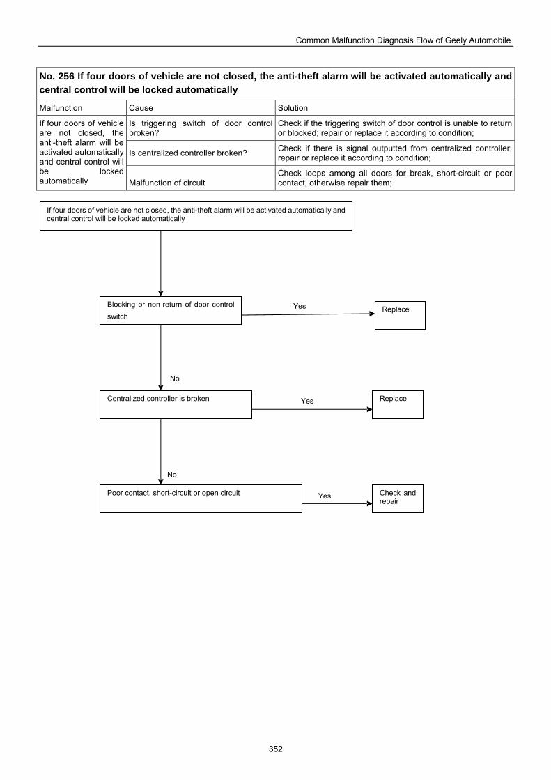
Common Malfunction Diagnosis Flow of Geely Automobile
352
No. 256 If four doors of vehicle are not closed, the anti-theft alarm will be activated automatically and central control will be locked automatically
Malfunction Cause Solution
Is triggering switch of door control broken?
Check if the triggering switch of door control is unable to return or blocked; repair or replace it according to condition;
Is centralized controller broken? Check if there is signal outputted from centralized controller; repair or replace it according to condition;
If four doors of vehicle are not closed, the anti-theft alarm will be activated automatically and central control will be locked automatically
Malfunction of circuit
Check loops among all doors for break, short-circuit or poor contact, otherwise repair them;
If four doors of vehicle are not closed, the anti-theft alarm will be activated automatically and central control will be locked automatically
Blocking or non-return of door control switch
Centralized controller is broken
Poor contact, short-circuit or open circuit
Replace
Replace
Check and repair
No
Yes
No
Yes
Yes
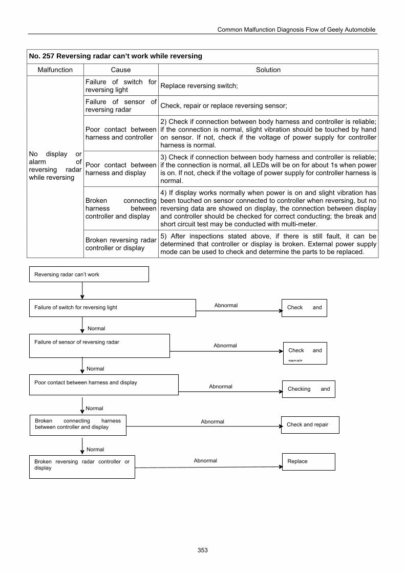
Common Malfunction Diagnosis Flow of Geely Automobile
353
No. 257 Reversing radar can’t work while reversing
Malfunction Cause Solution
Failure of switch for reversing light Replace reversing switch;
Failure of sensor of reversing radar Check, repair or replace reversing sensor;
Poor contact between harness and controller
2) Check if connection between body harness and controller is reliable; if the connection is normal, slight vibration should be touched by hand on sensor. If not, check if the voltage of power supply for controller harness is normal.
Poor contact between harness and display
3) Check if connection between body harness and controller is reliable; if the connection is normal, all LEDs will be on for about 1s when power is on. If not, check if the voltage of power supply for controller harness is normal.
Broken connecting harness between controller and display
4) If display works normally when power is on and slight vibration has been touched on sensor connected to controller when reversing, but no reversing data are showed on display, the connection between display and controller should be checked for correct conducting; the break and short circuit test may be conducted with multi-meter.
No display or alarm of reversing radar while reversing
Broken reversing radar controller or display
5) After inspections stated above, if there is still fault, it can be determined that controller or display is broken. External power supply mode can be used to check and determine the parts to be replaced.
Reversing radar can’t work
Check and Failure of switch for reversing light
Failure of sensor of reversing radar Check and
repair
Poor contact between harness and display
Broken connecting harness between controller and display
Broken reversing radar controller or display
Checking and
Check and repair
Replace Normal
Abnormal
Normal
Normal
Normal
Abnormal
Abnormal
Abnormal
Abnormal
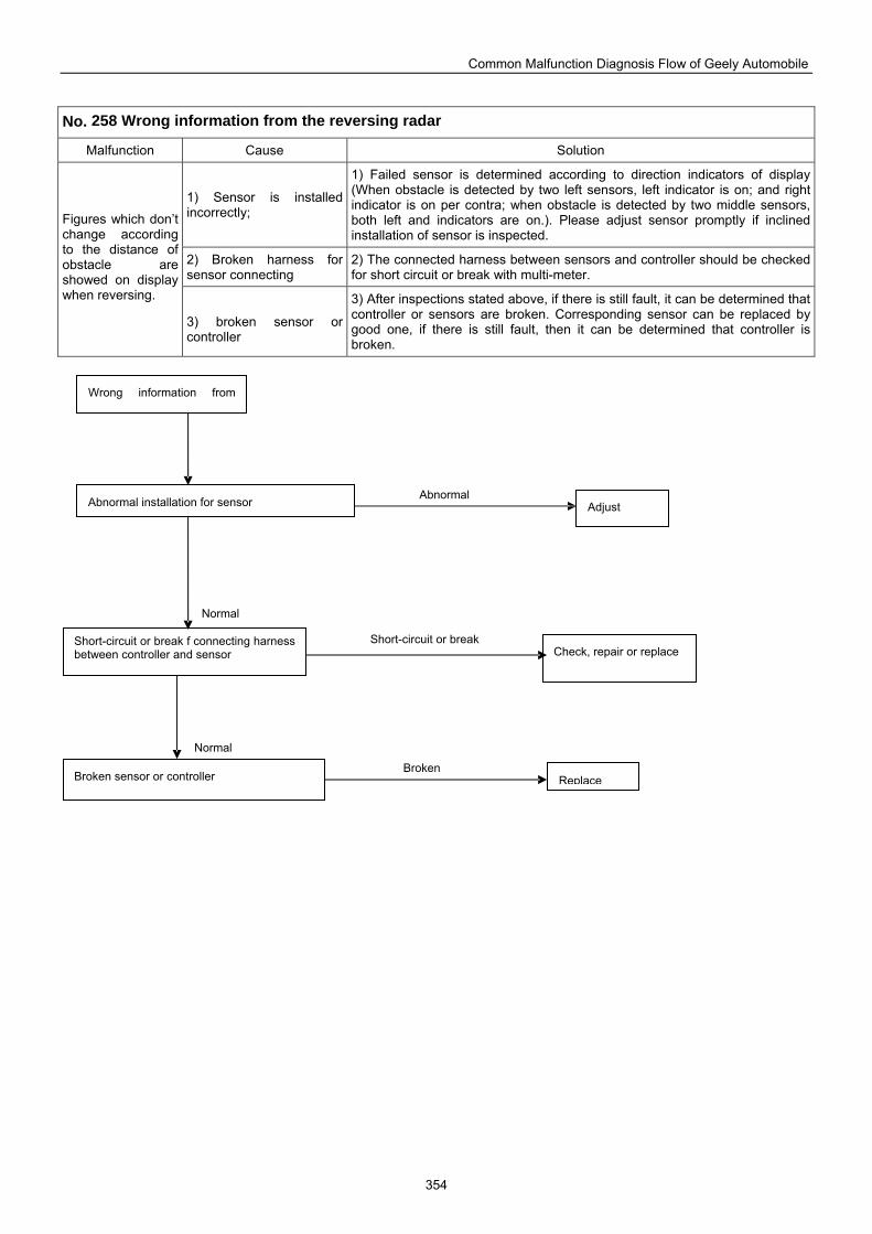
Common Malfunction Diagnosis Flow of Geely Automobile
354
No. 258 Wrong information from the reversing radar
Malfunction Cause Solution
1) Sensor is installed incorrectly;
1) Failed sensor is determined according to direction indicators of display (When obstacle is detected by two left sensors, left indicator is on; and right indicator is on per contra; when obstacle is detected by two middle sensors, both left and indicators are on.). Please adjust sensor promptly if inclined installation of sensor is inspected.
2) Broken harness for sensor connecting
2) The connected harness between sensors and controller should be checked for short circuit or break with multi-meter.
Figures which don’t change according to the distance of obstacle are showed on display when reversing.
3) broken sensor or controller
3) After inspections stated above, if there is still fault, it can be determined that controller or sensors are broken. Corresponding sensor can be replaced by good one, if there is still fault, then it can be determined that controller is broken.
Wrong information from
Adjust Abnormal installation for sensor
Short-circuit or break f connecting harness between controller and sensor Check, repair or replace
Broken sensor or controller Replace
Normal
Abnormal
Normal
Short-circuit or break
Broken
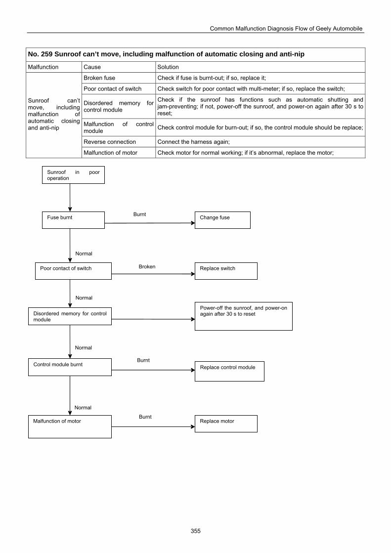
Common Malfunction Diagnosis Flow of Geely Automobile
355
No. 259 Sunroof can’t move, including malfunction of automatic closing and anti-nip
Malfunction Cause Solution
Broken fuse Check if fuse is burnt-out; if so, replace it;
Poor contact of switch Check switch for poor contact with multi-meter; if so, replace the switch;
Disordered memory for control module
Check if the sunroof has functions such as automatic shutting and jam-preventing; if not, power-off the sunroof, and power-on again after 30 s to reset;
Malfunction of control module Check control module for burn-out; if so, the control module should be replace;
Reverse connection Connect the harness again;
Sunroof can’t move, including malfunction of automatic closing and anti-nip
Malfunction of motor Check motor for normal working; if it’s abnormal, replace the motor;
Sunroof in poor operation
Fuse burnt Change fuse
Disordered memory for control module
Poor contact of switch Replace switch
Power-off the sunroof, and power-on again after 30 s to reset
Control module burnt Replace control module
Malfunction of motor Replace motor
Normal
Burnt
Normal
Normal
Normal
Broken
Burnt
Burnt
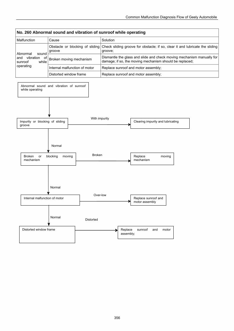
Common Malfunction Diagnosis Flow of Geely Automobile
356
No. 260 Abnormal sound and vibration of sunroof while operating
Malfunction Cause Solution
Obstacle or blocking of sliding groove
Check sliding groove for obstacle; if so, clear it and lubricate the sliding groove;
Broken moving mechanism Dismantle the glass and slide and check moving mechanism manually for damage; if so, the moving mechanism should be replaced;
Internal malfunction of motor Replace sunroof and motor assembly;
Abnormal sound and vibration of sunroof while operating
Distorted window frame Replace sunroof and motor assembly;
Clearing impurity and lubricating Impurity or blocking of sliding groove
Broken or blocking moving mechanism
Replace moving mechanism
Internal malfunction of motor Replace sunroof and motor assembly
Distorted window frame Replace sunroof and motor assembly;
Abnormal sound and vibration of sunroof while operating
Normal
Normal
Normal
With impurity
Broken
Over-low
Distorted
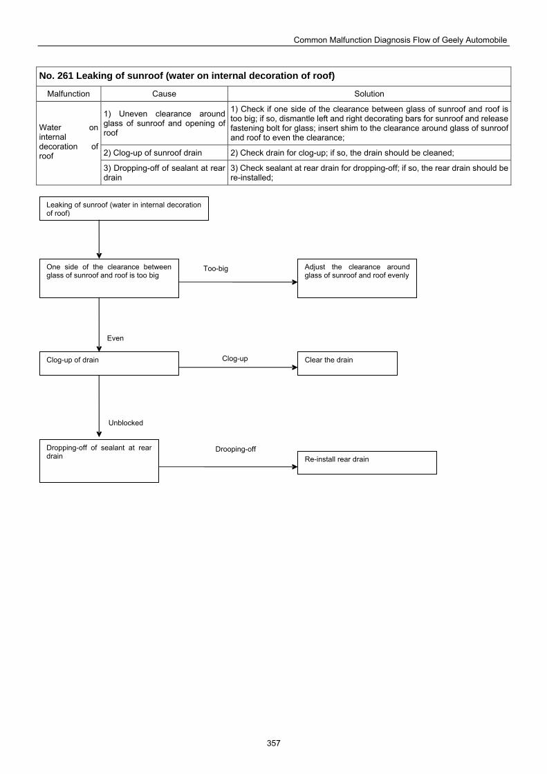
Common Malfunction Diagnosis Flow of Geely Automobile
357
No. 261 Leaking of sunroof (water on internal decoration of roof)
Malfunction Cause Solution
1) Uneven clearance around glass of sunroof and opening of roof
1) Check if one side of the clearance between glass of sunroof and roof is too big; if so, dismantle left and right decorating bars for sunroof and release fastening bolt for glass; insert shim to the clearance around glass of sunroof and roof to even the clearance;
2) Clog-up of sunroof drain 2) Check drain for clog-up; if so, the drain should be cleaned;
Water on internal decoration of roof
3) Dropping-off of sealant at rear drain
3) Check sealant at rear drain for dropping-off; if so, the rear drain should be re-installed;
Leaking of sunroof (water in internal decoration of roof)
One side of the clearance between glass of sunroof and roof is too big
Adjust the clearance around glass of sunroof and roof evenly
Clog-up of drain Clear the drain
Dropping-off of sealant at rear drain Re-install rear drain
Unblocked
Even
Too-big
Clog-up
Drooping-off
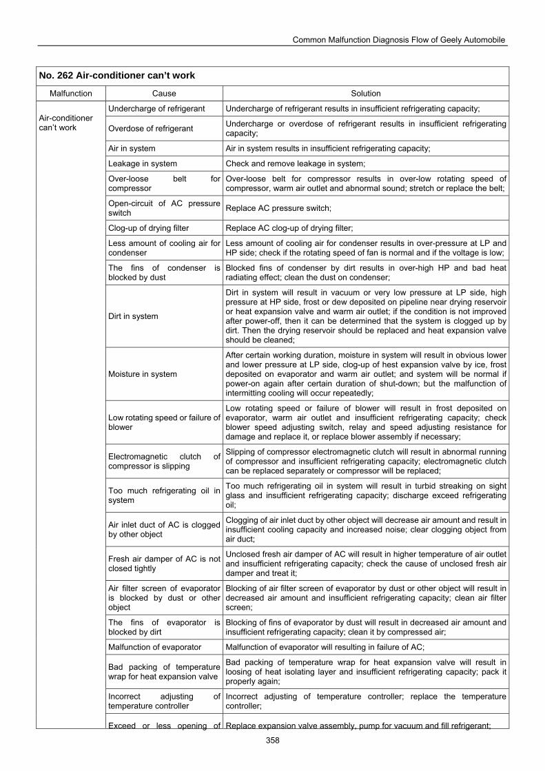
Common Malfunction Diagnosis Flow of Geely Automobile
358
No. 262 Air-conditioner can’t work
Malfunction Cause Solution
Undercharge of refrigerant Undercharge of refrigerant results in insufficient refrigerating capacity;
Overdose of refrigerant Undercharge or overdose of refrigerant results in insufficient refrigerating capacity;
Air in system Air in system results in insufficient refrigerating capacity;
Leakage in system Check and remove leakage in system;
Over-loose belt for compressor
Over-loose belt for compressor results in over-low rotating speed of compressor, warm air outlet and abnormal sound; stretch or replace the belt;
Open-circuit of AC pressure switch Replace AC pressure switch;
Clog-up of drying filter Replace AC clog-up of drying filter;
Less amount of cooling air for condenser
Less amount of cooling air for condenser results in over-pressure at LP and HP side; check if the rotating speed of fan is normal and if the voltage is low;
The fins of condenser is blocked by dust
Blocked fins of condenser by dirt results in over-high HP and bad heat radiating effect; clean the dust on condenser;
Dirt in system
Dirt in system will result in vacuum or very low pressure at LP side, high pressure at HP side, frost or dew deposited on pipeline near drying reservoir or heat expansion valve and warm air outlet; if the condition is not improved after power-off, then it can be determined that the system is clogged up by dirt. Then the drying reservoir should be replaced and heat expansion valve should be cleaned;
Moisture in system
After certain working duration, moisture in system will result in obvious lower and lower pressure at LP side, clog-up of hest expansion valve by ice, frost deposited on evaporator and warm air outlet; and system will be normal if power-on again after certain duration of shut-down; but the malfunction of intermitting cooling will occur repeatedly;
Low rotating speed or failure of blower
Low rotating speed or failure of blower will result in frost deposited on evaporator, warm air outlet and insufficient refrigerating capacity; check blower speed adjusting switch, relay and speed adjusting resistance for damage and replace it, or replace blower assembly if necessary;
Electromagnetic clutch of compressor is slipping
Slipping of compressor electromagnetic clutch will result in abnormal running of compressor and insufficient refrigerating capacity; electromagnetic clutch can be replaced separately or compressor will be replaced;
Too much refrigerating oil in system
Too much refrigerating oil in system will result in turbid streaking on sight glass and insufficient refrigerating capacity; discharge exceed refrigerating oil;
Air inlet duct of AC is clogged by other object
Clogging of air inlet duct by other object will decrease air amount and result in insufficient cooling capacity and increased noise; clear clogging object from air duct;
Fresh air damper of AC is not closed tightly
Unclosed fresh air damper of AC will result in higher temperature of air outlet and insufficient refrigerating capacity; check the cause of unclosed fresh air damper and treat it;
Air filter screen of evaporator is blocked by dust or other object
Blocking of air filter screen of evaporator by dust or other object will result in decreased air amount and insufficient refrigerating capacity; clean air filter screen;
The fins of evaporator is blocked by dirt
Blocking of fins of evaporator by dust will result in decreased air amount and insufficient refrigerating capacity; clean it by compressed air;
Malfunction of evaporator Malfunction of evaporator will resulting in failure of AC;
Bad packing of temperature wrap for heat expansion valve
Bad packing of temperature wrap for heat expansion valve will result in loosing of heat isolating layer and insufficient refrigerating capacity; pack it properly again;
Incorrect adjusting of temperature controller
Incorrect adjusting of temperature controller; replace the temperature controller;
Air-conditioner can’t work
Exceed or less opening of Replace expansion valve assembly, pump for vacuum and fill refrigerant;
Common Malfunction Diagnosis Flow of Geely Automobile
359
expansion valve
Malfunction of compressor Malfunction of compressor will resulting in failure of AC;
Short-circuit or break of loop and harness Check and repair loop and harness;
Malfunction of engine ECU Replace engine ECU;
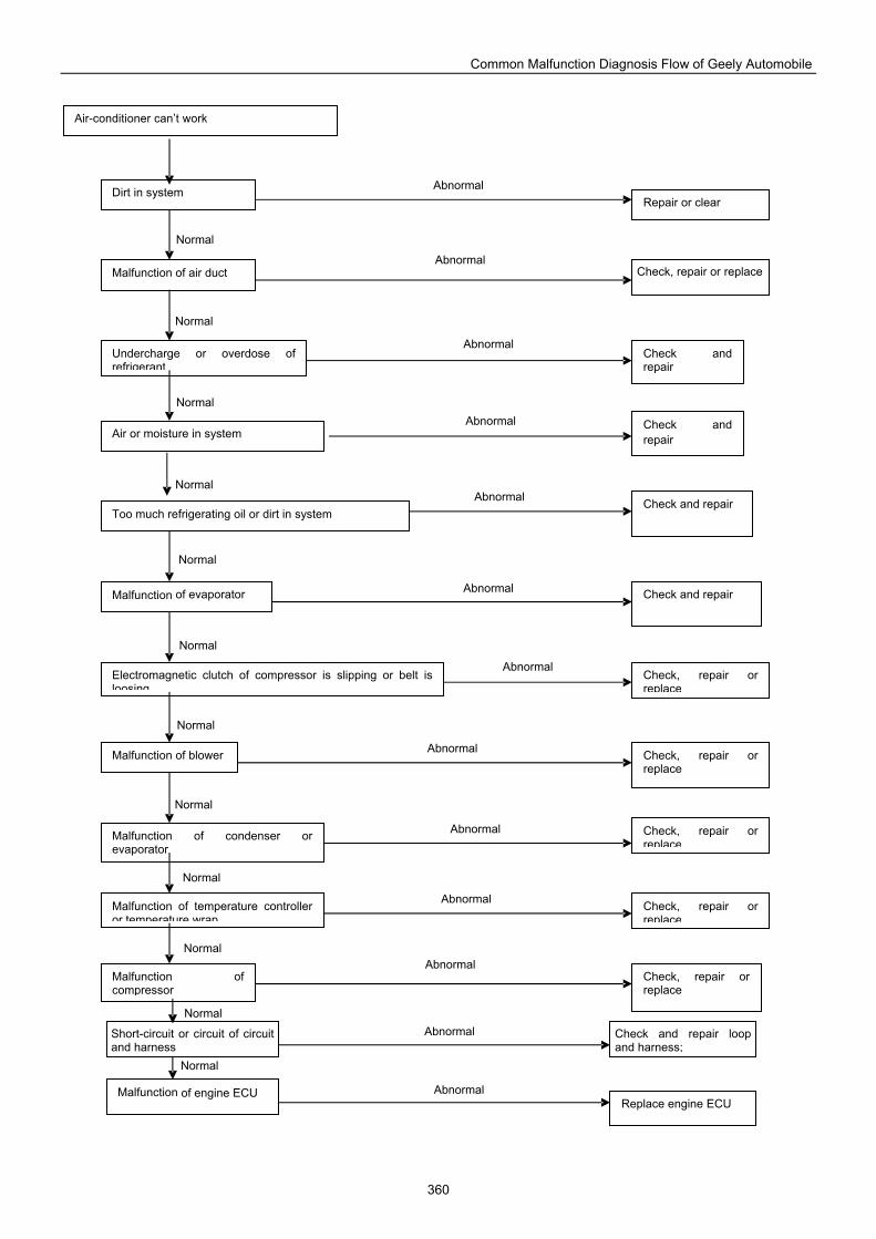
Common Malfunction Diagnosis Flow of Geely Automobile
360
Air or moisture in system
Air-conditioner can’t work
Dirt in system
Malfunction of air duct
Undercharge or overdose of refrigerant
Repair or clear
Check, repair or replace
Check and repair
Malfunction of evaporator
Too much refrigerating oil or dirt in system
Electromagnetic clutch of compressor is slipping or belt is loosing
Malfunction of blower
Malfunction of condenser or evaporator
Malfunction of temperature controller or temperature wrap
Malfunction of compressor
Check and repair
Check and repair
Check, repair or replace
Check, repair or replace
Check, repair or replace
Check, repair or replace
Check, repair or replace
Check and repair
Short-circuit or circuit of circuit and harness
Malfunction of engine ECU
Check and repair loop and harness;
Replace engine ECU
Normal
Abnormal
Normal
Normal
Normal
Normal
Normal
Normal
Normal
Normal
Normal
Normal
Normal
Abnormal
Abnormal
Abnormal
Abnormal
Abnormal
Abnormal
Abnormal
Abnormal
Abnormal
Abnormal
Abnormal
Abnormal
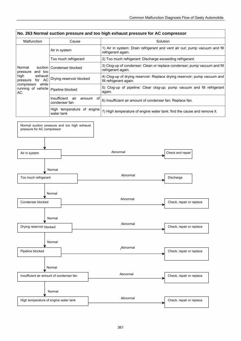
Common Malfunction Diagnosis Flow of Geely Automobile
361
No. 263 Normal suction pressure and too high exhaust pressure for AC compressor
Malfunction Cause Solution
Air in system 1) Air in system: Drain refrigerant and vent air out; pump vacuum and fill refrigerant again.
Too much refrigerant 2) Too much refrigerant: Discharge exceeding refrigerant.
Condenser blocked 3) Clog-up of condenser: Clean or replace condenser; pump vacuum and fill refrigerant again.
Drying reservoir blocked 4) Clog-up of drying reservoir: Replace drying reservoir; pump vacuum and fill refrigerant again.
Pipeline blocked 5) Clog-up of pipeline: Clear clog-up; pump vacuum and fill refrigerant again.
Insufficient air amount of condenser fan 6) Insufficient air amount of condenser fan: Replace fan.
Normal suction pressure and too high exhaust pressure for AC compressor while running of vehicle AC
High temperature of engine water tank 7) High temperature of engine water tank: find the cause and remove it.
Normal suction pressure and too high exhaust pressure for AC compressor
Too much refrigerant
Condenser blocked
Air in system
Drying reservoir blocked
Pipeline blocked
Insufficient air amount of condenser fan
High temperature of engine water tank
Check and repair
Discharge
Check, repair or replace
Check, repair or replace
Check, repair or replace
Check, repair or replace
Check, repair or replace
Normal
Abnormal
Normal
Abnormal
Normal
Abnormal Abnormal
Normal Abnormal
Normal Abnormal
Normal Abnormal
Abnormal
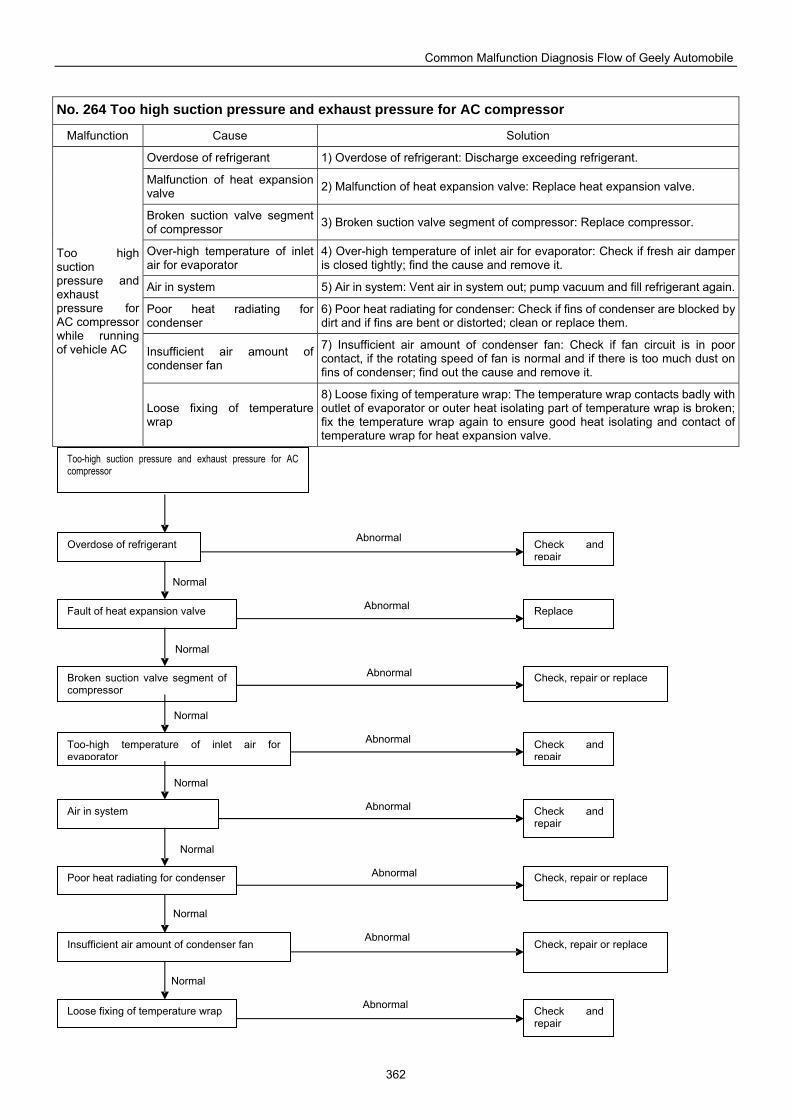
Common Malfunction Diagnosis Flow of Geely Automobile
362
No. 264 Too high suction pressure and exhaust pressure for AC compressor
Malfunction Cause Solution
Overdose of refrigerant 1) Overdose of refrigerant: Discharge exceeding refrigerant.
Malfunction of heat expansion valve 2) Malfunction of heat expansion valve: Replace heat expansion valve.
Broken suction valve segment of compressor 3) Broken suction valve segment of compressor: Replace compressor.
Over-high temperature of inlet air for evaporator
4) Over-high temperature of inlet air for evaporator: Check if fresh air damper is closed tightly; find the cause and remove it.
Air in system 5) Air in system: Vent air in system out; pump vacuum and fill refrigerant again.
Poor heat radiating for condenser
6) Poor heat radiating for condenser: Check if fins of condenser are blocked by dirt and if fins are bent or distorted; clean or replace them.
Insufficient air amount of condenser fan
7) Insufficient air amount of condenser fan: Check if fan circuit is in poor contact, if the rotating speed of fan is normal and if there is too much dust on fins of condenser; find out the cause and remove it.
Too high suction pressure and exhaust pressure for AC compressor while running of vehicle AC
Loose fixing of temperature wrap
8) Loose fixing of temperature wrap: The temperature wrap contacts badly with outlet of evaporator or outer heat isolating part of temperature wrap is broken; fix the temperature wrap again to ensure good heat isolating and contact of temperature wrap for heat expansion valve.
Too-high suction pressure and exhaust pressure for AC compressor
Overdose of refrigerant
Fault of heat expansion valve
Broken suction valve segment of compressor
Too-high temperature of inlet air for evaporator
Air in system
Poor heat radiating for condenser
Insufficient air amount of condenser fan
Loose fixing of temperature wrap
Check and repair
Replace
Check, repair or replace
Check and repair
Check and repair
Check, repair or replace
Check, repair or replace
Check and repair
Normal
Abnormal
Normal
Abnormal
Normal
Abnormal
Normal
Abnormal
Normal
Abnormal
Normal
Abnormal
Normal
Abnormal
Abnormal
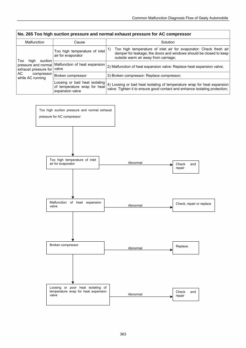
Common Malfunction Diagnosis Flow of Geely Automobile
363
No. 265 Too high suction pressure and normal exhaust pressure for AC compressor
Malfunction Cause Solution
Too high temperature of inlet air for evaporator
1) Too high temperature of inlet air for evaporator: Check fresh air damper for leakage; the doors and windows should be closed to keep outside warm air away from carriage;
Malfunction of heat expansion valve 2) Malfunction of heat expansion valve: Replace heat expansion valve;
Broken compressor 3) Broken compressor: Replace compressor;
Too high suction pressure and normal exhaust pressure for AC compressor while AC running
Loosing or bad heat isolating of temperature wrap for heat expansion valve
4) Loosing or bad heat isolating of temperature wrap for heat expansion valve: Tighten it to ensure good contact and enhance isolating protection;
Check and repair
Too high suction pressure and normal exhaust
pressure for AC compressor
Too high temperature of inlet air for evaporator
Malfunction of heat expansion valve
Broken compressor
Loosing or poor heat isolating of temperature wrap for heat expansion valve
Check and repair
Check, repair or replace
Replace
Abnormal
Abnormal
Abnormal
Abnormal
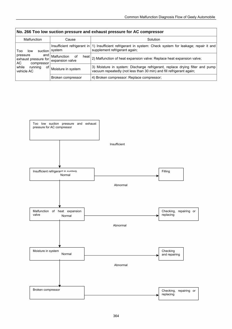
Common Malfunction Diagnosis Flow of Geely Automobile
364
Too low suction pressure and exhaust pressure for AC compressor
Insufficient refrigerant in system
Malfunction of heat expansion valve
Moisture in system
Broken compressor
Filling
Checking, repairing or replacing
Checking and repairing
Checking, repairing or replacing
No. 266 Too low suction pressure and exhaust pressure for AC compressor
Malfunction Cause Solution
Insufficient refrigerant in system
1) Insufficient refrigerant in system: Check system for leakage; repair it and supplement refrigerant again;
Malfunction of heat expansion valve 2) Malfunction of heat expansion valve: Replace heat expansion valve;
Moisture in system 3) Moisture in system: Discharge refrigerant, replace drying filter and pump vacuum repeatedly (not less than 30 min) and fill refrigerant again;
Too low suction pressure and exhaust pressure for AC compressor while running of vehicle AC
Broken compressor 4) Broken compressor: Replace compressor;
Normal
Abnormal
Normal
Normal
Abnormal
Abnormal
Insufficient
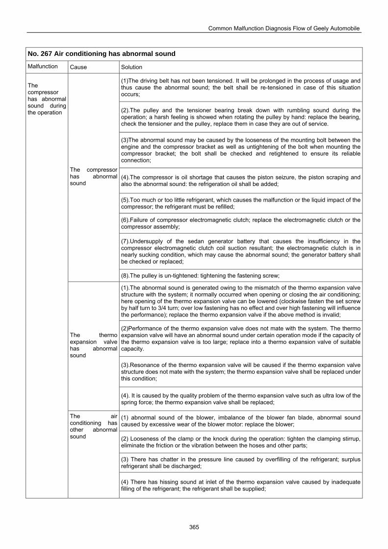
Common Malfunction Diagnosis Flow of Geely Automobile
365
No. 267 Air conditioning has abnormal sound
Malfunction t
Cause Solution
(1)The driving belt has not been tensioned. It will be prolonged in the process of usage and thus cause the abnormal sound; the belt shall be re-tensioned in case of this situation occurs;
(2).The pulley and the tensioner bearing break down with rumbling sound during the operation; a harsh feeling is showed when rotating the pulley by hand: replace the bearing, check the tensioner and the pulley, replace them in case they are out of service.
(3)The abnormal sound may be caused by the looseness of the mounting bolt between the engine and the compressor bracket as well as untightening of the bolt when mounting the compressor bracket; the bolt shall be checked and retightened to ensure its reliable connection;
(4).The compressor is oil shortage that causes the piston seizure, the piston scraping and also the abnormal sound: the refrigeration oil shall be added;
(5).Too much or too little refrigerant, which causes the malfunction or the liquid impact of the compressor; the refrigerant must be refilled;
(6).Failure of compressor electromagnetic clutch; replace the electromagnetic clutch or the compressor assembly;
(7).Undersupply of the sedan generator battery that causes the insufficiency in the compressor electromagnetic clutch coil suction resultant; the electromagnetic clutch is in nearly sucking condition, which may cause the abnormal sound; the generator battery shall be checked or replaced;
The compressor has abnormal sound
(8).The pulley is un-tightened: tightening the fastening screw;
(1).The abnormal sound is generated owing to the mismatch of the thermo expansion valve structure with the system; it normally occurred when opening or closing the air conditioning; here opening of the thermo expansion valve can be lowered (clockwise fasten the set screw by half turn to 3/4 turn; over low fastening has no effect and over high fastening will influence the performance); replace the thermo expansion valve if the above method is invalid;
(2)Performance of the thermo expansion valve does not mate with the system. The thermo expansion valve will have an abnormal sound under certain operation mode if the capacity of the thermo expansion valve is too large; replace into a thermo expansion valve of suitable capacity.
(3).Resonance of the thermo expansion valve will be caused if the thermo expansion valve structure does not mate with the system; the thermo expansion valve shall be replaced under this condition;
The thermo expansion valve has abnormal sound
(4). It is caused by the quality problem of the thermo expansion valve such as ultra low of the spring force; the thermo expansion valve shall be replaced;
(1) abnormal sound of the blower, imbalance of the blower fan blade, abnormal sound caused by excessive wear of the blower motor: replace the blower;
(2) Looseness of the clamp or the knock during the operation: tighten the clamping stirrup, eliminate the friction or the vibration between the hoses and other parts;
(3) There has chatter in the pressure line caused by overfilling of the refrigerant; surplus refrigerant shall be discharged;
The compressor has abnormal sound during the operation
The air conditioning has other abnormal sound
(4) There has hissing sound at inlet of the thermo expansion valve caused by inadequate filling of the refrigerant; the refrigerant shall be supplied;
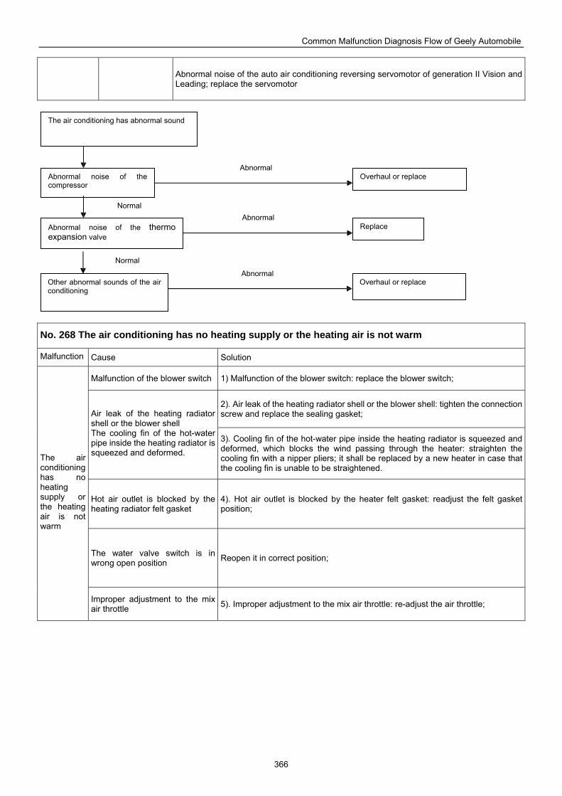
Common Malfunction Diagnosis Flow of Geely Automobile
366
Abnormal noise of the auto air conditioning reversing servomotor of generation II Vision and Leading; replace the servomotor
No. 268 The air conditioning has no heating supply or the heating air is not warm
Malfunction t
Cause Solution
Malfunction of the blower switch 1) Malfunction of the blower switch: replace the blower switch;
2). Air leak of the heating radiator shell or the blower shell: tighten the connection screw and replace the sealing gasket; Air leak of the heating radiator
shell or the blower shell The cooling fin of the hot-water pipe inside the heating radiator is squeezed and deformed.
3). Cooling fin of the hot-water pipe inside the heating radiator is squeezed and deformed, which blocks the wind passing through the heater: straighten the cooling fin with a nipper pliers; it shall be replaced by a new heater in case that the cooling fin is unable to be straightened.
Hot air outlet is blocked by the heating radiator felt gasket
4). Hot air outlet is blocked by the heater felt gasket: readjust the felt gasket position;
The water valve switch is in wrong open position Reopen it in correct position;
The air conditioning has no heating supply or the heating air is not warm
Improper adjustment to the mix air throttle 5). Improper adjustment to the mix air throttle: re-adjust the air throttle;
The air conditioning has abnormal sound
Abnormal noise of the compressor
Other abnormal sounds of the air conditioning
Abnormal noise of the thermo expansion valve
Overhaul or replace
Overhaul or replace
Replace
Normal
Abnormal
Abnormal
Abnormal
Normal
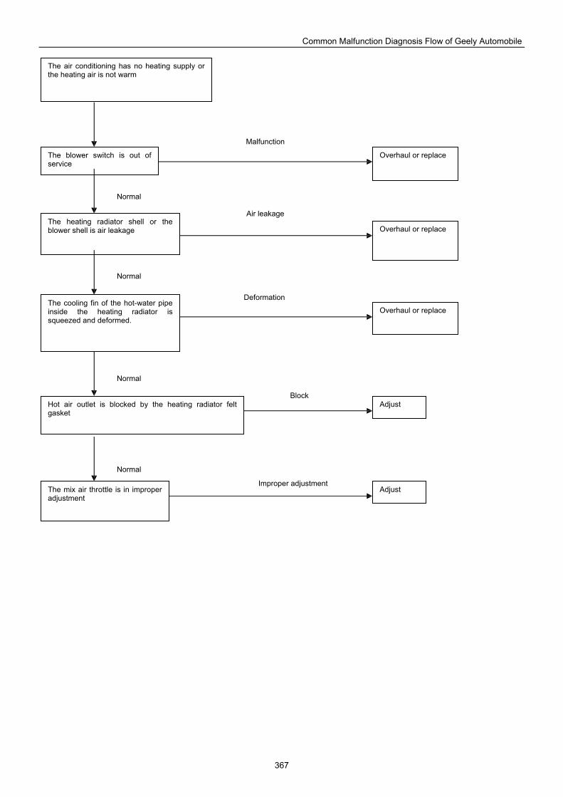
Common Malfunction Diagnosis Flow of Geely Automobile
367
The air conditioning has no heating supply or the heating air is not warm
The blower switch is out of service
The heating radiator shell or the blower shell is air leakage
The cooling fin of the hot-water pipe inside the heating radiator is squeezed and deformed.
Hot air outlet is blocked by the heating radiator felt gasket
The mix air throttle is in improper adjustment
Overhaul or replace
Overhaul or replace
Overhaul or replace
Adjust
Adjust
Normal
Normal
Normal
Normal
Malfunction
Air leakage
Deformation
Block
Improper adjustment
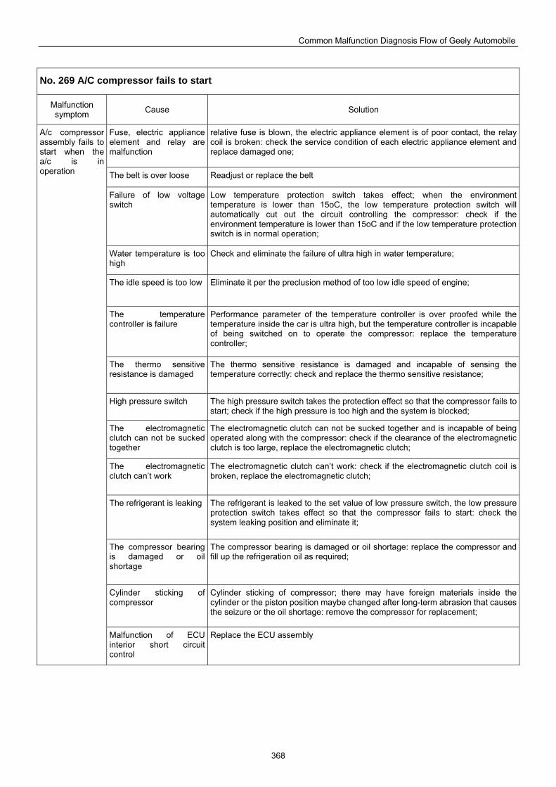
Common Malfunction Diagnosis Flow of Geely Automobile
368
No. 269 A/C compressor fails to start
Malfunction symptom Cause Solution
Fuse, electric appliance element and relay are malfunction
relative fuse is blown, the electric appliance element is of poor contact, the relay coil is broken: check the service condition of each electric appliance element and replace damaged one;
The belt is over loose Readjust or replace the belt
Failure of low voltage switch
Low temperature protection switch takes effect; when the environment temperature is lower than 15oC, the low temperature protection switch will automatically cut out the circuit controlling the compressor: check if the environment temperature is lower than 15oC and if the low temperature protection switch is in normal operation;
Water temperature is too high
Check and eliminate the failure of ultra high in water temperature;
The idle speed is too low Eliminate it per the preclusion method of too low idle speed of engine;
The temperature controller is failure
Performance parameter of the temperature controller is over proofed while the temperature inside the car is ultra high, but the temperature controller is incapable of being switched on to operate the compressor: replace the temperature controller;
The thermo sensitive resistance is damaged
The thermo sensitive resistance is damaged and incapable of sensing the temperature correctly: check and replace the thermo sensitive resistance;
High pressure switch The high pressure switch takes the protection effect so that the compressor fails to start; check if the high pressure is too high and the system is blocked;
The electromagnetic clutch can not be sucked together
The electromagnetic clutch can not be sucked together and is incapable of being operated along with the compressor: check if the clearance of the electromagnetic clutch is too large, replace the electromagnetic clutch;
The electromagnetic clutch can’t work
The electromagnetic clutch can’t work: check if the electromagnetic clutch coil is broken, replace the electromagnetic clutch;
The refrigerant is leaking The refrigerant is leaked to the set value of low pressure switch, the low pressure protection switch takes effect so that the compressor fails to start: check the system leaking position and eliminate it;
The compressor bearing is damaged or oil shortage
The compressor bearing is damaged or oil shortage: replace the compressor and fill up the refrigeration oil as required;
Cylinder sticking of compressor
Cylinder sticking of compressor; there may have foreign materials inside the cylinder or the piston position maybe changed after long-term abrasion that causes the seizure or the oil shortage: remove the compressor for replacement;
A/c compressor assembly fails to start when the a/c is in operation
Malfunction of ECU interior short circuit control
Replace the ECU assembly
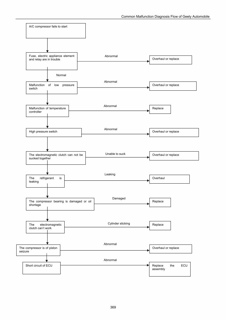
Common Malfunction Diagnosis Flow of Geely Automobile
369
A/C compressor fails to start
Fuse, electric appliance element and relay are in trouble
Malfunction of low pressure switch
Malfunction of temperature controller
High pressure switch
The electromagnetic clutch can not be sucked together
The refrigerant is leaking
The compressor bearing is damaged or oil shortage
The electromagnetic clutch can’t work
The compressor is of piston seizure
Overhaul or replace
Replace
Overhaul or replace
Overhaul or replace
Overhaul or replace
Overhaul
Replace
Replace
Overhaul or replace
Short circuit of ECU Replace the ECU assembly
Normal
Abnormal
Abnormal
Unable to suck
Abnormal
Abnormal
Leaking
Damaged
Cylinder sticking
Abnormal
Abnormal
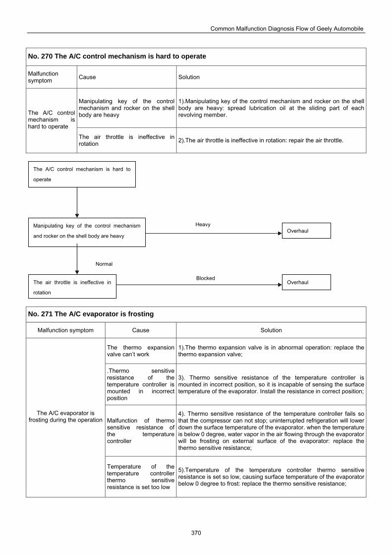
Common Malfunction Diagnosis Flow of Geely Automobile
370
No. 270 The A/C control mechanism is hard to operate
Malfunction symptom Cause Solution
Manipulating key of the control mechanism and rocker on the shell body are heavy
1).Manipulating key of the control mechanism and rocker on the shell body are heavy: spread lubrication oil at the sliding part of each revolving member. The A/C control
mechanism is hard to operate
The air throttle is ineffective in rotation 2).The air throttle is ineffective in rotation: repair the air throttle.
No. 271 The A/C evaporator is frosting
Malfunction symptom Cause Solution
The thermo expansion valve can’t work
1).The thermo expansion valve is in abnormal operation: replace the thermo expansion valve;
.Thermo sensitive resistance of the temperature controller is mounted in incorrect position
3). Thermo sensitive resistance of the temperature controller is mounted in incorrect position, so it is incapable of sensing the surface temperature of the evaporator. Install the resistance in correct position;
Malfunction of thermo sensitive resistance of the temperature controller
4). Thermo sensitive resistance of the temperature controller fails so that the compressor can not stop; uninterrupted refrigeration will lower down the surface temperature of the evaporator. when the temperature is below 0 degree, water vapor in the air flowing through the evaporator will be frosting on external surface of the evaporator: replace the thermo sensitive resistance;
The A/C evaporator is frosting during the operation
Temperature of the temperature controller thermo sensitive resistance is set too low
5).Temperature of the temperature controller thermo sensitive resistance is set so low, causing surface temperature of the evaporator below 0 degree to frost: replace the thermo sensitive resistance;
The A/C control mechanism is hard to
operate
Manipulating key of the control mechanism
and rocker on the shell body are heavy
The air throttle is ineffective in
rotation
Overhaul
Overhaul
Normal
Heavy
Blocked
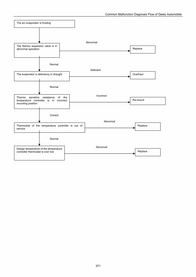
Common Malfunction Diagnosis Flow of Geely Automobile
371
The a/c evaporator is frosting
The thermo expansion valve is in abnormal operation
The evaporator is deficiency in draught
Thermo sensitive resistance of the temperature controller is in incorrect mounting position
Thermostat of the temperature controller is out of service
Design temperature of the temperature controller thermostat is over low
Replace
Overhaul
Re-mount
Replace
Replace
Normal
Normal
Correct
Normal
Abnormal
Deficient
Incorrect
Abnormal
Abnormal
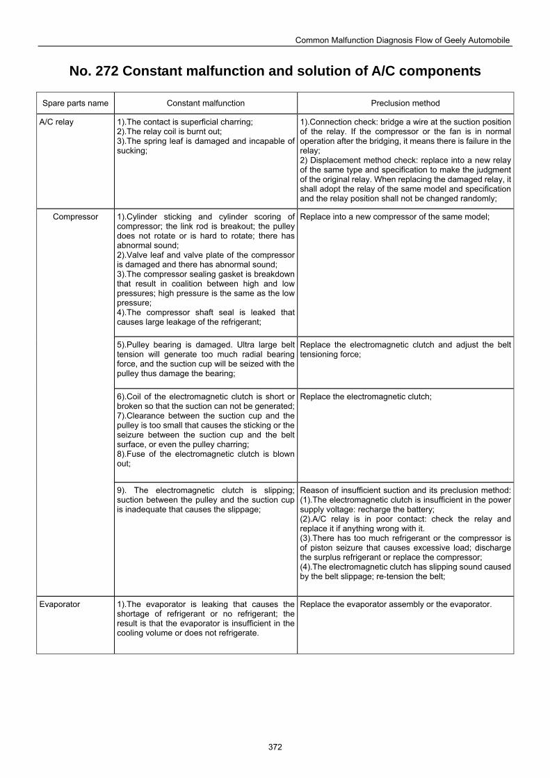
Common Malfunction Diagnosis Flow of Geely Automobile
372
No. 272 Constant malfunction and solution of A/C components
Spare parts name Constant malfunction Preclusion method
A/C relay 1).The contact is superficial charring; 2).The relay coil is burnt out; 3).The spring leaf is damaged and incapable of sucking;
1).Connection check: bridge a wire at the suction position of the relay. If the compressor or the fan is in normal operation after the bridging, it means there is failure in the relay; 2) Displacement method check: replace into a new relay of the same type and specification to make the judgment of the original relay. When replacing the damaged relay, it shall adopt the relay of the same model and specification and the relay position shall not be changed randomly;
1).Cylinder sticking and cylinder scoring of compressor; the link rod is breakout; the pulleydoes not rotate or is hard to rotate; there has abnormal sound; 2).Valve leaf and valve plate of the compressor is damaged and there has abnormal sound; 3).The compressor sealing gasket is breakdown that result in coalition between high and low pressures; high pressure is the same as the low pressure; 4).The compressor shaft seal is leaked that causes large leakage of the refrigerant;
Replace into a new compressor of the same model;
5).Pulley bearing is damaged. Ultra large belt tension will generate too much radial bearing force, and the suction cup will be seized with the pulley thus damage the bearing;
Replace the electromagnetic clutch and adjust the belt tensioning force;
6).Coil of the electromagnetic clutch is short or broken so that the suction can not be generated; 7).Clearance between the suction cup and the pulley is too small that causes the sticking or the seizure between the suction cup and the belt surface, or even the pulley charring; 8).Fuse of the electromagnetic clutch is blown out;
Replace the electromagnetic clutch;
Compressor
9). The electromagnetic clutch is slipping; suction between the pulley and the suction cup is inadequate that causes the slippage;
Reason of insufficient suction and its preclusion method: (1).The electromagnetic clutch is insufficient in the power supply voltage: recharge the battery; (2).A/C relay is in poor contact: check the relay and replace it if anything wrong with it. (3).There has too much refrigerant or the compressor is of piston seizure that causes excessive load; discharge the surplus refrigerant or replace the compressor; (4).The electromagnetic clutch has slipping sound caused by the belt slippage; re-tension the belt;
Evaporator 1).The evaporator is leaking that causes the shortage of refrigerant or no refrigerant; the result is that the evaporator is insufficient in thecooling volume or does not refrigerate.
Replace the evaporator assembly or the evaporator.
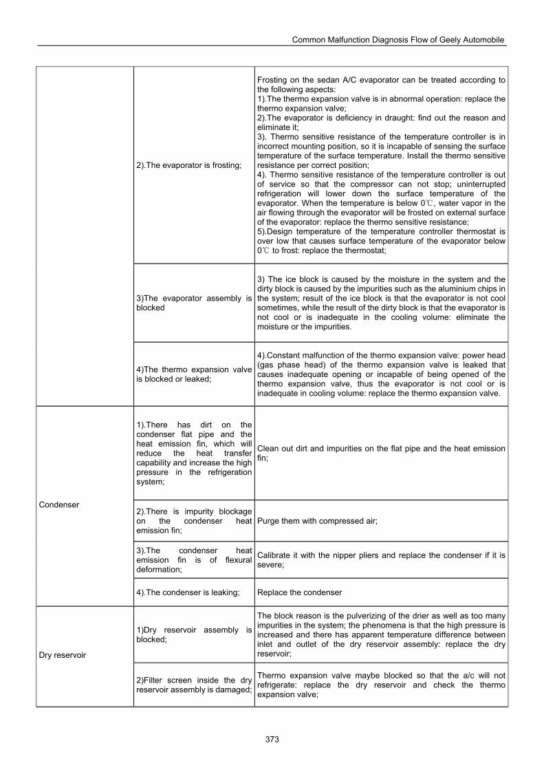
Common Malfunction Diagnosis Flow of Geely Automobile
373
2).The evaporator is frosting;
Frosting on the sedan A/C evaporator can be treated according to the following aspects: 1).The thermo expansion valve is in abnormal operation: replace the thermo expansion valve; 2).The evaporator is deficiency in draught: find out the reason and eliminate it; 3). Thermo sensitive resistance of the temperature controller is in incorrect mounting position, so it is incapable of sensing the surface temperature of the surface temperature. Install the thermo sensitive resistance per correct position; 4). Thermo sensitive resistance of the temperature controller is out of service so that the compressor can not stop; uninterrupted refrigeration will lower down the surface temperature of the evaporator. When the temperature is below 0, water vapor in the air flowing through the evaporator will be frosted on external surface of the evaporator: replace the thermo sensitive resistance; 5).Design temperature of the temperature controller thermostat is over low that causes surface temperature of the evaporator below 0 to frost: replace the thermostat;
3)The evaporator assembly is blocked
3) The ice block is caused by the moisture in the system and the dirty block is caused by the impurities such as the aluminium chips in the system; result of the ice block is that the evaporator is not cool sometimes, while the result of the dirty block is that the evaporator is not cool or is inadequate in the cooling volume: eliminate the moisture or the impurities.
4)The thermo expansion valve is blocked or leaked;
4).Constant malfunction of the thermo expansion valve: power head (gas phase head) of the thermo expansion valve is leaked that causes inadequate opening or incapable of being opened of the thermo expansion valve, thus the evaporator is not cool or is inadequate in cooling volume: replace the thermo expansion valve.
1).There has dirt on the condenser flat pipe and the heat emission fin, which will reduce the heat transfer capability and increase the high pressure in the refrigeration system;
Clean out dirt and impurities on the flat pipe and the heat emission fin;
2).There is impurity blockageon the condenser heat emission fin;
Purge them with compressed air;
3).The condenser heat emission fin is of flexural deformation;
Calibrate it with the nipper pliers and replace the condenser if it is severe;
Condenser
4).The condenser is leaking; Replace the condenser
1)Dry reservoir assembly is blocked;
The block reason is the pulverizing of the drier as well as too many impurities in the system; the phenomena is that the high pressure is increased and there has apparent temperature difference between inlet and outlet of the dry reservoir assembly: replace the dry reservoir; Dry reservoir
2)Filter screen inside the dry reservoir assembly is damaged;
Thermo expansion valve maybe blocked so that the a/c will not refrigerate: replace the dry reservoir and check the thermo expansion valve;
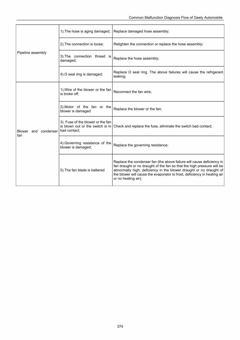
Common Malfunction Diagnosis Flow of Geely Automobile
374
1).The hose is aging damaged; Replace damaged hose assembly;
2).The connection is loose; Retighten the connection or replace the hose assembly;
3).The connection thread is damaged; Replace the hose assembly;
Pipeline assembly
4).O seal ring is damaged; Replace O seal ring. The above failures will cause the refrigerant leaking;
1).Wire of the blower or the fan is broke off; Reconnect the fan wire;
2).Motor of the fan or the blower is damaged Replace the blower or the fan;
3). Fuse of the blower or the fan is blown out or the switch is in bad contact;
Check and replace the fuse, eliminate the switch bad contact;
4).Governing resistance of the blower is damaged; Replace the governing resistance;
Blower and condenser fan
5).The fan blade is battered
Replace the condenser fan (the above failure will cause deficiency in fan draught or no draught of the fan so that the high pressure will be abnormally high; deficiency in the blower draught or no draught of the blower will cause the evaporator to frost, deficiency in heating air or no heating air);
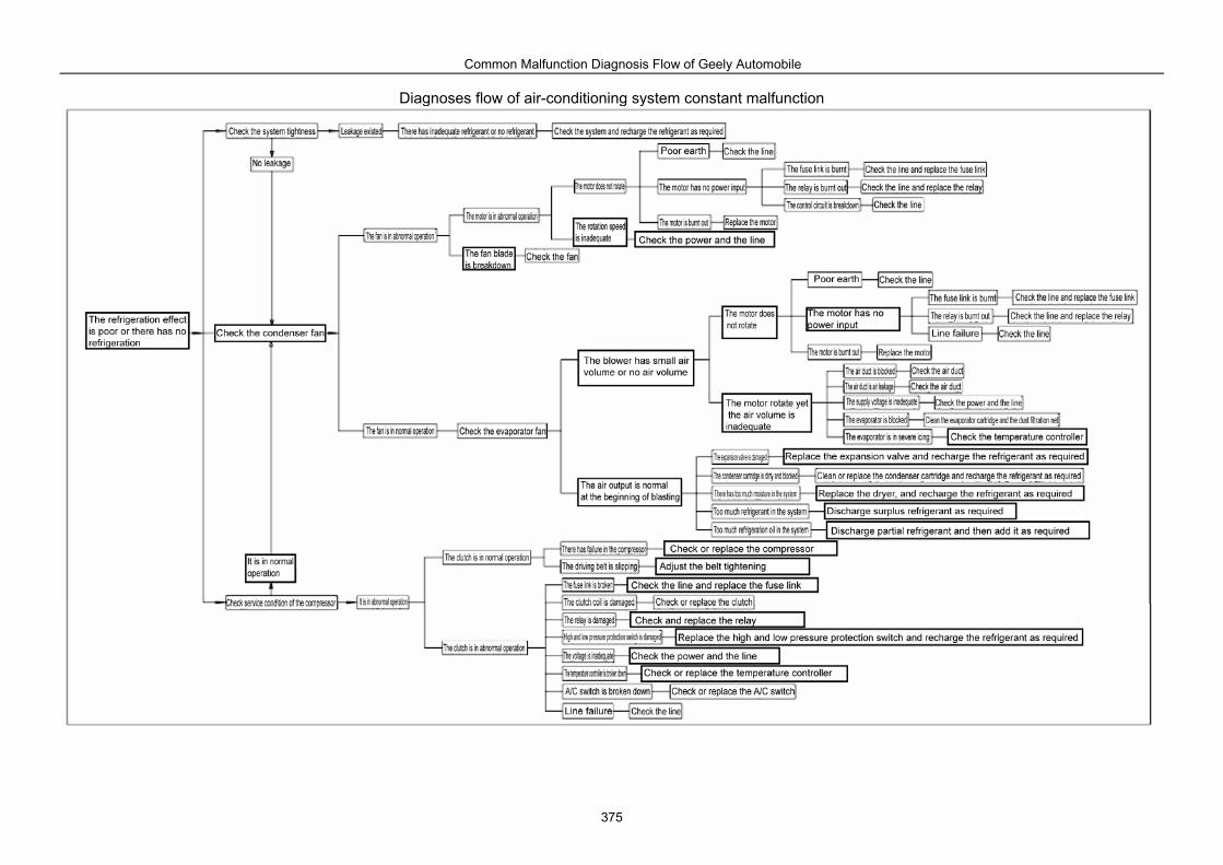
Common Malfunction Diagnosis Flow of Geely Automobile
375
Diagnoses flow of air-conditioning system constant malfunction
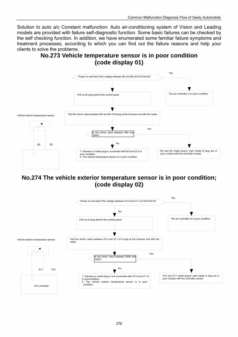
Common Malfunction Diagnosis Flow of Geely Automobile
376
Solution to auto a/c Constant malfunction: Auto air-conditioning system of Vision and Leading models are provided with failure self-diagnostic function. Some basic failures can be checked by the self checking function. In addition, we have enumerated some familiar failure symptoms and treatment processes, according to which you can find out the failure reasons and help your clients to solve the problems.
No.273 Vehicle temperature sensor is in poor condition (code display 01)
No.274 The vehicle exterior temperature sensor is in poor condition; (code display 02)
The a/c controller is in poor condition
B3 and B2 metal plug-in card inside B plug are in poor contact with the controller socket;
1. Harness or metal plug-in connected with B3 and b2 is in poor condition; 2. The vehicle temperature sensor is in poor condition.
Test the ohmic value between B3 and B2 of B plug at the harness end with the meter
Pull out B plug behind the control panel
Power on and test if the voltage between B3 and B2 is0.5V≤Vi≤4.8V Yes
Vehicle interior temperature sensor
Is the ohmic value between 500 and 100K?
Yes
No B2 B3
The a/c controller is in poor condition
A12 and A11 metal plug-in card inside A plug are in poor contact with the controller socket;
1. Harness or metal plug-in unit connected with A12 and A11 is in poorcondition; 2. The vehicle exterior temperature sensor is in poor condition.
Test the ohmic value between A12 and A11 of A plug at the harness end with the meter
Pull out A plug Aehind the control panel
Power on and test if the voltage between A12 and A11 is 0.5V≤Vi≤4.8V Yes
Vehicle exterior temperature sensor
Is the ohmic value between 500K and 100K?
Yes
No A11 A12
A/C controller
No
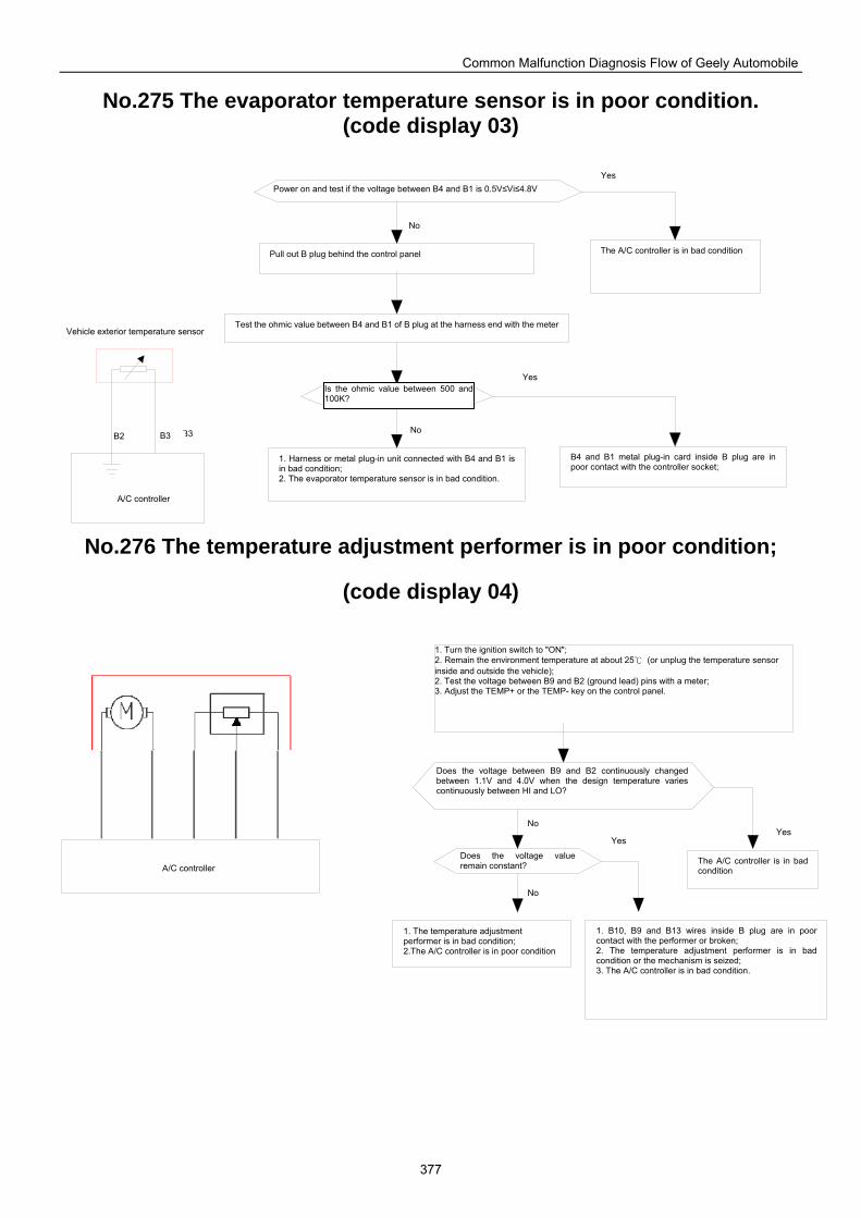
Common Malfunction Diagnosis Flow of Geely Automobile
377
No.275 The evaporator temperature sensor is in poor condition. (code display 03)
No.276 The temperature adjustment performer is in poor condition;
(code display 04)
1. The temperature adjustment performer is in bad condition; 2.The A/C controller is in poor condition
1. B10, B9 and B13 wires inside B plug are in poor contact with the performer or broken; 2. The temperature adjustment performer is in bad condition or the mechanism is seized; 3. The A/C controller is in bad condition.
The A/C controller is in bad condition
1. Turn the ignition switch to "ON"; 2. Remain the environment temperature at about 25 (or unplug the temperature sensor inside and outside the vehicle); 2. Test the voltage between B9 and B2 (ground lead) pins with a meter; 3. Adjust the TEMP+ or the TEMP- key on the control panel.
Does the voltage between B9 and B2 continuously changed between 1.1V and 4.0V when the design temperature varies continuously between HI and LO?
Does the voltage value remain constant? A/C controller
Yes Yes
No
No
The A/C controller is in bad condition
B4 and B1 metal plug-in card inside B plug are in poor contact with the controller socket;
1. Harness or metal plug-in unit connected with B4 and B1 is in bad condition; 2. The evaporator temperature sensor is in bad condition.
Test the ohmic value between B4 and B1 of B plug at the harness end with the meter
Pull out B plug behind the control panel
Power on and test if the voltage between B4 and B1 is 0.5V≤Vi≤4.8V Yes
Vehicle exterior temperature sensor
Is the ohmic value between 500 and100K?
Yes
No B3
A/C controller
No
B2 B3
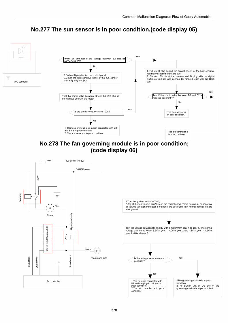
Common Malfunction Diagnosis Flow of Geely Automobile
378
故障6-
No.277 The sun sensor is in poor condition.(code display 05)
No.278 The fan governing module is in poor condition;
(code display 06)
The sun sensor is in poor condition.
1. Pull out B plug behind the control panel; let the light sensitive head fully exposed under the sun; 2. Connect B5 pin at the harness end B plug with the digital multimeter red pen and connect B2 (ground lead) with the black pen.
1.Pull out B plug behind the control panel; 2.Cover the light sensitive head of the sun sensor with a light-tight object.
Test the ohmic value between B2 and B5 of B plug at the harness end with the meter
1. Harness or metal plug-in unit connected with B2 and B3 is in poor condition; 2. The sun sensor is in poor condition. The a/c controller is
in poor condition
Power on and test if the voltage between B2 and B5is0.7V≤Vi≤4.85V
Test if the ohmic value between B5 and B2 is reduced apparently?
Is the ohmic value less than 100K?
A/C controller
Yes
No
Yes
No
Yes
No
1.The harness connected with B7 and the plug-in unit are in poor condition; 2.The a/c controller is in poor condition.
1The governing module is in poor condition; 2.The plug-in unit at DS end of the governing module is in poor contact.
Test the voltage between B7 and B2 with a meter from gear 1 to gear 5. The normal voltage shall be as follow: 3.9V at gear 1; 4.0V at gear 2 and 4.3V at gear 3; 4.5V at gear 4; 4.8V at gear 5.
1.Turn the ignition switch to "ON"; 2.Adjust the "air volume plus" key on the control panel. There has no air or abnormal air volume variation from gear 1 to gear 5; the air volume is in normal condition at the Max. gear 6.
Fan
rela
y
Hig
h sp
eed
real
y
Is the voltage value in normal condition?
3BW
M Blue
Blower
Fan ground lead
black
blue
/bla
ck
grey
/bro
wn
blue
/bro
wn
E
A/c controller
spee
d re
gula
tion
mod
ule
Yes
No
GAUSE meter
40A 800 power line (2)
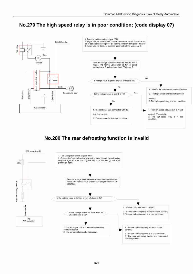
Common Malfunction Diagnosis Flow of Geely Automobile
379
No.279 The high speed relay is in poor condition; (code display 07)
No.280 The rear defrosting function is invalid
1. The high-speed relay socket is in bad
contact; A/c controller 2. The high-speed relay is in bad condition.
1.The GAUSE meter wire is in bad condition;
2. The high-speed relay socket is in bad
contact; 3. The high-speed relay is in bad condition.
1. Turn the ignition switch to gear "ON"; 2. Adjust the "air volume plus" key on the control panel. There has no air or abincreaseunsharpness air volume variation from gear 1 to gear 5, the air volume does not increase apparently at the Max. gear 6.
Test the voltage value between B6 and B2 with a meter. The normal value shall be 13V at gears excepet gear 6 and no more than 1V at gear 6.
1. The controller card connected with B6
is in bad contact;
2. The a/c controller is in bad condition;
GAUSE meter
Fan
rela
y
Blue
Blower
M
E
Fan ground lead
black
blue
/bla
ck
grey
/bro
wn
blue
/bro
wn
A/c controller
spee
d re
gula
tion
mod
ule
Is voltage value at gear 5 or gear 6 close to 0V?
Is the voltage value at gear 6 ≤ 1V?
Yes
No
Yes
No
Rea
r def
rost
ing
cont
rol
1. The A3 plug-in unit is in bad contact with the controller socket; 2. The a/c controller is in bad condition;
Test the voltage value between A3 and the ground with a meter. The normal value shall be 13V at light off and ≤ 1V at light on.
1. Turn the ignition switch to gear "ON"; 2. Operate the "rear defrosting" key on the control panel; the defrosting lamp will light up after pressing the key once and will go out after pressing it again.
1. The GAUSE meter wire is broken;
2. The rear defrosting relay socket is in bad contact; 3. The rear defrosting relay is in bad condition;
1. The rear defrosting relay socket is in bad contact;
2. The rear defrosting relay is in bad condition; 3. The rear defrosting heater and concerned harness problem.
Gre
en/W
hite
800 powe line (2)
2#30A
A3 A/C controller
Is the voltage value at light on or ligh off close to 0V?
Is the voltage value no more than 1Vwhen the light is on?
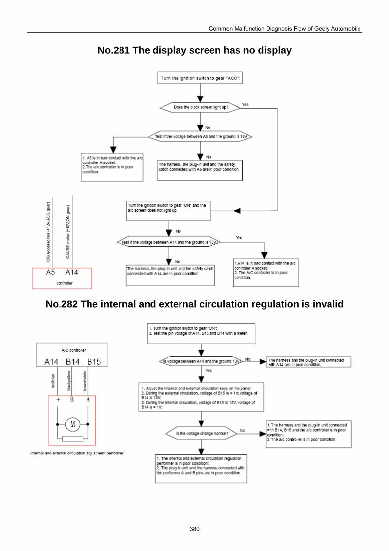
Common Malfunction Diagnosis Flow of Geely Automobile
380
No.281 The display screen has no display
No.282 The internal and external circulation regulation is invalid

Common Malfunction Diagnosis Flow of Geely Automobile
381
No.283 The wind direction adjustment is abnormal
No.284 The blower is in poor operation
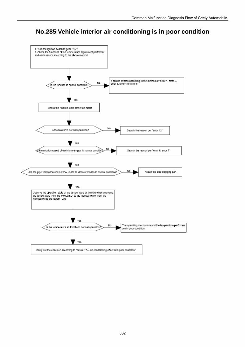
Common Malfunction Diagnosis Flow of Geely Automobile
382
No.285 Vehicle interior air conditioning is in poor condition
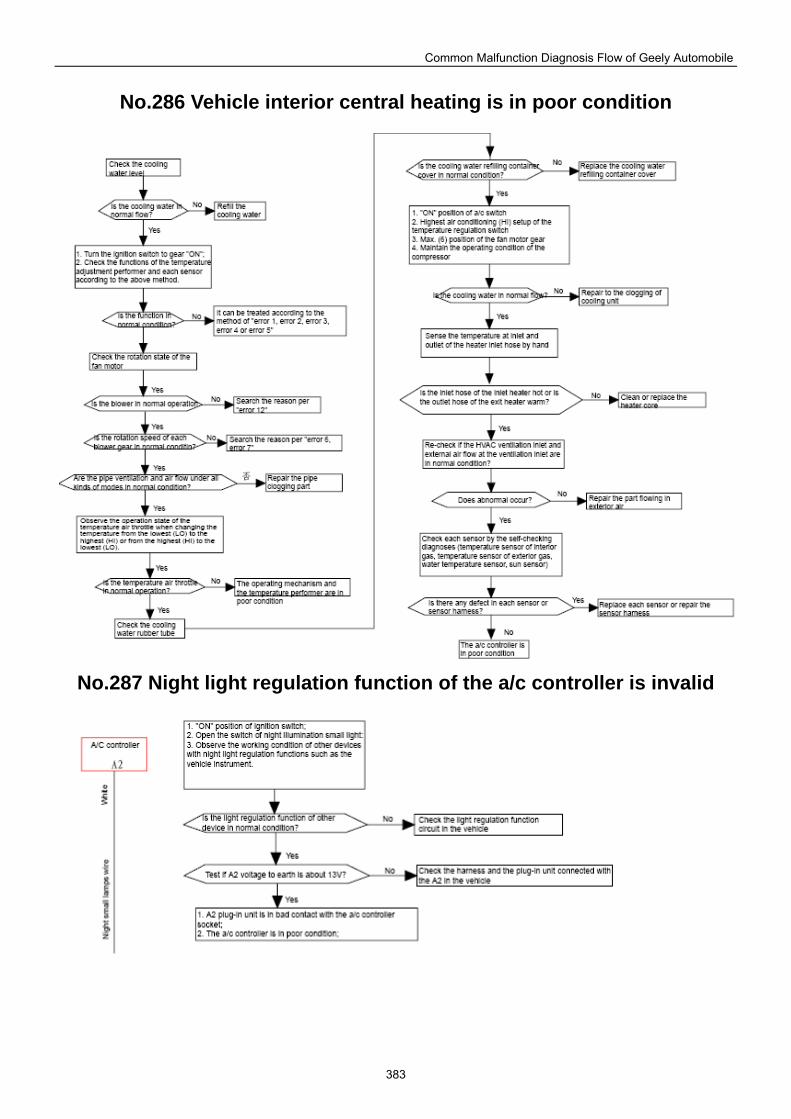
Common Malfunction Diagnosis Flow of Geely Automobile
383
No.286 Vehicle interior central heating is in poor condition
No.287 Night light regulation function of the a/c controller is invalid
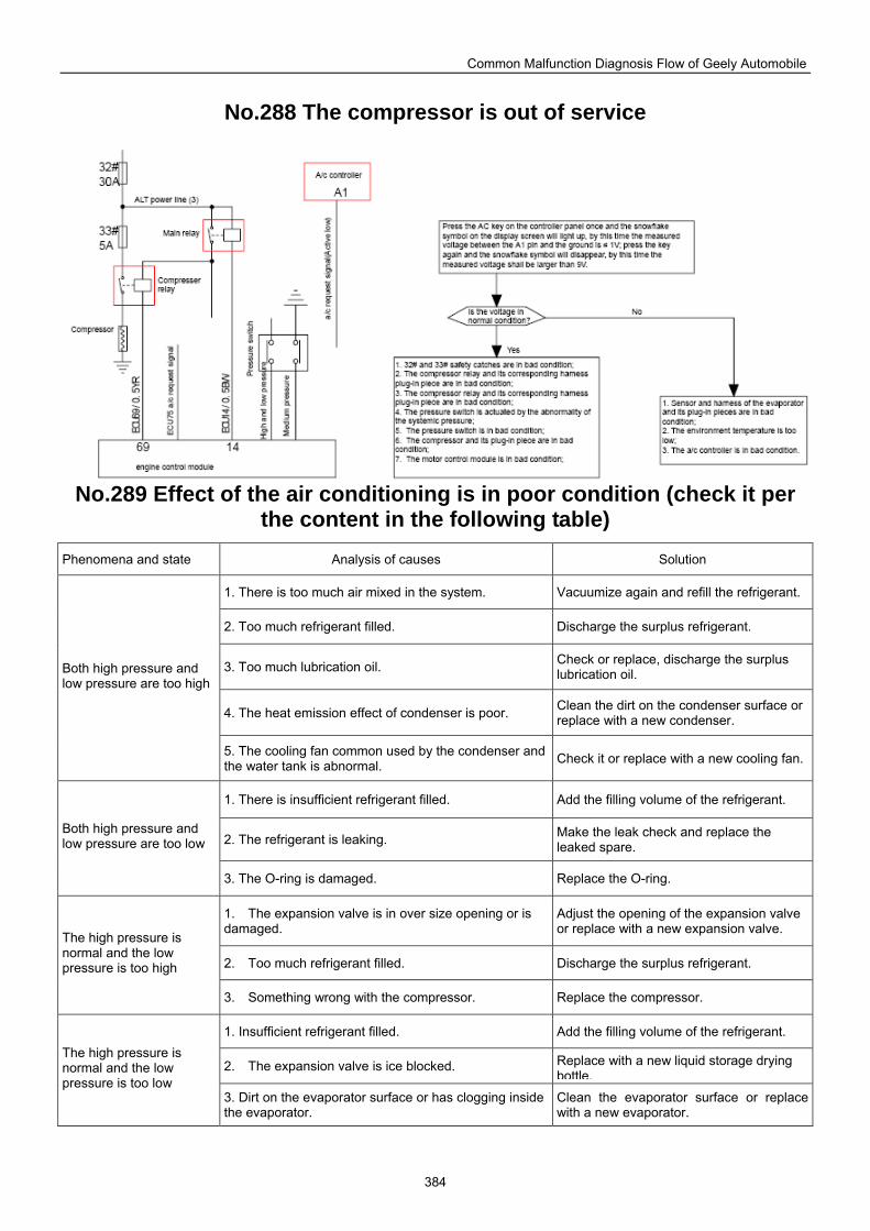
Common Malfunction Diagnosis Flow of Geely Automobile
384
No.288 The compressor is out of service
No.289 Effect of the air conditioning is in poor condition (check it per
the content in the following table)
Phenomena and state Analysis of causes Solution
1. There is too much air mixed in the system. Vacuumize again and refill the refrigerant.
2. Too much refrigerant filled. Discharge the surplus refrigerant.
3. Too much lubrication oil. Check or replace, discharge the surplus lubrication oil.
4. The heat emission effect of condenser is poor. Clean the dirt on the condenser surface or replace with a new condenser.
Both high pressure and low pressure are too high
5. The cooling fan common used by the condenser and the water tank is abnormal. Check it or replace with a new cooling fan.
1. There is insufficient refrigerant filled. Add the filling volume of the refrigerant.
2. The refrigerant is leaking. Make the leak check and replace the leaked spare.
Both high pressure and low pressure are too low
3. The O-ring is damaged. Replace the O-ring.
1. The expansion valve is in over size opening or is damaged.
Adjust the opening of the expansion valve or replace with a new expansion valve.
2. Too much refrigerant filled. Discharge the surplus refrigerant.
The high pressure is normal and the low pressure is too high
3. Something wrong with the compressor. Replace the compressor.
1. Insufficient refrigerant filled. Add the filling volume of the refrigerant.
2. The expansion valve is ice blocked. Replace with a new liquid storage drying bottle.
The high pressure is normal and the low pressure is too low
3. Dirt on the evaporator surface or has clogging inside the evaporator.
Clean the evaporator surface or replace with a new evaporator.
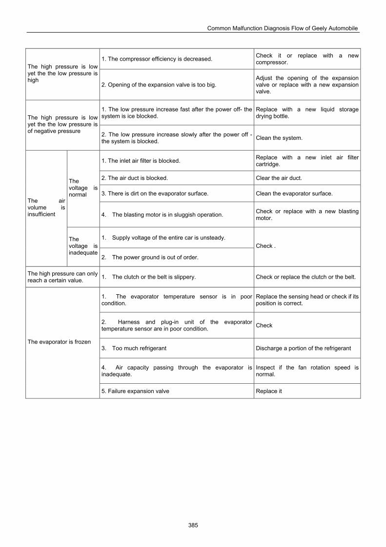
Common Malfunction Diagnosis Flow of Geely Automobile
385
1. The compressor efficiency is decreased. Check it or replace with a new compressor.
The high pressure is low yet the the low pressure is high
2. Opening of the expansion valve is too big. Adjust the opening of the expansion valve or replace with a new expansion valve.
1. The low pressure increase fast after the power off- the system is ice blocked.
Replace with a new liquid storage drying bottle. The high pressure is low
yet the the low pressure is of negative pressure 2. The low pressure increase slowly after the power off -
the system is blocked. Clean the system.
1. The inlet air filter is blocked. Replace with a new inlet air filter cartridge.
2. The air duct is blocked. Clear the air duct.
3. There is dirt on the evaporator surface. Clean the evaporator surface.
The voltage is normal
4. The blasting motor is in sluggish operation. Check or replace with a new blasting motor.
1. Supply voltage of the entire car is unsteady.
The air volume is insufficient
The voltage is inadequate
2. The power ground is out of order.
Check .
The high pressure can only reach a certain value. 1. The clutch or the belt is slippery. Check or replace the clutch or the belt.
1. The evaporator temperature sensor is in poor condition.
Replace the sensing head or check if its position is correct.
2. Harness and plug-in unit of the evaporator temperature sensor are in poor condition. Check
3. Too much refrigerant Discharge a portion of the refrigerant
4. Air capacity passing through the evaporator is inadequate.
Inspect if the fan rotation speed is normal.
The evaporator is frozen
5. Failure expansion valve Replace it
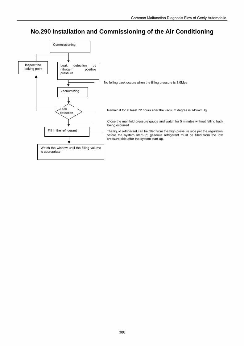
Common Malfunction Diagnosis Flow of Geely Automobile
386
No.290 Installation and Commissioning of the Air Conditioning
Commissioning
Inspect the leaking point
Leak detection by nitrogen positive pressure
Vacuumizing
Fill in the refrigerant
Watch the window until the filling volume is appropriate
Leak detection
Close the manifold pressure gauge and watch for 5 minutes without felling backbeing occurred
The liquid refrigerant can be filled from the high pressure side per the regulation before the system start-up; gaseous refrigerant must be filled from the low pressure side after the system start-up.
Remain it for at least 72 hours after the vacuum degree is 745mmHg
No felling back occurs when the filling pressure is 3.0Mpa
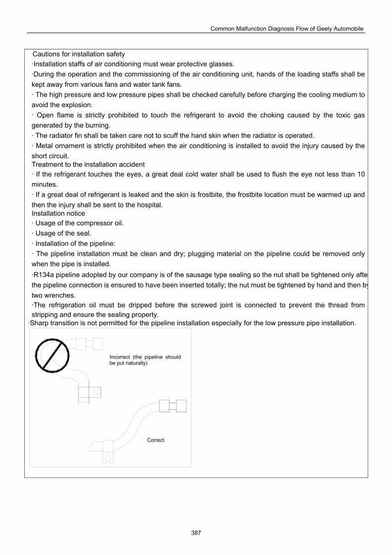
Common Malfunction Diagnosis Flow of Geely Automobile
387
Cautions for installation safety ·Installation staffs of air conditioning must wear protective glasses. ·During the operation and the commissioning of the air conditioning unit, hands of the loading staffs shall be kept away from various fans and water tank fans. · The high pressure and low pressure pipes shall be checked carefully before charging the cooling medium to avoid the explosion. · Open flame is strictly prohibited to touch the refrigerant to avoid the choking caused by the toxic gas generated by the burning. · The radiator fin shall be taken care not to scuff the hand skin when the radiator is operated. · Metal ornament is strictly prohibited when the air conditioning is installed to avoid the injury caused by the short circuit. Treatment to the installation accident · If the refrigerant touches the eyes, a great deal cold water shall be used to flush the eye not less than 10 minutes. · If a great deal of refrigerant is leaked and the skin is frostbite, the frostbite location must be warmed up and then the injury shall be sent to the hospital. Installation notice · Usage of the compressor oil. · Usage of the seal. · Installation of the pipeline: · The pipeline installation must be clean and dry; plugging material on the pipeline could be removed only when the pipe is installed. ·R134a pipeline adopted by our company is of the sausage type sealing so the nut shall be tightened only aftethe pipeline connection is ensured to have been inserted totally; the nut must be tightened by hand and then bytwo wrenches. ·The refrigeration oil must be dripped before the screwed joint is connected to prevent the thread from stripping and ensure the sealing property.
·Sharp transition is not permitted for the pipeline installation especially for the low pressure pipe installation.
Incorrect (the pipeline should be put naturally)
Correct
Common Malfunction Diagnosis Flow of Geely Automobile
388
Special repair kit for air conditioning The special repair kit for air conditioning is composed of the magnetic thickness gauge, the gas leak tester, the spare gas bottle, the service valve wrench, the refrigerant filling valve, the filling hose gasket and the service valve gasket, etc. Above tools are special tools used to repair the vehicle air-conditioning. Tools in the kit shall be used as much as possible during the repair process to ensure the check quality. Usage of the refrigerant filling valve The filling valve is as Fig. 4-6 1). Anti-clockwise rotate the filling valve handle until the valve needle is withdrawn. 2). Install the filling valve on the refrigerant tank and anti-clockwise rotate the sheet nut until it reaches the top position, then clockwise rotate the refrigerant filling valve until the filling valve is embedded into the refrigerant sealing plug. 3). Clockwise rotate the sheet nut to the end and fix the intermediate hose of the manifold pressure gauge into the connection of the filling valve. 4). Tighten the sheet nut. 5). Clockwise rotate the handle until the valve needle pierces into the sealing plug. 6). Provided the refrigerant is to be filled, the handle shall be rotated anti-clockwise to uplift the valve needle and at the same time the hand valve on the manifold pressure gauge is opened. 7). Provided it is to stop adding the refrigerant, clockwise rotate the handle so that the valve needle will enter into the sealing plug once again to play the sealing effect, and meanwhile close the hand valve on the manifold pressure gauge. Usage of the manifold pressure gauge The manifold pressure gauge is also called the manifold pressure meter, which is connected with the refrigeration system to carry out the vacuumizing, filling in the refrigerant and diagnosing the failure of the refrigeration system. Fig. 4-2 shows the structure of the manifold pressure gauge. It consists of the high pressure gauge, low-pressure gauge, manual low pressure valve, manual high-pressure valve, valve body, high pressure connection, low-pressure connector and refrigerant vacuumizing connector. During the operation, high and low pressure connectors are connected with high and low pressure fill in valves of the system respectively via the hose and the intermediate connector is connected with the suction pump or the refrigerant (HR134a) cylinder. The connector connecting the hose and the manifold pressure gauge could only be tightened by hand instead of by wrench, or else the connection thread may be damaged. Air inside the hose must be drained away during the usage. Detailed steps are as follows: 1). When the manual low pressure valve is opened and the manual high pressure valve is closed, the low pressure line is connected with the intermediate pipeline and the low pressure gauge. At that time the refrigerant can be filled or discharged from the low pressure side, and meanwhile pressures at both the high pressure side and the low pressure side can be detected. 2). When the manual low pressure valve is closed and the manual high pressure valve is opened, the pressure line is connected with the intermediate pipeline and the high pressure gauge. At that time the refrigerant can be filled or discharged from the high pressure side, and meanwhile pressures at both the high pressure side and the high-tension side can be detected. 3). Detection to pressures at high and low pressure sides can be made when both the manual high pressure valve and the low pressure valve are closed. 4). Refrigerant filling, vacuumizing and detecting to pressures at both the high pressure and low pressure sides can be carried out when both the manual high and low pressure valves are opened.
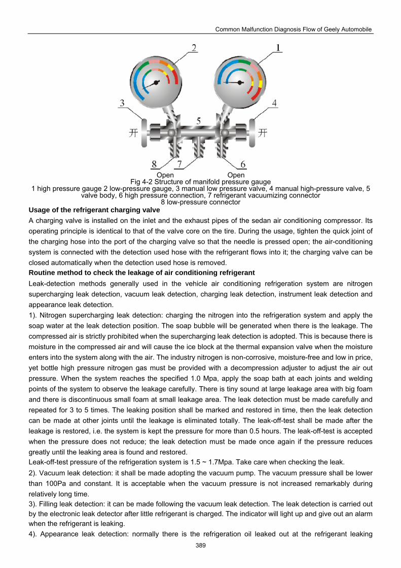
Common Malfunction Diagnosis Flow of Geely Automobile
389
Open Open
Fig 4-2 Structure of manifold pressure gauge 1 high pressure gauge 2 low-pressure gauge, 3 manual low pressure valve, 4 manual high-pressure valve, 5
valve body, 6 high pressure connection, 7 refrigerant vacuumizing connector 8 low-pressure connector
Usage of the refrigerant charging valve A charging valve is installed on the inlet and the exhaust pipes of the sedan air conditioning compressor. Its operating principle is identical to that of the valve core on the tire. During the usage, tighten the quick joint of the charging hose into the port of the charging valve so that the needle is pressed open; the air-conditioning system is connected with the detection used hose with the refrigerant flows into it; the charging valve can be closed automatically when the detection used hose is removed. Routine method to check the leakage of air conditioning refrigerant Leak-detection methods generally used in the vehicle air conditioning refrigeration system are nitrogen supercharging leak detection, vacuum leak detection, charging leak detection, instrument leak detection and appearance leak detection. 1). Nitrogen supercharging leak detection: charging the nitrogen into the refrigeration system and apply the soap water at the leak detection position. The soap bubble will be generated when there is the leakage. The compressed air is strictly prohibited when the supercharging leak detection is adopted. This is because there is moisture in the compressed air and will cause the ice block at the thermal expansion valve when the moisture enters into the system along with the air. The industry nitrogen is non-corrosive, moisture-free and low in price, yet bottle high pressure nitrogen gas must be provided with a decompression adjuster to adjust the air out pressure. When the system reaches the specified 1.0 Mpa, apply the soap bath at each joints and welding points of the system to observe the leakage carefully. There is tiny sound at large leakage area with big foam and there is discontinuous small foam at small leakage area. The leak detection must be made carefully and repeated for 3 to 5 times. The leaking position shall be marked and restored in time, then the leak detection can be made at other joints until the leakage is eliminated totally. The leak-off-test shall be made after the leakage is restored, i.e. the system is kept the pressure for more than 0.5 hours. The leak-off-test is accepted when the pressure does not reduce; the leak detection must be made once again if the pressure reduces greatly until the leaking area is found and restored. Leak-off-test pressure of the refrigeration system is 1.5 ~ 1.7Mpa. Take care when checking the leak. 2). Vacuum leak detection: it shall be made adopting the vacuum pump. The vacuum pressure shall be lower than 100Pa and constant. It is acceptable when the vacuum pressure is not increased remarkably during relatively long time. 3). Filling leak detection: it can be made following the vacuum leak detection. The leak detection is carried out by the electronic leak detector after little refrigerant is charged. The indicator will light up and give out an alarm when the refrigerant is leaking. 4). Appearance leak detection: normally there is the refrigeration oil leaked out at the refrigerant leaking
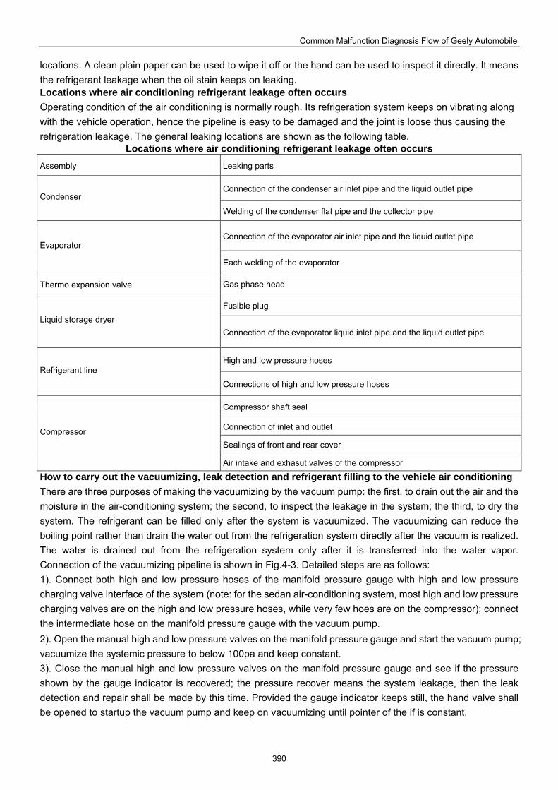
Common Malfunction Diagnosis Flow of Geely Automobile
390
locations. A clean plain paper can be used to wipe it off or the hand can be used to inspect it directly. It means the refrigerant leakage when the oil stain keeps on leaking. Locations where air conditioning refrigerant leakage often occurs Operating condition of the air conditioning is normally rough. Its refrigeration system keeps on vibrating along with the vehicle operation, hence the pipeline is easy to be damaged and the joint is loose thus causing the refrigeration leakage. The general leaking locations are shown as the following table.
Locations where air conditioning refrigerant leakage often occurs Assembly Leaking parts
Connection of the condenser air inlet pipe and the liquid outlet pipe Condenser
Welding of the condenser flat pipe and the collector pipe
Connection of the evaporator air inlet pipe and the liquid outlet pipe Evaporator
Each welding of the evaporator
Thermo expansion valve Gas phase head
Fusible plug Liquid storage dryer
Connection of the evaporator liquid inlet pipe and the liquid outlet pipe
High and low pressure hoses Refrigerant line
Connections of high and low pressure hoses
Compressor shaft seal
Connection of inlet and outlet
Sealings of front and rear cover Compressor
Air intake and exhasut valves of the compressor
How to carry out the vacuumizing, leak detection and refrigerant filling to the vehicle air conditioning There are three purposes of making the vacuumizing by the vacuum pump: the first, to drain out the air and the moisture in the air-conditioning system; the second, to inspect the leakage in the system; the third, to dry the system. The refrigerant can be filled only after the system is vacuumized. The vacuumizing can reduce the boiling point rather than drain the water out from the refrigeration system directly after the vacuum is realized. The water is drained out from the refrigeration system only after it is transferred into the water vapor. Connection of the vacuumizing pipeline is shown in Fig.4-3. Detailed steps are as follows: 1). Connect both high and low pressure hoses of the manifold pressure gauge with high and low pressure charging valve interface of the system (note: for the sedan air-conditioning system, most high and low pressure charging valves are on the high and low pressure hoses, while very few hoes are on the compressor); connect the intermediate hose on the manifold pressure gauge with the vacuum pump. 2). Open the manual high and low pressure valves on the manifold pressure gauge and start the vacuum pump; vacuumize the systemic pressure to below 100pa and keep constant. 3). Close the manual high and low pressure valves on the manifold pressure gauge and see if the pressure shown by the gauge indicator is recovered; the pressure recover means the system leakage, then the leak detection and repair shall be made by this time. Provided the gauge indicator keeps still, the hand valve shall be opened to startup the vacuum pump and keep on vacuumizing until pointer of the if is constant.
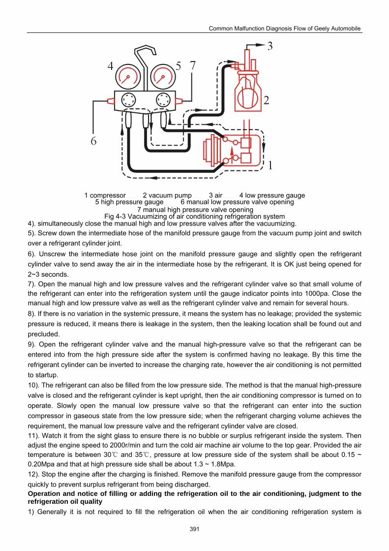
Common Malfunction Diagnosis Flow of Geely Automobile
391
1 compressor 2 vacuum pump 3 air 4 low pressure gauge 5 high pressure gauge 6 manual low pressure valve opening
7 manual high pressure valve opening Fig 4-3 Vacuumizing of air conditioning refrigeration system
4). simultaneously close the manual high and low pressure valves after the vacuumizing. 5). Screw down the intermediate hose of the manifold pressure gauge from the vacuum pump joint and switch over a refrigerant cylinder joint. 6). Unscrew the intermediate hose joint on the manifold pressure gauge and slightly open the refrigerant cylinder valve to send away the air in the intermediate hose by the refrigerant. It is OK just being opened for 2~3 seconds. 7). Open the manual high and low pressure valves and the refrigerant cylinder valve so that small volume of the refrigerant can enter into the refrigeration system until the gauge indicator points into 1000pa. Close the manual high and low pressure valve as well as the refrigerant cylinder valve and remain for several hours. 8). If there is no variation in the systemic pressure, it means the system has no leakage; provided the systemic pressure is reduced, it means there is leakage in the system, then the leaking location shall be found out and precluded. 9). Open the refrigerant cylinder valve and the manual high-pressure valve so that the refrigerant can be entered into from the high pressure side after the system is confirmed having no leakage. By this time the refrigerant cylinder can be inverted to increase the charging rate, however the air conditioning is not permitted to startup. 10). The refrigerant can also be filled from the low pressure side. The method is that the manual high-pressure valve is closed and the refrigerant cylinder is kept upright, then the air conditioning compressor is turned on to operate. Slowly open the manual low pressure valve so that the refrigerant can enter into the suction compressor in gaseous state from the low pressure side; when the refrigerant charging volume achieves the requirement, the manual low pressure valve and the refrigerant cylinder valve are closed. 11). Watch it from the sight glass to ensure there is no bubble or surplus refrigerant inside the system. Then adjust the engine speed to 2000r/min and turn the cold air machine air volume to the top gear. Provided the air temperature is between 30 and 35 , pressure at low pressure side of the system shall be about 0.15 ~
0.20Mpa and that at high pressure side shall be about 1.3 ~ 1.8Mpa. 12). Stop the engine after the charging is finished. Remove the manifold pressure gauge from the compressor quickly to prevent surplus refrigerant from being discharged. Operation and notice of filling or adding the refrigeration oil to the air conditioning, judgment to the refrigeration oil quality 1) Generally it is not required to fill the refrigeration oil when the air conditioning refrigeration system is
Common Malfunction Diagnosis Flow of Geely Automobile
392
maintained. However, the refrigeration oil must be added when parts of the refrigeration system are replaced and severe leakage of the system is precluded. There are two methods to fill the refrigeration oil as follows: (1) Shut down the air conditioning and fill the refrigeration oil utilizing the filling port on the compressor; screw out the filling port bolt and pour the required refrigeration lubrication oil into the filling port and then tighten the filling port bolt. (2) Detailed operation methods of charging the refrigeration oil when the vacuumizing is made are as follows:
Fig. 4-4 Filling the refrigeration lubrication oil with vacuumizing method 1- the manual low pressure valve is closed 2- the manual high pressure valve is opened
3- exhaust the air 4- vacuum pump 5- refrigeration lubrication oil a. Select a graduated cylinder to contain the refrigeration oil of the volume more than required. b. Screw down the hose connected with the low pressure charging valve from the manifold pressure gauge and insert it into the measuring cylinder containing the refrigeration oil. As shown in Fig.4-4. c. Startup the vacuum pump and open the manual high pressure valve on the manifold pressure gauge. Added refrigeration oil will be sucked into the compressor through the suction pipe via the charging valve at the low pressure side. Stop the suction of the vacuum pump and close the manual high pressure valve when the refrigeration oil volume has reached the specified volume. d. After the refrigeration oil is added per the vacuumizing method, the refrigeration system shall be vacuumized and the refrigerant shall be added. 2) The following notices shall be taken care when the refrigeration oil is used: (1). The refrigeration oil is easy in water absorption so the lid must be tightened right after the refrigeration oil is used (2). Deteriorate turbid refrigeration oil is not allowed, or else it will influence the normal operation of the compressor. (3). Excess refrigeration oil is not allowed to be added into the system, or else it will influence the refrigerating capacity of the vehicle air conditioning refrigeration system. (4) The refrigeration oil must be of the grade specified in the compressor instruction of that model. 3) Correlation method and dripping method can be adopted to judge the quality of the refrigeration oil: (1). Correlation method: put clean and standard refrigeration oil into a test tube as the standard oil and put the oil to be checked into another test tube of the same size to make the comparison. Provided the oil to be checked is of light yellow or of saffron yellow, it can be used, however the turbid solution of rufous color can not be used. (2). Dripping method: drip one drib of the refrigeration lubrication oil to be checked on a clean plain paper and watch its color. It means there is no impurity in the oil if its color is light and even; the oil can be used.

Common Malfunction Diagnosis Flow of Geely Automobile
393
How to inspect the refrigeration oil volume in air conditioning compressor The vehicle air conditioning compressor is a high-speed operation device. Its normal condition depends on the sufficiency of the refrigeration oil, however excess refrigeration oil will influence the refrigerating effect. Oil volume inside the compressor must be checked when the compressor or part of the refrigeration system are replaced. The inspection methods are as follows: Fig.4-5 shows the inspection to the refrigeration oil volume. Discharge the oil charge plug 1, watch it via the oil charge taphole and rotate the clutch foreplate; Wipe clean the oil dipstick with the cotton yarn and insert it into the compressor until end of the oil dipstick touches inner casing of the compressor; take out the oil dipstick and observe its immersion depth; oil level inside the compressor shall be between scale 4 and scale 6 if the oil charging is appropriate. Add it if it is inadequate and drain if it is excessive, then tighten the filling port plug.
Fig. 4-5 inspection to the refrigeration lubrication oil volume of the sedan air conditioning compressor
1- oil filling plug 2- Filling port 3- oil dipstick Provided there is no oil filling plug hole in the compressor, the oil shall be poured into a measuring cup to make the comparison with the oil charge volume specified in the instruction to judge if the compressor is required to add the oil. Generally oil content in the compressor shall not be less than 1/3 oil charging volume specified in the instruction, or else the oil shall be added. Compressor provided with the oil charging plug hole can also adopt this method, but the compressor assembly must be removed from the air-conditioning system.
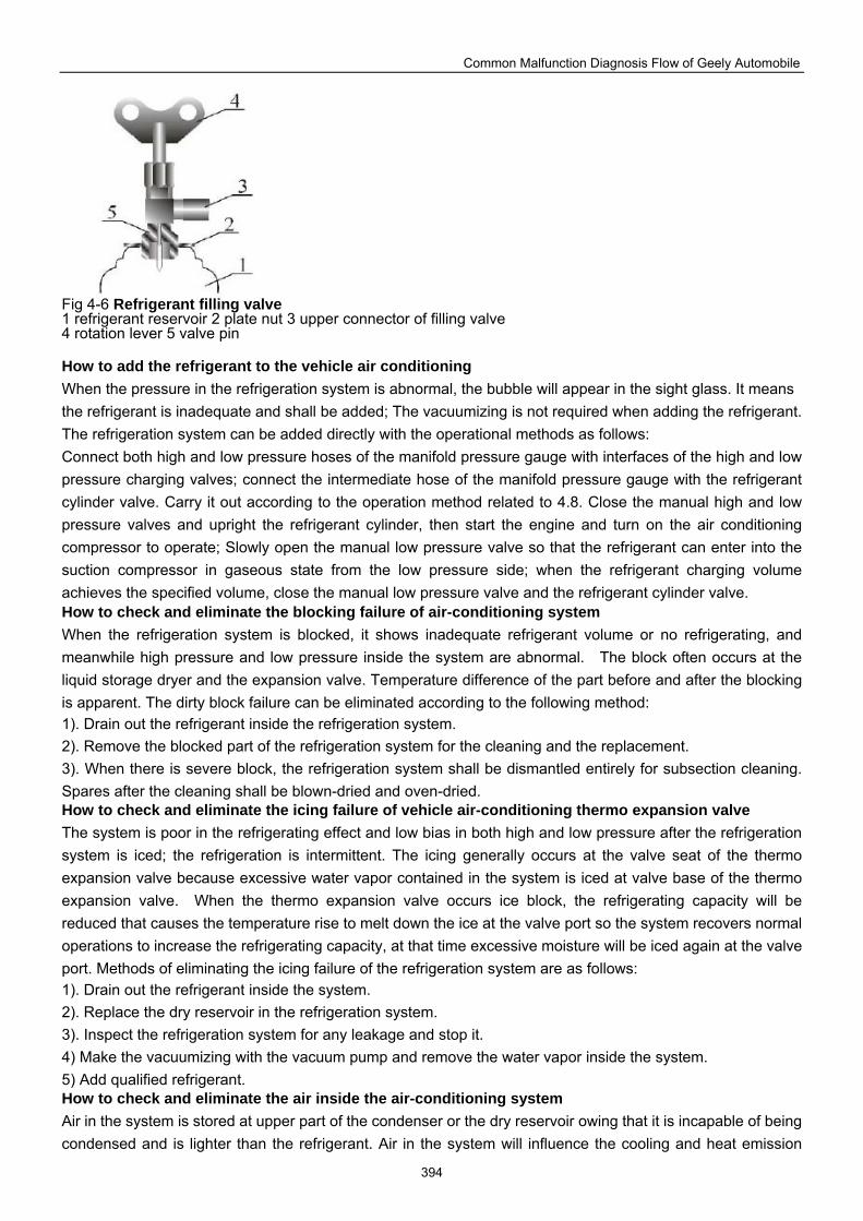
Common Malfunction Diagnosis Flow of Geely Automobile
394
Fig 4-6 Refrigerant filling valve 1 refrigerant reservoir 2 plate nut 3 upper connector of filling valve 4 rotation lever 5 valve pin How to add the refrigerant to the vehicle air conditioning When the pressure in the refrigeration system is abnormal, the bubble will appear in the sight glass. It means the refrigerant is inadequate and shall be added; The vacuumizing is not required when adding the refrigerant. The refrigeration system can be added directly with the operational methods as follows: Connect both high and low pressure hoses of the manifold pressure gauge with interfaces of the high and low pressure charging valves; connect the intermediate hose of the manifold pressure gauge with the refrigerant cylinder valve. Carry it out according to the operation method related to 4.8. Close the manual high and low pressure valves and upright the refrigerant cylinder, then start the engine and turn on the air conditioning compressor to operate; Slowly open the manual low pressure valve so that the refrigerant can enter into the suction compressor in gaseous state from the low pressure side; when the refrigerant charging volume achieves the specified volume, close the manual low pressure valve and the refrigerant cylinder valve. How to check and eliminate the blocking failure of air-conditioning system When the refrigeration system is blocked, it shows inadequate refrigerant volume or no refrigerating, and meanwhile high pressure and low pressure inside the system are abnormal. The block often occurs at the liquid storage dryer and the expansion valve. Temperature difference of the part before and after the blocking is apparent. The dirty block failure can be eliminated according to the following method: 1). Drain out the refrigerant inside the refrigeration system. 2). Remove the blocked part of the refrigeration system for the cleaning and the replacement. 3). When there is severe block, the refrigeration system shall be dismantled entirely for subsection cleaning. Spares after the cleaning shall be blown-dried and oven-dried. How to check and eliminate the icing failure of vehicle air-conditioning thermo expansion valve The system is poor in the refrigerating effect and low bias in both high and low pressure after the refrigeration system is iced; the refrigeration is intermittent. The icing generally occurs at the valve seat of the thermo expansion valve because excessive water vapor contained in the system is iced at valve base of the thermo expansion valve. When the thermo expansion valve occurs ice block, the refrigerating capacity will be reduced that causes the temperature rise to melt down the ice at the valve port so the system recovers normal operations to increase the refrigerating capacity, at that time excessive moisture will be iced again at the valve port. Methods of eliminating the icing failure of the refrigeration system are as follows: 1). Drain out the refrigerant inside the system. 2). Replace the dry reservoir in the refrigeration system. 3). Inspect the refrigeration system for any leakage and stop it. 4) Make the vacuumizing with the vacuum pump and remove the water vapor inside the system. 5) Add qualified refrigerant. How to check and eliminate the air inside the air-conditioning system Air in the system is stored at upper part of the condenser or the dry reservoir owing that it is incapable of being condensed and is lighter than the refrigerant. Air in the system will influence the cooling and heat emission
Common Malfunction Diagnosis Flow of Geely Automobile
395
effect of the condenser thus cause the condensing pressure and temperature over high, simultaneously low pressure of the system is high that causes the refrigerating capacity of overall system being reduced, so that air in the system shall be removed timely with the preclusion methods as follows: 1). Drain out the refrigerant inside the system. 2). Inspect the refrigeration system for any leakage and eliminate it. 3). Pump out the air in the system repeatedly with the vacuum pump. How to dismount the sedan air conditioning compressor When the air conditioning compressor is breakdown, most failure parts shall be dismounted to carry out the repair or the replacement except very few failure parts can be maintained on the vehicle instead of dismounting the compressor. The dismounting steps and requirements are as follows: Steps of dismounting the compressor from the compressor frame: (1). Dismount the connecting wire of the electromagnetic clutch. (2) Drain out the refrigerant from the refrigeration system. (3) Remove the hoses at intake and exhaust port of the compressor; the hose as well as intake and exhaust ports of the compressor shall be covered to prevent the dust and the water vapor from being entered into the system. (4) Dismount the driving belt of the compressor. (5) Remove the compressor fastening screw and the compressor from the compressor frame. (6) Pour out the oil inside the compressor and measure the oil output with the measuring cylinder to judge if it is required to add the oil and inspect the oil for any discoloration as well as any impurities in the oil. Inspection to the air conditioning control system The air conditioning control system can be checked according to the following methods: power→ ignition→ switch→ fuse cutout→ relay→ air conditioning switch ( fan switch, temperature detect switch)→temperature control circuit→pressure switch circuit→electromagnetic clutch→fan→electric machine. After the ignition switch is turned on, the current flows into the air conditioning switch through the fuse cutout and is branched. One branch flows into the evaporator blower motor and the other branch flows into the compressor electromagnetic clutch through the temperature controller and the pressure switch circuit. When malfunction is found in the auto security protection, the fuse shall be checked first for any burn-out; If it is in normal condition, control switch of the blower shall be turned on to inspect if the blower plug is in good contact, the blower governing resistance is in open circuit and the blower motor is damaged; If the blower is in normal operation, then finally check the control circuit of the electromagnetic clutch, the high and low pressure switch, the temperature controller as well as the electromagnetic clutch for any failure; eliminate any failure existed. How to inspect the vehicle air conditioning thermo expansion valve Inspection steps of the vehicle air conditioning expansion valve (take F type thermo expansion valve as an example) are as follows: 1). Eliminate the refrigerant in the system and remove the thermal expansion valve from the refrigeration system. 2). Supply the nitrogen with certain pressure (e.g. 0.05Mpa) at the high pressure inlet side of the thermal expansion valve. If there is no gas flowing out from the low pressure outlet side, it means the thermal expansion valve is out of service. 3). Then immerse the thermo bulb of the thermal expansion valve into warm water and enhance the water temperature; opening of the thermal expansion valve shall be increased (pressure at the low-pressure side is increased, i.e. the gas flow rate is increased), or else it means media inside the thermal expansion valve power head is leaked or the thermal expansion valve is blocked by impurities, then the thermal expansion valve shall be replaced. 4) The blocked thermal expansion valve shall be disassembled to determine the impurity nature. Other notices in repairing the vehicle air conditioning 1). Operation environment: cleanness and moistureproof shall be paid attention to when the air conditioning is
Common Malfunction Diagnosis Flow of Geely Automobile
396
checked. Dirt, dust and moisture shall be prevented from entering into the air-conditioning system. Areas around the assembling unit and the joint shall be cleaned out and rainy day maintenance shall be avoided. 2). Usage of the refrigerant: the refrigerant shall be stored in places of low temperature and dry when the refrigerant cylinder is stored and transported. It shall not be brought into locations with open flame such as the welding, nor exposed under the sunshine. Directly heating to the refrigerant cylinder or putting it into the hot water over 40 Celsius degree is strictly prohibited. The protective glasses shall be worn when the refrigerant is filled to avoid the eye frost damage. Please be noted that it shall not be contact with the skin. Provided the refrigerant is contacted with accidentally, a great deal of fresh water shall be used to rinse the contact area quickly to prevent the frost damage and ask for medical care as soon as possible. Manual high pressure valve on the manifold pressure gauge is strictly prohibited to open when the engine is in operation. The refrigerant will back flow into the refrigerant tank that cause the explosion. When the gaseous state refrigerant is charged from the low pressure side during the engine running, the refrigerant cylinder is not allowed to upend to avoid the compressor "cylinder slugging". The manifold pressure gauge shall be used to drain out the refrigerant inside the system from the low pressure side. The refrigerant shall be exhausted slowly with the time interval not less than 15 minutes to prevent the refrigeration oil from being drained out along with the refrigerant. 3). Operation to the refrigeration system pipeline: the pipeline or the joint shall be capped after the pipeline is dismounted to prevent the moisture and the dust from entering into it. The bending radius shall be as large as possible when the pipe is bent; the pipe orifice shall be remained leveling and clean when the pipe is cut and scraps inside the pipe shall be cleaned out; The trichloroethylene liquid shall be used to clean the pipeline, and the pipeline shall be dried sufficiently; The refrigeration oil shall be applied at the joint and the O-ring when the pipeline is connected; two wrenches shall be used to tighten or unscrew the pipeline joint. 4). Operation to the control wire: the battery ground wire (negative wire) shall be dismounted when the repair work is made to the air conditioning to prevent the circuit short circuit during the refrigeration system repair. Replaced wires shall be fixed by the adhesive tape and the original fasteners; wires of original color and original diameter shall be preferred; the wire is not allowed to close to high temperature objects such as the engine. There is several methods of judging the constant malfunction of the vehicle air conditioning as follows: 1). Hand feeling inspection: the failure is judged mostly by feeling the temperature of the parts by hand. High pressure loop (from the compressor outlet, the condenser and the dry reservoir to the thermal expansion valve outlet) shall be in a thermal behavior (50 ~ 70 ) when it is touched; if certain location is exceptionally hot or there is apparent temperature difference between the inlet and the outlet, it means there is the blocking. The low pressure loop (from the thermal expansion valve outlet, the evaporator and the compressor inlet) shall be cool (0 ~ 5 ) when it is touched. Provided there is no apparent temperature difference between the high
pressure side and the low pressure side, it means there is the leakage in the system or the compressor is broken down. 2). Visual examination: inspect each pipeline joint, compressor shaft seal, condenser and evaporator surface for any oil stain; the system has the leakage if there is any oil stain. 3). Sight glass inspection: observe and inspect the refrigerant state via the sight glass installed on the dry reservoir or the pipeline. The refrigerant shall be clear and bubble free, and the evaporator air outlet shall be cold under normal condition. It means that the refrigerant is highly inadequate when it is clear and bubble free yet the air outlet is not cold; is means that the refrigerant is inadequate when it is clear and has bubble in it, yet the air outlet is not cold enough. 4). Leak detection made by the electronic leak detector: electronic leak detector is used to inspect each joint of the overall system for any leakage. 5). Inspection made by the multi-meter: the multi-meter can be used to check out the air conditioning circuit breakdown and judge the broken circuit or the short circuit. 6). Manifold pressure meter: connect the manifold pressure meter with the system high and low pressure
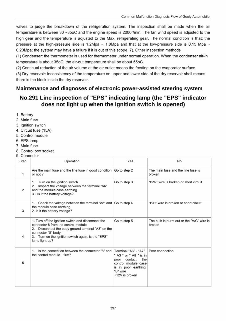
Common Malfunction Diagnosis Flow of Geely Automobile
397
valves to judge the breakdown of the refrigeration system. The inspection shall be made when the air temperature is between 30 ~35oC and the engine speed is 2000r/min. The fan wind speed is adjusted to the high gear and the temperature is adjusted to the Max. refrigerating gear. The normal condition is that: the pressure at the high-pressure side is 1.2Mpa ~ 1.8Mpa and that at the low-pressure side is 0.15 Mpa ~ 0.20Mpa; the system may have a failure if it is out of this scope. 7). Other inspection methods (1) Condenser: the thermometer is used for thermometer under normal operation. When the condenser air-in temperature is about 35oC, the air-out temperature shall be about 55oC. (2) Continual reduction of the air volume at the air outlet means the frosting on the evaporator surface. (3) Dry reservoir: inconsistency of the temperature on upper and lower side of the dry reservoir shell means there is the block inside the dry reservoir.
Maintenance and diagnoses of electronic power-assisted steering system
No.291 Line inspection of "EPS" indicating lamp (the "EPS" indicator does not light up when the ignition switch is opened)
1. Battery 2. Main fuse 3. Ignition switch 4. Circuit fuse (15A) 5. Control module 6. EPS lamp 7. Main fuse 8. Control box socket 9. Connector
Step Operation Yes No
1
Are the main fuse and the line fuse in good condition or not ?
Go to step 2 The main fuse and the line fuse is broken
2
1. Turn on the ignition switch 2. Inspect the voltage between the terminal "A6" and the module case earthing 3、Is it the battery voltage?
Go to step 3 “B/W” wire is broken or short circuit
3
1. Check the voltage between the terminal "A8" and the module case earthing 2. Is it the battery voltage?
Go to step 4 "B/R" wire is broken or short circuit
4
1. Turn off the ignition switch and disconnect the connector 8 from the control module 2. Disconnect the body ground terminal "A3" on the connector "8" body 3. Turn on the ignition switch again, is the "EPS" lamp light up?
Go to step 5 The bulb is burnt out or the "V/G" wire is broken
5
1. Is the connection between the connector "8" and the control module firm?
Terminal “A6”,“A7”" A3 " or " A8 " is in poor contact; the control module case is in poor earthing; "B" wire +12V is broken
Poor connection
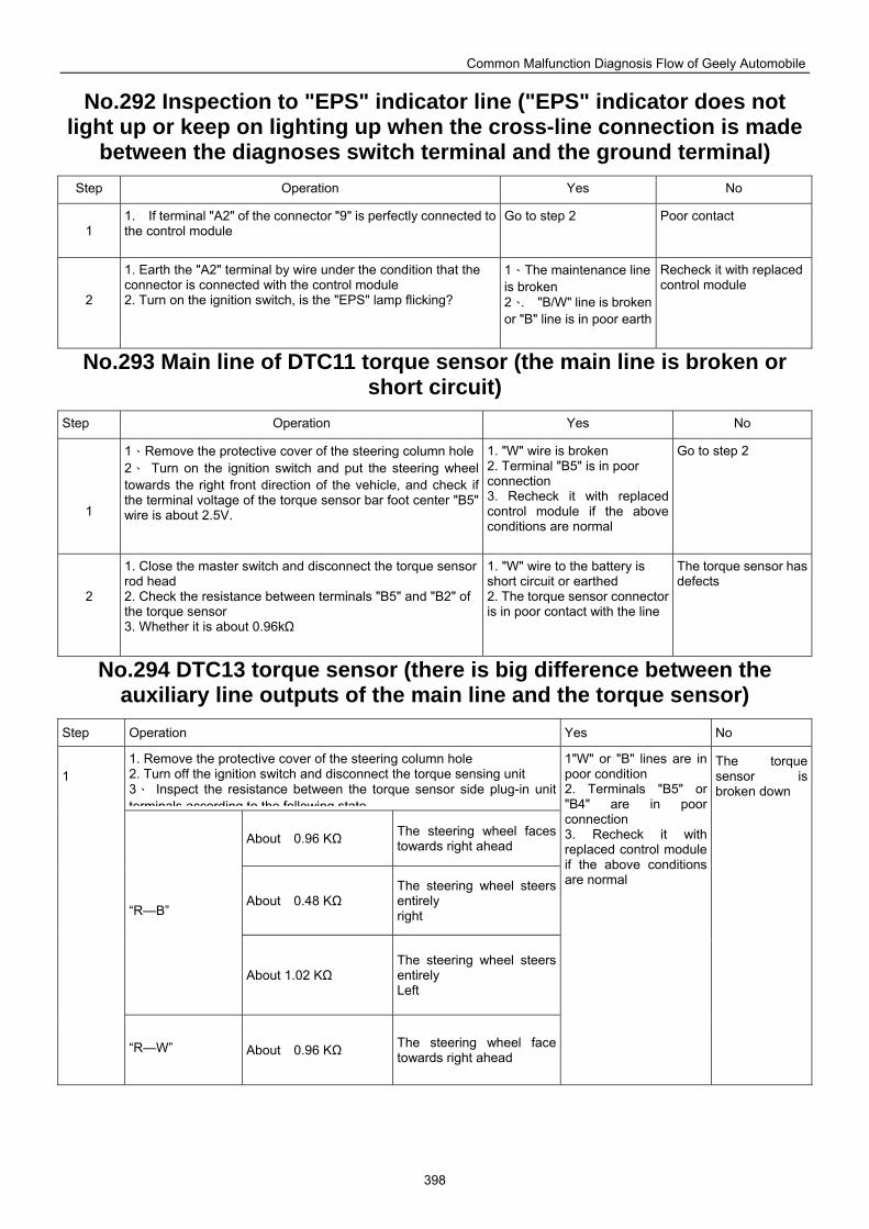
Common Malfunction Diagnosis Flow of Geely Automobile
398
No.292 Inspection to "EPS" indicator line ("EPS" indicator does not light up or keep on lighting up when the cross-line connection is made
between the diagnoses switch terminal and the ground terminal) Step Operation Yes No
1
1. If terminal "A2" of the connector "9" is perfectly connected to the control module
Go to step 2 Poor contact
2
1. Earth the "A2" terminal by wire under the condition that the connector is connected with the control module 2. Turn on the ignition switch, is the "EPS" lamp flicking?
1、The maintenance line is broken 2、. "B/W" line is broken or "B" line is in poor earth
Recheck it with replaced control module
No.293 Main line of DTC11 torque sensor (the main line is broken or short circuit)
Step Operation Yes No
1
1、Remove the protective cover of the steering column hole2、 Turn on the ignition switch and put the steering wheel towards the right front direction of the vehicle, and check if the terminal voltage of the torque sensor bar foot center "B5" wire is about 2.5V.
1. "W" wire is broken 2. Terminal "B5" is in poor connection 3. Recheck it with replaced control module if the above conditions are normal
Go to step 2
2
1. Close the master switch and disconnect the torque sensor rod head 2. Check the resistance between terminals "B5" and "B2" of the torque sensor 3. Whether it is about 0.96kΩ
1. "W" wire to the battery is short circuit or earthed 2. The torque sensor connector is in poor contact with the line
The torque sensor has defects
No.294 DTC13 torque sensor (there is big difference between the auxiliary line outputs of the main line and the torque sensor)
Step Operation Yes No
1. Remove the protective cover of the steering column hole 2. Turn off the ignition switch and disconnect the torque sensing unit 3、 Inspect the resistance between the torque sensor side plug-in unit terminals according to the following state
About 0.96 KΩ The steering wheel faces towards right ahead
About 0.48 KΩ The steering wheel steers entirely right “R—B”
About 1.02 KΩ The steering wheel steers entirely Left
1
“R—W” About 0.96 KΩ The steering wheel face towards right ahead
1"W" or "B" lines are in poor condition 2. Terminals "B5" or "B4" are in poor connection 3. Recheck it with replaced control module if the above conditions are normal
The torque sensor is broken down
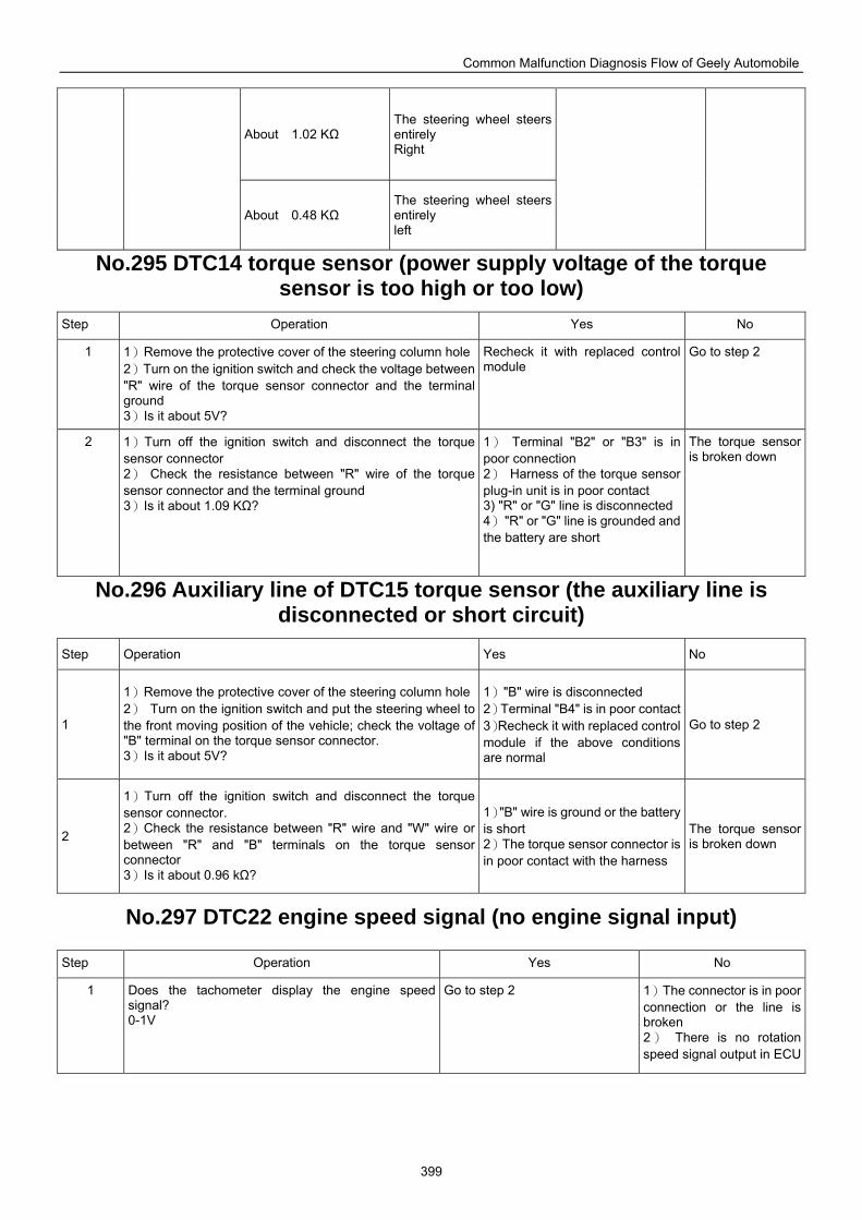
Common Malfunction Diagnosis Flow of Geely Automobile
399
About 1.02 KΩ The steering wheel steers entirely Right
About 0.48 KΩ The steering wheel steers entirely left
No.295 DTC14 torque sensor (power supply voltage of the torque sensor is too high or too low)
Step Operation Yes No
1 1)Remove the protective cover of the steering column hole2)Turn on the ignition switch and check the voltage between "R" wire of the torque sensor connector and the terminal ground 3)Is it about 5V?
Recheck it with replaced control module
Go to step 2
2 1)Turn off the ignition switch and disconnect the torque sensor connector 2) Check the resistance between "R" wire of the torque sensor connector and the terminal ground 3)Is it about 1.09 KΩ?
1) Terminal "B2" or "B3" is in poor connection 2) Harness of the torque sensor plug-in unit is in poor contact 3) "R" or "G" line is disconnected 4) "R" or "G" line is grounded and the battery are short
The torque sensor is broken down
No.296 Auxiliary line of DTC15 torque sensor (the auxiliary line is disconnected or short circuit)
Step Operation Yes No
1
1)Remove the protective cover of the steering column hole2) Turn on the ignition switch and put the steering wheel to the front moving position of the vehicle; check the voltage of "B" terminal on the torque sensor connector. 3)Is it about 5V?
1)"B" wire is disconnected 2)Terminal "B4" is in poor contact 3)Recheck it with replaced control module if the above conditions are normal
Go to step 2
2
1)Turn off the ignition switch and disconnect the torque sensor connector. 2)Check the resistance between "R" wire and "W" wire or between "R" and "B" terminals on the torque sensor connector 3)Is it about 0.96 kΩ?
1)"B" wire is ground or the battery is short 2)The torque sensor connector is in poor contact with the harness
The torque sensor is broken down
No.297 DTC22 engine speed signal (no engine signal input)
Step Operation Yes No
1 Does the tachometer display the engine speed signal? 0-1V
Go to step 2 1)The connector is in poor connection or the line is broken 2) There is no rotation speed signal output in ECU
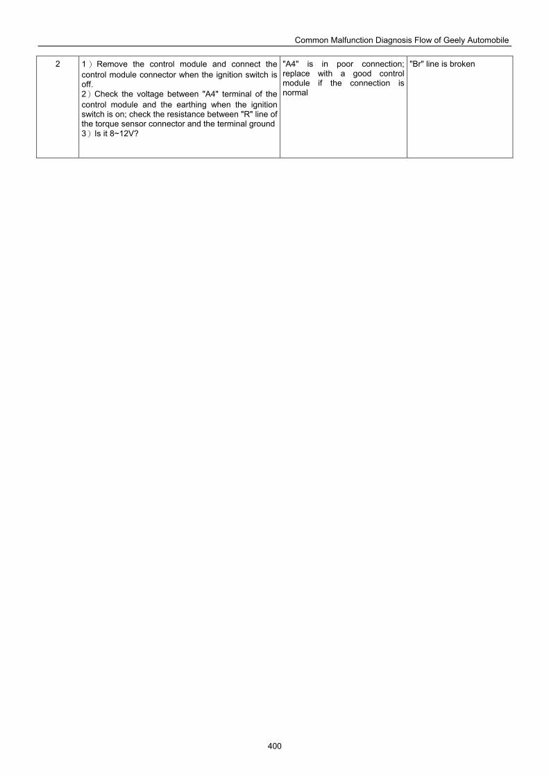
Common Malfunction Diagnosis Flow of Geely Automobile
400
2 1)Remove the control module and connect the control module connector when the ignition switch is off. 2)Check the voltage between "A4" terminal of the control module and the earthing when the ignition switch is on; check the resistance between "R" line of the torque sensor connector and the terminal ground3)Is it 8~12V?
"A4" is in poor connection; replace with a good control module if the connection is normal
"Br" line is broken
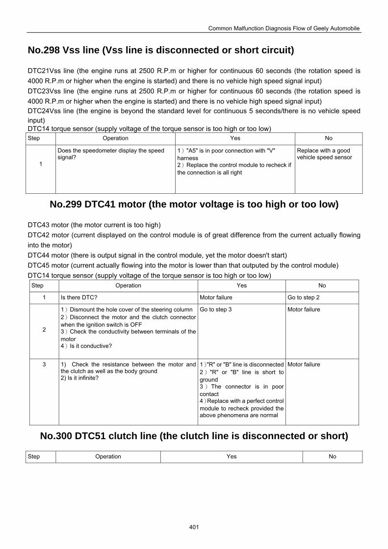
Common Malfunction Diagnosis Flow of Geely Automobile
401
No.298 Vss line (Vss line is disconnected or short circuit)
DTC21Vss line (the engine runs at 2500 R.P.m or higher for continuous 60 seconds (the rotation speed is 4000 R.P.m or higher when the engine is started) and there is no vehicle high speed signal input) DTC23Vss line (the engine runs at 2500 R.P.m or higher for continuous 60 seconds (the rotation speed is 4000 R.P.m or higher when the engine is started) and there is no vehicle high speed signal input) DTC24Vss line (the engine is beyond the standard level for continuous 5 seconds/there is no vehicle speed input) DTC14 torque sensor (supply voltage of the torque sensor is too high or too low) Step Operation Yes No
1
Does the speedometer display the speed signal?
1)"A5" is in poor connection with "V" harness 2)Replace the control module to recheck if the connection is all right
Replace with a good vehicle speed sensor
No.299 DTC41 motor (the motor voltage is too high or too low)
DTC43 motor (the motor current is too high) DTC42 motor (current displayed on the control module is of great difference from the current actually flowing into the motor) DTC44 motor (there is output signal in the control module, yet the motor doesn't start) DTC45 motor (current actually flowing into the motor is lower than that outputed by the control module) DTC14 torque sensor (supply voltage of the torque sensor is too high or too low)
Step Operation Yes No
1 Is there DTC? Motor failure Go to step 2
2
1)Dismount the hole cover of the steering column2)Disconnect the motor and the clutch connector when the ignition switch is OFF 3)Check the conductivity between terminals of the motor 4)Is it conductive?
Go to step 3 Motor failure
3 1) Check the resistance between the motor and the clutch as well as the body ground 2) Is it infinite?
1)"R" or "B" line is disconnected 2)"R" or "B" line is short to ground 3) The connector is in poor contact 4)Replace with a perfect control module to recheck provided the above phenomena are normal
Motor failure
No.300 DTC51 clutch line (the clutch line is disconnected or short)
Step Operation Yes No
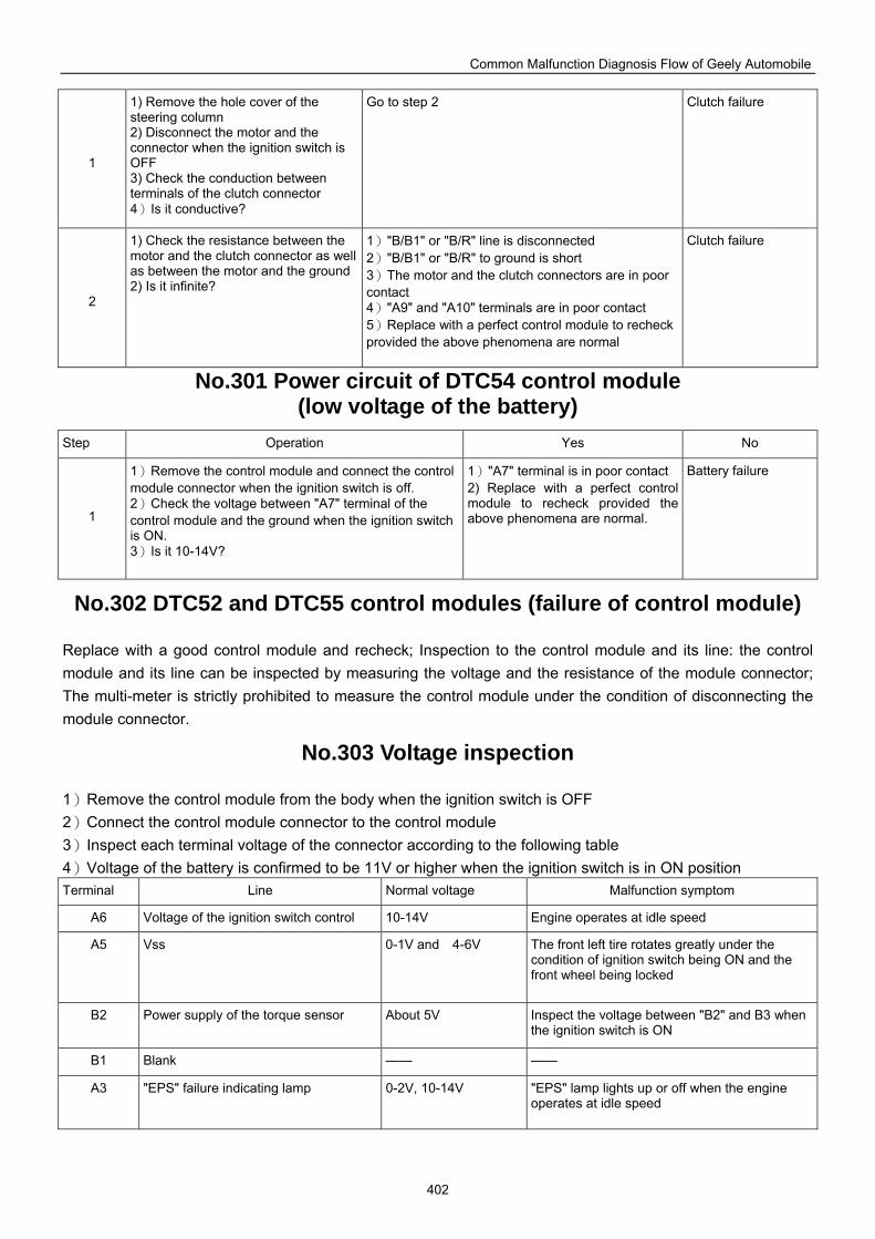
Common Malfunction Diagnosis Flow of Geely Automobile
402
1
1) Remove the hole cover of the steering column 2) Disconnect the motor and the connector when the ignition switch is OFF 3) Check the conduction between terminals of the clutch connector 4)Is it conductive?
Go to step 2 Clutch failure
2
1) Check the resistance between the motor and the clutch connector as well as between the motor and the ground 2) Is it infinite?
1)"B/B1" or "B/R" line is disconnected 2)"B/B1" or "B/R" to ground is short 3)The motor and the clutch connectors are in poor contact 4)"A9" and "A10" terminals are in poor contact 5)Replace with a perfect control module to recheck provided the above phenomena are normal
Clutch failure
No.301 Power circuit of DTC54 control module (low voltage of the battery)
Step Operation Yes No
1
1)Remove the control module and connect the control module connector when the ignition switch is off. 2)Check the voltage between "A7" terminal of the control module and the ground when the ignition switch is ON. 3)Is it 10-14V?
1)"A7" terminal is in poor contact 2) Replace with a perfect control module to recheck provided the above phenomena are normal.
Battery failure
No.302 DTC52 and DTC55 control modules (failure of control module)
Replace with a good control module and recheck; Inspection to the control module and its line: the control module and its line can be inspected by measuring the voltage and the resistance of the module connector; The multi-meter is strictly prohibited to measure the control module under the condition of disconnecting the module connector.
No.303 Voltage inspection
1)Remove the control module from the body when the ignition switch is OFF 2)Connect the control module connector to the control module 3)Inspect each terminal voltage of the connector according to the following table 4)Voltage of the battery is confirmed to be 11V or higher when the ignition switch is in ON position Terminal Line Normal voltage Malfunction symptom
A6 Voltage of the ignition switch control 10-14V Engine operates at idle speed
A5 Vss 0-1V and 4-6V The front left tire rotates greatly under the condition of ignition switch being ON and the front wheel being locked
B2 Power supply of the torque sensor About 5V Inspect the voltage between "B2" and B3 when the ignition switch is ON
B1 Blank —— ——
A3 "EPS" failure indicating lamp 0-2V, 10-14V "EPS" lamp lights up or off when the engine operates at idle speed
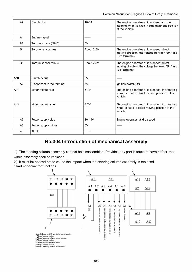
Common Malfunction Diagnosis Flow of Geely Automobile
403
A9 Clutch plus 10-14 The engine operates at idle speed and the steering wheel is fixed in straight ahead position of the vehicle
A4 Engine signal —— ——
B3 Torque sensor (GND) 0V
B4 Torque sensor plus About 2.5V The engine operates at idle speed, direct moving direction, the voltage between "B4" and "B3" terminals
B5 Torque sensor minus About 2.5V The engine operates at idle speed, direct moving direction, the voltage between "B4" and "B3" terminals
A10 Clutch minus 0V ——
A2 Disconnect to the terminal 5V Ignition switch ON
A11 Motor output plus 5-7V The engine operates at idle speed, the steering wheel is fixed to direct moving position of the vehicle
A12 Motor output minus 5-7V The engine operates at idle speed, the steering wheel is fixed to direct moving position of the vehicle
A7 Power supply plus 10-14V Engine operates at idle speed
A8 Power supply minus 0V ——
A1 Blank —— ——
No.304 Introduction of mechanical assembly
1)The steering column assembly can not be disassembled. Provided any part is found to have defect, the whole assembly shall be replaced. 2)It must be noticed not to cause the impact when the steering column assembly is replaced. Chart of connector functions
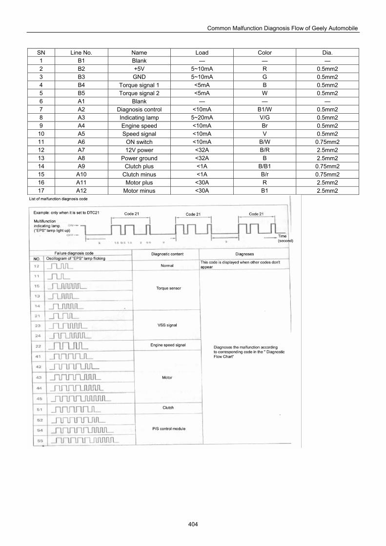
Common Malfunction Diagnosis Flow of Geely Automobile
404
SN Line No. Name Load Color Dia. 1 B1 Blank — — — 2 B2 +5V 5~10mA R 0.5mm2 3 B3 GND 5~10mA G 0.5mm2 4 B4 Torque signal 1 <5mA B 0.5mm2 5 B5 Torque signal 2 <5mA W 0.5mm2 6 A1 Blank — — — 7 A2 Diagnosis control <10mA B1/W 0.5mm2 8 A3 Indicating lamp 5~20mA V/G 0.5mm2 9 A4 Engine speed <10mA Br 0.5mm2
10 A5 Speed signal <10mA V 0.5mm2 11 A6 ON switch <10mA B/W 0.75mm2 12 A7 12V power <32A B/R 2.5mm2 13 A8 Power ground <32A B 2.5mm2 14 A9 Clutch plus <1A B/B1 0.75mm2 15 A10 Clutch minus <1A B/r 0.75mm2 16 A11 Motor plus <30A R 2.5mm2 17 A12 Motor minus <30A B1 2.5mm2
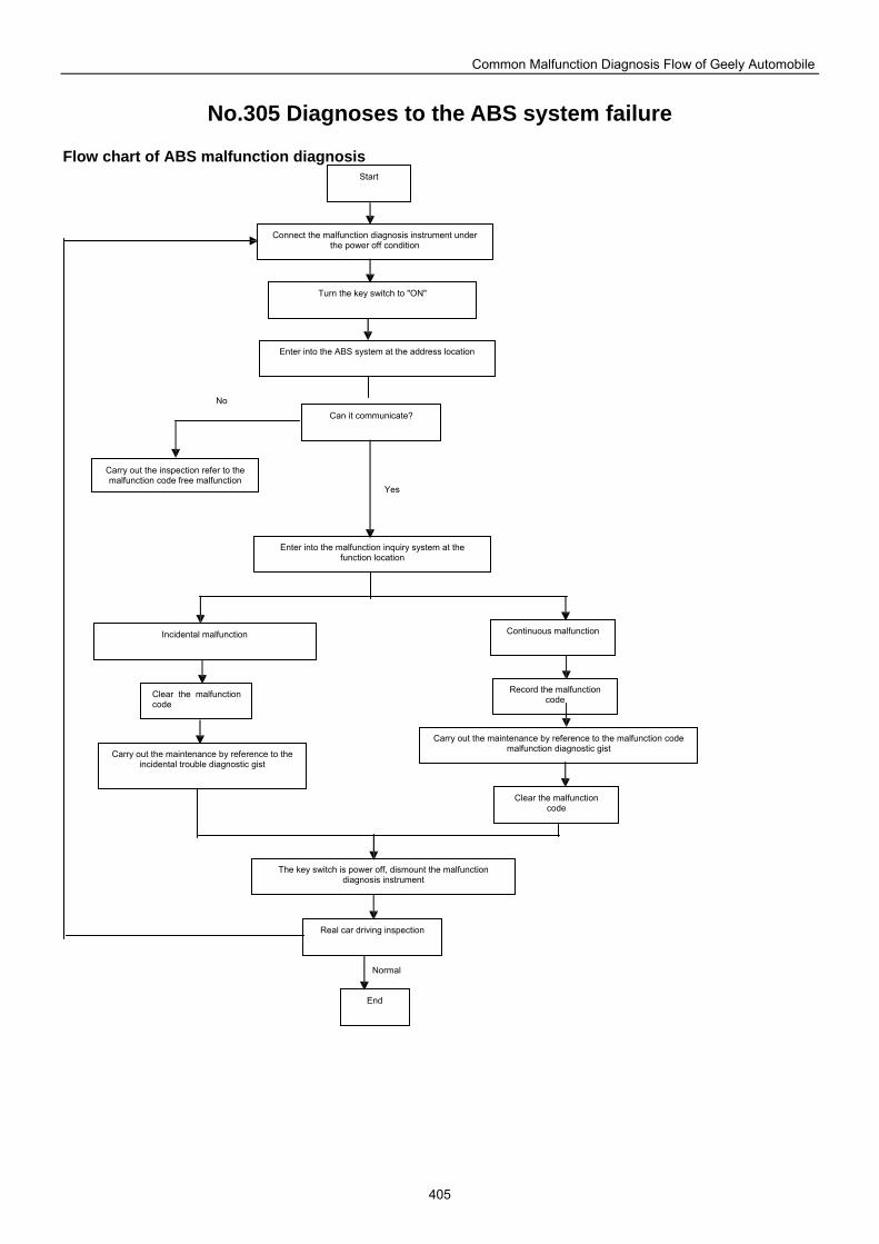
Common Malfunction Diagnosis Flow of Geely Automobile
405
No.305 Diagnoses to the ABS system failure
Flow chart of ABS malfunction diagnosis
Incidental malfunction Continuous malfunction
Clear the malfunction code
Carry out the maintenance by reference to the incidental trouble diagnostic gist
Record the malfunction code
Carry out the maintenance by reference to the malfunction code malfunction diagnostic gist
Clear the malfunction code
The key switch is power off, dismount the malfunction diagnosis instrument
Real car driving inspection
End
Start
Connect the malfunction diagnosis instrument under the power off condition
Turn the key switch to "ON"
Enter into the ABS system at the address location
Can it communicate?
Carry out the inspection refer to the malfunction code free malfunction
Enter into the malfunction inquiry system at the function location
Normal
No
Yes
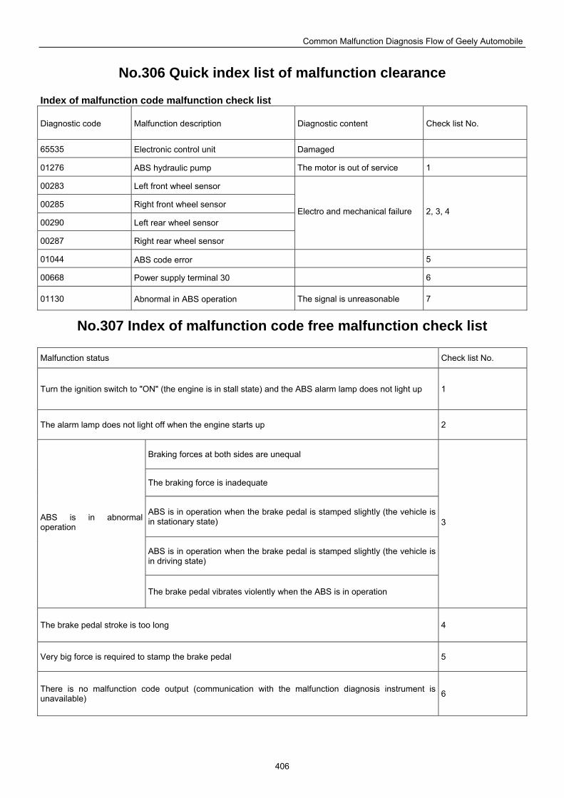
Common Malfunction Diagnosis Flow of Geely Automobile
406
No.306 Quick index list of malfunction clearance
Index of malfunction code malfunction check list
Diagnostic code Malfunction description Diagnostic content Check list No.
65535 Electronic control unit Damaged
01276 ABS hydraulic pump The motor is out of service 1
00283 Left front wheel sensor
00285 Right front wheel sensor
00290 Left rear wheel sensor
00287 Right rear wheel sensor
Electro and mechanical failure 2, 3, 4
01044 ABS code error 5
00668 Power supply terminal 30 6
01130 Abnormal in ABS operation The signal is unreasonable 7
No.307 Index of malfunction code free malfunction check list
Malfunction status Check list No.
Turn the ignition switch to "ON" (the engine is in stall state) and the ABS alarm lamp does not light up 1
The alarm lamp does not light off when the engine starts up 2
Braking forces at both sides are unequal
The braking force is inadequate
ABS is in operation when the brake pedal is stamped slightly (the vehicle is in stationary state)
ABS is in operation when the brake pedal is stamped slightly (the vehicle is in driving state)
ABS is in abnormal operation
The brake pedal vibrates violently when the ABS is in operation
3
The brake pedal stroke is too long 4
Very big force is required to stamp the brake pedal 5
There is no malfunction code output (communication with the malfunction diagnosis instrument is unavailable) 6
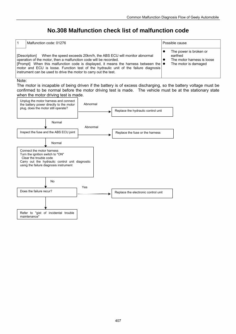
Common Malfunction Diagnosis Flow of Geely Automobile
407
No.308 Malfunction check list of malfunction code
1 Malfunction code: 01276 Possible cause
[Description] When the speed exceeds 20km/h, the ABS ECU will monitor abnormal operation of the motor, then a malfunction code will be recorded. [Prompt] When this malfunction code is displayed, it means the harness between the motor and ECU is loose. Function test of the hydraulic unit of the failure diagnosis instrument can be used to drive the motor to carry out the test.
The power is broken or earthed
The motor harness is loose The motor is damaged
Note: The motor is incapable of being driven if the battery is of excess discharging, so the battery voltage must be confirmed to be normal before the motor driving test is made. The vehicle must be at the stationary state when the motor driving test is made.
Unplug the motor harness and connect the battery power directly to the motor plug, does the motor still operate?
Inspect the fuse and the ABS ECU joint
Connect the motor harness Turn the ignition switch to "ON" Clear the trouble code Carry out the hydraulic control unit diagnostic using the failure diagnosis instrument
Does the failure recur?
Refer to "gist of incidental trouble maintenance"
Replace the hydraulic control unit
Replace the fuse or the harness
Replace the electronic control unit
Abnormal
Abnormal
Yes
Normal
Normal
No
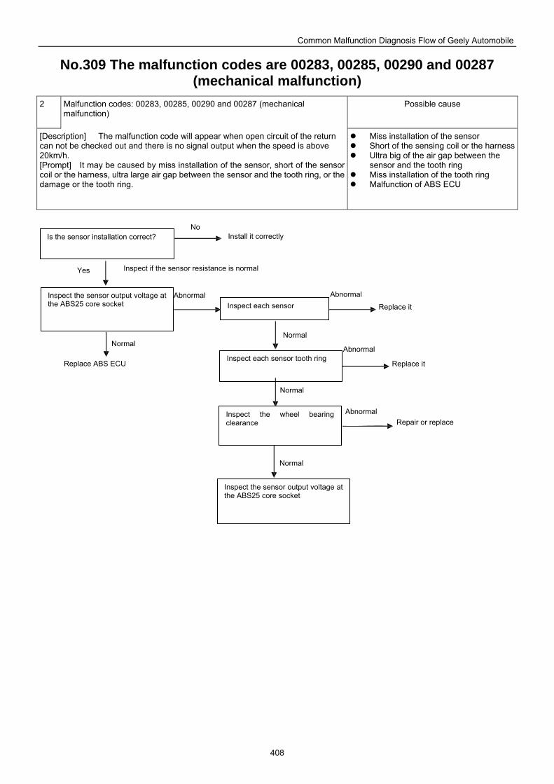
Common Malfunction Diagnosis Flow of Geely Automobile
408
No.309 The malfunction codes are 00283, 00285, 00290 and 00287 (mechanical malfunction)
2 Malfunction codes: 00283, 00285, 00290 and 00287 (mechanical malfunction)
Possible cause
[Description] The malfunction code will appear when open circuit of the return can not be checked out and there is no signal output when the speed is above 20km/h. [Prompt] It may be caused by miss installation of the sensor, short of the sensor coil or the harness, ultra large air gap between the sensor and the tooth ring, or the damage or the tooth ring.
Miss installation of the sensor Short of the sensing coil or the harness Ultra big of the air gap between the
sensor and the tooth ring Miss installation of the tooth ring Malfunction of ABS ECU
Is the sensor installation correct?
Inspect the sensor output voltage at the ABS25 core socket Inspect each sensor
Inspect each sensor tooth ring
Inspect the wheel bearing clearance
Inspect the sensor output voltage at the ABS25 core socket
Install it correctly
Inspect if the sensor resistance is normal
Replace ABS ECU
Replace it
Repair or replace Abnormal
Normal
Replace it
Abnormal
Abnormal Abnormal
No
Yes
Normal
Normal
Normal
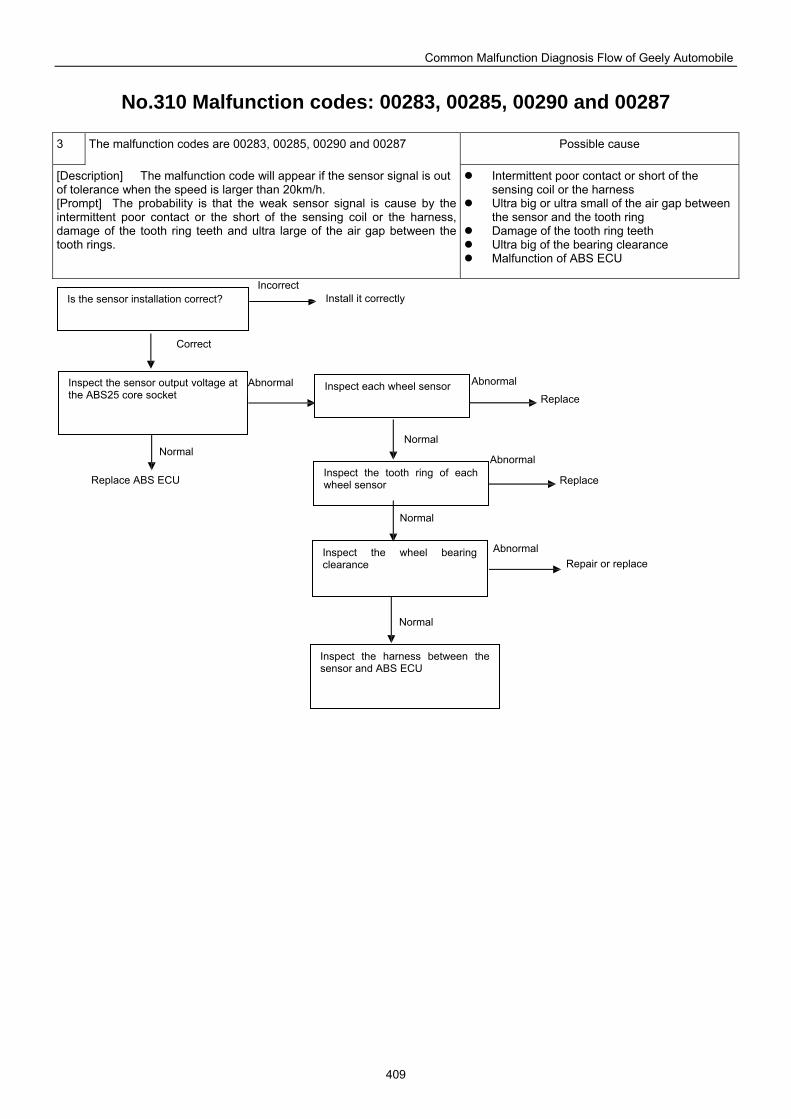
Common Malfunction Diagnosis Flow of Geely Automobile
409
No.310 Malfunction codes: 00283, 00285, 00290 and 00287
3 The malfunction codes are 00283, 00285, 00290 and 00287 Possible cause
[Description] The malfunction code will appear if the sensor signal is out of tolerance when the speed is larger than 20km/h. [Prompt] The probability is that the weak sensor signal is cause by the intermittent poor contact or the short of the sensing coil or the harness, damage of the tooth ring teeth and ultra large of the air gap between the tooth rings.
Intermittent poor contact or short of the sensing coil or the harness
Ultra big or ultra small of the air gap between the sensor and the tooth ring
Damage of the tooth ring teeth Ultra big of the bearing clearance Malfunction of ABS ECU
Is the sensor installation correct?
Inspect the sensor output voltage at the ABS25 core socket
Inspect each wheel sensor
Inspect the tooth ring of each wheel sensor
Inspect the wheel bearing clearance
Inspect the harness between the sensor and ABS ECU
Install it correctly
Correct
Replace ABS ECU
Replace
Repair or replace Abnormal
Normal
Replace
Abnormal
Abnormal Abnormal
Incorrect
Normal
Normal
Normal
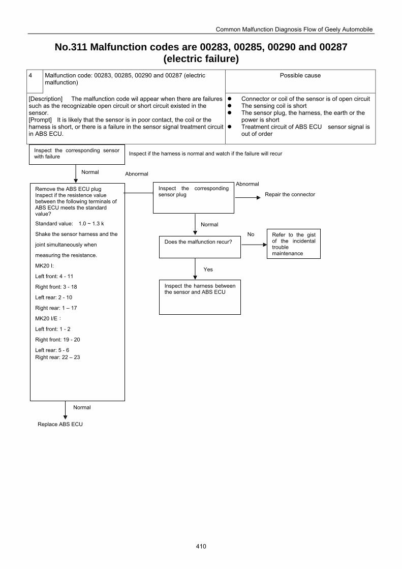
Common Malfunction Diagnosis Flow of Geely Automobile
410
No.311 Malfunction codes are 00283, 00285, 00290 and 00287 (electric failure)
4 Malfunction code: 00283, 00285, 00290 and 00287 (electric malfunction)
Possible cause
[Description] The malfunction code wil appear when there are failures such as the recognizable open circuit or short circuit existed in the sensor. [Prompt] It is likely that the sensor is in poor contact, the coil or the harness is short, or there is a failure in the sensor signal treatment circuit in ABS ECU.
Connector or coil of the sensor is of open circuit The sensing coil is short The sensor plug, the harness, the earth or the
power is short Treatment circuit of ABS ECU sensor signal is
out of order
Inspect the corresponding sensor with failure
Remove the ABS ECU plug Inspect if the resistence value between the following terminals of ABS ECU meets the standard value?
Standard value: 1.0 ~ 1.3 k
Shake the sensor harness and the
joint simultaneously when
measuring the resistance.
MK20 I:
Left front: 4 - 11
Right front: 3 - 18
Left rear: 2 - 10
Right rear: 1 – 17
MK20 I/E:
Left front: 1 - 2
Right front: 19 - 20
Left rear: 5 - 6 Right rear: 22 – 23
Inspect the corresponding sensor plug
Does the malfunction recur?
Inspect the harness between the sensor and ABS ECU
Refer to the gist of the incidental trouble maintenance
Inspect if the harness is normal and watch if the failure will recur
Repair the connector
Replace ABS ECU
Abnormal
Normal
Abnormal Normal
Normal
No
Yes
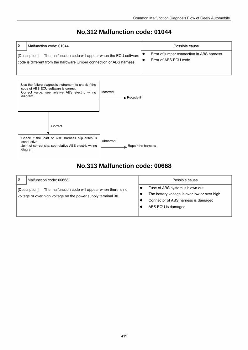
Common Malfunction Diagnosis Flow of Geely Automobile
411
No.312 Malfunction code: 01044
5 Malfunction code: 01044 Possible cause
[Description] The malfunction code will appear when the ECU software
code is different from the hardware jumper connection of ABS harness.
Error of jumper connection in ABS harness Error of ABS ECU code
No.313 Malfunction code: 00668
6 Malfunction code: 00668 Possible cause
[Description] The malfunction code will appear when there is no
voltage or over high voltage on the power supply terminal 30.
Fuse of ABS system is blown out The battery voltage is over low or over high
Connector of ABS harness is damaged
ABS ECU is damaged
Check if the joint of ABS harness slip stitch is conductive Joint of correct slip: see relative ABS electric wiring diagram
Use the failure diagnosis instrument to check if the code of ABS ECU software is correct Correct value: see relative ABS electric wiring diagram Recode it
Repair the harness
Incorrect
Correct
Abnormal
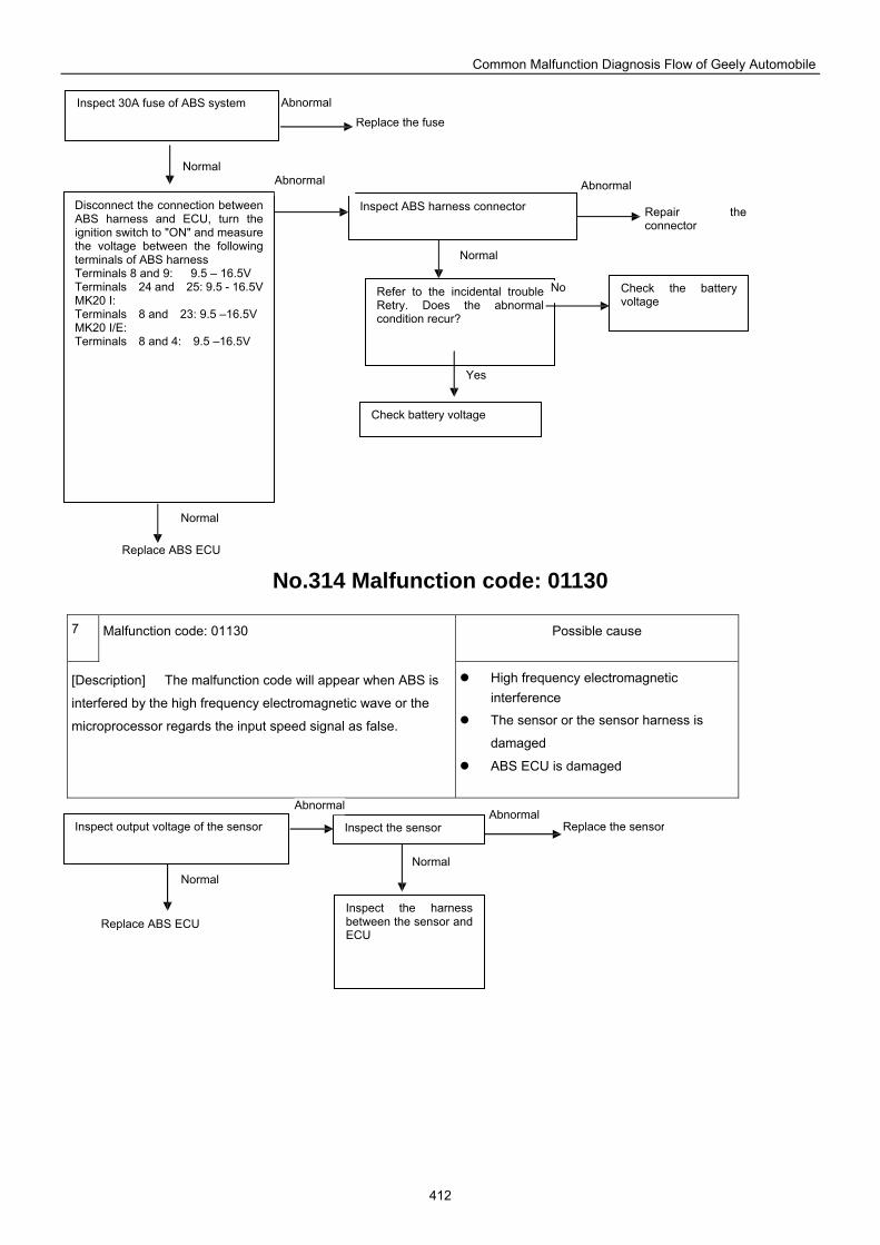
Common Malfunction Diagnosis Flow of Geely Automobile
412
Replace ABS ECU
No.314 Malfunction code: 01130
7 Malfunction code: 01130 Possible cause
[Description] The malfunction code will appear when ABS is
interfered by the high frequency electromagnetic wave or the
microprocessor regards the input speed signal as false.
High frequency electromagnetic interference
The sensor or the sensor harness is
damaged
ABS ECU is damaged
Inspect 30A fuse of ABS system
Disconnect the connection between ABS harness and ECU, turn the ignition switch to "ON" and measure the voltage between the following terminals of ABS harness Terminals 8 and 9: 9.5 – 16.5V Terminals 24 and 25: 9.5 - 16.5V MK20 I: Terminals 8 and 23: 9.5 –16.5V MK20 I/E: Terminals 8 and 4: 9.5 –16.5V
Inspect ABS harness connector
Refer to the incidental trouble Retry. Does the abnormal condition recur?
Check the battery voltage
Check battery voltage
Replace the fuse
Repair theconnector
Abnormal
Normal Abnormal Abnormal
Normal
Normal
No
Yes
Inspect output voltage of the sensor Inspect the sensor
Inspect the harness between the sensor and ECU
Normal Normal
Replace ABS ECU
Replace the sensorAbnormal
Abnormal
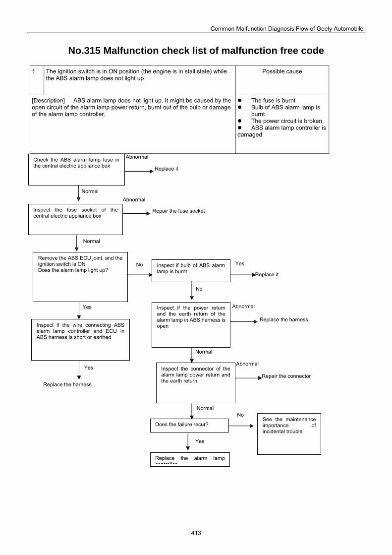
Common Malfunction Diagnosis Flow of Geely Automobile
413
No.315 Malfunction check list of malfunction free code
1 The ignition switch is in ON position (the engine is in stall state) while the ABS alarm lamp does not light up
Possible cause
[Description] ABS alarm lamp does not light up. It might be caused by the open circuit of the alarm lamp power return, burnt out of the bulb or damage of the alarm lamp controller.
The fuse is burnt Bulb of ABS alarm lamp is
burnt The power circuit is broken ABS alarm lamp controller is
damaged
Remove the ABS ECU joint, and the ignition switch is ON Does the alarm lamp light up?
Inspect if bulb of ABS alarm lamp is burnt
Inspect if the power return and the earth return of the alarm lamp in ABS harness is open
Inspect the connector of the alarm lamp power return and the earth return
Does the failure recur?
Inspect if the wire connecting ABS alarm lamp controller and ECU in ABS harness is short or earthed
Replace the alarm lamp controller
Check the ABS alarm lamp fuse in the central electric appliance box
Inspect the fuse socket of the central electric appliance box
See the maintenance importance of incidental trouble
Replace it
Repair the fuse socket
Replace it
Replace the harness
Repair the connector Replace the harness
Abnormal
Abnormal Normal
Normal
Yes
Yes
No Yes
No
Yes
No
Abnormal
Abnormal
Normal
Normal
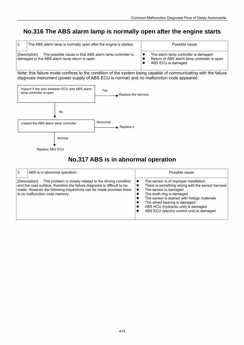
Common Malfunction Diagnosis Flow of Geely Automobile
414
No.316 The ABS alarm lamp is normally open after the engine starts
2 The ABS alarm lamp is normally open after the engine is started. Possible cause
[Description] The possible cause is that ABS alarm lamp controller is damaged or the ABS alarm lamp return is open.
The alarm lamp controller is damaged Return of ABS alarm lamp controller is open ABS ECU is damaged
Note: this failure mode confines to the condition of the system being capable of communicating with the failure diagnosis instrument (power supply of ABS ECU is normal) and no malfunction code appeared.
No.317 ABS is in abnormal operation
3 ABS is in abnormal operation Possible cause
[Description] This problem is closely related to the driving condition and the road surface, therefore the failure diagnosis is difficult to be made. However the following inspections can be made provided there is no malfunction code memory.
The sensor is of improper installation There is something wrong with the sensor harness The sensor is damaged The tooth ring is damaged The sensor is stained with foreign materials The wheel bearing is damaged ABS HCU (hydraulic unit) is damaged ABS ECU (electric control unit) is damaged
Inspect if the wire between ECU and ABS alarm lamp controller is open
Inspect the ABS alarm lamp controller
Replace the harness
Replace it
Replace ABS ECU
Yes
No
Abnormal
Normal
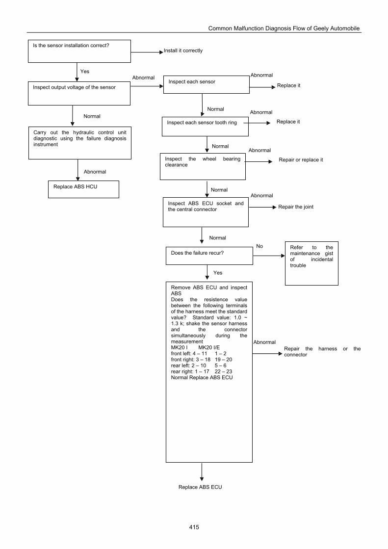
Common Malfunction Diagnosis Flow of Geely Automobile
415
Is the sensor installation correct?
Inspect output voltage of the sensor Inspect each sensor
Inspect each sensor tooth ring
Carry out the hydraulic control unit diagnostic using the failure diagnosis instrument
Replace ABS HCU
Inspect the wheel bearing clearance
Inspect ABS ECU socket and the central connector
Refer to the maintenance gist of incidental trouble
Remove ABS ECU and inspect ABS Does the resistence value between the following terminals of the harness meet the standard value? Standard value: 1.0 ~ 1.3 k; shake the sensor harness and the connector simultaneously during the measurement MK20 I MK20 I/E front left: 4 – 11 1 – 2 front right: 3 – 18 19 – 20 rear left: 2 – 10 5 – 6 rear right: 1 – 17 22 – 23 Normal Replace ABS ECU
Does the failure recur?
Install it correctly
Yes Abnormal Abnormal
Replace it
Normal Normal
Replace it
Abnormal
Normal
Normal
Normal
Yes
Abnormal
Abnormal
Abnormal
Abnormal
No
Repair or replace it
Repair the joint
Repair the harness or the connector
Replace ABS ECU
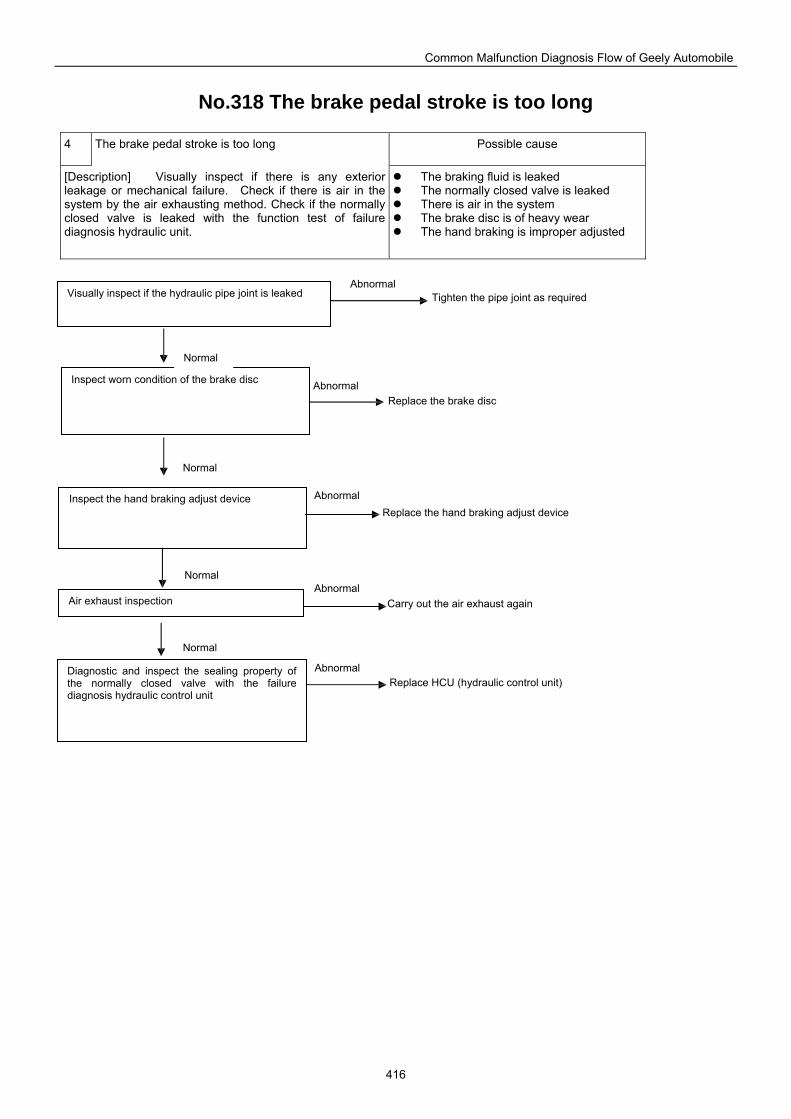
Common Malfunction Diagnosis Flow of Geely Automobile
416
No.318 The brake pedal stroke is too long
4 The brake pedal stroke is too long Possible cause
[Description] Visually inspect if there is any exterior leakage or mechanical failure. Check if there is air in the system by the air exhausting method. Check if the normally closed valve is leaked with the function test of failure diagnosis hydraulic unit.
The braking fluid is leaked The normally closed valve is leaked There is air in the system The brake disc is of heavy wear The hand braking is improper adjusted
Diagnostic and inspect the sealing property of the normally closed valve with the failure diagnosis hydraulic control unit
Inspect worn condition of the brake disc
Visually inspect if the hydraulic pipe joint is leaked
Inspect the hand braking adjust device
Air exhaust inspection
Tighten the pipe joint as required
Replace the brake disc
Replace the hand braking adjust device
Carry out the air exhaust again
Replace HCU (hydraulic control unit)
Abnormal
Abnormal
Abnormal
Abnormal
Abnormal
Normal
Normal
Normal
Normal
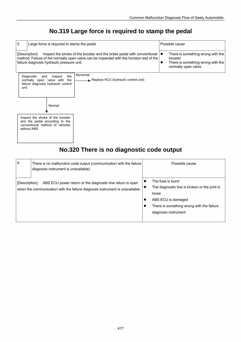
Common Malfunction Diagnosis Flow of Geely Automobile
417
No.319 Large force is required to stamp the pedal
5 Large force is required to stamp the pedal Possible cause
[Description] Inspect the stroke of the booster and the brake pedal with conventional method. Failure of the normally open valve can be inspected with the function test of the failure diagnosis hydraulic pressure unit.
There is something wrong with the booster
There is something wrong with the normally open valve
No.320 There is no diagnostic code output
6 There is no malfunction code output (communication with the failure diagnosis instrument is unavailable)
Possible cause
[Description] ABS ECU power return or the diagnostic line return is open
when the communication with the failure diagnosis instrument is unavailable.
The fuse is burnt The diagnostic line is broken or the joint is
loose
ABS ECU is damaged
There is something wrong with the failure
diagnosis instrument
Diagnostic and inspect the normally open valve with the failure diagnosis hydraulic control unit
Inspect the stroke of the booster and the pedal according to the conventional method of vehicles without ABS
Replace HCU (hydraulic control unit)Abnormal
Normal
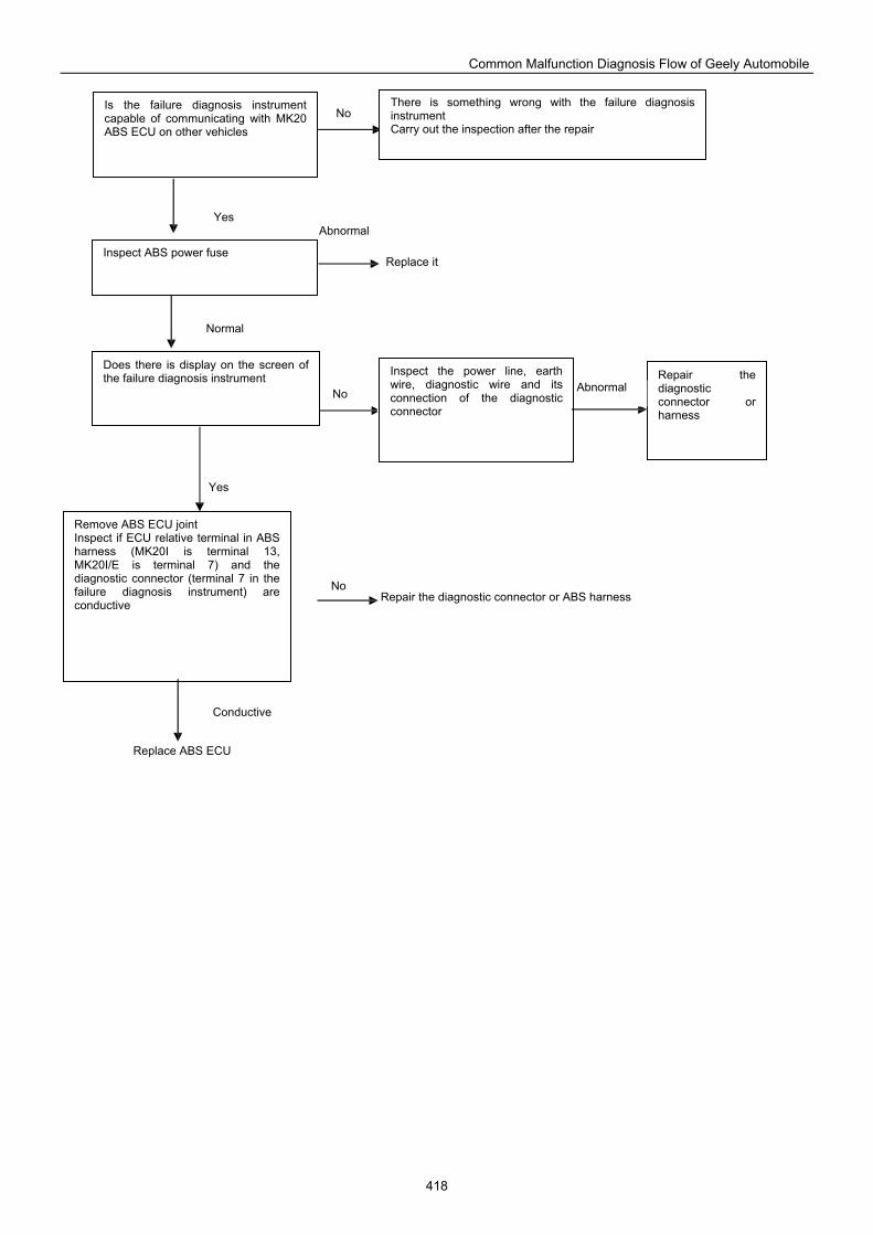
Common Malfunction Diagnosis Flow of Geely Automobile
418
Does there is display on the screen of the failure diagnosis instrument Inspect the power line, earth
wire, diagnostic wire and its connection of the diagnostic connector
Repair the diagnostic connector or harness
Remove ABS ECU joint Inspect if ECU relative terminal in ABS harness (MK20I is terminal 13, MK20I/E is terminal 7) and the diagnostic connector (terminal 7 in the failure diagnosis instrument) are conductive
Is the failure diagnosis instrument capable of communicating with MK20 ABS ECU on other vehicles
There is something wrong with the failure diagnosis instrument Carry out the inspection after the repair
Inspect ABS power fuse Replace it
Repair the diagnostic connector or ABS harness
Replace ABS ECU
No
Yes Abnormal
Normal
No Abnormal
Yes
No
Conductive
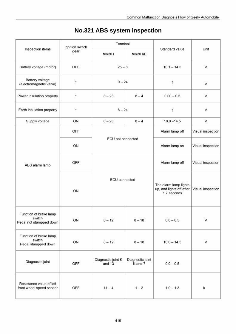
Common Malfunction Diagnosis Flow of Geely Automobile
419
No.321 ABS system inspection
Terminal Inspection items Ignition switch
gear MK20 I MK20 I/E
Standard value Unit
Battery voltage (motor) OFF 25 – 8 10.1 – 14.5 V
Battery voltage (electromagnetic valve) ↑ 9 – 24 ↑
V
Power insulation property ↑ 8 – 23 8 – 4 0.00 – 0.5 V
Earth insulation property ↑ 8 – 24 ↑ V
Supply voltage ON 8 – 23 8 – 4 10.0 –14.5 V
OFF Alarm lamp off Visual inspection
ON
ECU not connected
Alarm lamp on Visual inspection
OFF Alarm lamp off Visual inspectionABS alarm lamp
ON
ECU connected The alarm lamp lights up, and lights off after
1.7 seconds Visual inspection
Function of brake lamp switch
Pedal not stampped down
ON
8 – 12
8 – 18
0.0 – 0.5
V
Function of brake lamp switch
Pedal stampped down
ON
8 – 12
8 – 18
10.0 – 14.5
V
Diagnostic joint OFF
Diagnostic joint K and 13
Diagnostic joint K and 7
0.0 – 0.5
Resistance value of left front wheel speed sensor
OFF
11 – 4
1 – 2
1.0 – 1.3
k
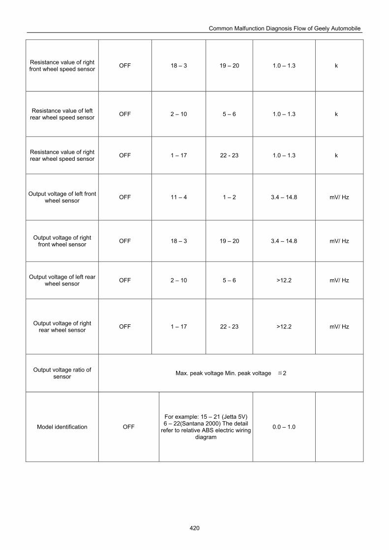
Common Malfunction Diagnosis Flow of Geely Automobile
420
Resistance value of right front wheel speed sensor OFF 18 – 3 19 – 20 1.0 – 1.3 k
Resistance value of left rear wheel speed sensor OFF 2 – 10 5 – 6 1.0 – 1.3 k
Resistance value of right rear wheel speed sensor OFF 1 – 17 22 - 23 1.0 – 1.3 k
Output voltage of left front wheel sensor OFF 11 – 4 1 – 2 3.4 – 14.8 mV/ Hz
Output voltage of right front wheel sensor OFF 18 – 3 19 – 20 3.4 – 14.8 mV/ Hz
Output voltage of left rear wheel sensor OFF 2 – 10 5 – 6 >12.2 mV/ Hz
Output voltage of right rear wheel sensor OFF 1 – 17 22 - 23 >12.2 mV/ Hz
Output voltage ratio of sensor Max. peak voltage Min. peak voltage 2≦
Model identification OFF
For example: 15 – 21 (Jetta 5V)6 – 22(Santana 2000) The detail
refer to relative ABS electric wiring diagram
0.0 – 1.0
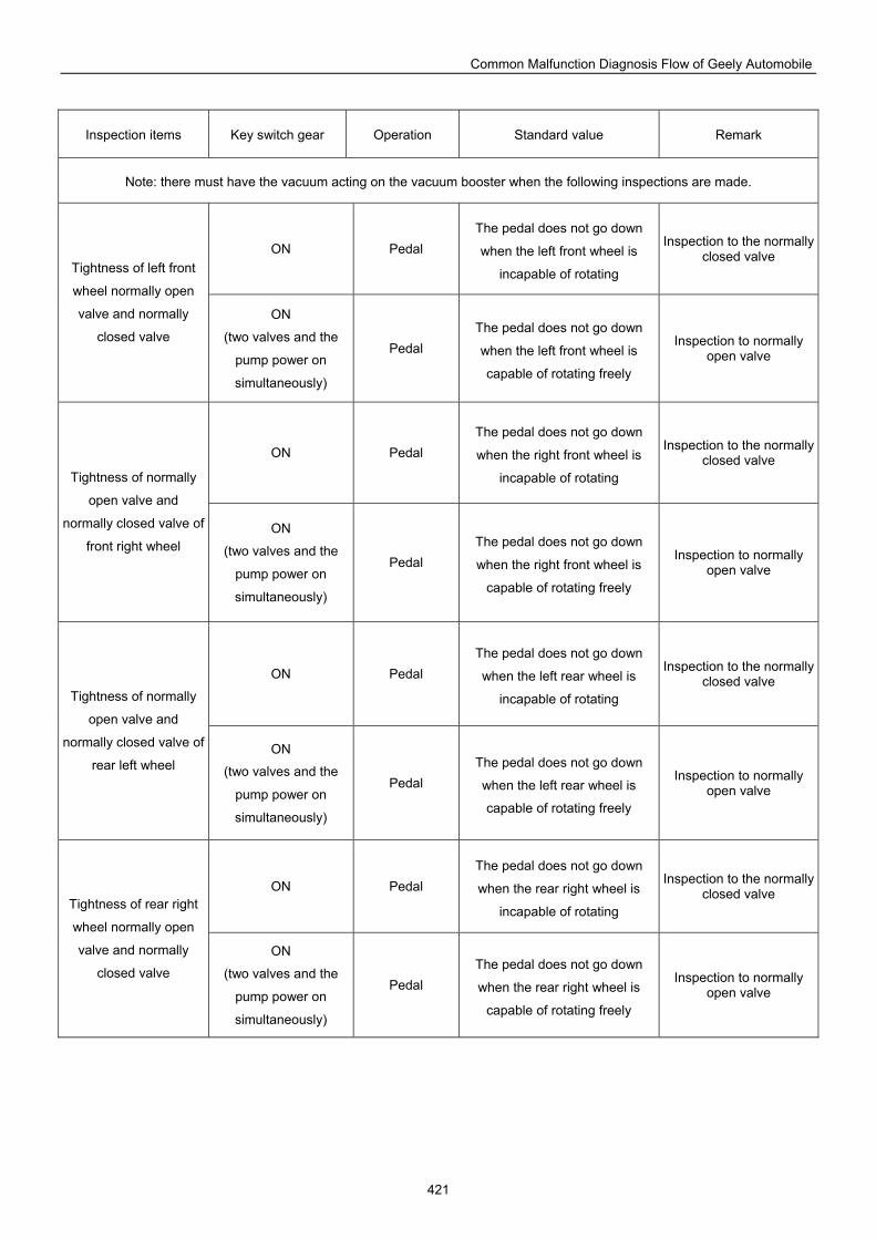
Common Malfunction Diagnosis Flow of Geely Automobile
421
Inspection items Key switch gear Operation Standard value Remark
Note: there must have the vacuum acting on the vacuum booster when the following inspections are made.
ON Pedal The pedal does not go down
when the left front wheel is
incapable of rotating
Inspection to the normally closed valve
Tightness of left front
wheel normally open
valve and normally
closed valve
ON
(two valves and the
pump power on
simultaneously)
Pedal The pedal does not go down
when the left front wheel is
capable of rotating freely
Inspection to normally open valve
ON Pedal The pedal does not go down
when the right front wheel is
incapable of rotating
Inspection to the normally closed valve
Tightness of normally
open valve and
normally closed valve of
front right wheel ON
(two valves and the
pump power on
simultaneously)
Pedal The pedal does not go down
when the right front wheel is
capable of rotating freely
Inspection to normally open valve
ON Pedal The pedal does not go down
when the left rear wheel is
incapable of rotating
Inspection to the normally closed valve
Tightness of normally
open valve and
normally closed valve of
rear left wheel ON
(two valves and the
pump power on
simultaneously)
Pedal The pedal does not go down
when the left rear wheel is
capable of rotating freely
Inspection to normally open valve
ON Pedal The pedal does not go down
when the rear right wheel is
incapable of rotating
Inspection to the normally closed valve
Tightness of rear right
wheel normally open
valve and normally
closed valve ON
(two valves and the
pump power on
simultaneously)
Pedal The pedal does not go down
when the rear right wheel is
capable of rotating freely
Inspection to normally open valve
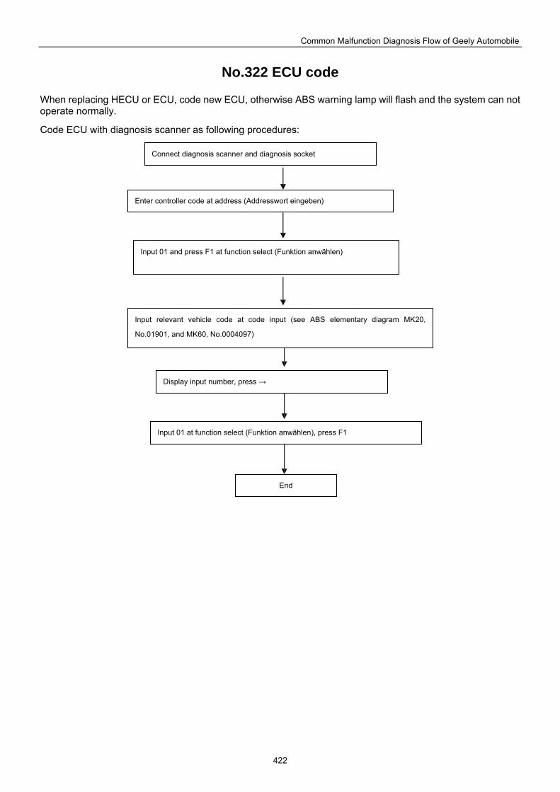
Common Malfunction Diagnosis Flow of Geely Automobile
422
No.322 ECU code
When replacing HECU or ECU, code new ECU, otherwise ABS warning lamp will flash and the system can not operate normally.
Code ECU with diagnosis scanner as following procedures:
Connect diagnosis scanner and diagnosis socket
Enter controller code at address (Addresswort eingeben)
Input 01 and press F1 at function select (Funktion anwählen)
Input relevant vehicle code at code input (see ABS elementary diagram MK20,
No.01901, and MK60, No.0004097)
Display input number, press →
Input 01 at function select (Funktion anwählen), press F1
End
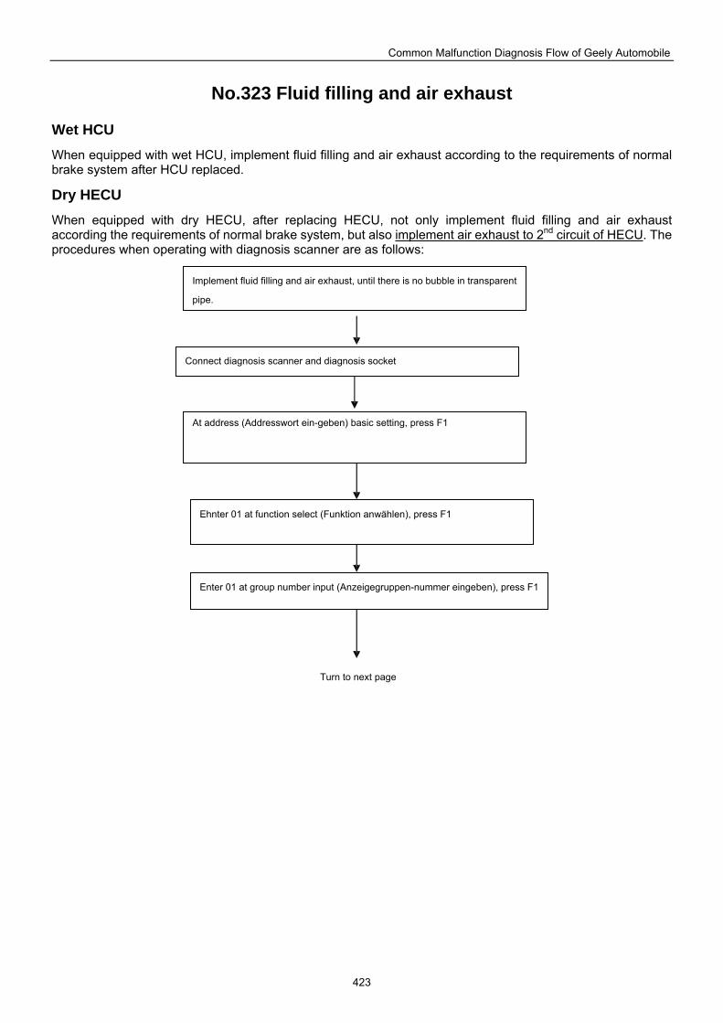
Common Malfunction Diagnosis Flow of Geely Automobile
423
No.323 Fluid filling and air exhaust
Wet HCU
When equipped with wet HCU, implement fluid filling and air exhaust according to the requirements of normal brake system after HCU replaced.
Dry HECU When equipped with dry HECU, after replacing HECU, not only implement fluid filling and air exhaust according the requirements of normal brake system, but also implement air exhaust to 2nd circuit of HECU. The procedures when operating with diagnosis scanner are as follows:
Implement fluid filling and air exhaust, until there is no bubble in transparent
pipe.
Connect diagnosis scanner and diagnosis socket
At address (Addresswort ein-geben) basic setting, press F1
Ehnter 01 at function select (Funktion anwählen), press F1
Enter 01 at group number input (Anzeigegruppen-nummer eingeben), press F1
Turn to next page
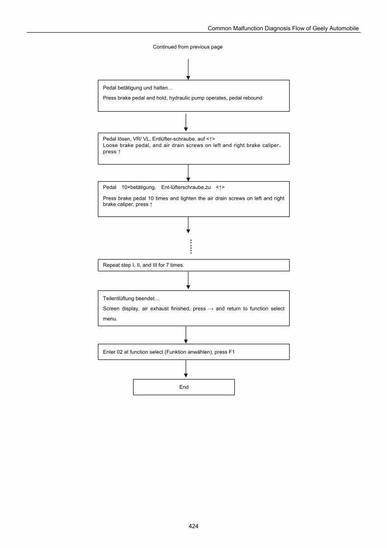
Common Malfunction Diagnosis Flow of Geely Automobile
424
Pedal betätigung und halten…
Press brake pedal and hold, hydraulic pump operates, pedal rebound
Pedal 10×betätigung, Ent-lüfterschraube,zu <↑>
Press brake pedal 10 times and tighten the air drain screws on left and right brake caliper, press ↑
Pedal lösen, VR/ VL, Entlüfter-schraube, auf <↑> Loose brake pedal, and air drain screws on left and right brake caliper,press ↑
Repeat step I, II, and III for 7 times.
Teilentlüftung beendet…
Screen display, air exhaust finished, press → and return to function select
menu.
Enter 02 at function select (Funktion anwählen), press F1
End
Continued from previous page
GEELY INTERNATIONAL CORPORATION Address: No.87 Qianyang Road, Shanghai, P.R.China Webside: www.geely-globe.com