Embed Size (px)
Citation preview

Protocol Technology
Common Channel
Signaling System 7 (SS7)
Part 1
Gusztáv Adamis
BME TMIT

Here you can find some additional information to
SS7
Slides 14 (the internal structure of the MTP-2
message), 15, 20, 23-24 and 29 are just for your
information, not part of the material
2

Channel Associated Signaling - CAS
Signaling: set-up and release of connections
between two subscribers
Signals were carried by the same circuit (
subscriber line, trunk) that carried the speech
during the call
Subscriber Signaling – between subscriber
and his local exchange
Not possible to send signaling messages in the
absence of a call
3

CCS
Signaling does not have to go along the
same path as speech
Abbreviated as CCS7, CCS#7, SS7 or
simply C7
Modular in design protocol architecture
Non call related signaling possible
Common Channel Signaling - CCS
4

5
Common Channel Signaling Systems
Digital signals on a voice circuit independent network
One signaling link serves the need of several voice circuits
Disadvantages:
additional subnetwork plus cost
more complicated switches
explicit continuity check needed
Advantages:
better voice circuit utilisation
complex messages: several services/features can be controlled
by one system
stronger protection than for voice transmission
call-independent messages possible
data base query
SMS
operation and mainteneance messages

CCSS
SP
SPSP
STP
Voice Network
SignalingNetwork
Circuit
Link
Signaling
(Transfer)
Point
6

CCSS
SP
SPSP
STP
Voice Network
SignalingNetwork
Circuit
Link
Signaling
(Transfer)
Point
SP
SCP
OAM
HLR
…
7

Connection Types
Associated connection
Same path for link and circuit
different, dedicated time slots
different, dedicated cables
Quasi-associated connection
Different paths
8

9
CCSS7 Subnetwork
B
C
D
E
A F

CCSS7 Protocol Architecture
SCCP
MAP, INAP
+TCAP
MTP 1 - 3
TelephoneUserPart
(TUP)
Level4
ISDNUser Part
(ISUP)
Level4
Call ControlServices
TransactionservicesOSI
layers
1
2
3
4 - 7
10

SS7 Protocol Layers
Signaling System 7 was introduced by AT&T in 1975 and approved by worldwide standard bodies in 1980.
SS7 basic functions are as follows
MTP (Message Transfer Part) - Provides a reliable transfer and delivery of signaling information in a signaling network.
TUP (Telephone User Part) - Provides the transport of call set-up information between two signaling points only for voice services.
ISUP (ISDN User Part) - Provides the transport of call set-up information between two signaling points.
SCCP (Signaling Connection Control Point) - Provides additional routing capabilities via SubSystem Numbers (SSNs). It also offers the capability of routing based on dialed digits or global title translation.
TCAP (Transaction Capability Application Part) - Provides the capability of transferring non-circuit-related information between signaling points.
-----------------------
SCTP (Streams Control Transmission Protocol) - Provides generic transport for SCN signaling .
M2PA (MTP 2 Peer-to-peer Adaptation Layer) - Enables SS7 links replacement over IP.
M2UA (MTP 2 User Adaptation Layer) - Enables SS7 back-hauling from remote end-points over IP.
M3UA (MTP 3 User Adaptation Layer) - Enables SS7 User Parts (e.g. ISUP and SCCP) to run over IP.
SUA (SCCP User Adaptation Layer) - Enables SS7 Application Parts (e.g. TCAP) to run over IP.
11

MTP levels of CCSS7
Level 1 Physical Connections
Message
Transfer
Part (MTP)
Level 3 Signaling Message Handling +
Signaling Network Management
Level 2 Data Link Control
12

Message Transfer Part (MTP)
Level 1 Physical Connections : Defines the physical,
electrical, and functional characteristics of the digital
signaling link. Defined physical interfaces include, DS1
(1.544 Mbps), E1 (2.048 Mbps), V.35 (64 kbps),DS0 (64
kbps), and DS0A (56 kbps).
Level 2 Data Link Control : Defines the functions and
procedures to ensure that messages are reliably
transmitted across a signaling link. They implement flow
control, message sequence validation, and error
checking. When an error occurs on a signaling link, the
messages are retransmitted.
Framing
Error detection and correction
Different message types
13
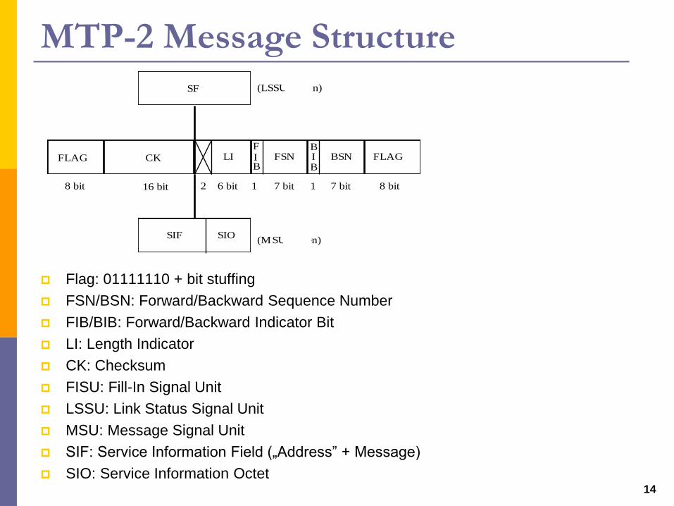
MTP-2 Message Structure
Flag: 01111110 + bit stuffing
FSN/BSN: Forward/Backward Sequence Number
FIB/BIB: Forward/Backward Indicator Bit
LI: Length Indicator
CK: Checksum
FISU: Fill-In Signal Unit
LSSU: Link Status Signal Unit
MSU: Message Signal Unit
SIF: Service Information Field („Address” + Message)
SIO: Service Information Octet 14
FLAGBIB
BSNFIB
FSNLIFLAG CK
8 bit
SF (LSSU esetén)
(MSU esetén)SIOSIF
16 bit 2 6 bit 1 7 bit 1 7 bit 8 bit

MTP-2 – Basic Error Correction
15
A B
1,0
2,01,0
3,0
4,02,0
X2,0
2,1
3,1
5,0
6,02,1
2,1
3,14,1
5,14,1
positiveack.
negativeack.
positiveack.
FSN,FIB BSN,BIB

Message Transfer Part (MTP)
Level 3
Signaling Message Handling: Provides message
routing between signaling points in a SS7 network.
Signaling Network Management: Monitors state of
the signaling network + performs reconfiguration when
necessary
16

Signaling Networks, Signaling Point Codes
Nemzeti
összekötő
hálózat
Nemzeti
hálózat D
Nemzeti
hálózat C
Nemzetközi hálózat
Nemzeti
hálózat A
Nemzeti
hálózat B
National
Interconnecting
Network
National
Network D
National
Network C
International Network
National
Network A
National
Network B
Signaling Point Code – 14 bit
ISPC = Zone Code + Area/Network Code + Signaling Point Identifier
NISPC
NSPC
17

MTP-3 Addressing
RL – Routing Label
OPC, DPC – Originating Point Code, Destination Point Code –
SLS – Signaling Link Selection
SIO – Service Indicator Octet = Network Indicator (NI) + Service
Indicator (SI)
SLS OPC DPC
4 bit 14 bit 14 bit 8 bit
SIO
RL
18

MTP-3 Signaling Message Handling
19
UPs MTP-3 Signaling Links
SNMISUPSCCP
Sign. Mess.distribution
Sign. Mess.discrimination
Sign. Mess.routing
MTP-2
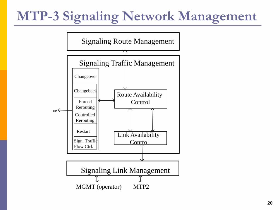
MTP-3 Signaling Network Management
20
Jelzésútvonal menedzselés
Signaling Traffic Management
Jelzésszakasz menedzselés
Vissza-kapcsolás
Kényszerítettátirányítás
átirányításVezérelt
Jelzésforgalom
folyamvezérlés
Újraindítás
Szakaszhasználhatóság vezérlés
UP
MGMT (operator) MTP2
Átkapcsolás
Jelzésútvonal menedzselésSignaling Route Management
Route Availability
Control
Signaling Link Management
Changeback
Forced
Rerouting
Sign. Traffic
Flow Ctrl.
RestartLink Availability
Control
UP
Changeover
Controlled
Rerouting

Protocol stack for fixed networks in CCSS7
Physical Connections
Data Link Control
Transport of SignalingMessages within one network
Call ControlMessages
MTPLevel 1
Level 2
Level 3
ISUP
Level 1
Level 2
Level 3
ISUP
MTP – Message Transfer Part
21

User Parts
Telephone User Part (TUP)
Defines the international telephone call control
signaling functions for basic call setup and release.
Withdrawn.
Data User Part (DUP)
Defines data transfer control. Obsolete.
ISDN User Part (ISUP)
Defines the protocol used to setup, manage, and
release trunk circuits that carry voice and data + ISDN
Supplementary Services Call Control
Circuit Supervision
22

ISUP Functional Blocks
23
Áramkörfelügyeletvezérlés
Üzenetküldésvezérlés
Üzenetelosztás vezérlés
Hívásfeldolgozásvezérlés
Hívásvezérlés
MTP
Switch
Call
Processing
Control
Circuit
Supervision
Control
Message
Sending
Control
Message
Distribution
Control
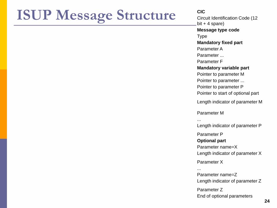
ISUP Message Structure
24
CIC
Circuit Identification Code (12
bit + 4 spare)
Message type code
Type
Mandatory fixed part
Parameter A
Parameter ...
Parameter F
Mandatory variable part
Pointer to parameter M
Pointer to parameter ...
Pointer to parameter P
Pointer to start of optional part
Length indicator of parameter M
Parameter M
...
Length indicator of parameter P
Parameter P
Optional part
Parameter name=X
Length indicator of parameter X
Parameter X
...
Parameter name=Z
Length indicator of parameter Z
Parameter Z
End of optional parameters

ISDN call establishment
SABME
UA
SABME
UA
I (Setup)
I (Setup Ack)
I (Information)
I (Call Proceeding)IAM
I (Alert)
I (Connection)I (Alert)
I (Connection)
I (Conn. Ack.)I (Conn. Ack.)
ACM
ANM
ISDN equipm. ISDN switch ISDN switch ISDN equipm.
DSS1 DSS1ISUP
B channel connection
Ringing
Answer
UI (Setup)
I (Setup Ack)
Ringing
tone
CPG
25

ISDN call establishment
SABME
UA
SABME
UA
I (Setup)
I (Setup Ack)
I (Information)
I (Call Proceeding)IAM
I (Alert)
I (Connection)I (Alert)
I (Connection)
I (Conn. Ack.)I (Conn. Ack.)
ACM
ANM
ISDN equipm. ISDN switch ISDN switch ISDN equipm.
DSS1 DSS1ISUP
B channel connection
Ringing
Answer
UI (Setup)
I (Setup Ack)
Ringing
tone
26

ISDN call release
ISDN equipm. ISDN switch ISDN switch ISDN equipm.
DSS1 DSS1ISUP
B channel connection
I (Disconnect)
I (Release)
I (Rel. Complete)
DISC
UA
REL
RLC
I (Disconnect)
I (Release)
I (Rel. Complete)
DISC
UA
Dis-
connect
27

ISUP messages
Initial address message (IAM): contains all necessary
information for a switch to establish a connection
Subsequent Address Message (SAM)
Address complete message (ACM): acknowledge to
IAM; the required circuit is reserved and the “phone is
ringing” (ringback tone)
Call Progress (CPG)
Answer message (ANM): occurs when the called party
picks up the phone
Release (REL): sent by the switch sensing that the
phone hung up
Release complete (RLC): each exchange that receives
REL, sends an RLC message back (this acknowledges
receipt of REL)28

IAM parameters
29
General info
Signaling requirements
Type of caller
Voice line (B channel) requirements