Embed Size (px)
Citation preview
Committee on NFPA 85
M E M O R A N D U M
TO: NFPA Technical Committee on Multiple Burner Boilers
FROM: Jeanne Moreau-Correia
DATE: August 5, 2009
SUBJECT: NFPA 85 ROP Letter Ballot
The ROP letter ballot for NFPA 85 is attached. The ballot is for formally voting on
whether or not you concur with the committee’s actions on the proposals. Reasons must
accompany all negative and abstention ballots.
Please do not vote negatively because of editorial errors. However, please bring such
errors to my attention for action.
Please complete and return your ballot as soon as possible but no later than Thursday,
August 20, 2009. As noted on the ballot form, please submit the ballot to Jeanne
Moreau-Correia, e-mail to [email protected] or fax to 617-984-7110.
The return of ballots is required by the Regulations Governing Committee Projects.
Attachment: Proposals
Report on Proposals – November 2010 NFPA 85_______________________________________________________________________________________________85-28 Log #82a BCS-MBB
_______________________________________________________________________________________________John Van Name, URS - Washington Division
Revise text as follows:(6) Where the common component does not contain a possible ignition source, a bypass shall not be required, as long
as the requirements contained in 6.5.3.2 Open-Flow Air Path and 6.4.2.3.4.3 (C) are met.When two or more boiler outlets are tied together, it is possible to pressurize this connection point
either by design or excursion. Positive pressure at the connection point eliminates an open air path and also permitsproducts of combustion from a running unit to enter a starting unit or a unit experiencing an emergency shutdown withloss of fans. A pressurized connection point also creates a safety issue for maintenance and inspection entries into ashutdown unit requiring emergency maintenance. A means of natural draft must always be provided for the emergencycondition to slowly purge the remaining products of combustion. Water seals block a natural draft flow path. ID fans withpositive discharge pressures keep the connection point pressurized above atmospheric pressure at all times.
The proposal is not appropriate for inclusion in Chapter 4 as it is specific to one type ofequipment covered by the code. It would also not be appropriate for chapter four to refer to requirements in anequipment chapter. The proposal is referred to the MBB TC for inclusion in Chapter 6.MBB TC Statement: The TC feels that the bypass should not be mandated because the proposed purge procedures
(6.4.2.3.4.3(C)) as described in Proposal 85-68 (Log #60) address the issues raised by the submitter.
_______________________________________________________________________________________________85-31 Log #CP9 BCS-MBB
_______________________________________________________________________________________________Technical Committee on Multiple Burner Boilers,
Add new text to read as follows:4.6.3.1.3 The burner management system interlock and alarm functions shall be initiated by one or more of the
following:(1) A switch or transmitter independent of control functions and signals(2) One or both of two continuously variable process signals exceeding a preset value(3) The median of three continuously variable process signals exceeding a preset value4.6.3.1.3.1 When multiple continuously variable process signals are provided to initiate interlock or alarm functions
those signals shall be monitored in comparison to each other by divergence or other fault diagnostic alarms.4.6.3.1.3.2 When multiple continuously variable process signals are provided to initiate interlock or alarm functions the
provided signals shall be generated by individual sensing devices connected to separate process taps.This is a refinement of language that currently exists in section 8.7.4.1.6 of the Code but which should
also be applicable to all boiler and combustion systems. Continuously variable process signals are preferred by manyover discrete process switches because they can be monitored to assure that they are continuing to respond to changesin the process. Modern continuously variable devices also are less prone to drift than process switches and thus providea better indicator of the process parameter they are monitoring. It is the intent of the TC to allow a single transmitter tobe used if independent of control functions. Editorially, the terminology was changed to singular to clarify the intent ofthe provision that a single switch or transmitter is adequate.
1Printed on 8/5/2009
Report on Proposals – November 2010 NFPA 85_______________________________________________________________________________________________85-36 Log #92c BCS-MBB
_______________________________________________________________________________________________Celso G. Schmidt, Forney Corporation
New text to read as follows:(12)* The hardware master fuel trip relay shall be of the type that stays tripped until the unit purge system interlock
permits it to be reset. Whenever the master fuel trip relay (s) is operated, it shall directly remove all fuel inputs from thefurnace in a redundant path with the soft master fuel trip which will trip all outputs to fuel related devices. The masterfuel trip relay contacts shall not only trip the fuel headers but all individual fuel related equipment and shall de-energizeall spark igniters and all ignition devices within the unit and flue gas path.
A.4.6.3.2.4 (12) The main hardware master fuel trip relay shall be a fail-safe relay with mechanically linked contacts toprevent the reclosing of the normally closed contact if a normally open contact is welded.
The master fuel trip relay is not addressed properly in the Chapter 4, common to all boilers andHRSGs. This proposal intends to make the existing requirements for MBB common to all boilers and HRSGs.
The proposal for the Annex A intends to utilize safe relays for the master fuel trip application. These relays meet IEC947-5-1-I. There are several manufacturers in the market and some relays are tamper resistant.
The Fundamentals TC feels that this requirement, which comes from the MBB chapter, is moreappropriately to be considered by the TCs which are responsible for the other boiler sections, i.e. SBB, HRSG, and FBB.The language came from 6.4.2.3.1(A) blocks 3-12. It is not appropriate to pull one requirement from the table intochapter 4 without the input from the other TCs. The TC feels that the equipment chapters contain requirements thataddress some of the submitter's concerns, and that the proposal should be forwarded to the other TCs for use inclarifying the applicable coverage.MBB TC Statement: The mandatory text of the proposal is already covered in Chapter 6. The MBB TC rejects theproposed annex material because Chapter 6 does not require mechanically linked relays. The MBB TC has no objectionto the action taken by the HRS TC on Proposal 85-35 (Log #92b).
_______________________________________________________________________________________________85-58 Log #CP7 BCS-MBB
_______________________________________________________________________________________________Technical Committee on Multiple Burner Boilers,
Revise text to read as follows:6.3.2 Forced draft (FD) and induced draft (ID) fans shall include all fans whose purpose is to supply air for combustion
or remove products of combustion, including associated booster fans, and excluding fans in the pulverized coal fuelsystem.
6.8.5.1.5.6 (C)(3) Although light-off of all burners associated with a pulverizer is recommended, it is sometimesnecessary to operate or light off with fewer than the total number of burners served by the pulverizer. In this event,positive means shall be provided to prevent fuel leakage into idle pulverized coal fuel piping and through idle burnersinto the furnace.
6.8.5.2.3.3 A pulverized fuel coal system shall be shut down in the following sequence:The TC replaced "pulverized fuel" with "pulverized coal" throughout chapter 6 to be consistent with
chapter 1, which limits Chapter 6 to pulverized coal systems.
2Printed on 8/5/2009

Report on Proposals – November 2010 NFPA 85_______________________________________________________________________________________________85-59 Log #89 BCS-MBB
_______________________________________________________________________________________________Ted Jablkowski, Fives North American Combustion, Inc.
Revise text to read as follows:6.4.2.2.14 The mandatory master fuel trip–sensing elements and circuits shall be independent of all other control
elements and circuits.
1) The existing language is unclear. It can be interpreted to mean that no logic used to initiate a masterfuel trip can originate in or be processed in compliant PLC based Burner Management System.
2) Hardwired is not defined.
The TC rejects the proposal because the term "hardwired" has been defined in action taken bythe Fundamentals TC on 85-12 (Log #26).
_______________________________________________________________________________________________85-60 Log #69 BCS-MBB
_______________________________________________________________________________________________Daniel J. Lee, ABB Incorporated, Michael Polagye, FM Global
Revise text as follows:Exception No. 2: Airflow measurement, and auctioneered furnace draft, and drum water level signals from the boiler
control system shall be permitted to be used for a master fuel trip, provided all of the following conditions are met:NFPA 85 is a consensus code based on industry accepted good engineering practice and is viewed as
a source document for the design of burner management systems. Insurance industry and NERC data show that boilerdamage from low drum water level is a leading cause of non-routine plant forced outages. As such, a master fuel tripbased on low water level in the drum for drum type boilers is a commonly recognized good engineering practice that isfurther supported by its inclusion in a major majority of multiple burner boiler BMS installations. The use of a controlsignal for the low drum water level trip is a proven means for establishing a reliable low water protection system inmultiple burner boilers and should be recognized in this code.
It has been stated in the past that low water protection is not a combustion related hazard and therefore does not fitwithin the scope of Chapter 6 in NFPA 85, which is to prevent fires and explosions in multiple-burner boilers. That beingsaid, and whether or not scenarios could be postulated where a low water condition leads to tube ruptures where theescaping steam/water smothers burner flame leading to delayed ignition and explosion, NFPA 85 is the primaryresource in North America for identifying BMS requirements and not including a low drum level trip in Figure 6.4.2.3.1has created confusion with users of the Code. Also, NFPA 85 requirements for implosion protection is in fact a not acombustion related hazard but a mechanical loss prevention. Adding low drum water level trip as a mechanical lossprevention is the current/past industry solution to prevent low water losses.
3Printed on 8/5/2009
Report on Proposals – November 2010 NFPA 85_______________________________________________________________________________________________85-61 Log #70 BCS-MBB
_______________________________________________________________________________________________Daniel J. Lee, ABB Incorporated, Michael Polagye, FM Global
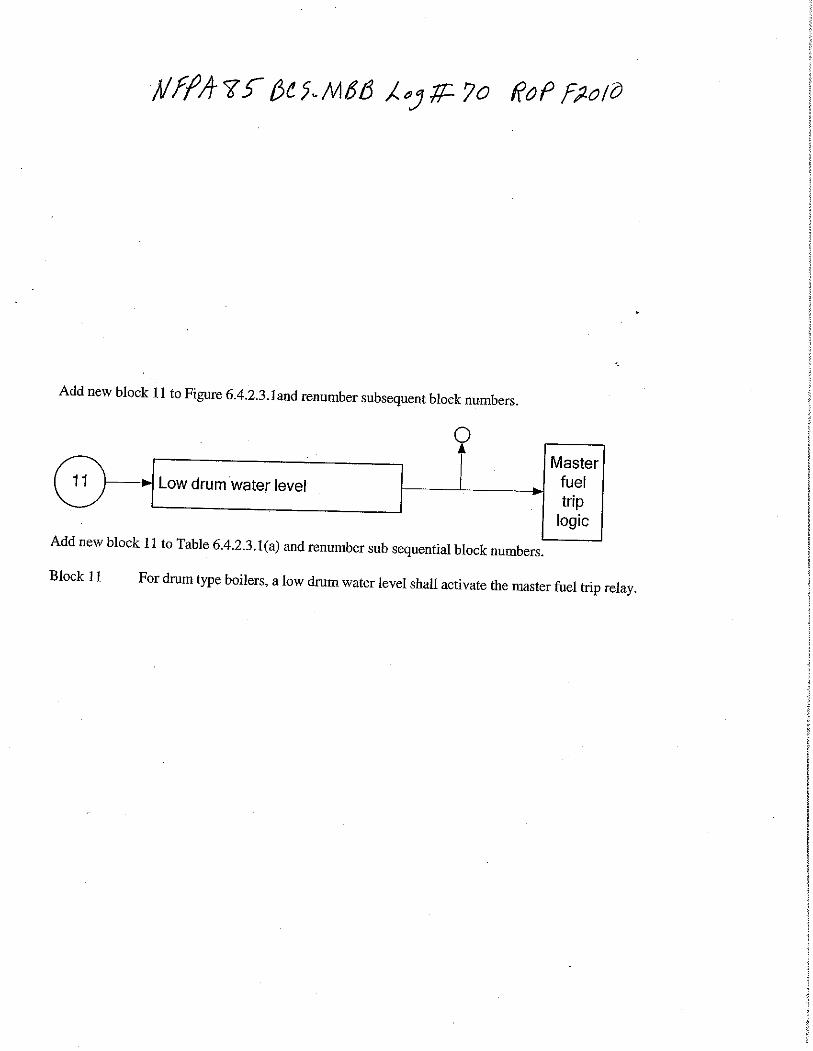
Add new block 11 to Figure 6.4.2.3.1 and renumber subsequent block numbers.
******Insert New Figure 6.4.2.3.1 Here******
Add new block 11 to Table 6.4.2.3.1(a) and renumber sub sequential block numbers.Block 11 For drum type boilers, a low drum water level shall activate the master fuel trip relay.
NFPA 85 is a consensus code based on industry accepted good engineering practices. Insuranceindustry and NERC data show that boiler damage from low drum water is a leading cause of non-routine plant forcedoutages. As such, a master fuel trip based on low water level in the drum for drum type boilers is a commonlyrecognized good engineering practice as supported by a major majority of existing multiple-burner BMS installations thatincorporate this interlock. Economic realities preclude the dedication of a control room operator to monitoring andresponding to drum level swings during normal unit operation and the addition of drum water level (low) trip as requiredinterlock should no longer be an optional interlock in the BMS based on owner and designer evaluation.
It has been stated in the past that low water protection is not a combustion related hazard and therefore does not fitwithin the scope of Chapter 6 in NFPA 85, which is to prevent fires and explosions in multiple-burner boilers. That beingsaid, and whether or not scenarios could be postulated where a low water condition leads to tube ruptures where theescaping steam/water smothers burner flame leading to delayed ignition and explosion, NFPA 85 is primary resource inNorth America for identifying BMS requirements and not including a low drum level trip in Figure 6.4.2.3.1 has createdconfusion with users of the Code. Also NFPA requirements for implosion protection is in fact not a combustion relatedhazard but a mechanical loss prevention. Adding low drum water level trip as a mechanical loss prevention is the pastand current industry solution for low water losses.
Insert proposed diagram as new block 10 and renumber subsequent blocks.A.6.4.2.3.1 In block 8 of Table 6.4.2.3.1(a), the partial loss of flame described is potentially more hazardous at lower
load levels. The decision regarding specific requirements or implementation of this trip should be a design decisionbased on furnace configuration, total number of burners, number of burners affected as a percentage of burners inservice, arrangement of burners affected, interlock system, and load level. This trip is interlocked through flamesupervisory equipment.In block 9 Table 6.4.2.3.1(a), the tables referenced describe the allowable differences in operating procedures based onthe classification of igniter being used. The following descriptions of conditions are typical for both Table 6.4.2.3.1(b) andTable 6.4.2.3.1(c).
(1) Condition 1: An event in which, after a successful boiler purge, an attempt(s) to place the first igniter in service fails.(2) Condition 2: An event in which an igniter(s) has been proven in service and subsequently all igniters are shut down
without the attempt ever having been made to place a burner or pulverizer in service.(3) Condition 3: An event in which gas and/or oil fuel burners were started or attempted to start and all burner valves
were subsequently closed while igniters remain proven in service.(4) Condition 4: An event in which a pulverizer system(s) was started up or attempted to start up and subsequently all
pulverizer systems were shut down while igniters remain proven in service.(5) Condition 5: An event in which any fuel has been placed in service and all fuel subsequently shut off
In the event that any main fuel is shut down while any other main fuel remains proven in service, the all-fuel-off masterfuel trip requirements do not apply.
In block 10 Table 6.4.2.3.1(a), low drum water level has been included as a master fuel trip. Although low drum waterlevel is not a combustion related hazard, NFPA 85 is the primary resource for identifying BMS requirements and notincluding a low drum level trip in Figure 6.4.2.3.1 has created confusion with users of the Code. A master fuel trip basedon low drum water level for drum type boilers is a commonly recognized good engineering practice.
The TC accepted the proposed diagram reordered as block 10, and chose to include parts ofthe substantiation in the annex.
4Printed on 8/5/2009
Report on Proposals – November 2010 NFPA 85_______________________________________________________________________________________________85-62 Log #49 BCS-MBB
_______________________________________________________________________________________________Dale E. Dressel, Solutia Incorporated
Change the wording associated with Block 6 in this table from:High furnace pressure, such as that resulting from a tube rupture or damper failure, shall activate the master fuel trip
relay.to:High furnace pressure, such as that resulting from a tube rupture, damper failure, overfiring, burner instability or flue
gas path pluggage, shall activate the master fuel trip relay.The examples given for high furnace pressure (tube rupture and damper failure) are not directly
related to combustion systems hazards although they can impact combustion conditions. The additional examplesadded are more directly related to the combustion systems hazards that it is the intent of the code to address.
The intent of the examples is not to provide an exhaustive list of the potential causes of highfurnace pressure.
_______________________________________________________________________________________________85-63 Log #58 BCS-MBB
_______________________________________________________________________________________________Henry K. Wong, URS Washington Division
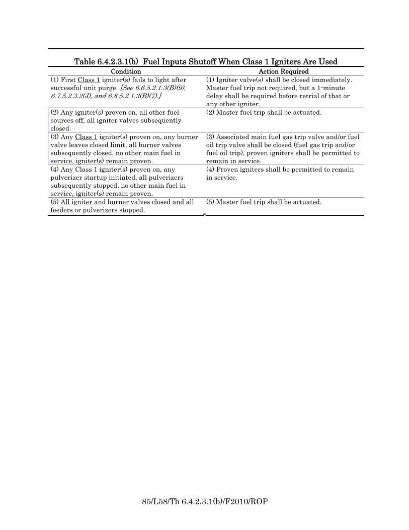
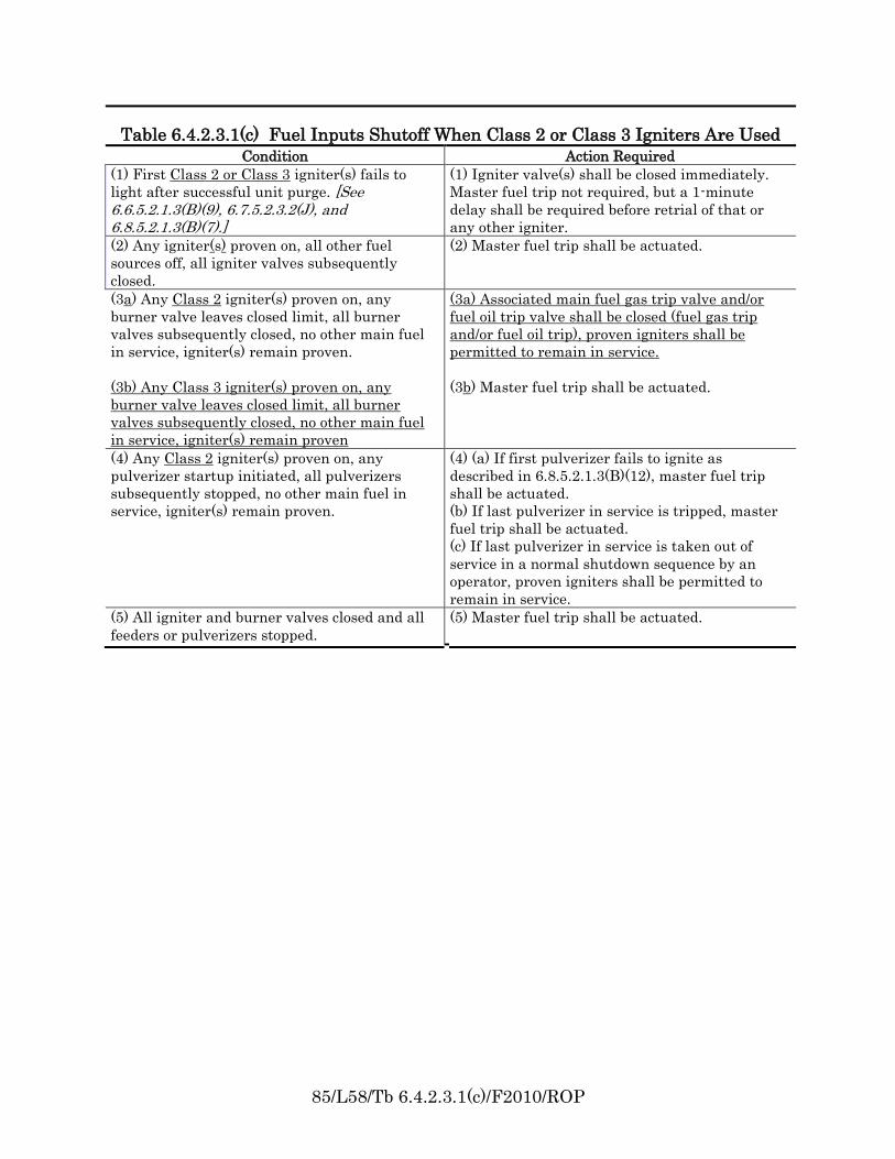
Revise Tables 6.4.2.3.1(b) and (c) as follows:
***Insert Tables 6.4.2.3.1(b) and 6.4.2.3.1(c) Here***
Table 6.4.2.3.1(B) & Table 6.4.2.3.1(C) provide a tabulated summary of various igniter/burnerscenarios during start up and the required interlock actions depending on the igniter Class used. Table 6.4.2.3.1(B)covers actions with Class 1 igniters. Table 6.4.2.3.1(C) covers Class 2 & Class 3 igniters. However due to the greatdifferences in capability of a Class 2 vs. a Class 3 igniter, the table as is, is confusing and conflicts with other parts ofthe code. The proposed revisions specifically separate Class 2 and Class 3 igniter situations.
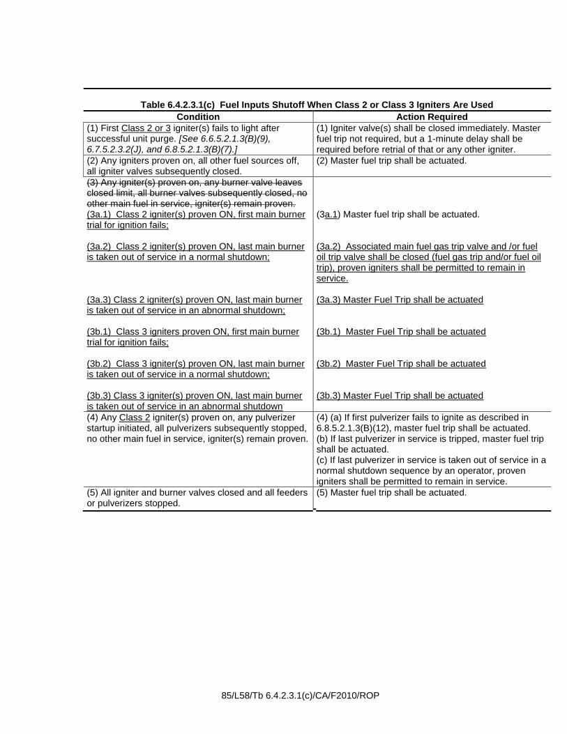
Accept proposed changes to table 6.4.2.3.1(b).Modify table 6.4.2.3.1(c) as follows:
***Insert Table 6.4.2.3.1(c) Here***
Allowing Class 2 proven ON igniters to remain ON after the last main burner is taken out ofservice in a normal shutdown still provides for both supervised and stable furnace conditions. This is consistent withwhat is allowed for Class 2 igniters in coal-fired burners.
_______________________________________________________________________________________________85-64 Log #CP5 BCS-MBB
_______________________________________________________________________________________________Technical Committee on Multiple Burner Boilers,
Revise text to read as follows:The master fuel trip relay contacts shall also trip primary air fans or exhausters, coal feeders, pulverizers, and coal
burner line shutoff valves, or take equivalent functional action to stop coal delivery to burners.The addition of the word "pulverizer" makes the table consistent with paragraph 6.8.5.2.5.4.
5Printed on 8/5/2009
85/L58/Tb 6.4.2.3.1(b)/F2010/ROP
Table 6.4.2.3.1(b) Fuel Inputs Shutoff When Class 1 Igniters Are Used
Condition Action Required
(1) First Class 1 igniter(s) fails to light after
successful unit purge. [See 6.6.5.2.1.3(B)(9), 6.7.5.2.3.2(J), and 6.8.5.2.1.3(B)(7).]
(1) Igniter valve(s) shall be closed immediately.
Master fuel trip not required, but a 1-minute
delay shall be required before retrial of that or
any other igniter.
(2) Any igniter(s) proven on, all other fuel
sources off, all igniter valves subsequently
closed.
(2) Master fuel trip shall be actuated.
(3) Any Class 1 igniter(s) proven on, any burner
valve leaves closed limit, all burner valves
subsequently closed, no other main fuel in
service, igniter(s) remain proven.
(3) Associated main fuel gas trip valve and/or fuel
oil trip valve shall be closed (fuel gas trip and/or
fuel oil trip), proven igniters shall be permitted to
remain in service.
(4) Any Class 1 igniter(s) proven on, any
pulverizer startup initiated, all pulverizers
subsequently stopped, no other main fuel in
service, igniter(s) remain proven.
(4) Proven igniters shall be permitted to remain
in service.
(5) All igniter and burner valves closed and all
feeders or pulverizers stopped.
(5) Master fuel trip shall be actuated.
85/L58/Tb 6.4.2.3.1(c)/F2010/ROP
Table 6.4.2.3.1(c) Fuel Inputs Shutoff When Class 2 or Class 3 Igniters Are Used
Condition Action Required
(1) First Class 2 or Class 3 igniter(s) fails to
light after successful unit purge. [See 6.6.5.2.1.3(B)(9), 6.7.5.2.3.2(J), and 6.8.5.2.1.3(B)(7).]
(1) Igniter valve(s) shall be closed immediately.
Master fuel trip not required, but a 1-minute
delay shall be required before retrial of that or
any other igniter.
(2) Any igniter(s) proven on, all other fuel
sources off, all igniter valves subsequently
closed.
(2) Master fuel trip shall be actuated.
(3a) Any Class 2 igniter(s) proven on, any
burner valve leaves closed limit, all burner
valves subsequently closed, no other main fuel
in service, igniter(s) remain proven.
(3b) Any Class 3 igniter(s) proven on, any
burner valve leaves closed limit, all burner
valves subsequently closed, no other main fuel
in service, igniter(s) remain proven
(3a) Associated main fuel gas trip valve and/or
fuel oil trip valve shall be closed (fuel gas trip
and/or fuel oil trip), proven igniters shall be
permitted to remain in service.
(3b) Master fuel trip shall be actuated.
(4) Any Class 2 igniter(s) proven on, any
pulverizer startup initiated, all pulverizers
subsequently stopped, no other main fuel in
service, igniter(s) remain proven.
(4) (a) If first pulverizer fails to ignite as
described in 6.8.5.2.1.3(B)(12), master fuel trip
shall be actuated.
(b) If last pulverizer in service is tripped, master
fuel trip shall be actuated.
(c) If last pulverizer in service is taken out of
service in a normal shutdown sequence by an
operator, proven igniters shall be permitted to
remain in service.
(5) All igniter and burner valves closed and all
feeders or pulverizers stopped.
(5) Master fuel trip shall be actuated.
85/L58/Tb 6.4.2.3.1(c)/CA/F2010/ROP
Table 6.4.2.3.1(c) Fuel Inputs Shutoff When Class 2 or Class 3 Igniters Are Used
Condition Action Required
(1) First Class 2 or 3 igniter(s) fails to light after successful unit purge. [See 6.6.5.2.1.3(B)(9), 6.7.5.2.3.2(J), and 6.8.5.2.1.3(B)(7).]
(1) Igniter valve(s) shall be closed immediately. Master fuel trip not required, but a 1-minute delay shall be required before retrial of that or any other igniter.
(2) Any igniters proven on, all other fuel sources off, all igniter valves subsequently closed.
(2) Master fuel trip shall be actuated.
(3) Any igniter(s) proven on, any burner valve leaves closed limit, all burner valves subsequently closed, no other main fuel in service, igniter(s) remain proven. (3a.1) Class 2 igniter(s) proven ON, first main burner trial for ignition fails; (3a.2) Class 2 igniter(s) proven ON, last main burner is taken out of service in a normal shutdown; (3a.3) Class 2 igniter(s) proven ON, last main burner is taken out of service in an abnormal shutdown; (3b.1) Class 3 igniters proven ON, first main burner trial for ignition fails; (3b.2) Class 3 igniter(s) proven ON, last main burner is taken out of service in a normal shutdown; (3b.3) Class 3 igniter(s) proven ON, last main burner is taken out of service in an abnormal shutdown
(3a.1) Master fuel trip shall be actuated. (3a.2) Associated main fuel gas trip valve and /or fuel oil trip valve shall be closed (fuel gas trip and/or fuel oil trip), proven igniters shall be permitted to remain in service. (3a.3) Master Fuel Trip shall be actuated (3b.1) Master Fuel Trip shall be actuated (3b.2) Master Fuel Trip shall be actuated (3b.3) Master Fuel Trip shall be actuated
(4) Any Class 2 igniter(s) proven on, any pulverizer startup initiated, all pulverizers subsequently stopped, no other main fuel in service, igniter(s) remain proven.
(4) (a) If first pulverizer fails to ignite as described in 6.8.5.2.1.3(B)(12), master fuel trip shall be actuated. (b) If last pulverizer in service is tripped, master fuel trip shall be actuated. (c) If last pulverizer in service is taken out of service in a normal shutdown sequence by an operator, proven igniters shall be permitted to remain in service.
(5) All igniter and burner valves closed and all feeders or pulverizers stopped.
(5) Master fuel trip shall be actuated.
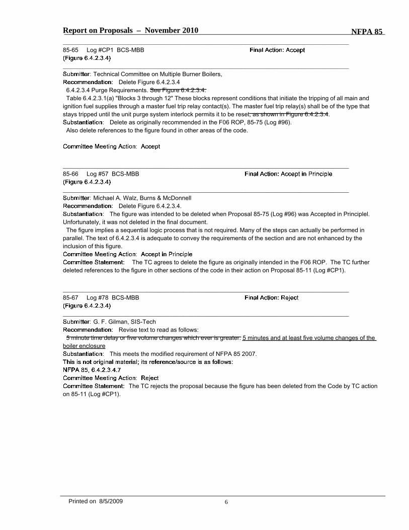
Report on Proposals – November 2010 NFPA 85_______________________________________________________________________________________________85-65 Log #CP1 BCS-MBB
_______________________________________________________________________________________________Technical Committee on Multiple Burner Boilers,
Delete Figure 6.4.2.3.46.4.2.3.4 Purge Requirements. See Figure 6.4.2.3.4.Table 6.4.2.3.1(a) "Blocks 3 through 12" These blocks represent conditions that initiate the tripping of all main and
ignition fuel supplies through a master fuel trip relay contact(s). The master fuel trip relay(s) shall be of the type thatstays tripped until the unit purge system interlock permits it to be reset, as shown in Figure 6.4.2.3.4.
Delete as originally recommended in the F06 ROP, 85-75 (Log #96).Also delete references to the figure found in other areas of the code.
_______________________________________________________________________________________________85-66 Log #57 BCS-MBB
_______________________________________________________________________________________________Michael A. Walz, Burns & McDonnell
Delete Figure 6.4.2.3.4.The figure was intended to be deleted when Proposal 85-75 (Log #96) was Accepted in Principlel.
Unfortunately, it was not deleted in the final document.The figure implies a sequential logic process that is not required. Many of the steps can actually be performed in
parallel. The text of 6.4.2.3.4 is adequate to convey the requirements of the section and are not enhanced by theinclusion of this figure.
The TC agrees to delete the figure as originally intended in the F06 ROP. The TC furtherdeleted references to the figure in other sections of the code in their action on Proposal 85-11 (Log #CP1).
_______________________________________________________________________________________________85-67 Log #78 BCS-MBB
_______________________________________________________________________________________________G. F. Gilman, SIS-Tech
Revise text to read as follows:5 minute time delay or five volume changes which ever is greater. 5 minutes and at least five volume changes of the
boiler enclosureThis meets the modified requirement of NFPA 85 2007.
The TC rejects the proposal because the figure has been deleted from the Code by TC actionon 85-11 (Log #CP1).
6Printed on 8/5/2009
Report on Proposals – November 2010 NFPA 85_______________________________________________________________________________________________85-68 Log #60 BCS-MBB
_______________________________________________________________________________________________Michael A. Walz, Burns & McDonnell
Revise text as follows:On an emergency shutdown where no fans remain in service, boiler enclosure purge conditions shall be
established and a boiler enclosure purge completed. Purge rate airflow shall be established in accordance with thefollowing procedure:
(1) Except for damper actions necessary to prevent positive or negative furnace pressure transients beyond designlimits, no damper actions shall be permitted that would reduce flue gas or air flow through the boiler enclosure until aftera normal boiler enclosure purge has been completedAll dampers in the air and flue gas passages of the unit shall beopened slowly to the fully open position to create as much natural draft as possible to ventilate the unit.
(2) Damper positioning shall be allowed as required to achieve flow distribution through areas of the boiler enclosurewhere combustible gases may be present.
(3) Open isolation and control dampers, except on fans isolated for maintenance.maintence. The opening of thesedampers shall be timed or controlled to prevent positive or negative furnace pressure transients beyond design limits.Where multiple boilers feed into a common piece of equipment or stack and there is the potential for reverse flow into anidle unit it shall be allowed to keep the most downstream damper closed. Opening of fan dampers shall be timed orcontrolled to ensure that positive or negative furnace pressure transients beyond design limits do not occur during fancoastdown.
(4) The conditions in (1) through (3) shall be maintained for an all fan trip hold period of at least 15 minutes prior toallowing any ID or FD fan to be re-started. This condition shall be maintained for at least 15 minutes.
(5) At the end of this period, the fan(s) shall be started in accordance with Section 6.5.(6) The airflow shall be increased gradually to the purge rate, and a boiler enclosure purge shall be completed.A.6.4.2.3.4.3 (C) many units are being equipped with downstream equipment that restricts flow. In this arrangement,
stack effect, and any associated draft, is reduced or completely eliminated. However, a hold period prior to re-startingthe fans allows the boiler setting to cool, in-leakage will promote further cooling, and, in the case of little or no draft, andsuspended particles are allowed to settle. It is important to remember that as the fans coast down, furnace pressuremust be controlled to prevent positive or negative excursions beyond design limits. This may require damper movementor blade positioning on axial flow fans. In the case of multiple boilers connected to common downstream equipment,dampers should be closed to isolate the boiler from backflow originating in other boilers remaining in operation. Thesedampers can be re-opened as the ID Fans are restarted and establish a positive flow out of the boiler.
The 2005 MBB/Purge Task Group consisting of Allan Zadiraka, Joe Vavreck, and Mike Walz, withguidance and additional input from Skip Yates and Henry Wong, generated this proposal.
The committee has received many questions regarding purge requirements following an all fan trip, particularly incases where downstream equipment restricts or eliminates stack effect. It was felt that additional clarity would beprovided by revising and expanding this section along with additional annex material.
Revise text to read as follows:On an emergency shutdown where no fans remain in service, boiler enclosure purge conditions shall be
established and a boiler enclosure purge completed. Purge rate airflow shall be established in accordance with thefollowing procedure:
(1) Except for damper actions necessary to prevent positive or negative furnace pressure transients beyond designlimits, no damper actions shall be permitted that would reduce flue gas or air flow through the boiler enclosure until aftera normal boiler enclosure purge has been completedAll dampers in the air and flue gas passages of the unit shall beopened slowly to the fully open position to create as much natural draft as possible to ventilate the unit.
(2) Damper positioning shall be allowed as required to achieve flow distribution through areas of the boiler enclosurewhere combustible gases may be present.
(3) Open isolation and control dampers, except on fans isolated for maintenance. The opening of these dampers shallbe timed or controlled to maintain positive or negative furnace pressure transients within design limits. Where multipleboilers feed into a common piece of equipment or stack and there is the potential for reverse flow into an idle unit it shallbe allowed to keep the most downstream damper closed. Opening of fan dampers shall be timed or controlled to ensurethat positive or negative furnace pressure transients beyond design limits do not occur during fan coastdown.
(4) The conditions in (1) through (3) shall be maintained for an all fan trip hold period of at least 15 minutes prior toallowing any ID or FD fan to be re-started. This condition shall be maintained for at least 15 minutes.
7Printed on 8/5/2009
Report on Proposals – November 2010 NFPA 85(5) At the end of this period, the fan(s) shall be started in accordance with Section 6.5.(6) The airflow shall be increased gradually to the purge rate, and a boiler enclosure purge shall be completed.A.6.4.2.3.4.3 (C) Many units are being equipped with downstream equipment that restricts flow. In this arrangement,
stack effect, and any associated draft, is reduced or completely eliminated. However, a hold period prior to re-startingthe fans allows the boiler setting to cool, in-leakage will promote further cooling, and, in the case of little or no draft, andsuspended particles are allowed to settle. It is important to remember that as the fans coast down, furnace pressuremust be controlled to prevent positive or negative excursions beyond design limits. This may require damper movementor blade positioning on axial flow fans. In the case of multiple boilers connected to common downstream equipment,dampers should be closed to isolate the boiler from backflow originating in other boilers remaining in operation. Thesedampers can be re-opened as the ID Fans are restarted and establish a positive flow out of the boiler.
The TC made minor wording modifications to correct typos and make the second statement in6.4.2.3.4.3(C)(3) positive. TC Members report that the concepts incorporated in the proposal have been usedsuccessfully in the field. The TC Members feel that the proposal addresses the issues of lack of draft due to back-endenvironmental control equipment and multiple units with common tie points. This also addresses issues whereenvironmental permits prohibit bypasses around environmental control equipment.
_______________________________________________________________________________________________85-69 Log #CP4 BCS-MBB
_______________________________________________________________________________________________Technical Committee on Multiple Burner Boilers,
Revise text to read as follows:6.4.2.3.4.4 Purge Rate Air Flow.(A)* The designer shall establish a minimum purge rate airflow. This purge rate airflow shall be in accordance with
6.4.2.3.4.4(B) and 6.4.2.3.4.4(DC).The TC makes this proposal as a correction to an oversight that occurred during the renumbering in
the last cycle.
_______________________________________________________________________________________________85-70 Log #30 BCS-MBB
_______________________________________________________________________________________________Robert Benz, Benz Air Engineering Co.
Revise text as follows:
Purge should be that amount of air flow rate over a specific period of time to assure that thecombustion volume is evacuated at least 5 times. More air volume changes result in significant quenching of hot boilerinternals without increasing safety. The use of purge air volume flow rates in excess of 75 percent of the design full loadfiring rate combustion air flow is superior to using lower (and recommended) 40 percent of design full load firing ratecombustion air flow.
The TC rejects the proposed changes to the wording of 6.4.2.3.4(E) because the purpose ofthe existing open register continuous purge light-off procedure is to assure that airflow is not reduced prior to light-off.
8Printed on 8/5/2009
Report on Proposals – November 2010 NFPA 85_______________________________________________________________________________________________85-71 Log #31 BCS-MBB
_______________________________________________________________________________________________Robert Benz, Benz Air Engineering Co.
Revise text as follows:
Purge should be that amount of air flow rate over a specific period of time to assure that thecombustion volume is evacuated at least 5 times. More air volume changes result in significant quenching of hot boilerinternals without increasing safety. The use of purge air volume flow rates in excess of 75 percent of the design full loadfiring rate combustion air flow is superior to using lower (and recommended) 40 percent of design full load firing ratecombustion air flow.
The TC rejects the proposal because the combination of requiring a minimum of 5 minutesAND at least 5 volume changes, whichever is longer, has been successfully demonstrated to reduce incidents duringlight-off.
_______________________________________________________________________________________________85-72 Log #41 BCS-MBB
_______________________________________________________________________________________________Tom Russell, Honeywell
Revise text as follows:This condition shall be sensed and alarmed when total airflow falls below purge rate.
The issue of purging needs to be clarified. Does the purge rate need to be fixed or can it be variable,the code is ambiguous on this topic. The code permits a boiler to be purged at various airflow rates, but it implies thatwhatever airflow rate is used for purging now becomes the minimum value to which airflow can be controlled. Thesechanges permit purging at rates above the minimum and then permits airflow to be reduced to the minimum.
Revise text to read as follows:This condition shall be sensed and alarmed when total airflow falls below the minimum purge rate established by the
designer in accordance with 6.4.2.3.4.4(A).The TC recognizes that purge may be accomplished at a rate greater than this
designer-established minimum purge airflow rate, but the alarm is associated with the designer-specified minimum.
9Printed on 8/5/2009
Report on Proposals – November 2010 NFPA 85_______________________________________________________________________________________________85-73 Log #21 BCS-MBB
_______________________________________________________________________________________________Dale P. Evely, Southern Company Services, Inc.
Revise text to read as follows:
(a) If the test block capability of the forced draft fan at ambient temperature is equal to or more positive than +8.7 kPa(+35 in. of water), the The positive transient design pressure shall be at least, but shall not be required to exceed, +8.7kPa (+35 in. of water).
(b) If the test block capability of the forced draft fan at ambient temperature is less positive than +8.7 kPa (+35 in. ofwater), the positive transient design pressure shall be at least, but shall not be required to exceed, the test blockcapability of the forced draft fan.
The existing code text should be reworded to eliminate the exception in keeping with NFPA Manual ofStyle section 2.3.5. This proposal will accomplish that without changing the intent of the existing Code text.
_______________________________________________________________________________________________85-74 Log #22 BCS-MBB
_______________________________________________________________________________________________Dale P. Evely, Southern Company Services, Inc.
Revise text to read as follows:
(a) If the test block capability of the induced draft fan at ambient temperature is equal to or more negative than -8.7 kPa(-35 in. of water), the The negative transient design pressure shall be at least as negative as, but shall not be required tobe more negative than, -8.7 kPa (-35 in. of water).
(b) If the test block capability of the induced draft fan at ambient temperature is less negative than -8.7 kPa (-35 in. ofwater), for example -6.72 kPa (-27 in. of water), the negative transient design pressure shall be at least as negative as,but shall not be required to be more negative than, the test block capability of the induced draft fan.
The existing code text should be reworded to eliminate the exception in keeping with NFPA Manual ofStyle section 2.3.5. This proposal will accomplish that without changing the intent of the existing Code text.
10Printed on 8/5/2009
Report on Proposals – November 2010 NFPA 85_______________________________________________________________________________________________85-75 Log #81 BCS-MBB
_______________________________________________________________________________________________Charles Moore, Shaw Group Fossil
Changes to Clause 6.5.2.2.2 and Figure 6.5.2.2.1.The existing design shown on the figure causes a problem that if directional blocking is set downstream of the MFT
feedforward and the override controller in the control loop, and is set to operate close to the normal measurement point,the directional blocking action will block the corrective action of the MFT feedforward and the override controller if theunit experiences a significant negative and positive pressure swing on a trip. This has evidenced itself on several unitsparticularly those with oil and gas fired boilers.
The idea is to provide directional blocking action on the operator action and the normal controller only while allowingthe two emergency controls to operate without being overridden or interrupted.
The override controller can be unidirectional ( negative pressure only) or bi directional operating whenever themeasurement gets outside a set "deadband".
The industry has applied the "OR" in the directional blocking or override controller as an "AND" as most controlsystems now feature both.
The controls manufacturers have not been willing to deviate from the Figure 6.5.2.2.1 design even though theyacknowledge the existence of the problem.
Furnace pressure system requirements.
***Insert Figure 6.5.2.2.1 Here***
The control system, as shown in Figure 6.5.2.2.1, shall include the following features and functions:(1) Three furnace pressure transmitters (B) in an auctioneered median-select system, each on a separate
pressure-sensing tap and suitably monitored (C) to minimize the possibility of operating with a faulty furnace pressuremeasurement
(2) A feed-forward signal (D), representative of boiler airflow demand, which can be permitted to be a fuel flow signal,a boiler-master signal, or other index of demand, but not a measured airflow signal
(3) An override action or directional blocking (E) on large furnace draft errors introduced after the auto/manual transferstation (F)
(4) A feed-forward action (G) initiated by a master fuel trip to minimize the pressure excursions, introduced after theauto/manual transfer station (F)
(5) Axial fans, where used, operated in their stable range to prevent a stall condition to prevent uncontrolled changes inairflow or flue gas flow
Furnace pressure system requirements.The control system, as shown in Figure 6.5.2.2.1, shall include the following features and functions:
(1) Three furnace pressure transmitters (B) in an auctioneered median-select system, each on a separatepressure-sensing tap and suitably monitored (C) to minimize the possibility of operating with a faulty furnace pressuremeasurement
(2) A feed-forward signal (D), representative of boiler airflow demand, which can be permitted to be a fuel flow signal,a boiler-master signal, or other index of demand, but not a measured airflow signal
(3) An override action or Directional blocking (E) on large furnace draft errors introduced after the auto/manual transferstation (F) and before the MFT feedforward, (G).
(4) A feed-forward action (G) initiated by a master fuel trip to minimize the pressure excursions, introduced after theauto/manual transfer station (F)
(5) Override action on large furnace draft errors (H).(6) Axial fans, where used, operated in their stable range to prevent a stall condition to prevent uncontrolled changes
in airflow or flue gas flow
Revise text to read as follows:*Change text in block (E) of figure 6.5.2.2.1 to "Fan override action and/or directional blocking on large furnace draft
11Printed on 8/5/2009
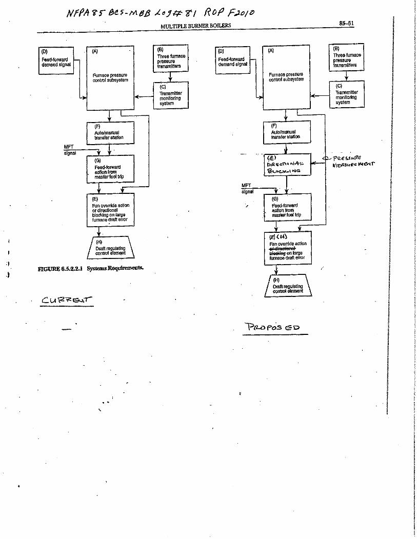
Report on Proposals – November 2010 NFPA 85pressure error"; change text in block (H) to "Draft regulating Furnace pressure final control element"
Furnace pressure system requirements.6.5.2.2.1 The furnace pressure control subsystem (A), as shown in Figure 6.5.2.2.1, shall position the draft- furnace
pressure regulating equipment so as to maintain furnace pressure at the desired set point.The furnace pressure control system, as shown in Figure 6.5.2.2.1, shall include the following features and
functions:(1) Three furnace pressure transmitters (B) in an auctioneered median-select system, each on a separate
pressure-sensing tap and suitably monitored (C) to minimize the possibility of operating with a faulty furnace pressuremeasurement
(2) A feed-forward signal (D), representative of boiler airflow demand, which can be permitted to be a fuel flow signal,a boiler-master signal, or other index of demand, but not a measured airflow signal
(3) On large furnace pressure errors, either an override action, or directional blocking, or both (E), on large furnacedraft errorsintroduced after the auto/manual transfer station (F)
(4) A feed-forward action (G) initiated by a master fuel trip to minimize the furnace pressure excursions, introducedafter the auto/manual transfer station (F)
(5) Axial fans, where used, operated in their stable range to prevent a stall condition to prevent uncontrolled changesin airflow or flue gas flow6.5.2.3 Component Requirements. The furnace pressure control element(s) [(H) in Figure 6.5.2.2.1] (draft fan inletdamper drive, blade pitch control, speed control) shall meet the following criteria:
(1)* The operating speed shall not exceed the control system's sensing and positioning capabilities.(2) The operating speed of the draft furnace pressure control equipment shall not be less than that of the airflow control
equipment.The TC does not agree with relocating the fan directional blocking ahead of the MFT for the
following reasons: If the MFT feedforward is located downstream of the directional blocking, the MFT feedforward willreduce the ID fan demand. If the MFT is the result of high furnace pressure, this may be incorrect action as the pressureexcursion may have been caused by a reduction in ID fan demand. If the MFT feedforward is located upstream of thedirectional blocking, the feedforward will have no effect on ID fan demand. From a high furnace pressure trip condition,implosion prevention is not a primary concern. As pressure in the furnace is reduced as a result of the MFT, directionalblocking will be released as soon as the pressure falls below the point where directional blocking was activated.
The TC agrees that either directional blocking and/or fan override actions may be acceptable control schemesdepending on the design. The TC has changed the word "draft" to "furnace pressure" throughout the section asappropriate for consistency with current industry terminology.
12Printed on 8/5/2009
Report on Proposals – November 2010 NFPA 85_______________________________________________________________________________________________85-76 Log #66 BCS-MBB
_______________________________________________________________________________________________Michael C. Polagye, FM Global
On installations with multiple ID fans or FD fans, the following shall apply:(1) Unless an alternate open-flow path is provided, all fan control devices and shutoff dampers shall be opened in
preparation for starting the first ID fan.(2)* Within the limitations of the fan manufacturer's recommendations, all flow control devices and shutoff dampers on
idle ID fans shall remain open until the first ID fan is in operation and all flow control devices and shutoff dampers on idleFD fans shall remain open until the first FD fans is are in operation while maintaining furnace pressure conditions andindication of an open-flow path.
It is not the intent of this paragraph to require air to recirculate backwards through idle ID fans until thefirst FD fan is started and in operation. The proposed change provides clarification.
Revise text to read as follows:On installations with multiple ID fans or FD fans, the following shall apply:
(1) Unless an alternate open-flow path is provided, all fan control devices and shutoff dampers shall be opened inpreparation for starting the first ID fan except as permitted by 6.4.2.3.4.3(C)(3).
(2)* Within the limitations of the fan manufacturer's recommendations, all flow control devices and shutoff dampers onidle ID fans shall remain open until the first ID fan is in operation and all flow control devices and shutoff dampers on idleFD fans shall remain open until the first FD fans is are in operation while maintaining furnace pressure conditions andindication of an open-flow path.
The TC made one minor editorial correction, and added text to the end of (1) to reflect actiontaken on 85-68 (Log #60).
_______________________________________________________________________________________________85-77 Log #32 BCS-MBB
_______________________________________________________________________________________________Robert Benz, Benz Air Engineering Co.
The total furnace air throughput shall not be reduced below the purge flow rate.The total furnace air throughput shall not be reduced below that needed for complete combustion and to maintain
burner stability.For multiple burner boilers, increasing the minimum air flow to that required to purge the furnace would
require burners to be initially started at a high rate of fuel input. Requiring a high rate of air flow through a boilersignificantly reduces efficiency. Setting an arbitrary minimum air flow through can be dangerous without an analysis tothe stability of the combustion air flow supply system.
The TC rejected the proposal because historical operating experience has proven thatoperation below the minimum airflow established in accordance with 6.4.2.3.4.4 has resulted in explosions.
13Printed on 8/5/2009
Report on Proposals – November 2010 NFPA 85_______________________________________________________________________________________________85-78 Log #39 BCS-MBB
_______________________________________________________________________________________________Tom Russell, Honeywell
Revise text as follows:The total furnace air throughput shall not be reduced below the purge air flow rate.
The issue of purging needs to be clarified. Does the purge rate need to be fixed or can it be variable,the code is ambiguous on this topic. The code permits a boiler to be purged at various airflow rates, but it implies thatwhatever airflow rate is used for purging now becomes the minimum value to which airflow can be controlled. Thesechanges permit purging at rates above the minimum and then permit airflow to be reduced to the minimum.
Revise text to read as follows:6.6.5.1.5.6(F) The total furnace air throughput shall not be reduced below the minimum purge air flow rate established
by the designer in accordance with 6.4.2.3.4.4(A).6.7.5.1.5.6(F) The total furnace air throughput shall not be reduced below the minimum purge air flow rate established
by the designer in accordance with 6.4.2.3.4.4(A).6.8.5.1.5.6(E) The total furnace air throughput shall not be reduced below the minimum purge air flow rate established
by the designer in accordance with 6.4.2.3.4.4(A).The TC recognizes that purge may be accomplished at a rate greater than this
designer-established minimum purge airflow rate. The unit must still light-off at the rate at which the purge isaccomplished. Subsequent to light-off, boiler load must be increased (increase of fuel and airflow) before airflow can bereduced below the actual purge rate used, down to the designer-established minimum.
_______________________________________________________________________________________________85-79 Log #33 BCS-MBB
_______________________________________________________________________________________________Robert Benz, Benz Air Engineering Co.
Revise text as follows:
For multiple burner boilers, increasing the minimum air flow to that required to purge the furnace wouldrequire burners to be initially started at a high rate of fuel input. Requiring a high rate of air flow through a boilersignificantly reduces efficiency. Setting an arbitrary minimum air flow through can be dangerous without an analysis tothe stability of the combustion air flow supply system.
The TC rejected the proposal because historical operating experience has proven thatoperation below the minimum airflow established in accordance with 6.4.2.3.4.4 has resulted in explosions. The rate offuel flow on the burners is permitted to be less than that required to match the purge rate airflow when the unit is beingstarted or at low loads.
14Printed on 8/5/2009
Report on Proposals – November 2010 NFPA 85_______________________________________________________________________________________________85-80 Log #40 BCS-MBB
_______________________________________________________________________________________________Tom Russell, Honeywell
Revise text as follows:The open-register light-off and purge procedure shall be used to maintain airflow at or above the
purge rate during all operations of the boiler.The issue of purging needs to be clarified. Does the purge rate need to be fixed or can it be variable,
the code is ambiguous on this topic. The code permits a boiler to be purged at various airflow rates, but it implies thatwhatever airflow rate is used for purging now becomes the minimum value to which airflow can be controlled. Thesechanges permit purging at rates above the minimum and then permits airflow to be reduced to the minimum.
Revise text to read as follows:6.6.5.1.5.7 The open-register light-off and purge procedure shall be used to maintain airflow at or above the
designer-established minimum purge rate during all operations of the boiler.6.7.5.1.5.7 The open-register light-off and purge procedure shall be used to maintain airflow at or above the
designer-established minimum purge rate during all operations of the boiler.6.8.5.1.5.7 The open-register light-off and purge procedure shall be used to maintain airflow at or above the
designer-established minimum purge rate during all operations of the boiler.The TC recognizes that purge may be accomplished at a rate greater than the
designer-established minimum purge airflow rate. The unit must still light-off at the rate at which the purge isaccomplished. Subsequent to light-off, boiler load must be increased (increase of fuel and airflow) before airflow can bereduced below the actual purge rate used, down to the designer-established minimum.
_______________________________________________________________________________________________85-81 Log #34 BCS-MBB
_______________________________________________________________________________________________Robert Benz, Benz Air Engineering Co.
Revise text as follows:
The light off of a burner at an air fuel ratio that is greater than 1, minimizes the risk of a fuel richenvironment within the furnace.
The TC rejected the proposal because a fuel-rich environment at the burner is required toachieve reliable ignition. Section 6.6.5.1.5.7(A)(3) requires an air-rich environment in the furnace.
15Printed on 8/5/2009
Report on Proposals – November 2010 NFPA 85_______________________________________________________________________________________________85-82 Log #35 BCS-MBB
_______________________________________________________________________________________________Robert Benz, Benz Air Engineering Co.
Revise text as follows:
Maintaining purge rates through a boiler warm up would result in an excessively high firing rate in oneor more of the firing burners. The resulting warm up would most likely result in a warm up rate that exceeds the boilerrecommended warm up rate.
The TC rejected the proposal because historical operating experience has proven thatoperation below the minimum airflow established in accordance with 6.4.2.3.4.4 has resulted in explosions. The rate offuel flow on the burners is permitted to be less than that required to match the purge rate airflow when the unit is beingstarted or at low loads.
_______________________________________________________________________________________________85-83 Log #44 BCS-MBB
_______________________________________________________________________________________________Tom Russell, Honeywell
Revise text as follows:Creation of an air-rich furnace atmosphere during lightoff and warm-up by maintaining total furnace airflow at
the same rate as that needed for the unit purge.The issue of purging needs to be clarified. Does the purge rate need to be fixed or can it be variable,
the code is ambiguous on this topic. The code permits a boiler to be purged at various airflow rates, but it implies thatwhatever airflow rate is used for purging now becomes the minimum value to which airflow can be controlled. Thesechanges permit purging at rates above the minimum and then permit airflow to be reduced to the minimum.
The TC rejected the proposal because it conflicts with the requirements of 6.4.2.3.4.4. Air flowmust remain at the actual purge airflow rate through light-off and initial loading.
_______________________________________________________________________________________________85-84 Log #36 BCS-MBB
_______________________________________________________________________________________________Robert Benz, Benz Air Engineering Co.
Revise text as follows:
A purge of a volume requires 5 volume changes. Requiring more than 5 air volume changes results ina reduction of efficiency, fan horsepower, with no increase in safety.
The TC rejects the proposal because the combination of requiring a minimum of 5 minutesAND at least 5 volume changes, whichever is longer, has been successfully demonstrated to reduce incidents duringcomponent start-up.
16Printed on 8/5/2009
Report on Proposals – November 2010 NFPA 85_______________________________________________________________________________________________85-85 Log #48 BCS-MBB
_______________________________________________________________________________________________Thomas D. Russell, Honeywell, Inc.
Revise text as follows:Except where Class 1 igniters are in service, a the master fuel trip shall be initiated when the flame detection system(s)
indicates that ignition has not been obtained within 5 seconds of the time the fuel actually begins to enter the furnace.Aligns 6.6.5.2.1.3(B)(11)(b) with 6.8.5.2.1.3(B)(12)(c) coal firing, and table 6.4.2.3.1(b) thus minimizing
confusion.
Revise text to read as follows:6.6.5.2.1.3(B)(11)(b) Except where associated Class 1 igniters are in service, a the master fuel trip shall be initiated
when the flame detection system(s) indicates that ignition has not been obtained within 5 seconds of the time the mainfuel actually begins to enter the furnace.
The TC added the word "associated" to make it clear that the exception applies only forburners that have associated Class 1 igniters. The word "main" has been added for clarity.
_______________________________________________________________________________________________85-86 Log #42 BCS-MBB
_______________________________________________________________________________________________Tom Russell, Honeywell
Revise text as follows:Total airflow shall not be reduced below the purge rate.
The issue of purging needs to be clarified. Does the purge rate need to be fixed or can it be variable,the code is ambiguous on this topic. The code permits a boiler to be purged at various airflow rates, but it implies thatwhatever airflow rate is used for purging now becomes the minimum value to which airflow can be controlled. Thesechanges permit purging at rates above the minimum and then permit airflow to be reduced to the minimum.
Revise text to read as follows:6.6.5.2.2.7 Total airflow shall not be reduced below the minimum purge rate established by the designer in accordance
with 6.4.2.3.4.4.6.7.5.2.2.7 Total airflow shall not be reduced below the minimum purge rate established by the designer in accordance
with 6.4.2.3.4.4.6.8.5.2.2.9 Total airflow shall not be reduced below the minimum purge rate established by the designer in accordance
with 6.4.2.3.4.4.The TC recognizes that purge may be accomplished at a rate greater than the
designer-established minimum purge airflow rate. The unit must still light-off at the rate at which the purge isaccomplished. Subsequent to light-off, boiler load must be increased (increase of fuel and airflow) before airflow can bereduced below the actual purge rate used, down to the designer-established minimum.
17Printed on 8/5/2009
Report on Proposals – November 2010 NFPA 85_______________________________________________________________________________________________85-87 Log #37 BCS-MBB
_______________________________________________________________________________________________Robert Benz, Benz Air Engineering Co.
Revise text as follows:
Requiring a high rate of air flow through a boiler significantly reduces efficiency. Setting an arbitraryminimum air flow through can be dangerous without an analysis to the stability of the combustion air flow supply system.The air flow requirements are that required for complete combustion.
The TC rejected the proposal because historical operating experience has proven thatoperation below the minimum airflow established in accordance with 6.4.2.3.4.4 has resulted in explosions. The 5percent margin is established to prevent nuisance trips due to measurement tolerances.
_______________________________________________________________________________________________85-88 Log #1 BCS-MBB
_______________________________________________________________________________________________
Charles A. Moore, Hull, MAAdd an Exception to read:
6.7.5.2.1.1(8) All safety shutoff valves are closed and all sparked de-energized.Exception: If the design of the fuel oil system requires the safety shutoff be open for fuel oil recirculation, the safety
shutoff valves may be open if all burner valves are proven closed.The added exception will permit the continued recirculation of the fuel oil for system warm up during
the start up procedure. If not, it appears that the recirculation system would be required to be shut down. In the commonsystem design, this presents a conflict with 6.7.5.2.1.1(10).
General Comment: The fuel oil system requirements for a fuel oil warm up recirculation system design seems toconflict with each other and are confusing. In addition, they do not address the mechanically atomized delta P style ofburner fuel oil supply system design where there is a continuous return flow. This return flow can be regulated, feed intoa pump, etc., but generally goes to some sort of a header where an elevated pressure is present. The requirements insome of the paragraphs cannot be met with the requirements of this type of system.
Revise text to read as follows:6.7.5.2.1.1(8) All individual burner safety shutoff valves are proven closed and all sparks are de-energized.(10) The circulating valves, or the fuel oil main safety shutoff valve if a circulating valve is not provided, shall be
permitted to be are open to provide and maintain hot oil in the burner headers.The TC recognizes that some designs require the main safety shutoff valve to remain open for
the purpose of fuel oil circulation. However, the TC has reworded sections 8 and 10 instead of imposing an exceptionon subparagraph 8, in accordance with the NFPA Manual of Style. In subparagraph 8, the TC specified exactly whichvalves are required to be closed. Subparagraph 10 now includes language to clarify that the main safety shutoff valvemay be used, if required, for circulation.
18Printed on 8/5/2009
Report on Proposals – November 2010 NFPA 85_______________________________________________________________________________________________85-89 Log #2 BCS-MBB
_______________________________________________________________________________________________
Charles A. Moore, Hull, MARevise text to read:
6.7.5.2.1.3(6) The main fuel control valve shall be closed open and the main safety shutoff valve(s) shall be open, butonly after the requirements of 6.7.5.12.9 for leak test requirements and 6.4.2.3.4 for permissive conditions in the unitpurge system have been satisfied.
In the design of most fuel oil systems if you close either of the valves, you will not get any warm up oilflow. This is unless a special circulation valve has been provided. There are many stations where this circulation valve isnot provided as it is viewed and a path around the trip valve. The code should not rule out the simpler and safer design.
General Comment: The fuel oil system requirements for a fuel oil warm up recirculation system design seems toconflict with each other and are confusing. In addition, they do not address the mechanically atomized delta P style ofburner fuel oil supply system design where there is a continuous return flow. This return flow can be regulated, feed intoa pump, etc., but generally goes to some sort of a header where an elevated pressure is present. The requirements insome of the paragraphs cannot be met with the requirements of this type of system.
The TC believes that this issue is addressed by 6.7.5.2.1.3(B)(7-b) in the 2007 edition.
_______________________________________________________________________________________________85-90 Log #3 BCS-MBB
_______________________________________________________________________________________________
Charles A. Moore, Hull, MARevise text to read:
6.7.5.2.1.3(7) It shall be determined that the main fuel control valve is closed (unless opening is required for the fuelwarm up system) and the following procedures performed:
This permits the main fuel oil valve to be open for recirculation.General Comment: The fuel oil system requirements for a fuel oil warm up recirculation system design seems to
conflict with each other and are confusing. In addition, they do not address the mechanically atomized delta P style ofburner fuel oil supply system design where there is a continuous return flow. This return flow can be regulated, feed intoa pump, etc., but generally goes to some sort of a header where an elevated pressure is present. The requirements insome of the paragraphs cannot be met with the requirements of this type of system.
This is part of the start-up sequence in preparation for firing, not for header warm-up. Headerwarm-up should have been accomplished in accordance with 6.7.5.2.1.3(5), prior to step 7.
19Printed on 8/5/2009
Report on Proposals – November 2010 NFPA 85_______________________________________________________________________________________________85-91 Log #46 BCS-MBB
_______________________________________________________________________________________________Thomas D. Russell, Honeywell, Inc.
Revise text as follows:Except where Class 1 igniters are in service, a the master fuel trip shall be initiated when the flame detection system(s)
indicates that ignition has not been obtained within 5 seconds of the time the fuel actually begins to enter the furnace.Aligns 6.6.5.2.1.3(B)(11)(b) with 6.8.5.2.1.3(B)(12)(c) coal firing, and table 6.4.2.3..1(b) thus
minimizing confusion.
Revise text to read as follows:6.7.5.2.1.3(B)(12)(b) Except where associated Class 1 igniters are in service, a the master fuel trip shall be initiated
when the flame detection system(s) indicates that ignition has not been obtained within 5 seconds of the time the mainfuel actually begins to enter the furnace.
The TC added the word "associated" to make it clear that the exception applies only forburners that have associated Class 1 igniters. The word "main" has been added for clarity.
_______________________________________________________________________________________________85-92 Log #38 BCS-MBB
_______________________________________________________________________________________________Robert Benz, Benz Air Engineering Co.
Revise text as follows:
For multiple burner boilers, increasing the minimum air flow to that required to purge the furnace wouldrequire burners to be initially started at a high rate of fuel input. Requiring a high rate of air flow through a boilersignificantly reduces efficiency. Setting an arbitrary minimum air flow through can be dangerous without an analysis tothe stability of the combustion air flow supply system.
The TC rejected the proposal because historical operating experience has proven thatoperation below the minimum airflow established in accordance with 6.4.2.3.4.4 has resulted in explosions. The rate offuel flow on the burners is permitted to be less than that required to match the purge rate airflow when the unit is beingstarted or at low loads.
_______________________________________________________________________________________________85-93 Log #84 BCS-MBB
_______________________________________________________________________________________________W. Scott Matz, Invensys Process Systems
Revise text to read as follows:The main fuel control valve shall be closed permitted to be open or closed and the main safety shutoff valve (s) shall
be open, only after the requirements of 6.7.5.1.3 for leak test requirements and 6.4.2.3.4 for permissive conditions in theunit purge system have been satisfied.
The original text did not address oil header designs that do not have special circulation valves.
The TC feels that this is already addressed in 6.7.5.2.1.3(B) (7-b) in the 2007 edition.
20Printed on 8/5/2009
Report on Proposals – November 2010 NFPA 85_______________________________________________________________________________________________85-94 Log #CP3 BCS-MBB
_______________________________________________________________________________________________Technical Committee on Multiple Burner Boilers,
Revise text to read as follows:6.7.5.2.3.7 As the fuel is reduced, the remaining burners shall be shut down sequentially as described in 6.7.5.2.3.5
and 6.7.5.2.3.6 except that the last burner shall not be scavenged unless an associated Class 1 or 2 igniter is in use.Class 2 igniters provide an adequate source of ignition for oil being purged into the furnace during a
normal shutdown, and therefore the TC is expanding the use of Class 2 igniters for scavenging the last burner.
_______________________________________________________________________________________________85-95 Log #29 BCS-MBB
_______________________________________________________________________________________________Robert Benz, Benz Air Engineering Co.
Revise text as follows:
Requiring a high rate of air flow through a boiler significantly reduces efficiency. Setting an arbitraryminimum air flow through can be dangerous without an analysis to the stability of the combustion air flow supply system.The air flow requirements are that required for complete combustion.
The TC rejected the proposal because historical operating experience has proven thatoperation below the minimum airflow established in accordance with 6.4.2.3.4.4 has resulted in explosions. The 5percent margin is established to prevent nuisance trips due to measurement tolerances.
_______________________________________________________________________________________________85-96 Log #CP8 BCS-MBB
_______________________________________________________________________________________________Technical Committee on Multiple Burner Boilers,
Revise text to read as follows:6.8.5.2.1.3 (B)(12)(a) Required ignition shall be obtained within 10 seconds following the specific time delay described
in 6.8.5.2.1.3(B)(117).TC corrected the reference.
21Printed on 8/5/2009
Report on Proposals – November 2010 NFPA 85_______________________________________________________________________________________________85-97 Log #45 BCS-MBB
_______________________________________________________________________________________________Tom Russell, Honeywell
Revise text as follows:The furnace airflow shall be readjusted after conditions stabilize, as necessary. Airflow shall not be reduced below the
purge rate.The issue of purging needs to be clarified. Does the purge rate need to be fixed or can it be variable,
the code is ambiguous on this topic. The code permits a boiler to be purged at various airflow rates, but it implies thatwhatever airflow rate is used for purging now becomes the minimum value to which airflow can be controlled. Thesechanges permit purging at rates above the minimum and then permits airflow to be reduced to the minimum.
The TC rejected the proposal because it conflicts with the requirements of 6.4.2.3.4.4.
_______________________________________________________________________________________________85-98 Log #47 BCS-MBB
_______________________________________________________________________________________________Thomas D. Russell, Honeywell, Inc.
Revise text as follows:Except where Class 1 igniters are in service, a master fuel trip shall be initiated on failure to ignite or on loss of ignition
for on placing the first pulverizer into service.Do not want to imply that any time the first pulverizer is removed from service a MFT is required.
Revise text to read as follows:6.8.5.2.1.3(B)(12)(c) Except where associated Class 1 igniters are in service, a master fuel trip shall be initiated on
failure to ignite or on loss of ignition for on placing the first pulverizer into service.The TC added the word "associated" to make it clear that the exception applies only for
burners that have associated Class 1 igniters.
_______________________________________________________________________________________________85-99 Log #61 BCS-MBB
_______________________________________________________________________________________________Allan J. Zadiraka, The Babcock & Wilcox Company
Revise text as follows:The igniter safety shutoff valve, individual igniter safety shutoff valves, primary air fans or exhausters, recirculating
fans, coal feeders, and pulverizers coal burner line shutoff valves or equivalent functional action to stop coal delivery toburners shall be tripped, and the igniter sparks shall be de-energized.
Block 12 of Table 6.4.2.3.1(a) does not include pulverizer in list of equipment to be stopped on MFT tohalt coal flow to unit. Pulverizer motor is typically stopped because of wear/vibration with no coal. Pulverizer motor isrun on some mill designs to remove coal remaining in tripped pulverizer group through pyrites hopper after an MFT asreferenced in Chapter 9.
The TC rejected the proposal because it is desired to trip the pulverizer on a master fuel trip.The TC agrees that it may be necessary to run the pulverizer motor to clear the mill prior to restart.
22Printed on 8/5/2009
Report on Proposals – November 2010 NFPA 85_______________________________________________________________________________________________85-100 Log #CP6 BCS-MBB
_______________________________________________________________________________________________Technical Committee on Multiple Burner Boilers,
Revise text to read as follows:(A) Igniter sparks shall be de-energized, the igniter safety shutoff valve, individual igniter safety shutoff valves, primary
air fans or exhausters, recirculating fans, coal feeders, and pulverizers shall be tripped, coal burner line shutoff valvesshall be closed or equivalent functional action shall be taken to stop coal delivery to burners and the igniter sparks shallbe de-energized.
The TC made editorial changes to make the paragraph consistent with Table 6.4.2.3.1(a) Blocks 3-12.
_______________________________________________________________________________________________85-121 Log #53 BCS-MBB
_______________________________________________________________________________________________Gordon G. Gaetke, The Dow Chemical Company
Add “*” to 6.4.2.3.4.6 (2). Following text proposed for Appendix.Analyzers may contain heated elements which exceed the auto-ignition temperature of many fuels. Zirconium oxide
analyzers, commonly used for oxygen analysis, contain an element heated to 1300°F (704°C). This high temperatureelement presents a potential ignition source to unburned fuel which could be present at startup. Some analyzers aredesigned to protect the sampled space from the ignition source by providing flashback protection (such as flamearresters in sample gas path) and skin temperatures rated at T2 (572°F / 300°C) or lower temperature rating. Analyzerswithout that protection will need to be proven off until a purge is successfully completed.
In 2005 a flammable hydrocarbon mixture formed in a chemical company’s process furnace that wasignited severely damaging the furnace. A power failure placed the furnace off-line and inadvertently permitted theintroduction of hydrocarbon material. The investigation determined an in situ zirconium oxide oxygen probe was thesource of ignition. These oxygen probes are very common with fired equipment such as boilers. Providing specificreference to such potential sources of ignition energy via the 6.4.2.3.4.6 (2) text will enhance industry knowledge andprevention of this hazard.
23Printed on 8/5/2009
Report on Proposals – November 2010 NFPA 85_______________________________________________________________________________________________85-122 Log #59 BCS-MBB
_______________________________________________________________________________________________Kris A. Gamble, Black & Veatch Corporation
Revise text as follows:The objective of the leak test is to ensure that the individual burner safety shutoff valves are not leaking gas fuel oil into
the furnace. The test can be performed by closing the main fuel header vent oil recirculating valve and the individualburner safety shutoff valves, then closing the main safety shutoff valve, thus pressurizing the header. If a chargingcirculating valve is used, the test is performed by closing the main safety shutoff valve and using the charging circulatingvalve to pressurize the header, then closing the charging circulating valve. The pressure must be held withinpredetermined limits for a predetermined amount of time for the test to be successful.
The test procedure in A.6.7.5.1.3 is copied from the fuel gas articles in A.6.6.5.1.3 and needs to berevised for fuel oil.
Revise text to read as follows:The objective of the leak test is to ensure that the individual burner safety shutoff valves are not leaking gas fuel oil into
the furnace. One method to perform this The test can be performed is by closing the main fuel header vent oilrecirculating valve, if provided, and the individual burner safety shutoff valves, then closing the main safety shutoff valve,thus pressurizing the header. If a charging circulating valve is used, the test is performed by closing the main safetyshutoff valve and using the charging circulating valve to pressurize the header, then closing the charging circulatingvalve. The pressure must be held within predetermined limits for a predetermined amount of time for the test to besuccessful.
The TC made minor editorial changes to the proposal.
_______________________________________________________________________________________________85-123 Log #72 BCS-MBB
_______________________________________________________________________________________________John P. O'Rourke, ALSTOM Power Inc.
In the first sentence, change "gas" to "oil".In the second sentence, revise text as follows: "The test can be performed by closing the main fuel header vent valve
recirculation valve (if provided) and..."The appendix material is related to performing an oil header leak test. The references to gas and vent
valves are not correct.
The action taken on 85-122 (Log #59) meets the intent of the submitter.
24Printed on 8/5/2009
Report on Proposals – November 2010 NFPA 85_______________________________________________________________________________________________85-124 Log #7 BCS-MBB
_______________________________________________________________________________________________
Charles A. Moore, Hull, MARevise Figure A.6.7.5.1.4(c) and A.6.7.5.1.4(d) as follows:
INSERT revised Figure A.6.7.5.1.4(c) HERE
INSERT revised Figure A.6.7.5.1.4(d) HERE
Safety shutoff valves should be shown in the return line to positively prevent fuel flow to the burnerheader. In many designs this line connects to the fuel oil system that is or could be at a positive pressure.
Add new text to read as follows:6.7.3.1.13*A.6.7.3.1.13 One method for meeting this requirement is to provide an automatic shutoff valve in the oil return line to
prevent the backflow of oil into the oil header.The TC agrees that a means for preventing the backflow of oil should be highlighted in the
annex material. However, the TC feels that 6.7.3.1.13 contains this requirement, and is therefore a more appropriatelocation for annex material. The TC rejected the modification of the A.6.7.5.1.4 diagrams to illustrate the valve locationbecause it could imply that the valve is necessary in every application.
_______________________________________________________________________________________________85-125 Log #85 BCS-MBB
_______________________________________________________________________________________________W. Scott Matz, Invensys Process Systems
Revise text to read as follows:
***Insert Artwork Here***Figure A.6.7.5.1.5.4(c) Typical Mechanical Atomizing Main Oil Burner System.
A safety shutoff valve should be shown in the return line to prevent the oil burner header from beingback pressured from the fuel oil system. If a recirculating valve is used it should be a safety shutoff valve.
The TC does not feel that there should be a bypass around the shutoff valve used to preventbackflow into the oil header. In addition, the TC believes that the recirculating valve does not need to be a shutoff valveas shown in the proposed diagram. The TC action on Proposal 85-124 (Log #7) on a similar proposal addresses thesubmitter's concern about preventing backflow of oil into the oil header.
25Printed on 8/5/2009