Embed Size (px)
Citation preview


The information in this document is subject to change without notice and does not represent acommitment on the part of Native Instruments GmbH. The software described by this docu-ment is subject to a License Agreement and may not be copied to other media. No part of thispublication may be copied, reproduced or otherwise transmitted or recorded, for any purpose,without prior written permission by Native Instruments GmbH, hereinafter referred to as NativeInstruments.
“Native Instruments”, “NI” and associated logos are (registered) trademarks of Native Instru-ments GmbH.
Mac, Mac OS, GarageBand, Logic, iTunes and iPod are registered trademarks of Apple Inc.,registered in the U.S. and other countries.Windows, Windows Vista and DirectSound are registered trademarks of Microsoft Corporationin the United States and/or other countries.All other trademarks are the property of their respective owners and use of them does not implyany affiliation with or endorsement by them.
Document authored by: Jan Ola Korte
Software version: 1.1 (07/2018)
Disclaimer

NATIVE INSTRUMENTS GmbHSchlesische Str. 29-30D-10997 BerlinGermanywww.native-instruments.de
NATIVE INSTRUMENTS North America, Inc.6725 Sunset Boulevard5th FloorLos Angeles, CA 90028USAwww.native-instruments.com
NATIVE INSTRUMENTS K.K.YO Building 3FJingumae 6-7-15, Shibuya-ku,Tokyo 150-0001Japanwww.native-instruments.co.jp
NATIVE INSTRUMENTS UK Limited18 Phipp StreetLondon EC2A 4NUUKwww.native-instruments.co.uk
NATIVE INSTRUMENTS FRANCE SARL113 Rue Saint-Maur75011 ParisFrance
www.native-instruments.com
SHENZHEN NATIVE INSTRUMENTS COMPANY Limited5F, Shenzhen Zimao Center
111 Taizi Road, Nanshan District, Shenzhen,Guangdong
China
www.native-instruments.com
© NATIVE INSTRUMENTS GmbH, 2018. All rights reserved.
Contact

Table of Contents1 Welcome to TRK-01 ..................................................................................................9
2 Document Conventions ..............................................................................................10
3 New in Version 1.1 ....................................................................................................11
4 Using TRK-01 in KOMPLETE KONTROL ........................................................................12
4.1 Opening TRK-01 in KOMPLETE KONTROL .................................................................................... 12
4.2 Exploring Factory Preset Files in KOMPLETE KONTROL ................................................................ 13
4.3 Saving and Loading User Preset Files in KOMPLETE KONTROL .................................................... 15
5 Using TRK-01 in REAKTOR 6 ......................................................................................18
5.1 Opening TRK-01 in REAKTOR 6 ................................................................................................... 18
5.2 Exploring Factory Preset Files in REAKTOR 6 ............................................................................... 19
5.3 Saving and Loading User Preset Files in REAKTOR 6 .................................................................. 20
6 MIDI Control and Host Integration ...............................................................................23
6.1 Switching Sound Variations and Patterns via MIDI ..................................................................... 23
6.2 Playing the Kick and the Bass via MIDI ...................................................................................... 24
6.3 Playing the Root Key via MIDI ..................................................................................................... 26
6.4 Automation and MIDI Control ...................................................................................................... 26
6.5 Routing Outputs in a Host .......................................................................................................... 27
7 Overview of TRK-01 ...................................................................................................28
8 Header .....................................................................................................................30
8.1 Copying, Pasting, and Clearing Elements ................................................................................... 31
8.2 Tuning Panel .............................................................................................................................. 33
8.3 Timing Panel .............................................................................................................................. 35
9 Kick Engine ..............................................................................................................36
9.1 Main Area ................................................................................................................................... 37
9.2 Display Area ............................................................................................................................... 38
Table of Contents
TRK-01 - MANUAL - 4

9.3 Modulation Area ......................................................................................................................... 40
9.4 Sound Selector ............................................................................................................................ 41
9.5 Sound Browser ............................................................................................................................ 42
9.6 Layer Sections ............................................................................................................................ 44
9.6.1 Layer Mode Selector ................................................................................................... 45
9.6.2 Pitch Envelope ........................................................................................................... 46
9.6.3 Sample Mode ............................................................................................................. 46
9.6.4 Synth Mode ................................................................................................................ 48
9.6.5 Rumble Mode ............................................................................................................. 49
9.6.6 Noise Mode ................................................................................................................ 49
9.7 Global Section ............................................................................................................................ 50
9.8 Envelope Sections ....................................................................................................................... 51
9.9 LFO+Noise Section ..................................................................................................................... 53
9.9.1 LFO+Noise Mode Selector .......................................................................................... 54
9.9.2 Slow, Fast, and Tempo Mode ..................................................................................... 55
9.9.3 Beat Mode ................................................................................................................. 55
9.10 Modulation Routing .................................................................................................................... 56
10 Bass Engine ..............................................................................................................58
10.1 Main Area ................................................................................................................................... 59
10.2 Display Area ............................................................................................................................... 60
10.3 Modulation Area ......................................................................................................................... 62
10.4 Sound Selector ............................................................................................................................ 63
10.5 Sound Browser ............................................................................................................................ 64
10.6 Tuning Controls .......................................................................................................................... 66
10.7 Oscillator Section ....................................................................................................................... 67
10.7.1 Oscillator Mode Selector ............................................................................................ 68
Table of Contents
TRK-01 - MANUAL - 5

10.7.2 Sub Oscillator ............................................................................................................ 69
10.7.3 Classic Mode ............................................................................................................. 69
10.7.4 Super Mode ................................................................................................................ 70
10.7.5 West Mode ................................................................................................................. 71
10.7.6 FM Mode .................................................................................................................... 72
10.7.7 Modern Mode ............................................................................................................. 73
10.8 Modifier Section .......................................................................................................................... 74
10.8.1 Modifier Mode Selector .............................................................................................. 75
10.8.2 Ring Mode ................................................................................................................. 76
10.8.3 Freq Mode .................................................................................................................. 77
10.8.4 Sine Mode .................................................................................................................. 78
10.8.5 S&H Mode .................................................................................................................. 78
10.9 Filter Section .............................................................................................................................. 79
10.9.1 Filter Mode Selector ................................................................................................... 80
10.9.2 Filter Key Tracking ..................................................................................................... 81
10.10 Envelope Sections ....................................................................................................................... 81
10.11 LFO Section ................................................................................................................................. 83
10.11.1 LFO Mode Selector ..................................................................................................... 84
10.11.2 Slow, Fast, and Tempo Mode ..................................................................................... 85
10.11.3 Beat Mode ................................................................................................................. 86
10.12 Modulation Routing .................................................................................................................... 86
11 Kick Effects ..............................................................................................................88
11.1 Main Area ................................................................................................................................... 89
11.2 Display Area ............................................................................................................................... 90
11.3 Insert Section ............................................................................................................................. 91
11.3.1 Insert Mode Selector .................................................................................................. 92
Table of Contents
TRK-01 - MANUAL - 6

11.3.2 Distort Mode .............................................................................................................. 93
11.3.3 S&H Mode .................................................................................................................. 94
11.3.4 Bit Redux Mode .......................................................................................................... 95
11.3.5 Lowpass Mode ........................................................................................................... 96
11.3.6 Highpass Mode .......................................................................................................... 96
11.4 Equalizer Section ........................................................................................................................ 97
11.5 Output Section ............................................................................................................................ 99
12 Bass Effects ..............................................................................................................102
12.1 Main Area ................................................................................................................................... 103
12.2 Display Area ............................................................................................................................... 104
12.3 Insert Section ............................................................................................................................. 106
12.3.1 Insert Mode Selector .................................................................................................. 107
12.3.2 Distort Mode .............................................................................................................. 107
12.3.3 Unison Mode .............................................................................................................. 108
12.3.4 Flanger Mode ............................................................................................................. 109
12.3.5 Phaser Mode .............................................................................................................. 110
12.4 Equalizer Section ........................................................................................................................ 110
12.5 Output Section ............................................................................................................................ 113
12.6 Ducking Envelope Section ........................................................................................................... 115
13 Sequencer ................................................................................................................117
13.1 Kick Pattern Area ........................................................................................................................ 118
13.2 Kick Sequencer Lanes ................................................................................................................. 119
13.3 Bass Pattern Area ....................................................................................................................... 120
13.4 Bass Sequencer Lanes ................................................................................................................ 121
13.5 Using Step Locks ........................................................................................................................ 122
13.6 Using Parameter Focus ............................................................................................................... 124
Table of Contents
TRK-01 - MANUAL - 7

14 Master ......................................................................................................................126
14.1 Delay .......................................................................................................................................... 127
14.2 Reverb ........................................................................................................................................ 128
14.3 Bass Enhancer ........................................................................................................................... 129
14.4 Booster ....................................................................................................................................... 130
15 Troubleshooting ........................................................................................................131
16 Credits ......................................................................................................................133
Table of Contents
TRK-01 - MANUAL - 8

1 Welcome to TRK-01
TRK-01 is an instrument for creating kick drums and bass sounds as the starting point andfoundation of your track. For this purpose, it combines the flexible KICK and BASS for soundgeneration and processing with powerful sequencers that allow you to intuitively realize com-plex musical ideas.
The controls of the KICK and BASS are optimized for playability, offering smooth operationand the maximum of sweet spots. Different modes for sections like the KICK’s Layers or theBASS’s OSCILLATOR allow you to completely change the character of the sound in an instant.
The sequencers enhance classic step sequencing with advanced features like Step Locks andParameter Focus that allow you to bring a whole new layer of animation to your sounds. Formore information, refer to ↑13.5, Using Step Locks and ↑13.6, Using Parameter Focus.
The innovative global TUNING concept ensures that the KICK and the BASS are always in tunewith each other and additional elements in your track, allowing you to keep low-frequency con-tent in check and match the key and scale of your project at all times. For more information,refer to ↑8.2, Tuning Panel.
Smart sound design and mixing features like the Ducking Envelope of the BASS allow you tofine-tune bass sounds in conjunction with your kick drum and interlace the two elements ininteresting ways. For more information, refer to ↑12.6, Ducking Envelope Section.
By fusing all of these features into an intuitive user interface, TRK-01 empowers you to createthe best possible foundation for your track in a playful manner. Enjoy!
Welcome to TRK-01
TRK-01 - MANUAL - 9

2 Document Conventions
This document uses particular formatting to point out special facts and to warn you of poten-tial issues. The icons introducing the following notes let you see what kind of information canbe expected:
The speech bubble icon indicates a useful tip that may often help you to solve a task more effi-ciently.
The exclamation mark icon highlights important information that is essential for the given context.
The red cross icon warns you of serious issues and potential risks that require your full attention.
Furthermore, the following formatting is used:
▪ Text appearing in (drop-down) menus (such as Open…, Save as… etc.) in the software andpaths to locations on your hard disk or other storage devices is printed in italics.
▪ Text appearing elsewhere (labels of buttons, controls, text next to checkboxes etc.) in thesoftware is printed in blue. Whenever you see this formatting applied, you will find thesame text appearing somewhere on the screen.
▪ Important names and concepts are printed in bold.
▪ References to keys on your computer’s keyboard you’ll find put in square brackets (e.g.,“Press [Shift] + [Enter]”).
► Single instructions are introduced by this play button type arrow.
→ Results of actions are introduced by this smaller arrow.
Document Conventions
TRK-01 - MANUAL - 10

3 New in Version 1.1
The following features and changes have been added to TRK-01 1.1:
▪ New Sound Browsers with Sound Presets for the KICK and the BASS allow you to quicklymix and match sound presets within a Preset file. For more information, refer to ↑9.5,Sound Browser and ↑10.5, Sound Browser.
▪ New KICK and BASS Sequencer Bypass buttons allow you to play the KICK and the BASSexternally using MIDI keyboards and sequencers. For more information, refer to ↑6.2, Play-ing the Kick and the Bass via MIDI.
▪ New MIDI control over the global ROOT key allows you to transpose the KICK and BASSSequencers externally. For more information, refer to ↑6.3, Playing the Root Key via MIDI.
▪ New visual aids in the EQUALIZER displays show the fundamental frequency of the ROOTkey and its harmonics. For more information, refer to ↑11.4, Equalizer Section and ↑12.4,Equalizer Section.
▪ New Step Lock Enable buttons in the KICK and BASS Sequencers allow you to enable ordisable the Step Locks in a sequence. For more information, refer to ↑13.1, Kick PatternArea and ↑13.3, Bass Pattern Area.
▪ New Offset Up and Down buttons in the BASS Sequencer allow you to shift the pitches ofall steps in the selected page up or down. For more information, refer to ↑13.3, Bass Pat-tern Area.
▪ New Layer Enable buttons for LAYER A and LAYER B in the KICK allow you to switch theLayers on or off. For more information, refer to ↑9.6, Layer Sections.
▪ New INVERT parameter in the KICK Layer’s SAMPLE mode allows you to invert the phaseof the loaded sample. For more information, refer to ↑9.6.3, Sample Mode.
▪ New individual stereo outputs for the DELAY and the REVERB send effects allow you toprocess and mix the signals in your host. For more information, refer to ↑6.5, Routing Out-puts in a Host.
▪ Fixed timing issues when switching patterns in certain hosts.
▪ Updated and improved manual covering the new features as well as adding more informa-tion to a number of key sections.
New in Version 1.1
TRK-01 - MANUAL - 11

4 Using TRK-01 in KOMPLETE KONTROL
TRK-01 is optimized to integrate with KOMPLETE KONTROL using Native Kontrol Standard(NKS). You can explore Factory Preset files in the KOMPLETE KONTROL Browser, and controlthe instrument using the KOMPLETE KONTROL keyboard.
The following sections explain how to open TRK-01 in KOMPLETE KONTROL, as well as ex-plore Factory Preset files and use User Preset files.
For more information about controlling TRK-01 using the KOMPLETE KONTROL keyboard, refer to↑6, MIDI Control and Host Integration.
4.1 Opening TRK-01 in KOMPLETE KONTROL
To open TRK-01 in KOMPLETE KONTROL:
12
4
3
Opening TRK-01 in KOMPLETE KONTROL
1. Go to the Browser’s Library tab (1).
2. Select the factory content (2).
3. Open the Product selector by clicking on the arrow symbol (3).
Using TRK-01 in KOMPLETE KONTROL
Opening TRK-01 in KOMPLETE KONTROL
TRK-01 - MANUAL - 12

4. Find TRK-01 in the list of Native Instruments products.
5. Place the mouse over the TRK-01 entry and click on the arrow symbol that appears in theupper right corner (4).
→ TRK-01 loads with its default Preset file.
4.2 Exploring Factory Preset Files in KOMPLETE KONTROL
To explore Factory Preset files in KOMPLETE KONTROL:
1
2
Exploring Factory Preset files in KOMPLETE KONTROL
You can use the Preset display in KOMPLETE KONTROL’s Header to load Preset files.
► Click on the arrow buttons in the Preset display (1).
Using TRK-01 in KOMPLETE KONTROL
Exploring Factory Preset Files in KOMPLETE KONTROL
TRK-01 - MANUAL - 13

→ The Preset files are loaded one after the other.
Alternatively, you can load Preset files from the Browser’s Results list and benefit from thePrehear function. This allows you to listen to the preview of a Preset file before loading it.
► Click on an entry in the Results list (2) to select it.
→ The preview of the corresponding Preset file is played back (Prehear needs to be enabledin KOMPLETE KONTROL).
► Double click on an entry in the Results list (2).
⇨ The corresponding Preset file is loaded.
Filtering Results by Musical Genre
If you want to only explore Preset files that are associated with a particular musical genre, youcan do so by using the TYPES filter in the KOMPLETE KONTROL Browser.
The Types and Sub-Types for TRK-01
To filter the entries in the Browser’s Results list by musical genres:
1. Open the TYPES filter in the Browser.
2. Click on the Type Multitrack to show the available Sub-Types.
3. Click on one of the musical genres available as Sub-Types.
→ The Results list only shows Preset files associated with the selected musical genre.
Using TRK-01 in KOMPLETE KONTROL
Exploring Factory Preset Files in KOMPLETE KONTROL
TRK-01 - MANUAL - 14

4.3 Saving and Loading User Preset Files in KOMPLETE KONTROL
In order to permanently save all adjustments and settings made in TRK-01 including yoursound variations, combinations of sound presets, samples, and patterns, you need to save aUser Preset file.
▪ For more information about sound variations, refer to ↑9.4, Sound Selector and ↑10.4,Sound Selector.
▪ For more information about sound presets, refer to ↑9.5, Sound Browser and ↑10.5, SoundBrowser.
▪ For more information about loading samples, refer to ↑9.6.3, Sample Mode.
▪ For more information about patterns, refer to ↑13.1, Kick Pattern Area.
Saving User Preset Files
To save a User Preset file:
1. Select the entry Save As… in the File submenu of the KOMPLETE KONTROL menu.
Using TRK-01 in KOMPLETE KONTROL
Saving and Loading User Preset Files in KOMPLETE KONTROL
TRK-01 - MANUAL - 15

2. Enter a name for your User Preset file and click on Save in the Save Preset dialog.
→ Your User Preset file is saved.
Loading User Preset Files
To load a previously saved User Preset file:
1. Select the user content in the KOMPLETE KONTROL Browser and ensure that TRK-01 isselected in the Product selector.
Using TRK-01 in KOMPLETE KONTROL
Saving and Loading User Preset Files in KOMPLETE KONTROL
TRK-01 - MANUAL - 16

2. Find your User Preset file in the Results list and double-click on it.
→ Your User Preset file is loaded.
User Preset files saved in KOMPLETE KONTROL can also be loaded when using TRK-01 in REAK-TOR 6. For more information about loading User Preset files in REAKTOR 6, refer to ↑5.3, Savingand Loading User Preset Files in REAKTOR 6.
Using TRK-01 in KOMPLETE KONTROL
Saving and Loading User Preset Files in KOMPLETE KONTROL
TRK-01 - MANUAL - 17
5 Using TRK-01 in REAKTOR 6
TRK-01 is a REAKTOR Ensemble that can be loaded in REAKTOR 6. This allows you to notonly play the instrument, but also combine it with other Ensembles, or dive into its Structureto learn more about how it is built.
Information about using Ensembles and the Structure can be found in the REAKTOR 6 documenta-tion.
The following sections explain how to open TRK-01 in REAKTOR 6, as well as explore FactoryPreset files and use User Preset files.
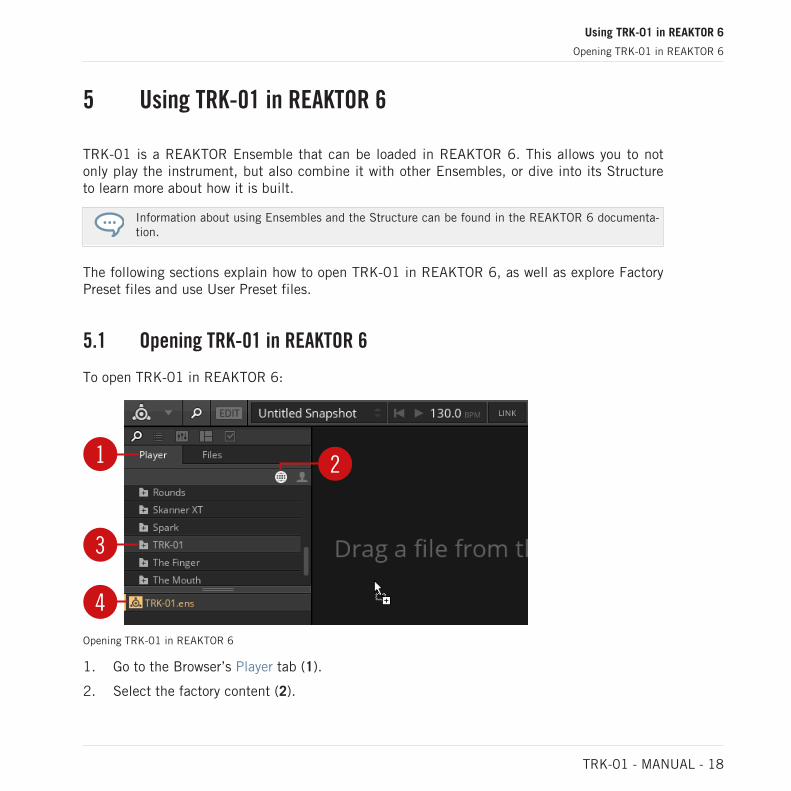
5.1 Opening TRK-01 in REAKTOR 6
To open TRK-01 in REAKTOR 6:
1 2
3
4Opening TRK-01 in REAKTOR 6
1. Go to the Browser’s Player tab (1).
2. Select the factory content (2).
Using TRK-01 in REAKTOR 6
Opening TRK-01 in REAKTOR 6
TRK-01 - MANUAL - 18

3. Find the TRK-01 folder (3) in the list of Native Instruments products and click on it.
4. Drag and drop TRK-01.ens (4) from the lower section of the Browser into REAKTOR’smain area, or double-click on it.
→ TRK-01 loads with its default Preset file.
5.2 Exploring Factory Preset Files in REAKTOR 6
In REAKTOR 6, TRK-01’s Factory Preset files can be explored by loading Snapshots. TheSnapshots are identical to the corresponding Preset files in KOMPLETE KONTROL.
You can use the Snapshot menu in REAKTOR’s Toolbar to load Snapshots.
► Click on the arrow buttons in the Snapshot menu.
→ The Snapshots are loaded one after the other.
Alternatively, you can load Snapshots from a list that is organized in musical genres.
1. Click on the Snapshot menu in REAKTOR’s Toolbar.
Using TRK-01 in REAKTOR 6
Exploring Factory Preset Files in REAKTOR 6
TRK-01 - MANUAL - 19

2. Click on an entry in the list.
→ The corresponding Snapshot is loaded.
5.3 Saving and Loading User Preset Files in REAKTOR 6
In order to permanently save all adjustments and settings made in TRK-01 including yoursound variations, combinations of sound presets, samples, and patterns, you need to save aUser Preset file.
▪ For more information about sound variations, refer to ↑9.4, Sound Selector and ↑10.4,Sound Selector.
▪ For more information about sound presets, refer to ↑9.5, Sound Browser and ↑10.5, SoundBrowser.
▪ For more information about loading samples, refer to ↑9.6.3, Sample Mode.
▪ For more information about patterns, refer to ↑13.1, Kick Pattern Area.
Saving User Preset Files
To save a User Preset file:
Using TRK-01 in REAKTOR 6
Saving and Loading User Preset Files in REAKTOR 6
TRK-01 - MANUAL - 20

1. Select the entry Save Preset As … in the File submenu of the REAKTOR Main menu.
2. Enter a name for your User Preset file and click on Save in the Save Preset As … dialog.
→ Your User Preset file is saved.
To ensure compatibility with KOMPLETE KONTROL, save the file into the following folder:
macOs: /Users/<user name>/Documents/Native Instruments/User Content/TRK-01
Windows: \Users\<user name>\Documents\Native Instruments\User Content\TRK-01
Loading User Preset Files
To load a previously saved User Preset file:
Using TRK-01 in REAKTOR 6
Saving and Loading User Preset Files in REAKTOR 6
TRK-01 - MANUAL - 21

1. Select User in REAKTOR’s Preset Browser.
2. Find your User Preset file in the lower section of the Browser and double-click on it.
→ Your User Preset file is loaded.
User Preset files saved in REAKTOR 6 can also be loaded in KOMPLETE KONTROL. For more infor-mation about loading User Preset files in KOMPLETE KONTROL, refer to ↑4.3, Saving and LoadingUser Preset Files in KOMPLETE KONTROL.
Using TRK-01 in REAKTOR 6
Saving and Loading User Preset Files in REAKTOR 6
TRK-01 - MANUAL - 22

6 MIDI Control and Host Integration
You can control TRK-01 via MIDI to perform using standard MIDI keyboards and controllers.This allows you to switch sound variations and patterns, play the global ROOT key or the KICKand the BASS externally, and adjust instrument parameters remotely. TRK-01 is optimized foruse with the KOMPLETE KONTROL keyboards by supporting Native Kontrol Standard (NKS)and the Light Guide.
The instrument integrates with your host by providing host automation of key controls and al-lowing you to use sequencers to control and play TRK-01 via MIDI. To facilitate full integrationinto your host’s mixer, individual stereo outputs are available for the KICK, the BASS, as wellas the DELAY and the REVERB send effects.
6.1 Switching Sound Variations and Patterns via MIDI
You can use MIDI keyboards and sequencers to switch both sound variations saved in theKICK’s and BASS’s Sound Selectors, as well as patterns of the KICK and BASS Sequencers.
The sound variations and patterns are switched by sending specific MIDI note messages toTRK-01. When a MIDI note message is received, the switching occurs instantly.
The MIDI note messages are mapped to the sound variations and patterns as shown in the fol-lowing image:
Keyboard mapping for KICK and BASS sound variations and patterns
▪ You can switch the sound variations saved in the eight slots of the KICK’s Sound Selectorwith MIDI notes # 36 (C2) to # 43 (G2).
▪ You can switch the eight patterns of the KICK Sequencer with MIDI notes # 48 (C3) to #55 (G3).
MIDI Control and Host Integration
Switching Sound Variations and Patterns via MIDI
TRK-01 - MANUAL - 23

▪ You can switch the sound variations saved in the eight slots of the BASS’s Sound Selectorwith MIDI notes # 60 (C4) to # 67 (G4).
▪ You can switch the eight patterns of the BASS Sequencer with MIDI notes # 72 (C5) to #79 (G5).
On KOMPLETE KONTROL keyboards, the keys corresponding to the correct MIDI note messages forswitching sound variations and patterns are highlighted in orange (for the KICK) and green (for theBASS) by using the Light Guide.
6.2 Playing the Kick and the Bass via MIDI
You can play the KICK and the BASS externally using MIDI keyboards and sequencers, whichallows you to integrate TRK-01 into your performance or sequencing setup in a flexible man-ner. In order to do this, you have to bypass the KICK and BASS Sequencers.
Bypassing the Kick and Bass Sequencers
The KICK and BASS Sequencers can be bypassed independently. This way you can choosewhether you want to play both the KICK and the BASS via MIDI or either one of them, allowingyou to switch sound variations and patterns for the other. For more information about switchingsound variations and patterns for the KICK and the BASS, refer to ↑6.1, Switching Sound Var-iations and Patterns via MIDI.
To bypass the KICK Sequencer and play the KICK via MIDI:
► Click on the KICK Sequencer Bypass button in the header of the pattern area.
To bypass the BASS Sequencer and play the BASS via MIDI:
► Click on the BASS Sequencer Bypass button in the header of the pattern area.
MIDI Control and Host Integration
Playing the Kick and the Bass via MIDI
TRK-01 - MANUAL - 24

Configurations for MIDI Control
The following configurations for controlling TRK-01 via MIDI are possible:
▪ KICK and BASS Sequencer Bypass buttons enabled: You can play the KICK with MIDI notes#21 (A0) to #59 (B3) and the BASS with MIDI notes #60 (C4) to #108 (C8):
▪ KICK Sequencer Bypass button enabled, BASS Sequencer Bypass button disabled: You canplay the KICK with MIDI notes #21 (A0) to #59 (B3) and switch sound variations and pat-terns for the BASS:
▪ KICK Sequencer Bypass button disabled, BASS Sequencer Bypass button enabled: You canplay the BASS with MIDI notes #60 (C4) to #108 (C8) and switch sound variations andpatterns for the KICK:
Output Transposition
In order to provide you with a meaningful range of pitches when playing the KICK and theBASS externally, the MIDI note information is transposed in the following way:
▪ Playing the KICK in the given input range of MIDI notes #21 (A0) to #59 (B3) producespitches in the range of MIDI notes #9 (A-1) to #47 (B2).
▪ Playing the BASS in the given input range of MIDI notes #60 (C4) to #108 (C8) producespitches in the range of MIDI notes #24 (C1) to #72 (C5).
Note that in order for these ranges to apply, the TUNE controls on the KICK and the BASS need tobe set to 0.
MIDI Control and Host Integration
Playing the Kick and the Bass via MIDI
TRK-01 - MANUAL - 25

6.3 Playing the Root Key via MIDI
You can play the global ROOT key via MIDI in order to transpose the KICK and BASS Sequenc-ers on the fly or program key changes in the host.
► To play the global ROOT key via MIDI send MIDI note events to TRK-01 on MIDI channel16.
→ The global ROOT key is set to the respective pitch when a MIDI note event is received.
If you want to transpose only the BASS but not the KICK, ensure that KICK TO ROOT in the Head-er’s TUNING panel is disabled. This way the pitch of the KICK is independent from the globalROOT key.
6.4 Automation and MIDI Control
TRK-01 allows for host automation and MIDI control of key controls. This enables you to per-form using standard MIDI controllers and use the automation features of your host to take con-trol over TRK-01.
The following controls are enabled for automation and MIDI control in a host:
▪ All controls in the Main and Modulation areas of the KICK and BASS.
▪ The KICK and BASS Level faders and the KICK and BASS Enable buttons in the MASTEREffects.
▪ The DELAY, REVERB, BASS Enhancer, and BOOSTER Enable buttons in the MASTER Ef-fects.
Since TRK-01 supports Native Kontrol Standard (NKS), all enabled controls are automatically map-ped to KOMPLETE KONTROL keyboards and MASCHINE controllers.
MIDI Control and Host Integration
Playing the Root Key via MIDI
TRK-01 - MANUAL - 26

6.5 Routing Outputs in a Host
In addition to its main stereo output, TRK-01 also offers individual stereo outputs for theKICK, the BASS, as well as the DELAY and the REVERB send effects. This allows you to proc-ess and mix the signals in your host.
The KICK and BASS outputs are directly fed by the OUTPUT sections of the KICK and BASSand are unaffected by settings made in the MASTER Effects.
The additional outputs are reported to the host by KOMPLETE KONTROL and REAKTOR 6 andcan be routed depending on the used host software.
For information about routing additional outputs of plug-ins in your host, refer to the host’s productdocumentation.
MIDI Control and Host Integration
Routing Outputs in a Host
TRK-01 - MANUAL - 27

7 Overview of TRK-01
TRK-01 consists of three main sections that structure the instrument’s functionality in a logi-cal and intuitive way:
1
2
3
Overview of TRK-01
(1) Header: The first main section provides global settings related to the tuning and timing ofthe instrument, and facilitates the instrument’s workflows for copying, pasting, and clearingthe contents of elements in the user interface.
▪ For more information about the Header, refer to ↑8, Header.
▪ For more information about copying, pasting, and clearing elements, refer to ↑8.1, Copy-ing, Pasting, and Clearing Elements.
Overview of TRK-01
TRK-01 - MANUAL - 28

(2) Engines / Effects: The second main section hosts the sound generation and processing of theKICK and BASS. The KICK features extensive possibilities to sculpt any kick drum soundimaginable, and the BASS allows you to create a wide range of bass sounds. The central EF-FECTS button toggles between the Engines for the sound generation, and the Effects for theprocessing.
▪ For more information about the KICK and BASS Engines, refer to ↑9, Kick Engine and ↑10,Bass Engine.
▪ For more information about the KICK and BASS Effects, refer to ↑11, Kick Effects and↑12, Bass Effects.
(3) Sequencer / Master: The third main section comprises the KICK and BASS Sequencers andthe MASTER Effects. The KICK and BASS Sequencers allow you to quickly realize musicalideas for the KICK and the BASS, while the MASTER Effects provide the means to enhanceand finalize the instrument’s output. The central MASTER button toggles between the KICKand BASS Sequencers and the MASTER Effects.
▪ For more information about the KICK and BASS Sequencers, refer to ↑13, Sequencer.
▪ For more information about the MASTER Effects, refer to ↑14, Master.
Overview of TRK-01
TRK-01 - MANUAL - 29

8 Header
The Header at the top of the TRK-01 user interface provides global settings related to the tun-ing and timing of the instrument, and facilitates the instrument’s workflows for copying, past-ing, and clearing the contents of elements in the user interface.
1 2
3 5
6
7
4
The Header
(1) TRK-01 logo: Shows the instrument's credits.
(2) TUNING: Shows or hides the TUNING panel with settings for the global ROOT key and theQuantizer of the instrument. For more information, refer to ↑8.2, Tuning Panel.
(3) TIMING: Shows or hides the TIMING panel with settings for the tempo and the groove ofthe instrument. For more information, refer to ↑8.3, Timing Panel.
(4) Focus View: Shows the selected element in the user interface. This element can be usedwith the COPY, PASTE, and CLEAR buttons. For more information, refer to ↑8.1, Copying,Pasting, and Clearing Elements.
(5) COPY / PASTE / CLEAR: These buttons are used to copy, paste, and clear the contents ofselected elements in the user interface, including the slots of the Sound Selectors as well asthe KICK and BASS Sequencer’s patterns, pages and Step Locks. For more information, referto ↑8.1, Copying, Pasting, and Clearing Elements.
(6) VOL slider: Adjusts the instrument’s output level in a range of -32 dB to +12 dB. The 0 dBposition is indicated by a fine line.
(7) TUNE slider: Adjusts the instrument’s global tuning in a range of -100 to +100 cents. The0 cent position is in the center and indicated by a fine line.
Header
TRK-01 - MANUAL - 30
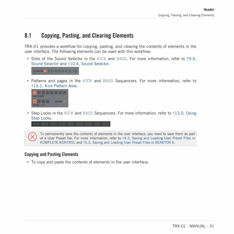
8.1 Copying, Pasting, and Clearing Elements
TRK-01 provides a workflow for copying, pasting, and clearing the contents of elements in theuser interface. The following elements can be used with this workflow:
▪ Slots of the Sound Selector in the KICK and BASS. For more information, refer to ↑9.4,Sound Selector and ↑10.4, Sound Selector.
▪ Patterns and pages in the KICK and BASS Sequencers. For more information, refer to↑13.1, Kick Pattern Area.
▪ Step Locks in the KICK and BASS Sequencers. For more information, refer to ↑13.5, UsingStep Locks.
To permanently save the contents of elements in the user interface, you need to save them as partof a User Preset file. For more information, refer to ↑4.3, Saving and Loading User Preset Files inKOMPLETE KONTROL and ↑5.3, Saving and Loading User Preset Files in REAKTOR 6.
Copying and Pasting Elements
▪ To copy and paste the contents of elements in the user interface:
Header
Copying, Pasting, and Clearing Elements
TRK-01 - MANUAL - 31

1. Select the element you want to copy content from, in this example the first slot of theBASS’s Sound Selector. The name of the selected element is shown in the Focus View ofthe Header.
2. Click on COPY in the Header to copy the contents of the selected element to the clip-board.
3. Select the element you want paste the contents of the clipboard to, in this example thefifth slot of the BASS’s Sound Selector. The name of the selected element is shown in theFocus View of the Header.
4. Click on PASTE in the Header to paste the contents of the clipboard to the selected ele-ment.
→ The contents of the first element are copied to the second element.
Clearing Elements
To clear the contents of elements in the user interface:
Header
Copying, Pasting, and Clearing Elements
TRK-01 - MANUAL - 32

1. Select the element you want to clear, in this example the first slot of the BASS’s SoundSelector. The name of the selected element is shown in the Focus View of the Header.
2. Click on CLEAR in the Header to clear the contents of the selected element.
8.2 Tuning Panel
The TUNING panel provides settings related to the global tuning of TRK-01, allowing you tomatch the key of other elements in your track and conveniently change the musical scale ofPreset files.
The global ROOT key is at the core of TRK-01’s tuning scheme. All tuning settings throughoutthe instrument relate to this base pitch and are set as offsets in semitones. This means thatyou can globally change the key of your project while preserving not only the intervals in yoursequences, but also the relationship between the pitch of the KICK and the BASS.
The central Quantizer processes the output of the BASS Sequencer and forces all pitches to amusical scale. In addition to selecting from a number of built-in scales, you can create yourown custom scales in the Quantizer’s Scale Editor.
The GLOBAL option allows you to preserve settings made in the TUNING panel when switchingPreset files. This allows you to match the scale and key your track and keep these settings inplace while exploring Preset files.
The KICK TO ROOT option locks the tuning of the KICK to the global ROOT key of the instru-ment. This allows you to maintain the pitch relationship of the KICK and the BASS while stillbeing able to change the key of your track.
If you enable KICK TO ROOT and set the KICK’s global TUNE control as well as the TUNE parame-ters of both LAYER A and LAYER B to 0, the KICK’s fundamental frequency will always match thebase pitch of the BASS. In many cases, this makes the low-frequency content of your track moresolid.
Header
Tuning Panel
TRK-01 - MANUAL - 33

3
1 5
4
2
6 7
8
9
The TUNING panel
(1) ROOT: Sets the global ROOT key for the instrument in semitone steps. All tuning settingsin TRK-01 relate to this base pitch.
(2) OCT: Sets the global ROOT key in octave steps.
(3) Quantizer Enable button: Switches the Quantizer on or off.
(4) Scale selector: Shows the selected scale of the Quantizer and allows you to select an entryfrom the selection of built-in scales by clicking on the left and right arrow buttons.
(5) Scale Editor: Shows the contents of the selected scale and allows you to create your owncustom scale for the Quantizer by selecting different notes. The black dot highlights the globalROOT key.
(6) Scale Browser button: Shows the Scale Browser with the built-in scales for the Quantizer:
The scales are organized into two pages, which you can select by clicking on the left and rightarrow buttons.
(7) KICK TO ROOT: Locks the tuning of the KICK to the global ROOT key of the instrument.
(8) GLOBAL: Toggles between the Quantizer settings saved in Preset Files and the globalQuantizer settings.
(9) EXIT: Exits the TUNING panel.
Header
Tuning Panel
TRK-01 - MANUAL - 34

8.3 Timing Panel
The TIMING panel provides settings related to the global clock and rhythm of TRK-01, allow-ing you to not only set the tempo or synchronize the instrument to the host (SYNC), but alsocreate interesting rhythms by changing the Clock Division, switching the TIMING to TRIPLETS,or adding a freely adjustable amount of SWING and GROOVE.
1
5
3
2
4 86 7
The TIMING panel
(1) Tempo: Sets the tempo of the instrument’s clock in BPM. When SYNC is enabled, the in-strument is synchronized to the host clock and Tempo shows the host's BPM value.
(2) SYNC: Synchronizes the instrument’s clock to the host clock.
(3) Clock Division: Sets the clock division of the KICK and BASS Sequencers to either 8thnotes (1/8) or 16th notes (1/16).
(4) Timing Division: Sets the rhythm of the KICK and BASS Sequencers to either a STRAIGHTor TRIPLET.
(5) Timing Display: Shows the settings made with SWING and GROOVE in relation to the basicclock.
(6) SWING: Adjusts the amount of swing applied to the clock.
(7) GROOVE: Adjusts the amount of rhythmic variation applied to the clock when SWING isused.
(8) EXIT: Exits the TIMING panel.
Header
Timing Panel
TRK-01 - MANUAL - 35

9 Kick Engine
The KICK Engine features extensive possibilities to sculpt any kick drum sound imaginableand seamlessly integrates with the BASS Engine to provide a solid foundation for your track.
It couples sampling and synthesizer techniques in a basic structure: Two independent Layersections including distortion and resonant filters, LAYER A and LAYER B, are combined in theGLOBAL section.
The KICK Engine’s controls are optimized to provide smooth transitions between timbres, withfocused parameter ranges that produce the maximum of sweet spots. The different modes ofthe LAYER A and LAYER B sections allow you to completely change the character of the KICKEngine on the fly.
The KICK Engine consists of three interface sections:
1
2
3
Overview of the KICK Engine
(1) Main area: Offers tuning settings, the Sound Selector for sound variations, and key controlsthat allow you to shape your sound. The controls are organized into three sections: LAYER A,GLOBAL, LAYER B. For more information, refer to ↑9.1, Main Area.
Kick Engine
TRK-01 - MANUAL - 36
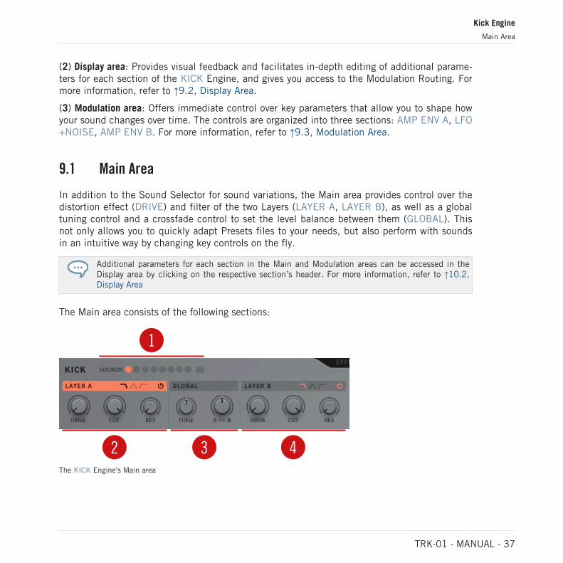
(2) Display area: Provides visual feedback and facilitates in-depth editing of additional parame-ters for each section of the KICK Engine, and gives you access to the Modulation Routing. Formore information, refer to ↑9.2, Display Area.
(3) Modulation area: Offers immediate control over key parameters that allow you to shape howyour sound changes over time. The controls are organized into three sections: AMP ENV A, LFO+NOISE, AMP ENV B. For more information, refer to ↑9.3, Modulation Area.
9.1 Main Area
In addition to the Sound Selector for sound variations, the Main area provides control over thedistortion effect (DRIVE) and filter of the two Layers (LAYER A, LAYER B), as well as a globaltuning control and a crossfade control to set the level balance between them (GLOBAL). Thisnot only allows you to quickly adapt Presets files to your needs, but also perform with soundsin an intuitive way by changing key controls on the fly.
Additional parameters for each section in the Main and Modulation areas can be accessed in theDisplay area by clicking on the respective section’s header. For more information, refer to ↑10.2,Display Area
The Main area consists of the following sections:
1
2 3 4The KICK Engine's Main area
Kick Engine
Main Area
TRK-01 - MANUAL - 37
(1) Sound Selector and Browser: The eight slots of the Sound Selector allow you to save and re-call sound variations for the KICK or load any of the sound presets included in the dedicatedSound Browser. For more information, refer to ↑9.4, Sound Selector and ↑9.5, Sound Browser.
(2) LAYER A: The first of two independent Layer sections has three controls in the Main areathat allow you to define the basic character of the sound. The first control adjusts the amountof DRIVE, or distortion, while the second and third control are dedicated to LAYER A’s filter.For more information, refer to ↑9.6, Layer Sections.
(3) GLOBAL: This central section has two controls in the Main area that allow you to controlthe tuning and mix of the KICK Engine. The first control adjusts the tuning, while the secondcontrol blends between LAYER A and LAYER B. For more information, refer to ↑9.7, GlobalSection.
(4) LAYER B: The second of two independent Layer sections has three controls in the Mainarea that allow you to define the basic character of the sound. The first control adjusts theamount of DRIVE, or distortion, while the second and third control are dedicated to LAYER B’sfilter. For more information, refer to ↑9.6, Layer Sections.
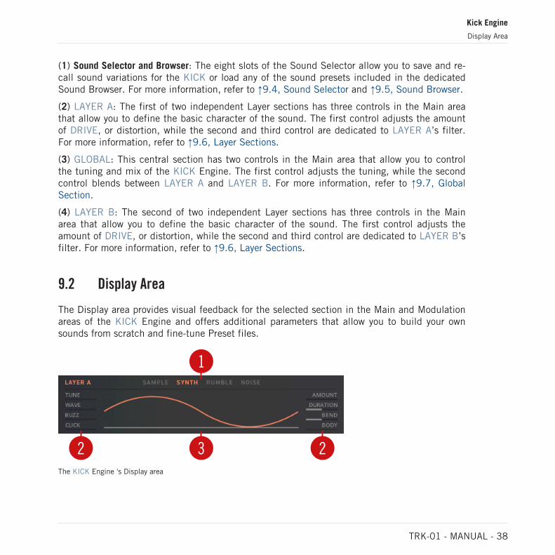
9.2 Display Area
The Display area provides visual feedback for the selected section in the Main and Modulationareas of the KICK Engine and offers additional parameters that allow you to build your ownsounds from scratch and fine-tune Preset files.
1
232The KICK Engine 's Display area
Kick Engine
Display Area
TRK-01 - MANUAL - 38

(1) Mode selector: Allows you to change the character of the selected section by choosing froma number of different modes. For example, this includes different sampling or synthesizertechniques for LAYER A and LAYER B, or a variety of synchronization options for LFO+NOISE.
(2) Additional parameters: Allow you to fine-tune settings related to the selected section. For ex-ample, this includes detailed settings for LAYER A’s and LAYER B’s LAYER modes and PitchEnvelopes, or additional options for the envelopes, AMP ENV A and AMP ENV B.
(3) Display: Provides visual feedback while you adjust the controls of the selected section. Forexample, this includes the waveform of LAYER A, LAYER B, and LFO+NOISE, or the shape ofthe envelopes, AMP ENV A and AMP ENV B.
The Display area is also used for Modulation Routing, allowing you assign the modulation producedby AMP ENV A, LFO+NOISE, and AMP ENV B to the Main area’s controls. For more information,refer to ↑9.10, Modulation Routing.
Accessing Additional Parameters
► To access additional parameters for any section in the Main area or the Modulation area,select the section by clicking on its header.
→ The Display area shows additional parameters for the selected section.
Kick Engine
Display Area
TRK-01 - MANUAL - 39

▪ For more information about LAYER A‘s and LAYER B‘s additional parameters, refer to ↑9.6,Layer Sections.
▪ For more information about GLOBAL’s additional parameters, refer to ↑9.7, Global Section.
▪ For more information about AMP ENV A‘s and AMP ENV B‘s additional parameters, refer to↑9.8, Envelope Sections.
▪ For more information about the LFO+NOISE’s additional parameters, refer to ↑9.9, LFO+Noise Section.
9.3 Modulation Area
The Modulation area provides control over the contours of the Amplitude envelopes for LAYERA and LAYER B, called AMP ENV A and AMP ENV B, as well as the basic parameters of thecombined low-frequency oscillator and noise generator, called LFO+NOISE. This not only al-lows you to quickly adapt Presets files to your needs, but also perform with sounds in an intui-tive way by changing key controls on the fly.
Additional parameters for each section in the Main and Modulation areas can be accessed in theDisplay area by clicking on the respective section’s header. For more information, refer to ↑10.2,Display Area
The Modulation area consists of the following sections:
1 2 3The KICK Engine’s Modulation area
(1) AMP ENV A: An envelope generator that controls LAYER A’s output level and can also beused to modulate any of the controls in the KICK Engine’s Main area. For more information,refer to ↑9.8, Envelope Sections.
Kick Engine
Modulation Area
TRK-01 - MANUAL - 40

(2) LFO+NOISE: A combined low-frequency oscillator and noise generator that can be used tomodulate any of the controls in the KICK Engine’s Main area. For more information, refer to↑9.9, LFO+Noise Section.
(4) AMP ENV B: An envelope generator that controls LAYER B’s output level and can also beused to modulate any of the controls in the KICK Engine’s Main area. For more information,refer to ↑9.8, Envelope Sections.
9.4 Sound Selector
The Sound Selector allows you to save and recall sound variations. It is located at the top ofthe KICK:
The Sound Selector
It consists of eight slots for saving and recalling sound variations for the KICK on the fly. Toget you started, the Factory Preset files come with pre-made sound variations in the first fourslots, allowing you to quickly find new combinations of sounds and patterns within the samePreset file.
All changes made to the KICK are immediately saved in the selected slot and can be recalledas long as the current Preset file is loaded. The contents of the slots can be saved permanentlyas part of a User Preset file.
Slots can also be recalled from the KOMPLETE KONTROL Keyboard. For more information, refer to↑6.1, Switching Sound Variations and Patterns via MIDI.
Creating Sound Variations with the Sound Selector
To create sound variations for the KICK:
Kick Engine
Sound Selector
TRK-01 - MANUAL - 41

1. Select any slot of the Sound Selector.
2. Set the controls and parameters of the KICK to the first sound variation you want to save.
3. Select another slot of the Sound Selector.
4. Set the controls and parameters to the second sound variation you want to save.
→ You can now toggle between the slots and recall the two sound variations on the fly.
To permanently save your sound variations, you need to save them as part of a User Preset file. Formore information, refer to ↑4.3, Saving and Loading User Preset Files in KOMPLETE KONTROL and↑5.3, Saving and Loading User Preset Files in REAKTOR 6.
9.5 Sound Browser
The Sound Browser allows you to load sound presets into the slots of the Sound Selector. It islocated at the top of the KICK:
The Sound Browser
The Sound Browser includes 64 sound presets that are organized in four categories: ANALOG,DIGITAL, ACOUSTIC, and SUB. The sound presets have been carefully selected to cover awide range of different styles. This allows you to quickly mix and match sound presets within aPreset file.
Since the Step Locks in a sequence also affect the controls of the KICK, loading sound presetsfrom the Sound Browser often leads to unexpected and interesting results. For more informa-tion about Step Locks, refer to ↑13.5, Using Step Locks.
Kick Engine
Sound Browser
TRK-01 - MANUAL - 42

The DELAY and REVERB effect sends are excluded from the sound presets in the Sound Browser.They retain their value when loading sound presets to preserve the mix of an existing Preset file.
Loading Sound Presets from the Sound Browser
To load a sound preset from the Sound Browser:
1. Click on the Sound Browser button to open it.
2. Click on a category of sound presets to select it.
3. Click on a sound preset to load it into the selected slot of the Sound Selector.
4. Close the Sound Browser by clicking on the Exit button.
→ The sound preset from the Sound Browser is loaded into the selected slot of the SoundSelector.
Kick Engine
Sound Browser
TRK-01 - MANUAL - 43

To permanently save your combination of sound presets, you need to save them as part of a UserPreset file. For more information, refer to ↑4.3, Saving and Loading User Preset Files in KOM-PLETE KONTROL and ↑5.3, Saving and Loading User Preset Files in REAKTOR 6.
9.6 Layer Sections
The Layer sections, LAYER A and LAYER B, are used to create two main sound elements thatcan be layered on top of each other, ranging from a variety of sampled or synthesized kickdrums to noise components and additional textures.
Each of them offers four different LAYER modes, including a sampler, a synthesizer, and twospecialized noise generators. You can select the LAYER mode in the Display area, which alsoprovides additional parameters related to the selected mode and the Pitch Envelope. For moreinformation, refer to ↑9.6.1, Layer Mode Selector and ↑9.6.2, Pitch Envelope.
The Layer sections’ controls in the Main area allow you to define the basic character of thesound:
The KICK Engine's LAYER A and LAYER B sections
▪ Filter Mode selector: This selector (frequency response symbol) in the header of the sectionallows you to select one of three filter modes for Layer’s filter: low-pass, band pass, andhigh pass.
▪ Layer Enable button: This button (power button symbol) in the header of the sectionswitches the Layer on or off.
▪ DRIVE: Adjusts the amount of Layer’s distortion effect.
Kick Engine
Layer Sections
TRK-01 - MANUAL - 44

▪ CUT: Adjusts the cutoff frequency of Layer’s filter. The effect of this control on the sounddepends on the setting of the Filter Mode selector. In low-pass mode, frequency contentabove the cutoff frequency is attenuated, creating a darker sound. In band pass mode, fre-quency content below and above the cutoff frequency is attenuated, creating a thinnersound. In high pass mode, frequency content below the cutoff frequency is attenuated, cre-ating a brighter sound.
▪ RES: Adjusts the resonance amount of Layer’s filter. As resonance increases, the frequencycontent at the cutoff frequency becomes more pronounced.
9.6.1 Layer Mode Selector
The LAYER Mode selector is one of the additional parameters in the Display area, allowing youto completely change the section’s character by choosing from a number of different modes:
The LAYER Mode selector
Each of the four available modes has its own distinct quality:
▪ SAMPLE: A sampler that includes 120 carefully selected samples in 6 categories and canalso load your own samples. For more information, refer to ↑9.6.3, Sample Mode.
▪ SYNTH: A synthesizer that is tailored towards creating kick drums, with special parametersfor shaping the timbre of the sound. For more information, refer to ↑9.6.4, Synth Mode.
▪ RUMBLE: A synthesizer that specializes in low-frequency rumble and noise, with full con-trol over the tonality and stability of the sound. For more information, refer to ↑9.6.5, Rum-ble Mode.
▪ NOISE: A synthesizer that specializes in textures and noise, with full control over the tonal-ity and stability of the sound. For more information, refer to ↑9.6.6, Noise Mode.
Kick Engine
Layer Sections
TRK-01 - MANUAL - 45

9.6.2 Pitch Envelope
The Pitch Envelope is an additional envelope that allows you to dynamically control LAYER A’sor LAYER B’s pitch over the duration of a note event. It is available in LAYER modes SYNTH,RUMBLE, and NOISE and can be adjusted in the Display area:
The Pitch Envelope parameters of LAYER A’s and LAYER B’s SYNTH mode
▪ AMOUNT: Adjusts the amount of envelope modulation applied to the Layer’s pitch in arange of 0 to +96 semitones, effectively setting the initial pitch before the envelope falls tothe base pitch as set with the TUNE controls.
▪ DURATION: Adjusts the duration of the envelope’s decay phase, which is the time it takesfor the envelope to fall to the base pitch as set with the TUNE controls.
▪ BEND: Adjusts the shape of the envelope’s decay phase from a smooth, almost linear re-sponse to a snappy exponential response.
▪ BODY: Adjusts the shape of the envelope’s decay phase by slowing down the initial rate ofits fall. This gives the sound more weight and body.
9.6.3 Sample Mode
LAYER A’s and LAYER B’s SAMPLE mode is a sampler that includes 120 carefully selectedsamples in six categories and can also load your own samples. This mode offers quick accessto many classic or special kick drums and is useful for creating interesting layered sounds.
SAMPLE mode has six additional parameters in the Display area:
Kick Engine
Layer Sections
TRK-01 - MANUAL - 46

Additional parameters of LAYER A’s and LAYER B’s SAMPLE mode
▪ TUNE: Adjusts the pitch of the Layer in a range of -12 to +12 semitones.
▪ AUTO: Adjusts the base pitch of the sample to match the global ROOT key.
▪ START: Adjusts the start point of the sample.
▪ END: Adjusts the end point of the sample.
▪ CATEGORY: Selects a category of samples for the SAMPLE parameter. The last entry(<USER>) calls up the user sample loaded to the respective Layer in the current Presetfile.
▪ SAMPLE: Selects a sample from the active CATEGORY.
▪ INVERT: Inverts the phase of the sample. This is useful for avoiding frequency cancella-tions when adding the sample to another Layer.
Loading User Samples
User samples can be loaded to a Layer in SAMPLE mode via drag and drop.
► To load a user sample, drag and drop the respective file onto the waveform display.
Kick Engine
Layer Sections
TRK-01 - MANUAL - 47

→ The user sample is loaded and CATEGORY switches to its last entry, <USER>.
Once a user sample has been loaded, it is available in the <USER> entry of the CATEGORYparameter of the respective Layer as long as the current Preset file is loaded.
To permanently save your samples, you need to save them as part of a User Preset file. For moreinformation, refer to ↑4.3, Saving and Loading User Preset Files in KOMPLETE KONTROL and↑5.3, Saving and Loading User Preset Files in REAKTOR 6.
9.6.4 Synth Mode
LAYER A’s and LAYER B’s SYNTH mode is a synthesizer that is tailored towards creating kickdrums, with special parameters for shaping the timbre of the sound. This mode offers full con-trol over all aspects of a kick drum and is useful for creating the basic foundation of the sound.
SYNTH mode has four additional parameters in the Display area:
Additional parameters of LAYER A’s and LAYER B’s SYNTH mode
▪ TUNE: Adjusts the pitch of the Layer in a range of -12 to +12 semitones.
▪ WAVE: Blends the basic wave shape of the sound from sine to triangle to square, effective-ly adding a variable amount of odd harmonics. This adds warmth or roughness to thesound.
▪ BUZZ: Adjusts the level of a filtered pulse wave that is layered on top of the basic waveshape. This additional texture makes it easier to discern the pitch of the sound at very lowfrequencies.
Kick Engine
Layer Sections
TRK-01 - MANUAL - 48

▪ CLICK: Adjusts the level of a click and a short noise burst at the beginning of the sound.This creates a pronounced transient that is more likely to cut through other elements in themusic.
9.6.5 Rumble Mode
LAYER A’s and LAYER B’s RUMBLE mode is a synthesizer that specializes in low-frequencyrumble and noise, with full control over the tonality and stability of the sound. This mode of-fers washed-out sub basses and is useful for adding a booming layer to the sound.
RUMBLE mode has four additional parameters in the Display area:
Additional parameters of LAYER A’s and LAYER B’s RUMBLE mode
▪ TUNE: Adjusts the pitch of the Layer in a range of -12 to +12 semitones.
▪ TONE: Adjusts the balance between low and high frequency components of the sound.
▪ RESO: Blends between noise and sine waves for both the low and high frequency compo-nents of the sound, giving the sound a distinct tonal quality.
▪ CHAOS: Adjust the amount of random stereo modulation applied to the pitch of the sound.
9.6.6 Noise Mode
LAYER A’s and LAYER B’s NOISE mode is a synthesizer that specializes in textures and noise,with full control over the tonality and stability of the sound. This mode offers sizzling high fre-quencies and is useful for adding presence to the sound.
NOISE mode has four additional parameters in the Display area:
Kick Engine
Layer Sections
TRK-01 - MANUAL - 49

Additional parameters of LAYER A’s and LAYER B’s NOISE mode
▪ TUNE: Adjusts the pitch of the Layer in a range of -12 to +12 semitones.
▪ RANGE: Sets the pitch range of the sound across three octaves.
▪ RESO: Adjusts the amount of resonance at the Layer’s base pitch, giving the sound a dis-tinct tonal quality.
▪ SHAPE: Morphs the shape of the output signal from spikey to clipped.
9.7 Global Section
The GLOBAL section is used to combine the sound elements created with LAYER A and LAY-ER B. It also provides a TUNE control for transposing the KICK Engine in relation to the globalROOT key.
The GLOBAL section’s controls in the Main area allow you to control the tuning and mix of theKICK Engine:
The KICK Engine's GLOBAL section
▪ TUNE: Transposes the KICK Engine globally in a range of -12 to +12 semitones. Changesare applied to both LAYER A and LAYER B in the same way.
▪ A <> B: Blends between the output of LAYER A and LAYER B.
Kick Engine
Global Section
TRK-01 - MANUAL - 50
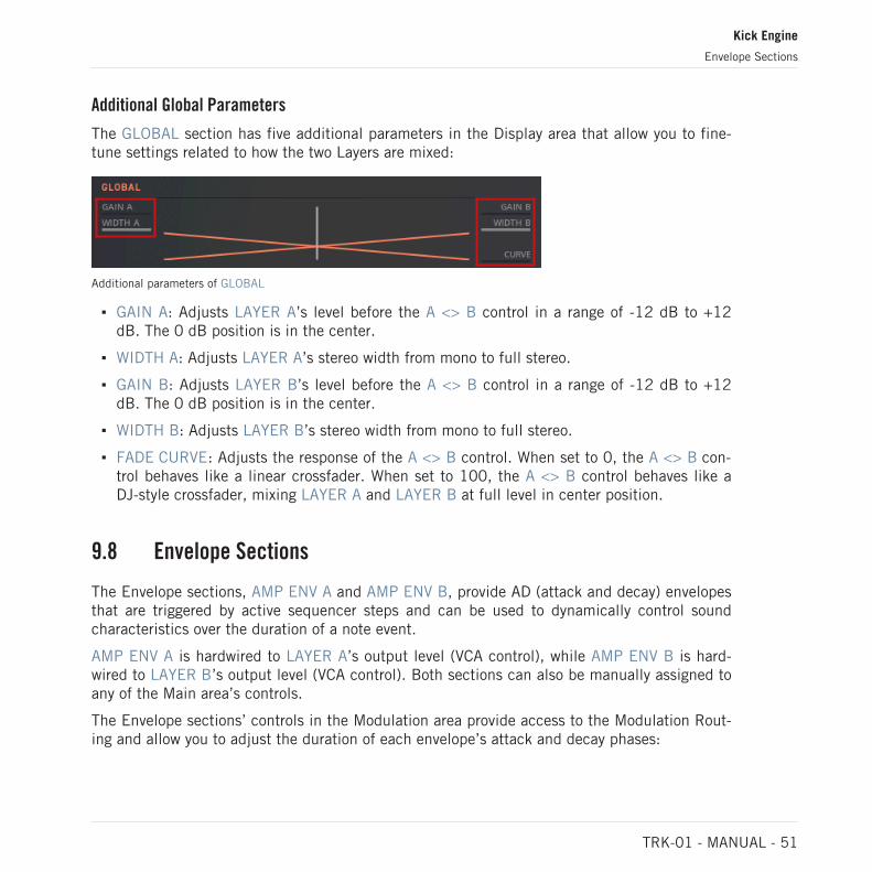
Additional Global Parameters
The GLOBAL section has five additional parameters in the Display area that allow you to fine-tune settings related to how the two Layers are mixed:
Additional parameters of GLOBAL
▪ GAIN A: Adjusts LAYER A’s level before the A <> B control in a range of -12 dB to +12dB. The 0 dB position is in the center.
▪ WIDTH A: Adjusts LAYER A’s stereo width from mono to full stereo.
▪ GAIN B: Adjusts LAYER B’s level before the A <> B control in a range of -12 dB to +12dB. The 0 dB position is in the center.
▪ WIDTH B: Adjusts LAYER B’s stereo width from mono to full stereo.
▪ FADE CURVE: Adjusts the response of the A <> B control. When set to 0, the A <> B con-trol behaves like a linear crossfader. When set to 100, the A <> B control behaves like aDJ-style crossfader, mixing LAYER A and LAYER B at full level in center position.
9.8 Envelope Sections
The Envelope sections, AMP ENV A and AMP ENV B, provide AD (attack and decay) envelopesthat are triggered by active sequencer steps and can be used to dynamically control soundcharacteristics over the duration of a note event.
AMP ENV A is hardwired to LAYER A’s output level (VCA control), while AMP ENV B is hard-wired to LAYER B’s output level (VCA control). Both sections can also be manually assigned toany of the Main area’s controls.
The Envelope sections’ controls in the Modulation area provide access to the Modulation Rout-ing and allow you to adjust the duration of each envelope’s attack and decay phases:
Kick Engine
Envelope Sections
TRK-01 - MANUAL - 51

The KICK Engine's AMP ENV A and AMP ENV B sections
▪ Route button: This button in the section’s header (wire connection symbol) shows the enve-lope’s Modulation Routing in the Display area, allowing you to assign the modulation pro-duced by the envelope to the Main area’s controls. For more information, refer to ↑9.10,Modulation Routing.
▪ ATT: Adjusts the duration of the envelope’s attack phase, which is the time the envelopetakes to rise from zero to peak level.
▪ DEC: Adjusts the duration of the envelope’s decay phase, which is the time the envelopetakes to fall from peak to zero level.
Additional Envelope Parameters
Both AMP ENV A and AMP ENV B have five additional parameters in the Display area that al-low you to fine-tune settings related to the envelope’s behavior:
Additional parameters of AMP ENV A and AMP ENV B
▪ VELOCITY: Adjusts how much velocity values of incoming notes affect the envelopestrength.
▪ SYNC: Enables tempo sync for the envelope, allowing you to set ATT and DEC in note val-ues relative to the host tempo (e.g. 1/1 for whole notes, 1/4 for quarter notes, etc.).
▪ ATT BEND: Adjusts the shape of the envelope’s attack phase from a snappy exponentialresponse to a sustained logarithmic response.
Kick Engine
Envelope Sections
TRK-01 - MANUAL - 52

▪ DEC BEND: Adjusts the shape of the envelope’s decay phase from a snappy exponentialresponse to a sustained logarithmic response.
▪ DEC BODY: Adjusts the shape of the envelope’s decay phase by slowing down the initialrate of its fall. This gives the sound more weight and body.
9.9 LFO+Noise Section
The LFO+NOISE section provides a flexible modulation source that combines a low-frequencyoscillator with a noise generator, allowing you to animate sound characteristics independentlyfrom note events. It produces a periodic or variably random signal depending on the amount ofNOISE added.
LFO+NOISE is not hardwired to a parameter and can be manually assigned to any of the Mainarea’s controls.
The section offers four different LFO+NOISE modes, allowing you to define the section’s tim-ing behavior. You can select the LFO+NOISE mode in the Display area, which also provides ad-ditional parameters related to the selected mode. For more information, refer to ↑9.9.1, LFO+Noise Mode Selector.
The LFO+NOISE section’s controls in the Modulation area provide access to the ModulationRouting and allow you to adjust key parameters of the low-frequency oscillator and the noisegenerator:
The KICK Engine's LFO+NOISE section
▪ Route button: This button in the section’s header (wire connection symbol) shows the LFO+NOISE’s Modulation Routing in the Display area, allowing you to assign the modulationproduced by the LFO+NOISE to the Main area’s controls. For more information, refer to↑9.10, Modulation Routing.
Kick Engine
LFO+Noise Section
TRK-01 - MANUAL - 53

▪ FREQ: Adjusts the frequency of the low-frequency oscillator, allowing you to set the speedof the modulation.
▪ WAVE: Morphs between the four waveforms of the low-frequency oscillator: sine, triangle,saw, and square.
▪ NOISE: Blends between the low-frequency oscillator and the noise generator.
▪ RATE: Adjusts the sampling rate and the smoothing of the noise generator, allow you to di-al in random signals ranging from smooth fluctuations to a variety of noise colors.
9.9.1 LFO+Noise Mode Selector
The LFO+NOISE Mode selector is one of the additional parameters in the Display area, allow-ing you to change the section’s timing behavior by choosing from a number of different modes:
The LFO+NOISE Mode selector
Each of the four available LFO+NOISE modes offers a different timing behavior:
▪ SLOW: A free-running low-frequency oscillator with a frequency range of 0.03 Hz to 20 Hz.For more information, refer to ↑9.9.2, Slow, Fast, and Tempo Mode.
▪ FAST: A free-running audio frequency oscillator with a frequency range of 20 Hz to 500Hz. For more information, refer ↑9.9.2, Slow, Fast, and Tempo Mode.
▪ TEMPO: A free-running low-frequency oscillator that is set in relation to the host tempo.For more information, refer to ↑9.9.2, Slow, Fast, and Tempo Mode.
▪ BEAT: A beat-locked low-frequency oscillator that is perfectly synchronized to the hostclock. For more information, refer to ↑9.9.3, Beat Mode.
Kick Engine
LFO+Noise Section
TRK-01 - MANUAL - 54

9.9.2 Slow, Fast, and Tempo Mode
The LFO+NOISES’s SLOW, FAST, and TEMPO modes are free-running low-frequency oscilla-tors with different frequency ranges:
▪ SLOW has a frequency range of 0.03 Hz to 20 Hz. This mode is useful for slow and evolv-ing modulation that is independent of the host tempo.
▪ FAST has a frequency range of 20 Hz to 500 Hz. This mode is useful for modulation in theaudible range, creating interesting sound effects.
▪ TEMPO is set in relation to the host tempo. This mode is useful for slow and evolving mod-ulation that follows the tempo of the song.
The SLOW, FAST, and TEMPO modes have two additional parameters in the Display area:
Additional parameters of the LFO+NOISE’s SLOW, FAST, and TEMPO modes
▪ RESET: Enables reset for the low-frequency oscillator. When enabled, each new note eventforces the low-frequency oscillator to start at its reset position as set with the PHASE pa-rameter. When disabled, the low-frequency oscillator continues its cycle independentlyfrom note events. RESET can be used to achieve consistent modulation for every noteevent.
▪ PHASE: When RESET is enabled, this parameter adjusts the reset position of the low-fre-quency oscillator, which is the point in its cycle where it starts for every new note event.When RESET is set to 0, the reset position is the beginning of the low-frequency oscilla-tor’s cycle. This parameter is not available when RESET is disabled.
9.9.3 Beat Mode
The LFO+NOISE’s BEAT mode is a beat-locked low-frequency oscillator that is perfectlysynchronized to the host clock. This mode is useful for rhythmic modulation that exactlymatches the beat of the song.
Kick Engine
LFO+Noise Section
TRK-01 - MANUAL - 55

BEAT mode has one additional parameter in the Display area:
Additional parameter of the LFO+NOISE's BEAT mode
▪ PHASE: Shifts the position of the beat-locked LFO+NOISE in BEAT mode relative to theclock of the host.
9.10 Modulation Routing
The Modulation Routing allows you to assign the modulation produced by each section in theModulation area to the controls of the Main area. This way you can dynamically control thetimbre of your sounds.
► To access the Modulation Routing for a section, click on the Route button in the section’sheader.
→ The Display area shows the respective section’s Modulation Routing.
The Modulation Routing in the Display area consists of one Modulation Amount control foreach of the Main area’s controls:
Kick Engine
Modulation Routing
TRK-01 - MANUAL - 56

1
2
The BASS's Modulation Routing
(1) Modulation Amount controls: Adjust the amount of modulation routed to the above control.Turning it to the right applies positive, regular modulation. Turning it to the left applies nega-tive, inverted modulation.
(2) RESET ALL: Sets all Modulation Amount controls to zero position.
Kick Engine
Modulation Routing
TRK-01 - MANUAL - 57

10 Bass Engine
The BASS Engine complements the percussive nature of the KICK Engine with a wide range ofbass sounds suitable to contribute another layer of expression to the low registers of your track.
It combines a variety of synthesizer techniques in a basic structure: The open-ended OSCILLA-TOR section for complex sound generation feeds a MODIFIER section for additional processingand a FILTER section for controlling and shaping the frequency content of the sound.
The BASS Engine’s controls are optimized to provide smooth transitions between timbres, withfocused parameter ranges that produce the maximum of sweet spots. The different modes ofthe OSCILLATOR, MODIFIER, and FILTER sections allow you to completely change the char-acter of the BASS Engine on the fly.
The BASS Engine consists of three interface areas:
1
2
3
Overview of the BASS Engine
(1) Main area: Offers tuning settings, the Sound Selector for sound variations, and key controlsthat allow you to shape your sound. The controls are organized into three sections: OSCILLA-TOR, MODIFIER, FILTER. For more information, refer to ↑10.1, Main Area.
Bass Engine
TRK-01 - MANUAL - 58

(2) Display area: Provides visual feedback and facilitates in-depth editing of additional parame-ters for each section of the BASS Engine, and gives you access to the Modulation Routing. Formore information, refer to ↑10.2, Display Area.
(3) Modulation area: Offers immediate control over key parameters that let you shape how yoursound changes over time. The controls are organized into three sections: AUX ENV, LFO, AMPENV. For more information, refer to ↑10.3, Modulation Area.
10.1 Main Area
In addition to tuning controls and the Sound Selector for sound variations, the Main area pro-vides control over the sound generation (OSCILLATOR) and additional processing (MODIFIER)of the BASS Engine, as well as its filter (FILTER). This not only allows you to quickly adaptPresets files to your needs, but also perform with sounds in an intuitive way by changing keycontrols on the fly.
Additional parameters for each section in the Main and Modulation areas can be accessed in theDisplay area by clicking on the respective section’s header. For more information, refer to ↑10.2,Display Area.
The Main area consists of the following sections:
3 4 5
1 2
The BASS Engine 's Main area
Bass Engine
Main Area
TRK-01 - MANUAL - 59

(1) Tuning controls: Allow you to transpose any note played by the BASS Engine and set thebehavior of its GLIDE function (portamento). For more information, refer to ↑10.6, Tuning Con-trols.
(2) Sound Selector and Browser: The eight slots of the Sound Selector allow you to save and re-call sound variations for the KICK or load any of the sound presets included in the dedicatedSound Browser. For more information, refer to ↑10.4, Sound Selector and ↑10.5, SoundBrowser.
(3) OSCILLATOR: This open-ended section for complex sound generation has three controls inthe Main area that allow you to define the basic character of the sound. The first two controlsadjust parameters specific to the selected OSCILLATOR mode, while the third control alwaysadjusts the level of the sub oscillator. For more information, refer to ↑10.7, Oscillator Section.
(4) MODIFIER: This section for additional processing has two controls in the Main area thatallow you to further refine the character of the sound. The first control adjusts a parameterspecific to the selected MODIFIER mode, while the second control adjusts the blend betweenthe input signal and the processed signal. For more information, refer to ↑10.8, Modifier Sec-tion.
(5) FILTER: This section is used to control and shape the frequency content of a sound andhas three controls in the Main area that allow you to shape the overall character of the sound.In addition to common cutoff and resonance controls, the third control adjusts the amount offeedback that is added to the OSCILLATOR signal from the output of the BASS Engine. Formore information, refer to ↑10.9, Filter Section.
10.2 Display Area
The Display area provides visual feedback for the selected section in the Main and Modulationareas of the BASS Engine and offers additional parameters that allow you to build your ownsounds from scratch and fine-tune Preset files.
Bass Engine
Display Area
TRK-01 - MANUAL - 60

1
232The BASS Engine 's Display area
(1) Mode selector: Allows you to change the character of the selected section by choosing froma number of different modes. For example, this includes different synthesizer techniques forthe OSCILLATOR, or a variety of synchronization options for the LFO.
(2) Additional parameters: Allow you to fine-tune settings related to the selected section. For ex-ample, this includes detailed settings for the OSCILLATOR’s OSCILLATOR modes and sub os-cillator, or additional options for the envelopes, AUX ENV and AMP ENV.
(3) Display: Provides visual feedback while you adjust the controls of the selected section. Forexample, this includes the waveform of the OSCILLATOR and LFO, or the shape of the enve-lopes, AUX ENV and AMP ENV.
The Display area is also used for Modulation Routing, allowing you assign the modulation producedby AUX ENV, LFO, and AMP ENV to the Main area’s controls. For more information, refer to↑10.12, Modulation Routing.
Accessing Additional Parameters
► To access additional parameters for any section in the Main area or the Modulation area,select the section by clicking on its header.
Bass Engine
Display Area
TRK-01 - MANUAL - 61

→ The Display area shows additional parameters for the selected section.
▪ For more information about the OSCILLATOR’s additional parameters, refer to ↑10.7, Os-cillator Section.
▪ For more information about the MODIFIER’s additional parameters, refer to ↑10.8, Modifi-er Section.
▪ For more information about FILTER‘s additional parameters, refer to ↑10.9, Filter Section.
▪ For more information about AUX ENV’s and AMP ENV’s additional parameters, refer to↑10.10, Envelope Sections.
▪ For more information about the LFO’s additional parameters, refer to ↑10.11, LFO Section.
10.3 Modulation Area
The Modulation area provides control over the contours of the Auxiliary and Amplitude enve-lopes, called AUX ENV the AMP ENV, as well as the frequency and the waveform of the low-frequency oscillator, called LFO. This not only allows you to quickly adapt Presets files to yourneeds, but also perform with sounds in an intuitive way by changing key controls on the fly.
Additional parameters for each section in the Main and Modulation areas can be accessed in theDisplay area by clicking on the respective section’s header. For more information, refer to ↑10.2,Display Area.
The Modulation area consists of the following sections:
Bass Engine
Modulation Area
TRK-01 - MANUAL - 62

1 2 3The BASS Engine’s Modulation area
(1) AUX ENV: An envelope generator that can be used to modulate any of the controls in theBASS Engine’s Main area. For more information, refer to ↑10.10, Envelope Sections.
(2) LFO: A low-frequency oscillator that can be used to modulate any of the controls in theKICK Engine’s Main area. For more information, refer to ↑10.11, LFO Section.
(4) AMP ENV: An envelope generator that controls the BASS Engine’s output level and can al-so be used to modulate any of the controls in the BASS Engine’s Main area. For more informa-tion, refer to ↑10.10, Envelope Sections.
10.4 Sound Selector
The Sound Selector allows you to save and recall sound variations. It is located at the top ofthe BASS:
The Sound Selector
Bass Engine
Sound Selector
TRK-01 - MANUAL - 63

It consists of eight slots for saving and recalling sound variations for the BASS on the fly. Toget you started, the Factory Preset files come with pre-made sound variations in the first fourslots, allowing you to quickly find new combinations of sounds and patterns within the samePreset file.
All changes made to the BASS are immediately saved in the selected slot and can be recalledas long as the current Preset file is loaded. The contents of the slots can be saved permanentlyas part of a User Preset file.
Slots can also be recalled from the KOMPLETE KONTROL Keyboard. For more information, refer to↑6.1, Switching Sound Variations and Patterns via MIDI.
Creating Sound Variations with the Sound Selector
To create sound variations for the BASS:
1. Select any slot of the Sound Selector
2. Set the controls and parameters of the BASS to the first sound variation you want to save.
3. Select another slot of the Sound Selector.
4. Set the controls and parameters to the second sound variation you want to save.
→ You can now toggle between the slots and recall the two sound variations on the fly.
Alternatively, you can first copy an existing sound variation to another slot and make yourchanges based on the original settings. For more information, refer to ↑8.1, Copying, Pasting,and Clearing Elements.
To permanently save your sound variations, you need to save them as part of a User Preset file. Formore information, refer to ↑4.3, Saving and Loading User Preset Files in KOMPLETE KONTROL and↑5.3, Saving and Loading User Preset Files in REAKTOR 6.
10.5 Sound Browser
The Sound Browser allows you to load sound presets into the slots of the Sound Selector. It islocated at the top of the BASS:
Bass Engine
Sound Browser
TRK-01 - MANUAL - 64

The Sound Browser
The Sound Browser includes 64 sound presets that are organized in four categories: ANALOG,DIGITAL, DISTORTED, and SUB. The sound presets have been carefully selected to cover awide range of different styles. This allows you to quickly mix and match sound presets within aPreset file.
Since the Step Locks in a sequence also affect the controls of the BASS, loading sound pre-sets from the Sound Browser often leads to unexpected and interesting results. For more infor-mation about Step Locks, refer to ↑13.5, Using Step Locks.
The DELAY and REVERB effect sends are excluded from the sound presets in the Sound Browser.They retain their value when loading sound presets to preserve the mix of an existing Preset file.
Loading Sound Presets from the Sound Browser
To load a sound preset from the Sound Browser:
1. Click on the Sound Browser button to open it.
2. Click on a category of sound presets to select it.
Bass Engine
Sound Browser
TRK-01 - MANUAL - 65

3. Click on a sound preset to load it into the selected slot of the Sound Selector.
4. Close the Sound Browser by clicking on the Exit button.
→ The sound preset from the Sound Browser is loaded into the selected slot of the SoundSelector.
To permanently save your combination of sound presets, you need to save them as part of a UserPreset file. For more information, refer to ↑4.3, Saving and Loading User Preset Files in KOM-PLETE KONTROL and ↑5.3, Saving and Loading User Preset Files in REAKTOR 6.
10.6 Tuning Controls
The Tuning controls allow you to transpose any note played by the BASS Engine and set thebehavior of its Glide function. Glide, or portamento, forces the pitch to slide from one se-quencer step to the next instead of changing abruptly.
The following controls are available:
The BASS Engine's Tuning controls
Bass Engine
Tuning Controls
TRK-01 - MANUAL - 66

▪ TUNE: Transposes the BASS Engine globally in a range of -36 to +36 semitones (in stepsof 12 semitones, or 1 octave).
▪ GLIDE Duration: Adjusts the time it takes the pitch to slide from one sequencer step to thenext. When set to its lowest value, OFF, the Glide function is disabled.
▪ GLIDE Mode: Switches between the two modes of the Glide function, ALWAYS and AUTO,and changes the trigger behavior of the envelopes. Find more information below.
Glide Mode
The two modes of the Glide function, ALWAYS and AUTO, allow you to define how Glide, orportamento, is applied to the steps of the BASS Sequencer. Additionally, each mode causesthe envelopes (AUX ENV and AMP ENV) to respond differently to the BASS Sequencer’s HOLDfunction.
▪ Glide function: When set to ALWAYS, the Glide function is applied to every sequencer step.This means that the pitch When set to AUTO, the Glide function is only applied to se-quencer steps that have HOLD enabled.
▪ Envelope behavior: When set to ALWAYS, all active steps trigger the envelopes, even ifHOLD is enabled for them. When set to AUTO, only the first active step of a group of stepswith HOLD enabled triggers the envelopes.
10.7 Oscillator Section
The OSCILLATOR section defines the sound of the BASS Engine by providing a sonic paletteranging from basic waveforms to more complex timbres that can be achieved with advancedtechniques like FM and wavetable synthesis.
The section offers five different OSCILLATOR modes covering classic sawtooth and squarewaveforms, a super sawtooth, special wave shaping techniques, as well as FM and wavetablesynthesis. You can select the OSCILLATOR mode in the Display area, which also provides addi-tional parameters related to the selected mode and the sub oscillator. For more information,refer to ↑10.7.1, Oscillator Mode Selector and ↑10.7.2, Sub Oscillator.
The OSCILLATOR section’s controls in the Main area allow you to define the basic character ofthe sound:
Bass Engine
Oscillator Section
TRK-01 - MANUAL - 67

The BASS Engine 's OSCILLATOR section
▪ Main OSCILLATOR controls: The first two controls in the OSCILLATOR section are specificto the selected OSCILLATOR mode. For more information, refer to ↑10.7.1, OscillatorMode Selector.
▪ SUB: Adjusts the level of the sub oscillator, allowing you to enhance the low-frequencycontent of your sound. The Display area offers additional parameters for the sub oscillator.For more information, refer to ↑10.7.2, Sub Oscillator.
10.7.1 Oscillator Mode Selector
The OSCILLATOR Mode selector is one of the additional parameters in the Display area, allow-ing you to completely change the section’s character by choosing from a number of differentmodes:
The OSCILLATOR Mode selector
Each of the five available OSCILLATOR modes has its own distinct quality:
▪ CLASSIC: A dual oscillator that morphs from a sawtooth to a square waveform, with adjust-able pulse-width. For more information, refer to ↑10.7.3, Classic Mode.
▪ SUPER: A sawtooth waveform oscillator that is mixed with six additional, variably detunedoscillator instances. For more information, refer to ↑10.7.4, Super Mode.
Bass Engine
Oscillator Section
TRK-01 - MANUAL - 68

▪ WEST: A wave shaping oscillator that morphs between three special waveforms and appliesadditional wave folding. For more information, refer to ↑10.7.5, West Mode.
▪ FM: Two-operator frequency modulation with easily controllable frequency intervals and adeep modulation index. For more information, refer to ↑10.7.6, FM Mode.
▪ MODERN: A wavetable oscillator that smoothly morphs between two wavetables and ap-plies special warping to the waveform. For more information, refer to ↑10.7.7, ModernMode.
10.7.2 Sub Oscillator
The sub oscillator is an additional, basic oscillator that allows you to reinforce the fundamentalfrequency of the sound produced by the BASS Engine, or add a sub octave to it. The SUB con-trol in the OSCILLATOR section adjusts the level of the sub oscillator, while the additional pa-rameters in the Display area change its tuning, timbre, and routing:
The sub oscillator parameters of the OSCILLATOR’s CLASSIC mode
▪ SUB TUNE: Adjusts the pitch of the sub oscillator in a range of -24 to +0 semitones (insteps of 12 semitones, or 1 octave).
▪ SUB TONE: Morphs between the three waveforms of the sub oscillator: sine, triangle,square.
▪ SUB ROUTE: Sets the position where the sub oscillator is fed into the BASS Engine’s sig-nal path: after the OSCILLATOR (POST OSC), after the MODIFIER and FILTER (PRE AMP),or after the BASS Effect’s EQUALIZER (POST EQ).
10.7.3 Classic Mode
The OSCILLATOR’s CLASSIC mode is a dual oscillator that morphs from a sawtooth to asquare waveform, with adjustable pulse-width. This mode offers typical subtractive synthesizertimbres and is useful for classic bass sounds with a warm quality.
Bass Engine
Oscillator Section
TRK-01 - MANUAL - 69

CLASSIC mode has two specific controls in the Main area and three additional parameters inthe Display area:
Additional parameters of the OSCILLATOR's CLASSIC mode
▪ WAVE: Morphs the waveform from sawtooth to square.
▪ WIDTH: Adjusts the pulse-width of the waveform, creating a lively chorusing effect whenmodulated.
▪ RESET: Enables oscillator reset. When enabled, the oscillator starts at the beginning of itscycle for every new note event. When disabled, the oscillator continues its cycle independ-ently from note events. RESET can be used to avoid clicks at the beginning of note eventswhen using fast settings for the envelope’s attack phase (ATT).
▪ VCO 2 LEVEL: Adjusts the level of the second oscillator.
▪ VCO 2 TUNE: Adjusts the pitch of the second oscillator in a range of 0 to +24 semitones.
10.7.4 Super Mode
The OSCILLATOR’s SUPER mode is a sawtooth waveform oscillator that is mixed with six addi-tional, variably detuned oscillator instances. This mode offers rich timbres and is useful foranimated bass sounds with a thick quality.
SUPER mode has two specific controls in the Main area and one additional parameter in theDisplay area:
Bass Engine
Oscillator Section
TRK-01 - MANUAL - 70

Additional parameters of the OSCILLATOR's SUPER mode
▪ MIX: Adjusts the level of six additional oscillator instances that are mixed with the basicoscillator.
▪ DETUNE: Introduces variations in pitch between the basic oscillator and the six additionaloscillators, creating a thick and animated sound.
▪ RESET: Enables oscillator reset. When enabled, the oscillator starts at the beginning of itscycle for every new note event. When disabled, the oscillator continues its cycle independ-ently from note events. Oscillator reset can be used to avoid clicks at the beginning of noteevents when using fast settings for the envelope’s attack phase (ATT).
10.7.5 West Mode
The OSCILLATOR’s WEST mode is a wave shaping oscillator that morphs between three spe-cial waveforms and applies additional wave folding. This mode offers abrasive timbres and isuseful for low bass sounds with a buzzy quality.
WEST mode has two specific controls in the Main area and one additional parameter in theDisplay area:
Bass Engine
Oscillator Section
TRK-01 - MANUAL - 71

Additional parameters of the OSCILLATOR's WEST mode
▪ SHAPE: Morphs between three waveforms: sine, spike, and sawtooth.
▪ FOLD: Introduces additional wave shaping by folding the waveform back into itself, creat-ing strong harmonics that add an abrasive quality to the sound.
▪ RESET: Enables oscillator reset. When enabled, the oscillator starts at the beginning of itscycle for every new note event. When disabled, the oscillator continues its cycle independ-ently from note events. Oscillator reset can be used to avoid clicks at the beginning of noteevents when using fast settings for the envelope’s attack phase (ATT).
10.7.6 FM Mode
The OSCILLATOR’s FM mode provides two-operator frequency modulation with easily controlla-ble frequency intervals and a deep modulation index. This mode offers typical FM synthesizertimbres and is useful for percussive bass sounds with an organic quality.
FM mode has two specific controls in the Main area and one additional parameter in the Dis-play area:
Bass Engine
Oscillator Section
TRK-01 - MANUAL - 72
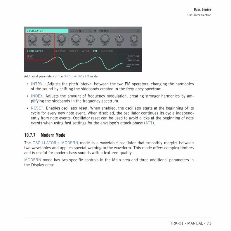
Additional parameters of the OSCILLATOR's FM mode
▪ INTRVL: Adjusts the pitch interval between the two FM operators, changing the harmonicsof the sound by shifting the sidebands created in the frequency spectrum.
▪ INDEX: Adjusts the amount of frequency modulation, creating stronger harmonics by am-plifying the sidebands in the frequency spectrum.
▪ RESET: Enables oscillator reset. When enabled, the oscillator starts at the beginning of itscycle for every new note event. When disabled, the oscillator continues its cycle independ-ently from note events. Oscillator reset can be used to avoid clicks at the beginning of noteevents when using fast settings for the envelope’s attack phase (ATT).
10.7.7 Modern Mode
The OSCILLATOR’s MODERN mode is a wavetable oscillator that smoothly morphs betweentwo wavetables and applies special warping to the waveform. This mode offers complex timbresand is useful for modern bass sounds with a textured quality
MODERN mode has two specific controls in the Main area and three additional parameters inthe Display area:
Bass Engine
Oscillator Section
TRK-01 - MANUAL - 73

Additional parameters of the OSCILLATOR's MODERN mode
▪ MORPH: Morphs between the two wavetables selected with WAVE A and WAVE B in theDisplay area (see below).
▪ WARP: Bends the waveform towards the beginning and the end of its cycle, adding a com-plex texture to the sound when modulated.
▪ RESET: Enables oscillator reset. When enabled, the oscillator starts at the beginning of itscycle for every new note event. When disabled, the oscillator continues its cycle independ-ently from note events. Oscillator reset can be used to avoid clicks at the beginning of noteevents when using fast settings for the envelope’s attack phase (ATT).
▪ WAVE A: Selects the first of two wavetables that you can morph between with the MORPHcontrol.
▪ WAVE B: Selects the second of two wavetables that you can morph between with theMORPH control.
10.8 Modifier Section
The MODIFIER section is used to refine the sound produced by the OSCILLATOR section. Itprovides additional processing ranging from subtle shifts in timbre to drastic distortion effectsand radical transformations.
Bass Engine
Modifier Section
TRK-01 - MANUAL - 74

The section offers four different MODIFIER modes, including ring modulation, frequency shift-ing, wave folding, and sample rate reduction. You can select the MODIFIER mode in the Dis-play area, which also provides additional parameters related to the selected mode. For moreinformation, refer to ↑10.8.1, Modifier Mode Selector.
The MODIFIER section’s controls in the Main area allow you to adjust the character andamount of the additional processing:
The BASS Engine's MODIFIER section
▪ MODIFIER Enable button: This button (power button symbol) in the header of the sectionswitches the MODIFIER on or off.
▪ MODIFIER Routing button: This button (arrow symbol) in the header of the section allowsyou to choose whether the MODIFIER is inserted before or after the FILTER. When the ar-row points to the right, the output of the OSCILLATOR first passes the MODIFIER and thenthe FILTER. When the arrow points to the left, the output of the OSCILLATOR first passesthe FILTER and then the MODIFIER.
▪ Main MODIFIER control: The first control in the MODIFIER section is specific to the select-ed MODIFIER mode. For more information, refer to ↑10.8.1, Modifier Mode Selector.
▪ MIX: Blends between the input signal and the processed signal.
10.8.1 Modifier Mode Selector
The MODIFIER Mode selector is one of the additional parameters in the Display area, allowingyou to completely change the section’s character by choosing from a number of differentmodes:
Bass Engine
Modifier Section
TRK-01 - MANUAL - 75

The MODIFIER Mode selector
Each of the four available MODIFIER modes has its own distinct quality:
▪ RING: A ring modulator that tracks the OSCILLATOR’s pitch, with adjustable pitch offsetfor the modulation signal. For more information, refer to ↑10.8.2, Ring Mode.
▪ FREQ: A frequency shifter that tracks the OSCILLATOR’s pitch, with adjustable pitch off-set. For more information, refer to ↑10.8.3, Freq Mode.
▪ SINE: A wave shaper that folds the signal’s waveform back into itself, with adjustableamount of folding. For more information, refer to ↑10.8.4, Sine Mode.
▪ S&H: A sample rate reducer that tracks the OSCILLATOR’s pitch, with adjustable pitch off-set for the sampling rate. For more information, refer to ↑10.8.5, S&H Mode.
10.8.2 Ring Mode
The MODIFIER’s RING mode is a ring modulator that tracks the OSCILLATOR’s pitch, with ad-justable pitch offset for the modulation signal. This mode is useful for adding a metallic quali-ty to the signal.
RING mode has one specific control in the Main area and one additional parameter in the Dis-play area:
Bass Engine
Modifier Section
TRK-01 - MANUAL - 76

Additional parameters of the MODIFIER's RING mode
▪ PITCH: Adjusts the frequency of the ring modulator’s modulation signal, shifting the addi-tional harmonics created by the ring modulator in the frequency spectrum.
▪ TONE: Morphs the ring modulator's modulation signal's waveform from sine to square.
10.8.3 Freq Mode
The MODIFIER’s FREQ mode is a frequency shifter that tracks the OSCILLATOR’s pitch, withadjustable pitch offset. This mode is useful for adding a dissonant quality to the signal.
FREQ mode has one specific control in the Main area:
Additional parameters of the MODIFIER's FREQ mode
▪ PITCH: Adjusts the frequency of the frequency shifter’s modulation signal, shifting the in-put signal’s harmonics in the frequency spectrum.
Bass Engine
Modifier Section
TRK-01 - MANUAL - 77

10.8.4 Sine Mode
The MODIFIER’s SINE mode is a wave shaper that folds the signal’s waveform back into itself,with adjustable amount of folding. This mode is useful for adding an abrasive quality to thesignal.
SINE mode has one specific control in the Main area:
Additional parameters of the MODIFIER's SINE mode
▪ DRIVE: Adjusts the amount of wave folding applied to the signal, creating strong additionalharmonics in the frequency spectrum.
10.8.5 S&H Mode
The MODIFIER’s S&H mode is a sample rate reducer that tracks the OSCILLATOR’s pitch,with adjustable pitch offset for the sampling rate. This mode is useful for adding a degradedquality to the signal.
S&H mode has one specific control in the Main area:
Bass Engine
Modifier Section
TRK-01 - MANUAL - 78
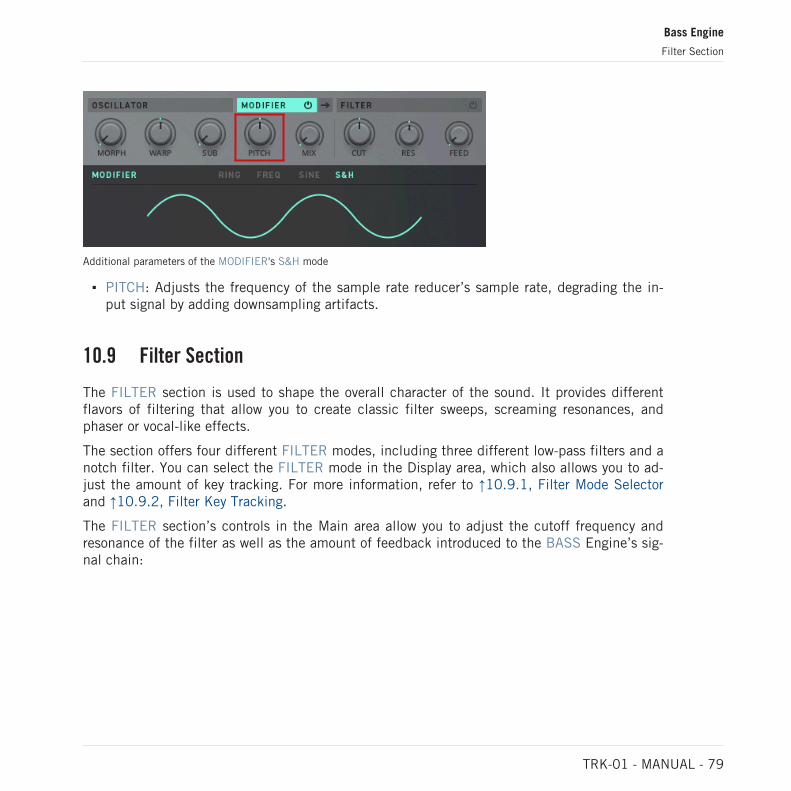
Additional parameters of the MODIFIER's S&H mode
▪ PITCH: Adjusts the frequency of the sample rate reducer’s sample rate, degrading the in-put signal by adding downsampling artifacts.
10.9 Filter Section
The FILTER section is used to shape the overall character of the sound. It provides differentflavors of filtering that allow you to create classic filter sweeps, screaming resonances, andphaser or vocal-like effects.
The section offers four different FILTER modes, including three different low-pass filters and anotch filter. You can select the FILTER mode in the Display area, which also allows you to ad-just the amount of key tracking. For more information, refer to ↑10.9.1, Filter Mode Selectorand ↑10.9.2, Filter Key Tracking.
The FILTER section’s controls in the Main area allow you to adjust the cutoff frequency andresonance of the filter as well as the amount of feedback introduced to the BASS Engine’s sig-nal chain:
Bass Engine
Filter Section
TRK-01 - MANUAL - 79
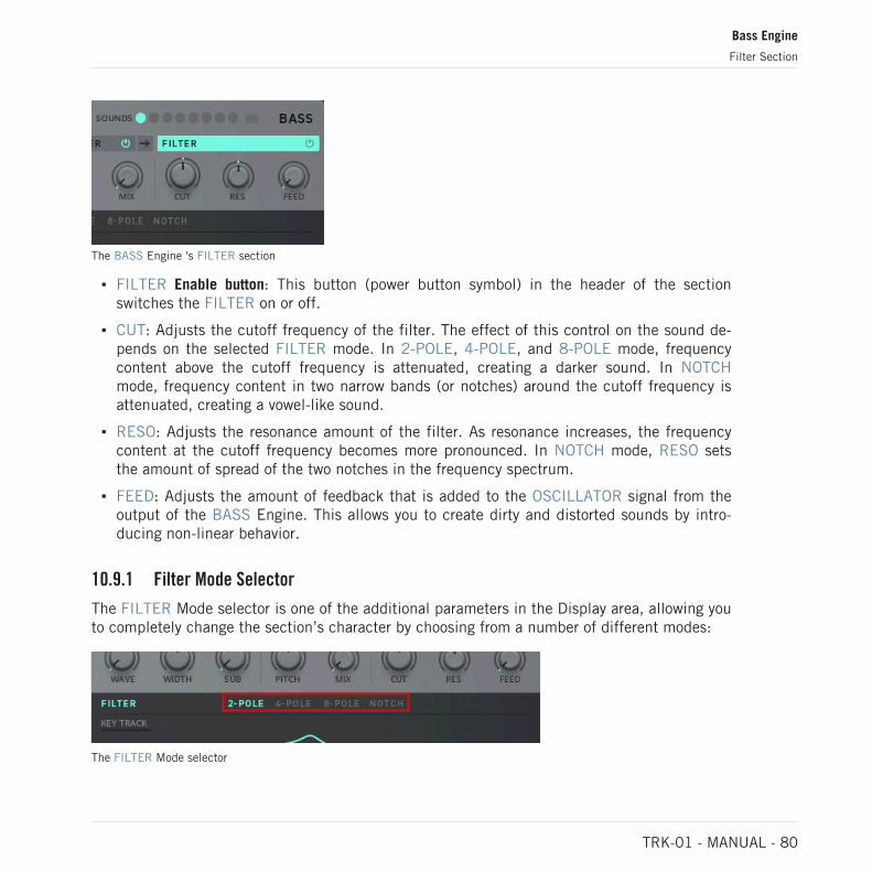
The BASS Engine 's FILTER section
▪ FILTER Enable button: This button (power button symbol) in the header of the sectionswitches the FILTER on or off.
▪ CUT: Adjusts the cutoff frequency of the filter. The effect of this control on the sound de-pends on the selected FILTER mode. In 2-POLE, 4-POLE, and 8-POLE mode, frequencycontent above the cutoff frequency is attenuated, creating a darker sound. In NOTCHmode, frequency content in two narrow bands (or notches) around the cutoff frequency isattenuated, creating a vowel-like sound.
▪ RESO: Adjusts the resonance amount of the filter. As resonance increases, the frequencycontent at the cutoff frequency becomes more pronounced. In NOTCH mode, RESO setsthe amount of spread of the two notches in the frequency spectrum.
▪ FEED: Adjusts the amount of feedback that is added to the OSCILLATOR signal from theoutput of the BASS Engine. This allows you to create dirty and distorted sounds by intro-ducing non-linear behavior.
10.9.1 Filter Mode Selector
The FILTER Mode selector is one of the additional parameters in the Display area, allowing youto completely change the section’s character by choosing from a number of different modes:
The FILTER Mode selector
Bass Engine
Filter Section
TRK-01 - MANUAL - 80

Each of the four available FILTER modes has its own distinct quality:
▪ 2-POLE: A 2-pole low-pass filter that attenuates frequency content above the cutoff fre-quency with a 12 dB/oct response. This mode is useful for a smooth filtering effect.
▪ 4-POLE: A 4-pole low-pass filter that attenuates frequency content above the cutoff fre-quency with a 24 dB/oct response. This mode is useful for a strong filtering effect.
▪ 8-POLE: An 8-pole low-pass filter that attenuates frequency content above the cutoff fre-quency with a 48 dB/oct response. This mode is useful for extreme filtering effects.
▪ NOTCH: A dual notch filter that attenuates frequencies in two narrow frequency bands (ornotches) around the cutoff frequency. This mode is useful for phaser or vocal-like filteringeffects.
10.9.2 Filter Key Tracking
The key tracking function makes the cutoff frequency follow the pitch of the oscillator, allow-ing you to achieve a consistent filtering behavior independently from the notes played by theBASS Engine. It is available as an additional parameter in the Display area:
The key tracking parameter of the FILTER
▪ KEY TRACK: Adjusts the degree to which the FILTER’s cutoff frequency (CUT) follows thepitch of the OSCILLATOR.
10.10 Envelope Sections
The Envelope sections, AUX ENV and AMP ENV, provide ADSR (attack, decay, sustain, and re-lease) envelopes that are triggered by active sequencer steps and can be used to dynamicallycontrol sound characteristics over the duration of a note event.
Bass Engine
Filter Section
TRK-01 - MANUAL - 81

The AUX ENV is not hardwired to any parameter, while the AMP ENV is hardwired the outputlevel (VCA control). Both sections can also be manually assigned to any of the Main area’s con-trols.
The Envelope sections’ controls in the Modulation area provide access to the Modulation Rout-ing and allow you to adjust the duration of each envelope’s attack and decay phases as well asthe level of the sustain phase:
The BASS Engine's AUX ENV and AMP ENV sections
▪ Route button: This button in the section’s header (wire connection symbol) shows the enve-lope’s Modulation Routing in the Display area, allowing you to assign the modulation pro-duced by the envelope to the Main area’s controls. For more information, refer to ↑10.12,Modulation Routing.
▪ ATT: Adjusts the duration of the envelope’s attack phase, which is the time the envelopetakes to rise from zero to peak level.
▪ DEC: Adjusts the duration of the envelope’s decay phase, which is the time the envelopetakes to fall from peak to sustain level. When RELEASE is enabled in the Display area, thiscontrol also adjusts the duration of the envelope’fs release phase, which is the time the en-velope takes to fall from sustain level to zero.
▪ SUS: Adjusts the level of the envelope’s sustain phase, at which the envelope stays as longas a note is held.
Additional Envelope Parameters
Both AUX ENV and AMP ENV have three additional parameters in the Display area that allowyou to fine-tune settings related to the envelope’s behavior:
Bass Engine
Envelope Sections
TRK-01 - MANUAL - 82

Additional parameters of AUX ENV and AMP ENV
▪ VELOCITY: Adjusts how much velocity values of incoming notes affect the envelopestrength.
▪ SYNC: Enables tempo sync for the envelope, allowing you to set ATT and DEC in note val-ues relative to the host tempo (e.g. 1/1 for whole notes, 1/4 for quarter notes, etc.).
▪ RELEASE: Enables the envelope’s release phase, which is the time the envelope takes tofall from the level of the sustain phase to zero. When enabled, the duration of the releasephase is tied to the duration of the decay phase and can be adjusted with the DEC control.
10.11 LFO Section
The LFO section provides a low-frequency oscillator that allows you to animate sound charac-teristics independently from note events. It produces a periodic signal that can be morphedbetween a number of different waveforms.
The LFO is not hardwired to a parameter and can be manually assigned to any of the Mainarea’s controls.
The section offers four different LFO modes, allowing you to define the section’s timing behav-ior. You can select the LFO mode in the Display area, which also provides additional parame-ters related to the selected mode. For more information, refer to ↑10.11.1, LFO Mode Selec-tor.
The LFO section’s controls in the Modulation area provide access to the Modulation Routingand allow you to adjust key parameters of the low-frequency oscillator:
Bass Engine
LFO Section
TRK-01 - MANUAL - 83

The BASS Engine 's LFO section
▪ Route button: This button in the section’s header (wire connection symbol) shows the LFO’sModulation Routing in the Display area, allowing you to assign the modulation produced bythe LFO to the Main area’s controls. For more information, refer to ↑9.10, ModulationRouting.
▪ FREQ: Adjusts the frequency of the low-frequency oscillator, allowing you to set the speedof the modulation.
▪ WAVE: Morphs between the four waveforms of the low-frequency oscillator: sine, triangle,saw, and square.
10.11.1 LFO Mode Selector
The LFO Mode selector is one of the additional parameters in the Display area, allowing you tochange the section’s timing behavior by choosing from a number of different modes:
The LFO Mode selector
Each of the four available LFO modes offers a different timing behavior:
▪ SLOW: A free-running low-frequency oscillator with a frequency range of 0.03 Hz to 20 Hz.For more information, refer to ↑10.11.2, Slow, Fast, and Tempo Mode.
Bass Engine
LFO Section
TRK-01 - MANUAL - 84
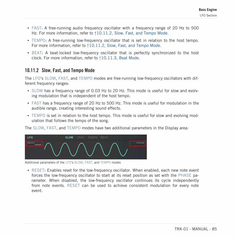
▪ FAST: A free-running audio frequency oscillator with a frequency range of 20 Hz to 500Hz. For more information, refer to ↑10.11.2, Slow, Fast, and Tempo Mode.
▪ TEMPO: A free-running low-frequency oscillator that is set in relation to the host tempo.For more information, refer to ↑10.11.2, Slow, Fast, and Tempo Mode.
▪ BEAT: A beat-locked low-frequency oscillator that is perfectly synchronized to the hostclock. For more information, refer to ↑10.11.3, Beat Mode.
10.11.2 Slow, Fast, and Tempo Mode
The LFO’s SLOW, FAST, and TEMPO modes are free-running low-frequency oscillators with dif-ferent frequency ranges:
▪ SLOW has a frequency range of 0.03 Hz to 20 Hz. This mode is useful for slow and evolv-ing modulation that is independent of the host tempo.
▪ FAST has a frequency range of 20 Hz to 500 Hz. This mode is useful for modulation in theaudible range, creating interesting sound effects.
▪ TEMPO is set in relation to the host tempo. This mode is useful for slow and evolving mod-ulation that follows the tempo of the song.
The SLOW, FAST, and TEMPO modes have two additional parameters in the Display area:
Additional parameters of the LFO’s SLOW, FAST, and TEMPO modes
▪ RESET: Enables reset for the low-frequency oscillator. When enabled, each new note eventforces the low-frequency oscillator to start at its reset position as set with the PHASE pa-rameter. When disabled, the low-frequency oscillator continues its cycle independentlyfrom note events. RESET can be used to achieve consistent modulation for every noteevent.
Bass Engine
LFO Section
TRK-01 - MANUAL - 85

▪ PHASE: When RESET is enabled, this parameter adjusts the reset position of the low-fre-quency oscillator, which is the point in its cycle where it starts for every new note event.When RESET is set to 0, the reset position is the beginning of the low-frequency oscilla-tor’s cycle. This parameter is not available when RESET is disabled.
10.11.3 Beat Mode
The LFO’s BEAT mode is a beat-locked low-frequency oscillator that is perfectly synchronizedto the host clock. This mode is useful for rhythmic modulation that exactly matches the beat ofthe song.
BEAT mode has one additional parameter in the Display area:
Additional parameter of the LFO's BEAT mode
▪ PHASE: Shifts the position of the beat-locked LFO in BEAT mode relative to the clock ofthe host.
10.12 Modulation Routing
The Modulation Routing allows you to assign the modulation produced by each section in theModulation area to the controls of the Main area. This way you can dynamically control thetimbre of your sounds.
► To access the Modulation Routing for a section, click on the Route button in the section’sheader.
→ The Display area shows the respective section’s Modulation Routing.
Bass Engine
LFO Section
TRK-01 - MANUAL - 86

The Modulation Routing in the Display area consists of one Modulation Amount control foreach of the Main area’s controls:
1
2
The BASS's Modulation Routing
(1) Modulation Amount controls: Adjust the amount of modulation routed to the above control.Turning it to the right applies positive, regular modulation. Turning it to the left applies nega-tive, inverted modulation.
(2) RESET ALL: Sets all Modulation Amount controls to zero position.
Bass Engine
Modulation Routing
TRK-01 - MANUAL - 87

11 Kick Effects
The KICK Effects add to the KICK Engine with a selection of effects and processors suitable toenhance and polish the basic sound of your kick drum.
It combines a flexible INSERT section for distortion and filtering effects with an EQUALIZERand an OUTPUT section that includes effect sends to the MASTER Effect’s DELAY and RE-VERB as well as a built-in compressor for final shaping of your kick drums’ dynamics.
The KICK Effects consist of two interface sections:
1
2
Overview of the KICK Effects
(1) Main area: Offers the Sound Selector for sound variations and key controls that allow you toshape your sound. The controls are organized into three sections: INSERT, EQUALIZER, OUT-PUT. For more information, refer to ↑11.1, Main Area.
(2) Display area: Provides visual feedback and facilitates in-depth editing of additional parame-ters for each section of the KICK Effects. For more information, refer to ↑11.2, Display Area.
Kick Effects
TRK-01 - MANUAL - 88

11.1 Main Area
In addition to the Sound Selector for sound variations, the Main area provides control over theflexible distortion and filtering effect (INSERT), the equalizer for balancing frequency content(EQUALIZER), as well as the output volume and effect sends (OUTPUT).
Additional parameters for each section in the Main and Modulation areas can be accessed in theDisplay area by clicking on the respective section’s header. For more information, refer to ↑10.2,Display Area
The Main area consists of the following sections:
1
2 3 4The KICK Effects’ Main area
(1) Sound Selector and Browser: The eight slots of the Sound Selector allow you to save and re-call sound variations for the KICK or load any of the sound presets included in the dedicatedSound Browser. For more information, refer to ↑9.4, Sound Selector and ↑9.5, Sound Browser.
(2) INSERT: This section for distortion and filtering effects has two controls in the Main areathat allow you to enhance the sound. The first control adjusts a parameter specific to the se-lected INSERT mode, while the second control adjusts the blend between the input signal andthe processed signal (except in LOWPASS and HIGHPASS mode). For more information, referto ↑11.3, Insert Section.
Kick Effects
Main Area
TRK-01 - MANUAL - 89

(3) EQUALIZER: This section is used to fine-tune frequency content and has three controls inthe Main area that allow you to adjust the tonal balance of the sound. The three controls at-tenuate or amplify the low, mid, and high frequencies. For more information, refer to ↑11.4,Equalizer Section.
(4) OUTPUT: This section for mixing has three controls in the Main area that allow you to final-ize the sound. The first control adjusts the output level, while the second and third control ad-just the level of the effect sends. For more information, refer to ↑11.5, Output Section.
11.2 Display Area
The Display area provides visual feedback for the selected section in the Main area of the KICKEffects and offers additional parameters that allow you to refine your sounds in high detail.
1
232The KICK Effect 's Display area
(1) Mode selector: Allows you to change the character of the INSERT by choosing from a num-ber of different modes. This section is also used for selecting different filter types for theEQUALIZER, as well as switching the OUTPUT’s built-in compressor on or off.
(2) Additional parameters: Allow you to fine-tune settings related to the selected section. For ex-ample, this includes detailed settings for the three bands of the EQUALIZER, or the built-incompressor available in the OUTPUT section.
(3) Display: Provides visual feedback while you adjust the controls of the selected section. Forexample, this includes the frequency response of the EQUALIZER, or detailed metering for theOUTPUT section.
Kick Effects
Display Area
TRK-01 - MANUAL - 90

Accessing Additional Parameters
1. To access additional parameters for any section in the Main area, select the section byclicking on its header.
2. The Display area shows additional parameters for the selected section.
▪ For more information about the INSERT‘s additional parameters, refer to ↑11.3, InsertSection.
▪ For more information about the EQUALIZER’s additional parameters, refer to ↑11.4, Equal-izer Section.
▪ For more information about the OUTPUT’s additional parameters, refer to ↑11.5, OutputSection.
11.3 Insert Section
The INSERT section is used to enhance the sound produced by the KICK Engine. It providesdistortion and filtering effects that can subtly shape a sound’s timbre, add new textures to it,or completely change its character.
Kick Effects
Insert Section
TRK-01 - MANUAL - 91

The section offers five different INSERT modes, including distortion, sample rate and bit re-duction, as well as filtering. You can select the INSERT mode in the Display area, which alsoprovides additional parameters related to the selected mode. For more information, refer to↑11.3.1, Insert Mode Selector.
The INSERT section’s controls in the Main area allow you to adjust the character and amountof the effect:
The BASS Effects’ INSERT section
▪ INSERT Enable button: This button (power button symbol) in the header of the sectionswitches the INSERT on or off.
▪ Main INSERT control: The first control in the INSERT section is specific to the selectedINSERT mode. For more information, refer to ↑11.3.1, Insert Mode Selector.
▪ MIX: Blends between the input signal and the processed signal. In both LOWPASS andHIGHPASS mode MIX is replaced with the filter’s resonance control (RES). For more infor-mation, refer to ↑11.3.5, Lowpass Mode and ↑11.3.6, Highpass Mode.
11.3.1 Insert Mode Selector
The INSERT Mode selector is one of the additional parameters in the Display area, allowingyou to completely change the section’s character by choosing from a number of differentmodes:
The INSERT Mode selector
Kick Effects
Insert Section
TRK-01 - MANUAL - 92

Each of the five available INSERT modes has its own distinct quality:
▪ DISTORT: A distortion effect that saturates or even clips the signal, with adjustableamount of input gain. For more information, refer to ↑11.3.2, Distort Mode.
▪ S&H: A sample rate reducer that tracks the KICK Engine’s pitch, with adjustable pitch off-set for the sampling rate. For more information, refer to ↑11.3.3, S&H Mode.
▪ BIT REDUX: A bit crusher with adjustable amount of bit reduction. For more information,refer to ↑11.3.4, Bit Redux Mode.
▪ LOWPASS: A low-pass filter that attenuates frequency content above the cutoff frequency,with adjustable cutoff frequency and resonance amount. For more information, refer to↑11.3.5, Lowpass Mode.
▪ HIGHPASS: A high-pass filter that attenuates frequency content below the cutoff frequen-cy, with adjustable cutoff frequency and resonance amount. For more information, refer to↑11.3.6, Highpass Mode.
11.3.2 Distort Mode
The INSERT’s DISTORT mode is a distortion effect that saturates or even clips the signal, withadjustable amount of input gain. This mode is useful for adding an aggressive quality to thesignal.
DISTORT mode has one specific control in the Main area and two additional parameters in theDisplay area:
Additional parameters of the INSERT's DISTORT mode
▪ DRIVE: Adjusts the amount of distortion applied to the signal.
Kick Effects
Insert Section
TRK-01 - MANUAL - 93

▪ TONE: Adjusts the tonal quality of the distortion effect from dark to bright.
▪ OUTPUT: Adjusts the effect’s output level in a range of -12 dB to +12 dB. The 0 dB posi-tion is in the center.
11.3.3 S&H Mode
The INSERT’s S&H mode is a sample rate reducer that tracks the KICK Engine’s pitch, withadjustable pitch offset for the sampling rate. This mode is useful for adding a degraded qualityto the signal.
S&H mode has one specific control in the Main area and three additional parameters in theDisplay area:
Additional parameters of the INSERT's S&H mode
▪ PITCH: Adjusts the frequency of the sample rate reducer’s sample rate, degrading the in-put signal by adding downsampling artifacts.
▪ LP PRE: Adjusts the cutoff frequency of a low-pass filter applied to the input signal. Fre-quency content above the cutoff frequency is attenuated, making the sound darker beforeit is processed by the sample rate reduction.
▪ LP POST: Adjusts the cutoff frequency of a low-pass filter applied to the output signal. Fre-quency content above the cutoff frequency is attenuated, making the sound darker after itis processed by the sample rate reduction.
▪ OUTPUT: Adjusts the effect’s output level in a range of -12 dB to +12 dB. The 0 dB posi-tion is in the center.
Kick Effects
Insert Section
TRK-01 - MANUAL - 94

11.3.4 Bit Redux Mode
The INSERT’s BIT REDUX mode is a bit crusher with adjustable amount of bit reduction. Thismode is useful for adding a degraded quality to the signal.
BIT REDUX mode has one specific control in the Main area and four additional parameters inthe Display area:
Additional parameters of the INSERT's BIT REDUX mode
▪ CRUSH: Adjusts the amount of bit reduction, degrading the input signal by lowering theresolution of the audio data and adding quantization noise.
▪ LP PRE: Adjusts the cutoff frequency of a low-pass filter applied to the input signal. Fre-quency content above the cutoff frequency is attenuated, making the sound darker beforeit is processed by the bit reduction.
▪ SQUASH: Adjusts the amount of compression applied to the input signal, reducing its dy-namic range before it is processed by the bit reduction.
▪ LP POST: Adjusts the cutoff frequency of a low-pass filter applied to the output signal. Fre-quency content above the cutoff frequency is attenuated, making the sound darker after itis processed by the bit reduction.
▪ OUTPUT: Adjusts the effect’s output level in a range of -12 dB to +12 dB. The 0 dB posi-tion is in the center.
Kick Effects
Insert Section
TRK-01 - MANUAL - 95

11.3.5 Lowpass Mode
The INSERT’s LOWPASS mode is a 2-pole low-pass filter that attenuates frequency contentabove the cutoff frequency with a 12 dB/Oct response, with adjustable cutoff frequency andresonance amount. This mode is useful for adding a dark quality to the sound.
LOWPASS mode has two specific controls in the Main area and one additional parameter inthe Display area:
Additional parameters of the INSERT's LOWPASS mode
▪ CUT: Adjusts the cutoff frequency of the low-pass filter. Frequency content above the cut-off frequency is attenuated, creating a darker sound.
▪ RES: Adjusts the resonance amount of the low-pass filter. As resonance increases, the fre-quency content at the cutoff frequency becomes more pronounced.
▪ OUTPUT: Adjusts the effect’s output level in a range of -12 dB to +12 dB. The 0 dB posi-tion is in the center.
11.3.6 Highpass Mode
The INSERT’s HIGHPASS mode is a high-pass filter that attenuates frequency content belowthe cutoff frequency, with adjustable cutoff frequency and resonance amount. This mode isuseful for adding a bright quality to the sound.
HIGHPASS mode has two specific controls in the Main area and one additional parameter inthe Display area:
Kick Effects
Insert Section
TRK-01 - MANUAL - 96

Additional parameters of the INSERT's HIGHPASS mode
▪ CUT: Adjusts the cutoff frequency of the high-pass filter. Frequency content below the cut-off frequency is attenuated, creating a brighter sound.
▪ RES: Adjusts the resonance amount of the high-pass filter. As resonance increases, the fre-quency content at the cutoff frequency becomes more pronounced.
▪ OUTPUT: Adjusts the effect’s output level in a range of -12 dB to +12 dB. The 0 dB posi-tion is in the center.
11.4 Equalizer Section
The EQUALIZER section is used to fine-tune the tonal character of the sound. It provides com-mon equalizer controls that allow you to balance out frequency content or make precisechanges to specific frequencies.
The section offers three bands of filtering: The LOW band can be either a low-shelf or bell fil-ter, the MID band is always a bell filter, and the HIGH band can be either a high-shelf or bellfilter. You can select the filter types in the Display area, which also provides additional param-eters like the filter frequency and bandwidth.
The EQUALIZER section’s controls in the Main area allow you to attenuate or amplify the low,mid, and high frequencies:
Kick Effects
Equalizer Section
TRK-01 - MANUAL - 97

The KICK Effects' EQUALIZER section
▪ EQUALIZER Enable button: This button (power button symbol) in the header of the sectionswitches the EQUALIZER on or off.
▪ LOW: Attenuates or amplifies the low-frequency band in a range of -15 dB to +15 dB. The0 dB position is in the center.
▪ MID: Attenuates or amplifies the mid-frequency band in a range of -15 dB to +15 dB. The0 dB position is in the center.
▪ HIGH: Attenuates or amplifies the high-frequency band in a range of -15 dB to +15 dB.The 0 dB position is in the center.
Additional Equalizer Parameters
The EQUALIZER has two selectors and six additional parameters in the Display area that allowyou to fine-tune settings related to the EQUALIZER’s behavior:
1 6
4 532
Additional parameters of the EQUALIZER
(1) LOW Hz / MID Hz / HIGH Hz: Moves the respective frequency band from 10 Hz to 22 kHzin the frequency spectrum.
Kick Effects
Equalizer Section
TRK-01 - MANUAL - 98

(2) Harmonics indicators: These visual aids mark the fundamental frequency of the global ROOTkey (strong vertical line) as well as the first sub-harmonic and the first and second harmonic(fine vertical lines).
(3) ROOT NOTE display: Shows the fundamental frequency of the global ROOT key. By clickingon the display you can toggle between the frequency value and the corresponding note value.
(4) LOW selector: Sets the filter type of the low-frequency band to low-shelf or bell. A low-shelffilter evenly attenuates or amplifies frequency content below the set frequency. A bell filter at-tenuates or amplifies frequency content at and around the set frequency.
(5) HIGH selector: Sets the filter type of the high-frequency band to low-shelf or bell. A high-shelf filter evenly attenuates or amplifies frequency content above the set frequency. A bell fil-ter attenuates or amplifies frequency content at and around the set frequency.
(6) LOW Q / MID Q / HIGH Q: Adjusts the width of the respective frequency band from wide tonarrow.
The ROOT Note display and the Harmonics indicators help you tune the EQUALIZER to the harmon-ic structure of your kick drum and bass sounds. For more information about the global ROOT key,refer to ↑8.2, Tuning Panel.
11.5 Output Section
The OUTPUT section is used to finalize the sound of the KICK. It offers basic mixing controlsas well as a compressor for controlling the dynamics of the output signal. You can adjust allsettings related to the compressor in the Display area.
The OUTPUT section’s controls in the Main area allow you to adjust the output volume and theeffect sends:
Kick Effects
Output Section
TRK-01 - MANUAL - 99

The KICK Effects' OUTPUT section
▪ PRE / POST selector: Selects whether the DELAY and REVERB effect sends are set inde-pendently from the VOLUME control (PRE) or not (POST).
▪ VOLUME: Adjusts the output volume of the KICK.
▪ DELAY: Adjusts the level of the signal sent to the DELAY in the MASTER Effects, effective-ly controlling the amount of the echo effect.
▪ REVERB: Adjusts the level of the signal sent to the REVERB in the MASTER Effects, effec-tively controlling the amount of the reverberation effect.
Additional Output Parameters
The OUTPUT has one button and six additional parameters in the Display area that allow youto control the section’s built-in compressor:
1 3
2
4Additional parameters of the OUTPUT
(1) Compressor Level Parameters:
Kick Effects
Output Section
TRK-01 - MANUAL - 100
▪ INPUT: Adjusts the compressor’s input level in a range of -24 dB to +24 dB. The 0 dBposition is in the center.
▪ THRESH: Adjusts the compressor’s threshold in a range of -36 dB to 0 dB. When the levelof a signal crosses the threshold, the compressor starts to attenuate the signal dynamically.
▪ OUTPUT: Adjusts the compressor’s output level in a range of -24 dB to +24 dB. The 0 dBposition is in the center.
(2) COMP button: Switches the compressor on or off.
(3) Compressor Behavior Parameters:
▪ RATIO: Adjusts the amount of attenuation applied to signals when their level crosses thethreshold (THRESH). Increasing RATIO leads to stronger attenuation.
▪ ATTACK: Adjusts the time it takes the compressor to apply the full amount of attenuationto the signal after its level has crossed the threshold (THRESH).
▪ RELEASE: Adjusts the time it takes the compressor to stop attenuating the signal after itslevel has fallen below the threshold (THRESH).
(4) Metering: Shows the peak level of the compressor’s input signal at the top, the amount ofattenuation applied by the compressor in the middle, and the peak level of the compressor’soutput signal at the bottom.
Kick Effects
Output Section
TRK-01 - MANUAL - 101

12 Bass Effects
The BASS Effects add to the BASS Engine with a selection of effects and processors suitableto enhance and polish your basic bass sound.
It combines a flexible INSERT section for distortion and modulation effects with an EQUALIZ-ER and an OUTPUT section that includes effect sends to the MASTER Effect’s DELAY andREVERB as well as a built-in compressor for final shaping of your bass sound’s dynamics.
The additional DUCK ENV is a special envelope generator that is triggered by active steps ofthe KICK Sequencer, allowing you to create effects similar to rhythmic sidechain-compressionor ducking.
The BASS Effects consist of three interface sections:
1
2
3
Overview of the BASS Effects
(1) Main area: Offers tuning settings, the Sound Selector for sound variations, and key controlsthat allow you to shape your sound. The controls are organized into three sections: INSERT,EQUALIZER, OUTPUT. For more information, refer to ↑12.1, Main Area.
Bass Effects
TRK-01 - MANUAL - 102

(2) Display area: Provides visual feedback and facilitates in-depth editing of additional parame-ters for each section of the BASS Effects. For more information, refer to ↑12.2, Display Area.
(3) Modulation area: Offers immediate control over key parameters of the DUCK ENV section, aspecial envelope generator that is triggered by active steps of the KICK Sequencer. For moreinformation, refer to ↑12.6, Ducking Envelope Section.
12.1 Main Area
In addition to tuning controls and the Sound Selector for sound variations, the Main area pro-vides control over the flexible distortion and modulation effect (INSERT), the equalizer for bal-ancing frequency content (EQUALIZER), as well as the output volume and effect sends (OUT-PUT).
Additional parameters for each group of controls can be accessed in the Display area by clicking onthe respective group’s header. For more information, refer to ↑10.2, Display Area.
The Main area consists of the following sections:
1
3 4 5
2
The BASS Effect 's Main area
(1) Tuning controls: Allow you to transpose any note played by the BASS Engine and set thebehavior of its GLIDE function (portamento). For more information, refer to ↑10.6, Tuning Con-trols.
Bass Effects
Main Area
TRK-01 - MANUAL - 103

(2) Sound Selector and Browser: The eight slots of the Sound Selector allow you to save and re-call sound variations for the KICK or load any of the sound presets included in the dedicatedSound Browser. For more information, refer to ↑10.4, Sound Selector and ↑10.5, SoundBrowser.
(3) INSERT: This section for distortion and modulation effects has two controls in the Mainarea that allow you to enhance the sound. The first control adjusts a parameter specific to theselected INSERT mode, while the second control adjusts the blend between the input signaland the processed signal. For more information, refer to ↑12.3, Insert Section.
(4) EQUALIZER: This section is used to fine-tune frequency content and has three controls inthe Main area that allow you to adjust the tonal balance of the sound. The three controls at-tenuate or amplify the low, mid, and high frequencies. For more information, refer to ↑12.4,Equalizer Section.
(5) OUTPUT: This section for mixing has three controls in the Main area that allow you to final-ize the sound. The first control adjusts the output level, while the second and third control ad-just the level of the effect sends. For more information, refer to ↑12.5, Output Section.
12.2 Display Area
The Display area provides visual feedback for the selected section in the Main area of theBASS Effects and offers additional parameters that allow you to refine your sounds in high de-tail.
1
232The BASS Effect 's Display area
Bass Effects
Display Area
TRK-01 - MANUAL - 104

(1) Mode selector: Allows you to change the character of the INSERT by choosing from a num-ber of different modes. This section is also used for selecting different filter types for theEQUALIZER, as well as switching the OUTPUT’s built-in compressor on or off.
(2) Additional parameters: Allow you to fine-tune settings related to the selected section. For ex-ample, this includes detailed settings for the three bands of the EQUALIZER, or the built-incompressor available in the OUTPUT section.
(3) Display: Provides visual feedback while you adjust the controls of the selected section. Forexample, this includes the frequency response of the EQUALIZER, or detailed metering for theOUTPUT section.
Accessing Additional Parameters
1. To access additional parameters for any section in the Main area, select the section byclicking on its header.
2. The Display area shows additional parameters for the selected section.
▪ For more information about the INSERT‘s additional parameters, refer to ↑12.3, InsertSection.
▪ For more information about the EQUALIZER’s additional parameters, refer to ↑12.4, Equal-izer Section.
Bass Effects
Display Area
TRK-01 - MANUAL - 105

▪ For more information about the OUTPUT’s additional parameters, refer to ↑12.5, OutputSection.
▪ For more information about the DUCK ENV’s additional parameters, refer to ↑12.6, Duck-ing Envelope Section.
12.3 Insert Section
The INSERT section is used to enhance the sound produced by the BASS Engine. It providesdistortion and modulation effects that can subtly shape a sound’s timbre, add new textures toit, or completely change its character.
The section offers four different INSERT modes, including distortion, a chorus-like unison ef-fect, flanging, and phasing. You can select the INSERT mode in the Display area, which alsoprovides additional parameters related to the selected mode. For more information, refer to↑12.3.1, Insert Mode Selector.
The INSERT section’s controls in the Main area allow you to adjust the character and amountof the effect:
The BASS Effects’ INSERT section
▪ INSERT Enable button: This button (power button symbol) in the header of the sectionswitches the INSERT on or off.
▪ Main INSERT control: The first control in the INSERT section is specific to the selectedINSERT mode. For more information, refer to ↑12.3.1, Insert Mode Selector.
▪ MIX: Blends between the input signal and the processed signal.
Bass Effects
Insert Section
TRK-01 - MANUAL - 106

12.3.1 Insert Mode Selector
The INSERT Mode selector is one of the additional parameters in the Display area, allowingyou to completely change the section’s character by choosing from a number of differentmodes:
The INSERT Mode selector
Each of the four available INSERT modes has its own distinct quality:
▪ DISTORT: A distortion effect that saturates or even clips the signal. For more information,refer to ↑12.3.2, Distort Mode.
▪ UNISON: A chorus-like effect that tracks the BASS Engine's pitch. For more information,refer to ↑12.3.3, Unison Mode.
▪ FLANGER: A flanger effect that produces moving, harmonically related peaks and notchesin the frequency spectrum. For more information, refer to ↑12.3.4, Flanger Mode.
▪ PHASER: A phaser effect that produces moving peaks and notches in the frequency spec-trum. For more information, refer to ↑12.3.5, Phaser Mode.
12.3.2 Distort Mode
The INSERT’s DISTORT mode is a distortion effect that saturates or even clips the signal, withadjustable amount of input gain. This mode is useful for adding an aggressive quality to thesignal.
DISTORT mode has one specific control in the Main area and two additional parameters in theDisplay area:
Bass Effects
Insert Section
TRK-01 - MANUAL - 107

Additional parameters of the INSERT's DISTORT mode
▪ DRIVE: Adjusts the amount of distortion applied to the signal.
▪ TONE: Adjusts the tonal quality of the distortion effect from dark to bright.
▪ OUTPUT: Adjusts the effect’s output level in a range of -12 dB to +12 dB. The 0 dB posi-tion is in the center.
12.3.3 Unison Mode
The INSERT’s UNISON mode is a chorus-like effect that tracks the BASS Engine's pitch, add-ing six variably detuned voices to the signal. This mode is useful for adding an ensemble-likequality to the signal.
UNISON mode has one specific control in the Main area and two additional parameters in theDisplay area:
Additional parameters of the INSERT's UNISON mode
Bass Effects
Insert Section
TRK-01 - MANUAL - 108

▪ DETUNE: Adjusts the amount of detuning applied to the voices added by UNISON mode.
▪ WIDTH: Spreads the voices added by UNISON mode in the stereo image.
▪ OUTPUT: Adjusts the effect’s output level in a range of -12 dB to +12 dB. The 0 dB posi-tion is in the center.
12.3.4 Flanger Mode
The INSERT’s FLANGER mode is a flanger effect that produces moving, harmonically relatedpeaks and notches in the frequency spectrum, with adjustable rate of movement. This mode isuseful for adding a resonant quality to the signal.
FLANGER mode has one specific control in the Main area and three additional parameters inthe Display area:
Additional parameters of the INSERT's FLANGER mode
▪ RATE: Adjusts the modulation frequency, changing the speed of the flanger effect’s move-ment.
▪ DEPTH: Adjusts the amount of modulation, adding movement to the flanger effect.
▪ FEEDBACK: Adjusts the level of the flanger's feedback signal, creating a more resonantand metallic sound.
▪ OUTPUT: Adjusts the effect’s output level in a range of -12 dB to +12 dB. The 0 dB posi-tion is in the center.
Bass Effects
Insert Section
TRK-01 - MANUAL - 109

12.3.5 Phaser Mode
The INSERT’s PHASER mode is a phaser effect that produces moving peaks and notches inthe frequency spectrum, with adjustable rate of movement. This mode is useful for adding avowel-like quality to the sound.
PHASER mode has one specific control in the Main area and three additional parameters inthe Display area:
Additional parameters of the INSERT's FLANGER mode
▪ RATE: Adjusts the modulation frequency, changing the speed of the phaser effect’s move-ment.
▪ DEPTH: Adjusts the amount of modulation, adding movement to the phaser effect.
▪ FEEDBACK: Adjusts the level of the phaser's feedback signal, making the peaks and notch-es in the frequency spectrum more pronounced.
▪ OUTPUT: Adjusts the effect’s output level in a range of -12 dB to +12 dB. The 0 dB posi-tion is in the center.
12.4 Equalizer Section
The EQUALIZER section is used to fine-tune the tonal character of the sound. It provides com-mon equalizer controls that allow you to balance out frequency content or make precisechanges to specific frequencies.
Bass Effects
Insert Section
TRK-01 - MANUAL - 110

The section offers three bands of filtering: The LOW band can be either a low-shelf or bell fil-ter, the MID band is always a bell filter, and the HIGH band can be either a high-shelf or bellfilter. You can select the filter types in the Display area, which also provides additional param-eters like the filter frequency and bandwidth.
The EQUALIZER section’s controls in the Main area allow you to attenuate or amplify the low,mid, and high frequencies:
The BASS Effects' EQUALIZER section
▪ EQUALIZER Enable button: This button (power button symbol) in the header of the sectionswitches the EQUALIZER on or off.
▪ LOW: Attenuates or amplifies the low-frequency band in a range of -15 dB to +15 dB. The0 dB position is in the center.
▪ MID: Attenuates or amplifies the mid-frequency band in a range of -15 dB to +15 dB. The0 dB position is in the center.
▪ HIGH: Attenuates or amplifies the high-frequency band in a range of -15 dB to +15 dB.The 0 dB position is in the center.
Additional Equalizer Parameters
The EQUALIZER has two selectors and six additional parameters in the Display area that allowyou to fine-tune settings related to the EQUALIZER’s behavior:
Bass Effects
Equalizer Section
TRK-01 - MANUAL - 111

1 6
4 532
Additional parameters of the EQUALIZER
(1) LOW Hz / MID Hz / HIGH Hz: Moves the respective frequency band from 10 Hz to 22 kHzin the frequency spectrum.
(2) Harmonics indicators: These visual aids mark the fundamental frequency of the global ROOTkey (strong vertical line) as well as the first sub-harmonic and the first and second harmonic(fine vertical lines).
(3) ROOT NOTE display: Shows the fundamental frequency of the global ROOT key. By clickingon the display you can toggle between the frequency value and the corresponding note value.
(4) LOW selector: Sets the filter type of the low-frequency band to low-shelf or bell. A low-shelffilter evenly attenuates or amplifies frequency content below the set frequency. A bell filter at-tenuates or amplifies frequency content at and around the set frequency.
(5) HIGH selector: Sets the filter type of the high-frequency band to low-shelf or bell. A high-shelf filter evenly attenuates or amplifies frequency content above the set frequency. A bell fil-ter attenuates or amplifies frequency content at and around the set frequency.
(6) LOW Q / MID Q / HIGH Q: Adjusts the width of the respective frequency band from wide tonarrow.
The ROOT Note display and the Harmonics indicators help you tune the EQUALIZER to the harmon-ic structure of your kick drum and bass sounds. For more information about the global ROOT key,refer to ↑8.2, Tuning Panel.
Bass Effects
Equalizer Section
TRK-01 - MANUAL - 112

12.5 Output Section
The OUTPUT section is used to finalize the sound of the BASS. It offers basic mixing controlsas well as a compressor for controlling the dynamics of the output signal. You can adjust allsettings related to the compressor in the Display area.
The OUTPUT section’s controls in the Main area allow you to adjust the output volume and theeffect sends:
The BASS Effects' OUTPUT section
▪ PRE / POST selector: Selects whether the DELAY and REVERB effect sends are set inde-pendently from the VOLUME control (PRE) or not (POST).
▪ VOLUME: Adjusts the output volume of the BASS.
▪ DELAY: Adjusts the level of the signal sent to the DELAY in the MASTER Effects, effective-ly controlling the amount of the echo effect.
▪ REVERB: Adjusts the level of the signal sent to the REVERB in the MASTER Effects, effec-tively controlling the amount of the reverberation effect.
Additional Output Parameters
The OUTPUT has one button and six additional parameters in the Display area that allow youto control the section’s built-in compressor:
Bass Effects
Output Section
TRK-01 - MANUAL - 113

1 3
2
4Additional parameters of the OUTPUT
(1) Compressor Level Parameters:
▪ INPUT: Adjusts the compressor’s input level in a range of -24 dB to +24 dB. The 0 dBposition is in the center.
▪ THRESH: Adjusts the compressor’s threshold in a range of -36 dB to 0 dB. When the levelof a signal crosses the threshold, the compressor starts to attenuate the signal dynamically.
▪ OUTPUT: Adjusts the compressor’s output level in a range of -24 dB to +24 dB. The 0 dBposition is in the center.
(2) COMP button: Switches the compressor on or off.
(3) Compressor Behavior Parameters:
▪ RATIO: Adjusts the amount of attenuation applied to signals when their level crosses thethreshold (THRESH). Increasing RATIO leads to stronger attenuation.
▪ ATTACK: Adjusts the time it takes the compressor to apply the full amount of attenuationto the signal after its level has crossed the threshold (THRESH).
▪ RELEASE: Adjusts the time it takes the compressor to stop attenuating the signal after itslevel has fallen below the threshold (THRESH).
(4) Metering: Shows the peak level of the compressor’s input signal at the top, the amount ofattenuation applied by the compressor in the middle, and the peak level of the compressor’soutput signal at the bottom.
Bass Effects
Output Section
TRK-01 - MANUAL - 114

12.6 Ducking Envelope Section
The BASS Effects’ DUCK ENV is a special envelope generator that is triggered by note eventssent from the KICK Sequencer. It produces an inverted modulation signal, meaning that it de-creases the value of a modulated control instead of increasing it like a regular envelope.
It can be used to modulate all controls of the BASS Effects’ Main area. This allows you to cre-ate effects similar to rhythmic sidechain-compression or ducking, with the freedom to applysuch modulation not only to the level of your bass sound, but also the INSERT, the EQUALIZ-ER, or the DELAY and REVERB effect sends.
The DUCK ENV consists of the following controls:
The BASS Effects’ DUCK ENV
▪ Route button: This button in the section’s header (wire connection symbol) shows the DUCKENV’s Modulation Routing in the Display area, allowing you to assign the modulation pro-duced by the DUCK ENV to the Main area’s controls. For more information, refer to↑10.12, Modulation Routing.
▪ TIME: Adjusts the overall duration of the envelope, which is the time it takes the envelopeto complete its attack, hold, and release phases.
▪ ATT: Adjusts the duration of the envelope's attack phase as a fraction of the overall dura-tion (TIME). The attack phase is the time the envelope takes to rise from zero to peak level.
▪ HOLD: Adjusts the duration of the envelope's hold phase as a fraction of the overall dura-tion (TIME). The hold phase is the time the envelope rests at peak level.
Additional Envelope Parameters
The DUCK ENV has six additional parameters in the Display area that allow you to fine-tunesettings related to its behavior:
Bass Effects
Ducking Envelope Section
TRK-01 - MANUAL - 115

Additional parameters of DUCK ENV
▪ VELOCITY: Adjusts how much velocity values of incoming note events from the KICK Se-quencer affect the envelope strength.
▪ SYNC: Enables tempo sync for the envelope, allowing you to set TIME in note values rela-tive to the host tempo (e.g. 1/1 for whole notes, 1/4 for quarter notes, etc.).
▪ ATT TYPE: Selects one of two types for the shape of the envelope's attack phase: TYPE 1provides logarithmic and exponential shapes, TYPE 2 provides sinusoidal shapes.
▪ AMOUNT: Adjusts the shape of the envelope’s decay phase. Depending on the selectedATT TYPE, either logarithmic and exponential shapes, or sinusoidal shapes are available.
▪ REL TYPE: Selects one of two types for the shape of the envelope's release phase: TYPE 1provides logarithmic and exponential shapes, TYPE 2 provides sinusoidal shapes.
▪ AMOUNT: Adjusts the shape of the envelope’s release phase. Depending on the selectedREL TYPE, either logarithmic and exponential shapes, or sinusoidal shapes are available.
Bass Effects
Ducking Envelope Section
TRK-01 - MANUAL - 116

13 Sequencer
TRK-01 integrates dedicated sequencers for both the KICK and the BASS to facilitate a fluentand inspiring workflow. It provides you with all the tools you need to create a solid foundationfor your track in one intuitive and cohesive interface.
The KICK and BASS Sequencers enhance classic step sequencing with advanced features likeStep Locks and Parameter Focus, allowing you to quickly realize musical ideas for the KICKand the BASS but also bringing a whole new layer of animation to your sounds.
► To switch from the MASTER Effects to the KICK and BASS Sequencers, click on the cen-tral MASTER button.
1 2 3The KICK and BASS Sequencers
(1) KICK Pattern area: Facilitates switching and organization of patterns, as well as of the pat-tern’s individual pages. For more information, refer to ↑13.1, Kick Pattern Area.
(2) KICK / BASS Sequencer lanes: Give you full control over the musical content of your pat-terns following the classic step sequencing paradigm. For more information, refer to ↑13.2,Kick Sequencer Lanes and ↑13.4, Bass Sequencer Lanes.
(3) BASS Pattern area: Facilitates switching and organization of patterns, as well as of the pat-tern’s individual pages. For more information, refer to ↑13.3, Bass Pattern Area.
Sequencer
TRK-01 - MANUAL - 117
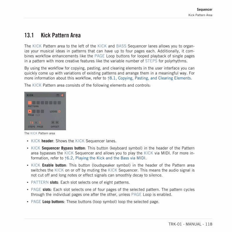
13.1 Kick Pattern Area
The KICK Pattern area to the left of the KICK and BASS Sequencer lanes allows you to organ-ize your musical ideas in patterns that can have up to four pages each. Additionally, it com-bines workflow enhancements like the PAGE Loop buttons for looped playback of single pagesin a pattern with more creative features like the variable number of STEPS for polyrhythms.
By using the workflow for copying, pasting, and clearing elements in the user interface you canquickly come up with variations of existing patterns and arrange them in a meaningful way. Formore information about this workflow, refer to ↑8.1, Copying, Pasting, and Clearing Elements.
The KICK Pattern area consists of the following elements and controls:
The KICK Pattern area
▪ KICK header: Shows the KICK Sequencer lanes.
▪ KICK Sequencer Bypass button: This button (keyboard symbol) in the header of the Patternarea bypasses the KICK Sequencer and allows you to play the KICK via MIDI. For more in-formation, refer to ↑6.2, Playing the Kick and the Bass via MIDI.
▪ KICK Enable button: This button (loudspeaker symbol) in the header of the Pattern areaswitches the KICK on or off by muting the KICK Sequencer. This means the audio signal isnot cut off and long notes or effect signals can smoothly decay to silence.
▪ PATTERN slots: Each slot selects one of eight patterns.
▪ PAGE slots: Each slot selects one of four pages of the selected pattern. The pattern cyclesthrough the individual pages one after the other, unless PAGE Loop is enabled.
▪ PAGE Loop buttons: These buttons (loop symbol) loop the selected page.
Sequencer
Kick Pattern Area
TRK-01 - MANUAL - 118

▪ LOCKS Enable button: Enables or disables Step Locks. When enabled, Step Locks are recal-led during playback. When disabled, Step Locks are not recalled and the set values of therespective controls are used.
▪ STEPS: Sets the number of steps in each page for the selected pattern.
▪ PAGE: Sets the number of pages for the selected pattern.
▪ OFFSET left/right buttons: Shift the contents of the selected page by one step to the left orto the right.
13.2 Kick Sequencer Lanes
The KICK Sequencer lanes follow the classic step sequencing paradigm and offer a fluentworkflow for creating musical patterns that is supported by the clear user interface and its re-fined mouse interactions.
The KICK Sequencer consists of the following elements and controls:
The KICK Sequencer
▪ BASS Sequencer Display lane: Shows the selected page of the BASS Sequencer in relationto the KICK Sequencer. Double-clicking this lane switches to the BASS Sequencer.
▪ VEL lane: Allows you to create note events and set their velocity. Left-click and drag acti-vates steps and sets velocity. Double-click sets velocity to default. Right-click deactivatessteps.
▪ LOCK lane: Enters Step Lock mode for the selected step. Clicking the selected step againexits Step Lock mode. For more information about Step Locks, refer to ↑13.5, Using StepLocks.
Sequencer
Kick Sequencer Lanes
TRK-01 - MANUAL - 119

▪ POS lane: Shows the current playback position of the BASS Sequencer.
13.3 Bass Pattern Area
The BASS Pattern area to the right of the KICK and BASS Sequencer lanes allows you to or-ganize your musical ideas in patterns that can have up to four pages each. Additionally, itcombines workflow enhancements like the PAGE Loop buttons for looped playback of singlepages in a pattern with more creative features like the variable number of STEPS for poly-rhythms.
By using the workflow for copying, pasting, and clearing elements in the user interface you canquickly come up with variations of existing patterns and arrange them in a meaningful way. Formore information about this workflow, refer to ↑8.1, Copying, Pasting, and Clearing Elements.
To permanently save your patterns, you need to save them as part of a User Preset file. For moreinformation, refer to ↑4.3, Saving and Loading User Preset Files in KOMPLETE KONTROL and↑5.3, Saving and Loading User Preset Files in REAKTOR 6.
The BASS Pattern area consists of the following elements and controls:
The BASS Pattern area
▪ BASS header: Shows the BASS Sequencer lanes.
▪ BASS Sequencer Bypass button: This button (keyboard symbol) in the header of the Patternarea bypasses the BASS Sequencer and allows you to play the BASS via MIDI. For moreinformation, refer to ↑6.2, Playing the Kick and the Bass via MIDI.
Sequencer
Bass Pattern Area
TRK-01 - MANUAL - 120

▪ BASS Enable button: This button (loudspeaker symbol) in the header of the Pattern areaswitches the BASS on or off by muting the BASS Sequencer. This means the audio signalis not cut off and long notes or effect signals can smoothly decay to silence.
▪ PATTERN slots: Each slot selects one of eight patterns.
▪ PAGE slots: Each slot selects one of four pages of the selected pattern. The pattern cyclesthrough the individual pages one after the other, unless PAGE Loop is enabled.
▪ PAGE Loop buttons: These buttons (loop symbol) loop the selected page.
▪ LOCKS Enable button: Enables or disables Step Locks. When enabled, Step Locks are recal-led during playback. When disabled, Step Locks are not recalled and the set values of therespective controls are used.
▪ STEPS: Sets the number of steps in each page for the selected pattern
▪ PAGE: Sets the number of pages for the selected pattern.
▪ OFFSET left/right buttons: Shift the contents of the selected page by one step to the left orthe right.
▪ OFFSET up/down buttons: Shift the pitches of all steps in the selected page up or down byone semitone.
13.4 Bass Sequencer Lanes
The BASS Sequencer lanes follow the classic step sequencing paradigm and offer a fluentworkflow for creating musical patterns that is supported by the clear user interface and its re-fined mouse interactions.
The lanes always show the contents of the selected PATTERN and PAGE slots in the BASSPattern area. All changes made to the lanes are immediately saved in the selected slots andcan be recalled as long as the current Preset file is loaded.
To permanently save your patterns, you need to save them as part of a User Preset file. For moreinformation, refer to ↑4.3, Saving and Loading User Preset Files in KOMPLETE KONTROL and↑5.3, Saving and Loading User Preset Files in REAKTOR 6.
The BASS Sequencer consists of the following elements and controls:
Sequencer
Bass Sequencer Lanes
TRK-01 - MANUAL - 121

The BASS Sequencer
▪ KICK Sequencer Display lane: Shows the selected page of the KICK Sequencer in relation tothe BASS Sequencer. Double-clicking this lane switches to the KICK Sequencer.
▪ PITCH lane: Sets the pitch for each step in semitones relative to the global ROOT key. Left-click activates a step, drag up or down sets pitch (hold SHIFT for octave steps). Double-click sets pitch to default. Right-click deactivates a step.
▪ VEL lane: Allows you to create note events and set their velocity. Left-click and drag acti-vates steps and sets velocity. Double-click sets velocity to default. Right-click deactivatessteps.
▪ HOLD lane: Sets the duration of note events by extending the length of the gate producedby a step to 1.5 steps. When HOLD is enabled for successive steps, even longer notes canbe created. Depending on the selected GLIDE Mode in the BASS Engine’s Tuning controlsHOLD affects the Glide and Envelope behavior differently. For more information, refer to↑10.6, Tuning Controls.
▪ LOCK lane: Enters Step Lock mode for the selected step. Clicking the selected step againexits Step Lock mode. For more information about Step Locks, refer to ↑13.5, Using StepLocks.
▪ POS lane: Shows the current playback position of the BASS Sequencer.
13.5 Using Step Locks
Step Locks add a whole new layer of animation to your sounds. They allow you to save valuesfor controls of the KICK and BASS to individual steps of the KICK and BASS Sequencers,which recall the saved values once the playback position has reached the corresponding steps.
Sequencer
Using Step Locks
TRK-01 - MANUAL - 122

All controls in the Main and Modulation areas of the KICK and the BASS are enabled for theStep Locks of the KICK Sequencer and the BASS Sequencer, respectively. This allows you tocreate dramatic effects by completely changing your sounds for each step of a sequence.
To save values for controls to individual steps by creating Step Locks:
1. Click on a step in the LOCK lane to enter Step Lock mode for this step.
2. Change any control in the Main or Modulation area.
3. Exit Step Lock mode by clicking on the Exit button.
→ The changed value is saved to the Step Lock and will be recalled once the playback posi-tion has reached the corresponding step.
Sequencer
Using Step Locks
TRK-01 - MANUAL - 123

13.6 Using Parameter Focus
Parameter Focus is a special mode in TRK-01 that allows you to conveniently edit all valuessaved in Step Locks for a specific control in the Main and Modulation areas of the KICK andthe BASS.
Additionally, this mode can be used to create multiple Step Locks for the control in focus atonce simply by drawing in values across the Step Lock lane.
To enter Parameter Focus mode for a specific control:
► Double click on the control’s label.
→ The control’s label turns white and the Sequencer switches to Parameter Focus mode.
1
2
3
4
Parameter Focus mode
(1) KICK / BASS Sequencer Display lane: Shows the selected page of the KICK Sequencer orthe BASS Sequencer.
(2) Step Lock Lane: Creates Step Locks and sets values for the control in focus. Left-click anddrag creates Step Locks and sets values. Double-click sets value to default. Right-click re-moves Step Locks.
Sequencer
Using Parameter Focus
TRK-01 - MANUAL - 124

(3) POS Lane: Shows the current play back position of the KICK Sequencer.
(4) Exit button: This button (X symbol) in the upper right corner of exits Parameter Focus mode.
Sequencer
Using Parameter Focus
TRK-01 - MANUAL - 125

14 Master
The MASTER Effects provide the means to enhance and finalize the instrument’s output. Thetwo large faders at the sides can be used to set the final mix of the KICK and the BASS, withindividual metering showing the respective peak level.
The DELAY and REVERB allow you to fine-tune the sound of the effect sends available in theOUTPUT sections of the KICK and BASS, and the BASS Enhancer and the BOOSTER maxi-mize the final mix before it is sent out of the instrument.
► To switch from the KICK and BASS Sequencers to the MASTER Effects, click on the cen-tral MASTER button.
1 2
43
5 6 7 8 9 10
1211The MASTER Effects
(1) KICK header: Shows the KICK Sequencer.
(2) KICK Enable button: Switches the KICK on or off by muting the KICK Sequencer. Thismeans the audio signal is not cut off and long notes or effect signals can smoothly decay tosilence.
(3) KICK metering: Shows the peak level of the KICK’s output signal.
(4) KICK Level fader: Adjusts the final output level of the KICK.
(5) DELAY: Provides all settings of the echo send effect. For more information, refer to ↑14.1,Delay.
Master
TRK-01 - MANUAL - 126

(6) REVERB: Provides all settings of the reverberation send effect. For more information, referto ↑14.2, Reverb.
(7) BASS Enhancer: Provides all settings of the bass enhancement master effect. For more in-formation, refer to ↑14.3, Bass Enhancer.
(8) BOOSTER: Provides all settings of the compression master effect. For more information, re-fer to ↑14.4, Booster.
(9) BASS header: Shows the BASS Sequencer.
(10) BASS Enable button: Switches the BASS on or off by muting the BASS Sequencer. Thismeans the audio signal is not cut off and long notes or effect signals can smoothly decay tosilence.
(11) BASS metering: Shows the peak level of the BASS’s output signal.
(12) BASS Level fader: Adjusts the final output level of the BASS.
14.1 Delay
The DELAY is a flexible echo send effect that is fed by the DELAY effect sends in the KICKand BASS Effects’ OUTPUT section.
The following parameters are available to fine-tune its sound:
The DELAY in the MASTER Effects
▪ DELAY Enable button: This button (power button symbol) in the header switches the DELAYon or off.
Master
Delay
TRK-01 - MANUAL - 127

▪ SYNC: Enables tempo sync for the delay time, allowing you to set TIME in note values rela-tive to the host tempo.
▪ FEEDBACK: Adjusts the level of the delay's feedback signal, effectively increasing thenumber of delay repetitions.
▪ TIME: Adjusts the delay time. Depending on the SYNC setting, the delay time either ad-justed in milliseconds or set in note values relative to the host tempo (e.g. 1/1 for wholenotes, 1/4 for quarter notes, etc.).
▪ WIDTH: Spreads the delay repetitions in the stereo image.
▪ DAMPING: Adjusts the tonal quality of the delay effect from dark to bright.
14.2 Reverb
The REVERB is a flexible reverberation send effect that is fed by the REVERB effect sends inthe KICK and BASS Effects’ OUTPUT section.
The following parameters are available to fine-tune its sound:
The REVERB in the MASTER Effects
▪ REVERB Enable button: This button (power button symbol) in the header switches the RE-VERB on or off.
▪ Spaces selector: Selects one of eight types of reverberant spaces: SMALL, LARGE, OUT-SIDE, REVERSE, GATED, NONLIN, GRAINY, REFLEX
▪ PRE-DELAY: Adjusts time it takes for the reverb effect to set in.
▪ DAMPING: Adjusts the tonal quality of the reverb effect from dark to bright.
Master
Reverb
TRK-01 - MANUAL - 128

▪ SIZE: Adjusts the size of the selected reverberant space.
▪ SHAPE: Transforms the selected reverberant space by changing the contour of the reflec-tion pattern and the amount of diffusion. The changes range from subtle shifts in the spa-tial perception to extreme reverse reverberation effects.
14.3 Bass Enhancer
The BASS Enhancer is a specialized bass enhancement master effect that can be used to rein-force and glue together the low-frequency components of the final output signal.
The following parameters are available to fine-tune its sound:
The BASS Enhancer in the MASTER Effects
▪ BASS Enhancer Enable button: This button (power button symbol) in the header switches theBASS Enhancer on or off.
▪ FREQ: Adjusts the cutoff frequency of the BASS Enhancer. Frequency content below thecutoff frequency is amplified.
▪ INPUT: Adjusts the BASS Enhancer's input level in a range of -24 dB to +24 dB. The 0 dBposition is in the center.
▪ DRIVE: Enables the internal saturation stage of the BASS Enhancer, adding harmonics tothe signal.
▪ OUTPUT: Adjusts the BASS Enhancer's output level in a range of -24 dB to +24 dB. The 0dB position is in the center.
Master
Bass Enhancer
TRK-01 - MANUAL - 129

14.4 Booster
The BOOSTER is a specialized compression master effect that can be used to maximize andsaturate the output signal.
You can use the BOOSTER only as a saturation effect, or soft clipper, by setting the RATIO of theBOOSTER's compressor to 1. This way the compressor is effectively bypassed.
The following parameters are available to fine-tune its sound:
The BOOSTER in the MASTER Effects
▪ BOOSTER Enable button: This button (power button symbol) in the header switches theBOOSTER Enhancer on or off.
▪ PRE-Q: Enables a fixed equalizer that applies low-cut filtering at 20 Hz and high-cut filter-ing at 18 kHz to the input signal.
▪ BOOST: Adjusts the BOOSTER's input level in a range of -12 dB to +36 dB. The 0 dB po-sition is in the center. Increasing BOOST also adds saturation to the signal.
▪ RATIO: Adjusts the amount of attenuation applied to signals when their level crosses thefixed threshold of the BOOSTER's compressor. Increasing RATIO leads to stronger attenua-tion.
▪ ATTACK: Adjusts the time it takes the BOOSTER's compressor to apply the full amount ofattenuation to the signal after its level has crossed the fixed threshold.
▪ RELEASE: Adjusts the time it takes the BOOSTER's compressor to stop attenuating thesignal after its level has fallen below the fixed threshold.
Master
Booster
TRK-01 - MANUAL - 130

15 Troubleshooting
If you are experiencing problems related to your product that the supplied documentation doesnot cover, you can get further help in the Support section of the Native Instruments website:
https://support.native-instruments.com/hc
The Support section allows you to search both the Knowledge Base and the Support Communi-ty for content related to your issue. The Knowledge Base and the Support Community gatheruseful information about your Native Instruments product and can be of great help to solvepossible issues you may encounter.
▪ The Knowledge Base is an ever-growing database of help articles by Native Instruments,providing solutions to common issues and answering frequently asked questions.
▪ The Support Community allows users to help users, and makes all the information and dis-cussion publicly available.
► Enter your query into the search field at the top of the Support section’s landing page inorder to find related entries from the Knowledge Base and the Support Community.
Before getting help please make sure you have downloaded the latest software for your product fromNative Access.
Support
If no entry from the Knowledge Base and the Support Community matches your problem, or ifthe matching entry does not solve the problem, you can contact the Native Instruments Sup-port team. You will find Contact Support buttons in the Support section of our website afterlooking for related content in the Knowledge Base and the Support Community.
When communicating with the Native Instruments Support team, keep in mind that the moredetails you can provide about your hardware, your operating system, the version of the softwareyou are running, and the problem you are experiencing, the better they will be able to help you.
In your description, you should mention:
▪ How to reproduce the problem
▪ What you have already tried to fix the problem
Troubleshooting
TRK-01 - MANUAL - 131
▪ A description of your setup, including all hardware and the version of your software
▪ The brand and specifications of your computer
When installing new software or software updates, a Readme file is included that contains latebreaking news and new information that was not yet included in the documentation. Please openand read this Readme file before contacting Technical Support.
User Forum
In the Native Instruments User Forum, you can discuss product features directly with otherusers and with experts moderating the forum. You can reach the User Forum via: http://www.native-instruments.com/forum.
Troubleshooting
TRK-01 - MANUAL - 132

16 Credits
Product Design: David Forrester
Instrument Development: Alexander Potekhin, David Forrester, Dietrich Pank, Clement Deste-phen
User Interface Design: Simon Martin
Quality Assurance: Thilo Rode
Sound Design: Jamil Samad, Tommaso De Donatis, Angelos Liaros, Jan Ola Korte, Antoniode Spirt, Stewart Walker, Thordur Arnarson, Marin Vrbica, Dietrich Pank, John Valasis, 9b0,Wellenrausch, Matt Fudge
Documentation: Jan Ola Korte
Product Owner: Marin Vrbica
Special Thanks: Jonathan Heppner, Thordur Arnarson, Efflam Le Bivic, Mickael Le Goff, Clau-dia Eden, Ricardo Esposito, Setaoc Mass, Tecture, Antonio de Spirt, Nadine Raihani, ElisabethDehlke, Robert Linke, and The Reaktor Team
Credits
TRK-01 - MANUAL - 133