Embed Size (px)
Citation preview
8/7/2019 commisioning cctv
http://slidepdf.com/reader/full/commisioning-cctv 1/42
BSBTC-05
BUILDING SERVICES BRANCH
TESTING AND COMMISSIONING
PROCEDURE NO. 5
FOR
BURGLAR ALARM AND SECURITY
INSTALLATION
IN
GOVERNMENT BUILDINGS
HONG KONG
HONG KONG SPECIAL ADMINISTRATIVE REGION GOVERNMENT
Building Services BranchArchitectural Services Department
(2000 Edition )

8/7/2019 commisioning cctv
http://slidepdf.com/reader/full/commisioning-cctv 2/42
BSBTC-05
COPYRIGHT 1. This Testing and Commissioning Procedure is solely compiled for use on BurglarAlarm and Security Installation in Government Buildings of the Hong Kong SpecialAdministrative Region. 2. This Testing and Commissioning Procedure is copyrighted and all rights (includingsubsequent amendment) are reserved. 3. It is hereby declared that the procedure contained therein may not be pertinent orfully cover the Burglar Alarm and Security Installation carried out by other GovernmentDepartments or private sectors. Prior consent by the Director of Architectural Servicesmust be obtained for adoption of this testing and commissioning procedure for BurglarAlarm and Security Installation of other nature or locations.
8/7/2019 commisioning cctv
http://slidepdf.com/reader/full/commisioning-cctv 3/42

8/7/2019 commisioning cctv
http://slidepdf.com/reader/full/commisioning-cctv 4/42
BSBTC-05 II
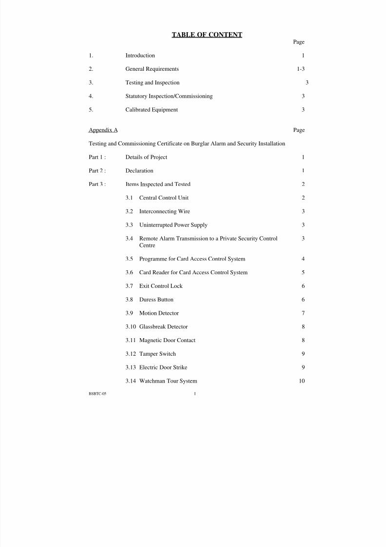
TABLE OF CONTENT
Page 3.15 Comments 11
Part 4 : Test Record attached to the Test Certificate 4.1 Burglar Alarm and Security Installation 12-31 4.2 Testing Equipment 32
Appendix B Page Testing and Commissioning progress chart for Burglar Alarm and SecurityInstallation
1-3
8/7/2019 commisioning cctv
http://slidepdf.com/reader/full/commisioning-cctv 5/42
BSBTC-05 1
B.S.B. Testing and Commissioning Procedure No. 5
Burglar Alarm and Security Installation
1. Introduction 1.1 This procedure is intended to lay down the minimum testing and
commissioning requirements to be carried out by the Contractor on a newBurglar Alarm and Security Installation upon completion or on an existingBurglar Alarm and Security Installation after a major alteration.Additional testing and commissioning (T & C) requirements may beproposed by the Contractor as appropriate and agreed by the ProjectBuilding Services Engineer (PBSE), e.g. for special equipment suppliedand/or installed by the Contractor.
1.2 This procedure is also written to facilitate the PBSE and Project Building
Services Inspector (PBSI) in carrying out the following aspects of work with respect to T & C.
(i) To vet and approve the T & C procedures proposed and submitted bythe Contractor.
(ii) To witness those T & C procedures as specified. (iii) To receive the T & C certificate and other supporting data.
2. General Requirements
2.1 The Contractor shall submit the T&C procedures together with the Testingand Commissioning progress chart in Appendix B to the PBSE forapproval. The submission shall be made at least one month before thecommencement of T&C.
2.2 Where tests are required to be witnessed by the PBSE/PBSI, the Contractor
shall give due advance notice (usually not less than three days) and providedetails of date, time and type of tests to be performed.
2.3 Upon completion of such T & C procedure, the Contractor shall complete
and sign a testing and commissioning certificate as Appendix A, to theeffect that agreed T & C procedures have been duly carried out.
2.4 Before carrying out any test, the Contractor shall ensure that the
installations comply with the statutory requirements and regulations.
8/7/2019 commisioning cctv
http://slidepdf.com/reader/full/commisioning-cctv 6/42
BSBTC-05 2
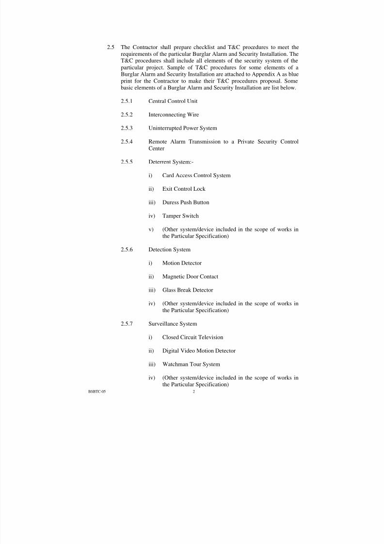
2.5 The Contractor shall prepare checklist and T&C procedures to meet therequirements of the particular Burglar Alarm and Security Installation. TheT&C procedures shall include all elements of the security system of theparticular project. Sample of T&C procedures for some elements of aBurglar Alarm and Security Installation are attached to Appendix A as blueprint for the Contractor to make their T&C procedures proposal. Somebasic elements of a Burglar Alarm and Security Installation are list below.
2.5.1 Central Control Unit
2.5.2 Interconnecting Wire
2.5.3 Uninterrupted Power System
2.5.4 Remote Alarm Transmission to a Private Security Control
Center
2.5.5 Deterrent System:-
i) Card Access Control System
ii) Exit Control Lock
iii) Duress Push Button
iv) Tamper Switch
v) (Other system/device included in the scope of works in
the Particular Specification) 2.5.6 Detection System
i) Motion Detector ii) Magnetic Door Contact iii) Glass Break Detector iv) (Other system/device included in the scope of works in
the Particular Specification)
2.5.7 Surveillance System
i) Closed Circuit Television ii) Digital Video Motion Detector iii) Watchman Tour System iv) (Other system/device included in the scope of works in
the Particular Specification)
8/7/2019 commisioning cctv
http://slidepdf.com/reader/full/commisioning-cctv 7/42
BSBTC-05 3
The above checklists are intended to indicate some basic requirements toensure proper functioning of the equipment. They are by no meansexhaustive. The Contractor shall exercise his expertise in this field topropose any additional tests and/or commissioning procedures that arenecessary for the system to perform its intended functions.
2.6 The commissioning procedures and test records are classified as
“Restricted” and are to be distributed on a “Need to Know” basis.
3. Testing and Inspection 3.1 The Contractor shall carry out the tests and inspections as shown in Part 3
and record the test results on Part 4 of Appendix A and as agreed betweenthe Project BSE and the Contractor.
3.2 The Contractor shall provide all the necessary staff, labour, materials and
equipment for a thorough test and examination of the installation. 4. Statutory Inspection/Commissioning
4.1 After the proper testing and commissioning of the Burglar Alarm and
Security Installation, the Contractor shall notify the appropriate Authority,through the PBSE, on the completion of the installation and its readinessfor inspection and testing.
5. Calibrated Equipment
5.1 The contractor shall supply calibrated equipment as stipulated in theSpecification of the Contract for the inspection, measuring and testing of the installation. The equipment shall be calibrated by laboratoriesaccredited by the Hong Kong Laboratory Accreditation Scheme (HKLAS)or other recognised accredited laboratories.

8/7/2019 commisioning cctv
http://slidepdf.com/reader/full/commisioning-cctv 8/42
Appendix A
Building Services Branch, ArchSD Page 1 of 32 Filecode: SR065.docFORM NO. BS/SR.065 Revision Date: 15 September 2000Issue Date: 3 March 2000
Testing and Commissioning Certificateon Burglar Alarm and Security Installation
Part 1 : Detail of Project
1.1 Project Title (with location) :
1.2 *P.W.P. / Project No. :
1.3 *Contract/Sub-contract/Quotation No. :
1.4 *Contractor/Sub-contractor :
1.5 PBSE :
1.6 PBSI : Part 2 : Declaration
2.1 I certify that the Burglar Alarm and Security Installation as specified inthe Contract/Sub-contract/Quotation at the above location has beeninspected, tested and commissioned in accordance with this procedureand/or any other procedures agreed between the PBSE and the Contractor.The results are satisfactory in the aspects as mentioned in Part 3 and/or asrecorded in Part 4 of this Certificate, except as indicated in theCOMMENTS items.
2.2 I also certify that site tests have been performed in accordance with the
requirements set out in Appendix A of this procedure and that the resultsare satisfactory. A record of the tests has been prepared and submitted tothe PBSE.
Signature of Contractor‘s Representative Full Name of Contractor‘s Representative Designation of Contractor‘s Representative Name and Stamp of Contractor
Date Notes : This certificate must be signed by a person authorized by the Firm/Company.
* Delete if not applicable
8/7/2019 commisioning cctv
http://slidepdf.com/reader/full/commisioning-cctv 9/42
Appendix A
Building Services Branch, ArchSD Page 2 of 32 Filecode: SR065.docFORM NO. BS/SR.065 Revision Date: 15 September 2000Issue Date: 3 March 2000
Items tested/ checked byContractor
Items witnessedby
PBSE/PBSI
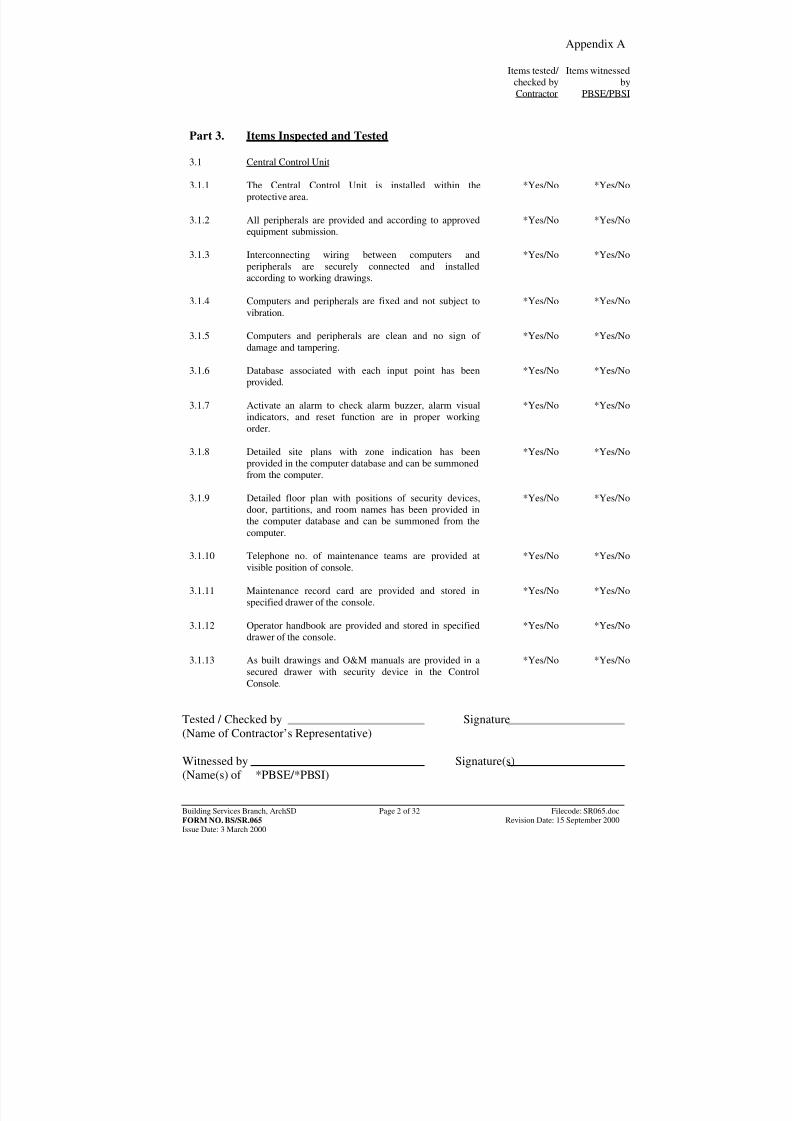
Part 3. Items Inspected and Tested
3.1 Central Control Unit
3.1.1 The Central Control Unit is installed within the
protective area.*Yes/No *Yes/No
3.1.2 All peripherals are provided and according to approved
equipment submission.*Yes/No *Yes/No
3.1.3 Interconnecting wiring between computers and
peripherals are securely connected and installedaccording to working drawings.
*Yes/No *Yes/No
3.1.4 Computers and peripherals are fixed and not subject to
vibration.*Yes/No *Yes/No
3.1.5 Computers and peripherals are clean and no sign of damage and tampering.
*Yes/No *Yes/No
3.1.6 Database associated with each input point has been
provided.*Yes/No *Yes/No
3.1.7 Activate an alarm to check alarm buzzer, alarm visual
indicators, and reset function are in proper workingorder.
*Yes/No *Yes/No
3.1.8 Detailed site plans with zone indication has been
provided in the computer database and can be summonedfrom the computer.
*Yes/No *Yes/No
3.1.9 Detailed floor plan with positions of security devices,door, partitions, and room names has been provided inthe computer database and can be summoned from thecomputer.
*Yes/No *Yes/No
3.1.10 Telephone no. of maintenance teams are provided at
visible position of console.*Yes/No *Yes/No
3.1.11 Maintenance record card are provided and stored in
specified drawer of the console.*Yes/No *Yes/No
3.1.12 Operator handbook are provided and stored in specified
drawer of the console.*Yes/No *Yes/No
3.1.13 As built drawings and O&M manuals are provided in a
secured drawer with security device in the ControlConsole.
*Yes/No *Yes/No
Tested / Checked by Signature(Name of Contractor’s Representative) Witnessed by Signature(s)(Name(s) of *PBSE/*PBSI)
8/7/2019 commisioning cctv
http://slidepdf.com/reader/full/commisioning-cctv 10/42
Appendix A
Building Services Branch, ArchSD Page 3 of 32 Filecode: SR065.docFORM NO. BS/SR.065 Revision Date: 15 September 2000Issue Date: 3 March 2000
Items tested/ checked byContractor
Items witnessedby
PBSE/PBSI
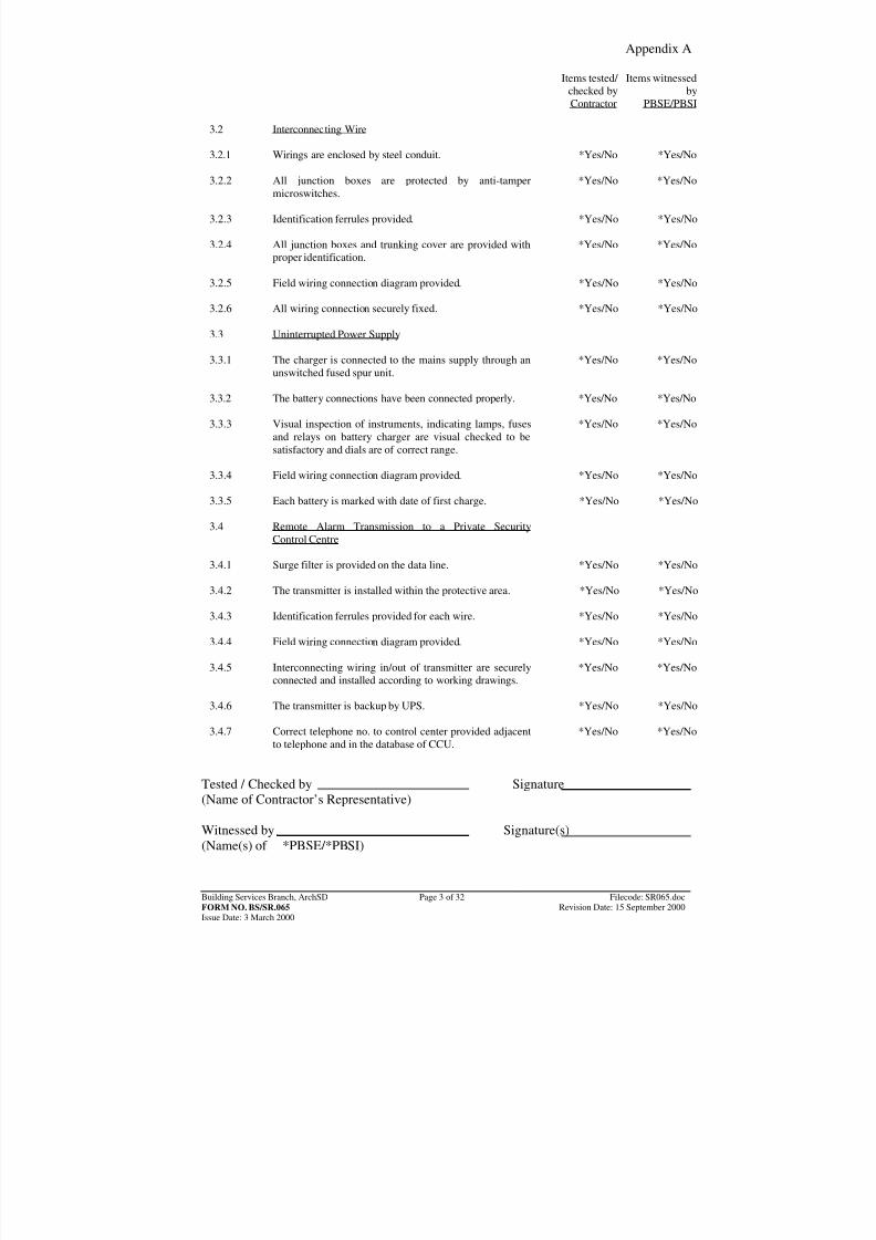
3.2 Interconnecting Wire
3.2.1 Wirings are enclosed by steel conduit. *Yes/No *Yes/No
3.2.2 All junction boxes are protected by anti-tampermicroswitches.
*Yes/No *Yes/No
3.2.3 Identification ferrules provided. *Yes/No *Yes/No
3.2.4 All junction boxes and trunking cover are provided with
proper identification.*Yes/No *Yes/No
3.2.5 Field wiring connection diagram provided. *Yes/No *Yes/No
3.2.6 All wiring connection securely fixed. *Yes/No *Yes/No
3.3 Uninterrupted Power Supply
3.3.1 The charger is connected to the mains supply through anunswitched fused spur unit. *Yes/No *Yes/No
3.3.2 The battery connections have been connected properly. *Yes/No *Yes/No
3.3.3 Visual inspection of instruments, indicating lamps, fuses
and relays on battery charger are visual checked to besatisfactory and dials are of correct range.
*Yes/No *Yes/No
3.3.4 Field wiring connection diagram provided. *Yes/No *Yes/No
3.3.5 Each battery is marked with date of first charge. *Yes/No *Yes/No
3.4 Remote Alarm Transmission to a Private Security
Control Centre
3.4.1 Surge filter is provided on the data line. *Yes/No *Yes/No
3.4.2 The transmitter is installed within the protective area. *Yes/No *Yes/No
3.4.3 Identification ferrules provided for each wire. *Yes/No *Yes/No
3.4.4 Field wiring connection diagram provided. *Yes/No *Yes/No
3.4.5 Interconnecting wiring in/out of transmitter are securely
connected and installed according to working drawings.*Yes/No *Yes/No
3.4.6 The transmitter is backup by UPS. *Yes/No *Yes/No
3.4.7 Correct telephone no. to control center provided adjacent
to telephone and in the database of CCU.*Yes/No *Yes/No
Tested / Checked by Signature(Name of Contractor’s Representative) Witnessed by Signature(s)(Name(s) of *PBSE/*PBSI)
8/7/2019 commisioning cctv
http://slidepdf.com/reader/full/commisioning-cctv 11/42
Appendix A
Building Services Branch, ArchSD Page 4 of 32 Filecode: SR065.docFORM NO. BS/SR.065 Revision Date: 15 September 2000Issue Date: 3 March 2000
Items tested/ checked byContractor
Items witnessedby
PBSE/PBSI
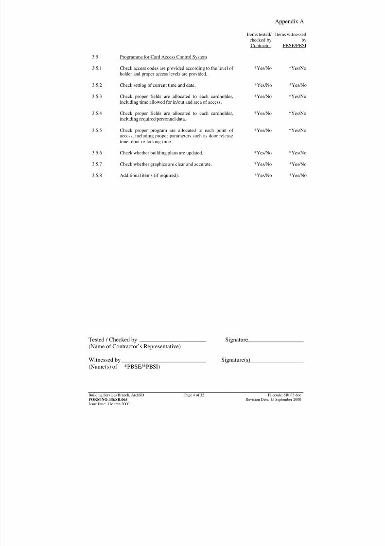
3.5 Programme for Card Access Control System
3.5.1 Check access codes are provided according to the level of holder and proper access levels are provided.
*Yes/No *Yes/No
3.5.2 Check setting of current time and date. *Yes/No *Yes/No
3.5.3 Check proper fields are allocated to each cardholder,
including time allowed for in/out and area of access.*Yes/No *Yes/No
3.5.4 Check proper fields are allocated to each cardholder,
including required personnel data.*Yes/No *Yes/No
3.5.5 Check proper program are allocated to each point of
access, including proper parameters such as door releasetime, door re-locking time.
*Yes/No *Yes/No
3.5.6 Check whether building plans are updated. *Yes/No *Yes/No
3.5.7 Check whether graphics are clear and accurate. *Yes/No *Yes/No
3.5.8 Additional items (if required): *Yes/No *Yes/No
Tested / Checked by Signature(Name of Contractor’s Representative) Witnessed by Signature(s)(Name(s) of *PBSE/*PBSI)
8/7/2019 commisioning cctv
http://slidepdf.com/reader/full/commisioning-cctv 12/42
Appendix A
Building Services Branch, ArchSD Page 5 of 32 Filecode: SR065.docFORM NO. BS/SR.065 Revision Date: 15 September 2000Issue Date: 3 March 2000
Items tested/ checked byContractor
Items witnessedby
PBSE/PBSI
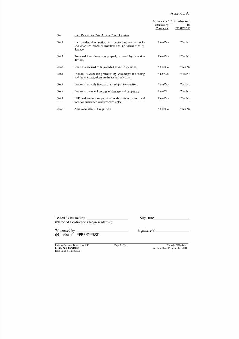
3.6 Card Reader for Card Access Control System
3.6.1 Card reader, door strike, door contactors, manual locksand door are properly installed and no visual sign of
damage.
*Yes/No *Yes/No
3.6.2 Protected items/areas are properly covered by detection
devices.*Yes/No *Yes/No
3.6.3 Device is secured with protected cover, if specified. *Yes/No *Yes/No
3.6.4 Outdoor devices are protected by weatherproof housing
and the sealing gaskets are intact and effective.*Yes/No *Yes/No
3.6.5 Device is securely fixed and not subject to vibration. *Yes/No *Yes/No
3.6.6 Device is clean and no sign of damage and tampering. *Yes/No *Yes/No
3.6.7 LED and audio tone provided with different colour andtone for authorized /unauthorized entry. *Yes/No *Yes/No
3.6.8 Additional items (if required): *Yes/No *Yes/No
Tested / Checked by Signature(Name of Contractor’s Representative) Witnessed by Signature(s)(Name(s) of *PBSE/*PBSI)
8/7/2019 commisioning cctv
http://slidepdf.com/reader/full/commisioning-cctv 13/42
Appendix A
Building Services Branch, ArchSD Page 6 of 32 Filecode: SR065.docFORM NO. BS/SR.065 Revision Date: 15 September 2000Issue Date: 3 March 2000
Items tested/ checked byContractor
Items witnessedby
PBSE/PBSI
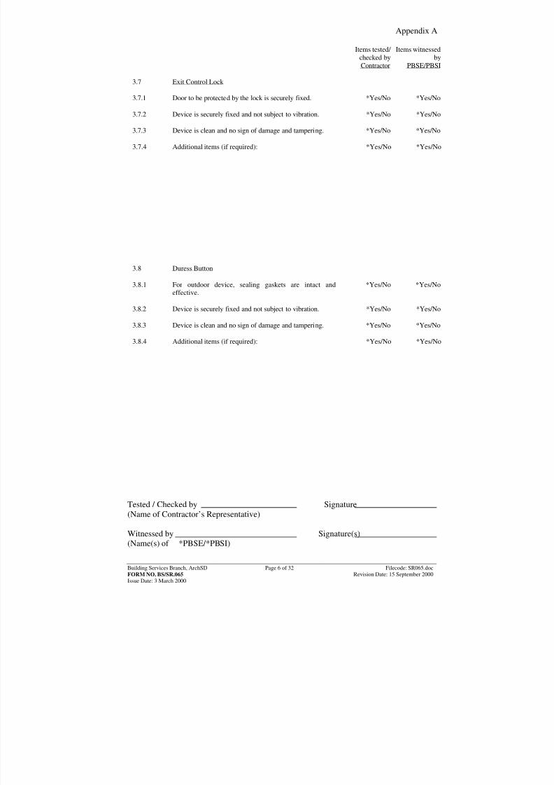
3.7 Exit Control Lock
3.7.1 Door to be protected by the lock is securely fixed. *Yes/No *Yes/No
3.7.2 Device is securely fixed and not subject to vibration. *Yes/No *Yes/No
3.7.3 Device is clean and no sign of damage and tampering. *Yes/No *Yes/No
3.7.4 Additional items (if required): *Yes/No *Yes/No
3.8 Duress Button
3.8.1 For outdoor device, sealing gaskets are intact andeffective.
*Yes/No *Yes/No
3.8.2 Device is securely fixed and not subject to vibration. *Yes/No *Yes/No
3.8.3 Device is clean and no sign of damage and tampering. *Yes/No *Yes/No
3.8.4 Additional items (if required): *Yes/No *Yes/No
Tested / Checked by Signature(Name of Contractor’s Representative) Witnessed by Signature(s)(Name(s) of *PBSE/*PBSI)
8/7/2019 commisioning cctv
http://slidepdf.com/reader/full/commisioning-cctv 14/42
Appendix A
Building Services Branch, ArchSD Page 7 of 32 Filecode: SR065.docFORM NO. BS/SR.065 Revision Date: 15 September 2000Issue Date: 3 March 2000
Items tested/ checked byContractor
Items witnessedby
PBSE/PBSI
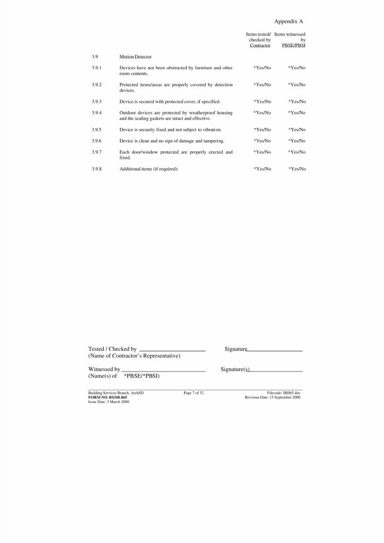
3.9 Motion Detector
3.9.1 Devices have not been obstructed by furniture and otherroom contents.
*Yes/No *Yes/No
3.9.2 Protected items/areas are properly covered by detection
devices.*Yes/No *Yes/No
3.9.3 Device is secured with protected cover, if specified. *Yes/No *Yes/No
3.9.4 Outdoor devices are protected by weatherproof housing
and the sealing gaskets are intact and effective.*Yes/No *Yes/No
3.9.5 Device is securely fixed and not subject to vibration. *Yes/No *Yes/No
3.9.6 Device is clean and no sign of damage and tampering. *Yes/No *Yes/No
3.9.7 Each door/window protected are properly erected and
fixed.
*Yes/No *Yes/No
3.9.8 Additional items (if required): *Yes/No *Yes/No
Tested / Checked by Signature(Name of Contractor’s Representative) Witnessed by Signature(s)(Name(s) of *PBSE/*PBSI)
8/7/2019 commisioning cctv
http://slidepdf.com/reader/full/commisioning-cctv 15/42
Appendix A
Building Services Branch, ArchSD Page 8 of 32 Filecode: SR065.docFORM NO. BS/SR.065 Revision Date: 15 September 2000Issue Date: 3 March 2000
Items tested/ checked byContractor
Items witnessedby
PBSE/PBSI
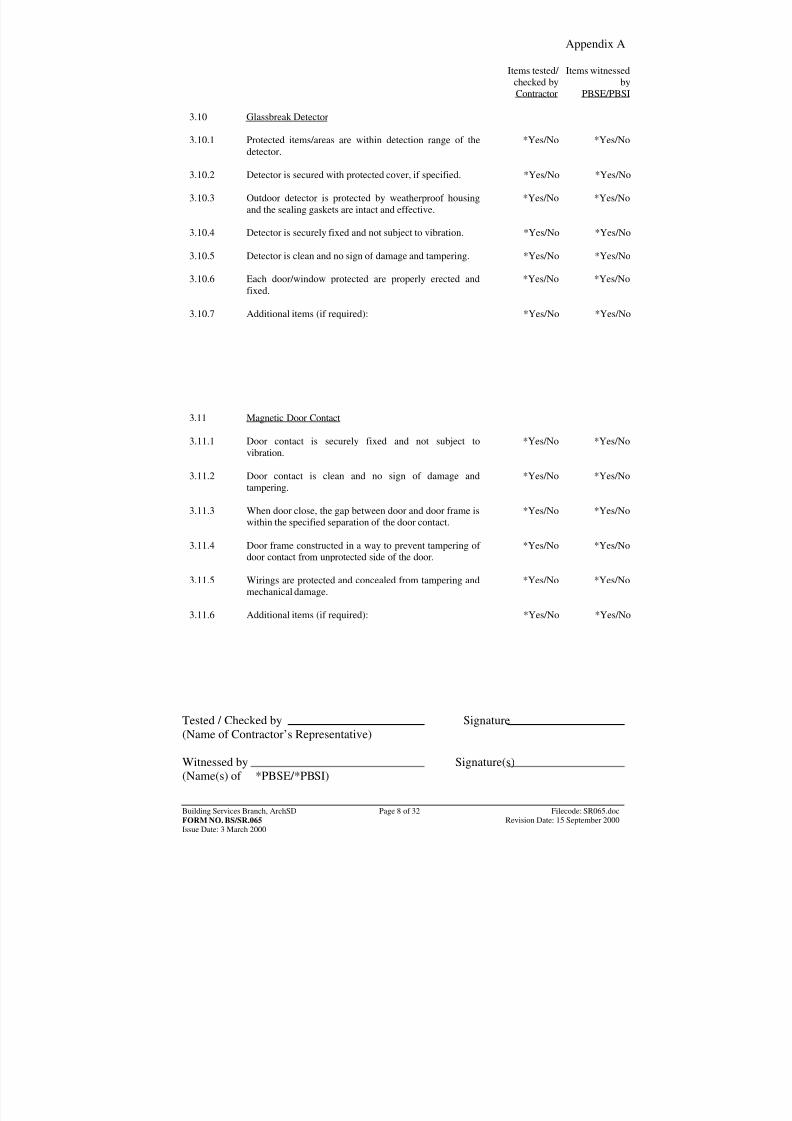
3.10 Glassbreak Detector
3.10.1 Protected items/areas are within detection range of thedetector.
*Yes/No *Yes/No
3.10.2 Detector is secured with protected cover, if specified. *Yes/No *Yes/No
3.10.3 Outdoor detector is protected by weatherproof housing
and the sealing gaskets are intact and effective.*Yes/No *Yes/No
3.10.4 Detector is securely fixed and not subject to vibration. *Yes/No *Yes/No
3.10.5 Detector is clean and no sign of damage and tampering. *Yes/No *Yes/No
3.10.6 Each door/window protected are properly erected and
fixed.*Yes/No *Yes/No
3.10.7 Additional items (if required): *Yes/No *Yes/No
3.11 Magnetic Door Contact
3.11.1 Door contact is securely fixed and not subject tovibration.
*Yes/No *Yes/No
3.11.2 Door contact is clean and no sign of damage and
tampering.
*Yes/No *Yes/No
3.11.3 When door close, the gap between door and door frame is
within the specified separation of the door contact.*Yes/No *Yes/No
3.11.4 Door frame constructed in a way to prevent tampering of
door contact from unprotected side of the door.*Yes/No *Yes/No
3.11.5 Wirings are protected and concealed from tampering and
mechanical damage.*Yes/No *Yes/No
3.11.6 Additional items (if required): *Yes/No *Yes/No
Tested / Checked by Signature(Name of Contractor’s Representative) Witnessed by Signature(s)(Name(s) of *PBSE/*PBSI)
8/7/2019 commisioning cctv
http://slidepdf.com/reader/full/commisioning-cctv 16/42
Appendix A
Building Services Branch, ArchSD Page 9 of 32 Filecode: SR065.docFORM NO. BS/SR.065 Revision Date: 15 September 2000Issue Date: 3 March 2000
Items tested/ checked byContractor
Items witnessedby
PBSE/PBSI
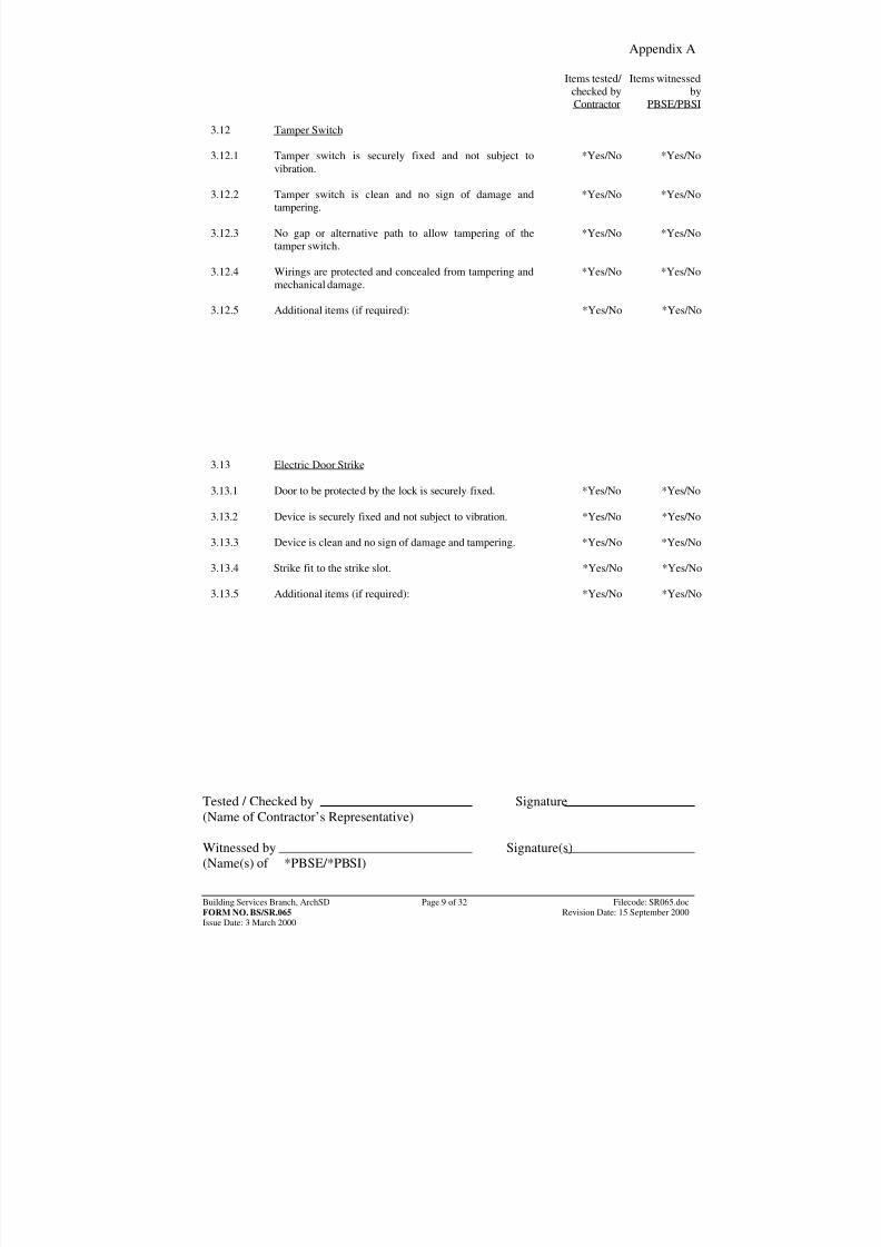
3.12 Tamper Switch
3.12.1 Tamper switch is securely fixed and not subject tovibration.
*Yes/No *Yes/No
3.12.2 Tamper switch is clean and no sign of damage and
tampering.*Yes/No *Yes/No
3.12.3 No gap or alternative path to allow tampering of the
tamper switch.*Yes/No *Yes/No
3.12.4 Wirings are protected and concealed from tampering and
mechanical damage.*Yes/No *Yes/No
3.12.5 Additional items (if required): *Yes/No *Yes/No
3.13 Electric Door Strike
3.13.1 Door to be protected by the lock is securely fixed. *Yes/No *Yes/No
3.13.2 Device is securely fixed and not subject to vibration. *Yes/No *Yes/No
3.13.3 Device is clean and no sign of damage and tampering. *Yes/No *Yes/No 3.13.4 Strike fit to the strike slot. *Yes/No *Yes/No
3.13.5 Additional items (if required): *Yes/No *Yes/No
Tested / Checked by Signature(Name of Contractor’s Representative) Witnessed by Signature(s)(Name(s) of *PBSE/*PBSI)
8/7/2019 commisioning cctv
http://slidepdf.com/reader/full/commisioning-cctv 17/42
8/7/2019 commisioning cctv
http://slidepdf.com/reader/full/commisioning-cctv 18/42
Appendix A
Building Services Branch, ArchSD Page 11 of 32 Filecode: SR065.docFORM NO. BS/SR.065 Revision Date: 15 September 2000Issue Date: 3 March 2000
Items tested/ checked byContractor
Items witnessedby
PBSE/PBSI
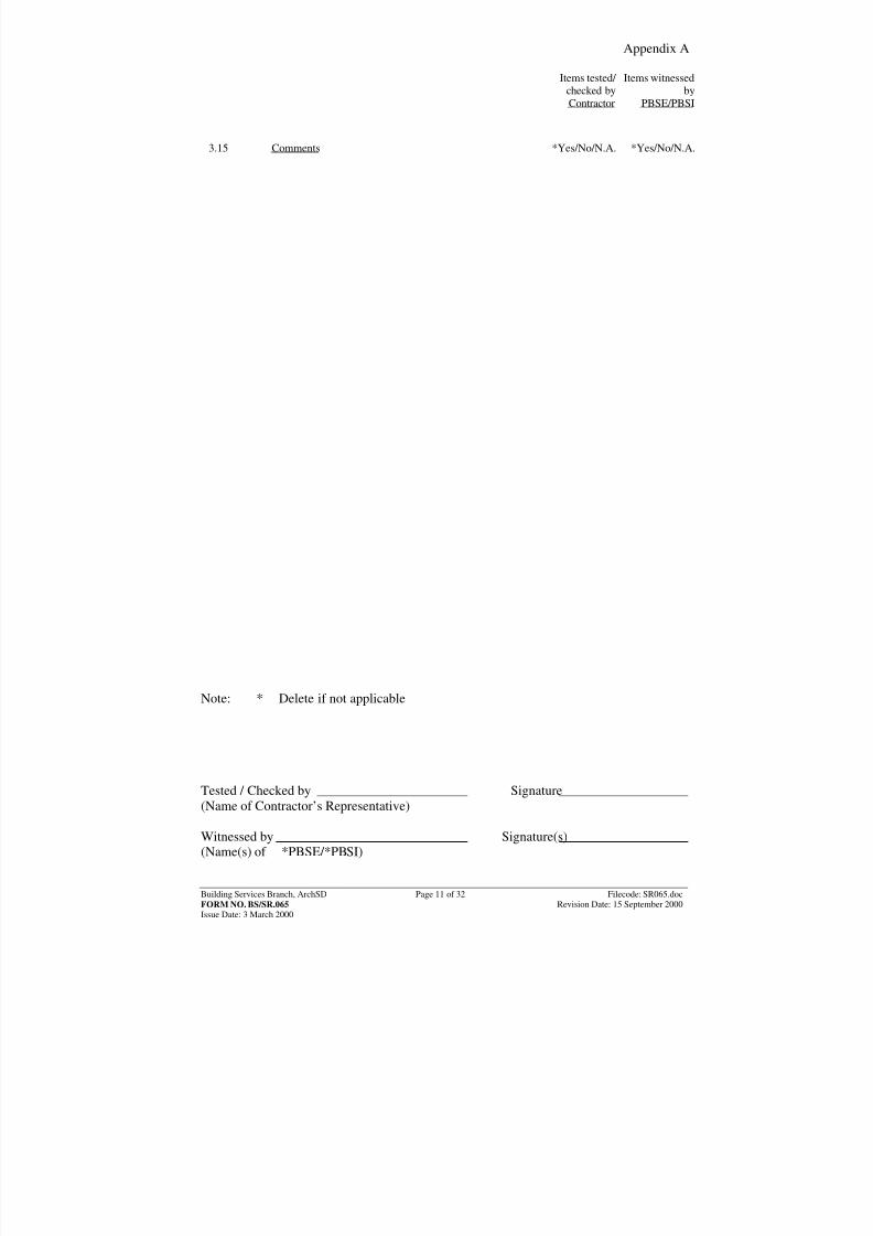
3.15 Comments *Yes/No/N.A. *Yes/No/N.A.
Note: * Delete if not applicable Tested / Checked by Signature(Name of Contractor’s Representative) Witnessed by Signature(s)(Name(s) of *PBSE/*PBSI)
8/7/2019 commisioning cctv
http://slidepdf.com/reader/full/commisioning-cctv 19/42
Appendix A
Building Services Branch, ArchSD Page 12 of 32 Filecode: SR065.docFORM NO. BS/SR.065 Revision Date: 15 September 2000Issue Date: 3 March 2000
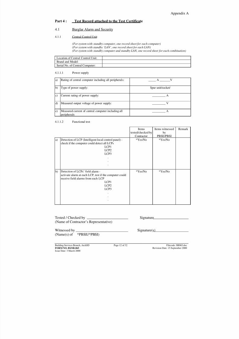
Part 4 : Test Record attached to the Test Certificate 4.1 Burglar Alarm and Security 4.1.1 Central Control Unit
(For system with standby computer, one record sheet for each computer)(For system with standby ‘LAN’, one record sheet for each LAN)(For system with standby computer and standby LAN, one record sheet for each combination)
Location of Central Control Unit:Brand and Model:Serial No. of Central Computer:
4.1.1.1 Power supply a) Rating of central computer including all peripherals: _____ A _______V
b) Type of power supply: Spur unit/socket/
c) Current rating of power supply: _________ A
d) Measured output voltage of power supply: _________ V
e) Measured current of central computer including allperipherals:
_________ A
4.1.1.2 Functional test
Itemstested/checked by
Contractor
Items witnessedby
PBSE/PBSI
Remark
a) Detection of LCP (Intelligent local control panel) -check if the computer could detect all LCPs
LCP1LCP2LCP3
.
.
.
*Yes/No *Yes/No
b) Detection of LCPs’ field alarm -activate alarm at each LCP, test if the computer couldreceive field alarms from each LCP
LCP1LCP2LCP3
.
.
.
*Yes/No *Yes/No
Tested / Checked by Signature(Name of Contractor’s Representative) Witnessed by Signature(s)(Name(s) of *PBSE/*PBSI)
8/7/2019 commisioning cctv
http://slidepdf.com/reader/full/commisioning-cctv 20/42
Appendix A
Building Services Branch, ArchSD Page 13 of 32 Filecode: SR065.docFORM NO. BS/SR.065 Revision Date: 15 September 2000Issue Date: 3 March 2000
Items
tested/checked byContractor
Items witnessedby
PBSE/PBSI
Remark
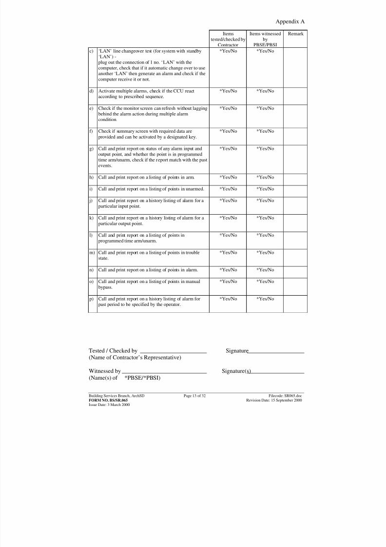
c) ‘LAN’ line changeover test (for system with standby‘LAN’) -plug out the connection of 1 no. ‘LAN’ with thecomputer, check that if it automatic change over to useanother ‘LAN’ then generate an alarm and check if the
computer receive it or not.
*Yes/No *Yes/No
d) Activate multiple alarms, check if the CCU reactaccording to prescribed sequence.
*Yes/No *Yes/No
e) Check if the monitor screen can refresh without laggingbehind the alarm action during multiple alarmcondition.
*Yes/No *Yes/No
f) Check if summary screen with required data areprovided and can be activated by a designated key.
*Yes/No *Yes/No
g) Call and print report on status of any alarm input andoutput point, and whether the point is in programmed
time arm/unarm, check if the report match with the pastevents.
*Yes/No *Yes/No
h) Call and print report on a listing of points in arm.
*Yes/No *Yes/No
i) Call and print report on a listing of points in unarmed.
*Yes/No *Yes/No
j) Call and print report on a history listing of alarm for aparticular input point.
*Yes/No *Yes/No
k) Call and print report on a history listing of alarm for aparticular output point.
*Yes/No *Yes/No
l) Call and print report on a listing of points inprogrammed time arm/unarm.
*Yes/No *Yes/No
m) Call and print report on a listing of points in troublestate.
*Yes/No *Yes/No
n) Call and print report on a listing of points in alarm.
*Yes/No *Yes/No
o) Call and print report on a listing of points in manualbypass.
*Yes/No *Yes/No
p) Call and print report on a history listing of alarm forpast period to be specified by the operator.
*Yes/No *Yes/No
Tested / Checked by Signature(Name of Contractor’s Representative) Witnessed by Signature(s)(Name(s) of *PBSE/*PBSI)
8/7/2019 commisioning cctv
http://slidepdf.com/reader/full/commisioning-cctv 21/42
Appendix A
Building Services Branch, ArchSD Page 14 of 32 Filecode: SR065.docFORM NO. BS/SR.065 Revision Date: 15 September 2000Issue Date: 3 March 2000
Itemstested/checked by
Contractor
Items witnessedby
PBSE/PBSI
Remark
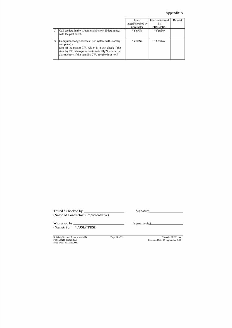
q) Call up data in the streamer and check if data matchwith the past event.
*Yes/No *Yes/No
r) Computer change over test (for system with standbycomputer) -
turn off the master CPU which is in use, check if thestandby CPU changeover automatically? Generate analarm, check if the standby CPU receive it or not?
*Yes/No *Yes/No
Tested / Checked by Signature(Name of Contractor’s Representative) Witnessed by Signature(s)(Name(s) of *PBSE/*PBSI)
8/7/2019 commisioning cctv
http://slidepdf.com/reader/full/commisioning-cctv 22/42
Appendix A
Building Services Branch, ArchSD Page 15 of 32 Filecode: SR065.docFORM NO. BS/SR.065 Revision Date: 15 September 2000Issue Date: 3 March 2000
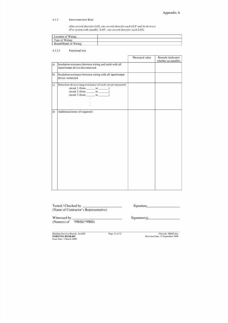
4.1.2 Interconnection Wire (One record sheet for LAN, one record sheet for each LCP and its devices) (For system with standby ‘LAN’, one record sheet for each LAN)
Location of Wiring:Type of Wiring:Brand/Model of Wiring:
4.1.2.1 Functional test
Measured value Remark (indicatedwhether acceptable)
a) Insulation resistance between wiring and earth with allinput/output device disconnected.
b) Insulation resistance between wiring with all input/outputdevice connected.
c) Detection devices loop resistance of each circuit measuredcircuit 1 (from ______ to _______)circuit 2 (from ______ to _______)circuit 3 (from ______ to _______)
.
.
.
d) Additional items (if required):
Tested / Checked by Signature(Name of Contractor’s Representative) Witnessed by Signature(s)(Name(s) of *PBSE/*PBSI)
8/7/2019 commisioning cctv
http://slidepdf.com/reader/full/commisioning-cctv 23/42
Appendix A
Building Services Branch, ArchSD Page 16 of 32 Filecode: SR065.docFORM NO. BS/SR.065 Revision Date: 15 September 2000Issue Date: 3 March 2000
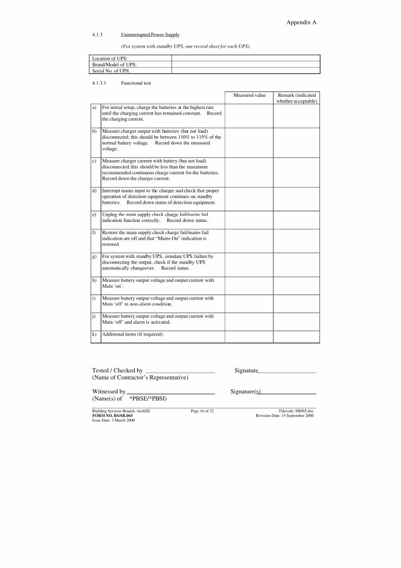
4.1.3 Uninterrupted Power Supply (For system with standby UPS, one record sheet for each UPS) Location of UPS:Brand/Model of UPS:Serial No. of UPS:
4.1.3.1 Functional test
Measured value Remark (indicatedwhether acceptable)
a) For initial setup, charge the batteries at the highest rateuntil the charging current has remained constant. Recordthe charging current.
b) Measure charger output with batteries (but not load)disconnected; this should be between 110% to 115% of thenormal battery voltage. Record down the measuredvoltage.
c) Measure charger current with battery (but not load)disconnected, this should be less than the maximumrecommended continuous charge current for the batteries.Record down the charger current.
d) Interrupt mains input to the charger and check that properoperation of detection equipment continues on standbybatteries. Record down status of detection equipment.
e) Unplug the main supply check charge fail/mains failindication function correctly. Record down status.
f) Restore the main supply check charge fail/mains failindication are off and that “Mains On” indication isrestored.
g) For system with standby UPS, simulate UPS failure bydisconnecting the output, check if the standby UPSautomatically changeover. Record status.
h) Measure battery output voltage and output current withMain ‘on’.
i) Measure battery output voltage and output current withMain ‘off’ in non-alarm condition.
j) Measure battery output voltage and output current withMain ‘off’ and alarm is activated.
k) Additional items (if required):
Tested / Checked by Signature(Name of Contractor’s Representative) Witnessed by Signature(s)(Name(s) of *PBSE/*PBSI)
8/7/2019 commisioning cctv
http://slidepdf.com/reader/full/commisioning-cctv 24/42
Appendix A
Building Services Branch, ArchSD Page 17 of 32 Filecode: SR065.docFORM NO. BS/SR.065 Revision Date: 15 September 2000Issue Date: 3 March 2000
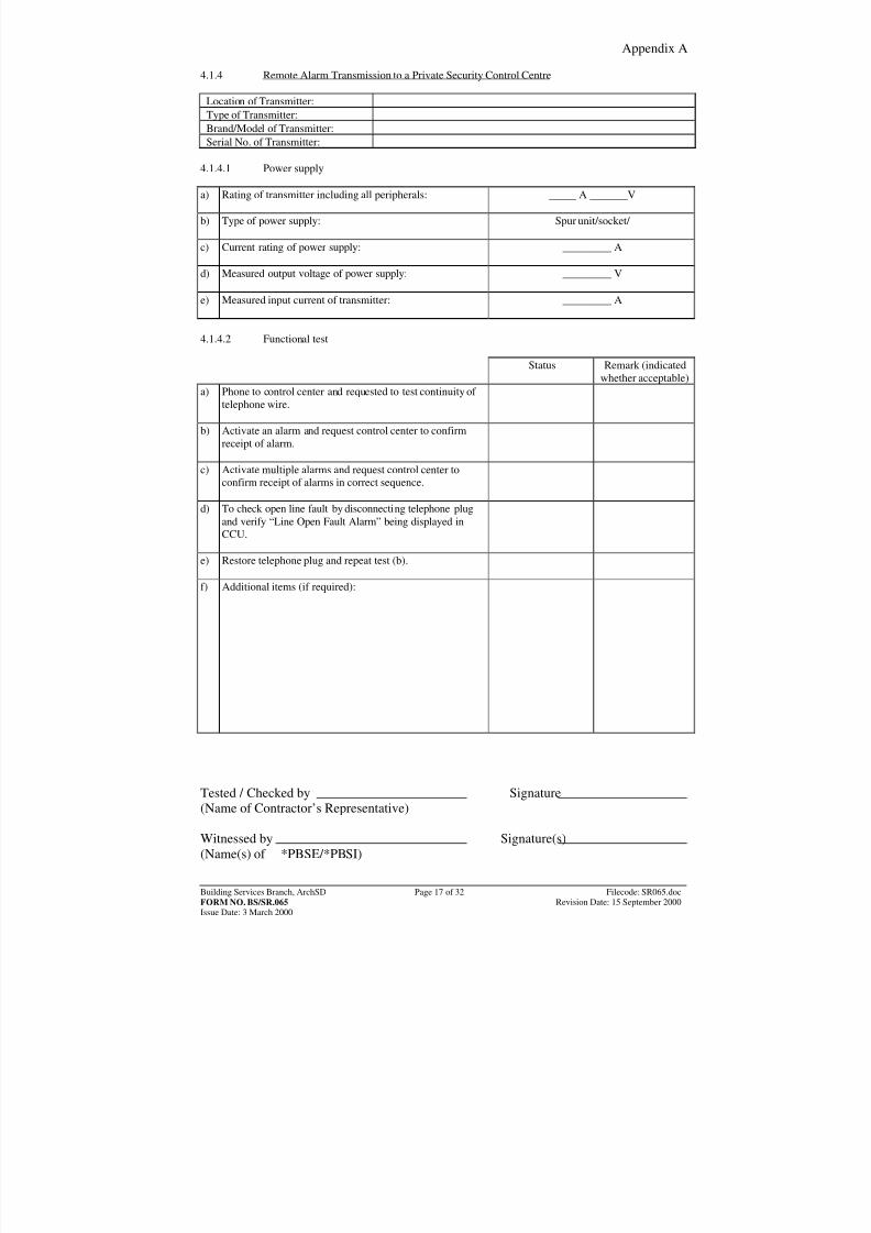
4.1.4 Remote Alarm Transmission to a Private Security Control Centre
Location of Transmitter:Type of Transmitter:Brand/Model of Transmitter:Serial No. of Transmitter:
4.1.4.1 Power supply a) Rating of transmitter including all peripherals:
_____ A _______V
b) Type of power supply:
Spur unit/socket/
c) Current rating of power supply:
_________ A
d) Measured output voltage of power supply:
_________ V
e) Measured input current of transmitter:
_________ A
4.1.4.2 Functional test
Status Remark (indicatedwhether acceptable)
a) Phone to control center and requested to test continuity of telephone wire.
b) Activate an alarm and request control center to confirmreceipt of alarm.
c) Activate multiple alarms and request control center toconfirm receipt of alarms in correct sequence.
d) To check open line fault by disconnecting telephone plugand verify “Line Open Fault Alarm” being displayed inCCU.
e) Restore telephone plug and repeat test (b).
f) Additional items (if required):
Tested / Checked by Signature(Name of Contractor’s Representative) Witnessed by Signature(s)(Name(s) of *PBSE/*PBSI)
8/7/2019 commisioning cctv
http://slidepdf.com/reader/full/commisioning-cctv 25/42
Appendix A
Building Services Branch, ArchSD Page 18 of 32 Filecode: SR065.docFORM NO. BS/SR.065 Revision Date: 15 September 2000Issue Date: 3 March 2000
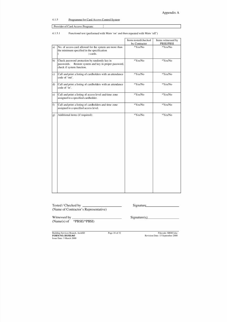
4.1.5 Programme for Card Access Control System
Provider of Card Access Program: 4.1.5.1 Functional test (performed with Main ‘on’ and then repeated with Main ‘off’)
Items tested/checkedby Contractor
Items witnessed byPBSE/PBSI
a) No. of access card allowed for the system are more thanthe minimum specified in the specification( ) cards.
*Yes/No *Yes/No
b) Check password protection by randomly key inpasswords. Restore system and key in proper password,check if system function.
*Yes/No *Yes/No
c) Call and print a listing of cardholders with an attendancecode of ‘out’.
*Yes/No *Yes/No
d) Call and print a listing of cardholders with an attendancecode of ‘in’.
*Yes/No *Yes/No
e) Call and print a listing of access level and time zoneassigned to a specified cardholder.
*Yes/No *Yes/No
f) Call and print a listing of cardholders and time zoneassigned to a specified access level.
*Yes/No *Yes/No
g) Additional items (if required):
*Yes/No *Yes/No
Tested / Checked by Signature(Name of Contractor’s Representative) Witnessed by Signature(s)(Name(s) of *PBSE/*PBSI)
8/7/2019 commisioning cctv
http://slidepdf.com/reader/full/commisioning-cctv 26/42
Appendix A
Building Services Branch, ArchSD Page 19 of 32 Filecode: SR065.docFORM NO. BS/SR.065 Revision Date: 15 September 2000Issue Date: 3 March 2000
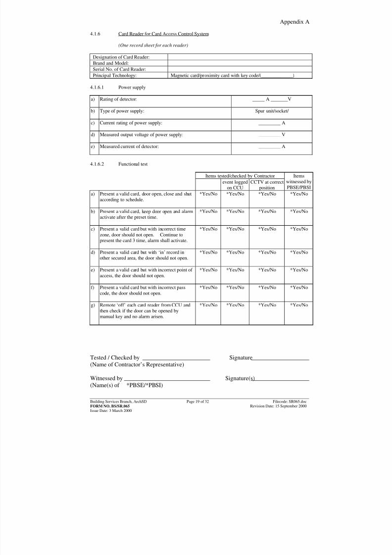
4.1.6 Card Reader for Card Access Control System (One record sheet for each reader)
Designation of Card Reader:Brand and Model:Serial No. of Card Reader:Principal Technology: Magnetic card/proximity card with key code/(_____________)
4.1.6.1 Power supply a) Rating of detector:
_____ A _______V
b) Type of power supply:
Spur unit/socket/
c) Current rating of power supply:
_________ A
d) Measured output voltage of power supply:
_________ V
e) Measured current of detector:
_________ A
4.1.6.2 Functional test
Items tested/checked by Contractorevent logged
on CCUCCTV at correct
position
Itemswitnessed byPBSE/PBSI
a) Present a valid card, door open, close and shutaccording to schedule.
*Yes/No *Yes/No *Yes/No *Yes/No
b) Present a valid card, keep door open and alarmactivate after the preset time.
*Yes/No *Yes/No *Yes/No *Yes/No
c) Present a valid card but with incorrect timezone, door should not open. Continue topresent the card 3 time, alarm shall activate.
*Yes/No *Yes/No *Yes/No *Yes/No
d) Present a valid card but with ‘in’ record inother secured area, the door should not open.
*Yes/No *Yes/No *Yes/No *Yes/No
e) Present a valid card but with incorrect point of access, the door should not open.
*Yes/No *Yes/No *Yes/No *Yes/No
f) Present a valid card but with incorrect passcode, the door should not open.
*Yes/No *Yes/No *Yes/No *Yes/No
g) Remote ‘off’ each card reader from CCU andthen check if the door can be opened bymanual key and no alarm arisen.
*Yes/No *Yes/No *Yes/No *Yes/No
Tested / Checked by Signature(Name of Contractor’s Representative) Witnessed by Signature(s)(Name(s) of *PBSE/*PBSI)
8/7/2019 commisioning cctv
http://slidepdf.com/reader/full/commisioning-cctv 27/42
Appendix A
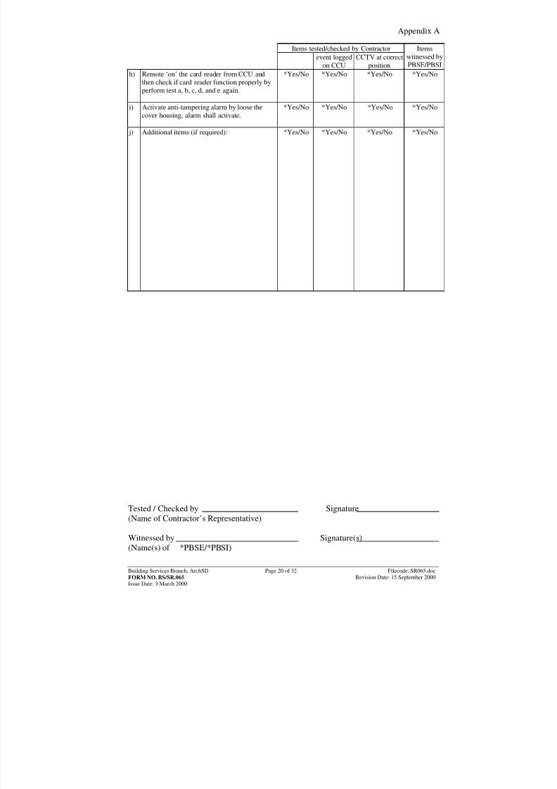
Building Services Branch, ArchSD Page 20 of 32 Filecode: SR065.docFORM NO. BS/SR.065 Revision Date: 15 September 2000Issue Date: 3 March 2000
Items tested/checked by Contractorevent logged
on CCUCCTV at correct
position
Itemswitnessed byPBSE/PBSI
h) Remote ‘on’ the card reader from CCU andthen check if card reader function properly byperform test a, b, c, d, and e again.
*Yes/No *Yes/No *Yes/No *Yes/No
i) Activate anti-tampering alarm by loose the
cover housing, alarm shall activate.
*Yes/No *Yes/No *Yes/No *Yes/No
j) Additional items (if required):
*Yes/No *Yes/No *Yes/No *Yes/No
Tested / Checked by Signature(Name of Contractor’s Representative) Witnessed by Signature(s)(Name(s) of *PBSE/*PBSI)
8/7/2019 commisioning cctv
http://slidepdf.com/reader/full/commisioning-cctv 28/42
Appendix A
Building Services Branch, ArchSD Page 21 of 32 Filecode: SR065.docFORM NO. BS/SR.065 Revision Date: 15 September 2000Issue Date: 3 March 2000
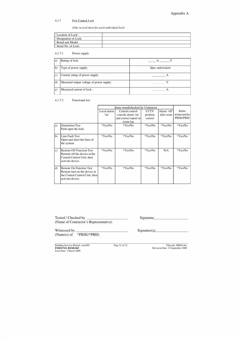
4.1.7 Exit Control Lock (One record sheet for each individual lock)
Location of Lock:Designation of Lock:Brand and Model:Serial No. of Lock:
4.1.7.1 Power supply a) Rating of lock:
_____ A _______V
b) Type of power supply:
Spur unit/socket/
c) Current rating of power supply:
_________ A
d) Measured output voltage of power supply:
_________ V
e) Measured current of lock:
_________ A
4.1.7.2 Functional test
Items tested/checked by ContractorLocal alarm
‘on’Central control
console alarm ‘on’and correct report in
event log
CCTVpositioncorrect
Alarm ‘off’after reset
Items
witnessed byPBSE/PBSI
a) Simulation TestPush open the lock.
*Yes/No *Yes/No *Yes/No *Yes/No *Yes/No
b) Line Fault TestOpen and short the lines of the system.
*Yes/No *Yes/No *Yes/No *Yes/No *Yes/No
c) Remote Off Function TestRemote off the device at theCentral Control Unit, thenactivate device.
*Yes/No *Yes/No *Yes/No N/A *Yes/No
d) Remote On Function TestRemote turn on the device atthe Central Control Unit, thenactivate device.
*Yes/No *Yes/No *Yes/No *Yes/No *Yes/No
Tested / Checked by Signature(Name of Contractor’s Representative) Witnessed by Signature(s)(Name(s) of *PBSE/*PBSI)
8/7/2019 commisioning cctv
http://slidepdf.com/reader/full/commisioning-cctv 29/42
Appendix A
Building Services Branch, ArchSD Page 22 of 32 Filecode: SR065.docFORM NO. BS/SR.065 Revision Date: 15 September 2000Issue Date: 3 March 2000
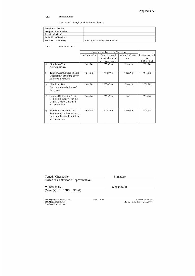
4.1.8 Duress Button (One record sheet for each individual device) Location of Device:Designation of Device:Brand and Model:Serial No. of Device:
Principal Technology: Breakglass/latching push button/ 4.1.8.1 Functional test
Items tested/checked by ContractorLocal alarm ‘on’ Central control
console alarm ‘on’and event logged
Alarm ‘off’ afterreset
Items witnessed
byPBSE/PBSI
a) Simulation TestActivate device.
*Yes/No *Yes/No *Yes/No *Yes/No
b) Tamper Alarm Function TestDisassembly the fixing coveror loosen the screws.
*Yes/No *Yes/No *Yes/No *Yes/No
c) Line Fault TestOpen and short the lines of the system.
*Yes/No *Yes/No *Yes/No *Yes/No
d) Remote Off Function TestRemote off the device at theCentral Control Unit, thenactivate device.
*Yes/No *Yes/No N/A *Yes/No
e) Remote On Function TestRemote turn on the device atthe Central Control Unit, thenactivate device.
*Yes/No *Yes/No *Yes/No *Yes/No
Tested / Checked by Signature(Name of Contractor’s Representative) Witnessed by Signature(s)(Name(s) of *PBSE/*PBSI)
8/7/2019 commisioning cctv
http://slidepdf.com/reader/full/commisioning-cctv 30/42
Appendix A
Building Services Branch, ArchSD Page 23 of 32 Filecode: SR065.docFORM NO. BS/SR.065 Revision Date: 15 September 2000Issue Date: 3 March 2000
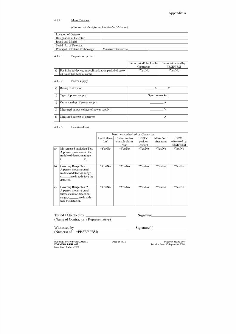
4.1.9 Motor Detector (One record sheet for each individual detector)
Location of Detector:Designation of Detector:Brand and Model:Serial No. of Detector:
Principal Detection Technology: Microwave/infrared/(_____________) 4.1.9.1 Preparation period
Items tested/checked byContractor
Items witnessed byPBSE/PBSI
a) For infrared device, an acclimatization period of up to24 hours has been allowed.
*Yes/No *Yes/No
4.1.9.2 Power supply a) Rating of detector:
_____ A _______V
b) Type of power supply:
Spur unit/socket/
c) Current rating of power supply:
_________ A
d) Measured output voltage of power supply:
_________ V
e) Measured current of detector:
_________ A
4.1.9.3 Functional test
Items tested/checked by ContractorLocal alarm
‘on’Central controlconsole alarm
‘on’
CCTVposition
correct
Alarm ‘off’after reset
Items
witnessed byPBSE/PBSI
a) Movement Simulation TestA person move around themiddle of detection range( m).
*Yes/No *Yes/No *Yes/No *Yes/No *Yes/No
b) Covering Range Test 1A person moves aroundmiddle of detection range,(______m) directly face thedetector.
*Yes/No *Yes/No *Yes/No *Yes/No *Yes/No
c) Covering Range Test 2A person moves around
furthest end of detectionrange, (______m) directlyface the detector.
*Yes/No *Yes/No *Yes/No *Yes/No *Yes/No
Tested / Checked by Signature(Name of Contractor’s Representative) Witnessed by Signature(s)(Name(s) of *PBSE/*PBSI)
8/7/2019 commisioning cctv
http://slidepdf.com/reader/full/commisioning-cctv 31/42
Appendix A
Building Services Branch, ArchSD Page 24 of 32 Filecode: SR065.docFORM NO. BS/SR.065 Revision Date: 15 September 2000Issue Date: 3 March 2000
Items tested/checked by ContractorLocal alarm
‘on’Central controlconsole alarm
‘on’
CCTVpositioncorrect
Alarm ‘off’after reset
Items
witnessed byPBSE/PBSI
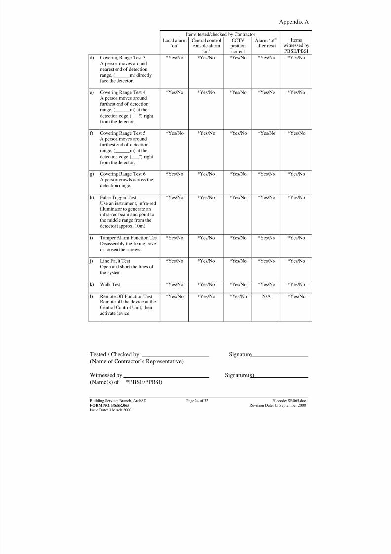
d) Covering Range Test 3A person moves aroundnearest end of detectionrange, (______m) directly
face the detector.
*Yes/No *Yes/No *Yes/No *Yes/No *Yes/No
e) Covering Range Test 4A person moves aroundfurthest end of detectionrange, (______m) at thedetection edge (___ ° ) rightfrom the detector.
*Yes/No *Yes/No *Yes/No *Yes/No *Yes/No
f) Covering Range Test 5A person moves aroundfurthest end of detectionrange, (______m) at thedetection edge (___ ° ) rightfrom the detector.
*Yes/No *Yes/No *Yes/No *Yes/No *Yes/No
g) Covering Range Test 6A person crawls across thedetection range.
*Yes/No *Yes/No *Yes/No *Yes/No *Yes/No
h) False Trigger TestUse an instrument, infra-redilluminator to generate aninfra-red beam and point tothe middle range from thedetector (approx. 10m).
*Yes/No *Yes/No *Yes/No *Yes/No *Yes/No
i) Tamper Alarm Function TestDisassembly the fixing coveror loosen the screws.
*Yes/No *Yes/No *Yes/No *Yes/No *Yes/No
j) Line Fault TestOpen and short the lines of the system.
*Yes/No *Yes/No *Yes/No *Yes/No *Yes/No
k) Walk Test
*Yes/No *Yes/No *Yes/No *Yes/No *Yes/No
l) Remote Off Function TestRemote off the device at theCentral Control Unit, thenactivate device.
*Yes/No *Yes/No *Yes/No N/A *Yes/No
Tested / Checked by Signature(Name of Contractor’s Representative) Witnessed by Signature(s)(Name(s) of *PBSE/*PBSI)
8/7/2019 commisioning cctv
http://slidepdf.com/reader/full/commisioning-cctv 32/42
Appendix A
Building Services Branch, ArchSD Page 25 of 32 Filecode: SR065.docFORM NO. BS/SR.065 Revision Date: 15 September 2000Issue Date: 3 March 2000
Items tested/checked by Contractor
Local alarm‘on’
Central controlconsole alarm
‘on’
CCTVpositioncorrect
Alarm ‘off’after reset
Items
witnessed byPBSE/PBSI
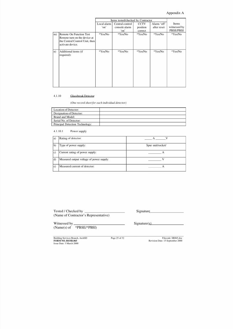
m) Remote On Function TestRemote turn on the device atthe Central Control Unit, thenactivate device.
*Yes/No *Yes/No *Yes/No *Yes/No *Yes/No
n) Additional items (if required):
*Yes/No *Yes/No *Yes/No *Yes/No *Yes/No
4.1.10 Glassbreak Detector (One record sheet for each individual detector) Location of Detector:Designation of Detector:Brand and Model:Serial No. of Detector:Principal Detection Technology: 4.1.10.1 Power supply a) Rating of detector:
_____ A _______V
b) Type of power supply:
Spur unit/socket/
c) Current rating of power supply:
_________ A
d) Measured output voltage of power supply:
_________ V
e) Measured current of detector:
_________ A
Tested / Checked by Signature(Name of Contractor’s Representative) Witnessed by Signature(s)(Name(s) of *PBSE/*PBSI)
8/7/2019 commisioning cctv
http://slidepdf.com/reader/full/commisioning-cctv 33/42
Appendix A
Building Services Branch, ArchSD Page 26 of 32 Filecode: SR065.docFORM NO. BS/SR.065 Revision Date: 15 September 2000Issue Date: 3 March 2000
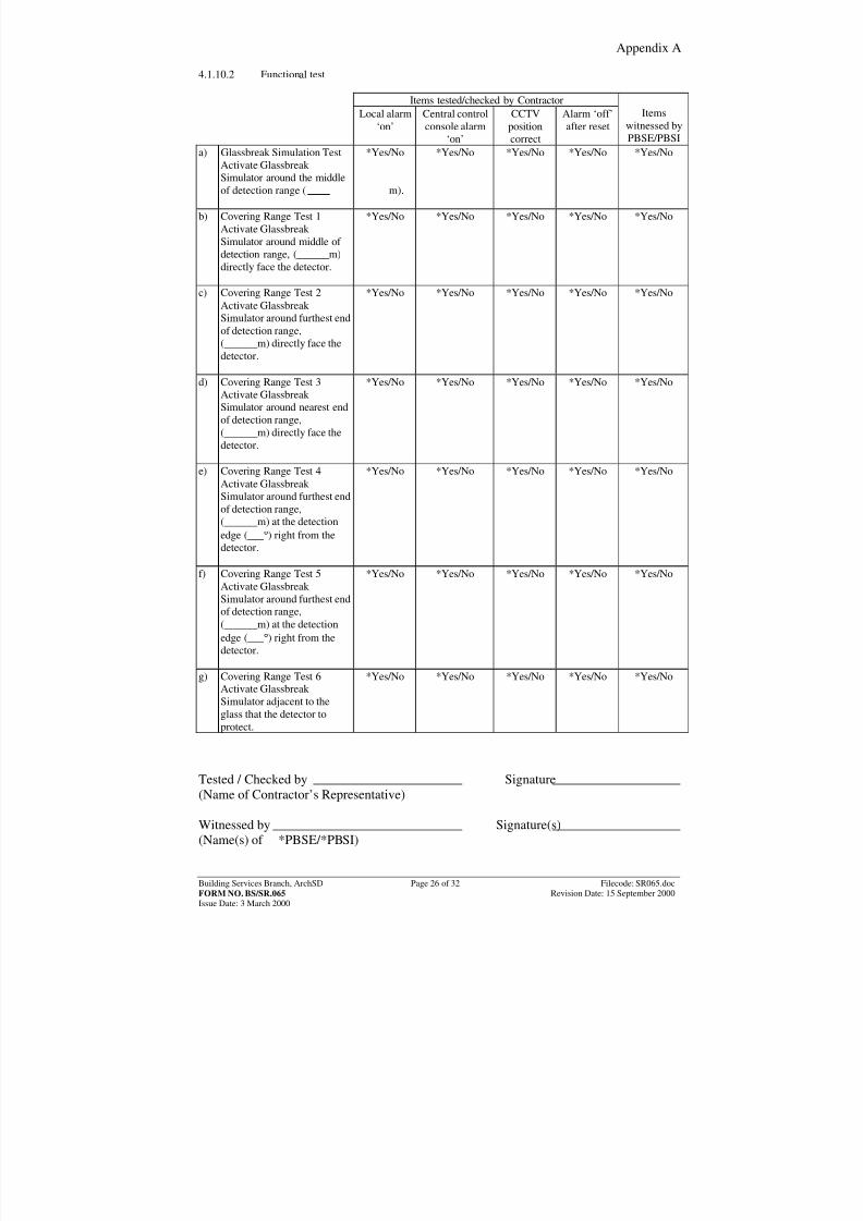
4.1.10.2 Functional test
Items tested/checked by ContractorLocal alarm
‘on’Central controlconsole alarm
‘on’
CCTVpositioncorrect
Alarm ‘off’after reset
Items
witnessed byPBSE/PBSI
a) Glassbreak Simulation TestActivate Glassbreak
Simulator around the middleof detection range ( m).
*Yes/No *Yes/No *Yes/No *Yes/No *Yes/No
b) Covering Range Test 1Activate Glassbreak Simulator around middle of detection range, (______m)directly face the detector.
*Yes/No *Yes/No *Yes/No *Yes/No *Yes/No
c) Covering Range Test 2Activate Glassbreak Simulator around furthest endof detection range,(______m) directly face the
detector.
*Yes/No *Yes/No *Yes/No *Yes/No *Yes/No
d) Covering Range Test 3Activate Glassbreak Simulator around nearest endof detection range,(______m) directly face thedetector.
*Yes/No *Yes/No *Yes/No *Yes/No *Yes/No
e) Covering Range Test 4Activate Glassbreak Simulator around furthest endof detection range,(______m) at the detection
edge (___°
) right from thedetector.
*Yes/No *Yes/No *Yes/No *Yes/No *Yes/No
f) Covering Range Test 5Activate Glassbreak Simulator around furthest endof detection range,(______m) at the detectionedge (___ ° ) right from thedetector.
*Yes/No *Yes/No *Yes/No *Yes/No *Yes/No
g) Covering Range Test 6Activate Glassbreak Simulator adjacent to the
glass that the detector toprotect.
*Yes/No *Yes/No *Yes/No *Yes/No *Yes/No
Tested / Checked by Signature(Name of Contractor’s Representative) Witnessed by Signature(s)(Name(s) of *PBSE/*PBSI)
8/7/2019 commisioning cctv
http://slidepdf.com/reader/full/commisioning-cctv 34/42
Appendix A
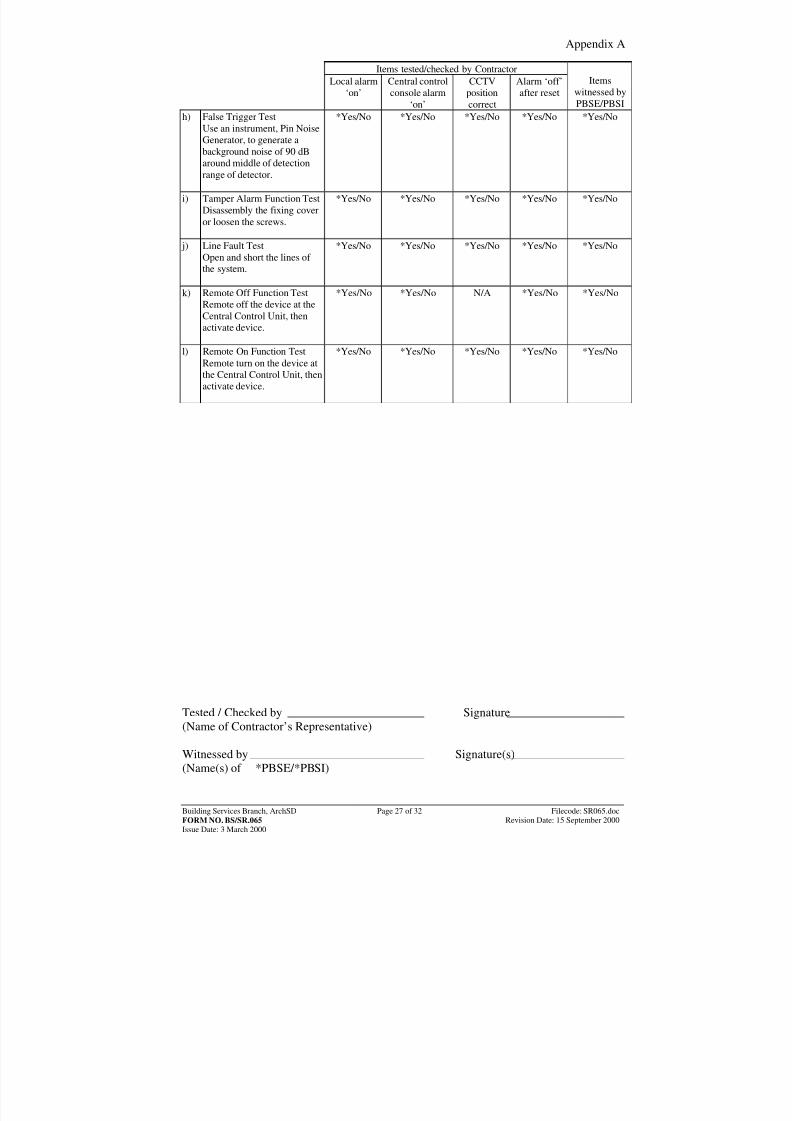
Building Services Branch, ArchSD Page 27 of 32 Filecode: SR065.docFORM NO. BS/SR.065 Revision Date: 15 September 2000Issue Date: 3 March 2000
Items tested/checked by Contractor
Local alarm‘on’
Central controlconsole alarm
‘on’
CCTVpositioncorrect
Alarm ‘off’after reset
Items
witnessed byPBSE/PBSI
h) False Trigger TestUse an instrument, Pin NoiseGenerator, to generate abackground noise of 90 dB
around middle of detectionrange of detector.
*Yes/No *Yes/No *Yes/No *Yes/No *Yes/No
i) Tamper Alarm Function TestDisassembly the fixing coveror loosen the screws.
*Yes/No *Yes/No *Yes/No *Yes/No *Yes/No
j) Line Fault TestOpen and short the lines of the system.
*Yes/No *Yes/No *Yes/No *Yes/No *Yes/No
k) Remote Off Function TestRemote off the device at theCentral Control Unit, then
activate device.
*Yes/No *Yes/No N/A *Yes/No *Yes/No
l) Remote On Function TestRemote turn on the device atthe Central Control Unit, thenactivate device.
*Yes/No *Yes/No *Yes/No *Yes/No *Yes/No
Tested / Checked by Signature(Name of Contractor’s Representative) Witnessed by Signature(s)(Name(s) of *PBSE/*PBSI)
8/7/2019 commisioning cctv
http://slidepdf.com/reader/full/commisioning-cctv 35/42
Appendix A
Building Services Branch, ArchSD Page 28 of 32 Filecode: SR065.docFORM NO. BS/SR.065 Revision Date: 15 September 2000Issue Date: 3 March 2000
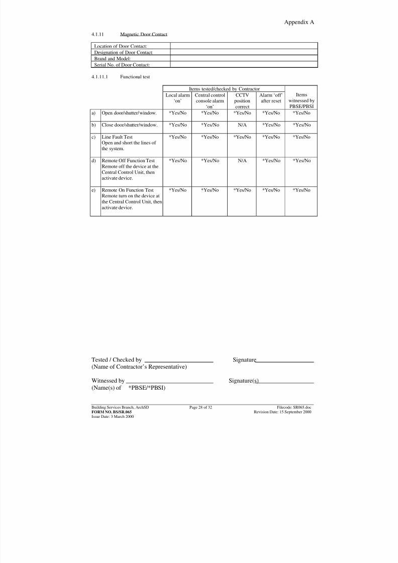
4.1.11 Magnetic Door Contact
Location of Door Contact:Designation of Door Contact:Brand and Model:Serial No. of Door Contact:
4.1.11.1 Functional test
Items tested/checked by ContractorLocal alarm
‘on’Central controlconsole alarm
‘on’
CCTVpositioncorrect
Alarm ‘off’after reset
Items
witnessed byPBSE/PBSI
a) Open door/shutter/window.
*Yes/No *Yes/No *Yes/No *Yes/No *Yes/No
b) Close door/shutter/window.
*Yes/No *Yes/No N/A *Yes/No *Yes/No
c) Line Fault TestOpen and short the lines of the system.
*Yes/No *Yes/No *Yes/No *Yes/No *Yes/No
d) Remote Off Function TestRemote off the device at theCentral Control Unit, thenactivate device.
*Yes/No *Yes/No N/A *Yes/No *Yes/No
e) Remote On Function TestRemote turn on the device atthe Central Control Unit, thenactivate device.
*Yes/No *Yes/No *Yes/No *Yes/No *Yes/No
Tested / Checked by Signature(Name of Contractor’s Representative) Witnessed by Signature(s)(Name(s) of *PBSE/*PBSI)
8/7/2019 commisioning cctv
http://slidepdf.com/reader/full/commisioning-cctv 36/42
Appendix A
Building Services Branch, ArchSD Page 29 of 32 Filecode: SR065.docFORM NO. BS/SR.065 Revision Date: 15 September 2000Issue Date: 3 March 2000
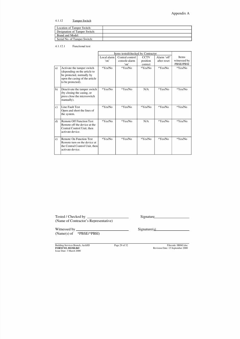
4.1.12 Tamper Switch
Location of Tamper Switch:Designation of Tamper Switch:Brand and Model:Serial No. of Tamper Switch:
4.1.12.1 Functional test
Items tested/checked by ContractorLocal alarm
‘on’Central controlconsole alarm
‘on’
CCTVpositioncorrect
Alarm ‘off’after reset
Items
witnessed byPBSE/PBSI
a) Activate the tamper switch(depending on the article tobe protected, normally byopen the casing of the articleto be protected).
*Yes/No *Yes/No *Yes/No *Yes/No *Yes/No
b) Deactivate the tamper switch(by closing the casing, orpress close the microswitchmanually).
*Yes/No *Yes/No N/A *Yes/No *Yes/No
c) Line Fault TestOpen and short the lines of the system.
*Yes/No *Yes/No *Yes/No *Yes/No *Yes/No
d) Remote Off Function TestRemote off the device at theCentral Control Unit, thenactivate device.
*Yes/No *Yes/No N/A *Yes/No *Yes/No
e) Remote On Function TestRemote turn on the device atthe Central Control Unit, thenactivate device.
*Yes/No *Yes/No *Yes/No *Yes/No *Yes/No
Tested / Checked by Signature(Name of Contractor’s Representative) Witnessed by Signature(s)(Name(s) of *PBSE/*PBSI)
8/7/2019 commisioning cctv
http://slidepdf.com/reader/full/commisioning-cctv 37/42
Appendix A
Building Services Branch, ArchSD Page 30 of 32 Filecode: SR065.docFORM NO. BS/SR.065 Revision Date: 15 September 2000Issue Date: 3 March 2000
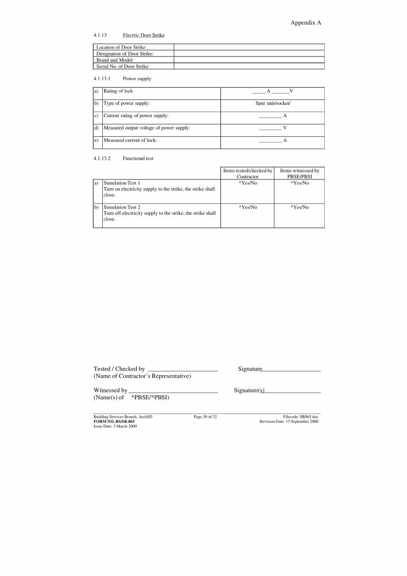
4.1.13 Electric Door Strike
Location of Door Strike:Designation of Door Strike:Brand and Model:Serial No. of Door Strike:
4.1.13.1 Power supply a) Rating of lock:
_____ A _______V
b) Type of power supply:
Spur unit/socket/
c) Current rating of power supply:
_________ A
d) Measured output voltage of power supply:
_________ V
e) Measured current of lock:
_________ A
4.1.13.2 Functional test
Items tested/checked byContractor
Items witnessed byPBSE/PBSI
a) Simulation Test 1Turn on electricity supply to the strike, the strike shallclose.
*Yes/No *Yes/No
b) Simulation Test 2Turn off electricity supply to the strike, the strike shallclose.
*Yes/No *Yes/No
Tested / Checked by Signature(Name of Contractor’s Representative) Witnessed by Signature(s)(Name(s) of *PBSE/*PBSI)
8/7/2019 commisioning cctv
http://slidepdf.com/reader/full/commisioning-cctv 38/42
Appendix A
Building Services Branch, ArchSD Page 31 of 32 Filecode: SR065.docFORM NO. BS/SR.065 Revision Date: 15 September 2000Issue Date: 3 March 2000
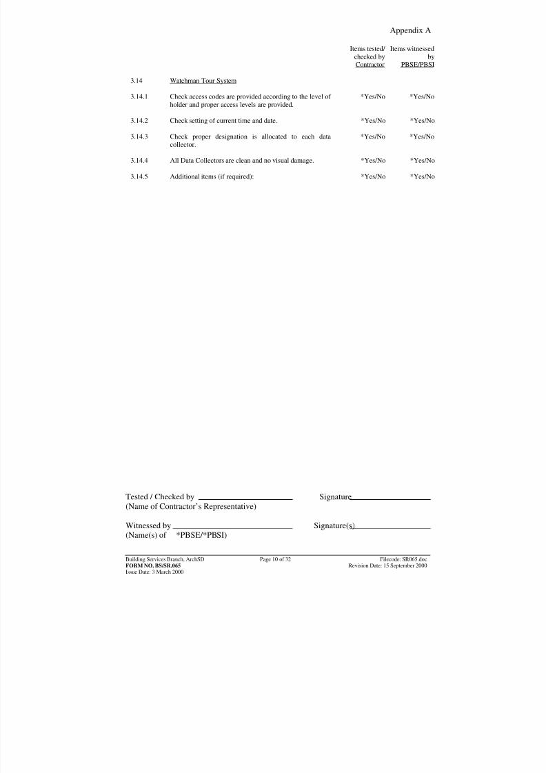
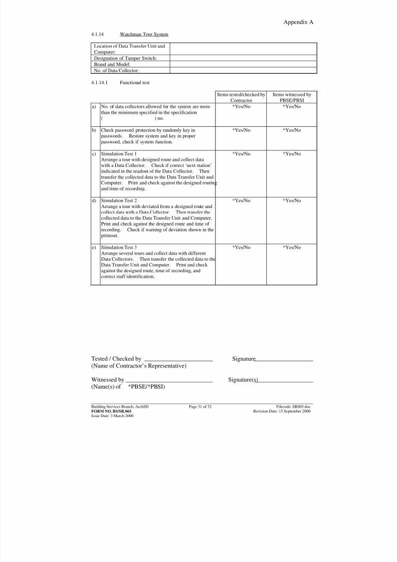
4.1.14 Watchman Tour System
Location of Data Transfer Unit andComputer:
Designation of Tamper Switch:Brand and Model:No. of Data Collector:
4.1.14.1 Functional test
Items tested/checked byContractor
Items witnessed byPBSE/PBSI
a) No. of data collectors allowed for the system are morethan the minimum specified in the specification( ) no.
*Yes/No *Yes/No
b) Check password protection by randomly key inpasswords. Restore system and key in properpassword, check if system function.
*Yes/No *Yes/No
c) Simulation Test 1Arrange a tour with designed route and collect datawith a Data Collector. Check if correct ‘next station’indicated in the readout of the Data Collector. Thentransfer the collected data to the Data Transfer Unit andComputer. Print and check against the designed routingand time of recording.
*Yes/No *Yes/No
d) Simulation Test 2Arrange a tour with deviated from a designed route andcollect data with a Data Collector. Then transfer thecollected data to the Data Transfer Unit and Computer.Print and check against the designed route and time of recording. Check if warning of deviation shown in theprintout.
*Yes/No *Yes/No
e) Simulation Test 3Arrange several tours and collect data with differentData Collectors. Then transfer the collected data to theData Transfer Unit and Computer. Print and check against the designed route, time of recording, andcorrect staff identification.
*Yes/No *Yes/No
Tested / Checked by Signature(Name of Contractor’s Representative) Witnessed by Signature(s)(Name(s) of *PBSE/*PBSI)
8/7/2019 commisioning cctv
http://slidepdf.com/reader/full/commisioning-cctv 39/42
Appendix A
Building Services Branch, ArchSD Page 32 of 32 Filecode: SR065.docFORM NO. BS/SR.065 Revision Date: 15 September 2000Issue Date: 3 March 2000
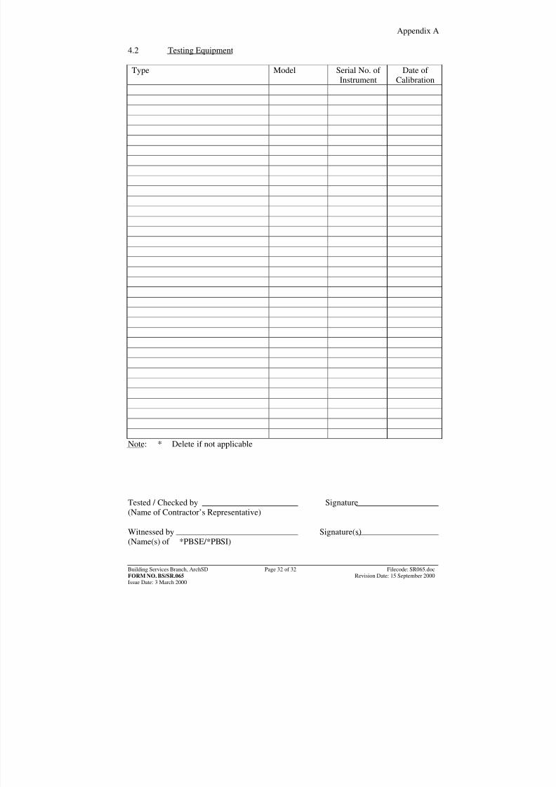
4.2 Testing Equipment
Type Model Serial No. of
InstrumentDate of
Calibration
Note: * Delete if not applicable Tested / Checked by Signature(Name of Contractor’s Representative) Witnessed by Signature(s)(Name(s) of *PBSE/*PBSI)
8/7/2019 commisioning cctv
http://slidepdf.com/reader/full/commisioning-cctv 40/42
Appendix B
Building Services Branch, ArchSD Page 1 of 3 Filecode: SR025.docFORM NO. BS/SR.025 Revision Date: 15 September 2000Issue Date: 3 March 2000
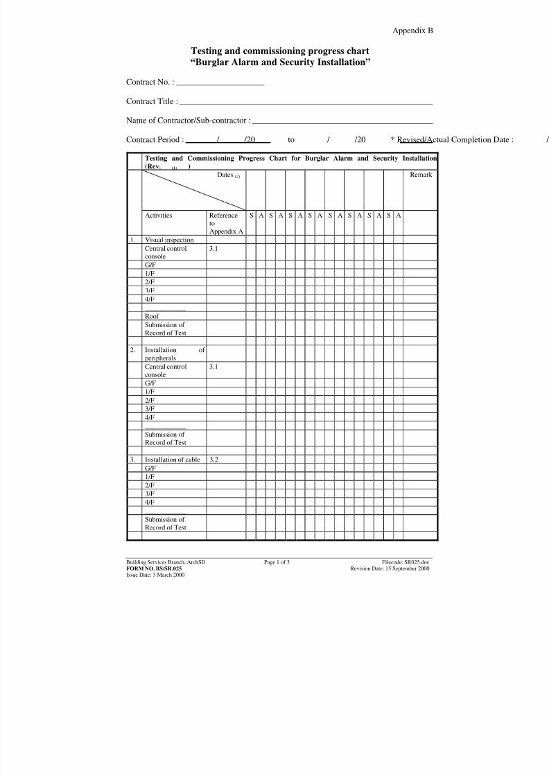
Testing and commissioning progress chart“Burglar Alarm and Security Installation”
Contract No. : Contract Title :
Name of Contractor/Sub-contractor : Contract Period : / /20 to / /20 * Revised/Actual Completion Date : / /20
Testing and Commissioning Progress Chart for Burglar Alarm and Security Installation(Rev. ) (1)
Dates (2)
Remark
Activities ReferencetoAppendix A
S A S A S A S A S A S A S A S A
1. Visual inspectionCentral controlconsole
3.1
G/F1/F2/F3/F4/F____________Roof Submission of Record of Test
2. Installation of
peripherals
Central controlconsole
3.1
G/F1/F2/F3/F4/F____________Submission of Record of Test
3. Installation of cable 3.2G/F1/F2/F3/F4/F____________Submission of Record of Test
8/7/2019 commisioning cctv
http://slidepdf.com/reader/full/commisioning-cctv 41/42
Appendix B
Building Services Branch, ArchSD Page 2 of 3 Filecode: SR025.docFORM NO. BS/SR.025 Revision Date: 15 September 2000Issue Date: 3 March 2000
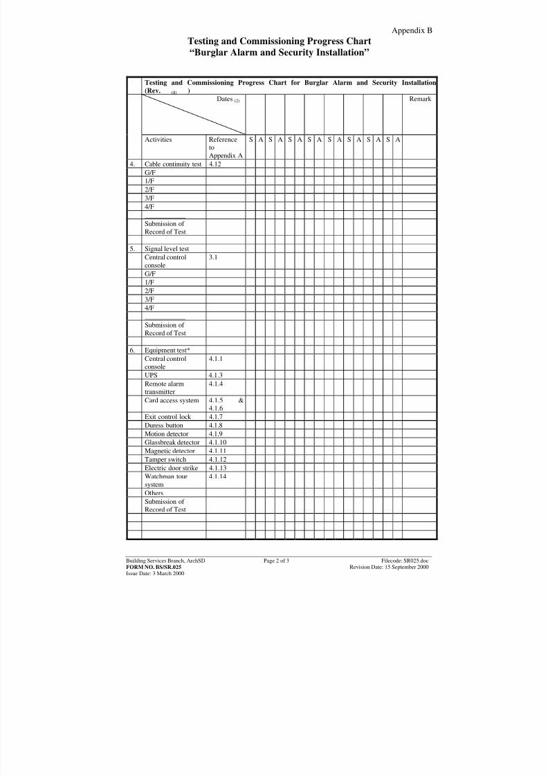
Testing and Commissioning Progress Chart“Burglar Alarm and Security Installation”
Testing and Commissioning Progress Chart for Burglar Alarm and Security Installation(Rev. ) (1)
Dates (2)
Remark
Activities ReferencetoAppendix A
S A S A S A S A S A S A S A S A
4. Cable continuity test 4.12G/F1/F2/F3/F4/F____________
Submission of Record of Test
5. Signal level test
Central controlconsole
3.1
G/F1/F2/F3/F4/F____________Submission of Record of Test
6. Equipment test*
Central controlconsole
4.1.1
UPS 4.1.3Remote alarmtransmitter
4.1.4
Card access system 4.1.5 &4.1.6
Exit control lock 4.1.7Duress button 4.1.8Motion detector 4.1.9Glassbreak detector 4.1.10
Magnetic detector 4.1.11Tamper switch 4.1.12Electric door strike 4.1.13Watchman toursystem
4.1.14
OthersSubmission of Record of Test
8/7/2019 commisioning cctv
http://slidepdf.com/reader/full/commisioning-cctv 42/42
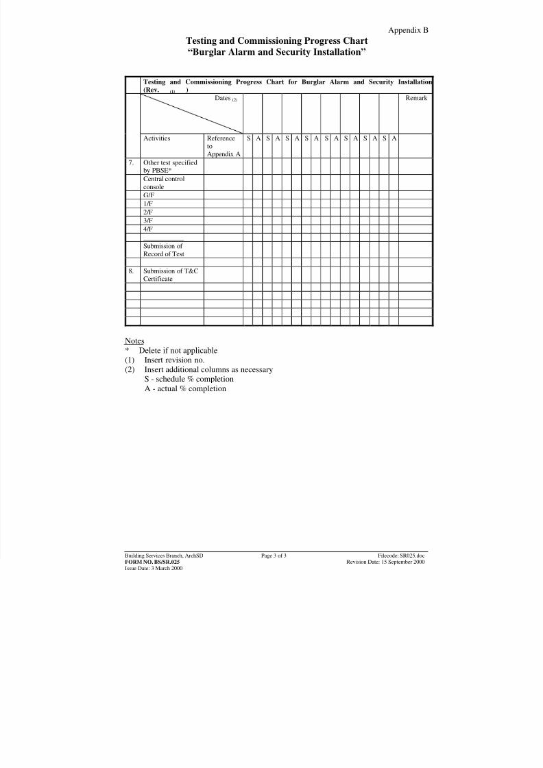
Appendix BTesting and Commissioning Progress Chart“Burglar Alarm and Security Installation”
Testing and Commissioning Progress Chart for Burglar Alarm and Security Installation(Rev. ) (1)
Dates (2)
Remark
Activities ReferencetoAppendix A
S A S A S A S A S A S A S A S A
7. Other test specifiedby PBSE*
Central controlconsole
G/F1/F2/F3/F4/F____________Submission of Record of Test
8. Submission of T&C
Certificate
Notes* Delete if not applicable(1) Insert revision no.(2) Insert additional columns as necessary
S - schedule % completionA - actual % completion