Embed Size (px)
Citation preview
Page 1 of 21
0SVSINSCOM Z-VENT� Commercial/Industrial MODEL SVE SERIES IV
INSTALLATION AND MAINTENANCE INSTRUCTIONS 3”- 24” SINGLE AND DOUBLE WALL
SPECIAL STAINLESS STEEL VENTING SYSTEM
FOR GAS BURNING APPLIANCES
CATEGORY II, III, & IV
UL1738 & S636 Read the following before installation of Z-Vent�
� Examine all components for possible shipping damage prior to installation. �
� The Z-Vent� system must be free to expand and contract. Check for unrestricted vent movement through walls, ceilings and roof penetrations. �
* The vent system must be properly supported “DURING ASSEMBLY” vertically & horizontally asprescribed in this manual. Failure to support the components at the point of install will cause unduestress on the joints of the components and fittings thereby voiding warranty.
� Proper joint assembly is essential for a safe installation. Follow these instructions exactly as written. Check the connection of all joints during and after completion of assembly for proper insertion depth and check gear clamps of single wall vents for proper torque.�
� Different manufacturers have different joint systems and adhesives. Do Not Mix Pipe, Fittings or Joining methods from different manufacturers beyond the flue collar adaptor. �
WARNING: CONDENSATION WITH HIGH ACID CONTENT MAY BE PRODUCED DUE TO UNFORESEEN CONDITIONS. THE HEATING APPLIANCE AND VENTING SYSTEM SHOULD BE INSPECTED BY A LICENSED CONTRACTOR ON AN ANNUAL BASIS FOR POSSIBLE SIGNS OF DETERIORATION DUE TO RUSTING OR PIN HOLES. CONDENSATION WITH HIGH ACID CONTENT MAY CAUSE LEAKAGE OF HARMFUL GASES WHICH CAN CAUSE NAUSEA, FAINTING OR DEATH. IF DETERIORATION IS DETECTED, IMMEDIATELY CEASE USE OF THE HEATING SYSTEM AND CALL FURNACE / BOILER INSTALLER FOR REMEDIAL ACTION.
IMPORTANT: The qualified installing contractor must leave this instruction with the end-user along with a vent layout drawing of the install detailing the entire vent system including all enclosures, access doors, condensate drains etc. The installer shall instruct the end-user on how to check the condensate drains periodically and if required, how to fill with water.
Sold by www.GadgetsGo.com Authorized Dealer
Page 2 of 21
CANADA: FLEXMASTER CANADA LTD. 452 ATTWELL DR. ETOBICOKE, ONTARIO M9W 5C3 (416) 679-0045
U.S.A.: Z-FLEX� US, INC. 20 COMMERCE PARK, NORTH BEDFORD, N.H. 03110-6911 1(800) 654-5600
Visit our web site at www.z-flex.com
Table of Contents Contents Page no.Hazard Definitions 2Contaminants Notice 3Observations to Note 3Minimum Clearances to Vent Termination 4Joint Procedure 5-6Clearances to Combustibles Table 6-7Horizontal / Side Wall Venting Installation 7How to Cut Single Wall Pipe 8Single Wall Adjustable 8-9Double Wall Adjustable 10Condensate Tube / Drain Tee Installation 11Support Systems 11-12Vertical Venting Installation 12Installing Fire-Stop Support / Spacer Plate 13Installing Z-Vent� Roof Jack Support System 14-16Installing Vent Pipe Through Z-Vent� Roof Jack Support System 16Installing Vent Pipe in an Existing Masonry Chimney 17Special fittings 17-18Illustrations 19-20Warranty 21
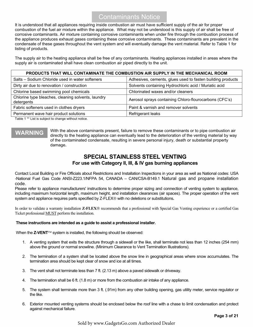
Hazard Definitions The following terms are used throughout this Installation Guide to bring attention to potential hazards of varying risk levels or to important information concerning the product and / or its use.
Indicates the presence of a hazardous situation which, if ignored, will result in death, serious injury or substantial property damage.
Indicates a potentially hazardous situation which, if ignored, can result in death, serious injury or substantial property damage.
Indicates a potentially hazardous situation which, if ignored, may result in minor injury or property damage.
Indicates special instructions on installation, operation or maintenance, which are important to equipment but not related to personal injury hazards.
DANGER!
WARNING!
CAUTION!
NOTICE
Sold by www.GadgetsGo.com Authorized Dealer
Page 3 of 21
WARNING
It is understood that all appliances requiring inside combustion air must have sufficient supply of the air for proper combustion of the fuel air mixture within the appliance. What may not be understood is this supply of air shall be free of corrosive contaminants. Air mixture containing corrosive contaminants when under fire through the combustion process of the appliance produces exhaust gases containing these corrosive contaminants. These contaminants are prevalent in the condensate of these gases throughout the vent system and will eventually damage the vent material. Refer to Table 1 for listing of products.
The supply air to the heating appliance shall be free of any contaminants. Heating appliances installed in areas where the supply air is contaminated shall have clean combustion air piped directly to the unit.
PRODUCTS THAT WILL CONTAMINATE THE COMBUSTION AIR SUPPLY IN THE MECHANICAL ROOM Salts – Sodium Chloride used in water softeners Adhesives, cements, glues used to fasten building products Dirty air due to renovation / construction Solvents containing Hydrochloric acid / Muriatic acid Chlorine based swimming pool chemicals Chlorinated waxes and/or cleaners Chlorine type bleaches, cleaning solvents, laundry detergents Aerosol sprays containing Chloro-flourocarbons (CFC’s)
Fabric softeners used in clothes dryers Paint & varnish and remover solvents Permanent wave hair product solutions Refrigerant leaks Table 1 ** List is subject to change without notice.
With the above contaminants present, failure to remove these contaminants or to pipe combustion air directly to the heating appliance can eventually lead to the deterioration of the venting material by way of the contaminated condensate, resulting in severe personal injury, death or substantial property damage.
SPECIAL STAINLESS STEEL VENTING For use with Category II, III, & IV gas burning appliances
Contact Local Building or Fire Officials about Restrictions and Installation Inspections in your area as well as National codes: USA -National Fuel Gas Code ANSI-Z223.1/NFPA 54, CANADA – CAN/CSA-B149.1 Natural gas and propane installation code. Please refer to appliance manufacturers' instructions to determine proper sizing and connection of venting system to appliance, including maximum horizontal length, maximum height, and installation clearances (air spaces). The proper operation of the vent system and appliance requires parts specified by Z-FLEX� with no deletions or substitutions.
In order to validate a warranty installation Z-FLEX� recommends that a professional with Special Gas Venting experience or a certified Gas Ticket professional MUST perform the installation.
These instructions are intended as a guide to assist a professional installer.
When the Z-VENT� system is installed, the following should be observed:
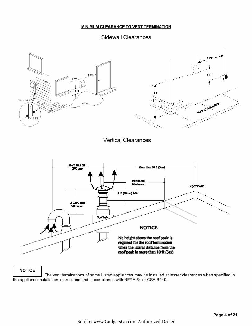
1. A venting system that exits the structure through a sidewall or the like, shall terminate not less than 12 inches (254 mm)above the ground or normal snowline. (Minimum Clearance to Vent Termination Illustrations).
2. The termination of a system shall be located above the snow line in geographical areas where snow accumulates. Thetermination area should be kept clear of snow and ice at all times.
3. The vent shall not terminate less than 7 ft. (2.13 m) above a paved sidewalk or driveway.
4. The termination shall be 6 ft. (1.8 m) or more from the combustion air intake of any appliance.
5. The system shall terminate more than 3 ft. (.91m) from any other building opening, gas utility meter, service regulator orthe like.
6. Exterior mounted venting systems should be enclosed below the roof line with a chase to limit condensation and protectagainst mechanical failure.
Contaminants Notice
Sold by www.GadgetsGo.com Authorized Dealer
Page 4 of 21
MINIMUM CLEARANCE TO VENT TERMINATION
Sidewall Clearances
Vertical Clearances
The vent terminations of some Listed appliances may be installed at lesser clearances when specified in the appliance installation instructions and in compliance with NFPA 54 or CSA B149.
NOTICE
Sold by www.GadgetsGo.com Authorized Dealer
Page 5 of 21
A. The Z-FLEX� SPECIAL STAINLESS VENT SYSTEM is for use only with appliances having a positive vent pressure of 8” of water column or less.
B. Except for installation in one and two family dwellings, a venting system that extends through any zone above that on which the connected appliance is located shall be provided with an enclosure having a fire resistance rating equal to or greater than that of the floor or roof assemblies through which it passes
C. Do not wrap the pipe with insulation or cladding or place any type of insulation within the required air spaces surrounding the venting system.
D. A termination must be used on all installations to assure proper operation and to prevent debris from entering the venting system.
E. Vertical runs must use a fire-stop as a lateral support at each ceiling level and at least one support at the base of the vertical run where required by the appliance manufacturer. For vertical runs exceeding 16 ft (4.88m), a support collar is required at 16 ft (4.88m) intervals. Support horizontal runs using loose fitting metal straps as hangers and similar supports at each elbow.
F: It is recommended that vertical and horizontal drain tees with 3inch p-traps be installed on long vent systems in order to eliminate the system of condensate as quickly as possible.
JOINT PROCEDURE
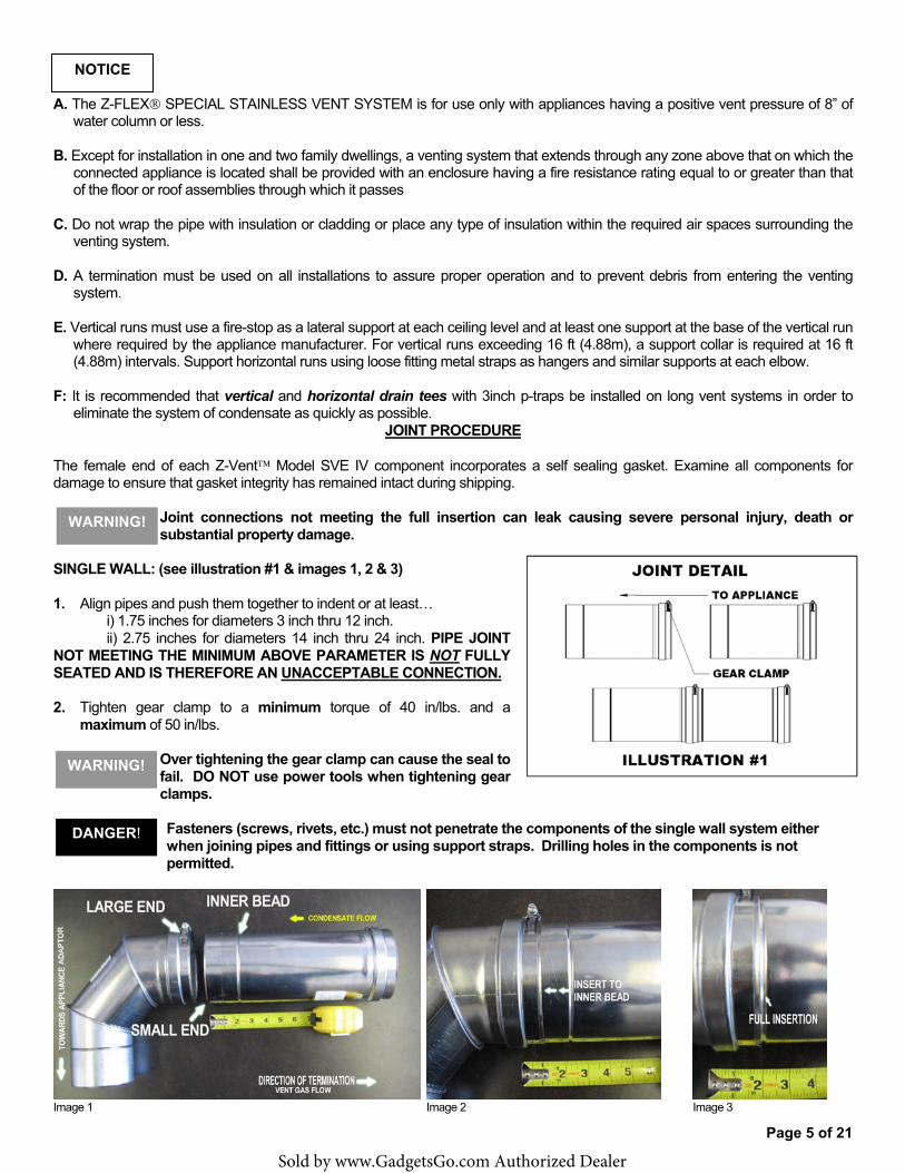
The female end of each Z-Vent� Model SVE IV component incorporates a self sealing gasket. Examine all components for damage to ensure that gasket integrity has remained intact during shipping.
Joint connections not meeting the full insertion can leak causing severe personal injury, death or substantial property damage.
SINGLE WALL: (see illustration #1 & images 1, 2 & 3)
1. Align pipes and push them together to indent or at least…i) 1.75 inches for diameters 3 inch thru 12 inch.ii) 2.75 inches for diameters 14 inch thru 24 inch. PIPE JOINT
NOT MEETING THE MINIMUM ABOVE PARAMETER IS NOT FULLY SEATED AND IS THEREFORE AN UNACCEPTABLE CONNECTION.
2. Tighten gear clamp to a minimum torque of 40 in/lbs. and amaximum of 50 in/lbs.
Over tightening the gear clamp can cause the seal to fail. DO NOT use power tools when tightening gear clamps.
Fasteners (screws, rivets, etc.) must not penetrate the components of the single wall system either when joining pipes and fittings or using support straps. Drilling holes in the components is not permitted.
Image 1 Image 2 Image 3
NOTICE
WARNING!
WARNING!
DANGER!
Sold by www.GadgetsGo.com Authorized Dealer
Page 6 of 21
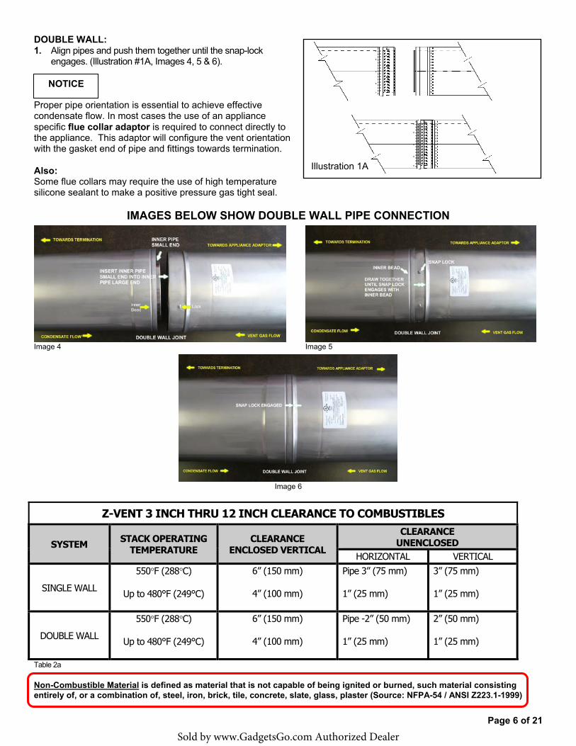
DOUBLE WALL: 1. Align pipes and push them together until the snap-lock
engages. (Illustration #1A, Images 4, 5 & 6).
Proper pipe orientation is essential to achieve effective condensate flow. In most cases the use of an appliance specific flue collar adaptor is required to connect directly to the appliance. This adaptor will configure the vent orientation with the gasket end of pipe and fittings towards termination.
Also: Some flue collars may require the use of high temperature silicone sealant to make a positive pressure gas tight seal.
IMAGES BELOW SHOW DOUBLE WALL PIPE CONNECTION
Image 4 Image 5
Image 6
Z-VENT 3 INCH THRU 12 INCH CLEARANCE TO COMBUSTIBLES
SYSTEM STACK OPERATING TEMPERATURE
CLEARANCE ENCLOSED VERTICAL
CLEARANCE UNENCLOSED
HORIZONTAL VERTICAL
SINGLE WALL
550�F (288�C)
Up to 480°F (249°C)
6” (150 mm)
4” (100 mm)
Pipe 3” (75 mm)
1” (25 mm)
3” (75 mm)
1” (25 mm)
DOUBLE WALL
550�F (288�C)
Up to 480°F (249°C)
6” (150 mm)
4” (100 mm)
Pipe -2” (50 mm)
1” (25 mm)
2” (50 mm)
1” (25 mm)
Table 2a
Non-Combustible Material is defined as material that is not capable of being ignited or burned, such material consisting entirely of, or a combination of, steel, iron, brick, tile, concrete, slate, glass, plaster (Source: NFPA-54 / ANSI Z223.1-1999)
NOTICE
Illustration 1A
Sold by www.GadgetsGo.com Authorized Dealer
Page 7 of 21
Z-VENT 14 INCH THRU 24 INCH CLEARANCE TO COMBUSTIBLES
SYSTEM STACK
OPERATING TEMPERATURE
CLEARANCE ENCLOSED HORIZONTAL / VERTICAL
CLEARANCE UNENCLOSED
HORIZONTAL VERTICA
L SINGLE / DOUBLE
WALL 480°F (249°C) Non-Combustible Material Non-Combustible Material 3” (75MM)
SINGLE / DOUBLE WALL 300�F (149�C) Non-Combustible Material 1” (25 MM) 1” (25 MM)
Table 2b
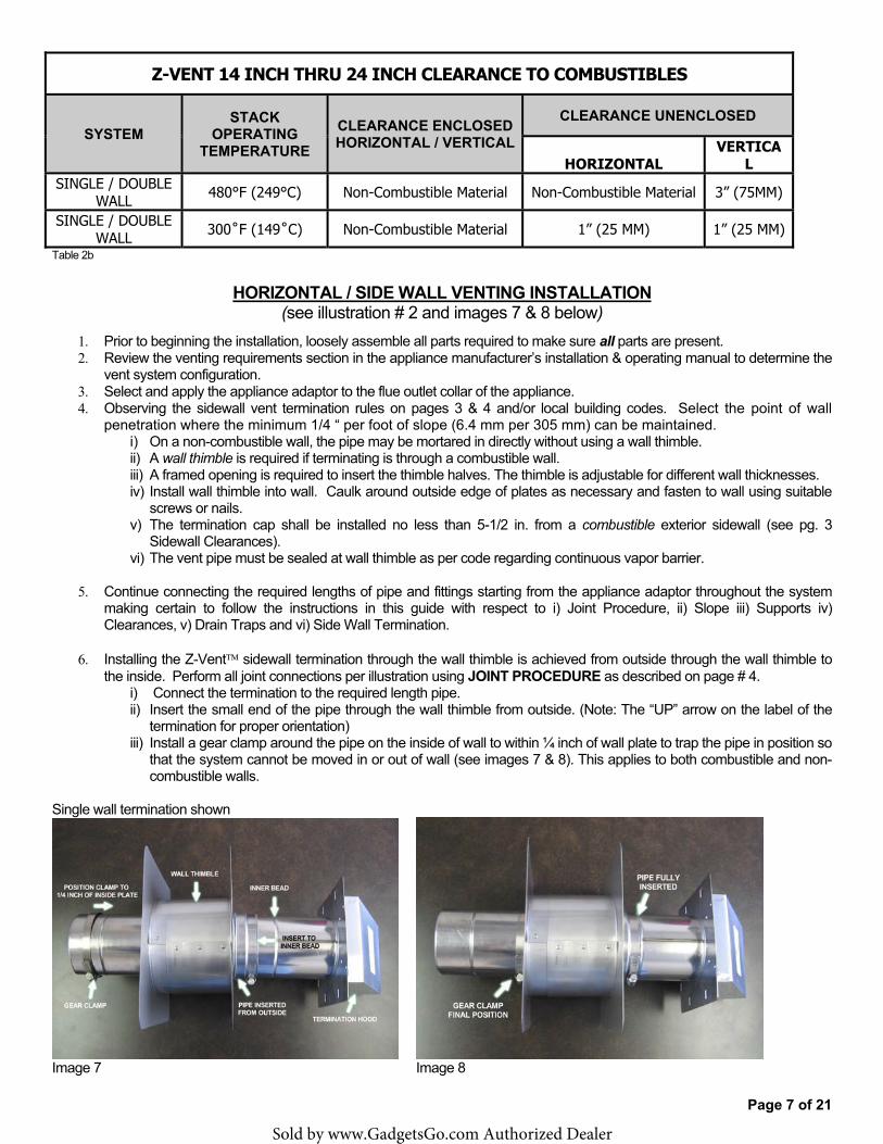
HORIZONTAL / SIDE WALL VENTING INSTALLATION (see illustration # 2 and images 7 & 8 below)
1. Prior to beginning the installation, loosely assemble all parts required to make sure all parts are present.2. Review the venting requirements section in the appliance manufacturer’s installation & operating manual to determine the
vent system configuration.3. Select and apply the appliance adaptor to the flue outlet collar of the appliance.4. Observing the sidewall vent termination rules on pages 3 & 4 and/or local building codes. Select the point of wall
penetration where the minimum 1/4 “ per foot of slope (6.4 mm per 305 mm) can be maintained.i) On a non-combustible wall, the pipe may be mortared in directly without using a wall thimble.ii) A wall thimble is required if terminating is through a combustible wall.iii) A framed opening is required to insert the thimble halves. The thimble is adjustable for different wall thicknesses.iv) Install wall thimble into wall. Caulk around outside edge of plates as necessary and fasten to wall using suitable
screws or nails.v) The termination cap shall be installed no less than 5-1/2 in. from a combustible exterior sidewall (see pg. 3
Sidewall Clearances).vi) The vent pipe must be sealed at wall thimble as per code regarding continuous vapor barrier.
5. Continue connecting the required lengths of pipe and fittings starting from the appliance adaptor throughout the systemmaking certain to follow the instructions in this guide with respect to i) Joint Procedure, ii) Slope iii) Supports iv)Clearances, v) Drain Traps and vi) Side Wall Termination.
6. Installing the Z-Vent� sidewall termination through the wall thimble is achieved from outside through the wall thimble tothe inside. Perform all joint connections per illustration using JOINT PROCEDURE as described on page # 4.
i) Connect the termination to the required length pipe.ii) Insert the small end of the pipe through the wall thimble from outside. (Note: The “UP” arrow on the label of the
termination for proper orientation)iii) Install a gear clamp around the pipe on the inside of wall to within ¼ inch of wall plate to trap the pipe in position so
that the system cannot be moved in or out of wall (see images 7 & 8). This applies to both combustible and non-combustible walls.
Single wall termination shown
Image 7 Image 8
Sold by www.GadgetsGo.com Authorized Dealer
Page 8 of 21
7. The system must be supported along its horizontal length every forty-eight inches or less and at all elbow locations usingsuitable supports around pipes (See Illustration #2) maintaining clearance to combustibles as per table 2a / b on page 6and/or 7.
8. The horizontal distance of the system from the appliance flue collar to the outside of the horizontal termination shall not begreater than that specified in the appliance manufacturer’s installation instructions.
Vent Pipe Slope
All horizontally installed portions of a vent system shall have a slope (upwards for Category II, III, or IV appliances) not less than 1/4” (6.4 mm) every 12 inches (305 mm) to prevent collection of condensate at any location in the vent system. This condensate shall be directed to a condensate drain installed within the system.
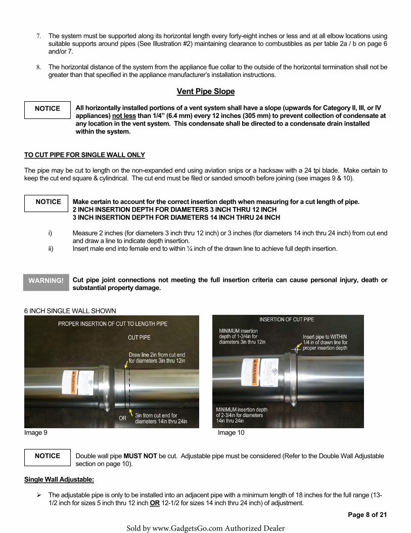
TO CUT PIPE FOR SINGLE WALL ONLY
The pipe may be cut to length on the non-expanded end using aviation snips or a hacksaw with a 24 tpi blade. Make certain to keep the cut end square & cylindrical. The cut end must be filed or sanded smooth before joining (see images 9 & 10).
Make certain to account for the correct insertion depth when measuring for a cut length of pipe. 2 INCH INSERTION DEPTH FOR DIAMETERS 3 INCH THRU 12 INCH 3 INCH INSERTION DEPTH FOR DIAMETERS 14 INCH THRU 24 INCH
i) Measure 2 inches (for diameters 3 inch thru 12 inch) or 3 inches (for diameters 14 inch thru 24 inch) from cut endand draw a line to indicate depth insertion.
ii) Insert male end into female end to within ¼ inch of the drawn line to achieve full depth insertion.
Cut pipe joint connections not meeting the full insertion criteria can cause personal injury, death or substantial property damage.
6 INCH SINGLE WALL SHOWN
Image 9 Image 10
Double wall pipe MUST NOT be cut. Adjustable pipe must be considered (Refer to the Double Wall Adjustable section on page 10).
Single Wall Adjustable:
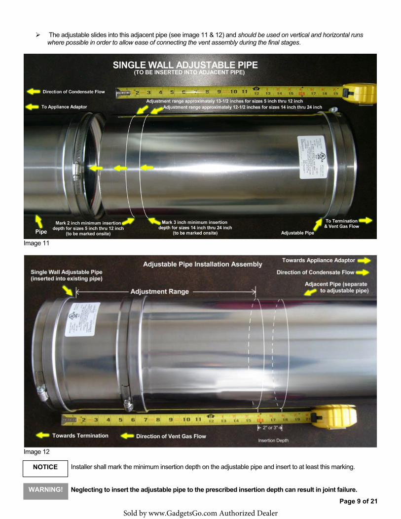
� The adjustable pipe is only to be installed into an adjacent pipe with a minimum length of 18 inches for the full range (13-1/2 inch for sizes 5 inch thru 12 inch OR 12-1/2 for sizes 14 inch thru 24 inch) of adjustment.
NOTICE
WARNING!
NOTICE
NOTICE
Sold by www.GadgetsGo.com Authorized Dealer
Page 9 of 21
� The adjustable slides into this adjacent pipe (see image 11 & 12) and should be used on vertical and horizontal runs where possible in order to allow ease of connecting the vent assembly during the final stages.
Image 11
Image 12
Installer shall mark the minimum insertion depth on the adjustable pipe and insert to at least this marking.
Neglecting to insert the adjustable pipe to the prescribed insertion depth can result in joint failure. WARNING!
NOTICE
Sold by www.GadgetsGo.com Authorized Dealer
Page 10 of 21
Double Wall Adjustable:
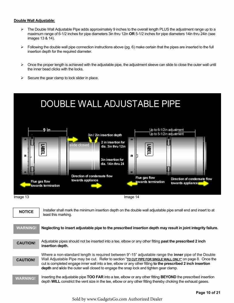
� The Double Wall Adjustable Pipe adds approximately 9 inches to the overall length PLUS the adjustment range up to a maximum range of 6-1/2 inches for pipe diameters 3in thru 12in OR 5-1/2 inches for pipe diameters 14in thru 24in (see images 13 & 14).
� Following the double wall pipe connection instructions above (pg. 6) make certain that the pipes are inserted to the full insertion depth for the required diameter.
� Once the proper length is achieved with the adjustable pipe, the adjustment sleeve can slide to close the outer wall until the inner bead clicks with the locks.
� Secure the gear clamp to lock slider in place.
Image 13 Image 14
Installer shall mark the minimum insertion depth on the double wall adjustable pipe small end and insert to at least this marking.
Neglecting to insert adjustable pipe to the prescribed insertion depth may result in joint integrity failure.
Adjustable pipes should not be inserted into a tee, elbow or any other fitting past the prescribed 2 inch insertion depth.
Where a non-standard length is required between 9”-15” adjustable range the inner pipe of the Double Wall Adjustable Pipe may be cut. Refer to section “TO CUT PIPE FOR SINGLE WALL ONLY” on page 8. Once the cut is completed engage inner wall into a tee, elbow or any other fitting to the prescribed 2 inch insertion depth and slide the outer wall closed to engage the snap lock and tighten gear clamp.
Inserting the adjustable pipe TOO FAR into a tee, elbow or any other fitting BEYOND the prescribed insertion depth WILL constrict the vent size in the tee, elbow or any other fitting thereby choking the exhaust gases.
NOTICE
WARNING!
CAUTION!
WARNING!
CAUTION!
Sold by www.GadgetsGo.com Authorized Dealer
Page 11 of 21
Condensate Tube Installation:
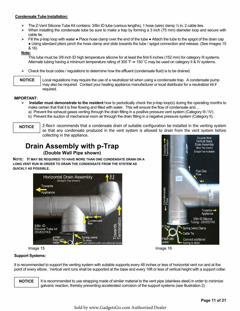
� The Z-Vent Silicone Tube Kit contains: 3/8in ID tube (various lengths), 1 hose (wire) clamp ½ in, 2 cable ties. � When installing the condensate tube be sure to make a trap by forming a 3 inch (75 mm) diameter loop and secure with
cable tie. � Fill the p-trap loop with water � Place hose clamp over the end of the tube � Attach the tube to the spigot of the drain cap
� Using standard pliers pinch the hose clamp and slide towards the tube / spigot connection and release. (See images 15 & 16)
Note: This tube must be 3/8 inch ID high temperature silicone for at least the first 6 inches (152 mm) for category III systems. Alternate tubing having a minimum temperature rating of 300�F � 150�C may be used on category II & IV systems.
� Check the local codes / regulations to determine how the effluent (condensate fluid) is to be drained.
Local regulations may require the use of a neutralizer kit when using a condensate trap. A condensate pump may also be required. Contact your heating appliance manufacturer or local distributor for a neutralizer kit if required.
IMPORTANT: � Installer must demonstrate to the resident how to periodically check the p-trap loop(s) during the operating months to
make certain that that it is free flowing and filled with water. This will ensure the flow of condensate and… a) Prevent the exhaust gases venting through the drain fitting in a positive pressure vent system (Category III / IV).b) Prevent the suction of mechanical room air through the drain fitting in a negative pressure system (Category II).
Z-flex� recommends that a condensate drain of suitable configuration be installed in the venting system so that any condensate produced in the vent system is allowed to drain from the vent system before collecting in the appliance.
Image 15 Image 16
Support Systems:
It is recommended to support the venting system with suitable supports every 48 inches or less of horizontal vent run and at the point of every elbow. Vertical vent runs shall be supported at the base and every 16ft or less of vertical height with a support collar.
It is recommended to use strapping made of similar material to the vent pipe (stainless steel) in order to minimize galvanic reaction, thereby preventing accelerated corrosion of the support systems (see Illustration 2)
NOTICE
Drain Assembly with p-Trap (Double Wall Pipe shown)
NOTICE
NOTICE
NOTE: IT MAY BE REQUIRED TO HAVE MORE THAN ONE CONDENSATE DRAIN ON A LONG VENT RUN IN ORDER TO DRAIN THE CONDENSATE FROM THE SYSTEM AS QUICKLY AS POSSIBLE.
Sold by www.GadgetsGo.com Authorized Dealer
Page 12 of 21
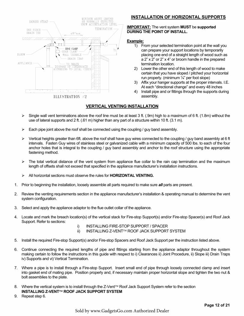
INSTALLATION OF HORIZONTAL SUPPORTS
IMPORTANT: The vent system MUST be supported DURING THE POINT OF INSTALL.
Example: 1) From your selected termination point at the wall you
can prepare your support locations by temporarily placing one end of a straight length of wood such as a 2” x 2” or 2” x 4” or broom handle in the prepared termination location.
2) Lower the other end of this length of wood to makecertain that you have sloped / pitched your horizontal run properly. (minimum ¼” per foot slope)
3) Affix your hanger supports at the proper intervals. I.E.At each “directional change” and every 48 inches
4) Install pipe and or fittings through the supports duringassembly.
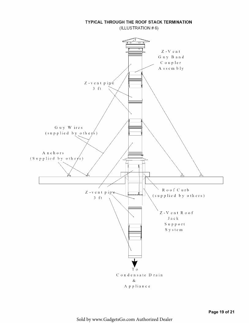
VERTICAL VENTING INSTALLATION
� Single wall vent terminations above the roof line must be at least 3 ft. (.9m) high to a maximum of 6 ft. (1.8m) without the use of lateral supports and 2 ft. (.61 m) higher than any part of a structure within 10 ft. (3.1 m).
� Each pipe joint above the roof shall be connected using the coupling / guy band assembly.
� Vertical heights greater than 6ft. above the roof shall have guy wires connected to the coupling / guy band assembly at 6 ft intervals. Fasten Guy wires of stainless steel or galvanized cable with a minimum capacity of 500 lbs. to each of the four anchor holes that is integral to the coupling / guy band assembly and anchor to the roof structure using the appropriate fastening method.
� The total vertical distance of the vent system from appliance flue collar to the rain cap termination and the maximum length of offsets shall not exceed that specified in the appliance manufacturer’s installation instructions.
� All horizontal sections must observe the rules for HORIZONTAL VENTING.
1. Prior to beginning the installation, loosely assemble all parts required to make sure all parts are present.
2. Review the venting requirements section in the appliance manufacturer’s installation & operating manual to determine the ventsystem configuration.
3. Select and apply the appliance adaptor to the flue outlet collar of the appliance.
4. Locate and mark the breach location(s) of the vertical stack for Fire-stop Support(s) and/or Fire-stop Spacer(s) and Roof JackSupport. Refer to sections:
i) INSTALLING FIRE-STOP SUPPORT / SPACERii) INSTALLING Z-VENT� ROOF JACK SUPPORT SYSTEM
5. Install the required Fire-stop Support(s) and/or Fire-stop Spacers and Roof Jack Support per the instruction listed above.
6. Continue connecting the required lengths of pipe and fittings starting from the appliance adaptor throughout the systemmaking certain to follow the instructions in this guide with respect to i) Clearances ii) Joint Procedure, ii) Slope iii) Drain Trapsiv) Supports and vi) Vertical Termination.
7. Where a pipe is to install through a Fire-stop Support. Insert small end of pipe through loosely connected clamp and insertinto gasket end of mating pipe. Position properly and, if necessary maintain proper horizontal slope and tighten the two nut &bolt assemblies to the plate.
8. Where the vertical system is to install through the Z-Vent� Roof Jack Support System refer to the sectionINSTALLING Z-VENT� ROOF JACK SUPPORT SYSTEM
9. Repeat step 6.
Sold by www.GadgetsGo.com Authorized Dealer
Page 13 of 21
10. Where the vent passes through the Roof Jack Support System extend the pipe above the roof following the VerticalTermination Clearances on pg. 4.
11. Install the Z-Vent� Top Support and, if necessary the Flashing on the pipe just above the Roof Jack Support assembly andseal around the top edge where the collar meets the pipe.
12. Affix the Z-Vent� vertical termination following the Joint Procedure. (illustration #1 images 1, & 2)
INSTALLING FIRE-STOP SUPPORT / SPACER PLATE
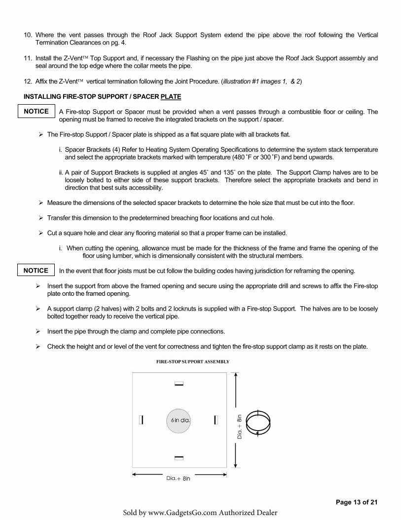
A Fire-stop Support or Spacer must be provided when a vent passes through a combustible floor or ceiling. The opening must be framed to receive the integrated brackets on the support / spacer.
� The Fire-stop Support / Spacer plate is shipped as a flat square plate with all brackets flat.
i. Spacer Brackets (4) Refer to Heating System Operating Specifications to determine the system stack temperatureand select the appropriate brackets marked with temperature (480�F or 300�F) and bend upwards.
ii. A pair of Support Brackets is supplied at angles 45� and 135� on the plate. The Support Clamp halves are to beloosely bolted to either side of these support brackets. Therefore select the appropriate brackets and bend indirection that best suits accessibility.
� Measure the dimensions of the selected spacer brackets to determine the hole size that must be cut into the floor.
� Transfer this dimension to the predetermined breaching floor locations and cut hole.
� Cut a square hole and clear any flooring material so that a proper frame can be installed.
i. When cutting the opening, allowance must be made for the thickness of the frame and frame the opening of thefloor using lumber, which is dimensionally consistent with the structural members.
In the event that floor joists must be cut follow the building codes having jurisdiction for reframing the opening.
� Insert the support from above the framed opening and secure using the appropriate drill and screws to affix the Fire-stop plate onto the framed opening.
� A support clamp (2 halves) with 2 bolts and 2 locknuts is supplied with a Fire-stop Support. The halves are to be loosely bolted together ready to receive the vertical pipe.
� Insert the pipe through the clamp and complete pipe connections.
� Check the height and or level of the vent for correctness and tighten the fire-stop support clamp as it rests on the plate.
NOTICE
NOTICE
Sold by www.GadgetsGo.com Authorized Dealer
Page 14 of 21
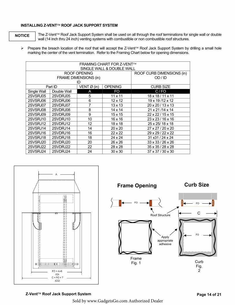
INSTALLING Z-VENT� ROOF JACK SUPPORT SYSTEM
The Z-Vent� Roof Jack Support System shall be used on all through the roof terminations for single wall or double wall (14 inch thru 24 inch) venting systems with combustible or non combustible roof structures.
� Prepare the breach location of the roof that will accept the Z-Vent� Roof Jack Support System by drilling a small hole marking the center of the vent termination. Refer to the Framing Chart below for opening dimensions.
FRAMING CHART FOR Z-VENT� SINGLE WALL & DOUBLE WALL
ROOF OPENING FRAME DIMENSIONS (in)
ID
ROOF CURB DIMENSIONS (in) OD / ID
Part ID VENT Ø (in) OPENING CURB SIZE Single Wall Double Wall A FO C / FO 2SVSRJ05 2SVDRJ05 5 11 x 11 18 x 18 / 11 x 11 2SVSRJ06 2SVDRJ06 6 12 x 12 19 x 19 /12 x 12 2SVSRJ07 2SVDRJ07 7 13 x 13 20 x 20 / 13 x 13 2SVSRJ08 2SVDRJ08 8 14 x 14 21 x 21 /14 x 14 2SVSRJ09 2SVDRJ09 9 15 x 15 22 x 22 / 15 x 15 2SVSRJ10 2SVDRJ10 10 16 x 16 23 x 23 / 16 x 16 2SVSRJ12 2SVDRJ12 12 18 x 18 25 x 25/ 18 x 18 2SVSRJ14 2SVDRJ14 14 20 x 20 27 x 27 / 20 x 20 2SVSRJ16 2SVDRJ16 16 22 x 22 29 x 29 / 22 x 22 2SVSRJ18 2SVDRJ18 18 24 x 24 31 x31 / 24 x 24 2SVSRJ20 2SVDRJ20 20 26 x 26 33 x 33 / 26 x 26 2SVSRJ22 2SVDRJ22 22 28 x 28 35 x 35 / 28 x 28 2SVSRJ24 2SVDRJ24 24 30 x 30 37 x 37 / 30 x 30
NOTICE
Z-Vent� Roof Jack Support System
Curb Size
C
FO
FO FO
Frame Opening
Roof Structure
Frame Fig. 1
Apply appropriate adhesive
Curb Fig.
2
Sold by www.GadgetsGo.com Authorized Dealer
Page 15 of 21
� Cut a square hole and clear any roofing material so that a proper frame can be installed.
� When cutting the opening, allowance must be made for the thickness of the frame.
In the event that roof joists must be cut - follow the building codes having jurisdiction for reframing the opening.
� For roof curb installations (recommended): Refer to the Curb Size in the Framing Chart for box framing sizes for masonry pour. Roof curbs may also be purchased at your local building supply store.
INSTALLING ON A FRAMED OPENING (Fig. 1)
� Implementing “best practice” and / or “preferred” methods. Drill sufficient holes in the roof jack plate. � Place the Z-vent� Roof Jack Support System (conical side up) by centering it over and lowering it down onto the frame
and transfer the position of the drilled holes from the plate onto the frame. Temporarily remove the Roof Jack for adhesive application.
� Apply the appropriate weather resistant adhesive (Fig. 1) to the frame observing the hole markings. � Install the Z-vent� Roof Jack Support System (conical side up) by centering it over the framed opening and lowering it
onto the frame and secure it using screws equipped with neoprene washers. � Using the appropriate roofing methods reapply the roofing material over the plate to maintain the roofing integrity. � Install the Z-Vent� flashing over the roof jack by implementing the standard contractor roofing methods.
INSTALLING ON A CURB (Fig. 2)
� Implementing “best practice” and / or “preferred” methods. Drill sufficient holes in the roof jack plate. � Place the Z-vent� Roof Jack Support System (conical side up) by centering it over and lowering it down onto the curb
and transfer the location of the drilled holes from the plate onto the curb. Temporarily remove the Roof Jack. Select the appropriate masonry drill bit size for the concrete screws being used and drill the marked holes in the curb to the prescribed depth.
� Apply the appropriate weather resistant adhesive (Fig. 2) to the curb observing the hole markings. � Install the Z-vent� Roof Jack Support System (conical side up) by centering it over and lowering it down onto the curb
again. This time fasten the plate to the curb with concrete screws equipped with neoprene washers. � Seal where the plate meets the curb with the appropriate weather resistant sealant.
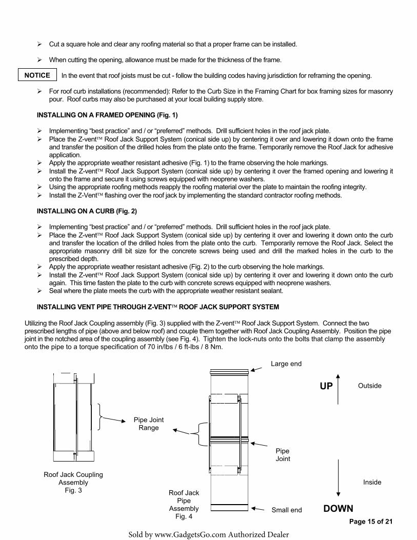
INSTALLING VENT PIPE THROUGH Z-VENT� ROOF JACK SUPPORT SYSTEM
Utilizing the Roof Jack Coupling assembly (Fig. 3) supplied with the Z-vent� Roof Jack Support System. Connect the two prescribed lengths of pipe (above and below roof) and couple them together with Roof Jack Coupling Assembly. Position the pipe joint in the notched area of the coupling assembly (see Fig. 4). Tighten the lock-nuts onto the bolts that clamp the assembly onto the pipe to a torque specification of 70 in/lbs / 6 ft-lbs / 8 Nm.
NOTICE
Roof Jack Coupling Assembly
Fig. 3
Pipe Joint Range
Roof Jack Pipe
Assembly Fig. 4
Outside UP
DOWN
Inside
Pipe Joint
Small end
Large end
Sold by www.GadgetsGo.com Authorized Dealer
Page 16 of 21
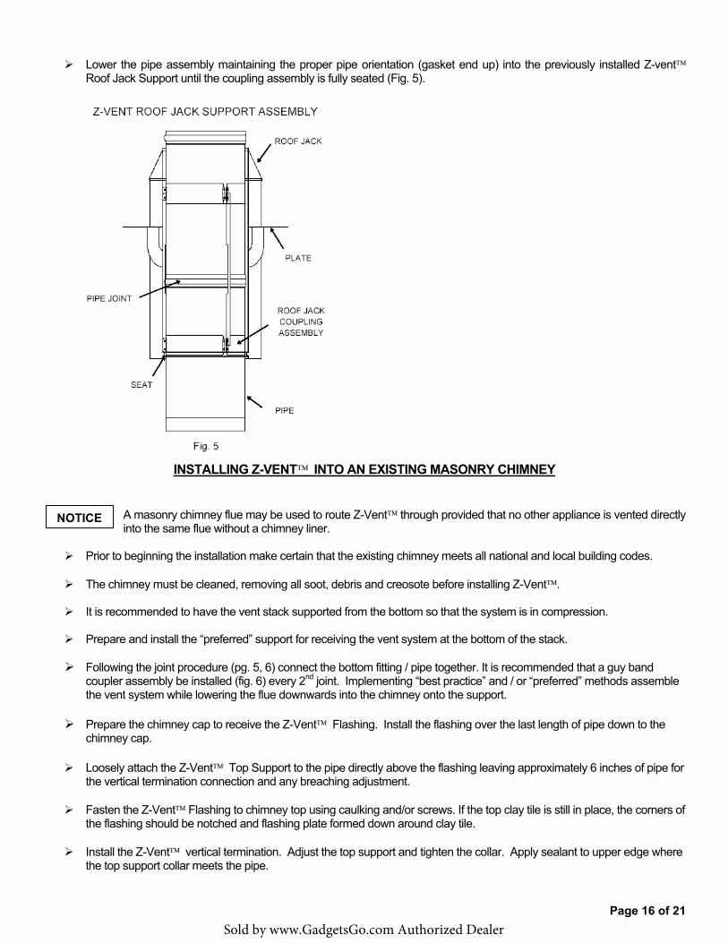
� Lower the pipe assembly maintaining the proper pipe orientation (gasket end up) into the previously installed Z-vent� Roof Jack Support until the coupling assembly is fully seated (Fig. 5).
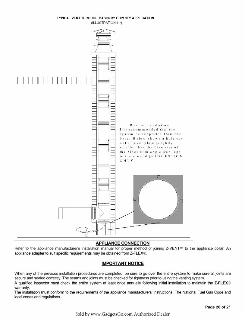
INSTALLING Z-VENT� INTO AN EXISTING MASONRY CHIMNEY
A masonry chimney flue may be used to route Z-Vent� through provided that no other appliance is vented directly into the same flue without a chimney liner.
� Prior to beginning the installation make certain that the existing chimney meets all national and local building codes.
� The chimney must be cleaned, removing all soot, debris and creosote before installing Z-Vent�.
� It is recommended to have the vent stack supported from the bottom so that the system is in compression.
� Prepare and install the “preferred” support for receiving the vent system at the bottom of the stack.
� Following the joint procedure (pg. 5, 6) connect the bottom fitting / pipe together. It is recommended that a guy band coupler assembly be installed (fig. 6) every 2nd joint. Implementing “best practice” and / or “preferred” methods assemble the vent system while lowering the flue downwards into the chimney onto the support.
� Prepare the chimney cap to receive the Z-Vent� Flashing. Install the flashing over the last length of pipe down to the chimney cap.
� Loosely attach the Z-Vent� Top Support to the pipe directly above the flashing leaving approximately 6 inches of pipe for the vertical termination connection and any breaching adjustment.
� Fasten the Z-Vent� Flashing to chimney top using caulking and/or screws. If the top clay tile is still in place, the corners of the flashing should be notched and flashing plate formed down around clay tile.
� Install the Z-Vent� vertical termination. Adjust the top support and tighten the collar. Apply sealant to upper edge where the top support collar meets the pipe.
NOTICE
Sold by www.GadgetsGo.com Authorized Dealer
Page 17 of 21
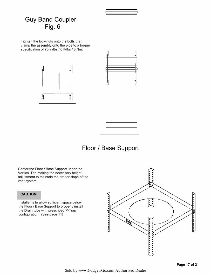
Guy Band Coupler Fig. 6
Tighten the lock-nuts onto the bolts that clamp the assembly onto the pipe to a torque specification of 70 in/lbs / 6 ft-lbs / 8 Nm.
Floor / Base Support
Center the Floor / Base Support under the Vertical Tee making the necessary height adjustment to maintain the proper slope of the vent system.
CAUTION!
Installer is to allow sufficient space below the Floor / Base Support to properly install the Drain tube with prescribed P-Trap configuration. (See page 11)
Sold by www.GadgetsGo.com Authorized Dealer
Page 18 of 21
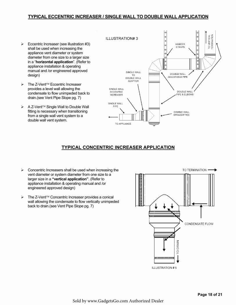
TYPICAL ECCENTRIC INCREASER / SINGLE WALL TO DOUBLE WALL APPLICATION
� Eccentric Increaser (see illustration #3) shall be used when increasing the appliance vent diameter or system diameter from one size to a larger size in a “horizontal application”. (Refer to appliance installation & operating manual and /or engineered approved design)
� The Z-Vent� Eccentric Increaser provides a level wall allowing the condensate to flow unimpeded back to drain.(see Vent Pipe Slope pg. 7)
� A Z-Vent� Single Wall to Double Wall fitting is necessary when transitioning from a single wall vent system to a double wall vent system.
TYPICAL CONCENTRIC INCREASER APPLICATION
� Concentric Increasers shall be used when increasing the vent diameter or system diameter from one size to a larger size in a “vertical application”. (Refer to appliance installation & operating manual and /or engineered approved design)
� The Z-Vent� Concentric Increaser provides a conical wall allowing the condensate to flow vertically unimpeded back to drain.(see Vent Pipe Slope pg. 7)
Sold by www.GadgetsGo.com Authorized Dealer
Page 19 of 21
Sold by www.GadgetsGo.com Authorized Dealer
Page 20 of 21
APPLIANCE CONNECTION Refer to the appliance manufacturer's installation manual for proper method of joining Z-VENT� to the appliance collar. An appliance adapter to suit specific requirements may be obtained from Z-FLEX�.
IMPORTANT NOTICE
When any of the previous installation procedures are completed, be sure to go over the entire system to make sure all joints are secure and sealed correctly. The seams and joints must be checked for tightness prior to using the venting system. A qualified inspector must check the entire system at least once annually following initial installation to maintain the Z-FLEX� warranty. The installation must conform to the requirements of the appliance manufacturers' instructions, The National Fuel Gas Code and local codes and regulations.
Sold by www.GadgetsGo.com Authorized Dealer
Page 21 of 21
Z-FLEX® LIMITED LIFETIME WARRANTY
Z-FLEX® (“Seller”) extends the following LIMITED WARRANTY for Z-VENT� (the “Z-Vent�”): Seller warrants that at the time of purchase, the Z-Vent� will be free of manufacturer’s defects in material and/or workmanship. This warranty shall extend to the original purchaser of the Z-Vent� or, if purchased by a contractor, to the end user. This warranty is valid for a period of fifteen (15) years from the date of purchase, provided that the Z-Vent� has been installed according to Z-Flex® installation instructions. Deviating from the installation and use instructions included with the Z-Vent� will void the warranty. Under this Limited Warranty, Seller’s sole responsibility and liability shall be to replace the Z-Vent� and/or accessories, if found by Seller to be defective according to the terms of the warranty, and shall not include replacement installation or other costs.
IMPORTANT: The Z-Vent� Model SVEIV is designed for use with Category II, III and IV furnace and boiler venting and should not be used with any other type of furnace and boiler venting. Use of the Z-Vent� with any other type of furnace and boiler venting other than those recommended by Seller for use with its Z-Vent� will void the warranty. WARNING: CONDENSATION WITH HIGH ACID CONTENT MAY BE PRODUCED DUE TO UNFORESEEN CONDITIONS. YOUR HEATING APPLIANCE AND VENTING SYSTEM SHOULD BE INSPECTED BY A LICENSED CONTRACTOR ON AN ANNUAL BASIS FOR POSSIBLE SIGNS OF DETERIORATION DUE TO RUSTING OR PIN HOLES. CONDENSATION WITH HIGH ACID CONTENT MAY CAUSE LEAKAGE OF HARMFUL GASES WHICH CAN CAUSE NAUSEA, FAINTING OR DEATH. IF DETERIORATION IS DETECTED CEASE USE OF HEATING SYSTEM AND CALL FURNACE/BOILER INSTALLER FOR REMEDIAL ACTION. To activate the warranty, the end-user must complete and return the Z-Flex® Warranty Registration Card within ninety (90) days of installation of the Z-Vent�. Upon written notice of any defects, Z-Flex® reserves the right to examine or establish reasonable proof of defective material or workmanship justifying replacement. NO OTHER EXPRESS WARRANTY HAS BEEN MADE OR WILL BE MADE ON BEHALF OF SELLER WITH RESPECT TO THE Z-VENT� OR THE INSTALLATION OR REPLACEMENT OF THE Z-VENT�. SELLER SHALL NOT BE LIABLE FOR ANY SPECIAL, INCIDENTAL, INDIRECT OR CON-SEQUENTIAL DAMAGES. As some jurisdictions do not allow the exclusion or limitation of incidental or consequential damages, the above limitations or exclusions may not apply to you. IMPLIED WARRANTIES, INCLUDING ANY WARRANTY OF MERCHANTABILITY OR FITNESS FOR A PARTICULAR PURPOSE, IMPOSED ON THIS SALE UNDER STATE LAW, ARE LIMITED TO THE PERIOD DURING WHICH THIS WARRANTY IS IN EFFECT. AS SOME JURISDICTIONS DO NOT ALLOW LIMITATIONS ON THE LENGTH OF AN IMPLIED WARRANTY, THE ABOVE LIMITATION MAY NOT APPLY TO YOU. Claims under this Warranty must be made within the warranty period in writing and directed to: In the USA; Warranty Claims, Z-Flex®(US) Inc., 20 Commerce Park North, Bedford, New Hampshire 03110, (603) 669-5136 or (800) 645-5600. In Canada; Warranty Claims, Z-Flex® Inc., 452 Attwell Drive, Etobicoke, Ontario, M9W 5C3, (416) 679-0045. This Warranty gives you specific legal rights, and you may also have other rights that vary in different States and Provinces.
� WARRANTY REGISTRATION CARD: Z-FLEX®
For this warranty to be effective, this card must be completed upon purchase of the covered Z-Vent� and returned to Z-Flex® within ninety (90) days of installation of the Z-Vent�. Original end-user’s name:__________________________________________________________________________
Address of premises in which the Z-Vent� is installed:___________________________________________________ ________________________________________________________________________________________________
Z-Vent� purchased from:___________________________________________________________________________
Date of Installation:_______________________________________________________________________________
Type of Heating System into which Z-Vent� installed:___________________________________________________
I understand and agree to the Warranty as stated:_____________________________________________________
__________________________________ ____________________________ Signature Date
Model SVE IV Instructions Sept. 15 2011
Sold by www.GadgetsGo.com Authorized Dealer