Embed Size (px)
Citation preview

Commercial PV Projects with AEE Solar
Glenn Hall
AEE Applications Engineer
1/19/2018

Discussion Topics
• Considering 60-cell vs 72-cell modules for Commercial PV
• Trends and developments for Commercial PV Systems• Sizing arrays with regards to Inverter capacity
• Optimal tilt of arrays on Commercial Projects
• NEC 2014/2017 Rapid Shutdown for Commercial Projects‒ Preparing for Module Level Requirements NEC2017 – Jan. 1, 2019!
• Trends and developments for ballasted systems
• Aerocompact Ballasted and Metal Roof Racking Systems• Example of maximizing output of a ballasted commercial PV system
• New Aerocompact Metal Roof offerings
• Carport and Canopy Solar Racking from Schletter
• Commercial Ground Racking Solutions• Considerations for inverter placement for commercial Ground Mounts
• Tax Credits – ITC and MACRS Depreciation • Example of value of Tax Credits, including MACRS
2
60-Cell vs. 72-Cell Modules
• Polycrystalline – 255-290 Watts
• Monocrystalline – 280 to 300+ Watts
• High Efficiency Mono – 335 to 350+ Watts
• Polycrystalline – 315 to 345 Watts
• Monocrystalline – 340 to 360 Watts
• High Efficiency – Not Typical
60-Cell Modules (typical) 72-Cell Modules (typical)
Limitations with 72-Cell modules for Commercial Projects
o Last year, we saw limited availability on 72-cell panels
o 60-Cell modules often lower cost per watt than equivalent 72-Cell modules
o Minimum order quantities often apply for 72-cell panels – full pallets or containers
o Power densities typically higher using 60-Cell modules
o 72-Cell panels may be restricted in areas with heavy snow load
o 72-Cell panels thicker frames often used, so larger modules can be heavier per watt
o Two people often required to handle 72-Cell modules, 60-cell panels are one person
o More aesthetic options available for 60-cell modules, if this is a customer requirement
Power Densities of modules available through AEE
60-Cell Modules 72 Cell Modules
Brand Model Watts/Sq.Ft. Brand Model Watts/Sq.Ft.
REC REC290TP2-BLK 16.1 REC REC335TP2-72 15.7
Hanwha Q.PEAK-300-G4-1 16.6 REC REC340TP2-72 15.9
LG LG335N1C-A4 18.6 REC REC345TP2-72 16.1
LG LG350Q1C-A5 19.4 Mission MSE355-SQ4S 16.6

Commercial PV Design Trends
Higher DC to AC inverter load ratio‒ <120% DC:AC was regarded as the PV industry standard
‒ 130% to 135% is becoming much more common
‒ New inverters such as SMA Core1-50kW, the Fronius Symo inverters, and Outback Proharvest have high advertised maximum DC to AC Ratios –designs can be up to 150%
‒ Inverters reach peak output earlier in the day, and minimal clipping during high irradiance is allowed. Inverters are not damaged by the PV Array.
‒ Fewer inverters needed for the site, resulting in lower cost to source, install, maintain, and warranty.
‒ More kWh can be generated at the site with lower BOS and inverter costs.
‒ Results in lower cost per generated kWh for the PV system.
High tilt angles to the South at latitude not always ideal‒ Higher tilts facing south result in larger inter-row shading
‒ Majority of net-metered solar production occurs during summer months
‒ Lower tilt angles allow larger PV arrays with higher energy production
‒ East/West racking solutions eliminate inter-row shading, maximizing energy density on the roof, at even lower cost and ballast weight

Rapid Shutdown Considerations
• NEC2014 690.12(B)(1), the PV Array boundary for uncontrolled conductors is 10’ ‒ Applies to all energized DC conductors on or inside a building‒ Conductors outside the boundary must be under 30 volts in 30 seconds‒ Allows first responders to de-energize the high voltage conductors quickly
• NEC2017 code reduces the PV array boundary to 1’, and has language for the voltage maximum within the array.‒ Code update shrinks the boundary for controlled conductors to 1’‒ Conductors outside the array must be under 30 volts in 30 seconds.‒ Jan.1, 2019 – NEC 2017 690.12(B)(2) becomes effective
• Voltage within the array must be under 80 volts in 30 seconds• In essence, requires Rapid Shutdown at the module level
• Outback ProHarvest, SMA Core1-50kW, and other commercial inverters that are mounted on the roof are compliant to NEC2014 and current NEC2017 code• Outback Proharvest inverters mount under panels• SMA Core1-50kW inverters easily located next to PV array• SolarEdge optimizers deactivate optimizers, and cut DC power at source

Rapid Shutdown Considerations
• Meeting Module Level RSD requirements after Jan.1, 2019
‒ SMA – Power+ branded Tigo optimizers and gateways on each panel
‒ Tigo optimizers and Gateway devices for other inverter brands
‒ SolarEdge single panel optimizers (P320, P370, P400) or commercial optimizers that have two inputs (P800P)
‒ Enphase IQ/IQ+ inverters
‒ Panels with Maxim optimized junction boxes may provide Rapid Shutdown Functionality with certain inverter manufacturers (Fronius)
• Traditional string inverters may become limited to being used on carports and for ground mount PV Arrays
‒ NEC2014/NEC2017 Rapid Shutdown requirements are only required for roof mount solar arrays

NEC Adoption Map – 11/1/2017

Outback ProHarvest TruestringCommercial Inverters
• For both 480 VAC and 208 VAC installations
‒ PRO480-8k
‒ PRO208-5k75
• Lightweight – 24 lbs. per unit
• Two DC String Inputs with dual MPPT Tracking with Monitoring over Powerline Communications
‒ Integrated MC4 Connectors speeds installation time
‒ Arc Fault Detection for each individual DC String
• Robust Waterproof NEMA6 enclosure
‒ Mounted under array
• Inherently compliant with NEC2014/NEC2017 Rapid Shutdown requirements
• Outabck ProHarvest Designed AC Splice Boxes
‒ Easily combines output of three inverters
‒ One combined output circuit - 40A 3P-480 VAC breaker or 60A 3P-208VAC breaker
12

SMA Tripower Core1 – 50kW Inverter
SMA Tripower Core1 – 50kW Inverter• Compact, robust design• 6 MPPT circuits, with two string inputs each
allows 12 total strings with integrated Amphenol H4 connectors without needing Fusing for individual strings
• SA compliant inverter – CA Rule 21, HI Rule 14H• Integrated AC/DC disconnect• High DC to AC ratios possible – up to 150%• Lift up and place directly on roof, or concrete
pad.• Built in WiFi access, with integrated datalogger
and access to Sunny Portal Monitoring• Suitable for Roof, Carport, or Ground Mount
Applications• Rapid Shutdown requirements for 2019 can be
accomplished with SMA Power+ MLPEs

SMA Inverter ‘Ready Rack’Ballasted Racking Units
SMA Tripower Inverters- 3P-480 VAC- 12.0, 15.0, 20.0, 24.0, and 30.0 kW Units- SA Compliant for CA and HawaiiSMA ReadyRack 2.0- For use with SMA Tripower inverters- Includes CU1000 combiner/disconnect- Factory assembled unit is shipped direct
to job site, and crane lifted in place

SolarEdge – Commercial Inverters
SolarEdge Commercial Inverter and Optimizer System- Inverters for both 3P-480VAC and 3P-208 VAC
applications- SA Compliant for CA and HI- Up to three input strings for the SE14.4kUS-208
and the SE33.3kUS-480- Larger models will start to be available, which gang
three 14.4k or three 33.3k inverters together, with a common disconnect.
- Rapid Shutdown NEC2017 - use Single Optimizers, or P800P dual optimizers – Reducing voltage within the array remains under NEC2017 limits.
- High DC to AC ratios possible – up to 145%- Since Rapid Shutdown is at the module level,
inverters can be placed on wall near point of utility connection.

Commercial Rooftop Racking
• Flat-roof arrays using ballasted racking solutions
• Quick to design & install
• Fewer materials needed than rail-based systems
• Minimizes or eliminates roof penetrations
• Avoids re-sealing
• Easier servicing of roof
• Less roof warranty issues
• Limitations of ballasted systems
• Seismic-related building codes may mandate some penetrations
• Not suitable for roofs with greater than 5° slope
• Not suitable for roofs over 50’ high
• Wind exposure drives ballast and module tilt limitations
• Be sure that designer and/or supplier uses correct wind loads, exposure categories, and risk factors!

Penetrating vs. Ballasted
• Roof penetrations into roof structure anchors PV array
• Roof penetrations must be properly sealed for array life
• Higher tilt angles are possible to increase module efficiency
• Can be installed on pitched or flat roof surfaces
• Lower array weight than ballasted, less roof dead load
• Roof maintenance requires removal of array racking and re-installation of penetrations
• Weight of array plus additional ballast anchors PV array
• Few to no roof penetrations required to anchor array
• Tilt angles typically <10° to minimize wind effects
• Pitch of roof limited depending on racking solution
• Higher roof loading due to ballast weight, higher dead load
• Array can be more easily removed and reinstalled for roof maintenance
Penetrating Racking Ballasted Racking

Hybrid Ballasted Systems
• Minimally attached system can offer best of both worlds
• Majority of array quickly installed
• Roof anchor and penetration points made in key areas of array
• Fewer penetrations to install and flash, array still removable
• Lower ballasting requirements can allow systems to be installed where roof loading is a concern
• If penetrations are located correctly, they prevent sliding of array, and can use static friction values, further reducing ballasting requirements
• Optimize tradeoff between penetrations and ballast
• Less penetrations require more ballasting and vice versa
• Combination of penetrations and ballast can be best way to meet wind and seismic load requirements
• California and some other seismic jurisdictions will always require some penetrations

Aerocompact Ballasted Racking
Aerocompact Ballast Racking‒ Landscape Format – connects directly to module
frames – no rails• South Facing 5°/10°/15° tilt• East/West 10° tilt - maximizes module density
and lowers ballasting requirements
‒ 25 year warranty. ‒ Wind Tunnel tested to 150 mph‒ UL2703 integrated grounding and fire code
compliant‒ Aerotool Design Software
• Full layout, ballasting plan, material list, and engineering reports
• Wet-stamp support for all 50 states• Final engineering and quotes• Light Version available for initial layout planning
‒ Pre-attached EPDM rubber pads on supports to protect roof surface; ballast trays when required
‒ Fast installation with single tool‒ Support for penetrations to lower ballasting or
for Seismic requirements. ‒ UL Listed Frame mounts available for
microinverters or optimizers‒ Over 100MW of installed projects in 2016

Example – More solar per roof possible with lower tilt arrays
Aerocompact 15° South• 160’ x 300’ area• 1,245 (280-W) modules • 348.6 kW (569 MWh)
Aerocompact 5° South • 160’ x 300’ area• 1,430 (280-W) modules • 400.4 kW (620 MWh)• 15% (9% kWh) increase
Aerocompact 10° East/West • 160’ x 300’ area• 1,586 (280-W) modules • 444.1 kW (673 MWh)• 27% (18% kWh) increase

Examples using AerocompactSouth and East/West Ballast Rack
15° South Tilt Ballasted Racking• 1,244 modules, 348.6kW DC Array
• Using 8x SE33.3kW inverters and P600 optimizers
• Array would produce estimated 569 MWh of power in year 1
• 3.22 psf roof dead load, needing 3,270 ballast blocks
5° South Tilt Ballasted Racking• 1,430 modules, 400.4kW DC Array
• Using 9x SE33.3kW inverters and P600 optimizers
• Array would produce estimated 620 MWh of power yr1 (+9%)
• 2.80 psf roof dead load, needing 2,389 ballast blocks
10° Tilt East-West Ballasted Racking• 1,586 modules, 444.6kW DC Array
• Using 10x SE33.3kW inverters and P600 optimizers
• Array would produce estimated 673 MWh of power yr1 (+18%)
• 2.35 psf roof dead load, needing only 910 ballast blocks
• Racking cost per watt can be up to half that of 15 degree racking, as it uses less materials, and does not require wind screens.

Commercial Racking – Metal Roofs
NEW! AEROCOMAPCT METAL ROOF MOUNTING OPTIONS
• TS - Trapezoidal Roof System
‒ Short support rail attached directly to roof, sealed with butyl tape, with top down clamps
‒ Economical and quick install
‒ Fully grounded system, UL2703
• T1 - Standing Seam Clamp System
‒ Seam Clamp attaches directly to roof, and provides attachment point for top down clamps
‒ Fast easy install
‒ Only two components!
‒ Fully grounded system, UL2703

Large Ground Mount Arrays
• Medium sized systems can be completed with a conventional ground mount racking
• SnapNrack Series 200 Ground Mount can be competitively employed for arrays up to about 150 kW DC.
• One rack of 100 300-watt, 60-cell modules with 25 rows of 4 high in landscape would result in a 30.0kW DC array, and suitable for use with Fronius Symo or SMA Tripower 24kW inverters, or three ProHarvest 8kW Truestring Inverters
• Ten 3’ deep front piers and ten 4’ deep back piers for many locations
• 4 racks 112 kW DC / 96 kW AC array field
• This array could fit in a 100’ x 150’ space
• Cost roughly $0.15-0.17/watt, plus galvanized piping and concrete
• Pile driven systems may require special engineering studies and specialized equipment rentals that can add too much cost for smaller projects

Ground Mount Solar Racking
SnapNrack Series 200UL• Optimal solution for small to medium sized ground mount arrays
• Four Module High Landscape orientation, typical
• Three high landscape also available.
• High module/power density
• UL2703 Listed – Only one grounding point per subarray required
• On-line configuration tool to determine BOM and engineering requirements
• Specialized equipment not required for installation
• Locally sourced Schedule 40 1-1/2” galvanized pipe lowers shipping costs
• Residential installers can easily utilize a known solution for larger projects

Ground Mount Solar Racking
Aerocompact G and G+ Series Ballasted Ground Racking • Commercial and utility ground mount installations
• Quick install times, without the need for piles, concrete or large machinery.
• Install as Completely ballasted, or with optional screw soil anchors.
• Up to 1 MW of racking can ship to a jobsite in a single truck load.
• Ideal for areas that have soil issues like landfills or brownfields, areas that cannot support deep piles or excavation due to rocks, or for areas of sensitive ecological nature where excavation is discouraged.
• Fleece mesh can be supplied to prevent vegetation growth around the module field.
• This ground mount system can be designed with either a South 15°-20°-25° tilt, or with a 10° tilt East/West Configuration

Ground Mount Solar Racking
NEW! Schletter FS Series Commercial Racking • Large Commercial or Utility Projects
• Can accommodate uneven terrain
• Two high portrait design typical to maximize number of panels per post
• Posts are typically pile driven; cement piers and ground screws available
• Designed for exceptional value for cost driven projects
• Soil sampling is required as part of the project planning process
• Aluminum extrusions, integrated grounding components, and component pre-assembly allow this commercial racking system to be quickly installed.
• Integrated grounding to UL2703 for lower install time and component count
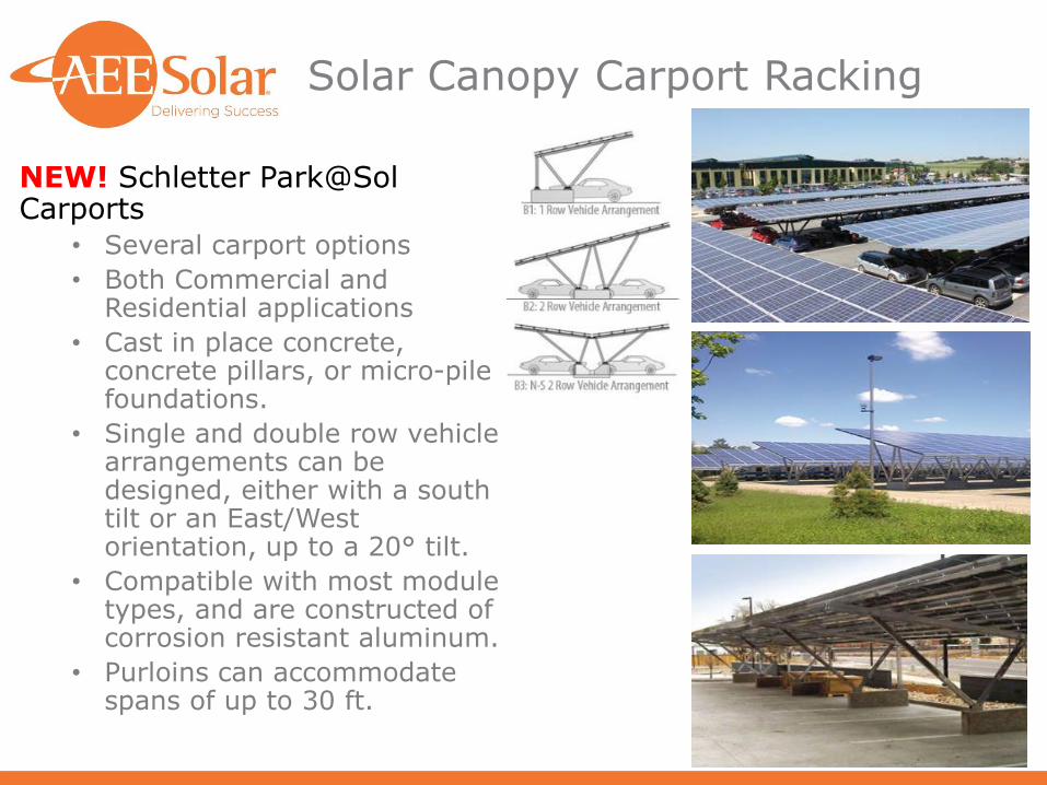
Solar Canopy Carport Racking
NEW! Schletter Park@SolCarports
• Several carport options
• Both Commercial and Residential applications
• Cast in place concrete, concrete pillars, or micro-pile foundations.
• Single and double row vehicle arrangements can be designed, either with a south tilt or an East/West orientation, up to a 20° tilt.
• Compatible with most module types, and are constructed of corrosion resistant aluminum.
• Purloins can accommodate spans of up to 30 ft.

Inverter Locations on Ground Mount Arrays
• Inverters for Ground Mount Arrays can be located behind the panels on the ground racks to save space and simplify installation
‒ NEMA 4 enclosures of typical inverters allow outdoor mounting
• AC vs DC voltage drop considerations
‒ Most 480VAC-3P inverters allow for 1,000 VDC max wiring
‒ Locating inverters close to point of connection will allow typical 600-800 VDC operation for array to inverter wiring
• 277 VAC Line-to-Neutral is 2-3 times more voltage drop and system losses vs. 600-800 VDC wiring
• Mounting inverters under array may avoid extra DC disconnects
• Monitoring may be easier if inverters are centralized

Federal ITC and MACRS Depreciation Tax Credits
• Federal Investment Tax Credit (ITC)
• 30% tax credit through 2019.
• 26% in 2020
• 22% in 2021
• 10% from 2022 on (no expiration for commercial ITC)
• Modified Accelerated Cost Recovery System (MACRS)
• 5-year accelerated depreciation for solar assets
• Additional tax savings represent nearly 10% of system cost
• NOTE: See that your end-customer reviews these options with an accountant or tax attorney

MACRS Depreciation Example
MACRS Depreciation Example• Consult your tax professional about IRS Form 4562 in calculating
the allowed MACRS depreciation for the 6 year period.‒ 85% of the net PV install costs are eligible for depreciation‒ Depreciation Schedule for year 1 to year 6
• 20% / 32% / 19.2% / 11.52% / 11.52% / 5.76%• Determines the ‘deduction’. Actual value depends on Corporate Tax Rate
• Example: 40kW PV array, $100,000 total system cost, and 30% corporate tax rate‒ Year one ITC Federal Tax Credit - $30,000 tax credit‒ Tax savings resulting from calculating MACRS Depreciation
• Year 1 - $5100• Year 2 - $8160• Year 3 - $4896• Year 4 - $2938• Year 5 - $2938• Year 6 - $147
• Net PV system install cost over 6 year period after ITC & MACRS‒ $100,000 - $30,000 - $24,179 = $45,821 net system install price ‒ System costs drop to $1.15/watt, ~50% of project offset by tax credits‒ This is independent of the value of the energy provided!

Questions and Answers
Any Questions?

Aerocompact 5° South Racking

Aerocompact 10° South Racking

Aerocompact+ 10° East-West

Aerocompact+ 10° East-West

Aerocompact Anchors Examples(For Seismic, or to reduced roof loading and ballasting)

Aerocompact 5° Racking

Aerocompact G20 Ground Racking

Aerocompact G20 Ground Racking

![Einheitenzertifikat - Fronius International/downloads/Solar Energy... · Referenz Prüfberichte [6] Bestimmung der elektrischen Eigenschaften des PV Wechselrichters "Fronius Symo](https://img.pdfslide.us/doc/110x75/5f29b0730c8a21074d3503e7/einheitenzertifikat-fronius-international-downloadssolar-energy-referenz.jpg)


![99 Y [%] 98 EFFICIENC 96 97 OUTPUT PO FRONIUS SYMO 95 94 ... › assets › brochures › iFrSym10-3-M.pdf · PROTECTIVE DEVICES SYMO 10.0-3-M SYMO 12.5-3-M SYMO 15 ... Modbus TCP](https://img.pdfslide.us/doc/110x75/5f1dfa25a8c823086e146a6d/99-y-98-efficienc-96-97-output-po-fronius-symo-95-94-a-assets-a-brochures.jpg)


![99 Y [%] 98 EFFICIENC 96 97 OUTPUT PO FRONIUS SYMO 95 94 ... · PROTECTIVE DEVICES SYMO 10.0-3-M SYMO 12.5-3-M SYMO 15.0-3-M SYMO 17.5-3-M SYMO 20.0-3-M ... Modbus TCP. JSON 6 inputs](https://img.pdfslide.us/doc/110x75/5f1dfa23a8c823086e146a67/99-y-98-efficienc-96-97-output-po-fronius-symo-95-94-protective-devices.jpg)