Embed Size (px)
Citation preview

& Motors Dump Pumps • C101/C102 . . . . . . . . . . . . . . . . . . . . . . . . . . . .78 - 79
• G101/G102 . . . . . . . . . . . . . . . . . . . . . . . . . . . .80 - 81
Gear Pumps & Motors • Series Overview . . . . . . . . . . . . . . . . . . . . . . . .82 - 84
• How To Identify Commercial Pumps ........................... 85
• P20 . . . . . . . . . . . . . . . . . . . . . . . . . . . . . . . . . .87 - 93
• 25X . . . . . . . . . . . . . . . . . . . . . . . . . . . . . . . . .95 - 101
Pumps
• P30 . . . . . . . . . . . . . . . . . . . . . . . . . . . . . . . .103 - 109
• P31 . . . . . . . . . . . . . . . . . . . . . . . . . . . . . . . .111 - 116
• 37X . . . . . . . . . . . . . . . . . . . . . . . . . . . . . . . .117 - 122
• P50 . . . . . . . . . . . . . . . . . . . . . . . . . . . . . . . .123 - 128
• P51 . . . . . . . . . . . . . . . . . . . . . . . . . . . . . . . .129 - 134
• P75 . . . . . . . . . . . . . . . . . . . . . . . . . . . . . . . .135 - 140
• P76 . . . . . . . . . . . . . . . . . . . . . . . . . . . . . . . .141 - 146
• 330/350/365 . . . . . . . . . . . . . . . . . . . . . . . . .147 - 154
CO
MM
ER
CIA
L IND
EX
C101/C102 Parts break down list can be found on page 79
WORLDWIDE PHONE 1-727-796-1300
FAX 1-727-797-8849
SALES OFFICE HOURS 8 A.M. TO 8 P.M. EASTERN TIME
www.herculeshydraulics.com
NORTH AMERICA PHONE 1-800-333-5617
FAX 1-800-759-6391 78
® Series C101/C102
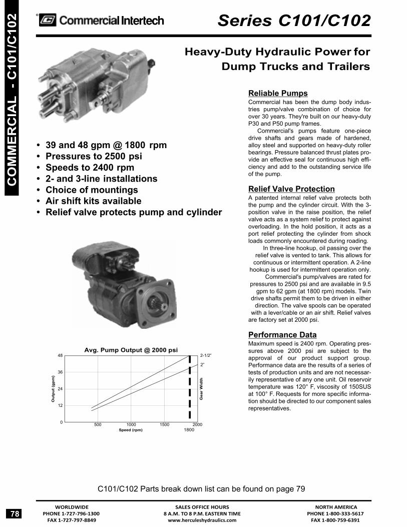
Heavy-Duty Hydraulic Power for Dump Trucks and Trailers
• 39 and 48 gpm @ 1800 rpm • Pressures to 2500 psi • Speeds to 2400 rpm • 2- and 3-line installations • Choice of mountings • Air shift kits available • Relief valve protects pump and cylinder
Avg. Pump Output @ 2000 psi 48 2-1/2”
2”
36
24
12
0 500 1000 1500 2000 Speed (rpm) 1800
Reliable Pumps Commercial has been the dump body indus- tries pump/valve combination of choice for over 30 years. They're built on our heavy-duty P30 and P50 pump frames.
Commercial's pumps feature one-piece drive shafts and gears made of hardened, alloy steel and supported on heavy-duty roller bearings. Pressure balanced thrust plates pro- vide an effective seal for continuous high effi- ciency and add to the outstanding service life of the pump.
Relief Valve Protection A patented internal relief valve protects both the pump and the cylinder circuit. With the 3- position valve in the raise position, the relief valve acts as a system relief to protect against overloading. In the hold position, it acts as a port relief protecting the cylinder from shock loads commonly encountered during roading.
In three-line hookup, oil passing over the relief valve is vented to tank. This allows for
continuous or intermittent operation. A 2-line hookup is used for intermittent operation only.
Commercial's pump/valves are rated for pressures to 2500 psi and are available in 9.5
gpm to 62 gpm (at 1800 rpm) models. Twin drive shafts permit them to be driven in either
direction. The valve spools can be operated with a lever/cable or an air shift. Relief valves
are factory set at 2000 psi.
Performance Data Maximum speed is 2400 rpm. Operating pres- sures above 2000 psi are subject to the approval of our product support group. Performance data are the results of a series of tests of production units and are not necessar- ily representative of any one unit. Oil reservoir temperature was 120° F, viscosity of 150SUS at 100° F. Requests for more specific informa- tion should be directed to our component sales representatives.
CO
MM
ER
CIA
L -
C10
1/C
102
Out
put (
gpm
)
Gea
r W
idth

NORTH AMERICA PHONE 1-800-333-5617
FAX 1-800-759-6391
SALES OFFICE HOURS 8 A.M. TO 8 P.M. EASTERN TIME
www.herculeshydraulics.com
WORLDWIDE PHONE 1-727-796-1300
FAX 1-727-797-8849 79
Series C101/C102 ®
C101/C102 Parts Breakdown Typical Parts
Item Description Part No. Req. Item Description Part No. Req. Item Description Part No. Req.A Shaft End Cover 313-5033-435 1 F Ring Seal 391-2585-009 2 J Pocket Seal 391-2882-050 12 B Snap Ring 391-2686-065 1 G Roller Bearing 391-0381-905 4 K Stud 391-1425-110 4 C Seal Retainer 391-3383-087 1 H Thrust Plate 391-2185-912 2 L Hex Nut 391-1451-076 6 D Lip Seal 391-2883-115 1 I Gear Set 2” 313-2920-230 1 M Port End Cover 1 E Check Assembly 393-3681-001 2 2 1/2” 313-2925-230 1 N Valve Spool 1
Item Description Part No. Req. Item Description Part No. Req. Item Description Part No. Req. 1 Hex Nut 391-1451-076 4 15 Gear 2” 314-8020-100 1 27 Washer 391-3784-029 4 2 Washer 391-3784-028 8 Housing 2 1/2” 314-8025-100 1 28 Cap Screw 2” 391-1401-111 4 3 Bracket (optional) 314-0100-005 1 16* Port End Cover 1 2 1/2” 391-1401-110 4 5 Snap Ring 391-2681-493 2 17* Valve Spool 1 29 Cap Screw 391-1401-082 4 6 Lip Seal 391-2883-096 2 18 “O” Ring 391-2881-103 2 30 Sleeve (optional) 391-3283-052 1 7 Shaft End Cover 314-5039-201 1 19A Wiper Ring 391-2883-147 1 31 Pipe Plug - 1” NPT 391-2282-006 1 8 Ring Seal 391-2585-009 4 19 Retainer Ring 391-3782-126 1 32 Spool End Cap 391-1881-073 1 9 Roller Bearing 391-0381-905 4 20 Snap Ring 391-2688-003 1 33 Spiral Pin 391-2085-009 1 10 Thrust Plate 391-2185-916 2 21 Detent Cap 314-0100-003 1 34 Bracket 391-0981-010 1 11 Pocket Seals 391-2882-050 12 22 Detent Ball 391-0282-009 1 35 Socket Hd. 391-1402-063 2 12 Gear Set 2” 314-2920-640 1 23 Detent Spring 391-3581-383 1 Cap Screw
2 1/2” 314-2925-640 1 24 Lock Washer 391-3788-002 1 36 Handle Ass’y 355-9100-009 1 13 Shaft Key 391-1781-021 1 25 Detent Retainer 391-2583-079 1 (optional)
14 Gasket Seal 391-2884-021 2 26 Relief Valve 355-9001-067 1 * Items 16, 17 M and N are not serviceable parts.
C102 Shaft End Parts List replaces items 1 thru 11, 16 and 28 shown below.
C101 Parts List
Seal Kit for C101 - CM-HC101 Seal Kit for C102 - CM-HC102
CO
MM
ER
CIA
L - C101/C
102

C101/C102 Parts break down list can be found on page 81
WORLDWIDE PHONE 1-727-796-1300
FAX 1-727-797-8849
SALES OFFICE HOURS 8 A.M. TO 8 P.M. EASTERN TIME
www.herculeshydraulics.com
NORTH AMERICA PHONE 1-800-333-5617
FAX 1-800-759-6391 80
® Series G101/G102
Pump/Valve Combinations Reliable Pumps Commercial’s G101 pump/valves are a compact hydraulic power source for small dump trucks. They’re based on Commercial’s well proven P30 design. These heavy-duty units are rated for 2500 psi service at speeds up to 2400 rpm.
Pump output is controlled by a 3-way, 3-position valve built into the port end cover. The valve can be actuated from the truck’s cab with a cable linkage or a remote air operator.
• 9.5 to 29 gpm @ 1800 rpm • Pressures to 2500 psi • Speeds to 2400 rpm • 2- and 3-line installations • Choice of mountings • Air shift kits available • Relief valve protects pump and
cylinder
Avg. Pump Output @ 2000 psi 40
30
20
10
2”
1-1/2”
G101 Features: • Lightweight
31 lbs with 3/4” gears 35 lbs with 1-1/2” gears 38 lbs with 2” gears
• Twin drive shafts make installation easy regardless of rotation direction • 2- or 3-line plumbing hookup • Output @ 1800 rpm
9.5 gpm (3/4” gears) 21 gpm (1-1/2” gears) 29 gpm (2” gears)
Mounting The G101 is mounted with a 2-bolt pad cast into the shaft end cover. The G102 direct PTO mount version is available with SAE-B 2- or 4-bolt flange mountings or a cloverleaf mount with 2.75” pilot diameter.
Drive Shafts G101’s have twin 1” SAE-BB keyed shafts that permit CW or CCW hookup without modifying the unit. G102’s have a single SAE-B splined shaft. Please specify direc- tion of rotation when ordering G102 models.
Relief Valve Protection The G101’s internal relief valve protects both the cylin- der and the pump. With the valve in the raise position, it protects the system against overloading. In hold, it acts as a port relief to protect the cylinder from shock loads. The relief valve is factory set at 2000 psi.
Performance Data Performance data shown are average results based on a series of laboratory tests of production units and are not representative of any one unit. Tests were run with the oil reservoir temperature was 120° F, viscosity of 150SUS at 100°F. Requests for more specific informa- tion should be directed to our component sales repre- sentatives.
0 300 600 900 1200 1500 1800 2400
Speed (rpm)
CO
MM
ER
CIA
L -
G10
1/G
102
Out
put
(gpm
)
Gea
r W
idth

NORTH AMERICA PHONE 1-800-333-5617
FAX 1-800-759-6391
SALES OFFICE HOURS 8 A.M. TO 8 P.M. EASTERN TIME
www.herculeshydraulics.com
WORLDWIDE PHONE 1-727-796-1300
FAX 1-727-797-8849 81
Series G101/G102 ®
G101/G102 Parts Breakdown Typical Parts List
Item Description Part No. Req. A Shaft End Cover 308-5030-201 1 B Lip Seal 391-2883-119 1 C Seal Retainer 391-3381-040 1 D Spacer 391-3383-069 1 E Snap Ring 3912686-063 1 F Checks 391-3681-001 2 G Ring Seal 391-2585-006 2 H Roller Bearing 391-0381-906 4 I Thrust Plate 391-2185-913 2 J Pocket Seal 391-2882-086 12 K Gear Set 3/4” 312-2907-130 1
1 1/2” 312-2915-230 1 2” 312-2920-230 1
G101 Parts List
G102 Shaft End Parts List replaces items 1 thru 8 in G101 Parts List below.
Item Description Part No. Req. Item Description Part No. Req. Item Description Part No. Req. 1 Snap Ring 391-2681-487 2 12 Port End Cover 1 26 Cap Screw 391-1433-020 2 2 Lip Seal 391-2883-119 2 13 Spool 1 27 Detent Ball 391-0282-009 1 3 Shaft End Cover 308-5016-201 1 14 Quad Ring Seal 391-1985-014 2 28 Spring 391-3581-383 1 4 Ring Seal 391-2585-006 4 15 Spool End Cap 391-1881-072 1 29 Lock Washer 391-3788-002 1 5 Roller Bearing 391-0381-906 4 16 Spiral Pin 391-2085-009 1 30 Detent Retainer 391-2583-079 1 6 Pocket Seal 391-2882-086 12 17 Bracket 391-0981-007 1 31 Relief Valve 355-9001-197 1 7 Thrust Plate 391-2185-913 2 18 Skt Hd Cap Screw 391-1402-063 2 32 Cap Screw 3/4” 391-1401-395 4 8 Gear Set 3/4” 312-2907-842 1 19 Cover Plate 391-2183-124 1 1 1/2” 391-1401-381 4
1 1/2” 312-2915-842 1 20 Retaining Ring 391-2681-485 1 2” 391-1401-382 42” 312-2920-842 1 21 Spring Guide 391-1642-136 1 33 Washer 391-3782-146 4
9 Key 391-1781-021 1 22 Spring 391-3581-212 1 34 Sleeve (optional) 391-3283-052 1 10 Gasket Seal 391-2884-019 2 23 Spring Guide 39101642-137 1 35 Pipe Plug 391-2282-003 1 11 Gear 3/4” 308-8007-901 1 24 Retaining Ring 391-2681-486 1
Housing 1 1/2” 308-8015-901 1 25A End Cap 308-4000-100 1
2” 308-8020-901 1 25 End Cap 308-4000-102 1
Seal Kit for G101 - CM-HG101 Seal Kit for G102 - CM-HG102
CO
MM
ER
CIA
L - G101/G
102

FAX 1-727-797-8849 www.herculeshydraulics.com FAX 1-800-759-6391
® Gear Pumps & Motors
82
Series P20
Series 25X
Series P30, P31
• 6 TO 33 gpm @ 2000 rpm • Pressures to 2000 psi • Speeds to 2000 rpm • Choice of mountings
Flow (GPM) @ Pump RPM
Speed Gear Width (inches) rpm 1 1-1/4 1-1/2 1-3/4 2 900 6.5 8 10 12 13.5
1200 9 11.5 14 16 18.5 1500 11.5 14.5 17.5 20.5 23.5 1800 14 18 21.5 25 29 2100 16.5 21 25 29.5 34 2400 19 24 29 34 39
• 8.5 TO 53 gpm @ 2000 rpm • Pressures to 2000 psi • Speeds to 2000 rpm • Choice of mountings
Flow (GPM) @ Pump RPM
Speed Gear Width (inches) rpm 1 1-1/4 1-1/2 1-3/4 2 2-1/4 2-1/2 900 8.5 10.5 13 15 17.5 20 22
1200 12 15 18 21 24 27 30 1500 15 19 23 27 31 35 39 1800 18 23 27.5 32.5 37.5 42 47 2100 21.5 27 32.5 38.5 44 49.5 55 2400 25 31 37 44 51 57 63.5
• 6 TO 33 gpm @ 2000 rpm • Pressures to 2000 psi • Speeds to 2000 rpm • Choice of mountings
Flow (GPM) @ Pump RPM
Speed Gear Width (inches) rpm 1 1-1/4 1-1/2 1-3/4 2 900 6.5 8 10 12 13.5
1200 9 11.5 14 16 18.5 1500 11.5 14.5 17.5 20.5 23.5 1800 14 18 21.5 25 29 2100 16.5 21 25 29.5 34 2400 19 24 29 34 39
CO
MM
ER
CIA
L S
ER
IES
WORLDWIDE SALES OFFICE HOURS NORTH AMERICA PHONE 1-727-796-1300 8 A.M. TO 8 P.M. EASTERN TIME PHONE 1-800-333-5617

FAX 1-800-759-6391 www.herculeshydraulics.com FAX 1-727-797-8849
Gear Pumps & Motors ®
• 6 TO 75 gpm @ 2000 rpm • Pressures to 2000 psi • Speeds to 2000 rpm • Choice of mountings
Flow (GPM) @ Pump RPM
Series 37X
Speed Gear Width (inches) rpm 1 1-1/4 1-1/2 1-3/4 2 2-1/4 2-1/2 3 600 4.5 6.5 8.5 10.5 12.5 14 16.5 20
1200 12.5 16.5 20 24 28 31.5 35.5 43 1800 20 26 31.5 37.5 43.5 49.5 55 66.5 2100 24 31 37.5 44.5 51 58 64.5 78 2400 28 36 43.5 51 59 67 74.5 90
• 6 TO 53 gpm @ 2000 rpm • Pressures to 2000 psi • Speeds to 2000 rpm • Choice of mountings
Flow (GPM) @ Pump RPM Speed Gear Width (inches)
rpm 1 1-1/4 1-1/2 1-3/4 2 2-1/4 2-1/2 900 8.5 10.5 13 15 17.5 20 22
1200 12 15 18 21 24 27 30 1500 15 19 23 27 31 35 39 1800 18 23 27.5 32.5 37.5 42 47 2100 21.5 27 32.5 38.5 44 49.5 55 2400 25 31 37 44 51 57 63.5
• 6 TO 100 gpm @ 2000 rpm • Pressures to 2000 psi • Speeds to 2000 rpm • Choice of mountings
Flow (GPM) @ Pump RPM
Series P50, P51
Series P75, P76
Speed Gear Width (inches) rpm 1 1-1/4 1-1/2 1-3/4 2 2-1/4 2-1/2 2-3/4 3 600 6 9 11.5 13.5 16.6 18.5 21 23 26
1200 17 22 27 32 37.5 42 48 52.5 58 1500 22 29 35.5 41.5 48 54.5 61 67 74 1800 27.5 35.5 43.5 51 59 66 74 81.5 90 2100 33 42 51.5 60 69.5 78 87 96.5 106 2400 38 49 59.5 70 80 90 101 111 122
83
CO
MM
ER
CIA
L SE
RIE
S
NORTH AMERICA SALES OFFICE HOURS WORLDWIDE PHONE 1-800-333-5617 8 A.M. TO 8 P.M. EASTERN TIME PHONE 1-727-796-1300

FAX 1-727-797-8849 www.herculeshydraulics.com FAX 1-800-759-6391
® Gear Pumps & Motors
Series 330, 350, 365
Series 330
Series 350
• 6 TO 78 gpm @ 2000 rpm • Pressures to 3500 psi • Speeds to 3000 rpm • Choice of mountings
84
Series 365
WORLDWIDE SALES OFFICE HOURS NORTH AMERICA PHONE 1-727-796-1300 8 A.M. TO 8 P.M. EASTERN TIME PHONE 1-800-333-5617
CO
MM
ER
CIA
L S
ER
IES
Pump Speed
rpm
Avg. Output (gpm) @ 3500 psi Gear Width (inches)
1 1-1/4 1-1/2 1-3/4 2 900 6.0 8.0 10.0 12.0 13.5
1200 8.5 11.5 14.0 16.0 18.5 1500 11.0 14.5 17.5 20.5 23.5 2100 16.5 21.0 25.0 29.5 34.0
2” data at 3000 psi
Pump Speed
rpm
Avg. Output (gpm) @ 3500 psi Gear Width (inches)
1 1-1/4 1-1/2 1-3/4 2 2-1/4 2-1/2 900 8.0 10.5 13.0 15.0 17.5 20.0 22.0
1200 11.5 15.0 18.0 21.0 24.0 27.0 30.0 1500 14.5 19.0 23.0 27.0 31.0 35.0 39.0 2100 21.0 27.0 32.5 38.5 44.0 49.5 55.0
2-1/2” data at 2500 psi 2” data at 3000 psi
Pump Speed
rpm
Avg. Output (gpm) @ 3500 psi Gear Width (inches)
1 1-1/4 1-1/2 1-3/4 2 2-1/4 2-1/2 900 10.5 13.5 15.0 17.0 20.5 27.5 31.0
1200 15.5 20.0 24.5 29.0 33.5 38.0 43.0 1500 20.0 25.5 31.0 37.5 43.0 49.0 55.0 2100 29.0 37.5 45.5 54.0 62.0 70.0 78.0
2-1/2” data at 3000 psi
FAX 1-800-759-6391 www.herculeshydraulics.com FAX 1-727-797-8849
®
IDENTIFYING PUMPS & MOTORS
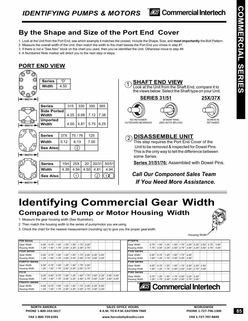
By the Shape and Size of the Port End Cover 1. Look at the Unit from the Port End, see which example it matches the closest. Include the Shape, Size, and most importantly the Bolt Pattern. 2. Measure the overall width of the Unit, then match the width to the chart beside the Port End you chose in step #1. 3. If there is not a “See Also” block on the chart you used, then you’ve identified the Unit. Otherwise move to step #4. 4. A Numbered Note marker will direct you to the next step or steps.
PORT END VIEW
SHAFT END VIEW Look at the Unit from the Shaft End, compare it to the views below. Select the Shaft type on your Unit.
SERIES 31/51 25X/37X
NO RETAINER/ W/SNAP RING SCREW IN OUTBOARD BEARINGS (SEE NOTE BELOW) RETAINER
DISASSEMBLE UNIT This step requires the Port End Cover of the
Unit to be removed & inspected for Dowel Pins. This is the only way to tell the difference between some Series. Series 31/51/76: Assembled with Dowel Pins.
Call Our Component Sales Team If You Need More Assistance.
Identifying Commercial Gear Width Compared to Pump or Motor Housing Width 1. Measure the gear housing width (See Illustration). 2. Then match the housing width to the series of pump/motor you are using. 3. Check the chart for the nearest measurement (rounding up) to give you the proper gear width.
Housing Width
P20 Series P75/P76
Gear Width Housing Width
0.50” 1.25”
0.75” 1.50”
1.00” 1.75”
1.25” 2.00”
1.50” 2.25”
1.75” 2.50”
2.00” 2.75”
Gear Width Housing Width
0.75” 1.75”
1.00” 2.00”
1.25” 2.25”
1.50” 2.50”
1.75” 2.75”
2.00” 3.00”
2.25” 3.25”
2.50” 3.50”
2.75” 3.75”
3.00” 4.00”
P25X Series P330 Series
Gear Width Housing Width
0.50” 1.25”
0.75” 1.50”
1.00” 1.75”
1.25” 2.00”
1.50” 2.25”
1.75” 2.50”
2.00” 2.75”
2.25” 3.00”
2.50” 3.25”
Gear Width Housing Width
0.50” 1.00”
0.75” 1.25”
1.25” 1.75”
1.50” 2.00”
1.75” 2.25”
2.00” 2.50”
P30/P31 Series P350 Series
Gear Width Housing Width
0.50” 1.25”
0.75” 1.50”
1.00” 1.75”
1.25” 2.00”
1.50” 2.25”
1.75” 2.50”
2.00” 2.75”
Gear Width Housing Width
0.50” 1.00”
0.75” 1.25”
1.25” 1.75”
1.50” 2.00”
1.75” 2.25”
2.00” 2.50”
2.25” 2.75”
2.50” 3.00”
P37X P365 Series Gear Width Housing Width
0.25” 1.25”
0.50” 1.50”
0.75” 1.75”
1.00” 2.00”
1.25” 2.25”
1.50” 2.50”
1.75” 2.75”
2.00” 3.00”
2.25” 3.25”
2.50” 3.50”
3.00” 4.00”
Gear Width Housing Width
0.75”1.25”
1.25”1.75”
1.50”2.00”
1.75”2.25”
2.00”2.50”
2.25”2.75”
2.50”3.00”
P50/P51 Series ® Gear Width Housing Width
0.50” 1.25”
0.75” 1.50”
1.00” 1.75”
1.25” 2.00”
1.50” 2.25”
1.75” 2.50”
2.00” 2.75”
2.25” 3.00”
2.50” 3.25”
NORTH AMERICA SALES OFFICE HOURS WORLDWIDE PHONE 1-800-333-5617 8 A.M. TO 8 P.M. EASTERN TIME PHONE 1-727-796-1300
85
WIDTH
WIDTH
WIDTH
WIDTH
1
2
CO
MM
ER
CIA
L SE
RIE
S
Series “D” Width 4.50
Series 315 330 350 365 Side Ported Width
4.25
6.68
7.12
7.38
Unported Width
4.00
4.81
5.75
6.25
Series 37X 75 / 76 125
Width 5.12 6.13 7.00 See Also 2
Series 15H 25X 20 30/31 50/51 Width 4.38 4.94 4.50 4.81 4.94
See Also 1 2 1 2

ntertech Cylinders, Pumps & Motors / Custom Hoists / LHA ccessories / Cylinders / Prince Cylinders & Pumps / Chief ylinders / Perfection Pumps / White Motors / Gresen®
ylinders, Pumps, Motors & Valves / Commercial Intertech ylinders, Pumps & Motors / Custom Hoists / LHA Accessories
Cylinders / Prince Cylinders & Pumps / Chief Cylinders / erfection Pumps / White Motors / Gresen® Cylinders, Pumps,
Motors & Valves / Commercial Intertech Cylinders, Pumps & Motors / Custom Hoists / LHA Accessories / Cylinders / Prince
ylinders & Pumps / Chief Cylinders / Perfection Pumps / White Motors / Gresen® Cylinders, Pumps, Motors & Valves /
ommercial Intertech Cylinders, Pumps & Motors / Custom oists / LHA Accessories / Cylinders / Prince Cylinders & umps / Chief Cylinders / Perfection Pumps / White Motors / resen®
Cylinders, Pumps, Motors & Valves / Commercial ntertech Cylinders, Pumps & Motors / Custom Hoists / LHA
ccessories / Cylinders / Prince Cylinders & Pumps / Chief ylinders / Perfection Pumps / White Motors / Gresen®
ylinders, Pumps, Motors & Valves / Commercial Intertech ylinders, Pumps & Motors / Custom Hoists / LHA Accessories
Cylinders / Prince Cylinders & Pumps / Chief Cylinders / erfection Pumps / White Motors / Gresen® Cylinders Pumps

FAX 1-800-759-6391 www.herculeshydraulics.com FAX 1-727-797-8849
4
Series P20
®
How To Specify and Code
P20 General Information Commercial’s P20 gear pumps and motors are an ideal power for the truck industry. With 1/2” gears, it measures only 6” from mounting flange to the port end cover and weighs only 25 lbs.
The P20 can produce flows up to 2.96 cir @ 300 psi; output to 3.94 cir up to 2500 psi. Maximum speed is 2400 rpm. Motors and pumps can be bi-rotational.
A variety of drive shafts and mounting styles are offered to meet your needs. Standard features include rigid, one-piece drive shaft and gears and pressure balanced thrust plates which assure top efficiency.
Performance Data Performance data shown are the average results based on a series of laboratory tests of produc- tion units and are not necessarily representative of any one unit. Tests were run with the oil reser- voir temperature at 120°F. Requests for more spe- cific data should be directed to our sales repre- sentatives.
Performance data for pumps and motors having other gear widths can be approximated by multi- plying values in tables below by actual gear width.
This catalog contains codes for our most popular models. Complete codes for all con- figurations are readily available upon request.
Single Units Full assembly codes for single units combine shaft end cover, port end cover, gear housing and drive shaft codes. They are preceded by the letter P or M for pump or motor — and by 20 to designate the series and model. An example of an assembly code follows:
M20 SINGLE MOTOR
Assembly Code: M 20A 942 BE YF15-30 3
Motor ........................................... M Series ......................................... 20 Model .......................................... A
1. Shaft End Cover ....................... 942 2. Port End Cover .......................... BE 3. Gear Housing . . . . . . . . . . . .YF15 2
4. Drive Shaft ................................. 30
Multiple Units Coding is the same as single units except that codes for added components must be included. Each gear unit added also requires code for a bearing carrier, the additional gear housing and connecting shaft. An example of an assembly code for a two-section Series 20 pump follows:
P20 MULTIPLE PUMP
Assembly Code: P 20B 278 BY OM20-43 D UG10-1
2
Variations
Pump ........................................... P Series ........................................ 30 Model .......................................... B
5
1. Shaft End Cover ................ 278 2. Port End Cover ................... BY 3. Gear Housing ................ OM20 4. Drive Shaft ........................... 43 5. Bearing Cover....................... D 6. Gear Housing .................UG10 7. Connecting Shaft ................... 1
Series 20 units are available with gear sections ranging from 1/2” to 2” in 1/4” increments which provide displacements from .985 to 3.94 cu. in. per revolution. Two or more gear sections can be assembled on one drive shaft to provide larger flows, supply other circuits or make smoother, more powerful motors.
When specifying multiple units you must consider the drive shaft’s strength. This is called a PL factor in which P = operating pressure and L = sum of gear widths. The recommended PL factors for various Series 20 shafts are shown with the shaft codes and are offered as a guide to shaft selection. A PL of 8000 means a maximum of 4” of gear can be operated at 2000 psi (2000 psi X 4” = 8000) without overloading the shaft. The gear widths can be divided many ways, eg. (2”-1”-1”, 1”-1”-1”-1”, 1-1/2”-1-1/2”-1/2”) to provide the output you need for several cir- cuits. This pump needs a drive shaft with a PL factor of 4500 or more to operate successfully.
NORTH AMERICA SALES OFFICE HOURS WORLDWIDE PHONE 1-800-333-5617 8 A.M. TO 8 P.M. EASTERN TIME PHONE 1-727-796-1300
87
7 4
6 3 1
1
CO
MM
ER
CIA
L - P20
Pump Speed
rpm
Avg. Output (gpm) @ 2000 psi Gear Width (inches)
1 1-1/4 1-1/2 1-3/4 2 900 6.5 8.0 10.0 12.0 13.5
1200 9.0 11.5 14.0 16.0 18.5 1500 11.5 14.5 17.5 20.5 23.5 2100 16.5 21.0 25.0 29.0 34.0
Motor Speed
rpm
Avg. Input/Output (gpm) @ 2000 psi 1” gear 1-1/2” gear 2” gear
gpm hp gpm hp gpm hp 800 9.0 7.0 13.0 11.0 17.0 14.5
1200 13.0 10.5 18.0 16.5 23.5 22.0 1600 16.4 14.0 23.0 22.0 30.5 29.0 2000 19.5 17.5 28.0 27.0 37.0 36.0

FAX 1-727-797-8849 www.herculeshydraulics.com FAX 1-800-759-6391
® Series P20
P20 Parts Breakdown Typical Parts List
Note: This page shows the typical arrangement of a 2-section unit. It may not be pictorially correct and is not to scale.
Plug 5 in position B gives clockwise rotation.
Plug 5 in position A gives counter-clockwise rotation.
Check valves in both positions give bi-directional rotation.
88
For Series P20 Seal Kits and Repair Parts, See Pages 475 - 477
CO
MM
ER
CIA
L -
P20
Item Description Part Number Item Description Part Number 1 Snap Ring CM-391-2686-063 11 Gasket Seals 580-239 2 Outboard Bearing CM-391-0381-040 12 Gear Housing See Option List 3 Seal CM-391-2883-058 13 Bearing Carrier See Option List 4 Shaft End Cover See Option List 14 Connecting Shaft See Option List 5 Check Assemblies or Plug CM-391-3681-001 15 Matched Gear Set See Option List 6 Ring Seals CM-391-2585-006 16 Gear Housing See Option List 7 Roller Bearings CM-391-0381-906 17 Port End Cover See Option List 8 Pocket Seals 18 Washers
9 Thrust Plates CM-391-2185-913 19 Studs or Cap Screws
10 Integral Drive Shaft and Gear Set
See Option List 20 Nuts
WORLDWIDE SALES OFFICE HOURS NORTH AMERICA PHONE 1-727-796-1300 8 A.M. TO 8 P.M. EASTERN TIME PHONE 1-800-333-5617

FAX 1-800-759-6391 www.herculeshydraulics.com FAX 1-727-797-8849
Series P20
®
Shaft & Port End Covers
P20 SHAFT END COVERS Description PUMPS MOTORS
* Available for special application upon request. NOT A STOCK ITEM
P20 PORT END COVERS
Priority Outlet see P1B-H2 for description of codes *Avaliable for special application upon request. NOT A STOCK ITEM.
89
Type
Outboard Bearing
1/4” NPT 1/4” BSPPCW CCW Double DRAIN DRAIN
Round Flange - 6 Bolt 1 Without 105 205 305 905 1905 With 405 505 605 805 1805
SAE B - 4 Bolt 1 Without 142 242 342 942 1942 With 442 542 642 842 1842
4 Bolt Cloverleaf PTO Mount 2 Without 127 227 327 — — SAE A - 2 Bolt 1 Without 194 294 394 994 1994
With 494 594 694 894 1894 SAE B - 2 Bolt 1 Without 197 297 397 997 1997
With 497 597 697 897 1897 2 Without 196* 296* 396* N/A N/A
Piggy Back Shaft End Cover
50-30 30-30
Without 191 291 391 N/A N/A
75-30 Without 192 292 392 N/A N/A Pad Mounting 1 Without 110 210 310 910 N/A
With 410 510 610 910 N/A
2 1
CO
MM
ER
CIA
L - P20
&
Description Single Pumps
Multiple Pumps Porting w/Reg Studs w/2 Ext Studs LH RH
No Ports BE BI BY — — NPT Ports KE* KI KY 3/4 — LE* LI LY 3/4 ME* MI MY 3/4 3/4 ODT Ports CE* CI CY 3/4 — DE* DI DY — 3/4 FE* FI FY 3/4 3/4 GE* GI GY 1 3/4 HE HI HY 3/4 1 JE* JI* JY* 1 1
NORTH AMERICA SALES OFFICE HOURS WORLDWIDE PHONE 1-800-333-5617 8 A.M. TO 8 P.M. EASTERN TIME PHONE 1-727-796-1300

FAX 1-727-797-8849 www.herculeshydraulics.com FAX 1-800-759-6391
Keyedf
Porti LH
ng RH
1/2
3/4
1
1 1/4
1 1/2
1 3/4
2
— — AB05 AB07 AB10 AB12 AB15 AB17 AB20 1/2 — IL07 IL10
— 1/2 IM07 IM10
1/2 1/2 IR07
3/4 — IC10 IC12 IC15
— 3/4 ID10 ID12 ID15
3/4 3/4 IF10 IF12 IF15 IF17 IF20 3/4 1‡ IG10‡ IG12
1‡ 3/4 IJ10 IJ12 IJ15 IJ17
1 — YC12 YC15 YC17
— 1 YD12 YD15 YD17
1 1 YF12 YF15 YF17 YF20 1 1 1/4‡ YG15‡ YG17 YG20
1 1/4‡ 1 YJ15‡ YJ17 YJ20 1 1/4 1 1/4 YL20
1 1/4‡ — IA15‡ IA17 IA20 — 1 1/4‡ IB15‡ IB17 IB20
1 1/4 1 1/2‡ YM20‡ 1 1/2‡ 1 1/4 YP20‡ 1 1/2‡ — YA20‡
— 1 1/2‡ YB20‡
® Series P20
Drive Shafts
P20 DRIVE SHAFTS Shaft Description
Code Type 1 Type 2
SAE B - Straight 30 — .875” Diameter - 1/4” X 1” Key Standard - Straight Keyed .9998’ Diameter - 1/4” X 1 1/4” Key
43 —
SAE B - 13 Tooth Spline .873 Major Diameter
25 65*
Standard - 6 Tooth Spline .997” Major Diameter
68* —
SAE A - 9 Tooth Spline .623” Major Diameter
95 —
Connecting Shaft - Multiple Units 1 1 Connecting Shaft - Piggyback Pump P30 to P30 14 —
P50 to P30 22 — P75 to P30 23 — * Available for special application upon request. Not a stock item.
P20 DRIVE SHAFT CODES GEAR WIDTH 1-14-22-23 25 30 43 65* 68* 95
1/2 •
3/4 • • • •
1 • • • • • • • 1 1/4 • • • • • • • 1 1/2 • • • • • •
1 3/4 • • • • • •
2 • • • • • •
Gear Housings
P20 GEAR HOUSINGS - NPT PORTS
‡ Low pressure only
90
6 3
4
CO
MM
ER
CIA
L -
P20
&
WORLDWIDE SALES OFFICE HOURS NORTH AMERICA PHONE 1-727-796-1300 8 A.M. TO 8 P.M. EASTERN TIME PHONE 1-800-333-5617

FAX 1-800-759-6391 www.herculeshydraulics.com FAX 1-727-797-8849
Series P20
®
Gear Housing
P20 GEAR HOUSINGS - SAE SPLIT FLANGE PORTSPorti
LH ng
RH
1/2
3/4
1
1 1/4
1 1/2
1 3/4
2 — — AB05 AB07 AB10 AB12 AB15 AB17 AB20 3/4 — UC10 UC12
— 3/4 UD10 UD12 UD15
3/4 3/4 UF10
3/4 1 UG10 UG12 UG20 3/4 1 1/4 UH12
1 3/4 UJ10 UJ12 UJ15 UJ17 UJ20 1 1/4 3/4 UK12
1 — OC12 OC15 OC17
— 1 OD12 OD15 OD17 OD20 1 1 OF10 OF12 OF15 OF17 OF20 1 1 1/4‡ OG12‡ OG15 OG17 OG20
1 1/4‡ 1 OJ12‡ OJ15 OJ17 OJ20 1 1 1/2‡ OH17‡ OH20
1 1/2‡ 1 OK17‡ OK20 1 1/4‡ — OA12‡ OA15 OA17 OA20
— 1 1/4‡ OB12‡ OB15 OB17 OB20 1 1/4 1 1/4 OL15 OL17 OL20 1 1/4 1 1/2‡ OM17‡ OM20
1 1/2‡ 1 1/4 OP17‡ OP20 1 1/2‡ — OE17‡ OE20
— 1 1/2‡ OU17‡ OU20 ‡ Low Pressure Only
P20 GEAR HOUSINGS - SAE STRAIGHT THREAD PORTS Port
LH ing
RH 1/2 3/4
1
1 1/4
1 1/2
1 3/4
2 — — AB05 AB07 AB10 AB12 AB15 AB17 AB20 3/4 — EC10 EC12 EC15
— 3/4 ED10 ED12 ED15 3/4 3/4 EF10 EF12 EF15 EF17 EF20 3/4 1‡ EG10‡ EG12‡ EG15 EG17
3/4 1 1/4‡ EH15‡ EH17‡
3/4 1 1/2‡ IN20‡ 1‡ 3/4 EJ10‡ EJ12‡ EJ15 EJ17 EJ20
1 1/4‡ 3/4 EL15‡ EK17‡
1 1/2‡ 3/4 IP20‡ 7/8 — EZ12
7/8 1‡ EL10‡ EL12‡
1‡ 7/8 EM10‡ EM12‡
1‡ — AC10‡ AC12 AC15 AC17 AC20 — 1‡ AD10‡ AD12 AD15 AD17 AD20 1 1 AF15 AF17 AF20 1 1 1/4‡ AG15‡ AG17‡ AG20 1 1 1/2‡ AH17‡ AH20‡
1 1/4‡ 1 AJ15‡ AJ17‡ AJ20 1 1/2‡ 1 AK17‡ AK20‡ 1 1/4‡ — AA15‡ AA17‡
— 1 1/4‡ AO15‡ AO17‡ 1 1/4 1 1/4 AL17 AL201 1/4 1 1/2‡ AM17‡ AM20‡
1 1/2‡ 1 1/4 AP17‡ AP20‡ 1 1/2‡ — AE17‡ AE20
— 1 1/2‡ AU17‡ AU20 ‡Low pressure only
91
6 3
CO
MM
ER
CIA
L - P20
&
NORTH AMERICA SALES OFFICE HOURS WORLDWIDE PHONE 1-800-333-5617 8 A.M. TO 8 P.M. EASTERN TIME PHONE 1-727-796-1300
FAX 1-727-797-8849 www.herculeshydraulics.com FAX 1-800-759-6391
® Series P20
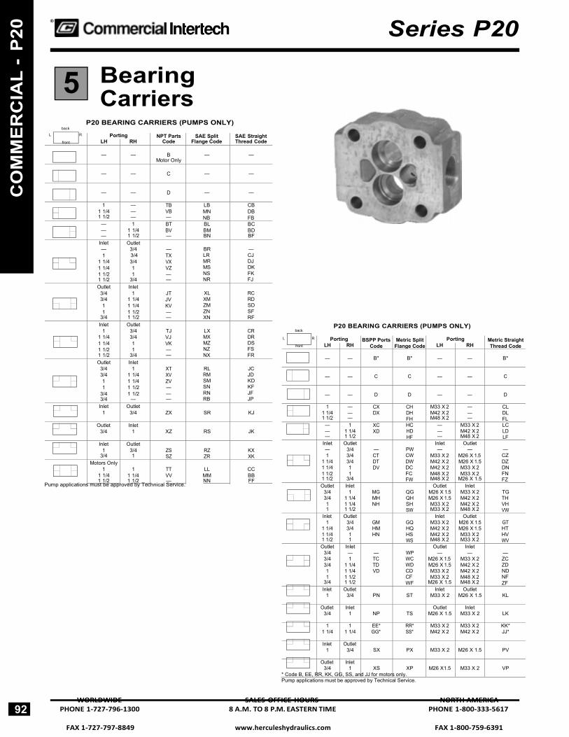
Bearing Carriers
P20 BEARING CARRIERS (PUMPS ONLY) back
back P20 BEARING CARRIERS (PUMPS ONLY)
Pump applications must be approved by Technical Service.
* Code B, EE, RR, KK, GG, SS, and JJ for motors only. Pump applications must be approved by Technical Service.
92 WORLDWIDE SALES OFFICE HOURS NORTH AMERICA
PHONE 1-727-796-1300 8 A.M. TO 8 P.M. EASTERN TIME PHONE 1-800-333-5617
5
CO
MM
ER
CIA
L -
P20
L R
front
Porting NPT Parts Code
SAE Split Flange Code
SAE Straight Thread Code LH RH
—
—
B
Motor Only
—
—
—
—
C
—
—
—
—
D
—
—
1 1 1/4 1 1/2
— — —
TB VB —
LB MN NB
CB DB FB
— — —
1 1 1/4 1 1/2
BT BV —
BL BM BN
BC BD BF
Inlet — 1
1 1/4 1 1/4 1 1/2 1 1/2
Outlet 3/4 3/4 3/4 1 1
3/4
— TX VX VZ — —
BR LR MR MS NS NR
— CJ DJ DK FK FJ
Outlet 3/4 3/4 1 1
3/4
Inlet 1
1 1/4 1 1/4 1 1/2 1 1/2
JT JV KV — —
XL XM ZM ZN XN
RC RD SD SF RF
Inlet 1
1 1/4 1 1/4 1 1/2 1 1/2
Outlet 3/4 3/4 1 1
3/4
TJ VJ VK — —
LX MX MZ NZ NX
CR DR DS FS FR
Outlet 3/4 3/4 1 1
3/4 3/4
Inlet 1
1 1/4 1 1/4 1 1/2 1 1/2
—
XT XV ZV — — —
RL RM SM SN RN RB
JC JD KD KF JF JP
Inlet 1
Outlet 3/4
ZX
SR
KJ
Outlet 3/4
Inlet 1
XZ
RS
JK
Inlet 1
3/4
Outlet 3/4 1
ZS SZ
RZ ZR
KX XK
Motors Only 1
1 1/4 1 1/2
1
1 1/4 1 1/2
TT VV —
LL MM NN
CC BB FF
L R
front
Porting BSPP Ports Code
Metric Split Flange Code
Porting Metric Straight Thread Code LH RH LH RH
—
—
B*
B*
— —
B*
—
—
C
C
— —
C
—
—
D
D
— —
D
1 1 1/4 1 1/2
— — —
CX DX
CH DH FH
M33 X 2 M42 X 2 M48 X 2
— — —
CL DL FL
— — —
1 1 1/4 1 1/2
XC XD
HCHD HF
— — —
M33 X 2 M42 X 2 M48 X 2
LC LD LF
Inlet— 1
1 1/4 1 1/4 1 1/2 1 1/2
Outlet 3/4 3/4 3/4 1 1
3/4
— CT DT DV
PW CW DW DC FC FW
Inlet —
M33 X 2 M42 X 2 M42 X 2 M48 X 2 M48 X 2
Outlet —
M26 X 1.5 M26 X 1.5 M33 X 2 M33 X 2
M26 X 1.5
— CZ DZ DN FN FZ
Outlet 3/4 3/4 1 1
Inlet 1
1 1/4 1 1/4 1 1/2
MG MH NH
QG QH SH SW
Outlet M26 X 1.5 M26 X 1.5 M33 X 2 M33 X 2
Inlet M33 X 2 M42 X 2 M42 X 2 M48 X 2
TG TH VH VW
Inlet 1
1 1/4 1 1/4 1 1/2
Outlet 3/4 3/4 1 1
GM HM HN
GQ HQ HS WS
Inlet M33 X 2 M42 X 2 M42 X 2 M48 X 2
Outlet M26 X 1.5 M26 X 1.5 M33 X 2 M33 X 2
GT HT HV WV
Outlet 3/4 3/4 3/4 1 1
3/4
Inlet — 1
1 1/4 1 1/4 1 1/2 1 1/2
— TC TD VD
WP WC WD CD CF WF
Outlet —
M26 X 1.5 M26 X 1.5 M33 X 2 M33 X 2
M26 X 1.5
Inlet—
M33 X 2 M42 X 2 M42 X 2 M48 X 2 M48 X 2
— ZC ZD ND NF ZF
Inlet 1
Outlet 3/4
PN
ST
Inlet M33 X 2
Outlet M26 X 1.5
KL
Outlet 3/4
Inlet 1
NP
TS
Outlet M26 X 1.5
Inlet M33 X 2
LK
1 1 1/4
1 1 1/4
EE* GG*
RR* SS*
M33 X 2 M42 X 2
M33 X 2 M42 X 2
KK* JJ*
Inlet 1
Outlet 3/4
SX
PX
M33 X 2 M26 X 1.5
PV
Outlet 3/4
Inlet 1
XS
XP
M26 X1.5 M33 X 2
VP

FAX 1-800-759-6391 www.herculeshydraulics.com FAX 1-727-797-8849
Series P20
®
Bearing Carriers
back
L R
front
Ports Ports Metric
SAE Split Split
Ports
SAE Str. Metric Porting NPT BSSP Porting Flge. Flge. Porting Thd. Str. Thd.
LH RH Code Code LH RH Code Code LH RH Code Code
—
—
B
B
—
—
B
B
—
—
B
B
—
—
E
E
—
—
E
E
—
—
E
E
1 1 1/4 1 1/2
— — —
M N —
X Y Z
1 1 141 1/2
— — —
J K L
T V W
1 1 1/4 1 1/2
M33 X 2 M42 X 2 M48 X 2
— — — — — —
F G H — — —
— — — Q R S
— —
3/4 1
BX KZ
DG DF
— —
3/4 1
GR MT
TR FM
— — —
3/4 1
M26 X 1.5 M33 X 2
GJ BK — —
— — QJ ML
— —
3/4 1
CV NK
DM MN
— —
3/4 1
FD JG
KT RP
— —
3/4 1
M26 X 1.5 M33 X 2
JH PC — —
— — BZ MK
1 1 1/4 1 1/2 1 1/4 1 1/2
3/4 3/4 3/4 1 1
GX HX — LZ —
FG SG XG GF MF
1 1 1/4 1 1/2 1 1/4 1 1/2
3/4 3/4 3/4 1 1
HR PR QR NT RT
VR WR XR QM VM
1 1 1/4 1 1/2 1 1/4 1 1/2
M33 X 2 M42 X 2 M48 X 2 M42 X 2 M48 X 2
3/4 3/4 3/4 1 1
M26 X 1.5 M26 X 1.5 M26 X 1.5 M33 X 2 M33 X 2
HJ MJ RJ PK RK — — — — —
— — — — — SJ XJ ZJ PL QL
1 1 1/4 1 1/2 1 1/4 1 1/2
3/4 3/4 3/4 1 1
GV MV — TK —
NM PM TM QN TN
1 1 1/4 1 1/2 1 1/4 1 1/2
3/4 3/4 3/4 1 1
GD MD PD PG RG
PT QT ZT TP ZP
1 1 1/4 1 1/2 1 1/4 1 1/2
M33 X 2 M42 X 2 M48 X 2 M42 X 2 M48 X 2
3/4 3/4 3/4 1 1
M26 X 1.5 M26 X 1.5 M26 X 1.5 M33 X 2 M33 X 2
PH RH WH QC VC — — — — —
— — — — — PZ QZ YZ QK SK
1
3/4
VG
HP
1
3/4
WL
FP
1 M33 X 2
3/4
M26 X 1.5
MC —
— CP
1
3/4
WG
LP
1
3/4
ZL
GP
1 M33 X 2
3/4
M26 X 1.5
SC —
— DP
NORTH AMERICA SALES OFFICE HOURS WORLDWIDE PHONE 1-800-333-5617 8 A.M. TO 8 P.M. EASTERN TIME PHONE 1-727-796-1300
93
5
CO
MM
ER
CIA
L - P20

ntertech Cylinders, Pumps & Motors / Custom Hoists / LHA ccessories / Cylinders / Prince Cylinders & Pumps / Chief ylinders / Perfection Pumps / White Motors / Gresen®
ylinders, Pumps, Motors & Valves / Commercial Intertech ylinders, Pumps & Motors / Custom Hoists / LHA Accessories
Cylinders / Prince Cylinders & Pumps / Chief Cylinders / erfection Pumps / White Motors / Gresen® Cylinders, Pumps,
Motors & Valves / Commercial Intertech Cylinders, Pumps & Motors / Custom Hoists / LHA Accessories / Cylinders / Prince
ylinders & Pumps / Chief Cylinders / Perfection Pumps / White Motors / Gresen® Cylinders, Pumps, Motors & Valves /
ommercial Intertech Cylinders, Pumps & Motors / Custom oists / LHA Accessories / Cylinders / Prince Cylinders & umps / Chief Cylinders / Perfection Pumps / White Motors / resen®
Cylinders, Pumps, Motors & Valves / Commercial ntertech Cylinders, Pumps & Motors / Custom Hoists / LHA
ccessories / Cylinders / Prince Cylinders & Pumps / Chief ylinders / Perfection Pumps / White Motors / Gresen®
ylinders, Pumps, Motors & Valves / Commercial Intertech ylinders, Pumps & Motors / Custom Hoists / LHA Accessories
Cylinders / Prince Cylinders & Pumps / Chief Cylinders / erfection Pumps / White Motors / Gresen® Cylinders, Pumps,
Motors & Valves / Commercial Intertech Cylinders, Pumps & Motors / Custom Hoists / LHA Accessories / Cylinders / Prince
ylinders & Pumps / Chief Cylinders / Perfection Pumps / White Motors / Gresen® Cylinders, Pumps, Motors & Valves /
ommercial Intertech Cylinders, Pumps & Motors / Custom oists / LHA Accessories / Cylinders / Prince Cylinders & umps / Chief Cylinders / Perfection Pumps / White Motors / resen®
Cylinders, Pumps, Motors & Valves / Commercial ntertech Cylinders, Pumps & Motors / Custom Hoists / LHA
ccessories / Cylinders / Prince Cylinders & Pumps / Chief ylinders / Perfection Pumps / White Motors / Gresen®
ylinders, Pumps, Motors & Valves / Commercial Intertech ylinders, Pumps & Motors / Custom Hoists / LHA Accessories
Cylinders / Prince Cylinders & Pumps / Chief Cylinders / ®
FAX 1-800-759-6391 www.herculeshydraulics.com FAX 1-727-797-8849
4
1 3
Series 25X
®
How To Specify and Code
25XReliability Commercial’s pumps and motors have always been the most reliable, most efficient in the world. They’re cast from high tensile iron for strength, machined precisely for efficiency, and carefully assembled and tested to assure long service life.
Call our Component sales team for quick applica- tion assistance and pump specifications.
Performance DataPerformance data shown are the average results based on a series of laboratory tests of produc- tion units and are not necessarily representative of any one unit. Tests were run with the oil reser- voir temperature at 120°F. Requests for more spe- cific data should be directed to our sales repre- sentatives.
Performance data for pumps and motors having other gear widths can be approximated by multi- plying values in the tables below by the actual gear width.
This catalog contains codes for our most popular models. Complete codes for all config- urations are readily available upon request.
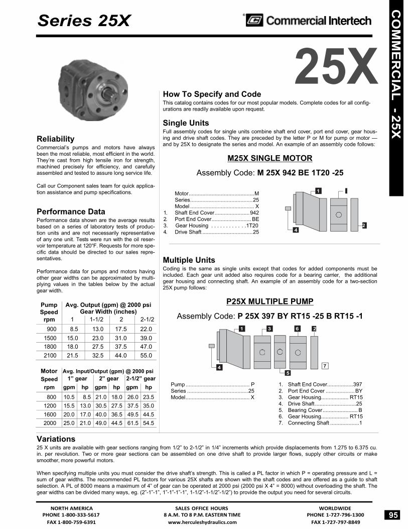
Single Units Full assembly codes for single units combine shaft end cover, port end cover, gear hous- ing and drive shaft codes. They are preceded by the letter P or M for pump or motor — and by 25X to designate the series and model. An example of an assembly code follows:
M25X SINGLE MOTOR
Assembly Code: M 25X 942 BE 1T20 -25
Motor ........................................... M Series ......................................... 25 Model .......................................... X
1. Shaft End Cover ....................... 942 2. Port End Cover .......................... BE 3. Gear Housing . . . . . . . . . . . .1T20 2 4. Drive Shaft ................................. 25
Multiple Units Coding is the same as single units except that codes for added components must be included. Each gear unit added also requires code for a bearing carrier, the additional gear housing and connecting shaft. An example of an assembly code for a two-section 25X pump follows:
P25X MULTIPLE PUMP
Assembly Code: P 25X 397 BY RT15 -25 B RT15 -1 2
Variations
Pump .......................................... P Series ........................................ 25 Model .......................................... X
5
1. Shaft End Cover ................. 397 2. Port End Cover ...................BY3. Gear Housing.................. RT15 4. Drive Shaft ........................... 25 5. Bearing Cover ....................... B 6. Gear Housing.................. RT15 7. Connecting Shaft ...................1
25 X units are available with gear sections ranging from 1/2” to 2-1/2” in 1/4” increments which provide displacements from 1.275 to 6.375 cu. in. per revolution. Two or more gear sections can be assembled on one drive shaft to provide larger flows, supply other circuits or make smoother, more powerful motors.
When specifying multiple units you must consider the drive shaft’s strength. This is called a PL factor in which P = operating pressure and L = sum of gear widths. The recommended PL factors for various 25X shafts are shown with the shaft codes and are offered as a guide to shaft selection. A PL of 8000 means a maximum of 4” of gear can be operated at 2000 psi (2000 psi X 4” = 8000) without overloading the shaft. The gear widths can be divided many ways, eg. (2”-1”-1”, 1”-1”-1”-1”, 1-1/2”-1-1/2”-1/2”) to provide the output you need for several circuits.
NORTH AMERICA SALES OFFICE HOURS WORLDWIDE PHONE 1-800-333-5617 8 A.M. TO 8 P.M. EASTERN TIME PHONE 1-727-796-1300 95
7 4
1 3 6
CO
MM
ER
CIA
L - 25X
Pump Speed
rpm
Avg. Output (gpm) @ 2000 psi Gear Width (inches)
1 1-1/2 2 2-1/2900 8.5 13.0 17.5 22.0
1500 15.0 23.0 31.0 39.0 1800 18.0 27.5 37.5 47.0 2100 21.5 32.5 44.0 55.0
Motor Speed
rpm
Avg. Input/Output (gpm) @ 2000 psi 1” gear 2” gear 2-1/2” gear
gpm hp gpm hp gpm hp 800 10.5 8.5 21.0 18.0 26.0 23.5
1200 15.5 13.0 30.5 27.5 37.5 35.0 1600 20.0 17.0 40.0 36.5 49.5 44.5 2000 25.0 21.0 49.0 44.5 61.5 54.5

FAX 1-727-797-8849 www.herculeshydraulics.com FAX 1-800-759-6391
® Series 25X
25X Parts Breakdown Typical Parts List
Note: Commercial Model 25X tandem pumps and motors can be furnished with either the Type I or Type II shaft. The Type II shaft is used with a thrust bearing and a needle bearing in place of the tapered roller bearing used in the Type I, in order to provide for the 6 bolt — 25/8” dia. pilot shaft end cover. Subassemblies are not interchangeable.
Due to a change in seals, items 31 and 35 are no longer applicable and have been deleted on this exploded view.
96
For Series 25X Seal Kits and Repair Parts, See Pages 475 - 477
CO
MM
ER
CIA
L -
25X
Item Description Part Number Item Description Part Number Item Description Part Number 1 Retainer Ring CM-391-2581-009 25 Thrust Washer 50 Roll Pin
2 Seal Retainer CM-391-2584-016 26 Shaft End Cover 51 Shaft Bushing
3 Double Lip Seal CM-391-2883-055 27 Needle Bearing 52 Bearing Carrier
4 “O” Ring CM-391-2881-120 28 Bearing & Seal Retainer 53 Connection Shaft
5 Bearing Cup 29 “O” Ring 54 Spacer
6 Tapered Bearing CM-391-0384-008 30 Back-up Ring 55 Roll pin
7 Key 32 Drive Shaft 56 Shaft Bushings
8 Drive Shaft 33 Snap Ring Retainer 57 Roller Bearings
9 Shaft End Cover 34 Snap Ring 58 Pocket Seal
10 Check Assemblies CM-391-3681-001 36 Bronze Shaft Bushing CM-391-0481-002 59 Thrust Plate CM-391-2185-912 11 Motor Shaft Seal 37 Conical Spring CM-391-3581-176 60 Connecting Stud
12 Seal Retainer 38 Roller Bearings 61 Lock Nut
13 “O” Ring 39 Pocket Seal 62 “O” Ring Gasket CM-391-2884-021 14 Drive Shaft 40 Thrust Plate CM-391-2185-912 63 Gear Housing
15 Spacer 41 “O” Ring Gasket CM-391-2884-021 64 “O” Ring Gasket CM-391-2884-021 16 Snap Ring 42 Gear Housing 65 Drive Gear
17 Spirolox Snap Ring 43 “O”Ring Gasket CM-391-2884-021 66 Driven Gear
18 Double Lip Seal 44 Drive Gear 67 Thrust plate CM-391-2185-912 19 Bearing and Seal Retainer 45 Driven Gear 68 Pocket Seal
20 Needle Bearing 46 Thrust Plate CM-391-2185-912 69 Roller Bearings
21 “O” Ring 47 Pocket Seal 70 Port End Cover
22 Thrust Bearing Race 48 Roller Bearings CM-391-0381-905 71 Washer
23 Thrust Bearing Rollers 49 Spacer 72 Stud
24 Drive Shaft 73 Hex Nut
WORLDWIDE SALES OFFICE HOURS NORTH AMERICA PHONE 1-727-796-1300 8 A.M. TO 8 P.M. EASTERN TIME PHONE 1-800-333-5617

FAX 1-800-759-6391 www.herculeshydraulics.com FAX 1-727-797-8849
Description
Type
PUMPS No Drain
MOTORS 1/4” NPT
Drain 1/4” BSPP
Drain CW CCW DoublePad Mounting Same as D Code 311
1 100 200 300 900 700 1700
Double Outboard Bearing 3 600 800 1800 Pad Mounting Same as D Code 312
1
101
201
301
901
701
1701
6 Bolt Round Flange Same as D Code 322 1 103 203 303 903 703 1703 4 Bolt Round Flange Same as D Code 321
2
104
204
304
904
704*
1704**
6 Bolt Round Flange Same as D Code 324
2
105
205
305
905
705*
1705**
4 Bolt Square Flange “Special” D 391
1
106
206
306
906
4 Bolt Round Flange for Direct Mount to Spicer to Chelsea PTO
2
107
207
307
907
SAE “B” 4 Bolt 1 142 242 342 942 742 1742 Double Outboard Bearing SAE “B” 4 Bolt
3
642
842
1842
SAE “C” 4 Bolt 1 178 278 378 978 778 1778 Double Outboard Bearing SAE “C” 4 Bolt 3
678
878 1878
SAE “B” 2 Bolt 1 197 297 397 997 797 1797 Double Outboard Bearing SAE “B” 2 Bolt
3
697
897
1897
SAE “C” 2 Bolt 1 198 298 398 998 798 1798
Series 25X
®
Shaft & Port End Covers
P 25 SHAFT END COVERS
* Codes 704 and 705 will have 1/8” NPT Drain ** Codes 1704 and 1705 will have 1/8” BSPP Drain
FLUSH STYLE - TYPE 1 PORT END COVERS
Description Single Multiple Pumps Porting Pumps w/o Support With Support
Studs Studs LH RH NPT Ports BE
CE BI CI
BY CY
— —
— 3/4
FE GE
FI GI
FY GY
3/4 3/4
— 3/4
OD Tube Ports DE HE
DI HI
DY HY
— 1/2
1/2 —
JE LE
JI LI
JY LY
1/2 —
1/2 3/4
KE ME
KI MI
KY MY
3/4 3/4
— 3/4
UE NE
UI NI
UY NY
5/8 —
— 5/8
TYPE 2 Description Code Rotation Port End Covers w/ .9996” Keyed Shaft
BO
Double
6 Bolt Round CO CCW 4 1/4” Bolt Circle 2.625” Pilot Dia.
DO
CW
NORTH AMERICA SALES OFFICE HOURS WORLDWIDE PHONE 1-800-333-5617 8 A.M. TO 8 P.M. EASTERN TIME PHONE 1-727-796-1300 97
2 1
CO
MM
ER
CIA
L - 25X
&

FAX 1-727-797-8849 www.herculeshydraulics.com FAX 1-800-759-6391
® Series 25X
P25 GEAR AND SHAFT COMBINATIONS
TYPE I Description Code Number Description Code Number Connecting Shaft 5-1 .873” Major Diameter 5-25 for Multiple Pumps 7-1 Standard SAE 13 Tooth 7-25
10-1 Spline - Type “B” 10-25 12-1 12-25 15-1 15-25 17-1 17-25 20-1 20-25 22-1 22-25
25-1 25-25 1.127” Round Shaft 5-2 Standard SAE Straight Keyed 5-30 Standard SAE 7-2 Shaft Type “B” 7-30 1/4 x 3/8 x 1 3/4 10-2 1/4 x 3/8 x 1” #15 P & W 10-30 # 51 P & W Key 12-2 Key 12-30
15-2 15-30 17-2 17-30 20-2 20-30 22-2 22-30
25-2 25-30 6 Spline 5-6 .8745” Round Shaft 5-38 1.120” Major Diameter 7-6 3/4 x 8/32 x 1 1/4” 7-38
10-6 # 19 P & W Key 10-38 12-6 12-38 15-6 15-38 17-6 17-38 20-6 20-38 22-6 22-38
25-6 25-38 Standard SAE 14 Tooth 5-7 .8745’ Round Shaft 5-39 Spline - Type “C” 7-7 # 19 P & W Key 7-39 1.2480” Major Diameter 10-7 3/16 x 9/32 x 1 1/4 10-39
12-7 12-39 15-7 15-39 17-7 17-39 20-7 20-39 22-7 22-39
25-7 25-39 1.250” Diameter Standard SAE 5-11 6 Spline - 1 3/8” Spline 5-40 Straight Key Shaft 7-11 .8730” Major Diameter 7-40 Type “C” # 25 P & W Key 10-11 10-40 5/16 x 13/32 x 1 1/2 12-11 12-40
15-11 15-40 17-11 17-40 20-11 20-40 22-11 22-40
25-11 25-40 6 Spline - 1 5/16” Spline 5-42 .9545’ Diamater Straight 5-52 .9846” Major Diameter 7-42 Keyed Shaft 7-52
10-42 1/4 x 3/8 x 1 1/4” 10-52 12-42 12-52 15-42 15-52 17-42 17-52 20-42 20-52 22-42 22-52
25-42 25-52 .9996” Diameter Round Shaft 5-43
1/4 x 5/8 x 1 1/4” 7-43
#21 P & W Key 10-43
12-43 15-43
17-43
20-43
22-43
25-43
98
WORLDWIDE SALES OFFICE HOURS NORTH AMERICA PHONE 1-727-796-1300 8 A.M. TO 8 P.M. EASTERN TIME PHONE 1-800-333-5617
4
TYPE II Description Code Number 1.249” Diameter 5-73 Straight Shaft 7-73 #55 P & W Key 10-73
12-73 15-73 17-73 20-73 22-73 25-73
Gear & Shaft Combinations
TYPE II Description Code Number 6 Spline - 1 13/16 Spline 5-99 .8730 Major Diameter 7-99 Supersedes Code 44 10-99
12-99 15-99 17-99 20-99 22-99
25-99 .8745” Diameter Round 5-45 Shaft 3/16 x 8/32 x 1 1/4” 7-45 #19 P & W Key 10-45
12-45 15-45 17-45 20-45 22-45
25-45 6 Spline - 1 8/32” Spline 5-46 .9846” Major Diameter 7-46
10-46 12-46 15-46 20-46 22-46
25-46 .9996” Diameter Round Shaft 5-47 1/4 x 3/8 x 1 1/4” 7-47 # 21 P & W Key 10-47
12-47 15-47 20-47 22-47
25-47 SAE “B” 13 Tooth 5-48 Spline - 1 3/4” Spline 7-48 .8730” Modified major Diameter 10-48
12-48 15-48 17-48 20-48 22-48
25-48 14 Tooth Involute 5-55 Spline - 31/32 7-55 1.2480” Major Diameter 10-55
12-55 15-55 17-55 20-55 22-55 25-55
CO
MM
ER
CIA
L -
25X

FAX 1-800-759-6391 www.herculeshydraulics.com FAX 1-727-797-8849
Series 25X
25X Gear housings - NPT Ports
®
Gear Housings
‡ Low pressure input only * Note: To be used only with Technical Service approval.
25X GEAR HOUSINGS - SAE SPLIT FLANGE PORTS
Porting
LH RH 3/4 1 1 1/4 1 1/2 1 3/4 2 2 1/4 2 1/2 — — AB07 AB10 AB12 AB15 AB17 AB20 AB22 AB25 — 1/2 OC07 OC17
1/2 — OP07 OP17
1/2 1/2 ZC17
— 3/4 OF12 OF15 OF17 OF20 OF22 OF25 3/4 — OR12 OR15 OR17 OR20 OR22 OR25 3/4 3/4 ZR10 ZR12 ZR15 ZR17 ZR20 ZR22 ZR25 — 1 OH10* OH12 OH15 OH17 OH20 OH22 OH25 1 — OT10* OT12 OT15 OT17 OT20 OT22 OT25 1 1 RL12* RL15 RL17 RL20 RL22 RL25 — 1 1/4‡ OJ12‡ OJ15 OJ17 OJ20 OJ22 OJ25
1 1/4‡ — OV12‡ OV15 OV17 OV20 OV22 OV25 1 1/4 1 1/4 RT15 RT17 RT20 RT22 RT25
— 1 1/2‡ OK15‡ OK17‡ OK20 OK22 OK25 1 1/2‡ — OW15‡ OW17‡ OW20 OW22 OW25 1 1/2 1/12 SC17‡ SC20 SC22 SC25
1 1/2‡ 1 RY15‡ RY17‡ RY20 RY22 RY25 1 1 1/2‡ RN15‡ RN17‡ RN20 RN22 RN25
1/2 3/4 ZF15 ZF17 ZF20 ZF22 ZF25 3/4 1/2 ZP15 ZP17 ZP20 ZP22 ZP25 3/4 1 ZT10 ZT15 AT17 ZT20 ZT22 ZT25 1 3/4 RJ10 RJ15 RJ17 RJ20 RJ22 RJ25 1 1 1/4‡ RM12‡ RM15 RM17 RM20 RM22 RM25
1 1/4‡ 1 RS12‡ RS15 RS17 RS20 RS22 RS25 1 1/4 3/4 RQ15 RQ17 RQ20 RQ22 RQ25 3/4 1 1/4 ZU15 ZU17 ZU20 ZU22 ZU25
1 1/4 1 1/2‡ RU15‡ RU17‡ RU20 RU22 RU25 1 1/2‡ 1 1/4 RZ15‡ RZ17‡ RZ20 RZ22 RZ25 1 1/2 2‡ SD20‡ SD22‡ SD25 2‡ 1 1/2 SH20‡ SH22‡ SH25
1 1/4 2‡ RX20‡ RX22‡ RX25 2‡ 1 1/4 SG20‡ SG22‡ SG25 1 2‡ OS22‡ OS25
2‡ 1 OZ22‡ OZ25 2 — OX20‡
— 2 OL20‡
‡ Low pressure input only* Note: To be used only with Technical Service approval.
25X GEAR HOUSINGS - SAE STRAIGHT THREAD PORTS
Porting
LH RH 3/4 1 1 1/4 1 1/2 1 3/4 2 2 1/4 2 1/2 — — AB07 AB10 AB12 AB15 AB17 AB20 AB22 AB25— 1/2 UC07 UC10 UC15
1/2 — UP07 UP10 UP15
1/2 1/2 YC07 YC10 YC12 YC15
— 5/8 UD10 UD12 UD15
5/8 — UQ10 UQ12 UQ15
5/8 5/8 YK10 YK12 YK15 YK20
— 3/4 UF10 UF12 UF15 UF17
3/4 — UR10 UR12 UR15 UR17
3/4 3/4 YR10 YR12 YR15 YR17 YR20 YR22 YR25 — 7/8 UG12 UG15 UG17 UG20 UG22 UG25 7/8 — US12 US15 US17 US20 US22 US25 7/8 7/8 YZ12 YZ15 YZ17 YZ20 YZ22 YZ25 — 1‡ UH12‡ UH15 UH17 UH20 UH22 UH25 1‡ — UT12‡ UT15 UT17 UT20 UT22 UT251 1 VL12* VL15 VL17 VL20 VL22 VL25 — 1 1/4 UJ20 UJ22 UJ25
1 1/4 — UV20 UV22 UV25 1 1/4 1 1/4 VT20 VT22 VT25
— 1 1/2 UK22
1 1/2 — UW22
5/8 1/2 YJ10 YJ15
5/8 3/4 YL10 YL12 YL15 YL17
3/4 5/8 YQ10 YQ12 YQ15 YQ17
3/4 7/8 YS22
7/8 3/4 YX22
7/8 1‡ VC12‡ VC15 VC17 VC20 VC22 VC25 1‡ 7/8 VK12‡ VK15 VK17 VK20 VK22 VK251 1 1/4‡ VM15‡ VM17‡ VM20 VM22 VM25
1 1/4‡ 1 VS15‡ VS17‡ VS20 VS22 VS251 1/4 1 1/2‡ VU20‡ VU22 VU25
1 1/2‡ 1 1/4 VZ20‡ VZ22 VZ25 3/4 1‡ YT10‡
1‡ 3/4 VJ10‡
1/2 5/8 YD10 YD15
1 1 1/2‡ VN17‡
1 1/2‡ 1 VG17‡
1 1/2 1 1/2 WC25 ‡ Low pressure input only * Note: To be used only with Technical Service approval.
NORTH AMERICA SALES OFFICE HOURS WORLDWIDE PHONE 1-800-333-5617 8 A.M. TO 8 P.M. EASTERN TIME PHONE 1-727-796-1300
99
Porting
LH RH 1/2 3/4 1 1 1/4 1 1/2 1 3/4 2 2 1/4 2 1/2 — — AB05 AB07 AB10 AB12 AB15 AB17 AB20 AB22 AB25— 1/2 AC07
1/2 — AP07
1/2 1/2 EC07 EC10
— 3/4 AF07 AF10 AF12 AF15 AF17 AF20
3/4 — AR07 AR10 AR12 AR15 AR17 AR20
3/4 3/4 ER10 ER12 ER15 ER17 ER20 ER22 ER25 1/2 3/4 ED07
3/4 1/2 EH07
— 1‡ AH10‡ AH12 AH15 AH17 AH20 AH22 AH25 1‡ — AT10‡ AT12 AT15 AT17 AT20 AT22 AT25 1 1 IL10* IL12 IL15 IL17 IL20 IL22 IL25
3/4 1‡ ET10‡ ET12 ET15 ET17 ET20 ET22 ET251‡ 3/4 IJ10‡ IJ12 IJ15 IJ17 IJ20 IJ22 IJ25 — 1 1/4 AJ17 AJ20 AJ22 AJ25
1 1/4 — AV17 AV20 AV22 AV25 1 1/4 1 1/4 IT17 IT20 IT22 IT25
1 1/2‡ — AW20‡ AW22 AW25 — 1 1/2‡ AK20‡ AK22 AK25
1 1/2 1 1/2 JC22 JC25 3/4 1 1/4 EU17 EU20 EU25
1 1/4 3/4 IQ17 IQ20 IQ25 1 1 1/4 IM15‡ IM17 IM20 IM22 IM25
1 1/4 1 IS15‡ IS17 IS20 IS22 IS25 1 1 1/2‡ IN20‡ IN22 IN25
1 1/2‡ 1 IY20‡ IY22 IY25 1 1/4 1 1/2‡ IU20‡ IU22 IU25
1 1/2‡ 1 1/4 IZ20‡ IZ22 IZ25
6 3
CO
MM
ER
CIA
L - 25X
&

FAX 1-727-797-8849 www.herculeshydraulics.com FAX 1-800-759-6391
® Series 25X
Bearing Carriers
back 25X BEARING CARRIERS
L R
front Porting
LH RH NPT Ports
CodeBSPP Code
SAE Split Flange Code
Metric Split Flange Code
SAE Straight Thread Code
Metric Straight Thread Code
—
—
B
—
—
—
—
—
—
—
C
—
—
—
—
—
—
—
H
—
—
—
—
—
3/4 — D MD FL XX ND NH1 — F MG FM XL NF NM
1 1/4 — G MH FN XM NG NN 1 1/2 — TL MM FP XN TH NO
— 3/4 J MO FQ XO — NP — 1 L MQ FR XP NJ NQ — 1 1/4 L MS FS XQ NK NZ — 1 1/2 TJ MX FT CQ TM ZZ
1 3/4 CV — — — — — 3/4 1 CW HO KZ JN TS RE
1 1/4 1 DB — LD — — — 3/4 1 1/4 — HR — JO — RI 1 1 1/4 DC HV LF JQ XZ RO
1 1/4 1 1/2 — — LK — — — 1 1/2 1 1/4 — — LJ — — —
1 1 1/2 XT HX XW JR TN RR 3/4 1 1/2 XR HS XF JP — RK 3/4 3/4 CT — KW — — — 1 1 CZ — LC — PX —
1 1/4 1 1/4 DF — — — — — 1 1/2 1 1/2 — — LM — — —
1 1/4 1 BN HM HB JL XX PS 1 1 1/4 BP — HC — — —
1 1/2 1 XS HN XV JM TK PV 1 3/4 BJ HD GV JD — PN
3/4 3/4 BH — GT — NX — 1 1 BM — — — PB —
1 1/4 1 1/4 SR — HF — PD — 1 1/2 1 1/2 — — HK — — — 1 1/2 3/4 XH HL — JK — PR 1 1/2 1 1/4 — — HG — — — 1 1/4 1 1/2 — — HH — — —
3/4 1 BW EG HP LH — SJ 1 1 1/4 CC BV HT LW XD SO 1 1 1/2 TV QV TX LX TZ SP
3/4 3/4 BT — — — — — 1 1 BZ — — — PJ —
1 1/4 1 1/4 CF — HW — PL — 1 1/4 1 CB — — — — — 1 1/2 1 1/2 — — KC — — —
1 3/4 CJ QC KG KB — GD3/4 1 CK — KH — — —
1 1/4 1 CN QN KL KR XC GX 1 1 1/4 CP — KM — — —
1 1/2 1 TT QO TW KX — GZ 3/4 3/4 CH — KF — — — 1 1 CM — — — PQ —
1 1/4 1 1/4 CR — — — — — 1 1/2 1 1/2 — — KT — — —
3/4 — CS — KV — PT — 1 — CX — LB — PW —
1 1/4 — DD — LG — PZ —
— 3/4 BG — — — NW — — 1 BL — — — — — — 1 1/4 — — — — PC —
3/4 — BS — — — PI — 1 — BX — HQ — PH —
1 1/4 — CD — — — — —
100 WORLDWIDE SALES OFFICE HOURS NORTH AMERICA
PHONE 1-727-796-1300 8 A.M. TO 8 P.M. EASTERN TIME PHONE 1-800-333-5617
5
CO
MM
ER
CIA
L -
25X

FAX 1-800-759-6391 www.herculeshydraulics.com FAX 1-727-797-8849
Series 25X
back
®
25X BEARING CARRIERS
Bearing Carriers
L R
front Porting
LH RH NPT Ports
Code BSPP Code
SAE Split Flange Code
Metric Split Flange Code
SAE Straight Thread Code
Metric Straight Thread Code
— 3/4 CG — KD — — — — 1 CL — KJ — PP — — 1 1/4 — — KN — — — — 1 1/2 — — KS — — —
3/4 3/4 Q — — — — — 1 3/4 R — FZ — — —
3/4 1 S — GB — — — 1 1/4 1 X — GG — — —
1 1 1/4 BB — GH — — — 1 1/2 — — — GQ — — —
1 1 W OB GF QB NR RA 1 1/4 1 1/4 BF OE GL QZ NV XJ 1 1/2 1 1/2 TQ ON GR BK TP JG
3/4 — P — — — — — 1 — V — — — — —
1 1/4 — BD — GK — NT —
— 3/4 N — — — NL — — 1 T — GC — — — — 1 1/4 BC — GJ — NS —
3/4 3/4 DG AL LN JS — GM1 1 DH AS LP JT QD GN
1 1/4 1 1/4 DJ AZ LQ JX AF GO 1 1/2 1 1/2 — HZ LR JZ — GP
3/4 3/4 DK KK — FO — SS 1 1 DL LL LT FV QH ST
1 1/4 1 1/4 DM VV LV FW QJ SV 1 1/2 1 1/2 — WW — FX — SW
3/4 — DZ — MN — — — 1 — FB — MP — QW —
1 1/4 — FC — — — QX — 1 1/2 — — — MR — — —
— 3/4 FD — — — — — — 1 FF — MT — TB — — 1 1/4 FG — MV — TC — — 1 1/2 — — MW — — —
— 3/4 DV — MJ — QR — — 1 DW — MK — QS — — 1 1/4 DX — ML — QT —
3/4 — FH — — — TD —1 — FJ — MZ — TF —
1 1/4 — FK — NB — TG — 1 1/2 — — — NC — — —
3/4 3/4 DR — — — — — 1 1 DS — MF — QP —
1 1/4 1 1/4 DT — — — QQ —
3/4 3/4 DN — — — QK — 1 1 DP — LZ — QL —
1 1/4 1 1/4 DQ — MB — — — 1 1/2 1 1/2 — — MC — — —
—
—
M
—
—
—
—
—
NORTH AMERICA SALES OFFICE HOURS WORLDWIDE PHONE 1-800-333-5617 8 A.M. TO 8 P.M. EASTERN TIME PHONE 1-727-796-1300
101
5
CO
MM
ER
CIA
L - 25X

ntertech Cylinders, Pumps & Motors / Custom Hoists / LHA ccessories / Cylinders / Prince Cylinders & Pumps / Chief ylinders / Perfection Pumps / White Motors / Gresen®
ylinders, Pumps, Motors & Valves / Commercial Intertech ylinders, Pumps & Motors / Custom Hoists / LHA Accessories
Cylinders / Prince Cylinders & Pumps / Chief Cylinders / erfection Pumps / White Motors / Gresen® Cylinders, Pumps,
Motors & Valves / Commercial Intertech Cylinders, Pumps & Motors / Custom Hoists / LHA Accessories / Cylinders / Prince
ylinders & Pumps / Chief Cylinders / Perfection Pumps / White Motors / Gresen® Cylinders, Pumps, Motors & Valves /
ommercial Intertech Cylinders, Pumps & Motors / Custom oists / LHA Accessories / Cylinders / Prince Cylinders & umps / Chief Cylinders / Perfection Pumps / White Motors / resen®
Cylinders, Pumps, Motors & Valves / Commercial ntertech Cylinders, Pumps & Motors / Custom Hoists / LHA
ccessories / Cylinders / Prince Cylinders & Pumps / Chief ylinders / Perfection Pumps / White Motors / Gresen®
ylinders, Pumps, Motors & Valves / Commercial Intertech ylinders, Pumps & Motors / Custom Hoists / LHA Accessories
Cylinders / Prince Cylinders & Pumps / Chief Cylinders / erfection Pumps / White Motors / Gresen® Cylinders, Pumps,
Motors & Valves / Commercial Intertech Cylinders, Pumps & Motors / Custom Hoists / LHA Accessories / Cylinders / Prince
ylinders & Pumps / Chief Cylinders / Perfection Pumps / White Motors / Gresen® Cylinders, Pumps, Motors & Valves /
ommercial Intertech Cylinders, Pumps & Motors / Custom oists / LHA Accessories / Cylinders / Prince Cylinders & umps / Chief Cylinders / Perfection Pumps / White Motors / resen®
Cylinders, Pumps, Motors & Valves / Commercial ntertech Cylinders, Pumps & Motors / Custom Hoists / LHA
ccessories / Cylinders / Prince Cylinders & Pumps / Chief ylinders / Perfection Pumps / White Motors / Gresen®
ylinders, Pumps, Motors & Valves / Commercial Intertech ylinders, Pumps & Motors / Custom Hoists / LHA Accessories
Cylinders / Prince Cylinders & Pumps / Chief Cylinders / erfection Pumps / White Motors / Gresen® Cylinders Pumps

FAX 1-800-759-6391 www.herculeshydraulics.com FAX 1-727-797-8849
1
Series P30
®
How To Specify and Code
P30Reliability Series 30 pumps and motors are cast from hi-ten- sile gray iron and offer a wide variety of drive shafts designed for high torque input/output. Unique pressure balanced thrust plates con- tribute to operating efficiencies of over 90%.
These units are designed for continuous operation in heavy-duty implement circuits. They’re equally at home on lift trucks, auto wreck- ers and small dump body applications.
Call our Component sales team for quick application assistance and pump specifications.
Performance Data Performance data shown are the average results based on a series of laboratory tests of produc- tion units and are not necessarily representative
of any one unit. Tests were run with the oil reser- voir temperature at 120°F. Requests for more spe- cific data should be directed to our sales repre- sentatives.
Performance data for pumps and motors having other gear widths can be approximated by multi- plying values in tables below by actual gear width.
This catalog contains codes for our most popular models. Complete codes for all config- urations are readily available upon request.
Single Units Full assembly codes for single units combine shaft end cover, port end cover, gear hous- ing and drive shaft codes. They are preceded by the letter P or M for pump or motor — and by 30 to designate the series and model. An example of an assembly code follows:
M30 SINGLE MOTOR
Assembly Code: M 30A 942 BE YF15-30
Motor . . . . . . . . . . . . . . . . . . . . .M 3 Series ......................................... 30 Model .......................................... A
1. Shaft End Cover ....................... 942 2. Port End Cover .......................... BE 3. Gear Housing ......................... YF15 4. Drive Shaft . . . . . . . . . . . . . . . .30 4
Multiple Units Coding is the same as single units except that codes for added components must be included. Each gear unit added also requires code for a bearing carrier, the additional gear housing and connecting shaft. An example of an assembly code for a two-section Series 30 pump follows:
P30 MULTIPLE PUMP
Assembly Code: P 30B 278 BY OM20-43 D UG10-1
2
Variations
Pump ........................................... P Series ........................................ 30 Model .......................................... B
5
1. Shaft End Cover ................ 278 2. Port End Cover ................... BY 3. Gear Housing ................ OM20 4. Drive Shaft ........................... 43 5. Bearing Cover ....................... D 6. Gear Housing ................ UG10 7. Connecting Shaft ................... 1
Series 30 units are available with gear sections ranging from 1/2” to 2” in 1/4” increments which provide displacements from .985 to 3.94 cu. in. per revolution. Two or more gear sections can be assembled on one drive shaft to provide larger flows, supply other circuits or make smoother, more powerful motors.
When specifying multiple units you must consider the drive shaft’s strength. This is called a PL factor in which P = operating pressure and L = sum of gear widths. The recommended PL factors for various Series 30 shafts are shown with the shaft codes and are offered as a guide to shaft selection. A PL of 8000 means a maximum of 4” of gear can be operated at 2000 psi (2000 psi X 4” = 8000) without overloading the shaft. The gear widths can be divided many ways, eg. (2”-1”-1”, 1”-1”-1”-1”, 1-1/2”-1-1/2”-1/2”) to provide the output you need for several circuits.
NORTH AMERICA SALES OFFICE HOURS WORLDWIDE PHONE 1-800-333-5617 8 A.M. TO 8 P.M. EASTERN TIME PHONE 1-727-796-1300 103
7 4
63 1
2
CO
MM
ER
CIA
L - P30
Pump Speed
rpm
Avg. Output (gpm) @ 2000 psi Gear Width (inches)
1 1-1/4 1-1/2 1-3/4 2 900 6.5 8.0 10.0 12.0 13.5
1200 9.0 11.5 14.0 16.0 18.5 1500 11.5 14.5 17.5 20.5 23.5 2100 16.5 21.0 25.0 29.0 34.0
Motor Speed
rpm
Avg. Input/Output (gpm) @ 2000 psi 1” gear 1-1/2” gear 2” gear
gpm hp gpm hp gpm hp 800 9.0 7.0 13.0 11.0 17.0 14.5
1200 13.0 10.5 18.0 16.5 23.5 22.0 1600 16.4 14.0 23.0 22.0 30.5 29.0 2000 19.5 17.5 28.0 27.0 37.0 36.0

FAX 1-727-797-8849 www.herculeshydraulics.com FAX 1-800-759-6391
® Series P30
P30 Parts Breakdown Typical Parts List Note: This page shows the typical arrangement of a 2-section unit. It may not be pictorially correct and is not to scale.
Plug 5 in position B gives clockwise rotation.
Plug 5 in position A gives counter-clockwise rotation.
Check valves in both positions give bi-directional rotation.
104
For Series P30 Seal Kits and Repair Parts, See Pages 475 - 477
CO
MM
ER
CIA
L -
P30
Item Description Part Number Item Description Part Number 1 Snap Ring CM-391-2686-063 10 Integral Drive Shaft See Option List 2 Outboard Bearing CM-391-0381-040 and Gear Set
3 Seal (Pump) CM-391-2883-058 11 Gasket Seals CM-391-2884-050 Hi Pressure Seal (Motor) CM-391-2883-119 12 Gear Housing See Option List
4 Shaft End Cover See Option List 13 Bearing Carrier See Option List 5 Check Assemblies CM-391-3681-001 14 Connecting Shaft See Option List
Plug CM-391-2286-004 15 Matched Gear Set See Option List 6 Ring Seals CM-391-2585-006 16 Gear Housing See Option List 7 Roller Bearings CM-391-0381-906 17 Port End Cover See Option List 8 Pocket Seals 18 Washers
9 Thrust Plates CM-391-2185-913 19 Studs or Cap Screws
20 Nuts
WORLDWIDE SALES OFFICE HOURS NORTH AMERICA PHONE 1-727-796-1300 8 A.M. TO 8 P.M. EASTERN TIME PHONE 1-800-333-5617

FAX 1-800-759-6391 www.herculeshydraulics.com FAX 1-727-797-8849
Description Single Pumps
Multiple Pumps Porting w/Reg Studs w/2 Ext Studs LH RH
No Ports BE BI BY — — NPT Ports KE* KI KY 3/4 — LE* LI LY 3/4 ME* MI MY 3/4 3/4 ODT Ports CE* CI CY 3/4 — DE* DI DY — 3/4 FE* FI FY 3/4 3/4 GE* GI GY 1 3/4 HE HI HY 3/4 1 JE* JI* JY* 1 1 BSPP Ports WE WI WY 3/4 — XE XI XY — 3/4 ZE ZI ZY 3/4 3/4 Metric Straight NE NI NY M26X1.5 — Thread Ports PE PI PY — M26X1.5 QE QI QY M26X1.5 M26X1.5 RE RI RY M33X2 M26X1.5 SE SI SY M26X1.5 M33X2 Piggyback Port End Cover
TYPE 30—30
CW KO
CCW LO
DOUBLE MO
Series P30
®
Shaft & Port End Covers
P30 SHAFT END COVERS Description PUMPS MOTORS
* Available for special application upon request. NOT A STOCK ITEM
P30 PORT END COVERS
Priority Outlet see P1B-H2 for description of codes *Avaliable for specialapplication upon request. NOT A STOCK ITEM.
NORTH AMERICA SALES OFFICE HOURS WORLDWIDE PHONE 1-800-333-5617 8 A.M. TO 8 P.M. EASTERN TIME PHONE 1-727-796-1300
105
Type
Outboard Bearing
1/4” NPT 1/4” BSPPCW CCW Double DRAIN DRAIN
Round Flange - 6 Bolt 1 Without 105 205 305 905 1905 With 405 505 605 805 1805
SAE B - 4 Bolt 1 Without 142 242 342 942 1942 With 442 542 642 842 1842
SAE C - 4 Bolt 1 Without 178 278 378 978 1978 With 478 578 678 878 1878
SAE A - 2 Bolt 1 Without 194 294 394 994 1994 With 494 594 694 894 1894
SAE B - 2 Bolt 1 Without 197 297 397 997 1997 With 497 597 697 897 1897
2 Without 196* 296* 396* N/A N/A Piggy Back Shaft End Cover
50-30 30-30
Without 191 291 391 N/A N/A
75-30 Without 192 292 392 N/A N/A Pad Mounting 1 Without N/A
With 400 500 600 800 1800
2 1
CO
MM
ER
CIA
L - P30
&

FAX 1-727-797-8849 www.herculeshydraulics.com FAX 1-800-759-6391
Drive
® Series P30
Shafts P30 DRIVE SHAFTS
Shaft Description Code
Type 1 Type 2 SAE B - Straight Keyedf .875” Diameter - 1/4” X 1” Key
30 —
Standard - Straight Keyed .9998’ Diameter - 1/4” X 1 1/4” Key
43 —
SAE B - 13 Tooth Spline .873 Major Diameter
25 65*
Standard - 6 Tooth Spline .997” Major Diameter
68* —
SAE A - 9 Tooth Spline .623” Major Diameter
95 —
Connecting Shaft - Multiple Units 1 1 Connecting Shaft - Piggyback Pump P30 to P30 14 —
P50 to P30 22 — P75 to P30 23 — * Available for special application upon request. Not a stock item.
P30 DRIVE SHAFT CODE GEAR WIDTH 1-14-22-23 25 30 43 65* 68* 95
1/2 •
3/4 • • • •
1 • • • • • • • 1 1/4 • • • • • • • 1 1/2 • • • • • •
1 3/4 • • • • • •
2 • • • • • •
Gear Housings
30 GEAR HOUSINGS - NPT PORTS
Porti LH
ng RH
1/2
3/4
1
1 1/4 1 1/2
1 3/4
2
— — AB05 AB07 AB10 AB12 AB15 AB17 AB20 1/2 — IL07 IL10
— 1/2 IM07 IM10
1/2 1/2 IR07
3/4 — IC10 IC12 IC15
— 3/4 ID10 ID12 ID15
3/4 3/4 IF10 IF12 IF15 IF17 IF203/4 1‡ IG10‡ IG12
1‡ 3/4 IJ10 IJ12 IJ15 IJ17
1 — YC12 YC15 YC17 — 1 YD12 YD15 YD17
1 1 YF12 YF15 YF17 YF20 1 1 1/4‡ YG15‡ YG17 YG20
1 1/4‡ 1 YJ15‡ YJ17 YJ20 1 1/4 1 1/4 YL20
1 1/4‡ — IA15‡ IA17 IA20 — 1 1/4‡ IB15‡ IB17 IB20
1 1/4 1 1/2‡ YM20‡ 1 1/2‡ 1 1/4 YP20‡ 1 1/2‡ — YA20‡
— 1 1/2‡ YB20‡ ‡ Low pressure only
106 WORLDWIDE SALES OFFICE HOURS NORTH AMERICA
PHONE 1-727-796-1300 8 A.M. TO 8 P.M. EASTERN TIME PHONE 1-800-333-5617
6 3
4
CO
MM
ER
CIA
L -
P30
&

FAX 1-800-759-6391 www.herculeshydraulics.com FAX 1-727-797-8849
Series P30
®
Gear Housings
P30 GEAR HOUSINGS - BSPP PORTS Porti
LH ng
RH
1/2
3/4
1
1 1/4
1 1/2
1 3/4
2 — — AB05 AB07 AB10 AB12 AB15 AB17 AB20
3/4‡ — YN07‡ YN10 YN12 YN15 YN17 YN20 — 3/4‡ YQ07‡ YQ10 YQ12 YQ15 YQ17 YQ20 3/4 3/4 YS10 YS12 YS15 YS17 YS20 3/4 1‡ YT10‡ YT12‡
1‡ 3/4 YV10‡ YV12‡ YV15 YV17 YV20 3/4 1 1/4‡ YU15‡ YU17‡ YU20‡
1 1/4‡ 3/4 YW15‡ YW17‡ YW20‡ 1‡ — SL12‡ SL15 SL17 SL20 — 1‡ RQ12‡ RQ15 RQ17 RQ20 1 1 MP12* MP15 MP17
1 1 1/4‡ VY15‡ VY17‡ VY20‡ 1 1 1/2 HW17 HW20
1 1/4‡ 1 IX15‡ IX17‡ IX20‡ 1 1/4‡ — NJ17‡ NJ20‡
— 1 1/4‡ UI17‡ UI20‡1 1/4 1 1/4 PF20‡ 1 1/2 1 1/4 IS17
‡ Low pressure only
P30 GEAR HOUSINGS - SAE SPLIT FLANGE PORTS Porti
LH ng
RH
1/2
3/4
1
1 1/4
1 1/2
1 3/4
2 — — AB05 AB07 AB10 AB12 AB15 AB17 AB20 3/4 — UC10 UC12
— 3/4 UD10 UD12 UD15
3/4 3/4 UF10
3/4 1 UG10 UG12 UG20 3/4 1 1/4 UH12
1 3/4 UJ10 UJ12 UJ15 UJ17 UJ20 1 1/4 3/4 UK12
1 — OC12 OC15 OC17
— 1 OD12 OD15 OD17 OD20 1 1 OF10 OF12 OF15 OF17 OF20 1 1 1/4‡ OG12‡ OG15 OG17 OG20
1 1/4‡ 1 OJ12‡ OJ15 OJ17 OJ20 1 1 1/2‡ OH17‡ OH20
1 1/2‡ 1 OK17‡ OK20 1 1/4‡ — OA12‡ OA15 OA17 OA20
— 1 1/4‡ OB12‡ OB15 OB17 OB20 1 1/4 1 1/4 OL15 OL17 OL20 1 1/4 1 1/2‡ OM17‡ OM20
1 1/2‡ 1 1/4 OP17‡ OP20 1 1/2‡ — OE17‡ OE20
— 1 1/2‡ OU17‡ OU20 ‡ Low Pressure Only
P30 GEAR HOUSINGS - METRIC SPLIT FLANGE PORTS Port
LH ng
RH
1/2
3/4
1
1 1/4
1 1/2
1 3/4
2 — — AB05 AB07 AB10 AB12 AB15 AB17 AB20 3/4 — VN10 VN12 VN15 VN17
— 3/4 VQ10 VQ12 VQ15 VQ17
3/4 3/4 VS10 VS12 3/4 1 VT10 VT12 VT15 VT17
1 3/4 RV10 RV12 RV15 RV17
3/4 1 1/4‡ RU12‡ RU17
1 1/4‡ 3/4 RW12‡ RW17
1 — UL10 UL12 UL15 UL17 UL20 — 1 UR10 UR12 UR15 UR17 UR20 1 1 UM12 UM15 UM17
1 1 1/4‡ VU12‡ VU15 VU17 VU20 1 1/4‡ 1 UX12‡ UX15 UX17 UX20
1 1 1/2‡ HO17‡ HO20 1 1/2‡ 1 VO17‡ VO20 1 1/4 — NO15 NO20
— 1 1/4 UO15 UO20 1 1/4 1 1/4 PO15 PO17 PO20 1 1/4 1 1/2‡ QO17‡ QO20
1 1/2‡ 1 1/4 SO17‡ SO20 1 1/2‡ — UY15‡ UY17‡
— 1 1/2‡ TO15‡ TO17‡ ‡ Low Pressure Only
P30 GEAR HOUSINGS - SAE STRAIGHT THREAD PORTS Port
LH ing
RH
1/2
3/4
1
1 1/4
1 1/2
1 3/4
2 — — AB05 AB07 AB10 AB12 AB15 AB17 AB20 3/4 — EC10 EC12 EC15
— 3/4 ED10 ED12 ED15
3/4 3/4 EF10 EF12 EF15 EF17 EF20 3/4 1‡ EG10‡ EG12‡ EG15 EG17
3/4 1 1/4‡ EH15‡ EH17‡ 3/4 1 1/2‡ IN20‡ 1‡ 3/4 EJ10‡ EJ12‡ EJ15 EJ17 EJ20
1 1/4‡ 3/4 EL15‡ EK17‡
1 1/2‡ 3/4 IP20‡ 7/8 — EZ12
7/8 1‡ EL10‡ EL12‡
1‡ 7/8 EM10‡ EM12‡
1‡ — AC10‡ AC12 AC15 AC17 AC20 — 1‡ AD10‡ AD12 AD15 AD17 AD20 1 1 AF15 AF17 AF20 1 1 1/4‡ AG15‡ AG17‡ AG20 1 1 1/2‡ AH17‡ AH20‡
1 1/4‡ 1 AJ15‡ AJ17‡ AJ20 1 1/2‡ 1 AK17‡ AK20‡ 1 1/4‡ — AA15‡ AA17‡
— 1 1/4‡ AO15‡ AO17‡ 1 1/4 1 1/4 AL17 AL20 1 1/4 1 1/2‡ AM17‡ AM20‡
1 1/2‡ 1 1/4 AP17‡ AP20‡ 1 1/2‡ — AE17‡ AE20
— 1 1/2‡ AU17‡ AU20 ‡Low pressure only
NORTH AMERICA SALES OFFICE HOURS WORLDWIDE PHONE 1-800-333-5617 8 A.M. TO 8 P.M. EASTERN TIME PHONE 1-727-796-1300
107
6 3
CO
MM
ER
CIA
L - P30
&

FAX 1-727-797-8849 www.herculeshydraulics.com FAX 1-800-759-6391
® Series P30
Gear Housings
P30 GEAR HOUSINGS - METRIC STRAIGHT THREAD PORTS
Bearing Carriers
*Rated to 2000 PSI maximum ‡Low pressure only
Port Size
Metric Straight Thread Size
3/4 M26 X 1.5 1 M33 X 2
1 1/4 M42 X 21 1/2 M48 X 2
P30 BEARING CARRIERS (FLOW DIVIDERS ONLY)
108 WORLDWIDE SALES OFFICE HOURS NORTH AMERICA
PHONE 1-727-796-1300 8 A.M. TO 8 P.M. EASTERN TIME PHONE 1-800-333-5617
back
L R
front
Ports Ports Metric
SAE Split Split
Ports
SAE Str. MetricPorting NPT BSSP Porting Flge. Flge. Porting Thd. Str. Thd.
LH RH Code Code LH RH Code Code LH RH Code Code
—
—
B
B
—
—
B
B
—
—
B
B
—
—
E
E
—
—
E
E
—
—
E
E
1 1 1/4 1 1/2
— — —
M N —
X Y Z
1 1 14 1 1/2
— — —
J K L
T V W
1 1 1/4 1 1/2
M33 X 2 M42 X 2 M48 X 2
— — — — — —
F G H — — —
— — — Q R S
— —
3/4 1
BX KZ
DG DF
— —
3/4 1
GR MT
TR FM
— — —
3/4 1
M26 X 1.5 M33 X 2
GJ BK — —
— — QJ ML
— —
3/4 1
CV NK
DM MN
— —
3/4 1
FD JG
KT RP
— —
3/4 1
M26 X 1.5 M33 X 2
JH PC — —
— — BZ MK
1 1 1/4 1 1/2 1 1/4 1 1/2
3/4 3/4 3/4 1 1
GX HX — LZ —
FG SG XG GF MF
1 1 1/4 1 1/2 1 1/4 1 1/2
3/4 3/4 3/4 1 1
HR PR QR NT RT
VR WR XR QM VM
1 1 1/4 1 1/2 1 1/4 1 1/2
M33 X 2 M42 X 2 M48 X 2 M42 X 2 M48 X 2
3/4 3/4 3/4 1 1
M26 X 1.5 M26 X 1.5 M26 X 1.5 M33 X 2 M33 X 2
HJ MJ RJ PK RK — — — — —
— — — — — SJ XJ ZJ PL QL
1 1 1/4 1 1/2 1 1/4 1 1/2
3/4 3/4 3/4 1 1
GV MV — TK —
NM PM TM QN TN
1 1 1/4 1 1/2 1 1/4 1 1/2
3/4 3/4 3/4 1 1
GD MD PD PG RG
PT QT ZT TP ZP
1 1 1/4 1 1/2 1 1/4 1 1/2
M33 X 2 M42 X 2 M48 X 2 M42 X 2 M48 X 2
3/4 3/4 3/4 1 1
M26 X 1.5 M26 X 1.5 M26 X 1.5 M33 X 2 M33 X 2
PH RH WH QC VC — — — — —
— — — — — PZ QZ YZ QK SK
1
3/4
VG
HP
1
3/4
WL
FP
1
M33 X 2
3/4
M26 X 1.5
MC —
— CP
1
3/4
WG
LP
1
3/4
ZL
GP
1
M33 X 2
3/4
M26 X 1.5
SC —
— DP
5
6 3
CO
MM
ER
CIA
L -
P30
& Porting
LH RH 1/2 3/4 1 1 1/4 1 1/2 1 3/4 2 — — AB05 AB07 AB10 AB12 AB15 AB17 AB20 3/4 — EN10 EN12
— 3/4 TQ10 TQ12 TQ15
3/4 3/4 ES10 ES12
3/4 1‡ ET10‡ ET12‡
1‡ 3/4 EV10‡ EV12‡ EV15 EV17
1‡ — NL10‡ NL15
— 1‡ ER10‡ ER15 ER17 ER20 1 1 CM12‡* CM15
1 1 1/4‡ VE15‡ VE17‡ VE20‡ 1 1/4‡ 1 EX15‡ EX17‡ EX20‡ 1 1/4 1 1/4 PA17* PA20* 1 1/4 1 1/2 QA20* 1 1/2 1 1/4 SA20*

FAX 1-800-759-6391 www.herculeshydraulics.com FAX 1-727-797-8849
Series P30 P30 BEARING CARRIERS (PUMPS ONLY)
® Bearing
back
back
Carriers
P30 BEARING CARRIERS (PUMPS ONLY)
Pump applications must be approved by Technical Service.
* Code B, EE, RR, KK, GG, SS, and JJ for motors only. Pump applications must be approved by Technical Service.
NORTH AMERICA SALES OFFICE HOURS WORLDWIDE PHONE 1-800-333-5617 8 A.M. TO 8 P.M. EASTERN TIME PHONE 1-727-796-1300
109
5
CO
MM
ER
CIA
L - P30
L R
front
Porting NPT Parts Code
SAE Split Flange Code
SAE Straight Thread Code LH RH
—
—
B
Motor Only
—
—
—
—
C
—
—
—
—
D
—
—
1 1 1/4 1 1/2
— — —
TB VB —
LB MN NB
CB DB FB
— — —
1 1 1/4 1 1/2
BT BV —
BL BM BN
BC BD BF
Inlet— 1
1 1/4 1 1/4 1 1/2 1 1/2
Outlet 3/4 3/4 3/4 1 1
3/4
— TX VX VZ — —
BR LR MR MS NS NR
— CJ DJ DK FK FJ
Outlet 3/4 3/4 1 1
3/4
Inlet 1
1 1/4 1 1/4 1 1/2 1 1/2
JT JV KV — —
XL XM ZM ZN XN
RC RD SD SF RF
Inlet 1
1 1/4 1 1/4 1 1/2 1 1/2
Outlet 3/4 3/4 1 1
3/4
TJ VJ VK — —
LX MX MZ NZ NX
CR DR DS FS FR
Outlet 3/4 3/41 1
3/4 3/4
Inlet 1
1 1/41 1/4 1 1/2 1 1/2
—
XT XV ZV — — —
RL RM SM SN RN RB
JC JD KD KF JF JP
Inlet 1
Outlet 3/4
ZX
SR
KJ
Outlet 3/4
Inlet 1
XZ
RS
JK
Inlet 1
3/4
Outlet 3/4 1
ZS SZ
RZ ZR
KX XK
Motors Only 1
1 1/4 1 1/2
1
1 1/4 1 1/2
TT VV —
LL MM NN
CC BB FF
L R
front
Porting BSPP Ports Code
Metric Split Flange Code
Porting Metric Straight Thread Code LH RH LH RH
—
—
B*
B*
—
— B*
— — C C — — C
—
—
D
D
—
— D
1 1 1/4 1 1/2
— — —
CX DX
CH DH FH
M33 X 2 M42 X 2 M48 X 2
— — —
CL DL FL
— — —
1 1 1/4 1 1/2
XC XD
HC HD HF
— — —
M33 X 2 M42 X 2 M48 X 2
LC LD LF
Inlet — 1
1 1/4 1 1/4 1 1/2 1 1/2
Outlet 3/4 3/4 3/4 1 1
3/4
— CT DT DV
PW CW DW DC FC FW
Inlet —
M33 X 2 M42 X 2 M42 X 2 M48 X 2 M48 X 2
Outlet —
M26 X 1.5 M26 X 1.5 M33 X 2 M33 X 2
M26 X 1.5
— CZ DZ DN FN FZ
Outlet 3/4 3/4 1 1
Inlet 1
1 1/4 1 1/4 1 1/2
MG MH NH
QG QH SH SW
Outlet M26 X 1.5 M26 X 1.5 M33 X 2 M33 X 2
Inlet M33 X 2 M42 X 2 M42 X 2 M48 X 2
TG TH VH VW
Inlet 1
1 1/4 1 1/4 1 1/2
Outlet 3/4 3/4 1 1
GM HM HN
GQ HQ HS WS
Inlet M33 X 2 M42 X 2 M42 X 2 M48 X 2
Outlet M26 X 1.5 M26 X 1.5 M33 X 2 M33 X 2
GT HT HV WV
Outlet 3/4 3/4 3/4 1 1
3/4
Inlet— 1
1 1/4 1 1/4 1 1/2 1 1/2
— TC TD VD
WP WC WD CD CF WF
Outlet—
M26 X 1.5 M26 X 1.5 M33 X 2 M33 X 2
M26 X 1.5
Inlet—
M33 X 2 M42 X 2 M42 X 2 M48 X 2 M48 X 2
— ZC ZD ND NF ZF
Inlet 1
Outlet 3/4
PN
ST
Inlet M33 X 2
Outlet M26 X 1.5 KL
Outlet 3/4
Inlet 1
NP
TS
Outlet M26 X 1.5
Inlet M33 X 2 LK
1 1 1/4
1 1 1/4
EE* GG*
RR* SS*
M33 X 2 M42 X 2
M33 X 2 M42 X 2
KK* JJ*
Inlet 1
Outlet 3/4
SX
PX
M33 X 2
M26 X 1.5 PV
Outlet 3/4
Inlet 1
XS
XP
M26 X1.5
M33 X 2 VP

ntertech Cylinders, Pumps & Motors / Custom Hoists / LHA ccessories / Cylinders / Prince Cylinders & Pumps / Chief ylinders / Perfection Pumps / White Motors / Gresen®
ylinders, Pumps, Motors & Valves / Commercial Intertech ylinders, Pumps & Motors / Custom Hoists / LHA Accessories
Cylinders / Prince Cylinders & Pumps / Chief Cylinders / erfection Pumps / White Motors / Gresen® Cylinders, Pumps,
Motors & Valves / Commercial Intertech Cylinders, Pumps & Motors / Custom Hoists / LHA Accessories / Cylinders / Prince
ylinders & Pumps / Chief Cylinders / Perfection Pumps / White Motors / Gresen® Cylinders, Pumps, Motors & Valves /
ommercial Intertech Cylinders, Pumps & Motors / Custom oists / LHA Accessories / Cylinders / Prince Cylinders & umps / Chief Cylinders / Perfection Pumps / White Motors / resen®
Cylinders, Pumps, Motors & Valves / Commercial ntertech Cylinders, Pumps & Motors / Custom Hoists / LHA
ccessories / Cylinders / Prince Cylinders & Pumps / Chief ylinders / Perfection Pumps / White Motors / Gresen®
ylinders, Pumps, Motors & Valves / Commercial Intertech ylinders, Pumps & Motors / Custom Hoists / LHA Accessories
Cylinders / Prince Cylinders & Pumps / Chief Cylinders / erfection Pumps / White Motors / Gresen® Cylinders, Pumps,
Motors & Valves / Commercial Intertech Cylinders, Pumps & Motors / Custom Hoists / LHA Accessories / Cylinders / Prince
ylinders & Pumps / Chief Cylinders / Perfection Pumps / White Motors / Gresen® Cylinders, Pumps, Motors & Valves /
ommercial Intertech Cylinders, Pumps & Motors / Custom oists / LHA Accessories / Cylinders / Prince Cylinders & umps / Chief Cylinders / Perfection Pumps / White Motors / resen®
Cylinders, Pumps, Motors & Valves / Commercial ntertech Cylinders, Pumps & Motors / Custom Hoists / LHA
ccessories / Cylinders / Prince Cylinders & Pumps / Chief ylinders / Perfection Pumps / White Motors / Gresen®
ylinders, Pumps, Motors & Valves / Commercial Intertech ylinders, Pumps & Motors / Custom Hoists / LHA Accessories
Cylinders / Prince Cylinders & Pumps / Chief Cylinders / ®

FAX 1-800-759-6391 www.herculeshydraulics.com FAX 1-727-797-8849
1
Series P31
®
How To Specify and Code
P31Reliability Series 31 and 30 pumps and motors are quite similar except that Series 31 units have steel alignment dowel pins which allow them to be rated for 500 psi higher pressure operation Both are cast from hi-tensile gray iron and offer a wide variety of drive shafts designed for high torque input/output. Unique pressure balanced thrust plates contribute to operating efficiencies of over 90%.
These units are designed for continuous operation in heavy-duty implement circuits. They’re equally at home on lift trucks, auto wreck- ers and small dump body applications.
Call our Component sales team for quick application assistance and pump specifications.
Performance Data Performance data shown are the average results based on a series of laboratory tests of produc- tion units and are not necessarily representative of any one unit. Tests were run with the oil reser- voir temperature at 120°F. Requests for more spe- cific data should be directed to our sales repre- sentatives.
Performance data for pumps and motors having other gear widths can be approximated by multiplying values in tables below by actual gear width.
This catalog contains codes for our most popular models. Complete codes for all con- figurations are readily available upon request.
Single Units Full assembly codes for single units combine shaft end cover, port end cover, gear hous- ing and drive shaft codes. They are preceded by the letter P or M for pump or motor — and by 31 to designate the series and model. An example of an assembly code follows:
M31 SINGLE MOTOR
Assembly Code: M 31A 942 BE YF15-30
Motor . . . . . . . . . . . . . . . . . . . . .M 3 Series ........................................ 31 Model .......................................... A
1. Shaft End Cover ...................... 942 2. Port End Cover .......................... BE 3. Gear Housing . . . . . . . . . . . .YF15 2 4. Drive Shaft . . . . . . . . . . . . . . . .30 4
Multiple Units Coding is the same as single units except that codes for added components must be included. Each gear unit added also requires code for a bearing carrier, the additional gear housing and connecting shaft. An example of an assembly code for a two-section Series 31 pump follows:
P31 MULTIPLE PUMP
Assembly Code: P 31B 278 BY OM20-43 D UG10-1
2
Variations
Pump .......................................... P Series ........................................ 31 Model .......................................... B
1. Shaft End Cover ................2782. Port End Cover ................... BY 3. Gear Housing ................. OM20 4. Drive Shaft ...........................43 5. Bearing Cover ....................... D 6. Gear Housing................. UG107. Connecting Shaft .................. 1
Series 31 units are available with gear sections ranging from 1/2” to 2” in 1/4” increments which provide displacements from .985 to 3.94 cu. in. per revolution. Two or more gear sections can be assembled on one drive shaft to provide larger flows, supply other circuits or make smoother, more powerful motors.
When specifying multiple units you must consider the drive shaft’s strength. This is called a PL factor in which P = operating pressure and L = sum of gear widths. The recommended PL factors for various Series 31 shafts are shown with the shaft codes and are offered as a guide to shaft selection. A PL of 8000 means a maximum of 4” of gear can be operated at 2000 psi (2000 psi X 4” = 8000) without overloading the shaft. The gear widths can be divided many ways, eg. (2”-1”-1”, 1”-1”-1”-1”, 1-1/2”-1-1/2”-1/2”) to provide the output you need for several circuits.
NORTH AMERICA SALES OFFICE HOURS WORLDWIDE PHONE 1-800-333-5617 8 A.M. TO 8 P.M. EASTERN TIME PHONE 1-727-796-1300 111
7 4 5
6 3 1
CO
MM
ER
CIA
L - P31
Pump Speed
rpm
Avg. Output (gpm) @ 2000 psi Gear Width (inches)
1 1-1/4 1-1/2 1-3/4 2 900 6.5 8.0 10.0 12.0 13.5
1200 9.0 11.5 14.0 16.0 18.5 1500 11.5 14.5 17.5 20.5 23.5 2100 16.5 21.0 25.0 29.0 34.0
Motor Speed
rpm
Avg. Input/Output (gpm) @ 2000 psi 1” gear 1-1/2” gear 2” gear
gpm hp gpm hp gpm hp 800 9.0 8.5 13.0 13.0 17.0 17.5
1200 13.0 13.0 18.0 20.0 23.5 27.0 1600 16.0 17.5 23.0 26.0 30.5 35.0 2000 19.5 21.0 28.0 32.0 37.0 43.5

FAX 1-727-797-8849 www.herculeshydraulics.com FAX 1-800-759-6391
® Series P31
P31 Parts Breakdown Typical Parts List Note: This page shows the typical arrangement of a 2-section unit. It may not be pictorially correct and is not to scale.
Plug 5 in position B gives clockwise rotation.
Plug 5 in position A gives counter-clockwise rotation.
Check valves in both positions give bi-directional rotation.
112
For Series P31 Seal Kits and Repair Parts, See Pages 475 - 477
CO
MM
ER
CIA
L -
P31
Item Description Part Number Item Description Part Number 1 Snap Ring CM-391-2686-063 11 Gasket Seals CM-391-2884-050 2 Outboard Bearing CM-391-0381-040 12 Gear Housing See Option List 3 Seal (Pump)
Hi Pressure Seal (Motor) CM-391-2883-058 CM-391-2883-119
12A 13
Dowel Pins Bearing Carrier
CM-391-2082-032 See Option List
4 Shaft End Cover See Option List 14 Connecting Shaft See Option List 5 Check Assemblies CM-391-3681-001 15 Matched Gear Set See Option List
6
Plug Ring Seals
CM-391-2286-004 CM-391-2585-006
16 16A
Gear Housing Dowel Pins
See Option List CM-391-2082-032
7 Roller Bearings CM-391-0381-906 17 Port End Cover See Option List 8 Pocket Seals 18 Washers
9 Thrust Plates CM-391-2185-913 19 Studs or Cap Screws
10 Integral Drive Shaft and Gear Set
See Option List 20 Nuts
WORLDWIDE SALES OFFICE HOURS NORTH AMERICA PHONE 1-727-796-1300 8 A.M. TO 8 P.M. EASTERN TIME PHONE 1-800-333-5617

FAX 1-800-759-6391 www.herculeshydraulics.com FAX 1-727-797-8849
Description
Type
Outboard Bearing
PUMPS MOTORS
CW
CCW Double
1/4” NPT Drain
1/4” BSPP Drain
Round Flange - 6 Bolt 1 Without 105 205 905 1905 With 405 505 805 1805
SAE B - 4 Bolt 1 Without 142 242 942 1942 With 442 542 842 1842
SAE C - 4 Bolt 1 Without 178 278 978 1978 With 478 578 878 1878
SAE A - 2 Bolt 1 Without 194 294 994 1994 With 494 594 894 1894
SAE B - 2 Bolt 1 Without 197 297 997 1997 With 497 597 897 1897
2 Without 196* 296* N/A N/A Piggy Back Shaft End Cover
50-30 30-30
Without 191 291 N/A N/A
75-30 Without 192 292 N/A N/A Pad Mounting 1 Without N/A
With 400 500 800 1800
Description Single Pumps
Multiple Pumps Porting w/Reg w/2 Ext Studs LH RH
No Ports BE BI BY — — ODT Ports CE*
DE* FE* GE* HE JE*
CI DI FI GI HI JI*
CY DY FY GY HY JY*
3/4 — 3/4 1
3/4 1
— 3/4 3/4 3/4 1 1
BSPP Ports WE XE ZE
WI XI ZI
WY XY ZY
3/4 — 3/4
— 3/4 3/4
Metric Straight Thread Ports
NE PE QE RE SE
NI PI QI RI SI
NY PY QY RY SY
M26 X 1.5 —
M26 X 1.5 M33 X 2
M26 X 1.5
— M26 X 1.5 M26 X 1.5 M26 X 1.5 M33 X 2
Piggyback Port End Cover
Type 31—31
CW KO
CCW LO
Series P31
®
Shaft & Port End Covers
P31 SHAFT END COVERS
Outboard bearing must be used with all drives subjected to radial loading. Helical gear drives must be approved through Technical Service. * Available for special application upon request. Not a stock item.
P31 PORT END COVERS
Priority Outlet see PB12-H2 for description of codes. Avaliable for special application upon request. Not a stock item.
NORTH AMERICA SALES OFFICE HOURS WORLDWIDE PHONE 1-800-333-5617 8 A.M. TO 8 P.M. EASTERN TIME PHONE 1-727-796-1300
113
2 1
CO
MM
ER
CIA
L - P31
&

FAX 1-727-797-8849 www.herculeshydraulics.com FAX 1-800-759-6391
® Series P31
Gear Housings
P31 GEAR HOUSINGS - BSPP PORTS Port
LH ing
RH
1/2
3/4
1
1 1/4
1 1/2
1 3/4
2 — — AB05 AB07 AB10 AB12 AB15 AB17 AB20
3/4‡ — YN10‡ YN12 YN15
— 3/4‡ YQ10‡ YQ12 YQ15 YQ20 3/4 3/4 YS10* YS12 YS15 YS20 3/4 1‡ YT12‡ YT15‡ YT17
1‡ 3/4 YV10‡* YV12‡ YV15‡ YV17 YV20 3/4 1 1/4‡ YU15‡ YU17‡
1 1/4‡ 3/4 YW17‡
1‡ — SL10‡ SL15 SL17 — 1 RQ15 RQ17
1 1 MP17 MP20 1 1 1/4‡ VY15‡* VY17‡
1 1/4‡ 1 IX15‡* IX17‡ IX20‡ 1 1 1/2‡ HW17‡ HW20‡
1 1/2‡ 1 VI17‡ VI20‡ 1 1/4‡ — NJ20‡
— 1 1/4‡ UI20‡ *2500 PSI Maximum
P31 GEAR HOUSINGS - SAE STRAIGHT THREAD PORTS Port
LH ing
RH
1/2
3/4
1
1 1/4
1 1/2
1 3/4
2 — — AB05 AB07 AB10 AB12 AB15 AB17 AB20
3/4‡ — EC10‡ EC12 EC15 EC17 EC20 — 3/4‡ ED10‡ ED12 ED15 ED17 ED20 3/4 3/4 EF12 EF15 EF17
3/4 1‡ EG12‡ EG15‡
1‡ 3/4 EJ12‡ EJ15‡
3/4 1 1/4‡ EH15‡ EH17‡
3/4 1 1/2‡ IN20‡ 1 1/4‡ 3/4 EK15‡ EK17‡
1‡ — AC10‡ AC12‡ AC15‡ AC17 AC20 — 1‡ AD10‡ AD12‡ AD15‡ AD17 AD20 1 1 AF15‡* AF17 AF20 1 1 1/4‡ AG15‡* AG17‡ AG20‡
1 1/4‡ 1 AJ15‡* AJ17‡ AJ20‡ 1 1/4‡ — AA15‡ AA17‡
1 1 1/4‡ AO15‡ AO17‡
1 1 1/2‡ AH17‡ AH20‡ 1 1/2‡ 1 AK17‡ AK20‡ 1 1/2‡ — AE20‡
— 1 1/2‡ AU20‡ 1 1/4 1 1/4 AL20*1 1/4 1 1/2‡ AM20*
1 1/2‡ 1 1/4 AP20 * 2500 PSI Maximum ‡ Low Pressure Only
P31 GEAR HOUSINGS - SAE SPLIT FLANGE PORTS
Port LH
ing RH
1/2
3/4
1
1 1/4
1 1/2
1 3/4 2
— — AB05 AB07 AB10 AB12 AB15 AB17 AB203/4 — UC10 UC12 UC15
— 3/4 UD10 UD12 UD15
3/4 3/4 UF10 UF12 UF15
3/4 1‡ UG10‡ UG12
1‡ 3/4 UJ10‡ UJ12
3/4 1 1/4‡ UH12‡ UH15‡
1 1/4‡ 3/4 UK12‡ UK15‡
1‡ — OC10‡ OC12 OC15
— 1‡ OD10‡ OD12 OD15
1 1 OF12 OF15 OF17 OF20 1 1 1/4‡ OG12‡ OG15‡ OG17 OG20
1 1/4‡ 1 OJ12‡ OJ15‡ OJ17 OJ20 1 1/4‡ — OA12‡ OA15‡
— 1 1/4‡ OB12‡ OB15‡
1 1 1/2‡ OH17‡ OH20‡ 1 1/2‡ 1 OK17‡ OK20‡ 1 1/4 1 1/4 OL17 OL201 1/4 1 1/2‡ OM17‡ OM20‡
1 1/2‡ 1 1/4 OP17‡ OP20‡ 1 1/2‡ — OE17‡ OE20‡
— 1 1/2‡ OU17‡ OU20‡ ‡ Low Pressure Only
P31 GEAR HOUSINGS - METRIC SPLIT FLANGE PORTS
Port LH
ing RH
1/2
3/4
1
1 1/4
1 1/2
1 3/4
2
— — AB05 AB07 AB10 AB12 AB15 AB17 AB20 3/4 — VN10 VN12 VN20 — 3/4 VQ10 VQ12 VQ20 3/4 3/4 VS10
3/4 1‡ VT10‡ VT12
1‡ 3/4 RV10‡ RV12
3/4 1 1/4‡ RU12‡ RU15‡
1 1/4‡ 3/4 RW12‡ RW15‡
1‡ — UL10‡ UL12 UL15
— 1‡ UR10‡ UR12 UR15
1 1 UM12 UM15 UM17 UM20 1 1 1/4‡ VU12‡ VU15‡ VU17 VU20
1 1/4‡ 1 UX12‡ UX15‡ UX17 UX20 1 1 1/2‡ HO17‡ HO20‡
1 1/2‡ 1 VO17‡ VO20‡ 1 1/4‡ — NO12‡ NO15‡
— 1 1/4‡ UO12‡ UO15‡
1 1/4 1 1/4 PO17 PO20 1 1/4 1 1/2‡ QO17‡ QO20‡
1 1/2‡ 1 1/4 SO17‡ SO20‡ 1 1/2‡ — UY17‡ UY20‡
— 1 1/2‡ TO17‡ TO20‡ ‡ Low Pressure Only
114 WORLDWIDE SALES OFFICE HOURS NORTH AMERICA
PHONE 1-727-796-1300 8 A.M. TO 8 P.M. EASTERN TIME PHONE 1-800-333-5617
6 3
CO
MM
ER
CIA
L -
P31
&

FAX 1-800-759-6391 www.herculeshydraulics.com FAX 1-727-797-8849
Series P31
®
Gear Housings
P31 GEAR HOUSINGS - METRIC STRAIGHT THREAD PORTS Po
LHrting
RH
1/2
3/4
1
1 1/4
1 1/2
1 3/4
2— — AB05 AB07 AB10 AB12 AB15 AB17 AB20
3/4‡ — EN10‡ EN12
— 3/4‡ TQ10‡ TQ12
3/4 3/4 ES10* ES12
3/4 1‡ ET12‡ ET15‡
1‡ 3/4 EV12‡ EV15‡
3/4 1 1/4‡ EU15‡
1 1/4‡ 3/4 EW15‡
1‡ — NL15‡
— 1‡ ER15‡
1 1 CM15‡
1 1 1/4‡ VE15‡*
1 1/4‡ 1 EX15‡
1 1 1/2‡ HA17‡ HA20‡ 1 1/2‡ 1 VA17‡ VA20‡
‡Low Pressure Only * 2500 PSI Maximum
Port Size
Metric Straight Thread Size
3/4 M26 X 1.51 M33 X 2
1 1/4 M42 X 2 1 1/2 M48 X 2
P31 DRIVE SHAFTS Shaft Description
Code Type 1 Type 2
SAE B - Straight Keyed .875” Diameter - 1/4” X 1” Key
30 —
Standard - Straight Keyed .9998’ Diameter - 1/4” X 1 1/4” Key
43 —
SAE B - 13 Tooth Spline .873 Major Diameter
25 65*
Standard - 6 Tooth Spline .997” Major Diameter
68* —
SAE A - 9 Tooth Spline .623” Major Diameter
95 —
Connecting Shaft - Multiple Units 1 1 Connecting Shaft - Piggyback Pump P30 to P30 14 —
P50 to P30 22 — P75 to P30 23 —
* Available for special application upon request. NOT A STOCK ITEM.
P31 DRIVE SHAFT CODE
Drive Shafts
GEAR WIDTH 1-14-22-23 25 30 43 65* 68* 95 1/2 •
3/4 • • • •
1 • • • • • • • 1 1/4 • • • • • • • 1 1/2 • • • • • •
1 3/4 • • • • • • 2 • • • • • •
NORTH AMERICA SALES OFFICE HOURS WORLDWIDE PHONE 1-800-333-5617 8 A.M. TO 8 P.M. EASTERN TIME PHONE 1-727-796-1300
115
4
6 3
CO
MM
ER
CIA
L - P31
&

FAX 1-727-797-8849 www.herculeshydraulics.com FAX 1-800-759-6391
® Series P31
Bearing Carriers
P31 BEARING CARRIERS (FLOW DIVIDERS ONLY)
back
L R
front
Ports
Porting
Po
ting
Ports
SAE Split Flge.
Metric Split Flge.
Ports
SAE Str.
Metric
Str. Po rting Thd. Thd. BSPP
Code LH RH LH RH Code Code LH RH Code Code
—
—
—
—
B
B
—
—
B
B
B
—
—
—
—
E
E
—
—
E
E
E
1 1 1/4 1 1/2
— — —
1 1 1/4 1 1/2
— — —
J K L
T V W
1 1 1/4 1 1/2
M33 X 2 M42 X 2 M48 X 2
— — — — — —
F G H — — —
— — — Q R S
X X Z
— —
3/4 1
— —
3/4 1
GR MT
TR FM
— — — —
3/4 1
M26 X 1.5 M33 X 2
GJ BK — —
— — QJ ML
DG DF
— —
3/4 1
— —
3/4 1
FD JG
KT RP
— — — —
3/4 1
M26 X 1.5 M33 X 2
JH PC — —
— — BZ MK
DM MN
1 1 1/4 1 1/21 1/4 1 1/2
3/4 3/4 3/4 1 1
1 1 1/4 1 1/2 1 1/4 1 1/2
3/4 3/4 3/4 1 1
HR PR QR NT RT
VR WR XR QM VM
1 1 1/4 1 1/21 1/4 1 1/2
M33 X 2 M42 X 2 M48 X 2 M42 X 2 M48 X 2
3/4 3/4 3/4 1 1
M26 X 1.5 M26 X 1.5 M26 X 1.5 M33 X 2 M33 X 2
HJ MJ RJ PK RK — — — — —
— — — — — SJ XJ ZJ PL QL
FG SG XG GF MF
1 1 1/4 1 1/2 1 1/4 1 1/2
3/4 3/4 3/4 1 1
1 1 1/4 1 1/2 1 1/4 1 1/2
3/4 3/4 3/4 1 1
GD MD PD PG RG
PT QT ZT TP ZP
1 1 1/4 1 1/2 1 1/4 1 1/2
M33X 2 M42 X2 M48 X 2 M42 X 2 M48 X 2
3/4 3/4 3/4 1 1
M26 X 1.5 M26 X 1.5 M26 X 1.5 M33 X 2 M33 X 2
PH RH WH QC VC — — — — —
— — — — — PZ QZ YZ QK SK
NM PM TM QN TN
1 3/4 1 3/4 WL FP 1
M33 X 2 3/4
M26 X 1.5 MC—
—CP
HP
1 3/4 1 3/4 ZL GP 1
M33 X 2 3/4
M26 X 1.5 SC —
—DP
LP
116 WORLDWIDE SALES OFFICE HOURS NORTH AMERICA
PHONE 1-727-796-1300 8 A.M. TO 8 P.M. EASTERN TIME PHONE 1-800-333-5617
5
CO
MM
ER
CIA
L -
P31

FAX 1-800-759-6391 www.herculeshydraulics.com FAX 1-727-797-8849
Series 37X
®
How To Specify and Code
37XReliability Commercial’s pumps and motors have always been the most reliable, most efficient in the world. They’re cast from high tensile iron for strength, machined precisely for efficiency, and carefully assembled and tested to assure long service life.
Call our Component sales team for quick applica- tion assistance and pump specifications.
Performance Data Performance data shown are the average results based on a series of laboratory tests of produc- tion units and are not necessarily representative of any one unit. Tests were run with the oil reser- voir temperature at 120°F. Requests for more spe- cific data should be directed to our sales repre- sentatives.
Performance data for pumps and motors having other gear widths can be approximated by multi- plying values in tables below by actual gear width.
This catalog contains codes for our most popular models. Complete codes for all configurations are readily available upon request.
Single Units Full assembly codes for single units combine shaft end cover, port end cover, gear hous- ing and drive shaft codes. They are preceded by the letter P or M for pump or motor — and by 37X to designate the series and model. An example of an assembly code follows:
M37X SINGLE MOTOR
Assembly Code: M 37X 942 BE 1T20 -25 3
Motor ...........................................M Series .........................................37 Model .......................................... X
1. Shaft End Cover ....................... 942 2. Port End Cover . . . . . . . . . . . . .BE 2 3. Gear Housing . . . . . . . . . . . .1T20 4 4. Drive Shaft .................................25
Multiple Units Coding is the same as single units except that codes for added components must be included. Each gear unit added also requires code for a bearing carrier, the additional gear housing and connecting shaft. An example of an assembly code for a two-section Series 37X pump follows:
P37X MULTIPLE PUMP
Assembly Code: P 37X 178BY VZ20-7 IL15-1
1 3 6 2
5
Variations
Pump .......................................... P Series ........................................ 37 Model .......................................... X
1. Shaft End Cover ................ 178 2. Port End Cover ................... BY 3. Gear Housing .................... Z20 4. Drive Shaft ............................ 7 5. Bearing Cover ....................... B 6. Gear Housing ..................... L15 7. Connecting Shaft .................. 1
37X units are available with gear sections ranging from 1” to 2-1/2” in 1/4” increments. Two or more gear sections can be assembled on one drive shaft to provide larger flows, supply other circuits or make smoother, more powerful motors.
When specifying multiple units you must consider the drive shaft’s strength. This is called a PL factor in which P = operating pressure and L = sum of gear widths. The recommended PL factors for various 37X shafts are shown with the shaft codes and are offered as a guide to shaft selection. A PL of 10000 means a maximum of 5” of gear can be operated at 2000 psi (2000 psi X 5” = 10000) without overloading the shaft. The gear widths can be divided many ways, eg. (2”-2”-1”, 1”-1”-1”-1”-1’, 1-1/2”-1-1/2”-2”) to provide the output you need for several circuits.
NORTH AMERICA SALES OFFICE HOURS WORLDWIDE PHONE 1-800-333-5617 8 A.M. TO 8 P.M. EASTERN TIME PHONE 1-727-796-1300 117
4 7
1
CO
MM
ER
CIA
L - 37X
Pump Speed
rpm
Avg. Output (gpm) @ 2000 psi Gear Width (inches)
1 1-1/2 2 2-1/2600 4.5 8.5 12.5 16.5
1200 12.5 20.0 28.0 35.5 1800 20.0 31.5 43.5 55.0 2100 24.0 37.5 51.0 64.5
Motor Speed
rpm
Avg. Input/Output (gpm) @ 2000 psi 1” gear 2” gear 2-1/2” gear
gpm hp gpm hp gpm hp 600 10.5 7.0 20.0 15.5 24.5 20.0
1000 16.0 12.0 31.0 26.0 38.0 34.5 1400 21.0 16.5 41.0 35.0 51.0 47.5 1800 26.5 20.0 52.0 45.0 64.0 60.0

FAX 1-727-797-8849 www.herculeshydraulics.com FAX 1-800-759-6391
® Series 37X
118
37X Parts Breakdown Typical Parts List
Item Description Part Number Item Description Part Number 1 Retainer Ring CM-391-2581-008 25 Connector Shaft 2 Seal Retainer CM-391-2548-015 26 Bearing Carrier
3 Double Lip Seal (Shaft Seal-Pumps) CM-391-2883-052 27 Roll pin
4 “O” Ring CM-391-2881-127 28 Shaft Bushing CM-391-0481-004 5 Tapered Roller Bearing CM-391-0384-006 29 Bearings
6 Drive Shaft 30 Thrust Plate
7 Shaft End Cover 31 Pocket Seal
8 Shaft Bushing (Bronze) CM-391-0481-001 32 Spacer
9 Conical Spring CM-391-3581-172 33 Matched Gears 10 Set Screw 34 Gasket Seal
11 Check Assemblies CM-391-3681-001 35 Gear Housing
12 Bearings 36 Gasket Seal CM-391-2884-023 13 Thrust Plate 37 Connecting Stud
14 Pocket Seals 38 Hex Head Nut
15 Spacer 39 Studs
16 Matched Gears 40 Thrust Plate
17 Gasket Seal 41 Pocket Seals
18 Gear Housing 42 Bearings
19 Gasket Seal 43 Port End Cover
20 Thrust Plate CM-391-2185-909 44 Washer
21 Pocket Seals 45 Hex Head Nut
22 Bearing CM-391-0381-904 46 Seal Retainer CM-391-2581-004 23 Roll Pin 47 Hi Pressure Seal (shaft seal-motors) CM-391-2883-094 24 Shaft Bushing
WORLDWIDE SALES OFFICE HOURS NORTH AMERICA PHONE 1-727-796-1300 8 A.M. TO 8 P.M. EASTERN TIME PHONE 1-800-333-5617
For Series 37X Seal Kits and Repair Parts, See Pages 475 - 477
CO
MM
ER
CIA
L -
37X

FAX 1-800-759-6391 www.herculeshydraulics.com FAX 1-727-797-8849
Description
Single Multiple Porting w/o External
Studs w/External
Studs
LH
RH NPT Ports BA BU BY — — CA CU CY — 3/4 DA DU DY — 1 FA FU FY 3/4 — GA GU GY 3/4 3/4 HA HU HY 3/4 1 JA JU JY 1 — KA KU KY 1 3/4 LA LU LY 1 1 ODT PORTS — — — — 1/2 — — — 1/2 — — — — 1/2 1/2 NA NU NY — 3/4 PA PU PY 3/4 — MA MU MY 3/4 3/4
Series 37X
®
Shaft & Port End Covers
37X SHAFT END COVERS SHAFT END COVERS MOTORS
Description
Type
PUMPS No 1/4” NPT 1/4” BSPP CW CCW Double Drain Drain Drain
Pad Mounting Double Outboard Bearing
1 2
111 211 311 611
911 711 811
1711 1811
SAE “B” 4 Bolt Double Outboard Bearing
1 2
142 242 342 642
942 742 842
1742 1842
Special Flange Interchangeable with a Sundstrand Model6” Dia B/C - 4 1/2 Pilot
1 Special
163 263 363 963
SE “C” 4 BoltDouble Outboard Bearing
1 2
178 478
278 578
378 678
976 778 878
1778 1878
6 Bolt Round Flange 4 1/4 B/C Interchangeable with Vickers M-2400 Motor
1 181 281 381 981
SAE “C” 2 Bolt 1 198 298 398 998 798 1798 Joy Only 4 Bolt 1 177 277 377
37X PORT END COVERS
NORTH AMERICA SALES OFFICE HOURS WORLDWIDE PHONE 1-800-333-5617 8 A.M. TO 8 P.M. EASTERN TIME PHONE 1-727-796-1300
119
2 1
CO
MM
ER
CIA
L - 37X
&

FAX 1-727-797-8849 www.herculeshydraulics.com FAX 1-800-759-6391
® Series 37X
Gear & Shaft Combinations
37X GEAR AND SHAFT COMBINATIONS Type I
Description Code Number Description Code Number Description Code Number 1.1247” Round Shaft 2.2 Standard SAE 14 Tooth 2-7 SAE “B” Straight Shaft 2-30 Straight Keyed 1/4 x 3/4 x1 1/4’ 5-2 Involute Spline - Type “C” 5-7 875 Dia 1/4 x 3/8 x 1” 5-30 #51 P & W Key 7-2 1.2480” Major Dia 7-7 # 15 P & W Key 7-30
10-2 10-7 10-30 12-2 12-7 12-30 15-2 15-7 15-30 17-2 17-7 17-30 20-2 20-7 Special - Not Stocked 20-30 22-2 25-7 22-30 25-2 30-7 25-30
30-2 1.250” Round Shaft 2-8 30-30 6 Spline 1.1096” Dia 2-3 1/4 x 3/8 x 1 3/4” 5-8 1.248” Maj Dia 2-31 2.” Full Spline 5-3 #51 P & W Key 7-8 6 Tooth Flat Spline 5-31
7-3 10-8 7-31 10-3 12-8 10-31 12-3 15-8 12-31 15-3 17-8 15-31 17-3 20-8 17-31 20-3 22-8 20-31 22-3 25-8 22-31 25-3 30-8 25-31
30-3 1.249” Dia Straight Key Shaft 2-11 30-31 6 Spline 1.120” Dia 2-6 13/16 x 15/32 x 1 1/2” 5-11 1.249” Dia Straight Keyed 2-33 1 13/16” to Shoulder 5-6 # 25 P & W Key 7-11 Shaft 3/16 x 15/32 x 2 1/2 5-33
7-6 10-11 # 58 P & W Key 7-33 10-6 12-11 10-33 12-6 15-11 12-33 15-6 17-11 15-33 17-6 20-11 Special - Not Stocked 15-33 20-6 22-11 20-33 22-6 25-11 22-33 25-6 30-11 25-33
30-6 SAE “B” 13 Tooth 2-25 30-33 1.1235” Major Dia 2-10 Involute Spline 5-25 1.247” Dia Straight Shaft 2-86 6 Tooth Spine 5-10 .873” Maj. Dia. 7-25 # 51 P & W Key 5-86 With Truarc Retaining Ring 7-10 10-25 Special for Warner & Swasey 7-86
10-10 12-25 10-86 12-10 15-25 12-86 15-10 17-25 15-86 17-10 20-25 17-86 22-10 22-25 20-86 25-10 25-25 22-86 30-10 30-25 25-86
30-86
Connecting Shafts Description Code Number Connecting Shaft 2-1
5-1 7-1
10-1 12-1 15-1 17-1 20-1 22-125-1
30-1
120 WORLDWIDE SALES OFFICE HOURS NORTH AMERICA
PHONE 1-727-796-1300 8 A.M. TO 8 P.M. EASTERN TIME PHONE 1-800-333-5617
4
CO
MM
ER
CIA
L - 3
7X
Type II Description Code Number 1.249” Dia Straight Shaft 2-73 # 55 P & W Key 5-73 1/2” - 13 NC Thread Tapped 7-73 3/4” Deep in Outboard End 10-73 For Double Bearing Shaft End 12-73 Cover 15-73
17-73 20-73 22-73 25-73
30-73 1.0937” Dia Straight 2-79 Shaft 1” - 14 NF-2 Threaded 5-79 End For Double Bearing 7-79 Shaft End Cover 10-79
12-79 15-79 17-79
Special Not Stocked 20-79 22-79 25-79
30-79
Description Code Number 1.250” Dia. SAE “C” 15-27 1”- 14 NS-2 17-27 Threaded End 20-27 # 25 P & W KEy 22-27 Special - Not Stocked 6 Spline 1.120” Dia 2-77 For Double Bearing Shaft 5-77 End Cover 7-77
10-77 12-77 15-77 17-77 20-77
Special - Not Stocked 22-77 25-77

FAX 1-800-759-6391 www.herculeshydraulics.com FAX 1-727-797-8849
Porting
LH RH 1/2 3/4 1 1 1/4 1 1/2 1 3/4 2 2 1/4 2 1/2 3 — — AB05 AB07 AB10 AB12 AB15 AB17 AB20 AB22 AB25 AB30 1/2 1/2 EC07 EC10 EC12
— 3/4 AF07 AF10 AF12 AF15 AF17
3/4 — AR07 AR10 AR12 AR15 AR17
3/4 3/4 ER07 ER10 ER12 ER15 ER17 ER20 ER22 ER25 ER30 3/4 1 ET10 ET12 ET15 ET17 ET20 ET22 ET25 ET30 1 3/4 IJ10 IJ12 IJ15 IJ17 IJ20 IJ22 IJ25 IJ30 — 1 AH10 AH12 AH15 AH17 AH20 AH22 AH25 AH30 1 — AT10 AT12 AT15 AT17 AT20 AT22 AT25 AT30 1 1 IL10 IL12 IL15 IL17 IL20 IL22 IL25 IL30 1 1 1/4 IM15 IM17 IM20 IM22 IM25 IM30
1 1/4 1 IS15 IS17 IS20 IS22 IS25 IS30— 1 1/4 AJ15 AJ17 AJ20 AJ22 AJ25 AJ30
1 1/4 — AV15 AV17 AV20 AV22 AV25 AV30 1 1/4 1 1/4 IT15 IT17 IT20 IT22 IT25 IT30 1 1/4 1 1/2 IU20 IU22 IU25 IU30 1 1/2 1 1/4 IZ20 IZ22 IZ25 IZ30
— 1 1/2 AK22 AK25 AK30 1 1/2 — AW22 AW25 AW30 1 1/2 1 1/2 JC20 JC22 JC25 JC30
1 1 1/2 IN20 IN22 IN25 IN30 1 1/2 1 IY20 IY22 IY25 IY30 3/4 1 1/4 EU15 EU17 EU20 EU22 EU25 EU30
1 1/4 3/4 IQ15 IQ17 IQ20 IQ22 IQ25 IQ30
Series 37X ®
Gear Housings
37X GEAR HOUSINGS - NPT PORTS
37X GEAR HOUSINGS - SAE STRAIGHT THREAD PORTS Porting
LH RH 3/4 1 1 1/4 1 1/2 1 3/4 2 2 1/4 2 1/2 3— — AB07 AB10 AB12 AB15 AB17 AB20 AB22 AB25 AB30 — 1/2 UC07 UC10 UC12 UC15
1/2 — UP07 UP10 UP12 UP15
1/2 1/2 YC07 YC10 YC12 YC15 1/2 3/4 YD07 YD10 YD12 YD15
5/8 1/2 YJ07 YJ10 YJ12 YJ15
— 5/8 UD07 UD10 UD12 UD15
5/8 — UQ07 UQ10 UQ12 UQ15
5/8 5/8 YK07 YK10 YK12 YK15
5/8 3/4 YL10 YL12 YL15 YL17
3/4 5/8 YQ10 YQ12 YQ15 YQ17
— 3/4 UF10 UF12 UF15 UF17
3/4 — UR10 UR12 UR15 UR17
3/4 3/4 YR10 YR12 YR15 YR17 YR20 YR22 YR25 YR30 3/4 7/8 YS12 YS15 YS17 YS20
7/8 3/4 YX10 YX12 YX15 YX17 YX20
— 7/8 UG12 UG15 UG17 UG20
7/8 — US12 US15 US17 US20
7/8 7/8 YZ12 YZ15 YZ17 YZ20
7/8 1 VC15 VC17 VC20 VC22 VC25
1 7/8 VK15 VK17 VK20 VK22 VK25
— 1 UH10 UH15 UH17 UH20 UH22 UH25
1 — UT10 UT15 UT17 UT20 UT22 UT25 1 1 VL12 VL15 VL17 VL20 VL22 VL25
1 1 1/4 VM20 VM22 VM25
1 1/4 1 VS20 VS22 VS25
— 1 1/4 UJ17 UJ20 UJ22 UJ25
1 1/4 — UV17 UV20 UV22 UV25
1 1/4 1 1/4 VT17 VT20 VT22 VT25 VT30 1 1/4 1 1/2 VU20 VU22 VU25 VU30 1 1/2 1 1/4 VZ20 VZ22 VZ25 VZ30
— 1 1/2 UK25 UK30 1 1/2 — UW25 UW30
1 3/4 VJ10 VJ12 3/4 1 YT10 YT12
37X GEAR HOUSINGS - SAE SPLIT FLANGE PORTS
Porting
LH RH 3/4 1 1 1/4 1 1/2 1 3/4 2 2 1/4 2 1/2 3 — — AB07 AB10 AB12 AB15 AB17 AB20 AB22 AB25 AB30 3/4 — OR07 OR10 OR12 OR15 OR17 OR20 OR22 OR25 OR30 — 3/4 OF07 OF10 OF12 OF15 OF17 OF20 OF22 OF25 OF30 3/4 1 ZT10 ZT12 ZT15 ZT17 ZT20 ZT22 ZT25 ZT30 1 3/4 RJ10 RJ12 RJ15 RJ17 RJ20 RJ22 RJ25 RJ30 — 1 OH10* OH12 OH15 OH17 OH20 OH22 OH25 OH30 1 — OT10* OT12 OT15 OT17 OT20 OT22 OT25 OT30 1 1 RL12 RL15 RL17 RL20 RL22 RL25 RL30 1 1 1/4 RM12 RM15 RM17 RM20 RM22 RM25 RM30
1 1/4 1 RS12 RS15 RS17 RS20 RS22 RS25 RS30 — 1 1/4 OJ15 OJ17 OJ20 OJ22 OJ25 OJ30
1 1/4 — OV15 OV17 OV20 OV22 OV25 OV30 1 1/4 1 1/4 RT15 RT17 RT20 RT22 RT25 RT301 1/4 1 1/2 RU17 RU20 RU22 RU25 RU30 1 1/2 1 1/4 RZ17 RZ20 RZ22 RZ25 RZ30
— 1 1/2 OK17* OK20 OK22 OK25 OK30 1 1/2 — OW17* OW20 OW22 OW25 OW301 1/2 1 1/2 SC20 SC22 SC25 SC30 1 1/2 2‡ SD22‡ SD25 SD30 1/2 — OP07 OP10 OP12 OP15 OP17 OP20 OP22 OP25 OP30 — 1/2 OC07 OC10 OC12 OC15 OC17 OC20 OC22 OC25 OC30 1/2 1/2 ZC07 ZC10 ZC12 ZC15 ZC17 ZC20 ZC22 ZC25 ZC30 1/2 3/4 ZF07 ZF10 ZF12 ZF15 ZF17 ZF20 ZF22 ZF25 ZF30 3/4 1/2 ZP07 ZP10 ZP12 ZP15 ZP17 ZP20 ZP22 ZP25 ZP302‡ 1 1/2 SH22‡ SH25 SH30 — 2 OL25 OL30 2 — OX25 OX30 2 2 SK25 SK30 — 2 1/2 OM30
2 1/2 — OY30 2 1/2 2 1/2 SQ30
2 1 1/4 SG25 SG30 1 1/4 2 RX25 RX30 1 1/2 2 1/2 SF30 2 1/2 1 1/2 SN30 3/4 3/4 ZR07 ZR10 ZR12 ZR15 ZR17 ZR20 ZR22 ZR25 ZR30 3/4 1 1/4 ZU15 ZU17 ZU20 ZU22 ZU25 ZU30
1 1/4 3/4 RQ15 RQ17 RQ20 RQ22 RQ25 RQ30 1 1 1/2‡ RN15‡ RN20
1 1/2‡ 1 RY15‡ RY20
2 1 OZ25
1 2 OS25
* Low pressure only ‡Low pressure inlet only
NORTH AMERICA SALES OFFICE HOURS WORLDWIDE PHONE 1-800-333-5617 8 A.M. TO 8 P.M. EASTERN TIME PHONE 1-727-796-1300
121
6 3
CO
MM
ER
CIA
L - 37X
&

FAX 1-727-797-8849 www.herculeshydraulics.com FAX 1-800-759-6391
® Series 37X
Bearing Carriers
back 37X BEARING CARRIERS
back 37X BEARING CARRIERS
L R
front Porting
LH RH NPT Parts
Code SAE Split
Flange Code SAE Straight Thread Code
1 3/4 CV —
3/4 1 CW KZ
1 1/4 1 DB LD
1 1 1/4 DC LF
1 1 1/2 XT XW
1 1/2 1 —
1 1/2 1 1/4 — LJ
1 1/4 1 1/2 — LK
3/4 3/4 CT KW — 1 1 CZ LC PX
1 1/4 1 1/4 DF — — 1 1/2 1 1/2 — LM — 3/4 1 1/2 — XJ — 3/4 1 1/4 — — BBJ 5/8 1 — — BBK
1 3/4 BJ GV
1 1/4 1 BN HB
1 1 1/4 BP HC
1 1/4 3/4 XB —
1 1/2 3/4 XH —
1 1/2 1 1/4 — HG
1 1/4 1 1/2 — HH
1 1/2 1 XS XV
3/4 3/4 BH GT NX 1 1 BM — PB
1 1/4 1 1/4 BR HF PD
3/4 1 BW HP
1 1/4 1 CB —
1 1 1/4 CC HT
1 1 1/2 TV TX
3/4 1 1/4 TR —
3/4 3/4 BT — — 1 1 BZ — PJ
1 1/4 1 1/4 CF HW PL 1 1/2 1 1/2 — KC —
1 3/4 CJ KG
3/4 1 CK KH
1 1/4 1 CN KL 1 1 1/4 CP KM
1 1/4 3/4 XG —
3/4 3/4 CH KF — 1 1 CM — PQ
1 1/4 1 1/4 CR — — 1 1/2 1 1/2 — KT — 1 1/2 1 1/4 — KQ —
1 1/2 1 — TW —
122 WORLDWIDE SALES OFFICE HOURS NORTH AMERICA
PHONE 1-727-796-1300 8 A.M. TO 8 P.M. EASTERN TIME PHONE 1-800-333-5617
5
CO
MM
ER
CIA
L -
37X
L R
front Porting
LH RH NPT Parts
Code SAE Split
Flange Code SAE Straight Thread Code
—
—
B
—
—
C
3/4 1
1 1/41 1/2
— — — —
D F G TL
FL FM FN FP
ND NF NG —
—
—
H
— — — —
3/4 1
1 1/4 1 1/2
J K L TJ
FO FR FS FT
— NJ NK—
1 1 1/41 1/2
1 3/4
1 1/41
3/4 —
1 1/4
1 1 1/4 1 1/2 3/4 1 1
1 1/4 3/4
1 1/4 —
W BF TO R S X
BB Q
BC BD
GF GL GR FZ GB GG GH — GJ GK
NR NV — — — — — — NS NT
3/4 1
1 1/41 1/2
3/4 1
1 1/4 1 1/2
DG DH DJ —
LN LP LQ LR
— QD QF —
3/4 1
1 1/41 1/2
3/4 1
1 1/4 1 1/2
DK DL DM —
— LT LV —
— QH QJ —
3/4 1
1 1/4
— — —
BS BX CD
—HQ —
PF PH —
— — — —
3/4 1
1 1/4 1 1/2
CG CL — —
KD KJ KN KS
— PP — —
— — —
3/4 1
1 1/4
DV DW DX
MJ MK ML
QR QS QT
3/4 1
1 1/41 1/2
— — — —
DZ FB FC —
MN MP — MR
— QW QX —
3/4 1
1 1/41 1/2
3/4 1
1 1/4 1 1/2
DN DP DQ —
—LZ MB MC
QK QL— —
—
—
M
—
—
— —
3/4 1
N T
—GC
NL —
3/4 1
— —
P V
——
— —
3/4 1
1 1/4
— — —
CS CX DD
KV LB LG
PT PW PZ
— —
—
3/4 1
1 1/4
BG BL —
—— —
NW — PC

FAX 1-800-759-6391 www.herculeshydraulics.com FAX 1-727-797-8849
Series P50
®
How To Specify and Code
P50Reliability Series 50 pumps and motors are cast from hi-ten- sile gray iron and offer a wide variety of drive shafts designed for high torque input/output. Unique pressure balanced thrust plates con- tribute to operating efficiencies of over 90%.
These units are designed for continuous operation in heavy-duty implement circuits. They’re equally at home on lift trucks, auto wreck- ers and small dump body applications.
Call our Component sales team for quick application assistance and pump specifications.
Performance Data Performance data shown are the average results based on a series of laboratory tests of produc- tion units and are not necessarily representative of any one unit. Tests were run with the oil reser- voir temperature at 120°F. Requests for more spe- cific data should be directed to our sales repre- sentatives.
Performance data for pumps and motors having other gear widths can be approximated by multi- plying values in tables below by actual gear width.
This catalog contains codes for our most popular models. Complete codes for all config- urations are readily available upon request.
Single Units Full assembly codes for single units combine shaft end cover, port end cover, gear hous- ing and drive shaft codes. They are preceded by the letter P or M for pump or motor — and by 50 to designate the series and model. An example of an assembly code follows:
M50 SINGLE MOTOR
Assembly Code: M 50A 942 BE YF15-7 3
Motor ........................................... M Series ......................................... 50 Model .......................................... A
1. Shaft End Cover ....................... 942 2. Port End Cover . . . . . . . . . . . . .BE 2 3. Gear Housing . . . . . . . . . . . .YF15 4 4. Drive Shaft ................................... 7
Multiple Units Coding is the same as single units except that codes for added components must be included. Each gear unit added also requires code for a bearing carrier, the additional gear housing and connecting shaft. An example of an assembly code for a two-section Series 50 pump follows:
P50 MULTIPLE PUMP
Assembly Code: P 50B 278 BY OM20-11 D UG10-1 2
Variations
Pump ........................................... P Series ........................................ 50 Model .......................................... B
5
1. Shaft End Cover ................ 278 2. Port End Cover .................... BY 3. Gear Housing ................ OM20 4. Drive Shaft .......................... 11 5. Bearing Cover .......................D 6. Gear Housing ................. UG10 7. Connecting Shaft ................... 1
Series 50 units are available with gear sections ranging from 1/2” to 2-1/2” in 1/4” increments which provide displacements from 1.27 to 6.37 cu. in. per revolution. Two or more gear sections can be assembled on one drive shaft to provide larger flows, supply other circuits or make smoother, more powerful motors.
When specifying multiple units you must consider the drive shaft’s strength. This is called a PL factor in which P = operating pressure and L = sum of gear widths. The recommended PL factors for various Series 50 shafts are shown with the shaft codes and are offered as a guide to shaft selection. A PL of 8000 means a maximum of 4” of gear can be operated at 2000 psi (2000 psi X 4” = 8000) without overloading the shaft. The gear widths can be divided many ways, eg. (2”-1”-1”, 1”-1”-1”-1”, 1-1/2”-1-1/2”-1/2”) to provide the output you need for several circuits.
NORTH AMERICA SALES OFFICE HOURS WORLDWIDE PHONE 1-800-333-5617 8 A.M. TO 8 P.M. EASTERN TIME PHONE 1-727-796-1300 123
7 4
63 1
1
CO
MM
ER
CIA
L - P50
Pump Speed
rpm
Avg. Output (gpm) @ 2000 psi Gear Width (inches)
1 1-1/2 2 2-1/2900 8.5 13.0 17.5 22.0
1200 12.0 18.0 24.0 30.0 1800 18.0 27.5 37.5 47.0 2100 21.5 32.5 44.0 55.0
Motor Speed
rpm
Avg. Input/Output (gpm) @ 2000 psi 1” gear 2” gear 2-1/2” gear
gpm hp gpm hp gpm hp 800 10.5 8.5 21.0 18.0 26.0 23.5
1200 15.5 13.0 30.5 27.5 37.5 35.0 1600 20.0 17.0 40.0 36.5 49.5 44.5 2000 25.0 21.0 49.0 44.5 61.5 54.5

FAX 1-727-797-8849 www.herculeshydraulics.com FAX 1-800-759-6391
® Series P50
P50 Parts Breakdown Typical Parts List Note: This page shows the typical arrangement of a 2-section unit. It may not be pictorially correct and is not to scale.
Plug 5 in position B gives clockwise rotation.
Plug 5 in position A gives counter-clockwise rotation.
Check valves in both positions give bi-directional rotation.
124
For Series P50 Seal Kits and Repair Parts, See Pages 475 - 477
CO
MM
ER
CIA
L -
P50
Item Description Part Number Item Description Part Number 1 Snap Ring CM-391-2686-065 10 Integral Drive Shaft See Option List 2 Outboard Bearing CM-391-0381-077 and Gear Set
3 Seal (Pump) CM-391-2883-103 11 Gasket Seals CM-391-2884-021 Hi Pressure Seal (Motor) CM-391-2883-115 12 Gear Housing See Option List
4 Shaft End Cover See Option List 13 Bearing Carrier See Option List 5 Check Assemblies CM-391-3681-001 14 Connecting Shaft See Option List
Plug CM-391-2286-004 15 Matched Gear Set See Option List 6 Ring Seals CM-391-2585-009 16 Gear Housing See Option List 7 Roller Bearings CM-391-0381-905 17 Port End Cover See Option List 8 Pocket Seals 18 Washers
9 Thrust Plates CM-391-2185-912 19 Studs or Cap Screws
20 Nuts
WORLDWIDE SALES OFFICE HOURS NORTH AMERICA PHONE 1-727-796-1300 8 A.M. TO 8 P.M. EASTERN TIME PHONE 1-800-333-5617

FAX 1-800-759-6391 www.herculeshydraulics.com FAX 1-727-797-8849
Series P50
®
Shaft & Port End Covers
P50 SHAFT END COVERS Description PUMPS MOTORS
Two (2) speed motor valve assemble and fittings
* Available for special application upon request. Not a stock item.
P50 PORT END COVERS
* Available for special application upon request. Not a stock item.
P50 DRIVE SHAFTS Shaft Description
Code Type 1 Type 2
Straight Keyed.998” Major Dia - 1/4 x 3/8” Key
43* —
SAE B - 13 Tooth Spline .8730” Major Dia”
25* —
SAE C - Straight Keyed 1.250” Major Dia - 5/16 x 1 1/2” Key
11 —
SAE C - 14 Tooth Spline 1.248” Major Diam.
7 53*
Connecting Shaft - Multiple Units 1 1 Connecting Shaft - Piggyback Pump P50 to P50 22 — P75 to P50 23 — * Available for special application upon request. NOT A STOCK ITEM.
P50 DRIVE SHAFT CODE
Drive Shafts
NORTH AMERICA SALES OFFICE HOURS WORLDWIDE PHONE 1-800-333-5617 8 A.M. TO 8 P.M. EASTERN TIME PHONE 1-727-796-1300
125
Gear Width 1/2 3/4 1
1 1/4 1 1/21 3/4
2 2 1/4 2 1/2
1-22-23 7 11 25* 43* 53*
• • •• • • • • • • • •
• • • • • • • • • • • • • • • • • • • • • • • • • • • • • •
• •
Description Single Pumps
Multiple w/o Studs
Pumps w/ Ext Studs
Por LH
ing RH
NPT Ports BE BI BY — — *KE KI KY 3/4 — *LE LI LY — 3/4 *ME MI MY 3/4 3/4 ODT Ports *CE CI CY 3/4 —
*DE DI DY — 3/4 *FE FI FY 3/4 3/4 BSPP Ports WE WI WY 3/4 — XE XI XY — 3/4 ZE ZI ZY 3/4 3/4 Metric Straight NE NI NY 3/4 — Thread Ports M26X1.5 PE PI PY — 3/4 M26X1.5 QE QI QY 3/4 3/4 M26X1.5 M26X1.5 Type CW CCW Double
MO MO
Piggyback Port 50 — 50 KO LO — End Cover 50 — 30 KO LO —
4
2 1
CO
MM
ER
CIA
L - P50
&
Type
OutboardBearing
CW CCW Double
1/4” NPT 1/4” BSPP DRAIN DRAIN
SAE B 4 Bolt 1 Without With
142 442
242 542
342 642
942 842
1942 1842
SAE C 4 Bolt 1 Without With
178 478
278 578
378 678
978 878
1978 1878
SAE B 4 Bolt 1
2
Without With
Without
197 497 196*
297 597 296*
397 697 396*
997 897 N/A
1997 1897 N/A
SAE C 2 Bolt 1
2
Without With
Without
198 498 199
298 598 299
398 698 399
998 898 N/A
1998 1898 N/A
Pad Mounting 1 Without With
N/A 400
N/A 500
N/A 600
N/A 800
N/A 1800
Piggyback Shaft End Cover
50-50 75-50
Without Without
191 192
291 292
391 392
N/A N/A
N/A N/A
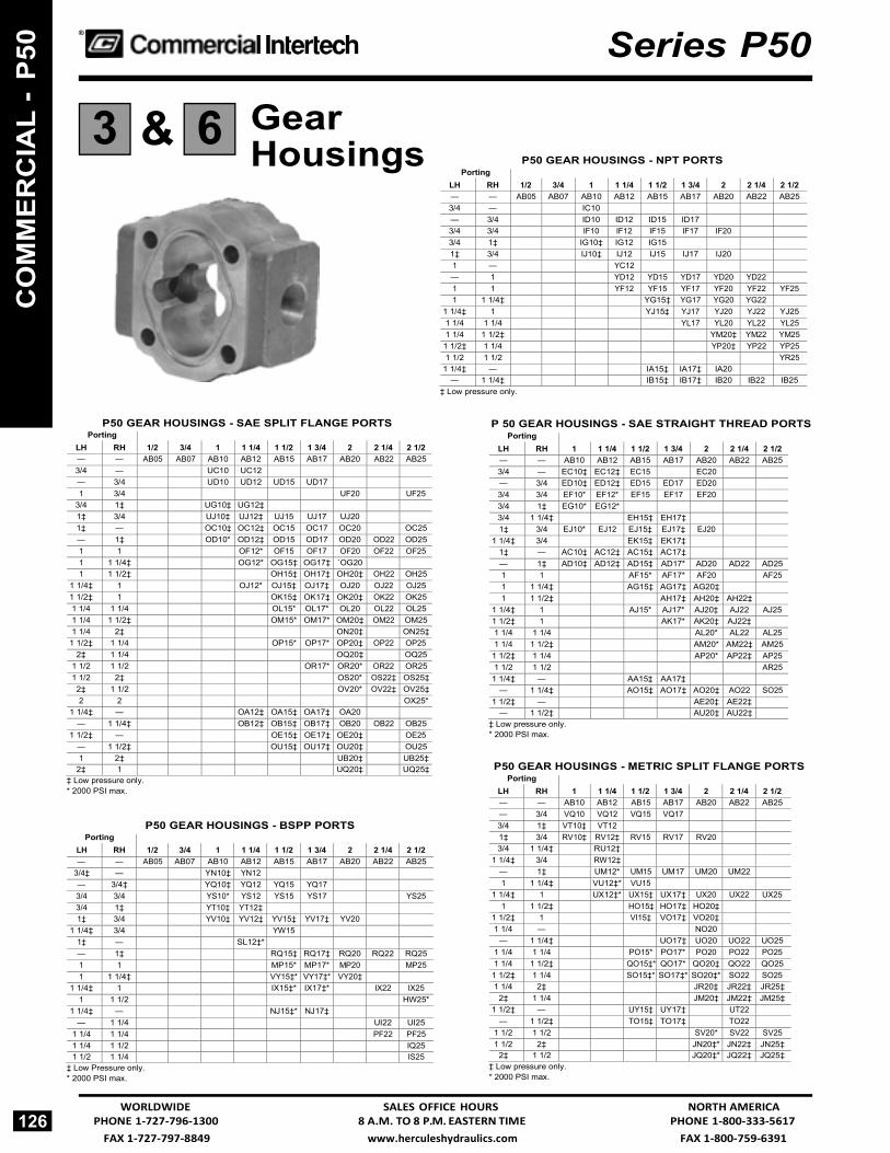
FAX 1-727-797-8849 www.herculeshydraulics.com FAX 1-800-759-6391
® Series P50
Gear Housings
P50 GEAR HOUSINGS - NPT PORTS
‡ Low pressure only.
P50 GEAR HOUSINGS - SAE SPLIT FLANGE PORTS Porting
LH RH 1/2 3/4 1 1 1/4 1 1/2 1 3/4 2 2 1/4 2 1/2 — — AB05 AB07 AB10 AB12 AB15 AB17 AB20 AB22 AB25 3/4 — UC10 UC12
— 3/4 UD10 UD12 UD15 UD17
1 3/4 UF20 UF25 3/4 1‡ UG10‡ UG12‡
1‡ 3/4 UJ10‡ UJ12‡ UJ15 UJ17 UJ20
1‡ — OC10‡ OC12‡ OC15 OC17 OC20 OC25 — 1‡ OD10* OD12‡ OD15 OD17 OD20 OD22 OD25 1 1 OF12* OF15 OF17 OF20 OF22 OF25 1 1 1/4‡ OG12* OG15‡ OG17‡ `OG20
1 1 1/2‡ OH15‡ OH17‡ OH20‡ OH22 OH25 1 1/4‡ 1 OJ12* OJ15‡ OJ17‡ OJ20 OJ22 OJ25 1 1/2‡ 1 OK15‡ OK17‡ OK20‡ OK22 OK25 1 1/4 1 1/4 OL15* OL17* OL20 OL22 OL251 1/4 1 1/2‡ OM15* OM17* OM20‡ OM22 OM25 1 1/4 2‡ ON20‡ ON25‡
1 1/2‡ 1 1/4 OP15* OP17* OP20‡ OP22 OP25 2‡ 1 1/4 OQ20‡ OQ25
1 1/2 1 1/2 OR17* OR20* OR22 OR25 1 1/2 2‡ OS20* OS22‡ OS25‡ 2‡ 1 1/2 OV20* OV22‡ OV25‡ 2 2 OX25*
1 1/4‡ — OA12‡ OA15‡ OA17‡ OA20
— 1 1/4‡ OB12‡ OB15‡ OB17‡ OB20 OB22 OB25 1 1/2‡ — OE15‡ OE17‡ OE20‡ OE25
— 1 1/2‡ OU15‡ OU17‡ OU20‡ OU25 1 2‡ UB20‡ UB25‡
2‡ 1 UQ20‡ UQ25‡ ‡ Low pressure only.* 2000 PSI max.
P50 GEAR HOUSINGS - BSPP PORTS Porting
LH RH 1/2 3/4 1 1 1/4 1 1/2 1 3/4 2 2 1/4 2 1/2 — — AB05 AB07 AB10 AB12 AB15 AB17 AB20 AB22 AB25
3/4‡ — YN10‡ YN12 — 3/4‡ YQ10‡ YQ12 YQ15 YQ17
3/4 3/4 YS10* YS12 YS15 YS17 YS25 3/4 1‡ YT10‡ YT12‡
1‡ 3/4 YV10‡ YV12‡ YV15‡ YV17‡ YV20
1 1/4‡ 3/4 YW15
1‡ — SL12‡*
— 1‡ RQ15‡ RQ17‡ RQ20 RQ22 RQ25 1 1 MP15* MP17* MP20 MP25 1 1 1/4‡ VY15‡* VY17‡* VY20‡
1 1/4‡ 1 IX15‡* IX17‡* IX22 IX25 1 1 1/2 HW25*
1 1/4‡ — NJ15‡* NJ17‡
— 1 1/4 UI22 UI25 1 1/4 1 1/4 PF22 PF25 1 1/4 1 1/2 IQ25 1 1/2 1 1/4 IS25
‡ Low Pressure only. * 2000 PSI max.
P 50 GEAR HOUSINGS - SAE STRAIGHT THREAD PORTS
Porting
LH RH 1 1 1/4 1 1/2 1 3/4 2 2 1/4 2 1/2— — AB10 AB12 AB15 AB17 AB20 AB22 AB25 3/4 — EC10‡ EC12‡ EC15 EC20
— 3/4 ED10‡ ED12‡ ED15 ED17 ED20
3/4 3/4 EF10* EF12* EF15 EF17 EF20
3/4 1‡ EG10* EG12*
3/4 1 1/4‡ EH15‡ EH17‡
1‡ 3/4 EJ10* EJ12 EJ15‡ EJ17‡ EJ20
1 1/4‡ 3/4 EK15‡ EK17‡
1‡ — AC10‡ AC12‡ AC15‡ AC17‡
— 1‡ AD10‡ AD12‡ AD15‡ AD17* AD20 AD22 AD25 1 1 AF15* AF17* AF20 AF25 1 1 1/4‡ AG15‡ AG17‡ AG20‡
1 1 1/2‡ AH17‡ AH20‡ AH22‡
1 1/4‡ 1 AJ15* AJ17* AJ20‡ AJ22 AJ25 1 1/2‡ 1 AK17* AK20‡ AJ22‡
1 1/4 1 1/4 AL20* AL22 AL25 1 1/4 1 1/2‡ AM20* AM22‡ AM25 1 1/2‡ 1 1/4 AP20* AP22‡ AP25 1 1/2 1 1/2 AR25 1 1/4‡ — AA15‡ AA17‡
— 1 1/4‡ AO15‡ AO17‡ AO20‡ AO22 SO25 1 1/2‡ — AE20‡ AE22‡
— 1 1/2‡ AU20‡ AU22‡
‡ Low pressure only. * 2000 PSI max.
P50 GEAR HOUSINGS - METRIC SPLIT FLANGE PORTS
Porting
LH RH 1 1 1/4 1 1/2 1 3/4 2 2 1/4 2 1/2 — — AB10 AB12 AB15 AB17 AB20 AB22 AB25 — 3/4 VQ10 VQ12 VQ15 VQ17
3/4 1‡ VT10‡ VT12
1‡ 3/4 RV10‡ RV12‡ RV15 RV17 RV20
3/4 1 1/4‡ RU12‡
1 1/4‡ 3/4 RW12‡
— 1‡ UM12* UM15 UM17 UM20 UM22 1 1 1/4‡ VU12‡* VU15
1 1/4‡ 1 UX12‡* UX15‡ UX17‡ UX20 UX22 UX25 1 1 1/2‡ HO15‡ HO17‡ HO20‡
1 1/2‡ 1 VI15‡ VO17‡ VO20‡
1 1/4 — NO20
— 1 1/4‡ UO17‡ UO20 UO22 UO251 1/4 1 1/4 PO15* PO17* PO20 PO22 PO25 1 1/4 1 1/2‡ QO15‡* QO17* QO20‡ QO22 QO25 1 1/2‡ 1 1/4 SO15‡* SO17‡* SO20‡* SO22 SO25 1 1/4 2‡ JR20‡ JR22‡ JR25‡
2‡ 1 1/4 JM20‡ JM22‡ JM25‡ 1 1/2‡ — UY15‡ UY17‡ UT22
— 1 1/2‡ TO15‡ TO17‡ TO22 1 1/2 1 1/2 SV20* SV22 SV25 1 1/2 2‡ JN20‡* JN22‡ JN25‡
2‡ 1 1/2 JQ20‡* JQ22‡ JQ25‡ ‡ Low pressure only. * 2000 PSI max.
126 WORLDWIDE SALES OFFICE HOURS NORTH AMERICA
PHONE 1-727-796-1300 8 A.M. TO 8 P.M. EASTERN TIME PHONE 1-800-333-5617
6 3
CO
MM
ER
CIA
L -
P50
& Porting
LH RH 1/2 3/4 1 1 1/4 1 1/2 1 3/4 2 2 1/4 2 1/2 — — AB05 AB07 AB10 AB12 AB15 AB17 AB20 AB22 AB25 3/4 — IC10
— 3/4 ID10 ID12 ID15 ID17
3/4 3/4 IF10 IF12 IF15 IF17 IF20
3/4 1‡ IG10‡ IG12 IG15
1‡ 3/4 IJ10‡ IJ12 IJ15 IJ17 IJ20
1 — YC12
— 1 YD12 YD15 YD17 YD20 YD22 1 1 YF12 YF15 YF17 YF20 YF22 YF25 1 1 1/4‡ YG15‡ YG17 YG20 YG22
1 1/4‡ 1 YJ15‡ YJ17 YJ20 YJ22 YJ251 1/4 1 1/4 YL17 YL20 YL22 YL25 1 1/4 1 1/2‡ YM20‡ YM22 YM25 1 1/2‡ 1 1/4 YP20‡ YP22 YP251 1/2 1 1/2 YR25
1 1/4‡ — IA15‡ IA17‡ IA20
— 1 1/4‡ IB15‡ IB17‡ IB20 IB22 IB25

FAX 1-800-759-6391 www.herculeshydraulics.com FAX 1-727-797-8849
Series P50 ®
Gear Housings
P50 GEAR HOUSINGS - METRIC SPLIT FLANGE PORTS Porting
LH RH 1 1 1/4 1 1/2 1 3/4 2 2 1/4 2 1/2 — — AB10 AB12 AB15 AB17 AB20 AB22 AB25 — 3/4 VQ10 VQ12 VQ15 VQ17
3/4 1‡ VT10‡ VT12
1‡ 3/4 RV10‡ RV12‡ RV15 RV17 RV20
3/4 1 1/4‡ RU12‡
1 1/4‡ 3/4 RW12‡
— 1‡ UM12* UM15 UM17 UM20 UM22
1 1 1/4‡ VU12‡* VU15
1 1/4‡ 1 UX12‡* UX15‡ UX17‡ UX20 UX22 UX25 1 1 1/2‡ HO15‡ HO17‡ HO20‡
1 1/2‡ 1 VI15‡ VO17‡ VO20‡
1 1/4 — NO20
— 1 1/4‡ UO17‡ UO20 UO22 UO25 1 1/4 1 1/4 PO15* PO17* PO20 PO22 PO25 1 1/4 1 1/2‡ QO15‡* QO17* QO20‡ QO22 QO25 1 1/2‡ 1 1/4 SO15‡* SO17‡* SO20‡* SO22 SO25 1 1/4 2‡ JR20‡ JR22‡ JR25‡
2‡ 1 1/4 JM20‡ JM22‡ JM25‡ 1 1/2‡ — UY15‡ UY17‡ UT22
— 1 1/2‡ TO15‡ TO17‡ TO22
1 1/2 1 1/2 SV20* SV22 SV25 1 1/2 2‡ JN20‡* JN22‡ JN25‡
2‡ 1 1/2 JQ20‡* JQ22‡ JQ25‡‡ Low pressure only.* 2000 PSI max.
P 50 GEAR HOUSINGS - METRIC STRAIGHT THREAD PORTS
Porting
LH RH 1 1 1/4 1 1/2 1 3/4 2 2 1/4 2 1/2 — — AB10 AB12 AB15 AB17 AB20 AB22 AB25
3/4‡ — EN10‡
— 3/4‡ TQ10‡ TQ12 TQ15 TQ17
3/4 3/4 ES10* ES12
3/4 1‡ ET10* ET12‡
1‡ 3/4 EV10* EV12‡ EV15‡ EV17 EV20
— 1‡ ER15‡ ER17 ER20 ER22
1 1 CM15* CM17 CM20
1 1 1/4‡ VE15* VE17‡
1 1/4‡ 1 EX15* EX17‡ EX20‡ EX22 EX25 — 1 1/4‡ UA20‡ UA22 UA25
1 1/4 1 1/4 PA20* PA22 PA25 1 1/4 1 1/2‡ QA20‡* QA22‡ QA251 1/2‡ 1 1/4 SA20‡* SA22‡ SA25
‡ Low pressure only. * 2000 PSI max.
Metric Straight Thread Size
Thread Size
3/4 M26 X 1.5 1 M33 X 2
1 1/4 M42 X 2 1 1/2 M48 X 2
P50 BEARING CARRIERS (FLOW DIVIDERS ONLY)
Bearing Carriers
NORTH AMERICA SALES OFFICE HOURS WORLDWIDE PHONE 1-800-333-5617 8 A.M. TO 8 P.M. EASTERN TIME PHONE 1-727-796-1300
127
5
6 3
CO
MM
ER
CIA
L - P50
&
back L R
front
Porting
SAE Split
Ports Metric Split
SAE Std
Metric Std
NPT Code
BSPP Code
Flange Code
Flange Code
Thread Code
Thread Code LH RH
—
—
B
B
B
B B
B
—
—
E
E
E
E E
E
1 — M N P — — —
X Y Z — — —
J K L — — —
T V W — — —
F G H — — —
— — — Q R S
1 1/4 — 1 1/2 —
M33 X 2 —M42 X 2 — M48 X 2 —
— 3/4 BX DG GR MT GJ — — 1 KZ DF TR FM BK —
M26 X 1.5 — — — — — — QJ M33 X 2 — — — — — — ML
— 3/4 CV DM FD KT JH — — 1 NK MN JG RP PC —
M26 X 1.5 — — — — — — BZ M33 X 2 — — — — — — MK
1 3/4 GX FG HR VR HJ — 1 1/4 3/4 HX SG PR WR MJ — 1 1/2 3/4 RX XG QR XR RJ — 1 1/4 1 LZ GF NT QM PK — 1 1/2 1 TZ MF RT VM RK —
M48 X 2 M26 X 1.5 — — — — — ZJ M42 X 2 M33 X 2 — — — — — PL M48 X 2 M22 X 2 — — — — — QLM33 X 2 M26 X 1.5 — — — — — SJ M42 X 2 M26 X1.5 — — — — — XJ
1 3/4 GV NM GD PT PH — 1 1/4 3/4 MV PM MD QT RH — 1 1/2 3/4 NV TM PD ZT WH — 1 1/4 1 TK QN PG TP QC — 1 1/2 1 ZK TN RG ZP VC —
M48 X 2 M26 X 1.5 — — — — — YZ M42 X 2 M33 X 2 — — — — — QK M48 X 2 M33 X 2 — — — — — SK M33 X 2 M26 X1 .5 — — — — — PZ M42 X 2 M26 X 1.5 — — — — — QZ
1
3/4
VG
HP
WL
FP MC
CP
1
3/4
WG
LP
ZL
GP SC
DP

FAX 1-727-797-8849 www.herculeshydraulics.com FAX 1-800-759-6391
® Series P50
Bearing Carriers
P50 BEARING CARRIERS (PUMPS ONLY) back
L R
front
Porting
BSPP Code
Metric Split Flange
Code
Porting
Metric Straight
Thread Code LH RH LH RH
—
—
B
—
—
—
—
—
—
C
—
—
—
—
—
—
D
—
—
—
—
Inlet
1 1 1/41 1/2
— — —
CX DX FX
CH DH FH
Inlet M33 X 2 M42 X 2 M48 X 2
— — —
CL DL FL
— — —
Inlet 1
1 1/41 1/2
XC XD XF
HC HD HF
— — —
Inlet M33 X 2 M42 X 2 M48 X 2
LC LD LF
Inlet— 1
1 1/4 1 1/4 1 1/2 1 1/2
Outlet 3/4 3/43/4 1 1
3/4
LT CT DT DV FV FT
PW CW DW DC FC FW
Inlet—
M33 X 2M42 X 2 M42 X 2 M48 X 2 M48 X 2
Outlet—
M26 X 1.5M26 X1.5 M33 X 2 M33 X 2
M26 X 1.5
— CZ DZ DN FN FZ
Outlet 3/43/4 3/4 1 1
Inlet 1 1/2
1 1 1/4 1 1/4 1 1/2
MW MG MH NH NW
QW QG QH SH SW
Outlet M26 X1.5 M26 X 1.5 M26 X 1.5 M33 X 2 M33 X 2
Inlet M48 X 2M33 X 2 M42 X 2 M42 X 2 M48 X 2
TW TG TH VH VW
Inlet 1
1 1/4 1 1/4 1 1/2 1 1/2
Outlet 3/43/4 1
3/4 1
GM HM HN WM WN
GQ HQ HS WQ WS
Inlet M33 X 2M42 X 2 M42 X 2 M48 X 2 M48 X 2
Outlet M26 X 1.5M26 X 1.5 M33 X 2
M26 X 1.5 M33 X 2
GT HT HV WT WV
Outlet 3/4 3/4 3/4 1 1
3/4
Inlet — 1
1 1/4 1 1/4 1 1/2 1 1/2
TL TC TD VD VF TF
WP WC WD CD CF WF
Outlet —
M26 X 1.5 M26 X1.5 M33 X 2 M33 X 2
M26 X 1.5
Inlet —
M33 X 2 M42 X 2 M42 X 2 M48 X 2 M48 X 2
— ZC ZD ND NF ZF
Inlet 1
Outlet 3/4
PN
ST
Inlet M33 X 2
Outlet M26 X 1.5
KL
Outlet
3/4 Inlet
1
NP
TS Outlet
M26 X1.5 Inlet
M33 X 2
LK
1
1 1/4 1 1/2
1 1 1/4 1 1/2
EE* GG*
RR* SS* XX*
M33 X 2M42 X 2
M33 X 2 M42 X 2
KK* JJ
* Code B, EE, RR, KK, GG, SS, and, XX for motors only. Pump applications must be approved by Technical Service.
P50 BEARING CARRIERS (PUMPS ONLY) back
L R
front
Porting
NPT Ports Code
SAE Split Flange Code
SAE Straight Thread Code LH RH
— — B* — —
—
—
C
—
—
—
—
D
—
—
Inlet 1
1 1/4 1 1/2
— — —
TB VB WB
LB MB NB
CB DB FB
— — —
Inlet 1
1 1/4 1 1/2
BT BV BW
BL BM BN
BC BD BF
Inlet 1
1 1/4 1 1/4 1 1/2 1 1/2
—
Outlet 3/4 3/4 1 1
3/4 3/4
TX VX VZ WZ WX —
LR MR MS NS NR BR
CJ DJ DK FK FJ PJ
Outlet 3/4 3/4 1 1
Inlet 1
1 1/4 1 1/4 1 1/2
JT JV KV KW
XL XM ZM ZN
RC RD SD SF
Inlet 1
1 1/4 1 1/4 1 1/2
Outlet 3/4 3/4 1 1
TJ VJ VK WK
LX MX MZ NZ
CR DR DS FS
Outlet 3/4 3/4 3/4 1 1
3/4
Inlet — 1
1 1/4 1 1/4 1 1/2 1 1/2
XQ XT XV ZV ZW XW
RB RL RM SM SN RN
— JC JD KD KF JF
Inlet
1 Outlet
3/4
ZX
SR
KJ
Outlet
3/4 Inlet
1
XZ
RS
JK
1
1 1/4 1 1/2
1 1 1/4 1 1/2
TT* VV* WW*
LL* MM* NN*
CC* BB* FF*
* Code B, TT, LL, CC, VV, MM, BB, WW, NN, and FF for motors only. Pump applications must be approved by Technical Services.
128 WORLDWIDE SALES OFFICE HOURS NORTH AMERICA
PHONE 1-727-796-1300 8 A.M. TO 8 P.M. EASTERN TIME PHONE 1-800-333-5617
5
CO
MM
ER
CIA
L -
P50

FAX 1-800-759-6391 www.herculeshydraulics.com FAX 1-727-797-8849
1
Series P51
®
How To Specify and Code
P51Reliability Series 51 and 50 pumps and motors are quite similar except that Series 51 units have steel alignment dowel pins which allow them to be rated for 500 psi higher pressure operation. Both are cast from hi-tensile gray iron and offer a wide variety of drive shafts designed for high torque input/output. Unique pressure balanced thrust plates contribute to operating efficiencies of over 90%.
These units are designed for continuous operation in heavy-duty implement circuits. They’re equally at home on lift trucks, auto wreck- ers and small dump body applications.
Call our Component sales team for quick application assistance and pump specifications.
Performance Data Performance data shown are the average results based on a series of laboratory tests of produc- tion units and are not necessarily representative
of any one unit. Tests were run with the oil reser- voir temperature at 120°F. Requests for more spe- cific data should be directed to our sales repre- sentatives.
Performance data for pumps and motors having other gear widths can be approximated by multi- plying values in tables below by actual gear width.
This catalog contains codes for our most popular models. Complete codes for all configurations are readily available upon request.
Single Units Full assembly codes for single units combine shaft end cover, port end cover, gear hous- ing and drive shaft codes. They are preceded by the letter P or M for pump or motor — and by 51 to designate the series and model. An example of an assembly code follows:
M51 SINGLE MOTOR
Assembly Code: M 51A 942 BE YF15-7
Motor . . . . . . . . . . . . . . . . . . . . .M 3
Series ......................................... 51 Model .......................................... A
1. Shaft End Cover ....................... 942 2. Port End Cover .......................... BE 3. Gear Housing . . . . . . . . . . . .YF15 2 4. Drive Shaft . . . . . . . . . . . . . . . . .7 4
Multiple Units Coding is the same as single units except that codes for added components must be included. Each gear unit added also requires code for a bearing carrier, the additional gear housing and connecting shaft. An example of an assembly code for a two-section Series 51 pump follows:
P51 MULTIPLE PUMP
Assembly Code: P 51B 278 BY OM20-11 D UG10-1
1 3 6 2
Variations
Pump .......................................... P Series ........................................ 51 Model .......................................... B
5
1. Shaft End Cover ................. 278 2. Port End Cover ................... BY 3. Gear Housing................. OM20 4. Drive Shaft ........................... 11 5. Bearing Cover ....................... D 6. Gear Housing................. UG10 7. Connecting Shaft ...................1
Series 51 units are available with gear sections ranging from 1/2” to 2-1/2” in 1/4” increments which provide displacements from 1.27 to 6.37 cu. in. per revolution. Two or more gear sections can be assembled on one drive shaft to provide larger flows, supply other circuits or make smoother, more powerful motors.
When specifying multiple units you must consider the drive shaft’s strength. This is called a PL factor in which P = operating pressure and L = sum of gear widths. The recommended PL factors for various Series 51 shafts are shown with the shaft codes and are offered as a guide to shaft selection. A PL of 8000 means a maximum of 4” of gear can be operated at 2000 psi (2000 psi X 4” = 8000) without overloading the shaft. The gear widths can be divided many ways, eg. (2”-1”-1”, 1”-1”-1”-1”, 1-1/2”-1-1/2”-1/2”) to provide the output you need for several circuits.
NORTH AMERICA SALES OFFICE HOURS WORLDWIDE PHONE 1-800-333-5617 8 A.M. TO 8 P.M. EASTERN TIME PHONE 1-727-796-1300 129
7 4
CO
MM
ER
CIA
L - P51
Pump Speed
rpm
Avg. Output (gpm) @ 2000 psi Gear Width (inches)
1 1-1/2 2 2-1/2900 8.5 13.0 17.5 22.0
1200 12.0 18.0 24.0 30.0 1800 18.0 27.5 37.5 47.0 2100 21.5 32.5 44.0 55.0
Motor Speed
rpm
Avg. Input/Output (gpm) @ 2000 psi 1” gear 2” gear 2-1/2” gear
gpm hp gpm hp gpm hp 800 10.5 10.5 21.0 23.0 26.0 29.5
1200 15.5 16.0 30.5 35.0 35.0 44.5 1600 20.0 21.0 40.0 46.0 49.5 58.5 2000 25.0 25.5 49.0 56.0 61.5 71.5

FAX 1-727-797-8849 www.herculeshydraulics.com FAX 1-800-759-6391
® Series P51
P51 Parts Breakdown Typical Parts List
Note: This page shows the typical arrangement of a 2-section unit. It may not be pictorially correct and is not to scale.
Plug 5 in position B gives clockwise rotation.
Plug 5 in position A gives counter-clockwise rotation.
Check valves in both positions give bi-directional rotation.
130
For Series P51 Seal Kits and Repair Parts, See Pages 475 - 477
CO
MM
ER
CIA
L -
P51
Item Description Part Number Item Description Part Number 1 Snap Ring CM-391-2686-065 11 Gasket Seals CM-391-2884-021 2 Outboard Bearing CM-391-0381-077 12 Gear Housing See Option List 3 Seal
Hi Pressure Seal (Motor) CM-391-2883-103 CM-391-2883-115
12A 13
Dowel Pins Bearing Carrier
CM-391-2082-032 See Option List
4 Shaft End Cover See Option List 14 Connecting Shaft See Option List 5 Check Assemblies CM-391-3681-001 15 Matched Gear Set See Option List
6
Plug Ring Seals
CM-391-2286-004 CM-391-2585-009
16 16A
Gear Housing Dowel Pins
See Option ListCM-391-2082-032
7 Roller Bearings CM-391-0381-905 17 Port End Cover See Option List 8 Pocket Seals 18 Washers
9 Thrust Plates CM-391-2185-912 19 Studs or Cap Screws
10 Integral Drive Shaftand Gear Set
See Option List 20 Nuts
WORLDWIDE SALES OFFICE HOURS NORTH AMERICA
PHONE 1-727-796-1300 8 A.M. TO 8 P.M. EASTERN TIME PHONE 1-800-333-5617

FAX 1-800-759-6391 www.herculeshydraulics.com FAX 1-727-797-8849
Type
Outboard Bearing CW CCW Double
1/4” NPT 1/4” BSPP DRAIN DRAIN
SAE B 4 Bolt 1 Without With
142 442
242 542
342 642
942 842
1942 1842
SAE C 4 Bolt 1 WithoutWith
178 478
278 578
378 678
978 878
1978 1878
SAE B 2 Bolt 1
2
Without With
Without
197 497 196*
297 597 296*
397 697 396*
997 897 N/A
1997 1897 N/A
SAE C 2 Bolt 1
2
Without With
Without
198 498 199
298 598 299
398 698 399
998 898 N/A
1998 1898 N/A
Pad Mounting 1 Without With
N/A 400
N/A 500
N/A 600
N/A 800
N/A 1800
Piggyback Shaft End Cover
50-50 75-50
Without Without
191 192
291 292
391 392
N/A N/A
N/A N/A
Description Single Pumps
Multiple Pumps Porting w/o Studs w/ Ext Studs LH RH
No Ports BE BI BY — — ODT Ports CE* CI CY 3/4 — DE* DI DY — 3/4 FE* FI FY 3/4 3/4 BSPP Ports WE WI WY 3/4 — XE XI XY — 3/4 ZE ZI ZY 3/4 3/4 Metric Straight NE NI NY 3/4 — Thread Ports M26 X 1.5 PE PI PY — 3/4 M26 X 1.5
QE QI QY 3/4 3/4 M26 X 1.5 M26 X 1.5 TYPE CW CCW DOUBLE
Piggyback Port 51—51 KO LO MO — End Cover 51—31 KO LO MO —
Series P51
®
Shaft & Port End Covers
P 51 SHAFT END COVERS Description PUMPS MOTORS
Two (2) speed motor valve assemble and fittings * Available for special application upon request. Not a stock item.
P51 PORT END COVERS
*Available for special application upon request. Not a stock item.
NORTH AMERICA SALES OFFICE HOURS WORLDWIDE PHONE 1-800-333-5617 8 A.M. TO 8 P.M. EASTERN TIME PHONE 1-727-796-1300
131
2 1
CO
MM
ER
CIA
L - P51
&

FAX 1-727-797-8849 www.herculeshydraulics.com FAX 1-800-759-6391
® Series P51
Drive Shafts
P51 DRIVE SHAFTS
* Available for special application upon request. NOT A STOCK ITEM.
P51 DRIVE SHAFT CODE Gear Width 1-22-23 7 11 25* 43* 53*
1/2 •
3/4 •
1 • • • • • • 1 1/4 • • • • • • 1 1/2 • • • • • • 1 3/4 • • • • • •
2 • • • • • • 2 1/4 • • • • • • 2 1/2 • • • • • •
Gear Housings
P51 GEAR HOUSINGS - BSPP PORTS Port
LH ing
RH
1/2
3/4
1
1 1/4
1 1/2
1 3/4
2
2 1/4
2 1/2 — — AB05 AB07 AB10 AB12 AB15 AB17 AB20 AB22 AB25
3/4‡ — YN10‡ YN12
— 3/4‡ YQ10‡ YQ12‡ YQ15‡ YQ17 YQ20
3/4 3/4 YS12 YS15 YS20
3/4 1‡ YT12‡
1‡ — SL12‡ SL15‡ 1‡ 3/4 YV12 YV15 YV17‡ YV20‡
— 1‡ RQ10‡ RQ15‡ RQ17‡ RQ20‡ RQ22 RQ25 1 1 MP20 MP25 1 1 1*/4‡ VY20‡
1 1/4 1 IX20‡ IX22 IX25 — 1 1/4 UI22 UI25
1 1/4 1 1/4 PF22 PF251 1/2‡ 1 VI20‡
1 1/4 1 1/2‡ IQ25‡ 1 1/2‡ 1 1/4 IS25‡
‡ Low pressure only.
132 WORLDWIDE SALES OFFICE HOURS NORTH AMERICA
PHONE 1-727-796-1300 8 A.M. TO 8 P.M. EASTERN TIME PHONE 1-800-333-5617
6 3
4
CO
MM
ER
CIA
L -
P51
&
Shaft Description
Code Type 1 Type 2
Straight Keyed .998’ Major Dia - 1/4 x 3/8” Key
43* —
SAE B - 13 Tooth Spline .8555” Major Dia”
25* —
SAE C - Straight Keyed 1.250” Major Dia - 3/4 x 1 1/2” Key
11 —
SAE C - 14 Tooth Spline 1.225” Major Diam.
7 53*
Connecting Shaft - Multiple Units 1 1Connecting Shaft - Piggyback Pump P51 to P51 22 —
P76 to P51 23 —

FAX 1-800-759-6391 www.herculeshydraulics.com FAX 1-727-797-8849
Series P51 ®
Gear Housings
P51 GEAR HOUSINGS - O.D. TUBE PORTS Porting
LH RH 1 1 1/4 1 1/2 1 3/4 2 2 1/4 2 1/2 — — AB10 AB12 AB15 AB17 AB20 AB22 AB25
3/4‡ — EC10‡ EC12‡
— 3/4‡ ED10‡ ED12‡
3/4 3/4 EF17
3/4 1‡ EG15‡
3/4 1 1/4‡ EH15* EH17‡
1 1/4‡ 3/4 EK15* EK17‡
1‡ — AC10‡ AC12‡ AC15‡ AC17‡
— 1‡ AD10‡ AD12‡ AD15‡ AD17‡
1 1 AF20* AF25 1 1 1/4 AG20*
1 1/4 1 AJ20*
1 1/4‡ — AA15‡ AA17‡
— 1 1/4‡ AO15‡ AO17‡
1 1 1/2 AH20*
1 1/2 1 AK20*
1 1/4 1 1/4 AL22 AL25 1 1/4 1 1/2‡ AM22‡ AM25‡
1 1/2‡ 1 1/4 AP22‡ AP25‡ 1 1/2‡ — AE20‡ AE22‡ AE25‡
— 1 1/2‡ AU20‡ AU22‡ AU25‡1 1/2 1 1/2 AR25*
‡ Low pressure only. * 2500 PSI maximum.
P51 GEAR HOUSINGS - SAE SPLIT FLANGE PORTS Porting
LH RH 1 1 1/4 1 1/2 1 3/4 2 2 1/4 2 1/2 — — AB10 AB12 AB15 AB17 AB20 AB22 AB25 3/4 — UC10* UC12* — 3/4 UD10* UD12
3/4 3/4 UF10* UF12
3/4 1‡ UG10* UG12‡ UG15
1‡ 3/4 UJ10* UJ12‡
3/4 1 1/4‡ UH12‡ UH15‡ UH17‡
1 1/4‡ 3/4 UK12‡ UK15‡ UK17‡
1‡ — OC12‡ OC15‡ OC17 OC20
— 1‡ OD12‡ OD15‡ OD17 OD20
1 1 OF15* OF17 OF20 OF22
1 1 1/4‡ OG12‡ OG15* OG17‡ OG20‡
1 1/4‡ 1 OJ15* OJ17‡ OJ20‡ OJ22
1 1/4‡ — OA12‡ OA15‡
— 1 1/4‡ OB12‡ OB15‡
1 1 1/2‡ OH15* OH17‡ OH20‡ OH22 1 1/2‡ 1 OK15* OK17‡ OK20‡ OK22 OK25 1 1/4 1 1/4 OL20* OL22 OL25 1 1/4 1 1/2 OM20‡* OM22 OM25 1 1/2 1 1/4 OP20‡* OP22 OP25
1 1/2‡ — OE15‡ OE17‡ OE20‡ OE22
— 1 1/2‡ OU15‡ OU17‡ OU20‡
1 1/4 2‡ ON20‡* ON22‡ ON25‡ 2‡ 1 1/4 OQ20‡* OQ22‡ OQ25‡
1 1/2 1 1/2 OR22 OR25 1 1/2 2‡ OS22‡ OS25‡ 2‡ 1 1/2 OV22‡ OV25‡
‡ Low pressure only. * 2500 PSI maximum.
P51 GEAR HOUSINGS - METRIC SPLIT FLANGE PORTS
Porting
LH RH 1 1 1/4 1 1/2 1 3/4 2 2 1/4 2 1/2 — — AB10 AB12 AB15 AB17 AB20 AB22 AB25
3/4‡ — VN10‡
— 3/4‡ VQ10‡ VQ20
3/4 3/4 VS10
3/4 1‡ VT10* VT12‡
1‡ 3/4 RV10* RV12‡
3/4 1 1/4‡ RU12‡ RU15‡
1 1/4‡ 3/4 RW12‡ RW15‡
1‡ — UL12‡ UL15‡ UL17 UL20
— 1‡ UR12‡ UR15‡ UR17 UR20
1 1 UM15* UM17 UM20 UM22
1 1 1/4‡ YU15* YU17‡ YU20‡ 1 1/4‡ 1 UX15* UX17‡ UX20‡
1 1 1/2‡ HO15* HO17‡ HO20‡ HO22
1 1/2‡ 1 VO15* VO17‡ VO20‡ VO22
1 1/4‡ — NO12‡ NO15‡ NO17
— 1 1/4‡ UO12‡ UO15‡
1 1/4 1 1/4 PO20* PO22 PO251 1/4 1 1/2 QO20* QO22 QO25 1 1/2 1 1/4 SO20* SO22 SO25 2‡ 1 JB20‡
1 1/4 2‡ JR20* JR22‡ JR25‡ 2‡ 1 1/4 JM20* JM22‡ JM25‡
1 1/2‡ — UY15 UY17‡ UY20‡
— 1 1/2‡ TO17‡ TO20‡
1 1/2 1 1/2 SV22 SV25 1 1/2 2‡ JN22‡ JN25‡ 2‡ 1 1/2 JQ22‡ JQ25‡
‡ Low pressure only. * 2500 PSI maximum.
P51 GEAR HOUSINGS - METRIC STRAIGHT THREAD PORTS
Porting
LH RH 1 1 1/4 1 1/2 1 3/4 2 2 1/4 2 1/2 — — AB10 AB12 AB15 AB17 AB20 AB22 AB25
3/4‡ — EN10‡
— 3/4 TQ10‡ TQ12‡ TQ15‡ TQ17
3/4 3/4 ES12*
3/4 1 ET12*
1‡ 3/4 EV12‡* EV15‡* EV17‡ EV20‡ — 1‡ ER15‡ ER17‡ ER20‡ ER22
1 1 CM17*
1 1 1/4 VE17*
1 1/4 1 EX17* EX20* EX22 EX25 — 1 1/4‡ UA20‡ UA22 UA25
1 1/4 1 1/4 PA22 PA25 1 1/4 1 1/2‡ QA22‡ QA25‡
1 1/2‡ 1 1/4 SA22‡ SA25‡ ‡ Low pressure only. * 2500 PSI maximum.
Metric Straight Thread Size
Thread Size
3/4 M26 X 1.5 1 M33 X 2
1 1/4 M42 X 2 1 1/2 M48 X 2
NORTH AMERICA SALES OFFICE HOURS WORLDWIDE PHONE 1-800-333-5617 8 A.M. TO 8 P.M. EASTERN TIME PHONE 1-727-796-1300
133
6 3
CO
MM
ER
CIA
L - P51
&

FAX 1-727-797-8849 www.herculeshydraulics.com FAX 1-800-759-6391
® Series P51
back
Bearing Carriers
P51 BEARING CARRIERS (PUMPS ONLY)
P51 BEARING CARRIERS (FLOW DIVIDERS ONLY)
back
L R
front
Porting
Ports
BSPP Code
SAE Split Flange Code
Metric Split Flange Code
SAE Str. Thread Code
Metric Str. Thread Code LH RH
—
—
B
B B
B
B Motor
—
—
E
E E
E
E
1 — X Y Z — — —
J K L — — —
T V W — — —
F G H — — —
— — — Q R S
1 1/4 — 1 1/2 —
M33 X 2 —M42 X 2 — M48 X 2 —
— 3/4 DG GR TR GJ — — 1 DF MT FM BK —
M26 X 1.5 — — — — — QJ M33 X 2 — — — — — ML
— 3/4 DM FD KT JH — — 1 MN JG RP PC —
M26 X 1.5 — — — — — BZ M33 X 2 — — — — — MK
1 3/4 FG HR VR HJ — 1 1/4 3/4 SG PR WR MJ — 1 1/3 3/4 XG QR XR RJ — 1 1/4 1 GF NT QM PK — 1 1/2 1 MF RT VM RK —
M48 X 2 M26 X 1.5 — — — — ZJ M42 X 2 M33 X 2 — — — — PL M48 X 2 M33 X2 — — — — QL M33 X2 M26 X1.5 — — — — SJM42 X 2 M26 X1.5 — — — — XJ
1 3/4 NM GD PT PH — 1 1/4 3/4 PM MD QT RH — 1 1/2 3/4 TM PD ZT WH — 1 1/4 1 QN PG TP QC — 1 1/2 1 TN RG ZP VC —
M48 X 2 M26 X1.5 — — — — YZ M42 X 2 M33 X 2 — — — — QK M48 X 2 M33 X 2 — — — — SK M33 X 2 M26 X1.5 — — — — PZ M42 X2 M26 X1.5 — — — — QZ
1 M33 X 2
3/4 M26 X1.5
HP —
WL —
FP —
MC —
CP
1 M33 X2
3/4 M26 X 1.5
LP —
ZL —
GP —
SX—
DP
L R
front
Porting SAE SplitFlange Code
SAE StraightThread Code
Porting BSPPParts Code
Metric SplitFlange Code
Porting MetricStraight Thread LH RH LH RH LH RH
—
—
B*
—
—
—
B*
—
—
—
—
—
—
C OR A
—
—
—
C
—
—
—
—
—
—
D OR U
—
—
—
D
—
—
—
—
Inlet 1
1 1/4 1 1/2
— — —
LB MB NB
CBN DB FB
Intel 1
1 1/4 1 1/2
— — —
CX DX FX
CH DH FH
Inlet M33 X 2 M42 X 2 M48 X 2
— — —
CL DL FL
— — —
Inlet 1
1 1/4 1 1/2
BL BM BN
BC BD BF
— — —
Inlet 1
1 1/4 1 1/2
XC XD XF
HC HD HF
— — —
Inlet M33 X 2 M42 X 2 M48 X 2
LC LD LF
Inlet1
1 1/4 1 1/4 1 1/2 1 1/2
—
Outlet3/4 3/4 1 1
3/4 3/4
LR MR MS NS NR BR
CJ DJ DK FK FJ PJ
Inlet— 1
1 1/4 1 1/4 1 1/2 1 1/2
Outlet3/4 3/4 3/4 1 1
3/4
— CT DT DV FV FT
PW CW DW DC FC FW
Inlet—
M33 X 2 M42 X2 M42 X2 M48 X 2 M48 X 2
Outlet—
M26 X1.5 M26 X1.5 M33 X 2 M33 X 2
M26 X 1.5
— CZ DZ DN FN FZ
Outlet3/4 3/4 3/4 1 1
Inlet1
1 1/4 1 1/2 1 1/4 1 1/2
XL XM XN ZM ZN
RC RD RF SD SF
Outlet3/4 3/4 3/4 1 1
Inlet1 1/2
1 1 1/4 1 1/4 1 1/2
MW MG MH NH NW
QW QG QH SH SW
OutletM26 X 1.5 M26 X1.5 M26 X1.5 M33 X 2 M33 X 2
InletM48 X 2 M33 X 2 M42 X2 M42 X 2 M48 X 2
TW TG TH VH VW
Inlet 1
1 1/4 1 1/4 1 1/2 1 1/2
Outlet 3/4 3/4 1
3/4 1
LX MX MZ NX NZ
CR DR DS FR FS
Inlet 1
1 1/4 1 1/4 1 1/2 1 1/2
Outlet 3/4 3/4 1
3/4 1
GM HM HN WM WN
GQ HQ HS WQ WS
Inlet M33 X 2 M42 X 2 M42 X2 M48 X 2 M48 X 2
Outlet M26 X1.5 M26 X 1.5 M33 X2
M26 X1.5 M33 X 2
GT HT HV WT WV
Outlet 3/4 3/4 3/4 1 1
3/4
Inlet — 1
1 1/4 1 1/4 1 1/2 1 1/2
RB RL RM SM SN RN
JP JC KD KS KF JF
Outlet 3/4 3/4 3/4 1 1
3/4
Inlet — 1
1 1/4 1 1/4 1 1/2 1 1/2
TL TC TD VD VF TF
WP WC WD CD CF WF
Outlet —
M26 X1.5 M26 X1.5 M33 X 2 M33 X 2
M26 X 1.5
Inlet —
M33 X 2 M42 X 2 M42 X 2 M48 X 2 M48 X 2
— ZC ZD ND NF ZF
Inlet 1
Outlet 3/4
SR
KJ
Inlet 1
Outlet 3/4
PN
ST
Inlet M33 X 2
Outlet M26 X 1.5
KL
Outlet
3/4 Inlet
1
RS
JK Outlet
3/4 Inlet
1
NP
TS Outlet
M26 X 1.5 Inlet
M33 X 2
LK
1 1 1/4 1 1/2
1 1 1/4 1 1/2
LL* MM* NN*
CC* BB* FF*
1 1 1/4
1 1 1/4
EE* GG*
RR* SS*
M33 X 2 M42 X 2
M33 X 2 M42 X 2
KK* JJ
* Code B, TT, LL, CC, VV, MM, BB, WW, NN, and FF for motors only. * Code B, EE, RR, KK, GG, and SS for motors only. Pump applications must be approved by Technical Service.
134 WORLDWIDE SALES OFFICE HOURS NORTH AMERICA
PHONE 1-727-796-1300 8 A.M. TO 8 P.M. EASTERN TIME PHONE 1-800-333-5617
5
CO
MM
ER
CIA
L -
P51

FAX 1-800-759-6391 www.herculeshydraulics.com FAX 1-727-797-8849
1
Series P75
®
How To Specify and Code
P75Reliability Series 75 pumps and motors are cast from hi-ten- sile gray iron and offer a wide variety of drive shafts designed for high torque input/output. Unique pressure balanced thrust plates con- tribute to operating efficiencies of over 90%.
These units are designed for continuous operation in heavy-duty implement circuits. They’re equally at home on lift trucks, auto wreck- ers and small dump body applications.
Call our Component sales team for quick application assistance and pump specifications.
Performance Data Performance data shown are the average results based on a series of laboratory tests of produc- tion units and are not necessarily representative
of any one unit. Tests were run with the oil reser- voir temperature at 120°F. Requests for more spe- cific data should be directed to our sales repre- sentatives.
Performance data for pumps and motors having other gear widths can be approximated by multi- plying values in tables below by actual gear width.
This catalog contains codes for our most popular models. Complete codes for all config- urations are readily available upon request.
Single UnitsFull assembly codes for single units combine shaft end cover, port end cover, gear hous- ing and drive shaft codes. They are preceded by the letter P or M for pump or motor — and by 75 to designate the series and model. An example of an assembly code follows:
M75 SINGLE MOTOR
Assembly Code: M 75A 942 BE YF15-7
Motor . . . . . . . . . . . . . . . . . . . . .M 3 Series ......................................... 75 Model .......................................... A
1. Shaft End Cover ....................... 942 2. Port End Cover .......................... BE 3. Gear Housing . . . . . . . . . . . .YF15 2 4. Drive Shaft . . . . . . . . . . . . . . . . .7 4
Multiple Units Coding is the same as single units except that codes for added components must be included. Each gear unit added also requires code for a bearing carrier, the additional gear housing and connecting shaft. An example of an assembly code for a two-section Series 75 pump follows:
P75 MULTIPLE PUMP
Assembly Code: P 75B 178 BI OK15-7 C OK12-1
2
Variations
Pump ........................................... P Series ........................................ 75 Model .......................................... B
1. Shaft End Cover ................ 178 2. Port End Cover ..................... BI 3. Gear Housing ................. OK15 4. Drive Shaft ............................ 7 5. Bearing Cover ....................... D 6. Gear Housing ................. OK12 7. Connecting Shaft................... 1
Series 75 units are available with gear sections ranging from 1/2” to 2-1/2” in 1/4” increments. Two or more gear sections can be assembled on one drive shaft to provide larger flows, supply other circuits or make smoother, more powerful motors.
When specifying multiple units you must consider the drive shaft’s strength. This is called a PL factor in which P = operating pressure and L = sum of gear widths. The recommended PL factors for various Series 75 shafts are shown with the shaft codes and are offered as a guide to shaft selection. A PL of 8000 means a maximum of 4” of gear can be operated at 2000 psi (2000 psi X 4” = 8000) without overloading the shaft. The gear widths can be divided many ways, eg. (2”-1”-1”, 1”-1”-1”-1”, 1-1/2”-1-1/2”-1/2”) to provide the output you need for several circuits.
NORTH AMERICA SALES OFFICE HOURS WORLDWIDE PHONE 1-800-333-5617 8 A.M. TO 8 P.M. EASTERN TIME PHONE 1-727-796-1300 135
7 4 5
6 31
CO
MM
ER
CIA
L - P75
Pump Speed
rpm
Avg. Output (gpm) @ 2000 psi Gear Width (inches)
1 1-1/2 2 2-1/2600 6.0 11.5 16.5 21.0
1200 17.0 27.0 37.5 48.0 1800 22.0 35.5 48.0 61.0 2100 33.0 51.5 69.5 87.0
Motor Speed
rpm
Avg. Input/Output (gpm) @ 2000 psi 1” gear 2” gear 2-1/2” gear
gpm hp gpm hp gpm hp 800 20.5 13.5 35.5 28.0 43.0 36.5
1200 27.5 19.5 49.5 42.0 60.5 54.0 1600 34.0 25.5 64.0 55.0 78.5 71.0 2000 41.5 30.0 78.0 67.5 96.5 87.0

FAX 1-727-797-8849 www.herculeshydraulics.com FAX 1-800-759-6391
® Series P75
P75 Parts Breakdown Typical Parts List Note: Plug 7 in position B gives clockwise rotation.
Plug 7 in position A gives counter-clockwise rotation.
Check valves in both positions give bi-directional rotation.
Item Description Part Number Item Description Part Number 1 Snap Ring CM-391-2686-025 12 Integral Drive Shaft See Option List 2 Outboard Bearing CM-391-0381-078 and Gear Set
Spacer CM-391-3383-018 13 Gasket Seals
3 Seal Retainer CM-391-2584-051 14 Gear Housing See Option List 4 “O” Ring CM-391-2881-457 15 Connecting Shaft See Option List 5 Seal (Pump) CM-391-2883-052 16 Bearing Carrier See Option List
Seal (Motor) CM-391-2883-094 17 Matched Gear Set See Option List 6 Shaft End Cover 18 Gear Housing See Option List 7 Check Assemblies CM-391-3681-001 19 Plug
Plug CM-391-2286-004 20 Port End Cover
8 Ring Seals CM-391-2585-011 21 Name Plate
9 Roller Bearings CM-391-0381-904 22 Drive Screws
10 Pocket Seals CM-391-2282-084 23 Washers
11 Thrust Plates CM-391-2185-920 24 Studs or Cap Screws
25 Nuts
136 WORLDWIDE SALES OFFICE HOURS NORTH AMERICA
PHONE 1-727-796-1300 8 A.M. TO 8 P.M. EASTERN TIME PHONE 1-800-333-5617
For Series P75 Seal Kits and Repair Parts, See Pages 475 - 477
CO
MM
ER
CIA
L -
P75

FAX 1-800-759-6391 www.herculeshydraulics.com FAX 1-727-797-8849
378
Series P75
®
Shaft & Port End Covers
P75 SHAFT END COVERS - PORT END COVERS Description PUMPS MOTORS Outboard
Bearing 1/4” NPT 1/4” BSPP
CW CCW Double DRAIN DRAIN SAE D - 4 Bolt Without
With 180 480
280580
380 680
980 880
1980 1880
SAE C - 2 Bolt Without With
198 498
298598
398 698
998 898
1998 1898
SAE B - 4 Bolt Without With
142 442
242542
342 642
942 842
1942 1842
SAE C - 4 Bolt Without With
178 478
278578
378 678
978 878
1978 1878
P75 PORT END COVERS Description Single
Pumps Multiple Pumps Porting
w/o Studs w/ Ext Studs LH RH No Ports BE BI BY - - SAE Straight Thread JE JI JY 1 1 Metric Straight Thread TE TI TY 1 1 Type CW CCW DUAL Piggyback Port 75-50 KO LO MO End Covers 75-30
P75 GEAR & SHAFT COMBINATIONS Shaft Description
Code Type 1 Type 2
SAE C -14 Tooth Spline - 1 5/16” Long For Single Units 1.2480” Major Dia.
7 —
SAE C - 14 Tooth Spline - 1 3/4” Spline For Mulitple Units 1.2480” Major Dia
7*(c) —
SAE C - Straight (Shaft only) For P75C Models 1.250” Dia 5/16 x 1 1/2” Key
11* 1
Connecting Shaft - Multiple Units 1 1 Connecting Shaft - Piggyback Pump 75-75 23 —
P75 DRIVE SHAFT CODE Gear Width 1-23 7 7* (c) 11*
3/4 • N/A Same • 1 • • as •
1 1/4 • • Regular • 1 1/2 • • Code 7 • 1 3/4 • • •
2 • • • 2 1/4 • • • 2 1/2 • • • 2 3/4 • • •
3 • • • * Available for special application upon request. Not a stock item.
Drive Shafts
NORTH AMERICA SALES OFFICE HOURS WORLDWIDE PHONE 1-800-333-5617 8 A.M. TO 8 P.M. EASTERN TIME PHONE 1-727-796-1300
137
4
2 1
CO
MM
ER
CIA
L - P75
&

WORLDWIDE PHONE 1-727-796-1300
FAX 1-727-797-8849
SALES OFFICE HOURS 8 A.M. TO 8 P.M. EASTERN TIME
www.herculeshydraulics.com
NORTH AMERICA PHONE 1-800-333-5617
FAX 1-800-759-6391 138
® Series P75
Gear Housings
P75 GEAR HOUSINGS - BSPP PORTS Port
LH ing
RH
3/4
1
1 1/4
1 1/2
1 3/4
2
2 1/4
2 1/2
2 3/4
3 — — AB07 AB10 AB12 AB15 AB17 AB20 AB22 AB25 AB27 AB30 — 3/4 YQ07 YQ10 YQ12 YQ15 YQ20
3/4 1‡ YT07‡ 1‡ 3/4 YV07‡ YV10 YV12 YV15 YV20
1 — SL12
— 1 RQ12 RQ15 RQ17 RQ20 RQ25
1 1 MP10* MP12 MP15
1 1 1/4‡ VY10‡* VY12‡*
1 1/4‡ 1 IX15 IX20 IX22 IX30 1 1 1/2‡ HW15‡
1 1/2 1 VI15‡ VI17‡
— 1 1/4‡ UT12‡*
1 1/4 1 1/4 PF15* PF17* PF20* PF25
1 1/2‡ 1 1/4 IS15‡* IS17‡* IS22
‡ Low pressure only. * 2000 PSI maximum.
P75 GEAR HOUSINGS - NPT PORTS Port
LH ing
RH
3/4
1
1 1/4
1 1/2
1 3/4
2
2 1/4
2 1/2
2 3/4
3 — — AB07 AB10 AB12 AB15 AB17 AB20 AB22 AB25 AB27 AB30 — 3/4 ID07 ID10 ID12 ID15
3/4 1 IG10
1 3/4 IJ10 IJ12 IJ15
— 1 YD12 YD15
1 1 YF10
1 1 1/4 YG12 YG15
1 1/4 1 YJ12 YJ15
1 1/4 1 1/4 YL12 YL15 YL17
P75 GEAR HOUSINGS - OD TUBE PORTS Port
LH ing
RH
3/4
1
1 1/4
1 1/2
1 3/4
2
2 1/4
2 1/2
2 3/4
3 — — AB07 AB10 AB12 AB15 AB17 AB20 AB22 AB25 AB27 AB30— 3/4 ED07 ED10 ED12 ED15
— 1 AD12 AD15
3/4 1‡ EG07‡
3/4 1 1/4‡ EH10‡
1‡ 3/4 EJ07‡ EJ12 EJ15
1 1 AF10* AF12 AF15 AF17 AF20
1 1 1/4‡ AG10‡* AG12‡
1 1 1/2‡ AH15‡
1 1/4‡ 3/4 EK10‡
1 1/4 1 1/2‡ AM15‡* AM17‡*
1 1/2‡ 1 1/4 AP15‡* AP17‡*
1 1/2 1 1/2 AR17
1 1/4‡ 1 AJ10‡* AJ12‡
1 1/2‡ 1 AK15‡
1 1/4 1 1/4 AL15* AL17* AL25 AL30 ‡ Low pressure only. * 2000 PSI maximum.
NOTE: AR17 must have Technical service approval.
6 3
CO
MM
ER
CIA
L -
P75
&

WORLDWIDE PHONE 1-727-796-1300
FAX 1-727-797-8849
SALES OFFICE HOURS 8 A.M. TO 8 P.M. EASTERN TIME
www.herculeshydraulics.com
NORTH AMERICA PHONE 1-800-333-5617
FAX 1-800-759-6391 140
SAE Split Flange ODT
METRIC BSPP Split Flange Str Thread
LH RH NPT Code Code Code Code Code Code MOTORS
—
—
B
B
1 1 1/4 1 1/2
1 1 1/4 1 1/2
—— —
— MM NN
CC BB —
EE GG HH
RR SS XX
KK JJ ZZ
PUMPS
—
—
C
C
—
—
D
D
®
Gear Housings
Series P75
P75 GEAR HOUSINGS - METRIC SPLIT FLANGE PORTS
Bearing Carriers
‡ Low pressure only. * 2000 PSI maximum.
P75 BEARING CARRIERS
Porti LH
ng RH 3/4 1 1 1/4 1 1/2 1 3/4 2 2 1/4 2 1/2 2 3/4 3
— — AB07 AB10 AB12 AB15 AB17 AB20 AB22 AB25 AB27 AB30 — 3/4 VQ07 VQ10 VQ12 VQ15
— 1 UR10 UR12 UR15 UR17 UR20
— 1 1/4 UO12 UO15 UO17 UO20 UO22 UO25
3/4 1 VT07 VT10
1 3/4 RV07 RV10 RV12 RV15 RV17 RV20
1 1 UM10 UM12 UM15 UM17 UM20
1 1 1/4‡ VU10‡ VU12
1 1/4‡ 1 UX10‡ UX12 UX15 UX17 UX20 UX22 UX25
1 1/4 1 1/4 PO12 PO15 PO17 PO20 PO22 PO25 PO27 PO30 1 1/2‡ 1 VO12‡ VO15‡
1 1 1/2‡ HO12‡ HO15‡
1 1/4 1 1/2‡ QO15‡ QO17 QO20 QO22
1 1/2‡ 1 1/4 SO15‡ SO17 SO20 SO22 SO25 SO27 SO30 1 1/2 1 1/2 SV17* SV20 SV22 SV25 SV27 SV30 1 1/4 2‡ JR17‡ JR20‡ JR22 JR25
2‡ 1 1/4 JM17‡ JM20‡ JM22 JM25
1 1/2 2‡ JN17‡* JN20‡ JN22 JN25 JN27 JN30 2‡ 1 1/2 JQ17‡* JQ20‡ JQ22 JQ25 JQ27 JQ30 2 2 JS27 JS30
1 1/2 2 1/2‡ JX27‡ JX30‡ 2 1/2‡ 1 1/2 LJ27‡ LJ30‡ 1 1/2‡ — UY20‡ UY22 UY25
— 1 1/2‡ TO20‡ TO22 TO25 TO27 TO30
5
6 3
CO
MM
ER
CIA
L -
P75
&

FAX 1-800-759-6391 www.herculeshydraulics.com FAX 1-727-797-8849
1
Series P76
®
How To Specify and Code
P76 Reliability Series 76 and 75 pumps and motors are quite similar except that Series 76 units have steel alignment dowel pins which allow them to be rated for 500 psi higher pressure operation Both are cast from hi-tensile gray iron and offer a wide variety of drive shafts designed for high torque input/output. Unique pressure balanced thrust plates contribute to operating efficiencies of over 90%.
These units are designed for continuous operation in heavy-duty implement circuits. They’re equally at home on lift trucks, auto wreck- ers and small dump body applications.
Call our Component sales team for quick application assistance and pump specifications.
Performance Data Performance data shown are the average results based on a series of laboratory tests of produc- tion units and are not necessarily representative of any one unit. Tests were run with the oil reser- voir temperature at 120°F. Requests for more spe- cific data should be directed to our sales repre- sentatives.
Performance data for pumps and motors having other gear widths can be approximated by multi- plying values in tables below by actual gear width.
This catalog contains codes for our most popular models. Complete codes for all con- figurations are readily available upon request.
Single UnitsFull assembly codes for single units combine shaft end cover, port end cover, gear hous- ing and drive shaft codes. They are preceded by the letter P or M for pump or motor — and by 76 to designate the series and model. An example of an assembly code follows:
M75 SINGLE MOTOR
Assembly Code: M 76A 942 BE YF15-7
Motor . . . . . . . . . . . . . . . . . . . . .M 3 Series ........................................ 76 Model .......................................... A
1. Shaft End Cover ...................... 942 2. Port End Cover .......................... BE 3. Gear Housing . . . . . . . . . . . .YF15 2 4. Drive Shaft . . . . . . . . . . . . . . . . .7 4
Multiple Units Coding is the same as single units except that codes for added components must be included. Each gear unit added also requires code for a bearing carrier, the additional gear housing and connecting shaft. An example of an assembly code for a two-section Series 76 pump follows:
P76 MULTIPLE PUMP
Assembly Code: P 76B 178 BI OK15-7 C OK12-1
2
Variations
Pump........................................... P Series ........................................ 76 Model .......................................... B
1. Shaft End Cover ................ 178 2. Port End Cover..................... BI 3. Gear Housing ................. OK15 4. Drive Shaft ............................ 7 5. Bearing Cover ....................... D 6. Gear Housing ................. OK12 7. Connecting Shaft .................. 1
Series 76 units are available with gear sections ranging from 1/2” to 2-1/2” in 1/4” increments. Two or more gear sections can be assembled on one drive shaft to provide larger flows, supply other circuits or make smoother, more powerful motors.
When specifying multiple units you must consider the drive shaft’s strength. This is called a PL factor in which P = operating pressure and L = sum of gear widths. The recommended PL factors for various Series 76 shafts are shown with the shaft codes and are offered as a guide to shaft selection. A PL of 8000 means a maximum of 4” of gear can be operated at 2000 psi (2000 psi X 4” = 8000) without overloading the shaft. The gear widths can be divided many ways, eg. (2”-1”-1”, 1”-1”-1”-1”, 1-1/2”-1-1/2”-1/2”) to provide the output you need for several circuits.
NORTH AMERICA SALES OFFICE HOURS WORLDWIDE PHONE 1-800-333-5617 8 A.M. TO 8 P.M. EASTERN TIME PHONE 1-727-796-1300 141
7 4 5
6 3 1
CO
MM
ER
CIA
L - P76
Pump Speed
rpm
Avg. Output (gpm) @ 2000 psi Gear Width (inches)
1 1-1/2 2 2-1/2 3 600 6.0 11.5 16.5 21.0 26.0
1200 17.0 27.0 37.5 48.0 58.0 1500 22.0 35.5 48.0 61.0 74.0 2100 33.0 51.5 69.5 87.0 106.0
Motor Speed
rpm
Avg. Input/Output (gpm) @ 2000 psi 1” gear 2” gear 2-1/2” gear
gpm hp gpm hp gpm hp800 20.5 18.0 35.5 36.5 43.0 46.5
1200 27.5 26.5 49.5 54.5 60.5 69.51600 34.0 35.0 64.0 72.0 78.5 91.52000 41.5 43.0 78.0 89.0 96.5 111.0

FAX 1-727-797-8849 www.herculeshydraulics.com FAX 1-800-759-6391
® Series P76
P76 Parts Breakdown Typical Parts List Note: This page shows the typical arrangement of a 2-section unit. It may not be pictorially correct and is not to scale.
Plug 7 in position B gives clockwise rotation.
Plug 7 in position A gives counter-clockwise rotation.
Check valves in both positions give bi-directional rotation.
Item Description Part Number Item Description Part Number 1 Snap Ring CM-391-2686-025 13 Gasket Seals 2 Outboard Bearing CM-391-0381-078 14 Gear Housing See Option List
Spacer CM-391-3383-018 14A Dowel Pins
3 Seal Retainer CM-391-2584-051 15 Connecting Shaft See Option List 4 “O” Ring CM-391-2881-457 16 Bearing Carrier See Option List 5 Seal (Pump) CM-391-2883-052 17 Matched Gear Set See Option List
Seal (Motor) CM-391-2883-094 18 Gear Housing See Option List 6 Shaft End Cover 18A Dowel Pins
7 Check Assemblies CM-391-3681-001 19 Plug Plug CM-391-2286-004 20 Port End Cover
8 Ring Seals CM-391-2585-011 21 Name Plate
9 Roller Bearings CM-391-0381-904 22 Drive Screws
10 Pocket Seals CM-391-2282-084 23 Washers
11 Thrust Plates CM-391-2185-920 24 Studs or Cap Screws
12 Integral Drive Shaft See Option List 25 Nuts
and Gear Set
142 WORLDWIDE SALES OFFICE HOURS NORTH AMERICA
PHONE 1-727-796-1300 8 A.M. TO 8 P.M. EASTERN TIME PHONE 1-800-333-5617
For Series P76 Seal Kits and Repair Parts, See Pages 475 - 477
CO
MM
ER
CIA
L -
P76

FAX 1-800-759-6391 www.herculeshydraulics.com FAX 1-727-797-8849
Series P76
®
Shaft & Port End Covers
P76 SHAFT END COVERS - PORT END COVERS Description
Outboard Bearing
PUMPS MOTORS
CW
CCW 1/4” NPTDRAIN
1/4” BSPPDRAIN
SAE D - 4 Bolt Without With
180 480
280 580
980 880
1980 1880
SAE C - 2 Bolt Without With
198 498
298 598
998 898
1998 1898
SAE B - 4 Bolt Without With
142 442
242 542
942 842
1942 1842
SAE C - 4 Bolt Without With
178 478
278 578
978 878
1978 1878
P76 PORT END COVERS Description Single
Pumps Multiple Pumps Porting
w/Reg Studs w/2 Ext Studs LH RH No Port BE BI BY — — SAE Straight Thread Ports
JE JI JY 1 1
Metric Straight Thread Ports
TE TI TY 1 1
Piggyback Port End Cover
Type 75-50 75-30
CW KO
CCW LO
DUAL MO
P76 GEAR & SHAFT COMBINATIONS
Shaft Description Code
Type 1 Type 2 SAE C - 14 Tooth Spline - 1 5/16” Long For Single Units 1.2480” Major Dia.
7 —
SAE C - 14 Tooth Spline - 1 3/4” Spline For Multiple Units 1.248” Major Dia
7* (c) —
SAE C - Straight (Shaft Only) For P75C Models. 1.250” Dia. 5/16 x 1 1/2” Key
11* —
Connecting Shaft - Multiple Units 1 1 Connecting Shaft - Piggyback Pump 23 — * Available for special application upon request. Not a stock item.
P76 DRIVE SHAFT CODE Gear Width 1-23 7 7* (c) 11*
3/4 • N/A Same • 1 • • as •
1 1/4 • • Regular • 1 1/2 • • Code 7 • 1 3/4 • • •
2 • • •2 1/4 • • • 2 1/2 • • • 2 3/4 • • •
3 • • • * Available for special application upon request. Not a stock item.
Drive Shafts
NORTH AMERICA SALES OFFICE HOURS WORLDWIDE PHONE 1-800-333-5617 8 A.M. TO 8 P.M. EASTERN TIME PHONE 1-727-796-1300
143
4
21
CO
MM
ER
CIA
L - P76
&

FAX 1-727-797-8849 www.herculeshydraulics.com FAX 1-800-759-6391
Port LH
ing RH
3/4
1
1 1/4
1 1/2
1 3/4
2
2 1/4
2 1/2
2 3/4
3
— — AB07 AB10 AB12 AB15 AB17 AB20 AB22 AB25 AB27 AB30 — 3/4 YQ07 YQ10 YQ12 YQ15
3/4 1‡ YT07‡* YT10‡
1‡ 3/4 YV07‡* YV10‡ YV12 YV15 YV20 YV22
1‡ — SL10‡
— 1 RQ12 RQ15 RQ20 RQ22 RQ25
1 1 MP12* MP15 MP17
1 1 1/4‡ VY12‡* VY22
1 1/4‡ 1 IX12‡* IX15‡ IX22
1 1/2‡ 1 VI15‡ VI20‡
— 1 1/4 UI25
1 1/4 1 1/4 PF22* PF25 PF30 1 1/2‡ 1 1/4 IS20‡* IS22‡*
3/4 3/4 YS10
1 1/4 3/4 YW25
® Series P76
Gear Housings
P76 GEAR HOUSINGS - BSPP PORTS
‡ Low pressure only. * 2500 PSI maximum.
P76 GEAR HOUSINGS - OD TUBE PORTS Port
LH ing
RH
3/4
1
1 1/4
1 1/2
1 3/4
2
2 1/4
2 1/2
2 3/4
3 — — AB07 AB10 AB12 AB15 AB17 AB20 AB22 AB25 AB27 AB30 3/4 1‡ EG07‡*
1‡ 3/4 EJ07‡*
1 1 AF12* AF15
3/4 1 1/4‡ EH10‡
1 1/4‡ 3/4 EK10‡
— 1 AD12* AD15
1 1 1/4‡ AG12‡* AG15‡
1 1 1/2‡ AH15‡
1 1/4‡ 1 AJ12‡* AJ15‡
1 1/2‡ 1 AK15‡
1 — AC12* AC15
‡ Low pressure only. *2500 PSI maximum.
P76 GEAR HOUSINGS - METRIC STRAIGHT THREAD PORTS Por
LH ting
RH
3/4
1
1 1/4
1 1/2
1 3/4
2
2 1/4
2 1/2
2 3/4
3 — — AB07 AB10 AB12 AB15 AB17 AB20 AB22 AB25 AB27 AB30 3/4 1‡ ET07‡
M26 X 1.5 M33 X 2
1 3/4 EV07‡* EV12 EV15
M33 X 2 M26 X 1.5
1 1 CM12* CM15*
M33 X 2 M33 X 2
— 3/4‡ TQ07‡ TQ10 TQ12 TQ15
— M26 X 1.5
— 1‡ ER12‡ ER15
— M33 X 2
‡ Low pressure only, * 2500 PSI maximum.
144 WORLDWIDE SALES OFFICE HOURS NORTH AMERICA
PHONE 1-727-796-1300 8 A.M. TO 8 P.M. EASTERN TIME PHONE 1-800-333-5617
6 3
CO
MM
ER
CIA
L -
P76
&

FAX 1-800-759-6391 www.herculeshydraulics.com FAX 1-727-797-8849
Series P76
®
Gear Housings
P76 GEAR HOUSINGS - SAE SPLIT FLANGE PORTS
‡ Low pressure only. * 2500 PSI maximum.
NORTH AMERICA SALES OFFICE HOURS WORLDWIDE PHONE 1-800-333-5617 8 A.M. TO 8 P.M. EASTERN TIME PHONE 1-727-796-1300
145
Por LH
ting RH
3/4
1
1 1/4
1 1/2
1 3/4
2
2 1/4
2 1/2
2 3/4
3
— — AB07 AB10 AB12 AB15 AB17 AB20 AB22 AB25 AB27 AB30 3/4 1 UG07 UG10 UG12
3/4 1 1/4 UH12 — 1 1/4 OB25
1 — OC07*
1 3/4 OJ07 UJ10
1 1 OF10 OF12 OF15 OF17 OF20
1 1 1/4‡ OG10‡ OG12
1 1/4‡ 1 OJ10‡ OJ12
1 1/4 1 1/4 OL12* OL15 OL17 OL20 OL22 OL25 OL274 OL30 1 1/2‡ 1 OK12‡ OK15‡ OK17‡
1 1 1/2‡ OH12‡ OH15‡ OH17‡
1 1/4 1 1/2‡ OM12‡* OM15‡ OM17‡ OM20 OM22
1 1/2‡ 1 1/4 OP12‡* OP15‡ OP17‡ OP20 OP22
1 1/2 1 1/2 OR20* OR22 OR25 OR27 OR30 1 1/4 2‡ ON17‡ ON20‡ ON22‡ ON25‡ ON27 ON30
2‡ 1 1/4 OQ17‡ OQ20‡ OQ22‡ OQ25‡ OQ27 OQ30 1 1/2 2‡ OS20‡* OS22* OS25‡ OS27 OS30
2‡ 1 1/2 OV20‡* OV22‡ OV25‡ OV27 OV302 2 OX25* OX27* OX30*
1 1/2 2 1/2‡ OT25‡ OT27‡ OT30‡ 2 1/2 1 1/2 OW25‡ OW27‡ OW30‡
1 1/2‡ — OE12‡ OE20* OE22
— 1 1/2 OU20* OU22
6 3
CO
MM
ER
CIA
L - P76
&

FAX 1-727-797-8849 www.herculeshydraulics.com FAX 1-800-759-6391
SAE Split Flange ODT
METRIC BSPP Split Flange Str Thread
LH RH NPT Code Code Code Code Code Code MOTORS
—
—
B
B
1 1 1/4 1 1/2
1 1 1/4 1 1/2
— — —
LL MM NN
CC BB —
EE GG HH
RR SS XX
KK JJ ZZ
PUMPS
— —
— —
C A
C A
— —
——
D U
D U
® Series P76
Bearing Carriers
P76 BEARING CARRIERS
back P76 FLOW DIVIDERS ONLY
146 WORLDWIDE SALES OFFICE HOURS NORTH AMERICA
PHONE 1-727-796-1300 8 A.M. TO 8 P.M. EASTERN TIME PHONE 1-800-333-5617
5
CO
MM
ER
CIA
L -
P76
L R
front
Ports SAE Split Flange ODT
METRIC BSPP Split Flange Str. Thread
LH RH NPT Code Code Code Code Code Code —
1 1 1/4 1 1/2
—— — —
E J K L
F G H
E X Y Z
T V W
Q R S
— 1
1 1/4 1 1/2
— 1 1/4 1 1/2
3/4 3/4 3/4 3/4 1 1 1
GR HR PR QR MT NT RT
GJ HJ MJ RJ BK PK RK
DG FG SG XG DF GF MF
TR VR WR XR FM QM VM
QJ SJ XJ ZJ ML PL QL
— 1
1 1/4 1 1/2
— 1 1/4 1 1/2
3/4 3/4 3/4 3/4 1 1 1
FD GD MD PD JG PG RG
JH PH RH WH PC QC VC
DM NM PM TM MN QN TN
KT PT QT ZT RP PT ZP
BZ PZ QZ YZ MK QK SK
1
3/4
WL MC
HP
FP
CP
1
3/4
ZL SC
LP
GP
DP
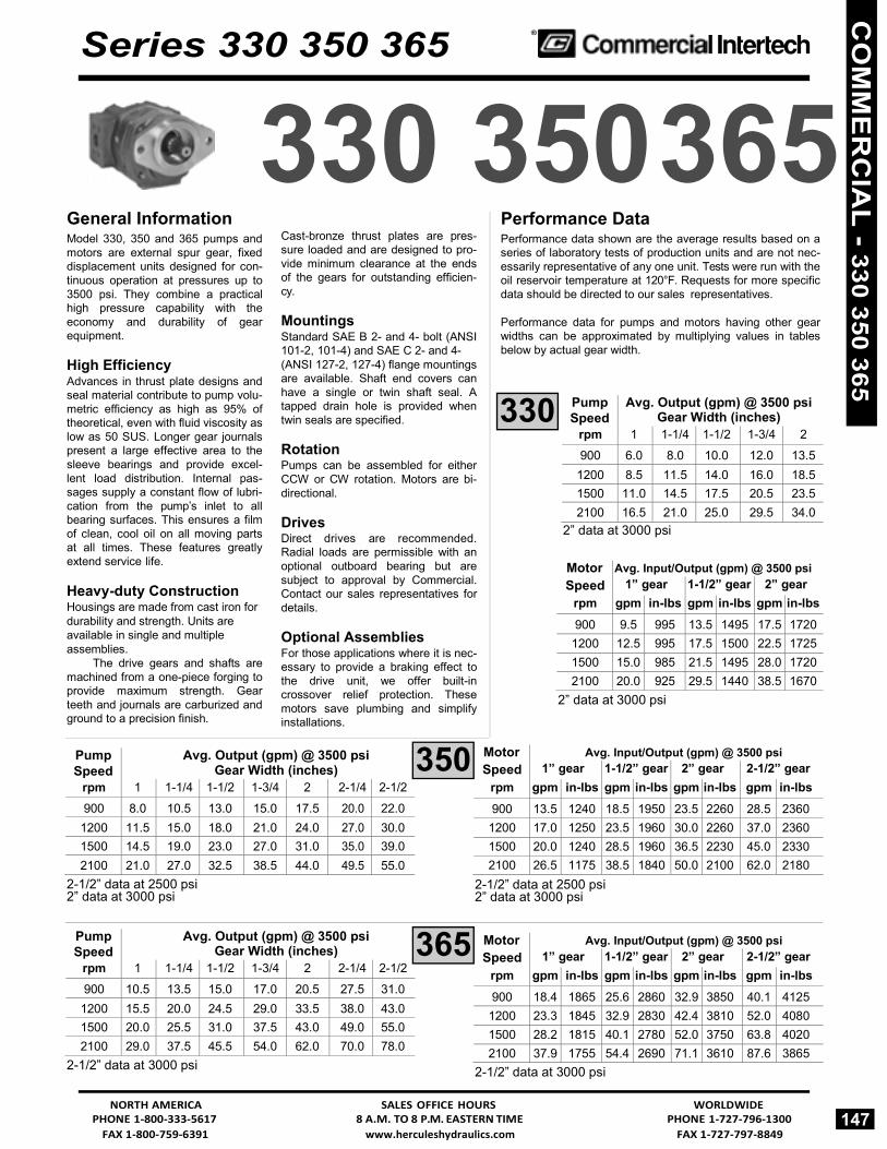
FAX 1-800-759-6391 www.herculeshydraulics.com FAX 1-727-797-8849
365
350
Pump Speed
rpm
Avg. Output (gpm) @ 3500 psi Gear Width (inches)
1 1-1/4 1-1/2 1-3/4 2 900 6.0 8.0 10.0 12.0 13.5
1200 8.5 11.5 14.0 16.0 18.5 1500 11.0 14.5 17.5 20.5 23.5 2100 16.5 21.0 25.0 29.5 34.0
Series 330 350 365 ®
General Information
330 350 365 Performance Data
Model 330, 350 and 365 pumps and motors are external spur gear, fixed displacement units designed for con- tinuous operation at pressures up to 3500 psi. They combine a practical high pressure capability with the economy and durability of gear equipment.
High Efficiency Advances in thrust plate designs and seal material contribute to pump volu- metric efficiency as high as 95% of theoretical, even with fluid viscosity as low as 50 SUS. Longer gear journals present a large effective area to the sleeve bearings and provide excel- lent load distribution. Internal pas- sages supply a constant flow of lubri- cation from the pump’s inlet to all bearing surfaces. This ensures a film of clean, cool oil on all moving parts at all times. These features greatly extend service life.
Heavy-duty Construction Housings are made from cast iron for durability and strength. Units are available in single and multiple assemblies.
The drive gears and shafts are machined from a one-piece forging to provide maximum strength. Gear teeth and journals are carburized and ground to a precision finish.
Cast-bronze thrust plates are pres- sure loaded and are designed to pro- vide minimum clearance at the ends of the gears for outstanding efficien- cy.
Mountings Standard SAE B 2- and 4- bolt (ANSI 101-2, 101-4) and SAE C 2- and 4- (ANSI 127-2, 127-4) flange mountings are available. Shaft end covers can have a single or twin shaft seal. A tapped drain hole is provided when twin seals are specified.
Rotation Pumps can be assembled for either CCW or CW rotation. Motors are bi- directional.
Drives Direct drives are recommended. Radial loads are permissible with an optional outboard bearing but are subject to approval by Commercial. Contact our sales representatives for details.
Optional Assemblies For those applications where it is nec- essary to provide a braking effect to the drive unit, we offer built-in crossover relief protection. These motors save plumbing and simplify installations.
Performance data shown are the average results based on a series of laboratory tests of production units and are not nec- essarily representative of any one unit. Tests were run with the oil reservoir temperature at 120°F. Requests for more specific data should be directed to our sales representatives.
Performance data for pumps and motors having other gear widths can be approximated by multiplying values in tables below by actual gear width.
2” data at 3000 psi
Motor Speed
rpm
Avg. Input/Output (gpm) @ 3500 psi 1” gear 1-1/2” gear 2” gear
gpm in-lbs gpm in-lbs gpm in-lbs 900 9.5 995 13.5 1495 17.5 1720
1200 12.5 995 17.5 1500 22.5 1725 1500 15.0 985 21.5 1495 28.0 1720 2100 20.0 925 29.5 1440 38.5 1670
2” data at 3000 psi
2-1/2” data at 2500 psi 2” data at 3000 psi
Pump Speed
rpm
Avg. Output (gpm) @ 3500 psi Gear Width (inches)
1 1-1/4 1-1/2 1-3/4 2 2-1/4 2-1/2 900 10.5 13.5 15.0 17.0 20.5 27.5 31.0
1200 15.5 20.0 24.5 29.0 33.5 38.0 43.0 1500 20.0 25.5 31.0 37.5 43.0 49.0 55.02100 29.0 37.5 45.5 54.0 62.0 70.0 78.0
2-1/2” data at 3000 psi
2-1/2” data at 2500 psi 2” data at 3000 psi
Motor Speed
rpm
Avg. Input/Output (gpm) @ 3500 psi 1” gear 1-1/2” gear 2” gear 2-1/2” gear
gpm in-lbs gpm in-lbs gpm in-lbs gpm in-lbs 900 18.4 1865 25.6 2860 32.9 3850 40.1 4125
1200 23.3 1845 32.9 2830 42.4 3810 52.0 4080 1500 28.2 1815 40.1 2780 52.0 3750 63.8 4020 2100 37.9 1755 54.4 2690 71.1 3610 87.6 3865
2-1/2” data at 3000 psi
NORTH AMERICA SALES OFFICE HOURS WORLDWIDE PHONE 1-800-333-5617 8 A.M. TO 8 P.M. EASTERN TIME PHONE 1-727-796-1300
147
Motor Speed
rpm
Avg. Input/Output (gpm) @ 3500 psi 1” gear 1-1/2” gear 2” gear 2-1/2” gear
gpm in-lbs gpm in-lbs gpm in-lbs gpm in-lbs 900 13.5 1240 18.5 1950 23.5 2260 28.5 2360
1200 17.0 1250 23.5 1960 30.0 2260 37.0 23601500 20.0 1240 28.5 1960 36.5 2230 45.0 23302100 26.5 1175 38.5 1840 50.0 2100 62.0 2180
Pump Speed
rpm
Avg. Output (gpm) @ 3500 psi Gear Width (inches)
1 1-1/4 1-1/2 1-3/4 2 2-1/4 2-1/2 900 8.0 10.5 13.0 15.0 17.5 20.0 22.0
1200 11.5 15.0 18.0 21.0 24.0 27.0 30.0 1500 14.5 19.0 23.0 27.0 31.0 35.0 39.0 2100 21.0 27.0 32.5 38.5 44.0 49.5 55.0
330
CO
MM
ER
CIA
L - 330 350 365

FAX 1-727-797-8849 www.herculeshydraulics.com FAX 1-800-759-6391
® Series 330 350 365
P330 Parts Breakdown Typical Parts List Note: Plug 5 required in position
Item Description Part Number Item Description Part Number1 Snap Ring 300-206 10 Gasket Seal 580-242 2 Outboard Bearing CM-391-0381-040 11 Dowel Pins (Solid) CM-391-2082-032 3 Seal CM-391-2883-058 12 Gear Housing See Option List 4 Shaft End Cover See Option List 13 Bearing Carrier See Option List 5 Plug 14 Connection Shaft See Option List 6 Bushings CM-391-0482-306 15 Matched Gear Set See Option List 7 Channel Seal CM-391-2885-065 16 Gear Housing See Option List 8 Thrust Plates CM-391-2185-956 17 Port End Cover
9 Integral Drive Shaft 18 Studs or Cap Screws and Gear Set 19 Washers
20 Nuts
148 WORLDWIDE SALES OFFICE HOURS NORTH AMERICA
PHONE 1-727-796-1300 8 A.M. TO 8 P.M. EASTERN TIME PHONE 1-800-333-5617
A and B.
For Series P330 Seal Kits and Repair Parts, See Pages 475 - 477
CO
MM
ER
CIA
L - 3
30 3
50 3
65

FAX 1-800-759-6391 www.herculeshydraulics.com FAX 1-727-797-8849
P350 Parts Breakdown Typical Parts List
For Series P350 Seal Kits and Repair Parts, See Pages 475 - 477
Series 330 350 365 ®
Note: Plug 5 in position B gives clockwise rotation.
Plug 5 in position A gives counter-clockwise rotation.
Item Description Part Number Item Description Part Number1 Snap Ring WHM-283 10 Gasket Seal 580-246 2 Outboard Bearing CM-391-0381-077 11 Dowel Pins (Solid) CM-391-2082-032 3 Seal CM-391-2883-103 12 Gear Housing See Option List 4 Shaft End Cover See Option List 13 Bearing Carrier See Option List 5 Plug 14 Connection Shaft See Option List 6 Bushings CM-391-0482-308 15 Matched Gear Set See Option List 7 Channel Seal CM-391-2885-066 16 Gear Housing See Option List 8 Thrust Plates CM-391-2185-957 17 Port End Cover
9 Integral Drive Shaft 18 Studs or Cap Screws and Gear Set 19 Washers
20 Nuts
NORTH AMERICA SALES OFFICE HOURS WORLDWIDE PHONE 1-800-333-5617 8 A.M. TO 8 P.M. EASTERN TIME PHONE 1-727-796-1300
149
CO
MM
ER
CIA
L - 330 350 365

FAX 1-727-797-8849 www.herculeshydraulics.com FAX 1-800-759-6391
® Series 330 350 365
P365 Parts Breakdown Typical Parts List Note: Plug 5 in position B gives clockwise rotation.
Plug 5 in position A gives counter-clockwise rotation.
Item Description Part Number Item Description Part Number1 Snap Ring 300-315 10 Gasket Seal 580-250 2 Outboard Bearing CM-391-0381-078 11 Dowel Pins (Hollow) CM-391-2082-062 3 Seal CM-391-2883-052 12 Gear Housing See Option List 4 Shaft End Cover See Option List 13 Bearing Carrier See Option List 5 Plug 14 Connection Shaft See Option List 6 Bushings CM-391-0482-307 15 Matched Gear Set See Option List 7 Channel Seal CM-391-2885-064 16 Gear Housing See Option List 8 Thrust Plates CM-391-2185-955 17 Port End Cover
9 Integral Drive Shaft 18 Studs or Cap Screws and Gear Set 19 Washers
20 Nuts
150 WORLDWIDE SALES OFFICE HOURS NORTH AMERICA
PHONE 1-727-796-1300 8 A.M. TO 8 P.M. EASTERN TIME PHONE 1-800-333-5617
For Series P365 Seal Kits and Repair Parts, See Pages 475 - 477
CO
MM
ER
CIA
L - 3
30 3
50 3
65

FAX 1-800-759-6391 www.herculeshydraulics.com FAX 1-727-797-8849
Series 330 350 365
&
®
Shaft & Port End Covers
P330/350/365 SHAFT END COVERS Description PUMPS MOTORS
Type Outboard Bearing CW CCW
1/4” NPT 1/4” BSPP DRAIN DRAIN
SAE B 4 Bolt 1 Without With
142 442
242 542
942 842
— —
SAE C 4 Bolt 1 Without With
178 478
278 578
978 878
1978 —
SAE B 2 Bolt P330/P350 Only
1 Without With
197 497
297 597
997 897
— —
SAE C 2 Bolt P350/P365 Only
1 Without With
198 498
298 598
998 —
—
P330/350/365 PORT END COVERS Side Ported
Split Flange Ports ODT Ports Porting Pump Motor
Double Pump Motor
Double Inlet Outlet CW CCW CW CCW — — BI IB (BI-P330) BA — — — 2 1 1/2 EC* CE* — — — — 2 1 1/4 EF* FE* — — — — 2 1 EG* GE* — — — —
1 1/2 1 1/2 EH* HE* CR* — — — 1 1/2 1 1/4 EJ JE — FB* BF* — 1 1/2 1 EK KE — FC* CF* — 1 1/4 1 1/4 EL LE CS FG* GF* VC 1 1/4 1 EM ME — FJ JF —
1 1 EN NE CT FL LF VN 2 — OE* EO* — — — —
1 1/2 — OF FO — BC* CB* — 1 1/4 — OG GO — BG GB —
1 — OJ JO — BJ JB — — 1 1/2 OL* LO* — — — — — 1 1/4 OM MO — BL LB — — 1 ON NO — BN NB — 3/4 3/4 — — CV — — VR
* Not available on 330. All other codes good for 330/350/365.
P330/350/365 METRIC PORT END COVERS Side Ported
330
350
Metric Metric Split Str. Thd. BSPP
Porting Flange Pump Motor Double
Motor Double
Pump Motor Double Inlet Outlet CW CCW CW CCW
2 1 1/2 ER* RE* — — — — — 2 1 1/4 ES* SE* — — — — — 2 1 ET* TE* — — — — —
1 1/2 1 1/2 EU* UE CW* — — — — 1 1/2 1 1/4 EV VE — — FN NF — 1 1/2 1 EW WE — — FP PF — 1 1/4 1 1/4 EX XE CX VS FR RF VX 1 1/4 1 EY YE — — FS SF —
1 1 EZ ZE CV VT FT TF VY 2 — OP* PO* — — — — —
1 1/2 — OR RO — — BP PB — 1 1/4 — OS SO — — BQ QB —
1 — OT TO — — BR RB —— 1 1/2 OV* VO* — — — — — — 1 1/4 OE WO — — BT TB — — 1 OX XO — — BU UB — 3/4 3/4 — — CZ VW — — VZ
* Not available on 330. All other codes good for 330/350/365.
365
NORTH AMERICA SALES OFFICE HOURS WORLDWIDE PHONE 1-800-333-5617 8 A.M. TO 8 P.M. EASTERN TIME PHONE 1-727-796-1300
151
2 1
CO
MM
ER
CIA
L - 330 350 365

FAX 1-727-797-8849 www.herculeshydraulics.com FAX 1-800-759-6391
® Series 330 350 365
Gear Housings
P330/350/365 GEAR HOUSINGS Gear housings are not ported on the 330, 350 and 365 models.
Code 330 350 365
Pumps Motors
AB EB
05 thru 20 05 thru 20
05 thru 25 10 thru 25
07 thru 25 10 thru 27
Drive Shafts
P330/350/365 DRIVE SHAFTS
Description
330 Code
350 Code
365 Code
Connecting Shaft 05-1 05-1 — 07-1 07-1 07-1 10-1 10-1 10-1 12-1 12-1 12-1 15-1 15-1 15-1 17-1 17-1 17-1 20-1 20-1 20-1 22-1 22-1 25-1 25-1 SAE C-14 teeth involute spline 07-7 10-7 07-7 10-7 12-7 10-7 ANSI 32-4 Major dia. 1.228 — 12-7 Single 15-7 Single 12-7
1.223 — 15-7 Tandem 17-7 Tandem 15-7 Minor dia. 1.0627 max. Continental ‡ 17-7 — 20-7 — 17-7
(1.040 max - 365) 20-7 22-7 20-7 25-7 22-7 25-7 10-11 07-11 SAE C-14 Keyed — 12-11 10-11 ANSI 32-1 diameter 1.250 — — 15-11 — 12-11 Key (.31 x .31 1.50) — — 17-11 — 15-11 Continental ‡ 20-11 Continental ‡ 17-11 22-11 20-11 25-11 22-11
25-11 SAE B-13 teeth involutespline ANSI 22-4 Major dia. .858
.853 Minor dia. .7335 max.
07-25 07-25 10-25 10-25
Single 12-25 Single 12-25 Tandem 15-25 Tandem 15-25
— 17-25 — 17-25 20-25 20-25
22-25 25-25
07-30 SAE B-Keyed 10-30 ANSI 22-1 diameter .875 12-30 Key (.25 x .25 x 1.00) 15-30 Continental ‡ 17-30 20-30 07-43 SAE BB Keyed Single 10-43 ANSI 25-1 diameter 1.000 Tandem 12-43 Key (.25 x .25 x 1.25) Continental ‡ 15-43 17.43 20-43 SAE BB-15 teeth involute spline ANSI 25-4 Major dia. .983
.978 Minor dia. .840
10-98 12-98
Single 15-98 Tandem 17-98
20-98 ‡ Continental shafts require shaft end covers with outboard bearings.
152 WORLDWIDE SALES OFFICE HOURS NORTH AMERICA
PHONE 1-727-796-1300 8 A.M. TO 8 P.M. EASTERN TIME PHONE 1-800-333-5617
4
6 3
CO
MM
ER
CIA
L - 3
30 3
50 3
65
&

FAX 1-800-759-6391 www.herculeshydraulics.com FAX 1-727-797-8849
Series 330 350 365 ®
Bearing Carriers
P330/350/365 BEARING CARRIER CODES
PUMP CODES Clockwise Counterclockwise
Code Code
MOTOR CODESDouble
Split Inlet Outlet Split Split
Top Bottom Flange ODT Flange ODT Flange ODT Dual Outlet
2 1/2* 2 1/2 2 1/2 2 1/2 2 1/2 2 1/2
2 2 2 2 2 2
1 1/2* 1 1/2* 1 1/2* 1 1/2 1 1/2 1 1/2 1 1/4 1 1/4 1 1/4
1
1 1/2 1 1/2 1 1/2 1 1/4 1 1/4
1 1 1/2 1 1/2 1 1/2 1 1/4 1 1/4
1 1 1/2 1 1/2 1 1/2 1 1/4 1 1/4
1 1 1/4 1 1/4
1 1
1 1/2 1 1/4
1 1 1/4
1 1
1 1/2 1 1/4
1 1/14
1 1
1 1/2 1 1/4
1 1 1/4
1 1
1 1/4 1 1 1
AC AD* AE* AF* AG* AH* AJ* AK* AL* AM AN AP AQ* AR* AS* AT AU AV AW AX
AY ‡ AZ
— — — — — —
GJ* GK* GL*
GM ‡ GN ‡ GP ‡ GQ* GR* GS* GT ‡ GU ‡ GV
GW ‡ GX ‡ GY GZ
CA* DA* EA* FA* GA* HA* JA* KA* LA* MA NA PA QA* RA* SA* TA UA VA WA XA
YA ‡ ZA
— — — — — —
JG* KG* LG*
MG ‡ NG ‡ PG ‡ QG* RG* SG* TG ‡ UG ‡ VG
WG ‡ XG ‡ YG ZG
— — — — — — — — — — — — — — — — — — — — — —
— — — — — — — — — — — — — — — — — — — — — —
Single Outlet
Inlet 2 1/2* 2 1/2* 2 1/2*
2 2 2
1 1/2 1 1/2 1 1/2 1 1/4 1 1/4
1
Outlet 1 1/2 1 1/4
1 1 1/2 1 1/4
1 1 1/2 1 1/4
1 1 1/4
1 1
— — — — — — — — — — — —
CJ* CL* CM* HB HC HF HL HM HN HO HP HQ
— — —
KB ‡ KC ‡ KF ‡ KL ‡ KM KN KO KP KQ
JC* LC* MC* BH CH FH LH MH NH OH PH QH
— — —
BK ‡ CK ‡ FK ‡ LK ‡ MK NK OK PK QK
— — — — — — — — — — — —
— — — — — — — — — — — —
Com- bined Outlet
2 1/2* 2 1/2*
2 22
1 1/2 1 1/2 1 1/4
13/4
1 1/2 1 1/4
2 1 1/2 1 1/4 1 1/2 1 1/4 1 1/4
13/4
— — — — — — — — — —
UC* UF* — UN UO UP UQ UR — —
— — —
PE ‡ PM ‡ PN ‡ PQ PR — —
CU* FU* — NU OU PU QU RU — —
— — —
EP ‡ MP ‡ NP ‡ QP RP — —
— —
AA ‡ — — BB — CC EE FF
— — — — —
MM ‡ —
NN QQ RR
Com- bined Outlet
—
—
— C
—
D
—
—
—
‡ Not available on P330* Available on P365 only
NORTH AMERICA SALES OFFICE HOURS WORLDWIDE PHONE 1-800-333-5617 8 A.M. TO 8 P.M. EASTERN TIME PHONE 1-727-796-1300
153
5
CO
MM
ER
CIA
L - 330 350 365

FAX 1-727-797-8849 www.herculeshydraulics.com FAX 1-800-759-6391
® Series 330 350 365
Bearing Carriers
P330/350/365 BEARING CARRIER CODES
PUMP CODES Clockwise Counterclockwise
MOTOR CODES Double
Inlet
Outlet
Metric Split
Flange
BSPP
Metric Split
Flange
BSPP
Metric Split
Flange
ODT
Metric Straight Thread Top Bottom
Dual Outlet
2 1/2 2 1/2 2 1/2 2 1/2 2 1/2 2 1/2
2 2 2 2 2 2
1 1/2 1 1/2 1 1/2 1 1/2 1 1/2 1 1/2 1 1/4 1 1/4 1 1/4
1
1 1/2 1 1/2 1 1/2 1 1/4 1 1/4
1 1 1/2 1 1/2 1 1/2 1 1/4 1 1/4
1 1 1/2 1 1/2 1 1/2 1 1/4 1 1/4
1 1 1/4 1 1/4
1 1
1 1/2 1 1/4
1 1 1/4
1 1
1 1/2 1 1/4
1 1/14
1 1
1 1/2 1 1/4
1 1 1/4
1 1
1 1/4 1 1 1
DB* DC* DE* DF* DG* DH* DJ* DK* DL* DM DN DP DQ* DR* DS* DT DU DV DW DX
DY ‡ DZ
— — — — — — JH JK JL JM JN JP JQ JR JS JT JU JV JW JX JY JZ
BD* CD* ED* FD* GD* HD* JD* KD* LD* MD ND PD QD* RD* SD* TD UD VD WD XD
YD ‡ ZD
— — — — — — HJ KJ LJ MJ NJ PJ QJ RJ SJ TJ UJ VJ WJ XJ YJ ZJ
— — — — — — — — — — — — — — — — — — — — — —
— — — — — — — — — — — — — — — — — — — — — —
— — — — — — — — — — — — — — — — — — — — — —
Single Outlet
Inlet 2 1/2 2 1/2 2 1/2
2 2 2
1 1/2 1 1/2 1 1/2 1 1/4 1 1/4
1
Outlet 1 1/2 1 1/4
1 1 1/2 1 1/4
1 1 1/2 1 1/4
1 1 1/4
1 1
— — — — — — — — — — — —
CN* CP* CQ* HR* HS* HT* HU* HV* HW* HX* HY* HZ*
— — — — — — — — — — — —
NC PC QC RH SH TH UH VH WH XH YH ZH
— — — — — — — — — — — —
— — — — — — — — — — — —
— — — — — — — — — — — —
— — — — — — — — — — — —
Com- bined Outlet
2 1 1/2 1 1/4
1 3/4
2 1 1/2 1 1/4
1 3/4
— — — — —
— — — — —
— — — — —
— — — — —
— — — — —
GG ‡ HH JJ KK LL
— WW ‡
XX YY ZZ
— SS ‡ TT UU VV
‡ Not available on P330 * Available on P365 only
154 WORLDWIDE SALES OFFICE HOURS NORTH AMERICA
PHONE 1-727-796-1300 8 A.M. TO 8 P.M. EASTERN TIME PHONE 1-800-333-5617
5
CO
MM
ER
CIA
L - 3
30 3
50 3
65