Embed Size (px)
Citation preview
Commercial off the Shelf Components in Reaction Wheels
Andrew Haslehurst' and Guy Richardson*
Abstract
This paper presents the approach adopted by Surrey Satellite Technology Ltd (SSTL) for development of reaction wheels incorporating commercial components and the accelerated life test / qualification philosophy. The paper focuses on the mechanical development and re-qualification of reaction wheel which has flown successfully on many missions having conducted years of in orbit operation. The scope of the requalification was to verify the wheels performance with ground testing for new missions where an increased life was required, with some re-design where applicable.
Introduction
The Microsat Reaction Wheel (MRW) or Micro Wheel was developed at SSTL in the mid-nineties and is unique in its design from the simple drive electronics which are enclosed in the base of the wheel to the commercial brushless DC motor using dry lubrication, to the wheel volume at approximately 100*100*100 mm3 all weighing in at under 1 kg, this wheel was succeeded by the Enhanced Microsat Reaction Wheel (EMRW) in the year 2000.
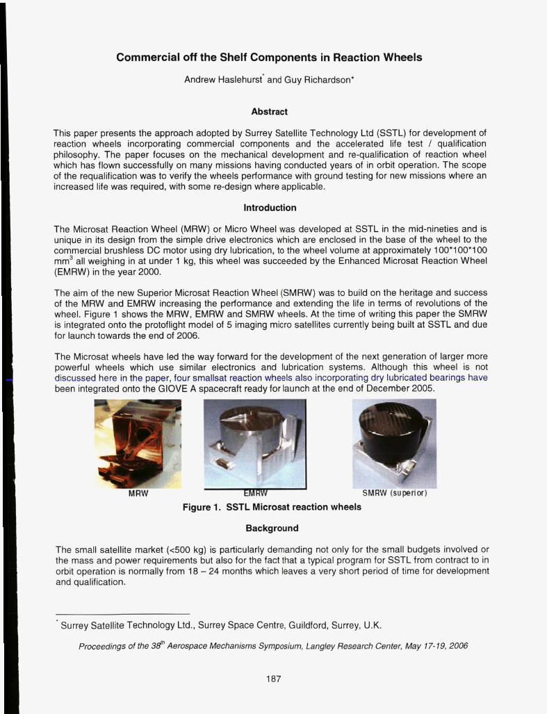
The aim of the new Superior Microsat Reaction Wheel (SMRW) was to build on the heritage and success of the MRW and EMRW increasing the performance and extending the life in terms of revolutions of the wheel. Figure 1 shows the MRW, EMRW and SMRW wheels. At the time of writing this paper the SMRW is integrated onto the protoflight model of 5 imaging micro satellites currently being built at SSTL and due for launch towards the end of 2006.
The Microsat wheels have led the way forward for the development of the next generation of larger more powerful wheels which use similar electronics and lubrication systems. Although this wheel is not discussed here in the paper, four smallsat reaction wheels also incorporating dry lubricated bearings have been integrated onto the GIOVE A spacecraft ready for launch at the end of December 2005.
Figure 1. SSTL Microsat reaction wheels
Background
The small satellite market (400 kg) is particularly demanding not only for the small budgets involved or the mass and power requirements but also for the fact that a typical program for SSTL from contract to in orbit operation is normally from 18 - 24 months which leaves a very short period of time for development and qualification.
' Surrey Satellite Technology Ltd., Surrey Space Centre, Guildford, Surrey, U.K.
Proceedings of the 3d' Aerospace Mechanisms Symposium, Langley Research Center, May 17- 19,2006
187
One approach that SSTL uses builds on its philosophy of "affordable access to space" by flying new developments as back-up or experimental units on missions. Hence, flight qualification can be achieved without the need for lengthy and costly ground qualification. The market SSTL is addressing is changing though and there are now fewer opportunities to qualify in this manner with customers demanding proven reliability and heritage.
To achieve the rapid development and qualification with wheels a different approach needs to be taken from the typical wet (oil or grease) bearing lubricated systems. This simplifies the design, not requiring reservoirs for the oil and anti-creep barriers but allows for an accelerated life test. Due to the properties of wet bearing lubricated systems preventing acceleration of life tests with either speed or bearing preload, wet lubricated systems have to perform real time life tests (at flight speed). This leads to very long, potentially costly wheel qualification programs, which can lead to launch occurring before wheel qualification is complete.
All of SSTL early spacecraft were microsats approximately 50-kg spacecraft 360-mm square by 750-mm long in launch configuration. The AOCS system of these microsats did not rely on reaction wheels to provide attitude stability. The spacecraft design used a gravity gradient boom to keep it nadir pointing. Yaw motion was controlled using magnetorquers. Augmenting the AOCS with wheels allowed much better control of yaw and the potential to off point from nadir to increase the imaging opportunities of a particular target. Early SSTL wheels were flown as experiments providing enhanced performance above the baseline mission requirements. This allowed development cost to be kept down by reducing ground testing to a minimum.
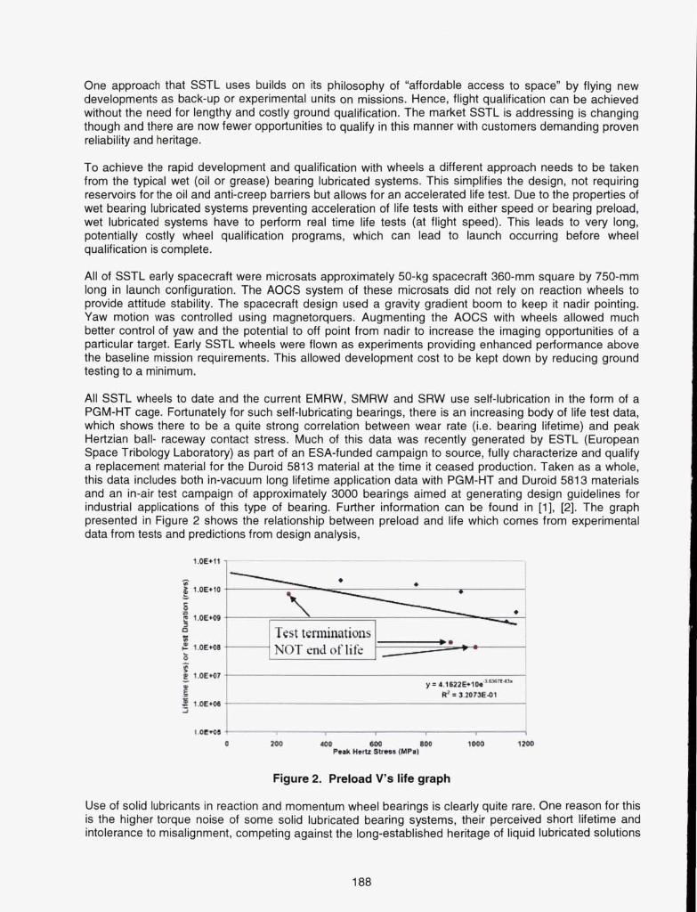
All SSTL wheels to date and the current EMRW, SMRW and SRW use self-lubrication in the form of a PGM-HT cage. Fortunately for such self-lubricating bearings, there is an increasing body of life test data, which shows there to be a quite strong correlation between wear rate (i.e. bearing lifetime) and peak Hertzian ball- raceway contact stress. Much of this data was recently generated by ESTL (European Space Tribology Laboratory) as part of an ESA-funded campaign to source, fully characterize and qualify a replacement material for the Duroid 5813 material at the time it ceased production. Taken as a whole, this data includes both in-vacuum long lifetime application data with PGM-HT and Duroid 581 3 materials and an in-air test campaign of approximately 3000 bearings aimed at generating design guidelines for industrial applications of this type of bearing. Further information can be found in [I], [2]. The graph presented in Figure 2 shows the relationship between preload and life which comes from experimental data from tests and predictions from design analysis,
Test terninatiozls . NOT end of life
Figure 2. Preload V's life graph
Use of solid lubricants in reaction and momentum wheel bearings is clearly quite rare. One reason for this is the higher torque noise of some solid lubricated bearing systems, their perceived short lifetime and intolerance to misalignment, competing against the long-established heritage of liquid lubricated solutions
which offer high lifetime (though often this is achievable only with the addition of a wheel re-lubrication system). The disadvantage of the conventional approach for an accelerated wheel development program is that to qualify a liquid-lubricated wheel, no strict tribologically valid method exists which can accelerate the life test without modification to the lubricant regime in a manner which risks significant under-test. For a solid-lubricated wheel however testing can be relatively straightforwardly carried out at high speed without significant impact on the lubricant wear behavior.
SSTL's approach with such bearings can be thought of using the cage as providing a lubricant reservoir with solid lubricant being transferred from cage to balls and ultimately onto the raceways as a so-called "transfer film". Bearing lifetime is limited by ultimate wear-out of the cage pockets or by excessive or lumpy transfer, which may in some applications create unacceptable torque noise.
For SSTL's first generation of reaction / momentum wheels, which were successfully flown, the lifetime requirement was not particularly high and the self-lubricating bearings were adopted and used in a relatively commercial manner. However, for this latest generation of wheels, there was a requirement to demonstrate a much higher lifetime nominally 2.2 billion revs for a 7-year DMC type mission (including a factor of 2) with low torque noise, combined with a programmatic need to demonstrate the life within an approximate 12 month testing window.
With this change in requirements for lifetime there is an on going investigation into extending life by using novel hybrid lubricant combinations, which are not presented in this paper.
MRW
Backaround / Development The first experimental MRW flew in 1995 on FASat-Alpha which unfortunately failed to separate from the launch vehicle upper stage. FASat-Bravo was built to replace FASat-Alpha and was successfully placed into orbit in 1998. The experimental reaction wheel worked well and encouraged development and use of similar reactions wheel on future missions.
Between 1997 and 1999 three reaction/moment wheels were developed: a nanosat momentum wheel, a minisat reaction wheel and a modified microsat reaction wheel. All of these wheels were based on commercial motors and with the exception of the nanosat momentum wheel, which used vacuum grease lubrication, all used dry lubricated bearings.
The most successful of these wheels was the modified microsat reaction wheel, which flew on Thai Phutt (TMSat), Tiungsat-1. TMSat and Tsingsat-1 each had a single wheel that was used for experimental operations only. Tsinghua-1 had 3 reaction wheels and was operated in three-axis reaction wheel control for months before its gravity gradient boom was deployed, during this time one wheel biased at 500 rpm conducted over - 6.59~108 revolutions.
The modified microsat reaction wheel used for Thai Phutt, Tiungsat-1, Tsinghua-1 was the basis of the EMRW. The EMRW is a primary attitude control component on six SSTL spacecraft currently in orbit. The first of the spacecraft to use the EMRW was AISat-1 this was the first spacecraft of the DMC constellation, launched in 2002. This spacecraft used two wheels in combination with a gravity gradient boom. Since the lifetime requirements for the AISat-1 wheel were largely met by the on orbit operation of the Tsinghua- 1 wheels and the design of the wheels were similar, extensive ground testing and requalification was not carried out.
UK-DMC, NiSat-1 and BilSat-1 were the next spacecraft to use the EMRW. These three were launched together in 2003 and also form part of the DMC constellation. The core platform design of UK-DMC and NiSat-1 was the same as AISat-1. However, BilSat-1 was first of a new generation of SSTL spacecraft designed to be more agile and have a longer mission life (seven years instead of five). It was not conclusive from the available data at that time that the EMRW design would have sufficient life to meet the mission requirements of BilSat-1. Hence, as a contingency, Bilsat-1 also included a deployable boom to allow gravity gradient ADCS operation in the event of a wheel failure.
189
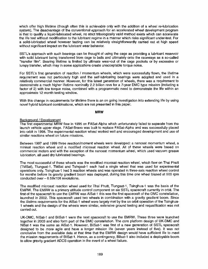
At this time ESTL performed a life test on a MRW motor miss aligning and loading the bearings to their maximum capacity in an attempt to purposefully cause an early failure. The wheel conducted 0.6-billion revolutions (proving mission life taking into account an acceleration factor) showing no signs of failure at which point the test was stopped and the bearings inspected. Some pitting was observed on some balls and these were examined under a SEM, which can be seen in Figure 3, the damaged areas showing delaminating are typical with high sub surface stress and although not desired the wheel was operating nominally.
The cages were weighed pre / post test and seen to have negligible cage weight loss. Assuming cage wear limits the life then it is predicted that lifetime in the order of tens of billions revs could be achieved. Although these tests fundamentally proved the motor was fit to meet current mission life requirements it was thought the life could be extended even further. Hence, it was determined that bearing misalignment should be taken out by some small design changes, which are presented in the development the SMRW.
Figure 3. MRW (SR4) Bearing inspection after life test
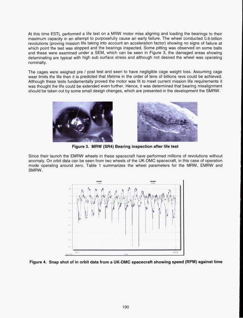
Since their launch the EMRW wheels in these spacecraft have performed millions of revolutions without anomaly. On orbit data can be seen from two wheels of the UK-DMC spacecraft, in this case of operation mode operating around zero. Table 1 summarizes the wheel parameters for the MRW, EMRW and SMRW.
t . . , . . . . a . .
I
w Lt 3mi8 tm wll 11-
Figure 4. Snap shot of in orbit data from a UK-DMC spacecraft showing speed (RPM) against time
190
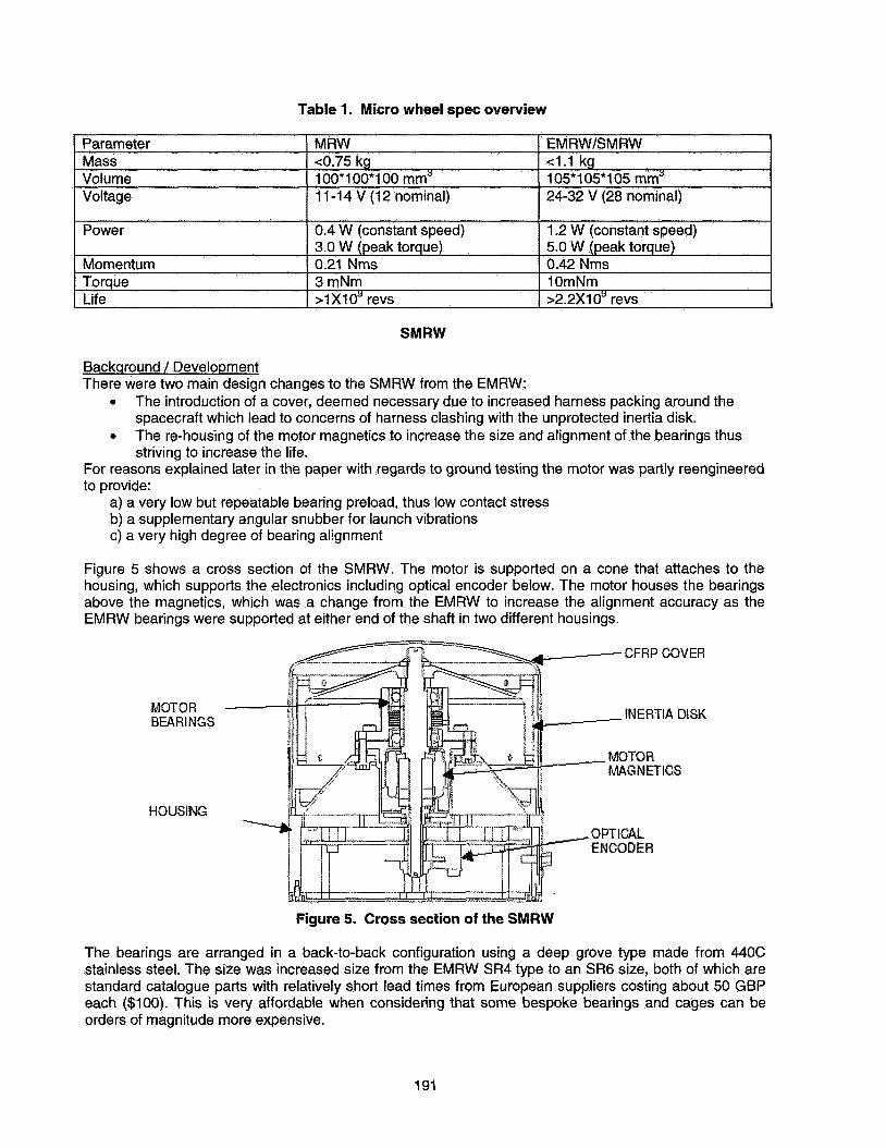
Table 1. Micro wheel spec overview
Power
Momentum Torque Life
Parameter MRW EMRW/SMRW Mass ~0.75 kg 4 . 1 kg Volume 1 OO*I OO*I 00 mm' 105*105*105 mm' Voltage 1 1-1 4 V (1 2 nominal) 24-32 V (28 nominal)
0.4 W (constant speed) 3.0 W (peak torque) 0.21 Nms 0.42 Nms 3 mNm lOmNm > I XI 0' revs
1.2 W (constant speed) 5.0 W (peak torque)
>2.2x1oy revs
SMRW
Backqround / Development There were two main design changes to the SMRW from the EMRW:
0
0
The introduction 0; a cove;, deemed necessary due to increased harness packing around the spacecraft which lead to concerns of harness clashing with the unprotected inertia disk. The re-housing of the motor magnetics to increase the size and alignment of the bearings thus striving to increase the life.
For reasons explained later in the paper with regards to ground testing the motor was partly reengineered to provide:
a) a very low but repeatable bearing preload, thus low contact stress b) a supplementary angular snubber for launch vibrations c) a very high degree of bearing alignment
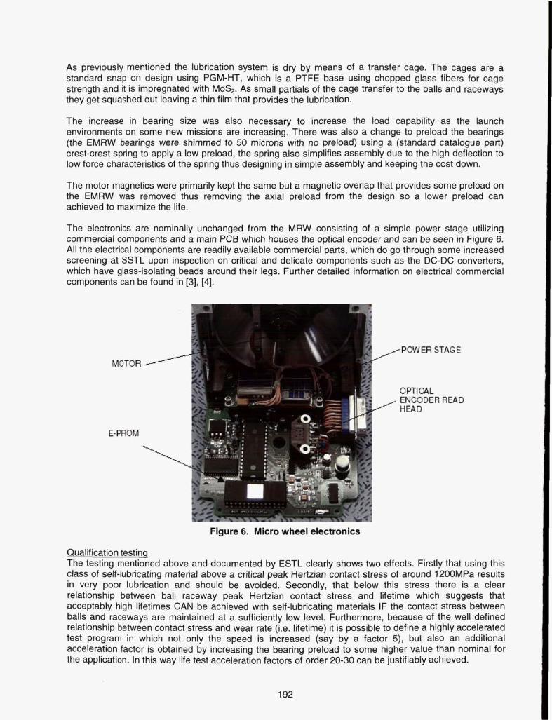
Figure 5 shows a cross section of the SMRW. The motor is supported on a cone that attaches to the housing, which supports the electronics including optical encoder below. The motor houses the bearings above the magnetics, which was a change from the EMRW to increase the alignment accuracy as the EMRW bearings were supported at either end of the shaft in two different housings.
Figure 5. Cross section of the SMRW
The bearings are arranged in a back-to-back configuration using a deep grove type made from 440C stainless steel. The size was increased size from the EMRW SR4 type to an SR6 size, both of which are standard catalogue parts with relatively short lead times from European suppliers costing about 50 GBP each ($100). This is very affordable when considering that some bespoke bearings and cages can be orders of magnitude more expensive.
191
As previously mentioned the lubrication system is dry by means of a transfer cage. The cages are a standard snap on design using PGM-HT, which is a PTFE base using chopped glass fibers for cage strength and it is impregnated with MoS2. As small partials of the cage transfer to the balls and raceways they get squashed out leaving a thin film that provides the lubrication.
The increase in bearing size was also necessary to increase the load capability as the launch environments on some new missions are increasing. There was also a change to preload the bearings (the EMRW bearings were shimmed to 50 microns with no preload) using a (standard catalogue part) crest-crest spring to apply a low preload, the spring also simplifies assembly due to the high deflection to low force characteristics of the spring thus designing in simple assembly and keeping the cost down.
The motor magnetics were primarily kept the same but a magnetic overlap that provides some preload on the EMRW was removed thus removing the axial preload from the design so a lower preload can achieved to maximize the life.
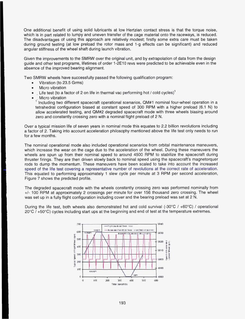
The electronics are nominally unchanged from the MRW consisting of a simple power stage utilizing commercial components and a main PCB which houses the optical encoder and can be seen in Figure 6. All the electrical components are readily available commercial parts, which do go through some increased screening at SSTL upon inspection on critical and delicate components such as the DC-DC converters, which have glass-isolating beads around their legs. Further detailed information on electrical commercial components can be found in [3], [4].
MOTOR
E-PROM
MOTOR -------
E-PROM
HPWER STAGE
OPTICAL
~~ ~~
Figure 6. Micro wheel electronics
Qualification testinq The testing mentioned above and documented by ESTL clearly shows two effects. Firstly that using this class of self-lubricating material above a critical peak Hertzian contact stress of around 1200MPa results in very poor lubrication and should be avoided, Secondly, that below this stress there is a clear relationship between ball raceway peak Hertzian contact stress and lifetime which suggests that acceptably high lifetimes CAN be achieved with self-lubricating materials IF the contact stress between balls and raceways are maintained at a sufficiently low level. Furthermore, because of the well defined relationship between contact stress and wear rate (i.e. lifetime) it is possible to define a highly accelerated test program in which not only the speed is increased (say by a factor 5), but also an additional acceleration factor is obtained by increasing the bearing preload to some higher value than nominal for the application. In this way life test acceleration factors of order 20-30 can be justifiably achieved.
192
One additional benefit of using solid lubricants at low Hertzian contact stress is that the torque noise, which is in pari related to lumpy and uneven transfer of the cage material onto the raceways, is reduced. The disadvantages of using this approach are relatively modest; firstly some extra care must be taken during ground testing (at low preload the rotor mass and 1-g effects can be significant) and reduced angular stiffness of the wheel shaft during launch vibration.
Given the improvements to the SMRW over the original unit, and by extrapolation of data from the design guide and other test programs, lifetimes of order 1 -2E10 revs were predicted to be achievable even in the absence of the improved bearing alignment.
Two SMRW wheels have successfully passed the following qualification program: 0 Vibration (to 23.5 Grms) 0 Micro vibration 0 . Life test (to a factor of 2 on life in thermal vac performing hot / cold cycles)' 0 Micro vibration
Including two different spacecraft operational scenarios, QM#1 nominal four-wheel operation in a 1'
tetrahedral configuration biased at constant speed of 300 RPM with a higher preload (6.1 N) to allow accelerated testing, and QM#2 degraded spacecraft mode with three wheels biasing around zero and constantly crossing zero with a nominal flight preload of 2 N.
Over a typical mission life of seven years in nominal mode this equates to 2.2 billion revolutions including a factor of 2. Taking into account acceleration philosophy mentioned above the life test only needs to run for a few months.
The nominal operational mode also included operational scenarios from orbital maintenance maneuvers, which increase the wear on the cage due to the acceleration of the wheel. During these maneuvers the wheels are spun up from their nominal speed to around 4500 RPM to stabilize the spacecraft during thruster firings. They are then driven slowly back to nominal speed using the spacecraft's magnetorquer rods to dump the momentum. These maneuvers have been scaled to take into account the increased speed of the life test covering a representative number of revolutions at the correct rate of acceleration. This equated to performing approximately 1 slew cycle per minute at 3 RPM per second acceleration, Figure 7 shows the predicted profile.
The degraded spacecraft mode with the wheels constantly crossing zero was performed nominally from +/- 100 RPM at approximately 2 crossings per minute for over 156 thousand zero crossing. The wheel was set up in a fully flight configuration including cover and the bearing preload was set at 2 N.
During the life test, both wheels also demonstrated hot and cold survival (-30°C / +60"C) / operational 20°C / +50°C) cycles including start ups at the beginning and end of test at the temperature extremes.
1LW
193
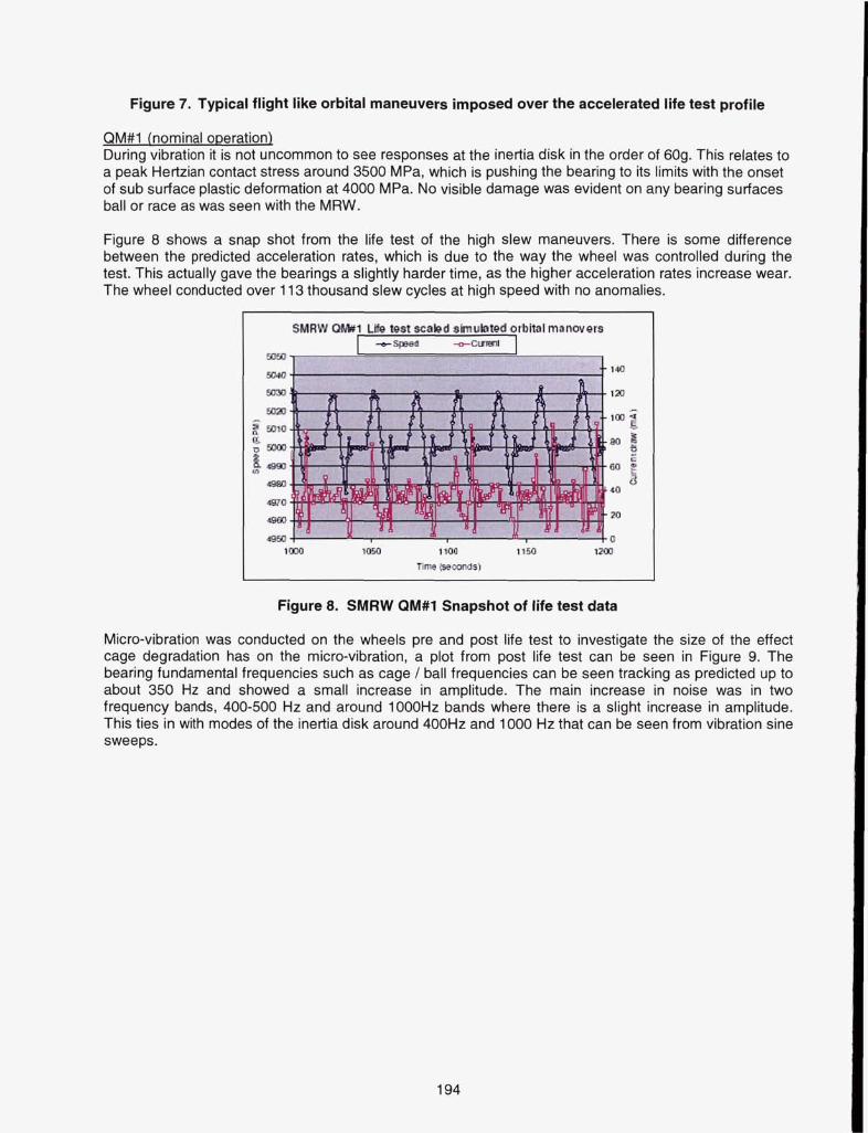
Figure 7. Typical flight like orbital maneuvers imposed over the accelerated life test profile
QM#1 (nominal oDeration) During vibration it is not uncommon to see responses at the inertia disk in the order of 60g. This relates to a peak Hertzian contact stress around 3500 MPa, which is pushing the bearing to its limits with the onset of sub surface plastic deformation at 4000 MPa. No visible damage was evident on any bearing surfaces ball or race as was seen with the MRW.
Figure 8 shows a snap shot from the life test of the high slew maneuvers. There is some difference between the predicted acceleration rates, which is due to the way the wheel was controlled during the test. This actually gave the bearings a slightly harder time, as the higher acceleration rates increase wear. The wheel conducted over 1 13 thousand slew cycles at high speed with no anomalies.
Figure 8. SMRW QM#1 Snapshot of life test data
Micro-vibration was conducted on the wheels pre and post life test to investigate the size of the effect cage degradation has on the micro-vibration, a plot from post life test can be seen in Figure 9. The bearing fundamental frequencies such as cage / ball frequencies can be seen tracking as predicted up to about 350 Hz and showed a small increase in amplitude. The main increase in noise was in two frequency bands, 400-500 Hz and around 1000Hz bands where there is a slight increase in amplitude. This ties in with modes of the inertia disk around 400Hz and 1000 Hz that can be seen from vibration sine sweeps.
194
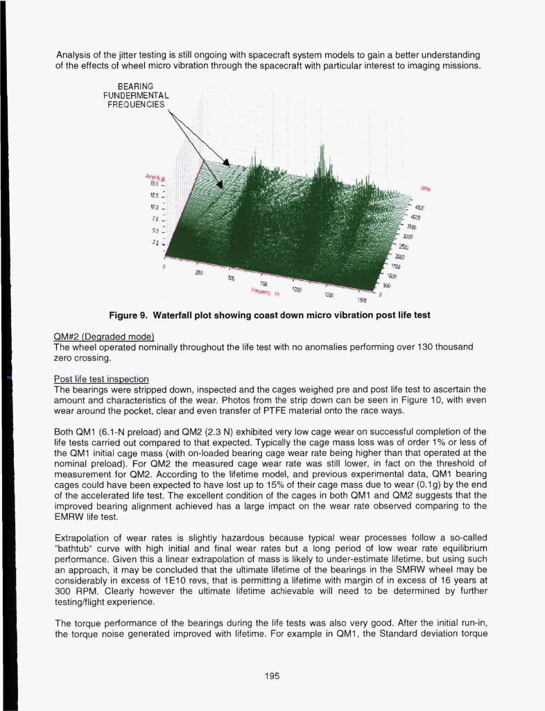
Analysis of the jitter testing is still ongoing with spacecraft system models to gain a better understanding of the effects of wheel micro vibration through the spacecraft with particular interest to imaging missions.
BEARING FUN DERMENTAL FREQUENCIES
aao 3.5 1
0
'Shp
Figure 9. Waterfall plot showing coast down micro vibration post life test
QM#2 (Declraded mode) The wheel operated nominally throughout the life test with no anomalies performing over 130 thousand zero crossing.
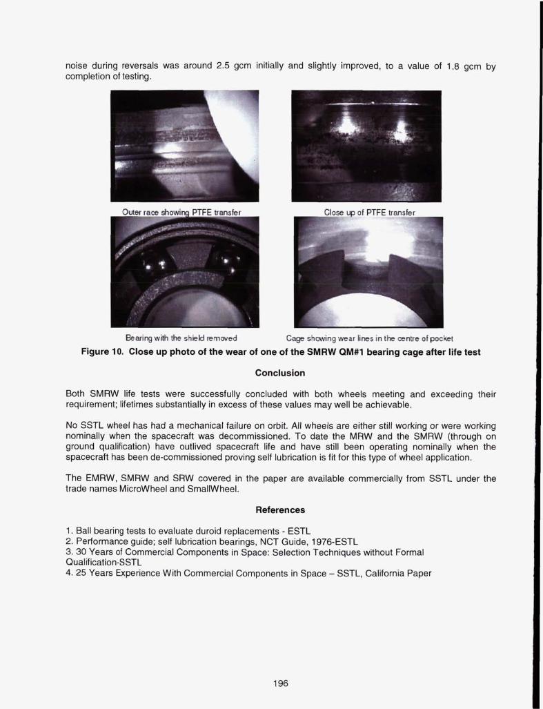
Post life test insDection The bearings were stripped down, inspected and the cages weighed pre and post life test to ascertain the amount and characteristics of the wear. Photos from the strip down can be seen in Figure 10, with even wear around the pocket, clear and even transfer of PTFE material onto the race ways.
Both QM1 (6.1-N preload) and QM2 (2.3 N) exhibited very low cage wear on successful completion of the life tests carried out compared to that expected. Typically the cage mass loss was of order 1% or less of the QM1 initial cage mass (with on-loaded bearing cage wear rate being higher than that operated at the nominal preload). For QM2 the measured cage wear rate was still lower, in fact on the threshold of measurement for QM2. According to the lifetime model, and previous experimental data, QM1 bearing cages could have been expected to have lost up to 15% of their cage mass due to wear (0.1g) by the end of the accelerated life test. The excellent condition of the cages in both QM1 and QM2 suggests that the improved bearing alignment achieved has a large impact on the wear rate observed comparing to the EMRW life test.
Extrapolation of wear rates is slightly hazardous because typical wear processes follow a so-called "bathtub" curve with high initial and final wear rates but a long period of low wear rate equilibrium performance. Given this a linear extrapolation of mass is likely to under-estimate lifetime, but using such an approach, it may be concluded that the ultimate lifetime of the bearings in the SMRW wheel may be considerably in excess of 1 E l 0 revs, that is permitting a lifetime with margin of in excess of 16 years at 300 RPM. Clearly however the ultimate lifetime achievable will need to be determined by further testing/flight experience.
The torque performance of the bearings during the life tests was also very good. After the initial run-in, the torque noise generated improved with lifetime. For example in QM1, the Standard deviation torque
195
noise during reversals was around 2.5 gcrn initially and slightly improved, to a value of 1.8 gcrn by completion of testing.
hearing wiih the shield mrnwed Cage shaving wear fines in the centre of pocket
Figure 10. Close up photo of the wear of one of the SMRW QM#1 bearing cage after life test
Conclusion
Both SMRW life tests were successfully concluded with both wheels meeting and exceeding their requirement; lifetimes substantially in excess of these values may well be achievable.
No SSTL wheel has had a mechanical failure on orbit. All wheels are either still working or were working nominally when the spacecraft was decommissioned. To date the MRW and the SMRW (through on ground qualification) have outlived spacecraft life and have still been operating nominally when the spacecraft has been de-commissioned proving self lubrication is fit for this type of wheel application.
The EMRW, SMRW and SRW covered in the paper are available commercially from SSTL under the trade names Microwheel and SmallWheel.
References
1. Ball bearing tests to evaluate duroid replacements - ESTL 2. Performance guide; self lubrication bearings, NCT Guide, 1976-ESTL 3. 30 Years of Commercial Components in Space: Selection Techniques without Formal Qualif ication-SSTL 4. 25 Years Experience With Commercial Components in Space - SSTL, California Paper
196