Embed Size (px)
Citation preview
Standard-Efficiency Rooftop Units with:• Exclusive integrated gas control board with diagnostics• Alumagard™ heat exchanger coating• Induced-draft fan for gas combustion• Tubular, dimpled heat exchangers• Pre-painted galvanized steel cabinet for long life and qualityappearance
• Commercial strength baserails with built-in rigging capability• Convertible design for horizontal supply/return• Non-corrosive, sloped condensate drain pan, meets ASHRAE62-89 (IAQ)
• Two-inch return-air filters• A wide assortment of factory-installed options available, in-cluding high static drives that provide additional performancerange
FEATURES/BENEFITSEvery compact one-piece unit arrives fully assembled, charged,tested, and ready to run.
INTEGRATED GAS UNIT CONTROLLER (IGC) (All Models)— All ignition components are contained in the compact IGCwhich is easily accessible for servicing. The IGC control board,designed and manufactured exclusively for Bryant rooftop units,provides built-in diagnostic capability. An LED (light-emitting di-ode) simplifies troubleshooting by providing visual fault notifica-tion and system status confirmation.
The IGC also contains an exclusive anti-cycle protection for gasheat operation. After 4 continuous cycles on the unit high-temperature limit switch, the gas heat operation is disabled, andan error code is issued. This feature greatly improves reliabilityof the rooftop unit.
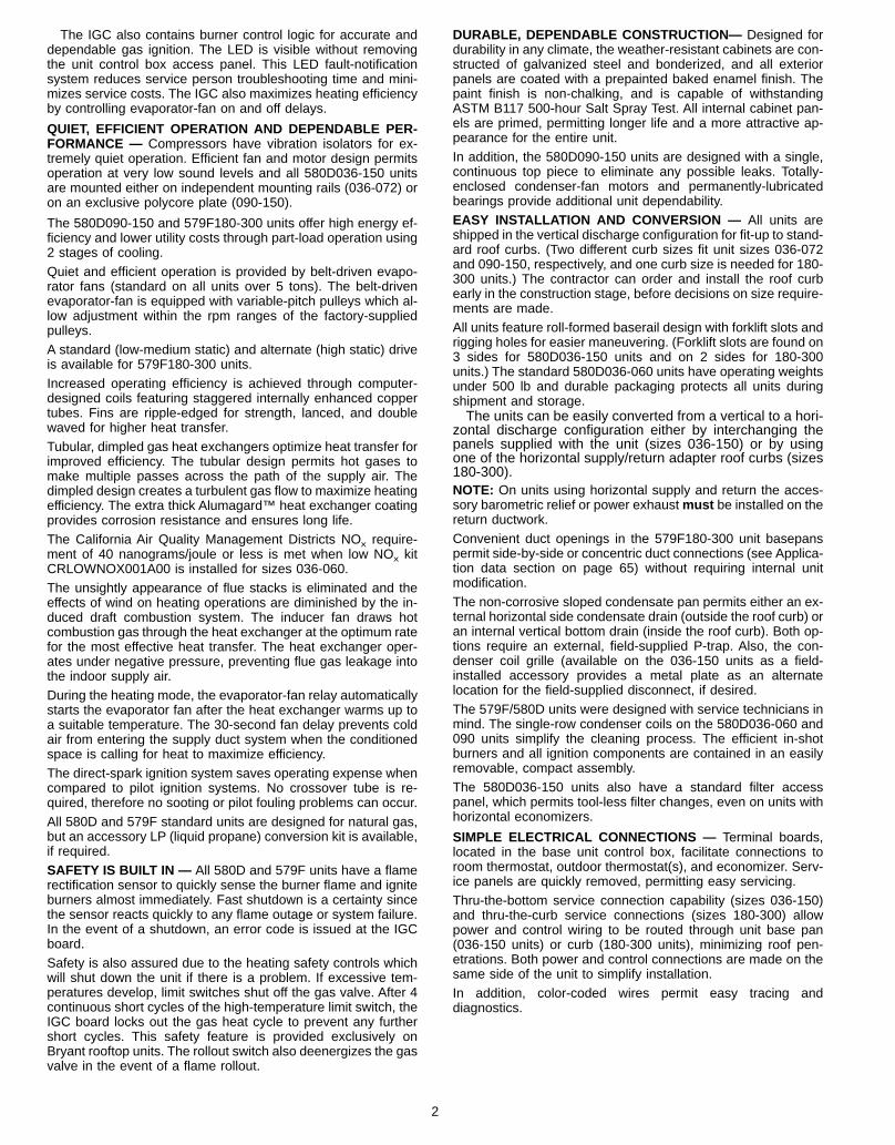
580D036-072
580D090-150
579F180,216
579F240,300
COMMERCIALSINGLE PACKAGE ROOFTOPGAS HEATING/ELECTRIC COOLING UNITS
Model 579F/580DSizes 036-300
3 to 25 Tons
Form No. PDS 580D.36.8
The IGC also contains burner control logic for accurate anddependable gas ignition. The LED is visible without removingthe unit control box access panel. This LED fault-notificationsystem reduces service person troubleshooting time and mini-mizes service costs. The IGC also maximizes heating efficiencyby controlling evaporator-fan on and off delays.
QUIET, EFFICIENT OPERATION AND DEPENDABLE PER-FORMANCE — Compressors have vibration isolators for ex-tremely quiet operation. Efficient fan and motor design permitsoperation at very low sound levels and all 580D036-150 unitsare mounted either on independent mounting rails (036-072) oron an exclusive polycore plate (090-150).
The 580D090-150 and 579F180-300 units offer high energy ef-ficiency and lower utility costs through part-load operation using2 stages of cooling.Quiet and efficient operation is provided by belt-driven evapo-rator fans (standard on all units over 5 tons). The belt-drivenevaporator-fan is equipped with variable-pitch pulleys which al-low adjustment within the rpm ranges of the factory-suppliedpulleys.A standard (low-medium static) and alternate (high static) driveis available for 579F180-300 units.Increased operating efficiency is achieved through computer-designed coils featuring staggered internally enhanced coppertubes. Fins are ripple-edged for strength, lanced, and doublewaved for higher heat transfer.Tubular, dimpled gas heat exchangers optimize heat transfer forimproved efficiency. The tubular design permits hot gases tomake multiple passes across the path of the supply air. Thedimpled design creates a turbulent gas flow to maximize heatingefficiency. The extra thick Alumagard™ heat exchanger coatingprovides corrosion resistance and ensures long life.The California Air Quality Management Districts NOx require-ment of 40 nanograms/joule or less is met when low NOx kitCRLOWNOX001A00 is installed for sizes 036-060.The unsightly appearance of flue stacks is eliminated and theeffects of wind on heating operations are diminished by the in-duced draft combustion system. The inducer fan draws hotcombustion gas through the heat exchanger at the optimum ratefor the most effective heat transfer. The heat exchanger oper-ates under negative pressure, preventing flue gas leakage intothe indoor supply air.During the heating mode, the evaporator-fan relay automaticallystarts the evaporator fan after the heat exchanger warms up toa suitable temperature. The 30-second fan delay prevents coldair from entering the supply duct system when the conditionedspace is calling for heat to maximize efficiency.The direct-spark ignition system saves operating expense whencompared to pilot ignition systems. No crossover tube is re-quired, therefore no sooting or pilot fouling problems can occur.All 580D and 579F standard units are designed for natural gas,but an accessory LP (liquid propane) conversion kit is available,if required.SAFETY IS BUILT IN — All 580D and 579F units have a flamerectification sensor to quickly sense the burner flame and igniteburners almost immediately. Fast shutdown is a certainty sincethe sensor reacts quickly to any flame outage or system failure.In the event of a shutdown, an error code is issued at the IGCboard.Safety is also assured due to the heating safety controls whichwill shut down the unit if there is a problem. If excessive tem-peratures develop, limit switches shut off the gas valve. After 4continuous short cycles of the high-temperature limit switch, theIGC board locks out the gas heat cycle to prevent any furthershort cycles. This safety feature is provided exclusively onBryant rooftop units. The rollout switch also deenergizes the gasvalve in the event of a flame rollout.
DURABLE, DEPENDABLE CONSTRUCTION— Designed fordurability in any climate, the weather-resistant cabinets are con-structed of galvanized steel and bonderized, and all exteriorpanels are coated with a prepainted baked enamel finish. Thepaint finish is non-chalking, and is capable of withstandingASTM B117 500-hour Salt Spray Test. All internal cabinet pan-els are primed, permitting longer life and a more attractive ap-pearance for the entire unit.In addition, the 580D090-150 units are designed with a single,continuous top piece to eliminate any possible leaks. Totally-enclosed condenser-fan motors and permanently-lubricatedbearings provide additional unit dependability.EASY INSTALLATION AND CONVERSION — All units areshipped in the vertical discharge configuration for fit-up to stand-ard roof curbs. (Two different curb sizes fit unit sizes 036-072and 090-150, respectively, and one curb size is needed for 180-300 units.) The contractor can order and install the roof curbearly in the construction stage, before decisions on size require-ments are made.All units feature roll-formed baserail design with forklift slots andrigging holes for easier maneuvering. (Forklift slots are found on3 sides for 580D036-150 units and on 2 sides for 180-300units.) The standard 580D036-060 units have operating weightsunder 500 lb and durable packaging protects all units duringshipment and storage.The units can be easily converted from a vertical to a hori-
zontal discharge configuration either by interchanging thepanels supplied with the unit (sizes 036-150) or by usingone of the horizontal supply/return adapter roof curbs (sizes180-300).NOTE: On units using horizontal supply and return the acces-sory barometric relief or power exhaustmust be installed on thereturn ductwork.Convenient duct openings in the 579F180-300 unit basepanspermit side-by-side or concentric duct connections (see Applica-tion data section on page 65) without requiring internal unitmodification.The non-corrosive sloped condensate pan permits either an ex-ternal horizontal side condensate drain (outside the roof curb) oran internal vertical bottom drain (inside the roof curb). Both op-tions require an external, field-supplied P-trap. Also, the con-denser coil grille (available on the 036-150 units as a field-installed accessory provides a metal plate as an alternatelocation for the field-supplied disconnect, if desired.The 579F/580D units were designed with service technicians inmind. The single-row condenser coils on the 580D036-060 and090 units simplify the cleaning process. The efficient in-shotburners and all ignition components are contained in an easilyremovable, compact assembly.The 580D036-150 units also have a standard filter accesspanel, which permits tool-less filter changes, even on units withhorizontal economizers.
SIMPLE ELECTRICAL CONNECTIONS — Terminal boards,located in the base unit control box, facilitate connections toroom thermostat, outdoor thermostat(s), and economizer. Serv-ice panels are quickly removed, permitting easy servicing.Thru-the-bottom service connection capability (sizes 036-150)and thru-the-curb service connections (sizes 180-300) allowpower and control wiring to be routed through unit base pan(036-150 units) or curb (180-300 units), minimizing roof pen-etrations. Both power and control connections are made on thesame side of the unit to simplify installation.In addition, color-coded wires permit easy tracing anddiagnostics.
2
PROVEN COMPRESSOR RELIABILITY — Design techniquesfeature computer programmed balance between compressor,condenser, and evaporator. Hermetic (036-150 units) and semi-hermetic (180-300 units) compressors with suction anddischarge service valves are equipped with compressor over-current and overtemperature protection to ensure dependability.Crankcase heaters (180-300 units) prevent refrigerant dilutionof oil during off cycles and ensure proper lubrication at start-upto prolong compressor life. Crankcase heaters are not neces-sary on 036-150 units due to high-side crankcase design (sizes072,150) and low refrigerant charge levels (sizes 036-150).The 579F180 unit (with factory-supplied unloading) is equippedwith a thermostatic expansion valve to precisely adjust refriger-ant flow during Stage 1 (unloaded) operation. All other 579F/580D units have the exclusive Acutrol™ metering device whichprecisely controls refrigerant flow, preventing slugging andflood-back, while maintaining optimum unit performance.Additional unloaders are not recommended on the 579F180-300 units.
INTEGRATED ECONOMIZERS AND OUTDOOR AIR —Optional economizers and manual outdoor-air dampers intro-duce outdoor air which mixes with the conditioned air, improvingindoor air quality and often reducing energy consumption.During a first stage call for cooling, if the outdoor-air tempera-ture is below the control changeover set point, the discharge-airsensor modulates the economizer outdoor-air damper open toachieve the changeover set point. When second-stage coolingis called for, the compressor is energized in addition to theeconomizer. If the outdoor-air temperature is above the change-over set point, the first stage of compression is activated andthe economizer stays at vent position. Economizer operation iscontrolled by Accusensor™ I dry-bulb thermostat that sensesoutdoor-air temperature. Accessory upgrade kits include Accu-sensor II solid-state enthalpy control (sizes 036-150) and Accu-sensor III enthalpy sensor.The Durablade economizer (option or accessory) on the580D036-150 units has a reliable sliding plate damper which iseasily adjusted for 100% outdoor air, 100% return air, or anyproportions of mixed air.The 580D036-150 units can also utilize the optional Parabladeeconomizer. This economizer incorporates a parallel-opposed
blade design with standard enthalpy controls. In addition, theParablade economizer has a spring return built into the dampermotor to provide reliable close-on-power-loss. The Parabladeeconomizer comes equipped with up to 45% barometric reliefcapability for high outdoor airflow applications.For units without economizer, year-round ventilation is en-hanced by a manual outdoor-air damper (ordered as standardon 579F180-300; ordered as an accessory or an optionon 580D036-150 units). The damper can be preset to admitup to 25% outdoor air (sizes 180-300) or 50% outdoor air(sizes 036-150).In addition, the barometric relief damper or power exhaustaccessory can be utilized to help maintain proper buildingpressure.
INDOOR-AIR QUALITY — Sloped condensate pans minimizebiological growth in rooftop units in accordance with ASHRAE(American Society of Heating, Refrigeration, and Air Condition-ing Engineers) Standard 62-89. Two-inch filters with optionaldirty filter indicator switch provide for greater particle reductionin the return air. The face-split evaporator coils improve the de-humidification capability of standard units, and standard en-thalpy controls provided with the optional or accessory (sizes036-150) economizers maximize building humidity control.
TABLE OF CONTENTSPage
Features/Benefits . . . . . . . . . . . . . . . . . . . . . . . . . . 1-3Model Number Nomenclature . . . . . . . . . . . . . . . . . . . 4,5ARI Capacity Ratings . . . . . . . . . . . . . . . . . . . . . . . . 6,7Physical Data . . . . . . . . . . . . . . . . . . . . . . . . . . . . 8-13Options and Accessories . . . . . . . . . . . . . . . . . . . . . 14-16Base Unit Dimensions . . . . . . . . . . . . . . . . . . . . . . . 17-20Accessory Dimensions . . . . . . . . . . . . . . . . . . . . . . 21-24Selection Procedure . . . . . . . . . . . . . . . . . . . . . . . . . 25Performance Data . . . . . . . . . . . . . . . . . . . . . . . . . 26-55Electrical Data . . . . . . . . . . . . . . . . . . . . . . . . . . . . 56,57Typical Piping and Wiring . . . . . . . . . . . . . . . . . . . . 58,59Typical Wiring Schematics . . . . . . . . . . . . . . . . . . . . 60-62Controls . . . . . . . . . . . . . . . . . . . . . . . . . . . . . . . . 63,64Application Data . . . . . . . . . . . . . . . . . . . . . . . . . . 65,66Guide Specifications . . . . . . . . . . . . . . . . . . . . . . . . 67-72
3
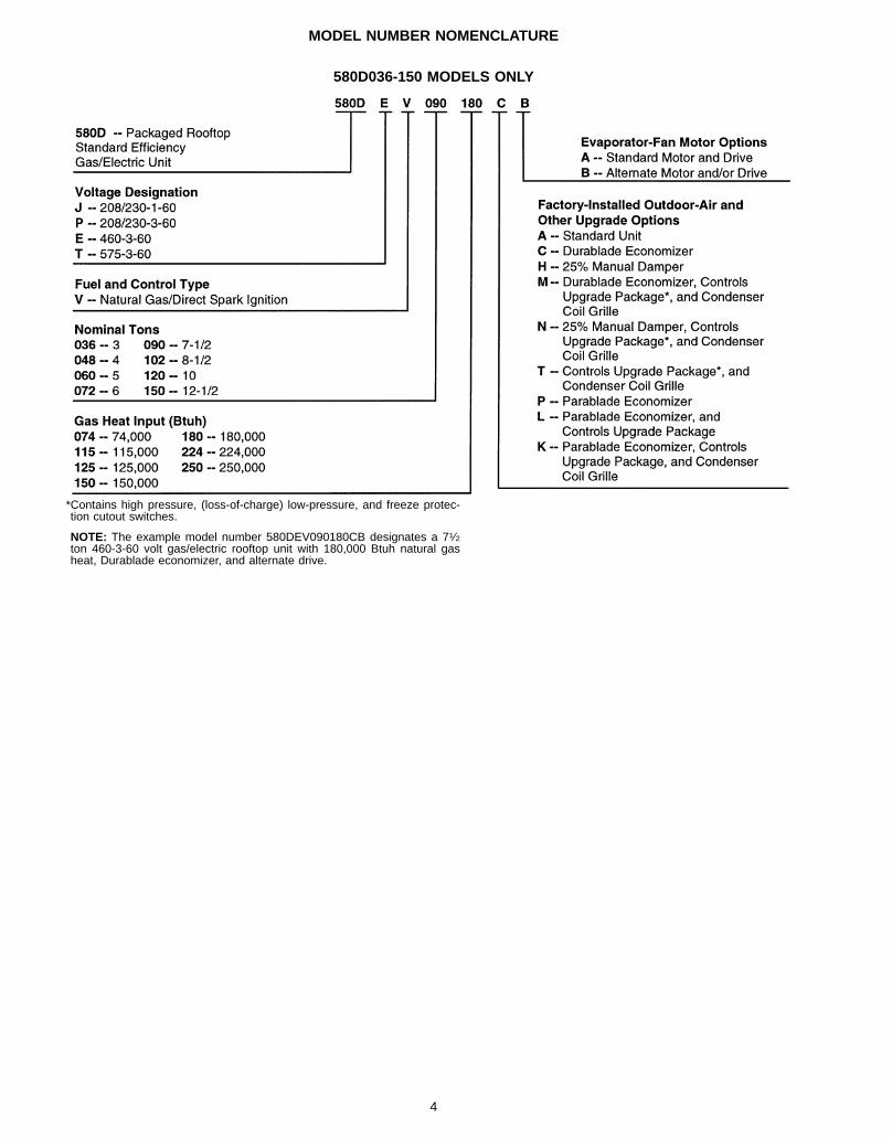
MODEL NUMBER NOMENCLATURE
*Contains high pressure, (loss-of-charge) low-pressure, and freeze protec-tion cutout switches.
NOTE: The example model number 580DEV090180CB designates a 71⁄2ton 460-3-60 volt gas/electric rooftop unit with 180,000 Btuh natural gasheat, Durablade economizer, and alternate drive.
580D036-150 MODELS ONLY
4
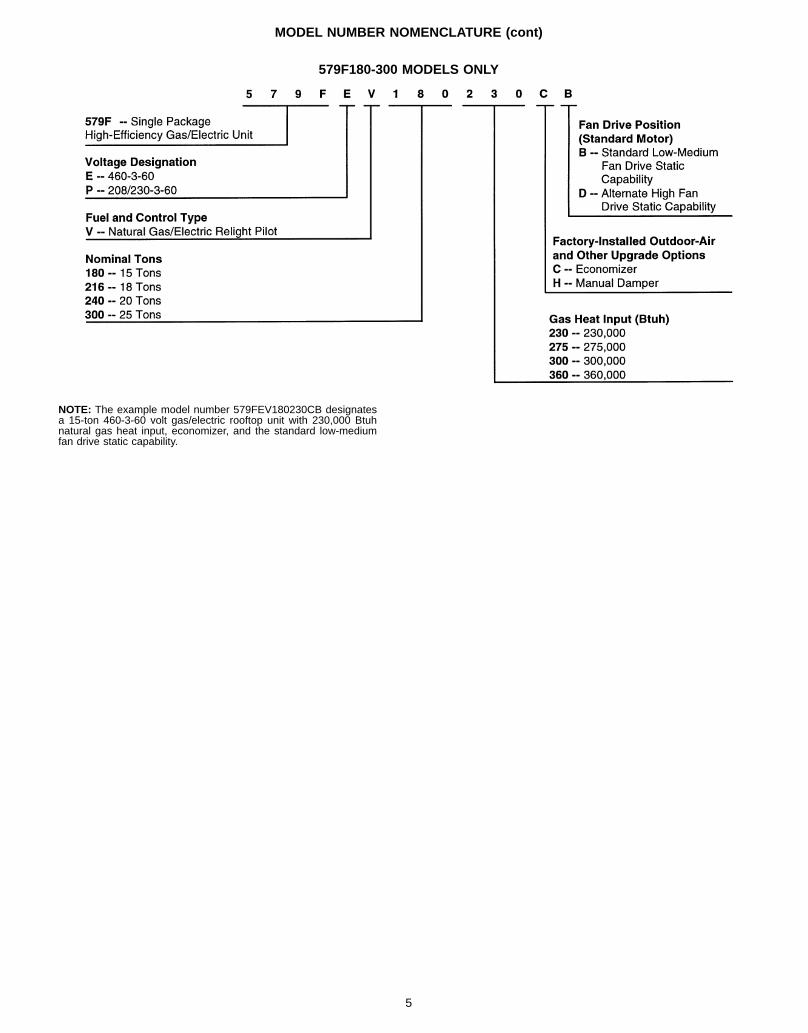
MODEL NUMBER NOMENCLATURE (cont)
579F180-300 MODELS ONLY
NOTE: The example model number 579FEV180230CB designatesa 15-ton 460-3-60 volt gas/electric rooftop unit with 230,000 Btuhnatural gas heat input, economizer, and the standard low-mediumfan drive static capability.
5
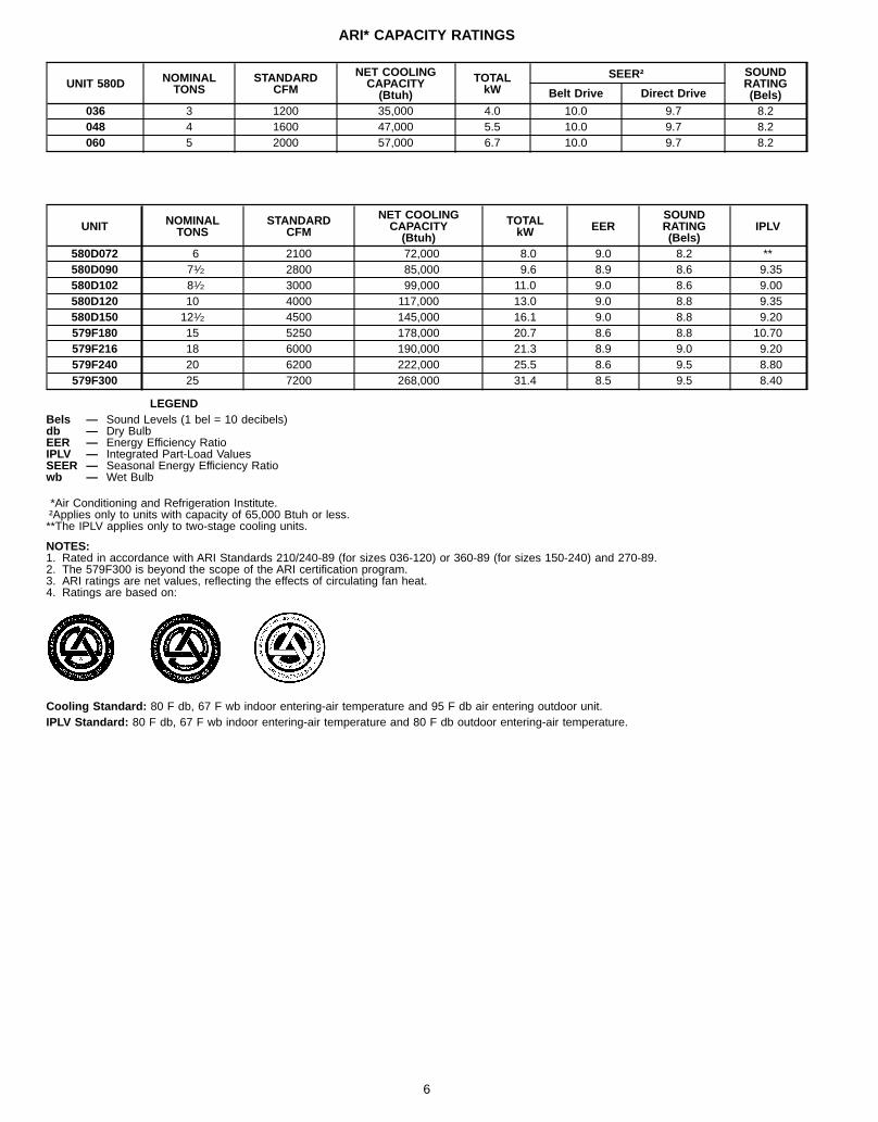
ARI* CAPACITY RATINGS
UNIT 580D NOMINALTONS
STANDARDCFM
NET COOLINGCAPACITY(Btuh)
TOTALkW
SEER† SOUNDRATING(Bels)Belt Drive Direct Drive
036 3 1200 35,000 4.0 10.0 9.7 8.2048 4 1600 47,000 5.5 10.0 9.7 8.2060 5 2000 57,000 6.7 10.0 9.7 8.2
UNIT NOMINALTONS
STANDARDCFM
NET COOLINGCAPACITY(Btuh)
TOTALkW EER
SOUNDRATING(Bels)
IPLV
580D072 6 2100 72,000 8.0 9.0 8.2 **580D090 71⁄2 2800 85,000 9.6 8.9 8.6 9.35580D102 81⁄2 3000 99,000 11.0 9.0 8.6 9.00580D120 10 4000 117,000 13.0 9.0 8.8 9.35580D150 121⁄2 4500 145,000 16.1 9.0 8.8 9.20579F180 15 5250 178,000 20.7 8.6 8.8 10.70579F216 18 6000 190,000 21.3 8.9 9.0 9.20579F240 20 6200 222,000 25.5 8.6 9.5 8.80579F300 25 7200 268,000 31.4 8.5 9.5 8.40
LEGENDBels — Sound Levels (1 bel = 10 decibels)db — Dry BulbEER — Energy Efficiency RatioIPLV — Integrated Part-Load ValuesSEER — Seasonal Energy Efficiency Ratiowb — Wet Bulb
*Air Conditioning and Refrigeration Institute.†Applies only to units with capacity of 65,000 Btuh or less.**The IPLV applies only to two-stage cooling units.
NOTES:1. Rated in accordance with ARI Standards 210/240-89 (for sizes 036-120) or 360-89 (for sizes 150-240) and 270-89.2. The 579F300 is beyond the scope of the ARI certification program.3. ARI ratings are net values, reflecting the effects of circulating fan heat.4. Ratings are based on:
Cooling Standard: 80 F db, 67 F wb indoor entering-air temperature and 95 F db air entering outdoor unit.IPLV Standard: 80 F db, 67 F wb indoor entering-air temperature and 80 F db outdoor entering-air temperature.
6
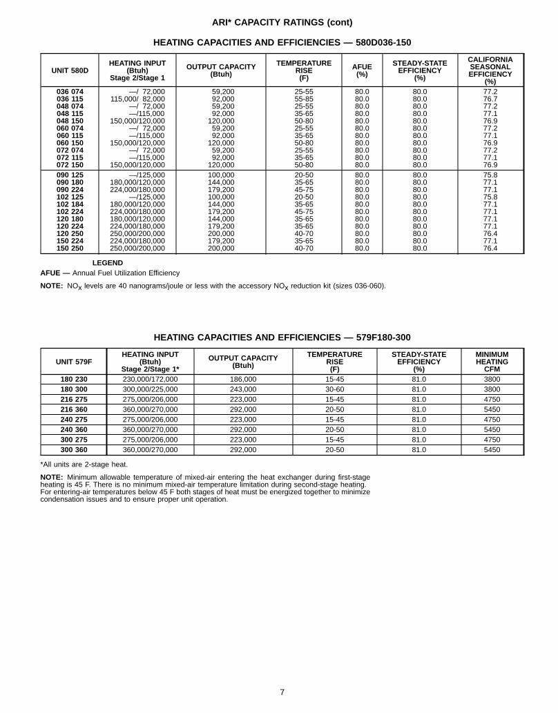
ARI* CAPACITY RATINGS (cont)
HEATING CAPACITIES AND EFFICIENCIES — 580D036-150
UNIT 580DHEATING INPUT
(Btuh)Stage 2/Stage 1
OUTPUT CAPACITY(Btuh)
TEMPERATURERISE(F)
AFUE(%)
STEADY-STATEEFFICIENCY
(%)
CALIFORNIASEASONALEFFICIENCY
(%)036 074 —/ 72,000 59,200 25-55 80.0 80.0 77.2036 115 115,000/ 82,000 92,000 55-85 80.0 80.0 76.7048 074 —/ 72,000 59,200 25-55 80.0 80.0 77.2048 115 —/115,000 92,000 35-65 80.0 80.0 77.1048 150 150,000/120,000 120,000 50-80 80.0 80.0 76.9060 074 —/ 72,000 59,200 25-55 80.0 80.0 77.2060 115 —/115,000 92,000 35-65 80.0 80.0 77.1060 150 150,000/120,000 120,000 50-80 80.0 80.0 76.9072 074 —/ 72,000 59,200 25-55 80.0 80.0 77.2072 115 —/115,000 92,000 35-65 80.0 80.0 77.1072 150 150,000/120,000 120,000 50-80 80.0 80.0 76.9090 125 —/125,000 100,000 20-50 80.0 80.0 75.8090 180 180,000/120,000 144,000 35-65 80.0 80.0 77.1090 224 224,000/180,000 179,200 45-75 80.0 80.0 77.1102 125 —/125,000 100,000 20-50 80.0 80.0 75.8102 184 180,000/120,000 144,000 35-65 80.0 80.0 77.1102 224 224,000/180,000 179,200 45-75 80.0 80.0 77.1120 180 180,000/120,000 144,000 35-65 80.0 80.0 77.1120 224 224,000/180,000 179,200 35-65 80.0 80.0 77.1120 250 250,000/200,000 200,000 40-70 80.0 80.0 76.4150 224 224,000/180,000 179,200 35-65 80.0 80.0 77.1150 250 250,000/200,000 200,000 40-70 80.0 80.0 76.4
LEGENDAFUE — Annual Fuel Utilization Efficiency
NOTE: NOx levels are 40 nanograms/joule or less with the accessory NOx reduction kit (sizes 036-060).
HEATING CAPACITIES AND EFFICIENCIES — 579F180-300
UNIT 579FHEATING INPUT
(Btuh)Stage 2/Stage 1*
OUTPUT CAPACITY(Btuh)
TEMPERATURERISE(F)
STEADY-STATEEFFICIENCY
(%)
MINIMUMHEATINGCFM
180 230 230,000/172,000 186,000 15-45 81.0 3800180 300 300,000/225,000 243,000 30-60 81.0 3800216 275 275,000/206,000 223,000 15-45 81.0 4750216 360 360,000/270,000 292,000 20-50 81.0 5450240 275 275,000/206,000 223,000 15-45 81.0 4750240 360 360,000/270,000 292,000 20-50 81.0 5450300 275 275,000/206,000 223,000 15-45 81.0 4750300 360 360,000/270,000 292,000 20-50 81.0 5450
*All units are 2-stage heat.
NOTE: Minimum allowable temperature of mixed-air entering the heat exchanger during first-stageheating is 45 F. There is no minimum mixed-air temperature limitation during second-stage heating.For entering-air temperatures below 45 F both stages of heat must be energized together to minimizecondensation issues and to ensure proper unit operation.
7
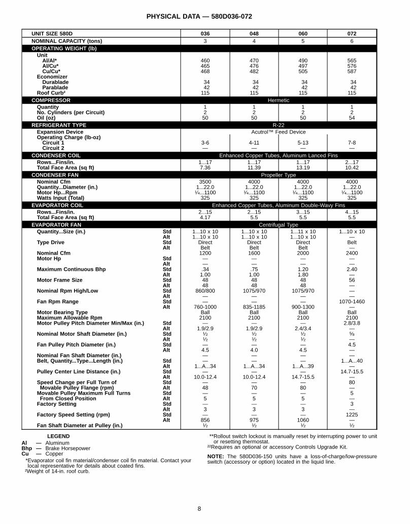
PHYSICAL DATA — 580D036-072
UNIT SIZE 580D 036 048 060 072NOMINAL CAPACITY (tons) 3 4 5 6OPERATING WEIGHT (lb)UnitAl/Al* 460 470 490 565Al/Cu* 465 476 497 576Cu/Cu* 468 482 505 587
EconomizerDurablade 34 34 34 34Parablade 42 42 42 42
Roof Curb† 115 115 115 115COMPRESSOR HermeticQuantity 1 1 1 1No. Cylinders (per Circuit) 2 2 2 2Oil (oz) 50 50 50 54
REFRIGERANT TYPE R-22Expansion Device Acutrol™ Feed DeviceOperating Charge (lb-oz)Circuit 1 3-6 4-11 5-13 7-8Circuit 2 — — — —
CONDENSER COIL Enhanced Copper Tubes, Aluminum Lanced FinsRows...Fins/in. 1...17 1...17 1...17 2...17Total Face Area (sq ft) 7.36 11.39 13.19 10.42
CONDENSER FAN Propeller TypeNominal Cfm 3500 4000 4000 4000Quantity...Diameter (in.) 1...22.0 1...22.0 1...22.0 1...22.0Motor Hp...Rpm 1⁄4...1100 1⁄4...1100 1⁄4...1100 1⁄4...1100Watts Input (Total) 325 325 325 325
EVAPORATOR COIL Enhanced Copper Tubes, Aluminum Double-Wavy FinsRows...Fins/in. 2...15 2...15 3...15 4...15Total Face Area (sq ft) 4.17 5.5 5.5 5.5
EVAPORATOR FAN Centrifugal TypeQuantity...Size (in.) Std 1...10 x 10 1...10 x 10 1...11 x 10 1...10 x 10
Alt 1...10 x 10 1...10 x 10 1...10 x 10 —Type Drive Std Direct Direct Direct Belt
Alt Belt Belt Belt —Nominal Cfm 1200 1600 2000 2400Motor Hp Std — — — —
Alt — — — —Maximum Continuous Bhp Std .34 .75 1.20 2.40
Alt 1.00 1.00 1.80 —Motor Frame Size Std 48 48 48 56
Alt 48 48 48 —Nominal Rpm High/Low Std 860/800 1075/970 1075/970 —
Alt — — — —Fan Rpm Range Std — — — 1070-1460
Alt 760-1000 835-1185 900-1300 —Motor Bearing Type Ball Ball Ball BallMaximum Allowable Rpm 2100 2100 2100 2100Motor Pulley Pitch Diameter Min/Max (in.) Std — — — 2.8/3.8
Alt 1.9/2.9 1.9/2.9 2.4/3.4 —Nominal Motor Shaft Diameter (in.) Std 1⁄2 1⁄2 1⁄2 5⁄8
Alt 1⁄2 1⁄2 1⁄2 —Fan Pulley Pitch Diameter (in.) Std — — — 4.5
Alt 4.5 4.0 4.5 —Nominal Fan Shaft Diameter (in.) — — — —Belt, Quantity...Type...Length (in.) Std — — — 1...A...40
Alt 1...A...34 1...A...34 1...A...39 —Pulley Center Line Distance (in.) Std — — — 14.7-15.5
Alt 10.0-12.4 10.0-12.4 14.7-15.5 —Speed Change per Full Turn of Std — — — 80Movable Pulley Flange (rpm) Alt 48 70 80 —Movable Pulley Maximum Full Turns Std — — — 5From Closed Position Alt 5 5 5 —Factory Setting Std — — — 3
Alt 3 3 3 —Factory Speed Setting (rpm) Std — — — 1225
Alt 856 975 1060 —Fan Shaft Diameter at Pulley (in.) 1⁄2 1⁄2 1⁄2 1⁄2
LEGENDAl — AluminumBhp — Brake HorsepowerCu — Copper*Evaporator coil fin material/condenser coil fin material. Contact yourlocal representative for details about coated fins.†Weight of 14-in. roof curb.
**Rollout switch lockout is manually reset by interrupting power to unitor resetting thermostat.
††Requires an optional or accessory Controls Upgrade Kit.
NOTE: The 580D036-150 units have a loss-of-charge/low-pressureswitch (accessory or option) located in the liquid line.
8
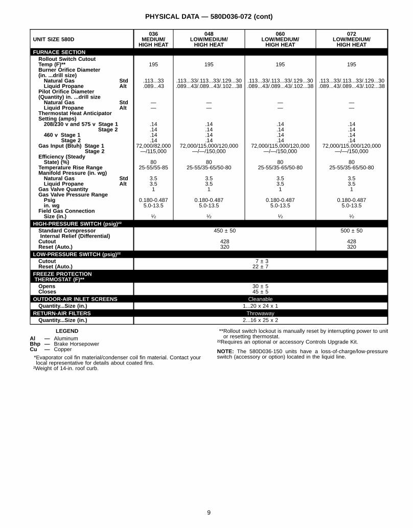
PHYSICAL DATA — 580D036-072 (cont)
UNIT SIZE 580D036
MEDIUM/HIGH HEAT
048LOW/MEDIUM/HIGH HEAT
060LOW/MEDIUM/HIGH HEAT
072LOW/MEDIUM/HIGH HEAT
FURNACE SECTIONRollout Switch CutoutTemp (F)** 195 195 195 195Burner Orifice Diameter(in. ...drill size)Natural Gas Std .113...33 .113...33/.113...33/.129...30 .113...33/.113...33/.129...30 .113...33/.113...33/.129...30Liquid Propane Alt .089...43 .089...43/.089...43/.102...38 .089...43/.089...43/.102...38 .089...43/.089...43/.102...38
Pilot Orifice Diameter(Quantity) in. ...drill sizeNatural Gas Std — — — —Liquid Propane Alt — — — —
Thermostat Heat AnticipatorSetting (amps)208/230 v and 575 v Stage 1 .14 .14 .14 .14
Stage 2 .14 .14 .14 .14460 v Stage 1 .14 .14 .14 .14
Stage 2 .14 .14 .14 .14Gas Input (Btuh) Stage 1 72,000/82,000 72,000/115,000/120,000 72,000/115,000/120,000 72,000/115,000/120,000
Stage 2 —/115,000 —/—/150,000 —/—/150,000 —/—/150,000Efficiency (SteadyState) (%) 80 80 80 80
Temperature Rise Range 25-55/55-85 25-55/35-65/50-80 25-55/35-65/50-80 25-55/35-65/50-80Manifold Pressure (in. wg)Natural Gas Std 3.5 3.5 3.5 3.5Liquid Propane Alt 3.5 3.5 3.5 3.5
Gas Valve Quantity 1 1 1 1Gas Valve Pressure RangePsig 0.180-0.487 0.180-0.487 0.180-0.487 0.180-0.487in. wg 5.0-13.5 5.0-13.5 5.0-13.5 5.0-13.5
Field Gas ConnectionSize (in.) 1⁄2 1⁄2 1⁄2 1⁄2
HIGH-PRESSURE SWITCH (psig)††Standard CompressorInternal Relief (Differential)
450 ± 50 500 ± 50
Cutout 428 428Reset (Auto.) 320 320
LOW-PRESSURE SWITCH (psig)††Cutout 7 ± 3Reset (Auto.) 22 ± 7
FREEZE PROTECTIONTHERMOSTAT (F)**Opens 30 ± 5Closes 45 ± 5
OUTDOOR-AIR INLET SCREENS CleanableQuantity...Size (in.) 1...20 x 24 x 1
RETURN-AIR FILTERS ThrowawayQuantity...Size (in.) 2...16 x 25 x 2
LEGENDAl — AluminumBhp — Brake HorsepowerCu — Copper
*Evaporator coil fin material/condenser coil fin material. Contact yourlocal representative for details about coated fins.†Weight of 14-in. roof curb.
**Rollout switch lockout is manually reset by interrupting power to unitor resetting thermostat.
††Requires an optional or accessory Controls Upgrade Kit.
NOTE: The 580D036-150 units have a loss-of-charge/low-pressureswitch (accessory or option) located in the liquid line.
9
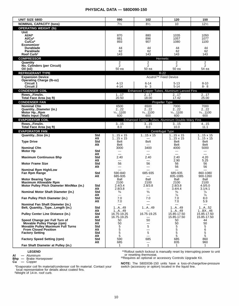
PHYSICAL DATA — 580D090-150
UNIT SIZE 580D 090 102 120 150NOMINAL CAPACITY (tons) 71⁄2 81⁄2 10 121⁄2OPERATING WEIGHT (lb)UnitAl/Al* 870 880 1035 1050Al/Cu* 881 896 1057 1077Cu/Cu* 893 907 1080 1100
EconomizerDurablade 44 44 44 44Parablade 62 62 62 62
Roof Curb† 143 143 143 143COMPRESSOR HermeticQuantity 2 2 2 2No. Cylinders (per Circuit) 2 2 2 2Oil (oz) 50 ea 50 ea 50 ea 54 ea
REFRIGERANT TYPE R-22Expansion Device Acutrol™ Feed DeviceOperating Charge (lb-oz)Circuit 1 4-13 6-14 5-13 8-10Circuit 2 4-14 6- 3 5-14 8- 8
CONDENSER COIL Enhanced Copper Tubes, Aluminum Lanced FinsRows...Fins/in. 1...17 2...17 2...17 2...17Total Face Area (sq ft) 20.50 18.00 17.42 25.00
CONDENSER FAN Propeller TypeNominal Cfm 6500 6500 7000 7000Quantity...Diameter (in.) 2...22 2...22 2...22 2...22Motor Hp...Rpm 1⁄4...1100 1⁄4...1100 1⁄4...1100 1⁄4...1100Watts Input (Total) 600 600 600 600
EVAPORATOR COIL Enhanced Copper Tubes, Aluminum Double-Wavy FinsRows...Fins/in. 3...15 3...15 3...15 4...15Total Face Area (sq ft) 8.0 8.0 10.0 11.1
EVAPORATOR FAN Centrifugal TypeQuantity...Size (in.) Std 1...15 x 15 1...15 x 15 1...15 x 15 1...15 x 15
Alt 1...15 x 15 — 1...15 x 15 1...15 x 15Type Drive Std Belt Belt Belt Belt
Alt Belt — Belt BeltNominal Cfm 3000 3400 4000 5000Motor Hp Std — — — —
Alt — — — —Maximum Continuous Bhp Std 2.40 2.40 2.40 4.20
Alt — — 2.90 5.25Motor Frame Size Std 56 56 56 56
Alt — — 56 56Nominal Rpm High/Low — — — —Fan Rpm Range Std 590-840 685-935 685-935 860-1080
Alt 685-935 — 835-1085 900-1260Motor Bearing Type Ball Ball Ball BallMaximum Allowable Rpm 2100 2100 2100 2100Motor Pulley Pitch Diameter Min/Max (in.) Std 2.4/3.4 2.8/3.8 2.8/3.8 4.0/5.0
Alt 2.8/3.8 — 3.4/4.4 3.1/4.1Nominal Motor Shaft Diameter (in.) Std 5⁄8 5⁄8 5⁄8 7⁄8
Alt — — 7⁄8 7⁄8Fan Pulley Pitch Diameter (in.) Std 7.0 7.0 7.0 8.0
Alt 7.0 — 7.0 5.9Nominal Fan Shaft Diameter (in.) — — — —Belt, Quantity...Type...Length (in.) Std 1...A...49 1...A...49 1...A...49 1...A...52
Alt 1...A...49 — 1...A...49 1...BX...46Pulley Center Line Distance (in.) Std 16.75-19.25 16.75-19.25 15.85-17.50 15.85-17.50
Alt 16.75-19.25 — 15.85-17.50 15.85-17.50Speed Change per Full Turn of Std 50 50 50 44Movable Pulley Flange (rpm) Alt 50 — 50 50Movable Pulley Maximum Full Turns Std 5 5 5 5From Closed Position Alt 5 — 5 6Factory Setting Std 5 5 5 5
Alt 5 — 5 5Factory Speed Setting (rpm) Std 590 685 685 860
Alt 685 — 835 960Fan Shaft Diameter at Pulley (in.) 1 1 1 1
LEGENDAl — AluminumBhp — Brake HorsepowerCu — Copper
*Evaporator coil fin material/condenser coil fin material. Contact yourlocal representative for details about coated fins.†Weight of 14-in. roof curb.
**Rollout switch lockout is manually reset by interrupting power to unitor resetting thermostat.
††Requires an optional or accessory Controls Upgrade Kit.
NOTE: The 580D036-150 units have a loss-of-charge/low-pressureswitch (accessory or option) located in the liquid line.
10
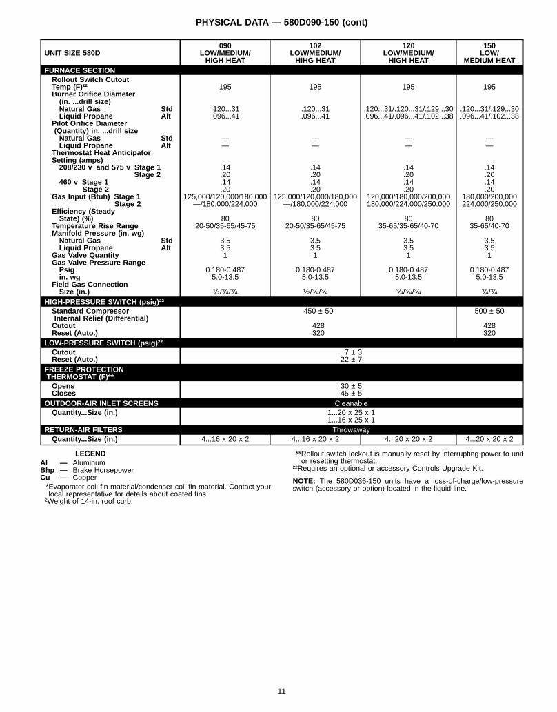
PHYSICAL DATA — 580D090-150 (cont)
UNIT SIZE 580D090
LOW/MEDIUM/HIGH HEAT
102LOW/MEDIUM/HIHG HEAT
120LOW/MEDIUM/HIGH HEAT
150LOW/
MEDIUM HEATFURNACE SECTIONRollout Switch CutoutTemp (F)†† 195 195 195 195Burner Orifice Diameter(in. ...drill size)Natural Gas Std .120...31 .120...31 .120...31/.120...31/.129...30 .120...31/.129...30Liquid Propane Alt .096...41 .096...41 .096...41/.096...41/.102...38 .096...41/.102...38
Pilot Orifice Diameter(Quantity) in. ...drill sizeNatural Gas Std — — — —Liquid Propane Alt — — — —
Thermostat Heat AnticipatorSetting (amps)208/230 v and 575 v Stage 1 .14 .14 .14 .14
Stage 2 .20 .20 .20 .20460 v Stage 1 .14 .14 .14 .14
Stage 2 .20 .20 .20 .20Gas Input (Btuh) Stage 1 125,000/120,000/180,000 125,000/120,000/180,000 120,000/180,000/200,000 180,000/200,000
Stage 2 —/180,000/224,000 —/180,000/224,000 180,000/224,000/250,000 224,000/250,000Efficiency (SteadyState) (%) 80 80 80 80
Temperature Rise Range 20-50/35-65/45-75 20-50/35-65/45-75 35-65/35-65/40-70 35-65/40-70Manifold Pressure (in. wg)Natural Gas Std 3.5 3.5 3.5 3.5Liquid Propane Alt 3.5 3.5 3.5 3.5
Gas Valve Quantity 1 1 1 1Gas Valve Pressure RangePsig 0.180-0.487 0.180-0.487 0.180-0.487 0.180-0.487in. wg 5.0-13.5 5.0-13.5 5.0-13.5 5.0-13.5
Field Gas ConnectionSize (in.) 1⁄2/3⁄4/3⁄4 1⁄2/3⁄4/3⁄4 3⁄4/3⁄4/3⁄4 3⁄4/3⁄4
HIGH-PRESSURE SWITCH (psig)††Standard CompressorInternal Relief (Differential)
450 ± 50 500 ± 50
Cutout 428 428Reset (Auto.) 320 320
LOW-PRESSURE SWITCH (psig)††Cutout 7 ± 3Reset (Auto.) 22 ± 7
FREEZE PROTECTIONTHERMOSTAT (F)**Opens 30 ± 5Closes 45 ± 5
OUTDOOR-AIR INLET SCREENS CleanableQuantity...Size (in.) 1...20 x 25 x 1
1...16 x 25 x 1RETURN-AIR FILTERS ThrowawayQuantity...Size (in.) 4...16 x 20 x 2 4...16 x 20 x 2 4...20 x 20 x 2 4...20 x 20 x 2
LEGENDAl — AluminumBhp — Brake HorsepowerCu — Copper*Evaporator coil fin material/condenser coil fin material. Contact yourlocal representative for details about coated fins.†Weight of 14-in. roof curb.
**Rollout switch lockout is manually reset by interrupting power to unitor resetting thermostat.
††Requires an optional or accessory Controls Upgrade Kit.
NOTE: The 580D036-150 units have a loss-of-charge/low-pressureswitch (accessory or option) located in the liquid line.
11
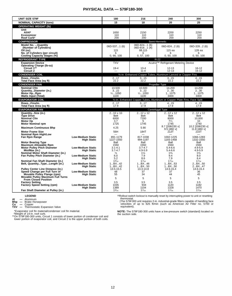
PHYSICAL DATA — 579F180-300
UNIT SIZE 579F 180 216 240 300NOMINAL CAPACITY (tons) 15 18 20 25OPERATING WEIGHT (lb)UnitAl/Al* 1650 2150 2200 2250
Economizer 110 110 110 110Roof Curb† 200 200 200 200
COMPRESSOR Semi-HermeticModel No. ...Quantity(Number of Cylinders) 06D-537...1 (6) 06D-824...1 (6)
06D-818...1 (4) 06D-824...2 (6) 06D-328...2 (6)
Oil (oz) 115 88,115 115 ea 128 eaNo. of Cylinders (per circuit) 6 6 6 6Cooling Capacity Stages (%) 0, 66, 100 0, 57, 100 0, 50, 100 0, 50, 100
REFRIGERANT TYPE R-22Expansion Device TXV Acutrol™ Refrigerant Metering DeviceOperating Charge (lb-oz)Circuit 1** 19-4 13-4 12-13 16-12Circuit 2 — 11-0 12-13 15-12
CONDENSER COIL 3⁄8-in. Enhanced Copper Tubes, Aluminum Lanced or Copper FinsRows...Fins/in. 2...17 3...15 3...15 4...15Total Face Area (sq ft) 22.2 22.2 22.2 22.2
CONDENSER FAN Propeller TypeNominal Cfm 10,500 10,500 14,200 14,200Quantity...Diameter (in.) 3...22 3...22 2...30 2...30Motor Hp...Rpm 1⁄2...1050 1⁄2...1050 1...1075 1...1075Watts Input (Total) 1100 1100 3400 3400
EVAPORATOR COIL 3⁄8-in. Enhanced Copper Tubes, Aluminum or Copper Plate Fins, Face SplitRows...Fins/in. 2...17 3...17 4...15 4...15Total Face Area (sq ft) 17.9 17.9 17.9 17.9
EVAPORATOR FAN Centrifugal TypeQuantity...Size (in.) 2...10 x 10 2...12 x 12 2...12 x 12 2...12 x 12Type Drive Belt Belt Belt BeltNominal Cfm 6000 7200 8000 10,000Motor Hp 3.7 5 71⁄2 10Motor Nominal rpm 1725 1745 1745 1740
Maximum Continuous Bhp 4.25 5.90 8.7 [208/230 v]9.5 [460 v]
10.2 [208/230 v]11.8 [460 v]
Motor Frame Size 56H 184T 213T 215TNominal Rpm High/Low — — — —Fan Rpm Range Low-Medium Static 891-1179 817-1038 1002-1225 1066-1283
High Static 1227-1550 994-1197 1193-1458 1332-1550Motor Bearing Type Ball Ball Ball BallMaximum Allowable Rpm 1550 1550 1550 1550Motor Pulley Pitch Diameter Low-Medium Static 3.1-4.1 3.7-4.7 5.4-6.6 4.9-5.9Min/Max (in.) High Static 3.7-4.7 4.9-5.9 5.4-6.6 4.9-5.9
Nominal Motor Shaft Diameter (in.) 7⁄8 11⁄8 13⁄8 13⁄8Fan Pulley Pitch Diameter (in.) Low-Medium Static 6.0 7.9 9.4 8.0
High Static 5.2 8.6 7.9 6.4Nominal Fan Shaft Diameter (in.) 13⁄16 17⁄16 17⁄16 17⁄16Belt, Quantity...Type...Length (in.) Low-Medium Static 1...BX...42 1...BX...46 1...BX...53 2...BX...50
High Static 1...BX...42 1...BX...50 1...BX...50 2...BX...47Pulley Center Line Distance (in.) 13.5-15.5 13.3-14.8 14.6-15.4 14.6-15.4Speed Change per Full Turn of Low-Medium Static 48 37 37 36Movable Pulley Flange (rpm) High Static 55 34 44 45
Movable Pulley Maximum Full TurnsFrom Closed Position 5 5 5 5
Factory Setting 3.5 3.5 3.5 3.5Factory Speed Setting (rpm) Low-Medium Static 1035 934 1120 1182
High Static 1389 1104 1328 1470Fan Shaft Diameter at Pulley (in.) 13⁄16 17⁄16 17⁄16 17⁄16
LEGENDAl — AluminumBhp — Brake HorsepowerCu — CopperTXV — Thermostatic Expansion Valve
*Evaporator coil fin material/condenser coil fin material.†Weight of 14-in. roof curb.**On 579F180-300 units, Circuit 1 consists of lower portion of condenser coil andlower portion of evaporator coil, and Circuit 2 is the upper portion of both coils.
††Rollout switch lockout is manually reset by interrupting power to unit or resettingthermostat.\The 579F300 unit requires 2-in. industrial-grade filters capable of handling facevelocities of up to 625 ft/min (such as American Air Filter no. 5700 orequivalent).
NOTE: The 579F180-300 units have a low-pressure switch (standard) located onthe suction side.
12
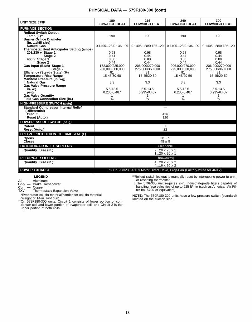
PHYSICAL DATA — 579F180-300 (cont)
UNIT SIZE 579F 180LOW/HIGH HEAT
216LOW/HIGH HEAT
240LOW/HIGH HEAT
300LOW/HIGH HEAT
FURNACE SECTIONRollout Switch CutoutTemp (F)†† 190 190 190 190
Burner Orifice Diameter(in. ...drill size)Natural Gas 0.1405...28/0.136...29 0.1405...28/0.136...29 0.1405...28/0.136...29 0.1405...28/0.136...29
Thermostat Heat Anticipator Setting (amps)208/230 v Stage 1 0.98 0.98 0.98 0.98
Stage 2 0.44 0.44 0.44 0.44460 v Stage 1 0.80 0.80 0.80 0.80
Stage 2 0.44 0.44 0.44 0.44Gas Input (Btuh) Stage 1 172,000/225,000 206,000/270,000 206,000/270,000 206,000/270,000
Stage 2 230,000/300,000 275,000/360,000 275,000/360,000 275,000/360,000Efficiency (Steady State) (%) 81 81 81 81Temperature Rise Range 15-45/30-60 15-45/20-50 15-45/20-50 15-45/20-50Manifold Pressure (in. wg)Natural Gas 3.3 3.3 3.3 3.3
Gas Valve Pressure Rangein. wg 5.5-13.5 5.5-13.5 5.5-13.5 5.5-13.5psig 0.235-0.487 0.235-0.487 0.235-0.487 0.235-0.487
Gas Valve Quantity 1 1 1 1Field Gas Connection Size (in.) 3⁄4 3⁄4 3⁄4 3⁄4
HIGH-PRESSURE SWITCH (psig)Standard Compressor Internal Relief(Differential)
—
Cutout 426Reset (Auto.) 320
LOW-PRESSURE SWITCH (psig)Cutout 7Reset (Auto.) 22
FREEZE PROTECTION THERMOSTAT (F)Opens 30 ± 5Closes 45 ± 5
OUTDOOR-AIR INLET SCREENS CleanableQuantity...Size (in.) 2...20 x 25 x 1
1...20 x 20 x 1RETURN-AIR FILTERS Throwaway \
Quantity...Size (in.) 4...20 x 20 x 24...16 x 20 x 2
POWER EXHAUST 1⁄2 Hp 208/230-460 v Motor Direct Drive, Prop-Fan (Factory-wired for 460 v)
LEGENDAl — AluminumBhp — Brake HorsepowerCu — CopperTXV — Thermostatic Expansion Valve*Evaporator coil fin material/condenser coil fin material.†Weight of 14-in. roof curb.
**On 579F180-300 units, Circuit 1 consists of lower portion of con-denser coil and lower portion of evaporator coil, and Circuit 2 is theupper portion of both coils.
††Rollout switch lockout is manually reset by interrupting power to unitor resetting thermostat.
\ The 579F300 unit requires 2-in. industrial-grade filters capable ofhandling face velocities of up to 625 ft/min (such as American Air Fil-ter no. 5700 or equivalent).
NOTE: The 579F180-300 units have a low-pressure switch (standard)located on the suction side.
13
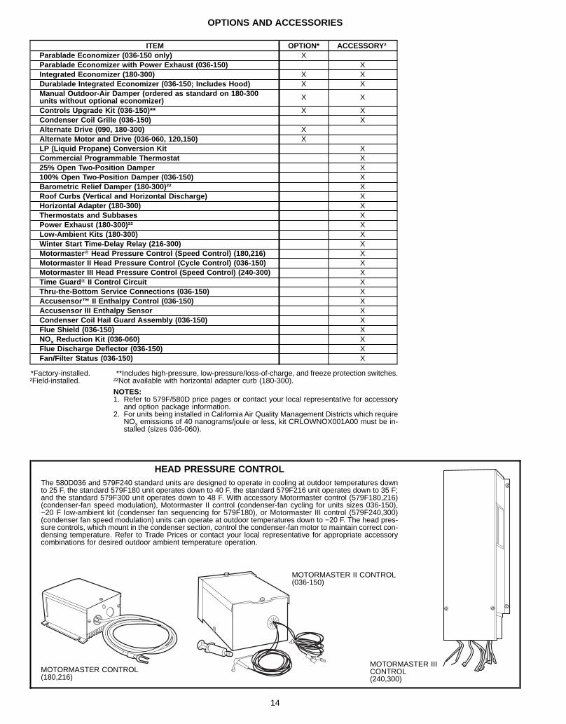
OPTIONS AND ACCESSORIES
ITEM OPTION* ACCESSORY†Parablade Economizer (036-150 only) XParablade Economizer with Power Exhaust (036-150) XIntegrated Economizer (180-300) X XDurablade Integrated Economizer (036-150; Includes Hood) X XManual Outdoor-Air Damper (ordered as standard on 180-300units without optional economizer) X X
Controls Upgrade Kit (036-150)** X XCondenser Coil Grille (036-150) XAlternate Drive (090, 180-300) XAlternate Motor and Drive (036-060, 120,150) XLP (Liquid Propane) Conversion Kit XCommercial Programmable Thermostat X25% Open Two-Position Damper X100% Open Two-Position Damper (036-150) XBarometric Relief Damper (180-300)†† XRoof Curbs (Vertical and Horizontal Discharge) XHorizontal Adapter (180-300) XThermostats and Subbases XPower Exhaust (180-300)†† XLow-Ambient Kits (180-300) XWinter Start Time-Delay Relay (216-300) XMotormaster T Head Pressure Control (Speed Control) (180,216) XMotormaster II Head Pressure Control (Cycle Control) (036-150) XMotormaster III Head Pressure Control (Speed Control) (240-300) XTime Guard T II Control Circuit XThru-the-Bottom Service Connections (036-150) XAccusensor™ II Enthalpy Control (036-150) XAccusensor III Enthalpy Sensor XCondenser Coil Hail Guard Assembly (036-150) XFlue Shield (036-150) XNOx Reduction Kit (036-060) XFlue Discharge Deflector (036-150) XFan/Filter Status (036-150) X
*Factory-installed.†Field-installed.
**Includes high-pressure, low-pressure/loss-of-charge, and freeze protection switches.††Not available with horizontal adapter curb (180-300).
NOTES:1. Refer to 579F/580D price pages or contact your local representative for accessory
and option package information.2. For units being installed in California Air Quality Management Districts which require
NOx emissions of 40 nanograms/joule or less, kit CRLOWNOX001A00 must be in-stalled (sizes 036-060).
HEAD PRESSURE CONTROLThe 580D036 and 579F240 standard units are designed to operate in cooling at outdoor temperatures downto 25 F, the standard 579F180 unit operates down to 40 F, the standard 579F216 unit operates down to 35 F;and the standard 579F300 unit operates down to 48 F. With accessory Motormaster control (579F180,216)(condenser-fan speed modulation), Motormaster II control (condenser-fan cycling for units sizes 036-150),−20 F low-ambient kit (condenser fan sequencing for 579F180), or Motormaster III control (579F240,300)(condenser fan speed modulation) units can operate at outdoor temperatures down to −20 F. The head pres-sure controls, which mount in the condenser section, control the condenser-fan motor to maintain correct con-densing temperature. Refer to Trade Prices or contact your local representative for appropriate accessorycombinations for desired outdoor ambient temperature operation.
MOTORMASTER CONTROL(180,216)
MOTORMASTER IIICONTROL(240,300)
MOTORMASTER II CONTROL(036-150)
14
OPTIONS AND ACCESSORIES (cont)
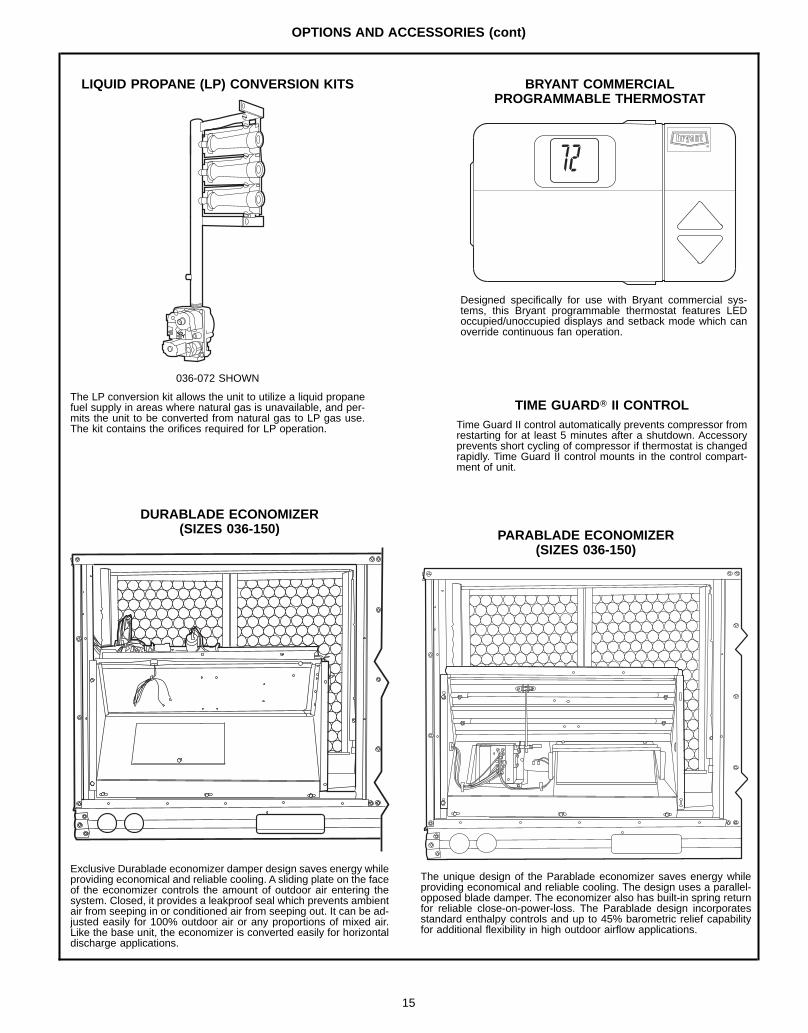
LIQUID PROPANE (LP) CONVERSION KITS
DURABLADE ECONOMIZER(SIZES 036-150)
Exclusive Durablade economizer damper design saves energy whileproviding economical and reliable cooling. A sliding plate on the faceof the economizer controls the amount of outdoor air entering thesystem. Closed, it provides a leakproof seal which prevents ambientair from seeping in or conditioned air from seeping out. It can be ad-justed easily for 100% outdoor air or any proportions of mixed air.Like the base unit, the economizer is converted easily for horizontaldischarge applications.
Designed specifically for use with Bryant commercial sys-tems, this Bryant programmable thermostat features LEDoccupied/unoccupied displays and setback mode which canoverride continuous fan operation.
TIME GUARDT II CONTROLTime Guard II control automatically prevents compressor fromrestarting for at least 5 minutes after a shutdown. Accessoryprevents short cycling of compressor if thermostat is changedrapidly. Time Guard II control mounts in the control compart-ment of unit.
PARABLADE ECONOMIZER(SIZES 036-150)
The unique design of the Parablade economizer saves energy whileproviding economical and reliable cooling. The design uses a parallel-opposed blade damper. The economizer also has built-in spring returnfor reliable close-on-power-loss. The Parablade design incorporatesstandard enthalpy controls and up to 45% barometric relief capabilityfor additional flexibility in high outdoor airflow applications.
036-072 SHOWN
The LP conversion kit allows the unit to utilize a liquid propanefuel supply in areas where natural gas is unavailable, and per-mits the unit to be converted from natural gas to LP gas use.The kit contains the orifices required for LP operation.
BRYANT COMMERCIALPROGRAMMABLE THERMOSTAT
15
OPTIONS AND ACCESSORIES (cont)
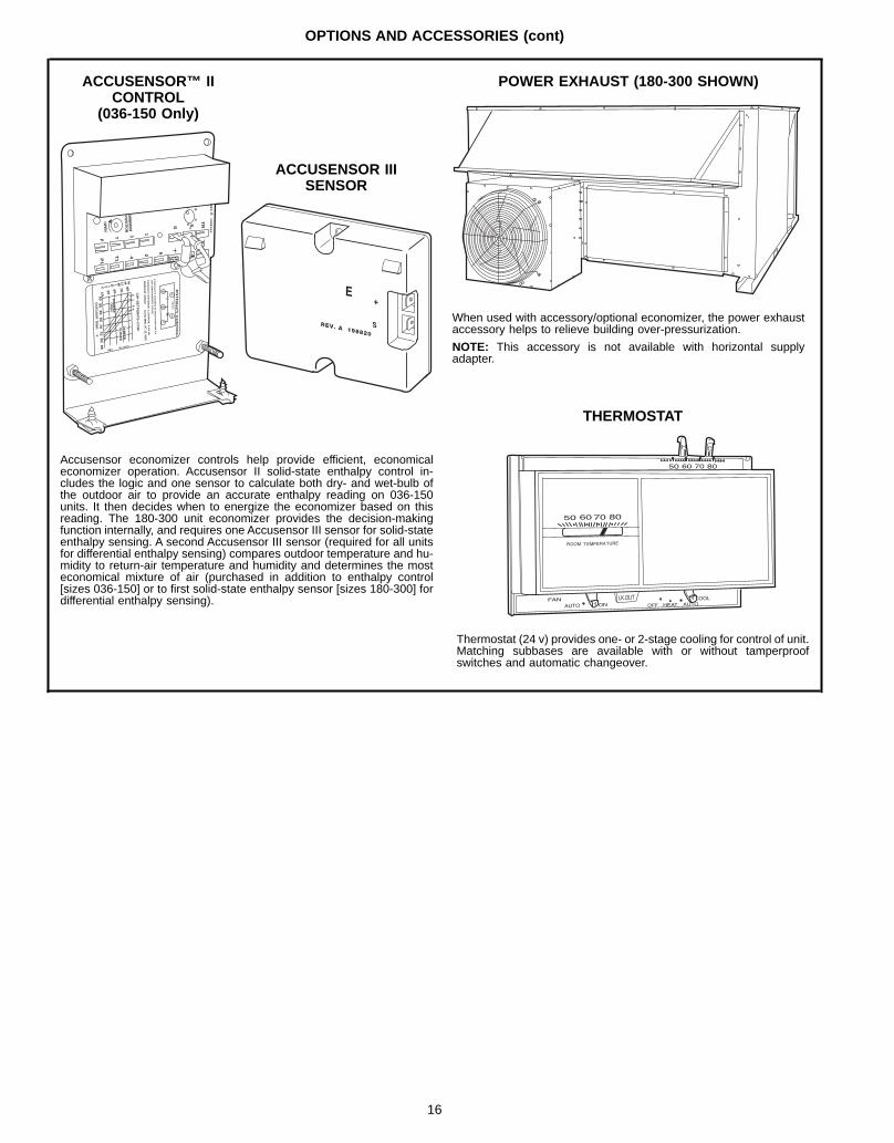
ACCUSENSOR™ IICONTROL
(036-150 Only)
MIN
IMU
MP
OS
ITION
OP
EN
3 1
TPP
1
T1
4 2 5
S SO
D
C
TR
B
RE
V. B
19
88
18
A
%HUM ID ITY 9070603010 D
CB
A60
65
70
75
55
50
85
80
DA
MP
ER
DA
MP
ER
CLO
SE
D
OP
EN
OU
TD
OO
R T
EM
P.°F
REV.97-3672
CW
–S
ET
PO
INT
S–
CC
W
CO
NTA
CT
S S
HO
WN
IN H
IGH
EN
TH
AL
PY
RU
SH
AT
24
VA
C3
mA
MIN
. AT
11 V
DC
CO
NTA
CT
RA
TIN
GS
: 1.5
A R
UN
, 3.5
A IN
OR
UN
PO
WE
RE
D S
TA
TE
12
3
TR
TR
12
4V
AC
EN
TH
AL
PY
CO
NT
RO
L
ACCUSENSOR IIISENSOR
+
Accusensor economizer controls help provide efficient, economicaleconomizer operation. Accusensor II solid-state enthalpy control in-cludes the logic and one sensor to calculate both dry- and wet-bulb ofthe outdoor air to provide an accurate enthalpy reading on 036-150units. It then decides when to energize the economizer based on thisreading. The 180-300 unit economizer provides the decision-makingfunction internally, and requires one Accusensor III sensor for solid-stateenthalpy sensing. A second Accusensor III sensor (required for all unitsfor differential enthalpy sensing) compares outdoor temperature and hu-midity to return-air temperature and humidity and determines the mosteconomical mixture of air (purchased in addition to enthalpy control[sizes 036-150] or to first solid-state enthalpy sensor [sizes 180-300] fordifferential enthalpy sensing).
POWER EXHAUST (180-300 SHOWN)
When used with accessory/optional economizer, the power exhaustaccessory helps to relieve building over-pressurization.
NOTE: This accessory is not available with horizontal supplyadapter.
THERMOSTAT
H C
Thermostat (24 v) provides one- or 2-stage cooling for control of unit.Matching subbases are available with or without tamperproofswitches and automatic changeover.
16
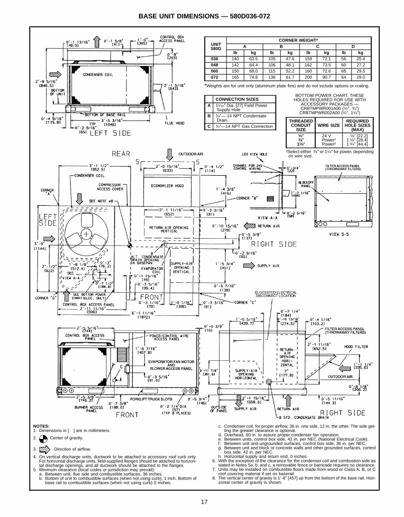
BASE UNIT DIMENSIONS — 580D036-072
UNIT580D
CORNER WEIGHT*A B C D
lb kg lb kg lb kg lb kg036 140 63.5 105 47.6 159 72.1 56 25.4048 142 64.4 106 48.1 162 73.5 60 27.2060 150 68.0 115 52.2 160 72.6 65 29.5072 165 74.8 136 61.7 200 90.7 64 29.0
*Weights are for unit only (aluminum plate fins) and do not include options or crating.
CONNECTION SIZESA 11⁄169 Dia. [27] Field Power
Supply HoleB 3⁄49— 14 NPT Condensate
DrainC 1⁄29—14 NPT Gas Connection
BOTTOM POWER CHART, THESEHOLES REQUIRED FOR USE WITH
ACCESSORY PACKAGES —CRBTMPWR001A00 (1⁄29, 3⁄49)CRBTMPWR002A00 (1⁄29, 11⁄49)
THREADEDCONDUITSIZE
WIRE SIZEREQUIREDHOLE SIZES
(MAX)1⁄2( 24 V 7⁄89 [22.2]3⁄4( Power† 11⁄89 [28.4]11⁄4( Power† 13⁄49 [44.4]
†Select either 3⁄49 or 11⁄49 for power, dependingon wire size.
NOTES:1. Dimensions in [ ] are in millimeters.
2. Center of gravity.
3. Direction of airflow.
4. On vertical discharge units, ductwork to be attached to accessory roof curb only.For horizontal discharge units, field-supplied flanges should be attached to horizon-tal discharge openings, and all ductwork should be attached to the flanges.
5. Minimum clearance (local codes or jurisdiction may prevail):a. Between unit, flue side and combustible surfaces, 36 inches.b. Bottom of unit to combustible surfaces (when not using curb), 1 inch. Bottom of
base rail to combustible surfaces (when not using curb) 0 inches.
c. Condenser coil, for proper airflow, 36 in. one side, 12 in. the other. The side get-ting the greater clearance is optional.
d. Overhead, 60 in. to assure proper condenser fan operation.e. Between units, control box side, 42 in. per NEC (National Electrical Code).f. Between unit and ungrounded surfaces, control box side, 36 in. per NEC.g. Between unit and block or concrete walls and other grounded surfaces, control
box side, 42 in. per NEC.h. Horizontal supply and return end, 0 inches.
6. With the exception of the clearance for the condenser coil and combustion side asstated in Notes 5a, b, and c, a removable fence or barricade requires no clearance.
7. Units may be installed on combustible floors made from wood or Class A, B, or Croof covering material if set on baserail.
8. The vertical center of gravity is 18-69 [457] up from the bottom of the base rail. Hori-zontal center of gravity is shown.
17
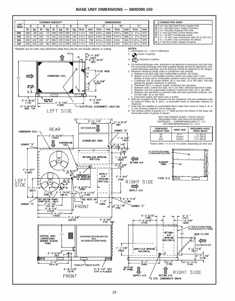
BASE UNIT DIMENSIONS — 580D090-150
UNIT580D
CORNER WEIGHT* DIMENSIONSA B C D ‘‘H’’ ‘‘J’’ ‘‘K’’ ‘‘L’’
lb kg lb kg lb kg lb kg ft-in. mm ft-in. mm ft-in. mm ft-in. mm090 189 86 161 73 239 109 280 127 1-27⁄8 378 3-55⁄16 1050 2-911⁄16 856 2- 27⁄16 672102 191 87 163 74 242 110 284 129 3-37⁄8 1013 3-55⁄16 1050 2-911⁄16 856 2- 27⁄16 672120 225 102 192 87 285 129 333 151 2-57⁄8 759 4-15⁄16 1253 3-03⁄8 924 2-107⁄16 875150 228 103 195 88 289 131 338 153 1-27⁄8 378 4-15⁄16 1253 3-03⁄8 924 2-107⁄16 875
*Weights are for units only (aluminum plate fins) and do not include options or crating.
CONNECTION SIZES
A 13⁄89 Dia [35] Field Power Supply HoleB 21⁄29 Dia [64] Power Supply KnockoutC 13⁄49 Dia [44] Charging Port HoleD 7⁄89 Dia [22] Field Control Wiring HoleE 3⁄49—14 NPT Condensate DrainF 1⁄29—14 NPT Gas Connection 090 125 & 102 125
3⁄49—14 NPT Gas Connection All OthersG 29 Dia [51] Power Supply Knockout
NOTES:1. Dimensions in [ ] are in millimeters.2. Center of gravity.
3. Direction of airflow.
4. On vertical discharge units, ductwork to be attached to accessory roof curb only.For horizontal discharge units field-supplied flanges should be attached to hori-zontal discharge openings, and all ductwork should be attached to the flanges.
5. Minimum clearance (local codes or jurisdiction may prevail):a. Between unit (flue side) and combustible surfaces, 48 inches.b. Bottom of unit to combustible surfaces (when not using curb) 1 inch.
Bottom of base rail to combustible surfaces (when not using curb) 0 inches.c. Condenser coil, for proper airflow, 36 in. one side, 12 in. the other. The side
getting the greater clearance is optional.d. Overhead, 60 in. to assure proper condenser fan operation.e. Between units, control box side, 42 in. per NEC (National Electrical Code).f. Between unit and ungrounded surfaces, control box side, 36 in. per NEC.g. Between unit and block or concrete walls and other grounded surfaces, con-
trol box side, 42 in. per NEC.h. Horizontal supply and return end, 0 inches.
6. With the exception of the clearance for the condenser coil and combustion sideas stated in Notes 5a, b, and c, a removable fence or barricade requires noclearance.
7. Units may be installed on combustible floors made from wood or Class A, B, orC roof covering material if set on base rail.
8. The vertical center of gravity is 18-79 [483] up from the bottom of the base rail.Horizontal center of gravity is shown.
BOTTOM POWER CHART, THESE HOLESREQUIRED FOR USE WITH ACCESSORYPACKAGES — CRBTMPWR001A00 (1⁄29, 3⁄49)
OR CRBTMPWR002A00 (1⁄29, 11⁄49)
THREADEDCONDUIT SIZE WIRE SIZE REQUIRED HOLE
SIZES (MAX)1⁄2( 24 V 7⁄89 [22.2]3⁄4( Power† 11⁄89 [28.4]11⁄4( Power† 13⁄49 [44.4]
†Select either 3⁄49 or 11⁄49 for power, depending on wire size.
18
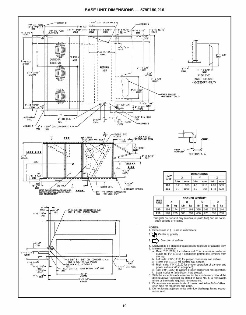
BASE UNIT DIMENSIONS — 579F180,216
UNIT579F
DIMENSIONSX Y Z
ft-in. mm ft-in. mm ft-in. mm180 3-2 965 4-0 1219 1-10 559216 3-7 1090 3-2 965 1- 8 508
UNIT579F
CORNER WEIGHT*A B C D
lb kg Lb kg lb kg lb kg180 384 174 370 168 358 162 538 244216 520 235 508 230 486 220 636 288
*Weights are for unit only (aluminum plate fins) and do not in-clude options or crating.
NOTES:1. Dimensions in ( ) are in millimeters.
2. Center of gravity.
3. Direction of airflow.
4. Ductwork to be attached to accessory roof curb or adapter only.5. Minimum clearance:
a. Rear: 7809 (2134) for coil removal. This dimension can be re-duced to 4809 (1219) if conditions permit coil removal fromthe top.
b. Left side: 4809 (1219) for proper condenser coil airflow.c. Front: 4809 (1219) for control box access.d. Right side: 4809 (1219) for proper operation of damper and
power exhaust (if so equipped).e. Top: 6809 (1829) to assure proper condenser fan operation.f. Local codes or jurisdiction may prevail.
6. With the exception of clearance for the condenser coil and thedamper/power exhaust as stated in Note No. 5, a removablefence or barricade requires no clearance.
7. Dimensions are from outside of corner post. Allow 08-5⁄169 (8) oneach side for top panel drip edge.
8. Do not locate adjacent units with flue discharge facing econo-mizer inlet.
19
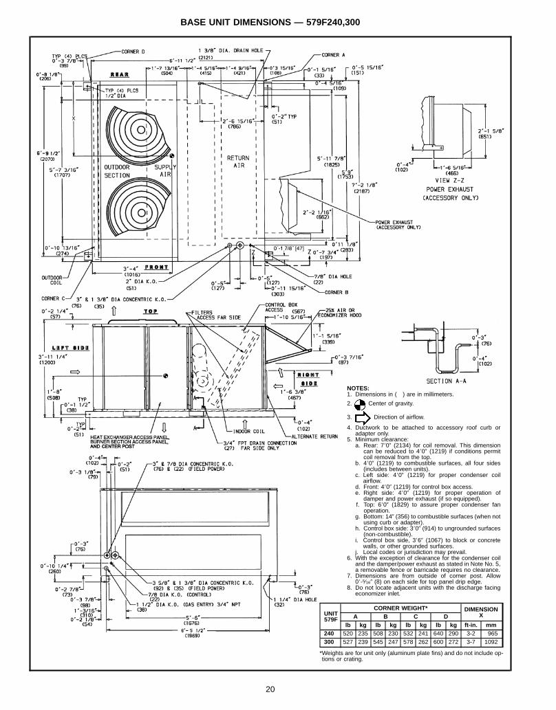
BASE UNIT DIMENSIONS — 579F240,300
UNIT579F
CORNER WEIGHT* DIMENSIONXA B C D
lb kg lb kg lb kg lb kg ft-in. mm240 520 235 508 230 532 241 640 290 3-2 965300 527 239 545 247 578 262 600 272 3-7 1092
*Weights are for unit only (aluminum plate fins) and do not include op-tions or crating.
NOTES:1. Dimensions in ( ) are in millimeters.
2. Center of gravity.
3. Direction of airflow.
4. Ductwork to be attached to accessory roof curb oradapter only.
5. Minimum clearance:a. Rear: 7809 (2134) for coil removal. This dimension
can be reduced to 4809 (1219) if conditions permitcoil removal from the top.
b. 4809 (1219) to combustible surfaces, all four sides(includes between units).
c. Left side: 4809 (1219) for proper condenser coilairflow.
d. Front: 4809 (1219) for control box access.e. Right side: 4809 (1219) for proper operation of
damper and power exhaust (if so equipped).f. Top: 6809 (1829) to assure proper condenser fan
operation.g. Bottom: 149 (356) to combustible surfaces (when not
using curb or adapter).h. Control box side: 3809 (914) to ungrounded surfaces
(non-combustible).i. Control box side, 3869 (1067) to block or concrete
walls, or other grounded surfaces.j. Local codes or jurisdiction may prevail.
6. With the exception of clearance for the condenser coiland the damper/power exhaust as stated in Note No. 5,a removable fence or barricade requires no clearance.
7. Dimensions are from outside of corner post. Allow08-5⁄169 (8) on each side for top panel drip edge.
8. Do not locate adjacent units with the discharge facingeconomizer inlet.
20
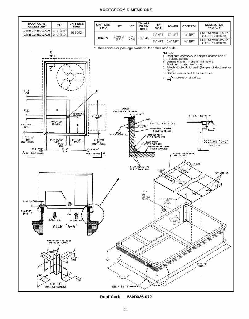
ACCESSORY DIMENSIONS
Roof Curb — 580D036-072
ROOF CURBACCESSORY ‘‘A’’ UNIT SIZE
580DCRRFCURB001A00 18-29 [356]
036-072CRRFCURB002A00 28-09 [610]
NOTES:1. Roof curb accessory is shipped unassembled.2. Insulated panels.3. Dimensions in [ ] are in millimeters.4. Roof curb: galvanized steel.5. Attach ductwork to curb (flanges of duct rest on
curb).6. Service clearance 4 ft on each side.
7. Direction of airflow.
UNIT SIZE580D ‘‘B’’ ‘‘C’’
‘‘D’’ ALTDRAINHOLE
‘‘E’’GAS POWER CONTROL CONNECTOR
PKG ACY
036-072 18-911⁄169[551]
18-49[406] 13⁄49 [45]
3⁄49 NPT 3⁄49 NPT 1⁄29 NPT CRBTMPWR001A00*(Thru-The-Bottom)
3⁄49 NPT 11⁄49 NPT 1⁄29 NPT CRBTMPWR002A00*(Thru-The-Bottom)
*Either connector package available for either roof curb.
21
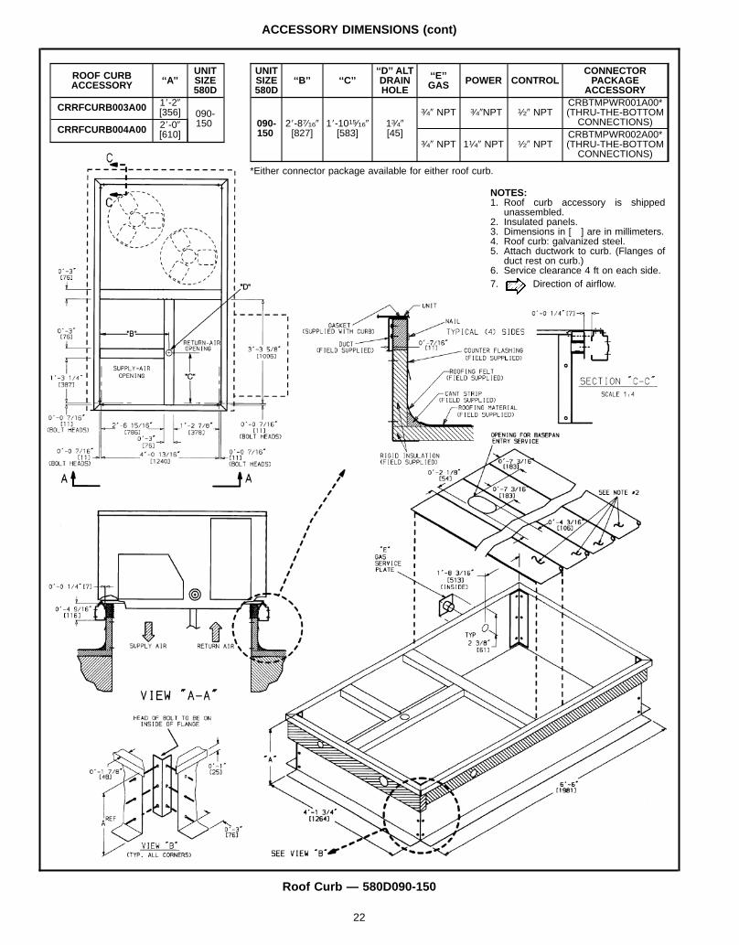
ACCESSORY DIMENSIONS (cont)
Roof Curb — 580D090-150
ROOF CURBACCESSORY ‘‘A’’
UNITSIZE580D
CRRFCURB003A00 18-29[356] 090-
150CRRFCURB004A00 28-09
[610]
UNITSIZE580D
‘‘B’’ ‘‘C’’‘‘D’’ ALTDRAINHOLE
‘‘E’’GAS POWER CONTROL
CONNECTORPACKAGE
ACCESSORY
090-150
28-87⁄169[827]
18-1015⁄169[583]
13⁄49[45]
3⁄49 NPT 3⁄49NPT 1⁄29 NPTCRBTMPWR001A00*(THRU-THE-BOTTOMCONNECTIONS)
3⁄49 NPT 11⁄49 NPT 1⁄29 NPTCRBTMPWR002A00*(THRU-THE-BOTTOMCONNECTIONS)
*Either connector package available for either roof curb.
NOTES:1. Roof curb accessory is shipped
unassembled.2. Insulated panels.3. Dimensions in [ ] are in millimeters.4. Roof curb: galvanized steel.5. Attach ductwork to curb. (Flanges of
duct rest on curb.)6. Service clearance 4 ft on each side.7. Direction of airflow.
22
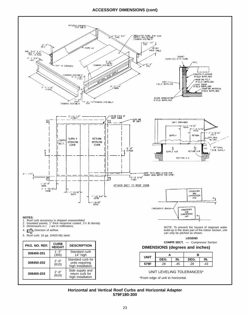
ACCESSORY DIMENSIONS (cont)
Horizontal and Vertical Roof Curbs and Horizontal Adapter579F180-300
NOTE: To prevent the hazard of stagnant waterbuild-up in the drain pan of the indoor section, unitcan only be pitched as shown.
LEGENDCOMPR SECT. — Compressor Section
NOTES:1. Roof curb accessory is shipped unassembled.2. Insulated panels, 19 thick neoprene coated, 11⁄2 lb density.3. Dimensions in ( ) are in millimeters.4. Direction of airflow.
5. Roof curb: 16 ga. (VA03-56) steel.
PKG. NO. REF. CURBHEIGHT DESCRIPTION
308450-201 18-29(355)
Standard curb149 high
308450-202 28-09(610)
Standard curb forunits requiringhigh installation
308450-203 28-09(610)
Side supply andreturn curb forhigh installation
DIMENSIONS (degrees and inches)
UNITA B
DEG. IN. DEG. IN.579F .28 .45 .28 .43
UNIT LEVELING TOLERANCES*
*From edge of unit to horizontal.
23
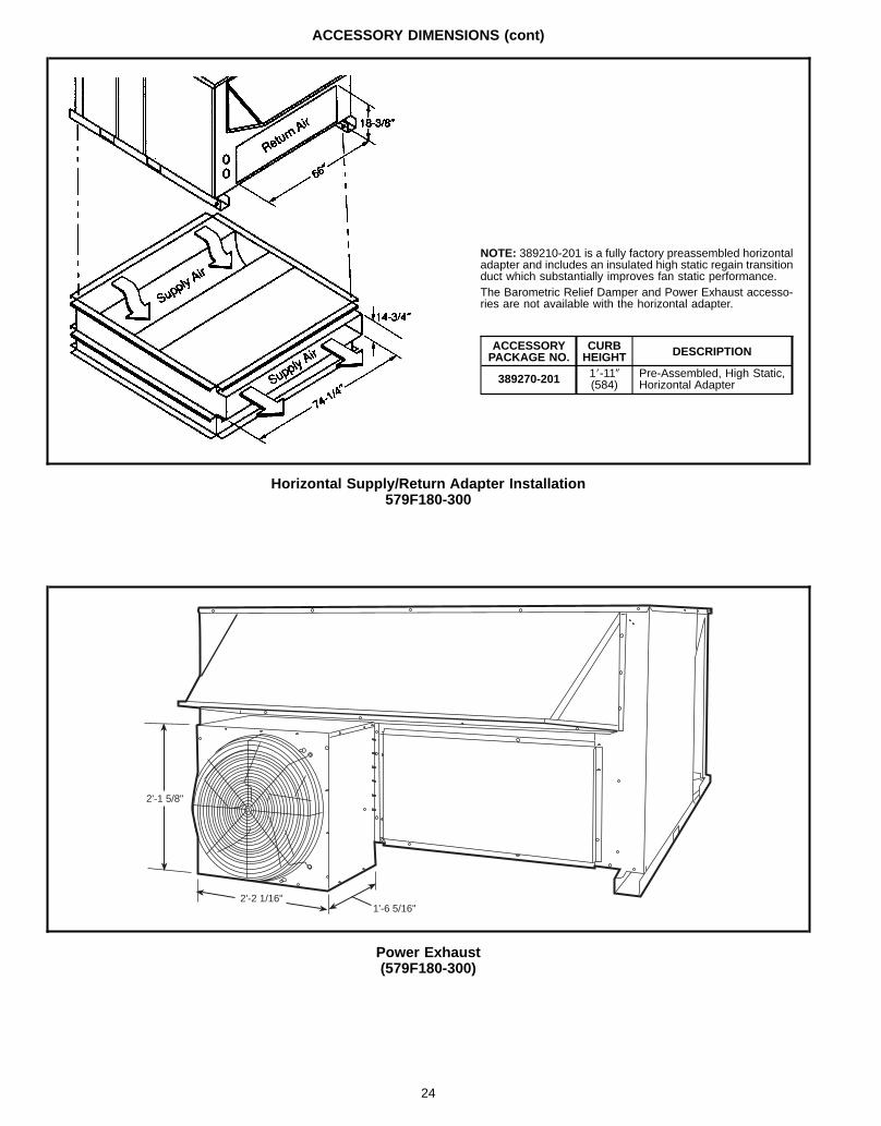
ACCESSORY DIMENSIONS (cont)
Horizontal Supply/Return Adapter Installation579F180-300
NOTE: 389210-201 is a fully factory preassembled horizontaladapter and includes an insulated high static regain transitionduct which substantially improves fan static performance.The Barometric Relief Damper and Power Exhaust accesso-ries are not available with the horizontal adapter.
ACCESSORYPACKAGE NO.
CURBHEIGHT DESCRIPTION
389270-201 18-119(584)
Pre-Assembled, High Static,Horizontal Adapter
Power Exhaust(579F180-300)
2'-1 5/8"
2'-2 1/16"1'-6 5/16"
24
SELECTION PROCEDURE (with 579F180 example)
I DETERMINE COOLING AND HEATING REQUIRE-MENTS AT DESIGN CONDITIONS.Given:Required Cooling Capacity . . . . . . . . . . . . 170,000 BtuhSensible Heat Capacity . . . . . . . . . . . . . . . 114,000 BtuhRequired Heating Capacity . . . . . . . . . . . . 200,000 BtuhCondenser Entering Air Temp . . . . . . . . . 95 F (Summer)Evaporator Entering Air Temp . . . . . . . . . . . . . 80 F edb,
67 F ewbEvaporator Air Quantity . . . . . . . . . . . . . . . . . . 4,500 cfmExternal Static Pressure . . . . . . . . . . . . . . . . . 0.6 in. wgElectrical Characteristics (V-Ph-Hz) . . . . . . . . . 460-3-60Vertical discharge unit with optional economizerrequired.edb — Entering dry-bulbewb — Entering wet-bulb
II SELECT UNIT BASED ON REQUIRED COOLINGCAPACITY.Enter Cooling Capacities table for 579F180 (page 29) atcondenser entering temperature 95 F, evaporator air en-tering at 4,500 cfm and 67 F wb. The 579F180unit will provide a total cooling capacity of 180,000 Btuhand a sensible heating capacity of 120,000 Btuh. For airentering evaporator at temperatures other than 80 F edb,calculate sensible heat capacity correction as required us-ing the formula in the notes following the Cooling Capaci-ties tables.NOTE: Unit ratings are gross capacities and do not includethe effect of evaporator-fan motor heat. To calculate netcapacities, see Step V.
III SELECT HEATING CAPACITY OF UNIT TO PROVIDEDESIGN CONDITION REQUIREMENTS.In the Heating Capacities and Efficiencies table (page 7)note that the 579F180 300 will provide an output capac-ity of 243,000 Btuh, which is adequate for the givenapplication.
IV DETERMINE FAN SPEED AND POWER REQUIRE-MENTS AT DESIGN CONDITIONS.Before entering the Fan Performance tables, cal-culate the total static pressure required based on unit com-ponents. From the given and the Accessory/FIOP StaticPressure table on page 52 find:External static pressure 0.60 in. wgEconomizer static pressure 0.04 in. wg
Total static pressure 0.64 in. wg
Enter the Fan Performance table 579F180 (page 47) at4,500 cfm and 0.64 in. wg external static pressure. By in-terpolation, find that the rpm is 988 and the watts are 1334.
V DETERMINE NET COOLING CAPACITY.Cooling capacities are gross capacities and do not includeindoor (evaporator) fan motor (IFM) heat. Use the watts in-put power to the motor calculated in Section IV above.IFM Watts = 1334Determine net cooling capacity using the followingformula:Net capacity = Gross capacity – IFM heat
= 180,000 Btuh – 1334 WattsBtuh(3.412 )Watts
= 180,000 Btuh – 4552 Btuh= 175,448 Btuh
Net sensible capacity = 120,000 Btuh – 4552 Btuh= 115,448 Btuh
The calculations show that a 579F180 unit with the stand-ard motor and standard low-medium static drive is the cor-rect selection for the given conditions.
25
PERFORMANCE DATA
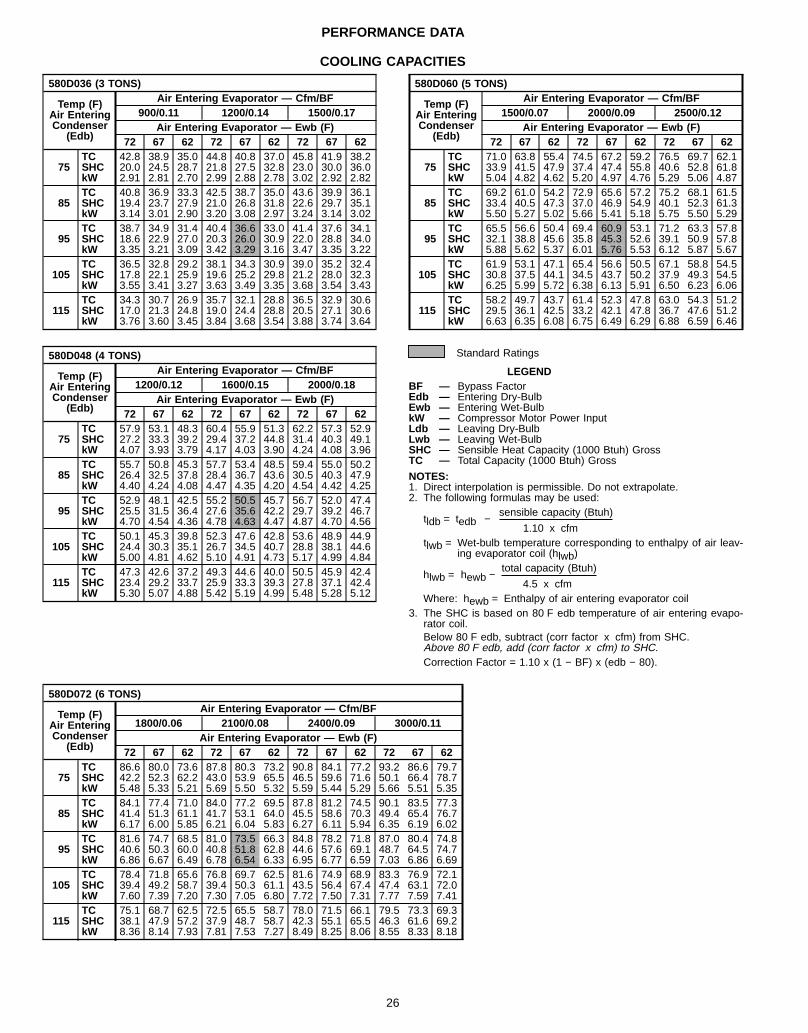
COOLING CAPACITIES
580D036 (3 TONS)
Temp (F)Air EnteringCondenser
(Edb)
Air Entering Evaporator — Cfm/BF900/0.11 1200/0.14 1500/0.17
Air Entering Evaporator — Ewb (F)72 67 62 72 67 62 72 67 62
75TC 42.8 38.9 35.0 44.8 40.8 37.0 45.8 41.9 38.2SHC 20.0 24.5 28.7 21.8 27.5 32.8 23.0 30.0 36.0kW 2.91 2.81 2.70 2.99 2.88 2.78 3.02 2.92 2.82
85TC 40.8 36.9 33.3 42.5 38.7 35.0 43.6 39.9 36.1SHC 19.4 23.7 27.9 21.0 26.8 31.8 22.6 29.7 35.1kW 3.14 3.01 2.90 3.20 3.08 2.97 3.24 3.14 3.02
95TC 38.7 34.9 31.4 40.4 36.6 33.0 41.4 37.6 34.1SHC 18.6 22.9 27.0 20.3 26.0 30.9 22.0 28.8 34.0kW 3.35 3.21 3.09 3.42 3.29 3.16 3.47 3.35 3.22
105TC 36.5 32.8 29.2 38.1 34.3 30.9 39.0 35.2 32.4SHC 17.8 22.1 25.9 19.6 25.2 29.8 21.2 28.0 32.3kW 3.55 3.41 3.27 3.63 3.49 3.35 3.68 3.54 3.43
115TC 34.3 30.7 26.9 35.7 32.1 28.8 36.5 32.9 30.6SHC 17.0 21.3 24.8 19.0 24.4 28.8 20.5 27.1 30.6kW 3.76 3.60 3.45 3.84 3.68 3.54 3.88 3.74 3.64
580D048 (4 TONS)
Temp (F)Air EnteringCondenser
(Edb)
Air Entering Evaporator — Cfm/BF1200/0.12 1600/0.15 2000/0.18
Air Entering Evaporator — Ewb (F)72 67 62 72 67 62 72 67 62
75TC 57.9 53.1 48.3 60.4 55.9 51.3 62.2 57.3 52.9SHC 27.2 33.3 39.2 29.4 37.2 44.8 31.4 40.3 49.1kW 4.07 3.93 3.79 4.17 4.03 3.90 4.24 4.08 3.96
85TC 55.7 50.8 45.3 57.7 53.4 48.5 59.4 55.0 50.2SHC 26.4 32.5 37.8 28.4 36.7 43.6 30.5 40.3 47.9kW 4.40 4.24 4.08 4.47 4.35 4.20 4.54 4.42 4.25
95TC 52.9 48.1 42.5 55.2 50.5 45.7 56.7 52.0 47.4SHC 25.5 31.5 36.4 27.6 35.6 42.2 29.7 39.2 46.7kW 4.70 4.54 4.36 4.78 4.63 4.47 4.87 4.70 4.56
105TC 50.1 45.3 39.8 52.3 47.6 42.8 53.6 48.9 44.9SHC 24.4 30.3 35.1 26.7 34.5 40.7 28.8 38.1 44.6kW 5.00 4.81 4.62 5.10 4.91 4.73 5.17 4.99 4.84
115TC 47.3 42.6 37.2 49.3 44.6 40.0 50.5 45.9 42.4SHC 23.4 29.2 33.7 25.9 33.3 39.3 27.8 37.1 42.4kW 5.30 5.07 4.88 5.42 5.19 4.99 5.48 5.28 5.12
580D060 (5 TONS)
Temp (F)Air EnteringCondenser
(Edb)
Air Entering Evaporator — Cfm/BF1500/0.07 2000/0.09 2500/0.12
Air Entering Evaporator — Ewb (F)72 67 62 72 67 62 72 67 62
75TC 71.0 63.8 55.4 74.5 67.2 59.2 76.5 69.7 62.1SHC 33.9 41.5 47.9 37.4 47.4 55.8 40.6 52.8 61.8kW 5.04 4.82 4.62 5.20 4.97 4.76 5.29 5.06 4.87
85TC 69.2 61.0 54.2 72.9 65.6 57.2 75.2 68.1 61.5SHC 33.4 40.5 47.3 37.0 46.9 54.9 40.1 52.3 61.3kW 5.50 5.27 5.02 5.66 5.41 5.18 5.75 5.50 5.29
95TC 65.5 56.6 50.4 69.4 60.9 53.1 71.2 63.3 57.8SHC 32.1 38.8 45.6 35.8 45.3 52.6 39.1 50.9 57.8kW 5.88 5.62 5.37 6.01 5.76 5.53 6.12 5.87 5.67
105TC 61.9 53.1 47.1 65.4 56.6 50.5 67.1 58.8 54.5SHC 30.8 37.5 44.1 34.5 43.7 50.2 37.9 49.3 54.5kW 6.25 5.99 5.72 6.38 6.13 5.91 6.50 6.23 6.06
115TC 58.2 49.7 43.7 61.4 52.3 47.8 63.0 54.3 51.2SHC 29.5 36.1 42.5 33.2 42.1 47.8 36.7 47.6 51.2kW 6.63 6.35 6.08 6.75 6.49 6.29 6.88 6.59 6.46
Standard Ratings
LEGENDBF — Bypass FactorEdb — Entering Dry-BulbEwb — Entering Wet-BulbkW — Compressor Motor Power InputLdb — Leaving Dry-BulbLwb — Leaving Wet-BulbSHC — Sensible Heat Capacity (1000 Btuh) GrossTC — Total Capacity (1000 Btuh) Gross
NOTES:1. Direct interpolation is permissible. Do not extrapolate.2. The following formulas may be used:
sensible capacity (Btuh)tldb = tedb −
1.10 x cfmtlwb = Wet-bulb temperature corresponding to enthalpy of air leav-
ing evaporator coil (hlwb)total capacity (Btuh)
hlwb = hewb −4.5 x cfm
Where: hewb = Enthalpy of air entering evaporator coil3. The SHC is based on 80 F edb temperature of air entering evapo-
rator coil.Below 80 F edb, subtract (corr factor x cfm) from SHC.Above 80 F edb, add (corr factor x cfm) to SHC.Correction Factor = 1.10 x (1 − BF) x (edb − 80).
580D072 (6 TONS)
Temp (F)Air EnteringCondenser
(Edb)
Air Entering Evaporator — Cfm/BF1800/0.06 2100/0.08 2400/0.09 3000/0.11
Air Entering Evaporator — Ewb (F)72 67 62 72 67 62 72 67 62 72 67 62
75TC 86.6 80.0 73.6 87.8 80.3 73.2 90.8 84.1 77.2 93.2 86.6 79.7SHC 42.2 52.3 62.2 43.0 53.9 65.5 46.5 59.6 71.6 50.1 66.4 78.7kW 5.48 5.33 5.21 5.69 5.50 5.32 5.59 5.44 5.29 5.66 5.51 5.35
85TC 84.1 77.4 71.0 84.0 77.2 69.5 87.8 81.2 74.5 90.1 83.5 77.3SHC 41.4 51.3 61.1 41.7 53.1 64.0 45.5 58.6 70.3 49.4 65.4 76.7kW 6.17 6.00 5.85 6.21 6.04 5.83 6.27 6.11 5.94 6.35 6.19 6.02
95TC 81.6 74.7 68.5 81.0 73.5 66.3 84.8 78.2 71.8 87.0 80.4 74.8SHC 40.6 50.3 60.0 40.8 51.8 62.8 44.6 57.6 69.1 48.7 64.5 74.7kW 6.86 6.67 6.49 6.78 6.54 6.33 6.95 6.77 6.59 7.03 6.86 6.69
105TC 78.4 71.8 65.6 76.8 69.7 62.5 81.6 74.9 68.9 83.3 76.9 72.1SHC 39.4 49.2 58.7 39.4 50.3 61.1 43.5 56.4 67.4 47.4 63.1 72.0kW 7.60 7.39 7.20 7.30 7.05 6.80 7.72 7.50 7.31 7.77 7.59 7.41
115TC 75.1 68.7 62.5 72.5 65.5 58.7 78.0 71.5 66.1 79.5 73.3 69.3SHC 38.1 47.9 57.2 37.9 48.7 58.7 42.3 55.1 65.5 46.3 61.6 69.2kW 8.36 8.14 7.93 7.81 7.53 7.27 8.49 8.25 8.06 8.55 8.33 8.18
26
PERFORMANCE DATA (cont)
COOLING CAPACITIES (cont)
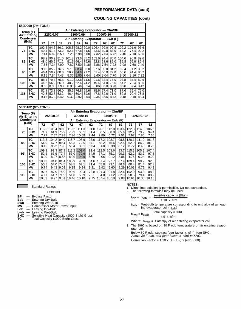
580D090 (71⁄2 TONS)
Temp (F)Air EnteringCondenser
(Edb)
Air Entering Evaporator — Cfm/BF2250/0.07 2800/0.09 3000/0.10 3750/0.12
Air Entering Evaporator — Ewb (F)72 67 62 72 67 62 72 67 62 72 67 62
75TC 102.8 94.8 86.2 105.8 98.2 90.0 106.4 99.0 90.8 109.2 101.6 93.6SHC 49.4 61.8 73.2 52.6 67.8 81.6 53.6 69.8 84.0 58.2 77.4 92.2kW 7.14 6.82 6.50 7.28 6.98 6.68 7.32 7.04 6.72 7.46 7.18 6.86
85TC 98.2 90.2 81.6 101.8 93.6 85.2 102.6 94.4 86.0 104.6 96.8 89.6SHC 48.0 60.2 71.2 51.6 66.4 79.6 52.8 68.6 82.0 56.8 76.0 89.4kW 7.66 7.34 7.00 7.82 7.50 7.18 7.86 7.54 7.22 7.98 7.68 7.40
95TC 93.8 85.2 76.6 97.0 88.4 80.0 97.6 89.0 81.2 99.4 91.2 85.2SHC 46.4 58.2 68.8 50.2 64.6 77.2 51.4 66.8 79.0 55.6 74.4 85.2kW 8.18 7.84 7.48 8.36 8.00 7.64 8.40 8.04 7.70 8.50 8.16 7.92
105TC 88.4 79.8 70.8 91.0 82.8 74.6 91.6 83.4 76.0 93.8 85.4 80.6SHC 44.6 56.2 66.0 48.2 62.6 74.2 49.4 64.8 75.6 54.2 72.4 80.6kW 8.68 8.30 7.98 8.80 8.46 8.14 8.86 8.50 8.20 8.98 8.64 8.42
115TC 82.8 73.8 66.0 85.2 76.8 69.6 85.6 77.4 71.0 87.6 79.4 76.0SHC 42.6 53.8 63.2 46.4 60.4 69.6 47.8 62.6 71.0 52.8 70.4 75.8kW 9.16 8.78 8.42 9.30 8.92 8.64 9.34 8.96 8.72 9.48 9.10 8.94
580D102 (81⁄2 TONS)
Temp (F)Air EnteringCondenser
(Edb)
Air Entering Evaporator — Cfm/BF2550/0.08 3000/0.10 3400/0.11 4250/0.135
Air Entering Evaporator — Ewb (F)72 67 62 72 67 62 72 67 62 72 67 62
75TC 116.6 108.4 99.0 119.2 111.3 101.8 120.1 112.8 103.6 122.3 114.8 106.3SHC 71.9 61.9 75.9 75.2 65.1 81.4 80.5 68.0 85.6 32.7 73.9 94.4kW 7.77 7.57 7.38 7.86 10.68 7.44 7.89 6.72 7.51 7.97 7.80 7.60
85TC 113.3 104.2 94.0 115.7 106.9 97.0 117.2 108.7 98.8 120.1 111.0 101.8SHC 54.0 67.7 80.4 56.3 72.5 87.1 58.2 76.4 92.5 62.9 84.2 101.0kW 8.46 8.22 7.96 5.54 8.31 8.04 8.60 8.38 8.12 8.72 8.48 8.23
95TC 109.1 99.3 87.3 111.2 102.0 91.4 112.5 103.6 93.7 115.3 105.8 107.4SHC 52.6 65.9 77.4 55.0 70.9 84.9 57.1 75.1 90.3 62.2 83.2 97.3kW 8.90 8.97 8.68 8.99 9.06 8.79 9.06 9.12 8.86 4.76 9.24 9.00
105TC 103.3 94.0 81.4 105.9 96.3 84.6 107.4 97.7 87.9 109.4 99.9 92.8SHC 50.5 54.0 74.5 53.5 69.1 81.4 55.8 73.1 86.6 60.4 81.4 92.8kW 9.74 9.43 9.08 9.85 9.54 9.21 9.92 9.60 9.29 10.03 9.72 9.48
115TC 97.7 87.9 75.9 99.9 90.4 78.8 101.3 91.8 82.4 102.9 93.8 88.3SHC 48.7 61.7 71.9 51.8 66.9 78.1 54.0 71.2 82.3 58.5 79.4 88.2kW 10.33 9.97 9.61 10.46 10.10 9.75 10.54 10.18 9.88 10.61 10.30 10.10
Standard Ratings
LEGENDBF — Bypass FactorEdb — Entering Dry-BulbEwb — Entering Wet-BulbkW — Compressor Motor Power InputLdb — Leaving Dry-BulbLwb — Leaving Wet-BulbSHC — Sensible Heat Capacity (1000 Btuh) GrossTC — Total Capacity (1000 Btuh) Gross
NOTES:1. Direct interpolation is permissible. Do not extrapolate.2. The following formulas may be used:
sensible capacity (Btuh)tldb = tedb −
1.10 x cfmtlwb = Wet-bulb temperature corresponding to enthalpy of air leav-
ing evaporator coil (hlwb)total capacity (Btuh)
hlwb = hewb −4.5 x cfm
Where: hewb = Enthalpy of air entering evaporator coil3. The SHC is based on 80 F edb temperature of air entering evapo-
rator coil.Below 80 F edb, subtract (corr factor x cfm) from SHC.Above 80 F edb, add (corr factor x cfm) to SHC.Correction Factor = 1.10 x (1 − BF) x (edb − 80).
27
PERFORMANCE DATA (cont)
COOLING CAPACITIES (cont)
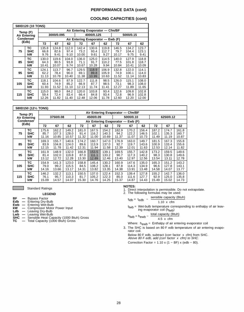
580D120 (10 TONS)
Temp (F)Air EnteringCondenser
(Edb)
Air Entering Evaporator — Cfm/BF3000/0.095 4000/0.125 5000/0.15
Air Entering Evaporator — Ewb (F)72 67 62 72 67 62 72 67 62
75TC 135.8 124.8 112.0 142.4 130.6 119.8 146.5 134.2 123.7SHC 66.8 82.6 97.4 73.2 93.4 112.7 79.7 104.4 123.1kW 9.76 9.41 9.10 10.00 9.61 9.27 10.17 9.75 9.41
85TC 130.0 119.6 104.0 136.0 125.0 114.5 140.0 127.9 118.8SHC 64.3 80.5 93.8 71.1 91.7 110.2 77.5 101.8 118.7kW 10.41 10.07 9.74 10.67 10.28 9.94 10.84 10.41 10.09
95TC 124.1 113.7 96.7 129.5 118.9 106.9 132.8 122.0 114.1SHC 62.2 78.4 90.0 69.1 89.8 105.9 74.9 100.1 114.0kW 11.13 10.78 10.40 11.38 10.99 10.63 11.52 11.14 10.83
105TC 118.1 104.6 87.9 122.7 111.8 98.5 126.0 115.1 108.0SHC 60.4 74.9 85.2 66.9 87.7 98.5 73.1 98.3 108.0kW 11.93 11.52 11.10 12.13 11.74 11.41 12.27 11.89 11.65
115TC 115.0 98.0 84.2 120.0 103.8 93.4 122.6 109.8 102.8SHC 59.4 72.4 83.4 66.4 84.8 93.4 72.8 96.9 102.8kW 12.26 11.82 11.40 12.48 12.06 11.78 12.60 12.20 12.00
580D150 (121⁄2 TONS)
Temp (F)Air EnteringCondenser
(Edb)
Air Entering Evaporator — Cfm/BF3750/0.08 4500/0.09 5000/0.10 6250/0.12
Air Entering Evaporator — Ewb (F)72 67 62 72 67 62 72 67 62 72 67 62
75TC 175.6 162.2 149.2 181.0 167.5 154.2 182.9 170.2 156.4 187.2 174.7 161.8SHC 85.7 107.3 128.0 91.4 116.2 140.3 94.2 122.2 146.5 102.1 135.3 160.7kW 11.16 10.85 10.57 11.32 11.00 10.69 11.37 11.07 10.73 11.49 11.19 10.87
85TC 169.3 155.7 140.6 174.2 160.7 147.0 176.9 163.0 149.7 181.5 167.3 155.8SHC 83.9 104.8 124.0 89.6 113.9 137.0 92.7 119.7 143.6 100.9 133.4 155.6kW 12.15 11.78 11.42 12.31 11.94 11.58 12.39 12.01 11.63 12.53 12.14 11.82
95TC 161.9 148.9 132.0 166.8 153.5 139.1 169.5 155.7 142.8 173.2 159.5 149.6SHC 81.4 102.0 119.8 87.0 111.1 133.2 90.7 117.3 140.2 98.3 130.8 149.6kW 13.12 12.72 12.28 13.30 12.89 12.46 13.40 12.97 12.56 13.54 13.11 12.78
105TC 154.9 141.3 123.0 158.8 145.4 130.2 160.9 147.6 135.0 165.3 151.2 143.2SHC 79.0 99.2 115.5 84.5 108.2 128.1 87.8 114.3 134.9 96.6 127.8 143.1kW 14.16 13.66 13.17 14.31 13.82 13.35 14.38 13.91 13.48 14.58 14.07 13.77
115TC 146.2 132.2 113.1 150.5 137.0 122.4 152.3 139.4 127.8 155.2 142.7 136.0SHC 76.1 95.7 110.3 81.7 105.2 122.3 85.0 111.6 127.7 92.9 125.0 135.8kW 15.09 14.57 14.07 15.30 14.76 14.25 15.37 14.87 14.43 15.49 15.02 14.73
Standard Ratings
LEGENDBF — Bypass FactorEdb — Entering Dry-BulbEwb — Entering Wet-BulbkW — Compressor Motor Power InputLdb — Leaving Dry-BulbLwb — Leaving Wet-BulbSHC — Sensible Heat Capacity (1000 Btuh) GrossTC — Total Capacity (1000 Btuh) Gross
NOTES:1. Direct interpolation is permissible. Do not extrapolate.2. The following formulas may be used:
sensible capacity (Btuh)tldb = tedb −
1.10 x cfmtlwb = Wet-bulb temperature corresponding to enthalpy of air leav-
ing evaporator coil (hlwb)total capacity (Btuh)
hlwb = hewb −4.5 x cfm
Where: hewb = Enthalpy of air entering evaporator coil3. The SHC is based on 80 F edb temperature of air entering evapo-
rator coil.Below 80 F edb, subtract (corr factor x cfm) from SHC.Above 80 F edb, add (corr factor x cfm) to SHC.Correction Factor = 1.10 x (1 − BF) x (edb − 80).
28
PERFORMANCE DATA (cont)
COOLING CAPACITIES (cont)
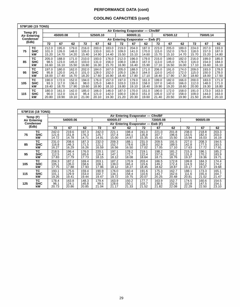
579F180 (15 TONS)
Temp (F)Air EnteringCondenser
(Edb)
Air Entering Evaporator — Cfm/BF4500/0.08 5250/0.10 6000/0.11 6750/0.12 7500/0.14
Air Entering Evaporator — Ewb (F)72 67 62 72 67 62 72 67 62 72 67 62 72 67 62
75TC 212.0 195.0 179.0 216.0 200.0 183.0 219.0 204.0 187.0 223.0 205.0 189.0 224.0 207.0 193.0SHC 101.0 126.0 148.0 105.0 133.0 161.0 109.0 141.0 170.0 115.0 152.0 179.0 118.0 157.0 187.0kW 15.20 14.70 14.20 15.40 14.90 14.40 15.50 15.10 14.60 15.70 15.10 14.70 15.70 15.20 14.80
85TC 205.0 188.0 171.0 210.0 193.0 176.0 212.0 196.0 179.0 215.0 199.0 182.0 216.0 199.0 185.0SHC 98.5 123.0 145.0 103.0 131.0 156.0 108.0 138.0 167.0 113.0 145.0 176.0 116.0 154.0 184.0kW 16.60 16.10 15.50 16.80 16.30 15.70 16.90 16.40 15.90 17.10 16.50 16.00 17.10 16.60 16.10
95TC 197.0 180.0 162.0 202.0 184.0 167.0 205.0 188.0 171.0 206.0 191.0 174.0 209.0 193.0 178.0SHC 95.8 120.0 141.0 101.0 128.0 152.0 105.0 136.0 164.0 110.0 143.0 172.0 115.0 150.0 178.0kW 18.00 17.40 16.70 18.20 17.60 16.90 18.40 17.80 17.10 18.40 17.90 17.30 18.60 18.00 17.50
105TC 190.0 172.0 152.0 194.0 176.0 157.0 197.0 179.0 161.0 199.0 182.0 166.0 200.0 183.0 171.0SHC 93.3 117.0 136.0 98.0 125.0 148.0 103.0 133.0 158.0 107.0 140.0 166.0 112.0 148.0 171.0kW 19.40 18.70 17.90 19.60 18.90 18.10 19.80 19.10 18.40 19.90 19.20 18.60 20.00 19.30 18.80
115TC 180.0 161.0 142.0 185.0 166.0 146.0 187.0 170.0 151.0 190.0 172.0 158.0 191.0 173.0 163.0SHC 90.0 112.0 131.0 95.4 121.0 142.0 100.0 130.0 151.0 105.0 137.0 158.0 109.0 144.0 163.0kW 20.80 19.90 19.10 21.00 20.10 19.30 21.20 20.30 19.60 21.40 20.50 19.90 21.50 20.60 20.10
579F216 (18 TONS)
Temp (F)Air EnteringCondenser
(Edb)
Air Entering Evaporator — Cfm/BF5400/0.06 6000/0.07 7200/0.08 9000/0.09
Air Entering Evaporator — Ewb (F)72 67 62 72 67 62 72 67 62 72 67 62
75TC 242.0 219.6 197.3 242.0 221.1 198.4 241.0 221.0 201.8 238.0 218.8 203.3SHC 121.6 151.8 176.3 125.7 157.4 184.1 135.8 167.7 196.6 143.5 182.4 203.0kW 14.72 14.78 14.71 14.91 15.00 14.97 15.35 15.43 15.50 15.94 16.03 16.19
85TC 231.0 208.6 187.3 232.0 209.3 188.1 231.0 209.5 191.5 227.0 208.3 194.5SHC 116.8 146.3 171.5 121.2 152.7 178.6 128.0 162.9 189.5 142.8 177.5 193.5kW 16.27 16.29 16.26 16.59 16.56 16.50 17.02 17.05 17.10 17.63 17.72 17.91
95TC 218.5 196.4 176.0 220.1 197.1 178.2 219.1 198.2 181.2 215.3 196.1 185.2SHC 112.5 141.3 165.6 116.4 147.1 172.7 122.4 157.6 181.2 131.8 170.2 183.9kW 17.83 17.79 17.73 18.15 18.12 18.08 18.64 18.71 18.76 19.37 19.36 19.71
105TC 204.3 187.2 169.4 203.1 187.2 170.9 203.4 186.5 172.8 199.8 184.3 174.4SHC 105.1 135.0 158.6 108.1 139.0 165.4 115.6 149.2 172.4 124.9 162.2 174.2kW 17.75 17.88 17.93 17.96 18.12 18.27 18.45 18.62 18.87 19.17 19.37 19.68
115TC 193.1 175.6 159.4 190.9 176.0 160.4 191.6 175.3 162.7 188.1 173.3 165.1SHC 101.1 129.9 153.0 102.7 134.1 158.4 110.6 143.7 162.6 111.6 155.4 164.7kW 19.26 19.41 19.44 19.47 19.72 19.75 20.07 20.25 20.48 20.81 21.02 21.47
125TC 178.4 163.8 148.3 179.4 163.9 150.2 177.7 163.9 152.7 174.5 160.6 154.5SHC 96.1 124.1 145.8 99.5 128.6 150.1 103.7 138.5 152.6 110.8 147.5 154.1kW 20.73 20.86 20.85 21.04 21.17 21.33 21.52 21.82 22.08 22.29 22.50 23.10
29
PERFORMANCE DATA (cont)
COOLING CAPACITIES (cont)
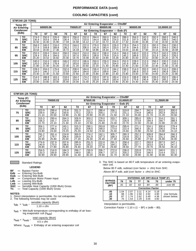
579F240 (20 TONS)
Temp (F)Air EnteringCondenser
(Edb)
Air Entering Evaporator — Cfm/BF6000/0.06 7000/0.07 8000/0.08 9000/0.09 10,000/0.10
Air Entering Evaporator — Ewb (F)72 67 62 72 67 62 72 67 62 72 67 62 72 67 62
75TC 274.0 250.0 226.0 280.0 256.0 232.0 284.0 260.0 236.0 288.0 264.0 242.0 292.0 268.0 246.0SHC 130.4 163.6 194.4 136.4 175.0 210.0 144.4 186.8 224.0 151.8 197.0 236.0 157.4 208.0 246.0kW 16.92 16.40 15.90 17.04 16.58 16.12 17.22 16.72 16.22 17.32 16.84 16.36 17.42 16.92 16.50
85TC 264.0 240.0 216.0 270.0 244.0 222.0 276.0 250.0 226.0 278.0 254.0 232.0 282.0 256.0 238.0SHC 127.6 159.8 189.8 138.2 172.2 206.0 141.8 183.4 220.0 147.8 194.6 232.0 154.6 204.0 236.0kW 18.54 18.00 17.36 18.72 18.18 17.60 18.96 18.34 17.74 19.04 18.46 17.94 19.14 18.56 18.08
95TC 252.0 228.0 204.0 258.0 234.0 210.0 262.0 238.0 216.0 266.0 240.0 222.0 270.0 242.0 228.0SHC 124.4 155.4 184.6 131.0 167.6 200.0 138.8 178.8 214.0 145.2 189.8 222.0 151.8 200.0 228.0kW 20.20 19.52 18.82 20.40 19.76 19.08 20.60 19.90 19.28 20.80 20.00 19.52 20.80 20.20 19.76
105TC 240.0 216.0 190.6 246.0 222.0 196.6 250.0 226.0 204.0 252.0 228.0 212.0 256.0 230.0 218.0SHC 120.0 150.8 178.4 127.2 163.6 193.8 135.0 175.2 204.0 141.6 185.4 212.0 147.4 196.2 218.0kW 21.80 21.00 20.20 22.00 21.20 20.60 22.20 21.40 20.80 22.40 21.60 21.00 22.40 21.60 21.40
115TC 228.0 204.0 176.6 232.0 208.0 184.6 236.0 212.0 194.2 238.0 214.0 202.0 240.0 216.0 208.0SHC 116.0 146.2 171.8 123.8 158.4 184.6 130.4 169.6 194.2 137.2 180.8 202.0 144.0 190.8 206.0kW 23.40 22.40 21.60 23.60 22.60 22.00 23.80 22.80 22.40 23.80 23.00 22.60 24.00 23.20 22.80
125TC 214.0 188.8 163.2 218.0 194.2 174.2 220.0 197.6 183.4 224.0 199.8 190.6 226.0 202.0 196.0SHC 111.0 140.8 162.8 118.6 153.4 174.2 125.8 164.8 183.4 132.0 175.6 190.4 139.0 185.2 195.4kW 24.80 23.80 23.00 25.00 24.00 23.40 25.20 24.20 23.80 25.40 24.40 24.00 25.40 24.60 24.40
579F300 (25 TONS)
Temp (F)Air EnteringCondenser
(Edb)
Air Entering Evaporator — Cfm/BF7000/0.03 8750/0.05 10,000/0.07 11,250/0.09
Air Entering Evaporator — Ewb (F)72 67 62 72 67 62 72 67 62 72 67 62
75TC 323.9 299.4 275.8 331.3 312.7 288.4 336.1 319.8 294.7 342.6 322.5 300.0SHC 159.4 195.2 230.6 170.1 216.5 259.1 177.6 231.1 276.8 186.6 242.9 292.6kW 21.10 20.50 19.90 21.30 20.90 20.20 21.50 21.10 20.40 21.70 21.20 20.50
85TC 315.3 290.4 264.3 326.9 303.2 278.0 333.7 309.1 285.0 335.1 314.2 291.1SHC 156.3 191.7 224.9 168.4 213.2 254.9 177.5 226.9 273.8 184.4 240.7 288.4kW 22.70 22.10 21.30 23.10 22.50 21.80 23.30 22.70 22.00 23.30 22.80 22.20
95TC 304.1 277.4 243.1 315.3 290.1 263.8 320.4 295.6 271.1 324.1 300.6 279.4SHC 152.0 186.5 215.2 165.0 208.5 248.0 173.0 222.4 266.4 181.6 236.5 279.4kW 24.80 24.00 23.20 25.20 24.50 23.50 25.40 24.60 23.80 25.50 24.80 24.10
105TC 291.2 261.4 224.8 300.9 274.2 242.1 305.7 280.3 252.3 309.8 284.8 266.3SHC 147.2 179.7 206.6 159.9 201.8 237.3 168.3 216.8 252.3 176.8 231.1 266.3kW 26.90 25.80 25.00 27.20 26.30 25.40 27.40 26.60 25.80 27.60 26.80 26.00
115TC 274.6 237.9 207.6 285.9 251.5 222.6 291.3 258.4 237.7 293.9 267.5 247.1SHC 140.9 170.0 198.6 154.9 193.2 222.6 164.1 208.7 237.7 163.0 224.3 247.1kW 28.80 27.80 26.80 29.40 28.20 27.40 29.60 28.50 27.70 29.70 28.50 28.10
125TC 254.5 214.9 184.3 266.7 230.9 206.7 272.0 236.0 220.8 276.1 240.0 231.1SHC 133.3 160.8 184.3 148.0 185.1 206.7 157.5 200.2 220.8 166.6 214.4 231.1kW 30.90 29.90 28.90 31.40 30.20 29.60 31.70 30.50 29.90 31.90 30.80 30.30
Standard Ratings
LEGENDBF — Bypass FactorEdb — Entering Dry-BulbEwb — Entering Wet-BulbkW — Compressor Motor Power InputLdb — Leaving Dry-BulbLwb — Leaving Wet-BulbSHC — Sensible Heat Capacity (1000 Btuh) GrossTC — Total Capacity (1000 Btuh) Gross
NOTES:1. Direct interpolation is permissible. Do not extrapolate.2. The following formulas may be used:
sensible capacity (Btuh)tldb = tedb − 1.10 x cfm
tlwb = Wet-bulb temperature corresponding to enthalpy of air leav-ing evaporator coil (hlwb)
total capacity (Btuh)hlwb = hewb − 4.5 x cfmWhere: hewb = Enthalpy of air entering evaporator coil
3. The SHC is based on 80 F edb temperature of air entering evapo-rator coil.Below 80 F edb, subtract (corr factor x cfm) from SHC.Above 80 F edb, add (corr factor x cfm) to SHC.
BYPASSFACTOR(BF)
ENTERING AIR DRY-BULB TEMP (F)79 78 77 76 75 under 7581 82 83 84 85 over 85
Correction Factor.05 1.04 2.07 3.11 4.14 5.18
Use formulashown below.
.10 .98 1.96 2.94 3.92 4.90
.20 .87 1.74 2.62 3.49 4.36
.30 .76 1.53 2.29 3.05 3.82
Interpolation is permissible.Correction Factor = 1.10 x (1 − BF) x (edb − 80).
30
PERFORMANCE DATA (cont)
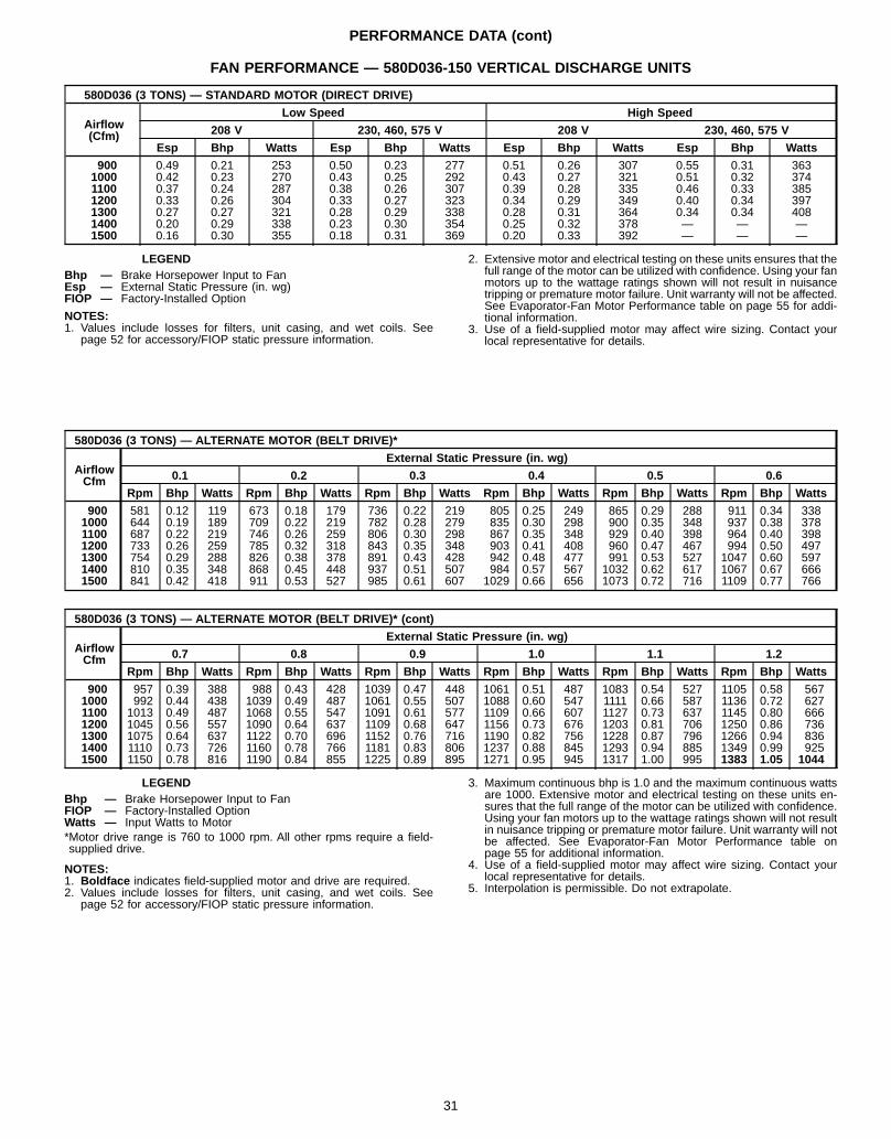
FAN PERFORMANCE — 580D036-150 VERTICAL DISCHARGE UNITS
580D036 (3 TONS) — STANDARD MOTOR (DIRECT DRIVE)
Airflow(Cfm)
Low Speed High Speed
208 V 230, 460, 575 V 208 V 230, 460, 575 V
Esp Bhp Watts Esp Bhp Watts Esp Bhp Watts Esp Bhp Watts
900 0.49 0.21 253 0.50 0.23 277 0.51 0.26 307 0.55 0.31 3631000 0.42 0.23 270 0.43 0.25 292 0.43 0.27 321 0.51 0.32 3741100 0.37 0.24 287 0.38 0.26 307 0.39 0.28 335 0.46 0.33 3851200 0.33 0.26 304 0.33 0.27 323 0.34 0.29 349 0.40 0.34 3971300 0.27 0.27 321 0.28 0.29 338 0.28 0.31 364 0.34 0.34 4081400 0.20 0.29 338 0.23 0.30 354 0.25 0.32 378 — — —1500 0.16 0.30 355 0.18 0.31 369 0.20 0.33 392 — — —
LEGENDBhp — Brake Horsepower Input to FanEsp — External Static Pressure (in. wg)FIOP — Factory-Installed Option
NOTES:1. Values include losses for filters, unit casing, and wet coils. See
page 52 for accessory/FIOP static pressure information.
2. Extensive motor and electrical testing on these units ensures that thefull range of the motor can be utilized with confidence. Using your fanmotors up to the wattage ratings shown will not result in nuisancetripping or premature motor failure. Unit warranty will not be affected.See Evaporator-Fan Motor Performance table on page 55 for addi-tional information.
3. Use of a field-supplied motor may affect wire sizing. Contact yourlocal representative for details.
580D036 (3 TONS) — ALTERNATE MOTOR (BELT DRIVE)*
AirflowCfm
External Static Pressure (in. wg)
0.1 0.2 0.3 0.4 0.5 0.6
Rpm Bhp Watts Rpm Bhp Watts Rpm Bhp Watts Rpm Bhp Watts Rpm Bhp Watts Rpm Bhp Watts
900 581 0.12 119 673 0.18 179 736 0.22 219 805 0.25 249 865 0.29 288 911 0.34 3381000 644 0.19 189 709 0.22 219 782 0.28 279 835 0.30 298 900 0.35 348 937 0.38 3781100 687 0.22 219 746 0.26 259 806 0.30 298 867 0.35 348 929 0.40 398 964 0.40 3981200 733 0.26 259 785 0.32 318 843 0.35 348 903 0.41 408 960 0.47 467 994 0.50 4971300 754 0.29 288 826 0.38 378 891 0.43 428 942 0.48 477 991 0.53 527 1047 0.60 5971400 810 0.35 348 868 0.45 448 937 0.51 507 984 0.57 567 1032 0.62 617 1067 0.67 6661500 841 0.42 418 911 0.53 527 985 0.61 607 1029 0.66 656 1073 0.72 716 1109 0.77 766
580D036 (3 TONS) — ALTERNATE MOTOR (BELT DRIVE)* (cont)
AirflowCfm
External Static Pressure (in. wg)
0.7 0.8 0.9 1.0 1.1 1.2
Rpm Bhp Watts Rpm Bhp Watts Rpm Bhp Watts Rpm Bhp Watts Rpm Bhp Watts Rpm Bhp Watts
900 957 0.39 388 988 0.43 428 1039 0.47 448 1061 0.51 487 1083 0.54 527 1105 0.58 5671000 992 0.44 438 1039 0.49 487 1061 0.55 507 1088 0.60 547 1111 0.66 587 1136 0.72 6271100 1013 0.49 487 1068 0.55 547 1091 0.61 577 1109 0.66 607 1127 0.73 637 1145 0.80 6661200 1045 0.56 557 1090 0.64 637 1109 0.68 647 1156 0.73 676 1203 0.81 706 1250 0.86 7361300 1075 0.64 637 1122 0.70 696 1152 0.76 716 1190 0.82 756 1228 0.87 796 1266 0.94 8361400 1110 0.73 726 1160 0.78 766 1181 0.83 806 1237 0.88 845 1293 0.94 885 1349 0.99 9251500 1150 0.78 816 1190 0.84 855 1225 0.89 895 1271 0.95 945 1317 1.00 995 1383 1.05 1044
LEGENDBhp — Brake Horsepower Input to FanFIOP — Factory-Installed OptionWatts — Input Watts to Motor*Motor drive range is 760 to 1000 rpm. All other rpms require a field-supplied drive.
NOTES:1. Boldface indicates field-supplied motor and drive are required.2. Values include losses for filters, unit casing, and wet coils. See
page 52 for accessory/FIOP static pressure information.
3. Maximum continuous bhp is 1.0 and the maximum continuous wattsare 1000. Extensive motor and electrical testing on these units en-sures that the full range of the motor can be utilized with confidence.Using your fan motors up to the wattage ratings shown will not resultin nuisance tripping or premature motor failure. Unit warranty will notbe affected. See Evaporator-Fan Motor Performance table onpage 55 for additional information.
4. Use of a field-supplied motor may affect wire sizing. Contact yourlocal representative for details.
5. Interpolation is permissible. Do not extrapolate.
31
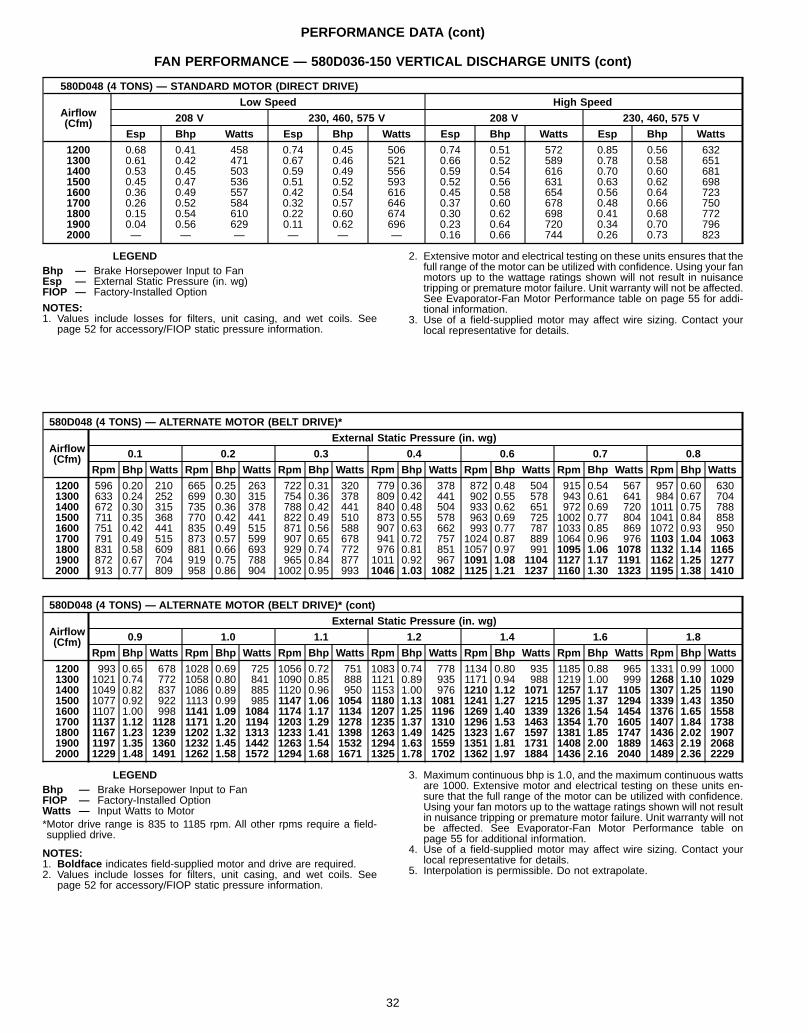
PERFORMANCE DATA (cont)
FAN PERFORMANCE — 580D036-150 VERTICAL DISCHARGE UNITS (cont)
580D048 (4 TONS) — STANDARD MOTOR (DIRECT DRIVE)
Airflow(Cfm)
Low Speed High Speed
208 V 230, 460, 575 V 208 V 230, 460, 575 V
Esp Bhp Watts Esp Bhp Watts Esp Bhp Watts Esp Bhp Watts
1200 0.68 0.41 458 0.74 0.45 506 0.74 0.51 572 0.85 0.56 6321300 0.61 0.42 471 0.67 0.46 521 0.66 0.52 589 0.78 0.58 6511400 0.53 0.45 503 0.59 0.49 556 0.59 0.54 616 0.70 0.60 6811500 0.45 0.47 536 0.51 0.52 593 0.52 0.56 631 0.63 0.62 6981600 0.36 0.49 557 0.42 0.54 616 0.45 0.58 654 0.56 0.64 7231700 0.26 0.52 584 0.32 0.57 646 0.37 0.60 678 0.48 0.66 7501800 0.15 0.54 610 0.22 0.60 674 0.30 0.62 698 0.41 0.68 7721900 0.04 0.56 629 0.11 0.62 696 0.23 0.64 720 0.34 0.70 7962000 — — — — — — 0.16 0.66 744 0.26 0.73 823
LEGENDBhp — Brake Horsepower Input to FanEsp — External Static Pressure (in. wg)FIOP — Factory-Installed Option
NOTES:1. Values include losses for filters, unit casing, and wet coils. See
page 52 for accessory/FIOP static pressure information.
2. Extensive motor and electrical testing on these units ensures that thefull range of the motor can be utilized with confidence. Using your fanmotors up to the wattage ratings shown will not result in nuisancetripping or premature motor failure. Unit warranty will not be affected.See Evaporator-Fan Motor Performance table on page 55 for addi-tional information.
3. Use of a field-supplied motor may affect wire sizing. Contact yourlocal representative for details.
580D048 (4 TONS) — ALTERNATE MOTOR (BELT DRIVE)*
Airflow(Cfm)
External Static Pressure (in. wg)
0.1 0.2 0.3 0.4 0.6 0.7 0.8
Rpm Bhp Watts Rpm Bhp Watts Rpm Bhp Watts Rpm Bhp Watts Rpm Bhp Watts Rpm Bhp Watts Rpm Bhp Watts
1200 596 0.20 210 665 0.25 263 722 0.31 320 779 0.36 378 872 0.48 504 915 0.54 567 957 0.60 6301300 633 0.24 252 699 0.30 315 754 0.36 378 809 0.42 441 902 0.55 578 943 0.61 641 984 0.67 7041400 672 0.30 315 735 0.36 378 788 0.42 441 840 0.48 504 933 0.62 651 972 0.69 720 1011 0.75 7881500 711 0.35 368 770 0.42 441 822 0.49 510 873 0.55 578 963 0.69 725 1002 0.77 804 1041 0.84 8581600 751 0.42 441 835 0.49 515 871 0.56 588 907 0.63 662 993 0.77 787 1033 0.85 869 1072 0.93 9501700 791 0.49 515 873 0.57 599 907 0.65 678 941 0.72 757 1024 0.87 889 1064 0.96 976 1103 1.04 10631800 831 0.58 609 881 0.66 693 929 0.74 772 976 0.81 851 1057 0.97 991 1095 1.06 1078 1132 1.14 11651900 872 0.67 704 919 0.75 788 965 0.84 877 1011 0.92 967 1091 1.08 1104 1127 1.17 1191 1162 1.25 12772000 913 0.77 809 958 0.86 904 1002 0.95 993 1046 1.03 1082 1125 1.21 1237 1160 1.30 1323 1195 1.38 1410
580D048 (4 TONS) — ALTERNATE MOTOR (BELT DRIVE)* (cont)
Airflow(Cfm)
External Static Pressure (in. wg)
0.9 1.0 1.1 1.2 1.4 1.6 1.8
Rpm Bhp Watts Rpm Bhp Watts Rpm Bhp Watts Rpm Bhp Watts Rpm Bhp Watts Rpm Bhp Watts Rpm Bhp Watts
1200 993 0.65 678 1028 0.69 725 1056 0.72 751 1083 0.74 778 1134 0.80 935 1185 0.88 965 1331 0.99 10001300 1021 0.74 772 1058 0.80 841 1090 0.85 888 1121 0.89 935 1171 0.94 988 1219 1.00 999 1268 1.10 10291400 1049 0.82 837 1086 0.89 885 1120 0.96 950 1153 1.00 976 1210 1.12 1071 1257 1.17 1105 1307 1.25 11901500 1077 0.92 922 1113 0.99 985 1147 1.06 1054 1180 1.13 1081 1241 1.27 1215 1295 1.37 1294 1339 1.43 13501600 1107 1.00 998 1141 1.09 1084 1174 1.17 1134 1207 1.25 1196 1269 1.40 1339 1326 1.54 1454 1376 1.65 15581700 1137 1.12 1128 1171 1.20 1194 1203 1.29 1278 1235 1.37 1310 1296 1.53 1463 1354 1.70 1605 1407 1.84 17381800 1167 1.23 1239 1202 1.32 1313 1233 1.41 1398 1263 1.49 1425 1323 1.67 1597 1381 1.85 1747 1436 2.02 19071900 1197 1.35 1360 1232 1.45 1442 1263 1.54 1532 1294 1.63 1559 1351 1.81 1731 1408 2.00 1889 1463 2.19 20682000 1229 1.48 1491 1262 1.58 1572 1294 1.68 1671 1325 1.78 1702 1362 1.97 1884 1436 2.16 2040 1489 2.36 2229
LEGENDBhp — Brake Horsepower Input to FanFIOP — Factory-Installed OptionWatts — Input Watts to Motor*Motor drive range is 835 to 1185 rpm. All other rpms require a field-supplied drive.
NOTES:1. Boldface indicates field-supplied motor and drive are required.2. Values include losses for filters, unit casing, and wet coils. See
page 52 for accessory/FIOP static pressure information.
3. Maximum continuous bhp is 1.0, and the maximum continuous wattsare 1000. Extensive motor and electrical testing on these units en-sure that the full range of the motor can be utilized with confidence.Using your fan motors up to the wattage ratings shown will not resultin nuisance tripping or premature motor failure. Unit warranty will notbe affected. See Evaporator-Fan Motor Performance table onpage 55 for additional information.
4. Use of a field-supplied motor may affect wire sizing. Contact yourlocal representative for details.
5. Interpolation is permissible. Do not extrapolate.
32
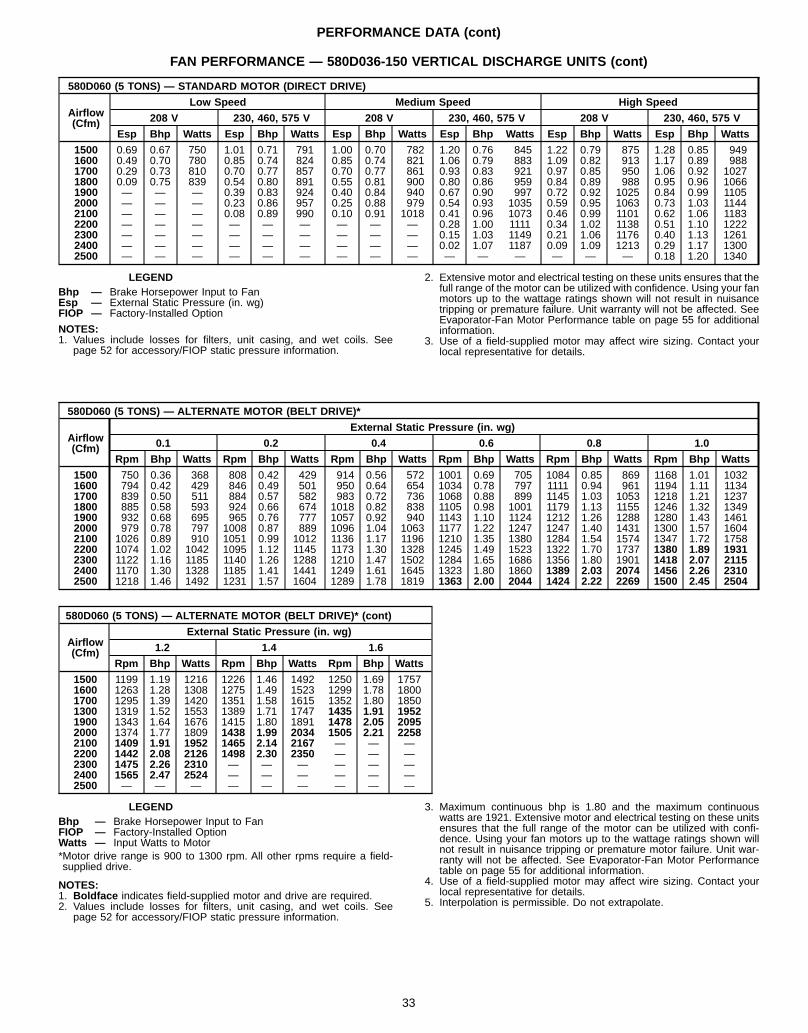
PERFORMANCE DATA (cont)
FAN PERFORMANCE — 580D036-150 VERTICAL DISCHARGE UNITS (cont)
580D060 (5 TONS) — STANDARD MOTOR (DIRECT DRIVE)
Airflow(Cfm)
Low Speed Medium Speed High Speed
208 V 230, 460, 575 V 208 V 230, 460, 575 V 208 V 230, 460, 575 V
Esp Bhp Watts Esp Bhp Watts Esp Bhp Watts Esp Bhp Watts Esp Bhp Watts Esp Bhp Watts
1500 0.69 0.67 750 1.01 0.71 791 1.00 0.70 782 1.20 0.76 845 1.22 0.79 875 1.28 0.85 9491600 0.49 0.70 780 0.85 0.74 824 0.85 0.74 821 1.06 0.79 883 1.09 0.82 913 1.17 0.89 9881700 0.29 0.73 810 0.70 0.77 857 0.70 0.77 861 0.93 0.83 921 0.97 0.85 950 1.06 0.92 10271800 0.09 0.75 839 0.54 0.80 891 0.55 0.81 900 0.80 0.86 959 0.84 0.89 988 0.95 0.96 10661900 — — — 0.39 0.83 924 0.40 0.84 940 0.67 0.90 997 0.72 0.92 1025 0.84 0.99 11052000 — — — 0.23 0.86 957 0.25 0.88 979 0.54 0.93 1035 0.59 0.95 1063 0.73 1.03 11442100 — — — 0.08 0.89 990 0.10 0.91 1018 0.41 0.96 1073 0.46 0.99 1101 0.62 1.06 11832200 — — — — — — — — — 0.28 1.00 1111 0.34 1.02 1138 0.51 1.10 12222300 — — — — — — — — — 0.15 1.03 1149 0.21 1.06 1176 0.40 1.13 12612400 — — — — — — — — — 0.02 1.07 1187 0.09 1.09 1213 0.29 1.17 13002500 — — — — — — — — — — — — — — — 0.18 1.20 1340
LEGENDBhp — Brake Horsepower Input to FanEsp — External Static Pressure (in. wg)FIOP — Factory-Installed Option
NOTES:1. Values include losses for filters, unit casing, and wet coils. See
page 52 for accessory/FIOP static pressure information.
2. Extensive motor and electrical testing on these units ensures that thefull range of the motor can be utilized with confidence. Using your fanmotors up to the wattage ratings shown will not result in nuisancetripping or premature failure. Unit warranty will not be affected. SeeEvaporator-Fan Motor Performance table on page 55 for additionalinformation.
3. Use of a field-supplied motor may affect wire sizing. Contact yourlocal representative for details.
580D060 (5 TONS) — ALTERNATE MOTOR (BELT DRIVE)*
Airflow(Cfm)
External Static Pressure (in. wg)
0.1 0.2 0.4 0.6 0.8 1.0
Rpm Bhp Watts Rpm Bhp Watts Rpm Bhp Watts Rpm Bhp Watts Rpm Bhp Watts Rpm Bhp Watts
1500 750 0.36 368 808 0.42 429 914 0.56 572 1001 0.69 705 1084 0.85 869 1168 1.01 10321600 794 0.42 429 846 0.49 501 950 0.64 654 1034 0.78 797 1111 0.94 961 1194 1.11 11341700 839 0.50 511 884 0.57 582 983 0.72 736 1068 0.88 899 1145 1.03 1053 1218 1.21 12371800 885 0.58 593 924 0.66 674 1018 0.82 838 1105 0.98 1001 1179 1.13 1155 1246 1.32 13491900 932 0.68 695 965 0.76 777 1057 0.92 940 1143 1.10 1124 1212 1.26 1288 1280 1.43 14612000 979 0.78 797 1008 0.87 889 1096 1.04 1063 1177 1.22 1247 1247 1.40 1431 1300 1.57 16042100 1026 0.89 910 1051 0.99 1012 1136 1.17 1196 1210 1.35 1380 1284 1.54 1574 1347 1.72 17582200 1074 1.02 1042 1095 1.12 1145 1173 1.30 1328 1245 1.49 1523 1322 1.70 1737 1380 1.89 19312300 1122 1.16 1185 1140 1.26 1288 1210 1.47 1502 1284 1.65 1686 1356 1.80 1901 1418 2.07 21152400 1170 1.30 1328 1185 1.41 1441 1249 1.61 1645 1323 1.80 1860 1389 2.03 2074 1456 2.26 23102500 1218 1.46 1492 1231 1.57 1604 1289 1.78 1819 1363 2.00 2044 1424 2.22 2269 1500 2.45 2504
580D060 (5 TONS) — ALTERNATE MOTOR (BELT DRIVE)* (cont)
Airflow(Cfm)
External Static Pressure (in. wg)
1.2 1.4 1.6
Rpm Bhp Watts Rpm Bhp Watts Rpm Bhp Watts
1500 1199 1.19 1216 1226 1.46 1492 1250 1.69 17571600 1263 1.28 1308 1275 1.49 1523 1299 1.78 18001700 1295 1.39 1420 1351 1.58 1615 1352 1.80 18501300 1319 1.52 1553 1389 1.71 1747 1435 1.91 19521900 1343 1.64 1676 1415 1.80 1891 1478 2.05 20952000 1374 1.77 1809 1438 1.99 2034 1505 2.21 22582100 1409 1.91 1952 1465 2.14 2167 — — —2200 1442 2.08 2126 1498 2.30 2350 — — —2300 1475 2.26 2310 — — — — — —2400 1565 2.47 2524 — — — — — —2500 — — — — — — — — —
LEGENDBhp — Brake Horsepower Input to FanFIOP — Factory-Installed OptionWatts — Input Watts to Motor*Motor drive range is 900 to 1300 rpm. All other rpms require a field-supplied drive.
NOTES:1. Boldface indicates field-supplied motor and drive are required.2. Values include losses for filters, unit casing, and wet coils. See
page 52 for accessory/FIOP static pressure information.
3. Maximum continuous bhp is 1.80 and the maximum continuouswatts are 1921. Extensive motor and electrical testing on these unitsensures that the full range of the motor can be utilized with confi-dence. Using your fan motors up to the wattage ratings shown willnot result in nuisance tripping or premature motor failure. Unit war-ranty will not be affected. See Evaporator-Fan Motor Performancetable on page 55 for additional information.
4. Use of a field-supplied motor may affect wire sizing. Contact yourlocal representative for details.
5. Interpolation is permissible. Do not extrapolate.
33
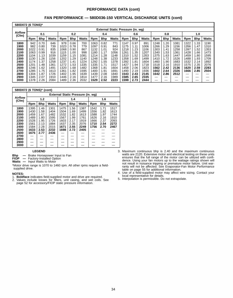
PERFORMANCE DATA (cont)
FAN PERFORMANCE — 580D036-150 VERTICAL DISCHARGE UNITS (cont)
580D072 (6 TONS)*
Airflow(Cfm)
External Static Pressure (in. wg)
0.1 0.2 0.4 0.6 0.8 1.0
Rpm Bhp Watts Rpm Bhp Watts Rpm Bhp Watts Rpm Bhp Watts Rpm Bhp Watts Rpm Bhp Watts
1800 942 0.70 646 978 0.66 700 1063 0.82 771 1147 0.97 891 1248 1.20 1081 1322 1.33 11901900 982 0.80 739 1023 0.78 779 1097 0.91 843 1175 1.11 1006 1266 1.29 1156 1356 1.47 13102000 1022 0.91 835 1068 0.90 867 1132 1.01 924 1218 1.23 1106 1303 1.41 1258 1397 1.52 13532100 1063 0.99 916 1115 1.00 998 1180 1.17 1056 1261 1.35 1207 1340 1.53 1361 1428 1.66 14732200 1104 1.13 1039 1159 1.15 1081 1214 1.28 1148 1310 1.52 1353 1375 1.63 1447 1459 1.80 15952300 1130 1.26 1156 1202 1.29 1140 1248 1.38 1233 1358 1.69 1499 1410 1.72 1526 1488 1.93 17092400 1174 1.37 1258 1237 1.41 1224 1292 1.55 1378 1392 1.81 1604 1460 1.90 1683 1532 2.14 18922500 1201 1.48 1361 1272 1.53 1335 1335 1.71 1517 1427 1.94 1718 1518 2.16 1910 1575 2.35 20762600 1246 1.62 1491 1320 1.68 1482 1368 1.81 1604 1458 2.06 1823 1562 2.42 2136 1620 2.59 22832700 1285 1.75 1613 1361 1.82 1595 1400 1.91 1691 1490 2.19 1936 1602 2.64 2326 1666 2.85 25042800 1304 1.87 1726 1402 1.95 1639 1439 2.08 1840 1543 2.43 2145 1642 2.86 2512 — — —2900 1345 2.07 1910 1446 2.16 1814 1477 2.16 1989 1585 2.65 2335 — — — — — —3000 1378 2.26 2084 1489 2.36 2032 1529 2.52 2223 1598 2.73 2444 — — — — — —
580D072 (6 TONS)* (cont)
Airflow(Cfm)
External Static Pressure (in. wg)
1.2 1.4 1.6
Rpm Bhp Watts Rpm Bhp Watts Rpm Bhp Watts
1800 1395 1.46 1301 1475 1.56 1387 1542 1.71 15171900 1430 1.58 1404 1504 1.69 1499 1556 1.82 16132000 1459 1.67 1482 1532 1.82 1613 1588 1.97 17442100 1489 1.80 1595 1567 1.99 1761 1626 2.16 19102200 1528 1.95 1726 1603 2.17 1919 1666 2.37 20932300 1561 2.13 1884 1637 2.35 2076 1710 2.54 22722400 1584 2.28 2015 1671 2.55 2249 1756 2.70 24672500 1633 2.53 2232 1698 2.72 2405 — — —2600 1675 2.77 2436 — — — — — —2700 — — — — — — — — —2800 — — — — — — — — —2900 — — — — — — — — —3000 — — — — — — — — —
LEGENDBhp — Brake Horsepower Input to FanFIOP — Factory-Installed OptionWatts — Input Watts to Motor*Motor drive range is 1070 to 1460 rpm. All other rpms require a field-supplied drive.
NOTES:1. Boldface indicates field-supplied motor and drive are required.2. Values include losses for filters, unit casing, and wet coils. See
page 52 for accessory/FIOP static pressure information.
3. Maximum continuous bhp is 2.40 and the maximum continuouswatts are 2120. Extensive motor and electrical testing on these unitsensures that the full range of the motor can be utilized with confi-dence. Using your fan motors up to the wattage ratings shown willnot result in nuisance tripping or premature motor failure. Unit war-ranty will not be affected. See Evaporator-Fan Motor Performancetable on page 55 for additional information.
4. Use of a field-supplied motor may affect wire sizing. Contact yourlocal representative for details.
5. Interpolation is permissible. Do not extrapolate.
34
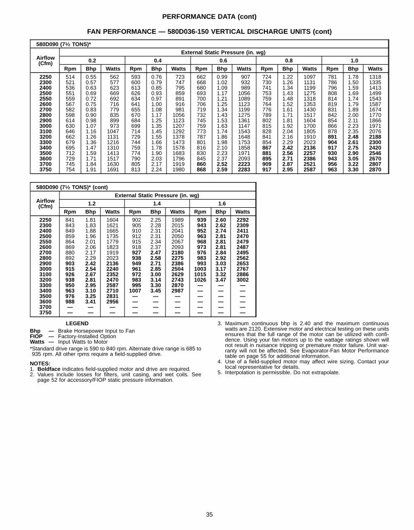
PERFORMANCE DATA (cont)
FAN PERFORMANCE — 580D036-150 VERTICAL DISCHARGE UNITS (cont)
580D090 (71⁄2 TONS)*
Airflow(Cfm)
External Static Pressure (in. wg)
0.2 0.4 0.6 0.8 1.0
Rpm Bhp Watts Rpm Bhp Watts Rpm Bhp Watts Rpm Bhp Watts Rpm Bhp Watts
2250 514 0.55 562 593 0.76 723 662 0.99 907 724 1.22 1097 781 1.78 13182300 521 0.57 577 600 0.79 747 668 1.02 932 730 1.26 1131 786 1.50 13352400 536 0.63 623 613 0.85 795 680 1.09 989 741 1.34 1199 796 1.59 14132500 551 0.69 669 626 0.93 859 693 1.17 1056 753 1.43 1275 808 1.69 14992550 559 0.72 692 634 0.97 891 700 1.21 1089 759 1.48 1318 814 1.74 15432600 567 0.75 716 641 1.00 916 706 1.25 1123 764 1.52 1353 819 1.79 15872700 582 0.83 779 655 1.08 981 719 1.34 1199 776 1.61 1430 831 1.89 16742800 598 0.90 835 670 1.17 1056 732 1.43 1275 789 1.71 1517 842 2.00 17702900 614 0.98 899 684 1.25 1123 745 1.53 1361 802 1.81 1604 854 2.11 18663000 630 1.07 973 699 1.35 1207 759 1.63 1147 815 1.92 1700 866 2.23 19713100 646 1.16 1047 714 1.45 1292 773 1.74 1543 828 2.04 1805 878 2.35 20763200 662 1.26 1131 729 1.55 1378 787 1.86 1648 841 2.16 1910 891 2.48 21883300 679 1.36 1216 744 1.66 1473 801 1.98 1753 854 2.29 2023 904 2.61 23003400 695 1.47 1310 759 1.78 1578 816 2.10 1858 867 2.42 2136 917 2.75 24203500 712 1.59 1413 774 1.90 1683 830 2.23 1971 881 2.56 2257 930 2.90 25463600 729 1.71 1517 790 2.03 1796 845 2.37 2093 895 2.71 2386 943 3.05 26703700 745 1.84 1630 805 2.17 1919 860 2.52 2223 909 2.87 2521 956 3.22 28073750 754 1.91 1691 813 2.24 1980 868 2.59 2283 917 2.95 2587 963 3.30 2870
580D090 (71⁄2 TONS)* (cont)
Airflow(Cfm)
External Static Pressure (in. wg)
1.2 1.4 1.6
Rpm Bhp Watts Rpm Bhp Watts Rpm Bhp Watts
2250 841 1.81 1604 902 2.25 1989 939 2.60 22922300 843 1.83 1621 905 2.28 2015 943 2.62 23092400 849 1.88 1665 910 2.31 2041 952 2.74 24112500 859 1.96 1735 912 2.31 2050 963 2.81 24702550 864 2.01 1779 915 2.34 2067 968 2.81 24792600 869 2.06 1823 918 2.37 2093 973 2.81 24872700 880 2.17 1919 927 2.47 2180 976 2.84 24952800 892 2.29 2023 938 2.58 2275 983 2.92 25622900 903 2.42 2136 949 2.71 2386 993 3.03 26533000 915 2.54 2240 961 2.85 2504 1003 3.17 27673100 926 2.67 2352 972 3.00 2629 1015 3.32 28863200 938 2.81 2470 983 3.14 2743 1026 3.47 30023300 950 2.95 2587 995 3.30 2870 — — —3400 963 3.10 2710 1007 3.45 2987 — — —3500 976 3.25 2831 — — — — — —3600 988 3.41 2956 — — — — — —3700 — — — — — — — — —3750 — — — — — — — — —
LEGENDBhp — Brake Horsepower Input to FanFIOP — Factory-Installed OptionWatts — Input Watts to Motor*Standard drive range is 590 to 840 rpm. Alternate drive range is 685 to935 rpm. All other rpms require a field-supplied drive.
NOTES:1. Boldface indicates field-supplied motor and drive are required.2. Values include losses for filters, unit casing, and wet coils. See
page 52 for accessory/FIOP static pressure information.
3. Maximum continuous bhp is 2.40 and the maximum continuouswatts are 2120. Extensive motor and electrical testing on these unitsensures that the full range of the motor can be utilized with confi-dence. Using your fan motors up to the wattage ratings shown willnot result in nuisance tripping or premature motor failure. Unit war-ranty will not be affected. See Evaporator-Fan Motor Performancetable on page 55 for additional information.
4. Use of a field-supplied motor may affect wire sizing. Contact yourlocal representative for details.
5. Interpolation is permissible. Do not extrapolate.
35
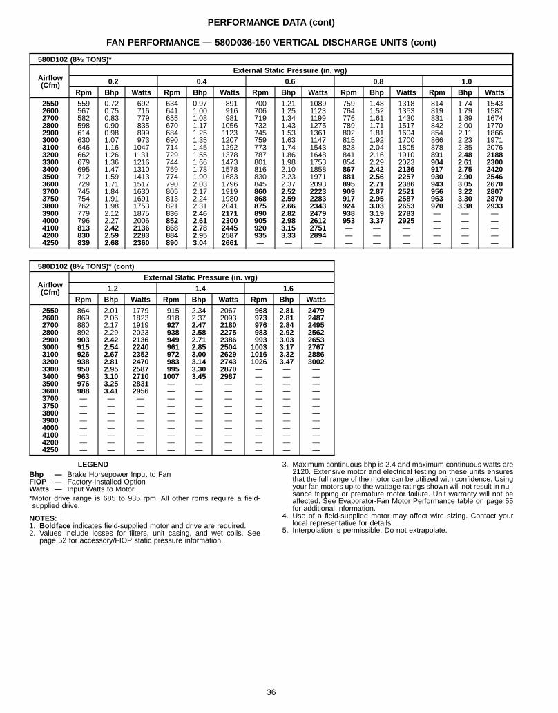
PERFORMANCE DATA (cont)
FAN PERFORMANCE — 580D036-150 VERTICAL DISCHARGE UNITS (cont)
580D102 (81⁄2 TONS)*
Airflow(Cfm)
External Static Pressure (in. wg)
0.2 0.4 0.6 0.8 1.0
Rpm Bhp Watts Rpm Bhp Watts Rpm Bhp Watts Rpm Bhp Watts Rpm Bhp Watts
2550 559 0.72 692 634 0.97 891 700 1.21 1089 759 1.48 1318 814 1.74 15432600 567 0.75 716 641 1.00 916 706 1.25 1123 764 1.52 1353 819 1.79 15872700 582 0.83 779 655 1.08 981 719 1.34 1199 776 1.61 1430 831 1.89 16742800 598 0.90 835 670 1.17 1056 732 1.43 1275 789 1.71 1517 842 2.00 17702900 614 0.98 899 684 1.25 1123 745 1.53 1361 802 1.81 1604 854 2.11 18663000 630 1.07 973 690 1.35 1207 759 1.63 1147 815 1.92 1700 866 2.23 19713100 646 1.16 1047 714 1.45 1292 773 1.74 1543 828 2.04 1805 878 2.35 20763200 662 1.26 1131 729 1.55 1378 787 1.86 1648 841 2.16 1910 891 2.48 21883300 679 1.36 1216 744 1.66 1473 801 1.98 1753 854 2.29 2023 904 2.61 23003400 695 1.47 1310 759 1.78 1578 816 2.10 1858 867 2.42 2136 917 2.75 24203500 712 1.59 1413 774 1.90 1683 830 2.23 1971 881 2.56 2257 930 2.90 25463600 729 1.71 1517 790 2.03 1796 845 2.37 2093 895 2.71 2386 943 3.05 26703700 745 1.84 1630 805 2.17 1919 860 2.52 2223 909 2.87 2521 956 3.22 28073750 754 1.91 1691 813 2.24 1980 868 2.59 2283 917 2.95 2587 963 3.30 28703800 762 1.98 1753 821 2.31 2041 875 2.66 2343 924 3.03 2653 970 3.38 29333900 779 2.12 1875 836 2.46 2171 890 2.82 2479 938 3.19 2783 — — —4000 796 2.27 2006 852 2.61 2300 905 2.98 2612 953 3.37 2925 — — —4100 813 2.42 2136 868 2.78 2445 920 3.15 2751 — — — — — —4200 830 2.59 2283 884 2.95 2587 935 3.33 2894 — — — — — —4250 839 2.68 2360 890 3.04 2661 — — — — — — — — —
580D102 (81⁄2 TONS)* (cont)
Airflow(Cfm)
External Static Pressure (in. wg)
1.2 1.4 1.6
Rpm Bhp Watts Rpm Bhp Watts Rpm Bhp Watts
2550 864 2.01 1779 915 2.34 2067 968 2.81 24792600 869 2.06 1823 918 2.37 2093 973 2.81 24872700 880 2.17 1919 927 2.47 2180 976 2.84 24952800 892 2.29 2023 938 2.58 2275 983 2.92 25622900 903 2.42 2136 949 2.71 2386 993 3.03 26533000 915 2.54 2240 961 2.85 2504 1003 3.17 27673100 926 2.67 2352 972 3.00 2629 1016 3.32 28863200 938 2.81 2470 983 3.14 2743 1026 3.47 30023300 950 2.95 2587 995 3.30 2870 — — —3400 963 3.10 2710 1007 3.45 2987 — — —3500 976 3.25 2831 — — — — — —3600 988 3.41 2956 — — — — — —3700 — — — — — — — — —3750 — — — — — — — — —3800 — — — — — — — — —3900 — — — — — — — — —4000 — — — — — — — — —4100 — — — — — — — — —4200 — — — — — — — — —4250 — — — — — — — — —
LEGENDBhp — Brake Horsepower Input to FanFIOP — Factory-Installed OptionWatts — Input Watts to Motor*Motor drive range is 685 to 935 rpm. All other rpms require a field-supplied drive.
NOTES:1. Boldface indicates field-supplied motor and drive are required.2. Values include losses for filters, unit casing, and wet coils. See
page 52 for accessory/FIOP static pressure information.
3. Maximum continuous bhp is 2.4 and maximum continuous watts are2120. Extensive motor and electrical testing on these units ensuresthat the full range of the motor can be utilized with confidence. Usingyour fan motors up to the wattage ratings shown will not result in nui-sance tripping or premature motor failure. Unit warranty will not beaffected. See Evaporator-Fan Motor Performance table on page 55for additional information.
4. Use of a field-supplied motor may affect wire sizing. Contact yourlocal representative for details.
5. Interpolation is permissible. Do not extrapolate.
36
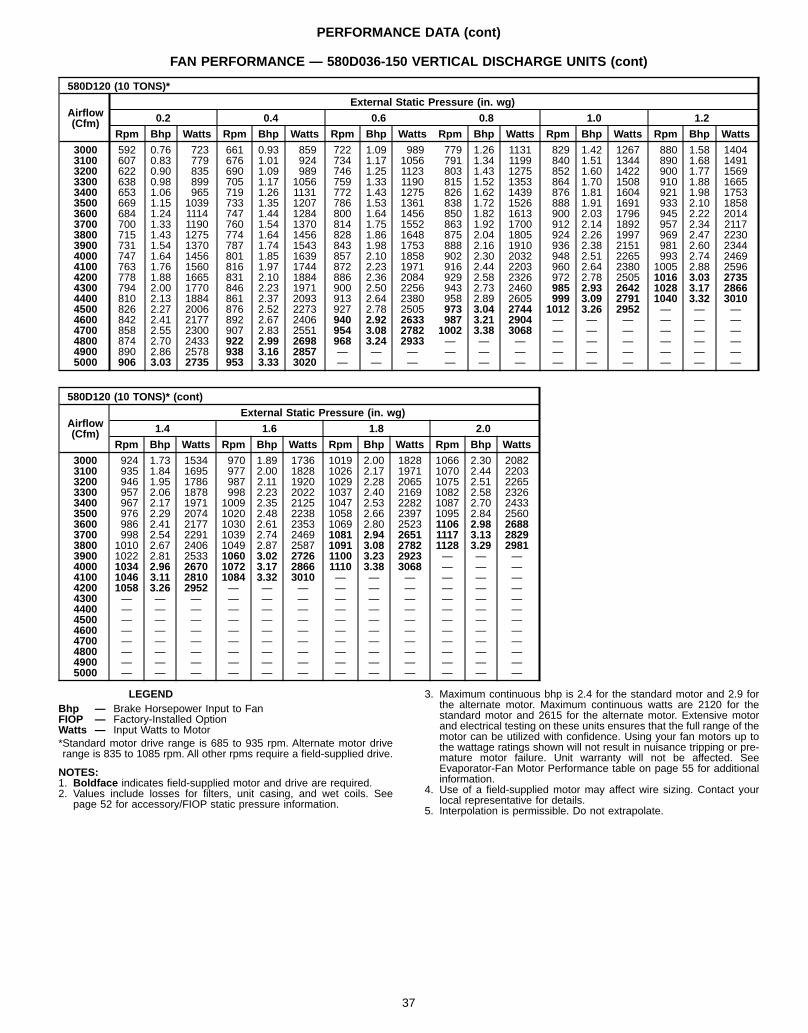
PERFORMANCE DATA (cont)
FAN PERFORMANCE — 580D036-150 VERTICAL DISCHARGE UNITS (cont)
580D120 (10 TONS)*
Airflow(Cfm)
External Static Pressure (in. wg)
0.2 0.4 0.6 0.8 1.0 1.2
Rpm Bhp Watts Rpm Bhp Watts Rpm Bhp Watts Rpm Bhp Watts Rpm Bhp Watts Rpm Bhp Watts
3000 592 0.76 723 661 0.93 859 722 1.09 989 779 1.26 1131 829 1.42 1267 880 1.58 14043100 607 0.83 779 676 1.01 924 734 1.17 1056 791 1.34 1199 840 1.51 1344 890 1.68 14913200 622 0.90 835 690 1.09 989 746 1.25 1123 803 1.43 1275 852 1.60 1422 900 1.77 15693300 638 0.98 899 705 1.17 1056 759 1.33 1190 815 1.52 1353 864 1.70 1508 910 1.88 16653400 653 1.06 965 719 1.26 1131 772 1.43 1275 826 1.62 1439 876 1.81 1604 921 1.98 17533500 669 1.15 1039 733 1.35 1207 786 1.53 1361 838 1.72 1526 888 1.91 1691 933 2.10 18583600 684 1.24 1114 747 1.44 1284 800 1.64 1456 850 1.82 1613 900 2.03 1796 945 2.22 20143700 700 1.33 1190 760 1.54 1370 814 1.75 1552 863 1.92 1700 912 2.14 1892 957 2.34 21173800 715 1.43 1275 774 1.64 1456 828 1.86 1648 875 2.04 1805 924 2.26 1997 969 2.47 22303900 731 1.54 1370 787 1.74 1543 843 1.98 1753 888 2.16 1910 936 2.38 2151 981 2.60 23444000 747 1.64 1456 801 1.85 1639 857 2.10 1858 902 2.30 2032 948 2.51 2265 993 2.74 24694100 763 1.76 1560 816 1.97 1744 872 2.23 1971 916 2.44 2203 960 2.64 2380 1005 2.88 25964200 778 1.88 1665 831 2.10 1884 886 2.36 2084 929 2.58 2326 972 2.78 2505 1016 3.03 27354300 794 2.00 1770 846 2.23 1971 900 2.50 2256 943 2.73 2460 985 2.93 2642 1028 3.17 28664400 810 2.13 1884 861 2.37 2093 913 2.64 2380 958 2.89 2605 999 3.09 2791 1040 3.32 30104500 826 2.27 2006 876 2.52 2273 927 2.78 2505 973 3.04 2744 1012 3.26 2952 — — —4600 842 2.41 2177 892 2.67 2406 940 2.92 2633 987 3.21 2904 — — — — — —4700 858 2.55 2300 907 2.83 2551 954 3.08 2782 1002 3.38 3068 — — — — — —4800 874 2.70 2433 922 2.99 2698 968 3.24 2933 — — — — — — — — —4900 890 2.86 2578 938 3.16 2857 — — — — — — — — — — — —5000 906 3.03 2735 953 3.33 3020 — — — — — — — — — — — —
580D120 (10 TONS)* (cont)
Airflow(Cfm)
External Static Pressure (in. wg)
1.4 1.6 1.8 2.0
Rpm Bhp Watts Rpm Bhp Watts Rpm Bhp Watts Rpm Bhp Watts
3000 924 1.73 1534 970 1.89 1736 1019 2.00 1828 1066 2.30 20823100 935 1.84 1695 977 2.00 1828 1026 2.17 1971 1070 2.44 22033200 946 1.95 1786 987 2.11 1920 1029 2.28 2065 1075 2.51 22653300 957 2.06 1878 998 2.23 2022 1037 2.40 2169 1082 2.58 23263400 967 2.17 1971 1009 2.35 2125 1047 2.53 2282 1087 2.70 24333500 976 2.29 2074 1020 2.48 2238 1058 2.66 2397 1095 2.84 25603600 986 2.41 2177 1030 2.61 2353 1069 2.80 2523 1106 2.98 26883700 998 2.54 2291 1039 2.74 2469 1081 2.94 2651 1117 3.13 28293800 1010 2.67 2406 1049 2.87 2587 1091 3.08 2782 1128 3.29 29813900 1022 2.81 2533 1060 3.02 2726 1100 3.23 2923 — — —4000 1034 2.96 2670 1072 3.17 2866 1110 3.38 3068 — — —4100 1046 3.11 2810 1084 3.32 3010 — — — — — —4200 1058 3.26 2952 — — — — — — — — —4300 — — — — — — — — — — — —4400 — — — — — — — — — — — —4500 — — — — — — — — — — — —4600 — — — — — — — — — — — —4700 — — — — — — — — — — — —4800 — — — — — — — — — — — —4900 — — — — — — — — — — — —5000 — — — — — — — — — — — —
LEGENDBhp — Brake Horsepower Input to FanFIOP — Factory-Installed OptionWatts — Input Watts to Motor*Standard motor drive range is 685 to 935 rpm. Alternate motor driverange is 835 to 1085 rpm. All other rpms require a field-supplied drive.
NOTES:1. Boldface indicates field-supplied motor and drive are required.2. Values include losses for filters, unit casing, and wet coils. See
page 52 for accessory/FIOP static pressure information.
3. Maximum continuous bhp is 2.4 for the standard motor and 2.9 forthe alternate motor. Maximum continuous watts are 2120 for thestandard motor and 2615 for the alternate motor. Extensive motorand electrical testing on these units ensures that the full range of themotor can be utilized with confidence. Using your fan motors up tothe wattage ratings shown will not result in nuisance tripping or pre-mature motor failure. Unit warranty will not be affected. SeeEvaporator-Fan Motor Performance table on page 55 for additionalinformation.
4. Use of a field-supplied motor may affect wire sizing. Contact yourlocal representative for details.
5. Interpolation is permissible. Do not extrapolate.
37
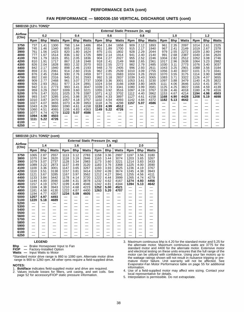
PERFORMANCE DATA (cont)
FAN PERFORMANCE — 580D036-150 VERTICAL DISCHARGE UNITS (cont)
580D150 (121⁄2 TONS)*
Airflow(Cfm)
External Static Pressure (in. wg)
0.2 0.4 0.6 0.8 1.0 1.2
Rpm Bhp Watts Rpm Bhp Watts Rpm Bhp Watts Rpm Bhp Watts Rpm Bhp Watts Rpm Bhp Watts
3750 737 1.41 1300 798 1.64 1486 854 1.84 1658 909 2.12 1893 961 2.35 2097 1014 2.61 23253800 745 1.46 1340 805 1.69 1531 861 1.89 1700 915 2.17 1940 967 2.41 2149 1019 2.67 23783900 761 1.56 1423 820 1.80 1624 875 2.01 1802 928 2.29 2044 979 2.55 2272 1029 2.80 24944000 777 1.67 1514 836 1.92 1725 889 2.14 1914 941 2.40 2140 991 2.68 2387 1040 2.94 26204100 793 1.79 1615 851 2.05 1836 904 2.27 2027 955 2.52 2246 1004 2.82 2512 1052 3.08 27464200 810 1.91 1717 867 2.18 1948 918 2.41 2149 968 2.65 2361 1017 2.96 2638 1064 3.23 28824300 826 2.04 1828 883 2.32 2070 933 2.55 2272 982 2.79 2485 1030 3.11 2773 1076 3.40 30374400 842 2.17 1940 898 2.46 2193 948 2.70 2405 996 2.93 2611 1043 3.25 2901 1088 3.56 31844500 859 2.31 2061 914 2.60 2316 962 2.85 2539 1010 3.09 2755 1056 3.40 3037 1101 3.73 33414600 876 2.45 2184 930 2.76 2459 977 3.01 2683 1024 3.26 2910 1070 3.55 3175 1114 3.90 34984700 892 2.60 2316 945 2.91 2593 992 3.18 2837 1039 3.43 3065 1083 3.71 3322 1126 4.07 36554800 909 2.77 2468 961 3.07 2737 1008 3.36 3001 1053 3.61 3230 1097 3.88 3479 1140 4.25 38224900 926 2.93 2611 977 3.24 2891 1024 3.54 3166 1068 3.80 3405 1111 4.06 3646 1153 4.41 39715000 942 3.11 2773 993 3.41 3047 1039 3.73 3341 1080 3.99 3581 1125 4.25 3822 1166 4.59 41395100 959 3.29 2937 1009 3.60 3221 1055 3.92 3516 1097 4.19 3767 1139 4.46 4018 1180 4.78 43165200 976 3.47 3101 1025 3.78 3387 1071 4.12 3702 1112 4.40 3962 1153 4.67 4214 1194 4.98 45035300 993 3.67 3285 1041 3.98 3572 1086 4.33 3897 1127 4.61 4158 1168 4.90 4428 1208 5.19 46985400 1010 3.87 3470 1057 4.18 3757 1102 4.54 4093 1142 4.84 4372 1182 5.13 4642 — — —5500 1027 4.07 3655 1073 4.39 3953 1118 4.76 4298 1157 5.07 4586 — — — — — —5600 1043 4.29 3860 1090 4.61 4158 1133 4.99 4512 — — — — — — — — —5700 1060 4.51 4065 1106 4.83 4363 1149 5.22 4726 — — — — — — — — —5800 1077 4.74 4279 1122 5.07 4586 — — — — — — — — — — — —5900 1094 4.98 4503 — — — — — — — — — — — — — — —6000 1111 5.22 4726 — — — — — — — — — — — — — — —6100 — — — — — — — — — — — — — — — — — —6250 — — — — — — — — — — — — — — — — — —
580D150 (121⁄2 TONS)* (cont)
Airflow(Cfm)
External Static Pressure (in. wg)
1.4 1.6 1.8 2.0
Rpm Bhp Watts Rpm Bhp Watts Rpm Bhp Watts Rpm Bhp Watts
3750 1065 2.87 2557 1113 3.12 2783 1158 3.36 2997 1197 3.56 31803800 1070 2.94 2620 1118 3.19 2846 1163 3.44 3074 1203 3.65 32673900 1079 3.07 2737 1128 3.34 2983 1173 3.60 3221 1214 3.83 34334000 1089 3.22 2873 1137 3.49 3120 1183 3.76 3368 1225 4.00 35904100 1100 3.36 3001 1147 3.65 3267 1193 3,93 3525 1236 4.19 37674200 1110 3.51 3138 1157 3.81 3414 1202 4.09 3674 1245 4.38 39434300 1121 3.67 3285 1167 3.97 3562 1212 4.27 3841 1255 4.56 41114400 1133 3.84 3442 1178 4.14 3720 1222 4.44 3999 1265 4.74 42794500 1144 4.00 3590 1188 4.31 3878 1232 4.62 4167 1274 4.93 44564600 1157 4.19 3767 1199 4.49 4046 1242 4.81 4344 1284 5.13 46424700 1169 4.38 3943 1210 4.68 4223 1252 5.00 4521 — — —4800 1181 4.58 4130 1222 4.87 4400 1263 5.20 4707 — — —4900 1194 4.77 4307 1234 5.09 4605 — — — — — —5000 1207 4.97 4493 — — — — — — — — —5100 1220 5.18 4689 — — — — — — — — —5200 — — — — — — — — — — — —5300 — — — — — — — — — — — —5400 — — — — — — — — — — — —5500 — — — — — — — — — — — —5600 — — — — — — — — — — — —5700 — — — — — — — — — — — —5800 — — — — — — — — — — — —5900 — — — — — — — — — — — —6000 — — — — — — — — — — — —6100 — — — — — — — — — — — —6250 — — — — — — — — — — — —
LEGENDBhp — Brake Horsepower Input to FanFIOP — Factory-Installed OptionWatts — Input Watts to Motor*Standard motor drive range is 860 to 1080 rpm. Alternate motor driverange is 900 to 1260 rpm. All other rpms require a field-supplied drive.
NOTES:1. Boldface indicates field-supplied motor and drive are required.2. Values include losses for filters, unit casing, and wet coils. See
page 52 for accessory/FIOP static pressure information.
3. Maximum continuous bhp is 4.20 for the standard motor and 5.25 forthe alternate motor. Maximum continuous watts are 3775 for thestandard motor and 4400 for the alternate motor. Extensive motorand electrical testing on these units ensures that the full range of themotor can be utilized with confidence. Using your fan motors up tothe wattage ratings shown will not result in nuisance tripping or pre-mature motor failure. Unit warranty will not be affected. SeeEvaporator-Fan Motor Performance table on page 55 for additionalinformation.
4. Use of a field-supplied motor may affect wire sizing. Contact yourlocal representative for details.
5. Interpolation is permissible. Do not extrapolate.
38
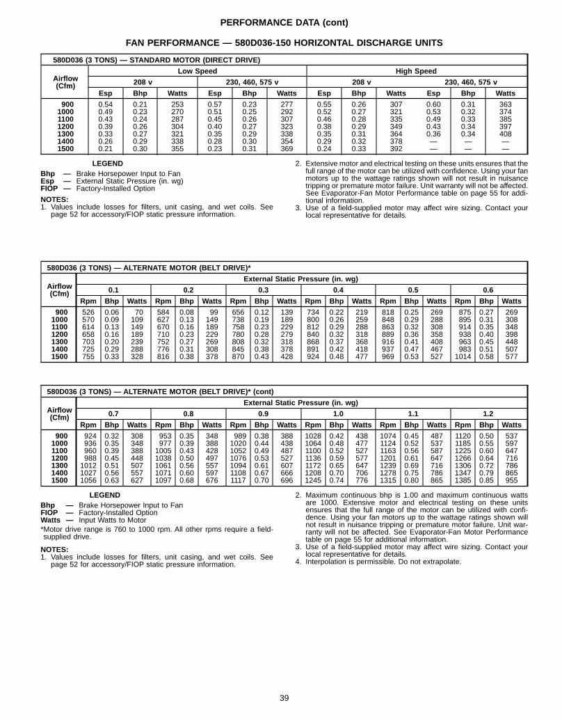
PERFORMANCE DATA (cont)
FAN PERFORMANCE — 580D036-150 HORIZONTAL DISCHARGE UNITS
580D036 (3 TONS) — STANDARD MOTOR (DIRECT DRIVE)
Airflow(Cfm)
Low Speed High Speed
208 v 230, 460, 575 v 208 v 230, 460, 575 v
Esp Bhp Watts Esp Bhp Watts Esp Bhp Watts Esp Bhp Watts
900 0.54 0.21 253 0.57 0.23 277 0.55 0.26 307 0.60 0.31 3631000 0.49 0.23 270 0.51 0.25 292 0.52 0.27 321 0.53 0.32 3741100 0.43 0.24 287 0.45 0.26 307 0.46 0.28 335 0.49 0.33 3851200 0.39 0.26 304 0.40 0.27 323 0.38 0.29 349 0.43 0.34 3971300 0.33 0.27 321 0.35 0.29 338 0.35 0.31 364 0.36 0.34 4081400 0.26 0.29 338 0.28 0.30 354 0.29 0.32 378 — — —1500 0.21 0.30 355 0.23 0.31 369 0.24 0.33 392 — — —
LEGENDBhp — Brake Horsepower Input to FanEsp — External Static Pressure (in. wg)FIOP — Factory-Installed Option
NOTES:1. Values include losses for filters, unit casing, and wet coils. See
page 52 for accessory/FIOP static pressure information.
2. Extensive motor and electrical testing on these units ensures that thefull range of the motor can be utilized with confidence. Using your fanmotors up to the wattage ratings shown will not result in nuisancetripping or premature motor failure. Unit warranty will not be affected.See Evaporator-Fan Motor Performance table on page 55 for addi-tional information.
3. Use of a field-supplied motor may affect wire sizing. Contact yourlocal representative for details.
580D036 (3 TONS) — ALTERNATE MOTOR (BELT DRIVE)*
Airflow(Cfm)
External Static Pressure (in. wg)
0.1 0.2 0.3 0.4 0.5 0.6
Rpm Bhp Watts Rpm Bhp Watts Rpm Bhp Watts Rpm Bhp Watts Rpm Bhp Watts Rpm Bhp Watts
900 526 0.06 70 584 0.08 99 656 0.12 139 734 0.22 219 818 0.25 269 875 0.27 2691000 570 0.09 109 627 0.13 149 738 0.19 189 800 0.26 259 848 0.29 288 895 0.31 3081100 614 0.13 149 670 0.16 189 758 0.23 229 812 0.29 288 863 0.32 308 914 0.35 3481200 658 0.16 189 710 0.23 229 780 0.28 279 840 0.32 318 889 0.36 358 938 0.40 3981300 703 0.20 239 752 0.27 269 808 0.32 318 868 0.37 368 916 0.41 408 963 0.45 4481400 725 0.29 288 776 0.31 308 845 0.38 378 891 0.42 418 937 0.47 467 983 0.51 5071500 755 0.33 328 816 0.38 378 870 0.43 428 924 0.48 477 969 0.53 527 1014 0.58 577
580D036 (3 TONS) — ALTERNATE MOTOR (BELT DRIVE)* (cont)
Airflow(Cfm)
External Static Pressure (in. wg)
0.7 0.8 0.9 1.0 1.1 1.2
Rpm Bhp Watts Rpm Bhp Watts Rpm Bhp Watts Rpm Bhp Watts Rpm Bhp Watts Rpm Bhp Watts
900 924 0.32 308 953 0.35 348 989 0.38 388 1028 0.42 438 1074 0.45 487 1120 0.50 5371000 936 0.35 348 977 0.39 388 1020 0.44 438 1064 0.48 477 1124 0.52 537 1185 0.55 5971100 960 0.39 388 1005 0.43 428 1052 0.49 487 1100 0.52 527 1163 0.56 587 1225 0.60 6471200 988 0.45 448 1038 0.50 497 1076 0.53 527 1136 0.59 577 1201 0.61 647 1266 0.64 7161300 1012 0.51 507 1061 0.56 557 1094 0.61 607 1172 0.65 647 1239 0.69 716 1306 0.72 7861400 1027 0.56 557 1071 0.60 597 1108 0.67 666 1208 0.70 706 1278 0.75 786 1347 0.79 8651500 1056 0.63 627 1097 0.68 676 1117 0.70 696 1245 0.74 776 1315 0.80 865 1385 0.85 955
LEGENDBhp — Brake Horsepower Input to FanFIOP — Factory-Installed OptionWatts — Input Watts to Motor*Motor drive range is 760 to 1000 rpm. All other rpms require a field-supplied drive.
NOTES:1. Values include losses for filters, unit casing, and wet coils. See
page 52 for accessory/FIOP static pressure information.
2. Maximum continuous bhp is 1.00 and maximum continuous wattsare 1000. Extensive motor and electrical testing on these unitsensures that the full range of the motor can be utilized with confi-dence. Using your fan motors up to the wattage ratings shown willnot result in nuisance tripping or premature motor failure. Unit war-ranty will not be affected. See Evaporator-Fan Motor Performancetable on page 55 for additional information.
3. Use of a field-supplied motor may affect wire sizing. Contact yourlocal representative for details.
4. Interpolation is permissible. Do not extrapolate.
39
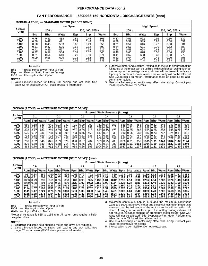
PERFORMANCE DATA (cont)
FAN PERFORMANCE — 580D036-150 HORIZONTAL DISCHARGE UNITS (cont)
580D048 (4 TONS) — STANDARD MOTOR (DIRECT DRIVE)
Airflow(Cfm)
Low Speed High Speed
208 v 230, 460, 575 v 208 v 230, 460, 575 v
Esp Bhp Watts Esp Bhp Watts Esp Bhp Watts Esp Bhp Watts
1200 0.75 0.41 458 0.81 0.45 506 0.87 0.51 572 0.92 0.56 6321300 0.68 0.42 471 0.74 0.46 521 0.79 0.52 589 0.85 0.58 6511400 0.60 0.45 503 0.66 0.49 556 0.71 0.54 616 0.77 0.60 6811500 0.51 0.47 536 0.58 0.52 593 0.64 0.56 631 0.70 0.62 6981600 0.42 0.49 557 0.49 0.54 616 0.56 0.58 654 0.63 0.64 7231700 0.32 0.52 584 0.39 0.57 646 0.48 0.60 678 0.55 0.66 7501800 0.21 0.54 610 0.29 0.60 674 0.41 0.62 698 0.48 0.68 7721900 0.09 0.56 629 0.18 0.62 696 0.33 0.64 720 0.41 0.70 7962000 — — — 0.06 0.65 731 0.26 0.66 744 0.33 0.73 823
LEGENDBhp — Brake Horsepower Input to FanEsp — External Static Pressure (in. wg)FIOP — Factory-Installed Option
NOTES:1. Values include losses for filters, unit casing, and wet coils. See
page 52 for accessory/FIOP static pressure information.
2. Extensive motor and electrical testing on these units ensures that thefull range of the motor can be utilized with confidence. Using your fanmotors up to the wattage ratings shown will not result in nuisancetripping or premature motor failure. Unit warranty will not be affected.See Evaporator-Fan Motor Performance table on page 55 for addi-tional information.
3. Use of a field-supplied motor may affect wire sizing. Contact yourlocal representative for details.
580D048 (4 TONS) — ALTERNATE MOTOR (BELT DRIVE)*
Airflow(Cfm)
External Static Pressure (in. wg)
0.1 0.2 0.3 0.4 0.6 0.7 0.8
Rpm Bhp Watts Rpm Bhp Watts Rpm Bhp Watts Rpm Bhp Watts Rpm Bhp Watts Rpm Bhp Watts Rpm Bhp Watts
1200 569 0.18 189 641 0.23 242 701 0.29 299 761 0.34 357 859 0.46 483 901 0.52 546 943 0.58 6091300 604 0.22 231 673 0.28 294 731 0.34 352 788 0.39 410 887 0.52 546 928 0.59 615 968 0.65 6831400 640 0.27 284 705 0.33 347 761 0.39 410 817 0.45 473 914 0.59 620 955 0.66 688 996 0.72 7571500 676 0.32 336 738 0.38 399 793 0.45 468 847 0.51 536 940 0.65 683 982 0.73 767 1024 0.81 8511600 713 0.38 399 772 0.44 462 825 0.51 536 877 0.58 609 967 0.73 767 1009 0.81 851 1051 0.89 9351700 750 0.45 473 806 0.51 536 857 0.59 615 908 0.66 693 997 0.81 851 1037 0.90 940 1077 1.01 10301800 788 0.52 546 841 0.59 620 890 0.67 704 939 0.75 788 1026 0.91 956 1065 1.01 1040 1104 1.07 11241900 826 0.60 630 876 0.68 714 924 0.76 799 971 0.84 883 1056 1.01 1061 1094 1.10 1151 1132 1.18 12402000 864 0.70 735 912 0.77 809 958 0.86 898 1004 0.94 988 1087 1.12 1177 1125 1.21 1271 1162 1.30 1366
580D048 (4 TONS) — ALTERNATE MOTOR (BELT DRIVE)* (cont)
Airflow(Cfm)
External Static Pressure (in. wg)
0.9 1.0 1.1 1.2 1.4 1.6 1.8
Rpm Bhp Watts Rpm Bhp Watts Rpm Bhp Watts Rpm Bhp Watts Rpm Bhp Watts Rpm Bhp Watts Rpm Bhp Watts
1200 987 0.64 652 1030 0.70 695 1068 0.79 792 1106 0.87 889 1134 0.98 998 1189 1.12 1138 1245 1.21 13581300 1006 0.71 709 1044 0.77 736 1086 0.84 833 1128 0.91 930 1183 1.10 1052 1226 1.23 1215 1297 1.35 14061400 1033 0.79 797 1069 0.86 838 1104 0.93 925 1139 1.01 1012 1218 1.14 1090 1286 1.34 1282 1320 1.48 14631500 1060 0.88 891 1095 0.95 930 1129 1.02 1022 1162 1.09 1114 1228 1.24 1186 1303 1.40 1339 1343 1.60 15301600 1087 1.01 1001 1123 1.05 1073 1156 1.13 1150 1185 1.20 1226 1250 1.35 1291 1319 1.51 1444 1382 1.68 16071700 1114 1.07 1108 1151 1.15 1185 1183 1.23 1262 1215 1.31 1339 1276 1.48 1415 1334 1.64 1569 1398 1.80 17221800 1141 1.17 1221 1178 1.26 1318 1211 1.35 1390 1243 1.43 1461 1303 1.61 1540 1359 1.78 1702 1418 1.95 18651900 1168 1.28 1371 1204 1.37 1502 1238 1.47 1548 1271 1.56 1594 1330 1.74 1664 1386 1.93 1846 1439 2.11 20182000 1197 1.39 1485 1231 1.48 1604 1265 1.59 1666 1298 1.69 1727 1358 1.89 1808 1413 2.08 1989 1466 2.27 2171
LEGENDBhp — Brake Horsepower Input to FanFIOP — Factory-Installed OptionWatts — Input Watts to Motor*Motor drive range is 835 to 1185 rpm. All other rpms require a field-supplied drive.
NOTES:1. Boldface indicates field-supplied motor and drive are required.2. Values include losses for filters, unit casing, and wet coils. See
page 52 for accessory/FIOP static pressure information.
3. Maximum continuous bhp is 1.00 and the maximum continuouswatts are 1000. Extensive motor and electrical testing on these unitsensures that the full range of the motor can be utilized with confi-dence. Using your fan motors up to the wattage ratings shown willnot result in nuisance tripping or premature motor failure. Unit war-ranty will not be affected. See Evaporator-Fan Motor Performancetable on page 55 for additional information.
4. Use of a field-supplied motor may affect wire sizing. Contact yourlocal representative for details.
5. Interpolation is permissible. Do not extrapolate.
40
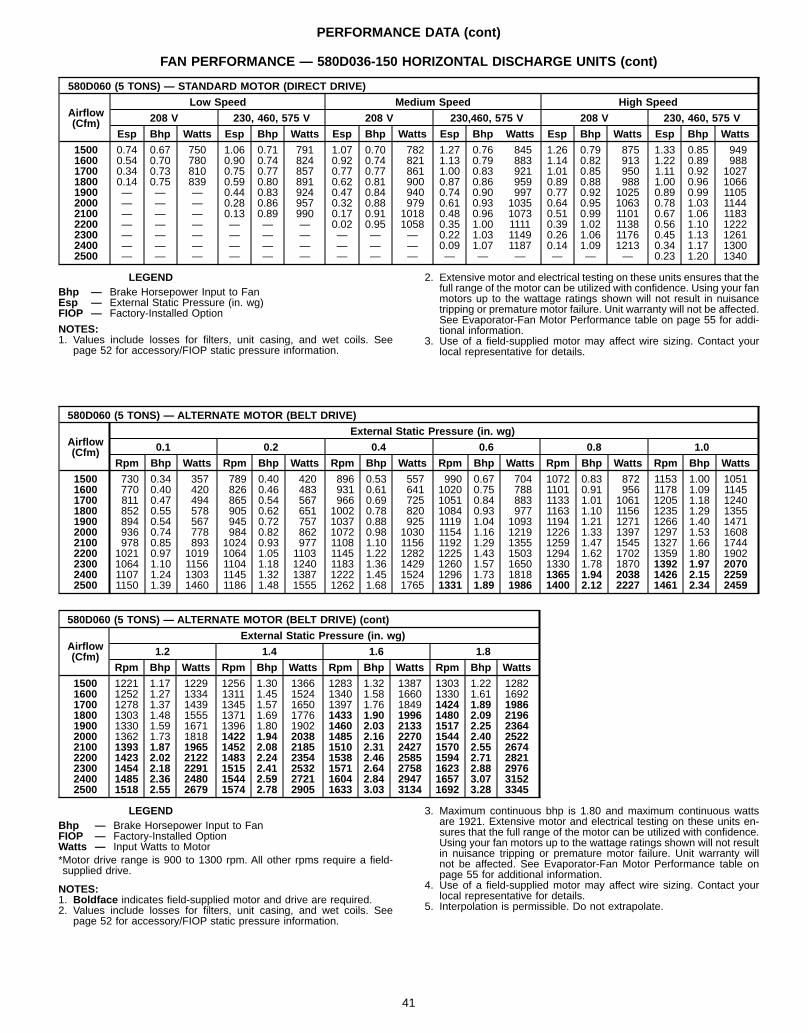
PERFORMANCE DATA (cont)
FAN PERFORMANCE — 580D036-150 HORIZONTAL DISCHARGE UNITS (cont)
580D060 (5 TONS) — STANDARD MOTOR (DIRECT DRIVE)
Airflow(Cfm)
Low Speed Medium Speed High Speed
208 V 230, 460, 575 V 208 V 230,460, 575 V 208 V 230, 460, 575 V
Esp Bhp Watts Esp Bhp Watts Esp Bhp Watts Esp Bhp Watts Esp Bhp Watts Esp Bhp Watts
1500 0.74 0.67 750 1.06 0.71 791 1.07 0.70 782 1.27 0.76 845 1.26 0.79 875 1.33 0.85 9491600 0.54 0.70 780 0.90 0.74 824 0.92 0.74 821 1.13 0.79 883 1.14 0.82 913 1.22 0.89 9881700 0.34 0.73 810 0.75 0.77 857 0.77 0.77 861 1.00 0.83 921 1.01 0.85 950 1.11 0.92 10271800 0.14 0.75 839 0.59 0.80 891 0.62 0.81 900 0.87 0.86 959 0.89 0.88 988 1.00 0.96 10661900 — — — 0.44 0.83 924 0.47 0.84 940 0.74 0.90 997 0.77 0.92 1025 0.89 0.99 11052000 — — — 0.28 0.86 957 0.32 0.88 979 0.61 0.93 1035 0.64 0.95 1063 0.78 1.03 11442100 — — — 0.13 0.89 990 0.17 0.91 1018 0.48 0.96 1073 0.51 0.99 1101 0.67 1.06 11832200 — — — — — — 0.02 0.95 1058 0.35 1.00 1111 0.39 1.02 1138 0.56 1.10 12222300 — — — — — — — — — 0.22 1.03 1149 0.26 1.06 1176 0.45 1.13 12612400 — — — — — — — — — 0.09 1.07 1187 0.14 1.09 1213 0.34 1.17 13002500 — — — — — — — — — — — — — — — 0.23 1.20 1340
LEGENDBhp — Brake Horsepower Input to FanEsp — External Static Pressure (in. wg)FIOP — Factory-Installed Option
NOTES:1. Values include losses for filters, unit casing, and wet coils. See
page 52 for accessory/FIOP static pressure information.
2. Extensive motor and electrical testing on these units ensures that thefull range of the motor can be utilized with confidence. Using your fanmotors up to the wattage ratings shown will not result in nuisancetripping or premature motor failure. Unit warranty will not be affected.See Evaporator-Fan Motor Performance table on page 55 for addi-tional information.
3. Use of a field-supplied motor may affect wire sizing. Contact yourlocal representative for details.
580D060 (5 TONS) — ALTERNATE MOTOR (BELT DRIVE)
Airflow(Cfm)
External Static Pressure (in. wg)
0.1 0.2 0.4 0.6 0.8 1.0
Rpm Bhp Watts Rpm Bhp Watts Rpm Bhp Watts Rpm Bhp Watts Rpm Bhp Watts Rpm Bhp Watts
1500 730 0.34 357 789 0.40 420 896 0.53 557 990 0.67 704 1072 0.83 872 1153 1.00 10511600 770 0.40 420 826 0.46 483 931 0.61 641 1020 0.75 788 1101 0.91 956 1178 1.09 11451700 811 0.47 494 865 0.54 567 966 0.69 725 1051 0.84 883 1133 1.01 1061 1205 1.18 12401800 852 0.55 578 905 0.62 651 1002 0.78 820 1084 0.93 977 1163 1.10 1156 1235 1.29 13551900 894 0.54 567 945 0.72 757 1037 0.88 925 1119 1.04 1093 1194 1.21 1271 1266 1.40 14712000 936 0.74 778 984 0.82 862 1072 0.98 1030 1154 1.16 1219 1226 1.33 1397 1297 1.53 16082100 978 0.85 893 1024 0.93 977 1108 1.10 1156 1192 1.29 1355 1259 1.47 1545 1327 1.66 17442200 1021 0.97 1019 1064 1.05 1103 1145 1.22 1282 1225 1.43 1503 1294 1.62 1702 1359 1.80 19022300 1064 1.10 1156 1104 1.18 1240 1183 1.36 1429 1260 1.57 1650 1330 1.78 1870 1392 1.97 20702400 1107 1.24 1303 1145 1.32 1387 1222 1.45 1524 1296 1.73 1818 1365 1.94 2038 1426 2.15 22592500 1150 1.39 1460 1186 1.48 1555 1262 1.68 1765 1331 1.89 1986 1400 2.12 2227 1461 2.34 2459
580D060 (5 TONS) — ALTERNATE MOTOR (BELT DRIVE) (cont)
Airflow(Cfm)
External Static Pressure (in. wg)
1.2 1.4 1.6 1.8
Rpm Bhp Watts Rpm Bhp Watts Rpm Bhp Watts Rpm Bhp Watts
1500 1221 1.17 1229 1256 1.30 1366 1283 1.32 1387 1303 1.22 12821600 1252 1.27 1334 1311 1.45 1524 1340 1.58 1660 1330 1.61 16921700 1278 1.37 1439 1345 1.57 1650 1397 1.76 1849 1424 1.89 19861800 1303 1.48 1555 1371 1.69 1776 1433 1.90 1996 1480 2.09 21961900 1330 1.59 1671 1396 1.80 1902 1460 2.03 2133 1517 2.25 23642000 1362 1.73 1818 1422 1.94 2038 1485 2.16 2270 1544 2.40 25222100 1393 1.87 1965 1452 2.08 2185 1510 2.31 2427 1570 2.55 26742200 1423 2.02 2122 1483 2.24 2354 1538 2.46 2585 1594 2.71 28212300 1454 2.18 2291 1515 2.41 2532 1571 2.64 2758 1623 2.88 29762400 1485 2.36 2480 1544 2.59 2721 1604 2.84 2947 1657 3.07 31522500 1518 2.55 2679 1574 2.78 2905 1633 3.03 3134 1692 3.28 3345
LEGENDBhp — Brake Horsepower Input to FanFIOP — Factory-Installed OptionWatts — Input Watts to Motor*Motor drive range is 900 to 1300 rpm. All other rpms require a field-supplied drive.
NOTES:1. Boldface indicates field-supplied motor and drive are required.2. Values include losses for filters, unit casing, and wet coils. See
page 52 for accessory/FIOP static pressure information.
3. Maximum continuous bhp is 1.80 and maximum continuous wattsare 1921. Extensive motor and electrical testing on these units en-sures that the full range of the motor can be utilized with confidence.Using your fan motors up to the wattage ratings shown will not resultin nuisance tripping or premature motor failure. Unit warranty willnot be affected. See Evaporator-Fan Motor Performance table onpage 55 for additional information.
4. Use of a field-supplied motor may affect wire sizing. Contact yourlocal representative for details.
5. Interpolation is permissible. Do not extrapolate.
41
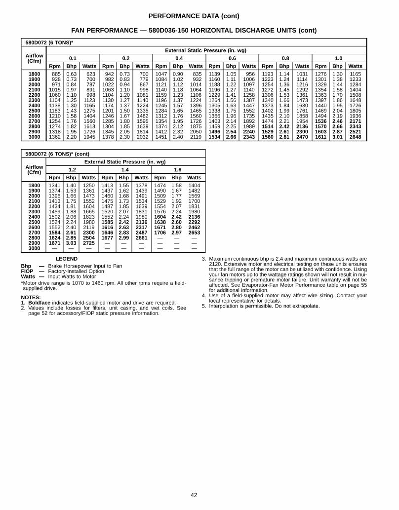
PERFORMANCE DATA (cont)
FAN PERFORMANCE — 580D036-150 HORIZONTAL DISCHARGE UNITS (cont)
580D072 (6 TONS)*
Airflow(Cfm)
External Static Pressure (in. wg)
0.1 0.2 0.4 0.6 0.8 1.0
Rpm Bhp Watts Rpm Bhp Watts Rpm Bhp Watts Rpm Bhp Watts Rpm Bhp Watts Rpm Bhp Watts
1800 885 0.63 623 942 0.73 700 1047 0.90 835 1139 1.05 956 1193 1.14 1031 1276 1.30 11651900 928 0.73 700 982 0.83 779 1084 1.02 932 1160 1.11 1006 1223 1.24 1114 1301 1.38 12332000 971 0.84 787 1022 0.94 867 1121 1.12 1014 1188 1.22 1097 1254 1.36 1216 1329 1.44 12842100 1015 0.97 891 1063 1.10 998 1140 1.18 1064 1196 1.27 1140 1272 1.45 1292 1354 1.58 14042200 1060 1.10 998 1104 1.20 1081 1159 1.23 1106 1229 1.41 1258 1306 1.53 1361 1363 1.70 15082300 1104 1.25 1123 1130 1.27 1140 1196 1.37 1224 1264 1.56 1387 1340 1.66 1473 1397 1.86 16482400 1138 1.30 1165 1174 1.37 1224 1245 1.57 1396 1305 1.63 1447 1373 1.84 1630 1440 1.95 17262500 1183 1.43 1275 1201 1.50 1335 1284 1.65 1465 1338 1.75 1552 1402 1.99 1761 1469 2.04 18052600 1210 1.58 1404 1246 1.67 1482 1312 1.76 1560 1366 1.96 1735 1435 2.10 1858 1494 2.19 19362700 1254 1.76 1560 1285 1.80 1595 1354 1.95 1726 1403 2.14 1892 1474 2.21 1954 1536 2.46 21712800 1274 1.82 1613 1304 1.85 1639 1374 2.12 1875 1459 2.25 1989 1514 2.42 2136 1570 2.66 23432900 1318 1.95 1726 1345 2.05 1814 1412 2.32 2050 1496 2.54 2240 1529 2.61 2300 1603 2.87 25213000 1362 2.20 1945 1378 2.30 2032 1451 2.40 2119 1534 2.66 2343 1560 2.81 2470 1611 3.01 2648
580D072 (6 TONS)* (cont)
Airflow(Cfm)
External Static Pressure (in. wg)
1.2 1.4 1.6
Rpm Bhp Watts Rpm Bhp Watts Rpm Bhp Watts
1800 1341 1.40 1250 1413 1.55 1378 1474 1.58 14041900 1374 1.53 1361 1437 1.62 1439 1490 1.67 14822000 1396 1.66 1473 1460 1.68 1491 1509 1.77 15692100 1413 1.75 1552 1475 1.73 1534 1529 1.92 17002200 1434 1.81 1604 1487 1.85 1639 1554 2.07 18312300 1459 1.88 1665 1520 2.07 1831 1576 2.24 19802400 1502 2.06 1823 1552 2.24 1980 1604 2.42 21362500 1524 2.24 1980 1585 2.42 2136 1638 2.60 22922600 1552 2.40 2119 1616 2.63 2317 1671 2.80 24622700 1584 2.61 2300 1646 2.83 2487 1706 2.97 26532800 1624 2.85 2504 1677 2.99 2661 — — —2900 1671 3.03 2725 — — — — — —3000 — — — — — — — — —
LEGENDBhp — Brake Horsepower Input to FanFIOP — Factory-Installed OptionWatts — Input Watts to Motor*Motor drive range is 1070 to 1460 rpm. All other rpms require a field-supplied drive.
NOTES:1. Boldface indicates field-supplied motor and drive are required.2. Values include losses for filters, unit casing, and wet coils. See
page 52 for accessory/FIOP static pressure information.
3. Maximum continuous bhp is 2.4 and maximum continuous watts are2120. Extensive motor and electrical testing on these units ensuresthat the full range of the motor can be utilized with confidence. Usingyour fan motors up to the wattage ratings shown will not result in nui-sance tripping or premature motor failure. Unit warranty will not beaffected. See Evaporator-Fan Motor Performance table on page 55for additional information.
4. Use of a field-supplied motor may affect wire sizing. Contact yourlocal representative for details.
5. Interpolation is permissible. Do not extrapolate.
42
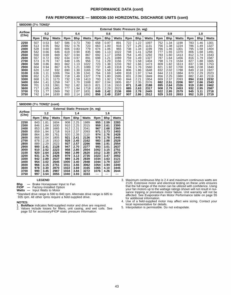
PERFORMANCE DATA (cont)
FAN PERFORMANCE — 580D036-150 HORIZONTAL DISCHARGE UNITS (cont)
580D090 (71⁄2 TONS)*
Airflow(Cfm)
External Static Pressure (in. wg)
0.2 0.4 0.6 0.8 0.9 1.0
Rpm Bhp Watts Rpm Bhp Watts Rpm Bhp Watts Rpm Bhp Watts Rpm Bhp Watts Rpm Bhp Watts
2250 507 0.53 547 586 0.73 700 658 0.97 891 722 1.22 1097 752 1.34 1199 783 1.46 13012300 513 0.55 562 592 0.76 723 663 1.00 916 727 1.26 1131 756 1.38 1224 786 1.49 13272400 528 0.60 600 606 0.83 779 674 1.06 965 738 1.34 1199 766 1.46 1301 795 1.58 14042500 542 0.66 646 619 0.90 835 686 1.13 1022 748 1.41 1258 777 1.55 1370 806 1.68 14912550 550 0.69 669 627 0.94 867 692 1.17 1056 754 1.45 1292 783 1.60 1413 812 1.74 15432600 557 0.72 692 634 0.97 891 698 1.21 1089 759 1.49 1327 787 1.64 1456 816 1.79 15872700 573 0.79 747 648 1.05 956 711 1.29 1156 770 1.58 1404 798 1.73 1534 827 1.88 16652800 588 0.86 803 662 1.13 1022 723 1.38 1233 782 1.66 1473 809 1.82 1613 837 1.98 17532900 604 0.94 867 676 1.21 1089 737 1.48 1318 794 1.76 1560 821 1.92 1700 848 2.08 18403000 620 1.02 932 690 1.30 1165 750 1.58 1404 806 1.86 1648 832 2.02 1788 849 2.18 19273100 636 1.11 1006 704 1.39 1241 764 1.69 1499 818 1.97 1744 844 2.13 1884 870 2.29 20233200 652 1.21 1089 718 1.49 1327 778 1.80 1595 831 2.09 1849 856 2.25 1980 882 2.40 21193300 668 1.31 1173 732 1.59 1413 793 1.92 1700 844 2.21 1954 869 2.37 2093 894 2.53 22323400 684 1.41 1258 747 1.70 1508 807 2.04 1805 857 2.35 2076 882 2.51 2206 907 2.66 23433500 701 1.53 1361 762 1.82 1613 821 2.16 1910 871 2.48 2188 895 2.64 2326 919 2.80 24623600 717 1.65 1465 777 1.94 1718 835 2.29 2023 885 2.63 2317 908 2.79 2453 932 2.95 25873700 733 1.77 1569 792 2.07 1831 849 2.42 2136 899 2.78 2445 922 2.95 2579 945 3.11 27183750 742 1.84 1630 800 2.14 1892 856 2.49 2197 907 2.86 2512 929 3.03 2653 952 3.20 2719
580D090 (71⁄2 TONS)* (cont)
Airflow(Cfm)
External Static Pressure (in. wg)
1.2 1.4 1.6
Rpm Bhp Watts Rpm Bhp Watts Rpm Bhp Watts
2250 843 1.81 1604 908 2.25 1989 955 2.59 22832300 846 1.84 1630 910 2.25 2015 959 2.61 23002400 853 1.88 1665 912 2.31 2041 967 2.68 23602500 859 1.94 1718 919 2.37 2093 971 2.73 24032550 864 1.99 1761 920 2.39 2110 974 2.76 24282600 868 2.04 1805 921 2.41 2136 976 2.78 24452700 878 2.16 1910 928 2.45 2162 983 2.88 25292800 889 2.29 2023 937 2.57 2266 986 2.91 25542900 900 2.41 2128 947 2.70 2377 993 3.01 26373000 910 2.52 2223 958 2.85 2504 1002 3.15 27513100 920 2.64 2326 968 2.99 2620 1012 3.30 28703200 931 2.76 2428 979 3.13 2735 1023 3.47 30023300 942 2.89 2537 989 3.26 2839 1034 3.63 31213400 954 3.02 2645 1000 3.40 2948 1044 3.79 32373500 966 3.15 2751 1011 3.55 3062 1054 3.94 33403600 978 3.30 2870 1022 3.69 3165 1065 4.10 34453700 990 3.45 2987 1034 3.84 3272 1076 4.26 35443750 997 3.54 3055 1040 3.93 3333 — — —
LEGENDBhp — Brake Horsepower Input to FanFIOP — Factory-Installed OptionWatts — Input Watts to Motor*Standard drive range is 590 to 840 rpm. Alternate drive range is 685 to935 rpm. All other rpms require a field-supplied drive.
NOTES:1. Boldface indicates field-supplied motor and drive are required.2. Values include losses for filters, unit casing, and wet coils. See
page 52 for accessory/FIOP static pressure information.
3. Maximum continuous bhp is 2.4 and maximum continuous watts are2120. Extensive motor and electrical testing on these units ensuresthat the full range of the motor can be utilized with confidence. Usingyour fan motors up to the wattage ratings shown will not result in nui-sance tripping or premature motor failure. Unit warranty will not beaffected. See Evaporator-Fan Motor Performance table on page 55for additional information.
4. Use of a field-supplied motor may affect wire sizing. Contact yourlocal representative for details.
5. Interpolation is permissible. Do not extrapolate.
43
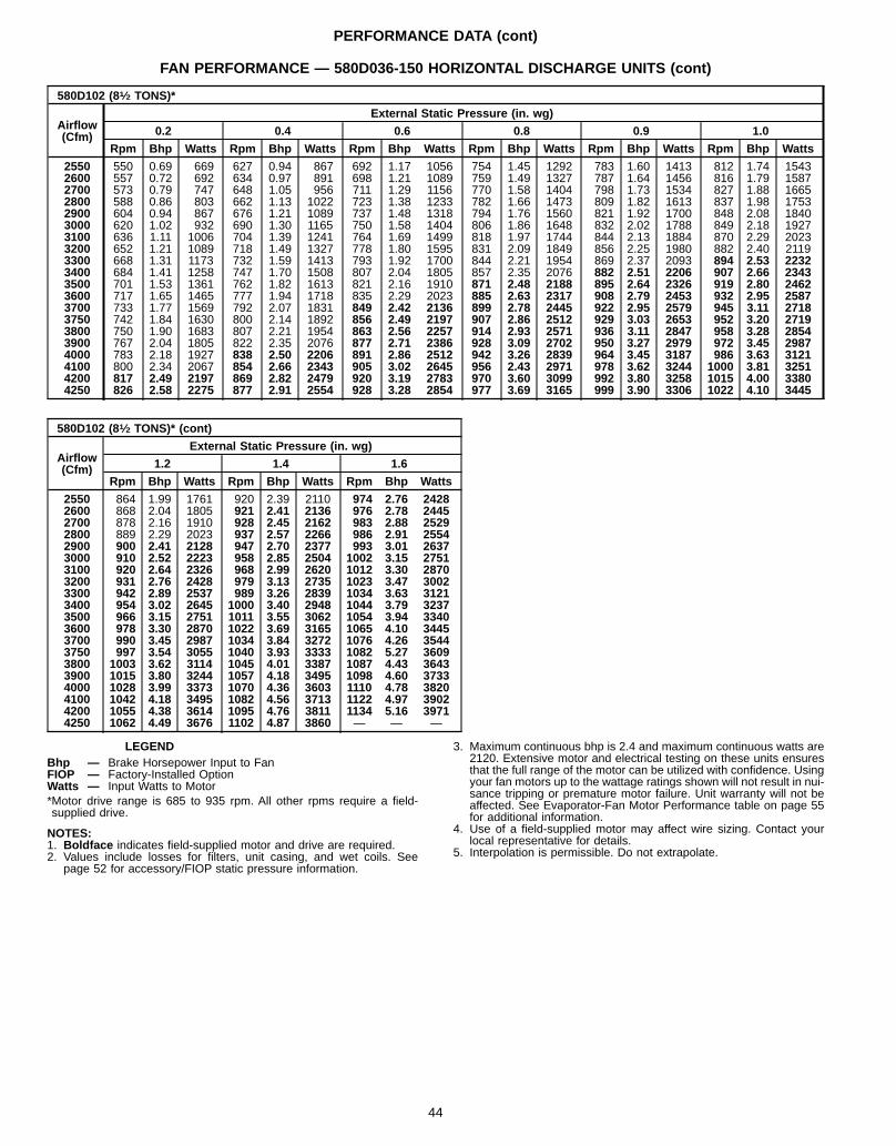
PERFORMANCE DATA (cont)
FAN PERFORMANCE — 580D036-150 HORIZONTAL DISCHARGE UNITS (cont)
580D102 (81⁄2 TONS)*
Airflow(Cfm)
External Static Pressure (in. wg)
0.2 0.4 0.6 0.8 0.9 1.0
Rpm Bhp Watts Rpm Bhp Watts Rpm Bhp Watts Rpm Bhp Watts Rpm Bhp Watts Rpm Bhp Watts
2550 550 0.69 669 627 0.94 867 692 1.17 1056 754 1.45 1292 783 1.60 1413 812 1.74 15432600 557 0.72 692 634 0.97 891 698 1.21 1089 759 1.49 1327 787 1.64 1456 816 1.79 15872700 573 0.79 747 648 1.05 956 711 1.29 1156 770 1.58 1404 798 1.73 1534 827 1.88 16652800 588 0.86 803 662 1.13 1022 723 1.38 1233 782 1.66 1473 809 1.82 1613 837 1.98 17532900 604 0.94 867 676 1.21 1089 737 1.48 1318 794 1.76 1560 821 1.92 1700 848 2.08 18403000 620 1.02 932 690 1.30 1165 750 1.58 1404 806 1.86 1648 832 2.02 1788 849 2.18 19273100 636 1.11 1006 704 1.39 1241 764 1.69 1499 818 1.97 1744 844 2.13 1884 870 2.29 20233200 652 1.21 1089 718 1.49 1327 778 1.80 1595 831 2.09 1849 856 2.25 1980 882 2.40 21193300 668 1.31 1173 732 1.59 1413 793 1.92 1700 844 2.21 1954 869 2.37 2093 894 2.53 22323400 684 1.41 1258 747 1.70 1508 807 2.04 1805 857 2.35 2076 882 2.51 2206 907 2.66 23433500 701 1.53 1361 762 1.82 1613 821 2.16 1910 871 2.48 2188 895 2.64 2326 919 2.80 24623600 717 1.65 1465 777 1.94 1718 835 2.29 2023 885 2.63 2317 908 2.79 2453 932 2.95 25873700 733 1.77 1569 792 2.07 1831 849 2.42 2136 899 2.78 2445 922 2.95 2579 945 3.11 27183750 742 1.84 1630 800 2.14 1892 856 2.49 2197 907 2.86 2512 929 3.03 2653 952 3.20 27193800 750 1.90 1683 807 2.21 1954 863 2.56 2257 914 2.93 2571 936 3.11 2847 958 3.28 28543900 767 2.04 1805 822 2.35 2076 877 2.71 2386 928 3.09 2702 950 3.27 2979 972 3.45 29874000 783 2.18 1927 838 2.50 2206 891 2.86 2512 942 3.26 2839 964 3.45 3187 986 3.63 31214100 800 2.34 2067 854 2.66 2343 905 3.02 2645 956 2.43 2971 978 3.62 3244 1000 3.81 32514200 817 2.49 2197 869 2.82 2479 920 3.19 2783 970 3.60 3099 992 3.80 3258 1015 4.00 33804250 826 2.58 2275 877 2.91 2554 928 3.28 2854 977 3.69 3165 999 3.90 3306 1022 4.10 3445
580D102 (81⁄2 TONS)* (cont)
Airflow(Cfm)
External Static Pressure (in. wg)
1.2 1.4 1.6
Rpm Bhp Watts Rpm Bhp Watts Rpm Bhp Watts
2550 864 1.99 1761 920 2.39 2110 974 2.76 24282600 868 2.04 1805 921 2.41 2136 976 2.78 24452700 878 2.16 1910 928 2.45 2162 983 2.88 25292800 889 2.29 2023 937 2.57 2266 986 2.91 25542900 900 2.41 2128 947 2.70 2377 993 3.01 26373000 910 2.52 2223 958 2.85 2504 1002 3.15 27513100 920 2.64 2326 968 2.99 2620 1012 3.30 28703200 931 2.76 2428 979 3.13 2735 1023 3.47 30023300 942 2.89 2537 989 3.26 2839 1034 3.63 31213400 954 3.02 2645 1000 3.40 2948 1044 3.79 32373500 966 3.15 2751 1011 3.55 3062 1054 3.94 33403600 978 3.30 2870 1022 3.69 3165 1065 4.10 34453700 990 3.45 2987 1034 3.84 3272 1076 4.26 35443750 997 3.54 3055 1040 3.93 3333 1082 5.27 36093800 1003 3.62 3114 1045 4.01 3387 1087 4.43 36433900 1015 3.80 3244 1057 4.18 3495 1098 4.60 37334000 1028 3.99 3373 1070 4.36 3603 1110 4.78 38204100 1042 4.18 3495 1082 4.56 3713 1122 4.97 39024200 1055 4.38 3614 1095 4.76 3811 1134 5.16 39714250 1062 4.49 3676 1102 4.87 3860 — — —
LEGENDBhp — Brake Horsepower Input to FanFIOP — Factory-Installed OptionWatts — Input Watts to Motor*Motor drive range is 685 to 935 rpm. All other rpms require a field-supplied drive.
NOTES:1. Boldface indicates field-supplied motor and drive are required.2. Values include losses for filters, unit casing, and wet coils. See
page 52 for accessory/FIOP static pressure information.
3. Maximum continuous bhp is 2.4 and maximum continuous watts are2120. Extensive motor and electrical testing on these units ensuresthat the full range of the motor can be utilized with confidence. Usingyour fan motors up to the wattage ratings shown will not result in nui-sance tripping or premature motor failure. Unit warranty will not beaffected. See Evaporator-Fan Motor Performance table on page 55for additional information.
4. Use of a field-supplied motor may affect wire sizing. Contact yourlocal representative for details.
5. Interpolation is permissible. Do not extrapolate.
44
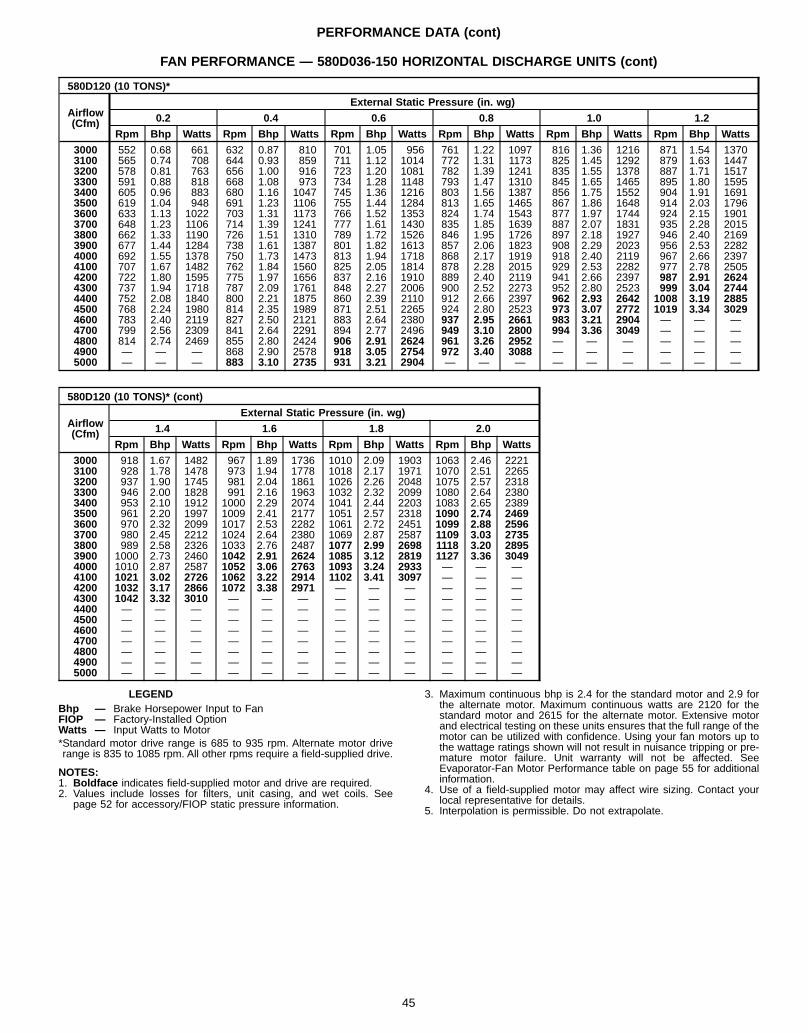
PERFORMANCE DATA (cont)
FAN PERFORMANCE — 580D036-150 HORIZONTAL DISCHARGE UNITS (cont)
580D120 (10 TONS)*
Airflow(Cfm)
External Static Pressure (in. wg)
0.2 0.4 0.6 0.8 1.0 1.2
Rpm Bhp Watts Rpm Bhp Watts Rpm Bhp Watts Rpm Bhp Watts Rpm Bhp Watts Rpm Bhp Watts
3000 552 0.68 661 632 0.87 810 701 1.05 956 761 1.22 1097 816 1.36 1216 871 1.54 13703100 565 0.74 708 644 0.93 859 711 1.12 1014 772 1.31 1173 825 1.45 1292 879 1.63 14473200 578 0.81 763 656 1.00 916 723 1.20 1081 782 1.39 1241 835 1.55 1378 887 1.71 15173300 591 0.88 818 668 1.08 973 734 1.28 1148 793 1.47 1310 845 1.65 1465 895 1.80 15953400 605 0.96 883 680 1.16 1047 745 1.36 1216 803 1.56 1387 856 1.75 1552 904 1.91 16913500 619 1.04 948 691 1.23 1106 755 1.44 1284 813 1.65 1465 867 1.86 1648 914 2.03 17963600 633 1.13 1022 703 1.31 1173 766 1.52 1353 824 1.74 1543 877 1.97 1744 924 2.15 19013700 648 1.23 1106 714 1.39 1241 777 1.61 1430 835 1.85 1639 887 2.07 1831 935 2.28 20153800 662 1.33 1190 726 1.51 1310 789 1.72 1526 846 1.95 1726 897 2.18 1927 946 2.40 21693900 677 1.44 1284 738 1.61 1387 801 1.82 1613 857 2.06 1823 908 2.29 2023 956 2.53 22824000 692 1.55 1378 750 1.73 1473 813 1.94 1718 868 2.17 1919 918 2.40 2119 967 2.66 23974100 707 1.67 1482 762 1.84 1560 825 2.05 1814 878 2.28 2015 929 2.53 2282 977 2.78 25054200 722 1.80 1595 775 1.97 1656 837 2.16 1910 889 2.40 2119 941 2.66 2397 987 2.91 26244300 737 1.94 1718 787 2.09 1761 848 2.27 2006 900 2.52 2273 952 2.80 2523 999 3.04 27444400 752 2.08 1840 800 2.21 1875 860 2.39 2110 912 2.66 2397 962 2.93 2642 1008 3.19 28854500 768 2.24 1980 814 2.35 1989 871 2.51 2265 924 2.80 2523 973 3.07 2772 1019 3.34 30294600 783 2.40 2119 827 2.50 2121 883 2.64 2380 937 2.95 2661 983 3.21 2904 — — —4700 799 2.56 2309 841 2.64 2291 894 2.77 2496 949 3.10 2800 994 3.36 3049 — — —4800 814 2.74 2469 855 2.80 2424 906 2.91 2624 961 3.26 2952 — — — — — —4900 — — — 868 2.90 2578 918 3.05 2754 972 3.40 3088 — — — — — —5000 — — — 883 3.10 2735 931 3.21 2904 — — — — — — — — —
580D120 (10 TONS)* (cont)
Airflow(Cfm)
External Static Pressure (in. wg)
1.4 1.6 1.8 2.0
Rpm Bhp Watts Rpm Bhp Watts Rpm Bhp Watts Rpm Bhp Watts
3000 918 1.67 1482 967 1.89 1736 1010 2.09 1903 1063 2.46 22213100 928 1.78 1478 973 1.94 1778 1018 2.17 1971 1070 2.51 22653200 937 1.90 1745 981 2.04 1861 1026 2.26 2048 1075 2.57 23183300 946 2.00 1828 991 2.16 1963 1032 2.32 2099 1080 2.64 23803400 953 2.10 1912 1000 2.29 2074 1041 2.44 2203 1083 2.65 23893500 961 2.20 1997 1009 2.41 2177 1051 2.57 2318 1090 2.74 24693600 970 2.32 2099 1017 2.53 2282 1061 2.72 2451 1099 2.88 25963700 980 2.45 2212 1024 2.64 2380 1069 2.87 2587 1109 3.03 27353800 989 2.58 2326 1033 2.76 2487 1077 2.99 2698 1118 3.20 28953900 1000 2.73 2460 1042 2.91 2624 1085 3.12 2819 1127 3.36 30494000 1010 2.87 2587 1052 3.06 2763 1093 3.24 2933 — — —4100 1021 3.02 2726 1062 3.22 2914 1102 3.41 3097 — — —4200 1032 3.17 2866 1072 3.38 2971 — — — — — —4300 1042 3.32 3010 — — — — — — — — —4400 — — — — — — — — — — — —4500 — — — — — — — — — — — —4600 — — — — — — — — — — — —4700 — — — — — — — — — — — —4800 — — — — — — — — — — — —4900 — — — — — — — — — — — —5000 — — — — — — — — — — — —
LEGENDBhp — Brake Horsepower Input to FanFIOP — Factory-Installed OptionWatts — Input Watts to Motor*Standard motor drive range is 685 to 935 rpm. Alternate motor driverange is 835 to 1085 rpm. All other rpms require a field-supplied drive.
NOTES:1. Boldface indicates field-supplied motor and drive are required.2. Values include losses for filters, unit casing, and wet coils. See
page 52 for accessory/FIOP static pressure information.
3. Maximum continuous bhp is 2.4 for the standard motor and 2.9 forthe alternate motor. Maximum continuous watts are 2120 for thestandard motor and 2615 for the alternate motor. Extensive motorand electrical testing on these units ensures that the full range of themotor can be utilized with confidence. Using your fan motors up tothe wattage ratings shown will not result in nuisance tripping or pre-mature motor failure. Unit warranty will not be affected. SeeEvaporator-Fan Motor Performance table on page 55 for additionalinformation.
4. Use of a field-supplied motor may affect wire sizing. Contact yourlocal representative for details.
5. Interpolation is permissible. Do not extrapolate.
45
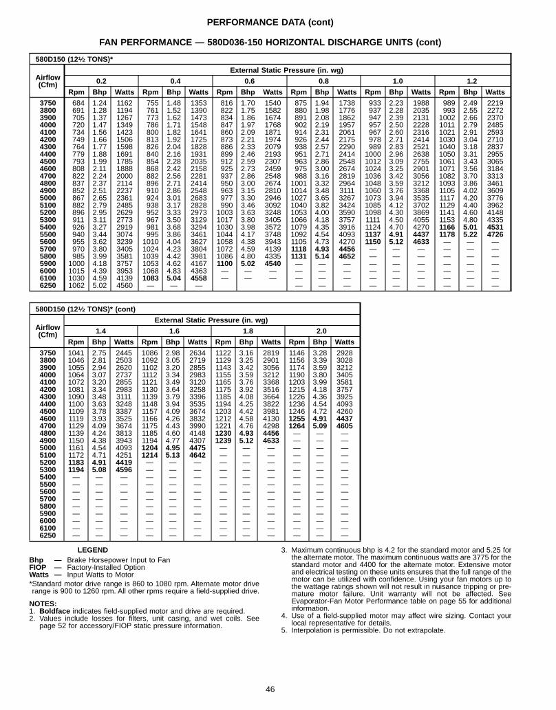
PERFORMANCE DATA (cont)
FAN PERFORMANCE — 580D036-150 HORIZONTAL DISCHARGE UNITS (cont)
580D150 (121⁄2 TONS)*
Airflow(Cfm)
External Static Pressure (in. wg)
0.2 0.4 0.6 0.8 1.0 1.2
Rpm Bhp Watts Rpm Bhp Watts Rpm Bhp Watts Rpm Bhp Watts Rpm Bhp Watts Rpm Bhp Watts
3750 684 1.24 1162 755 1.48 1353 816 1.70 1540 875 1.94 1738 933 2.23 1988 989 2.49 22193800 691 1.28 1194 761 1.52 1390 822 1.75 1582 880 1.98 1776 937 2.28 2035 993 2.55 22723900 705 1.37 1267 773 1.62 1473 834 1.86 1674 891 2.08 1862 947 2.39 2131 1002 2.66 23704000 720 1.47 1349 786 1.71 1548 847 1.97 1768 902 2.19 1957 957 2.50 2228 1011 2.79 24854100 734 1.56 1423 800 1.82 1641 860 2.09 1871 914 2.31 2061 967 2.60 2316 1021 2.91 25934200 749 1.66 1506 813 1.92 1725 873 2.21 1974 926 2.44 2175 978 2.71 2414 1030 3.04 27104300 764 1.77 1598 826 2.04 1828 886 2.33 2079 938 2.57 2290 989 2.83 2521 1040 3.18 28374400 779 1.88 1691 840 2.16 1931 899 2.46 2193 951 2.71 2414 1000 2.96 2638 1050 3.31 29554500 793 1.99 1785 854 2.28 2035 912 2.59 2307 963 2.86 2548 1012 3.09 2755 1061 3.43 30654600 808 2.11 1888 868 2.42 2158 925 2.73 2459 975 3.00 2674 1024 3.25 2901 1071 3.56 31844700 822 2.24 2000 882 2.56 2281 937 2.86 2548 988 3.16 2819 1036 3.42 3056 1082 3.70 33134800 837 2.37 2114 896 2.71 2414 950 3.00 2674 1001 3.32 2964 1048 3.59 3212 1093 3.86 34614900 852 2.51 2237 910 2.86 2548 963 3.15 2810 1014 3.48 3111 1060 3.76 3368 1105 4.02 36095000 867 2.65 2361 924 3.01 2683 977 3.30 2946 1027 3.65 3267 1073 3.94 3535 1117 4.20 37765100 882 2.79 2485 938 3.17 2828 990 3.46 3092 1040 3.82 3424 1085 4.12 3702 1129 4.40 39625200 896 2.95 2629 952 3.33 2973 1003 3.63 3248 1053 4.00 3590 1098 4.30 3869 1141 4.60 41485300 911 3.11 2773 967 3.50 3129 1017 3.80 3405 1066 4.18 3757 1111 4.50 4055 1153 4.80 43355400 926 3.27 2919 981 3.68 3294 1030 3.98 3572 1079 4.35 3916 1124 4.70 4270 1166 5.01 45315500 940 3.44 3074 995 3.86 3461 1044 4.17 3748 1092 4.54 4093 1137 4.91 4437 1178 5.22 47265600 955 3.62 3239 1010 4.04 3627 1058 4.38 3943 1105 4.73 4270 1150 5.12 4633 — — —5700 970 3.80 3405 1024 4.23 3804 1072 4.59 4139 1118 4.93 4456 — — — — — —5800 985 3.99 3581 1039 4.42 3981 1086 4.80 4335 1131 5.14 4652 — — — — — —5900 1000 4.18 3757 1053 4.62 4167 1100 5.02 4540 — — — — — — — — —6000 1015 4.39 3953 1068 4.83 4363 — — — — — — — — — — — —6100 1030 4.59 4139 1083 5.04 4558 — — — — — — — — — — — —6250 1062 5.02 4560 — — — — — — — — — — — —
580D150 (121⁄2 TONS)* (cont)
Airflow(Cfm)
External Static Pressure (in. wg)
1.4 1.6 1.8 2.0
Rpm Bhp Watts Rpm Bhp Watts Rpm Bhp Watts Rpm Bhp Watts
3750 1041 2.75 2445 1086 2.98 2634 1122 3.16 2819 1146 3.28 29283800 1046 2.81 2503 1092 3.05 2719 1129 3.25 2901 1156 3.39 30283900 1055 2.94 2620 1102 3.20 2855 1143 3.42 3056 1174 3.59 32124000 1064 3.07 2737 1112 3.34 2983 1155 3.59 3212 1190 3.80 34054100 1072 3.20 2855 1121 3.49 3120 1165 3.76 3368 1203 3.99 35814200 1081 3.34 2983 1130 3.64 3258 1175 3.92 3516 1215 4.18 37574300 1090 3.48 3111 1139 3.79 3396 1185 4.08 3664 1226 4.36 39254400 1100 3.63 3248 1148 3.94 3535 1194 4.25 3822 1236 4.54 40934500 1109 3.78 3387 1157 4.09 3674 1203 4.42 3981 1246 4.72 42604600 1119 3.93 3525 1166 4.26 3832 1212 4.58 4130 1255 4.91 44374700 1129 4.09 3674 1175 4.43 3990 1221 4.76 4298 1264 5.09 46054800 1139 4.24 3813 1185 4.60 4148 1230 4.93 4456 — — —4900 1150 4.38 3943 1194 4.77 4307 1239 5.12 4633 — — —5000 1161 4.54 4093 1204 4.95 4475 — — — — — —5100 1172 4.71 4251 1214 5.13 4642 — — — — — —5200 1183 4.91 4419 — — — — — — — — —5300 1194 5.08 4596 — — — — — — — — —5400 — — — — — — — — — — — —5500 — — — — — — — — — — — —5600 — — — — — — — — — — — —5700 — — — — — — — — — — — —5800 — — — — — — — — — — — —5900 — — — — — — — — — — — —6000 — — — — — — — — — — — —6100 — — — — — — — — — — — —6250 — — — — — — — — — — — —
LEGENDBhp — Brake Horsepower Input to FanFIOP — Factory-Installed OptionWatts — Input Watts to Motor*Standard motor drive range is 860 to 1080 rpm. Alternate motor driverange is 900 to 1260 rpm. All other rpms require a field-supplied drive.
NOTES:1. Boldface indicates field-supplied motor and drive are required.2. Values include losses for filters, unit casing, and wet coils. See
page 52 for accessory/FIOP static pressure information.
3. Maximum continuous bhp is 4.2 for the standard motor and 5.25 forthe alternate motor. The maximum continuous watts are 3775 for thestandard motor and 4400 for the alternate motor. Extensive motorand electrical testing on these units ensures that the full range of themotor can be utilized with confidence. Using your fan motors up tothe wattage ratings shown will not result in nuisance tripping or pre-mature motor failure. Unit warranty will not be affected. SeeEvaporator-Fan Motor Performance table on page 55 for additionalinformation.
4. Use of a field-supplied motor may affect wire sizing. Contact yourlocal representative for details.
5. Interpolation is permissible. Do not extrapolate.
46
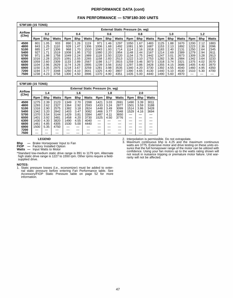
PERFORMANCE DATA (cont)
FAN PERFORMANCE — 579F180-300 UNITS
579F180 (15 TONS)
Airflow(Cfm)
External Static Pressure (in. wg)
0.2 0.4 0.6 0.8 1.0 1.2
Rpm Bhp Watts Rpm Bhp Watts Rpm Bhp Watts Rpm Bhp Watts Rpm Bhp Watts Rpm Bhp Watts
4500 801 1.05 933 890 1.26 1119 971 1.46 1297 1050 1.67 1483 1125 1.88 1670 1200 2.12 18834800 843 1.25 1110 928 1.47 1306 1006 1.68 1492 1081 1.90 1687 1153 2.13 1892 1223 2.36 20965100 885 1.47 1306 968 1.70 1510 1043 1.93 1714 1114 2.16 1918 1183 2.40 2131 1250 2.64 23455400 927 1.71 1519 1008 1.95 1732 1080 2.20 1954 1148 2.44 2167 1214 2.69 2389 1279 2.94 26115700 971 1.98 1758 1049 2.24 1989 1118 2.50 2220 1134 2.75 2442 1247 3.01 2673 1309 3.28 29136000 1016 2.28 2025 1091 2.55 2265 1158 2.83 2513 1222 3.10 2753 1282 3.36 2984 1342 3.64 32336300 1059 2.60 2309 1133 2.89 2567 1198 3.17 2815 1259 3.46 3073 1318 3.74 3321 1375 4.02 35706600 1104 2.96 2629 1174 3.26 2895 1239 3.56 3162 1297 3.86 3428 1355 4.15 3686 1405 4.40 39706900 1150 3.35 2975 1218 3.67 3259 1281 3.98 3535 1340 4.20 3730 1392 4.55 4040 1460 4.95 43507200 1194 3.77 3348 1260 4.10 3641 1325 4.40 3907 1390 4.65 4130 1440 5.10 4530 1510 5.30 47007500 1238 4.23 3758 1300 4.50 3996 1370 4.90 4351 1435 5.00 4440 1490 5.60 4970 — — —
579F180 (15 TONS)
Airflow(Cfm)
External Static Pressure (in. wg)
1.4 1.6 1.8 2.0
Rpm Bhp Watts Rpm Bhp Watts Rpm Bhp Watts Rpm Bhp Watts
4500 1275 2.39 2123 1349 2.70 2398 1421 3.03 2691 1490 3.39 30114800 1293 2.62 2327 1364 2.92 2593 1433 3.24 2877 1501 3.59 31885100 1316 2.90 2575 1382 3.18 2824 1448 3.49 3099 1514 3.86 34285400 1342 3.20 2842 1403 3.47 3082 1466 3.77 3348 1529 4.16 36945700 1370 3.54 3144 1429 3.81 3384 1487 4.11 3650 — — —6000 1401 3.92 3481 1458 4.20 3730 1525 4.50 3776 — — —6300 1430 4.30 3820 1490 4.55 4040 — — — — — —6600 1461 4.85 4305 1530 5.00 4440 — — — — — —6900 1500 5.35 4750 — — — — — — — — —7200 — — — — — — — — — — — —7500 — — — — — — — — — — — —
LEGENDBhp — Brake Horsepower Input to FanFIOP — Factory Installed OptionWatts — Input Watts to Motor*Standard low-medium static drive range is 891 to 1179 rpm. Alternatehigh static drive range is 1227 to 1550 rpm. Other rpms require a field-supplied drive.
NOTES:1. Static pressure losses (i.e., economizer) must be added to exter-
nal static pressure before entering Fan Performance table. SeeAccessory/FIOP Static Pressure table on page 52 for moreinformation.
2. Interpolation is permissible. Do not extrapolate.3. Maximum continuous bhp is 4.25 and the maximum continuous
watts are 3775. Extensive motor and drive testing on these units en-sures that the full horsepower range of the motor can be utilized withconfidence. Using your fan motors up to the watts rating shown willnot result in nuisance tripping or premature motor failure. Unit war-ranty will not be affected.
47
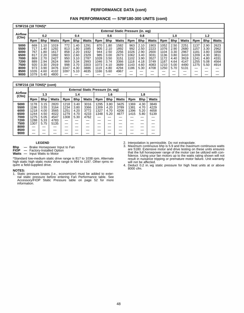
PERFORMANCE DATA (cont)
FAN PERFORMANCE — 579F180-300 UNITS (cont)
579F216 (18 TONS)*
Airflow(Cfm)
External Static Pressure (in. wg)
0.2 0.4 0.6 0.8 1.0 1.2
Rpm Bhp Watts Rpm Bhp Watts Rpm Bhp Watts Rpm Bhp Watts Rpm Bhp Watts Rpm Bhp Watts
5000 669 1.10 1019 772 1.40 1291 870 1.80 1582 963 2.10 1903 1052 2.50 2251 1137 2.90 26235500 717 1.40 1292 813 1.80 1585 905 2.10 1892 992 2.50 2223 1076 2.90 2680 1157 3.30 29626000 767 1.80 1617 858 2.20 1932 944 2.50 2256 1026 2.90 2600 1104 3.30 2967 1181 3.80 33586500 817 2.20 1992 903 2.60 2329 985 3.00 2673 1062 3.40 3031 1136 3.80 3410 1209 4.30 38117000 869 2.70 2427 950 3.10 2787 1028 3.50 3151 1102 3.90 3527 1172 4.40 3919 1241 4.80 43317200 889 2.94 2624 969 3.34 2993 1046 3.74 3366 1118 4.18 3749 1187 4.64 4147 1255 5.08 45647500 920 3.30 2919 998 3.70 3303 1073 4.10 3689 1143 4.60 4083 1210 5.00 4490 1275 5.50 49148000 973 3.90 3476 1047 4.30 3886 1119 4.80 4294 1186 5.30 4708 1250 5.70 5131 — — —8500 1026 4.60 4102 1097 5.10 4635 1166 5.60 4967 — — — — — — — — —9000 1079 5.40 4800 — — — — — — — — — — — — — — —
579F216 (18 TONS)* (cont)
Airflow(Cfm)
External Static Pressure (in. wg)
1.3 1.4 1.6 1.8
Rpm Bhp Watts Rpm Bhp Watts Rpm Bhp Watts Rpm Bhp Watts
5000 1178 3.15 2820 1218 3.40 3016 1295 3.80 3425 1369 4.30 38495500 1196 3.55 3164 1234 3.80 3366 1309 4.20 3789 1381 4.70 42296000 1218 4.00 3565 1251 4.20 3772 1327 4.70 4206 1396 5.20 46586500 1244 4.50 4022 1279 4.70 4233 1348 5.20 4677 1415 5.80 51397000 1275 5.05 4547 1308 5.30 4762 — — — — — —7200 1288 5.33 4783 — — — — — — — — —7500 1307 5.75 5135 — — — — — — — — —8000 — — — — — — — — — — — —8500 — — — — — — — — — — — —9000 — — — — — — — — — — — —
LEGENDBhp — Brake Horsepower Input to FanFIOP — Factory-Installed OptionWatts — Input Watts to Motor
*Standard low-medium static drive range is 817 to 1038 rpm. Alternatehigh static high static motor drive range is 994 to 1197. Other rpms re-quire a field-supplied drive.
NOTES:1. Static pressure losses (i.e., economizer) must be added to exter-
nal static pressure before entering Fan Performance table. SeeAccessory/FIOP Static Pressure table on page 52 for moreinformation.
2. Interpolation is permissible. Do not extrapolate.3. Maximum continuous bhp is 5.9 and the maximum continuous watts
are 5180. Extensive motor and drive testing on these units ensuresthat the full horsepower range of the motor can be utilized with con-fidence. Using your fan motors up to the watts rating shown will notresult in nuisance tripping or premature motor failure. Unit warrantywill not be affected.
4. Deduct 0.2 in. wg static pressure for high heat units at or above8000 cfm.
48
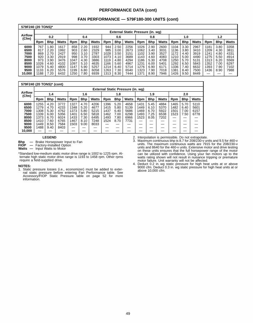
PERFORMANCE DATA (cont)
FAN PERFORMANCE — 579F180-300 UNITS (cont)
579F240 (20 TONS)*
Airflow(Cfm)
External Static Pressure (in. wg)
0.2 0.4 0.6 0.8 1.0 1.2
Rpm Bhp Watts Rpm Bhp Watts Rpm Bhp Watts Rpm Bhp Watts Rpm Bhp Watts Rpm Bhp Watts
6000 767 1.80 1617 858 2.20 1932 944 2.50 2256 1026 2.90 2600 1104 3.30 2967 1181 3.80 33586500 817 2.20 1992 903 2.60 2329 985 3.00 2673 1062 3.40 3031 1136 3.80 3410 1209 4.30 38117000 869 2.70 2427 950 3.10 2787 1028 3.50 3151 1102 3.90 3527 1172 4.40 3919 1241 4.80 43317500 920 3.30 2919 998 3.70 3303 1073 4.10 3689 1143 4.60 4083 1210 5.00 4490 1275 5.50 49148000 973 3.90 3476 1047 4.30 3886 1119 4.80 4294 1186 5.30 4708 1250 5.70 5131 1313 6.20 55698500 1026 4.60 4102 1097 5.10 4635 1166 5.60 4967 1231 6.00 5401 1292 6.50 5843 1352 7.00 62979000 1079 5.40 4800 1147 5.90 5257 1214 6.40 5714 1276 6.90 6171 1336 7.40 6632 1393 7.90 71029500 1133 6.20 5576 1199 6.80 6058 1263 7.30 6540 1323 7.90 7018 1381 8.40 7500 1436 8.90 7988
10,000 1188 7.20 6432 1250 7.80 6939 1313 8.30 7444 1371 8.90 7946 1426 9.50 8449 — — —
579F240 (20 TONS)* (cont)
Airflow(Cfm)
External Static Pressure (in. wg)
1.4 1.6 1.8 1.9 2.0
Rpm Bhp Watts Rpm Bhp Watts Rpm Bhp Watts Rpm Bhp Watts Rpm Bhp Watts
6000 1255 4.20 3772 1327 4.70 4206 1396 5.20 4658 1431 5.45 4884 1465 5.70 51106500 1279 4.70 4233 1348 5.20 4677 1415 5.80 5139 1449 6.10 5370 1482 6.40 56017000 1308 5.30 4762 1373 5.80 5215 1437 6.40 5686 1469 6.70 5922 1501 7.00 61577500 1339 6.00 5356 1401 6.50 5818 1462 7.00 6298 1493 7.25 6538 1523 7.50 67788000 1373 6.70 6024 1433 7.30 6495 1493 7.80 6966 1523 8.05 7202 — — —8500 1410 7.60 6765 1467 8.10 7248 1524 8.70 7731 — — — — — —9000 1449 8.50 7584 1503 9.00 8033 — — — — — — — — —9500 1488 9.40 8403 — — — — — — — — — — — —
10,000 — — — — — — — — — — — — — — —
LEGENDBhp — Brake Horsepower Input to FanFIOP — Factory-Installed OptionWatts — Input Watts to Motor
*Standard low-medium static motor drive range is 1002 to 1225 rpm. Al-ternate high static motor drive range is 1193 to 1458 rpm. Other rpmsrequire a field-supplied drive.
NOTES:1. Static pressure losses (i.e., economizer) must be added to exter-
nal static pressure before entering Fan Performance table. SeeAccessory/FIOP Static Pressure table on page 52 for moreinformation.
2. Interpolation is permissible. Do not extrapolate.3. Maximum continuous bhp is 8.7 for 208/230-v units and 9.5 for 460-v
units. The maximum continuous watts are 7915 for the 208/230-vunits and 8640 for the 460-v units. Extensive motor and drive testingon these units ensures that the full horsepower range of the motorcan be utilized with confidence. Using your fan motors up to thewatts rating shown will not result in nuisance tripping or prematuremotor failure. Unit warranty will not be affected.
4. Deduct 0.2 in. wg static pressure for high heat units at or above9000 cfm. Deduct 0.3 in. wg static pressure for high heat units at orabove 10,000 cfm.
49
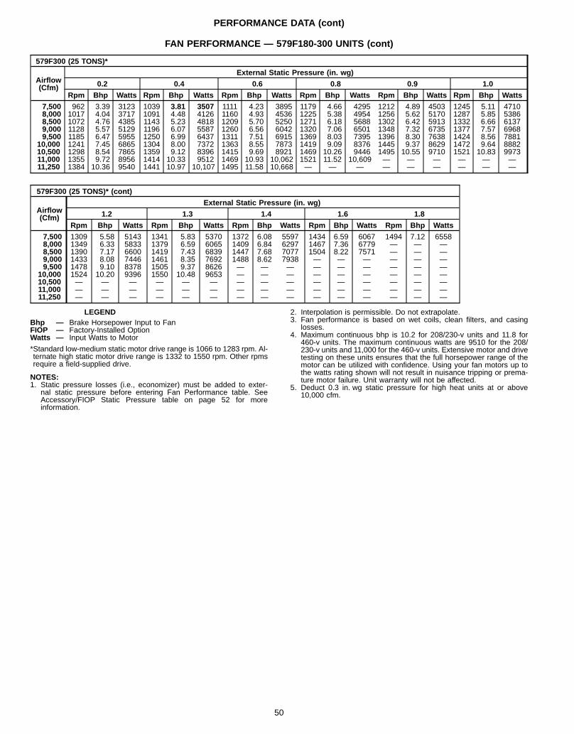
PERFORMANCE DATA (cont)
FAN PERFORMANCE — 579F180-300 UNITS (cont)
579F300 (25 TONS)*
Airflow(Cfm)
External Static Pressure (in. wg)
0.2 0.4 0.6 0.8 0.9 1.0
Rpm Bhp Watts Rpm Bhp Watts Rpm Bhp Watts Rpm Bhp Watts Rpm Bhp Watts Rpm Bhp Watts
7,500 962 3.39 3123 1039 3.81 3507 1111 4.23 3895 1179 4.66 4295 1212 4.89 4503 1245 5.11 47108,000 1017 4.04 3717 1091 4.48 4126 1160 4.93 4536 1225 5.38 4954 1256 5.62 5170 1287 5.85 53868,500 1072 4.76 4385 1143 5.23 4818 1209 5.70 5250 1271 6.18 5688 1302 6.42 5913 1332 6.66 61379,000 1128 5.57 5129 1196 6.07 5587 1260 6.56 6042 1320 7.06 6501 1348 7.32 6735 1377 7.57 69689,500 1185 6.47 5955 1250 6.99 6437 1311 7.51 6915 1369 8.03 7395 1396 8.30 7638 1424 8.56 7881
10,000 1241 7.45 6865 1304 8.00 7372 1363 8.55 7873 1419 9.09 8376 1445 9.37 8629 1472 9.64 888210,500 1298 8.54 7865 1359 9.12 8396 1415 9.69 8921 1469 10.26 9446 1495 10.55 9710 1521 10.83 997311,000 1355 9.72 8956 1414 10.33 9512 1469 10.93 10,062 1521 11.52 10,609 — — — — — —11,250 1384 10.36 9540 1441 10.97 10,107 1495 11.58 10,668 — — — — — — — — —
579F300 (25 TONS)* (cont)
Airflow(Cfm)
External Static Pressure (in. wg)
1.2 1.3 1.4 1.6 1.8
Rpm Bhp Watts Rpm Bhp Watts Rpm Bhp Watts Rpm Bhp Watts Rpm Bhp Watts
7,500 1309 5.58 5143 1341 5.83 5370 1372 6.08 5597 1434 6.59 6067 1494 7.12 65588,000 1349 6.33 5833 1379 6.59 6065 1409 6.84 6297 1467 7.36 6779 — — —8,500 1390 7.17 6600 1419 7.43 6839 1447 7.68 7077 1504 8.22 7571 — — —9,000 1433 8.08 7446 1461 8.35 7692 1488 8.62 7938 — — — — — —9,500 1478 9.10 8378 1505 9.37 8626 — — — — — — — — —
10,000 1524 10.20 9396 1550 10.48 9653 — — — — — — — — —10,500 — — — — — — — — — — — — — — —11,000 — — — — — — — — — — — — — — —11,250 — — — — — — — — — — — — — — —
LEGENDBhp — Brake Horsepower Input to FanFIOP — Factory-Installed OptionWatts — Input Watts to Motor
*Standard low-medium static motor drive range is 1066 to 1283 rpm. Al-ternate high static motor drive range is 1332 to 1550 rpm. Other rpmsrequire a field-supplied drive.
NOTES:1. Static pressure losses (i.e., economizer) must be added to exter-
nal static pressure before entering Fan Performance table. SeeAccessory/FIOP Static Pressure table on page 52 for moreinformation.
2. Interpolation is permissible. Do not extrapolate.3. Fan performance is based on wet coils, clean filters, and casing
losses.4. Maximum continuous bhp is 10.2 for 208/230-v units and 11.8 for
460-v units. The maximum continuous watts are 9510 for the 208/230-v units and 11,000 for the 460-v units. Extensive motor and drivetesting on these units ensures that the full horsepower range of themotor can be utilized with confidence. Using your fan motors up tothe watts rating shown will not result in nuisance tripping or prema-ture motor failure. Unit warranty will not be affected.
5. Deduct 0.3 in. wg static pressure for high heat units at or above10,000 cfm.
50
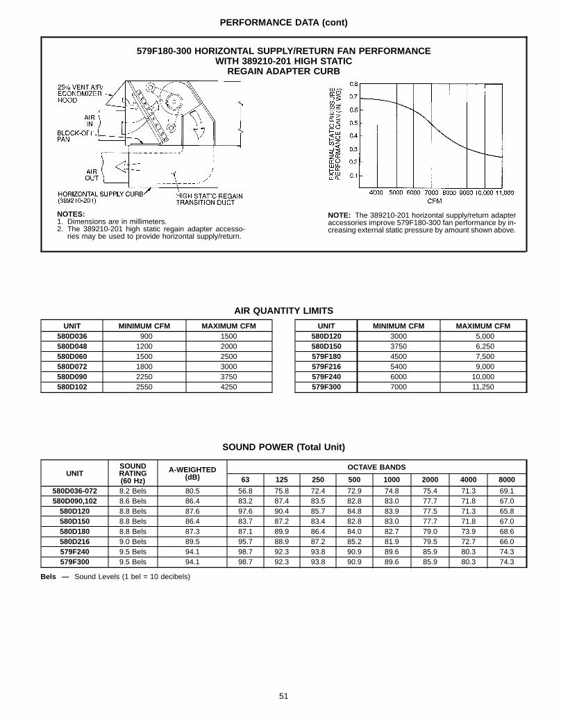
PERFORMANCE DATA (cont)
AIR QUANTITY LIMITS
UNIT MINIMUM CFM MAXIMUM CFM580D036 900 1500580D048 1200 2000580D060 1500 2500580D072 1800 3000580D090 2250 3750580D102 2550 4250
UNIT MINIMUM CFM MAXIMUM CFM580D120 3000 5,000580D150 3750 6,250579F180 4500 7,500579F216 5400 9,000579F240 6000 10,000579F300 7000 11,250
SOUND POWER (Total Unit)
UNITSOUNDRATING(60 Hz)
A-WEIGHTED(dB)
OCTAVE BANDS
63 125 250 500 1000 2000 4000 8000
580D036-072 8.2 Bels 80.5 56.8 75.8 72.4 72.9 74.8 75.4 71.3 69.1580D090,102 8.6 Bels 86.4 83.2 87.4 83.5 82.8 83.0 77.7 71.8 67.0580D120 8.8 Bels 87.6 97.6 90.4 85.7 84.8 83.9 77.5 71.3 65.8580D150 8.8 Bels 86.4 83.7 87.2 83.4 82.8 83.0 77.7 71.8 67.0580D180 8.8 Bels 87.3 87.1 89.9 86.4 84.0 82.7 79.0 73.9 68.6580D216 9.0 Bels 89.5 95.7 88.9 87.2 85.2 81.9 79.5 72.7 66.0579F240 9.5 Bels 94.1 98.7 92.3 93.8 90.9 89.6 85.9 80.3 74.3579F300 9.5 Bels 94.1 98.7 92.3 93.8 90.9 89.6 85.9 80.3 74.3
Bels — Sound Levels (1 bel = 10 decibels)
579F180-300 HORIZONTAL SUPPLY/RETURN FAN PERFORMANCEWITH 389210-201 HIGH STATIC
REGAIN ADAPTER CURB
NOTES:1. Dimensions are in millimeters.2. The 389210-201 high static regain adapter accesso-
ries may be used to provide horizontal supply/return.
NOTE: The 389210-201 horizontal supply/return adapteraccessories improve 579F180-300 fan performance by in-creasing external static pressure by amount shown above.
51
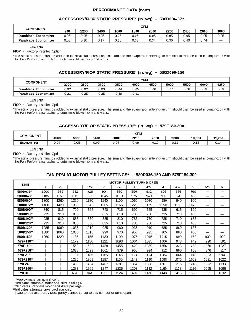
PERFORMANCE DATA (cont)
ACCESSORY/FIOP STATIC PRESSURE* (in. wg) − 580D036-072
COMPONENTCFM
900 1200 1400 1600 1800 2000 2200 2400 2600 3000Durablade Economizer 0.05 0.05 0.05 0.05 0.05 0.05 0.05 0.05 0.05 0.05Parablade Economizer 0.08 0.10 0.17 0.26 0.33 0.34 0.36 0.40 0.44 —
LEGENDFIOP − Factory-Installed Option*The static pressure must be added to external static pressure. The sum and the evaporator entering-air cfm should then be used in conjunction withthe Fan Performance tables to determine blower rpm and watts.
ACCESSORY/FIOP STATIC PRESSURE* (in. wg) − 580D090-150
COMPONENTCFM
2200 2500 3000 3500 4000 4500 5000 5500 6000 6250Durablade Economizer 0.02 0.02 0.03 0.04 0.05 0.06 0.07 0.08 0.09 0.09Parablade Economizer 0.21 0.25 0.35 0.49 0.61 — — — — —
LEGENDFIOP − Factory-Installed Option*The static pressure must be added to external static pressure. The sum and the evaporator entering-air cfm should then be used in conjunction withthe Fan Performance tables to determine blower rpm and watts.
ACCESSORY/FIOP STATIC PRESSURE* (in. wg) − 579F180-300
COMPONENTCFM
4500 5000 5400 6000 7200 7500 9000 10,000 11,250Economizer 0.04 0.05 0.06 0.07 0.09 0.10 0.11 0.12 0.14
LEGENDFIOP − Factory-Installed Option*The static pressure must be added to external static pressure. The sum and the evaporator entering-air cfm should then be used in conjunction withthe Fan Performance tables to determine blower rpm and watts.
FAN RPM AT MOTOR PULLEY SETTINGS* — 580D036-150 AND 579F180-300
UNITMOTOR PULLEY TURNS OPEN
0 1⁄2 1 11⁄2 2 21⁄2 3 31⁄2 4 41⁄2 5 51⁄2 6580D036† 1000 976 952 928 904 880 856 832 808 784 760 — —580D048† 1185 1150 1115 1080 1045 1010 975 940 905 870 835 — —580D060† 1300 1260 1220 1180 1140 1100 1060 1020 980 940 900 — —580D072** 1460 1420 1380 1345 1305 1265 1225 1185 1150 1110 1070 — —580D090** 840 815 790 765 740 715 690 665 635 615 590 — —580D090†† 935 910 885 860 835 810 785 760 735 710 685 — —580D102** 935 910 885 860 835 810 785 760 735 710 685 — —580D120** 935 910 885 860 835 810 785 760 735 710 685 — —580D120† 1085 1060 1035 1010 985 960 935 910 885 860 835 — —580D150** 1080 1060 1035 1015 990 970 950 925 905 880 860 — —580D150† 1260 1220 1185 1155 1130 1100 1075 1045 1015 990 960 930 900579F180** \ \ 1179 1150 1121 1093 1064 1035 1006 978 949 920 891579F180†† \ \ 1559 1522 1488 1455 1422 1389 1356 1323 1289 1256 1227579F216** \ \ 1038 1023 1001 979 956 934 912 890 868 846 817579F216†† \ \ 1197 1185 1165 1145 1124 1104 1084 1064 1043 1023 994579F240** \ \ 1225 1209 1187 1165 1143 1120 1098 1076 1053 1031 1022579F240†† \ \ 1458 1434 1407 1381 1354 1328 1301 1275 1248 1222 1193579F300** \ \ 1283 1269 1247 1225 1203 1182 1160 1138 1116 1095 1066579F300†† \ \ N/A N/A 1551 1524 1497 1470 1443 1415 1388 1361 1332
*Approximate fan rpm shown.†Indicates alternate motor and drive package.**Indicates standard motor and drive package.††Indicates alternate drive package only.
\Due to belt and pulley size, pulley cannot be set to this number of turns open.
52
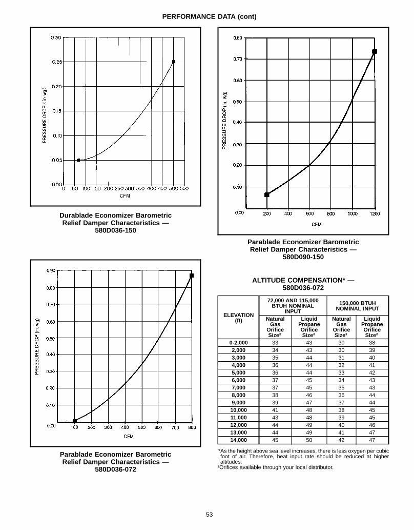
PERFORMANCE DATA (cont)
Durablade Economizer BarometricRelief Damper Characteristics —
580D036-150
Parablade Economizer BarometricRelief Damper Characteristics —
580D036-072
Parablade Economizer BarometricRelief Damper Characteristics —
580D090-150
ALTITUDE COMPENSATION* —580D036-072
ELEVATION(ft)
72,000 AND 115,000BTUH NOMINAL
INPUT
150,000 BTUHNOMINAL INPUT
NaturalGas
OrificeSize†
LiquidPropaneOrificeSize†
NaturalGas
OrificeSize†
LiquidPropaneOrificeSize†
0-2,000 33 43 30 382,000 34 43 30 393,000 35 44 31 404,000 36 44 32 415,000 36 44 33 426,000 37 45 34 437,000 37 45 35 438,000 38 46 36 449,000 39 47 37 4410,000 41 48 38 4511,000 43 48 39 4512,000 44 49 40 4613,000 44 49 41 4714,000 45 50 42 47
*As the height above sea level increases, there is less oxygen per cubicfoot of air. Therefore, heat input rate should be reduced at higheraltitudes.†Orifices available through your local distributor.
53
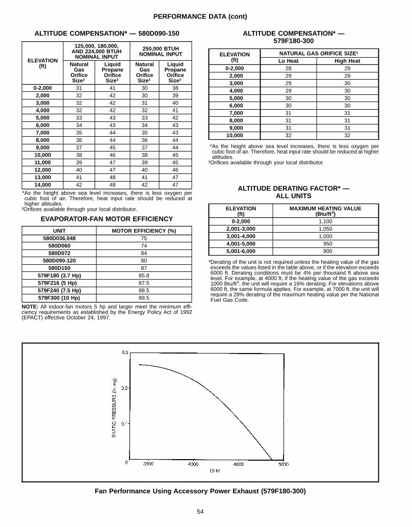
PERFORMANCE DATA (cont)
ALTITUDE COMPENSATION* — 580D090-150
ELEVATION(ft)
125,000, 180,000,AND 224,000 BTUHNOMINAL INPUT
250,000 BTUHNOMINAL INPUT
NaturalGas
OrificeSize†
LiquidPropaneOrificeSize†
NaturalGas
OrificeSize†
LiquidPropaneOrificeSize†
0-2,000 31 41 30 382,000 32 42 30 393,000 32 42 31 404,000 32 42 32 415,000 33 43 33 426,000 34 43 34 437,000 35 44 35 438,000 36 44 36 449,000 37 45 37 4410,000 38 46 38 4511,000 39 47 39 4512,000 40 47 40 4613,000 41 48 41 4714,000 42 48 42 47
*As the height above sea level increases, there is less oxygen percubic foot of air. Therefore, heat input rate should be reduced athigher altitudes.†Orifices available through your local distributor.
EVAPORATOR-FAN MOTOR EFFICIENCY
UNIT MOTOR EFFICIENCY (%)580D036,048 75580D060 74580D072 84
580D090-120 80580D150 87
579F180 (3.7 Hp) 85.8579F216 (5 Hp) 87.5579F240 (7.5 Hp) 88.5579F300 (10 Hp) 89.5
NOTE: All indoor-fan motors 5 hp and larger meet the minimum effi-ciency requirements as established by the Energy Policy Act of 1992(EPACT) effective October 24, 1997.
ALTITUDE COMPENSATION* —579F180-300
ELEVATION(ft)
NATURAL GAS ORIFICE SIZE†Lo Heat High Heat
0-2,000 28 292,000 29 293,000 29 304,000 29 305,000 30 306,000 30 307,000 31 318,000 31 319,000 31 3110,000 32 32
*As the height above sea level increases, there is less oxygen percubic foot of air. Therefore, heat input rate should be reduced at higheraltitudes.
†Orifices available through your local distributor.
ALTITUDE DERATING FACTOR* —ALL UNITS
ELEVATION(ft)
MAXIMUM HEATING VALUE(Btu/ft 3)
0-2,000 1,1002,001-3,000 1,0503,001-4,000 1,0004,001-5,000 9505,001-6,000 900
*Derating of the unit is not required unless the heating value of the gasexceeds the values listed in the table above, or if the elevation exceeds6000 ft. Derating conditions must be 4% per thousand ft above sealevel. For example, at 4000 ft, if the heating value of the gas exceeds1000 Btu/ft3, the unit will require a 16% derating. For elevations above6000 ft, the same formula applies. For example, at 7000 ft, the unit willrequire a 28% derating of the maximum heating value per the NationalFuel Gas Code.
Fan Performance Using Accessory Power Exhaust (579F180-300)
54
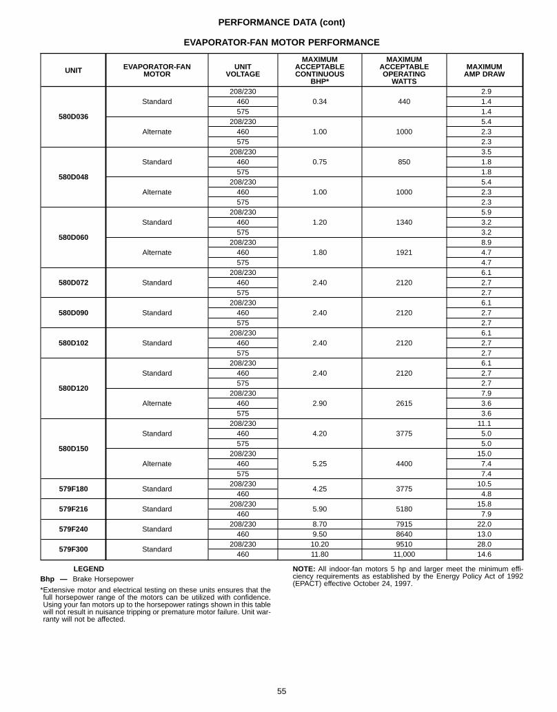
PERFORMANCE DATA (cont)
EVAPORATOR-FAN MOTOR PERFORMANCE
UNIT EVAPORATOR-FANMOTOR
UNITVOLTAGE
MAXIMUMACCEPTABLECONTINUOUS
BHP*
MAXIMUMACCEPTABLEOPERATING
WATTS
MAXIMUMAMP DRAW
580D036
Standard208/230
0.34 4402.9
460 1.4575 1.4
Alternate208/230
1.00 10005.4
460 2.3575 2.3
580D048
Standard208/230
0.75 8503.5
460 1.8575 1.8
Alternate208/230
1.00 10005.4
460 2.3575 2.3
580D060
Standard208/230
1.20 13405.9
460 3.2575 3.2
Alternate208/230
1.80 19218.9
460 4.7575 4.7
580D072 Standard208/230
2.40 21206.1
460 2.7575 2.7
580D090 Standard208/230
2.40 21206.1
460 2.7575 2.7
580D102 Standard208/230
2.40 21206.1
460 2.7575 2.7
580D120
Standard208/230
2.40 21206.1
460 2.7575 2.7
Alternate208/230
2.90 26157.9
460 3.6575 3.6
580D150
Standard208/230
4.20 377511.1
460 5.0575 5.0
Alternate208/230
5.25 440015.0
460 7.4575 7.4
579F180 Standard208/230
4.25 377510.5
460 4.8
579F216 Standard208/230
5.90 518015.8
460 7.9
579F240 Standard208/230 8.70 7915 22.0460 9.50 8640 13.0
579F300 Standard208/230 10.20 9510 28.0460 11.80 11,000 14.6
LEGENDBhp — Brake Horsepower
*Extensive motor and electrical testing on these units ensures that thefull horsepower range of the motors can be utilized with confidence.Using your fan motors up to the horsepower ratings shown in this tablewill not result in nuisance tripping or premature motor failure. Unit war-ranty will not be affected.
NOTE: All indoor-fan motors 5 hp and larger meet the minimum effi-ciency requirements as established by the Energy Policy Act of 1992(EPACT) effective October 24, 1997.
55
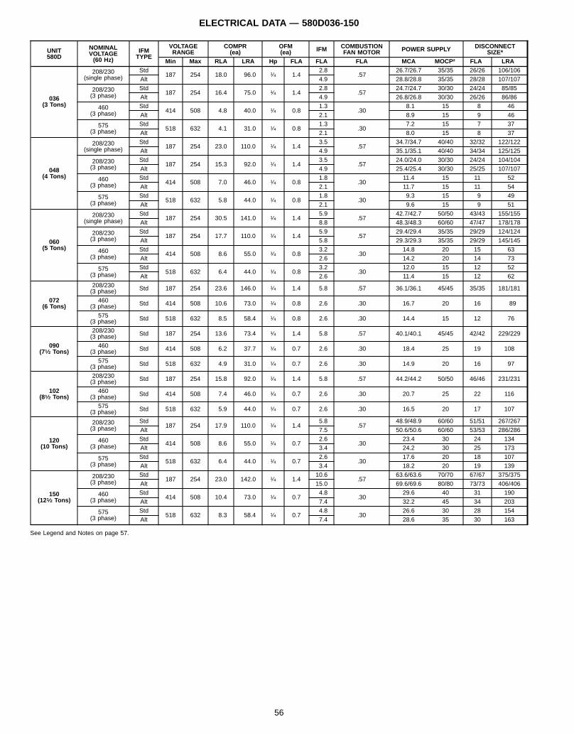
ELECTRICAL DATA — 580D036-150
UNIT580D
NOMINALVOLTAGE(60 Hz)
IFMTYPE
VOLTAGERANGE
COMPR(ea)
OFM(ea) IFM COMBUSTION
FAN MOTOR POWER SUPPLY DISCONNECTSIZE*
Min Max RLA LRA Hp FLA FLA FLA MCA MOCP† FLA LRA
036(3 Tons)
208/230(single phase)
Std187 254 18.0 96.0 1⁄4 1.4
2.8.57
26.7/26.7 35/35 26/26 106/106
Alt 4.9 28.8/28.8 35/35 28/28 107/107
208/230(3 phase)
Std187 254 16.4 75.0 1⁄4 1.4
2.8.57
24.7/24.7 30/30 24/24 85/85
Alt 4.9 26.8/26.8 30/30 26/26 86/86
460(3 phase)
Std414 508 4.8 40.0 1⁄4 0.8
1.3.30
8.1 15 8 46
Alt 2.1 8.9 15 9 46
575(3 phase)
Std518 632 4.1 31.0 1⁄4 0.8
1.3.30
7.2 15 7 37
Alt 2.1 8.0 15 8 37
048(4 Tons)
208/230(single phase)
Std187 254 23.0 110.0 1⁄4 1.4
3.5.57
34.7/34.7 40/40 32/32 122/122
Alt 4.9 35.1/35.1 40/40 34/34 125/125
208/230(3 phase)
Std187 254 15.3 92.0 1⁄4 1.4
3.5.57
24.0/24.0 30/30 24/24 104/104
Alt 4.9 25.4/25.4 30/30 25/25 107/107
460(3 phase)
Std414 508 7.0 46.0 1⁄4 0.8
1.8.30
11.4 15 11 52
Alt 2.1 11.7 15 11 54
575(3 phase)
Std518 632 5.8 44.0 1⁄4 0.8
1.8.30
9.3 15 9 49
Alt 2.1 9.6 15 9 51
060(5 Tons)
208/230(single phase)
Std187 254 30.5 141.0 1⁄4 1.4
5.9.57
42.7/42.7 50/50 43/43 155/155
Alt 8.8 48.3/48.3 60/60 47/47 178/178
208/230(3 phase)
Std187 254 17.7 110.0 1⁄4 1.4
5.9.57
29.4/29.4 35/35 29/29 124/124
Alt 5.8 29.3/29.3 35/35 29/29 145/145
460(3 phase)
Std414 508 8.6 55.0 1⁄4 0.8
3.2.30
14.8 20 15 63
Alt 2.6 14.2 20 14 73
575(3 phase)
Std518 632 6.4 44.0 1⁄4 0.8
3.2.30
12.0 15 12 52
Alt 2.6 11.4 15 12 62
072(6 Tons)
208/230(3 phase) Std 187 254 23.6 146.0 1⁄4 1.4 5.8 .57 36.1/36.1 45/45 35/35 181/181
460(3 phase) Std 414 508 10.6 73.0 1⁄4 0.8 2.6 .30 16.7 20 16 89
575(3 phase) Std 518 632 8.5 58.4 1⁄4 0.8 2.6 .30 14.4 15 12 76
090(71⁄2 Tons)
208/230(3 phase) Std 187 254 13.6 73.4 1⁄4 1.4 5.8 .57 40.1/40.1 45/45 42/42 229/229
460(3 phase) Std 414 508 6.2 37.7 1⁄4 0.7 2.6 .30 18.4 25 19 108
575(3 phase) Std 518 632 4.9 31.0 1⁄4 0.7 2.6 .30 14.9 20 16 97
102(81⁄2 Tons)
208/230(3 phase) Std 187 254 15.8 92.0 1⁄4 1.4 5.8 .57 44.2/44.2 50/50 46/46 231/231
460(3 phase) Std 414 508 7.4 46.0 1⁄4 0.7 2.6 .30 20.7 25 22 116
575(3 phase) Std 518 632 5.9 44.0 1⁄4 0.7 2.6 .30 16.5 20 17 107
120(10 Tons)
208/230(3 phase)
Std187 254 17.9 110.0 1⁄4 1.4
5.8.57
48.9/48.9 60/60 51/51 267/267
Alt 7.5 50.6/50.6 60/60 53/53 286/286
460(3 phase)
Std414 508 8.6 55.0 1⁄4 0.7
2.6.30
23.4 30 24 134
Alt 3.4 24.2 30 25 173
575(3 phase)
Std518 632 6.4 44.0 1⁄4 0.7
2.6.30
17.6 20 18 107
Alt 3.4 18.2 20 19 139
150(121⁄2 Tons)
208/230(3 phase)
Std187 254 23.0 142.0 1⁄4 1.4
10.6.57
63.6/63.6 70/70 67/67 375/375
Alt 15.0 69.6/69.6 80/80 73/73 406/406
460(3 phase)
Std414 508 10.4 73.0 1⁄4 0.7
4.8.30
29.6 40 31 190
Alt 7.4 32.2 45 34 203
575(3 phase)
Std518 632 8.3 58.4 1⁄4 0.7
4.8.30
26.6 30 28 154
Alt 7.4 28.6 35 30 163
See Legend and Notes on page 57.
56
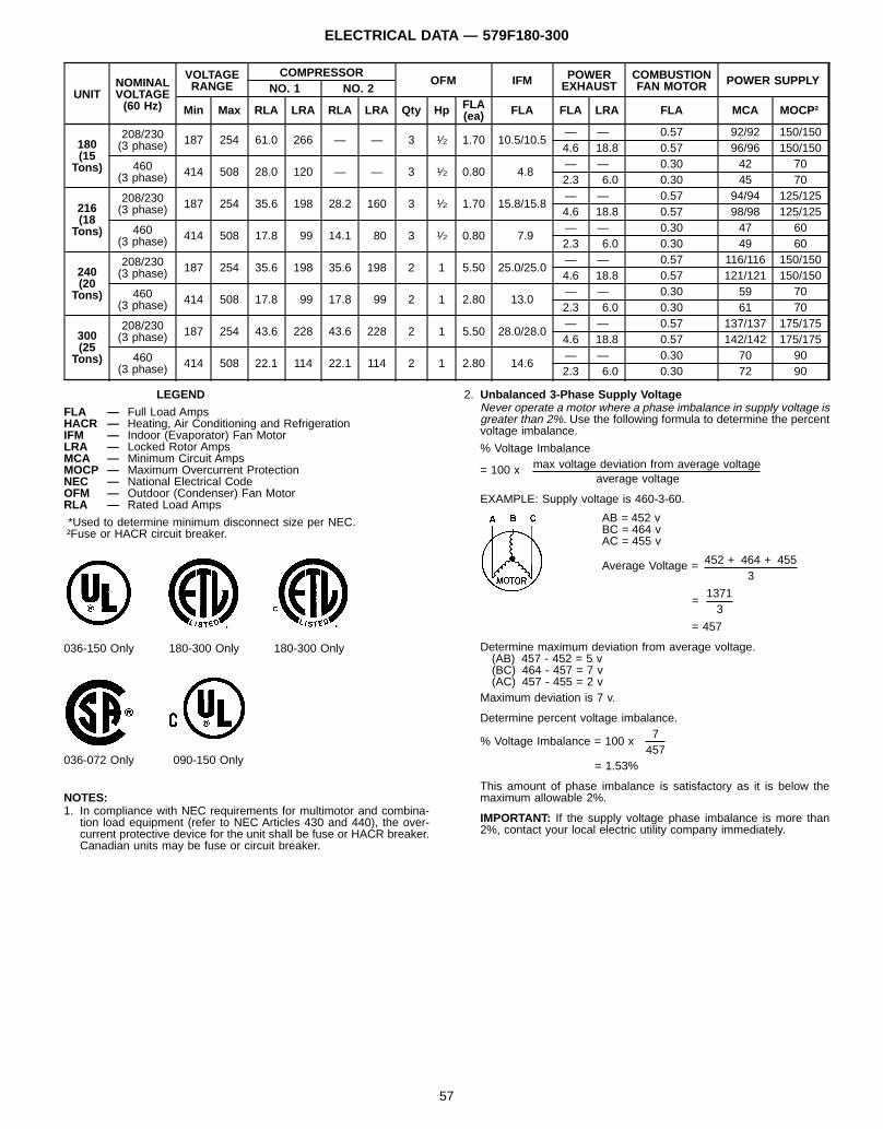
ELECTRICAL DATA — 579F180-300
UNITNOMINALVOLTAGE(60 Hz)
VOLTAGERANGE
COMPRESSOROFM IFM POWER
EXHAUSTCOMBUSTIONFAN MOTOR POWER SUPPLY
NO. 1 NO. 2
Min Max RLA LRA RLA LRA Qty Hp FLA(ea) FLA FLA LRA FLA MCA MOCP†
180(15
Tons)
208/230(3 phase) 187 254 61.0 266 — — 3 1⁄2 1.70 10.5/10.5
— — 0.57 92/92 150/1504.6 18.8 0.57 96/96 150/150
460(3 phase) 414 508 28.0 120 — — 3 1⁄2 0.80 4.8
— — 0.30 42 702.3 6.0 0.30 45 70
216(18
Tons)
208/230(3 phase) 187 254 35.6 198 28.2 160 3 1⁄2 1.70 15.8/15.8
— — 0.57 94/94 125/1254.6 18.8 0.57 98/98 125/125
460(3 phase) 414 508 17.8 99 14.1 80 3 1⁄2 0.80 7.9
— — 0.30 47 602.3 6.0 0.30 49 60
240(20
Tons)
208/230(3 phase) 187 254 35.6 198 35.6 198 2 1 5.50 25.0/25.0
— — 0.57 116/116 150/1504.6 18.8 0.57 121/121 150/150
460(3 phase) 414 508 17.8 99 17.8 99 2 1 2.80 13.0
— — 0.30 59 702.3 6.0 0.30 61 70
300(25
Tons)
208/230(3 phase) 187 254 43.6 228 43.6 228 2 1 5.50 28.0/28.0
— — 0.57 137/137 175/1754.6 18.8 0.57 142/142 175/175
460(3 phase) 414 508 22.1 114 22.1 114 2 1 2.80 14.6
— — 0.30 70 902.3 6.0 0.30 72 90
LEGEND
FLA — Full Load AmpsHACR — Heating, Air Conditioning and RefrigerationIFM — Indoor (Evaporator) Fan MotorLRA — Locked Rotor AmpsMCA — Minimum Circuit AmpsMOCP — Maximum Overcurrent ProtectionNEC — National Electrical CodeOFM — Outdoor (Condenser) Fan MotorRLA — Rated Load Amps
*Used to determine minimum disconnect size per NEC.†Fuse or HACR circuit breaker.
036-150 Only 180-300 Only 180-300 Only
036-072 Only 090-150 Only
NOTES:1. In compliance with NEC requirements for multimotor and combina-
tion load equipment (refer to NEC Articles 430 and 440), the over-current protective device for the unit shall be fuse or HACR breaker.Canadian units may be fuse or circuit breaker.
2. Unbalanced 3-Phase Supply VoltageNever operate a motor where a phase imbalance in supply voltage isgreater than 2%. Use the following formula to determine the percentvoltage imbalance.
% Voltage Imbalancemax voltage deviation from average voltage= 100 x
average voltage
EXAMPLE: Supply voltage is 460-3-60.
AB = 452 vBC = 464 vAC = 455 v
452 + 464 + 455Average Voltage =3
1371=
3
= 457
Determine maximum deviation from average voltage.(AB) 457 - 452 = 5 v(BC) 464 - 457 = 7 v(AC) 457 - 455 = 2 v
Maximum deviation is 7 v.
Determine percent voltage imbalance.7
% Voltage Imbalance = 100 x457
= 1.53%
This amount of phase imbalance is satisfactory as it is below themaximum allowable 2%.
IMPORTANT: If the supply voltage phase imbalance is more than2%, contact your local electric utility company immediately.
57
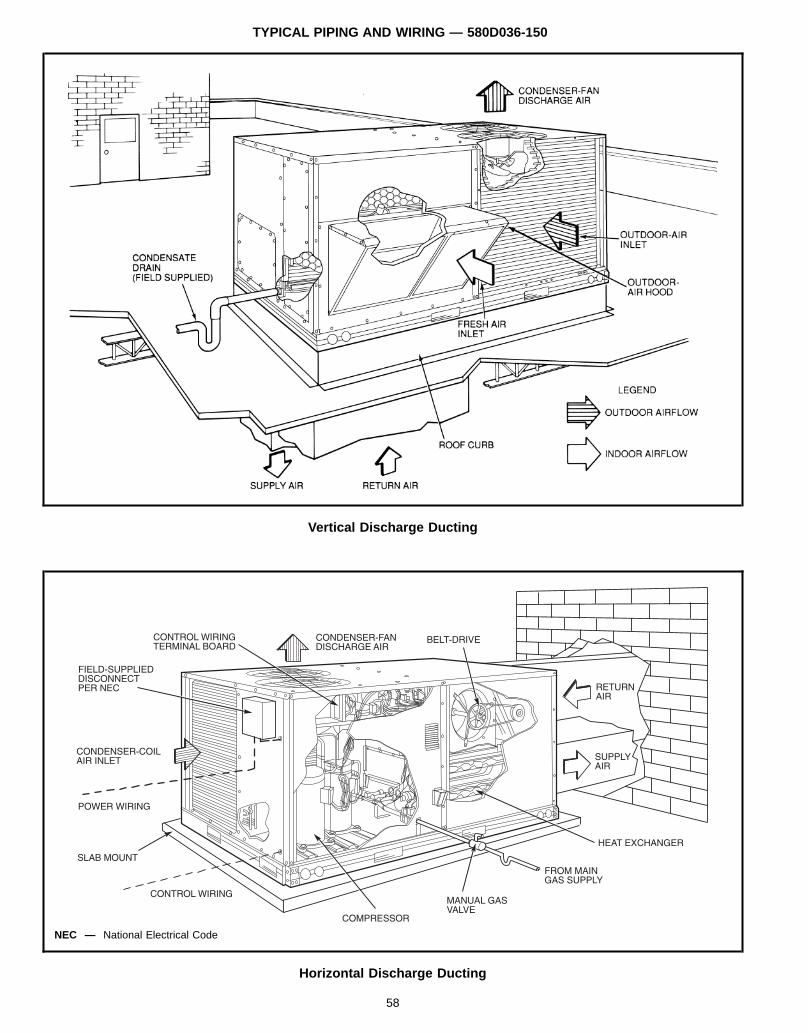
TYPICAL PIPING AND WIRING — 580D036-150
Vertical Discharge Ducting
Horizontal Discharge Ducting
NEC — National Electrical Code
58
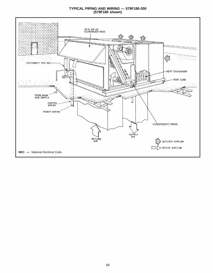
TYPICAL PIPING AND WIRING — 579F180-300(579F180 shown)
NEC — National Electrical Code
59
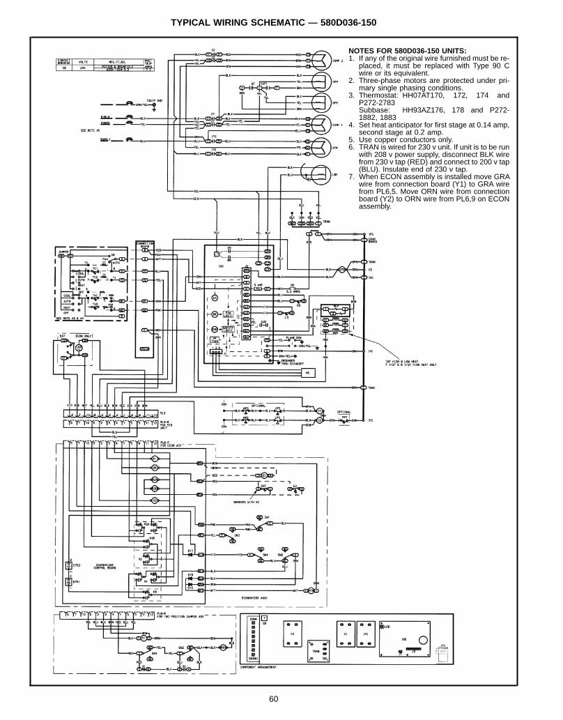
TYPICAL WIRING SCHEMATIC — 580D036-150
NOTES FOR 580D036-150 UNITS:1. If any of the original wire furnished must be re-
placed, it must be replaced with Type 90 Cwire or its equivalent.
2. Three-phase motors are protected under pri-mary single phasing conditions.
3. Thermostat: HH07AT170, 172, 174 andP272-2783Subbase: HH93AZ176, 178 and P272-1882, 1883
4. Set heat anticipator for first stage at 0.14 amp,second stage at 0.2 amp.
5. Use copper conductors only.6. TRAN is wired for 230 v unit. If unit is to be run
with 208 v power supply, disconnect BLK wirefrom 230 v tap (RED) and connect to 200 v tap(BLU). Insulate end of 230 v tap.
7. When ECON assembly is installed move GRAwire from connection board (Y1) to GRA wirefrom PL6,5. Move ORN wire from connectionboard (Y2) to ORN wire from PL6,9 on ECONassembly.
60
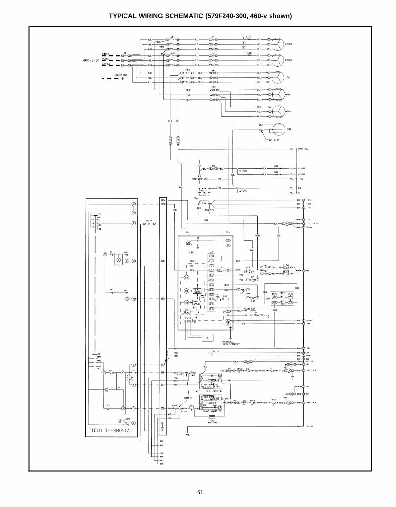
TYPICAL WIRING SCHEMATIC (579F240-300, 460-v shown)
61
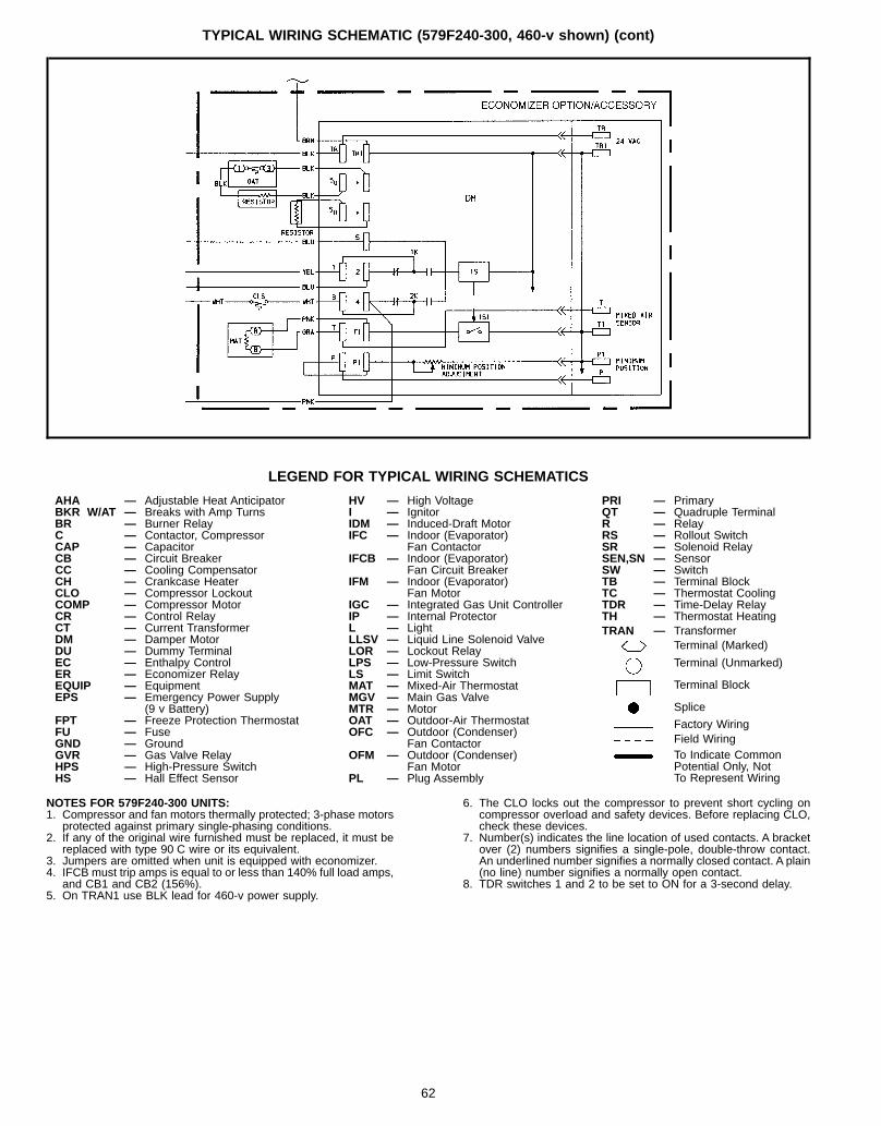
TYPICAL WIRING SCHEMATIC (579F240-300, 460-v shown) (cont)
LEGEND FOR TYPICAL WIRING SCHEMATICS
AHA — Adjustable Heat AnticipatorBKR W/AT — Breaks with Amp TurnsBR — Burner RelayC — Contactor, CompressorCAP — CapacitorCB — Circuit BreakerCC — Cooling CompensatorCH — Crankcase HeaterCLO — Compressor LockoutCOMP — Compressor MotorCR — Control RelayCT — Current TransformerDM — Damper MotorDU — Dummy TerminalEC — Enthalpy ControlER — Economizer RelayEQUIP — EquipmentEPS — Emergency Power Supply
(9 v Battery)FPT — Freeze Protection ThermostatFU — FuseGND — GroundGVR — Gas Valve RelayHPS — High-Pressure SwitchHS — Hall Effect Sensor
HV — High VoltageI — IgnitorIDM — Induced-Draft MotorIFC — Indoor (Evaporator)
Fan ContactorIFCB — Indoor (Evaporator)
Fan Circuit BreakerIFM — Indoor (Evaporator)
Fan MotorIGC — Integrated Gas Unit ControllerIP — Internal ProtectorL — LightLLSV — Liquid Line Solenoid ValveLOR — Lockout RelayLPS — Low-Pressure SwitchLS — Limit SwitchMAT — Mixed-Air ThermostatMGV — Main Gas ValveMTR — MotorOAT — Outdoor-Air ThermostatOFC — Outdoor (Condenser)
Fan ContactorOFM — Outdoor (Condenser)
Fan MotorPL — Plug Assembly
PRI — PrimaryQT — Quadruple TerminalR — RelayRS — Rollout SwitchSR — Solenoid RelaySEN,SN — SensorSW — SwitchTB — Terminal BlockTC — Thermostat CoolingTDR — Time-Delay RelayTH — Thermostat HeatingTRAN — Transformer
Terminal (Marked)
Terminal (Unmarked)
Terminal Block
Splice
Factory WiringField WiringTo Indicate CommonPotential Only, NotTo Represent Wiring
NOTES FOR 579F240-300 UNITS:1. Compressor and fan motors thermally protected; 3-phase motors
protected against primary single-phasing conditions.2. If any of the original wire furnished must be replaced, it must be
replaced with type 90 C wire or its equivalent.3. Jumpers are omitted when unit is equipped with economizer.4. IFCB must trip amps is equal to or less than 140% full load amps,
and CB1 and CB2 (156%).5. On TRAN1 use BLK lead for 460-v power supply.
6. The CLO locks out the compressor to prevent short cycling oncompressor overload and safety devices. Before replacing CLO,check these devices.
7. Number(s) indicates the line location of used contacts. A bracketover (2) numbers signifies a single-pole, double-throw contact.An underlined number signifies a normally closed contact. A plain(no line) number signifies a normally open contact.
8. TDR switches 1 and 2 to be set to ON for a 3-second delay.
62
CONTROLS
OPERATING SEQUENCECooling, Units Without Economizer — When thermostat callsfor cooling, terminals G and Y1 are energized. The indoor(evaporator) fan contactor (IFC) and compressor contactorno. 1 (C1) are energized, and evaporator-fan motor (IFM), com-pressor no. 1 (580D036-150 and 579F216-300) or unloadedcompressor (579F180), and condenser fan(s) start. The liquidline solenoid value for compressor no. 1 is deenergized open.The condenser-fan motor(s) runs continuously while unit is cool-ing. For units with 2 stages of cooling, if the thermostat calls fora second stage of cooling by energizing Y2, compressor con-tactor no. 2 (C2) is energized and compressor no. 2 starts(580D090-150 and 579F216-300), or compressor no. 1 runsfully loaded (579F180). The liquid line solenoid valve for com-pressor no. 2 (579F180 and 240) is deenergized to open.Heating, Units Without Economizer (580D036-150) — Whenthe thermostat calls for heating, terminal W1 is energized. In or-der to prevent thermostat short-cycling, the unit is locked intothe Heating mode for at least 1 minute when W1 is energized.The induced-draft motor (IDM) is then energized and the burnerignition sequence begins. The indoor (evaporator) fan motor(IFM) is energized 45 seconds after a flame is ignited. On unitsequipped for two stages of heat, when additional heat isneeded, W2 is energized and the high-fire solenoid on the maingas valve (MGV) is energized. When the thermostat is satisfiedand W1 is deenergized, the IFM stops after a 45-second time-off delay.Heating, Units Without Economizer (579F180-300)NOTE: The 579F180-300 units have 2 stages of heat.When the thermostat calls for heating, power is sent to W on theIGC (integrated gas unit controller) board. An LED (light-emitting diode) on the IGC board will be on during normal op-eration. A check is made to ensure that the rollout switch andlimit switch are closed. The induced-draft motor is then ener-gized, and when speed is proven with the hall effect sensor onthe motor, the ignition activation period begins. The burners willignite within 5 seconds.If the burners do not light, there is a 22-second delay before an-other 5-second attempt. If the burners still do not light, this se-quence is repeated for 15 minutes. After the 15 minutes haveelapsed, if the burners still have not lighted, heating is lockedout. To reset the control, break 24-v power to the thermostat.When ignition occurs the IGC board will continue to monitor thecondition of the rollout and limit switches, the hall effect sensor,as well as the flame sensor. If the unit is controlled through aroom thermostat set for fan auto., 45 seconds after ignition oc-curs, the indoor-fan motor will be energized. If for some reasonthe overtemperature limit opens prior to the start of the indoorfan blower, on the next attempt, the 45-second delay will beshortened to 5 seconds less than the time from initiation of heatto when the limit tripped. Gas will not be interrupted to the burn-ers and heating will continue. Once modified, the fan on delaywill not change back to 45 seconds unless power is reset to thecontrol.
When additional heat is required, W2 closes and initiates powerto the second stage of the main gas valve. When the thermostatis satisfied, W1 and W2 open and the gas valve closes, inter-rupting the flow of gas to the main burners. If the call for W1lasted less than 1 minute, the heating cycle will not terminateuntil 1 minute after W1 became active. If the unit is controlledthrough a room thermostat set for fan auto., the indoor-fan mo-tor will continue to operate for an additional 45 seconds thenstop. If the overtemperature limit opens after the indoor motor isstopped within 10 minutes of W1 becoming inactive, on the nextcycle the time will be extended by 15 seconds. The maximumdelay is 3 minutes. Once modified, the fan off delay will notchange back to 45 seconds unless power is reset to the control.A LED indicator is provided on the IGC to monitor operation.The IGC is located by removing the side panel and viewing theIGC through the view port located in the control box accesspanel. During normal operation, the LED is continuously on.Cooling, Units With Durablade Economizer (580D036-150)— When the outdoor-air temperature is above the OAT(outdoor-air thermostat) setting and the room thermostat callsfor cooling, compressor contactor no. 1 is energized to startcompressor no. 1 and the outdoor (condenser) fan motor(OFM). The indoor (evaporator) fan motor (IFM) is energizedand the economizer damper moves to the minimum position.Upon a further call for cooling, compressor contactor no. 2 willbe energized, starting compressor no. 2 (090-150 only). Afterthe thermostat is satisfied, the damper moves to the fully closedposition when using an auto fan or to the minimum positionwhen using a continuous fan.When the outdoor-air temperature is below the OAT setting andthe thermostat calls for cooling, the economizer dampers moveto the minimum position. If the supply-air temperature is above57 F, the damper continues to open until it reaches the fullyopen position or until the supply-air temperature drops below52 F.When the supply-air temperature falls to between 57 F and52 F, the damper will remain at an intermediate open position. Ifthe supply-air temperature falls below 52 F, the damper willmodulate closed until it reaches the minimum position or untilthe supply-air temperature is above 52 F. When the thermostatis satisfied, the damper will move to the fully closed positionwhen using an auto fan or to the minimum position when usinga continuous fan.If the outdoor air alone cannot satisfy the cooling requirementsof the conditioned space, economizer cooling is integrated withmechanical cooling, providing second-stage cooling. Compres-sor no. 1 and the condenser fan will be energized and the po-sition of the economizer damper will be determined by thesupply-air temperature. Compressor no. 2 is locked out.When the second stage of cooling is satisfied, the compressorand OFM will be deenergized. The damper position will be de-termined by the supply-air temperature.After a 30-second delay, the IFM shuts off. If the thermostatfan selector switch is in the ON position, the IFM will runcontinuously.
63
CONTROLS (cont)
Cooling, Units With Parablade Economizer (580D036-072)— When the outdoor air is above the enthalpy control (EC) set-ting, and the room thermostat calls for cooling, and the com-pressor contactor is energized to start the compressor and thecondenser-fan motor. The evaporator-fan motor is energizedand the economizer damper moves to the minimum position. Af-ter the room thermostat is satisfied, the damper will spring re-turn to the fully closed position.When the outdoor air is below the (EC) setting and the ther-
mostat calls for cooling, the economizer outdoor-air damper isopened proportionally to maintain between 50 and 56 F at themixed-air sensor. If outdoor air alone cannot satisfy the coolingrequirements, economizer cooling is integrated with mechanicalcooling. When the room thermostat is satisfied, the damper willspring return to the fully closed position.Cooling, Units With Parablade Economizer (580D090-150)— When the outdoor air is above the enthalpy control (EC) set-ting, and the room thermostat calls for cooling, and compressorcontactor no. 1 is energized to start compressor no. 1 and thecondenser-fan motor. The evaporator-fan motor is energizedand the economizer damper moves to the minimum position.Upon a further call for cooling, compressor contactor no. 2 is en-ergized, starting compressor no. 2. After the room thermostatis satisfied, the damper will spring return to the fully closedposition.When the outdoor-air temperature is below the EC setting andthe thermostat calls for cooling, the economizer outdoor-airdamper is opened proportionally to maintain between 50 and56 F at the mixed-air sensor. If outdoor-air alone cannot satisfythe cooling requirements, economizer cooling is integrated withmechanical cooling, and the second compressor is locked out.When the room thermostat is satisfied, the damper will springreturn to the fully closed position.Cooling, Units With Economizer (579F180-300) — Upon acall for cooling, when outdoor ambient is above the temperaturecontrol setting, the economizer damper moves to VENT posi-tion. The compressors and evaporator and condenser fansenergize.
Upon a first call for cooling, when outdoor ambient is below thetemperature control setting, the evaporator fan starts and theeconomizer opens to maintain 53 F leaving-air temperature.The compressors remain off.Upon a second-stage call for cooling, compressor no. 1 is en-ergized and mechanical cooling is integrated with econo-mizer cooling. If the outdoor-air temperature drops below50 F, a cooling lockout switch prevents the compressors fromrunning.When supply-air temperature drops below a fixed set point, theeconomizer damper modulates to maintain the temperature atthe fixed set point.A freeze protection thermostat (FPT) is located on the evapora-tor coil. It detects frost build-up and turns off the compressors,allowing the coil to clear. Once frost has melted, the compres-sors can be reenergized.Heating, Units With Economizer (580D036-150) — When thethermostat calls for heating, terminal W1 is energized. In orderto prevent thermostat short-cycling, the unit is locked into theHeating mode for at least 1 minute when W1 is energized. Theinduced-draft motor is then energized and the burner ignitionsequence begins. The indoor (evaporator) fan motor (IFM) isenergized 45 seconds after a flame is ignited and the dampermoves to the minimum position. On units equipped for twostages of heat, when additional heat is needed, W2 is energizedand the high-fire solenoid on the main gas valve (MGV) is en-ergized. When the thermostat is satisfied and W1 is deener-gized, the IFM stops after a 45 second time-off delay. Theeconomizer damper then moves to the fully closed position.When using continuous fan, the damper will remain in the mini-mum position.Heating, Units With Economizer (579F180-300) — Outdoor-air damper stays at VENT position while evaporator fan is op-erating. Refer to Heating, units without economizer section onpage 63 for remainder of operating sequence.
64
APPLICATION DATA
1. DUCTWORK (580D036-150) — Secure vertical dischargeductwork to roof curb. For horizontal discharge applica-tions, attach ductwork to unit, or field-supplied flanges canbe attached to horizontal discharge openings and all duct-work attached to flanges.
2. DUCTWORK (579F180-300) — Ductwork should be at-tached to the curb on all units. Interior installation may pro-ceed before unit is set in place on roof. If ductwork will beattached to the unit, do not drill in condensate drain panarea — leaks may result. See figures on page 66 for in-formation on field-installed concentric ductwork whenapplicable.
3. TO CONVERT DURABLADE ECONOMIZER FROMVER-TICAL DISCHARGE TO HORIZONTAL DISCHARGE(580D036-150):1. Remove economizer to gain access to return duct
opening.2. Move the horizontal discharge duct opening covers to
the vertical discharge openings.3. Rotate economizer 90 degrees (until the economizer
motor faces the condenser section).4. Rotate the barometric relief damper 90 degrees (econo-
mizer only).5. Install block-off plate over the opening on the access
panel.NOTE: Parablade economizer is for vertical discharge unitsonly.
4. THRU-THE-CURB SERVICE CONNECTIONS (579F180-300) — Roof curb connections allow field power wires, con-trol wires, and gas supply to enter through the roof curbopening.
5. THRU-THE-BOTTOM SERVICE CONNECTIONS(580D036-150) — An accessory kit is required for properinstallation of thru-the-bottom connections.
6. THERMOSTAT — Use of 2-stage cooling thermostat is rec-ommended for all units. A 2-stage cooling thermostat isrequired on units with accessory economizer to provideintegrated cooling.
7. HEATING-TO-COOLING CHANGEOVER — All units areautomatic changeover from heating to cooling when auto-matic changeover thermostat and subbase are used.
8. AIRFLOW — Units are draw-thru on cooling and blow-thruon heating.
9. MAXIMUM AIRFLOW— To minimize the possibility of con-densate blow-off from evaporator, airflow through unitsshould not exceed 500 cfm/ton on size 036-240 units, and11,250 cfm on size 028 units.
10. MINIMUM AIRFLOW — The minimum airflow for cooling is300 cfm/ton on size 036-240 units and 280 cfm/ton on size300 units. Refer to Heating Capacities and Efficienciestable on page 7 for minimum airflow cfm for heating on size180-300 units.
11. MINIMUM AMBIENT COOLING OPERATION TEMPERA-TURE (580D036-150) — The cooling temperature for size036-150 standard units is 25 F. With accessory Motor-masterT control units can operate at outdoor temperaturesdown to −20 F.
12. MINIMUM AMBIENT COOLING OPERATION TEMPERA-TURE (579F180-300) — Units are designed to operate atoutdoor temperatures down to 40 F for 579F180, 35 F for579F216 25 F for 579F240, and 48 F for 579F300. To op-erate at lower outdoor-air temperatures, see Price Pages orcontact your local representative for appropriate accessorycombinations for specific applications.
13. MAXIMUM OPERATING OUTDOOR-AIR TEMPERA-TURE— For cooling, this temperature is 115 F on size 036-180 units, 125 F on size 216-300 units.
14. HIGH ALTITUDE — A change to the gas orifice may be re-quired at high altitudes. Refer to Altitude Compensationcharts on pages 53 and 54.
15. MINIMUM TEMPERATURE — Air entering the heat ex-changer in heating must be a minimum of 50 F continuousand 45 F intermittent.
16. INTERNAL UNIT DESIGN — Due to the internal unit de-sign (draw-thru over the motor), air path, and specially de-signed motors, the full horsepower (maximum continuousbhp) listed in the Physical Data table and the notes follow-ing each Fan Performance table can be utilized with ex-treme confidence.Using motors with the values listed in the Physical and FanPerformance Data tables will not result in nuisance trippingor premature motor failure. The unit warranty will not beaffected.
65
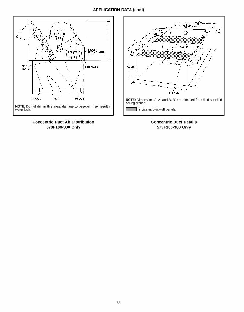
APPLICATION DATA (cont)
Concentric Duct Air Distribution579F180-300 Only
NOTE: Do not drill in this area, damage to basepan may result inwater leak.
Concentric Duct Details579F180-300 Only
NOTE: Dimensions A, A8 and B, B8 are obtained from field-suppliedceiling diffuser.
indicates block-off panels.
66
GUIDE SPECIFICATIONS — 580D036-150
PACKAGED ROOFTOP ELECTRIC COOLING UNITWITH GAS HEAT — CONSTANT VOLUME APPLICATION
HVAC GUIDE SPECIFICATIONSSIZE RANGE: 3 to 121⁄2 TONS, NOMINAL (COOLING)
72,000 TO 250,000 BTUH, NOMINAL(INPUT HEATING)
MODEL NUMBER: 580D
Part 1 — General1.01 SYSTEM DESCRIPTION
Outdoor rooftop mounted, electrically-controlled heatingand cooling unit utilizing a hermetic compressor(s) forcooling duty and gas combustion for heating duty. Unitshall discharge supply air vertically or horizontally asshown on contract drawings.
1.02 QUALITY ASSURANCEA. Unit shall be rated in accordance with ARI Standards 210/
240 or 360 and 270. Designed in accordance with ULStandard 1995.
B. Unit shall be designed to conform to ASHRAE 15, latestrevision.
C. Unit shall be UL-tested and certified in accordancewith ANSI Z21.47 Standards and UL listed and certifiedunder Canadian standards as a total package for safetyrequirements.
D. Roof curb shall be designed to conform to NRCAStandards.
E. Insulation and adhesive shall meet NFPA 90A require-ments for flame spread and smoke generation.
F. Unit casing shall be capable of withstanding 500-hour saltspray exposure per ASTM B117 (scribed specimen).
G. Unit shall be designed in accordance with ISO 9001, andshall be manufactured in a facility registered to ISO 9002/BS5750, Part 2.
H. Each 580D unit is subjected to completely automated runtesting on the assembly line. Each unit contains a factory-supplied printout indicating tested pressures, amperages,data, and inspectors; providing certification of the unit sta-tus at the time of manufacture.
1.03 DELIVERY, STORAGE, AND HANDLINGUnit shall be stored and handled per manufacturer’srecommendations.
Part 2 — Products2.01 EQUIPMENT (STANDARD)
A. General:Factory assembled, single-piece heating and cooling unit.Contained within the unit enclosure shall be all factorywiring, piping, controls, refrigerant charge (R-22), andspecial features required prior to field start-up.
B. Unit Cabinet:1. Unit cabinet shall be constructed of galvanized steel,
and shall be bonderized and coated with a prepaintedbaked enamel finish on all externally exposedsurfaces.
2. Evaporator fan compartment interior cabinet surfacesshall be insulated with a minimum 1⁄2-in. thick, flexiblefiberglass insulation, coated on the air side. Aluminumfoil-faced fiberglass insulation shall be used in the gasheat compartment.
3. Cabinet panels shall be easily removable forservicing.
4. Holes shall be provided in the base rails for riggingshackles to facilitate maneuvering and overhead rig-ging.
5. Unit shall have a factory-installed, sloped condensatedrain pan made of a non-corrosive material, providinga minimum 3⁄4-in. connection with both vertical andhorizontal drains, and shall comply with ASHRAEStandard 62.
6. Unit shall have a factory-installed filter access panel toprovide filter access with tool-less removal.
7. Unit shall have standard thru-the-bottom powerconnection capability.
C. Fans:1. Evaporator Fan:
a. Fan shall be direct or belt driven as shown on theequipment drawings. Belt drive shall include anadjustable-pitch motor pulley.
b. Fan wheel shall be double-inlet type with forward-curved blades.
c. Bearings shall be sealed, permanently lubri-cated ball-bearing type for longer life and lowermaintenance.
2. Evaporator fan shall be made from steel with acorrosion-resistant finish and shall be dynamicallybalanced.
3. Condenser fan shall be of the direct-driven propellertype and shall discharge air vertically.
4. Condenser fan shall have aluminum blades rivetedto corrosion-resistant steel spiders and shall be dy-namically balanced.
5. Induced-draft blower shall be of the direct-driven,single inlet, forward-curved centrifugal type, madefrom steel with a corrosion-resistant finish and shall bedynamically balanced.
D. Compressor(s):1. Fully hermetic type, internally protected.2. Factory spring-shock mounted and internally spring
mounted for vibration isolation.3. On independent mounting circuits (090-150).
E. Coils:1. Evaporator and condenser coils shall have aluminum
plate fins mechanically bonded to copper tubes withall joints brazed.
2. Tube sheet openings shall be belled to prevent tubewear.
3. Evaporator coil shall be of the face-split design whichproves effective in removing additional moisture fromthe supply air.
F. Heating Section:1. Induced-draft combustion type with energy saving
direct-spark ignition system and redundant main gasvalve.
2. The heat exchanger shall be of the tubular-sectiontype constructed of a minimum of 20-gage steelcoated with a nominal 1.2 mil aluminum-silicone alloyfor corrosion resistance.
3. Burners shall be of the in-shot type constructed ofaluminum-coated steel.
4. All gas piping shall enter the unit cabinet at asingle location.
67
GUIDE SPECIFICATIONS — 580D036-150 (cont)
5. The integrated gas controller (IGC) board shall includegas heat operation fault notification using an LED(light-emitting diode).
6. Unit shall be equipped with anti-cycle protection withone short cycle on unit flame rollout switch or 4 con-tinuous short cycles on the high-temperature limitswitch. Fault indication shall be made using an LED.
7. The IGC board shall contain algorithms that modifyevaporator-fan operation to prevent future cycling onhigh-temperature limit switch.
8. The LED shall be visible without removal of controlbox access panel.
G. Refrigerant Components:Refrigerant circuit components shall include:1. Fixed orifice feed system.2. Refrigerant strainer.3. Service gage connections on suction, discharge, and
liquid lines.H. Filter Section:
1. Standard filter section shall consist of factory-installed, low velocity, throwaway 2-in. thick fiberglassfilters of commercially available sizes.
2. Filter face velocity shall not exceed 320 fpm at nomi-nal airflows.
3. Filter section should use only one size filter.4. Filters shall be accessible through an access panel
with ‘‘no-tool’’ removal.I. Controls and Safeties:
1. Unit Controls:Unit shall be complete with self-contained low-voltagecontrol circuit protected by an auto-reset device.
2. Safeties:a. Unit shall incorporate compressor overtempera-
ture and overcurrent safety devices to shut offcompressor.
b. Heating section shall be provided with the follow-ing minimum protections:1) High-temperature limit switch.2) Induced-draft motor speed sensor.3) Flame rollout switch.4) Flame proving controls.
J. Operating Characteristics:1. Unit shall be capable of starting and running at
115 F ambient outdoor temperature, meeting maxi-mum load criteria of ARI Standard 210/240 or 360.
2. Compressor with standard controls shall be capable ofoperation down to 25 F ambient outdoor temperature.
K. Electrical Requirements:
All unit power wiring shall enter unit cabinet at a singlefactory-predrilled location.
L. Motors:1. Compressor motors shall be cooled by refrig-
erant gas passing through motor windings and shallhave line break thermal and current overloadprotection.
2. Evaporator-fan motor shall have permanently lubri-cated bearings and inherent automatic-reset thermaloverload protection.
3. Totally enclosed condenser-fan motor shall have per-manently lubricated bearings, and inherent automatic-reset thermal overload protection.
4. Induced-draft motor shall have permanently lubricatedsealed bearings and inherent automatic-reset thermaloverload protection.
M. Special Features:
Certain features are not applicable when the featuresdesignated * are specified. For assistance in amendingthe specifications, contact your local sales office.1. Roof Curbs (Horizontal and Vertical):
a. Formed galvanized steel with wood nailer stripand shall be capable of supporting entire unitweight.
b. Permits installation and securing of ductwork tocurb prior to mounting unit on the curb.
* 2. Integrated Economizers:a. Integrated integral modulating type capable of
simultaneous economizer and compressoroperation.
b. Includes all hardware and controls to providecooling with outdoor air.
c. Equipped with low-leakage dampers, not to ex-ceed 3% leakage at 1 in. wg pressure differential(variable sliding plate economizer only) or parallelblade design.
d. Capable of introducing up to 100% outdoorair.
e. Parallel opposed blade economizer shall beequipped with a barometric relief damper with upto 30% of return air (036-072) or 45% of return air(090-150) relief. The variable sliding plate econo-mizer is equipped with 30% of return-air relief(036-150).
f. Designed to close damper during loss-of-powersituations with emergency power supply (variablesliding plate economizer) or spring return built intomotor (parallel opposed blade economizer).
g. Dry bulb outdoor-air thermostat (variable slidingplate economizer) or enthalpy (parallel opposedblade economizer) protection shall be provided asstandard.
h. Variable sliding plate economizer is a guillotine-style damper, and the parallel opposed bladeeconomizer is a parallel blade design.
i. Parallel opposed blade economizer shall providecontrol of internal building pressure through its in-herent power exhaust function.
j. Parallel opposed blade economizer shall be ca-pable of exhausting up to 100% outdoor air.NOTE: Parallel opposed blade type economizershall also be available with power exhaust.
* 3. Manual Outdoor-Air Damper:
Manual damper package shall consist of damper,birdscreen, and rainhood which can be preset to ad-mit up to 50% outdoor air for year round ventilation.
* 4. 100% Two-Position Damper:a. Two-position damper package shall include single
blade damper and motor. Admits up to 100% out-door air.
68
GUIDE SPECIFICATIONS — 580D036-150 (cont)
b. Damper shall close upon indoor (evaporator) fanshutoff.
c. Designed to close damper during loss of powersituations.
d. Equipped with 15% barometric relief damper.* 5. 25% Two-Position Damper:
a. Two-position damper package shall include singleblade damper and motor. Admits up to 25% out-door air.
b. Damper shall close upon indoor (evaporator) fanshutoff.
c. Designed to close damper during loss of powersituations.
d. Equipped with barometric relief damper.* 6. Solid-State Enthalpy Control:
a. For use with variable sliding plate economizerpackage only.
b. Capable of sensing outdoor-air heat content (tem-perature and humidity) and control economizercut-in point to have minimum heat content airpassing over the evaporator coil for most efficientsystem operation.
* 7. Differential Enthalpy Sensor:a. For use with economizer only.b. Capable of comparing heat content (temperature
and humidity) of outdoor air and return air andcontrolling economizer cut-in point at the mosteconomical level.
* 8. Head Pressure Control Package:Consists of solid-state control and condenser-coiltemperature sensor to maintain condensing tem-perature between 90 F and 110 F at outdoor ambienttemperatures down to −20 F by condenser-fan speedmodulation or condenser-fan cycling.
9. LP (Liquid Propane) Gas Conversion Kit:Package shall contain all the necessary hardwareand instructions to convert a standard natural gasunit for use with liquefied propane gas.
* 10. Commercial Programmable Thermostat:Seven-day commercial progammable thermostatshall be capable of auto-changeover, F/C, 3-stageheating and 2-stage cabling. Thermostat shall alsobe equipped with complete system status display.
* 11. Flue Shield:Provides protection from the hot sides of the gas fluehood.
* 12. Thermostat and Subbase:Provides staged cooling and heating automatic (ormanual) changeover, fan control, and indicator light.
* 13. Condenser Coil Hail Guard Assembly:Hail guard shall protect against damage from hailand flying debris.
14. NOx Reduction Kit:Package shall contain all necessary hardware andinstructions to convert a standard natural gas unit toreduce the nitrous oxide (NOx) emissions to a levelof 40 nanograms/joule or less for unit sizes 036-060being installed in California Air Quality ManagementDistricts.
15. Controls Upgrade Kit:Kit shall contain high-pressure, loss-of-charge/low-pressure, and freeze protection switches. It shallmount on factory-installed Schrader fittings.
16. Alternate Motor(s) and/or Drive(s) (036-060, 090,120, 150):Alternate motor(s) and drive(s) shall be factory-installed to provide additional performance range.
17. Flue Discharge Deflector:Flue discharge deflector directs unit exhaust verti-cally instead of horizontally.
* 18. Condenser Coil Grille:The grille protects the condenser coil from damageby large objects without increasing unit clearances.
19. Compressor Cycle Delay:Unit shall be prevented from restarting for minimumof 5 min. after shutdown.
20. Thru-the-Bottom Service Connectors:Kit shall provide connectors to permit gas and elec-trical connections to be brought to the unit throughthe basepan.
21. Fan/Filter Status Switch:Provides status of indoor (evaporator) fan (ON/OFF)or filter (CLEAN/DIRTY). Status shall be displayedover communication bus when used with directdigital controls or with an indicator light at thethermostat.
69
GUIDE SPECIFICATIONS — 579F180-300
PACKAGED ROOFTOP ELECTRIC COOLING UNIT WITHGAS HEAT — CONSTANT VOLUME APPLICATION
HVAC GUIDE SPECIFICATIONSSIZE RANGE: 15 TO 25 TONS, NOMINAL (COOLING)
172,000 to 360,000 BTUH, NOMINAL(INPUT HEATING)
MODEL NUMBER: 579F
Part 1 — General1.01 SYSTEM DESCRIPTION
Unit is an outdoor rooftop mounted, electrically controlledheating and cooling unit utilizing a reciprocating semi-hermetic compressor(s) for cooling duty and gas combus-tion for heating duty. Supply air shall be dischargeddownward or horizontally (with horizontal supply/returncurb adapter assembly), as shown on contract drawings.Standard unit shall include a manual outdoor-air inlet.
1.02 QUALITY ASSURANCEA. Unit (180-290) shall be rated in accordance with ARI
Standards 270 and 360 and all units shall be designed inaccordance with UL Standard 1995.
NOTE: The 579F300 is beyond the scope of the ARI cer-tification program.
B. Unit shall be designed to conform to ASHRAE 15.C. Unit shall be ETL and ETL, Canada tested and certified in
accordance with ANSI Z21.47 Standards as a total pack-age.
D. Roof curb shall be designed to conform to NRCAStandards.
E. Insulation and adhesive shall meet NFPA 90A require-ments for flame spread and smoke generation.
F. Unit casing shall be capable of withstanding 500-hour saltspray exposure per ASTM B117 (scribed specimen).
G. Unit shall be manufactured in a facility registered to ISO9002/BS5750, Part 2.
1.03 DELIVERY, STORAGE, AND HANDLINGUnit shall be stored and handled per manufacturer’srecommendations.
Part 2 — Products2.01 EQUIPMENT (STANDARD)
A. General:The 579F unit shall be a factory assembled, single-pieceheating and cooling unit. Contained within the unit enclo-sure shall be all factory wiring, piping, controls, refrigerantcharge (R-22), and special features required prior to fieldstart-up.
B. Unit Cabinet:1. Unit cabinet shall be constructed of galvanized steel,
bonderized and coated with a prepainted bakedenamelfinish.
2. Indoor blower compartment interior surfaces shall beinsulated with a minimum 1⁄2-in. thick, 1 lb density neo-prene cooled, fiberglass insulation coated on the airside. Aluminum foil-faced fiberglass insulation shall beused in the gas heat compartment.
3. Cabinet panels shall be easily removable forservicing.
4. Filters shall be accessible through an access panel.
5. Holes shall be provided in the base rails for riggingshackles to facilitate overhead rigging.
6. Unit shall have a factory-installed internal condensatedrain connection and a sloped condensate pan.
C. Fans:1. Indoor blower (evaporator fan):
a. Fan shall be belt driven. Belt drive shall include anadjustable pulley. The standard fan drive shallhave a factory-installed low-medium static pres-sure fan drive. The alternate fan drive option shallhave a factory-installed high static pressure fandrive.
b. Fan wheel shall be made from steel with a corro-sion resistant finish. It shall be a dynamically bal-anced, double-inlet type with forward-curvedblades.
2. Condenser fans shall be of the direct-driven propellertype, with corrosion-resistant blades riveted tocorrosion-resistant steel supports. They shall be dy-namically balanced and discharge air upwards.
3. Induced-draft blower shall be of the direct-driven,single inlet, forward-curved, centrifugal type. It shallbe made from steel with a corrosion-resistant finishand shall be dynamically balanced.
D. Compressor(s):1. The reciprocating semi-hermetic compressor(s) has
factory-installed external spring vibration isolation.2. Factory-installed crankcase heater prevents refriger-
ant dilution of oil.3. The 180 size semi-hermetic compressor shall be
equipped with an electric unloader for capacity con-trol. Additional field-supplied unloaders are not recom-mended on any 180-300 sizes.
4. Compressors shall be on mechanically and electricallyindependent circuits (216-300 sizes).
E. Coils:1. Standard evaporator and condenser coils shall have
copper or aluminum plate fins mechanically bonded toseamless internally grooved copper tubes with alljoints brazed.
2. Optional precoated coils shall be coated with abaked-on organic, epoxy, phenolic coating.
F. Heating Section:1. Induced-draft combustion type with energy saving
direct-spark ignition system and redundant main gasvalve.
2. The heat exchanger shall be of the tubular-sectiontype constructed of a minimum of 20-gage steelcoated with a nominal 1.2 mil aluminum-silicone alloyfor corrosion resistance.
3. Burners shall be of the in-shot type constructed ofaluminum-coated steel.
4. All gas piping shall enter the unit at a single location.G. Refrigerant Components:
Refrigerant circuit components shall include:1. Fixed expansion device with filter driers.2. Service valve gage and connections on suction, dis-
charge, and liquid lines.3. Thermostatic expansion valve (size 180) or fixed ori-
fice feed system (sizes 216-300).
70
GUIDE SPECIFICATIONS — 579F180-300
H. Filter Section:
Standard filter section shall consist of 2 sizes of factory-installed 2-in. thick throwaway fiberglass filters ofcommercially available sizes.
I. Controls and Safeties:1. Unit Controls:
a. Economizer control (optional)b. Capacity control (2-step)c. Unit shall be complete with self-contained low-
voltage control circuit.2. Safeties:
a. Unit shall incorporate a solid-state compressorlockout which provides reset capability at thespace thermostat, should any of the followingsafety devices trip and shut off compressor:1) Compressor overtemperature, overcurrent.2) Low-pressure switch.3) Freezestats (evaporator coil).4) High-pressure switch.
b. Supply-air thermostat shall be located in the unit.c. Heating section shall be provided with the follow-
ing minimum protections:1) High-temperature limit switch.2) Induced-draft motor speed sensor.3) Flame rollout switch.4) Flame proving controls.5) Redundant gas valve.
J. Operating Characteristics:1. Unit shall be capable of starting and running at 115 F
ambient outdoor temperature per maximum load crite-ria of ARI Standard 360.
2. Unit with standard controls will operate in coolingdown to an outdoor ambient temperature of 40 F on579F180 units, to 35 F on 216 units, to 25 F ambienton 240 units, and to 48 F ambient on 300 units.
3. Unit shall be provided with fan time delay to preventcold air delivery.
K. Electrical Requirements:All unit power wiring shall enter unit cabinet at a singlelocation.
L. Motors:1. All compressor motors shall be of the refrigerant
cooled type with thermal and calibrated circuit breakeroverload protection.
2. All fan motors shall have permanently lubricated,sealed bearings and inherent automatic-reset thermaloverload protection or manual reset calibrated circuitbreakers.
3. All indoor-fan motors 5 hp and larger shall meet theminimum efficiency requirements as established bythe Energy Policy Act of 1992 (EPACT) effective Oc-tober 24, 1997.
M. Special Features:Certain features are not applicable when the featuresdesignated * are specified. For assistance in amendingthe specifications, contact your local sales office.
1. Roof Curbs (Horizontal and Vertical):a. Formed of 18-gage galvanized steel with wood
nailer strip and shall be capable of supporting en-tire unit weight.
b. Permits installing and securing ductwork to curbprior to mounting unit on the curb.
2. Horizontal Adapter Roof Curb:Includes factory-assembled adapter and ductand substantially improves evaporator fan staticperformance.
* 3. Integrated Economizer:a. Integrated type capable of simultaneous econo-
mizer and compressor operation to provide cool-ing with outdoor air.
b. Equipped with low-leakage dampers not toexceed 3% leakage, at 1.0 in. wg pressuredifferential.
c. Capable of introducing up to 100% outdoor air.d. Equipped with dry-bulb temperature control to
govern economizer changeover.e. Equipped with a mixed-air sensor that controls the
economizer to a 55 F control point.4. Two-Position Damper:
Two-position damper package shall include singleblade damper and motor. Admits up to 25% outdoorair, and shall close upon unit shutoff.
5. Accessory Compressor Cycle Delay:Compressor shall be prevented from restarting for aminimum of 5 minutes after shutdown.
* 6. Thermostats and Subbases:To provide staged heating and cooling in addition toautomatic (or manual) changeover and fan control.
* 7. Barometric Relief Damper Package:a. Package shall include damper, seals, hardware,
and hoods to relieve excess internal pressure.b. Damper shall close due to gravity upon unit shut-
down.* 8. Power Exhaust:
Package shall include an exhaust (propeller style)fan, 1⁄2 Hp 208-230, 460 v (factory-wired for 460 v)motor, and damper for vertical flow units with econo-mizer to control overpressurization of building.
* 9. Head Pressure Control Package:Consists of an accessory outdoor-air package and asolid-state control with condenser coil temperaturesensor for controlling condenser-fan motorspeed to maintain condensing temperature between90 F and 100 F at outdoor ambient temperaturedown to –20 F.
10. Low-Ambient Kits:When used, allows units to operate at lower outdoorambient temperatures. See trade prices for moreinformation.
71
GUIDE SPECIFICATIONS — 579F180-300
* 11. Enthalpy Sensor:a. For use with economizer only.b. Capable of comparing heat content (temperature
and humidity) of outdoor air and indoor air andcontrolling economizer cut-in point at the mosteconomical level.NOTE: Two accessory enthalpy sensors are re-quired for differential enthalpy control.
* 12. Commercial Programmable Thermostat:Seven-day commercial progammable thermostatshall be capable of auto-changeover, F/C, 3-stage
heating and 2-stage cooling. Thermostat shall alsobe equipped with complete system status display.
13. Winter Start Time-Delay Relay:Used in conjunction with the accessory low-ambientkit or head pressure control device, permits opera-tion in cooling at lower outdoor ambient tempera-tures. See price pages for more information.
14. Liquid Propane Conversion Kit:Kit shall contain all the necessary hardware and in-structions to convert a standard natural gas unit foruse with liquified propane gas.
Copyright 1998 Bryant Heating & Cooling Systems
SPECIFICATIONS SUBJECT TO CHANGE WITHOUT NOTICE
UNIT MUST BE INSTALLED IN ACCORDANCEWITH INSTALLATION INSTRUCTIONS
Printed in U.S.A. 9/98 CATALOG NO. 5258-001