Embed Size (px)
Citation preview
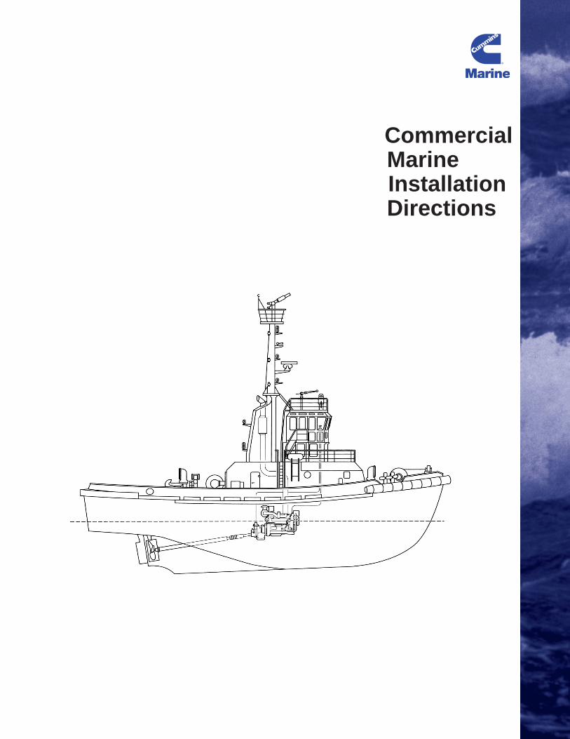
CommercialMarineInstallation Directions
Cummins Marine a Division of Cummins Engine Company, Inc.Cummins MerCrusier Diesel Marine LLC4500 Leeds Avenue - Suite 301Charleston, South Carolina 29405 U.S.A.Bulletin 3884744Printed in U.S.A. 11/04© 2004
250267_CECO_Cov 1/20/05 8:37 PM Page 1

COMMERCIAL MARINE INSTALLATION DIRECTIONS TABLE OF CONTENTS
INTRODUCTION...........................................................................................................................................3 ENGINE APPLICATION...............................................................................................................................4
Continuous Duty ........................................................................................................................................4 Heavy Duty ................................................................................................................................................4 Medium Continuous Duty ..........................................................................................................................4 Intermittent Duty ........................................................................................................................................5 Light Commercial.......................................................................................................................................5 Prime Power (Fixed Speed Auxiliary Only) ...............................................................................................5 Controllable Pitch Propellers .....................................................................................................................5
ENGINE MOUNTING/DRIVE SYSTEM........................................................................................................6 Engine Foundation ....................................................................................................................................7 Mount Location ..........................................................................................................................................8 Trunnion Mounting.....................................................................................................................................9 Engine Installation Angle.........................................................................................................................11 Solid Engine Mounting.............................................................................................................................12 Flexible Engine Mounting ........................................................................................................................14 Driveline...................................................................................................................................................15 Propeller Shaft Alignment........................................................................................................................16
ENGINE DRIVEN ACCESSORIES ............................................................................................................18 Belt Drive .................................................................................................................................................18 Front Power Take-off Clutches................................................................................................................21 Hydraulic Pump Drives ............................................................................................................................22
EXHAUST SYSTEMS.................................................................................................................................24 Dry Exhaust Systems ..............................................................................................................................25 Wet Exhaust Systems .............................................................................................................................31 Water Injection.........................................................................................................................................31
COOLING SYSTEM....................................................................................................................................37 Heat Exchanger Cooled ..........................................................................................................................38 Keel Coolers ............................................................................................................................................42 Keel Cooler Location ...............................................................................................................................43 Expansion Tank.......................................................................................................................................45 Engine Vents ...........................................................................................................................................46 Make-up Lines .........................................................................................................................................47 Heat Exchanger Cooling..........................................................................................................................48 Water/Cabin Heaters ...............................................................................................................................52 Plumbing..................................................................................................................................................53
AIR INTAKE SYSTEMS & ENGINE ROOM VENTILATION .....................................................................54 Remote Mounted Air Cleaner Piping.......................................................................................................56
FUEL SYSTEM ...........................................................................................................................................63 Fuel Tanks 0 to 1.6 M (0 to 5 Ft) Above Crankshaft Centerline..............................................................65 Fuel Tanks 1.6 to 8 M (5 to 25 Ft) Above Crankshaft Centerline............................................................66 Fuel Tanks 1.6 M (5 Ft) or More Below Crankshaft Centerline...............................................................68 Valves......................................................................................................................................................68 Fuel Line Plumbing..................................................................................................................................72 Duplex Fuel Filters...................................................................................................................................73
STARTING AND ELECTRICAL SYSTEMS...............................................................................................74 Starter Circuit Wiring ...............................................................................................................................79 Alternator Wiring......................................................................................................................................80 Voltage Range.........................................................................................................................................80

2
System Wiring .........................................................................................................................................81 Wire Routing............................................................................................................................................81 Instrument Panels....................................................................................................................................82 Bonding System ......................................................................................................................................83 Radio Interference Suppression..............................................................................................................83 Air Starting Systems................................................................................................................................84 Air Compressor........................................................................................................................................84 Air Piping .................................................................................................................................................84 Air Starter Lubricators..............................................................................................................................86 Other Considerations for Air Starters ......................................................................................................86
LUBRICATION SYSTEM............................................................................................................................87 Engine Crankcase Vents .........................................................................................................................91 Oil Pressure Gauge .................................................................................................................................92 Oil Temperature Gauge...........................................................................................................................92 Hose Routing...........................................................................................................................................93 Emergency Lubricating Oil System .........................................................................................................93

3
INTRODUCTION This manual is intended as a guide for the proper installation of Cummins marine diesel engines which are used in commercial applications. The manual is divided into sections which cover Cummins Inc. installation requirements and recommendations for each engine system. The requirements for each system are highlighted in bold text and must be met on any installation in order to obtain Cummins' concurrence to that installation. Failure to meet the installation requirements may result in poor performance, shorter engine life, higher maintenance costs or engine failure. Installations that do not comply with Cummins requirements may also be excluded from Warranty consideration. The purpose of the recommendations is to help the engine installer meet the requirements of a particular system. The recommendations are intended as an aid and their use is strictly optional so long as all of the installation requirements are met. If you have any questions concerning these requirements or anticipate any problems meeting any of the requirements, contact a Cummins Marine Application Engineer at your local Cummins distributor. This manual is applicable to the following engine families:
CUMMINS COMMERCIAL MARINE ENGINES ENGINE FAMILY CYL DISPLACEMENT
LITERS (CUBIC IN.) ASPIRATION
4B 4 3.9 (239) Natural, Turbocharged, Turbocharged and Aftercooled
6B 6 5.9 (359) Natural, Turbocharged, Turbocharged and Aftercooled
QSB 6 5.9 (359) Turbocharged and Aftercooled 6C 6 8.3 (505) Turbocharged and Aftercooled
QSC 6 8.3 (505) Turbocharged and Aftercooled QSL 6 8.9 (542) Turbocharged and Aftercooled QSM 6 10.8 (661) Turbocharged and Aftercooled
N14, N855 6 14.0 (855) Turbocharged, Turbocharged and Aftercooled
K19 6 19 (1150) Turbocharged, Turbocharged and Aftercooled
QSK19 6 19 (1150) Turbocharged and Aftercooled K38 12 38 (2300) Turbocharged and Aftercooled K50 16 50 (3067) Turbocharged and Aftercooled
QSK60 16 60.2 (3672) Turbocharged and Aftercooled

4
ENGINE APPLICATION
Marine Installation Requirements
The engine must be used in accordance with the application guidelines for that particular rating.
Engines must achieve or exceed rated speed at full throttle under any steady state operating condition; except engines in variable displacement boats, which must achieve no less than 100 rpm below rated at full throttle during a dead push or bollard pull.
Marine Installation Recommendations
Proper application of your Cummins marine engine is important to assure that the engine gives you the reliability and durability it was designed for.
The engine must be used in accordance with the application guidelines for that particular rating.
Cummins develops its marine engines to meet demanding customer expectations for performance, reliability and durability. In order for the engine to perform as it is intended, it must be used in accordance with Cummins' published marine ratings guidelines. It is important to choose the proper engine rating to provide the optimum performance in a given application. Listed below are the Cummins marine ratings guidelines.
Continuous Duty
This power rating is intended for continuous use in applications requiring uninterrupted service at full power. This rating is the ISO 3046 Standard Power Rating.
Heavy Duty
This power rating is intended for continuous use in variable load applications where full power is limited to eight hours out of every ten hours of operation. Also, reduced power operations must be at or below 200 rpm of the maximum rated rpm. This is an ISO 3046 Fuel Stop Power Rating and is for applications that operate 5,000 hours per year or less.
Medium Continuous Duty
This power rating is intended for continuous use in variable load applications where full power is limited to six hours out of every twelve hours of operation. Also, reduced power operations must be at or below 200 rpm of the maximum rated rpm. This is an ISO 3046 Fuel Stop Power Rating and is for applications that operate less than 3,000 hours per year.

5
Intermittent Duty
This power rating is intended for intermittent use in variable load applications where full power is limited to two hours out of every eight hours of operation. Also, reduced power operations must be at or below 200 rpm of the maximum rated rpm. This is an ISO 3046 Fuel Stop Power Rating and is for applications that operate less than 1,500 hours per year.
Light Commercial
This power rating is intended for use in variable load applications where full power is limited to one hour out of every twelve hours of operation. Also, reduced power operations must be at or below 400 rpm of the maximum rated rpm.
Prime Power (Fixed Speed Auxiliary Only)
Engines with this rating are available for an unlimited number of hours per year in variable load applications. Variable load is not to exceed a 70 percent average of the rated power during any operating period of 250 hours. Total operating time at 100 percent Prime Power shall not exceed 500 hours per year. A 10 percent overload capability is available for a period of one hour within a twelve hour period of operation. Total operating time at the 10 percent overload power shall not exceed 25 hours per year. This power rating conforms to ISO 8528 guidelines.
Engines must achieve or exceed rated speed at full throttle under any steady state operating condition; except engines in variable displacement boats, which must achieve no less than 100 rpm below rated at full throttle during a dead push or bollard pull.
Another important part of proper engine application is choosing the correct marine gear ratio and propeller size. Cummins develops its marine engines around loads based on propellers that are properly sized to absorb full engine horsepower under fully loaded conditions. Therefore, the marine gear ratio and propeller size must be chosen to allow the engine to achieve rated speed under fully loaded conditions (full fuel, water, passengers and maximum equipment load). This does not apply to bollard pull conditions, in which the boat is stationary in the water at full throttle. Under these conditions, the engines must achieve no less than 100 rpm below rated rpm.
Controllable Pitch Propellers
If controllable pitch propellers are to be used, the maximum pitch on the propeller should be determined under fully loaded conditions. The vessel should be taken out fully loaded and the pitch slowly increased until the engines are operating at rated speed at full throttle. This is the maximum amount of pitch that should be used under any operating conditions.

6
ENGINE MOUNTING/DRIVE SYSTEM
Marine Installation Requirements
The mounting system must be constructed so that the supporting structure deflections do not overstress the engine castings.
The engine must be installed so that the static bending moment at the point where the flywheel housing is attached to the engine does not exceed the maximum value on the Engine General Data Sheet.
Front trunnion type mounts must be adjusted to achieve end play clearance of 3.8 - 5.0 mm (.150 - .200") for the QSK19/K19 and 2.8 - 4.0 mm (.110 - .160") for the K38/K50 and QSK60 with the trunnion support bolted to the foundation.
The trunnion must be lubricated such that grease can be seen to flow from between the pivot and trunnion joint.
The static installation angle of the engine in a waterborne vessel must not be less than the minimum value given on the Engine General Data Sheet.
The static installation angle of the engine in a waterborne vessel must not be greater than the maximum value given on the Engine General Data Sheet.
Engine movement must be restrained sufficiently to prevent damage from physical contact between the engine components and adjoining structures; and the movement must not exceed the flexural limits of connecting systems.
On flexible mounted systems, the vibration isolators must be installed parallel to the engine centerline in both the vertical and horizontal directions. The mount must be free to deflect and must not be fully compressed under a static load.
The propeller shaft flange bore and face alignment must be within the marine gear manufacturer's limits.
A TVA must be performed on all new high horsepower engine installations (K19 and above) excluding gensets.

7
Marine Installation Recommendations
Engine Foundation
The engine foundation, consisting of longitudinal stringers and the engine bed, provides the attachment points for the engine and marine transmission to the vessel framework. This system should be rigid enough to resist excessive flexing in any part of the hull and securely hold the engine in place during all operating conditions. The longitudinal stringers are a part of the hull structure and are primarily used to stiffen the hull against stresses and deflections. They also provide support for the engine bed and distribute the engine and marine gear weight throughout the hull.
The mounting system must be constructed so that the supporting structure deflections do not overstress the engine castings.
The engine bed provides attachment points for the engine and marine gear. It should be made of welded steel or aluminum and welded or bolted to the stringers. The bed should be of a box type construction or have cross bracing to provide lateral support. This will assure that structural deflections are not transmitted to engine castings and will also limit the amount of lateral engine movement that is transferred to the hull causing vibration.

8
Mount Location
The engine must be installed so that the static bending moment at the point where the flywheel housing is attached to the engine does not exceed the maximum value on the Engine General Data Sheet.
The following table summarizes the requirements for engine families covered by this document.
In order to properly support the weight of the engine and marine gear, a six-point mounting system is recommended on all commercial engines. Cummins supplied engine and gear supports are recommended and should be located at the front, on the flywheel housing and on the marine gear on each side of the engine. When using a six-point mounting system, the engine should be aligned using the mounts at the front and at the marine gear. Once the alignment is complete, the flywheel housing mounts should be added.
MAXIMUM BENDING MOMENT, REAR FACE OF BLOCK ENGINE FAMILY
N-m lb-ft
4B 1356 (1000)
6B 1356 (1000)
QSB 1356 (1000)
6C, 480C-E 1356 (1000)
QSC 1356 (1000)
QSL 1356 (1000)
QSM 1356 (1000)
N14, N855 1356 (1000)
K19 1356 (1000)
QSK19 1356 (1000)
K38 6100 (4500)
K50 6100 (4500)
QSK60 10,350 (7634)

9
On flexible mounted engines, brackets which connect both the marine gear and the flywheel housing to a single isolator may be used if the bracket design is approved by Cummins Marine Engineering. If a six point mounting system cannot be used, your local Cummins Marine Application Engineer should be contacted for assistance in meeting this requirement. NOTE: If the gear must be mounted prior
to installation in the hull, the engine and gear should be mounted on base rails and the whole system installed together. The lifting brackets on the engine will not support the weight of the engine and gear.
Trunnion Mounting
Front trunnion type mounts must be adjusted to achieve end play clearance of 3.8 - 5.0 mm (.150 - .200") for the QSK19/K19 and 2.8 - 4.0 mm (.110 - .160") for the K38/K50 and QSK60 with the trunnion support bolted to the foundation.
The trunnion must be lubricated such that grease can be seen to flow from between the pivot and trunnion joint.
Some high-horsepower engines feature a front trunnion mount arrangement which allows for thermal expansion of the engine as well as flexure of the vessel hull relative to the engine. The trunnion mount requires special considerations as follows:
- The trunnion carries no thrust reaction. The rear mounts must be designed to handle full propeller thrust.
10
- The front mounting feet must be aligned axially with the centerline of the trunnion housing. There must be no offset or the trunnion may cock on the support.
- The trunnion must be installed with the proper end clearance and must be properly lubricated.
- If a flexible mounting system is used, it is recommended that a remote fixed gear be used to carry propeller thrust reaction, and a flexible coupling is chosen which is designed to handle relative movement between the engine and fixed gear.

11
Engine Installation Angle
The static installation angle of the engine in a waterborne vessel must not be less than the minimum value given on the Engine General Data Sheet.
For engines with no vent provision at the rear of the engine block, a nose down installation will not allow proper venting of the engine during fill and normal operation. This can lead to localized hot spots within the engine and possibly engine or component failures. In a vee-drive system, the engine sits with the nose towards the stern of the vessel. The typical planing angle of a planing hull is about 3 degrees. If the engine is installed with an angle of less than 3 degrees, it will be running nose down when the vessel is on plane. NOTE: If the planing angle of the vessel is going to be more than 3 degrees, then the
minimum installation angle for a vee-drive is the planing angle of the vessel. The static installation angle of the engine in a waterborne vessel must
not be greater than the maximum value given on the Engine General Data Sheet.
Installing the engine at an angle greater than that listed for the particular engine model may result in poor operation and performance and possible engine failure. If the installation angle is too large, the connecting rods may begin dipping into the oil in the pan. This may aerate the oil causing poor lubrication and decreased engine life. It may also cause high oil consumption, increased fuel consumption, low power and an increase in smoke levels. Too high of an installation angle may also result in a loss of oil supply to the lubricating oil pump and a loss of oil pressure to the engine. This can result in major engine damage and possible engine failure. Refer to the latest Engine General Data Sheet for the particular engine family for maximum installation angle requirements.

12
Engine movement must be restrained sufficiently to prevent damage from physical contact between the engine components and adjoining structures; and the movement must not exceed the flexural limits of the connecting systems.
Solid Engine Mounting
Solid mounting an engine is usually done by using brass or steel shims, pourable chocking compound or Fabreeka type washers and pads. The use of pourable chocking compounds is the simplest and preferred way to solid mount the engine. When using a chocking compound, the alignment of the marine transmission and propeller shaft is accomplished using jacking screws between the support brackets and the engine bed. The mounting bolts can be loosely put into place at this point or a hole can be drilled through the chocking compound later. The jacking screws, mounting bolts and bottom of the engine bracket should be coated with a grease or anti-bonding substance to allow them to be removed later. Temporary dams are put on the engine bed and should extend approximately 13mm (0.5") above the bottom of the engine beds. The chocking compound is poured in to fill the space between the bracket and engine bed. Once the compound has solidified, the jacking screws can be removed or left in place and the final mounting bolts are torqued down. When using jacking screws on wood or fiberglass engine beds, steel plates should be used under the jacking screws to prevent damage to the engine bed. The chocking compound manufacturer should be consulted for further recommendations.

13
Fabreeka type washers and pads consist of layers of rubber-impregnated canvas and will provide a small amount of flexibility for minor misalignment and a degree of protection from shock loading. A steel plate is required between the nut and Fabreeka pad to protect the pad from wear and should be the same size as the pad. It is still necessary to use brass or steel shims to align the engine and gear with the shafting. Transverse cross bracing on the engine bed and stringers should be used to prevent lateral engine movement on solid mounted systems. If a front power take-off clutch is used, it is a good practice to support the clutch. Clutch options available from Cummins must be supported to avoid over-stressing the nose of the crankshaft due to the overhung weight.
14
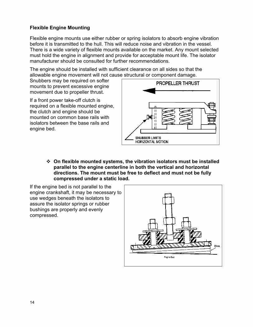
Flexible Engine Mounting
Flexible engine mounts use either rubber or spring isolators to absorb engine vibration before it is transmitted to the hull. This will reduce noise and vibration in the vessel. There is a wide variety of flexible mounts available on the market. Any mount selected must hold the engine in alignment and provide for acceptable mount life. The isolator manufacturer should be consulted for further recommendations. The engine should be installed with sufficient clearance on all sides so that the allowable engine movement will not cause structural or component damage. Snubbers may be required on softer mounts to prevent excessive engine movement due to propeller thrust. If a front power take-off clutch is required on a flexible mounted engine, the clutch and engine should be mounted on common base rails with isolators between the base rails and engine bed.
On flexible mounted systems, the vibration isolators must be installed parallel to the engine centerline in both the vertical and horizontal directions. The mount must be free to deflect and must not be fully compressed under a static load.
If the engine bed is not parallel to the engine crankshaft, it may be necessary to use wedges beneath the isolators to assure the isolator springs or rubber bushings are properly and evenly compressed.

15
Driveline
In order to isolate engine vibration and prevent it from being transferred to the hull through the propeller shaft, Cummins recommends that the distance from the marine gear output flange to a fixed stuffing box or first fixed bearing be a minimum of 20 times the shaft diameter. If the distance is less than this, a flexible coupling may be necessary to isolate the engine vibration. If the driveline is to have a remote mounted transmission, a constant velocity joint, or a pair of universal joints, and a sliding shaft must be used to allow for the relative motion between the flexible mounted engine and the fixed marine gear. If universal joints are to be used, it is important to remember that it is necessary to have the exact same angle at each joint under all operating conditions in order for the system to work properly. The driveline component manufacturer should always be consulted for more details on the installation of their product.

16
Propeller Shaft Alignment
The propeller shaft flange bore and face alignment must meet the gear manufacturer's requirements.
The alignment of the engine and marine transmission with the propeller shafting is essential to minimize vibration, noise, power loss and stress in the driveline components.
While aligning the engine and gear, check both the propeller shaft flange bore and face. The shaft and gear flanges should fit together without deflecting either the engine or the shaft from its operating position. This will allow the propeller shaft flange and marine gear output flange to mate properly without over stressing the driveline components. Cummins requires that the face alignment be within the gear manufacturer's specifications when checked with a feeler gauge at the top, bottom, and each side of the flanges. The shaft should then be rotated 180 degrees and checked again. The propeller shaft flange bore and face alignment should not be done until after the vessel is in the water and, on a solid mounted engine, should be rechecked after the vessel has been in the water and loaded to its normal operating condition.

17
On solid mounted engines, temporary alignment is made with jacking screws and final alignment is made using shim stock or chocking compound underneath the supports On flexible mounted engines the engine is aligned by shimming under the isolator and then the final alignment is accomplished using the adjusting nuts on the isolator. The mounting brackets should always be located as low as possible on the isolator stud to prevent over-stressing the stud. The alignment must be redone each time a flexible mounting system is disconnected from the propeller shaft since the system is not rigid. If the system uses a flexible stuffing box, it will be necessary to block the propeller shaft into the center of the stuffing box bore. This will assure that the shaft passes through the center of the stuffing box when the mounting is complete and will not prematurely wear out the bearing in the stuffing box.
18
ENGINE DRIVEN ACCESSORIES
Marine Installation Requirements
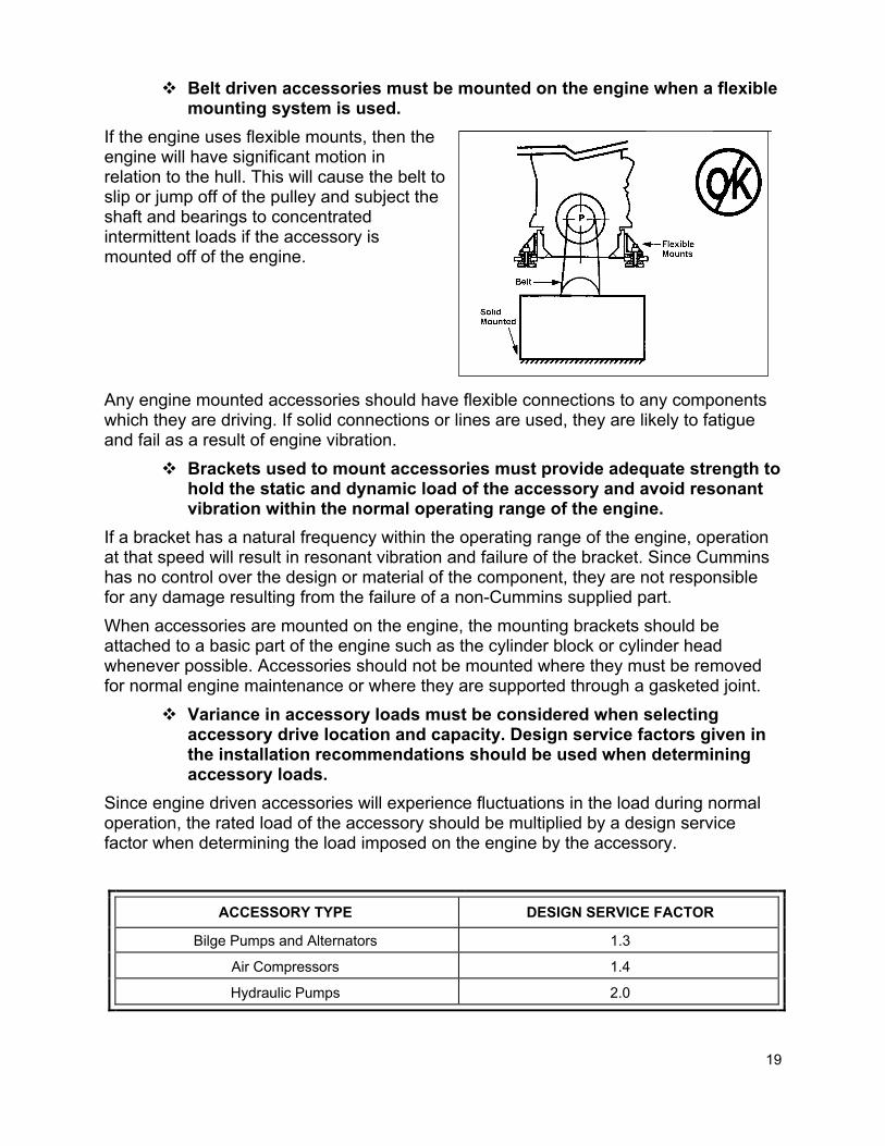
Belt driven accessories must be mounted on the engine when a flexible mounting system is used.
Brackets used to mount accessories must provide adequate strength to hold the static and dynamic load of the accessory and avoid resonant vibration within the normal operating range of the engine.
Variance in accessory loads must be considered when selecting accessory drive location and capacity. The design service factor given in the installation recommendations should be used when determining accessory loads. The maximum accessory load must not exceed the rated drive limit.
Belt driven equipment must be held in alignment to a tolerance of 1 mm in 200 mm (1/16 inch in 12 inches).
A TVA must be performed on all new engine installations with a front power takeoff.
The total power taken off of the front of the crankshaft cannot exceed the capacity of the FPTO clutch and the total power required of the engine may not exceed the value published in the option notes for that particular rating.
The engine must have sufficient crankshaft end clearance with the marine gear, and/or any FPTO installed, per the requirement on the Engine General Data Sheet.
All exposed rotating components must have a protective guard.
Marine Installation Recommendations
Belt Drive
Cummins marine engines may have belt drives for an alternator, raw water pump, and at least one open drive pulley for other accessories. Many engines also have crankshaft pulleys available for driving accessories. All Cummins belt drives use pulleys that are designed to SAE standards. New belts require a run-in period of 10-15 minutes under tension and should then be retensioned. This allows for the initial stretch of the belt and will help prevent it from jumping off the pulley.
19
Belt driven accessories must be mounted on the engine when a flexible mounting system is used.
If the engine uses flexible mounts, then the engine will have significant motion in relation to the hull. This will cause the belt to slip or jump off of the pulley and subject the shaft and bearings to concentrated intermittent loads if the accessory is mounted off of the engine. Any engine mounted accessories should have flexible connections to any components which they are driving. If solid connections or lines are used, they are likely to fatigue and fail as a result of engine vibration.
Brackets used to mount accessories must provide adequate strength to hold the static and dynamic load of the accessory and avoid resonant vibration within the normal operating range of the engine.
If a bracket has a natural frequency within the operating range of the engine, operation at that speed will result in resonant vibration and failure of the bracket. Since Cummins has no control over the design or material of the component, they are not responsible for any damage resulting from the failure of a non-Cummins supplied part. When accessories are mounted on the engine, the mounting brackets should be attached to a basic part of the engine such as the cylinder block or cylinder head whenever possible. Accessories should not be mounted where they must be removed for normal engine maintenance or where they are supported through a gasketed joint.
Variance in accessory loads must be considered when selecting accessory drive location and capacity. Design service factors given in the installation recommendations should be used when determining accessory loads.
Since engine driven accessories will experience fluctuations in the load during normal operation, the rated load of the accessory should be multiplied by a design service factor when determining the load imposed on the engine by the accessory.
ACCESSORY TYPE DESIGN SERVICE FACTOR
Bilge Pumps and Alternators 1.3
Air Compressors 1.4
Hydraulic Pumps 2.0

20
The direction as well as the load is important when considering belt driven accessories. The load capacity of crankshaft pulleys and other drive locations will vary at different angles due to the loading capability of the bearings. If two or more accessories are being driven from a single multigroove pulley, the accessories should be arranged to have opposing belt pulls so that the resulting force on the drive shaft is kept to a minimum. Accessory drive locations can be found on the particular engine installation drawing. Increasing the belt and pulley width may exceed the safe loading of the crankshaft or drive location and is not recommended unless the design has been reviewed by Cummins Marine Engineering. The amount of power that can be taken off of the front of the crankshaft is dependent upon the angle at which it is taken and the distance of the load from the nose of the crankshaft. Refer to the engine data sheets for the particular engine for maximum allowable crankshaft side loads and maximum torque that can be taken from the crankshaft. Any device rigidly attached to the front of the crank, other than an approved option, must be analyzed for the effects on crank bending, side-pull loading, mean and vibratory torques, and the capability of the crank bolted joint capacity. Belt driven equipment must be held in alignment to a tolerance of 1 mm in 200 mm (1/16 inch in 12 inches). Misalignment between the belt driven equipment and the engine will result in bending forces on the shafts involved, wearing of the belt, belt jumping and can result in bearing or belt failure. This can usually be checked with a straight edge.

21
Front Power Take-off Clutches
More power may be taken from a direct drive at the front of the crankshaft than any other accessory drive location. Many Cummins engines can be fitted with a front power take-off clutch for driving accessories such as a winch, fire pump, hydraulic pump or generator.
A TVA must be performed on all new engine installations with a front power takeoff.
All direct driven equipment will have some effect on torsional vibration. Excessive torsional vibration in a system can result in excessive noise, gear failure or, in the most severe cases, crankshaft failures. If a front power take-off arrangement is to be used, a torsional vibration analysis must be performed prior to installation. The torsional compatibility of the system is the responsibility of the installer (ref. ISO 3046-5) and not Cummins. If a front power take-off clutch is used, it is a good practice to support the clutch. Clutch options available from Cummins must be supported to avoid over-stressing the nose of the crankshaft due to the overhung weight.
The total power taken off of the front of the crankshaft cannot exceed the capacity of the FPTO clutch and the total power required of the engine may not exceed the values published in the option notes for that particular rating.
The total power capacity of each Cummins offered FPTO clutch is listed in the option notes found in the on-line sales e-book. This is the maximum amount of power that can be transmitted through the particular clutch and cannot be exceeded. Additionally, the total power required by the propeller and FPTO cannot exceed the full load torque curve at any given rpm. If the propeller is engaged, this means that the power available at the front is equal to the difference between the propeller curve and full load torque curve as seen on the engine performance data sheet.

22
The engine must have sufficient crankshaft end clearance with the marine gear, and/or any FPTO installed, per the requirement on the Engine General Data Sheet.
THE ENGINE MUST NOT BE RUN WITHOUT SUFFICIENT END CLEARANCE! Without end clearance, the crankshaft will be turning in solid contact with the engine thrust bearing surface and will damage the thrust bearing, crankshaft and engine block. To find the crankshaft end clearance, push the crankshaft vibration damper hub in until the crankshaft contacts the thrust bearing. Then pull the crankshaft forward. Refer to the applicable Troubleshooting and Repair manual which lists the minimum and maximum amount of allowable free axial movement for the engine model.
All exposed rotating components must have a protective guard. Since any rotating component may potentially injure someone through direct contact or through contact with loose clothing, a protective guard must be placed around any exposed rotating parts. Guards provided by Cummins must not be modified or altered without approval from Cummins Marine Engineering.
Hydraulic Pump Drives
Many of the Cummins engines covered in this manual have hydraulic pump drives as available options. The locations for the various hydraulic pump drives can be found on the installation drawing or in the on-line sales e-book. When using the hydraulic pump drives, it is important to not exceed the torque or bending moment limits of the drive location. All of Cummins' hydraulic pump drives are available with either an SAE type A or B flange and the limits for each are listed below.
SAE FLANGE TYPE TORQUE LIMIT MAXIMUM BENDING
MOMENT
A 58.4 N-m (571 in-lb)
8.5 N-m (75 in-lb)
B 209 N-m
(1852 in-lb) 28.3 N-m (250 in-lb)

23
The example to the right illustrates how to calculate the bending moment on the flange. In order to calculate the bending moment it is necessary to know the weight and center of gravity of the accessory.

24
EXHAUST SYSTEMS
Marine Installation Requirements
Protective guards, jacketing, and/or covers must be used wherever persons or gear may come in contact with any section of the exhaust system where the surface temperature exceeds 93ºC (200ºF).
Piping must not be installed near combustible material. All exhaust system surfaces with temperatures above 220ºC (428ºF)
which may be impinged as a result of a fuel system failure must be properly insulated.
The exhaust back pressure must not exceed 3 in. Hg (10 kPa). The exhaust system components must not impose excessive load or
bending moments on the exhaust manifold or turbocharger due to weight, inertia, relative motion of the components or dimensional change due to thermal growth.
o The maximum allowable bending moment at the turbine outlet mounting flange must not exceed the maximum specified on the Engine General Data Sheet.
o The maximum allowable direct load at the turbine outlet mounting flange must not exceed the maximum specified on the Engine General Data Sheet.
A flexible connection must be installed directly to the engine exhaust outlet connection.
The exhaust system must prevent the entrance of water into the engine or turbocharger whether it be from spray, rain, washing, wave action, boat motion or any other source.
o The highest point in the exhaust system must be dry and at least 12 in (305mm)* above the loaded water line (LWL). *For the 1.7, 2.8 and 4.2 liter inboard and sterndrive engines, the required dimension above the LWL is 11 in (279 mm) to the top of the elbow or riser.
o The point of water injection is downstream of and at least 8 in (203mm) from the internal high point of the elbow, or 2 in (50 mm) below the highest dry point.
o The injected water must not be able to flow backward into engine.
The exhaust gas must be dispersed so that it does not detrimentally affect the air cleaner function, the engine ambient environment, the crew or passengers.
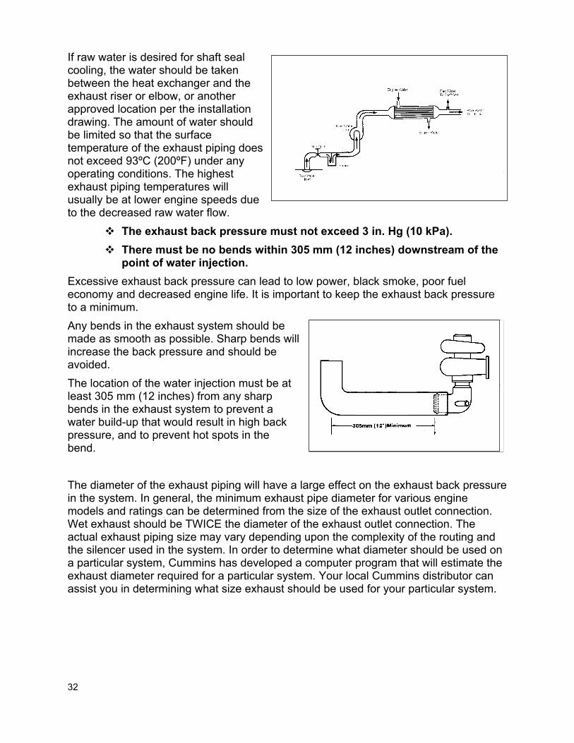
There must be no bends within 305 mm (12 inches) downstream of the point of water injection.

25
Wet exhaust piping must have a continuous downward slope of at least 2 degrees (35 mm per meter or 1/2" per foot).
A service port must be provided in the exhaust system. The service port must be internally threaded with standard pipe threads not larger than 12.7 mm (0.5 in). The port must be located between the engine exhaust outlet connection and the point where it mixes with sea water (for sea water cooled exhaust systems) or exits to ambient air (for dry exhaust systems).
Marine Installation Recommendations
The purpose of the exhaust system is to carry the exhaust gas from the engine to the atmosphere with minimal flow restriction. Marine applications have two types of exhaust systems, wet and dry.
Dry Exhaust Systems
Dry exhaust systems use steel or iron pipe for the exhaust piping, stainless steel flexible sections, and steel for the mufflers. Due to the high exhaust temperatures and the thermal conductivity of the metal components, they can be dangerous unless certain precautions are taken.
Protective guards, jacketing, and/or covers must be used wherever persons or gear may come in contact with any section of the exhaust system where the surface temperature exceeds 93ºC (200ºF).
For safety reasons, and to help maintain low engine room temperatures, thermal insulation or shields are required on all parts of a non-cooled, dry exhaust system. The insulation should be sufficient to maintain a surface temperature of less than 93° C (200° F).
Piping must not be installed near combustible material. Due to the high temperatures of a dry exhaust system, dry exhaust piping should never be installed near combustible materials. Cummins recommends that the wrapped exhaust piping be at least 15 cm (6 inches) from any combustible materials.

26
The exhaust back pressure must not exceed 3 in. Hg (10 kPa). Excessive exhaust back pressure can lead to low power, black smoke, poor fuel economy and decreased engine life. It is important to keep the exhaust back pressure to a minimum. Any bends in the exhaust system should be made as smooth as possible. Sharp bends will increase the back pressure and should be avoided. In general, the minimum exhaust pipe diameter for various engine models and ratings can be determined from the size of the exhaust outlet connection. The actual exhaust piping size may vary depending upon the complexity of the routing and the silencer used in the system. In order to determine what diameter should be used on a particular system, Cummins has developed a computer program that will estimate the exhaust diameter required for a particular system. Your local Cummins distributor can assist you in determining what size exhaust should be used for your particular system.
The exhaust system components must not impose excessive load or bending moments on the exhaust manifold or turbocharger due to weight, inertia, relative motion of the components or dimensional change due to thermal growth.
- The maximum allowable bending moment at the turbine outlet mounting flange must not exceed the maximum specified on the Engine General Data Sheet.
- The maximum allowable direct load at the turbine outlet mounting flange must not exceed the maximum specified on the Engine General Data Sheet.
The exhaust components attached to the engine are designed to support short sections of piping but not major exhaust system components or piping. The table below lists the maximum load and bending moments allowable at the turbocharger outlet mounting flange. Due to the variety and complexity of exhaust systems, calculation of these values should be done for the specific proposed configuration.
MAXIMUM BENDING MOMENT AND LOAD
ENGINE GROUP
MAXIMUM BENDING MOMENT
MAXIMUM LOAD (ZERO MOMENT ARM)
Mid-Range 12 Nm (9 lb.ft.) 6 kg (13 lb.)
Heavy Duty 19 Nm (14 lb.ft.) 9 kg (20 lb.)
High Horsepower 21 Nm (16 lb.ft.) 9 kg (20 lb.)

27
A flexible connection must be installed directly to the engine exhaust outlet connection.
For dry systems a flexible section must be utilized between the engine and shipboard piping, using a Cummins-supplied option or a customer-supplied flexible section. This connection protects the engine exhaust manifold and turbocharger from the stresses due to thermal expansion or relative movement of the engine and exhaust components. It also minimizes the transmission of vibration from the engine to the exhaust pipe.

28
Dry exhaust systems must be designed to accommodate the thermal growth of the piping without over stressing any components in the exhaust system or on the engine. One method to allow for this growth is to use a fixed support at the engine end and let the other end "float." All supports except the fixed support must be flexible to allow for the growth of the exhaust piping. This method is not suitable for systems which have long horizontal and vertical sections of piping in the same system.
If the exhaust system has both long vertical and horizontal sections, separate flexible exhaust sections must be used to absorb the thermal growth in each direction. The horizontal flexible sections should be installed as far away from the vertical piping as possible to avoid collecting soot and condensation in the bellows. Flexible exhaust sections must be installed in straight runs of piping without bends or offset.

29
The exhaust system must prevent the entrance of water into the engine or turbocharger whether it be from spray, rain, washing, wave action, boat motion or any other source.
If water enters the turbocharger or engine it will damage the turbocharger and, if it enters the exhaust manifold, may cause a hydraulic lock and engine failure upon start-up. This can usually be prevented in a dry exhaust system by using a 45 degree or greater bend at the top of the piping. The pipe should also have a slight overhang to make the entrance of water more difficult The exhaust outlet should face the stern of the boat so that any water that comes over the bow will not enter the exhaust system. Cummins also recommends a condensation trap and drain at the bottom of any vertical section.
The exhaust gas must be dispersed so that it does not detrimentally affect the air cleaner function, the engine ambient environment, the crew or passengers.
All exhaust outlets should be located aft of and above all air intake locations so as to prevent exhaust gases from re-entering the engine room. The exhaust outlet should be high enough above the deck or far enough aft so that the exhaust gases are dispersed into the atmosphere without adversely affecting the passengers or crew.

30
The exhaust outlet should also be angled out to the side of the vessel to allow the exhaust gas to disperse and not be drawn back onto the deck. The exhaust outlets should not be angled directly into the water as this will result in higher noise levels and the sudden quenching of the exhaust gases may result in a visible film of carbon deposits on the water.

31
Minimum Number of 0.31 inch (8mm) Diameter Spray Holes = Liters/Min Sea Water Flow = GPM Sea Water Flow 10 2.6
Wet Exhaust Systems
Water Injection
In a wet exhaust system, raw water is sprayed into the exhaust pipe at some point downstream of the turbocharger. Heat is transferred from the exhaust gases to the raw water and the exhaust gas temperature drops low enough to allow the use of hard rubber hose, fiberglass tube or other corrosion resistant materials downstream of the water injection. Wherever water is injected in the exhaust system, it is important that an even spray pattern is achieved. If the spray pattern is uneven, parts of the exhaust piping may not be sufficiently cooled. This can result in failure of the exhaust piping system due to overheating and a possible safety hazard from high surface temperatures. The surface temperature of the exhaust piping should not exceed 93ºC (200ºF) under any operating conditions. Cummins recommends using evenly distributed holes with an 8 mm (0.31 in) diameter, with the number of holes being dependent upon the raw water flow. The following equation can be used to determine the number of holes: No. Of Holes = L/min raw water flow = G/min raw water flow 10 2.6
32
If raw water is desired for shaft seal cooling, the water should be taken between the heat exchanger and the exhaust riser or elbow, or another approved location per the installation drawing. The amount of water should be limited so that the surface temperature of the exhaust piping does not exceed 93ºC (200ºF) under any operating conditions. The highest exhaust piping temperatures will usually be at lower engine speeds due to the decreased raw water flow.
The exhaust back pressure must not exceed 3 in. Hg (10 kPa). There must be no bends within 305 mm (12 inches) downstream of the
point of water injection. Excessive exhaust back pressure can lead to low power, black smoke, poor fuel economy and decreased engine life. It is important to keep the exhaust back pressure to a minimum. Any bends in the exhaust system should be made as smooth as possible. Sharp bends will increase the back pressure and should be avoided. The location of the water injection must be at least 305 mm (12 inches) from any sharp bends in the exhaust system to prevent a water build-up that would result in high back pressure, and to prevent hot spots in the bend. The diameter of the exhaust piping will have a large effect on the exhaust back pressure in the system. In general, the minimum exhaust pipe diameter for various engine models and ratings can be determined from the size of the exhaust outlet connection. Wet exhaust should be TWICE the diameter of the exhaust outlet connection. The actual exhaust piping size may vary depending upon the complexity of the routing and the silencer used in the system. In order to determine what diameter should be used on a particular system, Cummins has developed a computer program that will estimate the exhaust diameter required for a particular system. Your local Cummins distributor can assist you in determining what size exhaust should be used for your particular system.

33
The exhaust system must prevent the entrance of water into the engine or turbocharger whether it be from spray, rain, washing, wave action, boat motion or any other source.
o The highest point in the exhaust system must be dry and at least 12 in (305mm)* above the loaded water line (LWL). *For the 1.7, 2.8 and 4.2 liter inboard and sterndrive engines, the required dimension above the LWL is 11 in (279 mm) to the top of the elbow or riser.
o The point of water injection is downstream of and at least 8 in (203mm) from the internal high point of the elbow, or 2 in (50 mm) below the highest dry point.
o The injected water must not be able to flow backward into engine.
Wet exhaust piping must have a continuous downward slope of at least 2 degrees (35 mm per meter or 1/2" per foot).
Whenever possible, the engine should be installed with the exhaust manifold or turbocharger outlet at least 12" above the loaded waterline. The exhaust pipe must then have a continuous downward slope of at least 2 degrees (35 mm per meter or 1/2" per foot). A surge pipe is recommended to keep water from entering the engine through the exhaust system. All exhaust outlets should be located above the loaded waterline. A flapper valve may also be installed at the exhaust outlet to help prevent water from entering the exhaust system while slowing down or when the boat is at rest. If a water injection elbow is used, the elbow should be directed downward at a minimum of 15 degrees to prevent the water being injected from getting back into the turbocharger and should have a 1/8" pipe tap for exhaust restriction measurements.

34
If the engine cannot be installed with the turbocharger or exhaust manifold outlet 305 mm (12 in.) above the loaded waterline, then an exhaust riser or waterlift muffler should be used. An exhaust riser routes the exhaust above the vessel's normal waterline before injecting raw water into the exhaust pipe. A waterlift muffler may be used to route the exhaust gas and raw water above the loaded water line and out of the vessel. Waterlift mufflers are very restrictive and often require larger diameter exhaust piping than other systems. If the turbocharger or exhaust manifold outlet is below the loaded waterline, a siphon break is necessary to prevent the system from filling with water during engine shutdown. The line should be routed from the heat exchanger, above the waterline, then to the exhaust elbow. A vent line must also be incorporated since this will be the highest point in the raw water system.

35
The exhaust system components must not impose excessive load or bending moments on the exhaust manifold or turbocharger due to weight, inertia, relative motion of the components or dimensional change due to thermal growth.
o The maximum allowable bending moment at the turbine outlet mounting flange must not exceed the maximum specified on the Engine General Data Sheet.
o The maximum allowable direct load at the turbine outlet mounting flange must not exceed the maximum specified on the Engine General Data Sheet.
The exhaust components attached to the engine are designed to support short sections of piping but not major exhaust system components or piping. The table below lists the maximum load and bending moments allowable at the turbocharger outlet mounting flange. Due to the variety and complexity of exhaust systems, calculation of these values should be done for the specific proposed configuration.
MAXIMUM BENDING MOMENT AND LOAD
ENGINE GROUP
MAXIMUM BENDING MOMENT
MAXIMUM LOAD (ZERO MOMENT ARM)
Mid-Range 12 Nm (9 lb.ft.) 6 kg (13 lb.)
Heavy Duty 19 Nm (14 lb.ft.) 9 kg (20 lb.)
High Horsepower 21 Nm (16 lb.ft.) 9 kg (20 lb.)
All water cooled exhaust risers should be supported due to the added weight of the water in the riser. To provide flexibility in a wet exhaust system, a hose is usually installed immediately downstream of the water injection point. It is recommended that the gap, between the end of the piping at the water injection point and the downstream exhaust piping, be at least equal to the diameter of the exhaust piping.

36
The exhaust gas must be dispersed so that it does not detrimentally affect the air cleaner function, the engine ambient environment or the crew or passengers.
All exhaust outlets should be a sufficient distance from all intake and exhaust ventilation areas so as to prevent exhaust gases from re-entering the engine room. Whenever possible, it is recommended that the exhaust outlets be situated on the side of the vessel. As the air flows around the vessel, a slight vacuum will be created at the stern. If the exhaust outlets are located on the transom, the exhaust gas may be drawn back onto the deck of the boat. Locating the outlets on the side will help prevent this from occurring.
A service port must be provided in the exhaust system. The service port must be internally threaded with standard pipe threads not larger than 12.7 mm (0.5 in). The port must be located between the engine exhaust outlet connection and the point where it mixes with sea water (for sea water cooled exhaust systems) or exits to ambient air (for dry exhaust systems).
All engines subject to EPA Tier 1/Tier 2 emission standards must be equipped with a connection in the engine exhaust system that is located downstream of the engine and before any water injection point. This is for the temporary attachment of emissions sampling equipment. This connection must be internally threaded with standard pipe threads of a size not larger than one-half inch to meet EPA requirements.

37
COOLING SYSTEM
Marine Installation Requirements
Marine engine coolants must contain at least a minimum of 25% antifreeze concentration.
Marine engine coolants using less than 40% antifreeze concentration must maintain higher minimum SCA levels as prescribed in Service Bulletin No. 3666132, Section 8, except engines with parent bore blocks (non-linered engines) do not require SCA.
The expansion tank volume must provide for a minimum excess coolant volume that is equal to 20% of the engine coolant capacity listed on the Engine General Data Sheet AND 5% of the total coolant system volume.
Remote mounted expansion tanks must be mounted above the highest point in the cooling system.
The engine must have a closed cooling system that will maintain the system pressure between 103 kPa and 138 kPa (15 psi and 20 psi).
The overflow line from the pressure cap must be routed to safely drain excess coolant.
The system must vent during initial fill to allow filling of the total cooling system volume to 95% of its full capacity.
The cooling system must be designed and installed so that the maximum jacket water temperature does not exceed 96ºC (205ºF) under any operating conditions.
The pressure at the water pump inlet must be greater than atmospheric when the engine is run at rated speed with a coolant temperature of 82ºC to 88ºC (180ºF to 190ºF), and the system fill cap removed.
The pressure drop from the coolant outlet to the coolant inlet must not exceed 34.5 kPa (5 psi).
Keel coolers must be submerged in seawater under all operating conditions.
Separate cooling circuits must be used for each engine. Flexible lines must be installed between the engine and shipboard
piping to allow for relative motion. The cooling system must remove entrained air at engine start-up, and
must continuously remove air that enters the cooling system during normal operation.
The cooling system vent lines must be routed to the top air gap section of the expansion tank.
38
Cooling system vent lines must be routed continuously upward, and must not be teed together.
The makeup line must be at least 6 times the cross-sectional area of all vent lines.
Engines with a separate LTA cooler must not have a gear oil cooler installed in the main engine cooling circuit.
Heat Exchanger Cooled
The location of the sea water pickup must be below the water line at all operating conditions.
When measured by Cummins' recommended method, the sea water inlet restriction and discharge pressure must not exceed the value listed on the Engine General Data Sheet.
A sea water strainer/scoop with a maximum hole diameter of 1.6 mm (1/16 in.) must be used.
A seacock valve must be installed before the sea water pump and strainer.
All cooling system accessories must be located below the top coolant level of the expansion tank, and must have a minimum pressure rating of 414 kPa (60 psi).

39
Marine Installation Recommendations
Marine engine coolants must contain at least a minimum of 25% antifreeze concentration.
Marine engine coolants using less than 40% antifreeze concentration must maintain higher minimum SCA levels as prescribed in Service Bulletin No. 3666132, Section 8, except engines with parent bore blocks (non-linered engines) do not require SCA.
Cummins marine engines are designed to use a coolant that is 50% water and 50% ethylene or propylene glycol antifreeze. This mixture raises the boiling point of the coolant and prevents vapor pockets from forming in the engine as well as lowering the freezing temperature. The antifreeze will also provide additional protection from cavitation and liner erosion. The antifreeze concentration may be increased to 60% ethylene/propylene glycol for operation below -37ºC (-34ºF). All Cummins marine engines covered in this manual are designed to use Fleetguard's "DCA" system of chemical protection and are equipped with a DCA spin-on coolant treatment filter. DCA is a formulation of supplemental coolant additives specifically designed for Cummins engines and inhibits rust formation, helps prevent cavitation and neutralizes acids in the cooling system. The precharge DCA elements that come on many engines are designed for a standard Cummins heat exchanger cooling system. Since keel cooling systems have a much larger coolant volume, an additional DCA charge must be added at initial fill. Spin-on cartridges are available with 2 to 23 units of DCA. Larger coolant volumes are treated with DCA liquid or powder. The recommended DCA precharge levels are as follows:
ANTIFREEZE CONCENTRATION DCA LEVEL REQUIRED 40-60% ethylene/propylene glycol 3 units per gallon of cooling system volume
25-40% ethylene/propylene glycol 5 units per gallon of cooling system volume

40
To help reduce costs of fill and maintenance of high volume cooling systems, Service Bulletin No. 3666132, Section 8, contains provisions for using reduced levels of antifreeze in marine engines. When maximum freeze protection is not required, adequate cooling system protection may be achieved with reduced antifreeze concentration and higher minimum levels of DCA as described above. For instructions on checking and maintaining the cooling system refer to your Cummins Marine Operation and Maintenance manual.
The expansion tank volume must provide for a minimum excess coolant volume that is equal to 20% of the engine coolant capacity listed on the Engine General Data Sheet AND 5% of the total coolant system volume.
The engine coolant will expand approximately 5% between its high and low temperatures. The expansion tank must have enough capacity to accommodate this plus additional capacity for any evaporation or minor leaks. The following formula is used to calculate the minimum required deaeration expansion tank size: V =T/18 + E/4.5 Where: V = Minimum Expansion Tank Volume T = Total System Coolant Volume (including engine) E = Engine Coolant Volume For heat exchanger cooled engines, the expansion tank system has been properly sized for a Cummins supplied heat exchanger. If a customer is using a different heat exchanger or wishes to build their own expansion tank, the equation shown above should be used.
Remote mounted expansion tanks must be mounted above the highest point in the cooling system.
Since air will always travel to the highest point in the cooling system, it is necessary for the bottom of a remote mounted expansion tank to be above any other point in the cooling system. The bottom of the tank must be above all vent locations on the engine at any vessel trim and operating angle and all vent lines must have a continuous upward run to prevent air traps from forming.

41
The engine must have a closed cooling system that will maintain the system pressure between 103 kPa and 138 kPa (15 psi and 20 psi).
Dirt or debris must not be allowed to enter the engine cooling system. All cooling systems on Cummins engines should have a 103 kPa (15 psi) pressure cap unless the expansion tank is more than 1.5 meters (5 feet) above the engine. This will maintain the proper pressure in the cooling system which will in turn raise the boiling point of the coolant and help prevent overheating and cavitation. The recommended combinations of pressure caps and expansion tank height are as follows: Expansion Tank Height Above Engine Minimum Pressure Cap Meters (Feet) kPa (PSI) 0 to 1.5 (0 to 5) 103 (15) 1.5 to 4 (5 to 13) 48 (7) 3 to 7 (10 to 23) 28 (4) 6 to 9 (20 to 30) Fill Cap & Vent Expansion tanks more than 9 meters (30 feet) above the engine crankshaft are not recommended. Cummins also recommends that the expansion tank be located no more than 6 meters (18 feet) horizontally from the front of the engine. Expansion tanks that do not require a pressure cap must have a fill cap and a vent tube from the top of the tank to allow air and gases to escape from the cooling system. The vent must have a gooseneck to prevent dust and debris from contaminating the cooling system.

42
The system must vent during initial fill to allow filling of the total cooling system volume to 95% of its full capacity.
The engine should be filled slowly (less than 5 gpm) to allow the coolant to fill from the bottom of the cooling system up. Whenever possible, the antifreeze and water should be mixed before being added to the system. If this is not possible, they should be added in equal increments. The system should never be half filled with antifreeze and then topped off with water. Pure antifreeze may restrict the venting of the system due to the higher viscosity and prevent proper filling of the system. All petcocks should be open during filling, especially those on the keel cooler, to allow the air to escape, and then closed when the cooling system is full.
Keel Coolers
Keel cooling is a cooling system that uses a group of tubes, pipes, or channels in direct contact with the surrounding water to transfer heat from the coolant to the water. Keel cooling is widely used in river push boats and fishing boats, especially in areas of heavy silt, ice or other debris which may clog raw water inlets or erode heat exchanger tubes. Keel coolers may be manufactured units or fabricated. The manufactured type of keel cooler, or grid cooler, is generally much more compact and efficient than a fabricated unit. They are made of a "grid" of tubes that is attached to the bottom of the hull with an inlet and outlet connection for the engine water. The manufacturer of the unit should be consulted for proper sizing and installation.

43
Fabricated keel coolers will generally be a series of pipes or channels that are welded to the bottom of the hull. These tend to be less efficient, and therefore larger than a manufactured unit. Your local Cummins distributor can help with sizing and proper installation of these units. The other type of keel cooler that is used is a box cooler. This type uses a box or sea chest that sits inside the hull with openings to allow raw water to flow through it. The tube bundle sits inside the box and carries the engine water. These units are useful since they can be checked or serviced without pulling the boat out of the water and the cooler is protected from any impact with foreign objects. The manufacturer of the box cooler should be consulted for proper sizing and installation of the unit.
Keel Cooler Location
The keel cooler should be installed far enough below the waterline to avoid the aerated water close to the surface. Good keel cooler performance requires a constant water flow over the cooler. Locations that are in the water flow and flush on the hull are preferred over side locations and recessed installations. Recessed and shielded installations must allow for unobstructed raw water flow over the keel cooler tubes. Slow moving boats should have the keel coolers installed close to the propeller to benefit from movement of water through the propeller. Dredges and other vessels that will be operated with little movement through the water should have the keel coolers installed on an incline or vertically to promote water circulation by convection. Keel coolers should not be located in areas that are exposed to pounding seas, hull flexing or excessive vibration. The bow of a ship is subjected to tremendous water forces and is generally a poor location for a keel cooler. The area of the ship’s bottom adjacent to the keel is the strongest section and is the best keel cooler location.
44
The cooling system must be designed and installed so that the maximum jacket water temperature does not exceed 96ºC (205ºF) under any operating conditions.
Operating the engine with high engine coolant temperatures will result in shorter engine life and possible engine or component failure. The keel cooler must be sized properly to assure sufficient cooling under all operating conditions. If a manufactured keel cooler or box cooler is used, the system should be sized by the cooler manufacturer. All of the engine information required by the manufacturer can be found on the particular engine data sheet. Commercially made keel coolers are designed for the marine environment and should not be painted as this will adversely affect their performance. In order to assist boat builders who wish to fabricate their own keel coolers, Cummins has developed a computer program to calculate keel cooler size. Your local distributor can assist you with this calculation. Fabricated keel coolers should be painted with bottom paint to protect the metal from corrosion.
The pressure at the water pump inlet must be greater than atmospheric when the engine is run at rated speed with a coolant temperature of 82ºC to 88ºC (180ºF to 190ºF), and the system fill cap removed.
If the pressure on the suction side of the water pump is negative, the pump will cavitate and, in some cases, lose its prime. This will result in a loss of coolant flow and overheating of the engine. Any external cooling system components must be sized such that there is always a positive pressure at the water pump. Your Cummins distributor can help you in proper selection and sizing of cooling system components.
The pressure drop from the coolant outlet to the coolant inlet must not exceed 34.5 kPa (5 psi).
Pressure drops greater than 34.5 kPa (5 psi) will result in insufficient coolant flow through the engine and engine overheating. Any external cooling system components must be sized so that the external pressure drop is kept to a minimum. If a fabricated keel cooler is used, your Cummins distributor can help with proper sizing of the system.

45
On some systems it may be necessary to bypass some of the water around an external cooler (gear oil, fuel, etc.) at high speeds in order to keep the restriction within the 34.5 kPa (5 psi) limit. This may be done by using a bypass line with a valve. The valve is opened gradually until the pressure drop across the system is less than 5 psi. The control knob on the valve is then removed to prevent the valve position from being changed. Care should be taken to ensure that the gear oil temperatures are maintained within the manufacturer's limits when adjusting bypass flow.
The cooling system must remove entrained air at engine start-up, and must continuously remove air that enters the cooling system during normal operation.
If air becomes trapped in the engine cooling system it can lead to isolated hot spots in the engine and water pump cavitation. This will decrease engine life and may cause engine or component failures. A deaeration system consists of a properly designed expansion tank, vents and a make-up line.
Expansion Tank
A properly designed expansion tank is necessary to remove air from the cooling system during initial fill and during operation. If a customer wishes to build their own expansion tank, they should consult their local Cummins distributor for assistance.
46
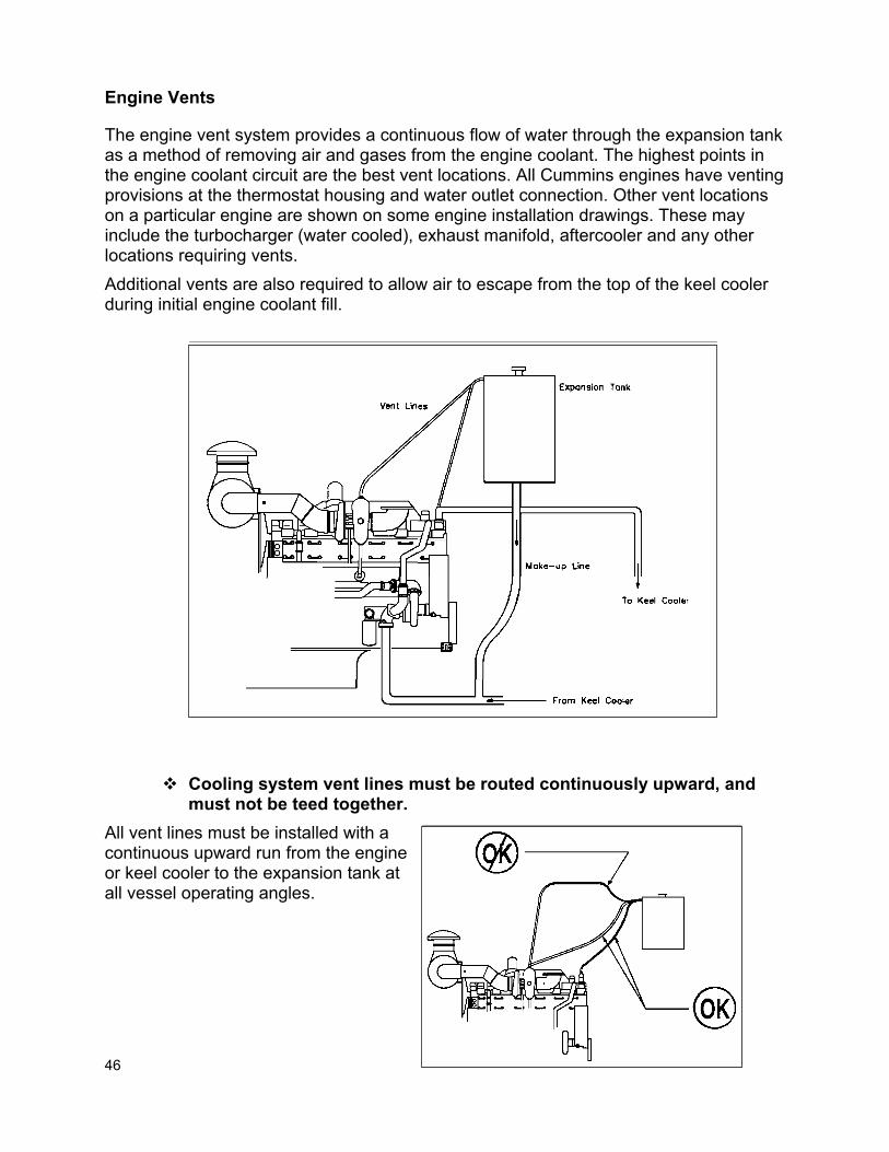
Engine Vents
The engine vent system provides a continuous flow of water through the expansion tank as a method of removing air and gases from the engine coolant. The highest points in the engine coolant circuit are the best vent locations. All Cummins engines have venting provisions at the thermostat housing and water outlet connection. Other vent locations on a particular engine are shown on some engine installation drawings. These may include the turbocharger (water cooled), exhaust manifold, aftercooler and any other locations requiring vents. Additional vents are also required to allow air to escape from the top of the keel cooler during initial engine coolant fill.
Cooling system vent lines must be routed continuously upward, and
must not be teed together. All vent lines must be installed with a continuous upward run from the engine or keel cooler to the expansion tank at all vessel operating angles.

47
Since vent lines run from points of different pressures, teeing the vent lines together may result in reduced vent water flow and inadequate venting of the system. Each vent line must be connected to the expansion tank without using tees or other fittings that would join the vent line together in a common vent. Joining the vents into a common line will reduce the total vent water flow and may result in aerated water flowing back into the engine. NOTE: On K38 and K50 engines shipped from Cummins Engine Co., some of the vent
lines will be teed together. The size and arrangement of these lines has been designed around the coolant pressures at the venting locations to avoid this problem. As a result, these lines are NOT interchangeable on the engine.
Make-up Lines
The deaerated water return, or make-up line, connection is located in the bottom of the expansion tank. The purpose of the make-up line is to provide a means for filling the engine and to feed the water from the vent lines back to the engine after it has been deaerated during operation. The make-up line should be plumbed from the bottom of the expansion tank to the engine water inlet line. The make-up line should not be plumbed to the water pump housing or body. When the make-up water enters the engine water inlet line, the turbulence created in the flow may cavitate the water pump. Therefore, the line should be plumbed at least 450 mm (18 inches) from the engine water pump inlet connection and at least 150 mm (6 inches) from any bends or elbows in the piping. This will reduce the chances of pump cavitation.
The makeup line must be at least 6 times the cross-sectional area of all vent lines.
The size of the make-up line is also important. The line must be large enough to allow proper coolant fill and to provide adequate return flow from the expansion tank without allowing air back into the system. The size of the make-up will depend on the number and size of the vent lines. In general, the cross-sectional area of the make-up line must be 6 times the sum of the vent line areas.

48
Heat Exchanger Cooling
A heat exchanger cooling system circulates engine coolant through a heat exchanger to remove heat from the engine. The engine coolant flows around the outside of the tubes in the heat exchanger and sea water flows through the tubes. The engine coolant leaves the heat exchanger and is recirculated through the engine by the engine water pump. The sea water flows in through the sea water pump, through the heat exchanger and then is injected into the exhaust piping or is discharged overboard. A heat exchanger cooled engine may have either a sea water gear oil cooler or a fresh water gear oil cooler. Additionally, a fuel cooler and aftercooler may be found in the sea water system.
The cooling system must be designed and installed so that the maximum jacket water temperature does not exceed 96ºC (205ºF) under any operating conditions.
Operating the engine with high engine coolant temperatures will result in shorter engine life and possible engine or component failure. The heat exchangers that are optionally available from Cummins Engine Company have an excess heat rejection capacity to allow for intermittent operation at high ambient temperatures and are recommended. Engine power levels must be reduced if high ambient temperatures raise the engine coolant temperature above 96ºC (205ºF).

49
The location of the sea water pickup must be below the water line at all operating conditions.
The sea water inlet must be in a location that provides a solid water flow to the sea water pump at all times and in all operating conditions. If air is ingested in the sea water system it can cause failure of the sea water pump and result in overheating the engine. If a scoop is used on the bottom of the hull at the sea water inlet it should be positioned as shown. The hull, forward of the sea water scoop, should be free of obstruction for undisturbed flow.
The cooling system must remove entrained air at engine start-up, and must continuously remove air that enters the cooling system during normal operation.
If air becomes trapped in the engine cooling system it can lead to isolated hot spots in the engine and water pump cavitation. This will decrease engine life and may cause engine or component failures. A deaeration system consists of a properly designed expansion tank, vents and a make-up line. Cummins supplied expansion tanks and plumbing are designed for proper deaeration of the system and are recommended. If another system is desired, refer to the keel cooling section for proper design of the deaeration system or consult your local Cummins distributor.
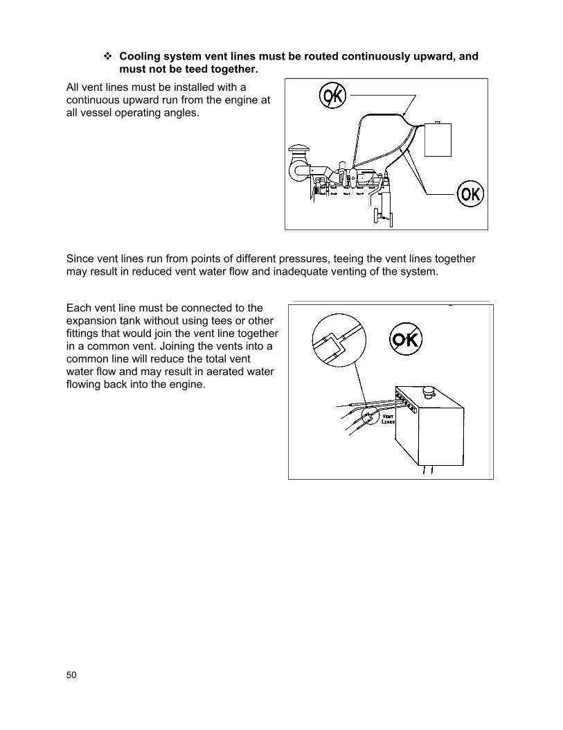
50
Cooling system vent lines must be routed continuously upward, and must not be teed together.
All vent lines must be installed with a continuous upward run from the engine at all vessel operating angles. Since vent lines run from points of different pressures, teeing the vent lines together may result in reduced vent water flow and inadequate venting of the system. Each vent line must be connected to the expansion tank without using tees or other fittings that would join the vent line together in a common vent. Joining the vents into a common line will reduce the total vent water flow and may result in aerated water flowing back into the engine.

51
When measured by Cummins' recommended method, the sea water inlet restriction and discharge pressure must not exceed the value listed on the Engine General Data Sheet.
If the sea water inlet restriction is too great, the sea water pump will not be able to supply enough water to the heat exchanger to satisfactorily cool the engine water. Excess restriction can also lead to sea water pump cavitation with reduced impeller life and, if rubber hose is used, collapse of the sea water piping. The piping from the sea water inlet on the bottom of the hull to the sea water pump should be short and as free of sharp bends as possible. Any sharp bends will cause an increase in the inlet restriction. Cummins has developed a computer program that will estimate the sea water piping diameter required for a particular system. Your local Cummins distributor can assist you in determining what size piping should be used for your particular system. The thru hull fittings and sea cock connections should be at least as large as the sea water piping and any scoop used on the bottom of the hull should be sized for the sea water flow of the engine. Each engine should have its own sea water inlet. This will prevent overheating all engines in the vessel if a sea water inlet should become plugged. All hose bead connections should have double hose clamps.

52
A sea water strainer and/or scoop with a maximum hole diameter of 1.6
mm (1/16 in.) must be used. Debris in the sea water system can lead to sea water pump damage or clogging of the heat exchanger. This will in turn result in overheating and possible failure of the engine. Cummins recommends the use of a wire mesh strainer in the sea water system prior to the sea water pump in addition to a scoop on the bottom of the hull. These strainers are generally much more effective than the scoop type strainers and can be checked for clogging and serviced more easily. If a scoop is used on the bottom of the hull, it must be able to handle the volume of sea water flow listed on the engine data sheet.
Water/Cabin Heaters
Whenever a water heater or cabin heater is added to the cooling system, the cooling system becomes dependent upon the integrity of the heater. Since a failure, leak or improper installation of a heater can result in progressive or catastrophic engine failure, Cummins is not responsible for any engine damage caused by the operation or installation of these components. To prevent overcooling of the engine water and to assure sufficient water flow in the engine, the water circulated to the water heater should be less than 5% of the engine water flow. This can be done with the proper sizing of the lines to the water heater or the use of a restrictor fitting.

53
The water heater should be located below the expansion tank with a vent line running continuously upward to the expansion tank to allow the system to vent completely with the engine off.
All cooling system accessories must be located below the top coolant level of the expansion tank, and must have a minimum pressure rating of 414 kPa (60 psi).
The water/cabin heater should have a minimum pressure rating of 414 kPa (60 psi). If the heater core has a lower pressure limit, it may result in a failure of the core, loss of coolant and engine failure.
Plumbing
When a water/cabin heater is used, the hot water supply and return should be to the ports indicated on the engine installation drawing.

54
AIR INTAKE SYSTEMS & ENGINE ROOM VENTILATION
Marine Installation Requirements
When tested by Cummins' recommended method, the air inlet system restriction must not exceed the value shown on the Engine General Data Sheet.
All engines must have an effective air cleaner to remove airborne dirt particles from the intake air. The air cleaner must have the minimum dirt holding capacity listed in the installation directions for the particular application.
The air inlet location, air piping and engine room ventilation must be designed so that the air inlet temperature measured at the inlet connection to the manifold or turbocharger is not more than 17ºC (30ºF) above the outside ambient temperature at rated speed and load. Maximum engine room temperature must not exceed 150ºF under any operating conditions.
All ducts, components, and connections are capable of operating in a maximum temperature of 92ºC (200ºF).
The air inlet must be located or shielded to prevent direct ingestion of water, snow, ice, exhaust gases, blowby gases, and other combustible vapors.
All remote mounted air cleaner plumbing must be routed away from high heat sources.
Remote mounted air cleaner plumbing must allow for thermal expansion and relative motion between the engine and shipyard piping.
Remote mounted air cleaner plumbing joints must be capable of functioning in an ambient temperature of 92º C (200º F), must be free from leaks, and must withstand a negative pressure (vacuum) of -8 kPa (-32 in. H2O) without collapsing.
Hoses connected to the compressor inlet must be rated for a continuous temperature of 205ºC (400ºF).
All piping must be free from chafing points. Oil bath type air cleaners are not approved for use on Cummins Marine
engines. The air cleaner media must be reinforced to prevent media from being
ingested by the engine. Forced ventilation systems must operate continuously any time the
engines are running. The integrity of the piping between the air cleaner and the engine must
not be broken during routine operation or maintenance functions.

55
Marine Installation Recommendations
When tested by Cummins' recommended method, the air inlet system restriction must not exceed the value shown on the Engine General Data Sheet.
High air inlet restriction will lead to decreased air flow through the engine for combustion. This in turn will lead to a decrease in power, performance and engine life as well as an increase in smoke. The air cleaner should be mounted in an area that is free of dirt, dust, fish scales or other debris that may plug the filter during regular operation, net handling or deck operations. If the exhaust and air intake are both above the vessel, the exhaust should be located higher and aft of the intake. If the exhaust gas is drawn back into the intake, the air cleaner can quickly become clogged.

56
Remote mounted air cleaners should not have inlets located where water can enter the element, either during operation or wash down. Avoid large flat areas where the intake can pull water into the engine during rain, rough weather or wash down operations. A water or condensation trap should be located prior to the air cleaner on remote mounted systems. The air cleaner should be easily serviced without removing other parts of the air system and should be checked at air cleaner service intervals or if the air inlet restriction increases unexpectedly.
Remote Mounted Air Cleaner Piping
The air inlet piping must be sized to provide inlet air to the engine without exceeding the air inlet restriction limit. Your Cummins distributor can assist you in properly sizing the intake air system. Engines with remote air cleaners should have a restriction indicator or vacuum gauge installed in the piping between the air cleaner and the engine. The preferred connection point for restriction indicators is in a straight section of pipe approximately 305 mm (12 inches) upstream of the engine or turbo inlet.

57
All engines must have an effective air cleaner to remove airborne dirt particles from the intake air. The air cleaner must have the minimum dirt holding capacity listed in the installation directions for the particular application.
Dirt is the primary cause of wear in an engine. Reducing the amount of dirt that enters the engine will increase the engine life. Although no universal standard for air cleaners has been established, the following guidelines are recommended: Efficiency at Dirt Holding 15% to 100% Capacity Type Rating Air Flow g/cfm (g/l/s) Construction Normal Duty 99.5 3 (6.4) Single Stage Medium Duty 99.7 10 (21) Single Stage Heavy Duty 99.9 25 (53) Two Stage Most pleasure boat applications have engine rooms that are relatively free of dirt and may use a normal duty air cleaner. Commercial applications that operate in a protected, clean environment may use a medium duty air cleaner. However, if the engine operates in an environment that contains debris that may clog the air cleaner (fish scales, coal/ grain dust, etc.) or a longer service interval is needed, then a heavy duty air cleaner should be used.
The air inlet location, air piping and engine room ventilation must be designed so that the air inlet temperature measured at the inlet connection to the manifold or turbocharger is not more than 17ºC (30ºF) above the outside ambient temperature at rated speed and load. Maximum engine room temperature must not exceed 150ºF under any operating conditions.
High air inlet temperatures will lead to high thermal stresses, high exhaust temperatures, poor engine performance, decreased fuel economy and shorter engine life. Inlet air temperatures above 27ºC (81ºF) will reduce engine power by approximately 1% for every additional 5.6ºC (10ºF) temperature rise. At lower engine speeds and loads, such as idle, temperatures may be higher without sacrificing engine life or performance.

58
If the air cleaner is to be remote mounted, the inlet location should be outside the engine room. The inlet should be located so that a supply of air at or near the ambient temperature is always available. Locations with high inlet air temperature should be avoided. Areas to consider as heat sources are exhaust components, mufflers, air conditioner and refrigeration condensers, boilers and heating system components and auxiliary engines. Marine engines with engine mounted air cleaners may draw air from the engine room. Engine rooms with natural draft ventilation must have vent openings of adequate size and location to ensure an ample supply of air at a reasonable temperature to the engine, and carry away heat from the machinery in the engine room.

59
Cummins has developed a computer program that will estimate the recommended minimum total ventilation area required for each engine in the engine room (including any auxiliary engines). The ventilation area will vary depending on location of the vents and the resulting flow of air through the engine room. Some systems may require larger ventilation areas in order to meet the installation requirement. Your local Cummins distributor can assist you in determining what ventilation area should be used for your particular engine room. Good circulation in the engine room is a key factor in keeping down the engine room temperature. Air inlets should be louvered or pointed forward to increase air circulation through the engine room.

60
The inlet vents should be ducted to the bottom of the engine room to promote bottom up circulation of the fresh air and to clear fumes and moisture from the bilge. The exhaust vents should be located near the top of the engine room to carry away the hot air in the engine room. In planning the ventilation ports, two-thirds of the area should be used for intake air and one third of the area should be for exhaust ventilation. If it is not possible to install sufficient ventilation ports to maintain the required engine room temperature, blowers and exhaust fans can be used to circulate fresh air through the engine room. The inlet blowers must have a capacity of two times the engine's rated air consumption listed on the engine performance data sheet. Exhaust fans should be from one-half to one times the rated air consumption of the engines to carry away the excess heat. With both engine mounted and remote mounted air cleaners, there should be enough ventilation to keep the engine room temperature below 54ºC (130ºF). Temperatures above this may cause a deterioration in the hoses and/or wiring on the engine. Maintaining reasonable engine room temperatures can be aided by insulating as many hot surfaces as possible (i.e., exhaust piping, turbocharger, muffler, heating system).

61
The integrity of the piping between the air cleaner and the engine must not be broken during routine operation or maintenance functions.
Any breaks or leaks in the air system after the air cleaner will allow dirt to enter the engine and decrease engine life. Relative movement between the engine, air cleaner and air inlet requires flexibility in the pipe components and flexible connections. Any deflections must occur in the flexible components and not in the rigid piping. On turbocharged engines a flexible connection must be provided between the compressor casing and the first piping support. The first support should be less than 1.5 meters (5 feet) from the turbocharger. Steel, aluminum and fiberglass reinforced plastic tubing have been used for air intake piping. Some of the factors to be considered in selecting tubing are: 1. If the tubing lacks strength or rigidity, tightening of the hose clamps to provide an
adequate seal may deform or crack the tube and allow dirt into the engine. 2. Rough end surfaces can cut or abrade the flexible connectors and prevent a proper
seal. 3. Inside and outside walls of tubing need to be smooth and leak-free to assure a
perfect seal and lessen air flow resistance. Butt welded tubing should have a flat surface (no bead) and be air tight.
The installer should use caution during any pipe welding in order to prevent slag on the inside of the pipe that may be drawn into the turbocharger.
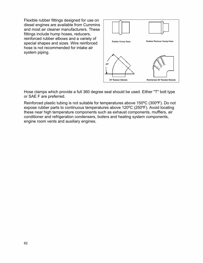
62
Flexible rubber fittings designed for use on diesel engines are available from Cummins and most air cleaner manufacturers. These fittings include hump hoses, reducers, reinforced rubber elbows and a variety of special shapes and sizes. Wire reinforced hose is not recommended for intake air system piping. Hose clamps which provide a full 360 degree seal should be used. Either "T" bolt type or SAE F are preferred. Reinforced plastic tubing is not suitable for temperatures above 150ºC (300ºF). Do not expose rubber parts to continuous temperatures above 120ºC (250ºF). Avoid locating these near high temperature components such as exhaust components, mufflers, air conditioner and refrigeration condensers, boilers and heating system components, engine room vents and auxiliary engines.
63
FUEL SYSTEM
Marine Installation Requirements
The engine must be installed with the fuel filter supplied with the engine.
The maximum static pressure at the fuel pump inlet must not exceed the value specified on the Engine General Data Sheet.
The maximum fuel return line restriction must not exceed the value specified on the Engine General Data Sheet when measured immediately after the engine mounted check valve.
The maximum restriction at the inlet of the fuel pump must not exceed the value specified on the Engine General Data Sheet.
The maximum fuel inlet temperature must not exceed the value listed on Engine Performance Data Sheet.
The supply line must be routed to prevent pressure surges and must be free from vertical loops.
The fuel tank must be equipped with a vent, and this vent must also be designed to prevent the entry of dirt and water.
The return fuel line must be routed at least 12” (0.3 m) from the supply line. It must be routed to the top of the tank for engine with PT and HPI fuel systems, and to the bottom of the fuel tank for all other engines.
A primary 30-micron fuel filter and water separator must be installed before the engine fuel inlet (all except common rail systems). A primary fuel water separator with a 10 micron rating and a drain valve must be installed between the engine and the fuel tank (common rail fuel systems only).
The fuel piping used between the engine and shipboard piping must have a flexible section to allow for relative movement of the engine and hull.
Non-Cummins hoses and fittings connected to the engine must comply to SAE J1942/J1527.
Fuel lines must be routed away from heat sources. A shut-off valve must be installed on the supply line. The fuel system must not contain any zinc, zinc plated or galvanized
components. Teflon tape must not be used on any fittings or threaded connections in
the fuel system.

64
Marine Installation Recommendations
The fuel system must deliver an adequate supply of clean fuel that is free of air and water to the engine. Fuel is drawn from the fuel tanks, through a fuel/water separator and fuel filters, and into the fuel pump. The fuel is also used to lubricate and cool many fuel system components.
The engine must be equipped with the fuel filter supplied with the engine.
All Cummins engines are supplied with an engine mounted or remote (kitted) fuel filter to remove contamination from the fuel. These filters are designed for Cummins engines and provide the protection necessary for the fuel pump and injectors.
The maximum static pressure at the fuel pump inlet must not exceed the value specified on the Engine General Data Sheet.
In the PT fuel system with open injectors, some of the injectors will be open at any time during engine shutdown, and any fuel that is allowed to flow through the supply or return lines will flow into one or more cylinders. When the engine is started, this may result in hydraulic lock and possible engine failure. All Cummins marine engines are supplied with engine mounted check valves to prevent fuel from flowing back into the cylinders during shutdown. These check valves should not be removed from the system under any circumstances. Static pressures at the fuel pump inlet in excess of the stated limits (while the engine is shut down) can allow fuel to leak past the check valve and shutoff valve, potentially flooding the cylinders.
The maximum fuel return line restriction must not exceed the value specified on the Engine General Data Sheet when measured immediately after the engine mounted check valve.
If the fuel return restriction is too high, excess fuel may be injected in the cylinder. This will cause higher cylinder pressures, higher temperatures, increased smoke, poor performance and a decrease in the engine life. The fuel return line size required for an engine will depend on the engine return flow rate, the length of the line, the number of bends and the number and type of fittings. In general, the minimum recommended return line pipe size will be the same as the fuel return fitting size. However, larger line sizes may be required when several bends, valves or fittings are used in the fuel plumbing. Whatever line size is used, the fuel return line restriction must not exceed the value specified on the Engine General Data Sheet.

65
If the fuel tanks are mounted above the engine, the fuel return line restriction will also be affected by the static pressure of the fluid above the engine.
Fuel Tanks 0 to 1.6 M (0 to 5 Ft) Above Crankshaft Centerline
When the fuel tank is located up to 1.6 meters (5 feet) above the crankshaft centerline, an engine mounted check valve in the return line will prevent flooding an engine cylinder through the return line.

66
Fuel Tanks 1.6 to 8 M (5 to 25 Ft) Above Crankshaft Centerline
For fuel tanks located up to 8 meters (25 feet) above the crankshaft centerline, a float tank or day tank should be used. If a float tank is used, it should be large enough so that the returning fuel does not significantly raise the temperature of the fuel supplied to the engine. A day tank requires a shut-off valve between it and the main tank so that it can be filled and then the supply can be shut off. In both cases a fuel filter should be used between the main tanks and the float/day tank, with a shut-off valve between the filter and the main tank to allow the filter to be serviced without spilling fuel. All auxiliary tanks (day or float) require a vent and should have a sight glass. The sight glass should be located in the vent line at the same height as the injectors. If the float valve should fail or the shut-off valve is left open, there will be fuel in the sight glass. If this happens, it is possible that fuel has entered the cylinders and the engine should not be started.
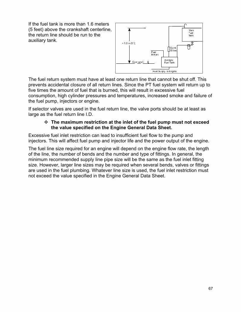
67
If the fuel tank is more than 1.6 meters (5 feet) above the crankshaft centerline, the return line should be run to the auxiliary tank. The fuel return system must have at least one return line that cannot be shut off. This prevents accidental closure of all return lines. Since the PT fuel system will return up to five times the amount of fuel that is burned, this will result in excessive fuel consumption, high cylinder pressures and temperatures, increased smoke and failure of the fuel pump, injectors or engine. If selector valves are used in the fuel return line, the valve ports should be at least as large as the fuel return line I.D.
The maximum restriction at the inlet of the fuel pump must not exceed the value specified on the Engine General Data Sheet.
Excessive fuel inlet restriction can lead to insufficient fuel flow to the pump and injectors. This will affect fuel pump and injector life and the power output of the engine. The fuel line size required for an engine will depend on the engine flow rate, the length of the line, the number of bends and the number and type of fittings. In general, the minimum recommended supply line pipe size will be the same as the fuel inlet fitting size. However, larger line sizes may be required when several bends, valves or fittings are used in the fuel plumbing. Whatever line size is used, the fuel inlet restriction must not exceed the value specified in the Engine General Data Sheet.
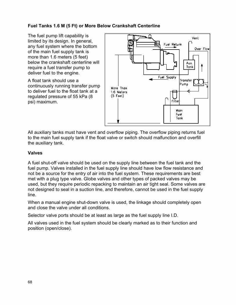
68
Fuel Tanks 1.6 M (5 Ft) or More Below Crankshaft Centerline
The fuel pump lift capability is limited by its design. In general, any fuel system where the bottom of the main fuel supply tank is more than 1.6 meters (5 feet) below the crankshaft centerline will require a fuel transfer pump to deliver fuel to the engine. A float tank should use a continuously running transfer pump to deliver fuel to the float tank at a regulated pressure of 55 kPa (8 psi) maximum. All auxiliary tanks must have vent and overflow piping. The overflow piping returns fuel to the main fuel supply tank if the float valve or switch should malfunction and overfill the auxiliary tank.
Valves
A fuel shut-off valve should be used on the supply line between the fuel tank and the fuel pump. Valves installed in the fuel supply line should have low flow resistance and not be a source for the entry of air into the fuel system. These requirements are best met with a plug type valve. Globe valves and other types of packed valves may be used, but they require periodic repacking to maintain an air tight seal. Some valves are not designed to seal in a suction line, and therefore, cannot be used in the fuel supply line. When a manual engine shut-down valve is used, the linkage should completely open and close the valve under all conditions. Selector valve ports should be at least as large as the fuel supply line I.D. All valves used in the fuel system should be clearly marked as to their function and position (open/close).

69
The supply line must be routed to prevent pressure surges and must be free from vertical loops.
The fuel supply and return line must be routed without loops. Any loops in the fuel plumbing will cause pressure surges in the line and result in engine speed instability. Whenever multiple engines are used, each engine should have separate fuel supply and return lines. Running two or more engines with common fuel lines can result in idle surge and speed stability problems. Pressure pulses in the return line of one engine may affect the operation of other engines that share the common return line. This can be overcome by using a common return line whose cross-sectional area is equal to the sum of the area of each of the individual return lines.
The fuel tank must be equipped with a vent, and this vent must also be designed to prevent the entry of dirt and water.
The vent allows the air and gases from the return line to escape from the fuel tank. It also equalizes internal and external pressures on the tank and prevents tank bulging or collapse. The vent line diameter should be at least 1/3 of the fill line diameter with a minimum fuel tank vent line size of 13 mm (0.5 inches).

70
The vent line should terminate above the deck in a protected location. A gooseneck at the top is recommended to keep dirt and water from entering the fuel tank through the vent line. Fuel tanks can be made of terneplate or phosphate coated steel, aluminum or fiberglass. Galvanized or zinc plated steel tanks or piping should never be used in a diesel fuel system. All auxiliary tanks should have vents routed to a point that is above the highest possible fuel level in the main tanks. This will prevent accidental flooding of the bilges if the auxiliary tank is overfilled.
The return fuel line must be routed at least 12” (0.3 m) from the supply line. It must be routed to the top of the tank for engine with PT and HPI fuel systems, and to the bottom of the fuel tank for all other engines.
On engines with PT and HPI fuel systems, the return fuel must be routed to the top of the tank (either the main or intermediate tank), at least 12 inches (305 mm) from the supply line. This will prevent entrained air in the return line from entering the supply line. It also minimizes the potential to stir up sediment from the bottom of the tank, especially on an older vessel with a Cummins repower.

71
On all other engines, fuel return lines should be installed to the bottom of the fuel tank or with drop tubes in the fuel tank keeping the outlet submerged at all times. Return lines to the top of the fuel tank may allow fuel to drain back into the tank and cause hard starting. The return should be located approximately 1 inch (25mm) above the bottom of the tank to provide space for collection of water and sediment, and at least 12 inches (305 mm) from the supply line.
A primary 30-micron fuel filter and water separator must be installed before the engine fuel inlet (all except common rail systems). A primary fuel water separator with a 10 micron rating and a drain valve must be installed between the engine and the fuel tank (common rail fuel systems only).
Cummins specifies a two-stage filtering setup for all engine installations. The primary filter (the first filter module after the tank) is normally mounted off-engine and is typically customer supplied. The secondary filter (the filter module just before the engine fuel pump) is Cummins-supplied and can be either engine-mounted or remotely mounted off-engine. The primary filter uses a relatively coarse media with a larger capacity compared to the secondary filter, and includes a water separator. Primary filtration of the fuel supply with a customer-supplied 30-micron filter (10-micron for common rail fuel systems) will extend the life of the secondary Cummins-supplied filter, without adding excessive inlet restriction to the system. All of the fuel pumps used on the engines in this manual are fuel lubricated. Water in the fuel will decrease the lubrication in the pump and possibly cause a failure of the pump. Injectors are also fuel lubricated and can also fail as a result of water in the fuel. Therefore, it is necessary to remove any water from the fuel before it reaches the fuel pump by using a fuel/water separator. Fuel/water separators that are available from Cummins Engine Company are recommended. If another fuel/water separator is to be used, it must be sized for the engine's fuel supply flow rate. This information is available on the engine performance data sheet.

72
Fuel Line Plumbing
The fuel piping used between the engine and shipboard piping must have a flexible section to allow for relative movement of the engine and hull.
Engine vibration, thermal growth of a hot engine and flexure of the hull when rolling and pitching in heavy seas could cause a rigid fuel line to crack and fail. Therefore, a section of flexible hose must be used between the engine and hull.
Non-Cummins hoses and fittings connected to the engine must comply to SAE J1942/J1527.
All fuel hoses must meet the flame resistance, burst presssure limits and other requirements of SAE J1942/J1527.
The fuel system must not contain any zinc, zinc plated or galvanized components.
Rigid piping materials suitable for the fuel system are black iron, steel, stainless steel, and flexible hose. The fuel system must not contain any zinc, zinc plated or galvanized components. Copper and copper-nickel lines are not recommended as they tend to work/age harden which will lead to leaks. The fuel lines should be routed where they are protected from damage. Tubing and hoses must be supported at regular intervals to prevent failure due to excessive load and vibration. Electrical wire ties are not designed to secure fuel tubing and hoses and are not recommended for this purpose.

73
Duplex Fuel Filters
Some marine agencies require duplex-type fuel filters on marine propulsion engines. This type of system allows the filters to be changed one at a time at sea without shutting off the engine. Duplex fuel filters are offered on some Cummins products. It is necessary to remote mount these filters when they are required on marine engines. Therefore, you should consult your local Cummins distributor for recommendations on installing these types of systems.

74
STARTING AND ELECTRICAL SYSTEMS
Marine Installation Requirements
The installed battery capacity must not be less than that specified on the General Engine Data Sheet.
The engine must achieve a minimum cranking speed of 150 rpm (tested with no fuel flow to the engine).
The maximum resistance in the starting circuit must not exceed 0.002 ohms.
If the alternator is not supplied with the engine, the installer must assume responsibility for adequate mounting.
All electrical harnesses must be loomed/covered, clamped securely and routed away from heat sources. The wiring must use protective grommets at clamp points.
All powered circuits must include wiring and fuses that comply with governing standards of the intended application.
Unswitched power to the ECM must be wired directly to the battery circuit.
Instrument panels and wiring must be installed according to Cummins installation instructions.
A functioning hour meter must be maintained on the engine. The air starter supply line size must meet the air starter manufacturer's
requirements.
Marine Installation Recommendations
The starting and electrical system must be designed so that the engine will start readily under the most severe ambient conditions ordinarily encountered. In order to achieve this objective, the installer must exercise good judgment in the selection and application of the electrical system components. These recommendations are offered as a guide to obtain a reliable system.

75
The installed battery capacity must not be less than that specified on the General Engine Data Sheet.
The engine must achieve a minimum cranking speed of 150 rpm (tested with no fuel flow to the engine).
There must be enough power available to the starter to ensure quick, reliable starts under any operating conditions. The minimum recommended battery capacity for the engines covered in this manual is listed on the corresponding Engine General Data Sheet. The temperature of the environment in which the vessel operates will greatly affect the power required for starting, so the worst case condition for the vessel should be used.

76
Battery voltage or current capacity can be increased by connecting batteries in different combinations of series and parallel arrangements. If the batteries are connected in parallel, the system current will be equal to the sum of the current for the two batteries and the system voltage will be the same as the individual voltages of the batteries. Connecting the batteries in series will increase the system voltage, but not the current. The voltage will be equal to the sum of the two battery voltages and the current will be equal to the current of either individual battery. If the batteries are connected in series and parallel, then both the system voltage and current will increase.

77
The table below lists typical battery capacities for various combinations.
TYPICAL BATTERY CAPACITIES BATTERY SYSTEM
BATTERY VOLTS CAPACITY VOLTS CAPACITY
SIZE V CCA QTY. WIRING V CCA 4D-640 12 640 2 Parallel 12 1280
4D-800 12 800 2 Parallel 12 1600
8D-900 12 900 2 Parallel 12 1800
4D-640 12 640 2 Series 24 640
4D-800 12 800 2 Series 24 800
8D-900 12 900 2 Series 24 900
4D-640 12 640 4 Series-Parallel 24 1280
4D-800 12 800 4 Series-Parallel 24 1600
8D-900 12 900 4 Series-Parallel 24 1800

78
The maximum resistance in the starting circuit must not exceed 0.002 Ohms.
If the circuit resistance is too high, the starting motor will not receive an adequate supply of electrical energy and will not provide reliable cranking over the range of conditions encountered in service. The maximum starting circuit resistance for the engines covered in this manual is 0.002 Ohms. The table below lists the maximum length of typical cables in the cranking circuit necessary to meet this requirement.
BATTERY TO CRANKING MOTOR CABLE SIZES MAXIMUM TOTAL LENGTH OF CABLE
IN CRANKING CIRCUIT MAXIMUM CIRCUIT
RESISTANCE #00 #000 #0000 OR TWO # 0 TWO #00 REMARKS
0.00200 Ohm 6.10 M (20 Feet)
8.23 M (27 Feet)
10.67 M (35 Feet)
13.72 M (45 Feet)
Single Cranking Motor
0.00200 Ohm 6.10 M (20 Feet)
8.23 M (27 Feet)
10.67 M (35 Feet)
13.72 M (45 Feet)
Dual Cranking Motors W/Single Battery Bank
This table lists the cable diameter and cross-sectional area for the sizes listed above.
CABLE DIAMETER CABLE SIZE (AWG)
mm in
CABLE AREA (SQ. MM)
#0 7.8 (.3065) 47.8
#00 8.4 (.3310) 55.4
#000 9.2 (.3625) 66.5
#0000 10.0 (.3938) 78.5
Starting motor circuit resistance will be affected by cable size and length, the number of connections in the system and the possible presence of additional contactors in the wiring arrangement. For assistance in calculating the circuit resistance, contact your local Cummins distributor.

79
Starter Circuit Wiring
The starter cable terminals should have soldered connections. Rosin flux should be used for soldering electrical connections. Acid flux solders will cause deterioration of the electrical connection. Connecting two strands of cable, such as two #00 or two #000 should be done carefully in order to assure that both wires have a good connection with the battery. The figure at right shows one method used to connect two cables to a battery. Tinning the stainless steel washers and cable connectors with solder will reduce the chances of problems due to corrosion. The use of a non-conductive grease at the connection will also help prevent corrosion. The cable to battery connections should use the maximum available contact area of the battery post. Clamps must be positioned squarely on the battery post or stud with clean surfaces and securely fastened. Stacked terminal connections which have only point or line contact will not be satisfactory.
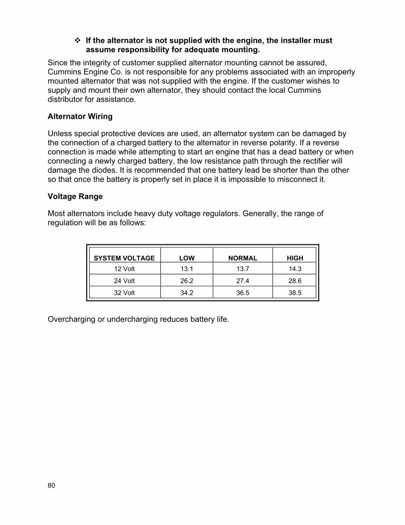
80
If the alternator is not supplied with the engine, the installer must assume responsibility for adequate mounting.
Since the integrity of customer supplied alternator mounting cannot be assured, Cummins Engine Co. is not responsible for any problems associated with an improperly mounted alternator that was not supplied with the engine. If the customer wishes to supply and mount their own alternator, they should contact the local Cummins distributor for assistance.
Alternator Wiring
Unless special protective devices are used, an alternator system can be damaged by the connection of a charged battery to the alternator in reverse polarity. If a reverse connection is made while attempting to start an engine that has a dead battery or when connecting a newly charged battery, the low resistance path through the rectifier will damage the diodes. It is recommended that one battery lead be shorter than the other so that once the battery is properly set in place it is impossible to misconnect it.
Voltage Range
Most alternators include heavy duty voltage regulators. Generally, the range of regulation will be as follows:
SYSTEM VOLTAGE LOW NORMAL HIGH 12 Volt 13.1 13.7 14.3
24 Volt 26.2 27.4 28.6
32 Volt 34.2 36.5 38.5
Overcharging or undercharging reduces battery life.
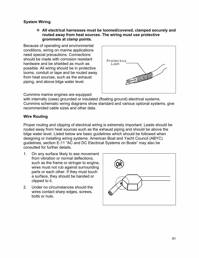
81
System Wiring
All electrical harnesses must be loomed/covered, clamped securely and routed away from heat sources. The wiring must use protective grommets at clamp points.
Because of operating and environmental conditions, wiring on marine applications need special precautions. Connections should be made with corrosion resistant hardware and be shielded as much as possible. All wiring should be in protective looms, conduit or tape and be routed away from heat sources, such as the exhaust piping, and above bilge water level. Cummins marine engines are equipped with internally (case) grounded or insulated (floating ground) electrical systems. Cummins schematic wiring diagrams show standard and various optional systems, give recommended cable sizes and other data.
Wire Routing
Proper routing and clipping of electrical wiring is extremely important. Leads should be routed away from heat sources such as the exhaust piping and should be above the bilge water level. Listed below are basic guidelines which should be followed when designing or installing wiring systems. American Boat and Yacht Council (ABYC) guidelines, section E-11 “AC and DC Electrical Systems on Boats” may also be consulted for further details. 1. On any surface likely to see movement
from vibration or normal deflections, such as the frame or stringer to engine, wires must not rub against surrounding parts or each other. If they must touch a surface, they should be banded or clipped to it.
2. Under no circumstances should the wires contact sharp edges, screws, bolts or nuts.
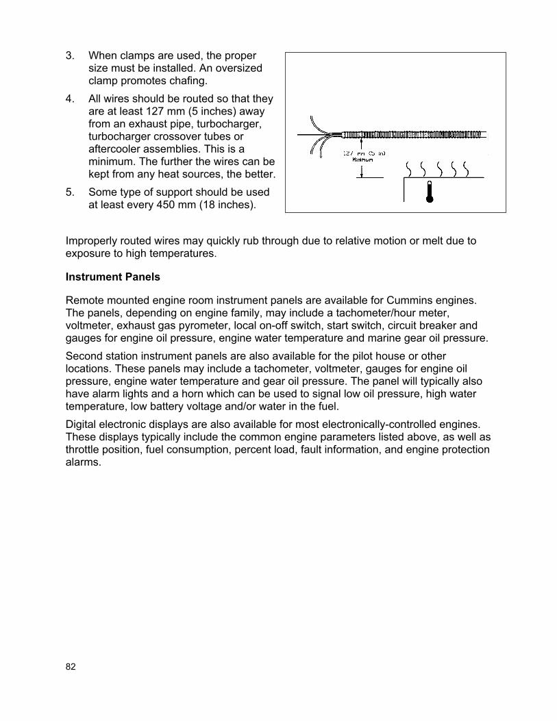
82
3. When clamps are used, the proper size must be installed. An oversized clamp promotes chafing.
4. All wires should be routed so that they are at least 127 mm (5 inches) away from an exhaust pipe, turbocharger, turbocharger crossover tubes or aftercooler assemblies. This is a minimum. The further the wires can be kept from any heat sources, the better.
5. Some type of support should be used at least every 450 mm (18 inches).
Improperly routed wires may quickly rub through due to relative motion or melt due to exposure to high temperatures.
Instrument Panels
Remote mounted engine room instrument panels are available for Cummins engines. The panels, depending on engine family, may include a tachometer/hour meter, voltmeter, exhaust gas pyrometer, local on-off switch, start switch, circuit breaker and gauges for engine oil pressure, engine water temperature and marine gear oil pressure. Second station instrument panels are also available for the pilot house or other locations. These panels may include a tachometer, voltmeter, gauges for engine oil pressure, engine water temperature and gear oil pressure. The panel will typically also have alarm lights and a horn which can be used to signal low oil pressure, high water temperature, low battery voltage and/or water in the fuel. Digital electronic displays are also available for most electronically-controlled engines. These displays typically include the common engine parameters listed above, as well as throttle position, fuel consumption, percent load, fault information, and engine protection alarms.

83
Instrument panels and wiring must be installed according to Cummins installation instructions.
Instrument panels should not be mounted on the engine due to engine vibration.
A functioning hour meter must be maintained on the engine. All engines must have a means for displaying current engine hours on the engine room instrument panel.
Bonding System
Marine engine installations require special bonding (grounding) of electrical system components to minimize electrolytic corrosion from stray currents and to minimize radio interference. Cummins recommends that ABYC guidelines (section E-11, “AC and DC Electrical Systems on Boats”) be consulted for design of the vessel bonding system.
Radio Interference Suppression
Radio frequency interference (RFI) can be created by many types of electrically operated equipment. Proper suppression techniques will improve the reception and extend the operating distances of communication equipment, radio direction finders, fish finders, depth sounders and the electronic gear. Most alternators have capacitors built in to reduce their contribution to RFI and solid state voltage regulators have further reduced the interference levels. Cummins recommends that ABYC guidelines (section E-11, “AC and DC Electrical Systems on Boats”) be consulted for good supression practice in vessel design. Use only approved marine type antennas that are matched to the electronic equipment they serve. Install antennas on the opposite side of the boat from the engine instrument panel and as far forward as possible.
84
Air Starting Systems
Air starting is available as an engine option for many engines covered in this manual and is acceptable for use on all Cummins engines.
Air Compressor
Cummins recommends the use of a separate motor driven or clutch actuated air compressor. Separate motor driven or clutched air compressors can be sized to the air requirements of the vessel and operate only on demand. Engine driven air compressors are not offered on Cummins marine engines.
Air Piping
The figure on the following page is a typical piping schematic for an air starting system. The only connection in the bottom of the tank should be the drain required to bleed off condensed moisture, which could cause rust and corrosion if allowed in the cranking motor. Drain valves of the screw-out tapered-seat variety are recommended since others are unreliable and are a common source of air leaks. The inlet check valve is mounted directly on the receiver where it is supported and provides maximum protection to the air supply.
The air starter supply line size must meet the air starter manufacturer's requirements.
Air starter manufacturers generally recommend the use of 1.5 inch ID minimum hose or pipe for supply lines up to 4.6 meters (15 feet) in length, and 2 inch minimum for supply lines greater than 4.6 meters (15 feet). Also, a 300 mesh strainer (50 micron filtration) on the air supply line is recommended to extend the life of air starters.
The engine must achieve a minimum cranking speed of 150 rpm (tested with no fuel flow to the engine).
Air starter manufacturers recommend that the dynamic pressure at the starter to be no less than 90 psi for satisfactory performance. Dynamic pressure refers to the pressure measured at the starter while the starter is operating and flowing air. A dynamic pressure of less than 90 psi can lead to a no-crank condition with either a vane or turbine starter. Optimum performance will be achieved with 120 psi dynamic pressure at the starter.

85
The hose should have J.I.C. fittings with dry seal threads. Any pipe fittings used should also be dry seal type. All connections should be made up with Loctite pipe sealant or equivalent. Teflon tape does not provide enough friction at the pipe threads to prevent loosening; and when carelessly applied, it may get inside the piping and clog valves. It should not be used in air starting systems.

86
Air Starter Lubricators
Automatic lubricators are recommended for vane type air starters to increase air motor reliability and extend its life; however, they are not required on turbine air starters. The installer must bleed the air out of the lubricator after the initial engine start to prevent a permanent air lock.
Other Considerations for Air Starters
The exhaust port in the starting motor should be protected from dirt and water. When the starting motor is not furnished with the engine, it should be sized according to the starter manufacturer's recommendations. All of the air starters available from Cummins have a maximum pressure rating of 10.4 bar (150 psig). It is imperative, therefore, that a pressure regulator be used to prevent application of higher pressures to the starter with vessel air systems delivering more than 150 psi (measured at the starter). Pressure regulator valves are available through Cummins for some engine families, or can be purchased in the aftermarket.

87
LUBRICATION SYSTEM
Marine Installation Requirements
The lubricating filters that are furnished by Cummins Engine Company with every engine must be installed.
All engines must be installed with a Cummins supplied lubricating oil bypass filter or combination filter.
The lubricating oil dipstick must be marked with the high and low oil level when the vessel is in the water and at its normal trim.
All lube oil and fuel hoses and fittings not supplied by Cummins Marine and connected to the engine or marine gear must comply to SAE J1942 and SAE J1527.
The lubricating oil used in the engine must meet the specifications listed in the Operation and Maintenance manual.
Closed crankcase ventilation systems are not permitted, except for Cummins-supplied systems.
Any non-Cummins supplied oil pans must be approved by a Cummins Marine Application Engineer.
All lines must be routed away from heat sources. Flexible lines must be installed between the engine and shipboard
piping to allow for relative motion.
Marine Installation Recommendations
The lubrication system must provide a continuous supply of clean lubricating oil to the engine at a controlled temperature. Proper installation and maintenance of the lubrication oil system is essential to ensure long engine life and performance.
The lubricating filters that are furnished by Cummins Engine Company with every engine must be installed.
All engines must be installed with a Cummins supplied lubricating oil bypass filter or combination filter.
All engine models are supplied with a full flow lubricating oil filter plus bypass filter, or a combination filter. For engine-mounted options, the engine installation drawing specifies the filter location and space required for element removal. Optional engine mounted filter locations are available for some engine models and information on these may be obtained from the on-line sales e-book. Engine oil filters that are integral with the engine cannot be removed or modified. Cummins offers a variety of lubrication filter systems depending on the engine family.

88
Definitions of Filter Types Full flow filter - contains a single media, provides relatively coarse filtration, and requires a separate bypass filter. Bypass filter - contains a single media, provides fine (low micron rating) filtration, and is used in combination with a full flow filter. Takes only a small portion of the total oil flow such that the pressure drop is not excessive. Combination filter - contains two different media (one coarse and one fine) in the same element, and does not require an external bypass filter. Requires a bypass hose from the filter head to the oil pan. Venturi combination filter - same as the combination filter but the element and head design is such that it doesn't require a bypass hose. Duplex Lube Filters Some marine agencies require duplex-type lube filters on marine propulsion engines. This type of system allows the filters to be changed one at a time at sea without shutting off the engine. Duplex lube filters are offered on some Cummins products. It is necessary to remote mount these filters when they are required on marine engines. Therefore, you should consult your local Cummins distributor for recommendations on these types of systems.

89
Bypass filters are normally engine mounted. All Cummins bypass filters are spin-on types and must be mounted vertically. If the bypass filter is to be remote mounted, the location of the bypass filter supply and return can be found on the engine installation drawing. When filled with oil, the bypass lube oil filter has considerable weight and sturdy brackets are required to support it. A location should be selected where it is easily serviced and where neither it nor the connecting lines are subject to damage. The hose routing for the bypass filter should be as short as possible to provide the least flow resistance.
The lubricating oil dipstick must be marked with the high and low oil level when the vessel is in the water and at its normal trim.
Since the installation angle of a marine engine may vary greatly between vessels, the high and low oil levels on the dipstick will also vary as the engine angle changes. Dipsticks should be marked by engraving. Stamping or notching will weaken the dipstick and the tip of the dipstick may break off in the oil pan. The procedure for calibrating marine engine dipsticks is located on the tag attached to the dipstick and in the Operation and Maintenance manual.
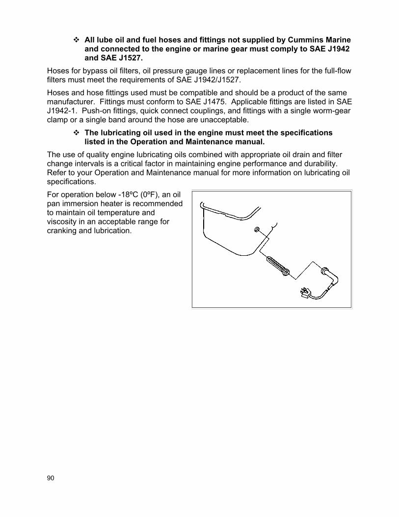
90
All lube oil and fuel hoses and fittings not supplied by Cummins Marine and connected to the engine or marine gear must comply to SAE J1942 and SAE J1527.
Hoses for bypass oil filters, oil pressure gauge lines or replacement lines for the full-flow filters must meet the requirements of SAE J1942/J1527. Hoses and hose fittings used must be compatible and should be a product of the same manufacturer. Fittings must conform to SAE J1475. Applicable fittings are listed in SAE J1942-1. Push-on fittings, quick connect couplings, and fittings with a single worm-gear clamp or a single band around the hose are unacceptable.
The lubricating oil used in the engine must meet the specifications listed in the Operation and Maintenance manual.
The use of quality engine lubricating oils combined with appropriate oil drain and filter change intervals is a critical factor in maintaining engine performance and durability. Refer to your Operation and Maintenance manual for more information on lubricating oil specifications. For operation below -18ºC (0ºF), an oil pan immersion heater is recommended to maintain oil temperature and viscosity in an acceptable range for cranking and lubrication.

91
The engine oil pan is usually not accessible in a marine application. Lube oil drain hoses or sump pumps are optionally available on all engine models for installations where the oil pan drain plug is difficult to access. Sump pumps can be of the electric or hand-pump variety.
Engine Crankcase Vents
During normal operation a small amount of combustion gas escapes past the piston compression rings into the crankcase. These blow-by gases are vented through the engine breathers. Most of the oil mist and vapor is removed by the breathers and drains back into the engine. However, some oil vapor is carried through the breathers by the blow-by gases. Engines that operate in an open area may allow the gases and oil vapor to escape at the breather. On boats, the gases and oil vapor should be piped out of the engine room. Vessels with dry exhaust systems can vent the blow-by into the exhaust gas flow after the muffler. The blow-by must not be routed too close to the turbocharger outlet because the higher pressure will prevent blow-by gases from exiting the crankcase. Also, blow-by gases should not be vented to the atmosphere near the engine air intake or directly into air cleaners or the turbocharger inlet. The oil build-up that occurs may plug the air cleaner element and can cause turbocharger failures, loss of power and decrease the effectiveness of the aftercooler.
Closed crankcase ventilation systems are not permitted, except for Cummins-supplied systems.
There are external crankcase vent filtration systems available through your Cummins distributor. The discharge of these units should be vented to the engine room airspace, or piped out of the engine room. The use of closed crankcase ventilation systems, where the crankcase vent is plumbed to the engine inlet, is not approved for use on Cummins engines, except for Cummins factory options available on some light-duty applications. Aftermarket or non-factory-installed closed crankcase systems are not permitted because they can contaminate turbochargers and aftercoolers.

92
Crankcase vent plumbing should have a continuous upward slope to prevent oil build-up in the vent lines. Drain fittings are required at the bottom of long vertical runs to remove accumulated oil.
Oil Pressure Gauge
An oil pressure gauge is recommended to indicate lubricating oil pressure during operation. The tapped hole for the oil pressure gauge is specified on the engine installation drawing. Optional locations are available on most engine models. Oil pressures at normal operating temperature are listed on the Engine General Data Sheet and in the Operation and Maintenance manual. The pressure with cold oil may be twice as much as the maximum oil pressure of a warmed-up engine and this should be considered when selecting a gauge. All Cummins marine single station instrument panels come with oil pressure gauges and sending units. If low oil pressure alarms are to be used, Cummins recommends using the minimum oil pressure listed on the engine data sheet as the alarm set point.
Oil Temperature Gauge
An oil temperature gauge is sometimes used on installations to indicate operating temperatures. The sensing element for the oil temperature gauge should be installed in the oil pan sump at the lowest point possible for the most accurate temperature reading.

93
Hose Routing
The lines should be supported along their length to prevent chafing against adjacent structures. Electrical wire ties are not designed to secure flexible hoses and are not recommended for this purpose in the lubricating system. Hoses should be shielded from high temperatures when routed near the exhaust system or other hot areas. When installing hoses, provide enough slack in the hoses to allow for changes in the lengths when the hose is pressurized. Hoses shrink in length by up to 4 percent when in service. Hoses should be installed without twists or kinks, and all bends should be larger than the minimum bend radius given by the hose manufacturer. When used as a suction hose or in vacuum service, many hoses require an internal support coil to prevent the hose from collapsing.
Emergency Lubricating Oil System
An emergency lubricating oil system is required by some marine classification societies for vessels in unrestricted service. This system is intended to be used in situations where the engine lube oil system has ceased functioning and the engine is required to run for a short period of time for the safety of the ship and her crew. The emergency lubricating oil system should never be used as a substitute for normal engine repair or maintenance.

94
NOTES

95
NOTES