Embed Size (px)
Citation preview

Commercial Grilles, Registers & Diffusers
Edition 10
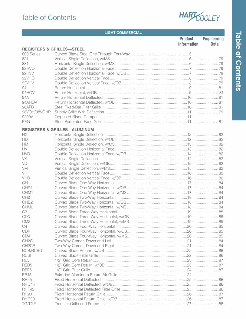
Table of Contents
LIGHT COMMERCIAL
Product Engineering Information Data REGISTERS & GRILLES—STEEL800 Series Curved Blade Steel One Through Four-Way .......................................................5821 Vertical Single Deflection, w/MS ..........................................................................6 ........................ 79831 Horizontal Single Deflection, w/MS .....................................................................6 ........................ 7992HVO Double Deflection Horizontal Face .....................................................................7 ........................ 7992HVV Double Deflection Horizontal Face, w/OB ..........................................................7 ........................ 7992VHO Double Deflection Vertical Face ..........................................................................8 ........................ 7992VHV Double Deflection Vertical Face, w/OB ...............................................................8 ........................ 7994 Return Horizontal .................................................................................................9 ........................ 8194HOV Return Horizontal, w/OB ......................................................................................9 .........................8194A Return Horizontal Deflected ..............................................................................10 ........................ 8194AHOV Return Horizontal Deflected, w/OB ...................................................................10 ........................ 8196AFB Steel Fixed-Bar Filter Grille ................................................................................10 ........................ 8198VOH/98VOHP Supply Grille With Deflection .............................................................................11 ........................ 799200V Opposed-Blade Damper ...................................................................................11PFG Steel Perforated Face Grille...............................................................................11 ........................ 81
REGISTERS & GRILLES—ALUMINUMHX Horizontal Single Deflection ..............................................................................12 ........................ 82HD Horizontal Single Deflection, w/OB ...................................................................12 ........................ 82HM Horizontal Single Deflection, w/MS ...................................................................13 ........................ 82HV Double Deflection Horizontal Face ...................................................................13 ........................ 82HVD Double Deflection Horizontal Face, w/OB ........................................................14 ........................ 82VX Vertical Single Deflection ...................................................................................14 ........................ 82VD Vertical Single Deflection, w/OB ........................................................................15 ........................ 82VM Vertical Single Deflection, w/MS ........................................................................15 ........................ 82VH Double Deflection Vertical Face ........................................................................16 ........................ 82VHD Double Deflection Vertical Face, w/OB .............................................................16 ........................ 82CH1 Curved Blade One-Way Horizontal ...................................................................17 ........................ 84CHD1 Curved Blade One-Way Horizontal, w/OB ........................................................17 ........................ 84CHM1 Curved Blade One-Way Horizontal, w/MS ........................................................17 ........................ 84CH2 Curved Blade Two-Way Horizontal ...................................................................18 ........................ 84CHD2 Curved Blade Two-Way Horizontal, w/OB ........................................................18 ........................ 84CHM2 Curved Blade Two-Way Horizontal, w/MS ........................................................18 ........................ 84C3 Curved Blade Three-Way Horizontal .................................................................19 ........................ 85CD3 Curved Blade Three-Way Horizontal, w/OB ......................................................19 ........................ 85CM3 Curved Blade Three-Way Horizontal, w/MS ......................................................19 ........................ 85C4 Curved Blade Four-Way Horizontal ...................................................................20 ........................ 85CD4 Curved Blade Four-Way Horizontal, w/OB ........................................................20 ........................ 85CM4 Curved Blade Four-Way Horizontal, w/MS ........................................................20 ........................ 85CH2CL Two-Way Corner, Down and Left ......................................................................21 ........................ 84CH2CR Two-Way Corner, Down and Right ....................................................................21 ........................ 84RCB/RCBD Curved Blade Return , w/OB .............................................................................22 ........................ 86RCBF Curved Blade Filter Grille ...................................................................................22 ........................ 86RE5 1/2” Grid Core Return ........................................................................................23 ........................ 87RED5 1/2” Grid Core Return, w/OB .............................................................................23 ........................ 87REF5 1/2” Grid Filter Grille ..........................................................................................24 ........................ 87ER45 Extruded Aluminum Return Air Grille .................................................................24RH45 Fixed Horizontal Deflected ................................................................................25 ........................ 86RHD45 Fixed Horizontal Deflected, w/OB .....................................................................25 ........................ 86RHF45 Fixed Horizontal Deflected Filter Grille ..............................................................25 ........................ 86RH90 Fixed Horizontal Return Grille ............................................................................26 ........................ 87RHD90 Fixed Horizontal Return Grille, w/OB .................................................................26 ........................ 87TG/TGF Transfer Grille and Frame ..................................................................................27 ........................ 88
Table o
f Co
ntents
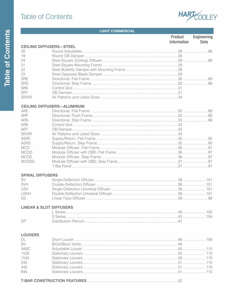
Table of Contents
LIGHT COMMERCIAL
Product Engineering Information Data CEILING DIFFUSERS—STEEL20 Round Adjustable ..............................................................................................28 ........................ 8819 Round OB Damper ............................................................................................2824 Steel Square (Ceiling) Diffuser ..........................................................................29 ........................ 8821 Steel Square Mounting Frame ..........................................................................2922 Steel Butterfly Damper with Mounting Frame ...................................................2923 Steel Opposed Blade Damper ..........................................................................29SRE Directional, Flat Frame ......................................................................................30 ........................ 89SRS Directional, Step Frame .....................................................................................30 ........................ 89SR6 Control Grid .......................................................................................................31SR7 OB Damper ........................................................................................................31SR/AR Air Patterns and Listed Sizes ............................................................................34
CEILING DIFFUSERS—ALUMINUMARE Directional, Flat Frame ......................................................................................32 ........................ 89ARF Directional, Flush Frame ...................................................................................32 ........................ 89ARS Directional, Step Frame .....................................................................................33 ........................ 89AR6 Control Grid .......................................................................................................33AR7 OB Damper ........................................................................................................33SR/AR Air Patterns and Listed Sizes ............................................................................34ASRE Supply/Return, Flat Frame .................................................................................35 ........................ 95ASRS Supply/Return, Step Frame ...............................................................................35 ........................ 95MCD Modular Diffuser, Flat Frame .............................................................................36 ........................ 97MCDD Modular Diffuser with OBD, Flat Frame ............................................................36 ........................ 97MCDS Modular Diffuser, Step Frame ...........................................................................36 ........................ 97MCDSD Modular Diffuser with OBD, Step Frame ...........................................................37 ........................ 97 T-Bar Panel ........................................................................................................37 ........................ 97
SPIRAL DIFFUSERSSV Single-Deflection Diffuser ..................................................................................38 ...................... 101SVH Double-Deflection Diffuser ................................................................................38 ...................... 101USV Single-Deflection Universal Diffuser ..................................................................38 ...................... 101USVH Double-Deflection Universal Diffuser ................................................................39 ...................... 101SS Linear Face Diffuser ..........................................................................................39 ........................ 99
LINEAR & SLOT DIFFUSERS L Series ..............................................................................................................40 ...................... 102 S Series ..............................................................................................................43 ...................... 104DP Distribution Plenum ...........................................................................................47
LOUVERSDL Drum Louver ......................................................................................................48 ...................... 108BV Brick/Block Vents ...............................................................................................494ABC Adjustable Louver ..............................................................................................50 ...................... 1101530 Stationary Louvers .............................................................................................50 ...................... 1101545 Stationary Louvers .............................................................................................50 ...................... 110245 Stationary Louvers .............................................................................................51 ...................... 110445 Stationary Louvers .............................................................................................51 ...................... 110645 Stationary Louvers .............................................................................................51 ...................... 110
T-BAR CONSTRUCTION FEATURES .........................................................................................52
Tab
le o
f C
ont
ents
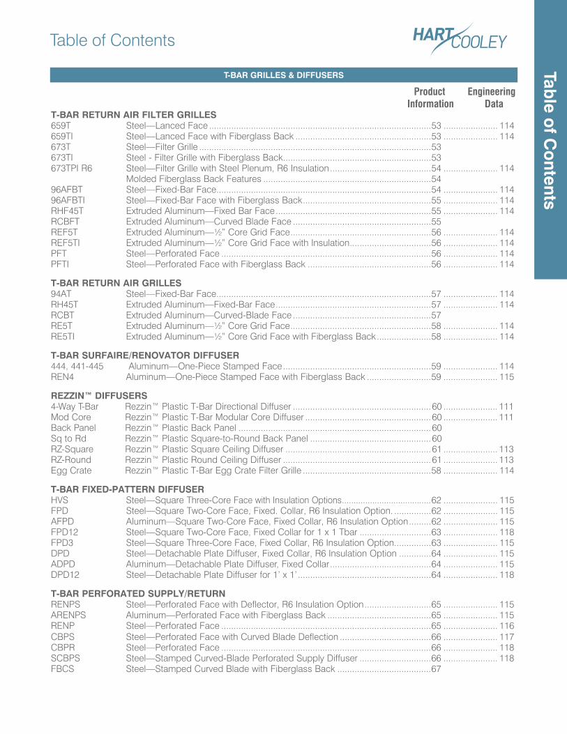
Table of Contents
T-BAR GRILLES & DIFFUSERS
Product Engineering Information Data T-BAR RETURN AIR FILTER GRILLES 659T Steel—Lanced Face ..........................................................................................53 ...................... 114659TI Steel—Lanced Face with Fiberglass Back .......................................................53 ...................... 114673T Steel—Filter Grille ..............................................................................................53673TI Steel - Filter Grille with Fiberglass Back ............................................................53673TPI R6 Steel—Filter Grille with Steel Plenum, R6 Insulation .........................................54 ...................... 114 Molded Fiberglass Back Features ....................................................................5496AFBT Steel—Fixed-Bar Face .......................................................................................54 ...................... 11496AFBTI Steel—Fixed-Bar Face with Fiberglass Back ....................................................55 ...................... 114RHF45T Extruded Aluminum—Fixed Bar Face ...............................................................55 ...................... 114RCBFT Extruded Aluminum—Curved Blade Face ........................................................55REF5T Extruded Aluminum—½” Core Grid Face .........................................................56 ...................... 114REF5TI Extruded Aluminum—½” Core Grid Face with Insulation .................................56 ...................... 114PFT Steel—Perforated Face .....................................................................................56 ...................... 114PFTI Steel—Perforated Face with Fiberglass Back ..................................................56 ...................... 114
T-BAR RETURN AIR GRILLES94AT Steel—Fixed-Bar Face .......................................................................................57 ...................... 114RH45T Extruded Aluminum—Fixed-Bar Face ...............................................................57 ...................... 114RCBT Extruded Aluminum—Curved-Blade Face ........................................................57RE5T Extruded Aluminum—½” Core Grid Face .........................................................58 ...................... 114RE5TI Extruded Aluminum—½” Core Grid Face with Fiberglass Back ......................58 ...................... 114
T-BAR SURFAIRE/RENOVATOR DIFFUSER444, 441-445 Aluminum—One-Piece Stamped Face ............................................................59 ...................... 114REN4 Aluminum—One-Piece Stamped Face with Fiberglass Back ..........................59 ...................... 115
REZZIN™ DIFFUSERS4-Way T-Bar Rezzin™ Plastic T-Bar Directional Diffuser ........................................................60 ...................... 111Mod Core Rezzin™ Plastic T-Bar Modular Core Diffuser ...................................................60 ...................... 111Back Panel Rezzin™ Plastic Back Panel ..............................................................................60Sq to Rd Rezzin™ Plastic Square-to-Round Back Panel .................................................60RZ-Square Rezzin™ Plastic Square Ceiling Diffuser ...........................................................61 ...................... 113RZ-Round Rezzin™ Plastic Round Ceiling Diffuser ............................................................61 ...................... 113Egg Crate Rezzin™ Plastic T-Bar Egg Crate Filter Grille ....................................................58 ...................... 114
T-BAR FIXED-PATTERN DIFFUSERHVS Steel—Square Three-Core Face with Insulation Options ......................................62 ...................... 115FPD Steel—Square Two-Core Face, Fixed. Collar, R6 Insulation Option. ...............62 ...................... 115AFPD Aluminum—Square Two-Core Face, Fixed Collar, R6 Insulation Option .........62 ...................... 115FPD12 Steel—Square Two-Core Face, Fixed Collar for 1 x 1 Tbar .............................63 ...................... 118FPD3 Steel—Square Three-Core Face, Fixed Collar, R6 Insulation Option ...............63 ...................... 115DPD Steel—Detachable Plate Diffuser, Fixed Collar, R6 Insulation Option .............64 ...................... 115ADPD Aluminum—Detachable Plate Diffuser, Fixed Collar .........................................64 ...................... 115DPD12 Steel—Detachable Plate Diffuser for 1’ x 1’ ......................................................64 ...................... 118
T-BAR PERFORATED SUPPLY/RETURNRENPS Steel—Perforated Face with Deflector, R6 Insulation Option ...........................65 ...................... 115ARENPS Aluminum—Perforated Face with Fiberglass Back ..........................................65 ...................... 115RENP Steel—Perforated Face .....................................................................................65 ...................... 116CBPS Steel—Perforated Face with Curved Blade Deflection .....................................66 ...................... 117CBPR Steel—Perforated Face .....................................................................................66 ...................... 118SCBPS Steel—Stamped Curved-Blade Perforated Supply Diffuser .............................66 ...................... 118FBCS Steel—Stamped Curved Blade with Fiberglass Back ......................................67
Table o
f Co
ntents
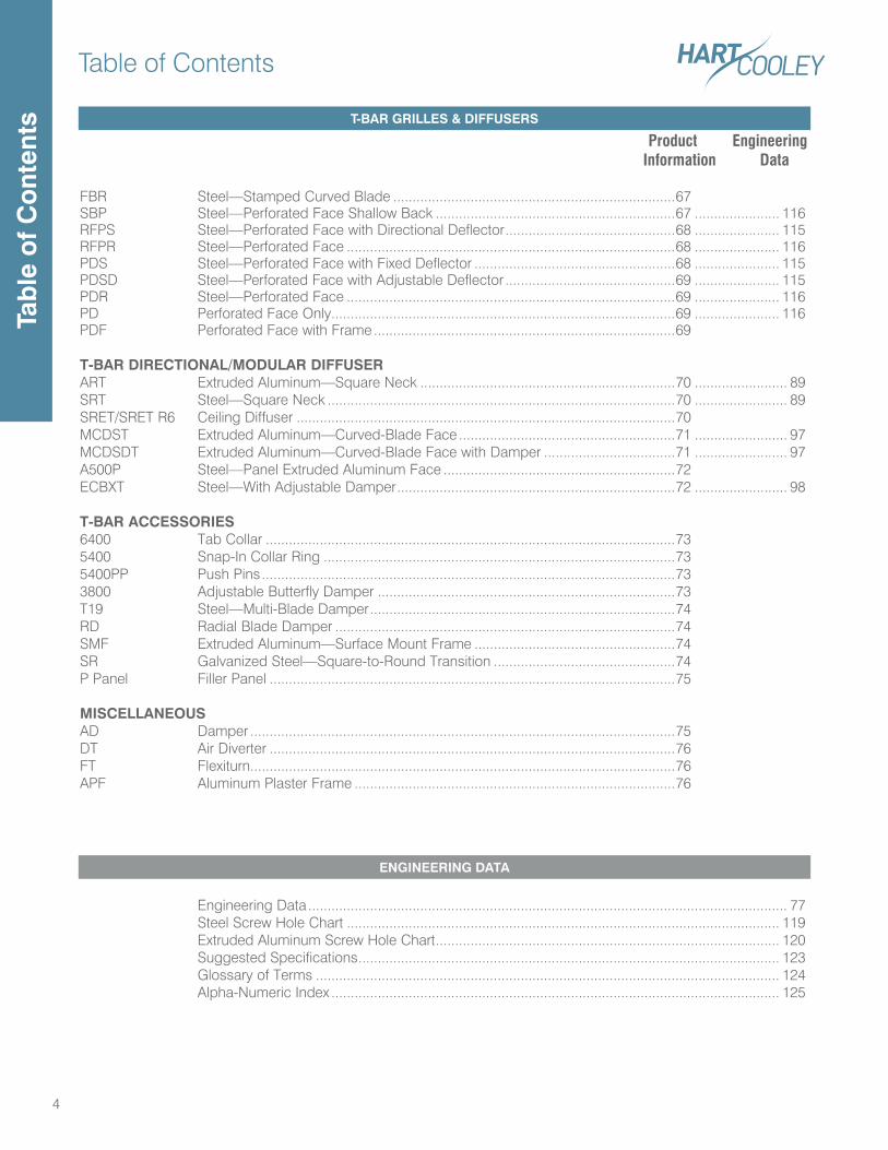
Table of Contents
4
Product Engineering Information Data
FBR Steel—Stamped Curved Blade .........................................................................67SBP Steel—Perforated Face Shallow Back ..............................................................67 ...................... 116RFPS Steel—Perforated Face with Directional Deflector ............................................68 ...................... 115RFPR Steel—Perforated Face .....................................................................................68 ...................... 116PDS Steel—Perforated Face with Fixed Deflector ....................................................68 ...................... 115PDSD Steel—Perforated Face with Adjustable Deflector ............................................69 ...................... 115PDR Steel—Perforated Face .....................................................................................69 ...................... 116PD Perforated Face Only .........................................................................................69 ...................... 116PDF Perforated Face with Frame ..............................................................................69
T-BAR DIRECTIONAL/MODULAR DIFFUSERART Extruded Aluminum—Square Neck ..................................................................70 ........................ 89SRT Steel—Square Neck ..........................................................................................70 ........................ 89SRET/SRET R6 Ceiling Diffuser ..................................................................................................70MCDST Extruded Aluminum—Curved-Blade Face ........................................................71 ........................ 97MCDSDT Extruded Aluminum—Curved-Blade Face with Damper ..................................71 ........................ 97A500P Steel—Panel Extruded Aluminum Face ............................................................72ECBXT Steel—With Adjustable Damper ........................................................................72 ........................ 98
T-BAR ACCESSORIES6400 Tab Collar ..........................................................................................................735400 Snap-In Collar Ring ...........................................................................................735400PP Push Pins ...........................................................................................................733800 Adjustable Butterfly Damper .............................................................................73T19 Steel—Multi-Blade Damper ...............................................................................74RD Radial Blade Damper ........................................................................................74SMF Extruded Aluminum—Surface Mount Frame ....................................................74SR Galvanized Steel—Square-to-Round Transition ...............................................74P Panel Filler Panel .........................................................................................................75
MISCELLANEOUSAD Damper ..............................................................................................................75DT Air Diverter .........................................................................................................76FT Flexiturn..............................................................................................................76APF Aluminum Plaster Frame ...................................................................................76
Engineering Data ............................................................................................................................ 77 Steel Screw Hole Chart ................................................................................................................ 119 Extruded Aluminum Screw Hole Chart ......................................................................................... 120 Suggested Specifications ............................................................................................................. 123 Glossary of Terms ........................................................................................................................ 124 Alpha-Numeric Index .................................................................................................................... 125
T-BAR GRILLES & DIFFUSERS
ENGINEERING DATA
Tab
le o
f C
ont
ents
5
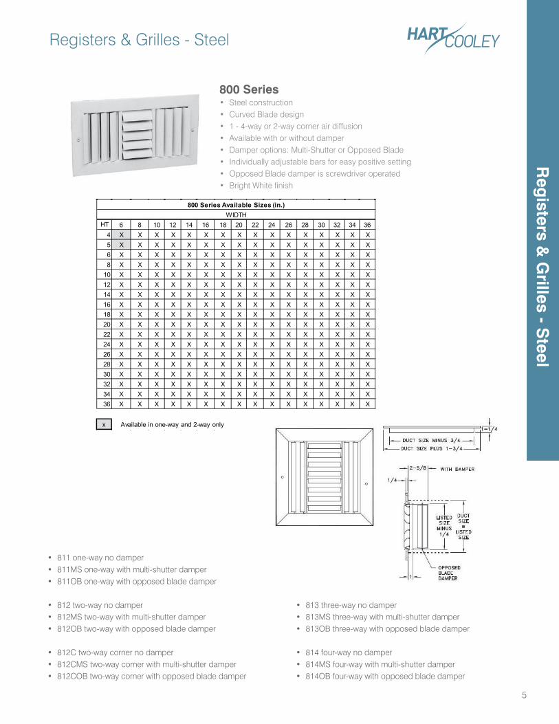
800 Series• Steel construction• Curved Blade design• 1 - 4-way or 2-way corner air diffusion• Available with or without damper• Damper options: Multi-Shutter or Opposed Blade• Individually adjustable bars for easy positive setting• Opposed Blade damper is screwdriver operated• Bright White finish
• 811 one-way no damper• 811MS one-way with multi-shutter damper• 811OB one-way with opposed blade damper
• 812 two-way no damper• 812MS two-way with multi-shutter damper• 812OB two-way with opposed blade damper
• 812C two-way corner no damper• 812CMS two-way corner with multi-shutter damper• 812COB two-way corner with opposed blade damper
• 813 three-way no damper• 813MS three-way with multi-shutter damper• 813OB three-way with opposed blade damper
• 814 four-way no damper• 814MS four-way with multi-shutter damper• 814OB four-way with opposed blade damper
HT 6 8 10 12 14 16 18 20 22 24 26 28 30 32 34 364 X X X X X X X X X X X X X X X X5 X X X X X X X X X X X X X X X X6 X X X X X X X X X X X X X X X X8 X X X X X X X X X X X X X X X X
10 X X X X X X X X X X X X X X X X12 X X X X X X X X X X X X X X X X14 X X X X X X X X X X X X X X X X16 X X X X X X X X X X X X X X X X18 X X X X X X X X X X X X X X X X20 X X X X X X X X X X X X X X X X22 X X X X X X X X X X X X X X X X24 X X X X X X X X X X X X X X X X26 X X X X X X X X X X X X X X X X28 X X X X X X X X X X X X X X X X30 X X X X X X X X X X X X X X X X32 X X X X X X X X X X X X X X X X34 X X X X X X X X X X X X X X X X36 X X X X X X X X X X X X X X X X
x Available in one-way and 2-way only
WIDTH800 Series Available Sizes (in.)
Registers & Grilles - SteelR
egisters &
Grilles - S
teel
Registers & Grilles - Steel
6 Engineering Data on Page 79-80
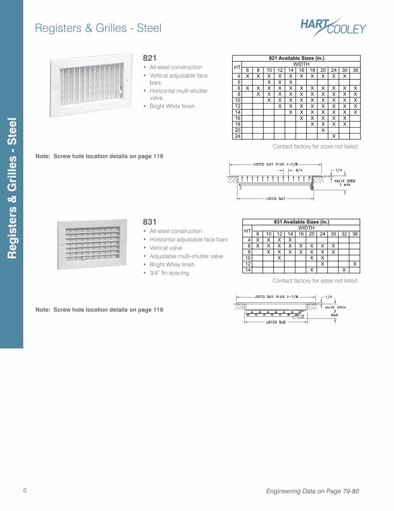
821 • All-steel construction• Vertical adjustable face
bars• Horizontal multi-shutter
valve• Bright White finish
831 • All-steel construction• Horizontal adjustable face bars• Vertical valve • Adjustable multi-shutter valve• Bright White finish• 3/4” fin spacing
6 8 10 12 14 16 18 20 24 30 36 4 X X X X X X X X X X 5 X X X 6 X X X X X X X X X X X 8 X X X X X X X X X X10 X X X X X X X X X12 X X X X X X X X14 X X X X X X X16 X X X X X18 X X X X20 X24 X
HT
821 Available Sizes (in.)WIDTH
8 10 12 14 16 20 24 30 32 36 4 X X X X 6 X X X X X X X X 8 X X X X X X X10 X X X12 X X14 X X
HT
831 Available Sizes (in.)WIDTH
Note: Screw hole location details on page 119
Note: Screw hole location details on page 119
Contact factory for sizes not listed.
Contact factory for sizes not listed.
Reg
iste
rs &
Gri
lles
- S
teel
Registers & Grilles - Steel
7
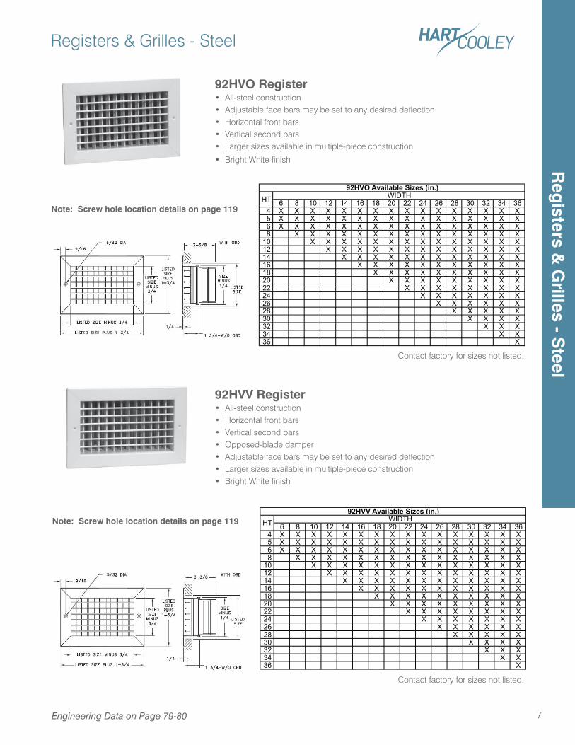
92HVO Register• All-steel construction• Adjustable face bars may be set to any desired deflection• Horizontal front bars• Vertical second bars• Larger sizes available in multiple-piece construction
• Bright White finish
92HVV Register• All-steel construction• Horizontal front bars• Vertical second bars• Opposed-blade damper• Adjustable face bars may be set to any desired deflection• Larger sizes available in multiple-piece construction• Bright White finish
Note: Screw hole location details on page 119
Note: Screw hole location details on page 1196 8 10 12 14 16 18 20 22 24 26 28 30 32 34 36
4 X X X X X X X X X X X X X X X X 5 X X X X X X X X X X X X X X X X 6 X X X X X X X X X X X X X X X X 8 X X X X X X X X X X X X X X X10 X X X X X X X X X X X X X X12 X X X X X X X X X X X X X14 X X X X X X X X X X X X16 X X X X X X X X X X X18 X X X X X X X X X X20 X X X X X X X X X22 X X X X X X X X24 X X X X X X X26 X X X X X X28 X X X X X30 X X X X32 X X X34 X X36 X
HT92HVO Available Sizes (in.)
WIDTH
6 8 10 12 14 16 18 20 22 24 26 28 30 32 34 36 4 X X X X X X X X X X X X X X X X 5 X X X X X X X X X X X X X X X X 6 X X X X X X X X X X X X X X X X 8 X X X X X X X X X X X X X X X10 X X X X X X X X X X X X X X12 X X X X X X X X X X X X X14 X X X X X X X X X X X X16 X X X X X X X X X X X18 X X X X X X X X X X20 X X X X X X X X X22 X X X X X X X X24 X X X X X X X26 X X X X X X28 X X X X X30 X X X X32 X X X34 X X36 X
92HVV Available Sizes (in.)HT WIDTH
Engineering Data on Page 79-80
Contact factory for sizes not listed.
Contact factory for sizes not listed.
Reg
isters & G
rilles - Steel
Registers & Grilles - Steel
8 Engineering Data on Page 79-80
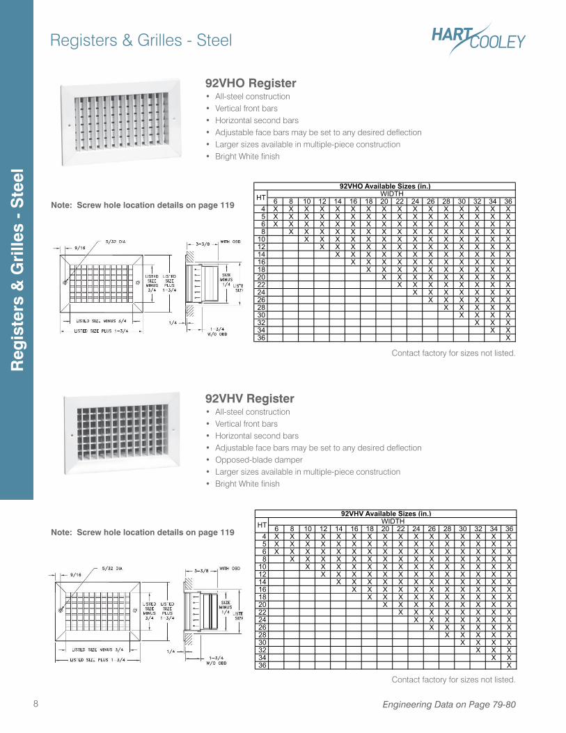
92VHO Register• All-steel construction• Vertical front bars• Horizontal second bars• Adjustable face bars may be set to any desired deflection• Larger sizes available in multiple-piece construction• Bright White finish
92VHV Register• All-steel construction• Vertical front bars• Horizontal second bars• Adjustable face bars may be set to any desired deflection• Opposed-blade damper• Larger sizes available in multiple-piece construction• Bright White finish
Note: Screw hole location details on page 119
Note: Screw hole location details on page 119
6 8 10 12 14 16 18 20 22 24 26 28 30 32 34 36 4 X X X X X X X X X X X X X X X X 5 X X X X X X X X X X X X X X X X 6 X X X X X X X X X X X X X X X X 8 X X X X X X X X X X X X X X X10 X X X X X X X X X X X X X X12 X X X X X X X X X X X X X14 X X X X X X X X X X X X16 X X X X X X X X X X X18 X X X X X X X X X X20 X X X X X X X X X22 X X X X X X X X24 X X X X X X X26 X X X X X X28 X X X X X30 X X X X32 X X X34 X X36 X
HT WIDTH92VHO Available Sizes (in.)
6 8 10 12 14 16 18 20 22 24 26 28 30 32 34 36 4 X X X X X X X X X X X X X X X X 5 X X X X X X X X X X X X X X X X 6 X X X X X X X X X X X X X X X X 8 X X X X X X X X X X X X X X X10 X X X X X X X X X X X X X X12 X X X X X X X X X X X X X14 X X X X X X X X X X X X16 X X X X X X X X X X X18 X X X X X X X X X X20 X X X X X X X X X22 X X X X X X X X24 X X X X X X X26 X X X X X X28 X X X X X30 X X X X32 X X X34 X X36 X
92VHV Available Sizes (in.)HT WIDTH
Contact factory for sizes not listed.
Contact factory for sizes not listed.
Reg
iste
rs &
Gri
lles
- S
teel
Registers & Grilles - Steel
9Engineering Data on Page 81
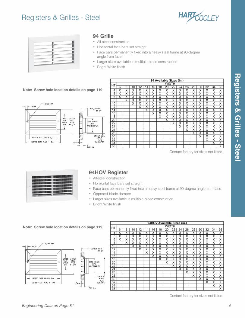
94 Grille• All-steel construction• Horizontal face bars set straight• Face bars permanently fixed into a heavy steel frame at 90-degree
angle from face• Larger sizes available in multiple-piece construction• Bright White finish
94HOV Register• All-steel construction• Horizontal face bars set straight• Face bars permanently fixed into a heavy steel frame at 90-degree angle from face• Opposed-blade damper• Larger sizes available in multiple-piece construction• Bright White finish
Note: Screw hole location details on page 119
Note: Screw hole location details on page 119
6 8 10 12 14 16 18 20 22 24 26 28 30 32 34 36 4 X X X X X X X X X X X X X X X X 5 X X X X X X X X X X X X X X X X 6 X X X X X X X X X X X X X X X X 8 X X X X X X X X X X X X X X X10 X X X X X X X X X X X X X X12 X X X X X X X X X X X X X14 X X X X X X X X X X X X16 X X X X X X X X X X X18 X X X X X X X X X X20 X X X X X X X X X22 X X X X X X X X24 X X X X X X X26 X X X X X X28 X X X X X30 X X X X32 X X X34 X X36 X
94 Available Sizes (in.)HT WIDTH
6 8 10 12 14 16 18 20 22 24 26 28 30 32 34 36 4 X X X X X X X X X X X X X X X X 5 X X X X X X X X X X X X X X X X 6 X X X X X X X X X X X X X X X X 8 X X X X X X X X X X X X X X X10 X X X X X X X X X X X X X X12 X X X X X X X X X X X X X14 X X X X X X X X X X X X16 X X X X X X X X X X X18 X X X X X X X X X X20 X X X X X X X X X22 X X X X X X X X24 X X X X X X X26 X X X X X X28 X X X X X30 X X X X32 X X X34 X X36 X
HT WIDTH94HOV Available Sizes (in.)
Contact factory for sizes not listed.
Contact factory for sizes not listed.
Reg
isters & G
rilles - Steel
Registers & Grilles - Steel
10
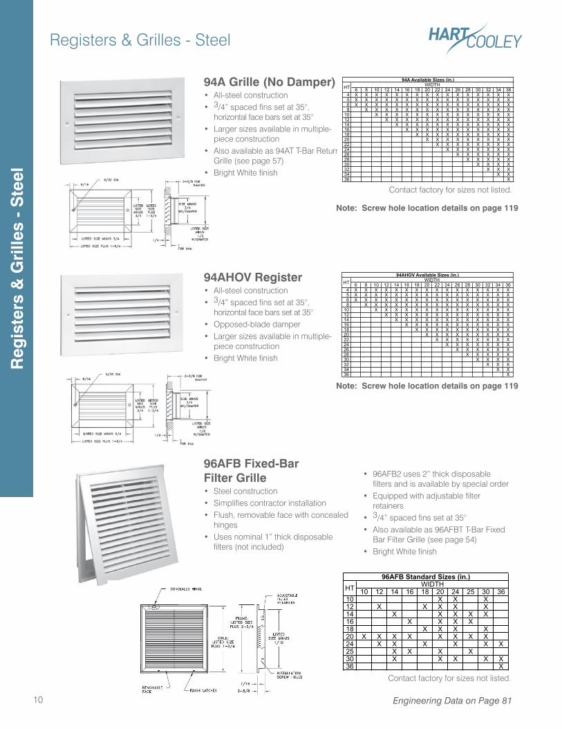
94A Grille (No Damper)• All-steel construction• 3/4” spaced fins set at 35°,
horizontal face bars set at 35°• Larger sizes available in multiple-
piece construction• Also available as 94AT T-Bar Return
Grille (see page 57)• Bright White finish
94AHOV Register• All-steel construction• 3/4” spaced fins set at 35°,
horizontal face bars set at 35°• Opposed-blade damper• Larger sizes available in multiple-
piece construction• Bright White finish
96AFB Fixed-Bar Filter Grille• Steel construction• Simplifies contractor installation• Flush, removable face with concealed
hinges• Uses nominal 1” thick disposable
filters (not included)
• 96AFB2 uses 2” thick disposable filters and is available by special order
• Equipped with adjustable filter retainers
• 3/4” spaced fins set at 35°• Also available as 96AFBT T-Bar Fixed
Bar Filter Grille (see page 54)• Bright White finish
Engineering Data on Page 81
Note: Screw hole location details on page 119
Note: Screw hole location details on page 119
6 8 10 12 14 16 18 20 22 24 26 28 30 32 34 36 4 X X X X X X X X X X X X X X X X 5 X X X X X X X X X X X X X X X X 6 X X X X X X X X X X X X X X X X 8 X X X X X X X X X X X X X X X10 X X X X X X X X X X X X X X12 X X X X X X X X X X X X X14 X X X X X X X X X X X X16 X X X X X X X X X X X18 X X X X X X X X X X20 X X X X X X X X X22 X X X X X X X X24 X X X X X X X26 X X X X X X28 X X X X X30 X X X X32 X X X34 X X36 X
94A Available Sizes (in.)HT WIDTH
6 8 10 12 14 16 18 20 22 24 26 28 30 32 34 36 4 X X X X X X X X X X X X X X X X 5 X X X X X X X X X X X X X X X X 6 X X X X X X X X X X X X X X X X 8 X X X X X X X X X X X X X X X10 X X X X X X X X X X X X X X12 X X X X X X X X X X X X X14 X X X X X X X X X X X X16 X X X X X X X X X X X18 X X X X X X X X X X20 X X X X X X X X X22 X X X X X X X X24 X X X X X X X26 X X X X X X28 X X X X X30 X X X X32 X X X34 X X36 X
94AHOV Available Sizes (in.)HT WIDTH
10 12 14 16 18 20 24 25 30 3610 X X X12 X X X X X14 X X X X X16 X X X X18 X X X X20 X X X X X X X X24 X X X X X X25 X X X X30 X X X X X36 X
96AFB Standard Sizes (in.)WIDTHHT
Contact factory for sizes not listed.
Contact factory for sizes not listed.
Reg
iste
rs &
Gri
lles
- S
teel
Registers & Grilles - Steel
11Engineering Data on Page 79-81
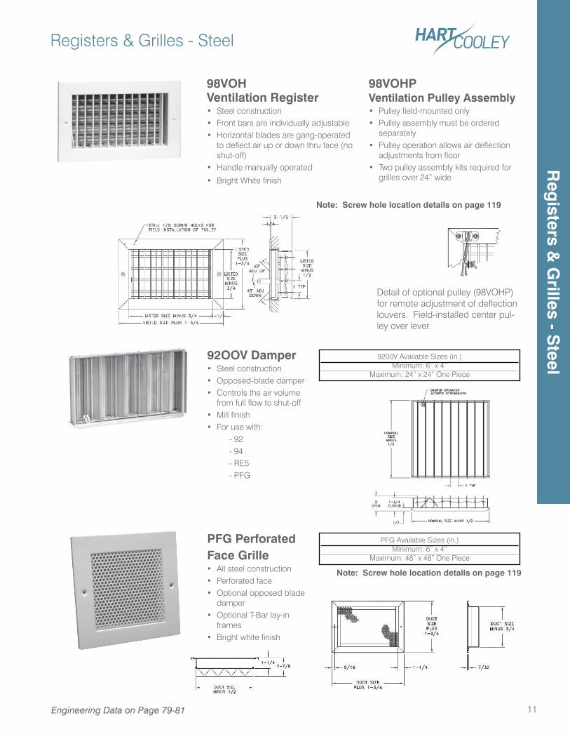
98VOHVentilation Register• Steel construction• Front bars are individually adjustable• Horizontal blades are gang-operated
to deflect air up or down thru face (no shut-off)
• Handle manually operated
• Bright White finish
98VOHPVentilation Pulley Assembly• Pulley field-mounted only• Pulley assembly must be ordered
separately• Pulley operation allows air deflection
adjustments from floor• Two pulley assembly kits required for
grilles over 24” wide
92OOV Damper• Steel construction• Opposed-blade damper• Controls the air volume
from full flow to shut-off• Mill finish• For use with: - 92 - 94 - RE5 - PFG
Detail of optional pulley (98VOHP) for remote adjustment of deflection louvers. Field-installed center pul-ley over lever.
9200V Available Sizes (in.)Minimum: 6” x 4”
Maximum: 24” x 24” One Piece
Note: Screw hole location details on page 119
PFG Perforated Face Grille• All steel construction• Perforated face• Optional opposed blade
damper• Optional T-Bar lay-in
frames• Bright white finish
PFG Available Sizes (in.)Minimum: 6” x 4”
Maximum: 48” x 48” One Piece
Note: Screw hole location details on page 119
Reg
isters & G
rilles - Steel
Registers & Grilles - Aluminum
12
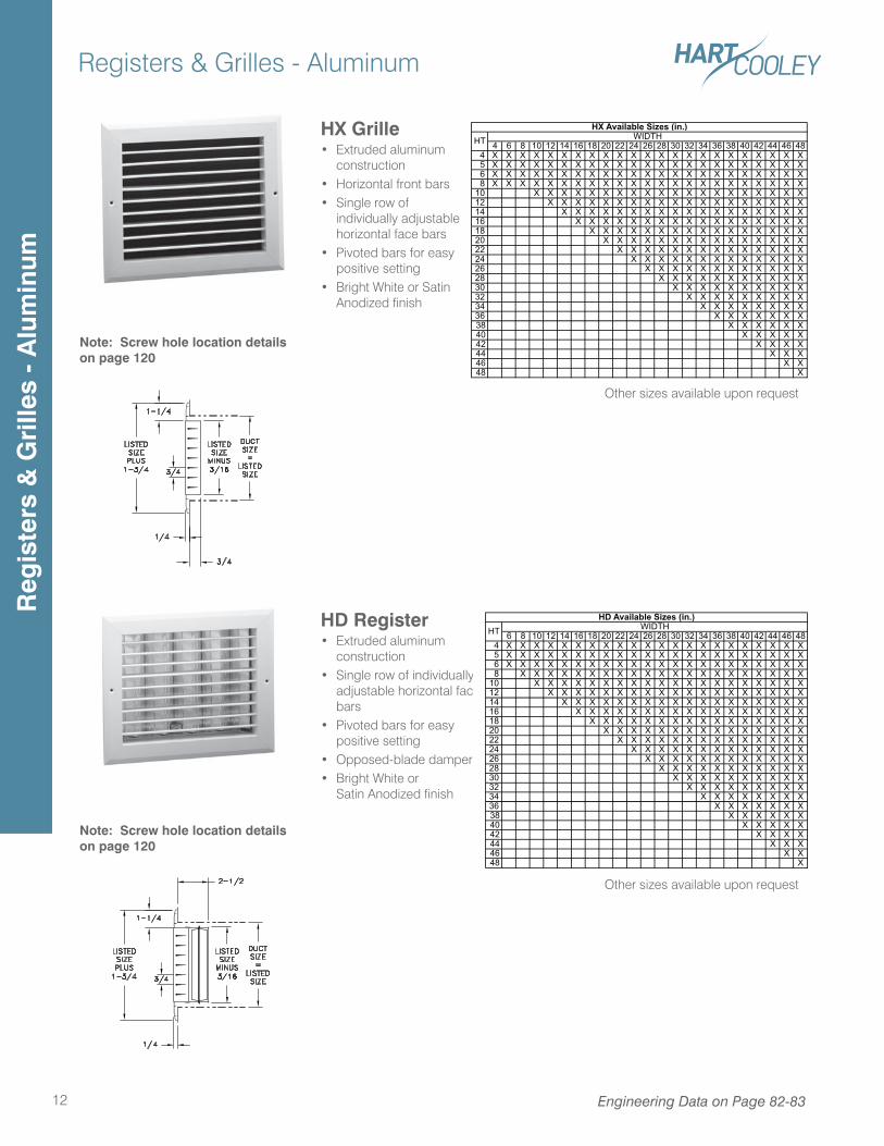
HX Grille• Extruded aluminum
construction• Horizontal front bars• Single row of
individually adjustable horizontal face bars
• Pivoted bars for easy positive setting
• Bright White or Satin Anodized finish
HD Register• Extruded aluminum
construction• Single row of individually
adjustable horizontal face bars
• Pivoted bars for easy positive setting
• Opposed-blade damper• Bright White or
Satin Anodized finish
Engineering Data on Page 82-83
4 6 8 10 12 14 16 18 20 22 24 26 28 30 32 34 36 38 40 42 44 46 48 4 X X X X X X X X X X X X X X X X X X X X X X X 5 X X X X X X X X X X X X X X X X X X X X X X X 6 X X X X X X X X X X X X X X X X X X X X X X X 8 X X X X X X X X X X X X X X X X X X X X X X X10 X X X X X X X X X X X X X X X X X X X X12 X X X X X X X X X X X X X X X X X X X14 X X X X X X X X X X X X X X X X X X16 X X X X X X X X X X X X X X X X X18 X X X X X X X X X X X X X X X X20 X X X X X X X X X X X X X X X22 X X X X X X X X X X X X X X24 X X X X X X X X X X X X X26 X X X X X X X X X X X X28 X X X X X X X X X X X30 X X X X X X X X X X32 X X X X X X X X X34 X X X X X X X X36 X X X X X X X38 X X X X X X40 X X X X X42 X X X X44 X X X46 X X48 X
HX Available Sizes (in.)WIDTHHT
Note: Screw hole location details on page 120
Other sizes available upon request
Note: Screw hole location details on page 120
Other sizes available upon request
6 8 10 12 14 16 18 20 22 24 26 28 30 32 34 36 38 40 42 44 46 48 4 X X X X X X X X X X X X X X X X X X X X X X 5 X X X X X X X X X X X X X X X X X X X X X X 6 X X X X X X X X X X X X X X X X X X X X X X 8 X X X X X X X X X X X X X X X X X X X X X10 X X X X X X X X X X X X X X X X X X X X12 X X X X X X X X X X X X X X X X X X X14 X X X X X X X X X X X X X X X X X X16 X X X X X X X X X X X X X X X X X18 X X X X X X X X X X X X X X X X20 X X X X X X X X X X X X X X X22 X X X X X X X X X X X X X X24 X X X X X X X X X X X X X26 X X X X X X X X X X X X28 X X X X X X X X X X X30 X X X X X X X X X X32 X X X X X X X X X34 X X X X X X X X36 X X X X X X X38 X X X X X X40 X X X X X42 X X X X44 X X X46 X X48 X
HTHD Available Sizes (in.)
WIDTH
Reg
iste
rs &
Gri
lles
- A
lum
inum
Registers & Grilles - Aluminum
13
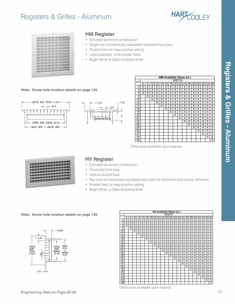
HV Register• Extruded aluminum construction• Horizontal front bars• Vertical second bars• Two rows of individually adjustable face bars for horizontal and vertical deflection• Pivoted bars for easy positive setting• Bright White or Satin Anodized finish
HM Register• Extruded aluminum construction• Single row of individually adjustable horizontal face bars• Pivoted bars for easy positive setting• Lever-operated, multi-shutter valve• Bright White or Satin Anodized finish
6 8 10 12 14 16 18 20 22 24 26 28 30 32 34 36 4 X X X X X X X X X X X X X X X X 5 X X X X X X X X X X X X X X X X 6 X X X X X X X X X X X X X X X X 8 X X X X X X X X X X X X X X X10 X X X X X X X X X X X X X X12 X X X X X X X X X X X X X14 X X X X X X X X X X X X16 X X X X X X X X X X X18 X X X X X X X X X X20 X X X X X X X X X22 X X X X X X X X24 X X X X X X X26 X X X X X X28 X X X X X30 X X X X32 X X X34 X X36 X
HTHM Available Sizes (in.)
WIDTH
6 8 10 12 14 16 18 20 22 24 26 28 30 32 34 36 38 40 42 44 46 48 4 X X X X X X X X X X X X X X X X X X X X X X 5 X X X X X X X X X X X X X X X X X X X X X X 6 X X X X X X X X X X X X X X X X X X X X X X 8 X X X X X X X X X X X X X X X X X X X X X10 X X X X X X X X X X X X X X X X X X X X12 X X X X X X X X X X X X X X X X X X X14 X X X X X X X X X X X X X X X X X X16 X X X X X X X X X X X X X X X X X18 X X X X X X X X X X X X X X X X20 X X X X X X X X X X X X X X X22 X X X X X X X X X X X X X X24 X X X X X X X X X X X X X26 X X X X X X X X X X X X28 X X X X X X X X X X X30 X X X X X X X X X X32 X X X X X X X X X34 X X X X X X X X36 X X X X X X X38 X X X X X X40 X X X X X42 X X X X44 X X X46 X X48 X
HV Available Sizes (in.)HT WIDTH
Note: Screw hole location details on page 120
Note: Screw hole location details on page 120
Other sizes available upon request
Other sizes available upon requestEngineering Data on Page 82-83
Reg
isters & G
rilles - Alum
inum
Registers & Grilles - Aluminum
14
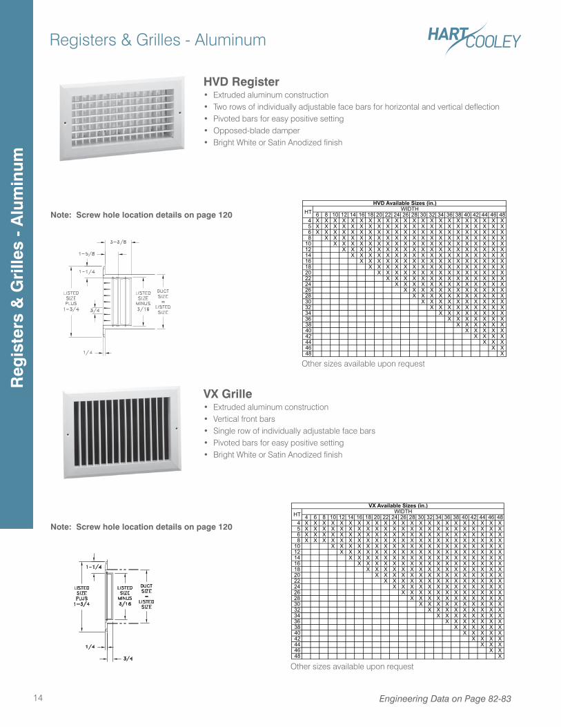
HVD Register• Extruded aluminum construction• Two rows of individually adjustable face bars for horizontal and vertical deflection• Pivoted bars for easy positive setting• Opposed-blade damper• Bright White or Satin Anodized finish
VX Grille• Extruded aluminum construction• Vertical front bars• Single row of individually adjustable face bars• Pivoted bars for easy positive setting• Bright White or Satin Anodized finish
Note: Screw hole location details on page 120
Note: Screw hole location details on page 120
6 8 10 12 14 16 18 20 22 24 26 28 30 32 34 36 38 40 42 44 46 48 4 X X X X X X X X X X X X X X X X X X X X X X 5 X X X X X X X X X X X X X X X X X X X X X X 6 X X X X X X X X X X X X X X X X X X X X X X 8 X X X X X X X X X X X X X X X X X X X X X10 X X X X X X X X X X X X X X X X X X X X12 X X X X X X X X X X X X X X X X X X X14 X X X X X X X X X X X X X X X X X X16 X X X X X X X X X X X X X X X X X18 X X X X X X X X X X X X X X X X20 X X X X X X X X X X X X X X X22 X X X X X X X X X X X X X X24 X X X X X X X X X X X X X26 X X X X X X X X X X X X28 X X X X X X X X X X X30 X X X X X X X X X X32 X X X X X X X X X34 X X X X X X X X36 X X X X X X X38 X X X X X X40 X X X X X42 X X X X44 X X X46 X X48 X
HVD Available Sizes (in.)HT WIDTH
4 6 8 10 12 14 16 18 20 22 24 26 28 30 32 34 36 38 40 42 44 46 48 4 X X X X X X X X X X X X X X X X X X X X X X X 5 X X X X X X X X X X X X X X X X X X X X X X X 6 X X X X X X X X X X X X X X X X X X X X X X X 8 X X X X X X X X X X X X X X X X X X X X X X X10 X X X X X X X X X X X X X X X X X X X X12 X X X X X X X X X X X X X X X X X X X14 X X X X X X X X X X X X X X X X X X16 X X X X X X X X X X X X X X X X X18 X X X X X X X X X X X X X X X X20 X X X X X X X X X X X X X X X22 X X X X X X X X X X X X X X24 X X X X X X X X X X X X X26 X X X X X X X X X X X X28 X X X X X X X X X X X30 X X X X X X X X X X32 X X X X X X X X X34 X X X X X X X X36 X X X X X X X38 X X X X X X40 X X X X X42 X X X X44 X X X46 X X48 X
VX Available Sizes (in.)WIDTHHT
Other sizes available upon request
Other sizes available upon request
Engineering Data on Page 82-83
Reg
iste
rs &
Gri
lles
- A
lum
inum
Registers & Grilles - Aluminum
15Engineering Data on Page 82-83
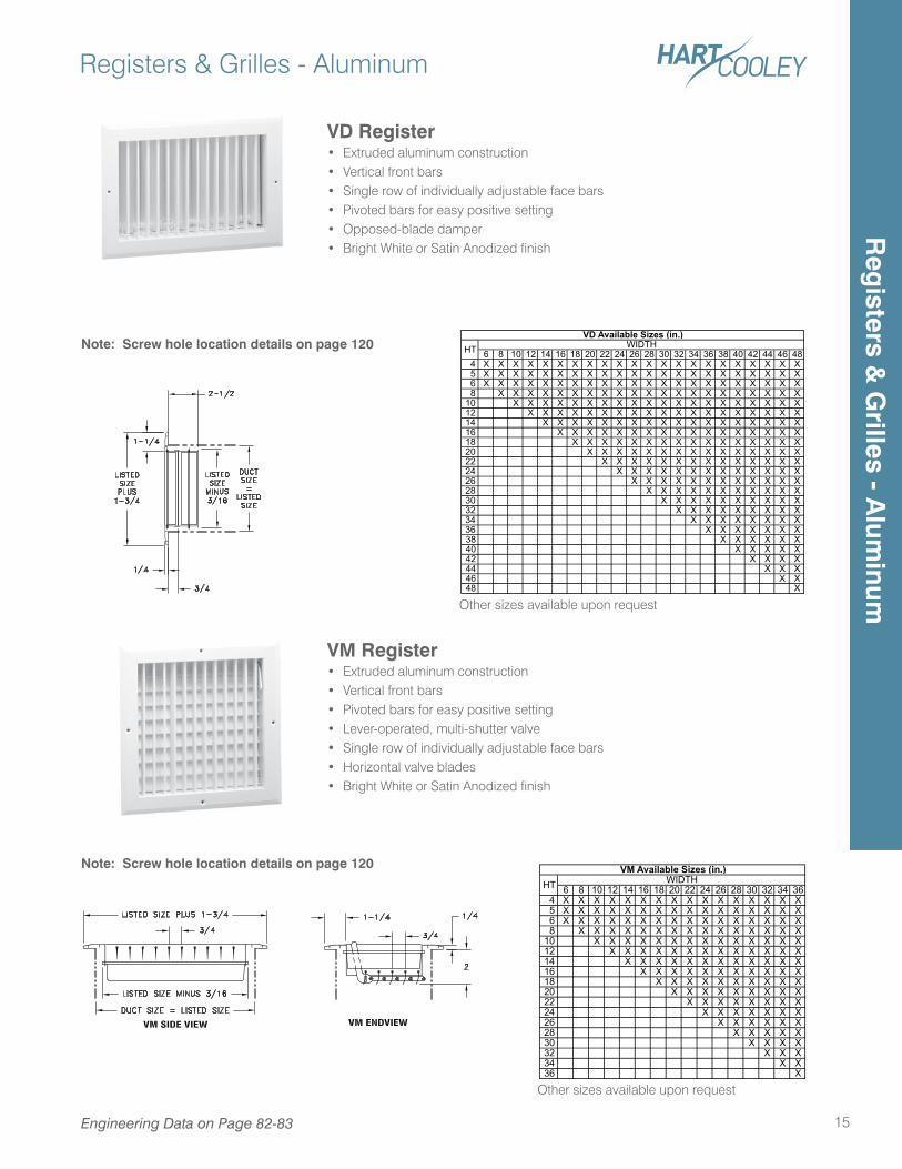
VD Register• Extruded aluminum construction• Vertical front bars• Single row of individually adjustable face bars• Pivoted bars for easy positive setting• Opposed-blade damper• Bright White or Satin Anodized finish
VM Register• Extruded aluminum construction• Vertical front bars• Pivoted bars for easy positive setting• Lever-operated, multi-shutter valve• Single row of individually adjustable face bars• Horizontal valve blades• Bright White or Satin Anodized finish
Note: Screw hole location details on page 120
Note: Screw hole location details on page 120
6 8 10 12 14 16 18 20 22 24 26 28 30 32 34 36 38 40 42 44 46 48 4 X X X X X X X X X X X X X X X X X X X X X X 5 X X X X X X X X X X X X X X X X X X X X X X 6 X X X X X X X X X X X X X X X X X X X X X X 8 X X X X X X X X X X X X X X X X X X X X X10 X X X X X X X X X X X X X X X X X X X X12 X X X X X X X X X X X X X X X X X X X14 X X X X X X X X X X X X X X X X X X16 X X X X X X X X X X X X X X X X X18 X X X X X X X X X X X X X X X X20 X X X X X X X X X X X X X X X22 X X X X X X X X X X X X X X24 X X X X X X X X X X X X X26 X X X X X X X X X X X X28 X X X X X X X X X X X30 X X X X X X X X X X32 X X X X X X X X X34 X X X X X X X X36 X X X X X X X38 X X X X X X40 X X X X X42 X X X X44 X X X46 X X48 X
VD Available Sizes (in.)HT WIDTH
6 8 10 12 14 16 18 20 22 24 26 28 30 32 34 36 4 X X X X X X X X X X X X X X X X 5 X X X X X X X X X X X X X X X X 6 X X X X X X X X X X X X X X X X 8 X X X X X X X X X X X X X X X10 X X X X X X X X X X X X X X12 X X X X X X X X X X X X X14 X X X X X X X X X X X X16 X X X X X X X X X X X18 X X X X X X X X X X20 X X X X X X X X X22 X X X X X X X X24 X X X X X X X26 X X X X X X28 X X X X X30 X X X X32 X X X34 X X36 X
VM Available Sizes (in.)HT WIDTH
Other sizes available upon request
Other sizes available upon request
Reg
isters & G
rilles - Alum
inum
Registers & Grilles - Aluminum
16 Engineering Data on Page 82-83
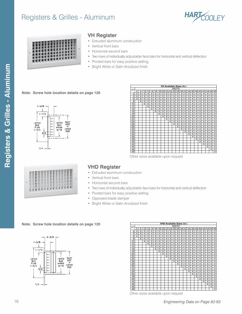
VHD Register• Extruded aluminum construction• Vertical front bars• Horizontal second bars• Two rows of individually adjustable face bars for horizontal and vertical deflection• Pivoted bars for easy positive setting• Opposed-blade damper• Bright White or Satin Anodized finish
VH Register• Extruded aluminum construction• Vertical front bars• Horizontal second bars• Two rows of individually adjustable face bars for horizontal and vertical deflection• Pivoted bars for easy positive setting• Bright White or Satin Anodized finish
Note: Screw hole location details on page 120
Note: Screw hole location details on page 120
6 8 10 12 14 16 18 20 22 24 26 28 30 32 34 36 38 40 42 44 46 48 4 X X X X X X X X X X X X X X X X X X X X X X 5 X X X X X X X X X X X X X X X X X X X X X X 6 X X X X X X X X X X X X X X X X X X X X X X 8 X X X X X X X X X X X X X X X X X X X X X10 X X X X X X X X X X X X X X X X X X X X12 X X X X X X X X X X X X X X X X X X X14 X X X X X X X X X X X X X X X X X X16 X X X X X X X X X X X X X X X X X18 X X X X X X X X X X X X X X X X20 X X X X X X X X X X X X X X X22 X X X X X X X X X X X X X X24 X X X X X X X X X X X X X26 X X X X X X X X X X X X28 X X X X X X X X X X X30 X X X X X X X X X X32 X X X X X X X X X34 X X X X X X X X36 X X X X X X X38 X X X X X X40 X X X X X42 X X X X44 X X X46 X X48 X
VH Available Sizes (in.)HT WIDTH
6 8 10 12 14 16 18 20 22 24 26 28 30 32 34 36 38 40 42 44 46 48 4 X X X X X X X X X X X X X X X X X X X X X X 5 X X X X X X X X X X X X X X X X X X X X X X 6 X X X X X X X X X X X X X X X X X X X X X X 8 X X X X X X X X X X X X X X X X X X X X X10 X X X X X X X X X X X X X X X X X X X X12 X X X X X X X X X X X X X X X X X X X14 X X X X X X X X X X X X X X X X X X16 X X X X X X X X X X X X X X X X X18 X X X X X X X X X X X X X X X X20 X X X X X X X X X X X X X X X22 X X X X X X X X X X X X X X24 X X X X X X X X X X X X X26 X X X X X X X X X X X X28 X X X X X X X X X X X30 X X X X X X X X X X32 X X X X X X X X X34 X X X X X X X X36 X X X X X X X38 X X X X X X40 X X X X X42 X X X X44 X X X46 X X48 X
HTVHD Available Sizes (in.)
WIDTH
Other sizes available upon request
Other sizes available upon request
Reg
iste
rs &
Gri
lles
- A
lum
inum
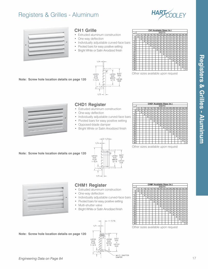
CHD1 Register• Extruded aluminum construction• One-way deflection• Individually adjustable curved-face bars• Pivoted bars for easy positive setting• Opposed-blade damper• Bright White or Satin Anodized finish
Registers & Grilles - Aluminum
17Engineering Data on Page 84
CH1 Grille• Extruded aluminum construction• One-way deflection• Individually adjustable curved-face bars• Pivoted bars for easy positive setting• Bright White or Satin Anodized finish
CHM1 Register• Extruded aluminum construction• One-way deflection• Individually adjustable curved-face bars• Pivoted bars for easy positive setting• Multi-shutter valve• Bright White or Satin Anodized finish
6 8 10 12 14 16 18 20 22 24 26 28 30 32 34 36 6 X X X X X X X X X X X X X X X X 8 X X X X X X X X X X X X X X X10 X X X X X X X X X X X X X X12 X X X X X X X X X X X X X14 X X X X X X X X X X X X16 X X X X X X X X X X X18 X X X X X X X X X X20 X X X X X X X X X22 X X X X X X X X24 X X X X X X X26 X X X X X X28 X X X X X30 X X X X32 X X X34 X X36 X
CH1 Available Sizes (in.)WIDTHHT
6 8 10 12 14 16 18 20 22 24 26 28 30 32 34 36 6 X X X X X X X X X X X X X X X X 8 X X X X X X X X X X X X X X X10 X X X X X X X X X X X X X X12 X X X X X X X X X X X X X14 X X X X X X X X X X X X16 X X X X X X X X X X X18 X X X X X X X X X X20 X X X X X X X X X22 X X X X X X X X24 X X X X X X X26 X X X X X X28 X X X X X30 X X X X32 X X X34 X X36 X
CHD1 Available Sizes (in.)HT WIDTH
6 8 10 12 14 16 18 20 22 24 26 28 30 32 34 36 6 X X X X X X X X X X X X X X X X 8 X X X X X X X X X X X X X X X10 X X X X X X X X X X X X X X12 X X X X X X X X X X X X X14 X X X X X X X X X X X X16 X X X X X X X X X X X18 X X X X X X X X X X20 X X X X X X X X X22 X X X X X X X X24 X X X X X X X26 X X X X X X28 X X X X X30 X X X X32 X X X34 X X36 X
CHM1 Available Sizes (in.)HT WIDTH
Note: Screw hole location details on page 120
Other sizes available upon request
Note: Screw hole location details on page 120
Other sizes available upon request
Note: Screw hole location details on page 120
Other sizes available upon request
Reg
isters & G
rilles - Alum
inum
Registers & Grilles - Aluminum
18 Engineering Data on Page 84
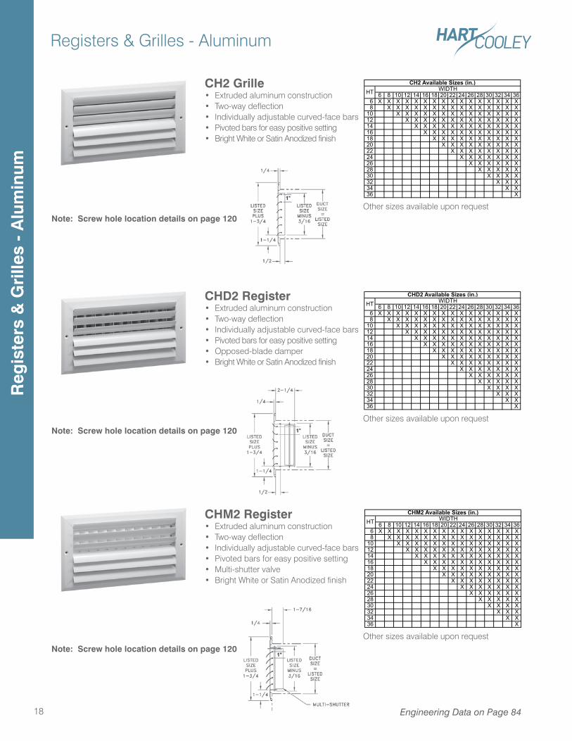
CH2 Grille• Extruded aluminum construction• Two-way deflection• Individually adjustable curved-face bars• Pivoted bars for easy positive setting• Bright White or Satin Anodized finish
CHD2 Register• Extruded aluminum construction• Two-way deflection• Individually adjustable curved-face bars• Pivoted bars for easy positive setting• Opposed-blade damper• Bright White or Satin Anodized finish
CHM2 Register• Extruded aluminum construction• Two-way deflection• Individually adjustable curved-face bars• Pivoted bars for easy positive setting• Multi-shutter valve• Bright White or Satin Anodized finish
6 8 10 12 14 16 18 20 22 24 26 28 30 32 34 36 6 X X X X X X X X X X X X X X X X 8 X X X X X X X X X X X X X X X10 X X X X X X X X X X X X X X12 X X X X X X X X X X X X X14 X X X X X X X X X X X X16 X X X X X X X X X X X18 X X X X X X X X X X20 X X X X X X X X X22 X X X X X X X X24 X X X X X X X26 X X X X X X28 X X X X X30 X X X X32 X X X34 X X36 X
CH2 Available Sizes (in.)HT WIDTH
6 8 10 12 14 16 18 20 22 24 26 28 30 32 34 36 6 X X X X X X X X X X X X X X X X 8 X X X X X X X X X X X X X X X10 X X X X X X X X X X X X X X12 X X X X X X X X X X X X X14 X X X X X X X X X X X X16 X X X X X X X X X X X18 X X X X X X X X X X20 X X X X X X X X X22 X X X X X X X X24 X X X X X X X26 X X X X X X28 X X X X X30 X X X X32 X X X34 X X36 X
CHD2 Available Sizes (in.)HT WIDTH
6 8 10 12 14 16 18 20 22 24 26 28 30 32 34 36 6 X X X X X X X X X X X X X X X X 8 X X X X X X X X X X X X X X X10 X X X X X X X X X X X X X X12 X X X X X X X X X X X X X14 X X X X X X X X X X X X16 X X X X X X X X X X X18 X X X X X X X X X X20 X X X X X X X X X22 X X X X X X X X24 X X X X X X X26 X X X X X X28 X X X X X30 X X X X32 X X X34 X X36 X
CHM2 Available Sizes (in.)HT WIDTH
Note: Screw hole location details on page 120Other sizes available upon request
Note: Screw hole location details on page 120Other sizes available upon request
Note: Screw hole location details on page 120
Other sizes available upon request
Reg
iste
rs &
Gri
lles
- A
lum
inum
Registers & Grilles - Aluminum
19Engineering Data on Page 85
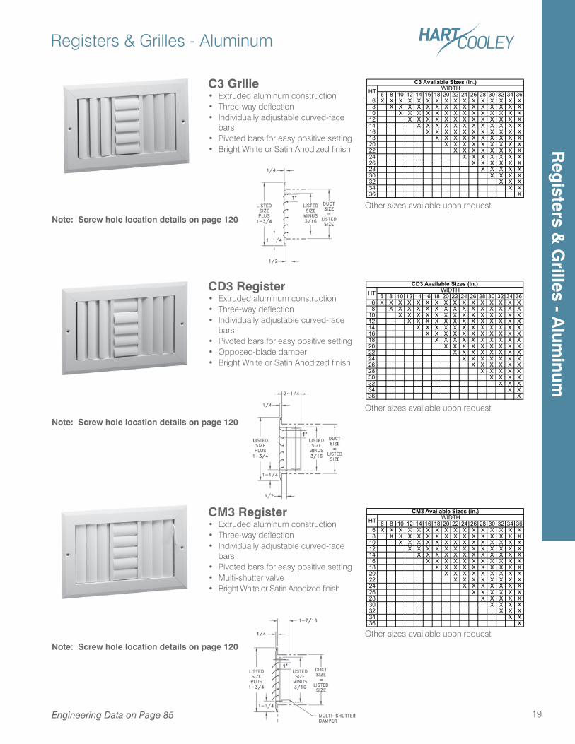
6 8 10 12 14 16 18 20 22 24 26 28 30 32 34 36 6 X X X X X X X X X X X X X X X X 8 X X X X X X X X X X X X X X X10 X X X X X X X X X X X X X X12 X X X X X X X X X X X X X14 X X X X X X X X X X X X16 X X X X X X X X X X X18 X X X X X X X X X X20 X X X X X X X X X22 X X X X X X X X24 X X X X X X X26 X X X X X X28 X X X X X30 X X X X32 X X X34 X X36 X
C3 Available Sizes (in.)HT WIDTH
6 8 10 12 14 16 18 20 22 24 26 28 30 32 34 36 6 X X X X X X X X X X X X X X X X 8 X X X X X X X X X X X X X X X10 X X X X X X X X X X X X X X12 X X X X X X X X X X X X X14 X X X X X X X X X X X X16 X X X X X X X X X X X18 X X X X X X X X X X20 X X X X X X X X X22 X X X X X X X X24 X X X X X X X26 X X X X X X28 X X X X X30 X X X X32 X X X34 X X36 X
CD3 Available Sizes (in.)HT WIDTH
6 8 10 12 14 16 18 20 22 24 26 28 30 32 34 36 6 X X X X X X X X X X X X X X X X 8 X X X X X X X X X X X X X X X10 X X X X X X X X X X X X X X12 X X X X X X X X X X X X X14 X X X X X X X X X X X X16 X X X X X X X X X X X18 X X X X X X X X X X20 X X X X X X X X X22 X X X X X X X X24 X X X X X X X26 X X X X X X28 X X X X X30 X X X X32 X X X34 X X36 X
HT WIDTHCM3 Available Sizes (in.)
Other sizes available upon request
Other sizes available upon request
Other sizes available upon request
CD3 Register• Extruded aluminum construction• Three-way deflection• Individually adjustable curved-face
bars• Pivoted bars for easy positive setting• Opposed-blade damper• Bright White or Satin Anodized finish
CM3 Register• Extruded aluminum construction• Three-way deflection• Individually adjustable curved-face
bars• Pivoted bars for easy positive setting• Multi-shutter valve• Bright White or Satin Anodized finish
Note: Screw hole location details on page 120
Note: Screw hole location details on page 120
Note: Screw hole location details on page 120
C3 Grille• Extruded aluminum construction• Three-way deflection• Individually adjustable curved-face
bars• Pivoted bars for easy positive setting• Bright White or Satin Anodized finish R
egisters &
Grilles - A
luminum
Registers & Grilles - Aluminum
20
6 8 10 12 14 16 18 20 22 24 26 28 30 32 34 36 6 X X X X X X X X X X X X X X X X 8 X X X X X X X X X X X X X X X10 X X X X X X X X X X X X X X12 X X X X X X X X X X X X X14 X X X X X X X X X X X X16 X X X X X X X X X X X18 X X X X X X X X X X20 X X X X X X X X X22 X X X X X X X X24 X X X X X X X26 X X X X X X28 X X X X X30 X X X X32 X X X34 X X36 X
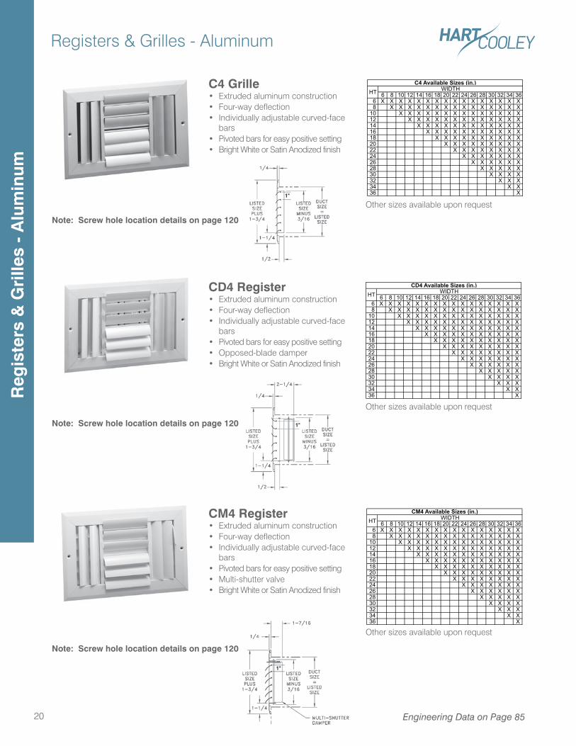
C4 Available Sizes (in.)HT WIDTH
6 8 10 12 14 16 18 20 22 24 26 28 30 32 34 36 6 X X X X X X X X X X X X X X X X 8 X X X X X X X X X X X X X X X10 X X X X X X X X X X X X X X12 X X X X X X X X X X X X X14 X X X X X X X X X X X X16 X X X X X X X X X X X18 X X X X X X X X X X20 X X X X X X X X X22 X X X X X X X X24 X X X X X X X26 X X X X X X28 X X X X X30 X X X X32 X X X34 X X36 X
CD4 Available Sizes (in.)HT WIDTH
6 8 10 12 14 16 18 20 22 24 26 28 30 32 34 36 6 X X X X X X X X X X X X X X X X 8 X X X X X X X X X X X X X X X10 X X X X X X X X X X X X X X12 X X X X X X X X X X X X X14 X X X X X X X X X X X X16 X X X X X X X X X X X18 X X X X X X X X X X20 X X X X X X X X X22 X X X X X X X X24 X X X X X X X26 X X X X X X28 X X X X X30 X X X X32 X X X34 X X36 X
CM4 Available Sizes (in.)HT WIDTH
Other sizes available upon request
Other sizes available upon request
Other sizes available upon request
Note: Screw hole location details on page 120
Note: Screw hole location details on page 120
Note: Screw hole location details on page 120
CM4 Register• Extruded aluminum construction• Four-way deflection• Individually adjustable curved-face
bars• Pivoted bars for easy positive setting• Multi-shutter valve• Bright White or Satin Anodized finish
C4 Grille• Extruded aluminum construction• Four-way deflection• Individually adjustable curved-face
bars• Pivoted bars for easy positive setting• Bright White or Satin Anodized finish
CD4 Register• Extruded aluminum construction• Four-way deflection• Individually adjustable curved-face
bars• Pivoted bars for easy positive setting• Opposed-blade damper• Bright White or Satin Anodized finish
Engineering Data on Page 85
Reg
iste
rs &
Gri
lles
- A
lum
inum
Registers & Grilles - Aluminum
21
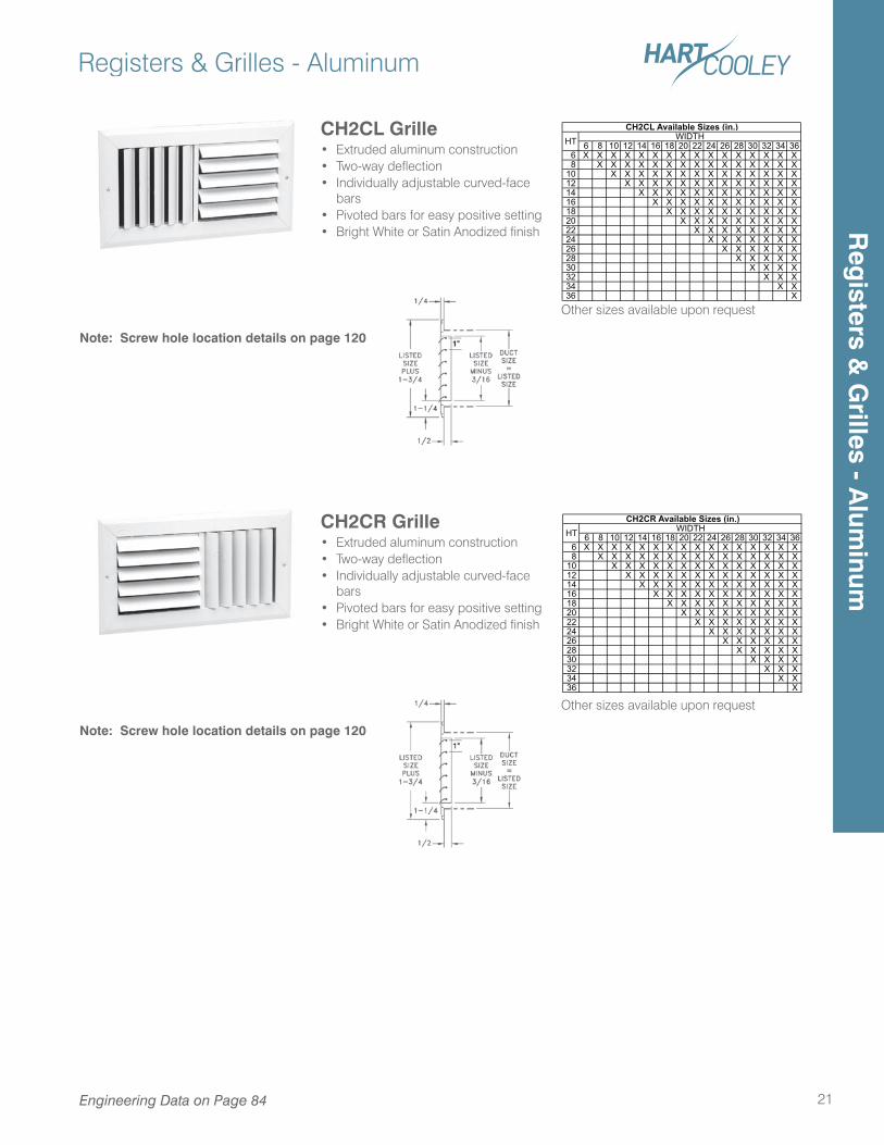
6 8 10 12 14 16 18 20 22 24 26 28 30 32 34 36 6 X X X X X X X X X X X X X X X X 8 X X X X X X X X X X X X X X X10 X X X X X X X X X X X X X X12 X X X X X X X X X X X X X14 X X X X X X X X X X X X16 X X X X X X X X X X X18 X X X X X X X X X X20 X X X X X X X X X22 X X X X X X X X24 X X X X X X X26 X X X X X X28 X X X X X30 X X X X32 X X X34 X X36 X
CH2CL Available Sizes (in.)HT WIDTH
6 8 10 12 14 16 18 20 22 24 26 28 30 32 34 36 6 X X X X X X X X X X X X X X X X 8 X X X X X X X X X X X X X X X10 X X X X X X X X X X X X X X12 X X X X X X X X X X X X X14 X X X X X X X X X X X X16 X X X X X X X X X X X18 X X X X X X X X X X20 X X X X X X X X X22 X X X X X X X X24 X X X X X X X26 X X X X X X28 X X X X X30 X X X X32 X X X34 X X36 X
HT WIDTHCH2CR Available Sizes (in.)
Other sizes available upon request
Other sizes available upon request
Note: Screw hole location details on page 120
Note: Screw hole location details on page 120
CH2CL Grille• Extruded aluminum construction• Two-way deflection• Individually adjustable curved-face
bars• Pivoted bars for easy positive setting• Bright White or Satin Anodized finish
CH2CR Grille• Extruded aluminum construction• Two-way deflection• Individually adjustable curved-face
bars• Pivoted bars for easy positive setting• Bright White or Satin Anodized finish
Engineering Data on Page 84
Reg
isters & G
rilles - Alum
inum
Registers & Grilles - Aluminum
22
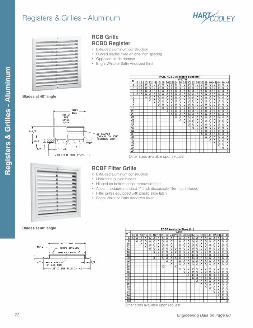
RCB GrilleRCBD Register• Extruded aluminum construction• Curved blades fixed on one-inch spacing• Opposed-blade damper• Bright White or Satin Anodized finish
RCBF Filter Grille• Extruded aluminum construction• Horizontal curved blades• Hinged on bottom edge, removable face• Accommodates standard 1” thick disposable filter (not included)• Filter grilles equipped with plastic slide latch• Bright White or Satin Anodized finish
Engineering Data on Page 86
Other sizes available upon request
Other sizes available upon request
6 8 10 12 14 16 18 20 22 24 26 28 30 32 34 36 38 40 42 44 46 48 4 X X X X X X X X X X X X X X X X X X X X X X 5 X X X X X X X X X X X X X X X X X X X X X X 6 X X X X X X X X X X X X X X X X X X X X X X 8 X X X X X X X X X X X X X X X X X X X X X X10 X X X X X X X X X X X X X X X X X X X X12 X X X X X X X X X X X X X X X X X X X14 X X X X X X X X X X X X X X X X X X16 X X X X X X X X X X X X X X X X X18 X X X X X X X X X X X X X X X X20 X X X X X X X X X X X X X X X22 X X X X X X X X X X X X X X24 X X X X X X X X X X X X X26 X X X X X X X X X X X X28 X X X X X X X X X X X30 X X X X X X X X X X32 X X X X X X X X X34 X X X X X X X X36 X X X X X X X38 X X X X X X40 X X X X X42 X X X X44 X X X46 X X48 X
RCB, RCBD Available Sizes (in.)HT WIDTH
6 8 10 12 14 16 18 20 22 24 25 26 28 30 32 34 36 38 40 42 44 46 48 6 X X X X X X X X X X X X X X X X X X X X X X 8 X X X X X X X X X X X X X X X X X X X X X10 X X X X X X X X X X X X X X X X X X X X12 X X X X X X X X X X X X X X X X X X X14 X X X X X X X X X X X X X X X X X X X16 X X X X X X X X X X X X X X X X X X18 X X X X X X X X X X X X X X X X20 X X X X X X X X X X X X X X X X X22 X X X X X X X X X X X X X X24 X X X X X X X X X X X X X25 X X26 X X X X X X X X X X X X28 X X X X X X X X X X X30 X X X X X X X X X X32 X X X X X X X X X34 X X X X X X X X36 X X X X X X X38 X X X X X X40 X X X X X42 X X X X44 X X X46 X X48 X
HTRCBF Available Sizes (in.)
WIDTH
Blades at 40° angle
Blades at 40° angle
Reg
iste
rs &
Gri
lles
- A
lum
inum
Registers & Grilles - Aluminum
23Engineering Data on Page 87
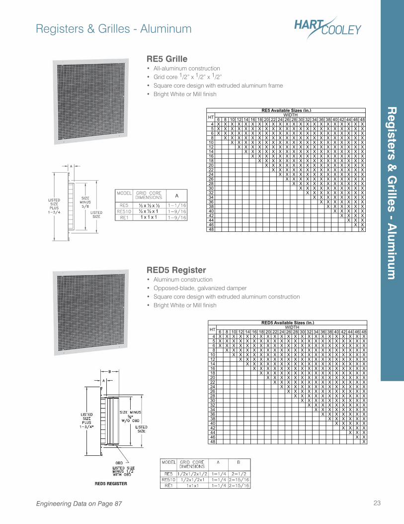
RED5 Register• Aluminum construction• Opposed-blade, galvanized damper• Square core design with extruded aluminum construction• Bright White or Mill finish
RE5 Grille• All-aluminum construction• Grid core 1/2” x 1/2” x 1/2”• Square core design with extruded aluminum frame• Bright White or Mill finish
6 8 10 12 14 16 18 20 22 24 26 28 30 32 34 36 38 40 42 44 46 48 4 X X X X X X X X X X X X X X X X X X X X X X 5 X X X X X X X X X X X X X X X X X X X X X X 6 X X X X X X X X X X X X X X X X X X X X X X 8 X X X X X X X X X X X X X X X X X X X X X10 X X X X X X X X X X X X X X X X X X X X12 X X X X X X X X X X X X X X X X X X X14 X X X X X X X X X X X X X X X X X X16 X X X X X X X X X X X X X X X X X18 X X X X X X X X X X X X X X X X20 X X X X X X X X X X X X X X X22 X X X X X X X X X X X X X X24 X X X X X X X X X X X X X26 X X X X X X X X X X X X28 X X X X X X X X X X X30 X X X X X X X X X X32 X X X X X X X X X34 X X X X X X X X36 X X X X X X X38 X X X X X X40 X X X X X42 X X X X44 X X X46 X X48 X
RE5 Available Sizes (in.)HT WIDTH
6 8 10 12 14 16 18 20 22 24 26 28 30 32 34 36 38 40 42 44 46 48 4 X X X X X X X X X X X X X X X X X X X X X X 5 X X X X X X X X X X X X X X X X X X X X X X 6 X X X X X X X X X X X X X X X X X X X X X X 8 X X X X X X X X X X X X X X X X X X X X X10 X X X X X X X X X X X X X X X X X X X X12 X X X X X X X X X X X X X X X X X X X14 X X X X X X X X X X X X X X X X X X16 X X X X X X X X X X X X X X X X X18 X X X X X X X X X X X X X X X X20 X X X X X X X X X X X X X X X22 X X X X X X X X X X X X X X24 X X X X X X X X X X X X X26 X X X X X X X X X X X X28 X X X X X X X X X X X30 X X X X X X X X X X32 X X X X X X X X X34 X X X X X X X X36 X X X X X X X38 X X X X X X40 X X X X X42 X X X X44 X X X46 X X48 X
RED5 Available Sizes (in.)HT WIDTH
Reg
isters & G
rilles - Alum
inum
Registers & Grilles - Aluminum
24 Engineering Data on Page 86-87
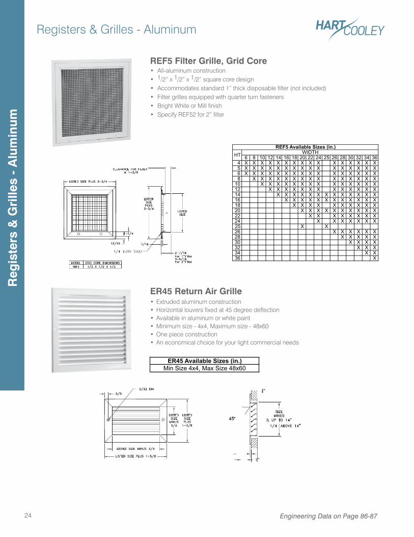
REF5 Filter Grille, Grid Core• All-aluminum construction• 1/2” x 1/2” x 1/2” square core design• Accommodates standard 1” thick disposable filter (not included)• Filter grilles equipped with quarter turn fasteners• Bright White or Mill finish• Specify REF52 for 2” filter
6 8 10 12 14 16 18 20 22 24 25 26 28 30 32 34 36 4 X X X X X X X X X X X X X X X X 5 X X X X X X X X X X X X X X X X 6 X X X X X X X X X X X X X X X X 8 X X X X X X X X X X X X X X X10 X X X X X X X X X X X X X X12 X X X X X X X X X X X X X14 X X X X X X X X X X X X X16 X X X X X X X X X X X X18 X X X X X X X X X X20 X X X X X X X X X X22 X X X X X X X X24 X X X X X X X25 X X26 X X X X X X28 X X X X X30 X X X X32 X X X34 X X36 X
HTREF5 Available Sizes (in.)
WIDTH
Reg
iste
rs &
Gri
lles
- A
lum
inum
ER45 Return Air Grille• Extruded aluminum construction• Horizontal louvers fixed at 45 degree deflection• Available in aluminum or white paint• Minimum size - 4x4, Maximum size - 48x60• One piece construction• An economical choice for your light commercial needs
ER45 Available Sizes (in.)Min Size 4x4, Max Size 48x60
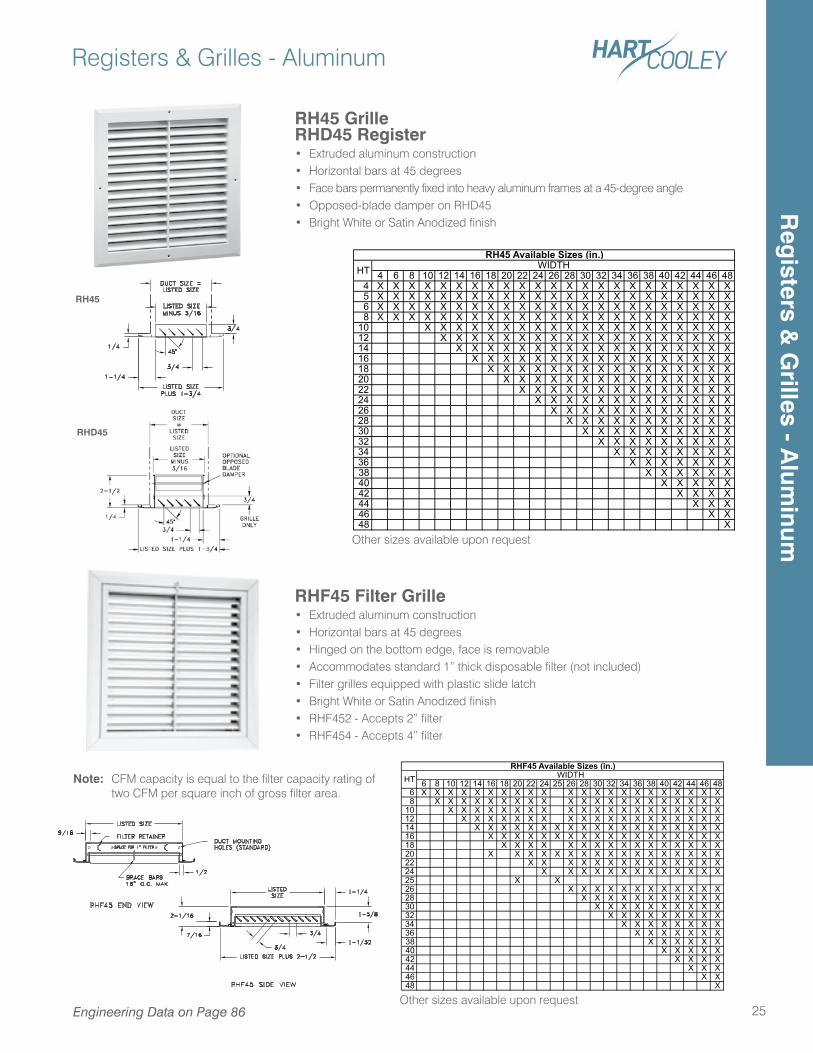
RH45
RHD45
4 6 8 10 12 14 16 18 20 22 24 26 28 30 32 34 36 38 40 42 44 46 48 4 X X X X X X X X X X X X X X X X X X X X X X X 5 X X X X X X X X X X X X X X X X X X X X X X X 6 X X X X X X X X X X X X X X X X X X X X X X X 8 X X X X X X X X X X X X X X X X X X X X X X X10 X X X X X X X X X X X X X X X X X X X X12 X X X X X X X X X X X X X X X X X X X14 X X X X X X X X X X X X X X X X X X16 X X X X X X X X X X X X X X X X X18 X X X X X X X X X X X X X X X X20 X X X X X X X X X X X X X X X22 X X X X X X X X X X X X X X24 X X X X X X X X X X X X X26 X X X X X X X X X X X X28 X X X X X X X X X X X30 X X X X X X X X X X32 X X X X X X X X X34 X X X X X X X X36 X X X X X X X38 X X X X X X40 X X X X X42 X X X X44 X X X46 X X48 X
RH45 Available Sizes (in.)HT WIDTH
Other sizes available upon request
Registers & Grilles - Aluminum
25Engineering Data on Page 86
RH45 GrilleRHD45 Register• Extruded aluminum construction• Horizontal bars at 45 degrees• Face bars permanently fixed into heavy aluminum frames at a 45-degree angle• Opposed-blade damper on RHD45• Bright White or Satin Anodized finish
RHF45 Filter Grille• Extruded aluminum construction• Horizontal bars at 45 degrees• Hinged on the bottom edge, face is removable• Accommodates standard 1” thick disposable filter (not included)• Filter grilles equipped with plastic slide latch• Bright White or Satin Anodized finish• RHF452 - Accepts 2” filter• RHF454 - Accepts 4” filter
Note: CFM capacity is equal to the filter capacity rating of two CFM per square inch of gross filter area.
Other sizes available upon request
6 8 10 12 14 16 18 20 22 24 25 26 28 30 32 34 36 38 40 42 44 46 48 6 X X X X X X X X X X X X X X X X X X X X X X 8 X X X X X X X X X X X X X X X X X X X X X10 X X X X X X X X X X X X X X X X X X X X12 X X X X X X X X X X X X X X X X X X X14 X X X X X X X X X X X X X X X X X X X16 X X X X X X X X X X X X X X X X X X18 X X X X X X X X X X X X X X X X20 X X X X X X X X X X X X X X X X X22 X X X X X X X X X X X X X X24 X X X X X X X X X X X X X25 X X26 X X X X X X X X X X X X28 X X X X X X X X X X X30 X X X X X X X X X X32 X X X X X X X X X34 X X X X X X X X36 X X X X X X X38 X X X X X X40 X X X X X42 X X X X44 X X X46 X X48 X
HTRHF45 Available Sizes (in.)
WIDTH
Reg
isters & G
rilles - Alum
inum
Registers & Grilles - Aluminum
26 Engineering Data on Page 87
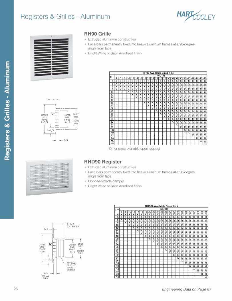
RHD90 Register• Extruded aluminum construction• Face bars permanently fixed into heavy aluminum frames at a 90-degree
angle from face• Opposed-blade damper• Bright White or Satin Anodized finish
RH90 Grille• Extruded aluminum construction• Face bars permanently fixed into heavy aluminum frames at a 90-degree
angle from face• Bright White or Satin Anodized finish
4 6 8 10 12 14 16 18 20 22 24 26 28 30 32 34 36 38 40 42 44 46 48 4 X X X X X X X X X X X X X X X X X X X X X X X 5 X X X X X X X X X X X X X X X X X X X X X X X 6 X X X X X X X X X X X X X X X X X X X X X X X 8 X X X X X X X X X X X X X X X X X X X X X X X10 X X X X X X X X X X X X X X X X X X X X12 X X X X X X X X X X X X X X X X X X X14 X X X X X X X X X X X X X X X X X X16 X X X X X X X X X X X X X X X X X18 X X X X X X X X X X X X X X X X20 X X X X X X X X X X X X X X X22 X X X X X X X X X X X X X X24 X X X X X X X X X X X X X26 X X X X X X X X X X X X28 X X X X X X X X X X X30 X X X X X X X X X X32 X X X X X X X X X34 X X X X X X X X36 X X X X X X X38 X X X X X X40 X X X X X42 X X X X44 X X X46 X X48 X
RH90 Available Sizes (in.)HT WIDTH
Other sizes available upon request
6 8 10 12 14 16 18 20 22 24 26 28 30 32 34 36 38 40 42 44 46 48 4 X X X X X X X X X X X X X X X X X X X X X X 5 X X X X X X X X X X X X X X X X X X X X X X 6 X X X X X X X X X X X X X X X X X X X X X X 8 X X X X X X X X X X X X X X X X X X X X X10 X X X X X X X X X X X X X X X X X X X X12 X X X X X X X X X X X X X X X X X X X14 X X X X X X X X X X X X X X X X X X16 X X X X X X X X X X X X X X X X X18 X X X X X X X X X X X X X X X X20 X X X X X X X X X X X X X X X22 X X X X X X X X X X X X X X24 X X X X X X X X X X X X X26 X X X X X X X X X X X X28 X X X X X X X X X X X30 X X X X X X X X X X32 X X X X X X X X X34 X X X X X X X X36 X X X X X X X38 X X X X X X40 X X X X X42 X X X X44 X X X46 X X48 X
RHD90 Available Sizes (in.)HT WIDTH
Reg
iste
rs &
Gri
lles
- A
lum
inum
Registers & Grilles - Aluminum
27Engineering Data on Page 88
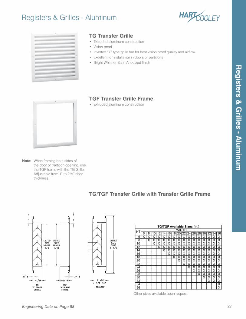
TG Transfer Grille• Extruded aluminum construction• Vision proof• Inverted “Y” type grille bar for best vision proof quality and airflow• Excellent for installation in doors or partitions• Bright White or Satin Anodized finish
TGF Transfer Grille Frame• Extruded aluminum construction
TG/TGF Transfer Grille with Transfer Grille Frame
Note: When framing both sides of the door or partition opening, use the TGF frame with the TG Grille. Adjustable from 1” to 21/8” door thickness.
6 8 10 12 14 16 18 20 22 24 26 28 30 32 34 36 6 X X X X X X X X X X X X X X X X 8 X X X X X X X X X X X X X X X10 X X X X X X X X X X X X X X12 X X X X X X X X X X X X X14 X X X X X X X X X X X X16 X X X X X X X X X X X18 X X X X X X X X X X20 X X X X X X X X X22 X X X X X X X X24 X X X X X X X26 X X X X X X28 X X X X X30 X X X X32 X X X34 X36 X
TG/TGF Available Sizes (in.)HT WIDTH
Other sizes available upon request
Reg
isters & G
rilles - Alum
inum
Ceiling Diffusers - Steel
28
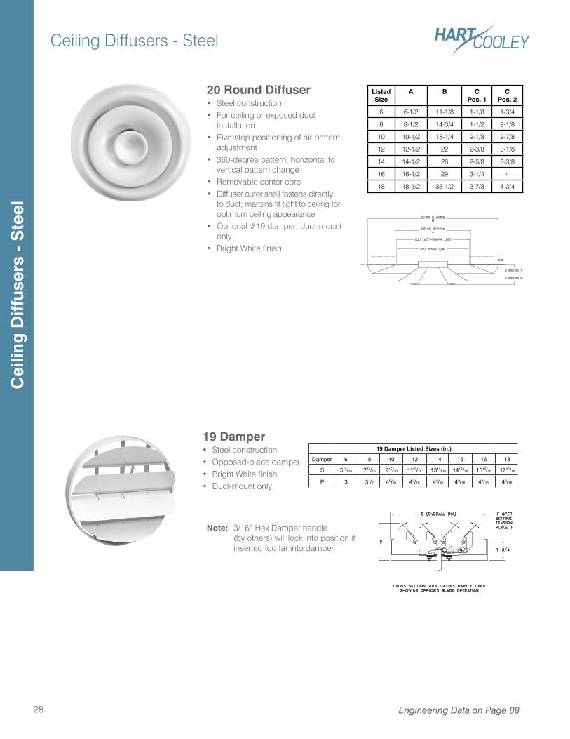
20 Round Diffuser• Steel construction• For ceiling or exposed duct
installation• Five-step positioning of air pattern
adjustment• 360-degree pattern, horizontal to
vertical pattern change• Removable center core• Diffuser outer shell fastens directly
to duct; margins fit tight to ceiling for optimum ceiling appearance
• Optional #19 damper; duct-mount only
• Bright White finish
Engineering Data on Page 88
19 Damper• Steel construction• Opposed-blade damper• Bright White finish• Duct-mount only
Note: 3/16” Hex Damper handle (by others) will lock into position if inserted too far into damper
19 Damper Listed Sizes (in.)
Damper 6 8 10 12 14 15 16 18
S 515/16 715/16 915/16 1115/16 1315/16 1415/16 1515/16 1715/16
P 3 31/2 49/16 49/16 49/16 49/16 49/16 49/16
Listed Size
A B CPos. 1
CPos. 2
6 6-1/2 11-1/8 1-1/8 1-3/4
8 8-1/2 14-3/4 1-1/2 2-1/8
10 10-1/2 18-1/4 2-1/8 2-7/8
12 12-1/2 22 2-3/8 3-1/8
14 14-1/2 26 2-5/8 3-3/8
16 16-1/2 29 3-1/4 4
18 18-1/2 33-1/2 3-7/8 4-3/4
Cei
ling
Diff
user
s -
Ste
el
Ceiling Diffusers - Steel
29
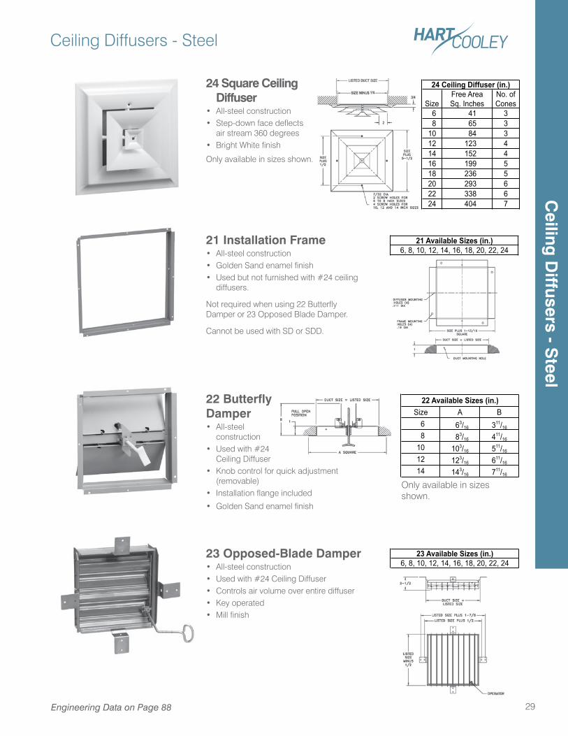
24 Square Ceiling Diffuser
• All-steel construction• Step-down face deflects
air stream 360 degrees• Bright White finish
Only available in sizes shown.
SizeFree AreaSq. Inches
No. ofCones
6 41 3 8 65 310 84 312 123 414 152 416 199 518 236 520 293 622 338 624 404 7
24 Ceiling Diffuser (in.)
22 Butterfly Damper• All-steel
construction• Used with #24
Ceiling Diffuser• Knob control for quick adjustment
(removable)• Installation flange included
• Golden Sand enamel finish
21 Installation Frame• All-steel construction• Golden Sand enamel finish• Used but not furnished with #24 ceiling
diffusers.
Not required when using 22 Butterfly Damper or 23 Opposed Blade Damper.
Cannot be used with SD or SDD.
21 Available Sizes (in.)6, 8, 10, 12, 14, 16, 18, 20, 22, 24
Size A B 6 63/16 311/16
8 83/16 411/16
10 103/16 511/16
12 123/16 611/16
14 143/16 711/16
22 Available Sizes (in.)
23 Opposed-Blade Damper• All-steel construction• Used with #24 Ceiling Diffuser• Controls air volume over entire diffuser• Key operated• Mill finish
23 Available Sizes (in.)6, 8, 10, 12, 14, 16, 18, 20, 22, 24
Only available in sizes shown.
Engineering Data on Page 88
Ceiling
Diffusers - S
teel
Ceiling Diffusers - Steel
30 Engineering Data on Page 89-94
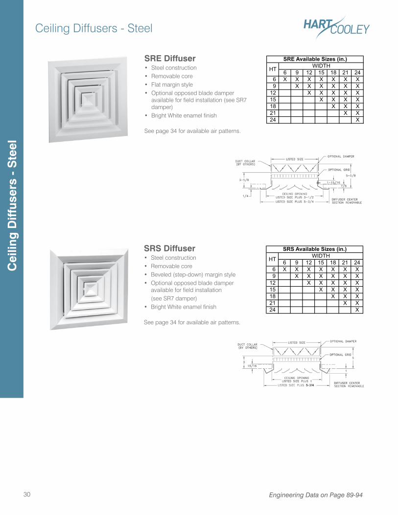
SRS Diffuser• Steel construction• Removable core• Beveled (step-down) margin style• Optional opposed blade damper
available for field installation (see SR7 damper)• Bright White enamel finish
See page 34 for available air patterns.
6 9 12 15 18 21 24 6 X X X X X X X 9 X X X X X X12 X X X X X15 X X X X18 X X X21 X X24 X
SRS Available Sizes (in.)
HT WIDTH
SRE Diffuser• Steel construction• Removable core• Flat margin style• Optional opposed blade damper
available for field installation (see SR7 damper)
• Bright White enamel finish
See page 34 for available air patterns.
6 9 12 15 18 21 24 6 X X X X X X X 9 X X X X X X12 X X X X X15 X X X X18 X X X21 X X24 X
SRE Available Sizes (in.)
HT WIDTH
Cei
ling
Diff
user
s -
Ste
el
Ceiling Diffusers - Steel
31
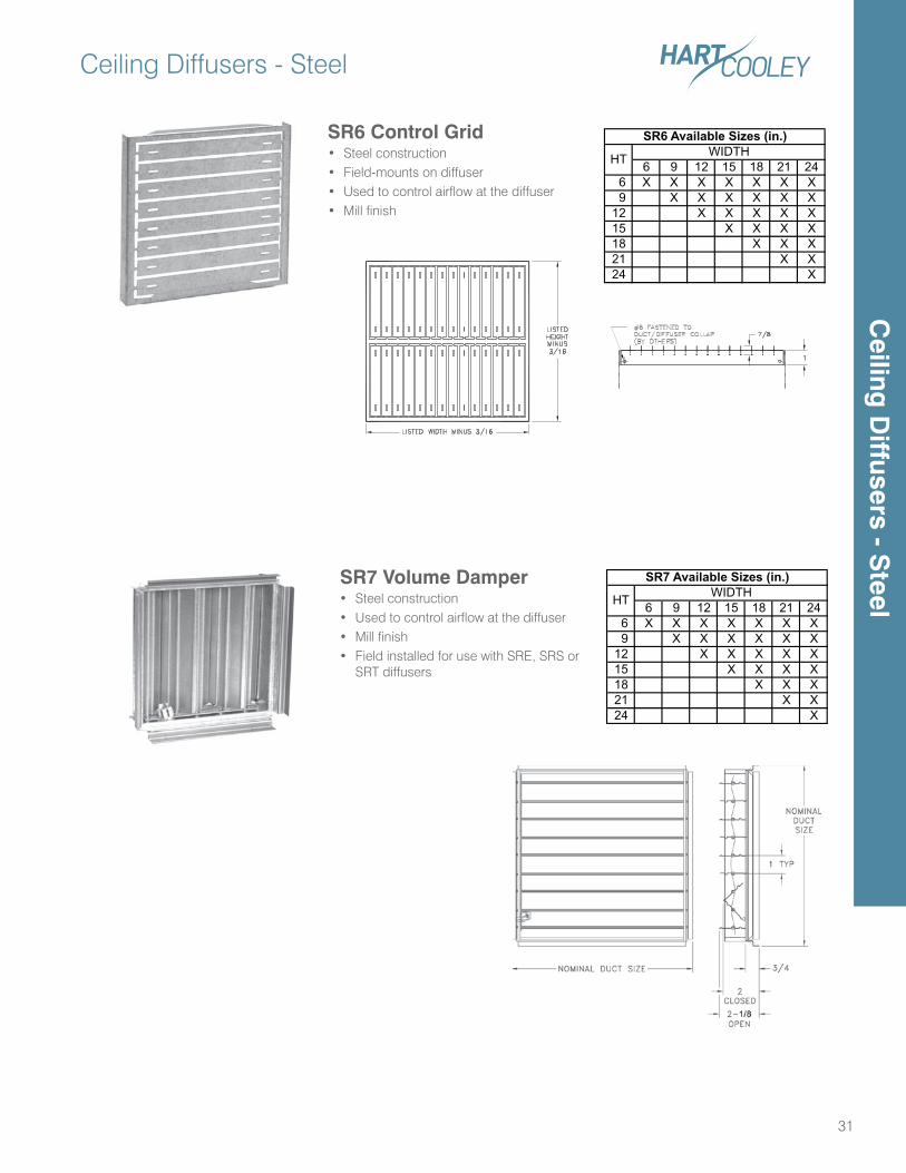
SR7 Volume Damper• Steel construction• Used to control airflow at the diffuser• Mill finish• Field installed for use with SRE, SRS or
SRT diffusers
6 9 12 15 18 21 24 6 X X X X X X X 9 X X X X X X12 X X X X X15 X X X X18 X X X21 X X24 X
SR7 Available Sizes (in.)
HT WIDTH
SR6 Control Grid • Steel construction• Field-mounts on diffuser• Used to control airflow at the diffuser• Mill finish
6 9 12 15 18 21 24 6 X X X X X X X 9 X X X X X X12 X X X X X15 X X X X18 X X X21 X X24 X
SR6 Available Sizes (in.)
HT WIDTH
Ceiling
Diffusers - S
teel
Ceiling Diffusers - Aluminum
32 Engineering Data on Page 89-94
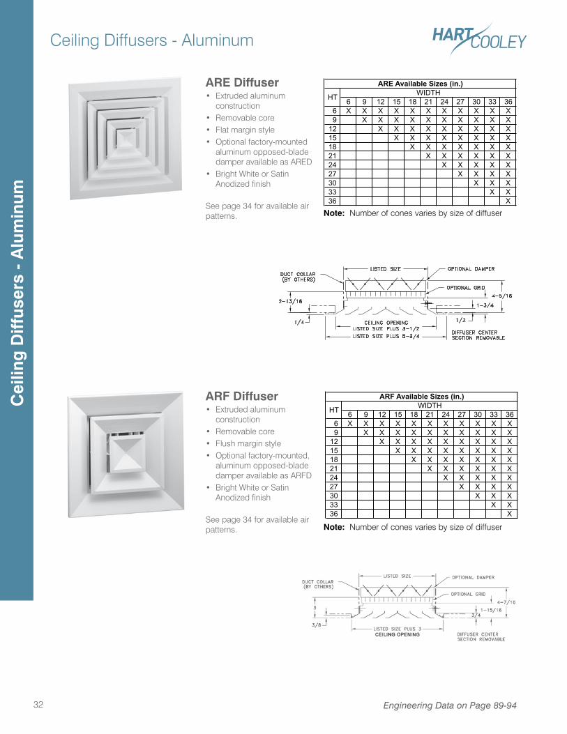
ARE Diffuser• Extruded aluminum
construction• Removable core• Flat margin style• Optional factory-mounted
aluminum opposed-blade damper available as ARED
• Bright White or Satin Anodized finish
See page 34 for available air patterns.
ARF Diffuser• Extruded aluminum
construction• Removable core• Flush margin style• Optional factory-mounted,
aluminum opposed-blade damper available as ARFD
• Bright White or Satin Anodized finish
See page 34 for available air patterns.
6 9 12 15 18 21 24 27 30 33 36 6 X X X X X X X X X X X 9 X X X X X X X X X X12 X X X X X X X X X15 X X X X X X X X18 X X X X X X X21 X X X X X X24 X X X X X27 X X X X30 X X X33 X X36 X
ARE Available Sizes (in.)
HT WIDTH
6 9 12 15 18 21 24 27 30 33 36 6 X X X X X X X X X X X 9 X X X X X X X X X X12 X X X X X X X X X15 X X X X X X X X18 X X X X X X X21 X X X X X X24 X X X X X27 X X X X30 X X X33 X X36 X
ARF Available Sizes (in.)
HT WIDTH
Note: Number of cones varies by size of diffuser
Note: Number of cones varies by size of diffuser
Cei
ling
Diff
user
s -
Alu
min
um
Ceiling Diffusers - Aluminum
33Engineering Data on Page 89-94
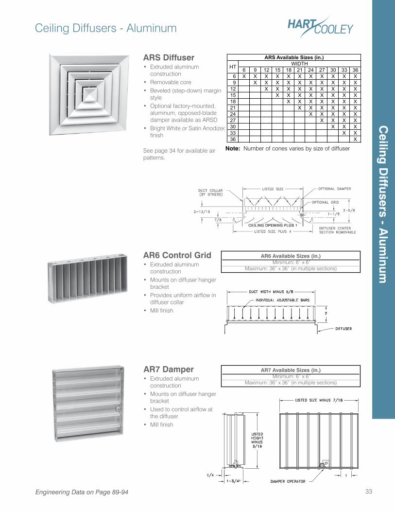
ARS Diffuser• Extruded aluminum
construction• Removable core• Beveled (step-down) margin
style• Optional factory-mounted,
aluminum, opposed-blade damper available as ARSD
• Bright White or Satin Anodized finish
See page 34 for available air patterns.
AR7 Available Sizes (in.) Minimum: 6” x 6”
Maximum: 36” x 36” (in multiple sections)
AR6 Available Sizes (in.) Minimum: 6” x 6”
Maximum: 36” x 36” (in multiple sections)
AR6 Control Grid • Extruded aluminum
construction• Mounts on diffuser hanger
bracket• Provides uniform airflow in
diffuser collar• Mill finish
AR7 Damper• Extruded aluminum
construction• Mounts on diffuser hanger
bracket• Used to control airflow at
the diffuser• Mill finish
6 9 12 15 18 21 24 27 30 33 36 6 X X X X X X X X X X X 9 X X X X X X X X X X12 X X X X X X X X X15 X X X X X X X X18 X X X X X X X21 X X X X X X24 X X X X X27 X X X X30 X X X33 X X36 X
HT WIDTHARS Available Sizes (in.)
Note: Number of cones varies by size of diffuser
Ceiling
Diffusers - A
luminum
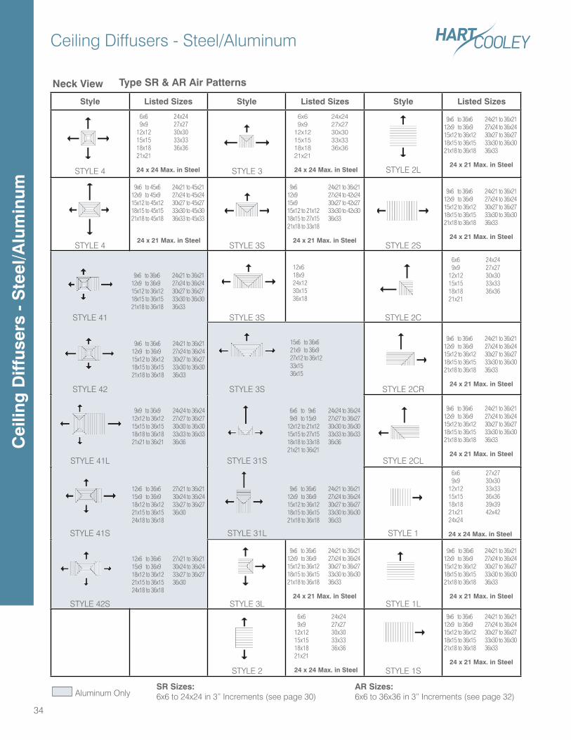
Style Listed Sizes Style Listed Sizes Style Listed Sizes
STYLE 2L
Ceiling Diffusers - Steel/Aluminum
34
STYLE 4 STYLE 3
Type SR & AR Air Patterns
STYLE 4
STYLE 41
STYLE 42
STYLE 41L
STYLE 41S
STYLE 42S
Aluminum Only
Neck View
STYLE 3S
STYLE 3S
STYLE 3S
STYLE 31S
STYLE 31L
STYLE 3L
STYLE 2
STYLE 2S
STYLE 2C
STYLE 2CR
STYLE 2CL
STYLE 1
STYLE 1L
STYLE 1S
SR Sizes:6x6 to 24x24 in 3” Increments (see page 30)
AR Sizes:6x6 to 36x36 in 3” Increments (see page 32)
6x6 24x24 9x9 27x2712x12 30x3015x15 33x3318x18 36x3621x21
24 x 24 Max. in Steel
12x618x924x1230x1536x18
6x6 24x24 9x9 27x2712x12 30x3015x15 33x3318x18 36x3621x21
24 x 24 Max. in Steel
6x6 24x24 9x9 27x2712x12 30x3015x15 33x3318x18 36x3621x21
24 x 24 Max. in Steel
6x6 24x24 9x9 27x2712x12 30x3015x15 33x3318x18 36x3621x21
6x6 27x27 9x9 30x3012x12 33x3315x15 36x3618x18 39x3921x21 42x4224x24
24 x 24 Max. in Steel
9x6 to 45x6 24x21 to 45x2112x9 to 45x9 27x24 to 45x2415x12 to 45x12 30x27 to 45x2718x15 to 45x15 33x30 to 45x3021x18 to 45x18 36x33 to 45x33
24 x 21 Max. in Steel
6x6 to 9x6 24x24 to 36x24 9x9 to 15x9 27x27 to 36x2712x12 to 21x12 30x30 to 36x3015x15 to 27x15 33x33 to 36x3318x18 to 33x18 36x3621x21 to 36x21
9x6 24x21 to 36x2112x9 27x24 to 42x2415x9 30x27 to 42x2715x12 to 21x12 33x30 to 42x3018x15 to 27x15 36x3321x18 to 33x18
24 x 21 Max. in Steel
9x6 to 36x6 24x21 to 36x2112x9 to 36x9 27x24 to 36x2415x12 to 36x12 30x27 to 36x2718x15 to 36x15 33x30 to 36x3021x18 to 36x18 36x33
9x6 to 36x6 24x21 to 36x2112x9 to 36x9 27x24 to 36x2415x12 to 36x12 30x27 to 36x2718x15 to 36x15 33x30 to 36x3021x18 to 36x18 36x33
24 x 21 Max. in Steel
9x6 to 36x6 24x21 to 36x2112x9 to 36x9 27x24 to 36x2415x12 to 36x12 30x27 to 36x2718x15 to 36x15 33x30 to 36x3021x18 to 36x18 36x33
24 x 21 Max. in Steel
9x6 to 36x6 24x21 to 36x2112x9 to 36x9 27x24 to 36x2415x12 to 36x12 30x27 to 36x2718x15 to 36x15 33x30 to 36x3021x18 to 36x18 36x33
24 x 21 Max. in Steel
9x6 to 36x6 24x21 to 36x2112x9 to 36x9 27x24 to 36x2415x12 to 36x12 30x27 to 36x2718x15 to 36x15 33x30 to 36x3021x18 to 36x18 36x33
24 x 21 Max. in Steel
9x6 to 36x6 24x21 to 36x2112x9 to 36x9 27x24 to 36x2415x12 to 36x12 30x27 to 36x2718x15 to 36x15 33x30 to 36x3021x18 to 36x18 36x33
24 x 21 Max. in Steel
9x6 to 36x6 24x21 to 36x2112x9 to 36x9 27x24 to 36x2415x12 to 36x12 30x27 to 36x2718x15 to 36x15 33x30 to 36x3021x18 to 36x18 36x33
24 x 21 Max. in Steel
9x6 to 36x6 24x21 to 36x2112x9 to 36x9 27x24 to 36x2415x12 to 36x12 30x27 to 36x2718x15 to 36x15 33x30 to 36x3021x18 to 36x18 36x33
24 x 21 Max. in Steel
9x6 to 36x6 24x21 to 36x2112x9 to 36x9 27x24 to 36x2415x12 to 36x12 30x27 to 36x2718x15 to 36x15 33x30 to 36x3021x18 to 36x18 36x33
15x6 to 36x621x9 to 36x927x12 to 36x1233x1536x15
9x6 to 36x6 24x21 to 36x2112x9 to 36x9 27x24 to 36x2415x12 to 36x12 30x27 to 36x2718x15 to 36x15 33x30 to 36x3021x18 to 36x18 36x33
12x6 to 36x6 27x21 to 36x2115x9 to 36x9 30x24 to 36x2418x12 to 36x12 33x27 to 36x2721x15 to 36x15 36x3024x18 to 36x18
12x6 to 36x6 27x21 to 36x2115x9 to 36x9 30x24 to 36x2418x12 to 36x12 33x27 to 36x2721x15 to 36x15 36x3024x18 to 36x18
9x9 to 36x9 24x24 to 36x2412x12 to 36x12 27x27 to 36x2715x15 to 36x15 30x30 to 36x3018x18 to 36x18 33x33 to 36x3321x21 to 36x21 36x36C
eilin
g D
iffus
ers
- S
teel
/Alu
min
um
Ceiling Diffusers - Aluminum
35
SupplySize
ReturnNeck
SupplySize
ReturnNeck
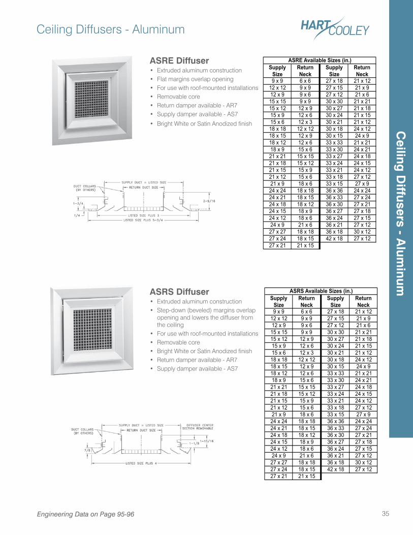
9 x 9 6 x 6 27 x 18 21 x 1212 x 12 9 x 9 27 x 15 21 x 912 x 9 9 x 6 27 x 12 21 x 615 x 15 9 x 9 30 x 30 21 x 2115 x 12 12 x 9 30 x 27 21 x 1815 x 9 12 x 6 30 x 24 21 x 1515 x 6 12 x 3 30 x 21 21 x 1218 x 18 12 x 12 30 x 18 24 x 1218 x 15 12 x 9 30 x 15 24 x 918 x 12 12 x 6 33 x 33 21 x 2118 x 9 15 x 6 33 x 30 24 x 2121 x 21 15 x 15 33 x 27 24 x 1821 x 18 15 x 12 33 x 24 24 x 1521 x 15 15 x 9 33 x 21 24 x 1221 x 12 15 x 6 33 x 18 27 x 1221 x 9 18 x 6 33 x 15 27 x 924 x 24 18 x 18 36 x 36 24 x 2424 x 21 18 x 15 36 x 33 27 x 2424 x 18 18 x 12 36 x 30 27 x 2124 x 15 18 x 9 36 x 27 27 x 1824 x 12 18 x 6 36 x 24 27 x 1524 x 9 21 x 6 36 x 21 27 x 1227 x 27 18 x 18 36 x 18 30 x 1227 x 24 18 x 15 42 x 18 27 x 1227 x 21 21 x 15
ASRE Available Sizes (in.)
SupplySize
ReturnNeck
SupplySize
ReturnNeck
9 x 9 6 x 6 27 x 18 21 x 1212 x 12 9 x 9 27 x 15 21 x 912 x 9 9 x 6 27 x 12 21 x 615 x 15 9 x 9 30 x 30 21 x 2115 x 12 12 x 9 30 x 27 21 x 1815 x 9 12 x 6 30 x 24 21 x 1515 x 6 12 x 3 30 x 21 21 x 1218 x 18 12 x 12 30 x 18 24 x 1218 x 15 12 x 9 30 x 15 24 x 918 x 12 12 x 6 33 x 33 21 x 2118 x 9 15 x 6 33 x 30 24 x 2121 x 21 15 x 15 33 x 27 24 x 1821 x 18 15 x 12 33 x 24 24 x 1521 x 15 15 x 9 33 x 21 24 x 1221 x 12 15 x 6 33 x 18 27 x 1221 x 9 18 x 6 33 x 15 27 x 924 x 24 18 x 18 36 x 36 24 x 2424 x 21 18 x 15 36 x 33 27 x 2424 x 18 18 x 12 36 x 30 27 x 2124 x 15 18 x 9 36 x 27 27 x 1824 x 12 18 x 6 36 x 24 27 x 1524 x 9 21 x 6 36 x 21 27 x 1227 x 27 18 x 18 36 x 18 30 x 1227 x 24 18 x 15 42 x 18 27 x 1227 x 21 21 x 15
ASRS Available Sizes (in.)ASRS Diffuser• Extruded aluminum construction• Step-down (beveled) margins overlap
opening and lowers the diffuser from the ceiling
• For use with roof-mounted installations• Removable core• Bright White or Satin Anodized finish• Return damper available - AR7• Supply damper available - AS7
ASRE Diffuser• Extruded aluminum construction• Flat margins overlap opening• For use with roof-mounted installations• Removable core• Return damper available - AR7• Supply damper available - AS7
• Bright White or Satin Anodized finish
Engineering Data on Page 95-96
Ceiling
Diffusers - A
luminum
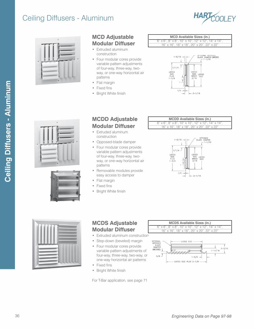
Ceiling Diffusers - Aluminum
36
MCDD Adjustable Modular Diffuser• Extruded aluminum
construction• Opposed-blade damper• Four modular cores provide
variable pattern adjustments of four-way, three-way, two-way, or one-way horizontal air patterns
• Removable modules provide easy access to damper
• Flat margin• Fixed fins• Bright White finish
MCDD Available Sizes (in.)6” x 6”, 8” x 8”, 10” x 10”, 12” x 12”, 14” x 14”,
16” x 16”, 18” x 18”, 20” x 20”, 22” x 22”
MCDS Adjustable Modular Diffuser• Extruded aluminum construction• Step-down (beveled) margin• Four modular cores provide
variable pattern adjustments of four-way, three-way, two-way, or one-way horizontal air patterns
• Fixed fins• Bright White finish
For T-Bar application, see page 71
MCDS Available Sizes (in.)6” x 6”, 8” x 8”, 10” x 10”, 12” x 12”, 14” x 14”,
16” x 16”, 18” x 18”, 20” x 20”, 22” x 22”
MCD Adjustable Modular Diffuser• Extruded aluminum
construction• Four modular cores provide
variable pattern adjustments of four-way, three-way, two-way, or one-way horizontal air patterns
• Flat margin• Fixed fins• Bright White finish
MCD Available Sizes (in.)6” x 6”, 8” x 8”, 10” x 10”, 12” x 12”, 14” x 14”,
16” x 16”, 18” x 18”, 20” x 20”, 22” x 22”
Engineering Data on Page 97-98
Cei
ling
Diff
user
s -
Alu
min
um
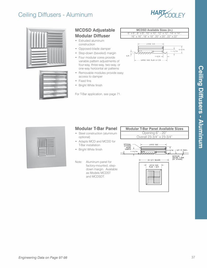
Ceiling Diffusers - Aluminum
37
MCDSD Adjustable Modular Diffuser• Extruded aluminum
construction• Opposed-blade damper• Step-down (beveled) margin• Four modular cores provide
variable pattern adjustments of four-way, three-way, two-way, or one-way horizontal air patterns
• Removable modules provide easy access to damper
• Fixed fins• Bright White finish
For T-Bar application, see page 71.
MCDSD Available Sizes (in.)6” x 6”, 8” x 8”, 10” x 10”, 12” x 12”, 14” x 14”,
16” x 16”, 18” x 18”, 20” x 20”, 22” x 22”
Modular T-Bar Panel • Steel construction (aluminum
optional)• Adapts MCD and MCDD for
T-Bar installation• Bright White finish
Note: Aluminum panel for factory-mounted, step-down margin. Available as Models MCDST and MCDSDT.
Modular T-Bar Panel Available SizesOpening 6” - 20”
Overall 23-3/4” x 23-3/4”
Engineering Data on Page 97-98
Ceiling
Diffusers - A
luminum
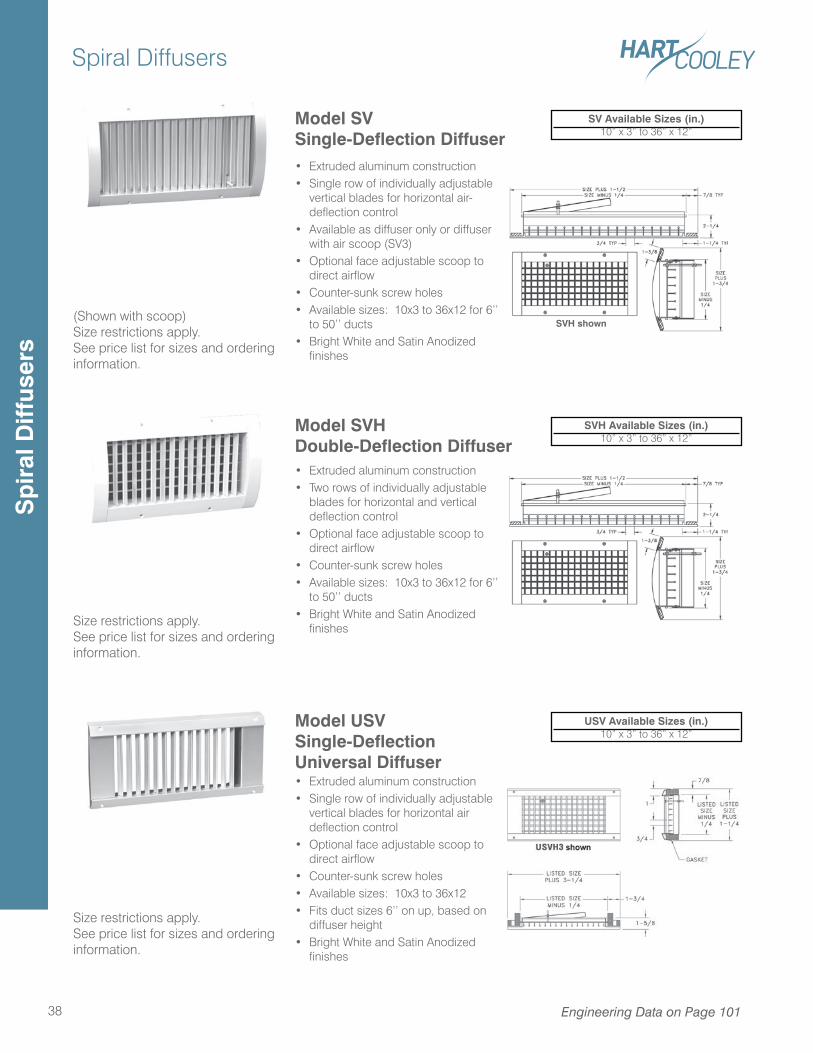
Spiral Diffusers
38 Engineering Data on Page 101
Model SVHDouble-Deflection Diffuser• Extruded aluminum construction• Two rows of individually adjustable
blades for horizontal and vertical deflection control
• Optional face adjustable scoop to direct airflow
• Counter-sunk screw holes• Available sizes: 10x3 to 36x12 for 6’’
to 50’’ ducts• Bright White and Satin Anodized
finishes
Model SVSingle-Deflection Diffuser• Extruded aluminum construction• Single row of individually adjustable
vertical blades for horizontal air-deflection control
• Available as diffuser only or diffuser with air scoop (SV3)
• Optional face adjustable scoop to direct airflow
• Counter-sunk screw holes• Available sizes: 10x3 to 36x12 for 6’’
to 50’’ ducts• Bright White and Satin Anodized
finishes
SVH shown
SVH Available Sizes (in.)10” x 3” to 36” x 12”
SV Available Sizes (in.)10” x 3” to 36” x 12”
Size restrictions apply.See price list for sizes and ordering information.
(Shown with scoop)Size restrictions apply.See price list for sizes and ordering information.
Model USVSingle-DeflectionUniversal Diffuser• Extruded aluminum construction• Single row of individually adjustable
vertical blades for horizontal air deflection control
• Optional face adjustable scoop to direct airflow
• Counter-sunk screw holes• Available sizes: 10x3 to 36x12 • Fits duct sizes 6’’ on up, based on
diffuser height• Bright White and Satin Anodized
finishes
USV Available Sizes (in.)10” x 3” to 36” x 12”
Size restrictions apply.See price list for sizes and ordering information.
Sp
iral
Diff
user
s
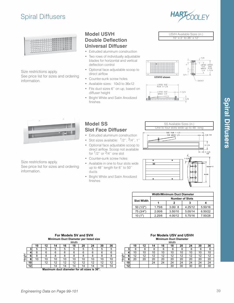
Spiral Diffusers
39Engineering Data on Page 99-101
Model SSSlot Face Diffuser• Extruded aluminum construction• Slot sizes available: 1/2’’, 3/4’’, 1’’• Optional face adjustable scoop to
direct airflow. Scoop not available for 1/2’’ or 3/4’’ one slot
• Counter-sunk screw holes• Available in one to four slots wide
up to 48’’ length for 6’’ to 50’’ ducts
• Bright White and Satin Anodized finishes
Size restrictions apply.See price list for sizes and ordering information.
Model USVHDouble DeflectionUniversal Diffuser• Extruded aluminum construction• Two rows of individually adjustable
blades for horizontal and vertical deflection control
• Optional face adjustable scoop to direct airflow
• Counter-sunk screw holes• Available sizes: 10x3 to 36x12 • Fits duct sizes 6’’ on up, based on
diffuser height• Bright White and Satin Anodized
finishes
USVH Available Sizes (in.)10” x 3” to 36” x 12”
Size restrictions apply.See price list for sizes and ordering information.
1 2 3 4 50 (1/2") 1.75/6 3.00/ 8 4.25/12 5.50/16 75 (3/4") 2.00/6 3.50/10 5.00/14 6.50/22 10 (1") 2.25/6 4.00/12 5.75/16 7.50/28
Number of SlotsWidth/Minimum Duct Diameter
Slot Width
10 12 14 16 18 20 24 30 36 10 12 14 16 18 20 24 30 36 3 5 5 5 5 5 5 5 5 5 3 6 6 6 6 6 6 6 6 6 4 6 6 6 6 6 6 6 6 6 4 10 10 10 10 10 10 10 10 10 6 8 8 8 8 8 8 8 8 8 6 12 12 12 12 12 12 12 12 12 8 10 10 10 10 10 10 10 10 10 8 20 20 20 20 20 20 20 20 2010 12 12 12 12 12 12 12 12 10 24 24 24 24 24 24 2412 14 14 14 14 14 14 14 12 30 30 30 30 30
Height
Minimum Duct Diameter per listed sizeWidth
For Models USV and USVHMinimum Duct Diameter
Width
Height
Maximum duct diameter for all sizes is 36".
For Models SV and SVH
SS Available Sizes (in.)One to four slots wide up to 48” long
Sp
iral Diffusers
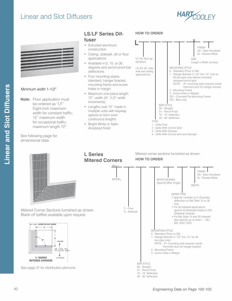
Linear and Slot Diffusers
40
MODEL
LS/LF Series Dif-fuser• Extruded aluminum
construction• Ceiling, sidewall, sill or floor
applications• Available in 0, 15, or 30
degrees and pencil proof bar deflections
• Four mounting styles-standard, hanger bracket, mounting frame and screw holes in margin
• Maximum one-piece length 72”, width 24” (1/2” width increments)
• Lengths over 72” made in multiple units with keyway splices to form even continuous lengths
• Bright White or Satin Anodized finish
HOW TO ORDER
LF (for floor ap-plication)
LS (for sill, side-wall and ceiling applications)
TYPE1 - Grille Only2 - Grille With Control Grid3 - Grille With Damper4 - Grille With Control Grid and Damper
BAR STYLE00 - Straight01 - Pencil Proof15 - 15° deflection30 - 30° deflection
MOUNTING STYLE0 - Standard (Floor or Sill)1 - Hanger Bracket (1-1/2” thru 12” only for 00 bar style only without mounted damper/control grid) NOTE: #1 mounting style requires inside hemmed duct for hanger bracket2 - Mounting Frame3 - Screw Holes in MarginGO - Concrete/Tile Mounting FrameOO - Bars only
SIZELength x Width (inches)
FINISHSA - Satin AnodizedW - Painted White
FINISHSA - Satin AnodizedW - Painted White
X
MITER DEGREE(Specify Miter Angle)
WIDTH
MITER TYPE• Specify I (Inside) or O (Outside)
deflection on Bar Style 15 or 30 only
• For all sidewall applications specify SI (Sidewall Inside) or SO (Sidewall Outside)
• For Bar Style 15 and 30 sidewall also specify up or down — SIU, SID, SOU, SOD
Mitered corner sections furnished as shown.
HOW TO ORDER
L
L Series Mitered Corners
BAR STYLE00 - Straight01 - Pencil Proof15 - 15° deflection30 - 30° deflection
MOUNTING STYLE0 - Standard (Floor or Sill)1 - Hanger Bracket (1-1/2” thru 12” for 00 bar style only) NOTE: #1 mounting style requires inside hemmed duct for hanger bracket2 - Mounting Frame3 - screw holes in Margin
MCL1
Mitered Corner Sections furnished as shown. Blank off baffles available upon request.
Minimum width 1-1/2”
See page 47 for distribution plenums.
F - FloorS - Sidewall
Note: Floor application must be ordered as “LF.” Eight-inch maximum width for constant traffic; 12” maximum width for occasional traffic; maximum length 72”.
See following page for dimensional data.
Engineering Data on Page 102-103
Line
ar a
nd S
lot
Diff
user
s
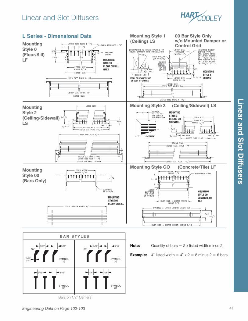
Linear and Slot Diffusers
41
L Series - Dimensional DataMountingStyle 0(Floor/Sill)LF
MountingStyle 00(Bars Only)
Mounting Style GO (Concrete/Tile) LF
Note: Quantity of bars = 2 x listed width minus 2.
Example: 4” listed width = 4” x 2 = 8 minus 2 = 6 bars.
B A R S T Y L E S
Bars on 1/2” Centers
Engineering Data on Page 102-103
Mounting Style 1(Ceiling) LS
00 Bar Style Onlyw/o Mounted Damper orControl Grid
MountingStyle 2(Ceiling/Sidewall)LS
Mounting Style 3 (Ceiling/Sidewall) LS
Linear and S
lot D
iffusers
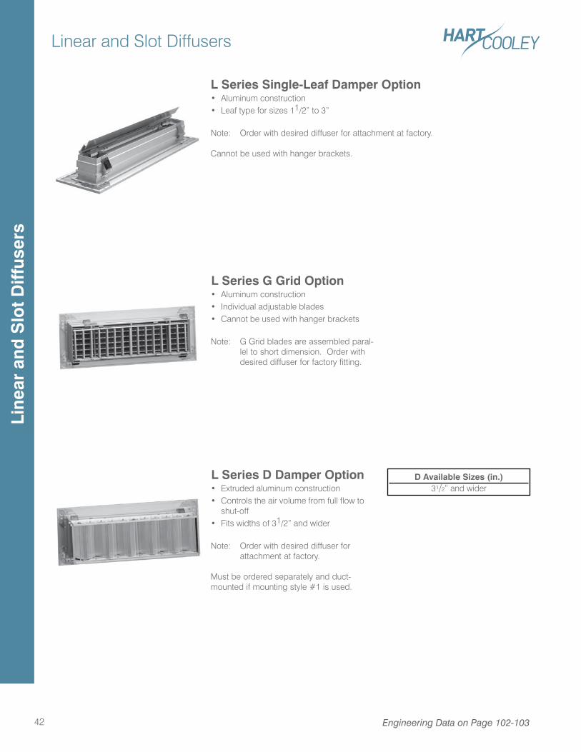
Linear and Slot Diffusers
42 Engineering Data on Page 102-103
L Series G Grid Option• Aluminum construction• Individual adjustable blades• Cannot be used with hanger brackets
Note: G Grid blades are assembled paral-lel to short dimension. Order with desired diffuser for factory fitting.
L Series Single-Leaf Damper Option• Aluminum construction• Leaf type for sizes 11/2” to 3”
Note: Order with desired diffuser for attachment at factory.
Cannot be used with hanger brackets.
L Series D Damper Option• Extruded aluminum construction• Controls the air volume from full flow to
shut-off• Fits widths of 31/2” and wider
Note: Order with desired diffuser for attachment at factory.
Must be ordered separately and duct-mounted if mounting style #1 is used.
D Available Sizes (in.)31/2” and wider
Line
ar a
nd S
lot
Diff
user
s
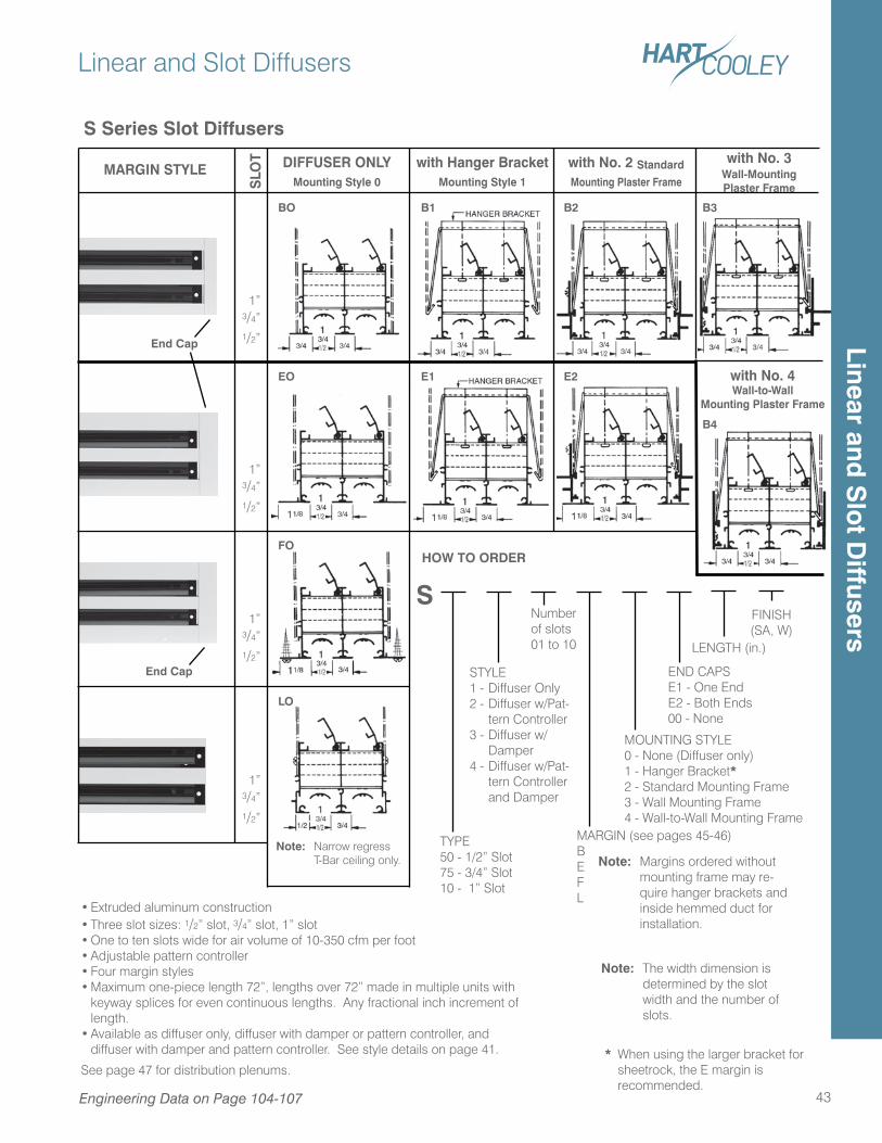
• Extruded aluminum construction• Three slot sizes: 1/2” slot, 3/4” slot, 1” slot• One to ten slots wide for air volume of 10-350 cfm per foot• Adjustable pattern controller• Four margin styles• Maximum one-piece length 72”, lengths over 72” made in multiple units with
keyway splices for even continuous lengths. Any fractional inch increment of length.
• Available as diffuser only, diffuser with damper or pattern controller, and diffuser with damper and pattern controller. See style details on page 41.
See page 47 for distribution plenums.
Linear and Slot Diffusers
43
1”3/4”1/2”
1”3/4”1/2”
1”3/4”1/2”
1”3/4”1/2”
MARGIN STYLE DIFFUSER ONLY with Hanger Bracket with No. 2 Standard
Mounting Style 0 Mounting Style 1 Mounting Plaster FrameSLO
T
BO
EO E1
B2
E2
B1
LO
FO
Note: Narrow regress T-Bar ceiling only.
HOW TO ORDER
Number of slots01 to 10
STYLE1 - Diffuser Only2 - Diffuser w/Pat-
tern Controller3 - Diffuser w/
Damper4 - Diffuser w/Pat-
tern Controller and Damper
TYPE50 - 1/2” Slot75 - 3/4” Slot10 - 1” Slot
MARGIN (see pages 45-46)BEFL
Note: Margins ordered without mounting frame may re-quire hanger brackets and inside hemmed duct for installation.
MOUNTING STYLE0 - None (Diffuser only)1 - Hanger Bracket*2 - Standard Mounting Frame3 - Wall Mounting Frame4 - Wall-to-Wall Mounting Frame
END CAPSE1 - One EndE2 - Both Ends00 - None
LENGTH (in.)
FINISH (SA, W)
S
S Series Slot Diffusers
Note: The width dimension is determined by the slot width and the number of slots.
* When using the larger bracket for sheetrock, the E margin is recommended.
End Cap
End Cap
Engineering Data on Page 104-107
B3
with No. 4Wall-to-Wall
Mounting Plaster Frame
B4
with No. 3 Wall-MountingPlaster Frame
Linear and S
lot D
iffusers
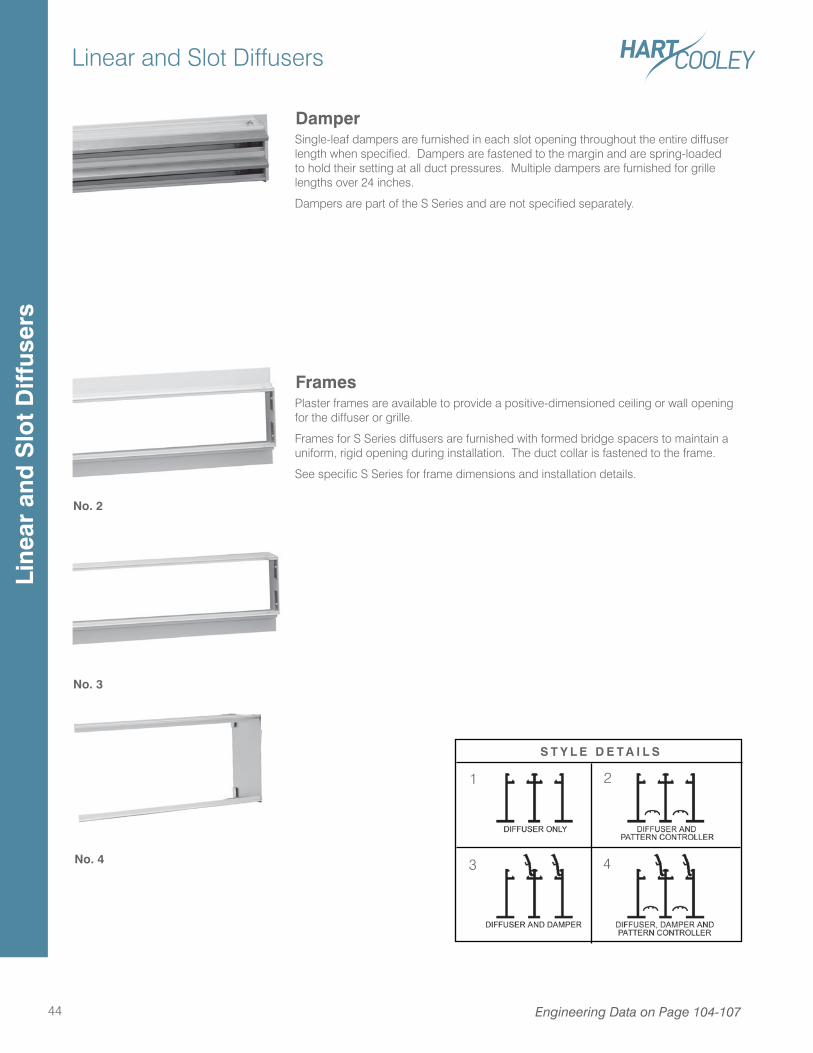
Linear and Slot Diffusers
44
FramesPlaster frames are available to provide a positive-dimensioned ceiling or wall opening for the diffuser or grille.
Frames for S Series diffusers are furnished with formed bridge spacers to maintain a uniform, rigid opening during installation. The duct collar is fastened to the frame.
See specific S Series for frame dimensions and installation details.
DamperSingle-leaf dampers are furnished in each slot opening throughout the entire diffuser length when specified. Dampers are fastened to the margin and are spring-loaded to hold their setting at all duct pressures. Multiple dampers are furnished for grille lengths over 24 inches.
Dampers are part of the S Series and are not specified separately.
No. 2
No. 3
No. 4
S T Y L E D E T A I L S
1 2
3 4
Engineering Data on Page 104-107
Line
ar a
nd S
lot
Diff
user
s
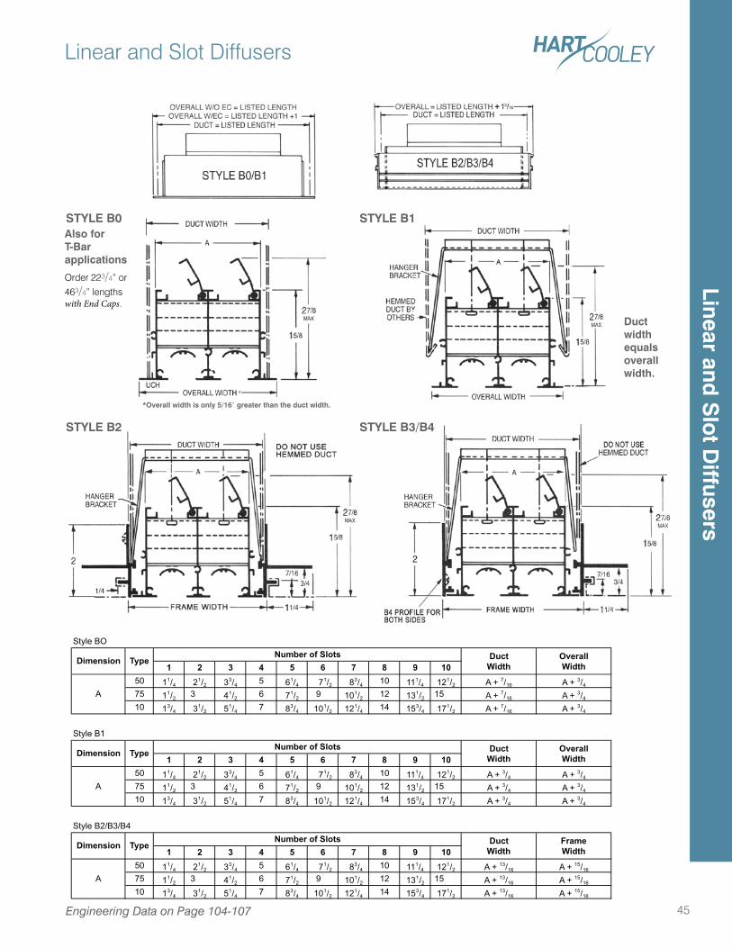
Linear and Slot Diffusers
45Engineering Data on Page 104-107
STYLE B1STYLE B0
STYLE B2
*Overall width is only 5/16” greater than the duct width.
*
Style BO
1 2 3 4 5 6 7 8 9 1050 11/4 21/2 33/4 5 61/4 71/2 83/4 10 111/4 121/2 A + 7/16 A + 3/4
75 11/2 3 41/2 6 71/2 9 101/2 12 131/2 15 A + 7/16 A + 3/4
10 13/4 31/2 51/4 7 83/4 101/2 121/4 14 153/4 171/2 A + 7/16 A + 3/4
Style B1
1 2 3 4 5 6 7 8 9 1050 11/4 21/2 33/4 5 61/4 71/2 83/4 10 111/4 121/2 A + 3/4 A + 3/4
75 11/2 3 41/2 6 71/2 9 101/2 12 131/2 15 A + 3/4 A + 3/4
10 13/4 31/2 51/4 7 83/4 101/2 121/4 14 153/4 171/2 A + 3/4 A + 3/4
Style B2/B3/B4
1 2 3 4 5 6 7 8 9 1050 11/4 21/2 33/4 5 61/4 71/2 83/4 10 111/4 121/2 A + 13/16 A + 15/16
75 11/2 3 41/2 6 71/2 9 101/2 12 131/2 15 A + 13/16 A + 15/16
10 13/4 31/2 51/4 7 83/4 101/2 121/4 14 153/4 171/2 A + 13/16 A + 15/16
DuctWidth
A
A
Dimension Type FrameWidth
Number of Slots
Number of Slots
DuctWidth
OverallWidth
DuctWidth
OverallWidth
Number of SlotsDimension Type
A
Dimension Type
STYLE B3/B4
Also forT-Barapplications
Duct width equals overall width.
Order 223/4” or
463/4” lengths with End Caps.
Linear and S
lot D
iffusers
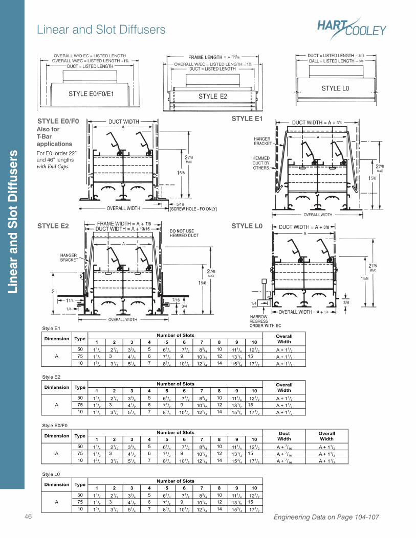
Linear and Slot Diffusers
46 Engineering Data on Page 104-107
Style E1
1 2 3 4 5 6 7 8 9 1050 11/4 21/2 33/4 5 61/4 71/2 83/4 10 111/4 121/2 A + 11/2
75 11/2 3 41/2 6 71/2 9 101/2 12 131/2 15 A + 11/2
10 13/4 31/2 51/4 7 83/4 101/2 121/4 14 153/4 171/2 A + 11/2
Style E2
1 2 3 4 5 6 7 8 9 1050 11/4 21/2 33/4 5 61/4 71/2 83/4 10 111/4 121/2 A + 11/2
75 11/2 3 41/2 6 71/2 9 101/2 12 131/2 15 A + 11/2
10 13/4 31/2 51/4 7 83/4 101/2 121/4 14 153/4 171/2 A + 11/2
Style E0/F0
1 2 3 4 5 6 7 8 9 1050 11/4 21/2 33/4 5 61/4 71/2 83/4 10 111/4 121/2 A + 7/16 A + 11/2
75 11/2 3 41/2 6 71/2 9 101/2 12 131/2 15 A + 7/16 A + 11/2
10 13/4 31/2 51/4 7 83/4 101/2 121/4 14 153/4 171/2 A + 7/16 A + 11/2
Style L0
1 2 3 4 5 6 7 8 9 1050 11/4 21/2 33/4 5 61/4 71/2 83/4 10 111/4 121/2
75 11/2 3 41/2 6 71/2 9 101/2 12 131/2 1510 13/4 31/2 51/4 7 83/4 101/2 121/4 14 153/4 171/2
A
A
Dimension TypeNumber of Slots
A
Dimension TypeNumber of Slots Duct
WidthOverallWidth
A
Dimension TypeNumber of Slots Overall
Width
Dimension TypeNumber of Slots Overall
Width
STYLE E2
STYLE E1
STYLE L0
STYLE E0/F0Also forT-BarapplicationsFor E0, order 22” and 46” lengths with End Caps.
Line
ar a
nd S
lot
Diff
user
s
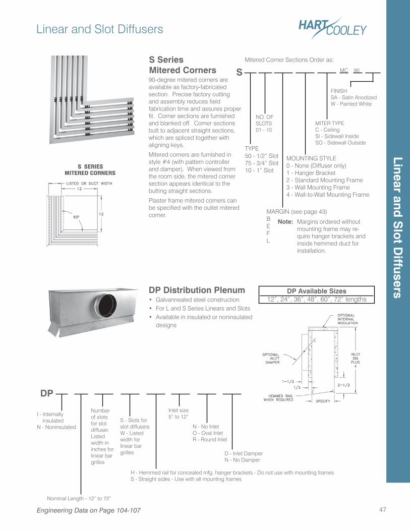
Linear and Slot Diffusers
47Engineering Data on Page 104-107
DP Distribution Plenum• Galvannealed steel construction• For L and S Series Linears and Slots• Available in insulated or noninsulated
designs
DP Available Sizes12”, 24”, 36”, 48”, 60”, 72” lengths
S SeriesMitered Corners90-degree mitered corners are available as factory-fabricated section. Precise factory cutting and assembly reduces field fabrication time and assures proper fit. Corner sections are furnished and blanked off. Corner sections butt to adjacent straight sections, which are spliced together with aligning keys.
Mitered corners are furnished in style #4 (with pattern controller and damper). When viewed from the room side, the mitered corner section appears identical to the butting straight sections.
Plaster frame mitered corners can be specified with the outlet mitered corner.
MC 90
NO. OFSLOTS01 - 10
MITER TYPEC - CeilingSI - Sidewall InsideSO - Sidewall Outside
FINISHSA - Satin AnodizedW - Painted White
Mitered Corner Sections Order as:
S
Nominal Length - 12” to 72”
S - Slots for slot diffusersW - Listed width for linear bar grilles
H - Hemmed rail for concealed mfg. hanger brackets - Do not use with mounting framesS - Straight sides - Use with all mounting frames
I - Internally insulatedN - Noninsulated
Number of slots for slot diffuser. Listed width in inches for linear bar grilles
N - No InletO - Oval InletR - Round Inlet
D - Inlet DamperN - No Damper
Inlet size 5” to 12”
DP
TYPE50 - 1/2” Slot75 - 3/4” Slot10 - 1” Slot
MARGIN (see page 43)BEFL
Note: Margins ordered without mounting frame may re-quire hanger brackets and inside hemmed duct for installation.
MOUNTING STYLE0 - None (Diffuser only)1 - Hanger Bracket2 - Standard Mounting Frame3 - Wall Mounting Frame4 - Wall-to-Wall Mounting Frame
Linear and S
lot D
iffusers
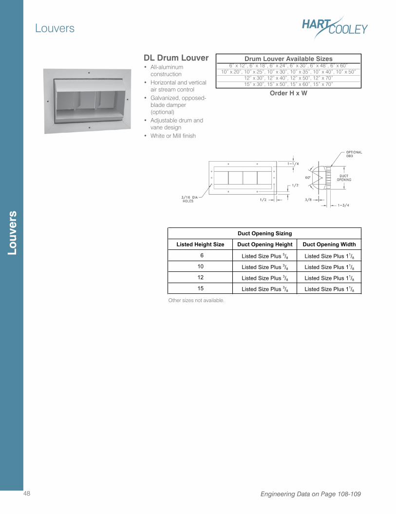
Louvers
48 Engineering Data on Page 108-109
DL Drum Louver• All-aluminum
construction• Horizontal and vertical
air stream control• Galvanized, opposed-
blade damper (optional)
• Adjustable drum and vane design
• White or Mill finish
Drum Louver Available Sizes6” x 12”, 6” x 18”, 6” x 24”, 6” x 30”, 6” x 48”, 6” x 60”
10” x 20”, 10” x 25”, 10” x 30”, 10” x 35”, 10” x 40”, 10” x 50” 12” x 30”, 12” x 40”, 12” x 50”, 12” x 70” 15” x 30”, 15” x 50”, 15” x 60”, 15” x 70”
Order H x W
Listed Height Size Duct Opening Height Duct Opening Width
6 Listed Size Plus 5/8 Listed Size Plus 11/8
10 Listed Size Plus 3/8 Listed Size Plus 11/8
12 Listed Size Plus 3/8 Listed Size Plus 11/8
15 Listed Size Plus 3/8 Listed Size Plus 11/8
Duct Opening Sizing
Other sizes not available.
Louv
ers
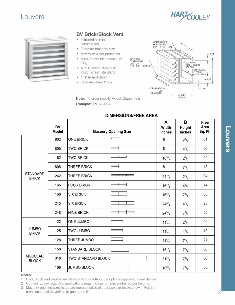
BVModel Masonry Opening Size
AWidthInches
BHeightInches
FreeArea
Sq. Ft.
802 ONE BRICK 8 21/2 .01
805 TWO BRICK 8 43/4 .06
162 TWO BRICK 163/8 21/2 .02
808 THREE BRICK 8 71/2 .13
242 THREE BRICK 243/4 21/2 .04
165 FOUR BRICK 163/8 43/4 .14
168 SIX BRICK 163/8 71/2 .30
245 SIX BRICK 243/4 43/4 .23
248 NINE BRICK 243/4 71/2 .50
122 ONE JUMBO 115/8 21/2 .02
125 TWO JUMBO 115/8 43/4 .10
128 THREE JUMBO 115/8 71/2 .21
158 STANDARD BLOCK 151/2 71/2 .30
318 TWO STANDARD BLOCK 313/8 71/2 .66
168 JUMBO BLOCK 163/8 71/2 .30
MODULARBLOCK
JUMBOBRICK
STANDARDBRICK
DIMENSIONS/FREE AREA
Louvers
49
Notes:1. Brick/Block vent depths are identical with or without the optional opposed-blade damper.2. Contact factory regarding applications requiring custom size widths and/or heights.3. Masonry opening sizes listed are representative of the blocks or bricks shown. Field di-
mensions must be verified to guarantee fit.
BV Brick/Block Vent• Extruded aluminum
construction• Standard masonry size• Maximum water protection• 6063-T5 extruded aluminum
alloy• 18 x 16 mesh aluminum
insect screen standard• 4” standard depth• Satin Anodized finish
Note: To order specify Model, Depth, Finish
Example: BV168 4 SA
Louvers
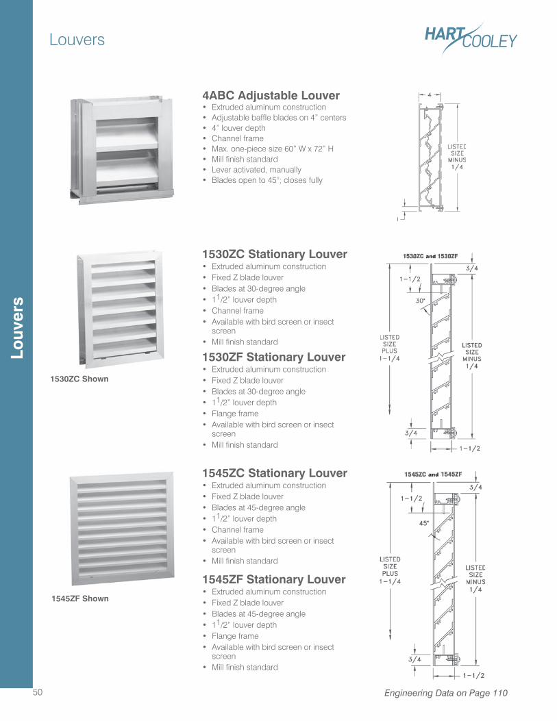
Louvers
50
1530ZC Stationary Louver• Extruded aluminum construction• Fixed Z blade louver• Blades at 30-degree angle• 11/2” louver depth• Channel frame• Available with bird screen or insect
screen• Mill finish standard
1530ZF Stationary Louver• Extruded aluminum construction• Fixed Z blade louver• Blades at 30-degree angle• 11/2” louver depth• Flange frame• Available with bird screen or insect
screen• Mill finish standard
1545ZC Stationary Louver• Extruded aluminum construction• Fixed Z blade louver• Blades at 45-degree angle• 11/2” louver depth• Channel frame• Available with bird screen or insect
screen• Mill finish standard
1545ZF Stationary Louver• Extruded aluminum construction• Fixed Z blade louver• Blades at 45-degree angle• 11/2” louver depth• Flange frame• Available with bird screen or insect
screen• Mill finish standard
1530ZC Shown
1545ZF Shown
Engineering Data on Page 110
4ABC Adjustable Louver• Extruded aluminum construction• Adjustable baffle blades on 4” centers• 4” louver depth• Channel frame• Max. one-piece size 60” W x 72” H• Mill finish standard• Lever activated, manually• Blades open to 45°; closes fully
Louv
ers
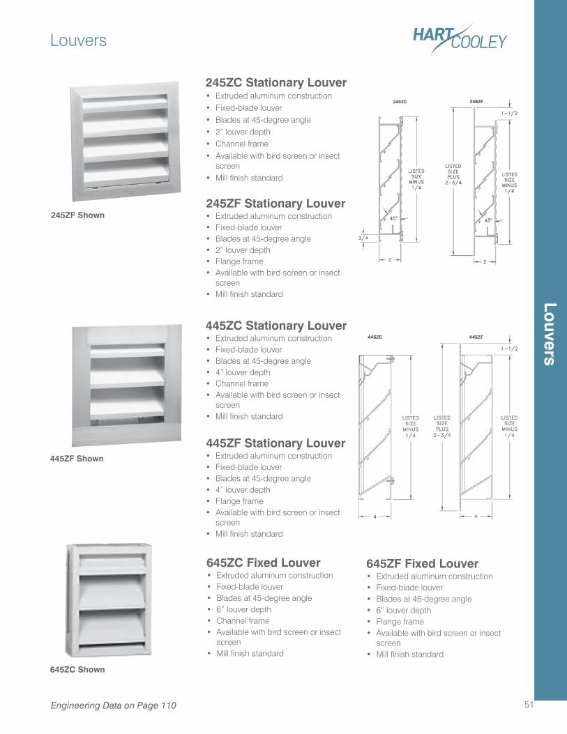
Louvers
51
445ZF Stationary Louver• Extruded aluminum construction• Fixed-blade louver• Blades at 45-degree angle• 4” louver depth• Flange frame• Available with bird screen or insect
screen• Mill finish standard
445ZC Stationary Louver• Extruded aluminum construction• Fixed-blade louver• Blades at 45-degree angle• 4” louver depth• Channel frame• Available with bird screen or insect
screen• Mill finish standard
645ZC Fixed Louver• Extruded aluminum construction• Fixed-blade louver• Blades at 45-degree angle• 6” louver depth• Channel frame• Available with bird screen or insect
screen• Mill finish standard
645ZF Fixed Louver• Extruded aluminum construction• Fixed-blade louver• Blades at 45-degree angle• 6” louver depth• Flange frame• Available with bird screen or insect
screen• Mill finish standard
245ZF Shown
445ZF Shown
645ZC Shown
Engineering Data on Page 110
245ZF Stationary Louver• Extruded aluminum construction• Fixed-blade louver• Blades at 45-degree angle• 2” louver depth• Flange frame• Available with bird screen or insect
screen• Mill finish standard
245ZC Stationary Louver• Extruded aluminum construction• Fixed-blade louver• Blades at 45-degree angle• 2” louver depth• Channel frame• Available with bird screen or insect
screen• Mill finish standard
Louvers
T-Bar Construction Features
52
Our popular supply and return products for T-Bar
ceilings are an innovative response to the challenge of
creating a better indoor environment. T-Bar products
combine clean appearance with installation ease, and
include critical design details to ensure consistent
performance. Glass fiber insulation minimizes
condensation, and the aluminum foil vapor barrier
protects the insulation from moisture, if condensation
occurs.
Patented adjustable deflectors permit a variety of
directional patterns and minimizes static pressure loss.
A unique modular collar system provides a standard
collar and damper unit, which can be shared between
a number of different T-Bar products. In addition,
Hart & Cooley offers specialty T-Bar products to meet
specific design demands. Surfaire® diffusers feature
deflector apertures that enhance mixing of conditioned
air.
T-Bar products are offered in lanced, perforated,
louvered and fixed-bar face styles, with steel or molded
fiberglass backs. They include a choice of easy
mounting systems and adjustable damper designs.
T-B
ar C
ons
truc
tion
Feat
ures
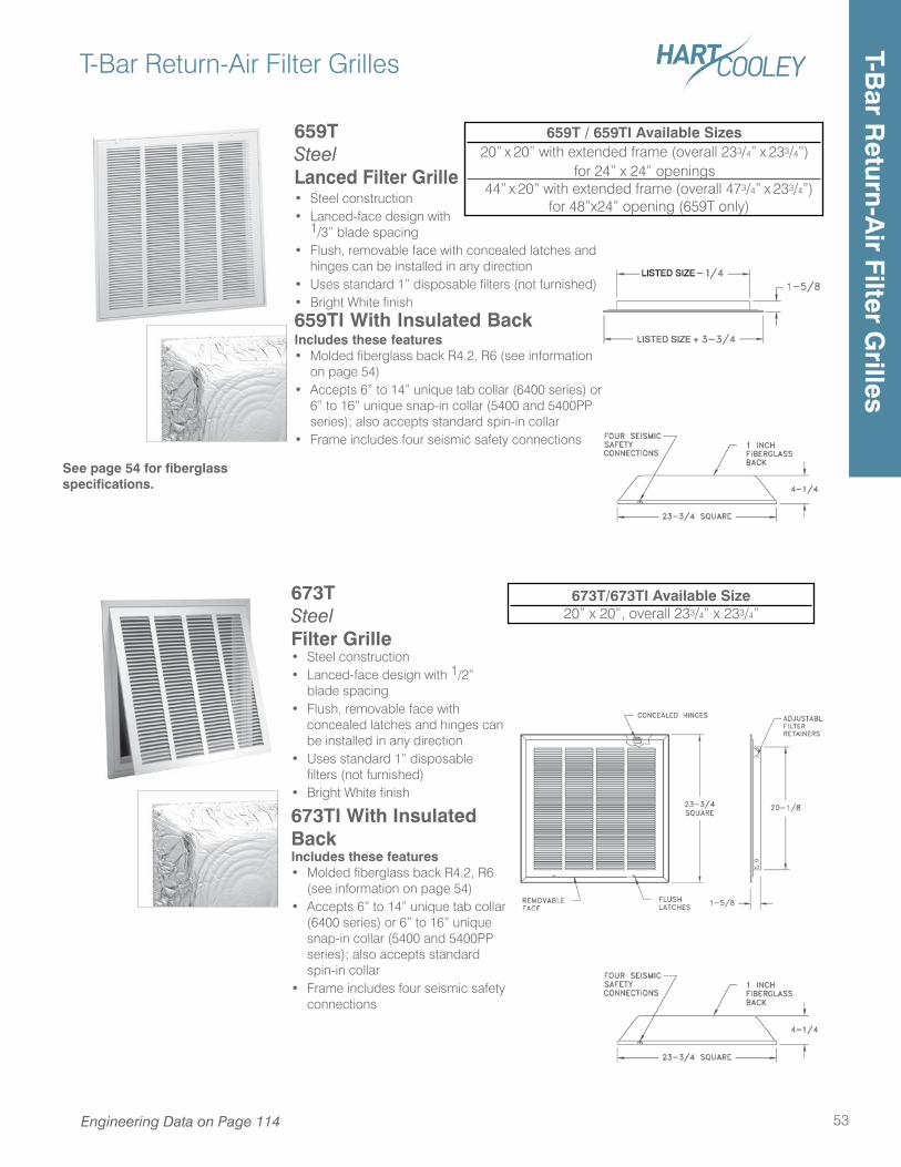
T-Bar Return-Air Filter Grilles
53Engineering Data on Page 114
659TSteelLanced Filter Grille• Steel construction• Lanced-face design with
1/3” blade spacing• Flush, removable face with concealed latches and
hinges can be installed in any direction• Uses standard 1” disposable filters (not furnished)• Bright White finish659TI With Insulated BackIncludes these features• Molded fiberglass back R4.2, R6 (see information
on page 54)• Accepts 6” to 14” unique tab collar (6400 series) or
6” to 16” unique snap-in collar (5400 and 5400PP series); also accepts standard spin-in collar
• Frame includes four seismic safety connections
659T / 659TI Available Sizes20” x 20” with extended frame (overall 233/4” x 233/4”)
for 24” x 24” openings 44” x 20” with extended frame (overall 473/4” x 233/4”)
for 48”x24” opening (659T only)
See page 54 for fiberglass specifications.
673T Steel Filter Grille• Steel construction• Lanced-face design with 1/2”
blade spacing• Flush, removable face with
concealed latches and hinges can be installed in any direction
• Uses standard 1” disposable filters (not furnished)
• Bright White finish
673TI With Insulated BackIncludes these features• Molded fiberglass back R4.2, R6
(see information on page 54)• Accepts 6” to 14” unique tab collar
(6400 series) or 6” to 16” unique snap-in collar (5400 and 5400PP series); also accepts standard spin-in collar
• Frame includes four seismic safety connections
673T/673TI Available Size20” x 20”, overall 233/4” x 233/4”
T-Bar R
eturn-Air Filter G
rilles
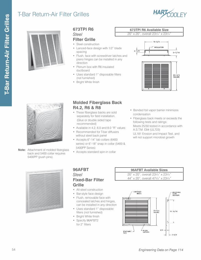
T-Bar Return-Air Filter Grilles
54 Engineering Data on Page 114
96AFBT Steel Fixed-Bar Filter Grille• All-steel construction• Bar-style face design• Flush, removable face with
concealed latches and hinges, can be installed in any direction
• Uses standard 1” disposable filters (not furnished)
• Bright White finish• Specify 96AFBT2 for 2” filters
96AFBT Available Sizes20” x 20”, overall 233/4” x 233/4”44” x 20”, overall 473/4” x 233/4”
Molded Fiberglass Back R4.2, R6 & R8• These fiberglass backs are sold separately for field installation. (Glue or double sided tape recommended)• Available in 4.2, 6.0 and 8.0 “R” values• Recommended for T-bar diffusers without steel back panel• Accepts 6”-14” tab collars (6400 series) or 6”-18” snap in collar (5400 & 5400PP Series)• Accepts standard spin-in collar
• Bonded foil vapor barrier minimizes condensation• Fiberglass back meets or exceeds the following tests and ratings: Meets 25/50 tested in accordance with A.S.T.M. E84 (UL723) UL181 Erosion and Impact Test, and will not support microbial growth
Note: Attachment of molded fiberglass back and 5400 collar requires 5400PP (push pins).
673TPI R6 Steel Filter Grille• Steel construction• Lanced-face design with 1/2” blade
spacing• Flush, face with screwdriver latches and
piano hinges can be installed in any direction
• Plenum box with R6 insulated ductboard
• Uses standard 1” disposable filters (not furnished)
• Bright White finish
673TPI R6 Available Size20” x 20”, overall 233/4” x 233/4”
T-B
ar R
etur
n-A
ir F
ilter
Gri
lles
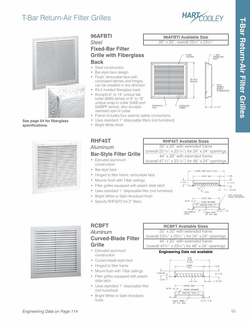
T-Bar Return-Air Filter Grilles
55
RCBFT Aluminum Curved-Blade Filter Grille• Extruded aluminum
construction• Curved-blade style face• Hinged to filter frame• Mount flush with T-Bar ceilings• Filter grilles equipped with plastic
slide latch• Uses standard 1” disposable filter
(not furnished)• Bright White or Satin Anodized
finish
RCBFT Available Sizes20” x 20” with extended frame
(overall 233/4” x 233/4” ) for 24” x 24” openings44” x 20” with extended frame
(overall 473/4” x 233/4”) for 48” x 24” openingsEngineering Data not available
96AFBTI SteelFixed-Bar Filter Grille with Fiberglass Back• Steel construction• Bar-style face design• Flush, removable face with
concealed latches and hinges, can be installed in any direction
• R4.2 molded fiberglass back• Accepts 6” to 14” unique tab
collar (6400 series) or 6” to 16” unique snap-in collar (5400 and 5400PP series); also accepts standard spin-in collar
• Frame includes four seismic safety connections• Uses standard 1” disposable filters (not furnished)• Bright White finish
RHF45T Aluminum Bar-Style Filter Grille• Extruded aluminum
construction• Bar-style face• Hinged to filter frame, removable face• Mounts flush with T-Bar ceilings• Filter grilles equipped with plastic slide latch• Uses standard 1” disposable filter (not furnished)• Bright White or Satin Anodized finish• Specify RHF45T2 for 2” filters
RHF45T Available Sizes20” x 20” with extended frame
(overall 23 3/4” x 23 3/4”) for 24” x 24” openings44” x 20” with extended frame
(overall 47 3/4” x 23 3/4”) for 48” x 24” openings
96AFBTI Available Size20” x 20”, overall 233/4” x 233/4”
See page 54 for fiberglass specifications.
Engineering Data on Page 114
T-Bar R
eturn-Air Filter G
rilles
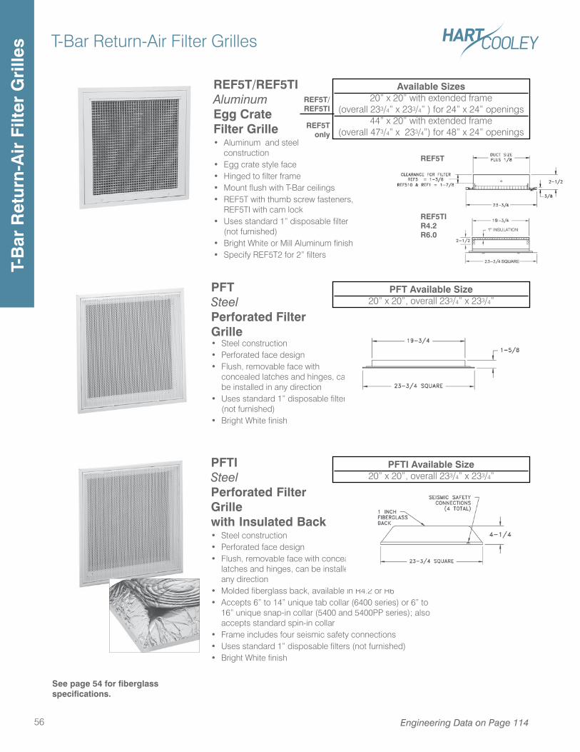
REF5T/REF5TIAluminum Egg Crate Filter Grille• Aluminum and steel
construction• Egg crate style face• Hinged to filter frame• Mount flush with T-Bar ceilings• REF5T with thumb screw fasteners,
REF5TI with cam lock• Uses standard 1” disposable filter
(not furnished)• Bright White or Mill Aluminum finish• Specify REF5T2 for 2” filters
T-Bar Return-Air Filter Grilles
56 Engineering Data on Page 114
PFT Steel Perforated Filter Grille• Steel construction• Perforated face design• Flush, removable face with
concealed latches and hinges, can be installed in any direction
• Uses standard 1” disposable filters (not furnished)
• Bright White finish
PFT Available Size20” x 20”, overall 233/4” x 233/4”
PFTI Steel Perforated Filter Grillewith Insulated Back• Steel construction• Perforated face design• Flush, removable face with concealed
latches and hinges, can be installed in any direction
• Molded fiberglass back, available in R4.2 or R6• Accepts 6” to 14” unique tab collar (6400 series) or 6” to
16” unique snap-in collar (5400 and 5400PP series); also accepts standard spin-in collar
• Frame includes four seismic safety connections• Uses standard 1” disposable filters (not furnished)• Bright White finish
PFTI Available Size20” x 20”, overall 233/4” x 233/4”
See page 54 for fiberglass specifications.
Available Sizes20” x 20” with extended frame
(overall 233/4” x 233/4” ) for 24” x 24” openings44” x 20” with extended frame
(overall 473/4” x 233/4”) for 48” x 24” openings
REF5T
REF5TIR4.2R6.0
REF5T/REF5TI
REF5Tonly
T-B
ar R
etur
n-A
ir F
ilter
Gri
lles
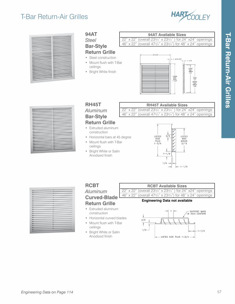
T-Bar Return-Air Grilles
57
94AT Steel Bar-Style Return Grille• Steel construction• Mount flush with T-Bar
ceilings• Bright White finish
94AT Available Sizes22” x 22” (overall 233/4” x 233/4” ) for 24” x24” openings46” x 22” (overall 473/4” x 233/4”) for 48” x 24” openings
RH45TAluminumBar-Style Return Grille• Extruded aluminum
construction• Horizontal bars at 45 degrees• Mount flush with T-Bar
ceilings• Bright White or Satin
Anodized finish
RH45T Available Sizes22” x 22” (overall 233/4” x 233/4” ) for 24” x24” openings46” x 22” (overall 473/4” x 233/4”) for 48” x 24” openings
RCBT AluminumCurved-BladeReturn Grille• Extruded aluminum
construction• Horizontal curved blades• Mount flush with T-Bar
ceilings• Bright White or Satin
Anodized finish
RCBT Available Sizes22” x 22” (overall 233/4” x 233/4” ) for 24” x24” openings46” x 22” (overall 473/4” x 233/4”) for 48” x 24” openings
Engineering Data not available
Engineering Data on Page 114
T-Bar R
eturn-Air G
rilles
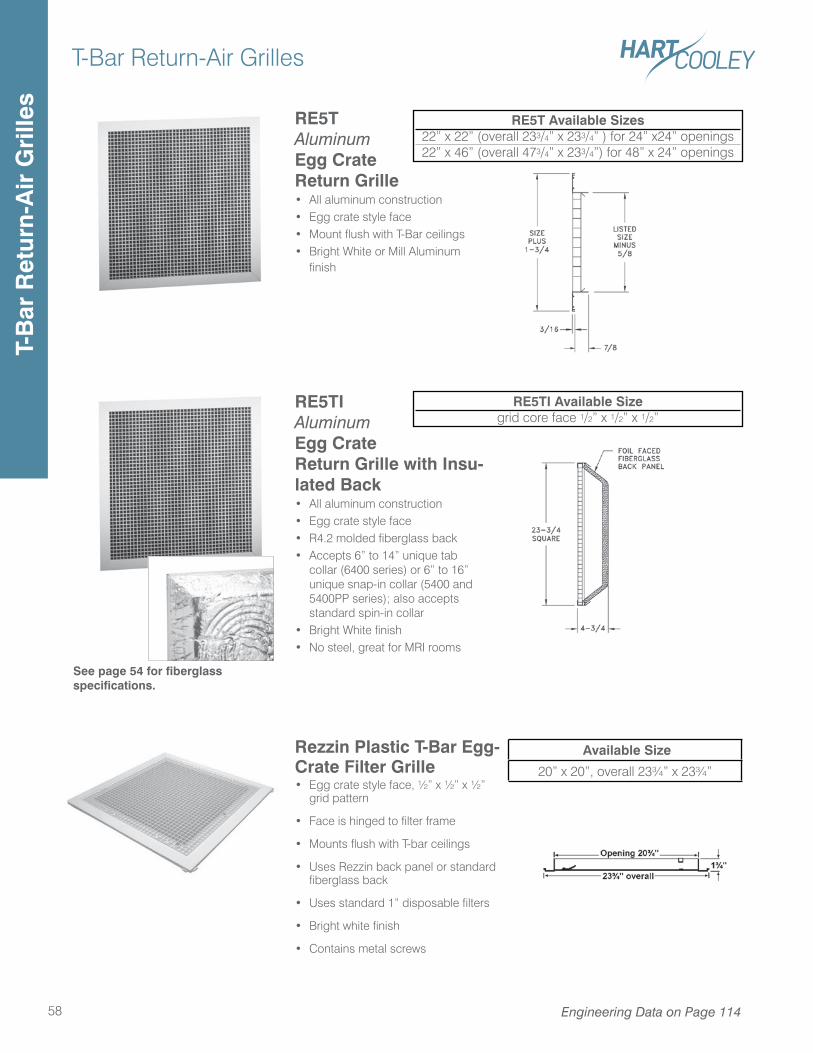
T-Bar Return-Air Grilles
58 Engineering Data on Page 114
RE5TAluminumEgg CrateReturn Grille• All aluminum construction• Egg crate style face• Mount flush with T-Bar ceilings• Bright White or Mill Aluminum
finish
RE5T Available Sizes22” x 22” (overall 233/4” x 233/4” ) for 24” x24” openings22” x 46” (overall 473/4” x 233/4”) for 48” x 24” openings
RE5TI AluminumEgg CrateReturn Grille with Insu-lated Back• All aluminum construction• Egg crate style face• R4.2 molded fiberglass back• Accepts 6” to 14” unique tab
collar (6400 series) or 6” to 16” unique snap-in collar (5400 and 5400PP series); also accepts standard spin-in collar
• Bright White finish• No steel, great for MRI rooms
RE5TI Available Sizegrid core face 1/2” x 1/2” x 1/2”
See page 54 for fiberglass specifications.
Rezzin Plastic T-Bar Egg-Crate Filter Grille• Egg crate style face, ½” x ½” x ½”
grid pattern
• Face is hinged to filter frame
• Mounts flush with T-bar ceilings
• Uses Rezzin back panel or standard fiberglass back
• Uses standard 1” disposable filters
• Bright white finish
• Contains metal screws
Available Size
20” x 20”, overall 23¾” x 23¾”
T-B
ar R
etur
n-A
ir G
rille
s
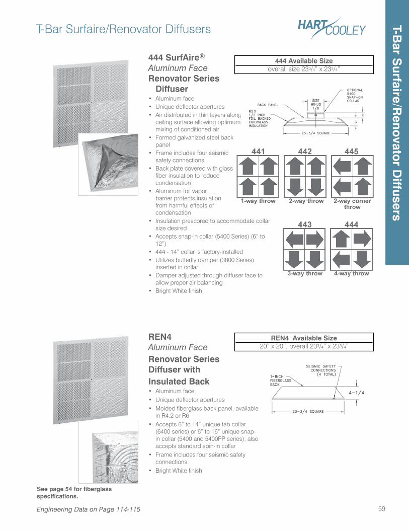
444 SurfAire® Aluminum Face Renovator Series
Diffuser• Aluminum face • Unique deflector apertures • Air distributed in thin layers along
ceiling surface allowing optimum mixing of conditioned air
• Formed galvanized steel back panel
• Frame includes four seismic safety connections
• Back plate covered with glass fiber insulation to reduce condensation
• Aluminum foil vapor barrier protects insulation from harmful effects of condensation
• Insulation prescored to accommodate collar size desired
• Accepts snap-in collar (5400 Series) (6” to 12”)
• 444 - 14” collar is factory-installed• Utilizes butterfly damper (3800 Series)
inserted in collar• Damper adjusted through diffuser face to
allow proper air balancing• Bright White finish
T-Bar Surfaire/Renovator Diffusers
59
REN4 Aluminum Face Renovator Series Diffuser with Insulated Back• Aluminum face• Unique deflector apertures• Molded fiberglass back panel, available
in R4.2 or R6• Accepts 6” to 14” unique tab collar
(6400 series) or 6” to 16” unique snap-in collar (5400 and 5400PP series); also accepts standard spin-in collar
• Frame includes four seismic safety connections
• Bright White finish
REN4 Available Size20” x 20”, overall 233/4” x 233/4”
See page 54 for fiberglass specifications.
444 Available Sizeoverall size 233/4” x 233/4”
Engineering Data on Page 114-115
T-Bar S
urfaire/Reno
vator D
iffusers
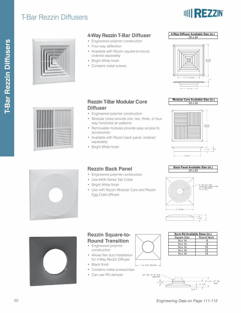
T-Bar Rezzin Diffusers
60 Engineering Data on Page 111-112
Rezzin T-Bar Modular Core Diffuser• Engineered polymer construction• Modular cores provide one, two, three, or four-
way horizontal air patterns• Removable modules provide easy access to
accessories• Available with Rezzin back panel, ordered
separately• Bright White finish
4-Way Rezzin T-Bar Diffuser• Engineered polymer construction• Four-way deflection• Available with Rezzin square-to-round,
ordered separately• Bright White finish• Contains metal screws
Rezzin Back Panel• Engineered polymer construction• Use 6400 Series Tab Collar• Bright White finish• Use with Rezzin Modular Core and Rezzin
Egg Crate diffuser
Available Size (in.)24 x 24
Available Size (in.)24 x 24
Available Size (in.)24 x 24
Rezzin Square-to-Round Transition• Engineered polymer
construction• Allows flex duct installation
for 4-Way Rezzin Diffuser• Black finish• Contains metal screws/clips• Can use RD damper
Available Sizes (in.)Round NeckSquare Size
14 x 14
14 x 1414 x 1414 x 14
14 x 14 6 8101214
T-B
ar R
ezzi
n D
iffus
ers
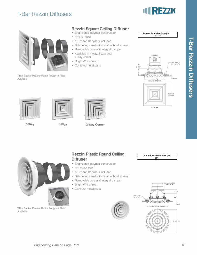
T-Bar Rezzin Diffusers
61
Rezzin Square Ceiling Diffuser• Engineered polymer construction• 12”x12” face• 6”, 7” and 8” collars included• Ratcheting cam lock–install without screws• Removable core and integral damper• Available in 4-way, 3-way and 2-way corner• Bright White finish• Contains metal parts
Rezzin Plastic Round Ceiling Diffuser• Engineered polymer construction• 12” round face• 6”, 7” and 8” collars included• Ratcheting cam lock–install without screws• Removable core and integral damper• Bright White finish• Contains metal parts
4-Way 2-Way Corner
Engineering Data on Page 113
3-Way
Available Size (in.)12
Available Size (in.)12
T-Bar Backer Plate or Rafter Rough-In Plate Available
T-Bar Backer Plate or Rafter Rough-In Plate Available
T-Bar R
ezzin Diffusers
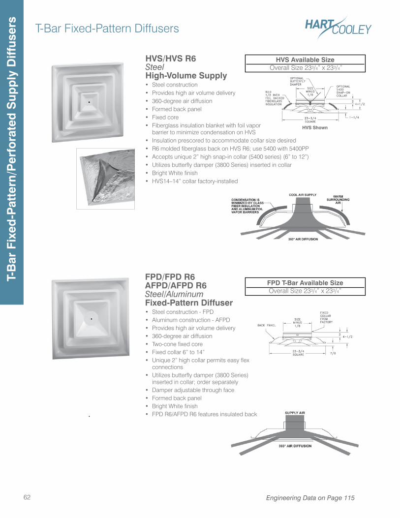
T-Bar Fixed-Pattern Diffusers
62
HVS/HVS R6Steel High-Volume Supply• Steel construction• Provides high air volume delivery• 360-degree air diffusion• Formed back panel• Fixed core• Fiberglass insulation blanket with foil vapor
barrier to minimize condensation on HVS• Insulation prescored to accommodate collar size desired• R6 molded fiberglass back on HVS R6; use 5400 with 5400PP• Accepts unique 2” high snap-in collar (5400 series) (6” to 12”)• Utilizes butterfly damper (3800 Series) inserted in collar• Bright White finish• HVS14–14” collar factory-installed
HVS Available Size Overall Size 233/4” x 233/4”
HVS Shown
FPD/FPD R6AFPD/AFPD R6Steel/AluminumFixed-Pattern Diffuser • Steel construction - FPD• Aluminum construction - AFPD• Provides high air volume delivery• 360-degree air diffusion• Two-cone fixed core• Fixed collar 6” to 14”• Unique 2” high collar permits easy flex
connections• Utilizes butterfly damper (3800 Series)
inserted in collar; order separately• Damper adjustable through face• Formed back panel• Bright White finish• FPD R6/AFPD R6 features insulated back
FPD T-Bar Available SizeOverall Size 233/4” x 233/4”
Engineering Data on Page 115
T-B
ar F
ixed
-Pat
tern
/Per
fora
ted
Sup
ply
Diff
user
s
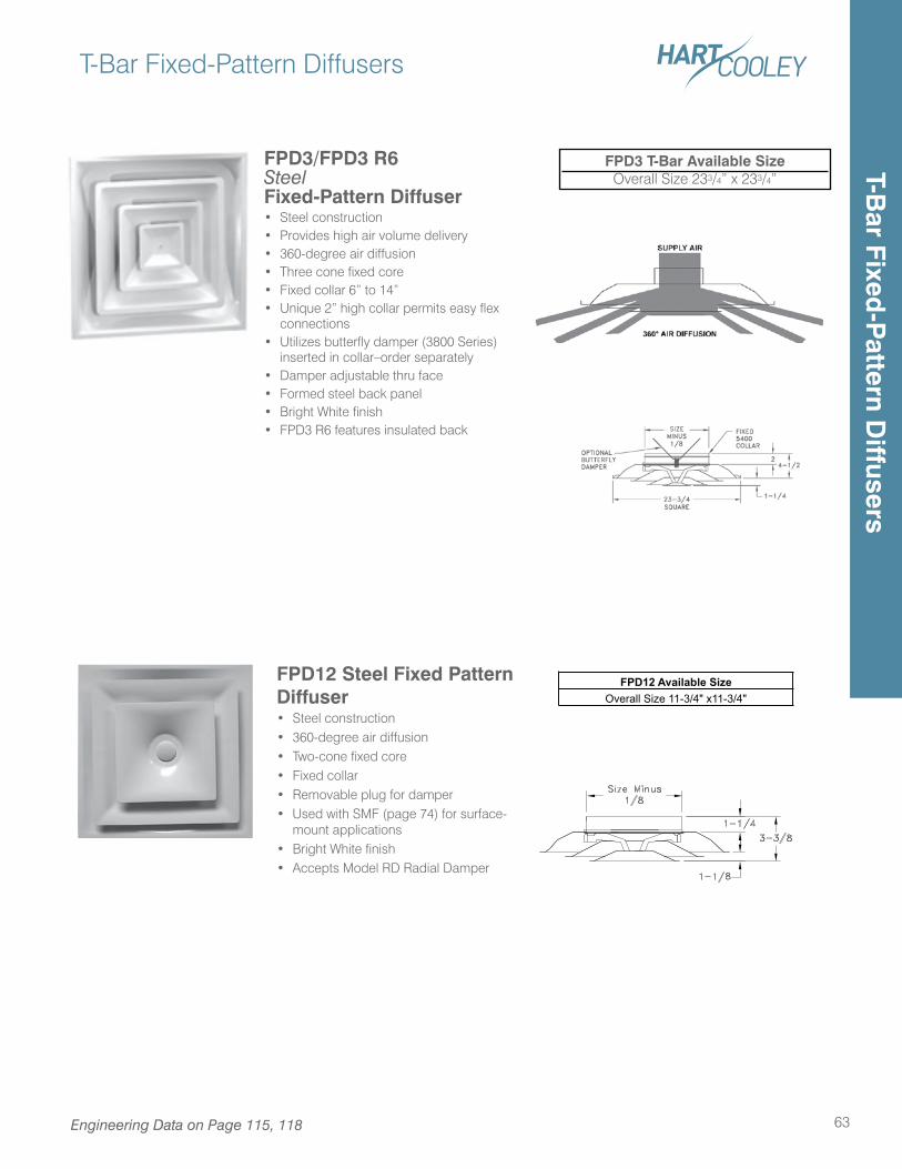
T-Bar Fixed-Pattern Diffusers
63
T-Bar Fixed
-Pattern D
iffusers
FPD3/FPD3 R6 Steel Fixed-Pattern Diffuser • Steel construction• Provides high air volume delivery• 360-degree air diffusion• Three cone fixed core • Fixed collar 6” to 14”• Unique 2” high collar permits easy flex
connections• Utilizes butterfly damper (3800 Series)
inserted in collar–order separately• Damper adjustable thru face• Formed steel back panel• Bright White finish• FPD3 R6 features insulated back
FPD3 T-Bar Available SizeOverall Size 233/4” x 233/4”
FPD12 Steel Fixed Pattern Diffuser• Steel construction• 360-degree air diffusion• Two-cone fixed core• Fixed collar• Removable plug for damper• Used with SMF (page 74) for surface-
mount applications• Bright White finish• Accepts Model RD Radial Damper
FPD12 Available SizeOverall Size 11-3/4" x11-3/4"
Engineering Data on Page 115, 118
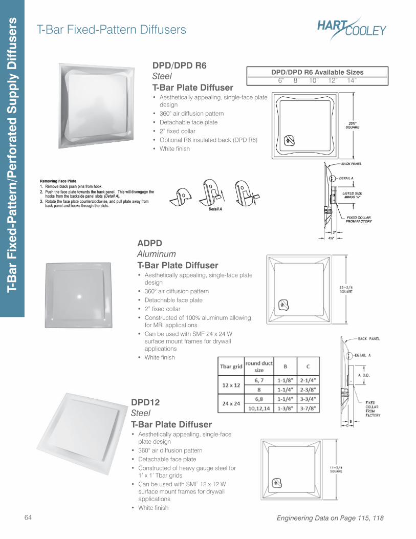
T-Bar Fixed-Pattern Diffusers
64 Engineering Data on Page 115, 118
T-B
ar F
ixed
-Pat
tern
/Per
fora
ted
Sup
ply
Diff
user
s
DPD/DPD R6SteelT-Bar Plate Diffuser• Aesthetically appealing, single-face plate
design• 360° air diffusion pattern• Detachable face plate• 2” fixed collar• Optional R6 insulated back (DPD R6)• White finish
DPD/DPD R6 Available Sizes6” 8” 10” 12” 14”
DPD12SteelT-Bar Plate Diffuser• Aesthetically appealing, single-face
plate design• 360° air diffusion pattern• Detachable face plate• Constructed of heavy gauge steel for
1’ x 1’ Tbar grids• Can be used with SMF 12 x 12 W
surface mount frames for drywall applications
• White finish
ADPDAluminumT-Bar Plate Diffuser• Aesthetically appealing, single-face plate
design• 360° air diffusion pattern• Detachable face plate• 2” fixed collar• Constructed of 100% aluminum allowing
for MRI applications• Can be used with SMF 24 x 24 W
surface mount frames for drywall applications
• White finish
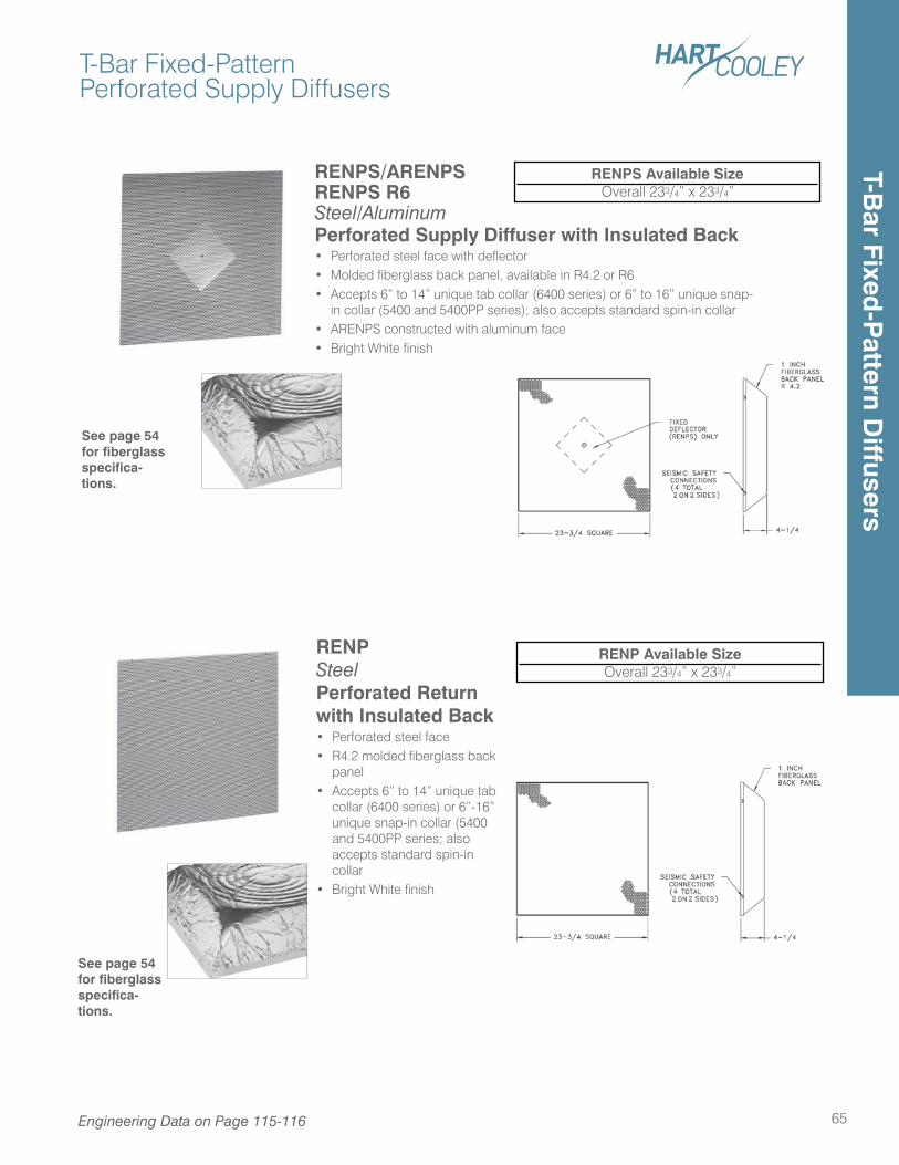
T-Bar Fixed-PatternPerforated Supply Diffusers
65
RENPS/ARENPSRENPS R6Steel/AluminumPerforated Supply Diffuser with Insulated Back• Perforated steel face with deflector• Molded fiberglass back panel, available in R4.2 or R6• Accepts 6” to 14” unique tab collar (6400 series) or 6” to 16” unique snap-
in collar (5400 and 5400PP series); also accepts standard spin-in collar• ARENPS constructed with aluminum face• Bright White finish
RENPS Available SizeOverall 233/4” x 233/4”
RENP Steel Perforated Return with Insulated Back• Perforated steel face• R4.2 molded fiberglass back
panel• Accepts 6” to 14” unique tab
collar (6400 series) or 6”-16” unique snap-in collar (5400 and 5400PP series; also accepts standard spin-in collar
• Bright White finish
RENP Available SizeOverall 233/4” x 233/4”
See page 54 for fiberglass specifica-tions.
See page 54 for fiberglass specifica-tions.
Engineering Data on Page 115-116
T-Bar Fixed
-Pattern D
iffusers
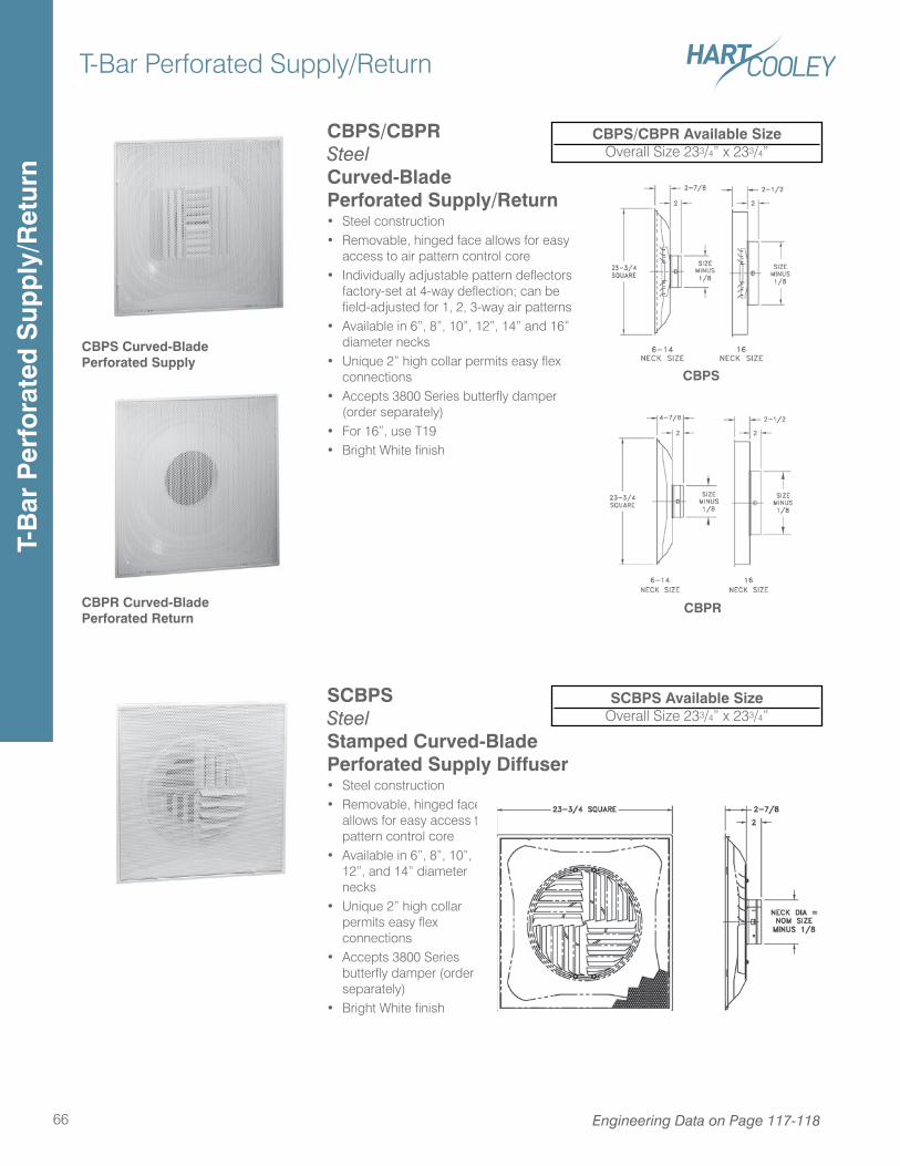
SCBPS Steel Stamped Curved-BladePerforated Supply Diffuser• Steel construction• Removable, hinged face
allows for easy access to pattern control core
• Available in 6”, 8”, 10”, 12”, and 14” diameter necks
• Unique 2” high collar permits easy flex connections
• Accepts 3800 Series butterfly damper (order separately)
• Bright White finish
T-Bar Perforated Supply/Return
66
SCBPS Available SizeOverall Size 233/4” x 233/4”
CBPS/CBPR Steel Curved-BladePerforated Supply/Return• Steel construction• Removable, hinged face allows for easy
access to air pattern control core• Individually adjustable pattern deflectors
factory-set at 4-way deflection; can be field-adjusted for 1, 2, 3-way air patterns
• Available in 6”, 8”, 10”, 12”, 14” and 16” diameter necks
• Unique 2” high collar permits easy flex connections
• Accepts 3800 Series butterfly damper (order separately)
• For 16”, use T19• Bright White finish
CBPR Curved-Blade Perforated Return
CBPS Curved-BladePerforated Supply
CBPS/CBPR Available SizeOverall Size 233/4” x 233/4”
CBPS
CBPR
Engineering Data on Page 117-118
T-B
ar P
erfo
rate
d S
upp
ly/R
etur
n
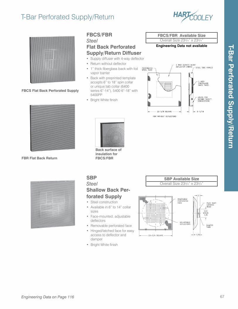
T-Bar Perforated Supply/Return
67
Engineering Data not available
Engineering Data on Page 116
SBP SteelShallow Back Per-forated Supply• Steel construction• Available in 6” to 14” collar
sizes• Face-mounted, adjustable
deflectors• Removable perforated face• Hinged/latched face for easy
access to deflector and damper
• Bright White finish
SBP Available SizeOverall Size 233/4” x 233/4”
FBCS/FBR SteelFlat Back PerforatedSupply/Return Diffuser• Supply diffuser with 4-way deflector• Return without deflector• 1” thick fiberglass back with foil
vapor barrier• Back with preprinted template
accepts 6” to 18” spin collar or unique tab collar (6400 series 6”-14”), 5400 6”-18” with 5400PP
• Bright White finish
Back surface of insulation for FBCS/FBR
FBCS/FBR Available SizeOverall Size 233/4” x 233/4”
FBCS Flat Back Perforated Supply
FBR Flat Back Return
T-Bar P
erforated
Sup
ply/R
eturn
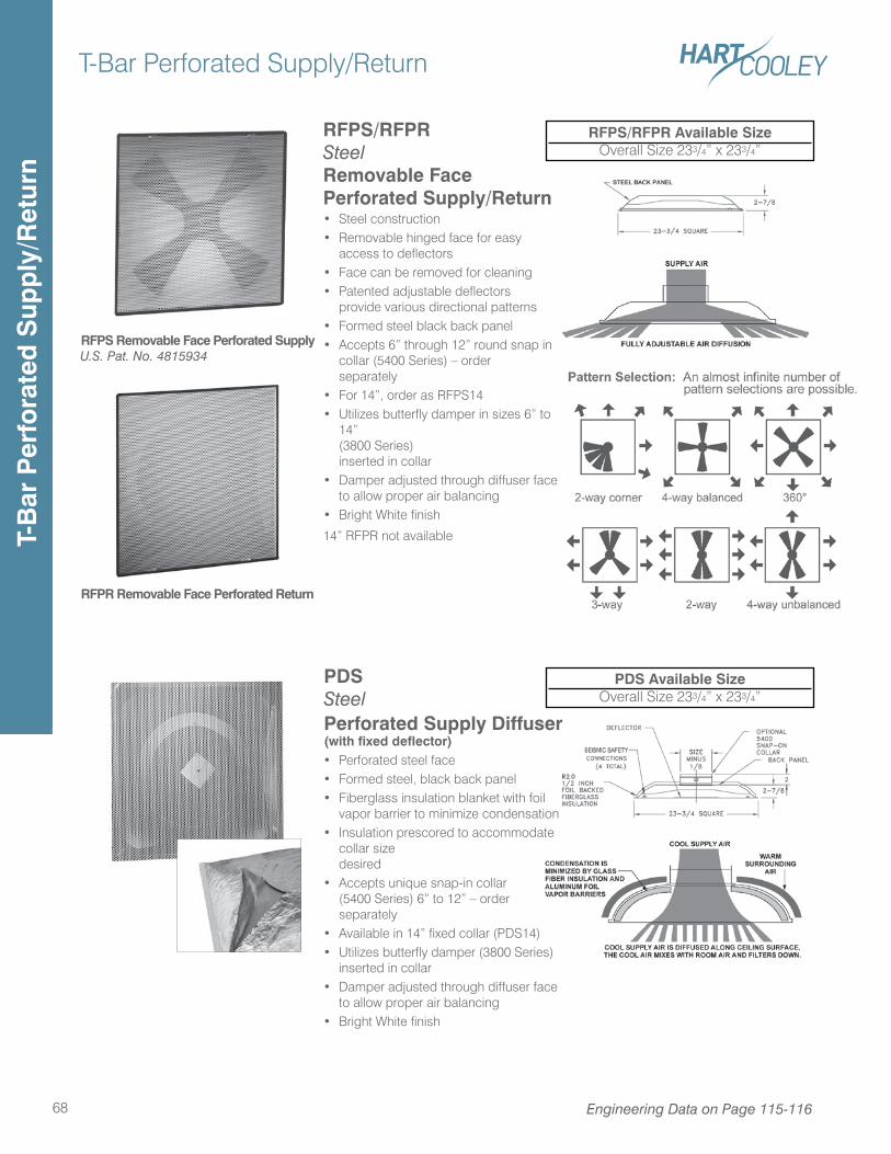
T-Bar Perforated Supply/Return
68
RFPS/RFPR Available SizeOverall Size 233/4” x 233/4”
RFPS Removable Face Perforated Supply
RFPR Removable Face Perforated Return
PDS Available SizeOverall Size 233/4” x 233/4”
U.S. Pat. No. 4815934
PDS Steel Perforated Supply Diffuser (with fixed deflector)• Perforated steel face• Formed steel, black back panel• Fiberglass insulation blanket with foil
vapor barrier to minimize condensation• Insulation prescored to accommodate
collar size desired• Accepts unique snap-in collar
(5400 Series) 6” to 12” – order separately
• Available in 14” fixed collar (PDS14)• Utilizes butterfly damper (3800 Series)
inserted in collar• Damper adjusted through diffuser face
to allow proper air balancing• Bright White finish
RFPS/RFPR Steel Removable FacePerforated Supply/Return• Steel construction• Removable hinged face for easy
access to deflectors• Face can be removed for cleaning• Patented adjustable deflectors
provide various directional patterns• Formed steel black back panel• Accepts 6” through 12” round snap in
collar (5400 Series) – order separately• For 14”, order as RFPS14 • Utilizes butterfly damper in sizes 6” to
14” (3800 Series) inserted in collar• Damper adjusted through diffuser face
to allow proper air balancing• Bright White finish
14” RFPR not available
Engineering Data on Page 115-116
T-B
ar P
erfo
rate
d S
upp
ly/R
etur
n
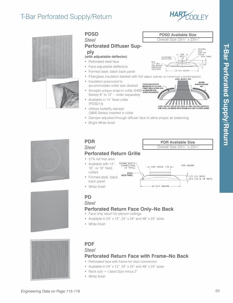
PDSD SteelPerforated Diffuser Sup-ply
(with adjustable deflector)• Perforated steel face• Face adjustable deflectors• Formed steel, black back panel• Fiberglass insulation blanket with foil vapor barrier to minimize condensation• Insulation prescored to
accommodate collar size desired• Accepts unique snap-in collar (5400
Series) 6” to 12” – order separately• Available in 14” fixed collar
(PDSD14)• Utilizes butterfly damper
(3800 Series) inserted in collar• Damper adjusted through diffuser face to allow proper air balancing• Bright White finish
T-Bar Perforated Supply/Return
69
PDSD Available Size Overall Size 233/4” x 233/4”
PDR Steel Perforated Return Grille • 51% net free area• Available with 14”,
16”, or 18” fixed collars
• Formed steel, black back panel
• White finish
PD Steel Perforated Return Face Only–No Back • Face only return for plenum ceilings• Available in 24” x 12”, 24” x 24” and 48” x 24” sizes
• White finish
PDF Steel Perforated Return Face with Frame–No Back• Perforated face with frame for duct connection• Available in 24” x 12”, 24” x 24” and 48” x 24” sizes• Neck size = Listed Size minus 2”• White finish
PDR Available Size Overall Size 233/4” x 233/4”
Engineering Data on Page 115-116
T-Bar P
erforated
Sup
ply/R
eturn
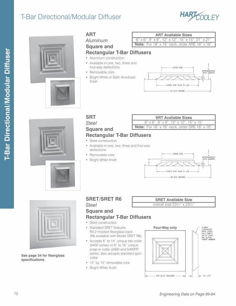
T-Bar Directional/Modular Diffuser
70 Engineering Data on Page 89-94
ART Aluminum Square and Rectangular T-Bar Diffusers• Aluminum construction• Available in one, two, three and
four-way deflections• Removable core• Bright White or Satin Anodized
finish
ART Available Sizes6” x 6”, 9” x 9”, 12” x 12”, 15” x 15”, 21” x 21”
Note: For 18” x 18” neck, order ARE 18” x 18”.
SRT Steel Square and Rectangular T-Bar Diffusers• Steel construction• Available in one, two, three and four-way
deflections• Removable core• Bright White finish
SRT Available Sizes6” x 6”, 9” x 9”, 12” x 12”, 15” x 15”
Note: For 18” x 18” neck, order SRE 18” x 18”.
SRET/SRET R6Steel Square and Rectangular T-Bar Diffusers• Steel construction• Standard SRET features
R4.2 molded fiberglass back (R6 available with Model SRET R6)
• Accepts 6” to 14” unique tab collar (6400 series) or 6” to 16” unique snap-in collar (5400 and 5400PP series; also accepts standard spin-in collar
• 15” by 15” removable core• Bright White finish
SRET Available Sizeoverall size 233/4” x 233/4”
Four-Way only
See page 54 for fiberglass specifications.
T-B
ar D
irec
tiona
l/Mo
dul
ar D
iffus
er
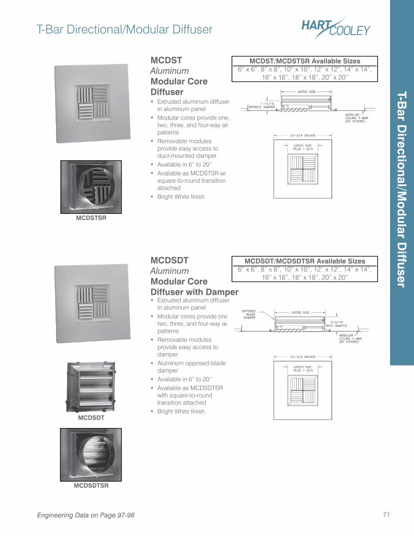
MCDSDT Aluminum Modular Core Diffuser with Damper• Extruded aluminum diffuser
in aluminum panel• Modular cores provide one,
two, three, and four-way air patterns
• Removable modules provide easy access to damper
• Aluminum opposed-blade damper
• Available in 6” to 20”• Available as MCDSDTSR
with square-to-round transition attached
• Bright White finish
T-Bar Directional/Modular Diffuser
71
MCDSDT/MCDSDTSR Available Sizes6” x 6”, 8” x 8”, 10” x 10”, 12” x 12”, 14” x 14”,
16” x 16”, 18” x 18”, 20” x 20”
MCDST Aluminum Modular Core Diffuser• Extruded aluminum diffuser
in aluminum panel• Modular cores provide one,
two, three, and four-way air patterns
• Removable modules provide easy access to duct-mounted damper
• Available in 6” to 20”• Available as MCDSTSR with
square-to-round transition attached
• Bright White finish
MCDST/MCDSTSR Available Sizes6” x 6”, 8” x 8”, 10” x 10”, 12” x 12”, 14” x 14”,
16” x 16”, 18” x 18”, 20” x 20”
MCDSTSR
MCDSDTSR
MCDSDT
Engineering Data on Page 97-98
T-Bar D
irectional/M
od
ular Diffuser
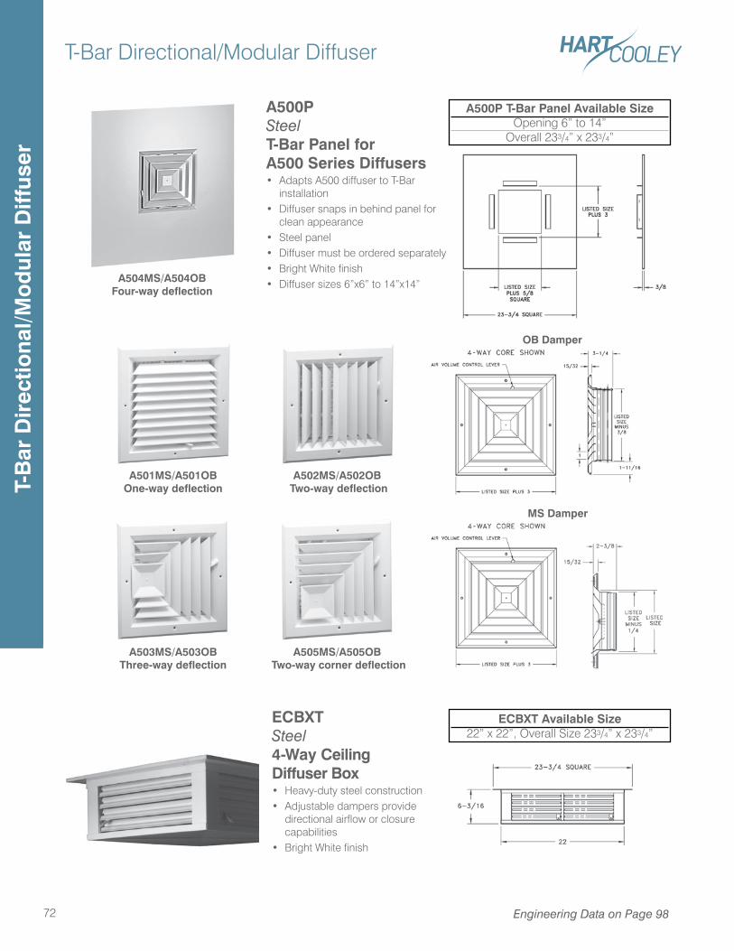
A503MS/A503OB Three-way deflection
A505MS/A505OB Two-way corner deflection
T-Bar Directional/Modular Diffuser
72
A500P Steel T-Bar Panel forA500 Series Diffusers• Adapts A500 diffuser to T-Bar
installation• Diffuser snaps in behind panel for
clean appearance• Steel panel• Diffuser must be ordered separately • Bright White finish• Diffuser sizes 6”x6” to 14”x14”
A500P T-Bar Panel Available SizeOpening 6” to 14”
Overall 233/4” x 233/4”
ECBXT Steel 4-Way Ceiling Diffuser Box• Heavy-duty steel construction• Adjustable dampers provide
directional airflow or closure capabilities
• Bright White finish
ECBXT Available Size22” x 22”, Overall Size 233/4” x 233/4”
A504MS/A504OBFour-way deflection
A501MS/A501OBOne-way deflection
A502MS/A502OB Two-way deflection
OB Damper
MS Damper
Engineering Data on Page 98
T-B
ar D
irec
tiona
l/Mo
dul
ar D
iffus
er
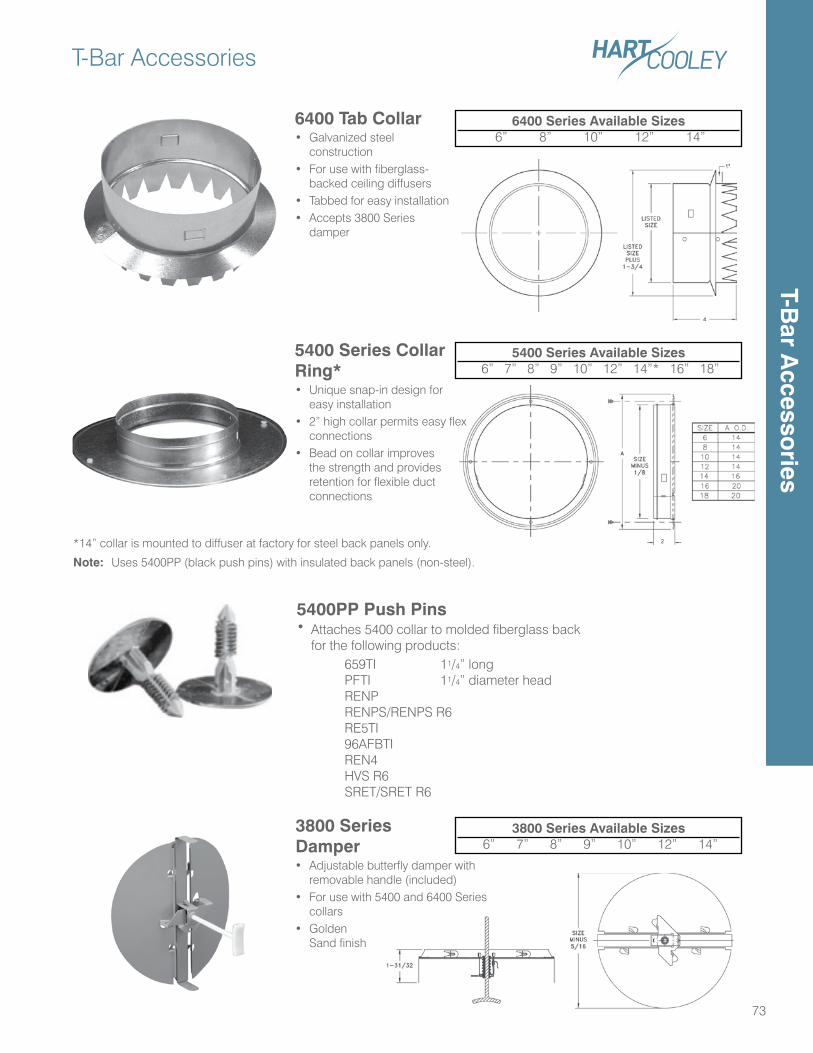
T-Bar Accessories
73
6400 Tab Collar• Galvanized steel
construction• For use with fiberglass-
backed ceiling diffusers• Tabbed for easy installation• Accepts 3800 Series
damper
6400 Series Available Sizes 6” 8” 10” 12” 14”
5400PP Push Pins• Attaches 5400 collar to molded fiberglass back
for the following products: 659TI 11/4” long PFTI 11/4” diameter head RENP RENPS/RENPS R6 RE5TI 96AFBTI REN4 HVS R6 SRET/SRET R6
5400 Series Collar Ring*• Unique snap-in design for
easy installation• 2” high collar permits easy flex
connections• Bead on collar improves
the strength and provides retention for flexible duct connections
5400 Series Available Sizes 6” 7” 8” 9” 10” 12” 14”* 16” 18”
*14” collar is mounted to diffuser at factory for steel back panels only.
Note: Uses 5400PP (black push pins) with insulated back panels (non-steel).
3800 Series Damper• Adjustable butterfly damper with
removable handle (included)• For use with 5400 and 6400 Series
collars• Golden
Sand finish
3800 Series Available Sizes 6” 7” 8” 9” 10” 12” 14”
T-Bar A
ccessories
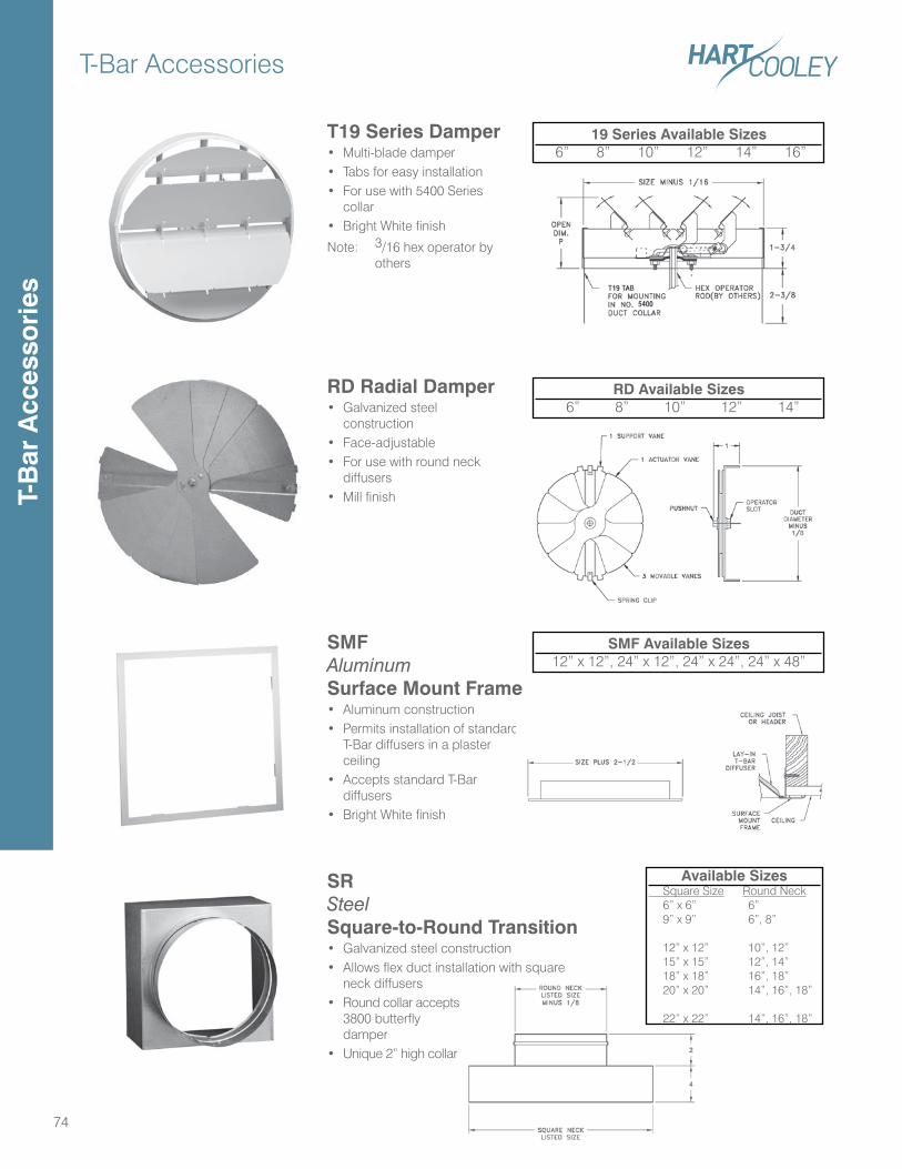
T-Bar Accessories
74
SMF Aluminum Surface Mount Frame• Aluminum construction• Permits installation of standard
T-Bar diffusers in a plaster ceiling
• Accepts standard T-Bar diffusers
• Bright White finish
SMF Available Sizes12” x 12”, 24” x 12”, 24” x 24”, 24” x 48”
RD Radial Damper• Galvanized steel
construction• Face-adjustable• For use with round neck
diffusers• Mill finish
RD Available Sizes 6” 8” 10” 12” 14”
T19 Series Damper• Multi-blade damper• Tabs for easy installation• For use with 5400 Series
collar• Bright White finish
Note: 3/16 hex operator by others
19 Series Available Sizes 6” 8” 10” 12” 14” 16”
SR Steel Square-to-Round Transition• Galvanized steel construction• Allows flex duct installation with square
neck diffusers• Round collar accepts
3800 butterfly damper
• Unique 2” high collar
Available Sizes Square Size Round Neck 6” x 6” 6” 9” x 9” 6”, 8” 12” x 12” 10”, 12” 15” x 15” 12”, 14” 18” x 18” 16”, 18” 20” x 20” 14”, 16”, 18” 22” x 22” 14”, 16”, 18”
T-B
ar A
cces
sori
es
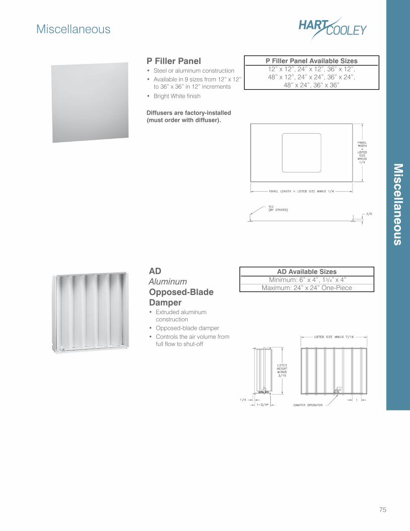
Miscellaneous
75
P Filler Panel• Steel or aluminum construction• Available in 9 sizes from 12” x 12”
to 36” x 36” in 12” increments
• Bright White finish
Diffusers are factory-installed (must order with diffuser).
P Filler Panel Available Sizes12” x 12”, 24” x 12”, 36” x 12”,48” x 12”, 24” x 24”, 36” x 24”,
48” x 24”, 36” x 36”
AD Aluminum Opposed-Blade Damper• Extruded aluminum
construction • Opposed-blade damper• Controls the air volume from
full flow to shut-off
AD Available Sizes Minimum: 6” x 4”, 13/4” x 4”
Maximum: 24” x 24” One-Piece
Miscellaneo
us
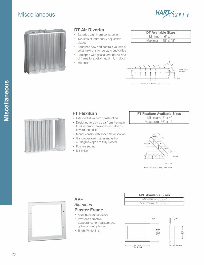
Miscellaneous
76
DT Air Diverter• Extruded aluminum construction• Two sets of individually adjustable
blades• Equalizes flow and controls volume at
collar take-offs to registers and grilles• Equipped with gasket around outside
of frame for positioning firmly in duct• Mill finish
DT Available Sizes Minimum: 6” x 4”
Maximum: 48” x 48”
FT Flexiturn• Extruded aluminum construction• Designed to pick up air from the main
trunk at branch take-offs and divert it toward the grille
• Mounts easily with sheet metal screws• Gang-operated blades move from
45 degrees open to fully closed • Positive setting• Mill finish
FT Flexiturn Available Sizes Minimum: 8” x 4”
Maximum: 36” x 18”
APF Aluminum Plaster Frame• Aluminum construction • Provides attractive
appearance for registers and grilles around plaster
• Bright White finish
APF Available Sizes Minimum: 6” x 4”
Maximum: 48” x 48”
Mis
cella
neo
us
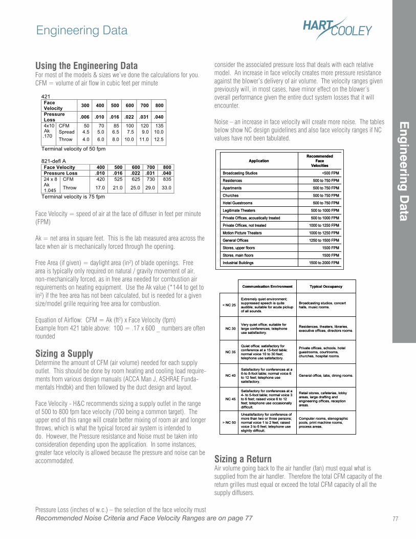
Using the Engineering DataFor most of the models & sizes we’ve done the calculations for you.CFM = volume of air flow in cubic feet per minute
Face Velocity = speed of air at the face of diffuser in feet per minute (FPM)
Ak = net area in square feet. This is the lab measured area across the face when air is mechanically forced through the opening.
Free Area (if given) = daylight area (in²) of blade openings. Free area is typically only required on natural / gravity movement of air, non-mechanically forced, as in free area needed for combustion air requirements on heating equipment. Use the Ak value (*144 to get to in²) if the free area has not been calculated, but is needed for a given size/model grille requiring free area for combustion.
Equation of Airflow: CFM = Ak (ft²) x Face Velocity (fpm)Example from 421 table above: 100 = .17 x 600 _ numbers are often rounded
Sizing a SupplyDetermine the amount of CFM (air volume) needed for each supply outlet. This should be done by room heating and cooling load require-ments from various design manuals (ACCA Man J, ASHRAE Funda-mentals Hndbk) and then followed by the duct design and layout.
Face Velocity - H&C recommends sizing a supply outlet in the range of 500 to 800 fpm face velocity (700 being a common target). The upper end of this range will create better mixing of room air and longer throws, which is what the typical forced air system is intended to do. However, the Pressure resistance and Noise must be taken into consideration depending upon the application. In some instances, greater face velocity is allowed because the pressure and noise can be accommodated.
Pressure Loss (inches of w.c.) – the selection of the face velocity must
consider the associated pressure loss that deals with each relative model. An increase in face velocity creates more pressure resistance against the blower’s delivery of air volume. The velocity ranges given previously will, in most cases, have minor effect on the blower’s overall performance given the entire duct system losses that it will encounter.
Noise – an increase in face velocity will create more noise. The tables below show NC design guidelines and also face velocity ranges if NC values have not been tabulated.
Sizing a ReturnAir volume going back to the air handler (fan) must equal what is supplied from the air handler. Therefore the total CFM capacity of the return grilles must equal or exceed the total CFM capacity of all the supply diffusers.
421 Face Velocity 300 400 500 600 700 800
Pressure Loss .006 .010 .016 .022 .031 .040
CFM 50 70 85 100 120 135 Spread 4.5 5.0 6.5 7.5 9.0 10.0
4x10 Ak .170 Throw 4.0 6.0 8.0 10.0 11.0 12.5
Terminal velocity of 50 fpm 821-defl A Face Velocity 400 500 600 700 800 Pressure Loss .010 .016 .022 .031 .040
CFM 420 525 625 730 835 24 x 8 Ak 1.045 Throw 17.0 21.0 25.0 29.0 33.0
Terminal velocity is 75 fpm
Recommended Noise Criteria and Face Velocity Ranges are on page 77
Engineering Data
77
Eng
ineering D
ata
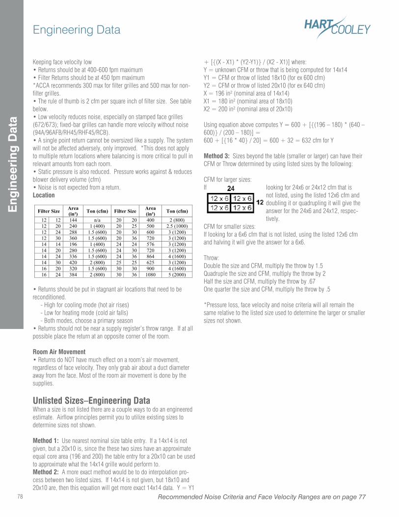
Engineering Data
78 Recommended Noise Criteria and Face Velocity Ranges are on page 77
Eng
inee
ring
Dat
a
Keeping face velocity low• Returns should be at 400-600 fpm maximum• Filter Returns should be at 450 fpm maximum*ACCA recommends 300 max for filter grilles and 500 max for non-filter grilles.• The rule of thumb is 2 cfm per square inch of filter size. See table below.• Low velocity reduces noise, especially on stamped face grilles (672/673); fixed-bar grilles can handle more velocity without noise (94A/96AFB/RH45/RHF45/RCB).• A single point return cannot be oversized like a supply. The system will not be affected adversely, only improved. *This does not apply to multiple return locations where balancing is more critical to pull in relevant amounts from each room.• Static pressure is also reduced. Pressure works against & reduces blower delivery volume (cfm)• Noise is not expected from a return.Location
• Returns should be put in stagnant air locations that need to be reconditioned. - High for cooling mode (hot air rises) - Low for heating mode (cold air falls) - Both modes, choose a primary season• Returns should not be near a supply register’s throw range. If at all possible place the return at an opposite corner of the room.
Room Air Movement• Returns do NOT have much effect on a room’s air movement, regardless of face velocity. They only grab air about a duct diameter away from the face. Most of the room air movement is done by the supplies.
Unlisted Sizes–Engineering DataWhen a size is not listed there are a couple ways to do an engineered estimate. Airflow principles permit you to utilize existing sizes to determine sizes not shown.
Method 1: Use nearest nominal size table entry. If a 14x14 is not given, but a 20x10 is, since the these two sizes have an approximate equal core area (196 and 200) the table entry for a 20x10 can be used to approximate what the 14x14 grille would perform to.Method 2: A more exact method would be to do interpolation pro-cess between two listed sizes. If 14x14 is not given, but 18x10 and 20x10 are, then this equation will get more exact 14x14 data. Y = Y1
+ [{(X - X1) * (Y2-Y1)} / (X2 - X1)] where: Y = unknown CFM or throw that is being computed for 14x14Y1 = CFM or throw of listed 18x10 (for ex 600 cfm)Y2 = CFM or throw of listed 20x10 (for ex 640 cfm)X = 196 in² (nominal area of 14x14)X1 = 180 in² (nominal area of 18x10)X2 = 200 in² (nominal area of 20x10)
Using equation above computes Y = 600 + [{(196 – 180) * (640 – 600)} / (200 – 180)] = 600 + [{16 * 40} / 20] = 600 + 32 = 632 cfm for Y
Method 3: Sizes beyond the table (smaller or larger) can have their CFM or Throw determined by using listed sizes by the following: CFM for larger sizes:If looking for 24x6 or 24x12 cfm that is
not listed, using the listed 12x6 cfm and doubling it or quadrupling it will give the answer for the 24x6 and 24x12, respec-tively.
CFM for smaller sizes:If looking for a 6x6 cfm that is not listed, using the listed 12x6 cfm and halving it will give the answer for a 6x6.
Throw:Double the size and CFM, multiply the throw by 1.5Quadruple the size and CFM, multiply the throw by 2Half the size and CFM, multiply the throw by .67One quarter the size and CFM, multiply the throw by .5
*Pressure loss, face velocity and noise criteria will all remain the same relative to the listed size used to determine the larger or smaller sizes not shown.
Filter Size Area
(in ) Ton (cfm) Filter Size
Area
(in ) Ton (cfm)
12 12 144 n/a 20 20 400 2 (800)
12 20 240 1 (400) 20 25 500 2.5 (1000)
12 24 288 1.5 (600) 20 30 600 3 (1200)
12 30 360 1.5 (600) 20 36 720 3 (1200)
14 14 196 1 (400) 24 24 576 3 (1200)
14 20 280 1.5 (600) 24 30 720 3 (1200)
14 24 336 1.5 (600) 24 36 864 4 (1600)
14 30 420 2 (800) 25 25 625 3 (1200)
16 20 320 1.5 (600) 30 30 900 4 (1600)
16 24 384 2 (800) 30 36 1080 5 (2000)
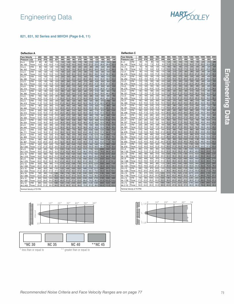
79
Engineering Data
Recommended Noise Criteria and Face Velocity Ranges are on page 77
821, 831, 92 Series and 98VOH (Page 6-8, 11)
Deflection A400 500 600 700 800 900 1000 1100 1200 1300 1400 1600 1800 2000
.010 .016 .022 .031 .040 .050 .062 .075 .090 .105 .122 .160 .202 .249CFM 65 80 100 110 130 145 160 175 190 210 225 255 290 320Throw 6.5 8.0 10.0 11.0 13.0 15.0 16.0 18.0 19.0 21.0 23.0 26.0 29.0 32.0CFM 80 100 120 140 160 180 200 220 240 265 285 325 365 405Throw 7.0 9.0 11.0 13.0 14.0 16.0 18.0 20.0 22.0 24.0 26.0 29.0 33.0 36.0CFM 100 120 145 170 195 220 245 270 295 315 340 390 440 490Throw 8.0 10.0 12.0 14.0 16.0 18.0 20.0 22.0 24.0 26.0 28.0 32.0 36.0 40.0CFM 115 145 170 200 230 255 285 315 345 370 400 460 515 570Throw 8.5 11.0 13.0 15.0 17.0 19.0 22.0 24.0 26.0 28.0 30.0 35.0 39.0 43.0CFM 125 155 190 220 250 280 310 345 375 405 435 500 560 625Throw 9.0 11.0 14.0 16.0 18.0 20.0 22.0 25.0 27.0 29.0 31.0 36.0 41.0 45.0CFM 125 155 190 220 250 285 315 345 375 410 440 500 565 630Throw 9.0 11.0 14.0 16.0 18.0 21.0 23.0 25.0 27.0 30.0 32.0 36.0 41.0 45.0CFM 145 185 220 255 295 330 365 405 440 475 510 585 660 730Throw 10.0 12.0 15.0 17.0 20.0 22.0 24.0 27.0 29.0 32.0 34.0 39.0 44.0 49.0CFM 150 190 225 265 305 340 380 415 455 495 530 605 680 760Throw 10.0 12.0 15.0 17.0 20.0 22.0 25.0 27.0 30.0 33.0 35.0 40.0 45.0 50.0CFM 170 210 250 295 335 380 420 460 505 545 585 670 755 840Throw 11.0 13.0 16.0 18.0 21.0 24.0 26.0 29.0 32.0 34.0 37.0 42.0 47.0 53.0CFM 180 220 265 310 355 400 445 490 535 575 620 710 800 890Throw 11.0 13.0 16.0 19.0 22.0 24.0 27.0 30.0 32.0 35.0 38.0 43.0 49.0 54.0CFM 205 255 305 355 410 460 510 560 610 665 715 815 920 1020Throw 12.0 15.0 17.0 20.0 23.0 26.0 29.0 32.0 35.0 38.0 41.0 47.0 53.0 58.0CFM 210 265 315 370 420 475 525 580 630 685 735 840 945 1050Throw 12.0 15.0 18.0 21.0 23.0 27.0 29.0 32.0 35.0 38.0 41.0 47.0 53.0 59.0CFM 255 315 380 445 505 570 635 695 760 825 890 1015 1140 1270Throw 13.0 16.0 19.0 23.0 26.0 29.0 32.0 35.0 39.0 42.0 45.0 52.0 58.0 65.0CFM 255 320 385 445 510 575 640 705 770 830 895 1015 1140 1270Throw 13.0 16.0 19.0 23.0 26.0 29.0 32.0 36.0 39.0 42.0 45.0 52.0 58.0 65.0CFM 310 385 465 540 615 695 770 850 925 1000 1080 1235 1390 1540Throw 14.0 18.0 21.0 25.0 28.0 32.0 35.0 39.0 43.0 46.0 50.0 57.0 64.0 71.0CFM 345 435 520 610 695 780 870 955 1040 1130 1215 1390 1560 1735Throw 15.0 19.0 23.0 26.0 30.0 34.0 38.0 41.0 45.0 49.0 53.0 60.0 68.0 75.0CFM 385 485 580 675 775 870 965 1065 1160 1255 1355 1545 1740 1935Throw 16.0 20.0 24.0 28.0 32.0 36.0 40.0 44.0 48.0 51.0 56.0 63.0 71.0 79.0CFM 420 525 625 730 835 940 1045 1150 1255 1360 1465 1670 1880 2090Throw 17.0 21.0 25.0 29.0 33.0 37.0 41.0 46.0 50.0 54.0 58.0 66.0 74.0 83.0CFM 525 655 785 915 1050 1180 1310 1440 1570 1705 1835 2095 2360 2620Throw 19.0 23.0 28.0 32.0 37.0 42.0 46.0 51.0 56.0 60.0 65.0 74.0 84.0 93.0CFM 530 660 790 925 1055 1185 1320 1450 1585 1715 1845 2110 2375 2640Throw 19.0 23.0 28.0 33.0 37.0 42.0 46.0 51.0 56.0 60.0 65.0 74.0 84.0 93.0CFM 630 790 945 1105 1260 1420 1575 1735 1890 2050 2205 2520 2835 3150Throw 20.0 25.0 30.0 36.0 41.0 46.0 51.0 56.0 61.0 66.0 71.0 81.0 91.0 101.0CFM 635 795 995 1115 1275 1435 1595 1750 1910 2070 2230 2550 2865 3185Throw 20.0 25.0 31.0 36.0 41.0 47.0 51.0 56.0 61.0 66.0 71.0 82.0 92.0 102.0CFM 660 825 990 1160 1325 1490 1655 1820 1985 2150 2315 2645 2975 3310Throw 21.0 26.0 31.0 37.0 42.0 47.0 52.0 57.0 63.0 68.0 73.0 83.0 94.0 104.0CFM 795 995 1195 1390 1590 1790 1990 2190 2385 2585 2785 3180 3580 3980Throw 23.0 29.0 34.0 40.0 46.0 51.0 57.0 63.0 68.0 74.0 80.0 91.0 103.0 114.0CFM 800 1000 1200 1400 1600 1800 2000 2200 2395 2595 2795 3195 3595 3995Throw 23.0 29.0 34.0 40.0 45.0 51.0 57.0 63.0 68.0 74.0 80.0 91.0 103.0 114.0CFM 960 1200 1440 1680 1920 2160 2400 2640 2880 3120 3365 3845 4325 4805Throw 25.0 31.0 38.0 44.0 50.0 56.0 63.0 69.0 75.0 81.0 88.0 100.0 113.0 125.0
Terminal Velocity of 75 FPM
36 x 12Ak 2.402
30 x 10Ak 1.65436 x 10Ak 1.989
14 x 4Ak .286
12 x 6Ak .37916 x 5Ak .41914 x 6Ak .444
30 x 8Ak 1.310
20 x 5Ak .52624 x 5Ak .63420 x 6Ak .64024 x 6Ak .771
Face Velocity
8 x 4Ak .16010 x 4Ak .20212 x 4Ak .244
16 x 6Ak .510
Pressure Loss
12 x 5Ak .31210 x 6Ak .31414 x 5Ak .366
24 x 12Ak 1.593
20 x 8Ak .86830 x 6Ak .96724 x 8Ak 1.045
24 x 10Ak 1.31936 x 8Ak 1.576
30 x 12Ak 1.997
Deflection C400 500 600 700 800 900 1000 1100 1200 1300 1400 1600 1800 2000
.010 .016 .022 .031 .040 .050 .062 .075 .090 .105 .122 .160 .202 .249CFM 55 70 85 100 110 125 140 155 170 180 195 225 250 280Throw 5.0 6.0 7.5 8.5 9.5 11.0 12.0 14.0 15.0 16.0 17.0 20.0 22.0 24.0CFM 70 90 105 125 140 160 180 195 215 230 250 285 320 355Throw 5.0 7.0 8.0 9.5 11.0 12.0 14.0 15.0 17.0 18.0 19.0 22.0 25.0 28.0CFM 85 110 130 150 170 195 215 235 260 280 300 345 385 430Throw 6.0 8.0 9.0 11.0 12.0 14.0 15.0 17.0 18.0 20.0 21.0 24.0 27.0 30.0CFM 100 125 150 175 200 225 250 275 300 330 355 405 455 505Throw 6.5 8.0 10.0 11.0 13.0 15.0 16.0 18.0 20.0 22.0 23.0 26.0 30.0 33.0CFM 110 135 165 190 220 245 275 300 330 355 385 440 495 550Throw 7.0 8.5 10.0 12.0 14.0 15.0 17.0 19.0 21.0 22.0 24.0 28.0 31.0 34.0CFM 110 140 165 195 220 245 275 305 330 360 385 440 495 550Throw 7.0 8.5 10.0 12.0 14.0 15.0 17.0 19.0 21.0 22.0 24.0 27.0 31.0 34.0CFM 130 160 195 225 255 290 320 355 385 415 450 515 580 645Throw 7.5 9.0 11.0 13.0 15.0 17.0 18.0 21.0 22.0 24.0 26.0 30.0 34.0 37.0CFM 135 165 200 235 265 300 335 365 400 435 465 535 600 665Throw 7.5 9.5 11.0 13.0 15.0 17.0 19.0 21.0 23.0 25.0 26.0 30.0 34.0 38.0CFM 150 185 220 260 295 330 370 405 445 480 515 590 665 740Throw 8.0 10.0 12.0 14.0 16.0 18.0 20.0 22.0 24.0 26.0 28.0 32.0 36.0 40.0CFM 155 195 235 275 315 350 390 430 470 510 545 625 705 780Throw 8.0 10.0 12.0 14.0 17.0 18.0 20.0 23.0 25.0 27.0 29.0 33.0 37.0 41.0CFM 180 225 270 315 360 405 450 495 540 580 625 715 805 895Throw 9.0 11.0 13.0 15.0 18.0 20.0 22.0 24.0 26.0 28.0 31.0 35.0 39.0 44.0CFM 185 230 280 325 370 415 465 510 555 600 650 740 835 925Throw 9.0 11.0 13.0 16.0 18.0 20.0 22.0 25.0 27.0 29.0 31.0 36.0 40.0 44.0CFM 225 280 335 390 445 500 555 615 670 725 780 890 1005 1115Throw 10.0 12.0 15.0 17.0 19.0 22.0 24.0 27.0 29.0 32.0 34.0 40.0 44.0 49.0CFM 225 280 340 395 450 505 565 620 675 730 790 900 1015 1125Throw 10.0 12.0 15.0 17.0 20.0 22.0 25.0 27.0 29.0 32.0 34.0 39.0 44.0 49.0CFM 270 340 405 475 540 610 680 745 815 880 950 1085 1220 1355Throw 11.0 14.0 16.0 19.0 21.0 24.0 27.0 30.0 32.0 35.0 38.0 43.0 49.0 54.0CFM 305 380 460 535 610 685 765 840 915 990 1070 1220 1375 1525Throw 11.0 14.0 17.0 20.0 23.0 26.0 29.0 32.0 34.0 37.0 40.0 46.0 52.0 57.0CFM 340 425 510 595 680 765 850 935 1020 1105 1190 1360 1530 1700Throw 12.0 15.0 18.0 21.0 24.0 27.0 30.0 33.0 36.0 39.0 42.0 48.0 54.0 60.0CFM 370 460 550 645 735 825 920 1010 1105 1195 1285 1470 1655 1840Throw 13.0 16.0 19.0 22.0 25.0 28.0 31.0 35.0 38.0 41.0 44.0 50.0 57.0 63.0CFM 460 575 690 805 920 1035 1150 1265 1380 1500 1615 1845 2075 2305Throw 14.0 15.0 21.0 25.0 28.0 32.0 35.0 39.0 42.0 46.0 49.0 56.0 63.0 70.0CFM 465 580 695 810 930 1045 1160 1275 1390 1510 1625 1855 2090 2320Throw 14.0 18.0 21.0 25.0 28.0 32.0 35.0 39.0 42.0 46.0 49.0 56.0 64.0 71.0CFM 555 695 830 970 1110 1245 1385 1525 1665 1800 1940 2220 2495 2770Throw 15.0 19.0 19.0 27.0 31.0 35.0 39.0 42.0 46.0 50.0 54.0 62.0 69.0 77.0CFM 560 700 840 980 1120 1260 1400 1540 1680 1820 1960 2240 2520 2800Throw 16.0 19.0 23.0 27.0 31.0 35.0 39.0 43.0 47.0 50.0 54.0 62.0 70.0 78.0CFM 580 725 870 1020 1165 1310 1455 1600 1745 1890 2035 2325 2615 2910Throw 16.0 20.0 24.0 28.0 32.0 36.0 39.0 43.0 47.0 51.0 55.0 63.0 71.0 79.0CFM 700 875 1050 1225 1400 1575 1750 1925 2100 2275 2450 2800 3150 3500Throw 17.0 22.0 26.0 30.0 35.0 39.0 43.0 48.0 52.0 56.0 61.0 69.0 78.0 87.0CFM 700 880 1055 1230 1405 1580 1755 1930 2110 2285 2460 2810 3160 3510Throw 17.0 22.0 26.0 30.0 35.0 39.0 43.0 48.0 52.0 56.0 61.0 69.0 78.0 87.0CFM 845 1055 1265 1480 1690 1990 2110 2325 2535 2745 2955 3380 3800 4225Throw 19.0 24.0 28.0 33.0 38.0 43.0 47.0 52.0 57.0 62.0 66.0 76.0 86.0 95.0
Terminal Velocity of 75 FPM
24 x 5Ak .55720 x 6Ak .56324 x 6Ak .67820 x 8Ak .763
16 x 5Ak .36914 x 6Ak .39116 x 6Ak .44820 x 5Ak .463
10 x 6Ak .27614 x 5Ak .32112 x 6Ak .333
8 x 4Ak .14010 x 4Ak .17812 x 4Ak .21514 x 4Ak .252
Pressure Loss
12 x 5Ak .274
30 x 6Ak .85024 x 8Ak .919
Face Velocity
30 x 8Ak 1.15224 x 10Ak 1.16036 x 8Ak 1.38624 x 12Ak 1.40130 x 10Ak 1.45436 x 10Ak 1.74930 x 12Ak 1.75636 x 12Ak 2.112
*NC 30 NC 35 NC 40 **NC 45* less than or equal to ** greater than or equal to
Eng
ineering D
ata
0
0
10'10'
10'
20' 30' 40' 50' 60'
ST
RA
IG
HT
0
0
10'10'
10'
20' 30' 40' 50
0°
22
°2
2°
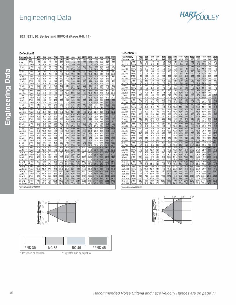
821, 831, 92 Series and 98VOH (Page 6-8, 11)
Deflection E400 500 600 700 800 900 1000 1100 1200 1300 1400 1600 1800 2000
.010 .016 .022 .031 .040 .050 .062 .075 .090 .105 .122 .160 .202 .249CFM 50 60 75 85 100 110 125 135 150 160 175 200 225 250Throw 3.5 4.5 5.5 6.0 7.5 8.0 9.0 10.0 11.0 12.0 13.0 15.0 16.0 18.0CFM 65 80 95 110 125 140 155 175 190 205 220 250 285 315Throw 4.0 5.0 6.0 7.0 8.0 9.0 10.0 11.0 12.0 13.0 14.0 16.0 19.0 20.0CFM 75 95 115 135 150 170 190 210 230 245 265 305 340 380Throw 4.5 5.5 7.0 8.0 9.0 10.0 11.0 12.0 14.0 15.0 16.0 18.0 20.0 22.0CFM 90 110 135 155 180 200 220 245 265 290 310 355 400 445Throw 5.0 6.0 7.5 8.5 10.0 11.0 12.0 13.0 14.0 16.0 17.0 19.0 22.0 24.0CFM 95 120 145 170 195 220 240 265 290 315 340 385 435 485Throw 5.0 6.5 7.5 9.0 10.0 12.0 13.0 14.0 15.0 17.0 18.0 20.0 23.0 25.0CFM 100 120 145 170 195 220 245 270 295 315 340 390 440 490Throw 5.0 6.5 7.5 9.0 10.0 11.0 13.0 14.0 15.0 16.0 18.0 20.0 23.0 26.0CFM 115 140 170 200 225 255 285 310 340 370 400 455 510 570Throw 5.5 7.0 8.0 9.5 11.0 12.0 14.0 15.0 16.0 18.0 19.0 22.0 25.0 28.0CFM 120 145 175 205 235 265 295 325 355 380 410 470 530 590Throw 5.5 7.0 8.5 9.5 11.0 13.0 14.0 15.0 17.0 18.0 19.0 22.0 25.0 28.0CFM 130 165 195 230 260 295 325 360 390 425 455 520 585 650Throw 6.0 7.5 9.0 10.0 12.0 13.0 15.0 16.0 18.0 19.0 21.0 24.0 26.0 29.0CFM 140 175 205 240 275 310 345 380 415 450 485 550 620 690Throw 6.0 7.5 9.0 11.0 12.0 14.0 15.0 17.0 18.0 20.0 21.0 24.0 27.0 30.0CFM 16 200 240 275 315 355 395 435 475 515 555 635 715 790Throw 6.5 8.0 10.0 11.0 13.0 15.0 16.0 18.0 19.0 21.0 23.0 26.0 29.0 32.0CFM 165 205 245 285 325 365 410 450 490 530 570 655 735 815Throw 6.5 8.5 10.0 11.0 13.0 15.0 17.0 18.0 20.0 21.0 23.0 26.0 30.0 33.0CFM 195 245 295 345 395 445 490 540 590 640 690 785 885 965Throw 7.0 9.0 11.0 13.0 14.0 16.0 18.0 20.0 22.0 23.0 25.0 29.0 32.0 36.0CFM 200 250 300 350 400 445 495 545 595 645 695 795 895 995Throw 7.5 9.0 11.0 13.0 15.0 16.0 18.0 20.0 22.0 24.0 25.0 29.0 33.0 36.0CFM 240 300 360 420 480 540 600 660 720 775 835 955 1075 1195Throw 8.0 10.0 12.0 14.0 16.0 18.0 20.0 22.0 24.0 26.0 28.0 32.0 36.0 40.0CFM 270 335 405 470 540 605 675 740 810 875 940 1075 1210 1345Throw 8.5 11.0 13.0 15.0 17.0 19.0 21.0 23.0 25.0 27.0 30.0 34.0 38.0 42.0CFM 300 375 450 525 600 675 750 825 900 975 1050 1200 1350 1500Throw 9.0 11.0 13.0 16.0 18.0 20.0 22.0 25.0 27.0 29.0 31.0 36.0 40.0 45.0CFM 325 405 485 570 650 730 810 890 975 1055 1135 1300 1460 1620Throw 9.5 12.0 14.0 16.0 19.0 21.0 23.0 25.0 28.0 30.0 32.0 37.0 42.0 46.0CFM 405 510 610 710 815 915 1015 1120 1220 1320 1425 1625 1830 2035Throw 11.0 13.0 16.0 18.0 21.0 23.0 26.0 29.0 31.0 34.0 36.0 42.0 47.0 52.0CFM 410 510 615 715 820 920 1025 1125 1230 1330 1430 1635 1840 2045Throw 10.0 13.0 16.0 18.0 21.0 23.0 26.0 29.0 31.0 34.0 36.0 42.0 47.0 52.0CFM 490 610 735 855 980 1100 1220 1345 1465 1590 1710 1955 2200 2445Throw 11.0 14.0 17.0 20.0 23.0 26.0 28.0 31.0 34.0 37.0 40.0 46.0 51.0 57.0CFM 495 620 740 865 990 1110 1235 1360 1485 1605 1730 1975 2225 2470Throw 11.0 14.0 17.0 20.0 23.0 26.0 29.0 32.0 34.0 37.0 40.0 46.0 52.0 57.0CFM 515 640 770 900 1025 1155 1285 1410 1540 1670 1795 2055 2310 2565Throw 12.0 15.0 17.0 20.0 23.0 26.0 29.0 32.0 35.0 38.0 42.0 46.0 52.0 58.0CFM 615 770 925 1080 1235 1390 1545 1700 1850 2005 2160 2470 2775 3085Throw 13.0 16.0 19.0 22.0 26.0 29.0 32.0 35.0 38.0 42.0 45.0 51.0 57.0 64.0CFM 620 775 930 1085 1240 1395 1550 1705 1860 2015 2170 2480 2790 3100Throw 13.0 16.0 19.0 22.0 26.0 29.0 32.0 35.0 39.0 42.0 45.0 51.0 58.0 64.0CFM 745 930 1120 1305 1490 1680 1865 2050 2235 2425 2610 2980 3355 3730Throw 14.0 18.0 21.0 25.0 28.0 32.0 35.0 39.0 42.0 46.0 49.0 56.0 63.0 70.0
Terminal Velocity of 75 FPM
Face VelocityPressure Loss8 x 4Ak .12410 x 4Ak .15712 x 4Ak .19014 x 4Ak .22212 x 5Ak .24210 x 6Ak .24414 x 5Ak .28412 x 6Ak .29416 x 5Ak .32514 x 6Ak .34516 x 6Ak .39620 x 5Ak .40824 x 5Ak .49220 x 6Ak .49724 x 6Ak .59820 x 8Ak .67330 x 6Ak .75024 x 8Ak .81130 x 8Ak 1.01724 x 10Ak 1.02336 x 8Ak 1.22224 x 12Ak 1.23630 x 10Ak 1.28336 x 10Ak 1.54330 x 12Ak 1.55036 x 12Ak 1.864
Deflection G400 500 600 700 800 900 1000 1100 1200 1300 1400 1600 1800 2000
.010 .016 .022 .031 .040 .050 .062 .075 .090 .105 .122 .160 .202 .249CFM 50 60 70 85 95 105 120 130 145 155 165 190 215 240Throw 2.5 3.0 4.0 4.5 5.0 5.5 6.5 7.0 8.0 8.5 9.0 10.0 12.0 13.0CFM 55 70 85 100 115 130 145 155 170 185 200 230 255 285Throw 2.5 3.5 4.0 5.0 5.5 6.5 7.0 7.5 8.0 9.0 9.5 11.0 12.0 14.0CFM 70 85 105 120 140 155 175 190 210 225 240 275 310 345Throw 3.0 3.5 4.5 5.5 6.0 7.0 7.5 8.5 9.0 10.0 11.0 12.0 14.0 15.0CFM 80 100 120 140 160 180 200 220 240 265 285 325 365 405Throw 3.0 4.0 5.0 5.5 6.5 7.5 8.0 9.0 9.5 11.0 12.0 13.0 15.0 16.0CFM 90 110 130 155 175 200 220 240 265 285 310 350 395 440Throw 3.5 4.5 5.0 6.0 7.0 8.0 8.5 9.5 10.0 11.0 12.0 14.0 15.0 17.0CFM 90 110 135 155 180 200 220 245 265 290 310 355 400 445Throw 3.5 4.5 5.0 6.0 7.0 7.5 8.5 9.5 10.0 11.0 12.0 14.0 15.0 17.0CFM 105 130 155 180 205 230 260 285 310 335 360 415 465 515Throw 4.0 4.5 5.5 6.5 7.5 8.5 9.5 10.0 11.0 12.0 13.0 15.0 17.0 18.0CFM 105 135 160 190 215 240 270 295 320 350 375 430 480 535Throw 4.0 5.0 5.5 6.5 7.5 8.5 9.5 10.0 11.0 12.0 13.0 15.0 17.0 19.0CFM 120 150 180 205 235 265 295 325 355 385 415 475 535 590Throw 4.0 5.0 6.0 7.0 8.0 9.0 10.0 11.0 12.0 13.0 14.0 16.0 18.0 20.0CFM 125 155 190 220 250 285 315 345 375 410 440 500 565 630Throw 4.0 5.0 6.0 7.0 8.0 9.5 10.0 11.0 12.0 13.0 14.0 16.0 18.0 20.0CFM 145 180 215 250 290 325 360 395 430 470 505 575 650 720Throw 4.5 5.5 6.5 7.5 9.0 10.0 11.0 12.0 13.0 14.0 15.0 17.0 20.0 22.0CFM 150 185 225 260 300 335 370 410 445 485 520 595 670 745Throw 4.5 5.5 6.5 7.5 9.0 10.0 11.0 12.0 13.0 14.0 15.0 18.0 20.0 22.0CFM 180 225 270 315 360 405 450 495 540 580 625 715 805 895Throw 5.0 7.5 7.5 8.5 10.0 11.0 12.0 13.0 15.0 16.0 17.0 19.0 22.0 24.0CFM 180 225 270 315 360 410 455 500 545 590 635 725 815 905Throw 5.0 6.0 7.5 8.5 10.0 11.0 12.0 14.0 15.0 16.0 17.0 20.0 22.0 25.0CFM 220 275 325 380 435 490 545 600 655 710 765 870 980 1090Throw 5.5 7.0 8.0 9.5 11.0 12.0 13.0 15.0 16.0 18.0 19.0 21.0 24.0 27.0CFM 245 305 370 430 490 555 615 675 735 800 860 980 1105 1230Throw 5.5 7.0 8.5 10.0 11.0 13.0 14.0 16.0 17.0 19.0 20.0 23.0 26.0 29.0CFM 275 340 410 480 545 615 685 750 820 890 955 1095 1230 1365Throw 6.0 7.5 9.0 11.0 12.0 14.0 15.0 17.0 18.0 20.0 21.0 24.0 27.0 30.0CFM 295 370 445 515 590 665 740 815 885 960 1035 1180 1330 1480Throw 6.5 8.0 9.5 11.0 13.0 14.0 16.0 17.0 19.0 20.0 22.0 25.0 28.0 31.0CFM 370 465 555 650 740 835 925 1020 1110 1205 1295 1480 1665 1850Throw 7.0 9.0 10.0 12.0 14.0 16.0 17.0 19.0 21.0 23.0 24.0 28.0 31.0 35.0CFM 375 465 560 650 745 840 930 1025 1120 1210 1305 1490 1675 1865Throw 7.0 9.0 11.0 12.0 14.0 16.0 18.0 19.0 21.0 23.0 25.0 28.0 32.0 35.0CFM 445 555 670 780 890 1005 1115 1225 1335 1450 1560 1780 2005 2230Throw 7.5 9.5 12.0 13.0 15.0 17.0 19.0 21.0 23.0 25.0 27.0 31.0 35.0 39.0CFM 450 565 675 790 900 1015 1125 1240 1350 1465 1575 1800 2025 2250Throw 7.5 9.5 12.0 14.0 15.0 17.0 19.0 21.0 23.0 25.0 27.0 31.0 35.0 39.0CFM 470 585 700 820 935 1050 1170 1285 1405 1520 1635 1870 2105 2340Throw 8.0 10.0 12.0 14.0 16.0 18.0 20.0 22.0 24.0 26.0 27.0 31.0 35.0 39.0CFM 560 705 845 985 1125 1265 1405 1545 1685 1830 1970 2250 2530 2810Throw 8.5 11.0 13.0 15.0 17.0 19.0 22.0 24.0 26.0 28.0 30.0 35.0 39.0 43.0CFM 565 705 845 990 1130 1270 1410 1555 1695 1835 1975 2260 2540 2825Throw 8.5 11.0 13.0 15.0 17.0 19.0 22.0 24.0 26.0 28.0 30.0 35.0 39.0 43.0CFM 680 850 1020 1190 1360 1530 1700 1870 2040 2210 2375 2715 3055 3395Throw 9.5 12.0 14.0 17.0 19.0 21.0 24.0 26.0 29.0 31.0 33.0 38.0 43.0 48.0
Terminal Velocity of 75 FPM
Face VelocityPressure Loss8 x 4Ak .11910 x 4Ak .14312 x 4Ak .17314 x 4Ak .20212 x 5Ak .22010 x 6Ak .22214 x 5Ak .25812 x 6Ak .26816 x 5Ak .29614 x 6Ak .31416 x 6Ak .36020 x 5Ak .372
30 x 10Ak 1.169
24 x 5Ak .44820 x 6Ak .45324 x 6Ak .54520 x 8Ak .614
36 x 10Ak 1.406
36 x 12Ak 1.698
30 x 6Ak .68324 x 8Ak .73930 x 8Ak .92624 x 10Ak .932
30 x 12Ak 1.412
36 x 8Ak 1.11424 x 12Ak 1.126
*NC 30 NC 35 NC 40 **NC 45* less than or equal to ** greater than or equal to
0
0
10'10'
10'
20' 30'
0°
22
°2
2°
42
°4
2°
0
0
10'
10'
10'
20' 30'
55
°4
2°
22
°0
°2
2°
42
°5
5°
Recommended Noise Criteria and Face Velocity Ranges are on page 7780
Engineering DataE
ngin
eeri
ng D
ata
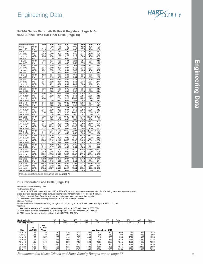
94/94A Series Return Air Grilles & Registers (Page 9-10)96AFB Steel Fixed-Bar Filter Grille (Page 10)
Face Velocity 300 400 500 600 700 800 900 10006 x 6 CFM 45 60 75 90 105 120 135 150Ak .150 Ps .010 .019 .029 .046 .060 .075 .100 .130
CFM 84 112 140 169 197 225 253 281Ps .010 .019 .029 .046 .060 .075 .100 .130CFM 135 180 225 270 315 360 405 450Ps .011 .019 .030 .042 .057 .072 .094 .119CFM 96 127 159 191 223 255 287 318Ps .011 .019 .029 .045 .059 .074 .099 .128CFM 112 150 187 225 262 300 337 375Ps .011 .019 .029 .044 .058 .074 .097 .124CFM 152 203 254 304 355 406 456 507Ps .011 .019 .030 .041 .056 .072 .093 .116CFM 198 264 330 395 461 527 593 659Ps .011 .019 .030 .039 .054 .070 .089 .109CFM 267 355 444 533 622 711 800 888Ps .011 .020 .031 .040 .055 .074 .091 .111CFM 301 401 502 602 703 803 903 1004Ps .011 .020 .031 .041 .056 .076 .092 .112CFM 336 448 560 672 784 895 1007 1119Ps .011 .020 .031 .041 .056 .078 .093 .114CFM 406 541 676 811 946 1082 1217 1352Ps .011 .020 .031 .043 .058 .081 .095 .116CFM 458 611 764 917 1069 1222 1375 1528Ps .011 .020 .032 .043 .058 .083 .096 .117CFM 511 682 852 1023 1193 1364 1534 1704Ps .011 .020 .032 .044 .059 .084 .097 .118CFM 571 761 951 1141 1331 1522 1712 1902Ps .011 .020 .032 .044 .059 .086 .098 .119CFM 618 824 1030 1236 1442 1649 1855 2061Ps .011 .020 .032 .045 .060 .087 .099 .120CFM 690 920 1150 1380 1610 1840 2070 2300Ps .011 .020 .032 .045 .060 .089 .100 .120CFM 781 1041 1301 1561 1822 2082 2342 2602Ps .011 .020 .032 .045 .060 .090 .100 .121CFM 835 1114 1392 1671 1949 2228 2506 2785Ps .011 .020 .031 .046 .060 .090 .100 .121CFM 946 1261 1576 1892 2207 2522 2838 3153Ps .011 .019 .031 .045 .059 .090 .099 .120CFM 1057 1410 1762 2115 2467 2820 3172 3525Ps .011 .019 .030 .045 .058 .089 .098 .119CFM 1284 1712 2140 2568 2996 3424 3852 4280Ps .011 .018 .028 .043 .055 .085 .092 .114CFM 1341 1789 2236 2683 3130 3577 4024 4471Ps .011 .017 .028 .042 .054 .083 .091 .112CFM 1633 2177 2721 3265 3810 4354 4898 5442Ps .010 .015 .024 .037 .047 .070 .079 .100CFM 1751 2335 2919 3503 4086 4670 5254 5838Ps .009 .014 .022 .035 .043 .064 .073 .095CFM 1992 2656 3320 3984 4648 5312 5976 6640Ps .008 .012 .017 .029 .034 .048 .059 .081CFM 2742 3656 4570 5484 6398 7312 8226 9140Ps .008 .012 .017 .029 .034 .048 .059 .081CFM 3808 5077 6346 7615 8884 10154 11423 12692Ps .008 .012 .017 .029 .034 .048 .059 .081
10 x 10Ak .45012 x 6Ak .32014 x 6Ak .37014 x 8Ak .510
8 x 8Ak .280
24 x 12Ak 1.35018 x 18Ak 1.53030 x 12Ak 1.70020 x 20Ak 1.900
12 x 12Ak .66024 x 8Ak .89018 x 12Ak 1.00030 x 8Ak 1.120
36 x 18Ak 3.15030 x 24Ak 3.52036 x 24Ak 4.28030 x 30Ak 4.470
36 x 12Ak 2.06024 x 20Ak 2.30030 x 18Ak 2.60024 x 24Ak 2.780
48 x 48Ak 12.700
For sizes not listed and sizing tips see page(s) 7
36 x 30Ak 5.44048 x 24Ak 5.84036 x 36Ak 6.64048 x 36Ak 9.140
PFG Perforated Face Grille (Page 11)Return Air Grille Balancing DataTo Determine CFM:1. Use an ALNOR Velometer with No. 2220 or 2220A Tip or a 4" rotating vane anemometer. If a 4" rotating vane anemometer is used,place dial face against perforated plate, and sample in a random manner for at least 1 minute.2. Select proper Ak from Table by unit size and instrument used for measuring velocity.3. Determine CFM by the following equation: CFM = Ak x Average Velocity.Sample ProblemDetermine Return Airflow Rate (CFM) through a 10 x 10, using an ALNOR Velometer with Tip No. 2220 or 2220A.Solution1. Assume the average of 6 velocity readings taken with an ALNOR Velometer is 2000 FPM.2. From Table, the Area Factor for a 10 x 10 using an ALNOR Velometer is Ak = .39 sq. ft.3. CFM = Ak x Average Velocity = .39 sq. ft. x 2000 FPM = 780 CFM
Neck Velocity 200 300 400 500 600 650 700 750 800 900S.P. Drop w/OBD .012 .027 .049 .078 .110 .130 .150 .170 .190 .240
SizeAk
ALNOR
Ak4" ROT.
Vane10 x 10 .39 .55 140 210 285 350 415 450 485 520 555 62512 x12 .46 .79 200 300 400 500 600 650 700 750 800 90014 x 14 .62 1.07 270 410 545 680 815 885 955 1020 1090 122510 x 22 .71 1.21 305 460 610 765 915 995 1070 1150 1220 137516 x 16 .82 1.40 355 530 710 890 1065 1155 1245 1335 1425 160018 x 18 1.05 1.77 450 675 900 1125 1350 1460 1575 1690 1800 203020 x 20 1.28 2.25 555 835 1110 1390 1665 1805 1945 2080 2220 250022 x 22 1.55 2.70 670 1010 1345 1680 2020 2180 2350 2520 2690 3020
Air Capacities - CFM
Recommended Noise Criteria and Face Velocity Ranges are on page 77
Engineering Data
81
Eng
ineering D
ata
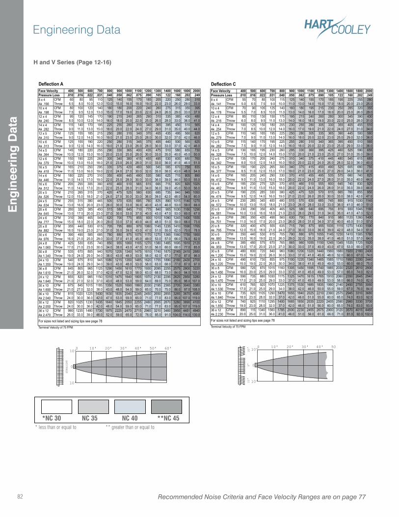
H and V Series (Page 12-16)
Deflection A400 500 600 700 800 900 1000 1100 1200 1300 1400 1600 1800 2000
.010 .016 .022 .031 .040 .050 .062 .075 .090 .105 .122 .160 .202 .249CFM 60 80 95 110 125 140 155 170 185 205 220 250 280 310Throw 6.5 8.0 10.0 12.0 13.0 15.0 16.0 18.0 19.0 22.0 23.0 26.0 29.0 33.0CFM 80 100 120 140 160 180 200 220 240 260 275 315 355 395Throw 7.5 9.5 12.0 13.0 15.0 17.0 19.0 20.0 22.0 24.0 26.0 29.0 33.0 37.0CFM 95 120 145 170 190 215 240 265 290 310 335 385 430 480Throw 8.0 10.0 12.0 14.0 16.0 18.0 20.0 22.0 25.0 26.0 28.0 33.0 36.0 41.0CFM 115 140 170 195 225 255 280 310 340 365 395 450 510 565Throw 9.0 11.0 13.0 15.0 18.0 20.0 22.0 24.0 27.0 29.0 31.0 35.0 40.0 44.0CFM 125 155 185 215 250 280 310 340 370 405 435 495 560 620Throw 9.0 12.0 14.0 16.0 19.0 21.0 23.0 25.0 28.0 30.0 32.0 37.0 42.0 46.0CFM 125 155 190 220 250 280 315 345 375 405 440 500 565 625Throw 9.0 12.0 14.0 16.0 19.0 21.0 23.0 26.0 28.0 30.0 33.0 37.0 42.0 46.0CFM 145 180 220 255 290 330 365 400 435 475 510 580 655 730Throw 10.0 12.0 15.0 18.0 20.0 23.0 25.0 28.0 30.0 33.0 35.0 40.0 45.0 50.0CFM 150 190 225 265 305 340 380 415 455 495 530 605 680 760Throw 10.0 13.0 15.0 18.0 21.0 23.0 26.0 28.0 31.0 33.0 36.0 41.0 46.0 51.0CFM 165 210 250 295 335 375 420 460 500 545 585 670 750 835Throw 11.0 13.0 16.0 19.0 22.0 24.0 27.0 30.0 32.0 35.0 38.0 43.0 48.0 54.0CFM 180 225 270 310 355 400 445 490 535 580 625 715 805 890Throw 11.0 14.0 17.0 19.0 22.0 25.0 28.0 30.0 33.0 36.0 39.0 44.0 50.0 55.0CFM 205 255 305 360 410 460 510 565 615 665 715 820 920 1025Throw 11.0 14.0 17.0 20.0 22.0 25.0 28.0 31.0 34.0 36.0 39.0 45.0 50.0 56.0CFM 210 265 315 370 420 475 525 580 630 685 735 840 945 1050Throw 12.0 15.0 18.0 21.0 24.0 27.0 30.0 33.0 36.0 39.0 42.0 48.0 54.0 60.0CFM 255 315 380 445 505 570 635 695 760 825 890 1015 1140 1270Throw 13.0 16.0 20.0 23.0 26.0 30.0 33.0 36.0 40.0 43.0 46.0 53.0 59.0 66.0CFM 260 325 385 450 515 580 645 710 775 840 905 1030 1160 1290Throw 13.0 17.0 20.0 23.0 27.0 30.0 33.0 37.0 40.0 43.0 47.0 53.0 60.0 67.0CFM 310 390 465 545 620 700 775 855 930 1010 1090 1245 1400 1555Throw 15.0 18.0 22.0 26.0 29.0 33.0 37.0 40.0 44.0 48.0 51.0 59.0 66.0 73.0CFM 355 440 530 615 705 795 880 970 1060 1145 1235 1410 1590 1765Throw 16.0 19.0 23.0 27.0 31.0 35.0 39.0 43.0 47.0 51.0 55.0 62.0 70.0 78.0CFM 390 490 585 685 780 880 975 1075 1170 1270 1365 1560 1755 1950Throw 16.0 21.0 25.0 29.0 33.0 37.0 41.0 45.0 49.0 53.0 57.0 66.0 74.0 82.0CFM 425 530 635 740 850 955 1060 1165 1270 1380 1485 1695 1910 2120Throw 17.0 21.0 23.0 30.0 34.0 38.0 43.0 47.0 51.0 56.0 60.0 68.0 77.0 85.0CFM 535 670 805 940 1070 1205 1340 1475 1610 1740 1875 2145 2410 2680Throw 19.0 24.0 29.0 34.0 38.0 43.0 48.0 53.0 58.0 62.0 67.0 77.0 87.0 96.0CFM 540 675 810 945 1080 1215 1350 1485 1620 1755 1890 2160 2430 2700Throw 19.0 24.0 29.0 34.0 39.0 43.0 48.0 53.0 58.0 63.0 68.0 77.0 87.0 97.0CFM 645 805 965 1125 1290 1450 1610 1770 1930 2095 2255 2575 2900 3220Throw 21.0 26.0 32.0 37.0 42.0 47.0 52.0 58.0 63.0 68.0 73.0 84.0 94.0 105.0CFM 655 820 985 1150 1310 1475 1640 1805 1970 2130 2295 2625 2950 3280Throw 21.0 27.0 32.0 37.0 43.0 48.0 53.0 59.0 64.0 69.0 75.0 85.0 96.0 107.0CFM 675 845 1015 1185 1350 1520 1690 1860 2030 2195 2365 2705 3040 3380Throw 21.0 27.0 32.0 38.0 43.0 48.0 54.0 59.0 65.0 70.0 75.0 86.0 97.0 108.0CFM 815 1020 1225 1430 1630 1835 2040 2245 2450 2650 2855 3265 3670 4080Throw 24.0 30.0 36.0 42.0 47.0 53.0 59.0 65.0 71.0 77.0 83.0 95.0 107.0 119.0CFM 820 1025 1230 1435 1640 1845 2050 2255 2460 2665 2870 3280 3690 4100Throw 24.0 30.0 36.0 42.0 48.0 54.0 59.0 65.0 71.0 77.0 83.0 95.0 107.0 119.0CFM 990 1235 1480 1730 1975 2225 2470 2715 2965 3210 3460 3950 4451 4940Throw 26.0 33.0 39.0 46.0 52.0 59.0 65.0 72.0 78.0 85.0 91.0 104.0 114.0 130.0
Terminal Velocity of 75 FPM
For sizes not listed and sizing tips see page 7
30 x 10Ak 1.69036 x 10Ak 2.04030 x 12Ak 2.05036 x 12Ak 2.470
30 x 8Ak 1.34024 x 10Ak 1.35036 x 8Ak 1.61024 x 12Ak 1.640
24 x 6Ak .77720 x 8Ak .88230 x 6Ak .97624 x 8Ak 1.060
16 x 6Ak .51220 x 5Ak .52624 x 5Ak .63420 x 6Ak .645
16 x 5Ak .41814 x 6Ak .446
12 x 4Ak .24014 x 4Ak .28212 x 5Ak .31010 x 6Ak .313
Face VelocityPressure Loss8 x 4Ak .15610 x 4Ak .198
14 x 5Ak .36412 x 6Ak .379
Deflection C400 500 600 700 800 900 1000 1100 1200 1300 1400 1600 1800 2000
.010 .016 .022 .031 .040 .050 .062 .075 .090 .105 .122 .160 .202 .249CFM 55 70 85 100 115 125 140 155 170 185 195 225 255 280Throw 5.0 6.5 7.5 9.0 10.0 11.0 13.0 14.0 15.0 17.0 18.0 20.0 23.0 25.0CFM 70 90 105 125 140 160 180 195 215 230 250 285 320 355Throw 5.5 7.0 8.5 10.0 11.0 13.0 14.0 16.0 17.0 18.0 20.0 23.0 26.0 29.0CFM 85 110 130 150 175 195 215 240 260 280 300 345 390 430Throw 6.0 8.0 9.5 11.0 13.0 14.0 16.0 18.0 19.0 20.0 22.0 25.0 28.0 31.0CFM 100 125 150 180 205 230 255 280 305 330 355 405 455 510Throw 7.0 8.5 10.0 12.0 14.0 16.0 17.0 19.0 21.0 22.0 24.0 27.0 31.0 34.0CFM 110 140 165 195 225 250 280 305 335 365 390 445 500 560Throw 7.0 9.0 11.0 13.0 14.0 16.0 18.0 20.0 22.0 23.0 25.0 29.0 32.0 36.0CFM 115 140 170 195 225 255 280 310 340 365 395 450 510 565Throw 7.5 9.0 11.0 12.0 14.0 16.0 18.0 20.0 22.0 23.0 25.0 29.0 33.0 36.0CFM 130 165 195 230 260 295 330 360 395 425 460 525 590 655Throw 7.5 10.0 12.0 14.0 15.0 17.0 20.0 21.0 23.0 25.0 27.0 31.0 35.0 39.0CFM 135 170 205 240 275 310 340 375 410 445 480 545 615 685Throw 8.0 10.0 12.0 14.0 16.0 18.0 20.0 22.0 24.0 26.0 28.0 32.0 36.0 40.0CFM 150 190 225 265 300 340 375 415 450 490 525 605 680 755Throw 8.5 11.0 12.0 15.0 17.0 19.0 21.0 23.0 25.0 27.0 29.0 34.0 38.0 41.0CFM 165 205 245 290 330 370 410 455 495 535 575 660 740 825Throw 9.0 11.0 13.0 16.0 18.0 20.0 22.0 24.0 27.0 28.0 31.0 35.0 40.0 44.0CFM 185 230 275 325 370 415 460 510 555 600 645 740 830 925Throw 9.0 11.0 13.0 15.0 18.0 20.0 22.0 24.0 26.0 28.0 31.0 35.0 39.0 44.0CFM 190 235 285 330 380 425 475 520 570 615 665 760 855 950Throw 9.5 12.0 14.0 16.0 19.0 21.0 23.0 26.0 28.0 30.0 33.0 38.0 42.0 47.0CFM 230 285 345 400 460 515 570 630 685 745 800 915 1030 1145Throw 10.0 13.0 15.0 18.0 21.0 23.0 26.0 28.0 33.0 33.0 36.0 41.0 46.0 51.0CFM 230 290 350 405 465 525 580 640 695 755 815 930 1045 1160Throw 10.0 13.0 16.0 18.0 21.0 23.0 26.0 29.0 31.0 34.0 36.0 41.0 47.0 52.0CFM 280 350 420 490 560 630 700 770 840 910 980 1120 1260 1400Throw 11.0 14.0 17.0 20.0 23.0 26.0 28.0 31.0 34.0 37.0 40.0 45.0 51.0 57.0CFM 320 400 475 555 635 715 795 875 955 1035 1115 1270 1430 1590Throw 12.0 15.0 18.0 21.0 24.0 27.0 30.0 33.0 36.0 39.0 42.0 48.0 54.0 61.0CFM 350 440 530 615 705 790 880 970 1055 1145 1230 1410 1585 1760Throw 13.0 16.0 19.0 22.0 26.0 29.0 32.0 35.0 38.0 41.0 46.0 51.0 57.0 64.0CFM 385 480 575 670 765 865 960 1055 1150 1245 1345 1535 1725 1920Throw 13.0 17.0 20.0 23.0 27.0 30.0 33.0 37.0 40.0 43.0 47.0 53.0 60.0 67.0CFM 480 600 720 840 960 1080 1200 1320 1440 1560 1680 1920 2160 2400Throw 15.0 19.0 22.0 26.0 30.0 33.0 37.0 41.0 45.0 48.0 52.0 60.0 67.0 74.0CFM 490 610 730 855 975 1100 1220 1340 1465 1585 1710 1950 2200 2440Throw 15.0 19.0 22.0 26.0 30.0 34.0 38.0 41.0 45.0 49.0 53.0 60.0 68.0 75.0CFM 580 725 870 1015 1160 1305 1450 1595 1740 1885 2030 2320 2610 2900Throw 16.0 20.0 25.0 29.0 33.0 37.0 41.0 45.0 49.0 53.0 57.0 65.0 74.0 82.0CFM 590 735 880 1030 1175 1325 1470 1615 1765 1910 2060 2350 2645 2940Throw 17.0 21.0 25.0 29.0 33.0 37.0 41.0 45.0 49.0 53.0 58.0 66.0 74.0 82.0CFM 610 765 920 1070 1225 1375 1530 1685 1835 1990 2140 2450 2755 3060Throw 17.0 21.0 25.0 29.0 34.0 38.0 42.0 46.0 50.0 55.0 59.0 67.0 76.0 84.0CFM 735 920 1105 1290 1470 1655 1840 2025 2210 2390 2575 2945 3310 3680Throw 18.0 23.0 28.0 32.0 37.0 42.0 46.0 51.0 55.0 60.0 65.0 74.0 83.0 92.0CFM 740 925 1110 1295 1400 1665 1850 2035 2220 2405 2590 2960 3330 3700Throw 19.0 23.0 28.0 32.0 37.0 42.0 46.0 51.0 56.0 60.0 65.0 74.0 83.0 93.0CFM 890 115 1340 1560 1785 2000 2230 2455 2675 2900 3120 3570 4015 4460Throw 20.0 25.0 31.0 36.0 41.0 46.0 51.0 56.0 61.0 66.0 71.0 81.0 92.0 102.0
Terminal Velocity of 75 FPM
36 x 12Ak 2.230
For sizes not listed and sizing tips see page 7
24 x 12Ak 1.47030 x 10Ak 1.53036 x 10Ak 1.84030 x 12Ak 1.850
24 x 8Ak .95930 x 8Ak 1.20024 x 10Ak 1.22036 x 8Ak 1.450
20 x 6Ak .58124 x 6Ak .70120 x 8Ak .79530 x 6Ak .880
14 x 6Ak .41216 x 6Ak .46220 x 5Ak .47424 x 5Ak .572
10 x 6Ak .28214 x 5Ak .32812 x 6Ak .34216 x 5Ak .377
10 x 4Ak .17812 x 4Ak .21614 x 4Ak .25412 x 5Ak .279
Face VelocityPressure Loss8 x 4Ak .141
*NC 30 NC 35 NC 40 **NC 45* less than or equal to ** greater than or equal to
0
0
10'10'
10'
20' 30' 40' 50' 60'
ST
RA
IG
HT
0
0
10'10'
10'
20' 30' 40' 50
0°
22
°2
2°
Recommended Noise Criteria and Face Velocity Ranges are on page 7782
Engineering DataE
ngin
eeri
ng D
ata
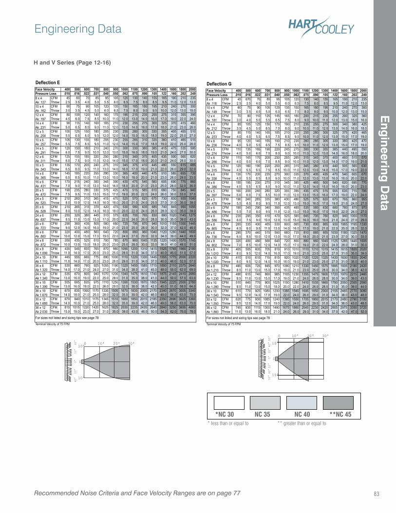
H and V Series (Page 12-16)
Deflection E400 500 600 700 800 900 1000 1100 1200 1300 1400 1600 1800 2000
.010 .016 .022 .031 .040 .050 .062 .075 .090 .105 .122 .160 .202 .249CFM 45 60 70 85 95 105 120 130 140 155 165 190 210 235Throw 2.5 3.5 4.0 5.0 5.5 6.0 6.5 7.5 8.0 8.5 9.5 11.0 12.0 13.0CFM 60 75 90 105 120 135 150 165 180 195 210 240 270 300Throw 3.0 3.5 4.5 5.0 6.0 6.5 7.5 8.0 9.0 9.5 10.0 12.0 13.0 15.0CFM 80 100 120 140 160 175 195 215 235 255 275 315 355 395Throw 4.5 6.0 7.5 8.5 10.0 11.0 12.0 13.0 14.0 16.0 17.0 19.0 22.0 24.0CFM 90 115 140 160 185 210 230 255 275 300 325 370 415 460Throw 5.0 6.5 8.0 9.0 11.0 12.0 13.0 14.0 16.0 17.0 18.0 21.0 23.0 26.0CFM 100 125 150 180 205 230 255 280 305 330 355 405 455 510Throw 5.5 6.5 8.0 9.5 12.0 12.0 14.0 15.0 16.0 18.0 19.0 22.0 25.0 27.0CFM 105 130 155 180 205 230 255 285 310 335 360 410 465 515Throw 5.5 7.5 8.5 9.5 11.0 12.0 14.0 15.0 17.0 18.0 19.0 22.0 25.0 28.0CFM 120 150 180 210 240 270 300 330 360 385 415 475 535 595Throw 6.0 7.5 9.0 10.0 12.0 13.0 15.0 16.0 18.0 19.0 21.0 24.0 27.0 30.0CFM 125 155 185 220 250 280 310 340 375 405 435 500 560 620Throw 6.0 7.5 9.0 11.0 12.0 14.0 15.0 17.0 18.0 20.0 21.0 24.0 28.0 30.0CFM 135 170 205 240 275 310 345 375 410 445 480 550 615 685Throw 6.5 8.0 9.5 11.0 13.0 14.0 16.0 17.0 19.0 21.0 22.0 26.0 29.0 32.0CFM 145 185 220 255 290 330 365 400 440 475 510 585 655 730Throw 6.5 8.5 10.0 11.0 13.0 15.0 16.0 18.0 20.0 21.0 23.0 26.0 29.0 33.0CFM 170 215 240 300 345 390 430 475 545 560 605 690 775 860Throw 7.0 9.0 11.0 12.0 14.0 16.0 18.0 20.0 21.0 23.0 25.0 28.0 32.0 36.0CFM 190 235 280 330 375 425 470 515 565 610 660 750 845 940Throw 7.5 9.5 11.0 13.0 15.0 17.0 19.0 20.0 22.0 24.0 26.0 30.0 33.0 37.0CFM 210 260 310 365 415 470 520 570 625 675 730 830 935 1040Throw 8.0 10.0 12.0 14.0 16.0 18.0 20.0 21.0 24.0 25.0 27.0 31.0 35.0 39.0CFM 210 265 315 370 420 475 530 580 635 685 740 845 950 1055Throw 8.0 10.0 12.0 14.0 16.0 18.0 20.0 22.0 24.0 26.0 28.0 32.0 35.0 39.0CFM 255 320 380 445 510 575 635 700 765 830 890 1020 1145 1275Throw 8.5 11.0 13.0 15.0 17.0 20.0 22.0 24.0 26.0 28.0 30.0 35.0 39.0 43.0CFM 290 360 435 505 580 650 725 795 870 940 1010 1155 1300 1445Throw 9.0 12.0 14.0 16.0 19.0 21.0 23.0 25.0 28.0 30.0 32.0 37.0 42.0 46.0CFM 320 400 480 560 640 720 800 880 960 1040 1120 1280 1440 1600Throw 10.0 12.0 15.0 17.0 19.0 22.0 24.0 27.0 29.0 32.0 34.0 39.0 44.0 49.0CFM 350 435 525 610 700 785 870 960 1045 1135 1220 1400 1570 1745Throw 10.0 13.0 15.0 18.0 20.0 23.0 25.0 28.0 30.0 33.0 36.0 41.0 48.0 51.0CFM 435 545 655 765 870 980 1090 1200 1310 1415 1525 1745 1960 2180Throw 11.0 14.0 17.0 20.0 23.0 25.0 28.0 31.0 34.0 37.0 40.0 45.0 51.0 57.0CFM 445 555 665 775 890 1000 1110 1220 1330 1445 1555 1775 2000 2220Throw 11.0 14.0 17.0 20.0 23.0 26.0 29.0 31.0 34.0 37.0 40.0 46.0 52.0 57.0CFM 530 660 790 925 1055 1190 1320 1450 1585 1715 1850 2110 2375 2640Throw 14.0 17.0 21.0 24.0 27.0 31.0 34.0 38.0 41.0 45.0 48.0 55.0 62.0 69.0CFM 535 670 805 940 1070 1205 1340 1475 1610 1740 1875 2145 2410 2680Throw 13.0 16.0 19.0 22.0 25.0 28.0 31.0 35.0 38.0 41.0 44.0 50.0 57.0 63.0CFM 555 695 835 975 1110 1250 1390 1530 1670 1805 1945 2225 2500 2780Throw 13.0 16.0 19.0 22.0 26.0 29.0 32.0 38.0 38.0 42.0 45.0 51.0 58.0 64.0CFM 670 835 1000 1170 1335 1505 1670 1835 2005 2170 2340 2670 3005 3340Throw 14.0 18.0 21.0 25.0 28.0 32.0 35.0 39.0 42.0 46.0 49.0 56.0 63.0 70.0CFM 670 840 1010 1175 1345 1510 1680 1850 2015 2185 2350 2690 3025 3360Throw 14.0 16.0 21.0 25.0 28.0 32.0 35.0 39.0 42.0 46.0 49.0 56.0 63.0 70.0CFM 810 1015 1220 1420 1625 1825 2030 2235 2435 2640 2840 3250 3655 4060Throw 15.0 19.0 23.0 27.0 31.0 35.0 39.0 43.0 46.0 50.0 54.0 62.0 70.0 78.0
Terminal Velocity of 75 FPM
30 x 12Ak 1.68036 x 12Ak 2.030
For sizes not listed and sizing tips see page 7
36 x 8Ak 1.32024 x 12Ak 1.34030 x 10Ak 1.39036 x 10Ak 1.670
30 x 6Ak .80024 x 8Ak .87230 x 8Ak 1.09024 x 10Ak 1.110
24 x 5Ak .52020 x 6Ak .52824 x 6Ak .63720 x 8Ak .723
16 x 5Ak .34314 x 6Ak .36516 x 6Ak .43120 x 5Ak .470
12 x 5Ak .25410 x 6Ak .25714 x 5Ak .29112 x 6Ak .311
8 x 4Ak .12710 x 4Ak .16212 x 4Ak .19714 x 4Ak .231
Face VelocityPressure Loss
Deflection G400 500 600 700 800 900 1000 1100 1200 1300 1400 1600 1800 2000
.010 .016 .022 .031 .040 .050 .062 .075 .090 .105 .122 .160 .202 .249CFM 45 670 70 85 95 105 120 130 140 155 165 190 210 235Throw 2.5 3.5 4.0 5.0 5.5 6.0 6.5 7.5 8.0 8.5 9.5 11.0 12.0 13.0CFM 60 75 90 105 120 135 150 165 180 195 210 240 270 300Throw 3.0 3.5 4.5 5.0 6.0 6.5 7.5 8.0 9.0 9.5 10.0 12.0 13.0 15.0CFM 70 90 110 125 145 165 180 200 215 235 255 290 325 360Throw 3.0 4.0 5.0 5.5 6.5 7.5 8.0 9.0 10.0 11.0 12.0 13.0 15.0 16.0CFM 85 105 125 150 170 190 210 235 255 275 300 340 380 425Throw 3.5 4.5 5.0 6.5 7.0 8.0 9.0 10.0 11.0 12.0 13.0 14.0 16.0 18.0CFM 95 115 140 165 185 210 235 255 280 305 325 375 420 465Throw 4.0 4.5 5.5 6.5 7.5 8.5 9.5 10.0 11.0 12.0 13.0 15.0 17.0 19.0CFM 95 120 140 165 190 210 235 260 285 305 330 380 425 470Throw 4.0 5.0 5.5 6.5 7.5 8.5 9.5 10.0 11.0 12.0 13.0 15.0 17.0 19.0CFM 110 135 165 190 220 245 275 300 330 355 385 440 495 550Throw 4.0 5.0 6.0 7.0 8.0 9.0 10.0 11.0 12.0 13.0 14.0 16.0 18.0 20.0CFM 115 145 170 200 230 255 285 315 345 370 400 460 515 570Throw 4.0 5.0 6.0 7.0 8.5 9.0 10.0 11.0 12.0 13.0 14.0 17.0 19.0 21.0CFM 125 160 190 220 250 285 315 345 380 410 440 505 565 630Throw 4.5 5.5 6.5 7.5 8.5 10.0 11.0 12.0 13.0 14.0 15.0 17.0 19.0 22.0CFM 135 170 200 235 270 300 335 370 405 435 470 540 605 670Throw 4.5 5.5 6.5 8.0 9.0 10.0 11.0 12.0 13.0 13.0 16.0 18.0 20.0 22.0CFM 155 195 230 270 310 345 385 425 465 500 540 620 695 770Throw 4.5 5.5 6.5 8.0 9.0 10.0 11.0 12.0 14.0 15.0 16.0 18.0 20.0 23.0CFM 160 200 240 280 320 355 395 435 475 515 555 635 715 795Throw 5.0 6.0 7.5 8.5 10.0 11.0 12.0 13.0 15.0 16.0 17.0 19.0 22.0 24.0CFM 190 240 285 335 380 430 480 525 575 620 670 765 860 955Throw 5.5 6.5 8.0 9.5 11.0 12.0 13.0 15.0 16.0 17.0 19.0 21.0 24.0 27.0CFM 195 245 290 340 390 435 485 535 585 630 680 780 875 970Throw 5.5 7.0 8.0 9.5 11.0 12.0 13.0 15.0 16.0 17.0 19.0 22.0 24.0 27.0CFM 235 295 350 410 470 525 585 645 705 760 820 940 1055 1170Throw 6.0 7.5 9.0 10.0 12.0 13.0 15.0 16.0 18.0 19.0 21.0 24.0 27.0 29.0CFM 265 335 400 465 530 600 665 730 800 865 930 1065 1195 1330Throw 6.5 8.0 9.5 11.0 13.0 14.0 16.0 17.0 19.0 21.0 22.0 25.0 28.0 32.0CFM 295 370 440 515 590 660 735 810 885 955 1030 1180 1325 1470Throw 6.5 8.5 10.0 12.0 13.0 15.0 17.0 18.0 20.0 21.0 23.0 27.0 30.0 33.0CFM 320 400 480 560 640 720 800 880 960 1045 1125 1285 1445 1605Throw 7.0 8.5 10.0 12.0 14.0 15.0 17.0 19.0 21.0 22.0 24.0 28.0 31.0 35.0CFM 405 505 605 705 810 910 1010 1110 1210 1315 1415 1615 1820 2020Throw 8.0 9.5 12.0 14.0 16.0 17.0 19.0 21.0 23.0 25.0 27.0 31.0 35.0 39.0CFM 410 510 610 715 815 920 1020 1120 1225 1325 1430 1630 1835 2040Throw 8.0 9.5 12.0 14.0 16.0 18.0 19.0 21.0 23.0 25.0 27.0 31.0 35.0 40.0CFM 485 605 725 845 970 1090 1210 1330 1450 1575 1695 1935 2180 2420Throw 8.5 11.0 13.0 15.0 17.0 19.0 21.0 23.0 25.0 28.0 30.0 34.0 38.0 42.0CFM 490 615 740 860 985 1105 1230 1355 1475 1600 1720 1970 2215 2460Throw 8.5 11.0 13.0 15.0 17.0 19.0 21.0 24.0 26.0 28.0 30.0 34.0 39.0 43.0CFM 510 640 770 900 1025 1150 1280 1410 1535 1665 1790 2050 2305 2560Throw 8.5 11.0 13.0 15.0 18.0 20.0 22.0 24.0 26.0 28.0 31.0 35.0 39.0 44.0CFM 615 770 925 1080 1230 1385 1540 1695 1850 2000 2155 2465 2770 3080Throw 9.5 12.0 14.0 17.0 19.0 22.0 24.0 26.0 29.0 31.0 34.0 38.0 43.0 48.0CFM 620 775 930 1085 1240 1395 1550 1705 1860 2015 2170 2480 2790 3100Throw 9.5 12.0 14.0 17.0 19.0 22.0 24.0 26.0 29.0 31.0 34.0 38.0 43.0 48.0CFM 745 930 1115 1300 1490 1675 1860 2045 2230 2420 2605 2975 3350 3720Throw 11.0 13.0 16.0 18.0 21.0 24.0 26.0 29.0 31.0 34.0 37.0 42.0 47.0 52.0
Terminal Velocity of 75 FPM
36 x 10Ak 1.54030 x 12Ak 1.55036 x 12Ak 1.860
For sizes not listed and sizing tips see page 7
24 x 10Ak 1.02036 x 8Ak 1.21024 x 12Ak 1.23030 x 10Ak 1.280
20 x 8Ak .66530 x 6Ak .73624 x 8Ak .80230 x 8Ak 1.010
20 x 5Ak .39724 x 5Ak .47820 x 6Ak .48624 x 6Ak .586
12 x 6Ak .28616 x 5Ak .31514 x 6Ak .33616 x 6Ak .386
14 x 4Ak .21212 x 5Ak .23310 x 6Ak .23614 x 5Ak .274
Pressure Loss8 x 4Ak .11810 x 4Ak .14912 x 4Ak .181
Face Velocity
*NC 30 NC 35 NC 40 **NC 45* less than or equal to ** greater than or equal to
0
0
10'10'
10'
20' 30'
0°
22
°2
2°
42
°4
2°
0
0
10'
10'
10'
20' 30'
55
°4
2°
22
°0
°2
2°
42
°5
5°
Recommended Noise Criteria and Face Velocity Ranges are on page 77
Engineering Data
83
Eng
ineering D
ata
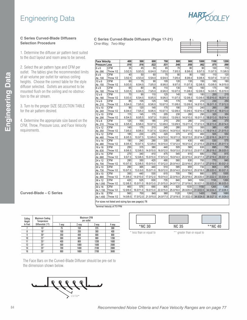
C Series Curved-Blade DiffusersSelection Procedure
1. Determine the diffuser air pattern best suited to the duct layout and room area to be served.
2. Select the air pattern type and CFM per outlet. The tables give the recommended limits of air volume per outlet for various ceiling heights. Choose the correct table for the style diffuser selected. Outlets are assumed to be mounted flush on the ceiling and no obstruc-tion to the air stream.
3. Turn to the proper SIZE SELECTION TABLE for the air pattern desired.
4. Determine the appropriate size based on the CFM, Throw, Pressure Loss, and Face Velocity requirements.
Curved-Blade – C Series
Maximum CFMper outlet
CeilingHeightIn Feet
Maximum CoolingTemperature
Differential (°F) 1 way 2 way 3 way 4 way7 15° 75 150 225 3008 18° 100 200 300 4009 20° 200 400 600 80010 22° 300 600 900 120011 25° 400 800 1200 160012 25° 500 1000 1500 200014 25° 700 1400 2100 280016 25° 900 1800 2700 3600
The Face Bars on the Curved-Blade Diffuser should be pre-set to the dimension shown below.
13/32"
*NC 30 NC 35 **NC 40* less than or equal to ** greater than or equal to
C Series Curved-Blade Diffusers (Page 17-21)One-Way, Two-Way
400 500 600 700 800 900 1000 1100 1200.010 .016 .022 .031 .040 .050 .062 .075 .090
CFM 35 45 55 65 70 80 90 100 110Throw 1/2 3.5/2.5 5.0/3.5 6.0/4.0 7.0/5.0 7.5/5.5 8.5/6.0 9.5/7.0 11.0/7.5 11.5/8.5CFM 40 50 60 70 80 90 100 110 120Throw 1/2 3.5/2.5 4.5/3.0 5.5/4.0 6.5/4.5 7.0/5.0 8.0/6.0 9.0/6.5 10.0/7.0 11.0/7.5CFM 60 75 90 105 120 135 150 165 180Throw 1/2 5.0/3.5 6.0/4.5 7.0/5.0 8.5/6.0 9.5/7.0 11.0/7.5 12.0/8.5 13.0/9.5 14.0/10.0CFM 65 80 95 110 130 145 160 175 190Throw 1/2 5.0/3.5 6.0/4.5 7.5/5.0 8.5/6.0 10.0/7.0 11.0/8.0 12.0/9.0 14.0/9.5 15.0/10.0CFM 70 90 110 125 145 160 180 200 215Throw 1/2 5.0/3.5 6.5/4.5 8.0/5.5 9.0/6.5 11.0/7.5 12.0/8.5 13.0/9.5 15.0/10.0 16.0/11.0CFM 85 105 125 145 170 190 210 230 250Throw 1/2 5.5/4.0 7.0/5.0 8.5/6.0 10.0/7.0 11.0/8.0 13.0/9.0 14.0/10.0 16.0/11.0 17.0/12.0CFM 95 120 145 170 190 215 240 265 290Throw 1/2 6.0/4.0 7.5/5.0 9.0/6.5 10.0/7.5 12.0/8.0 13.0/9.5 15.0/10.0 16.0/11.0 18.0/13.0CFM 115 145 175 205 230 260 290 320 350Throw 1/2 6.5/4.5 8.0/5.5 9.5/7.0 11.0/8.0 13.0/9.0 14.0/10.0 16.0/11.0 18.0/13.0 19.0/14.0CFM 125 155 185 215 250 280 310 340 370Throw 1/2 6.5/5.0 8.5/6.0 10.0/7.0 12.0/8.0 13.0/9.5 15.0/11.0 17.0/12.0 18.0/13.0 20.0/14.0CFM 140 175 210 245 280 315 350 385 420Throw 1/2 7.0/5.0 9.0/6.0 11.0/7.5 12.0/8.5 14.0/10.0 16.0/11.0 18.0/12.0 19.0/14.0 21.0/15.0CFM 185 230 275 320 370 415 460 505 550Throw 1/2 8.0/5.5 10.0/7.5 12.0/9.0 14.0/10.0 16.0/11.0 18.0/13.0 20.0/14.0 22.0/16.0 24.0/17.0CFM 190 240 290 335 385 430 480 530 575Throw 1/2 8.0/5.5 10.0/7.5 12.0/9.0 14.0/10.0 17.0/12.0 18.0/13.0 21.0/15.0 23.0/16.0 25.0/17.0CFM 250 315 380 440 505 565 630 695 755Throw 1/2 9.5/6.5 12.0/8.5 14.0/10.0 16.0/12.0 19.0/13.0 21.0/15.0 23.0/17.0 26.0/18.0 28.0/20.0CFM 270 340 410 475 545 610 680 750 815Throw 1/2 9.5/7.0 12.0/8.5 15.0/10.0 17.0/12.0 19.0/14.0 22.0/15.0 24.0/17.0 27.0/19.0 29.0/21.0CFM 280 350 420 490 560 630 700 770 840Throw 1/2 10.0/7.0 12.0/8.5 15.0/10.0 17.0/12.0 20.0/14.0 22.0/16.0 25.0/17.0 27.0/19.0 30.0/21.0CFM 290 365 440 510 585 655 730 805 875Throw 1/2 10.0/7.0 13.0.9.0 15.0/11.0 18.0/12.0 20.0/14.0 23.0/16.0 25.0/18.0 28.0/20.0 30.0/21.0CFM 350 440 530 615 705 790 880 970 1055Throw 1/2 11.0/8.0 14.0/10.0 17.0/12.0 19.0/14.0 22.0/16.0 25.0/18.0 28.0/20.0 31.0/22.0 33.0/24.0CFM 420 525 630 735 840 945 1050 1155 1260Throw 1/2 12.0/8.5 15.0/11.0 18.0/13.0 21.0/15.0 24.0/17.0 27.0/19.0 30.0/21.0 33.0/23.0 36.0/25.0CFM 460 575 690 805 920 1035 1150 1265 1380Throw 1/2 12.0/9.0 16.0/11.0 19.0/13.0 22.0/15.0 25.0/18.0 28.0/20.0 31.0/22.0 34.0/24.0 37.0/26.0CFM 560 700 840 980 1120 1260 1400 1540 1680Throw 1/2 14.0/9.5 17.0/12.0 21.0/15.0 24.0/17.0 27.0/19.0 31.0/22.0 34.0/24.0 38.0/27.0 41.0/29.0
Terminal Velocity of 75 FPM
Face VelocityPressure Loss6 x 6Ak .0908 x 6Ak .10010 x 6Ak .1508 x 8Ak .16012 x 6Ak .18014 x 6Ak .210
36 x 10Ak .880
10 x 10Ak .24012 x 10Ak .29016 x 8Ak .31012 x 12Ak .350
36 x 12Ak 1.050
36 x 16Ak 1.400
For sizes not listed and sizing tips see page(s) 7
16 x 12Ak .46014 x 14Ak .48016 x 16Ak .63020 x 14Ak .680
30 x 16Ak 1.150
24 x 12Ak. 70030 x 10Ak .730
L L
L
Recommended Noise Criteria and Face Velocity Ranges are on page 7784
Engineering DataE
ngin
eeri
ng D
ata
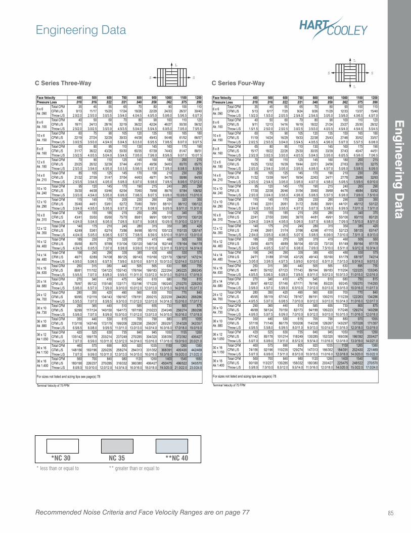
C Series Three-Way
L
SS
C Series Four-Way
L
L
SS
400 500 600 700 800 900 1000 1100 1200.010 .016 .022 .031 .040 .050 .062 .075 .090
Total CFM 35 45 55 65 70 80 90 100 110CFM L/S 5/13 6/17 7/20 9/24 9/26 11/29 12/33 13/37 15/40Throw L/S 1.5/2.0 1.5/3.0 2.0/3.5 2.5/4.0 2.5/4.5 3.0/5.0 3.5/6.0 4.0/6.5 4.5/7.0Total CFM 40 50 60 70 80 90 100 110 120CFM L/S 9/11 12/13 14/16 16/19 18/22 21/24 23/27 25/30 28/32Throw L/S 1.5/1.5 2.5/2.0 2.5/2.5 3.0/2.5 3.5/3.0 4.0/3.5 4.5/4.0 4.5/4.5 5.5/4.5Total CFM 60 75 90 105 120 135 150 165 180CFM L/S 11/19 14/24 16/29 19/33 22/38 25/43 27/48 30/52 33/57Throw L/S 2.0/2.5 2.5/3.5 3.0/4.0 3.5/4.5 4.0/5.5 4.5/6.0 5.0/7.0 5.5/7.5 6.0/8.0Total CFM 65 80 95 110 130 145 160 175 190CFM L/S 15/17 18/22 22/26 25/30 30/35 33/39 37/43 40/47 44/51Throw L/S 2.5/2.0 3.0/2.5 3.5/3.0 4.0/3.5 5.0/4.5 3.5/5.0 6.0/5.5 6.5/6.0 7.0/6.5Total CFM 70 90 110 125 145 160 180 200 215CFM L/S 10/25 13/32 16/39 19/44 22/51 24/56 27/63 30/70 32/75Throw L/S 2.0/3.0 2.5/4.0 3.0/5.0 3.5/5.5 4.0/6.5 4.5/7.0 5.0/8.0 5.5/8.5 6.0/9.5Total CFM 85 105 125 145 170 190 210 230 250CFM L/S 11/32 13/39 16/47 18/54 22/63 24/71 27/78 29/86 32/93Throw L/S 2.0/3.5 2.5/4.5 3.0/5.0 3.5/6.0 4.0/7.0 4.5/8.0 5.0/8.5 5.5/9.5 6.0/10.0Total CFM 95 120 145 170 190 215 240 265 290CFM L/S 17/30 22/38 26/46 31/54 35/60 39/68 44/76 48/84 53/92Throw L/S 2.5/3.0 3.0/4.0 3.5/5.0 4.5/6.0 5.0/6.5 5.5/7.5 6.5/8.0 7.0/9.0 7.5/10.0Total CFM 115 145 175 205 230 260 290 320 350CFM L/S 17/40 22/51 26/61 31/72 35/80 39/91 44/101 48/112 53/122Throw L/S 2.5/4.0 3.0/5.0 3.5/5.5 4.5/7.0 5.0/7.5 5.5/8.5 6.5/9.5 7.0/11.0 7.5/11.0Total CFM 125 155 185 215 250 280 310 340 370CFM L/S 22/41 27/50 33/60 38/70 44/81 49/91 55/100 60/110 65/120Throw L/S 3.0/4.0 3.5/4.5 4.0/5.5 5.0/6.5 5.5/7.5 6.5/8.5 7.0/9.5 7.5/10.0 8.5/11.0Total CFM 140 175 210 245 280 315 350 385 420CFM L/S 21/49 26/61 31/74 37/86 42/98 47/110 52/123 58/135 63/147Throw L/S 2.5/4.0 3.5/5.0 4.0/6.5 5.0/7.5 5.5/8.5 6.0/9.5 7.0/10.0 7.5/11.0 8.0/13.0Total CFM 185 230 275 320 370 415 460 505 550CFM L/S 33/60 40/75 48/89 56/104 65/120 73/135 81/149 89/164 97/178Throw L/S 3.5/4.5 4.0/5.5 5.0/7.0 6.0/8.0 7.0/9.0 7.5/10.0 8.5/11.0 9.0/12.0 10.0/14.0Total CFM 190 240 290 335 385 430 480 530 575CFM L/S 24/71 31/89 37/108 43/125 49/143 55/160 61/179 68/197 74/214Throw L/S 3.0/5.0 3.5/6.5 4.5/7.5 5.0/9.0 6.0/10.0 6.5/11.0 7.5/13.0 8.0/14.0 9.0/15.0Total CFM 250 315 380 440 505 565 630 695 755CFM L/S 44/81 55/102 67/123 77/143 89/164 99/183 111/204 122/225 133/245Throw L/S 4.0/5.5 5.0/6.5 6.0/8.0 7.0/9.5 8.0/11.0 9.0/12.0 10.0/13.0 11.0/15.0 12.0/16.0Total CFM 270 340 410 475 545 610 680 750 815CFM L/S 38/97 48/122 57/148 67/171 76/196 85/220 95/245 105/270 114/293Throw L/S 3.5/6.0 4.5/7.0 5.5/9.0 6.5/10.0 7.0/12.0 8.0/13.0 9.0/15.0 10.0/16.0 11.0/17.0Total CFM 280 350 420 490 560 630 700 770 840CFM L/S 45/95 56/119 67/143 78/167 89/191 100/215 111/239 122/263 134/286Throw L/S 4.0/5.5 5.0/7.0 6.0/8.5 7.0/10.0 8.0/12.0 9.0/13.0 10.0/14.0 11.0/16.0 12.0/17.0Total CFM 290 365 440 510 585 655 730 805 875CFM L/S 46/99 58/124 70/150 82/173 94/199 105/223 117/248 129/274 140/298Throw L/S 4.0/6.0 5.0/7.5 6.0/9.0 7.0/10.0 8.0/12.0 9.0/13.0 10.0/15.0 11.0/16.0 12.0/18.0Total CFM 350 440 530 615 705 790 880 970 1055CFM L/S 57/118 71/149 86/179 100/208 114/238 128/267 143/297 157/328 171/357Throw L/S 4.5/6.5 5.5/8.0 6.5/9.5 8.0/11.0 9.0/13.0 10.0/14.0 11.0/16.0 12.0/18.0 13.0/19.0Total CFM 420 525 630 735 840 945 1050 1155 1260CFM L/S 67/142 85/178 101/214 118/249 135/285 152/320 169/356 186/392 203/427Throw L/S 5.0/7.0 6.0/9.0 7.0/11.0 8.5/12.0 9.5/14.0 11.0/16.0 12.0/18.0 13.0/19.0 14.0/21.0Total CFM 460 575 690 805 920 1035 1150 1265 1380CFM L/S 74/156 92/196 110/235 129/274 147/313 166/352 184/391 202/430 221/469Throw L/S 5.0/7.0 6.0/9.0 7.5/11.0 8.5/13.0 10.0/15.0 11.0/16.0 12.0/18.0 14.0/20.0 15.0/22.0Total CFM 560 700 840 980 1120 1260 1400 1540 1680CFM L/S 90/190 113/237 135/285 158/332 180/380 203/427 225/475 248/522 270/570Throw L/S 5.5/8.0 7.0/10.0 8.5/12.0 9.5/14.0 11.0/16.0 12.0/18.0 14.0/20.0 15.0/22.0 17.0/24.0
Terminal Velocity of 75 FPM
For sizes not listed and sizing tips see page(s) 7
36 x 10Ak .880
36 x 12Ak 1.050
30 x 16Ak 1.150
36 x 16Ak 1.400
16 x 16Ak .630
20 x 14Ak .680
24 x 12Ak. 700
30 x 10Ak .730
16 x 8Ak .310
12 x 12Ak .350
16 x 12Ak .460
14 x 14Ak .480
12 x 6Ak .180
14 x 6Ak .210
10 x 10Ak .240
12 x 10Ak .290
6 x 6Ak .090
8 x 6Ak .100
10 x 6Ak .150
8 x 8Ak .160
Face VelocityPressure Loss
400 500 600 700 800 900 1000 1100 1200.010 .016 .022 .031 .040 .050 .062 .075 .090
Total CFM 35 45 55 65 70 80 90 100 110CFM L/S 9/13 11/17 15/20 17/24 18/26 22/29 24/33 26/37 30/40Throw L/S 2.0/2.0 2.5/3.0 3.0/3.5 3.5/4.0 4.0/4.5 4.5/5.0 5.0/6.0 5.5/6.5 6.0/7.0Total CFM 40 50 60 70 80 90 100 110 120CFM L/S 18/11 24/13 28/16 32/19 36/22 42/24 46/27 50/30 56/32Throw L/S 2.5/2.0 3.0/2.5 3.5/3.0 4.5/3.5 5.0/4.0 5.5/4.5 6.0/5.0 7.0/5.0 7.5/5.5Total CFM 60 75 90 105 120 135 150 165 180CFM L/S 22/19 27/24 32/29 39/33 44/38 49/43 54/48 61/52 66/57Throw L/S 3.0/2.5 3.5/3.0 4.5/4.0 5.0/4.5 6.0.5.0 6.5/5.5 7.0/6.5 8.0/7.0 9.0/7.5Total CFM 65 80 95 110 130 145 160 175 190CFM L/S 31/17 36/22 43/26 50/30 60/35 67/39 74/43 81/47 88/51Throw L/S 3.5/2.5 4.0/3.5 5.0/4.0 5.5/4.5 7.0/5.0 7.5/6.0 8.5/6.5 9.0/7.0 10.0/7.5Total CFM 70 90 110 125 145 160 180 200 215CFM L/S 20/25 26/32 32/39 37/44 43/51 48/56 54/63 60/70 65/75Throw L/S 2.5/3.0 3.5/4.0 4.5/5.0 5.0.5.5 5.5/6.5 6.5/7.0 7.0/8.0 8.0/8.5 8.5/9.5Total CFM 85 105 125 145 170 190 210 230 250CFM L/S 21/32 27/39 31/47 37/54 44/63 48/71 54/78 58/86 64/93Throw L/S 2.5/3.5 3.5/4.5 4.0/5.0 5.0/6.0 6.0/7.0 6.5/8.0 7.0/8.5 8.0/9.5 17.0/12.0Total CFM 95 120 145 170 190 215 240 265 290CFM L/S 35/30 44/38 53/46 62/54 70/60 79/68 88/76 97/84 106/92Throw L/S 3.5/3.0 4.5/4.0 5.5/5.0 6.0/6.0 7.0/6.5 8.0/7.5 9.0/8.0 10.0/9.0 11.0/10.0Total CFM 115 145 175 205 230 260 290 320 350CFM L/S 35/40 44/51 53/61 62/72 70/80 78/91 88/101 96/112 106/122Throw L/S 3.5/4.0 4.5/5.0 5.5/5.5 6.5/7.0 7.0/7.5 8.0/8.5 9.0/9.5 9.5/11.0 11.0/11.0Total CFM 125 155 185 215 250 280 310 340 370CFM L/S 43/41 55/50 65/60 75/70 88/81 98/91 108/101 120/110 130/120Throw L/S 4.0/4.0 5.0/4.5 6.0/5.5 7.0/6.5 8.0/7.5 9.0/8.5 10.0/9.5 11.0/10.0 12.0/11.0Total CFM 140 175 210 245 280 315 350 385 420CFM L/S 42/49 53/61 62/74 73/86 84/98 95/110 105/123 115/135 126/147Throw L/S 4.0/4.0 5.0/5.0 6.0/6.5 6.5/7.5 7.5/8.5 8.5/9.5 9.5/10.0 11.0/11.0 13.0/13.0Total CFM 185 230 275 320 370 415 460 505 550CFM L/S 65/60 80/75 97/89 113/104 130/120 146/134 162/149 178/164 194/178Throw L/S 4.5/4.5 6.0/5.5 7.0/7.0 8.5/8.0 9.5/9.0 11.0/10.0 12.0/11.0 13.0/12.0 14.0/14.0Total CFM 190 240 290 335 385 430 480 530 575CFM L/S 48/71 62/89 74/108 86/125 99/143 110/160 123/179 136/197 147/214Throw L/S 4.0/5.0 5.0/6.5 6.5/7.5 7.5/9.0 8.5/10.0 9.5/11.0 10.0/13.0 12.0/14.0 13.0/15.0Total CFM 250 315 380 440 505 565 630 695 755CFM L/S 88/81 111/102 134/123 155/143 178/164 199/183 222/204 245/225 266/245Throw L/S 5.5/5.5 7.0/7.0 8.5/8.0 9.5/9.5 11.0/11.0 13.0/12.0 14.0/13.0 15.0/15.0 17.0/16.0Total CFM 270 340 410 475 545 610 680 750 815CFM L/S 76/97 95/122 115/148 133/171 153/196 171/220 190/245 210/270 228/293Throw L/S 5.0/6.0 6.5/7.0 7.5/9.0 9.0/10.0 10.0/12.0 12.0/13.0 13.0/15.0 14.0/16.0 15.0/17.0Total CFM 280 350 420 490 560 630 700 770 840CFM L/S 90/95 112/119 134/143 156/167 178/191 200/215 222/239 244/263 268/286Throw L/S 5.5/5.5 7.0/7.0 8.5/8.5 9.5/10.0 11.0/12.0 12.0/13.0 14.0/14.0 15.0/16.0 17.0/17.0Total CFM 290 365 440 510 585 655 730 805 875CFM L/S 92/99 117/124 140/150 164/173 187/199 210/223 234/248 258/274 280/298Throw L/S 5.5/6.0 7.0/7.5 8.5/9.0 10.0/10.0 11.0/12.0 13.0/13.0 14.0/15.0 16.0/16.0 17.0/18.0Total CFM 350 440 530 615 705 790 880 970 1055CFM L/S 113/118 143/149 172/179 199/208 228/238 256/267 285/297 314/328 342/357Throw L/S 6.5/6.5 8.0/8.0 9.5/9.5 11.0/11.0 13.0/13.0 14.0/14.0 16.0/16.0 17.0/18.0 19.0/19.0Total CFM 420 525 630 735 840 945 1050 1155 1260CFM L/S 135/142 169/178 203/214 237/249 270/285 304/320 338/356 372/392 406/427Throw L/S 7.0/7.0 8.5/9.0 10.0/11.0 12.0/12.0 14.0/14.0 15.0/16.0 17.0/18.0 19.0/19.0 20.0/21.0Total CFM 460 575 690 805 920 1035 1150 1265 1380CFM L/S 148/156 183/196 220/235 258/274 294/313 331/352 368/391 405/430 442/469Throw L/S 7.0/7.0 9.0/9.0 10.0/11.0 12.0/13.0 14.0/15.0 16.0/16.0 18.0/18.0 19.0/20.0 21.0/22.0Total CFM 560 700 840 980 1120 1260 1400 1540 1680CFM L/S 180/190 226/237 270/285 316/332 360/380 406/427 450/475 496/522 540/570Throw L/S 8.0/8.0 10.0/10.0 12.0/12.0 14.0/14.0 16.0/16.0 18.0/18.0 19.0/20.0 21.0/22.0 23.0/24.0
Terminal Velocity of 75 FPM
30 x 16Ak 1.150
36 x 16Ak 1.400
For sizes not listed and sizing tips see page(s) 7
Face VelocityPressure Loss
6 x 6Ak .090
8 x 6Ak .100
10 x 6Ak .150
8 x 8Ak .160
12 x 6Ak .180
14 x 6Ak .210
10 x 10Ak .240
12 x 10Ak .290
16 x 8Ak .310
12 x 12Ak .350
36 x 10Ak .880
36 x 12Ak 1.050
16 x 12Ak .460
14 x 14Ak .480
16 x 16Ak .630
20 x 14Ak .680
24 x 12Ak. 700
30 x 10Ak .730
*NC 30 NC 35 **NC 40* less than or equal to ** greater than or equal to
Recommended Noise Criteria and Face Velocity Ranges are on page 77
Engineering Data
85
Eng
ineering D
ata
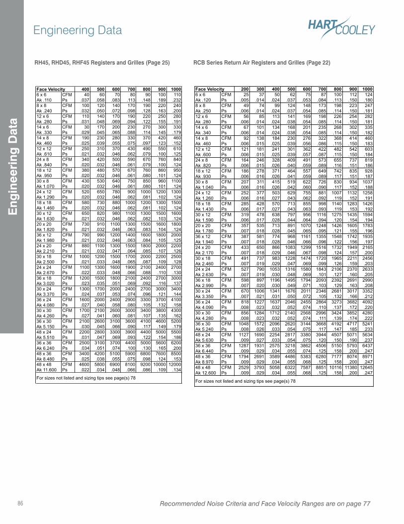
RH45, RHD45, RHF45 Registers and Grilles (Page 25) RCB Series Return Air Registers and Grilles (Page 22)
400 500 600 700 800 900 1000CFM 40 60 70 80 90 100 110Ps .037 .058 .083 .113 .148 .189 .232CFM 100 120 140 170 190 220 240Ps .032 .050 .072 .098 .128 .163 .200CFM 110 140 170 190 220 250 280Ps .031 .048 .069 .094 .122 .155 .191CFM 30 170 200 230 270 300 330Ps .029 .045 .065 .088 .114 .145 .179CFM 190 230 280 330 370 420 460Ps .025 .039 .055 .075 .097 .123 .152CFM 250 310 370 430 490 550 610Ps .021 .032 .046 .062 .079 .100 .125CFM 340 420 500 590 670 760 840Ps .020 .032 .046 .061 .079 .100 .124CFM 380 480 570 670 760 860 950Ps .020 .032 .046 .061 .080 .101 .124CFM 430 530 640 750 850 960 1100Ps .020 .032 .046 .061 .080 .101 .124CFM 520 650 780 900 1000 1200 1300Ps .020 .032 .046 .062 .081 .102 .124CFM 580 730 880 1000 1200 1300 1500Ps .020 .032 .046 .062 .081 .102 .124CFM 650 820 980 1100 1300 1500 1600Ps .021 .032 .046 .062 .082 .103 .124CFM 730 910 1100 1300 1500 1600 1800Ps .021 .032 .046 .063 .083 .104 .124CFM 790 990 1200 1400 1600 1800 2000Ps .021 .032 .046 .063 .084 .105 .125CFM 880 1100 1300 1500 1800 2000 2200Ps .021 .032 .047 .064 .085 .107 .126CFM 1000 1200 1500 1700 2000 2200 2500Ps .021 .033 .048 .065 .087 .109 .128CFM 1100 1300 1600 1900 2100 2400 2700Ps .022 .033 .048 .066 .088 .110 .130CFM 1200 1500 1800 2100 2400 2700 3000Ps .023 .035 .051 .069 .092 .116 .137CFM 1300 1700 2000 2400 2700 3000 3400Ps .024 .037 .053 .074 .096 .121 .144CFM 1600 2000 2400 2900 3300 3700 4100Ps .027 .040 .058 .080 .105 .132 .158CFM 1700 2100 2600 3000 3400 3800 4300Ps .027 .041 .060 .081 .107 .135 .162CFM 2100 2600 3100 3600 4100 4600 5200Ps .030 .045 .066 .090 .117 .149 .179CFM 2200 2800 3300 3900 4400 5000 5500Ps .031 .047 .069 .093 .122 .154 .186CFM 2500 3100 3700 4400 5000 5600 6200Ps .034 .051 .074 .100 .130 .165 .200CFM 3400 4200 5100 5900 6800 7600 8500Ps .025 .038 .055 .075 .098 .124 .153CFM 4600 5800 6900 8100 9200 10000 12000Ps .022 .034 .048 .066 .086 .109 .134
36 x 18Ak 3.02030 x 24Ak 3.37036 x 24Ak 4.080
30 x 12Ak 1.63020 x 20Ak 1.820
30 x 30Ak 4.26036 x 30Ak 5.150
36 x 36Ak 6.24048 x 36Ak 8.48048 x 48Ak 11.600
For sizes not listed and sizing tips see page(s) 7
18 x 12Ak .95030 x 8Ak 1.070
36 x 12Ak 1.98024 x 20Ak 2.21030 x 18Ak 2.50024 x 24Ak 2.670
24 x 12Ak 1.29018 x 18Ak 1.460
Face Velocity6 x 6Ak .1108 x 8Ak .240
48 x 24Ak 5.510
12 x 6Ak .28014 x 6Ak .33014 x 8Ak .46012 x 12Ak .61024 x 8Ak .840
200 300 400 500 600 700 800 900 1000CFM 25 37 50 62 75 87 100 112 124Ps .005 .014 .024 .037 .053 .084 .113 .150 .180CFM 49 74 99 124 148 173 198 223 247Ps .006 .014 .024 .037 .054 .085 .114 .150 .181CFM 56 85 113 141 169 198 226 254 282Ps .006 .014 .024 .038 .054 .085 .114 .150 .181CFM 67 101 134 168 201 235 268 302 335Ps .006 .014 .024 .038 .054 .085 .114 .150 .182CFM 92 138 184 230 276 322 368 414 460Ps .006 .015 .025 .039 .056 .086 .115 .150 .183CFM 121 181 241 301 362 422 482 542 603Ps .006 .015 .025 .039 .057 .087 .115 .150 .184CFM 164 246 328 409 491 573 655 737 819Ps .006 .015 .026 .040 .059 .089 .116 .151 .186CFM 186 278 371 464 557 649 742 835 928Ps .006 .016 .026 .041 .059 .089 .117 .151 .187CFM 207 311 415 519 622 726 830 934 1037Ps .006 .016 .026 .042 .060 .090 .117 .152 .188CFM 252 377 503 629 755 881 1007 1132 1258Ps .006 .016 .027 .043 .062 .092 .119 .152 .191CFM 285 428 570 713 855 998 1140 1283 1426Ps .006 .017 .027 .043 .063 .093 .119 .153 .192CFM 319 478 638 797 956 1116 1275 1435 1594Ps .006 .017 .028 .044 .064 .094 .120 .154 .194CFM 357 535 713 891 1070 1248 1426 1605 1783Ps .007 .018 .028 .045 .065 .095 .121 .155 .196CFM 387 581 774 968 1161 1355 1548 1742 1935Ps .007 .018 .028 .046 .066 .096 .122 .156 .197CFM 433 650 866 1083 1299 1516 1732 1949 2165Ps .007 .018 .029 .046 .067 .098 .124 .157 .200CFM 491 737 983 1228 1474 1720 1965 2211 2456Ps .007 .019 .029 .047 .069 .099 .126 .159 .203CFM 527 790 1053 1316 1580 1843 2106 2370 2633Ps .007 .019 .030 .048 .069 .101 .127 .160 .205CFM 598 897 1196 1495 1794 2093 2392 2691 2990Ps .007 .020 .030 .049 .071 .103 .129 .163 .208CFM 670 1006 1341 1676 2011 2346 2681 3017 3352Ps .007 .021 .031 .050 .072 .105 .132 .166 .212CFM 818 1227 1637 2046 2455 2864 3273 3682 4092Ps .008 .023 .032 .052 .074 .110 .137 .172 .220CFM 856 1284 1712 2140 2568 2996 3424 3852 4280Ps .008 .023 .032 .052 .074 .111 .139 .174 .222CFM 1048 1572 2096 2620 3144 3668 4192 4717 5241Ps .008 .026 .033 .054 .075 .117 .147 .185 .233CFM 1127 1690 2254 2817 3380 3944 4507 5071 5634Ps .009 .027 .033 .054 .075 .120 .150 .190 .237CFM 1287 1931 2575 3218 3862 4506 5150 5793 6437Ps .009 .029 .034 .055 .074 .125 .158 .200 .247CFM 1794 2691 3589 4486 5383 6280 7177 8074 8971Ps .009 .029 .034 .055 .068 .125 .158 .200 .247CFM 2529 3793 5058 6322 7587 8851 10116 11380 12645Ps .009 .029 .034 .055 .068 .125 .158 .200 .247
48 x 24Ak 5.63036 x 36Ak 6.44048 x 36Ak 8.97048 x 48Ak 12.600
For sizes not listed and sizing tips see page(s) 7
30 x 24Ak 3.35036 x 24Ak 4.09030 x 30Ak 4.28036 x 30Ak 5.240
24 x 20Ak 2.17030 x 18Ak 2.46024 x 24Ak 2.63036 x 18Ak 2.990
18 x 12Ak .93030 x 8Ak 1.04024 x 12Ak 1.260
12 x 6Ak .28014 x 6Ak .34014 x 8Ak .46012 x 12Ak .600
6 x 6Ak .1208 x 8Ak .250
24 x 8Ak .820
18 x 18Ak 1.430
Face Velocity
30 x 12Ak 1.59020 x 20Ak 1.78036 x 12Ak 1.940
Recommended Noise Criteria and Face Velocity Ranges are on page 7786
Engineering DataE
ngin
eeri
ng D
ata
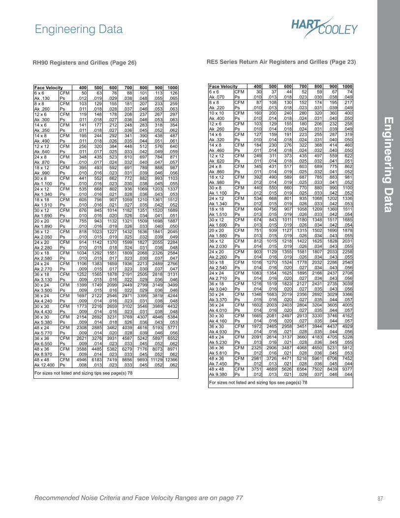
RE5 Series Return Air Registers and Grilles (Page 23)
400 500 600 700 800 900 1000CFM 30 37 44 52 59 67 74Ps .010 .013 .018 .023 .030 .038 .049CFM 87 108 130 152 174 195 217Ps .010 .013 .018 .023 .031 .039 .049CFM 160 200 240 280 320 360 400Ps .010 .014 .018 .024 .031 .040 .050CFM 103 129 155 180 206 232 258Ps .010 .014 .018 .024 .031 .039 .049CFM 127 159 191 223 255 287 319Ps .010 .014 .018 .024 .031 .040 .050CFM 184 230 276 322 368 414 460Ps .011 .014 .018 .024 .032 .040 .050CFM 249 311 373 435 497 559 622Ps .011 .014 .018 .025 .032 .041 .051CFM 345 431 517 603 689 775 862Ps .011 .014 .019 .025 .032 .041 .052CFM 392 490 589 687 785 883 981Ps .012 .014 .019 .025 .033 .041 .052CFM 440 550 660 770 880 990 1100Ps .012 .015 .019 .025 .033 .042 .052CFM 534 668 801 935 1068 1202 1336Ps .012 .015 .019 .026 .033 .042 .053CFM 604 756 907 1058 1209 1360 1511Ps .013 .015 .019 .026 .033 .042 .054CFM 674 843 1011 1180 1348 1517 1685Ps .013 .015 .019 .026 .034 .042 .054CFM 751 939 1127 1315 1502 1690 1878Ps .013 .015 .019 .026 .034 .043 .055CFM 812 1015 1218 1422 1625 1828 2031Ps .014 .015 .019 .026 .034 .043 .055CFM 903 1129 1355 1581 1807 2033 2258Ps .014 .016 .019 .026 .034 .043 .055CFM 1016 1270 1524 1778 2032 2286 2540Ps .014 .016 .020 .027 .034 .043 .056CFM 1083 1354 1625 1895 2166 2437 2708Ps .014 .016 .020 .027 .034 .043 .056CFM 1216 1519 1823 2127 2431 2735 3039Ps .014 .016 .020 .027 .035 .043 .056CFM 1346 1683 2019 2356 2692 3029 3366Ps .015 .016 .020 .027 .035 .044 .057CFM 1602 2003 2403 2804 3204 3605 4005Ps .014 .016 .020 .027 .035 .044 .057CFM 1665 2081 2497 2913 3330 3746 4162Ps .014 .016 .020 .027 .035 .044 .057CFM 1972 2465 2958 3451 3944 4437 4929Ps .014 .016 .021 .028 .035 .044 .056CFM 2091 2614 3137 3660 4183 4705 5228Ps .013 .016 .021 .028 .036 .045 .055CFM 2325 2906 3487 4068 4650 5231 5812Ps .012 .016 .021 .028 .036 .045 .053CFM 2981 3726 4471 5216 5961 6706 7452Ps .012 .013 .021 .028 .036 .045 .044CFM 3751 4689 5626 6564 7502 8439 9377Ps .012 .013 .021 .029 .037 .046 .044
48 x 36Ak 7.45048 x 48Ak 9.380
For sizes not listed and sizing tips see page(s) 7
30 x 30Ak 4.16036 x 30Ak 4.93048 x 24Ak 5.23036 x 36Ak 5.810
24 x 24Ak 2.71036 x 18Ak 3.04030 x 24Ak 3.37036 x 24Ak 4.010
20 x 20Ak 1.88036 x 12Ak 2.03024 x 20Ak 2.26030 x 18Ak 2.540
30 x 8Ak 1.10024 x 12Ak 1.34018 x 18Ak 1.51030 x 12Ak 1.690
14 x 8Ak .46012 x 12Ak .62024 x 8Ak .86018 x 12Ak .980
8 x 8Ak .22010 x 10Ak .40012 x 6Ak .26014 x 6Ak .320
Face Velocity6 x 6Ak .070
RH90 Registers and Grilles (Page 26)
400 500 600 700 800 900 1000CFM 50 63 76 88 101 113 126Ps .012 .019 .029 .038 .048 .055 .065CFM 103 129 155 181 207 233 259Ps .011 .018 .028 .037 .046 .053 .063CFM 119 148 178 208 237 267 297Ps .011 .018 .027 .036 .046 .053 .063CFM 141 177 212 248 283 318 354Ps .011 .018 .027 .036 .045 .052 .062CFM 195 244 292 341 390 438 487Ps .011 .018 .026 .035 .044 .051 .061CFM 256 320 384 448 512 576 640Ps .011 .017 .025 .033 .042 .049 .059CFM 348 435 523 610 697 784 871Ps .010 .017 .024 .032 .040 .047 .057CFM 395 493 592 691 789 888 987Ps .010 .016 .023 .031 .039 .046 .056CFM 441 552 662 772 882 993 1103Ps .010 .016 .023 .030 .038 .045 .055CFM 535 668 802 936 1069 1203 1337Ps .010 .016 .021 .028 .036 .043 .053CFM 605 756 907 1059 1210 1361 1512Ps .010 .016 .021 .027 .035 .042 .052CFM 676 845 1014 1182 1351 1520 1689Ps .010 .016 .020 .026 .034 .041 .051CFM 755 943 1132 1321 1509 1698 1887Ps .010 .016 .019 .026 .033 .040 .050CFM 818 1023 1227 1432 1636 1841 2045Ps .010 .015 .019 .025 .032 .039 .049CFM 914 1142 1370 1599 1827 2055 2284Ps .010 .015 .018 .024 .031 .038 .048CFM 1034 1292 1551 1809 2068 2326 2584Ps .010 .015 .017 .023 .030 .037 .047CFM 1106 1383 1659 1936 2213 2489 2766Ps .009 .015 .017 .023 .030 .037 .047CFM 1252 1565 1878 2191 2505 2818 3131Ps .009 .015 .016 .022 .029 .036 .046CFM 1399 1749 2099 2449 2799 3149 3499Ps .009 .015 .016 .022 .029 .036 .046CFM 1697 2122 2546 2971 3395 3819 4244Ps .009 .014 .016 .023 .031 .038 .048CFM 1773 2216 2659 3102 3546 3989 4432Ps .009 .014 .016 .023 .031 .038 .048CFM 2154 2692 3231 3769 4307 4846 5384Ps .009 .014 .018 .026 .036 .043 .053CFM 2308 2885 3462 4039 4616 5193 5771Ps .009 .014 .020 .028 .039 .046 .056CFM 2621 3276 3931 4587 5242 5897 6552Ps .009 .014 .023 .033 .045 .052 .062CFM 3588 4485 5382 6279 7176 8073 8971Ps .009 .014 .023 .033 .045 .052 .062CFM 4946 6183 7419 8656 9893 11129 12366Ps .008 .013 .023 .033 .045 .052 .062
48 x 36Ak 8.970
For sizes not listed and sizing tips see page(s) 7
48 x 48Ak 12.400
30 x 30Ak 4.43036 x 30Ak 5.38048 x 24Ak 5.77036 x 36Ak 6.550
24 x 24Ak 2.77036 x 18Ak 3.13030 x 24Ak 3.50036 x 24Ak 4.240
20 x 20Ak 1.89036 x 12Ak 2.05024 x 20Ak 2.28030 x 18Ak 2.580
30 x 8Ak 1.10024 x 12Ak 1.34018 x 18Ak 1.51030 x 12Ak 1.690
14 x 8Ak .49012 x 12Ak .64024 x 8Ak .87018 x 12Ak .990
6 x 6Ak .1308 x 8Ak .26012 x 6Ak .30014 x 6Ak .350
Face Velocity
Recommended Noise Criteria and Face Velocity Ranges are on page 77
Engineering Data
87
Eng
ineering D
ata
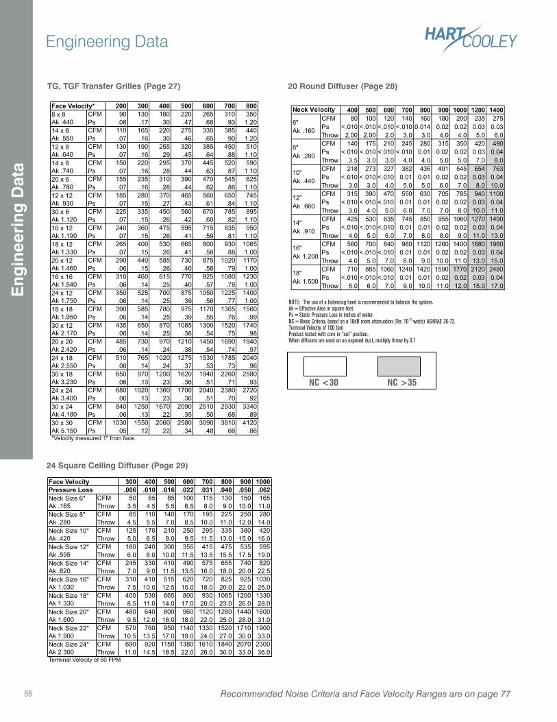
TG, TGF Transfer Grilles (Page 27)
200 300 400 500 600 700 800CFM 90 130 180 220 265 310 350Ps .08 .17 .30 .47 .68 .93 1.20CFM 110 165 220 275 330 385 440Ps .07 .16 .30 .46 .65 .90 1.20CFM 130 190 255 320 385 450 510Ps .07 .16 .29 .45 .64 .88 1.10CFM 150 220 295 370 445 520 590Ps .07 .16 .28 .44 .63 .87 1.10CFM 155 235 310 390 470 545 625Ps .07 .16 .28 .44 .62 .86 1.10CFM 185 280 370 465 560 650 745Ps .07 .15 .27 .43 .61 .84 1.10CFM 225 335 450 560 670 785 895Ps .07 .15 .26 .42 .60 .82 1.10CFM 240 360 475 595 715 835 950Ps .07 .15 .26 .41 .59 .81 1.10CFM 265 400 530 665 800 930 1065Ps .07 .15 .26 .41 .58 .88 1.00CFM 290 440 585 730 875 1020 1170Ps .06 .15 .26 .40 .58 .79 1.00CFM 310 460 615 770 925 1080 1230Ps .06 .14 .25 .40 .57 .78 1.00CFM 350 525 700 875 1050 1225 1400Ps .06 .14 .25 .39 .56 .77 1.00CFM 390 585 780 975 1170 1365 1560Ps .06 .14 .25 .39 .55 .76 .99CFM 435 650 870 1085 1300 1520 1740Ps .06 .14 .25 .38 .54 .75 .98CFM 485 730 970 1210 1450 1690 1940Ps .06 .14 .24 .38 .54 .74 .97CFM 510 765 1020 1275 1530 1785 2040Ps .06 .14 .24 .37 .53 .73 .96CFM 650 970 1290 1620 1940 2260 2580Ps .06 .13 .23 .36 .51 .71 .93CFM 680 1020 1360 1700 2040 2380 2720Ps .06 .13 .23 .36 .51 .70 .92CFM 840 1250 1670 2090 2510 2930 3340Ps .06 .13 .22 .35 .50 .68 .89CFM 1030 1550 2060 2580 3090 3610 4120Ps .05 .12 .22 .34 .48 .66 .86
*Velocity measured 1" from face.
Face Velocity*8 x 8Ak .44014 x 6Ak .55012 x 8Ak .640
16 x 12Ak 1.19018 x 12Ak 1.33020 x 12Ak 1.46016 x 16Ak 1.540
14 x 8Ak .74020 x 6Ak .78012 x 12Ak .93030 x 6Ak 1.120
24 x 12Ak 1.750
30 x 30Ak 5.150
18 x 18Ak 1.95030 x 12Ak 2.17020 x 20Ak 2.42024 x 18Ak 2.55030 x 18Ak 3.23024 x 24Ak 3.40030 x 24Ak 4.180
20 Round Diffuser (Page 28)
NOTE: The use of a balancing hood is recommended to balance the system.Ak = Effective Area in square feetPs = Static Pressure Loss in inches of waterNC = Noise Criteria, based on a 10dB room attenuation (Re: 10-12 watts) ASHRAE 36-72.Terminal Velocity of 100 fpmProduct tested with core in “out” position.When diffusers are used on an exposed duct, multiply throw by 0.7
NC <30 NC >35
Recommended Noise Criteria and Face Velocity Ranges are on page 7788
Engineering DataE
ngin
eeri
ng D
ata
24 Square Ceiling Diffuser (Page 29)
300 400 500 600 700 800 900 1000.006 .010 .016 .022 .031 .040 .050 .062
CFM 50 65 85 100 115 130 150 165
Throw 3.5 4.5 5.5 6.5 8.0 9.0 10.0 11.0
CFM 85 110 140 170 195 225 250 280
Throw 4.5 5.5 7.0 8.5 10.0 11.0 12.0 14.0
CFM 125 170 210 250 295 335 380 420
Throw 5.0 6.5 8.0 9.5 11.5 13.0 15.0 16.0
CFM 180 240 300 355 415 475 535 595
Throw 6.0 8.0 10.0 11.5 13.5 15.5 17.5 19.0
CFM 245 330 410 490 575 655 740 820
Throw 7.0 9.0 11.5 13.5 16.0 18.0 20.0 22.5
CFM 310 410 515 620 720 825 925 1030
Throw 7.5 10.0 12.5 15.0 18.0 20.0 22.0 25.0
CFM 400 530 665 800 930 1065 1200 1330
Throw 8.5 11.0 14.0 17.0 20.0 23.0 26.0 28.0
CFM 480 640 800 960 1120 1280 1440 1600
Throw 9.5 12.0 16.0 18.0 22.0 25.0 28.0 31.0
CFM 570 760 950 1140 1330 1520 1710 1900
Throw 10.5 13.5 17.0 19.0 24.0 27.0 30.0 33.0
CFM 690 920 1150 1380 1610 1840 2070 2300
Throw 11.0 14.5 18.5 22.0 26.0 30.0 33.0 36.0Terminal Velocity of 50 FPM
Face Velocity
Neck Size 6"
Ak .165
Neck Size 8"
Ak .280
Neck Size 24"
Ak 2.300
Pressure Loss
Neck Size 10"
Ak .420
Neck Size 12"
Ak .595
Neck Size 14"
Ak .820
Neck Size 16"
Ak 1.030
Neck Size 18"
Ak 1.330
Neck Size 20"
Ak 1.600
Neck Size 22"
Ak 1.900
400 500 600 700 800 900 1000 1200 1400CFM 80 100 120 140 160 180 200 235 275
Ps <.010 <.010 <.010 <.010 0.014 0.02 0.02 0.03 0.03
Throw 2.00 2.00 2.0 3.0 3.0 4.0 4.0 5.0 6.0
CFM 140 175 210 245 280 315 350 420 490
Ps <.010 <.010 <.010 <.010 0.01 0.02 0.02 0.03 0.04
Throw 3.5 3.0 3.0 4.0 4.0 5.0 5.0 7.0 8.0
CFM 218 273 327 382 436 491 545 654 763
Ps <.010 <.010 <.010 0.01 0.01 0.02 0.02 0.03 0.04
Throw 3.0 3.0 4.0 5.0 5.0 6.0 7.0 8.0 10.0
CFM 315 390 470 550 630 705 785 940 1100
Ps <.010 <.010 <.010 0.01 0.01 0.02 0.02 0.03 0.04
Throw 3.0 4.0 5.0 6.0 7.0 7.0 8.0 10.0 11.0
CFM 425 530 635 745 850 955 1060 1270 1490
Ps <.010 <.010 <.010 0.01 0.01 0.02 0.02 0.03 0.04
Throw 4.0 5.0 6.0 7.0 8.0 8.0 9.0 11.0 13.0
CFM 560 700 840 980 1120 1260 1400 1680 1960
Ps <.010 <.010 <.010 0.01 0.01 0.02 0.02 0.03 0.04
Throw 4.0 5.0 7.0 8.0 9.0 10.0 11.0 13.0 15.0
CFM 710 885 1060 1240 1420 1590 1770 2120 2480
Ps <.010 <.010 <.010 0.01 0.01 0.02 0.02 0.03 0.04
Throw 5.0 6.0 7.0 9.0 10.0 11.0 12.0 15.0 17.0
Neck Velocity
6"
Ak .160
8"
Ak .280
18"
Ak 1.500
10"
Ak .440
12"
Ak .660
14"
Ak .910
16"
Ak 1.200
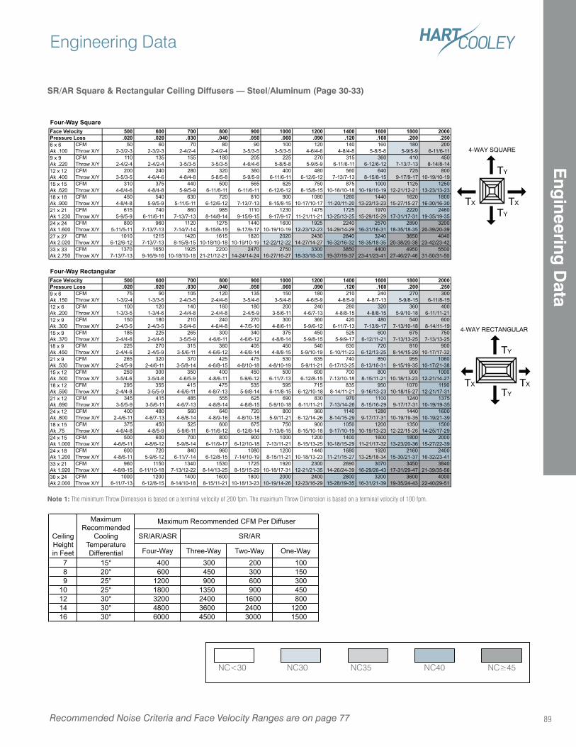
SR/AR Square & Rectangular Ceiling Diffusers — Steel/Aluminum (Page 30-33)
Note 1: The minimum Throw Dimension is based on a terminal velocity of 200 fpm. The maximum Throw Dimension is based on a terminal velocity of 100 fpm.
TY
TY
TXTX
4-WAY SQUARE
TY
TY
TXTX
4-WAY RECTANGULAR
Four-Way Square500 600 700 800 900 1000 1200 1400 1600 1800 2000.020 .020 .030 .040 .050 .060 .090 .120 .160 .200 .250
CFM 50 60 70 80 90 100 120 140 160 180 200
Throw X/Y 2-3/2-3 2-3/2-3 2-4/2-4 2-4/2-4 3-5/3-5 3-5/3-5 4-6/4-6 4-8/4-8 5-8/5-8 5-9/5-9 6-11/6-11
CFM 110 135 155 180 205 225 270 315 360 410 450
Throw X/Y 2-4/2-4 2-4/2-4 3-5/3-5 3-5/3-5 4-6/4-6 5-8/5-8 5-9/5-9 6-11/6-11 6-12/6-12 7-13/7-13 8-14/8-14
CFM 200 240 280 320 360 400 480 560 640 725 800
Throw X/Y 3-5/3-5 4-6/4-6 4-8/4-8 5-8/5-8 5-9/5-9 6-11/6-11 6-12/6-12 7-13/7-13 8-15/8-15 9-17/9-17 10-19/10-19
CFM 310 375 440 500 565 625 750 875 1000 1125 1250
Throw X/Y 4-6/4-6 4-8/4-8 5-9/5-9 6-11/6-11 6-11/6-11 6-12/6-12 8-15/8-15 10-18/10-18 10-19/10-19 12-21/12-21 13-23/13-23
CFM 450 540 630 720 810 900 1080 1260 1440 1620 1800
Throw X/Y 4-8/4-8 5-9/5-9 5-11/5-11 6-12/6-12 7-13/7-13 8-15/8-15 10-17/10-17 11-20/11-20 13-23/13-23 15-27/15-27 16-30/16-30
CFM 615 740 860 985 1110 1230 1475 1725 1970 2220 2460
Throw X/Y 5-9/5-9 6-11/6-11 7-13/7-13 8-14/8-14 9-15/9-15 9-17/9-17 11-21/11-21 13-25/13-25 15-29/15-29 17-31/17-31 19-35/19-35
CFM 800 960 1120 1275 1440 1600 1925 2240 2570 2890 3200
Throw X/Y 5-11/5-11 7-13/7-13 7-14/7-14 8-15/8-15 9-17/9-17 10-19/10-19 12-23/12-23 14-29/14-29 16-31/16-31 18-35/18-35 20-39/20-39
CFM 1010 1215 1420 1615 1820 2020 2430 2840 3240 3650 4040
Throw X/Y 6-12/6-12 7-13/7-13 8-15/8-15 10-18/10-18 10-19/10-19 12-22/12-22 14-27/14-27 16-32/16-32 18-35/18-35 20-38/20-38 23-42/23-42
CFM 1370 1650 1925 2200 2470 2750 3300 3850 4400 4950 5500
Throw X/Y 7-13/7-13 9-16/9-16 10-18/10-18 21-21/12-21 14-24/14-24 16-27/16-27 18-33/18-33 19-37/19-37 23-41/23-41 27-46/27-46 31-50/31-50
Four-Way Rectangular500 600 700 800 900 1000 1200 1400 1600 1800 2000.020 .020 .030 .040 .050 .060 .090 .120 .160 .200 .250
CFM 75 90 105 120 135 150 180 210 240 270 300
Throw X/Y 1-3/2-4 1-3/3-5 2-4/3-5 2-4/4-6 3-5/4-6 3-5/4-8 4-6/5-9 4-6/5-9 4-8/7-13 5-9/8-15 6-11/8-15
CFM 100 120 140 160 180 200 240 280 320 360 400
Throw X/Y 1-3/3-5 1-3/4-6 2-4/4-8 2-4/4-8 2-4/5-9 3-5/6-11 4-6/7-13 4-8/8-15 4-8/8-15 5-9/10-18 6-11/11-21
CFM 150 180 210 240 270 300 360 420 480 540 600
Throw X/Y 2-4/3-5 2-4/3-5 3-5/4-6 4-6/4-8 4-7/5-10 4-8/6-11 5-9/6-12 6-11/7-13 7-13/9-17 7-13/10-18 8-14/11-19
CFM 185 225 265 300 340 375 450 525 600 675 750
Throw X/Y 2-4/4-6 2-4/4-6 3-5/5-9 4-6/6-11 4-6/6-12 4-8/8-14 5-9/8-15 5-9/9-17 6-12/11-21 7-13/13-25 7-13/13-25
CFM 225 270 315 360 405 450 540 630 720 810 900
Throw X/Y 2-4/4-6 2-4/5-9 3-5/6-11 4-6/6-12 4-6/8-14 4-8/8-15 5-9/10-19 5-10/11-23 6-12/13-25 8-14/15-29 10-17/17-32
CFM 265 320 370 425 475 530 635 740 850 955 1060
Throw X/Y 2-4/5-9 2-4/6-11 3-5/8-14 4-6/8-15 4-8/10-18 4-8/10-19 5-9/11-21 6-17/13-25 8-13/16-31 9-15/19-35 10-17/21-38
CFM 250 300 350 400 450 500 600 700 800 900 1000
Throw X/Y 3-5/4-6 3-5/4-8 4-6/5-9 4-8/6-11 5-9/6-12 6-11/7-13 6-12/8-15 7-13/10-18 8-15/11-21 10-18/13-23 12-21/14-27
CFM 295 355 415 475 535 595 715 835 950 1070 1190
Throw X/Y 2-4/4-8 3-5/5-9 4-6/6-11 4-8/7-13 5-9/8-14 6-11/8-15 6-12/10-18 8-14/11-21 9-16/13-23 10-18/15-27 12-21/17-31
CFM 345 415 485 555 625 690 830 970 1100 1240 1375
Throw X/Y 3-5/5-9 3-5/6-11 4-6/7-13 4-8/8-14 4-8/8-15 5-9/10-18 6-11/11-21 7-13/14-26 8-15/16-29 9-17/17-31 10-19/19-35
CFM 400 480 560 640 720 800 960 1140 1280 1440 1600
Throw X/Y 2-4/6-11 4-6/7-13 4-6/8-14 4-8/9-16 4-8/10-18 5-9/11-21 6-12/14-26 8-14/15-29 9-17/17-31 10-19/19-35 10-19/21-39
CFM 375 450 525 600 675 750 900 1050 1200 1350 1500
Throw X/Y 4-6/4-8 4-8/5-9 5-9/6-11 6-11/6-12 6-12/8-14 7-13/8-15 8-15/10-18 9-17/10-19 10-19/13-23 12-22/15-26 14-25/17-29
CFM 500 600 700 800 900 1000 1200 1400 1600 1800 2000
Throw X/Y 4-6/6-11 4-8/6-12 5-9/8-14 6-11/9-17 6-12/10-18 7-13/11-21 8-15/13-25 10-18/15-29 11-21/17-32 13-23/20-36 15-27/22-39
CFM 600 720 840 960 1080 1200 1440 1680 1920 2160 2400
Throw X/Y 4-8/6-11 5-9/6-12 6-11/7-14 6-12/8-15 7-14/10-19 8-15/11-21 10-18/13-23 11-21/15-27 13-25/18-34 15-30/21-37 16-32/23-41
CFM 960 1150 1340 1530 1725 1920 2300 2690 3070 3450 3840
Throw X/Y 4-8/8-15 6-11/10-18 7-13/12-22 8-14/13-25 8-15/15-29 10-18/17-31 12-21/21-35 14-26/24-39 16-29/26-43 17-31/29-47 21-39/35-56
CFM 1000 1200 1400 1600 1800 2000 2400 2800 3200 3600 4000
Throw X/Y 6-11/7-13 6-12/8-15 8-14/10-18 8-15/11-21 10-18/13-23 10-19/14-26 12-23/16-29 15-28/19-35 16-31/21-39 19-35/24-43 22-40/29-51
18 x 9
Ak .450
Face VelocityPressure Loss9 x 6
Ak .150
15 x 15
Ak .620
18 x 18
Ak .900
21 x 21
Ak 1.230
24 x 24
Ak 1.600
30 x 24
Ak 2.000
27 x 27
Ak 2.020
33 x 33
Ak 2.750
24 x 12
Ak .800
18 x 15
Ak .75
24 x 15
Ak 1.000
24 x 18
Ak 1.200
21 x 9
Ak .530
15 x 12
Ak .500
18 x 12
Ak .590
Face Velocity
6 x 6
Ak .100
9 x 9
Ak .220
12 x 12
Ak .400
Pressure Loss
33 x 21
Ak 1.920
21 x 12
Ak .690
12 x 6
Ak .200
12 x 9
Ak .300
15 x 9
Ak .370
SR/AR/ASR
Four-Way Three-Way Two-Way One-Way
7 15° 400 300 200 100
8 20° 600 450 300 150
9 25° 1200 900 600 300
10 25° 1800 1350 900 450
12 30° 3200 2400 1600 800
14 30° 4800 3600 2400 1200
16 30° 6000 4500 3000 1500
Maximum
Recommended
Cooling
Temperature
Differential
Ceiling
Height
in Feet
Maximum Recommended CFM Per Diffuser
SR/AR
Recommended Noise Criteria and Face Velocity Ranges are on page 77
Engineering Data
89
Eng
ineering D
ata
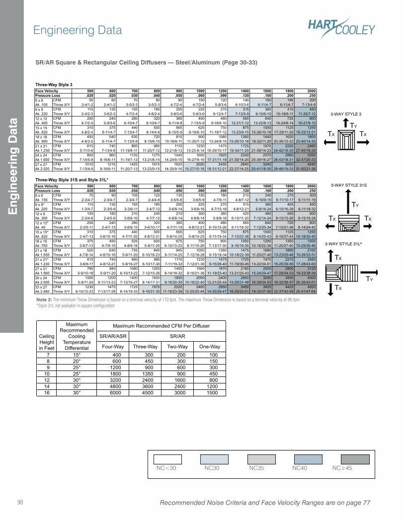
Note 2: The minimum Throw Dimension is based on a terminal velocity of 170 fpm. The maximum Throw Dimension is based on a terminal velocity of 85 fpm.*Style 31L not available in square configuration
TY
TXTX
3-WAY STYLE 3
TY
TXTX
3-WAY STYLE 31S
TY
TX
TX
3-WAY STYLE 31L*
Three-Way Style 3500 600 700 800 900 1000 1200 1400 1600 1800 2000.020 .020 .030 .040 .050 .060 .090 .120 .160 .200 .250
CFM 50 60 70 80 90 100 120 140 160 180 200
Throw X/Y 2-4/1-2 2-4/1-2 3-5/2-3 3-5/2-3 4-7/2-4 4-7/2-4 5-9/3-6 6-10/3-6 6-11/4-7 6-11/4-7 7-13/4-8
CFM 110 135 155 180 205 225 270 315 360 410 450
Throw X/Y 2-4/2-3 3-6/2-3 4-7/2-4 4-8/2-4 5-9/3-6 5-9/3-6 6-12/4-7 7-13/5-9 9-15/6-10 10-18/6-11 11-20/7-12
CFM 200 240 280 320 360 400 480 560 640 725 800
Throw X/Y 4-7/2-5 5-9/3-6 6-10/4-7 6-10/4-7 6-11/4-8 7-13/5-9 9-16/6-10 12-21/7-12 13-22/8-13 14-24/8-14 16-27/9-15
CFM 310 375 440 500 565 625 750 875 1000 1125 1250
Throw X/Y 4-8/2-4 6-11/4-7 7-13/4-7 8-14/4-8 8-15/5-9 9-16/6-10 11-19/7-12 13-23/9-15 15-26/10-18 17-29/11-20 19-33/12-21
CFM 450 540 630 720 810 900 1080 1260 1440 1620 1800
Throw X/Y 4-9/3-5 6-11/4-7 7-13/5-9 9-15/6-10 10-18/6-11 11-20/7-12 13-24/9-15 15-26/10-18 18-32/11-20 20-35/12-22 23-40/14-25
CFM 615 740 860 985 1110 1230 1475 1725 1970 2220 2460
Throw X/Y 5-11/3-6 7-13/4-8 11-19/6-11 11-20/7-12 12-21/8-13 13-23-8-14 16-29/10-17 19-34/11-20 21-39/14-23 24-42/16-25 27-45/18-29
CFM 800 960 1120 1275 1440 1600 1925 2240 2570 2890 3200
Throw X/Y 7-14/5-9 9-16/6-11 11-19/7-13 13-21/8-14 14-24/9-15 16-27/9-16 17-31/11-19 21-35/14-24 25-39/16-27 28-43/18-31 32-47/20-33
CFM 1010 1215 1420 1615 1820 2020 2430 2840 3240 3650 4040
Throw X/Y 7-13/4-9 9-16/6-11 11-20/7-13 13-23/9-15 14-25/9-16 15-27/10-18 18-31/12-21 22-37/14-25 25-41/18-30 28-46/19-33 31-50/21-36
Three-Way Style 31S and Style 31L*500 600 700 800 900 1000 1200 1400 1600 1800 2000.020 .020 .030 .040 .050 .060 .090 .120 .160 .200 .250
CFM 75 90 105 120 135 150 180 210 240 270 300
Throw X/Y 2-3/4-7 2-3/4-7 2-3/4-7 2-4/4-8 3-5/5-8 3-6/5-9 4-7/6-11 4-8/7-12 6-10/9-15 6-11/10-17 6-11/11-19
CFM 115 135 155 180 200 225 270 315 360 405 450
Throw X/Y 1-3/4-7 2-3/5-9 2-3/6-11 2-4/7-12 3-6/8-14 3-6/9-16 4-7/10-18 4-8/12-21 5-9/14-24 6-10/16-28 6-11/18-32
CFM 150 180 210 240 210 300 360 420 480 540 600
Throw X/Y 2-3/4-8 2-4/5-9 3-6/6-10 4-7/7-12 4-8/8-14 4-8/8-14 5-9/9-16 6-10/11-20 7-12/14-24 8-13/15-26 9-15/16-28
CFM 200 240 280 320 360 400 480 560 640 720 800
Throw X/Y 2-3/5-11 2-4/7-13 3-6/9-15 3-6/10-17 4-7/11-19 4-8/12-21 6-10/15-26 6-11/18-32 7-12/20-34 7-13/21-36 8-14/24-42
CFM 310 375 440 500 565 625 750 875 1000 1125 1250
Throw X/Y 2-4/7-13 3-6/10-18 4-7/11-20 4-8/12-21 5-9/14-25 5-9/14-25 6-11/19-34 7-13/22-38 8-14/25-43 9-16/27-44 10-18/30-45
CFM 375 450 525 600 675 750 900 1050 1200 1350 1500
Throw X/Y 3-6/7-13 4-7/9-15 4-8/9-16 5-9/11-20 6-10/13-23 6-11/15-26 7-13/17-30 9-16/19-35 10-18/22-39 11-20/27-40 13-25/30-46
CFM 525 630 735 840 945 1050 1260 1475 1680 1890 2100
Throw X/Y 4-7/8-14 4-8/10-18 5-9/11-20 6-10/18-23 6-11/14-25 7-12/16-28 9-15/19-34 10-18/22-39 11-20/27-40 13-23/29-46 15-26/33-51
CFM 615 740 860 985 1110 1230 1475 1725 1970 2210 2460
Throw X/Y 3-6/9-17 4-8/12-21 5-9/16-27 6-10/17-30 7-11/19-32 7-12/21-36 9-15/26-40 11-19/30-45 13-22/34-51 15-25/39-56 17-28/43-60
CFM 780 940 1080 1250 1400 1560 1870 2180 2500 2800 3120
Throw X/Y 5-9/10-18 5-9/11-20 6-10/13-22 7-12/15-26 8-14/18-32 9-16/21-36 11-19/23-40 13-21/25-43 15-24/29-47 17-29/34-53 19-33/38-59
CFM 1000 1200 1400 1600 1800 2000 2400 2800 3200 3500 4000
Throw X/Y 5-9/11-20 6-11/13-23 7-13/16-27 8-14/17-31 9-16/20-35 10-18/22-40 12-21/25-44 14-25/31-48 16-29/34-53 18-32/38-57 20-35/43-61
CFM 1230 1475 1725 1970 2220 2460 2950 3450 3925 4425 4920
Throw X/Y 6-10/13-23 7-13/17-28 8-14/19-33 9-16/21-35 11-18/23-39 12-20/25-44 14-25/29-47 16-29/33-51 18-33/37-56 22-37/42-59 25-41/47-64
21 x 21*
Ak 1.230
27 x 21
Ak 1.560
30 x 24
Ak 2.000
33 x 27
Ak 2.460
12 x 12*
Ak .40
15 x 15*
Ak .620
18 x 15
Ak .750
21 x 18
Ak 1.050
Pressure Loss9 x 6
Ak .150
9 x 9*
Ak .220
12 x 9
Ak .300
24 x 24
Ak 1.600
27 x 27
Ak 2.020
Face Velocity
12 x 12
Ak .400
15 x 15
Ak .620
18 x 18
Ak .900
21 x 21
Ak 1.230
Face VelocityPressure Loss6 x 6
Ak .100
9 x 9
Ak .220
SR/AR/ASR
Four-Way Three-Way Two-Way One-Way
7 15° 400 300 200 100
8 20° 600 450 300 150
9 25° 1200 900 600 300
10 25° 1800 1350 900 450
12 30° 3200 2400 1600 800
14 30° 4800 3600 2400 1200
16 30° 6000 4500 3000 1500
Maximum
Recommended
Cooling
Temperature
Differential
Ceiling
Height
in Feet
Maximum Recommended CFM Per Diffuser
SR/AR
SR/AR Square & Rectangular Ceiling Diffusers — Steel/Aluminum (Page 30-33)
Recommended Noise Criteria and Face Velocity Ranges are on page 7790
Engineering DataE
ngin
eeri
ng D
ata
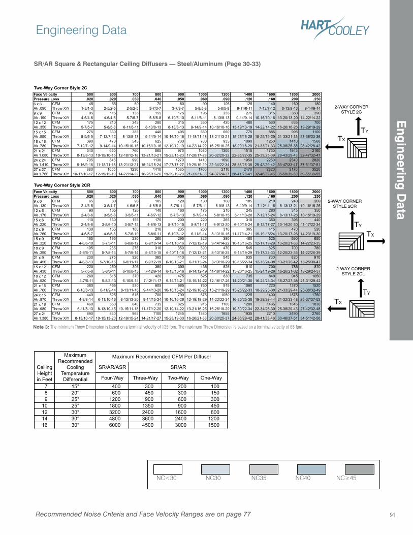
Note 3: The minimum Throw Dimension is based on a terminal velocity of 135 fpm. The maximum Throw Dimension is based on a terminal velocity of 65 fpm.
TY
TX
2-WAY CORNERSTYLE 2C
TY
TX
2-WAY CORNERSTYLE 2CR
2-WAY CORNERSTYLE 2CL
TY
TX
2-WAY CORNERSTYLE 2CL
Two-Way Corner Style 2C500 600 700 800 900 1000 1200 1400 1600 1800 2000.020 .020 .030 .040 .050 .060 .090 .120 .160 .200 .250
CFM 45 55 60 70 80 90 105 125 140 160 180
Throw X/Y 1-3/1-3 2-5/2-5 2-5/2-5 3-7/3-7 3-7/3-7 5-8/5-8 5-8/5-8 6-11/6-11 7-12/7-12 8-13/8-13 9-14/9-14
CFM 95 115 135 155 175 195 235 275 315 350 390
Throw X/Y 4-6/4-6 4-6/4-6 5-7/5-7 5-8/5-8 6-10/6-10 6-11/6-11 8-13/8-13 9-14/9-14 10-16/10-16 13-20/13-20 14-22/14-22
CFM 175 210 245 280 315 350 420 480 560 635 700
Throw X/Y 5-7/5-7 5-8/5-8 6-11/6-11 8-13/8-13 8-13/8-13 9-14/9-14 10-16/10-16 13-19/13-19 14-22/14-22 16-26/16-26 19-29/19-29
CFM 275 330 385 440 495 550 660 775 885 995 1100
Throw X/Y 5-9/5-9 7-12/7-12 8-13/8-13 9-14/9-14 10-16/10-16 11-18/11-18 13-21/13-21 15-25/15-25 19-29/19-29 21-33/21-33 23-36/23-36
CFM 390 470 545 625 700 780 935 1090 1250 1410 1560
Throw X/Y 7-12/7-12 9-14/9-14 10-15/10-15 10-16/10-16 12-19/12-19 14-22/14-22 16-25/16-25 18-29/18-29 21-33/21-33 25-38/25-38 28-42/28-42
CFM 540 650 760 865 975 1080 1300 1515 1730 1945 2160
Throw X/Y 8-13/8-13 10-15/10-15 12-18/12-18 13-21/13-21 15-23/15-23 17-28/17-28 20-32/20-32 22-35/22-35 25-39/25-39 29-43/29-43 32-47/32-47
CFM 705 845 990 1130 1270 1410 1690 1950 2250 2540 2820
Throw X/Y 9-16/9-16 11-18/11-18 13-21/13-21 15-24/15-24 17-27/17-27 19-29/19-29 22-34/22-34 25-38/25-38 29-42/29-42 33-47/33-47 37-51/37-51
CFM 880 1055 1230 1410 1585 1760 2110 2470 2820 3170 3520
Throw X/Y 10-17/10-17 12-19/12-19 14-22/14-22 16-26/16-26 19-29/19-29 21-33/21-33 24-37/24-37 28-41/28-41 32-46/32-46 35-50/35-50 39-55/39-55
Two-Way Corner Style 2CR500 600 700 800 900 1000 1200 1400 1600 1800 2000.020 .020 .030 .040 .050 .060 .090 .120 .160 .200 .250
CFM 65 80 95 105 120 130 160 185 210 240 260
Throw X/Y 2-4/3-5 3-5/4-7 4-6/5-8 4-6/5-8 5-7/6-11 5-7/6-11 6-9/8-13 6-10/9-14 7-12/11-16 8-13/13-21 10-16/16-25
CFM 90 105 120 140 160 175 210 245 280 315 350
Throw X/Y 2-4/3-6 3-5/5-8 3-5/6-11 4-6/7-12 5-7/8-13 5-7/9-14 5-8/10-15 6-11/13-20 7-12/15-24 8-13/17-26 10-15/19-29
CFM 110 130 155 175 200 220 265 310 350 395 440
Throw X/Y 2-4/5-8 3-5/6-10 3-5/7-12 4-6/8-13 5-7/10-15 5-8/11-17 6-9/13-20 6-10/15-24 8-12/17-27 10-14/20-30 11-17/22-34
CFM 130 155 180 210 235 260 310 365 415 470 520
Throw X/Y 4-6/5-7 4-6/5-8 5-7/6-10 5-8/6-11 6-10/8-12 6-11/9-14 8-13/10-16 11-17/14-21 19-19-16/24 13-20/17-26 14-23/19-30
CFM 165 195 230 260 295 325 390 460 525 590 650
Throw X/Y 4-6/6-10 5-7/6-11 6-8/8-12 6-9/10-14 6-11/10-16 7-12/12-19 9-14/14-22 10-15/16-25 12-17/19-29 13-20/21-33 14-22/23-35
CFM 195 235 275 310 350 390 470 545 625 700 780
Throw X/Y 4-6/6-11 5-7/8-13 5-7/9-14 5-8/10-15 6-10/11-18 7-12/13-21 8-13/16-25 9-15/19-29 11-17/22-33 12-20/23-35 14-22/26-39
CFM 230 275 320 365 410 455 545 635 730 820 910
Throw X/Y 4-6/8-13 5-7/10-15 6-8/11-17 6-9/12-19 6-10/13-21 6-11/15-24 8-13/18-29 10-15/22-34 12-18/24-38 13-21/26-42 15-25/30-47
CFM 220 260 305 350 390 435 525 610 700 785 870
Throw X/Y 5-7/5-8 5-8/6-11 6-10/8-13 7-12/9-14 8-13/10-16 9-14/12-19 11-18/14-22 13-20/16-25 15-24/19-29 16-26/21-32 18-29/24-37
CFM 260 315 370 420 475 525 630 735 840 945 1050
Throw X/Y 4-7/6-11 5-8/8-13 6-10/9-14 7-12/11-17 9-14/13-21 10-15/14-22 12-18/17-26 14-20/21-30 16-24/23-34 18-27/27-38 21-31/29-42
CFM 380 455 530 605 685 760 915 1060 1220 1370 1520
Throw X/Y 6-10/8-13 6-11/9-14 8-13/11-18 9-14/13-20 10-16/15-24 12-19/16-26 13-21/19-29 15-26/22-33 18-29/25-38 21-33/29-44 25-38/32-49
CFM 440 525 615 700 790 875 1050 1225 1400 1575 1750
Throw X/Y 4-9/8-14 6-11/10-16 8-13/13-20 9-14/15-24 10-16/16-26 12-19/19-29 14-22/22-34 16-25/25-38 19-29/29-44 21-32/33-48 25-37/37-52
CFM 460 550 640 735 825 915 1100 1280 1465 1645 1830
Throw X/Y 6-11/8-13 8-13/10-15 10-15/11-18 11-17/12-20 12-19/14-22 13-21/16-25 16-26/19-29 19-30/22-34 22-34/26-39 25-38/29-43 27-42/32-48
CFM 690 830 965 1100 1245 1380 1655 1935 2210 2490 2760
Throw X/Y 8-13/10-17 10-15/13-20 12-19/15-24 14-21/17-27 15-23/19-30 16-26/21-33 20-30/25-37 24-36/29-42 28-41/33-46 30-46/37-51 34-51/42-56
27 x 21
Ak 1.380
18 x 12
Ak .520
21 x 15
Ak .760
24 x 15
Ak .870
21 x 18
Ak .980
15 x 9
Ak .320
18 x 9
Ak .390
21 x 9
Ak .450
15 x 12
Ak .430
9 x 6
Ak .130
12 x 6
Ak .170
15 x 6
Ak .220
12 x 9
Ak .260
24 x 24
Ak 1.410
27 x 27
Ak 1.760
Face VelocityPressure Loss
12 x 12
Ak .350
15 x 15
Ak .550
18 x 18
Ak .780
21 x 21
Ak 1.080
Face VelocityPressure Loss6 x 6
Ak .090
9 x 9
Ak .190
SR/AR/ASR
Four-Way Three-Way Two-Way One-Way
7 15° 400 300 200 100
8 20° 600 450 300 150
9 25° 1200 900 600 300
10 25° 1800 1350 900 450
12 30° 3200 2400 1600 800
14 30° 4800 3600 2400 1200
16 30° 6000 4500 3000 1500
Maximum
Recommended
Cooling
Temperature
Differential
Ceiling
Height
in Feet
Maximum Recommended CFM Per Diffuser
SR/AR
SR/AR Square & Rectangular Ceiling Diffusers — Steel/Aluminum (Page 30-33)
Recommended Noise Criteria and Face Velocity Ranges are on page 77
Engineering Data
91
Eng
ineering D
ata
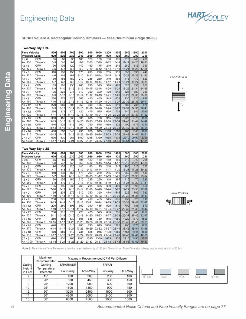
Note 3: The minimum Throw Dimension is based on a terminal velocity of 135 fpm. The maximum Throw Dimension is based on a terminal velocity of 65 fpm.
TY
TY
2-WAY STYLE 2L
TX TX
2-WAY STYLE 2S
Two-Way Style 2L500 600 700 800 900 1000 1200 1400 1600 1800 2000.020 .020 .030 .040 .050 .060 .090 .120 .160 .200 .250
CFM 65 80 95 105 120 130 160 185 210 240 260
Throw Y 3-5 3-5 5-7 6-8 7-10 7-10 8-12 10-14 11-17 14-20 16-23
CFM 90 105 120 140 160 175 210 245 280 315 350
Throw Y 3-5 5-7 6-8 6-9 7-10 8-12 10-14 12-18 15-21 16-23 17-25
CFM 110 130 155 175 200 220 265 310 350 395 440
Throw Y 4-6 6-8 6-9 7-10 9-13 10-14 10-15 13-19 15-21 18-26 21-30
CFM 130 155 180 210 235 260 310 365 415 470 520
Throw Y 5-7 6-8 6-9 8-12 10-14 10-14 11-17 14-21 16-24 19-27 20-31
CFM 165 195 230 260 295 325 390 460 525 590 650
Throw Y 6-8 7-10 8-12 9-13 10-15 12-18 14-20 16-24 18-26 21-31 24-35
CFM 195 235 275 310 350 390 470 545 625 700 780
Throw Y 6-9 8-12 9-13 10-14 11-17 13-19 15-21 17-25 19-29 22-33 25-39
CFM 230 275 320 365 410 455 545 635 730 820 910
Throw Y 7-10 8-12 9-13 11-16 12-18 14-20 16-24 19-27 22-32 25-36 29-41
CFM 220 260 305 350 390 435 525 610 700 785 870
Throw Y 6-9 8-12 10-14 10-15 12-18 14-20 15-24 18-27 22-32 24-36 28-41
CFM 260 315 370 420 475 525 630 735 840 945 1050
Throw Y 7-11 9-13 11-15 12-18 13-19 15-21 18-26 20-29 23-34 27-39 31-42
CFM 380 455 530 605 685 760 915 1060 1220 1370 1520
Throw Y 9-13 10-15 12-18 14-20 15-23 17-25 20-30 23-34 27-40 31-44 34-48
CFM 440 525 615 700 790 875 1050 1225 1400 1575 1750
Throw Y 8-14 11-16 13-19 15-21 17-25 19-29 22-33 25-38 29-42 33-48 38-54
CFM 460 550 640 735 825 915 1100 1280 1465 1645 1830
Throw Y 10-15 11-17 13-19 16-22 19-25 20-28 23-33 26-38 29-42 34-46 38-51
CFM 690 830 965 1100 1245 1380 1655 1935 2210 2490 2760
Throw Y 11-17 14-20 17-24 19-27 21-31 23-35 27-40 34-46 38-51 42-56 47-61
Two-Way Style 2S500 600 700 800 900 1000 1200 1400 1600 1800 2000.020 .020 .030 .040 .050 .060 .090 .120 .160 .200 .250
CFM 65 80 95 105 120 130 160 185 210 240 265
Throw X 3-6 4-7 5-8 6-9 8-12 9-13 10-14 11-17 13-19 15-23 17-26
CFM 90 105 120 140 160 175 210 245 280 315 350
Throw X 4-7 6-8 7-10 8-12 9-13 10-14 11-17 14-20 15-23 17-25 19-29
CFM 110 130 155 175 200 220 265 310 350 395 440
Throw X 5-7 6-9 7-10 9-13 10-15 11-17 13-19 15-23 18-26 21-30 23-34
CFM 130 155 180 210 235 260 310 365 415 470 520
Throw X 6-8 6-9 7-10 9-13 9-13 10-15 13-19 15-21 17-25 19-29 21-31
CFM 165 195 230 260 295 325 390 460 525 590 650
Throw X 7-10 8-12 9-13 10-14 12-18 14-20 16-24 18-26 19-29 23-33 27-39
CFM 195 235 275 310 350 390 470 545 625 700 780
Throw X 7-10 9-13 11-17 12-18 13-19 15-23 18-27 20-30 -22-32 25-38 29-43
CFM 230 275 320 365 410 455 545 635 730 820 910
Throw X 9-13 9-14 10-15 12-18 15-21 16-24 19-29 22-33 26-38 29-42 32-47
CFM 220 260 305 350 390 435 525 610 700 785 870
Throw X 7-10 8-12 10-14 11-17 13-19 15-21 16-24 19-27 22-33 25-38 29-42
CFM 260 315 370 420 475 525 630 735 840 945 1050
Throw X 8-11 10-14 10-15 12-18 14-20 15-23 18-27 23-33 -25-37 29-42 32-47
CFM 380 455 530 605 685 760 915 1060 1220 1370 1520
Throw X 10-15 11-17 14-20 15-23 18-26 20-29 22-33 26-38 29-42 35-46 39-51
CFM 440 525 615 700 790 875 1050 1225 1400 1575 1750
Throw X 9-14 11-17 15-21 17-25 19-29 22-32 25-37 28-41 33-45 38-51 43-56
CFM 460 550 640 735 825 915 1100 1280 1465 1645 1830
Throw X 11-17 12-18 14-20 16-24 19-27 20-29 23-34 27-40 32-45 37-49 40-55
CFM 690 830 965 1100 1245 1380 1655 1935 2210 2490 2760
Throw X 12-18 15-21 18-25 21-29 23-33 25-37 29-43 33-48 38-53 43-59 49-63
21 x 15
Ak .760
24 x 15
Ak .870
21 x 18
Ak .910
27 x 21
Ak 1.300
15 x 12
Ak .430
18 x 12
Ak .520
12 x 6
Ak .170
15 x 6
Ak .220
12 x 9
Ak .260
15 x 9
Ak .320
21 x 15
Ak .760
21 x 9
Ak .450
15 x 12
Ak .430
21 x 18
Ak .910
18 x 9
Ak .390
21 x 9
Ak .450
Face VelocityPressure Loss9 x 6
Ak .130
12 x 6
Ak .170
15 x 6
Ak .220
12 x 9
Ak .260
15 x 9
Ak .320
18 x 9
Ak .390
24 x 15
Ak .870
18 x 12
Ak .520
27 x 21
Ak 1.300
Face VelocityPressure Loss9 x 6
Ak .130
SR/AR/ASR
Four-Way Three-Way Two-Way One-Way
7 15° 400 300 200 100
8 20° 600 450 300 150
9 25° 1200 900 600 300
10 25° 1800 1350 900 450
12 30° 3200 2400 1600 800
14 30° 4800 3600 2400 1200
16 30° 6000 4500 3000 1500
Maximum
Recommended
Cooling
Temperature
Differential
Ceiling
Height
in Feet
Maximum Recommended CFM Per Diffuser
SR/AR
SR/AR Square & Rectangular Ceiling Diffusers — Steel/Aluminum (Page 30-33)
Recommended Noise Criteria and Face Velocity Ranges are on page 7792
Engineering DataE
ngin
eeri
ng D
ata
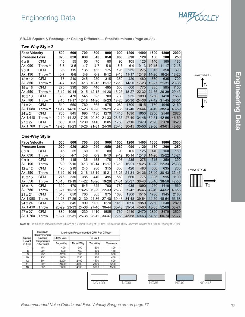
TY
TY
2-WAY STYLE 2
1-WAY STYLE
TX
Note 3: The minimum Throw Dimension is based on a terminal velocity of 135 fpm. The maximum Throw Dimension is based on a terminal velocity of 65 fpm.
Two-Way Style 2500 600 700 800 900 1000 1200 1400 1600 1800 2000.020 .020 .030 .040 .050 .060 .090 .120 .160 .200 .250
CFM 45 55 60 70 80 90 105 125 140 160 180
Throw Y 3-5 3-5 4-7 4-7 5-8 5-8 6-9 9-13 10-15 11-17 12-18
CFM 95 115 135 155 175 195 235 275 315 350 390
Throw Y 5-7 6-8 6-8 6-9 8-12 9-13 11-17 12-18 14-20 16-24 18-26
CFM 175 210 245 280 315 350 420 480 560 635 700
Throw Y 4-7 6-9 9-13 10-15 11-17 12-18 14-20 17-23 18-27 21-31 23-35
CFM 275 330 385 440 495 550 660 775 885 995 1100
Throw Y 8-12 10-14 10-15 12-18 14-20 15-23 18-27 22-32 24-36 26-39 29-43
CFM 390 470 545 625 700 780 935 1090 1250 1410 1560
Throw Y 9-15 11-17 12-18 14-20 15-23 18-26 20-30 -24-36 27-42 31-45 36-51
CFM 540 650 760 865 975 1080 1300 1515 1730 1945 2160
Throw Y 11-17 14-20 15-23 18-26 19-29 23-35 26-40 29-44 34-49 38-54 43-59
CFM 705 845 990 1130 1270 1410 1690 1950 2250 2540 2820
Throw Y 12-19 14-22 17-25 20-30 21-33 23-35 27-40 34-46 39-51 42-56 46-60
CFM 880 1055 1230 1410 1585 1760 2110 2470 2820 3170 3520
Throw Y 12-20 15-23 18-26 21-31 24-36 26-40 30-45 35-50 39-56 43-61 48-66
One-Way Style500 600 700 800 900 1000 1200 1400 1600 1800 2000.020 .020 .030 .040 .050 .060 .090 .120 .160 .200 .250
CFM 45 55 60 70 80 90 105 125 140 160 180
Throw 3-5 4-7 5-8 6-9 8-10 9-12 10-14 12-18 14-20 15-22 16-24
CFM 95 115 135 155 175 195 235 275 315 350 390
Throw 6-9 7-10 9-13 10-14 11-17 13-19 15-21 18-26 19-29 22-33 25-38
CFM 175 210 245 280 315 350 420 480 560 635 700
Throw 8-12 10-14 12-18 13-19 15-21 18-26 21-31 24-36 27-40 30-43 33-45
CFM 275 330 385 440 495 550 660 775 885 995 1100
Throw 10-16 13-19 14-22 18-26 19-29 21-31 25-37 30-43 35-46 38-50 42-56
CFM 390 470 545 625 700 780 935 1090 1250 1410 1560
Throw 13-21 15-23 18-26 19-29 22-33 25-38 29-42 35-46 42-49 44-52 49-56
CFM 540 650 760 865 975 1080 1300 1515 1730 1945 2160
Throw 14-23 17-25 21-30 24-36 27-40 30-43 34-48 39-54 44-60 48-64 53-68
CFM 705 845 990 1130 1270 1410 1690 1950 2250 2540 2820
Throw 20-29 23-33 24-36 27-40 30-44 35-48 39-54 43-60 48-65 52-69 56-74
CFM 880 1055 1230 1410 1585 1760 2110 2470 2820 3170 3520
Throw 19-27 22-31 25-38 28-42 33-47 36-53 43-58 49-63 54-68 60-73 65-77
Face VelocityPressure Loss
9 x 9
Ak .190
Face VelocityPressure Loss
15 x 15
Ak .550
18 x 18
Ak .780
6 x 6
Ak .090
9 x 9
Ak .190
12 x 12
Ak .350
15 x 15
Ak .550
18 x 18
Ak .780
21 x 21
Ak 1.080
24 x 24
Ak 1.410
27 x 27
Ak 1.760
21 x 21
Ak 1.080
24 x 24
Ak 1.410
27 x 27
Ak 1.760
12 x 12
Ak .350
6 x 6
Ak .090
SR/AR/ASR
Four-Way Three-Way Two-Way One-Way
7 15° 400 300 200 100
8 20° 600 450 300 150
9 25° 1200 900 600 300
10 25° 1800 1350 900 450
12 30° 3200 2400 1600 800
14 30° 4800 3600 2400 1200
16 30° 6000 4500 3000 1500
Maximum
Recommended
Cooling
Temperature
Differential
Ceiling
Height
in Feet
Maximum Recommended CFM Per Diffuser
SR/AR
SR/AR Square & Rectangular Ceiling Diffusers — Steel/Aluminum (Page 30-33)
Recommended Noise Criteria and Face Velocity Ranges are on page 77
Engineering Data
93
Eng
ineering D
ata
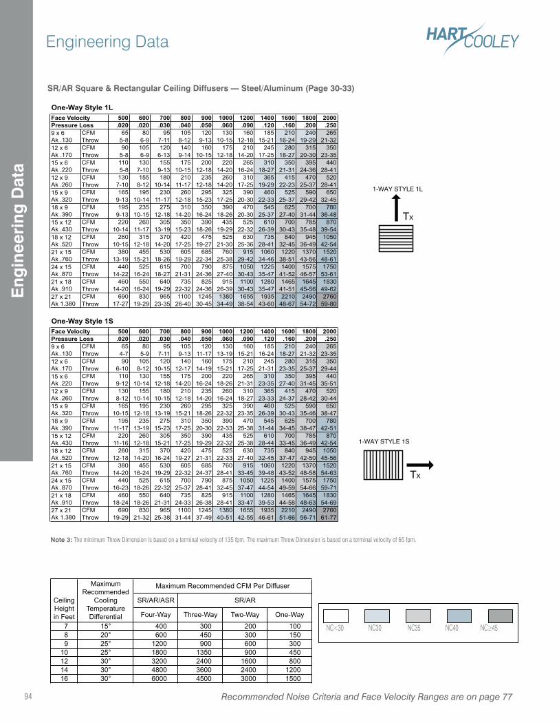
1-WAY STYLE 1L
TX
1-WAY STYLE 1S
TX
SR/AR Square & Rectangular Ceiling Diffusers — Steel/Aluminum (Page 30-33)
Note 3: The minimum Throw Dimension is based on a terminal velocity of 135 fpm. The maximum Throw Dimension is based on a terminal velocity of 65 fpm.
One-Way Style 1L500 600 700 800 900 1000 1200 1400 1600 1800 2000.020 .020 .030 .040 .050 .060 .090 .120 .160 .200 .250
CFM 65 80 95 105 120 130 160 185 210 240 265
Throw 5-8 6-9 7-11 8-12 9-13 10-15 12-18 15-21 16-24 19-29 21-32
CFM 90 105 120 140 160 175 210 245 280 315 350
Throw 5-8 6-9 6-13 9-14 10-15 12-18 14-20 17-25 18-27 20-30 23-35
CFM 110 130 155 175 200 220 265 310 350 395 440
Throw 5-8 7-10 9-13 10-15 12-18 14-20 16-24 18-27 21-31 24-36 28-41
CFM 130 155 180 210 235 260 310 365 415 470 520
Throw 7-10 8-12 10-14 11-17 12-18 14-20 17-25 19-29 22-23 25-37 28-41
CFM 165 195 230 260 295 325 390 460 525 590 650
Throw 9-13 10-14 11-17 12-18 15-23 17-25 20-30 22-33 25-37 29-42 32-45
CFM 195 235 275 310 350 390 470 545 625 700 780
Throw 9-13 10-15 12-18 14-20 16-24 18-26 20-30 25-37 27-40 31-44 36-48
CFM 220 260 305 350 390 435 525 610 700 785 870
Throw 10-14 11-17 13-19 15-23 18-26 19-29 22-32 26-39 30-43 35-48 39-54
CFM 260 315 370 420 475 525 630 735 840 945 1050
Throw 10-15 12-18 14-20 17-25 19-27 21-30 25-36 28-41 32-45 36-49 42-54
CFM 380 455 530 605 685 760 915 1060 1220 1370 1520
Throw 13-19 15-21 18-26 19-29 22-34 25-38 29-42 34-46 38-51 43-56 48-61
CFM 440 525 615 700 790 875 1050 1225 1400 1575 1750
Throw 14-22 16-24 18-27 21-31 24-36 27-40 30-43 35-47 41-52 46-57 53-61
CFM 460 550 640 735 825 915 1100 1280 1465 1645 1830
Throw 14-20 16-24 19-29 22-32 24-36 26-39 30-43 35-47 41-51 45-56 49-62
CFM 690 830 965 1100 1245 1380 1655 1935 2210 2490 2760
Throw 17-27 19-29 23-35 26-40 30-45 34-49 38-54 43-60 48-67 54-72 59-80
One-Way Style 1S500 600 700 800 900 1000 1200 1400 1600 1800 2000.020 .020 .030 .040 .050 .060 .090 .120 .160 .200 .250
CFM 65 80 95 105 120 130 160 185 210 240 265
Throw 4-7 5-9 7-11 9-13 11-17 13-19 15-21 16-24 18-27 21-32 23-35
CFM 90 105 120 140 160 175 210 245 280 315 350
Throw 6-10 8-12 10-15 12-17 14-19 15-21 17-25 21-31 23-35 25-37 29-44
CFM 110 130 155 175 200 220 265 310 350 395 440
Throw 9-12 10-14 12-18 14-20 16-24 18-26 21-31 23-35 27-40 31-45 35-51
CFM 130 155 180 210 235 260 310 365 415 470 520
Throw 8-12 10-14 10-15 12-18 14-20 16-24 18-27 23-33 24-37 28-42 30-44
CFM 165 195 230 260 295 325 390 460 525 590 650
Throw 10-15 12-18 13-19 15-21 18-26 22-32 23-35 26-39 30-43 35-46 38-47
CFM 195 235 275 310 350 390 470 545 625 700 780
Throw 11-17 13-19 15-23 17-25 20-30 22-33 25-38 31-44 34-45 38-47 42-51
CFM 220 260 305 350 390 435 525 610 700 785 870
Throw 11-16 12-18 15-21 17-25 19-29 22-32 25-38 28-44 33-45 36-49 42-54
CFM 260 315 370 420 475 525 630 735 840 945 1050
Throw 12-18 14-20 16-24 19-27 21-31 22-33 27-40 32-45 37-47 42-50 45-56
CFM 380 455 530 605 685 760 915 1060 1220 1370 1520
Throw 14-20 16-24 19-29 22-32 24-37 28-41 33-45 39-48 43-52 48-58 54-63
CFM 440 525 615 700 790 875 1050 1225 1400 1575 1750
Throw 16-23 18-26 22-32 25-37 28-41 32-45 37-47 44-54 49-59 54-66 59-71
CFM 460 550 640 735 825 915 1100 1280 1465 1645 1830
Throw 18-24 18-26 21-31 24-33 26-38 28-41 33-47 39-53 44-58 48-63 54-69
CFM 690 830 965 1100 1245 1380 1655 1935 2210 2490 2760
Throw 19-29 21-32 25-38 31-44 37-49 40-51 42-55 46-61 51-66 56-71 61-77
Face VelocityPressure Loss9 x 6
Ak .130
12 x 6
Ak .170
15 x 6
Ak .220
12 x 9
Ak .260
15 x 9
Ak .320
18 x 9
Ak .390
15 x 12
Ak .430
Face Velocity
18 x 12
Ak .520
21 x 15
Ak .760
24 x 15
Ak .870
21 x 18
Ak .910
27 x 21
Ak 1.380
18 x 9
Ak .390
15 x 12
Ak .430
Pressure Loss9 x 6
Ak .130
12 x 6
Ak .170
15 x 6
Ak .220
27 x 21
Ak 1.380
18 x 12
Ak .520
21 x 15
Ak .760
24 x 15
Ak .870
21 x 18
Ak .910
12 x 9
Ak .260
15 x 9
Ak .320
SR/AR/ASR
Four-Way Three-Way Two-Way One-Way
7 15° 400 300 200 100
8 20° 600 450 300 150
9 25° 1200 900 600 300
10 25° 1800 1350 900 450
12 30° 3200 2400 1600 800
14 30° 4800 3600 2400 1200
16 30° 6000 4500 3000 1500
Maximum
Recommended
Cooling
Temperature
Differential
Ceiling
Height
in Feet
Maximum Recommended CFM Per Diffuser
SR/AR
Recommended Noise Criteria and Face Velocity Ranges are on page 7794
Engineering DataE
ngin
eeri
ng D
ata
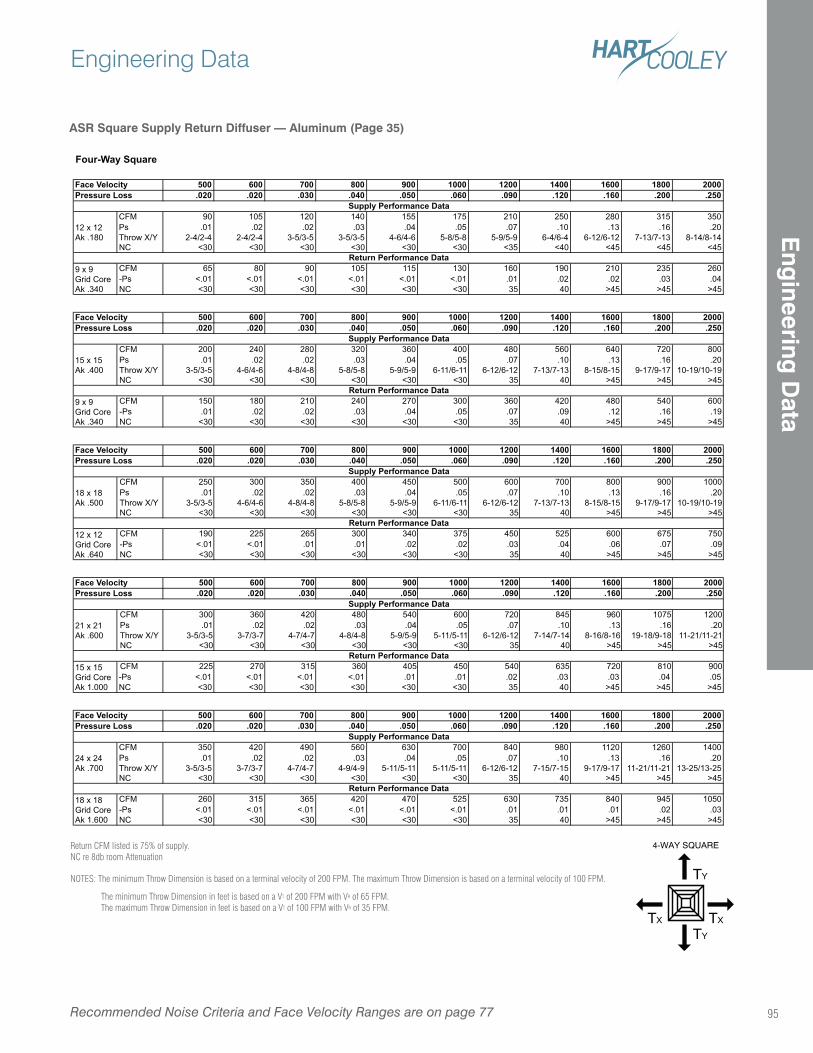
ASR Square Supply Return Diffuser — Aluminum (Page 35)
TY
TY
TXTX
4-WAY SQUAREReturn CFM listed is 75% of supply.NC re 8db room Attenuation
NOTES: The minimum Throw Dimension is based on a terminal velocity of 200 FPM. The maximum Throw Dimension is based on a terminal velocity of 100 FPM.
The minimum Throw Dimension in feet is based on a VT of 200 FPM with VR of 65 FPM. The maximum Throw Dimension in feet is based on a VT of 100 FPM with VR of 35 FPM.
500 600 700 800 900 1000 1200 1400 1600 1800 2000.020 .020 .030 .040 .050 .060 .090 .120 .160 .200 .250
CFM 90 105 120 140 155 175 210 250 280 315 350
Ps .01 .02 .02 .03 .04 .05 .07 .10 .13 .16 .20
Throw X/Y 2-4/2-4 2-4/2-4 3-5/3-5 3-5/3-5 4-6/4-6 5-8/5-8 5-9/5-9 6-4/6-4 6-12/6-12 7-13/7-13 8-14/8-14
NC <30 <30 <30 <30 <30 <30 <35 <40 <45 <45 <45
CFM 65 80 90 105 115 130 160 190 210 235 260
-Ps <.01 <.01 <.01 <.01 <.01 <.01 .01 .02 .02 .03 .04
NC <30 <30 <30 <30 <30 <30 35 40 >45 >45 >45
500 600 700 800 900 1000 1200 1400 1600 1800 2000.020 .020 .030 .040 .050 .060 .090 .120 .160 .200 .250
CFM 200 240 280 320 360 400 480 560 640 720 800
Ps .01 .02 .02 .03 .04 .05 .07 .10 .13 .16 .20
Throw X/Y 3-5/3-5 4-6/4-6 4-8/4-8 5-8/5-8 5-9/5-9 6-11/6-11 6-12/6-12 7-13/7-13 8-15/8-15 9-17/9-17 10-19/10-19
NC <30 <30 <30 <30 <30 <30 35 40 >45 >45 >45
CFM 150 180 210 240 270 300 360 420 480 540 600
-Ps .01 .02 .02 .03 .04 .05 .07 .09 .12 .16 .19
NC <30 <30 <30 <30 <30 <30 35 40 >45 >45 >45
500 600 700 800 900 1000 1200 1400 1600 1800 2000.020 .020 .030 .040 .050 .060 .090 .120 .160 .200 .250
CFM 250 300 350 400 450 500 600 700 800 900 1000
Ps .01 .02 .02 .03 .04 .05 .07 .10 .13 .16 .20
Throw X/Y 3-5/3-5 4-6/4-6 4-8/4-8 5-8/5-8 5-9/5-9 6-11/6-11 6-12/6-12 7-13/7-13 8-15/8-15 9-17/9-17 10-19/10-19
NC <30 <30 <30 <30 <30 <30 35 40 >45 >45 >45
CFM 190 225 265 300 340 375 450 525 600 675 750
-Ps <.01 <.01 .01 .01 .02 .02 .03 .04 .06 .07 .09
NC <30 <30 <30 <30 <30 <30 35 40 >45 >45 >45
500 600 700 800 900 1000 1200 1400 1600 1800 2000.020 .020 .030 .040 .050 .060 .090 .120 .160 .200 .250
CFM 300 360 420 480 540 600 720 845 960 1075 1200
Ps .01 .02 .02 .03 .04 .05 .07 .10 .13 .16 .20
Throw X/Y 3-5/3-5 3-7/3-7 4-7/4-7 4-8/4-8 5-9/5-9 5-11/5-11 6-12/6-12 7-14/7-14 8-16/8-16 19-18/9-18 11-21/11-21
NC <30 <30 <30 <30 <30 <30 35 40 >45 >45 >45
CFM 225 270 315 360 405 450 540 635 720 810 900
-Ps <.01 <.01 <.01 <.01 .01 .01 .02 .03 .03 .04 .05
NC <30 <30 <30 <30 <30 <30 35 40 >45 >45 >45
500 600 700 800 900 1000 1200 1400 1600 1800 2000.020 .020 .030 .040 .050 .060 .090 .120 .160 .200 .250
CFM 350 420 490 560 630 700 840 980 1120 1260 1400
Ps .01 .02 .02 .03 .04 .05 .07 .10 .13 .16 .20
Throw X/Y 3-5/3-5 3-7/3-7 4-7/4-7 4-9/4-9 5-11/5-11 5-11/5-11 6-12/6-12 7-15/7-15 9-17/9-17 11-21/11-21 13-25/13-25
NC <30 <30 <30 <30 <30 <30 35 40 >45 >45 >45
CFM 260 315 365 420 470 525 630 735 840 945 1050
-Ps <.01 <.01 <.01 <.01 <.01 <.01 .01 .01 .01 .02 .03
NC <30 <30 <30 <30 <30 <30 35 40 >45 >45 >45
12 x 12
Ak .180
Supply Performance Data
Return Performance Data9 x 9
Grid Core
Ak .340
Return Performance Data9 x 9
Grid Core
Ak .340
Face VelocityPressure Loss
Face VelocityPressure Loss
Supply Performance Data
15 x 15
Ak .400
Four-Way Square
Face VelocityPressure Loss
Supply Performance Data
Face VelocityPressure Loss
Supply Performance Data
18 x 18
Ak .500
Return Performance Data12 x 12
Grid Core
Ak .640
Pressure LossSupply Performance Data
24 x 24
Ak .700
Return Performance Data
21 x 21
Ak .600
Return Performance Data15 x 15
Grid Core
Ak 1.000
Face Velocity
18 x 18
Grid Core
Ak 1.600
Recommended Noise Criteria and Face Velocity Ranges are on page 77
Engineering Data
95
Eng
ineering D
ata
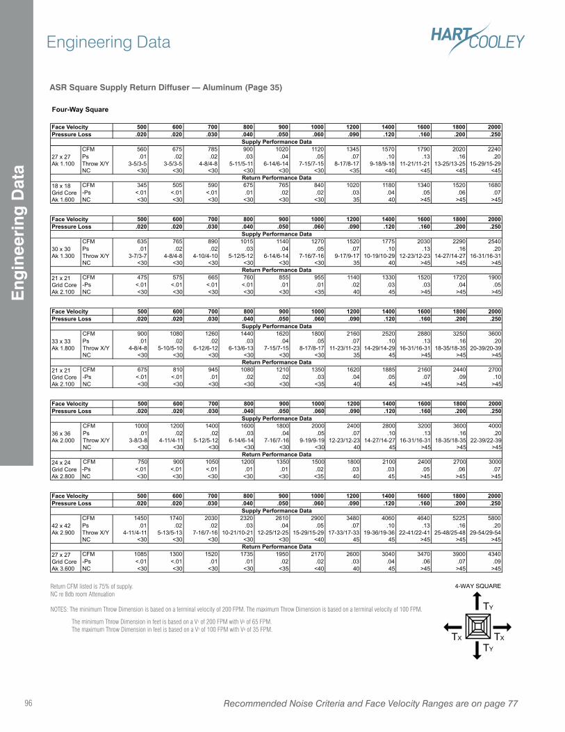
ASR Square Supply Return Diffuser — Aluminum (Page 35)
TY
TY
TXTX
4-WAY SQUAREReturn CFM listed is 75% of supply.NC re 8db room Attenuation
NOTES: The minimum Throw Dimension is based on a terminal velocity of 200 FPM. The maximum Throw Dimension is based on a terminal velocity of 100 FPM.
The minimum Throw Dimension in feet is based on a VT of 200 FPM with VR of 65 FPM. The maximum Throw Dimension in feet is based on a VT of 100 FPM with VR of 35 FPM.
500 600 700 800 900 1000 1200 1400 1600 1800 2000.020 .020 .030 .040 .050 .060 .090 .120 .160 .200 .250
CFM 560 675 785 900 1020 1120 1345 1570 1790 2020 2240
Ps .01 .02 .02 .03 .04 .05 .07 .10 .13 .16 .20
Throw X/Y 3-5/3-5 3-5/3-5 4-8/4-8 5-11/5-11 6-14/6-14 7-15/7-15 8-17/8-17 9-18/9-18 11-21/11-21 13-25/13-25 15-29/15-29
NC <30 <30 <30 <30 <30 <30 <35 <40 <45 <45 <45
CFM 345 505 590 675 765 840 1020 1180 1340 1520 1680
-Ps <.01 <.01 <.01 .01 .02 .02 .03 .04 .05 .06 .07
NC <30 <30 <30 <30 <30 <30 35 40 >45 >45 >45
500 600 700 800 900 1000 1200 1400 1600 1800 2000.020 .020 .030 .040 .050 .060 .090 .120 .160 .200 .250
CFM 635 765 890 1015 1140 1270 1520 1775 2030 2290 2540
Ps .01 .02 .02 .03 .04 .05 .07 .10 .13 .16 .20
Throw X/Y 3-7/3-7 4-8/4-8 4-10/4-10 5-12/5-12 6-14/6-14 7-16/7-16 9-17/9-17 10-19/10-29 12-23/12-23 14-27/14-27 16-31/16-31
NC <30 <30 <30 <30 <30 <30 35 40 >45 >45 >45
CFM 475 575 665 760 855 955 1140 1330 1520 1720 1900
-Ps <.01 <.01 <.01 <.01 .01 .01 .02 .03 .03 .04 .05
NC <30 <30 <30 <30 <30 <35 40 45 >45 >45 >45
500 600 700 800 900 1000 1200 1400 1600 1800 2000.020 .020 .030 .040 .050 .060 .090 .120 .160 .200 .250
CFM 900 1080 1260 1440 1620 1800 2160 2520 2880 3250 3600
Ps .01 .02 .02 .03 .04 .05 .07 .10 .13 .16 .20
Throw X/Y 4-8/4-8 5-10/5-10 6-12/6-12 6-13/6-13 7-15/7-15 8-17/8-17 11-23/11-23 14-29/14-29 16-31/16-31 18-35/18-35 20-39/20-39
NC <30 <30 <30 <30 <30 <30 35 45 >45 >45 >45
CFM 675 810 945 1080 1210 1350 1620 1885 2160 2440 2700
-Ps <.01 <.01 .01 .02 .02 .03 .04 .05 .07 .09 .10
NC <30 <30 <30 <30 <30 <35 40 45 >45 >45 >45
500 600 700 800 900 1000 1200 1400 1600 1800 2000.020 .020 .030 .040 .050 .060 .090 .120 .160 .200 .250
CFM 1000 1200 1400 1600 1800 2000 2400 2800 3200 3600 4000
Ps .01 .02 .02 .03 .04 .05 .07 .10 .13 .16 .20
Throw X/Y 3-8/3-8 4-11/4-11 5-12/5-12 6-14/6-14 7-16/7-16 9-19/9-19 12-23/12-23 14-27/14-27 16-31/16-31 18-35/18-35 22-39/22-39
NC <30 <30 <30 <30 <30 <30 40 45 >45 >45 >45
CFM 750 900 1050 1200 1350 1500 1800 2100 2400 2700 3000
-Ps <.01 <.01 <.01 .01 .01 .02 .03 .03 .05 .06 .07
NC <30 <30 <30 <30 <30 <35 40 45 >45 >45 >45
500 600 700 800 900 1000 1200 1400 1600 1800 2000.020 .020 .030 .040 .050 .060 .090 .120 .160 .200 .250
CFM 1450 1740 2030 2320 2610 2900 3480 4060 4640 5225 5800
Ps .01 .02 .02 .03 .04 .05 .07 .10 .13 .16 .20
Throw X/Y 4-11/4-11 5-13/5-13 7-16/7-16 10-21/10-21 12-25/12-25 15-29/15-29 17-33/17-33 19-36/19-36 22-41/22-41 25-48/25-48 29-54/29-54
NC <30 <30 <30 <30 <30 <40 45 45 >45 >45 >45
CFM 1085 1300 1520 1735 1950 2170 2600 3040 3470 3900 4340
-Ps <.01 <.01 .01 .01 .02 .02 .03 .04 .06 .07 .09
NC <30 <30 <30 <30 <35 <40 40 45 >45 >45 >45
Supply Performance Data
27 x 27
Ak 1.100
Return Performance Data18 x 18
Grid Core
Ak 1.600
Four-Way Square
Face VelocityPressure Loss
Return Performance Data21 x 21
Grid Core
Ak 2.100
Face VelocityPressure Loss
Face VelocityPressure Loss
Supply Performance Data
30 x 30
Ak 1.300
Face VelocityPressure Loss
Supply Performance Data
36 x 36
Ak 2.000
Supply Performance Data
33 x 33
Ak 1.800
Return Performance Data21 x 21
Grid Core
Ak 2.100
Supply Performance Data
42 x 42
Ak 2.900
Return Performance Data27 x 27
Grid Core
Ak 3.600
Return Performance Data24 x 24
Grid Core
Ak 2.800
Face VelocityPressure Loss
Recommended Noise Criteria and Face Velocity Ranges are on page 7796
Engineering DataE
ngin
eeri
ng D
ata
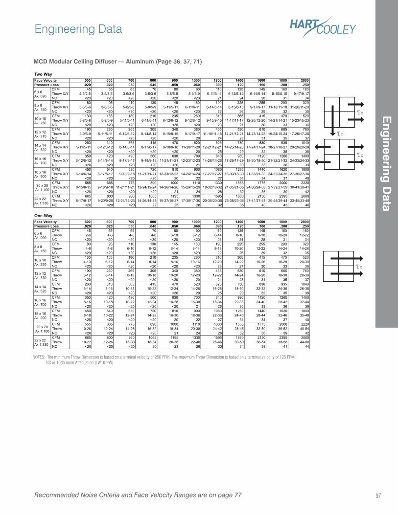
MCD Modular Ceiling Diffuser — Aluminum (Page 36, 37, 71)
TY
TX
TX
TX
NOTES: The minimum Throw Dimension is based on a terminal velocity of 250 FPM. The maximum Throw Dimension is based on a terminal velocity of 125 FPM. NC re 10db room Attenuation (LW10-12W)
Two Way500 600 700 800 900 1000 1200 1400 1600 1800 2000.020 .020 .030 .040 .050 .060 .090 .120 .160 .200 .250
CFM 45 55 65 70 80 90 110 125 145 160 180
Throw X/Y 2-5/2-5 3-5/3-5 3-6/3-6 3-6/3-6 5-8/5-8 5-9/5-9 5-11/5-11 6-12/6-12 6-14/6-14 8-15/8-15 9-17/9-17
NC <20 <20 <20 <20 <20 <20 21 24 28 31 34
CFM 80 95 110 130 145 160 190 225 255 290 320
Throw X/Y 3-6/3-6 3-6/3-6 5-8/5-8 5-9/5-9 5-11/5-11 6-11/6-11 6-14/6-14 8-15/8-15 9-17/9-17 11-18/11-18 11-20/11-20
NC <20 <20 <20 <20 <20 <20 22 26 29 32 35
CFM 130 155 180 210 235 260 310 365 415 470 520
Throw X/Y 3-8/3-8 5-9/5-9 5-11/5-11 6-11/6-11 6-12/6-12 8-12/8-12 9-15/9-15 11-17/11-17 12-20/12-20 14-21/14-21 15-23/15-23
NC <20 <20 <20 <20 <20 <20 23 27 30 33 36
CFM 190 230 265 305 340 380 455 530 610 685 760
Throw X/Y 5-9/5-9 5-11/5-11 6-12/6-12 8-14/8-14 8-15/8-15 9-17/9-17 11-18/11-18 12-21/12-21 14-23/14-23 15-24/15-24 17-26/17-26
NC <20 <20 <20 <20 <20 20 24 28 31 35 37
CFM 260 310 365 415 470 520 625 730 830 935 1040
Throw X/Y 5-11/5-11 6-12/6-12 8-14/8-14 8-17/8-17 9-18/9-18 11-20/11-20 12-21/12-21 14-23/14-23 17-24/17-24 18-27/18-27 20-29/20-29
NC <20 <20 <20 <20 <20 20 25 29 32 35 38
CFM 350 420 490 560 630 700 840 980 1120 1260 1400
Throw X/Y 6-12/6-12 8-14/8-14 8-17/8-17 9-18/9-18 11-21/11-21 12-23/12-23 14-26/14-26 17-29/17-29 18-30/18-30 21-32/21-32 24-33/24-33
NC <20 <20 <20 <20 <20 21 26 30 33 36 39
CFM 450 540 630 720 810 900 1080 1260 1440 1620 1800
Throw X/Y 6-14/6-14 8-17/8-17 9-18/9-18 11-21/11-21 12-23/12-23 14-24/14-24 17-27/17-27 18-30/18-30 21-33/21-33 24-35/24-35 27-36/27-36
NC <20 <20 <20 <20 20 22 27 31 34 37 40
CFM 555 665 775 890 1000 1110 1330 1555 1775 2000 2220
Throw X/Y 8-15/8-15 9-18/9-18 11-21/11-21 12-24/12-24 14-26/14-26 15-29/15-29 18-32/18-32 21-35/21-35 24-38/24-38 27-39/27-39 30-41/30-41
NC <20 <20 <20 <20 21 24 28 32 36 39 42
CFM 665 800 930 1065 1195 1330 1595 1860 2130 2395 2660
Throw X/Y 8-17/8-17 9-20/9-20 12-23/12-23 14-26/14-26 15-27/15-27 17-30/17-30 20-35/20-35 23-38/23-38 27-41/27-41 29-44/29-44 33-45/33-45
NC <20 <20 <20 22 25 28 32 36 40 43 46
One-Way500 600 700 800 900 1000 1200 1400 1600 1800 2000.020 .020 .030 .040 .050 .060 .090 .120 .160 .200 .250
CFM 45 55 65 70 80 90 110 125 145 160 180
Throw 2-6 4-6 4-8 4-8 6-10 6-12 6-14 8-16 8-18 10-20 12-22
NC <20 <20 <20 <20 <20 <20 21 24 28 31 34
CFM 80 95 110 130 145 160 190 225 255 290 320
Throw 4-8 4-8 6-10 6-12 6-14 8-14 8-18 10-20 12-22 14-24 14-26
NC <20 <20 <20 <20 <20 <20 22 26 29 32 35
CFM 130 155 180 210 235 260 310 365 415 470 520
Throw 4-10 6-12 6-14 8-14 8-16 10-16 12-20 14-22 16-26 18-28 20-30
NC <20 <20 <20 <20 <20 <20 23 27 30 33 36
CFM 190 230 265 305 340 380 455 530 610 685 760
Throw 6-12 6-14 8-16 10-18 10-20 12-20 12-22 14-24 16-28 18-30 20-30
NC <20 <20 <20 <20 <20 20 24 28 31 35 37
CFM 260 310 365 415 470 520 625 730 830 935 1040
Throw 6-14 8-16 10-18 10-22 12-24 14-26 16-28 18-30 22-32 24-36 26-38
NC <20 <20 <20 <20 <20 20 25 29 32 35 38
CFM 350 420 490 560 630 700 840 980 1120 1260 1400
Throw 8-16 10-18 10-22 12-24 14-28 16-30 18-34 22-38 24-40 28-42 32-44
NC <20 <20 <20 <20 <20 21 26 30 33 36 39
CFM 450 540 630 720 810 900 1080 1260 1440 1620 1800
Throw 8-18 10-22 12-24 14-28 16-30 18-36 22-36 24-40 28-44 32-46 35-48
NC <20 <20 <20 <20 20 22 27 31 34 37 40
CFM 555 665 775 890 1000 1110 1330 1555 1775 2000 2220
Throw 10-20 12-24 14-28 16-32 18-34 20-38 24-42 28-46 32-50 36-52 40-54
NC <20 <20 <20 <20 21 24 28 32 36 39 42
CFM 665 800 930 1065 1195 1330 1595 1860 2130 2395 2660
Throw 10-22 12-26 16-30 18-34 20-36 22-40 26-46 30-50 36-54 38-58 44-60
NC <20 <20 <20 20 23 26 30 34 38 41 44
8 x 8
Ak .150
10 x 10
Ak .250
12 x 12
Ak .370
14 x 14
Ak .520
Face VelocityPressure Loss
6 x 6
Ak .090
8 x 8
Ak .150
16 x 16
Ak .700
18 x 18
Ak .900
20 x 20
Ak 1.100
22 x 22
Ak 1.330
18 x 18
Ak .900
20 x 20
Ak 1.100
22 x 22
Ak 1.330
10 x 10
Ak .250
12 x 12
Ak .370
14 x 14
Ak .520
16 x 16
Ak .700
Face VelocityPressure Loss
6 x 6
Ak .090
Recommended Noise Criteria and Face Velocity Ranges are on page 77
Engineering Data
97
Eng
ineering D
ata
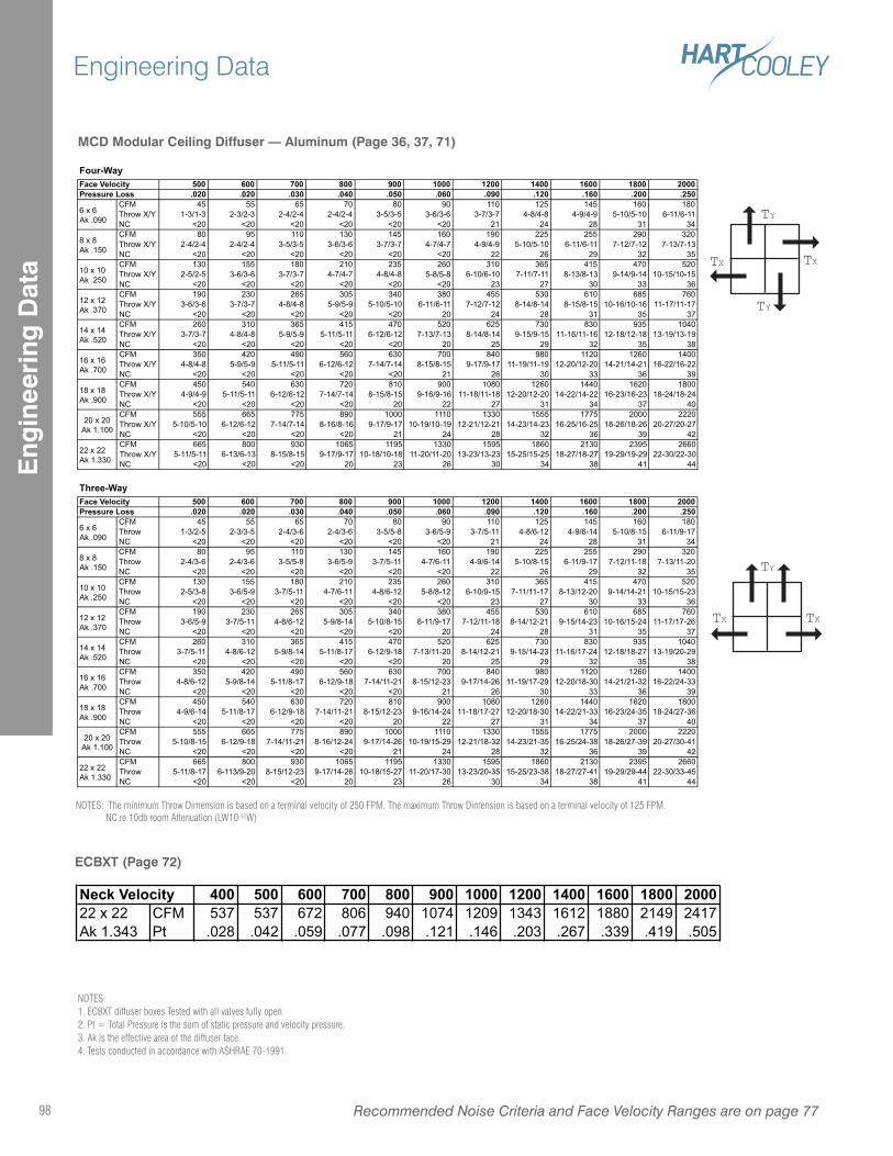
TY
TY
TX TX
TY
TXTX
ECBXT (Page 72)
NOTES:1. ECBXT diffuser boxes Tested with all valves fully open.2. Pt = Total Pressure is the sum of static pressure and velocity pressure.3. Ak is the effective area of the diffuser face. 4. Tests conducted in accordance with ASHRAE 70-1991.
MCD Modular Ceiling Diffuser — Aluminum (Page 36, 37, 71)
NOTES: The minimum Throw Dimension is based on a terminal velocity of 250 FPM. The maximum Throw Dimension is based on a terminal velocity of 125 FPM. NC re 10db room Attenuation (LW10-12W)
Four-Way500 600 700 800 900 1000 1200 1400 1600 1800 2000.020 .020 .030 .040 .050 .060 .090 .120 .160 .200 .250
CFM 45 55 65 70 80 90 110 125 145 160 180
Throw X/Y 1-3/1-3 2-3/2-3 2-4/2-4 2-4/2-4 3-5/3-5 3-6/3-6 3-7/3-7 4-8/4-8 4-9/4-9 5-10/5-10 6-11/6-11
NC <20 <20 <20 <20 <20 <20 21 24 28 31 34
CFM 80 95 110 130 145 160 190 225 255 290 320
Throw X/Y 2-4/2-4 2-4/2-4 3-5/3-5 3-6/3-6 3-7/3-7 4-7/4-7 4-9/4-9 5-10/5-10 6-11/6-11 7-12/7-12 7-13/7-13
NC <20 <20 <20 <20 <20 <20 22 26 29 32 35
CFM 130 155 180 210 235 260 310 365 415 470 520
Throw X/Y 2-5/2-5 3-6/3-6 3-7/3-7 4-7/4-7 4-8/4-8 5-8/5-8 6-10/6-10 7-11/7-11 8-13/8-13 9-14/9-14 10-15/10-15
NC <20 <20 <20 <20 <20 <20 23 27 30 33 36
CFM 190 230 265 305 340 380 455 530 610 685 760
Throw X/Y 3-6/3-6 3-7/3-7 4-8/4-8 5-9/5-9 5-10/5-10 6-11/6-11 7-12/7-12 8-14/8-14 8-15/8-15 10-16/10-16 11-17/11-17
NC <20 <20 <20 <20 <20 20 24 28 31 35 37
CFM 260 310 365 415 470 520 625 730 830 935 1040
Throw X/Y 3-7/3-7 4-8/4-8 5-9/5-9 5-11/5-11 6-12/6-12 7-13/7-13 8-14/8-14 9-15/9-15 11-16/11-16 12-18/12-18 13-19/13-19
NC <20 <20 <20 <20 <20 20 25 29 32 35 38
CFM 350 420 490 560 630 700 840 980 1120 1260 1400
Throw X/Y 4-8/4-8 5-9/5-9 5-11/5-11 6-12/6-12 7-14/7-14 8-15/8-15 9-17/9-17 11-19/11-19 12-20/12-20 14-21/14-21 16-22/16-22
NC <20 <20 <20 <20 <20 21 26 30 33 36 39
CFM 450 540 630 720 810 900 1080 1260 1440 1620 1800
Throw X/Y 4-9/4-9 5-11/5-11 6-12/6-12 7-14/7-14 8-15/8-15 9-16/9-16 11-18/11-18 12-20/12-20 14-22/14-22 16-23/16-23 18-24/18-24
NC <20 <20 <20 <20 20 22 27 31 34 37 40
CFM 555 665 775 890 1000 1110 1330 1555 1775 2000 2220
Throw X/Y 5-10/5-10 6-12/6-12 7-14/7-14 8-16/8-16 9-17/9-17 10-19/10-19 12-21/12-21 14-23/14-23 16-25/16-25 18-26/18-26 20-27/20-27
NC <20 <20 <20 <20 21 24 28 32 36 39 42
CFM 665 800 930 1065 1195 1330 1595 1860 2130 2395 2660
Throw X/Y 5-11/5-11 6-13/6-13 8-15/8-15 9-17/9-17 10-18/10-18 11-20/11-20 13-23/13-23 15-25/15-25 18-27/18-27 19-29/19-29 22-30/22-30
NC <20 <20 <20 20 23 26 30 34 38 41 44
Three-Way500 600 700 800 900 1000 1200 1400 1600 1800 2000.020 .020 .030 .040 .050 .060 .090 .120 .160 .200 .250
CFM 45 55 65 70 80 90 110 125 145 160 180
Throw 1-3/2-5 2-3/3-5 2-4/3-6 2-4/3-6 3-5/5-8 3-6/5-9 3-7/5-11 4-8/6-12 4-9/6-14 5-10/8-15 6-11/9-17
NC <20 <20 <20 <20 <20 <20 21 24 28 31 34
CFM 80 95 110 130 145 160 190 225 255 290 320
Throw 2-4/3-6 2-4/3-6 3-5/5-8 3-6/5-9 3-7/5-11 4-7/6-11 4-9/6-14 5-10/8-15 6-11/9-17 7-12/11-18 7-13/11-20
NC <20 <20 <20 <20 <20 <20 22 26 29 32 35
CFM 130 155 180 210 235 260 310 365 415 470 520
Throw 2-5/3-8 3-6/5-9 3-7/5-11 4-7/6-11 4-8/6-12 5-8/8-12 6-10/9-15 7-11/11-17 8-13/12-20 9-14/14-21 10-15/15-23
NC <20 <20 <20 <20 <20 <20 23 27 30 33 36
CFM 190 230 265 305 340 380 455 530 610 685 760
Throw 3-6/5-9 3-7/5-11 4-8/6-12 5-9/8-14 5-10/8-15 6-11/9-17 7-12/11-18 8-14/12-21 9-15/14-23 10-16/15-24 11-17/17-26
NC <20 <20 <20 <20 <20 20 24 28 31 35 37
CFM 260 310 365 415 470 520 625 730 830 935 1040
Throw 3-7/5-11 4-8/6-12 5-9/8-14 5-11/8-17 6-12/9-18 7-13/11-20 8-14/12-21 9-15/14-23 11-16/17-24 12-18/18-27 13-19/20-29
NC <20 <20 <20 <20 <20 20 25 29 32 35 38
CFM 350 420 490 560 630 700 840 980 1120 1260 1400
Throw 4-8/6-12 5-9/8-14 5-11/8-17 6-12/9-18 7-14/11-21 8-15/12-23 9-17/14-26 11-19/17-29 12-20/18-30 14-21/21-32 16-22/24-33
NC <20 <20 <20 <20 <20 21 26 30 33 36 39
CFM 450 540 630 720 810 900 1080 1260 1440 1620 1800
Throw 4-9/6-14 5-11/8-17 6-12/9-18 7-14/11-21 8-15/12-23 9-16/14-24 11-18/17-27 12-20/18-30 14-22/21-33 16-23/24-35 18-24/27-36
NC <20 <20 <20 <20 20 22 27 31 34 37 40
CFM 555 665 775 890 1000 1110 1330 1555 1775 2000 2220
Throw 5-10/8-15 6-12/9-18 7-14/11-21 8-16/12-24 9-17/14-26 10-19/15-29 12-21/18-32 14-23/21-35 16-25/24-38 18-26/27-39 20-27/30-41
NC <20 <20 <20 <20 21 24 28 32 36 39 42
CFM 665 800 930 1065 1195 1330 1595 1860 2130 2395 2660
Throw 5-11/8-17 6-113/9-20 8-15/12-23 9-17/14-26 10-18/15-27 11-20/17-30 13-23/20-35 15-25/23-38 18-27/27-41 19-29/29-44 22-30/33-45
NC <20 <20 <20 20 23 26 30 34 38 41 44
Face Velocity
12 x 12
Ak .370
14 x 14
Ak .520
16 x 16
Ak .700
18 x 18
Ak .900
Pressure Loss
6 x 6
Ak .090
8 x 8
Ak .150
10 x 10
Ak .250
10 x 10
Ak .250
12 x 12
Ak .370
20 x 20
Ak 1.100
22 x 22
Ak 1.330
Face VelocityPressure Loss
22 x 22
Ak 1.330
14 x 14
Ak .520
16 x 16
Ak .700
18 x 18
Ak .900
20 x 20
Ak 1.100
6 x 6
Ak .090
8 x 8
Ak .150
Neck Velocity 400 500 600 700 800 900 1000 1200 1400 1600 1800 200022 x 22 CFM 537 537 672 806 940 1074 1209 1343 1612 1880 2149 2417
Ak 1.343 Pt .028 .042 .059 .077 .098 .121 .146 .203 .267 .339 .419 .505
Recommended Noise Criteria and Face Velocity Ranges are on page 7798
Engineering DataE
ngin
eeri
ng D
ata
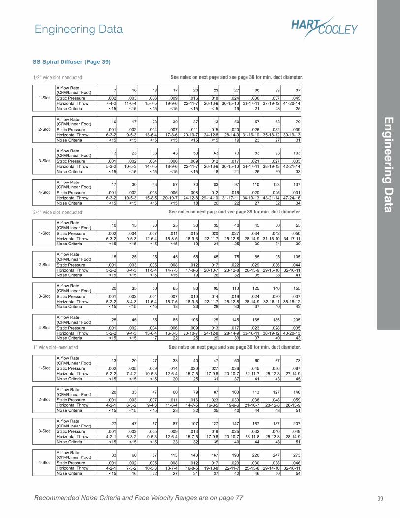
SS Spiral Diffuser (Page 39)
" wide slot - nonducted
Airflow Rate
(CFM/Linear Foot)7 10 13 17 20 23 27 30 33 37
Static Pressure .002 .003 .006 .009 .016 .018 .024 .030 .037 .045
Horizontal Throw 7-4-2 11-6-4 15-7-5 19-9-6 22-11-7 26-13-9 30-15-10 33-17-11 37-19-12 41-20-14
Noise Criteria <15 <15 <15 <15 <15 <15 19 21 23 25
Airflow Rate
(CFM/Linear Foot)10 17 23 30 37 43 50 57 63 70
Static Pressure .001 .002 .004 .007 .011 .015 .020 .026 .032 .039
Horizontal Throw 6-3-2 9-5-3 13-6-4 17-8-6 20-10-7 24-12-8 28-14-9 31-16-10 35-18-12 39-19-13
Noise Criteria <15 <15 <15 <15 <15 <15 19 23 27 31
Airflow Rate
(CFM/Linear Foot)13 23 33 43 53 63 73 83 93 103
Static Pressure .001 .002 .004 .006 .009 .012 .017 .021 .027 .033
Horizontal Throw 5-3-2 10-5-3 14-7-5 18-9-6 22-11-7 26-13-9 30-15-10 34-17-11 38-19-13 42-21-14
Noise Criteria <15 <15 <15 <15 <15 18 21 25 30 33
Airflow Rate
(CFM/Linear Foot)17 30 43 57 70 83 97 110 123 137
Static Pressure .001 .002 .003 .005 .008 .012 .016 .020 .025 .031
Horizontal Throw 6-3-2 10-5-3 15-8-5 20-10-7 24-12-8 29-14-10 31-17-11 38-19-13 43-21-14 47-24-16
Noise Criteria <15 <15 <15 <15 18 20 22 27 32 34
Airflow Rate
(CFM/Linear Foot)10 15 20 25 30 35 40 45 50 55
Static Pressure .002 .004 .007 .011 .015 .020 .027 .034 .042 .050
Horizontal Throw 6-3-2 9-5-3 12-6-4 15-8-5 18-9-6 22-11-7 25-12-8 28-14-9 31-15-10 34-17-11
Noise Criteria <15 <15 <15 <15 19 21 25 30 34 39
Airflow Rate
(CFM/Linear Foot)15 25 35 45 55 65 75 85 95 105
Static Pressure .001 .003 .005 .008 .012 .017 .022 .029 .036 .044
Horizontal Throw 5-2-2 8-4-3 11-5-4 14-7-5 17-8-6 20-10-7 23-12-8 26-13-9 29-15-10 32-16-11
Noise Criteria <15 <15 <15 <15 19 26 32 35 38 41
Airflow Rate
(CFM/Linear Foot)20 35 50 65 80 95 110 125 140 155
Static Pressure .001 .002 .004 .007 .010 .014 .019 .024 .030 .037
Horizontal Throw 5-2-2 8-4-3 11-6-4 15-7-5 18-9-6 22-11-7 25-12-8 28-14-9 32-16-11 35-18-12
Noise Criteria <15 <15 <15 18 23 28 33 37 40 43
Airflow Rate
(CFM/Linear Foot)25 45 65 85 105 125 145 165 185 205
Static Pressure .001 .002 .004 .006 .009 .013 .017 .023 .028 .035
Horizontal Throw 5-2-2 9-4-3 13-6-4 16-8-5 20-10-7 24-12-8 28-14-9 32-16-11 38-19-12 40-20-13
Noise Criteria <15 <15 17 22 25 29 33 37 40 43
Airflow Rate
(CFM/Linear Foot)13 20 27 33 40 47 53 60 67 73
Static Pressure .002 .005 .009 .014 .020 .027 .036 .045 .056 .067
Horizontal Throw 5-2-2 7-4-2 10-5-3 12-6-4 15-7-5 17-9-6 20-10-7 22-11-7 25-12-8 27-14-9
Noise Criteria <15 <15 <15 20 25 31 37 41 43 45
Airflow Rate
(CFM/Linear Foot)20 33 47 60 79 87 100 113 127 140
Static Pressure .001 .003 .007 .011 .016 .023 .030 .038 .048 .059
Horizontal Throw 4-2-1 6-3-2 9-4-3 11-6-4 14-7-5 16-8-5 19-9-6 21-10-7 23-12-8 26-13-9
Noise Criteria <15 <15 <15 23 32 35 40 44 48 51
Airflow Rate
(CFM/Linear Foot)27 47 67 87 107 127 147 167 187 207
Static Pressure .001 .003 .005 .009 .013 .019 .025 .032 .040 .049
Horizontal Throw 4-2-1 6-3-2 9-5-3 12-6-4 15-7-5 17-9-6 20-10-7 23-11-8 25-13-8 28-14-9
Noise Criteria <15 <15 <15 23 32 35 40 44 48 51
Airflow Rate
(CFM/Linear Foot)33 60 87 113 140 167 193 220 247 273
Static Pressure .001 .002 .005 .008 .012 .017 .023 .030 .038 .046
Horizontal Throw 4-2-1 7-3-2 10-5-3 13-7-4 16-8-5 19-10-8 22-11-7 25-13-8 29-14-10 32-16-11
Noise Criteria <15 16 22 27 31 37 42 46 50 54
1-Slot
2-Slot
3-Slot
2-Slot
4-Slot
" wide slot - nonducted
1-Slot
2-Slot
3-Slot
4-Slot
3-Slot
4-Slot
1" wide slot - nonducted
1-Slot
1/2” wide slot–nonducted
3/4” wide slot–nonducted
1” wide slot–nonducted
See notes on next page and see page 39 for min. duct diameter.
See notes on next page and see page 39 for min. duct diameter.
See notes on next page and see page 39 for min. duct diameter.
Recommended Noise Criteria and Face Velocity Ranges are on page 77
Engineering Data
99
Eng
ineering D
ata
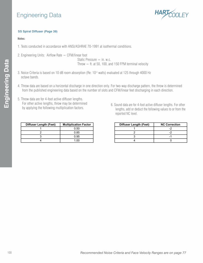
SS Spiral Diffuser (Page 39)
Diffuser Length (Feet) Multiplication Factor Diffuser Length (Feet) NC Correction1 0.50 1 -2
2 0.85 2 -2
3 0.95 3 -1
4 1.00 4 0
Notes:
1. Tests conducted in accordance with ANSI/ASHRAE 70-1991 at isothermal conditions.
2. Engineering Units: Airflow Rate = CFM/linear foot Static Pressure = in. w.c. Throw = ft. at 50, 100, and 150 FPM terminal velocity
3. Noice Criteria is based on 10 dB room absorption (Re: 1012 watts) evaluated at 125 through 4000 Hz octave bands.
4. Throw data are based on a horizontal discharge in one direction only. For two-way discharge pattern, the throw is determined from the published engineering data based on the number of slots and CFM/linear feet discharging in each direction.
5. Throw data are for 4-foot active diffuser lengths. For other active lengths, throw may be determined by applying the following multiplication factors.
6. Sound data are for 4-foot active diffuser lengths. For other lengths, add or deduct the following values to or from the reported NC level.
Recommended Noise Criteria and Face Velocity Ranges are on page 77100
Engineering DataE
ngin
eeri
ng D
ata
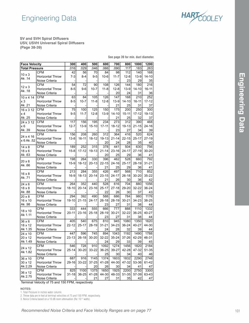
300 400 500 600 700 800 1000 1200.016 .029 .046 .066 .090 .117 .183 .263
CFM 42 56 70 84 98 112 140 168
Horizontal Throw 7-3 8-4 9-5 10-6 11-7 12-8 13-9 14-10
Noise Criteria - - - - - 23 29 35
CFM 54 72 90 108 126 144 180 216
Horizontal Throw 8-5 9-6 10-7 11-8 12-8 13-9 14-10 16-11
Noise Criteria - - - - 20 24 31 36
CFM 63 84 105 126 147 168 210 252
Horizontal Throw 8-5 10-7 11-8 12-8 13-9 14-10 16-11 17-12
Noise Criteria - - - - 21 25 31 37
CFM 75 100 125 150 175 200 250 300
Horizontal Throw 9-5 11-7 12-8 13-9 14-10 15-11 17-12 19-13
Noise Criteria - - - - 21 25 32 37
CFM 117 156 195 234 273 312 390 468
Horizontal Throw 12-7 13-9 15-10 17-11 18-12 19-13 21-15 24-16
Noise Criteria - - - - 23 27 34 39
CFM 156 208 260 312 364 416 520 624
Horizontal Throw 13-8 16-11 18-12 19-13 21-14 22-15 25-17 27-19
Noise Criteria - - - 20 24 28 35 40
CFM 189 252 315 378 441 504 630 756
Horizontal Throw 15-8 17-12 19-13 21-14 23-16 24-17 27-19 30-20
Noise Criteria - - - 20 25 29 36 41
CFM 198 264 330 396 462 528 660 792
Horizontal Throw 15-9 18-12 20-13 22-15 24-16 25-17 28-19 31-21
Noise Criteria - - - 21 25 29 36 41
CFM 213 284 355 426 497 568 710 852
Horizontal Throw 16-9 18-13 20-14 23-15 24-17 26-18 30-20 35-22
Noise Criteria - - - 21 26 30 36 42
CFM 264 352 440 528 616 704 880 1056
Horizontal Throw 18-10 20-14 23-16 25-17 27-18 29-20 32-22 36-24
Noise Criteria - - - 22 26 30 37 43
CFM 294 392 490 588 686 784 980 1176
Horizontal Throw 19-10 21-15 24-17 26-18 28-19 30-21 34-23 38-25
Noise Criteria - - - 23 27 31 38 44
CFM 333 444 555 666 777 888 1110 1332
Horizontal Throw 20-11 23-16 25-18 28-19 30-21 32-22 36-25 40-27
Noise Criteria - - - 23 27 31 38 44
CFM 405 540 675 810 945 1080 1350 1620
Horizontal Throw 22-12 25-17 28-19 31-21 34-23 36-24 40-27 44-30
Noise Criteria - - - 24 28 32 39 44
CFM 447 596 745 894 1043 1192 1490 1788
Horizontal Throw 23-13 26-18 30-20 32-22 35-24 37-26 42-29 46-31
Noise Criteria - - - 24 29 33 39 45
CFM 546 728 910 1092 1274 1456 1820 2184
Horizontal Throw 25-14 30-20 33-22 36-25 39-27 42-28 47-32 51-35
Noise Criteria - - - 25 30 34 40 46
CFM 687 916 1145 1374 1603 1832 2290 2748
Horizontal Throw 29-16 33-22 37-25 41-28 44-30 47-32 53-36 61-42
Noise Criteria - - 20 26 30 34 41 47
CFM 825 1100 1375 1650 1925 2200 2750 3300
Horizontal Throw 31-18 36-25 41-28 44-30 48-33 51-35 57-39 63-43
Noise Criteria - - 21 27 31 35 42 47
24 x 3 12
x 6
Ak .39
Face VelocityTotal Pressure
10 x 3
Ak .14
12 x 3
Ak .18
10 x 4 14
x 3
Ak .21
16 x 3 12
x 4
Ak .25
Terminal Velocity of 75 and 150 FPM, respectively
24 x 4 16
x 6 Ak .52
14 x 8
18 x 6
Ak .63
36 x 10
30 x 12
Ak 2.29
36 x 12
Ak 2.75
18 x 10
Ak 1.11
36 x 6
18 x 12
Ak 1.35
24 x 10
20 x 12
Ak 1.49
24 x 12
Ak 1.82
20 x 6
Ak .66
16 x 8
Ak .71
24 x 6
18 x 8
Ak .88
20 x 8
16 x 10
Ak .98
SV and SVH Spiral DiffusersUSV, USVH Universal Spiral Diffusers(Page 38-39)
NOTES: 1. Total Pressure in inches water column.2. Throw data are in feet at terminal velocities of 75 and 150 FPM, respectively.3. Noice Criteria based on a 10 dB room attenuation (Re: 10-12 watts).
See page 39 for min. duct diameter.
Recommended Noise Criteria and Face Velocity Ranges are on page 77
Engineering Data
101
Eng
ineering D
ata
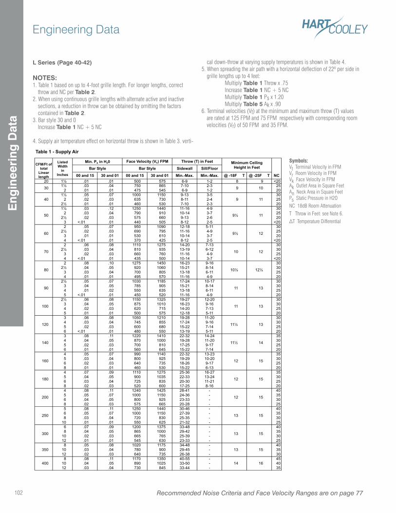
L Series (Page 40-42)
NOTES:1. Table 1 based on up to 4-foot grille length. For longer lengths, correct
throw and NC per Table 2.2. When using continuous grille lengths with alternate active and inactive
sections, a reduction in throw can be obtained by omitting the factors contained in Table 2.
3. Bar style 30 and 0 Increase Table 1 NC + 5 NC
4. Supply air temperature effect on horizontal throw is shown in Table 3. verti-
cal down-throw at varying supply temperatures is shown in Table 4.5. When spreading the air path with a horizontal deflection of 22º per side in
grille lengths up to 4 feet: Multiply Table 1 Throw x .75 Increase Table 1 NC + 5 NC Multiply Table 1 Ps x 1.20 Multiply Table 5 Ak x .906. Terminal velocities (Vt) at the minimum and maximum throw (T) values
are rated at 125 FPM and 75 FPM respectively with corresponding room velocities (Vr) of 50 FPM and 35 FPM.
Sidewall Sill/Floor
00 and 15 30 and 01 00 and 15 30 and 01 Min.-Max. Min.-Max. @ -18F T @ -25F T20 1 .01 .01 500 575 6-9 1-2 8 9 <20
1 .03 .04 750 865 7-10 2-3 252 .01 .01 475 545 6-9 1-2 20
1 .05 .07 1000 1150 9-13 3-5 302 .02 .03 635 730 8-11 2-4 25
2 .01 .01 460 530 7-10 2-3 20 1 .03 .12 1250 1440 11-16 4-9 30
2 .03 .04 790 910 10-14 3-7 25 2 .02 .03 575 660 9-13 2-6 20
3 <.01 .01 440 505 8-12 2-5 <202 .05 .07 950 1090 12-18 5-11 30
2 .02 .03 690 795 11-16 4-9 253 .01 .01 530 610 10-14 3-7 204 <.01 .01 370 425 8-12 2-5 <202 .06 .08 1110 1275 14-20 7-13 30
2 .03 .04 810 935 13-19 6-12 303 .02 .03 660 760 11-16 4-9 254 <.01 .01 435 500 10-14 3-7 <202 .08 .10 1275 1450 16-23 9-16 30
2 .04 .05 920 1060 15-21 8-14 303 .03 .04 700 805 13-18 6-11 254 .01 .01 495 570 11-16 4-9 20
2 .05 .07 1030 1185 17-24 10-17 303 .04 .05 785 905 15-21 8-14 304 .01 .02 550 635 13-18 6-11 255 <.01 .01 450 520 11-16 4-9 20
2 .06 .08 1150 1325 19-27 12-20 303 .04 .05 875 1010 16-23 9-16 304 .02 .03 620 715 14-20 7-13 255 .01 .01 500 575 12-18 5-11 203 .06 .08 1050 1210 19-28 11-20 304 .03 .04 745 855 17-24 9-16 305 .02 .03 600 680 15-22 7-14 256 <.01 .01 480 550 13-19 5-11 203 .08 .11 1220 1410 22-32 14-24 354 .04 .05 870 1000 19-28 11-20 305 .02 .03 700 810 17-25 9-17 256 .01 .01 560 645 15-22 7-14 204 .05 .07 990 1140 22-32 13-23 355 .03 .04 800 925 19-29 10-20 306 .02 .03 640 735 18-26 9-17 258 .01 .01 460 530 15-22 6-13 204 .07 .09 1110 1275 25-36 16-27 355 .04 .05 900 1035 22-33 13-24 306 .03 .04 725 835 20-30 11-21 258 .02 .03 520 600 17-25 8-16 204 .08 .11 1240 1425 28-41 - 405 .05 .07 1000 1150 24-36 - 356 .04 .05 800 925 23-33 - 308 .02 .03 575 665 20-28 - 255 .08 .11 1250 1440 30-46 - 406 .05 .07 1000 1150 27-39 - 358 .03 .04 720 830 25-35 - 30
10 .01 .01 550 625 21-32 - 256 .07 .09 1200 1375 33-48 - 408 .04 .05 865 1000 29-42 - 35
10 .02 .03 665 765 25-39 - 3012 .01 .01 545 630 23-33 - 258 .05 .08 1020 1175 34-48 - 40
10 .03 .04 780 900 29-45 - 3512 .02 .03 640 735 26-38 - 308 .08 .11 1170 1350 40-55 - 45
10 .04 .05 890 1025 33-50 - 4012 .03 .04 730 845 33-44 - 35
50
40
30
Throw (T) in Feet Minimum CeilingHeight in Feet
9 11
Table 1 - Supply Air
Min. Ps in H20Bar Style
CFM/Ft of total
Linear length
ListedWidth
inInches NC
9 10
60 9 12
9 11
Face Velocity (Vk) FPM
Bar Style
70 10 12
80 10 12
90 11 13
100 11 13
120 11 13
140 11 14
160 12 15
180 12 15
200 12 15
250 13 15
400 14 16
300 13 15
350 13 15
Symbols:Vt Terminal Velocity in FPMVr Room Velocity in FPMVk Face Velocity in FPMAk Outlet Area in Square FeetAn Neck Area in Square FeetPs Static Pressure in H2O
NC 18dB Room Attenuation
T Throw in Feet: see Note 6.
Recommended Noise Criteria and Face Velocity Ranges are on page 77102
Engineering DataE
ngin
eeri
ng D
ata
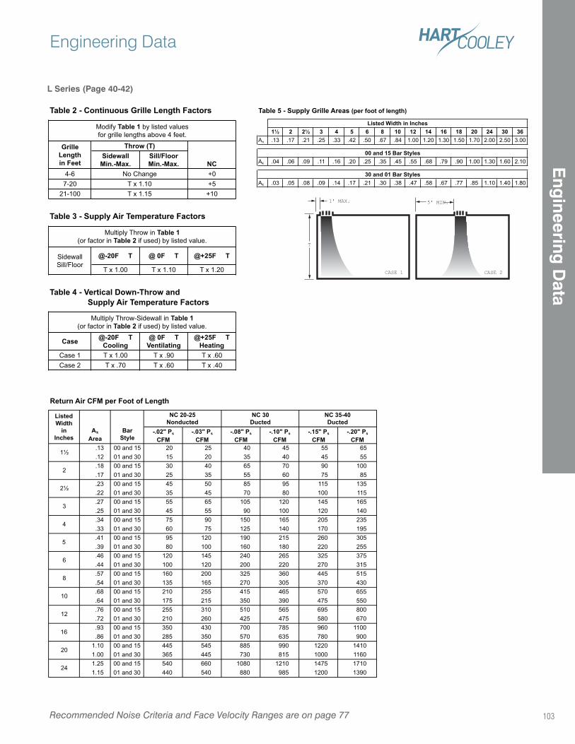
1' MAX.
CASE 1
T
5' MIN.
CASE 2
L Series (Page 40-42)
SidewallMin.-Max.
Sill/FloorMin.-Max. NC
4-6 +0
7-20 +5
21-100 +10
@-20F T @ 0F T @+25F T
T x 1.00 T x 1.10 T x 1.20
Case @-20F TCooling
@ 0F TVentilating
@+25F THeating
Case 1 T x 1.00 T x .90 T x .60
Case 2 T x .70 T x .60 T x .40
Sidewall
Sill/Floor
Table 4 - Vertical Down-Throw and Supply Air Temperature Factors
Multiply Throw-Sidewall in Table 1(or factor in Table 2 if used) by listed value.
Modify Table 1 by listed values
for grille lengths above 4 feet.
Table 2 - Continuous Grille Length Factors
Table 3 - Supply Air Temperature Factors
Multiply Throw in Table 1(or factor in Table 2 if used) by listed value.
Throw (T)
No Change
T x 1.10
T x 1.15
GrilleLengthin Feet
1 2 2 3 4 5 6 8 10 12 14 16 18 20 24 30 36An .13 .17 .21 .25 .33 .42 .50 .67 .84 1.00 1.20 1.30 1.50 1.70 2.00 2.50 3.00
Ak .04 .06 .09 .11 .16 .20 .25 .35 .45 .55 .68 .79 .90 1.00 1.30 1.60 2.10
Ak .03 .05 .08 .09 .14 .17 .21 .30 .38 .47 .58 .67 .77 .85 1.10 1.40 1.80
Listed Width in Inches
00 and 15 Bar Styles
30 and 01 Bar Styles
Table 5 - Supply Grille Areas (per foot of length)
Return Air CFM per Foot of Length
-.02" Ps
CFM-.03" Ps
CFM-.08" Ps
CFM-.10" Ps
CFM-.15" Ps
CFM-.20" Ps
CFM.13 00 and 15 20 25 40 45 55 65
.12 01 and 30 15 20 35 40 45 55
.18 00 and 15 30 40 65 70 90 100
.17 01 and 30 25 35 55 60 75 85
.23 00 and 15 45 50 85 95 115 135
.22 01 and 30 35 45 70 80 100 115
.27 00 and 15 55 65 105 120 145 165
.25 01 and 30 45 55 90 100 120 140
.34 00 and 15 75 90 150 165 205 235
.33 01 and 30 60 75 125 140 170 195
.41 00 and 15 95 120 190 215 260 305
.39 01 and 30 80 100 160 180 220 255
.46 00 and 15 120 145 240 265 325 375
.44 01 and 30 100 120 200 220 270 315
.57 00 and 15 160 200 325 360 445 515
.54 01 and 30 135 165 270 305 370 430
.68 00 and 15 210 255 415 465 570 655
.64 01 and 30 175 215 350 390 475 550
.76 00 and 15 255 310 510 565 695 800
.72 01 and 30 210 260 425 475 580 670
.93 00 and 15 350 430 700 785 960 1100
.86 01 and 30 285 350 570 635 780 900
1.10 00 and 15 445 545 885 990 1220 1410
1.00 01 and 30 365 445 730 815 1000 1160
1.25 00 and 15 540 660 1080 1210 1475 1710
1.15 01 and 30 440 540 880 985 1200 1390
NC 35-40Ducted
ListedWidth
inInches
NC 20-25Nonducted
16
5
Ak
AreaBar
Style
1
2
20
24
NC 30Ducted
6
8
10
12
2
3
4
Recommended Noise Criteria and Face Velocity Ranges are on page 77
Engineering Data
103
Eng
ineering D
ata
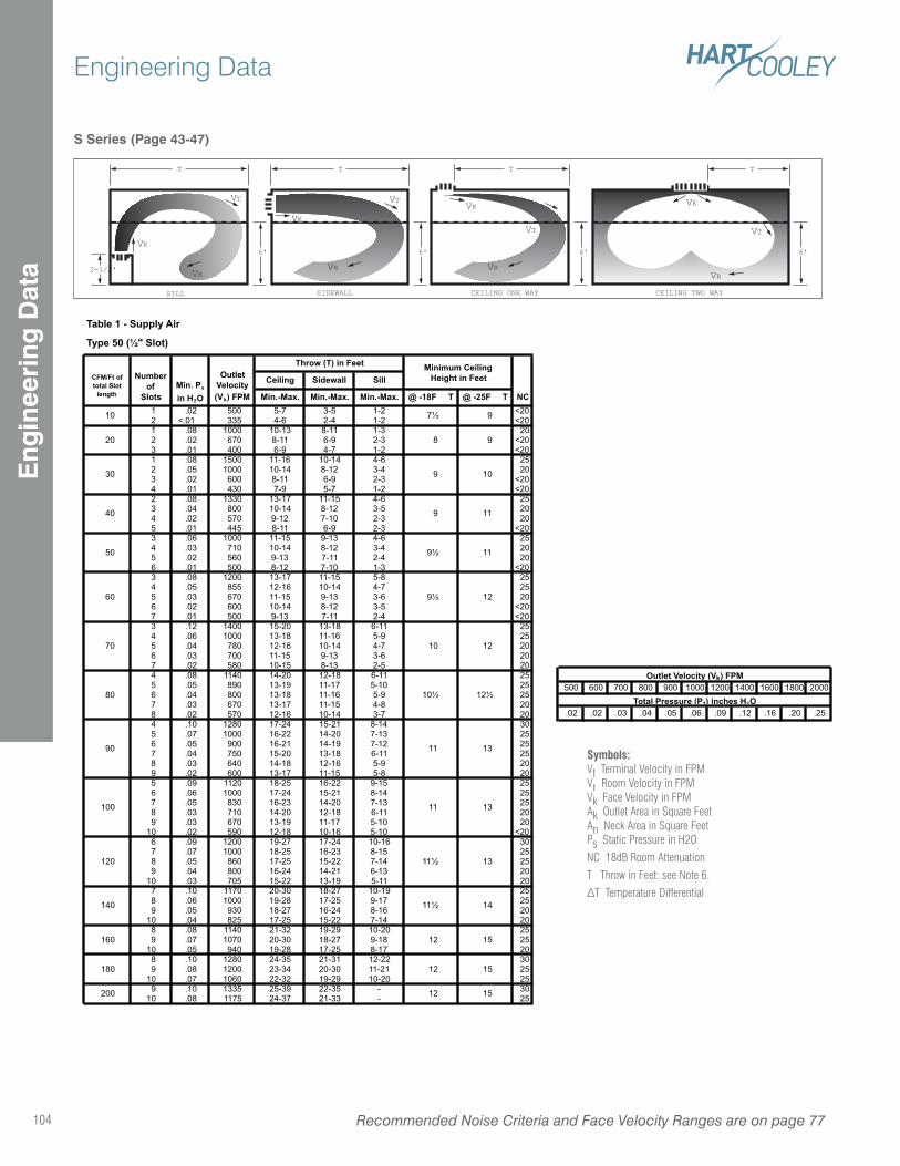
S Series (Page 43-47)
T T
VK
VT
CEILING ONE WAY CEILING TWO WAY
6' 6' 6'
VRVR
T
VK
VT
SIDEWALL
6'
VR
T
VK
VT
SILL
2-1/2' VR
VK
VT
Type 50 ( " Slot)
Ceiling Sidewall Sill
Min.-Max. Min.-Max. Min.-Max. @ -18F T @ -25F T1 .02 500 5-7 3-5 1-2 <202 <.01 335 4-6 2-4 1-2 <201 .08 1000 10-13 8-11 1-3 202 .02 670 8-11 6-9 2-3 <203 .01 400 6-9 4-7 1-2 <201 .08 1500 11-16 10-14 4-6 252 .05 1000 10-14 8-12 3-4 203 .02 600 8-11 6-9 2-3 <204 .01 430 7-9 5-7 1-2 <202 .08 1330 13-17 11-15 4-6 253 .04 800 10-14 8-12 3-5 204 .02 570 9-12 7-10 2-3 205 .01 445 8-11 6-9 2-3 <203 .06 1000 11-15 9-13 4-6 254 .03 710 10-14 8-12 3-4 205 .02 560 9-13 7-11 2-4 206 .01 500 8-12 7-10 1-3 <203 .08 1200 13-17 11-15 5-8 254 .05 855 12-16 10-14 4-7 255 .03 670 11-15 9-13 3-6 206 .02 600 10-14 8-12 3-5 <207 .01 500 9-13 7-11 2-4 <203 .12 1400 15-20 13-18 6-11 254 .06 1000 13-18 11-16 5-9 255 .04 780 12-16 10-14 4-7 206 .03 700 11-15 9-13 3-6 207 .02 580 10-15 8-13 2-5 204 .08 1140 14-20 12-18 6-11 255 .05 890 13-19 11-17 5-10 256 .04 800 13-18 11-16 5-9 257 .03 670 13-17 11-15 4-8 208 .02 570 12-16 10-14 3-7 204 .10 1280 17-24 15-21 8-14 305 .07 1000 16-22 14-20 7-13 256 .05 900 16-21 14-19 7-12 257 .04 750 15-20 13-18 6-11 258 .03 640 14-18 12-16 5-9 209 .02 600 13-17 11-15 5-8 205 .09 1120 18-25 16-22 9-15 256 .06 1000 17-24 15-21 8-14 257 .05 830 16-23 14-20 7-13 258 .03 710 14-20 12-18 6-11 209 .03 670 13-19 11-17 5-10 20
10 .02 590 12-18 10-16 5-10 <206 .09 1200 19-27 17-24 10-16 307 .07 1000 18-25 16-23 8-15 258 .05 860 17-25 15-22 7-14 259 .04 800 16-24 14-21 6-13 20
10 .03 705 15-22 13-19 5-11 207 .10 1170 20-30 18-27 10-19 258 .06 1000 19-28 17-25 9-17 259 .05 930 18-27 16-24 8-16 20
10 .04 825 17-25 15-22 7-14 208 .08 1140 21-32 19-29 10-20 259 .07 1070 20-30 18-27 9-18 25
10 .05 940 19-28 17-25 8-17 208 .10 1280 24-35 21-31 12-22 309 .08 1200 23-34 20-30 11-21 25
10 .07 1060 22-32 19-29 10-20 259 .10 1335 25-39 22-35 - 30
10 .08 1175 24-37 21-33 - 25
15
12
50 9 11
11 13
100 11 13
Min. Ps
in H2O
OutletVelocity(Vk) FPM
10
20
9 11
7 9
8
9
70 10 12
60 9 12
180
120 11 13
140 11 14
12 160
10
40
200 12 15
80 10 12
90
15
Table 1 - Supply Air
CFM/Ft of total Slot
length
Numberof
Slots
9
Throw (T) in Feet Minimum CeilingHeight in Feet
NC
30
500 600 700 800 900 1000 1200 1400 1600 1800 2000
.02 .02 .03 .04 .05 .06 .09 .12 .16 .20 .25
Total Pressure (Pt) inches H2O
Outlet Velocity (Vk) FPM
Symbols:Vt Terminal Velocity in FPMVr Room Velocity in FPMVk Face Velocity in FPMAk Outlet Area in Square FeetAn Neck Area in Square FeetPs Static Pressure in H2O
NC 18dB Room Attenuation
T Throw in Feet: see Note 6.
Recommended Noise Criteria and Face Velocity Ranges are on page 77104
Engineering DataE
ngin
eeri
ng D
ata
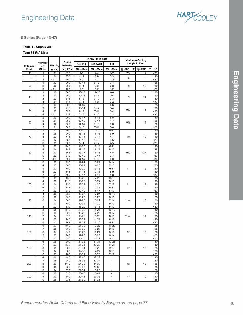
S Series (Page 43-47)
Type 75 ( " Slot)
Ceiling Sidewall Sill
Min.-Max. Min.-Max. Min.-Max. @ -18F T @ -25F T10 1 .01 335 4-6 2-4 1-2 7 9 <20
1 .04 670 8-11 6-9 2-3 20
2 <.01 400 6-9 4-7 1-2 <20
1 .09 1000 10-14 8-12 3-4 25
2 .02 600 8-11 6-9 2-3 20
3 <.01 430 7-9 5-7 1-2 <20
1 .16 1340 13-17 11-15 4-6 30
2 .04 800 10-14 8-12 3-4 25
3 .02 575 9-12 7-10 2-3 20
4 .01 445 8-11 6-9 2-3 <20
2 .06 1000 11-15 9-13 4-6 25
3 .03 715 10-14 8-12 3-4 20
4 .02 555 9-13 7-11 2-4 <20
5 <.01 415 7-12 6-10 2-3 <20
2 .09 1200 13-17 11-15 5-8 30
3 .04 860 12-16 10-14 4-7 25
4 .02 665 11-15 9-13 3-6 20
5 .01 500 9-13 7-11 3-4 <20
2 .13 1400 15-20 13-18 6-11 30
3 .06 1000 13-18 11-16 5-9 25
4 .03 775 12-16 10-14 4-7 20
5 .02 585 10-15 8-13 3-5 <20
6 .01 500 9-14 7-12 2-5 <20
3 .07 1140 14-20 12-18 6-11 30
4 .04 885 13-19 11-17 5-10 25
5 .03 665 13-17 11-15 4-8 20
6 .02 575 12-16 10-14 3-7 <20
7 <.01 500 11-15 9-13 3-6 <20
3 .09 1290 17-24 15-21 8-14 30
4 .05 1000 16-22 14-20 7-13 25
5 .03 750 15-20 13-18 6-11 20
6 .02 645 14-18 12-16 5-9 20
7 .01 560 13-17 11-15 4-8 <20
3 .13 1430 19-26 17-23 10-16 35
4 .06 1110 18-25 16-22 9-15 30
5 .04 830 16-23 14-20 7-13 25
6 .03 715 14-20 12-18 6-11 20
7 .02 630 13-19 11-17 5-10 <20
4 .09 1330 19-27 17-24 10-16 30
5 .06 1000 18-26 16-23 8-15 25
6 .04 860 17-25 15-22 7-14 20
7 .03 750 16-23 14-20 6-12 20
8 .02 630 15-20 13-18 5-10 <20
5 .08 1170 20-30 18-27 10-19 30
6 .06 1000 19-28 17-25 9-17 25
7 .04 875 18-26 16-23 8-15 25
8 .03 740 16-24 14-21 6-13 20
9 .02 665 15-21 13-19 5-11 <20
6 .07 1150 21-32 19-29 10-20 25
7 .05 1000 20-30 18-27 9-18 25
8 .04 840 18-27 16-24 8-16 20
9 .03 760 17-26 15-23 6-14 <20
10 .02 695 16-25 14-22 5-13 <20
6 .09 1290 24-35 21-31 12-22 30
7 .07 1130 23-34 20-30 11-21 30
8 .05 950 20-31 18-28 9-19 25
9 .04 860 19-30 17-27 8-18 20
10 .03 780 18-29 16-26 7-17 <20
6 .11 1440 26-40 23-36 - 30
7 .08 1250 25-38 22-34 - 30
8 .06 1110 24-36 21-32 - 25
9 .05 955 22-33 20-30 - 25
10 .04 870 21-31 19-28 - 20
8 .10 1315 26-46 23-41 - 35
9 .07 1190 25-42 22-38 - 30
10 .06 1085 24-39 21-35 - 25
250 13 15
180 12 15
200 12 15
140 11 14
160 12 15
100 11 13
120 11 13
80 10 12
90 11 13
60 9 12
70 10 12
40 9 11
50 9 11
20 8 9
30 9 10
NC
Table 1 - Supply Air
CFM perFoot
Numberof
SlotsMin. Ps
in H2O
OutletVelocity(Vk) FPM
Throw (T) in Feet Minimum CeilingHeight in Feet
Recommended Noise Criteria and Face Velocity Ranges are on page 77
Engineering Data
105
Eng
ineering D
ata
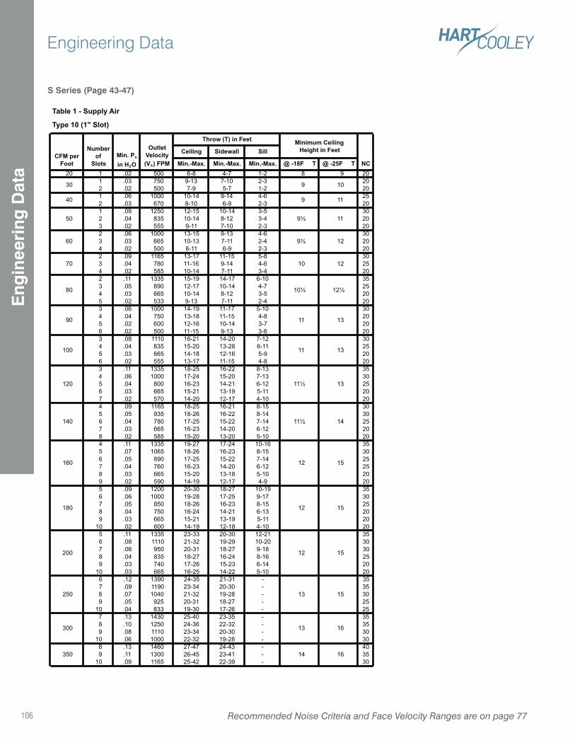
S Series (Page 43-47)
Type 10 (1" Slot)
Ceiling Sidewall Sill
Min.-Max. Min.-Max. Min.-Max. @ -18F T @ -25F T20 1 .02 500 6-8 4-7 1-2 8 9 20
1 .03 750 9-13 7-10 2-3 20
2 .02 500 7-9 5-7 1-2 20
1 .06 1000 10-14 9-14 4-6 25
2 .03 670 8-10 6-9 2-3 20
1 .09 1250 12-15 10-14 3-5 30
2 .04 835 10-14 8-12 3-4 20
3 .02 555 9-11 7-10 2-3 20
2 .06 1000 13-15 9-13 4-6 30
3 .03 665 10-13 7-11 2-4 20
4 .02 500 8-11 6-9 2-3 20
2 .09 1165 13-17 11-15 5-8 30
3 .04 780 11-16 9-14 4-6 25
4 .02 585 10-14 7-11 3-4 20
2 .11 1335 15-19 14-17 6-10 35
3 .05 890 12-17 10-14 4-7 25
4 .03 665 10-14 8-12 3-5 20
5 .02 533 9-13 7-11 2-4 20
3 .06 1000 14-19 11-17 5-10 30
4 .04 750 13-18 11-15 4-8 20
5 .02 600 12-16 10-14 3-7 20
6 .02 500 11-15 9-13 3-6 20
3 .08 1110 16-21 14-20 7-12 30
4 .04 835 15-20 13-28 6-11 25
5 .03 665 14-18 12-16 5-9 20
6 .02 555 13-17 11-15 4-8 20
3 .11 1335 18-25 16-22 8-13 35
4 .06 1000 17-24 15-20 7-13 30
5 .04 800 16-23 14-21 6-12 25
6 .03 665 15-21 13-19 5-11 20
7 .02 570 14-20 12-17 4-10 20
4 .09 1165 18-25 16-21 8-15 30
5 .05 935 18-26 16-22 8-14 30
6 .04 780 17-25 15-22 7-14 25
7 .03 665 16-23 14-20 6-12 20
8 .02 585 15-20 13-20 5-10 20
4 .11 1335 19-27 17-24 10-16 35
5 .07 1065 18-26 16-23 8-15 30
6 .05 890 17-25 15-22 7-14 25
7 .04 760 16-23 14-20 6-12 25
8 .03 665 15-20 13-18 5-10 20
9 .02 590 14-19 12-17 4-9 20
5 .09 1200 20-30 18-27 10-19 35
6 .06 1000 19-28 17-25 9-17 30
7 .05 850 18-26 16-23 8-15 25
8 .04 750 16-24 14-21 6-13 20
9 .03 665 15-21 13-19 5-11 20
10 .02 600 14-19 12-18 4-10 20
5 .11 1335 23-33 20-30 12-21 35
6 .08 1110 21-32 19-29 10-20 30
7 .06 950 20-31 18-27 9-18 30
8 .04 835 18-27 16-24 8-16 25
9 .03 740 17-26 15-23 6-14 20
10 .03 665 16-25 14-22 5-10 20
6 .12 1390 24-35 21-31 - 35
7 .09 1190 23-34 20-30 - 35
8 .07 1040 21-32 19-28 - 30
9 .05 925 20-31 18-27 - 25
10 .04 833 19-30 17-26 - 25
7 .13 1430 25-40 23-35 - 35
8 .10 1250 24-36 22-32 - 35
9 .08 1110 23-34 20-30 - 30
10 .06 1000 22-32 19-28 - 30
8 .13 1460 27-47 24-43 - 40
9 .11 1300 26-45 23-41 - 35
10 .09 1165 25-42 22-39 - 30
200 12 15
350 14 16
250 13 15
300
160 12 15
180 12 15
13 16
120 11 13
140 11 14
90 11 13
100 11 13
70 10 12
80 10 12
50 9 11
60 9 12
Minimum CeilingHeight in Feet
NC
30 9 10
40 9 11
Table 1 - Supply Air
CFM perFoot
Numberof
SlotsMin. Ps
in H2O
OutletVelocity(Vk) FPM
Throw (T) in Feet
Recommended Noise Criteria and Face Velocity Ranges are on page 77106
Engineering DataE
ngin
eeri
ng D
ata
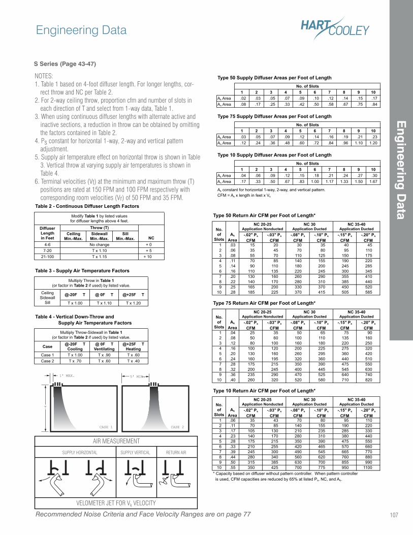
S Series (Page 43-47)
NOTES:1. Table 1 based on 4-foot diffuser length. For longer lengths, cor-
rect throw and NC per Table 2.2. For 2-way ceiling throw, proportion cfm and number of slots in
each direction of T and select from 1-way data, Table 1.3. When using continuous diffuser lengths with alternate active and
inactive sections, a reduction in throw can be obtained by omitting the factors contained in Table 2.
4. Ps constant for horizontal 1-way, 2-way and vertical pattern adjustment.
5. Supply air temperature effect on horizontal throw is shown in Table 3. Vertical throw at varying supply air temperatures is shown in Table 4.
6. Terminal velocities (Vt) at the minimum and maximum throw (T) positions are rated at 150 FPM and 100 FPM respectively with corresponding room velocities (Vr) of 50 FPM and 35 FPM.
1' MAX.
CASE 1
T
5' MIN.
CASE 2
AIR MEASUREMENT
SUPPLY HORIZONTAL SUPPLY VERTICAL RETURN AIR
VELOMETER JET FOR Vk VELOCITY
CeilingMin.-Max.
SidewallMin.-Max.
SillMin.-Max.
4-6 + 0
7-20 + 5
21-100 + 10T x 1.15
Throw (T)
Modify Table 1 by listed values
for diffuser lengths above 4 feet.
Table 2 - Continuous Diffuser Length Factors
DiffuserLengthin Feet NC
No change
T x 1.10
1 2 3 4 5 6 7 8 9 10Ak Area .02 .03 .05 .07 .09 .10 .12 .14 .15 .17
An Area .08 .17 .25 .33 .42 .50 .58 .67 .75 .84
1 2 3 4 5 6 7 8 9 10Ak Area .03 .05 .07 .09 .12 .14 .16 .19 .21 .23
An Area .12 .24 .36 .48 .60 .72 .84 .96 1.10 1.20
1 2 3 4 5 6 7 8 9 10Ak Area .04 .06 .09 .12 .15 .18 .21 .24 .27 .30
An Area .17 .33 .50 .67 .83 1.00 1.17 1.33 1.50 1.67
Ak constant for horizontal 1-way, 2-way, and vertical pattern.
CFM = Ak x length in feet x Vk
Type 10 Supply Diffuser Areas per Foot of LengthNo. of Slots
Type 50 Supply Diffuser Areas per Foot of LengthNo. of Slots
Type 75 Supply Diffuser Areas per Foot of LengthNo. of Slots
Type 50 Return Air CFM per Foot of Length*
-.02" Ps
CFM-.03" Ps
CFM-.08" Ps
CFM-.10" Ps
CFM-.15" Ps
CFM-.20" Ps
CFM1 .03 15 20 30 35 40 45
2 .06 35 45 70 80 95 110
3 .08 55 70 110 125 150 175
4 .11 70 85 140 155 190 220
5 .14 90 110 180 200 245 285
6 .16 110 135 220 245 300 345
7 .20 130 160 260 290 355 410
8 .22 140 170 280 310 385 440
9 .25 165 200 330 370 450 520
10 .28 185 225 370 415 505 585
Type 75 Return Air CFM per Foot of Length*
-.02" Ps
CFM-.03" Ps
CFM-.08" Ps
CFM-.10" Ps
CFM-.15" Ps
CFM-.20" Ps
CFM1 .04 25 35 50 65 75 90
2 .08 50 60 100 110 135 160
3 .12 80 100 160 180 220 250
4 .16 100 120 200 225 275 320
5 .20 130 160 260 295 360 420
6 .24 160 195 320 360 440 510
7 .28 175 215 350 390 475 550
8 .32 200 245 400 445 545 630
9 .36 235 290 470 525 640 740
10 .40 260 320 520 580 710 820
Type 10 Return Air CFM per Foot of Length*
-.02" Ps
CFM-.03" Ps
CFM-.08" Ps
CFM-.10" Ps
CFM-.15" Ps
CFM-.20" Ps
CFM1 .06 35 43 70 80 95 110
2 .11 70 85 140 155 190 220
3 .17 105 130 210 235 285 330
4 .23 140 170 280 310 380 440
5 .28 175 215 350 390 475 550
6 .33 210 255 420 465 570 660
7 .39 245 300 490 545 665 770
8 .44 280 340 560 620 760 880
9 .50 315 385 630 700 855 990
10 .55 350 425 700 775 950 1100
NC 30Application Ducted
NC 35-40Application Ducted
No.of
SlotsAk
Area
NC 20-25Application Nonducted
NC 30Application Ducted
* Capacity based on diffuser without pattern controller. When pattern controller
is used, CFM capacities are reduced by 65% at listed Ps, NC, and Ak.
NC 30Application Ducted
NC 35-40Application DuctedNo.
ofSlots
Ak
Area
NC 20-25Application Nonducted
NC 35-40Application Ducted
No.of
SlotsAk
Area
NC 20-25Application Nonducted
@-20F T @ 0F T @+25F T
T x 1.00 T x 1.10 T x 1.20
Case @-20F TCooling
@ 0F TVentilating
@+25F THeating
Case 1 T x 1.00 T x .90 T x .60
Case 2 T x .70 T x .60 T x .40
Table 3 - Supply Air Temperature Factors
Multiply Throw in Table 1(or factor in Table 2 if used) by listed value.
Ceiling
Sidewall
Sill
Multiply Throw-Sidewall in Table 1(or factor in Table 2 if used) by listed value.
Table 4 - Vertical Down-Throw and Supply Air Temperature Factors
Recommended Noise Criteria and Face Velocity Ranges are on page 77
Engineering Data
107
Eng
ineering D
ata
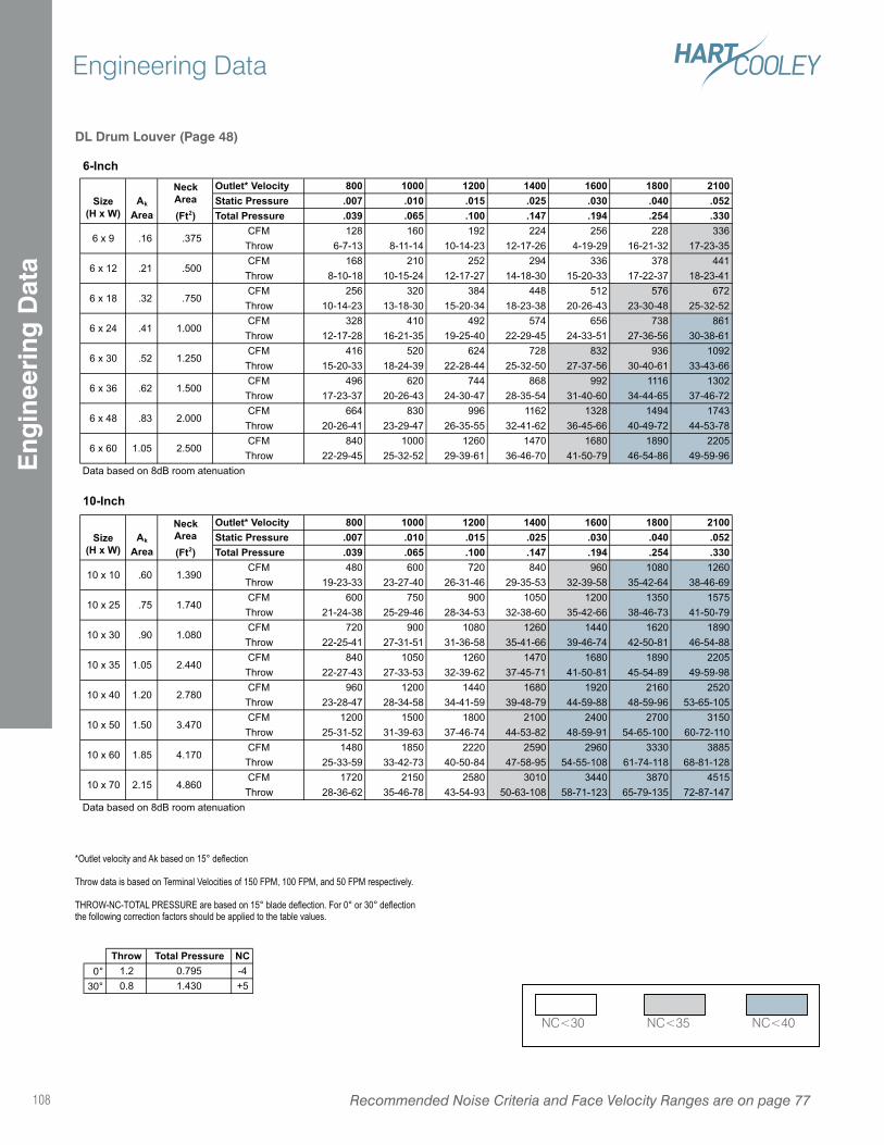
*Outlet velocity and Ak based on 15° deflection
Throw data is based on Terminal Velocities of 150 FPM, 100 FPM, and 50 FPM respectively.
THROW-NC-TOTAL PRESSURE are based on 15° blade deflection. For 0° or 30° deflection the following correction factors should be applied to the table values.
DL Drum Louver (Page 48)
Outlet* Velocity 800 1000 1200 1400 1600 1800 2100Static Pressure .007 .010 .015 .025 .030 .040 .052Total Pressure .039 .065 .100 .147 .194 .254 .330
CFM 128 160 192 224 256 228 336
Throw 6-7-13 8-11-14 10-14-23 12-17-26 4-19-29 16-21-32 17-23-35
CFM 168 210 252 294 336 378 441
Throw 8-10-18 10-15-24 12-17-27 14-18-30 15-20-33 17-22-37 18-23-41
CFM 256 320 384 448 512 576 672
Throw 10-14-23 13-18-30 15-20-34 18-23-38 20-26-43 23-30-48 25-32-52
CFM 328 410 492 574 656 738 861
Throw 12-17-28 16-21-35 19-25-40 22-29-45 24-33-51 27-36-56 30-38-61
CFM 416 520 624 728 832 936 1092
Throw 15-20-33 18-24-39 22-28-44 25-32-50 27-37-56 30-40-61 33-43-66
CFM 496 620 744 868 992 1116 1302
Throw 17-23-37 20-26-43 24-30-47 28-35-54 31-40-60 34-44-65 37-46-72
CFM 664 830 996 1162 1328 1494 1743
Throw 20-26-41 23-29-47 26-35-55 32-41-62 36-45-66 40-49-72 44-53-78
CFM 840 1000 1260 1470 1680 1890 2205
Throw 22-29-45 25-32-52 29-39-61 36-46-70 41-50-79 46-54-86 49-59-96
Data based on 8dB room atenuation
Outlet* Velocity 800 1000 1200 1400 1600 1800 2100Static Pressure .007 .010 .015 .025 .030 .040 .052Total Pressure .039 .065 .100 .147 .194 .254 .330
CFM 480 600 720 840 960 1080 1260
Throw 19-23-33 23-27-40 26-31-46 29-35-53 32-39-58 35-42-64 38-46-69
CFM 600 750 900 1050 1200 1350 1575
Throw 21-24-38 25-29-46 28-34-53 32-38-60 35-42-66 38-46-73 41-50-79
CFM 720 900 1080 1260 1440 1620 1890
Throw 22-25-41 27-31-51 31-36-58 35-41-66 39-46-74 42-50-81 46-54-88
CFM 840 1050 1260 1470 1680 1890 2205
Throw 22-27-43 27-33-53 32-39-62 37-45-71 41-50-81 45-54-89 49-59-98
CFM 960 1200 1440 1680 1920 2160 2520
Throw 23-28-47 28-34-58 34-41-59 39-48-79 44-59-88 48-59-96 53-65-105
CFM 1200 1500 1800 2100 2400 2700 3150
Throw 25-31-52 31-39-63 37-46-74 44-53-82 48-59-91 54-65-100 60-72-110
CFM 1480 1850 2220 2590 2960 3330 3885
Throw 25-33-59 33-42-73 40-50-84 47-58-95 54-55-108 61-74-118 68-81-128
CFM 1720 2150 2580 3010 3440 3870 4515
Throw 28-36-62 35-46-78 43-54-93 50-63-108 58-71-123 65-79-135 72-87-147
Data based on 8dB room atenuation
10 x 10 .60 1.390
6 x 48 .83
6 x 60
6-Inch
10-Inch
Size(H x W)
Ak
Area
NeckArea(Ft2)
.375
.500
.750
1.000
Size(H x W)
NeckArea(Ft2)
6 x 9
6 x 12
6 x 24
6 x 18
Ak
Area
.16
.21
.32
.41
.52
.62
1.05
6 x 30
6 x 36
1.250
1.500
2.000
2.500
1.740
10 x 30 .90 1.080
10 x 25 .75
10 x 35 1.05 2.440
10 x 40 1.20 2.780
10 x 50 1.50 3.470
10 x 60 1.85 4.170
10 x 70 2.15 4.860
Throw Total Pressure NC0° 1.2 0.795 -4
30° 0.8 1.430 +5
NC<30 NC<35 NC<40
Recommended Noise Criteria and Face Velocity Ranges are on page 77108
Engineering DataE
ngin
eeri
ng D
ata
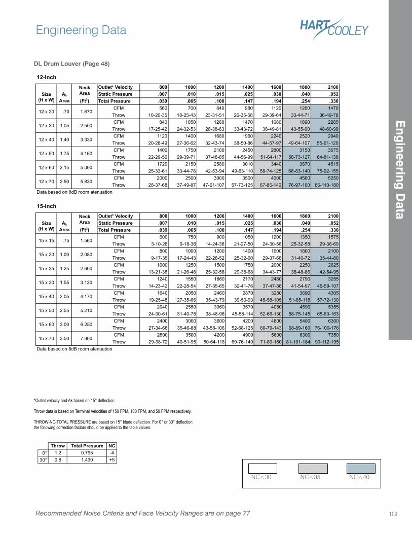
*Outlet velocity and Ak based on 15° deflection
Throw data is based on Terminal Velocities of 150 FPM, 100 FPM, and 50 FPM respectively.
THROW-NC-TOTAL PRESSURE are based on 15° blade deflection. For 0° or 30° deflection the following correction factors should be applied to the table values.
DL Drum Louver (Page 48)
Outlet* Velocity 800 1000 1200 1400 1600 1800 2100Static Pressure .007 .010 .015 .025 .030 .040 .052Total Pressure .039 .065 .100 .147 .194 .254 .330
CFM 560 700 840 980 1120 1260 1470
Throw 10-20-35 18-25-43 23-31-51 26-35-58 29-39-64 33-44-71 36-49-78
CFM 840 1050 1260 1470 1680 1890 2205
Throw 17-25-42 24-32-53 28-38-63 33-43-72 38-49-81 43-55-90 48-60-99
CFM 1120 1400 1680 1960 2240 2520 2940
Throw 20-28-49 27-36-62 32-43-74 38-50-86 44-57-97 49-64-107 55-61-120
CFM 1400 1750 2100 2450 2800 3150 3675
Throw 22-29-56 29-39-71 37-48-85 44-56-99 51-64-117 58-73-127 64-81-138
CFM 1720 2150 2580 3010 3440 3870 4515
Throw 25-33-61 33-44-78 42-53-94 49-63-110 58-74-125 66-83-140 75-92-155
CFM 2000 2500 3000 3500 4000 4500 5250
Throw 28-37-68 37-49-87 47-61-107 57-73-125 67-86-142 76-97-160 86-110-180
Data based on 8dB room atenuation
Outlet* Velocity 800 1000 1200 1400 1600 1800 2100Static Pressure .007 .010 .015 .025 .030 .040 .052Total Pressure .039 .065 .100 .147 .194 .254 .330
CFM 600 750 900 1050 1200 1350 1575
Throw 3-10-28 9-18-36 14-24-36 21-27-50 24-30-56 25-32-58 29-38-69
CFM 800 1000 1200 1400 1600 1800 2100
Throw 9-17-35 17-24-43 22-28-52 25-32-60 29-37-68 31-40-72 35-44-80
CFM 1000 1250 1500 1750 2000 2250 2625
Throw 13-21-38 21-26-48 25-32-58 29-38-68 34-43-77 38-48-86 42-54-95
CFM 1240 1550 1860 2170 2480 2790 3255
Throw 14-23-42 22-28-54 27-35-65 32-41-76 37-47-86 41-54-97 46-59-107
CFM 1640 2050 2460 2870 3280 3690 4305
Throw 19-25-48 27-35-66 35-43-79 39-50-93 45-58-105 51-65-118 57-72-130
CFM 2040 2550 3060 3570 4080 4590 5355
Throw 24-30-61 31-40-78 38-48-96 45-58-114 52-66-130 58-75-145 65-83-163
CFM 2400 3000 3600 4200 4800 5400 6300
Throw 27-34-68 35-46-88 43-58-106 52-68-125 60-79-143 68-89-160 76-100-176
CFM 2800 3500 4200 4900 5600 6300 7350
Throw 29-38-72 40-51-95 50-64-118 60-76-140 71-89-160 81-101-184 90-112-195
Data based on 8dB room atenuation
12-Inch
Size(H x W)
Ak
Area
NeckArea(Ft2)
12 x 20 .70 1.670
12 x 30 1.05 2.500
12 x 40 1.40 3.330
12 x 50 1.75 4.160
12 x 60 2.15 5.000
15-Inch
12 x 70 2.50 5.830
Size(H x W)
Ak
Area
NeckArea(Ft2)
15 x 15 .75 1.560
15 x 20 1.00 2.080
15 x 25 1.25 2.600
15 x 30 1.55 3.120
15 x 40 2.05 4.170
15 x 70 3.50 7.300
15 x 50 2.55 5.210
15 x 60 3.00 6.250
Throw Total Pressure NC0° 1.2 0.795 -4
30° 0.8 1.430 +5
NC<30 NC<35 NC<40
Recommended Noise Criteria and Face Velocity Ranges are on page 77
Engineering Data
109
Eng
ineering D
ata
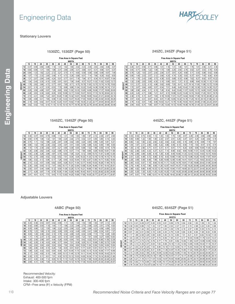
12 18 24 30 36 42 48 54 60 66 72 78 84 90 9612 0.13 0.21 0.29 0.37 0.45 0.53 0.61 0.69 0.76 0.84 0.92 1.00 1.08 1.16 1.24
18 0.39 0.63 0.86 1.10 1.33 1.57 1.80 2.04 2.27 2.51 2.74 2.98 3.22 3.45 3.96
24 0.65 1.04 1.44 1.83 2.22 2.61 3.00 3.39 3.78 4.18 4.57 4.96 5.35 5.74 6.13
30 0.91 1.46 2.01 2.56 3.10 3.65 4.20 4.75 5.29 5.84 6.39 6.94 7.48 8.03 8.58
36 1.17 1.88 2.58 3.28 3.99 4.69 5.40 6.10 6.80 7.51 8.21 8.91 9.62 10.32 11.03
42 1.43 2.29 3.15 4.01 4.87 5.73 6.59 7.45 8.31 9.17 10.03 10.89 11.75 12.61 13.47
48 1.69 2.71 3.73 4.74 5.76 6.77 7.79 8.81 9.82 10.84 11.85 12.87 13.89 14.90 15.92
54 1.95 3.13 4.30 5.47 6.64 7.82 8.99 10.16 11.33 12.50 13.68 14.85 16.02 17.19 18.37
60 2.21 3.53 4.87 6.20 7.53 8.86 10.18 11.51 12.84 14.17 15.50 16.83 18.16 19.48 20.81
66 2.47 3.96 5.44 6.93 8.41 9.90 11.38 12.87 14.35 15.84 17.32 18.80 20.29 21.77 23.26
72 2.73 4.38 6.02 7.66 9.30 10.94 12.58 14.22 15.86 17.50 19.14 20.78 22.42 24.06 25.71
78 2.99 4.79 6.59 8.39 10.18 11.98 13.78 15.57 17.37 19.17 20.96 22.76 24.56 26.35 28.15
84 3.26 5.21 7.16 9.11 11.07 13.02 14.97 16.93 18.88 20.83 22.79 24.74 26.69 28.65 30.60
90 3.52 5.62 7.73 9.84 11.95 14.06 16.17 18.26 20.39 22.50 24.61 26.72 28.83 30.94 33.04
96 3.78 6.04 8.31 10.57 12.84 15.10 17.37 19.63 21.90 25.16 26.43 28.70 30.96 33.23 35.49
HEIG
HT
Free Area in Square FeetWIDTH
4ABC (Page 50) 645ZC, 6545ZF (Page 51)
245ZC, 245ZF (Page 51)
445ZC, 445ZF (Page 51)
1530ZC, 1530ZF (Page 50)
1545ZC, 1545ZF (Page 50)
Stationary Louvers
Adjustable Louvers
12 18 24 30 36 42 48 54 60 66 72 78 84 90 96 12 18 24 30 36 42 48 54 60 66 72 78 84 90 9612 0.37 0.58 0.80 0.98 1.19 1.41 1.62 1.80 2.02 2.23 2.45 2.63 2.84 3.06 3.27 12 0.26 0.41 0.56 0.71 0.86 1.01 1.16 1.31 1.46 1.61 1.76 1.91 2.06 2.21 2.36
18 0.60 0.96 1.31 1.60 1.96 2.31 2.66 2.95 3.31 3.66 4.01 4.31 4.66 5.01 5.37 18 0.45 0.71 0.96 1.22 1.48 1.73 1.99 2.25 2.50 2.76 3.02 3.27 3.53 3.79 4.05
24 0.84 1.33 1.82 2.23 2.72 3.21 3.70 4.11 4.60 5.09 5.58 5.99 6.48 6.97 7.46 24 0.76 1.20 1.63 2.07 2.50 2.94 3.37 3.81 4.24 4.68 5.11 5.55 5.98 6.42 6.86
30 1.07 1.70 2.33 2.85 3.48 4.11 4.73 5.26 5.89 6.51 7.14 7.66 8.29 8.92 9.55 30 0.95 1.49 2.03 2.57 3.12 3.66 4.20 4.74 5.29 5.83 6.37 6.91 7.45 8.00 8.54
36 1.31 2.07 2.84 3.48 4.24 5.01 5.77 6.41 7.18 7.94 8.71 9.34 10.11 10.87 11.64 36 1.14 1.78 2.43 3.08 3.73 4.38 5.03 5.68 6.33 6.98 7.62 8.27 8.92 9.57 10.22
42 1.54 2.45 3.35 4.10 5.00 5.91 6.81 7.56 8.46 9.37 10.27 11.02 11.92 12.83 13.73 42 1.32 2.08 2.83 3.59 4.35 5.10 5.86 6.61 7.37 8.12 8.88 9.64 10.39 11.15 11.90
48 1.78 2.82 3.86 4.72 5.77 6.81 7.85 8.71 9.75 10.79 11.83 12.70 13.74 14.78 15.82 48 1.51 2.37 3.23 4.10 4.96 5.82 6.69 7.55 8.41 9.27 10.14 11.00 11.86 12.72 13.59
54 2.01 3.19 4.37 5.35 6.53 7.70 8.88 9.86 11.04 12.22 13.40 14.38 15.56 16.74 17.91 54 1.70 2.67 3.64 4.60 5.57 6.54 7.51 8.48 9.45 10.42 11.39 12.36 13.33 14.30 15.27
60 2.25 3.56 4.88 5.97 7.29 8.60 9.92 11.02 12.33 13.65 14.96 16.06 17.37 18.69 20.00 60 1.88 2.96 4.04 5.11 6.19 7.26 8.34 9.42 10.49 11.57 12.65 13.72 14.80 15.87 16.95
66 2.48 3.93 5.39 6.60 8.05 9.50 10.96 12.17 13.62 15.07 16.53 17.74 19.19 20.64 22.10 66 2.20 3.45 4.71 5.96 7.21 8.47 9.72 10.98 12.23 13.49 14.74 16.00 17.25 18.51 19.76
72 2.72 4.31 5.90 7.22 8.81 10.40 11.99 13.32 14.91 16.50 18.09 19.42 21.01 22.60 24.19 72 2.38 3.74 5.11 6.47 7.83 9.19 10.55 11.91 13.27 14.64 16.00 17.36 18.72 20.08 21.44
78 2.95 4.68 6.41 7.85 9.58 11.30 13.03 14.47 16.20 17.93 19.65 21.09 22.82 24.55 26.28 78 2.57 4.04 5.51 6.97 8.44 9.91 11.38 12.85 14.32 15.78 17.25 18.72 20.19 21.66 23.13
84 3.19 5.05 6.92 8.47 10.34 12.20 14.07 15.62 17.49 19.35 21.22 22.77 24.64 26.50 28.37 84 2.76 4.33 5.91 7.48 9.06 10.63 12.21 13.78 15.36 16.93 18.51 20.08 21.66 23.23 24.81
90 3.42 5.42 7.43 9.10 11.10 13.10 15.10 16.77 18.78 20.78 22.78 24.45 26.45 28.46 30.46 90 2.94 4.63 6.31 7.99 9.67 11.35 13.04 14.72 16.40 18.08 19.76 21.45 23.13 24.81 26.49
HE
IGH
T
WIDTHFree Area in Square Feet Free Area in Square Feet
WIDTH
HE
IGH
T
12 18 24 30 36 42 48 54 60 66 72 78 84 90 96 12 18 24 30 36 42 48 54 60 66 72 78 84 90 9612 0.30 0.47 0.64 0.79 0.96 1.14 1.31 1.45 1.63 1.80 1.97 2.12 2.29 2.47 2.64 12 0.33 0.53 0.73 0.93 1.13 1.34 1.54 1.74 1.94 2.07 2.28 2.48 2.68 2.88 3.08
18 0.50 0.79 1.08 1.32 1.61 1.90 2.20 2.44 2.73 3.02 3.31 3.55 3.85 4.14 4.43 18 0.55 0.89 1.22 1.56 1.90 2.23 2.57 2.91 3.25 3.47 3.81 4.25 4.48 4.82 5.16
24 0.70 1.11 1.52 1.86 2.26 2.67 3.08 3.42 3.83 4.24 4.65 4.99 5.40 5.81 6.21 24 0.82 1.32 1.82 2.32 2.82 3.32 3.82 4.32 4.83 5.16 5.66 6.16 6.66 7.16 7.67
30 0.90 1.42 1.95 2.39 2.92 3.44 3.97 4.41 4.93 5.46 5.98 6.42 6.95 7.48 8.00 30 1.04 1.67 2.31 2.95 3.58 4.22 4.86 5.49 6.13 6.56 7.19 7.83 8.47 9.10 9.74
36 1.10 1.74 2.39 2.92 3.57 4.21 4.85 5.39 6.03 6.68 7.32 7.86 8.50 9.14 9.79 36 1.30 2.10 2.90 3.71 4.51 5.31 6.11 6.91 7.71 8.24 9.05 9.85 10.65 11.45 12.25
42 1.30 2.06 2.82 3.46 4.22 4.98 5.74 6.37 7.14 7.90 8.66 9.29 10.05 10.81 11.58 42 1.52 2.46 3.40 4.33 5.27 6.21 7.14 8.08 9.02 9.64 10.58 11.51 12.45 13.39 14.32
48 1.50 2.38 3.26 3.99 4.87 5.75 6.63 7.36 8.24 9.12 9.99 10.73 11.61 12.48 13.36 48 1.79 2.89 3.99 5.09 6.19 7.29 8.39 9.49 10.60 11.33 12.43 13.53 14.63 15.73 16.83
54 1.70 2.70 3.69 4.52 5.52 6.52 7.51 8.34 9.34 10.33 11.33 12.16 13.16 14.15 15.15 54 2.01 3.25 4.48 5.72 6.96 8.19 9.43 10.66 11.90 12.73 13.96 15.20 16.45 17.67 18.91
60 1.90 3.02 4.13 5.06 6.17 7.28 8.40 9.33 10.44 11.55 12.67 13.60 14.71 15.82 16.94 60 2.28 3.68 5.08 6.48 7.88 9.28 10.68 12.08 13.48 14.41 15.81 17.22 18.62 20.02 21.42
66 2.10 3.33 4.57 5.59 6.82 8.05 9.28 10.31 11.54 12.77 14.00 15.03 16.26 17.49 18.72 66 2.50 4.03 5.57 7.10 8.64 10.18 11.71 13.25 14.79 15.81 17.35 18.88 20.42 21.95 23.49
72 2.30 3.65 5.00 6.13 7.47 8.82 10.17 11.29 12.64 13.99 15.34 16.46 17.81 19.16 20.51 72 2.76 4.46 6.16 7.86 9.56 11.26 12.97 14.67 16.37 17.50 16.20 20.99 22.60 24.30 26.00
78 2.50 3.97 5.44 6.66 8.12 9.59 11.06 12.28 13.74 15.21 16.68 17.90 19.37 20.83 22.30 78 2.98 4.82 6.66 8.49 10.33 12.16 14.00 15.84 17.67 18.90 20.73 22.57 24.40 26.24 28.07
84 2.71 4.29 5.87 7.19 8.78 10.36 11.94 13.26 14.85 16.43 18.01 19.33 20.92 22.50 24.08 84 3.25 5.25 7.25 9.25 11.25 13.25 15.25 17.25 19.25 20.58 22.58 24.48 26.58 28.58 30.58
90 2.91 4.61 6.31 7.73 9.43 11.13 12.83 14.25 15.95 17.65 19.35 20.77 22.47 24.17 25.87 90 3.47 5.61 7.74 9.88 12.01 14.15 16.28 18.42 20.56 21.98 24.12 26.25 28.39 30.52 32.66
Free Area in Square Feet Free Area in Square FeetWIDTH WIDTH
HE
IGH
T
HE
IGH
T
12 18 24 30 36 42 48 54 60 66 72 78 84 90 9612 0.24 0.38 0.53 0.67 0.82 0.96 1.11 1.25 1.40 1.54 1.68 1.83 1.97 2.12 2.26
18 0.42 0.68 0.93 1.19 1.45 1.17 1.96 2.22 2.48 2.73 2.99 3.25 3.51 3.76 4.02
24 0.55 0.88 1.22 1.55 1.88 2.22 2.55 2.89 3.22 3.56 3.89 4.23 4.56 4.89 5.23
30 0.76 1.23 1.69 2.16 2.62 3.09 3.55 4.02 4.48 4.95 5.41 5.88 6.34 6.81 7.27
36 0.93 1.49 2.06 2.62 3.19 3.76 4.32 4.89 5.45 6.02 6.58 7.15 7.72 8.28 8.85
42 1.11 1.79 2.47 3.15 3.83 4.51 5.19 5.87 6.55 7.23 7.91 8.59 9.27 9.95 10.63
48 1.30 2.09 2.88 3.67 4.46 5.26 6.05 6.84 7.63 8.42 9.22 10.01 10.80 11.59 12.38
54 1.42 2.29 3.16 4.03 4.90 5.77 6.64 7.51 8.38 9.25 10.11 10.98 11.85 12.73 13.59
60 1.64 2.64 3.64 4.64 5.64 6.64 7.64 8.64 9.64 10.64 11.64 12.64 13.64 14.64 15.64
66 1.80 2.90 4.00 5.10 6.20 7.30 8.40 9.51 10.61 11.71 12.81 13.91 15.01 16.11 17.21
72 1.99 3.20 4.42 5.63 6.84 8.06 9.27 10.49 11.70 12.92 14.15 15.34 16.56 17.77 18.99
78 2.17 3.50 4.82 6.15 7.48 8.80 10.13 11.46 12.78 14.11 15.44 16.76 18.09 19.42 20.74
84 2.30 3.70 5.11 6.51 7.91 9.32 10.72 12.13 13.53 14.93 16.34 17.74 19.14 20.55 21.95
90 2.51 4.05 5.58 7.12 8.65 10.19 11.72 13.25 14.79 16.32 17.86 19.39 20.93 22.46 24.00
96 2.68 4.31 5.95 7.58 9.22 10.85 12.49 14.12 15.76 17.39 19.03 20.67 22.30 23.94 25.57
Free Area in Square FeetWIDTH
HE
IGH
T
Recommended Velocity:Exhaust: 400-500 fpmIntake: 300-400 fpmCFM=Free area (ft2) x Velocity (FPM)
Recommended Noise Criteria and Face Velocity Ranges are on page 77110
Engineering DataE
ngin
eeri
ng D
ata
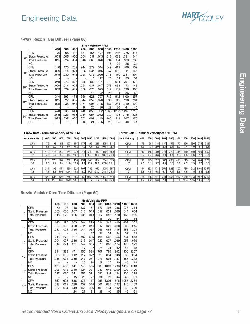
400 500 600 700 800 900 1000 1200 1400 1600CFM 79 98 118 137 157 177 196 236 275 314
Static Pressure .003 .005 .006 .008 .011 .013 .016 .023 .031 .041
Total Pressure .015 .024 .034 .046 .060 .076 .094 .134 .183 .238
NC - - - - - - 15 22 26 31
CFM 140 175 209 244 279 314 349 419 489 559
Static Pressure .009 .014 .021 .028 .037 .046 .057 .082 .111 .145
Total Pressure .019 .030 .043 .058 .076 .096 .118 .170 .231 .301
NC - - - - 18 22 23 31 35 39
CFM 218 273 327 382 436 491 545 654 764 873
Static Pressure .009 .014 .021 .028 .037 .047 .058 .083 .113 .148
Total Pressure .019 .029 .042 .058 .075 .095 .117 .169 .230 .300
NC - - - - 18 22 26 31 36 40
CFM 314 393 471 550 628 707 785 942 1100 1257
Static Pressure .015 .022 .032 .044 .059 .076 .095 .142 .198 .264
Total Pressure .025 .038 .054 .074 .098 .126 .157 .231 .319 .422
NC - - - 18 20 26 29 36 41 45
CFM 428 535 641 748 855 962 1069 1283 1497 1710
Static Pressure .015 .023 .033 .044 .057 .072 .089 .128 .175 .228
Total Pressure .025 .037 .053 .072 .094 .119 .146 .211 .287 .375
NC - - - 15 21 25 29 35 40 44
Neck Velocity FPM
10"
12"
14"
6"
8"
400 500 600 700 800 900 1000 1200 1400 1600CFM 79 98 118 137 157 177 196 236 275 314
Static Pressure .003 .005 .007 .010 .013 .017 .021 .030 .041 .054
Total Pressure .018 .023 .026 .035 .043 .067 .086 .120 .166 .209
NC - - - - - 16 20 24 30 34
CFM 140 175 209 244 279 314 349 419 489 559
Static Pressure .004 .006 .008 .011 .014 .017 .020 .028 .036 .045
Total Pressure .013 .021 .030 .041 .053 .066 .081 .115 .155 .201
NC - - - - 17 22 24 34 37 41
CFM 218 273 327 382 436 491 545 654 764 873
Static Pressure .004 .007 .010 .013 .017 .022 .027 .039 .053 .069
Total Pressure .014 .021 .031 .042 .055 .070 .086 .124 .170 .222
NC - - - 17 22 26 34 42 44 48
CFM 314 393 471 550 628 707 785 942 1100 1257
Static Pressure .006 .009 .012 .017 .022 .028 .034 .048 .065 .084
Total Pressure .015 .024 .035 .047 .061 .077 .095 .137 .186 .242
NC - - - 20 24 27 35 40 45 49
CFM 428 535 641 748 855 962 1069 1283 1497 1710
Static Pressure .008 .013 .018 .024 .031 .040 .048 .069 .093 .120
Total Pressure .017 .030 .041 .056 .071 .090 .114 .144 .200 .278
NC - - 15 23 27 34 39 44 48 51
CFM 559 698 838 977 1117 1257 1396 1676 1955 2234
Static Pressure .012 .019 .028 .037 .048 .061 .075 .107 .145 .189
Total Pressure .022 .034 .049 .066 .086 .108 .134 .192 .260 .339
NC - - 24 27 31 38 40 45 49 51
14"
16"
Neck Velocity FPM
6"
8"
10"
12"
4-Way Rezzin TBar Diffuser (Page 60)
Rezzin Modular Core Tbar Diffuser (Page 60)
Throw Data - Terminal Velocity of 75 FPM Throw Data - Terminal Velocity of 150 FPM
Neck Velocity 400 500 600 700 800 900 1000 1200 1400 1600 Neck Velocity 400 500 600 700 800 900 1000 1200 1400 1600
CFM 79 98 118 137 157 177 196 236 275 314 CFM 79 98 118 137 157 177 196 236 275 314
6" 3.1 3.9 4.6 5.4 6.2 7.0 7.7 9.3 10.8 12.4 6" 1.3 1.7 2.0 2.4 2.7 3.0 3.4 4.0 4.7 5.4
CFM 140 175 209 244 279 314 349 419 489 559 CFM 140 175 209 244 279 314 349 419 489 559
8" 5.3 6.7 8.0 9.3 10.7 12.0 13.3 16.0 18.7 21.3 8" 2.2 2.7 3.3 3.8 4.4 4.9 5.5 6.6 7.7 8.8
CFM 218 273 327 382 436 491 545 654 764 873 CFM 218 273 327 382 436 491 545 654 764 873
10" 6.3 7.9 9.4 11.0 12.6 14.1 15.7 18.8 22.0 25.1 10" 2.5 3.1 3.7 4.4 5.0 5.6 6.2 7.5 8.7 10.0
CFM 314 393 471 550 628 707 785 942 1100 1257 CFM 314 393 471 550 628 707 785 942 1100 1257
12" 7.1 8.8 10.6 12.4 14.2 15.9 17.7 21.2 24.8 28.3 12" 3.8 4.8 5.8 6.7 7.7 8.6 9.6 11.5 13.4 15.3
CFM 428 535 641 748 855 962 1069 1283 1497 1710 CFM 428 535 641 748 855 962 1069 1283 1497 1710
14" 9.1 11.3 13.6 15.9 18.1 20.4 22.7 27.2 31.8 36.3 14" 4.2 5.2 6.3 7.3 8.3 9.4 10.4 12.5 14.6 16.7
Recommended Noise Criteria and Face Velocity Ranges are on page 77
Engineering Data
111
Eng
ineering D
ata
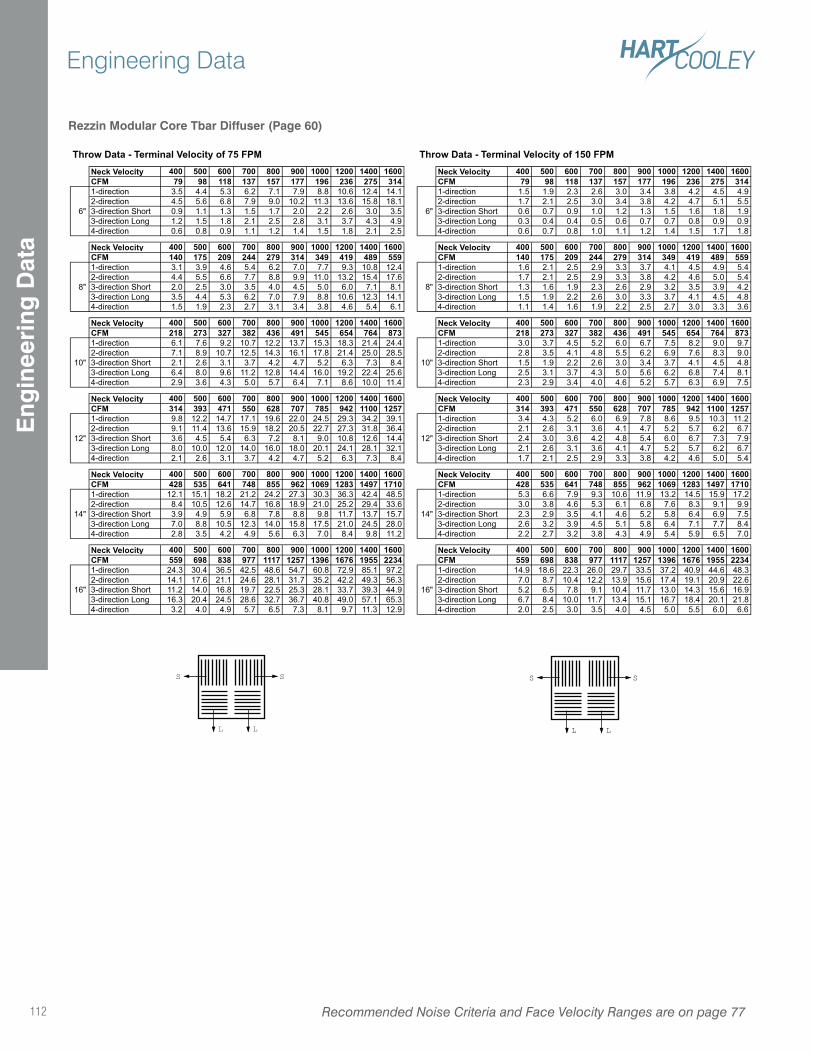
S S
L L
Rezzin Modular Core Tbar Diffuser (Page 60)
S S
L L
Throw Data - Terminal Velocity of 75 FPM Throw Data - Terminal Velocity of 150 FPMNeck Velocity 400 500 600 700 800 900 1000 1200 1400 1600 Neck Velocity 400 500 600 700 800 900 1000 1200 1400 1600CFM 79 98 118 137 157 177 196 236 275 314 CFM 79 98 118 137 157 177 196 236 275 3141-direction 3.5 4.4 5.3 6.2 7.1 7.9 8.8 10.6 12.4 14.1 1-direction 1.5 1.9 2.3 2.6 3.0 3.4 3.8 4.2 4.5 4.9
2-direction 4.5 5.6 6.8 7.9 9.0 10.2 11.3 13.6 15.8 18.1 2-direction 1.7 2.1 2.5 3.0 3.4 3.8 4.2 4.7 5.1 5.5
3-direction Short 0.9 1.1 1.3 1.5 1.7 2.0 2.2 2.6 3.0 3.5 3-direction Short 0.6 0.7 0.9 1.0 1.2 1.3 1.5 1.6 1.8 1.9
3-direction Long 1.2 1.5 1.8 2.1 2.5 2.8 3.1 3.7 4.3 4.9 3-direction Long 0.3 0.4 0.4 0.5 0.6 0.7 0.7 0.8 0.9 0.9
4-direction 0.6 0.8 0.9 1.1 1.2 1.4 1.5 1.8 2.1 2.5 4-direction 0.6 0.7 0.8 1.0 1.1 1.2 1.4 1.5 1.7 1.8
Neck Velocity 400 500 600 700 800 900 1000 1200 1400 1600 Neck Velocity 400 500 600 700 800 900 1000 1200 1400 1600CFM 140 175 209 244 279 314 349 419 489 559 CFM 140 175 209 244 279 314 349 419 489 5591-direction 3.1 3.9 4.6 5.4 6.2 7.0 7.7 9.3 10.8 12.4 1-direction 1.6 2.1 2.5 2.9 3.3 3.7 4.1 4.5 4.9 5.4
2-direction 4.4 5.5 6.6 7.7 8.8 9.9 11.0 13.2 15.4 17.6 2-direction 1.7 2.1 2.5 2.9 3.3 3.8 4.2 4.6 5.0 5.4
3-direction Short 2.0 2.5 3.0 3.5 4.0 4.5 5.0 6.0 7.1 8.1 3-direction Short 1.3 1.6 1.9 2.3 2.6 2.9 3.2 3.5 3.9 4.2
3-direction Long 3.5 4.4 5.3 6.2 7.0 7.9 8.8 10.6 12.3 14.1 3-direction Long 1.5 1.9 2.2 2.6 3.0 3.3 3.7 4.1 4.5 4.8
4-direction 1.5 1.9 2.3 2.7 3.1 3.4 3.8 4.6 5.4 6.1 4-direction 1.1 1.4 1.6 1.9 2.2 2.5 2.7 3.0 3.3 3.6
Neck Velocity 400 500 600 700 800 900 1000 1200 1400 1600 Neck Velocity 400 500 600 700 800 900 1000 1200 1400 1600CFM 218 273 327 382 436 491 545 654 764 873 CFM 218 273 327 382 436 491 545 654 764 8731-direction 6.1 7.6 9.2 10.7 12.2 13.7 15.3 18.3 21.4 24.4 1-direction 3.0 3.7 4.5 5.2 6.0 6.7 7.5 8.2 9.0 9.7
2-direction 7.1 8.9 10.7 12.5 14.3 16.1 17.8 21.4 25.0 28.5 2-direction 2.8 3.5 4.1 4.8 5.5 6.2 6.9 7.6 8.3 9.0
3-direction Short 2.1 2.6 3.1 3.7 4.2 4.7 5.2 6.3 7.3 8.4 3-direction Short 1.5 1.9 2.2 2.6 3.0 3.4 3.7 4.1 4.5 4.8
3-direction Long 6.4 8.0 9.6 11.2 12.8 14.4 16.0 19.2 22.4 25.6 3-direction Long 2.5 3.1 3.7 4.3 5.0 5.6 6.2 6.8 7.4 8.1
4-direction 2.9 3.6 4.3 5.0 5.7 6.4 7.1 8.6 10.0 11.4 4-direction 2.3 2.9 3.4 4.0 4.6 5.2 5.7 6.3 6.9 7.5
Neck Velocity 400 500 600 700 800 900 1000 1200 1400 1600 Neck Velocity 400 500 600 700 800 900 1000 1200 1400 1600CFM 314 393 471 550 628 707 785 942 1100 1257 CFM 314 393 471 550 628 707 785 942 1100 12571-direction 9.8 12.2 14.7 17.1 19.6 22.0 24.5 29.3 34.2 39.1 1-direction 3.4 4.3 5.2 6.0 6.9 7.8 8.6 9.5 10.3 11.2
2-direction 9.1 11.4 13.6 15.9 18.2 20.5 22.7 27.3 31.8 36.4 2-direction 2.1 2.6 3.1 3.6 4.1 4.7 5.2 5.7 6.2 6.7
3-direction Short 3.6 4.5 5.4 6.3 7.2 8.1 9.0 10.8 12.6 14.4 3-direction Short 2.4 3.0 3.6 4.2 4.8 5.4 6.0 6.7 7.3 7.9
3-direction Long 8.0 10.0 12.0 14.0 16.0 18.0 20.1 24.1 28.1 32.1 3-direction Long 2.1 2.6 3.1 3.6 4.1 4.7 5.2 5.7 6.2 6.7
4-direction 2.1 2.6 3.1 3.7 4.2 4.7 5.2 6.3 7.3 8.4 4-direction 1.7 2.1 2.5 2.9 3.3 3.8 4.2 4.6 5.0 5.4
Neck Velocity 400 500 600 700 800 900 1000 1200 1400 1600 Neck Velocity 400 500 600 700 800 900 1000 1200 1400 1600CFM 428 535 641 748 855 962 1069 1283 1497 1710 CFM 428 535 641 748 855 962 1069 1283 1497 17101-direction 12.1 15.1 18.2 21.2 24.2 27.3 30.3 36.3 42.4 48.5 1-direction 5.3 6.6 7.9 9.3 10.6 11.9 13.2 14.5 15.9 17.2
2-direction 8.4 10.5 12.6 14.7 16.8 18.9 21.0 25.2 29.4 33.6 2-direction 3.0 3.8 4.6 5.3 6.1 6.8 7.6 8.3 9.1 9.9
3-direction Short 3.9 4.9 5.9 6.8 7.8 8.8 9.8 11.7 13.7 15.7 3-direction Short 2.3 2.9 3.5 4.1 4.6 5.2 5.8 6.4 6.9 7.5
3-direction Long 7.0 8.8 10.5 12.3 14.0 15.8 17.5 21.0 24.5 28.0 3-direction Long 2.6 3.2 3.9 4.5 5.1 5.8 6.4 7.1 7.7 8.4
4-direction 2.8 3.5 4.2 4.9 5.6 6.3 7.0 8.4 9.8 11.2 4-direction 2.2 2.7 3.2 3.8 4.3 4.9 5.4 5.9 6.5 7.0
Neck Velocity 400 500 600 700 800 900 1000 1200 1400 1600 Neck Velocity 400 500 600 700 800 900 1000 1200 1400 1600CFM 559 698 838 977 1117 1257 1396 1676 1955 2234 CFM 559 698 838 977 1117 1257 1396 1676 1955 22341-direction 24.3 30.4 36.5 42.5 48.6 54.7 60.8 72.9 85.1 97.2 1-direction 14.9 18.6 22.3 26.0 29.7 33.5 37.2 40.9 44.6 48.3
2-direction 14.1 17.6 21.1 24.6 28.1 31.7 35.2 42.2 49.3 56.3 2-direction 7.0 8.7 10.4 12.2 13.9 15.6 17.4 19.1 20.9 22.6
3-direction Short 11.2 14.0 16.8 19.7 22.5 25.3 28.1 33.7 39.3 44.9 3-direction Short 5.2 6.5 7.8 9.1 10.4 11.7 13.0 14.3 15.6 16.9
3-direction Long 16.3 20.4 24.5 28.6 32.7 36.7 40.8 49.0 57.1 65.3 3-direction Long 6.7 8.4 10.0 11.7 13.4 15.1 16.7 18.4 20.1 21.8
4-direction 3.2 4.0 4.9 5.7 6.5 7.3 8.1 9.7 11.3 12.9 4-direction 2.0 2.5 3.0 3.5 4.0 4.5 5.0 5.5 6.0 6.6
6"
8"
6"
8"
14"
16"
14"
16"
10"
12"
10"
12"
Recommended Noise Criteria and Face Velocity Ranges are on page 77112
Engineering DataE
ngin
eeri
ng D
ata
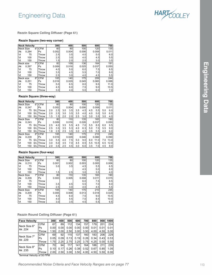
Rezzin Square Ceiling Diffuser (Page 61)
Rezzin Round Ceiling Diffuser (Page 61)
R (two-way corner)
6" CFM
Ak 0.284 Ps
Vt 75 Throw
Vt 100 Throw
Vt 150 Throw
7" CFM
Ak 0.267 Ps
Vt 75 Throw
Vt 100 Throw
Vt 150 Throw
8" CFM
Ak 0.251 Ps
Vt 75 Throw
Vt 100 Throw
Vt 150 Throw
R (three-way)
6" CFM
Ak 0.247 Ps
Vt 75 S/L Throw 2.0 2.5 3.0 3.5 3.5 4.5 4.5 5.5 5.0 6.0
Vt 100 S/L Throw 2.0 2.5 3.0 3.5 3.5 4.0 4.0 5.0 5.0 6.0
Vt 150 S/L Throw 1.5 1.5 2.0 2.0 2.5 3.0 3.0 3.5 3.0 4.0
7" CFM
Ak 0.243 Ps
Vt 75 S/L Throw 2.5 4.0 3.5 5.5 4.5 7.0 5.5 8.5 6.0 9.5
Vt 100 S/L Throw 2.5 3.5 3.5 5.3 4.0 6.3 5.0 7.5 5.5 9.0
Vt 150 S/L Throw 1.8 2.5 2.5 3.5 3.0 4.5 3.5 5.5 4.0 6.0
8" CFM
Ak 0.239 Ps
Vt 75 S/L Throw 3.0 5.5 4.0 7.5 5.0 9.0 6.0 11.0 7.0 13.0
Vt 100 S/L Throw 3.0 5.0 3.5 7.0 4.5 8.5 5.5 10.5 6.5 12.0
Vt 150 S/L Throw 2.0 3.5 2.5 4.5 3.0 6.0 3.5 7.0 4.5 8.0
R (four-way)
6" CFM
Ak 0.210 Ps
Vt 75 Throw
Vt 100 Throw
Vt 150 Throw
7" CFM
Ak 0.209 Ps
Vt 75 Throw
Vt 100 Throw
Vt 150 Throw
8" CFM
Ak 0.209 Ps
Vt 75 Throw
Vt 100 Throw
Vt 150 Throw
2.5
Neck Size 80 100
3.5 4.0
Neck size 136
2.5 3.0 4.0
1.5 2.0 2.5
Neck size
2.5 3.0 4.0
0.009
Neck Velocity 300 400
0.006
Neck Size 100
Neck Size 105
0.046
Neck Size
1.5 2.5 3.0
Neck Size 175
3.5 4.5 5.5
600Neck Velocity 400 500120
70060
4.5 6.0 7.5
105 140
0.003 0.005
300135
0.002 0.004 0.006 0.008 0.011
5.0 6.0
4.5 5.5
3.0 3.5
164 191
0.050
82 109
7.5 8.5
0.009 0.016 0.025 0.037
8.0
4.0 5.0 6.0
3.5 4.5 5.5 7.0
4.5 5.5
105 140 175 209 244
0.065 0.088
5.0 6.5 8.0 9.5 11.0
0.016 0.029 0.045
9.0 10.5
3.0 4.0 5.0 6.0 7.0
4.5 6.0 7.5
600 700Neck Size 60 80 100 120 135
500
0.008 0.011
Neck Size 80 110 135 165 190
0.002 0.004
245
0.016 0.026 0.037 0.050
140 175 210
0.066 0.090
Neck Velocity 300 400 500 600 700
0.016 0.029
120 135
0.001 0.002 0.003 0.005 0.006
60 80
5.5 6.5
4.5 5.0 6.0
3.0 3.5 4.5
3.5 4.0
80 110 135 165 190
0.011 0.015
6.0 7.5 8.5
0.008
7.0 8.0
2.5 3.0 4.0 4.5 5.5
8.5 10.0
210 245
0.005 0.008 0.013 0.018 0.025
5.5 6.53.0 3.5 4.5
9.0 10.5
4.0 5.5 7.0
300 400 500 600 700 800 900 1000CFM 67 89 112 134 157 179 201 224
Ps 0.00 0.00 0.00 0.00 0.00 0.01 0.01 0.01
Throw 1.50 2.00 2.50 3.00 3.50 4.00 4.50 5.00
CFM 69 92 115 137 160 183 206 229
Ps 0.05 0.09 0.13 0.19 0.26 0.34 0.43 0.53
Throw 1.75 2.25 2.75 3.25 3.75 4.25 5.00 5.50
CFM 70 94 117 141 164 188 211 235
Ps 0.10 0.17 0.26 0.38 0.52 0.67 0.85 1.05
Throw 2.00 2.50 3.00 3.50 4.00 4.50 5.50 6.00Terminal Velocity of 50 FPM
Face Velocity
Neck Size 6"
Ak .224
Neck Size 7"
Ak .229
Neck Size 8"
Ak .235
Recommended Noise Criteria and Face Velocity Ranges are on page 77
Engineering Data
113
Eng
ineering D
ata
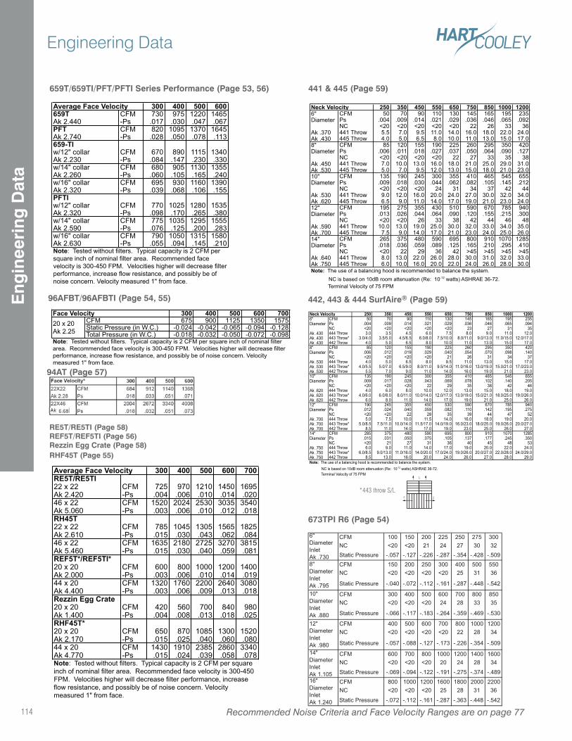
441 & 445 (Page 59)
442, 443 & 444 SurfAire® (Page 59)96AFBT/96AFBTI (Page 54, 55)
659T/659TI/PFT/PFTI Series Performance (Page 53, 56)
300 400 500 600659T CFM 730 975 1220 1465Ak 2.440 -Ps .017 .030 .047 .067PFT CFM 820 1095 1370 1645Ak 2.740 -Ps .028 .050 .078 .113659-TIw/12" collar CFM 670 890 1115 1340Ak 2.230 -Ps .084 .147 .230 .330w/14" collar CFM 680 905 1130 1355Ak 2.260 -Ps .060 .105 .165 .240w/16" collar CFM 695 930 1160 1390Ak 2.320 -Ps .039 .068 .106 .155PFTIw/12" collar CFM 770 1025 1280 1535Ak 2.320 -Ps .098 .170 .265 .380w/14" collar CFM 775 1035 1295 1555Ak 2.590 -Ps .076 .125 .200 .283w/16" collar CFM 790 1050 1315 1580Ak 2.630 -Ps .055 .094 .145 .210
Average Face Velocity
Note: Tested without filters. Typical capacity is 2 CFM per
square inch of nominal filter area. Recommended face
velocity is 300-450 FPM. Velocities higher will decrease filter
performance, increase flow resistance, and possibly be of
noise concern. Velocity measured 1" from face.
250 350 450 550 650 750 850 1000 12006" CFM 50 70 90 110 130 145 165 195 235Diameter Ps .004 .009 .014 .021 .029 .036 .046 .065 .092
NC <20 <20 <20 <20 <20 22 26 33 36Ak .370 441 Throw 5.5 7.0 9.5 11.0 14.0 16.0 18.0 22.0 24.0Ak .430 445 Throw 4.0 5.0 6.5 8.0 10.0 11.0 13.0 15.0 17.08" CFM 85 120 155 190 225 260 295 350 420Diameter Ps .006 .011 .018 .027 .037 .050 .064 .090 .127
NC <20 <20 <20 <20 22 27 33 35 38Ak .450 441 Throw 7.0 10.0 13.0 16.0 18.0 21.0 25.0 29.0 31.0Ak .530 445 Throw 5.0 7.0 9.5 12.0 13.0 15.0 18.0 21.0 23.010" CFM 135 190 245 300 355 410 465 545 655Diameter Ps .009 .018 .030 .044 .062 .082 .105 .145 .212
NC <20 <20 <20 24 31 34 37 42 44Ak .530 441 Throw 9.0 12.0 16.0 20.0 24.0 27.0 30.0 32.0 34.0Ak .620 445 Throw 6.5 9.0 11.0 14.0 17.0 19.0 21.0 23.0 24.012" CFM 195 275 355 430 510 590 670 785 940Diameter Ps .013 .026 .044 .064 .090 .120 .155 .215 .300
NC <20 <20 26 33 38 42 44 46 48Ak .590 441 Throw 10.0 13.0 19.0 25.0 30.0 32.0 33.0 34.0 35.0Ak .700 445 Throw 7.5 9.0 14.0 17.0 21.0 23.0 24.0 25.0 26.014" CFM 265 375 480 590 695 800 910 1070 1285Diameter Ps .018 .036 .059 .089 .125 .165 .210 .295 .410
NC <20 22 29 36 42 >45 >45 >45 >45Ak .640 441 Throw 8.0 13.0 22.0 26.0 28.0 30.0 31.0 32.0 33.0Ak .750 445 Throw 6.0 10.0 16.0 20.0 22.0 24.0 26.0 28.0 30.0
Neck Velocity
Note: The use of a balancing hood is recommended to balance the system.
NC is based on 10dB room attenuation (Re: 10-12 watts) ASHRAE 36-72.
Terminal Velocity of 75 FPM
300 400 500 600 700CFM 675 900 1125 1350 1575Static Pressure (in W.C.) -0.024 -0.042 -0.065 -0.094 -0.128Total Pressure (in W.C.) -0.018 -0.032 -0.050 -0.072 -0.098
Face Velocity20 x 20
Ak 2.25
Note: Tested without filters. Typical capacity is 2 CFM per square inch of nominal filter
area. Recommended face velocity is 300-450 FPM. Velocities higher will decrease filter
performance, increase flow resistance, and possibly be of noise concern. Velocity
measured 1" from face.
250 350 450 550 650 750 850 1000 12006" CFM 50 70 90 110 130 145 165 195 235Diameter Ps .004 .009 .014 .021 .029 .036 .046 .065 .094
NC <20 <20 <20 <20 <20 23 27 31 35Ak .430 444 Throw 3.0 3.5 4.5 6.0 7.5 8.0 9.0 11.0 12.0Ak .430 443 Throw* 3.0/4.0 3.5/5.0 4.5/6.5 6.0/8.0 7.5/10.0 8.0/11.0 9.0/13.0 11.0/15.0 12.0/17.0Ak .430 442 Throw 4.0 5.0 6.5 8.0 10.0 11.0 13.0 15.0 17.08" CFM 85 120 155 190 225 260 295 350 420Diameter Ps .006 .012 .019 .029 .040 .054 .070 .098 .140
NC <20 <20 <20 <20 21 26 31 34 37Ak .530 444 Throw 4.0 5.0 6.5 8.0 9.5 11.0 13.0 15.0 17.0Ak .530 443 Throw* 4.0/5.5 5.0/7.0 6.5/9.0 8.0/11.0 9.5/14.0 11.0/16.0 13.0/19.0 15.0/21.0 17.0/23.0Ak .530 442 Throw 5.5 7.0 9.0 11.0 14.0 16.0 19.0 21.0 23.010" CFM 135 190 245 300 355 410 465 545 655Diameter Ps .009 .017 .028 .043 .069 .078 .102 .140 .205
NC <20 <20 <20 22 29 35 38 42 46Ak .620 444 Throw 4.0 6.0 8.0 10.0 12.0 13.0 15.0 18.0 19.0Ak .620 443 Throw* 4.0/6.0 6.0/8.0 8.0/11.0 10.0/14.0 12.0/17.0 13.0/19.0 15.0/21.0 18.0/25.0 19.0/26.0Ak .620 442 Throw 6.0 8.0 11.0 14.0 17.0 19.0 21.0 25.0 26.012" CFM 190 245 355 450 530 590 670 785 940Diameter Ps .012 .024 .040 .059 .082 .110 .142 .195 .275
NC <20 <20 22 28 35 39 44 47 52Ak .700 444 Throw 5.0 7.5 10.0 11.5 14.0 16.0 18.0 19.0 20.0Ak .700 443 Throw* 5.0/8.5 7.5/11.0 10.0/14.0 11.5/17.0 14.0/19.0 16.0/23.0 18.0/25.0 19.0/26.0 20.0/27.0Ak .700 442 Throw 8.5 11.0 14.0 17.0 19.0 23.0 25.0 26.0 27.014" CFM 285 375 480 590 695 800 910 1070 1285Diameter Ps .015 .031 .050 .075 .105 .137 .177 .245 .350
NC <20 21 27 31 36 40 45 48 53Ak .750 444 Throw 6.0 9.0 11.0 14.0 17.0 19.0 20.0 22.0 24.0Ak .750 443 Throw* 6.0/8.5 9.0/13.0 11.0/16.0 14.0/20.0 17.0/24.0 19.0/26.0 20.0/27.0 22.0/28.0 24.0/29.0Ak .750 442 Throw 8.5 13.0 16.0 20.0 24.0 26.0 27.0 28.0 29.0Note: The use of a balancing hood is recommended to balance the system.
NC is based on 10dB room attenuation (Re: 10-12 watts) ASHRAE 36-72.
Terminal Velocity of 75 FPM
Neck Velocity
*443 throw S/L
300 400 500 600 700RE5T/RE5TI22 x 22 CFM 725 970 1210 1450 1695Ak 2.420 -Ps .004 .006 .010 .014 .02046 x 22 CFM 1520 2024 2530 3035 3540Ak 5.060 -Ps .003 .006 .010 .012 .018RH45T22 x 22 CFM 785 1045 1305 1565 1825Ak 2.610 -Ps .015 .030 .043 .062 .08446 x 22 CFM 1635 2180 2725 3270 3815Ak 5.460 -Ps .015 .030 .040 .059 .081REF5T*/REF5TI*20 x 20 CFM 600 800 1000 1200 1400Ak 2.000 -Ps .003 .006 .010 .014 .01944 x 20 CFM 1320 1760 2200 2640 3080Ak 4.400 -Ps .003 .006 .009 .013 .018R20 x 20 CFM 420 560 700 840 980Ak 1.400 -Ps .004 .008 .013 .018 .025RHF45T*20 x 20 CFM 650 870 1085 1300 1520Ak 2.170 -Ps .015 .025 .040 .060 .08044 x 20 CFM 1430 1910 2385 2860 3340Ak 4.770 -Ps .015 .024 .039 .058 .078
Average Face Velocity
Note: Tested without filters. Typical capacity is 2 CFM per square
inch of nominal filter area. Recommended face velocity is 300-450
FPM. Velocities higher will decrease filter performance, increase
flow resistance, and possibly be of noise concern. Velocity
measured 1" from face.
S S
L
Recommended Noise Criteria and Face Velocity Ranges are on page 77114
Engineering DataE
ngin
eeri
ng D
ata
94AT (Page 57)
RE5T/RE5TI (Page 58)REF5T/REF5TI (Page 56)Rezzin Egg Crate (Page 58)RHF45T (Page 55)
CFM 100 150 200 225 250 275 300
NC <20 <20 21 24 27 30 32
Static Pressure -.057 -.127 -.226 -.287 -.354 -.428 -.509
CFM 150 200 250 300 400 500 550
NC <20 <20 <20 <20 25 31 36
Static Pressure -.040 -.072 -.112 -.161 -.287 -.448 -.542
CFM 300 400 500 600 700 800 850
NC <20 <20 <20 24 28 33 35
Static Pressure -.066 -.117 -.183 -.264 -.359 -.469 -.530
CFM 400 500 600 700 800 1000 1200
NC <20 <20 <20 <20 22 28 34
Static Pressure -.057 -.088 -.127 -.173 -.226 -.354 -.509
CFM 600 700 800 1000 1200 1400 1600
NC <20 <20 <20 20 24 28 34
Static Pressure -.069 -.094 -.122 -.191 -.275 -.374 -.489
CFM 800 1000 1200 1600 1800 2000 2200
NC <20 <20 <20 25 28 31 36
Static Pressure -.072 -.112 -.161 -.287 -.363 -.448 -.542
16"
Diameter
Inlet
Ak 1.240
6"
Diameter
Inlet
Ak .730
8"
Diameter
Inlet
Ak .795
10"
Diameter
Inlet
Ak .880
12"
Diameter
Inlet
Ak .980
14"
Diameter
Inlet
Ak 1.105
673TPI R6 (Page 54)
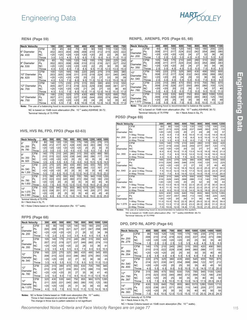
RFPS (Page 68)300 400 500 600 700 800 900 1000 1200
CFM 60 80 100 120 140 160 180 200 235
Ps .005 .009 .015 .021 .027 .037 .047 .058 .080
NC <20 <20 <20 <20 21 26 32 34 39
Throw 1.5 2.0 2.5 3.0 3.5 4.0 4.5 5.5 6.5
CFM 105 140 175 210 245 280 315 350 420
Ps .007 .012 .019 .027 .037 .049 .060 .074 .110
NC <20 <20 <20 <20 22 28 33 36 41
Throw 2.5 3.5 4.5 5.5 6.5 7.0 8.0 9.0 10.5
CFM 165 220 270 325 380 435 490 545 655
Ps .008 .015 .023 .033 .046 .060 .076 .093 .135
NC <20 <20 <20 22 27 32 36 39 43
Throw 3.5 4.5 5.5 6.5 7.5 8.5 9.5 11.0 13.0
CFM 235 315 390 470 550 630 705 785 945
Ps .010 .018 .027 .039 .053 .070 .088 .110 .160
NC <20 <20 <20 20 27 35 38 41 45
Throw 3.5 5.0 6.0 7.5 8.5 10.0 11.0 12.5 15.0
CFM 320 430 535 640 750 855 960 1070 1285
Ps .011 .020 .031 .045 .060 .080 .105 .125 .180
NC <20 <20 <20 25 31 34 39 43 49
Throw 4.0 5.5 7.0 8.5 10.0 11.0 12.5 14.0 16.5
Notes: NC is Noise Criteria based on 10dB room absorption (Re: 10-12 watts).
Throw in feet measured at a terminal velocity of 100 FPM.
The change in throw due to pattern selection is not significant.
12"
Diameter
Ak .780
14"
Diameter
Ak 1.070
Neck Velocity
6"
Diameter
Ak .200
8"
Diameter
Ak .350
10"
Diameter
Ak .540
400 500 600 700 800 900 1000 1200 1400 1600CFM 80 100 120 135 155 175 195 235 275 315Ps .008 .012 .017 .021 .028 .035 .043 .063 .086 .112NC <20 <20 <20 <20 <20 <20 20 25 30 35Throw 2.0 3.0 3.0 3.5 4.0 4.5 5.0 6.0 7.0 8.0CFM 140 175 210 245 280 315 350 420 490 560Ps .010 .015 .022 .029 .038 .049 .060 .086 .117 .150NC <20 <20 <20 <20 20 25 30 35 35 40Throw 3.5 4.5 5.5 6.5 7.0 8.0 9.0 10.5 12.5 14.5CFM 220 270 325 380 435 490 545 655 765 870Ps .014 .021 .030 .041 .054 .068 .084 .122 .167 .212NC <20 <20 <20 20 25 30 35 35 40 45Throw 5.5 7.0 8.5 10.0 11.0 12.5 14.0 17.0 19.5 22.0CFM 315 390 470 550 630 705 785 940 1100 1255Ps .015 .023 .033 .045 .060 .072 .094 .132 .180 .230NC <20 <20 20 25 30 35 35 40 45 45Throw 6.0 7.5 9.0 10.5 12.0 13.5 15.0 18.0 21.0 24.0CFM 430 535 640 750 855 960 1070 1285 1500 1710Ps .023 .036 .051 .071 .093 .115 .140 .205 .277 .350NC <20 <20 20 25 30 35 40 40 45 45Throw 6.5 8.0 9.5 11.5 13.0 14.5 16.0 19.0 22.5 25.0
12"
An .780
Ak 1.650
14"
An 1.070
Ak 2.060
Terminal Velocity of 75 FPM
An = Neck Area in Sq. Ft.
NC = Noise Criteria based on 10dB room absorption (Re: 10-12 watts).
Neck Velocity6"
An .200
Ak .780
8"
An .350
Ak .920
10"
An .540
Ak 1.200
HVS, HVS R6, FPD, FPD3 (Page 62-63)
RENPS, ARENPS, PDS (Page 65, 68)
DPD, DPD R6, ADPD (Page 64)
400 500 600 700 800 900 1000 1200 1400 1600CFM 80 100 120 135 155 175 195 235 275 315
Ps .006 .010 .014 .018 .023 .030 .037 .054 .073 .096
NC <20 <20 <20 <20 <20 20 25 30 35 40
Throw 1.0 2.0 2.0 2.5 3.0 3.5 4.0 4.5 5.5 6.5
CFM 140 175 210 245 280 315 350 420 490 560
Ps .010 .015 .022 .029 .038 .049 .060 .086 .117 .150
NC <20 <20 <20 20 25 30 30 35 40 45
Throw 2.5 3.5 4.0 4.5 5.0 5.5 6.0 7.0 8.0 9.0
CFM 220 275 325 380 435 490 545 655 765 875
Ps .014 .021 .030 .041 .054 .068 .084 .122 .167 .212
NC <20 <20 <20 20 25 30 35 40 45 50
Throw 4.0 5.5 6.5 8.0 9.0 10.5 11.5 14.5 17.0 20.0
CFM 315 395 470 550 630 705 785 945 1100 1260
Ps .015 .023 .033 .045 .060 .072 .094 .132 .180 .230
NC <20 <20 20 25 30 35 35 40 45 50
Throw 5.5 7.0 8.5 10.0 11.5 13.0 14.5 17.5 20.5 24.0
CFM 430 535 640 750 855 960 1070 1280 1500 1710
Ps .023 .036 .051 .071 .093 .115 .140 .205 .277 .350
NC <20 <20 25 30 35 35 40 45 50 55
Throw 7.0 8.5 10.5 12.0 13.5 15.5 17.0 20.5 24.0 24.5
Terminal Velocity of 75 FPM
An = Neck Area in Sq. Ft.
NC = Noise Criteria based on 10dB room absorption (Re: 10-12 watts).
Neck Velocity
14"
An 1.070
Ak .393
6"
An .200
Ak .279
8"
An .350
Ak .354
10"
An .540
Ak .400
12"
An .780
Ak .397
REN4 (Page 59)
180 220 300 350 400 450 500 580 650 700CFM 35 45 60 70 80 90 100 115 130 135Ps .002 .003 .004 .006 .008 .010 .012 .015 .020 .022NC <20 <20 <20 <20 <20 <20 20 22 26 30Throw 3.0 3.5 4.5 5.5 6.5 7.5 8.0 9.0 11.0 11.0CFM 65 75 105 120 140 155 175 200 225 245Ps .002 .003 .006 .008 .010 .013 .016 .021 .027 .032NC <20 <20 <20 <20 <20 22 25 30 35 38Throw 4.0 5.0 6.0 7.0 8.5 9.5 11.0 12.0 13.0 15.0CFM 100 120 165 190 220 245 275 315 355 380Ps .003 .005 .009 .011 .015 .019 .024 .031 .040 .045NC <20 <20 <20 <20 20 23 27 33 35 39Throw 4.0 5.5 7.0 8.0 9.5 11.0 12.0 13.0 15.0 16.0CFM 140 175 235 275 315 355 395 455 510 550Ps .005 .007 .013 .018 .023 .029 .036 .048 .061 .071NC <20 <20 <20 <20 21 24 27 33 36 40Throw 4.5 5.5 7.0 8.0 10.0 11.0 12.0 14.0 15.0 17.0CFM 190 235 320 375 430 480 535 620 695 750Ps .007 .011 .020 .027 .036 .044 .055 .074 .094 .107NC <20 <20 <20 <20 20 24 28 32 35 40Throw 4.5 5.5 7.0 8.5 10.0 11.0 12.0 14.0 16.0 17.0
12" Diameter
Ak .700
14" Diameter
Ak .750
Note: The use of a balancing hood is recommended to balance the system.
NC is based on 10dB room attenuation (Re: 10-12 watts) ASHRAE 36-72.
Terminal Velocity of 75 FPM
Neck Velocity
6" Diameter
Ak .430
8" Diameter
Ak .530
10" Diameter
Ak .620
Recommended Noise Criteria and Face Velocity Ranges are on page 77
Engineering Data
115
Eng
ineering D
ata
PDSD (Page 69)
300 400 500 600 700 800 900 1000 1200CFM 60 80 100 120 135 155 175 195 235
Ps .007 .013 .020 .029 .037 .048 .062 .076 .110
NC <20 <20 <20 20 21 24 28 33 37
1-Way Throw 4.0 6.0 7.0 8.0 10.0 11.0 13.0 14.0 16.0
2- and 3-Way Throw 3.5 4.5 6.0 7.0 8.0 9.5 10.5 11.5 13.0
4-Way Throw 2.5 3.5 4.5 5.0 6.0 7.0 7.5 8.0 9.0
CFM 105 140 175 210 245 280 315 350 420
Ps .011 .019 .030 .043 .059 .077 .097 .120 .173
NC <20 <20 <20 20 22 27 31 35 40
1-Way Throw 6.0 8.0 10.0 11.5 13.0 14.5 16.0 18.0 21.0
2- and 3-Way Throw 5.0 7.0 8.5 10.5 12.0 13.5 14.5 16.0 19.0
4-Way Throw 4.0 5.0 6.5 7.5 9.0 10.0 11.5 12.5 14.0
CFM 165 220 275 325 380 435 490 545 655
Ps .015 .026 .040 .046 .076 .100 .125 .115 .225
NC <20 <20 <20 21 27 33 37 40 45
1-Way Throw 8.5 11.0 14.0 16.5 19.0 22.0 25.0 27.0 30.0
2- and 3-Way Throw 7.5 10.0 12.5 14.5 17.0 19.5 22.0 24.0 27.0
4-Way Throw 5.0 7.0 8.5 10.5 12.0 14.0 15.5 17.0 20.0
CFM 235 315 395 470 550 630 705 785 940
Ps .016 .029 .045 .068 .086 .113 .140 .170 .250
NC <20 <20 <20 20 25 32 35 38 44
1-Way Throw 10.0 13.0 16.5 19.5 22.0 25.0 27.0 30.0 34.0
2- and 3-Way Throw 8.5 11.5 14.5 17.5 20.0 22.0 25.0 27.0 30.0
4-Way Throw 6.0 8.0 10.0 12.0 14.0 16.5 18.0 20.0 23.0
CFM 320 430 535 640 750 855 960 1070 1285
Ps .021 .037 .057 .082 .112 .145 .180 .225 .320
NC <20 <20 20 26 31 36 40 44 49
1-Way Throw 11.0 15.0 19.0 22.5 26.0 29.0 32.0 35.0 39.0
2- and 3-Way Throw 10.0 13.5 17.0 20.0 23.0 26.0 28.0 31.0 35.0
4-Way Throw 7.0 10.0 12.0 14.4 17.0 19.0 21.0 23.0 27.0
Neck Velocity
Notes: The use of a balancing hood is recommended to balance the system.
NC is based on 10dB room attenuation (Re: 10-12 watts) ASHRAE 36-72.
Terminal Velocity of 75 FPM
6"
Diameter
An .200
8"
Diameter
An .350
10"
Diameter
An .540
12"
Diameter
An .780
14"
Diameter
An 1.070
300 400 500 600 700 800 900 1000 1100CFM 60 80 100 120 140 160 180 200 220Ps .008 .011 .017 .024 .032 .042 .054 .066 .080NC <20 <20 <20 <20 24 27 32 36 38Throw 1.0 2.0 3.0 3.0 4.0 4.0 5.0 5.0 6.0CFM 105 140 175 210 245 280 310 350 385Ps .008 .011 .017 .024 .034 .043 .054 .068 .083NC <20 <20 <20 20 24 27 30 34 38Throw 2.0 3.0 4.0 4.0 5.0 6.0 7.0 8.0 8.5CFM 165 220 270 325 385 430 490 550 600Ps .008 .012 .017 .024 .032 .043 .056 .068 .082NC <20 <20 20 24 29 33 36 39 42Throw 2.0 3.0 4.0 5.0 5.0 6.0 7.0 8.0 9.0CFM 230 310 390 470 550 610 700 780 870Ps .009 .016 .026 .037 .050 .065 .080 .100 .125NC <20 <20 20 23 26 31 34 37 40Throw 3.0 4.0 5.0 6.0 7.0 8.0 9.0 10.0 11.0CFM 315 430 535 640 750 855 960 1090 1200Ps .009 .016 .026 .037 .050 .065 .083 .125 .150NC <20 20 25 30 35 39 43 45 48Throw 3.0 5.0 6.0 7.0 8.0 9.0 10.0 11.0 12.0
Note: The use of a balancing hood is recommended to balance the system.
NC is based on 10dB room attenuation (Re: 10-12 watts) ASHRAE 36-72.
Terminal Velocity of 75 FPM An = Neck Area in Sq. Ft.
12"
Diameter
An .780
14"
Diameter
An 1.070
Neck Velocity6"
Diameter
An .200
8"
Diameter
An .350
10"
Diameter
An .540
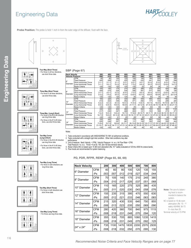
Note: The use of a balanc-ing hood is recom-mended to balance the system.
NC is based on 10 db room attenuation (Re: 10 - 12 watts) ASHRAE 36-72. X=less than 20.
Terminal velocity of 75 FPM.
PD, PDR, RFPR, RENP (Page 65, 68, 69)
Probe Position: The probe is held 1 inch in from the outer edge of the diffuser, flush with the face.
PROBEPOSITION
SBP (Page 67)
Three-Way (Short Throw)• For throw in all three directions,
use short throw data.
1 23 4
1 23 4
Notes: 1. Tests conducted in accordance with ANSI/ASHRAE 70-1991 at isothermal conditions. 2. Tests conducted with a straight rigid inlet condition. Other inlet conditions may alter
performance. 3. Unit of measure: Neck Velocity = FPM; Velocity Pressure = in. w.c. Air Flow Rate = CFM;
Total Pressure = in. w.c. Throw = ft at 50, 100, and 150 fpm terminal velocity 4. Noise Criteria (NC) is based upon 10 dB room absorption (Re: 10-12 watts) evaluated at 125 thru 4000 Hz octave bands. 5. Flow hoods are recommended for system balancing.
Four-Way (Short Throw)• For throw in all four directions,
use short throw data.
Three-Way (Long & Short)• For throw in the #2 & #4 direction
use long throw data.• For throw in the #1 & #3 direc-
tions, use short throw data.
Two-Way Corner (Long & Short)• For throw in the #2 & #4 direction
use long throw data.
• For throw in the #1 & #3 direc-tions, use short throw data.
Two-Way (Long Throw)• For throw in both directions use
long throw data.
Two-Way (Short Throw)• For throw in both directions use
short throw data.
One-Way (Long Throw)• For throw use long throw data.
1 23 4
1 23 4
300 400 500 600 700 800 900 1000 1200 1400.006 .010 .016 .022 .031 .040 .051 .062 .090 .122
CFM 60 80 100 120 140 160 180 200 240 280Total Pressure .005 .008 .013 .025 .025 .032 .041 .050 .027 .098Short Horizontal Throw 2-1-1 2-1-1 3-1-1 3-2-1 4-2-1 4-2-1 5-2-2 5-3-2 6-3-2 7-4-2Long Horizontal Throw 3-1-1 4-2-1 5-2-2 6-3-2 7-3-2 8-4-3 9-4-3 10-5-3 12-6-4 14-7-5Noise Criteria <20 <20 <20 <20 <20 22 24 26 31 37CFM 105 140 175 210 245 280 315 350 420 490Total Pressure .009 .015 .024 .034 .046 .061 .077 .095 .136 .185Short Horizontal Throw 3-1-1 4-2-1 5-2-2 6-4-3 7-3-2 8-4-3 9-4-3 10-5-3 12-6-4 14-7-5Long Horizontal Throw 5-3-2 7-4-2 9-5-3 11-5-4 13-6-4 15-7-5 16-8-5 18-9-6 22-11-7 25-13-8Noise Criteria <20 <20 <20 <20 20 25 30 34 39 44CFM 165 220 275 330 385 440 495 550 660 770Total Pressure .013 .023 .036 .052 .071 .092 .117 .144 .208 .283Short Horizontal Throw 5-2-2 6-3-2 8-4-3 10-5-3 11-6-4 13-6-4 14-7-5 16-8-5 19-10-6 23-11-8Long Horizontal Throw 9-5-3 12-6-4 15-8-5 18-9-6 21-11-7 24-12-8 27-14-9 30-15-10 36-18-12 42-21-14Noise Criteria <20 <20 <20 22 25 28 33 36 41 47CFM 240 320 400 480 560 640 720 800 960 1120Total Pressure .017 .030 .047 .068 .093 .121 .153 .189 .273 .371Short Horizontal Throw 7-4-2 10-5-3 12-6-4 15-7-5 17-9-6 20-10-7 22-11-7 25-12-8 30-15-10 35-17-12Long Horizontal Throw 14-7-5 19-9-6 23-12-8 28-14-9 33-16-11 37-19-12 42-21-14 47-23-16 56-28-19 65-33-22Noise Criteria <20 <20 21 25 29 32 35 38 44 50CFM 330 440 550 660 770 880 990 1100 1320 1540Total Pressure .020 .036 .057 .081 .111 .145 .183 .226 .326 .443Short Horizontal Throw 11-6-4 15-7-5 18-9-6 22-11-7 26-13-9 29-15-10 33-17-11 37-18-12 44-22-15 52-26-17Long Horizontal Throw 21-10-7 28-14-9 34-17-11 41-21-14 48-24-16 55-28-18 62-31-21 69-34-23 83-41-28 97-48-32Noise Criteria <20 <20 25 31 36 40 43 45 48 53
12"
Diameter
14"
Diameter
Neck VelocityVelocity Pressure
6"
Diameter
8"
Diameter
10"
Diameter
200 300 400 500 600 700 800CFM 40 60 80 100 120 135 155
-Ps .003 .007 .012 .019 .027 .034 .044
CFM 70 105 140 175 210 245 380
-Ps .004 .010 .017 .026 .037 .051 .068
CFM 110 165 220 275 325 380 435
-Ps .005 .011 .020 .030 .043 .058 .076
CFM 155 235 315 395 470 550 630
-Ps .005 .012 .021 .033 .046 .063 .083
CFM 215 320 430 535 640 750 855
-Ps .006 .013 .023 .035 .050 .069 .090
CFM 280 420 560 700 840 975 1115
-Ps .008 .018 .031 .048 .070 .094 .120
CFM 355 530 705 885 1060 1235 1415
-Ps .008 .018 .031 .049 .070 .092 .125
CFM 735 1100 1470 1835 2200 2570 2935
-Ps .008 .018 .032 .050 .070 .095 .130
16" Diameter
18" Diameter
24" x 24"
Neck Velocity
6" Diameter
8" Diameter
10" Diameter
12" Diameter
14" Diameter
Recommended Noise Criteria and Face Velocity Ranges are on page 77116
Engineering DataE
ngin
eeri
ng D
ata
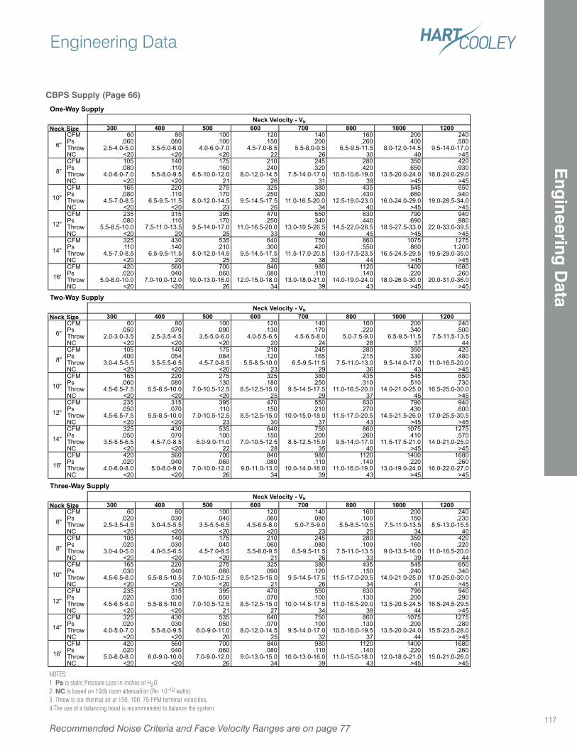
NOTES:1. Ps is static Pressure Loss in inches of H2O2. NC is based on 10db room attenuation (Re: 10-12 watts)3. Throw is iso-thermal air at 150, 100, 75 FPM terminal velocities.4.The use of a balancing hood is recommended to balance the system.
CBPS Supply (Page 66)
One-Way Supply
300 400 500 600 700 800 1000 1200CFM 60 80 100 120 140 160 200 240Ps .060 .080 .100 .150 .200 .260 .400 .580Throw 2.5-4.0-5.0 3.5-5.0-6.0 4.0-6.0-7.0 4.5-7.0-8.5 5.5-8.0-9.5 6.5-9.5-11.5 8.0-12.0-14.5 9.5-14.0-17.0NC <20 <20 <20 22 26 30 40 >45CFM 105 140 175 210 245 280 350 420Ps .080 .110 .160 .240 .320 .420 .650 .930Throw 4.0-6.0-7.0 5.5-8.0-9.5 6.5-10.0-12.0 8.0-12.0-14.5 7.5-14.0-17.0 10.5-10.6-19.0 13.5-20.0-24.0 16.0-24.0-29.0NC <20 <20 21 26 31 39 >45 >45CFM 165 220 275 325 380 435 545 650Ps .080 .110 .170 .250 .320 .430 .660 .940Throw 4.5-7.0-8.5 6.5-9.5-11.5 8.0-12.0-14.5 9.5-14.5-17.5 11.0-16.5-20.0 12.5-19.0-23.0 16.0-24.0-29.0 19.0-28.5-34.0NC <20 <20 23 26 34 40 >45 >45CFM 235 315 395 470 550 630 790 940Ps .080 .110 .170 .250 .340 .440 .690 .980Throw 5.5-8.5-10.0 7.5-11.0-13.5 9.5-14.0-17.0 11.0-16.5-20.0 13.0-19.5-26.5 14.5-22.0-26.5 18.5-27.5-33.0 22.0-33.0-39.5NC <20 20 25 33 40 45 >45 >45CFM 325 430 535 640 750 860 1075 1275Ps .110 .140 .210 .300 .420 .550 .860 1.200Throw 4.5-7.0-8.5 6.5-9.5-11.5 8.0-12.0-14.5 9.5-14.5-17.5 11.5-17.0-20.5 13.0-17.5-23.5 16.5-24.5-29.5 19.5-29.0-35.0NC <20 20 25 30 38 44 >45 >45CFM 420 560 700 840 980 1120 1400 1680Ps .020 .040 .060 .080 .110 .140 .220 .260Throw 5.0-8.0-10.0 7.0-10.0-12.0 10.0-13.0-16.0 12.0-15.0-18.0 13.0-18.0-21.0 14.0-19.0-24.0 18.0-26.0-30.0 20.0-31.0-36.0NC <20 <20 26 34 39 43 >45 >45
Two-Way Supply
300 400 500 600 700 800 1000 1200CFM 60 80 100 120 140 160 200 240Ps .050 .070 .090 .130 .170 .220 .340 .500Throw 2.0-3.0-3.5 2.5-3.5-4.5 3.5-5.0-6.0 4.0-5.5-6.5 4.5-6.5-8.0 5.0-7.5-9.0 6.5-9.5-11.5 7.5-11.5-13.5NC <20 <20 <20 20 24 28 37 44CFM 105 140 175 210 245 280 350 420Ps .400 .054 .084 .120 .165 .215 .330 .480Throw 3.0-4.5-5.5 3.5-5.5-6.5 4.5-7.0-8.5 5.5-8.5-10.0 6.5-9.5-11.5 7.5-11.0-13.0 9.5-14.0-17.0 11.0-16.5-20.0NC <20 <20 <20 23 29 36 43 >45CFM 165 220 275 325 380 435 545 650Ps .060 .080 .130 .180 .250 .310 .510 .730Throw 4.5-6.5-7.5 5.5-8.5-10.0 7.0-10.5-12.5 8.5-12.5-15.0 9.5-14.5-17.5 11.0-16.5-20.0 14.0-21.0-25.0 16.5-25.0-30.0NC <20 <20 <20 25 29 37 45 >45CFM 235 315 395 470 550 630 790 940Ps .050 .070 .110 .150 .210 .270 .430 .600Throw 4.5-6.5-7.5 5.5-8.5-10.0 7.0-10.5-12.5 8.5-12.5-15.0 10.0-15.0-18.0 11.5-17.0-20.5 14.5-21.5-26.0 17.0-25.5-30.5NC <20 <20 23 30 37 43 >45 >45CFM 325 430 535 640 750 860 1075 1275Ps .050 .070 .100 .150 .200 .260 .410 .570Throw 3.5-5.5-6.5 4.5-7.0-8.5 6.0-9.0-11.0 7.0-10.5-12.5 8.5-12.5-15.0 9.5-14.0-17.0 11.5-17.5-21.0 14.0-21.0-25.0NC <20 <20 22 28 35 40 >45 >45CFM 420 560 700 840 980 1120 1400 1680Ps .020 .040 .060 .080 .110 .140 .220 .260Throw 4.0-6.0-8.0 5.0-8.0-9.0 7.0-10.0-12.0 9.0-11.0-13.0 10.0-14.0-16.0 11.0-16.0-19.0 13.0-19.0-24.0 16.0-22.0-27.0NC <20 <20 26 34 39 43 >45 >45
Three-Way Supply
300 400 500 600 700 800 1000 1200CFM 60 80 100 120 140 160 200 240Ps .020 .030 .040 .060 .080 .100 .150 .230Throw 2.5-3.5-4.5 3.0-4.5-5.5 3.5-5.5-6.5 4.5-6.5-8.0 5.0-7.5-9.0 5.5-8.5-10.5 7.5-11.0-13.5 8.5-13.0-15.5NC <20 <20 <20 <20 23 25 34 40CFM 105 140 175 210 245 280 350 420Ps .020 .030 .040 .060 .080 .100 .160 .220Throw 3.0-4.0-5.0 4.0-5.5-6.5 4.5-7.0-8.5 5.5-8.0-9.5 6.5-9.5-11.5 7.5-11.0-13.5 9.0-13.5-16.0 11.0-16.5-20.0NC <20 <20 <20 21 26 33 39 44CFM 165 220 275 325 380 435 545 650Ps .030 .040 .060 .090 .120 .150 .240 .340Throw 4.5-6.5-8.0 5.5-8.5-10.5 7.0-10.5-12.5 8.5-12.5-15.0 9.5-14.5-17.5 11.5-17.0-20.5 14.0-21.0-25.0 17.0-25.0-30.0NC <20 <20 <20 21 26 34 41 >45CFM 235 315 395 470 550 630 790 940Ps .020 .030 .050 .070 .100 .130 .200 .290Throw 4.5-6.5-8.0 5.5-8.5-10.0 7.0-10.5-12.5 8.5-12.5-15.0 10.0-14.5-17.5 11.0-16.5-20.0 13.5-20.5-24.5 16.5-24.5-29.5NC <20 <20 21 27 34 39 44 >45CFM 325 430 535 640 750 860 1075 1275Ps .020 .030 .050 .070 .100 .130 .200 .280Throw 4.0-5.0-7.0 5.5-8.0-9.5 6.0-9.0-11.0 8.0-12.0-14.5 9.5-14.0-17.0 10.5-16.0-19.5 13.5-20.0-24.0 15.5-23.5-28.0NC <20 <20 20 25 32 37 44 >45CFM 420 560 700 840 980 1120 1400 1680Ps .020 .040 .060 .080 .110 .140 .220 .260Throw 5.0-6.0-8.0 6.0-9.0-10.0 7.0-9.0-12.0 9.0-13.0-15.0 10.0-13.0-16.0 11.0-15.0-18.0 12.0-18.0-21.0 15.0-21.0-26.0NC <20 <20 26 34 39 43 >45 >45
6"
8"
10"
12"
14"
16'
10"
12"
14"
16'
Neck Velocity - VN
Neck Size
14"
16'
Neck Velocity - VN
Neck Size
6"
8"
Neck Velocity - VN
6"
8"
10"
Neck Size
12"
Recommended Noise Criteria and Face Velocity Ranges are on page 77
Engineering Data
117
Eng
ineering D
ata
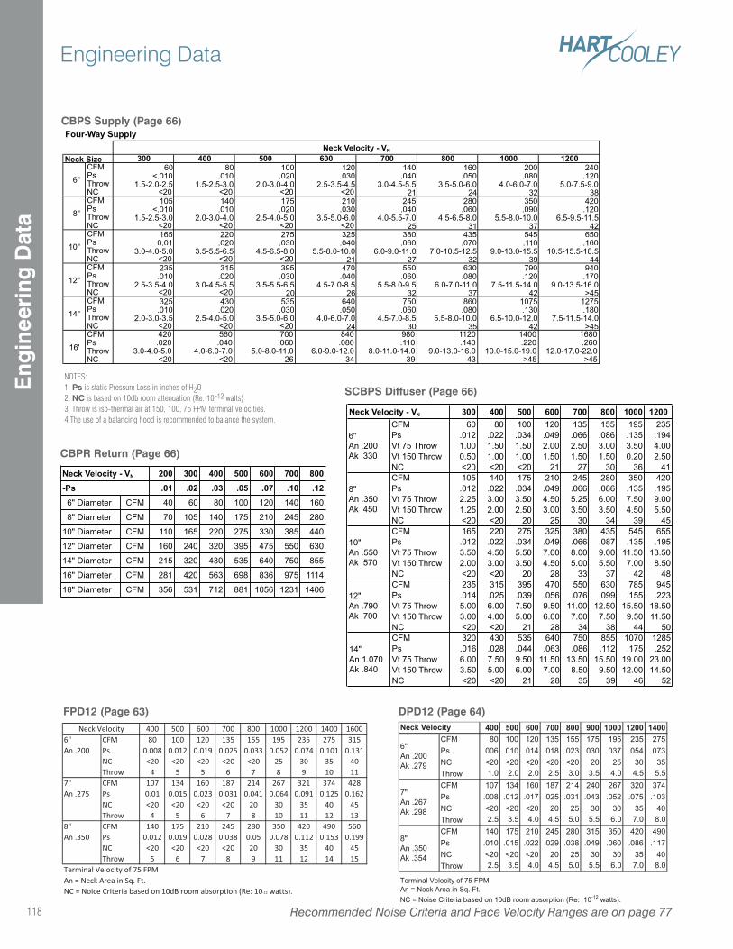
CBPR Return (Page 66)
SCBPS Diffuser (Page 66)
300 400 500 600 700 800 1000 1200CFM 60 80 100 120 135 155 195 235
Ps .012 .022 .034 .049 .066 .086 .135 .194
Vt 75 Throw 1.00 1.50 1.50 2.00 2.50 3.00 3.50 4.00
Vt 150 Throw 0.50 1.00 1.00 1.50 1.50 1.50 0.20 2.50
NC <20 <20 <20 21 27 30 36 41
CFM 105 140 175 210 245 280 350 420
Ps .012 .022 .034 .049 .066 .086 .135 .195
Vt 75 Throw 2.25 3.00 3.50 4.50 5.25 6.00 7.50 9.00
Vt 150 Throw 1.25 2.00 2.50 3.00 3.50 3.50 4.50 5.50
NC <20 <20 20 25 30 34 39 45
CFM 165 220 275 325 380 435 545 655
Ps .012 .022 .034 .049 .066 .087 .135 .195
Vt 75 Throw 3.50 4.50 5.50 7.00 8.00 9.00 11.50 13.50
Vt 150 Throw 2.00 3.00 3.50 4.50 5.00 5.50 7.00 8.50
NC <20 <20 20 28 33 37 42 48
CFM 235 315 395 470 550 630 785 945
Ps .014 .025 .039 .056 .076 .099 .155 .223
Vt 75 Throw 5.00 6.00 7.50 9.50 11.00 12.50 15.50 18.50
Vt 150 Throw 3.00 4.00 5.00 6.00 7.00 7.50 9.50 11.50
NC <20 <20 21 28 34 38 44 50
CFM 320 430 535 640 750 855 1070 1285
Ps .016 .028 .044 .063 .086 .112 .175 .252
Vt 75 Throw 6.00 7.50 9.50 11.50 13.50 15.50 19.00 23.00
Vt 150 Throw 3.50 5.00 6.00 7.00 8.50 9.50 12.00 14.50
NC <20 <20 21 28 35 39 46 52
14"
An 1.070
Ak .840
Neck Velocity - VN
6"
An .200
Ak .330
8"
An .350
Ak .450
10"
An .550
Ak .570
12"
An .790
Ak .700
NOTES:1. Ps is static Pressure Loss in inches of H2O2. NC is based on 10db room attenuation (Re: 10-12 watts)3. Throw is iso-thermal air at 150, 100, 75 FPM terminal velocities.4.The use of a balancing hood is recommended to balance the system.
CBPS Supply (Page 66)Four-Way Supply
300 400 500 600 700 800 1000 1200CFM 60 80 100 120 140 160 200 240Ps <.010 .010 .020 .030 .040 .050 .080 .120Throw 1.5-2.0-2.5 1.5-2.5-3.0 2.0-3.0-4.0 2.5-3.5-4.5 3.0-4.5-5.5 3.5-5.0-6.0 4.0-6.0-7.0 5.0-7.5-9.0NC <20 <20 <20 <20 21 24 32 38CFM 105 140 175 210 245 280 350 420Ps <.010 .010 .020 .030 .040 .060 .090 .120Throw 1.5-2.5-3.0 2.0-3.0-4.0 2.5-4.0-5.0 3.5-5.0-6.0 4.0-5.5-7.0 4.5-6.5-8.0 5.5-8.0-10.0 6.5-9.5-11.5NC <20 <20 <20 <20 25 31 37 42CFM 165 220 275 325 380 435 545 650Ps 0.01 .020 .030 .040 .060 .070 .110 .160Throw 3.0-4.0-5.0 3.5-5.5-6.5 4.5-6.5-8.0 5.5-8.0-10.0 6.0-9.0-11.0 7.0-10.5-12.5 9.0-13.0-15.5 10.5-15.5-18.5NC <20 <20 <20 21 27 32 39 44CFM 235 315 395 470 550 630 790 940Ps .010 .020 .030 .040 .060 .080 .120 .170Throw 2.5-3.5-4.0 3.0-4.5-5.5 3.5-5.5-6.5 4.5-7.0-8.5 5.5-8.0-9.5 6.0-7.0-11.0 7.5-11.5-14.0 9.0-13.5-16.0NC <20 <20 20 26 32 37 42 >45CFM 325 430 535 640 750 860 1075 1275Ps .010 .020 .030 .050 .060 .080 .130 .180Throw 2.0-3.0-3.5 2.5-4.0-5.0 3.5-5.0-6.0 4.0-6.0-7.0 4.5-7.0-8.5 5.5-8.0-10.0 6.5-10.0-12.0 7.5-11.5-14.0NC <20 <20 <20 24 30 35 42 >45CFM 420 560 700 840 980 1120 1400 1680Ps .020 .040 .060 .080 .110 .140 .220 .260Throw 3.0-4.0-5.0 4.0-6.0-7.0 5.0-8.0-11.0 6.0-9.0-12.0 8.0-11.0-14.0 9.0-13.0-16.0 10.0-15.0-19.0 12.0-17.0-22.0NC <20 <20 26 34 39 43 >45 >45
Neck Velocity - VN
12"
14"
16'
Neck Size
6"
8"
10"
200 300 400 500 600 700 800-Ps .01 .02 .03 .05 .07 .10 .12 6" Diameter CFM 40 60 80 100 120 140 160
8" Diameter CFM 70 105 140 175 210 245 280
10" Diameter CFM 110 165 220 275 330 385 440
12" Diameter CFM 160 240 320 395 475 550 630
14" Diameter CFM 215 320 430 535 640 750 855
16" Diameter CFM 281 420 563 698 836 975 1114
18" Diameter CFM 356 531 712 881 1056 1231 1406
Neck Velocity - VN
FPD12 (Page 63)400 500 600 700 800 1000 1200 1400 1600
6" CFM 80 100 120 135 155 195 235 275 315An .200 Ps 0.008 0.012 0.019 0.025 0.033 0.052 0.074 0.101 0.131
NC <20 <20 <20 <20 <20 25 30 35 40Throw 4 5 5 6 7 8 9 10 11
7" CFM 107 134 160 187 214 267 321 374 428An .275 Ps 0.01 0.015 0.023 0.031 0.041 0.064 0.091 0.125 0.162
NC <20 <20 <20 <20 20 30 35 40 45Throw 4 5 6 7 8 10 11 12 13
8" CFM 140 175 210 245 280 350 420 490 560An .350 Ps 0.012 0.019 0.028 0.038 0.05 0.078 0.112 0.153 0.199
NC <20 <20 <20 <20 20 30 35 40 45Throw 5 6 7 8 9 11 12 14 15
Terminal Velocity of 75 FPMAn = Neck Area in Sq. Ft.NC = Noice Criteria based on 10dB room absorption (Re: 10-12 watts).
Neck Velocity
Recommended Noise Criteria and Face Velocity Ranges are on page 77118
Engineering DataE
ngin
eeri
ng D
ata
400 500 600 700 800 900 1000 1200 1400CFM 80 100 120 135 155 175 195 235 275
Ps .006 .010 .014 .018 .023 .030 .037 .054 .073
NC <20 <20 <20 <20 <20 20 25 30 35
Throw 1.0 2.0 2.0 2.5 3.0 3.5 4.0 4.5 5.5
CFM 107 134 160 187 214 240 267 320 374
Ps .008 .012 .017 .025 .031 .043 .052 .075 .103
NC <20 <20 <20 20 25 30 30 35 40
Throw 2.5 3.5 4.0 4.5 5.0 5.5 6.0 7.0 8.0
CFM 140 175 210 245 280 315 350 420 490
Ps .010 .015 .022 .029 .038 .049 .060 .086 .117
NC <20 <20 <20 20 25 30 30 35 40
Throw 2.5 3.5 4.0 4.5 5.0 5.5 6.0 7.0 8.0
Terminal Velocity of 75 FPM
An = Neck Area in Sq. Ft.
NC = Noise Criteria based on 10dB room absorption (Re: 10-12
watts).
Neck Velocity
6"
An .200
Ak .279
7"
An .267
Ak .298
8"
An .350
Ak .354
DPD12 (Page 64)
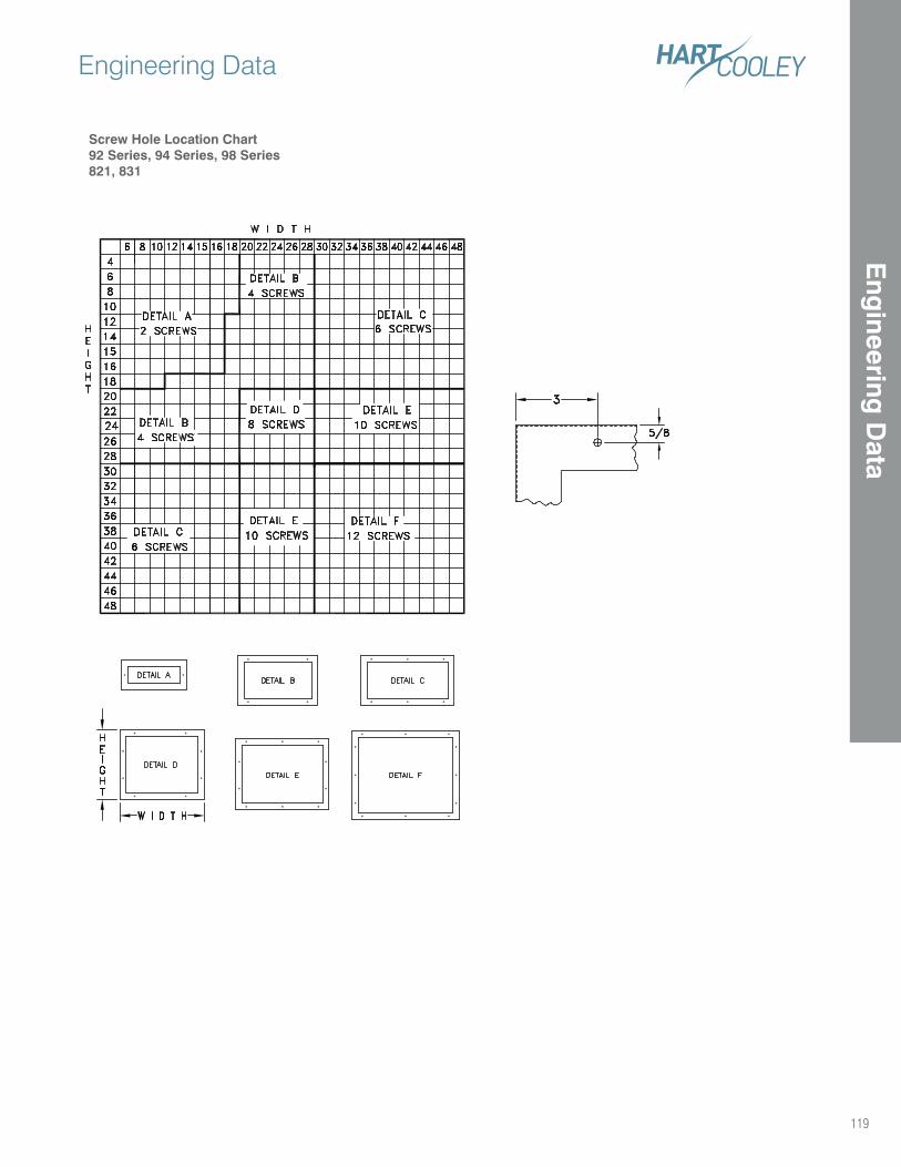
Screw Hole Location Chart92 Series, 94 Series, 98 Series 821, 831
Engineering Data
119
Eng
ineering D
ata
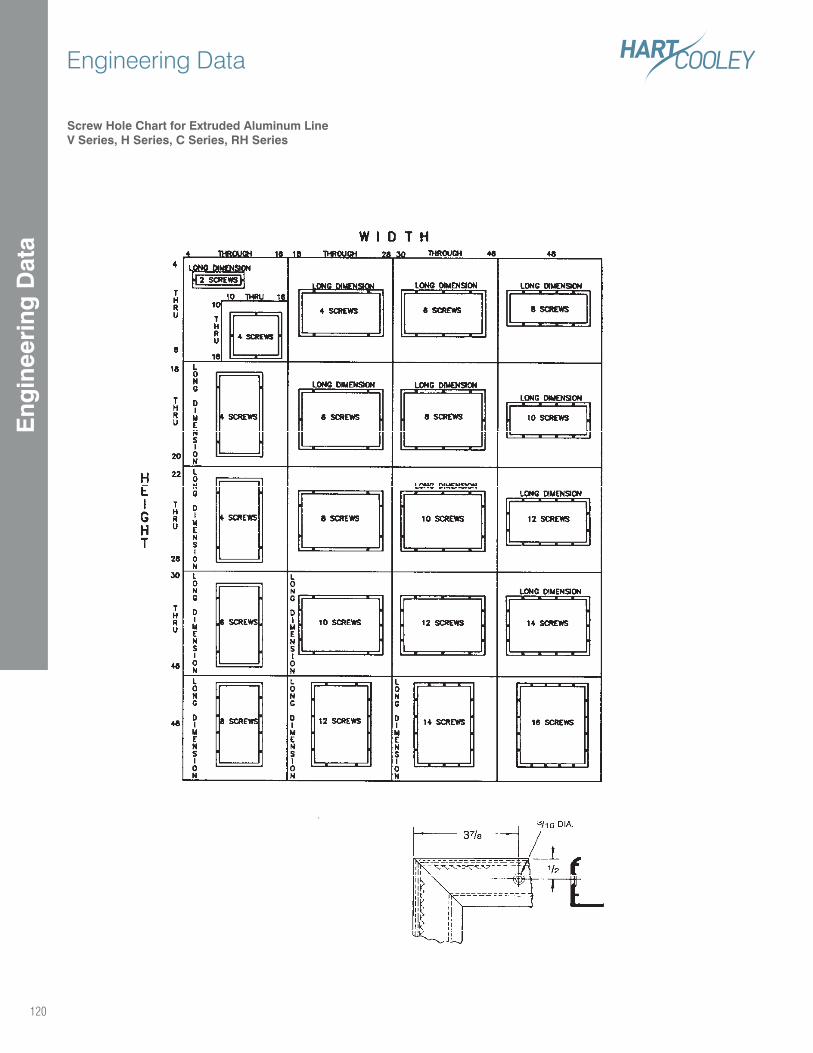
Engineering Data
120
Eng
inee
ring
Dat
a
Screw Hole Chart for Extruded Aluminum LineV Series, H Series, C Series, RH Series
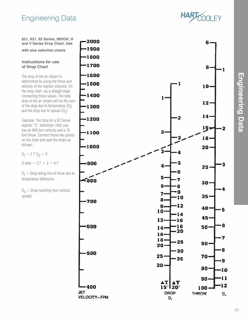
121
Engineering Data
821, 831, 92 Series, 98VOH, H and V Series Drop Chart, Use
with size selection charts
Instructions for use of Drop Chart
The drop of the air stream is determined by using the throw and velocity of the register selected. On the drop chart, lay a straight edge connecting these values. The total drop of the air stream will be the sum of the drop due to temperature (Dt) and the drop due to spread (Ds).
Example: The drop for a 92 Series register “C” deflection 16x5 size has an 800 fpm velocity and a 16 foot throw. Connect these two points on the chart and read the drops as follows:
Dt = 2.7’ Ds = 2’
D total = 2.7 + 2 = 4.7’
Dt = Drop along line of throw due to temperature difference.
Ds = Drop resulting from vertical spread.
Eng
ineering D
ata
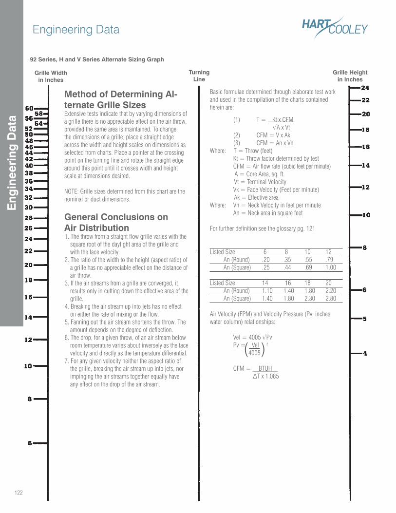
92 Series, H and V Series Alternate Sizing Graph
Method of Determining Al-ternate Grille SizesExtensive tests indicate that by varying dimensions of a grille there is no appreciable effect on the air throw, provided the same area is maintained. To change the dimensions of a grille, place a straight edge across the width and height scales on dimensions as selected from charts. Place a pointer at the crossing point on the turning line and rotate the straight edge around this point until it crosses width and height scale at dimensions desired.
NOTE: Grille sizes determined from this chart are the nominal or duct dimensions.
General Conclusions on Air Distribution1. The throw from a straight flow grille varies with the
square root of the daylight area of the grille and with the face velocity.
2. The ratio of the width to the height (aspect ratio) of a grille has no appreciable effect on the distance of air throw.
3. If the air streams from a grille are converged, it results only in cutting down the effective area of the grille.
4. Breaking the air stream up into jets has no effect on either the rate of mixing or the flow.
5. Fanning out the air stream shortens the throw. The amount depends on the degree of deflection.
6. The drop, for a given throw, of an air stream below room temperature varies about inversely as the face velocity and directly as the temperature differential.
7. For any given velocity neither the aspect ratio of the grille, breaking the air stream up into jets, nor impinging the air streams together equally have any effect on the drop of the air stream.
Basic formulae determined through elaborate test work and used in the compilation of the charts contained herein are:
(1) T = Kt x CFM
(2) CFM = V x Ak (3) CFM = An x VnWhere: T = Throw (feet) Kt = Throw factor determined by test CFM = Air flow rate (cubic feet per minute) A = Core Area, sq. ft. Vt = Terminal Velocity Vk = Face Velocity (Feet per minute) Ak = Effective areaWhere: Vn = Neck Velocity in feet per minute An = Neck area in square feet
For further definition see the glossary pg. 121
Listed Size 6 8 10 12 An (Round) .20 .35 .55 .79 An (Square) .25 .44 .69 1.00
Listed Size 14 16 18 20 An (Round) 1.10 1.40 1.80 2.20 An (Square) 1.40 1.80 2.30 2.80
Air Velocity (FPM) and Velocity Pressure (Pv, inches water column) relationships:
Pv = Vel 2
4005
CFM = BTUH
( )
Grille Widthin Inches
TurningLine
Grille Heightin Inches
122
Engineering Data
Eng
inee
ring
Dat
a
Suggested Specifications
Surfaire® T-Bar DiffusersFurnish and install Hart & Cooley SurfAire® insulated ceiling diffusers as shown on the plans. The diffuser shall be a 2’x2’ T-Bar lay-in. Face shall be stucco embossed aluminum with off-white baked enamel finish for ceiling aesthetics, corrosion protection and ease of clean-ing. Face will have formed deflector apertures which distribute air in thin layers along the ceiling surface and which provide for optimum dispersion in one, two, three, four-way or two-way corner patterns.
Back panel shall be formed galvanized steel covered with glass fiber insulation and an aluminum foil vapor barrier. Insulation is held securely in place by face margin edge fold over. Insulation will be prescored to accept specified collar sizes.
5400 Series collars will be supplied providing efficient, tight at-tachment with bayonet fasteners to mating prepunched holes in back panel. Collars will provide flex duct locking tabs and damper mounting slots. Collar damper slots provide for damper attachment or removal at any time.
3800 Series, fully adjustable, butterfly dampers shall be supplied (if specified). Damper adjustment handle is inserted before or after damper is mounted and is removable at any time.
Perforated Insulated T-Bar Diffusers and Return GrillesContractor shall furnish and install Hart & Cooley PDS perforated diffuser or PDSD perforated diffuser with deflectors as indicated on the plans. Perforated diffusers shall be 2’x2’ T-Bar lay-in. Exposed face will have a minimum 51% free area and be coated with off-white baked enamel finish. Deflectors (if specified) shall be fully adjust-able, externally providing one, two, three, four-way or two-way corner air diffusion capability.
Back panel shall be black pre-coated formed steel covered with glass fiber insulation and an aluminum foil vapor barrier. Insulation is held securely in place by face margin edge fold over. Insulation is prescored to accept specified collar sizes.
5400 Series collars will be supplied providing efficient, tight at-tachment with bayonet fasteners to mating pre-punched holes in back panel. Collars will provide flex duct locking tabs and damper mounting slots. Collar damper slots provide for damper attachment or removal at any time.
3800 Series fully adjustable butterfly dampers shall be supplied (if specified). Damper adjustment handle is inserted before or after damper is mounted and is removable at any time.
Matching Hart & Cooley PDR perforated return air grilles shall be furnished according to the plans.
Removable Face Perforated T-Bar Diffusers and Return GrillesContractor shall furnish and install Hart & Cooley RFPS series per-forated diffusers as indicated on the plans. Exposed face will be of a removable hinged style with a minimum 51% free area and be coated with white baked enamel finish. Deflectors are to be the patented, directable deflector to ensure proper adjustable air deflection. Back panel shall be black, pre-coated, formed steel to minimize sight into diffuser.
5400 Series collars will be supplied providing efficient, tight attach-ment with bayonet fasteners to mating pre-punched holes in back panel. Collars will provide flex duct locking tabs and amper mounting slots. Collar damper slots provide for damper attachment or removal at any time.
3800 Series fully adjustable butterfly dampers shall be supplied (if specified). Damper adjustment handle is inserted before or after damper is mounted and is removable at any time.
Matching Hart & Cooley RFPR perforated return air grilles shall be furnished according to the plans.
High Volume Supply T-Bar DiffuserContractor shall furnish and install Hart & Cooley HVS high volume supply 2’x2’ T-Bar lay-in diffuser as shown on the plans. This dif-fuser will consist of a formed back panel and three stepdown formed elements, all made of heavy gauge steel. Finish shall be an off-white baked enamel. Interior air diffusion elements are easily removable at any time without tools for access to damper control rod. The air diffu-sion pattern shall be a full 360°.
The back panel shall be fully insulated with fiberglass having an aluminum foil vapor barrier. Insulation is held rigidly in place with adhesive and will be prescored to accept specified collar sizes.
5400 Series collars will be supplied providing efficient, tight attach-ment with bayonet fasteners to mating pre-punched holes in back panel. Collars will provide flex duct locking tabs and amper mounting slots. Collar damper slots provide for damper attachment or removal at any time.
3800 Series fully adjustable butterfly dampers shall be supplied (if specified). Damper adjustment handle is inserted before or after damper is mounted and is removable at any time.
Fixed Pattern T-Bar DiffuserContractor shall furnish and install Hart & Cooley FPD fixed pattern diffuser 2’x2’ T-Bar lay-in as shown on the plans. This diffuser will consist of a formed back panel and two stepdown formed elements, all made of heavy gauge steel. Finish shall be an off-white baked enamel. Interior air diffusion elements are easily removable at any time without tools for access to damper or neck. The air diffusion pattern shall be a full 360°.
3800 Series fully adjustable butterfly dampers shall be supplied (if specified) and can be adjustable through the face.
123
Sug
gested
Sp
ecifications
Glossary of Terms
Ceiling or Wall EffectThe tendency of an air stream moving along a wall or ceiling surface to remain in contact with that surface.
Core AreaThe total plane area of that portion of a grille, face, or register bounded by a line tangent to the outer opening through which air can pass. The core area is less than the register size. Example, a 14-in. x 8-in. register may have a core that is 1 in. less than the listed size; so, the core area is 13in. x 7in. – 91 sq. in.
DiffuserAn outlet discharging supply air in a spreading pattern.
DiffusionDistribution of air within a space by an outlet discharging supply air in a spreading pattern.
DropThe vertical distance between the base of the outlet and the bottom of the air stream at the end of the horizontal throw.
Effective Area, Ak (Sq. Ft.)The calculated area of an outlet based on the average measured velocity between the fins.
EnvelopeThe outer boundary of an air stream moving at a specific velocity (for example, a 50 fpm envelope).
Free AreaThe total minimum area of the openings in the air outlet or inlet through which air can pass.
GrilleA louvered covering for an opening through which air passes.
InductionThe process of drawing room air into the projected air stream due to the velocity of the projected air stream (sometimes called aspiration).
Jet Velocity, Fpm (Face Velocity)The average measured velocity of air passing between the fins.
Natural Convection CurrentsAir currents created by a buoyancy effect caused by the difference in temperature between the room air and the air in contact with a warm or cold surface.
OutletAny opening through which air is delivered to condition a space.
Outlet Velocity, FpmThe average velocity of the supply air, measured as it passes through the plane of the opening in the supply outlet.
Pressure Loss, WGIndicates how much total pressure is required to move air through a register.
Primary AirThe mixture of supply air from the outlet and room air within the 1 50 fpm envelope.
Radius of Diffusion, Ft.The horizontal distance (throw) from a ceiling diffuser to the point of terminal velocity.
RegisterA grille which is equipped with a damper or control valve, and which directs air in a nonspreading jet.
ReturnAny opening through which air is removed from a conditioned space.
Spread, Ft.The maximum width of the total air stream at the point of terminal veloc-ity.
Static Pressure, PSThe outward force of air within a duct measured in inches of water.
Stratification BoundaryThe boundary between room air currents moving faster than 1 5 fpm and the stratification zone.
Stratified ZoneA region in which room air velocity is less than 1 5 fpm.
Temperature DifterentialThe temperature difference between the primary and the room air.
The temperature difference between points within the same space.
Terminal Velocity, FpmWhen the velocity of total air drops to 50 or 75 fpm, depending on the particular application, it reaches terminal velocity. Terminal velocity is not sharply defined for all applications.
Throw (Blow), Ft.The horizontal distance an air stream travels after leaving a horizontal sidewall outlet before maximum velocity is reduced to terminal velocity. For a perimeter outlet, throw is the vertical distance the air stream travels before maximum velocity is reduced to terminal velocity.
Total AirThe mixture of projected air and room air set in motion by the supply air.
Total Pressure, PtThe sum of the velocity and static pressures measured in inches of water.
Vane RatioThe ratio showing depth of vane to minimum width between two adjacent vanes.
Velocity Pressure, PvThe forward-moving force of air within a duct measured in inches of water.
NC Noise CriteriaA single number noise rating system that indicates what Broad Band, continuous sounds are reasonably acceptable.
124
Eng
inee
ring
Dat
aG
loss
ary
of
Term
s
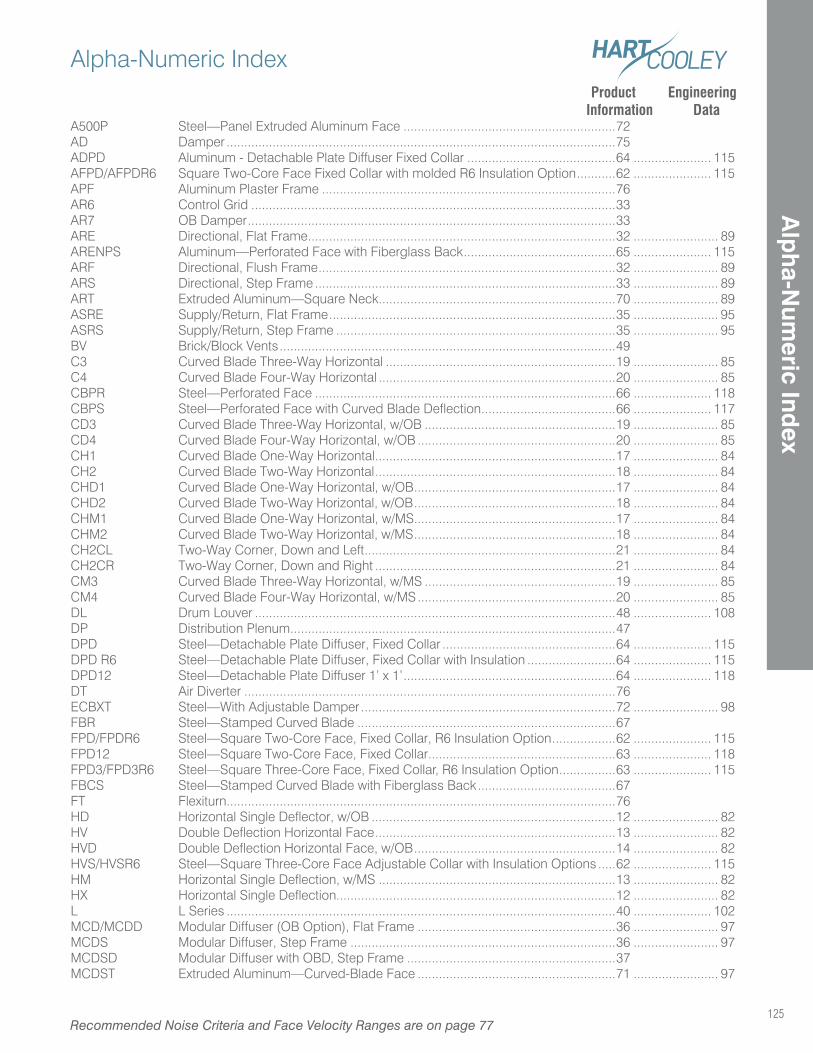
125
Alpha-Numeric Index
Recommended Noise Criteria and Face Velocity Ranges are on page 77
Alp
ha-N
umeric Ind
ex
Product Engineering Information Data A500P Steel—Panel Extruded Aluminum Face ............................................................72AD Damper ..............................................................................................................75ADPD Aluminum - Detachable Plate Diffuser Fixed Collar ..........................................64 ...................... 115AFPD/AFPDR6 Square Two-Core Face Fixed Collar with molded R6 Insulation Option ...........62 ...................... 115APF Aluminum Plaster Frame ...................................................................................76AR6 Control Grid .......................................................................................................33AR7 OB Damper ........................................................................................................33ARE Directional, Flat Frame .......................................................................................32 ........................ 89ARENPS Aluminum—Perforated Face with Fiberglass Back ...........................................65 ...................... 115ARF Directional, Flush Frame ....................................................................................32 ........................ 89ARS Directional, Step Frame .....................................................................................33 ........................ 89ART Extruded Aluminum—Square Neck ...................................................................70 ........................ 89ASRE Supply/Return, Flat Frame .................................................................................35 ........................ 95ASRS Supply/Return, Step Frame ...............................................................................35 ........................ 95BV Brick/Block Vents ...............................................................................................49C3 Curved Blade Three-Way Horizontal .................................................................19 ........................ 85C4 Curved Blade Four-Way Horizontal ...................................................................20 ........................ 85CBPR Steel—Perforated Face .....................................................................................66 ...................... 118CBPS Steel—Perforated Face with Curved Blade Deflection ......................................66 ...................... 117CD3 Curved Blade Three-Way Horizontal, w/OB ......................................................19 ........................ 85CD4 Curved Blade Four-Way Horizontal, w/OB ........................................................20 ........................ 85CH1 Curved Blade One-Way Horizontal ....................................................................17 ........................ 84CH2 Curved Blade Two-Way Horizontal ....................................................................18 ........................ 84CHD1 Curved Blade One-Way Horizontal, w/OB .........................................................17 ........................ 84CHD2 Curved Blade Two-Way Horizontal, w/OB .........................................................18 ........................ 84CHM1 Curved Blade One-Way Horizontal, w/MS .........................................................17 ........................ 84CHM2 Curved Blade Two-Way Horizontal, w/MS .........................................................18 ........................ 84CH2CL Two-Way Corner, Down and Left .......................................................................21 ........................ 84CH2CR Two-Way Corner, Down and Right ....................................................................21 ........................ 84CM3 Curved Blade Three-Way Horizontal, w/MS ......................................................19 ........................ 85CM4 Curved Blade Four-Way Horizontal, w/MS ........................................................20 ........................ 85DL Drum Louver ......................................................................................................48 ...................... 108DP Distribution Plenum ............................................................................................47DPD Steel—Detachable Plate Diffuser, Fixed Collar .................................................64 ...................... 115DPD R6 Steel—Detachable Plate Diffuser, Fixed Collar with Insulation .........................64 ...................... 115DPD12 Steel—Detachable Plate Diffuser 1’ x 1’ ............................................................64 ...................... 118DT Air Diverter .........................................................................................................76ECBXT Steel—With Adjustable Damper ........................................................................72 ........................ 98FBR Steel—Stamped Curved Blade .........................................................................67FPD/FPDR6 Steel—Square Two-Core Face, Fixed Collar, R6 Insulation Option ..................62 ...................... 115FPD12 Steel—Square Two-Core Face, Fixed Collar .....................................................63 ...................... 118FPD3/FPD3R6 Steel—Square Three-Core Face, Fixed Collar, R6 Insulation Option ................63 ...................... 115FBCS Steel—Stamped Curved Blade with Fiberglass Back .......................................67FT Flexiturn..............................................................................................................76HD Horizontal Single Deflector, w/OB .....................................................................12 ........................ 82HV Double Deflection Horizontal Face ....................................................................13 ........................ 82HVD Double Deflection Horizontal Face, w/OB .........................................................14 ........................ 82HVS/HVSR6 Steel—Square Three-Core Face Adjustable Collar with Insulation Options .....62 ...................... 115HM Horizontal Single Deflection, w/MS ...................................................................13 ........................ 82HX Horizontal Single Deflection...............................................................................12 ........................ 82L L Series ..............................................................................................................40 ...................... 102MCD/MCDD Modular Diffuser (OB Option), Flat Frame ........................................................36 ........................ 97MCDS Modular Diffuser, Step Frame ...........................................................................36 ........................ 97MCDSD Modular Diffuser with OBD, Step Frame ...........................................................37MCDST Extruded Aluminum—Curved-Blade Face ........................................................71 ........................ 97
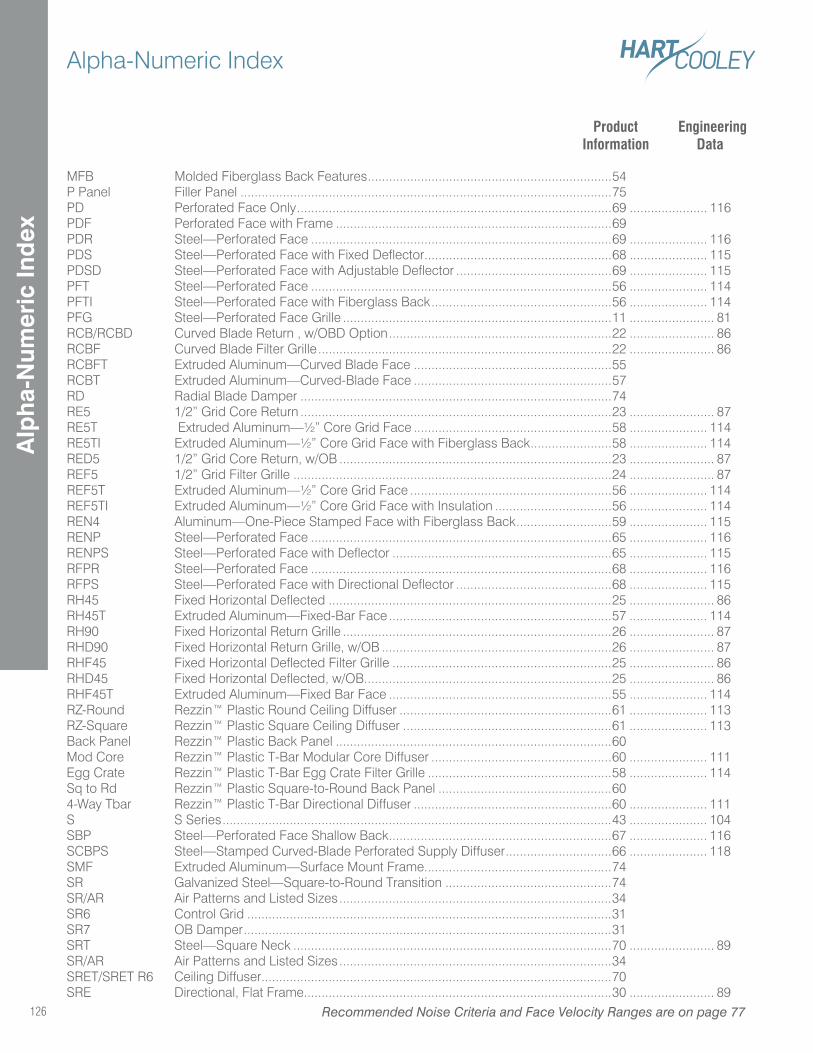
Alpha-Numeric Index
126 Recommended Noise Criteria and Face Velocity Ranges are on page 77
Alp
ha-
Num
eric
Ind
ex
Product Engineering Information Data
MFB Molded Fiberglass Back Features .....................................................................54P Panel Filler Panel .........................................................................................................75PD Perforated Face Only .........................................................................................69 ...................... 116PDF Perforated Face with Frame ..............................................................................69 PDR Steel—Perforated Face .....................................................................................69 ...................... 116PDS Steel—Perforated Face with Fixed Deflector .....................................................68 ...................... 115PDSD Steel—Perforated Face with Adjustable Deflector ............................................69 ...................... 115PFT Steel—Perforated Face .....................................................................................56 ...................... 114PFTI Steel—Perforated Face with Fiberglass Back ...................................................56 ...................... 114PFG Steel—Perforated Face Grille ............................................................................11 ........................ 81RCB/RCBD Curved Blade Return , w/OBD Option ...............................................................22 ........................ 86RCBF Curved Blade Filter Grille ...................................................................................22 ........................ 86RCBFT Extruded Aluminum—Curved Blade Face ........................................................55RCBT Extruded Aluminum—Curved-Blade Face ........................................................57RD Radial Blade Damper ........................................................................................74RE5 1/2” Grid Core Return ........................................................................................23 ........................ 87RE5T Extruded Aluminum—½” Core Grid Face ........................................................58 ...................... 114RE5TI Extruded Aluminum—½” Core Grid Face with Fiberglass Back .......................58 ...................... 114RED5 1/2” Grid Core Return, w/OB .............................................................................23 ........................ 87REF5 1/2” Grid Filter Grille ..........................................................................................24 ........................ 87REF5T Extruded Aluminum—½” Core Grid Face .........................................................56 ...................... 114REF5TI Extruded Aluminum—½” Core Grid Face with Insulation .................................56 ...................... 114REN4 Aluminum—One-Piece Stamped Face with Fiberglass Back ...........................59 ...................... 115RENP Steel—Perforated Face .....................................................................................65 ...................... 116RENPS Steel—Perforated Face with Deflector ..............................................................65 ...................... 115RFPR Steel—Perforated Face .....................................................................................68 ...................... 116RFPS Steel—Perforated Face with Directional Deflector ............................................68 ...................... 115RH45 Fixed Horizontal Deflected ................................................................................25 ........................ 86RH45T Extruded Aluminum—Fixed-Bar Face ...............................................................57 ...................... 114RH90 Fixed Horizontal Return Grille ............................................................................26 ........................ 87RHD90 Fixed Horizontal Return Grille, w/OB .................................................................26 ........................ 87RHF45 Fixed Horizontal Deflected Filter Grille ..............................................................25 ........................ 86RHD45 Fixed Horizontal Deflected, w/OB ......................................................................25 ........................ 86RHF45T Extruded Aluminum—Fixed Bar Face ...............................................................55 ...................... 114RZ-Round Rezzin™ Plastic Round Ceiling Diffuser ............................................................61 ...................... 113RZ-Square Rezzin™ Plastic Square Ceiling Diffuser ...........................................................61 ...................... 113Back Panel Rezzin™ Plastic Back Panel ..............................................................................60Mod Core Rezzin™ Plastic T-Bar Modular Core Diffuser ...................................................60 ...................... 111Egg Crate Rezzin™ Plastic T-Bar Egg Crate Filter Grille ....................................................58 ...................... 114 Sq to Rd Rezzin™ Plastic Square-to-Round Back Panel .................................................604-Way Tbar Rezzin™ Plastic T-Bar Directional Diffuser ........................................................60 ...................... 111S S Series ..............................................................................................................43 ...................... 104SBP Steel—Perforated Face Shallow Back ...............................................................67 ...................... 116SCBPS Steel—Stamped Curved-Blade Perforated Supply Diffuser ..............................66 ...................... 118SMF Extruded Aluminum—Surface Mount Frame.....................................................74SR Galvanized Steel—Square-to-Round Transition ...............................................74SR/AR Air Patterns and Listed Sizes .............................................................................34SR6 Control Grid .......................................................................................................31SR7 OB Damper ........................................................................................................31SRT Steel—Square Neck ..........................................................................................70 ........................ 89SR/AR Air Patterns and Listed Sizes .............................................................................34SRET/SRET R6 Ceiling Diffuser ...................................................................................................70SRE Directional, Flat Frame .......................................................................................30 ........................ 89
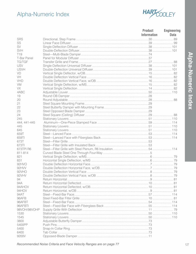
127
Alpha-Numeric Index
Recommended Noise Criteria and Face Velocity Ranges are on page 77
Alp
ha-N
umeric Ind
ex
Product Engineering Information Data SRS Directional, Step Frame .....................................................................................30 ........................ 89SS Linear Face Diffuser ...........................................................................................39 ........................ 99SV Single-Deflection Diffuser ..................................................................................38 ...................... 101SVH Double-Deflection Diffuser .................................................................................38 ...................... 101T19 Steel—Multi-Blade Damper ...............................................................................74T-Bar Panel Panel for Modular Diffuser .................................................................................37TG/TGF Transfer Grille and Frame ..................................................................................27 ........................ 88USV Single-Deflection Universal Diffuser ..................................................................38 ...................... 101USVH Double-Deflection Universal Diffuser .................................................................39 ...................... 101VD Vertical Single Deflector, w/OB ..........................................................................15 ........................ 82VH Double Deflection Vertical Face ........................................................................16 ........................ 82VHD Double Deflection Vertical Face, w/OB .............................................................16 ........................ 82VM Vertical Single Deflection, w/MS ........................................................................15 ........................ 82VX Vertical Single Deflection ...................................................................................14 ........................ 824ABC Adjustable Louver ..............................................................................................50 ...................... 11019 Round OB Damper ............................................................................................2820 Round Adjustable ..............................................................................................28 ........................ 8821 Steel Square Mounting Frame ...........................................................................2922 Steel Butterfly Damper with Mounting Frame ....................................................2923 Steel Opposed Blade Damper ..........................................................................2924 Steel Square (Ceiling) Diffuser ..........................................................................29 ........................ 88245 Stationary Louvers .............................................................................................51 ...................... 110444, 441-445 Aluminum—One-Piece Stamped Face ............................................................59 ...................... 114445 Stationary Louvers .............................................................................................51 ...................... 110645 Stationary Louvers .............................................................................................51 ...................... 110659T Steel—Lanced Face ..........................................................................................53 ...................... 114659TI Steel—Lanced Face with Fiberglass Back ........................................................53 ...................... 114673T Steel—Filter Grille ..............................................................................................53673TI Steel—Filter Grille with Insulated Back ..............................................................53673TPI R6 Steel—Filter Grille with Steel Plenum, R6 Insulation..........................................54 ...................... 114811-814 Curved Blade Steel One Through Four-Way .......................................................5821 Vertical Single Deflection, w/MS ..........................................................................6 ........................ 79831 Horizontal Single Deflection, w/MS .....................................................................6 ........................ 7992HVO Double Deflection Horizontal Face ......................................................................7 ........................ 7992HVV Double Deflection Horizontal Face, w/OB ...........................................................7 ........................ 7992VHO Double Deflection Vertical Face ..........................................................................8 ........................ 7992VHV Double Deflection Vertical Face, w/OB ...............................................................8 ........................ 7994 Return Horizontal .................................................................................................9 ........................ 8194A Return Horizontal Deflected ...............................................................................10 ........................ 8194AHOV Return Horizontal Deflected, w/OB ....................................................................10 ........................ 8194HOV Return Horizontal, w/OB ......................................................................................9 ........................ 8194AT Steel—Fixed-Bar Face .......................................................................................57 ...................... 11496AFB Steel Fixed-Bar Filter Grille ................................................................................10 ........................ 8196AFBT Steel—Fixed-Bar Face .......................................................................................54 ...................... 11496AFBTI Steel—Fixed-Bar Face with Fiberglass Back ....................................................55 ...................... 11498VOH/98VOHP Supply Grille With Deflection .............................................................................11 ........................ 791530 Stationary Louvers .............................................................................................50 ...................... 1101545 Stationary Louvers .............................................................................................50 ...................... 1103800 Adjustable Butterfly Damper ..............................................................................735400PP Push Pins ...........................................................................................................735400 Snap-In Collar Ring ............................................................................................736400 Tab Collar ..........................................................................................................739200V Opposed-Blade Damper ...................................................................................11

Hart & Cooley Inc
5030 Corporate Exchange Blvd. SEGrand Rapids, MI 49512
P (800) 433-6341F (800) 223-8461
hartandcooley.com
CHECKOUT OUR NEW WEBSITE!HARTANDCOOLEY.COM
hartandcooley.com
128

Offered by,
Hart & Cooley is proud to be an HCI brand
5030 Corporate Exchange Blvd. SEGrand Rapids, MI 49512
P (800) 433-6341F (800) 223-8461
hartandcooley.com
©2014 Hart & Cooley, Inc. Form No. 851531 08/2014