Embed Size (px)
Citation preview

COMMENTARY ON THE PRESCRIPTIVE METHOD FOR RESIDENTIAL COLD-FORMED
STEEL FRAMING
Second Edition
Prepared for
The U.S. Department of Housing and Urban Development
Office of Policy Development and Research Washington, DC
Co-Sponsored by
The American Iron and Steel Institute Washington, DC
and
The National Association of Home Builders
Washington, DC
by
NAHB Research Center, Inc. 400 Prince George's Boulevard
Upper Marlboro, MD 20774
August 1997


ii
Disclaimer While the material presented in this document has been prepared in accordance with recognized engineering principles and sound judgments, this document should not be used without first securing competent advice with respect to its suitability for any given application. The use of this document is subject to approval by the local code authority. Although the information in this document is believed to be accurate, neither the authors, nor reviewers, nor the United States Department of Housing and Urban Development of the U.S. Government, nor the American Iron and Steel Institute, nor the NAHB Research Center, nor any of their employees or representatives makes any warranty, guarantee, or representation, expressed or implied, with respect to the accuracy, effectiveness, or usefulness of any information, method, or material in this document, nor assumes any liability for the use of any information, methods, or materials disclosed herein, or for damages arising from such use.

iii
Foreword For centuries homebuilders in the United States have made wood their material of choice because of its satisfactory performance, abundant supply, and relatively low cost. However, increases and unpredictable fluctuations in the price of framing lumber, as well as concerns with its quality, are causing builders and other providers of affordable housing to seek alternative building products. Use of cold-formed steel framing in the residential market has increased over the past several years. Its price stability; consistent quality; similarity to conventional framing; success in the commercial market; and resistance to fire, rot, and termites have attracted the attention of many builders and designers. But lack of prescriptive construction requirements has prevented this alternative material from gaining wider acceptance among homebuilders and code officials. Commentary on the Prescriptive Method for Residential Cold-Formed Steel Framing (Commentary) provides the background, supplemental information, engineering assumptions and methods, and detailed calculations that support its companion volume the Prescriptive Method for Residential Cold-Formed Steel Framing. Both volumes were developed under the sponsorship of the U.S. Department of Housing and Urban Development (HUD) through a cooperative agreement with the National Association of Home Builders (NAHB) and the American Iron and Steel Institute (AISI). The program was conducted by the NAHB Research Center with assistance from steering, advisory, and engineering committees. These committees represented the interests and expertise of steel manufacturers, steel producers, code officials, academics, researchers, professional engineers, and builders experienced in cold-formed steel framing. Paul A. Leonard Deputy Assistant Secretary Policy Development

iv

COMMENTARY ON THE PRESCRIPTIVE METHOD FOR RESIDENTIAL COLD-FORMED STEEL FRAMING
v
Acknowledgments The Commentary On The Prescriptive Method For Residential Cold-Formed Steel Framing was prepared by the NAHB Research Center under sponsorship of the U.S. Department of Housing and Urban Development (HUD). We wish to recognize the National Association of Home Builders (NAHB) and the American Iron and Steel Institute (AISI) whose co-funding made this project possible. Special appreciation is extended to William Freeborne of HUD for guidance throughout the project. The preparation of this commentary required the talents of many dedicated professionals. The principal authors were Nader R. Elhajj, P.E. and Kevin Bielat with review by Jay Crandell, P.E. Appreciation is especially extended to members of the steering committee (listed below) who provided guidance on this document and who, with their input, made this work much more complete. Kevin Bielat; NAHB Research Center Delbert F. Boring, P.E.; AISI Roger Brockenbrough; RL Brockenbrough & Associates, Inc Jay Crandell, P.E.; NAHB Research Center Nader Elhajj, P.E.; NAHB Research Center William Freeborne; HUD Richard Haws, P.E.; American Buildings Company Jonathan Humble, AIA; AISI Jeffrey Klaiman, CSI, CDT; Dale / Incor Bill Knorr; Knorr Steel Framing Systems Dr. Roger LaBoube, P.E.; University of Missouri-Rolla
Jay Larson, P.E.; Bethlehem Steel Corp. Mike Meyers; U.S. Steel Mark Nowak; NAHB Research Center Neal Peterson, P.E.; Devco Engineering, Inc. Gregory Ralph; Dietrich Industries, Inc. Dr. Paul Seaburg, P.E.; University of Nebraska, Lincoln David Smith, P.E. Kurt Stochlia; ICBO Evaluation Service, Inc. Geoff Stone, AISI Mark Tipton; Met Homes Ken Vought; USS - POSCO Tim Waite, P.E.; T.J. Waite & Associates Steve Walker, P.E.
The NAHB Research Center appreciates and recognizes the Light Gauge Steel Engineers Association (LGSEA) for their support and the following individuals and companies who provided steel, tools, and other materials to support various research and testing efforts. Steve Argo and Bill Sauerwein of Black & Decker Ray Frobosilo of Super Stud Building Products, Inc. Ken Gilbert of Quick Drive USA, Inc. Michael Kerner of Marino\Ware Jeffrey Klaiman of Dale / Incor Jay Larson of Bethlehem Steel Corp. Robert Madsen and Neal Peterson of Devco Engineering, Inc.

COMMENTARY ON THE PRESCRIPTIVE METHOD FOR RESIDENTIAL COLD-FORMED STEEL FRAMING
vi
Acknowledgments (continued) Dean H. Peyton of Anderson-Peyton Structural Engineering Consultants Gregory Ralph of Dietrich Industries, Inc. Bill Reese of Grabber Construction Products Michelle Shiira and Art Linn of Simpson Strong-Tie Company, Inc. Marge Spencer of Compass International Appreciation is also extended to the following members of the steering committee who participated in the development of the first edition of the Commentary on the Prescriptive Method for Residential Cold-Formed Steel Framing: Joe Bertoni Kevin Bielat; NAHB Research Center Delbert F. Boring, P.E.; AISI Roger Brockenbrough; RL Brockenbrough & Associates, Inc Jay Crandell, P.E.; NAHB Research Center Ed DiGirolamo; The Steel Network Nader Elhajj, P.E.; NAHB Research Center John D. Ewing; USS - POSCO William “Bill” Farkas; NAHB Research Center William Freeborne; HUD Richard Haws, P.E.; AISI Bill Knorr; Knorr Steel Framing Systems Dr. Roger LaBoube, P.E.; University of Missouri-Rolla Mike Meyers; U.S. Steel
Mark Nowak; NAHB Research Center Dr. Teoman Pekoz; Cornell University Neal L. Peterson, P.E.; Devco Engineering Gregory Ralph; Dietrich Industries, Inc. Dr. Paul Seaburg; Pennsylvania State University David Smith, P.E. Kurt Stochlia; ICBO Evaluation Service, Inc. Mark Tipton; Met Homes Ken Vought; USS - POSCO Tim Waite, P.E.; T.J. Waite & Associates Steve Walker, P.E. Julian White, Jr.; Dale/Incor Riley Williams; Mitchell and Best Roger Wildt, P.E.; Bethlehem Steel
COMMENTARY ON THE PRESCRIPTIVE METHOD FOR RESIDENTIAL COLD-FORMED STEEL FRAMING
vii
TABLE OF CONTENTS
PART I - COMMENTARY ..........................................................................................................................................1
INTRODUCTION...........................................................................................................................................3 C1.0 GENERAL .............................................................................................................................................3
C1.1 Purpose.....................................................................................................................................3 C1.2 Approach ..................................................................................................................................3 C1.3 Scope ........................................................................................................................................3 C1.4 Definitions................................................................................................................................5
C2.0 MATERIALS, SHAPES AND STANDARD SIZES ............................................................................6
C2.1 Types of Cold-Formed Steel ....................................................................................................6 C2.2 Physical Dimensions ................................................................................................................6 C2.3 Uncoated Material Thickness...................................................................................................7 C2.4 Bend Radius .............................................................................................................................7 C2.5 Yield Strength ..........................................................................................................................9 C2.6 Corrosion Protection ................................................................................................................9 C2.7 Web Holes..............................................................................................................................10 C2.8 Cutting, Notching, and Hole Patching....................................................................................11 C2.9 Bearing Stiffeners...................................................................................................................11 C2.10 Clip Angles...........................................................................................................................12 C2.11 Fasteners...............................................................................................................................12
C3.0 LABELING ..........................................................................................................................................16
C4.0 FOUNDATION..................................................................................................................................16
C5.0 FLOORS.............................................................................................................................................16
C5.1 Floor Construction..................................................................................................................16 C5.2 Floor to Foundation or Bearing Wall Connection..................................................................16 C5.3 Allowable Joist Spans ............................................................................................................17 C5.4 Joist Bracing...........................................................................................................................18 C5.5 Floor Cantilevers ....................................................................................................................18 C5.6 Splicing ..................................................................................................................................19 C5.7 Framing of Openings..............................................................................................................19 C5.8 Floor Trusses ..........................................................................................................................19
C6.0 STRUCTURAL WALLS .....................................................................................................................20
C6.1 Wall Construction ..................................................................................................................20 C6.2 Wall to Foundation or Floor Connection ...............................................................................20 C6.3 Load Bearing Walls................................................................................................................20 C6.4 Stud Bracing (Buckling Resistance).......................................................................................25 C6.5 Splicing ..................................................................................................................................25 C6.6 Corner Framing ......................................................................................................................25 C6.7 Headers...................................................................................................................................25 C6.8 Wall Bracing ..........................................................................................................................29 C6.9 Hold-down Requirements ......................................................................................................37 C6.10 Wind Uplift ..........................................................................................................................37
COMMENTARY ON THE PRESCRIPTIVE METHOD FOR RESIDENTIAL COLD-FORMED STEEL FRAMING
viii
TABLE OF CONTENTS (continued)
C7.0 NON-STRUCTURAL WALLS ...........................................................................................................39 C7.1 Non-Load Bearing Studs........................................................................................................39 C7.2 Construction Details ...............................................................................................................40
C8.0 ROOF SYSTEMS ................................................................................................................................45
C8.1 Roof Construction ..................................................................................................................45 C8.2 Allowable Ceiling Joist Span .................................................................................................45 C8.3 Ceiling Joist Bracing ..............................................................................................................45 C8.4 Rafters ....................................................................................................................................45 C8.5 Rafter Bottom Flange Bracing ...............................................................................................46 C8.6 Splicing ..................................................................................................................................46 C8.7 Roof Trusses...........................................................................................................................46 C8.8 Roof Tie Downs .....................................................................................................................46
C9.0 MECHANICAL, UTILITIES, AND INSULATION...........................................................................47
C10.0 CONSTRUCTION GUIDELINES.....................................................................................................51
C11.0 REFERENCES ...................................................................................................................................54
PART II - HOW TO USE THE PRESCRIPTIVE METHOD.................................................................................58
1. INTRODUCTION ......................................................................................................................60 2. FRAMING MEMBERS..............................................................................................................62 3. FLOOR FRAMING SELECTION .............................................................................................63 4. WALL FRAMING SELECTION...............................................................................................64 5. ROOF FRAMING SELECTION................................................................................................70
PART III - ENGINEERING CALCULATIONS........................................................................................................74
INTRODUCTION ..........................................................................................................................76 SECTION PROPERTIES EXAMPLES .........................................................................................77 FLOOR JOIST DESIGN AND EXAMPLE...................................................................................89 WALL STUD DESIGN AND EXAMPLE ....................................................................................95 HEADER DESIGN AND EXAMPLE .........................................................................................113 SHEARWALL BRACING REQUIREMENTS CALCULATION..............................................116 CEILING JOIST DESIGN AND EXAMPLE..............................................................................118 RAFTER DESIGN AND EXAMPLE ..........................................................................................124

COMMENTARY ON THE PRESCRIPTIVE METHOD FOR RESIDENTIAL COLD-FORMED STEEL FRAMING
ix
TABLE OF CONTENTS (continued)
APPENDIX A - Section Property Tables APPENDIX B - Metric Conversion APPENDIX C - Energy Code And Related Thermal Performance Issues Associated With Steel Framing In
Homes APPENDIX D - Fire Resistance Issues Related To Cold-Formed Steel Framing In Homes
COMMENTARY ON THE PRESCRIPTIVE METHOD FOR RESIDENTIAL COLD-FORMED STEEL FRAMING
x
LIST OF TABLES PART I Table C2.3 Material Thickness ................................................................................................ 8 Table C2.4 Maximum Bend Radius ......................................................................................... 8 Table C2.6 Coating Designation Reference ........................................................................... 10 Table C2.11.1 Minimum Allowable Capacity for Steel to Steel Connections ............................ 14 Table C2.11.2 Typical fasteners Used with Steel Framing ......................................................... 15 Table C6.3 Maximum Allowable Heights For 2 x 4 Curtain Wall Studs 33 ksi ............................. 22 Table C6.4 Maximum Allowable Heights For 2 x 6 Curtain Wall Studs 33 ksi ............................. 23 Table C6.5 Steel Stud Thickness for 20-foot Walls Supporting Roof and Ceiling Only ....... 24 Table C6.8.1 Monotonic Load Test Results ................................................................................... 30 Table C6.8.2 Wall Bracing for Wind Conditions: Minimum Length (Feet) of Full-Height Structural Sheathing on Exterior Walls with a Single Hold-down at Each Corner ..........33 Table C6.8.3 Wall Bracing for Seismic Conditions: Minimum Percent Length of Full-Height Structural Sheathing on Exterior Walls with a Single Hold-down at Each Corner ......... 34 Table C6.8.4 Wall Bracing for Wind Conditions: Minimum Length (Feet) of Full-Height Structural Sheathing on Exterior Walls Without Hold-downs at Corners ........................35 Table C6.8.5 Wall Bracing for Seismic Conditions: Minimum Percent Length of Full-Height Structural Sheathing on Exterior Walls Without Hold-downs at Corners ........................36 Table C6.8.6 Monotonic Load Test Results .................................................................................. 37 Table C7.1 Maximum Allowable Clear Non-Load Bearing Stud Height Mid-Height Bracing ..........................................................................................................40 Table C7.2 Maximum Allowable Clear Non-Load Bearing Stud Height Fully Braced Walls ...........................................................................................................41 Table C9.0 Fiber Glass Insulation ............................................................................................. 50 Table C9.1 Foam Sheathing R-Values at 75oF Mean Temperature ............................................... 50 Table C10.0 Tools Recommended for Use with Residential Steel Framing ....................................... 54
LIST OF FIGURES Figure C2.11 Screw Attachments .............................................................................................. 13 Figure C6.7 Header Category..................................................................................................... 26 Figure C6.8 Typical Sill Plate Connection Detail ......................................................................... 28 Figure C7.2.1 Window Framing Detail - 1 ................................................................................ 42 Figure C7.2.2 Window Framing Detail - 2 ................................................................................ 43 Figure C7.2.3 Door Framing Detail - 1 ...................................................................................... 44 Figure C7.2.4 Door Framing Detail - 2 ...................................................................................... 45 Figure C9.1 Plan View of Trim Attached With Finishing Nails....................................................... 51 Figure C9.2 Cabinet Blocking Detail ........................................................................................... 51
COMMENTARY ON THE PRESCRIPTIVE METHOD FOR RESIDENTIAL COLD-FORMED STEEL FRAMING
xi


COMMENTARY ON THE PRESCRIPTIVE METHOD FOR RESIDENTIAL COLD-FORMED STEEL FRAMING
PART I
COMMENTARY

COMMENTARY ON THE PRESCRIPTIVE METHOD FOR RESIDENTIAL COLD-FORMED STEEL FRAMING
2

COMMENTARY ON THE PRESCRIPTIVE METHOD FOR RESIDENTIAL COLD-FORMED STEEL FRAMING
3
INTRODUCTION The Commentary on the Prescriptive Method for Residential Cold-Formed Steel Framing (Commentary) is provided to facilitate the use of and provide background information for the second edition of the Prescriptive Method For Residential Cold-Formed Steel Framing (Prescriptive Method) [1]. The Prescriptive Method was developed as an interim guideline for the construction of one-and two-family residential dwellings using cold-formed steel framing. In this Commentary, the individual sections, figures, and tables are presented in the same sequence found in the Prescriptive Method. Part I of the Commentary documents the assumptions and the derivation of the requirements contained in the Prescriptive Method. Part II of the Commentary contains an illustrative example on how to use the provisions of the Prescriptive Method. Part III of the Commentary contains design examples illustrating the proper application of the different standards and specifications in the Prescriptive Method. C1.0 GENERAL C1.1 Purpose The goal of the Prescriptive Method is to present prescriptive criteria (tables, figures, guidelines) for the construction of one-and two-story dwellings framed with cold-formed steel members. Prior to this document, there were no prescriptive standards available to builders and code officials for the purpose of constructing cold-formed steel houses without the added expense of a design professional and other costs associated with using a “non-standard” material for residential construction. The second edition of the Prescriptive Method presents the minimum requirements to provide basic residential construction that is consistent with the safety levels provided in the current U.S. building codes governing residential construction. The Prescriptive Method is not applicable to all possible conditions of use and is subject to the applicability limits set forth in Table 1.1. The applicability limits should be carefully understood as they define important constraints on the use of the Prescriptive Method. C1.2 Approach The requirements, figures, and tables provided in the Prescriptive Method are based on the AISI Specification for the Design of Cold-Formed Steel Structural Members [2], the American Society of Civil Engineers’ (ASCE) Minimum Design Loads for Buildings and Other Structures [3], and the pertinent requirements of the CABO One- and Two-Family Dwelling Code [4], the BOCA National Building Code [5], the Uniform Building Code [6], and the Standard Building Code [7]. Engineering decisions requiring interpretations or judgments in applying these references are documented in this Commentary. C1.3 Scope It is unrealistic to develop an easy to use document that provides prescriptive requirements to cover all types and styles of steel-framed houses. Therefore, the second edition of the Prescriptive Method [1] is limited in its applicability to light residential construction. The requirements set forth in the Prescriptive Method only apply to the construction of cold-formed steel-framed houses that meet the limits set forth in Table 1.1. The applicability limits are necessary to define reasonable boundaries to the conditions that must be considered in developing prescriptive construction requirements. The Prescriptive Method, however, does not limit the application of alternative methods or materials through engineering design.
COMMENTARY ON THE PRESCRIPTIVE METHOD FOR RESIDENTIAL COLD-FORMED STEEL FRAMING
4
The basic applicability limits were established from industry convention and experience. Detailed applicability limits were documented in the process of developing prescriptive design requirements for various elements of the structure. In some cases, engineering sensitivity analyses were performed to help define appropriate limits. The applicability limits strike a reasonable balance between engineering theory, available test data, and proven field practices for typical residential construction applications. The applicability limits are intended to prevent misapplication while addressing a reasonably large percentage of new housing conditions. Additional research, design or testing is needed to relax overly-restrictive constraints within the Prescriptive Method. Special consideration is directed toward the following items related to the applicability limits. Building Geometry The provisions in the Prescriptive Method apply to detached one- or two-family dwellings, townhouses, and other attached single-family dwellings not more than two stories in height. Its application to homes with complex architectural configurations is subject to careful interpretation of the user and design support may be required. The most common house widths (or depths) range from 24 feet to 36 feet, with load bearing wall heights up to ten feet. The house width as used in the Prescriptive Method is the dimension measured along the length of the trusses or the joists (floor or ceilings) between the outmost structural walls. A house complying with this document can not be of a length greater than 60 feet. Length is measured in the direction parallel to the roof ridge or floor joists. Site Conditions The snow loads are typically given in a ground snow load map such as provided in ASCE 7-93 [3] or by local practice. The major building codes in the U.S. either adopt the ASCE 7 [3] snow load requirements or have a similar map published in the code. The 0 to 70 psf ground snow load used in the Prescriptive Method covers approximately 90 percent of the United States’, which was deemed to include the majority of the houses that are expected to utilize this document. Houses in areas with higher snow loads should not use this document without consulting a design professional. All areas of the U.S. fall within the 70 to 110 mph (fastest-mile) range of design wind speeds [3]. The wind exposure category in the Prescriptive Method is limited to Exposures A, B, and C. Wind speed and exposure are defined in the Prescriptive Method. Wind exposure categories A, B, and C cover the majority of residential site conditions. Wind exposure is a critical determinant of the wind loads to be expected at a given site, and it should be determined by good judgment on a case-by-case basis. Houses built along the immediate coastline (i.e. beach front property) are classified as Exposure D and therefore, can not use this document without consulting a design professional. Because of additional engineering concerns and complications in high wind conditions (i.e. greater than 90 mph exposure C), engineering design of wall bracing and building anchorage (i.e. uplift straps and hold-down brackets) is required in these regions (refer to Sections C6.8 and C6.9). Buildings constructed per the Prescriptive Method are limited to regions designated as Seismic Zones 0, 1, 2, 3 and 4. However, because of additional engineering concerns, complications, and limitations in the wall bracing and hold-down requirements, buildings in Seismic Zones 3 and higher may require the services of a design professional to address these particular items. Loads Building codes and standards handle loads and load combinations differently. Consistent values were established for design loads in accordance with a review of the major building codes and standards. The results of this load review are embodied in the applicability limits table in the Prescriptive Method. Loads and load combinations requiring calculations to analyze the structural components and assemblies of a home are presented in the design examples shown throughout this document.

COMMENTARY ON THE PRESCRIPTIVE METHOD FOR RESIDENTIAL COLD-FORMED STEEL FRAMING
5
C1.4 Definitions The definitions in the Prescriptive Method are self explanatory. Additional definitions that warrant some technical explanation, are briefly discussed below. Design Thickness: The design thickness of the steel members is the minimum uncoated (i.e. not galvanized) material thickness divided by 0.95. Design thickness is used in developing the requirements and provisions of the Prescriptive Method (i.e. design thickness is used in calculating section properties, member capacities, and connections capacities). This adjustment is approved in the current AISI Design Specification [2] and it conservatively accounts for the normal variations of material thickness above the minimum required thickness. Torsional Rigidity: Relatively thin cold-formed C-shaped members are very susceptible to torsional buckling. Due to this concern, bending members (i.e. floor joists or roof rafters) should always be used in a manner consistent with the provisions in the Prescriptive Method and the loads associated with conventional, repetitive member framing practices. Local Buckling and Post Buckling Strength: Cold-formed steel C-shaped members consist of thin elements compared to their overall dimensions, and therefore, tend to buckle or distort at stresses well below the yield point when they are subjected to high compression, bending, shear, or bearing loads. This concern is addressed in the engineering analysis; however, this could become a problem if steel members (studs, headers, etc.) are used in a manner inconsistent with the provisions in the Prescriptive Method and the conventional practices of repetitive member-framing. Tests at the NAHB Research Center [25] [31] have shown that cold-formed elements fail (local buckling) at loads higher than predicted when used in a manner consistent with the Prescriptive Method. In fact, the elements tend to carry loads above their individual local buckling strength because of the load re-distribution experienced in repetitive member framing. Therefore, the post buckling strength is utilized in the design of cold-formed members for use in the Prescriptive Method.

COMMENTARY ON THE PRESCRIPTIVE METHOD FOR RESIDENTIAL COLD-FORMED STEEL FRAMING
6
C2.0 MATERIALS, SHAPES AND STANDARD SIZES C2.1 Types of Cold-Formed Steel C2.1.1 Structural Members In the Prescriptive Method, acceptable structural members are standard C-shapes produced by roll forming hot-dipped metallic coated sheet steel conforming to one of the four categories of steel presented in the Prescriptive Method, and in accordance with the American Iron and Steel Institute (AISI) "Specification for the Design of Cold-Formed Structural Steel Members" [2] requirements. These four categories are: American Society for Testing and Materials (ASTM) A 653 [8], A 792 [9], A 875 [10], and steels conforming to A 653 [8] with the exception of certain elongation and tensile strength to yield strength ratio requirements. Tracks are commonly used in conjunction with the standard C-shaped members specified in the Prescriptive Method. Steel tracks consist of channels (i.e. U-shaped) that are also rolled or brake formed from hot-dipped metallic coated sheet steel. C2.1.2 Non-Structural Members ASTM C 645 [11] is currently referenced in the three model building codes and is used in the Prescriptive Method as a resource for construction of non-load bearing walls (i.e. partitions). By definition, non-structural members may only be used in non-load bearing applications. C2.2 Physical Dimensions Because of significant variation in the industry related to dimensions of cold-formed steel members, dimensions were standardized (i.e. web depth, flange width, lip size, uncoated steel thickness, bend radius, and yield strength) to allow for the development of the Prescriptive Method. Dimensional standardization was focused on the C-shaped member because of its widespread use in the industry. Web Depth: The actual web sizes in the Prescriptive Method are limited to 3-1/2 inches, 5-1/2 inches, 8 inches, 10 inches, and 12 inches. The 3-1/2 and 5-1/2 inch web depths were chosen to accommodate current framing dimensions utilized in the residential building industry (i.e. to accommodate window and door jambs). These sizes can be used directly with conventional building materials and practices. The size of the web for 8, 10, and 12-inch members are not of great significance because they are typically used for horizontal framing members (i.e. headers and joists). Flange Width: The Prescriptive Method requires the standard C-shape have a minimum of 1-5/8 inch flange with a maximum flange dimension of 2 inches. A review of current producers of cold formed steel members showed that 1-5/8 inch flanges are widely used. The range of flange widths, from 1-5/8 to 2 inches, encompasses the majority of C-shaped products in the roll forming industry, when combined with the above web depths. An increase in flange size above the 2 inch maximum limit may result in decreased capacity for certain members. Lip Size: The Prescriptive Method also provides a minimum size for the stiffening lip of 1/2 inch. This dimension is also common in the industry. Sensitivity analyses performed to optimize the lip dimension showed that a slight increase in capacity results from a 5/8 inch or 3/4 inch lip size in certain conditions. However, decreasing the lip size had a detrimental effects in many circumstances. Therefore, the 1/2 inch lip dimension is considered an optimal minimum requirement and basis for engineering analysis. The industry designation column shown in Table 2.1 of the Prescriptive Method provides the terminology that the steel industry has agreed upon for designating the different steel members. For example a 350S162-33 designation indicates a steel stud (S) with 3.500 inch (3-1/2 inch) web, 1.625 inch (1-5/8 inch) flanges, and 33 mil thickness. A 350T162-33 indicates a track (T) with 3.500 inch (3-1/2 inch) web, 1.625 inch (1-5/8 inch) flanges, and 33 mil thickness. This industry designator is slightly different from the labeling section requirement because the intent for the industry designation is one method of meeting the labeling (or identification) requirements in the Prescriptive Method.

COMMENTARY ON THE PRESCRIPTIVE METHOD FOR RESIDENTIAL COLD-FORMED STEEL FRAMING
7
For engineering purposes, the section properties and an example on how to calculate these properties for the standard C-shapes are shown in PART III. These section properties were used in the engineering calculations to develop the Prescriptive Method. The Prescriptive Method requires steel tracks to have a minimum flange dimension of 1-1/4 inches. This dimension is widely used by the steel industry and ensures a sufficient flange width to allow fastening of the track to the framing members and finish materials. Steel track webs are measured from inside to inside of flanges and thus have wider overall web depths than the associated standard C-shapes. This difference in size allows the C-shape to properly nest into the track sections. Steel tracks are also available in thicknesses matching those required for the standards C-shapes. In the Prescriptive Method, tracks are always required to have the same thickness as the wall, floor, or roof structural members to which they are attached. C2.3 Uncoated Material Thickness The steel thickness required by the Prescriptive Method is the minimum uncoated material thickness (excluding the thickness of the metallic coating) and is given in mils (1/1000 of an inch). This unit is a deviation from the current practice which uses a gauge designation for thickness. The gauge represents a range of thicknesses and is therefore, a vague unit of measure when specifying minimums. In order to achieve consistency, the "mil" designation was adopted. Therefore, the 33 mils (20 gauge), 43 mils (18 gauge), 54 mils (16 gauge), 68 mils (14 gauge), and 97 mils (12 gauge) are specified for the thicknesses. The design thickness (shown in Table C2.3 below) is the value used in the computation of member capacities. The reduction in thickness that occurs at corner bends is purposefully ignored, and the design thickness of the flat steel stock, exclusive of coatings, is used in the structural calculations. The design thickness is defined as the minimum delivered thickness divided by 0.95 which follows the provisions of the AISI Design Specification [2]. This adjustment reasonably accounts for the normal variation in material thickness above the minimum delivered material thickness required. The reader is referred to Part III of this document for engineering calculations illustrating the use of the design thickness in the computation of section properties. C2.4 Bend Radius The bend radius is measured from the inside of bends in cold-formed steel members. It has an impact on the capacity of structural steel members. As the inside bend radius increases, the effective flat width of the element decreases and thus, the member's capacity decreases. Conversely, strength increases are realized in the regions of bends due to a phenomena known as cold-working which locally increases the yield strength of the steel. The steering committee established the maximum bend radius to be the greater of 3/32-inch or twice the material thickness. This requirement was established to provide manufacturers with a reasonable tolerance without adversely affecting the strength of the member. The maximum bend radii (shown in Table C2.4 below) were used in the computations of member capacities for the Prescriptive Method. The reader is referred to (Part III) for the engineering calculations illustrating the use of the bend radius in the computation of section properties.

COMMENTARY ON THE PRESCRIPTIVE METHOD FOR RESIDENTIAL COLD-FORMED STEEL FRAMING
8
Table C2.3 Material Thickness
Designation
(mils)
Minimum Delivered Thickness
(inches)
Design Thickness
(inches)
Reference Gauge
Number
18 0.018 0.019 25
27 0.027 0.028 22
33 0.033 0.035 20
43 0.043 0.045 18
54 0.054 0.057 16
68 0.068 0.071 14
97 0.097 0.102 12 For SI: 1 inch = 25.4 mm.
Table C2.4 Maximum Bend Radius
Designation
(mils)
Minimum Delivered
Thickness (t)
(inches)
Maximum Bend
Radius
Maximum Bend Radius
(inches)
18 0.018 3/32 in. 0.0937
27 0.027 3/32 in. 0.0937
33 0.033 3/32 in. 0.0937
43 0.043 3/32 in. 0.0937
54 0.054 2 x thickness 0.108
68 0.068 2 x thickness 0.136
97 0.097 2 x thickness 0.194 For SI: 1 inch = 25.4 mm.

COMMENTARY ON THE PRESCRIPTIVE METHOD FOR RESIDENTIAL COLD-FORMED STEEL FRAMING
9
C2.5 Yield Strength The Prescriptive Method applies to steels with minimum yield strengths of 33 ksi or 50 ksi. The 33 ksi steels are the minimum required for all steel floors, roofs, and header components. Steel stud tables are provided for both 33 ksi and 50 ksi minimum yield strength. The 50 ksi yield strength steel was included as separate option for wall studs selection because of the notable economic benefit in this particular application. Strength increase from cold working is utilized for the standardized C-shaped members in the Prescriptive Method concerning the calculated bending strength of flexural members, concentrically loaded compression members, and members with combined axial and bending loads. The reader is referred to Part III for engineering calculations illustrating the stress increase due to cold-working and it’s use in calculating section properties. C2.6 Corrosion Protection In residential construction, it is not considered likely for any structural steel framing to be exposed to a severe corrosive environment, except for locations close to coastal areas. The degree of protection is determined by considering the use of the member, its exposure, climate, and other conditions. Metallic coating is required to ensure that the steel framing structure will perform its required function during its expected life. The minimum galvanizing coatings of G-40 for interior non-structural (non-load bearing) members, and G-60 for structural members provides adequate protective coating for steel-framed members in normal environments. The user should be cautious in coastal areas and other severe climatic conditions, where greater corrosion protection may be required (for example G-90 may be recommended). The Prescriptive Method provides the minimum coating designation and references the applicable ASTM standards. The requirements for metallic coatings are given in ASTM A924 [12]. Users of cold-formed steel framing are encouraged to locate (store or construct) steel framing members within the protection of the building envelope and adequately shield steel materials from direct, long-term contact with moisture, from the ground or the outdoor climate. The Prescriptive Method includes a provision permitting the usage of other metallic coatings that are equivalent to the galvanized coating. However, only coatings that provide sacrificial protection are permissible. Sacrificial protection is necessary to protect bare steel from corrosion at locations where the steel has been penetrated (e.g. holes). Table C2.6 provides coating designation references that are obtained from the applicable ASTM Standards.

COMMENTARY ON THE PRESCRIPTIVE METHOD FOR RESIDENTIAL COLD-FORMED STEEL FRAMING
10
Table C2.6 Coating Designation Reference
Material / Coating Minimum
Triple Spot Total -
Both Sides (oz/ft2)
Minimum Single Spot
Total- Both Sides
(oz/ft2)
Minimum Triple Spot
Total - Both Sides
(g/m2)
Minimum Single Spot
Total- Both Sides
(g/m2)
Coating Thickness- Both Sides (microns)
AZ50 galvalume 0.50 0.43 40.7 AZ55 galvalume 0.55 0.50 44.8 AZ60 galvalume 0.60 0.52 48.8
AZ150 galvalume 150 130 40.0 AZ165 galvalume 165 150 44.0 AZ180 galvalume 180 155 48.0 G40 galvanized 0.40 0.30 17.1 G60 galvanized 0.60 0.50 25.6 G90 galvanized 0.90 0.80 38.5 Z120 galvanized 120 90 16.8 Z180 galvanized 180 150 25.2 Z275 galvanized 275 235 38.5
GF45 galfan 0.45 0.35 20.5 GF60 galfan 0.60 0.50 27.3 GF75 galfan 0.75 0.65 34.2
ZGF135 galfan 135 113 20.1 ZGF180 galfan 180 150 26.9 ZGF225 galfan 225 195 33.6
Densities: galvalume - 3.75 g/cm3; galvanized - 7.1 g/cm3; galfan - 6.70 g/cm3. Reference ASTM Standards for galvanized , galvalume, and galfan: A653 [8], A792 [9], and A875 [10] respectively.
C2.7 Web Holes The AISI Design Specification [2] does not address web holes (punchouts) beyond small circular holes. Web holes, typically 1-1/2 inch wide x 4 inch long are common in the cold-formed steel industry to accommodate plumbing, electrical, and mechanical materials. Floor joists typically require larger holes to accommodate sanitary, drain lines, vents, and other utilities. Floor and Ceiling Joists: Floor and ceiling joists used in the Prescriptive Method are all designed assuming maximum hole dimensions and minimum spacings as shown in Table 2.4 of the Prescriptive Method. The width of the hole is measured along the depth of the web and the length of the hole is measured parallel to the length of the member. The span tables are calculated based on the presence of these holes. The design procedure follows the “Design Guide For Cold-Formed Steel Beams With Web Perforations” [13] which provides a criteria for calculating the allowable axial and bending load of perforated members subject to bending and shear, such as floor joists. The tabulated hole dimensions and spacing shown in Table 2.4 are based on a web hole width-to-web depth ratio not exceeding 0.4 and a maximum hole length of 2.67 times the width of the hole, but not greater than 6 inches.
COMMENTARY ON THE PRESCRIPTIVE METHOD FOR RESIDENTIAL COLD-FORMED STEEL FRAMING
11
Studs, header members, rafters, and other structural members: Studs, header members, rafters, and other structural members (except floor and ceiling joists) used in the Prescriptive Method are all assumed punched with a standard hole of 1-1/2 in. wide x 4 in. long (the width of the hole is along the depth of the web and the length of the hole is parallel to the member). The span tables are calculated based on the presence of standard holes with a minimum center-to-center spacing equal to three times the outside depth of the stud section, but need not exceed 24 inches. A minimum distance of 12 inches from center of hole to end of member is also required. The design procedure follows International Conference of Building Officials (ICBO) AC46 "Acceptance Criteria For Steel Studs And Joists" [14]. ICBO AC46 provides a criteria to calculate the allowable axial and bending load of a perforated wall stud or a structural member. The example in Part III of this document illustrates the use of this procedure in calculating the reduction in the allowable shear capacity due to punchouts. The ICBO AC46 approach has the following limitations: Center to center spacing of the perforations (holes) shall be at least three times the outside depth of the
member, but need not exceed 24 inches. Perforation width (across the web) shall not exceed half the member depth or 2-1/2 inches. Perforation length
shall not exceed 2.67 times the hole width or 4.5 inches. Minimum distance between the end of the stud and the near edge of the perforation shall be 10 inches. All web perforations are located along the center line of the web. C2.8 Cutting, Notching, and Hole Patching As mentioned before, the webs of all structural members, in the Prescriptive Method, were assumed to have holes when calculating member capacities. Structural members having holes that do not conform to the tabulated holes shown in Tables 2.4 or 2.5 need to be reinforced to achieve the structural capacity used in the design. The hole patch detail is applicable only if the hole depth does not exceed half the depth of the web, and the hole length (along the web) does not exceed the depth of the web or 6 inches, whichever is greater. The hole patching detail results in a member that has an equivalent capacity to an un-patched member with standard holes. Cutting or notching of load bearing members are not allowed in the Prescriptive Method because this condition will greatly reduce the structural capacity of the member C2.9 Bearing Stiffeners Webs of thin walled cold-formed steel members may cripple or buckle locally at concentrated load or bearing reaction. The allowable reactions and concentrated loads for beams having single un-reinforced webs depend on web depth, bend radius, web thickness, yield strength, and actual bearing length. Bearing stiffeners (also called transverse or web stiffeners) are required at all support or bearing point locations for all floor joists and where required for ceiling joists. The stiffeners are specified to be a minimum of 43 mil track section or 33 mil C-shaped member. These sections were specified because their axial load carrying capacity exceed that of the concentrated load (from top floors , walls, and roofs) and the additional reaction (from the imposed load on the joists).

COMMENTARY ON THE PRESCRIPTIVE METHOD FOR RESIDENTIAL COLD-FORMED STEEL FRAMING
12
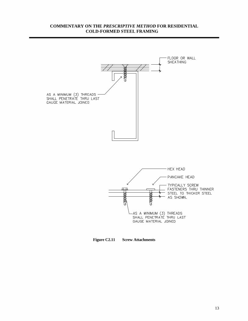
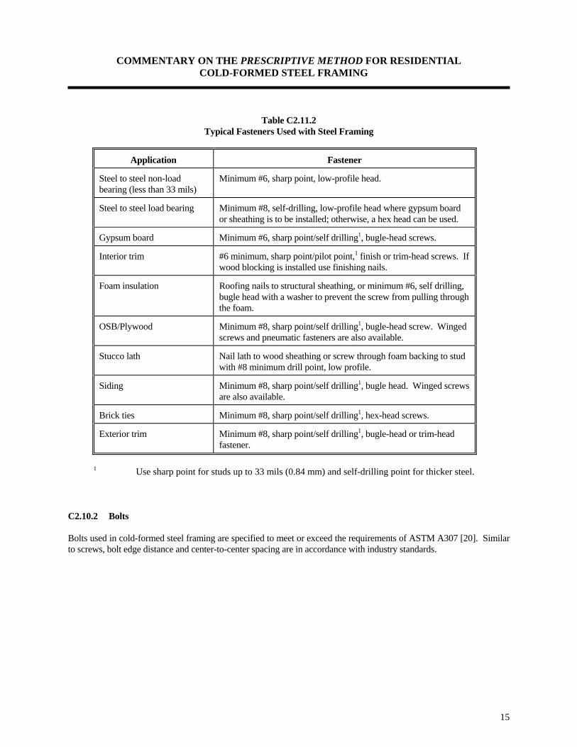
C2.10 Clip Angles The clip angles used in the Prescriptive Method are commonly used in the residential steel framing market. C2.11 Fasteners This section is not intended to limit the fastening techniques to those listed. Other fastening methods are permitted to be used with this document provided that the connection's capacity is shown to exceed that implied in the Prescriptive Method. Testing, design, or code approvals may be necessary for alternate fastening techniques. C2.11.1 Screws Fastening of cold-formed steel framing members is limited to screws in the Prescriptive Method. Self-drilling tapping screws conforming to the requirements of the Society of Automotive Engineers (SAE) J78 [15] are used extensively in the Prescriptive Method. There is a need for additional standards for screws related to applications with cold-formed steel framing. Requirements for sharp point screws, connecting gypsum board and sheathing to steel studs, are found in ASTM C 1002 [16] and ASTM C 954 [17]. An edge distance and center-to-center spacing of three screw diameters follow industry recommendations, the AISI guidelines [18] and the University of Missouri-Rolla Center for Cold-Formed Steel Structures’ (CCFSS) Technical Bulletin [19]. The minimum screw size specified in this document is #8 for structural applications, however, larger diameter screws may be required to provide drill capacities through steel thicknesses greater than 100 mils (refer to Table 2.6 in the Prescriptive Method). In certain applications, # 10 screws are specified in the Prescriptive Method for practical purposes and added capacity. The point style of the screw will affect the constructability in certain applications. For example, a sharp point screw may be efficiently used to connect gypsum board and other panel products to steel framing members that are no thicker than 33 mils. For these reasons, screw manufacturer recommendations should be consulted. Driveability of screws in different thicknesses of steels have been an issue with end users. This issue is addressed in the Prescriptive Method by providing a table listing the maximum steel thickness into which a particular self-drilling, tapping screw can be driven without difficulty. The maximum steel thickness represents the total thickness of the connected parts (refer to Fig. C2.11). This information is provided in the Prescriptive Method because the driveability of screws vary. Again, the user should consult with screw manufacturers for proper fastener application. Screw capacities given in the table below (Table C2.11.1) are calculated based on the design method given in the CCFSS document [19]. The CCFSS document provides the equations necessary to calculate the shear, pullover, and pullout capacity of a connection based on the thicknesses of the steel being fastened together. The equations are conservatively based on tests performed on thousands of screws of many different types and levels of quality. An example of engineering calculations to determine the capacity of a screw is provided in Part III of this document. Table C2.11.2 provides a list of typical fastener type and application used in steel construction.
COMMENTARY ON THE PRESCRIPTIVE METHOD FOR RESIDENTIAL COLD-FORMED STEEL FRAMING
13
Figure C2.11 Screw Attachments

COMMENTARY ON THE PRESCRIPTIVE METHOD FOR RESIDENTIAL COLD-FORMED STEEL FRAMING
14
Table C2.11.1 Minimum Allowable Fastener Capacity for Steel to Steel Connections
[Safety factor = 3.0]
Screw Size Minimum Shank
Diameter (inches)
Minimum Head
Diameter (inches)
Minimum Capacity (lbs.)
Shear Capacity Pullout Capacity
43 mils 1 33 mils 1 43 mils 1 33 mils 1
#8 0.164 0.322 244 164 94 72
#10 0.190 0.384 263 177 109 84
For SI: 1 inch = 25.4 mm, 1 lb. = 4.5 N 1 The value represents the smaller thickness of two pieces of steel being connected.
COMMENTARY ON THE PRESCRIPTIVE METHOD FOR RESIDENTIAL COLD-FORMED STEEL FRAMING
15
Table C2.11.2 Typical Fasteners Used with Steel Framing
Application Fastener
Steel to steel non-load bearing (less than 33 mils)
Minimum #6, sharp point, low-profile head.
Steel to steel load bearing Minimum #8, self-drilling, low-profile head where gypsum board or sheathing is to be installed; otherwise, a hex head can be used.
Gypsum board Minimum #6, sharp point/self drilling1, bugle-head screws.
Interior trim #6 minimum, sharp point/pilot point,1 finish or trim-head screws. If wood blocking is installed use finishing nails.
Foam insulation Roofing nails to structural sheathing, or minimum #6, self drilling, bugle head with a washer to prevent the screw from pulling through the foam.
OSB/Plywood Minimum #8, sharp point/self drilling1, bugle-head screw. Winged screws and pneumatic fasteners are also available.
Stucco lath Nail lath to wood sheathing or screw through foam backing to stud with #8 minimum drill point, low profile.
Siding Minimum #8, sharp point/self drilling1, bugle head. Winged screws are also available.
Brick ties Minimum #8, sharp point/self drilling1, hex-head screws.
Exterior trim Minimum #8, sharp point/self drilling1, bugle-head or trim-head fastener.
1 Use sharp point for studs up to 33 mils (0.84 mm) and self-drilling point for thicker steel. C2.10.2 Bolts Bolts used in cold-formed steel framing are specified to meet or exceed the requirements of ASTM A307 [20]. Similar to screws, bolt edge distance and center-to-center spacing are in accordance with industry standards.

COMMENTARY ON THE PRESCRIPTIVE METHOD FOR RESIDENTIAL COLD-FORMED STEEL FRAMING
16
C3.0 LABELING
The labeling (identification) system specified in the Prescriptive Method is a minimum requirement. Additional information may be added to the stamp, logo, stencil, or embossment. The requirements in this section closely follow what is currently proposed by the industry. The labeling requirements are necessary for building code enforcement, construction coordination, and quality control. The following is an example of a possible labeling stamp.
C4.0 FOUNDATION The Prescriptive Method does not provide prescriptive requirements for foundation construction. It references the model building codes for the design and installation of the foundation. The Prescriptive Method provides prescriptive requirements for the connection of steel framing to the foundation in Sections 5.0 and 6.0. Anchor bolts (i.e. J-bolts) must be installed in concrete in accordance with current building code requirements. C5.0 FLOORS C5.1 Floor Construction The Prescriptive Method shows a typical floor construction layout with the different elements of the floor identified. Floor construction in the Prescriptive Method is limited to design wind speeds less than or equal to 110 mph (fastest-mile) and to Seismic Zones 0, 1, 2, 3, and 4. However, as mentioned in the applicability limit table of the Prescriptive Method (Table 1.1), an approved design will be required for hold-down requirements, and/or uplift straps for steel floors in buildings subjected to wind speeds greater than 90 mph, Exposure C, and buildings located in Seismic Zone 3 or higher. This limitation is a result of the additional design required for connections of the floor to the foundation or bearing walls. In-line framing is also emphasized in the Prescriptive Method. The maximum tolerance between the centerlines of the floor joists and the studs is limited to a maximum of 3/4-inch. The tolerance given in is the maximum and at no time should be exceeded without consulting a design professional. C5.2 Floor to Foundation or Bearing Wall Connection The Prescriptive Method provides three different details for connecting floor joists to foundations or load bearing walls, three different details for connecting cantilevered floors to foundations or load bearing walls, one detail for lapped joists and one detail for continuous joist installation. The details are self explanatory and reflect a selection from current practice.
ABC 0.043 G60 33 ksi

COMMENTARY ON THE PRESCRIPTIVE METHOD FOR RESIDENTIAL COLD-FORMED STEEL FRAMING
17
C5.3 Allowable Joist Spans The Prescriptive Method provides floor joist tables with maximum allowable spans for two live load conditions: 30 psf and 40 psf. The spans shown in the Prescriptive Method assume bearing stiffeners are installed at each bearing point. Bearing (web) stiffener requirements are also provided in Section 2.9 of the Prescriptive Method. An example of the calculation of the maximum allowable joist span is shown in Part III of this document. In the design of floor joists, any one of several engineering criteria may control the prescriptive requirements depending on the configuration of the section, thickness of material, and member length. The analysis used in the Prescriptive Method includes checks for:
• Yielding • Flexural buckling • Web crippling • Shear • Deflection • Combined bending and shear (for multiple spans)
All joists are considered punched in accordance with Table 2.4. The compression flange (top flange) of the floor joists are also assumed to be continually braced by the subflooring, thus providing lateral restraint for the top flanges. The joist span tables are calculated based on deflection limit of L/480 for live load and L/240 for total loads, where L is the span length. Building codes vary in requirements for deflection criteria. Also, deflection requirements which have worked well in the past for one type of material or method have created problems when applied to others. One particular serviceability problem is related to floor vibrations and many practitioners and standards use more stringent deflection criteria than the L/360 typically required for residential floors. Deflection limits are primarily established with regard to serviceability concerns. The intent is to prevent excessive deflection which might result in cracking of finishes. The deflection criteria also affects the "feel" of the building in terms of rigidity and vibratory response to normal occupant loads. For a material like steel, which has a high material strength, longer spans are possible with members of lower apparent stiffness (i.e. E x I). In such cases, typical deflection criteria may not be appropriate. For example, industry experience indicates that an L/360 deflection limit often results in these floors being perceived to be "bouncy" by occupants. This condition may be misconstrued as a sign of weakness by the occupant. While a deflection-to-span- ratio of L/360 may be adequate under static loading, it is suggested that a significantly tighter deflection-to-span ratio under the full design live load only may be appropriate to ensure adequate performance. The deflection-to-span ratio has always been a controversial issue when it is used to assess human comfort. A higher deflection limit is usually recommended to overcome the concern with nuisance vibrations. To ensure dynamic performance, the Australians [21] for example, consider a deflection-to-span ratio of L/750 (under full live loading) to be appropriate in the absence of full dynamic analysis. Furthermore, the Australians provide a criterion to determine what is an acceptable "house" system, based on critical damping. This method is not generic and requires the calculation of the first natural frequency and percent damping of the floor which depend on the physical dimensions, stiffness, and attachments of the house. Due to this fact, a more simplistic approach would be to tighten the deflection criteria. A floor deflection-to-span ratio of L/480 typically results in an increase in the percent of critical damping as suggested by the AISC, and thus ensures that vibration does not exceed a tolerable level. Many engineers apply a L/480 deflection criteria when designing steel floor joists. A recent research program initiated an effort to develop an accurate method to predict steel floor vibration performance [22]. A method was proposed to determine the vibration acceptability of cold-formed steel, C-joist supported residential floor systems which depends only on the dimensions and cross sectional properties of the floor. While appears to provide a relatively consistent vibration performance criterion it is not adopted in the Prescriptive Method at

COMMENTARY ON THE PRESCRIPTIVE METHOD FOR RESIDENTIAL COLD-FORMED STEEL FRAMING
18
this time. The reader is referred to reference 22 for a detailed description of the method and its application. Part III of this document summarizes the recommended method and provides an example on its application. Multiple Spans: Multiple spans are commonly used in the residential steel building market. When multiple spans are used certain measures are necessary to address the reactions of the loaded members. The first reaction to address is the magnitude of the reaction at the middle support which is greater than the end reactions. This may create web crippling failure at the middle support. This is resolved by requiring web stiffeners at all bearing points. The second reaction is the presence of negative moments (i.e. reversed bending) at the middle reaction region, causing the compression flanges to be at the bottom rather than the top of the joists. If left unbraced, this would cause lateral instability and may cause premature failure of the joists under extreme loading conditions. Furthermore, shear and bending interaction are checked for multiple spans due to the presence of high shear and bending stresses at the middle reactions, creating greater susceptibility of web buckling. Bottom flange bracing at interior supports is provided by ceiling finishes (when present) and by positive connection to the interior bearing wall. Possible benefits from composite action with the floor diaphragm were not utilized in the development of the Prescriptive Method. C5.4 Joist Bracing Steel floors have long been designed by considering the joists as simple beams acting independently without consideration of composite action from floor sheathing. For typical residential floors, it has been assumed that the floor sheathing's only function is to transfer the loads to the joists, and to provide continuous lateral bracing to the compression flanges neglecting many factors that affect the strength and stiffness of a floor. Testing has indicated that using a single joist for strength calculation agrees with actual behavior when uniform loads are applied [23].
Bracing the bottom flanges of joists as specified in the Prescriptive Method is based on industry practice and engineering judgment. Steel strapping as well as finished ceilings are considered to be adequate bracing for the tension flanges. It is necessary, however, for steel strapping to have blocking (or bridging) installed at a maximum spacing of 12 feet and at the termination ends of all straps. Alternatively, the ends of steel straps may be fastened to a stable component of the building in lieu of or blocking (i.e. to concrete wall or foundation). C5.5 Floor Cantilevers Cantilevered floor joists are used often. In many cases, cantilevers support load bearing walls which create special loading conditions that require separate engineering analysis. In the Prescriptive Method, floor cantilevers are limited to a maximum of 24 inches for floors supporting one wall and roof only (one story). This limitation is imposed to minimize the impact of the added load on the floor joists. To fully utilize the strength of the joist, holes are not permitted in cantilevered portions. Floor cantilevers supporting two stories are permitted provided that the floor joists are doubled (back to back C-shaped members screwed with two # 8 screws at minimum of 24 inches on center along the centerline of the webs) and the cantilevered section does not exceed 24 inches.
COMMENTARY ON THE PRESCRIPTIVE METHOD FOR RESIDENTIAL COLD-FORMED STEEL FRAMING
19
C5.6 Splicing Splicing of structural members is not a typical application, but some situations may arise where splicing requirements would be useful. Applications may include repair of damaged joists, simplified details for dropped floors, and others. Splices, generally, are required to transfer shear, bending moments, and axial loads. Some splices may occur over points of bearing, and splicing may only be required to transmit nominal axial loads. The Floor joist spans provided in the Prescriptive Method are based on the assumption that the joists are continuous, with no splices Therefore, splicing of joist members in the Prescriptive Method requires an approved design except when lapped joists occur at interior bearing points. C5.7 Framing of Openings Openings in floors are needed for several reasons (e.g. chimneys). The Prescriptive Method limits the width of the floor opening width to 8 feet and provides a provision for reinforcing the members around floor openings. All members around floor openings (i.e. header and trimmer joists) are required to be box-type members made by nesting a C-shaped joist into a track and fastening them together along the top and bottom flanges. These built-up members are required to have a minimum size and thickness not less than the floor joists. Each header joist is required to be connected to the trimmer joist with a clip angle on either side of each connection. The clip angle is required to be of a thickness equivalent to the floor joists. C5.8 Floor Trusses This section is included so that pre-engineered floor trusses can be used in conjunction with this document. The American Iron and Steel Institute (AISI) has developed a Design Guide For Cold-Formed Steel Trusses [24] to assist in truss design.

COMMENTARY ON THE PRESCRIPTIVE METHOD FOR RESIDENTIAL COLD-FORMED STEEL FRAMING
20
C6.0 STRUCTURAL WALLS C6.1 Wall Construction The Prescriptive Method covers wall studs in buildings within the applicability limits of Table 1.1. The maximum design conditions are Seismic Zone 4, ground snow load of 70 psf, and design wind speed of 110 mph fastest-mile in Exposure C conditions (i.e. open terrain). C6.2 Wall to Foundation or Floor Connection The Prescriptive Method provides commonly used details to connect wall studs to foundations or bearing walls. The details are self explanatory and reflect current practice in residential steel framing. C6.3 Load Bearing Walls The Prescriptive Method provides the minimum required thicknesses of steel studs for different wind speeds, exposure categories, wall heights, building widths, and ground snow loads. Stud selection tables are limited to one- and two-story buildings with load bearing wall heights up to 10 feet. The 8-foot walls are widely used in residential construction, however, steel framed homes often take advantage of higher ceilings such as 9- and 10-foot walls. The 50 ksi (steel’s yield strength) stud tables were developed to take advantage of the higher yield strength which allows thinner studs in many cases. The wall studs are grouped in two categories:
• Studs for one-story or second floor of two-story building (supporting roof only) • Studs for first story of a two-story building (supporting roof + one floor)
For walls sheathed with a wood structural panel (7/16-inch OSB or 15/32-inch plywood), a reduction in thickness of the stud is allowed by footnote in the stud selection tables for 33 ksi steel. These reductions have been investigated in recent testing of wall assemblies under combined bending and axial loads conducted at the NAHB Research Center [25]. All studs in exterior walls are treated as load bearing members for the purpose of simplifying the Prescriptive Method. The following design assumptions were made in analyzing the wall stud selection tables.
• Studs are simply supported beam - columns. • Bracing of the interior and exterior flanges of the studs by sheathing or mechanical bracing
(mechanical bracing at mid-height for 8' studs, 1/3 point for 9' and 10' studs.) • Maximum roof overhang of 24 inches. • Roof slopes limited to a range of 3:12 to 12:12. • Deflection Criteria: L/240 • Ceilings, roofs, attics, and floors span the full width of the house (no interior load bearing walls).

COMMENTARY ON THE PRESCRIPTIVE METHOD FOR RESIDENTIAL COLD-FORMED STEEL FRAMING
21
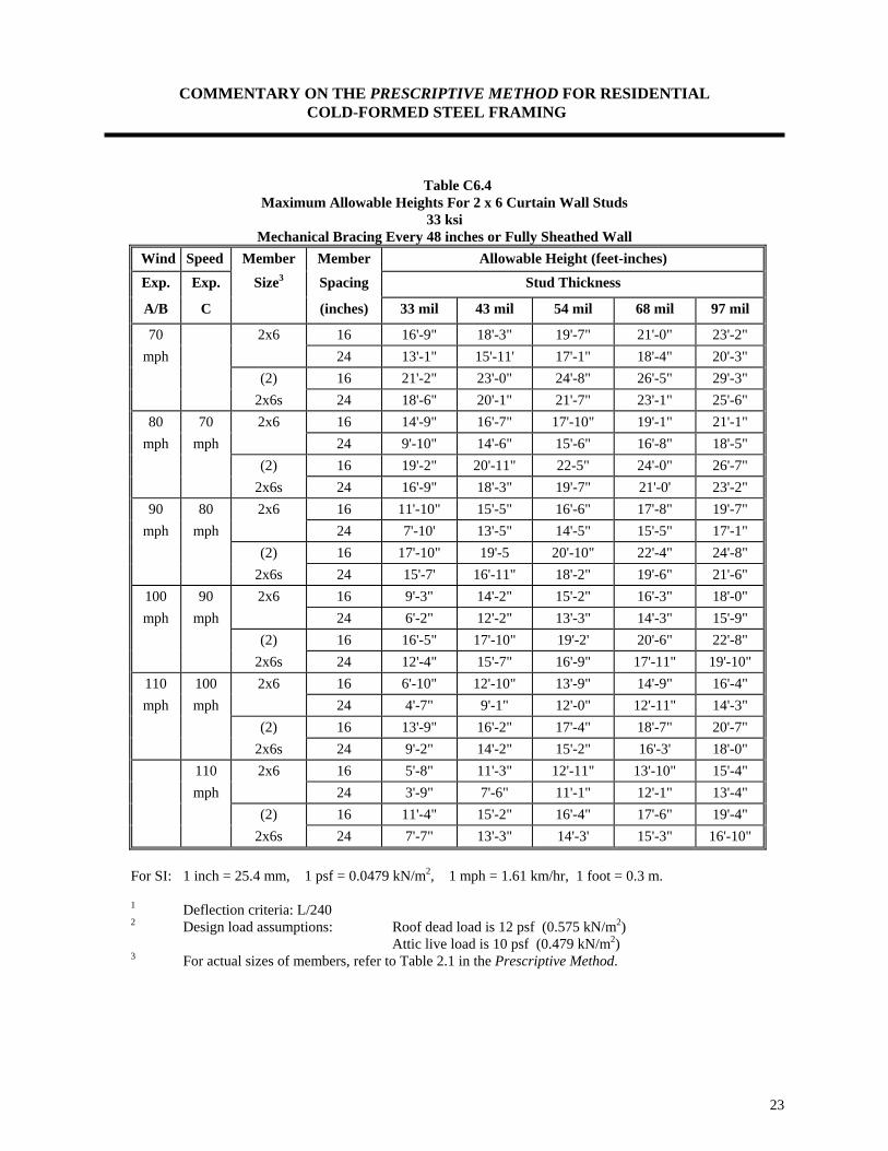
Deflection limits are primarily established with regard to serviceability concerns. The intent is to prevent excessive deflection which might result in cracking of finishes. For walls, most codes generally agree that L/240 represents an acceptable serviceability limit for deflection. For walls with flexible finishes, such as steel siding or roofing, L/180 is often used. The reader is referred to Part III for an example calculation of wall studs. Tables C6.3 and C6.4 (following pages) provide the maximum allowable height of curtain wall studs (i.e. gable end wall studs) for different wind speeds and exposures. These tables were developed based on the following assumptions:
• No composite action is considered for doubled-up members. • All studs are considered to be mechanically braced at 48 inches on center. • All steels have a minimum yield strength of 33 ksi.
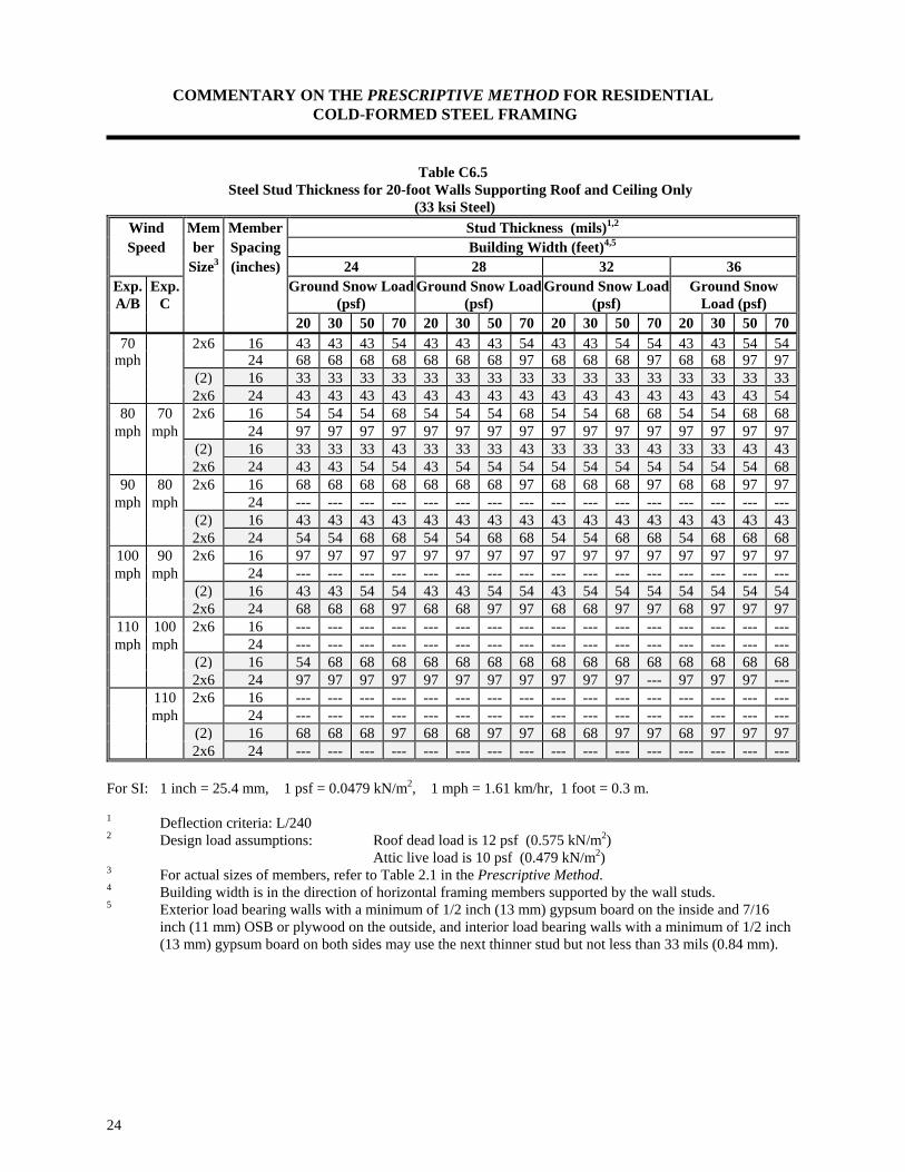
Table C6.5 provides the minimum allowable stud thicknesses that can be used for 20 foot wall studs supporting roof and ceiling only. This table is also developed based on the following assumptions:
• No composite action is considered for doubled-up members or sheathed assemblies. • All studs are considered to be mechanically braced at 48 inches on center. • All steels have a minimum yield strength of 33 ksi.
It is to be noted that lower stud thicknesses can be achieved with 50 ksi steels and/or with fully sheathed walls.

COMMENTARY ON THE PRESCRIPTIVE METHOD FOR RESIDENTIAL COLD-FORMED STEEL FRAMING
22
Table C6.3 Maximum Allowable Heights For 2 x 4 Curtain Wall Studs
33 ksi Mechanical Bracing Every 48 inches or Fully Sheathed Wall
Wind Speed Member Member Allowable Height (feet-inches)
Exp. Exp. Size3 Spacing Stud Thickness
A/B C (inches) 33 mil 43 mil 54 mil 68 mil 97 mil
70 2x4 16 11'-9" 12'-10" 13'-9" 14'-8" 16'-2" mph 24 10'-4" 11'-2" 12'-0" 12'-10" 14'-1"
(2) 16 14'-10" 16'-2" 17'-4" 18'-6" 20'-4" 2x4s 24 13'-0" 14'-1" 15'-1" 16'-2" 17'-10"
80 70 2x4 16 10'-8" 11'-8" 12'-6" 13'-4" 14'-8" mph mph 24 9'-4" 10'-2" 10'-11" 11'-8" 12'-10"
(2) 16 13'-6" 14'-8" 15'-9" 16'-10" 18'-6" 2x4s 24 11'-9" 12'-10" 13'-9" 14'-8" 16'-2"
90 80 2x4 16 9'-11" 10'-10" 11'-7" 12'-5" 13'-7" mph mph 24 8'-8" 9'-5" 10'-1" 10'-10" 11'-11"
(2) 16 12'-6" 13'-8" 14'-7" 15'-7" 17'-2" 2x4s 24 10'-11" 11'-11" 12'-9" 13'-8" 15'-0"
100 90 2x4 16 9'-2" 9'-11" 10'-8" 11'-5" 12'-7" mph mph 24 7'-0" 8'-8" 9'-4" 9'-11" 10'-11"
(2) 16 11'-6" 12'-7" 13'-5" 14'-4" 15'-10" 2x4s 24 12'-4" 15'-7" 16'-9" 17'-11" 19'-10"
110 100 2x4 16 7'-10" 9'-0" 9'-8" 10'-4" 11'-4" mph mph 24 5'-3" 7'-10" 8'-5" 9'-0" 9'-11"
(2) 16 10'-5" 11'-4" 12'-2" 13'-0" 14'-4" 2x4s 24 9'-1" 9'-11" 10'-8" 11'-4" 12'-6" 110 2x4 16 6'-6" 8'-5" 9'-1" 9'-8" 10'-8" mph 24 4'-4" 7'-5" 7'-11" 8'-5" 9'-4" (2) 16 9'-10" 10'-8" 11'-5" 12'-3" 13'-5" 2x4s 24 8'-7" 9'-4" 10'-0" 10'-8" 11'-9"
For SI: 1 inch = 25.4 mm, 1 psf = 0.0479 kN/m2, 1 mph = 1.61 km/hr, 1 foot = 0.3 m.
1 Deflection criteria: L/240 2 Design load assumptions: Roof dead load is 12 psf (0.575 kN/m2) Attic live load is 10 psf (0.479 kN/m2) 3 For actual sizes of members, refer to Table 2.1 in the Prescriptive Method.
COMMENTARY ON THE PRESCRIPTIVE METHOD FOR RESIDENTIAL COLD-FORMED STEEL FRAMING
23
Table C6.4 Maximum Allowable Heights For 2 x 6 Curtain Wall Studs
33 ksi Mechanical Bracing Every 48 inches or Fully Sheathed Wall
Wind Speed Member Member Allowable Height (feet-inches)
Exp. Exp. Size3 Spacing Stud Thickness
A/B C (inches) 33 mil 43 mil 54 mil 68 mil 97 mil
70 2x6 16 16'-9" 18'-3" 19'-7" 21'-0" 23'-2" mph 24 13'-1" 15'-11' 17'-1" 18'-4" 20'-3"
(2) 16 21'-2" 23'-0" 24'-8" 26'-5" 29'-3" 2x6s 24 18'-6" 20'-1" 21'-7" 23'-1" 25'-6"
80 70 2x6 16 14'-9" 16'-7" 17'-10" 19'-1" 21'-1" mph mph 24 9'-10" 14'-6" 15'-6" 16'-8" 18'-5"
(2) 16 19'-2" 20'-11" 22-5" 24'-0" 26'-7" 2x6s 24 16'-9" 18'-3" 19'-7" 21'-0' 23'-2"
90 80 2x6 16 11'-10" 15'-5" 16'-6" 17'-8" 19'-7" mph mph 24 7'-10' 13'-5" 14'-5" 15'-5" 17'-1"
(2) 16 17'-10" 19'-5 20'-10" 22'-4" 24'-8" 2x6s 24 15'-7' 16'-11" 18'-2" 19'-6" 21'-6"
100 90 2x6 16 9'-3" 14'-2" 15'-2" 16'-3" 18'-0" mph mph 24 6'-2" 12'-2" 13'-3" 14'-3" 15'-9"
(2) 16 16'-5" 17'-10" 19'-2' 20'-6" 22'-8" 2x6s 24 12'-4" 15'-7" 16'-9" 17'-11" 19'-10"
110 100 2x6 16 6'-10" 12'-10" 13'-9" 14'-9" 16'-4" mph mph 24 4'-7" 9'-1" 12'-0" 12'-11" 14'-3"
(2) 16 13'-9" 16'-2" 17'-4" 18'-7" 20'-7" 2x6s 24 9'-2" 14'-2" 15'-2" 16'-3' 18'-0" 110 2x6 16 5'-8" 11'-3" 12'-11" 13'-10" 15'-4" mph 24 3'-9" 7'-6" 11'-1" 12'-1" 13'-4" (2) 16 11'-4" 15'-2" 16'-4" 17'-6" 19'-4" 2x6s 24 7'-7" 13'-3" 14'-3' 15'-3" 16'-10"
For SI: 1 inch = 25.4 mm, 1 psf = 0.0479 kN/m2, 1 mph = 1.61 km/hr, 1 foot = 0.3 m.
1 Deflection criteria: L/240 2 Design load assumptions: Roof dead load is 12 psf (0.575 kN/m2) Attic live load is 10 psf (0.479 kN/m2) 3 For actual sizes of members, refer to Table 2.1 in the Prescriptive Method.
COMMENTARY ON THE PRESCRIPTIVE METHOD FOR RESIDENTIAL COLD-FORMED STEEL FRAMING
24
Table C6.5 Steel Stud Thickness for 20-foot Walls Supporting Roof and Ceiling Only
(33 ksi Steel) Wind Mem Member Stud Thickness (mils)1,2 Speed ber Spacing Building Width (feet)4,5
Size3 (inches) 24 28 32 36 Exp. A/B
Exp. C
Ground Snow Load (psf)
Ground Snow Load (psf)
Ground Snow Load (psf)
Ground Snow Load (psf)
20 30 50 70 20 30 50 70 20 30 50 70 20 30 50 7070 2x6 16 43 43 43 54 43 43 43 54 43 43 54 54 43 43 54 54
mph 24 68 68 68 68 68 68 68 97 68 68 68 97 68 68 97 97 (2) 16 33 33 33 33 33 33 33 33 33 33 33 33 33 33 33 33 2x6 24 43 43 43 43 43 43 43 43 43 43 43 43 43 43 43 54
80 70 2x6 16 54 54 54 68 54 54 54 68 54 54 68 68 54 54 68 68mph mph 24 97 97 97 97 97 97 97 97 97 97 97 97 97 97 97 97
(2) 16 33 33 33 43 33 33 33 43 33 33 33 43 33 33 43 43 2x6 24 43 43 54 54 43 54 54 54 54 54 54 54 54 54 54 68
90 80 2x6 16 68 68 68 68 68 68 68 97 68 68 68 97 68 68 97 97mph mph 24 --- --- --- --- --- --- --- --- --- --- --- --- --- --- --- ---
(2) 16 43 43 43 43 43 43 43 43 43 43 43 43 43 43 43 43 2x6 24 54 54 68 68 54 54 68 68 54 54 68 68 54 68 68 68
100 90 2x6 16 97 97 97 97 97 97 97 97 97 97 97 97 97 97 97 97mph mph 24 --- --- --- --- --- --- --- --- --- --- --- --- --- --- --- ---
(2) 16 43 43 54 54 43 43 54 54 43 54 54 54 54 54 54 54 2x6 24 68 68 68 97 68 68 97 97 68 68 97 97 68 97 97 97
110 100 2x6 16 --- --- --- --- --- --- --- --- --- --- --- --- --- --- --- ---mph mph 24 --- --- --- --- --- --- --- --- --- --- --- --- --- --- --- ---
(2) 16 54 68 68 68 68 68 68 68 68 68 68 68 68 68 68 68 2x6 24 97 97 97 97 97 97 97 97 97 97 97 --- 97 97 97 --- 110 2x6 16 --- --- --- --- --- --- --- --- --- --- --- --- --- --- --- --- mph 24 --- --- --- --- --- --- --- --- --- --- --- --- --- --- --- --- (2) 16 68 68 68 97 68 68 97 97 68 68 97 97 68 97 97 97 2x6 24 --- --- --- --- --- --- --- --- --- --- --- --- --- --- --- ---
For SI: 1 inch = 25.4 mm, 1 psf = 0.0479 kN/m2, 1 mph = 1.61 km/hr, 1 foot = 0.3 m. 1 Deflection criteria: L/240 2 Design load assumptions: Roof dead load is 12 psf (0.575 kN/m2) Attic live load is 10 psf (0.479 kN/m2) 3 For actual sizes of members, refer to Table 2.1 in the Prescriptive Method. 4 Building width is in the direction of horizontal framing members supported by the wall studs. 5 Exterior load bearing walls with a minimum of 1/2 inch (13 mm) gypsum board on the inside and 7/16 inch (11 mm) OSB or plywood on the outside, and interior load bearing walls with a minimum of 1/2 inch (13 mm) gypsum board on both sides may use the next thinner stud but not less than 33 mils (0.84 mm).

COMMENTARY ON THE PRESCRIPTIVE METHOD FOR RESIDENTIAL COLD-FORMED STEEL FRAMING
25
C6.4 Stud Bracing (Buckling Resistance) Studs in load bearing walls are laterally braced on each flange by either a continuous 1-1/2 inch x 33 mil (minimum) strap at mid-height (or third points for 9-foot and 10-foot studs) or by direct attachment of structural sheathing or rigid wall finishes (i.e. APA rated plywood or OSB, gypsum wall board) according to the requirements of the Prescriptive Method. Therefore, all studs were assumed to be braced at mid-height (or third points for 9-foot and 10-foot studs) for engineering analysis of the stud tables. As previously noted, the benefit of structurally sheathed walls on the required stud thickness and the composite wall strength are recognized in the footnotes to the stud tables. Temporary bracing is necessary to facilitate safe construction practices and to ensure that the structural integrity of the wall assembly is maintained. Prior to the installation of cladding, a wall stud is free to twist, thus making the stud subject to premature failure under heavy construction loads (i.e. stack of gypsum wallboard or roof shingles). In such cases, adequate temporary bracing must be provided. C6.5 Splicing The stud tables provided in the Prescriptive Method are based on the assumption that the studs are continuous, with no splices. Therefore, load bearing steel studs shall not be spliced without an approved design. Non-structural members such as wall tracks are spliced according to the requirements and details in the Prescriptive Method. C6.6 Corner Framing The Prescriptive Method utilizes a traditional three-stud practice for framing corners. C6.7 Headers Headers are horizontal members used to transfer loads around openings in load bearing walls. Headers specified in the Prescriptive Method are allowed only above the opening immediately below the wall top track (i.e. high headers). Headers are formed from two equal sized C-shaped members in a back-to-back or box type configuration. Cripple studs, installed below headers or window sills, are required to have a size and thickness equivalent to or grater than the adjacent full height wall studs. Tracks used to frame around openings are also required to be of a thickness equivalent to or greater than the wall studs. Headers were divided into three categories: headers supporting roof and ceiling only (i.e. one story house or upper story of two story house); headers supporting one story, roof and ceiling (i.e. bottom floor of a two story house); and headers supporting one story, roof and ceiling, with center load bearing beam (i.e. bottom floor of a two story house). These categories are illustrated in Figure C6.7.
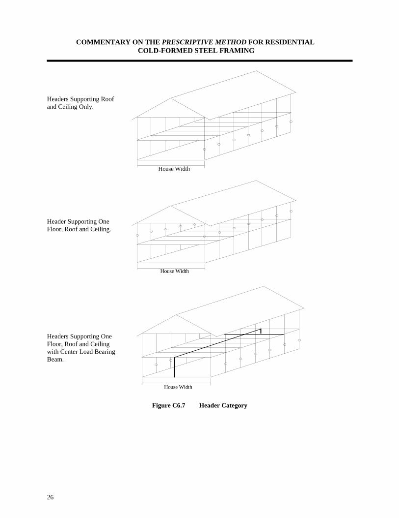
COMMENTARY ON THE PRESCRIPTIVE METHOD FOR RESIDENTIAL COLD-FORMED STEEL FRAMING
26
Headers Supporting Roof and Ceiling Only. Header Supporting One Floor, Roof and Ceiling. Headers Supporting One Floor, Roof and Ceiling with Center Load Bearing Beam.
Figure C6.7 Header Category
House Width
House Width
House Width
COMMENTARY ON THE PRESCRIPTIVE METHOD FOR RESIDENTIAL COLD-FORMED STEEL FRAMING
27
The following design assumptions were made in analyzing header spans:
• Headers are simply supported beams. • Maximum roof overhang of 12 inches. • Roof slopes limited to a range of 3:12 to 12:12 • Ceilings, roofs, attics, and floors span the full width of the house, no interior load bearing walls,
except as noted. • The allowable capacity of each header is calculated as twice the allowable capacity of a single member
(i.e. no composite action). • Deflection criteria: L/240 • Reduction in tributary area of the attic is not considered. This reduction could reduce the attic design
live load by a minimum of 25 percent. The reader is referred to Part III for a detailed calculation of header spans. The required number of jack and king studs was calculated based on the size of the opening. The number was determined by taking the width of the opening, divided by the stud spacing, and rounding the decimal to the next higher number. The resulting number is further divided into jack and king studs based on the required axial capacity being provided by the jack studs only. King and jack studs are required to be the same size and thickness as the adjacent wall studs. Jack and king studs are interconnected by structural sheathing (plywood or OSB) to transfer lateral loads when multiple king and jack studs are required. Figure C6.8 shows typical details of connecting the sill plate to the studs at the location of openings in a wall.

COMMENTARY ON THE PRESCRIPTIVE METHOD FOR RESIDENTIAL COLD-FORMED STEEL FRAMING
28
Figure C6.8 Typical Sill Plate Connection Detail

COMMENTARY ON THE PRESCRIPTIVE METHOD FOR RESIDENTIAL COLD-FORMED STEEL FRAMING
29
C6.8 Wall Bracing The wall bracing requirements in the Prescriptive Method are limited to wind loads less than 90 C (or 100 A/B) and Seismic Zones 0, 1, and 2 (excluding Zones 3 and 4). These limits were established because of the additional concerns for building geometry constraints and design issues such as hold-down requirements for shearwalls. Homes built in conditions that exceed these loading limits must have the wall bracing engineered by a design professional. The reader is referred to Section C6.8.2.1 for an alternate shearwall bracing method for high wind and seismic regions. The development of wall bracing requirements for the Prescriptive Method involved several activities including:
• a review of applicable wall bracing tests and data; • development of the engineering approach to apply loads and determine lateral resistance; • selection of wall bracing methods and materials for the Prescriptive Method; • determination of appropriate safety factors and allowable capacities; • sensitivity studies of the effects of lateral loads (wind and seismic) relative to building geometry (i.e. • roof slope, width, length, and wall height); • comparison of earthquake induced lateral loads to those from wind based on the applicability limits for
the Prescriptive Method (i.e. dead loads, geometry, etc.); • sensitivity (parametric) studies to guide simplification of the prescriptive requirements; and, • testing of wall bracing requirements utilized in the Prescriptive Method.
Wall bracing in cold-formed steel structures has typically relied on case-by-case design of diagonal steel strapping, its anchorage, and associated details. Shearwall testing of steel-framed walls using monotonic and cyclic loads has recently provided data for applications using structural sheathing (15/32-inch plywood or 7/16-inch oriented strand board) as the bracing method [26]. In wood-frame homes, structural sheathing (e.g. plywood or OSB) is a common bracing method, particularly in conditions of high lateral loads. However, many conventionally built homes in normal load conditions use wood let-in braces (diagonal 1x4s) or steel straps for racking resistance. Alternatively, 4'x8' bracing panels of structural sheathing may be substituted for the let-in braces forming a "partially" or "intermittently" sheathed wall. While these methods are non-engineered and have been established by experience, they have performed well in regions not subject to high winds. For one- and two-story detached homes with simple geometries and limited wall openings, these conventional bracing practices have also performed satisfactorily in past seismic events. The trend in high seismic and high wind regions is toward engineered designs using structural sheathing and numerous hold-down brackets. The wall bracing requirements in the Prescriptive Method were based on an engineered approach that utilized available technical knowledge. Two wall bracing methods were investigated based on engineering test data or rational analysis to provide wall bracing requirements for the Prescriptive Method. These methods are diagonal steel straps and structural (wood) sheathing (e.g. OSB or plywood). Verification tests were performed on the diagonal steel strap requirements. These tests indicated that additional testing or design work was needed to develop simple diagonal strap bracing requirements that may be used efficiently in the Prescriptive Method. This concern relates to the limited capability of the "non-structural" top and bottom wall tracks to adequately resist compressive or bending loads that result when strap bracing or non-continuous sheathing ("partially sheathed" walls) are used for lateral support. For this reason, the wall bracing in the Prescriptive Method was conservatively limited to the use of continuously sheathed walls with the previously described limitations on loading conditions and building geometry.
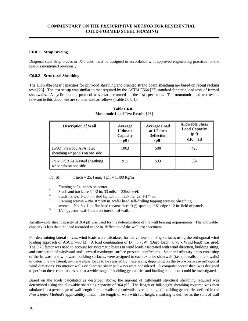
COMMENTARY ON THE PRESCRIPTIVE METHOD FOR RESIDENTIAL COLD-FORMED STEEL FRAMING
30
C6.8.1 Strap Bracing Diagonal steel strap braces or 'X-braces' must be designed in accordance with approved engineering practices for the reasons mentioned previously. C6.8.2 Structural Sheathing The allowable shear capacities for plywood sheathing and oriented strand board sheathing are based on recent racking tests [26]. The test set-up was similar to that required by the ASTM E564 [27] standard for static load tests of framed shearwalls. A cyclic loading protocol was also performed on the test specimens. The monotonic load test results relevant to this document are summarized as follows (Table C6.8.1):
Table C6.8.1 Monotonic Load Test Results [26]
Description of Wall Average Ultimate Capacity
(plf)
Average Load at 1/2 inch Deflection
(plf)
Allowable Shear Load Capacity
(plf) S.F. = 2.5
15/32" Plywood APA rated sheathing w/ panels on one side
1063 508 425
7/16" OSB APA rated sheathing w/ panels on one side
911 593 364
For SI: 1 inch = 25.4 mm, I plf = 1.488 Kg/m
1 Framing at 24 inches on center. 2 Studs and track are 3-1/2 in. 33 mils. -- 33ksi steel. 3 Studs flange: 1-5/8 in.; stud lip: 3/8 in.; track flange: 1-1/4 in. 4 Framing screws -- No. 8 x 5/8 in. wafer head self-drilling tapping screws; Sheathing
screws -- No. 8 x 1 in. flat head (coarse thread) @ spacing of 6" edge / 12 in. field of panels. 5 1/2” gypsum wall board on interior of wall.
An allowable shear capacity of 364 plf was used for the determination of the wall bracing requirements. The allowable capacity is less than the load recorded at 1/2 in. deflection of the wall test specimens. For determining lateral forces, wind loads were calculated for the various building surfaces using the orthogonal wind loading approach of ASCE 7-93 [3]. A load combination of D + 0.75W (Dead load + 0.75 x Wind load) was used. The 0.75 factor was used to account for systematic biases in wind loads associated with wind direction, building siting, and correlation of windward and leeward maximum surface pressure coefficients. Standard tributary areas consisting of the leeward and windward building surfaces, were assigned to each exterior shearwall (i.e. sidewalls and endwalls) to determine the lateral, in-plane shear loads to be resisted by these walls, depending on the two worst-case orthogonal wind directions. No interior walls or alternate shear pathways were considered. A computer spreadsheet was designed to perform these calculations so that a wide range of building geometries and loading conditions could be investigated. Based on the loads calculated as described above, the amount of full-height structural sheathing required was determined using the allowable sheathing capacity of 364 plf. The length of full-height sheathing required was then tabulated as a percentage of wall length for sidewalls and endwalls over the range of building geometries defined in the Prescriptive Method's applicability limits. The length of wall with full-height sheathing is defined as the sum of wall

COMMENTARY ON THE PRESCRIPTIVE METHOD FOR RESIDENTIAL COLD-FORMED STEEL FRAMING
31
segments that have sheathing extending from the bottom track to the top track, without interruption due to openings (i.e., the total of lengths of wall between openings). Further, the individual wall segments must be 48 inches in length or greater to contribute to the required length of full-height sheathing for a given wall line, unless permitted otherwise. As a final step necessary for a basic prescriptive approach, the requirements were conservatively reduced to the minimum percent lengths of full-height sheathed wall shown in the wall bracing table of the Prescriptive Method. The only building geometry parameter retained was roof slope due to a significant impact on the wind loads transferred to the shearwalls. Footnotes to the shearwall table provide additional information related to the proper applications of the requirements. C6.8.2.1 Wall Bracing: Alternate Approach and Bracing for High Wind and Seismic Regions The following is an alternate wall bracing method that is also applicable to high wind and seismic regions. This method is based on recent pilot tests conducted at the NAHB Research Center [28] to develop a “perforated” shearwall design approach for steel-framed walls. Basic shearwall capacity values are used from the tests performed at the University of Santa Clara [26]. These alternate provisions are considered preliminary and should be approved by an engineer prior to use. Wall Bracing: The minimum length of full-height sheathing on 8-foot high exterior walls shall be the greater length determined in accordance with Tables C6.8.2, C6.8.3, C6.8.4, or C6.8.5 depending on wind and seismic conditions and whether or not hold-downs are used. The length of full-height sheathing on a given wall line shall be determined by the sum of all individual full height sheathed wall sections, which are a minimum of 24 inches wide and which are uninterrupted by openings. Offset wall segments in a given wall line shall be permitted provided the total length of full-height structural sheathing meets or exceeds the minimum required length for the entire wall line, including all offset segments that are parallel to the main wall line. A minimum of 24 inches of full-height structural sheathing shall be located at each end of the exterior wall lines and at the ends of segments of those portions of walls that are offset from the main wall line by more than 4 feet.
Exception: Panels to either side of garage openings shall be a minimum of 16 inches provided that living spaces are not supported by the garage walls.
For walls greater than 8 feet in height, the minimum lengths of full-height structural sheathing in Tables C6.8.2 and C6.8.4 shall be multiplied by 1.10 for 9-foot high walls and multiplied by 1.20 for 10-foot high walls. These multipliers shall not be used to increase minimum percent lengths of full-height sheathing required by Tables C6.8.4 and C6.8.5 for seismic conditions. A minimum of 27 inch width or 30 inch width of full-height structural sheathing shall be located at each end of the exterior wall lines for 9-foot high or 10-foot high walls, respectively.
Exception: Panels to either side of garage openings shall be a minimum of 24 inches wide or 28 inches wide for 9-foot and 10-foot walls, respectively, provided that living spaces are not supported by the garage walls. All other provisions for 9-foot and 10-foot high walls are the same as required for 8-foot high walls except when hold-downs are used in accordance with the Hold-down Alternate Approach (see Section C6.9)

COMMENTARY ON THE PRESCRIPTIVE METHOD FOR RESIDENTIAL COLD-FORMED STEEL FRAMING
32
Table C6.8.2 Wall Bracing for Wind Conditions:
Minimum Length of Full-Height Structural Sheathing on Exterior Walls with a Single Hold-down at Each Corner1,2,3
Wall
Supporting: Roof Slope
Wind Speed (mph-fastest mile) and Exposure
70 A/B 80 A/B 90 A/B 100 A/B 110 A/B
70 C 80 C 90 C 100 C 110 C
Endwalls (walls at gable end or perpendicular to ridge)
Roof & Ceiling 3:12 4 4 4 4 4 4 5
Only 6:12 4 4 4 4 6 7 8
9:12 4 5 6 8 10 12 14
12:12 5 7 9 11 13 16 19
One Story, 3:12 4 5 7 8 11 13 15
Roof & Ceiling 6:12 5 6 8 10 12 15 17
9:12 6 8 10 12 16 19 22
12:12 8 10 12 15 19 22 25
Sidewalls (walls parallel to ridge)
Roof & Ceiling 3:12 4 4 4 4 6 7 8
Only 6:12 4 4 4 6 7 9 11
9:12 4 4 5 7 8 11 13
12:12 4 5 6 8 10 12 15
One Story, 3:12 4 5 6 8 10 12 14
Roof & Ceiling 6:12 4 5 7 9 11 14 16
9:12 5 6 8 10 13 15 18
12:12 5 7 9 11 14 17 20
For SI: 1 mph = 49 m/sec; 1 foot = 0.3 m; 1 inch = 25.4 mm 1 All exterior wall surfaces shall be completely sheathed, including areas above and below openings. 2 Linear interpolation shall be permitted. 3 A single hold-down shall be located at each building corner in accordance with Section C6.9.

COMMENTARY ON THE PRESCRIPTIVE METHOD FOR RESIDENTIAL COLD-FORMED STEEL FRAMING
33
Table C6.8.3 Wall Bracing for Seismic Conditions:
Minimum Percent Length of Full-Height Structural Sheathing on Exterior Walls with a Single Hold-down at Each Corner1,2,3
Wall
Supporting:
Seismic Zone 1
(Aa = 0.1g)
Seismic Zone 2
(Aa = 0.2g)
Seismic Zone 3
(Aa = 0.3g)
Seismic Zone 4
(Aa = 0.4g)
Endwall Sidewall Endwall Sidewall Endwall Sidewall Endwall Sidewall
Roof & Ceiling Only
10%
10%
20%
15%
30%
20%
35%
25%
One Story, Roof & Ceiling
20%
15%
30%
25%
45%
30%
55%
40%
For SI: 1 mph = 49 m/sec; 1 foot = 0.3 m 1 All exterior wall surfaces shall be completely sheathed, including areas above and below openings. 2 A single hold-down shall be located at each building corner in accordance with the alternate approach in Section C6.9. 3 Percentages are given as a percentage of the total sidewall or endwall length. For example, a 28 foot long endwall supporting one story plus a roof and ceiling in Seismic Zone 3 is required to have 45% of its length in full-height structural sheathing (i.e. 45 x 28/100 = 12.6 ft).

COMMENTARY ON THE PRESCRIPTIVE METHOD FOR RESIDENTIAL COLD-FORMED STEEL FRAMING
34
Table C6.8.4 Wall Bracing for Wind Conditions:
Minimum Length (Feet) of Full-Height Structural Sheathing on Exterior Walls Without Hold-downs at Corners1,2,3
Wall
Supporting: Roof Slope
Wind Speed (mph-fastest mile) and Exposure
70 A/B 80 A/B 90 A/B 100 A/B 110 A/B
70 C 80 C 90 C 100 C 110 C
Endwalls (walls at gable end or perpendicular to ridge)
Roof & Ceiling 3:12 6 6 6 6 6 6 8
Only 6:12 6 6 6 6 9 11 12
9:12 6 8 9 12 15 18 21
12:12 8 11 14 17 20 24 29
One Story, 3:12 6 8 11 12 17 20 23
Roof & Ceiling 6:12 8 9 12 15 18 23 26
9:12 9 12 15 18 24 29 33
12:12 12 15 18 23 29 33 N/A
Sidewalls (walls parallel to ridge)
Roof & Ceiling 3:12 6 6 6 6 9 11 12
Only 6:12 6 6 6 9 11 14 17
9:12 6 6 8 11 12 17 20
12:12 6 8 9 12 15 18 23
One Story, 3:12 6 8 9 12 15 18 21
Roof & Ceiling 6:12 6 8 11 14 17 21 24
9:12 8 9 12 15 20 23 27
12:12 8 11 14 17 21 25 30
For SI: 1 mph = 49 m/sec; 1 foot = 0.3 m
1 All exterior wall surfaces shall be completely sheathed, including areas above and below openings. 2 Linear interpolation shall be permitted. 3 N/A = design required or use Table C6.8.2 which requires corner hold-downs.

COMMENTARY ON THE PRESCRIPTIVE METHOD FOR RESIDENTIAL COLD-FORMED STEEL FRAMING
35
Table C6.8.5 Wall Bracing for Seismic Conditions:
Minimum Percent Length of Full-Height Structural Sheathing on Exterior Walls Without Hold-downs at Corners1,2
Wall
Supporting:
Seismic Zone 1 Seismic Zone 2 Seismic Zone 3 Seismic Zone 4
Endwall Sidewall Endwall Sidewall Endwall Sidewall Endwall Sidewall
Roof & Ceiling Only 15% 15% 30% 20% 45% 30% 55% 35%
One Story, Roof & Ceiling
25% 20% 45% 35% 65% 45% 85% 60%
For SI: 1 foot = 0.3 m
1 All exterior wall surfaces shall be completely sheathed, including areas above and below openings. 2 Percentages are given as a percentage of the total sidewall or endwall length. For example, a 28 foot long endwall supporting one story plus a roof and ceiling in Seismic Zone 3 is required to have 65% of its length in full-height structural sheathing (i.e. 0.65 x 28 ft. = 18 ft.).
Explanation and Derivation of the Wall Bracing Alternate Approach Shearwall tests performed on steel-framed wall specimens (i.e. 4 foot and 8 foot lengths) and assemblies up to 40 foot in length with varying degrees of openings made it possible to determine relatively efficient shearwall bracing requirements for high wind and seismic conditions [26] [28]. However, judgment is still required when applying the wall bracing requirements to homes with very complex layouts in areas where high seismic and wind risks occur (i.e. seismic zone 4 and the hurricane coastline). Complex homes may be generally defined by walls with numerous corners and offsets, particularly when coupled with large rooms having ceilings that extend vertically across more than one story. In such cases, an engineered design should be sought. A growing resource of testing of steel-framed walls using monotonic and cyclic loads has recently provided data for applications using structural sheathing (15/32-inch plywood or 7/16-inch OSB) as the bracing method. This testing has also led to recent building code approvals providing data to a broader community of designers and code officials. The alternate approach provided in this section is based on engineered approach that utilized new design methodology known as perforated shearwalls [28] and shearwall capacity data [26]. Two structural sheathing materials are permitted based on test data and rational engineering analysis for shearwalls following the perforated shearwall design method and using ASCE 7-93 [3] wind and seismic loads. These materials are 7/16 inch OSB and 15/32 inch plywood with 1/2 inch gypsum wallboard on the interior wall surface. The allowable shear capacities for plywood sheathing and oriented strand board sheathing was taken as 455 plf based on available test data conducted in conformance with the ASTM E 564 [27] standard. The results relevant to this document are summarized in Table C6.8.6:

COMMENTARY ON THE PRESCRIPTIVE METHOD FOR RESIDENTIAL COLD-FORMED STEEL FRAMING
36
Table C6.8.6 Monotonic Load Test Results [26]
Description of Wall Average Ultimate Capacity
(plf)
Average Load at 1/2 inch Deflection
(plf)
Allowable Shear Load
Capacity (plf)
S.F. = 2.0
15/32" Plywood APA rated sheathing w/ panels on one side
1063 508 531
7/16" OSB APA rated sheathing w/ panels on one side
911 593 455
For SI: 1 inch = 25.4 mm, I plf = 1.488 Kg/m
1 Framing at 24 inches on center. 2 Studs and track are 3-1/2 in. 33 mils. -- 33ksi steel. 3 Studs flange: 1-5/8 in.; stud lip: 3/8 in.; track flange: 1-1/4 in. 4 Framing screws -- No. 8 x 5/8 in. wafer head self-drilling tapping screws; sheathing screws -- No. 8 x 1 in. flat head (coarse thread) @ spacing of 6" edge / 12 in. field of panels. 5 1/2” gypsum wall board on interior of wall.
An allowable shear capacity of 455 plf was used for the determination of the wall bracing requirements. The allowable capacity is less than the load recorded at 1/2 in. deflection of the wall test specimens. For determining lateral forces, wind loads and seismic loads were calculated using the appropriate provisions of ASCE 7-93 [3]. A load combination of D + 0.75W (Dead load + 0.75 x Wind load) was used. The 0.75 factor was used to account for systematic biases in wind loads associated with wind direction, building siting, and correlation of windward and leeward maximum surface pressure coefficients. This adjustment is more conservative than the practice of multiplying the entire load combination by 0.75 as is commonly done for steel framing when wind loads are considered. For seismic loads, a combination of D+L+S+E was used with a ductility factor (R) of 6.0 instead of 6.5 as is commonly used for wood framing. This was done because of the slightly less ductile behavior of steel walls and is a judgment based on limited test results [26] [28]. No interior walls or alternate shear pathways were considered. Computer spreadsheets were designed to perform these calculations so that a wide range of building geometries and loading conditions could be investigated. Based on the loads calculated as described above, the amount of full-height structural sheathing required was determined using the smaller (OSB) allowable sheathing capacity of 455 plf. The length of full-height sheathing required was then tabulated over the range of building geometries defined in the Prescriptive Method's applicability limits. This length is reported as a percentage of the total wall length for seismic loads because the seismic load is proportionate to the wall length for a given building width. For wind, actual sheathing lengths are used because the wind load is governed by a relationship between roof slope and the building plan dimensions. A maximum tributary length or width of 16 feet was also assumed for both wind and seismic loads on exterior shearwalls only. The length of wall with full-height sheathing is defined as the sum of wall segments that have sheathing extending from the base (bottom track) to the top track, without interruption due to openings (i.e., the total of lengths of wall between openings). Further, the individual wall segments must be 24 inches in length or greater to contribute to the required length of full-height sheathing for a given wall line. Separate tables are provided for seismic and wind conditions and the more stringent requirement for a give site applies. Also, the user may opt to include hold-down brackets in exchange for the amount of full-height sheathing required. Footnotes to the shearwall table provide additional information related to the proper application of the requirements.
COMMENTARY ON THE PRESCRIPTIVE METHOD FOR RESIDENTIAL COLD-FORMED STEEL FRAMING
37
C6.9 Hold-down Requirements
In wind conditions greater than 90 mph exposure C and in Seismic Zones 3 and 4, hold-down brackets to stabilize shearwalls must be designed by a design professional. Alternate Hold-down Requirements This alternate method is provided in conjunction with Tables C6.8.2 through C6.8.5 in Section C6.8 of the Commentary. In conditions where wind speeds are in excess of 90 mph (144 km/hr) Exposure C or 100 mph Exposure A/B, and in Seismic Zones 3 and 4, hold-down brackets shall be provided at the ends of each major wall line and at the ends of any parallel wall segment offset from the main wall lines by greater than 4 feet. A hold-down bracket shall consist of an approved strap or bracket adequately attached to the base of the corner stud and anchored to the foundation, floor, or wall below to form a continuous load path to the foundation. Approved hold-down brackets or straps shall have a minimum allowable capacity of 2,000 lb. for walls supporting a roof and ceiling only and 3,000 lb. for walls supporting one story plus a roof and ceiling. These hold-down capacities shall be multiplied by 1.15 for 9-foot high walls and 1.25 for 10-foot high walls. Minimum full-height sheathing lengths or percentages in Tables C6.8.2 and C6.8.3 require a single hold-down located at each building corner (i.e. each end of a wall). Hold-downs shall be provided at the ends of each major wall line and at the ends of any parallel wall segment offset from the main wall lines by greater than 4 feet when Tables C6.8.2 and C6.8.3 are used. As an alternative approach to Tables C6.8.2 and C6.8.3 Tables C6.8.4 and C6.8.5 provide the minimum required lengths of full-height sheathing when hold-downs are not used. In higher wind conditions, wind uplift straps shall still be provided in accordance with Section 6.10. Wall bracing tables (C6.8.2 through C6.8.5) are provided for the option of either including or not including hold-down brackets in exchange for greater amounts of full-height sheathing. When hold-downs are specified by preference, they are only necessary at the ends of the “perforated” shearwalls in accordance with verification tests and the design methodology developed for efficient shearwall design [28]. In such cases, the hold-downs shall be provided in accordance with the capacities stated. Specific engineered designs using hold-downs at both ends of each wall segment in a given wall line may provide some additional capacity or allow for greater amounts of window and door openings. The hold-down resistance for shearwalls (rotational restraint) for the range of wind and seismic loads permitted is provided by standard connection details (screws and anchor bolts) for walls to foundations and floors, the available dead load restraining forces, and system effects at the corners of light-frame construction. For higher load conditions, hold-downs may be included at the ends of the walls to reduce the amount of full-height sheathing required or to increase the shear (racking) strength of the wall. The required capacity of the hold-down brackets are based on treatment of the wall as an assembly in accordance with the perforated shearwall approach referred to in Section C6.8 of the commentary. C6.10 Wind Uplift
In wind conditions greater than 90 mph exposure C, uplift straps to offset potential wind uplift loads must be included as provided for in Table 6.1. Wind uplift loads are calculated in accordance with the wind load provisions of ASCE 7-93 [3]. Values for intermediate wind uplift loads in Table 6.1 may be interpolated. It should be noted that uplift straps are only required on walls directly connected to the roof. They are not required on lower story walls because the uplift loads are offset by floor dead loads and the conventional wall-to-floor connections given in Table 6.1, even in the
COMMENTARY ON THE PRESCRIPTIVE METHOD FOR RESIDENTIAL COLD-FORMED STEEL FRAMING
38
higher wind conditions. Also, a specified uplift strap is required for each king stud supporting headers. The king stud strap or connector shall have the same capacity as the layout studs spaced at 16 inches or 24 inches on center. Building overturning (uplift) forces due to lateral wind loads are resisted by hold-down requirements (see Section C6.9).

COMMENTARY ON THE PRESCRIPTIVE METHOD FOR RESIDENTIAL COLD-FORMED STEEL FRAMING
39
C7.0 NON-STRUCTURAL WALLS C7.1 Non-Load Bearing Studs For interior non-load bearing partition walls, a minimum of 18 mil studs are specified in the Prescriptive Method. Consideration should be given for acceptable serviceability (rigidity) at interior wall openings for doors, shelving, cabinets, and other purposes. ASTM C 645 [11] is specified as the reference standard for non-load bearing walls. The Prescriptive Method provides several details commonly used in non-load bearing applications. Tables C7.1 and C7.2 (below) provide limiting heights for selected non-load bearing studs subjected to a lateral load of 5 psf. These tables are provided for guidance only and should only be used where instructions and/or recommendations are not available from the manufacturer.
Table C7.1 Maximum Allowable Clear Non-Load Bearing Stud Height 1,2,3,4
Mid-Height Bracing
Industry Designation
Actual Stud Size (Web x Flange x Thickness) 5
(inches)
Stud Spacing
(inches)
16” oc 24” oc 350S125-18 3.5 x 1.25 x 0.018 9’-10” 6’-6” 350S125-27 3.5 x 1.25 x 0.027 12’-4” 10’-11” 350S125-33 3.5 x 1.25 x 0.033 13’-0” 11’-8”
For SI: 1 inch = 25.4 mm, 1 psf = 0.048 kN/m2, 1 foot = 0.3 m 1 Stud height based on stud capacity alone (i.e. no composite action). 2 Maximum lateral load is 5 psf (0.24 kN/m2) 3 Minimum yield strength is 33 ksi (228 kPa) 4 Applicable to deflection limits of L/120, L/180, and L/240 5 All sections have a minimum lip size of 3/16 inch (5 mm)

COMMENTARY ON THE PRESCRIPTIVE METHOD FOR RESIDENTIAL COLD-FORMED STEEL FRAMING
40
Table C7.2 Maximum Allowable Clear Non-Load Bearing Stud Height 1,2,3
Fully Braced Walls
Industry Designation
Actual Stud Size (Web x Flange x
Thickness) 4
Stud Spacing (inches)
Deflection Criteria
(inches) 16” oc L/120
24” oc L/120
16” oc L/180
24” oc L/180
16” oc L/240
24” oc L/240
350S125-18 3.5 x 1.25 x 0.018 9’-10” 6’-6” 9’-10” 6’-6” 9’-10” 6’-6”
350S125-27 3.5 x 1.25 x 0.027 16’-11” 13’-10” 15’-10” 13’-10” 14’-5” 12’-7”
350S125-33 3.5 x 1.25 x 0.033 19’-4” 15’-9” 17’-0” 14’-10” 15’-6” 13’-6”
For SI: 1 inch = 25.4 mm, 1 psf = 0.048 kN/m2, 1 foot = 0.3 m, 1 Stud height based on stud capacity fully braced (continuously supported by gypsum wall board). 2 Maximum lateral load is 5 psf (0.24 kN/m2) 3 Minimum yield strength is 33 ksi (228 kPa) 4 All sections have a minimum lip size of 3/16 inch (5 mm)
C7.2 Construction Details Details C7.2.1, C7.2.2, C7.2.3, and C7.2.4 are typical door and window framing details that are widely used in the residential steel framing market.
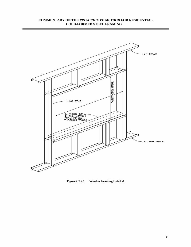
COMMENTARY ON THE PRESCRIPTIVE METHOD FOR RESIDENTIAL COLD-FORMED STEEL FRAMING
41
Figure C7.2.1 Window Framing Detail -1
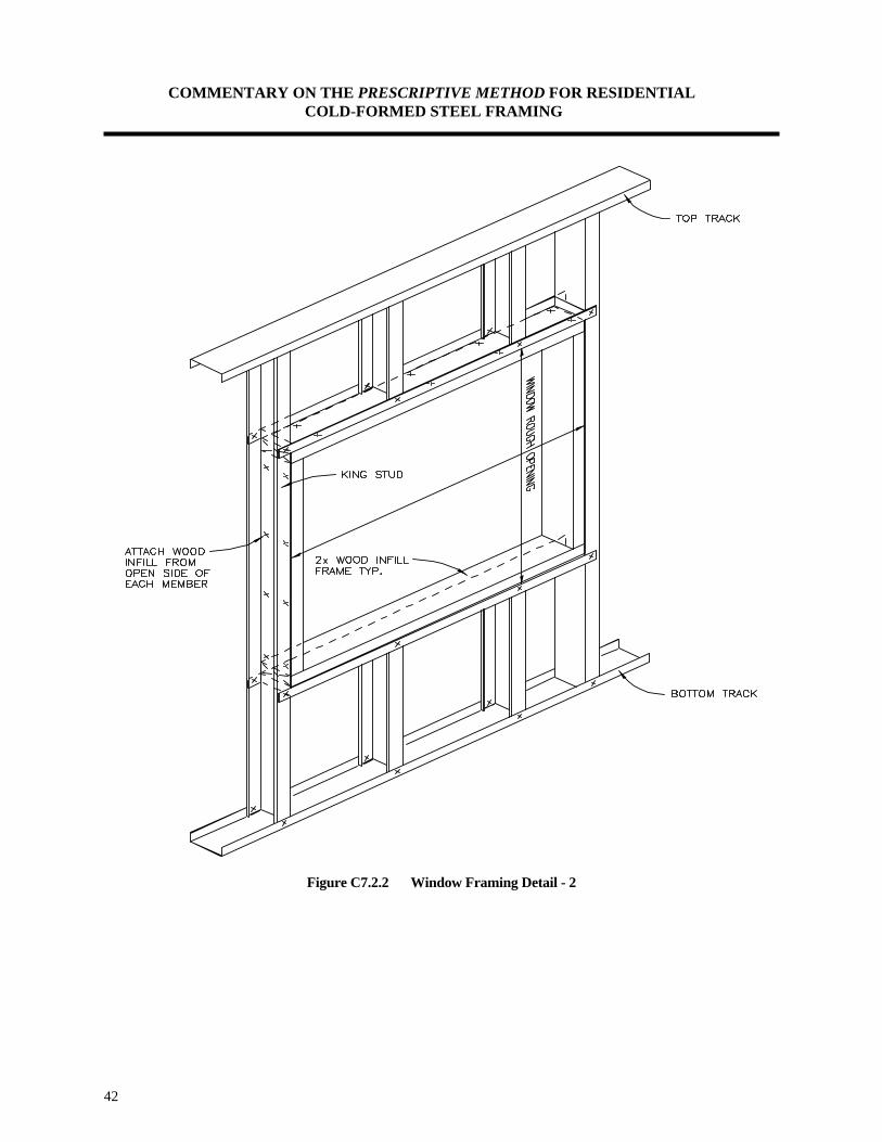
COMMENTARY ON THE PRESCRIPTIVE METHOD FOR RESIDENTIAL COLD-FORMED STEEL FRAMING
42
Figure C7.2.2 Window Framing Detail - 2

COMMENTARY ON THE PRESCRIPTIVE METHOD FOR RESIDENTIAL COLD-FORMED STEEL FRAMING
43
Figure C7.2.3 Door Framing Detail - 1

COMMENTARY ON THE PRESCRIPTIVE METHOD FOR RESIDENTIAL COLD-FORMED STEEL FRAMING
44
Figure C7.2.4 Door Framing Detail - 2

COMMENTARY ON THE PRESCRIPTIVE METHOD FOR RESIDENTIAL COLD-FORMED STEEL FRAMING
45
C8.0 ROOF SYSTEMS C8.1 Roof Construction Roof construction in the Prescriptive Method is limited to design wind speeds less than or equal to 110 mph (fastest mile) and to Seismic Zones 0, 1, 2, 3, and 4. Uplift straps should be provided for wind conditions in excess of 90 mph exposure C. C8.2 Allowable Ceiling Joist Span Ceiling joist tables in the Prescriptive Method provide the maximum allowable ceiling joist spans for two loading conditions: 10 psf and 20 psf attic live loads. Ceiling joists require stiffeners at all support locations. In the design of ceiling joists, any one of several engineering criteria may control the prescriptive requirements depending on the configuration of the section, thickness of material, and member length. The analysis must include checks for:
• Yielding • Flexural buckling • Web crippling (not required if web stiffeners are specified) • Shear • Deflection
The engineering approach used to develop ceiling joist span tables for Prescriptive Method is similar to that used for floor joists with the exception of the magnitude of dead and live loads. The reader is referred to Part III for a detailed example of the engineering calculations. C8.3 Ceiling Joist Bracing Gypsum board (i.e. finished ceilings) is considered to be adequate bracing for the bottom (tension) flanges of the ceiling joists. Ceiling joist tables provide spans for braced, as well as unbraced, top flanges. For braced top (compression) flanges it is necessary for steel strapping to have blocking (or bridging) installed at a maximum spacing of 12 feet and at the termination of all straps. Moreover, the ends of steel straps are designed to be fastened to a stable component of the building. C8.4 Rafters The rafter span table was designed based primarily on gravity loads, hence the rafter spans are reported on the horizontal projection of the rafter, regardless of the slope. The gravity loads consist of a 10 psf dead load and the greater of a minimum 16 psf live load or the applied roof snow load. As mentioned previously, applied snow loads are calculated by multiplying the ground snow load by 0.7 (no further reductions or increases are made for special cases). Ground snow load intervals are as follows: 20 psf, 30 psf, 50 psf, and 70 psf. Wind load effects are correlated to equivalent snow loads as shown in the Prescriptive Method. Wind pressures were calculated using the ASCE 7-93 [3] Components and Cladding method. Wind loads acting perpendicular to the plane of the rafter were adjusted to represent loads acting orthogonal to the horizontal projection of the rafter. Wind loads were examined for both uplift and downward loads and the worst case was correlated to a corresponding snow load. Permissible roof slopes range between 3:12 through 12:12 and more importantly, the roof system must consist of both ceiling joists (i.e. acting as rafter ties) and rafters. The Prescriptive Method does not currently address cathedral ceilings because a prescriptive ridge beam and post design is not provided.

COMMENTARY ON THE PRESCRIPTIVE METHOD FOR RESIDENTIAL COLD-FORMED STEEL FRAMING
46
The heel joint connection, which connects the ceiling joist to the rafter, uses # 10 screws. Lapped ceiling joists shall be connected with the same screw size and number (or more) as the heel joint connection to ensure adequate transfer of tension loads across the spliced joint. The splice must occur over an interior bearing wall. C8.5 Rafter Bottom Flange Bracing The bracing requirements provided in the Prescriptive Method are self explanatory and are commonly used in residential steel construction. The requirements are similar to those found in the floor framing section when gypsum wall board is not applied to the bottom of the joists. C8.6 Splicing Splices are usually required to transfer shear, bending moments, and axial loads. Splices or lapped ceiling joists may occur over points of bearing as previously described. The rafter spans provided in the Prescriptive Method are based on the assumption that the members are continuous, with no splices. Therefore, rafters shall not be spliced without an approved design. Splicing details for non-structural members (i.e. tracks) are shown in the Prescriptive Method. C8.7 Roof Trusses The Prescriptive Method allows for the usage of pre-engineered truss systems. Any pre-engineered truss member can not be cut, notched, or altered unless so designed. C8.8 Roof Tie Downs In wind conditions greater than 70 mph exposure C (90 mph exposure A/B), uplift straps or connectors shall be provided in accordance with Table 8.14. Wind uplift loads are calculated in accordance with the wind load provisions of ASCE 7-93 [3]. Values for intermediate wind uplift loads in Table 6.1 may be interpolated. Straps or connectors should be selected and installed such that the required capacities are achieved and in-line framing between the roof members and the walls studs is maintained.
COMMENTARY ON THE PRESCRIPTIVE METHOD FOR RESIDENTIAL COLD-FORMED STEEL FRAMING
47
C9.0 MECHANICAL, UTILITIES, AND INSULATION This section provides references to the applicable building codes that must be followed when installing mechanical and utility equipment or services in residential steel-framed houses. The following recommendations reflect typical methods of construction. Hangers for plumbing Pipes Hangers for plumbing pipes in steel framing should be secured with a 3/4-inch, #6, sharp-point screw in 18- and 27-mil studs and a #8, self-drilling screw in thicker studs. Protection of Plumbing Pipes Plastic pipes need not be protected from corrosion when in contact with steel studs. However corrosion is a possibility where copper comes in direct contact with the steel. Copper shall be separated from the steel framing by either of the following methods:
• Plastic insulators, foam insulators or grommets should be used where copper passes through a steel stud.
• Copper piping shall be wrapped with pipe insulation when the copper piping run(s) are parallel to the
steel framing member. The insulation is intended to separate the copper piping from the steel member.
Attachment of Plumbing Fixtures Plumbing fixtures can be attached with #10, low-profile screws with a sharp point for 18- and 27-mil studs and self-drilling point screws for 33-mil and thicker studs. Electrical Boxes Electrical boxes that have mounting brackets that attach to the side of the studs rather than to the front should be used to prevent bulges in the gypsum board. Electrical boxes can be attached with 3/4-inch, #6, sharp-point screws for 18- and 27-mil studs and #8, self-drilling screws for thicker studs. Securing Wiring Two 1/4 inch holes and a zip tie are used to secure multiple wires such as at a receptacle installation. Duct tape should not be used without consulting the electrical inspector. Where multiple wires exiting a box, such as in a double or triple gang box, standoff clips are typically used for securing the wiring. These clips can be installed with a single 3/4-inch, #6, sharp-point screw for 18- and 27-mil studs and #8, self-drilling screws for thicker studs. Hangers for Ducts Hangers for ducts are typically attached to steel framing with 3/4-inch, #8, self-drilling screws.

COMMENTARY ON THE PRESCRIPTIVE METHOD FOR RESIDENTIAL COLD-FORMED STEEL FRAMING
48
Bulkhead Framing Ducts are normally run in attic space, interior walls, or drop down ceilings, however, bulkheads will occasionally be needed. Where this is desired, this framing is typically non-load bearing, and can be framed using 33 mil or thinner, C-shaped studs and tracks. Sections are assembled the same as walls with #8 self-drilling, low-profile screws. Batt Insulation When batt type insulation is to be installed in the cavity of the framing member a “full width” type batt will be required in order to span from framing member web to framing member web. While batt insulation may friction fit between studs, duct tape may be used to hold the insulation in place until the gypsum board is installed. Exterior-Foam Insulation The installation of foam type insulation may require some additional lateral support for the framing members due to the forces of the wet foam product expanding during its curing process, therefore, it is recommended that the manufacturer be contacted for the installation preparation and installation instructions. Foam sheathing are typically installed on steel framed walls using any of the following:
• Self-drilling screws with washers to prevent the screws from pulling through. • Construction adhesive applied to the studs to hold the foam in place before the siding material is
applied. • Double-sided tape applied to the studs to hold the foam until the siding is applied.
Where plywood or oriented strand board (OSB) sheathing is used, roofing nails, screws, or adhesive may be used to attach the foam. In many climates the use of board type insulation may be required to provide a thermal break between the steel framing and the exterior temperatures. Suggested solutions may be found in the AISI publication RG-9405 [29] entitled “Thermal Design Guide For Exterior Walls”. For a complete energy analysis a design professional that is familiar with thermal analysis of steel framing may be consulted. Table C9.0 provides a partial list of fiber glass insulation properties. Table C9.1 provides a partial list of foam sheathing R values at 75oF mean temperature. Both Tables C9.0 and C9.1 are provided here for reference only. Manufacturers data, publications, and technical catalogs shall be consulted.

COMMENTARY ON THE PRESCRIPTIVE METHOD FOR RESIDENTIAL COLD-FORMED STEEL FRAMING
49
Table C9.0 Fiber Glass Insulation
Product R-Value Thickness Width1 Length Face
CertainTeed R-19 6¼" 24 48" UnfacedCertainTeed R-19 6¼" 16 & 24 96" UnfacedCertainTeed R-19 6¼" 16 & 24 96" KraftCertainTeed R-11 3½" 16 & 24 96" KraftCertainTeed R-19 6¼" 16 & 24 48" Flame FoilCertainTeed R-13 3½" 16 & 24 48" Flame FoilCertainTeed R-11 3½" 16 & 24 48" Flame Foil
Owens Corning R-11 3½" 16 & 24 96" Unfaced, Kraft, or FoilOwens Corning R-13 3½" 16 & 24 96" Unfaced, Kraft, or FoilOwens Corning R-19 6¼" 16 & 24 96" Unfaced, Kraft, or Foil
For SI: 1 inch = 2.54 mm, oF = 1.8(oC) + 32
1 Width is “full width” type batt insulation.
Table C9.1 Foam Sheathing
R-Values at 75oF Mean Temperature
Product Nominal Board Thickness (inches) 1/2" 3/4" 1" 1-1/2" 2"
Celotex Tuff-R 4.0 5.6 8.0 12.0 16.0 Celotex Thermax 3.6 5.4 7.2 10.8 14.4
Dow Syrofoam 3.0 4.0 5.0
For SI: 1 inch = 25.4 mm, oF = 1.8(oC) + 32 Baseboard and Other Interior Trim Attachments Several methods are used to secure trim to steel studs. The following is a list of current methods of attaching interior trim, cabinets and vanities, closet shelving, and gypsum board installation. The information is provided for guidance only.
• Construction adhesive. Finishing nails driven at criss-cross angles into the track in pairs hold the trim firmly in place while the adhesive dries (see Figure C9.1 below).
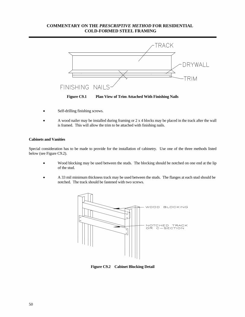
COMMENTARY ON THE PRESCRIPTIVE METHOD FOR RESIDENTIAL COLD-FORMED STEEL FRAMING
50
Figure C9.1 Plan View of Trim Attached With Finishing Nails
• Self-drilling finishing screws. • A wood nailer may be installed during framing or 2 x 4 blocks may be placed in the track after the wall is framed. This will allow the trim to be attached with finishing nails.
Cabinets and Vanities Special consideration has to be made to provide for the installation of cabinetry. Use one of the three methods listed below (see Figure C9.2).
• Wood blocking may be used between the studs. The blocking should be notched on one end at the lip of the stud.
• A 33 mil minimum thickness track may be used between the studs. The flanges at each stud should be
notched. The track should be fastened with two screws.
Figure C9.2 Cabinet Blocking Detail

COMMENTARY ON THE PRESCRIPTIVE METHOD FOR RESIDENTIAL COLD-FORMED STEEL FRAMING
51
Closet Shelving Bugle-head fasteners are commonly used to attach wood supports for closet shelving. Sharp-point screws are used for 18- and 27-mil thick studs and wing-tips screws for 33-mil and thicker studs. Hex-head or low-profile screws can be used for the attachment of shelving brackets. Gypsum Board Installation Number 6, 1-1/4-inch bugle-head screws with sharp-point tips shall be used to hang gypsum board on 18- to 33-mil thick steel studs. Self-drilling #6, 1-1/4 inch, bugle-head screws are used to hang gypsum board on thicker studs. Construction adhesive may also be used. Refer to ASTM C955 [30] and ASTM C1002 [16]. C10.0 CONSTRUCTION GUIDELINES The construction guidelines are provided to supplement the requirements of the Prescriptive Method and are considered good construction practices. These guidelines should not be considered comprehensive. Manufacturer's catalogs, recommendations, and other technical literature should also be consulted. Additional construction guidelines are provided below. General • Installation tolerances are very critical in achieving an acceptable floor or roof line in establishing effective
bracing. User is encouraged to use string line, plum bob, level or transit in order to achieve acceptable installation tolerances.
Tools and Fasteners Proper tools and techniques are very essential to any trade. Table C10.0 provides a list of tools that are commonly used in residential steel framing. • Cutting methods which cause significant heating of the steel or damage to the coatings shall only be used when the
galvanized coating is repaired. • Welding, in lieu of fastening, is permitted provided that weld capacity is shown to exceed screw(s) capacity. All
shop and field welds shall be brushed clean and provided with a corrosion protective metallic coating. Typically, steel members that are 33 mil in thickness or thinner should not be welded without the approval of a design professional. All welding shall be performed using certified welders specializing in cold-formed steel.
• Screws shall typically be driven through the thinner material into the thicker material. • Installation drilling tools shall drive screws at lower speeds of 2500 RPM for screw sizes up to #10 and 1800 RPM
for #12 (2500 RPM is acceptable provided that care is taken to minimize heat buildup). • Pre-drilled holes for preset bolts shall not be oversized more than 1/16 inch for bolt sizes up to 1/2 inch and no
more than 1/8 inch for bolt sizes larger than 1/2 inch in diameter.

COMMENTARY ON THE PRESCRIPTIVE METHOD FOR RESIDENTIAL COLD-FORMED STEEL FRAMING
52
Floor Joists • Stiffeners are required at all joist bearing locations (i.e. where the joists sit on the bearing wall or beam). It is
equally acceptable to install the stiffener on either face of the joist web. The required length (or height) of the stiffener need not be the full depth of the joist but rather may be allowed a 1/4 inch tolerance on each end of the stiffener. For example an 8 inch joist may have a 7-1/2 inch minimum stiffener length equally positioned over the height of the joist web. The end of a stiffener should not be more than 1/2 inch from either the top or bottom of the joist.
Walls • Wall bridging will use the same pattern of blocked bay at the end of each run with additional intermediate blocked
bays at 12 foot on center for lengths of walls greater than 12 feet. Wall bridging is not necessary if appropriate sheathing is placed on both flanges of the stud prior to loading the wall.
• Verify that interior non-load bearing partitions located under horizontal load carrying members (i.e. joists, rafters,
and trusses) are attached in a manner that will allow for vertical deflection of the framing above without inducing load on the partition.
• A sill sealer, or equivalent, should be provided between the underside of the wall when fastened directly to
concrete. Trusses • The Prescriptive Method calls for pre-engineered (pre-designed) trusses to be designed by others. • Dimensions and proper bearing locations as shown on truss design drawing shall always be verified before starting
installation of the truss. • Temporary construction bracing should remain in place as long as necessary for the safe and acceptable completion
of the roof or floor and may also remain in place after permanent bracing is installed. • Trusses are laterally unstable until bracing is properly installed; necessary caution should be employed during the
installation process. • Overloading of roof trusses before permanent bracing and/or sheathing is installed shall not be permitted. • Heavy construction loads such as stacks of plywood, gypsum board, bricks, HVAC units, etc. should never be
placed on trusses before they are properly braced. Trusses are not typically designed for dynamic loads (moving loads). Sleepers for mechanical equipment should be located at panel points or over main supporting members, or on trusses which have been designed to carry such loads.
• Trusses shall not be placed over loose lintels, shelf angles, headers, beams, or other supporting structures not
securely attached to the building. • Trusses which do not meet interior load bearing walls should be shimmed for adequate bearing. Trusses shall not
be pulled down to any interior partition.

COMMENTARY ON THE PRESCRIPTIVE METHOD FOR RESIDENTIAL COLD-FORMED STEEL FRAMING
53
Table C10.0 Tools Recommended for Use with Residential Steel Framing
Cutting
Aviation snips - cuts up to 33-mil material and makes cuts for coping track flanges.
14-gauge swivel head electric shear - cuts up to 68-mil material.
14-inch chop saw - for cutting multiple sections simultaneously, especially partition studs.
Step drill bit, 1 inch - for drilling holes in studs and track.
Hole punch, 1¼ inch - for field punching holes for the installation of electrical and plumbing systems.
Fastening Adjustable clutch screw gun - with industrial motor (5.4 amps), 0-2500 rpm variable speed, reversible, bit tip
holder release, adjustable torque control for framing.
Magnetic bit tip holder and #2 Phillips bit tips.
5/16-inch magnetic hex driver for hex-head screws. Two pair of 3-inch, two pair of 6-inch, and one pair of 12-inch locking C-clamps with regular tips for
clamping steel together while fastening.
Deep-throat bar clamp - for clamping headers in wall sections while fastening. Gypsum board screw gun - with industrial motor (5.4 amps), 0-4000 rpm variable speed, reversible, with depth
locating nose piece for sheathing and gypsum board installation.
Miscellaneous
3½-inch and 5-inch hand seamers - for bending and coping track.
Bull-nose pliers - for removing screws.
Magnetic level
Felt markers - for layout and cuts (black and red). Other miscellaneous tools include: tape measure, speed square, utility knife, wallboard ax, and 50' grounded
extension cords.

COMMENTARY ON THE PRESCRIPTIVE METHOD FOR RESIDENTIAL COLD-FORMED STEEL FRAMING
54
C11.0 REFERENCES [1] Prescriptive Method for Residential Cold-Formed Steel Framing, Second Edition. Prepared for
the US Department of Housing and Urban Development, the American Iron and Steel Institute, and the National Association of Home Builders, by the NAHB Research Center, Inc., Upper Marlboro, MD. August 1997.
[2] Specification For The Design Of Cold Formed Steel Structural Members (August 19, 1986 Edition with December 11, 1989 Addendum). American Iron and Steel Institute (AISI), Washington, DC. 1989. [3] Minimum Design Load for Buildings and Other Structures (ASCE 7-93). American Society
of Civil Engineers, New York, NY. 1993.
[4] CABO (1995), One and Two Family Dwelling Code, 1995 Edition, Council of American Building Officials.
[5] The BOCA National Building Code. Building Officials & Code Administrators International,
Inc. (BOCA). Country Club Hills, Illinois. 1993. [6] Uniform Building Code. International Conference of Building Officials (ICBO). Whittier, California.
1994. [7] Standard Building Code. Southern Building Code Congress International, Inc. (SBCCI).
Birmingham, Alabama. 1994. [8] ASTM A 653 / A 653M - 1996 Standard Specification for Steel Sheet, Zinc-Coated (Galvanized) or Zinc-
Iron Alloy-Coated (Galvannealed) by the Hot-Dip Process, American Society for Testing and Materials (ASTM), West Conshohocken, PA. 1996.
[9] ASTM A 792 / A 792M Standard Specification for Steel Sheet, 55% Aluminum-Zinc Alloy-Coated by the
Hot-Dip Process, American Society for Testing and Materials (ASTM), West Conshohocken, PA. 1996. [10] ASTM A 875 / A 875M Standard Specification for Steel Sheet, Zinc-5% Aluminum Alloy Metallic-Coated
by the Hot-Dip Process, American Society for Testing and Materials (ASTM), West Conshohocken, PA. 1996.
[11] ASTM C 645 - 96a Standard Specification for Nonstructural Steel Framing Members, American Society
for Testing and Materials (ASTM), West Conshohocken, PA. 1996. [12] ASTM A 924 / A 924M - 96a Standard Specification for General Requirement for Steel Sheet, Metallic-
Coated by the Hot-Dip Process, American Society for Testing and Materials (ASTM), ASTM, West Conshohocken, PA. 1996.
[13] LaBoube, R. (1996), Design Guide For Cold-Formed Steel Beams With Web Perforations. University of
Missouri-Rolla, Rolla, MO. November 1996. [14] ICBO Evaluation Service, Inc. No. AC 46, Acceptance Criteria for Steel Studs and Joists, International
Conference of Building Officials (ICBO). Approved July, 1992; Effective April, 1993. Whittier, California.
COMMENTARY ON THE PRESCRIPTIVE METHOD FOR RESIDENTIAL COLD-FORMED STEEL FRAMING
55
C11.0 REFERENCES (continued) [15] SAE J-78-1979, Steel Self Drilling Tapping Screws, Society of Automotive Engineers (SAE), 1979. [16] ASTM C 1002-96ae1 Standard Specification for Steel Drill Screws for the Application of Gypsum Board
or Metal Plaster Bases, American Society for Testing and Materials (ASTM), West Conshohocken, PA. 1996.
[17] ASTM C 954-96ae1 Standard Specification for Steel Drill Screws for the Application of Gypsum Panel
Products or Metal Plaster Bases to Steel Studs From 0.033 in. (0.84 mm) to 0.112 in. (2.84 mm) in Thickness, American Society for Testing and Materials (ASTM), West Conshohocken, PA. 1996.
[18] AISI Publication RG-933, Fasteners for Residential Steel Framing, American Iron and Steel Institute,
Washington DC, June 1993. [19] CCFSS Technical Bulletin Vol. 2, No. 1, AISI Specification Provisions for Screw Connections, Center for
Cold-Formed Steel Structures, University of Missouri-Rolla, Rolla, MO; February 1993. [20] ASTM Standard A 307 - 94 Standard Specification for Carbon Steel Bolts and Studs, 60000 PSI Tensile
Strength, American Society for Testing and Materials (ASTM), ASTM, West Conshohocken, PA. 1994. [21] Structural Performance Requirements For Domestic Steel Framing, Australian Institute of Steel
Construction (AISC). Milsons Point, Australia. 1991. [22] Kraus, C. and Murray, T. (1997), Floor Vibration Criterion For Cold- Formed C-Shaped Supported
Residential Floor Systems; Report No. CE/VPI-ST 97/04, Virginia Tech, Blacksburg, VA, February 1997. [23] WJE Report Number 73345, Report of Laboratory Tests and Analytical Studies of Structural
Characteristics of Cold-Formed Steel-Joists Floor Systems, Wiss, Janney, Elstner Associates, Inc. San Francisco, California. December 1977.
[24] AISI Publication RG-9518, Design Guide For Cold-Formed Steel Trusses, American Iron and Steel
Institute (AISI), Washington, DC. December 1995. [25] NAHB Research Center Combined Axial and Bending Load Tests of Fully-Sheathed Cold-Formed Steel
Wall Assemblies, Prepared for the US Department of Housing and Urban Development, The American Iron and Steel Institute, and the National Association of Home Builders, by the NAHB Research Center, Inc., Upper Marlboro, MD. July 1997.
[26] Serrette, Reynaud, et al., “Shear Wall Values for Light Weight Steel framing,” Prepared for the American
Iron and Steel Institute, Washington, DC. January 1996. [27] ASTM E 564 Standard Method of Static Load Test for Shear Resistance of Framed Walls for Buildings.
American Society for Testing and Materials (ASTM), West Conshohocken, PA. 1995. [28] NAHB Research Center Monotonic Tests of Cold-Formed Steel Shear Walls with Openings. Prepared for
the US Department of Housing and Urban Development, the American Iron and Steel Institute, and the National Association of Home Builders, by the NAHB Research Center, Inc., Upper Marlboro, MD. July 1997.
COMMENTARY ON THE PRESCRIPTIVE METHOD FOR RESIDENTIAL COLD-FORMED STEEL FRAMING
56
C11.0 REFERENCES (continued) [29] AISI Publication RG-9405, Thermal Design Guide For Exterior Walls, American Iron and Steel Institute
(AISI), Washington, DC. December 1995. [30] ASTM C 955-96a Standard Specification for Load-Bearing (Transverse and Axial) Steel Studs, Runners
(Tracks), and Bracing or Bridging for Screw Application of Gypsum Board and Metal Plaster Bases, American Society for Testing and Materials (ASTM), West Conshohocken, PA. 1996.
COMMENTARY ON THE PRESCRIPTIVE METHOD FOR RESIDENTIAL COLD-FORMED STEEL FRAMING
57

COMMENTARY ON THE PRESCRIPTIVE METHOD FOR RESIDENTIAL COLD-FORMED STEEL FRAMING
PART II
HOW TO USE THE PRESRIPTIVE METHOD

COMMENTARY ON THE PRESCRIPTIVE METHOD FOR RESIDENTIAL COLD-FORMED STEEL FRAMING
59

COMMENTARY ON THE PRESCRIPTIVE METHOD FOR RESIDENTIAL COLD-FORMED STEEL FRAMING
60
1. INTRODUCTION This part provides a step by step procedure on how to apply the requirements of the Prescriptive Method when designing a home. A typical residential building is used to demonstrate the application of steel framing requirements. The example building has the following physical characteristics:
Building type: Two story house (over an unfinished basement) with a center load bearing beam supporting the first floor and center load bearing wall supporting the second floor.
Building width: 28 feet Building length: 40 feet. First story wall height: 8 feet. Second story wall height: 8 feet. Wall stud spacing: 24" oc. Floor joist spacing: 24" oc. Roof framing: Ceiling joists with rafters Roof slope: 8:12 Roof soffit overhang: 1 foot The following design criteria is applicable to the example home:
Ground Snow Load (psf)
Wind Speed (mph) and Exposure
Seismic Condition by
Zone
Bottom Floor Live
Load
Top Floor Live Load
Floor Dead Load
50 70 mph, Exp. C Zone 0 40 psf 30 psf 10 psf Building elevations are shown in the following page.

COMMENTARY ON THE PRESCRIPTIVE METHOD FOR RESIDENTIAL COLD-FORMED STEEL FRAMING
61
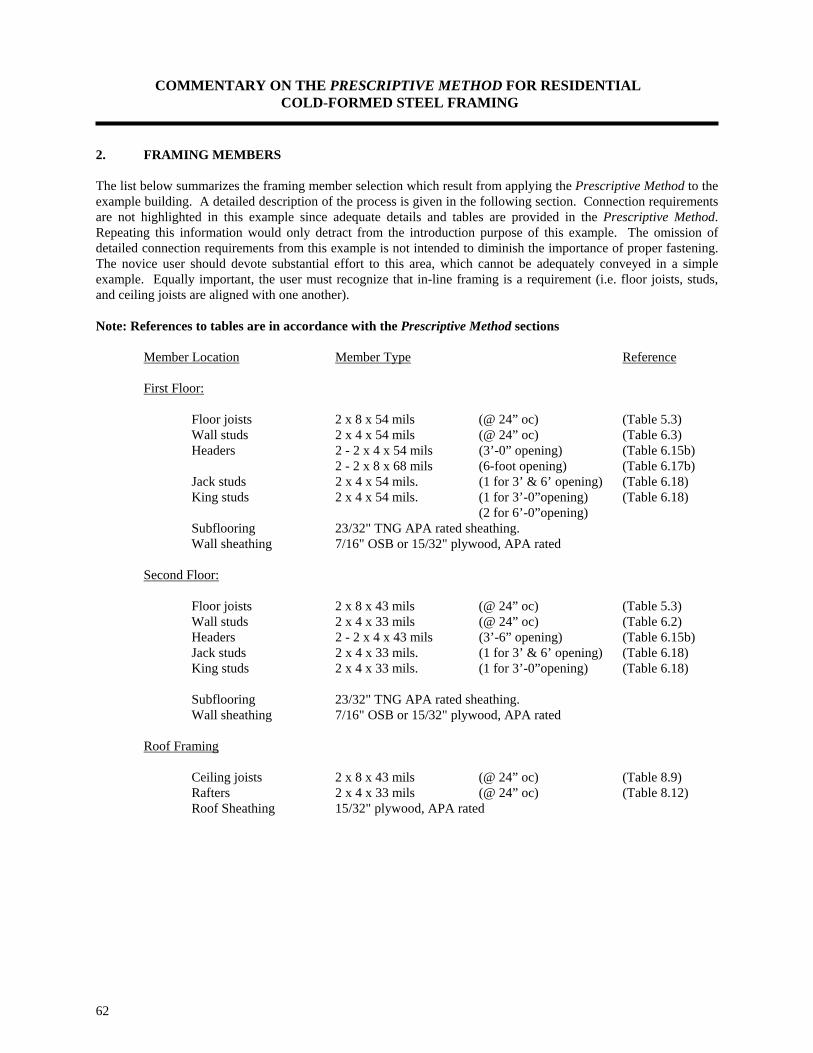
COMMENTARY ON THE PRESCRIPTIVE METHOD FOR RESIDENTIAL COLD-FORMED STEEL FRAMING
62
2. FRAMING MEMBERS The list below summarizes the framing member selection which result from applying the Prescriptive Method to the example building. A detailed description of the process is given in the following section. Connection requirements are not highlighted in this example since adequate details and tables are provided in the Prescriptive Method. Repeating this information would only detract from the introduction purpose of this example. The omission of detailed connection requirements from this example is not intended to diminish the importance of proper fastening. The novice user should devote substantial effort to this area, which cannot be adequately conveyed in a simple example. Equally important, the user must recognize that in-line framing is a requirement (i.e. floor joists, studs, and ceiling joists are aligned with one another). Note: References to tables are in accordance with the Prescriptive Method sections Member Location Member Type Reference First Floor: Floor joists 2 x 8 x 54 mils (@ 24” oc) (Table 5.3) Wall studs 2 x 4 x 54 mils (@ 24” oc) (Table 6.3) Headers 2 - 2 x 4 x 54 mils (3’-0” opening) (Table 6.15b) 2 - 2 x 8 x 68 mils (6-foot opening) (Table 6.17b) Jack studs 2 x 4 x 54 mils. (1 for 3’ & 6’ opening) (Table 6.18) King studs 2 x 4 x 54 mils. (1 for 3’-0”opening) (Table 6.18) (2 for 6’-0”opening) Subflooring 23/32" TNG APA rated sheathing. Wall sheathing 7/16" OSB or 15/32" plywood, APA rated Second Floor: Floor joists 2 x 8 x 43 mils (@ 24” oc) (Table 5.3) Wall studs 2 x 4 x 33 mils (@ 24” oc) (Table 6.2) Headers 2 - 2 x 4 x 43 mils (3’-6” opening) (Table 6.15b) Jack studs 2 x 4 x 33 mils. (1 for 3’ & 6’ opening) (Table 6.18) King studs 2 x 4 x 33 mils. (1 for 3’-0”opening) (Table 6.18) Subflooring 23/32" TNG APA rated sheathing. Wall sheathing 7/16" OSB or 15/32" plywood, APA rated Roof Framing Ceiling joists 2 x 8 x 43 mils (@ 24” oc) (Table 8.9) Rafters 2 x 4 x 33 mils (@ 24” oc) (Table 8.12) Roof Sheathing 15/32" plywood, APA rated

COMMENTARY ON THE PRESCRIPTIVE METHOD FOR RESIDENTIAL COLD-FORMED STEEL FRAMING
63
3. FLOOR FRAMING SELECTION Floor Joist Selection: The design house is 28’-0” wide, and by taking into account the depth of the end wall supports and a beam or bearing wall at the middle span, the first floor clear span is 13’-3” and second floor span is 13’-6”. A 13’-3” clear span for the first floor framing members is used in conjunction with the desired 24 inch on-center spacing of joists and 40 psf live load in order to select a 2 x 8 x 54 mil joist member from Table 5.3 as shown below (Table 5.4 could have been used if a continuous joist is to be used). The 2 x 8 x 54 mil member happens to have an allowable span of exactly 13’-3”. Applying the same sequence for the second floor framing, in this case the 13’-6” clear span in conjunction with the 24 inch on-center spanning and the 30 psf live load, Table 5.3 allows the use of a 2 x 8 x 43 mils joist member. The 2 x 8 x 43 mils member has an allowable span of 13’-7”. In addition to the selection of joist members, Table 5.2 requires one #8 screw per flange of the joist member for connection to the joist track or two #8 screws per bearing stiffener. Bearing stiffeners shall be located, for purpose of this exercise, as illustrated in Figures 2.7, and 5.1. Lateral bracing for the example building shall be provided in the form of subfloor sheathing panels, steel straps or gypsum board. For the application of plywood sheathing to the top flanges of the joists, Section 5.4 of the Prescriptive Method shall be employed with Table 5.2 which states that subflooring shall be fastened with #8 screws at six inches on-center at the edges and ten inches on-center at intermediate supports.
Table 5.3 Allowable Spans For Cold-Formed Steel Floor Joists
Single Span 33 ksi Steel
Nominal 30 psf Live Load 40 psf Live Load
Joist Size 5 Spacing (inches) Spacing (inches)
12 16 24 12 16 24
2 x 6 x 54 13'-7" 12'-4" 10'-9" 12'-4" 11'-2" 9'-9"
2 x 8 x 33 15'-8" 13'-3" 8'-10" 14'-0" 10'-7" 7'-1"
2 x 8 x 43 17'-1" 15'-6" 13'-7" 15'-6" 14'-1" 12'-3"
2 x 8 x 54 18'-4" 16'-8" 14'-7" 16'-8" 15'-2" 13'-3"
2 x 8 x 68 19'-8" 17'-11" 15'-7" 17'-11" 16'-3" 14'-2"

COMMENTARY ON THE PRESCRIPTIVE METHOD FOR RESIDENTIAL COLD-FORMED STEEL FRAMING
64
Recognizing that the first floor framing is constructed over an unfinished basement, steel strapping may be used as bottom flange lateral support in lieu of gypsum ceiling board. The strapping shall be attached to the bottom of each flange of the joist members with #8 screws. In addition, blocking or bridging shall be spaced at 12-foot perpendicular to the framing direction, which complies with Section 5.4 and Figures 5.1 and 5.2. Since the second floor joists are framed over a finished space the use of gypsum board sheathing will be employed pursuant to Section 5.4. 4. WALL FRAMING SELECTION Wall Studs Selection: As part of the selection process for wall studs it had been assumed that the building is 28 feet in width, is subject to a wind speed of 70 mph /Exposure C (or 90 mph, exposure B) and 50 psf ground snow load, has walls 8 feet high per floor and a stud spacing of 24 inches on-center. For the second floor wall framing, Table 6.2 allows a 2 x 4 x 33 mil stud to be used as shown below. For the first floor stud wall framing (i.e. first story of a two story building), we find that Table 6.3 results in a 2 x 4 x 54 mil stud member as shown below. Since the exterior is structurally sheathed and the interior is finished with 1/2 in. gypsum wall board, the thickness of steel may be reduced to 43 mil in accordance with footnote 5 in Table 6.3. A #8 screw through each flange is used to fasten studs below to the top and bottom track pursuant to Table 6.14. As currently required in the Prescriptive Method, all exterior portions of the walls are fully sheathed. The interior face of the wall is assumed to have a gypsum wall board finish. Section 6.4 of the Prescriptive Method provides the proper fastening requirements of the gypsum board. Interior load bearing walls(s) are sheathed with gypsum board on each side in accordance with Section 6.4.
Table 6.2 Steel Stud Thickness for 8' Walls Supporting Roof and Ceiling Only
(One Story or Second Floor of a Two Story Building) 33 ksi Steel
Wind Mem Member Stud Thickness (mils)1,2 Speed ber Spacing Building Width (feet)4,5
Size3 (inches) 24 28 32 36 Exp.
B Exp.
C Ground Snow Load
(psf) Ground Snow Load
(psf) Ground Snow Load
(psf) Ground Snow Load
(psf) 20 30 50 70 20 30 50 70 20 30 50 70 20 30 50 70
70 2x4 16 33 33 33 33 33 33 33 33 33 33 33 33 33 33 33 33mph 24 33 33 33 33 33 33 33 33 33 33 33 33 33 33 33 43
2x6 16 33 33 33 33 33 33 33 33 33 33 33 33 33 33 33 33 24 33 33 33 33 33 33 33 33 33 33 33 33 33 33 33 33
80 70 2x4 16 33 33 33 33 33 33 33 33 33 33 33 33 33 33 33 33mph mph 24 33 33 33 33 33 33 33 33 33 33 33 43 33 33 43 43
2x6 16 33 33 33 33 33 33 33 33 33 33 33 33 33 33 33 33
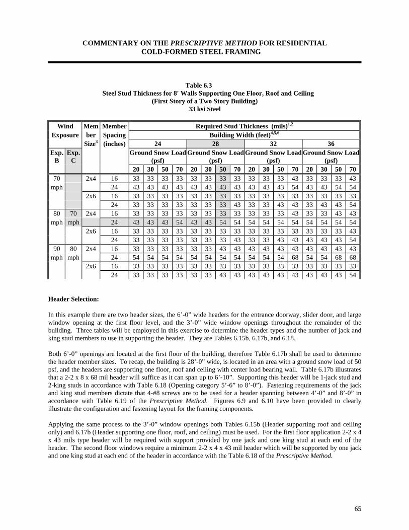
COMMENTARY ON THE PRESCRIPTIVE METHOD FOR RESIDENTIAL COLD-FORMED STEEL FRAMING
65
Table 6.3 Steel Stud Thickness for 8' Walls Supporting One Floor, Roof and Ceiling
(First Story of a Two Story Building) 33 ksi Steel
Wind Mem Member Required Stud Thickness (mils)1,2
Exposure ber Spacing Building Width (feet)4,5,6 Size3 (inches) 24 28 32 36
Exp. B
Exp. C
Ground Snow Load (psf)
Ground Snow Load (psf)
Ground Snow Load (psf)
Ground Snow Load(psf)
20 30 50 70 20 30 50 70 20 30 50 70 20 30 50 7070 2x4 16 33 33 33 33 33 33 33 33 33 33 33 43 33 33 33 43
mph 24 43 43 43 43 43 43 43 43 43 43 43 54 43 43 54 54 2x6 16 33 33 33 33 33 33 33 33 33 33 33 33 33 33 33 33 24 33 33 33 33 33 33 33 43 33 33 43 43 33 43 43 54
80 70 2x4 16 33 33 33 33 33 33 33 33 33 33 33 43 33 33 43 43mph mph 24 43 43 43 54 43 43 54 54 54 54 54 54 54 54 54 54
2x6 16 33 33 33 33 33 33 33 33 33 33 33 33 33 33 33 43 24 33 33 33 33 33 33 33 43 33 33 43 43 43 43 43 54
90 80 2x4 16 33 33 33 33 33 33 43 43 43 43 43 43 43 43 43 43mph mph 24 54 54 54 54 54 54 54 54 54 54 54 68 54 54 68 68
2x6 16 33 33 33 33 33 33 33 33 33 33 33 33 33 33 33 33 24 33 33 33 33 33 33 43 43 43 43 43 43 43 43 43 54
Header Selection: In this example there are two header sizes, the 6’-0” wide headers for the entrance doorway, slider door, and large window opening at the first floor level, and the 3’-0” wide window openings throughout the remainder of the building. Three tables will be employed in this exercise to determine the header types and the number of jack and king stud members to use in supporting the header. They are Tables 6.15b, 6.17b, and 6.18. Both 6’-0” openings are located at the first floor of the building, therefore Table 6.17b shall be used to determine the header member sizes. To recap, the building is 28’-0” wide, is located in an area with a ground snow load of 50 psf, and the headers are supporting one floor, roof and ceiling with center load bearing wall. Table 6.17b illustrates that a 2-2 x 8 x 68 mil header will suffice as it can span up to 6’-10”. Supporting this header will be 1-jack stud and 2-king studs in accordance with Table 6.18 (Opening category 5’-6” to 8’-0”). Fastening requirements of the jack and king stud members dictate that 4-#8 screws are to be used for a header spanning between 4’-0” and 8’-0” in accordance with Table 6.19 of the Prescriptive Method. Figures 6.9 and 6.10 have been provided to clearly illustrate the configuration and fastening layout for the framing components. Applying the same process to the 3’-0” window openings both Tables 6.15b (Header supporting roof and ceiling only) and 6.17b (Header supporting one floor, roof, and ceiling) must be used. For the first floor application 2-2 x 4 x 43 mils type header will be required with support provided by one jack and one king stud at each end of the header. The second floor windows require a minimum 2-2 x 4 x 43 mil header which will be supported by one jack and one king stud at each end of the header in accordance with the Table 6.18 of the Prescriptive Method.

COMMENTARY ON THE PRESCRIPTIVE METHOD FOR RESIDENTIAL COLD-FORMED STEEL FRAMING
66
Table 6.17b Allowable Header Spans for
Headers Supporting One Floor, Roof and Ceiling 1,2
First story of a two-story building with center load bearing Beam 33 ksi
Nominal Member 50 psf Ground Snow Load 70 psf Ground Snow Load
Size 3 Building Width 4 Building Width 4
24' 28' 32' 36' 24' 28' 32' 36'
2-2 x 4 x 33 2'-2" - - - - - - -
2-2 x 4 x 43 3'-3" 3'-1" 2'-11" 2'-8" 3'-0" 2'-9" 2'-6" 2'-3"
2-2 x 4 x 54 3'-8" 3'-5" 3'-3" 3'-1" 3'-5" 3'-2" 3'-0" 2'-10"
2-2 x 4 x 68 4'-1" 3'-10" 3'-8" 3'-6" 3'-9" 3'-7" 3'-4" 3'-2"
2-2x 4 x 97 4'-10" 4'-7" 4'-4" 4'-1" 4'-6" 4'-3" 4'-0" 3'-10"
2-2x 6 x 33 - - - - - - - -
2-2 x 6 x 43 4'-0" 3'-7" 3'-2" 2'-11" 3'-5" 3'-1" 2'-9" 2'-6"
2-2x 6 x 54 4'-11" 4'-8" 4'-5" 4'-2" 4'-7" 4'-4" 4'-1" 3'-11"
2-2 x 6 x 68 5'-7" 5'-3" 4'-11" 4'-9" 5'-2" 4'-10" 4'-7" 4'-4"
2-2 x 6 x 97 6'-8" 6'-3" 5'-11" 5'-7" 6'-2" 5'-9" 5'-6" 5'-2"
2-2 x 8 x 33 - - - - - - - -
2-2 x 8 x 43 3'-1" 2'-9" 2'-5" 2'-3" 2'-8" 2'-4" - -
2-2x 8 x 54 6'-2" 5'-5" 4'-11" 4'-5" 5'-3" 4'-8" 4'-2" 3'-9"
2-2 x 8 x 68 7'-3" 6'-10" 6'-6" 6'-2" 6'-9" 6'-4" 6'-0" 5'-8"
2-2 x 8 x 97 8'-8" 8'-2" 7'-9" 7'-5" 8'-1" 7'-7" 7'-2" 6'-10"
2-2 x 10 x 43 2'-7" 2'-3" 2'-1" - 2'-3" - - -
2-2 x 10 x 54 5'-1" 4'-6" 4'-1" 3'-8" 4'-5" 3'-11" 3'-6" 3'-2"
2-2 x 10 x 68 8'-7" 8'-1" 7'-8" 7'-3" 7'-11" 7'-6" 7'-0" 6'-4"
2-2 x 10 x 97 10'-3" 9'-8" 9'-2" 8'-9" 9'-6" 9'-0" 8'-6" 8'-1"
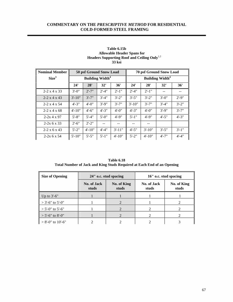
COMMENTARY ON THE PRESCRIPTIVE METHOD FOR RESIDENTIAL COLD-FORMED STEEL FRAMING
67
Table 6.15b Allowable Header Spans for
Headers Supporting Roof and Ceiling Only1,2
33 ksi
Nominal Member 50 psf Ground Snow Load 70 psf Ground Snow Load
Size3 Building Width4 Building Width4
24' 28' 32' 36' 24' 28' 32' 36' 2-2 x 4 x 33 3'-0" 2'-7" 2'-4" 2'-1" 2'-4" 2'-1" -- --
2-2 x 4 x 43 3'-10" 3'-7" 3'-4" 3'-2" 3'-5" 3'-2" 3'-0" 2'-9"
2-2 x 4 x 54 4'-3" 4'-0" 3'-9" 3'-7" 3'-10" 3'-7" 3'-4" 3'-2"
2-2 x 4 x 68 4'-10" 4'-6" 4'-3" 4'-0" 4'-3" 4'-0" 3'-9" 3'-7"
2-2x 4 x 97 5'-8" 5'-4" 5'-0" 4'-9" 5'-1" 4'-9" 4'-5" 4'-3"
2-2x 6 x 33 2'-6" 2'-2" -- -- -- --
2-2 x 6 x 43 5'-2" 4'-10" 4'-4" 3'-11" 4'-5" 3'-10" 3'-5" 3'-1"
2-2x 6 x 54 5'-10" 5'-5" 5'-1" 4'-10" 5'-2" 4'-10" 4'-7" 4'-4"
Table 6.18 Total Number of Jack and King Studs Required at Each End of an Opening
Size of Opening 24" o.c. stud spacing 16" o.c. stud spacing
No. of Jack studs
No. of King studs
No. of Jack studs
No. of King studs
Up to 3'-6" 1 1 1 1
> 3'-6" to 5'-0" 1 2 1 2
> 5'-0" to 5'-6" 1 2 2 2
> 5'-6" to 8'-0" 1 2 2 2
> 8'-0" to 10'-6" 2 2 2 3
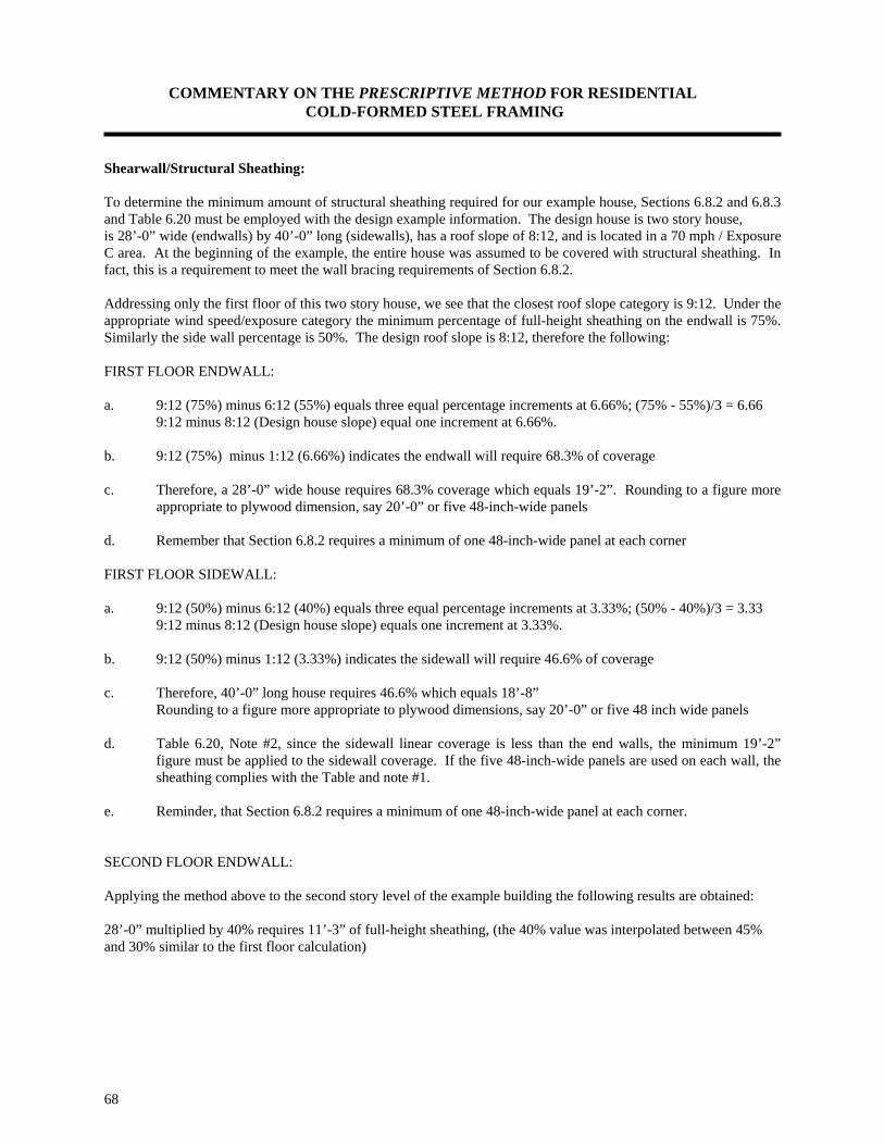
COMMENTARY ON THE PRESCRIPTIVE METHOD FOR RESIDENTIAL COLD-FORMED STEEL FRAMING
68
Shearwall/Structural Sheathing: To determine the minimum amount of structural sheathing required for our example house, Sections 6.8.2 and 6.8.3 and Table 6.20 must be employed with the design example information. The design house is two story house, is 28’-0” wide (endwalls) by 40’-0” long (sidewalls), has a roof slope of 8:12, and is located in a 70 mph / Exposure C area. At the beginning of the example, the entire house was assumed to be covered with structural sheathing. In fact, this is a requirement to meet the wall bracing requirements of Section 6.8.2. Addressing only the first floor of this two story house, we see that the closest roof slope category is 9:12. Under the appropriate wind speed/exposure category the minimum percentage of full-height sheathing on the endwall is 75%. Similarly the side wall percentage is 50%. The design roof slope is 8:12, therefore the following: FIRST FLOOR ENDWALL: a. 9:12 (75%) minus 6:12 (55%) equals three equal percentage increments at 6.66%; (75% - 55%)/3 = 6.66 9:12 minus 8:12 (Design house slope) equal one increment at 6.66%. b. 9:12 (75%) minus 1:12 (6.66%) indicates the endwall will require 68.3% of coverage c. Therefore, a 28’-0” wide house requires 68.3% coverage which equals 19’-2”. Rounding to a figure more
appropriate to plywood dimension, say 20’-0” or five 48-inch-wide panels d. Remember that Section 6.8.2 requires a minimum of one 48-inch-wide panel at each corner FIRST FLOOR SIDEWALL: a. 9:12 (50%) minus 6:12 (40%) equals three equal percentage increments at 3.33%; (50% - 40%)/3 = 3.33 9:12 minus 8:12 (Design house slope) equals one increment at 3.33%. b. 9:12 (50%) minus 1:12 (3.33%) indicates the sidewall will require 46.6% of coverage c. Therefore, 40’-0” long house requires 46.6% which equals 18’-8” Rounding to a figure more appropriate to plywood dimensions, say 20’-0” or five 48 inch wide panels d. Table 6.20, Note #2, since the sidewall linear coverage is less than the end walls, the minimum 19’-2”
figure must be applied to the sidewall coverage. If the five 48-inch-wide panels are used on each wall, the sheathing complies with the Table and note #1.
e. Reminder, that Section 6.8.2 requires a minimum of one 48-inch-wide panel at each corner. SECOND FLOOR ENDWALL: Applying the method above to the second story level of the example building the following results are obtained: 28’-0” multiplied by 40% requires 11’-3” of full-height sheathing, (the 40% value was interpolated between 45% and 30% similar to the first floor calculation)

COMMENTARY ON THE PRESCRIPTIVE METHOD FOR RESIDENTIAL COLD-FORMED STEEL FRAMING
69
SECOND FLOOR SIDEWALL: 40’-0” multiplied by 30% requires 12’-0” of full-height sheathing. No adjustment to the lengths of full-height sheathing is necessary in either case.
Table 6.20 Minimum Percentage of Full Height
Structural Sheathing Along Exterior Wall Lines1,2,3,4
Wall Condition Roof Slope Wind Speed (mph) and Exposure
Up To 70 C or 90 A/B
or Seismic Zones 0, 1, & 2
Up To 90 C or 100 A/B
Endwall Sidewall Endwall Sidewall
One-Story or 3:12 30% 30% 30% 30%
Second Floor of 6:12 30% 30% 40% 30%
Two-Story 9:12 45% 30% 75% 50%
Construction 12:12 60% 40% 100% 70%
First Floor of 3:12 50% 35% 80% 55%
Two-Story 6:12 55% 40% 90% 60%
Construction 9:12 75% 50% Design Required
12:12 95% 65%

COMMENTARY ON THE PRESCRIPTIVE METHOD FOR RESIDENTIAL COLD-FORMED STEEL FRAMING
70
5. ROOF FRAMING SELECTION Ceiling Joists Selection The design house is 28’-0” wide, and by taking into account the depth of the end wall supports and a beam or bearing wall at the middle span, the ceiling joist clear span is 13’-9”. A 13’-9” desired ceiling joist span is used in conjunction with the 24 inch on-center spacing of members and the 20 psf attic live load in order to select a 2 x 8 x 54 mil joist member from Table 8.11 as shown below. Moreover, no stiffeners are required for the ceiling joists.
Table 8.11 Allowable Spans For Cold-Formed Steel Ceiling Joists (33 ksi)
Two Equal Spans Without Bearing Stiffeners 20 Lbs. per Sq. Ft. Live Load (Limited Attic Storage) 1,2,3,4
Nominal Lateral Support of Top (Compression Flange)
Joist Size 5 Unbraced Mid-Span Bracing Third-Point Bracing
Spacing (inches) Spacing (inches) Spacing (inches) 16 24 16 24 16 24
2 x 4 x 68 14'-0" 12'-4" 15'-9" 12'-5" 15'-9" 12'-5" 2 x 4 x 97 16'-7" 14'-5" 18'-3" 15'-2" 18'-3" 15'-2" 2 x 6 x 33 9'-3" 6'-9" 9'-3" 6'-9" 9'-3" 6'-9" 2 x 6 x 43 13'-0" 9'-8" 13'-0" 9'-8" 13'-0" 9'-8" 2 x 6 x 54 14'-3" 12'-4" 16'-4" 12'-4" 16'-4" 12'-4" 2 x 6 x 68 15'-6" 13'-9" 20'-3" 15'-7" 20'-3" 15'-7" 2 x 6 x 97 18'-0" 15'-11" 23'-7" 20'-6" 25'-10" 21'-0" 2 x 8 x 33 - - - - - - 2 x 8 x 43 14'-0" 10'-2" 14'-0" 10'-2" 14'-0" 10'-2" 2 x 8 x 54 15'-9" 13'-10" 18'-9" 13'-10" 18'-9" 13'-10" 2 x 8 x 68 17'-0" 15'-2" 23'-3" 18'-3" 24'-2" 18'-3" 2 x 8 x 97 19'-6" 17'-3" 26'-0" 23'-2" 30'-11" 25'-11"
In addition to the selection of joist members, Table 8.1 requires two #10 screws per joist for connection to the top track of a load bearing wall. Bearing stiffeners are not required for the ceiling joists selected. Lateral bracing for the selected ceiling joists shall be provided in the form of sheathing, steel straps or gypsum board. A 2 x 4 x 33 C-shape or track member or steel strapping may be used as bracing of the top flange. The strapping should be fastened to each top flange of the ceiling joists with a minimum of one #8 screw. Blocking or bridging shall also be installed in-line with the strapping at a maximum spacing of 12’-0” and at the termination of all straps. The blocking and/or bridging details are similar to those used for the steel floor assembly. Gypsum board shall be installed on the bottom flanges (tension flanges) of ceiling joists with #6 screws in accordance with Section 8.3.
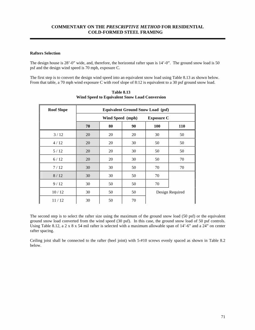
COMMENTARY ON THE PRESCRIPTIVE METHOD FOR RESIDENTIAL COLD-FORMED STEEL FRAMING
71
Rafters Selection The design house is 28’-0” wide, and, therefore, the horizontal rafter span is 14’-0”. The ground snow load is 50 psf and the design wind speed is 70 mph, exposure C. The first step is to convert the design wind speed into an equivalent snow load using Table 8.13 as shown below. From that table, a 70 mph wind exposure C with roof slope of 8:12 is equivalent to a 30 psf ground snow load.
Table 8.13 Wind Speed to Equivalent Snow Load Conversion
Roof Slope Equivalent Ground Snow Load (psf)
Wind Speed (mph) Exposure C
70 80 90 100 110
3 / 12 20 20 20 30 50
4 / 12 20 20 30 50 50
5 / 12 20 20 30 50 50
6 / 12 20 20 30 50 70
7 / 12 30 30 50 70 70
8 / 12 30 30 50 70
9 / 12 30 50 50 70
10 / 12 30 50 50 Design Required
11 / 12 30 50 70 The second step is to select the rafter size using the maximum of the ground snow load (50 psf) or the equivalent ground snow load converted from the wind speed (30 psf). In this case, the ground snow load of 50 psf controls. Using Table 8.12, a 2 x 8 x 54 mil rafter is selected with a maximum allowable span of 14’-6” and a 24” on center rafter spacing. Ceiling joist shall be connected to the rafter (heel joint) with 5-#10 screws evenly spaced as shown in Table 8.2 below.

COMMENTARY ON THE PRESCRIPTIVE METHOD FOR RESIDENTIAL COLD-FORMED STEEL FRAMING
72
Table 8.12 Allowable Horizontal Rafter Spans1,2,3
33 ksi
Nominal Ground Snow Loads
Joist Size 4 20 psf Ground 30 psf Ground 50 psf Ground 70 psf Ground
Spacing (inches) Spacing (inches) Spacing (inches) Spacing (inches) 16 24 16 24 16 24 16 24
2 x 6 x 33 12'-8" 10'-4" 11'-9" 9'-7" 9'-11" 8'-1" 8'-10" 7'-2" 2 x 6 x 43 15'-5" 12' -7" 14'-3" 11'-8" 12'-1" 9'-10" 10'-8" 8'-9"
2 x 6 x 54 13'-0" 14'-2" 16'-1" 13'-1" 13'-8" 11'-2" 12'-1" 9'-10"
2 x 6 x 68 18'-1" 15'-10" 17'-3" 14'-9" 15'-4" 12'-6" 13'-6" 11'-1"
2 x 6 x 97 20'-1" 17'-6" 19'-1" 16'-8" 17'-1" 14' 15'-7" 13'-2"
2 x 8 x 33 15'-5" 11'-5" 14'-4" 9'-10" 10'-7" 7'-1" 8'-3" 5'-6"
2 x 8 x 43 19'-1" 15'-7' 17'-9" 14'-6" 15'-1" 12'-3" 13'-3" 10'-9"
2 x 8 x 54 22'-7" 18'-5" 21'-0" 17'-1" 17'-9" 14'-6" 15'-9" 12-10"
2 x 8 x 68 24'-7" 20'-9" 23'-4" 19'-3" 20'-0" 16'-4" 17'-8" 14'-5"
Table 8.2 Number of Screws Required For Heel Joint Connections1
Roof Building Width (feet)
Slope 24' 28' 32' 36'
Ground Snow Load (psf)
Ground Snow Load (psf)
Ground Snow Load (psf)
Ground Snow Load (psf)
20 30 50 70 20 30 50 70 20 30 50 70 20 30 50 70 3/12 5 6 9 12 6 7 10 13 7 8 12 15 8 9 13 17 4/12 4 5 7 9 5 6 8 10 6 6 9 12 6 7 10 13 5/12 4 4 6 7 4 5 7 9 5 5 8 10 5 6 9 11 6/12 3 4 5 7 4 4 6 8 4 5 7 9 4 5 7 10 7/12 3 3 5 6 3 4 5 7 4 4 6 8 4 5 7 9 8/12 3 3 4 5 3 3 5 6 3 4 5 7 4 4 6 8 9/12 2 3 4 5 3 3 4 6 3 4 5 6 3 4 6 7

COMMENTARY ON THE PRESCRIPTIVE METHOD FOR RESIDENTIAL COLD-FORMED STEEL FRAMING
73
The rafter to ridge member connection shall use four #10 screws at each leg of the angle as shown in Table 8.3 below.
Table 8.3
Number of Screws Required at Each Leg of Clip Angle For Rafter to Ridge Member Connection1
Building Width Ground Snow Load (psf)
(feet) 0 to 20 21 to 30 31 to 50 51 to 70 24 2 3 4 4 28 2 3 4 5 32 3 3 4 5 36 3 4 5 6
Bottom flange rafter bracing can be accomplished using a 1-1/2” x 33 mil strap, 33 mil C-shape member, or 33 mil track at a maximum spacing of 8 feet along the rafter span. A 2 x 4 x 33 mil C-shape member at mid span is selected here. The C-shape member is fastened to each rafter with a minimum of one #8 screw. Permanent roof bracing for the example building is provided by structural (roof) sheathing fastened to the rafters with #8 screws at 6 inches on center along the edges and 12 inches on center at interior supports in accordance with Table 8.1. Adequate temporary bracing of the roof framing is required for stability during construction until the roof sheathing is applied.

COMMENTARY ON THE PRESCRIPTIVE METHOD FOR RESIDENTIAL COLD-FORMED STEEL FRAMING
74
PART III
ENGINEERING CALCULATIONS

COMMENTARY ON THE PRESCRIPTIVE METHOD FOR RESIDENTIAL COLD-FORMED STEEL FRAMING

COMMENTARY ON THE PRESCRIPTIVE METHOD FOR RESIDENTIAL COLD-FORMED STEEL FRAMING
76
INTRODUCTION This section of the document contains example calculations for the different requirements contained in the Prescriptive Method. The section starts out with the basic calculation of the different section properties of a typical C-shaped member, than the capacity of that member is calculated based on the requirements of the AISI Specification. The flow of the engineering calculations follow that of the Prescriptive Method: designing floor joists, wall studs, headers, shearwalls, and finally roof framing. All references used in the design examples shown in this section are listed in Part I of this document.

COMMENTARY ON THE PRESCRIPTIVE METHOD FOR RESIDENTIAL COLD-FORMED STEEL FRAMING
77
SECTION PROPERTIES EXAMPLES The following examples illustrate the calculation of various section properties for 2 x 8 x 54 mil and 2 x 4 x 43 mil C-shapes. The purpose of these examples is to show how the section properties are derived. All properties are calculated in accordance with the AISI "Specification For The Design Of Cold-Formed Steel Structural Members, August 19, 1986 Edition with December 11, 1989 Addendum". The section properties are based on the requirements of Sections 2.1, 2.2, 2.3, 2.4, and 2.5 of the Prescriptive Method. Calculate the gross section properties of a 2 x 4 x 43 mil C-shape: The following information is either specified in the Prescriptive Method or is given in the AISI Specification: Web size = 3.5 in. Flange size = 1.625 in. Lip size = 0.5 in. Base metal thickness = 0.0423 in. Inside bend radius = 0.09375 in. Hole width = 1.5 in. Hole length = 4 in. Yield stress = 33,000 psi Tensile strength = 45,000 psi (AISI Section 5 of Supplementary Information) Modulus of elasticity = 29,500,000 psi (AISI Section 4 of Supplementary Information) Shear modulus = 11,300,000 psi (AISI Section 4 of Supplementary Information) Area: Gross Area: Design thickness = Minimum uncoated thickness / 0.95 = 0.043 / 0.95 = 0.045 in. a = Web - 2(Radius + thickness) = 3.5 - 2(0.0937 + 0.045) = 3.223 in. b = Flange - 2(Radius + thickness) = 1.625 - 2(0.0937 + 0.045) = 1.348 in. c = Lip - (Radius + thickness) = 0.5 - (0.0937 + 0.045) = 0.361 in. u = 1.57 x (Radius + thickness/2) = 1.57(0.0937 + 0.045/2) = 0.182 in. r = (Radius + thickness/2) = (0.0937 + 0.045/2) = 0.116 in. α = 1 The above properties are based on the equations given in the Supplementary Information Section of the AISI Specification: Area = thickness [a + 2b + 2c + α (2u + 2c)] AISI Section 1.2 Area = 0.045[(3.228 + 2 x 1.347 + 2 x 0.361 + 1(2 x 0.183 + 2 x 0.361)] = 0.332 in2 Net Area: Net area = Gross area - hole area
X
0.138"
0.138"
3.5" X
Y
0.045"
1.625"
0.361"
Y
0.138"
0.5"
1.348"
R=3/32ö
3.223"
COMMENTARY ON THE PRESCRIPTIVE METHOD FOR RESIDENTIAL COLD-FORMED STEEL FRAMING
78
Net Area = 0.332 - 1.5 (0.045) = 0.265 in2 Weight per foot: Gross weight per foot: weight/foot = Gross area x density of steel = 0.322 (490/144) = 1.131 lb./ft. Net weight per foot: weight/foot = Net area x density of steel = 0.265 (490/144) = 0.901 lb./ft. Gross Properties About X-Axis: (AISI Supplementary Information Section 1.2) Gross moment of inertia, Ixx Ixx = 2t 0.417a3 + b(a/2 + r)2 + u(a/2 + 0.637r)2 + 0.0149r3 + α[ 0.0833c3 + (c/4)(a - c)2 + u(a/2 + 0.637r)2 + 0.149r3] Ixx = 0.649 in.4 Gross section modulus, Sxx Sxx = Ix / Ycg Ycg = 3.5 / 2 = 1.75 in. Sxx = 0.649 / 1.75 = 0.371 in3 Radius of gyration, rx rx = [Ix / A]1/2 rx = [0.649 / 0.332]1/2 = 1.398 in. Gross Properties About Y-Axis: Gross moment of inertia, Iyy Iyy = 2t b(b/2 + r)2 + 0.833b3 + 0.356r3 + α[ c(b + 2r)2 + u(b + 1.637r)2 + 0.149r3] - Area (x')2 Where x' = Distance between centroid and web centerline. x' = (2t/Area) b(b/2 + r) + u(0.363r) + α[ u(b + 1.637r) + c(b + 2r)] x' = 0.522 in. Iyy = 0.124 in4 Gross section modulus, Syy Syy = Iy / Xcg Xcg = x' + thickness /2 = 0.522 + 0.045/2 = 0.545 in. Syy = 0.124 / 0.545 = 0.228 in3 Radius of gyration, ry

COMMENTARY ON THE PRESCRIPTIVE METHOD FOR RESIDENTIAL COLD-FORMED STEEL FRAMING
79
ry = [Iy / A]1/2 ry = [0.1240 / 0.332]1/2 = 0.611 in. Torsional Properties: St. Venant torsion constant, J: J = (t3/3)[ a + 2b + 2u + α ( 2c + 2u)] AISI Supplementary Information, Section 1.2.2 J = [(0.0451)3/3] [ 3.222 + 2(1.347) + 2(0.183) + 1(2 x 0.361 + 2 x 0.183)] J = 2.25 x 10⁻⁴ in.4 Warping constant, Cw: The warping constant is calculated in accordance with equation 9 of Section 1.22 of the AISI Supplementary Information (Page III-9). Cw = 0.344 in.6 Polar radii of gyration, ro: The polar radius of gyration of a section is calculated about the centroidal principal axis. ro = [rx
2 + ry
2 + xo
2 ]1/2 Where xo = - (x' + m)
m = distance between shear center and web centerline calculated in accordance with equation 6 of Section 1.2.2 of the Supplemental Information of the AISI Specification = 0.822 in.. xo = - ( 0.522 + 0.822) = 1.344 ro = [(1.398)2
+ (0.611)2 + (1.344)2
]1/2 ro = 2.033 in. Torsional flexural constant, β: β = 1 - ( xo / ro )2 β = 1 - ( 1.344 / 2.033 )2 β = 0.563 Web Crippling Strength: Calculate the web crippling strength of a 2 x 4 x 43 mil C-shape per Section C3.4 of the AISI Design Specification. h/t = 3.5 / 0.045 = 77.78 < 200 R/t = 0.0937 / 0.045 = 2.082 < 6 N/t = 1.5 / 0.045 = 33.33 < 210 N/h = 1.5 / 3.5 = 0.429 < 3.5 Therefore, the equations in AISI Table C3.4-1 apply.
COMMENTARY ON THE PRESCRIPTIVE METHOD FOR RESIDENTIAL COLD-FORMED STEEL FRAMING
80
Equation C3.4-1, for stiffened flanges, end reactions, will be used: t2kC3C4 Cθ [179 - 0.33(h/t)][1 + 0.01(N/t)] Eq. C3.4-1 k = F4 / 33 = 1 Eq. C3.4-21 C3 = 1.33 - 0.33k = 1.0 Eq. C3.4-12 C4 = 0.5 ≤ 1.15 - 0.15 R/t ≤ 1.0 = 0.838 Eq. C3.4-13 Cθ = 0.7 + 0.3 (θ / 90)2 = 0.7 + 0.3(90/90)2 = 1.0 Eq. C3.4-20 Web crippling capacity = (0.045)2(1)(1)(0.838)(1)[179 - 0.33(77.78)][1 + 0.01(33.33)] x 1000 = 347 lb. Calculate the web crippling strength of a back-to-back 2 x 4 x 43 mil C-shape per Section C3.4 of the AISI Design Specification. Equation C3.4-3, shapes having multiple webs, will be used: t2FyC6[5.0 + 0.63(N/t)1/2] C6 = 1 + (h/t)/750 when h/t ≤ 150 = 1.095 Eq. C3.4-15 Web crippling capacity = (0.045)2(33,000)(1.095)[5 + 0.63(33.33)1/2] = 632 lbs.

COMMENTARY ON THE PRESCRIPTIVE METHOD FOR RESIDENTIAL COLD-FORMED STEEL FRAMING
81
2 x 8 x 54 mil C-Shape Section Properties: The following section properties correspond to a 2 x 8 x 54 mil C-shape (From section property tables) (Dimensions and configuration are in accordance with Section 2.0 of the Prescriptive Method) Gross Area = 0.667 in2 Net Area = 0.582 in.2 Xo= - 0.935 in. Ixx = 5.70 in.4 Sxx = 1.425 in.3 J = 71.3x10⁻⁵ in.4 Iyy = 0.192 in.4 Syy = 0.150 in.3 (gross section modulus) Cw = 2.503 in.6 rx = 2.93 in. ry = 0.536 in. ro= 3.12 in. Syy = 0.136 in.3 (Effective section modulus) β = 0.91 Ix = 5.70 in.4 (Effective moment of inertia) Sx = 1.425 in.3 (Effective section modulus) Fya = 37.2 ksi Ma = 31,767 lb.-in. (2,647.5 ft-lb.) Va = 1,9731 lbs. (shear capacity for section with no holes) Va = 1,566 lbs. (shear capacity for section with holes) Pa = 1029 lbs. (Allowable web crippling capacity, multiple webs) Pa = 471 lbs. (Allowable web crippling capacity, single web) (All references to nomenclature, sections, and equation numbers are from the AISI Design Specification): Design thickness = 0.057 in. Minimum uncoated delivered thickness = 0.057 x 0.95 = 0.054 in. (AISI Section A3.4) Inside bend radius = R R = 2t = 2 x 0.0538 = 0.108 in. Area = t[a + 2b + 2c + α (2u + 2c)] (AISI Supplementary Information Section 1.22) Where: a = Web - 2( Radius + thickness) = 8.0 - 2(0.108 + 0.057) = 7.670 in. b = Flange - 2(Radius + thickness) = 1.625 - 2(0.108 + 0.057) = 1.295 in. c = Lip - (Radius + thickness) = 0.5 - (0.108 + 0.057) = 0.335 in. u = 1.57 (Radius + thickness/2) = 1.57(0.108 + 0.057/2) = 0.214 in. a = 1.0 Gross Area = 0.057(7.670 + 2 x 1.295 + 2 x 0.335 + 2 x 0.335 + 2 x 0.214) = 0.647 in.2 Net Area = Gross area - area of opening = 0.686 - 1.5 x 0.057 = 0.600 in.2 Weight per foot = Gross area x density of steel = 0.647 x 490 /144 = 2.20 lb./ft. Gross Ycg = 8 / 2 = 4.00 in.
X
0.165"
0.165"
8.0" X
Y
0.057"
1.625"
0.335"
Y
0.138"
0.5"
1.295ö
R=0.108ö
7.670"

COMMENTARY ON THE PRESCRIPTIVE METHOD FOR RESIDENTIAL COLD-FORMED STEEL FRAMING
82
Calculate gross moment of inertia, Ixx: (AISI Supplementary Information Section 1.2) r = Radius + Thickness/2 = 0.136 in. Ixx = 2t 0.417a3 + b(a/2 + r)2 + u(a/2 + 0.637r)2 + 0.0149r3 + α[ 0.0833c3 + (c/4)(a - c)2 + u(a/2 + 0.637r)2 +
0.149r3] Ixx = 5.70 in4 Gross section modulus, Sxx: Sxx = Ixx / Ycg = 5.70 / 4.00 = 1.425 in.3 Radius of gyration, rx : rx = [(Ixx/Area)]1/2 = [(5.70/0.647)]1/2 = 2.97 in. Calculate gross moment of inertia, Iyy:(AISI Supplementary Information Section 1.2) Iyy = 2t b(b/2 + r)2 + 0.833b3 + 0.356r3 + α[ c(b + 2r)2 + u(b + 1.637r)2 + 0.149r3] - Area (x')2 Where x' = Distance between centroid and web centerline = (2t/Area) b(b/2 + r) + u(0.363r) + α[ u(b + 1.637r) + c(b + 2r)] = 0.319 in. Iyy = 0.192 in.4 Gross Xcg = x' + t/2 = 0.347 in. Gross section modulus, Syy: Syy = Iyy / Xcg = 0.192 / 0.347 = 0.553 in.3 Radius of gyration, ry : ry = [(Iyy/Area)]1/2 = [(0.192/0.647)]1/2 = 0.545 in. Torsional Properties: Calculate distance between centroid and shear center: (AISI Supplementary Information Section 1.2) Xo = -(x' + m) m = distance between shear center and web centerline calculated in accordance with equation 6 of Section 1.2.2 of the Supplemental Information of the AISI Specification. m= 0.616 in. Xo= -(0.319 + 0.616) = - 0.935 in. St. Venant torsional constant, J: (AISI Supplementary Information Section 1.2)

COMMENTARY ON THE PRESCRIPTIVE METHOD FOR RESIDENTIAL COLD-FORMED STEEL FRAMING
83
J = (t3/3)[ a + 2b + 2u + α ( 2c + 2u)] AISI Supplementary Information, Section 1.2.2 J = 7.13 x 10⁻⁴ in.4 Warping constant, Cw: For calculation of Cw refer to AISI Supplementary Information Section 1.2, Section III, page 11: The warping constant is calculated in accordance with equation 9 of Section 1.22 of the AISI Supplementary Information (Page III-9). Cw = 2.503 in.6 Polar radii of gyration, ro: The polar radii of gyration of a section is calculated about the centroidal principal axis. ro= [(rx
2 + ry2 + Xo
2)]1/2 ro = [(2.932 + 0.5362 + 0.9352)]1/2 ro= 3.12 in. Torsional flexural constant, β: (AISI Supplementary Information Section 1.2) β= 1 - (Xo / Ro)2 β = 1 - (-0.935/3.12)2 β = 0.910 Calculate the yield strength due to cold working, Fya: In order to use equation A5.2.2-1 of the AISI Design Specification, the channel must have a compact compression flange, that is ρ = 1. For this section, assume the reduction factor ρ is 1. Fya = CFyc + (1 - C)Fyf Equation A5.2.2-1 Limitation of this equation: Fu/Fy ≥ 1.2 R/t ≤ 7 θ ≤ 120° Fy = 33 ksi, Fu = 45 ksi, t = 0.057 in., R = 0.108 in., θ = 90 degrees, Fyf = 33 ksi (Virgin yield point) Fu/Fy = 45 / 33 = 1.364 ≥ 1.2 OK R/t = 0.108 / 0.057 = 1.894 ≤ 7 OK θ = 90° ≤ 120° OK Fyc = [(Bc)(Fy )/(R/t)m] Equation A5.2.2-2 m = 0.192(Fu/Fy ) - 0.068 Equation A5.2.2-4 m = 0.192(1.364) - 0.068 = 0.194 Bc = 3.69(Fu/Fy ) - 0.819((Fu/Fy )2 - 1.79 Equation A5.2.2-3 Bc = 3.69( 1.364 ) - 0.819( 1.364)2 - 1.79 = 1.719 C = (total cross sectional area of two corners) / (Full cross sectional area of flange) Flange width = 1.625 -2(R + t) = 1.625 - 2(0.108 + 0.057) = 1.295 in.
COMMENTARY ON THE PRESCRIPTIVE METHOD FOR RESIDENTIAL COLD-FORMED STEEL FRAMING
84
Arc length of radius = 1.57 r (Where r = R + t/2) 1.57(0.108 + 0.057/2) = 0.214 in. C = (2 x 0.214) / (2 x 0.214 + 1.295) = 0.248 Fyc = [(1.719)(33.0 )/(1.894)0.194 = 50.12 ksi Fya = 0.248(50.12) + (1 - 0.248)(33) = 37.2 ksi Effective Section Properties: Ix and Mn are first calculated based on initiation of yielding, and then the effective moment and Ix are calculated based on Procedure I for deflection determination at the allowable moment. Calculate Ixx: Refer to Section B4.2 of the AISI Design Specification: Flange width/thickness = w/t = 1.295 / 0.057 = 22.72 < 60 OK Lip depth/thickness = d/t = 0.335 / 0.057 = 5.88 < 60 OK S = (1.28)x[(E/f) ]1/2 Equation B4-1 Where E = 29,500,000 psi, and f = 37,200 psi (due to cold forming) S = 1.28 x [(29,500,000 / 37,200) ]1/2 = 36.04 S/3 = 12.01 36.04 > w/t= 22.72 > 12.01 Section B4.2 (a) Therefore, Case II applies Therefore, Ia / t4 = 399 [(w/t)/S - 0.330)]3 Equation B4.2-6 Ia / t4 = 10.91 Ia = 11.2 x 10⁻⁵ in.4 The moment of inertia of the full edge stiffener (lip), Is: d = D - (R + t) = 0.5 - ( 0.107 + 0.057) = 0.336 in. d/t = 0.335/0.057 = 5.88 < 14 (max. d/t) Is = td3/12 = (0.335)3(0.057) / 12 = 18 x 10-5 in.4 Is/ Ia = 18 x 10-5 / 11.2 x 10-5 = 1.61 This is greater than 1, therefore, use 1.0 C2 = 1.0 Equation B4.2-7 C1 = 2 - 1 = 1 Equation B4.2-8 D/w = 0.5/1.30 = 0.385 0.8 > D/w = 0.385 > 0.25 n = 0.5 k = [4.82 - 5D/w](Is/ Ia)n + 0.43 =< 5.25 -5D/w Equation B4.2-9 k = 3.3 Use k = 3.3 to calculate l the plate slenderness factor for the compression flange per section B2.1: λ = [1.052/(k)1/2 ](w / t)(f / E)1/2 = 0.468 Equation B2.1-4 λ < 0.673, Therefore, b = w = 1.297 in. Equation B2.1-1
COMMENTARY ON THE PRESCRIPTIVE METHOD FOR RESIDENTIAL COLD-FORMED STEEL FRAMING
85
[Compression flange is fully effective] The effective width of the edge stiffener can be computed in accordance with section B3.2 of the AISI Design Specification. Using k = 0.43, d/t = 5.89 and a conservative f = Fy, the slenderness factor is λ = [1.052/(0.43)1/2 ](5.88)(f / E)1/2 = 0.336 Equation B2.1-4 λ < 0.673, Therefore, d's = ds Equation B2.1-1 Where d's is the effective width of the edge stiffener. ds = d's(Is/Ia) = 0.335 in. Compression stiffener (lip) is fully effective. Check if web is fully effective: Locate neutral axis based on a full element. Assume the web is fully effective, and top fiber stress is Fya: (Fya was previously calculated to be 37,200 ksi)
Element Effective Length (L) (in.)
Distance. From Top Fiber, y (in.)
Ly (in2)
Ly2 (in3)
I1' About Own Axis (in4)
Web 7.670 4.00 30.687 122.747 37.627
Tension Flange 1.295 7.972 10.337 82.404
Compression Flange
1.295 0.0283 0.0367 0.001
Upper Corners 0.427 0.078 0.033 0.003
Lower Corners 0.427 7.9224 3.3792 26.771
Upper Stiffener 0.335 0.332 0.112 0.037 0.003
Lower Stiffener 0.335 7.668 2.575 19.748 0.003
Sum 11.79 47.16 251.71 37.63
ycg = Σ (Ly) / Σ L = 47.16 / 11.79 = 4.00 inches. (Distance from top fiber) Since the distance from the compression fiber to the neutral axis is equal to one half the beam depth, a compression stress of Fya will govern as assumed (i.e. initial yield is in compression) Use section B2.3 of the AISI Design Specification to check the effectiveness of the web element. f1 = Fya (ycg - thickness - radius) / ycg = 37,200(4.0 - 0.057 - 0.108) / 4 = 35,665 psi (Compression) f2 = - Fya (Web - ycg - thickness - radius)/ycg = -37,200 (8.0 - 4.00 - 0.057 - 0.108 ) / 4.00 f2 = - 35,665 psi (Tension) Ψ = f2/f1 = -1 Ψ < - 0.236 Equation B2.3-1 k = 4 + 2(1 - Ψ )3 + 2(1 - Ψ ) = 24 Equation B2.3-4 b1 = be / (3 - Ψ ) Equation B2.3-1

COMMENTARY ON THE PRESCRIPTIVE METHOD FOR RESIDENTIAL COLD-FORMED STEEL FRAMING
86
b2 = be / 2 Equation B2.3-2 Where be is calculated per section B2.1 of the AISI Design Specification with f1 substituted for f and k as determined above: λ = [1.052/(24)1/2 ](7.670 / 0.057)(35,665 /29,500,000)1/2 = 1.005 Equation B2.1-4 λ > 0.673, Therefore, be = ρ (web) Equation B2.1-2 ρ = (1 - 0.22 / λ) / λ = (1 - 0.22/1.005) / 1.005 = 0.777 be = 0.777(7.670) = 5.96 in. b2 = 5.96 / 2 = 2.98 in. b1 = 5.96 / ( 3 + 1) = 1.49 in. b1 + b2 = 2.98 + 1.49 = 4.47 in. Compression portion of the web calculated on the basis of the effective section = ycg -(R + t) = 4.00- (0.108 + 0.057) = 3.836 in. Since b1 + b2 = 4.47 in. > 3.836 in., the web element is fully effective as assumed. b1 + b2 shall be taken as 3.836 in. ycg = 4.00 in. I'(x) = Ly2 + I'1 - Lycg
2 = 251.71 + 37.63 - 11.79(4.0)2 = 100.7 in.3 Ix = I'(x) * t = 100.7 (0.057) = 5.74 in.4 (This number is slightly larger than the number generated by the computer program, as shown in the section property tables, due to the fact that the thickness used above is rounded up to 0.057 while the computer used all decimal places.) Sx = Ix / ycg = 5.74/4.0 = 1.43 in.3 (Effective section modulus) Mn = Se Fy = 1.43 (37,200) = 53,196 lb.-in. Safety factor = 1.67 Ma = Mn / S.F. = 53,196 / 1.67 = 31,854 lb.-in. (2,654 ft-lb.) Calculate Allowable Moment, My My = (Fy)(Sy) / 1.67 (where Sy is the effective section modulus) My = 33,000 (0.136) / 1.67 = 2687 lb.-in. = 224 ft-lb. Calculate Allowable Shear: Refer to section C3.2 of the AISI Design Specification, for unpunched web (web with no holes). Compute the depth of the flat portion of the web (h) h = h - 2(R + t) = 8.00 - 2( 0.108 + 0.057) = 7.67 in. h/t = 7.67/0.057 = 135 < 200 OK

COMMENTARY ON THE PRESCRIPTIVE METHOD FOR RESIDENTIAL COLD-FORMED STEEL FRAMING
87
Calculate 1.38[EKv/Fy]1/2 = 1.38 [29,500,000 x 5.34 / 37,200]1/2 = 89.8 h/t > 89.8, Therefore, Va = 0.53 EKv(t)3 / h Equation C3.2-2 Va = 0.53(29,500,000)(5.43)(0.057)3 / 7.67 = 2,050 lbs. (unpunched) Calculate the allowable shear value for the 2 x 8 x 54 mil C-shaped member with punched web, per the ICBO AC46 method. Holes are 1.5 in. wide x 4 in. long, located along the centerline of the web. The allowable shear capacity of a 2 x 8 x 54 mil C-shape was calculated above as 2,050 lb. for a section with no holes. Calculate reduction factor: qs qs = 1 - 1.1 (a/d) = 1 - 1.1(1.5 / 8) = 0.794 where a = web size = 3.5 in. and d = width of hole = 1.5 in. Allowable shear Va = 2,050 * qs = 2,050 (0.794) = 1,628 lbs. (with standard holes) Calculate Allowable Web Crippling Strength: Refer to section C3.4 of the AISI Design Specification, for web with no holes The equations given in Table C3.4-1 of the AISI Design Specification are applicable to sections with h/t < 200 and R/t ≤ 6. For the 2 x 8 x 54 mil C-shape, both provisions are met. The length of bearing (N) is assumed to be a minimum of 1.5 in. Use equation C3.4-1 for single webs, stiffened flanges: Pa = t2 k C3 C4 Cθ [179 - 0.33(h/t)][1 + 0.01(N/t)] Equation C3.4-1 k = Fy/33 = 33.0/33.0 = 1.0 (Note Fya can not be used for this section) Equation C3.4-21 C3 = 1.33 - 0.33(1.00) = 1.00 Equation C3.4-12 C4 = 1.15 - 0.15R/t = 0.866 Equation C3.4-13 C6 = 1 + (h/t) / 750 = 1.179 when h/t ≤ 150 Equation C3.4-15 Cθ = 0.7 + 0.3(θ/90)2 = 1.0 Equation C3.4-20 Pa = (0.057)2 (1.00)(1.00)(0.866)(1.0)[179 - 0.33(135)][1 + 0.01(1.5/0.057)] Pa = 0.477 kips = 477 lbs. Calculate the web crippling capacity for a multiple web, stiffened flanges section using equation C3.4-3: Pa = (0.057)2 (33,000)(1.179)[5.0 + 0.63(1.5/0.057)0.5] Pa = 1,028 lbs.

COMMENTARY ON THE PRESCRIPTIVE METHOD FOR RESIDENTIAL COLD-FORMED STEEL FRAMING
88
SCREW CAPACITY EXAMPLE The following is an example for calculating the capacity of # 10 screw connecting two 43 mil steel C-shaped members. All referenced equations and sections are to the CCFSS Technical Bulletin Vol. 2, No. 1, February 1993 document. Screw diameter = 0.19 inches (# 10 screw) Ultimate capacity of steel = 45 ksi (tensile) Steel minimum uncoated thickness = 0.045 inch (43 mils design thickness) Factor of safety = 3.0 Calculate Shear capacity: (Section E4.3.1) The shear force per screw shall not exceed Pas Pas = Pns / 3 t2/t1 = 1.0 < 1.0 Pns1 = 4.2(t3d)1/2 Fu2 [Eq. E4.3.1] Pns1 = 4.2(0.0453 x 0.19)1/2 (45.0) = 0.786 kips Pns2 = 2.7(t1d) Fu1 [Eq. E4.3.2] Pns2 = 2.7(0.045x 0.19)(45.0) = 1.039 kips Pns3 = 2.7(t2d) Fu2 [Eq. E4.3.3] Pns1 = 2.7(0.045x 0.19)(45.0) = 1.039 kips Therefore, Pns = 0.786 kips = 786 lbs. ⇒ Pas = Pns / 3 = 262 lbs. Pull out in Screw: (Section E4.4.1) The pullout force shall not exceed Pnot where Pnot = 0.85 x tc x d x Fu2 [Eq. E4.4.1.1] Pnot = 0.85 x 0.045 x 0.19 x 45.0 = 0.327 kips = 327 lbs. Paot = 327 / 3 = 109 lbs. Pull-over in Screw: (Section E4.4.2) The pull-over force shall not exceed Pnov where Pnov = 1.5 x t1 x dw x Fu1 [Eq. E4.4.2.1] Pnov = 1.5 x 2 x 0.045 x 0.19 x 45.0 = 1.154 kips = 1,154 lbs. (conservatively assuming the washer diameter is 2 x screw diameter) Paov = 1,154 / 3 = 385 lbs. Therefore, the controlling capacity of the connection is: Shear = 262 lbs. Pullout = 109 lbs.

COMMENTARY ON THE PRESCRIPTIVE METHOD FOR RESIDENTIAL COLD-FORMED STEEL FRAMING
89
FLOOR JOIST DESIGN AND EXAMPLE The engineering approach used in the Prescriptive Method carefully considers floor joists dead and live load combinations as they apply to the design of joists. The objective was to maintain a simple table format without sacrificing the economies possible through case-by-case design. Floor joists were designed using conservative engineering assumptions which neglect the benefits of composite action of floor assemblies. The composite strength of typical residential floor assemblies may provide higher resistance to bending and deflection. Web crippling check, and combined bending and web crippling check are not required because web stiffeners are specified at all bearing points. The following applied loads were used in developing the joist tables: Dead Load: Floor Dead Load = 10 psf Live Loads: Sleeping Quarters = 30 psf Other Rooms = 40 psf These loads are widely accepted by the engineering community (i.e. ASCE 7-93), and are specified in the major building codes: CABO, SBCCI, UBC, and BOCA (UBC does not permit the 30 psf live load). The section properties and moment and shear capacities were determined in accordance with the AISI Design Specification requirement. The allowable joist spans were based on the minimum spans resulting from the following equations based on a simply supported span:
Bending: Sb
=F
b x S
x x 8000
w x Spacing
Deflection Sd w
=I x x 188800000
Spacing x Deflection limit*3
Web Crippling Sw
Pallow x 24
w x Spacing=
Shear Ss
P allow x 24
w x Spacing=
Where: S = Single span, feet Fb = Allowable bending (compressive) stress = 33/1.67 = 19.76 ksi
Ix = Moment of inertia, inches4. w = Load per square foot, psf Sx = Section modulus, inches3. Spacing = Spacing of joists, inches.
Deflection limit = Allowable deflection limit (S/480 for live loads and S/240 for total load) Pallow = Allowable end reaction for 1.5 in. bearing length, lbs.
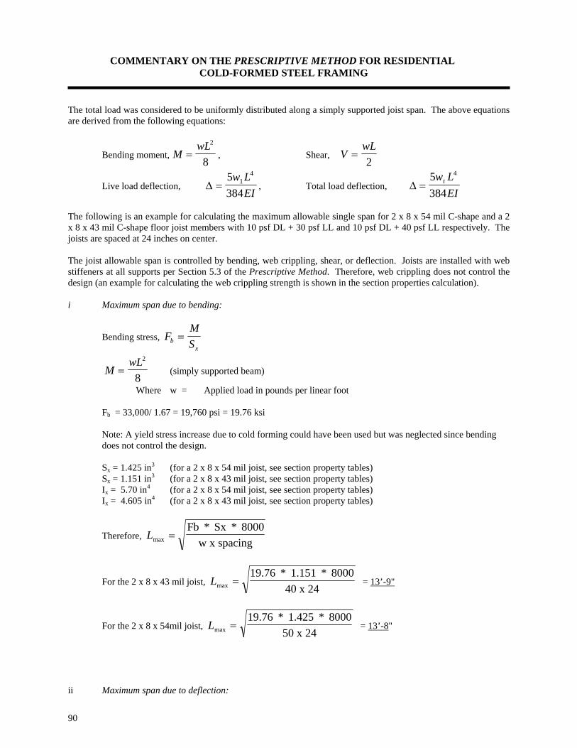
COMMENTARY ON THE PRESCRIPTIVE METHOD FOR RESIDENTIAL COLD-FORMED STEEL FRAMING
90
The total load was considered to be uniformly distributed along a simply supported joist span. The above equations are derived from the following equations:
Bending moment, MwL
=2
8, Shear, V
wL=
2
Live load deflection, ∆ =5384
14w L
EI, Total load deflection, ∆ =
5384
4w LEI
t
The following is an example for calculating the maximum allowable single span for 2 x 8 x 54 mil C-shape and a 2 x 8 x 43 mil C-shape floor joist members with 10 psf DL + 30 psf LL and 10 psf DL + 40 psf LL respectively. The joists are spaced at 24 inches on center. The joist allowable span is controlled by bending, web crippling, shear, or deflection. Joists are installed with web stiffeners at all supports per Section 5.3 of the Prescriptive Method. Therefore, web crippling does not control the design (an example for calculating the web crippling strength is shown in the section properties calculation). i Maximum span due to bending:
Bending stress, FMSb
x=
MwL
=2
8 (simply supported beam)
Where w = Applied load in pounds per linear foot Fb = 33,000/ 1.67 = 19,760 psi = 19.76 ksi Note: A yield stress increase due to cold forming could have been used but was neglected since bending does not control the design. Sx = 1.425 in3 (for a 2 x 8 x 54 mil joist, see section property tables) Sx = 1.151 in3 (for a 2 x 8 x 43 mil joist, see section property tables) Ix = 5.70 in4 (for a 2 x 8 x 54 mil joist, see section property tables) Ix = 4.605 in4 (for a 2 x 8 x 43 mil joist, see section property tables)
Therefore, Lmax =Fb * Sx * 8000
w x spacing
For the 2 x 8 x 43 mil joist, Lmax =19.76 * 1.151 * 8000
40 x 24 = 13’-9"
For the 2 x 8 x 54mil joist, Lmax =19.76 * 1.425 * 8000
50 x 24 = 13’-8"
ii Maximum span due to deflection:

COMMENTARY ON THE PRESCRIPTIVE METHOD FOR RESIDENTIAL COLD-FORMED STEEL FRAMING
91
For a simply supported beam with a uniformly distributed load, the maximum deflection is:
δmax =5384
4wLEI
δmax = L/360 for wt and L/480 for wl wt = Total load (psf) wl = Live load (psf) E = 29,500,000 psi
For the 2 x 8 x 43 mil joist:
Due to total load: Lmax =4.605 * 188800000
* 24 * 360403 = 13’-7”
Due to live load: Lmax =4.605 x 188800000
* 24 x 480303 = 13’-7”
Therefore, the maximum allowable span is 13'-7" For the 2 x 8 x 54 mil joist:
Due to total load: Lmax =5.70 * 188800000
* 24 * 360503 = 13’-7”
Due to live load: Lmax =5.70 * 188800000
* 24 * 480403 = 13'-3"
Therefore, the maximum allowable span is 13'-3"
iii Maximum span due to shear:
Shear, VwL
=2
w (plf) = Applied load (psf) multiplied by the joist spacing (ft)
Vallow = 1,566.5 lbs. (for a 2 x 8 x 54 mil punched joist, see section property tables) Vallow = 787.2 lbs. (for a 2 x 8 x 43 mil punched joist, see section property tables) For the 2 x 8 x 43 mil joist:
LV
w spacingallow
max *=
24 ⇒ Lmax
* .*
=24 787 2
40 24 = 19.68’ = 19’-8”
For the 2 x 8 x 54 mil joist:

COMMENTARY ON THE PRESCRIPTIVE METHOD FOR RESIDENTIAL COLD-FORMED STEEL FRAMING
92
LV
w spacingallow
max *=
24 ⇒ Lmax
* .*
=24 1566 6
50 24 = 31.33’ = 31’-4”
The allowable spans are the smaller of the maximum spans due to bending, shear, and deflection limits. Maximum allowable span for 2 x 8 x 43 mil joist is 13'-7” for a 30 psf live load + 10 psf dead load. Maximum allowable span for 2 x 8 x 54 mil joist is 13'-3" for a 40 psf live load + 10 psf dead load. Floor Vibration Proposed Procedure The proposed Virginia Tech criterion for determining vibration acceptability in cold-formed steel joist supported residential floor systems due to human activity is described below: 1. Calculate the critical central floor deflection from Onysko’s Criterion as modified to represent expected in-situ
performance: For L < 144 inches
Ycrit
41
L1.3= inches
For 144 inches≤ L ≤ 288 inches
[ ]Ycrit
41
L1.3 0.00458L 0.338= + inches
Where L is the floor joist span in inches.
2. Calculate the predicted deflection of a single joist, A0t, due to 225 lb. (1.0 kN) concentrated load at mid-span:
Aot
225L3
48EI= in.
Where L = floor span, in.
E = modulus of elasticity of the joists, psi
I = moment of inertia of joist alone, in.4
3. Calculate the number of effective joists, Neff, from the SJI Equation:
N eff 1 2 cosX
2Xo= + ∑
π
Where: X = distance from the center joist to the joist under consideration, in. X0 = distance from center joist to the edge of the effective floor = 1.06εL, in. L = joist span, in. ε = (Dx/Dy)0.25 Dx = flexural stiffness perpendicular to the joist = Ect3/12, lb.-in. Dy = flexural stiffness parallel to the joist = EIt/S Ec = modulus of elasticity of the sub-flooring, psi E = modulus of elasticity of the joists, psi t = sub-flooring thickness, in. It = moment of inertia of joist alone, in.4 S = joist spacing, in.
4. Calculate the predicted center floor deflection, Ao :
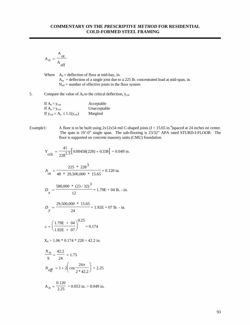
COMMENTARY ON THE PRESCRIPTIVE METHOD FOR RESIDENTIAL COLD-FORMED STEEL FRAMING
93
AoA
otA
eff=
Where A0 = deflection of floor at mid-bay, in. Aot = deflection of a single joist due to a 225 lb. concentrated load at mid-span, in. Neff = number of effective joists in the floor system 5. Compare the value of A0 to the critical deflection, ycrit If Ao < ycrit Acceptable If Ao > ycrit Unacceptable If ycrit < Ao ≤ 1.1(ycrit) Marginal Example1: A floor is to be built using 2x12x54 mil C-shaped joists (I = 15.65 in.4)spaced at 24 inches on center.
The span is 19’-0” single span. The sub-flooring is 23/32” APA rated STURD-I-FLOOR. The floor is supported on concrete masonry units (CMU) foundation.
[ ]Ycrit
41
2281.3= +0 00458(228) 0 338. . = 0.049 in.
Aot
225 * 2283
48 * 29,500,000 * 15.65= = 0.120 in.
Dx
=580,000 * (23 / 32)3
12= 1.79E + 04 lb. - in.
Dy
=29,500,000 * 15.65
24= 1.92E + 07 lb. - in.
ε =⎛⎝⎜
⎞⎠⎟
1.79E + 04
1.92E + 07
0 25.= 0.174
X0 = 1.06 * 0.174 * 228 = 42.2 in. X oS
42.2
24= = 1.75
Neff = +⎛⎝⎜
⎞⎠⎟1 2
24
2 42.2cos
*
π = 2.25
A o0.1202.25= = 0.053 in. > 0.049 in.
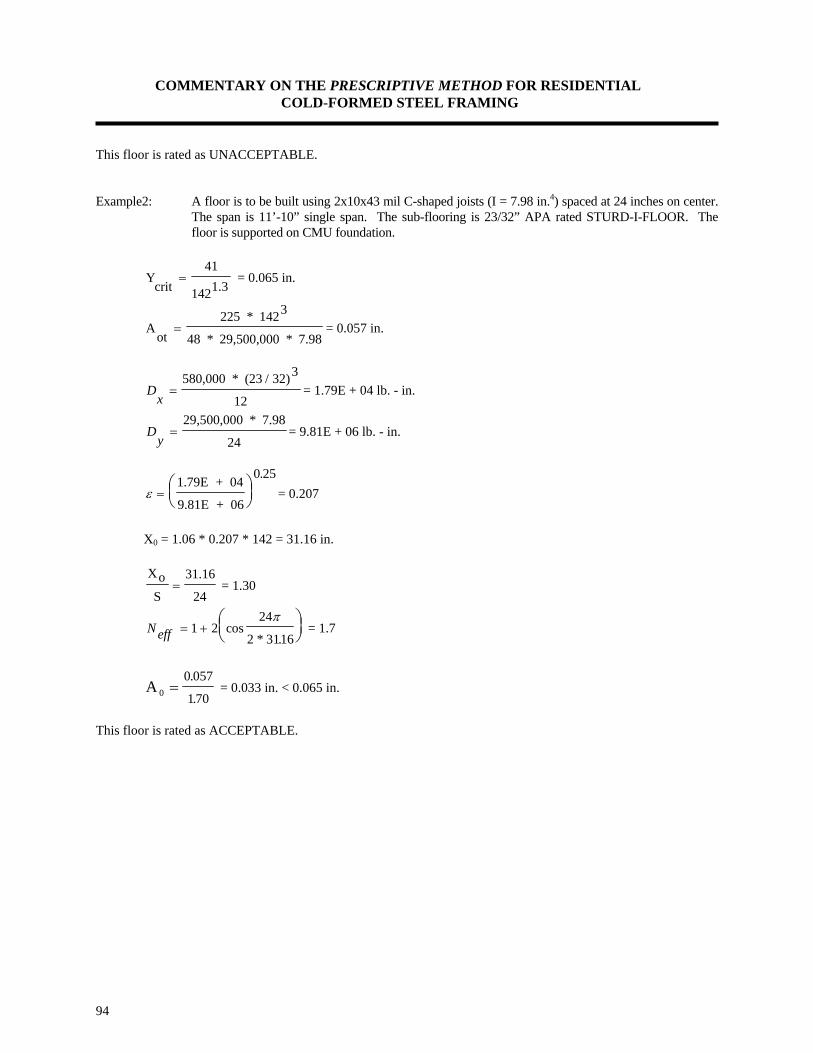
COMMENTARY ON THE PRESCRIPTIVE METHOD FOR RESIDENTIAL COLD-FORMED STEEL FRAMING
94
This floor is rated as UNACCEPTABLE. Example2: A floor is to be built using 2x10x43 mil C-shaped joists (I = 7.98 in.4) spaced at 24 inches on center.
The span is 11’-10” single span. The sub-flooring is 23/32” APA rated STURD-I-FLOOR. The floor is supported on CMU foundation.
Ycrit
41
1421.3= = 0.065 in.
Aot
225 * 1423
48 * 29,500,000 * 7.98= = 0.057 in.
Dx
=580,000 * (23 / 32)3
12= 1.79E + 04 lb. - in.
Dy
=29,500,000 * 7.98
24= 9.81E + 06 lb. - in.
ε =⎛⎝⎜
⎞⎠⎟
1.79E + 04
9.81E + 06
0 25.= 0.207
X0 = 1.06 * 0.207 * 142 = 31.16 in. XoS
31.16
24= = 1.30
Neff = +⎛⎝⎜
⎞⎠⎟1 2
24
2 3116cos
* .
π = 1.7
A 0
0 057
170=
.
. = 0.033 in. < 0.065 in.
This floor is rated as ACCEPTABLE.

COMMENTARY ON THE PRESCRIPTIVE METHOD FOR RESIDENTIAL COLD-FORMED STEEL FRAMING
95
WALL STUD DESIGN AND EXAMPLE In the design of compression members, such as wall studs, any one of several engineering criteria may control the prescriptive requirements depending on the thickness and length of the stud. The engineering analysis includes checks for:
• Yielding, • Overall column buckling, • Flexural buckling, • Torsional buckling, • Torsional-flexural buckling, and • Local buckling of an individual member.
The engineering approach used in the Prescriptive Method considers wind, snow, and live load combinations as they apply to the design of studs. The objective was to maintain a simple table format without sacrificing the economies possible through case-by-case design. Wall studs were designed using conservative engineering assumptions which neglect the benefits of system effects of wall assemblies. The composite strength of typical residential wall assemblies provides higher resistance to out-of-plane bending and axial load conditions. The following applied loads were used in developing the wall stud tables: Dead Loads: Floor Dead Load = 10 psf Wall Dead Load = 10 psf Ceiling Dead Load = 5 psf Roof Dead Load = 7 psf Live Loads: Second Floor Live Load = 30 psf First Floor Live Load = 40 psf Roof Live Load = Greater of 16 psf or Snow Load. Snow Loads The ASCE 7-93 ground snow map was divided into four regions as follows: Region Ground snow load 1 0 to 20 psf 2 21 to 30 psf 3 31 to 50 psf 4 51 to 70 psf Applied roof snow loads are calculated by simply multiplying the ground snow load by a 0.7 conversion factor recognized in ASCE 7 and other snow load provisions (no further reductions were made for special cases). Roof slopes are assumed to range from 3:12 to 12:12. Ground Snow Load (psf) 20 30 50 70 Applied Roof Snow Load (psf) 16 21 35 49 The sloped roof snow load, Ps = Cs x Pf, where Pf is the flat roof snow load. Pf = 0.7 Ce Ct I Pg

COMMENTARY ON THE PRESCRIPTIVE METHOD FOR RESIDENTIAL COLD-FORMED STEEL FRAMING
96
I is the importance factor depending on building classification. Houses are typically class I structures, with an importance factor of 1.0.
Pg = Ground snow load from the ASCE 7-93 estimated ground snow map (psf). This map is also included in all major building codes.
Ce is the exposure factor depending on the location of the house. Ce varies from 0.8 for windy, unsheltered areas, to 1.2 for heavily sheltered areas. A factor of 1.0 is deemed reasonable for houses.
Ct is a thermal factor that varies from 1.0 for heated structures to 1.2 for unheated structures. The thermal factor should be used based on the thermal conditions which is likely to exist during the life of the structure. Houses are typically considered heated structures with Ct = 1.0. Although it is possible that a brief interruption of power will cause temporary cooling of a heated house, the joint probability of this with a peak snow load is highly unlikely. Houses that are unoccupied during cold seasons, may experience a higher thermal factor, however, for unoccupied buildings the importance factor drops to 0.8, thus reducing the design loads by 20%, which offsets the 20% increase in the thermal factor. Cs is the roof slope factor ranging from approximately 0.1 to 1.0. For warm roofs (i.e. house roofs) the Cs curve is slightly smoother than that for cold roofs. Roofs with slopes up to 6:12 have a slope factor of 1.0, while roofs with slopes greater than 7:12 have a slope factor between 0.4 to 1.0. A slope factor of 1.0 is judged to be conservative for houses with roof slopes from 3:12 to 12:12. Unbalanced snow loads, sliding snow loads, and snow drifts on lower roofs were not considered due to the lack of evidence for damage from unbalanced loads on homes and the lack of data to typify the statistical uncertainties associated with this load pattern on residential structures. Rain-on-snow surcharge load was also not considered in the calculations. Roof slopes in the Prescriptive Method exceed the 1/2 inch per foot requirement by ASCE 7-93 for the added load to be considered. Therefore, the snow load can be computed as: 1.0 * 0.7 * 1.0 * 1.0 * Pg = 0.7 Pg Wind Loads Wind loads were based on wind speeds ranging from 70 to 110 mph for exposure categories A, B, and C in ASCE 7. Studs were designed using Components and Cladding wind pressure coefficients and a load combination of D + W. Studs were also designed for concurrent wind, snow, and live loads (multiple loading) using Main Wind Force Resisting System (MWFRS) pressure coefficients and the following load combinations: (D + L + ½ S + W) or (D + L + S + ½ W), based on the Uniform Building Code (UBC). The multiple load combination was found to control the design for the range of conditions encountered in the Prescriptive Method. The MWFRS wind loads are shown in Table C6.3 a. For Main Wind Force Resisting Systems (MWFRS): Wind load = W = 0.00256KzGhCp(VI)2
Where Kz = 0.87 (at 20 feet, for Exposure C) Gh = 1.29 (Exposure C, 20 feet) Cp = 0.8 (Windward wall) I = 1 (for residential buildings in areas with wind speed < 100 mph) b. For Components and Cladding: Wind load = W = 0.00256Kz(GCp + GCpi)(VI)2
Where: Kz = 0.87 (at 20 feet, for Exposure C)

COMMENTARY ON THE PRESCRIPTIVE METHOD FOR RESIDENTIAL COLD-FORMED STEEL FRAMING
97
GCp = - 1.5 (Components and Cladding, wall interior, Zone 4) GCpi = ± 0.25 (Components and Cladding, interior pressure, enclosed buildings) I = 1 (for residential buildings in areas with wind speed <90 mph) I = 1.05 (for residential buildings in areas with wind speed ≥ 100 mph) Exposure B Components and Cladding pressure coefficients GCp and GCpi were taken as 85 percent of the Exposure C coefficients based upon ASCE 7-95. Applying the above equation, the design wind loads used in generating the stud tables are as follows (Table C6.3):
Table C6.3
Wind Exposure
MWFRS Wind Loads (psf)
70 mph 80 mph 90 mph 100 mph 110 mph B 15 20 25 32 43 C 20 25 32 43 52
Load Combination: The following loading combinations were investigated to determine the controlling design load on the studs: A: Using MWFRS coefficients for wind loads with a 1/3 increase in allowable stresses for load combinations including wind (per AISI Cold-Formed Steel Design Specification):
1) 0.75(D + L + ½ S + W) 2) 0.75(D + L + S + ½ W)
B: Using Component and Cladding coefficients for wind loads with a 1/3 increase in allowable stresses. D + W Where: D = Dead load; S = Snow load; L = Live load W = Wind load Example The following is an example for calculating the applicable loads on wall studs and designing the wall studs to resist such loads. A hypothetical two story steel building is used to demonstrate the engineering calculations used in the Prescriptive Method. The building has the following physical dimensions: Building type: Two story house with basement. Building width: 28 feet (with 2 foot roof overhang) Building length: 40 feet. First story wall height: 8 feet.

COMMENTARY ON THE PRESCRIPTIVE METHOD FOR RESIDENTIAL COLD-FORMED STEEL FRAMING
98
Second story wall height: 8 feet. Wall stud spacing: 24" o.c. Wind speed and Exposure: 70 mph Exposure C (or 80 mph Exposure B) Ground snow load: 30 psf Opening size: 8 feet. The wall studs are subjected to a combined axial and lateral loads. Axial loads are due to roof live and dead loads, plus top floor live and dead loads. Lateral loads are due to wind pressure. The following loads are given: Ground Snow load = 50 psf Roof dead load = 7 psf Wall dead load = 10 psf Ceiling dead load = 5 psf Floor dead load = 10 psf Top floor live load = 30 psf Attic live load = 10 psf Wind speed & Exposure 70 mph, Exposure C i. Roof Load: For wall studs, the roof load was based on a ground snow load of 50 psf. Roof Snow load = S = 0.8 x 50 = 40 psf (0.8 is conservatively used) ii. Wind Loads: Wind loads were calculated using both main wind force resisting systems (MWFRS) and component and cladding (C&C) coefficients, as follows: a. MWFRS: Wind load = W = 0.00256KzGhCpV2
Kz = 0.87 (at 20 feet, Exposure C) Gh = 1.29 (Exposure C, 20 feet) Cp = 0.8 (Windward wall) V = 70 mph W = 0.00256(0.87)(1.29)(0.8)(70)2 = 11.26 psf use 12 psf. b. Components and Cladding: Wind load = W = 0.00256Kz(GCp + GCpi)(V)2
Kz = 0.87 (at 20 feet, Exposure C) GCp = ± 1.5 (for components and cladding, Zone 4, wall interior) GCpi = ± 0.25 (for components and cladding interior pressure, enclosed buildings) V = 70 mph W = 0.00256(0.87)(1.5 + 0.25)(70)2 = 19.10 psf The applied loads on the two story building are calculated as follows: Roof live load = maximum of snow load or roof live load (16 psf minimum).

COMMENTARY ON THE PRESCRIPTIVE METHOD FOR RESIDENTIAL COLD-FORMED STEEL FRAMING
99
Snow load = 0.7 x 30 = 21 psf (calculated per ASCE 7-93 criteria, no other reduction is used) Wind loads are calculated in accordance with ASCE 7-93. Wind load = WL = 0.00256Kz(GCp + GCpi)(VI)2 WL = 0.00256(0.87)(1.5 + 0.25)(70 x 1)2 = 19.10 psf round up to 20 psf. [or for 80 mph Exposure B: WL = 0.00256(0.87)(1.5 + 0.25)(80 x 1)2 x 0.85 = 21 psf] Case 1: Dead load + live load + half snow load + full wind load (D + L + ½ S + W) a. One story building or the top floor of a two story building: Applied axial load = (roof dead load) x (house width + 2' overhang) / 2 + 1/2 (snow load) x (house width + 2’)/2 + (attic live load + ceiling dead load) x (house width)/2 Applied axial load = (7)(28 + 2)/2 + ½ (40) x (28 + 2) / 2 + (10 + 5)(28/2) = 615 lb./ft Applied axial load = 1230 lbs. Per stud for 24 inch on center spacing. Applied lateral load = 12 psf (MWFRS) b. Bottom floor of a two story building:
Applied axial load = (roof dead load) x (house width + 2' overhang) / 2 + (second floor + ceiling dead
load) x (28'/2) + second story wall dead load + (attic live load + second floor live load)x(house width)/2 + ½ (roof live load) x (house width + 2' overhang)/2
Applied axial load = (7)(28 + 2)/2 + (10 + 5) x (28/2) + (10 x 8) + (10 + 30) x (28) / 2 + 1/2 (40)(28 + 2) / 2 = 1255 lb./ft Applied axial load = 1255 x 24”/12” = 2510 lbs. Per stud (24” spacing) Applied lateral load = 12 psf (MWFRS) Case 2: Dead load + live load + half wind load + full snow load (D + L + S + ½ W) a. One story building or the top floor of a two story building: Applied axial load = (roof dead load) x (house width + 2' overhang) / 2 + (snow load) x (house width + 2') / 2 + (attic live load + ceiling dead load) x (house width)/2 Applied axial load = (7)(28 + 2)/2 + (40) x (28 + 2) / 2 + (10 + 5)(28/2) = 915 lb./ft Applied axial load = 915 x 24”/12” = 1830 lbs. per stud (24” spacing) Applied lateral load = Half MWFRS load = 12 / 2 = 6 psf (MWFRS) b. Bottom floor of a two story building:
Applied axial load = (roof dead load) x (house width + 2' overhang) / 2 + (second floor + ceiling dead

COMMENTARY ON THE PRESCRIPTIVE METHOD FOR RESIDENTIAL COLD-FORMED STEEL FRAMING
100
load)*(28'/2) + second floor wall dead load + (attic live load + second floor live load) x (house width) / 2 + (snow) x (house width + 2' overhang) / 2
Applied axial load = (7)(28 + 2)/2 + (10 + 5) x (28/2) + (8 x 10) + (10 + 30) x (28) / 2
+(40) x (28 + 2)/2 = 1555 lb./ft Applied axial load = 1555 x 24”/12” = 3110 lbs. per stud (24” spacing) Applied lateral load = Half MWFRS load = 12 / 2 = 6 psf (MWFRS) Case 3: Dead load + Wind load (D + W) a. One story building or the top floor of a two story building: Applied axial load = (roof dead load) x (house width + 2' overhang) / 2 + ceiling dead load) x (house width) / 2 Applied axial load = (7)(28 + 2)/2 + (5)(28/2) = 175 lb./ft Applied axial load = (175)(24”/12”) = 350 lbs. per stud (24” o.c. spacing) Applied lateral load = 19.10 psf (components and cladding) b. Bottom floor of a two story building: Applied axial load = (roof dead load) x (house width + 2' overhang) / 2 + (second floor dead load + ceiling dead load) x (28’/2) + second floor wall dead load Applied axial load = (7)(28 + 2)/2 + (10 + 5) x (28/2) + (10 x 8) = 395 lb./ft Applied axial load = 395(24”/12”) = 790 lbs. per stud (24” o.c. spacing) Applied lateral load = 19.10 psf (components and cladding) Therefore, the load combinations to be checked are: a) One story building: 1830 lbs. axial with 6 psf lateral 1230 lbs. axial with 12 psf lateral 350 lbs. axial with 19.1 psf lateral b) Bottom story: 3110 lbs. axial with 6 psf lateral 2510 lbs. axial with 12 psf lateral 790 lbs. axial with 19.1 psf lateral

COMMENTARY ON THE PRESCRIPTIVE METHOD FOR RESIDENTIAL COLD-FORMED STEEL FRAMING
101
Design Wall Studs Select a stud size and check its capacity to see if it can resist the applied loads. A 2 x 4 x 43 mil C-shaped stud is initially selected. Calculate the capacity of a 2 x 4 x 43:
The allowable moment is calculated as the smallest nominal moment calculated per Sections C3.1.1, C3.1.2, and C3.1.3 divided by a factor of safety of 1.67. All referenced equations and sections here are those in the AISI Design Specification. Nominal section strength per AISI Section C3.1.1: Use procedure (a) based on initiation of yielding. Mn = Se Fy Eq. C3.1.1-1 Where Fy is the design yield strength. Se = Elastic section modulus of the effective section calculated with the extreme compression or tension fiber at Fy Calculate strength increase due to cold working per Section A5.2.2 of the AISI Specification: (assuming that the quantity r is unity as determined according to AISI Section B2 for each of the component elements of the section.) Fya = CFyc + ( 1 - C )Fyf Eq. A5.2.2-1 Fyf = 33,000 psi C = corner cross sectional area of flange/full cross sectional area of flange
8’
0.50”
3.50”
1.625”
Y
X X
Y
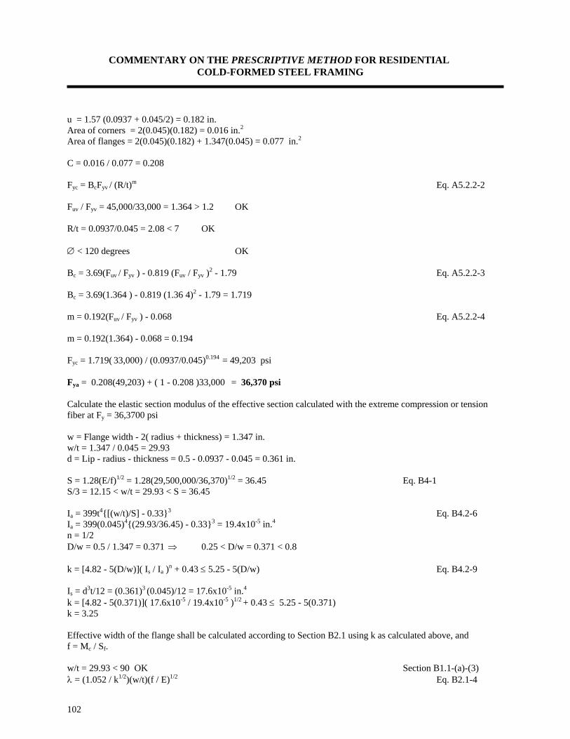
COMMENTARY ON THE PRESCRIPTIVE METHOD FOR RESIDENTIAL COLD-FORMED STEEL FRAMING
102
u = 1.57 (0.0937 + 0.045/2) = 0.182 in. Area of corners = 2(0.045)(0.182) = 0.016 in.2 Area of flanges = 2(0.045)(0.182) + 1.347(0.045) = 0.077 in.2 C = 0.016 / 0.077 = 0.208 Fyc = BcFyv / (R/t)m Eq. A5.2.2-2 Fuv / Fyv = 45,000/33,000 = 1.364 > 1.2 OK R/t = 0.0937/0.045 = 2.08 < 7 OK ∅ < 120 degrees OK Bc = 3.69(Fuv / Fyv ) - 0.819 (Fuv / Fyv )2 - 1.79 Eq. A5.2.2-3 Bc = 3.69(1.364 ) - 0.819 (1.36 4)2 - 1.79 = 1.719 m = 0.192(Fuv / Fyv ) - 0.068 Eq. A5.2.2-4 m = 0.192(1.364) - 0.068 = 0.194 Fyc = 1.719( 33,000) / (0.0937/0.045)0.194 = 49,203 psi Fya = 0.208(49,203) + ( 1 - 0.208 )33,000 = 36,370 psi Calculate the elastic section modulus of the effective section calculated with the extreme compression or tension fiber at Fy = 36,3700 psi w = Flange width - 2( radius + thickness) = 1.347 in. w/t = 1.347 / 0.045 = 29.93 d = Lip - radius - thickness = 0.5 - 0.0937 - 0.045 = 0.361 in. S = 1.28(E/f)1/2 = 1.28(29,500,000/36,370)1/2 = 36.45 Eq. B4-1 S/3 = 12.15 < w/t = 29.93 < S = 36.45 Ia = 399t4[(w/t)/S] - 0.333 Eq. B4.2-6 Ia = 399(0.045)4(29.93/36.45) - 0.333 = 19.4x10⁻⁵ in.4 n = 1/2 D/w = 0.5 / 1.347 = 0.371 ⇒ 0.25 < D/w = 0.371 < 0.8 k = [4.82 - 5(D/w)]( Is / Ia )n + 0.43 ≤ 5.25 - 5(D/w) Eq. B4.2-9 Is = d3t/12 = (0.361)3 (0.045)/12 = 17.6x10⁻⁵ in.4 k = [4.82 - 5(0.371)]( 17.6x10-5 / 19.4x10-5 )1/2 + 0.43 ≤ 5.25 - 5(0.371) k = 3.25 Effective width of the flange shall be calculated according to Section B2.1 using k as calculated above, and f = Mc / Sf. w/t = 29.93 < 90 OK Section B1.1-(a)-(3) λ = (1.052 / k1/2)(w/t)(f / E)1/2 Eq. B2.1-4

COMMENTARY ON THE PRESCRIPTIVE METHOD FOR RESIDENTIAL COLD-FORMED STEEL FRAMING
103
Where f = Mc / Sf = 36,370 psi λ = [1.052/ (3.25)1/2](29.93)(36,370/29,500,000)1/2 = 0.613 λ ≤ 0.613 ⇒ b = w Eq. B2.1-1 Effective width b = 1.347 inches (i.e. compression flange is fully effective) Compression Stiffener: Determine the effective width of the compression stiffener (lip): D = 0.5 inches d = 0.361 inches. d/t = 0.361/0.045 = 8.02 < 60 OK Section B1.1-(a)-(3) D/w = 0.5 / 1.347 = 0.371 0.25 < D/w = 0.371 < 0.8 Calculate the effective width for the lip per AISI Section B2.1 : λ = [1.052/ (k)1/2](w/t)[f / E]1/2 Eq. B2.1-4 Where f = Mc / Sf = 36,370 psi and k = 0.43 per AISI Section B3.1 λ = [1.052 / (0.43)1/2](8.02)(36,370/29,500,000)1/2 = 0.452 λ ≤ 0.673 ⇒ d'
s = d = 0.361 in. Eq. B2.1-1 ds = d'
s (Is/Ia) £ d's Eq. B4.2-11
ds = 0.361 (17.6x10⁻⁵ /19.4x10-5 ) ≤ 0.361 ds = 0.33 in. Effective width of lip ds = 0.33 inches (i.e. compression stiffener is not fully effective) Assume the web is fully effective.
Element Effective length (in)
Distance from top fiber, y (in.)
Ly
in.2
Ly2
in.3
I1' About own
axis in.3
Web Tension flange Comp. Flange Upper corners Lower corners Upper stiffener Lower stiffener
3.222 1.347 1.347 0.3651 0.3651 0.33
0.361
1.75 3.478 0.023 0.065 3.435 0.303 3.181
5.639 4.685 0.030 0.024 1.255 0.099 1.149
9.868 16.292 0.001 0.002 4.309 0.030 3.653
2.788 - - - -
0.003 0.004
Sum 7.337 12.881 34.156 2.795 1 Where corner length = Length of arc = 1.57(R + t/2) = 0.183 in.. Two corners = 0.365 in. Distance from top fiber to x-axis is Ycg = 12.881 / 7.337 = 1.756 inches

COMMENTARY ON THE PRESCRIPTIVE METHOD FOR RESIDENTIAL COLD-FORMED STEEL FRAMING
104
Since distance from the top compression fiber to the neutral axis is greater than one half the beam depth, the compression stress of 36,440 psi will govern as assumed (i.e. initial yielding is in compression). Check if web is fully effective: f1 = +f (Ycg - t - R)/Ycg = 36,370(1.756 - 0.045 - 0.0937)/1.756 = 33,497 psi f2 = -f (Web size - Ycg - t - R)/Ycg = 36,370(3.5 - 1.756 - 0.045 - 0.0937)/1.756 f2 = - 33,248 psi (tension) The effective widths are calculated per AISI Section B2.3 (a) for load capacity determination. Ψ = f2 / f1 = -0.993 ≤ - 0.236 Section B2.3 b1 = be / (3-Ψ) Eq. B2.3-1 b2 = be / 2 Eq. B2.3-2 b1 + b2 shall not exceed the compression portion of the web calculated on the basis of effective section. be = Effective width b determined in accordance with Section B2.1 with f1 substituted for f and k determined as follows: k = 4 + 2(1 - Ψ)3 + 2(1 - Ψ) Eq. B2.3-4 k = 4 + 2(1 + 0.993)3 + 2(1 + 0.993) = 23.818 h = w = Web - 2(Radius + thickness) = 3.5 - 2(0.0937 + 0.045) = 3.223 in. h/t = 3.223 / 0.045 = 71.62 < 200 OK Section B1.2-(a) λ(web) = [1.052 / (23.818)1/2](71.62)(33,497/29,500,000)1/2 = 0.52 < 0.673 Eq. B2.1-4 be = w = 3.223 in. Eq. B2.1-1 b2 = 3.223 / 2 = 1.611 in. b1 = 3.223 / (3 + 0.993) = 0.807 in. b1 + b2 = 1.611 + 0.807 = 2.418 in. Compression portion of the web = ycg - (Radius + thickness) = 1.756 - (0.0937 + 0.045) = 1.617 inches. Since b1 + b2 = 2.418 in. > 1.617 in., b1 + b2 shall be taken as 1.617 in. This verifies the assumption that the web is fully effective. I'x = Ly2 + I'
1 - L(ycg)2
I'x = 34.156 + 2.795 - 7.337(1.756 )2 = 14.33 in.3 Actual Ix = I'x t = (14.33)(0.045) = 0.645 in4 Se = Ix / ycg = 0.645 / 1.756 = 0.367 in3 Mn = Se Fy Eq. C3.1.1-1 Mn = (0.367)(36,370) = 13,348 lb.-in. = 1,112 ft-lb.
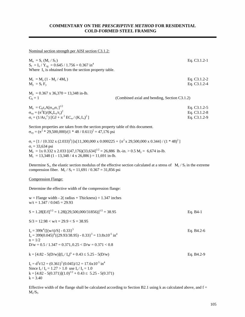
COMMENTARY ON THE PRESCRIPTIVE METHOD FOR RESIDENTIAL COLD-FORMED STEEL FRAMING
105
Nominal section strength per AISI section C3.1.2: Mn = Sc (Mc / Sf ) Eq. C3.1.2-1 Sf = Ix / Ycg = 0.645 / 1.756 = 0.367 in4 Where Ix is obtained from the section property table. Mc = My (1 - My / 4Me ) Eq. C3.1.2-2 My = Sf Fy Eq. C3.1.2-4 My = 0.367 x 36,370 = 13,348 in-lb. Cb = 1 (Combined axial and bending, Section C3.1.2) Me = CbroA[σeyσt ]1/2 Eq. C3.1.2-5 σey = (π2E)/(KyLy/ry)2 Eq. C3.1.2-8 σt = (1/Aro
2 ) [GJ + π 2 ECw / (Kt Lt)2 ] Eq. C3.1.2-9 Section properties are taken from the section property table of this document. σey = (π2 * 29,500,000)/(1 * 48 / 0.611)2 = 47,176 psi σt = [1 / 0.332 x (2.033)2]x[11,300,000 x 0.000225 + π2 x 29,500,000 x 0.344 / (1 * 48)2 ] σt = 33,634 psi Me = 1x 0.332 x 2.033 [(47,176)(33,634]1/2 = 26,886 lb.-in. > 0.5 My = 6,674 in-lb. Mc = 13,348 (1 - 13,348 / 4 x 26,886 ) = 11,691 in-lb. Determine Sc, the elastic section modulus of the effective section calculated at a stress of Mc / Sf in the extreme compression fiber. Mc / Sf = 11,691 / 0.367 = 31,856 psi Compression Flange: Determine the effective width of the compression flange: w = Flange width - 2( radius + Thickness) = 1.347 inches w/t = 1.347 / 0.045 = 29.93 S = 1.28[E/f]1/2 = 1.28[(29,500,000/31856)]1/2 = 38.95 Eq. B4-1 S/3 = 12.98 < w/t = 29.9 < S = 38.95 Ia = 399t4[(w/t)/S] - 0.333 Eq. B4.2-6 Ia = 399(0.045)4(29.93/38.95) - 0.333 = 13.8x10⁻⁵ in4 n = 1/2 D/w = 0.5 / 1.347 = 0.371, 0.25 < D/w = 0.371 < 0.8 k = [4.82 - 5(D/w)](Is / Ia)n + 0.43 ≤ 5.25 - 5(D/w) Eq. B4.2-9 Is = d3t/12 = (0.361)3 (0.045)/12 = 17.6x10⁻⁵ in4 Since Is / Ia = 1.27 > 1.0 use Is / Ia = 1.0 k = [4.82 - 5(0.371)](1.0)1/2 + 0.43 ≤ 5.25 - 5(0.371) k = 3.40 Effective width of the flange shall be calculated according to Section B2.1 using k as calculated above, and f = Mc/Sf.

COMMENTARY ON THE PRESCRIPTIVE METHOD FOR RESIDENTIAL COLD-FORMED STEEL FRAMING
106
w/t = 29.93 < 90 OK Section B1.1-(a)-(3) λ = [1.052 / (k)1/2](w / t)(f / E)1/2 Eq. B2.1-4 Where f = Mc / Sf = 31,856 psi λ = [1.052 / (3.40)1/2](29.93)(31,856 / 29,500,000)1/2 = 0.561 λ ≤ 0.673 ⇒ b = w Eq. B2.1-1 Effective width b = 1.347 inches (i.e. compression flange is fully effective) Compression Stiffener: Determine the effective width of the compression stiffener (lip): d = Lip size - radius - thickness = 0.5 - 0.0937 - 0.045 = 0.361 in. d/t = 0.361/0.045 = 8.02 < 60 OK Section B1.1-(a)-(3) D/w = 0.5 / 1.347 = 0.371, 0.25 < D/w = 0.371 < 0.8 Calculate the effective width for the lip per AISI Section B2.1 : λ = [1.052/(k)1/2](w/t)(f/E)1/2 Eq. B2.1-4 Where f = Mc / Sf = 31,856 psi and k = 0.43 per AISI Section B3.1 λ = [1.052/(0.43)1/2](8.02)(31,856 / 29,500,000)1/2 = 0.423 λ ≤ 0.673 ⇒ d'
s = d = 0.361 in. Eq. B2.1-1 ds = d'
s (Is/Ia) ≤ d's Eq. B4.2-11
Effective width of lip ds = 0.361 inches (i.e. compression stiffener is fully effective) Thus, one concludes that the section is fully effective. Ycg = 3.5 / 2 = 1.75 in. (from symmetry)

COMMENTARY ON THE PRESCRIPTIVE METHOD FOR RESIDENTIAL COLD-FORMED STEEL FRAMING
107
Web: Check if web is fully effective: (Section B2.3): Assume the web is fully effective, and top fiber stress is 31,907 psi:
Element Effective length L (in)
Distance from top fiber, y (in.)
Ly in.2
Ly2 in.3
I1' About own
axis in.3
Web Tension flange Comp. Flange Upper corners Lower corners Upper stiffener Lower stiffener
3.222 1.347 1.347 0.3651
0.3651
0.361 0.361
1.75 3.478 0.023 0.065 3.435 0.319 3.181
5.639 4.685 0.030 0.024 1.255 0.115 1.149
9.868 16.292 0.001 0.002 4.309 0.037 3.653
2.788 - - - - 0.004 0.004
Sum 7.37 12.25 12.897 34.163 2.796
1 Where corner length = Length of arc = 1.57(R + t/2) = 0.183 in.. Two corners = 0.365 in. Distance from top fiber to x-axis is Ycg = 12.897 / 7.367 = 1.75 inches f1 = +f (Ycg - t - R)/Ycg = 31,856(1.75 - 0.045 - 0.0937)/1.75 = 29,331 psi f2 = -f (Web size - Ycg - t - R)/Ycg = 31,856(3.5 - 1.75 - 0.045 - 0.0937)/1.75 =- 29,331 psi The effective widths are calculated per Section B2.3 (a) for load capacity determination. Ψ = f2 / f1 = -1 ≤ - 0.236 Section B2.3 b1 = be / (3-Ψ) Eq. B2.3-1 b2 = be / 2 Eq. B2.3-2 b1 + b2 shall not exceed the compression portion of the web calculated on the basis of effective section. be = Effective width b determined in accordance with Section B2.1 with f1 substituted for f and k determined as follows: k = 4 + 2(1 - Ψ )3 + 2(1 - Ψ ) Eq. B2.3-4 k = 4 + 2(1 + 1)3 + 2(1 + 1) = 24 h = w = Web - 2(Radius + thickness) = 3.5 - 2(0.0937 + 0.045) = 3.222 in. h/t = 3.222 / 0.045 = 71.45 < 200 OK Section B1.2-(a) λ(web) = [1.052 / (24)1/2](71.62)[29,331/29,500,000]1/2 = 0.485 < 0.673 Eq. B2.1-4 be = w = 3.222 inches Eq. B2.1-1 b2 = 3.222 / 2 = 1.611 inches b1 = 3.222 / (3 + 1) = 0.805 inches b1 + b2 = 1.611 + 0.805 = 2.416 inches Compression portion of the web = ycg - (Radius + thickness) = 1.75 - (0.0937 + 0.045) = 1.611in. Since b1 + b2 = 2.416 in. > 1.611 in., b1 + b2 shall be taken as 1.611in. This verifies the assumption that the web is fully effective.

COMMENTARY ON THE PRESCRIPTIVE METHOD FOR RESIDENTIAL COLD-FORMED STEEL FRAMING
108
I'x = Ly2 + I'1 - Ly2
cg I'x = 34.163 + 2.796 - 7.37(1.75)2 = 14.388 in3 Actual Ix = I'x t = (14.388)(0.045) = 0.647 in4 Se = Ix / ycg = 0.647 / 1.75 = 0.370 in3 Mn = Se Fy Eq. C3.1.1-1 Mn = 0.370 x 31,856 = 11787 in-lb. = 982 ft-lb. Nominal section strength per AISI Section C3.1.3: This section is not applicable to the wall studs in this example. Allowable moment: The allowable moment is the smallest nominal moment calculated per Sections C3.1.1, C3.1.2, and C3.1.3 divided by a factor of safety of 1.67. Ω = 1.67 Ma = Mn / 1.67 Eq. C3.1-1 Ma = 11,787/1.67 = 7,058 in-lb. = 588 ft-lb. ii. Allowable Shear Va Shear for unpunched web: The allowable shear Va is calculated in accordance with Section C3.2 of the AISI Specification. Calculate the depth of the flat portion of the web, h, measured along the plane of the web. h = Web size - 2(radius + thickness) = 3.5 - 2(0.0937 + 0.045) = 3.223 in. h/t = 3.223/0.045 = 71.62 < 200 Calculate 1.38 (Ekv / Fy )1/2 = 1.38(29,500,000 x 5.34 / 33,000)1/2 = 95.35 Where kv is shear buckling coefficient = 5.34 Fy = 33,000 psi (stress increase due to cold-forming can not be used here) h/t = 71.62 < 95.35 Þ Va = 0.38t2 (EkvFy)1/2 ≤ 0.4(h)(t)(Fy) Eq. C3.2-1 Va = 0.38(0.045)2 (29,500,000 x 5.34 x 33,000)1/2
≤ (0.4 x 3.223 x 0.045 x 33,000)
Va = 1,754 lbs. ≤ 1914 lbs. OK. Va = 1,754 lbs.
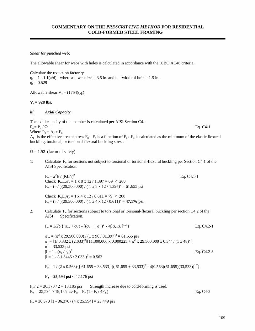
COMMENTARY ON THE PRESCRIPTIVE METHOD FOR RESIDENTIAL COLD-FORMED STEEL FRAMING
109
Shear for punched web: The allowable shear for webs with holes is calculated in accordance with the ICBO AC46 criteria. Calculate the reduction factor q: qs = 1 - 1.1(a/d) where a = web size = 3.5 in. and b = width of hole = 1.5 in. qs = 0.529 Allowable shear Va = (1754)(qs) Va = 928 lbs. iii. Axial Capacity The axial capacity of the member is calculated per AISI Section C4. Pa = Pn / Ω Eq. C4-1 Where Pn = Ae x Fn Ae is the effective area at stress Fn . Fn is a function of Fe . Fe is calculated as the minimum of the elastic flexural buckling, torsional, or torsional-flexural buckling stress. Ω = 1.92 (factor of safety) 1. Calculate Fe for sections not subject to torsional or torsional-flexural buckling per Section C4.1 of the AISI Specification.
Fe = π2E / (KL/r)2 Eq. C4.1-1 Check KxLx/rx = 1 x 8 x 12 / 1.397 = 69 < 200 Fe = ( π2 )(29,500,000) / ( 1 x 8 x 12 / 1.397)2 = 61,655 psi
Check KyLy/ry = 1 x 4 x 12 / 0.611 = 79 < 200 Fe = ( π2 )(29,500,000) / ( 1 x 4 x 12 / 0.611)2 = 47,176 psi
2. Calculate Fe for sections subject to torsional or torsional-flexural buckling per section C4.2 of the AISI Specification.
Fe = 1/2b (σex + σt ) - [(σex + σt )2 - 4βσexσt ]1/2 Eq. C4.2-1 σex = (π2 x 29,500,000) / (1 x 96 / 01.397)2 = 61,655 psi σt = [1/ 0.332 x (2.033)2][11,300,000 x 0.000225 + π2 x 29,500,000 x 0.344 / (1 x 48)2 ] σt = 33,533 psi β = 1 - (xo / ro )2 Eq. C4.2-3 β = 1 - (-1.3445 / 2.033 )2 = 0.563 Fe = 1 / (2 x 0.563)[ 61,655 + 33,533]-[( 61,655 + 33,533)2 - 4(0.563)(61,655)(33,533)]1/2 Fe = 25,594 psi < 47,176 psi
Fy / 2 = 36,370 / 2 = 18,185 psi Strength increase due to cold-forming is used. Fe = 25,594 > 18,185 ⇒ Fn = Fy (1 - Fy / 4Fe ) Eq. C4-3 Fn = 36,370 [1 - 36,370 / (4 x 25,594] = 23,449 psi

COMMENTARY ON THE PRESCRIPTIVE METHOD FOR RESIDENTIAL COLD-FORMED STEEL FRAMING
110
Ae can be easily calculated to be 0.243 in2 Pn = (0.243)(23,449) ≅ 5,700 lbs. Pa = 5,700 / 1.92 Pa = 2,969 lbs. iv. Combined Axial and Bending Check combined axial and bending in accordance with AISI Section C5. The axial force and bending moments shall satisfy the following AISI interaction equations: P/Pa + (CmxMx)/(Maxαx) + (CmyMy) (Mayαy) ≤ 1.33 Eq. C5-1 P/Pao + Mx / Max + My / May <1.33 Eq. C5-2 In this example, My = 0 and the stresses are increased by 33% per AISI Section A4.4 Cmx = 1 conservatively taken as 1 per AISI Section C5 1/ αy , 1/αx are magnification factors = 1/[1 - (ΩcP/Pcr)] Eq. C5-4 P = Applied axial load Mx = Applied moment = wL2/8 Pa = Allowable axial load determined in accordance with Section C4 = 2,969 lbs. Pao = Allowable axial load determined in accordance with Section C4, with Fn = Fy Pao = Fy Ae / 1.92 = (36,370)(0.243) / 1.92 = 4,603 lbs. Ωc = Factor of safety = 1.92 Pcr = π2EIb / (Kb/Lb.)2 Eq. C5-5 Ib = Gross moment of inertia = 0.65 in4 Pcr = π2 (29,500,000)(0.65) / (1 / 96)2 = 20,535 lbs. Max = 588 ft-lbs. (previously calculated) αx = 1 - ΩcP/Pcr = 1 - 1.92 (P / 20,535) Case 1: D + L + (Lr or S) + ½ W
One story: 1230 lbs. axial load with 12 psf lateral load Lateral load = 12 psf = 12 x 24" / 12" = 24 plf Mx = wL2/ 8 = (24)(8)2 / 8 = 192 ft-lb. Eq. C5-1: 1230/2,969 + (1x 192) / (588)[1 - 1.92 (1,230/20,535] ≤ 1.33 0.78 < 1.33 OK Eq. C5-2: 1,230 / 4,603 + 192 / 588 ≤ 1.33 0.59 < 1.33 OK Bottom story: 2510 lbs. axial load with 12 psf lateral load Lateral load = 12 psf = 12 * 24" / 12" = 24 plf
Mx = wL2/ 8 = (24)(8)2 / 8 = 192 ft-lb.
Eq. C5-1: 2,510 / 2,969 + (1x 192) / (588)[1 - 1.92 (2,510 / 20,535] ≤ 1.33 1.27 < 1.33 OK

COMMENTARY ON THE PRESCRIPTIVE METHOD FOR RESIDENTIAL COLD-FORMED STEEL FRAMING
111
Eq. C5-2: 2,510 / 4,603 + 192 / 588 < 1.33 0.87 < 1.33 OK
Case 2: D + L + (Lr or S) + ½ W
One story: 1830 lbs. axial load with 6 psf lateral load Lateral load = 6 psf = 6 x 24" / 12" = 12 plf Mx = wL2/ 8 = (12)(8)2 / 8 = 96 ft-lb. Eq. C5-1: 1,830/2,969 + (1x 96) / (588)[1 - 1.92 (1,830/20,535] ≤ 1.33 0.81 < 1.33 OK Eq. C5-2: 1,830 / 4,603 + 96 / 588 ≤ 1.33
0.56 < 1.33 OK
Bottom story: 3110 lbs. axial load with 6 psf lateral load Lateral load = 6 psf = 6 x 24" / 12" = 12 plf Mx = wL2/8 = (12)(8)2 / 8 = 96 ft-lb. Eq. C5-1: 3,110 / 2,969 + (1x 96) / (588)[1 - 1.92 (3,110 / 20,535] ≤ 1.33 1.26 < 1.33 OK Eq. C5-2: 3,110 / 4,603 + 96 / 588 ≤ 1.33 0.84 < 1.33 OK
Case 3: D + W
One story: 350 lbs. axial load with 19.1 psf lateral load Lateral load = 19.1 psf = 12 x 24" / 12" = 38.2 plf Mx = wL2 / 8 = (38.2)(8)2 / 8 = 305.6 ft.-lbs. Eq. C5-1: 350/2,969 + (1x 305.6) / (588)[1 - 1.92 (350/20,535] ≤ 1.33 0.65 < 1.33 OK Eq. C5-2: 350 / 4,603 + 305.6 / 588 ≤ 1.33 0.59 < 1.33 OK
Bottom story: 790 lbs. axial load with 19.1 psf lateral load Lateral load = 19.1 psf = 12 x 24" / 12" = 38.2 plf Mx = wL2/ 8 = (38.2)(8)2 / 8 = 305.6 ft-lb. Eq. C5-1: 790 / 2,969 + (1 x 305.6) / (588)[1 - 1.92 (790 / 20,535] ≤ 1.33 0.83 < 1.33 OK

COMMENTARY ON THE PRESCRIPTIVE METHOD FOR RESIDENTIAL COLD-FORMED STEEL FRAMING
112
Eq. C5-2: 790 / 4,603 + 305.6 / 588 ≤ 1.33 0.69 < 1.33 OK
Therefore, the 2 x 4 x 43 mil stud is adequate. v. Deflection Check: Check the stud deflection using the maximum lateral pressure of 19.1 psf:
δ =5384
4wLEI
δ =×5
19 112
2412
12
384 29 500 000 0 649
4( . )( )
( )( )
(8 )
( , , )( . ) = 0.18 in. < L/240 = 0.40 in. OK

COMMENTARY ON THE PRESCRIPTIVE METHOD FOR RESIDENTIAL COLD-FORMED STEEL FRAMING
113
HEADER DESIGN AND EXAMPLE The following loads were used in developing the header tables: Ceiling dead load = 5 psf Roof dead load = 7 psf Second floor dead load = 10 psf Wall dead load = 10 psf Roof live load = Greater of snow load or 16 psf Attic live load = 10 psf Snow load = Varies from 0 to 70 psf ground snow load Second floor live load = 30 psf Attic live load = 10 psf Headers supporting roof and ceiling only: Vertical load acting on a header supporting one floor only = Roof dead load + roof live load + ceiling dead load + attic live load Headers supporting one floor, roof and ceiling: Vertical load acting on a header supporting one floor and a roof = Roof dead load + roof live load + ceiling dead load + attic live load + second floor live and dead load + second floor wall dead load. Headers supporting one floor, roof and ceiling, with center load bearing beam: Vertical load acting on a header supporting one floor and a roof = Roof dead load + roof live load + ceiling dead load + attic live load + (1/2 second floor live and dead load + 1/2 second floor wall dead load) Snow loads Snow loads were calculated for 20, 30, and 50 psf ground snow loads as follows: Design snow load = 0.7 x Ground snow load (No other adjustments were made for special cases) Load Combination: Several load combinations were also investigated to determine the controlling design load on the headers. The following load combination was found to control the design: D + 0.75(L + S)

COMMENTARY ON THE PRESCRIPTIVE METHOD FOR RESIDENTIAL COLD-FORMED STEEL FRAMING
114
Example: Design a header for an 6-foot opening and calculate the number of king and jack studs required. The 6-foot opening is located on the first floor of a two-story building, and the studs are installed 24 in. on center. The building width is 24 feet. The ground snow load is 40 psf and the attic live load is 10 psf. Design loads for bottom floor headers are as follows: Snow load = 40 psf Roof dead load = 7 psf Wall dead load = 10 psf Ceiling dead load = 5 psf Second floor dead load = 10 psf Second floor live load = 30 psf Attic live load = 10 psf Headers were designed for vertical loads only. The load combination used to design the headers is:
D + 0.75L + (Lr or S)
Vertical design load acting on the header = Roof dead load + ceiling dead load + second floor dead load + second story wall dead load + 0.75[snow load + attic live load + second floor live load] W = (7 psf)(28’ + 2’)/2 + (5 psf)(28’/2) + (10 psf)(28’/2) + 10 psf x 10’ + 0.75[(40 psf)(28’ + 2’)/2 + (10 psf)(28’/2) + 30 psf (28’/2)] W = 1363 lbs./ft. (a wall height of 10 feet is conservatively used to calculate second story wall dead load) Select a 2 x 8 x 68 back-to-back header, and check its adequacy to resist the applied loads. Allowable moment for a 2 x 8 x 68 mil section = 3,356 ft-lb. (From section property table) Conservatively, multiply this moment capacity by two to obtain the capacity for a back-to-back header consisting of two 2 x 8 x 68 mil C-shaped members. Ma = 3,356 x 2 = 6,712 lbs.-ft. Allowable shear = 6333 lbs. (From section property table)
Applied moment on header, Ma = WL2
8 ⇒ L =
8MW
a
Maximum span due to applied moment, L = 8 6 7121 363( , )
, = 6.28 feet.
Applied shear on header, V WL=
2 ⇒ L V
W=
2
Maximum span due to allowable shear, L = 2 6 3331 363× ,,
= 9.29 feet.
Web crippling is not a concern here because the header is connected with an angle to the king stud. The angle stiffens the web and acts as a web stiffener. The maximum header span is, therefore, 6’-3" which is greater than the opening size.
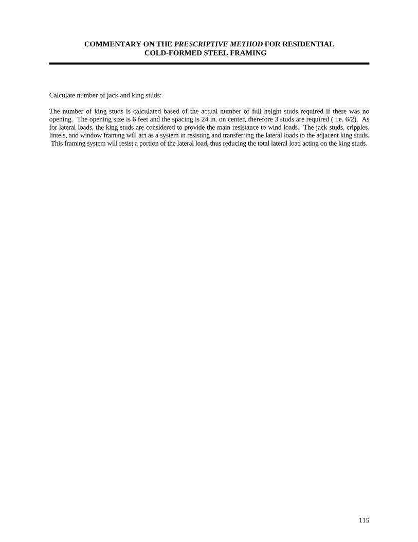
COMMENTARY ON THE PRESCRIPTIVE METHOD FOR RESIDENTIAL COLD-FORMED STEEL FRAMING
115
Calculate number of jack and king studs: The number of king studs is calculated based of the actual number of full height studs required if there was no opening. The opening size is 6 feet and the spacing is 24 in. on center, therefore 3 studs are required ( i.e. 6/2). As for lateral loads, the king studs are considered to provide the main resistance to wind loads. The jack studs, cripples, lintels, and window framing will act as a system in resisting and transferring the lateral loads to the adjacent king studs. This framing system will resist a portion of the lateral load, thus reducing the total lateral load acting on the king studs.
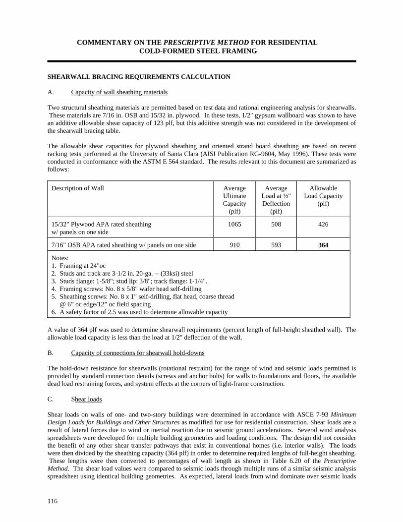
COMMENTARY ON THE PRESCRIPTIVE METHOD FOR RESIDENTIAL COLD-FORMED STEEL FRAMING
116
SHEARWALL BRACING REQUIREMENTS CALCULATION A. Capacity of wall sheathing materials Two structural sheathing materials are permitted based on test data and rational engineering analysis for shearwalls. These materials are 7/16 in. OSB and 15/32 in. plywood. In these tests, 1/2" gypsum wallboard was shown to have an additive allowable shear capacity of 123 plf, but this additive strength was not considered in the development of the shearwall bracing table. The allowable shear capacities for plywood sheathing and oriented strand board sheathing are based on recent racking tests performed at the University of Santa Clara (AISI Publication RG-9604, May 1996). These tests were conducted in conformance with the ASTM E 564 standard. The results relevant to this document are summarized as follows:
Description of Wall Average Ultimate Capacity
(plf)
Average Load at ½" Deflection
(plf)
Allowable Load Capacity
(plf)
15/32" Plywood APA rated sheathing w/ panels on one side
1065 508 426
7/16" OSB APA rated sheathing w/ panels on one side 910 593 364
Notes: 1. Framing at 24"oc 2. Studs and track are 3-1/2 in. 20-ga. -- (33ksi) steel 3. Studs flange: 1-5/8"; stud lip: 3/8"; track flange: 1-1/4". 4. Framing screws: No. 8 x 5/8" wafer head self-drilling 5. Sheathing screws: No. 8 x 1" self-drilling, flat head, coarse thread @ 6” oc edge/12” oc field spacing 6. A safety factor of 2.5 was used to determine allowable capacity
A value of 364 plf was used to determine shearwall requirements (percent length of full-height sheathed wall). The allowable load capacity is less than the load at 1/2" deflection of the wall. B. Capacity of connections for shearwall hold-downs The hold-down resistance for shearwalls (rotational restraint) for the range of wind and seismic loads permitted is provided by standard connection details (screws and anchor bolts) for walls to foundations and floors, the available dead load restraining forces, and system effects at the corners of light-frame construction. C. Shear loads Shear loads on walls of one- and two-story buildings were determined in accordance with ASCE 7-93 Minimum Design Loads for Buildings and Other Structures as modified for use for residential construction. Shear loads are a result of lateral forces due to wind or inertial reaction due to seismic ground accelerations. Several wind analysis spreadsheets were developed for multiple building geometries and loading conditions. The design did not consider the benefit of any other shear transfer pathways that exist in conventional homes (i.e. interior walls). The loads were then divided by the sheathing capacity (364 plf) in order to determine required lengths of full-height sheathing. These lengths were then converted to percentages of wall length as shown in Table 6.20 of the Prescriptive Method. The shear load values were compared to seismic loads through multiple runs of a similar seismic analysis spreadsheet using identical building geometries. As expected, lateral loads from wind dominate over seismic loads

COMMENTARY ON THE PRESCRIPTIVE METHOD FOR RESIDENTIAL COLD-FORMED STEEL FRAMING
117
for light-frame steel structures in seismic Zones 2, 1, or 0. The wind spreadsheet was also used to determine adjustment factors for loads when 9' or 10' walls are used in lieu of a standard 8' wall. D. Required full height sheathing The required amounts of structural sheathing in Table 6.20 were determined based on the structural sheathing capacities and shear loads calculated as described above. For a 28’ x 40’, 2-story house (roof slope 8:12), and interpolating between values in Table 6.20, the following design is achieved:
Percentage from Table
6.20
%
Wall Length
L
Required Length of
Full-height Sheathing
% x L
Actual Capacity
(L) x (%) x 364plf (lbs.)
Required Capacity (from specific analysis
of building loads)
Upper Story endwall sidewall
40 % 30 %
28’ 40’
11’-0" 12’-0"
4,004 lb. 4,368 lb.
2,816 lb. 1,776 lb.
Lower Story endwall sidewall
68 % 47 %
28’ 40’
19’-0" 19’-0"
6,919 lb. 6,919 lb.
5,451 lb. 2,801 lb.
As shown in this example, the actual capacity is well above that required by a detailed analysis.

COMMENTARY ON THE PRESCRIPTIVE METHOD FOR RESIDENTIAL COLD-FORMED STEEL FRAMING
118
CEILING JOIST DESIGN AND EXAMPLE The following applied loads were used in developing the ceiling joist tables: Dead Load: Ceiling Dead Load = 5 psf Live Loads: With Attic Storage = 20 psf; Without Attic Storage = 10 psf The section properties, moment and shear capacities were determined per the AISI Specification. All joists are assumed punched with 1-1/2 in. wide x 4 in. long holes spaced at 24 inches on center. The compression flanges of the ceiling joists are assumed to be laterally braced at mid-point, third point, and unbraced. The provisions for the combined bending and web crippling and combined bending and shear were taken directly from the AISI Design Specification. Deflection limits are primarily established with regard to serviceability concerns. The intent is to prevent excessive deflection which might result in cracking of finishes. For ceiling joists, most codes generally agree that L/240 represents an acceptable serviceability limit for deflection. Therefore, ceiling finishes in the Prescriptive Method are limited to L/240 deflection. Example: The following is an example for selecting and designing a ceiling joist member for the following building configuration and loading conditions: Building width = 30 ft Wind speed = 80 mph, exposure C Attic dead load = 5 psf Ground snow load = 30 psf Spacing = 24 inches on center Roof slope = 6:12 Roof dead load = 10 psf Load bearing wall at mid-span First, select the proper ceiling joist from the ceiling joist tables in the Prescriptive Method: With an interior bearing wall the clear span would be 14'-6" (30'/2 = 15' less 6", i.e. 4" for outside wall and 2" for inside wall), select a ceiling joist at 24 "on center with a dead load of 5 psf and a live load of 10 psf. One feasible solution is a twin span 2 x 6 x 33 mil joist with a maximum allowable span of 14'-10". The section properties for this member can be calculated using the AISI Design Specification. The section properties listed below are taken from the section property table. Fy = 33 ksi Sx = 0.505 in3 Ix = 1.451 in.4 Ix gross = 1.451 in.4 Fya = 33 ksi ry = 0.587 in. xo = -1.136 in. rx = 2.11 in. G = 11,300 ksi ro = 2.467 in. J = 0.00013 in.4 Spacing = 24 in. on center E = 29,500 ksi CW = 0.702 in.6 Agross = 0.326 in.2 K = 1.0 Iy gross = 0.1125 in4 Def.LL= L/240 Def.TL= L/180 L.L. = 10 psf D.L. = 5 psf The allowable span shall be the smaller of: 1. maximum span due to bending 2. maximum span due to shear 3. maximum span due to deflection 4. maximum span due to bending and shear combined

COMMENTARY ON THE PRESCRIPTIVE METHOD FOR RESIDENTIAL COLD-FORMED STEEL FRAMING
119
1. Bending per AISI Design Specification Section C3, "Flexural Members" (all referenced equations and sections are those of the AISI Design Specification) Ma = Mn/Wf Mn = smallest nominal moment of Sections C3.1.1, C3.1.2, and C3.1.3 Ωf = 1.67 (factor of safety) C3.1.1 Nominal Section Strength Mn = SeFy Se = Sx Mn = (0.505)x(33.0) = 16.67 kip-in. ≅ 1390 lb. - ft. C3.1.2 Lateral Buckling Strength Mn = Sc (Mc / Sf ) Eq. C3.1.2-1 Sf = Ix / Ycg = 1.451 / 2.75 = 0.528 in.4 Mc = My (1 - My / 4Me ) Eq. C3.1.2-2 My = Sf Fy Eq. C3.1.2-4 My = 0.528 * 33,000 = 17,424 lb.-in. Cb = 1.75 (M1 = 0, Section C3.1.2) Me = CbroA[σeyσt]1/2 Eq. C3.1.2-5 σey = (π2E)/(KyLy/ry)2 Eq. C3.1.2-8 σt = (1/Aro
2 )[GJ + π2ECw / (Kt Lt)2 ] Eq. C3.1.2-9 σey = (π2 x 29,500,000)/(1 x 89 / 0.587)2 = 12,665 psi σt = [1 / 0.326 x (2.467)2]x[11,300,000 x 0.00013 + π2 x 29,500,000 x 0.702 / (1 x 89)2 ] σt = 13,746 psi Me = 1.75 x 2.467 x 0.326 [(12,665)(13,746)]1/2 = 18,570 lb.-in. > 0.5 My = 8,712 lb.-in. Mc = 17,424 (1 - 17,424 / 4 x 18,570 ) = 13,337 lb.-in. Determine Sc, the elastic section modulus of the effective section, calculated at a stress of Mc / Sf in the extreme compression fiber. Mc / Sf = 13,337 / 0.527 = 25,307 psi Compression Flange: Determine the effective width of the compression flange: w = Flange width - 2( radius + Thickness) = 1.368 in. w/t = 1.368/0.035 = 39.09 <60 O.K. S = 1.28[(E/f)]1/2 = 1.28[(29,500,000/25,307)]1/2 = 43.70 Eq. B4-1 S/3 = 14.57 < w/t = 39.09 < S = 43.70 Ia = 399t4[(w/t)/S] - 0.333 Eq. B4.2-6 Ia = 399(0.035)4[39.09/43.70] - 0.333 = 10.7x10⁻⁵ in.4 n = 1/2

COMMENTARY ON THE PRESCRIPTIVE METHOD FOR RESIDENTIAL COLD-FORMED STEEL FRAMING
120
D/w = 0.5 / 1.367 = 0.366, 0.25 < D/w = 0.366 < 0.8 k = [4.82 - 5(D/w)](Is/Ia)n + 0.43 ≤ 5.25 - 5(D/w) Eq. B4.2-9 d = lip-radius-thickness = 0.372 in. Is = d3t/12 = (0.372)3 (0.035)/12 = 14.8x10⁻⁵ in.4 k = [4.82 - 5(0.365)]x[ 14.8x10⁻⁵/ 10.7x10⁻⁵]0.5 + 0.43 ≤ 5.25 - 5(0.365) k = 3.43 Effective width of the flange shall be calculated according to AISI Design Specification Section B2.1 using k as calculated above, and f = Mc / Sf. Since Is > Ia and D/w < 0.8, the stiffener is not considered as a simple lip. w/t = 39.09 < 90 OK Section B1.1-(a)-(3) λ = [1.052/(k)1/2](w/t)(f/E)1/2 Eq. B2.1-4 Where f = Mc / Sf = 25,307 psi λ = [1.052/(3.43)1/2](39.09)(25,307 / 29,500,000)1/2 = 0.650 λ ≤ 0.673 ⇒ b = w Eq. B2.1-1 Effective width b = 1.368 inches (i.e. compression flange is fully effective) Compression Stiffener: Determine the effective width of the compression stiffener (lip): D = 0.5 inches d/t = 0.372/0.035 = 10.629 < 60 OK Section B1.1-(a)-(3) D/w = 0.5 / 1.368 = 0.365, 0.25 < D/w = 0.365 < 0.8 Calculate the effective width for the lip per AISI Design Specification Section B2.1 : λ = [1.052/(k)1/2](w/t)(f/E)1/2 Eq. B2.1-4 Where f = Mc / Sf = 25,307 psi and k = 0.43 per AISI Design Specification Section B3.1 λ = [1.052/(0.43)1/2](10.629)(25,307/29,500,000)1/2 = 0.50 λ ≤ 0.673 ⇒ d'
s = d = 0.372 in. Eq. B2.1-1 ds = d'
s (Is/Ia) ≤ d's Eq. B4.2-11
Effective width of lip ds = 0.372 inches (i.e. compression stiffener is fully effective) Thus, one assumes that the section is fully effective. Ycg = 5.5 / 2 = 2.75 in. (from symmetry) Web: Check if web is fully effective: (AISI Design Specification Section B2.3) Assume the web is fully effective, and top fiber stress is 25,307 psi: f1 = +f (Ycg - t - R)/Ycg = 25,307(2.75 - 0.035 - 0.0937)/2.75 = 24,123 psi f2 = -f (Web size - Ycg - t - R)/Ycg = 25,307(5.5 - 2.75 - 0.035 - 0.0937)/2.75

COMMENTARY ON THE PRESCRIPTIVE METHOD FOR RESIDENTIAL COLD-FORMED STEEL FRAMING
121
f2 = - 24,123 psi (tension) The effective widths are calculated per AISI Design Specification Section B2.3 (a) for load capacity determination. Ψ = f2 / f1 = -1 ≤ - 0.236 Section B2.3 b1 = be / (3- Ψ) Eq. B2.3-1 b2 = be / 2 Eq. B2.3-2 b1 + b2 shall not exceed the compression portion of the web calculated on the basis of effective section. be = Effective width b determined in accordance with Section B2.1 with f1 substituted for f and k determined as follows: k = 4 + 2(1 - Ψ)3 + 2(1 - Ψ) Eq. B2.3-4 k = 4 + 2(1 + 1)3 + 2(1 + 1) = 24 h = w = Web - 2(Radius + thickness) = 5.5 - 2(0.0937 + 0.035) = 5.243 inches. h/t = 5.243 / 0.035 = 149.80 < 200 OK Section B1.2-(a) λ(web) = [1.052/(24)1/2](149.80)(24,123/29,500,000)1/2 = 0.87 > 0.673 Eq. B2.1-4 ρ(web) = (1-.22/λ)/λ = (1-0.22/0.87)/0.87 = 0.859 be = ρ(web) w = 4.503 inches Eq. B2.1-1 b2 = be / 2 = 2.25 inches b1 = be / (3 + 1) = 1.126 inches. b1 + b2 = 1.126 + 2.25 = 3.376 inches Compression portion of the web = ycg - (Radius + thickness) = 2.75 - (0.0937 + 0.035) = 2.62 inches. Since b1 + b2 = 3.376 > 2.622 in., b1 + b2 shall be taken as 2.62 in. This verifies the assumption that the web is fully effective.
Element Effective length (in)
Distance from top fiber, y (in.)
Ly
in.2
Ly2
in.3
I1' About own
axis in.3
Web Tension flange Comp. Flange Comp. corners
Tension corners Comp. stiffener
Tension stiffener
5.243 1.368 1.368 0.3491 0.3491 0.372 0.372
2.75 5.483 0.018 0.058 5.442 0.314 5.186
14.419 7.502 0.024 0.020 1.898 0.117 1.927
39.652 41.131 0.0004 0.001
10.328 0.037 9.995
12.012 - - - -
.004
.004
Sum 9.42 25.91 101.145 12.02 1 Where corner length = Length of arc = 1.57(R + t/2) = 0.174. Two corners = 0.349 in I'x = Ly2 + I'
1 - Ly2cg
I'x = 101.145 + 12.02 - 9.42(2.75)2 = 42.23 in.3 Actual Ix = I'x t = (42.23)(0.035) = 1.478 in.4

COMMENTARY ON THE PRESCRIPTIVE METHOD FOR RESIDENTIAL COLD-FORMED STEEL FRAMING
122
Se = Ix / ycg = 1.478 / 2.75 = 0.537 in.3 Mn = Se Fy Eq. C.1.1-1 Mn = 0.537 x 25,307 = 13,590 lb.-in C3.1.3 "Beams Having One Flange Through-Fastened to Deck or Sheathing" does not apply. Allowable moment: The allowable moment is the smallest nominal moment calculated per AISI Design Specification Sections C3.1.1, C3.1.2, and C3.1.3 divided by a factor of safety of 1.67. W = 1.67 Ma = Mn / 1.67 Eq. C3.1-1 Ma = 13,590/1.67 = 8,138 lb.-in. = 678 ft.-lb. Mmax = (9/128)wL2 (twin span beam, with web stiffeners, at the mid span where bottom flange is unbraced) w= 15 psf (10 psf Attic LL + 5 psf DL) w= 15 psf x 2 ft o.c. = 30 plf
L x
x=
128 8 138
9 3012
,
L = 215 in L = 17 ft - 11 in 2. C3.2 Strength for shear (with ICBO AC46 method of calculating shear with holes) Calculate the depth of the flat portion of the web, h. h = web depth - 2(r + t) h = 5.5 - 2(0.0937 - 0.035) = 5.243 in h/t = 151.54 Calculate 1.38(EKv/Fy)1/2 1.38(Ekv / Fy)1/2 = 1.38(29,500,000x5.34 / 33,000)1/2 = 95.35 Since h/t > 1.38(Ekv/Fy)1/2 Va = 0.53(Ekvt3/h) Va = 0.53(29,500,000 x 5.34 x 0.0353 / 5.243) = 660 lb. (without holes) ICBO method for calculating shear capacity of member with holes. qs = 1 - 1.1 (hole depth / web depth) (qs is the shear reduction factor) qs = 1 - 1.1(1.5/5.5) = 0.7 Va(hole) = Va x qs = 462 lb. V = 5/8 wL (simply supported twin span with web stiffeners) L =( 5/8) x Va(hole) / w L = (8/5) x 462 / 30 L =24.6 ft L= 24'-7”

COMMENTARY ON THE PRESCRIPTIVE METHOD FOR RESIDENTIAL COLD-FORMED STEEL FRAMING
123
3. Span limit due to deflection
δ =wL
EI
4
185 (simply supported twin span)
d= L/240 w = 15 psf = 0.104 psi
L EIw spacing
=185
2401 3
* */
L = 236 in. L= 19'- 8" 4. Calculate the span limit due to combined bending and shear at the intermediate support. (AISI Design Specification Section C3.3 Strength for Combined Bending and Shear) M/Mado ≤ 1 and V/Va £ 1 Maxo = Allowable moment about the centroidal axis per AISI Design Specification Section C3.1.1 Maxo = 1390/1.67 = 832 ft-lb. (as calculated before) Va = 660 lb. (Va without holes because holes are not permitted within 12 in. of a bearing point) V = (5/8) wL (maximum shear at the intermediate support) M = wL2/8 (Maximum moment at intermediate support considering the member fully braced at both flanges) [(wL2/8) / 832] ≤ 1 [0.625wL / 660] ≤ 1 Solve for L using worst case (shear and moment): L= 14.90 ft when M = Mado L= 14'-11" Therefore, at L = 14.90 ft, V = (5/8) wL = (5/8) x 30 x 14.90 = 279 lb. Since V/Va = (283/660) = 0.43 < 0.7 the interaction equation need not be checked. Hence, L= 14'-11" Allowable joist span is controlled by AISI Design Specification Section C3.3 = L = 14'-11"

COMMENTARY ON THE PRESCRIPTIVE METHOD FOR RESIDENTIAL COLD-FORMED STEEL FRAMING
124
RAFTER DESIGN AND EXAMPLE The following is an example for selecting and calculating the capacity for the rafters required for the example building configuration and loading condition shown in the ceiling joist example above. Rafter Selection: The horizontal rafter projection is just under 15 feet. From the "Allowable Rafter Span" table, select a rafter at 24 inches on center and the worst case of a ground snow load of 30 psf or an equivalent load to a wind speed of 80 mph, exposure C. First, convert the 80 mph exposure C wind speed to an equivalent ground snow load. For a slope of 6:12, an 80 mph Exposure C converts to a 20 psf ground snow load. Therefore, the 30 psf ground snow load should be used because it is higher. Two feasible solutions are 2 x 8 x 54 mil C-shaped member spanning 17'-1" or a 2 x 10 x 43 mil C-shaped member spanning 16'-0". Calculate the capacity of the members selected to prove their structural adequacy. i. Calculate the wind load due to the 80 mph, Exposure C, wind speed: Both uplift and inward acting wind loads must be examined and the worst case converted to an equivalent snow load effect. ASCE 7-93 components and cladding coefficients are used to calculate the wind pressures. Downward load: q = 0.00256 x Kz x (GCp + GCpi ) x (V x I)2 Kz = 0.87 for exposure C GCp = 0 (Zone 1, Tributary area = 75 ft2, page 18 ASCE 7-93) GCpi = 0.25 (± .25 whichever is worst) I = 1.0 (non-coastal) q = 0.00256 x 0.87 x (0 + 0.25) (80x1)2 q = 3.56 psf (acting perpendicular to the plane of the rafter) qy-slope = q/cosθ (converts load to an equivalent load acting in the y direction along the rafter plane) qy-slope= 3.56 / cos(26.56) = 3.98 psf qhorizontal =qy-slope/cosθ (converts load to an equivalent load acting perpendicular to the horizontal projection) qhorizontal = 3.98 / cos(26.56) = 4.45 psf Upward load: q = 0.00256 x Kz x (GCp + GCpi ) x (V x I)2 Kz = 0.87 for exposure C GCp = -1.2 (Zone 1, Tributary area = 75 ft2, page 18 ASCE 7-93) GCpi = -0.25 (± 0.25 whichever is worse) I = 1.0 (non-coastal) q = 0.00256 x 0.87 x (-1.2-0.25) (80x1)2 q = -20.67 psf (acting perpendicular to the plane of the rafter) qy-slope = q/cosθ (converts load to an equivalent load acting in the y direction along the rafter plane) qy-slope = -20.67 / cos(26.56) = -23.11 psf qy-slope + DL = -23.11 + 10 = 13.11 (compensate for dead load while loads are in the same direction and plane) qhorizontal = (qy-slope + D.L.) / cosθ (converts load to an equivalent load acting perpendicular to the horizontal projection) qhorizontal = -13.11 / cos(26.56) = -14.66 psf ii. Calculate the maximum allowable rafter span

COMMENTARY ON THE PRESCRIPTIVE METHOD FOR RESIDENTIAL COLD-FORMED STEEL FRAMING
125
From the Section Property Table Fy = 33 ksi Sx = 1.41 in3 Ix = 7.98 in4 D.L. = 15 psf S.L.ground= 30 psf Def.TL= L/180 Def.LL= L/240 Spacing = 24 in. on center The allowable span shall be the shorter of: 1. maximum span due to bending 2. maximum span due to shear 3. maximum span due to deflection 1. Bending per AISI Design Specification Section C, "Flexural Members" (all referenced equations and sections are those of the AISI Design Specification) Ma = Mn/Ωf Mn = smallest nominal moment of C3.1.1, C3.1.2, C3.1.3 Ωf = 1.67 (factor of safety) C3.1.1 Nominal Section Strength Mn = SeFy Se = Sx Mn = (1.41)x(33.0) = 46.5 kip-in = 46,500 lb.-in. C3.1.2 Lateral Buckling Strength This section does not apply because roof sheathing provides lateral support. C3.1.3 Beams Having One Flange Through-Fastened to Deck or Sheathing Does not apply. Ma= (46,500)/1.67 = 27,844 lb.-in. Mmax = wL2 / 8 (simply supported single span) w = (15 + 30 x 0.8)psf = 39 psf w = 36 psf x 2 ft oc = 78 plf L2 = (8 x 27,844) / (78/12 lb./in) L = 185.12 in ⇒ L = 15'-3" 2. C3.2 Strength for Shear (with ICBO AC46 method of calculating shear with holes) Calculate the depth of the flat portion of the web, h. h = web depth - 2(r + t) h = 10.0 - 2(0.0937 + 0.045) = 9.723 in. h/t = 216.07 Calculate 1.38(EKv/Fy).5 1.38(Ekv/Fy).5 = 1.38(29,500,000 x 5.34 / 33000)1/2 = 95.35

COMMENTARY ON THE PRESCRIPTIVE METHOD FOR RESIDENTIAL COLD-FORMED STEEL FRAMING
126
Since h/t > 1.38(EKv/Fy).5 Va = 0.53(EKvt3/h) Va = 0.53(29,500,000 x 5.34 x 0.0453 / 9.723) = 782 lb. (without holes) ICBO AC46 method for calculating shear capacity with holes qs = 1 - 1.1(hole depth / web depth) shear reduction factor qs = 1 - 1.1(1.5/10) = 0.835 Va(hole) = Va x qs = 653 lb. V= wL/2 (simply supported single span) L = 2 x Va(hole) / w L = 2 x 653 / 78 L = 16.74 ft = 16'-9" 3. Span limit due to deflection d = 5 x w x L4 / (384 x E x I) (simply supported single span) Total load (d= L/180, w = 39 psf = 3.25 psi) L = [384 x 29,500,000 x Ix / (3.25 x 24 *180)]1/3 L = 186 in. = 15-6” Live load (d= L/240, w = 24 psf = 2.00 psi) L = [384 x 29,500,000 x Ix / (2.00 x 24 x 240)]1/3 L = 198.72 in. = 16'-7" Bending controls the design, hence the allowable rafter span is L = 15'-3" iii. Verify the adequacy of the ridge member shear connection. Consider the horizontal projection of a simply supported rafter. Vmax = wL/2 (L=15 ft, w =78 plf) Vmax = 78 x 15 / 2 = 585 lb. The nominal shear capacity of a # 10 screw is 789 lb. Therefore the allowable screw capacity (Sallow) is: Sallow = 789 / 3 (use a safety factor of 3) Sallow = 263 lb. Number of screws needed = 585/263 = 2.22 screws This number is rounded up to 3 screws. iv. Verify the adequacy of the heel joist connection SL = 24 psf (30 x 0.8) House Width = 32 ft (use 32' to match table intervals) Roof DL = 7 psf Ceiling D.L. = 5 psf Spacing = 24 in Screw Capacity = 243 lb. (with a safety factor of 3)

COMMENTARY ON THE PRESCRIPTIVE METHOD FOR RESIDENTIAL COLD-FORMED STEEL FRAMING
127
Roof Loading Diagram
Find the reactions. R = wL/2 R = ( (24+7+5) x 2) x 32 / 2 = 1,152 lb. A distributed load of [(24+7) x2] psf or 62 plf is spread across the length of the building. One fourth of this load will be concentrated at the end walls, joints 1 & 2, and half the load will be concentrated at the ridge beam connection, joint 3. Similarly, a distributed load of 5 psf or 10 plf is spread across the length of the ceiling joist. This load will be divided equally at each end of the wall (i.e. at joints 1 and 2).
Free Body Diagram
21 psf S.L. + 10 psf Roof D.L.
Ceiling D.L. = 5 psf
992 lb.
R = 1,152 lb.
496 lb. + 160 lb.
Joint 1
Joint 3
R = 1,152 lb.
Joint 2
496 lb. + 160 lb
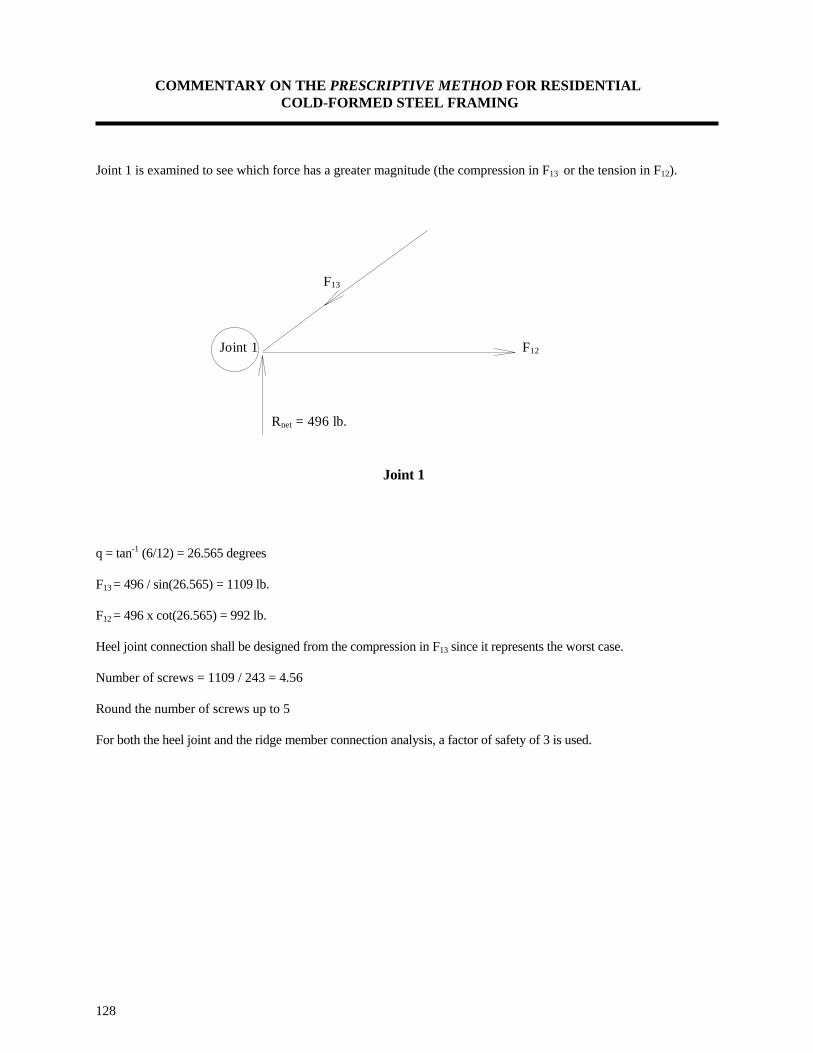
COMMENTARY ON THE PRESCRIPTIVE METHOD FOR RESIDENTIAL COLD-FORMED STEEL FRAMING
128
Joint 1 is examined to see which force has a greater magnitude (the compression in F13 or the tension in F12).
Joint 1
q = tan-1 (6/12) = 26.565 degrees F13 = 496 / sin(26.565) = 1109 lb. F12 = 496 x cot(26.565) = 992 lb. Heel joint connection shall be designed from the compression in F13 since it represents the worst case. Number of screws = 1109 / 243 = 4.56 Round the number of screws up to 5 For both the heel joint and the ridge member connection analysis, a factor of safety of 3 is used.
F13
Rnet = 496 lb.
Joint 1 F12

COMMENTARY ON THE PRESCRIPTIVE METHOD FOR RESIDENTIAL COLD-FORMED STEEL FRAMING
129

COMMENTARY ON THE PRESCRIPTIVE METHOD FOR RESIDENTIAL COLD-FORMED STEEL FRAMING
APPENDIX A
Section Property Tables

COMMENTARY ON THE PRESCRIPTIVE METHOD FOR RESIDENTIAL COLD-FORMED STEEL FRAMING


COMMENTARY ON THE PRESCRIPTIVE METHOD FOR RESIDENTIAL COLD-FORMED STEEL FRAMING
APPENDIX B
Metric Conversion

COMMENTARY ON THE PRESCRIPTIVE METHOD FOR RESIDENTIAL COLD-FORMED STEEL FRAMING