Embed Size (px)
Citation preview
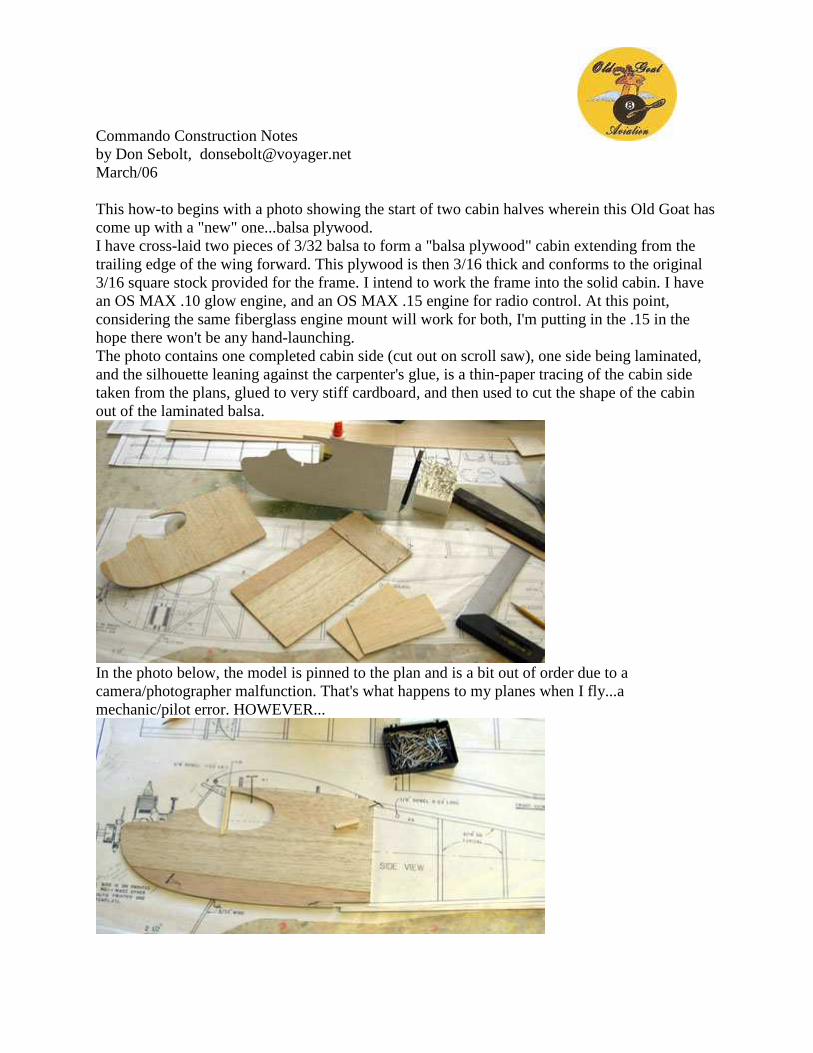
Commando Construction Notes by Don Sebolt, [email protected] March/06 This how-to begins with a photo showing the start of two cabin halves wherein this Old Goat has come up with a "new" one...balsa plywood. I have cross-laid two pieces of 3/32 balsa to form a "balsa plywood" cabin extending from the trailing edge of the wing forward. This plywood is then 3/16 thick and conforms to the original 3/16 square stock provided for the frame. I intend to work the frame into the solid cabin. I have an OS MAX .10 glow engine, and an OS MAX .15 engine for radio control. At this point, considering the same fiberglass engine mount will work for both, I'm putting in the .15 in the hope there won't be any hand-launching. The photo contains one completed cabin side (cut out on scroll saw), one side being laminated, and the silhouette leaning against the carpenter's glue, is a thin-paper tracing of the cabin side taken from the plans, glued to very stiff cardboard, and then used to cut the shape of the cabin out of the laminated balsa.
In the photo below, the model is pinned to the plan and is a bit out of order due to a camera/photographer malfunction. That's what happens to my planes when I fly...a mechanic/pilot error. HOWEVER...
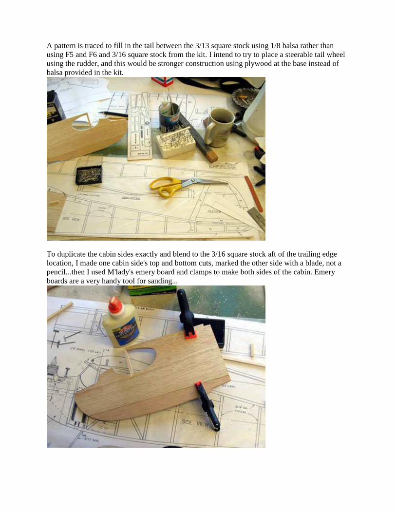
A pattern is traced to fill in the tail between the 3/13 square stock using 1/8 balsa rather than using F5 and F6 and 3/16 square stock from the kit. I intend to try to place a steerable tail wheel using the rudder, and this would be stronger construction using plywood at the base instead of balsa provided in the kit.
To duplicate the cabin sides exactly and blend to the 3/16 square stock aft of the trailing edge location, I made one cabin side's top and bottom cuts, marked the other side with a blade, not a pencil...then I used M'lady's emery board and clamps to make both sides of the cabin. Emery boards are a very handy tool for sanding...
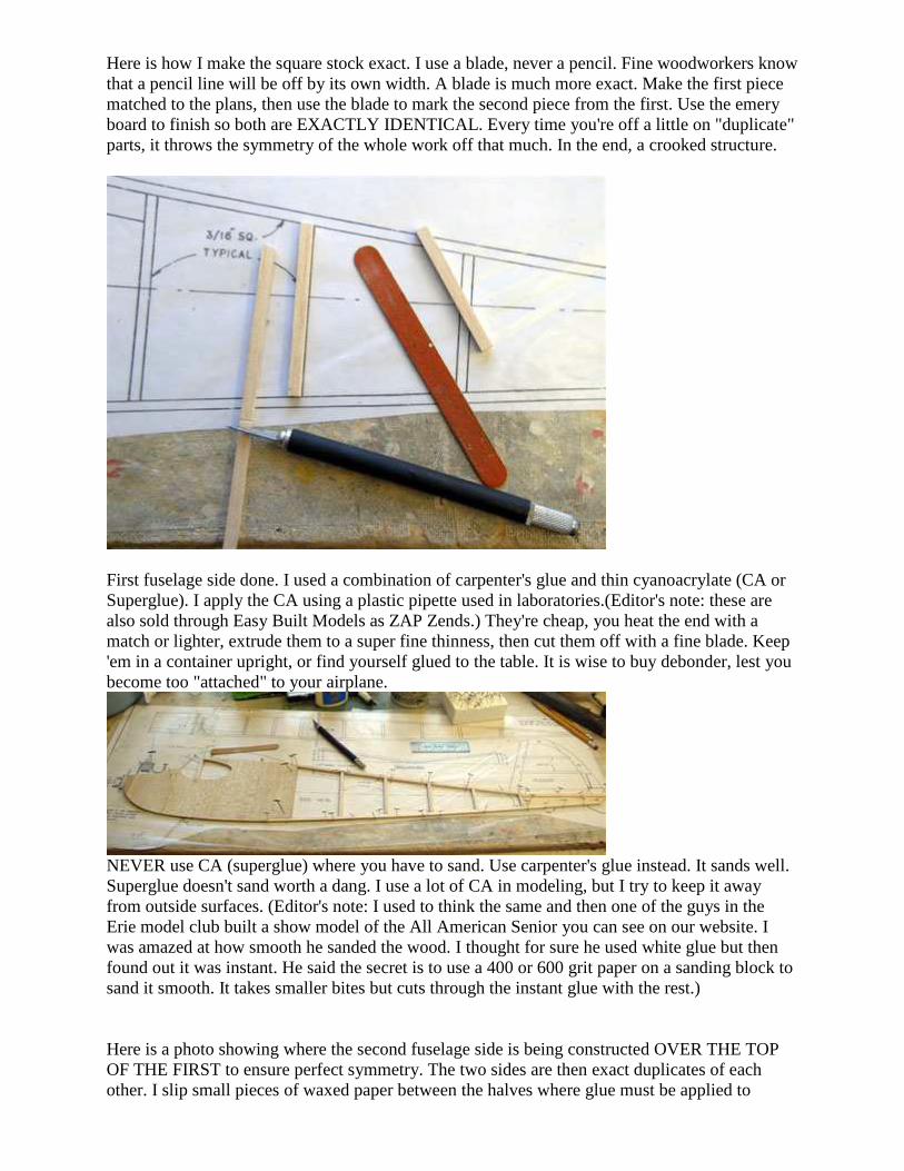
Here is how I make the square stock exact. I use a blade, never a pencil. Fine woodworkers know that a pencil line will be off by its own width. A blade is much more exact. Make the first piece matched to the plans, then use the blade to mark the second piece from the first. Use the emery board to finish so both are EXACTLY IDENTICAL. Every time you're off a little on "duplicate" parts, it throws the symmetry of the whole work off that much. In the end, a crooked structure.
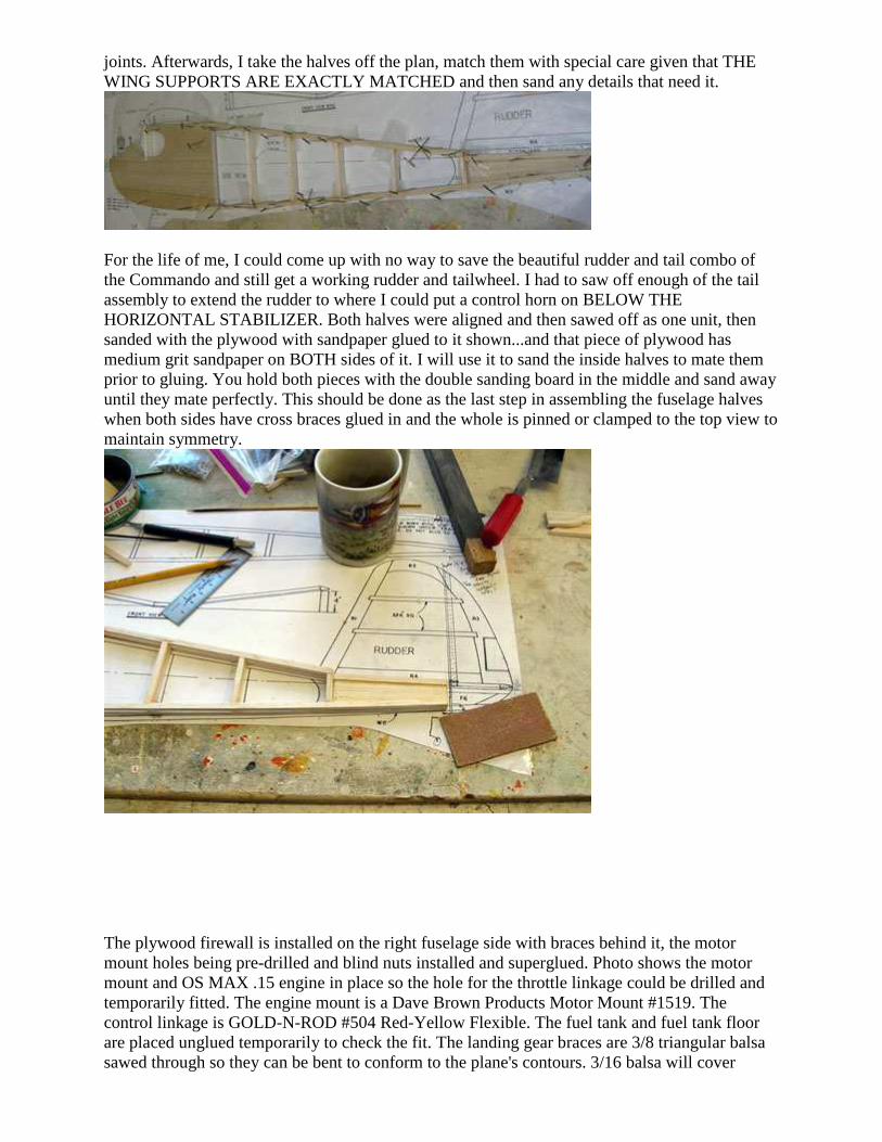
First fuselage side done. I used a combination of carpenter's glue and thin cyanoacrylate (CA or Superglue). I apply the CA using a plastic pipette used in laboratories.(Editor's note: these are also sold through Easy Built Models as ZAP Zends.) They're cheap, you heat the end with a match or lighter, extrude them to a super fine thinness, then cut them off with a fine blade. Keep 'em in a container upright, or find yourself glued to the table. It is wise to buy debonder, lest you become too "attached" to your airplane.
NEVER use CA (superglue) where you have to sand. Use carpenter's glue instead. It sands well. Superglue doesn't sand worth a dang. I use a lot of CA in modeling, but I try to keep it away from outside surfaces. (Editor's note: I used to think the same and then one of the guys in the Erie model club built a show model of the All American Senior you can see on our website. I was amazed at how smooth he sanded the wood. I thought for sure he used white glue but then found out it was instant. He said the secret is to use a 400 or 600 grit paper on a sanding block to sand it smooth. It takes smaller bites but cuts through the instant glue with the rest.) Here is a photo showing where the second fuselage side is being constructed OVER THE TOP OF THE FIRST to ensure perfect symmetry. The two sides are then exact duplicates of each other. I slip small pieces of waxed paper between the halves where glue must be applied to
joints. Afterwards, I take the halves off the plan, match them with special care given that THE WING SUPPORTS ARE EXACTLY MATCHED and then sand any details that need it.
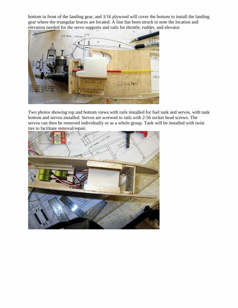
For the life of me, I could come up with no way to save the beautiful rudder and tail combo of the Commando and still get a working rudder and tailwheel. I had to saw off enough of the tail assembly to extend the rudder to where I could put a control horn on BELOW THE HORIZONTAL STABILIZER. Both halves were aligned and then sawed off as one unit, then sanded with the plywood with sandpaper glued to it shown...and that piece of plywood has medium grit sandpaper on BOTH sides of it. I will use it to sand the inside halves to mate them prior to gluing. You hold both pieces with the double sanding board in the middle and sand away until they mate perfectly. This should be done as the last step in assembling the fuselage halves when both sides have cross braces glued in and the whole is pinned or clamped to the top view to maintain symmetry.
The plywood firewall is installed on the right fuselage side with braces behind it, the motor mount holes being pre-drilled and blind nuts installed and superglued. Photo shows the motor mount and OS MAX .15 engine in place so the hole for the throttle linkage could be drilled and temporarily fitted. The engine mount is a Dave Brown Products Motor Mount #1519. The control linkage is GOLD-N-ROD #504 Red-Yellow Flexible. The fuel tank and fuel tank floor are placed unglued temporarily to check the fit. The landing gear braces are 3/8 triangular balsa sawed through so they can be bent to conform to the plane's contours. 3/16 balsa will cover
bottom in front of the landing gear, and 3/16 plywood will cover the bottom to install the landing gear where the triangular braces are located. A line has been struck to note the location and elevation needed for the servo supports and rails for throttle, rudder, and elevator.
Two photos showing top and bottom views with rails installed for fuel tank and servos, with tank bottom and servos installed. Servos are screwed to rails with 2-56 socket head screws. The servos can then be removed individually or as a whole group. Tank will be installed with twist ties to facilitate removal/repair.
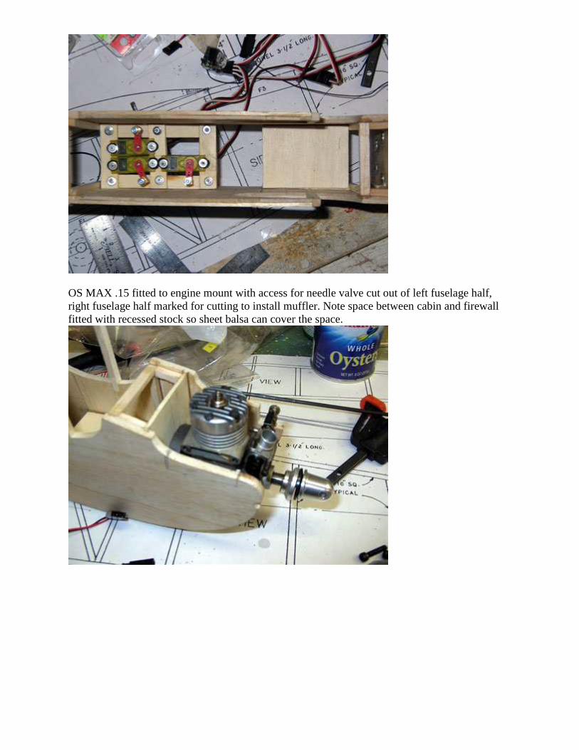
OS MAX .15 fitted to engine mount with access for needle valve cut out of left fuselage half, right fuselage half marked for cutting to install muffler. Note space between cabin and firewall fitted with recessed stock so sheet balsa can cover the space.
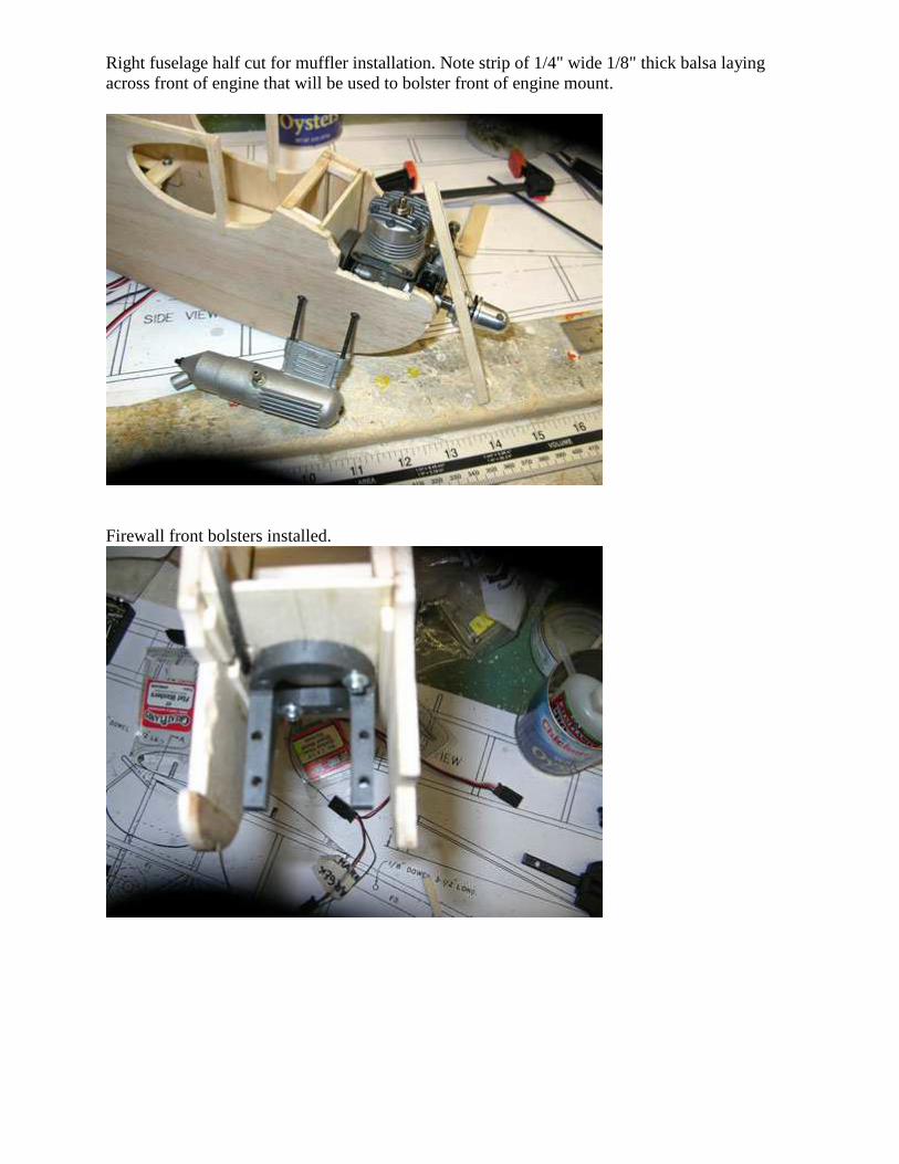
Right fuselage half cut for muffler installation. Note strip of 1/4" wide 1/8" thick balsa laying across front of engine that will be used to bolster front of engine mount.
Firewall front bolsters installed.
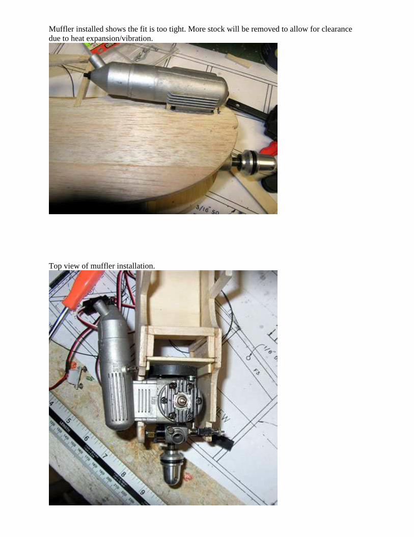
Muffler installed shows the fit is too tight. More stock will be removed to allow for clearance due to heat expansion/vibration.
Top view of muffler installation.
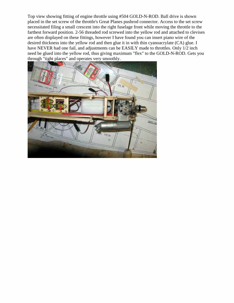
Top view showing fitting of engine throttle using #504 GOLD-N-ROD. Ball drive is shown placed in the set screw of the throttle's Great Planes pushrod connector. Access to the set screw necessitated filing a small crescent into the right fuselage front while moving the throttle to the farthest forward position. 2-56 threaded rod screwed into the yellow rod and attached to clevises are often displayed on these fittings, however I have found you can insert piano wire of the desired thickness into the yellow rod and then glue it in with thin cyanoacrylate (CA) glue. I have NEVER had one fail, and adjustments can be EASILY made to throttles. Only 1/2 inch need be glued into the yellow rod, thus giving maximum "flex" to the GOLD-N-ROD. Gets you through "tight places" and operates very smoothly.
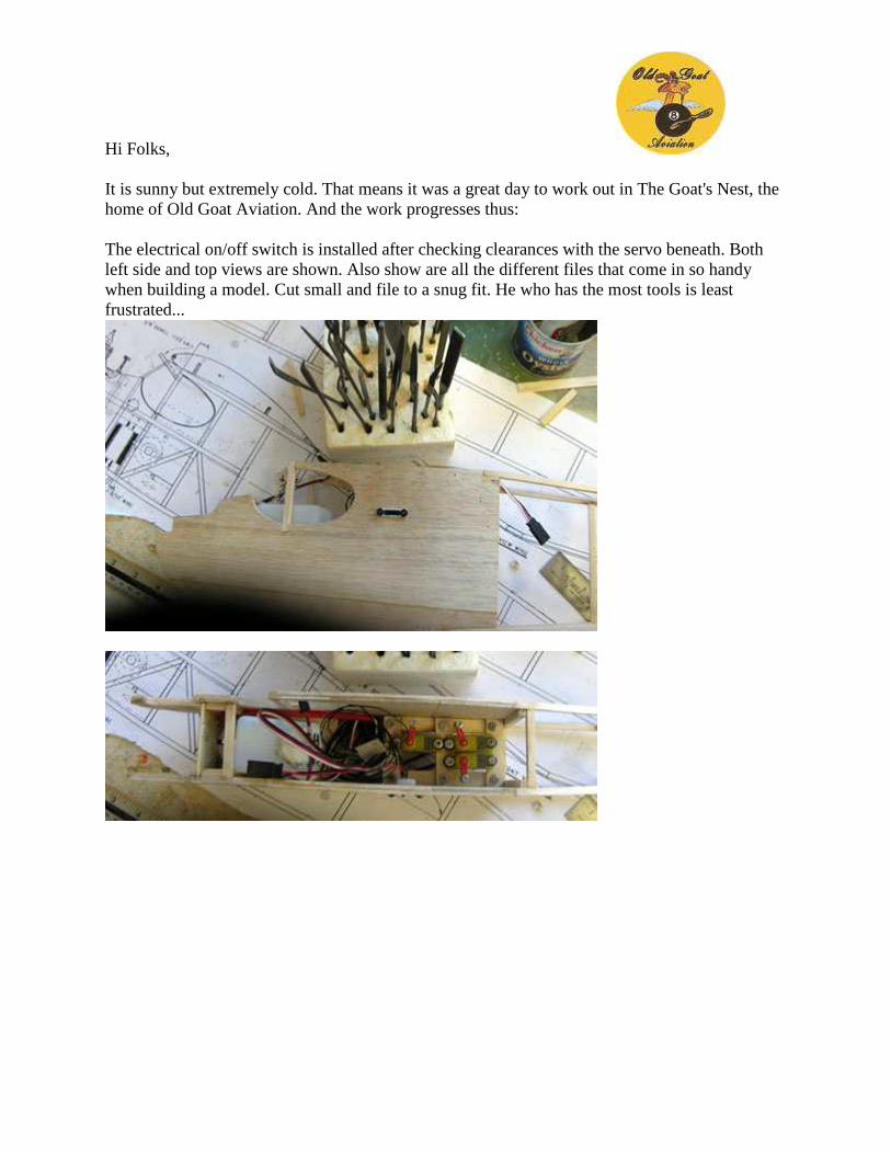
Hi Folks, It is sunny but extremely cold. That means it was a great day to work out in The Goat's Nest, the home of Old Goat Aviation. And the work progresses thus: The electrical on/off switch is installed after checking clearances with the servo beneath. Both left side and top views are shown. Also show are all the different files that come in so handy when building a model. Cut small and file to a snug fit. He who has the most tools is least frustrated...
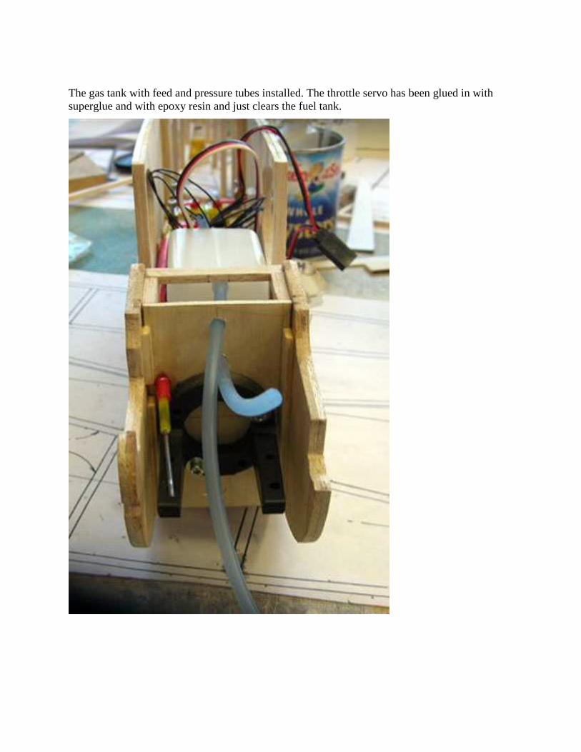
The gas tank with feed and pressure tubes installed. The throttle servo has been glued in with superglue and with epoxy resin and just clears the fuel tank.
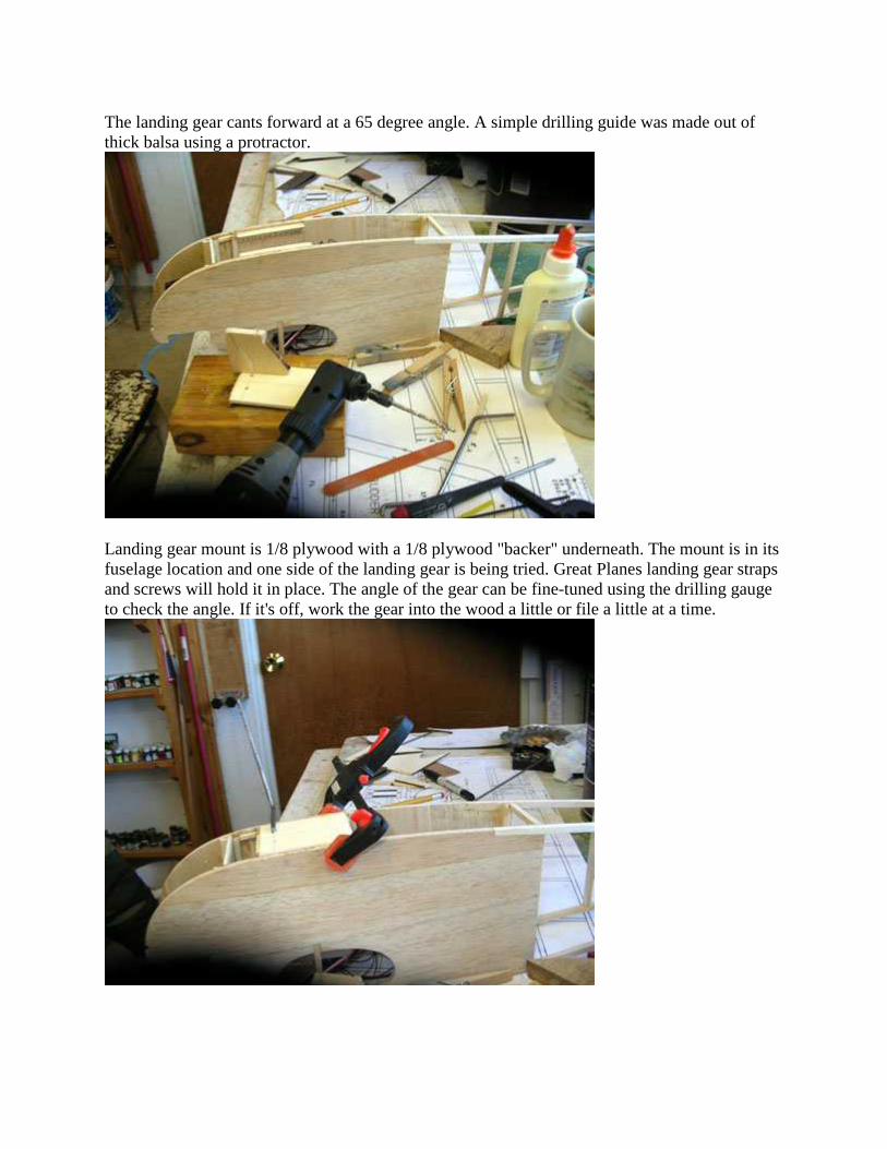
The landing gear cants forward at a 65 degree angle. A simple drilling guide was made out of thick balsa using a protractor.
Landing gear mount is 1/8 plywood with a 1/8 plywood "backer" underneath. The mount is in its fuselage location and one side of the landing gear is being tried. Great Planes landing gear straps and screws will hold it in place. The angle of the gear can be fine-tuned using the drilling gauge to check the angle. If it's off, work the gear into the wood a little or file a little at a time.
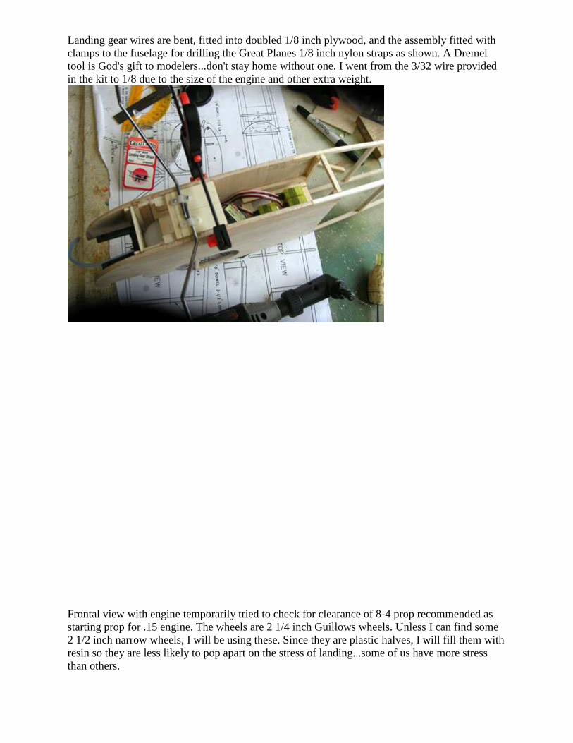
Landing gear wires are bent, fitted into doubled 1/8 inch plywood, and the assembly fitted with clamps to the fuselage for drilling the Great Planes 1/8 inch nylon straps as shown. A Dremel tool is God's gift to modelers...don't stay home without one. I went from the 3/32 wire provided in the kit to 1/8 due to the size of the engine and other extra weight.
Frontal view with engine temporarily tried to check for clearance of 8-4 prop recommended as starting prop for .15 engine. The wheels are 2 1/4 inch Guillows wheels. Unless I can find some 2 1/2 inch narrow wheels, I will be using these. Since they are plastic halves, I will fill them with resin so they are less likely to pop apart on the stress of landing...some of us have more stress than others.
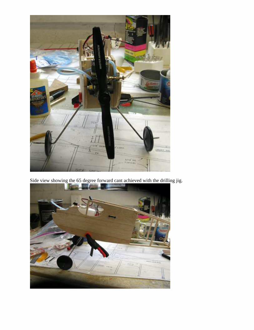
Side view showing the 65 degree forward cant achieved with the drilling jig.
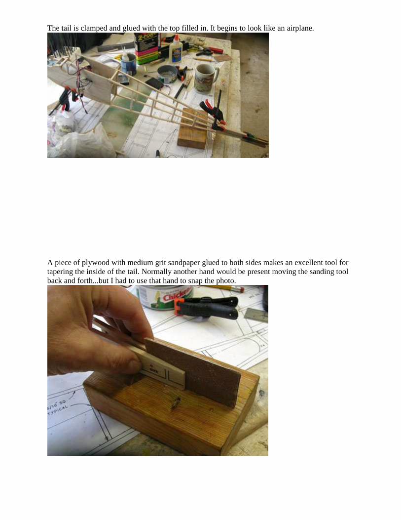
The tail is clamped and glued with the top filled in. It begins to look like an airplane.
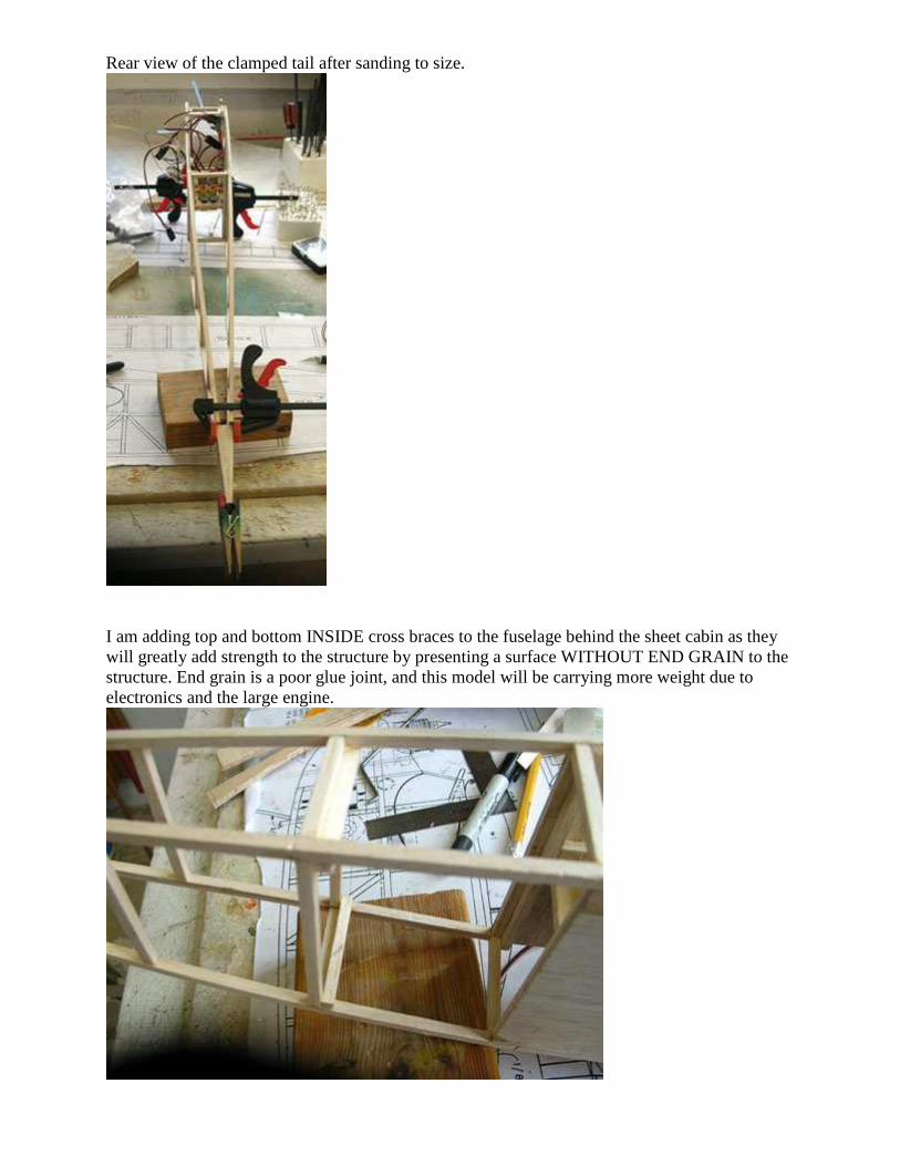
A piece of plywood with medium grit sandpaper glued to both sides makes an excellent tool for tapering the inside of the tail. Normally another hand would be present moving the sanding tool back and forth...but I had to use that hand to snap the photo.
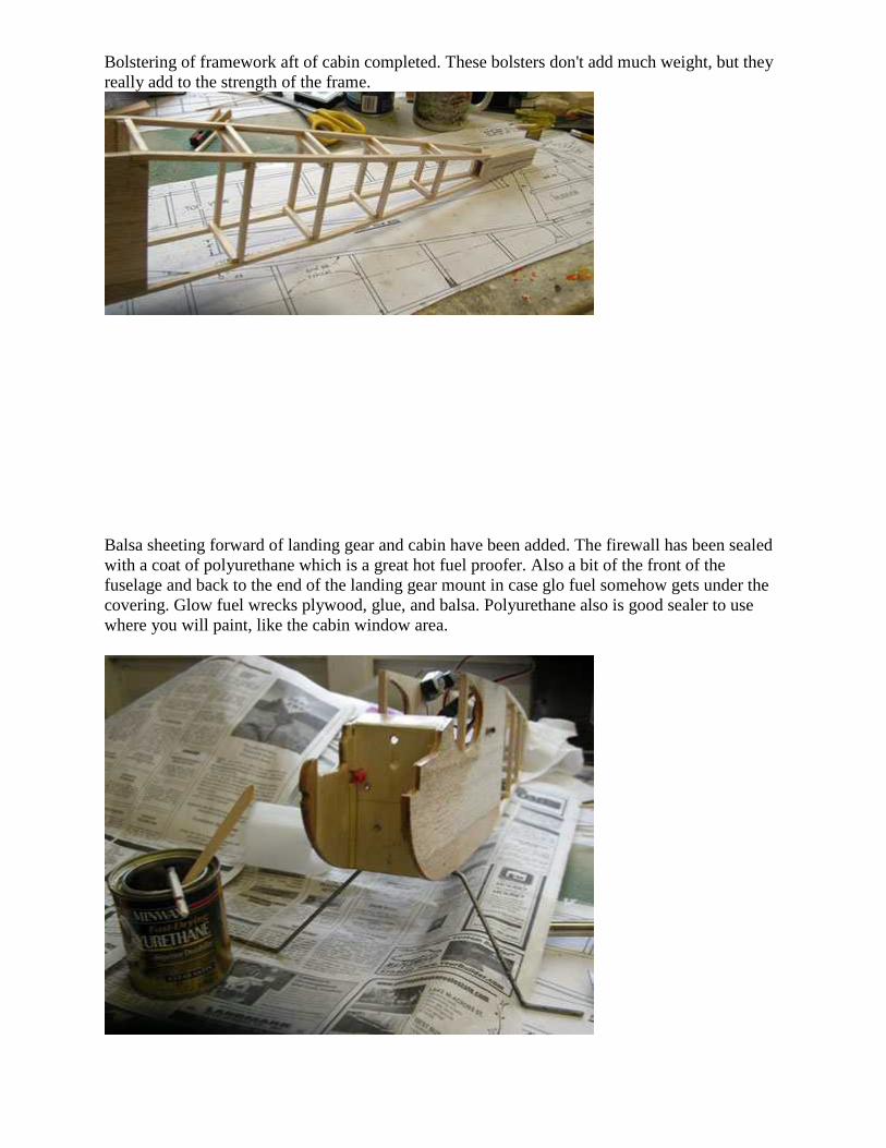
Rear view of the clamped tail after sanding to size.
I am adding top and bottom INSIDE cross braces to the fuselage behind the sheet cabin as they will greatly add strength to the structure by presenting a surface WITHOUT END GRAIN to the structure. End grain is a poor glue joint, and this model will be carrying more weight due to electronics and the large engine.
Bolstering of framework aft of cabin completed. These bolsters don't add much weight, but they really add to the strength of the frame.
Balsa sheeting forward of landing gear and cabin have been added. The firewall has been sealed with a coat of polyurethane which is a great hot fuel proofer. Also a bit of the front of the fuselage and back to the end of the landing gear mount in case glo fuel somehow gets under the covering. Glow fuel wrecks plywood, glue, and balsa. Polyurethane also is good sealer to use where you will paint, like the cabin window area.
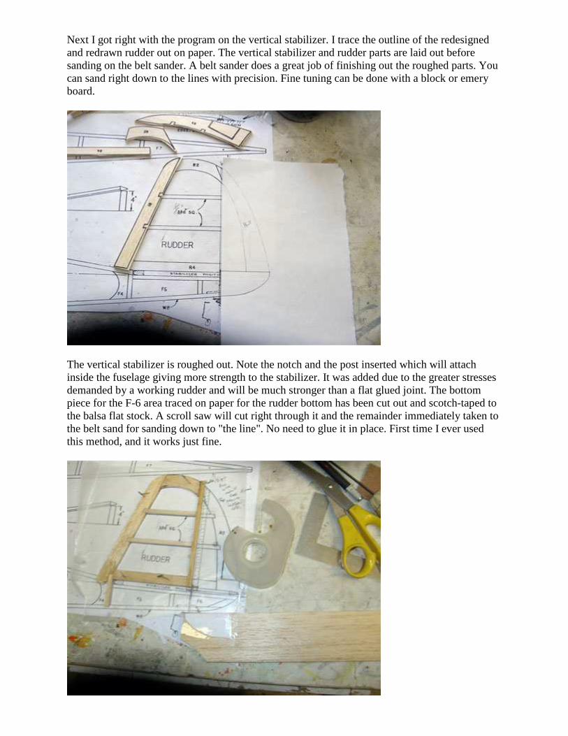
Next I got right with the program on the vertical stabilizer. I trace the outline of the redesigned and redrawn rudder out on paper. The vertical stabilizer and rudder parts are laid out before sanding on the belt sander. A belt sander does a great job of finishing out the roughed parts. You can sand right down to the lines with precision. Fine tuning can be done with a block or emery board.
The vertical stabilizer is roughed out. Note the notch and the post inserted which will attach inside the fuselage giving more strength to the stabilizer. It was added due to the greater stresses demanded by a working rudder and will be much stronger than a flat glued joint. The bottom piece for the F-6 area traced on paper for the rudder bottom has been cut out and scotch-taped to the balsa flat stock. A scroll saw will cut right through it and the remainder immediately taken to the belt sand for sanding down to "the line". No need to glue it in place. First time I ever used this method, and it works just fine.
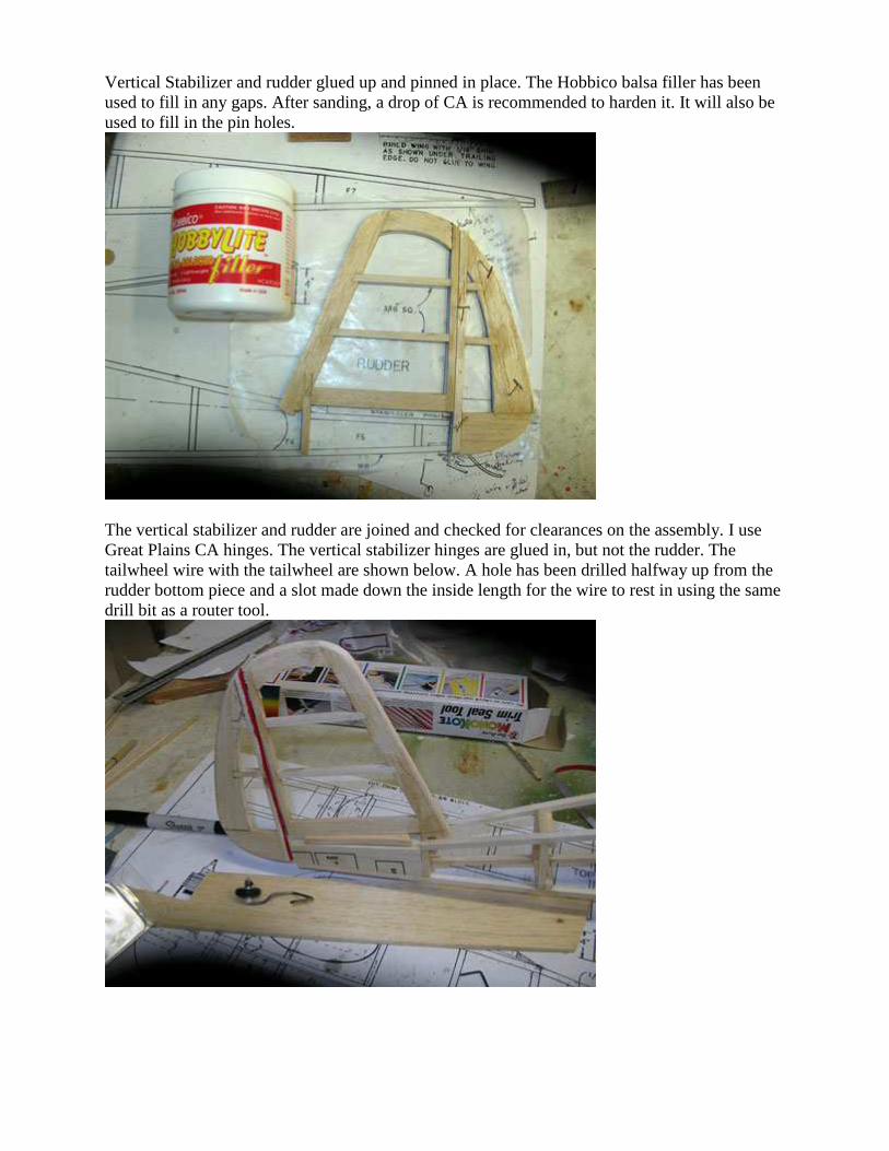
Vertical Stabilizer and rudder glued up and pinned in place. The Hobbico balsa filler has been used to fill in any gaps. After sanding, a drop of CA is recommended to harden it. It will also be used to fill in the pin holes.
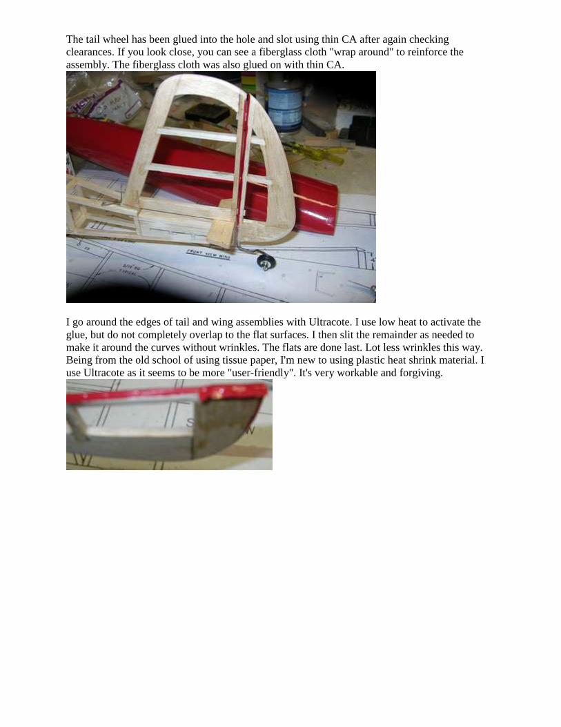
The vertical stabilizer and rudder are joined and checked for clearances on the assembly. I use Great Plains CA hinges. The vertical stabilizer hinges are glued in, but not the rudder. The tailwheel wire with the tailwheel are shown below. A hole has been drilled halfway up from the rudder bottom piece and a slot made down the inside length for the wire to rest in using the same drill bit as a router tool.
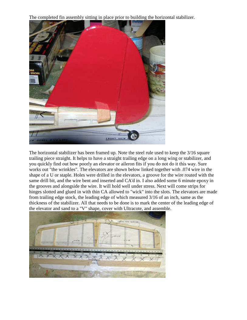
The tail wheel has been glued into the hole and slot using thin CA after again checking clearances. If you look close, you can see a fiberglass cloth "wrap around" to reinforce the assembly. The fiberglass cloth was also glued on with thin CA.
I go around the edges of tail and wing assemblies with Ultracote. I use low heat to activate the glue, but do not completely overlap to the flat surfaces. I then slit the remainder as needed to make it around the curves without wrinkles. The flats are done last. Lot less wrinkles this way. Being from the old school of using tissue paper, I'm new to using plastic heat shrink material. I use Ultracote as it seems to be more "user-friendly". It's very workable and forgiving.
The completed fin assembly sitting in place prior to building the horizontal stabilizer.
The horizontal stabilizer has been framed up. Note the steel rule used to keep the 3/16 square trailing piece straight. It helps to have a straight trailing edge on a long wing or stabilizer, and you quickly find out how poorly an elevator or aileron fits if you do not do it this way. Sure works out "the wrinkles". The elevators are shown below linked together with .074 wire in the shape of a U or staple. Holes were drilled in the elevators, a groove for the wire routed with the same drill bit, and the wire bent and inserted and CA'd in. I also added some 6 minute epoxy in the grooves and alongside the wire. It will hold well under stress. Next will come strips for hinges slotted and glued in with thin CA allowed to "wick" into the slots. The elevators are made from trailing edge stock, the leading edge of which measured 3/16 of an inch, same as the thickness of the stabilizer. All that needs to be done is to mark the center of the leading edge of the elevator and sand to a "V" shape, cover with Ultracote, and assemble.
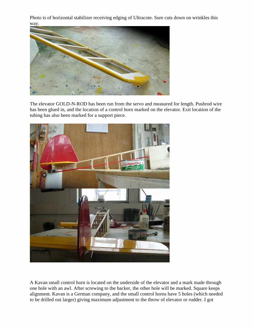
Photo is of horizontal stabilizer receiving edging of Ultracote. Sure cuts down on wrinkles this way.
The elevator GOLD-N-ROD has been run from the servo and measured for length. Pushrod wire has been glued in, and the location of a control horn marked on the elevator. Exit location of the tubing has also been marked for a support piece.
A Kavan small control horn is located on the underside of the elevator and a mark made through one hole with an awl. After screwing to the backer, the other hole will be marked. Square keeps alignment. Kavan is a German company, and the small control horns have 5 holes (which needed to be drilled out larger) giving maximum adjustment to the throw of elevator or rudder. I got
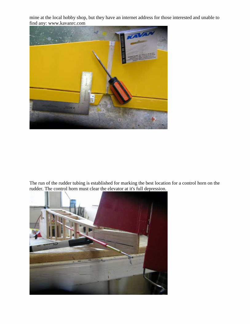
mine at the local hobby shop, but they have an internet address for those interested and unable to find any: www.kavanrc.com
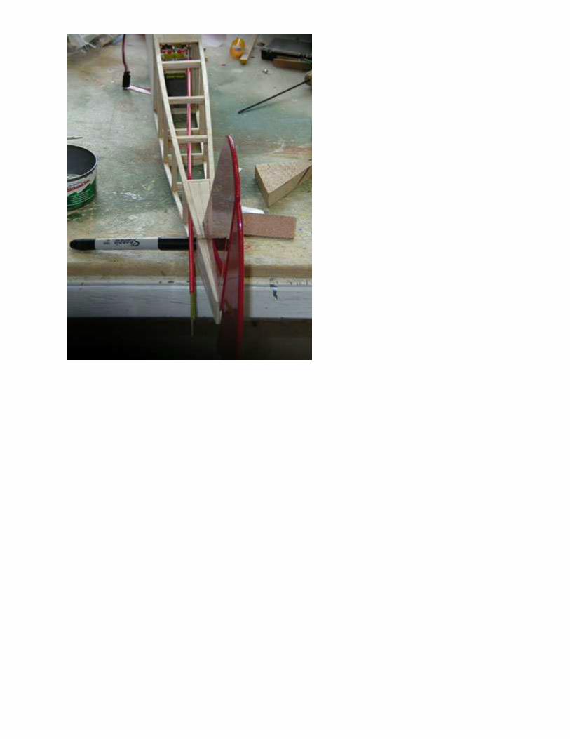
The run of the rudder tubing is established for marking the best location for a control horn on the rudder. The control horn must clear the elevator at it's full depression.
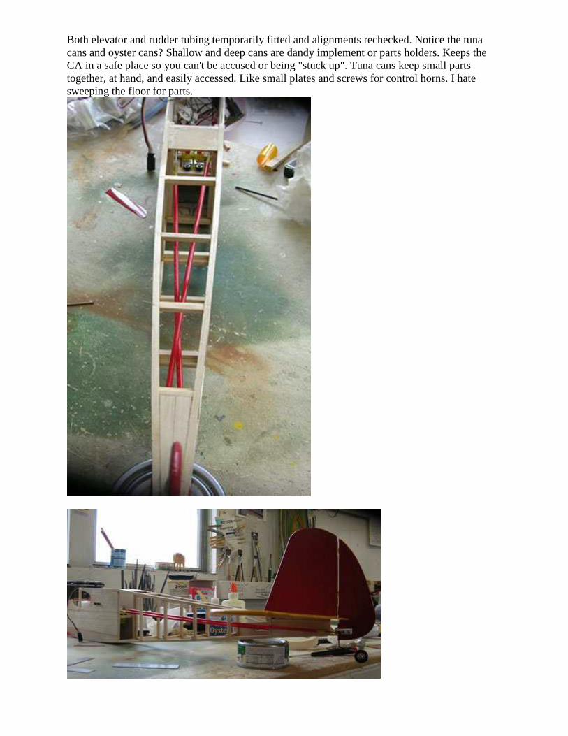
Both elevator and rudder tubing temporarily fitted and alignments rechecked. Notice the tuna cans and oyster cans? Shallow and deep cans are dandy implement or parts holders. Keeps the CA in a safe place so you can't be accused or being "stuck up". Tuna cans keep small parts together, at hand, and easily accessed. Like small plates and screws for control horns. I hate sweeping the floor for parts.
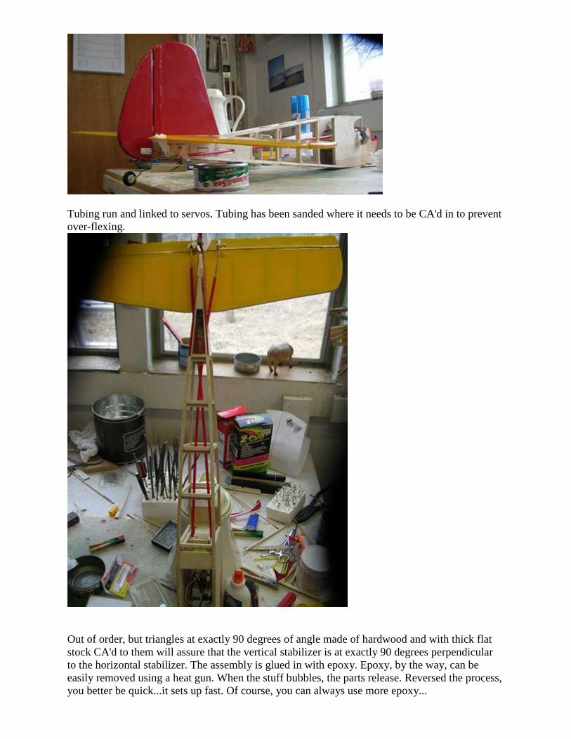
Tubing run and linked to servos. Tubing has been sanded where it needs to be CA'd in to prevent over-flexing.
Out of order, but triangles at exactly 90 degrees of angle made of hardwood and with thick flat stock CA'd to them will assure that the vertical stabilizer is at exactly 90 degrees perpendicular to the horizontal stabilizer. The assembly is glued in with epoxy. Epoxy, by the way, can be easily removed using a heat gun. When the stuff bubbles, the parts release. Reversed the process, you better be quick...it sets up fast. Of course, you can always use more epoxy...
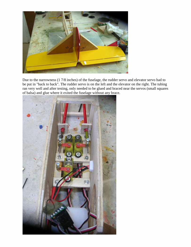
Due to the narrowness (1 7/8 inches) of the fuselage, the rudder servo and elevator servo had to be put in "back to back". The rudder servo is on the left and the elevator on the right. The tubing ran very well and after testing, only needed to be glued and braced near the servos (small squares of balsa) and glue where it exited the fuselage without any brace.
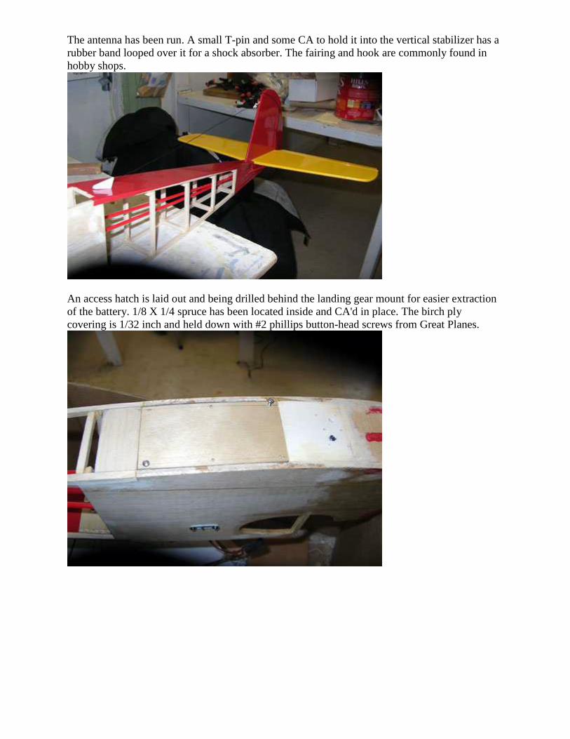
The antenna has been run. A small T-pin and some CA to hold it into the vertical stabilizer has a rubber band looped over it for a shock absorber. The fairing and hook are commonly found in hobby shops.
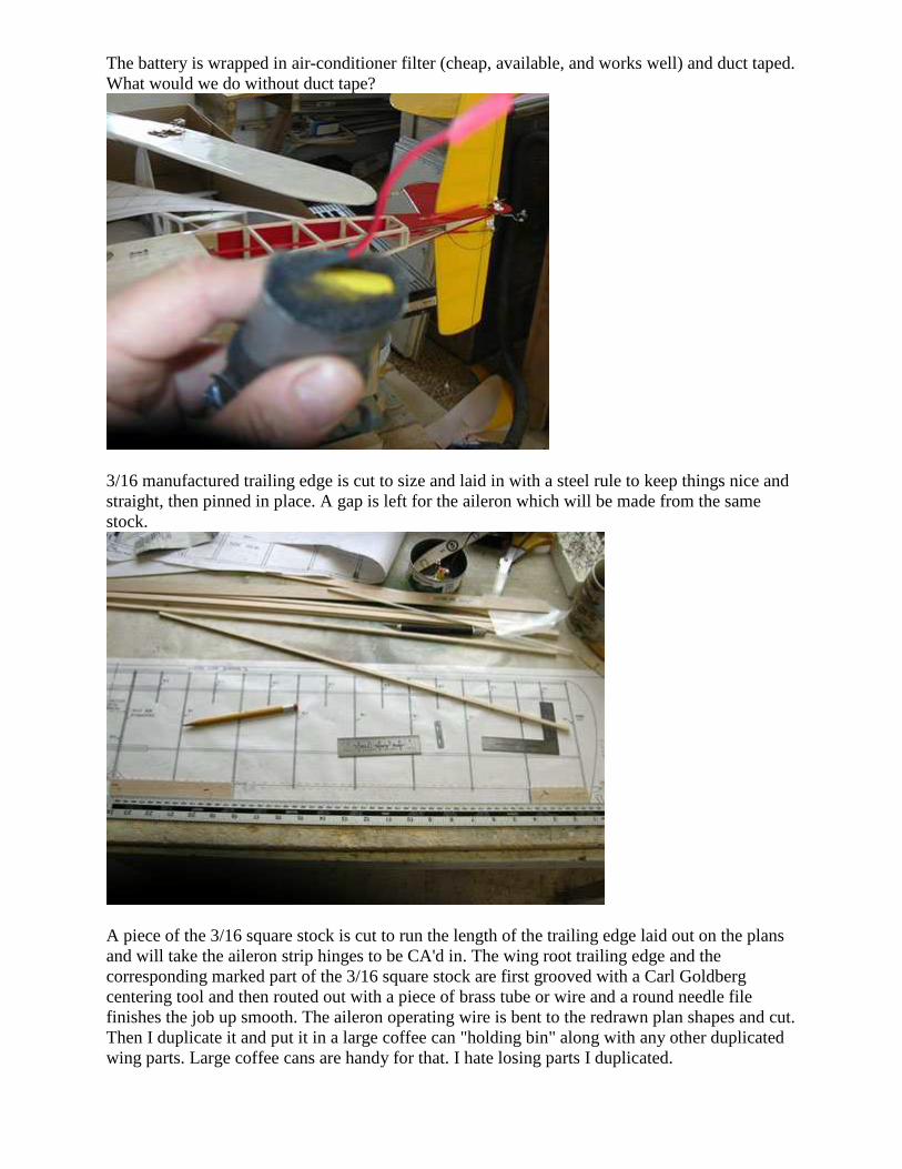
An access hatch is laid out and being drilled behind the landing gear mount for easier extraction of the battery. 1/8 X 1/4 spruce has been located inside and CA'd in place. The birch ply covering is 1/32 inch and held down with #2 phillips button-head screws from Great Planes.
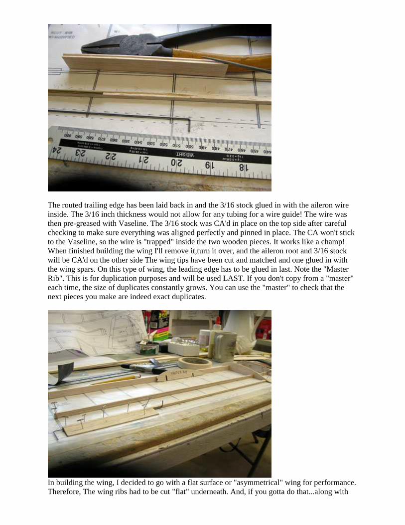
The battery is wrapped in air-conditioner filter (cheap, available, and works well) and duct taped. What would we do without duct tape?
3/16 manufactured trailing edge is cut to size and laid in with a steel rule to keep things nice and straight, then pinned in place. A gap is left for the aileron which will be made from the same stock.
A piece of the 3/16 square stock is cut to run the length of the trailing edge laid out on the plans and will take the aileron strip hinges to be CA'd in. The wing root trailing edge and the corresponding marked part of the 3/16 square stock are first grooved with a Carl Goldberg centering tool and then routed out with a piece of brass tube or wire and a round needle file finishes the job up smooth. The aileron operating wire is bent to the redrawn plan shapes and cut. Then I duplicate it and put it in a large coffee can "holding bin" along with any other duplicated wing parts. Large coffee cans are handy for that. I hate losing parts I duplicated.
The routed trailing edge has been laid back in and the 3/16 stock glued in with the aileron wire inside. The 3/16 inch thickness would not allow for any tubing for a wire guide! The wire was then pre-greased with Vaseline. The 3/16 stock was CA'd in place on the top side after careful checking to make sure everything was aligned perfectly and pinned in place. The CA won't stick to the Vaseline, so the wire is "trapped" inside the two wooden pieces. It works like a champ! When finished building the wing I'll remove it,turn it over, and the aileron root and 3/16 stock will be CA'd on the other side The wing tips have been cut and matched and one glued in with the wing spars. On this type of wing, the leading edge has to be glued in last. Note the "Master Rib". This is for duplication purposes and will be used LAST. If you don't copy from a "master" each time, the size of duplicates constantly grows. You can use the "master" to check that the next pieces you make are indeed exact duplicates.
In building the wing, I decided to go with a flat surface or "asymmetrical" wing for performance. Therefore, The wing ribs had to be cut "flat" underneath. And, if you gotta do that...along with
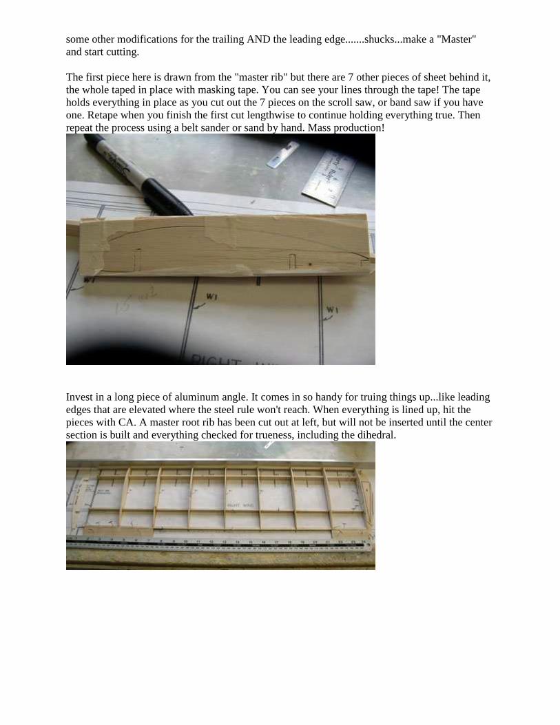
some other modifications for the trailing AND the leading edge.......shucks...make a "Master" and start cutting. The first piece here is drawn from the "master rib" but there are 7 other pieces of sheet behind it, the whole taped in place with masking tape. You can see your lines through the tape! The tape holds everything in place as you cut out the 7 pieces on the scroll saw, or band saw if you have one. Retape when you finish the first cut lengthwise to continue holding everything true. Then repeat the process using a belt sander or sand by hand. Mass production!
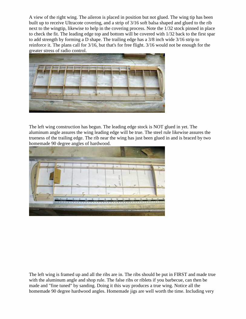
Invest in a long piece of aluminum angle. It comes in so handy for truing things up...like leading edges that are elevated where the steel rule won't reach. When everything is lined up, hit the pieces with CA. A master root rib has been cut out at left, but will not be inserted until the center section is built and everything checked for trueness, including the dihedral.
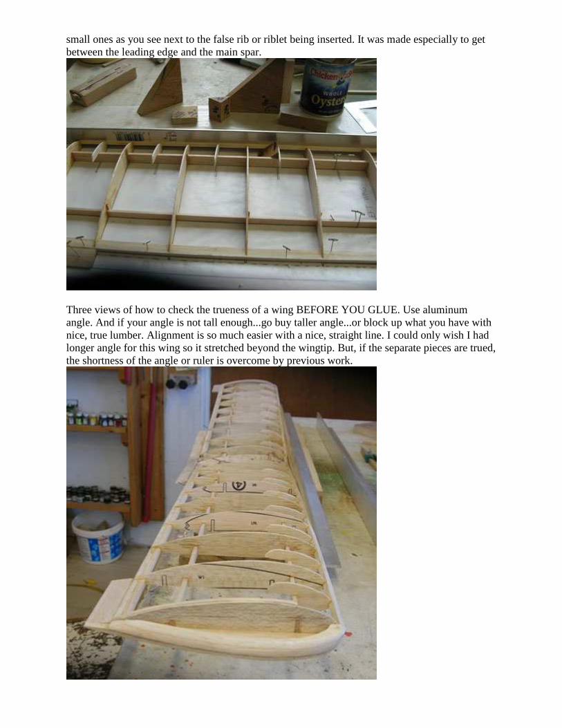
A view of the right wing. The aileron is placed in position but not glued. The wing tip has been built up to receive Ultracote covering, and a strip of 3/16 soft balsa shaped and glued to the rib next to the wingtip, likewise to help in the covering process. Note the 1/32 stock pinned in place to check the fit. The leading edge top and bottom will be covered with 1/32 back to the first spar to add strength by forming a D shape. The trailing edge has a 3/8 inch wide 3/16 strip to reinforce it. The plans call for 3/16, but that's for free flight. 3/16 would not be enough for the greater stress of radio control.
The left wing construction has begun. The leading edge stock is NOT glued in yet. The aluminum angle assures the wing leading edge will be true. The steel rule likewise assures the trueness of the trailing edge. The rib near the wing has just been glued in and is braced by two homemade 90 degree angles of hardwood.
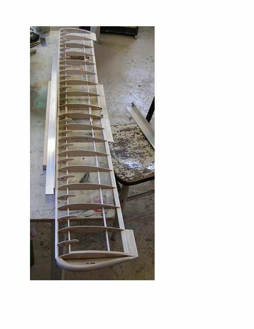
The left wing is framed up and all the ribs are in. The ribs should be put in FIRST and made true with the aluminum angle and shop rule. The false ribs or riblets if you barbecue, can then be made and "fine tuned" by sanding. Doing it this way produces a true wing. Notice all the homemade 90 degree hardwood angles. Homemade jigs are well worth the time. Including very
small ones as you see next to the false rib or riblet being inserted. It was made especially to get between the leading edge and the main spar.
Three views of how to check the trueness of a wing BEFORE YOU GLUE. Use aluminum angle. And if your angle is not tall enough...go buy taller angle...or block up what you have with nice, true lumber. Alignment is so much easier with a nice, straight line. I could only wish I had longer angle for this wing so it stretched beyond the wingtip. But, if the separate pieces are trued, the shortness of the angle or ruler is overcome by previous work.
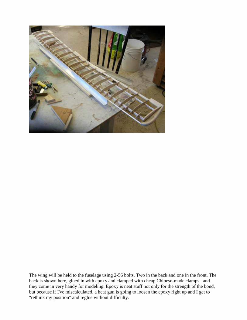
The wing will be held to the fuselage using 2-56 bolts. Two in the back and one in the front. The back is shown here, glued in with epoxy and clamped with cheap Chinese-made clamps...and they come in very handy for modeling. Epoxy is neat stuff not only for the strength of the bond, but because if I've miscalculated, a heat gun is going to loosen the epoxy right up and I get to "rethink my position" and reglue without difficulty.
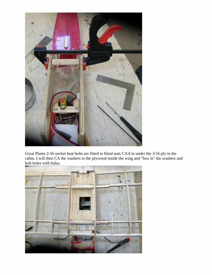
Great Plains 2-56 socket heat bolts are fitted to blind nuts CA'd in under the 3/16 ply in the cabin. I will then CA the washers to the plywood inside the wing and "box in" the washers and bolt holes with balsa.
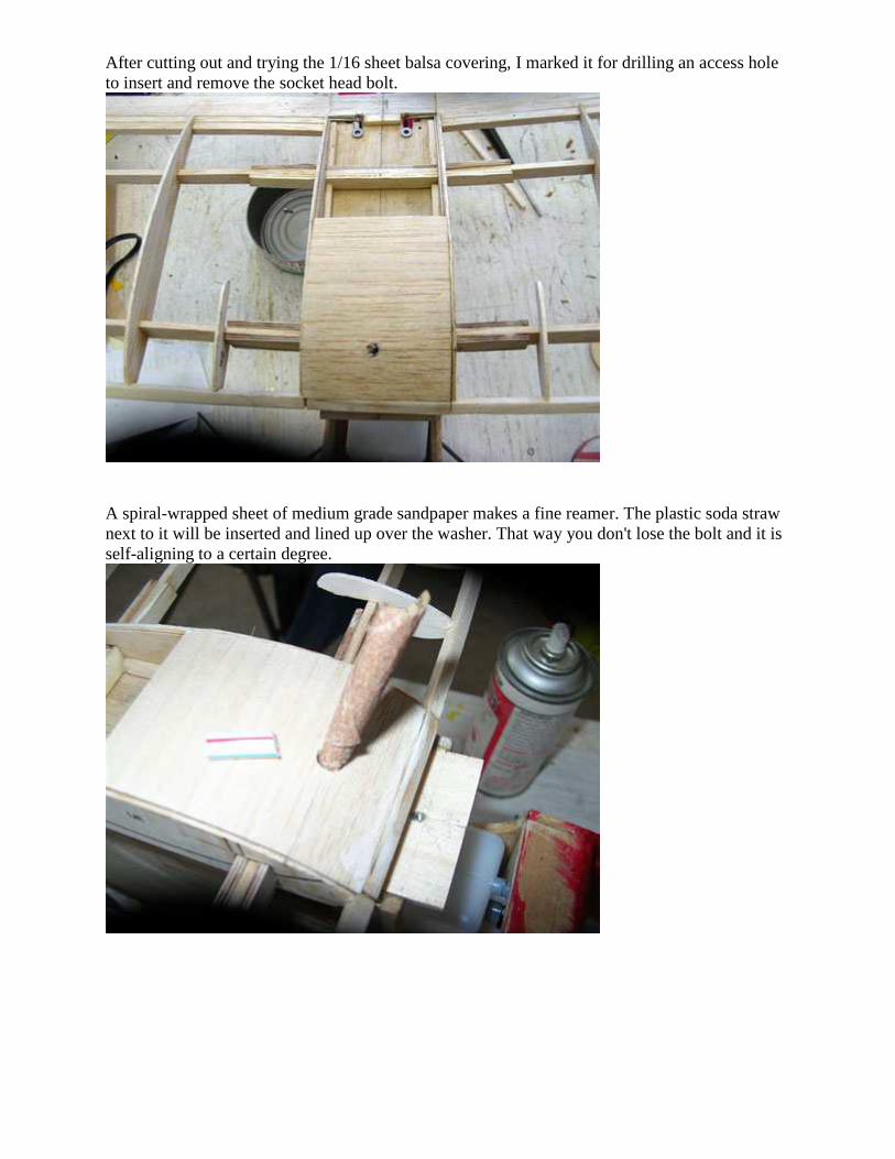
After cutting out and trying the 1/16 sheet balsa covering, I marked it for drilling an access hole to insert and remove the socket head bolt.
A spiral-wrapped sheet of medium grade sandpaper makes a fine reamer. The plastic soda straw next to it will be inserted and lined up over the washer. That way you don't lose the bolt and it is self-aligning to a certain degree.
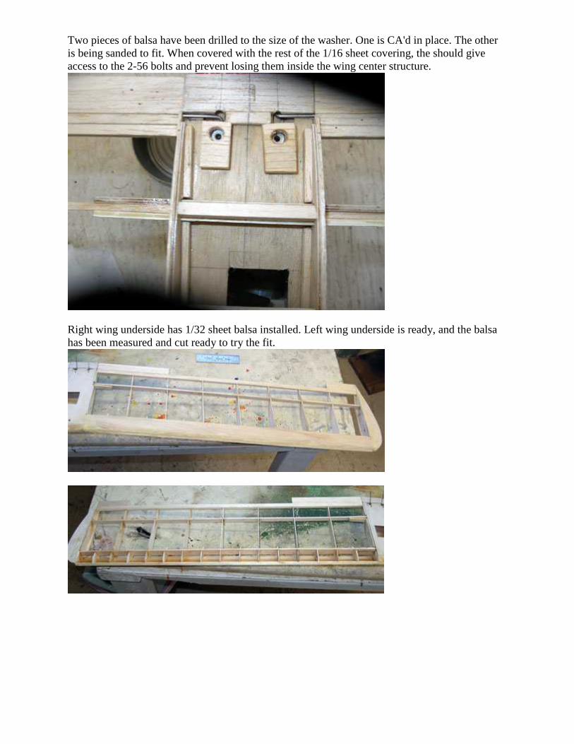
Two pieces of balsa have been drilled to the size of the washer. One is CA'd in place. The other is being sanded to fit. When covered with the rest of the 1/16 sheet covering, the should give access to the 2-56 bolts and prevent losing them inside the wing center structure.
Right wing underside has 1/32 sheet balsa installed. Left wing underside is ready, and the balsa has been measured and cut ready to try the fit.
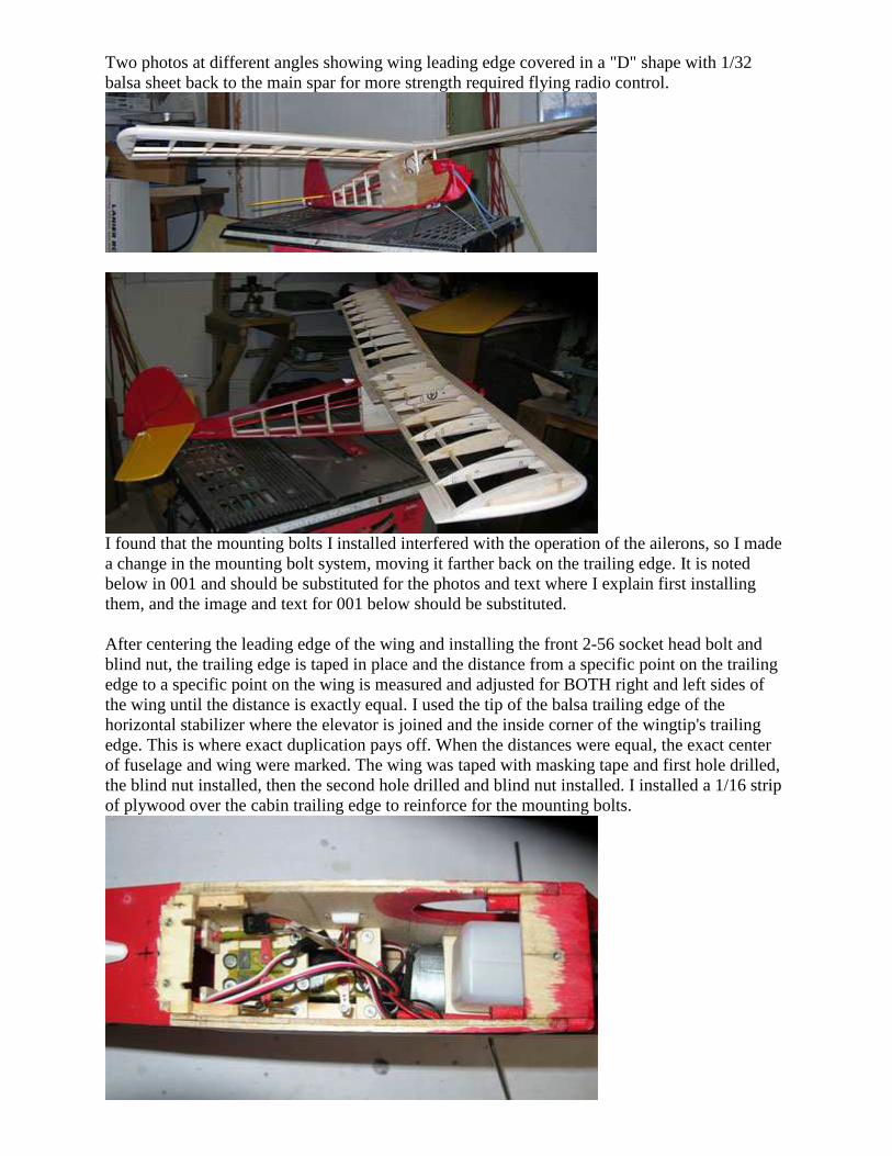
Two photos at different angles showing wing leading edge covered in a "D" shape with 1/32 balsa sheet back to the main spar for more strength required flying radio control.
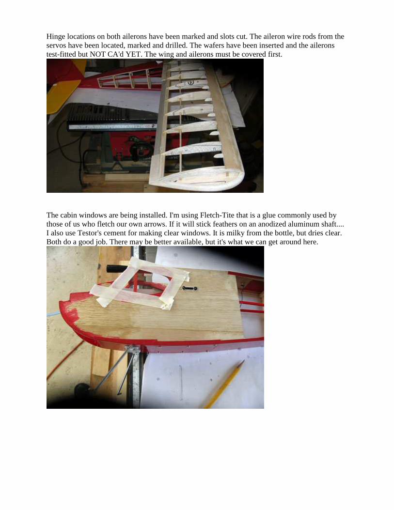
I found that the mounting bolts I installed interfered with the operation of the ailerons, so I made a change in the mounting bolt system, moving it farther back on the trailing edge. It is noted below in 001 and should be substituted for the photos and text where I explain first installing them, and the image and text for 001 below should be substituted. After centering the leading edge of the wing and installing the front 2-56 socket head bolt and blind nut, the trailing edge is taped in place and the distance from a specific point on the trailing edge to a specific point on the wing is measured and adjusted for BOTH right and left sides of the wing until the distance is exactly equal. I used the tip of the balsa trailing edge of the horizontal stabilizer where the elevator is joined and the inside corner of the wingtip's trailing edge. This is where exact duplication pays off. When the distances were equal, the exact center of fuselage and wing were marked. The wing was taped with masking tape and first hole drilled, the blind nut installed, then the second hole drilled and blind nut installed. I installed a 1/16 strip of plywood over the cabin trailing edge to reinforce for the mounting bolts.
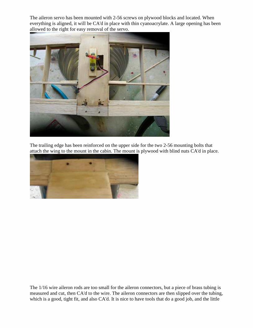
Hinge locations on both ailerons have been marked and slots cut. The aileron wire rods from the servos have been located, marked and drilled. The wafers have been inserted and the ailerons test-fitted but NOT CA'd YET. The wing and ailerons must be covered first.
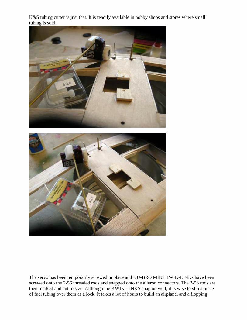
The cabin windows are being installed. I'm using Fletch-Tite that is a glue commonly used by those of us who fletch our own arrows. If it will stick feathers on an anodized aluminum shaft.... I also use Testor's cement for making clear windows. It is milky from the bottle, but dries clear. Both do a good job. There may be better available, but it's what we can get around here.
The aileron servo has been mounted with 2-56 screws on plywood blocks and located. When everything is aligned, it will be CA'd in place with thin cyanoacrylate. A large opening has been allowed to the right for easy removal of the servo.
The trailing edge has been reinforced on the upper side for the two 2-56 mounting bolts that attach the wing to the mount in the cabin. The mount is plywood with blind nuts CA'd in place.
The 1/16 wire aileron rods are too small for the aileron connectors, but a piece of brass tubing is measured and cut, then CA'd to the wire. The aileron connectors are then slipped over the tubing, which is a good, tight fit, and also CA'd. It is nice to have tools that do a good job, and the little
K&S tubing cutter is just that. It is readily available in hobby shops and stores where small tubing is sold.
The servo has been temporarily screwed in place and DU-BRO MINI KWIK-LINKs have been screwed onto the 2-56 threaded rods and snapped onto the aileron connectors. The 2-56 rods are then marked and cut to size. Although the KWIK-LINKS snap on well, it is wise to slip a piece of fuel tubing over them as a lock. It takes a lot of hours to build an airplane, and a flopping
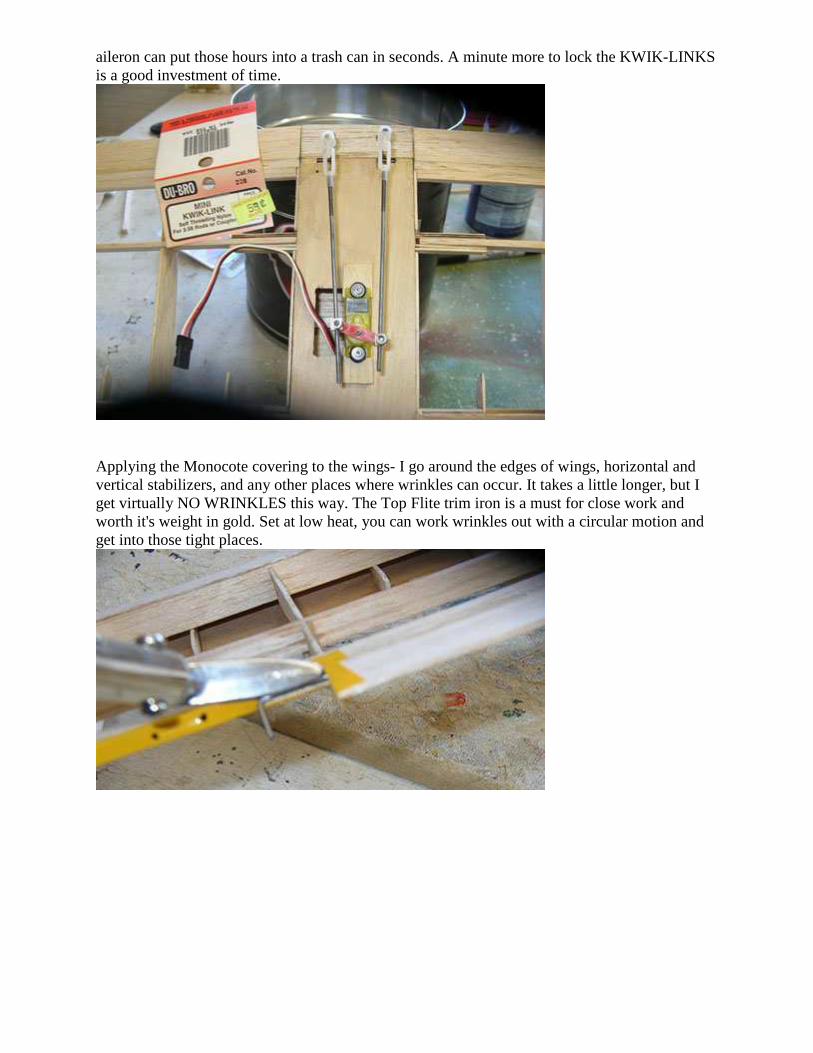
aileron can put those hours into a trash can in seconds. A minute more to lock the KWIK-LINKS is a good investment of time.
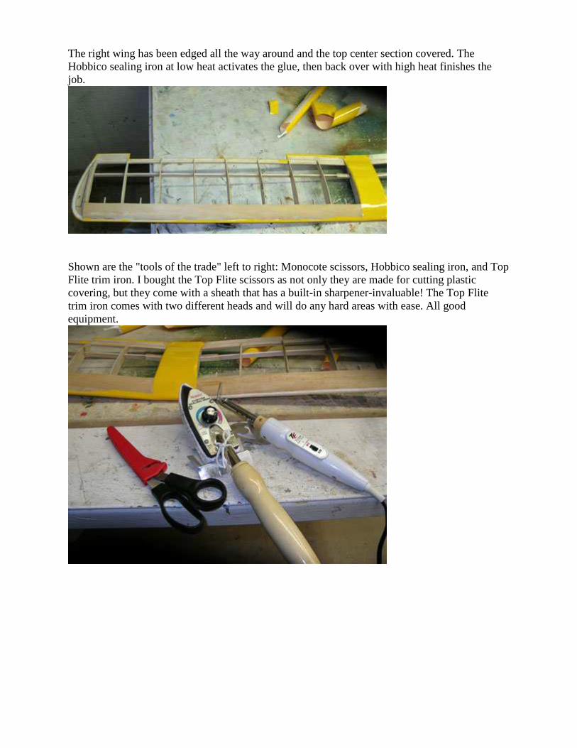
Applying the Monocote covering to the wings- I go around the edges of wings, horizontal and vertical stabilizers, and any other places where wrinkles can occur. It takes a little longer, but I get virtually NO WRINKLES this way. The Top Flite trim iron is a must for close work and worth it's weight in gold. Set at low heat, you can work wrinkles out with a circular motion and get into those tight places.
The right wing has been edged all the way around and the top center section covered. The Hobbico sealing iron at low heat activates the glue, then back over with high heat finishes the job.
Shown are the "tools of the trade" left to right: Monocote scissors, Hobbico sealing iron, and Top Flite trim iron. I bought the Top Flite scissors as not only they are made for cutting plastic covering, but they come with a sheath that has a built-in sharpener-invaluable! The Top Flite trim iron comes with two different heads and will do any hard areas with ease. All good equipment.
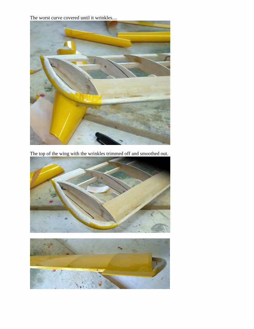
The worst curve covered until it wrinkles....
The top of the wing with the wrinkles trimmed off and smoothed out.
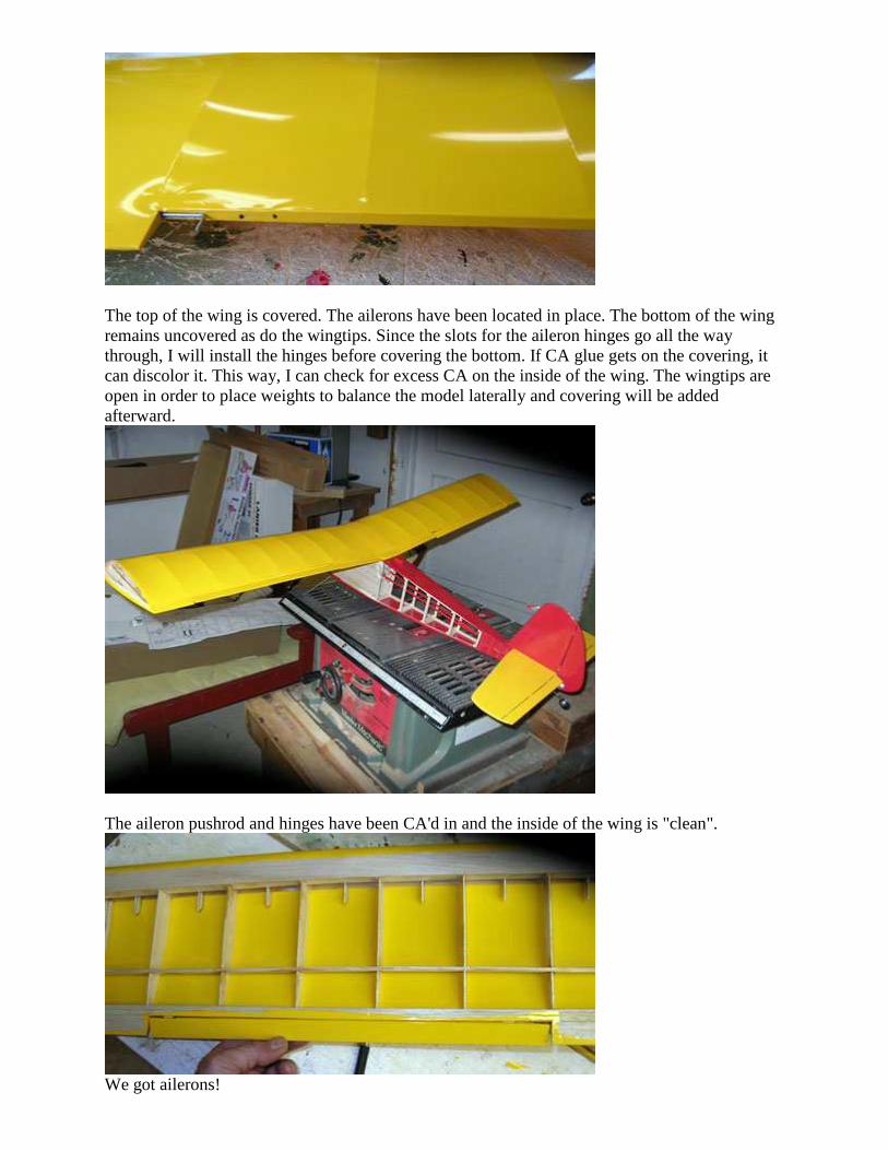
The top of the wing is covered. The ailerons have been located in place. The bottom of the wing remains uncovered as do the wingtips. Since the slots for the aileron hinges go all the way through, I will install the hinges before covering the bottom. If CA glue gets on the covering, it can discolor it. This way, I can check for excess CA on the inside of the wing. The wingtips are open in order to place weights to balance the model laterally and covering will be added afterward.
The aileron pushrod and hinges have been CA'd in and the inside of the wing is "clean".
We got ailerons!
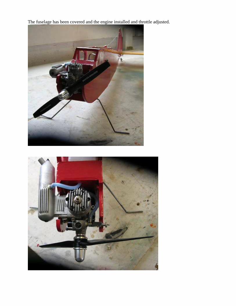
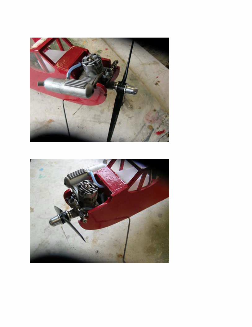
The fuselage has been covered and the engine installed and throttle adjusted.
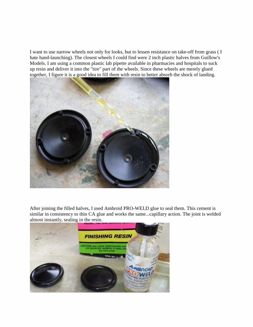
I want to use narrow wheels not only for looks, but to lessen resistance on take-off from grass ( I hate hand-launching). The closest wheels I could find were 2 inch plastic halves from Guillow's Models. I am using a common plastic lab pipette available in pharmacies and hospitals to suck up resin and deliver it into the "tire" part of the wheels. Since these wheels are merely glued together, I figure it is a good idea to fill them with resin to better absorb the shock of landing.
After joining the filled halves, I used Ambroid PRO-WELD glue to seal them. This cement is similar in consistency to thin CA glue and works the same...capillary action. The joint is welded almost instantly, sealing in the resin.
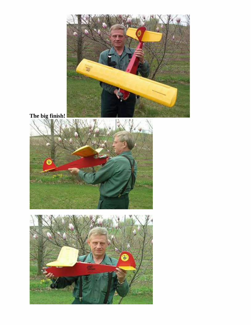
The big finish!
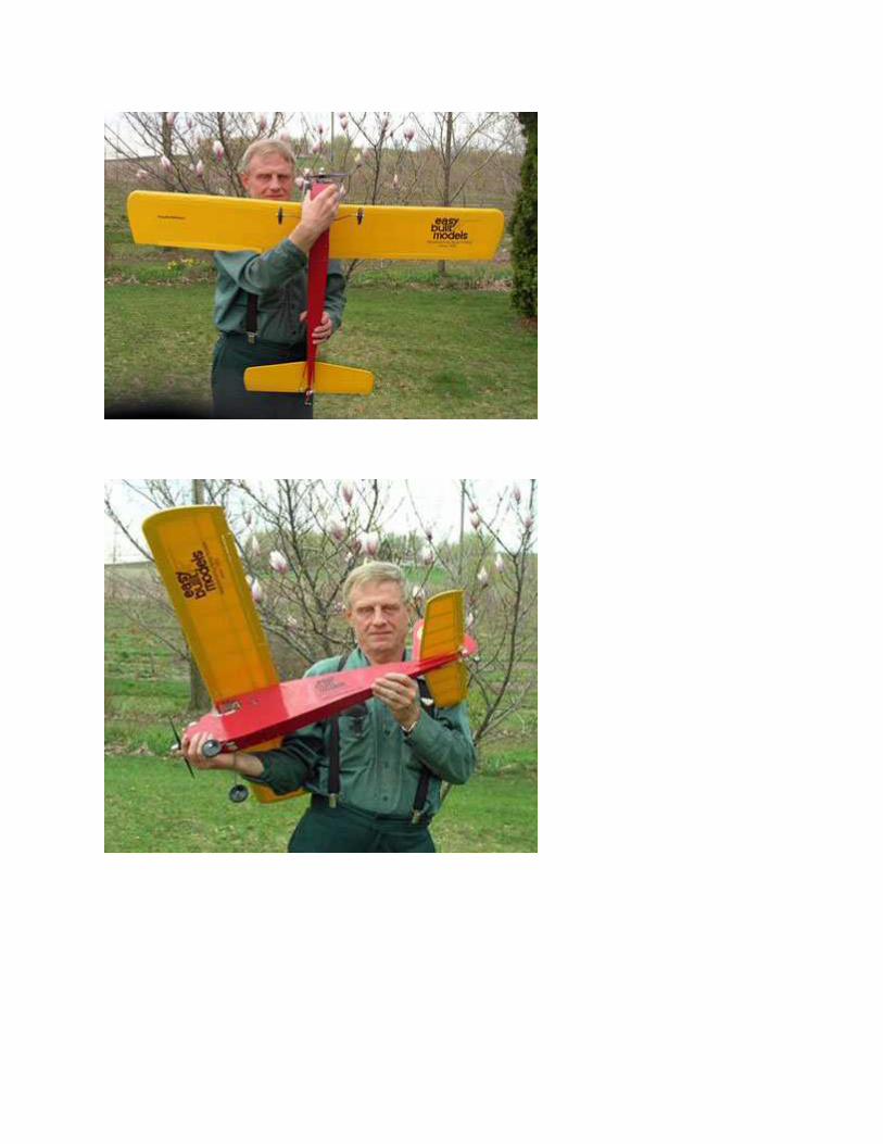
Balsa flies better. .