Embed Size (px)
Citation preview
613-50571-00 Rev. B
Management Software
AT-S63
Command Line InterfaceUser’s GuideAT-9400 Series Layer 2+ Gigabit Ethernet Switches
Version 1.1.0

Copyright © 2005 Allied Telesyn, Inc. All rights reserved. No part of this publication may be reproduced without prior written permission from Allied Telesyn, Inc.Microsoft and Internet Explorer are registered trademarks of Microsoft Corporation. Netscape Navigator is a registered trademark of Netscape Communications Corporation. All other product names, company names, logos or other designations mentioned herein are trademarks or registered trademarks of their respective owners.Allied Telesyn, Inc. reserves the right to make changes in specifications and other information contained in this document without prior written notice. The information provided herein is subject to change without notice. In no event shall Allied Telesyn, Inc. be liable for any incidental, special, indirect, or consequential damages whatsoever, including but not limited to lost profits, arising out of or related to this manual or the information contained herein, even if Allied Telesyn, Inc. has been advised of, known, or should have known, the possibility of such damages.
Contents
Preface ................................................................................................................................................................................13Where to Find Web-based Guides .......................................................................................................................................14Contacting Allied Telesyn .....................................................................................................................................................15
Online Support ..............................................................................................................................................................15Email and Telephone Support .......................................................................................................................................15Returning Products........................................................................................................................................................15Sales or Corporate Information .....................................................................................................................................15Management Software Updates....................................................................................................................................15
Chapter 1: Starting a Command Line Management Session .........................................................................................17Starting a Command Line Management Session .................................................................................................................18Command Line Interface Features .......................................................................................................................................19Command Formatting...........................................................................................................................................................20
Chapter 2: Basic Command Line Commands .................................................................................................................21CLEAR SCREEN..................................................................................................................................................................22EXIT......................................................................................................................................................................................23HELP ....................................................................................................................................................................................24LOGOFF, LOGOUT and QUIT .............................................................................................................................................25MENU ...................................................................................................................................................................................26SAVE CONFIGURATION.....................................................................................................................................................27SET PROMPT ......................................................................................................................................................................28SET SWITCH CONSOLEMODE ..........................................................................................................................................29SHOW USER .......................................................................................................................................................................30
Chapter 3: Basic Switch Commands ...............................................................................................................................31DISABLE DHCPBOOTP.......................................................................................................................................................33DISABLE IP REMOTEASSIGN ............................................................................................................................................34DISABLE TELNET................................................................................................................................................................35ENABLE BOOTP..................................................................................................................................................................36ENABLE DHCP ....................................................................................................................................................................37ENABLE IP REMOTEASSIGN .............................................................................................................................................38ENABLE TELNET.................................................................................................................................................................39PING.....................................................................................................................................................................................40PURGE IP ............................................................................................................................................................................41RESET SWITCH...................................................................................................................................................................42RESET SYSTEM..................................................................................................................................................................43RESTART REBOOT.............................................................................................................................................................44RESTART SWITCH..............................................................................................................................................................45SET ASYN............................................................................................................................................................................47SET IP INTERFACE.............................................................................................................................................................48SET IP ROUTE.....................................................................................................................................................................50SET PASSWORD MANAGER..............................................................................................................................................51SET PASSWORD OPERATOR............................................................................................................................................52SET SWITCH CONSOLETIMER..........................................................................................................................................53SET SWITCH MULTICASTMODE .......................................................................................................................................54SET SYSTEM.......................................................................................................................................................................56SET USER PASSWORD......................................................................................................................................................57SHOW ASYN........................................................................................................................................................................58SHOW DHCPBOOTP...........................................................................................................................................................59SHOW IP INTERFACE.........................................................................................................................................................60
3
Contents
SHOW IP ROUTE.................................................................................................................................................................61SHOW SWITCH....................................................................................................................................................................62SHOW SYSTEM...................................................................................................................................................................63
Chapter 4: SNMPv2 and SNMPv2c Commands ..............................................................................................................65ADD SNMP COMMUNITY....................................................................................................................................................66CREATE SNMP COMMUNITY.............................................................................................................................................68DESTROY SNMP COMMUNITY..........................................................................................................................................71DISABLE SNMP ...................................................................................................................................................................72DISABLE SNMP AUTHENTICATETRAP .............................................................................................................................73DISABLE SNMP COMMUNITY ............................................................................................................................................74ENABLE SNMP ....................................................................................................................................................................75ENABLE SNMP AUTHENTICATETRAP ..............................................................................................................................76ENABLE SNMP COMMUNITY .............................................................................................................................................77SET SNMP COMMUNITY ....................................................................................................................................................78SHOW SNMP .......................................................................................................................................................................80
Chapter 5: Simple Network Time Protocol (SNTP) Commands .....................................................................................83ADD SNTPSERVER PEER|IPADDRESS ............................................................................................................................84DELETE SNTPSERVER PEER|IPADDRESS......................................................................................................................85DISABLE SNTP ....................................................................................................................................................................86ENABLE SNTP .....................................................................................................................................................................87PURGE SNTP.......................................................................................................................................................................88SET DATE ............................................................................................................................................................................89SET SNTP ............................................................................................................................................................................90SET TIME .............................................................................................................................................................................91SHOW SNTP ........................................................................................................................................................................92SHOW TIME .........................................................................................................................................................................93
Chapter 6: Enhanced Stacking Commands ....................................................................................................................95ACCESS SWITCH................................................................................................................................................................96SET SWITCH STACKMODE................................................................................................................................................98SHOW REMOTELIST.........................................................................................................................................................100
Chapter 7: Port Parameter Commands ..........................................................................................................................101ACTIVATE SWITCH PORT ................................................................................................................................................102DISABLE INTERFACE LINKTRAP.....................................................................................................................................103DISABLE SWITCH PORT...................................................................................................................................................104DISABLE SWITCH PORT FLOW .......................................................................................................................................105ENABLE INTERFACE LINKTRAP......................................................................................................................................106ENABLE SWITCH PORT....................................................................................................................................................107ENABLE SWITCH PORT FLOW ........................................................................................................................................108PURGE SWITCH PORT.....................................................................................................................................................109RESET SWITCH PORT......................................................................................................................................................110SET SWITCH PORT...........................................................................................................................................................111SET SWITCH PORT RATELIMITING.................................................................................................................................117SHOW INTERFACE ...........................................................................................................................................................120SHOW SWITCH PORT.......................................................................................................................................................122
Chapter 8: Port Statistics Commands ...........................................................................................................................123RESET SWITCH PORT COUNTER...................................................................................................................................124SHOW SWITCH COUNTER...............................................................................................................................................125SHOW SWITCH PORT COUNTER....................................................................................................................................126
Chapter 9: Static Port Trunking Commands .................................................................................................................127ADD SWITCH TRUNK........................................................................................................................................................128CREATE SWITCH TRUNK.................................................................................................................................................129DELETE SWITCH TRUNK .................................................................................................................................................131DESTROY SWITCH TRUNK..............................................................................................................................................132SET SWITCH TRUNK ........................................................................................................................................................133SHOW SWITCH TRUNK ....................................................................................................................................................134
Chapter 10: LACP Commands ........................................................................................................................................135
4
AT-S63 Management Software Web Browser Interface User’s Guide
ADD LACP PORT .............................................................................................................................................................. 136CREATE LACP AGGREGATOR ....................................................................................................................................... 137DELETE LACP PORT........................................................................................................................................................ 139DESTROY LACP AGGREGATOR..................................................................................................................................... 140DISABLE LACP.................................................................................................................................................................. 141ENABLE LACP................................................................................................................................................................... 142SET LACP AGGREGATOR ............................................................................................................................................... 143SET LACP PRIORITY........................................................................................................................................................ 144SET LACP STATE ............................................................................................................................................................. 145SHOW LACP...................................................................................................................................................................... 146
Chapter 11: Port Mirroring Commands ......................................................................................................................... 147SET SWITCH MIRROR ..................................................................................................................................................... 148SET SWITCH PORT MIRROR .......................................................................................................................................... 149SHOW SWITCH MIRROR ................................................................................................................................................. 151
Chapter 12: Networking Stack ....................................................................................................................................... 153DELETE IP ARP ................................................................................................................................................................ 154DELETE TCP ..................................................................................................................................................................... 155RESET IP ARP .................................................................................................................................................................. 156SET IP ARP TIMEOUT ...................................................................................................................................................... 157SHOW IP ARP ................................................................................................................................................................... 158SHOW IP ROUTE .............................................................................................................................................................. 159SHOW TCP........................................................................................................................................................................ 160
Chapter 13: File System Commands ............................................................................................................................. 161COPY ................................................................................................................................................................................. 162CREATE CONFIG.............................................................................................................................................................. 163DELETE FILE..................................................................................................................................................................... 164FORMAT DEVICE.............................................................................................................................................................. 165LOAD ................................................................................................................................................................................. 166RENAME............................................................................................................................................................................ 171SET CFLASH DIR.............................................................................................................................................................. 172SET CONFIG ..................................................................................................................................................................... 173SHOW CFLASH................................................................................................................................................................. 175SHOW CONFIG ................................................................................................................................................................. 176SHOW FILE ....................................................................................................................................................................... 177SHOW FLASH ................................................................................................................................................................... 178UPLOAD ............................................................................................................................................................................ 179
Chapter 14: Event Log Commands ............................................................................................................................... 185ADD LOG OUTPUT ........................................................................................................................................................... 186CREATE LOG OUTPUT .................................................................................................................................................... 188DESTROY LOG OUTPUT ................................................................................................................................................. 190DISABLE LOG ................................................................................................................................................................... 191DISABLE LOG OUTPUT.................................................................................................................................................... 192ENABLE LOG .................................................................................................................................................................... 193ENABLE LOG OUTPUT..................................................................................................................................................... 194PURGE LOG...................................................................................................................................................................... 195SAVE LOG ......................................................................................................................................................................... 196SET LOG FULLACTION .................................................................................................................................................... 198SET LOG OUTPUT............................................................................................................................................................ 199SHOW LOG ....................................................................................................................................................................... 201SHOW LOG OUTPUT........................................................................................................................................................ 206SHOW LOG STATUS ........................................................................................................................................................ 207
Chapter 15: Classifier Commands ................................................................................................................................. 209CREATE CLASSIFIER....................................................................................................................................................... 210DESTROY CLASSIFIER.................................................................................................................................................... 213PURGE CLASSIFIER ........................................................................................................................................................ 214SET CLASSIFIER .............................................................................................................................................................. 215SHOW CLASSIFIER .......................................................................................................................................................... 218
5
Contents
Chapter 16: ACL Commands ..........................................................................................................................................219CREATE ACL .....................................................................................................................................................................220DESTROY ACL...................................................................................................................................................................222PURGE ACL .......................................................................................................................................................................223SET ACL.............................................................................................................................................................................224SHOW ACL.........................................................................................................................................................................226
Chapter 17: Denial of Service (DoS) Defense Commands ...........................................................................................227SET DOS ............................................................................................................................................................................228SET DOS IPOPTION..........................................................................................................................................................229SET DOS LAND..................................................................................................................................................................231SET DOS PINGOFDEATH .................................................................................................................................................232SET DOS SMURF ..............................................................................................................................................................234SET DOS SYNFLOOD .......................................................................................................................................................235SET DOS TEARDROP .......................................................................................................................................................237SHOW DOS........................................................................................................................................................................239
Chapter 18: Quality of Service (QoS) Commands ........................................................................................................241ADD QOS FLOWGROUP...................................................................................................................................................242ADD QOS POLICY .............................................................................................................................................................243ADD QOS TRAFFICCLASS ...............................................................................................................................................244CREATE QOS FLOWGROUP............................................................................................................................................245CREATE QOS POLICY ......................................................................................................................................................247CREATE QOS TRAFFICCLASS ........................................................................................................................................253DELETE QOS FLOWGROUP ............................................................................................................................................257DELETE QOS POLICY.......................................................................................................................................................258DELETE QOS TRAFFICCLASS.........................................................................................................................................259DESTROY QOS FLOWGROUP.........................................................................................................................................260DESTROY QOS POLICY ...................................................................................................................................................261DESTROY QOS TRAFFICCLASS......................................................................................................................................262PURGE QOS ......................................................................................................................................................................263SET QOS FLOWGROUP ...................................................................................................................................................264SET QOS POLICY..............................................................................................................................................................267SET QOS PORT.................................................................................................................................................................270SET QOS TRAFFICCLASS................................................................................................................................................271SHOW QOS FLOWGROUP ...............................................................................................................................................275SHOW QOS POLICY..........................................................................................................................................................276SHOW QOS TRAFFICCLASS............................................................................................................................................277
Chapter 19: Class of Service (CoS) Commands ...........................................................................................................279MAP QOS COSP................................................................................................................................................................280PURGE QOS ......................................................................................................................................................................282SET QOS COSP.................................................................................................................................................................283SET QOS SCHEDULING ...................................................................................................................................................284SHOW QOS CONFIG.........................................................................................................................................................285
Chapter 20: IGMP Snooping Commands .......................................................................................................................287DISABLE IGMPSNOOPING ...............................................................................................................................................288ENABLE IGMPSNOOPING ................................................................................................................................................289SET IP IGMP ......................................................................................................................................................................290SHOW IGMPSNOOPING ...................................................................................................................................................292SHOW IP IGMP ..................................................................................................................................................................293
Chapter 21: RRP Snooping Commands ........................................................................................................................295DISABLE RRPSNOOPING.................................................................................................................................................296ENABLE RRPSNOOPING..................................................................................................................................................297SHOW RRPSNOOPING.....................................................................................................................................................298
Chapter 22: SNMPv3 Commands ...................................................................................................................................299ADD SNMPV3 USER..........................................................................................................................................................301CLEAR SNMPV3 ACCESS ................................................................................................................................................303CLEAR SNMPV3 COMMUNITY.........................................................................................................................................305
6
AT-S63 Management Software Web Browser Interface User’s Guide
CLEAR SNMPV3 NOTIFY ................................................................................................................................................. 306CLEAR SNMPV3 TARGETADDR...................................................................................................................................... 307CLEAR SNMPV3 VIEW ..................................................................................................................................................... 308CREATE SNMPV3 ACCESS ............................................................................................................................................. 309CREATE SNMPV3 COMMUNITY...................................................................................................................................... 312CREATE SNMPV3 GROUP............................................................................................................................................... 314CREATE SNMPV3 NOTIFY............................................................................................................................................... 316CREATE SNMPV3 TARGETADDR ................................................................................................................................... 318CREATE SNMPV3 TARGETPARAMS .............................................................................................................................. 320CREATE SNMPV3 VIEW................................................................................................................................................... 322DELETE SNMPV3 USER .................................................................................................................................................. 324DESTROY SNMPv3 ACCESS........................................................................................................................................... 325DESTROY SNMPv3 COMMUNITY ................................................................................................................................... 327DESTROY SNMPv3 GROUP ............................................................................................................................................ 328DESTROY SNMPv3 NOTIFY ............................................................................................................................................ 329DESTROY SNMPv3 TARGETADDR................................................................................................................................. 330DESTROY SNMPv3 TARGETPARMS .............................................................................................................................. 331DESTROY SNMPV3 VIEW................................................................................................................................................ 332PURGE SNMPV3 ACCESS............................................................................................................................................... 333PURGE SNMPV3 COMMUNITY ....................................................................................................................................... 334PURGE SNMPV3 NOTIFY ................................................................................................................................................ 335PURGE SNMPV3 TARGETADDR..................................................................................................................................... 336PURGE SNMPV3 VIEW .................................................................................................................................................... 337SET SNMPV3 ACCESS..................................................................................................................................................... 338SET SNMPV3 COMMUNITY ............................................................................................................................................. 340SET SNMPV3 GROUP ...................................................................................................................................................... 342SET SNMPV3 NOTIFY ...................................................................................................................................................... 344SET SNMPV3 TARGETADDR........................................................................................................................................... 346SET SNMPV3 TARGETPARAMS...................................................................................................................................... 348SET SNMPV3 USER ......................................................................................................................................................... 350SET SNMPV3 VIEW .......................................................................................................................................................... 352SHOW SNMPV3 ACCESS ................................................................................................................................................ 354SHOW SNMPV3 COMMUNITY ......................................................................................................................................... 355SHOW SNMPv3 GROUP................................................................................................................................................... 356SHOW SNMPV3 NOTIFY .................................................................................................................................................. 357SHOW SNMPV3 TARGETADDR ...................................................................................................................................... 358SHOW SNMPV3 TARGETPARAMS ................................................................................................................................. 359SHOW SNMPV3 USER ..................................................................................................................................................... 360SHOW SNMPV3 VIEW ...................................................................................................................................................... 361
Chapter 23: STP Commands .......................................................................................................................................... 363ACTIVATE STP.................................................................................................................................................................. 364DISABLE STP .................................................................................................................................................................... 365ENABLE STP ..................................................................................................................................................................... 366PURGE STP ...................................................................................................................................................................... 367SET STP ............................................................................................................................................................................ 368SET STP PORT ................................................................................................................................................................. 371SHOW STP ........................................................................................................................................................................ 373
Chapter 24: RSTP Commands ....................................................................................................................................... 375ACTIVATE RSTP ............................................................................................................................................................... 376DISABLE RSTP ................................................................................................................................................................. 377ENABLE RSTP .................................................................................................................................................................. 378PURGE RSTP.................................................................................................................................................................... 379SET RSTP.......................................................................................................................................................................... 380SET RSTP PORT............................................................................................................................................................... 383SHOW RSTP ..................................................................................................................................................................... 386
Chapter 25: MSTP Commands ....................................................................................................................................... 389ACTIVATE MSTP............................................................................................................................................................... 390ADD MSTP......................................................................................................................................................................... 391
7
Contents
CREATE MSTP ..................................................................................................................................................................392DELETE MSTP...................................................................................................................................................................393DESTROY MSTP MSTIID ..................................................................................................................................................394DISABLE MSTP..................................................................................................................................................................395ENABLE MSTP...................................................................................................................................................................396PURGE MSTP ....................................................................................................................................................................397SET MSTP..........................................................................................................................................................................398SET MSTP CIST.................................................................................................................................................................401SET MSTP MSTI ................................................................................................................................................................402SET MSTP MSTIVLANASSOC ..........................................................................................................................................404SET MSTP PORT...............................................................................................................................................................405SHOW MSTP......................................................................................................................................................................408
Chapter 26: VLANs and Multiple VLAN Mode Commands ...........................................................................................411ADD VLAN..........................................................................................................................................................................412CREATE VLAN...................................................................................................................................................................415DELETE VLAN ...................................................................................................................................................................418DESTROY VLAN ................................................................................................................................................................421SET SWITCH INFILTERING ..............................................................................................................................................422SET SWITCH MANAGEMENTVLAN..................................................................................................................................423SET SWITCH VLANMODE.................................................................................................................................................424SET VLAN ..........................................................................................................................................................................426SHOW VLAN ......................................................................................................................................................................427
Chapter 27: GARP VLAN Registration Protocol Commands .......................................................................................429DISABLE GARP .................................................................................................................................................................430ENABLE GARP ..................................................................................................................................................................431PURGE GARP....................................................................................................................................................................432SET GARP PORT...............................................................................................................................................................433SET GARP TIMER..............................................................................................................................................................434SHOW GARP......................................................................................................................................................................436SHOW GARP COUNTER...................................................................................................................................................437SHOW GARP DATABASE .................................................................................................................................................439SHOW GARP GIP ..............................................................................................................................................................440SHOW GARP MACHINE....................................................................................................................................................441
Chapter 28: Protected Ports VLAN Commands ............................................................................................................443ADD VLAN GROUP............................................................................................................................................................444CREATE VLAN PORTPROTECTED..................................................................................................................................446DELETE VLAN ...................................................................................................................................................................447DESTROY VLAN ................................................................................................................................................................449SET VLAN ..........................................................................................................................................................................450SHOW VLAN ......................................................................................................................................................................451
Chapter 29: Port Security Commands ...........................................................................................................................453SET SWITCH PORT INTRUSIONACTION ........................................................................................................................454SET SWITCH PORT SECURITYMODE.............................................................................................................................455SHOW SWITCH PORT INTRUSION..................................................................................................................................458SHOW SWITCH PORT SECURITYMODE.........................................................................................................................459
Chapter 30: 802.1x Port-based Network Access Control Commands ........................................................................461DISABLE PORTACCESS|PORTAUTH ..............................................................................................................................462DISABLE RADIUSACCOUNTING......................................................................................................................................463ENABLE PORTACCESS|PORTAUTH ...............................................................................................................................464ENABLE RADIUSACCOUNTING.......................................................................................................................................465SET PORTACCESS|PORTAUTH PORT ROLE=AUTHENTICATOR................................................................................466SET PORTACCESS|PORTAUTH PORT ROLE=SUPPLICANT........................................................................................470SET RADIUSACCOUNTING ..............................................................................................................................................472SHOW PORTACCESS|PORTAUTH ..................................................................................................................................474SHOW PORTACCESS|PORTAUTH PORT .......................................................................................................................475SHOW RADIUSACCOUNTING..........................................................................................................................................476
8
AT-S63 Management Software Web Browser Interface User’s Guide
Chapter 31: MAC Address Table Commands ............................................................................................................... 477ADD SWITCH FDB|FILTER............................................................................................................................................... 478DELETE SWITCH FDB|FILTER......................................................................................................................................... 480RESET SWITCH FDB........................................................................................................................................................ 481SET SWITCH AGINGTIMER|AGEINGTIMER ................................................................................................................... 482SHOW SWITCH AGINGTIMER|AGEINGTIMER............................................................................................................... 483SHOW SWITCH FDB......................................................................................................................................................... 484
Chapter 32: Web Server Commands ............................................................................................................................. 487DISABLE HTTP SERVER.................................................................................................................................................. 488ENABLE HTTP SERVER................................................................................................................................................... 489PURGE HTTP SERVER .................................................................................................................................................... 490SET HTTP SERVER .......................................................................................................................................................... 491SHOW HTTP SERVER...................................................................................................................................................... 496
Chapter 33: Encryption Key Commands ...................................................................................................................... 497CREATE ENCO KEY ......................................................................................................................................................... 498DESTROY ENCO KEY ...................................................................................................................................................... 502SET ENCO KEY................................................................................................................................................................. 503SHOW ENCO..................................................................................................................................................................... 504
Chapter 34: Public Key Infrastructure (PKI) Certificate Commands .......................................................................... 505ADD PKI CERTIFICATE .................................................................................................................................................... 506CREATE PKI CERTIFICATE ............................................................................................................................................. 508CREATE PKI ENROLLMENTREQUEST........................................................................................................................... 511DELETE PKI CERTIFICATE.............................................................................................................................................. 513PURGE PKI........................................................................................................................................................................ 514SET PKI CERTIFICATE..................................................................................................................................................... 515SET PKI CERTSTORELIMIT ............................................................................................................................................. 517SET SYSTEM DISTINGUISHEDNAME............................................................................................................................. 518SHOW PKI ......................................................................................................................................................................... 519SHOW PKI CERTIFICATE................................................................................................................................................. 520
Chapter 35: Secure Sockets Layer (SSL) Commands ................................................................................................. 521SET SSL ............................................................................................................................................................................ 522SHOW SSL ........................................................................................................................................................................ 523
Chapter 36: Secure Shell (SSH) Commands ................................................................................................................ 525DISABLE SSH SERVER.................................................................................................................................................... 526ENABLE SSH SERVER..................................................................................................................................................... 527SET SSH SERVER ............................................................................................................................................................ 530SHOW SSH........................................................................................................................................................................ 532
Chapter 37: TACACS+ and RADIUS Commands .......................................................................................................... 533ADD RADIUSSERVER ...................................................................................................................................................... 534ADD TACACSSERVER ..................................................................................................................................................... 536DELETE RADIUSSERVER................................................................................................................................................ 537DELETE TACACSSERVER............................................................................................................................................... 538DISABLE AUTHENTICATION ........................................................................................................................................... 539ENABLE AUTHENTICATION ............................................................................................................................................ 540PURGE AUTHENTICATION.............................................................................................................................................. 541SET AUTHENTICATION.................................................................................................................................................... 542SHOW AUTHENTICATION ............................................................................................................................................... 544
Chapter 38: Management ACL Commands .................................................................................................................. 545ADD MGMTACL................................................................................................................................................................. 546DELETE MGMTACL .......................................................................................................................................................... 549DISABLE MGMTACL ......................................................................................................................................................... 550ENABLE MGMTACL .......................................................................................................................................................... 551SET MGMTACL STATE..................................................................................................................................................... 552SHOW MGMTACL ............................................................................................................................................................. 554Index ................................................................................................................................................................................. 555
9

Contents
10
Tables
Table 1. File Name Extensions ..........................................................................................................................................168Table 2. File Name Extensions ..........................................................................................................................................181Table 3. Default Syslog Facilities .......................................................................................................................................188Table 4. AT-S63 Modules ..................................................................................................................................................202Table 5. Event Log Severity Levels ...................................................................................................................................204Table 6. Default Mappings of IEEE 802.1p Priority Levels to Priority Queues ..................................................................280Table 7. Bridge Priority Value Increments .........................................................................................................................368Table 8. STP Auto-Detect Port Costs ................................................................................................................................371Table 9. Auto-Detect Port Trunk Costs ..............................................................................................................................371Table 10. Port Priority Value Increments ...........................................................................................................................372Table 11. Bridge Priority Value Increments .......................................................................................................................380Table 12. RSTP Auto-Detect Port Costs ...........................................................................................................................383Table 13. RSTP Auto-Detect Port Trunk Costs .................................................................................................................383Table 14. Port Priority Value Increments ...........................................................................................................................384Table 15. CIST Priority Value Increments .........................................................................................................................401Table 16. MSTI Priority Value Increments .........................................................................................................................402Table 17. Port Priority Value Increments ...........................................................................................................................406
11

Tables
12
Preface
This guide contains instructions on how to use the command line interface of the AT-S63 management software and contains the following sections:
“Where to Find Web-based Guides” on page 14“Contacting Allied Telesyn” on page 15
13

Preface
Where to Find Web-based Guides
The installation and user guides for all Allied Telesyn products are available in portable document format (PDF) on our web site at www.alliedtelesyn.com. You can view the documents online or download them onto a local workstation or server.
14
AT-LX3800U Multi-Service Transport System Installation and Maintenance Guide
Contacting Allied Telesyn
This section provides Allied Telesyn contact information for technical support as well as sales and corporate information.
Online Support You can request technical support online by accessing the Allied Telesyn Knowledge Base: http://kb.alliedtelesyn.com. You can use the Knowledge Base to submit questions to our technical support staff and review answers to previously asked questions.
Email andTelephone
Support
For Technical Support via email or telephone, refer to the Support & Services section of the Allied Telesyn web site: www.alliedtelesyn.com.
ReturningProducts
Products for return or repair must first be assigned a return materials authorization (RMA) number. A product sent to Allied Telesyn without an RMA number will be returned to the sender at the sender’s expense.
To obtain an RMA number, contact Allied Telesyn Technical Support through our web site: www.alliedtelesyn.com.
Sales orCorporate
Information
You can contact Allied Telesyn for sales or corporate information through our web site: www.alliedtelesyn.com. To find the contact information for your country, select Contact Us -> Worldwide Contacts.
ManagementSoftware Updates
New releases of management software for our managed products are available from either of the following Internet sites:
Allied Telesyn web site: www.alliedtelesyn.com Allied Telesyn FTP server: ftp://ftp.alliedtelesyn.com
If you prefer to download new software from the Allied Telesyn FTP server from your workstation’s command prompt, you will need FTP client software and you must log in to the server. Enter “anonymous” for the user name and your email address for the password.
15

Preface
16
Chapter 1
Starting a Command Line Management Session
This chapter contains the following topics:
“Starting a Command Line Management Session” on page 18“Command Line Interface Features” on page 19“Command Formatting” on page 20
17
Chapter 1: Starting a Command Line Management Session
Starting a Command Line Management Session
The default management session type is the command line interface (CLI). The prompt differs depending on whether you logged in as manager or operator. If you logged in as manager, you will see “#.” If you logged in as operator, you will see “$.” You can now manage the switch with the command line commands.
NoteWeb browser management does not support the command line interface.
18
AT-S63 Management Software Command Line Interface User’s Guide
Command Line Interface Features
The following features are supported in the command line interface:
Command history - Use the up and down arrow keys.Context-specific help - Press the question mark key at any time to see a list of legal next parameters. Keyword abbreviations - Any keyword can be recognized by typing an unambiguous prefix, for example, “sh” for “show”. Tab key - Pressing the Tab key fills in the rest of the keyword. For example, typing “di” and pressing the Tab key enters “disable.”
19
Chapter 1: Starting a Command Line Management Session
Command Formatting
The following formatting conventions are used in this manual:
screen text font - This font illustrates the format of a command and command examples.screen text font - Italicized screen text indicates a variable for you to enter.[ ] - Brackets indicate optional parameters.| - Vertical line separates parameter options for you to choose from.
20
Chapter 2
Basic Command Line Commands
This chapter contains the following commands:
“CLEAR SCREEN” on page 22“EXIT” on page 23“HELP” on page 24“LOGOFF, LOGOUT and QUIT” on page 25“MENU” on page 26“SAVE CONFIGURATION” on page 27“SET PROMPT” on page 28“SET SWITCH CONSOLEMODE” on page 29“SHOW USER” on page 30
NoteRemember to save your changes with the SAVE CONFIGURATION command.
Section I: Basic Features 21

Chapter 2: Basic Command Line Commands
CLEAR SCREEN
Syntax
clear screen
Parameters
None.
Description
This command clears the screen.
Example
The following command clears the screen:
clear screen
22 Section I: Basic Features
AT-S63 Management Software Menus Interface User’s Guide
EXIT
Syntax
exit
Parameters
None.
Description
This command displays the AT-S63 Main Menu. It performs the same function as the MENU command.
Example
The following command displays the main menu:
exit
Section I: Basic Features 23
Chapter 2: Basic Command Line Commands
HELP
Syntax
help
Parameters
None.
Description
This command displays a list of the CLI keywords with a brief description for each keyword.
Example
The following command displays the CLI keywords:
help
24 Section I: Basic Features
AT-S63 Management Software Menus Interface User’s Guide
LOGOFF, LOGOUT and QUIT
Syntax
logoff
logout
quit
Parameters
None.
Description
These three commands all perform the same function: they end a management session. If you are managing a slave switch, the commands return you to the master switch from which you started the management session.
Example
The following command ends a management session:
logoff
Section I: Basic Features 25
Chapter 2: Basic Command Line Commands
MENU
Syntax
menu
Parameters
None.
Description
This command displays the AT-S63 Main Menu. For instructions on how to use the management menus, refer to Chapter 2, “Starting a Local or Remote Management Session” in the AT-S63 Management Software Menus Interface User’s Guide.
Example
The following command displays the AT-S63 Main Menu:
menu
26 Section I: Basic Features
AT-S63 Management Software Menus Interface User’s Guide
SAVE CONFIGURATION
Syntax
save configuration
Parameters
None.
Description
This command saves your changes to the switch’s active boot configuration file for permanent storage.
Whenever you make a change to an operating parameter of the switch, such as enter a new IP address or create a new VLAN, the change is stored in temporary memory. It will be lost the next time you reset the switch or power cycle the unit.
To permanently save your changes, you must use this command. The changes are saved in the active boot configuration file as a series of commands. The commands in the file are used by the switch to recreate all of its settings, such as VLANs and port settings, whenever you reset or power cycle the unit.
To view the name of the currently active boot configuration file, see “SHOW CONFIG” on page 176. To view the contents of a configuration file, see “SHOW FILE” on page 177. For background information on boot configuration files, refer to Chapter 10, “File System” in the AT-S63 Management Software Menus Interface User’s Guide.
Example
The following command saves your configuration changes to the active boot configuration file:
save configuration
Section I: Basic Features 27
Chapter 2: Basic Command Line Commands
SET PROMPT
Syntax
set prompt="prompt"
Parameter
prompt Specifies the command line prompt. The prompt can be from one to 12 alphanumeric characters. Spaces and special characters are allowed. The prompt must be enclosed in quotes.
Description
This command changes the command prompt. Assigning each switch a different command prompt can make it easier for you to identify the different switches in your network when you manage them.
NoteIf you define the system name before you set up a system prompt, the switch uses the first 16 characters of the system name as the prompt. See “SET SYSTEM” on page 56.
Example
The following command changes the command prompt to “Sales Switch”:
set prompt="Sales Switch"
28 Section I: Basic Features
AT-S63 Management Software Menus Interface User’s Guide
SET SWITCH CONSOLEMODE
Syntax
set switch consolemode=menu|cli
Parameter
consolemode Specifies the mode you want management sessions to start in. Options are:
menu Specifies the AT-S63 Main Menu.
cli Specifies the command line prompt. This is the default.
Description
You use this command to specify whether you want your management sessions to start by displaying the command line interface (CLI) or the AT-S63 Main Menu. The default is the CLI.
Example
The following command configures the management software to display the menus whenever you start a management session:
set switch consolemode=menu
Section I: Basic Features 29
Chapter 2: Basic Command Line Commands
SHOW USER
Syntax
show user
Parameter
None.
Description
Displays the user account you used to log on to manage the switch.
Example
show user
30 Section I: Basic Features
Chapter 3
Basic Switch Commands
This chapter contains the following commands:
“DISABLE DHCPBOOTP” on page 33“DISABLE IP REMOTEASSIGN” on page 34“DISABLE TELNET” on page 35“ENABLE BOOTP” on page 36“ENABLE DHCP” on page 37“ENABLE IP REMOTEASSIGN” on page 38“ENABLE TELNET” on page 39“PING” on page 40“PURGE IP” on page 41“RESET SWITCH” on page 42“RESET SYSTEM” on page 43“RESTART REBOOT” on page 44“RESTART SWITCH” on page 45“SET ASYN” on page 47“SET IP INTERFACE” on page 48“SET IP ROUTE” on page 50“SET PASSWORD MANAGER” on page 51“SET PASSWORD OPERATOR” on page 52“SET SWITCH CONSOLETIMER” on page 53“SET SWITCH MULTICASTMODE” on page 54“SET SYSTEM” on page 56“SET USER PASSWORD” on page 57“SHOW ASYN” on page 58“SHOW DHCPBOOTP” on page 59“SHOW IP INTERFACE” on page 60“SHOW IP ROUTE” on page 61“SHOW SWITCH” on page 62“SHOW SYSTEM” on page 63
31

Chapter 3: Basic Switch Commands
NoteRemember to save your changes with the SAVE CONFIGURATION command.
32
AT-S63 Management Software Command Line Interface User’s Guide
DISABLE DHCPBOOTP
Syntax
disable dhcpbootp
Parameters
None.
Description
This command deactivates the DHCP and BOOTP client software on the switch. This command is equivalent to “DISABLE IP REMOTEASSIGN” on page 34. The default setting for the client software is disabled.
To activate the DHCP and BOOTP client software, refer to “ENABLE BOOTP” on page 36 or “ENABLE IP REMOTEASSIGN” on page 38.
Example
The following command deactivates the DHCP and BOOTP client software:
disable dhcpbootp
33
Chapter 3: Basic Switch Commands
DISABLE IP REMOTEASSIGN
Syntax
disable ip remoteassign
Parameters
None.
Description
This command deactivates the DHCP and BOOTP client software on the switch. This command is equivalent to “DISABLE DHCPBOOTP” on page 33. The default setting for the client software is disabled.
To activate the DHCP and BOOTP client software, refer to “ENABLE BOOTP” on page 36 or “ENABLE IP REMOTEASSIGN” on page 38.
Example
The following command deactivates the DHCP and BOOTP client software:
disable ip remoteassign
34
AT-S63 Management Software Command Line Interface User’s Guide
DISABLE TELNET
Syntax
disable telnet
Parameters
None.
Description
This command disables the Telnet server software on the switch. You might disable the server software if you do not want anyone to manage the switch using the Telnet application protocol or if you plan to use the Secure Shell protocol. The default setting for the Telnet server is enabled.
Example
The following command deactivates the Telnet server:
disable telnet
35
Chapter 3: Basic Switch Commands
ENABLE BOOTP
Syntax
enable bootp
Parameters
None.
Description
This command activates the BOOTP client software on the switch. This command is equivalent to “SET IP INTERFACE” on page 48. The default setting for the BOOTP client software is disabled.
NoteWhen you activate BOOTP, the switch immediately begins to query the network for a BOOTP server. The switch continues to query the network for its IP configuration until it receives a response.
Any static IP address, subnet mask, or gateway address assigned to the switch is deleted from the System Configuration menu and replaced with the value the switch receives from the BOOTP server. If you later disable BOOTP, these values are returned to their default settings.
To disable BOOTP, refer to “DISABLE DHCPBOOTP” on page 33 or “DISABLE IP REMOTEASSIGN” on page 34.
NoteYou cannot manually assign an IP address or subnet mask to a switch when the BOOTP client software has been activated.
Example
The following command activates the BOOTP client software on the switch:
enable bootp
36
AT-S63 Management Software Command Line Interface User’s Guide
ENABLE DHCP
Syntax
enable dhcp
Parameters
None.
Description
This command activates the DHCP client software on the switch. This command is equivalent to “SET IP INTERFACE” on page 48. The default setting for the DHCP client software is disabled.
NoteWhen you activate DHCP, the switch immediately begins to query the network for a DHCP server. The switch continues to query the network for its IP configuration until it receives a response.
Any static IP address, subnet mask, or gateway address assigned to the switch is deleted from the System Configuration menu and replaced with the value the switch receives from the BOOTP server. If you later disable DHCP, these values are returned to their default settings.
To disable DHCP, refer to “DISABLE DHCPBOOTP” on page 33 or “DISABLE IP REMOTEASSIGN” on page 34.
NoteYou cannot manually assign an IP address or subnet mask to a switch when the DHCP client software has been activated.
Example
The following command activates the DHCP client software on the switch:
enable dhcp
37
Chapter 3: Basic Switch Commands
ENABLE IP REMOTEASSIGN
Syntax
enable ip remoteassign
Parameters
None.
Description
This command activates the DHCP and BOOTP client software on the switch. This command is equivalent to “ENABLE BOOTP” on page 36. The default setting for the DHCP and BOOTP client software is disabled.
NoteWhen you activate BOOTP/DHCP, the switch immediately begins to query the network for a BOOTP or DHCP server. The switch continues to query the network for its IP configuration until it receives a response.
Any static IP address, subnet mask, or gateway address assigned to the switch is deleted from the System Configuration menu and replaced with the value the switch receives from the BOOTP or DHCP server. If you later disable BOOTP and DHCP, these values are returned to their default settings.
To disable DHCP and BOOTP, refer to “DISABLE DHCPBOOTP” on page 33 or “DISABLE IP REMOTEASSIGN” on page 34.
NoteYou cannot manually assign an IP address or subnet mask to a switch once the DHCP and BOOTP client software has been activated.
Example
The following command activates the DHCP and BOOTP client software on the switch:
enable ip remoteassign
38
AT-S63 Management Software Command Line Interface User’s Guide
ENABLE TELNET
Syntax
enable telnet
Parameters
None.
Description
This command activates the Telnet server on the switch. With the server activated, you can manage the switch using the Telnet application protocol from any management station on your network. To disable the server, refer to “DISABLE TELNET” on page 35. The default setting for the Telnet server is enabled.
Example
The following command activates the Telnet server:
enable telnet
39
Chapter 3: Basic Switch Commands
PING
Syntax
ping ipaddress
Parameter
ipaddress Specifies the IP address of an end node you want the switch to ping.
Description
This command instructs the switch to ping an end node. You can use this command to determine whether a valid link exists between the switch and another device.
NoteThe switch must have an IP address and subnet mask in order for you to use this command.
Example
The following command pings an end node with the IP address of 149.245.22.22
ping 149.245.22.22
The results of the ping are displayed on the screen.
40

AT-S63 Management Software Command Line Interface User’s Guide
PURGE IP
Syntax
purge ip [ipaddress] [netmask] [route]
Parameters
ipaddress Returns the switch’s IP address to the default setting 0.0.0.0.
netmask Returns the subnet mask to the default setting 0.0.0.0.
route Returns the gateway address to the default setting 0.0.0.0.
Description
This command returns the switch’s IP address, subnet mask, and default gateway address to the default settings.
To set these parameters, refer to “SET IP INTERFACE” on page 48 and “SET IP ROUTE” on page 50. To view the current settings, refer to “SET SYSTEM” on page 56.
Examples
The following command returns the IP address and subnet mask to the default values:
purge ip ipaddress netmask
The following command resets just the gateway address to its default value:
purge ip ipaddress route
The following command resets all three parameters:
purge ip ipaddress
41
Chapter 3: Basic Switch Commands
RESET SWITCH
Syntax
reset switch
Parameters
None.
Description
This command does all of the following:
Performs a soft reset on all ports. The reset takes less than a second to complete. The ports retain their current operating parameter settings. To perform this function on a per-port basis, refer to “RESET SWITCH PORT” on page 110.Resets the statistics counters for all ports to zero. To perform this function on a per-port basis, refer to “RESET SWITCH PORT COUNTER” on page 124.Deletes all dynamic MAC addresses from the MAC address table. To perform this function on a per-port basis, refer to “RESET SWITCH FDB” on page 481.
Examples
This command resets the switch according to the description above:
reset switch
42
AT-S63 Management Software Command Line Interface User’s Guide
RESET SYSTEM
Syntax
reset system [name] [contact] [location]
Parameters
name Deletes the switch’s name.
contact Deletes the switch’s contact.
location Deletes the switch’s location.
Description
This command delete’s the switch’s name, the name of the network administrator responsible for managing the unit, and the location of the unit. To set these parameters, refer to “SET SYSTEM” on page 56.
Examples
This command deletes all three parameter settings:
reset system
This command deletes just the name:
reset system name
43
Chapter 3: Basic Switch Commands
RESTART REBOOT
Syntax
restart reboot
Parameters
None.
Description
This command resets the switch. The switch runs its internal diagnostics, loads the AT-S63 management software, and configures its parameter settings using the current boot configuration file. The reset takes approximately 20 to 30 seconds to complete. The switch does not forward traffic during the time required to run its internal diagnostics and initialize its operating software. Some network traffic may be lost.
NoteBe sure to use the SAVE CONFIGURATION command to save your changes before resetting the switch. Any unsaved changes are lost.
Example
The following resets the switch:
restart reboot
44
AT-S63 Management Software Command Line Interface User’s Guide
RESTART SWITCH
Syntax
restart switch config=none|filename.cfg
Parameters
config Specifies the configuration file. The file must already exist on the switch. The NONE option returns the switch to its default values.
Description
This command loads a different configuration file on the switch or returns the switch’s parameter settings to their default values.
If you specify a configuration file, the switch automatically resets itself and configures its parameters according to the settings in the configuration file specified in the command.
Specifying the NONE option returns the switch’s operating parameters to the default setting. Please note the following before using this option:
Returning the switch to its default values deletes all port-based and tagged VLANs you may have created on the switch.This option does not delete files from the AT-S63 file system. To delete files, refer to “DELETE FILE” on page 164.This option does not delete encryption keys stored in the key database. To delete encryption keys, refer to “DESTROY ENCO KEY” on page 502.Returning a switch to its default values does not change the settings in the active boot configuration file.To reset the active configuration file back to the default settings, you must use the SAVE CONFIGURATION command after the switch reboots and you have reestablished your management session. Otherwise, the switch reverts to the previous configuration the next time you reset the switch.
NoteFor a list of default values, refer to Appendix A, “AT-S63 Default Settings” in the AT-S63 Management Software Menus Interface User’s Guide or in the AT-S63 Management Software Web Browser Interface User’s Guide.
This command does not change the assignment of the active boot
45
Chapter 3: Basic Switch Commands
configuration file, the configuration file the switch uses the next time it is reset. If you reset or power cycle the switch, the switch uses the previous configuration. To change the active boot configuration file, refer to “SET CONFIG” on page 173.
Your local or remote management session with the switch ends when you reset the switch. You must reestablish the session to continue managing the switch.
Example
The following command configures the switch using the configuration file named switch12.cfg:
restart switch config=switch12.cfg
The following command resets the switch to its default values:
restart switch config=none
46
AT-S63 Management Software Command Line Interface User’s Guide
SET ASYN
Syntax
set asyn speed=1200|2400|4800|9600|19200|38400|57600|115200 [prompt=”prompt”]
Parameters
speed Sets the speed (baud rate) of the serial terminal port on the switch. The default is 9600 bps.
prompt Specifies the command line prompt. The prompt can be from one to 12 alphanumeric characters. Spaces and special characters are allowed. The prompt must be enclosed in double quotes. This parameter performs the same function as “SET PROMPT” on page 28.
Description
This command sets the baud rate of the serial terminal port on the switch. The port is used for local management of the switch. You can also use this command to set the command line prompt.
NoteA change to the baud rate of the port ends your management session if you are managing the switch locally. To reestablish a local management session you must change the speed of the terminal or the terminal emulator program to match the new speed of the serial terminal port on the switch.
Example
The following command sets the baud rate to 115200 bps:
set asyn speed=115200
47
Chapter 3: Basic Switch Commands
SET IP INTERFACE
Syntax
set ip interface=eth0 ipaddress=ipaddress|BOOTP|DHCP mask|netmask=subnetmask
Parameters
interface Specifies the interface number. This value is always eth0.
ipaddress Specifies an IP address for the switch or activates the BOOTP or DHCP client software.
mask Specifies the subnet mask for the switch. You mustnetmask specify a subnet mask if you manually assigned the
switch an IP address. These parameters are equivalent. The default is 0.0.0.0.
Description
This command configures the following switch parameters:
IP addressSubnet mask
This command can also activate the DHCP and BOOTP client software on the switch. Activating DHCP and BOOTP with this command is equivalent to using “ENABLE BOOTP” on page 36 or “ENABLE IP REMOTEASSIGN” on page 38.
NoteYou cannot assign an IP address to the switch if the DHCP and BOOTP client software is activated.
To display the current IP address and subnet mask, refer to “SHOW IP INTERFACE” on page 60. To return the IP address and subnet mask to their default values, refer to “PURGE IP” on page 41.
For background information on when to assign a switch an IP address, refer to Chapter 3, “Basic Switch Parameters” in the AT-S63 Management Software Command Line Interface User’s Guide.
Examples
The following command sets the switch’s IP address to 140.35.22.22 and the subnet mask to 255.255.255.0:
48
AT-S63 Management Software Command Line Interface User’s Guide
set ip interface=eth0 ipaddress=140.35.22.22 netmask=255.255.255.0
The following command sets just the subnet mask:
set ip interface=eth0 netmask=255.255.255.252
The following command activates the DHCP and BOOTP client software:
set ip interface=eth0 ipaddress=dhcp
49
Chapter 3: Basic Switch Commands
SET IP ROUTE
Syntax
set ip route ipaddress=ipaddress
Parameter
ipaddress Specifies the IP address of the default gateway for the switch.
Description
This command specifies the IP address of the default gateway for the switch. This IP address is required if you intend to remotely manage the device from a remote management station that is separated from the unit by a router.
Example
The following command sets the default gateway to 140.35.22.12:
set ip route ipaddress=140.35.22.12
50
AT-S63 Management Software Command Line Interface User’s Guide
SET PASSWORD MANAGER
Syntax
set password manager
Parameters
None.
Description
This command sets the manager’s password. Logging in as manager allows you to view and change all switch parameters. The default password is “friend.” The password can be from 0 to 16 alphanumeric characters. Allied Telesyn recommends that you avoid special characters, such as spaces, asterisks, or exclamation points because some web browsers do not accept them in passwords. The password is case sensitive.
Example
The following command changes the manager’s password:
set password manager
Follow the prompts to enter the new password.
51
Chapter 3: Basic Switch Commands
SET PASSWORD OPERATOR
Syntax
set password operator
Parameters
None.
Description
This command sets the operator’s password. Logging in as operator allows you to only view the switch parameters. The default password is “operator.” The password can be from 0 to 16 alphanumeric characters. Allied Telesyn recommends that you avoid special characters, such as spaces, asterisks, or exclamation points because some web browsers do not accept them in passwords. The password is case sensitive.
Example
The following command changes the operator’s password:
set password operator
Follow the prompts to enter the new password.
52
AT-S63 Management Software Command Line Interface User’s Guide
SET SWITCH CONSOLETIMER
Syntax
set switch consoletimer=value
Parameter
consoletimer Specifies the console timer in minutes. The range is 1 to 60 minutes. The default is 10 minutes.
Description
This command sets the console timer, which is used by the management software to end inactive management sessions. If the AT-S63 software does not detect any activity from a local or remote management station after the period of time set by the console timer, it automatically ends the management session. This security feature can prevent unauthorized individuals from using your management station should you step away from your system while configuring a switch. To view the current console timer setting, refer to “SHOW SWITCH” on page 62.
Example
The following command sets the console timer to 25 minutes:
set switch consoletimer=25
53
Chapter 3: Basic Switch Commands
SET SWITCH MULTICASTMODE
Syntax
set switch multicastmode=[a|b|c|d]
Parameter
multicast mode Specifies the multicast mode. The options are:
a Discards all ingress spanning tree BPDU and 802.1x EAPOL packets on all ports.
b Forwards ingress spanning tree BPDU and 802.1x EAPOL packets across all VLANs and ports.
c Forwards ingress BPDU and EAPOL packets only among the untagged ports of the VLAN where the ingress port is a member.
d Forwards ingress BPDU and EAP packets on both tagged and untagged ports of the VLAN where the ingress port is a member.
Description
This command controls the behavior of the switch when forwarding ingress spanning tree BPDU packets and 802.1x port-based access control EAPOL packets when these features are disabled on the switch. Note the following when setting this parameter:
You can only set this parameter from this command. You cannot configure it from the menus or web browser interface.The mode is set at the switch level. You cannot configure it on a per-port basis.A switch can have only one mode active at a time.The mode setting applies to spanning tree protocol BPDUs when STP, RSTP, and MSTP are disabled on the switch.The mode setting applies to 802.1x port-based access control EAPOL packets when 802.1x is disabled.There are four possible states: A, B, C, and D:
A - Discards all ingress spanning tree BPDU and 802.1x EAPOL packets on all ports. The switch behaves as follows:
If STP, RSTP, and MSTP are disabled, all ingress BPDUs are
54
AT-S63 Management Software Command Line Interface User’s Guide
discarded.If 802.1x port-based access control is disabled, all ingress EAPOL packets are discarded.
B - Forwards ingress spanning tree BPDU and 802.1x EAPOL packets across all VLANs and ports. This is the default setting. The switch behaves as follows:
If STP, RSTP, and MSTP are disabled, ingress BPDUs are flooded on all ports.If STP, RSTP, MSTP, and 802.1x are disabled on the switch, BPDUs and EAPOL packets are flooded on all ports.If the switch is running STP or RSTP and 802.1x is disabled, EAPOL packets are flooded on all ports, except ports in the blocking state.If the switch is running MSTP and 802.1x is disabled, EAPOL packets are flooded on all ports, including ports in the blocking state.
C - Forwards ingress BPDU and EAPOL packets only on untagged ports of the VLAN where the ingress port is a member. Packets are not forwarded from tagged ports. The VLAN is identified by the PVID assigned to the ingress port.
D - Forwards ingress BPDU and EAP packets from both tagged and untagged ports of the VLAN where the ingress port is a member. The VLAN is identified by the PVID assigned to the ingress port.
Example
The following command sets the switch’s mode to A to discard all ingress BPDUs and 802.1 EAPOL packets:
set switch multicastmode=a
55
Chapter 3: Basic Switch Commands
SET SYSTEM
Syntax
set system [name="name"] [contact="contact"] [location="location"]
Parameters
name Specifies the name of the switch. The name can be from 1 to 39 alphanumeric characters in length and must be enclosed in double quotes (“ “). Spaces are allowed.
contact Specifies the name of the network administrator responsible for managing the switch. The contact can be from 1 to 39 alphanumeric characters in length and must be enclosed in double quotes. Spaces are allowed.
location Specifies the location of the switch. The location can be from 1 to 39 alphanumeric characters in length and must be enclosed in double quotes. Spaces are allowed.
Description
This command sets a switch’s name, the name of the network administrator responsible for managing the unit, and the location of the unit.
If a parameter already has a value, the new value replaces the existing value. To view the current values for these parameters, refer to “SHOW SYSTEM” on page 63. To delete a value without assigning a new value, refer to “RESET SYSTEM” on page 43.
NoteIf you define the system name before you set up a system prompt, the switch uses the first 16 characters of the system name as the prompt. See “SET PROMPT” on page 28.
Examples
The following command sets a switch’s information:
set system name="Sales" contact="Jane Smith" location="Bldg 3, rm 212"
The following command sets just the system’s name:
set system name="PR Office"
56
AT-S63 Management Software Command Line Interface User’s Guide
SET USER PASSWORD
Syntax
set user manager|operator password=password
Parameter
password Specifies the password.
Description
This command sets the manager or operator’s password. The default manager password is “friend.” The default operator password is “operator.” The password can be from 0 to 16 alphanumeric characters. Allied Telesyn recommends that you avoid special characters, such as spaces, asterisks, or exclamation points because some web browsers do not accept them in passwords. The password is case sensitive.
SET USER MANAGER PASSWORD is equivalent to “SET PASSWORD MANAGER” on page 51. SET USER OPERATOR PASSWORD is equivalent to “SET PASSWORD OPERATOR” on page 52.
Example
The following command sets the operator’s password:
set user operator password=newby
57
Chapter 3: Basic Switch Commands
SHOW ASYN
Syntax
show asyn
Parameters
None.
Description
This command displays the settings for the serial terminal port on the switch. To configure the baud rate, refer to “SET ASYN” on page 47.
Example
The following command displays the serial terminal port settings:
show asyn
58
AT-S63 Management Software Command Line Interface User’s Guide
SHOW DHCPBOOTP
Syntax
show dhcpbootp
Parameters
None.
Description
This command displays the status of the DHCP and BOOTP client software on the switch. The status will be either “enabled” or “disabled.” The default setting for DHCP and BOOTP is disabled.
To enable the DHCP and BOOTP client software, refer to “ENABLE BOOTP” on page 36 or “ENABLE IP REMOTEASSIGN” on page 38. To disable the client software, refer to “DISABLE DHCPBOOTP” on page 33 or “DISABLE IP REMOTEASSIGN” on page 34.
Example
The following command displays the status of the DHCP and BOOTP client software:
show dhcpbootp
59
Chapter 3: Basic Switch Commands
SHOW IP INTERFACE
Syntax
show ip interface=eth0
Parameter
interface Specifies the switch’s interface number. This value is always eth0.
Description
This command displays the current values for the following switch parameters:
IP addressSubnet maskDefault gateway
To manually set the IP address and subnet mask, refer to “SET IP INTERFACE” on page 48. To manually set the default gateway address, refer to “SET IP ROUTE” on page 50.
Example
The following command displays the IP address, subnet mask, and default gateway of the switch:
show ip interface=eth0
60
AT-S63 Management Software Command Line Interface User’s Guide
SHOW IP ROUTE
Syntax
show ip route
Parameters
None.
Description
This command displays the switch’s default gateway address. You can also display the gateway address using “SHOW IP INTERFACE” on page 60.
To manually set the default gateway address, refer to “SET IP ROUTE” on page 50.
Example
The following command displays the default gateway address of the switch:
show ip route
61
Chapter 3: Basic Switch Commands
SHOW SWITCH
Syntax
show switch
Parameters
None.
Description
This command displays the following switch parameters:
Application software versionApplication software build dateBootloader versionBootloader build dateMAC addressSwitch VLAN modeManagement VLAN IDIngress filteringMirroring stateEnhanced stacking modeManagement console disconnect timer intervalWeb server statusTelnet server statusMAC address aging timeConsole startup mode
Example
The following command displays the switch information listed above:
show switch
62
AT-S63 Management Software Command Line Interface User’s Guide
SHOW SYSTEM
Syntax
show system
Parameters
None.
Description
This command displays the following information:
MAC addressIP addressModel nameSubnet maskSerial numberGatewaySystem up timeBootloader versionBootloader build dateApplication software versionApplication software build dateSystem nameAdministrator (or the network administrator responsible for managing the unit)Location (of the unit)System 1.25 V powerSystem 1.8 V powerSystem 2.5 V powerSystem 3.3 V powerSystem 5 V powerSystem 12 V powerSystem temperatureSystem fan speedMain PSURPS
63

Chapter 3: Basic Switch Commands
For instructions on how to set the name, contact, and location of the switch, see “SET SYSTEM” on page 56.
Example
The following command displays the information about the switch:
show system
64
Chapter 4
SNMPv2 and SNMPv2c Commands
This chapter contains the following commands:
“ADD SNMP COMMUNITY” on page 66“CREATE SNMP COMMUNITY” on page 68“DESTROY SNMP COMMUNITY” on page 71“DISABLE SNMP” on page 72“DISABLE SNMP AUTHENTICATETRAP” on page 73“DISABLE SNMP COMMUNITY” on page 74“ENABLE SNMP” on page 75“ENABLE SNMP AUTHENTICATETRAP” on page 76“ENABLE SNMP COMMUNITY” on page 77“SET SNMP COMMUNITY” on page 78“SHOW SNMP” on page 80
NoteRemember to save your changes with the SAVE CONFIGURATION command.
NoteFor background information on SNMPv1 and SNMPv2c, refer to Chapter 4, “SNMPv1 and SNMPv2c” in the AT-S63 Management Software Menus Interface User’s Guide.
Section I: Basic Features 65
Chapter 4: SNMPv2 and SNMPv2c Commands
ADD SNMP COMMUNITY
Syntax
add snmp community="community" [traphost=ipaddress] [manager=ipaddress]
Parameters
community Specifies an existing SNMP community string on the switch. This parameter is case sensitive. The name must be enclosed in double quotes if it contains a space or special character such as an exclamation point. Otherwise, the quotes are optional.
traphost Specifies the IP address of a trap receiver.
manager Specifies the IP address of a management station to have SNMP access to the switch using the community string.
Description
This command adds the IP address of a trap receiver or a management station to an existing community string.
The TRAPHOST parameter specifies a trap receiver for the SNMP community string. This is the IP address of a device to which traps generated by the switch are sent. A community string can have up to eight IP addresses of trap receivers, but only one can be added at a time with this command.
The MANAGER parameter specifies a management station to be allowed SNMP management access to the switch using the community string. This parameter applies only to community strings with a closed status. A community string can have up to eight IP addresses of management stations, but only one can be added at a time with this command.
To create a new community string, refer to “CREATE SNMP COMMUNITY” on page 68. To view the current community strings, refer to “SHOW SNMP” on page 80.
Examples
The following command permits access by a management station with the IP address 149.212.11.22 to the switch through the “private” community string:
add snmp community=private manager=149.212.11.22
66 Section I: Basic Features

AT-S63 Management Software Menus Interface User’s Guide
The following command adds the IP address 149.212.10.11 as a trap receiver to the “public” community string:
add snmp community=public traphost=149.212.10.11
Section I: Basic Features 67
Chapter 4: SNMPv2 and SNMPv2c Commands
CREATE SNMP COMMUNITY
Syntax
create snmp community="community" [access=read|write] [open=yes|no] [traphost=ipaddress] [manager=ipaddress]
Parameters
community Specifies a new community string. The maximum length of a community string is 15 alphanumeric characters. Spaces are allowed. The name must be enclosed in double quotes if it includes a space or other special character such as an exclamation point. Otherwise, the quotes are optional. The string is case sensitive.
access Specifies the access level of the new community string. Options are “read” for read only access and “write” for both read and write access. The default is “read.”
open Specifies the open or closed status of the community string. The options are:
yes The community string is open, meaning any management station can use the string to access the switch.
no The community string is closed, meaning only those management stations whose IP addresses are assigned to the string can use it to access the switch. You can assign a management IP address to the string using the MANAGER option in this command. The default setting for a community string is closed.
traphost Specifies the IP address of a trap receiver to receive system traps.
manager Specifies the IP address of a management station that can use the community string to access the switch. This option applies if you specify the status of the community string as closed. A community string can have up to eight IP addresses of management stations, but only one can be assigned with this option.
Description
This command creates a new SNMP community string on the switch. The switch comes with two default community strings, “public,” with an access
68 Section I: Basic Features
AT-S63 Management Software Menus Interface User’s Guide
of read only, and “private,” with an access level of read and write. A switch can support up to eight community strings.
The COMMUNITY parameter specifies the new community string. The string can be up to 15 alphanumeric characters. The string is case sensitive.
The ACCESS parameter defines the access level for the new community string. The access level can be either read or read and write. The READ option specifies the read access level and the WRITE option specifies the read and write access level.
The OPEN parameters controls whether the string will have an open or closed status. If you specify YES, ON or TRUE, the string will have an open status. Any management station will be able to use the string to access the switch. If you specify NO, OFF or FALSE, the string will have a closed status and only those management stations whose IP addresses are assigned to the switch will be able to use the string. This is the default.
The TRAPHOST parameter specifies the IP address of a trap receiver to receive traps from the switch. A community string can have up to eight trap receivers, but only one can be assigned when a community string is created. To add IP addresses of trap receivers to an existing community string, see “ADD SNMP COMMUNITY” on page 66.
The MANAGER parameter specifies the IP address of a management station to be permitted SNMP access to the switch through the community string. You use this parameter when you give a community string a closed status. A community string with a closed status can only be used by those management stations whose IP addresses have been assigned to the string.
A community string can have up to eight manager IP addresses, but only one can be assigned when a community string is created. To add IP addresses of management stations to an existing community string, see “ADD SNMP COMMUNITY” on page 66.
Examples
The following command creates the new community string “serv12” with read access level and an access status of open:
create snmp community=serv12 access=read open=yes
The following command creates the new community string “wind11” with read and write access level. To limit the use of the string, its access status is specified as closed and it is assigned the IP address of the management station that will use the string:
create snmp community=wind11 access=write open=no manager=149.35.24.22
Section I: Basic Features 69

Chapter 4: SNMPv2 and SNMPv2c Commands
(The OPEN=NO parameter could be omitted from the example because closed status is the default for a new community string.)
This command creates a community string called “serv12” with a closed status. The command assigns the string the IP address of a management that can use the string and also receive SNMP traps:
create snmp community=serv12 access=write open=no traphost=149.35.24.22 manager=149.35.24.22
70 Section I: Basic Features
AT-S63 Management Software Menus Interface User’s Guide
DESTROY SNMP COMMUNITY
Syntax
destroy snmp community="community"
Parameter
community Specifies an SNMP community string to delete from the switch. This parameter is case sensitive. The name must be enclosed in double quotes if it contains a space or special character, such as an exclamation point. Otherwise, the quotes are optional.
Description
This command deletes an SNMP community string from the switch. IP addresses of management stations and SNMP trap receivers assigned to the community string are deleted as well.
Example
The following command deletes the community string “wind44”:
destroy snmp community=wind44
Section I: Basic Features 71
Chapter 4: SNMPv2 and SNMPv2c Commands
DISABLE SNMP
Syntax
disable snmp
Parameters
None.
Description
This command disables SNMP on the switch. You cannot manage the unit from an SNMP management station when SNMP is disabled. The default setting for SNMP is disabled.
Example
The following command disables SNMP on the switch:
disable snmp
72 Section I: Basic Features
AT-S63 Management Software Menus Interface User’s Guide
DISABLE SNMP AUTHENTICATETRAP
Syntax
disable snmp authenticatetrap|authenticate_trap
Parameters
None.
Description
This command stops the switch from sending authentication failure traps to trap receivers. However, the switch will continue to send other system traps, such as alarm traps. The default setting for sending authentication failure traps is disabled.
The AUTHENTICATETRAP and AUTHENTICATE_TRAP keywords are equivalent.
To activate the authentication failure trap, refer to “ENABLE SNMP AUTHENTICATETRAP” on page 76.
Example
The following command instructs the switch not to send authentication failure traps to SNMP trap receivers:
disable snmp authenticatetrap
Section I: Basic Features 73
Chapter 4: SNMPv2 and SNMPv2c Commands
DISABLE SNMP COMMUNITY
Syntax
disable snmp community="community"
Parameter
community Specifies an SNMP community string to disable on the switch. This parameter is case sensitive. The string must be enclosed in double quotes if it contains a space or other special character such as an exclamation point. Otherwise, the quotes are optional.
Description
This command disables a community string on the switch, while leaving SNMP and all other community strings active. IP addresses of management stations or trap receivers assigned to the community string are also disabled. A disabled community string cannot be used by a management station to access the switch.
Example
The following command deactivates the SNMP community string “sw1200” and the IP addresses of any management stations and trap receivers assigned to the community string:
disable snmp community=sw1200
74 Section I: Basic Features
AT-S63 Management Software Menus Interface User’s Guide
ENABLE SNMP
Syntax
enable snmp
Parameters
None.
Description
This command activates SNMP on the switch. After activated, you can remotely manage the unit with an SNMP application program from a management station on your network. The default setting for SNMP on the switch is disabled.
Example
The following command activates SNMP on the switch:
enable snmp
Section I: Basic Features 75
Chapter 4: SNMPv2 and SNMPv2c Commands
ENABLE SNMP AUTHENTICATETRAP
Syntax
enable snmp authenticatetrap|authenticate_trap
Parameters
None.
Description
This command configures the switch to send authentication failure traps to trap receivers. The switch sends an authentication failure trap whenever a SNMP management station attempts to access the switch using an incorrect or invalid community string, or the management station’s IP address has not been added to a community string that has a closed access status.
The default setting for sending authentication failure traps is disabled. Refer to “ADD SNMP COMMUNITY” on page 66 to enter the IP addresses of the SNMP trap receivers.
The AUTHENTICATETRAP and AUTHENTICATE_TRAP keywords are equivalent.
Example
The following command configures the switch to send authentication failure traps to SNMP trap receivers:
enable snmp authenticatetrap
76 Section I: Basic Features
AT-S63 Management Software Menus Interface User’s Guide
ENABLE SNMP COMMUNITY
Syntax
enable snmp community="community"
Parameter
community Specifies an SNMP community string. This parameter is case sensitive. The name must be enclosed in double quotes if it contains a space or other special character such as an exclamation point. Otherwise, the quotes are optional.
Description
This command activates a community string on the switch. The default setting for a community string is enabled. You would use this command to enable a community string that you had disabled with the DISABLE SNMP COMMUNITY command.
Example
The following command enables the SNMP community string “private”:
enable snmp community=private
Section I: Basic Features 77
Chapter 4: SNMPv2 and SNMPv2c Commands
SET SNMP COMMUNITY
Syntax
set snmp community="community" [access=read|write] [open=yes|no]
Parameters
community Specifies the SNMP community string whose access level or access status is to be changed. This community string must already exist on the switch. This parameter is case sensitive. The name must be enclosed in double quotes if it contains a space or other special character such as an exclamation point. Otherwise, the quotes are optional.
access Specifies the new access level. Options are “read” for read only access and “write” for both read and write access. If no access level is specified, the default is “read.”
open Specifies the open or closed access status of the community string. The options are:
yes The community string is open, meaning that any management station can use the string to access the switch.
no The community string is closed, meaning that only those management stations whose IP addresses are assigned to the string can use it to access the switch. To add IP addresses of management stations to a community string, refer to “ADD SNMP COMMUNITY” on page 66. The default setting for a community string is closed.
Description
This command changes the access level and access status of an existing SNMP community string.
Examples
The following command changes the access status for the SNMP community string “sw44” to closed:
set snmp community=sw44 open=no
78 Section I: Basic Features

AT-S63 Management Software Menus Interface User’s Guide
The following command changes the access level for the SNMP community string “serv12” to read and write with open access:
set snmp community=serv12 access=write open=yes
Section I: Basic Features 79
Chapter 4: SNMPv2 and SNMPv2c Commands
SHOW SNMP
Syntax
show snmp [community="community"]
Parameter
community Specifies a community string on the switch. This parameter is case sensitive. The name must be enclosed in double quotes if it contains a space or other special character such as an exclamation point. Otherwise, the quotes are optional. Default community strings are “public” and “private.”
Description
This command displays the following SNMP information:
SNMP status - The status will be enabled or disabled. If enabled, you can manage the switch with an SNMP application program from a remote management station. If disabled, you cannot remotely manage the switch using SNMP. The default for SNMP is disabled. To enable SNMP, refer “ENABLE SNMP” on page 75. To disable SNMP, refer to “DISABLE SNMP” on page 72.Authentication failure traps - This status will be enabled or disabled. If enabled, the switch sends out authentication failure traps to trap receivers. If disabled, the switch will not send out authentication failure traps, but will send out other system traps. The switch sends an authentication failure trap whenever a SNMP management station attempts to access the switch using an incorrect or invalid community string, or the management station’s IP address has not been added to a community string that has a closed access status. The default setting is enabled.
To enable authentication failure traps, refer to “ENABLE SNMP AUTHENTICATETRAP” on page 76. To disable the sending of this trap, see “DISABLE SNMP AUTHENTICATETRAP” on page 73. To add IP addresses of management stations to receive the trap, refer to the “ADD SNMP COMMUNITY” on page 66.
SNMP community strings - The switch comes with the two default community strings public, which has read access, and private, which has read and write access. To add new community strings, see “CREATE SNMP COMMUNITY” on page 68. To delete community strings, refer to “DESTROY SNMP COMMUNITY” on page 71.Management station IP addresses - These are the IP addresses of management stations that can access the switch through a community
80 Section I: Basic Features
AT-S63 Management Software Menus Interface User’s Guide
string that has a closed access status. (Management station IP addresses are displayed only when you specify a specific community string using the COMMUNITY parameter in this command.) To add IP addresses of management stations to a community string, refer to “ADD SNMP COMMUNITY” on page 66. Trap receiver IP addresses - These are the IP addresses of management stations to receive SNMP traps from the switch. (IP addresses or trap receivers are displayed only when you specify a specific community string using the COMMUNITY parameter in this command.) To add IP addresses to a community string, refer to “ADD SNMP COMMUNITY” on page 66.Access Status - If a community string shows an Open Access with Yes, the string has an open access status, meaning any management stations can use the string. A string with a Open Access of No has a closed access status; only those management stations whose IP addresses have been assigned to the string can use it. To change the access status, refer to “SET SNMP COMMUNITY” on page 78.
Examples
The following command displays the SNMP status and the community strings on the switch:
show snmp
The following command displays specific information about the “private” community string. The information includes the IP addresses of management stations that can use the string and the IP addresses of SNMP trap receivers:
show snmp community=private
Section I: Basic Features 81

Chapter 4: SNMPv2 and SNMPv2c Commands
82 Section I: Basic Features
Chapter 5
Simple Network Time Protocol (SNTP) Commands
This chapter contains the following commands:
“ADD SNTPSERVER PEER|IPADDRESS” on page 84“DELETE SNTPSERVER PEER|IPADDRESS” on page 85“DISABLE SNTP” on page 86“ENABLE SNTP” on page 87“PURGE SNTP” on page 88“SET DATE” on page 89“SET SNTP” on page 90“SET TIME” on page 91“SHOW SNTP” on page 92“SHOW TIME” on page 93
NoteRemember to save your changes with the SAVE CONFIGURATION command.
NoteFor background information on SNTP, refer to Chapter 3, “Basic Switch Parameters” in the AT-S63 Management Software Menus Interface User’s Guide.
83
Chapter 5: Simple Network Time Protocol (SNTP) Commands
ADD SNTPSERVER PEER|IPADDRESS
Syntax
add sntpserver peer|ipaddress=ipaddress
Parameter
peer Specifies the IP address of an SNTP server. Theseipaddress parameters are equivalent.
Description
This command adds the IP address of an SNTP server to the SNTP client software on the switch. The switch uses the SNTP server to set its date and time. If an IP address has already been assigned, the new address overwrites the old address.
NoteIf the switch is obtaining its IP address and subnet mask from a DHCP sever, you can configure the DHCP server to provide the switch with an IP address of an NTP or SNTP server. If you configured the DHCP server to provide this address, then you do not need to enter it with this command.
Example
The following command specifies the IP address of 148.35.16.248 for the SNTP server:
add sntpserver ipaddress=148.35.16.248
84
AT-S63 Management Software Command Line Interface User’s Guide
DELETE SNTPSERVER PEER|IPADDRESS
Syntax
delete sntpserver peer|ipaddress=ipaddress
Parameter
peer Specifies the IP address of an SNTP server. Theipaddress parameters are equivalent.
Description
This command deletes the IP address of the SNTP server from the SNTP client software on the switch and returns the parameter to the default value of 0.0.0.0. To view the IP address, refer to “SHOW SNTP” on page 92.
Example
The following command deletes the SNTP server with the IP address 148.35.16.248:
delete sntpserver ipaddress=148.35.16.248
85
Chapter 5: Simple Network Time Protocol (SNTP) Commands
DISABLE SNTP
Syntax
disable sntp
Parameters
None.
Description
This command disables the SNTP client software on the switch. The default setting for SNTP is disabled.
Example
The following command disables SNTP on the switch:
disable sntp
86
AT-S63 Management Software Command Line Interface User’s Guide
ENABLE SNTP
Syntax
enable sntp
Parameters
None.
Description
This command enables the SNTP client software on the switch. The default setting for SNTP is disabled. After enabled, the switch will obtain its date and time from an SNTP server, assuming that you have specified a server IP address with “ADD SNTPSERVER PEER|IPADDRESS” on page 84.
Example
The following command enables the SNTP client software:
enable sntp
87
Chapter 5: Simple Network Time Protocol (SNTP) Commands
PURGE SNTP
Syntax
purge sntp
Parameters
None.
Description
This command clears the SNTP configuration and disables the SNTP server. To disable SNTP and retain the configuration, see “DISABLE SNTP” on page 86.
Example
The following command clears the SNTP configuration and disables SNTP:
purge sntp
88
AT-S63 Management Software Command Line Interface User’s Guide
SET DATE
Syntax
set date=dd-mm-yyyy
Parameter
date Specifies the date for the switch in day-month-year format.
Description
This command sets the date on the switch. You can use this command to set the switch’s date if you are not using an SNTP server.
NoteThe system’ date, when set with this command, is lost whenever you power cycle or reset the switch. To avoid having to reenter the date, you can configure the SNTP client software so that the switch automatically obtains this information from an SNTP server.
Example
The following command sets the switch’s date to December 11, 2004:
set date=11-12-2004
89
Chapter 5: Simple Network Time Protocol (SNTP) Commands
SET SNTP
Syntax
set sntp [dst=enabled|disabled] [pollinterval=value] [utcoffset=value]
Parameters
dst Enables or disables daylight savings time.
pollinterval Specifies the time interval between two successive queries to the SNTP server. The range is 60 to 1200 seconds. The default is 600 seconds.
utcoffset Specifies the time difference in hours between UTC and local time. The range is -12 to +12 hours. The default is 0 hours.
Description
This command enables or disables daylight savings time and sets the polling and UTC offset times for the SNTP client software.
NoteThe switch does not set DST automatically. If the switch is in a locale that uses DST, you must remember to enable this in April when DST begins and disable it in October when DST ends. If the switch is in a locale that does not use DST, set this option to disabled all the time.
Example
The following command enables daylight savings time, sets the poll interval to 300 seconds, and sets the UTC offset to -8 hours:
set sntp dst=enabled pollinterval=300 utcoffset=-8
90
AT-S63 Management Software Command Line Interface User’s Guide
SET TIME
Syntax
set time=hh:mm:ss
Parameter
time Specifies the hour, minute, and second for the switch’s time in 24-hour format.
Description
This command sets the time on the switch. You can use this command to set the switch’s time if you are not using an SNTP server.
NoteThe system time, when set with this command, is lost whenever you power cycle or reset the switch. To avoid having to reenter the time, you can configure the SNTP client software so that the switch automatically obtains this information from and SNTP server.
Example
The following command sets the switch’s time to 4:34 pm and 52 seconds:
set time=16:34:52
91
Chapter 5: Simple Network Time Protocol (SNTP) Commands
SHOW SNTP
Syntax
show sntp
Parameters
None.
Description
This command displays the following information:
Status of the SNTP client softwareSNTP server IP addressUTC OffsetDaylight Savings Time (DST) - enabled or disabledPoll intervalLast Delta - The last adjustment that had to be applied to the system time. It is the drift in the system clock between two successive queries to the SNTP server.
Example
The following command displays SNTP client software information:
show sntp
92
AT-S63 Management Software Command Line Interface User’s Guide
SHOW TIME
Syntax
show time
Parameters
None.
Description
This command shows the system’s current date and time.
Example
The following command shows the system’s date and time.
show time
93

Chapter 5: Simple Network Time Protocol (SNTP) Commands
94
Chapter 6
Enhanced Stacking Commands
This chapter contains the following commands:
“ACCESS SWITCH” on page 96“SET SWITCH STACKMODE” on page 98“SHOW REMOTELIST” on page 100
NoteRemember to save your changes with the SAVE CONFIGURATION command.
NoteFor background information on enhanced stacking, refer to Chapter 5, “Enhanced Stacking” in the AT-S63 Management Software Menus Interface User’s Guide.
95
Chapter 6: Enhanced Stacking Commands
ACCESS SWITCH
Syntax
access switch number=number|macaddress=macaddress
Parameters
number Specifies the number of the switch in an enhanced stack that you want to manage. You view this number using the SHOW REMOTELIST command.
macaddress Specifies the MAC address of the switch you want to manage. This can also be displayed using the SHOW REMOTELIST command. You can enter the address in either of the following formats:
xxxxxxxxxxxx or xx:xx:xx:xx:xx:xx
Description
This command starts a management session on another switch that supports enhanced stacking, such as another AT-9400 Series switch or an AT-8000 Series switch. You can specify the switch by switch number or by MAC address, both of which are displayed with “SHOW REMOTELIST” on page 100.
NoteYou must perform the ACCESS SWITCH command from a management session of a master switch. This command will not work from a management session of a slave switch. To determine the master or slave status of your switch, use “SHOW SWITCH” on page 62.
NoteYou must perform the SHOW REMOTELIST command before using the ACCESS SWITCH command.
When you are finished managing a slave switch, use the LOGOFF, LOGOUT, or QUIT commands to end the management session and return back to the master switch from which you started the management session. For information, refer to “LOGOFF, LOGOUT and QUIT” on page 25.
96
AT-S63 Management Software Menus Interface User’s Guide
Examples
The following command starts a management session on switch number 12:
access switch number=12
The following command starts a management session on a switch with the MAC address 00:30:84:52:02:11
access switch macaddress=003084520211
97
Chapter 6: Enhanced Stacking Commands
SET SWITCH STACKMODE
Syntax
set switch stackmode=master|slave|unavailable
Parameter
stackmode Specifies the enhanced stacking mode of the switch. The options are:
master Specifies the switch’s stacking mode as master. A master switch must be assigned an IP address and subnet mask.
slave Specifies the switch’s stacking mode as slave. A slave does not need an IP address. This is the default setting for a switch.
unavailable Specifies the switch’s stacking mode as unavailable. A switch with this status cannot be managed from an enhanced stack. It can be managed locally through its RS-232 terminal port or remotely if it is assigned an IP address and subnet mask.
Description
This command sets a switch’s enhanced stacking status.
NoteTo determine the master or slave status of a switch, use “SHOW SWITCH” on page 62.
NoteYou cannot change the stacking status of a switch through enhanced stacking. If a switch does not have an IP address or subnet mask, such as a slave switch, you must use a local management session to change its stacking status. If the switch has an IP address and subnet mask, such as a master switch, you can use either a local or a Telnet management session to change its stacking status.
98

AT-S63 Management Software Menus Interface User’s Guide
Example
The following command sets the switch’s stacking status to master:
set switch stackmode=master
99
Chapter 6: Enhanced Stacking Commands
SHOW REMOTELIST
Syntax
show remotelist [sorted by=macaddress|name]
Parameter
sorted Sorts the list either by MAC address or by name. The default is by MAC address.
Description
This command displays a list of the switches in an enhanced stack. This command can only be performed from a management session on a master switch. The list does not include the master switch on which you started the management session.
NoteYou must perform the SHOW REMOTELIST command from a management session of a master switch. This command will not work from a management session of a slave switch. To determine the master or slave status of your switch, use “SHOW SWITCH” on page 62.
Example
The following command displays the switches in an enhanced stack, sorted by MAC address, the default sorting method:
show remotelist
The following command displays the switches sorted by name:
show remotelist sorted=name
100
Chapter 7
Port Parameter Commands
This chapter contains the following commands:
“ACTIVATE SWITCH PORT” on page 102“DISABLE INTERFACE LINKTRAP” on page 103“DISABLE SWITCH PORT” on page 104“DISABLE SWITCH PORT FLOW” on page 105“ENABLE INTERFACE LINKTRAP” on page 106“ENABLE SWITCH PORT” on page 107“ENABLE SWITCH PORT FLOW” on page 108“PURGE SWITCH PORT” on page 109“RESET SWITCH PORT” on page 110“SET SWITCH PORT” on page 111“SET SWITCH PORT RATELIMITING” on page 117“SHOW INTERFACE” on page 120“SHOW SWITCH PORT” on page 122
NoteRemember to save your changes with the SAVE CONFIGURATION command.
NoteFor background information on port parameters, refer to Chapter 6, “Port Parameters” in the AT-S63 Management Software Menus Interface User’s Guide.
101
Chapter 7: Port Parameter Commands
ACTIVATE SWITCH PORT
Syntax
activate switch port=port autonegotiate
Parameter
port Specifies a port. You can specify more than one port at a time. You can specify the ports individually (for example, 5,7,22), as a range (for example, 18-23), or both (for example, 1,5,14-22).
Description
If a port is using autonegotiation to set its speed and duplex mode, you can use this command to prompt the port to renegotiate its settings with its end node. This can be helpful if you believe that a port and an end node have not successfully negotiated their settings.
If the speed and duplex mode on a port were set manually, this command overrides those settings and returns the port to autonegotiation. It should be noted that when a port is returned to autonegotiation, the MDI/MDI-X setting on the port is returned to Auto-Detect.
Example
This command forces ports 1 and 4 to use autonegotiation to set speed and duplex mode:
activate switch port=1,4 autonegotiate
102
AT-S63 Management Software Command Line Interface User’s Guide
DISABLE INTERFACE LINKTRAP
Syntax
disable interface=port linktrap
Parameter
port Specifies the port on which you want to disable link traps. You can specify more than one port at a time. You can specify the ports individually (for example, 5,7,22), as a range (for example, 18-23), or both (for example, 1,5,14-22).
Description
This command disables link traps on the port.
NoteSNMP must be enabled and correctly configured to generate traps and, therefore, allow you to disable link traps on a specific port.
Example
The following command disables link traps on port 21:
disable interface=21
103
Chapter 7: Port Parameter Commands
DISABLE SWITCH PORT
Syntax
disable switch port=port
Parameter
port Specifies the port to disable. You can specify more than one port at a time. You can specify the ports individually (for example, 5,7,22), as a range (for example, 18-23), or both (for example, 1,5,14-22).
Description
This command disables a port. After disabled, a port stops forwarding traffic. The default setting for a port is enabled. This command performs the same function are the STATUS option in the SET SWITCH PORT command.
Example
The following command disables ports 12 and 24:
disable switch port=12,24
104
AT-S63 Management Software Command Line Interface User’s Guide
DISABLE SWITCH PORT FLOW
Syntax
disable switch port=port flow=pause
Parameter
port Specifies the port where you want to deactivate flow control. You can specify more than one port at a time. You can specify the ports individually (for example, 5,7,22), as a range (for example, 18-23), or both (for example, 1,5,14-22).
Description
This command deactivates flow control on a port. Flow control only applies to ports operating in full duplex mode. This command performs the same function as the flowcontrol=disabled option in the SET SWITCH PORT command.
Example
The following command deactivates flow control on port 6:
disable switch port=6 flow=pause
105
Chapter 7: Port Parameter Commands
ENABLE INTERFACE LINKTRAP
Syntax
enable interface=port linktrap
Parameter
port Specifies the port on which you want to enable link traps. You can specify more than one port at a time. You can specify the ports individually (for example, 5,7,22), as a range (for example, 18-23), or both (for example, 1,5,14-22).
Description
This command enables link traps on the port.
NoteSNMP must be enabled and correctly configured to generate traps and, therefore, allow you to enable link traps on a specific port.
Example
The following command enables link traps on port 21:
enable interface=21
106
AT-S63 Management Software Command Line Interface User’s Guide
ENABLE SWITCH PORT
Syntax
enable switch port=port
Parameter
port Specifies the port to enable. You can specify more than one port at a time. You can specify the ports individually (for example, 5,7,22), as a range (for example, 18-23), or both (for example, 1,5,14-22).
Description
This command enables a port. After enabled, a port begins to forward traffic. The default setting for a port is enabled. This command performs the same function are the STATUS option is the SET SWITCH PORT command.
Example
The following command enables ports 1 to 4:
disable switch port=1-4
107
Chapter 7: Port Parameter Commands
ENABLE SWITCH PORT FLOW
Syntax
enable switch port=port flow=pause
Parameter
port Specifies the port where you want to activate flow control. You can specify more than one port at a time. You can specify the ports individually (for example, 5,7,22), as a range (for example, 18-23), or both (for example, 1,5,14-22).
Description
This command activates flow control on a port. Flow control only applies to ports operating in full duplex mode. When flow control is activated, a port sends out a PAUSE packet whenever it wants the end node to stop sending packets.
This command performs the same function as the flowcontrol=enabled option in the SET SWITCH PORT command.
Example
The following command activates flow control on port 5:
enable switch port=5 flow=pause
108
AT-S63 Management Software Command Line Interface User’s Guide
PURGE SWITCH PORT
Syntax
purge switch port=port
Parameters
None
Description
This command resets all the port’s settings back to the factory default values. To reset a port and retain its settings, use “RESET SWITCH PORT” on page 110.
Example
The following example resets the settings for port 10 to the factory default values:
purge switch port=10
109
Chapter 7: Port Parameter Commands
RESET SWITCH PORT
Syntax
reset switch port=port
Parameter
port Specifies the port to reset. You can specify the ports individually (for example, 5,7,22), as a range (for example, 18-23), or both (for example, 1,5,14-22).
Description
This command resets a port. The reset takes less that a second to complete. You might reset a port if it is experiencing a problem establishing a link with its end node. The port retains its current operating parameter settings. This command performs the same function as the SOFTRESET parameter in the SET SWITCH PORT command. To reset a port to the factory default settings, use “PURGE SWITCH PORT” on page 109.
Example
The following command resets ports 5 to 8:
reset switch port=5-8
110
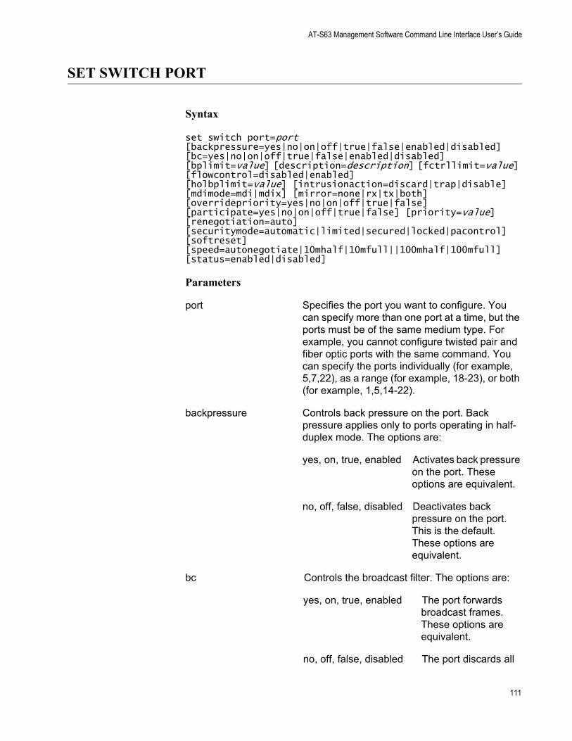
AT-S63 Management Software Command Line Interface User’s Guide
SET SWITCH PORT
Syntax
set switch port=port [backpressure=yes|no|on|off|true|false|enabled|disabled][bc=yes|no|on|off|true|false|enabled|disabled] [bplimit=value] [description=description] [fctrllimit=value] [flowcontrol=disabled|enabled][holbplimit=value] [intrusionaction=discard|trap|disable] [mdimode=mdi|mdix] [mirror=none|rx|tx|both] [overridepriority=yes|no|on|off|true|false] [participate=yes|no|on|off|true|false] [priority=value] [renegotiation=auto] [securitymode=automatic|limited|secured|locked|pacontrol] [softreset] [speed=autonegotiate|10mhalf|10mfull||100mhalf|100mfull][status=enabled|disabled]
Parameters
port Specifies the port you want to configure. You can specify more than one port at a time, but the ports must be of the same medium type. For example, you cannot configure twisted pair and fiber optic ports with the same command. You can specify the ports individually (for example, 5,7,22), as a range (for example, 18-23), or both (for example, 1,5,14-22).
backpressure Controls back pressure on the port. Back pressure applies only to ports operating in half-duplex mode. The options are:
yes, on, true, enabled Activates back pressure on the port. These options are equivalent.
no, off, false, disabled Deactivates back pressure on the port. This is the default. These options are equivalent.
bc Controls the broadcast filter. The options are:
yes, on, true, enabled The port forwards broadcast frames. These options are equivalent.
no, off, false, disabled The port discards all
111
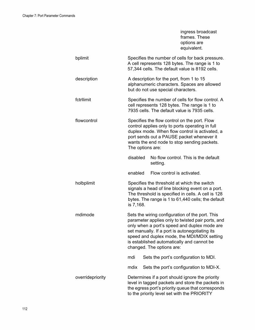
Chapter 7: Port Parameter Commands
ingress broadcast frames. These options are equivalent.
bplimit Specifies the number of cells for back pressure. A cell represents 128 bytes. The range is 1 to 57,344 cells. The default value is 8192 cells.
description A description for the port, from 1 to 15 alphanumeric characters. Spaces are allowed but do not use special characters.
fctrllimit Specifies the number of cells for flow control. A cell represents 128 bytes. The range is 1 to 7935 cells. The default value is 7935 cells.
flowcontrol Specifies the flow control on the port. Flow control applies only to ports operating in full duplex mode. When flow control is activated, a port sends out a PAUSE packet whenever it wants the end node to stop sending packets. The options are:
disabled No flow control. This is the default setting.
enabled Flow control is activated.
holbplimit Specifies the threshold at which the switch signals a head of line blocking event on a port. The threshold is specified in cells. A cell is 128 bytes. The range is 1 to 61,440 cells; the default is 7,168.
mdimode Sets the wiring configuration of the port. This parameter applies only to twisted pair ports, and only when a port’s speed and duplex mode are set manually. If a port is autonegotiating its speed and duplex mode, the MDI/MDIX setting is established automatically and cannot be changed. The options are:
mdi Sets the port’s configuration to MDI.
mdix Sets the port’s configuration to MDI-X.
overridepriority Determines if a port should ignore the priority level in tagged packets and store the packets in the egress port’s priority queue that corresponds to the priority level set with the PRIORITY
112
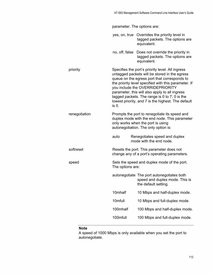
AT-S63 Management Software Command Line Interface User’s Guide
parameter. The options are:
yes, on, true Overrides the priority level in tagged packets. The options are equivalent.
no, off, false Does not override the priority in tagged packets. The options are equivalent.
priority Specifies the port’s priority level. All ingress untagged packets will be stored in the egress queue on the egress port that corresponds to the priority level specified with this parameter. If you include the OVERRIDEPRIORITY parameter, this will also apply to all ingress tagged packets. The range is 0 to 7; 0 is the lowest priority, and 7 is the highest. The default is 0.
renegotiation Prompts the port to renegotiate its speed and duplex mode with the end node. This parameter only works when the port is using autonegotiation. The only option is:
auto Renegotiates speed and duplex mode with the end node.
softreset Resets the port. This parameter does not change any of a port’s operating parameters.
speed Sets the speed and duplex mode of the port. The options are:
autonegotiate The port autonegotiates both speed and duplex mode. This is the default setting.
10mhalf 10 Mbps and half-duplex mode.
10mfull 10 Mbps and full-duplex mode.
100mhalf 100 Mbps and half-duplex mode.
100mfull 100 Mbps and full-duplex mode.
NoteA speed of 1000 Mbps is only available when you set the port to autonegotiate.
113
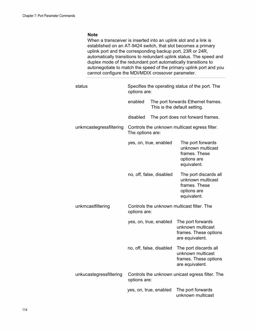
Chapter 7: Port Parameter Commands
NoteWhen a transceiver is inserted into an uplink slot and a link is established on an AT-9424 switch, that slot becomes a primary uplink port and the corresponding backup port, 23R or 24R, automatically transitions to redundant uplink status. The speed and duplex mode of the redundant port automatically transitions to autonegotiate to match the speed of the primary uplink port and you cannot configure the MDI/MDIX crossover parameter.
status Specifies the operating status of the port. The options are:
enabled The port forwards Ethernet frames. This is the default setting.
disabled The port does not forward frames.
unkmcastegressfiltering Controls the unknown multicast egress filter. The options are:
yes, on, true, enabled The port forwards unknown multicast frames. These options are equivalent.
no, off, false, disabled The port discards all unknown multicast frames. These options are equivalent.
unkmcastfiltering Controls the unknown multicast filter. The options are:
yes, on, true, enabled The port forwards unknown multicast frames. These options are equivalent.
no, off, false, disabled The port discards all unknown multicast frames. These options are equivalent.
unkucastegressfiltering Controls the unknown unicast egress filter. The options are:
yes, on, true, enabled The port forwards unknown multicast
114
AT-S63 Management Software Command Line Interface User’s Guide
frames. These options are equivalent.
no, off, false, disabled The port discards all unknown multicast frames. These options are equivalent.
unkucastfiltering Controls the unknown unicast filter. The options are:
yes, on, true, enabled The port forwards unknown unicast frames. These options are equivalent.
no, off, false, disabled The port discards all unknown unicast frames. These options are equivalent.
Description
This command sets a port’s operating parameters. You can set more than one parameter at a time. For an explanation of the port parameters, refer to Chapter 6, “Port Parameters” in the AT-S63 Management Software Menus Interface User’s Guide.
Examples
The following command disables ports 1 to 6:
set switch port=1-6 status=disabled
The following command configures port 8 to operate at 10 Mbps, half duplex:
set switch port=8 speed=10mhalf
The following command sets the speed to 100 Mbps, the duplex mode to full duplex, the wiring configuration to MDI-X, and flow control to enabled for ports 2 to 6:
set switch port=2-6 speed=100mfull mdimode=mdix flowcontrol=enabled
The following command sets port priority to 5 and activates the broadcast filter for ports 5, 8, and 12:
set switch port=5,8,12 priority=5 bcastfiltering=enabled
The following command resets port 5:
115

Chapter 7: Port Parameter Commands
set switch port=5 softreset
116
AT-S63 Management Software Command Line Interface User’s Guide
SET SWITCH PORT RATELIMITING
Syntax
set switch port=port [bcastratelimiting=yes|no|on|off|true|false|enabled|disabled] [bcastrate=value][mcastratelimiting=yes|no|on|off|true|false|enabled|disabled] [mcastrate=value][unkucastratelimiting=yes|no|on|off|true|false|enabled|disabled] [unkucastrate=value]
Parameters
port Specifies the port you want to configure. You can specify more than one port at a time, but the ports must be of the same medium type. For example, you cannot configure twisted pair and fiber optic ports with the same command. You can specify the ports individually (for example, 5,7,22), as a range (for example, 18-23), or both (for example, 1,5,14-22).
ratelimit Specifies the number of ingress packets the switch ports accept each second. This setting applies all packet types that have their rate limit enabled. The options are:
auto Returns the parameter to its default setting of 1.
value Specifies the number of packets in the range of 0 to 262,143.
bcastratelimiting Enables or disables rate limit for ingress broadcast packets. The options are:
yes, on, true, enabled Activates broadcast packet rate limit on the port. The options are equivalent.
no, off, false, disabled Deactivates broadcast packet rate limit on the port. The options are equivalent.
mcastratelimiting Enables or disables rate limit for ingress multicast packets. The options are:
yes, on, true, enabled Activates multicast
117
Chapter 7: Port Parameter Commands
packet rate limit on the port. The options are equivalent.
no, off, false, disabled Deactivates multicast packet rate limit on the port. The options are equivalent.
unkucastratelimiting Enables or disables rate limit for ingress unicast packets. The options are:
yes, on, true, enabled Activates unicast packet rate limit on the port. The options are equivalent.
no, off, false, disabled Deactivates unicast packet rate limit on the port. The options are equivalent.
Description
This command sets the maximum number of ingress packets the switch ports accept each second. Packets exceeding the threshold are discarded. You can enable the rate limiting threshold independently for unicast, multicast, and broadcast packets. However, the same threshold applies to all packet types.
The RATELIMIT parameter sets the packet limit. This limit applies to all the ports. There can be only one packet limit value for the switch. Additionally, the same packet limit applies to the three types of packets that you can filter on.
The BCLIMIT, MCLIMIT, and UCLIMIT parameters are used to toggle on and off the different filters. A filter applies to all switch ports.
As an example., assume that you set a rate limit of 5,000 packets and you enable multicast and broadcast rate limiting. Each switch port will accept up to 5,000 multicast packets and 5,000 broadcast packets each second. If a port receives more than that of either type, it discards the extra packets. Because the feature was not activated for unicast packets, the ports do not restrict their number.
118
AT-S63 Management Software Command Line Interface User’s Guide
Examples
The following command sets a rate limit of 40,000 ingress packets and activates broadcast and multicast rate limiting on all switch ports:
set switch port=1 ratelimit=40000 bclimit=enabled mclimit=enabled
The following command activates unicast rate filtering on all ports without changing the current rate limit:
set switch port=1 uclimit=enabled
The following command changes the rate limit to 15,000 packets:
set switch port=1 ratelimit=15000
119
Chapter 7: Port Parameter Commands
SHOW INTERFACE
Syntax
show interface=port
Parameter
port Specifies the port whose interface information you want to display. You can specify more than one port at a time. You can specify the ports individually (for example, 5,7,22), as a range (for example, 18-23), or both (for example, 1,5,14-22).
Description
This command displays the contents of the interface MIB for a specific port and provides the following information:
ifIndex - The index of the interface in the interface table.ifMTU - The size, in octets, of the largest packet that can be transmitted on this port.ifSpeed - An estimate of the port’s current bandwidth, in pits per second.ifAdminStatus - The configured state of the port, one of the following:
up - The port is up.
down - The port is down.
ifOperStatus - The current operational status of the port, one of the following:
up - A valid link exists between the port and the end node.
down - The port and the end node have not established a link.
unknown - The port status is unknown.
ifLinkUpDownTrapEnable - Whether or not link traps have been enabled for the port, one of the following:
enabled - Link traps are enabled. To disable link traps, see “DISABLE INTERFACE LINKTRAP” on page 103.
disabled - Link traps are disabled. To enable link traps, see “ENABLE INTERFACE LINKTRAP” on page 106.
120

AT-S63 Management Software Command Line Interface User’s Guide
Example
The following command displays information about port 21:
show interface 21
121
Chapter 7: Port Parameter Commands
SHOW SWITCH PORT
Syntax
show switch port[=port]
Parameter
port Specifies the port whose parameter settings you want to view. You can specify more than one port at a time. You can specify the ports individually (for example, 5,7,22), as a range (for example, 18-23), or both (for example, 1,5,14-22). All ports are displayed if you omit the port number.
Description
This command displays a port’s operating parameters, such as speed and duplex mode. For details on port parameters, refer to Chapter 6, “Port Parameters” in the <Italic>AT-S63 Management Software Menus Interface User’s Guide.
Examples
The following command displays the operating settings for all ports:
show switch port
The following command displays the operating settings for port 14:
show switch port=14
122
Chapter 8
Port Statistics Commands
This chapter contains the following commands:
“RESET SWITCH PORT COUNTER” on page 124“SHOW SWITCH COUNTER” on page 125“SHOW SWITCH PORT COUNTER” on page 126
NoteRemember to save your changes with the SAVE CONFIGURATION command.
NoteFor background information on port statistics, refer to Chapter 6, “Port Parameters” in the AT-S63 Management Software Menus Interface User’s Guide.
123
Chapter 8: Port Statistics Commands
RESET SWITCH PORT COUNTER
Syntax
reset switch port=port counter
Parameter
port Specifies the port whose statistics counters you want to return to zero. You can specify more than one port at a time. You can specify the ports individually (for example, 5,7,22), as a range (for example, 18-23), or both (for example, 1,5,14-22).
Description
This command returns a port’s statistics counters to zero.
Example
The following command returns the counters on ports 14 and 15 to zero:
reset switch port=14-15 counter
124
AT-S63 Management Software Command Line Interface User’s Guide
SHOW SWITCH COUNTER
Syntax
show switch counter
Parameters
None.
Description
This command displays operating statistics, such as the number of packets received and transmitted, and the number of CRC errors, for the entire switch. For a list of and definitions for the statistics, refer to Chapter 3, “Basic Switch Parameters” in the <Italic>AT-S63 Management Software Menus Interface User’s Guide.
Example
The following command displays the switch’s operating statistics:
show switch counter
125
Chapter 8: Port Statistics Commands
SHOW SWITCH PORT COUNTER
Syntax
show switch port=port counter
Parameter
port Specifies the port whose statistics you want to view. You can specify more than one port at a time. To view all ports, do not specify a port.
Description
This command displays the operating statistics for a port on the switch. Examples of the statistics include the number of packets transmitted and received, and the number of CRC errors. For a list of and definitions for the statistics, refer to Chapter 6, “Port Parameters” in the <Italic>AT-S63 Management Software Menus Interface User’s Guide.
Examples
The following command displays the operating statistics for port 14:
show switch port=14 counter
The following command displays the operating statistics for all ports:
show switch port counter
126
Chapter 9
Static Port Trunking Commands
This chapter contains the following commands:
“ADD SWITCH TRUNK” on page 128“CREATE SWITCH TRUNK” on page 129“DELETE SWITCH TRUNK” on page 131“DESTROY SWITCH TRUNK” on page 132“SET SWITCH TRUNK” on page 133“SHOW SWITCH TRUNK” on page 134
NoteRemember to save your changes with the SAVE CONFIGURATION command.
NoteFor background information and guidelines on static port trunking, refer to Chapter 7, “Static and LACP Port Trunks” in the AT-S63 Management Software Menus Interface User’s Guide.
127
Chapter 9: Static Port Trunking Commands
ADD SWITCH TRUNK
Syntax
add switch trunk=name [tgid=id_number] port=port
Parameters
trunk Specifies the name of the static port trunk to be modified.
tgid Specifies the ID number of the static port trunk to be modified. This parameter is optional.
port Specifies the port to be added to the port trunk. You can add more than one port at a time. You can specify the ports individually (for example, 5,7,22), as a range (for example, 18-20), or both (for example, 1,14-16).
Description
This command adds ports to an existing static port trunk. To initially create a static port trunk, refer to “CREATE SWITCH TRUNK” on page 129.
CautionDisconnect all data cables from the ports of the trunk on the switch before using this command. Adding a port to a port trunk without first disconnecting the cables may result in loops in your network topology, which can produce broadcast storms and poor network performance.
NoteIf the port you are adding will be the lowest numbered port in the trunk, its parameter settings will overwrite the settings of the existing ports in the trunk. Consequently, you check to see if its settings are appropriate prior to adding it to the trunk. If the port will not be the lowest numbered port, then its settings are changed to match the settings of the existing ports in the trunk.
Example
The following command adds port 5 to a port trunk called load22:
add switch trunk=load22 port=5
128
AT-S63 Management Software Command Line Interface User’s Guide
CREATE SWITCH TRUNK
Syntax
create switch trunk=name port=ports [tgid=id_number] [select=macsrc|macdest|macboth|ipsrc|ipdest|ipboth]
Parameters
trunk Specifies the name of the trunk. The name can be up to 16 alphanumeric characters. No spaces or special characters are allowed.
port Specifies the ports to be added to the port trunk. You can specify the ports individually (for example, 5, 7, 22), as a range (for example, 18-23), or both (for example, 1, 5, 14-22).
tgid Specifies the trunk ID number. If this parameter is omitted, the lowest available ID number is used.
select Specifies the load distribution method. Options are:
macsrc Source MAC address.
macdest Destination MAC address.
macboth Source address/destination MAC address.
ipsrc Source IP address.
ipdest Destination IP address.
ipboth Source address/destination IP address.
Description
This command creates a static port trunk. To create the trunk, you specify the ports on the switch that will constitute the trunk.
NoteAll ports in a trunk must operate at the same speed. When you include port 23R or 24R in a trunk and the port transitions to redundant uplink status, the port speed is automatically adjusted to 1000 Mbps. If the other ports in the trunk are operating at a different speed, port trunking may be unpredictable. Because of these port speed variables, Allied Telesyn suggests that you not include port 23R or 24R in a port trunk.
129
Chapter 9: Static Port Trunking Commands
CautionDo not connect the cables to the trunk ports on the switches until after you have created the trunk in the management software. Connecting the cables before configuring the software will create a loop in your network topology. Data loops can result in broadcast storms and poor network performance.
Examples
The following command creates a static port trunk using ports 3 through 6. The command names the trunk “load22” and sets the load distribution method to destination MAC address.
create switch trunk=load22 port=3-6 select=macdest
The following command creates a port trunk consisting of ports 15,17, and 23. The command names the trunk “trunk4”. No load distribution method is specified, so the default source and destination MAC addresses is used:
create switch trunk=trunk4 port=15,17,23
130
AT-S63 Management Software Command Line Interface User’s Guide
DELETE SWITCH TRUNK
Syntax
delete switch trunk=name [tgid=id_number] port=port
Parameters
trunk Specifies the name of the static port trunk to be modified.
tgid Specifies the ID number of the static port trunk to be modified. This parameter is optional.
port Specifies the port to be removed from the existing port trunk. You can specify more than one port at a time.
Description
This command removes ports from a static port trunk. To completely remove a port trunk from a switch, see “DESTROY SWITCH TRUNK” on page 132.
CautionDisconnect all data cables from the ports of the trunk on the switch before using this command. Removing a port from a port trunk without first disconnecting the cables may result in loops in your network topology, which can produce broadcast storms and poor network performance.
Example
The following command removes port 9 from a port trunk called Dev_trunk:
delete switch trunk=Dev_trunk port=9
131
Chapter 9: Static Port Trunking Commands
DESTROY SWITCH TRUNK
Syntax
destroy switch trunk=name [tgid=id_number]
Parameter
trunk Specifies the name of the trunk to be deleted.
tgid Specifies the ID number of the static port trunk to be deleted. This parameter is optional.
Description
This command deletes a static port trunk from a switch. After a port trunk has been deleted, the ports that made up the trunk can be connected to different end nodes.
CautionDisconnect the cables from the port trunk on the switch before destroying the trunk. Deleting a port trunk without first disconnecting the cables can create loops in your network topology. Data loops can result in broadcast storms and poor network performance.
Example
The following command deletes the trunk called load22 from the switch:
destroy switch trunk=load22
132
AT-S63 Management Software Command Line Interface User’s Guide
SET SWITCH TRUNK
Syntax
set switch trunk=name [tgid=id_number] select=macsrc|macdest|macboth|ipsrc|ipdest|ipboth
Parameters
trunk Specifies the name of the static port trunk.
tgid Specifies the ID number of the static port trunk to be modified. This parameter is optional.
select Specifies the load distribution method. Options are:
macsrc Source MAC address.
macdest Destination MAC address.
macboth Source address/destination MAC address.
ipsrc Source IP address.
ipdest Destination IP address.
ipboth Source address/destination IP address.
Description
This command changes the load distribution method of an existing static port trunk.
Example
The following command changes the load distribution method of a trunk named “Load11” to destination IP address:
set switch trunk=Load11 select=ipdest
133
Chapter 9: Static Port Trunking Commands
SHOW SWITCH TRUNK
Syntax
show switch trunk
Parameters
None.
Description
This command displays the names, ports, and load distribution methods of the static port trunks on the switch.
Example
The following command displays port trunking information:
show switch trunk
134
Chapter 10
LACP Commands
This chapter contains the following commands:
“ADD LACP PORT” on page 136“CREATE LACP AGGREGATOR” on page 137“DELETE LACP PORT” on page 139“DESTROY LACP AGGREGATOR” on page 140“DISABLE LACP” on page 141“ENABLE LACP” on page 142“SET LACP AGGREGATOR” on page 143“SET LACP PRIORITY” on page 144“SET LACP STATE” on page 145“SHOW LACP” on page 146
NoteRemember to save your changes with the SAVE CONFIGURATION command.
NoteFor background information and guidelines on LACP, refer to Chapter 7, “Static and LACP Port Trunks” in the AT-S63 Management Software Menus Interface User’s Guide.
135
Chapter 10: LACP Commands
ADD LACP PORT
Syntax
add lacp port=port aggregator=name priority=priority adminkey=key
Parameters
port Specifies the port to be added to the aggregator. You can add more than one port at a time. You can specify the ports individually (for example, 5,7,22), as a range (for example, 18-20), or both (for example, 1,14-16).
aggregator Specifies the name of the aggregator.
priority The priority level of the port, a hexadecimal number between 0x1 and 0xffff. The lower the number, the higher the priority.
adminkey Specifies the ID for the aggregator, a hexadecimal number between 0x1 and 0xffff.
Description
This command adds ports to an existing aggregator. If the aggregator is not specified, the ports are associated with the aggregator of the lowest numbered port. If the admin key is not specified, the admin key of the first port is used to associate these ports. To initially create an aggregator, refer to “CREATE LACP AGGREGATOR” on page 137.
Example
The following command adds ports 8 and 22 to the aggregator named AGG_1:
add lacp port=8,22 aggregator=AGG_1
136
AT-S63 Management Software Command Line Interface User’s Guide
CREATE LACP AGGREGATOR
Syntax
create lacp aggregator=name port=port [distribution=macsrc|macdest|macboth|ipsrc|ipdest|ipboth] adminkey=key
Parameters
aggregator Specifies the name of the aggregator. The name can be up to 20 alphanumeric characters. No spaces or special characters are allowed.
port Specifies the port to be added to the aggregator. You can add more than one port at a time. You can specify the ports individually (for example, 5,7,22), as a range (for example, 18-20), or both (for example, 1,14-16).
distribution Specifies the load distribution method, which can be one of the following:
macsrc Source MAC address.
macdest Destination MAC address.
macboth Source address/destination MAC address. This is the default.
ipsrc Source IP address.
ipdest Destination IP address.
ipboth Source address/destination IP address.
adminkey Specifies the ID for the aggregator, a hexadecimal number between 0x1 and 0xffff.
Description
This command creates an LACP aggregator. If you do not specify a distribution method, the default method is macboth. If you do not specify an admin key, the default admin key of the first port being added to this aggregator is used.
Examples
The following command creates an LACP aggregator named “AGG_1” containing ports 1 through 4 and operating with the source MAC address
137

Chapter 10: LACP Commands
distribution method:
create lacp aggregator=agg_1 distribution=macsrc
138
AT-S63 Management Software Command Line Interface User’s Guide
DELETE LACP PORT
Syntax
delete lacp port=port aggregator=name adminkey=key
Parameters
port Specifies the port to be deleted from the aggregator. You can delete more than one port at a time. You can specify the ports individually (for example, 5,7,22), as a range (for example, 18-20), or both (for example, 1,14-16).
aggregator Specifies the name of the aggregator.
adminkey Specifies the ID for the aggregator, a hexadecimal number between 0x1 and 0xffff.
Description
This command removes ports from an aggregator. If you do not specify the aggregator name, the ports are removed from the aggregator to which they were associated, and their association with the default aggregator is restored. To completely remove an aggregator, see “DESTROY LACP AGGREGATOR” on page 140.
Example
The following command removes port 9 from an aggregator named AGG_5:
delete lacp port=9 aggregator=agg_5
139
Chapter 10: LACP Commands
DESTROY LACP AGGREGATOR
Syntax
destroy lacp [aggregator=name] [adminkey=key]
Parameter
aggregator Specifies the name of the aggregator.
adminkey Specifies the ID for the aggregator, a hexadecimal number between 0x1 and 0xffff.
Description
This command deletes an LACP aggregator either by the aggregator name or the admin key.
Example
The following command deletes the aggregator named AGG_15:
destroy aggregator=agg_15
140
AT-S63 Management Software Command Line Interface User’s Guide
DISABLE LACP
Syntax
disable lacp
Parameters
None.
Description
This command disables LACP. The default is disabled. Another command that performs the same function is “SET LACP STATE” on page 145.
Example
The following command disables LACP:
disable lacp
141
Chapter 10: LACP Commands
ENABLE LACP
Syntax
enable lacp
Parameters
None.
Description
This command enables LACP. The default is disabled. Another command that performs the same function is “SET LACP STATE” on page 145.
Example
The following command enables LACP:
enable lacp
142

AT-S63 Management Software Command Line Interface User’s Guide
SET LACP AGGREGATOR
Syntax
set lacp aggregator=name [distribution=macsrc|macdest|macboth|ipsrc|ipdest|ipboth] adminkey=key
Parameters
aggregator Specifies the name of the aggregator.
distribution Specifies the load distribution method, which can be one of the following:
macsrc Source MAC address.
macdest Destination MAC address.
macboth Source address/destination MAC address. This is the default.
ipsrc Source IP address.
ipdest Destination IP address.
ipboth Source address/destination IP address.
adminkey Specifies the ID for the aggregator, a hexadecimal number between 0x1 and 0xffff. The lower the number, the higher the priority.
Description
This command allows you to modify an LACP aggregator’s load distribution method and admin key.
Example
The following command modifies the mode of an LACP aggregator named AGG_5 to the source MAC address distribution method:
set lacp aggregator=agg_5 mode=macsrc
143
Chapter 10: LACP Commands
SET LACP PRIORITY
Syntax
set lacp priority=priority
Parameters
priority The priority level of the port, a hexadecimal number between 0x1 and 0xffff. The lower the number, the higher the priority.
Description
This command sets the priority of the switch. LACP uses the priority to resolve conflicts between two switches to decide which switch makes the decision about which ports to aggregate.
Example
The following command sets the priority of the system to 0x8000:
set lacp priority=0x8000
144
AT-S63 Management Software Command Line Interface User’s Guide
SET LACP STATE
Syntax
set lacp state=[enable|disable]
Parameters
state The state of LACP on the switch. The options are:
enable Enables LACP. This option performs the same function as “ENABLE LACP” on page 142.
disable Disables LACP. This is the default. This option performs the same function as “DISABLE LACP” on page 141.
Description
This command enables or disables LACP.
Example
The following command enables LACP on the system:
set lacp state=enable
145
Chapter 10: LACP Commands
SHOW LACP
Syntax
show lacp [port=port] [aggregator=name] [machine]
Parameter
port Specifies the port(s) to display. You can specify the ports individually (for example, 5,7,22), as a range (for example, 18-20), or both (for example, 1,14-16).
aggregator Specifies the name of the aggregator.
Description
This command displays the configuration and/or machine states of the ports, and/or the aggregators.
Examples
The following command displays general LACP status information:
show lacp
The following command displays the LACP configuration for ports 13 and 16:
show lacp port=13,16
The following command displays the configuration of the aggregators on the system:
show lacp aggregator
The following command displays the LACP machine states for each port on the system:
show lacp machine
146
Chapter 11
Port Mirroring Commands
This chapter contains the following commands:
“SET SWITCH MIRROR” on page 148“SET SWITCH PORT MIRROR” on page 149“SHOW SWITCH MIRROR” on page 151
NoteRemember to save your changes with the SAVE CONFIGURATION command.
NoteFor background information and guidelines on port mirroring, refer to Chapter 8, “Port Mirroring” in the AT-S63 Management Software Menus Interface User’s Guide.
147
Chapter 11: Port Mirroring Commands
SET SWITCH MIRROR
Syntax
set switch mirror=port
Parameter
mirror Specifies the destination port for the port mirror. This is the port to where the traffic from the source ports will be copied. You can specify only one port as the destination port. Specifying “0” (zero) disables port mirroring.
Description
This command enables mirroring and specifies the destination port, or disables mirroring. To select the source ports, refer to “SET SWITCH PORT MIRROR” on page 149.
NoteWhen a transceiver is inserted into an uplink slot and a link is established, that slot becomes a primary uplink port and the corresponding backup port, 23R or 24R, automatically transitions to redundant uplink status. Any settings for port mirroring remain intact when the backup port makes the transition to a redundant uplink state.
Examples
The following command enables mirroring and makes port 11 the destination port:
set switch mirror=11
The following command disables port mirroring:
set switch mirror=0
148
AT-S63 Management Software Command Line Interface User’s Guide
SET SWITCH PORT MIRROR
Syntax
set switch port=port mirror=none|rx|tx|both
Parameters
port Specifies the source port of a port mirror. You can specify more than one port. You can specify the ports individually (for example, 5, 7, 22), as a range (for example, 18-23), or both (for example, 1, 5, 14-22).
mirror Specifies which traffic on the source ports is to be mirrored to the destination port. The options are:
rx Specifies ingress mirroring.
tx Specifies egress mirroring.
both Specifies both ingress and egress mirroring.
none Removes a port as a source port.
Description
This command specifies the source ports of a port mirror. If the port mirror already has source ports, the new source ports are added to the existing ports. You can also use the command to remove source ports.
You must set the destination port before you can select the source ports. To set the destination port, refer to “SET SWITCH MIRROR” on page 148.
NoteWhen a transceiver is inserted into an uplink slot and a link is established, that slot becomes a primary uplink port and the corresponding backup port, 23R or 24R, automatically transitions to redundant uplink status. Any settings for port mirroring remain intact when the backup port makes the transition to a redundant uplink state.
Examples
The following command specifies ports 16 and 17 as new source ports for the port mirror. Only the ingress traffic is mirrored:
set switch port=16-17 mirror=rx
149

Chapter 11: Port Mirroring Commands
The following command removes ports 5, 7, and 10 as source ports of a port mirror:
set switch port=5,7,10 mirror=none
150
AT-S63 Management Software Command Line Interface User’s Guide
SHOW SWITCH MIRROR
Syntax
show switch mirror
Parameters
None.
Description
This command displays the source and destination ports of a port mirror on the switch.
Example
The following command displays the ports of a port mirror:
show switch mirror
151

Chapter 11: Port Mirroring Commands
152
Chapter 12
Networking Stack
This chapter contains the following commands:
“DELETE IP ARP” on page 154“DELETE TCP” on page 155“RESET IP ARP” on page 156“SET IP ARP TIMEOUT” on page 157“SHOW IP ARP” on page 158“SHOW IP ROUTE” on page 159“SHOW TCP” on page 160
NoteRemember to save your changes with the SAVE CONFIGURATION command.
NoteFor background information on the networking stack, refer to Chapter 9, “Networking Stack” in the AT-S63 Management Software Menus Interface User’s Guide.
Section I: Basic Features 153
Chapter 12: Networking Stack
DELETE IP ARP
Syntax
delete ip arp [ipaddress|all]
Parameter
ipaddress Specifies the IP address of the ARP entry you want to delete from the ARP table.
all Specifies the deletion of all non-system ARP entries in the table.
Description
This command deletes specific or all ARP entries from the ARP table.
Example
The following command deletes the ARP entry with the IP address of 192.168.1.1:
delete ip arp 192.168.1.1
154 Section I: Basic Features
AT-S63 Management Software Menus Interface User’s Guide
DELETE TCP
Syntax
delete tcp indexnumber
Parameter
indexnumber Specifies the internal socket ID number assigned to the connection. Enter the index number of the TCP connection you want to delete. The range is 0 to 65535 with a default of 0. To display the index number, refer to “SHOW TCP” on page 160.
Description
This command deletes a TCP connection.
Example
The following command deletes TCP connection number 12:
delete tcp 12
Section I: Basic Features 155
Chapter 12: Networking Stack
RESET IP ARP
Syntax
reset ip arp
Parameter
None
Description
This command resets the ARP table by clearing all entries except those created by the switch during initialization.
Example
The following command deletes all non-system entries in the ARP table:
reset ip arp
156 Section I: Basic Features
AT-S63 Management Software Menus Interface User’s Guide
SET IP ARP TIMEOUT
Syntax
set ip arp timeout=integer
Parameter
timeout The range is 1 to 260000 seconds. The default setting is 400 seconds.
Description
This command prevents the table from becoming full with inactive entries. It allows you to set the timer for removing temporary entries in the ARP table. Inactive temporary entries in the ARP table are timed out according to the ARP cache timeout value which is set with the timeout option.
Example
The following command sets the timer to 600 seconds:
set ip arp timeout=600
Section I: Basic Features 157
Chapter 12: Networking Stack
SHOW IP ARP
Syntax
show ip arp
Parameter
None
Description
This command displays the ARP table.
Example
The following command displays the ARP table.
show ip arp
158 Section I: Basic Features
AT-S63 Management Software Menus Interface User’s Guide
SHOW IP ROUTE
Syntax
show ip route
Parameter
None
Description
This command displays the IP route table.
Example
The following command displays the IP route table:
show ip route
Section I: Basic Features 159
Chapter 12: Networking Stack
SHOW TCP
Syntax
show tcp
Parameter
None
Description
This command displays the TCP connections and the TCP global information which is MIB variables defined in TCP group.
Example
The following command displays the TCP connections and the TCP global information:
show tcp
160 Section I: Basic Features
Chapter 13
File System Commands
This chapter contains the following commands:
“COPY” on page 162“CREATE CONFIG” on page 163“DELETE FILE” on page 164“FORMAT DEVICE” on page 165“LOAD” on page 166“RENAME” on page 171“SET CFLASH DIR” on page 172“SET CONFIG” on page 173“SHOW CFLASH” on page 175“SHOW CONFIG” on page 176“SHOW FILE” on page 177“SHOW FLASH” on page 178“UPLOAD” on page 179
NoteFor background information on the switch’s file system, refer to Chapter 10, “File System” in the AT-S63 Management Software Menus Interface User’s Guide. For information about downloading and uploading files, refer to Chapter 10, “File System” in the AT-S63 Management Software Menus Interface User’s Guide.
161
Chapter 13: File System Commands
COPY
Syntax
copy [flash:|cflash:]sourcefile.ext [flash:|cflash:]destinationfile.ext
Parameters
sourcefile.ext Specifies the name of the source file.
destinationfile.ext Specifies the name of the destination file.
Description
This command creates a copy of an existing file. The new filename must be a valid filename from 1 to 16 alphanumeric characters. The name of the copy must be unique from the other files in the file system.
ext is the three-letter file extension, and can be any of the following file types: “.cer”, “.cfg”, “.key” and “.csr”. You must give the copy the same extension as the original file.
You can also specify the location of the file, either in flash memory (flash:) or on a compact flash card (cflash:). The default is flash memory.
NoteYou cannot copy files with a “.ukf” extension.
Examples
The following command creates a copy of the configuration file “admin.cfg” and names the copy “admin2.cfg” in flash memory:
copy admin.cfg admin2.cfg
The following command creates a copy of the configuration file “switch 12.cfg” and names the copy “backup.cfg” in flash memory:
copy "switch 12.cfg" backup.cfg
The following command copies the configuration file “9408switches” from flash memory to a compact flash card:
copy 9408switches.cfg cflash:9408switches.cfg
162
AT-S63 Management Software Command Line Interface User’s Guide
CREATE CONFIG
Syntax
create config=[flash:|cflash:]filename.cfg
Parameter
config Specifies the name of a new configuration file. If the filename contains spaces, it must be enclosed in double quotes. Otherwise, the quotes are optional.
Description
This command creates a new configuration file containing the commands required to recreate the current configuration of the switch.
The CONFIG parameter specifies the name of the configuration file to create. The file extension must be “.cfg”. If the file already exists, it is replaced. If the file does not exist it is created.
The filename can be from 1 to 16 alphanumeric characters, not including the “.cfg” extension. Spaces are allowed. Be sure to enclose the name in double quotes if you include a space in the name. Wildcards are not allowed.
You can also specify the location of the file, either in flash memory (flash:) or on a compact flash card (cflash:). The default is flash memory.
This command does not change the assignment of the active boot configuration file, which is the file the switch uses to configure itself the next time it is reset or power cycled. To assign the new configuration file as the active boot configuration file, refer to “SET CONFIG” on page 173.
Example
The following command creates the new configuration file Switch12.cfg. The file will contain all of the commands necessary to recreate the switch’s current configuration:
create config=Switch12.cfg
The following command creates a configuration file named “l2switches” on the compact flash card:
create config=cflash:l2switches.cfg
163
Chapter 13: File System Commands
DELETE FILE
Syntax
delete file=[flash:|cflash:]filename
Parameter
file Specifies the name of the file to be deleted. A name with spaces must be enclosed in double quotes. Otherwise, the quotes are optional.
Description
This command deletes a file from the file system.
You can also specify the location of the file, either in flash memory (flash:) or on a compact flash card (cflash:). The default is flash memory.
When you delete a file, note the following:
Deleting the configuration file that is acting as the active boot configuration file causes the switch to use its default settings the next time you reboot or power cycle the switch, unless you select another active boot configuration file. For instructions on how to change the active boot configuration file, refer to see “SET CONFIG” on page 173.To delete a certificate, you must first remove the certificate from the certificate database using “DELETE PKI CERTIFICATE” on page 513.Files with a “.ukf” extension cannot be deleted with this command. These files are encryption key pairs. To delete an encryption key from the switch, refer to “DESTROY ENCO KEY” on page 502.
To list the files in the file system, refer to “SHOW FILE” on page 177.
Examples
The following command deletes the configuration file named “Switch 12.cfg” on a compact flash card:
delete file=cflash:"Switch 12.cfg"
The following command deletes the certificate enrollment request SW55a.csr:
delete file=SW55a.csr
164
AT-S63 Management Software Command Line Interface User’s Guide
FORMAT DEVICE
Syntax
format device=flash
Parameter
device Specifies the device to format. The only option is “Flash” for the flash memory in the switch.
Description
This command formats the flash memory in the switch and therefore removes all files including the configuration files. The image file (application block) is not deleted.
Example
The following example formats the flash memory in the switch:
format device=flash
165
Chapter 13: File System Commands
LOAD
Syntax
load method=[tftp|xmodem|local] [srcfile=[flash:|cflash:]filename|file=[flash:|cflash:]filename] destfile=appblock|[flash:|cflash:]filename server=ipaddress
Parameters
method Specifies the download method. The options are:
tftp Specifies a TFTP download. To use this option, there must be a network node with TFTP server software. The file to download onto the switch must be stored on the TFTP server. You can use the TFTP option from either a local or Telnet management session.
xmodem Specifies an Xmodem download via a local management session. This download method is only available from a local management session.
local Specifies a method to transfer an image into the application block from flash memory or a compact flash card.
srcfile or file Specifies the filename of the file you are downloading onto the switch. The parameter is required for TFTP or local download.
destfile Specifies the destination filename for the file. This is the name under which the file is to be stored on the switch. The name can be from 1 to 16 alphanumeric characters, not including the three-letter extension. If the name includes spaces, enclose it in double quotes. The options are:
appblock Specifies an image file download.
filename Specifies any file type.
server Specifies the IP address of network node containing the TFTP server software. This parameter is required for a TFTP download.
166
AT-S63 Management Software Command Line Interface User’s Guide
Description
This command downloads files to the switch’s file system or onto a compact flash card or to the application block (image area).
You can also use this command to download a new version of the AT-S63 management software onto a switch.
You can also use this command to download any of the following types of files into a switch’s file system:
Configuration filePublic key certificatePublic key certificate enrollment requestEncryption key
The METHOD parameter states the type of download. There are three possible types of downloads. A TFTP download uses the TFTP client software on the switch to download a file or image from a TFTP server on your network. The file that you are downloading must be stored on the TFTP server. You can perform this type of download from either a local or Telnet management session of a slave or master switch.
The XMODEM download method uses the Xmodem utility to download a file or image file onto the switch from a terminal or computer with a terminal emulator program connected to the serial terminal port on the switch. You can perform this type of download only from a local management session and the file to download must be stored on the computer connected to the switch’s serial terminal port. You can perform this type of download on either a slave or master switch.
A LOCAL load method transfers an image file from flash memory or a compact flash card to the application block.
The DESTFILE parameter specifies a name for the file. This is the name the file will be stored as on the switch. This parameter can be either “appblock” or a regular file name. Enclose the name in double quotes if it contains a space.
When you specify APPBLOCK, the new image file is downloaded and the switch is automatically upgraded. If the APPBLOCK parameter is not specified, the file is stored as any other file in the file system and the upgrade is not performed. When you specify a file name instead of APPBLOCK, the file is stored in the file system and the upgrade is not performed even if the file is an image file.
When you specify the new name of a downloaded file, you must be sure to give it the correct three-letter extension, depending on the file type. The
167
Chapter 13: File System Commands
file name extensions are shown in Table 1.
The equivalent SRCFILE and FILE parameters specify the name of the file that you want to download. This parameter is required only for TFTP and local downloads.
You can also specify the location of the file, either in flash memory (flash:) or on a compact flash card (cflash:). The default is flash memory.
Before downloading files, note the following:
When you download a new version of the AT-S63 management software image onto a switch, be sure to specify the DESTFILE filename as “ATS63.IMG”. Do not give the image file any other name.When you download a new configuration file onto a switch, the file is stored in the switch’s file system, but it is not automatically assigned as the active boot file. To assign a newly downloaded configuration file as the active file, see “SET CONFIG” on page 173.In networks consisting of several AT-9400 Series switches, you can simplify an upgrade procedure by first upgrading a master switch to the latest software version via a local or remote management session and then downloading the new software switch-to-switch from the master switch to the slave switches.You cannot download the AT-S63 software image onto any other type of switch than an AT-9400 Series switch.The current configuration of a switch is retained when a new AT-S63 software image is installed. To return a switch to its default configuration settings, refer to “RESTART SWITCH” on page 45.The AT-S63 image file contains the bootloader for the switch. You cannot load the image file and bootloader separately.
For an Xmodem download, note the following:
Table 1. File Name Extensions
Extension File Type
.img AT-S63 management software image
.cfg AT-S63 configuration file
.cer Public key certificate
.csr Public key certificate enrollment request
.key Encryption key file
168
AT-S63 Management Software Command Line Interface User’s Guide
Xmodem can download a file only onto the switch on which you started the local management session. You cannot use Xmodem to download a file onto a switch accessed through enhanced stacking.The new AT-S63 image file must be stored on the computer or terminal connected to the serial terminal port on the switch.
For a TFTP download, note the following:
There must be a node on your network that contains the TFTP server software and the file to be downloaded must be stored on that server.Start the TFTP server software before you perform the download command.The switch on which you are downloading the file must have an IP address and subnet mask, such as a master switch of an enhanced stack. You cannot use TFTP on a slave switch because that type of switch typically does not have an IP address. Perform the download from a local management session of the switch using Xmodem.
CautionAfter you have downloaded an AT-S63 image file using the APPBLOCK parameter, the switch writes the image to flash memory, resets itself, and re initializes the software, a process that can take a minute or so to complete. Do not interrupt the process by resetting or power cycling the switch. Some network traffic may be lost during the process.
For a local download, note the following:
Make sure that a compact flash card is loaded into the compact flash slot.
Xmodem Download Examples
The following command uses Xmodem to download a new AT-S63 software image onto the switch and perform the upgrade:
load method=xmodem destfile=appblock
All Xmodem transfers must be performed from a local management session. Xmodem is not supported from a Telnet management session.
After you have entered the command, the management software displays a confirmation prompt followed by another prompt instructing you to begin the file transfer. To start the transfer, use your terminal emulation program to specify the location of the AT-S63 software image file stored on your workstation. The transfer protocol must be Xmodem or 1K Xmodem.
The following command uses Xmodem to download a new AT-S63 image file and store it in the file system without performing the upgrade:
169
Chapter 13: File System Commands
load method=xmodem destfile=ats63.img
The following command uses Xmodem to download an AT-S63 configuration file to the switch’s file system and gives it the name sw12_boot.cfg:
load method=xmodem destfile=sw12_boot.cfg
Because this is another Xmodem transfer, it must be performed from a local management session. After entering this command, you must specify the location of the configuration file stored on your workstation using your terminal emulation program.
TFTP Download Examples
The following command downloads a new AT-S63 image to the switch using TFTP and upgrades the switch. You can perform a TFTP download from either a local or Telnet management session. The command uses the SERVER parameter to specify the IP address of the TFTP server and the FILE or SRCFILE parameter to indicate the location of the image file on the TFTP server.
load method=tftp file=ats63.img destfile=appblock server=149.166.22.12
The following command uses TFTP to download the image file and store it in the file system without performing the upgrade:
load method=tftp server=149.166.22.12 file=ats63.img destfile=ats63.img
The following command uses TFTP to download the configuration file Switch12.cfg onto the switch:
load method=tftp server=149.166.22.12 srcfile=switch12.cfg destfile=Switch12.cfg
Local Download Example
The following command transfers an AT-S63 image file from the switch’s file system to the application image area:
load method=local srcfile=ats63.img destfile=appblock
170
AT-S63 Management Software Command Line Interface User’s Guide
RENAME
Syntax
rename filename1.ext filename2.ext
Parameters
filename1.ext Specifies the name of the file to be renamed. If the name contains spaces, enclose it in double quotes. Otherwise, the quotes are optional.
filename2.ext Specifies the new name for the file. The filename can be from 1 to 16 alphanumeric characters, not including the filename extension. Spaces are allowed. If the name contains spaces, it must be enclosed in double quotes. The filename extension must be the same as in the original filename. The new name must be unique in the file system.
Description
This command renames a file. The source and destination file extensions must be the same.
NoteYou cannot rename files with a “.ukf” extension.
You can also specify the location of the file, either in flash memory (flash:) or on a compact flash card (cflash:). The default is flash memory. When you specify the file location, the source and destination locations must be the same.
Example
The following command renames the file “Switch12.cfg” to “Sw 44a.cfg”:
rename Switch12.cfg "Sw 44a.cfg"
171
Chapter 13: File System Commands
SET CFLASH DIR
Syntax
set cflash dir=directory
Parameter
dir The directory path.
Description
This command sets the current directory on the compact flash card.
Example
The following command specifies a directory on the compact flash card named “configs”:
set cflash dir=configs
172
AT-S63 Management Software Command Line Interface User’s Guide
SET CONFIG
Syntax
set config=[flash:|cflash:]filename.cfg|none
Parameter
config Specifies the name of the configuration file to act as the active configuration file for the switch. The name can be from 1 to 16 alphanumeric characters, not including the extension “.cfg”. If the filename contains spaces, it must be enclosed in double quotes.
Description
This command sets the active configuration file for a switch. The switch uses the active configuration file to configure its parameter settings the next time it is rebooted or power cycled.
To view the name of the currently active configuration file, see “SHOW CONFIG” on page 176.
You can specify a configuration file that already exists in the switch’s file system. To view the configuration files already in a switch’s file system, see “SHOW FILE” on page 177. Configuration files have a “.cfg” extension.
Selecting a new active boot configuration file does not change the current configuration of the switch. If you want the switch to reconfigure itself according to the configuration in the newly assigned active boot configuration file, reset or power cycle the switch.
You do not need to use the SAVE CONFIGURATION command when you change the designated active configuration file. The change is automatically saved to permanent memory.
If you specify NONE, the switch creates the file after you use the SAVE CONFIGURATION command.
You can also specify the location of the file, either in flash memory (flash:) or on a compact flash card (cflash:). The default is flash memory.
NoteThe active boot configuration file is updated whenever you use the SAVE CONFIGURATION command.
173
Chapter 13: File System Commands
Example
The following command sets the boot configuration file to switch22.cfg:
set config=switch22.cfg
The switch uses the switch22.cfg configuration file the next time it is reset.
174
AT-S63 Management Software Command Line Interface User’s Guide
SHOW CFLASH
Syntax
show cflash
Parameter
None
Description
This command displays information about the compact flash card including the current directory, the number of files, how much space is used, and amount of space available on the compact flash card.
Example
show cflash
175
Chapter 13: File System Commands
SHOW CONFIG
Syntax
show config [dynamic] [info]
Parameters
dynamic Displays the settings for all the switch and port parameters in command line format.
info Displays the settings for all the switch and port parameters.
Description
This command, when used without any parameter, displays two pieces of information. The first is the “Boot configuration file.” This is the configuration file the switch uses the next time it is reset or power cycled. This is also the configuration file the switch uses to save your configuration changes when you use the SAVE CONFIGURATION command. To change the boot configuration file, refer to “SET CONFIG” on page 173.
The second piece of information is the “Current Configuration.” This is the boot configuration file the switch used the last time it was reset or power cycled.
The DYNAMIC parameter displays all the switch settings but in command line format for those switch parameters that have been changed from their default settings.
Adding the INFO parameter to the command displays all the switch settings. It performs the same function as all the other SHOW commands in one command.
Examples
The following command displays the names of the current configuration files:
show config
The following command displays all the switch settings:
show config info
176
AT-S63 Management Software Command Line Interface User’s Guide
SHOW FILE
Syntax
show file=[flash:|cflash:]filename.ext
Parameter
file Specifies the name of the file to be displayed. Use double quotes to enclose the name if it contains spaces. Otherwise, the quotes are optional.
If you do not specify a file name, the command displays a list of all files in flash memory as well as on the compact flash card.
Description
This command displays a list of the files in the switch’s file system. You can use the wildcard “*” to replace any part of the filename to allow a more selective display.
You can also specify the location of the file, either in flash memory (flash:) or on a compact flash card (cflash:). The default is flash memory.
You can also use this command to display the contents of a configuration file.
Examples
The following command displays all the files in the switch’s file system:
show file=*.*
The following command displays all the configuration files on the switch:
show file=*.cfg
The following command displays the contents of the configuration file boot.cfg on a compact flash card:
show file=cflash:boot.cfg
The following command displays all files in the flash memory as well as on a compact flash card:
show file
177
Chapter 13: File System Commands
SHOW FLASH
Syntax
show flash
Parameter
None
Description
This command displays information about the flash memory including the current directory, the number of files, how much space is used, and amount of space available in the flash memory in the switch.
Example
show flash
178
AT-S63 Management Software Command Line Interface User’s Guide
UPLOAD
Syntax
upload method=[tftp|xmodem|remoteswitch|local] [[srcfile=[flash:|cflash:][appblock|switchcfg|filename]|[file=a[flash:|cflash:][appblock|switchcfg|filename]] destfile=[flash:|cflash:]filename server=ipaddress switchlist=switches verbose=[yes|no|on|off|true|false]
Parameters
method Specifies the method of the upload. The options are:
tftp Specifies a TFTP download. To use this option, there must be a network node with TFTP server software. The file to download onto the switch must be stored on the TFTP server. You can use the TFTP option from either a local or Telnet management session.
xmodem Specifies an Xmodem download via a local management session. This download method is only available from a local management session.
remoteswitch Specifies an enhanced stacking upload to a remote switch.
local Specifies the transfer of an image file from the switch’s file system to the appblock area.
srcfile or file Specifies the name of the file you are uploading from the switch. If the name contains spaces, enclose the name in quotes. The options are:
appblock Specifies an image file upload.
switchcfg Specifies a configuration file upload.
filename Specifies any file type.
destfile Specifies a filename for the file when saved on the TFTP server. If the name contains spaces, enclose the name in quotes. This parameter is used with a TFTP or LOCAL upload.
server Specifies the IP address of the network node containing the TFTP server software. This parameter is used with a TFTP
179
Chapter 13: File System Commands
upload.
switchlist Specifies the switches in an enhanced stack to which to upload the software image or configuration file from the master switch. To view the switches in an enhanced stack, see “SHOW REMOTELIST” on page 100. This parameter is used with the REMOTESWITCH parameter. You can specify more than one switch at a time (for example, 1,3,4).
verbose Specifies whether to display details of the upload operation. This option can only be used with the REMOTESWITCH upload method. The options are:
yes, on, true Display the upload details. The options are equivalent.
no, off, false Do not display the upload details. The options are equivalent.
Description
This command uploads any of the following types of files from a switch to a management station, TFTP server, compact flash card, or remote switch through enhanced stacking:
AT-S63 software imageConfiguration filePublic key certificatePublic key certificate enrollment requestEncryption key
This command can upload files as follows:
From a management station to a slave or master switch using Xmodem or TFTP.From a master switch to other switches in an enhanced stack.From a management station to a compact flash card in a switch.
The METHOD parameter states the type of upload. There are four possible types of uploads. A TFTP upload uses the TFTP client software on the switch to upload a file from the switch to a TFTP server on your network. You can perform this type of upload from either a local or Telnet management session.
The XMODEM upload method uses the Xmodem utility to upload a file from the switch to a terminal or computer with a terminal emulator program connected to the serial terminal port on the switch. This type of upload must be performed from a local management session.
180
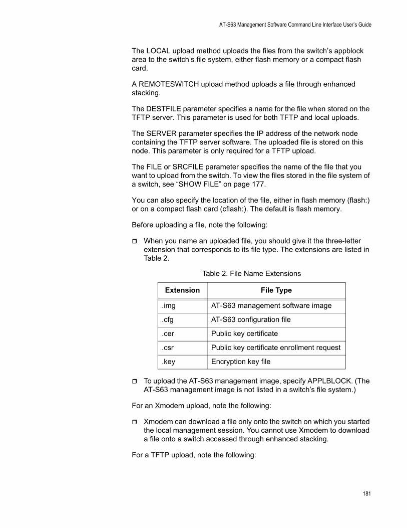
AT-S63 Management Software Command Line Interface User’s Guide
The LOCAL upload method uploads the files from the switch’s appblock area to the switch’s file system, either flash memory or a compact flash card.
A REMOTESWITCH upload method uploads a file through enhanced stacking.
The DESTFILE parameter specifies a name for the file when stored on the TFTP server. This parameter is used for both TFTP and local uploads.
The SERVER parameter specifies the IP address of the network node containing the TFTP server software. The uploaded file is stored on this node. This parameter is only required for a TFTP upload.
The FILE or SRCFILE parameter specifies the name of the file that you want to upload from the switch. To view the files stored in the file system of a switch, see “SHOW FILE” on page 177.
You can also specify the location of the file, either in flash memory (flash:) or on a compact flash card (cflash:). The default is flash memory.
Before uploading a file, note the following:
When you name an uploaded file, you should give it the three-letter extension that corresponds to its file type. The extensions are listed in Table 2.
To upload the AT-S63 management image, specify APPLBLOCK. (The AT-S63 management image is not listed in a switch’s file system.)
For an Xmodem upload, note the following:
Xmodem can download a file only onto the switch on which you started the local management session. You cannot use Xmodem to download a file onto a switch accessed through enhanced stacking.
For a TFTP upload, note the following:
Table 2. File Name Extensions
Extension File Type
.img AT-S63 management software image
.cfg AT-S63 configuration file
.cer Public key certificate
.csr Public key certificate enrollment request
.key Encryption key file
181
Chapter 13: File System Commands
There must be a node on your network that contains the TFTP server software and the file to be downloaded must be stored on that server.Start the TFTP server software before you perform the download command.The switch to which you are uploading the file must have an IP address and subnet mask, such as a master switch of an enhanced stack. You cannot use TFTP on a slave switch because that type of switch typically does not have an IP address. Perform the download from a local management session of the switch using Xmodem, or, switch to switch using the REMOTESWITCH option.
Examples
Xmodem and TFTP Upload Examples
The following command uses Xmodem to upload a switch’s configuration file called “sw22 boot.cfg” from a local management session:
upload method=xmodem file="sw22 boot.cfg"
After entering the command, use your terminal emulator program to indicate where you want to store the file on your computer and its filename.
The following command uploads a switch’s configuration file using TFTP:
upload method=tftp file=switch4.cfg destfile=switch4.cfg server=149.36.11.21
Switch to Switch Upload Examples
The following command uploads the AT-S63 image file on the master switch to switches 2 and 4 in an enhanced stack. (Switch numbers are displayed using “SHOW REMOTELIST” on page 100.)
upload method=remoteswitch file=ats63.img switchlist=2,4
You can use the REMOTESWITCH option from either a local or a Telnet management session. However, the switch on which you are executing the command must be the master switch of the enhanced stack.
The following command downloads a boot configuration file on the master switch to slave switch 2:
load method=remoteswitch destfile=boot.cfg switchlist=2
Management Station to Compact Flash Card Example
The following command uploads a configuration file called “switch.cfg” from a management station to a file with the same name on a compact
182

AT-S63 Management Software Command Line Interface User’s Guide
flash card on a switch:
upload method=local srcfile=switch.cfg cflash:destfile=switch.cfg
183

Chapter 13: File System Commands
184
Chapter 14
Event Log Commands
This chapter contains the following commands:
“ADD LOG OUTPUT” on page 186“CREATE LOG OUTPUT” on page 188“DESTROY LOG OUTPUT” on page 190“DISABLE LOG” on page 191“DISABLE LOG OUTPUT” on page 192“ENABLE LOG” on page 193“ENABLE LOG OUTPUT” on page 194“PURGE LOG” on page 195“SAVE LOG” on page 196“SET LOG FULLACTION” on page 198“SET LOG OUTPUT” on page 199“SHOW LOG” on page 201“SHOW LOG OUTPUT” on page 206“SHOW LOG STATUS” on page 207
NoteRemember to save your changes with the SAVE CONFIGURATION command. For more information about the event log, refer to Chapter 12, “Event Log” in the AT-S63 Management Software Menus Interface User’s Guide.
185
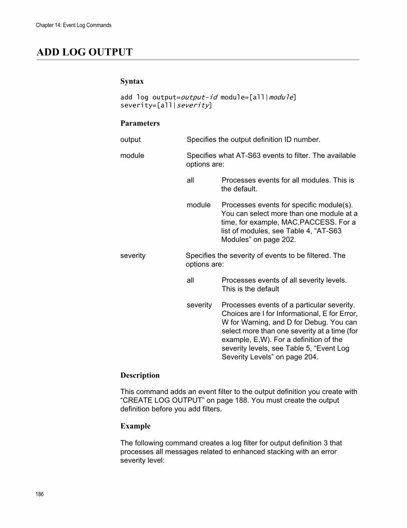
Chapter 14: Event Log Commands
ADD LOG OUTPUT
Syntax
add log output=output-id module=[all|module] severity=[all|severity]
Parameters
output Specifies the output definition ID number.
module Specifies what AT-S63 events to filter. The available options are:
all Processes events for all modules. This is the default.
module Processes events for specific module(s). You can select more than one module at a time, for example, MAC,PACCESS. For a list of modules, see Table 4, “AT-S63 Modules” on page 202.
severity Specifies the severity of events to be filtered. The options are:
all Processes events of all severity levels. This is the default
severity Processes events of a particular severity. Choices are I for Informational, E for Error, W for Warning, and D for Debug. You can select more than one severity at a time (for example, E,W). For a definition of the severity levels, see Table 5, “Event Log Severity Levels” on page 204.
Description
This command adds an event filter to the output definition you create with “CREATE LOG OUTPUT” on page 188. You must create the output definition before you add filters.
Example
The following command creates a log filter for output definition 3 that processes all messages related to enhanced stacking with an error severity level:
186

AT-S63 Management Software Command Line Interface User’s Guide
add log output=3 module=estack severity=e
187
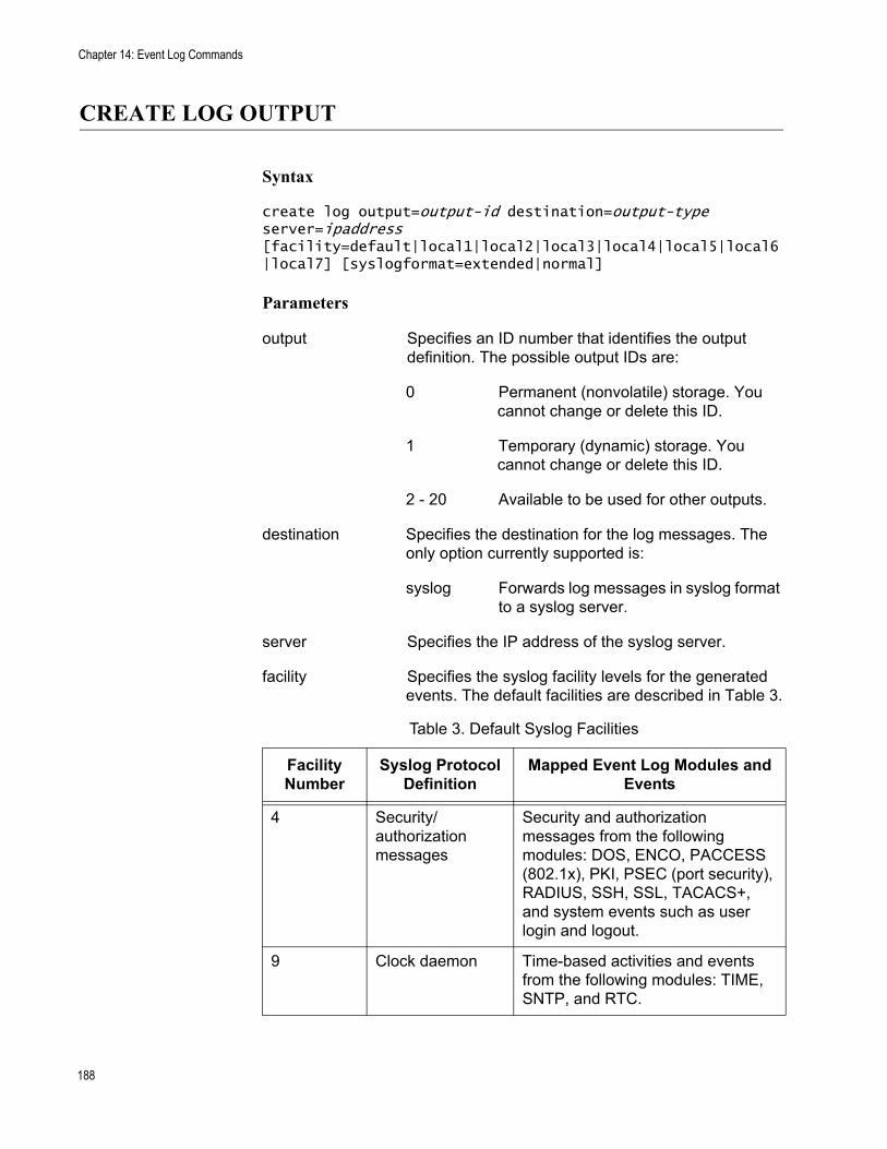
Chapter 14: Event Log Commands
CREATE LOG OUTPUT
Syntax
create log output=output-id destination=output-type server=ipaddress [facility=default|local1|local2|local3|local4|local5|local6|local7] [syslogformat=extended|normal]
Parameters
output Specifies an ID number that identifies the output definition. The possible output IDs are:
0 Permanent (nonvolatile) storage. You cannot change or delete this ID.
1 Temporary (dynamic) storage. You cannot change or delete this ID.
2 - 20 Available to be used for other outputs.
destination Specifies the destination for the log messages. The only option currently supported is:
syslog Forwards log messages in syslog format to a syslog server.
server Specifies the IP address of the syslog server.
facility Specifies the syslog facility levels for the generated events. The default facilities are described in Table 3.
Table 3. Default Syslog Facilities
Facility Number
Syslog Protocol Definition
Mapped Event Log Modules and Events
4 Security/authorization messages
Security and authorization messages from the following modules: DOS, ENCO, PACCESS (802.1x), PKI, PSEC (port security), RADIUS, SSH, SSL, TACACS+, and system events such as user login and logout.
9 Clock daemon Time-based activities and events from the following modules: TIME, SNTP, and RTC.
188
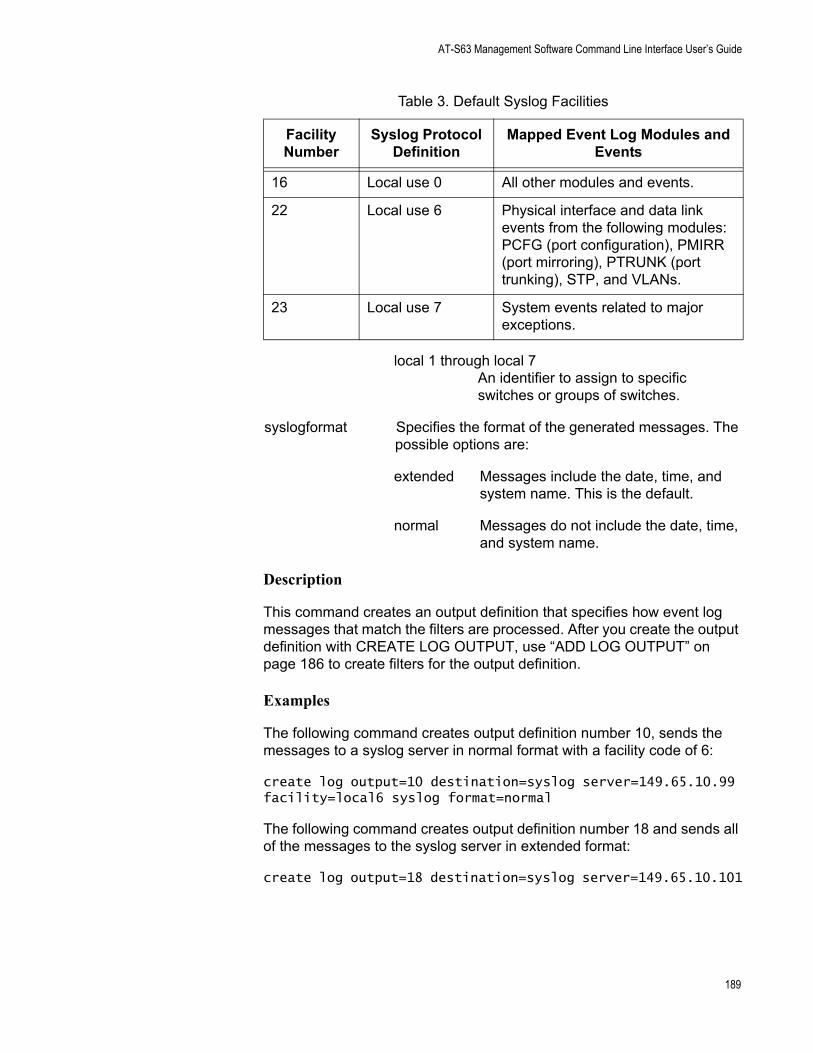
AT-S63 Management Software Command Line Interface User’s Guide
local 1 through local 7An identifier to assign to specific switches or groups of switches.
syslogformat Specifies the format of the generated messages. The possible options are:
extended Messages include the date, time, and system name. This is the default.
normal Messages do not include the date, time, and system name.
Description
This command creates an output definition that specifies how event log messages that match the filters are processed. After you create the output definition with CREATE LOG OUTPUT, use “ADD LOG OUTPUT” on page 186 to create filters for the output definition.
Examples
The following command creates output definition number 10, sends the messages to a syslog server in normal format with a facility code of 6:
create log output=10 destination=syslog server=149.65.10.99 facility=local6 syslog format=normal
The following command creates output definition number 18 and sends all of the messages to the syslog server in extended format:
create log output=18 destination=syslog server=149.65.10.101
16 Local use 0 All other modules and events.
22 Local use 6 Physical interface and data link events from the following modules: PCFG (port configuration), PMIRR (port mirroring), PTRUNK (port trunking), STP, and VLANs.
23 Local use 7 System events related to major exceptions.
Table 3. Default Syslog Facilities
Facility Number
Syslog Protocol Definition
Mapped Event Log Modules and Events
189
Chapter 14: Event Log Commands
DESTROY LOG OUTPUT
Syntax
destroy log output=output-id
Parameters
output Specifies the output definition ID number.
Description
This command deletes the specified output definition. To disable the output definition without deleting it, see “DISABLE LOG OUTPUT” on page 192.
Example
The following command destroys output definition number 3:
destroy log output=3
190
AT-S63 Management Software Command Line Interface User’s Guide
DISABLE LOG
Syntax
disable log
Parameters
None.
Description
This command disables the event log module.
NoteThe event log, even when disabled, still logs all AT-S63 initialization events that occur when the switch is reset or power cycled. Any switch events that occur after AT-S63 initialization are recorded only if the event log is enabled.
Examples
The following command disables the event log on the switch:
disable log
191
Chapter 14: Event Log Commands
DISABLE LOG OUTPUT
Syntax
disable log output[=output-id]
Parameters
output Specifies the output definition ID number to disable.
Description
This command disables the specified output definition and no log messages are processed by this definition although the definition still exists. To permanently remove an output definition, see “DESTROY LOG OUTPUT” on page 190. To enable the output definition again, see “ENABLE LOG OUTPUT” on page 194.
Example
The following command disables (but does not delete) output definition number 7:
disable log output=7
The following command disables all configured definitions:
disable log output
192
AT-S63 Management Software Command Line Interface User’s Guide
ENABLE LOG
Syntax
enable log
Parameters
None.
Description
This command activates the event log. After the log is activated, the switch immediately starts to process events. The default setting for the event log is enabled.
Example
The following command activates the event log module on the switch:
enable log
193
Chapter 14: Event Log Commands
ENABLE LOG OUTPUT
Syntax
enable log output[=output-id]
Parameters
output Specifies the output definition ID number to enable.
Description
This command enables the specified output definition that was disabled using “DISABLE LOG OUTPUT” on page 192.
Example
The following command enables output definition number 4:
enable log output=4
The following command enables all output definitions:
enable log output
194
AT-S63 Management Software Command Line Interface User’s Guide
PURGE LOG
Syntax
purge log[=permanent|temporary]
Parameter
log Specifies the type of memory on the switch where the log file you want to purge is located. The options are:
permanent Permanent (nonvolatile) memory. Deletes all events stored in nonvolatile memory, which can contain up to 2,000 events.
temporary Temporary memory. Deletes all events stored in temporary memory, which can contain up to 4,000 events. This is the default if you do not specify the “permanent” option.
Description
This command deletes all the entries stored in an event log.
Example
The following command deletes the entries in the event log stored in temporary memory:
purge log=temporary
195
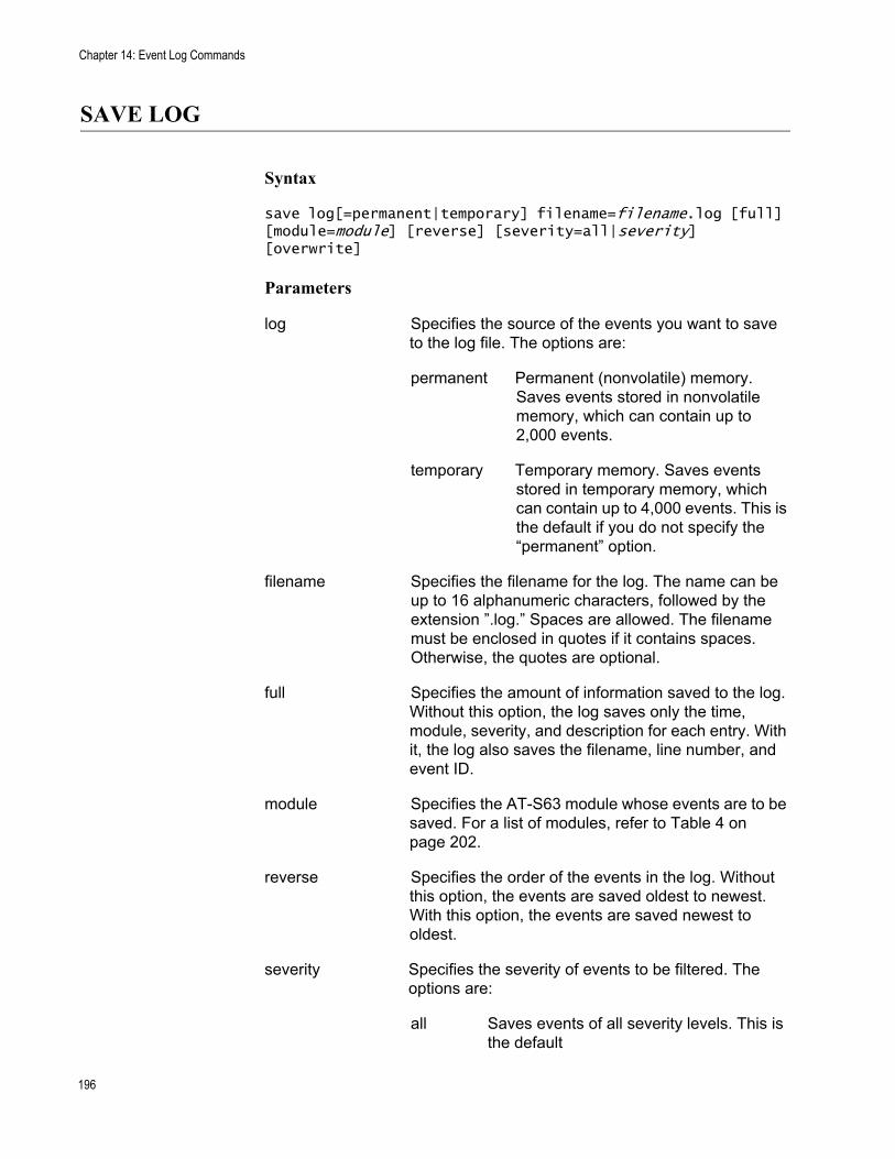
Chapter 14: Event Log Commands
SAVE LOG
Syntax
save log[=permanent|temporary] filename=filename.log [full] [module=module] [reverse] [severity=all|severity] [overwrite]
Parameters
log Specifies the source of the events you want to save to the log file. The options are:
permanent Permanent (nonvolatile) memory. Saves events stored in nonvolatile memory, which can contain up to 2,000 events.
temporary Temporary memory. Saves events stored in temporary memory, which can contain up to 4,000 events. This is the default if you do not specify the “permanent” option.
filename Specifies the filename for the log. The name can be up to 16 alphanumeric characters, followed by the extension ”.log.” Spaces are allowed. The filename must be enclosed in quotes if it contains spaces. Otherwise, the quotes are optional.
full Specifies the amount of information saved to the log. Without this option, the log saves only the time, module, severity, and description for each entry. With it, the log also saves the filename, line number, and event ID.
module Specifies the AT-S63 module whose events are to be saved. For a list of modules, refer to Table 4 on page 202.
reverse Specifies the order of the events in the log. Without this option, the events are saved oldest to newest. With this option, the events are saved newest to oldest.
severity Specifies the severity of events to be filtered. The options are:
all Saves events of all severity levels. This is the default
196
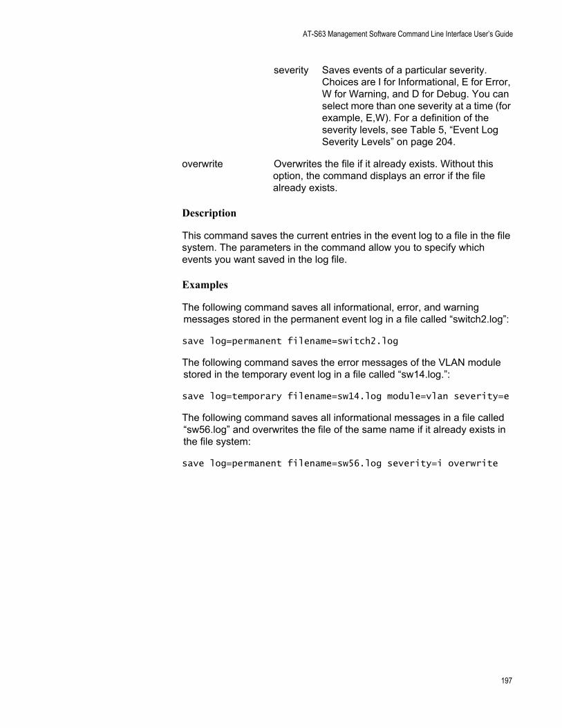
AT-S63 Management Software Command Line Interface User’s Guide
severity Saves events of a particular severity. Choices are I for Informational, E for Error, W for Warning, and D for Debug. You can select more than one severity at a time (for example, E,W). For a definition of the severity levels, see Table 5, “Event Log Severity Levels” on page 204.
overwrite Overwrites the file if it already exists. Without this option, the command displays an error if the file already exists.
Description
This command saves the current entries in the event log to a file in the file system. The parameters in the command allow you to specify which events you want saved in the log file.
Examples
The following command saves all informational, error, and warning messages stored in the permanent event log in a file called “switch2.log”:
save log=permanent filename=switch2.log
The following command saves the error messages of the VLAN module stored in the temporary event log in a file called “sw14.log.”:
save log=temporary filename=sw14.log module=vlan severity=e
The following command saves all informational messages in a file called “sw56.log” and overwrites the file of the same name if it already exists in the file system:
save log=permanent filename=sw56.log severity=i overwrite
197
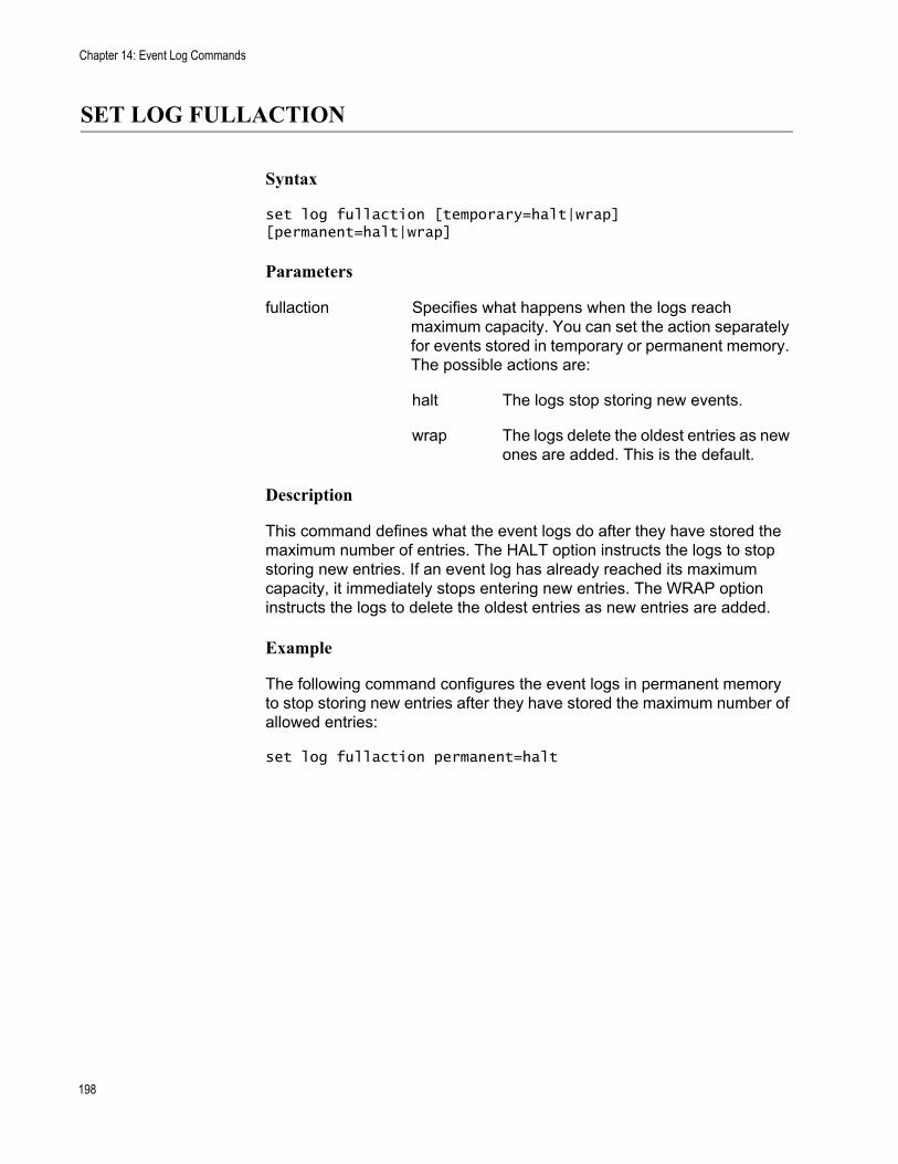
Chapter 14: Event Log Commands
SET LOG FULLACTION
Syntax
set log fullaction [temporary=halt|wrap] [permanent=halt|wrap]
Parameters
fullaction Specifies what happens when the logs reach maximum capacity. You can set the action separately for events stored in temporary or permanent memory. The possible actions are:
halt The logs stop storing new events.
wrap The logs delete the oldest entries as new ones are added. This is the default.
Description
This command defines what the event logs do after they have stored the maximum number of entries. The HALT option instructs the logs to stop storing new entries. If an event log has already reached its maximum capacity, it immediately stops entering new entries. The WRAP option instructs the logs to delete the oldest entries as new entries are added.
Example
The following command configures the event logs in permanent memory to stop storing new entries after they have stored the maximum number of allowed entries:
set log fullaction permanent=halt
198
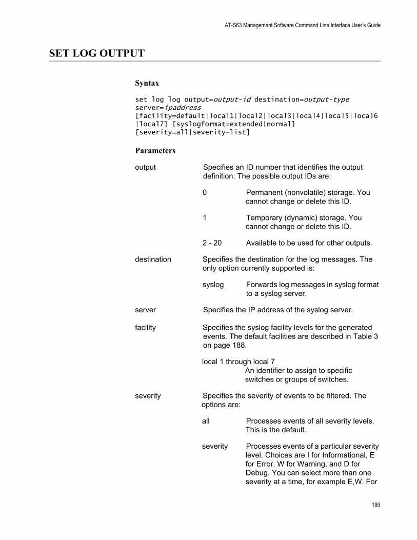
AT-S63 Management Software Command Line Interface User’s Guide
SET LOG OUTPUT
Syntax
set log log output=output-id destination=output-type server=ipaddress [facility=default|local1|local2|local3|local4|local5|local6|local7] [syslogformat=extended|normal] [severity=all|severity-list]
Parameters
output Specifies an ID number that identifies the output definition. The possible output IDs are:
0 Permanent (nonvolatile) storage. You cannot change or delete this ID.
1 Temporary (dynamic) storage. You cannot change or delete this ID.
2 - 20 Available to be used for other outputs.
destination Specifies the destination for the log messages. The only option currently supported is:
syslog Forwards log messages in syslog format to a syslog server.
server Specifies the IP address of the syslog server.
facility Specifies the syslog facility levels for the generated events. The default facilities are described in Table 3 on page 188.
local 1 through local 7An identifier to assign to specific switches or groups of switches.
severity Specifies the severity of events to be filtered. The options are:
all Processes events of all severity levels. This is the default.
severity Processes events of a particular severity level. Choices are I for Informational, E for Error, W for Warning, and D for Debug. You can select more than one severity at a time, for example E,W. For
199
Chapter 14: Event Log Commands
a definition of the severity levels, see Table 5 on page 204.
Description
This command modifies an existing event filter created with “CREATE LOG OUTPUT” on page 188.
Example
The following command modifies output definition number 6 to filter out all messages except those that are of high severity from the RADIUS module:
set log output=3 module=radius severity=all
200
AT-S63 Management Software Command Line Interface User’s Guide
SHOW LOG
Syntax
show log=permanent|temporary [full] [module=module] [reverse] [severity=severity]
Parameters
log Specifies which of the two event logs you want to view. The options are:
permanent Displays the events stored in permanent memory.
temporary Displays the events stored in temporary memory.
full Specifies the amount of information displayed by the log. Without this option, the log displays the time, module, severity, and description for each entry. With it, the log also displays the filename, line number, and event ID.
module Specifies the AT-S63 module whose events you want displayed. For a list of modules, refer to Table 4 on page 202.
reverse Specifies the order of the events in the log. Without this option, the events are displayed oldest to newest. With this option, the events are displayed newest to oldest.
severity Specifies the severity of events to be displayed. The options are:
all Displays events of all severity levels. This is the default
severity Displays events of a particular severity. Choices are I for Informational, E for Error, W for Warning, and D for Debug. You can select more than one severity at a time (for example, E,W). For a definition of the severity levels, see Table 5, “Event Log Severity Levels” on page 204.
201
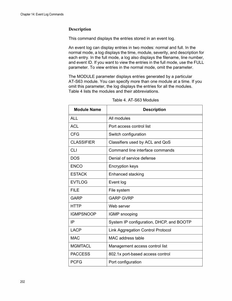
Chapter 14: Event Log Commands
Description
This command displays the entries stored in an event log.
An event log can display entries in two modes: normal and full. In the normal mode, a log displays the time, module, severity, and description for each entry. In the full mode, a log also displays the filename, line number, and event ID. If you want to view the entries in the full mode, use the FULL parameter. To view entries in the normal mode, omit the parameter.
The MODULE parameter displays entries generated by a particular AT-S63 module. You can specify more than one module at a time. If you omit this parameter, the log displays the entries for all the modules. Table 4 lists the modules and their abbreviations.
Table 4. AT-S63 Modules
Module Name Description
ALL All modules
ACL Port access control list
CFG Switch configuration
CLASSIFIER Classifiers used by ACL and QoS
CLI Command line interface commands
DOS Denial of service defense
ENCO Encryption keys
ESTACK Enhanced stacking
EVTLOG Event log
FILE File system
GARP GARP GVRP
HTTP Web server
IGMPSNOOP IGMP snooping
IP System IP configuration, DHCP, and BOOTP
LACP Link Aggregation Control Protocol
MAC MAC address table
MGMTACL Management access control list
PACCESS 802.1x port-based access control
PCFG Port configuration
202
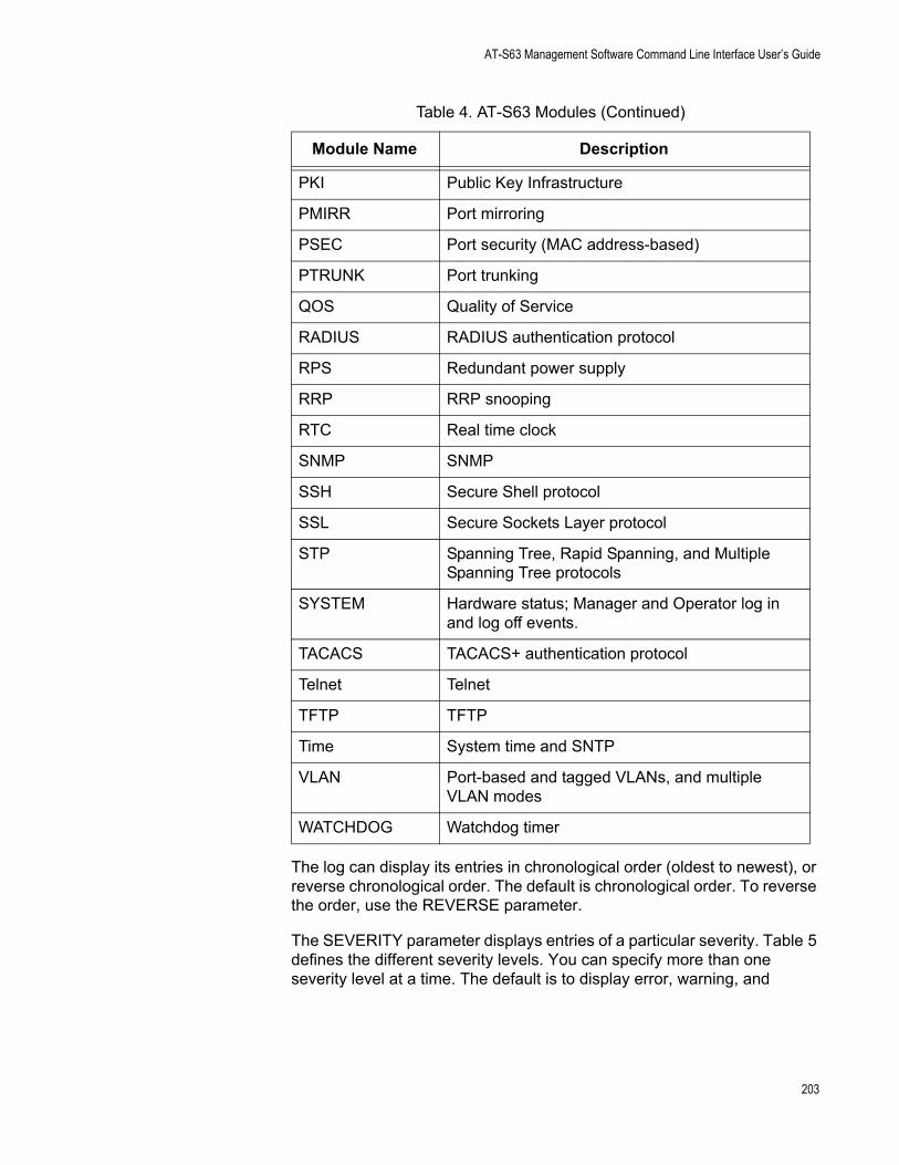
AT-S63 Management Software Command Line Interface User’s Guide
The log can display its entries in chronological order (oldest to newest), or reverse chronological order. The default is chronological order. To reverse the order, use the REVERSE parameter.
The SEVERITY parameter displays entries of a particular severity. Table 5 defines the different severity levels. You can specify more than one severity level at a time. The default is to display error, warning, and
PKI Public Key Infrastructure
PMIRR Port mirroring
PSEC Port security (MAC address-based)
PTRUNK Port trunking
QOS Quality of Service
RADIUS RADIUS authentication protocol
RPS Redundant power supply
RRP RRP snooping
RTC Real time clock
SNMP SNMP
SSH Secure Shell protocol
SSL Secure Sockets Layer protocol
STP Spanning Tree, Rapid Spanning, and Multiple Spanning Tree protocols
SYSTEM Hardware status; Manager and Operator log in and log off events.
TACACS TACACS+ authentication protocol
Telnet Telnet
TFTP TFTP
Time System time and SNTP
VLAN Port-based and tagged VLANs, and multiple VLAN modes
WATCHDOG Watchdog timer
Table 4. AT-S63 Modules (Continued)
Module Name Description
203
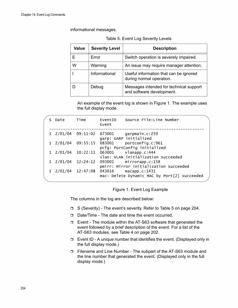
Chapter 14: Event Log Commands
informational messages.
An example of the event log is shown in Figure 1. The example uses the full display mode.
Figure 1. Event Log Example
The columns in the log are described below:
S (Severity) - The event’s severity. Refer to Table 5 on page 204.Date/Time - The date and time the event occurred.Event - The module within the AT-S63 software that generated the event followed by a brief description of the event. For a list of the AT-S63 modules, see Table 4 on page 202.Event ID - A unique number that identifies the event. (Displayed only in the full display mode.)Filename and Line Number - The subpart of the AT-S63 module and the line number that generated the event. (Displayed only in the full display mode.)
Table 5. Event Log Severity Levels
Value Severity Level Description
E Error Switch operation is severely impaired.
W Warning An issue may require manager attention.
I Informational Useful information that can be ignored during normal operation.
D Debug Messages intended for technical support and software development.
S Date Time EventID Source File:Line NumberEvent
------------------------------------------------------------------I 2/01/04 09:11:02 073001 garpmain.c:259
garp: GARP initializedI 2/01/04 09:55:15 083001 portconfig.c:961
pcfg: PortConfig initializedI 2/01/04 10:22:11 063001 vlanapp.c:444
vlan: VLAN initialization succeededI 2/01/04 12:24:12 093001 mirrorapp.c:158
pmirr: Mirror initialization succeededI 2/01/04 12:47:08 043016 macapp.c:1431
mac: Delete Dynamic MAC by Port[2] succeeded
204
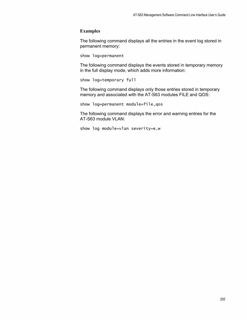
AT-S63 Management Software Command Line Interface User’s Guide
Examples
The following command displays all the entries in the event log stored in permanent memory:
show log=permanent
The following command displays the events stored in temporary memory in the full display mode, which adds more information:
show log=temporary full
The following command displays only those entries stored in temporary memory and associated with the AT-S63 modules FILE and QOS:
show log=permanent module=file,qos
The following command displays the error and warning entries for the AT-S63 module VLAN:
show log module=vlan severity=e,w
205
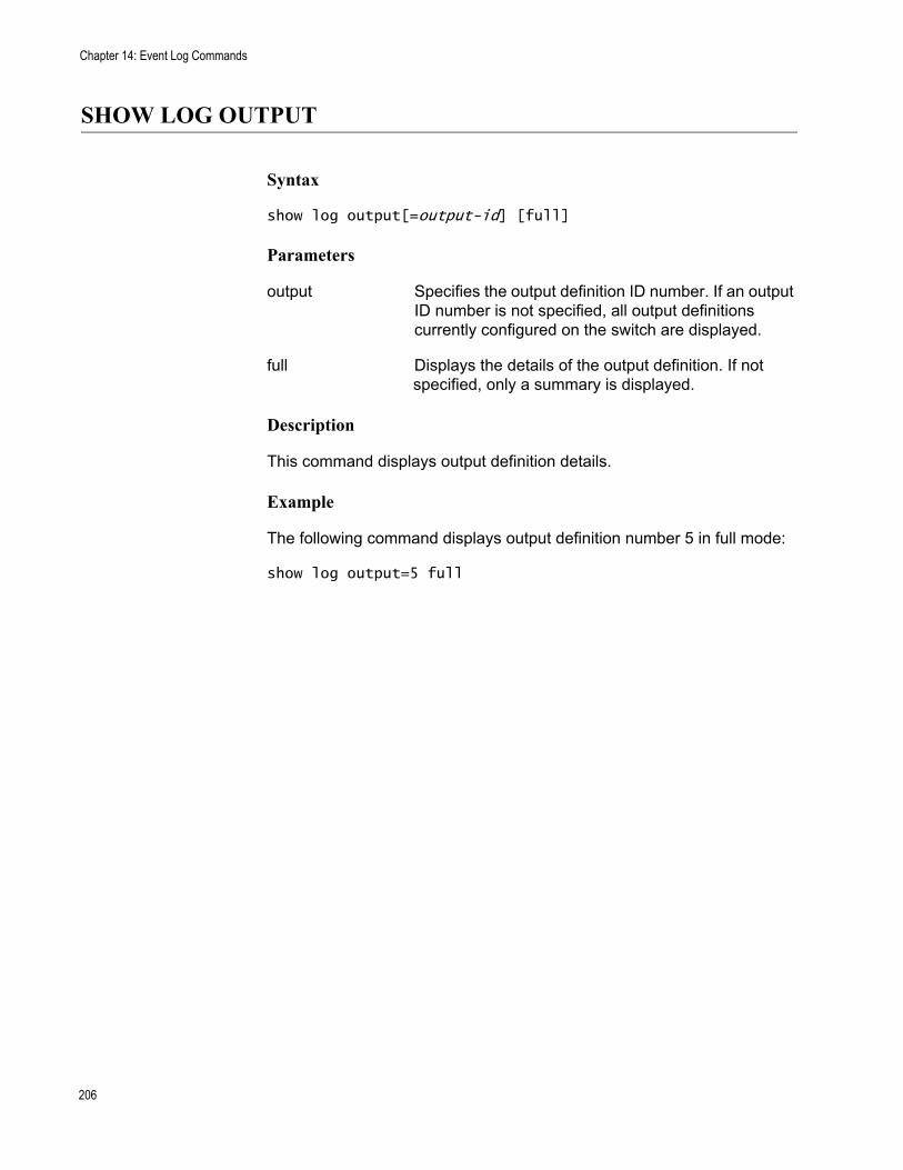
Chapter 14: Event Log Commands
SHOW LOG OUTPUT
Syntax
show log output[=output-id] [full]
Parameters
output Specifies the output definition ID number. If an output ID number is not specified, all output definitions currently configured on the switch are displayed.
full Displays the details of the output definition. If not specified, only a summary is displayed.
Description
This command displays output definition details.
Example
The following command displays output definition number 5 in full mode:
show log output=5 full
206
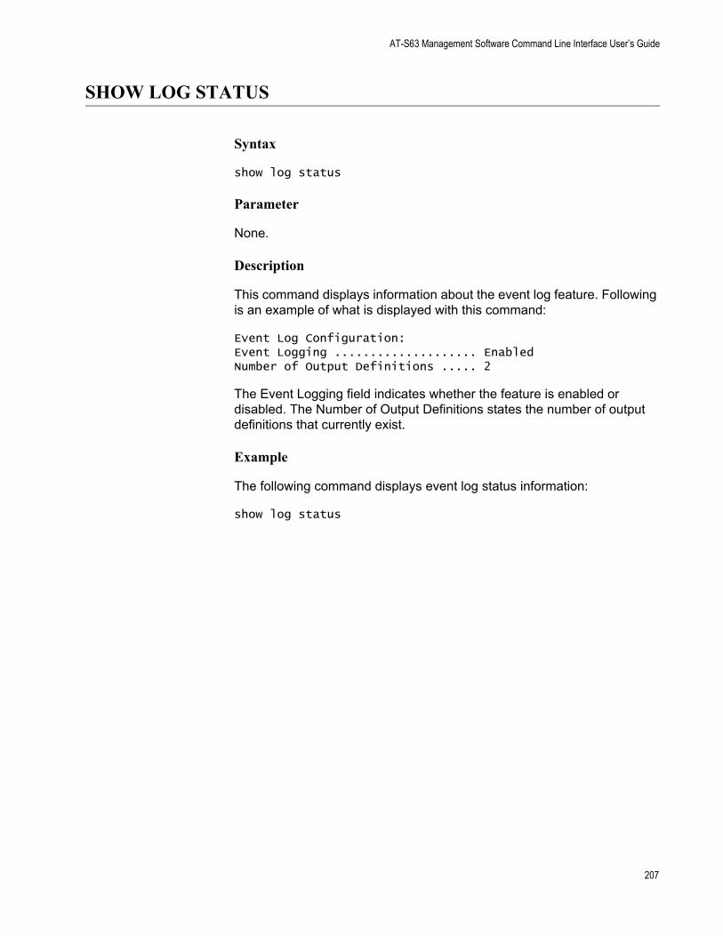
AT-S63 Management Software Command Line Interface User’s Guide
SHOW LOG STATUS
Syntax
show log status
Parameter
None.
Description
This command displays information about the event log feature. Following is an example of what is displayed with this command:
Event Log Configuration:Event Logging .................... EnabledNumber of Output Definitions ..... 2
The Event Logging field indicates whether the feature is enabled or disabled. The Number of Output Definitions states the number of output definitions that currently exist.
Example
The following command displays event log status information:
show log status
207

Chapter 14: Event Log Commands
208
Chapter 15
Classifier Commands
This chapter contains the following commands:
“CREATE CLASSIFIER” on page 210“DESTROY CLASSIFIER” on page 213“PURGE CLASSIFIER” on page 214“SET CLASSIFIER” on page 215“SHOW CLASSIFIER” on page 218
NoteRemember to use the SAVE CONFIGURATION command to save your changes on the switch.
NoteFor background information on classifiers, refer to Chapter 13, “Classifiers” in the AT-S63 Management Software Menus Interface User’s Guide.
Section I: Basic Features 209
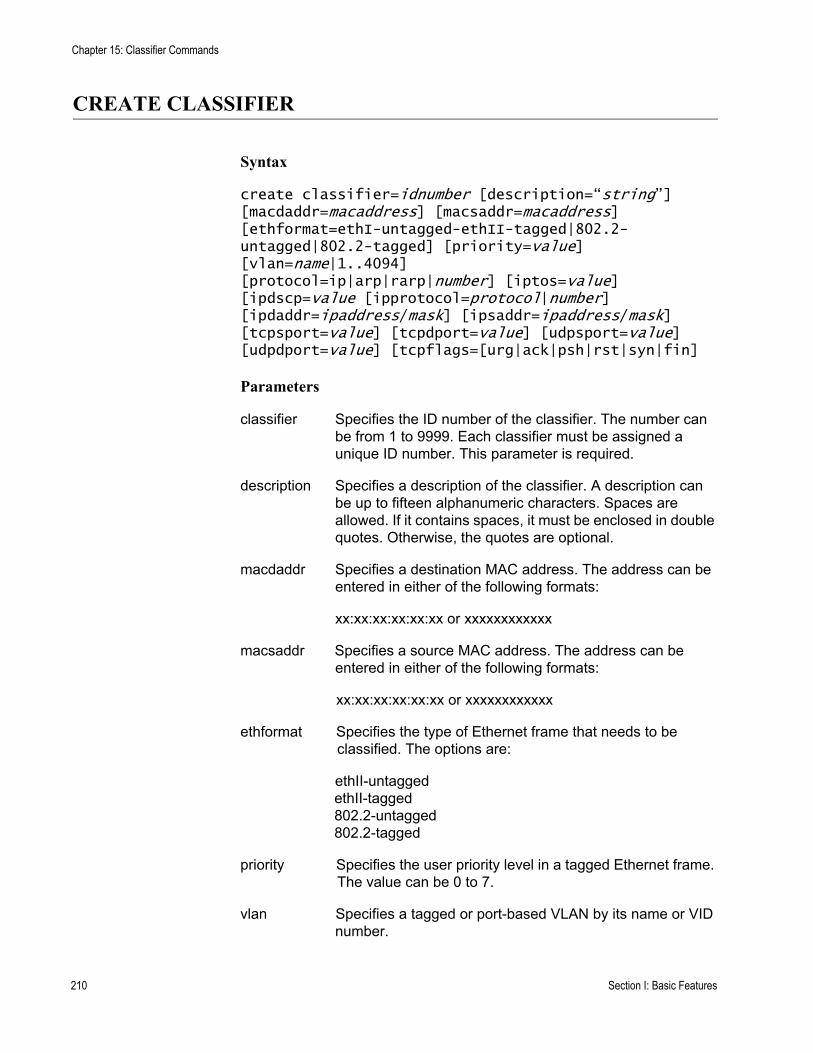
Chapter 15: Classifier Commands
CREATE CLASSIFIER
Syntax
create classifier=idnumber [description=“string”] [macdaddr=macaddress] [macsaddr=macaddress] [ethformat=ethI-untagged-ethII-tagged|802.2-untagged|802.2-tagged] [priority=value] [vlan=name|1..4094][protocol=ip|arp|rarp|number] [iptos=value] [ipdscp=value [ipprotocol=protocol|number] [ipdaddr=ipaddress/mask] [ipsaddr=ipaddress/mask] [tcpsport=value] [tcpdport=value] [udpsport=value] [udpdport=value] [tcpflags=[urg|ack|psh|rst|syn|fin]
Parameters
classifier Specifies the ID number of the classifier. The number can be from 1 to 9999. Each classifier must be assigned a unique ID number. This parameter is required.
description Specifies a description of the classifier. A description can be up to fifteen alphanumeric characters. Spaces are allowed. If it contains spaces, it must be enclosed in double quotes. Otherwise, the quotes are optional.
macdaddr Specifies a destination MAC address. The address can be entered in either of the following formats:
xx:xx:xx:xx:xx:xx or xxxxxxxxxxxx
macsaddr Specifies a source MAC address. The address can be entered in either of the following formats:
xx:xx:xx:xx:xx:xx or xxxxxxxxxxxx
ethformat Specifies the type of Ethernet frame that needs to be classified. The options are:
ethII-untaggedethII-tagged802.2-untagged802.2-tagged
priority Specifies the user priority level in a tagged Ethernet frame. The value can be 0 to 7.
vlan Specifies a tagged or port-based VLAN by its name or VID number.
210 Section I: Basic Features
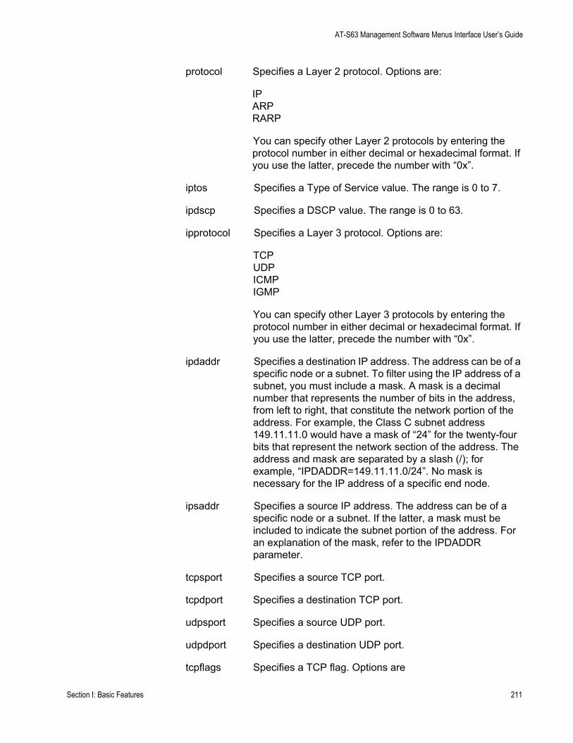
AT-S63 Management Software Menus Interface User’s Guide
protocol Specifies a Layer 2 protocol. Options are:
IPARPRARP
You can specify other Layer 2 protocols by entering the protocol number in either decimal or hexadecimal format. If you use the latter, precede the number with “0x”.
iptos Specifies a Type of Service value. The range is 0 to 7.
ipdscp Specifies a DSCP value. The range is 0 to 63.
ipprotocol Specifies a Layer 3 protocol. Options are:
TCPUDPICMPIGMP
You can specify other Layer 3 protocols by entering the protocol number in either decimal or hexadecimal format. If you use the latter, precede the number with “0x”.
ipdaddr Specifies a destination IP address. The address can be of a specific node or a subnet. To filter using the IP address of a subnet, you must include a mask. A mask is a decimal number that represents the number of bits in the address, from left to right, that constitute the network portion of the address. For example, the Class C subnet address 149.11.11.0 would have a mask of “24” for the twenty-four bits that represent the network section of the address. The address and mask are separated by a slash (/); for example, “IPDADDR=149.11.11.0/24”. No mask is necessary for the IP address of a specific end node.
ipsaddr Specifies a source IP address. The address can be of a specific node or a subnet. If the latter, a mask must be included to indicate the subnet portion of the address. For an explanation of the mask, refer to the IPDADDR parameter.
tcpsport Specifies a source TCP port.
tcpdport Specifies a destination TCP port.
udpsport Specifies a source UDP port.
udpdport Specifies a destination UDP port.
tcpflags Specifies a TCP flag. Options are
Section I: Basic Features 211
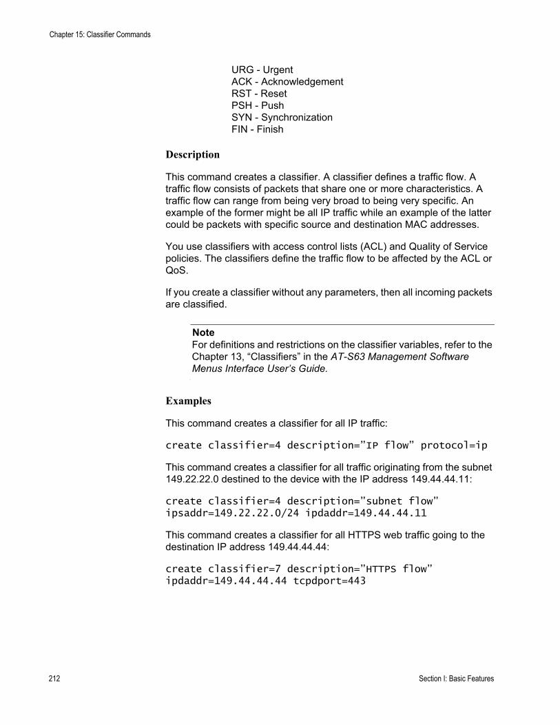
Chapter 15: Classifier Commands
URG - UrgentACK - AcknowledgementRST - ResetPSH - PushSYN - SynchronizationFIN - Finish
Description
This command creates a classifier. A classifier defines a traffic flow. A traffic flow consists of packets that share one or more characteristics. A traffic flow can range from being very broad to being very specific. An example of the former might be all IP traffic while an example of the latter could be packets with specific source and destination MAC addresses.
You use classifiers with access control lists (ACL) and Quality of Service policies. The classifiers define the traffic flow to be affected by the ACL or QoS.
If you create a classifier without any parameters, then all incoming packets are classified.
NoteFor definitions and restrictions on the classifier variables, refer to the Chapter 13, “Classifiers” in the AT-S63 Management Software Menus Interface User’s Guide.
Examples
This command creates a classifier for all IP traffic:
create classifier=4 description=”IP flow” protocol=ip
This command creates a classifier for all traffic originating from the subnet 149.22.22.0 destined to the device with the IP address 149.44.44.11:
create classifier=4 description=”subnet flow” ipsaddr=149.22.22.0/24 ipdaddr=149.44.44.11
This command creates a classifier for all HTTPS web traffic going to the destination IP address 149.44.44.44:
create classifier=7 description=”HTTPS flow” ipdaddr=149.44.44.44 tcpdport=443
212 Section I: Basic Features
AT-S63 Management Software Menus Interface User’s Guide
DESTROY CLASSIFIER
Syntax
destroy classifier=idnumber
Parameters
classifier Specifies the ID number of the classifier to be deleted. The number can be from 1 to 9999. You can delete more than one classifier at a time. You can specify the classifiers individually (e.g., 2,5,7) as a range (e.g., 11-14), or both (e.g., 2,4-8,12).
Description
This command deletes a classifier from the switch. To delete a classifier, you need to know its ID number. To display the ID numbers of the classifiers, refer to “SHOW CLASSIFIER” on page 218.
You cannot delete a classifier if it belongs to an ACL or QoS policy that has already been assigned to a port. You must first remove the port assignments from the ACL or policy before you can delete the classifier.
Example
This command deletes classifiers 2 and 4:
destroy classifier=2,4
Section I: Basic Features 213
Chapter 15: Classifier Commands
PURGE CLASSIFIER
Syntax
purge classifier
Parameters
None.
Description
This command deletes all classifiers from the switch. You cannot delete a classifier if it belongs to an ACL or QoS policy that has already been assigned to a port. You must first remove the port assignments from the ACL or policy before you can delete the classifier.
Example
This command deletes all classifiers on the switch:
purge classifier
214 Section I: Basic Features
AT-S63 Management Software Menus Interface User’s Guide
SET CLASSIFIER
Syntax
set classifier=idnumber [description=”string”] [macdaddr=macaddress|any] [macsaddr=macaddress|any] [priority=value] [vlan=name|1..4094|any][protocol=ip|arp|rarp|number|any] [iptos=value|any] [ipdscp=value|any] [ipprotocol=protocol|number|any] [ipdaddr=ipaddress/mask|any] [ipsaddr=ipaddress/mask|any] [tcpsport=value|any] [tcpdport=value|any] [udpsport=value|any] [udpdport=value|any] [tcpflags=[urg|ack|psh|rst|syn|fin|any]
Parameters
classifier Specifies the ID number of the classifier to be modified. You can modify only one classifier at a time. The number can be from 1 to 9999.
description Specifies a description of the classifier. A description can be up to fifteen alphanumeric characters. Spaces are allowed. If it contains spaces, it must be enclosed in double quotes. Otherwise, the quotes are optional.
macdaddr Specifies a destination MAC address. The address can be entered in either of the following formats:
xx:xx:xx:xx:xx:xx or xxxxxxxxxxxx
macsaddr Specifies a source MAC address. The address can be entered in either of the following formats:
xx:xx:xx:xx:xx:xx or xxxxxxxxxxxx
priority Specifies the user priority level in a tagged Ethernet frame. The value can be 0 to 7.
vlan Specifies a tagged or port-based VLAN by its name or VID number.
protocol Specifies a Layer 2 protocol. Options are:
IPARPRARP
You can specify additional Layer 2 protocols by entering the protocol number in either decimal or hexadecimal format. For the latter, precede the number with “0x”.
Section I: Basic Features 215
Chapter 15: Classifier Commands
iptos Specifies a Type of Service value. The range is 0 to 7.
ipdscp Specifies a DSCP value. The range is 0 to 63.
ipprotocol Specifies a Layer 3 protocol. Options are:
TCPUDPICMPIGMP
You can specify other Layer 3 protocols by entering the protocol number in either decimal or hexadecimal format. If you use the latter, precede the number with “0x”.
ipdaddr Specifies a destination IP address. The address can be of a specific node or a subnet. To filter using the IP address of a subnet, you must include a mask. A mask is a decimal number that represents the number of bits in the address, from left to right, that constitute the network portion of the address. For example, the Class C subnet address 149.11.11.0 would have a mask of “24” for the twenty-four bits that represent the network section of the address. The address and mask are separated by a slash (/); for example, “IPDADDTR=149.11.11.0/24”. No mask is necessary for the IP address of a specific end node.
ipsaddr Specifies a source IP address. The address can be of a specific node or a subnet. If the latter, a mask must be included to indicate the subnet portion of the address. For an explanation of the mask, refer to the IPDADDR parameter.
tcpsport Specifies a source TCP port.
tcpdport Specifies a destination TCP port.
udpsport Specifies a source UDP port.
udpdport Specifies a destination UDP port.
tcpflags Specifies a TCP flag. Options are
URG - UrgentACK - AcknowledgementRST - ResetPSH - PushSYN - SynchronizationFIN - Finish
216 Section I: Basic Features
AT-S63 Management Software Menus Interface User’s Guide
Description
This command modifies an existing classifier. The only setting of a classifier you cannot change is its ID number.
Specifying a new value for a variable that already has a value overwrites the current value with the new one. The ANY option removes a variable’s value without assigning it a new value. A classifier must contain a least one variable with a value, besides the classifier ID and description.
You cannot modify a classifier if it belongs to an ACL or QoS policy that has already been assigned to a port. You must first remove the port assignments from the ACL or policy before you can modify the classifier.
Examples
This command adds the destination IP address 149.22.22.22 and the source subnet IP address 149.44.44.0 to classifier ID 4:
set classifier=4 ipdaddr=149.22.22.22 ipsaddr=149.44.44.0/24
This command adds the Layer 3 protocol IGMP to classifier ID 6:
set classifier=6 ipprotocol=igmp
This command removes the current setting for the UDP destination port variable from classifier ID 5 without assigning a new value:
set classifier=5 udpdport=any
Section I: Basic Features 217
Chapter 15: Classifier Commands
SHOW CLASSIFIER
Syntax
show classifier[=idnumber]
Parameters
classifier Specifies the ID of the classifier you want to view. You can specify more than one classifier at a time.
Description
This command displays the classifiers on a switch.
Examples
This command displays all of the classifiers:
show classifier
This command displays classifier ID 12:
show classifier=12
218 Section I: Basic Features
Chapter 16
ACL Commands
This chapter contains the following commands:
“CREATE ACL” on page 220“DESTROY ACL” on page 222“PURGE ACL” on page 223“SET ACL” on page 224“SHOW ACL” on page 226
NoteRemember to save your changes with the SAVE CONFIGURATION command.
NoteFor background information on access control lists (ACL), refer to Chapter 14, “Access Control Lists” in the AT-S63 Management Software Menus Interface User’s Guide.
Section I: Basic Features 219
Chapter 16: ACL Commands
CREATE ACL
Syntax
create acl=value [description=”string”] [action=deny|permit] classifierlist=value [portlist=ports]
Parameters
acl Specifies an ID number for the ACL. The number can be from 0 to 255. Each ACL must have a unique ID number.
description Specifies a description for the ACL. A description can be up to 15 alphanumeric characters. Spaces are allowed. If the description contains spaces, it must be enclosed in double quotes. Otherwise, the quotes are optional.
action Specifies the action to be taken by the port when a ingress packet matches a classifier attached to the ACL. Options are:
permit The port accepts the packet.
deny The port discards the packet, provided that the packet does not match the classifier of a permit ACL assigned to the same port. This is the default action.
classifierlist Specifies the ID numbers of the classifiers to be assigned to the ACL. When entering multiple ID numbers, separate the numbers with a comma (e.g., 4,6,7). The classifiers must already exist on the switch. The order in which you specify the classifiers is not important. An ACL must have at least one classifier.
portlist Specifies the port where this ACL is to be assigned. You can assign an ACL to more than one port. When entering multiple ports, the ports can be listed individually (e.g., 2,5,7), as a range (e.g., 8-12) or both (e.g., 1-4,6,8).
Description
This command creates an ACL. An ACL is used to filter ingress packets on a port.
220 Section I: Basic Features
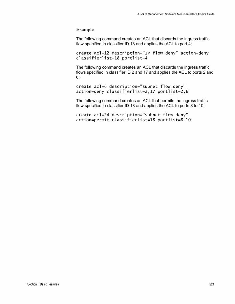
AT-S63 Management Software Menus Interface User’s Guide
Example
The following command creates an ACL that discards the ingress traffic flow specified in classifier ID 18 and applies the ACL to port 4:
create acl=12 description=”IP flow deny” action=deny classifierlist=18 portlist=4
The following command creates an ACL that discards the ingress traffic flows specified in classifier ID 2 and 17 and applies the ACL to ports 2 and 6:
create acl=6 description=”subnet flow deny” action=deny classifierlist=2,17 portlist=2,6
The following command creates an ACL that permits the ingress traffic flow specified in classifier ID 18 and applies the ACL to ports 8 to 10:
create acl=24 description=”subnet flow deny” action=permit classifierlist=18 portlist=8-10
Section I: Basic Features 221
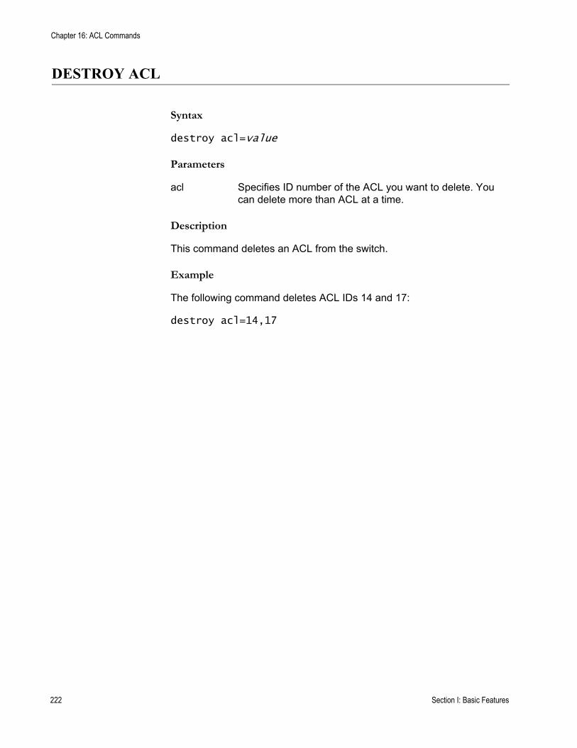
Chapter 16: ACL Commands
DESTROY ACL
Syntax
destroy acl=value
Parameters
acl Specifies ID number of the ACL you want to delete. You can delete more than ACL at a time.
Description
This command deletes an ACL from the switch.
Example
The following command deletes ACL IDs 14 and 17:
destroy acl=14,17
222 Section I: Basic Features
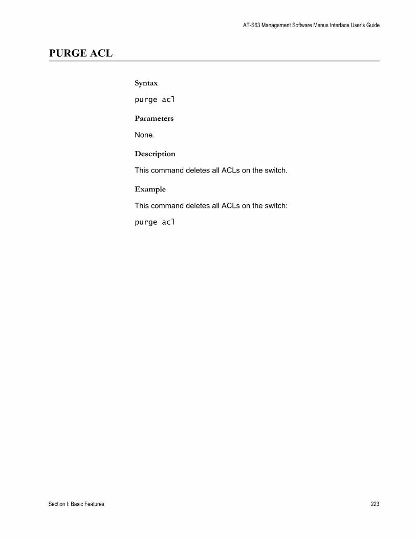
AT-S63 Management Software Menus Interface User’s Guide
PURGE ACL
Syntax
purge acl
Parameters
None.
Description
This command deletes all ACLs on the switch.
Example
This command deletes all ACLs on the switch:
purge acl
Section I: Basic Features 223
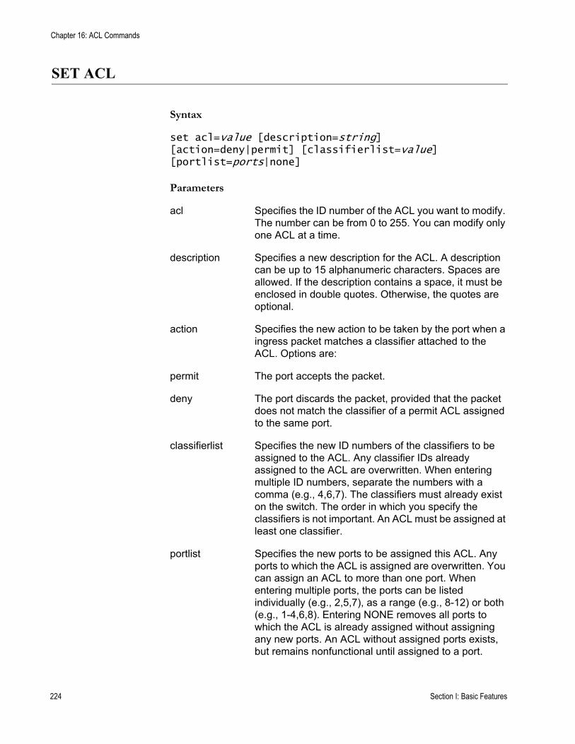
Chapter 16: ACL Commands
SET ACL
Syntax
set acl=value [description=string] [action=deny|permit] [classifierlist=value] [portlist=ports|none]
Parameters
acl Specifies the ID number of the ACL you want to modify. The number can be from 0 to 255. You can modify only one ACL at a time.
description Specifies a new description for the ACL. A description can be up to 15 alphanumeric characters. Spaces are allowed. If the description contains a space, it must be enclosed in double quotes. Otherwise, the quotes are optional.
action Specifies the new action to be taken by the port when a ingress packet matches a classifier attached to the ACL. Options are:
permit The port accepts the packet.
deny The port discards the packet, provided that the packet does not match the classifier of a permit ACL assigned to the same port.
classifierlist Specifies the new ID numbers of the classifiers to be assigned to the ACL. Any classifier IDs already assigned to the ACL are overwritten. When entering multiple ID numbers, separate the numbers with a comma (e.g., 4,6,7). The classifiers must already exist on the switch. The order in which you specify the classifiers is not important. An ACL must be assigned at least one classifier.
portlist Specifies the new ports to be assigned this ACL. Any ports to which the ACL is assigned are overwritten. You can assign an ACL to more than one port. When entering multiple ports, the ports can be listed individually (e.g., 2,5,7), as a range (e.g., 8-12) or both (e.g., 1-4,6,8). Entering NONE removes all ports to which the ACL is already assigned without assigning any new ports. An ACL without assigned ports exists, but remains nonfunctional until assigned to a port.
224 Section I: Basic Features
AT-S63 Management Software Menus Interface User’s Guide
Description
This command modifies an ACL. You can use the command to change the description, action, classifiers, and ports of an ACL.
Example
This command changes the description of ACL ID 4:
set acl=4 description=”ARP flow”
This command changes the action of ACL ID 6 to permit and reassigns it to ports 4 to 7:
set acl=6 action=permit portlist=4-7
This command changes the classifiers of ACL ID 41:
set acl=41 classifierlist=22,24,36
Section I: Basic Features 225
Chapter 16: ACL Commands
SHOW ACL
Syntax
show acl[=value]
Parameters
aclSpecifies the ID of the ACL you want to view. You can specify more than one ACL at a time.
Description
This command displays the ACLs on the switch.
Example
This command displays all of the ACLs:
show acl
This command displays ACL ID 22:
show acl=22
226 Section I: Basic Features
Chapter 17
Denial of Service (DoS) Defense Commands
This chapter contains the following command:
“SET DOS” on page 228“SET DOS IPOPTION” on page 229“SET DOS LAND” on page 231“SET DOS PINGOFDEATH” on page 232“SET DOS SMURF” on page 234“SET DOS SYNFLOOD” on page 235“SET DOS TEARDROP” on page 237“SHOW DOS” on page 239
NoteRemember to save your changes with the SAVE CONFIGURATION command.
NoteFor background information on Denial of Service (DoS) attacks and the defense mechanisms employed by the management software, refer to Chapter 15, “Denial of Service Defense” in the AT-S63 Management Software Menus Interface User’s Guide.
227
Chapter 17: Denial of Service (DoS) Defense Commands
SET DOS
Syntax
set dos ipaddress=ipaddress subnet=mask uplinkport=port
Parameters
ipaddress Specifies the IP address of one of the devices connected to the switch, preferably the lowest IP address.
subnet Specifies the subnet mask of the LAN. A binary “1” indicates the switch should filter on the corresponding bit of the address, while a “0” indicates that it should not.
uplinkport Specifies the port on the switch that is connected to a device (for example, a DSL router) that leads outside the network. You can specify only one port. This parameter is required only for the Land defense.
Description
This command is required for the SMURF and Land defenses. The SMURF defense uses the LAN address and mask to determine the broadcast address of your network. The Land defense uses this information to determine which traffic is local and which is remote to your network.
As an example, assume that the devices connected to a switch are using the IP address range 149.11.11.1 to 149.11.11.50. The IP address would be 149.11.11.1 and the mask would be 0.0.0.63.
Examples
The following command sets the IP address to 149.11.11.1 and the mask to 0.0.0.63:
set dos ipaddress=149.11.11.1 subnet=0.0.0.63
The following command sets the IP address to 149.22.22.1, the mask to 0.0.0.255, and the uplink port for the Land defense to port 24:
set dos ipaddress=149.22.22.1 subnet=0.0.0.255 uplinkport=24
228
AT-S63 Management Software Command Line Interface User’s Guide
SET DOS IPOPTION
Syntax
set dos ipoption port=port state=enable|disable [mirrorport=port]
Parameters
port Specifies the switch port on which you want to enable or disable the IP Option defense. You can specify more than one port at a time.
state Specifies the state of the IP Option defense. The options are:
enable Activates the defense.
disable Deactivates the defense. This is the default.
mirrorport Specifies a port where invalid traffic is copied. You can specify only one port.
Description
This command enables and disables the IP Option DoS defense.
This type of attack occurs when an attacker sends packets containing bad IP options to a victim node. There are many different types of IP options attacks and the AT-S63 management software does not try to distinguish between them. Rather, a switch port where this defense is activated counts the number of ingress IP packets containing IP options. If the number exceeds 20 packets per second, the switch considers this a possible IP options attack and does the following occurs:
It sends a trap to the management stations.The switch port discards all ingress packets containing IP options for a one minute period.
This defense mechanism does not involve the switch’s CPU. You can activate it on as many ports as you want without it impacting switch performance.
229

Chapter 17: Denial of Service (DoS) Defense Commands
Example
The following command activates the IP Options defense on ports 5, 7, and 10:
set dos ipoption port=5,7,10 state=enable
230
AT-S63 Management Software Command Line Interface User’s Guide
SET DOS LAND
Syntax
set dos land port=port state=enable|disable [mirrorport=port]
Parameters
port Specifies the switch port on which you want to enable or disable the Land defense. You can specify more than one port at a time.
state Specifies the state of the Land defense. The options are:
enable Activates the defense.
disable Deactivates the defense. This is the default.
mirrorport Specifies a port where invalid traffic is copied. You can specify only one port.
Description
This command enables and disables the Land DoS defense. For an explanation of this attack and the AT-S63 defense mechanism, refer to Chapter 31, “Denial of Service Defense” in the <Italic>AT-S63 Management Software Menus Interface User’s Guide.
Example
The following command activates the Land defense on ports 5 and 7:
set dos land port=5,7 state=enable
231
Chapter 17: Denial of Service (DoS) Defense Commands
SET DOS PINGOFDEATH
Syntax
set dos pingofdeath port=port state=enable|disable [mirrorport=port]
Parameters
port Specifies the switch ports on which to enable or disable the Ping of Death defense. You can specify more than one port at a time.
state Specifies the state of the IP Option defense. The options are:
enable Activates the defense.
disable Deactivates the defense. This is the default.
mirrorport Specifies a port where invalid traffic is copied. You can specify only one port.
Description
This command activates and deactivates the Ping of Death DoS defense.
In this DoS, an attacker sends an oversized, fragmented Ping packet to the victim, which, if lacking a policy for handling oversized packets, may freeze.
To defend against this form of attack, a switch port searches for the last fragment of a fragmented Ping request and examines its offset to determine if the packet size is greater than 63,488 bits. If it is, the fragment is forwarded to the switch’s CPU for final packet size determination. If the switch determines that the packet is oversized, the following occurs:
The switch sends a trap to the management stations.The switch port discards the fragment and, for a one minute period, discards all ingress Ping packets on the port.
232
AT-S63 Management Software Command Line Interface User’s Guide
NoteThis defense mechanism requires some involvement by the switch’s CPU, though not as much as the Teardrop defense. This will not impact the forwarding of traffic between the switch ports, but it can affect the handling of CPU events, such as the processing of IGMP packets and spanning tree BPDUs. For this reason, Allied Telesyn recommends that you strictly limit the use of this defense, activating it only on those ports where an attack is most likely to originate.
Example
The following command activates the defense on ports 1 and 5:
set dos pingofdeath port=1,5 state=enable
233
Chapter 17: Denial of Service (DoS) Defense Commands
SET DOS SMURF
Syntax
set dos smurf port=port state=enable|disable
Parameters
port Specifies the switch ports on which you want to enable or disable SMURF defense. You can select more than one port at a time.
state Specifies the state of the SMURF defense. The options are:
enable Activates the defense.
disable Deactivates the defense. This is the default.
Description
This command activates and deactivates the SMURF DoS defense.
This DoS attack is instigated by an attacker sending a Ping request containing a broadcast address as the destination address and the address of the victim as the source of the Ping. This overwhelms the victim with a large number of Ping replies from other network nodes.
A switch port defends against this form of attack by examining the destination addresses of ingress Ping packets and discarding those that contain a broadcast address as a destination address.
To implement this defense, you need to specify the IP address of any device on your network, preferably the lowest IP address, and a mask using “SET DOS” on page 228. The switch uses the combination of the two to determine your network’s broadcast address. Any ingress Ping packets containing the broadcast address are discarded.
This defense mechanism does not involve the switch’s CPU. You can activate it on as many ports as you want without having it negatively impact switch performance.
Example
The following command activates this defense on port 17:
set dos smurf port=17 state=enable
234
AT-S63 Management Software Command Line Interface User’s Guide
SET DOS SYNFLOOD
Syntax
set dos synflood port=port state=enable|disable
Parameters
port Specifies the switch ports on which you want to enable or disable this DoS defense. You can select more than one port at a time.
state Specifies the state of the DoS defense. The options are:
enable Activates the defense.
disable Deactivates the defense. This is the default.
Description
This command activates and deactivates the SYN ACK Flood DoS defense.
In this type of attack, an attacker, seeking to overwhelm a victim with TCP connection requests, sends a large number of TCP SYN packets with bogus source addresses to the victim. The victim responds with SYN ACK packets, but since the original source addresses are bogus, the victim node does not receive any replies. If the attacker sends enough requests in a short enough period, the victim may freeze operations once the requests exceed the capacity of its connections queue.
To defend against this form of attack, a switch port monitors the number of ingress TCP-SYN packets it receives. If a port receives more 60 TCP-SYN packets per second, the following occurs.
The switch sends a trap to the management stations The port discards all ingress TCP-SYN packets for a one minute period.
This defense mechanism does not involve the switch’s CPU. You can activate it on as many ports as you want without it impacting switch performance.
235

Chapter 17: Denial of Service (DoS) Defense Commands
Example
The following command activates the defense on ports 18 to 20:
set dos synflood port=18-20 state=enable
236
AT-S63 Management Software Command Line Interface User’s Guide
SET DOS TEARDROP
Syntax
set dos teardrop port=port state=enable|disable [mirrorport=auto|port]
Parameters
port Specifies the switch ports on which you want to enable or disable this DoS defense. You can select more than one port at a time.
state Specifies the state of the DoS defense. The options are:
enable Activates the defense.
disable Deactivates the defense. This is the default.
mirrorport Specifies a port where invalid traffic is copied. You can specify only one port.
Description
This command activates and deactivates the Teardrop DoS defense.
In this DoS attack, an attacker sends a packet in several fragments with a bogus offset value, used to reconstruct the packet, in one of the fragments to a victim. This results in the victim being unable to reassemble the packet, possibly causing it to freeze operations.
The defense mechanism for this type of attack has all ingress IP traffic received on a port sent to the switch’s CPU. The CPU samples related, consecutive fragments, checking for fragments with invalid offset values. If one is found, the following occurs:
The switch sends a trap to the management stations.The switch port discards the fragment with the invalid offset and, for a one minute period, discards all ingress IP fragments on the port.
Because the CPU examines only a sampling of the ingress IP traffic on a port, there is no guarantee that the switch will caught or prevent this type of attack.
CautionThis defense is extremely CPU intensive and should be used with caution. Unrestricted use can cause a switch to halt operations if the CPU becomes overwhelmed with IP traffic. To prevent this, Allied
237
Chapter 17: Denial of Service (DoS) Defense Commands
Telesyn recommends that you activate this defense on only one port at a time, and only on a port where ingress fragments comprise only a small percentage of its total traffic.
Example
The following command activates the defense on port 22:
set dos teardrop port=22 state=enable
238
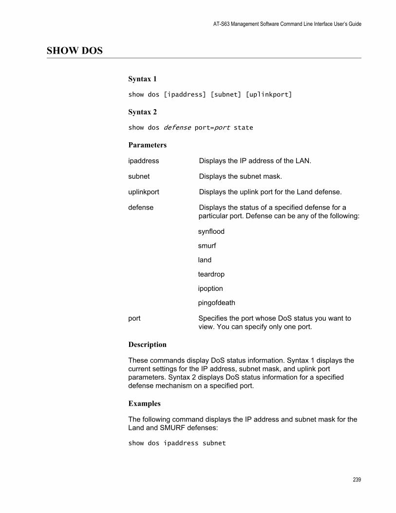
AT-S63 Management Software Command Line Interface User’s Guide
SHOW DOS
Syntax 1
show dos [ipaddress] [subnet] [uplinkport]
Syntax 2
show dos defense port=port state
Parameters
ipaddress Displays the IP address of the LAN.
subnet Displays the subnet mask.
uplinkport Displays the uplink port for the Land defense.
defense Displays the status of a specified defense for a particular port. Defense can be any of the following:
synflood
smurf
land
teardrop
ipoption
pingofdeath
port Specifies the port whose DoS status you want to view. You can specify only one port.
Description
These commands display DoS status information. Syntax 1 displays the current settings for the IP address, subnet mask, and uplink port parameters. Syntax 2 displays DoS status information for a specified defense mechanism on a specified port.
Examples
The following command displays the IP address and subnet mask for the Land and SMURF defenses:
show dos ipaddress subnet
239

Chapter 17: Denial of Service (DoS) Defense Commands
The following command displays the status of the SMURF defense on port 4:
show dos smurf port=4 state
240
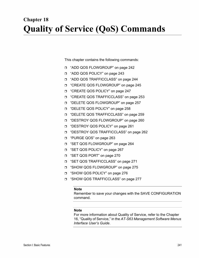
Chapter 18
Quality of Service (QoS) Commands
This chapter contains the following commands:
“ADD QOS FLOWGROUP” on page 242“ADD QOS POLICY” on page 243“ADD QOS TRAFFICCLASS” on page 244“CREATE QOS FLOWGROUP” on page 245“CREATE QOS POLICY” on page 247“CREATE QOS TRAFFICCLASS” on page 253“DELETE QOS FLOWGROUP” on page 257“DELETE QOS POLICY” on page 258“DELETE QOS TRAFFICCLASS” on page 259“DESTROY QOS FLOWGROUP” on page 260“DESTROY QOS POLICY” on page 261“DESTROY QOS TRAFFICCLASS” on page 262“PURGE QOS” on page 263“SET QOS FLOWGROUP” on page 264“SET QOS POLICY” on page 267“SET QOS PORT” on page 270“SET QOS TRAFFICCLASS” on page 271“SHOW QOS FLOWGROUP” on page 275“SHOW QOS POLICY” on page 276“SHOW QOS TRAFFICCLASS” on page 277
NoteRemember to save your changes with the SAVE CONFIGURATION command.
NoteFor more information about Quality of Service, refer to the Chapter 16, “Quality of Service,” in the AT-S63 Management Software Menus Interface User’s Guide.
Section I: Basic Features 241
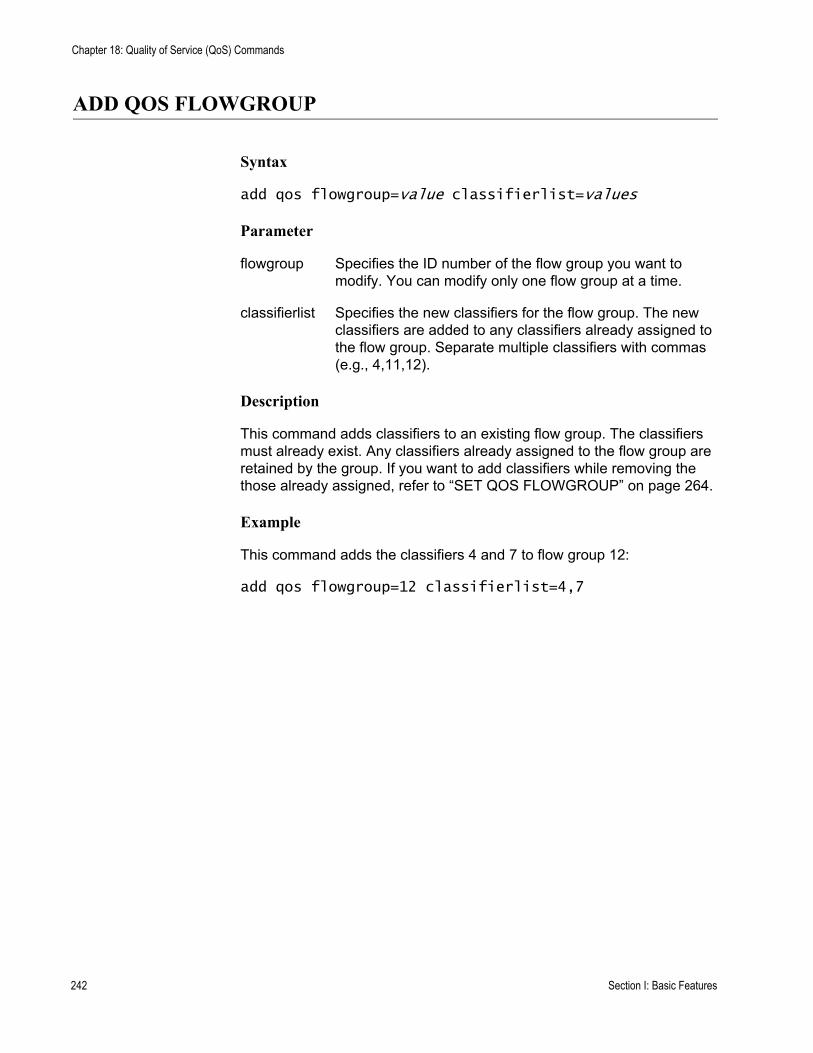
Chapter 18: Quality of Service (QoS) Commands
ADD QOS FLOWGROUP
Syntax
add qos flowgroup=value classifierlist=values
Parameter
flowgroup Specifies the ID number of the flow group you want to modify. You can modify only one flow group at a time.
classifierlist Specifies the new classifiers for the flow group. The new classifiers are added to any classifiers already assigned to the flow group. Separate multiple classifiers with commas (e.g., 4,11,12).
Description
This command adds classifiers to an existing flow group. The classifiers must already exist. Any classifiers already assigned to the flow group are retained by the group. If you want to add classifiers while removing the those already assigned, refer to “SET QOS FLOWGROUP” on page 264.
Example
This command adds the classifiers 4 and 7 to flow group 12:
add qos flowgroup=12 classifierlist=4,7
242 Section I: Basic Features
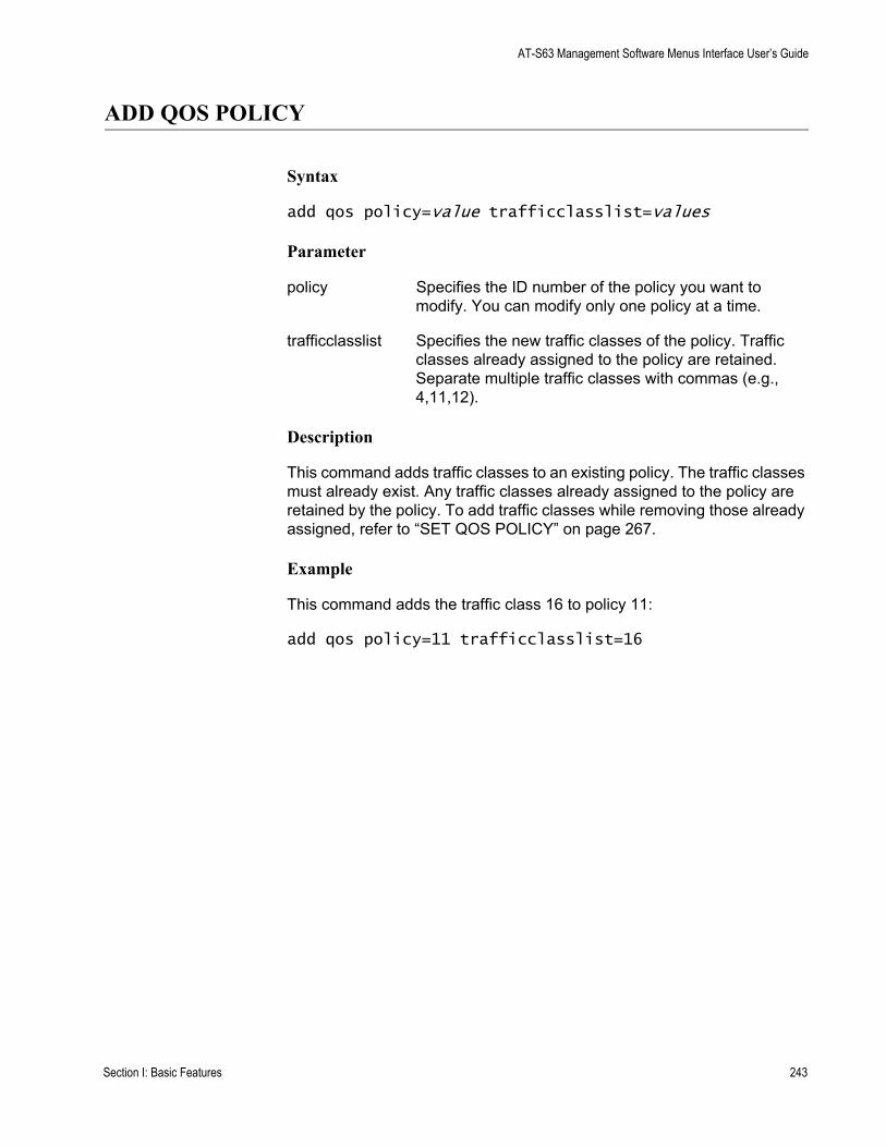
AT-S63 Management Software Menus Interface User’s Guide
ADD QOS POLICY
Syntax
add qos policy=value trafficclasslist=values
Parameter
policy Specifies the ID number of the policy you want to modify. You can modify only one policy at a time.
trafficclasslist Specifies the new traffic classes of the policy. Traffic classes already assigned to the policy are retained. Separate multiple traffic classes with commas (e.g., 4,11,12).
Description
This command adds traffic classes to an existing policy. The traffic classes must already exist. Any traffic classes already assigned to the policy are retained by the policy. To add traffic classes while removing those already assigned, refer to “SET QOS POLICY” on page 267.
Example
This command adds the traffic class 16 to policy 11:
add qos policy=11 trafficclasslist=16
Section I: Basic Features 243
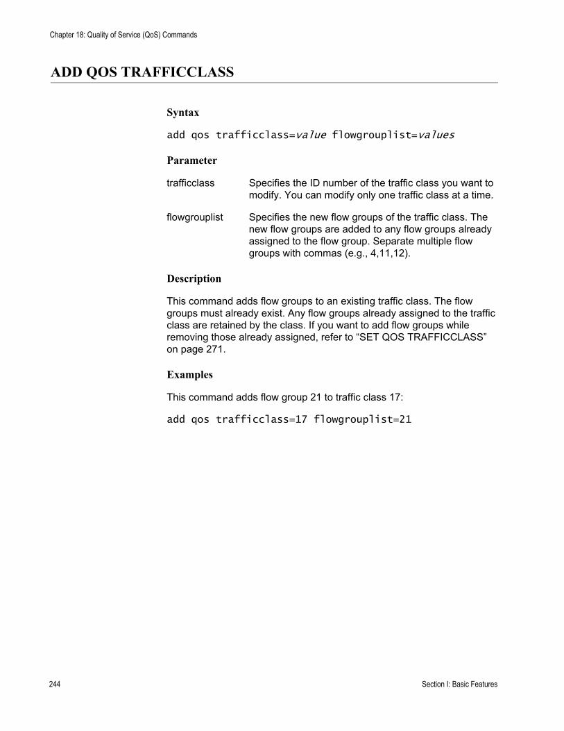
Chapter 18: Quality of Service (QoS) Commands
ADD QOS TRAFFICCLASS
Syntax
add qos trafficclass=value flowgrouplist=values
Parameter
trafficclass Specifies the ID number of the traffic class you want to modify. You can modify only one traffic class at a time.
flowgrouplist Specifies the new flow groups of the traffic class. The new flow groups are added to any flow groups already assigned to the flow group. Separate multiple flow groups with commas (e.g., 4,11,12).
Description
This command adds flow groups to an existing traffic class. The flow groups must already exist. Any flow groups already assigned to the traffic class are retained by the class. If you want to add flow groups while removing those already assigned, refer to “SET QOS TRAFFICCLASS” on page 271.
Examples
This command adds flow group 21 to traffic class 17:
add qos trafficclass=17 flowgrouplist=21
244 Section I: Basic Features
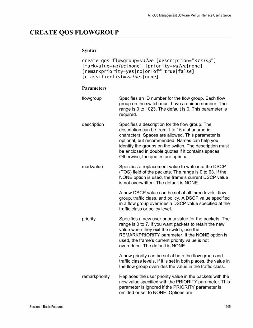
AT-S63 Management Software Menus Interface User’s Guide
CREATE QOS FLOWGROUP
Syntax
create qos flowgroup=value [description=”string”] [markvalue=value|none] [priority=value|none] [remarkpriority=yes|no|on|off|true|false] [classifierlist=values|none]
Parameters
flowgroup Specifies an ID number for the flow group. Each flow group on the switch must have a unique number. The range is 0 to 1023. The default is 0. This parameter is required.
description Specifies a description for the flow group. The description can be from 1 to 15 alphanumeric characters. Spaces are allowed. This parameter is optional, but recommended. Names can help you identify the groups on the switch. The description must be enclosed in double quotes if it contains spaces. Otherwise, the quotes are optional.
markvalue Specifies a replacement value to write into the DSCP (TOS) field of the packets. The range is 0 to 63. If the NONE option is used, the frame’s current DSCP value is not overwritten. The default is NONE.
A new DSCP value can be set at all three levels: flow group, traffic class, and policy. A DSCP value specified in a flow group overrides a DSCP value specified at the traffic class or policy level.
priority Specifies a new user priority value for the packets. The range is 0 to 7. If you want packets to retain the new value when they exit the switch, use the REMARKPRIORITY parameter. If the NONE option is used, the frame’s current priority value is not overridden. The default is NONE.
A new priority can be set at both the flow group and traffic class levels. If it is set in both places, the value in the flow group overrides the value in the traffic class.
remarkpriority Replaces the user priority value in the packets with the new value specified with the PRIORITY parameter. This parameter is ignored if the PRIORITY parameter is omitted or set to NONE. Options are:
Section I: Basic Features 245
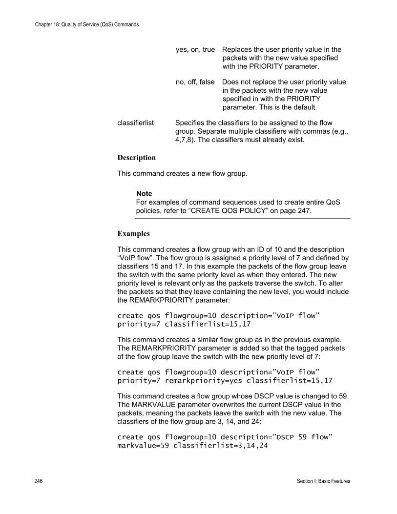
Chapter 18: Quality of Service (QoS) Commands
yes, on, true Replaces the user priority value in the packets with the new value specified with the PRIORITY parameter.
no, off, false Does not replace the user priority value in the packets with the new value specified in with the PRIORITY parameter. This is the default.
classifierlist Specifies the classifiers to be assigned to the flow group. Separate multiple classifiers with commas (e.g., 4,7,8). The classifiers must already exist.
Description
This command creates a new flow group.
NoteFor examples of command sequences used to create entire QoS policies, refer to “CREATE QOS POLICY” on page 247.
Examples
This command creates a flow group with an ID of 10 and the description “VoIP flow”. The flow group is assigned a priority level of 7 and defined by classifiers 15 and 17. In this example the packets of the flow group leave the switch with the same priority level as when they entered. The new priority level is relevant only as the packets traverse the switch. To alter the packets so that they leave containing the new level, you would include the REMARKPRIORITY parameter:
create qos flowgroup=10 description=”VoIP flow” priority=7 classifierlist=15,17
This command creates a similar flow group as in the previous example. The REMARKPRIORITY parameter is added so that the tagged packets of the flow group leave the switch with the new priority level of 7:
create qos flowgroup=10 description=”VoIP flow” priority=7 remarkpriority=yes classifierlist=15,17
This command creates a flow group whose DSCP value is changed to 59. The MARKVALUE parameter overwrites the current DSCP value in the packets, meaning the packets leave the switch with the new value. The classifiers of the flow group are 3, 14, and 24:
create qos flowgroup=10 description=”DSCP 59 flow” markvalue=59 classifierlist=3,14,24
246 Section I: Basic Features
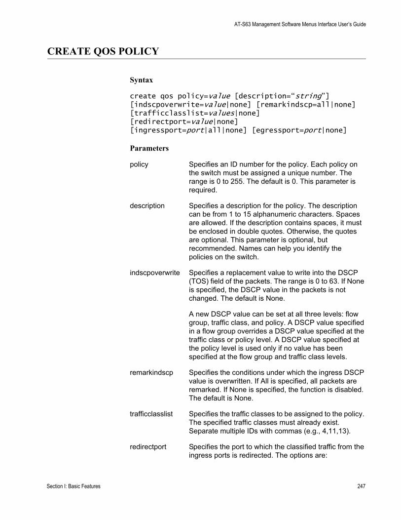
AT-S63 Management Software Menus Interface User’s Guide
CREATE QOS POLICY
Syntax
create qos policy=value [description=“string”] [indscpoverwrite=value|none] [remarkindscp=all|none] [trafficclasslist=values|none][redirectport=value|none][ingressport=port|all|none] [egressport=port|none]
Parameters
policy Specifies an ID number for the policy. Each policy on the switch must be assigned a unique number. The range is 0 to 255. The default is 0. This parameter is required.
description Specifies a description for the policy. The description can be from 1 to 15 alphanumeric characters. Spaces are allowed. If the description contains spaces, it must be enclosed in double quotes. Otherwise, the quotes are optional. This parameter is optional, but recommended. Names can help you identify the policies on the switch.
indscpoverwrite Specifies a replacement value to write into the DSCP (TOS) field of the packets. The range is 0 to 63. If None is specified, the DSCP value in the packets is not changed. The default is None.
A new DSCP value can be set at all three levels: flow group, traffic class, and policy. A DSCP value specified in a flow group overrides a DSCP value specified at the traffic class or policy level. A DSCP value specified at the policy level is used only if no value has been specified at the flow group and traffic class levels.
remarkindscp Specifies the conditions under which the ingress DSCP value is overwritten. If All is specified, all packets are remarked. If None is specified, the function is disabled. The default is None.
trafficclasslist Specifies the traffic classes to be assigned to the policy. The specified traffic classes must already exist. Separate multiple IDs with commas (e.g., 4,11,13).
redirectport Specifies the port to which the classified traffic from the ingress ports is redirected. The options are:
Section I: Basic Features 247
Chapter 18: Quality of Service (QoS) Commands
value Specifies a port number.
none No redirect port specified.
ingressport Specifies the ingress ports to which the policy is to be assigned. Ports can be identified individually (e.g., 5,7,22), as a range (e.g., 18-23), or both (e.g., 1,5,14-22).
A port can be an ingress port of only one policy at a time. If a port is already an ingress port of a policy, you must remove the port from its current policy assignment before adding it to another policy.
egressport Specifies the egress port to which the policy is to be assigned. You can enter only one egress port. The egress port must be within the same port block as the ingress ports. On switches with 24 ports (plus uplinks), ports 1-26 form a port block. On switches with 48 ports (plus uplinks), ports 1-24 and 49 form one port block and ports 25-48 and 50 form a second port block.
A port can be an egress port of only one policy at a time. If a port is already an egress port of a policy, you must remove the port from its current policy assignment before adding it to another policy.
Description
This command creates a new QoS policy.
Examples
This command creates a policy with an ID of 75 and the description “DB flow.” The policy is appointed the traffic classes 12 and 25 and is assigned to ingress port 5:
create qos policy=75 description=”DB flow” trafficclasslist=12,25 ingressport=5
This command creates a policy with an ID of 23 and the description “Video.” The ID of the traffic class for the policy is 19. The DSCP value is replaced with the value 50 for all ingress packets of the traffic class. The policy is assigned to port 14:
create qos policy=23 description=video indscpoverwrite=50 remarkindscp=all trafficclasslist=19 ingressport=14
248 Section I: Basic Features
AT-S63 Management Software Menus Interface User’s Guide
QoS Command Sequence Examples
Creating a QoS policy involves a command sequence that creates one or more classifiers, a flow group, a traffic class, and finally the policy. The following sections contain examples of the command sequences for different types of policies.
Example 1: Voice Application
Voice applications typically require a small bandwidth but it must be consistent. They are sensitive to latency (interpacket delay) and jitter (delivery delay). Voice applications can be set up to have the highest priority.
This example creates two policies that ensure low latency for all traffic sent by and destined to a voice application located on a node with the IP address 149.44.44.44. The policies raise the priority level of the packets to 7, the highest level. Policy 6 is for traffic from the application that enter the switch on port 1. Policy 11 is for traffic arriving on port 8 going to the application.
Policy 6 Commands:
create classifier=22 description=”VoIP flow” ipsadddr=149.44.44.44
create qos flowgroup=14 description=”VoIP flow” priority=7 classifierlist=22
create qos trafficclass=18 description=”VoIP flow” flowgrouplist=14
create qos policy=6 description=”VoIP flow” trafficclasslist=18 ingressport=1
Policy 11 Commands:
create classifier=23 description=”VoIP flow” ipdadddr=149.44.44.44
create qos flowgroup=17 description=”VoIP flow” priority=7 classifierlist=23
create qos trafficclass=15 description=”VoIP flow” flowgrouplist=17
create qos policy=11 description=”VoIP flow” trafficclasslist=15 ingressport=8
The parts of the policies are:
Section I: Basic Features 249
Chapter 18: Quality of Service (QoS) Commands
Classifiers - Define the traffic flow by specifying the IP address of the node with the voice application. The classifier for Policy 6 specifies the address as a source address since this classifier is part of a policy concerning packets coming from the application. The classifier for Policy 11 specifies the address as a destination address since this classifier is part of a policy concerning packets going to the application.Flow Groups - Specify the new priority level of 7 for the packets. It should be noted that in this example the packets leave the switch with the same priority level they had when they entered. The new priority level is relevant only as the packets traverse the switch. To alter the packets so that they leave containing the new level, you would use the REMARKPRIORITY option in the CREATE QOS FLOWGROUP command. Traffic Classes - No action is taken by the traffic classes, other than to specify the flow groups. Traffic class has a priority setting that can be used to override the priority level of packets, just as in a flow group. If you enter a priority value both in the flow group and the traffic class, the value in the flow group overrides the value in the traffic class.Policies - Specify the traffic class and the port to which the policy is to be assigned. Policy 6 is applied to port 1 since this is where the application is located. Policy 11 is applied to port 8 since this is where traffic going to the application will be received on the switch.
Example 2: Video Application
Video applications typically require a larger bandwidth than voice applications. Video applications can be set up to have a high priority and buffering, depending on the application.
This example creates policies with low latency and jitter for video streams (for example, net conference calls). The policies assign the packets a priority level of 4 and limit the bandwidth to 5 Mbps. The node containing the application has the IP address 149.44.44.44. Policy 17 is assigned to port 1, where the application is located, and Policy 32 is assigned to port 8 where packets destined to the application enter the switch.
Policy 17 Commands:
create classifier=16 description=”video flow” ipsadddr=149.44.44.44
create qos flowgroup=41 description=”video flow” priority=4 classifierlist=16
create qos trafficclass=19 description=”video flow” maxbandwidth=5 flowgrouplist=41
create qos policy=17 description=”video flow” trafficclasslist=19 ingressport=1
250 Section I: Basic Features
AT-S63 Management Software Menus Interface User’s Guide
Policy 32 Commands:
create classifier=42 description=”video flow” ipdadddr=149.44.44.44
create qos flowgroup=36 description=”video flow” priority=4 classifierlist=42
create qos trafficclass=21 description=”video flow” maxbandwidth=5 flowgrouplist=36
create qos policy=32 description=”video flow” trafficclasslist=21 ingressport=8
The parts of the policies are:
Classifiers - Specify the IP address of the node with a video application. The classifier for Policy 17 specifies the address as a source address since this classifier is part of a policy concerning packets sent by the application. The classifier for Policy 32 specifies the address as a destination address since this classifier is part of a policy concerning packets going to the application.Flow Groups - Specify the new priority level of 4 for the packets. As with the previous example, the packets leave the switch with the same priority level they had when they entered. The new priority level is relevant only while the packets traverse the switch. To alter the packets so that they leave containing the new level, you would change option 5, Remark Priority, to Yes. Traffic Classes - Specify a maximum bandwidth of 5 Mbps for the packet stream. Bandwidth assignment can only be made at the traffic class level.Policies - Specify the traffic class and the port where the policy is to be assigned.
Example 3: Critical Database
Critical databases typically require a high bandwidth. They also typically require less priority than either voice or video.
The policies in this example assign 50 Mbps bandwidth, with no change to priority, to traffic going to and from a database. The database is located on a node with the IP address 149.44.44.44 on port 1 of the switch.
Policy 15 Commands:
create classifier=42 description=database ipsadddr=149.44.44.44
create qos flowgroup=36 description=database classifierlist=42
Section I: Basic Features 251
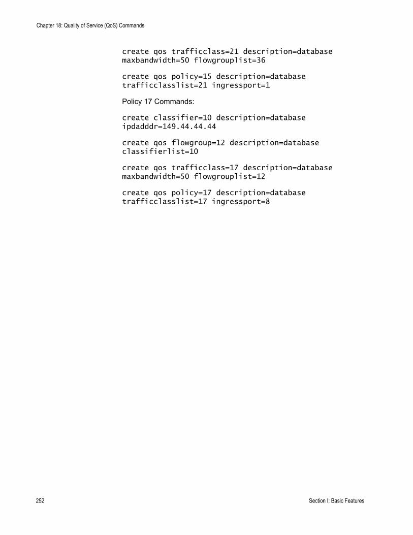
Chapter 18: Quality of Service (QoS) Commands
create qos trafficclass=21 description=database maxbandwidth=50 flowgrouplist=36
create qos policy=15 description=database trafficclasslist=21 ingressport=1
Policy 17 Commands:
create classifier=10 description=database ipdadddr=149.44.44.44
create qos flowgroup=12 description=database classifierlist=10
create qos trafficclass=17 description=database maxbandwidth=50 flowgrouplist=12
create qos policy=17 description=database trafficclasslist=17 ingressport=8
252 Section I: Basic Features
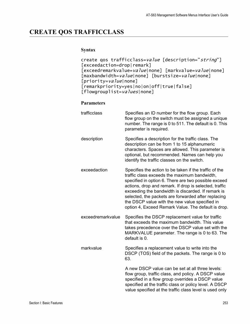
AT-S63 Management Software Menus Interface User’s Guide
CREATE QOS TRAFFICCLASS
Syntax
create qos trafficclass=value [description=”string”] [exceedaction=drop|remark] [exceedremarkvalue=value|none] [markvalue=value|none] [maxbandwidth=value|none] [burstsize=value|none] [priority=value|none] [remarkpriority=yes|no|on|off|true|false] [flowgrouplist=values|none]
Parameters
trafficclass Specifies an ID number for the flow group. Each flow group on the switch must be assigned a unique number. The range is 0 to 511. The default is 0. This parameter is required.
description Specifies a description for the traffic class. The description can be from 1 to 15 alphanumeric characters. Spaces are allowed. This parameter is optional, but recommended. Names can help you identify the traffic classes on the switch.
exceedaction Specifies the action to be taken if the traffic of the traffic class exceeds the maximum bandwidth, specified in option 6. There are two possible exceed actions, drop and remark. If drop is selected, traffic exceeding the bandwidth is discarded. If remark is selected, the packets are forwarded after replacing the DSCP value with the new value specified in option 4, Exceed Remark Value. The default is drop.
exceedremarkvalue Specifies the DSCP replacement value for traffic that exceeds the maximum bandwidth. This value takes precedence over the DSCP value set with the MARKVALUE parameter. The range is 0 to 63. The default is 0.
markvalue Specifies a replacement value to write into the DSCP (TOS) field of the packets. The range is 0 to 63.
A new DSCP value can be set at all three levels: flow group, traffic class, and policy. A DSCP value specified in a flow group overrides a DSCP value specified at the traffic class or policy level. A DSCP value specified at the traffic class level is used only
Section I: Basic Features 253
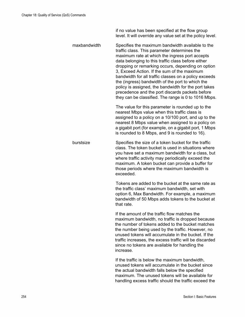
Chapter 18: Quality of Service (QoS) Commands
if no value has been specified at the flow group level. It will override any value set at the policy level.
maxbandwidth Specifies the maximum bandwidth available to the traffic class. This parameter determines the maximum rate at which the ingress port accepts data belonging to this traffic class before either dropping or remarking occurs, depending on option 3, Exceed Action. If the sum of the maximum bandwidth for all traffic classes on a policy exceeds the (ingress) bandwidth of the port to which the policy is assigned, the bandwidth for the port takes precedence and the port discards packets before they can be classified. The range is 0 to 1016 Mbps.
The value for this parameter is rounded up to the nearest Mbps value when this traffic class is assigned to a policy on a 10/100 port, and up to the nearest 8 Mbps value when assigned to a policy on a gigabit port (for example, on a gigabit port, 1 Mbps is rounded to 8 Mbps, and 9 is rounded to 16).
burstsize Specifies the size of a token bucket for the traffic class. The token bucket is used in situations where you have set a maximum bandwidth for a class, but where traffic activity may periodically exceed the maximum. A token bucket can provide a buffer for those periods where the maximum bandwidth is exceeded.
Tokens are added to the bucket at the same rate as the traffic class’ maximum bandwidth, set with option 6, Max Bandwidth. For example, a maximum bandwidth of 50 Mbps adds tokens to the bucket at that rate.
If the amount of the traffic flow matches the maximum bandwidth, no traffic is dropped because the number of tokens added to the bucket matches the number being used by the traffic. However, no unused tokens will accumulate in the bucket. If the traffic increases, the excess traffic will be discarded since no tokens are available for handling the increase.
If the traffic is below the maximum bandwidth, unused tokens will accumulate in the bucket since the actual bandwidth falls below the specified maximum. The unused tokens will be available for handling excess traffic should the traffic exceed the
254 Section I: Basic Features
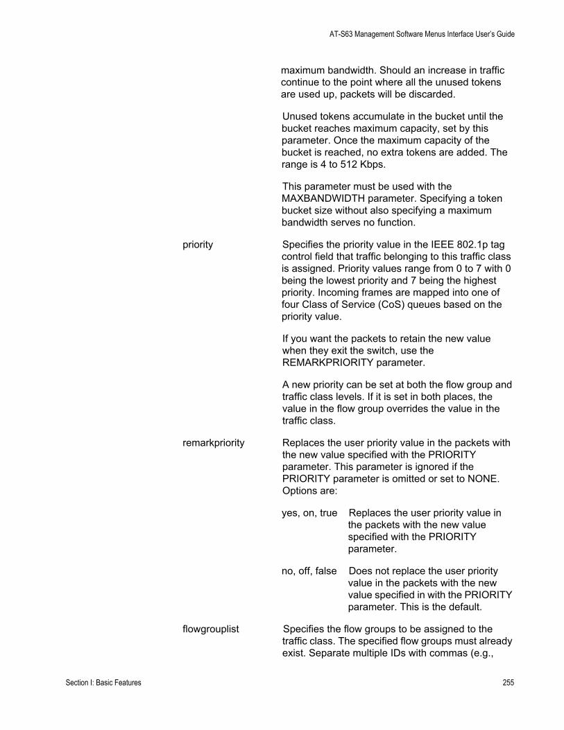
AT-S63 Management Software Menus Interface User’s Guide
maximum bandwidth. Should an increase in traffic continue to the point where all the unused tokens are used up, packets will be discarded.
Unused tokens accumulate in the bucket until the bucket reaches maximum capacity, set by this parameter. Once the maximum capacity of the bucket is reached, no extra tokens are added. The range is 4 to 512 Kbps.
This parameter must be used with the MAXBANDWIDTH parameter. Specifying a token bucket size without also specifying a maximum bandwidth serves no function.
priority Specifies the priority value in the IEEE 802.1p tag control field that traffic belonging to this traffic class is assigned. Priority values range from 0 to 7 with 0 being the lowest priority and 7 being the highest priority. Incoming frames are mapped into one of four Class of Service (CoS) queues based on the priority value.
If you want the packets to retain the new value when they exit the switch, use the REMARKPRIORITY parameter.
A new priority can be set at both the flow group and traffic class levels. If it is set in both places, the value in the flow group overrides the value in the traffic class.
remarkpriority Replaces the user priority value in the packets with the new value specified with the PRIORITY parameter. This parameter is ignored if the PRIORITY parameter is omitted or set to NONE. Options are:
yes, on, true Replaces the user priority value in the packets with the new value specified with the PRIORITY parameter.
no, off, false Does not replace the user priority value in the packets with the new value specified in with the PRIORITY parameter. This is the default.
flowgrouplist Specifies the flow groups to be assigned to the traffic class. The specified flow groups must already exist. Separate multiple IDs with commas (e.g.,
Section I: Basic Features 255
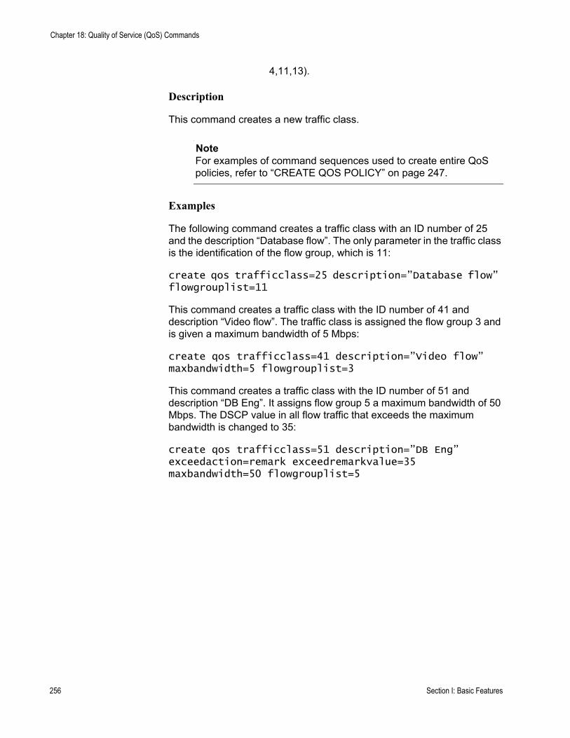
Chapter 18: Quality of Service (QoS) Commands
4,11,13).
Description
This command creates a new traffic class.
NoteFor examples of command sequences used to create entire QoS policies, refer to “CREATE QOS POLICY” on page 247.
Examples
The following command creates a traffic class with an ID number of 25 and the description “Database flow”. The only parameter in the traffic class is the identification of the flow group, which is 11:
create qos trafficclass=25 description=”Database flow” flowgrouplist=11
This command creates a traffic class with the ID number of 41 and description “Video flow”. The traffic class is assigned the flow group 3 and is given a maximum bandwidth of 5 Mbps:
create qos trafficclass=41 description=”Video flow” maxbandwidth=5 flowgrouplist=3
This command creates a traffic class with the ID number of 51 and description “DB Eng”. It assigns flow group 5 a maximum bandwidth of 50 Mbps. The DSCP value in all flow traffic that exceeds the maximum bandwidth is changed to 35:
create qos trafficclass=51 description=”DB Eng” exceedaction=remark exceedremarkvalue=35 maxbandwidth=50 flowgrouplist=5
256 Section I: Basic Features
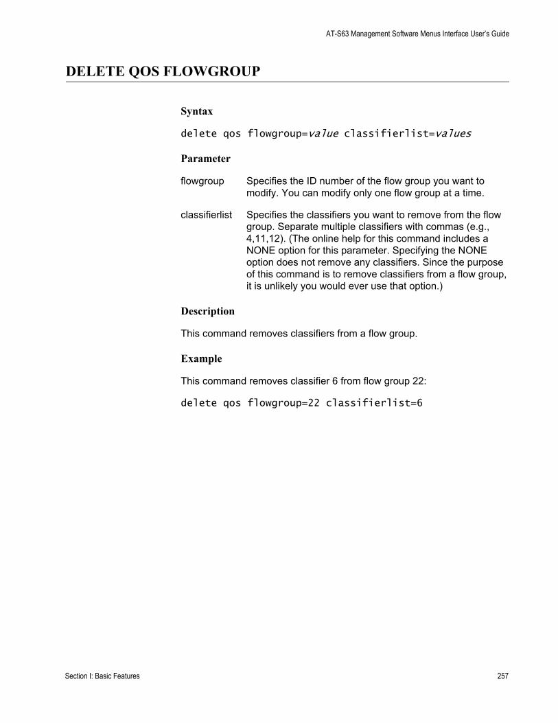
AT-S63 Management Software Menus Interface User’s Guide
DELETE QOS FLOWGROUP
Syntax
delete qos flowgroup=value classifierlist=values
Parameter
flowgroup Specifies the ID number of the flow group you want to modify. You can modify only one flow group at a time.
classifierlist Specifies the classifiers you want to remove from the flow group. Separate multiple classifiers with commas (e.g., 4,11,12). (The online help for this command includes a NONE option for this parameter. Specifying the NONE option does not remove any classifiers. Since the purpose of this command is to remove classifiers from a flow group, it is unlikely you would ever use that option.)
Description
This command removes classifiers from a flow group.
Example
This command removes classifier 6 from flow group 22:
delete qos flowgroup=22 classifierlist=6
Section I: Basic Features 257
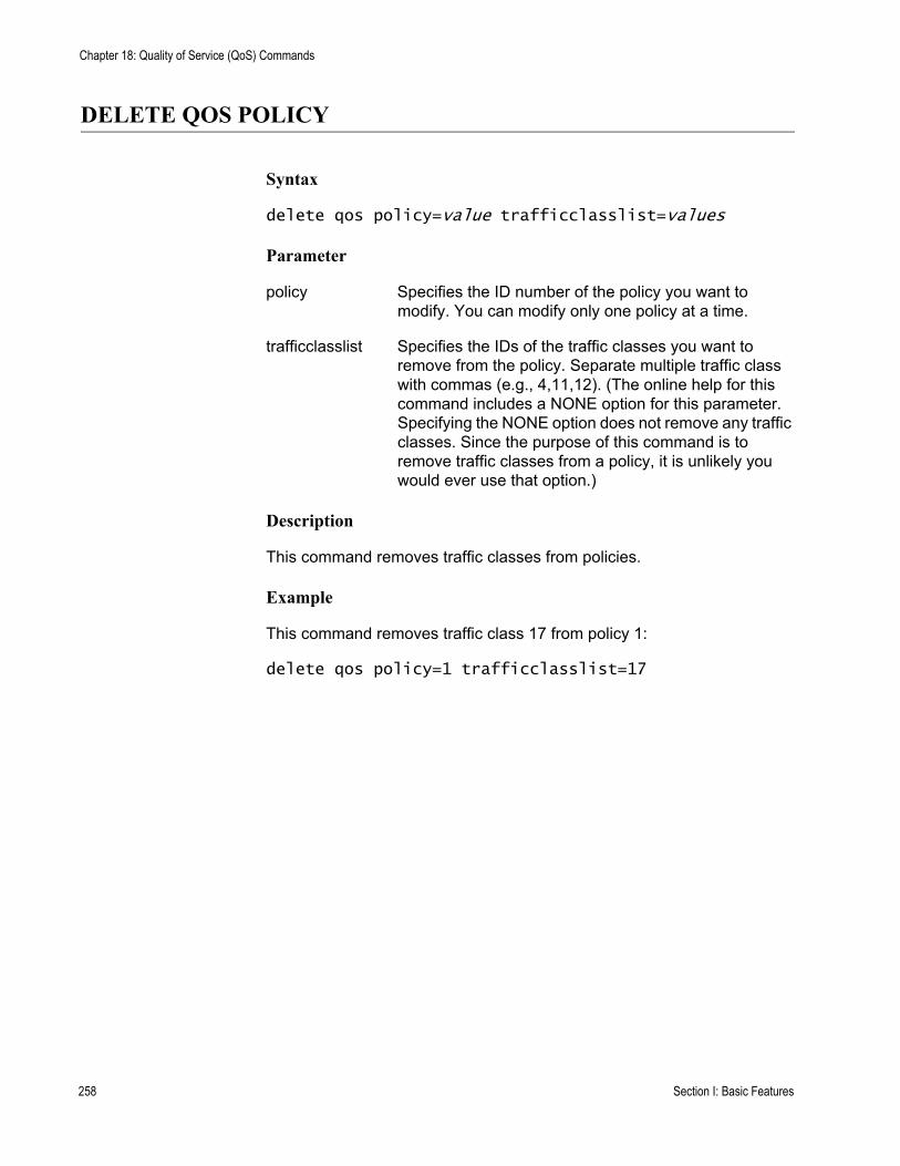
Chapter 18: Quality of Service (QoS) Commands
DELETE QOS POLICY
Syntax
delete qos policy=value trafficclasslist=values
Parameter
policy Specifies the ID number of the policy you want to modify. You can modify only one policy at a time.
trafficclasslist Specifies the IDs of the traffic classes you want to remove from the policy. Separate multiple traffic class with commas (e.g., 4,11,12). (The online help for this command includes a NONE option for this parameter. Specifying the NONE option does not remove any traffic classes. Since the purpose of this command is to remove traffic classes from a policy, it is unlikely you would ever use that option.)
Description
This command removes traffic classes from policies.
Example
This command removes traffic class 17 from policy 1:
delete qos policy=1 trafficclasslist=17
258 Section I: Basic Features
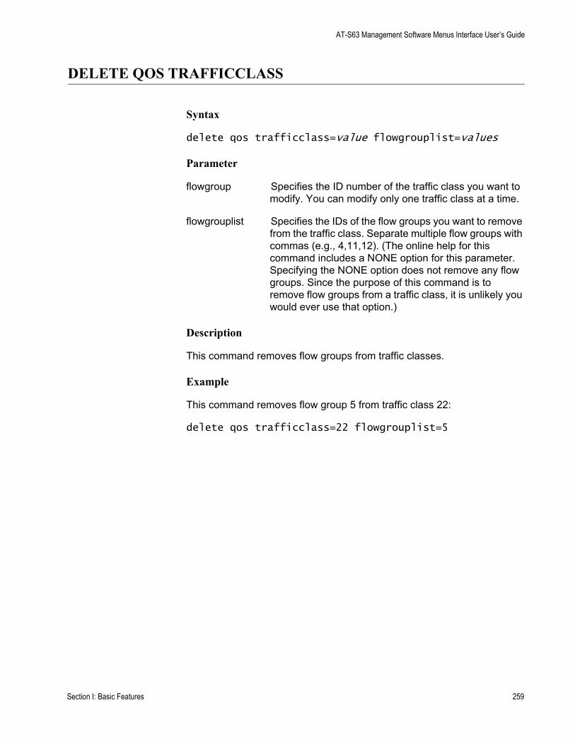
AT-S63 Management Software Menus Interface User’s Guide
DELETE QOS TRAFFICCLASS
Syntax
delete qos trafficclass=value flowgrouplist=values
Parameter
flowgroup Specifies the ID number of the traffic class you want to modify. You can modify only one traffic class at a time.
flowgrouplist Specifies the IDs of the flow groups you want to remove from the traffic class. Separate multiple flow groups with commas (e.g., 4,11,12). (The online help for this command includes a NONE option for this parameter. Specifying the NONE option does not remove any flow groups. Since the purpose of this command is to remove flow groups from a traffic class, it is unlikely you would ever use that option.)
Description
This command removes flow groups from traffic classes.
Example
This command removes flow group 5 from traffic class 22:
delete qos trafficclass=22 flowgrouplist=5
Section I: Basic Features 259
Chapter 18: Quality of Service (QoS) Commands
DESTROY QOS FLOWGROUP
Syntax
destroy qos flowgroup=value
Parameter
flowgroup Specifies the ID number of the flow group you want to delete. You can delete more than one flow group at a time. You can specify the flow groups individually, as a range, or both.
Description
This command deletes flow groups.
Examples
This command deletes the flow group 22:
destroy qos flowgroup=22
This command deletes the flow groups 16 to 20 and 23:
destroy qos flowgroup=16-20,23
260 Section I: Basic Features
AT-S63 Management Software Menus Interface User’s Guide
DESTROY QOS POLICY
Syntax
destroy qos policy=value
Parameter
flowgroup Specifies the ID number of the policy you want to delete. You can delete more than one policy at a time. You can specify the flow groups individually, as a range, or both.
Description
This command deletes QoS policies.
Examples
This command deletes policy 41:
destroy qos policy=41
This command deletes policies 5 and 23:
destroy qos policy=5,23
Section I: Basic Features 261
Chapter 18: Quality of Service (QoS) Commands
DESTROY QOS TRAFFICCLASS
Syntax
destroy qos trafficclass=value
Parameter
trafficclass Specifies the ID number of the traffic class you want to delete. You can delete more than one traffic class at a time. You can specify the flow groups individually, as a range, or both.
Description
This command deletes traffic classes.
Examples
This command deletes traffic class 22:
destroy qos trafficclass=22
This command deletes traffic classes 16 to 20 and 23:
destroy qos trafficclass=16-20,23
262 Section I: Basic Features
AT-S63 Management Software Menus Interface User’s Guide
PURGE QOS
Syntax
purge qos
Parameters
None
Description
This command destroys all policies, traffic classes, and flow groups; resets the CoS priorities to port egress queues to the default values; and sets the scheduling mode and egress weight queues to their default values.
Example
The following command resets QoS to the default values:
purge qos
Section I: Basic Features 263
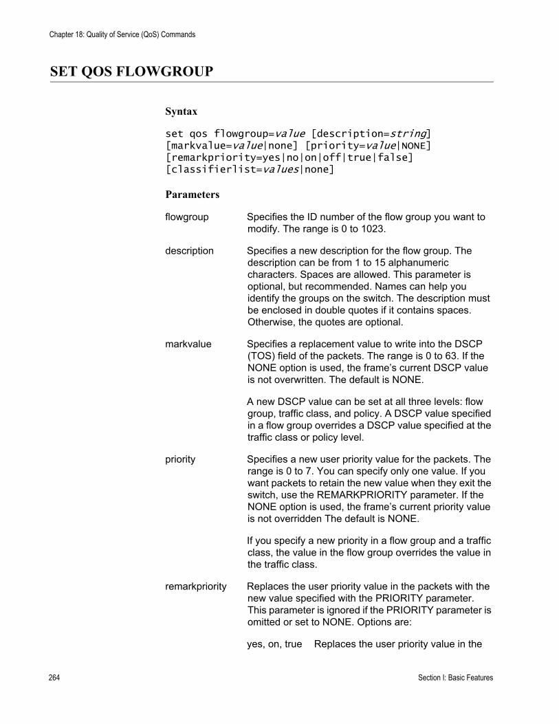
Chapter 18: Quality of Service (QoS) Commands
SET QOS FLOWGROUP
Syntax
set qos flowgroup=value [description=string] [markvalue=value|none] [priority=value|NONE] [remarkpriority=yes|no|on|off|true|false] [classifierlist=values|none]
Parameters
flowgroup Specifies the ID number of the flow group you want to modify. The range is 0 to 1023.
description Specifies a new description for the flow group. The description can be from 1 to 15 alphanumeric characters. Spaces are allowed. This parameter is optional, but recommended. Names can help you identify the groups on the switch. The description must be enclosed in double quotes if it contains spaces. Otherwise, the quotes are optional.
markvalue Specifies a replacement value to write into the DSCP (TOS) field of the packets. The range is 0 to 63. If the NONE option is used, the frame’s current DSCP value is not overwritten. The default is NONE.
A new DSCP value can be set at all three levels: flow group, traffic class, and policy. A DSCP value specified in a flow group overrides a DSCP value specified at the traffic class or policy level.
priority Specifies a new user priority value for the packets. The range is 0 to 7. You can specify only one value. If you want packets to retain the new value when they exit the switch, use the REMARKPRIORITY parameter. If the NONE option is used, the frame’s current priority value is not overridden The default is NONE.
If you specify a new priority in a flow group and a traffic class, the value in the flow group overrides the value in the traffic class.
remarkpriority Replaces the user priority value in the packets with the new value specified with the PRIORITY parameter. This parameter is ignored if the PRIORITY parameter is omitted or set to NONE. Options are:
yes, on, true Replaces the user priority value in the
264 Section I: Basic Features
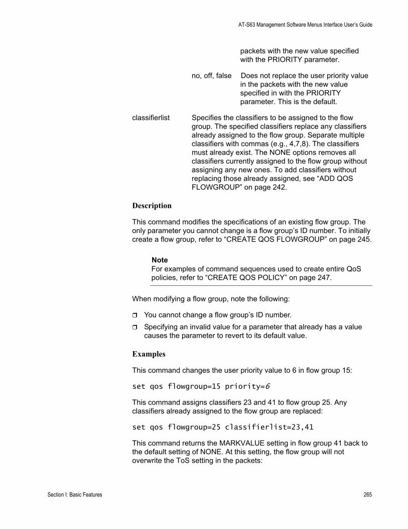
AT-S63 Management Software Menus Interface User’s Guide
packets with the new value specified with the PRIORITY parameter.
no, off, false Does not replace the user priority value in the packets with the new value specified in with the PRIORITY parameter. This is the default.
classifierlist Specifies the classifiers to be assigned to the flow group. The specified classifiers replace any classifiers already assigned to the flow group. Separate multiple classifiers with commas (e.g., 4,7,8). The classifiers must already exist. The NONE options removes all classifiers currently assigned to the flow group without assigning any new ones. To add classifiers without replacing those already assigned, see “ADD QOS FLOWGROUP” on page 242.
Description
This command modifies the specifications of an existing flow group. The only parameter you cannot change is a flow group’s ID number. To initially create a flow group, refer to “CREATE QOS FLOWGROUP” on page 245.
NoteFor examples of command sequences used to create entire QoS policies, refer to “CREATE QOS POLICY” on page 247.
When modifying a flow group, note the following:
You cannot change a flow group’s ID number.Specifying an invalid value for a parameter that already has a value causes the parameter to revert to its default value.
Examples
This command changes the user priority value to 6 in flow group 15:
set qos flowgroup=15 priority=6
This command assigns classifiers 23 and 41 to flow group 25. Any classifiers already assigned to the flow group are replaced:
set qos flowgroup=25 classifierlist=23,41
This command returns the MARKVALUE setting in flow group 41 back to the default setting of NONE. At this setting, the flow group will not overwrite the ToS setting in the packets:
Section I: Basic Features 265

Chapter 18: Quality of Service (QoS) Commands
set qos flowgroup=41 markvalue=none
266 Section I: Basic Features
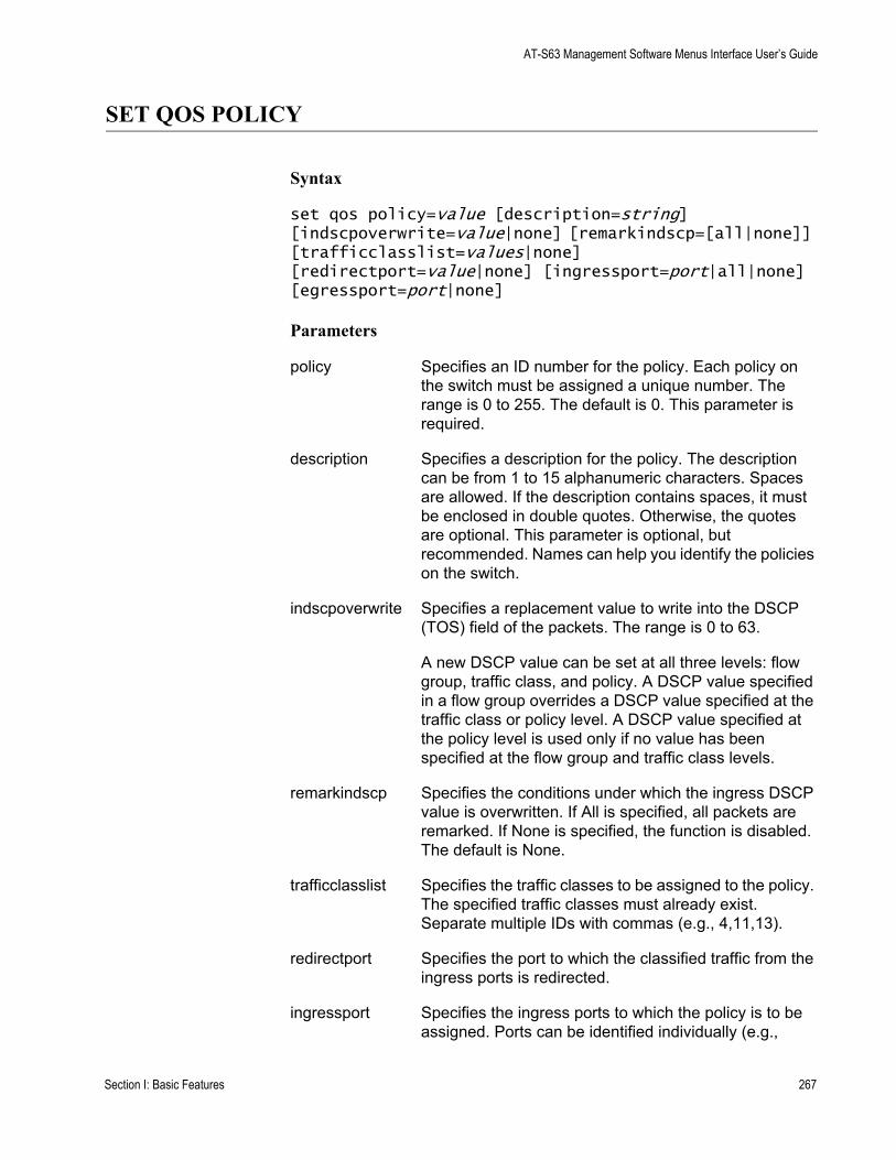
AT-S63 Management Software Menus Interface User’s Guide
SET QOS POLICY
Syntax
set qos policy=value [description=string] [indscpoverwrite=value|none] [remarkindscp=[all|none]] [trafficclasslist=values|none] [redirectport=value|none] [ingressport=port|all|none] [egressport=port|none]
Parameters
policy Specifies an ID number for the policy. Each policy on the switch must be assigned a unique number. The range is 0 to 255. The default is 0. This parameter is required.
description Specifies a description for the policy. The description can be from 1 to 15 alphanumeric characters. Spaces are allowed. If the description contains spaces, it must be enclosed in double quotes. Otherwise, the quotes are optional. This parameter is optional, but recommended. Names can help you identify the policies on the switch.
indscpoverwrite Specifies a replacement value to write into the DSCP (TOS) field of the packets. The range is 0 to 63.
A new DSCP value can be set at all three levels: flow group, traffic class, and policy. A DSCP value specified in a flow group overrides a DSCP value specified at the traffic class or policy level. A DSCP value specified at the policy level is used only if no value has been specified at the flow group and traffic class levels.
remarkindscp Specifies the conditions under which the ingress DSCP value is overwritten. If All is specified, all packets are remarked. If None is specified, the function is disabled. The default is None.
trafficclasslist Specifies the traffic classes to be assigned to the policy. The specified traffic classes must already exist. Separate multiple IDs with commas (e.g., 4,11,13).
redirectport Specifies the port to which the classified traffic from the ingress ports is redirected.
ingressport Specifies the ingress ports to which the policy is to be assigned. Ports can be identified individually (e.g.,
Section I: Basic Features 267
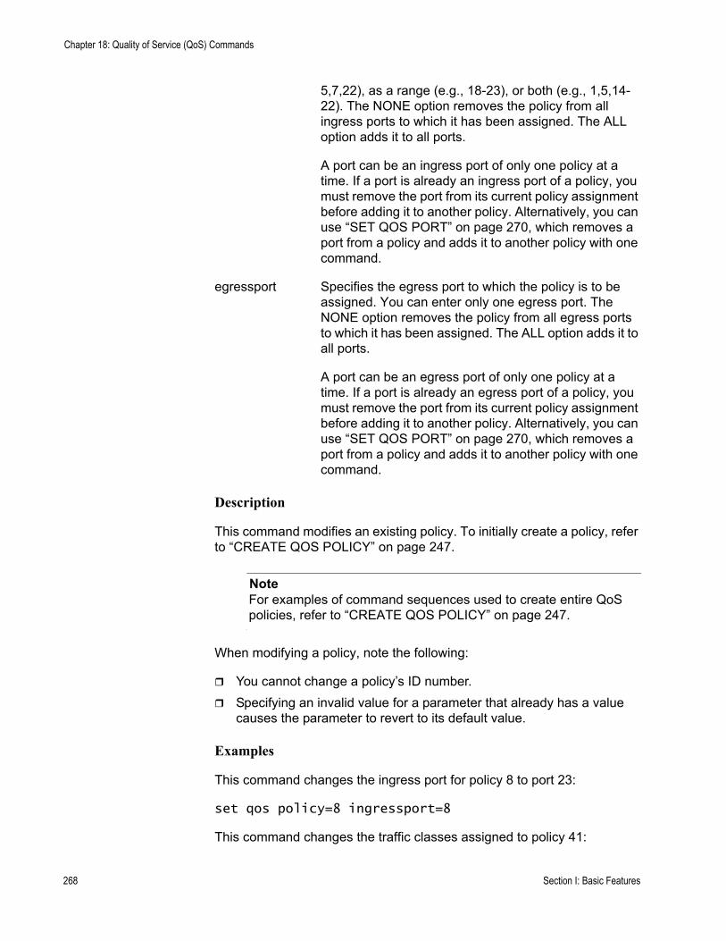
Chapter 18: Quality of Service (QoS) Commands
5,7,22), as a range (e.g., 18-23), or both (e.g., 1,5,14-22). The NONE option removes the policy from all ingress ports to which it has been assigned. The ALL option adds it to all ports.
A port can be an ingress port of only one policy at a time. If a port is already an ingress port of a policy, you must remove the port from its current policy assignment before adding it to another policy. Alternatively, you can use “SET QOS PORT” on page 270, which removes a port from a policy and adds it to another policy with one command.
egressport Specifies the egress port to which the policy is to be assigned. You can enter only one egress port. The NONE option removes the policy from all egress ports to which it has been assigned. The ALL option adds it to all ports.
A port can be an egress port of only one policy at a time. If a port is already an egress port of a policy, you must remove the port from its current policy assignment before adding it to another policy. Alternatively, you can use “SET QOS PORT” on page 270, which removes a port from a policy and adds it to another policy with one command.
Description
This command modifies an existing policy. To initially create a policy, refer to “CREATE QOS POLICY” on page 247.
NoteFor examples of command sequences used to create entire QoS policies, refer to “CREATE QOS POLICY” on page 247.
When modifying a policy, note the following:
You cannot change a policy’s ID number.Specifying an invalid value for a parameter that already has a value causes the parameter to revert to its default value.
Examples
This command changes the ingress port for policy 8 to port 23:
set qos policy=8 ingressport=8
This command changes the traffic classes assigned to policy 41:
268 Section I: Basic Features

AT-S63 Management Software Menus Interface User’s Guide
set qos policy=41 trafficclasslist=12,23
Section I: Basic Features 269
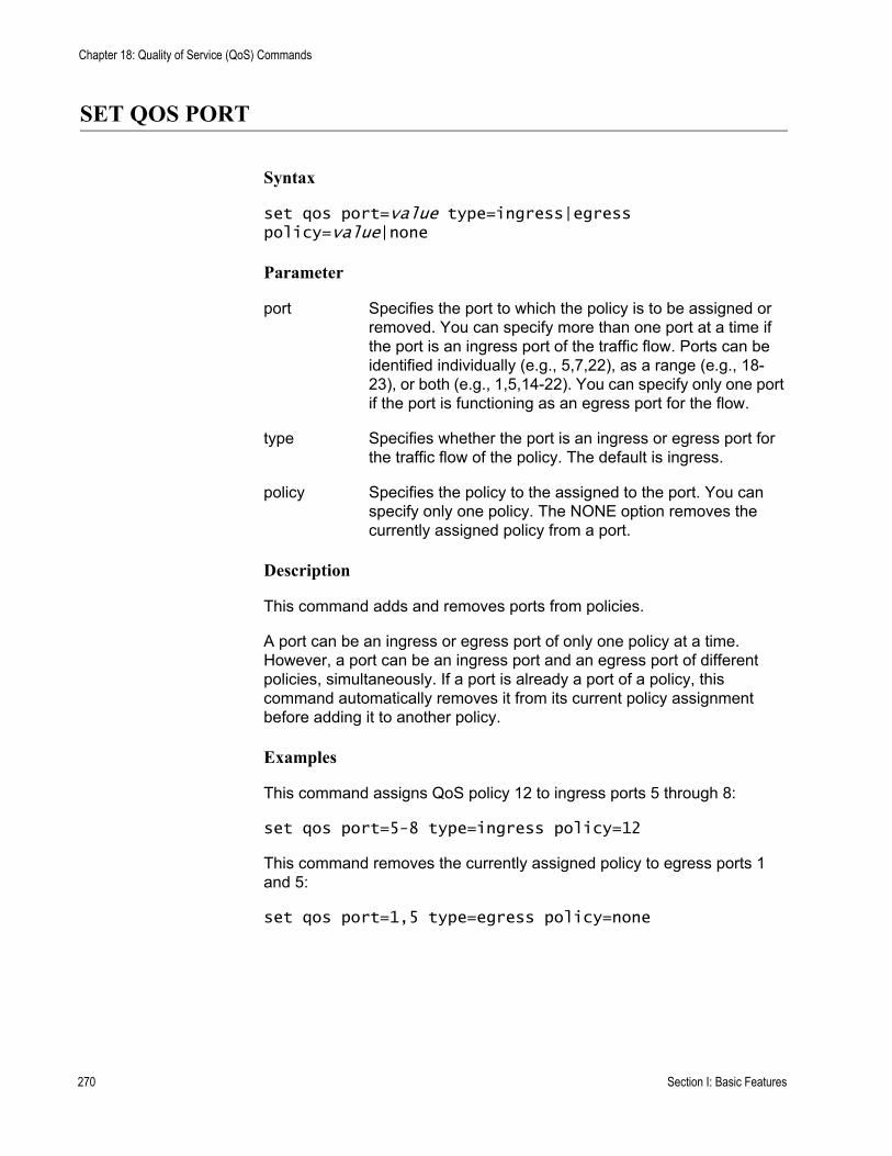
Chapter 18: Quality of Service (QoS) Commands
SET QOS PORT
Syntax
set qos port=value type=ingress|egress policy=value|none
Parameter
port Specifies the port to which the policy is to be assigned or removed. You can specify more than one port at a time if the port is an ingress port of the traffic flow. Ports can be identified individually (e.g., 5,7,22), as a range (e.g., 18-23), or both (e.g., 1,5,14-22). You can specify only one port if the port is functioning as an egress port for the flow.
type Specifies whether the port is an ingress or egress port for the traffic flow of the policy. The default is ingress.
policy Specifies the policy to the assigned to the port. You can specify only one policy. The NONE option removes the currently assigned policy from a port.
Description
This command adds and removes ports from policies.
A port can be an ingress or egress port of only one policy at a time. However, a port can be an ingress port and an egress port of different policies, simultaneously. If a port is already a port of a policy, this command automatically removes it from its current policy assignment before adding it to another policy.
Examples
This command assigns QoS policy 12 to ingress ports 5 through 8:
set qos port=5-8 type=ingress policy=12
This command removes the currently assigned policy to egress ports 1 and 5:
set qos port=1,5 type=egress policy=none
270 Section I: Basic Features
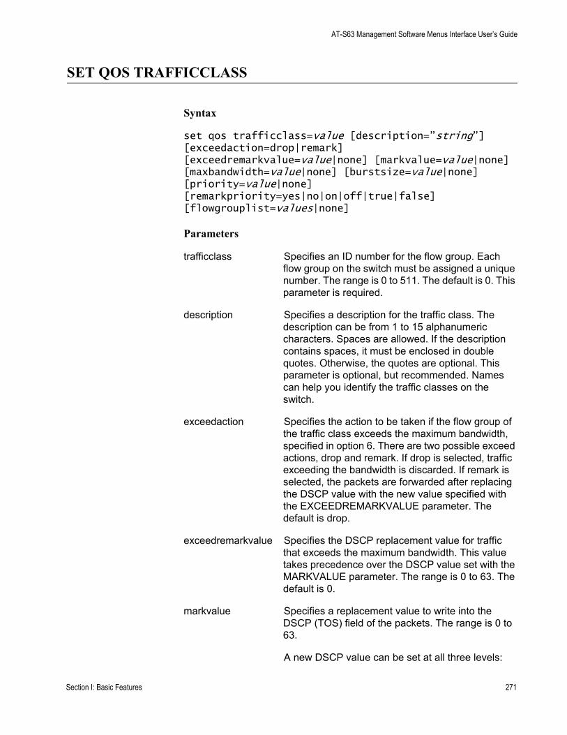
AT-S63 Management Software Menus Interface User’s Guide
SET QOS TRAFFICCLASS
Syntax
set qos trafficclass=value [description=”string”] [exceedaction=drop|remark] [exceedremarkvalue=value|none] [markvalue=value|none] [maxbandwidth=value|none] [burstsize=value|none] [priority=value|none] [remarkpriority=yes|no|on|off|true|false] [flowgrouplist=values|none]
Parameters
trafficclass Specifies an ID number for the flow group. Each flow group on the switch must be assigned a unique number. The range is 0 to 511. The default is 0. This parameter is required.
description Specifies a description for the traffic class. The description can be from 1 to 15 alphanumeric characters. Spaces are allowed. If the description contains spaces, it must be enclosed in double quotes. Otherwise, the quotes are optional. This parameter is optional, but recommended. Names can help you identify the traffic classes on the switch.
exceedaction Specifies the action to be taken if the flow group of the traffic class exceeds the maximum bandwidth, specified in option 6. There are two possible exceed actions, drop and remark. If drop is selected, traffic exceeding the bandwidth is discarded. If remark is selected, the packets are forwarded after replacing the DSCP value with the new value specified with the EXCEEDREMARKVALUE parameter. The default is drop.
exceedremarkvalue Specifies the DSCP replacement value for traffic that exceeds the maximum bandwidth. This value takes precedence over the DSCP value set with the MARKVALUE parameter. The range is 0 to 63. The default is 0.
markvalue Specifies a replacement value to write into the DSCP (TOS) field of the packets. The range is 0 to 63.
A new DSCP value can be set at all three levels:
Section I: Basic Features 271
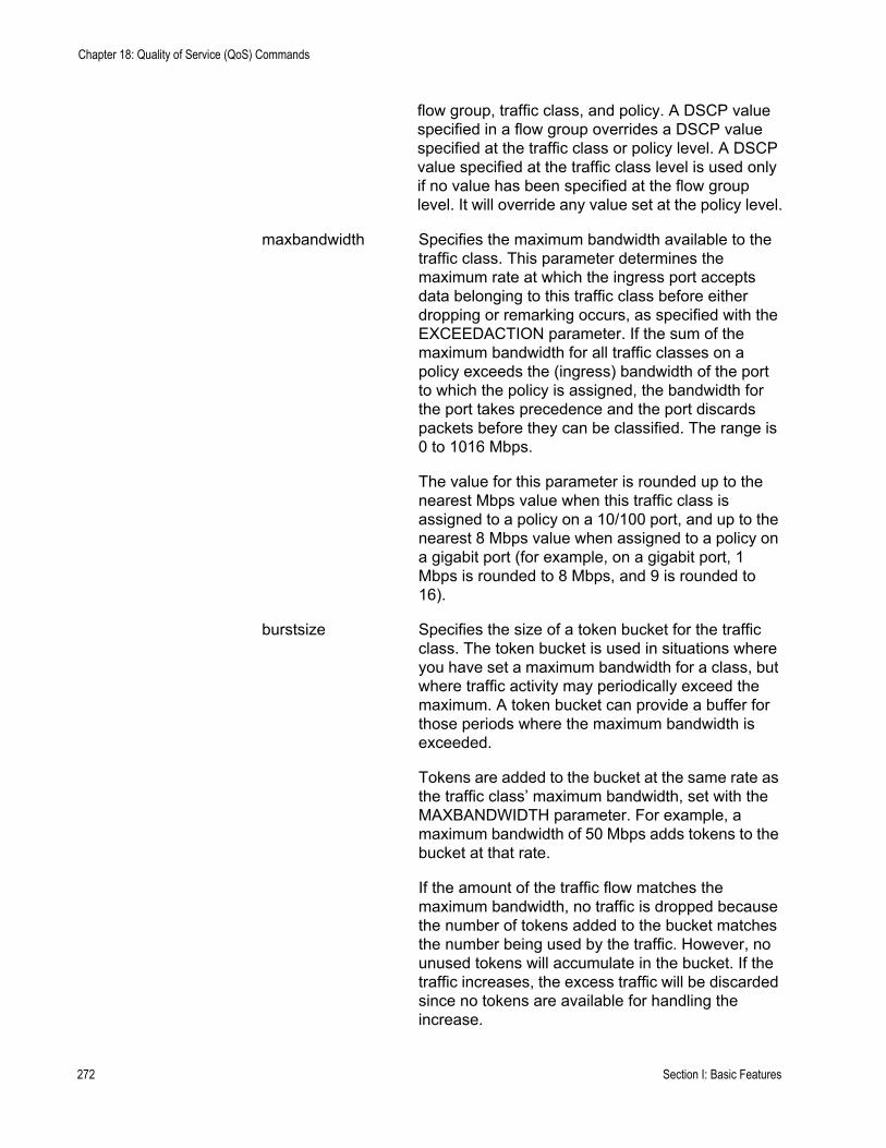
Chapter 18: Quality of Service (QoS) Commands
flow group, traffic class, and policy. A DSCP value specified in a flow group overrides a DSCP value specified at the traffic class or policy level. A DSCP value specified at the traffic class level is used only if no value has been specified at the flow group level. It will override any value set at the policy level.
maxbandwidth Specifies the maximum bandwidth available to the traffic class. This parameter determines the maximum rate at which the ingress port accepts data belonging to this traffic class before either dropping or remarking occurs, as specified with the EXCEEDACTION parameter. If the sum of the maximum bandwidth for all traffic classes on a policy exceeds the (ingress) bandwidth of the port to which the policy is assigned, the bandwidth for the port takes precedence and the port discards packets before they can be classified. The range is 0 to 1016 Mbps.
The value for this parameter is rounded up to the nearest Mbps value when this traffic class is assigned to a policy on a 10/100 port, and up to the nearest 8 Mbps value when assigned to a policy on a gigabit port (for example, on a gigabit port, 1 Mbps is rounded to 8 Mbps, and 9 is rounded to 16).
burstsize Specifies the size of a token bucket for the traffic class. The token bucket is used in situations where you have set a maximum bandwidth for a class, but where traffic activity may periodically exceed the maximum. A token bucket can provide a buffer for those periods where the maximum bandwidth is exceeded.
Tokens are added to the bucket at the same rate as the traffic class’ maximum bandwidth, set with the MAXBANDWIDTH parameter. For example, a maximum bandwidth of 50 Mbps adds tokens to the bucket at that rate.
If the amount of the traffic flow matches the maximum bandwidth, no traffic is dropped because the number of tokens added to the bucket matches the number being used by the traffic. However, no unused tokens will accumulate in the bucket. If the traffic increases, the excess traffic will be discarded since no tokens are available for handling the increase.
272 Section I: Basic Features
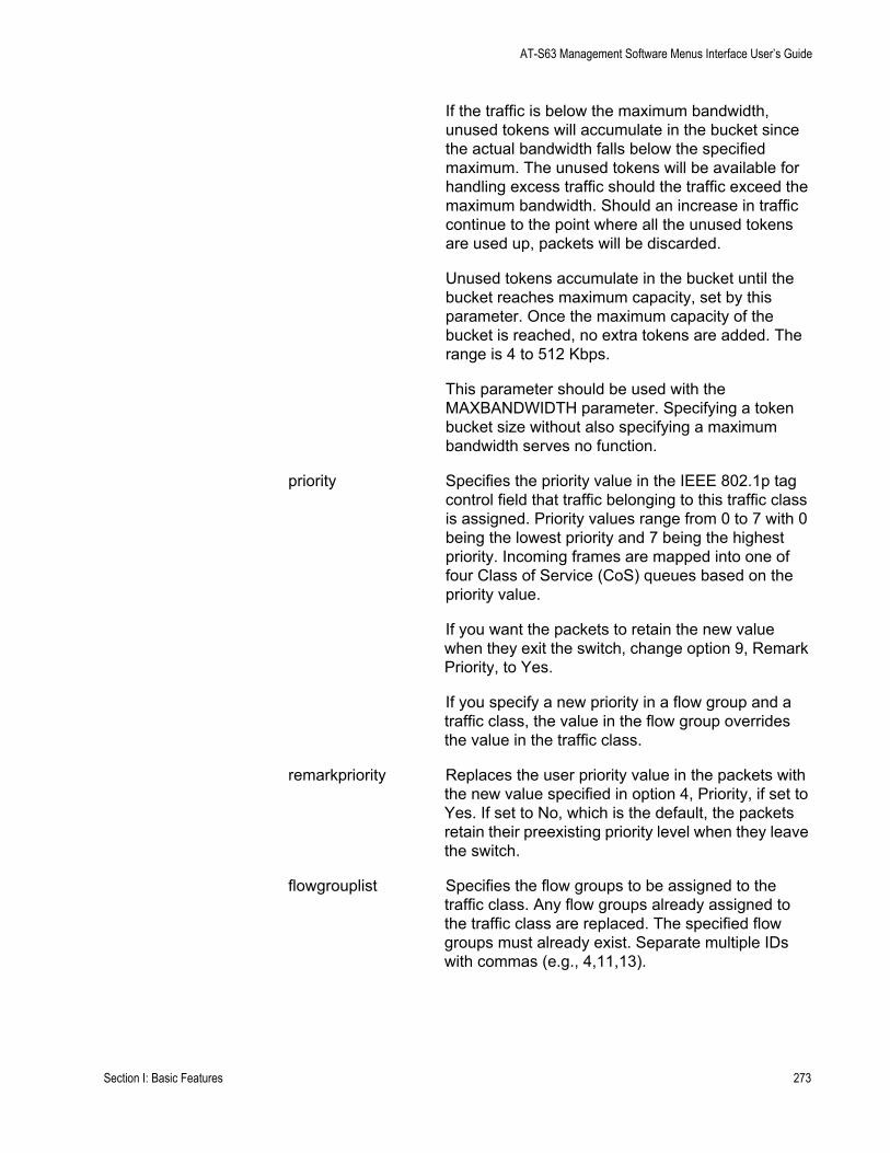
AT-S63 Management Software Menus Interface User’s Guide
If the traffic is below the maximum bandwidth, unused tokens will accumulate in the bucket since the actual bandwidth falls below the specified maximum. The unused tokens will be available for handling excess traffic should the traffic exceed the maximum bandwidth. Should an increase in traffic continue to the point where all the unused tokens are used up, packets will be discarded.
Unused tokens accumulate in the bucket until the bucket reaches maximum capacity, set by this parameter. Once the maximum capacity of the bucket is reached, no extra tokens are added. The range is 4 to 512 Kbps.
This parameter should be used with the MAXBANDWIDTH parameter. Specifying a token bucket size without also specifying a maximum bandwidth serves no function.
priority Specifies the priority value in the IEEE 802.1p tag control field that traffic belonging to this traffic class is assigned. Priority values range from 0 to 7 with 0 being the lowest priority and 7 being the highest priority. Incoming frames are mapped into one of four Class of Service (CoS) queues based on the priority value.
If you want the packets to retain the new value when they exit the switch, change option 9, Remark Priority, to Yes.
If you specify a new priority in a flow group and a traffic class, the value in the flow group overrides the value in the traffic class.
remarkpriority Replaces the user priority value in the packets with the new value specified in option 4, Priority, if set to Yes. If set to No, which is the default, the packets retain their preexisting priority level when they leave the switch.
flowgrouplist Specifies the flow groups to be assigned to the traffic class. Any flow groups already assigned to the traffic class are replaced. The specified flow groups must already exist. Separate multiple IDs with commas (e.g., 4,11,13).
Section I: Basic Features 273
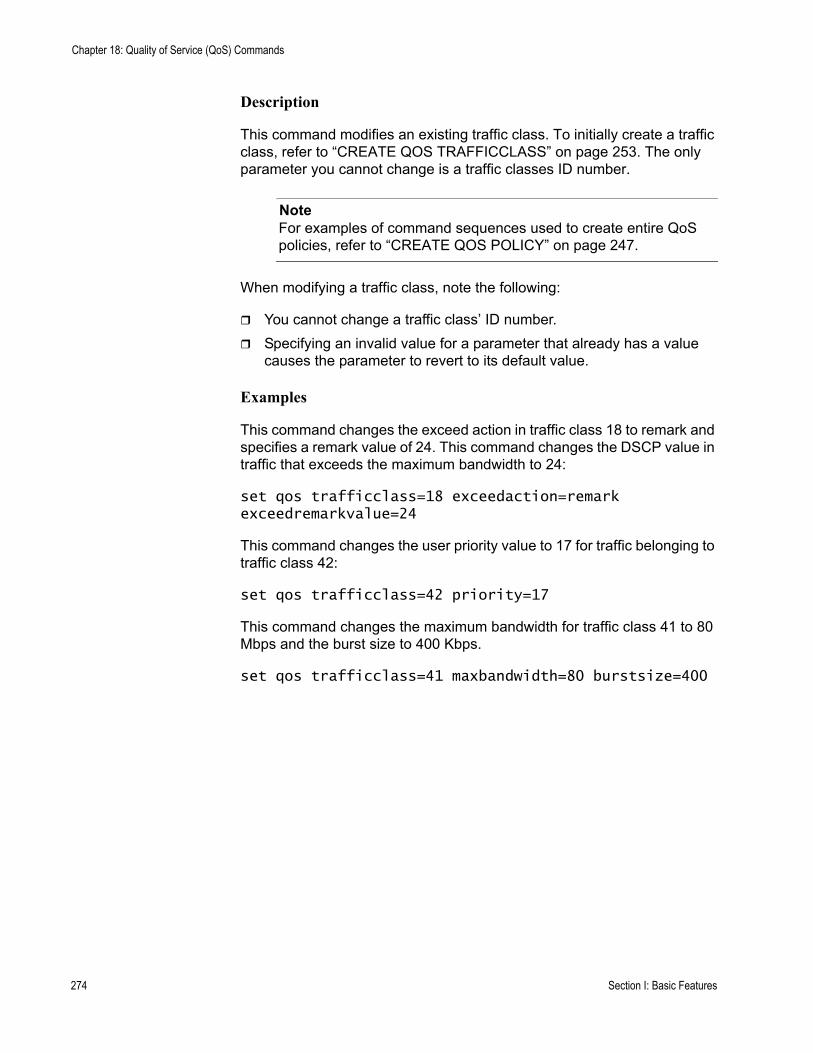
Chapter 18: Quality of Service (QoS) Commands
Description
This command modifies an existing traffic class. To initially create a traffic class, refer to “CREATE QOS TRAFFICCLASS” on page 253. The only parameter you cannot change is a traffic classes ID number.
NoteFor examples of command sequences used to create entire QoS policies, refer to “CREATE QOS POLICY” on page 247.
When modifying a traffic class, note the following:
You cannot change a traffic class’ ID number.Specifying an invalid value for a parameter that already has a value causes the parameter to revert to its default value.
Examples
This command changes the exceed action in traffic class 18 to remark and specifies a remark value of 24. This command changes the DSCP value in traffic that exceeds the maximum bandwidth to 24:
set qos trafficclass=18 exceedaction=remark exceedremarkvalue=24
This command changes the user priority value to 17 for traffic belonging to traffic class 42:
set qos trafficclass=42 priority=17
This command changes the maximum bandwidth for traffic class 41 to 80 Mbps and the burst size to 400 Kbps.
set qos trafficclass=41 maxbandwidth=80 burstsize=400
274 Section I: Basic Features
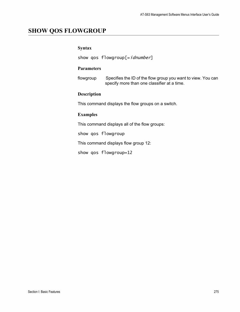
AT-S63 Management Software Menus Interface User’s Guide
SHOW QOS FLOWGROUP
Syntax
show qos flowgroup[=idnumber]
Parameters
flowgroup Specifies the ID of the flow group you want to view. You can specify more than one classifier at a time.
Description
This command displays the flow groups on a switch.
Examples
This command displays all of the flow groups:
show qos flowgroup
This command displays flow group 12:
show qos flowgroup=12
Section I: Basic Features 275
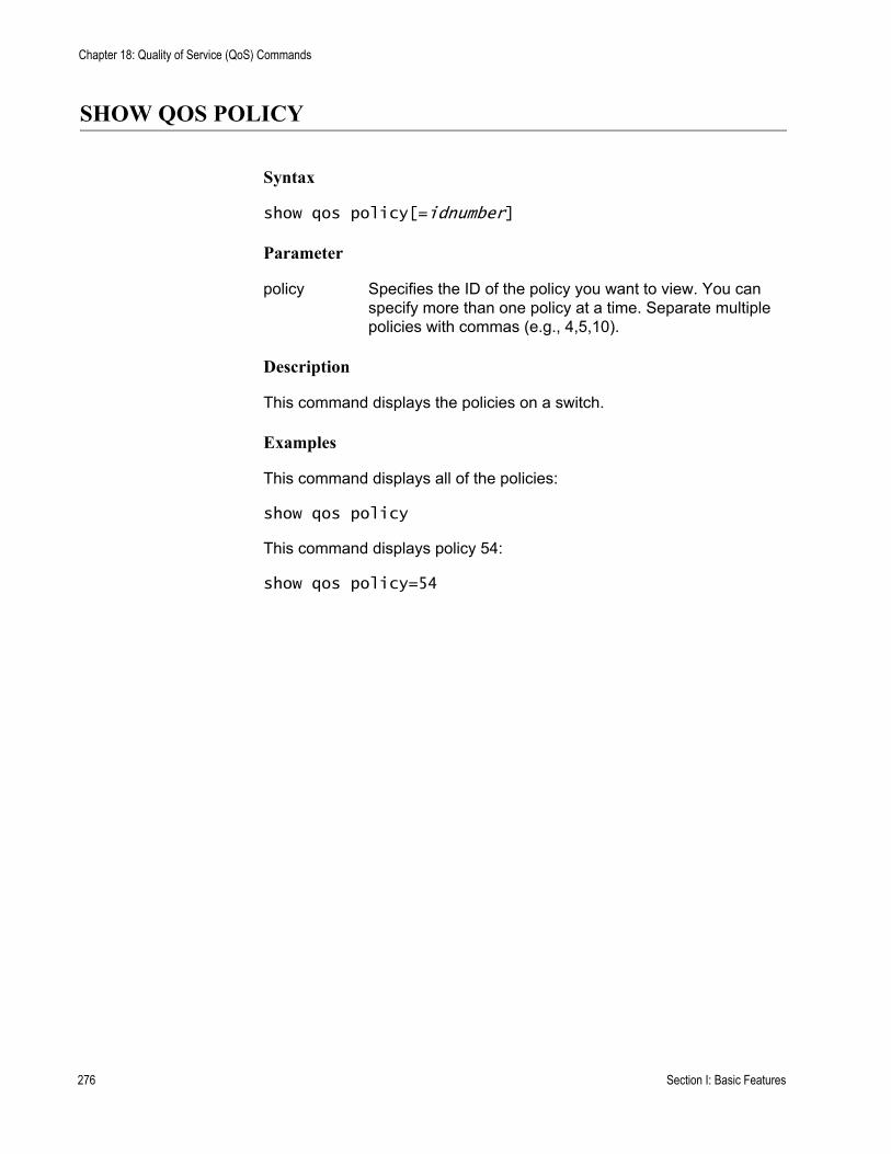
Chapter 18: Quality of Service (QoS) Commands
SHOW QOS POLICY
Syntax
show qos policy[=idnumber]
Parameter
policy Specifies the ID of the policy you want to view. You can specify more than one policy at a time. Separate multiple policies with commas (e.g., 4,5,10).
Description
This command displays the policies on a switch.
Examples
This command displays all of the policies:
show qos policy
This command displays policy 54:
show qos policy=54
276 Section I: Basic Features
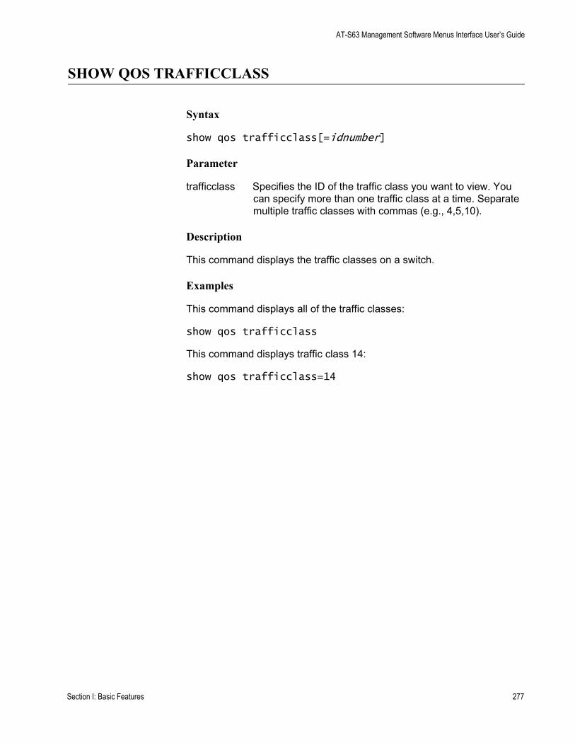
AT-S63 Management Software Menus Interface User’s Guide
SHOW QOS TRAFFICCLASS
Syntax
show qos trafficclass[=idnumber]
Parameter
trafficclass Specifies the ID of the traffic class you want to view. You can specify more than one traffic class at a time. Separate multiple traffic classes with commas (e.g., 4,5,10).
Description
This command displays the traffic classes on a switch.
Examples
This command displays all of the traffic classes:
show qos trafficclass
This command displays traffic class 14:
show qos trafficclass=14
Section I: Basic Features 277

Chapter 18: Quality of Service (QoS) Commands
278 Section I: Basic Features
Chapter 19
Class of Service (CoS) Commands
This chapter contains the following commands:
“MAP QOS COSP” on page 280“SET QOS COSP” on page 283“SET QOS SCHEDULING” on page 284“SHOW QOS CONFIG” on page 285
NoteRemember to save your changes with the SAVE CONFIGURATION command.
NoteFor background information on Class of Service, refer to Chapter 17, “Class of Service” in the AT-S63 Management Software Menus Interface User’s Guide.
279
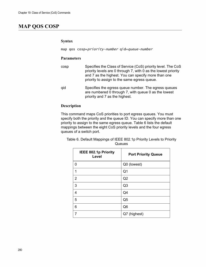
Chapter 19: Class of Service (CoS) Commands
MAP QOS COSP
Syntax
map qos cosp=priority-number qid=queue-number
Parameters
cosp Specifies the Class of Service (CoS) priority level. The CoS priority levels are 0 through 7, with 0 as the lowest priority and 7 as the highest. You can specify more than one priority to assign to the same egress queue.
qid Specifies the egress queue number. The egress queues are numbered 0 through 7, with queue 0 as the lowest priority and 7 as the highest.
Description
This command maps CoS priorities to port egress queues. You must specify both the priority and the queue ID. You can specify more than one priority to assign to the same egress queue. Table 6 lists the default mappings between the eight CoS priority levels and the four egress queues of a switch port.
Table 6. Default Mappings of IEEE 802.1p Priority Levels to Priority Queues
IEEE 802.1p Priority Level Port Priority Queue
0 Q0 (lowest)
1 Q1
2 Q2
3 Q3
4 Q4
5 Q5
6 Q6
7 Q7 (highest)
280

AT-S63 Management Software Command Line Interface User’s Guide
Example
The following command maps priorities 4 and 5, to queue 3:
map qos cosp=4,5 qid=3
281
Chapter 19: Class of Service (CoS) Commands
PURGE QOS
Syntax
purge qos
Parameters
None
Description
This command destroys all policies, traffic classes, and flow groups; resets the CoS priorities to port egress queues to the default values; and sets the scheduling mode and egress weight queues to their default values.
Example
The following command resets QoS to the default values:
purge qos
282
AT-S63 Management Software Command Line Interface User’s Guide
SET QOS COSP
Syntax
set qos cosp=priority-number qid=queue-number
Parameters
cosp Specifies the Class of Service (CoS) priority level. The CoS priority levels are 0 through 7, with 0 as the lowest priority and 7 as the highest. You can specify more than one priority to assign to the same egress queue.
qid Specifies the egress queue number. The egress queues are numbered 0 through 7, with queue 0 as the lowest priority and 7 as the highest.
Description
This command maps CoS priorities to port egress queues. You must specify both the priority and the queue ID. You can assign more than one priority to an egress queue. Table 6 on page 280 lists the default mappings between the eight CoS priority levels and the eight egress queues of a switch port.
NoteThis command is equivalent to “MAP QOS COSP” on page 280.
Example
The following command maps priorities 5 and 6 to egress queue 1:
set qos cosp=5,6 qid=1
283
Chapter 19: Class of Service (CoS) Commands
SET QOS SCHEDULING
Syntax
set qos scheduling=strict|wrr weights=weights
Parameters
scheduling Specifies the type of scheduling. The options are:
strict Strict priority. The port transmits all packets out of the higher priority queues before it transmits any from the low priority queues. This is the default.
wrr Weighted round robin. The port transmits a set number of packets from each queue in a round robin manner.
weights Specifies the weight given to each of a port’s eight egress priority queues. You must specify the weights if scheduling will be weighted round robin. The range for each queue is 0 to 15 packets, and the default is 1. The weights are specified in the following order: Q0, Q1, Q2, Q3, Q4, Q5, Q6, Q7. For example, to assign Q0 and Q1 a weight of 1, Q2 and Q3 a weight of 5, Q4 and Q5 a weight of 10, and Q6 and Q7 a weight of 15, you enter this parameter as weights=1,1,5,5,10,10,15,15. The parameter must include all eight queues.
Description
Sets the QoS scheduling method and the weights for round robin scheduling.
Examples
The following command sets the scheduling to strict:
set qos scheduling=strict
The following command sets the scheduling to weighted round robin and gives egress priority queues Q0 to Q3 a weight of 1, and Q4 to Q7 a weight of 15:
set qos scheduling=wrr weights=1,1,1,1,15,15,15,15
284
AT-S63 Management Software Command Line Interface User’s Guide
SHOW QOS CONFIG
Syntax
show qos config
Parameters
None.
Description
Displays the QoS priority queues and scheduling.
Example
The following command displays the QoS priority queues and scheduling:
show qos config
285

Chapter 19: Class of Service (CoS) Commands
286
Chapter 20
IGMP Snooping Commands
This chapter contains the following commands:
“DISABLE IGMPSNOOPING” on page 288“ENABLE IGMPSNOOPING” on page 289“SET IP IGMP” on page 290“SHOW IGMPSNOOPING” on page 292“SHOW IP IGMP” on page 293
NoteRemember to use the SAVE CONFIGURATION command to save your changes on the switch.
NoteFor background information on IGMP Snooping, refer to Chapter 18, “IGMP Snooping” in the AT-S63 Management Software Menus Interface User’s Guide.
287
Chapter 20: IGMP Snooping Commands
DISABLE IGMPSNOOPING
Syntax
disable igmpsnooping
Parameters
None.
Description
This command deactivates IGMP snooping on the switch. This command performs the same function as the SNOOPINGSTATUS option in the command “SET IP IGMP” on page 290.
Example
The following command deactivates IGMP snooping:
disable igmpsnooping
288
AT-S63 Management Software Command Line Interface User’s Guide
ENABLE IGMPSNOOPING
Syntax
enable igmpsnooping
Parameters
None.
Description
This command activates IGMP snooping on the switch. This command performs the same function as the SNOOPINGSTATUS option in the command “SET IP IGMP” on page 290.
Example
The following command activates IGMP snooping:
enable igmpsnooping
289
Chapter 20: IGMP Snooping Commands
SET IP IGMP
Syntax
set ip igmp [snoopingstatus=enabled|disabled] [hoststatus=singlehost|multihost] [timeout=value] [numbermulticastgroups=value] [routerport=port|all|none|auto]
Parameters
snoopingstatus Activates and deactivates IGMP snooping on the switch. The options are:enabled Activates IGMP snooping.
disabled Deactivates IGMP snooping. This is the default setting
hoststatus Specifies the IGMP host node topology. Options are:
singlehost Activates the Single-Host/Port setting, which is appropriate when there is only one host node connected to a port on the switch. This is the default setting.
multihost Activates the Multi-Host setting, which is appropriate if there is more than one host node connected to a switch port.
timeout Specifies the time period, in seconds, used by the switch in determining inactive host nodes. An inactive host node is a node that has not sent an IGMP report during the specified time interval. The range is 1 to 86,400 seconds (24 hours); the default is 260 seconds.
290
AT-S63 Management Software Command Line Interface User’s Guide
numbermulticastgroups Specifies the maximum number of multicast addresses the switch learns. This parameter is useful with networks that contain a large number of multicast groups. You can use the parameter to prevent the switch’s MAC address table from filling up with multicast addresses, leaving no room for dynamic or static MAC addresses. The range is 1 to 256 addresses; the default is 64 addresses.
routerport Specifies the port(s) on the switch connected to a multicast router. Options are:
port Specifies the router port(s) manually.
all Specifies all of the switch ports.none Sets the mode to manual
without any router ports specified.
auto Activates auto-detect, where the switch automatically determines the ports with multicast routers.
Description
This command configures the IGMP snooping parameters.
Example
The following command activates IGMP snooping, sets the IGMP topology to Multi-Host, and sets the timeout value to 120 seconds:
set ip igmp snoopingstatus=enabled hoststatus=multihost timeout=120
The following command changes the topology to Single-Host:
set ip igmp hoststatus=singlehost
The following command disables IGMP snooping:
set ip igmp snoopingstatus=disabled
291
Chapter 20: IGMP Snooping Commands
SHOW IGMPSNOOPING
Syntax
show igmpsnooping
Parameters
None.
Description
This command displays the following IGMP parameters:
IGMP snooping statusMulticast host topologyHost/router timeout intervalMaximum multicast groups
NoteFor instructions on how to set the IGMP parameters, refer to “SET IP IGMP” on page 290.
Examples
The following command displays the current IGMP parameter settings:
show igmpsnooping
292
AT-S63 Management Software Command Line Interface User’s Guide
SHOW IP IGMP
Syntax
show ip igmp [hostlist] [routerlist]
Parameters
hostlist Displays a list of the multicast groups learned by the switch, as well as the ports on the switch that are connected to host nodes. This parameter displays information only there are active host nodes.
routerlist Displays the ports on the switch where multicast routers are detected. This parameter displays information only when there are active multicast routers.
Description
This command displays the following IGMP parameters:
IGMP snooping statusMulticast host topologyHost/router timeout intervalMaximum multicast groupsMulticast router port(s)
This command performs the same function as “SHOW IGMPSNOOPING” on page 292. For instructions on how to set the IGMP parameters, refer to “SET IP IGMP” on page 290.
Examples
The following command displays the current IGMP parameter settings:
show ip igmp
The following command displays a list of active host nodes connected to the switch:
show ip igmp hostlist
293

Chapter 20: IGMP Snooping Commands
The following command displays a list of active multicast routers:
show ip igmp routerlist
294
Chapter 21
RRP Snooping Commands
This chapter contains the following commands:
“DISABLE RRPSNOOPING” on page 296“ENABLE RRPSNOOPING” on page 297“SHOW RRPSNOOPING” on page 298
NoteRemember to save your changes with the SAVE CONFIGURATION command.
NoteFor background information on RRP snooping, refer to Chapter 19, “RRP Snooping” in the AT-S63 Management Software Menus Interface User’s Guide.
295
Chapter 21: RRP Snooping Commands
DISABLE RRPSNOOPING
Syntax
disable rrpsnooping
Parameters
None.
Description
This command disables RRP snooping. This is the default setting.
Example
The following command disables RRP snooping:
disable rrpsnooping
296
AT-S63 Management Software Command Line Interface User’s Guide
ENABLE RRPSNOOPING
Syntax
enable rrpsnooping
Parameters
None.
Description
This command enables RRP snooping.
Example
The following command activates RRP snooping on the switch:
enable rrpsnooping
297
Chapter 21: RRP Snooping Commands
SHOW RRPSNOOPING
Syntax
show rrpsnooping
Parameter
None.
Description
This command displays the status of RRP snooping, enabled or disabled.
Example
The following command displays the status of RRP snooping:
show rrpsnooping
298
Chapter 22
SNMPv3 Commands
This chapter contains the following commands:
“ADD SNMPV3 USER” on page 301“CLEAR SNMPV3 ACCESS” on page 303“CLEAR SNMPV3 COMMUNITY” on page 305“CLEAR SNMPV3 NOTIFY” on page 306“CLEAR SNMPV3 TARGETADDR” on page 307“CLEAR SNMPV3 VIEW” on page 308“CREATE SNMPV3 ACCESS” on page 309“CREATE SNMPV3 COMMUNITY” on page 312“CREATE SNMPV3 GROUP” on page 314“CREATE SNMPV3 NOTIFY” on page 316“CREATE SNMPV3 TARGETADDR” on page 318“CREATE SNMPV3 TARGETPARAMS” on page 320“CREATE SNMPV3 VIEW” on page 322“DELETE SNMPV3 USER” on page 324“DESTROY SNMPv3 ACCESS” on page 325“DESTROY SNMPv3 COMMUNITY” on page 327“DESTROY SNMPv3 GROUP” on page 328“DESTROY SNMPv3 NOTIFY” on page 329“DESTROY SNMPv3 TARGETADDR” on page 330“DESTROY SNMPv3 TARGETPARMS” on page 331“DESTROY SNMPV3 VIEW” on page 332“PURGE SNMPV3 ACCESS” on page 333“PURGE SNMPV3 COMMUNITY” on page 334“PURGE SNMPV3 NOTIFY” on page 335“PURGE SNMPV3 TARGETADDR” on page 336“PURGE SNMPV3 VIEW” on page 337“SET SNMPV3 ACCESS” on page 338“SET SNMPV3 COMMUNITY” on page 340“SET SNMPV3 GROUP” on page 342
299
Chapter 22: SNMPv3 Commands
“SET SNMPV3 NOTIFY” on page 344“SET SNMPV3 TARGETADDR” on page 346“SET SNMPV3 TARGETPARAMS” on page 348“SET SNMPV3 USER” on page 350“SET SNMPV3 VIEW” on page 352“SHOW SNMPV3 ACCESS” on page 354“SHOW SNMPV3 COMMUNITY” on page 355“SHOW SNMPv3 GROUP” on page 356“SHOW SNMPV3 NOTIFY” on page 357“SHOW SNMPV3 TARGETADDR” on page 358“SHOW SNMPV3 TARGETPARAMS” on page 359“SHOW SNMPV3 USER” on page 360“SHOW SNMPV3 VIEW” on page 361
NoteRemember to save your changes with the SAVE CONFIGURATION command.
NoteFor background information about the SNMPv3 protocol, refer to Chapter 20, “SNMPv3” in the AT-S63 Management Software Menus Interface User’s Guide.
300
AT-S63 Management Software Command Line Interface User’s Guide
ADD SNMPV3 USER
Syntax
add snmpv3 user=user [authentication=md5|sha] authpassword=password privpassword=password [storagetype=volatile|nonvolatile]
Parameters
user Specifies the name of an SNMPv3 user, up to 32 alphanumeric characters.
authentication Specifies the authentication protocol that is used to authenticate this user with an SNMP entity (manager or NMS). If you do not specify an authentication protocol, this parameter is automatically set to None. The options are:
md5 The MD5 authentication protocol. SNMPv3 Users are authenticated with the MD5 authentication protocol after a message is received.
sha The SHA authentication protocol. Users are authenticated with the SHA authentication protocol after a message is received.
Note: You must specify the authentication protocol before you specify the authentication password.
authpassword Specifies a password for the authentication protocol, up to 32 alphanumeric characters. If you specify an authentication protocol, then you must configure an authentication protocol password.
privpassword Specifies a password for the 3DES privacy, or encryption protocol, up to 32 alphanumeric characters. This is an optional parameter.
Note: If you specify a privacy password, the privacy protocol is set to DES. You must also specify an authentication protocol and password.
storagetype Specifies the storage type of this table entry. This is an optional parameter. The options are:
volatile Does not allow you to save the table entry to the configuration file on the switch. This is the default.
nonvolatile Allows you to save the table entry to the
301
Chapter 22: SNMPv3 Commands
configuration file on the switch.
Description
This command creates an SNMPv3 User Table entry.
Examples
The following command creates an SNMPv3 user with the name “steven142” with an authentication protocol of MD5, an authentication password of “99doublesecret12”, a privacy password of “encrypt178” and a storage type of nonvolatile.
add snmpv3 user=steven142 authentication=md5 authpassword=99doublesecret12 privpassword=encrypt178 storagetype=nonvolatile
The following command creates an SNMPv3 user with the name “77hoa” an authentication protocol of SHA, an authentication password of “youvegottobekidding88” and a storage type of nonvolatile.
add snmpv3 user=77hoa authentication=sha authpassword=youvegottobekidding88 storagetype=nonvolatile
302
AT-S63 Management Software Command Line Interface User’s Guide
CLEAR SNMPV3 ACCESS
Syntax
clear snmpv3 access=access [securitymodel=v1|v2c|v3] [securitylevel=noauthentication|authentication|privacy] readview writeview notifyview
Parameters
access Specifies the name of the security group, up to 32 alphanumeric characters.
securitymodel Specifies the security model. The options are:
v1 Associates the Security Name, or User Name, with the SNMPv1 protocol.
v2c Associates the Security Name, or User Name, with the SNMPv2c protocol.
v3 Associates the Security Name, or User Name, with the SNMPv3 protocol.
securitylevel Specifies the security level. The options are:
noauthentication This option provides no authentication protocol and no privacy protocol.
authentication This option provides an authentication protocol, but no privacy protocol.
privacy This option provides an authentication protocol and the privacy protocol.
readview Specifies a Read View Name that allows the users assigned to this security group to view the information specified by the View Table entry. This is an optional parameter.
writeview Specifies a Write View Name that allows the users assigned to this security group to write, or modify, the information in the specified View Table. This is an optional parameter.
notifyview Specifies a Notify View Name that allows the users assigned to this security group to send traps permitted in the specified View. This is an optional
303
Chapter 22: SNMPv3 Commands
parameter.
Description
This command clears the specified fields in an SNMPv3 Access Table entry.
Examples
The following command clears the readview parameter in a security group called “Engineering” which has a security model of the SNMPv3 protocol and a security level of privacy.
clear snmpv3 access=Engineering securitymodel=v3 securitylevel=privacy readview
The following command clears the values in the readview, writeview, and notifyview parameters in a security group called “SystemTest.” This group has a security model of the SNMPv3 protocol and a security level of authentication.
clear snmpv3 access=SystemTest securitymodel=v3 securitylevel=authentication readview writeview notifyview
304
AT-S63 Management Software Command Line Interface User’s Guide
CLEAR SNMPV3 COMMUNITY
Syntax
clear snmpv3 community index=index transporttag
Parameters
index Specifies the name of an existing SNMPv3 Community Table entry, up to 32 alphanumeric characters.
transporttag Specifies the transport tag, up to 32 alphanumeric characters.
Description
This command clears the transporttag parameter in an SNMPv3 Community Table entry.
Examples
The following command clears the value of the transporttag parameter in the SNMPv3 Community Table entry with an index of 1005:
clear snmpv3 community index=1005 transporttag
The following command clears the value of the transporttag parameter in the SNMPv3 Community Table entry with an index of 421:
clear snmpv3 community index=421 transporttag
305
Chapter 22: SNMPv3 Commands
CLEAR SNMPV3 NOTIFY
Syntax
clear snmpv3 notify=notify tag
Parameters
notify Specifies the name of an SNMPv3 Notify Table entry, up to 32 alphanumeric characters.
tag Specifies the notify tag name, up to 32 alphanumeric characters.
Description
This command clears the value of the tag parameter in an SNMPv3 Notify Table entry.
Examples
The following command deletes the value of the tag parameter in an SNMPv3 Notify Table entry called “hwengtrap:”
clear snmpv3 notify=hwengtraptag tag
The following command deletes the value of the tag parameter in an SNMPv3 Notify Table entry called “hwenginformtag:”
clear snmpv3 notify=hwenginform tag
306
AT-S63 Management Software Command Line Interface User’s Guide
CLEAR SNMPV3 TARGETADDR
Syntax
clear snmpv3 targetaddr=targetaddr taglist
Parameters
targetaddr Specifies the name of the SNMPv3 Target Address Table entry, up to 32 alphanumeric characters.
taglist Specifies a tag or list of tags, up to 256 alphanumeric characters.
Description
This command clears the value of the taglist parameter in an SNMPv3 Target Address Table entry.
Examples
The following command deletes the value of the taglist parameter from the SNMPv3 Target Address Table entry called “snmphost79:”
clear snmpv3 targetaddr=snmphost44 taglist
The following command deletes the value of the taglist parameter from the SNMPv3 Target Address Table entry called “snmphost79:”
clear snmpv3 targetaddr=snmphost79 taglist
307
Chapter 22: SNMPv3 Commands
CLEAR SNMPV3 VIEW
Syntax
clear snmpv3 view=view [subtree=OID|text] mask
Parameters
view Specifies the name of the SNMPv3 view, up to 32 alphanumeric characters.
subtree Specifies the view of the MIB Tree. Options are:
OID A numeric value in hexadecimal format.
text Text name of the view.
mask Specifies the subtree mask, in hexadecimal format.
Description
This command clears the value of the mask parameter in an SNMPv3 View Table entry.
Examples
The following command clears the value of the subtree mask from the SNMPv3 view of 1.3.6.1.2.1.1:
clear snmpv3 view=1.3.6.1.2.1.1 mask
The following command clears the value of subtree mask from the SNMPv3 view called private. The subtree has a value of 1.3.6.1.4 (private MIBs).
clear snmpv3 view=private subtree=1.3.6.1.4 mask
308
AT-S63 Management Software Command Line Interface User’s Guide
CREATE SNMPV3 ACCESS
Syntax
create snmpv3 access=access [securitymodel=v1|v2c|v3] [securitylevel=noauthentication|authentication|privacy] readview=readview writeview=writeview notifyview=notifyview [storagetype=volatile|nonvolatile]
Parameters
access Specifies the name of the security group, up to 32 alphanumeric characters.
securitymodel Specifies the security model. The options are:
v1 Associates the Security Name, or User Name, with the SNMPv1 protocol.
v2c Associates the Security Name, or User Name, with the SNMPv2c protocol.
v3 Associates the Security Name, or User Name, with the SNMPv3 protocol.
securitylevel Specifies the security level. The options are:
noauthentication This option provides no authentication protocol and no privacy protocol.
authentication This option provides an authentication protocol, but no privacy protocol.
privacy This option provides an authentication protocol and the privacy protocol.
readview Specifies a Read View Name that allows the users assigned to this Group Name to view the information specified by the View Table entry. This is an optional parameter. If you do not assign a value to this parameter, then the readview parameter defaults to none.
writeview Specifies a Write View Name that allows the users assigned to this Security Group to write, or modify, the information in the specified View Table. This is an optional parameter. If you do not assign a value to this parameter, then the writeview parameter defaults to none.
309
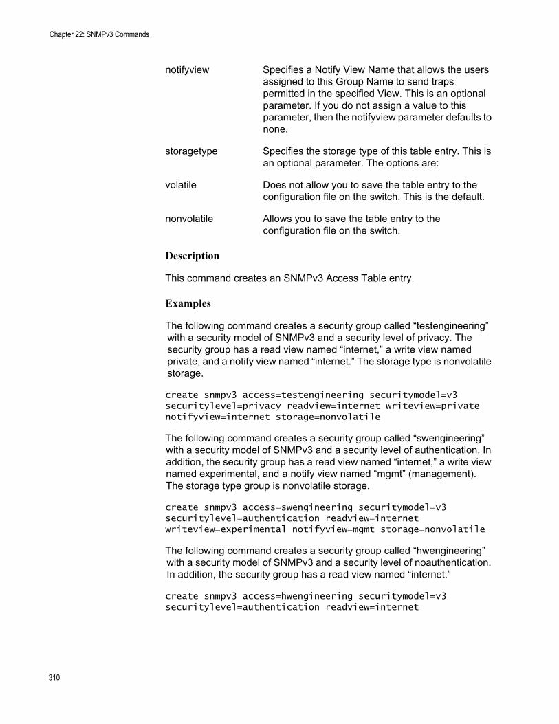
Chapter 22: SNMPv3 Commands
notifyview Specifies a Notify View Name that allows the users assigned to this Group Name to send traps permitted in the specified View. This is an optional parameter. If you do not assign a value to this parameter, then the notifyview parameter defaults to none.
storagetype Specifies the storage type of this table entry. This is an optional parameter. The options are:
volatile Does not allow you to save the table entry to the configuration file on the switch. This is the default.
nonvolatile Allows you to save the table entry to the configuration file on the switch.
Description
This command creates an SNMPv3 Access Table entry.
Examples
The following command creates a security group called “testengineering” with a security model of SNMPv3 and a security level of privacy. The security group has a read view named “internet,” a write view named private, and a notify view named “internet.” The storage type is nonvolatile storage.
create snmpv3 access=testengineering securitymodel=v3 securitylevel=privacy readview=internet writeview=private notifyview=internet storage=nonvolatile
The following command creates a security group called “swengineering” with a security model of SNMPv3 and a security level of authentication. In addition, the security group has a read view named “internet,” a write view named experimental, and a notify view named “mgmt” (management). The storage type group is nonvolatile storage.
create snmpv3 access=swengineering securitymodel=v3 securitylevel=authentication readview=internet writeview=experimental notifyview=mgmt storage=nonvolatile
The following command creates a security group called “hwengineering” with a security model of SNMPv3 and a security level of noauthentication. In addition, the security group has a read view named “internet.”
create snmpv3 access=hwengineering securitymodel=v3 securitylevel=authentication readview=internet
310

AT-S63 Management Software Command Line Interface User’s Guide
NoteIn the above example, the storage type has not been specified. As a result, the storage type for the hwengineering security group is volatile storage.
311
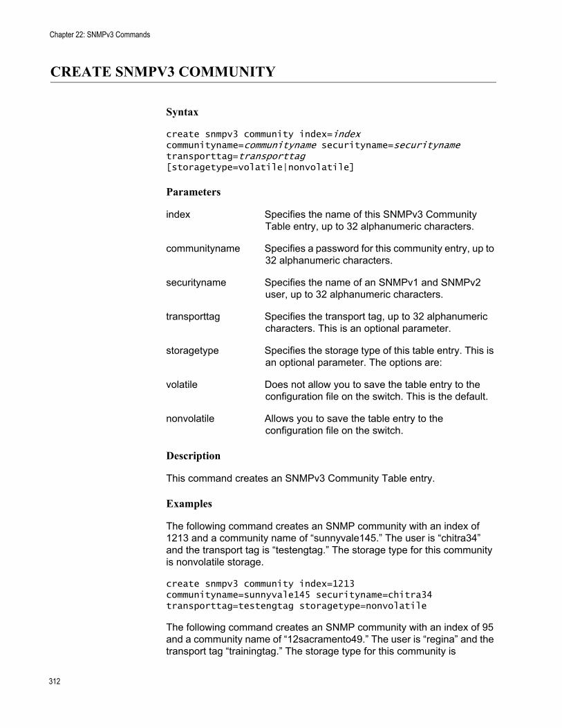
Chapter 22: SNMPv3 Commands
CREATE SNMPV3 COMMUNITY
Syntax
create snmpv3 community index=index communityname=communityname securityname=securityname transporttag=transporttag [storagetype=volatile|nonvolatile]
Parameters
index Specifies the name of this SNMPv3 Community Table entry, up to 32 alphanumeric characters.
communityname Specifies a password for this community entry, up to 32 alphanumeric characters.
securityname Specifies the name of an SNMPv1 and SNMPv2 user, up to 32 alphanumeric characters.
transporttag Specifies the transport tag, up to 32 alphanumeric characters. This is an optional parameter.
storagetype Specifies the storage type of this table entry. This is an optional parameter. The options are:
volatile Does not allow you to save the table entry to the configuration file on the switch. This is the default.
nonvolatile Allows you to save the table entry to the configuration file on the switch.
Description
This command creates an SNMPv3 Community Table entry.
Examples
The following command creates an SNMP community with an index of 1213 and a community name of “sunnyvale145.” The user is “chitra34” and the transport tag is “testengtag.” The storage type for this community is nonvolatile storage.
create snmpv3 community index=1213 communityname=sunnyvale145 securityname=chitra34 transporttag=testengtag storagetype=nonvolatile
The following command creates an SNMP community with an index of 95 and a community name of “12sacramento49.” The user is “regina” and the transport tag “trainingtag.” The storage type for this community is
312

AT-S63 Management Software Command Line Interface User’s Guide
nonvolatile storage.
create snmpv3 community index=95 communityname=12sacramento49 securityname=regina transporttag=trainingtag storagetype=nonvolatile
313
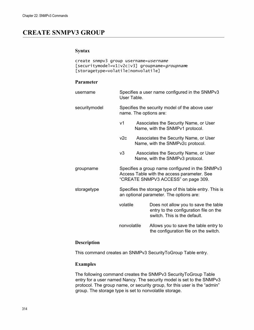
Chapter 22: SNMPv3 Commands
CREATE SNMPV3 GROUP
Syntax
create snmpv3 group username=username [securitymodel=v1|v2c|v3] groupname=groupname [storagetype=volatile|nonvolatile]
Parameter
username Specifies a user name configured in the SNMPv3 User Table.
securitymodel Specifies the security model of the above user name. The options are:
v1 Associates the Security Name, or User Name, with the SNMPv1 protocol.
v2c Associates the Security Name, or User Name, with the SNMPv2c protocol.
v3 Associates the Security Name, or User Name, with the SNMPv3 protocol.
groupname Specifies a group name configured in the SNMPv3 Access Table with the access parameter. See “CREATE SNMPV3 ACCESS” on page 309.
storagetype Specifies the storage type of this table entry. This is an optional parameter. The options are:
volatile Does not allow you to save the table entry to the configuration file on the switch. This is the default.
nonvolatile Allows you to save the table entry to the configuration file on the switch.
Description
This command creates an SNMPv3 SecurityToGroup Table entry.
Examples
The following command creates the SNMPv3 SecurityToGroup Table entry for a user named Nancy. The security model is set to the SNMPv3 protocol. The group name, or security group, for this user is the “admin” group. The storage type is set to nonvolatile storage.
314
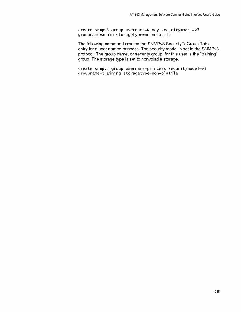
AT-S63 Management Software Command Line Interface User’s Guide
create snmpv3 group username=Nancy securitymodel=v3 groupname=admin storagetype=nonvolatile
The following command creates the SNMPv3 SecurityToGroup Table entry for a user named princess. The security model is set to the SNMPv3 protocol. The group name, or security group, for this user is the “training” group. The storage type is set to nonvolatile storage.
create snmpv3 group username=princess securitymodel=v3 groupname=training storagetype=nonvolatile
315
Chapter 22: SNMPv3 Commands
CREATE SNMPV3 NOTIFY
Syntax
create snmpv3 notify=notify tag=tag [type=trap|inform] [storagetype=volatile|nonvolatile]
Parameters
notify Specifies the name of an SNMPv3 Notify Table entry, up to 32 alphanumeric characters.
tag Specifies the notify tag name, up to 32 alphanumeric characters. This is an optional parameter.
type Specifies the message type. This is an optional parameter. The options are:
trap Trap messages are sent, with no response expected from another entity (NMS or manager). This is the default.
inform Inform messages are sent, with a response expected from another entity (NMS or manager).
storagetype Specifies the storage type of this table entry. This is an optional parameter. The options are:
volatile Does not allow you to save the table entry to the configuration file on the switch. This is the default.
nonvolatile Allows you to save the table entry to the configuration file on the switch.
Description
This command creates an SNMPv3 Notify Table entry.
Examples
The following command creates the SNMPv3 Notify Table entry called “testengtrap1” and the notify tag is “testengtag1.” The message type is defined as a trap message and the storage type for this entry is nonvolatile storage.
create snmpv3 notify=testengtrap1 tag=testengtag1 type=trap storagetype=nonvolatile
316

AT-S63 Management Software Command Line Interface User’s Guide
The following command creates the SNMPv3 Notify Table entry called “testenginform5” and the notify tag is “testenginformtag5.” The message type is defined as an inform message and the storage type for this entry is nonvolatile storage.
create snmpv3 notify=testenginform5 tag=testenginformtag5 type=inform storagetype=nonvolatile
317
Chapter 22: SNMPv3 Commands
CREATE SNMPV3 TARGETADDR
Syntax
create snmpv3 targetaddr=targetaddr params=params ipaddress=ipaddress udpport=udpport timeout=timeout retries=retries taglist=taglist [storagetype=volatile|nonvolatile]
Parameters
targetaddr Specifies the name of the SNMP manager, or host, that manages the SNMP activity on the switch, up to 32 alphanumeric characters.
params Specifies the target parameters name, up to 32 alphanumeric characters.
ipaddress Specifies the IP address of the host.
udpport Specifies the UDP port in the range of 0 to 65535. The default UDP port is 162. This is an optional parameter.
timeout Specifies the timeout value in milliseconds. The range is 0 to 2,147,483,647 milliseconds, and the default is 1500 milliseconds. This is an optional parameter.
retries Specifies the number of times the switch resends an inform message. The default is 3. This is an optional parameter.
taglist Specifies a tag or list of tags, up to 256 alphanumeric characters. Use a space to separate entries. This is an optional parameter.
storagetype Specifies the storage type of this table entry. This is an optional parameter. The options are:
volatile Does not allow you to save the table entry to the configuration file on the switch. This is the default.
nonvolatile Allows you to save the table entry to the configuration file on the switch.
Description
This command creates an SNMPv3 Target Address Table entry.
318
AT-S63 Management Software Command Line Interface User’s Guide
Examples
In the following command, the name of the Target Address Table entry is “snmphost1.” In addition, the params parameter is assigned to “snmpv3manager” and the IP address is 198.1.1.1. The tag list consists of “swengtag,” “hwengtag,” and “testengtag.” The storage type for this table entry is nonvolatile storage.
create snmpv3 targetaddr=snmphost1 params=snmpv3manager ipaddress=198.1.1.1 taglist=swengtag hwengtag testengtag storagetype=nonvolatile
In the following command, the name of the Target Address Table entry is snmphost99. The params parameter is “snmpmanager7” and the IP address is 198.1.2.2. The tag list is “trainingtag.” The storage type for this table entry is nonvolatile storage.
create snmpv3 targetaddr=snmphost99 params=snmpmanager7 ipaddress=198.1.2.2 taglist=trainingtag storagetype=nonvolatile
319
Chapter 22: SNMPv3 Commands
CREATE SNMPV3 TARGETPARAMS
Syntax
create snmpv3 targetparams=targetparams username=username [securitymodel=v1|v2c|v3] [messageprocessing=v1|v2c|v3] [securitylevel=noauthentication|authentication|privacy] [storagetype=volatile|nonvolatile]
Parameters
targetparams Specifies the name of the SNMPv3 Target Parameters Table entry, up to 32 alphanumeric characters.
username Specifies a user name configured in the SNMPv3 User Table.
securitymodel Specifies the security model of the above user name. The options are:
v1 Associates the User Name, or Security Name, with the SNMPv1 protocol.
v2c Associates the User Name, or Security Name, with the SNMPv2c protocol.
v3 Associates the User Name, or Security Name, with the SNMPv3 protocol.
messageprocessing Specifies the SNMP protocol that is used to process, or send messages. Configure this parameter only if you have selected the SNMPv1 or SNMPv2c protocols as the security model. If you have selected the SNMPv3 protocol as the security model, message processing is automatically set to the SNMPv3 protocol. The options are:
v1 Messages are processed with the SNMPv1 protocol.
v2c Messages are processed with the SNMPv2c protocol.
v3 Messages are processed with the SNMPv3 protocol.
securitylevel Specifies the security level. The options are:
noauthentication This option provides no authentication protocol and
320
AT-S63 Management Software Command Line Interface User’s Guide
no privacy protocol.
authentication This option provides an authentication protocol, but no privacy protocol.
privacy This option provides an authentication protocol and the privacy protocol.
storagetype Specifies the storage type of this table entry. This is an optional parameter. The options are:
volatile Does not allow you to save the table entry to the configuration file on the switch. This is the default.
nonvolatile Allows you to save the table entry to the configuration file on the switch.
Description
This command creates an SNMPv3 Target Parameters Table entry.
Examples
In the following command, the Target Parameters Table entry is called “snmpv3mgr13” and user name is “user444.” The security model is set to the SNMPv3 protocol. In addition, the security level is set to privacy and the storage type is nonvolatile.
create snmpv3 targetparams=snmpv3mgr13 username=user444 securitymodel=v3 securitylevel=privacy storagetype=nonvolatile
In the following command, the Target Parameters Table entry is called “snmpmanager” and the user name is “pat365.” The security model is set to SNMPv3 protocol. In addition, the security level is set to authentication and the storage type is nonvolatile.
create snmpv3 targetparams=snmpmanager username=pat365 securitymodel=v3 securitylevel=authentication storagetype=nonvolatile
321
Chapter 22: SNMPv3 Commands
CREATE SNMPV3 VIEW
Syntax
create snmpv3 view=view [subtree=OID|text] mask=mask [type=included|excluded][storagetype=volatile|nonvolatile]
Parameters
view Specifies the name of the view, up to 32 alphanumeric characters.
subtree Specifies the view of the MIB Tree. The options are:
OID A numeric value in hexadecimal format.
text Text name of the view.
mask Specifies the subtree mask, in hexadecimal format.
type Specifies the view type. This is an optional parameter. The options are:
included Permits a user to view the specified subtree. This is the default.
excluded Does not permit a user to view the specified subtree.
storagetype Specifies the storage type of this table entry. This is an optional parameter. The options are:
volatile Does not allow you to save the table entry to the configuration file on the switch. This is the default.
nonvolatile Allows you to save the table entry to the configuration file on the switch.
Description
This command creates an SNMPv3 View Table entry.
Examples
The following command creates an SNMPv3 View Table entry called “internet1” with a subtree value of the Internet MIBs and a view type of included. The storage type for this table entry is nonvolatile storage.
322

AT-S63 Management Software Command Line Interface User’s Guide
create snmpv3 view=internet1 subtree=internet type=included storagetype=nonvolatile
The following command creates an SNMPv3 View Table entry called “tcp1” with a subtree value of the TCP/IP MIBs and a view type of excluded. The storage type for this table entry is nonvolatile storage.
create snmpv3 view=tcp1 subtree=tcp type=excluded storagetype=nonvolatile
323
Chapter 22: SNMPv3 Commands
DELETE SNMPV3 USER
Syntax
delete snmpv3 user=user
Parameters
user Specifies the name of an SNMPv3 user to delete from the switch.
Description
This command deletes an SNMPv3 User Table entry. After you delete an SNMPv3 user from the switch, you cannot recover it.
Examples
The following command deletes the user named “wilson890.”
delete snmpv3 user=wilson890
The following command deletes the user named “75murthy75.”
delete snmpv3 user=75murthy75
324
AT-S63 Management Software Command Line Interface User’s Guide
DESTROY SNMPv3 ACCESS
Syntax
destroy snmpv3 access=access [securitymodel=v1|v2c|v3] [securitylevel=noauthentication|authentication|privacy]
Parameter
access Specifies an SNMPv3 Access Table entry.
securitymodel Specifies the security model of the user name specified above. The options are:
v1 Associates the Security Name, or User Name, with the SNMPv1 protocol.
v2c Associates the Security Name, or User Name, with the SNMPv2c protocol.
v3 Associates the Security Name, or User Name, with the SNMPv3 protocol.
securitylevel Specifies the security level. The options are:
noauthentication This option provides no authentication protocol and no privacy protocol.
authentication This option provides an authentication protocol, but no privacy protocol.
privacy This option provides an authentication protocol and the privacy protocol.
Description
This command deletes an SNMPv3 Access Table entry. After you delete an SNMPv3 Access Table entry, you cannot recover it.
Examples
The following command deletes the SNMPv3 Access Table entry called “swengineering” with a security model of the SNMPv3 protocol and a security level of authentication.
325

Chapter 22: SNMPv3 Commands
destroy snmpv3 access=swengineering securitymodel=v3 securitylevel=authentication
The following command deletes the SNMPv3 Access Table entry called “testengineering” with a security model of the SNMPv3 protocol and a security level of privacy.
destroy snmpv3 access=testengineering securitymodel=v3 securitylevel=privacy
326
AT-S63 Management Software Command Line Interface User’s Guide
DESTROY SNMPv3 COMMUNITY
Syntax
destroy snmpv3 community index=index
Parameter
index Specifies the name of this SNMPv3 Community Table entry, up to 32 alphanumeric characters.
Description
This command deletes an SNMPv3 Community Table entry. After you delete an SNMPv3 Community Table entry, you cannot recover it.
Examples
The following command deletes an SNMPv3 Community Table entry with an index of 1001.
destroy snmpv3 community index=1001
The following command deletes an SNMPv3 Community Table entry with an index of 5.
destroy snmpv3 community index=5
327
Chapter 22: SNMPv3 Commands
DESTROY SNMPv3 GROUP
Syntax
destroy snmpv3 group username=username [securitymodel=v1|v2c|v3]
Parameter
username Specifies a user name configured in the SNMPv3 User Table.
securitymodel Specifies the security model of the above user name. The options are:
v1 Associates the Security Name, or User Name, with the SNMPv1 protocol.
v2c Associates the Security Name, or User Name, with the SNMPv2c protocol.
v3 Associates the Security Name, or User Name, with the SNMPv3 protocol.
Description
This command deletes an SNMPv3 SecurityToGroup Table entry. After you delete an SNMPv3 SecurityToGroup Table entry, you cannot recover it.
Examples
The following command deletes an SNMPv3 User Table entry for a user called Dave with an security model of the SNMPv3 protocol:
destroy snmpv3 group username=Dave securitymodel=v3
The following command deletes an SNMPv3 User Table entry for a user called May with an security model of the SNMPv3 protocol:
destroy snmpv3 group username=May securitymodel=v3
328
AT-S63 Management Software Command Line Interface User’s Guide
DESTROY SNMPv3 NOTIFY
Syntax
destroy snmpv3 notify=notify
Parameter
notify Specifies an SNMPv3 Notify Table entry.
Description
This command deletes an SNMPv3 Notify Table entry. After you delete an SNMPv3 Notify Table entry, you cannot recover it.
Examples
The following command deletes an SNMPv3 Notify Table entry called “systemtestnotifytrap.”
destroy snmpv3 notify=systemtestnotifytrap
The following command deletes an SNMPv3 Notify Table entry called “engineeringinform1.”
destroy snmpv3 notify=engineeringinform1
329
Chapter 22: SNMPv3 Commands
DESTROY SNMPv3 TARGETADDR
Syntax
destroy snmpv3 targetaddr=target
Parameter
targetaddr Specifies an SNMPv3 Target Address table entry.
Description
This command deletes an SNMPv3 Target Address Table entry. After you delete an SNMPv3 Target Address Table entry, you cannot recover it.
Example
The following command deletes an SNMPv3 Address Table entry called “snmpmanager.”
destroy snmpv3 targetaddr=snmpmanager
330
AT-S63 Management Software Command Line Interface User’s Guide
DESTROY SNMPv3 TARGETPARMS
Syntax
destroy snmpv3 targetparams=targetparams
Parameter
targetparams Specifies an SNMPv3 Target Parameters table entry.
Description
This command deletes an SNMPv3 Target Parameters Table entry. After you delete an SNMPv3 Target Parameters Table entry, you cannot recover it.
Examples
The following command deletes the SNMPv3 Target Parameters Table entry called “targetparameter1.”
destroy snmpv3 targetparams=targetparameter1
The following command deletes the SNMPv3 Target Parameters Table entry called “snmpmanager.”
destroy snmpv3 targetparams=snmpmanager
331
Chapter 22: SNMPv3 Commands
DESTROY SNMPV3 VIEW
Syntax
destroy snmpv3 view=view [subtree=OID|text]
Parameters
view Specifies the name of the view, up to 32 alphanumeric characters.
subtree Specifies the view subtree view. The options are:
OID A numeric value in hexadecimal format.
text Text name of the view.
Description
This command deletes an SNMPv3 View Table entry. After you delete an SNMPv3 View Table entry, you cannot recover it.
Examples
The following command deletes the SNMPv3 View Table entry named “experimental. “ The subtree value of this table entry is experimental.
destroy snmpv3 view=experimental subtree=experimental
The following command deletes the SNMPv3 View Table entry named “directory.” The subtree value of this table entry is 1.3.6.1.3.
destroy snmpv3 view=directory subtree=1.3.6.1.3
332
AT-S63 Management Software Command Line Interface User’s Guide
PURGE SNMPV3 ACCESS
Syntax
purge snmpv3 access
Parameters
None
Description
This command resets the SNMPv3 Access Table to its default value by removing all the access table entries. To remove a single entry, use “DESTROY SNMPv3 ACCESS” on page 325.
Example
The following example removes all the SNMPv3 Access Table entries:
purge snmpv3 access
333
Chapter 22: SNMPv3 Commands
PURGE SNMPV3 COMMUNITY
Syntax
purge snmpv3 community
Parameters
None
Description
This command resets the SNMPv3 Community Table to its default value by removing all the community table entries. To remove a single entry, use “DESTROY SNMPv3 COMMUNITY” on page 327.
Example
The following example removes all the SNMPv3 Community Table entries:
purge snmpv3 community
334
AT-S63 Management Software Command Line Interface User’s Guide
PURGE SNMPV3 NOTIFY
Syntax
purge snmpv3 notify
Parameters
None
Description
This command resets the SNMPv3 Notify Table to its default value by removing all the notify table entries. To remove a single entry, use “DESTROY SNMPv3 NOTIFY” on page 329.
Example
The following example removes all the entries from the SNMPv3 Notify Table:
purge snmpv3 notify
335
Chapter 22: SNMPv3 Commands
PURGE SNMPV3 TARGETADDR
Syntax
purge snmpv3 targetaddr
Parameters
None
Description
This command resets the SNMPv3 Target Address Table to its default values by removing all the target address table entries. To remove a single entry, use “DESTROY SNMPv3 TARGETADDR” on page 330.
Example
The following example removes all the entries from the SNMPv3 Target Address Table:
purge snmpv3 targetaddr
336
AT-S63 Management Software Command Line Interface User’s Guide
PURGE SNMPV3 VIEW
Syntax
purge snmpv3 view
Parameters
None
Description
This command resets the SNMPv3 View Table to its default values by removing all the view table entries. To remove a single entry, use “DESTROY SNMPV3 VIEW” on page 332.
Example
The following example removes all the entries from the SNMPv3 View Table:
purge snmpv3 view
337
Chapter 22: SNMPv3 Commands
SET SNMPV3 ACCESS
Syntax
set snmpv3 access=access [securitymodel=v1|v2c|v3] [securitylevel=noauthentication|authentication|privacy] readview=readview writeview=writeview notifyview=notifyview [storagetype=volatile|nonvolatile]
Parameters
access Specifies the name of the group, up to 32 alphanumeric characters.
securitymodel Specifies the security model. Options are:
v1 Associates the Security Name, or User Name, with the SNMPv1 protocol.
v2c Associates the Security Name, or User Name, with the SNMPv2c protocol.
v3 Associates the Security Name, or User Name, with the SNMPv3 protocol.
securitylevel Specifies the security level. The options are:
noauthentication This option provides no authentication protocol and no privacy protocol.
authentication This option provides an authentication protocol, but no privacy protocol.
privacy This option provides an authentication protocol and the privacy protocol.
readview Specifies a Read View Name that allows the users assigned to this Group Name to view the information specified by the View Table entry.
writeview Specifies a Write View Name that allows the users assigned to this Security Group to write, or modify, the information in the specified View Table.
notifyview Specifies a Notify View Name that allows the users assigned to this Group Name to send traps permitted in the specified View.
338
AT-S63 Management Software Command Line Interface User’s Guide
storagetype Specifies the storage type of this table entry. This is an optional parameter. The options are:
volatile Does not allow you to save the table entry to the configuration file on the switch. This is the default.
nonvolatile Allows you to save the table entry to the configuration file on the switch.
Description
This command modifies an SNMPv3 Access Table entry.
Examples
The following command modifies the group called engineering. The new read view is the Internet MIBs and the storage type is volatile storage.
set snmpv3 access=engineering securitymodel=v3 securitylevel=authentication readview=internet storagetype=volatile
The following command modifies the group called training. The read view, write view, and notify view are set to the Internet MIBs. The storage type is nonvolatile storage.
set snmpv3 access=training securitymodel=v3 securitylevel=privacy readview=internet writeview=internet notifyview=internet storagetype=nonvolatile
339
Chapter 22: SNMPv3 Commands
SET SNMPV3 COMMUNITY
Syntax
set snmpv3 community index=index communityname=communityname securityname=securityname transporttag=transporttag [storagetype=volatile|nonvolatile]
Parameters
index Specifies the name of this SNMPv3 Community Table entry, up to 32 alphanumeric characters.
communityname Specifies a password of this community, up to 32 alphanumeric characters.
securityname Specifies the name of an SNMPv1 and SNMPv2 user, up to 32 alphanumeric characters.
transporttag Specifies the transport tag, up to 32 alphanumeric characters.
storagetype Specifies the storage type of this table entry. This is an optional parameter. The options are:
volatile Does not allow you to save the table entry to the configuration file on the switch. This is the default.
nonvolatile Allows you to save the table entry to the configuration file on the switch.
Description
This command modifies an SNMPv3 Community Table entry.
Examples
The following command modifies the community table entry with an index of 1001. The community has a password of “secretpassword98” and a security name of “user451.” The transport tag is set to “sampletag4” and the storage type is set to nonvolatile storage.
set snmpv3 community index=1001 communityname=secretpassword98 securityname=user451 transporttag=sampletag4 storagetype=nonvolatile
The following command modifies the community table entry with an index of 52. The community has a password of “oldmiss71” and a security name of “jjhuser234.” The transport tag is set to “testtag40.”
340
AT-S63 Management Software Command Line Interface User’s Guide
set snmpv3 community index=52 communityname=oldmiss71 securityname=jjhuser234 transporttag=testtag40
341
Chapter 22: SNMPv3 Commands
SET SNMPV3 GROUP
Syntax
set snmpv3 group username=username [securitymodel=v1|v2c|v3] groupname=groupname [storagetype=volatile|nonvolatile]
Parameter
username Specifies a user name configured in the SNMPv3 User Table.
securitymodel Specifies the security model of the above user name. The options are:
v1 Associates the Security Name, or User Name, with the SNMPv1 protocol.
v2c Associates the Security Name, or User Name, with the SNMPv2c protocol.
v3 Associates the Security Name, or User Name, with the SNMPv3 protocol.
groupname Specifies a group name configured in the SNMPv3 Access Table.
storagetype Specifies the storage type of this table entry. This is an optional parameter. The options are:
volatile Does not allow you to save the table entry to the configuration file on the switch. This is the default.
nonvolatile Allows you to save the table entry to the configuration file on the switch.
Description
This command modifies an SNMPv3 SecurityToGroup Table entry.
Examples
The following command modifies the SecurityToGroup Table entry with a user name of “nancy28.” The security model is the SNMPv3 protocol. and the group name is set to engineering.
set snmpv3 group username=nancy28 securitymodel=v3 groupname=engineering
The following command modifies the SecurityToGroup Table entry with a
342

AT-S63 Management Software Command Line Interface User’s Guide
user name of “nelvid.” The security model is the SNMPv3 protocol and the group name “systemtest.”
set snmpv3 group username=nelvid securitymodel=v3 groupname=systemtest
343
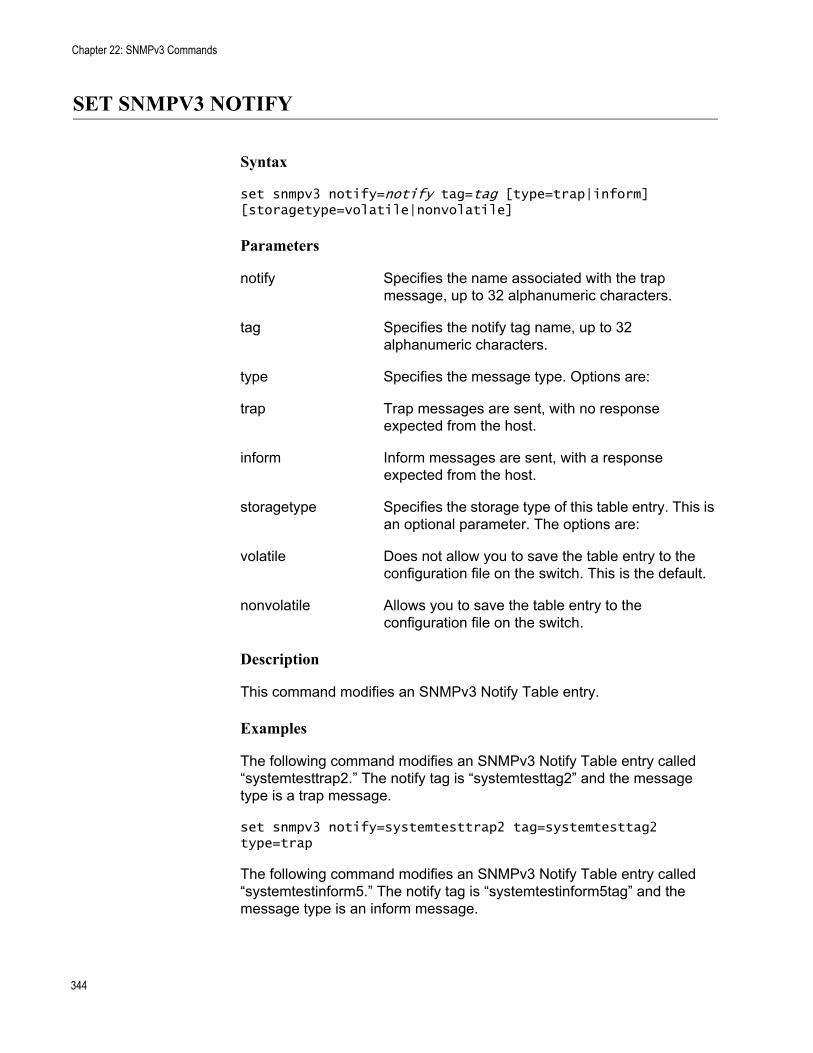
Chapter 22: SNMPv3 Commands
SET SNMPV3 NOTIFY
Syntax
set snmpv3 notify=notify tag=tag [type=trap|inform] [storagetype=volatile|nonvolatile]
Parameters
notify Specifies the name associated with the trap message, up to 32 alphanumeric characters.
tag Specifies the notify tag name, up to 32 alphanumeric characters.
type Specifies the message type. Options are:
trap Trap messages are sent, with no response expected from the host.
inform Inform messages are sent, with a response expected from the host.
storagetype Specifies the storage type of this table entry. This is an optional parameter. The options are:
volatile Does not allow you to save the table entry to the configuration file on the switch. This is the default.
nonvolatile Allows you to save the table entry to the configuration file on the switch.
Description
This command modifies an SNMPv3 Notify Table entry.
Examples
The following command modifies an SNMPv3 Notify Table entry called “systemtesttrap2.” The notify tag is “systemtesttag2” and the message type is a trap message.
set snmpv3 notify=systemtesttrap2 tag=systemtesttag2 type=trap
The following command modifies an SNMPv3 Notify Table entry called “systemtestinform5.” The notify tag is “systemtestinform5tag” and the message type is an inform message.
344

AT-S63 Management Software Command Line Interface User’s Guide
set snmpv3 notify=systemtestinform5 tag=systemtestinform5tag type=inform
345
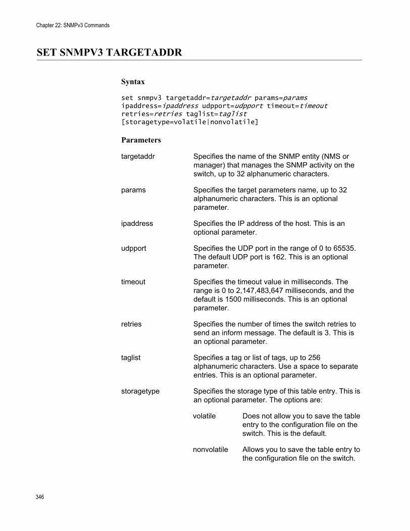
Chapter 22: SNMPv3 Commands
SET SNMPV3 TARGETADDR
Syntax
set snmpv3 targetaddr=targetaddr params=params ipaddress=ipaddress udpport=udpport timeout=timeout retries=retries taglist=taglist [storagetype=volatile|nonvolatile]
Parameters
targetaddr Specifies the name of the SNMP entity (NMS or manager) that manages the SNMP activity on the switch, up to 32 alphanumeric characters.
params Specifies the target parameters name, up to 32 alphanumeric characters. This is an optional parameter.
ipaddress Specifies the IP address of the host. This is an optional parameter.
udpport Specifies the UDP port in the range of 0 to 65535. The default UDP port is 162. This is an optional parameter.
timeout Specifies the timeout value in milliseconds. The range is 0 to 2,147,483,647 milliseconds, and the default is 1500 milliseconds. This is an optional parameter.
retries Specifies the number of times the switch retries to send an inform message. The default is 3. This is an optional parameter.
taglist Specifies a tag or list of tags, up to 256 alphanumeric characters. Use a space to separate entries. This is an optional parameter.
storagetype Specifies the storage type of this table entry. This is an optional parameter. The options are:
volatile Does not allow you to save the table entry to the configuration file on the switch. This is the default.
nonvolatile Allows you to save the table entry to the configuration file on the switch.
346
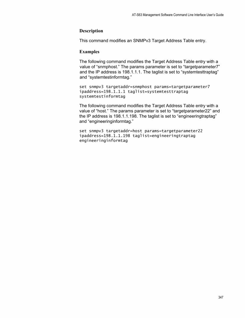
AT-S63 Management Software Command Line Interface User’s Guide
Description
This command modifies an SNMPv3 Target Address Table entry.
Examples
The following command modifies the Target Address Table entry with a value of “snmphost.” The params parameter is set to “targetparameter7” and the IP address is 198.1.1.1. The taglist is set to “systemtesttraptag” and “systemtestinformtag.”
set snmpv3 targetaddr=snmphost params=targetparameter7 ipaddress=198.1.1.1 taglist=systemtesttraptag systemtestinformtag
The following command modifies the Target Address Table entry with a value of “host.” The params parameter is set to “targetparameter22” and the IP address is 198.1.1.198. The taglist is set to “engineeringtraptag” and “engineeringinformtag.”
set snmpv3 targetaddr=host params=targetparameter22 ipaddress=198.1.1.198 taglist=engineeringtraptag engineeringinformtag
347
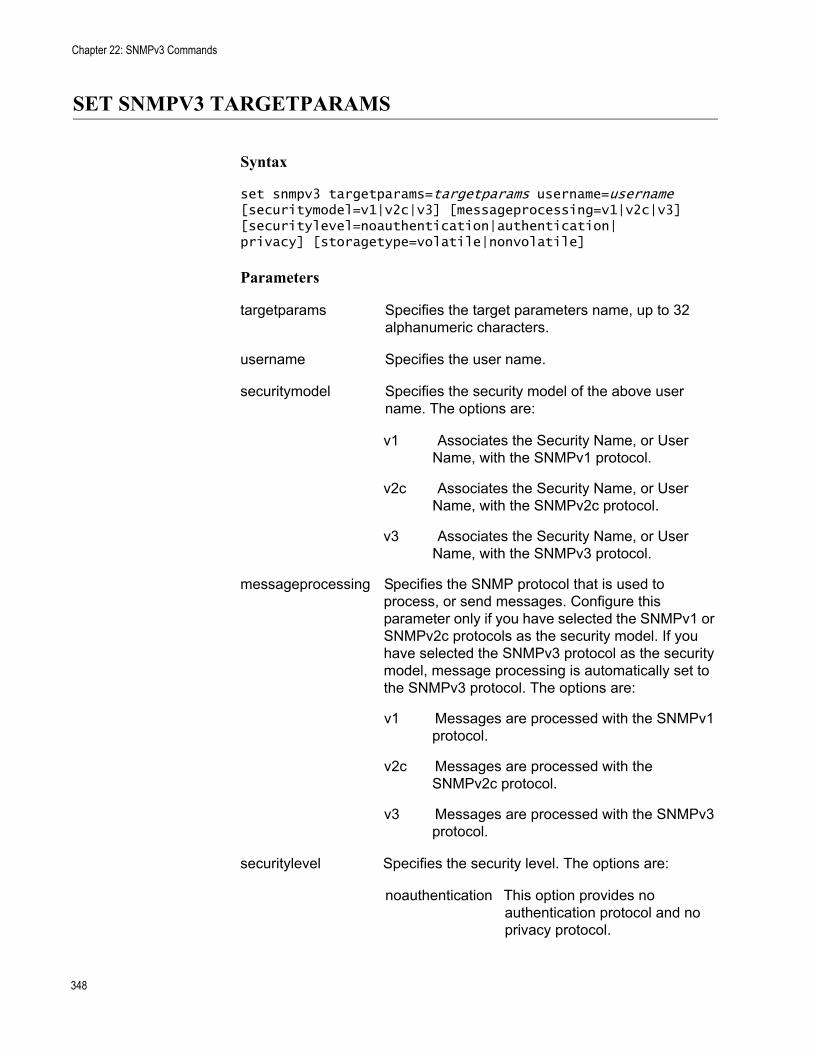
Chapter 22: SNMPv3 Commands
SET SNMPV3 TARGETPARAMS
Syntax
set snmpv3 targetparams=targetparams username=username [securitymodel=v1|v2c|v3] [messageprocessing=v1|v2c|v3] [securitylevel=noauthentication|authentication|privacy] [storagetype=volatile|nonvolatile]
Parameters
targetparams Specifies the target parameters name, up to 32 alphanumeric characters.
username Specifies the user name.
securitymodel Specifies the security model of the above user name. The options are:
v1 Associates the Security Name, or User Name, with the SNMPv1 protocol.
v2c Associates the Security Name, or User Name, with the SNMPv2c protocol.
v3 Associates the Security Name, or User Name, with the SNMPv3 protocol.
messageprocessing Specifies the SNMP protocol that is used to process, or send messages. Configure this parameter only if you have selected the SNMPv1 or SNMPv2c protocols as the security model. If you have selected the SNMPv3 protocol as the security model, message processing is automatically set to the SNMPv3 protocol. The options are:
v1 Messages are processed with the SNMPv1 protocol.
v2c Messages are processed with the SNMPv2c protocol.
v3 Messages are processed with the SNMPv3 protocol.
securitylevel Specifies the security level. The options are:
noauthentication This option provides no authentication protocol and no privacy protocol.
348
AT-S63 Management Software Command Line Interface User’s Guide
authentication This option provides an authentication protocol, but no privacy protocol.
privacy This option provides an authentication protocol and the privacy protocol.
storagetype Specifies the storage type of this table entry. This is an optional parameter. The options are:
volatile Does not allow you to save the table entry to the configuration file on the switch. This is the default.
nonvolatile Allows you to save the table entry to the configuration file on the switch.
Description
This command modifies a Target Parameters Table entry.
Examples
The following command modifies the Target Parameters Table entry called “host23.” The user name is “user7990” and the security model is the SNMPv3 protocol. The security level is set to the privacy level.
set snmpv3 targetparams=host23 username=loan1 securitymodel=v3 securitylevel=privacy
The following command modifies the Target Parameters Table entry called “manager9”. The user name is “loan1” and the security model is the SNMPv3 protocol. The security level is set to the authentication protocol.
set snmpv3 targetparams=manager9 username=loan1 securitymodel=v3 securitylevel=authentication
349
Chapter 22: SNMPv3 Commands
SET SNMPV3 USER
Syntax
set snmpv3 user=user [authentication=md5|sha] authpassword=password privpassword=password [storagetype=volatile|nonvolatile]
Parameters
user Specifies the name of an SNMPv3 user, up to 32 alphanumeric characters.
authentication Specifies the authentication protocol that is used to authenticate this user with an SNMPv3 entity (or NMS). The default is no authentication. The options are:
md5 The MD5 authentication protocol. Users are authenticated with the MD5 authentication protocol after a message is received.
sha The SHA authentication protocol. Users are authenticated with the SHA authentication protocol after a message is received.
authpassword Specifies a password for the authentication protocol, up to 32 alphanumeric characters.
privpassword Specifies a password for the 3DES privacy, or encryption protocol, up to 32 alphanumeric characters. Configuring a privacy protocol password, turns on the DES privacy protocol.
storagetype Specifies the storage type of this table entry. This is an optional parameter. The options are:
volatile Does not allow you to save the table entry to the configuration file on the switch. This is the default.
nonvolatile Allows you to save the table entry to the configuration file on the switch.
Description
This command modifies an SNMPv3 User Table entry.
350
AT-S63 Management Software Command Line Interface User’s Guide
Examples
The following command modifies a User Table entry called “atiuser104”. The authentication protocol is set to the MD5 protocol and the authentication password is “atlanta45denver.” The DES privacy protocol is on and the privacy password is “denvertoatlanta3.”
set snmpv3 user=atiuser104 authentication=md5 authpassword=atlanta45denver privpassword=denvertoatlanta3
The following command modifies a User Table entry called “atiuser104.” The authentication protocol is set to the MD5 protocol and the authentication password is “nycbostonwash56.” The privacy protocol is on and the privacy password is “bostontoamherst7.” The storage type is set to nonvolatile storage.
set snmpv3 user=atiuser104 authentication=md5 authpassword=nycbostonwash56 privpassword=bostontoamherst7 storagetype=nonvolatile
351
Chapter 22: SNMPv3 Commands
SET SNMPV3 VIEW
Syntax
set snmpv3 view=view [subtree=OID|text] mask=mask[type=included|excluded][storagetype=volatile|nonvolatile]
Parameters
view Specifies the name of the view, up to 32 alphanumeric characters.
subtree Specifies the view subtree view. Options are:
OID A numeric value in hexadecimal format.
text Text name of the view.
mask Specifies the subtree mask, in hexadecimal format.
type Specifies the view type. Options are:
included Permits the user assign to this View Name to see the specified subtree.
excluded Does not permit the user assigned to this View Name to see the specified subtree.
storagetype Specifies the storage type of this table entry. This is an optional parameter. The options are:
volatile Does not allow you to save the table entry to the configuration file on the switch. This is the default.
nonvolatile Allows you to save the table entry to the configuration file on the switch.
Description
This command modifies an SNMPv3 View Table entry.
Examples
The following command modifies the view called “internet1.” The subtree is set to the Internet MIBs and the view type is included.
set snmpv3 view=internet1 subtree=internet type=included
352

AT-S63 Management Software Command Line Interface User’s Guide
The following command modifies the view called system. The subtree is set to 1.3.6.1.2.1 (System MIBs) and the view type is excluded.
set snmpv3 view=system subtree=1.3.6.1.2.1 type=excluded
353
Chapter 22: SNMPv3 Commands
SHOW SNMPV3 ACCESS
Syntax
show snmpv3 access=access
Parameter
access Specifies an SNMPv3 Access Table entry.
Description
This command displays the SNMPv3 Access Table. You can display one or all of the table entries.
Examples
The following command displays the SNMPv3 Access Table entry called “production.”
show snmpv3 access=production
The following command displays all of the SNMPv3 Access Table entries:
show snmpv3 access
354
AT-S63 Management Software Command Line Interface User’s Guide
SHOW SNMPV3 COMMUNITY
Syntax
show snmpv3 community index=index
Parameter
index Specifies the name of this SNMPv3 Community Table entry, up to 32 alphanumeric characters.
Description
This command displays the SNMPv3 Community Table. You can display one or all of the SNMPv3 Community Table entries.
Examples
The following command displays the Community Table entry with an index of 246:
show snmpv3 community index=246
The following command displays all of the Community Table entries:
show snmpv3 community
355
Chapter 22: SNMPv3 Commands
SHOW SNMPv3 GROUP
Syntax
show snmpv3 group username=username [securitymodel=v1|v2c|v3]
Parameter
username Specifies a user name configured in the SNMPv3 User Table.
securitymodel Specifies the security model of the above user name. The options are:
v1 Associates the Security Name, or User Name, with the SNMPv1 protocol.
v2c Associates the Security Name, or User Name, with the SNMPv2c protocol.
v3 Associates the Security Name, or User Name, with the SNMPv3 protocol.
Description
This command displays SNMPv3 SecurityToGroup Table entries. You can display one or all of the table entries.
Example
The following command displays the SNMPv3 SecurityToGroup Table entry for a user named Dave who is assigned a security model of the SNMPv3 protocol.
show snmpv3 group username=Dave securitymodel=v3
The following command displays all of the SNMPv3 SecurityToGroup Table entries:
show snmpv3 group
356
AT-S63 Management Software Command Line Interface User’s Guide
SHOW SNMPV3 NOTIFY
Syntax
show snmpv3 notify=notify
Parameter
notify Specifies an SNMPv3 Notify Table entry.
Description
This command displays SNMPv3 Notify Table entries. You can display one or all of the table entries.
Examples
The following command displays the SNMPv3 Notify Table entry called “testengtrap1”:
show snmpv3 notify=testengtrap1
The following command displays all of the SNMPv3 Notify Table entries:
show snmpv3 notify
357
Chapter 22: SNMPv3 Commands
SHOW SNMPV3 TARGETADDR
Syntax
show snmpv3 targetaddr=targetaddr
Parameter
targetaddr Specifies an SNMPv3 Target Address Table entry.
Description
This command displays SNMPv3 Target Address Table entries. You can display one or all of the table entries.
Examples
The following command displays the SNMPv3 Target Address Table entry called “snmpv3host55”:
show snmpv3 targetaddr=snmpv3host55
The following command displays all of the SNMPv3 Target Address Table entries:
show snmpv3 targetaddr
358
AT-S63 Management Software Command Line Interface User’s Guide
SHOW SNMPV3 TARGETPARAMS
Syntax
show snmpv3 targetparams=targetparams
Parameter
targetparamsSpecifies an SNMPv3 Target Parameters Table entry.
Description
This command displays SNMPv3 Target Parameters Table entries. You can display one or all of the table entries.
Examples
The following command displays the SNMPv3 Target Parameters Table entry called “snmpv3manager95”:
show snmpv3 targetparams=snmpv3manager95
The following command displays all of the SNMPv3 Target Parameters Table entries:
show snmpv3 targetparams
359
Chapter 22: SNMPv3 Commands
SHOW SNMPV3 USER
Syntax
show snmpv3 user=user
Parameters
userSpecifies the name of an SNMPv3 user, up to 32 alphanumeric characters.
Description
This command displays SNMPv3 User Table entries. You can display one or all of the table entries.
Examples
The following command displays the SNMPv3 User Table entry for a user name of Robert:
show snmpv3 user=Robert
The following command displays all of the SNMPv3 User Table entries:
show snmpv3 user
360
AT-S63 Management Software Command Line Interface User’s Guide
SHOW SNMPV3 VIEW
Syntax
show snmpv3 view=view [subtree=OID|text]
Parameter
view Specifies an SNMPv3 View Table entry.
subtree Specifies the view subtree view. Options are:
OID A numeric value in hexadecimal format.
text Text name of the view.
Description
This command displays the SNMPv3 View Table entries. You can display one or all of the table entries.
Examples
The following command displays the SNMPv3 View Table entry called “snmpv3manager95”:
show snmpv3 targetparams=snmpv3manager95
The following command displays all the SNMPv3 View Table entries:
show snmpv3 targetparams
361

Chapter 22: SNMPv3 Commands
362
Chapter 23
STP Commands
This chapter contains the following commands:
“ACTIVATE STP” on page 364“DISABLE STP” on page 365“ENABLE STP” on page 366“PURGE STP” on page 367“SET STP” on page 368“SET STP PORT” on page 371“SHOW STP” on page 373
NoteRemember to save your changes with the SAVE CONFIGURATION command.
NoteFor background information on the Spanning Tree Protocol (STP)., refer to Chapter 21, “STP and RSTP” in the AT-S63 Management Software Menus Interface User’s Guide.
363
Chapter 23: STP Commands
ACTIVATE STP
Syntax
activate stp
Parameters
None.
Description
Use this command to designate STP as the active spanning tree on the switch. You cannot enable STP or configure its parameters until you have designated it as the active spanning tree with this command.
Only one spanning tree protocol, STP, RSTP, or MSTP, can be active on the switch at a time.
Example
The following command designates STP as the active spanning tree:
activate stp
364
AT-S63 Management Software Command Line Interface User’s Guide
DISABLE STP
Syntax
disable stp
Parameters
None.
Description
This command disables the Spanning Tree Protocol on the switch. The default setting for STP is disabled. To view the current status of STP, refer to “SHOW STP” on page 373.
Example
The following command disables STP:
disable stp
365
Chapter 23: STP Commands
ENABLE STP
Syntax
enable stp
Parameters
None.
Description
This command enables the Spanning Tree Protocol on the switch. The default setting for STP is disabled. To view the current status of STP, refer to “SHOW STP” on page 373.
NoteYou cannot enable STP until after you have activated it with “ACTIVATE STP” on page 364.
Example
The following command enables STP on the switch:
enable stp
366
AT-S63 Management Software Command Line Interface User’s Guide
PURGE STP
Syntax
purge stp
Parameters
None.
Description
This command returns all STP bridge and port parameters to the default settings. STP must be disabled in order for you to use this command. To disable STP, see “DISABLE STP” on page 365.
Example
The following command resets the STP parameter settings to their default values:
purge stp
367
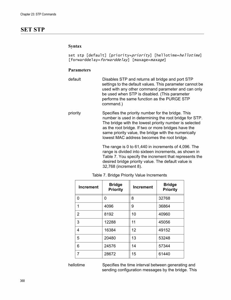
Chapter 23: STP Commands
SET STP
Syntax
set stp [default] [priority=priority] [hellotime=hellotime] [forwarddelay=forwarddelay] [maxage=maxage]
Parameters
default Disables STP and returns all bridge and port STP settings to the default values. This parameter cannot be used with any other command parameter and can only be used when STP is disabled. (This parameter performs the same function as the PURGE STP command.)
priority Specifies the priority number for the bridge. This number is used in determining the root bridge for STP. The bridge with the lowest priority number is selected as the root bridge. If two or more bridges have the same priority value, the bridge with the numerically lowest MAC address becomes the root bridge.
The range is 0 to 61,440 in increments of 4,096. The range is divided into sixteen increments, as shown in Table 7. You specify the increment that represents the desired bridge priority value. The default value is 32,768 (increment 8).
hellotime Specifies the time interval between generating and sending configuration messages by the bridge. This
Table 7. Bridge Priority Value Increments
Increment Bridge Priority Increment Bridge
Priority
0 0 8 32768
1 4096 9 36864
2 8192 10 40960
3 12288 11 45056
4 16384 12 49152
5 20480 13 53248
6 24576 14 57344
7 28672 15 61440
368
AT-S63 Management Software Command Line Interface User’s Guide
parameter can be from 1 to 10 seconds. The default is 2 seconds.
forwarddelay Specifies the waiting period before a bridge changes to a new state, for example, becomes the new root bridge after the topology changes. If the bridge transitions too soon, all links may not have had time to adapt to the change, resulting in network loops. The range is 4 to 30 seconds. The default is 15 seconds.
maxage Specifies the length of time after which stored bridge protocol data units (BPDUs) are deleted by the bridge. All bridges in a bridged LAN use this aging time to test the age of stored configuration messages called bridge protocol data units (BPDUs). For example, if you use the default 20, all bridges delete current configuration messages after 20 seconds. The range is 6 to 40 seconds. The default is 20 seconds.
NoteThe value for the maxage parameter must be greater than (2 x (hellotime +1)) and less than (2 x (forwarddelay -1)).
Description
This command sets the following STP parameters:
Bridge priorityHello timeForwarding delayMaximum age time
This command can also disable STP and return the STP parameters to their default settings.
NoteYou can use this command only if STP is designated as the active spanning tree protocol on the switch. See “ACTIVATE STP” on page 364.
Examples
The following command sets the switch’s bridge priority value to 45,056 (increment 11):
set stp priority=11
369

Chapter 23: STP Commands
The following command sets the hello time to 7 seconds and the forwarding delay to 25 seconds:
set stp hellotime=7 forwarddelay=25
The following command returns all STP parameters on the switch to the default values:
set stp default
370
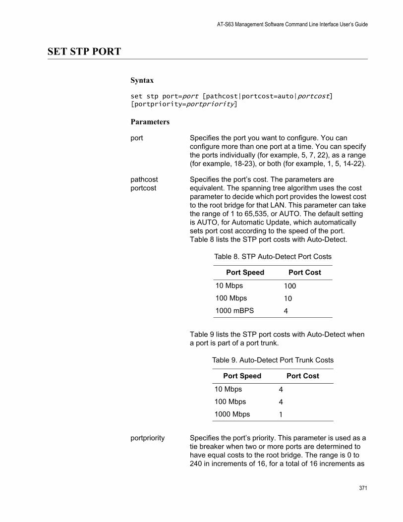
AT-S63 Management Software Command Line Interface User’s Guide
SET STP PORT
Syntax
set stp port=port [pathcost|portcost=auto|portcost] [portpriority=portpriority]
Parameters
port Specifies the port you want to configure. You can configure more than one port at a time. You can specify the ports individually (for example, 5, 7, 22), as a range (for example, 18-23), or both (for example, 1, 5, 14-22).
pathcost Specifies the port’s cost. The parameters areportcost equivalent. The spanning tree algorithm uses the cost
parameter to decide which port provides the lowest cost to the root bridge for that LAN. This parameter can take the range of 1 to 65,535, or AUTO. The default setting is AUTO, for Automatic Update, which automatically sets port cost according to the speed of the port. Table 8 lists the STP port costs with Auto-Detect.
Table 9 lists the STP port costs with Auto-Detect when a port is part of a port trunk.
portpriority Specifies the port’s priority. This parameter is used as a tie breaker when two or more ports are determined to have equal costs to the root bridge. The range is 0 to 240 in increments of 16, for a total of 16 increments as
Table 8. STP Auto-Detect Port Costs
Port Speed Port Cost
10 Mbps 100
100 Mbps 10
1000 mBPS 4
Table 9. Auto-Detect Port Trunk Costs
Port Speed Port Cost
10 Mbps 4
100 Mbps 4
1000 Mbps 1
371
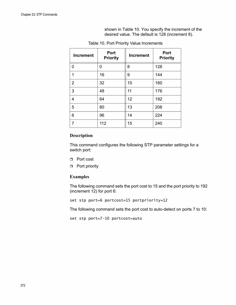
Chapter 23: STP Commands
shown in Table 10. You specify the increment of the desired value. The default is 128 (increment 8).
Description
This command configures the following STP parameter settings for a switch port:
Port costPort priority
Examples
The following command sets the port cost to 15 and the port priority to 192 (increment 12) for port 6:
set stp port=6 portcost=15 portpriority=12
The following command sets the port cost to auto-detect on ports 7 to 10:
set stp port=7-10 portcost=auto
Table 10. Port Priority Value Increments
Increment Port Priority Increment Port
Priority
0 0 8 128
1 16 9 144
2 32 10 160
3 48 11 176
4 64 12 192
5 80 13 208
6 96 14 224
7 112 15 240
372
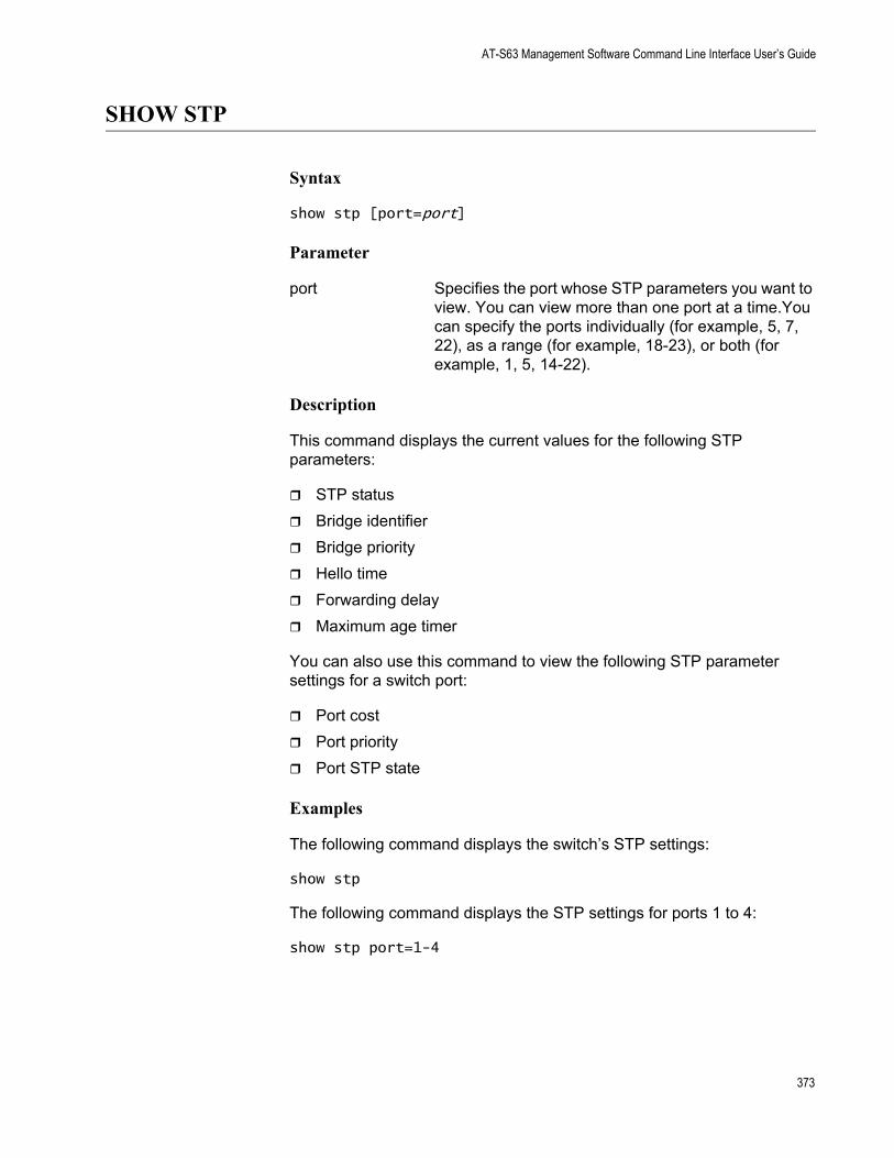
AT-S63 Management Software Command Line Interface User’s Guide
SHOW STP
Syntax
show stp [port=port]
Parameter
port Specifies the port whose STP parameters you want to view. You can view more than one port at a time.You can specify the ports individually (for example, 5, 7, 22), as a range (for example, 18-23), or both (for example, 1, 5, 14-22).
Description
This command displays the current values for the following STP parameters:
STP statusBridge identifierBridge priorityHello timeForwarding delayMaximum age timer
You can also use this command to view the following STP parameter settings for a switch port:
Port costPort priorityPort STP state
Examples
The following command displays the switch’s STP settings:
show stp
The following command displays the STP settings for ports 1 to 4:
show stp port=1-4
373

Chapter 23: STP Commands
374
Chapter 24
RSTP Commands
This chapter contains the following commands:
“ACTIVATE RSTP” on page 376“DISABLE RSTP” on page 377“ENABLE RSTP” on page 378“PURGE RSTP” on page 379“SET RSTP” on page 380“SET RSTP PORT” on page 383“SHOW RSTP” on page 386
NoteRemember to save your changes with the SAVE CONFIGURATION command.
NoteFor background information on the Rapid Spanning Tree Protocol (RSTP), refer to Chapter 21, “STP and RSTP” in the AT-S63 Management Software Menus Interface User’s Guide.
375
Chapter 24: RSTP Commands
ACTIVATE RSTP
Syntax
activate rstp
Parameters
None.
Description
Use this command to designate RSTP as the active spanning tree on the switch. After you have selected RSTP, you can enable or disable it using the ENABLE RSTP and DISABLE RSTP commands. RSTP is active on a switch only after you have designated it as the active spanning tree with this command and enabled it with the ENABLE RSTP command.
Only one spanning tree protocol, STP, RSTP, or MSTP, can be active on the switch at a time.
Example
The following command designates RSTP as the active spanning tree:
activate rstp
376

AT-S63 Management Software Command Line Interface User’s Guide
DISABLE RSTP
Syntax
disable rstp
Parameters
None.
Description
This command disables the Rapid Spanning Tree Protocol on the switch. To view the current status of RSTP, use “SHOW RSTP” on page 386.
Example
The following command disables RSTP:
disable rstp
377
Chapter 24: RSTP Commands
ENABLE RSTP
Syntax
enable rstp
Parameters
None.
Description
This command enables the Rapid Spanning Tree Protocol on the switch. The default setting for RSTP is disabled. To view the current status of RSTP, use “SHOW RSTP” on page 386.
You cannot enable RSTP until you have activated it with the ACTIVATE RSTP command.
Example
The following command enables RSTP:
enable rstp
378

AT-S63 Management Software Command Line Interface User’s Guide
PURGE RSTP
Syntax
purge rstp
Parameters
None.
Description
This command returns all RSTP bridge and port parameters to the default settings. RSTP must be disabled before you can use this command. To disable RSTP, refer to “DISABLE RSTP” on page 377.
Example
The following command resets RSTP:
purge rstp
379
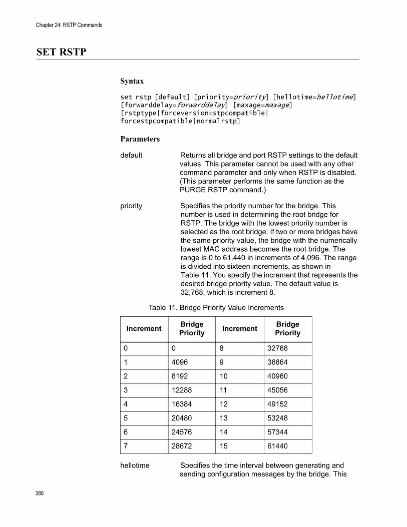
Chapter 24: RSTP Commands
SET RSTP
Syntax
set rstp [default] [priority=priority] [hellotime=hellotime] [forwarddelay=forwarddelay] [maxage=maxage][rstptype|forceversion=stpcompatible|forcestpcompatible|normalrstp]
Parameters
default Returns all bridge and port RSTP settings to the default values. This parameter cannot be used with any other command parameter and only when RSTP is disabled. (This parameter performs the same function as the PURGE RSTP command.)
priority Specifies the priority number for the bridge. This number is used in determining the root bridge for RSTP. The bridge with the lowest priority number is selected as the root bridge. If two or more bridges have the same priority value, the bridge with the numerically lowest MAC address becomes the root bridge. The range is 0 to 61,440 in increments of 4,096. The range is divided into sixteen increments, as shown in Table 11. You specify the increment that represents the desired bridge priority value. The default value is 32,768, which is increment 8.
hellotime Specifies the time interval between generating and sending configuration messages by the bridge. This
Table 11. Bridge Priority Value Increments
Increment Bridge Priority Increment Bridge
Priority
0 0 8 32768
1 4096 9 36864
2 8192 10 40960
3 12288 11 45056
4 16384 12 49152
5 20480 13 53248
6 24576 14 57344
7 28672 15 61440
380
AT-S63 Management Software Command Line Interface User’s Guide
parameter can be from 1 to 10 seconds. The default is 2 seconds.
forwarddelay Specifies the waiting period before a bridge changes to a new state, for example, becomes the new root bridge after the topology changes. If the bridge transitions too soon, not all links may have yet adapted to the change, resulting in network loops. The range is 4 to 30 seconds. The default is 15 seconds. This parameter effects only those ports operating in the STP compatible mode.
maxage Specifies the length of time, in seconds, after which stored bridge protocol data units (BPDUs) are deleted by the bridge. All bridges in a bridged LAN use this aging time to test the age of stored configuration messages called bridge protocol data units (BPDUs). For example, if you use the default value of 20, all bridges delete current configuration messages after 20 seconds. The range of this parameter is 6 to 40 seconds. The default is 20 seconds.
NoteThe value for the maxage parameter must be greater than (2 x (hellotime +1)) and less than (2 x (forwarddelay -1)).
rstptype Sets the RSTP mode. The parameters areforceversion equivalent. The options are:
stpcompatible The bridge uses the RSTP parameter settings, but transmits only STP BPDU packets from the ports. This option is equivalent to the FORCESTPCOMPATIBLE option.
forcestpcompatible The bridge uses the RSTP parameter settings, but transmits only STP BPDU packets from the ports. This option is equivalent to the STPCOMPATIBLE option.
normalrspt The bridge uses RSTP. It transmits RSTP BPDU packets, except on ports connected to bridges running STP. This is the default setting.
381
Chapter 24: RSTP Commands
Description
This command configures the following RSTP parameter settings.
Bridge priorityHello timeForwarding delayMaximum age timePort priorityForce version of STP or normal RSTP
This command can also return the RSTP parameters to their default settings.
NoteYou can use this command only if RSTP is the active spanning tree protocol on the switch. See “ACTIVATE RSTP” on page 376.
Examples
The following command sets the bridge priority to 20480 (increment 5), the hello time to 5 seconds, and the forwarding delay to 20 seconds:
set rstp priority=5 hellotime=5 forwarddelay=20
The following command uses the FORCEVERSION parameter to configure the bridge to use the RSTP parameters but to transmit only STP BPDU packets:
set rstp forceversion=stpcompatible
The following command returns all RSTP parameter settings to their default values:
set rstp default
382
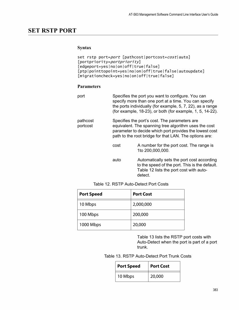
AT-S63 Management Software Command Line Interface User’s Guide
SET RSTP PORT
Syntax
set rstp port=port [pathcost|portcost=cost|auto] [portpriority=portpriority][edgeport=yes|no|on|off|true|false] [ptp|pointtopoint=yes|no|on|off|true|false|autoupdate][migrationcheck=yes|no|on|off|true|false]
Parameters
port Specifies the port you want to configure. You can specify more than one port at a time. You can specify the ports individually (for example, 5, 7, 22), as a range (for example, 18-23), or both (for example, 1, 5, 14-22).
pathcost Specifies the port’s cost. The parameters areportcost equivalent. The spanning tree algorithm uses the cost
parameter to decide which port provides the lowest cost path to the root bridge for that LAN. The options are:
cost A number for the port cost. The range is 1to 200,000,000.
auto Automatically sets the port cost according to the speed of the port. This is the default. Table 12 lists the port cost with auto-detect.
Table 13 lists the RSTP port costs with Auto-Detect when the port is part of a port trunk.
Table 12. RSTP Auto-Detect Port Costs
Port Speed Port Cost
10 Mbps 2,000,000
100 Mbps 200,000
1000 Mbps 20,000
Table 13. RSTP Auto-Detect Port Trunk Costs
Port Speed Port Cost
10 Mbps 20,000
383
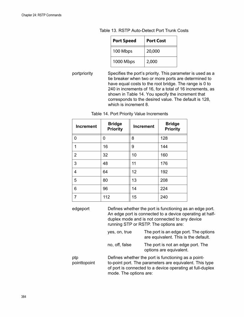
Chapter 24: RSTP Commands
portpriority Specifies the port’s priority. This parameter is used as a tie breaker when two or more ports are determined to have equal costs to the root bridge. The range is 0 to 240 in increments of 16, for a total of 16 increments, as shown in Table 14. You specify the increment that corresponds to the desired value. The default is 128, which is increment 8.
edgeport Defines whether the port is functioning as an edge port. An edge port is connected to a device operating at half-duplex mode and is not connected to any device running STP or RSTP. The options are:
yes, on, true The port is an edge port. The options are equivalent. This is the default.
no, off, false The port is not an edge port. The options are equivalent.
ptp Defines whether the port is functioning as a point-pointtopoint to-point port. The parameters are equivalent. This type
of port is connected to a device operating at full-duplex mode. The options are:
100 Mbps 20,000
1000 Mbps 2,000
Table 14. Port Priority Value Increments
Increment Bridge Priority Increment Bridge
Priority
0 0 8 128
1 16 9 144
2 32 10 160
3 48 11 176
4 64 12 192
5 80 13 208
6 96 14 224
7 112 15 240
Table 13. RSTP Auto-Detect Port Trunk Costs
Port Speed Port Cost
384
AT-S63 Management Software Command Line Interface User’s Guide
yes, on, true The port is an point-to-point port. The options are equivalent.
no, off, false The port is not an point-to-point port. The parameters are equivalent. are equivalent.
autoupdate The port’s status is determined automatically. This is the default.
migrationcheck Enables and disables migration check. The purpose of this feature is to change from the RSTP mode to the STP mode if STP BDPU packets are received on the selected port. When you enable this option, the bridge will send out RSTP BPDU packets from the selected port until STP BPDU packets are received. The port will remain in the RSTP mode until it receives an STP BPDU packet. The options are:
yes, on, true Enable migration check. The options are equivalent.
no, off, false Disable migration check. The options are equivalent.
Description
This command sets a port’s RSTP settings.
Examples
The following command sets the port cost to 1,000,000 and port priority to 224 (increment 14) on port 4:
set rstp port=4 portcost=1000000 portpriority=14
The following command changes ports 6 to 8 so they are not considered edge ports:
set rstp port=6-8 edgeport=no
385
Chapter 24: RSTP Commands
SHOW RSTP
Syntax
show rstp [portconfig=port|portstate=port]
Parameters
portconfig Displays the RSTP port settings. You can specify more than one port at a time.
portstate Displays the RSTP port status. You can specify more than one port at a time.
Description
You can use this command to display the RSTP parameter settings. Values are displayed for the following parameters:
RSTP statusBridge identifierBridge priorityHello timeMaximum agingForwarding delay
You can also use this command to view the following RSTP parameter settings for a switch port:
Port costPort priorityEdge and point-to-point status
Examples
The following command displays the bridge’s RSTP settings:
show rstp
The following command displays the RSTP port settings for ports 1 to 4:
show rstp portconfig=1-4
386
AT-S63 Management Software Command Line Interface User’s Guide
The following command displays RSTP port status for port 15:
show rstp portstate=15
387

Chapter 24: RSTP Commands
388
Chapter 25
MSTP Commands
This chapter contains the following commands:
“ACTIVATE MSTP” on page 390“ADD MSTP” on page 391“CREATE MSTP” on page 392“DELETE MSTP” on page 393“DESTROY MSTP MSTIID” on page 394“DISABLE MSTP” on page 395“ENABLE MSTP” on page 396“PURGE MSTP” on page 397“SET MSTP” on page 398“SET MSTP CIST” on page 401“SET MSTP MSTI” on page 402“SET MSTP MSTIVLANASSOC” on page 404“SET MSTP PORT” on page 405“SHOW MSTP” on page 408
NoteRemember to save your changes with the SAVE CONFIGURATION command.
NoteFor background information on the Multiple Spanning Tree Protocol (MSTP)., refer to Chapter 22, “MSTP” in the AT-S63 Management Software Menus Interface User’s Guide.
389
Chapter 25: MSTP Commands
ACTIVATE MSTP
Syntax
activate mstp
Parameters
None.
Description
This command designates MSTP as the active spanning tree on the switch. You cannot enable MSTP or configure its parameters until after you have designated it as the active spanning tree with this command.
Only one spanning tree protocol can be active on the switch at a time.
Example
The following command designates MSTP as the active spanning tree:
activate mstp
390
AT-S63 Management Software Command Line Interface User’s Guide
ADD MSTP
Syntax
add mstp mstiid=mstiid mstivlanassoc=vids
Parameters
mstiid Specifies the ID of the multiple spanning tree instance (MSTI) to which you want to associate VLANs. You can specify only one MSTI ID at a time. The range is 1 to 15.
mstivlanassoc Specifies the VID of the VLAN you want to associate with the MSTI ID. You can specify more than one VID at a time (for example, 2,5,44).
Description
This command associates VLANs to a MSTI.
The MSTIID parameter specifies the MSTI ID. The MSTI must already exist on the switch. To create a spanning tree instance, see “CREATE MSTP” on page 392.
The MSTIVLANASSOC parameter specifies the VIDs of the VLANs you want to associate with the MSTI. The VLANs must already exist on the switch. Any VLANs already associated with the MSTI are retained. If you want to add VLANs to a MSTI while removing those already associated to it, see “SET MSTP MSTIVLANASSOC” on page 404.
Examples
The following command associates the VLAN with the VID 4 to MSTI ID 8:
add mstp mstiid=8 mstivlanassoc=4
The following command associates the VLANs with the VIDs 24 and 44 to MSTI ID 11:
add mstp mstiid=11 mstivlanassoc=24,44
391
Chapter 25: MSTP Commands
CREATE MSTP
Syntax
create mstp mstiid=mstiid [mstivlanassoc=vids]
Parameters
mstiid Specifies the MSTI ID of the spanning tree instance you want to create. You can specify only one MSTI ID at a time. The range is 1 to 15.
mstivlanassoc Specifies the VID of the VLAN you want to associate with the MSTI ID. You can specify more than one VID at a time (for example, 2,5,44).
Description
This command creates an MSTI ID and associates VLANs to the new spanning tree instance.
The MSTIID parameter specifies the new MSTI ID.
The MSTIVLANASSOC parameter specifies the VIDs of the VLANs you want to associate with the new MSTI. The VLANs must already exist on the switch. If you do not specify any VLANs, you can add them later using “ADD MSTP” on page 391 or “SET MSTP MSTIVLANASSOC” on page 404.
Examples
The following command creates the MSTI ID 8 and associates to it the VLAN with the VID 4:
create mstp mstiid=8 mstivlanassoc=4
The following command creates the MSTI ID 11 and associates to it the VLANs with the VIDs 24 and 44:
create mstp mstiid=11 mstivlanassoc=24,44
392

AT-S63 Management Software Command Line Interface User’s Guide
DELETE MSTP
Syntax
delete mstp mstiid=mstiid mstivlanassoc=vids
Parameters
mstiid Specifies the MSTI ID of the spanning tree instance where you want to remove VLANs. You can specify only one MSTI ID at a time. The range is 1 to 15.
mstivlanassoc Specifies the VID of the VLAN you want to remove from the spanning tree instance. You can specify more than one VID at a time (for example, 2,5,44).
Description
This command removes a VLAN from a spanning tree instance. A VLAN removed from a spanning tree instance is automatically returned to CIST.
The MSTIID parameter specifies the MSTI ID.
The MSTIVLANASSOC parameter specifies the VIDs of the VLANs you want to remove from the spanning tree instance.
Examples
The following command deletes the VLAN with the VID 4 from MSTI ID 8:
delete mstp mstiid=8 mstivlanassoc=4
The following command deletes the VLANs with the VIDs 24 and 44 from MSTI ID 11:
delete mstp mstiid=11 mstivlanassoc=24,44
393

Chapter 25: MSTP Commands
DESTROY MSTP MSTIID
Syntax
destroy mstp mstiid=mstiid
Parameter
mstiid Specifies the MSTI ID of the spanning tree instance you want to delete. You can specify only one MSTI ID at a time. The range is 1 to 15.
Description
This command deletes a spanning tree instance. VLANs associated with a deleted MSTI are returned to CIST.
Example
The following command deletes the spanning tree instance 4:
destroy mstp mstiid=4
394
AT-S63 Management Software Command Line Interface User’s Guide
DISABLE MSTP
Syntax
disable mstp
Parameters
None.
Description
This command disables the Multiple Spanning Tree Protocol on the switch. To view the current status of MSTP, refer to “SHOW MSTP” on page 408.
Example
The following command disables MSTP:
disable mstp
395
Chapter 25: MSTP Commands
ENABLE MSTP
Syntax
enable mstp
Parameters
None.
Description
This command enables Multiple Spanning Tree Protocol on the switch. To view the current status of MSTP, refer to “SHOW MSTP” on page 408.
You must select MSTP as the active spanning tree on the switch before you can enable it with this command. To activate MSTP, see “ACTIVATE MSTP” on page 390.
Example
The following command enables MSTP:
enable mstp
396
AT-S63 Management Software Command Line Interface User’s Guide
PURGE MSTP
Syntax
purge mstp
Parameters
None.
This command returns all MSTP bridge and port parameters settings to their default values.
In order for you to use this command, MSTP must be the active spanning tree protocol on the switch and the protocol must be disabled. To select MSTP as the active spanning tree protocol on the switch, see “ACTIVATE MSTP” on page 390. To disable MSTP, refer to “DISABLE MSTP” on page 395.
Example
The following command resets the MSTP bridge and port parameter settings:
purge mstp
397
Chapter 25: MSTP Commands
SET MSTP
Syntax
set mstp [default] [forceversion=stpcompatible|forcestpcompatible|normalmstp] [hellotime=hellotime] [forwarddelay=forwarddelay] [maxage=maxage] [maxhops=maxhops] [configname="name"] [revisionlevel=number]
Parameters
default Disables MSTP and returns all bridge and port MSTP settings to the default values. This parameter cannot be used with any other parameter. (This parameter performs the same function as the PURGE MSTP command.) The spanning tree protocol must be disabled to use this parameter.
forceversion Controls whether the bridge will operate with MSTP or in an STP-compatible mode. If you select MSTP, the bridge will operate all ports in MSTP, except for those ports that receive STP or RSTP BPDU packets. If you select STP Compatible or Force STP Compatible, the bridge uses its MSTP parameter settings, but sends only STP BPDU packets from the ports
The options are:
stpcompatible The bridge uses the MSTP parameter settings, but transmits only STP BPDU packets from the ports. This option is equivalent to the FORCESTPCOMPATIBLE option.
forcestpcompatible The bridge uses the MSTP parameter settings, but transmits only STP BPDU packets from the ports. This option is equivalent to the STPCOMPATIBLE option.
398
AT-S63 Management Software Command Line Interface User’s Guide
normalmspt The bridge uses MSTP. The bridge sends out MSTP BPDU packets from all ports except for those ports connected to bridges running STP. This is the default setting.
hellotime Specifies the time interval between generating and sending configuration messages by the bridge. This parameter can be from 1 to 10 seconds. The default is 2 seconds.
forwarddelay Specifies the waiting period before a bridge changes to a new state, for example, becomes the new root bridge after the topology changes. If the bridge transitions too soon, not all links may have yet adapted to the change, resulting in network loops. The default is 15 seconds. This parameter effects only those ports operating in the STP compatible mode.
maxage Specifies the length of time, in seconds, after which stored bridge protocol data units (BPDUs) are deleted by the bridge. All bridges in a bridged LAN use this aging time to test the age of stored configuration messages called bridge protocol data units (BPDUs). For example, if you use the default value of 20, all bridges delete current configuration messages after 20 seconds. The range of this parameter is 6 to 40 seconds. The default is 20 seconds.
NoteThe value for the maxage parameter must be greater than (2 x (hellotime +1)) and less than (2 x (forwarddelay -1)).
maxhops Specifies the maximum hops counter. MSTP regions use this parameter to discard BPDUs. The Max Hop counter in a BPDU is decreased every time the BPDU crosses an MSTP regional boundary. After the counter reaches zero, the BPDU is deleted.
configname Specifies the name of the MSTP region. The range is 0 (zero) to 32 alphanumeric characters. The name is case-sensitive and must be the same on all bridges in a region. Examples include Sales Region and Production Region. The name must be enclosed in quotes.
revisionlevel Specifies the version number of an MSTP region. The range is 0 (zero) to 255. This is an arbitrary number that you assign to a region. The version level must be the
399
Chapter 25: MSTP Commands
same on all bridges in a region. Different regions can have the same version level without conflict.
Description
This command configures the following MSTP parameter settings.
Hello timeForwarding delayMaximum age timeMaximum hop countForce version of STP or normal MSTPConfiguration nameRevision level
Examples
The following command disables MSTP and returns all MSTP parameter settings to their default values:
set mstp default
The following command sets the hop count to 10, the configuration name to Engineering Region, and the reversion level to 2:
set mstp maxhops=10 configname="Engineering Region" revisionlevel=2
The following command uses the FORCEVERSION parameter to configure the bridge to use the MSTP parameters but to transmit only STP BPDU packets:
set mstp forceversion=forcestpcompatible
400
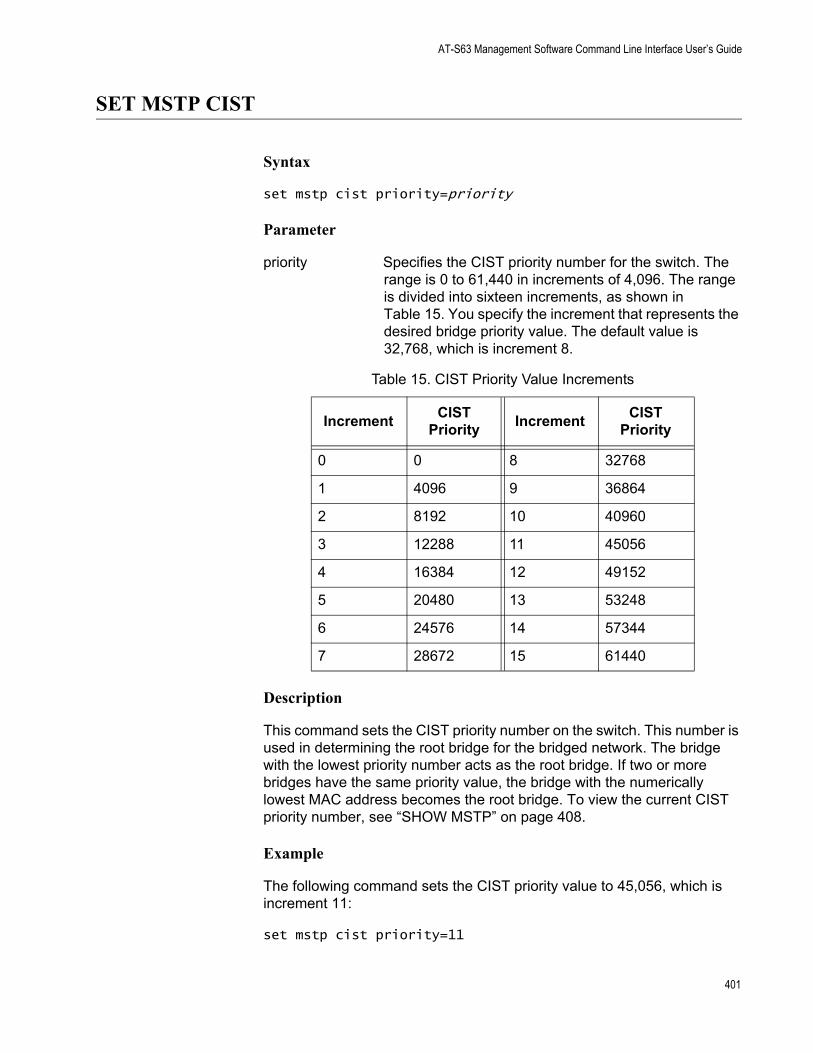
AT-S63 Management Software Command Line Interface User’s Guide
SET MSTP CIST
Syntax
set mstp cist priority=priority
Parameter
priority Specifies the CIST priority number for the switch. The range is 0 to 61,440 in increments of 4,096. The range is divided into sixteen increments, as shown in Table 15. You specify the increment that represents the desired bridge priority value. The default value is 32,768, which is increment 8.
Description
This command sets the CIST priority number on the switch. This number is used in determining the root bridge for the bridged network. The bridge with the lowest priority number acts as the root bridge. If two or more bridges have the same priority value, the bridge with the numerically lowest MAC address becomes the root bridge. To view the current CIST priority number, see “SHOW MSTP” on page 408.
Example
The following command sets the CIST priority value to 45,056, which is increment 11:
set mstp cist priority=11
Table 15. CIST Priority Value Increments
Increment CIST Priority Increment CIST
Priority
0 0 8 32768
1 4096 9 36864
2 8192 10 40960
3 12288 11 45056
4 16384 12 49152
5 20480 13 53248
6 24576 14 57344
7 28672 15 61440
401
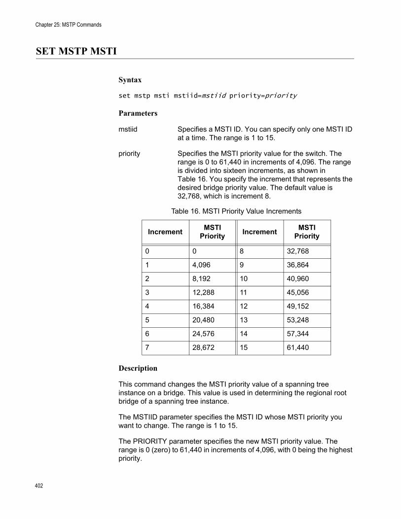
Chapter 25: MSTP Commands
SET MSTP MSTI
Syntax
set mstp msti mstiid=mstiid priority=priority
Parameters
mstiid Specifies a MSTI ID. You can specify only one MSTI ID at a time. The range is 1 to 15.
priority Specifies the MSTI priority value for the switch. The range is 0 to 61,440 in increments of 4,096. The range is divided into sixteen increments, as shown in Table 16. You specify the increment that represents the desired bridge priority value. The default value is 32,768, which is increment 8.
Description
This command changes the MSTI priority value of a spanning tree instance on a bridge. This value is used in determining the regional root bridge of a spanning tree instance.
The MSTIID parameter specifies the MSTI ID whose MSTI priority you want to change. The range is 1 to 15.
The PRIORITY parameter specifies the new MSTI priority value. The range is 0 (zero) to 61,440 in increments of 4,096, with 0 being the highest priority.
Table 16. MSTI Priority Value Increments
Increment MSTI Priority Increment MSTI
Priority
0 0 8 32,768
1 4,096 9 36,864
2 8,192 10 40,960
3 12,288 11 45,056
4 16,384 12 49,152
5 20,480 13 53,248
6 24,576 14 57,344
7 28,672 15 61,440
402

AT-S63 Management Software Command Line Interface User’s Guide
Examples
The following command changes the MSTI priority value to 45,056 (increment 11) for the MSTI ID 4:
set mstp msti mstiid=4 priority=11
The following command changes the MSTI priority value to 8,192 (increment 2) for the MSTI ID 6:
set mstp msti mstiid=6 priority=2
403

Chapter 25: MSTP Commands
SET MSTP MSTIVLANASSOC
Syntax
set mstp mstivlanassoc mstiid=mstiid vlanlist=vids
Parameters
mstiid Specifies the ID of the spanning tree instance where you want to associate VLANs. You can specify only one MSTI ID at a time. The range is 1 to 15.
vlanlist Specifies the VID of the VLAN you want to associate with the MSTI ID. You can specify more than one VID at a time (for example, 2,5,44). If VLANs have already been associated with the MSTI, they are overwritten.
Description
This command associates VLANs to spanning tree instances.
The MSTIID parameter specifies the ID of the spanning tree instance. The spanning tree instance must already exist on the switch. To create a spanning tree instance, see “CREATE MSTP” on page 392.
The VLANLIST parameter specifies the VID of the VLANs you want to associate with the MSTI. The VLANs must already exist on the switch. If VLANs are already associated with the MSTI, they are removed and returned to CIST. If you want to add VLANs to an MSTI and retain those VLANs already associated with it, see “ADD MSTP” on page 391.
Examples
The following command associates the VLAN with the VID 4 to MSTI ID 8:
set mstp mstivlanassoc mstiid=8 vlanlist=4
The following command associates VIDs 24 and 44 to MSTI ID 11:
set mstp mstivlanassoc mstiid=11 vlanlist=24,44
404
AT-S63 Management Software Command Line Interface User’s Guide
SET MSTP PORT
Syntax
set mstp port=port|all [intportcost=auto|portcost] [extportcost=portcost] [portpriority=priority][edgeport=yes|no|no|on|off|true|false] [ptp|pointtopoint=yes|no|on|off|true|false|autoupdate] [migrationcheck=yes|no|on|off|true|false]
Parameters
port Specifies the port you want to configure. You can specify more than one port at a time. To configure all ports in the switch, enter ALL.
intportcost Specifies the cost of a port connected to a bridge that is part of the same MSTP region. This is referred to as an internal port cost. The range is 0 to 200,000,000. The default setting is Auto-detect (0), which sets port cost depending on the speed of the port. Default values are 2,000,000 for 10 Mbps ports, 200,000 for a 100 Mbps ports, and 20,000 for one gigabit ports.
extportcost Specifies the cost of a port connected to a bridge which is a member of another MSTP region or is running STP or RSTP. This is referred to as an external port cost. The range is 0 to 200,000,000. The default setting is 200,000.
portpriority Specifies the port’s priority. This parameter is used as a tie breaker when two or more ports are determined to have equal costs to the root bridge. The range is 0 to 240 in increments of 16, for a total of 16 increments, as shown in Table 17 on page 406. You specify the increment of the desired value. The default is 128, which is increment 8.
405
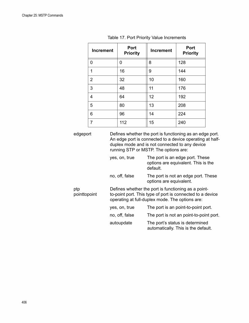
Chapter 25: MSTP Commands
edgeport Defines whether the port is functioning as an edge port. An edge port is connected to a device operating at half-duplex mode and is not connected to any device running STP or MSTP. The options are:
yes, on, true The port is an edge port. These options are equivalent. This is the default.
no, off, false The port is not an edge port. These options are equivalent.
ptp Defines whether the port is functioning as a point-pointtopoint to-point port. This type of port is connected to a device
operating at full-duplex mode. The options are:
yes, on, true The port is an point-to-point port.
no, off, false The port is not an point-to-point port.
autoupdate The port’s status is determined automatically. This is the default.
Table 17. Port Priority Value Increments
Increment Port Priority Increment Port
Priority
0 0 8 128
1 16 9 144
2 32 10 160
3 48 11 176
4 64 12 192
5 80 13 208
6 96 14 224
7 112 15 240
406
AT-S63 Management Software Command Line Interface User’s Guide
migrationcheck This parameter resets a MSTP port, allowing it to send MSTP BPDUs. When a MSTP bridge receives STP BPDUs on an MSTP port, the port transmits STP BPDUs. The MSTP port continues to transmit STP BPDUs indefinitely. Set the migrationcheck parameter to yes to reset the MSTP port to transmit MSTP BPDUs.
yes, on, true Enable migration check. The options are equivalent.
no, off, false Disable migration check. The options are equivalent.
NoteEach time a MSTP port is reset by receiving STP BPDUs, set the migrationcheck parameter to yes, allowing the port to send MSTP BPDUs.
Description
This command sets a port’s MSTP settings.
Examples
The following command sets the internal port cost to 1,000,000 and port priority to 224 (increment 14) for Port 4:
set mstp port=4 intportcost=1000000 portpriority=14
The following command changes Ports 6 to 8 so they are not considered edge ports:
set mstp port=6-8 edgeport=no
The following command returns Port 7 to the default MSTP settings:
set mstp port=7 default
407
Chapter 25: MSTP Commands
SHOW MSTP
Syntax
show mstp [portconfig=ports] [portstate=ports] [msti] [cist] [mstivlanassoc]
Parameters
portconfig Specifies a port. You can specify more than one port at a time. For a list of the MSTP information displayed by this parameter, refer to Description below.
portstate Specifies a port. You can specify more than one port at a time. For a list of the MSTP information displayed by this parameter, refer to Description below.
msti Displays a list of the MSTIs on the switch and their associated VLANs. The list does not include the CIST.
cist Displays the CIST priority and the VLANs associated with CIST.
mstivlanassoc Displays a list of the MSTIs on the switch, including the CIST, and their associated VLANs.
NoteYou can specify only one parameter at a time in this command.
Description
This command displays MSTP parameters. For definitions of the MSTP terms used below, refer to Chapter 17, “MSTP” in the <Italic>AT-S63 Management Software Menus Interface User’s Guide.
Entering SHOW MSTP without any parameters displays the following MSTP settings:
MSTP statusForce versionHello timeForwarding delayMaximum ageMaximum hopsConfiguration name
408
AT-S63 Management Software Command Line Interface User’s Guide
Reversion levelBridge identifier
The PORTCONFIG parameter displays the following MSTP port parameter settings:
Edge-port statusPoint-to-point statusExternal and internal port costsPort priority
The PORTSTATE parameter displays the following MSTP port status information:
MSTP port stateMSTI IDMSTP rolePoint-to-point statusSpanning tree versionPort cost
The MSTI parameter displays the following information for each spanning tree instance (excluding the CIST) on the switch:
MSTI IDMSTI priorityRegional root IDPath costAssociated VLANs
The CIST parameter displays the CIST priority value and the VLANs associated with this spanning tree instance.
The MSTIVLANASSOC parameter displays the VLAN to MSTI associations.
409

Chapter 25: MSTP Commands
410
Chapter 26
VLANs and Multiple VLAN Mode Commands
This chapter contains the following commands:
“ADD VLAN” on page 412“CREATE VLAN” on page 415“DELETE VLAN” on page 418“DESTROY VLAN” on page 421“SET SWITCH INFILTERING” on page 422“SET SWITCH MANAGEMENTVLAN” on page 423“SET SWITCH VLANMODE” on page 424“SET VLAN” on page 426“SHOW VLAN” on page 427
NoteRemember to use the SAVE CONFIGURATION command to save your changes on the switch.
NoteFor background information on tagged and port-based VLANs, multiple VLAN modes, and ingress filtering, refer to Chapter 23, “Port-based and Tagged VLANs” in the AT-S63 Management Software Menus Interface User’s Guide. For information about multiple VLANs, refer to Chapter 25, “Multiple VLANs” in the AT-S63 Management Software Menus Interface User’s Guide.
411
Chapter 26: VLANs and Multiple VLAN Mode Commands
ADD VLAN
Syntax 1
add vlan=name [vid=vid] port=ports|all frame=untagged|tagged
Syntax 2
add vlan=name [vid=vid] taggedports=ports|all untaggedports=ports|all
Parameters
vlan Specifies the name of the VLAN you want to modify. The name can be from 1 to 20 characters in length.
vid Specifies the VID of the VLAN you want to modify. This parameter is optional.
port Specifies the ports to be added to the VLAN. You can specify the ports individually (for example, 5, 7, 22), as a range (for example, 18-23), or both (for example, 1, 5, 14-22).
frame Identifies the new ports as either tagged or untagged. This parameter must be used with the PORT parameter.
taggedports Specifies the ports to be added as tagged ports to the VLAN. To include all ports on the switch as tagged ports in the VLAN, use ALL.
untaggedports Specifies the ports to be added as untagged ports to the VLAN. Specifying ALL adds all ports on the switch as untagged ports to the VLAN.
Description
This command adds tagged and untagged ports to an existing port-based or tagged VLAN.
NoteTo initially create a VLAN, see “CREATE VLAN” on page 415. To remove ports from a VLAN, see “DELETE VLAN” on page 418.
412
AT-S63 Management Software Command Line Interface User’s Guide
NoteWhen a transceiver is inserted into an uplink slot and a link is established, that slot becomes a primary uplink port and the corresponding backup port, 23R or 24R, automatically transitions to redundant uplink status. Any VLAN settings remain intact when the backup port makes the transition to a redundant uplink state.
This command has two syntaxes. You can use either command to add ports to a VLAN. The difference between the two is that Syntax 1 can add only one type of port, tagged or untagged, at a time to a VLAN, while Syntax 2 can add both in the same command. This is illustrated in Examples below.
When you add untagged ports to a VLAN, the ports are automatically removed from their current untagged VLAN assignment. This is because a port can be an untagged member of only one VLAN at a time. For example, if you add port 4 as an untagged port to a VLAN, the port is automatically removed from whichever VLAN it is currently an untagged member.
Adding a tagged port to a VLAN does not change the port’s current tagged and untagged VLAN assignments. This is because a tagged port can belong to more than one VLAN at a time. For instance, if you add port 6 as an tagged port to a new VLAN, port 6 remains a tagged and untagged member of its other VLAN assignments.
Examples
The following command uses Syntax 1 to add ports 4 and 7 as untagged members to a VLAN called Sales:
add vlan=sales port=4,7 frame=untagged
The following command does the same thing using Syntax 2:
add vlan=sales untaggedports=4,7
The following command uses Syntax 1 to add port 3 as a tagged member to a VLAN called Production:
add vlan=production port=3 frame=tagged
The following command does the same thing using Syntax 2:
add vlan=production untaggedports=3
Adding both tagged and untagged ports to a VLAN using Syntax 1 takes two commands, one command for each port type. For example, if you had a VLAN called Service and you wanted to add port 5 as a tagged port and ports 7 and 8 as untagged ports, the commands would be:
413

Chapter 26: VLANs and Multiple VLAN Mode Commands
add vlan=Service port=5 frame=tagged
add vlan=Service port=7-8 frame=untagged
Using Syntax 2, you can add both types of ports with just one command:
add vlan=Service untaggedports=7-8 taggedports=5
414
AT-S63 Management Software Command Line Interface User’s Guide
CREATE VLAN
Syntax 1
create vlan=name vid=vid port=ports|all frame=untagged|tagged
Syntax 2
create vlan=name vid=vid taggedports=ports|all untaggedports=ports|all
Parameters
vlan Specifies the name of the VLAN. You must assign a name to a VLAN.
The name can be from 1 to 20 characters in length and should reflect the function of the nodes that will be a part of the VLAN (for example, Sales or Accounting). The name cannot contain spaces or special characters, such as asterisks (*) or exclamation points (!).
The name cannot be the same as the name of an existing VLAN on the switch.
If the VLAN is unique in your network, then the name needs to be unique as well. If the VLAN spans multiple switches, then the name for the VLAN should be the same on each switch.
vid Specifies the VLAN identifier. The range is 2 to 4094. The VLAN must be assigned a VID.
You cannot use the VID 1, which is reserved for the Default_VLAN.
The VID cannot be the same as the VID of an existing VLAN on the switch.
If this VLAN is unique in your network, then its VID should also be unique. If this VLAN is part of a larger VLAN that spans multiple switches, then the VID value for the VLAN should be the same on each switch. For example, if you are creating a VLAN called Sales that spans three switches, assign the Sales VLAN on each switch the same VID value.
415
Chapter 26: VLANs and Multiple VLAN Mode Commands
port Specifies the ports on the switch that are either tagged or untagged members of the new VLAN. You can specify the ports individually (for example, 5, 7, 22), as a range (for example, 18-23), or both (for example, 1, 5, 14-22). To specify all ports on the switch, use ALL. This parameter must be followed by the FRAME parameter.
frame Specifies whether the ports of the VLAN are to be tagged or untagged. This parameter must be used with the PORT parameter.
taggedports Specifies the ports on the switch to serve as tagged ports in the VLAN. To specify all ports on the switch, use ALL. Omit this parameter if the VLAN does not contain tagged ports.
untaggedports Specifies the ports on the switch to function as untagged ports in the VLAN. To specify all ports on the switch, use ALL. Omit this parameter if the VLAN does not contain untagged ports.
Description
This command creates a port-based or tagged VLAN.
This command has two syntaxes. You can use either syntax to create a port-based or tagged VLAN. The difference between the two syntaxes is how you specify which ports are members of the VLAN and whether the ports are tagged or untagged. Syntax 1 is limited because it allows you to specify either tagged or untagged ports, but not both at the same time. On the other hand, you can use Syntax 2 to create a VLAN that has both types of ports. This is illustrated in the Examples section below.
When you create a new VLAN, untagged ports of the new VLAN are automatically removed from their current untagged VLAN assignment. This is because a port can be an untagged member of only one VLAN at a time. For example, creating a new VLAN with untagged Ports 1 to 4 automatically removes these ports from whichever VLAN they are currently untagged members.
The PVID of an untagged port is automatically changed to match the VID number of the VLAN to which it is added. For instance, if you make port 4 an untagged member of a VLAN with a VID of 15, port 4’s PVID is changed to 15 automatically.
Tagged ports of the new VLAN remain as tagged and untagged members of their current VLAN assignments. No change is made to a tagged port’s current VLAN assignments, other than its addition to the new VLAN. This is because a tagged port can belong to more than one VLAN at a time. For example, if you add port 6 as a tagged port to a new VLAN, port 6 remains
416
AT-S63 Management Software Command Line Interface User’s Guide
a member of its other current untagged and tagged VLAN assignments.
Examples
The following command uses Syntax 1 to create a port-based VLAN called Sales with a VID of 3. The VLAN will consist of ports 4 to 8 and ports 12 to 16. All ports will be untagged ports in the VLAN:
create vlan=Sales vid=3 port=4-8,12-16 frame=untagged
The following command uses Syntax 2 to create the same VLAN:
create vlan=Sales vid=3 untaggedports=4-8,12-16
In the following command, Syntax 1 is used to create a tagged VLAN called Production with a VID of 22. The VLAN will consist of two tagged ports, ports 3 and 6:
create vlan=Production vid=22 port=3,6 frame=tagged
The following command uses Syntax 2 to create the same VLAN:
create vlan=Sales vid=22 taggedports=3,6
You cannot use Syntax 1 to create a tagged VLAN that contains both untagged and tagged ports. For instance, suppose you wanted to create a VLAN called Service with a VID of 16 and untagged ports 1, 4, 5-7 and tagged ports 11 and 12. Creating this VLAN using Syntax 1 would actually require two commands. You would first need to create the VLAN, specifying either the untagged or tagged ports. As an example, the following command creates the VLAN and specifies the untagged ports:
create vlan=Service vid=16 port=1,4,5-7 frame=untagged
Then, to add the other ports (in this case tagged ports), you would need to use the ADD VLAN command.
Syntax 2 allows you to create a VLAN of both tagged and untagged ports all in one command. Here is the command that would create our example:
create vlan=Service vid=16 untaggedports=1,4,5-7 taggedports=11-12
The advantage of Syntax 2 over Syntax 1 is that you can create VLANs containing both types of ports with one rather than two commands.
417
Chapter 26: VLANs and Multiple VLAN Mode Commands
DELETE VLAN
Syntax 1
delete vlan=name [vid=vid] port=ports frame=untagged|tagged
Syntax 2
delete vlan=name [vid=vid] taggedports=ports untaggedports=ports
Parameters
vlan Specifies the name of the VLAN to be modified.
vid Specifies the VID of the VLAN to be modified. This parameter is optional.
port Specifies the ports to be removed from the VLAN. This parameter must be used with the FRAME parameter.
frame Identifies the ports to be removed as tagged or untagged. This parameter must be used with the PORT parameter.
taggedports Specifies the tagged ports to be removed from the VLAN.
untaggedports Specifies the untagged ports to be removed from the VLAN.
Description
This command removes tagged and untagged ports from a port-based or tagged VLAN.
This command has two syntaxes. You can use either command to delete ports from a VLAN. The difference between the two is that Syntax 1 can remove only one type of port, tagged or untagged, at a time from a VLAN, while Syntax 2 allows you to remove both port types in the same command. This is illustrated in the Examples section below.
NoteTo delete a VLAN, see “DESTROY VLAN” on page 421.
418
AT-S63 Management Software Command Line Interface User’s Guide
NoteYou cannot change a VLAN’s name or VID.
When you remove an untagged port from a VLAN, the following happens:
The port is returned to the Default_VLAN as an untagged port.If the port is also a tagged member of other VLANS, those VLAN assignments are not changed. The port remains a tagged member of the other VLANs. For example, if you remove Port 4 from a VLAN, the port is automatically returned as an untagged port to the Default VLAN. If Port 4 is functioning as a tagged member in one or more other VLANs, it remains as a tagged member of those VLANs.If you remove an untagged port from the Default_VLAN without assigning it to another VLAN, the port is excluded as an untagged member from all VLANs on the switch.
When you remove a tagged port from a VLAN, all of its other tagged and untagged VLAN assignments remain unchanged.
Examples
The following command uses Syntax 1 to delete untagged ports 4 and 7 from a VLAN called Sales:
delete vlan=sales port=4,7 frame=untagged
The following command does the same thing using Syntax 2:
delete vlan=sales untaggedports=4,7
The following command uses Syntax 1 to delete tagged port 13 from a VLAN called Production:
delete vlan=production port=13 frame=tagged
The following command does the same thing using Syntax 2:
delete vlan=production untaggedports=13
To delete both tagged and untagged ports from a VLAN using Syntax 1 takes two commands. For example, if you had a VLAN called Service and you wanted to delete from the VLAN tagged port 2 and untagged ports 6 to 8, the commands would be:
delete vlan=Service port=2 frame=tagged
delete vlan=Service port=6-8 frame=untagged
Using Syntax 2, you can do the whole thing with just one command:
419

Chapter 26: VLANs and Multiple VLAN Mode Commands
delete vlan=Service untaggedports=6-8 taggedports=2
420
AT-S63 Management Software Command Line Interface User’s Guide
DESTROY VLAN
Syntax
destroy vlan vlan=name|all [vid=vid]
Parameters
vlan Specifies the name of the VLAN to be deleted. To delete all VLANs, use the ALL option.
vid Specifies the VID of the VLAN to be deleted. This parameter is optional.
Description
When the switch is operating in the user-configured VLAN mode, you can use this command to delete port-based and tagged VLANs from a switch. You can use the command to deleted selected VLANS or to delete all VLANs, with the exception of the Default_VLAN.
When the switch is operating in the 802.1q-compliant mode, this command returns the switch back to the user-configure VLAN mode.
Examples
The following command deletes the Sales VLAN from the switch:
destroy vlan vlan=Sales
The following command deletes the Sales VLAN using both the name and the VID:
destroy vlan vlan=Sales vid=102
The following command deletes all port-based and tagged VLANs on a switch:
destroy vlan=all
421
Chapter 26: VLANs and Multiple VLAN Mode Commands
SET SWITCH INFILTERING
Syntax
set switch infiltering=yes|no|on|off|true|false
Parameters
infiltering Specifies the operating status of ingress filtering. The options are:
yes, on, true Activates ingress filtering. The options are equivalent. This is the default.
no, off, false Deactivates ingress filtering. The options are equivalent.
Description
This command controls the status of ingress filtering. When ingress filtering is activated, which is the default, tagged frames are filtered when they are received on a port. When ingress filtering is deactivated, tagged frames are filtered before they are transmitted out a port. To view the current setting, use the “SHOW SWITCH” on page 62. For further information on ingress filtering, refer to the <Italic>AT-S63 Management Software Menus Interface User’s Guide.
Example
The following command deactivates ingress filtering:
set switch infiltering=off
422
AT-S63 Management Software Command Line Interface User’s Guide
SET SWITCH MANAGEMENTVLAN
Syntax
set switch managementvlan=name|VID
Parameter
managementvlan Specifies the management VLAN. You can specify the VLAN by name or by its VID. You can specify only one management VLAN. The default management VLAN is Default_VLAN (VID 1).
Description
This command sets the management VLAN. The switch uses this VLAN to watch for management packets from Telnet and web browser management sessions. For background information on the function of the management VLAN, refer to Chapter 19, “Port-based and Tagged VLANs” in the <Italic>AT-S63 Management Software Menus Interface User’s Guide. To determine the current management VLAN, use the SHOW SWITCH command.
Example
The following command sets the TechSupport VLAN as the management VLAN:
set switch managementvlan=TechSupport
423
Chapter 26: VLANs and Multiple VLAN Mode Commands
SET SWITCH VLANMODE
Syntax
set switch vlanmode=userconfig|dotqmultiple| multiple [uplinkport=port]
Parameters
vlanmode Controls the switch’s VLAN mode. Options are:
userconfig This mode allows you to create your own port-based and tagged VLANs. This is the default setting.
dotqmultiple This option configures the switch for the 802.1Q-compliant multiple VLAN mode.
multiple This option configures the switch for the non-802.1Q compliant multiple VLAN mode.
uplinkport Specifies the port on the switch to function as the uplink port when the switch is operating in one of the two multiple VLAN modes. You can specify only one port.
Description
You use this command to configure the switch for one of the multiple VLAN modes or so that you can create port-based and tagged VLANs.
If you select one of the multiple VLAN modes, you must also set an uplink port with the UPLINKPORT parameter. You can specify only one uplink port.
NoteFor background information on the multiple VLAN modes, refer to Chapter 25, “Multiple VLANs” in the AT-S63 Management Software Menus Interface User’s Guide.
Examples
The following command configures the switch for the 802.1Q-compliant multiple VLAN mode and specifies port 4 as the uplink port:
set switch vlanmode=dotqmultiple uplinkport=4
424

AT-S63 Management Software Command Line Interface User’s Guide
The following command sets the switch so that you can create your own port-based and tagged VLANs:
set switch vlanmode=userconfig
425
Chapter 26: VLANs and Multiple VLAN Mode Commands
SET VLAN
Syntax
set vlan=name [vid=vid] type=portbased
Parameter
vlan Specifies the name of the dynamic GVRP VLAN you want to convert into a static VLAN. To view VLAN names, refer to “SHOW VLAN” on page 427.
vid Specifies the VID of the dynamic VLAN. To view VIDs, refer to “SHOW VLAN” on page 427. This parameter is optional.
type Specifies the type of static VLAN to which the dynamic VLAN is to be converted. There is only one option: PORTBASED.
Description
This command converts a dynamic GVRP VLAN into a static tagged VLAN. You can perform this command to permanently retain the VLANs the switch learned through GVRP.
NoteThis command cannot convert a dynamic GVRP port in a static VLAN into a static port. For that you must manually modify the static VLAN, specifying the dynamic port as either a tagged or untagged member of the VLAN.
Example
This command changes the dynamic VLAN GVRP_VLAN_22 into a static VLAN:
set vlan=gvrp_vlan_22 type=portbased
426
AT-S63 Management Software Command Line Interface User’s Guide
SHOW VLAN
Syntax
show vlan[=name|vid]
Parameter
vlan Specifies the name or VID of the VLAN.
Description
This command displays the following information:
VLAN modeVLAN nameUntagged port(s)Tagged port(s)
Examples
The following command displays all the VLANs on the switch:
show vlan
The following command displays information on only the Sales VLAN:
show vlan=sales
The following command displays information the VLAN with the VID of 22:
show vlan=22
427

Chapter 26: VLANs and Multiple VLAN Mode Commands
428
Chapter 27
GARP VLAN Registration Protocol Commands
This chapter contains the following commands:
“DISABLE GARP” on page 430“ENABLE GARP” on page 431“PURGE GARP” on page 432“SET GARP PORT” on page 433“SET GARP TIMER” on page 434“SHOW GARP” on page 436“SHOW GARP COUNTER” on page 437“SHOW GARP DATABASE” on page 439“SHOW GARP GIP” on page 440“SHOW GARP MACHINE” on page 441
NoteRemember to save your changes with the SAVE CONFIGURATION command.
NoteYou cannot convert a dynamic GVRP VLAN or port to a static VLAN or port using the command line interface. That is possible only from the menus interface. For background information on GVRP, refer to Chapter 24, “GARP VLAN Registration Protocol” in the AT-S63 Management Software Menus Interface User’s Guide.
429
Chapter 27: GARP VLAN Registration Protocol Commands
DISABLE GARP
Syntax
disable garp=gvrp [gip]
Parameters
garp Specifies the GARP application you want to disable. The only GARP application supported by AT-S63 management software is GVRP.
gip Disables GARP Information Propagation (GIP).
NoteThe online help for this command contains an STP option. The option is not supported.
Description
This command disables GVRP on the switch. After disabled, the switch will not learn any new dynamic GVRP VLANs or dynamic GVRP ports.
You can also use this command to disable GIP.
NoteDo not disable GIP if the switch is running GVRP. GIP is required for proper GVRP operation.
Examples
The following command disables GVRP on the switch:
disable garp=gvrp
The following command disables GIP only:
disable garp=gvrp gip
430
AT-S63 Management Software Command Line Interface User’s Guide
ENABLE GARP
Syntax
enable garp=gvrp [gip]
Parameters
garp Specifies the GARP application you want to enable. The only GARP application supported by AT-S63 management software is GVRP.
gip Enables GARP Information Propagation (GIP).
NoteThe online help for this command contains an STP option. This option is not supported.
Description
This command enables GVRP on the switch. After activated, the switch will learn dynamic GVRP VLANs and dynamic GVRP ports.
You can also use this command to enable GIP. GIP must be enabled for GVRP to operate properly.
Examples
The following command enables GVRP on the switch:
enable garp=gvrp
The following command enables GIP only:
enable garp=gvrp gip
431
Chapter 27: GARP VLAN Registration Protocol Commands
PURGE GARP
Syntax
purge garp=gvrp
Parameter
garp Specifies the GARP application you want to reset. The only GARP application supported by AT-S63 management software is GVRP.
NoteThe online help for this command contains an STP option. This option is not supported.
Description
This command disables GVRP and returns all GVRP parameters to their default settings. All GVRP-related statistics counters are returned to zero.
Example
The following command disables GVRP and returns all GVRP parameters to their default values:
purge garp=gvrp
432
AT-S63 Management Software Command Line Interface User’s Guide
SET GARP PORT
Syntax
set garp=gvrp port=port mode=normal|none
Parameters
garp Specifies the GARP application you want to configure. The only GARP application supported by AT-S63 management software is GVRP.
port Specifies the port you want to configure on the switch. You can specify more than one port at a time.
mode Specifies the GVRP mode of the port. Modes are:
normal The port will participate in GVRP. The port will process GVRP information and transmit PDUs. This is the default.
none The port will not participate in GVRP. The port will not process GVRP information nor transmit PDUs.
NoteThe online help for this command contains an STP option. This option is not supported.
Description
This command sets a port’s GVRP status. If you want a port to learn remote VLANs and transmit PDUs, set its mode to Normal. If you do not want a port to participate in GVRP, set its mode to None.
Examples
The following command sets ports 1 to 4 to not participate in GVRP:
set garp=gvrp port=1-4 mode=none
The following command activates GVRP on port 3:
set garp=gvrp port=3 mode=normal
433
Chapter 27: GARP VLAN Registration Protocol Commands
SET GARP TIMER
Syntax
set garp=gvrp timer [default] [jointime=value] [leavetime=value] [leavealltime=value]
Parameters
garp Specifies the GARP application you want to configure. The only GARP application supported by AT-S63 management software is GVRP.
default Returns the GARP timers to their default settings.
jointime Specifies the Join Timer in centiseconds, which are one hundredths of a second. The default is 20 centi seconds.
If you change this timer, it must be in relation to the GVRP Leave Timer according to the following equation:
Join Timer <= (2 x (GVRP Leave Timer))
leavetimer Specifies the LeaveTimer in centiseconds, which are one hundredths of a second. The default is 60 centi seconds.
leavealltime Specifies the LeaveAllTimer in centiseconds. The default is 1000 centiseconds.
NoteThe online help for this command contains an STP option. This option is not supported.
Description
This command sets the GARP timers.
NoteThe settings for these timers must be the same on all GVRP-active network devices.
434
AT-S63 Management Software Command Line Interface User’s Guide
Examples
The following command sets the Join Period timer to 0.1 second, Leave Period timer to 0.35 seconds, and the LeaveAllPeriod timer to 11 seconds for all GVRP applications:
set garp=gvrp timer jointime=10 leavetime=35 leavealltime=1100
The following command sets the timers to their default values:
set garp=gvrp timer default
435
Chapter 27: GARP VLAN Registration Protocol Commands
SHOW GARP
Syntax
show garp=gvrp
Parameter
garp Specifies the GARP application you want to display. The only GARP application supported by AT-S63 management software is GVRP.
NoteThe online help for this command contains an STP option. This option is not supported.
Description
This command displays current values for the following GARP application parameters:
GARP application protocolGVRP statusGVRP GIP statusGVRP Join TimeGVRP Leave TimeGVRP Leaveall TimePort informationMode
Example
The following command displays GVRP information:
show garp=gvrp
436
AT-S63 Management Software Command Line Interface User’s Guide
SHOW GARP COUNTER
Syntax
show garp=gvrp counter
Parameter
garp Specifies the GARP application you want to display. The only GARP application supported by AT-S63 management software is GVRP.
NoteThe online help for this command contains an STP option. This option is not supported.
Description
This command displays the current values for the following GARP packet and message counters:
GARP applicationReceive: Total GARP PacketsTransmit: Total GARP PacketsReceive: Invalid GARP PacketsReceive Discarded: GARP DisabledReceive DIscarded: Port Not ListeningTransmit Discarded: Port Not SendingReceive Discarded: Invalid PortReceive Discarded: Invalid ProtocolReceive Discarded: Invalid FormatReceive Discarded: Database FullReceive GARP Messages: LeaveAllTransmit GARP Messages: LeaveAllReceive GARP Messages: JoinEmptyTransmit GARP Messages: JoinEmptyReceive GARP Messages: JoinInTransmit GARP Messages: JoinInReceive GARP Messages: LeaveEmptyTransmit GARP Messages: LeaveEmpty
437
Chapter 27: GARP VLAN Registration Protocol Commands
Receive GARP Messages: LeaveInTransmit GARP Messages: LeaveInReceive GARP Messages: EmptyTransmit GARP Messages: EmptyReceive GARP Messages: Bad MessageReceive GARP Messages: Bad Attribute
Example
The following command displays information for all GARP application counters:
show garp=gvrp counter
438
AT-S63 Management Software Command Line Interface User’s Guide
SHOW GARP DATABASE
Syntax
show garp=gvrp database
Parameters
garp Specifies the GARP application you want to display. The only GARP application supported by AT-S63 management software is GVRP.
NoteThe online help for this command contains an STP option. This option is not supported.
Description
This command displays the following parameters for the internal database for the GARP application. Each attribute is represented by a GID index within the GARP application.
GARP ApplicationGID IndexAttributeUsed
Example
The following command displays the database for all GARP applications:
show garp=gvrp database
439
Chapter 27: GARP VLAN Registration Protocol Commands
SHOW GARP GIP
Syntax
show garp=gvrp gip
Parameter
garp Specifies the GARP application you want to display. The only GARP application supported by AT-S63 management software is GVRP.
NoteThe online help for this command contains an STP option. This option is not supported.
Description
This command displays the following parameters for the GIP-connected ring for the GARP application:
GARP ApplicationGIP contactSTP ID
Example
The following command displays the GIP-connected ring for all GARP applications:
show garp=gvrp gip
440
AT-S63 Management Software Command Line Interface User’s Guide
SHOW GARP MACHINE
Syntax
show garp=gvrp machine
Parameter
garp Specifies the GARP application you want to display. The only GARP application supported by AT-S63 management software is GVRP.
NoteThe online help for this command contains an STP option. This option is not supported.
Description
This command displays the following parameters for the GID state machines for the GARP application. The output is shown on a per-GID index basis; each attribute is represented by a GID index within the GARP application.
VLANPortAppReg
Example
The following command displays GID state machines for all GARP applications:
show garp=gvrp machine
441

Chapter 27: GARP VLAN Registration Protocol Commands
442
Chapter 28
Protected Ports VLAN Commands
This chapter contains the following commands:
“ADD VLAN GROUP” on page 444“CREATE VLAN PORTPROTECTED” on page 446“DELETE VLAN” on page 447“DESTROY VLAN” on page 449“SET VLAN” on page 450“SHOW VLAN” on page 451
NoteRemember to save your changes with the SAVE CONFIGURATION command.
NoteFor background information on protected ports VLANs, refer to Chapter 26, “Protected Ports VLANs” in the AT-S63 Management Software Menus Interface User’s Guide.
443
Chapter 28: Protected Ports VLAN Commands
ADD VLAN GROUP
Syntax 1
add vlan=name|vid ports=ports frame=tagged|untagged group=uplink|1..256
Syntax 2
add vlan=name|vid [taggedports=ports] [untaggedports=ports] group=uplink|1..256
Parameters
vlan Specifies the name or VID of the protected ports VLAN where ports are to be added. You can identify the VLAN by either its name or VID.
ports Specifies the uplink port(s) or the ports of a group. You can specify the ports individually (for example, 5, 7, 22), as a range (for example, 18-22), or both (for example, 1, 5, 14-22). This parameter must be used with the FRAME parameter.
frame Identifies the new ports as either tagged or untagged. This parameter must be used with the PORTS parameter.
taggedports Specifies the tagged ports to be added to the VLAN.
untaggedports Specifies the untagged ports to be added to the VLAN.
group Specifies that the port(s) being added is an uplink port or belongs to a new group. If the port(s) being added is an uplink port, specify the UPLINK option. Otherwise, specify the group number for the port. The group range is 1 to 256. The number must be unique for each group on the switch.
Description
These commands perform two functions. One is to specify the uplink port of a protected ports VLAN. The other function is to add ports to groups within a VLAN.
444
AT-S63 Management Software Command Line Interface User’s Guide
Note the following before using this command:
You must first create the protected ports VLAN by giving it a name and a VID before you can add ports. Creating a VLAN is accomplished with “CREATE VLAN PORTPROTECTED” on page 446.Both command syntaxes perform the same function. The difference is that with syntax 1 you can add ports of only one type, tagged or untagged, at a time. With syntax 2, you can add both at the same time.If you are adding an untagged port to a group, the port cannot be an untagged member of another protected port VLAN. It must be an untagged member of the Default_VLAN or a port-based or tagged VLAN. To remove a port from a protected port VLAN, use “DELETE VLAN” on page 447.You cannot add a new uplink port to a VLAN if the VLAN has already been assigned an uplink port. Instead, you must delete the existing uplink port(s) using the “DELETE VLAN” on page 447 and then re-add the uplink port(s) using this command.You cannot add ports to an existing group. To modify an existing group, you must delete the group by removing all ports from it, using “DELETE VLAN” on page 447, and then add the ports back to the group using this command.
Examples
The following command uses Syntax 1 to specify that port 11 is to be an untagged uplink port for the protected ports VLAN called InternetGroups:
add vlan=InternetGroups ports=11 frame=untagged group=uplink
The following command accomplishes the same thing using Syntax 2:
add vlan=InternetGroups untaggedports=11 group=uplink
The following command uses Syntax 1 to create group 4 in the InternetGroups VLAN. The group will consist of two untagged ports, 5 and 6:
add vlan=InternetGroups port=5,6 frame=untagged group=4
The following command does the same thing using Syntax 2:
add vlan=InternetGroups untaggedports=5,6 group=4
445
Chapter 28: Protected Ports VLAN Commands
CREATE VLAN PORTPROTECTED
Syntax
create vlan=name vid=vid portprotected
Parameters
vlan Specifies the name of the new protected ports VLAN. The name can be from one to fifteen alphanumeric characters in length. The name should reflect the function of the nodes that will be a part of the protected ports VLAN (for example, InternetGroups). The name cannot contain spaces or special characters, such as an asterisk (*) or exclamation point (!).
vid Specifies a VID for the new protected ports VLAN. The range is 2 to 4094. This number must be unique from the VIDs of all other tagged, untagged, and port protected VLANs on the switch.
Description
This command is the first step to creating a protected ports VLAN. This command assigns a name and VID to the VLAN. The second step is to specify an uplink port and the port groups using “ADD VLAN GROUP” on page 444.
Examples
The following command creates a protected ports VLAN called InternetGroups and assigns it a VID of 12:
create vlan=InternetGroups vid=12 portprotected
446
AT-S63 Management Software Command Line Interface User’s Guide
DELETE VLAN
Syntax 1
delete vlan=name|vid ports=ports frame=tagged|untagged
Syntax 2
delete vlan=name|vid [taggedports=ports] [untaggedports=ports]
Parameters
vlan Specifies the name or VID of the VLAN to be modified. You can specify the VLAN by its name or VID.
port Specifies the port to be removed from the VLAN. You can specify more than one port at a time. This parameter must be used with the FRAME parameter.
frame Identifies the ports to be removed as tagged or untagged. This parameter must be used with the PORT parameter.
taggedports Specifies the tagged ports to be removed from the VLAN.
untaggedports Specifies the untagged ports to be removed from the VLAN.
Description
This command removes ports from a protected ports VLAN. You can use this command to remove an uplink port or a port from a group.
Note the following before using this command:
Both command syntaxes perform the same function. The difference is that with Syntax 1 you can delete ports of only one type, tagged or untagged, at a time. With Syntax 2, you can delete both types at the same time.Deleting all ports from a group deletes the group from the VLAN.Deleted untagged ports are returned to the Default_VLAN as untagged.You can delete ports from only one group at a time.
447
Chapter 28: Protected Ports VLAN Commands
Examples
The following command uses Syntax 1 to delete untagged port 12 from the InternetGroups VLAN:
delete vlan=InternetGroups port=12 frame=untagged
The following command accomplishes the same thing using Syntax 2:
delete vlan=InternetGroups untagged=12
448
AT-S63 Management Software Command Line Interface User’s Guide
DESTROY VLAN
Syntax
destroy vlan=name|vid|all
Parameters
vlan Specifies the name or VID of the VLAN to be destroyed. To delete all tagged, port-based, and protected ports VLANs on the switch, use the ALL option.
Description
This command deletes VLANs from the switch. You can use this command to delete tagged, port-based, and protected port VLANs. All untagged ports in a deleted VLAN are automatically returned to the Default_VLAN. You cannot delete the Default_VLAN.
Example
The following command deletes the VLAN called InternetGroups:
destroy vlan=InternetGroups
The following command deletes all VLANs:
destroy vlan=all
449
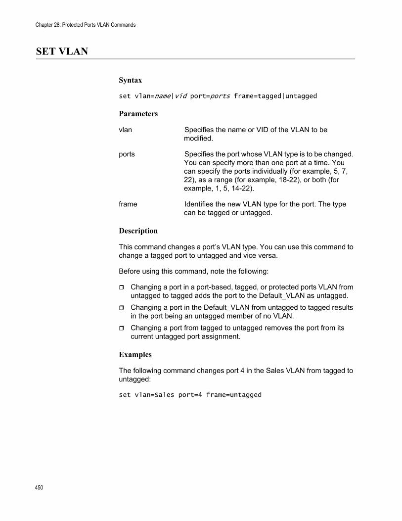
Chapter 28: Protected Ports VLAN Commands
SET VLAN
Syntax
set vlan=name|vid port=ports frame=tagged|untagged
Parameters
vlan Specifies the name or VID of the VLAN to be modified.
ports Specifies the port whose VLAN type is to be changed. You can specify more than one port at a time. You can specify the ports individually (for example, 5, 7, 22), as a range (for example, 18-22), or both (for example, 1, 5, 14-22).
frame Identifies the new VLAN type for the port. The type can be tagged or untagged.
Description
This command changes a port’s VLAN type. You can use this command to change a tagged port to untagged and vice versa.
Before using this command, note the following:
Changing a port in a port-based, tagged, or protected ports VLAN from untagged to tagged adds the port to the Default_VLAN as untagged.Changing a port in the Default_VLAN from untagged to tagged results in the port being an untagged member of no VLAN.Changing a port from tagged to untagged removes the port from its current untagged port assignment.
Examples
The following command changes port 4 in the Sales VLAN from tagged to untagged:
set vlan=Sales port=4 frame=untagged
450
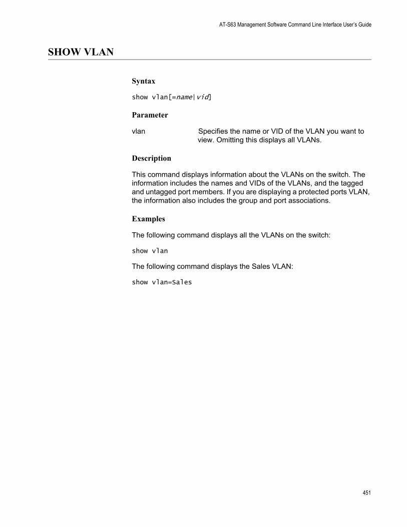
AT-S63 Management Software Command Line Interface User’s Guide
SHOW VLAN
Syntax
show vlan[=name|vid]
Parameter
vlan Specifies the name or VID of the VLAN you want to view. Omitting this displays all VLANs.
Description
This command displays information about the VLANs on the switch. The information includes the names and VIDs of the VLANs, and the tagged and untagged port members. If you are displaying a protected ports VLAN, the information also includes the group and port associations.
Examples
The following command displays all the VLANs on the switch:
show vlan
The following command displays the Sales VLAN:
show vlan=Sales
451

Chapter 28: Protected Ports VLAN Commands
452
Chapter 29
Port Security Commands
This chapter contains the following command:
“SET SWITCH PORT INTRUSIONACTION” on page 454“SET SWITCH PORT SECURITYMODE” on page 455“SHOW SWITCH PORT INTRUSION” on page 458“SHOW SWITCH PORT SECURITYMODE” on page 459
NoteRemember to save your changes with the SAVE CONFIGURATION command.
NoteFor background information on port security, refer to Chapter 27, “Port Security” in the AT-S63 Management Software Menus Interface User’s Guide.
453
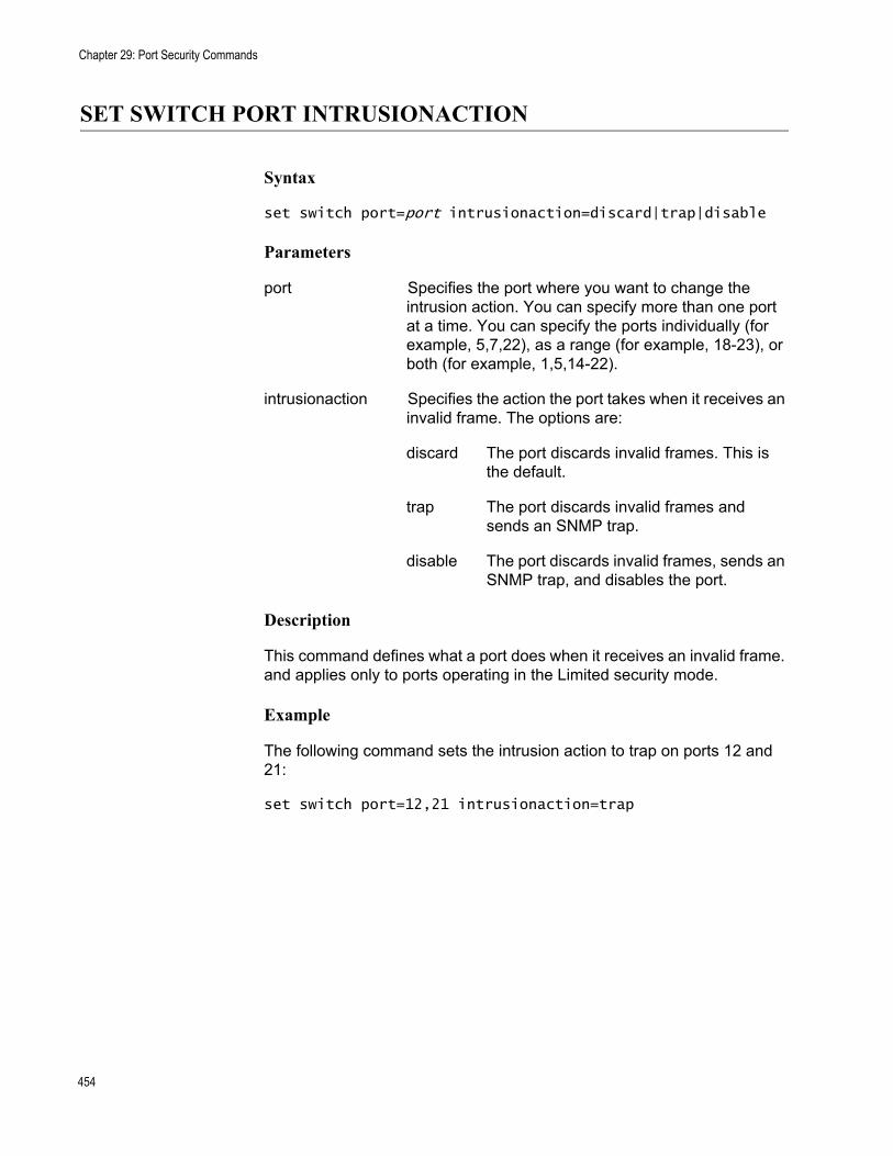
Chapter 29: Port Security Commands
SET SWITCH PORT INTRUSIONACTION
Syntax
set switch port=port intrusionaction=discard|trap|disable
Parameters
port Specifies the port where you want to change the intrusion action. You can specify more than one port at a time. You can specify the ports individually (for example, 5,7,22), as a range (for example, 18-23), or both (for example, 1,5,14-22).
intrusionaction Specifies the action the port takes when it receives an invalid frame. The options are:
discard The port discards invalid frames. This is the default.
trap The port discards invalid frames and sends an SNMP trap.
disable The port discards invalid frames, sends an SNMP trap, and disables the port.
Description
This command defines what a port does when it receives an invalid frame. and applies only to ports operating in the Limited security mode.
Example
The following command sets the intrusion action to trap on ports 12 and 21:
set switch port=12,21 intrusionaction=trap
454
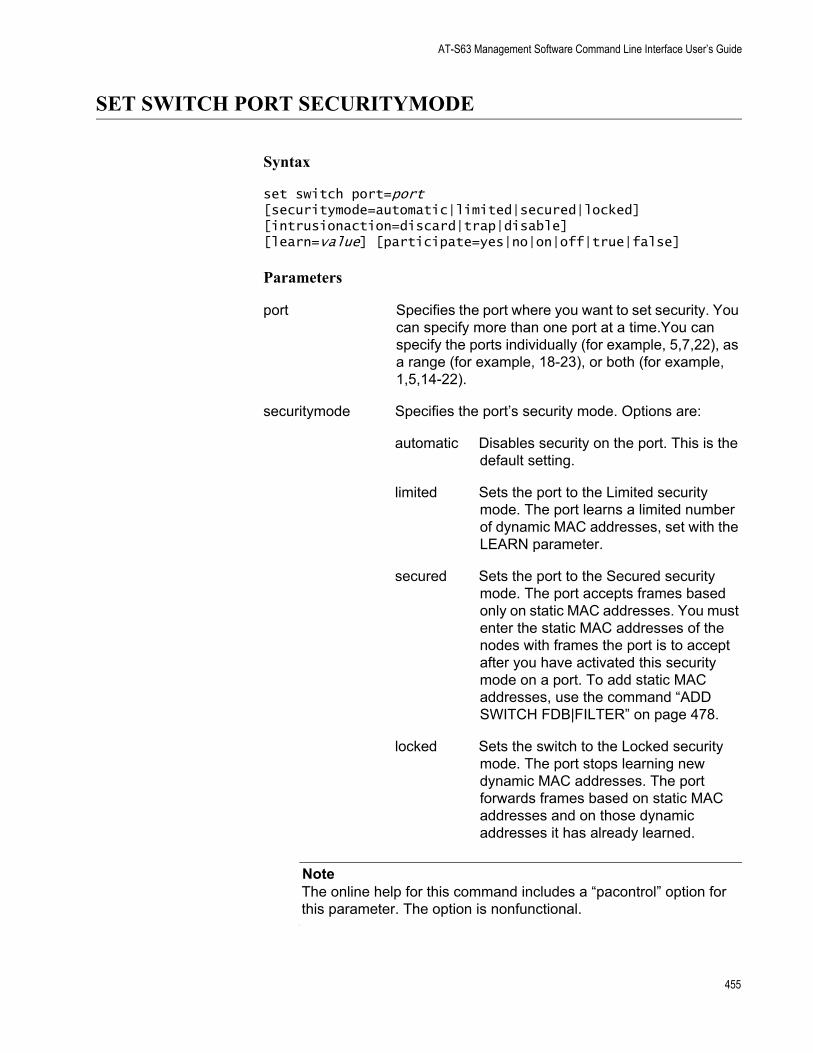
AT-S63 Management Software Command Line Interface User’s Guide
SET SWITCH PORT SECURITYMODE
Syntax
set switch port=port [securitymode=automatic|limited|secured|locked][intrusionaction=discard|trap|disable][learn=value] [participate=yes|no|on|off|true|false]
Parameters
port Specifies the port where you want to set security. You can specify more than one port at a time.You can specify the ports individually (for example, 5,7,22), as a range (for example, 18-23), or both (for example, 1,5,14-22).
securitymode Specifies the port’s security mode. Options are:
automatic Disables security on the port. This is the default setting.
limited Sets the port to the Limited security mode. The port learns a limited number of dynamic MAC addresses, set with the LEARN parameter.
secured Sets the port to the Secured security mode. The port accepts frames based only on static MAC addresses. You must enter the static MAC addresses of the nodes with frames the port is to accept after you have activated this security mode on a port. To add static MAC addresses, use the command “ADD SWITCH FDB|FILTER” on page 478.
locked Sets the switch to the Locked security mode. The port stops learning new dynamic MAC addresses. The port forwards frames based on static MAC addresses and on those dynamic addresses it has already learned.
NoteThe online help for this command includes a “pacontrol” option for this parameter. The option is nonfunctional.
455
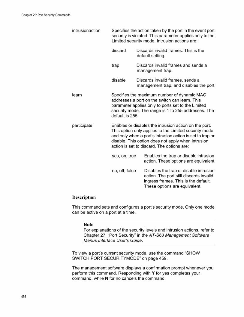
Chapter 29: Port Security Commands
intrusionaction Specifies the action taken by the port in the event port security is violated. This parameter applies only to the Limited security mode. Intrusion actions are:
discard Discards invalid frames. This is the default setting.
trap Discards invalid frames and sends a management trap.
disable Discards invalid frames, sends a management trap, and disables the port.
learn Specifies the maximum number of dynamic MAC addresses a port on the switch can learn. This parameter applies only to ports set to the Limited security mode. The range is 1 to 255 addresses. The default is 255.
participate Enables or disables the intrusion action on the port. This option only applies to the Limited security mode and only when a port’s intrusion action is set to trap or disable. This option does not apply when intrusion action is set to discard. The options are:
yes, on, true Enables the trap or disable intrusion action. These options are equivalent.
no, off, false Disables the trap or disable intrusion action. The port still discards invalid ingress frames. This is the default. These options are equivalent.
Description
This command sets and configures a port’s security mode. Only one mode can be active on a port at a time.
NoteFor explanations of the security levels and intrusion actions, refer to Chapter 27, “Port Security” in the AT-S63 Management Software Menus Interface User’s Guide.
To view a port’s current security mode, use the command “SHOW SWITCH PORT SECURITYMODE” on page 459.
The management software displays a confirmation prompt whenever you perform this command. Responding with Y for yes completes your command, while N for no cancels the command.
456
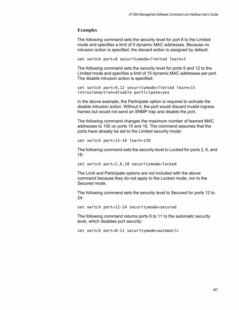
AT-S63 Management Software Command Line Interface User’s Guide
Examples
The following command sets the security level for port 8 to the Limited mode and specifies a limit of 5 dynamic MAC addresses. Because no intrusion action is specified, the discard action is assigned by default:
set switch port=8 securitymode=limited learn=5
The following command sets the security level for ports 9 and 12 to the Limited mode and specifies a limit of 15 dynamic MAC addresses per port. The disable intrusion action is specified:
set switch port=9,12 securitymode=limited learn=15 intrusionaction=disable participate=yes
In the above example, the Participate option is required to activate the disable intrusion action. Without it, the port would discard invalid ingress frames but would not send an SNMP trap and disable the port.
The following command changes the maximum number of learned MAC addresses to 150 on ports 15 and 16. The command assumes that the ports have already be set to the Limited security mode:
set switch port=15-16 learn=150
The following command sets the security level to Locked for ports 2, 6, and 18:
set switch port=2,6,18 securitymode=locked
The Limit and Participate options are not included with the above command because they do not apply to the Locked mode, nor to the Secured mode.
The following command sets the security level to Secured for ports 12 to 24:
set switch port=12-24 securitymode=secured
The following command returns ports 8 to 11 to the automatic security level, which disables port security:
set switch port=8-11 securitymode=automatic
457
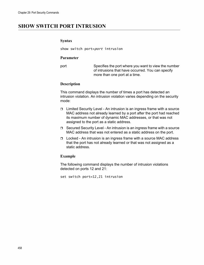
Chapter 29: Port Security Commands
SHOW SWITCH PORT INTRUSION
Syntax
show switch port=port intrusion
Parameter
port Specifies the port where you want to view the number of intrusions that have occurred. You can specify more than one port at a time.
Description
This command displays the number of times a port has detected an intrusion violation. An intrusion violation varies depending on the security mode:
Limited Security Level - An intrusion is an ingress frame with a source MAC address not already learned by a port after the port had reached its maximum number of dynamic MAC addresses, or that was not assigned to the port as a static address.Secured Security Level - An intrusion is an ingress frame with a source MAC address that was not entered as a static address on the port.Locked - An intrusion is an ingress frame with a source MAC address that the port has not already learned or that was not assigned as a static address.
Example
The following command displays the number of intrusion violations detected on ports 12 and 21:
set switch port=12,21 intrusion
458
AT-S63 Management Software Command Line Interface User’s Guide
SHOW SWITCH PORT SECURITYMODE
Syntax
show switch port=port securitymode
Parameters
port Specifies the port whose security mode settings you want to view. You can specify the ports individually (for example, 5,7,22), as a range (for example, 18-23), or both (for example, 1,5,14-22).
Description
This command displays the security mode settings for the ports on the switch.
Example
The following command displays the security mode settings for ports 1 to 5:
show switch port=1-5 securitymode
459

Chapter 29: Port Security Commands
460
Chapter 30
802.1x Port-based Network Access Control Commands
This chapter contains the following commands:
“DISABLE PORTACCESS|PORTAUTH” on page 462“DISABLE RADIUSACCOUNTING” on page 463“ENABLE PORTACCESS|PORTAUTH” on page 464“ENABLE RADIUSACCOUNTING” on page 465“SET PORTACCESS|PORTAUTH PORT ROLE=AUTHENTICATOR” on page 466“SET PORTACCESS|PORTAUTH PORT ROLE=SUPPLICANT” on page 470“SET RADIUSACCOUNTING” on page 472“SHOW PORTACCESS|PORTAUTH” on page 474“SHOW PORTACCESS|PORTAUTH PORT” on page 475“SHOW RADIUSACCOUNTING” on page 476
NoteRemember to save your changes with the SAVE CONFIGURATION command.
NoteFor background information on 802.1x Port-based Network Access Control, refer to Chapter 28, “802.1x Port-based Network Access Control” in the AT-S63 Management Software Menus Interface User’s Guide.
461
Chapter 30: 802.1x Port-based Network Access Control Commands
DISABLE PORTACCESS|PORTAUTH
Syntax
disable portaccess|portauth
NoteThe PORTACCESS and PORTAUTH keywords are equivalent.
Parameters
None.
Description
This command disables 802.1x Port-based Network Access Control on the switch. This is the default setting.
Example
The following command disables 802.1x Port-based Network Access Control on the switch:
disable portaccess
462

AT-S63 Management Software Command Line Interface User’s Guide
DISABLE RADIUSACCOUNTING
Syntax
disable radiusaccounting
Parameters
None
Description
This command disables RADIUS accounting on the switch. This command is equivalent to the SET RADIUSACCOUNTING STATUS=DISABLED command.
Example
The following command disables RADIUS accounting:
disable radiusaccounting
463
Chapter 30: 802.1x Port-based Network Access Control Commands
ENABLE PORTACCESS|PORTAUTH
Syntax
enable portaccess|portauth
NoteThe PORTACCESS and PORTAUTH keywords are equivalent.
Parameters
None.
Description
This command activates 802.1x Port-based Network Access Control on the switch. The default setting for this feature is disabled.
NoteYou should activate and configure the RADIUS client software on the switch before you activate port-based access control. Refer to “SET AUTHENTICATION” on page 542.
Example
The following command enables 802.1x Port-based Network Access Control on the switch:
enable portaccess
464
AT-S63 Management Software Command Line Interface User’s Guide
ENABLE RADIUSACCOUNTING
Syntax
enable radiusaccounting
Parameters
None
Description
This command enables RADIUS accounting on the switch. This command is equivalent to the SET RADIUSACCOUNTING STATUS=ENABLED command.
Example
The following command disables RADIUS accounting:
enable radiusaccounting
465
Chapter 30: 802.1x Port-based Network Access Control Commands
SET PORTACCESS|PORTAUTH PORT ROLE=AUTHENTICATOR
Syntax
set portaccess|portauth port=port type|role=authenticator|none [control=auto|authorised|forceauthenticate| unauthorised|forceunauthenticate] [quietperiod=value] [txperiod=value] [reauthperiod=value] [supptimeout=value] [servertimeout|servtimeout=value] [maxreq=value][ctrldirboth=ingress|both] [reauthenabled=enabled|disabled] [piggyback=enabled|disabled]
NoteThe PORTACCESS and PORTAUTH keywords are equivalent.
Parameters
port Specifies the port that you want to set to the Authenticator role or whose Authenticator settings you want to adjust. You can specify more than one port at a time.
type Specifies the role of the port. The parameters arerole equivalent. The options are:
authenticator Specifies the authenticator role.
none Disables port-based access control on the port.
control Specifies the authenticator state. The options are:
auto Sets the port state to 802.1X port-based authentication. The port begins in the unauthorized state, allowing only EAPOL frames to be sent and received through the port. The authentication process begins when the link state of the port changes. The switch requests the identity of the client and begins relaying authentication messages between the client and the authentication server. Each client that attempts to access the network is uniquely
466
AT-S63 Management Software Command Line Interface User’s Guide
identified by the switch by using the client's MAC address. This is the default setting.
authorised or Disables 802.1X port-basedforceauthenticate authentication and causes the
port to transition to the authorized state without any authentication exchange required. The port transmits and receives normal traffic without 802.1X-based authentication of the client. The parameters are equivalent.
unauthorised or Causes the port to remain inforceunauthenticate the unauthorized state,
ignoring all attempts by the client to authenticate. The switch cannot provide authentication services to the client through the interface. The parameters are equivalent.
quietperiod Sets the number of seconds that the switch remains in the quiet state following a failed authentication exchange with the client. The default value is 60 seconds. The range is 0 to 65,535 seconds.
txperiod Sets the number of seconds that the switch waits for a response to an EAP-request/identity frame from the client before retransmitting the request. The default value is 30 seconds. The range is 1 to 65,535 seconds.
reauthperiod Enables periodic reauthentication of the client, which is disabled by default. The default value is 3600 seconds. The range is 1 to 65,535 seconds.
supptimeout Sets the switch-to-client retransmission time for the EAP-request frame. The default value for this parameter is 30 seconds. The range is 1 to 600 seconds.
servertimeout Sets the timer used by the switch to determineservtimeout authentication server timeout conditions. The default
value is 10 seconds. The range is 1 to 60 seconds. The parameters are equivalent.
maxreq Specifies the maximum number of times that the switch retransmits an EAP Request packet to the client before it times out the authentication session. The range is 1 to
467
Chapter 30: 802.1x Port-based Network Access Control Commands
10 retransmissions and the default is 2.
ctrldirboth Specifies how the port is to handle ingress and egress broadcast and multicast packets when in the unauthorized state. When a port is set to the authenticator role, it remains in the unauthorized state until the client logs on by providing a username and password combination. In the unauthorized state, the port accepts only EAP packets from the client. All other ingress packets that the port might receive from the client, including multicast and broadcast traffic, is discarded until the supplicant has logged on.
You can use this selection to control how an authenticator port handles egress broadcast and multicast traffic when in the unauthorized state. You can instruct the port to forward this traffic to the client, even though the client has not logged on, or you can have the port discard the traffic.
The options are:
ingress An authenticator port, when in the unauthorized state, discards all ingress broadcast and multicast packets from the client while forwarding all egress broadbast and multicast traffic to the same client. This is the default setting.
both An authenticator port, when in the unauthorized state, does not forward ingress or egress broadcast and multicast packets from or to the client until the client has logged on.
reauthenabled Controls whether the client must periodically reauthenticate. The options are:
enabled Specifies that the client must periodically reauthenticate. This is the default setting. The time period between reauthentications is set with the reauthperiod parameter.
disabled Specifies that reauthentication by the client is not required after the initial authentication. Reauthentication is only required if there is a change to the status of the link between the supplicant and the switch or the switch is reset or power cycled.
468
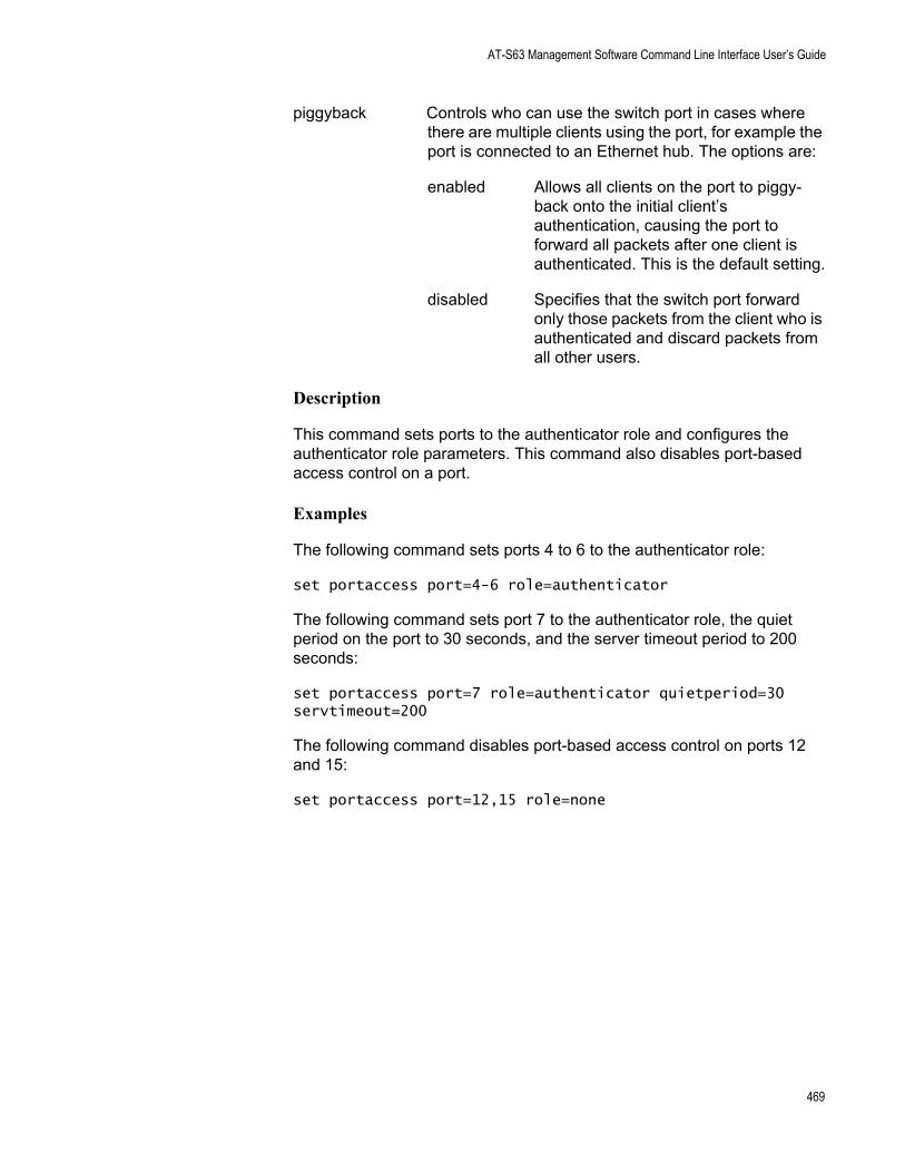
AT-S63 Management Software Command Line Interface User’s Guide
piggyback Controls who can use the switch port in cases where there are multiple clients using the port, for example the port is connected to an Ethernet hub. The options are:
enabled Allows all clients on the port to piggy-back onto the initial client’s authentication, causing the port to forward all packets after one client is authenticated. This is the default setting.
disabled Specifies that the switch port forward only those packets from the client who is authenticated and discard packets from all other users.
Description
This command sets ports to the authenticator role and configures the authenticator role parameters. This command also disables port-based access control on a port.
Examples
The following command sets ports 4 to 6 to the authenticator role:
set portaccess port=4-6 role=authenticator
The following command sets port 7 to the authenticator role, the quiet period on the port to 30 seconds, and the server timeout period to 200 seconds:
set portaccess port=7 role=authenticator quietperiod=30 servtimeout=200
The following command disables port-based access control on ports 12 and 15:
set portaccess port=12,15 role=none
469
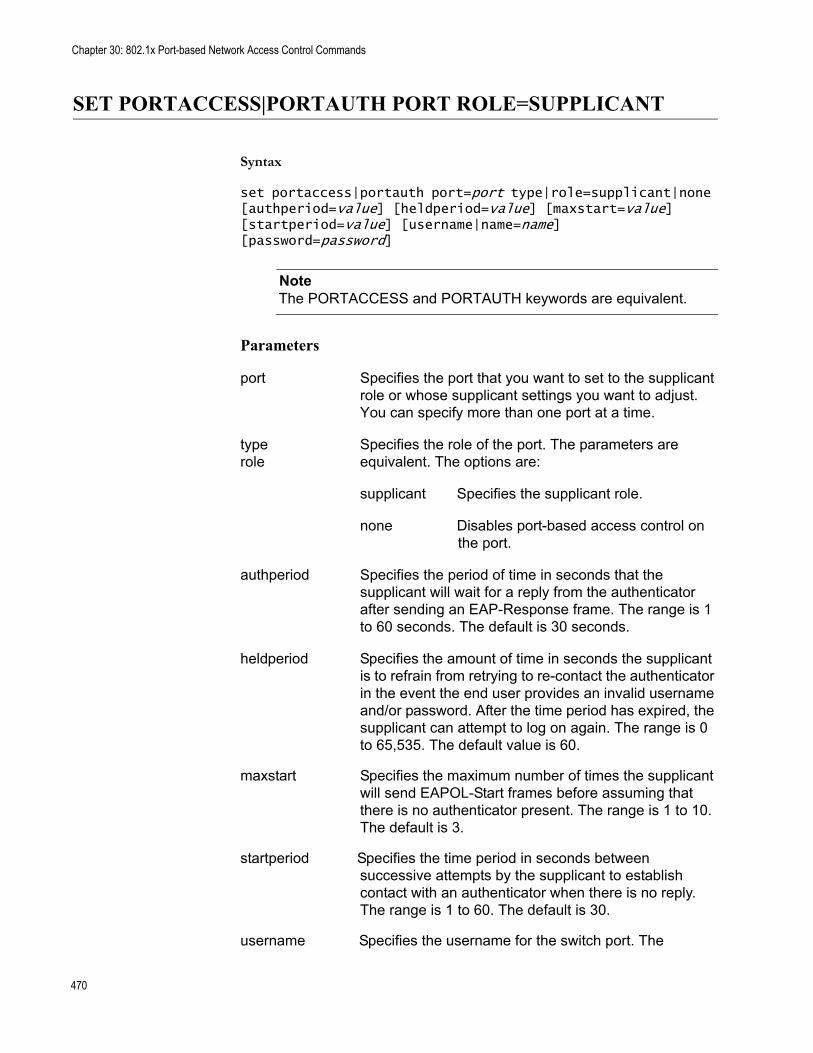
Chapter 30: 802.1x Port-based Network Access Control Commands
SET PORTACCESS|PORTAUTH PORT ROLE=SUPPLICANT
Syntax
set portaccess|portauth port=port type|role=supplicant|none [authperiod=value] [heldperiod=value] [maxstart=value] [startperiod=value] [username|name=name] [password=password]
NoteThe PORTACCESS and PORTAUTH keywords are equivalent.
Parameters
port Specifies the port that you want to set to the supplicant role or whose supplicant settings you want to adjust. You can specify more than one port at a time.
type Specifies the role of the port. The parameters arerole equivalent. The options are:
supplicant Specifies the supplicant role.
none Disables port-based access control on the port.
authperiod Specifies the period of time in seconds that the supplicant will wait for a reply from the authenticator after sending an EAP-Response frame. The range is 1 to 60 seconds. The default is 30 seconds.
heldperiod Specifies the amount of time in seconds the supplicant is to refrain from retrying to re-contact the authenticator in the event the end user provides an invalid username and/or password. After the time period has expired, the supplicant can attempt to log on again. The range is 0 to 65,535. The default value is 60.
maxstart Specifies the maximum number of times the supplicant will send EAPOL-Start frames before assuming that there is no authenticator present. The range is 1 to 10. The default is 3.
startperiod Specifies the time period in seconds between successive attempts by the supplicant to establish contact with an authenticator when there is no reply. The range is 1 to 60. The default is 30.
username Specifies the username for the switch port. The
470
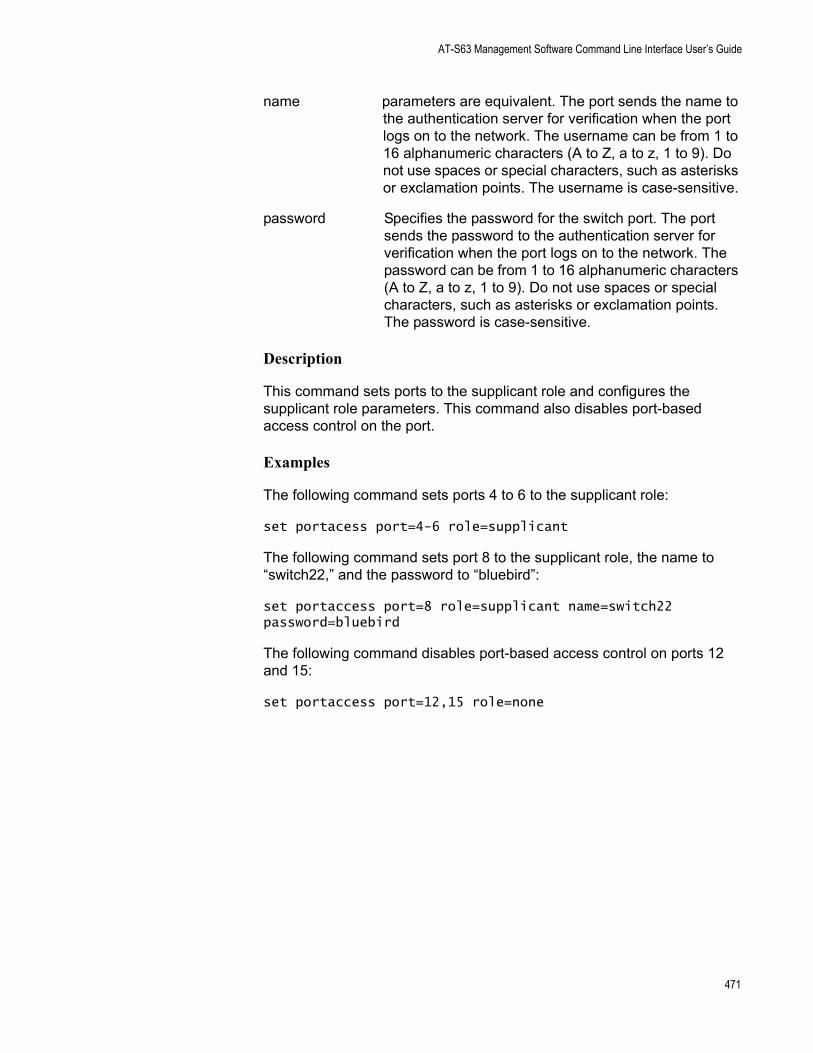
AT-S63 Management Software Command Line Interface User’s Guide
name parameters are equivalent. The port sends the name to the authentication server for verification when the port logs on to the network. The username can be from 1 to 16 alphanumeric characters (A to Z, a to z, 1 to 9). Do not use spaces or special characters, such as asterisks or exclamation points. The username is case-sensitive.
password Specifies the password for the switch port. The port sends the password to the authentication server for verification when the port logs on to the network. The password can be from 1 to 16 alphanumeric characters (A to Z, a to z, 1 to 9). Do not use spaces or special characters, such as asterisks or exclamation points. The password is case-sensitive.
Description
This command sets ports to the supplicant role and configures the supplicant role parameters. This command also disables port-based access control on the port.
Examples
The following command sets ports 4 to 6 to the supplicant role:
set portacess port=4-6 role=supplicant
The following command sets port 8 to the supplicant role, the name to “switch22,” and the password to “bluebird”:
set portaccess port=8 role=supplicant name=switch22 password=bluebird
The following command disables port-based access control on ports 12 and 15:
set portaccess port=12,15 role=none
471
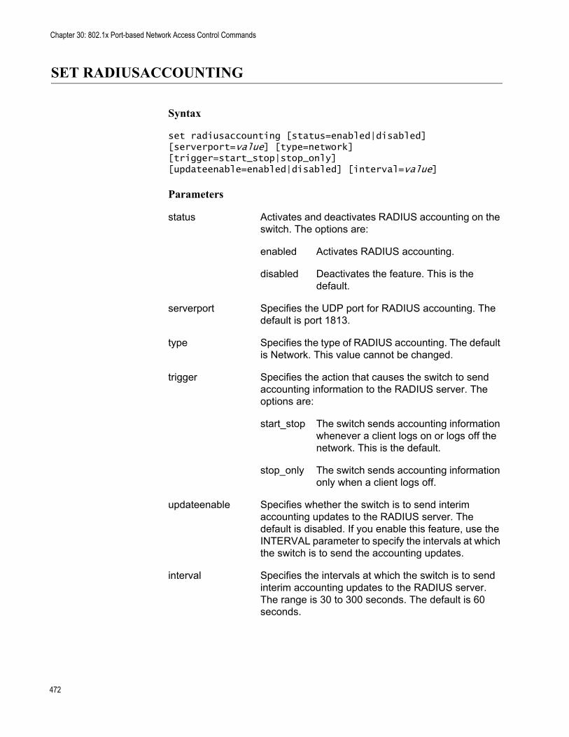
Chapter 30: 802.1x Port-based Network Access Control Commands
SET RADIUSACCOUNTING
Syntax
set radiusaccounting [status=enabled|disabled] [serverport=value] [type=network] [trigger=start_stop|stop_only] [updateenable=enabled|disabled] [interval=value]
Parameters
status Activates and deactivates RADIUS accounting on the switch. The options are:
enabled Activates RADIUS accounting.
disabled Deactivates the feature. This is the default.
serverport Specifies the UDP port for RADIUS accounting. The default is port 1813.
type Specifies the type of RADIUS accounting. The default is Network. This value cannot be changed.
trigger Specifies the action that causes the switch to send accounting information to the RADIUS server. The options are:
start_stop The switch sends accounting information whenever a client logs on or logs off the network. This is the default.
stop_only The switch sends accounting information only when a client logs off.
updateenable Specifies whether the switch is to send interim accounting updates to the RADIUS server. The default is disabled. If you enable this feature, use the INTERVAL parameter to specify the intervals at which the switch is to send the accounting updates.
interval Specifies the intervals at which the switch is to send interim accounting updates to the RADIUS server. The range is 30 to 300 seconds. The default is 60 seconds.
472
AT-S63 Management Software Command Line Interface User’s Guide
Description
RADIUS accounting is supported on those switch ports operating in the Authenticator role. The accounting information sent by the switch to a RADIUS server includes the date and time when clients log on and log off, as well as the number of packets sent and received by a switch port during a client session. This feature is disabled by default on the switch.
Examples
The following command activates RADIUS accounting and sets the trigger to stop only:
set radiusaccounting status=enabled trigger=stop_only
The following command enables the update feature and sets the interval period to 200 seconds:
set radiusaccounting updateenable=enabled interval=200
473
Chapter 30: 802.1x Port-based Network Access Control Commands
SHOW PORTACCESS|PORTAUTH
Syntax
show portaccess|portauth config|status
NoteThe PORTACCESS and PORTAUTH keywords are equivalent.
Parameters
config Displays whether port-based access control is enabled or disabled on the switch.
status Displays the role and status of each port.
Description
Use this command to display operating information for port-based access control.
The CONFIG parameter displays:
Enabled or disabled status of port-based access controlAuthentication method
The STATUS parameter displays the following information for each port:
Port roleStatus
Examples
The following command displays whether port-based access control is enabled or disabled on the switch:
show portaccess config
The following command displays the role and status for each port:
show portaccess status
474
AT-S63 Management Software Command Line Interface User’s Guide
SHOW PORTACCESS|PORTAUTH PORT
Syntax
show portaccess|portauth port=port authenticator|supplicant config|status
NoteThe PORTACCESS and PORTAUTH keywords are equivalent.
Parameters
port Specifies the port whose port-based access control settings you want to view. You can specify more than one port at a time.
authenticator Indicates that the port is an authenticator.
supplicant Indicates that the port is a supplicant.
config Displays the port-based access control settings for the port.
status Displays the status and role of the port.
Description
Use this command to display information about authenticator and supplicant ports.
Examples
The following displays the status for port 10, which has been set to the authenticator role:
show portaccess port=10 authenticator status
This command displays the port access configuration of port 12 which is a supplicant port:
show portaccess port=12 supplicant config
475
Chapter 30: 802.1x Port-based Network Access Control Commands
SHOW RADIUSACCOUNTING
Syntax
show radiusaccounting
Parameters
None.
Description
Use this command to display the current parameter settings for RADIUS accounting. For an explanation of the parameters, refer to “SET RADIUSACCOUNTING” on page 472.
Examples
The following command displays the current parameter settings for RADIUS accounting:
show radiusaccounting
476
Chapter 31
MAC Address Table Commands
This chapter contains the following commands:
“ADD SWITCH FDB|FILTER” on page 478“DELETE SWITCH FDB|FILTER” on page 480“RESET SWITCH FDB” on page 481“SET SWITCH AGINGTIMER|AGEINGTIMER” on page 482“SHOW SWITCH FDB” on page 484
NoteRemember to save your changes with the SAVE CONFIGURATION command.
NoteFor background information on the MAC address table, refer to Chapter 29, “MAC Address Table” in the AT-S63 Management Software Menus Interface User’s Guide.
477
Chapter 31: MAC Address Table Commands
ADD SWITCH FDB|FILTER
Syntax
add switch fdb|filter destaddress|macaddress=macaddress port=port vlan=name|vid
NoteThe FDB and FILTER keywords are equivalent.
Parameters
destaddress Specifies the static unicast or multicast address to bemacaddress added to the switch’s MAC address table. The
parameters are equivalent. The address can be entered in either of the following formats:
xxxxxxxxxxxx or xx:xx:xx:xx:xx:xx
port Specifies the port(s) to which the MAC address is to be assigned. You can specify only one port if you are adding a unicast address. You can specify more than one port if you are entering a multicast address.
vlan Specifies the name or the VID of the VLAN to which the node designated by the MAC address is a member.
Description
This command adds static unicast and multicast MAC addresses to the switch’s MAC address table. A MAC address added with this command is never timed out from the MAC address table, even when the end node or, in the case of a multicast address, the multicast application is inactive.
If you are entering a static multicast address, the address must be assigned to the port when the multicast application is located and to the ports where the host nodes are connected. Assigning the address only to the port where the multicast application is located will result in the failure of the multicast packets to be properly forwarded to the host nodes.
Examples
The following command adds the static MAC address 00:A0:D2:18:1A:11 to port 7. It assumes the port where the MAC address is to be assigned is a member of the Default_VLAN:
478

AT-S63 Management Software Command Line Interface User’s Guide
add switch fdb macaddress=00A0D2181A11 port=7 vlan=default_vlan
The following command adds the multicast MAC address 01:00:51:00:00 10 to ports 1 to 5. The ports belong to the Engineering VLAN:
add switch fdb macaddress=010051000010 port=1-5 vlan=Engineering
479
Chapter 31: MAC Address Table Commands
DELETE SWITCH FDB|FILTER
Syntax
delete switch fdb|filter macaddress=macaddress vlan=name|vid
NoteThe FDB and FILTER keywords are equivalent.
Parameters
macaddress Specifies the dynamic or static unicast or multicast MAC address to delete from the MAC address table. The address can be entered in either of the following formats:
xxxxxxxxxxxx or xx:xx:xx:xx:xx:xx
vlan Specifies the VLAN containing the port(s) where the address was learned or assigned. The VLAN can be specified by name or VID.
Description
This command deletes dynamic and static unicast and multicast addresses from the switch’s MAC address table.
NoteYou cannot delete a switch’s MAC address, an STP BPDU MAC address, or a broadcast address.
Examples
The following command deletes the static MAC address 00:A0:D2:18:1A:11 from the table. The port where the address was learned or assigned is part of the Default_VLAN, which has a VID of 1:
delete switch fdb macaddress=00A0D2181A11 vlan=1
The following command deletes the MAC address 00:A0:C1:11:22:44 from the table. The port where the address was learned or assigned is part of the Sales VLAN:
delete switch fdb macaddress=00a0c1112244 vlan=sales
480
AT-S63 Management Software Command Line Interface User’s Guide
RESET SWITCH FDB
Syntax
reset switch fdb port=port
Parameter
port Specifies the port whose dynamic MAC addresses you want to delete from the MAC address table. You can specify more than one port at a time.
Description
This command deletes the dynamic MAC addresses learned on a specified port. After a port’s dynamic MAC addresses have been deleted, the port begins to learn new addresses.
Example
The following command deletes all the dynamic MAC addresses learned in port 5:
reset switch fdb port=5
481
Chapter 31: MAC Address Table Commands
SET SWITCH AGINGTIMER|AGEINGTIMER
Syntax
set switch agingtimer|ageingtimer=value
Parameter
agingtimer Specifies the aging timer for the MAC address table.ageingtimer The value is in seconds. The range is 0 to 1048575.
The default is 300 seconds (5 minutes). The parameters are equivalent.
Description
The switch uses the aging timer to delete inactive dynamic MAC addresses from the MAC address table. When the switch detects that no packets have been sent to or received from a particular MAC address in the table after the period specified by the aging time, the switch deletes the address. This prevents the table from becoming full of addresses of nodes that are no longer active. Setting the aging timer to 0 disables the timer and therefore no dynamic MAC addresses are aged out.
To view the current setting for the MAC address aging timer, refer to “SHOW SWITCH AGINGTIMER|AGEINGTIMER” on page 483.
Example
The following command sets the aging timer to 120 seconds (2 minutes):
set switch agingtimer=120
482
AT-S63 Management Software Command Line Interface User’s Guide
SHOW SWITCH AGINGTIMER|AGEINGTIMER
Syntax
show switch agingtimer|ageingtimer
Parameters
None.
Description
This command displays the current setting for the aging timer. The switch uses the aging timer to delete inactive dynamic MAC addresses from the MAC address table. To set the aging timer, refer to “SET SWITCH AGINGTIMER|AGEINGTIMER” on page 482.
Example
The following command displays the current setting for the MAC address aging timer:
show switch agingtimer
483
Chapter 31: MAC Address Table Commands
SHOW SWITCH FDB
Syntax
show switch fdb [address=macaddress] [port=port] [status=static|dynamic|multicast] [vlan=name]
Parameters
address Specifies a MAC address. Use this parameter to determine the port on the switch on which a particular MAC address was learned (dynamic) or assigned (static). The address can be entered in either of the following formats:
xxxxxxxxxxxx or xx:xx:xx:xx:xx:xx
port Specifies a port on the switch. Use this parameter to view all addresses learned on a particular port. You can specify more than one port.
status Specifies the type of MAC addresses you want to view. Choices are static, dynamic, and multicast. If no status is stated, the command displays the static and dynamic unicast addresses.
vlan Specifies a VLAN name. Use this parameter to view the MAC addresses learned or assigned to the ports of a particular VLAN on the switch.
NoteYou can specify more than one parameter at a time with this command.
Description
This command displays the MAC addresses learned or assigned to the ports on the switch.
Examples
The following command displays all the static and dynamic unicast MAC addresses in the switch’s MAC address table:
show switch fdb
The following command displays just the static unicast MAC addresses:
show switch fdb status=static
484
AT-S63 Management Software Command Line Interface User’s Guide
The following command displays the static and dynamic multicast addresses:
show switch fdb status=multicast
The following command displays the port on which the MAC address 00:A0:D2:18:1A:11 was learned (dynamic) or added (static):
show switch fdb address=00A0D2181A11
The following command displays the MAC addresses learned on port 2:
show switch fdb port=2
The following command displays the MAC addresses learned on the ports in the Sales VLAN:
show switch fdb vlan=sales
The following command displays the static MAC addresses on port 17:
show switch fdb port=17 status=static
485

Chapter 31: MAC Address Table Commands
486
Chapter 32
Web Server Commands
This chapter contains the following commands:
“DISABLE HTTP SERVER” on page 488“ENABLE HTTP SERVER” on page 489“PURGE HTTP SERVER” on page 490“SET HTTP SERVER” on page 491“SHOW HTTP SERVER” on page 496
NoteRemember to use the SAVE CONFIGURATION command to save your changes.
NoteFor background information on the web server, refer to Chapter 30, “Web Server” in the AT-S63 Management Software Menus Interface User’s Guide.
487
Chapter 32: Web Server Commands
DISABLE HTTP SERVER
Syntax
disable http server
Parameters
None.
Description
This command disables the web server on the switch. When the server is disabled, you cannot manage the switch from a web browser. To view the current status of the web server, see “SHOW HTTP SERVER” on page 496.
Example
The following command disables the web server:
disable http server
488
AT-S63 Management Software Command Line Interface User’s Guide
ENABLE HTTP SERVER
Syntax
enable http server
Parameters
None.
Description
This command activates the web server on the switch. Activating the server allows you to manage the unit from a web browser. To view the current status of the web server, see “SHOW HTTP SERVER” on page 496.
Example
The following command activates the web server:
enable http server
489
Chapter 32: Web Server Commands
PURGE HTTP SERVER
Syntax
purge http server
Parameters
None.
Description
This command resets the HTTP server to its default values. Refer to Appendix A, “AT-S63 Default Settings” in the AT-S63 Management Software Menus Interface User’s Guide or in the AT-S63 Management Software Web Browser Interface User’s Guide. To view the current web server settings, refer to “SHOW HTTP SERVER” on page 496.
Example
The following command resets the web server parameters to their default values:
purge http server
490
AT-S63 Management Software Command Line Interface User’s Guide
SET HTTP SERVER
Syntax
set http server [security=enabled|disabled] [sslkeyid=key-id] [port=port]
Parameters
security Specifies the security mode of the web server. The options are:
enabled Specifies that the web server is to function in the secure HTTPS mode.
disabled Specifies that the web server is to function in the non-secure HTTP mode. This is the default.
sslkeyid Specifies a key pair ID. This parameter is required if you are configuring the web server to operate in the secure HTTPS mode.
port Specifies the TCP port number that the web server will listen on. The default for non-secure HTTP operation is port 80. The default for secure HTTPS operation is port 443.
Description
This command configures the web server. You can configure the server for either secure HTTPS or non-secure HTTP operation.
Before configuring the web server, please note the following:
You cannot use this command when the web server is enabled. You must first disable the web server before making changes. To disable the server, refer to “DISABLE HTTP SERVER” on page 488.To configure the web server for the HTTPS secure mode, you must first create an encryption key and a certificate, and add the certificate to the certificate database. The management software will not allow you to configure the web server for the secure HTTPS mode until those steps have been completed.
Examples
The following command configures the web server for the non-secure HTTP mode. Since no port is specified, the default HTTP port 80 is used:
491
Chapter 32: Web Server Commands
set http server security=disabled
The following command configures the web server for the secure HTTPS mode. It specifies the key pair ID as 5. Since no port is specified, the default HTTPS port 443 is used:
set http server security=enabled sslkeyid=5
General Configuration Steps for a Self-signed Certificate
Below are the steps to configuring the switch’s web server for a self-signed certificate using the command line commands:
1. Set the switch’s date and time. You can do this manually using “SET DATE” on page 89 or you can configure the switch to obtain the date and time from an SNTP server using “ADD SNTPSERVER PEER|IPADDRESS” on page 84.
2. Create an encryption key pair using “CREATE ENCO KEY” on page 498 (syntax 1).
3. Create the self-signed certificate using “CREATE PKI CERTIFICATE” on page 508.
4. Add the self-signed certificate to the certificate database using “ADD PKI CERTIFICATE” on page 506.
5. Disable the switch’s web server using “DISABLE HTTP SERVER” on page 488.
6. Configure the web server using “SET HTTP SERVER” on page 491.
7. Activate the web server using “ENABLE HTTP SERVER” on page 489.
The following is an example of the command sequence to configuring the web server for a self-signed certificate. (The example does not include step 1, setting the system time.)
1. This command creates the encryption key pair with an ID of 4, a length of 512 bits, and the description “Switch 12 key”:
create enco key=4 type=rsa length=512 description="Switch 12 key"
2. This command creates a self-signed certificate using the key created in step 1. The certificate is assigned the filename “Sw12cert.cer. (The “.cer” extension is not included in the command because it is added automatically by the management software.) The certificate is assigned the serial number 0 and a distinguished name of 149.11.11.11, which is the IP address of a master switch:
492
AT-S63 Management Software Command Line Interface User’s Guide
create pki certificate=Sw12cert keypair=4 serialnumber=0 subject="cn=149.11.11.11"
3. This command adds the new certificate to the certificate database. The certificate is given a description of “Switch 12 certificate”:
add pki certificate="Switch 12 certificate" location=Sw12cert.cer
4. This command disables the web server:
disable http server
5. This command configures the web server by activating HTTPS and specifying the encryption key pair created in step 1:
set http server security=enabled sslkeyid=4
6. This command enables the web server:
enable http server
General Configuration Steps for a CA Certificate
Below are the steps to configuring the switch’s web server for CA certificates using the command line commands. The steps explain how to create an encryption key and a self-signed certificate, and how to configure the web server for the certificate:
1. Set the switch’s date and time. You can do this manually using the “SET DATE” on page 89 or you can configure the switch to obtain the date and time from an SNTP server using “ADD SNTPSERVER PEER|IPADDRESS” on page 84.
2. Create an encryption key pair using “CREATE ENCO KEY” on page 498 (syntax 1).
3. Set the switch’s distinguished name using “SET SYSTEM DISTINGUISHEDNAME” on page 518.
4. Create an enrollment request using “CREATE PKI ENROLLMENTREQUEST” on page 511.
5. Upload the enrollment request from the switch to a management station or FTP server using “UPLOAD” on page 179.
6. Submit the enrollment request to a CA.
7. After you have received the CA certificates, download them into the switch’s file system using “LOAD” on page 166.
493
Chapter 32: Web Server Commands
8. Add the CA certificates to the certificate database using “ADD PKI CERTIFICATE” on page 506.
9. Disable the switch’s web server using the command “DISABLE HTTP SERVER” on page 488.
10. Configure the web server using “SET HTTP SERVER” on page 491.
11. Activate the web server using “ENABLE HTTP SERVER” on page 489
The following is an example of the command sequence for configuring the web server for CA certificates. It explains how to create an encryption key and enrollment request, and how to download the CA certificates on the switch. (The example does not include step 1, setting the system time, nor the procedure for submitting the request to a CA, which will vary depending on the enrollment requirements of the CA.)
1. This command creates the encryption key pair with an ID of 8, a length of 512 bits, and the description “Switch 24 key”:
create enco key=8 type=rsa length=512 description="Switch 24 key"
2. This command sets the switch’s distinguished name to the IP address 149.44.44.44, which is the IP address of a master switch:
set system distinguishedname="cn=149.44.44.44"
3. This command creates an enrollment request using the encryption key created in step 1. It assigns the request the filename “sw24cer.csr”. The command omits the “.csr” extension because the management software adds it automatically:
create pki enrollmentrequest=sw24cer keypair=8
4. This command uploads the enrollment request from the switch’s file system to a TFTP server. The command assumes that the TFTP server has the IP address 149.88.88.88. (This step could also be performed using Xmodem.)
upload method=tftp destfile=c:sw24cer.csr server=149.88.88.88 file=sw24cer.csr
5. These commands download the CA certificates into the switch’s file system from the TFTP server. The commands assume that the IP address of the server is 149.88.88.88 and that the certificate names are “sw24cer.cer” and “ca.cer”. (This step could be performed using Xmodem.)
load method=tftp destfile=sw24cer.cer server=149.88.88.88 file=c:sw24cer.cer
494
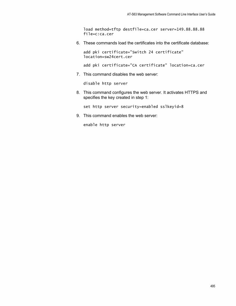
AT-S63 Management Software Command Line Interface User’s Guide
load method=tftp destfile=ca.cer server=149.88.88.88 file=c:ca.cer
6. These commands load the certificates into the certificate database:
add pki certificate="Switch 24 certificate" location=sw24cert.cer
add pki certificate="CA certificate" location=ca.cer
7. This command disables the web server:
disable http server
8. This command configures the web server. It activates HTTPS and specifies the key created in step 1:
set http server security=enabled sslkeyid=8
9. This command enables the web server:
enable http server
495
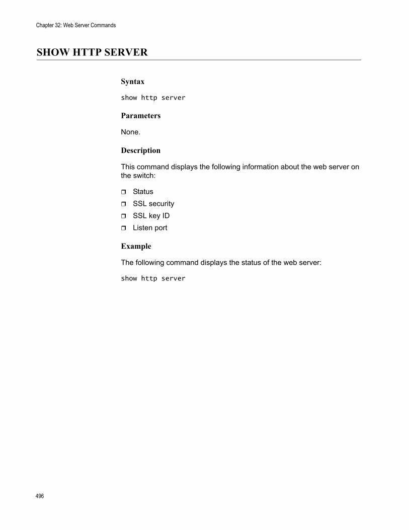
Chapter 32: Web Server Commands
SHOW HTTP SERVER
Syntax
show http server
Parameters
None.
Description
This command displays the following information about the web server on the switch:
StatusSSL securitySSL key IDListen port
Example
The following command displays the status of the web server:
show http server
496
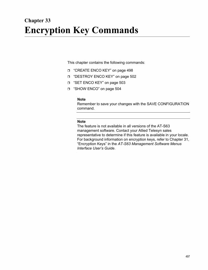
Chapter 33
Encryption Key Commands
This chapter contains the following commands:
“CREATE ENCO KEY” on page 498“DESTROY ENCO KEY” on page 502“SET ENCO KEY” on page 503“SHOW ENCO” on page 504
NoteRemember to save your changes with the SAVE CONFIGURATION command.
NoteThe feature is not available in all versions of the AT-S63 management software. Contact your Allied Telesyn sales representative to determine if this feature is available in your locale. For background information on encryption keys, refer to Chapter 31, “Encryption Keys” in the AT-S63 Management Software Menus Interface User’s Guide.
497
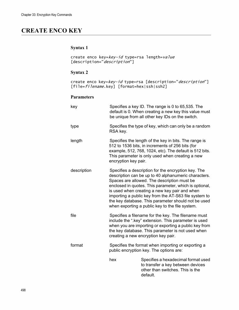
Chapter 33: Encryption Key Commands
CREATE ENCO KEY
Syntax 1
create enco key=key-id type=rsa length=value [description="description"]
Syntax 2
create enco key=key-id type=rsa [description="description"] [file=filename.key] [format=hex|ssh|ssh2]
Parameters
key Specifies a key ID. The range is 0 to 65,535. The default is 0. When creating a new key this value must be unique from all other key IDs on the switch.
type Specifies the type of key, which can only be a random RSA key.
length Specifies the length of the key in bits. The range is 512 to 1536 bits, in increments of 256 bits (for example, 512, 768, 1024, etc). The default is 512 bits. This parameter is only used when creating a new encryption key pair.
description Specifies a description for the encryption key. The description can be up to 40 alphanumeric characters. Spaces are allowed. The description must be enclosed in quotes. This parameter, which is optional, is used when creating a new key pair and when importing a public key from the AT-S63 file system to the key database. This parameter should not be used when exporting a public key to the file system.
file Specifies a filename for the key. The filename must include the “.key” extension. This parameter is used when you are importing or exporting a public key from the key database. This parameter is not used when creating a new encryption key pair.
format Specifies the format when importing or exporting a public encryption key. The options are:
hex Specifies a hexadecimal format used to transfer a key between devices other than switches. This is the default.
498
AT-S63 Management Software Command Line Interface User’s Guide
ssh Specifies a format for Secure Shell version 1 users.
ssh2 Specifies a format for Secure Shell version 2 users.
Description
This command serves two functions. One is to create encryption keys. The other is to import and export public encryption keys from the AT-S63 file system to the key database.
CautionKey generation is a CPU-intensive process. Because this process may affect switch behavior, Allied Telesyn recommends creating keys when the switch is not connected to a network or during periods of low network activity.
Syntax 1 Description
Syntax 1 creates encryption key pairs. It creates both the public and private keys of a key pair. A new key pair is automatically stored in the key database and the file system. To view the current keys on a switch, use the “SHOW ENCO” on page 504.
The KEY parameter specifies the identification number for the key. The number must be unique from all other key pairs already on the switch. The range is 0 to 65,535. This number is used only for identification purposes and not in generating the actual encryption key pair.
The TYPE parameter specifies the type of key to be created. The only option is RSA.
The LENGTH parameter specifies the length of the key in bits. The range is 512 to 1,536 bits, in increments of 256 bits (for example, 512, 768, 1024, etc). Before selecting a key length, note the following
For SSL and web browser encryption, key length can be any valid value within the range.For SSH host and server key pairs, the two key pairs must be created separately and be of different lengths of at least one increment (256 bits) apart. The recommended length for the server key is 768 bits and the recommended length for the host key is 1024 bits.
The DESCRIPTION parameter is optional. You can use it to add a description to the key. This can help you identify the different keys on the switch. The description can be up to forty alphanumeric characters. It must be enclosed in quotes and spaces are allowed.
499
Chapter 33: Encryption Key Commands
Syntax 1 Examples
This example creates a key with the ID of 12 and a length of 512 bits:
create enco key=12 type=rsa length=512
This example creates a key with the ID of 4, a length of 1024 bits, and a description of “Switch12a encryption key.”:
create enco key=4 type=rsa length=1024 description="Switch12a encryption key"
Syntax 2 Description
Syntax 2 is used to import and export public encryption keys. You can import a public key from the AT-S63 file system to the key database or vice versa.
The only circumstance in which you are likely to use this command is if you are using an SSH client that does not download the key automatically when you start an SSH management session. In that situation, you can use this procedure to export the SSH client key from the key database into the AT-S63 file system, from where you can download it onto the SSH management session for incorporation in your SSH client software.
You should not use this command to export an SSL public key. Typically, an SSL public key only has value when incorporated into a certificate or enrollment request.
The KEY parameter specifies the identification number for the key. The range is 0 to 65,535. If you are importing a public key from the file system to the key database, the key ID that you select must be unused; it cannot already be assigned to another key pair. Importing a public key to the database assumes that you have already stored the public key in the file system. To download files into the file system, refer to “LOAD” on page 166.
If you are exporting a public key from the key database to the file system, the KEY parameter should specify the ID of the key that you want to export. Only the public key of a key pair is exported to the file system. You cannot export a private key.
The TYPE parameter specifies the type of key to be imported or exported. The only option is RSA.
The FILE parameter specifies the filename of the encryption key. The filename must include the “.key” extension. If you are exporting a key from the key database to the file system, the filename must be unique from all other files in the file system. If you are importing a key, the filename should specify the name of the file in the file system that contains the key you want to import into the key database.
500
AT-S63 Management Software Command Line Interface User’s Guide
The DESCRIPTION parameter specifies a user-defined description for the key. This parameter should be used only when importing a key and not when exporting a key. The description will appear next to the key when you view the key database. Descriptions can help you identify the different keys stored in the switch.
The FORMAT parameter specifies the format of the key, which can be either Secure Shell format (SSH version 1 or 2) or hexadecimal format (HEX). The FORMAT parameter must be specified when importing or exporting keys. The default is HEX.
Syntax 2 Examples
This is an example of exporting a public key from the key database to the file system. The example assumes that the ID of the key pair with the public key to be exported is 12 and that you want to store the key as a file called “public12.key” in the file system. It specifies the format as SSH version 1 and the type as RSA:
create enco key=12 type=rsa file=public12.key format=ssh
This is an example of importing a public key from the file system to the key database. It assumes that the name of the file containing the public key is swpub24.key and that the key is to be given the ID number 6 in the key database. It gives the key the description “Switch 24 public key.” The format is SSH version 2 and the type is RSA:
create enco key=6 type=rsa description="Switch 24 public key" file=swpub24.key format=ssh2
501
Chapter 33: Encryption Key Commands
DESTROY ENCO KEY
Syntax
destroy enco key=key-id
Parameter
key Specifies the ID number of the key pair to be deleted from the key database.
Description
This command deletes an encryption key pair from the key database. This command also deletes a key’s corresponding ”.UKF” file from the file system. After a key pair is deleted, any SSL certificate created using the public key of the key pair will be invalid and cannot be used to manage the switch. To view the keys, see “SHOW ENCO” on page 504.
You cannot delete a key pair if it is being used by SSL or SSH. You must first either disable the SSL or SSH server software on the switch or reconfigure the software by specifying another key.
Example
The following command destroys the encryption key pair with the key ID 4:
destroy enco key=4
502
AT-S63 Management Software Command Line Interface User’s Guide
SET ENCO KEY
Syntax
set enco key=key-id description="description"
Parameters
key Specifies the ID number of the key pair whose description you want to change.
description Specifies the new description of the key. The description can contain up to 25 alphanumeric characters. Spaces are allowed. The description must be enclosed in double quotes.
Description
This command changes the description of a key pair. Descriptions can make it easier to identify the different keys on a switch.
The KEY parameter specifies the identification number of the key. The encryption key must already exist. To view the keys on a switch, see “SHOW ENCO” on page 504.
The DESCRIPTION parameter specifies the new description for the key.
Example
The following command changes the description for the key with the ID 6 to “Switch 22 key”:
set enco key=1 description="Switch 22 key"
503
Chapter 33: Encryption Key Commands
SHOW ENCO
Syntax
show enco key=key-id
Parameters
key Specifies the ID of a specific key whose information you want to display. Otherwise, all keys are displayed.
Description
This command displays information about encryption key pairs stored in the key database. This command displays the following information about each key:
IDAlgorithmLength DigestDescription
Example
The following command displays the information on encryption key 1:
show enco key=1
504
Chapter 34
Public Key Infrastructure (PKI) Certificate Commands
This chapter contains the following commands:
“ADD PKI CERTIFICATE” on page 506“CREATE PKI CERTIFICATE” on page 508“CREATE PKI ENROLLMENTREQUEST” on page 511“DELETE PKI CERTIFICATE” on page 513“PURGE PKI” on page 514“SET PKI CERTIFICATE” on page 515“SET PKI CERTSTORELIMIT” on page 517“SET SYSTEM DISTINGUISHEDNAME” on page 518“SHOW PKI” on page 519“SHOW PKI CERTIFICATE” on page 520
NoteRemember to save your changes with the SAVE CONFIGURATION command.
NoteThe feature is not available in all versions of the AT-S63 management software. Contact your Allied Telesyn sales representative to determine if this feature is available in your locale. For background information on Public Key Infrastructure certificates, refer to Chapter 32, “PKI Certificates and SSL” in the AT-S63 Management Software Menus Interface User’s Guide.
505
Chapter 34: Public Key Infrastructure (PKI) Certificate Commands
ADD PKI CERTIFICATE
Syntax
add pki certificate="name" location="filename.cer" [trusted=yes|no|on|off|true|false] [type=ca|ee|self]
Parameters
certificate Specifies a name for the certificate. This is the name for the certificate as it will appear in the certificate database list. The name can up to 40 alphanumeric characters. Spaces are allowed. If the name contains spaces, it must be enclosed in double quotes. Each certificate must be given a unique name.
location Specifies the filename of the certificate, with the “.cer” file extension, as it is stored in the switch’s file system.
trusted Specifies whether or not the certificate is from a trusted CA. The options are:
yes, on, true Specifies that the certificate is from a trusted CA. This is the default.
no, off, false Specifies that the certificate is not from a trusted CA.
type Specifies the type of certificate being added. The options are:
ca Tags the certificate as a CA certificate.
ee Tags the certificate as belonging to another end entity (EE). This is the default.
self Tags the certificate as its own.
Description
This command adds a certificate to the certificate database from the AT-S63 file system. To view the certificate files in the file system, refer to “SHOW FILE” on page 177. To view the certificates already in the database, refer to “SHOW PKI CERTIFICATE” on page 520.
The CERTIFICATE parameter assigns the certificate a name. The name can be from 1 to 40 alphanumeric characters. Each certificate in the
506
AT-S63 Management Software Command Line Interface User’s Guide
database should be given a unique name.
The LOCATION parameter specifies the filename of the certificate as stored in the switch’s file system. When specifying the filename, be sure to include the file extension “.cer”.
The TRUSTED parameter specifies whether the certificate is from a trusted CA. The default is TRUE. Only self-signed root CA certificates are typically set to be automatically trusted, and only after the user has checked the certificate’s fingerprint and other details using “SHOW PKI CERTIFICATE” on page 520.
The TYPE parameter specifies what type of certificate is being added. Self signed certificates should be assigned a type of SELF. If CA is specified, the switch tags this certificate as a CA certificate. If ENDENTITY or EE is specified, the switch tags the certificate to indicate that it belongs to an end entity. The default is ENDENTITY.
NoteThe TRUSTED and TYPE parameters have no affect on the operation of a certificate. You can select any permitted value for either parameter, or you can omit the parameters. The parameters are included only as placeholders for information in the certificate database.
Example
The following command loads the certificate “sw12.cer” from the file system into the certificate database. The certificate is assigned the name “Switch 12 certificate”:
add pki certificate="Switch 12 certificate" location="sw12.cer" type=self
507
Chapter 34: Public Key Infrastructure (PKI) Certificate Commands
CREATE PKI CERTIFICATE
Syntax
create pki certificate=name keypair=key-id serialnumber=value [format=der|pem]subject="distinguished-name"
Parameters
certificate Specifies a name for the self-signed certificate. The name can be from one to eight alphanumeric characters. Spaces are allowed; if included, the name must be enclosed in double quotes. The management software automatically adds the “.cer” extension.
keypair Specifies the ID of the key pair that you want to use to create the certificate.
serialnumber Specifies the serial number for the certificate. The range is 0 to 2147483647. The default is 0.
format Specifies the type of encoding the certificate will use. The options are:
der Specifies binary format which cannot be displayed. This is the default.
pem Specifies an ASCII-encoded format that allows the certificate to be displayed once it is generated.
subject Specifies the distinguished name for the certificate. The name must be enclosed in quotes.
Description
This command creates a self-signed certificate. You can use the certificate to add encryption to your web browser management sessions of the switch. A new self-signed certificate is automatically stored in the switch’s file system.
Before you can create a self-signed certificate, you must create an encryption key pair. The certificate will contain the public key of the key pair. To create a key pair, refer to “CREATE PKI CERTIFICATE” on page 508.
After you have created a new self-signed certificate, you need to load it into the certificate database. The switch cannot use the certificate for
508
AT-S63 Management Software Command Line Interface User’s Guide
encrypted web browser management systems until it is loaded into the database. For instructions, refer to “ADD PKI CERTIFICATE” on page 506.
NoteFor a review of the steps to configuring the web server for a self-signed certificate, refer to “SET HTTP SERVER” on page 491.
The CERTIFICATE parameter assigns a file name to the certificate. This is the name under which the certificate will be stored as in the switch’s file system. The name can be from one to eight alphanumeric characters. If the name includes a space, it must be enclosed in double quotes. The software automatically adds the extension “.cer” to the name.
The KEYPAIR parameter specifies the ID of the encryption key that you want to use to create the certificate. The public key of the pair will be incorporated into the certificate. The key pair that you select must already exist on the switch. To create a key pair, refer to “CREATE ENCO KEY” on page 498. To view the IDs of the keys already on the switch, refer to “SHOW ENCO” on page 504.
The SERIALNUMBER parameter specifies the number to be inserted into the serial number field of the certificate. A serial number is typically used to distinguish a certificate from all others issued by the same issuer, in this case the switch. Self-signed certificates are usually assigned a serial number of 0.
The FORMAT parameter specifies the type of encoding the certificate will use. PEM is ASCII-encoded and allows the certificate to be displayed once it has been generated. DER encoding is binary and so cannot be displayed. The default is DER.
The SUBJECT parameter specifies the distinguished name for the certificate. The name is inserted in the subject field of the certificate. Allied Telesyn recommends using the IP address of the master switch as the distinguished name (for example, “cn=149.11.11.11”). If your network has a Domain Name System and you mapped a name to the IP address of a switch, you can specify the switch’s name instead of the IP address as the distinguished name. For a explanation of distinguished names, refer to Chapter 27, “PKI Certificates and SSL” in the <Italic>AT-S63 Management Software Menus Interface User’s Guide.
Examples
The following command creates a self-signed certificate. It assigns the certificate the filename “sw12.cer”. (The management software automatically adds the “.cer” extension.) The command uses the key pair with the ID 12 to create the certificate. The format is ASCII and the distinguished name is the IP address of a master switch:
509
Chapter 34: Public Key Infrastructure (PKI) Certificate Commands
create pki certificate=sw12 keypair=12 serialnumber=0 format=pem subject="cn=149.11.11.11"
The following command creates a self-signed certificate with a filename of “S45 cert”. The key pair used to create it has the ID 5. No format is specified, so the default binary format is used. The distinguished name is the IP address of another master switch:
create pki certificate="S45 cert" keypair=5 serialnumber=0 subject="cn=149.22.22.22"
510
AT-S63 Management Software Command Line Interface User’s Guide
CREATE PKI ENROLLMENTREQUEST
Syntax
create pki enrollmentrequest="name" keypair=key-id [format=der|pem] [type=pkcs10]
Parameters
enrollmentrequest Specifies a filename for the enrollment request. The filename can be from 1 to 8 alphanumeric characters. If the name contains spaces, it must be enclosed in double quotes. The management software automatically adds the “.csr” extension.
keypair Specifies the key pair that you want to use to create the enrollment request.
format Specifies the type of encoding the certificate request will use. The options are:
der Specifies binary format which cannot be displayed. This is the default.
pem Specifies an ASCII-encoded format that allows the certificate to be displayed once it is generated.
type Formats the request according to PKCS #10.
Description
This command creates a certificate enrollment request. You create an enrollment request when you want a public or private CA to issue a certificate.
Before you can create an enrollment request, you must create the key pair that you want the CA to use when creating the certificate. The enrollment request will contain the public key of the key pair. To create a key pair, refer to “CREATE PKI CERTIFICATE” on page 508.
You must also set the system’s distinguished name before using this command. For a explanation of distinguished names, refer to Chapter 27, “PKI Certificates and SSL” in the AT-S63 Management Software Menus Interface User’s Guide. To set the distinguished name, refer to “SET SYSTEM DISTINGUISHEDNAME” on page 518.
511
Chapter 34: Public Key Infrastructure (PKI) Certificate Commands
NoteFor a review of the steps to configuring the web server for a CA certificate, refer to “SET HTTP SERVER” on page 491.
The ENROLLMENTREQUEST parameter specifies a filename for the request. The filename can contain from 1 to 8 alphanumeric characters. If spaces are used, the name must be enclosed in quotes. The management software automatically adds the “.csr” extension. This is the filename under which the request will be stored in the file system.
The KEYPAIR parameter specifies the key that you want to use to create the enrollment request. The public key of the pair is incorporated into the request.
The FORMAT parameter specifies the type of encoding format for the request. DER specifies that the enrollment request should be written straight to the binary file. PEM specifies that the enrollment request should be encoded using the “Privacy Enhanced Mail” format. The default is DER. This parameter is only valid for manual enrollment.
The TYPE parameter specifies the type of request. The only option is PKCS10.
You do not need to use the SAVE CONFIGURATION command after you create an enrollment request. The file is permanently saved in the file system until you manually delete it.
Examples
The following command creates an enrollment request. It names the enrollment request file “Switch12” and uses the key pair with the ID 4 to generate the request:
create pki enrollmentrequest=Switch12 keypair=4
512
AT-S63 Management Software Command Line Interface User’s Guide
DELETE PKI CERTIFICATE
Syntax
delete pki certificate="name"
Parameter
certificate Specifies the name of the certificate you want to delete from the certificate database. The name is case sensitive. If the name contains spaces, it must be enclosed in double quotes. Wildcards are not allowed.
Description
This command deletes a certificate from the switch’s certificate database. To view the certificates in the database, refer to “SHOW PKI CERTIFICATE” on page 520.
Deleting a certificate from the database does not delete it from the file system. To delete a file from the file system, refer to “DELETE FILE” on page 164.
You cannot delete a certificate from the database if you specified its corresponding encryption key as the active key in the web server configuration. The switch considers the certificate to be in use and will not allow you to delete it. You must first configure the web server with another encryption key pair for a different certificate.
Example
The following command deletes the certificate “Switch 12 certificate” from the certificate database:
delete pki certificate="Switch 12 certificate"
513
Chapter 34: Public Key Infrastructure (PKI) Certificate Commands
PURGE PKI
Syntax
purge pki
Parameters
None.
Description
This command deletes all certificates from the certificate database and resets the certificate database storage limit to the default. This command does not delete the certificates from the file system. To delete files from the file system, refer to “DELETE FILE” on page 164.
Example
The following command deletes the certificates from the database and resets the storage limit to the default:
purge pki
514
AT-S63 Management Software Command Line Interface User’s Guide
SET PKI CERTIFICATE
Syntax
set pki certificate="name" [trusted=yes|no|on|off|true|false][type=ca|ee|self]
Parameters
certificate Specifies the certificate name whose trust or type you want to change. The name is case sensitive. If the name contains spaces, it must be enclosed in quotes.
trusted Specifies whether or not the certificate is from a trusted CA. The options are:
yes, on, true Specifies that the certificate is from a trusted CA. This is the default. The options are equivalent.
no, off, false Specifies that the certificate is not from a trusted CA. The options are equivalent.
type Specifies a type for the certificate. The options are:
ca Tags the certificate as a CA certificate.
ee Tags the certificate as belonging to another end entity (EE). This is the default.
self Tags the certificate as its own.
Description
This command changes the level of trust and type for a certificate in the switch’s certificate database. To list the certificates in the database, refer to “SHOW PKI CERTIFICATE” on page 520.
The TRUSTED parameter specifies whether the certificate is from a trusted CA. The default is TRUE. Only self-signed root CA certificates are typically set to be automatically trusted, and only after the user has checked the certificate’s fingerprint and other details using “SHOW PKI CERTIFICATE” on page 520.
The TYPE parameter specifies the certificate type. If CA is specified, the switch tags this certificate as a CA certificate. If ENDENTITY or EE is specified, the switch tags the certificate to indicate that it belongs to an end entity. If SELF is specified, the switch tags the certificate as its own. The default is ENDENTITY.
515
Chapter 34: Public Key Infrastructure (PKI) Certificate Commands
NoteThe TRUSTED and TYPE parameters have no affect on the operation of a certificate. You can select any permitted value for either parameter. The parameters are included only as placeholders for information in the certificate database.
Example
The following command sets the certificate named “Switch 12 certificate” to be trusted.
set pki certificate="Switch 12 certificate" trusted=true
516
AT-S63 Management Software Command Line Interface User’s Guide
SET PKI CERTSTORELIMIT
Syntax
set pki certstorelimit=value
Parameter
certstorelimit Specifies the maximum number of certificates that can be stored in the certificate database. The range is 12 and 256; the default is 256.
Description
This command sets the maximum number of certificates that can be stored in the switch’s certificate database.
Example
The following command sets the certificate storage limit to 100:
set pki certstorelimit=100
517
Chapter 34: Public Key Infrastructure (PKI) Certificate Commands
SET SYSTEM DISTINGUISHEDNAME
Syntax
set system distinguishedname="name"
Parameter
distinguishedname Specifies the distinguished name for the switch. The name must be enclosed in quotes.
Description
This command sets the distinguished name for the switch. The distinguished name is used to create a self signed certificate or enrollment request. For a explanation of distinguished names, refer to Chapter 27, “PKI Certificates and SSL” in the <Italic>AT-S63 Management Software Menus Interface User’s Guide.
Allied Telesyn recommends using the switch’s IP address or, for networks with a Domain Name System, its domain name as the distinguished name. For slave switches, which do not have an IP address, you can use the IP address or domain name of the master switch of the enhanced stack as the slave switch’s distinguished name.
To set the distinguished name when creating a self signed certificate, you can use this command or you can set it directly in “CREATE PKI CERTIFICATE” on page 508, which is the command for creating a self signed certificate. It has a parameter for setting the distinguished name.
If you are creating an enrollment request, you must set the distinguished name with this command first before creating the request. The command for creating an enrollment request is “CREATE PKI ENROLLMENTREQUEST” on page 511.
Example
The following command sets the switch’s distinguished name to the IP address 169.22.22.22:
set system distinguishedname="cn=169.22.22.22"
518
AT-S63 Management Software Command Line Interface User’s Guide
SHOW PKI
Syntax
show pki
Parameters
None.
Description
This command displays the current setting for the maximum number of certificates the switch will allow you to store in the certificate database. To change this value, refer to “SET PKI CERTSTORELIMIT” on page 517.
Example
The following command displays the current PKI settings:
show pki
519
Chapter 34: Public Key Infrastructure (PKI) Certificate Commands
SHOW PKI CERTIFICATE
Syntax
show pki certificate[="name"]
Parameter
certificate Specifies the name of the certificate whose information you want to view. If the name contains spaces, it must be enclosed in double quotes. This parameter is case sensitive. Wildcards are not allowed.
Description
This command lists all of the certificates in the certificates database. This command can also display information about a specific certificate in the database.
Example
The following command lists all of the certificates in the database:
show pki certificate
The following command displays information specific to the certificate “Switch 12 certificate”:
show pki certificate="Switch 12 certificate"
520
Chapter 35
Secure Sockets Layer (SSL) Commands
This chapter contains the following command:
“SET SSL” on page 522“SHOW SSL” on page 523
NoteRemember to save your changes with the SAVE CONFIGURATION command.
NoteThe feature is not available in all versions of the AT-S63 management software. Contact your Allied Telesyn sales representative to determine if this feature is available in your locale. For background information on SSL, refer to Chapter 32, “PKI Certificates and SSL” in the AT-S63 Management Software Menus Interface User’s Guide.
521
Chapter 35: Secure Sockets Layer (SSL) Commands
SET SSL
Syntax
set ssl [cachetimeout=value] [maxsessions=value]
Parameters
cachetimeout Specifies the maximum time in seconds that a session will be retained in the cache The range is 1 to 600 seconds. The default is 300 seconds.
maxsessions Specifies the maximum number of sessions that will be allowed in the session resumption cache. The range is 0 to 100 sessions. The default is 50 sessions.
Description
This command configures the SSL parameters.
The CACHETIMEOUT parameter determines the maximum time that a session will be retained in the cache. The cache stores information about closed connections so they can be resumed quickly. The default is 300 seconds.
The MAXSESSIONS parameter specifies the maximum number of sessions that will be allowed in the session resumption cache. The number of ENCO channels supported by the switch limits this number. The default is 50 sessions.
Example
The following command sets the session resumption cache to 180 seconds:
set ssl cachetimeout=180
522
AT-S63 Management Software Command Line Interface User’s Guide
SHOW SSL
Syntax
show ssl
Parameters
None.
Description
This command displays the current settings for the following SSL values:
VersionAvailable ciphersMaximum number of sessionsCache timeout
Example
The following command displays the current SSL settings:
show ssl
523

Chapter 35: Secure Sockets Layer (SSL) Commands
524
Chapter 36
Secure Shell (SSH) Commands
This chapter contains the following commands:
“DISABLE SSH SERVER” on page 526“ENABLE SSH SERVER” on page 527“SET SSH SERVER” on page 530“SHOW SSH” on page 532
NoteRemember to save your changes with the SAVE CONFIGURATION command.
NoteThe feature is not available in all versions of the AT-S63 management software. Contact your Allied Telesyn sales representative to determine if this feature is available in your locale. For background information on SSH, refer to Chapter 33, “Secure Shell (SSH)” in the AT-S63 Management Software Menus Interface User’s Guide.
525
Chapter 36: Secure Shell (SSH) Commands
DISABLE SSH SERVER
Syntax
disable ssh server
Parameters
None.
Description
This command disables the Secure Shell server. When the Secure Shell server is disabled, connections from Secure Shell clients are not accepted.
By default, the Secure Shell server is disabled.
Example
The following command disables the Secure Shell server:
disable ssh server
526
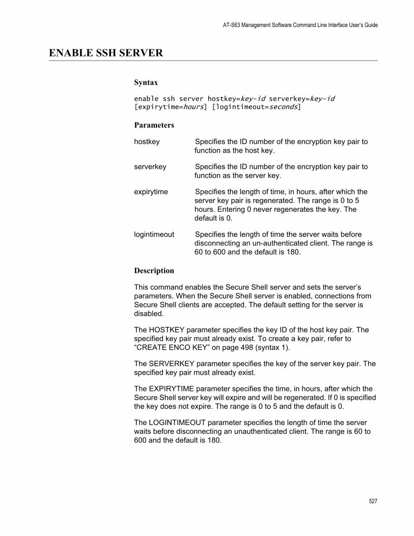
AT-S63 Management Software Command Line Interface User’s Guide
ENABLE SSH SERVER
Syntax
enable ssh server hostkey=key-id serverkey=key-id [expirytime=hours] [logintimeout=seconds]
Parameters
hostkey Specifies the ID number of the encryption key pair to function as the host key.
serverkey Specifies the ID number of the encryption key pair to function as the server key.
expirytime Specifies the length of time, in hours, after which the server key pair is regenerated. The range is 0 to 5 hours. Entering 0 never regenerates the key. The default is 0.
logintimeout Specifies the length of time the server waits before disconnecting an un-authenticated client. The range is 60 to 600 and the default is 180.
Description
This command enables the Secure Shell server and sets the server’s parameters. When the Secure Shell server is enabled, connections from Secure Shell clients are accepted. The default setting for the server is disabled.
The HOSTKEY parameter specifies the key ID of the host key pair. The specified key pair must already exist. To create a key pair, refer to “CREATE ENCO KEY” on page 498 (syntax 1).
The SERVERKEY parameter specifies the key of the server key pair. The specified key pair must already exist.
The EXPIRYTIME parameter specifies the time, in hours, after which the Secure Shell server key will expire and will be regenerated. If 0 is specified the key does not expire. The range is 0 to 5 and the default is 0.
The LOGINTIMEOUT parameter specifies the length of time the server waits before disconnecting an unauthenticated client. The range is 60 to 600 and the default is 180.
527
Chapter 36: Secure Shell (SSH) Commands
NoteBefore you enable SSH, disable the Telnet management session. Otherwise, the security provided by SSH is not active. See “DISABLE TELNET” on page 35.
Example
The following command activates the Secure Shell server and specifies encryption key pair 0 as the host key and key pair 1 as the server key:
enable ssh server hostkey=0 serverkey=1
General Configuration Steps for SSH Operation
Configuring the SSH server involves several commands. The information in this section lists the functions and commands you need to perform to configure the SSH feature.
1. Create two encryption key pairs. One pair will function as the SSH host key and another as the SSH server key. The keys must be of different lengths of at least one increment (256 bits) apart. The recommended size for the server key is 768 bits. The recommended size for the server key is 1024 bits. To create a key pair, see to “CREATE ENCO KEY” on page 498.
2. Disable Telnet access to the switch with the DISABLE TELNET command. See “DISABLE TELNET” on page 35.
Although the AT-S63 management software allows the SSH and Telnet servers to be active on the switch simultaneously, allowing Telnet to remain active negates the security of the SSH feature.
3. Configure and activate SSH on the switch using “ENABLE SSH SERVER” on page 527.
4. Install SSH client software on your PC.
Follow the directions provided with the client software. You can download SSH client software from the Internet. Two popular SSH clients are PuTTY and CYGWIN.
5. Log on to the SSH server from the SSH client.
Acceptable users are those with a Manager or Operator login as well as users configured with the RADIUS and TACACS+ protocols. You can add, delete, and modify users with the RADIUS and TACACS+ feature. For information about how to configure RADIUS and TACACS+, see Chapter 37, “TACACS+ and RADIUS Commands” on page 533.
528
AT-S63 Management Software Command Line Interface User’s Guide
Example
The following is an example of the command sequence to configuring the SSH software on the server:
1. The first step is to create the two encryption key pairs. Each key must be created separately and the key lengths must be at least one increment (256 bits) apart. The following two commands create the host and server keys using the recommended key lengths:
create enco key=1 type=rsa length=1024 description="host key"
create enco key=2 type=rsa length=768 description="server key"
2. The following command disables Telnet:
disable telnet
3. The last command activates the SSH software and sets the host key as encryption key pair 1 and the server key as key pair 2:
enable ssh server hostkey=1 serverkey=2
529
Chapter 36: Secure Shell (SSH) Commands
SET SSH SERVER
Syntax
set ssh server hostkey=key-id serverkey=key-id [expirytime=hours] [logintimeout=seconds]
Parameters
hostkey Specifies the ID number of the encryption key pair to function as the host key.
serverkey Specifies the ID number of the encryption key pair to function as the server key.
expirytime Specifies the length of time, in hours, after which the server key pair is regenerated. The range is 0 to 5 hours. Entering 0 never regenerates the key. The default is 0.
logintimeout Specifies the length of time the server waits before disconnecting an un-authenticated client. The range is 60 to 600 and the default is 180.
Description
This command modifies the configuration of the Secure Shell server parameters.
The HOSTKEY parameter specifies the key ID of the host key pair. The specified key pair must already exist. To create a key pair, refer to “CREATE ENCO KEY” on page 498 (syntax 1).
The SERVERKEY parameter specifies the key of the server key pair. The specified key pair must already exist.
The EXPIRYTIME parameter specifies the time, in hours, after which the Secure Shell server key will expire and will be regenerated. If 0 is specified the key does not expire. The range is 0 to 5 and the default is 0.
The LOGINTIMEOUT parameter specifies the length of time the server waits before disconnecting an un-authenticated client. The range is 60 to 600 seconds. The default is 180 seconds.
530
AT-S63 Management Software Command Line Interface User’s Guide
Example
The following command sets the Secure Shell server key expiry time to 1 hour:
set ssh server expirytime=1
531
Chapter 36: Secure Shell (SSH) Commands
SHOW SSH
Syntax
show ssh
Parameters
None.
Description
This command displays the current values for the following SSH parameters:
Versions supportedServer StatusServer PortHost Key IDHost Key Bits (size of host key in bits)Server Key IDServer Key Bits (size of server key in bits)Server Key Expiry (hours)Login Timeout (seconds)Authentication AvailableCiphers AvailableMACs AvailableData Compression
Example
The following command displays the configuration of the Secure Shell server:
show ssh
532
Chapter 37
TACACS+ and RADIUS Commands
This chapter contains the following commands:
“ADD RADIUSSERVER” on page 534“ADD TACACSSERVER” on page 536“DELETE RADIUSSERVER” on page 537“DELETE TACACSSERVER” on page 538“DISABLE AUTHENTICATION” on page 539“ENABLE AUTHENTICATION” on page 540“PURGE AUTHENTICATION” on page 541“SET AUTHENTICATION” on page 542“SHOW AUTHENTICATION” on page 544
NoteRemember to save your changes with the SAVE CONFIGURATION command.
NoteFor background information on the TACACS+ and RADIUS protocols, refer to Chapter 34, “TACACS+ and RADIUS Protocols” in the AT-S63 Management Software Menus Interface User’s Guide.
533
Chapter 37: TACACS+ and RADIUS Commands
ADD RADIUSSERVER
Syntax
add radiusserver server|ipaddress=ipaddress order=value [secret=string] [port=value] [accport=value]
Parameters
server Specifies an IP address of a RADIUS server. The parameters
ipaddress are equivalent.
order Specifies the order that the RADIUS servers are queried by the switch. This value can be from 1 to 3. The servers are queried starting with 1.
secret Specifies the encryption key used for this server.
port Specifies the UDP (User Datagram Protocol) port of the RADIUS server. The default is port 1812.
accport Specifies the UDP port for RADIUS accounting. The default is port 1813.
Description
This command specifies the IP addresses of RADIUS servers and the order they are to be queried by the switch. There can be up to three servers, but you must specify each one individually with this command. You may specify an encryption key, a RADIUS UDP port, and a RADIUS accounting UDP port.
Examples
The following command adds a RADIUS server with the 149.245.22.22 IP address and specifies it as the first server in the list:
add radiusserver ipaddress=149.245.22.22 order=1
The following command adds the RADIUS server with the IP address 149.245.22.22. In addition, it specifies the server as the third RADIUS server to be queried by the switch and has a UDP port of 3.
add radiusserver ipaddress=149.245.22.22 order=3 port=3
The following command adds a RADIUS server with an IP address of 149.245.22.22. In addition, it specifies the order is 2, the encryption key is tiger74, and the UDP port is 1811.
534

AT-S63 Management Software Command Line Interface User’s Guide
add radiusserver ipaddress=149.245.22.22 order=2 secret=tiger74 port=1811
535
Chapter 37: TACACS+ and RADIUS Commands
ADD TACACSSERVER
Syntax
add tacacsserver server|ipaddress=ipaddress order=value [secret=string]
Parameters
server Specifies an IP address of a TACACS+ server. The ipaddress parameters are equivalent.
order Specifies the order that your TACACS+ servers are queried by the switch. You can assign order to up to 3 servers with 1 being the first server queried.
secret Specifies the optional encryption key used on this server.
Description
This command adds the IP addresses of TACACS+ servers to your switch along with the order the TACACS+ servers are to be queried and an optional encryption key.
Examples
The following command adds a TACACS+ server with an IP address 149.245.22.20 and an order value of 1:
add tacacsserver ipaddress=149.245.22.20 order=1
The following command adds a TACACS+ server with an IP address of 149.245.22.24, an order of 2, and an encryption code of lioness54:
add tacacsserver ipaddress=149.245.22.24 order=2 secret=lioness54
The following command adds a TACACS+ server with an IP address 149.245.22.26 and specifies that this TACACS+ server is the third TACACS+ server to be queried by the switch:
add tacacsserver ipaddress=149.245.22.26 order=3
536
AT-S63 Management Software Command Line Interface User’s Guide
DELETE RADIUSSERVER
Syntax
delete radiusserver server|ipaddress=ipaddress
Parameter
server Specifies the IP address of a RADIUS server to be deleted ipaddress from the management software. The parameters are
equivalent.
Description
This command deletes the IP address of a RADIUS from your switch.
Example
The following command deletes the RADIUS server with the IP address 149.245.22.22:
delete radiusserver ipaddress=149.245.22.22
537
Chapter 37: TACACS+ and RADIUS Commands
DELETE TACACSSERVER
Syntax
delete tacacsserver server|ipaddress=ipaddress
Parameter
server Specifies the IP address of a TACACS+ server to be deleted ipaddress from the management software. The parameters are
equivalent.
Description
This command deletes the IP address of a TACACS+ server from your switch.
Example
The following command deletes the TACACS+ server with the IP address 149.245.22.20:
delete tacacsserver ipaddress=149.245.22.20
538
AT-S63 Management Software Command Line Interface User’s Guide
DISABLE AUTHENTICATION
Syntax
disable authentication
Parameters
None.
Description
This command disables TACACS+ and RADIUS manager account authentication on your switch. When you disable authentication you retain your current authentication parameter settings.
NoteThis command applies only to TACACS+ and RADIUS manager accounts. Disabling authentication means that you must use the default manager accounts of manager and operator to manage the switch. This command does not affect 802.1x port-based access control.
Example
The following command disables TACACS+ and RADIUS authentication on your switch:
disable authentication
539
Chapter 37: TACACS+ and RADIUS Commands
ENABLE AUTHENTICATION
Syntax
enable authentication
Parameters
None.
Description
This command enables TACACS+ or RADIUS manager account authentication on your switch. To select an authenticator protocol, refer to “SET AUTHENTICATION” on page 542.
NoteIf you are using the RADIUS authentication protocol for 802.1x Port-based Network Access Control but not for manager account authentication, you do not need to use this command. You can leave the RADIUS manager account feature disabled. The switch still has access to the RADIUS configuration information for 802.1x port-based access control.
Example
The following command enables authentication on your switch:
enable authentication
540
AT-S63 Management Software Command Line Interface User’s Guide
PURGE AUTHENTICATION
Syntax
purge authentication
Parameters
None.
Description
This command disables authentication, returns the authentication method to TACACS+, deletes any global secret, and returns the timeout value to its default setting of 10 seconds. This command does not delete the IP address or secret of any RADIUS or TACACS+ authentication servers you may have specified.
Example
The following command returns the authentication settings to their default values:
purge authentication
541
Chapter 37: TACACS+ and RADIUS Commands
SET AUTHENTICATION
Syntax
set authentication method=tacacs|radius [secret=string] [timeout=value]
Parameters
method Specifies which authenticator protocol, TACACS+ or RADIUS, is to be the active protocol on the switch.
secret Specifies the global encryption key that is used by the TACACS+ or RADIUS servers. If the servers use different encryption keys, you can leave this parameter blank and set individual encryption keys with “ADD TACACSSERVER” on page 536 or “ADD RADIUSSERVER” on page 534.
timeout Specifies the maximum amount of time the switch waits for a response from an authentication server before the switch assumes the server will not respond. If the timeout expires and the server has not responded, the switch queries the next server in the list. After the switch has exhausted the list of servers, the switch defaults to the standard Manager and Operator accounts. The default is 30 seconds. The range is 1 to 300 seconds.
Description
This command selects the authentication protocol. One one authentication protocol can be active on the switch at a time. You may specify a global encryption code and the maximum number of seconds the switch waits for a response from an authenticator server.
Examples
The following command selects TACACS+ as the authentication protocol on the switch:
set authentication method=tacacs
The following command selects TACACS+ as the authentication protocol and specifies a global encryption key of tiger54:
set authentication method=tacacs secret=tiger54
The following command selects RADIUS as the authentication protocol
542

AT-S63 Management Software Command Line Interface User’s Guide
with a global encryption key of leopard09 and a timeout of 15 seconds:
set authentication method=radius secret=leopard09 timeout=15
543
Chapter 37: TACACS+ and RADIUS Commands
SHOW AUTHENTICATION
Syntax
show authentication [=tacacs|radius]
Parameters
None.
Description
This command displays the following information about the authenticated protocols on the switch:
Status - The status of your authenticated protocol: enabled or disabled.Authentication Method - The authentication protocol activated on your switch. Either TACACS+ or RADIUS protocol may be active. The TACACS+ protocol is the default.The IP addresses of up to three authentication servers.The server encryption keys, if defined.TAC global secret - The global encryption code that applies to all authentication servers.Timeout - The length of the time, in seconds, before the switch assumes the server will not respond.
Entering the command without specifying either TACACS or RADIUS displays the current status of the authentication feature and the specifics of the currently selected authentication protocol. Specifying TACACS or RADIUS in the command displays the specifics for that authentication protocol.
Example
The following command displays authentication protocol information on your switch:
show authentication
The following command displays the information for the RADIUS protocol:
show authentication=radius
544
Chapter 38
Management ACL Commands
This chapter contains the following commands:
“ADD MGMTACL” on page 546“DELETE MGMTACL” on page 549“DISABLE MGMTACL” on page 550“ENABLE MGMTACL” on page 551“SET MGMTACL STATE” on page 552“SHOW MGMTACL” on page 554
NoteRemember to save your changes with the SAVE CONFIGURATION command.
NoteFor background information on the Management ACL, refer to Chapter 35, “Management Access Control Lists” in the AT-S63 Management Software Menus Interface User’s Guide.
545
Chapter 38: Management ACL Commands
ADD MGMTACL
Syntax
add mgmtacl ipddress=ipaddress mask=string protocol=tcp|udp|all interface=telnet|web|all
Parameters
ipaddress Specifies the IP address of a specific management station or of a subnet.
mask Specifies the mask used by the switch to filter the IP address. A binary “1” indicates the switch should filter on the corresponding bit of the address, while a “0” indicates that it should not. If, in the IPADDRESS parameter, you specified the IP address of a specific management station, the appropriate mask is 255.255.255.255. If you are filtering on a subnet, then the mask would depend on the subnet address. For example, for a Class C subnet address of 149.11.11.32, the mask would be 255.255.255.224.
protocol Specifies the protocol of the management packets. The options are:
tcp Transmission control protocol.
udp User datagram protocol.
all Both TCP and UDP packets.
NoteSince management packets from both Telnet and web browser management sessions are TCP, you should specify either TCP or ALL. Do not specify UDP.
interface Specifies the type of remote management allowed. The options are:
telnet Telnet management
web Web management
all Both Telnet and web management
Description
This command adds an access control entry to the Management ACL.
546
AT-S63 Management Software Command Line Interface User’s Guide
There can be up to 256 ACEs in a Management ACL.
An ACE is an implicit “permit” statement. A workstation that meets the criteria of the ACE will be allowed to remotely manage the switch.
The IPADDRESS parameter specifies the IP address of a specific management station or a subnet.
The MASK parameter indicates the parts of the IP address the switch should filter on. A binary “1” indicates the switch should filter on the corresponding bit of the address, while a “0” indicates that it should not. If you are filtering on a specific IP address, use the mask 255.255.255.255. For a subnet, you need to enter the appropriate mask. For example, to allow all management stations in the subnet 149.11.11.0 to manage the switch, you would enter the mask 255.255.255.0.
The PROTOCOL parameter allows you to choose TCP, UDP, or both as the protocol for the management packets. Since Telnet and web browser management packets for an AT-8524M switch are exclusively TCP, only that protocol should be specified as the protocol.
The INTERFACE parameter allows you control whether the remote management station can manage the switch using Telnet, a web browser, or both. For example, you might create an ACE that states that a particular remote management station can only use a web browser to manage the switch.
NoteYou must specify all the parameters when you add an entry.
Example
The following command allows the management station with the IP address 169.254.134.247 to manage the switch from either a Telnet or web browser management session:
add mgmtacl ipaddress=169.254.134.247 mask=255.255.255.255 protocol=tcp interface=all
The following command allows the management station with the IP address 169.254.134.12 to manage the switch only from a web browser management session:
add mgmtacl ipaddress=169.254.134.12 mask=255.255.255.255 protocol=tcp interface=web
The following command allows all management stations in the Class A subnet 169.24.144.128 to manage the switch using a Telnet protocol application:
547

Chapter 38: Management ACL Commands
add mgmtacl ipaddress=169.24.144.128 mask=255.255.255.224 protocol=tcp interface=web
548
AT-S63 Management Software Command Line Interface User’s Guide
DELETE MGMTACL
Syntax
delete mgmtacl ipaddress=ipaddress mask=string protocol=tcp|udp|all interface=telnet|web|all
Parameters
ipaddress Specifies the IP address to be deleted.
mask Specifies the mask of the IP address.
protocol Specifies the protocol of the management packets. The options are:
tcp Transmission control protocol.
udp User datagram protocol.
all Both TCP and UDP packets.
interface Specifies the method of remote management. The options are:
telnet Telnet management
web Web management.
all Both Telnet and web management.
Description
This command deletes an ACE from the Management ACL.
NoteYou must enter all the parameters to delete an entry. To view the entries in the Management ACL, refer to “SHOW MGMTACL” on page 554.
Example
The following command deletes an ACE from the Management ACL:
delete mgmtacl ipaddress=169.254.134.247 mask=255.255.0.0 protocol=tcp interface=all
549
Chapter 38: Management ACL Commands
DISABLE MGMTACL
Syntax
disable mgmtacl
Parameters
None
Description
This command disables the management ACL and performs the same function as the SETMGMTALL STATE=DISABLE command.
Example
The following command disables the management ACL:
disable mgmtacl
550
AT-S63 Management Software Command Line Interface User’s Guide
ENABLE MGMTACL
Syntax
enable mgmtacl
Parameters
None
Description
This command enables the management ACL and performs the same function as the SETMGMTALL STATE=DISABLE command.
NoteActivating the Management ACL without entering any access control entries (ACEs) prohibits you from remotely managing the switch from a Telnet or web browser management session.
Example
The following command enables the management ACL:
enable mgmtacl
551
Chapter 38: Management ACL Commands
SET MGMTACL STATE
Syntax
set mgmtacl [state=disable|enable] [ipaddress=ipaddress] [mask=mask] [protocol=tcp] [interface=telnet|web|all]
Parameters
state Sets the state of the Management ACL. The options are:
enable Enables the Management ACL.
disable Disables the Management ACL. This is the default setting.
ipaddress The IP address of a specific management station or a subnet.
mask The mask that indicates the parts of the IP address that the switch should filter on. A binary “1” indicates the switch should filter on the corresponding bit of the address, while a “0” indicates that it should not. To filter on a specific IP address, use 255.255.255.255 as the mask. To filter on a subnet, use the appropriate subnet mask.
protocol The protocol the management station will use. The only option is tcp.
interface The interface the management station will use to manage the switch. The options are:
telnet Allows Telnet packets.
web Allows web browser management packets.
all Allows both Telnet and web browser management packets.
Description
This command creates the Management ACL.
NoteActivating the Management ACL without entering any access control entries (ACEs) prohibits you from remotely managing the switch from a Telnet or web browser management session.
552

AT-S63 Management Software Command Line Interface User’s Guide
Example
The following command enables the Management ACL on a specific management station, sets the interface to TCP and allows both Telnet and web browser management sessions:
set mgmtacl state=enable ipaddress=149.32.2.4 protocol=tcp interface=all
553
Chapter 38: Management ACL Commands
SHOW MGMTACL
Syntax
show mgmtacl state|entries
Parameters
state Displays the status of the Management ACL as either enabled or disabled.
entries Lists the entries in the Management ACL.
Description
This command shows the state of and/or entries in the Management ACL.
Examples
The following command displays whether the Management ACL is enabled or disabled:
show mgmtacl state
The following command displays the ACEs in the Management ACL:
show mgmtacl entries
554
Index
Numerics802.1Q multiple VLAN mode 424802.1x Port-based Network Access Control 472
authenticator portconfiguring 466displaying 474
disabling 462displaying 474, 475enabling 464supplicant port
configuring 470displaying 474
Aaccess control
authenticator port, displaying 474supplicant port, displaying 474
access control list (ACL)creating 220deleting 222, 223displaying 226modifying 224
access control lists. See also Management ACLACCESS SWITCH command 96ACL. See access control list (ACL) and Management ACLACTIVATE MSTP command 390ACTIVATE RSTP command 376ACTIVATE STP command 364ACTIVATE SWITCH PORT command 102ADD LACP PORT command 136ADD LOG OUTPUT command 186ADD MGMTACL command 546ADD MSTP command 391ADD PKI CERTIFICATE command 506ADD QOS FLOWGROUP command 242ADD QOS POLICY command 243ADD QOS TRAFFICCLASS command 244ADD RADIUSSERVER command 534ADD SNMP COMMUNITY command 66ADD SNMPV3 USER command 301, 350ADD SNTPSERVER PEER|IPADDRESS command 84ADD SWITCH FDB|FILTER command 478ADD SWITCH TRUNK command 128ADD TACACSSERVER command 536ADD VLAN command 412ADD VLAN GROUP command 444Address Resolution Protocol (ARP) table
configuring timeout value 157aging timer 482
AT-S63 software imagedownloading 166uploading 179
AT-S63 software, resetting to factory defaults 44authentication
disabling 539displaying 544enabling 540protocol, selecting 542resetting to defaults 541
authentication failure trapsdisabling 73displaying 80enabling 76
authenticator portconfiguring 466displaying 474, 475
Bback pressure 111boot configuration file names, displaying 176BOOTP
disabling 33, 34enabling 36, 38status, displaying 59
BPDU 381, 399bridge forwarding delay 368, 380, 398bridge hello time 368, 380, 398bridge max age 368, 380, 398bridge priority 368broadcast filter 111
Ccache timeout 522certificate database 517certificates
name, changing 515trust level, changing 515
CIST priority 401Class of Service. See CoSclassifiers
creating 210deleting 213, 214displaying 218modifying 215removing from flow group 257
CLEAR SCREEN command 22CLEAR SNMPV3 ACCESS command 303CLEAR SNMPV3 COMMUNITY command 305
555
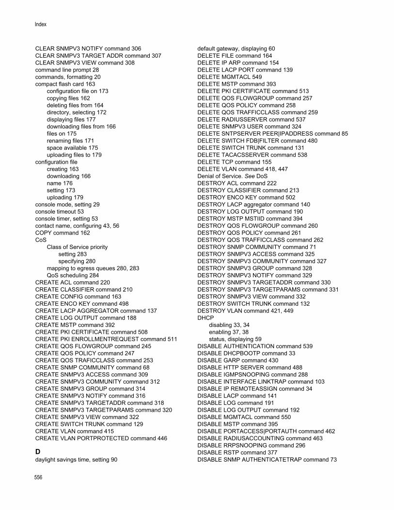
Index
CLEAR SNMPV3 NOTIFY command 306CLEAR SNMPV3 TARGET ADDR command 307CLEAR SNMPV3 VIEW command 308command line prompt 28commands, formatting 20compact flash card 163
configuration file on 173copying files 162deleting files from 164directory, selecting 172displaying files 177downloading files from 166files on 175renaming files 171space available 175uploading files to 179
configuration filecreating 163downloading 166name 176setting 173uploading 179
console mode, setting 29console timeout 53console timer, setting 53contact name, configuring 43, 56COPY command 162CoS
Class of Service prioritysetting 283specifying 280
mapping to egress queues 280, 283QoS scheduling 284
CREATE ACL command 220CREATE CLASSIFIER command 210CREATE CONFIG command 163CREATE ENCO KEY command 498CREATE LACP AGGREGATOR command 137CREATE LOG OUTPUT command 188CREATE MSTP command 392CREATE PKI CERTIFICATE command 508CREATE PKI ENROLLMENTREQUEST command 511CREATE QOS FLOWGROUP command 245CREATE QOS POLICY command 247CREATE QOS TRAFICCLASS command 253CREATE SNMP COMMUNITY command 68CREATE SNMPV3 ACCESS command 309CREATE SNMPV3 COMMUNITY command 312CREATE SNMPV3 GROUP command 314CREATE SNMPV3 NOTIFY command 316CREATE SNMPV3 TARGETADDR command 318CREATE SNMPV3 TARGETPARAMS command 320CREATE SNMPV3 VIEW command 322CREATE SWITCH TRUNK command 129CREATE VLAN command 415CREATE VLAN PORTPROTECTED command 446
Ddaylight savings time, setting 90
default gateway, displaying 60DELETE FILE command 164DELETE IP ARP command 154DELETE LACP PORT command 139DELETE MGMTACL 549DELETE MSTP command 393DELETE PKI CERTIFICATE command 513DELETE QOS FLOWGROUP command 257DELETE QOS POLICY command 258DELETE QOS TRAFFICCLASS command 259DELETE RADIUSSERVER command 537DELETE SNMPV3 USER command 324DELETE SNTPSERVER PEER|IPADDRESS command 85DELETE SWITCH FDB|FILTER command 480DELETE SWITCH TRUNK command 131DELETE TACACSSERVER command 538DELETE TCP command 155DELETE VLAN command 418, 447Denial of Service. See DoSDESTROY ACL command 222DESTROY CLASSIFIER command 213DESTROY ENCO KEY command 502DESTROY LACP aggregator command 140DESTROY LOG OUTPUT command 190DESTROY MSTP MSTIID command 394DESTROY QOS FLOWGROUP command 260DESTROY QOS POLICY command 261DESTROY QOS TRAFFICCLASS command 262DESTROY SNMP COMMUNITY command 71DESTROY SNMPV3 ACCESS command 325DESTROY SNMPV3 COMMUNITY command 327DESTROY SNMPV3 GROUP command 328DESTROY SNMPV3 NOTIFY command 329DESTROY SNMPV3 TARGETADDR command 330DESTROY SNMPV3 TARGETPARAMS command 331DESTROY SNMPV3 VIEW command 332DESTROY SWITCH TRUNK command 132DESTROY VLAN command 421, 449DHCP
disabling 33, 34enabling 37, 38status, displaying 59
DISABLE AUTHENTICATION command 539DISABLE DHCPBOOTP command 33DISABLE GARP command 430DISABLE HTTP SERVER command 488DISABLE IGMPSNOOPING command 288DISABLE INTERFACE LINKTRAP command 103DISABLE IP REMOTEASSIGN command 34DISABLE LACP command 141DISABLE LOG command 191DISABLE LOG OUTPUT command 192DISABLE MGMTACL command 550DISABLE MSTP command 395DISABLE PORTACCESS|PORTAUTH command 462DISABLE RADIUSACCOUNTING command 463DISABLE RRPSNOOPING command 296DISABLE RSTP command 377DISABLE SNMP AUTHENTICATETRAP command 73
556
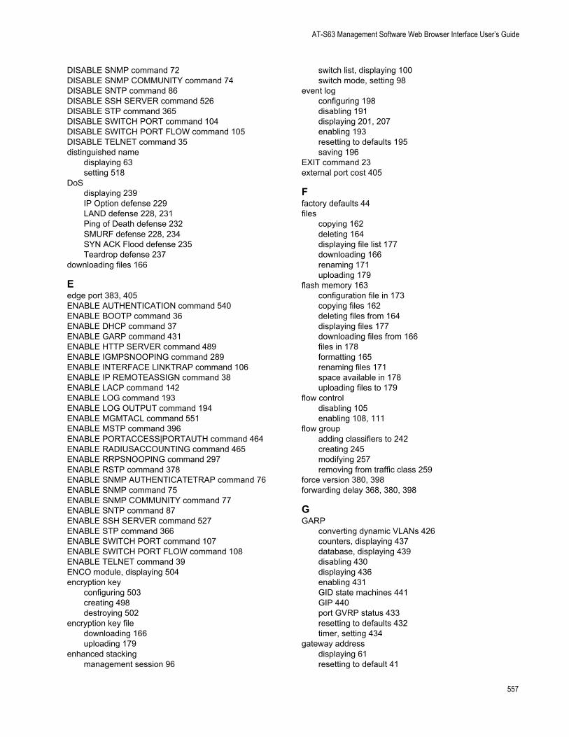
AT-S63 Management Software Web Browser Interface User’s Guide
DISABLE SNMP command 72DISABLE SNMP COMMUNITY command 74DISABLE SNTP command 86DISABLE SSH SERVER command 526DISABLE STP command 365DISABLE SWITCH PORT command 104DISABLE SWITCH PORT FLOW command 105DISABLE TELNET command 35distinguished name
displaying 63setting 518
DoSdisplaying 239IP Option defense 229LAND defense 228, 231Ping of Death defense 232SMURF defense 228, 234SYN ACK Flood defense 235Teardrop defense 237
downloading files 166
Eedge port 383, 405ENABLE AUTHENTICATION command 540ENABLE BOOTP command 36ENABLE DHCP command 37ENABLE GARP command 431ENABLE HTTP SERVER command 489ENABLE IGMPSNOOPING command 289ENABLE INTERFACE LINKTRAP command 106ENABLE IP REMOTEASSIGN command 38ENABLE LACP command 142ENABLE LOG command 193ENABLE LOG OUTPUT command 194ENABLE MGMTACL command 551ENABLE MSTP command 396ENABLE PORTACCESS|PORTAUTH command 464ENABLE RADIUSACCOUNTING command 465ENABLE RRPSNOOPING command 297ENABLE RSTP command 378ENABLE SNMP AUTHENTICATETRAP command 76ENABLE SNMP command 75ENABLE SNMP COMMUNITY command 77ENABLE SNTP command 87ENABLE SSH SERVER command 527ENABLE STP command 366ENABLE SWITCH PORT command 107ENABLE SWITCH PORT FLOW command 108ENABLE TELNET command 39ENCO module, displaying 504encryption key
configuring 503creating 498destroying 502
encryption key filedownloading 166uploading 179
enhanced stackingmanagement session 96
switch list, displaying 100switch mode, setting 98
event logconfiguring 198disabling 191displaying 201, 207enabling 193resetting to defaults 195saving 196
EXIT command 23external port cost 405
Ffactory defaults 44files
copying 162deleting 164displaying file list 177downloading 166renaming 171uploading 179
flash memory 163configuration file in 173copying files 162deleting files from 164displaying files 177downloading files from 166files in 178formatting 165renaming files 171space available in 178uploading files to 179
flow controldisabling 105enabling 108, 111
flow groupadding classifiers to 242creating 245modifying 257removing from traffic class 259
force version 380, 398forwarding delay 368, 380, 398
GGARP
converting dynamic VLANs 426counters, displaying 437database, displaying 439disabling 430displaying 436enabling 431GID state machines 441GIP 440port GVRP status 433resetting to defaults 432timer, setting 434
gateway addressdisplaying 61resetting to default 41
557
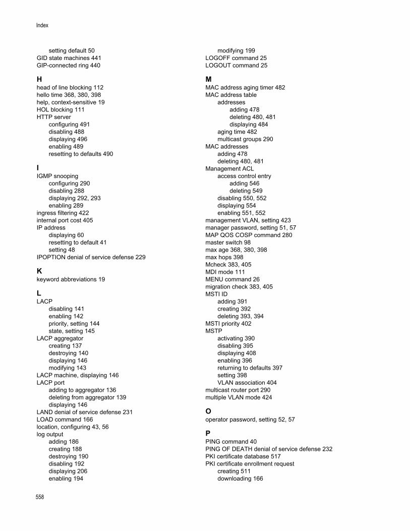
Index
setting default 50GID state machines 441GIP-connected ring 440
Hhead of line blocking 112hello time 368, 380, 398help, context-sensitive 19HOL blocking 111HTTP server
configuring 491disabling 488displaying 496enabling 489resetting to defaults 490
IIGMP snooping
configuring 290disabling 288displaying 292, 293enabling 289
ingress filtering 422internal port cost 405IP address
displaying 60resetting to default 41setting 48
IPOPTION denial of service defense 229
Kkeyword abbreviations 19
LLACP
disabling 141enabling 142priority, setting 144state, setting 145
LACP aggregatorcreating 137destroying 140displaying 146modifying 143
LACP machine, displaying 146LACP port
adding to aggregator 136deleting from aggregator 139displaying 146
LAND denial of service defense 231LOAD command 166location, configuring 43, 56log output
adding 186creating 188destroying 190disabling 192displaying 206enabling 194
modifying 199LOGOFF command 25LOGOUT command 25
MMAC address aging timer 482MAC address table
addressesadding 478deleting 480, 481displaying 484
aging time 482multicast groups 290
MAC addressesadding 478deleting 480, 481
Management ACLaccess control entry
adding 546deleting 549
disabling 550, 552displaying 554enabling 551, 552
management VLAN, setting 423manager password, setting 51, 57MAP QOS COSP command 280master switch 98max age 368, 380, 398max hops 398Mcheck 383, 405MDI mode 111MENU command 26migration check 383, 405MSTI ID
adding 391creating 392deleting 393, 394
MSTI priority 402MSTP
activating 390disabling 395displaying 408enabling 396returning to defaults 397setting 398VLAN association 404
multicast router port 290multiple VLAN mode 424
Ooperator password, setting 52, 57
PPING command 40PING OF DEATH denial of service defense 232PKI certificate database 517PKI certificate enrollment request
creating 511downloading 166
558
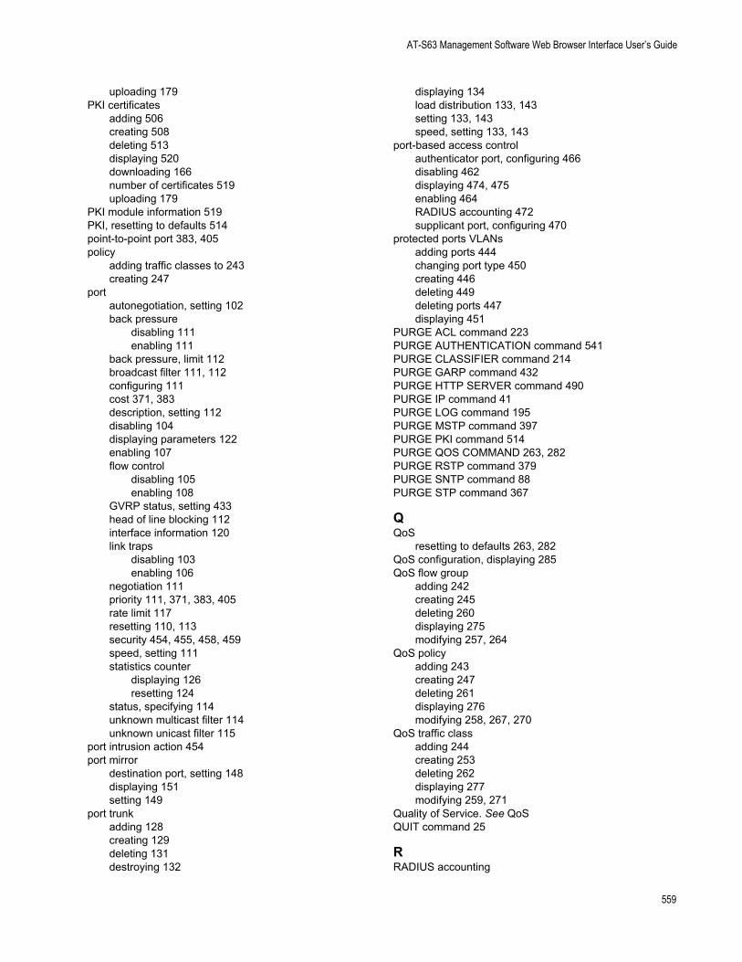
AT-S63 Management Software Web Browser Interface User’s Guide
uploading 179PKI certificates
adding 506creating 508deleting 513displaying 520downloading 166number of certificates 519uploading 179
PKI module information 519PKI, resetting to defaults 514point-to-point port 383, 405policy
adding traffic classes to 243creating 247
portautonegotiation, setting 102back pressure
disabling 111enabling 111
back pressure, limit 112broadcast filter 111, 112configuring 111cost 371, 383description, setting 112disabling 104displaying parameters 122enabling 107flow control
disabling 105enabling 108
GVRP status, setting 433head of line blocking 112interface information 120link traps
disabling 103enabling 106
negotiation 111priority 111, 371, 383, 405rate limit 117resetting 110, 113security 454, 455, 458, 459speed, setting 111statistics counter
displaying 126resetting 124
status, specifying 114unknown multicast filter 114unknown unicast filter 115
port intrusion action 454port mirror
destination port, setting 148displaying 151setting 149
port trunkadding 128creating 129deleting 131destroying 132
displaying 134load distribution 133, 143setting 133, 143speed, setting 133, 143
port-based access controlauthenticator port, configuring 466disabling 462displaying 474, 475enabling 464RADIUS accounting 472supplicant port, configuring 470
protected ports VLANsadding ports 444changing port type 450creating 446deleting 449deleting ports 447displaying 451
PURGE ACL command 223PURGE AUTHENTICATION command 541PURGE CLASSIFIER command 214PURGE GARP command 432PURGE HTTP SERVER command 490PURGE IP command 41PURGE LOG command 195PURGE MSTP command 397PURGE PKI command 514PURGE QOS COMMAND 263, 282PURGE RSTP command 379PURGE SNTP command 88PURGE STP command 367
QQoS
resetting to defaults 263, 282QoS configuration, displaying 285QoS flow group
adding 242creating 245deleting 260displaying 275modifying 257, 264
QoS policyadding 243creating 247deleting 261displaying 276modifying 258, 267, 270
QoS traffic classadding 244creating 253deleting 262displaying 277modifying 259, 271
Quality of Service. See QoSQUIT command 25
RRADIUS accounting
559
Index
configuring 472disabling 463displaying 476enabling 465
RADIUS serveradding 534deleting 537
rate limiting 117RENAME command 171RESET IP ARP command 156, 157RESET SWITCH command 42RESET SWITCH FDB command 481RESET SWITCH PORT command 110RESET SWITCH PORT COUNTER command 124RESET SYSTEM command 43RESTART REBOOT command 44RESTART SWITCH command 45round robin QoS scheduling 284RRP snooping
disabling 296displaying 298enabling 297
RSTPactivating 376disabling 377displaying 386enabling 378port, setting 383resetting to defaults 379setting 380
SSAVE CONFIGURATION command 27SAVE LOG command 196Secure Shell (SSH), configuration overview 528serial terminal port
settings, displaying 58speed, setting 47
SET ACL command 224SET ASYN command 47SET AUTHENTICATION command 542SET CLASSIFIER command 215SET CONFIG command 173SET DATE TIME command 89, 91SET DOS command 228SET DOS IPOPTION command 229SET DOS LAND command 231SET DOS PINGOFDEATH command 232SET DOS SMURF command 234SET DOS SYNFLOOD command 235SET DOS TEARDROP command 237SET ENCO KEY command 503SET GARP PORT command 433SET GARP TIMER command 434SET HTTP SERVER SECURITY command 491SET IP IGMP command 290SET IP INTERFACE command 48SET IP ROUTE command 50SET LACP AGGREGATOR command 143
SET LACP PRIORITY command 144SET LACP STATE command 145SET LOG FULLACTION command 198SET LOG OUTPUT command 199SET MANAGER OPERATOR command 57SET MGMTACL STATE command 552SET MSTP CIST command 401SET MSTP command 398SET MSTP MSTI command 402SET MSTP MSTIVLANASSOC command 404SET MSTP PORT command 405SET PASSWORD MANAGER command 51SET PASSWORD OPERATOR command 52, 57SET PKI CERTIFICATE command 515SET PKI CERTSTORELIMIT command 517SET PORTACCESS|PORT AUTH PORT AUTHENTICA-
TOR command 466SET PORTACCESS|PORT AUTH PORT SUPPLICANT
command 470SET PROMPT command 28SET QOS COSP command 283SET QOS FLOWGROUP command 264SET QOS POLICY command 267SET QOS PORT command 270SET QOS SCHEDULING command 284SET QOS TRAFFICCLASS command 271SET RADIUSACCOUNTING command 472SET RSTP command 380SET RSTP PORT command 383SET SNMP COMMUNITY command 78SET SNMPV3 ACCESS command 338SET SNMPV3 COMMUNITY command 340SET SNMPV3 GROUP command 342SET SNMPV3 NOTIFY command 344SET SNMPV3 TARGETADDR command 346SET SNMPV3 TARGETPARAMS command 348SET SNMPV3 VIEW command 352SET SNTP command 90SET SSH SERVER command 530SET SSL command 522SET STP command 368SET STP PORT command 371SET SWITCH AGINGTIMER|AGEINGTIMER command
482SET SWITCH CONSOLEMODE command 29SET SWITCH CONSOLETIMER command 53SET SWITCH INFILTERING command 422SET SWITCH MANAGEMENTVLAN command 423SET SWITCH MIRROR command 148SET SWITCH PORT command 111SET SWITCH PORT INTRUSION command 454SET SWITCH PORT MIRROR command 149SET SWITCH PORT RATELIMITING command 117SET SWITCH PORT SECURITYMODE command 455SET SWITCH STACKMODE command 98SET SWITCH TRUNK command 133, 143SET SWITCH VLANMODE command 424SET SYSTEM command 56SET SYSTEM DISTINGUISHEDNAME command 518
560
AT-S63 Management Software Web Browser Interface User’s Guide
SET VLAN command 426, 450SHOW ACL command 226SHOW ASYN command 58SHOW AUTHENTICATION command 544SHOW CLASSIFIER command 218SHOW CONFIG command 176SHOW DHCPBOOTP command 59SHOW DOS command 239SHOW ENCO command 504SHOW FILE command 177SHOW GARP command 436SHOW GARP COUNTER command 437SHOW GARP DATABASE command 439SHOW GARP GIP command 440SHOW GARP MACHINE command 441SHOW HTTP SERVER command 496SHOW IGMPSNOOPING command 292SHOW INTERFACE command 120SHOW IP ARP command 158SHOW IP IGMP command 293SHOW IP INTERFACE command 60SHOW IP ROUTE command 61, 159SHOW LACP command 146SHOW LOG command 201SHOW LOG OUTPUT command 206SHOW LOG STATUS command 207SHOW MGMTACL command 554SHOW MSTP command 408SHOW PKI CERTIFICATE command 520SHOW PKI command 519SHOW PORTACCESS|PORTAUTH command 474SHOW PORTACCESS|PORTAUTH PORT command 475SHOW QOS CONFIG command 285SHOW QOS FLOWGROUP command 275SHOW QOS POLICY command 276SHOW QOS TRAFFICCLASS command 277SHOW RADIUSACCOUNTING command 476SHOW REMOTELIST command 100SHOW RRPSNOOPING command 298SHOW RSTP command 386SHOW SNMP command 80SHOW SNMPV3 ACCESS command 354SHOW SNMPV3 COMMUNITY command 355SHOW SNMPV3 GROUP command 356SHOW SNMPV3 NOTIFY command 357SHOW SNMPV3 TARGETADDR command 358SHOW SNMPV3 TARGETPARAMS command 359SHOW SNMPV3 USER command 360SHOW SNMPV3 VIEW command 361SHOW SNTP command 92SHOW SSH command 532SHOW SSL command 523SHOW STP command 373SHOW SWITCH AGINGTIMER|AGEINGTIMER command
483SHOW SWITCH command 62SHOW SWITCH COUNTER command 125SHOW SWITCH FDB command 484SHOW SWITCH MIRROR command 151
SHOW SWITCH PORT command 122SHOW SWITCH PORT COUNTER command 126SHOW SWITCH PORT INTRUSION command 458SHOW SWITCH PORT SECURITYMODE command 459SHOW SWITCH TRUNK command 134SHOW SYSTEM command 63SHOW TCP command 160SHOW TIME command 93SHOW USER command 30SHOW VLAN command 427, 451slave switch 98SMURF denial of service defense 234SNMP
disabling 72information, displaying 80
SNMP communityadding 66creating 68destroying 71disabling 74enabling 75, 77modifying 78
SNMP management access 66SNMPv3 Access Table entry
clearing 303creating 309deleting 325modifying 338
SNMPv3 Community Table entryclearing 305creating 312deleting 327modifying 340
SNMPv3 Notify Table entryclearing 306creating 316deleting 329modifying 344
SNMPv3 SecurityToGroup Table entrycreating 314deleting 328modifying 342
SNMPv3 Target Address Table entryclearing 307creating 318deleting 330modifying 346
SNMPv3 Target Parameters Table entrycreating 320deleting 331displaying 359modifying 348
SNMPv3 User Table entryadding 301deleting 324displaying 360
SNMPv3 View Table entryclearing 308creating 322
561
Index
deleting 332displaying 361
SNTPdisabling 86enabling 87information, displaying 92IP address
deleting 85specifying 84
resetting to defaults 88SSH configuration, displaying 532SSH server
configuring 530disabling 526enabling 527
SSLconfiguring 522displaying 523
static multicast address 478static unicast address 478STP
activating 364disabling 365displaying 373enabling 366port, setting 371resetting to defaults 367setting 368
strict QoS scheduling 284subnet mask
displaying 60resetting to default 41setting 48
supplicant portconfiguring 470displaying 474, 475
switchaccessing via enhanced stacking 96configuration, displaying 176distinguished name 63information, displaying 63parameters, displaying 62restarting 45statistics counters, displaying 125
SYNFLOOD denial of service defense 235system date
displaying 93setting 89, 91
system filesdownloading 166uploading 179
system name, configuring 43, 56system time
displaying 93setting 89, 91
TTACACS+ server
adding 536
deleting 538tagged port
adding 444adding to VLAN 412deleting 418, 447specifying 415
TEARDROP denial of service defense 237Telnet server
disabling 35enabling 39
temperature, switch, displaying 63traffic class
adding flow groups to 244creating 253removing from policy 258
trap receiver 66
Uunknown multicast filter 114unknown unicast filter 115untagged port
adding 444adding to VLAN 412deleting 418, 447specifying 415
UPLOAD command 179uploading files 179UTC offset, setting 90
VVLAN
adding ports 412converting dynamic VLANs into static 426creating 415deleting 418destroying 421displaying 427multiple 424
VLAN ID 415
562