Embed Size (px)
Citation preview

Fort Walton Beach, FL 32548 | 850-244-2332 | 1-888-325-9422 | www.gomicrosystems.com
Command & Control
Autopilots & Payloads
Tracking & IFF
Transponders
Scoring Systems
Flight Termination &
Range Safety
Custom Test Sets

Note to exporters: If this equipment is purchased for export, it will require an export license under
International Traffic in Arms Regulations (ITAR) approved by the U.S. Department of State. An end
user statement must be submitted to Micro Systems, Inc. with your purchase order for our review. The
end user statement must be on company letterhead with an authorized signature and is to be either
faxed or mailed (no e-mails). We will require that you supply our Contracts Department with a valid
export license number and expiration date before any equipment will be shipped.
PH: (850) 244-2332

To be the premier global supplier of unmanned vehicle systems, software products, and engineering services to
continuously exceed our customer’s expectations by providing the highest degree of quality and customer service.
Supporting The Defense Industry Since 1976
Our Vision
Micro Systems, Inc. is an AS9100C and ISO 9001:2008 certified
wholly owned subsidiary of Kratos Defense and Security
Solutions, headquartered in Fort Walton Beach Florida. Since
1976 we have been continuously exceeding our customers’
expectations in engineering, production and field services.
Our principal business is the design, development, and
manufacture of sophisticated systems used in a broad range of
advanced defense applications primarily in the unmanned systems
segment of the aerospace and defense industry. In our over 30
year history we have served the defense industry with a wide
range of solutions and products for Command and Control, Flight
Telemetry, Over-the-Horizon Communication, Electronic
Warfare, Flight Line Test, and Range Safety.
We offer a broad range of products including Unmanned Vehicle
Control Systems, Sophisticated Avionics, Radar Tracking and
Datalink Transponders, Scoring Systems, Custom Test
Equipment, and Advanced Flight Termination Systems.
This catalog contains just a few of the many products that we
offer to the industry. If you do not find a product that meets the
exact needs of your requirements please contact us and we can
discuss options to modify an existing product or design a new
product.
Our experienced team of management, engineering, and
production personnel are goal oriented, recognized leaders in the
defense industry. They follow through from design, prototype,
qualification, manufacturing, test to final delivery.
We are dedicated to providing total customer satisfaction and have
a team in-place with the resources, commitment, and Total
Quality mind-set necessary to provide high-performance, high
reliability products to the Aerospace and Defense Industry.
We are proud to serve you.
1

Micro Systems maintains a staff of highly skilled and
experienced systems, hardware, and software engineers. We
can provide off the shelf or custom developed solutions from
individual circuit card assemblies through large integrated
systems. Our environmental experience ranges from ground
benign (air conditioned and heated buildings) to flightline to
airborne uninhabited fighter. Our products incorporate
analog/digital/mixed signal, RF to 6 GHz, high performance
embedded software, and graphical user interfaces.
Micro Systems is committed to achieving the
highest level of quality in every aspect of its
business practices.
Capabilities
We maintain a comprehensive Quality Assurance Program
centered on the concepts of Total Quality. The program fully
complies with the requirements of AS9100C and ANSI/ISO/
ASQ Q9001-2008. The Quality Program consists of continuous
improvement activities involving everyone in the organization,
managers and workers, in a totally integrated effort to improve
performance at every level. This approach originates with the
President whose obsession with quality is constantly visible to
all employees.
Our quality system is independently reviewed by BSi
Management Systems every six months. We have been
certified continuously since January 1999.
Quality System
MICRO SYSTEMS, INC.35 Hill Ave Fort Walton Beach FL 32548 | PH: 1-888-325-9422 | Fax: 1-850-243-1378 | www.gomicrosystems.com
2
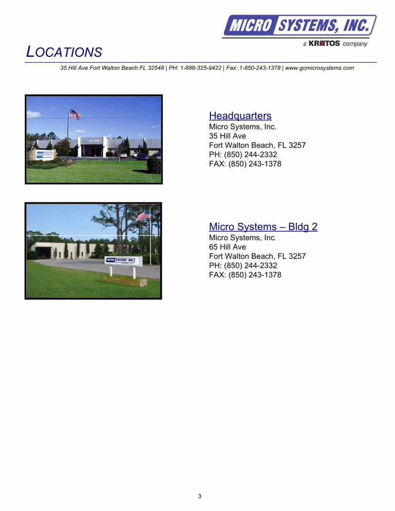
HeadquartersMicro Systems, Inc.
35 Hill Ave
Fort Walton Beach, FL 3257
PH: (850) 244-2332
FAX: (850) 243-1378
Micro Systems – Bldg 2Micro Systems, Inc.
65 Hill Ave
Fort Walton Beach, FL 3257
PH: (850) 244-2332
FAX: (850) 243-1378
LOCATIONS35 Hill Ave Fort Walton Beach FL 32548 | PH: 1-888-325-9422 | Fax: 1-850-243-1378 | www.gomicrosystems.com
3
Domestic Representatives
Please check our
website for the latest
representative contact
information
International Representatives
United States – RF Simulation Products
Precision Marketing Inc.
Joe Penna
Southeast Region
PH: (954) 752-1700
FAX: (954) 973-6335Email: [email protected]
Web: www.precision-marketing.com
Australia – Full Product Line
Global Defense Solutions Pty Ltd.
Laurie Koster
PH: +61(0)2-4423-7959
Email: [email protected]
Web: www.globaldefence.com
Germany – Full Product Line
TelData Systems
Herb Wutz
PH: +49-8121-410118
FAX: +49-8121-226692
Email: [email protected]
Web: www.teldatasystem.de
Italy – Full Product Line
Crisel
Eugenia Finocchiaro
PH: +39-06-35498681
FAX: +39-06-35498686
Email: [email protected]
Web: www.crisel.itKorea (Us office) – Full Product Line
Global Advance, Inc.
W.C. Kim
PH: (818) 889-7054
FAX: (818) 889-3950Email: [email protected]
Web: www.globaladvanceinc.com
Korea – Full Product Line
Global Overseas Co., Ltd.
E.S. Yi & J.J. Song
PH: +82-02-338-7031
FAX: +82-02-338-1098
Email: [email protected]
Web: www.globaladvanceinc.com
Singapore, Malaysia, Brunei, &
Indonesia – Full Product Line
Precision Technologies Pte Ltd.
Richard Wong
PH: +65-6-273-4573
Email: [email protected]
Web: www.pretech.com.sg
Spain – Full Product Line
Industrializacion, S.A. (INSA)
Juan De Lorenzo
PH: +34(91) 5422005
FAX: +34(91)5424426
Email: [email protected]
Taiwan – Full Product Line
Tai E Tradign Co. Ltd.
Frank Chu
PH: +886-2-2577-3325
FAX: +886-2-2577-9951
Email: [email protected]
Web: www.taieco.com.tw
Thailand – Full Product Line
Thailand Siam Aviation Co., Ltd.
Warathan Makarabhirom
PH: +662-248-7360
FAX: +662-248-7634
Email: [email protected]
United Kingdom – Full Product Line
Photo-Sonics Intl Ltd
Bruce Hefford
PH: +44(0) 1844-260600
FAX: +44(0) 1844 260126Email: [email protected]
Web: www.photosonics.com
REPRESENTATIVES35 Hill Ave Fort Walton Beach FL 32548 | PH: 1-888-325-9422 | Fax: 1-850-243-1378 | www.gomicrosystems.com
4
Turkey – Full Product Line
Photo-Sonics Intl Ltd
Bruce Hefford
PH: +44(0) 1844-260600
FAX: +44(0) 1844 260126Email: [email protected]
Web: www.photosonics.com
United States – Full Product Line
AeroGear
Joel Webber
East U.S. Region
PH: (561) 753-4327Email: [email protected]
Web: www.aerogear.us
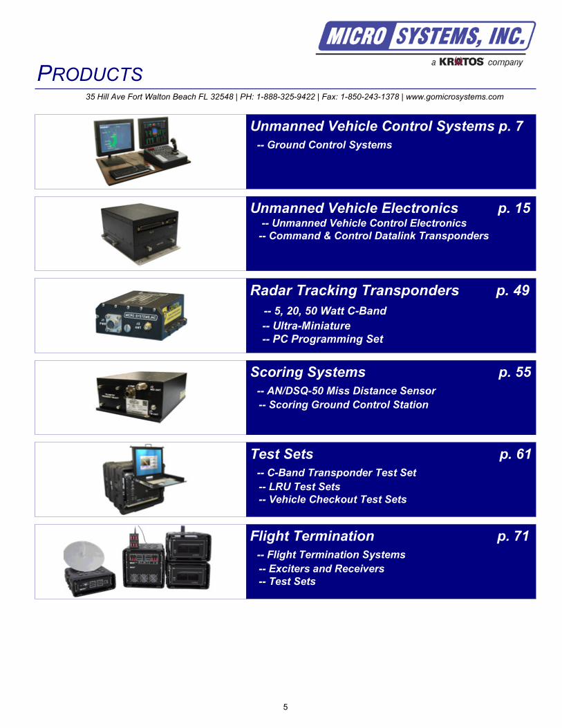
Radar Tracking Transponders p. 49
-- 5, 20, 50 Watt C-Band
-- Ultra-Miniature
-- PC Programming Set
Unmanned Vehicle Control Systems p. 7
-- Ground Control Systems
Unmanned Vehicle Electronics p. 15-- Unmanned Vehicle Control Electronics
-- Command & Control Datalink Transponders
PRODUCTS35 Hill Ave Fort Walton Beach FL 32548 | PH: 1-888-325-9422 | Fax: 1-850-243-1378 | www.gomicrosystems.com
5
Scoring Systems p. 55
-- AN/DSQ-50 Miss Distance Sensor
-- Scoring Ground Control Station
Test Sets p. 61
-- C-Band Transponder Test Set
-- LRU Test Sets
-- Vehicle Checkout Test Sets
Flight Termination p. 71
-- Flight Termination Systems
-- Exciters and Receivers
-- Test Sets

6

The Micro Systems, Inc. Unmanned Vehicle Control Systems are developed based on our MOdular
Networked TArGet control Equipment (MONTAGE) architecture which offers the latest in performance,
flexibility, and cost effectiveness. These systems are available in Portable, Transportable, and Fixed Site,
configurations. Our Vehicle Control Systems can be configured to control up to eight air vehicles and/or a
mix of up to sixteen ground or sea surface vehicles, with a simultaneous mix of vehicle types and can be
field expanded with no change to system software (plug and play). Our systems have been interfaced to a
variety of remotely piloted vehicles including: BQM-167 (i and xi versions), Firejet, MQM-107 D/E, BQM-
74E, Chukkar, BQM-34 (-47 and -49), BQM-167A/I, BQM-167X, BQM-177A/I, Firejet, MSST, QUH-1 Rotary
Wing Target, QST-35 ship target, Falconet, and the High Speed Maneuverable Surface Target (HSMST).
UNMANNED VEHICLE CONTROL SYSTEMS35 Hill Ave Fort Walton Beach FL 32548 | PH: 1-888-325-9422 | Fax: 1-850-243-1378 | www.gomicrosystems.com
7

8
Unmanned Vehicle Control System
UVCS
Data Sheet
Export Sales of this product are subject to U.S. Government approval.
Sales will not be approved to countries prohibited by the International Trade in Arms Regulations (ITAR)
35 Hill Ave Fort Walton Beach FL 32548 | PH: 1-888-325-9422 | Fax: 1-850-243-1378 | www.gomicrosystems.com
AS9100C and ISO 9001:2008 Certified
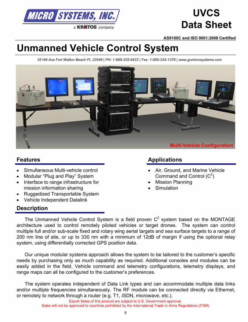
The Unmanned Vehicle Control System is a field proven C2
system based on the MONTAGE
architecture used to control remotely piloted vehicles or target drones. The system can control
multiple full and/or sub-scale fixed and rotary wing aerial targets and sea surface targets to a range of
200 nm line of site, or up to 330 nm with a minimum of 12dB of margin if using the optional relay
system, using differentially corrected GPS position data.
Our unique modular systems approach allows the system to be tailored to the customer’s specific
needs by purchasing only as much capability as required. Additional consoles and modules can be
easily added in the field. Vehicle command and telemetry configurations, telemetry displays, and
range maps can all be configured to the customer’s preferences.
The system operates independent of Data Link types and can accommodate multiple data links
and/or multiple frequencies simultaneously. The RF module can be connected directly via Ethernet,
or remotely to network through a router (e.g. T1, ISDN, microwave, etc.).
Simultaneous Multi-vehicle control
Modular “Plug and Play” System
Interface to range infrastructure for
mission information sharing
Ruggedized Transportable System
Vehicle Independent Datalink
Features
Description
Applications
Air, Ground, and Marine Vehicle
Command and Control (C2)
Mission Planning
Simulation
9
Multi-Vehicle Configuration
Technical Specifications
Contact us for custom modifications
For additional information contact:
Micro Systems, Inc.
35 Hill Ave
Fort Walton Beach, FL 32547
PH: 1-888-325-9422
FAX: 1-850-243-1378
www.gomicrosystems.com
© 2010 Micro Systems, Inc
Specifications subject to change without notice
Vehicle and Datalink Independent
Configure with multiple datalinks simultaneously
Field UpgradeableAdditional consoles and modules can easily be added (up to 8 vehicles)
Temporary expansion for special mission requirements
Modular Systems Approach
Distributed Multi-processor System
Configurable using “Building Blocks – Purchase only as much capability as needed
Highly Cost Effective
High Capability Configurations Available
High Capacity – for full scale vehicle
Reduced Capacity (reduced cost) – for subscale vehicles (MQM-107, BQM-167, Medium size UAV, UGV, USV)
Simultaneous Vehicle Operation – for multi-vehicle missions
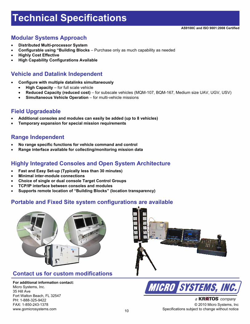
Portable and Fixed Site system configurations are available
Highly Integrated Consoles and Open System Architecture
Fast and Easy Set-up (Typically less than 30 minutes)
Minimal inter-module connections
Choice of single or dual console Target Control Groups
TCP/IP interface between consoles and modules
Supports remote location of “Building Blocks” (location transparency)
Range Independent
No range specific functions for vehicle command and control
Range interface available for collecting/monitoring mission data
10
AS9100C and ISO 9001:2008 Certified
Portable Vehicle Control System
P-MONTAGE
Data Sheet
Export Sales of this product are subject to U.S. Government approval.
Sales will not be approved to countries prohibited by the International Trade in Arms Regulations (ITAR)
35 Hill Ave Fort Walton Beach FL 32548 | PH: 1-888-325-9422 | Fax: 1-850-243-1378 | www.gomicrosystems.com
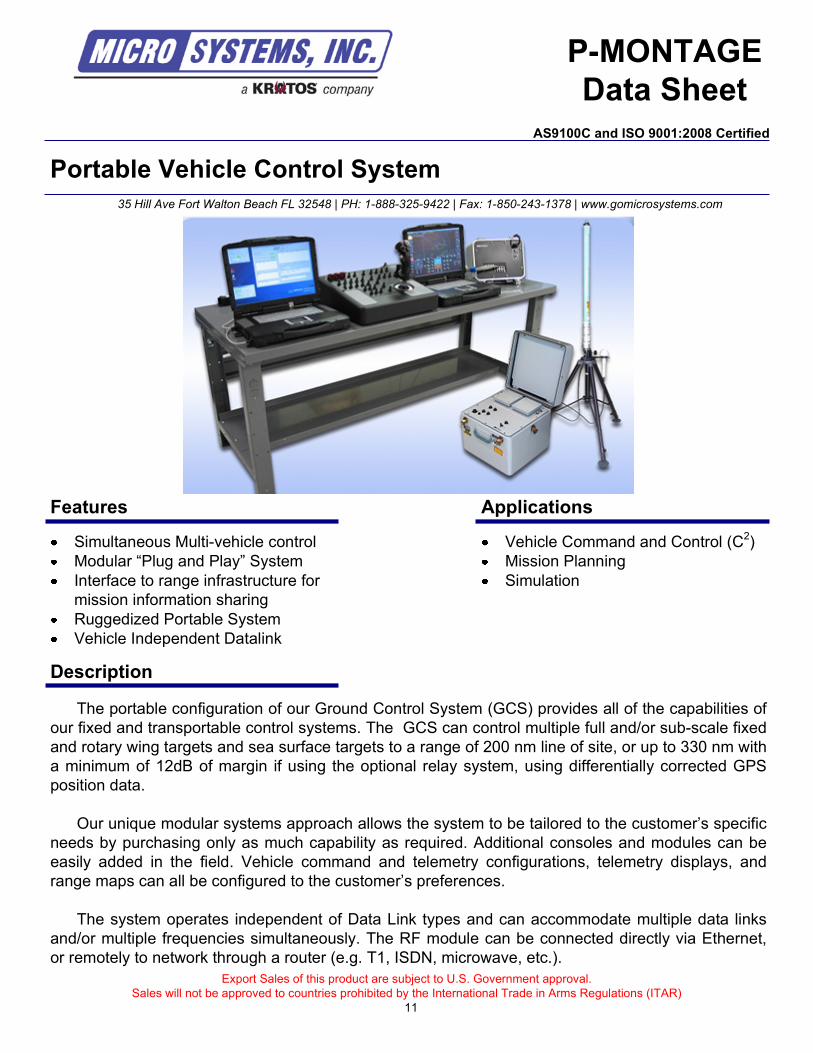
The portable configuration of our Ground Control System (GCS) provides all of the capabilities of
our fixed and transportable control systems. The GCS can control multiple full and/or sub-scale fixed
and rotary wing targets and sea surface targets to a range of 200 nm line of site, or up to 330 nm with
a minimum of 12dB of margin if using the optional relay system, using differentially corrected GPS
position data.
Our unique modular systems approach allows the system to be tailored to the customer’s specific
needs by purchasing only as much capability as required. Additional consoles and modules can be
easily added in the field. Vehicle command and telemetry configurations, telemetry displays, and
range maps can all be configured to the customer’s preferences.
The system operates independent of Data Link types and can accommodate multiple data links
and/or multiple frequencies simultaneously. The RF module can be connected directly via Ethernet,
or remotely to network through a router (e.g. T1, ISDN, microwave, etc.).
Simultaneous Multi-vehicle control
Modular “Plug and Play” System
Interface to range infrastructure for
mission information sharing
Ruggedized Portable System
Vehicle Independent Datalink
Description
Applications
Vehicle Command and Control (C2)
Mission Planning
Simulation
Features
AS9100C and ISO 9001:2008 Certified
11
Technical Specifications
Contact us for custom modifications
For additional information contact:
Micro Systems, Inc.
35 Hill Ave
Fort Walton Beach, FL 32547
PH: 1-888-325-9422
FAX: 1-850-243-1378
www.gomicrosystems.com
© 2010 Micro Systems, Inc
Specifications subject to change without notice
Vehicle and Datalink Independent
Configure with multiple datalinks simultaneously
Field UpgradeableAdditional consoles and modules can easily be added (up to 8 vehicles)
Temporary expansion for special mission requirements
Modular Systems Approach
Distributed Multi-processor System
Configurable using “Building Blocks – Purchase only as much capability as needed
Highly Cost Effective
High Capability Configurations Available
Open System Architecture
TCP/IP interface between consoles and modules
Supports remote location of “Building Blocks” (location transparency)
Common Console Design
Range Situation Displays (option) and System Control Consoles are physically and electrically identical
Fewer spares required
High Capacity – for full scale vehicle
Reduced Capacity (reduced cost) – for subscale vehicles (MQM-107, BQM-167, Medium size UAV, UGV, USV)
Simultaneous Vehicle Operation – for multi-vehicle missions
Range Independent
No range specific functions for vehicle command and control
Range interface available for collecting/monitoring mission data
Highly Integrated Consoles
Fast and Easy Set-up (Typically less than 30 minutes)
Minimal inter-module connections
Choice of single or dual console Target Control Groups
Ruggedized, Environmentally Protected Consoles
Ruggedized Laptops, keyboards, and command panels
Designed to meet MIL-STD-810 and MIL-STD-461 qualification
AS9100C and ISO 9001:2008 Certified
12
Multi-Platform Appliqué Kit (M-PAK)
M-PAK
Data Sheet
Export Sales of this product are subject to U.S. Government approval.
Sales will not be approved to countries prohibited by the International Trade in Arms Regulations (ITAR)
35 Hill Ave Fort Walton Beach FL 32548 | PH: 1-888-325-9422 | Fax: 1-850-243-1378 | www.gomicrosystems.com
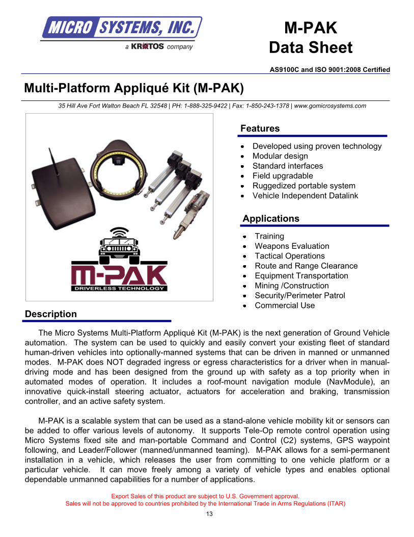
The Micro Systems Multi-Platform Appliqué Kit (M-PAK) is the next generation of Ground Vehicle
automation. The system can be used to quickly and easily convert your existing fleet of standard
human-driven vehicles into optionally-manned systems that can be driven in manned or unmanned
modes. M-PAK does NOT degraded ingress or egress characteristics for a driver when in manual-
driving mode and has been designed from the ground up with safety as a top priority when in
automated modes of operation. It includes a roof-mount navigation module (NavModule), an
innovative quick-install steering actuator, actuators for acceleration and braking, transmission
controller, and an active safety system.
M-PAK is a scalable system that can be used as a stand-alone vehicle mobility kit or sensors can
be added to offer various levels of autonomy. It supports Tele-Op remote control operation using
Micro Systems fixed site and man-portable Command and Control (C2) systems, GPS waypoint
following, and Leader/Follower (manned/unmanned teaming). M-PAK allows for a semi-permanent
installation in a vehicle, which releases the user from committing to one vehicle platform or a
particular vehicle. It can move freely among a variety of vehicle types and enables optional
dependable unmanned capabilities for a number of applications.
Developed using proven technology
Modular design
Standard interfaces
Field upgradable
Ruggedized portable system
Vehicle Independent Datalink
Description
Applications
Training
Weapons Evaluation
Tactical Operations
Route and Range Clearance
Equipment Transportation
Mining /Construction
Security/Perimeter Patrol
Commercial Use
Features
AS9100C and ISO 9001:2008 Certified
13
Technical Specifications
Contact us for custom modifications
For additional information contact:
Micro Systems, Inc.
35 Hill Ave
Fort Walton Beach, FL 32547
PH: 1-888-325-9422
FAX: 1-850-243-1378
www.gomicrosystems.com
© 2010 Micro Systems, Inc
Specifications subject to change without notice
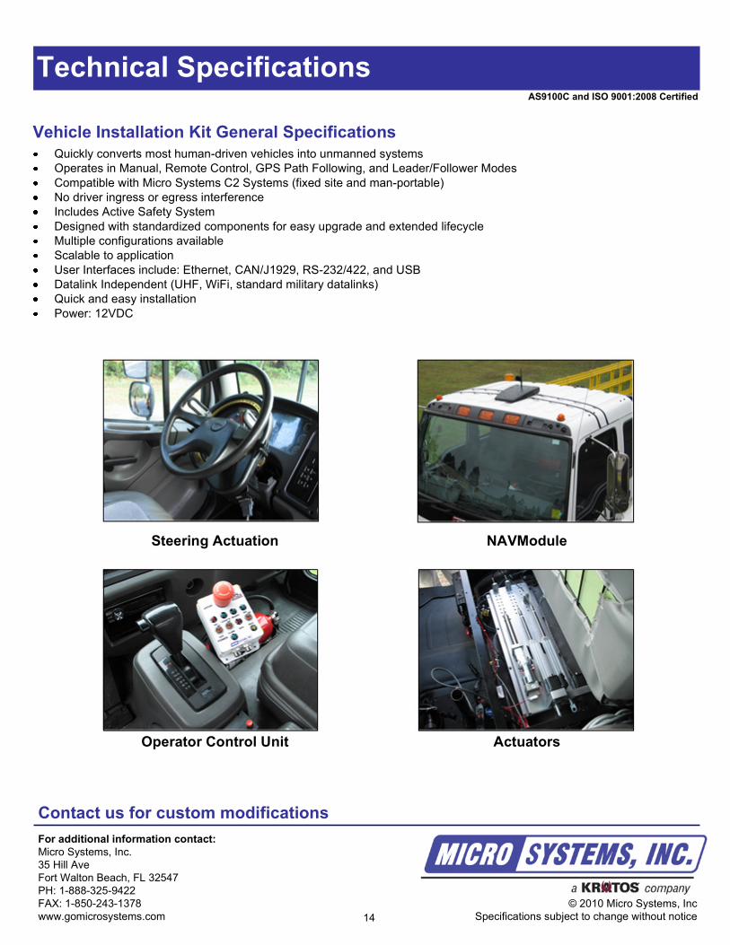
Vehicle Installation Kit General Specifications
Quickly converts most human-driven vehicles into unmanned systems
Operates in Manual, Remote Control, GPS Path Following, and Leader/Follower Modes
Compatible with Micro Systems C2 Systems (fixed site and man-portable)
No driver ingress or egress interference
Includes Active Safety System
Designed with standardized components for easy upgrade and extended lifecycle
Multiple configurations available
Scalable to application
User Interfaces include: Ethernet, CAN/J1929, RS-232/422, and USB
Datalink Independent (UHF, WiFi, standard military datalinks)
Quick and easy installation
Power: 12VDC
AS9100C and ISO 9001:2008 Certified
14
Steering Actuation NAVModule
Operator Control Unit Actuators
UNMANNED VEHICLE ELECTRONICS35 Hill Ave Fort Walton Beach FL 32548 | PH: 1-888-325-9422 | Fax: 1-850-243-1378 | www.gomicrosystems.com
15
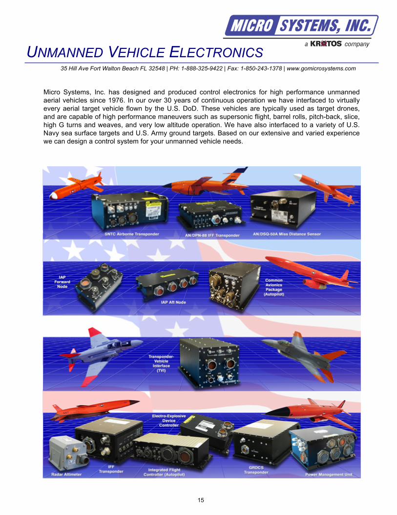
Micro Systems, Inc. has designed and produced control electronics for high performance unmanned
aerial vehicles since 1976. In our over 30 years of continuous operation we have interfaced to virtually
every aerial target vehicle flown by the U.S. DoD. These vehicles are typically used as target drones,
and are capable of high performance maneuvers such as supersonic flight, barrel rolls, pitch-back, slice,
high G turns and weaves, and very low altitude operation. We have also interfaced to a variety of U.S.
Navy sea surface targets and U.S. Army ground targets. Based on our extensive and varied experience
we can design a control system for your unmanned vehicle needs.

16
Unmanned Vehicle Mission Computer
Description
UVMC
Data Sheet
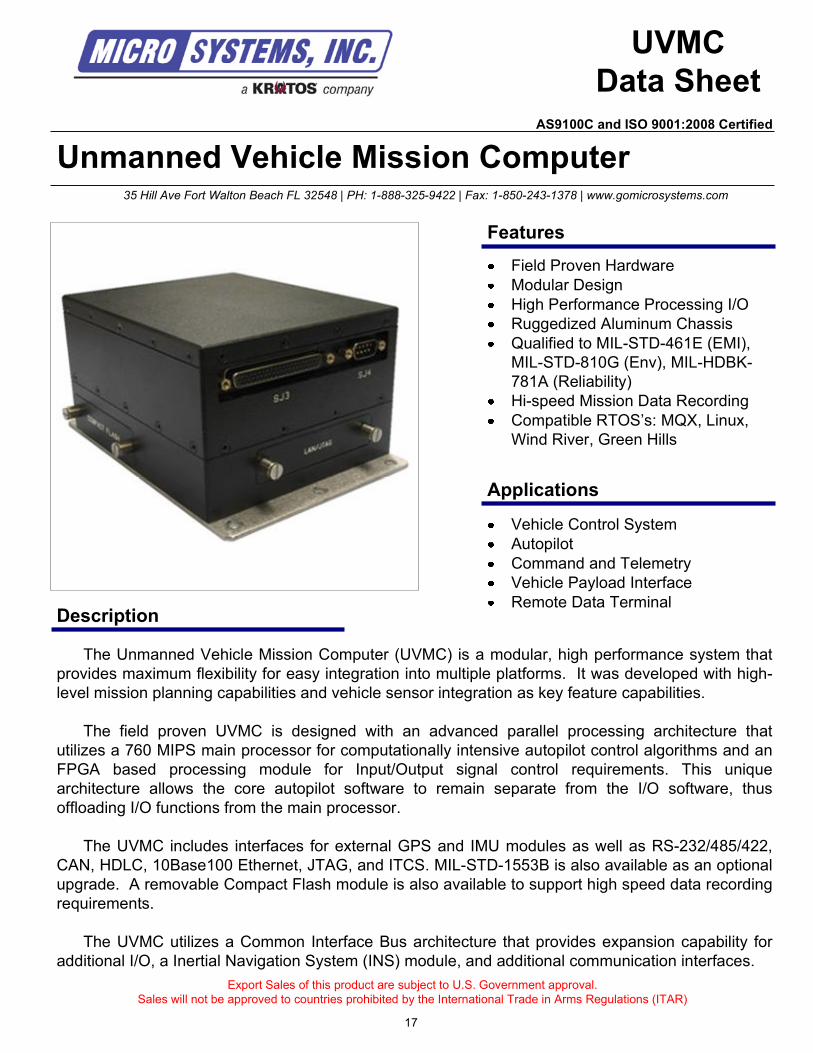
The Unmanned Vehicle Mission Computer (UVMC) is a modular, high performance system that
provides maximum flexibility for easy integration into multiple platforms. It was developed with high-
level mission planning capabilities and vehicle sensor integration as key feature capabilities.
The field proven UVMC is designed with an advanced parallel processing architecture that
utilizes a 760 MIPS main processor for computationally intensive autopilot control algorithms and an
FPGA based processing module for Input/Output signal control requirements. This unique
architecture allows the core autopilot software to remain separate from the I/O software, thus
offloading I/O functions from the main processor.
The UVMC includes interfaces for external GPS and IMU modules as well as RS-232/485/422,
CAN, HDLC, 10Base100 Ethernet, JTAG, and ITCS. MIL-STD-1553B is also available as an optional
upgrade. A removable Compact Flash module is also available to support high speed data recording
requirements.
The UVMC utilizes a Common Interface Bus architecture that provides expansion capability for
additional I/O, a Inertial Navigation System (INS) module, and additional communication interfaces.
Export Sales of this product are subject to U.S. Government approval.
Sales will not be approved to countries prohibited by the International Trade in Arms Regulations (ITAR)
Vehicle Control System
Autopilot
Command and Telemetry
Vehicle Payload Interface
Remote Data Terminal
35 Hill Ave Fort Walton Beach FL 32548 | PH: 1-888-325-9422 | Fax: 1-850-243-1378 | www.gomicrosystems.com
Features
Applications
Field Proven Hardware
Modular Design
High Performance Processing I/O
Ruggedized Aluminum Chassis
Qualified to MIL-STD-461E (EMI),
MIL-STD-810G (Env), MIL-HDBK-
781A (Reliability)
Hi-speed Mission Data Recording
Compatible RTOS’s: MQX, Linux,
Wind River, Green Hills
17
AS9100C and ISO 9001:2008 Certified
Technical Specifications
Available Real Time Operating Systems (RTOS) and Board Support Packages
Compatible with: MQX, Linux, Wind River, Green Hills
Environmental (MIL-STD-810G) / EMI (MIL-STD-461E)
Temperature: Operating: -40 C to +70 C
Cooling: Passive Conductive (no moving parts)
Vibration: Random, 0.4g2/Hz to 0.0429g
2/Hz, 8 minutes per orthogonal axis
Altitude: 50,000 ft
Shock: Operating: 300G for 1ms, 3 pulses per axis
Humidity: Up to 95% @ 40 C (all boards are conformal coated)
EMI/RFI: CE102, RE102, CS101, CS114, CS115 and RS103
Characteristics
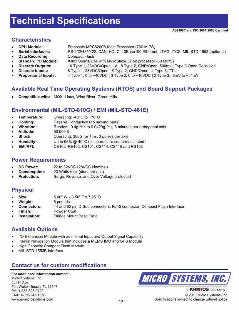
CPU Module: Freescale MPC5200B Main Processor (760 MIPS)
Serial Interfaces: RS-232/485/422, CAN, HDLC, 10Base100 Ethernet, JTAG, ITCS, MIL-STD-1553 (optional)
Data Recording: Compact Flash
Standard I/O Module: Xilinx Spartan 3A with MicroBlaze 32 bit processor (60 MIPS)
Discrete Outputs: 10 Type 1, 28VDC/Open, 1A | 8 Type 2, GND/Open, 500ma | Type 3 Open Collection
Discrete Inputs: 8 Type 1, 28VDC/Open | 6 Type 2, GND/Open | 4 Type 3, TTL
Proportional Inputs: 4 Type 1, 0 to +40VDC | 3 Type 2, 0 to +10VDC | 2 Type 3, -8mV to +54mV
Power Requirements
DC Power: 22 to 32VDC (28VDC Nominal)
Consumption: 20 Watts max (standard unit)
Protection: Surge, Reverse, and Over Voltage protected
Physical
Size: 5.00" W x 3.50" T x 7.25" D
Weight: 6 pounds
Connectors: 44 and 62 pin D-Sub connectors, RJ45 connector, Compact Flash Interface
Finish: Powder Coat
Installation: Flange Mount Base Plate
Available Options
I/O Expansion Module with additional Input and Output Signal Capability
Inertial Navigation Module that includes a MEMS IMU and GPS Module
High Capacity Compact Flash Module
MIL-STD-1553B Interface
Contact us for custom modifications
For additional information contact:
Micro Systems, Inc.
35 Hill Ave
Fort Walton Beach, FL 32547
PH: 1-888-325-9422
FAX: 1-850-243-1378
www.gomicrosystems.com
© 2010 Micro Systems, Inc
Specifications subject to change without notice18
AS9100C and ISO 9001:2008 Certified
Multi-Service Data Link (MSDL) Transponder
Description
MSDL
Data Sheet
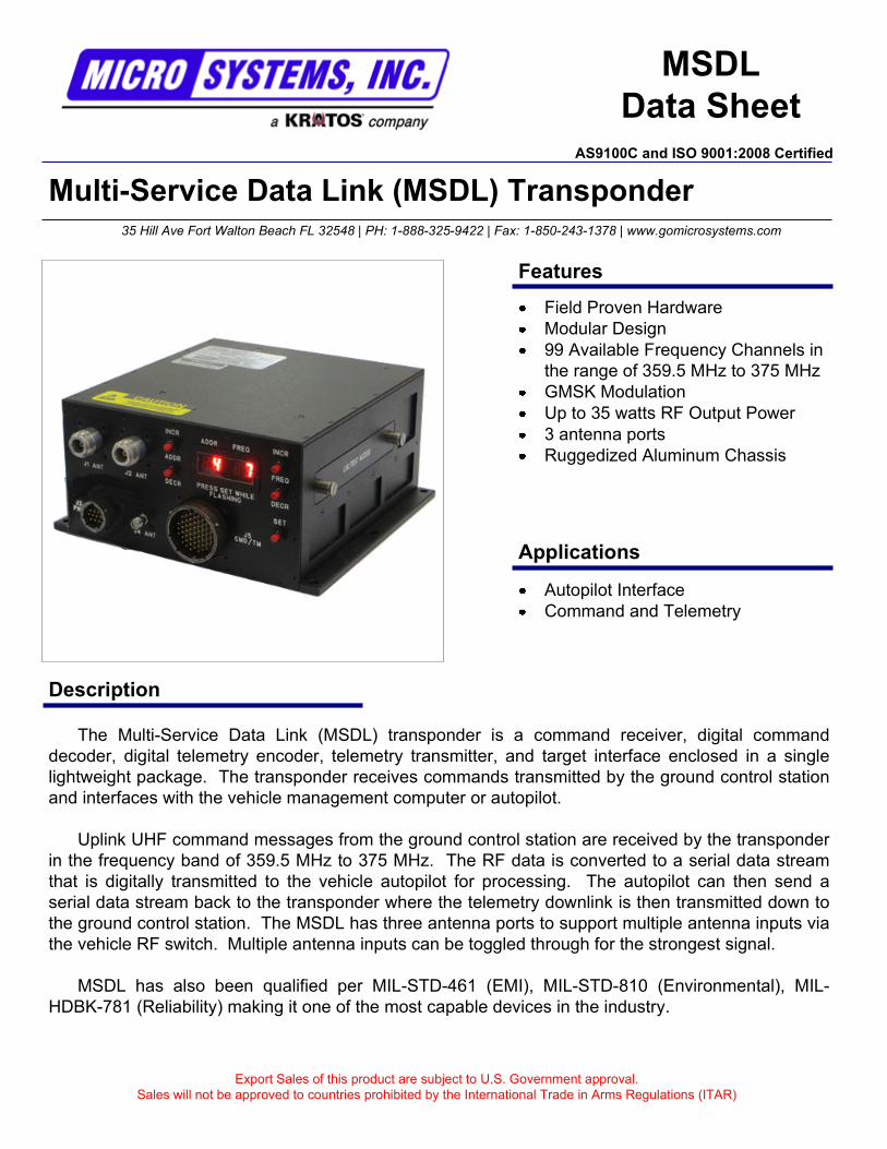
The Multi-Service Data Link (MSDL) transponder is a command receiver, digital command
decoder, digital telemetry encoder, telemetry transmitter, and target interface enclosed in a single
lightweight package. The transponder receives commands transmitted by the ground control station
and interfaces with the vehicle management computer or autopilot.
Uplink UHF command messages from the ground control station are received by the transponder
in the frequency band of 359.5 MHz to 375 MHz. The RF data is converted to a serial data stream
that is digitally transmitted to the vehicle autopilot for processing. The autopilot can then send a
serial data stream back to the transponder where the telemetry downlink is then transmitted down to
the ground control station. The MSDL has three antenna ports to support multiple antenna inputs via
the vehicle RF switch. Multiple antenna inputs can be toggled through for the strongest signal.
MSDL has also been qualified per MIL-STD-461 (EMI), MIL-STD-810 (Environmental), MIL-
HDBK-781 (Reliability) making it one of the most capable devices in the industry.
Export Sales of this product are subject to U.S. Government approval.
Sales will not be approved to countries prohibited by the International Trade in Arms Regulations (ITAR)
Autopilot Interface
Command and Telemetry
35 Hill Ave Fort Walton Beach FL 32548 | PH: 1-888-325-9422 | Fax: 1-850-243-1378 | www.gomicrosystems.com
Features
Applications
Field Proven Hardware
Modular Design
99 Available Frequency Channels in
the range of 359.5 MHz to 375 MHz
GMSK Modulation
Up to 35 watts RF Output Power
3 antenna ports
Ruggedized Aluminum Chassis
AS9100C and ISO 9001:2008 Certified
Technical Specifications
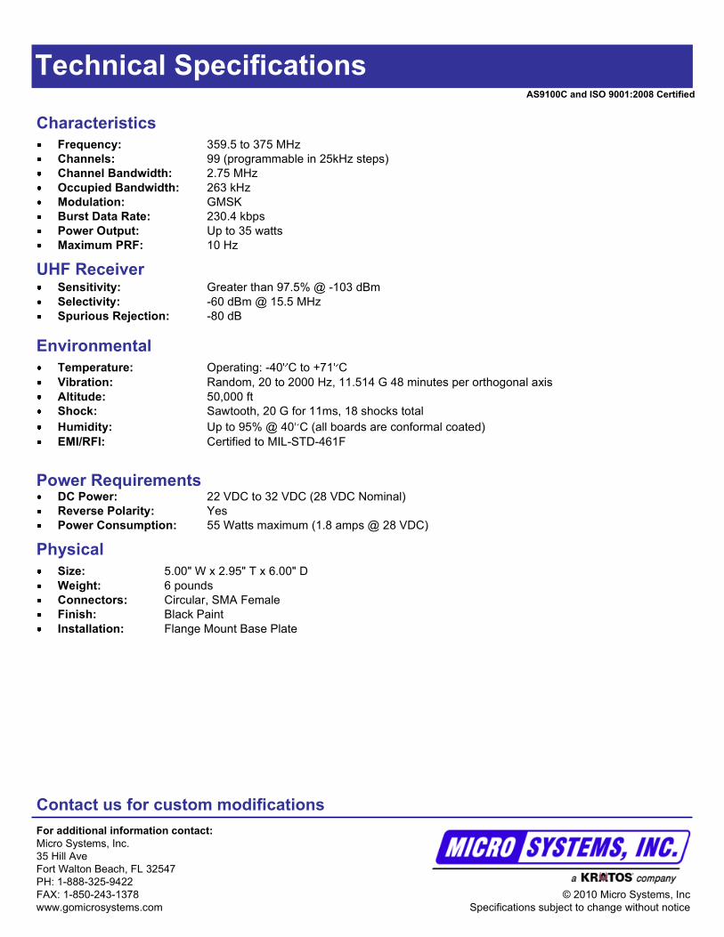
UHF ReceiverSensitivity: Greater than 97.5% @ -103 dBm
Selectivity: -60 dBm @ 15.5 MHz
Spurious Rejection: -80 dB
Characteristics
Frequency: 359.5 to 375 MHz
Channels: 99 (programmable in 25kHz steps)
Channel Bandwidth: 2.75 MHz
Occupied Bandwidth: 263 kHz
Modulation: GMSK
Burst Data Rate: 230.4 kbps
Power Output: Up to 35 watts
Maximum PRF: 10 Hz
Contact us for custom modifications
For additional information contact:
Micro Systems, Inc.
35 Hill Ave
Fort Walton Beach, FL 32547
PH: 1-888-325-9422
FAX: 1-850-243-1378
www.gomicrosystems.com
© 2010 Micro Systems, Inc
Specifications subject to change without notice
Environmental
Temperature: Operating: -40 C to +71 C
Vibration: Random, 20 to 2000 Hz, 11.514 G 48 minutes per orthogonal axis
Altitude: 50,000 ft
Shock: Sawtooth, 20 G for 11ms, 18 shocks total
Humidity: Up to 95% @ 40 C (all boards are conformal coated)
EMI/RFI: Certified to MIL-STD-461F
Physical
Size: 5.00" W x 2.95" T x 6.00" D
Weight: 6 pounds
Connectors: Circular, SMA Female
Finish: Black Paint
Installation: Flange Mount Base Plate
Power RequirementsDC Power: 22 VDC to 32 VDC (28 VDC Nominal)
Reverse Polarity: Yes
Power Consumption: 55 Watts maximum (1.8 amps @ 28 VDC)
AS9100C and ISO 9001:2008 Certified
Common Avionics Package (CAP) Node
Description
CAP Node
Data Sheet
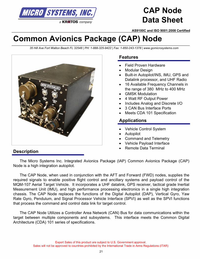
The Micro Systems Inc. Integrated Avionics Package (IAP) Common Avionics Package (CAP)
Node is a high integration autopilot.
The CAP Node, when used in conjunction with the AFT and Forward (FWD) nodes, supplies the
required signals to enable positive flight control and ancillary systems and payload control of the
MQM-107 Aerial Target Vehicle. It incorporates a UHF datalink, GPS receiver, tactical grade Inertial
Measurement Unit (IMU), and high performance processing electronics in a single high integration
chassis. The CAP Node replaces the functions of the Digital Autopilot (DAP), Vertical Gyro, Yaw
Rate Gyro, Pendulum, and Signal Processor Vehicle Interface (SPVI) as well as the SPVI functions
that process the command and control data link for target control.
The CAP Node Utilizes a Controller Area Network (CAN) Bus for data communications within the
target between multiple components and subsystems. This interface meets the Common Digital
Architecture (CDA) 101 series of specifications.
Export Sales of this product are subject to U.S. Government approval.
Sales will not be approved to countries prohibited by the International Trade in Arms Regulations (ITAR)
Vehicle Control System
Autopilot
Command and Telemetry
Vehicle Payload Interface
Remote Data Terminal
35 Hill Ave Fort Walton Beach FL 32548 | PH: 1-888-325-9422 | Fax: 1-850-243-1378 | www.gomicrosystems.com
Features
Applications
Field Proven Hardware
Modular Design
Built-in Autopilot/INS, IMU, GPS and
Datalink processor, and UHF Radio
16 Available Frequency Channels in
the range of 380 MHz to 400 MHz
GMSK Modulation
4 Watt RF Output Power
Includes Analog and Discrete I/O
3 CAN Bus Interface Ports
Meets CDA 101 Specification
21
AS9100C and ISO 9001:2008 Certified
Technical Specifications
Input/Output Signals
Analog Inputs: +/- 10 VDC at 12 bit resolution, 4 ports
Analog Outputs: +/- 10 VDC at 12 bit resolution, drive capacity 10 mA (max), 4 ports
Discrete Inputs: Diode protected, 2 VDC to 35 VDC Active, 0.8 VDC in active, 4 ports
Discrete Outputs: 28 VDC/Open output, 2 Amp to resistive load, 0.5 amp to inductive load, 4 ports
Characteristics
Datalink Processor: Interfaces with MSI Upgraded Target Tracking Control System (TTCS/U)
Frequency: 380 MHz to 400 MHz
Channels: 16
Channel Bandwidth: 25 kHz
Occupied Bandwidth: 20 kHz
Modulation: GMSK
Command Data Format: RS-232 Asynchronous Serial Data
Burst Data Rate: 14.4 kbps
Transmit Power: 4 Watts
Maximum PRF: 10 Hz
UHF Antenna Switch: Switching between upper and lower antennas for reliable communications
CAN Bus: Adheres to CDA 101 Specifications
Receiver Sensitivity: -100 dBm @ 1x10⁻⁴
BER
Receiver Selectivity: -60 dBm @ 12.5 kHz
Spurious Rejection: -70 dB
Contact us for custom modifications
For additional information contact:
Micro Systems, Inc.
35 Hill Ave
Fort Walton Beach, FL 32547
PH: 1-888-325-9422
FAX: 1-850-243-1378
www.gomicrosystems.com
© 2010 Micro Systems, Inc
Specifications subject to change without notice
Environmental
Temperature: Operating: -40 C to +71 C, Non-Operating: -40 C to +85 C
Cooling: Passive Conductive (no moving parts)
Vibration: Random, 0.04 G2/Hz 20 – 20,000 Hz, 6 dB/Hz per orthogonal axis
Altitude: Sea level to 55,000 ft
Shock: 15 G for 11ms, 18 shocks total
Acceleration: 7.5 G constant in any axis
Humidity: Up to 100% (all boards are conformal coated)
MTBF: > 1000 Hrs
MTBCF: > 1500 Hrs
Physical
Size: 6.60" W x 5.25" T x 12.31" D
Weight: 6 pounds
Connectors: MIL-C38999
Finish: Black Paint
Installation: Flange Mount Base Plate
Power Requirements
DC Power: 22 VDC to 32 VDC (28 VDC Nominal)
Protection: Surge, Reverse, and Over Voltage protected
Power Consumption: 100 Watts maximum
22
AS9100C and ISO 9001:2008 Certified
IAP Forward Node
Description
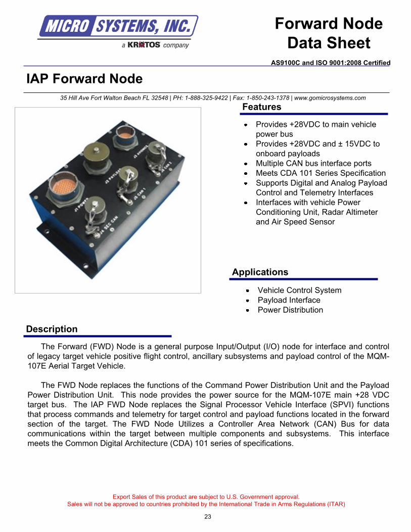
The Forward (FWD) Node is a general purpose Input/Output (I/O) node for interface and control
of legacy target vehicle positive flight control, ancillary subsystems and payload control of the MQM-
107E Aerial Target Vehicle.
The FWD Node replaces the functions of the Command Power Distribution Unit and the Payload
Power Distribution Unit. This node provides the power source for the MQM-107E main +28 VDC
target bus. The IAP FWD Node replaces the Signal Processor Vehicle Interface (SPVI) functions
that process commands and telemetry for target control and payload functions located in the forward
section of the target. The FWD Node Utilizes a Controller Area Network (CAN) Bus for data
communications within the target between multiple components and subsystems. This interface
meets the Common Digital Architecture (CDA) 101 series of specifications.
Export Sales of this product are subject to U.S. Government approval.
Sales will not be approved to countries prohibited by the International Trade in Arms Regulations (ITAR)
Vehicle Control System
Payload Interface
Power Distribution
35 Hill Ave Fort Walton Beach FL 32548 | PH: 1-888-325-9422 | Fax: 1-850-243-1378 | www.gomicrosystems.com
Features
Applications
Provides +28VDC to main vehicle
power bus
Provides +28VDC and ± 15VDC to
onboard payloads
Multiple CAN bus interface ports
Meets CDA 101 Series Specification
Supports Digital and Analog Payload
Control and Telemetry Interfaces
Interfaces with vehicle Power
Conditioning Unit, Radar Altimeter
and Air Speed Sensor
Forward Node
Data Sheet
23
AS9100C and ISO 9001:2008 Certified
Technical Specifications
Environmental
Temperature, Operating: -40°C to +71°C
Temperature, Storage: -40°C to +85°C
Random Vibration: Operating, 0.4 G2/Hz 20 Hz - 2000Hz 6 dB/Hz
Altitude: Sea level to 55,000 feet
Acceleration: 7.5G constant in any axis
Shock: 15G, 11 millisecond duration
Humidity: 100%
Electrical
Power Requirements
Input Voltage: 22 VDC to 32 VDC (+28 VDC nominal)
Protection: Reverse Polarity Protected
Power Conditioning Unit (PCU): Rectifies and filters Target Alternator AC, 8 amps maximum total
Distributes +28 VDC to Target Power Bus for Target elements, Aft Node and
CAP node
Provides +/- 15 VDC ( +/- 1%) 400 mA Internal, +/- 100 mA External
Provides + 5 VDC( +/- 1%) 500 mA Internal
Power Consumption: 25 Watts maximum
Physical
Dimensions: 8.4" L x 4.8" W x 4.5" H
Weight: Approximately 4 pounds
Connectors: J1 = MS27468T23B55P
J2 = MS27468T17B35PB
J3 = MS27468T17B35PA
J4, J5, J6 = MS27468T11B5P
Contact us for custom modifications
For additional information contact:
Micro Systems, Inc.
35 Hill Ave
Fort Walton Beach, FL 32547
PH: 1-888-325-9422
FAX: 1-850-243-1378
www.gomicrosystems.com
© 2010 Micro Systems, Inc
Specifications subject to change without notice
Analog Inputs: +/- 10VDC. 0-5VDC at 12 bit resolution
Analog Outputs: +/- 10VDC, 0-5VDC at 12 bits resolution, maximum drive capacity 10mA
Discrete Inputs: Diode protection, 0.8 VDC inactive, 2 to 35 VDC active
Discrete Outputs: + 28 VDC/open output, 2 amp to resistive load, 0.5 amp to inductive load
Short circuit protection without damage
Open = >10 Megaohms impedance to ground
Minimum load = 200 mA
CAN Bus: Adheres to CDA 101 Specifications
24
AS9100C and ISO 9001:2008 Certified
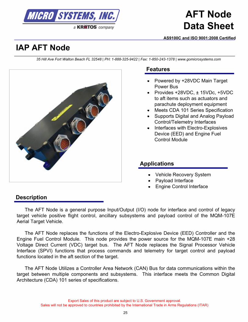
IAP AFT Node
Description
The AFT Node is a general purpose Input/Output (I/O) node for interface and control of legacy
target vehicle positive flight control, ancillary subsystems and payload control of the MQM-107E
Aerial Target Vehicle.
The AFT Node replaces the functions of the Electro-Explosive Device (EED) Controller and the
Engine Fuel Control Module. This node provides the power source for the MQM-107E main +28
Voltage Direct Current (VDC) target bus. The AFT Node replaces the Signal Processor Vehicle
Interface (SPVI) functions that process commands and telemetry for target control and payload
functions located in the aft section of the target.
The AFT Node Utilizes a Controller Area Network (CAN) Bus for data communications within the
target between multiple components and subsystems. This interface meets the Common Digital
Architecture (CDA) 101 series of specifications.
Export Sales of this product are subject to U.S. Government approval.
Sales will not be approved to countries prohibited by the International Trade in Arms Regulations (ITAR)
Vehicle Recovery System
Payload Interface
Engine Control Interface
35 Hill Ave Fort Walton Beach FL 32548 | PH: 1-888-325-9422 | Fax: 1-850-243-1378 | www.gomicrosystems.com
Features
Applications
Powered by +28VDC Main Target
Power Bus
Provides +28VDC, ± 15VDc, +5VDC
to aft items such as actuators and
parachute deployment equipment
Meets CDA 101 Series Specification
Supports Digital and Analog Payload
Control/Telemetry Interfaces
Interfaces with Electro-Explosives
Device (EED) and Engine Fuel
Control Module
AFT Node
Data Sheet
25
AS9100C and ISO 9001:2008 Certified
Technical Specifications
Environmental Temperature, Operating: -40°C to +71°C
Temperature, Storage: -40°C to +85°C
Random Vibration: Operating, 0.4G2/Hz 20 Hz – 2000 Hz 6 dB/Hz
Altitude: Sea level to 55,000 feet
Acceleration: 7.5 G constant in any axis
Shock: 15G, 11 millisecond duration
Humidity: 100%
Electrical
Power Requirements
Input Votage: 22 to 32 VDC, Reverse Polarity Protected, + 12 VDC Recovery Battery
Power Conditioning Unit (PCU) Provides +/- 15 VDC (+/- 1%), + 5 VDC at 12 bit resolution
Power Consumption: 25 Watts maximum
Physical
Dimensions: 5.5" W x 10.8" L x 2.0" H
Weight: Approximately 3 pounds
Contact us for custom modifications
For additional information contact:
Micro Systems, Inc.
35 Hill Ave
Fort Walton Beach, FL 32547
PH: 1-888-325-9422
FAX: 1-850-243-1378
www.gomicrosystems.com
© 2010 Micro Systems, Inc
Specifications subject to change without notice
Analog Inputs: +/- 10 VDC. 0 – 10 VDC, 0 – 5 VDC at 12 bit resolution Load Resistance
Conversion 15 ohms to 95 ohms, 12 bits, 10 mA source
Analog Outputs: +/- 10 VDC, 0 – 5 VDC at 12 bits resolution, maximum drive capacity 10 mA
Discrete Inputs: Diode protection, 0.8 VDC inactive, 2 VDC to 35 VDC active
Discrete Outputs: 28 VDC/open output, 2 or 4 amp to resistive load, 0.5 amp to inductive load
Short circuit protection without damage
Open = >10 Megaohms impedance to ground
12 VDC/ground output trigger voltage
12 VDC/open, source 50 mA
DPDT Relay 5 amp, 28 VDC 750 mA Resistive, 200 mA Inductive
CAN Bus: Adheres to CDA 101 Specifications
26
AS9100C and ISO 9001:2008 Certified
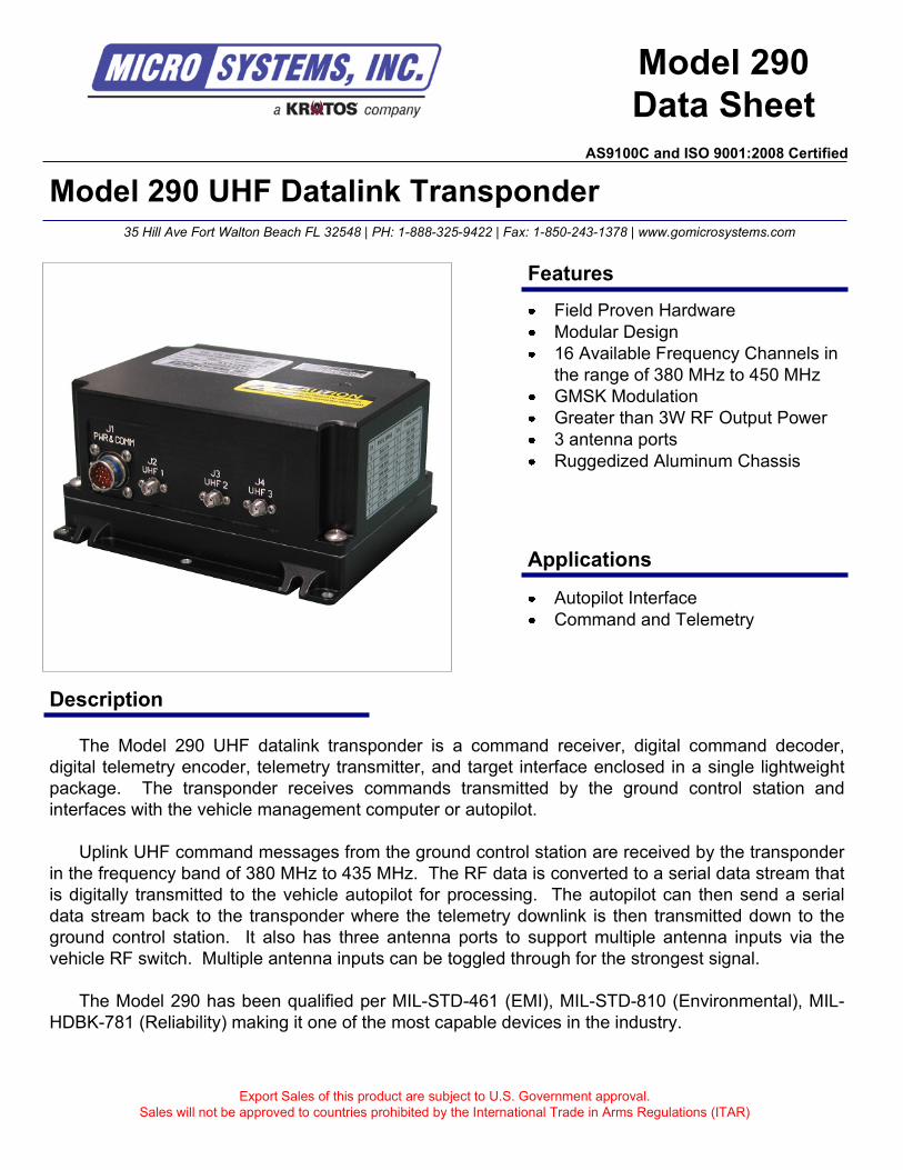
Model 290 UHF Datalink Transponder
Description
Model 290
Data Sheet
The Model 290 UHF datalink transponder is a command receiver, digital command decoder,
digital telemetry encoder, telemetry transmitter, and target interface enclosed in a single lightweight
package. The transponder receives commands transmitted by the ground control station and
interfaces with the vehicle management computer or autopilot.
Uplink UHF command messages from the ground control station are received by the transponder
in the frequency band of 380 MHz to 435 MHz. The RF data is converted to a serial data stream that
is digitally transmitted to the vehicle autopilot for processing. The autopilot can then send a serial
data stream back to the transponder where the telemetry downlink is then transmitted down to the
ground control station. It also has three antenna ports to support multiple antenna inputs via the
vehicle RF switch. Multiple antenna inputs can be toggled through for the strongest signal.
The Model 290 has been qualified per MIL-STD-461 (EMI), MIL-STD-810 (Environmental), MIL-
HDBK-781 (Reliability) making it one of the most capable devices in the industry.
Export Sales of this product are subject to U.S. Government approval.
Sales will not be approved to countries prohibited by the International Trade in Arms Regulations (ITAR)
Autopilot Interface
Command and Telemetry
35 Hill Ave Fort Walton Beach FL 32548 | PH: 1-888-325-9422 | Fax: 1-850-243-1378 | www.gomicrosystems.com
Features
Applications
Field Proven Hardware
Modular Design
16 Available Frequency Channels in
the range of 380 MHz to 450 MHz
GMSK Modulation
Greater than 3W RF Output Power
3 antenna ports
Ruggedized Aluminum Chassis
AS9100C and ISO 9001:2008 Certified

Technical Specifications
UHF ReceiverSensitivity: -100 dBm @ 1x10
-4BER
Selectivity: -60 dBm @ 12.5 kHz
Spurious Rejection: -70 dB
Characteristics
Frequency: Model 290-1: 435 MHz to 450 MHz | Model 290-2: 380 MHz to 400 MHz
Channels: 16
Channel Bandwidth: 25 kHz
Occupied Bandwidth: 20 kHz
Modulation: GMSK
Burst Data Rate: 14.4 kbps
Power Output: Greater than 3 Watts
Maximum PRF: 10 Hz
Contact us for custom modifications
For additional information contact:
Micro Systems, Inc.
35 Hill Ave
Fort Walton Beach, FL 32547
PH: 1-888-325-9422
FAX: 1-850-243-1378
www.gomicrosystems.com
© 2010 Micro Systems, Inc
Specifications subject to change without notice
Environmental (MIL-STD-810) / EMI (MIL-STD-461D)
Temperature: Operating: -40 C to +71 C
Vibration: Random, 15 to 2000 Hz, 9.3 G 30 minutes per orthogonal axis
Altitude: 50,000 ft
Shock: Sawtooth, 20 G for 11ms, 18 shocks total
Humidity: Up to 95% @ 40 C (all boards are conformal coated)
EMI/RFI: Certified to MIL-STD-461D, Class A1
Physical
Size: 5.00" W x 2.95" T x 6.00" D
Weight: 6 pounds
Connectors: Circular, SMA Female
Finish: Black Paint
Installation: Flange Mount Base Plate
Power RequirementsDC Power: 22 VDC to 32 VDC (28 VDC Nominal)
Reverse Polarity: Yes
Power Consumption: 55 Watts maximum (1.8 amps @ 28 VDC)
AS9100C and ISO 9001:2008 Certified
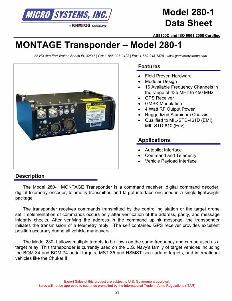
MONTAGE Transponder – Model 280-1
Description
Model 280-1
Data Sheet
The Model 280-1 MONTAGE Transponder is a command receiver, digital command decoder,
digital telemetry encoder, telemetry transmitter, and target interface enclosed in a single lightweight
package.
The transponder receives commands transmitted by the controlling station or the target drone
set. Implementation of commands occurs only after verification of the address, parity, and message
integrity checks. After verifying the address in the command uplink message, the transponder
initiates the transmission of a telemetry reply. The self contained GPS receiver provides excellent
position accuracy during all vehicle maneuvers.
The Model 280-1 allows multiple targets to be flown on the same frequency and can be used as a
target relay. This transponder is currently used on the U.S. Navy’s family of target vehicles including
the BQM-34 and BQM-74 aerial targets, MST-35 and HSMST sea surface targets, and international
vehicles like the Chukar III.
Export Sales of this product are subject to U.S. Government approval.
Sales will not be approved to countries prohibited by the International Trade in Arms Regulations (ITAR)
Autopilot Interface
Command and Telemetry
Vehicle Payload Interface
35 Hill Ave Fort Walton Beach FL 32548 | PH: 1-888-325-9422 | Fax: 1-850-243-1378 | www.gomicrosystems.com
Features
Applications
Field Proven Hardware
Modular Design
16 Available Frequency Channels in
the range of 435 MHz to 450 MHz
GPS Receiver
GMSK Modulation
4 Watt RF Output Power
Ruggedized Aluminum Chassis
Qualified to MIL-STD-461D (EMI),
MIL-STD-810 (Env)
29
AS9100C and ISO 9001:2008 Certified
Technical Specifications
UHF Receiver
Sensitivity: -100 dBm @ 1x10⁻⁴
BER
Selectivity: -60 dBm @ 12.5 kHz
Spurious Rejection: -70 dB
Characteristics
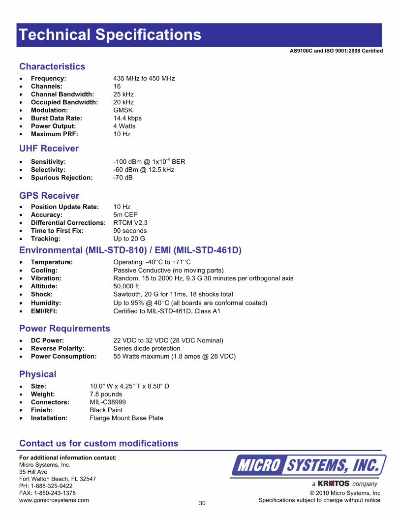
Frequency: 435 MHz to 450 MHz
Channels: 16
Channel Bandwidth: 25 kHz
Occupied Bandwidth: 20 kHz
Modulation: GMSK
Burst Data Rate: 14.4 kbps
Power Output: 4 Watts
Maximum PRF: 10 Hz
Contact us for custom modifications
For additional information contact:
Micro Systems, Inc.
35 Hill Ave
Fort Walton Beach, FL 32547
PH: 1-888-325-9422
FAX: 1-850-243-1378
www.gomicrosystems.com
© 2010 Micro Systems, Inc
Specifications subject to change without notice
GPS ReceiverPosition Update Rate: 10 Hz
Accuracy: 5m CEP
Differential Corrections: RTCM V2.3
Time to First Fix: 90 seconds
Tracking: Up to 20 G
Environmental (MIL-STD-810) / EMI (MIL-STD-461D)
Temperature: Operating: -40 C to +71 C
Cooling: Passive Conductive (no moving parts)
Vibration: Random, 15 to 2000 Hz, 9.3 G 30 minutes per orthogonal axis
Altitude: 50,000 ft
Shock: Sawtooth, 20 G for 11ms, 18 shocks total
Humidity: Up to 95% @ 40 C (all boards are conformal coated)
EMI/RFI: Certified to MIL-STD-461D, Class A1
Physical
Size: 10.0" W x 4.25" T x 8.50" D
Weight: 7.8 pounds
Connectors: MIL-C38999
Finish: Black Paint
Installation: Flange Mount Base Plate
Power Requirements
DC Power: 22 VDC to 32 VDC (28 VDC Nominal)
Reverse Polarity: Series diode protection
Power Consumption: 55 Watts maximum (1.8 amps @ 28 VDC)
30
AS9100C and ISO 9001:2008 Certified
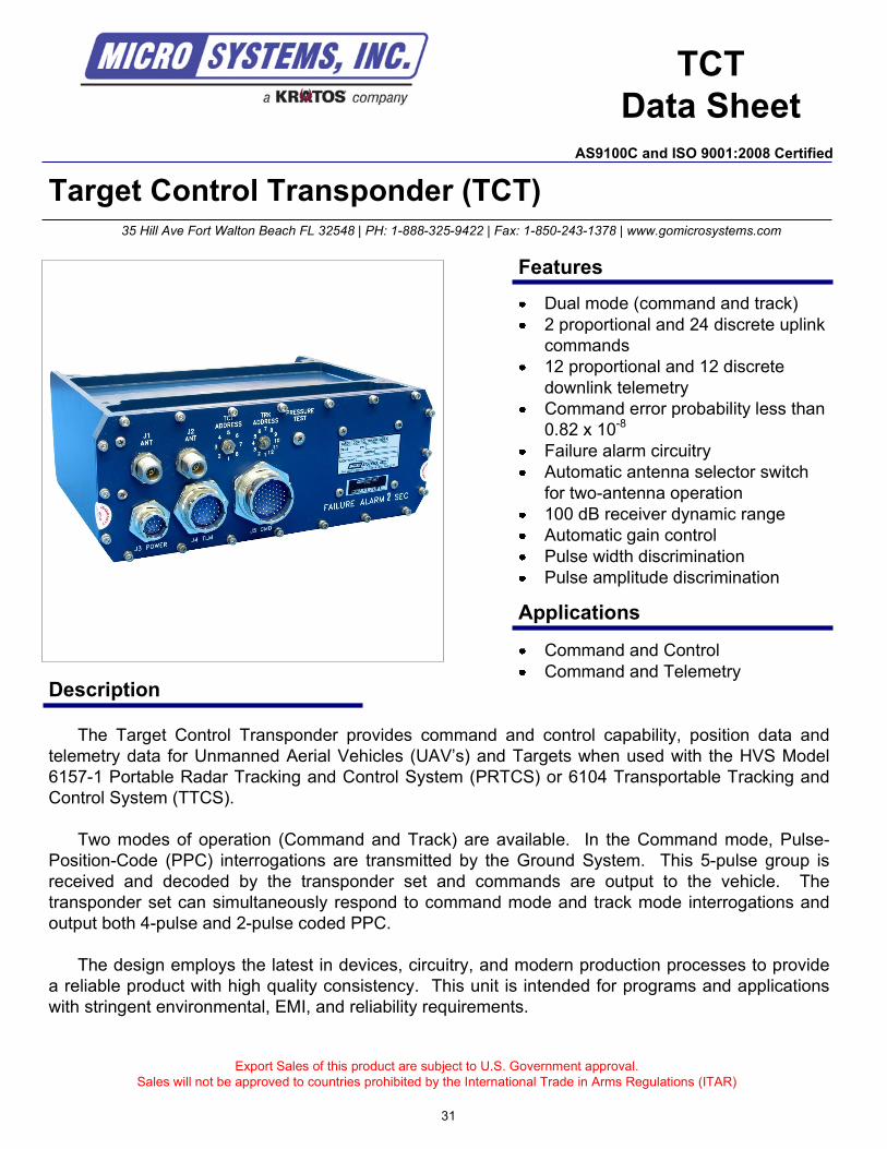
Target Control Transponder (TCT)
Description
TCT
Data Sheet
The Target Control Transponder provides command and control capability, position data and
telemetry data for Unmanned Aerial Vehicles (UAV’s) and Targets when used with the HVS Model
6157-1 Portable Radar Tracking and Control System (PRTCS) or 6104 Transportable Tracking and
Control System (TTCS).
Two modes of operation (Command and Track) are available. In the Command mode, Pulse-
Position-Code (PPC) interrogations are transmitted by the Ground System. This 5-pulse group is
received and decoded by the transponder set and commands are output to the vehicle. The
transponder set can simultaneously respond to command mode and track mode interrogations and
output both 4-pulse and 2-pulse coded PPC.
The design employs the latest in devices, circuitry, and modern production processes to provide
a reliable product with high quality consistency. This unit is intended for programs and applications
with stringent environmental, EMI, and reliability requirements.
Export Sales of this product are subject to U.S. Government approval.
Sales will not be approved to countries prohibited by the International Trade in Arms Regulations (ITAR)
35 Hill Ave Fort Walton Beach FL 32548 | PH: 1-888-325-9422 | Fax: 1-850-243-1378 | www.gomicrosystems.com
Features
Dual mode (command and track)
2 proportional and 24 discrete uplink
commands
12 proportional and 12 discrete
downlink telemetry
Command error probability less than
0.82 x 10⁻⁸
Failure alarm circuitry
Automatic antenna selector switch
for two-antenna operation
100 dB receiver dynamic range
Automatic gain control
Pulse width discrimination
Pulse amplitude discrimination
AS9100C and ISO 9001:2008 Certified
Command and Control
Command and Telemetry
Applications
31
Technical Specifications
For additional information contact:
Micro Systems, Inc.
35 Hill Ave
Fort Walton Beach, FL 32547
PH: 1-888-325-9422
FAX: 1-850-243-1378
www.gomicrosystems.com
© 2010 Micro Systems, Inc
Specifications subject to change without notice
AS9100C and ISO 9001:2008 Certified
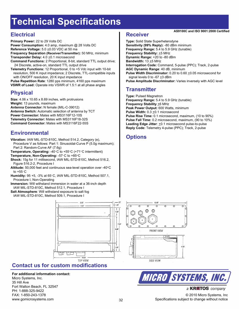
PhysicalSize: 4.06 x 10.65 x 8.69 inches, with protrusions
Weight: 13 pounds, maximum
Antenna Connector: N female (MIL-C-39012)
Antenna Switch: Automatic selection of antenna by TCT
Power Connector: Mates with MS3116F12-10S
Telemetry Connector: Mates with MS3116F18-32S
Command Connector: Mates with MS3116F22-55S
ElectricalPrimary Power: 22 to 29 Volts DC
Power Consumption: 4.0 amp, maximum @ 28 Volts DC
Reference Voltage: 5.0 +0.03 VDC at 50 ma
Frequency Separation (Receiver/Transmitter): 50 MHz, minimum
Transponder Delay: 4.0 +0.1 microsecond
Command Functions: 2 Proportional, 8-bit, standard TTL output drive;
24 Discrete, active-on, standard TTL output drive
Telemetry Functions: 12 Proportional, 0 to +5 Vdc input with 10-bit
resolution, 500 K input impedance; 2 Discrete, TTL-compatible inputs
with ON/OFF resolution, 20 K input impedance
Pulse Repetition Rate: 1280 pps minimum, 4160 pps maximum
VSWR of Load: Operate into VSWR of 1.5:1 at all phase angles
EnvironmentalVibration: IAW MIL-STD-810C, Method 514.2, Category (e),
Procedure V as follows: Part 1: Sinusoidal-Curve P (5.0g maximum);
Part 2: Random-Curve AF (7.6g)
Temperature, Operating: -40 C to +55 C (+71 C intermittent)
Temperature, Non-Operating: -57 C to +85 C
Shock: 15g for 11 millisecond, IAW MIL-STD-810C, Method 516.2,
Figure 516.2-2, Procedure I
Altitude: 50,000 feet and continuous sea-level operation over -40 C
to +55 C
Humidity: 95 +5, -3% at 65 C, IAW MIL-STD-810C, Method 507.1,
Procedure I, Non-Operating
Immersion: Will withstand immersion in water at a 36-inch depth
IAW MIL-STD-810C, Method 512.1, Procedure I
Salt Atmosphere: Will withstand exposure to salt fog
IAW MIL-STD-810C, Method 509.1, Procedure I
Contact us for custom modifications
TransmitterType: Pulsed Magnetron
Frequency Range: 5.4 to 5.9 GHz (tunable)
Frequency Stability +6 MHz
Peak Power Output: 600 Watts, minimum
Pulse Width: 0.3 +0.1 microsecond
Pulse Rise Time: 0.1 microsecond, maximum, (10 to 90%)
Pulse Fall Time: 0.2 microsecond, maximum, (90 to 10%)
Leading Edge Jitter: +0.1 microsecond pulse-to-pulse
Reply Code: Telemetry 4-pulse (PPC); Track, 2-pulse
ReceiverType: Solid State Superheterodyne
Sensitivity (99% Reply): -80 dBm minimum
Frequency Range: 5.4 to 5.9 GHz (tunable)
Frequency Stability: +5 MHz
Dynamic Range: +20 to -80 dBm
Bandwidth: 13 +5 MHz
Interrogation Code: Command, 5-pulse (PPC); Track, 2-pulse
AGC Dynamic Range: 40 dB, minimum
Pulse Width Discriminator: 0.20 to 0.60 +0.05 microsecond for
signal levels 0 to -67 +3 dBm
Pulse Amplitude Discriminator: Varies inversely with AGC level
Options
32
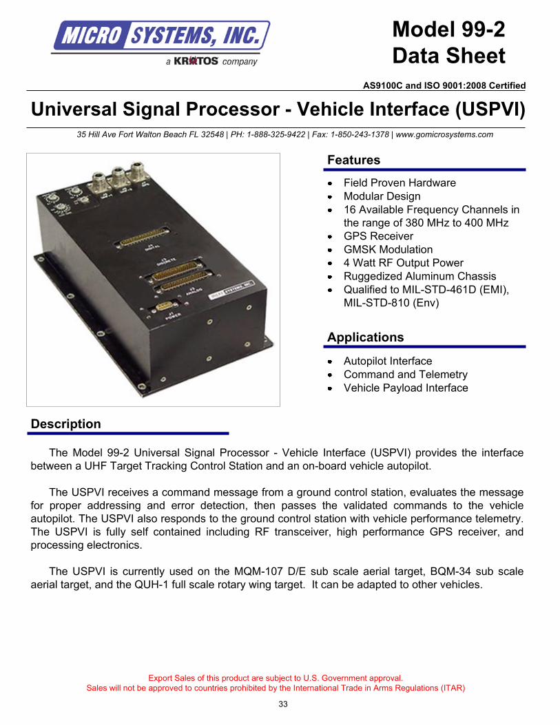
Universal Signal Processor - Vehicle Interface (USPVI)
Description
Model 99-2
Data Sheet
The Model 99-2 Universal Signal Processor - Vehicle Interface (USPVI) provides the interface
between a UHF Target Tracking Control Station and an on-board vehicle autopilot.
The USPVI receives a command message from a ground control station, evaluates the message
for proper addressing and error detection, then passes the validated commands to the vehicle
autopilot. The USPVI also responds to the ground control station with vehicle performance telemetry.
The USPVI is fully self contained including RF transceiver, high performance GPS receiver, and
processing electronics.
The USPVI is currently used on the MQM-107 D/E sub scale aerial target, BQM-34 sub scale
aerial target, and the QUH-1 full scale rotary wing target. It can be adapted to other vehicles.
Export Sales of this product are subject to U.S. Government approval.
Sales will not be approved to countries prohibited by the International Trade in Arms Regulations (ITAR)
Autopilot Interface
Command and Telemetry
Vehicle Payload Interface
35 Hill Ave Fort Walton Beach FL 32548 | PH: 1-888-325-9422 | Fax: 1-850-243-1378 | www.gomicrosystems.com
Features
Applications
Field Proven Hardware
Modular Design
16 Available Frequency Channels in
the range of 380 MHz to 400 MHz
GPS Receiver
GMSK Modulation
4 Watt RF Output Power
Ruggedized Aluminum Chassis
Qualified to MIL-STD-461D (EMI),
MIL-STD-810 (Env)
33
AS9100C and ISO 9001:2008 Certified
Technical Specifications
UHF ReceiverSensitivity: -100 dBm @ 1x10
-4BER
Selectivity: -60 dBm @ 12.5 kHz
Spurious Rejection: -70 dB
Characteristics
Frequency: 380 MHz to 400 MHz
Channels: 16
Channel Bandwidth: 25 kHz
Occupied Bandwidth: 20 kHz
Modulation: GMSK
Burst Data Rate: 14.4 kbps
Power Output: 4 Watts
Maximum PRF: 10 Hz
Contact us for custom modifications
For additional information contact:
Micro Systems, Inc.
35 Hill Ave
Fort Walton Beach, FL 32547
PH: 1-888-325-9422
FAX: 1-850-243-1378
www.gomicrosystems.com
© 2010 Micro Systems, Inc
Specifications subject to change without notice
GPS ReceiverPosition Update Rate: 10 Hz
Accuracy: 5m CEP
Differential Corrections: RTCM V2.3
Time to First Fix: 90 seconds
Tracking: Up to 20 G
Environmental (MIL-STD-810) / EMI (MIL-STD-461D)
Temperature: Operating: -40 C to +71 C
Cooling: Passive Conductive (no moving parts)
Vibration: Random, 15 to 2000 Hz, 9.3 G 30 minutes per orthogonal axis
Altitude: 50,000 ft
Shock: Sawtooth, 20 G for 11ms, 18 shocks total
Humidity: Up to 95% @ 40 C (all boards are conformal coated)
EMI/RFI: Certified to MIL-STD-461D, Class A1
Physical
Size: 6.50" W x 4.25" T x 11.5" D
Weight: 8 pounds
Connectors: D-Subminiture
Finish: Black Paint
Installation: Flange Mount Base Plate
Power RequirementsDC Power: 22 VDC to 32 VDC (28 VDC Nominal)
Reverse Polarity: Series diode protection
Power Consumption: 55 Watts maximum (1.8 amps @ 28 VDC)
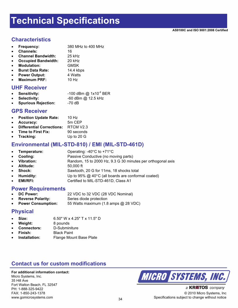
34
AS9100C and ISO 9001:2008 Certified
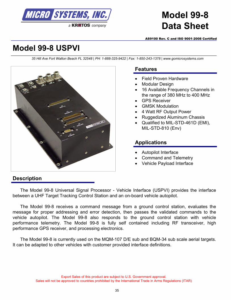
Model 99-8 USPVI
Description
Model 99-8
Data Sheet
The Model 99-8 Universal Signal Processor - Vehicle Interface (USPVI) provides the interface
between a UHF Target Tracking Control Station and an on-board vehicle autopilot.
The Model 99-8 receives a command message from a ground control station, evaluates the
message for proper addressing and error detection, then passes the validated commands to the
vehicle autopilot. The Model 99-8 also responds to the ground control station with vehicle
performance telemetry. The Model 99-8 is fully self contained including RF transceiver, high
performance GPS receiver, and processing electronics.
The Model 99-8 is currently used on the MQM-107 D/E sub and BQM-34 sub scale aerial targets.
It can be adapted to other vehicles with customer provided interface definitions.
Export Sales of this product are subject to U.S. Government approval.
Sales will not be approved to countries prohibited by the International Trade in Arms Regulations (ITAR)
Autopilot Interface
Command and Telemetry
Vehicle Payload Interface
35 Hill Ave Fort Walton Beach FL 32548 | PH: 1-888-325-9422 | Fax: 1-850-243-1378 | www.gomicrosystems.com
AS9100 Rev. C and ISO 9001-2008 Certified
Features
Applications
Field Proven Hardware
Modular Design
16 Available Frequency Channels in
the range of 380 MHz to 400 MHz
GPS Receiver
GMSK Modulation
4 Watt RF Output Power
Ruggedized Aluminum Chassis
Qualified to MIL-STD-461D (EMI),
MIL-STD-810 (Env)
35
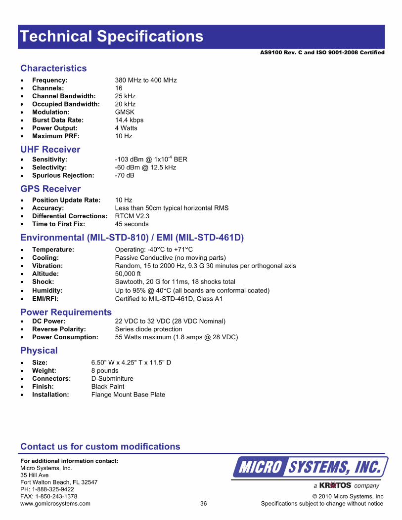
AS9100 Rev. C and ISO 9001-2008 Certified
Technical Specifications
UHF ReceiverSensitivity: -103 dBm @ 1x10
-4BER
Selectivity: -60 dBm @ 12.5 kHz
Spurious Rejection: -70 dB
Characteristics
Frequency: 380 MHz to 400 MHz
Channels: 16
Channel Bandwidth: 25 kHz
Occupied Bandwidth: 20 kHz
Modulation: GMSK
Burst Data Rate: 14.4 kbps
Power Output: 4 Watts
Maximum PRF: 10 Hz
Contact us for custom modifications
For additional information contact:
Micro Systems, Inc.
35 Hill Ave
Fort Walton Beach, FL 32547
PH: 1-888-325-9422
FAX: 1-850-243-1378
www.gomicrosystems.com
© 2010 Micro Systems, Inc
Specifications subject to change without notice
GPS ReceiverPosition Update Rate: 10 Hz
Accuracy: Less than 50cm typical horizontal RMS
Differential Corrections: RTCM V2.3
Time to First Fix: 45 seconds
Environmental (MIL-STD-810) / EMI (MIL-STD-461D)
Temperature: Operating: -40 C to +71 C
Cooling: Passive Conductive (no moving parts)
Vibration: Random, 15 to 2000 Hz, 9.3 G 30 minutes per orthogonal axis
Altitude: 50,000 ft
Shock: Sawtooth, 20 G for 11ms, 18 shocks total
Humidity: Up to 95% @ 40 C (all boards are conformal coated)
EMI/RFI: Certified to MIL-STD-461D, Class A1
Physical
Size: 6.50" W x 4.25" T x 11.5" D
Weight: 8 pounds
Connectors: D-Subminiture
Finish: Black Paint
Installation: Flange Mount Base Plate
Power RequirementsDC Power: 22 VDC to 32 VDC (28 VDC Nominal)
Reverse Polarity: Series diode protection
Power Consumption: 55 Watts maximum (1.8 amps @ 28 VDC)
36
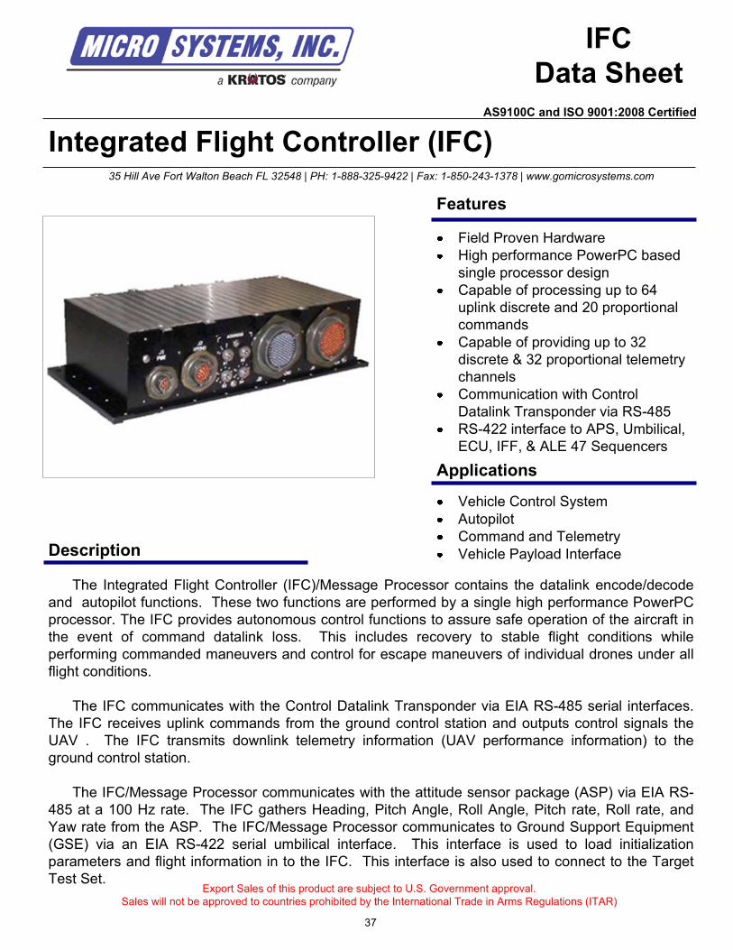
Integrated Flight Controller (IFC)
Description
IFC
Data Sheet
The Integrated Flight Controller (IFC)/Message Processor contains the datalink encode/decode
and autopilot functions. These two functions are performed by a single high performance PowerPC
processor. The IFC provides autonomous control functions to assure safe operation of the aircraft in
the event of command datalink loss. This includes recovery to stable flight conditions while
performing commanded maneuvers and control for escape maneuvers of individual drones under all
flight conditions.
The IFC communicates with the Control Datalink Transponder via EIA RS-485 serial interfaces.
The IFC receives uplink commands from the ground control station and outputs control signals the
UAV . The IFC transmits downlink telemetry information (UAV performance information) to the
ground control station.
The IFC/Message Processor communicates with the attitude sensor package (ASP) via EIA RS-
485 at a 100 Hz rate. The IFC gathers Heading, Pitch Angle, Roll Angle, Pitch rate, Roll rate, and
Yaw rate from the ASP. The IFC/Message Processor communicates to Ground Support Equipment
(GSE) via an EIA RS-422 serial umbilical interface. This interface is used to load initialization
parameters and flight information in to the IFC. This interface is also used to connect to the Target
Test Set.Export Sales of this product are subject to U.S. Government approval.
Sales will not be approved to countries prohibited by the International Trade in Arms Regulations (ITAR)
Vehicle Control System
Autopilot
Command and Telemetry
Vehicle Payload Interface
35 Hill Ave Fort Walton Beach FL 32548 | PH: 1-888-325-9422 | Fax: 1-850-243-1378 | www.gomicrosystems.com
Applications
Features
Field Proven Hardware
High performance PowerPC based
single processor design
Capable of processing up to 64
uplink discrete and 20 proportional
commands
Capable of providing up to 32
discrete & 32 proportional telemetry
channels
Communication with Control
Datalink Transponder via RS-485
RS-422 interface to APS, Umbilical,
ECU, IFF, & ALE 47 Sequencers
37
AS9100C and ISO 9001:2008 Certified
Technical Specifications
Environmental
Temperature: Operating: -40 C to +71 C Storage: -54 C to +125 C
Cooling: Passive Conductive (no moving parts)
Vibration: Operating, Random, 0.15g2/Hz, 20Hz to 100Hz
Operating, Random, 0.04g2/Hz 100Hz to 2000 Hz for 5 minutes per orthogonal axis (8.8 Grms)
Altitude: Sea Level to 50,000 ft
Shock: Half Sine, 20 G’s peak, 11 ms, 3 axes
Humidity: Up to 95% @ 40 C (all boards are conformal coated)
Acceleration: 10 G’s, 3 axes, tested at drone level
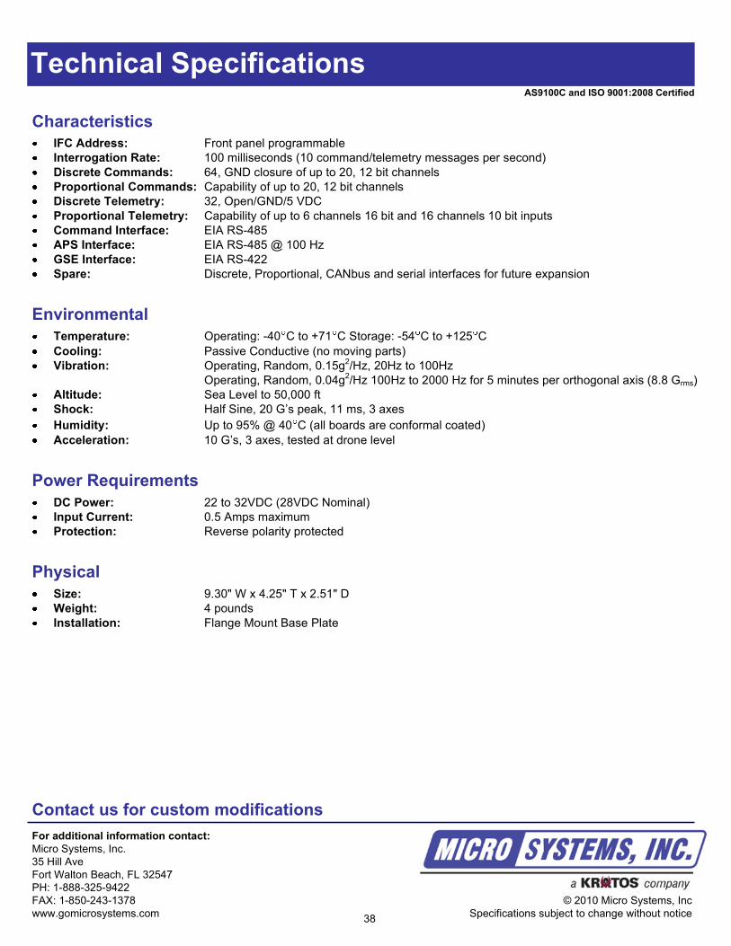
Characteristics
IFC Address: Front panel programmable
Interrogation Rate: 100 milliseconds (10 command/telemetry messages per second)
Discrete Commands: 64, GND closure of up to 20, 12 bit channels
Proportional Commands: Capability of up to 20, 12 bit channels
Discrete Telemetry: 32, Open/GND/5 VDC
Proportional Telemetry: Capability of up to 6 channels 16 bit and 16 channels 10 bit inputs
Command Interface: EIA RS-485
APS Interface: EIA RS-485 @ 100 Hz
GSE Interface: EIA RS-422
Spare: Discrete, Proportional, CANbus and serial interfaces for future expansion
Power Requirements
DC Power: 22 to 32VDC (28VDC Nominal)
Input Current: 0.5 Amps maximum
Protection: Reverse polarity protected
Physical
Size: 9.30" W x 4.25" T x 2.51" D
Weight: 4 pounds
Installation: Flange Mount Base Plate
Contact us for custom modifications
For additional information contact:
Micro Systems, Inc.
35 Hill Ave
Fort Walton Beach, FL 32547
PH: 1-888-325-9422
FAX: 1-850-243-1378
www.gomicrosystems.com
© 2010 Micro Systems, Inc
Specifications subject to change without notice38
AS9100C and ISO 9001:2008 Certified
Power Management Unit (PMU)
Description
PMU
Data Sheet
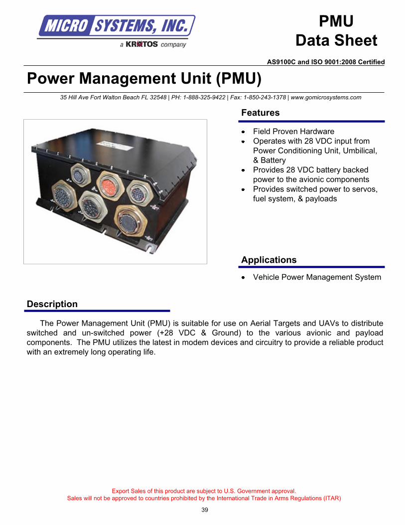
The Power Management Unit (PMU) is suitable for use on Aerial Targets and UAVs to distribute
switched and un-switched power (+28 VDC & Ground) to the various avionic and payload
components. The PMU utilizes the latest in modem devices and circuitry to provide a reliable product
with an extremely long operating life.
Export Sales of this product are subject to U.S. Government approval.
Sales will not be approved to countries prohibited by the International Trade in Arms Regulations (ITAR)
Vehicle Power Management System
35 Hill Ave Fort Walton Beach FL 32548 | PH: 1-888-325-9422 | Fax: 1-850-243-1378 | www.gomicrosystems.com
Applications
Features
Field Proven Hardware
Operates with 28 VDC input from
Power Conditioning Unit, Umbilical,
& Battery
Provides 28 VDC battery backed
power to the avionic components
Provides switched power to servos,
fuel system, & payloads
39
AS9100C and ISO 9001:2008 Certified
Technical Specifications
CapabilitiesOperates with 28 VDC input from:
- Power Conditioning Unit
- Umbilical
- Battery
Provides 28 VDC battery backed power to the avionic components of the air vehicle including but not limited to:
- Fuel control system including Main Flow Meter and Linearizer
- Transfer Flow Meter and Linearizer
- Fuel Quality Sensor
- Fuel Boost Pump
- APS, Radar Altimeter, Command & Control Transponder, Engine Control Unit, Antenna Switch, EED, GPS
antenna, IFC, Pitot Heaters and IFF Transponder
Provides switched power to:
- Servo actuators including Rudder, Stabilator, Aileron, & Speed Brakes
- Fuel Pumps, Air Data Module, Strobe Light, Engine Igniter, & Scoring
- Payload components including APC-4 (up to 10 amps @ 28 VDC) for future payload use
- PMU provides spare switched power (5 amp, 12 amp, & 25 amp) for future payload use
- Accepts Discrete commands from the Integrated Flight Controller (IFC) to provide switched power to the
onboard components
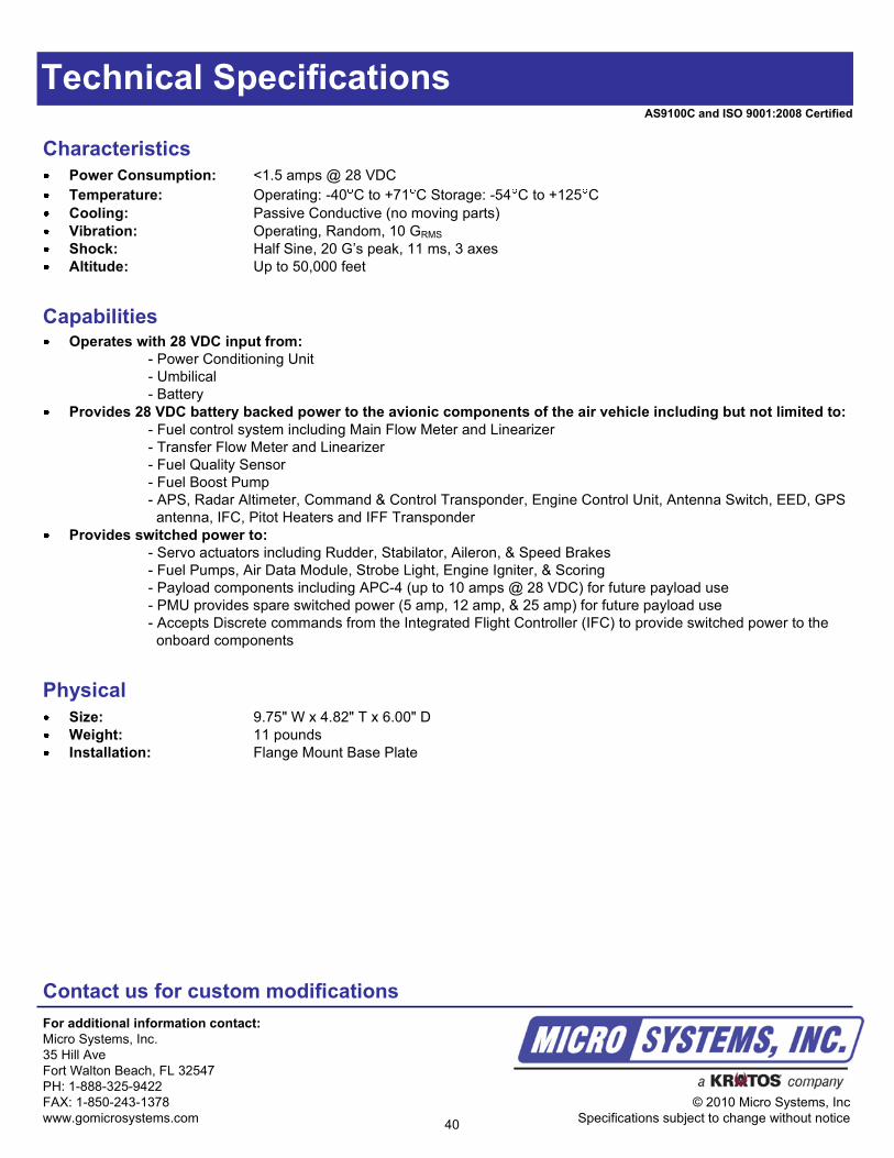
Characteristics
Power Consumption: <1.5 amps @ 28 VDC
Temperature: Operating: -40 C to +71 C Storage: -54 C to +125 C
Cooling: Passive Conductive (no moving parts)
Vibration: Operating, Random, 10 GRMS
Shock: Half Sine, 20 G’s peak, 11 ms, 3 axes
Altitude: Up to 50,000 feet
Physical
Size: 9.75" W x 4.82" T x 6.00" D
Weight: 11 pounds
Installation: Flange Mount Base Plate
Contact us for custom modifications
For additional information contact:
Micro Systems, Inc.
35 Hill Ave
Fort Walton Beach, FL 32547
PH: 1-888-325-9422
FAX: 1-850-243-1378
www.gomicrosystems.com
© 2010 Micro Systems, Inc
Specifications subject to change without notice40
AS9100C and ISO 9001:2008 Certified
Electro-Explosive Device (EED) Controller
Description
EED
Data Sheet
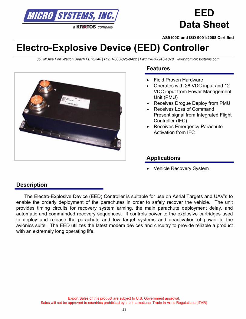
The Electro-Explosive Device (EED) Controller is suitable for use on Aerial Targets and UAV’s to
enable the orderly deployment of the parachutes in order to safely recover the vehicle. The unit
provides timing circuits for recovery system arming, the main parachute deployment delay, and
automatic and commanded recovery sequences. It controls power to the explosive cartridges used
to deploy and release the parachute and tow target systems and deactivation of power to the
avionics suite. The EED utilizes the latest modem devices and circuitry to provide reliable a product
with an extremely long operating life.
Export Sales of this product are subject to U.S. Government approval.
Sales will not be approved to countries prohibited by the International Trade in Arms Regulations (ITAR)
Vehicle Recovery System
35 Hill Ave Fort Walton Beach FL 32548 | PH: 1-888-325-9422 | Fax: 1-850-243-1378 | www.gomicrosystems.com
Applications
Features
Field Proven Hardware
Operates with 28 VDC input and 12
VDC input from Power Management
Unit (PMU)
Receives Drogue Deploy from PMU
Receives Loss of Command
Present signal from Integrated Flight
Controller (IFC)
Receives Emergency Parachute
Activation from IFC
41
AS9100C and ISO 9001:2008 Certified
Technical Specifications
CapabilitiesRecovery Initiation:
- Emergency Parachute Release: Manual activation fo the recovery and tail cone release sequence
- Command Signal Loss: Automatic recovery sequence initiation upon Loss of Command (IFC OK)
- Low Voltage: Automatic recovery sequence initiation upon detection of a low voltage of 22 +/- 1 VDC
- Drogue Deploy: Automatic recovery sequence initiation upon Loss of regulated 15 VDC power or 28 VDC
Drogue Deploy
Recovery Arm (Telemetry)
- The downlink telemetry data for the recovery arm: 3.5 +/- VDC
Provides switched power to:
- Orderly activation of the Squibs, Bag Line Cutters, and Chute Release Circuit armaments
- Organized chute release switch activation, chute release Squib firing, and final deactivation of the power to
the avionics components of the vehicle
Characteristics
Input Voltage Range: 24 VDC to 32 VDC (28 VDC Nominal) and 12 VDC +/- 1 VDC
Power Consumption: <1 amp @ 28 VDC
Temperature: Operating: -40 C to +71 C Storage: -54 C to +125 C
Cooling: Passive Conductive (no moving parts)
Vibration: Operating, Random, 10 GRMS
Shock: Half Sine, 20 G’s peak, 11 ms, 3 axes
Altitude: Up to 50,000 feet
Physical
Size: 9.30" W x 4.125" T x 2.51" D
Weight: 3.5 pounds
Installation: Flange Mount Base Plate
Contact us for custom modifications
For additional information contact:
Micro Systems, Inc.
35 Hill Ave
Fort Walton Beach, FL 32547
PH: 1-888-325-9422
FAX: 1-850-243-1378
www.gomicrosystems.com
© 2010 Micro Systems, Inc
Specifications subject to change without notice42
AS9100C and ISO 9001:2008 Certified
Export Sales of this product are subject to U.S. Government approval.
Sales will not be approved to countries prohibited by the International Trade in Arms Regulations (ITAR)
35 Hill Ave Fort Walton Beach FL 32548 | PH: 1-888-325-9422 | Fax: 1-850-243-1378 | www.gomicrosystems.com
43
GRDCS/DFCS RF Transponder
Description
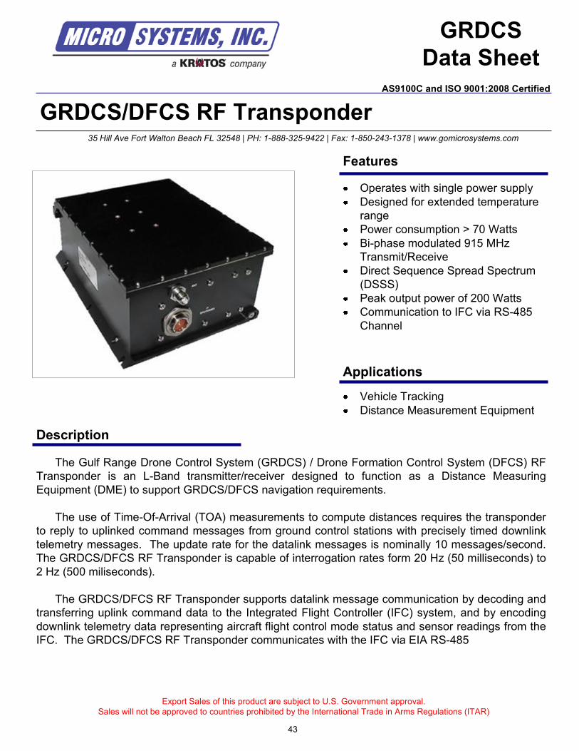
The Gulf Range Drone Control System (GRDCS) / Drone Formation Control System (DFCS) RF
Transponder is an L-Band transmitter/receiver designed to function as a Distance Measuring
Equipment (DME) to support GRDCS/DFCS navigation requirements.
The use of Time-Of-Arrival (TOA) measurements to compute distances requires the transponder
to reply to uplinked command messages from ground control stations with precisely timed downlink
telemetry messages. The update rate for the datalink messages is nominally 10 messages/second.
The GRDCS/DFCS RF Transponder is capable of interrogation rates form 20 Hz (50 milliseconds) to
2 Hz (500 miliseconds).
The GRDCS/DFCS RF Transponder supports datalink message communication by decoding and
transferring uplink command data to the Integrated Flight Controller (IFC) system, and by encoding
downlink telemetry data representing aircraft flight control mode status and sensor readings from the
IFC. The GRDCS/DFCS RF Transponder communicates with the IFC via EIA RS-485
Vehicle Tracking
Distance Measurement Equipment
Applications
Features
Operates with single power supply
Designed for extended temperature
range
Power consumption > 70 Watts
Bi-phase modulated 915 MHz
Transmit/Receive
Direct Sequence Spread Spectrum
(DSSS)
Peak output power of 200 Watts
Communication to IFC via RS-485
Channel
AS9100C and ISO 9001:2008 Certified
GRDCS
Data Sheet

Technical Specifications
Contact us for custom modifications
For additional information contact:
Micro Systems, Inc.
35 Hill Ave
Fort Walton Beach, FL 32547
PH: 1-888-325-9422
FAX: 1-850-243-1378
www.gomicrosystems.com
© 2010 Micro Systems, Inc
Specifications subject to change without notice44
Environmental
Characteristics
Input Voltage: +24 +/- 0.5 VDC to +32 +/- 0.2 VDC (+28VDC Nominal)
Power Consumption: 70 Watts maximum
Data Message Format: GRDCS message format
GRDCS Address: 9 Bits
Drone Delay: (1 to 31) X (0.5 ms)
Modulation: Bi-phase modulation, Direct Sequence Spread Spectrum (DSSS)
Transmit Frequency: 915 MHz (L-Band)
Transmit Frequency Stability: +10 ppm over operating temperature range
Duty Cycle: 2.0 % indefinitely
Receive Center Frequency: 915 MHz (L-Band)
Receive Center Frequency Stability: +10 ppm over operating temperature range
Deceive Dynamic Range: 91 dB minimum
Receive Image Rejection: 60 dB minimum
RF Input: Maximum +53 dBm at a maximum of 2.0 percent
IFC Interface: EIA RS-485
Physical
Size: 9.75" W x 7.42" T x 4.00" D
Weight: less than 13 pounds (excluding the mounting brackets)
Connectors: J1 = TNC; J2 = MS27474Y12B35P
Random Vibration: Operating: 0.015g2/Hz 20 to 100 Hz
0.04g2/Hz 100 to 2000 Hz for 5 minutes in each orthogonal direction (8.8 Grms)
Temperature: Operating: -40 C to +71 C Storage: -54 C to +125 C
Cooling: Passive Conductive (no moving parts)
Shock: Half Sine, 20 G’s peak, 11 ms, 3 axes
Altitude: Sea level up to 50,000 feet
Humidity: To 95% at any temperature forming frost or condensation
AS9100C and ISO 9001:2008 Certified
IFF Transponder Model MD500L
Description
MD500L
Data Sheet
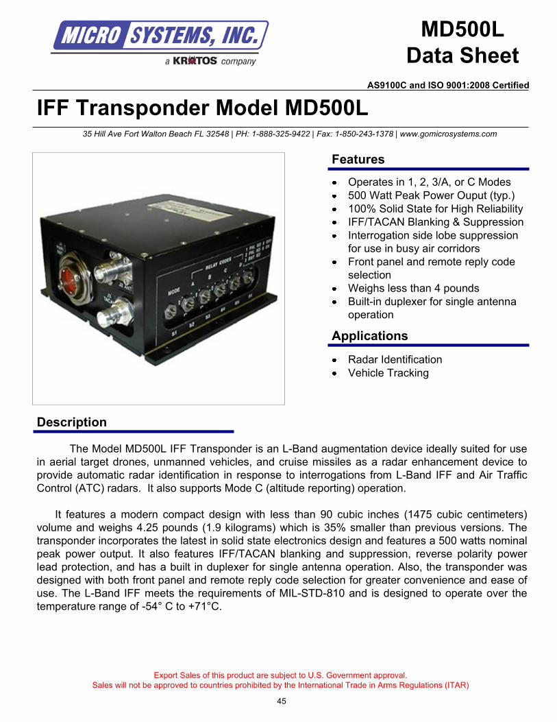
The Model MD500L IFF Transponder is an L-Band augmentation device ideally suited for use
in aerial target drones, unmanned vehicles, and cruise missiles as a radar enhancement device to
provide automatic radar identification in response to interrogations from L-Band IFF and Air Traffic
Control (ATC) radars. It also supports Mode C (altitude reporting) operation.
It features a modern compact design with less than 90 cubic inches (1475 cubic centimeters)
volume and weighs 4.25 pounds (1.9 kilograms) which is 35% smaller than previous versions. The
transponder incorporates the latest in solid state electronics design and features a 500 watts nominal
peak power output. It also features IFF/TACAN blanking and suppression, reverse polarity power
lead protection, and has a built in duplexer for single antenna operation. Also, the transponder was
designed with both front panel and remote reply code selection for greater convenience and ease of
use. The L-Band IFF meets the requirements of MIL-STD-810 and is designed to operate over the
temperature range of -54° C to +71°C.
Export Sales of this product are subject to U.S. Government approval.
Sales will not be approved to countries prohibited by the International Trade in Arms Regulations (ITAR)
Radar Identification
Vehicle Tracking
35 Hill Ave Fort Walton Beach FL 32548 | PH: 1-888-325-9422 | Fax: 1-850-243-1378 | www.gomicrosystems.com
Features
Applications
Operates in 1, 2, 3/A, or C Modes
500 Watt Peak Power Ouput (typ.)
100% Solid State for High Reliability
IFF/TACAN Blanking & Suppression
Interrogation side lobe suppression
for use in busy air corridors
Front panel and remote reply code
selection
Weighs less than 4 pounds
Built-in duplexer for single antenna
operation
45
AS9100C and ISO 9001:2008 Certified
Technical Specifications
ElectricalFrequency: 1030 / 1090 MHz
Impedance, Input/Output: 50 ohms nominal
Protection: Built-in series diode
protection against from DC
input power reversal
Input Voltage: 24 to 32 VDC, common GND
Quiescent Current: 0.4 Amp nominal
Input Current: 1.1 Amp typical @ 2500 prf
Input Power: 40 Watts max, all conditions
Suppression Modes:
(1) Decoding suppression during transmission
(2) Interrogation Side Lobe Suppression (ISLS)
(3) Over-interrogation reply limiting
(4) Suppression from an external IFF or TACAN
system
(5) Provides suppression pulse to an IFF or TACAN
system
Contact us for custom modifications
For additional information contact:
Micro Systems, Inc.
35 Hill Ave
Fort Walton Beach, FL 32547
PH: 1-888-325-9422
FAX: 1-850-243-1378
www.gomicrosystems.com
© 2010 Micro Systems, Inc
Specifications subject to change without notice
Receiver
Type: Direct RF detection & Logarithmic
Amplification
Frequency (3dB): 1027.5 MHz to 1032.5 MHz
(or specify)
Sensitivity: -69 dBm to -77 dBm, internally
adjustable
Dynamic Range: 50 dB min
Pulse Decoding: Modes externally or remotely
selected
Mode 1 pulse spacing: 3.0 +/- 0.1 secs
Mode 2 pulse spacing: 5.0 +/- 0.2 secs
Mode 3A pulse spacing: 8.0 +/- 0.2 secs
Mode 3C pulse spacing: 21.0 +/- 0.2 secs
Pulse Width (all modes): 0.8 +/- 0.1 secs
Sidelobe Suppression
Pulse: Positioned 2.0 +/- 0.15 secs
from first pulse. Suppression
occurs when this pulse > in
amplitude to first pulse.
Transmitter
Type: Solid-state, silicon bipolar
transistors
Frequency (3dB): 1090 +/- 3 MHz
Power Output: 5 Bit encoded signal between 2
framing pulses spaced 20.3 +/-
0.1 secs
Pulse Width: 0.45 +/- 0.1 secs
Reply Code
Select: Front panel switches or remote
Receive to Transmit
Delay: 3.5 secs nominal (jitter 0.1
secs max
Random
Triggering: 5 pulse trains per second maxPhysical
Size: 5.00" W x 2.52" T x 5.13" D
(12.7 cm x 6.40 cm x 13.03 cm)
Weight: 4 pounds
Antenna. Connector: TNC Female
Pwr/Remote Connector: MS27474E14B35P
IFF/TACAN Connector: BNC female
Installation: Flange Mount Base Plate
Environmental
Temp, Operating: -66 F (-54 C) to 160 F (+71 C)
Temp, Storage: -80 F (-62 C) to 185 F (+85 C)
Altitude: Sea Level to 100,000 feet
Humidity: Any, up to 100% including
condensation due to temperature
change (all boards are conformal
coated)
Leakage: Water immersion to a depth of 1m for
2 hrs
Vibration: Random, 9.3 Grms max from 10 to
2000 Hz
Acceleration: 20 G in each of 6 direction for 1 min
per axis while operating
Shock: 20 G (11 ms), 3 shocks each axis
EMI/RFI: MIL-STD-461, tested per MIL-STD-
462
46
AS9100C and ISO 9001:2008 Certified
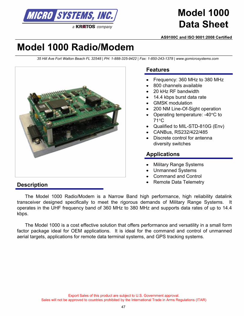
Model 1000 Radio/Modem
Description
Model 1000
Data Sheet
The Model 1000 Radio/Modem is a Narrow Band high performance, high reliability datalink
transceiver designed specifically to meet the rigorous demands of Military Range Systems. It
operates in the UHF frequency band of 360 MHz to 380 MHz and supports data rates of up to 14.4
kbps.
The Model 1000 is a cost effective solution that offers performance and versatility in a small form
factor package ideal for OEM applications. It is ideal for the command and control of unmanned
aerial targets, applications for remote data terminal systems, and GPS tracking systems.
Export Sales of this product are subject to U.S. Government approval.
Sales will not be approved to countries prohibited by the International Trade in Arms Regulations (ITAR)
Military Range Systems
Unmanned Systems
Command and Control
Remote Data Telemetry
35 Hill Ave Fort Walton Beach FL 32548 | PH: 1-888-325-9422 | Fax: 1-850-243-1378 | www.gomicrosystems.com
Features
Applications
Frequency: 360 MHz to 380 MHz
800 channels available
20 kHz RF bandwidth
14.4 kbps burst data rate
GMSK modulation
200 NM Line-Of-Sight operation
Operating temperature: -40 C to
71 C
Qualified to MIL-STD-810G (Env)
CANBus, RS232/422/485
Discrete control for antenna
diversity switches
47
AS9100C and ISO 9001:2008 Certified
Technical Specifications
Contact us for custom modifications
For additional information contact:
Micro Systems, Inc.
35 Hill Ave
Fort Walton Beach, FL 32547
PH: 1-888-325-9422
FAX: 1-850-243-1378
www.gomicrosystems.com
© 2010 Micro Systems, Inc
Specifications subject to change without notice
Transmitter
Frequency Range: 360 MHz to 380 MHz
Output Power: 5, 10, and 25 Watt versions available
Range – Line of Sight: 200 Nautical Miles (NM)
Modulation: GMSK, 14.4 kbps burst data rate
Occupied Bandwidth: < 20 kHz
Channels: 800
Channel Bandwidth: 25 kHz
Maximum PRF: 10 Hz
Environmental
Temperature: Operating: -40 C to +71 C
Cooling: Passive Conductive (no moving parts)
Vibration: Random, 15 to 2000 Hz, 9.3 G 30 minutes per orthogonal axis
Altitude: 50,000 ft
Shock: Sawtooth, 20 G for 11ms, 18 shocks total
Humidity: Up to 95% @ 40 C (all boards are conformal coated)
Physical
Size – 5 Watt: 2.90" W x 3.80" D x 1.43" T
Size – 10, 25 Watt: 2.90" W x 4.20" D x 1.43" T
Weight: 0.5 pounds
Enclosure: Optional
Power Requirements
DC Power: 15 VDC Nominal
Reverse Polarity: Series diode protection
Receiver
Sensitivity: -105 dBm @ 1x10⁻⁴
BER
RF Selectivity: -60 dBm @ 30 kHz
Dynamic Range: 115 dB
Data Transmission
Error Detection: 24 or 32 bit CRC
Error Correction: Convolutional Encoding/Viterbi Decoding
Link Throughput: 14.4 kbps
Data Interface: Serial
Protocol: RS-232/485/422, CANBus
Data Connector: 9 pin D-Subminiature (Female)
48
AS9100C and ISO 9001:2008 Certified
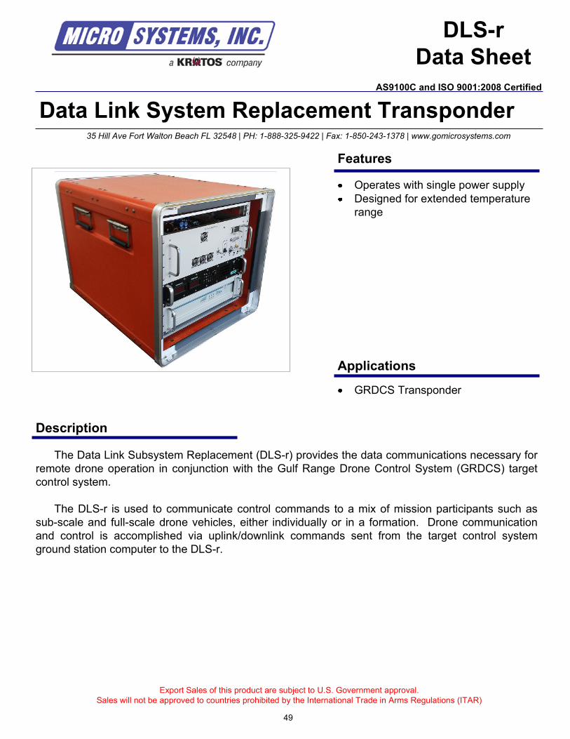
Export Sales of this product are subject to U.S. Government approval.
Sales will not be approved to countries prohibited by the International Trade in Arms Regulations (ITAR)
35 Hill Ave Fort Walton Beach FL 32548 | PH: 1-888-325-9422 | Fax: 1-850-243-1378 | www.gomicrosystems.com
49
Data Link System Replacement Transponder
Description
The Data Link Subsystem Replacement (DLS-r) provides the data communications necessary for
remote drone operation in conjunction with the Gulf Range Drone Control System (GRDCS) target
control system.
The DLS-r is used to communicate control commands to a mix of mission participants such as
sub-scale and full-scale drone vehicles, either individually or in a formation. Drone communication
and control is accomplished via uplink/downlink commands sent from the target control system
ground station computer to the DLS-r.
GRDCS Transponder
Applications
Features
Operates with single power supply
Designed for extended temperature
range
AS9100C and ISO 9001:2008 Certified
DLS-r
Data Sheet
Technical Specifications
Contact us for custom modifications
For additional information contact:
Micro Systems, Inc.
35 Hill Ave
Fort Walton Beach, FL 32547
PH: 1-888-325-9422
FAX: 1-850-243-1378
www.gomicrosystems.com
© 2010 Micro Systems, Inc
Specifications subject to change without notice50
Environmental
Characteristics
Input Voltage: +24 +/- 0.5 VDC to +32 +/- 0.2 VDC (+28VDC Nominal)
Power Consumption: 70 Watts maximum
Data Message Format: GRDCS message format
GRDCS Address: 9 Bits
Drone Delay: (1 to 31) X (0.5 ms)
Modulation: Bi-phase modulation, Direct Sequence Spread Spectrum (DSSS)
Transmit Frequency: 915 MHz (L-Band)
Transmit Frequency Stability: +10 ppm over operating temperature range
Duty Cycle: 2.0 % indefinitely
Receive Center Frequency: 915 MHz (L-Band)
Receive Center Frequency Stability: +10 ppm over operating temperature range
Deceive Dynamic Range: 91 dB minimum
Receive Image Rejection: 60 dB minimum
RF Input: Maximum +53 dBm at a maximum of 2.0 percent
IFC Interface: EIA RS-485
Physical
Size: 9.75" W x 7.42" T x 4.00" D
Weight: less than 13 pounds (excluding the mounting brackets)
Connectors: J1 = TNC; J2 = MS27474Y12B35P
Random Vibration: Operating: 0.015g2/Hz 20 to 100 Hz
0.04g2/Hz 100 to 2000 Hz for 5 minutes in each orthogonal direction (8.8 Grms)
Temperature: Operating: -40 C to +71 C Storage: -54 C to +125 C
Cooling: Passive Conductive (no moving parts)
Shock: Half Sine, 20 G’s peak, 11 ms, 3 axes
Altitude: Sea level up to 50,000 feet
Humidity: To 95% at any temperature forming frost or condensation
AS9100C and ISO 9001:2008 Certified
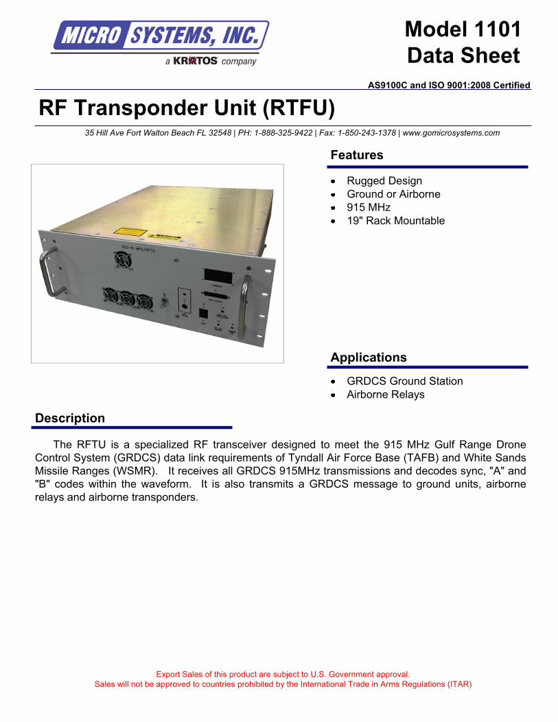
Export Sales of this product are subject to U.S. Government approval.
Sales will not be approved to countries prohibited by the International Trade in Arms Regulations (ITAR)
35 Hill Ave Fort Walton Beach FL 32548 | PH: 1-888-325-9422 | Fax: 1-850-243-1378 | www.gomicrosystems.com
RF Transponder Unit (RTFU)
Description
The RFTU is a specialized RF transceiver designed to meet the 915 MHz Gulf Range Drone
Control System (GRDCS) data link requirements of Tyndall Air Force Base (TAFB) and White Sands
Missile Ranges (WSMR). It receives all GRDCS 915MHz transmissions and decodes sync, "A" and
"B" codes within the waveform. It is also transmits a GRDCS message to ground units, airborne
relays and airborne transponders.
GRDCS Ground Station
Airborne Relays
Applications
Features
Rugged Design
Ground or Airborne
915 MHz
19" Rack Mountable
AS9100C and ISO 9001:2008 Certified
Model 1101
Data Sheet
Technical Specifications
Contact us for custom modifications
For additional information contact:
Micro Systems, Inc.
35 Hill Ave
Fort Walton Beach, FL 32547
PH: 1-888-325-9422
FAX: 1-850-243-1378
www.gomicrosystems.com
© 2010 Micro Systems, Inc
Specifications subject to change without notice
Environmental
General
Operating Frequency: 915 MHz + 9.15 kHz
Modulation: BPSK
Antenna Port: TX/RX, 50 ohms type N connector, Maximum VSWR 1.5:1
Operating Voltage: 22-32 VDC (28 VDC Nominal)
Operating Current: < 5 Amps receive only, < 20 Amps transmit (max duty cycle)
Physical
Size: 16.9" W x 7.0" T x 20.4" D
Weight: less than 100 pounds
Temperature: Operating: -40 C to +71 C Storage: -54 C to +125 C
Vibration: Random (propeller aircraft)
AS9100C and ISO 9001:2008 Certified
Transmitter
Operating Frequency: 915 MHz + 9.15 kHz
Receiver Sensitivity: -90.0 dBm at volts for temp rng > -40 C to < -20 C
-91.5 dBm w/ obj of -96 dBm, at volts for temp rng > -20 C to < +50 C
-90.0 dBm at volts for temp rng > +50 C to < +71 C
Receiver Dynamic Range: 80.0 dBm, span -10dBm to -90 dBm, at volts for temp rng > -40 C to < -20 C
81.5 dBm, span -10dBm to -91.5 dBm, at volts for temp rng > -20 C to < +50 C
80.0 dBm, span -10dBm to -90 dBm, at volts for temp rng > +50 C to < +71 C
Image Rejection: 60 dB (min)
Receiver
Operating Frequency: 915 MHz + 9.15 kHz
Modulation: BPSK
Transmitter Power: > +53 dBm (200W) for temp range > -40 C to < 0 C
> +56 dBm (400W) for temp range > 0 C to < +43 C
> +53 dBm (200W) for temp range > +43 C to < +71 C
Duty Cycle: 20% Maximum
Power Droop: < 1 dB
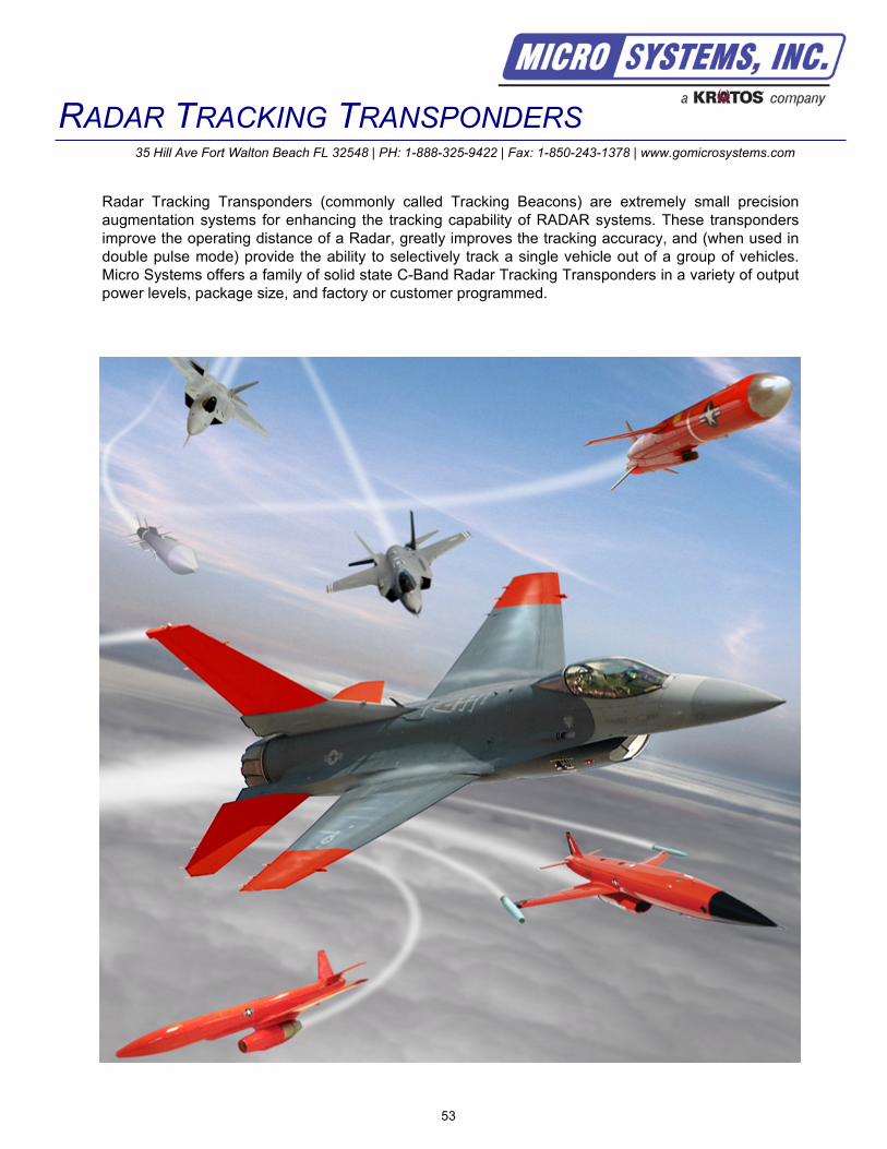
RADAR TRACKING TRANSPONDERS35 Hill Ave Fort Walton Beach FL 32548 | PH: 1-888-325-9422 | Fax: 1-850-243-1378 | www.gomicrosystems.com
53
Radar Tracking Transponders (commonly called Tracking Beacons) are extremely small precision
augmentation systems for enhancing the tracking capability of RADAR systems. These transponders
improve the operating distance of a Radar, greatly improves the tracking accuracy, and (when used in
double pulse mode) provide the ability to selectively track a single vehicle out of a group of vehicles.
Micro Systems offers a family of solid state C-Band Radar Tracking Transponders in a variety of output
power levels, package size, and factory or customer programmed.

54
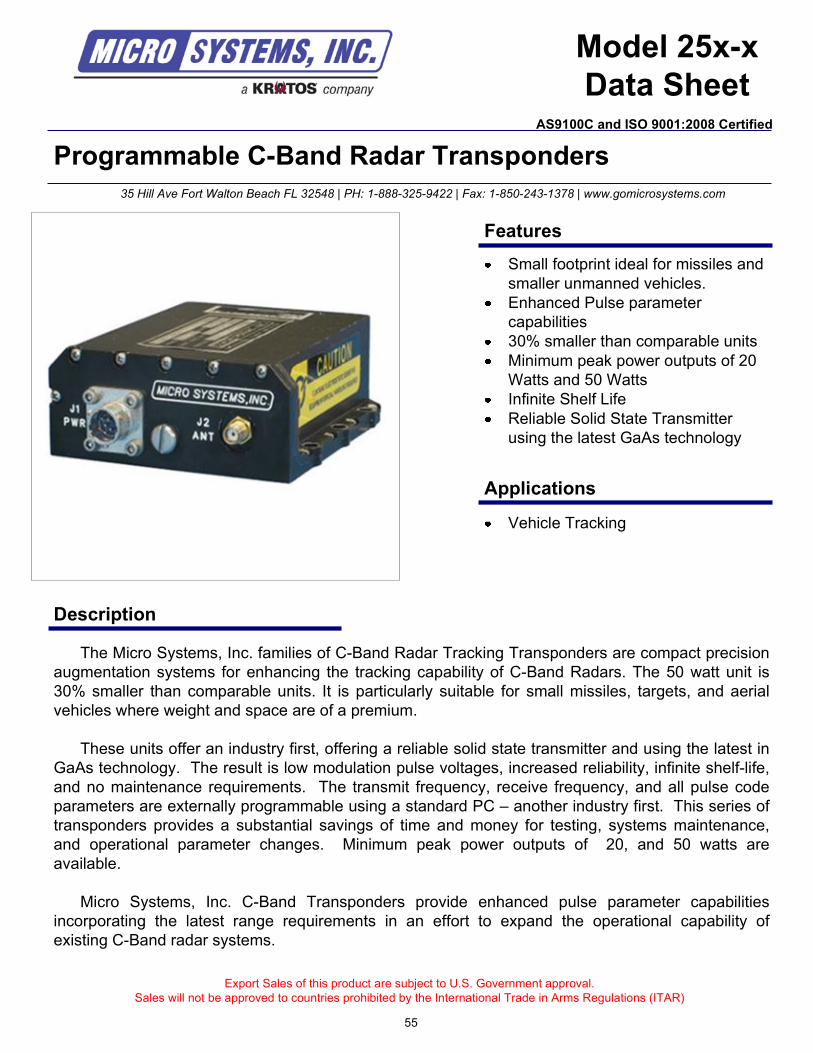
Programmable C-Band Radar Transponders
Description
The Micro Systems, Inc. families of C-Band Radar Tracking Transponders are compact precision
augmentation systems for enhancing the tracking capability of C-Band Radars. The 50 watt unit is
30% smaller than comparable units. It is particularly suitable for small missiles, targets, and aerial
vehicles where weight and space are of a premium.
These units offer an industry first, offering a reliable solid state transmitter and using the latest in
GaAs technology. The result is low modulation pulse voltages, increased reliability, infinite shelf-life,
and no maintenance requirements. The transmit frequency, receive frequency, and all pulse code
parameters are externally programmable using a standard PC – another industry first. This series of
transponders provides a substantial savings of time and money for testing, systems maintenance,
and operational parameter changes. Minimum peak power outputs of 20, and 50 watts are
available.
Micro Systems, Inc. C-Band Transponders provide enhanced pulse parameter capabilities
incorporating the latest range requirements in an effort to expand the operational capability of
existing C-Band radar systems.
Export Sales of this product are subject to U.S. Government approval.
Sales will not be approved to countries prohibited by the International Trade in Arms Regulations (ITAR)
Vehicle Tracking
35 Hill Ave Fort Walton Beach FL 32548 | PH: 1-888-325-9422 | Fax: 1-850-243-1378 | www.gomicrosystems.com
Features
Applications
Small footprint ideal for missiles and
smaller unmanned vehicles.
Enhanced Pulse parameter
capabilities
30% smaller than comparable units
Minimum peak power outputs of 20
Watts and 50 Watts
Infinite Shelf Life
Reliable Solid State Transmitter
using the latest GaAs technology
Model 25x-x
Data Sheet
55
AS9100C and ISO 9001:2008 Certified
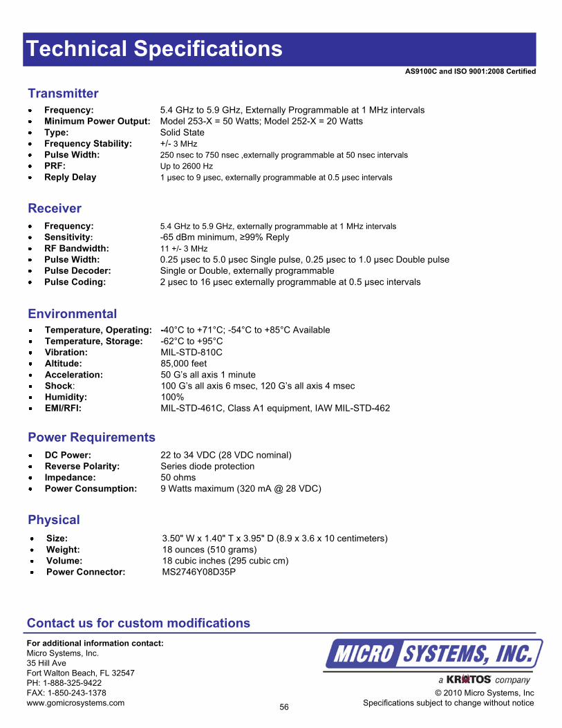
Technical Specifications
Contact us for custom modifications
For additional information contact:
Micro Systems, Inc.
35 Hill Ave
Fort Walton Beach, FL 32547
PH: 1-888-325-9422
FAX: 1-850-243-1378
www.gomicrosystems.com
© 2010 Micro Systems, Inc
Specifications subject to change without notice
EnvironmentalTemperature, Operating: -40°C to +71°C; -54°C to +85°C Available
Temperature, Storage: -62°C to +95°C
Vibration: MIL-STD-810C
Altitude: 85,000 feet
Acceleration: 50 G’s all axis 1 minute
Shock: 100 G’s all axis 6 msec, 120 G’s all axis 4 msec
Humidity: 100%
EMI/RFI: MIL-STD-461C, Class A1 equipment, IAW MIL-STD-462
Transmitter
Frequency: 5.4 GHz to 5.9 GHz, Externally Programmable at 1 MHz intervals
Minimum Power Output: Model 253-X = 50 Watts; Model 252-X = 20 Watts
Type: Solid State
Frequency Stability: +/- 3 MHz
Pulse Width: 250 nsec to 750 nsec ,externally programmable at 50 nsec intervals
PRF: Up to 2600 Hz
Reply Delay 1 µsec to 9 µsec, externally programmable at 0.5 µsec intervals
Power Requirements
DC Power: 22 to 34 VDC (28 VDC nominal)
Reverse Polarity: Series diode protection
Impedance: 50 ohms
Power Consumption: 9 Watts maximum (320 mA @ 28 VDC)
Physical
Size: 3.50" W x 1.40" T x 3.95" D (8.9 x 3.6 x 10 centimeters)
Weight: 18 ounces (510 grams)
Volume: 18 cubic inches (295 cubic cm)
Power Connector: MS2746Y08D35P
Receiver
Frequency: 5.4 GHz to 5.9 GHz, externally programmable at 1 MHz intervals
Sensitivity: -65 dBm minimum, ≥99% Reply
RF Bandwidth: 11 +/- 3 MHz
Pulse Width: 0.25 µsec to 5.0 µsec Single pulse, 0.25 µsec to 1.0 µsec Double pulse
Pulse Decoder: Single or Double, externally programmable
Pulse Coding: 2 µsec to 16 µsec externally programmable at 0.5 µsec intervals
56
AS9100C and ISO 9001:2008 Certified
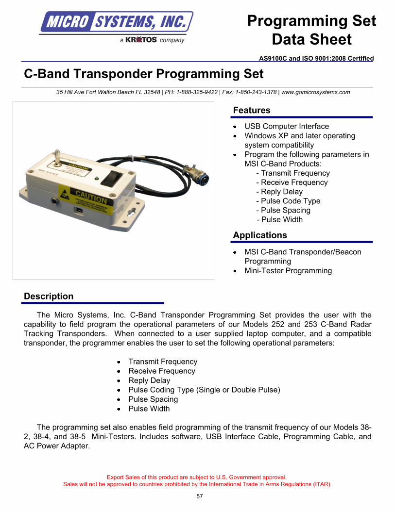
Export Sales of this product are subject to U.S. Government approval.
Sales will not be approved to countries prohibited by the International Trade in Arms Regulations (ITAR)
57
C-Band Transponder Programming Set
Description
The Micro Systems, Inc. C-Band Transponder Programming Set provides the user with the
capability to field program the operational parameters of our Models 252 and 253 C-Band Radar
Tracking Transponders. When connected to a user supplied laptop computer, and a compatible
transponder, the programmer enables the user to set the following operational parameters:
Transmit Frequency
Receive Frequency
Reply Delay
Pulse Coding Type (Single or Double Pulse)
Pulse Spacing
Pulse Width
The programming set also enables field programming of the transmit frequency of our Models 38-
2, 38-4, and 38-5 Mini-Testers. Includes software, USB Interface Cable, Programming Cable, and
AC Power Adapter.
MSI C-Band Transponder/Beacon
Programming
Mini-Tester Programming
35 Hill Ave Fort Walton Beach FL 32548 | PH: 1-888-325-9422 | Fax: 1-850-243-1378 | www.gomicrosystems.com
Features
Applications
USB Computer Interface
Windows XP and later operating
system compatibility
Program the following parameters in
MSI C-Band Products:
- Transmit Frequency
- Receive Frequency
- Reply Delay
- Pulse Code Type
- Pulse Spacing
- Pulse Width
Programming Set
Data SheetAS9100C and ISO 9001:2008 Certified
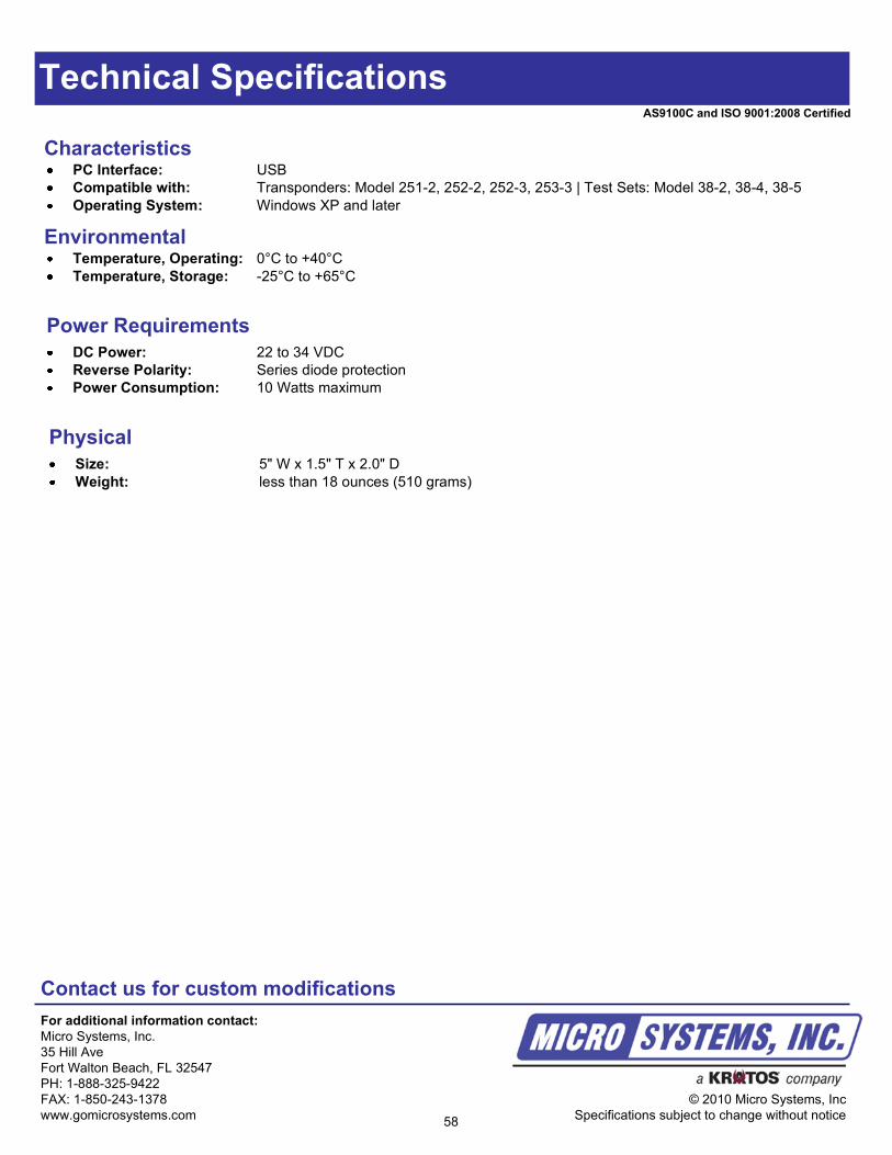
Technical Specifications
Contact us for custom modifications
For additional information contact:
Micro Systems, Inc.
35 Hill Ave
Fort Walton Beach, FL 32547
PH: 1-888-325-9422
FAX: 1-850-243-1378
www.gomicrosystems.com
© 2010 Micro Systems, Inc
Specifications subject to change without notice58
AS9100C and ISO 9001:2008 Certified
CharacteristicsPC Interface: USB
Compatible with: Transponders: Model 251-2, 252-2, 252-3, 253-3 | Test Sets: Model 38-2, 38-4, 38-5
Operating System: Windows XP and later
Power Requirements
DC Power: 22 to 34 VDC
Reverse Polarity: Series diode protection
Power Consumption: 10 Watts maximum
Physical
Size: 5" W x 1.5" T x 2.0" D
Weight: less than 18 ounces (510 grams)
Environmental Temperature, Operating: 0°C to +40°C
Temperature, Storage: -25°C to +65°C
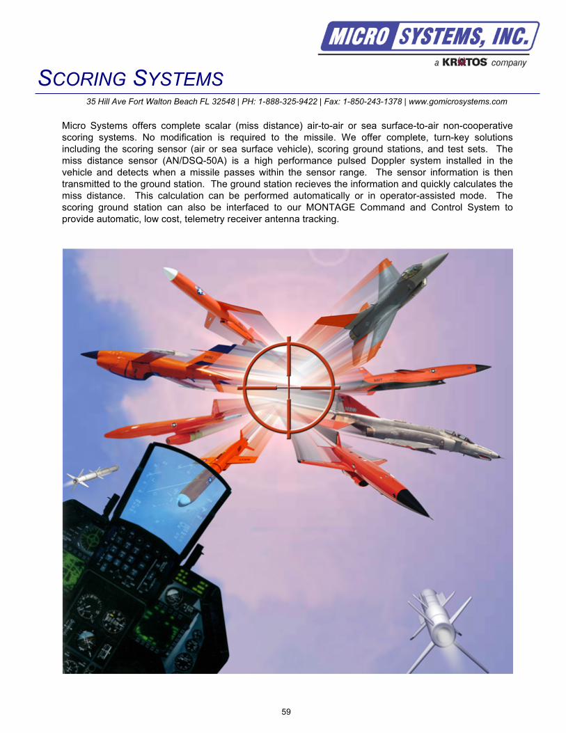
SCORING SYSTEMS35 Hill Ave Fort Walton Beach FL 32548 | PH: 1-888-325-9422 | Fax: 1-850-243-1378 | www.gomicrosystems.com
Micro Systems offers complete scalar (miss distance) air-to-air or sea surface-to-air non-cooperative
scoring systems. No modification is required to the missile. We offer complete, turn-key solutions
including the scoring sensor (air or sea surface vehicle), scoring ground stations, and test sets. The
miss distance sensor (AN/DSQ-50A) is a high performance pulsed Doppler system installed in the
vehicle and detects when a missile passes within the sensor range. The sensor information is then
transmitted to the ground station. The ground station recieves the information and quickly calculates the
miss distance. This calculation can be performed automatically or in operator-assisted mode. The
scoring ground station can also be interfaced to our MONTAGE Command and Control System to
provide automatic, low cost, telemetry receiver antenna tracking.
59

60
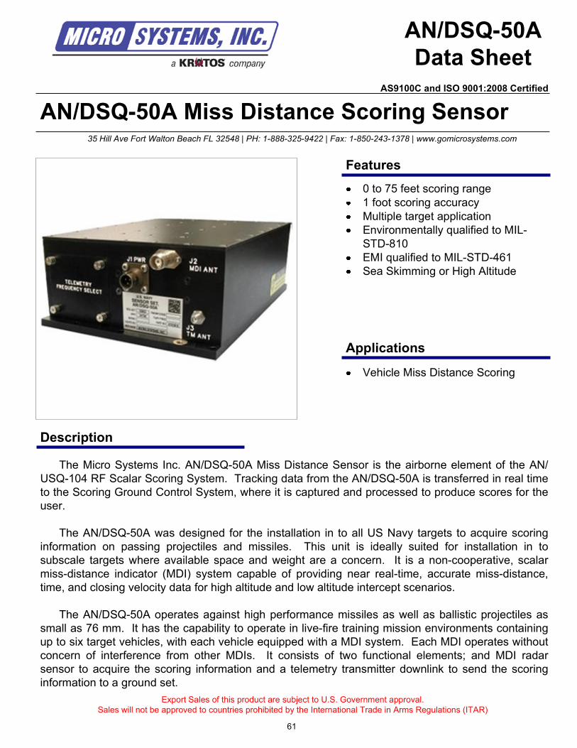
AN/DSQ-50A Miss Distance Scoring Sensor
Description
AN/DSQ-50A
Data Sheet
The Micro Systems Inc. AN/DSQ-50A Miss Distance Sensor is the airborne element of the AN/
USQ-104 RF Scalar Scoring System. Tracking data from the AN/DSQ-50A is transferred in real time
to the Scoring Ground Control System, where it is captured and processed to produce scores for the
user.
The AN/DSQ-50A was designed for the installation in to all US Navy targets to acquire scoring
information on passing projectiles and missiles. This unit is ideally suited for installation in to
subscale targets where available space and weight are a concern. It is a non-cooperative, scalar
miss-distance indicator (MDI) system capable of providing near real-time, accurate miss-distance,
time, and closing velocity data for high altitude and low altitude intercept scenarios.
The AN/DSQ-50A operates against high performance missiles as well as ballistic projectiles as
small as 76 mm. It has the capability to operate in live-fire training mission environments containing
up to six target vehicles, with each vehicle equipped with a MDI system. Each MDI operates without
concern of interference from other MDIs. It consists of two functional elements; and MDI radar
sensor to acquire the scoring information and a telemetry transmitter downlink to send the scoring
information to a ground set.
Export Sales of this product are subject to U.S. Government approval.
Sales will not be approved to countries prohibited by the International Trade in Arms Regulations (ITAR)
Vehicle Miss Distance Scoring
35 Hill Ave Fort Walton Beach FL 32548 | PH: 1-888-325-9422 | Fax: 1-850-243-1378 | www.gomicrosystems.com
Features
Applications
0 to 75 feet scoring range
1 foot scoring accuracy
Multiple target application
Environmentally qualified to MIL-
STD-810
EMI qualified to MIL-STD-461
Sea Skimming or High Altitude
61
AS9100C and ISO 9001:2008 Certified
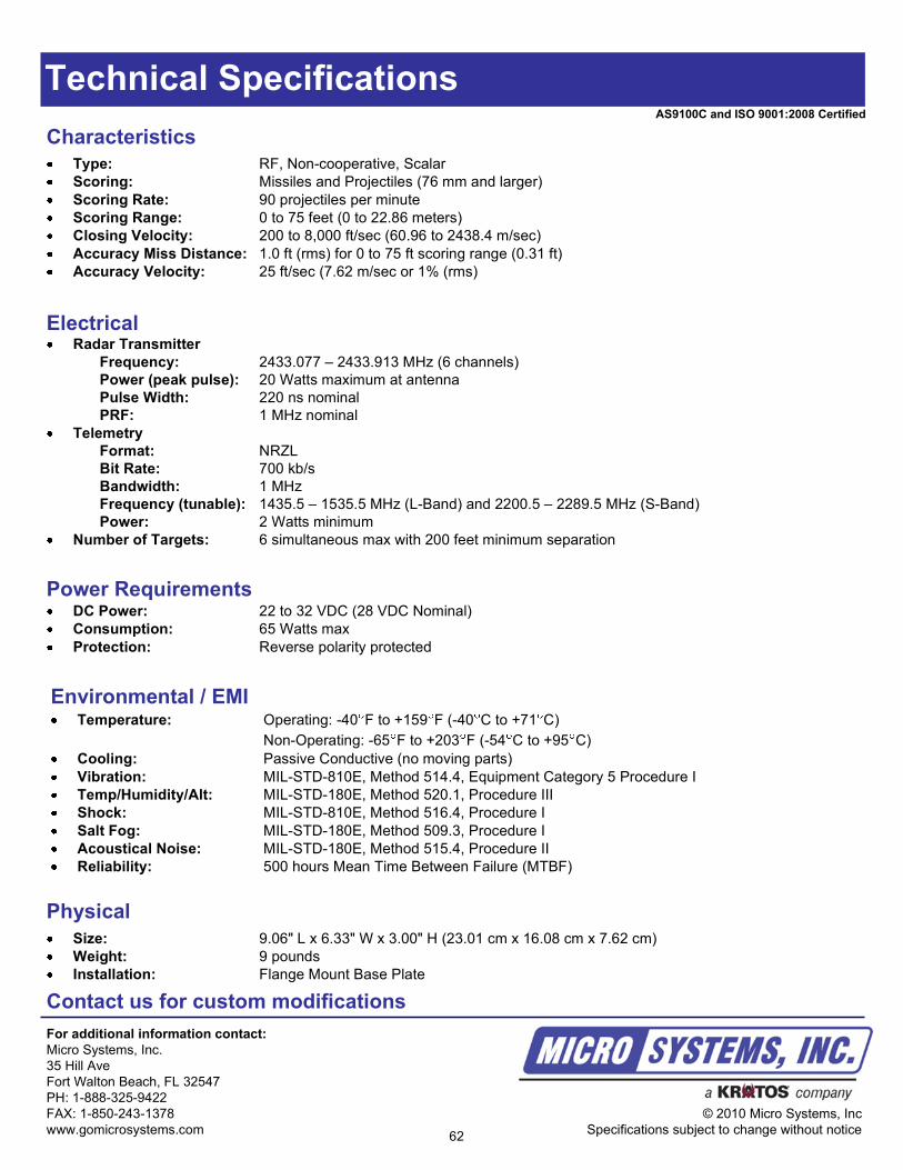
Technical Specifications
ElectricalRadar Transmitter
Frequency: 2433.077 – 2433.913 MHz (6 channels)
Power (peak pulse): 20 Watts maximum at antenna
Pulse Width: 220 ns nominal
PRF: 1 MHz nominal
Telemetry
Format: NRZL
Bit Rate: 700 kb/s
Bandwidth: 1 MHz
Frequency (tunable): 1435.5 – 1535.5 MHz (L-Band) and 2200.5 – 2289.5 MHz (S-Band)
Power: 2 Watts minimum
Number of Targets: 6 simultaneous max with 200 feet minimum separation
Characteristics
Type: RF, Non-cooperative, Scalar
Scoring: Missiles and Projectiles (76 mm and larger)
Scoring Rate: 90 projectiles per minute
Scoring Range: 0 to 75 feet (0 to 22.86 meters)
Closing Velocity: 200 to 8,000 ft/sec (60.96 to 2438.4 m/sec)
Accuracy Miss Distance: 1.0 ft (rms) for 0 to 75 ft scoring range (0.31 ft)
Accuracy Velocity: 25 ft/sec (7.62 m/sec or 1% (rms)
Power RequirementsDC Power: 22 to 32 VDC (28 VDC Nominal)
Consumption: 65 Watts max
Protection: Reverse polarity protected
Physical
Size: 9.06" L x 6.33" W x 3.00" H (23.01 cm x 16.08 cm x 7.62 cm)
Weight: 9 pounds
Installation: Flange Mount Base Plate
Contact us for custom modifications
For additional information contact:
Micro Systems, Inc.
35 Hill Ave
Fort Walton Beach, FL 32547
PH: 1-888-325-9422
FAX: 1-850-243-1378
www.gomicrosystems.com
© 2010 Micro Systems, Inc
Specifications subject to change without notice
Environmental / EMITemperature: Operating: -40 F to +159 F (-40 C to +71 C)
Non-Operating: -65 F to +203 F (-54 C to +95 C)
Cooling: Passive Conductive (no moving parts)
Vibration: MIL-STD-810E, Method 514.4, Equipment Category 5 Procedure I
Temp/Humidity/Alt: MIL-STD-180E, Method 520.1, Procedure III
Shock: MIL-STD-810E, Method 516.4, Procedure I
Salt Fog: MIL-STD-180E, Method 509.3, Procedure I
Acoustical Noise: MIL-STD-180E, Method 515.4, Procedure II
Reliability: 500 hours Mean Time Between Failure (MTBF)
62
AS9100C and ISO 9001:2008 Certified
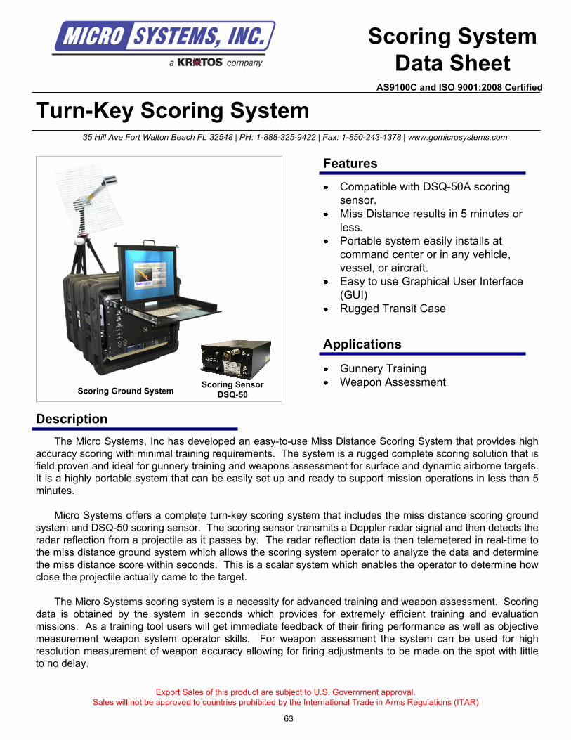
Turn-Key Scoring System
Description
Scoring System
Data Sheet
The Micro Systems, Inc has developed an easy-to-use Miss Distance Scoring System that provides high
accuracy scoring with minimal training requirements. The system is a rugged complete scoring solution that is
field proven and ideal for gunnery training and weapons assessment for surface and dynamic airborne targets.
It is a highly portable system that can be easily set up and ready to support mission operations in less than 5
minutes.
Micro Systems offers a complete turn-key scoring system that includes the miss distance scoring ground
system and DSQ-50 scoring sensor. The scoring sensor transmits a Doppler radar signal and then detects the
radar reflection from a projectile as it passes by. The radar reflection data is then telemetered in real-time to
the miss distance ground system which allows the scoring system operator to analyze the data and determine
the miss distance score within seconds. This is a scalar system which enables the operator to determine how
close the projectile actually came to the target.
The Micro Systems scoring system is a necessity for advanced training and weapon assessment. Scoring
data is obtained by the system in seconds which provides for extremely efficient training and evaluation
missions. As a training tool users will get immediate feedback of their firing performance as well as objective
measurement weapon system operator skills. For weapon assessment the system can be used for high
resolution measurement of weapon accuracy allowing for firing adjustments to be made on the spot with little
to no delay.
Export Sales of this product are subject to U.S. Government approval.
Sales will not be approved to countries prohibited by the International Trade in Arms Regulations (ITAR)
Gunnery Training
Weapon Assessment
35 Hill Ave Fort Walton Beach FL 32548 | PH: 1-888-325-9422 | Fax: 1-850-243-1378 | www.gomicrosystems.com
Features
Applications
Compatible with DSQ-50A scoring
sensor.
Miss Distance results in 5 minutes or
less.
Portable system easily installs at
command center or in any vehicle,
vessel, or aircraft.
Easy to use Graphical User Interface
(GUI)
Rugged Transit Case
Scoring Ground SystemScoring Sensor
DSQ-50
63
AS9100C and ISO 9001:2008 Certified
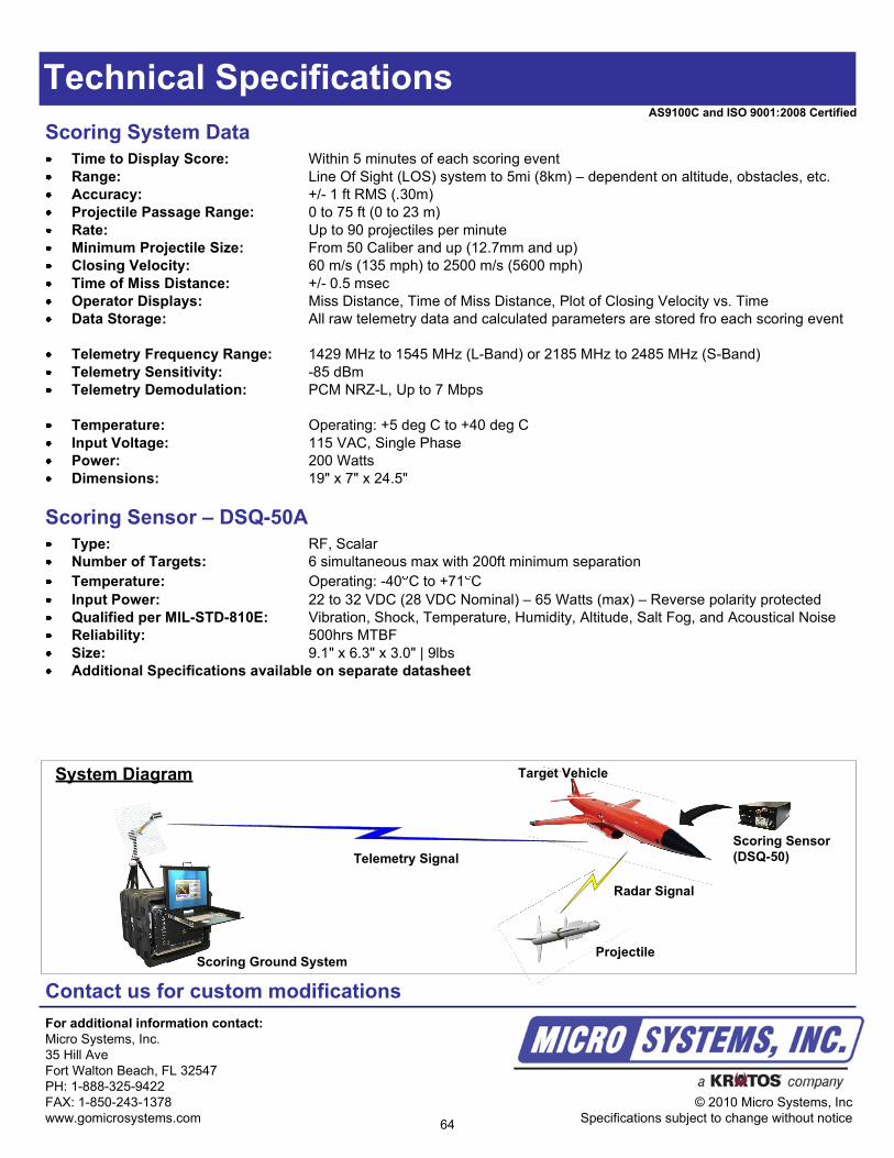
Technical Specifications
Contact us for custom modifications
For additional information contact:
Micro Systems, Inc.
35 Hill Ave
Fort Walton Beach, FL 32547
PH: 1-888-325-9422
FAX: 1-850-243-1378
www.gomicrosystems.com
© 2010 Micro Systems, Inc
Specifications subject to change without notice
Scoring System Data
Time to Display Score: Within 5 minutes of each scoring event
Range: Line Of Sight (LOS) system to 5mi (8km) – dependent on altitude, obstacles, etc.
Accuracy: +/- 1 ft RMS (.30m)
Projectile Passage Range: 0 to 75 ft (0 to 23 m)
Rate: Up to 90 projectiles per minute
Minimum Projectile Size: From 50 Caliber and up (12.7mm and up)
Closing Velocity: 60 m/s (135 mph) to 2500 m/s (5600 mph)
Time of Miss Distance: +/- 0.5 msec
Operator Displays: Miss Distance, Time of Miss Distance, Plot of Closing Velocity vs. Time
Data Storage: All raw telemetry data and calculated parameters are stored fro each scoring event
Telemetry Frequency Range: 1429 MHz to 1545 MHz (L-Band) or 2185 MHz to 2485 MHz (S-Band)
Telemetry Sensitivity: -85 dBm
Telemetry Demodulation: PCM NRZ-L, Up to 7 Mbps
Temperature: Operating: +5 deg C to +40 deg C
Input Voltage: 115 VAC, Single Phase
Power: 200 Watts
Dimensions: 19" x 7" x 24.5"
Scoring Sensor – DSQ-50A
Type: RF, Scalar
Number of Targets: 6 simultaneous max with 200ft minimum separation
Temperature: Operating: -40 C to +71 C
Input Power: 22 to 32 VDC (28 VDC Nominal) – 65 Watts (max) – Reverse polarity protected
Qualified per MIL-STD-810E: Vibration, Shock, Temperature, Humidity, Altitude, Salt Fog, and Acoustical Noise
Reliability: 500hrs MTBF
Size: 9.1" x 6.3" x 3.0" | 9lbs
Additional Specifications available on separate datasheet
System Diagram
Telemetry Signal
Target Vehicle
Projectile
Radar Signal
Scoring Ground System
Scoring Sensor
(DSQ-50)
64
AS9100C and ISO 9001:2008 Certified
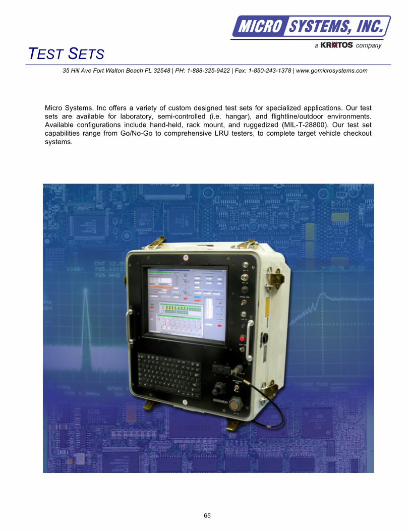
TEST SETS35 Hill Ave Fort Walton Beach FL 32548 | PH: 1-888-325-9422 | Fax: 1-850-243-1378 | www.gomicrosystems.com
Micro Systems, Inc offers a variety of custom designed test sets for specialized applications. Our test
sets are available for laboratory, semi-controlled (i.e. hangar), and flightline/outdoor environments.
Available configurations include hand-held, rack mount, and ruggedized (MIL-T-28800). Our test set
capabilities range from Go/No-Go to comprehensive LRU testers, to complete target vehicle checkout
systems.
65

66
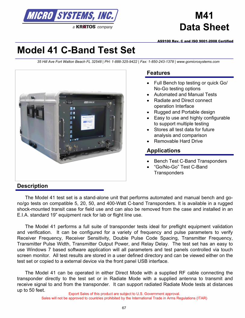
Model 41 C-Band Test Set
Description
M41
Data Sheet
The Model 41 test set is a stand-alone unit that performs automated and manual bench and go-
no/go tests on compatible 5, 20, 50, and 400-Watt C-band Transponders. It is available in a rugged
shock-mounted transit case for field use and can also be removed from the case and installed in an
E.I.A. standard 19” equipment rack for lab or flight line use.
The Model 41 performs a full suite of transponder tests ideal for preflight equipment validation
and verification. It can be configured for a variety of frequency and pulse parameters to verify
Receiver Frequency, Receiver Sensitivity, Double Pulse Code Spacing, Transmitter Frequency,
Transmitter Pulse Width, Transmitter Output Power, and Relay Delay. The test set has an easy to
use Windows 7 based software application will all parameters and test panels controlled via touch
screen monitor. All test results are stored in a user defined directory and can be viewed either on the
test set or copied to a external device via the front panel USB interface.
The Model 41 can be operated in either Direct Mode with a supplied RF cable connecting the
transponder directly to the test set or in Radiate Mode with a supplied antenna to transmit and
receive signal to and from the transponder. It can support radiated Radiate Mode tests at distances
up to 50 feet. Export Sales of this product are subject to U.S. Government approval.
Sales will not be approved to countries prohibited by the International Trade in Arms Regulations (ITAR)
Bench Test C-Band Transponders
“Go/No-Go” Test C-Band
Transponders
35 Hill Ave Fort Walton Beach FL 32548 | PH: 1-888-325-9422 | Fax: 1-850-243-1378 | www.gomicrosystems.com
AS9100 Rev. C and ISO 9001-2008 Certified
Features
Applications
Full Bench top testing or quick Go/
No-Go testing options
Automated and Manual Tests
Radiate and Direct connect
operation Interface
Rugged and Portable design
Easy to use and highly configurable
to support multiple testing
Stores all test data for future
analysis and comparison
Removable Hard Drive
67
AS9100 Rev. C and ISO 9001-2008 Certified
Technical Specifications
Receiver
Frequency: 5.4 GHz to 5.9 GHz
Frequency Adjustment: 1.0 MHz steps
RF Bandwidth: 5.35 GHz to 5.95 GHz
Measurement Accuracy: +/- 2 MHz
Environmental
Temperature: Operating: -20 C to +65 C
Storage: -40 C to +70 C
Transmitter
Frequency: 5.4 GHz to 5.9 GHz
Frequency Adjustment: 1.0 MHz steps
Frequency Stability: +/- 2 MHz
Pulse Width: Single Pulse: 0.5 sec +/- 0.2 sec
Double Pulse: 0.5 sec +/- 0.1 sec
Power Output Direct: 0 dBm to <-70 dBm calibrated output to test Transponder receiver sensitivity
(adjustable in 1 dB steps)
Power Output Radiate: > 30 dBm
PGRF: 1000 Hz (fixed)
Pulse Code Spacing: 3 sec to 15 sec in 0.1 sec steps
Operation Modes: Radiate and Direct
Contact us for custom modifications
For additional information contact:
Micro Systems, Inc.
35 Hill Ave
Fort Walton Beach, FL 32547
PH: 1-888-325-9422
FAX: 1-850-243-1378
www.gomicrosystems.com
© 2010 Micro Systems, Inc
Specifications subject to change without notice
Power Requirements
Input Voltage: 115 +/- 5 VAC, 60 Hz Single Phase
Functional Tests
Receiver Sensitivity
Receiver Frequency
Double Pulse Code Spacing
Transmitter Frequency
Transmitter Pulse Width
Transmitter Output Power
Reply Delay
68
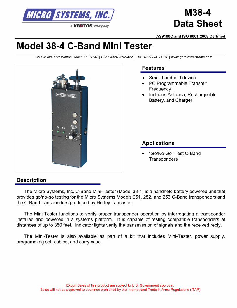
Model 38-4 C-Band Mini Tester
Description
M38-4
Data Sheet
The Micro Systems, Inc. C-Band Mini-Tester (Model 38-4) is a handheld battery powered unit that
provides go/no-go testing for the Micro Systems Models 251, 252, and 253 C-Band transponders and
the C-Band transponders produced by Herley Lancaster.
The Mini-Tester functions to verify proper transponder operation by interrogating a transponder
installed and powered in a systems platform. It is capable of testing compatible transponders at
distances of up to 350 feet. Indicator lights verify the transmission of signals and the received reply.
The Mini-Tester is also available as part of a kit that includes Mini-Tester, power supply,
programming set, cables, and carry case.
Export Sales of this product are subject to U.S. Government approval.
Sales will not be approved to countries prohibited by the International Trade in Arms Regulations (ITAR)
“Go/No-Go” Test C-Band
Transponders
35 Hill Ave Fort Walton Beach FL 32548 | PH: 1-888-325-9422 | Fax: 1-850-243-1378 | www.gomicrosystems.com
Features
Applications
Small handheld device
PC Programmable Transmit
Frequency
Includes Antenna, Rechargeable
Battery, and Charger
AS9100C and ISO 9001:2008 Certified
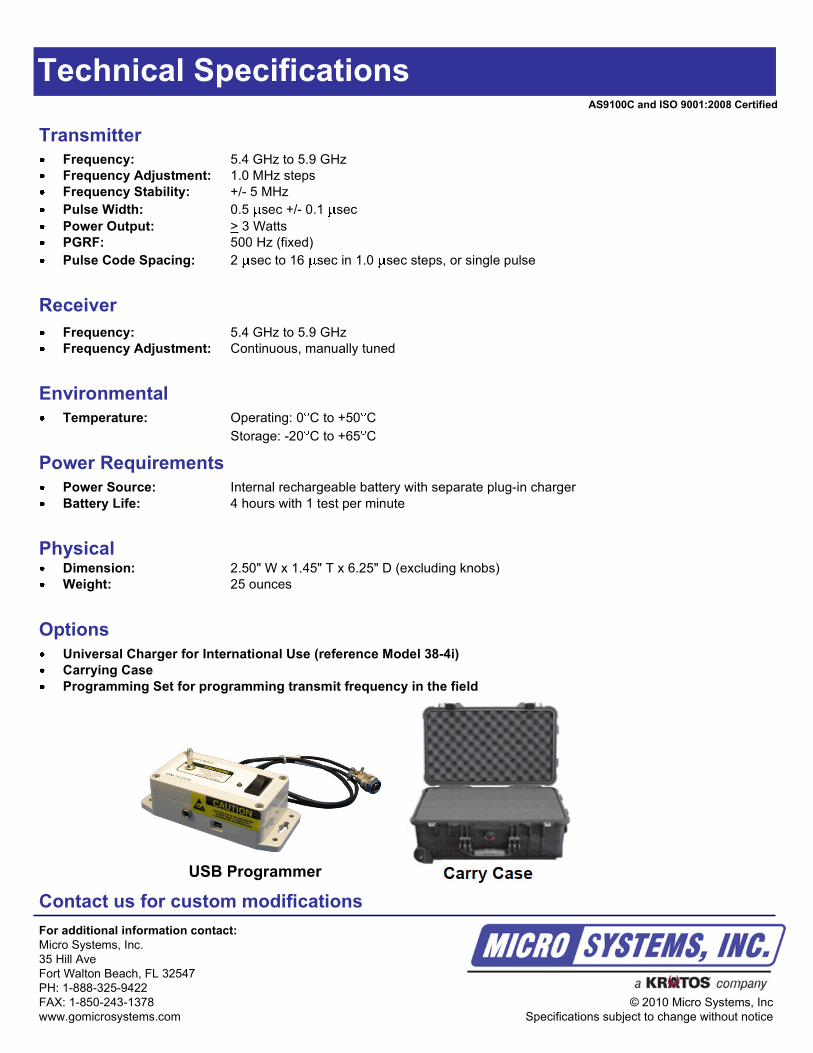
Technical Specifications
Receiver
Frequency: 5.4 GHz to 5.9 GHz
Frequency Adjustment: Continuous, manually tuned
Environmental
Temperature: Operating: 0 C to +50 C
Storage: -20 C to +65 C
Transmitter
Frequency: 5.4 GHz to 5.9 GHz
Frequency Adjustment: 1.0 MHz steps
Frequency Stability: +/- 5 MHz
Pulse Width: 0.5 sec +/- 0.1 sec
Power Output: > 3 Watts
PGRF: 500 Hz (fixed)
Pulse Code Spacing: 2 sec to 16 sec in 1.0 sec steps, or single pulse
Power Requirements
Power Source: Internal rechargeable battery with separate plug-in charger
Battery Life: 4 hours with 1 test per minute
Contact us for custom modifications
For additional information contact:
Micro Systems, Inc.
35 Hill Ave
Fort Walton Beach, FL 32547
PH: 1-888-325-9422
FAX: 1-850-243-1378
www.gomicrosystems.com
© 2010 Micro Systems, Inc
Specifications subject to change without notice
PhysicalDimension: 2.50" W x 1.45" T x 6.25" D (excluding knobs)
Weight: 25 ounces
Options
Universal Charger for International Use (reference Model 38-4i)
Carrying Case
Programming Set for programming transmit frequency in the field
AS9100C and ISO 9001:2008 Certified
USB Programmer
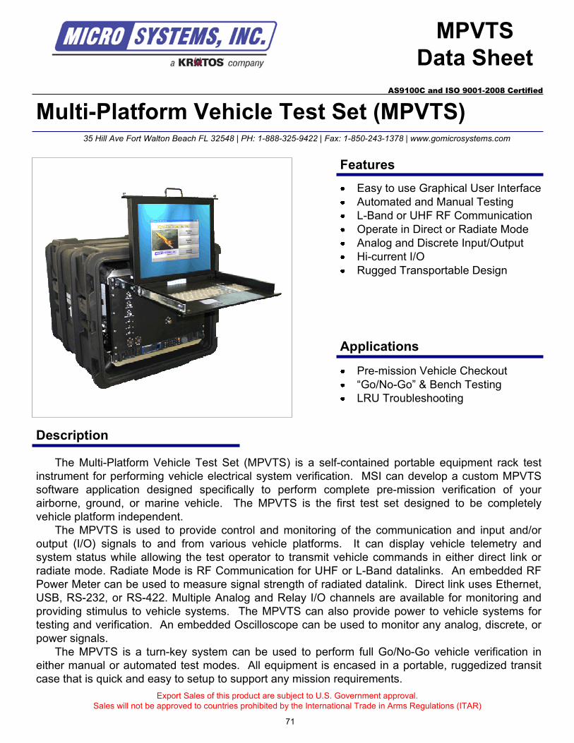
Multi-Platform Vehicle Test Set (MPVTS)
Description
MPVTS
Data Sheet
The Multi-Platform Vehicle Test Set (MPVTS) is a self-contained portable equipment rack test
instrument for performing vehicle electrical system verification. MSI can develop a custom MPVTS
software application designed specifically to perform complete pre-mission verification of your
airborne, ground, or marine vehicle. The MPVTS is the first test set designed to be completely
vehicle platform independent.
The MPVTS is used to provide control and monitoring of the communication and input and/or
output (I/O) signals to and from various vehicle platforms. It can display vehicle telemetry and
system status while allowing the test operator to transmit vehicle commands in either direct link or
radiate mode. Radiate Mode is RF Communication for UHF or L-Band datalinks. An embedded RF
Power Meter can be used to measure signal strength of radiated datalink. Direct link uses Ethernet,
USB, RS-232, or RS-422. Multiple Analog and Relay I/O channels are available for monitoring and
providing stimulus to vehicle systems. The MPVTS can also provide power to vehicle systems for
testing and verification. An embedded Oscilloscope can be used to monitor any analog, discrete, or
power signals.
The MPVTS is a turn-key system can be used to perform full Go/No-Go vehicle verification in
either manual or automated test modes. All equipment is encased in a portable, ruggedized transit
case that is quick and easy to setup to support any mission requirements.
Export Sales of this product are subject to U.S. Government approval.
Sales will not be approved to countries prohibited by the International Trade in Arms Regulations (ITAR)
Pre-mission Vehicle Checkout
“Go/No-Go” & Bench Testing
LRU Troubleshooting
35 Hill Ave Fort Walton Beach FL 32548 | PH: 1-888-325-9422 | Fax: 1-850-243-1378 | www.gomicrosystems.com
AS9100C and ISO 9001-2008 Certified
Features
Applications
Easy to use Graphical User Interface
Automated and Manual Testing
L-Band or UHF RF Communication
Operate in Direct or Radiate Mode
Analog and Discrete Input/Output
Hi-current I/O
Rugged Transportable Design
71
Technical Specifications
Electrical
Input Power - MPVTS uses two primary power sources; 1 for internal components and the second for vehicle power
Contact us for custom modifications
For additional information contact:
Micro Systems, Inc.
35 Hill Ave
Fort Walton Beach, FL 32547
PH: 1-888-325-9422
FAX: 1-850-243-1378
www.gomicrosystems.com
© 2010 Micro Systems, Inc
Specifications subject to change without notice
Vehicle Power
MPVTS Input Power: 115VAC +/- 10 VAC, 60Hz, 15 Amps
MPVTS Vehicle Power Supply Input: 115VAC +/- 10 VAC, 60 Hz, 30 Amps
6 High Current Outputs: 0 – 36VDC, 10A
4 Low Current Outputs: 0 – 20 VDC, 5A
Analog I/O
34 Inputs: 0 – 40 VDC (4kohm nominal load)
10 Inputs: 0 – 20 VDC (4kohm nominal load)
6 Ouputs: -10 – 10 VDC
Relay Closures
9 Relay Closures: 8 Normally Open (NO), 1 Normally Closed (NC)
Serial Communication
RS-422: 5 wire, 115,200 baud, 8, N, 1
RS-232: 9 pin
RS-485: 2 wire ,19.2 baud, 8, Odd parity, 1
USB: 3 ports on front panel
Ethernet: TCP/IP
RF Modules
UHF
Frequencies: 380 – 400 MHz, 435 – 450 MHz, or 358 – 380 MHz
Bandwidth: 20 kHz and 25 kHz available
Channels: 16
L-Band GRDCS Ground Station Module
Frequency: 915 MHz
Bandwidth: 1 kHz
Channels: 1
Physical
Size: 8U, E.I.A. Rackmount Transit Case - 30"W x 30"D x 23"H
Weight: Less than 150lbs
Temperature: +5 deg C to +40 deg C
Reliability (MTBF): 1000hrs
Options
RF Modules
Interface Cables
Rack Configuration
72
AS9100C and ISO 9001:2008 Certified
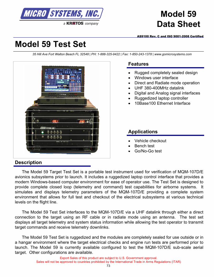
Model 59 Test Set
Description
Model 59
Data Sheet
The Model 59 Target Test Set is a portable test instrument used for verification of MQM-107D/E
avionics subsystems prior to launch. It includes a ruggedized laptop control interface that provides a
modern Windows-based computer environment for ease of operator use. The Test Set is designed to
provide complete closed loop (telemetry and command) test capabilities for airborne systems. It
simulates and displays telemetry parameters of the MQM-107D/E providing a complete system
environment that allows for full test and checkout of the electrical subsystems at various technical
levels on the flight line.
The Model 59 Test Set interfaces to the MQM-107D/E via a UHF datalink through either a direct
connection to the target using an RF cable or in radiate mode using an antenna. The test set
displays all target telemetry and system status information while allowing the test operator to transmit
target commands and receive telemetry downlinks.
The Model 59 Test Set is ruggedized and the modules are completely sealed for use outside or in
a hangar environment where the target electrical checks and engine run tests are performed prior to
launch. The Model 59 is currently available configured to test the MQM-107D/E sub-scale aerial
target. Other configurations are available.
Export Sales of this product are subject to U.S. Government approval.
Sales will not be approved to countries prohibited by the International Trade in Arms Regulations (ITAR)
Vehicle checkout
Bench test
Go/No-Go test
35 Hill Ave Fort Walton Beach FL 32548 | PH: 1-888-325-9422 | Fax: 1-850-243-1378 | www.gomicrosystems.com
AS9100 Rev. C and ISO 9001-2008 Certified
Features
Applications
Rugged completely sealed design
Windows user interface
Direct and Radiate mode operation
UHF 380-400MHz datalink
Digital and Analog signal interfaces
Ruggedized laptop controller
10Base100 Ethernet Interface
73
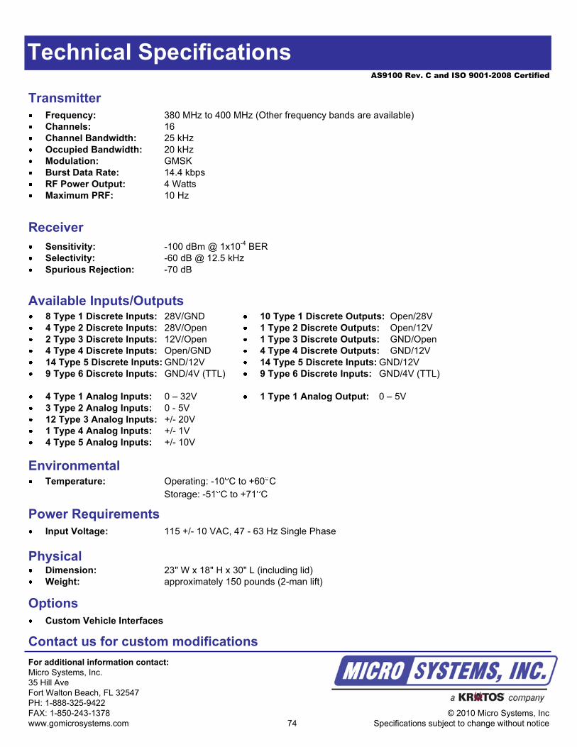
AS9100 Rev. C and ISO 9001-2008 Certified
Technical Specifications
Receiver
Sensitivity: -100 dBm @ 1x10⁻⁴
BER
Selectivity: -60 dB @ 12.5 kHz
Spurious Rejection: -70 dB
EnvironmentalTemperature: Operating: -10 C to +60 C
Storage: -51 C to +71 C
Transmitter
Frequency: 380 MHz to 400 MHz (Other frequency bands are available)
Channels: 16
Channel Bandwidth: 25 kHz
Occupied Bandwidth: 20 kHz
Modulation: GMSK
Burst Data Rate: 14.4 kbps
RF Power Output: 4 Watts
Maximum PRF: 10 Hz
Power Requirements
Input Voltage: 115 +/- 10 VAC, 47 - 63 Hz Single Phase
Contact us for custom modifications
For additional information contact:
Micro Systems, Inc.
35 Hill Ave
Fort Walton Beach, FL 32547
PH: 1-888-325-9422
FAX: 1-850-243-1378
www.gomicrosystems.com
© 2010 Micro Systems, Inc
Specifications subject to change without notice
PhysicalDimension: 23" W x 18" H x 30" L (including lid)
Weight: approximately 150 pounds (2-man lift)
Options
Custom Vehicle Interfaces
Available Inputs/Outputs8 Type 1 Discrete Inputs: 28V/GND
4 Type 2 Discrete Inputs: 28V/Open
2 Type 3 Discrete Inputs: 12V/Open
4 Type 4 Discrete Inputs: Open/GND
14 Type 5 Discrete Inputs: GND/12V
9 Type 6 Discrete Inputs: GND/4V (TTL)
4 Type 1 Analog Inputs: 0 – 32V
3 Type 2 Analog Inputs: 0 - 5V
12 Type 3 Analog Inputs: +/- 20V
1 Type 4 Analog Inputs: +/- 1V
4 Type 5 Analog Inputs: +/- 10V
10 Type 1 Discrete Outputs: Open/28V
1 Type 2 Discrete Outputs: Open/12V
1 Type 3 Discrete Outputs: GND/Open
4 Type 4 Discrete Outputs: GND/12V
14 Type 5 Discrete Inputs: GND/12V
9 Type 6 Discrete Inputs: GND/4V (TTL)
1 Type 1 Analog Output: 0 – 5V
74
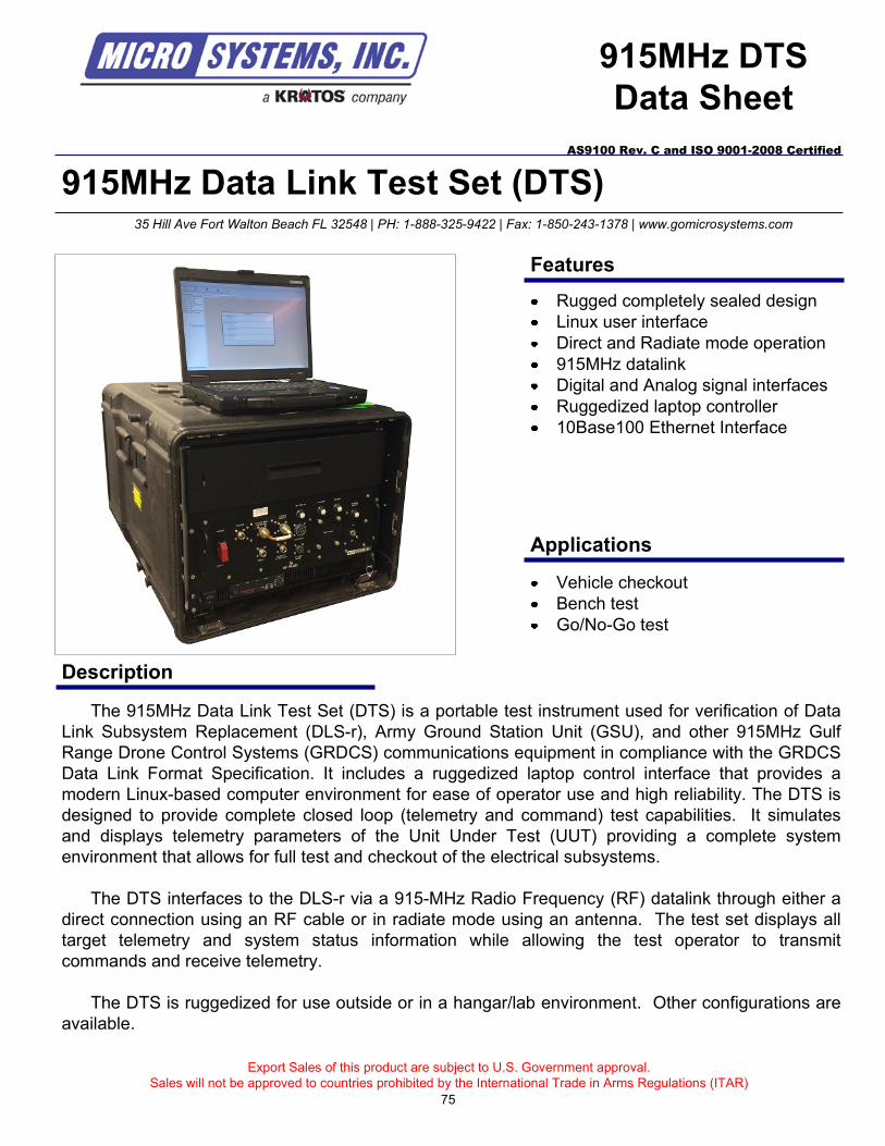
915MHz Data Link Test Set (DTS)
Description
915MHz DTS
Data Sheet
The 915MHz Data Link Test Set (DTS) is a portable test instrument used for verification of Data
Link Subsystem Replacement (DLS-r), Army Ground Station Unit (GSU), and other 915MHz Gulf
Range Drone Control Systems (GRDCS) communications equipment in compliance with the GRDCS
Data Link Format Specification. It includes a ruggedized laptop control interface that provides a
modern Linux-based computer environment for ease of operator use and high reliability. The DTS is
designed to provide complete closed loop (telemetry and command) test capabilities. It simulates
and displays telemetry parameters of the Unit Under Test (UUT) providing a complete system
environment that allows for full test and checkout of the electrical subsystems.
The DTS interfaces to the DLS-r via a 915-MHz Radio Frequency (RF) datalink through either a
direct connection using an RF cable or in radiate mode using an antenna. The test set displays all
target telemetry and system status information while allowing the test operator to transmit
commands and receive telemetry.
The DTS is ruggedized for use outside or in a hangar/lab environment. Other configurations are
available.
Export Sales of this product are subject to U.S. Government approval.
Sales will not be approved to countries prohibited by the International Trade in Arms Regulations (ITAR)
Vehicle checkout
Bench test
Go/No-Go test
35 Hill Ave Fort Walton Beach FL 32548 | PH: 1-888-325-9422 | Fax: 1-850-243-1378 | www.gomicrosystems.com
AS9100 Rev. C and ISO 9001-2008 Certified
Features
Applications
Rugged completely sealed design
Linux user interface
Direct and Radiate mode operation
915MHz datalink
Digital and Analog signal interfaces
Ruggedized laptop controller
10Base100 Ethernet Interface
75
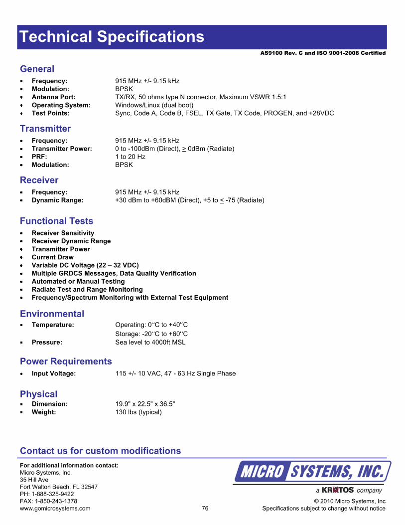
AS9100 Rev. C and ISO 9001-2008 Certified
Technical Specifications
EnvironmentalTemperature: Operating: 0 C to +40 C
Storage: -20 C to +60 C
Pressure: Sea level to 4000ft MSL
General
Frequency: 915 MHz +/- 9.15 kHz
Modulation: BPSK
Antenna Port: TX/RX, 50 ohms type N connector, Maximum VSWR 1.5:1
Operating System: Windows/Linux (dual boot)
Test Points: Sync, Code A, Code B, FSEL, TX Gate, TX Code, PROGEN, and +28VDC
Power Requirements
Input Voltage: 115 +/- 10 VAC, 47 - 63 Hz Single Phase
Contact us for custom modifications
For additional information contact:
Micro Systems, Inc.
35 Hill Ave
Fort Walton Beach, FL 32547
PH: 1-888-325-9422
FAX: 1-850-243-1378
www.gomicrosystems.com
© 2010 Micro Systems, Inc
Specifications subject to change without notice
PhysicalDimension: 19.9" x 22.5" x 36.5"
Weight: 130 lbs (typical)
76
Functional Tests
Receiver Sensitivity
Receiver Dynamic Range
Transmitter Power
Current Draw
Variable DC Voltage (22 – 32 VDC)
Multiple GRDCS Messages, Data Quality Verification
Automated or Manual Testing
Radiate Test and Range Monitoring
Frequency/Spectrum Monitoring with External Test Equipment
Transmitter
Frequency: 915 MHz +/- 9.15 kHz
Transmitter Power: 0 to -100dBm (Direct), > 0dBm (Radiate)
PRF: 1 to 20 Hz
Modulation: BPSK
Receiver
Frequency: 915 MHz +/- 9.15 kHz
Dynamic Range: +30 dBm to +60dBM (Direct), +5 to < -75 (Radiate)
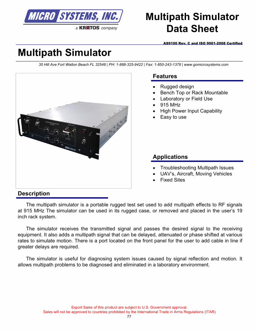
Multipath Simulator
Description
Multipath Simulator
Data Sheet
The multipath simulator is a portable rugged test set used to add multipath effects to RF signals
at 915 MHz The simulator can be used in its rugged case, or removed and placed in the user’s 19
inch rack system.
The simulator receives the transmitted signal and passes the desired signal to the receiving
equipment. It also adds a multipath signal that can be delayed, attenuated or phase shifted at various
rates to simulate motion. There is a port located on the front panel for the user to add cable in line if
greater delays are required.
The simulator is useful for diagnosing system issues caused by signal reflection and motion. It
allows multipath problems to be diagnosed and eliminated in a laboratory environment.
Export Sales of this product are subject to U.S. Government approval.
Sales will not be approved to countries prohibited by the International Trade in Arms Regulations (ITAR)
Troubleshooting Multipath Issues
UAV’s, Aircraft, Moving Vehicles
Fixed Sites
35 Hill Ave Fort Walton Beach FL 32548 | PH: 1-888-325-9422 | Fax: 1-850-243-1378 | www.gomicrosystems.com
AS9100 Rev. C and ISO 9001-2008 Certified
Features
Applications
Rugged design
Bench Top or Rack Mountable
Laboratory or Field Use
915 MHz
High Power Input Capability
Easy to use
77
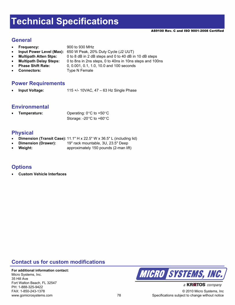
AS9100 Rev. C and ISO 9001-2008 Certified
Technical Specifications
EnvironmentalTemperature: Operating: 0 C to +50 C
Storage: -20 C to +60 C
General
Frequency: 900 to 930 MHz
Input Power Level (Max): 650 W Peak, 20% Duty Cycle (J2 UUT)
Multipath Atten Stps: 0 to 8 dB in 2 dB steps and 0 to 40 dB in 10 dB steps
Multipath Delay Steps: 0 to 8ns in 2ns steps, 0 to 40ns in 10ns steps and 100ns
Phase Shift Rate: 0, 0.001, 0.1, 1.0, 10.0 and 100 seconds
Connectors: Type N Female
Power Requirements
Input Voltage: 115 +/- 10VAC, 47 – 63 Hz Single Phase
Contact us for custom modifications
For additional information contact:
Micro Systems, Inc.
35 Hill Ave
Fort Walton Beach, FL 32547
PH: 1-888-325-9422
FAX: 1-850-243-1378
www.gomicrosystems.com
© 2010 Micro Systems, Inc
Specifications subject to change without notice
PhysicalDimension (Transit Case): 11.1" H x 22.5" W x 36.5" L (including lid)
Dimension (Drawer): 19" rack mountable, 3U, 23.5" Deep
Weight: approximately 150 pounds (2-man lift)
Options
Custom Vehicle Interfaces
78
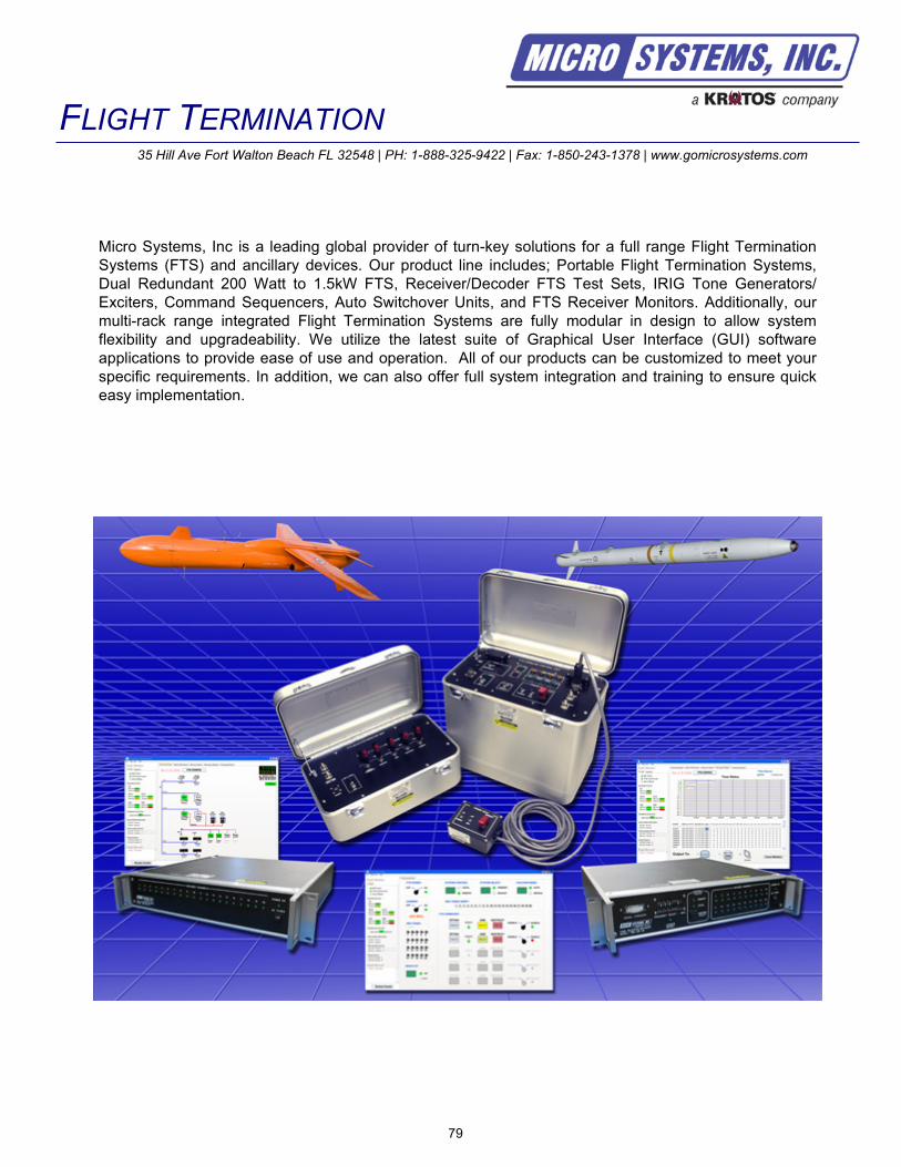
79
FLIGHT TERMINATION35 Hill Ave Fort Walton Beach FL 32548 | PH: 1-888-325-9422 | Fax: 1-850-243-1378 | www.gomicrosystems.com
Micro Systems, Inc is a leading global provider of turn-key solutions for a full range Flight Termination
Systems (FTS) and ancillary devices. Our product line includes; Portable Flight Termination Systems,
Dual Redundant 200 Watt to 1.5kW FTS, Receiver/Decoder FTS Test Sets, IRIG Tone Generators/
Exciters, Command Sequencers, Auto Switchover Units, and FTS Receiver Monitors. Additionally, our
multi-rack range integrated Flight Termination Systems are fully modular in design to allow system
flexibility and upgradeability. We utilize the latest suite of Graphical User Interface (GUI) software
applications to provide ease of use and operation. All of our products can be customized to meet your
specific requirements. In addition, we can also offer full system integration and training to ensure quick
easy implementation.

80
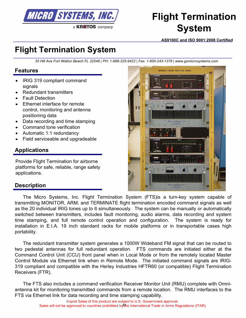
Flight Termination System
The Micro Systems, Inc. Flight Termination System (FTS)is a turn-key system capable of
transmitting MONITOR, ARM, and TERMINATE flight termination encoded command signals as well
as the 20 individual IRIG tones up to 6 simultaneously. The system can be manually or automatically
switched between transmitters, includes fault monitoring, audio alarms, data recording and system
time stamping, and full remote control operation and configuration. The system is ready for
installation in E.I.A. 19 inch standard racks for mobile platforms or in transportable cases high
portability.
The redundant transmitter system generates a 1000W Wideband FM signal that can be routed to
two pedestal antennas for full redundant operation. FTS commands are initiated either at the
Command Control Unit (CCU) front panel when in Local Mode or from the remotely located Master
Control Module via Ethernet link when in Remote Mode. The initiated command signals are IRIG-
319 compliant and compatible with the Herley Industries HFTR60 (or compatible) Flight Termination
Receivers (FTR).
The FTS also includes a command verification Receiver Monitor Unit (RMU) complete with Omni-
antenna kit for monitoring transmitted commands from a remote location. The RMU interfaces to the
FTS via Ethernet link for data recording and time stamping capability.Export Sales of this product are subject to U.S. Government approval.
Sales will not be approved to countries prohibited by the International Trade in Arms Regulations (ITAR)
35 Hill Ave Fort Walton Beach FL 32548 | PH: 1-888-325-9422 | Fax: 1-850-243-1378 | www.gomicrosystems.com
Flight Termination
SystemAS9100C and ISO 9001:2008 Certified
Provide Flight Termination for airborne
platforms for safe, reliable, range safety
applications.
Features
Applications
IRIG 319 compliant command
signals
Redundant transmitters
Fault Detection
Ethernet interface for remote
control, monitoring and antenna
positioning data
Data recording and time stamping
Command tone verification
Automatic 1:1 redundancy
Field serviceable and upgradeable
Description
81
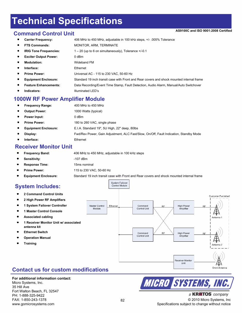
Technical Specifications
For additional information contact:
Micro Systems, Inc.
35 Hill Ave
Fort Walton Beach, FL 32547
PH: 1-888-325-9422
FAX: 1-850-243-1378
www.gomicrosystems.com
© 2010 Micro Systems, Inc
Specifications subject to change without notice
AS9100C and ISO 9001:2008 CertifiedCommand Control Unit
Carrier Frequency: 406 MHz to 450 MHz, adjustable in 100 kHz steps, +/- .005% Tolerance
FTS Commands: MONITOR, ARM, TERMINATE
IRIG Tone Frequencies: 1 – 20 (up to 6 on simultaneously), Tolerance +/-0.1
Exciter Output Power: 0 dBm
Modulation: Wideband FM
Interface: Ethernet
Prime Power: Universal AC - 115 to 230 VAC, 50-60 Hz
Equipment Enclosure: Standard 19 inch transit case with Front and Rear covers and shock mounted internal frame
Feature Enhancements: Data Recording/Event Time Stamp, Fault Detection, Audio Alarm, Manual/Auto Switchover
Indicators: Illuminated LED’s
Receiver Monitor UnitFrequency Band: 406 MHz to 450 MHz, adjustable in 100 kHz steps
Sensitivity: -107 dBm
Response Time: 15ms nominal
Prime Power: 115 to 230 VAC, 50-60 Hz
Equipment Enclosure: Standard 19 inch transit case with Front and Rear covers and shock mounted internal frame
1000W RF Power Amplifier ModuleFrequency Range: 400 MHz to 450 MHz
Output Power: 1000 Watts (typical)
Power Input: 0 dBm
Prime Power: 180 to 260 VAC, single phase
Equipment Enclosure: E.I.A. Standard 19", 5U High, 22" deep, 80lbs
Display: Fwd/Rev Power, Gain Adjustment, ALC Fast/Slow, On/Off, Fault Indication, Standby Mode
Interface: Ethernet
System Includes:
2 Command Control Units
2 High Power RF Amplifiers
1 System Failover Controller
1 Master Control Console
Associated cabling
1 Receiver Monitor Unit w/ associated
antenna kit
Ethernet Switch
Operation Manual
Training
Contact us for custom modifications
82
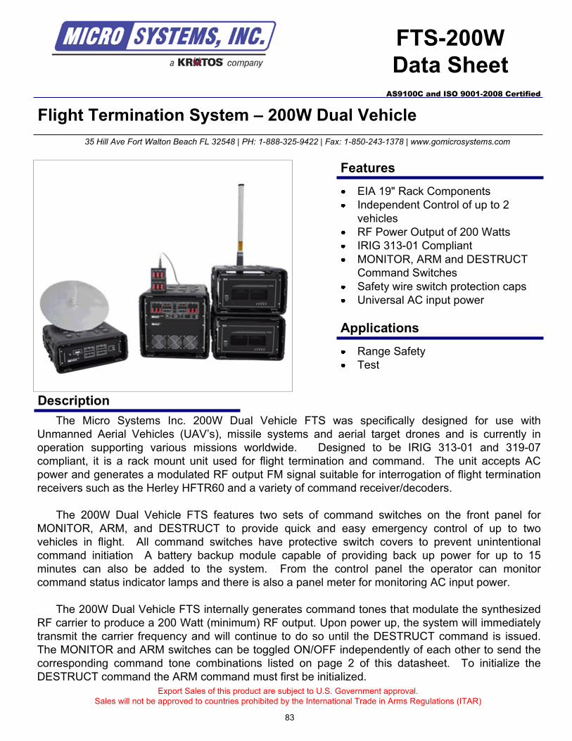
Flight Termination System – 200W Dual Vehicle
Description
Export Sales of this product are subject to U.S. Government approval.
Sales will not be approved to countries prohibited by the International Trade in Arms Regulations (ITAR)
35 Hill Ave Fort Walton Beach FL 32548 | PH: 1-888-325-9422 | Fax: 1-850-243-1378 | www.gomicrosystems.com
AS9100C and ISO 9001-2008 Certified
Features
Applications
EIA 19" Rack Components
Independent Control of up to 2
vehicles
RF Power Output of 200 Watts
IRIG 313-01 Compliant
MONITOR, ARM and DESTRUCT
Command Switches
Safety wire switch protection caps
Universal AC input power
Range Safety
Test
The Micro Systems Inc. 200W Dual Vehicle FTS was specifically designed for use with
Unmanned Aerial Vehicles (UAV’s), missile systems and aerial target drones and is currently in
operation supporting various missions worldwide. Designed to be IRIG 313-01 and 319-07
compliant, it is a rack mount unit used for flight termination and command. The unit accepts AC
power and generates a modulated RF output FM signal suitable for interrogation of flight termination
receivers such as the Herley HFTR60 and a variety of command receiver/decoders.
The 200W Dual Vehicle FTS features two sets of command switches on the front panel for
MONITOR, ARM, and DESTRUCT to provide quick and easy emergency control of up to two
vehicles in flight. All command switches have protective switch covers to prevent unintentional
command initiation A battery backup module capable of providing back up power for up to 15
minutes can also be added to the system. From the control panel the operator can monitor
command status indicator lamps and there is also a panel meter for monitoring AC input power.
The 200W Dual Vehicle FTS internally generates command tones that modulate the synthesized
RF carrier to produce a 200 Watt (minimum) RF output. Upon power up, the system will immediately
transmit the carrier frequency and will continue to do so until the DESTRUCT command is issued.
The MONITOR and ARM switches can be toggled ON/OFF independently of each other to send the
corresponding command tone combinations listed on page 2 of this datasheet. To initialize the
DESTRUCT command the ARM command must first be initialized.
FTS-200W
Data Sheet
83
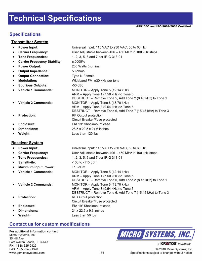
AS9100C and ISO 9001-2008 Certified
Technical Specifications
Specifications
Contact us for custom modifications
For additional information contact:
Micro Systems, Inc.
35 Hill Ave
Fort Walton Beach, FL 32547
PH: 1-888-325-9422
FAX: 1-850-243-1378
www.gomicrosystems.com
© 2010 Micro Systems, Inc
Specifications subject to change without notice
Power Input: Universal Input: 115 VAC to 230 VAC, 50 to 60 Hz
Carrier Frequency: User Adjustable between 406 – 450 MHz in 100 kHz steps
Tone Frequencies: 1, 2, 3, 5, 6 and 7 per IRIG 313-01
Sensitivity: -106 to -115 dBm
Maximum Input Power: +13 dBm
Vehicle 1 Commands: MONITOR – Apply Tone 5 (12.14 kHz)
ARM – Apply Tone 1 (7.50 kHz) to Tone 5
DESTRUCT – Remove Tone 5, Add Tone 2 (8.46 kHz) to Tone 1
Vehicle 2 Commands: MONITOR – Apply Tone 6 (13.70 kHz)
ARM – Apply Tone 3 (9.54 kHz) to Tone 6
DESTRUCT – Remove Tone 6, Add Tone 7 (15.45 kHz) to Tone 3
Protection: RF Output protection
Circuit Breaker/Fuse protected
Enclosure: EIA 19" Shockmount case
Dimensions: 24 x 22.5 x 9.3 inches
Weight: Less than 50 lbs
Receiver System
Power Input: Universal Input: 115 VAC to 230 VAC, 50 to 60 Hz
Carrier Frequency: User Adjustable between 406 – 450 MHz in 100 kHz steps
Tone Frequencies: 1, 2, 3, 5, 6 and 7 per IRIG 313-01
Carrier Frequency Stability: ±.0005%
Power Output: 200 Watts (nominal)
Output Impedance: 50 ohms
Output Connection: Type N Female
Modulation: Wideband FM, ±30 kHz per tone
Spurious Outputs: -50 dBc
Vehicle 1 Commands: MONITOR – Apply Tone 5 (12.14 kHz)
ARM – Apply Tone 1 (7.50 kHz) to Tone 5
DESTRUCT – Remove Tone 5, Add Tone 2 (8.46 kHz) to Tone 1
Vehicle 2 Commands: MONITOR – Apply Tone 6 (13.70 kHz)
ARM – Apply Tone 3 (9.54 kHz) to Tone 6
DESTRUCT – Remove Tone 6, Add Tone 7 (15.45 kHz) to Tone 3
Protection: RF Output protection
Circuit Breaker/Fuse protected
Enclosure: EIA 19" Shockmount case
Dimensions: 28.5 x 22.5 x 21.6 inches
Weight: Less than 120 lbs
Transmitter System
84
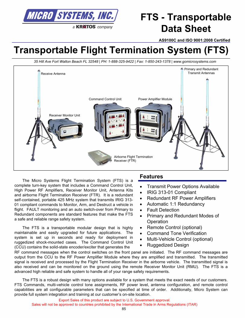
Export Sales of this product are subject to U.S. Government approval.
Sales will not be approved to countries prohibited by the International Trade in Arms Regulations (ITAR)
85
Transportable Flight Termination System (FTS)35 Hill Ave Fort Walton Beach FL 32548 | PH: 1-888-325-9422 | Fax: 1-850-243-1378 | www.gomicrosystems.com
The Micro Systems Flight Termination System (FTS) is a
complete turn-key system that includes a Command Control Unit,
High Power RF Amplifiers, Receiver Monitor Unit, Antenna Kits
and airborne Flight Termination Receiver (FTR). It is a redundant
self-contained, portable 425 MHz system that transmits IRIG 313-
01 compliant commands to Monitor, Arm, and Destruct a vehicle in
flight. FAULT monitoring and an auto switch-over from Primary to
Redundant components are standard features that make the FTS
a safe and reliable range safety system.
The FTS is a transportable modular design that is highly
maintainable and easily upgraded for future applications. The
system is set up in seconds and ready for deployment in
ruggedized shock-mounted cases. The Command Control Unit
(CCU) contains the solid-state encoder/exciter that generates the
FTS - Transportable
Data Sheet
Features
Transmit Power Options Available
IRIG 313-01 Compliant
Redundant RF Power Amplifiers
Automatic 1:1 Redundancy
Fault Detection
Primary and Redundant Modes of
Operation
Remote Control (optional)
Command Tone Verification
Multi-Vehicle Control (optional)
Ruggedized Design
RF command messages when the control switches on the front panel are initiated. The RF command messages are
output from the CCU to the RF Power Amplifier Module where they are amplified and transmitted. The transmitted
signal is received and processed by the Flight Termination Receiver in the airborne vehicle. The transmitted signal is
also received and can be monitored on the ground using the remote Receiver Monitor Unit (RMU). The FTS is a
advanced high reliable and safe system to handle all of your range safety requirements.
Command Control Unit Power Amplifier Module
Primary and Redundant
Transmit AntennasReceive Antenna
Receiver Monitor Unit
Airborne Flight Termination
Receiver (FTR)
The FTS is a robust design with many options available for a system that meets the exact needs of our customers.
FTS Commands, multi-vehicle control tone assignments, RF power level, antenna configuration, and remote control
capabilities are all configurable parameters that can be specified at time of order. Additionally, Micro System can
provide full system integration and training at our customer’s on-site location.
AS9100C and ISO 9001:2008 Certified
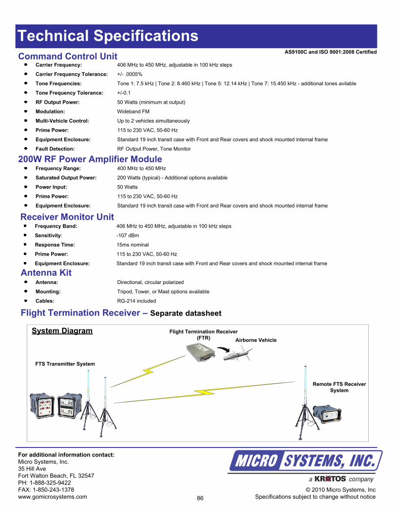
Technical Specifications
Command Control Unit
For additional information contact:
Micro Systems, Inc.
35 Hill Ave
Fort Walton Beach, FL 32547
PH: 1-888-325-9422
FAX: 1-850-243-1378
www.gomicrosystems.com
© 2010 Micro Systems, Inc
Specifications subject to change without notice
Carrier Frequency: 406 MHz to 450 MHz, adjustable in 100 kHz steps
Carrier Frequency Tolerance: +/- .0005%
Tone Frequencies: Tone 1: 7.5 kHz | Tone 2: 8.460 kHz | Tone 5: 12.14 kHz | Tone 7: 15.450 kHz - additional tones avilable
Tone Frequency Tolerance: +/-0.1
RF Output Power: 50 Watts (minimum at output)
Modulation: Wideband FM
Multi-Vehicle Control: Up to 2 vehicles simultaneously
Prime Power: 115 to 230 VAC, 50-60 Hz
Equipment Enclosure: Standard 19 inch transit case with Front and Rear covers and shock mounted internal frame
Fault Detection: RF Output Power, Tone Monitor
Receiver Monitor UnitFrequency Band: 406 MHz to 450 MHz, adjustable in 100 kHz steps
Sensitivity: -107 dBm
Response Time: 15ms nominal
Prime Power: 115 to 230 VAC, 50-60 Hz
Equipment Enclosure: Standard 19 inch transit case with Front and Rear covers and shock mounted internal frame
Antenna KitAntenna: Directional, circular polarized
Mounting: Tripod, Tower, or Mast options available
Cables: RG-214 included
200W RF Power Amplifier ModuleFrequency Range: 400 MHz to 450 MHz
Saturated Output Power: 200 Watts (typical) - Additional options available
Power Input: 50 Watts
Prime Power: 115 to 230 VAC, 50-60 Hz
Equipment Enclosure: Standard 19 inch transit case with Front and Rear covers and shock mounted internal frame
FTS Transmitter System
Remote FTS Receiver
System
Flight Termination Receiver
(FTR) Airborne Vehicle
System Diagram
Flight Termination Receiver – Separate datasheet
86
AS9100C and ISO 9001:2008 Certified
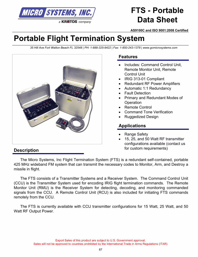
Portable Flight Termination System
Description
FTS - Portable
Data Sheet
The Micro Systems, Inc Flight Termination System (FTS) is a redundant self-contained, portable
425 MHz wideband FM system that can transmit the necessary codes to Monitor, Arm, and Destroy a
missile in flight.
The FTS consists of a Transmitter Systems and a Receiver System. The Command Control Unit
(CCU) is the Transmitter System used for encoding IRIG flight termination commands. The Remote
Monitor Unit (RMU) is the Receiver System for detecting, decoding, and monitoring commanded
signals from the CCU. A Remote Control Unit (RCU) is also included for initiating FTS commands
remotely from the CCU.
The FTS is currently available with CCU transmitter configurations for 15 Watt, 25 Watt, and 50
Watt RF Output Power.
Export Sales of this product are subject to U.S. Government approval.
Sales will not be approved to countries prohibited by the International Trade in Arms Regulations (ITAR)
Range Safety
15, 25, and 50 Watt RF transmitter
configurations available (contact us
for custom requirements)
35 Hill Ave Fort Walton Beach FL 32548 | PH: 1-888-325-9422 | Fax: 1-850-243-1378 | www.gomicrosystems.com
Features
Applications
Includes: Command Control Unit,
Remote Monitor Unit, Remote
Control Unit
IRIG 313-01 Compliant
Redundant RF Power Amplifiers
Automatic 1:1 Redundancy
Fault Detection
Primary and Redundant Modes of
Operation
Remote Control
Command Tone Verification
Ruggedized Design
87
AS9100C and ISO 9001:2008 Certified
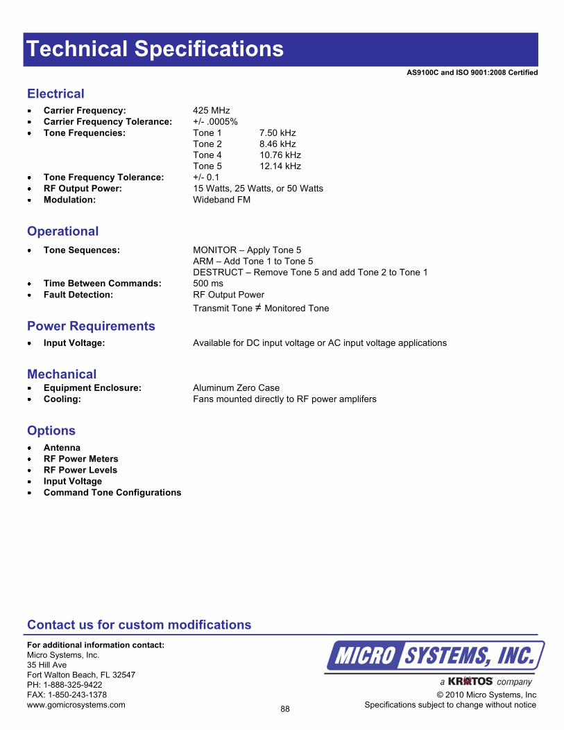
Technical Specifications
Operational
Tone Sequences: MONITOR – Apply Tone 5
ARM – Add Tone 1 to Tone 5
DESTRUCT – Remove Tone 5 and add Tone 2 to Tone 1
Time Between Commands: 500 ms
Fault Detection: RF Output Power
Transmit Tone ≠ Monitored Tone
Electrical
Carrier Frequency: 425 MHz
Carrier Frequency Tolerance: +/- .0005%
Tone Frequencies: Tone 1 7.50 kHz
Tone 2 8.46 kHz
Tone 4 10.76 kHz
Tone 5 12.14 kHz
Tone Frequency Tolerance: +/- 0.1
RF Output Power: 15 Watts, 25 Watts, or 50 Watts
Modulation: Wideband FM
Power Requirements
Input Voltage: Available for DC input voltage or AC input voltage applications
Contact us for custom modifications
For additional information contact:
Micro Systems, Inc.
35 Hill Ave
Fort Walton Beach, FL 32547
PH: 1-888-325-9422
FAX: 1-850-243-1378
www.gomicrosystems.com
© 2010 Micro Systems, Inc
Specifications subject to change without notice
MechanicalEquipment Enclosure: Aluminum Zero Case
Cooling: Fans mounted directly to RF power amplifers
Options
Antenna
RF Power Meters
RF Power Levels
Input Voltage
Command Tone Configurations
88
AS9100C and ISO 9001:2008 Certified
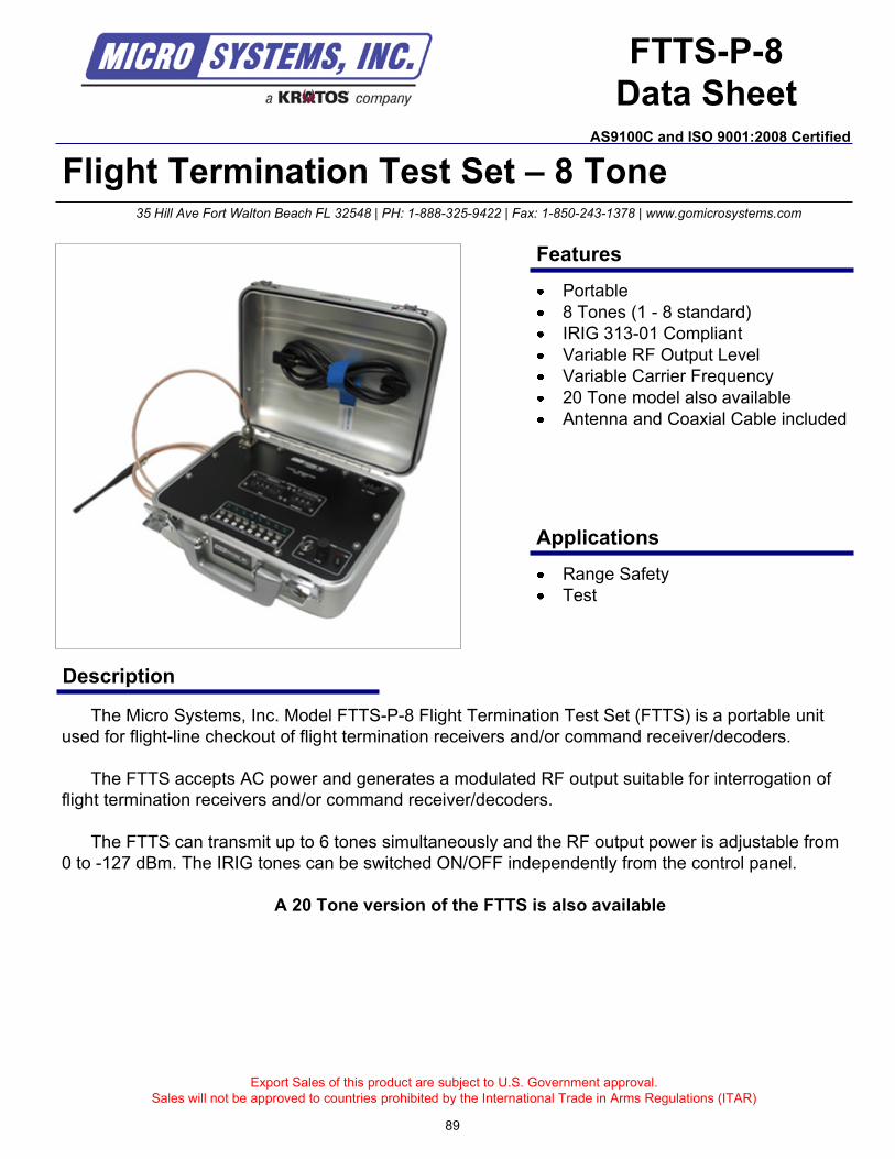
Flight Termination Test Set – 8 Tone
Description
Export Sales of this product are subject to U.S. Government approval.
Sales will not be approved to countries prohibited by the International Trade in Arms Regulations (ITAR)
35 Hill Ave Fort Walton Beach FL 32548 | PH: 1-888-325-9422 | Fax: 1-850-243-1378 | www.gomicrosystems.com
Features
Applications
Portable
8 Tones (1 - 8 standard)
IRIG 313-01 Compliant
Variable RF Output Level
Variable Carrier Frequency
20 Tone model also available
Antenna and Coaxial Cable included
Range Safety
Test
The Micro Systems, Inc. Model FTTS-P-8 Flight Termination Test Set (FTTS) is a portable unit
used for flight-line checkout of flight termination receivers and/or command receiver/decoders.
The FTTS accepts AC power and generates a modulated RF output suitable for interrogation of
flight termination receivers and/or command receiver/decoders.
The FTTS can transmit up to 6 tones simultaneously and the RF output power is adjustable from
0 to -127 dBm. The IRIG tones can be switched ON/OFF independently from the control panel.
A 20 Tone version of the FTTS is also available
FTTS-P-8
Data SheetAS9100C and ISO 9001:2008 Certified
89
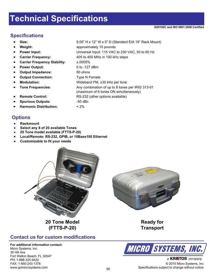
Technical Specifications
Specifications
Contact us for custom modifications
For additional information contact:
Micro Systems, Inc.
35 Hill Ave
Fort Walton Beach, FL 32547
PH: 1-888-325-9422
FAX: 1-850-243-1378
www.gomicrosystems.com
© 2010 Micro Systems, Inc
Specifications subject to change without notice
Size: 9.00” H x 12” W x 5" D (Standard EIA 19” Rack Mount)
Weight: approximately 10 pounds
Power Input: Universal Input: 115 VAC to 230 VAC, 50 to 60 Hz
Carrier Frequency: 405 to 450 MHz in 100 kHz steps
Carrier Frequency Stability: ±.0005%
Power Output: 0 to -127 dBm
Output Impedance: 50 ohms
Output Connection: Type N Female
Modulation: Wideband FM, ±30 kHz per tone
Tone Frequencies: Any combination of up to 8 tones per IRIG 313-01
(maximum of 6 tones ON simultaneously)
Remote Control: RS-232 (other options available)
Spurious Outputs: -50 dBc
Harmonic Distribution: < 2%
OptionsRackmount
Select any 8 of 20 available Tones
20 Tone model available (FTTS-P-20)
Local/Remote: RS-232, GPIB, or 10Base100 Ethernet
Customizable to fit your needs
AS9100C and ISO 9001:2008 Certified
20 Tone Model
(FTTS-P-20)
Ready for
Transport
90
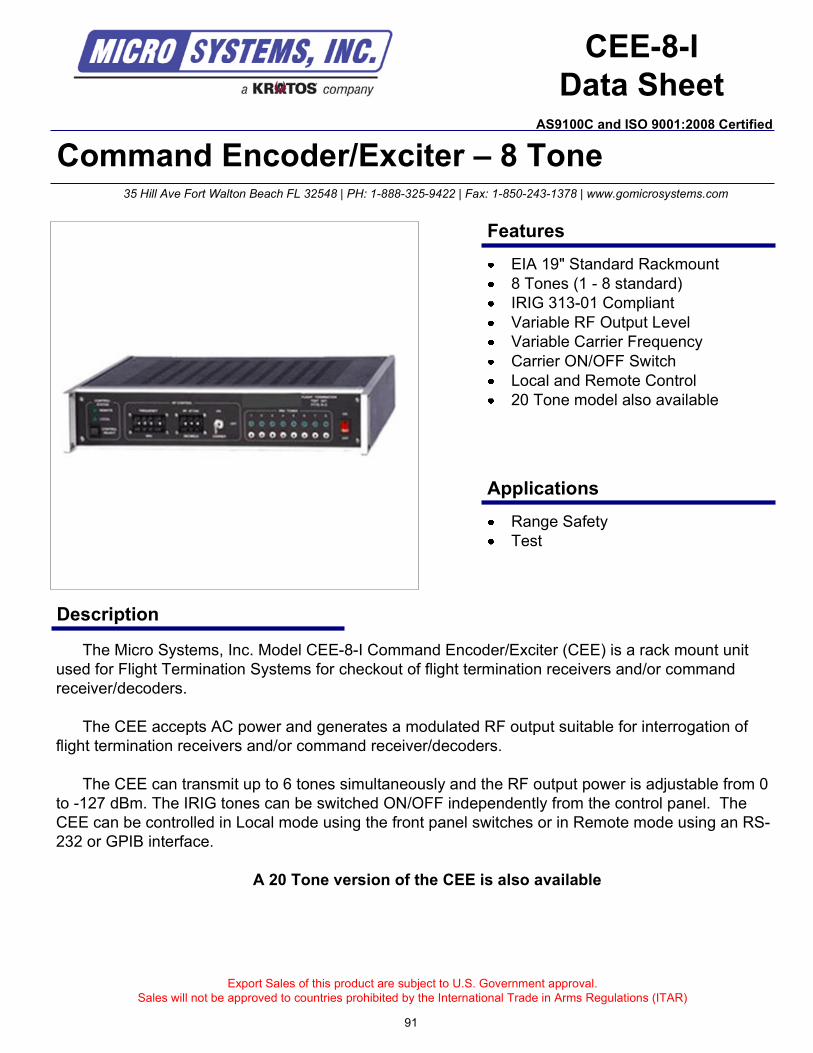
Command Encoder/Exciter – 8 Tone
Description
Export Sales of this product are subject to U.S. Government approval.
Sales will not be approved to countries prohibited by the International Trade in Arms Regulations (ITAR)
35 Hill Ave Fort Walton Beach FL 32548 | PH: 1-888-325-9422 | Fax: 1-850-243-1378 | www.gomicrosystems.com
Features
Applications
EIA 19" Standard Rackmount
8 Tones (1 - 8 standard)
IRIG 313-01 Compliant
Variable RF Output Level
Variable Carrier Frequency
Carrier ON/OFF Switch
Local and Remote Control
20 Tone model also available
Range Safety
Test
The Micro Systems, Inc. Model CEE-8-I Command Encoder/Exciter (CEE) is a rack mount unit
used for Flight Termination Systems for checkout of flight termination receivers and/or command
receiver/decoders.
The CEE accepts AC power and generates a modulated RF output suitable for interrogation of
flight termination receivers and/or command receiver/decoders.
The CEE can transmit up to 6 tones simultaneously and the RF output power is adjustable from 0
to -127 dBm. The IRIG tones can be switched ON/OFF independently from the control panel. The
CEE can be controlled in Local mode using the front panel switches or in Remote mode using an RS-
232 or GPIB interface.
A 20 Tone version of the CEE is also available
CEE-8-I
Data Sheet
91
AS9100C and ISO 9001:2008 Certified
Technical Specifications
Specifications
Contact us for custom modifications
For additional information contact:
Micro Systems, Inc.
35 Hill Ave
Fort Walton Beach, FL 32547
PH: 1-888-325-9422
FAX: 1-850-243-1378
www.gomicrosystems.com
© 2010 Micro Systems, Inc
Specifications subject to change without notice
Size: 3.50” H x 18.75” D (Standard EIA 19” Rack Mount)
Power Input: Universal Input: 115 VAC to 230 VAC, 50 to 60 Hz
Carrier Frequency: 406 to 450 MHz in 100 kHz steps
Carrier Frequency Stability: ±.0005%
RF Power Output: 0 to -127 dBm
Output Impedance: 50 ohms
Output Connection: Type N Female
Modulation: Wideband FM, ±30 kHz per tone
Tone Frequencies: Any combination of up to 8 tones per IRIG 313-01
(maximum of 6 tones ON simultaneously)
Remote Control: RS-232 (other options available)
Spurious Outputs: -50 dBc
Harmonic Distribution: < 2%
OptionsPortable
Select any 8 of 20 available Tones
20 Tone model available
Local/Remote: RS-232, GPIB, or 10Base100 Ethernet
Customizable to fit your needs
92
AS9100C and ISO 9001:2008 Certified
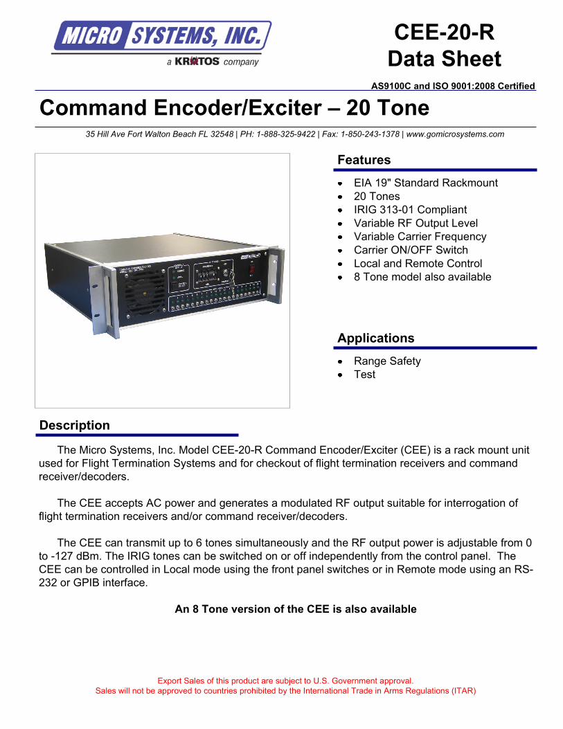
Command Encoder/Exciter – 20 Tone
Description
Export Sales of this product are subject to U.S. Government approval.
Sales will not be approved to countries prohibited by the International Trade in Arms Regulations (ITAR)
35 Hill Ave Fort Walton Beach FL 32548 | PH: 1-888-325-9422 | Fax: 1-850-243-1378 | www.gomicrosystems.com
Features
Applications
EIA 19" Standard Rackmount
20 Tones
IRIG 313-01 Compliant
Variable RF Output Level
Variable Carrier Frequency
Carrier ON/OFF Switch
Local and Remote Control
8 Tone model also available
Range Safety
Test
The Micro Systems, Inc. Model CEE-20-R Command Encoder/Exciter (CEE) is a rack mount unit
used for Flight Termination Systems and for checkout of flight termination receivers and command
receiver/decoders.
The CEE accepts AC power and generates a modulated RF output suitable for interrogation of
flight termination receivers and/or command receiver/decoders.
The CEE can transmit up to 6 tones simultaneously and the RF output power is adjustable from 0
to -127 dBm. The IRIG tones can be switched on or off independently from the control panel. The
CEE can be controlled in Local mode using the front panel switches or in Remote mode using an RS-
232 or GPIB interface.
An 8 Tone version of the CEE is also available
CEE-20-R
Data SheetAS9100C and ISO 9001:2008 Certified
Technical Specifications
Specifications
Contact us for custom modifications
For additional information contact:
Micro Systems, Inc.
35 Hill Ave
Fort Walton Beach, FL 32547
PH: 1-888-325-9422
FAX: 1-850-243-1378
www.gomicrosystems.com
© 2010 Micro Systems, Inc
Specifications subject to change without notice
Size: 3.50” H x 18.75” D (Standard EIA 19” Rack Mount)
Carrier Frequency: 406 to 450 MHz in 100 kHz steps
Carrier Frequency Stability: ±.0005%
Power Output: 0 to -127 dBm
Output Impedance: 50 ohms
Output Connection: Type N Female
Modulation: Wideband FM, ±30 kHz per tone
Tone Frequencies: 20 tones per IRIG 313-01
(maximum of 6 tones ON simultaneously)
Remote Control: RS-232 (other options available)
Spurious Outputs: -50 dBc
Harmonic Distribution: < 2%
Options
Portable
8 Tone model available
Local/Remote: RS-232, GPIB, or 10Base100 Ethernet
Customizable to fit your needs
AS9100C and ISO 9001:2008 Certified
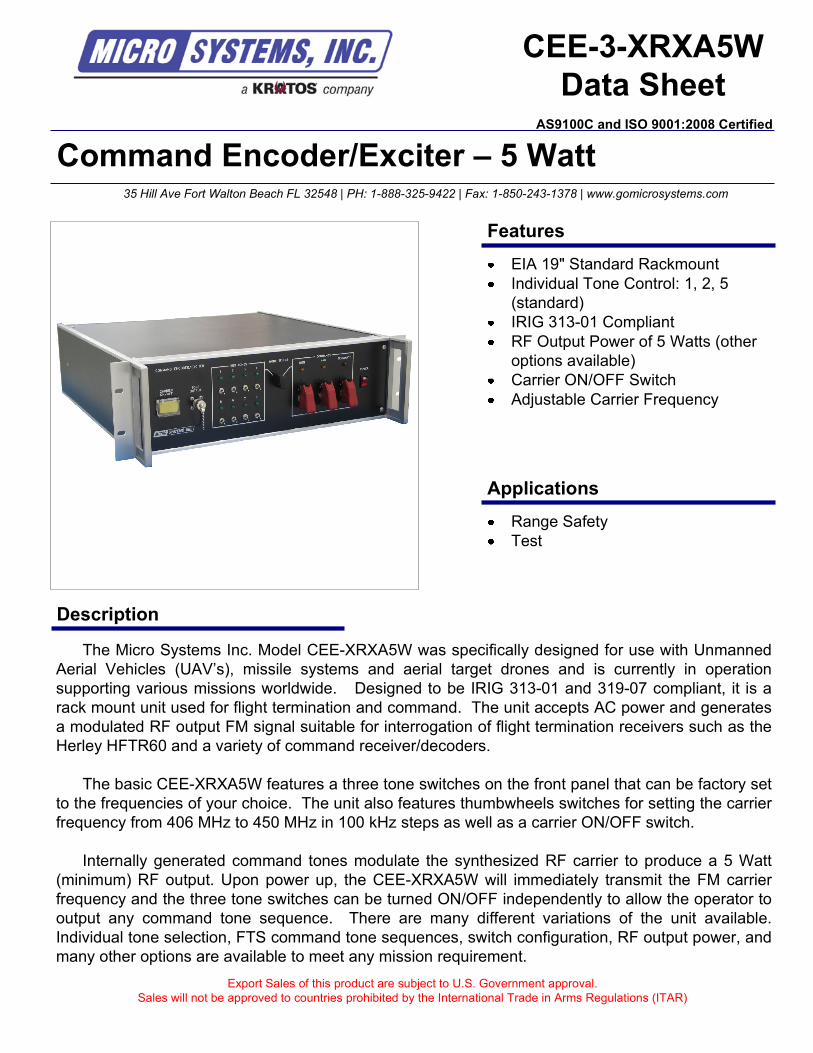
Command Encoder/Exciter – 5 Watt
Description
Export Sales of this product are subject to U.S. Government approval.
Sales will not be approved to countries prohibited by the International Trade in Arms Regulations (ITAR)
35 Hill Ave Fort Walton Beach FL 32548 | PH: 1-888-325-9422 | Fax: 1-850-243-1378 | www.gomicrosystems.com
Features
Applications
EIA 19" Standard Rackmount
Individual Tone Control: 1, 2, 5
(standard)
IRIG 313-01 Compliant
RF Output Power of 5 Watts (other
options available)
Carrier ON/OFF Switch
Adjustable Carrier Frequency
Range Safety
Test
The Micro Systems Inc. Model CEE-XRXA5W was specifically designed for use with Unmanned
Aerial Vehicles (UAV’s), missile systems and aerial target drones and is currently in operation
supporting various missions worldwide. Designed to be IRIG 313-01 and 319-07 compliant, it is a
rack mount unit used for flight termination and command. The unit accepts AC power and generates
a modulated RF output FM signal suitable for interrogation of flight termination receivers such as the
Herley HFTR60 and a variety of command receiver/decoders.
The basic CEE-XRXA5W features a three tone switches on the front panel that can be factory set
to the frequencies of your choice. The unit also features thumbwheels switches for setting the carrier
frequency from 406 MHz to 450 MHz in 100 kHz steps as well as a carrier ON/OFF switch.
Internally generated command tones modulate the synthesized RF carrier to produce a 5 Watt
(minimum) RF output. Upon power up, the CEE-XRXA5W will immediately transmit the FM carrier
frequency and the three tone switches can be turned ON/OFF independently to allow the operator to
output any command tone sequence. There are many different variations of the unit available.
Individual tone selection, FTS command tone sequences, switch configuration, RF output power, and
many other options are available to meet any mission requirement.
CEE-3-XRXA5W
Data SheetAS9100C and ISO 9001:2008 Certified
Technical Specifications
Contact us for custom modifications
For additional information contact:
Micro Systems, Inc.
35 Hill Ave
Fort Walton Beach, FL 32547
PH: 1-888-325-9422
FAX: 1-850-243-1378
www.gomicrosystems.com
© 2010 Micro Systems, Inc
Specifications subject to change without notice
AS9100C and ISO 9001:2008 Certified
Specifications
Power Input: Universal Input: 115 VAC to 230 VAC, 50 to 60 Hz
Carrier Frequency: 406 to 450 MHz in 100 kHz steps
Tone Frequencies: 1 through 20 are available per IRIG 313-01
Carrier Frequency Stability: ±.0005%
Power Output: 5 Watts (minimum) and higher power options are available
Output Impedance: 50 ohms
Output Connection: Type N Female
Modulation: Wideband FM, ±30 kHz per tone
Spurious Outputs: -50 dBc
Commands (Optional): MONITOR – Tone 5
OPTIONAL – Tone 4
ARM – Tone 5 + Tone 2
DESTRUCT – Tone 2 + Tone 1 minus Tone 5
Size: 5.25” H x 18.75” D (Standard 3U EIA 19” Rack Mount)
Weight: Less than 20lbs
OptionsPortable
Tone Assignments
RF Power Level
FTS Commands
Local/Remote: RS-232, GPIB
Permanently attached power cord
Customizable to fit your needs
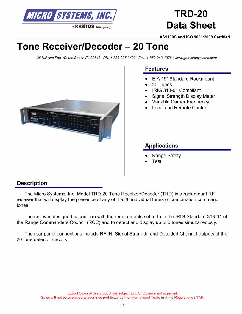
Tone Receiver/Decoder – 20 Tone
Description
Export Sales of this product are subject to U.S. Government approval.
Sales will not be approved to countries prohibited by the International Trade in Arms Regulations (ITAR)
35 Hill Ave Fort Walton Beach FL 32548 | PH: 1-888-325-9422 | Fax: 1-850-243-1378 | www.gomicrosystems.com
Features
Applications
EIA 19" Standard Rackmount
20 Tones
IRIG 313-01 Compliant
Signal Strength Display Meter
Variable Carrier Frequency
Local and Remote Control
Range Safety
Test
The Micro Systems, Inc. Model TRD-20 Tone Receiver/Decoder (TRD) is a rack mount RF
receiver that will display the presence of any of the 20 individual tones or combination command
tones.
The unit was designed to conform with the requirements set forth in the IRIG Standard 313-01 of
the Range Commanders Council (RCC) and to detect and display up to 6 tones simultaneously.
The rear panel connections include RF IN, Signal Strength, and Decoded Channel outputs of the
20 tone detector circuits.
TRD-20
Data Sheet
97
AS9100C and ISO 9001:2008 Certified
Technical Specifications
Specifications
Contact us for custom modifications
For additional information contact:
Micro Systems, Inc.
35 Hill Ave
Fort Walton Beach, FL 32547
PH: 1-888-325-9422
FAX: 1-850-243-1378
www.gomicrosystems.com
© 2010 Micro Systems, Inc
Specifications subject to change without notice
Size: 3.50” H x 18.75” D (Standard EIA 19” Rack Mount)
Power Input: Universal Input: 115 VAC to 230 VAC, 50 to 60 Hz
Carrier Detect: Front Panel LED display and discrete output on rear panel
Channel Deviation Threshold: ± 10 to ± 15 kHz
Channel Bandwidth: ± 1% Minimum @ 2 dB Bandwidth
± 4% Maximum @ 14 dB Bandwidth
RF Input: 406 MHz to 450 MHz, 50 ohm BNC female connector
RF Sensitivity: - 100 dBm
Decoded Channel Output: DB-37 Female output connector driven by an Open Collector, DC output
module
Remote Control: RS-232 (other options available)
Signal Strength: Voltage ranges from 0 VDC to 5 VDC
Options
Portable
IF Input
Audio Input
Compact hard case for portable use
Local/Remote: RS-232, GPIB, or 10Base100 Ethernet
Decoded Channel Output – TTL Logic or Contact Closures
Customizable to fit your needs
98
AS9100C and ISO 9001:2008 Certified
99
35 Hill Ave Fort Walton Beach FL 32548 | PH: 1-888-325-9422 | Fax: 1-850-243-1378 | www.gomicrosystems.com
CONDITIONS OF SALE
100
CONDITIONS OF SALE35 Hill Ave Fort Walton Beach FL 32548 | PH: 1-888-325-9422 | Fax: 1-850-243-1378 | www.gomicrosystems.com
101
CONDITIONS OF SALE35 Hill Ave Fort Walton Beach FL 32548 | PH: 1-888-325-9422 | Fax: 1-850-243-1378 | www.gomicrosystems.com
102
CONDITIONS OF SALE35 Hill Ave Fort Walton Beach FL 32548 | PH: 1-888-325-9422 | Fax: 1-850-243-1378 | www.gomicrosystems.com


Since 1976
Providing High Performance Command & Control,
Flight Termination and Range Safety Systems
35 Hill Ave
Fort Walton Beach, FL 32548
PH: 1-888-324-9555
FAX: 1-850-243-1378
www.gomicrosystems.com