Embed Size (px)
Citation preview

Command Console
ProfileCommand ConsoleInstallation manual

2 PROFILE INSTALLATION MANUAL Eaton.com/profile
Profile Installation Manual
Table of ContentsSECTION I – GENERAL INFORMATIONAbout this manual � � � � � � � � � � � � � � � � � � � � � � � � � � � �3 Contact information � � � � � � � � � � � � � � � � � � � � � � � � � �70 Before you begin � � � � � � � � � � � � � � � � � � � � � � � � � � � �4 Safety warnings and precautions � � � � � � � � � � � � � � 4-6 Electrical ratings � � � � � � � � � � � � � � � � � � � � � � � � � � � � �6 Console capacities � � � � � � � � � � � � � � � � � � � � � � � � � � �6 Console environment � � � � � � � � � � � � � � � � � � � � � � . � � 6
SECTION II – PREPARING TO ASSEMBLE A CONSOLEEaton’s Profile Command Console components � � � � �7
Common Profile components � � � � � � � � � � � � � � � � 7 Profile Sit-to-stand desk components � � � � � � � � � � 8
Tools required � � � � � � � � � � � � � � � � � � � � � � � � � � � � � � 9 Personal protective equipment recommended � � � � 9 Assembly hardware � � � � � � � � � � � � � � � � � � � � � � � � � 9 Order of work � � � � � � � � � � � � � � � � � � � � � � � � � � � � � � 9
SECTION III – ASSEMBLING A CONSOLEUnderstanding Profile core support structures � 10-20 Installing Profile core wall structures � � � � � � � � � � � 12 Typical core wall configurations � � � � � � � � � � � � � � � 13
Attach stackable display wall cores � � � � � � � � � � � 14 Join linear core configurations � � � � � � � � � � � � � � 13 Angular core connectors � � � � � � � � � � � � � � � � � � � 14
Stabilizing the core wall support structure � � � � � � � 21 Installing a docker � � � � � � � � � � � � � � � � � � � � � � � � 21 Installing a full depth upright � � � � � � � � � � � � � � � 22 Installing a linear transition upright � � � � � � � � � � � 22 Installing an angular transition upright � � � � � � � � 23Installing stationary work surfaces � � � � � � � � � � � � � 24Installing core wall skins � � � � � � � � � � � � � � � � � � � � 27 About standard skins � � � � � � � � � � � � � � � � � � � � � � 27 About modular skins � � � � � � � � � � � � � � � � � � � � � � 27 Installing a standard skin � � � � � � � � � � � � � � � � � � � 27 Installing modular skins � � � � � � � � � � � � � � � � � � 28-29 Installing modular slat wall � � � � � � � � � � � � � � � � � 29Installing a desktop rackmount module � � � � � � � � � 30Installing core wall top trim caps � � � � � � � � � � � � � � 32 Installing standard top trim caps � � � � � � � � � � � � � 33 Installing monitor pole top trim caps � � � � � � � � � 34 Installing top trim caps with privacy screens � � � 35Installing core wall privacy screens � � � � � � � � � � � � 37Installing a CPU caddy � � � � � � � � � � � � � � � � � � � � � � 38
SECTION IVASSEMBLING SIT-TO-STAND DESKSTo install a corner sit-to-stand desk � � � � � � � � � � 39-55To install a linear sit-to-stand desk � � � � � � � � � � � 56-65
SECTION VSKIN CONFIGURATION GUIDE � � � � � � � � � � � � 66-69

3
Profile Installation Manual
PROFILE INSTALLATION MANUAL Eaton.com/profile
About this GuideThis document is intended to help provide direction on the unpacking and basic assembly of Eaton’s Profile Command Console System and it’s configurable accessories� Additional copies of this manual are available at: www�Eaton�com/Profile
Intended Audience This document is intended for personnel experienced at installing console equipment in a control center facility�
Technical Support If you encounter any problems with this installation, send an email and detailed description of the problem, as well as contact information, to Technical Support at: ToSupportESWorcesterMA@eaton�com
DISCLAIMER OF WARRANTIES AND LIMITATION OF LIABILITYThe information, recommendations, descriptions and safety notations in this document are based on Eaton Corporation’s (“Eaton”) experience and judgment and may not cover all contingencies� If further information is required, an Eaton sales office should be consulted� Sale of the product shown in this literature is subject to the terms and conditions outlined in appropriate Eaton selling policies or other contractual agreement between Eaton and the purchaser�THERE ARE NO UNDERSTANDINGS, AGREEMENTS, WARRANTIES, EXPRESSED OR IMPLIED, INCLUDING WARRANTIES OF FITNESS FOR A PARTICULAR PURPOSE OR MERCHANTABILITY, OTHER THAN THOSE SPECIFICALLY SET OUT IN ANY EXISTING CONTRACT BETWEEN THE PARTIES� ANY SUCH CONTRACT STATES THE ENTIRE OBLIGATION OF EATON� THE CONTENTS OF THIS DOCUMENT SHALL NOT BECOME PART OF OR MODIFY ANY CONTRACT BETWEEN THE PARTIES� In no event will Eaton be responsible to the purchaser or user in contract, in tort (including negligence), strict liability or otherwise for any special, indirect, incidental or consequential damage or loss whatsoever, including but not limited to damage or loss of use of equipment, plant or power system, cost of capital, loss of power, additional expenses in the use of existing power facilities, or claims against the purchaser or user by its customers resulting from the use of the information, recommendations and descriptions contained herein� The information contained in this manual is subject to change without notice�
Document HistoryThe following table shows this document’s revision history:
April, 2011 First Publication – Pub No� 89943
Sales Representative and Contact InformationContact your Eaton sales representative using one of the methods below:Phone Call us toll free at 800-225-7348 (US only)
or 508-852-4300
Mail Eaton 160 Gold Star Boulevard Worcester, MA 01606
Email InfoESWorcesterMA@Eaton�com
Web Visit us at Eaton�com/profile and click on “Contact Us�” Complete and submit the form as directed on our website�

4 PROFILE INSTALLATION MANUAL Eaton.com/profile
• Read and understand the instruction herein before attempting to unpack, assemble, operate or service the Profile Command Console�
• Follow all information that is found on safety labels on the product and packaging�
• Familiarize yourself with the various console components described within this manual�
• The use of personal protective equipment such as safety glasses, work gloves and steel toed shoes are recommended during the unpacking and set-up of the console�
• Read, understand and follow the guidelines and limitations herein for loading your console�
• Familiarize yourself with the warning symbols that appear throughout this manual�
Before You Begin Before installing Eaton’s Profile Command Console, it is recommended that you do the following:
DANGER
DANGER indicates a hazardous situation which, if not avoided, will result in death or serious injury�
WARNING
WARNING indicates a hazardous situation which, if not avoided, could result in death or serious injury�
CAUTION
CAUTION indicates a hazardous situation which, if not avoided, could result in minor or moderate injury�
NOTICENOTICE is used to address practices not related to physical injury� Notice points out something of special interest to the reader in direct context or relationship to the immediate topic or step being performed�
IMPORTANTIMPORTANT notes provide information of interest to the reader of a more global or general context�

5
Profile Installation Manual
PROFILE INSTALLATION MANUAL Eaton.com/profile
Important Safety InstructionsDANGER Read all instructions before assembling and using this furnishing - Save these instructions
DANGER
WARNING – To reduce the risk of electric shock: This console may include electrified sit-to-stand desks, power distribution units and (or) other electrical devices� Always fully unplug this console from the electrical outlet(s) before cleaning, testing, repairing or moving the console�
WARNING
1� This console is for commercial use only�
2� Unplug all cords from outlet(s) before putting on or taking off parts
3� Close supervision is necessary when this furnishing is used by, or near children, invalids, or disabled persons�
4� Use this furnishing only for its intended use as described in these instructions� Do not use attachments not recommended by the manufacturer�
5� Never operate this furnishing if it has a damaged cord or plug, if it is not working properly, if it has been dropped or damaged, or has become wet� Return the furnishing to a service center for examination and repair�
6� Keep the cord(s) away from heated surfaces�
7� Never operate the furnishing with the air openings blocked� Keep the air openings free of lint, hair, and the like�
8� Never drop or insert any object into any ventilation opening�
9� Do not use outdoors�
10� To disconnect, turn all controls to the off position, then remove plugs from outlets�
11�
WARNING: Risk of Electric Shock
– Connect this furnishing to properly grounded outlets only� See grounding instructions�
12� To reduce risk of electrical shock, electrified components of this furnishing have polarized plugs (one blade wider than the other)�These plugs will fit into polarized outlets only one way� If a plug does not fit fully into the outlet, reverse the plug� If it still does not fit, contact a qualified electrician to install the proper outlet� Do not change the plug in any way�
13� CAUTION: Pinch Point - DO NOT, UNDER ANY CIRCUMSTANCE, PLACE A BODY PART IN THE PATH OF THE WORKSURFACE WHILE IT IS BEING LOWERED� DO NOT PLACE ANY OBJECT ON TOP OF THE CONSOLE’S THAT COULD INTERFERE WITH THE TRAVEL OF THE WORKSURFACE�
Depending on your chosen configuration, this console may have an electrically driven adjustable work surface� In its lowest position, the work surface is very close to the support base structure�
14� Installation and assembly must be performed by qualified personnel�
15� Ensure that the floor is able to withstand the weight of the console when fully loaded�
16� Ensure the console is plumb and level for proper operation� Route all power cords and cabling as instructed, away from any possible pinch points or moving parts�
17� To reduce risk of personal injury and product damage, always ensure a sufficient amount of personnel are present when unpacking, moving and assembling the console system�
Failure to adhere to these warnings may result in serious injury or property damage.

6 PROFILE INSTALLATION MANUAL Eaton.com/profile
Important Safety Instructions (continued) DANGER Read all instructions before assembling and using this furnishing - Save these instructions
DANGER
Electrical RatingsLift motor controller: 90 – 240V AC, 48Hz – 63Hz (universal)
Console CapacitiesDynamic load capacity of height adjustable lift motors: 157 lb� ea�Primary stationary work surface capacity: 1�5 lbs� per inch of perimeterMotorized sit-to-stand rear work surface capacity: the lesser of 1�57 lbs per inch of perimeter (or) 157 pounds per lift motorMotorized sit-to-stand front work surface capacity: 100 lbs�Monitor pole capacity: 60 lbs� each
WARNING
Do not apply loads that exceed the capacity of the console� The applied load includes any items installed or placed onto the console work surface or into the base cabinet compartments after receipt of the console from the carrier� Applied loads include (but are not limited to) monitor poles, electronic equipment, power distribution units, cabling, Personal Environment System, and personal items�
Console Environment
CAUTION
TO ENSURE ADEQUATE AIR FLOW TO COOL STORED ELECTRONIC DEVICES, DO NOT LOCATE THE BACK OF THE CONSOLE CLOSER THAN 3" TO ANY WALL, OR SIMILAR OBSTRUCTION� DO NOT PLACE ANY OBSTRUCTION NEAR ANY COOLING PERFORATIONS�

7
Profile Installation Manual
PROFILE INSTALLATION MANUAL Eaton.com/profile
P a g e | 5
Eaton’s Profile Command Console Installation Manual
Common Profile Command Console Components (Refer to section III of this manual.)
Core wall support structure (Ref. Section III-A) (Hidden by skins)
Stackable display wall cores (Ref. section III-A)
Linear transition upright (Ref. Section III-C)
Docker (Ref. Section III-C)
Work surface support bracket (Ref. Section III-D)
Peninsula work surface (Ref. section III-D)
Support leg (Ref. section III-D)
Privacy screen (Ref. section III-I)
Vertical end trim (Ref. section III-H)
Top trim cap (Ref. section III-G)
Top trim cap with privacy glass (Ref. section III-G)
Conference end work surface (Ref. section III-D)
Angular wedge upright (Ref. section III-C)
Linear work surface (Ref. section III-D)
Full depth upright (Ref. section III-C)
Standard steel skin (Ref. Section III-E and Section V)
Angular wedge connector (Ref. section III-B)
Slat wall (Ref. Section III-A)
Desktop rack mount module (Ref. section III-F)
CPU caddy (Ref. section III-J)
Modular skin panel (Ref. section III-E)
Cable access panel (Ref. Section III-E)
Convex wedge work surface (Ref. Section III-D)

8
ProfileInstallation Manual
PROFILE INSTALLATION MANUAL Eaton.com/profile
P a g e | 6
Eaton’s Profile Command Console Installation Manual
Profile Motorized Sit-to-Stand Desks (Refer to section IV of this manual.)
Standard steel skin Outer lift leg assembly (RH)
Rear monitor work surface
Front keyboard work surface
Motorized lift column
Center lift leg assembly
Outer lift leg assembly (LH)

9
Profile Installation Manual
PROFILE INSTALLATION MANUAL Eaton.com/profile
P a g e | 7
Eaton’s Profile Command Console Installation Manual
Tools required • Cordless screw gun (recommended) • Magnetic driver bit holder (recommended) • 3⁄8" hex driver bit • Phillips driver bit • 7⁄16" combination wrench • Level • Tape measure • 5/32” Allen hex wrench • 4mm Allen hex wrench (req’d for motorized sit-to-stand desks) • 3mm Allen hex wrench (req’d for top trim caps with privacy glass screen)
Personal protective equipment recommended • Eye protection • Work gloves • Steel toe shoes
Assembly Hardware The Profile Command Console system offers a wide variety of components and accessories that allow you to specify and install numerous configurations. As such, there are many types fasteners that are required for installation, depending on the item being installed. Accompanying each instruction image is a small illustration of each required fastener.
Order of Work Profile installations will vary in complexity. However, while all installations will require the most basic elements of the Profile line (core wall structures, stabilizing elements, and work surfaces) more complex installations will require a mixed variety of other available components covered in this manual. All installations will begin by installing and stabilizing the core wall structures as defined in section III.A, III.B and III.C of this manual. Once the core walls have been suitably stabilized, the installer may use his discretion as to the order of ensuing work. The overall order of this manual, beyond these three initial sections, follows a convenient order of work for most installations. However, there may be combinations of components that require deviation from this sequence in order to improve access for some component installations. Refer to section IV. for instruction on installing Profile motorized sit-to-stand desks. Due to the complexity of installation, these instructions are organized in a separate section. However, at the discretion of the installer, a motorized sit-to-stand desk may be installed any time after the core wall structure has been stabilized.
Stackable display wall cores
Stackable display wall cores Stackable display wall cores

10
ProfileInstallation Manual
PROFILE INSTALLATION MANUAL Eaton.com/profile
P a g e | 8
Eaton’s Profile Command Console Installation Manual
SECTION III - Assembling a Console A. Understanding Profile Core Support Structures
Profile cores are the vertical open steel wall structures that provide the foundational support for work surfaces, storage units, cabling and accessories.
Standard Base and Stackable Wall Cores Standard cores are available as base cores and stackable display wall cores. All base and stackable display wall cores are available in widths that range from 24” to 72”, in various 6” increments. All core widths are divided horizontally into one or more 24”, 30” or 36” horizontal modular sections. The widths of all finishing panels (commonly called “skins”) and modular accessories that attach to the core support structure will be defined by these width modules.
A standard base core is 29” high*, where the top of the base core is coincident with the top of a stationary (fixed height) work surface. Stackable display wall cores are available in 12” and 16” heights. They can be stacked on top of the base core to create core wall support structures that extend above the work surface, up to the safe maximum height limit.
Unitized Cores Unitized cores integrate a base core and a stackable display wall core into a single unit. This reduces the amount of components that need to be assembled at your site. The unitized cores are available in all of the same widths as standard cores. They are available in two heights, 41” and 45”. These heights are equivalent to a standard 29” high base core plus a 12” or 16” stackable display wall core. Additional 12” or 16” standard stackable display wall cores can be stacked on top of the unitized core, up to the safe maximum height limit.
Stackable display wall core (12”H shown)
Base core (29”H)
*36” high base cores are also available, however they are only used in rare applications.
Unitized core (41”H shown)
Figure 1
Figure 2

11
Profile Installation Manual
PROFILE INSTALLATION MANUAL Eaton.com/profile
P a g e | 9
Eaton’s Profile Command Console Installation Manual
Profile Core Anatomy Core wall support structures can be configured as single-sided (work surfaces on only one side) and double-sided (work surfaces attached to both sides). The core units will be clad with either standard or modular finishing panels (commonly called “skins”). If desired, standard and modular skins can be intermixed, where one type is on the user side of the core and the other type is on the opposite non-user service side (i.e. back) of the core. To learn more about Profile skins, refer to Section III.E and Section V of this installation guide and to the Profile Configuration Guide.
Core Wall Features There are several core frame features that you will need to be familiar with to follow the core assembly steps.
Slat wall
Cable grommets
Leveling feet
Trapezoidal alignment tabs
Cable access covers
Standard skins
Trapezoidal alignment recess
Figure 3
Figure 4

12
ProfileInstallation Manual
PROFILE INSTALLATION MANUAL Eaton.com/profile
P a g e | 10
Eaton’s Profile Command Console Installation Manual
B. Installing Profile Core Wall Structures
Profile core wall units can be joined together in linear or angular configurations (see figure 5). Both stationary (fixed-height) and ergonomic sit-to-stand work surfaces can be attached to one or both sides of the core wall structure. When cores units are joined in a linear configuration, they can attach directly to one another. However, angular core wedge connectors are required when joining cores at an angle. Angular core wedge connectors are available in various heights that match different combinations of stackable display wall cores.
The core wedge connectors may be used to join core walls of differing heights. When the wall heights are not all the same, the height of the angular connector is
always equal to the lowest wall. Transition end trims are required to finish the exposed ends of the taller core wall(s).
Angular core wedge connectors are available in both “stationary” and “ergonomic” styles. Stationary connectors have various feature that are required for stationary (fixed height) work surface support brackets. However, ergonomic connectors will NOT have the features that are required to attach stationary work surfaces. Ergonomic connectors are usually used adjacent to ergonomic sit-to-stand work surfaces which connect differently than stationary work surfaces.
Types of Angular Wedge Connectors: 90° Stationary Concave Connectors: Used with fixed height corner work surfaces. Work surface(s) are positioned inside the angle (concave side). The inner vertical panel(s) will have a notch at the 29” height to accommodate the corner of the work surface. Available sub-types are: 2-core 90°, 3-core 90° (“T”) , 4-core 90° (“X”). See figures 9 & 12.
2-Core Stationary Concave Wedge Connectors: Used with fixed height linear work surfaces, each mitered at the center of the angle. The work surfaces are positioned inside the angle (concave side). The inner vertical (narrow) panel will have a notch at the 29” height to accommodate the corner of the work surface. The bottom part of the inner vertical panel will have trapezoidal slots for work surface support brackets. Available angles: 15°, 30°, 45°, 60°. See figure 8.
2-Core Stationary Convex Wedge Connectors: Used with fixed height work surfaces. The work surface is outside of the angle (convex side). The outer vertical (narrow) panel will be full height. The inner (wide) vertical panel will be full height and have (2) mounting holes for a work surface “L” bracket. Available angles: 15°, 30°, 45°, 60°. See figure 10.
3-Core Stationary Wedge Connectors: Used with fixed height work surfaces. Used to connect 3 core walls in a Y configuration. The inner vertical panels will have a notch at the 29” height to accommodate the corner of the work surface. Available in 120°/120°/120° and 90°/135°/135° configurations. See figure 11.
Ergonomic Connectors: Similar to the connectors above, but will not have any features to support fixed height work surfaces. Usually used at angular core transitions adjacent to ergonomic sit-to-stand work surface(s). See figure 13.
Core Installation Sequence The sequence for assembling core wall units will vary depending on your configuration. If you are joining two adjacent core sections with an angular wedge connector, you must attach the stackable core display walls onto the base cores before installing the angular wedge connector. However, if you are simply joining two adjacent core wall sections in a linear configuration, you may join the base cores together and then add the stackable core walls later.
Ideally, the stackable core walls should be installed as late as possible in the assembly sequence with consideration to the above stated
limitations. This allows you to add stabilizing elements to the configuration (see next section) before adding excessive height to the core structure. To ensure the safest installation process, it is always best to start assembling the core wall support structure where there is an angular transition in the structure. Angular transitions help to ensure that the core support structure is reasonably self-stabilized, until additional stabilizing components are added, as instructed in the following section.
For ease of installation it may be necessary to remove any pre-installed skins and cable access panels from the core units. Refer to section III.E of this manual for instructions on removal and re-attachment of skins and panels.
After the cores walls have been installed, adjust all of the leveling feet to ensure that the entire core wall structure is level and plumb in all directions. All levelers should be in contact with the floor. See figure 3. Also, cable bushings are supplied with each core unit. They may be installed into the cable passage holes when the core wall structure is initially set up, or left for future use by a cabling technician. See figure 4.
IMPORTANT
NOTICE

13
Profile Installation Manual
PROFILE INSTALLATION MANUAL Eaton.com/profile
P a g e | 11
Eaton’s Profile Command Console Installation Manual
2-core concave angled configuration
Work surface on concave side 2-core 90° corner
configuration
4-core 360° “X” configuration
3-core 180° “T” configuration
Double angled concave configuration
Linear configuration work surface on one side
TYPICAL CORE WALL CONFIGURATIONS (To learn more about configuring profile core walls refer to the Profile
Configuration Guide)
Figure 5
3-core angle configurations– 120°/ 120°/120° “Y” & 90°/ 135°/135° “Y” versions available
2-core convex angled configuration
Work surface on convex side
Linear configuration work surface on both sides

14
ProfileInstallation Manual
PROFILE INSTALLATION MANUAL Eaton.com/profile
P a g e | 12
Eaton’s Profile Command Console Installation Manual
To Attach A Stackable Display Wall Core On Top Of A Base Core Position the stackable display wall core onto the base core, engaging the trapezoidal alignment tabs into the trapezoidal recesses on the display wall core. Attach the display wall to the base with (4) ¼-20 x ½” Allen screws and (4) ¼-20 nuts, one set into each trapezoidal tab. Also attach the center vertical support(s) using (2) #10 x 3/8” Phillips head self-tapping screws for each support.
Joining Linear Core Configurations Attach adjacent core units together with 1/4-20 x ½” hex head screws and ¼-20 nuts. Use (4) screws for each base core and (2) screws for each stackable wall core.
Joining 2-Core Stationary Concave Angular Configurations (15°, 30°, 45°, 60°) (Multiple height options are available)
Figure 6 - Slat wall removed for clarity
Figure 7 – (Slat wall and skins removed for clarity)
¼-20 x ½” Allen screws
¼-20 nuts #10 x 3/8” Phillips head self-tapping screws
¼-20 x 1/2” hex head self-tapping screws
¼-20 nuts
15
Profile Installation Manual
PROFILE INSTALLATION MANUAL Eaton.com/profile
P a g e | 14
Eaton’s Profile Command Console Installation Manual
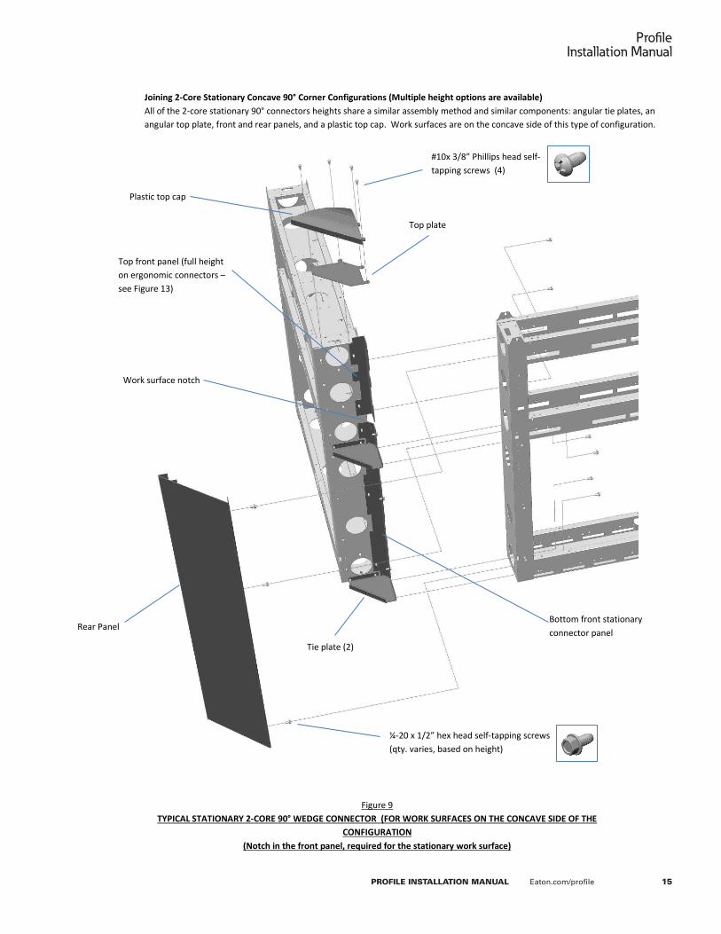
Joining 2-Core Stationary Concave 90° Corner Configurations (Multiple height options are available) All of the 2-core stationary 90° connectors heights share a similar assembly method and similar components: angular tie plates, an angular top plate, front and rear panels, and a plastic top cap. Work surfaces are on the concave side of this type of configuration.
Figure 9 TYPICAL STATIONARY 2-CORE 90° WEDGE CONNECTOR (FOR WORK SURFACES ON THE CONCAVE SIDE OF THE
CONFIGURATION (Notch in the front panel, required for the stationary work surface)
Plastic top cap
Top plate
Top front panel (full height on ergonomic connectors – see Figure 13)
¼-20 x 1/2” hex head self-tapping screws (qty. varies, based on height)
Rear Panel
Tie plate (2)
Bottom front stationary connector panel
Work surface notch
#10x 3/8” Phillips head self-tapping screws (4)

16
ProfileInstallation Manual
PROFILE INSTALLATION MANUAL Eaton.com/profile
P a g e | 13
Eaton’s Profile Command Console Installation Manual
All of the 2-core stationary concave angular wedge connectors share a similar assembly method and similar components: angular tie plates, an angular top plate, front and rear panels, and a plastic top cap. Work surfaces are on the concave side of this type of configuration. The lower front panel is slotted for work surface support brackets.
Figure 8
TYPICAL STATIONARY 2-CORE CONCAVE WEDGE CONNECTOR (15°, 30°, 45°, 60°) FOR WORK SURFACES ON THE CONCAVE SIDE OF THE CONFIGURATION
(Slots in the bottom front panel, required for stationary work surface support brackets)
Plastic top cap
Tie plate
Top plate
Top front panel (full height on ergonomic connectors – see Figure 13)
Bottom front stationary connector panel has work surface bracket holes; (compare to ergonomic connector seen in Figure 13)
Rear Panel
¼-20 x 1/2” hex head self-tapping screws (qty. varies, based on height)
#10x 3/8” Phillips head self-tapping screws (4)
If an angular transition upright is going to be assembled to this core transition, you may leave the rear panel temporarily dis-assembled to allow access to the upright mounting holes in the bottom front panel. Install the rear panel after having installed the transition upright. See figures 21 and 22.
Work surface notch

17
Profile Installation Manual
PROFILE INSTALLATION MANUAL Eaton.com/profile
P a g e | 15
Eaton’s Profile Command Console Installation Manual
Joining 2-Core Stationary Convex Angular Configurations (15°, 30°, 45°, 60°, 90°) (Multiple height options are available) All of the 2-core stationary convex wedge connectors share a similar assembly method and similar components: angular tie plates, an angular top plate, front and rear panels, and a plastic top cap. Work surfaces are on the convex side of this type of connector. Unlike the concave angular connectors, the narrow (rear) vertical panel is one piece and un-slotted. The wide (front) panel is pre-drilled to accept a work surface “L” support bracket.
Plastic top cap
Rear panel
¼-20 x 1/2” hex head self-tapping screws (qty. varies, based on height)
#10x 3/8” Phillips head self-tapping screws (4)
Front Panel
Tie plate (2)
#10 x 3/8” Phillips flat head self-tapping screws
Work surface “L” bracket
Top plate
Figure 10 TYPICAL STATIONARY 2-CORE CONVEX WEDGE CONNECTOR (15°, 30°, 45°, 60°) FOR WORK SURFACES ON THE CONVEX SIDE OF THE
CONFIGURATION

18
ProfileInstallation Manual
PROFILE INSTALLATION MANUAL Eaton.com/profile
P a g e | 16
Eaton’s Profile Command Console Installation Manual
Joining 3-Core Stationary “Y” Configurations (Multiple height options are available) The 3-core stationary “Y” connectors are available in 120°/120°/120° (shown below) and 90°/135°/135° configurations. Both “Y” connectors share a similar assembly method and similar components: angular tie plates, an angular top plate, (3) front panels, and a plastic top cap.
Figure 11
TYPICAL STATIONARY 3-CORE “Y” CONNECTOR (Notice the notch in the front panels, required for the stationary work surfaces)
Plastic top cap
Top plate
¼-20 x 1/2” hex head self-tapping screws (qty. varies, based on height)
#10x 3/8” Phillips head self-tapping screws (6)
Tie plate(2)
Notched front panel (3)
Work surface notch

19
Profile Installation Manual
PROFILE INSTALLATION MANUAL Eaton.com/profile
P a g e | 17
Eaton’s Profile Command Console Installation Manual
Joining 180° and 360° Stationary “T” and “X” Corner Configurations (Multiple height options are available) Multi-core 180° and 360° stationary connectors are available for both 3-core “T” (shown below) and 4-core “X” configurations. Both “T” and “X” connectors share a similar assembly method and similar components: tie plates, a top plate, a plastic top cap, front panels, and for the “T” style, a rear panel (not required for “X” style).
Plastic top cap
Top plate
¼-20 x 1/2” hex head self-tapping screws (qty. varies, based on height)
#10x 3/8” Phillips head self-tapping screws (Qty. varies)
Tie plate(2)
Notched front panel 2 required for “T” style; 4 required for “X” style
Rear panel (on “T” style only)
Figure 12 TYPICAL STATIONARY MULTI-CORE 180° AND 360° CORNER CONNECTORS (“T” STYLE SHOWN; “X” STYLE IS SIMILAR)
(Notice the notch in the front panels, required for the stationary work surfaces)
Work surface notch

20
ProfileInstallation Manual
PROFILE INSTALLATION MANUAL Eaton.com/profile
P a g e | 18
Eaton’s Profile Command Console Installation Manual
Joining Cores with Ergonomic Wedge Connectors (Multiple options are available) Ergonomic wedge connectors are usually used at angular core wall transitions adjacent to a sit-to-stand work surface. Sit-to-stand work surfaces require different support components than stationary (fixed height) work surfaces. So as such, while the ergonomic connectors are similar to the stationary connectors, they will not have any of the features required to accommodate stationary work surface support components.
The method to install ergonomic wedge connectors will be essentially the same as the stationary connectors, described in the previous sections.
Notice in Figure 13 that neither of the vertical panels have any holes, notches or slots for work surface support components.
Figure 13
TYPICAL ERGONOMIC WEDGE CONNECTOR
NOTICE

21
ProfileInstallation Manual
PROFILE INSTALLATION MANUAL Eaton.com/profile
P a g e | 19
Eaton’s Profile Command Console Installation Manual
C. Stabilizing the Core Wall Support Structure
In order to ensure a safe and stable console configuration, the core wall support structure must be stabilized using a variety of stability enhancing components that attach to the core. These components also usually serve as support elements for stationary work surfaces. To ensure maximum stability during the installation process, install the stabilizing components to the core wall structure as early as possible in the assembly sequence. Refer to your office plan layout to determine the location of your core wall stabilizing components.
To learn more about configuring Profile with the appropriate stabilizing components, refer to the Profile Configuration Guide.
Stabilizing The Core Wall Structure With A Docker A typical docker is shown in figure 14. While many other sizes are available, they all share a similar installation method.
Position the docker against the base core frame, aligning the side of the docker with the end of the base core. Attach the docker to the core with (3) 1/4”-20” x 3/4” Phillips head screws and (3) ¼-20 nuts. It may be necessary to adjust the docker’s leveling feet to align the attachment holes.
¼-20 x ¾” Phillips head screws (3)
¼-20 nuts (3)
Figure 14
Figure 16
Figure 15
Work surface attachment holes in top surface

22
ProfileInstallation Manual
PROFILE INSTALLATION MANUAL Eaton.com/profile
P a g e | 20
Eaton’s Profile Command Console Installation Manual
Stabilizing The Core Wall Structure With A Full Depth Upright Full depth uprights are available in left and right hands (left hand shown). Orient the upright so that the work surface support flange is towards the center of the core. Insert the hooks on the rear of the upright into the slots in the base core frame and push down. Tap the top of the upright with a soft mallet to ensure that the hooks are firmly seated. Install three 1/4”-20 x 1/2” hex head screws into the upright to secure it in place. Adjust the upright’s leveling foot so that it contacts the floor without influencing the leveling of the core structure.
Stabilizing The Core Wall Structure With A Linear Transition Upright A linear transition upright assembles to the vertical members of two adjacent base core frames that are joined in a linear configuration. It supports two adjacent linear work surfaces, one attached to each of the adjacent base core frames.
First assemble the left and right cantilever supports to the transition upright using (4) ¼-20 x ½” Allen head screws and (4) ¼” lock washers for each support. Then align the transition upright assembly with the holes in the base core frames as shown. Then attach the upright with (6) 1/4”-20 button head cap screws and (6) ¼-20 nuts. Adjust the upright’s leveling foot so that it contacts the floor without influencing the leveling of the core structure.
¼-20 x 1/2” Hex head self-tapping screws (3)
Work surface attachment flange
Hooks
Slots
¼-20 x 1/2” Allen head screws (6)
¼-20 x 1/2” Allen head screws and lock washers (8)
¼-20 Nuts (6)
Figure 17 Figure 18
Figure 19 Figure 20

23
ProfileInstallation Manual
PROFILE INSTALLATION MANUAL Eaton.com/profile
P a g e | 21
Eaton’s Profile Command Console Installation Manual
Stabilizing The Core Wall Structure With An Angular Wedge Upright Angular wedge uprights assemble to either the concave or convex side of an angular core configuration. They may be used on all convex angular configurations and all concave angular configurations except 90°. For concave applications, the upright attaches to the bottom vertical front panel of the angular connector. For convex applications the uprights attach to the vertical core wall members adjacent to the angular connector. One upright is required for concave applications; two are required for convex applications.
For concave applications, the rear panel of the angular core connector must be removed to gain access to the transition upright mounting holes. Re-attach the rear panel after installation of the upright.
First assemble the left and right work surface supports to the transition upright(s) using (4) ¼-20 x ½” Allen head screws and (4) ¼” lock washers for each support (see figure 21). Then align the upright assembly(s) with the holes in the core wall structure. Attach the upright(s) with (6) 1/4-20 hex head self-tapping screws (see figures 22 and 23). Adjust the uprights’ leveling feet so that they contact the floor without influencing the leveling of the core structure.
¼-20 x 1/2” Hex head self-tapping screws (6)
¼-20 x 1/2” Allen head screws and lock washers (8)
Work surface supports
Rear panel
Bottom front panel
Figure 21 Figure 22 -Concave Application
Figure 23 – Convex Application
¼-20 x 1/2” Hex head self-tapping screws (3 per upright)
NOTICE

24
ProfileInstallation Manual
PROFILE INSTALLATION MANUAL Eaton.com/profile
P a g e | 22
Eaton’s Profile Command Console Installation Manual
D. Installing Stationary Work Surfaces Stationary work surfaces are available in many shapes and sizes, however, they all require similar installation methods.
Most work surfaces have a full radius bull nosed edge treatment along the user facing edge(s), while the non-user edges have a flat edge treatment. However, on work surfaces that have corner radii or curved contours, the bull nosed edge will traverse along the contour and along each edge adjacent to the radius.
Refer to your office plan layout to determine the location of individual work surfaces. Most work surfaces will fall into one of the following categories.
However, there may be minor variations in each category that are not shown (see figure 24).
Linear Work Surfaces attach to a base core frame and are equal in width to the core frame to which they attach. They are available in several depths, and the depth is constant along the entire width. Some stationary linear work surfaces have an attached adjustable keyboard surface. (Refer step 11 in in section IV for adjustable keyboard work surface assembly instructions.)
Corner Work Surfaces attach to two core frames that are connected at 90 degrees. The size of the corner work surface is such that the lengths of the surface’s mounting edges are equal to the lengths of the (2) core frames to which they attach. The 90 degree corner of the work surface may be a sharp corner or it may be truncated at 45 degrees. The truncated corner aligns with a third base core frame that transitions at 45 degrees between the flanking 90 degree base core frames. The user facing bull nose edge of the corner work surface may be straight or curved. Some stationary linear work surfaces have an attached adjustable keyboard surface.
Concave Angular Work Surfaces are similar to linear work surfaces, but with one or two mitered edges. Each mitered edge abuts the mitered edge of an adjacent work surface when used on the concave side of an angular core configuration.
Convex Wedge Work Surfaces fill the angular gap between adjacent linear work surfaces when they are attached to the convex side of an angular core configuration. Convex wedge work surfaces are available in various angles and depths. The user facing bull nose edge may be curved or straight, depending on the application. The angled sides of the wedge may differ, in order to transition to abutting work surfaces of different depths. Some wedge work surfaces may require a post leg for additional support.
Transitional Work Surfaces are similar to linear work surfaces, however, in addition to the bull nosed primary edge, the bull nose continues around at least one additional side of the work surface, running back to the base core frame to which it attaches. These work surfaces are usually used to end a run of work surfaces where it is desirable to have a round corner instead of the relatively sharp corner of a linear work surface. It is common for the transitional surfaces to be used adjacent to a lift work surface.
Linear Conference Bridge Work Surfaces are similar to linear work surfaces, however, the user facing edge protrudes outward to create a personal conference space. The protruding edge requires an additional post leg for support. Although not required, the conference bridge usually has an abutting linear work surface on each side.
Peninsula Work Surfaces are similar to conference bridges, however they protrude out further than the conference bridge. The peninsula work surface usually attaches to a narrower base core than the conference bridges. Peninsula work surfaces also require a post style support leg for additional support.
Conference End Work Surfaces are half round work surface that protruded beyond the end of a run of cores. These are only used in double sided applications where there are work surfaces on both sides of the core. The conference end work surface requires post style support leg(s) for support.
IMPORTANT

25
ProfileInstallation Manual
PROFILE INSTALLATION MANUAL Eaton.com/profile
P a g e | 23
Eaton’s Profile Command Console Installation Manual
Installing a Typical Work Surface Stationary work surfaces are supported by a combination of cantilevered work surface support brackets and (or) the stabilizing components defined in the previous section (dockers, end panels and transition support uprights). In some cases a work surface may require supplemental post style support leg(s) for additional support. In most cases, stationary work surfaces are joined to adjacent stationary surfaces with tie plates. Furthermore, larger work surfaces often require an additional “L” shaped support bracket, attached to the center of the base core to which the surface attaches. See figure 25.
Installing Work Surface Support Hardware Work Surface Support Brackets - Work surface support bracket(s) are installed at the end of a work surface when no other means of support, such as a docker, is present. The brackets are available in left hand and right hand versions. Engage the hooks on the work surface bracket into the trapezoidal shaped holes in the base core upright. If required, use a rubber mallet to seat the hooks. Secure each bracket with (1) ¼-20 x ½” hex head self-tapping screw. See figure 26.
“L” Bracket - A supplemental “L” bracket is normally required for work surfaces that exceed a 36” span. If required, attach the supplemental “L” bracket to the base core with (2) #10 x 1/2” Phillips flat head self-tapping screws. See figure 26. (“L” brackets are also used to support the narrow edge of a convex wedge work surface (see figure 13).
Tie Plates - If the stationary work surface is adjacent to another stationary work surface, attach a tie plate across the seam with (4) #10 x ¾” Philips head wood screws, (2) into each work surface. See figure 26.
Support Legs – Attach a support leg to the underside of a work surface with (6) #10 x ¾” Phillips head wood screws. Adjust the leg’s leveling foot to ensure that the work surface is level. See figure 27.
Installing The Work Surface Carefully position the work surface onto the work surface support hardware. All support hardware have attachment holes that align with pre-drilled holes in the work surface. Secure the surface to the hardware and to any other support component, such as an end panel, with ¾” Philips head wood screws. Do not omit any screws. If you have a unique application that requires additional holes in the work surface, use a 1/8” diameter drill bit to drill the required screw pilot holes. Do not drill deeper than ¾”. See figures 26, 27 and 28.
*If your stationary work surface has a manually adjustable keyboard surface, install the stationary portion of the work surface as described in this section and then refer to page 50 to learn how to install the adjustable keyboard surface.
Figure 24
Linear
Corner
Conference Bridge
Linear
Linear
Linear
Linear
Linear
Linear with keyboard surface*
Linear
Conference End
Peninsula
Transitional
Corner with keyboard surface*
Transitional
User edge may be curved or straight
Linear
Linear
90° Convex
Convex wedge (2 depths)
Convex wedge
Concave angular (single miter)
Concave angular (dual miter)

26
ProfileInstallation Manual
PROFILE INSTALLATION MANUAL Eaton.com/profile
P a g e | 24
Eaton’s Profile Command Console Installation Manual
Figure 25
Figure 27
Figure 26
Figure 28
Work surface support bracket
Typical stabilizing component (End panel shown)
Support Leg
“L” bracket
#10 x ¾” Phillips head wood (3) screw
Work surface support bracket
¼-20 x ½” hex head self-tapping screw (1)
Tie plate
“L” bracket Use (2) #10 x 1/2” Phillips flat head self-tapping screws
#10 x ¾” Phillips head wood screws
Support Leg
Leveling foot
Stabilizing component (End panel shown)
#10 x ¾” Phillips head wood screws
Tie plate

27
ProfileInstallation Manual
PROFILE INSTALLATION MANUAL Eaton.com/profile
P a g e | 25
Eaton’s Profile Command Console Installation Manual
E. Installing Core Wall Skins
Core wall support structures can be configured as single-sided (work surfaces on only one side) and double-sided (work surfaces attached to both sides). The core units will be clad on both sides with either standard or modular finishing panels (commonly called “skins”). If desired, standard and modular skins can be intermixed, where one type is on the user side of the core and the other type is on the opposite non-user service side (i.e. back) of the core.
To learn more about configuring Profile skins, refer to Section V Skin Configuration Guide of this manual. This guide will show the various skin
configurations for each core size. This will be particularly helpful in determining the appropriate skin size to be used adjacent to a docker or a CPU caddy.
About Standard Skins Standard skins are painted steel panels with decorative beveled edges that snap on and off of the core. They can be used on the non-user side of the core and on the user side, below the work surface. If modular skins are not specified for the user side of the core, the user side of the core above the work surface will have full width slat wall panel(s) and removable cable access covers. The slat wall is used to support flat panel display arms, task lights, and organization accessories such as paper trays and light duty shelves.
About Modular Skins Modular skins are rectangular “tiles” that are available in various finishes: fabric, laminate, painted steel , white board and modular slat wall sections. They can be intermixed to create a unique personalized appearance and can be specified for use on the non-user service side of the core wall structure, or on the user side of the core above the work surface. (Standard skins are always required below a work surface.)
Figure 29 SINGLE-SIDED CORE (non-user service side shown)
Stackable wall core
Base core
Finger pull recess
Standard steel skin panel
Beveled edge
Standard full width slat wall on user side
Figure 30 - NON-USER SIDE
Figure 31 - USER SIDE (Modular skins only above work surface)
Modular laminate and acoustical fabric panels
Cable access panel
Modular skin (with flexible cable seal along bottom edge)
Modular slat wall
Modular base panel
IMPORTANT

28
ProfileInstallation Manual
PROFILE INSTALLATION MANUAL Eaton.com/profile
P a g e | 26
Eaton’s Profile Command Console Installation Manual
Installing A Standard Skin Panel Holding the panel at an angle, insert the panel’s bottom hooks into the appropriate slots in the horizontal member of the core structure. Push the panel against the core, with the top panel retention clips engaging into the upper slots. The panel may be removed by pulling on the top of the panel in the finger pull recess, un-seating the retention clips.
Installing Modular Skin Panels To The Non-user (Service Side) Of A Core Wall Attach a vertical divider wherever there is a joint between adjacent modular style skins, using (2) ¼-20 x ½” hex head self-tapping screws and (1) #10 x ½” Phillips flat head self-tapping screws for each divider. (Vertical dividers are only required for the base core; they are not required on stackable wall cores.) Then attach a base skirt bracket to each end of the core using (4) ¼-20 x ½” hex head self-tapping screws for each bracket. Engage the base skirt’s hooks into the slots at the bottom of the core. Secure the skirt with (2) #10 x 3/8” Phillips head self-tapping screws. The skin panels install similar to the standard skins, hooking at the bottom and latching at the top (see figures 30 and 32).
Figure 32
1
2
Base skirt ¼-20 x ½” hex head self-tapping screws
Base skirt bracket
Divider
#10 x 1/2” Phillips flat head self-tapping screw (1)
Figure 32
#10 x 3/8” Phillips head self-tapping screw (1)
Figure 33
Slots
Upper slots
Retention clips
Lower slots
29
ProfileInstallation Manual
PROFILE INSTALLATION MANUAL Eaton.com/profile
P a g e | 27
Eaton’s Profile Command Console Installation Manual
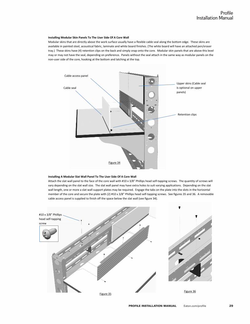
Installing Modular Skin Panels To The User Side Of A Core Wall Modular skins that are directly above the work surface usually have a flexible cable seal along the bottom edge. These skins are available in painted steel, acoustical fabric, laminate and white board finishes. (The white board will have an attached pen/eraser tray.) These skins have (4) retention clips on the back and simply snap onto the core. Modular skin panels that are above this level may or may not have the seal, depending on preference. Panels without the seal attach in the same way as modular panels on the non-user side of the core, hooking at the bottom and latching at the top.
Installing A Modular Slat Wall Panel To The User Side Of A Core Wall Attach the slat wall panel to the face of the core wall with #10 x 3/8” Phillips head self-tapping screws. The quantity of screws will vary depending on the slat wall size. The slat wall panel may have extra holes to suit varying applications. Depending on the slat wall length, one or more a slat wall support plates may be required. Engage the tabs on the plate into the slots in the horizontal member of the core and secure the plate with (2) #10 x 3/8” Phillips head self-tapping screws. See figures 35 and 36. A removable cable access panel is supplied to finish off the space below the slat wall (see figure 34).
Figure 34
Upper skins (Cable seal is optional on upper panels)
Retention clips
Cable seal
Cable access panel
Figure 35 Figure 36
#10 x 3/8” Phillips head self-tapping screw

30
ProfileInstallation Manual
PROFILE INSTALLATION MANUAL Eaton.com/profile
P a g e | 28
Eaton’s Profile Command Console Installation Manual
F. Installing Desktop Rackmount Modules
Desktop rackmount modules are available in several heights ranging from 6U to 15U. (A “U” is an industry standard unit of measure that is equal to 1.75” of vertical storage space.) They must be attached to a 16” high stackable wall core directly above a work surface. When a rackmount module is attached to a 30” or 36” wide core module, it will require a filler panel adjacent to the module. The filler panel will be supplied with the unit. When attached to a 24” wide core module, a filler panel is not required.
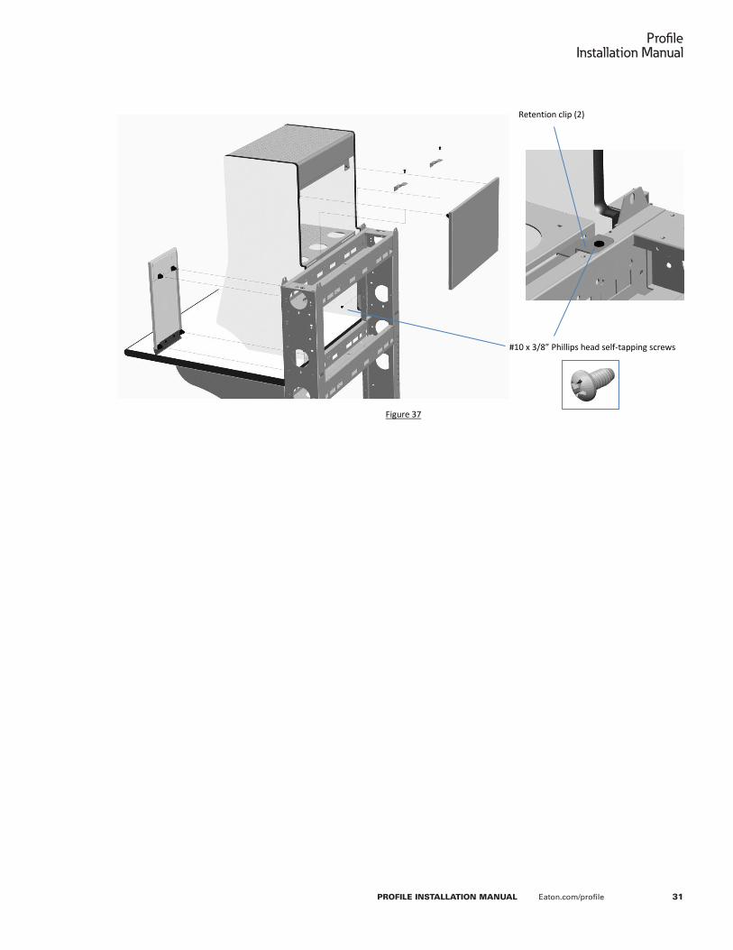
Assembling A Desktop Rackmount Module Fully assemble the rackmount module as shown in figure 36 before attaching it to the Profile core wall structure. Use #10 x ½” Phillips head machine screws wherever there is a pre-installed threaded insert in the side panel. Use #8 x ½” Phillips head wood screws to attach parts to the edge of the side panels. Depending on the size of your rackmount module, all of the parts shown below may not be required. Attach the unit to the core wall with #10 x 3/8” Phillips head self-tapping screws (see figure 37).
16” high stackable wall core
6U rackmount module on a 24” wide core
Removable filler panel (May be located on the right or left)
Figure 35
15U rackmount module on a 30” wide core
Figure 36
Side panel (1 LH and 1 RH)
Top panel (6U top panel is slightly different that the one shown)
Equipment mounting rails
Bottom panel
Side mounting plate (2 required when attaching to a 24” wide core section)
Filler panel latch plate
Intermediate divider (not required on 6U modules)
Removable rear access panel (not required on 6U modules)
Filler panel (not required when attaching module to a 24” wide core section
#10 x ½” Phillips head machine screws
#8 x ½” Phillips head wood screws
#8 x ½” Phillips head wood screws
31
ProfileInstallation Manual
PROFILE INSTALLATION MANUAL Eaton.com/profile
P a g e | 29
Eaton’s Profile Command Console Installation Manual
Figure 37
#10 x 3/8” Phillips head self-tapping screws
Retention clip (2)

32
ProfileInstallation Manual
PROFILE INSTALLATION MANUAL Eaton.com/profile
P a g e | 30
Eaton’s Profile Command Console Installation Manual
G. Installing Core Wall Top Trim Caps
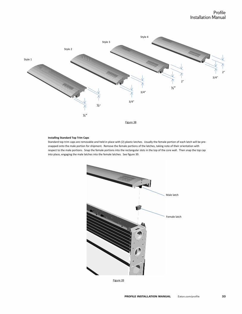
The length of a top trim cap is equal to the modular width of the core wall section onto which it will be assembled (i.e. a 72” long cap is assembled to a 72” wide core wall section). The top trim caps are available in 3 types: standard caps, caps that accommodate monitor poles, and caps that accommodate glass privacy screens. Each type of top cap will require different assembly steps.
Additionally, each top cap type is available in four basic flange combinations (styles). Each style is defined by the height of the cap’s two vertical flanges (1/2”, ¾” or 2”). The core wall’s skin configuration will dictate the top cap style. Normally, a core side configured with a full width slat wall will require a top cap with a 1/2” flange. A side configured with standard skins will require a cap with a 2” flange, and a side configured with modular skins will require a medium ¾” flange. Refer to the chart below and figure 38.
Definitions Dual sided: Work surfaces on both sides of the core wall.
Single sided: Work surfaces on one side of the core wall; the entire height of the opposite side is configured with skins.
Standard skins: Painted steel skins with beveled vertical edges. Modular skins: Rectangular “tiles” that are available in various finishes: fabric, laminate, painted steel , white board.
33
ProfileInstallation Manual
PROFILE INSTALLATION MANUAL Eaton.com/profile
P a g e | 31
Eaton’s Profile Command Console Installation Manual
Installing Standard Top Trim Caps Standard top trim caps are removable and held in place with (2) plastic latches. Usually the female portion of each latch will be pre-snapped onto the male portion for shipment. Remove the female portions of the latches, taking note of their orientation with respect to the male portions. Snap the female portions into the rectangular slots in the top of the core wall. Then snap the top cap into place, engaging the male latches into the female latches. See figure 39.
½”
½”
½”
Style 1
3/4”
3/4” 2”
2”
Style 2
Style 3
Style 4
Figure 38
Figure 39
Male latch
Female latch
3/4”

34
ProfileInstallation Manual
PROFILE INSTALLATION MANUAL Eaton.com/profile
P a g e | 32
Eaton’s Profile Command Console Installation Manual
Installing Monitor Pole Top Trim Caps (Monitor pole top trim caps are not compatible with core walls that are configured with slat wall.)
Attach a top cap support bracket to each end of the core wall’s top channel. Locate the brackets 4 inches from each end of the core wall section. The hooks on the bracket engage the channel’s vertical flanges. To retain the brackets in place, tighten the (2) Phillips head clamping screws on each bracket. See figures 41 and 42.
Attach the slotted base plate to the middle of the core wall’s top channel with (6) ¼-20 x ½” hex head self-tapping screws. (Depending on your configuration, it may be necessary to drill .218” (7/32”) holes into the top channel for the plate mounting screws.) Then attach the upper pole support to the channel with (4) #10 x 3/4” Phillips head self-tapping screws. See figure 42.
Attach the monitor pole using the hardware and instructions supplied with the pole. Assembly will be similar to figure 43.
Figure 40
Top cap support bracket Clamping screw
Slotted base plate
Upper pole support
#10 x 3/4” Phillips head self-tapping screws 4”
¼-20 x ½” hex head self-tapping screws
Figure 43
Figure 41
Figure 42

35
ProfileInstallation Manual
PROFILE INSTALLATION MANUAL Eaton.com/profile
P a g e | 33
Eaton’s Profile Command Console Installation Manual
Installing Top Trim Caps With Glass Privacy Screens Attach a top cap support bracket to each end of the core wall’s top channel. Locate the brackets 4 inches from each end of the core wall section. The hooks on the bracket engage the channel’s vertical flanges. To retain the brackets in place, tighten the (2) Phillips head clamping screws on each bracket. See figure 44. (60” and 72” sizes require (2) additional top cap support brackets at the center. Locate each bracket 4” from the center of the core wall.)
Attach a glass pane stanchion to each top cap support bracket with a ¼-20 x 7/8” Phillips head machine screw. Position the glass pane into the stanchions. Use a 1/8” Allen wrench to tighten the stanchion’s clamping screws to retain the glass. Do not over-tighten. See figure 45.
Center of core wall
4”
Top cap support bracket
4”
Clamping screws
¼-20 x 7/8” Phillips head machine screw
Glass pane stanchion
Figure 44
Figure 45
36
ProfileInstallation Manual
PROFILE INSTALLATION MANUAL Eaton.com/profile
P a g e | 34
Eaton’s Profile Command Console Installation Manual
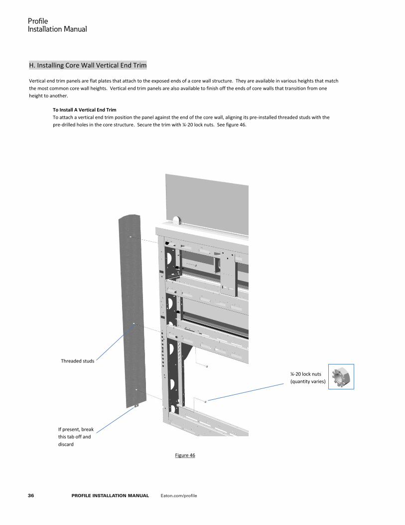
H. Installing Core Wall Vertical End Trim
Vertical end trim panels are flat plates that attach to the exposed ends of a core wall structure. They are available in various heights that match the most common core wall heights. Vertical end trim panels are also available to finish off the ends of core walls that transition from one height to another.
To Install A Vertical End Trim To attach a vertical end trim position the panel against the end of the core wall, aligning its pre-installed threaded studs with the pre-drilled holes in the core structure. Secure the trim with ¼-20 lock nuts. See figure 46.
¼-20 lock nuts (quantity varies)
Threaded studs
Figure 46
If present, break this tab off and discard

37
ProfileInstallation Manual
PROFILE INSTALLATION MANUAL Eaton.com/profile
P a g e | 35
Eaton’s Profile Command Console Installation Manual
I. Installing Core Wall Privacy Screens
Privacy screens attach to the ends of a core wall run, providing visual privacy. They are available for both single sided and dual sided configurations in a variety of heights. A dual sided privacy screen assembles similar to the single sided screen shown below.
To install A Privacy Screen Attach “L” brackets to the privacy screen with #8 x 1-1/4” Phillips head wood screws (see figure 47). Then attach the privacy screen to the end of the core wall structure with ¼-20 x ½” hex head self-tapping screws (see figure 48).
Attach the end trim panel to the core with ¼-20 x ½” hex head self-tapping screws (see figure 49). Then attach the top plate to the privacy screen with #10 Phillips flat head self-tapping screws (see figure 50).
A supporting component is required to support the work surface adjacent to the privacy screen (a work surface bracket as shown, or an end panel or docker). Fasten the support component to the privacy screen with a #10 x ¾” Phillips head wood screw. (It may be necessary to remove a “knock-out” slug from the work surface supporting component.)
Figure 47a Figure 47b
Figure 50 Figure 49
Figure 48
“L” bracket
End trim panel
¼-20 x ½” hex head self-tapping screws
Top plate
¼-20 x ½” hex head self-tapping screws
#8 x 1-1/4” Phillips head wood screws
#10 x ¾” Phillips head wood screw
#10 x ½” Phillips flat head self-tapping screws

38
ProfileInstallation Manual
PROFILE INSTALLATION MANUAL Eaton.com/profile
P a g e | 36
Eaton’s Profile Command Console Installation Manual
J. Installing A CPU Caddy
A CPU caddy usually replaces a 22” wide standard skin on the user side of a core, below the work surface. Refer to the Section V Skin Configuration Guide of this manual to determine how to configure standard skins adjacent to the caddy.
To install A CPU Caddy Attach the side plate to the base core with (4) ¼-20 x ½” hex head self-tapping screws. Position the plate so that the bottom of the plate is 2” from the floor. (A final minor height adjustment may be required to ensure proper vertical alignment to the pivoting caddy.) Attach the pivoting caddy assembly to the base core with (4) ¼-20 x ½” hex head self-tapping screws, ensuring that the caddy’s wheels contact the floor. Rotate the caddy to ensure proper function. Also check the function of the caddy’s lock to ensure proper engagement with the side plate.
¼-20 x ½” hex head self-tapping screws (8)
Figure 51
Side plate
2”
39
ProfileInstallation Manual
PROFILE INSTALLATION MANUAL Eaton.com/profile
P a g e | 37
Eaton’s Profile Command Console Installation Manual
SECTION IV - Assembling Profile Motorized Sit-to-Stand Desks
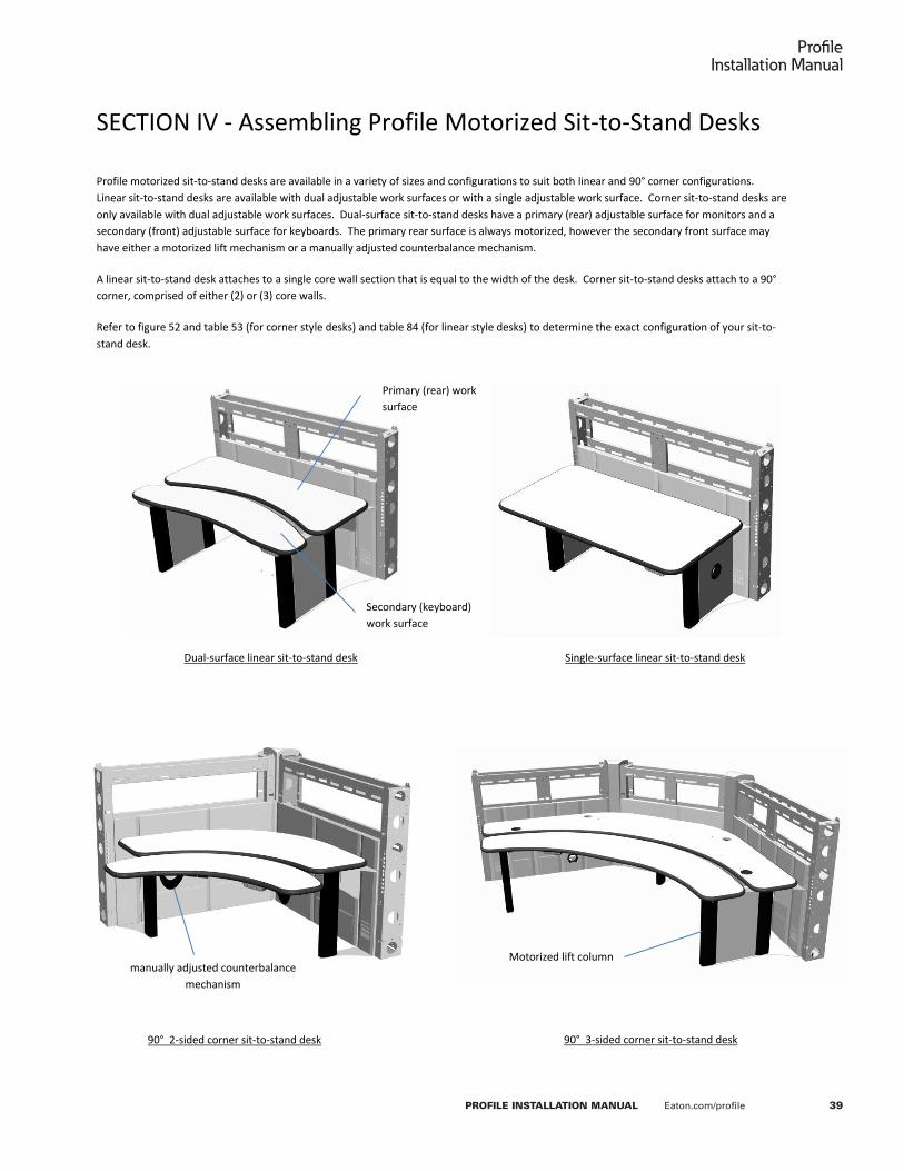
Profile motorized sit-to-stand desks are available in a variety of sizes and configurations to suit both linear and 90° corner configurations. Linear sit-to-stand desks are available with dual adjustable work surfaces or with a single adjustable work surface. Corner sit-to-stand desks are only available with dual adjustable work surfaces. Dual-surface sit-to-stand desks have a primary (rear) adjustable surface for monitors and a secondary (front) adjustable surface for keyboards. The primary rear surface is always motorized, however the secondary front surface may have either a motorized lift mechanism or a manually adjusted counterbalance mechanism.
A linear sit-to-stand desk attaches to a single core wall section that is equal to the width of the desk. Corner sit-to-stand desks attach to a 90° corner, comprised of either (2) or (3) core walls.
Refer to figure 52 and table 53 (for corner style desks) and table 84 (for linear style desks) to determine the exact configuration of your sit-to-stand desk.
Figure 52
90° 2-sided corner sit-to-stand desk 90° 3-sided corner sit-to-stand desk
Dual-surface linear sit-to-stand desk Single-surface linear sit-to-stand desk
Primary (rear) work surface
Secondary (keyboard) work surface
manually adjusted counterbalance mechanism
Motorized lift column

40
ProfileInstallation Manual
PROFILE INSTALLATION MANUAL Eaton.com/profile
P a g e | 38
Eaton’s Profile Command Console Installation Manual
A. To install A Corner Sit-to-stand Desk (Refer to Section IV.B for linear sit-to-stand desks) All Profile corner sit-to-stand desks are comprised of similar components: lift leg assemblies, work surface support frames, work surfaces, electronic components and core skins. Some corner sit-to-stand desks may have additional components such as manual counterbalance mechanisms (for non-motorized keyboard surfaces) and cable management devices. However, while the components are all similar, there will be some variations based on the model size and configuration.
Refer to the following table (figure 53) to determine the features and variations of your specific model number. The installation steps on the following pages will refer to the information found in this table.
Corner Sit-to-Stand Desk Configuration Table (Figure 53)

41
ProfileInstallation Manual
PROFILE INSTALLATION MANUAL Eaton.com/profile
P a g e | 39
Eaton’s Profile Command Console Installation Manual
Step 1. Determine The Component Layout Of Your Corner Sit-to-Stand Desk Refer to table 53 an figures 54 and 55 to determine the layout of your corner sit-to-stand desk model. They will define the size and style of each component along with the locations of your core wall skins and lift leg assemblies. The figures in step 2 and step 7 on the following pages will help you visually identify the style and size of your lift leg and work surface frame components.
1
1 2 3 4
2
3
4
Center Lift Leg Assembly (May not be required) Refer to column 7 in
table 53
Outer Lift Leg Assembly (Style will vary)
Refer to column 6 in table 53
This skin may not be required Refer to column 11 in table 53
Skin Position Numbers Refer to columns 8 thru
11 in table 53 to determine skin width for
each position
Outer Lift Leg Inset Distance Refer to column 14 in table 53
1
Figure 54 (Corners STS Desks with 2 core walls)
2 4 3 5 6
1
2
3
5
4
6
Skin Position Numbers Refer to columns 8 thru
13 in table 53 to determine skin width for
each position
Outer Lift Leg Assembly (Style and position will vary) Refer to column 6 in table 53 for style and columns 10 thru
13 for location
Center Lift Leg Assembly (Style will vary)
Refer to column 7 in table 53
Outer Lift Leg Inset Refer to column 14 in table 53
Figure 55 (Corners STS Desks with 3 core walls)

42
ProfileInstallation Manual
PROFILE INSTALLATION MANUAL Eaton.com/profile
P a g e | 40
Eaton’s Profile Command Console Installation Manual
Step 2. Visual Identification Of Lift Leg Variations A Profile console installation may include several different sit-to stand desk models. The lift legs can have minor variations from one model to another. Use figures 56 through 61 and the information found in table 53 to identify the appropriate lift legs for each of your sit-to-stand desks.
A B
C
Figure 56 – A Style In-Line Dual Outer Lift Legs (LH Assembly Shown)
Figure 57 – B Style Single Outer Lift Legs (LH Assembly Shown)
Figure 58 – C Style Single Outer Lift Legs (LH Assembly Shown)
NOTE: There are no sub-types for C style legs
Figure 59 – D Style Dual Angled Outer Lift Legs (LH Assembly Shown)
NOTE: There are no sub-types for D style legs
Figure 60 – E Style Center Lift Legs (Used for 2-core 90° corner configurations)
NOTE: There are no sub-types for E style legs
Figure 61 – F Style Center Lift Legs (Used for 3-core 90° corner configurations)
D

43
ProfileInstallation Manual
PROFILE INSTALLATION MANUAL Eaton.com/profile
P a g e | 41
Eaton’s Profile Command Console Installation Manual
Step 3. Align The Core Wall Frames
The core walls that support the corner sit-to-stand desk must be properly aligned and leveled. Failure to properly align the walls
can cause excessive stress on the desk’s lift components resulting in poor performance and premature wear. Before proceeding with the assembly of your corner sit-to-stand desk, ensure that the core walls form a true 90° angle. Adjust the core walls so that the diagonal corner-to-corner distance of your installation matches the values shown in figure 62.
Figure 62

44
ProfileInstallation Manual
PROFILE INSTALLATION MANUAL Eaton.com/profile
P a g e | 42
Eaton’s Profile Command Console Installation Manual
Step 4. Install The Outer Lift Legs a. The following figures show the installation of a left hand A style outer lift leg. B, C and D style outer lift legs attach the
same way. b. Refer to column 14 in table 53 to determine the lift leg inset. Then attach the outer lift leg assembly to the core wall with
(5) ¼-20 x ½” hex head self-tapping screws, as shown in figure 63. (A 2-1/2” inset is shown in this example.) c. Install (2) #10 x 3/8” Phillips head self-tapping screws into the top of the lift leg face plate. Leave the screws protruding
about 1/16”. Engage the “U” slots in the top of the upper leg skin onto the screws. The lower leg skin magnetically attaches to the face plate.
d. Repeat these steps for the right hand lift leg assembly. e. Adjust the lift legs’ levelers to ensure that the leg assemblies and core walls are plumb.
Upper leg skin
#10 x 3/8” Phillips head self-tapping screws (2)
¼-20 x ½” hex head self-tapping screws (10)
Figure 63
Figure 64
Lower leg skin
Lift leg face plate
Lift Leg Inset (See column 14 on table 53)

45
ProfileInstallation Manual
PROFILE INSTALLATION MANUAL Eaton.com/profile
P a g e | 43
Eaton’s Profile Command Console Installation Manual
Step 5a. Install An E Style Center Lift Leg E Style center lift legs are used for 2-core corner sit-to stand desks. 3-Core corner sit-to-stand desks use F style center lift legs. a. Refer to column 7 in table 53 to determine the center lift leg style required for your corner sit-to-stand desk. The
instructions in this step are for E style center lift legs. If your desk requires an F style center lift leg, proceed to step 5b. If your desk does not require a center lift leg at all, proceed to step 6.
b. The upper and lower center lift leg skins should be pre-attached at the factory. If they are not pre-assembled, attach each skin to the center lift leg assembly with (4) #10 x 3/8” Phillips head self-tapping screws.
c. Attach the style E center lift leg assembly to the intersecting core walls with (4) ¼-20 x ½” hex head self-tapping screws. See figure 65.
d. Adjust the lift leg’s leveler to ensure that it is in contact with the floor.
Figure 65
¼-20 x ½” hex head self-tapping screws (10)
Lower skin panel
Upper skin panel

46
ProfileInstallation Manual
PROFILE INSTALLATION MANUAL Eaton.com/profile
P a g e | 44
Eaton’s Profile Command Console Installation Manual
Step 5b. Install An F Style Center Lift Leg F Style center lift legs are used for 3-core corner sit-to stand desks. 2-Core corner sit-to-stand desks use E style center lift legs. a. Refer to column 7 in table 53 to determine the center lift leg style required for your corner sit-to-stand desk. The
instructions in this step are for F style center lift legs. If your desk requires an E style center lift leg, refer to step 5a. If your desk does not require a center lift leg at all, proceed to step 6.
b. Attach the F style center lift leg assembly to the center of the middle core wall with (4) ¼-20 x ½” hex head self-tapping screws. See figure 66.
c. Install (2) #10 x 3/8” Phillips head self-tapping screws into the top of the lift leg face plate. Leave the screws protruding about 1/16”. Engage the “U” slots in the top of the upper leg skin onto the screws. The lower leg skin magnetically attaches to the face plate. See figure 67.
d. Adjust the lift leg’s leveler to ensure that it is in contact with the floor.
Figure 66
¼-20 x ½” hex head self-tapping screws (4)
Figure 67
#10 x 3/8” Phillips head self-tapping screws (2)
Upper skin panel
Lower skin panel

47
ProfileInstallation Manual
PROFILE INSTALLATION MANUAL Eaton.com/profile
P a g e | 45
Eaton’s Profile Command Console Installation Manual
Step 6. Route The Lift Column Electrical Connectors The lift motors’ electrical connectors have integrally molded strain reliefs. Slide the grooved strain relief into one of the notches in the top of the lift motor. The top of the strain relief should be flush with the top of the column. See figure 68. The connectors for the outer rear lift motors should exit the motors towards the knee-well of the corner sit-to-stand desk, facing forward. The connectors for the front lift motors (if present on your desk) should exit the motors toward the knee-well of the desk, facing rearward. See figure 69. The connectors for the rear center lift motor (if present on your desk) can exit either side of the lift motor, facing forward.
Figure 68
Figure 69

48
ProfileInstallation Manual
PROFILE INSTALLATION MANUAL Eaton.com/profile
P a g e | 46
Eaton’s Profile Command Console Installation Manual
Step 7. Visual Identification Of Rear Work Surface Support Frame Variations A Profile console installation may include several different sit-to stand desk models. The rear work surface support frames can have minor variations from one model to another. Use figures 70 through 73 along with the information found in column 16 of table 53 to identify the appropriate work surface support frame for each of your sit-to-stand desks.
Figure 70 – G Style Rear Work Surface Support Frame
Figure 71 – H Style Rear Work Surface Support Frame NOTE: There are no sub-types for H style frames
Figure 72 – J Style Rear Work Surface Support Frame NOTE: There are no sub-types for J style frames
Figure 73 – K Style Rear Work Surface Support Frame NOTE: There are no sub-types for K style frames
Leg (typ.) Gusset
47” (typ.) 36” (typ.)
120°

49
ProfileInstallation Manual
PROFILE INSTALLATION MANUAL Eaton.com/profile
P a g e | 47
Eaton’s Profile Command Console Installation Manual
Step 8. Install The Rear Work Surface Support Frame
The following figure shows the installation a G style rear work surface support frame. H, J and K style frames (not shown) attach in a similar manner.
The support frame’s end plates have several beveled mounting holes. Use the table below to determine which holes to use for your corner sit-to-stand desk model. Position the rear work surface support frame on top of the lift motor s, aligning the correct holes with the lift motor s. If you have difficulty in aligning the correct holes, you may have to re-position the core wall frames slightly. Using the wrong holes or forcing the components into alignment can cause excessive stress on the desk’s lift components resulting in poor performance and premature wear.
Attach the frame to the lift motors using (4) M6 x 14mm Allen flat head machine screws for each motor. See figure 74.
DO NOT PINCH OR DAMAGE THE LIFT COLUMN WIRES OR CONNECTORS.
1 2 3 4 5 6 7 8
Figure 74
M6 x 14mm Allen flat head machine screws
NOTICE
WARNING

50
ProfileInstallation Manual
PROFILE INSTALLATION MANUAL Eaton.com/profile
P a g e | 48
Eaton’s Profile Command Console Installation Manual
Step 8. Install The Rear Work Surface The following figure shows the installation a PEC60602 rear work
surface. Work surfaces for other corner sit-to-stand desk models attach the same way. In order to minimize handling weight, some larger 72” x 72” desks have 2-piece rear work surfaces, with a seam along the center of the surface.
Position the rear work-surface panel(s) on top of the rear work surface support frame, aligning its mounting holes with the holes in the frame. When properly positioned, the rear edges of the work surface will be about 2-1/4” from the core wall frames. Attach the work surface with #10 x ¾” Phillips head wood screws. SOME SCREW HOLES MAY NOT BE ACCESSABLE UNTIL THE DESK IS WIRED AND ELEVATED. IF SO, INSTALL THESE SCREWS LATER IN THE ASSEMBLY. DO NOT OMIT ANY SCREWS.
Step 9a. Install The Front Work Surface Support Brackets
This step only applies to corner sit-to-stand desks with motorized front work surfaces (refer to column 5 in table 53). If your desk
has a manually counterbalanced front work surface, refer to step 11 to learn how to install the counterbalance mechanism.
NOTE: PL4842482 model corner sit-to-stand desks require a unique front work surface support component. Refer to step 9b
for this model desk.
The support brackets have several beveled mounting holes. Use the table below to determine which holes to use for your corner sit-to-stand desk model. Position the work surface support brackets on top of the lift motors, aligning the correct holes with the lift motors. Attach each bracket to the lift motor with (4) M6 x 14mm Allen flat head machine screws. See figure 76.
WARNING: DO NOT PINCH OR DAMAGE THE LIFT MOTOR WIRES OR CONNECTORS.
Figure 75
2-1/4” (typ.)
Figure 76 (This example uses holes 1 and 4 for desk
PEC60602)
M6 x 14mm Allen flat head machine
screws
Fron
t
Rear
1 3 4 2 5 6 7 8
NOTICE
NOTICE
NOTICE

51
ProfileInstallation Manual
PROFILE INSTALLATION MANUAL Eaton.com/profile
P a g e | 49
Eaton’s Profile Command Console Installation Manual
Step 9b. Install The Front Work Surface Support Frame (Model PL4842482 only) Position the PL4842482 front work surface support frame on top of the motorized lift motors. Align the beveled holes in the stiffener with the holes in the top of the lift motors. Attach the frame to the lift motors with (8) M6 x 14mm Allen flat head machine screws. See figure 77.
Step 10. Install The Motorized Front Work Surface This step only applies to corner sit-to-stand desks with motorized
front work surfaces (refer to column 5 in table 53). If your desk has a manually counterbalanced front work surface, refer to step 11 to learn how to install the counterbalance mechanism.
Position the front work-surface on top of the work surface support brackets, aligning its mounting holes with the holes in the brackets. When properly positioned, the rear edges of the work surface will be about 2” from the rear work surface. Attach the front work surface with #10 x ¾” Phillips head wood screws. SOME SCREW HOLES MAY NOT BE ACCESSABLE UNTIL THE DESK IS WIRES AND ELEVATED. IF SO, INSTALL THESE SCREWS LATER IN THE ASSEMBLY. DO NOT OMIT ANY SCREWS.
M6 x 14mm Allen flat head machine
screws
Figure 77
2”
Figure 78
NOTICE

52
ProfileInstallation Manual
PROFILE INSTALLATION MANUAL Eaton.com/profile
P a g e | 50
Eaton’s Profile Command Console Installation Manual
Step 11. Install The Manually Counterbalanced Front Work Surface This step only applies to corner sit-to-stand desks with manually
counterbalanced front work surfaces (refer to column 5 in table 53). If your desk has a motorized front work surface, refer to steps 9 and 10 to learn how to install the work surface, and then proceed to step 12.
The counterbalance mechanism will be packaged separately. Disregard the instructions included with the mechanism and refer to this manual for assembly and installation steps.
a. Assemble the left and right arms and the cross tube with the washers and locknuts provided with the mechanism. Then assemble nut covers onto the lock nuts.
b. Place the counterbalance mechanism on the floor. Adjust the paddle and knobs until all four mounting brackets are aligned and planar. Release the paddle and tighten the knobs.
c. Assemble the mechanism to the rear work surface with the (16) long wood screws provided with the mechanism. DO NOT OMIT ANY SCREWS.
d. Position the front work surface onto the mechanism, aligning the threaded studs with the bracket holes. Use the nuts and washers provided with the surface to secure it to the mechanism.
e. Attach the height adjustment paddle assembly to the front work surface with the (8) short wood screws provided with the mechanism.
Figure 80
Figure 79
Washers, nuts and nut covers (supplied with mechanism)
#10 washers (6)
Long wood screws (16) (supplied with mechanism)
Short wood screws (8) (supplied with mechanism) #10 nuts (6)
Cross tube Arms
NOTICE

53
ProfileInstallation Manual
PROFILE INSTALLATION MANUAL Eaton.com/profile
P a g e | 51
Eaton’s Profile Command Console Installation Manual
Step 12. Install The Electronic Control Boxes and Button Pads A Profile console installation may include several different sit-to stand desk models. Refer to columns 17 and 18 in table 53 to determine the appropriate control boxes for your sit-to-stand desk(s). A control box is required for each motorized work surface. Motorized work surfaces that have 2 lift motors will require a smaller 2-channel control box. Motorized work surfaces that have 3 lift motors will require a larger 3-channel control box.
Mount the appropriate control boxes to the underside of the work surfaces with (2) #10 x 1-3/4” long Phillips head screws, as shown in figure 81. The rear work surface control box mounts to the right hand work surface frame channel with its power receptacle pointing left towards the center of the desk. The front control box mounts to the middle of the front work surface with its power receptacle pointing to the right.
Mount (1) button pad for each motorized work surface to the underside of the front work surface using (2) #8 x ¾” Phillips flat head wood screws for each pad. If your corner sit-to-stand desk has only one motorized work surface, mount the control pad in the right hand position. See figure 81.
#10 x 1-3/4” long Phillips head wood
screws
#8 x ¾” Phillips flat head wood screws
3-channel control box (10-1/2” x 3-3/4”)
Button pad for rear work surface
2-channel control box (8-3/8” x 3-3/4”)
Figure 81
Power receptacle this side
Power receptacle this side
Button pad for front work surface

54
ProfileInstallation Manual
PROFILE INSTALLATION MANUAL Eaton.com/profile
P a g e | 52
Eaton’s Profile Command Console Installation Manual
Step 13. Connect The Electronic Lift Components Your Profile corner sit-to-stand desk will include power cables and several long and short lift motor cables. The quantity of cables included with your desk will depend on the desk size and whether or not you have a motorized front work surface. Along with the cables, you will receive various cable retention devices that will be used to route and manage the cables.
Short lift motor cables are 42” long. Long lift motor cables are 83” long Power cables are 130” long
Figures 82 and 83 show the wiring of a typical corner sit-to-stand desk with (3) rear lift motors and (2) front lift motors (PEC60602). However, some desks will only have (2) rear lift motors and (or) a manual counterbalanced front work surface with no lift motors. Note the lift motor numbers in figure 82; connect the motors to the corresponding numbered receptacles on each control box. Connect one control pad to the “A1” receptacle on each control box. Ensure that all cable retention devices are properly engaged when plugging in the cables.
Rear motor #1 Rear motor #3
Front motor #1 Rear motor #2
Front motor #2
Front control pad
Rear control pad
Long motor cable
Long motor cable
Short motor cable
Short motor cable
Front AC power cord
Short motor cable
Rear AC power cord Coil and retain excess cable when required
Cable retainers
Bottom View
Leave 36” slack (service loop) for front control pad cable and front
AC power cord
Screw-on cable array retainer
Front motor #1
Rear motor #1
Front motor #2
Figure 82
Figure 83 (view from rear of desk)
Front work surface
Rear work surface

55
ProfileInstallation Manual
PROFILE INSTALLATION MANUAL Eaton.com/profile
P a g e | 53
Eaton’s Profile Command Console Installation Manual
S
2
3
1
Step 14. Verify Proper Operation of the Corner Sit-to-Stand Desk
BEFORE ENERGIZING OR OPERATING THE LIFT SYSTEM
• MAKE SURE THAT THE PRECEDING ASSEMBLY STEPS HAVE BEEN FOLLOWED AND ARE COMPLETED.
• VERIFY THE CORRECT POSITION OF ALL LIFT MOTOR CONNECTORS. VERIFY THAT ALL LIFT MOTOR CABLES ARE PROPERLY SEATED IN THEIR RECEPTACLES. • MAKE SURE THAT THE VOLTAGE OF THE CONTROL BOX IS CORRECT BEFORE THE SYSTEM IS CONNECTED TO THE MAINS.
14.A. Plug the Profile sit-to-stand desk in: This product is for use on a circuit having a nominal rating of 120 volts and is equipped with a specific electrical plug to permit connection to a proper electrical circuit.
Motorized lift columns and control pads must be attached to the control box before it is connected to an electrical outlet. Inspect the sit-to-stand desk to ensure that no cables are pinched or in the travel path of any desk component.
Make sure that the product is connected to outlets having the same configuration as the plugs. No adapter should be used with this product. Once the sit-to-stand desk has been connected to the appropriate outlet, the lift motor system will be energized.
14.B. Operation of the lift control pad:
14.C. Initialize the lift motor system: The lift motor system is initialized by pressing and holding the down button. The motors will automatically lower to their bottom most position (if not already there), then run upwards approx. 3mm, and then down again to their lowest position. Only release the down button when the movement has completely stopped. If the button is released before the sequence is completed then the initialization is interrupted and must be started again from the beginning. It is sometimes necessary to press the down button twice to start the initialization. This is because the system can be in different modes when the initialization starts.
IF THE CONTROL BOX MAKES UNUSUAL NOISE OR ODORS, IMMEDIATELY UNPLUG THE UNIT FROM THE AC
RECEPTACLE. INSPECT ALL CABLES TO ENSURE THAT THEY ARE NOT DAMAGED. RECORD ALL ERROR CODES SHOWN.
• DO NOT PLUG THE UNIT IN AGAIN. CONTACT TECHNICAL ASSISTANCE FOR HELP USING THE CONTACT INFORMATION IN SECTION 1 OF THE INSTALLATION GUIDE.
Step 15. Install Core Skins Each corner sit-to-stand desk will have a unique arrangement of core skins sizes, depending on the size and style of the desk. Refer to table 53 and figures 54 and 55 to determine the arrangement of core skins for your desk. Install the skins following the procedures shown in Section III.E of this manual.
Desk Up – Press the arrow button lift the desk. The function is only active while button is pressed.
Desk Down – Press the arrow button to lower the desk. The function is only active while the button is pressed.
Store Memory – Press this button and then within 2 seconds, press 1, 2 or 3 to store the current desk position.
Memory position 1
Memory position 2
Memory position 3
WARNING
WARNING

56
ProfileInstallation Manual
PROFILE INSTALLATION MANUAL Eaton.com/profile
P a g e | 54
Eaton’s Profile Command Console Installation Manual
B. To install A Linear Sit-to-stand Desk (Refer to the previous section, Section IV.A., for corner sit-to-stand desks) All Profile linear sit-to-stand desks are comprised of similar components: lift leg assemblies, work surface support frames, work surfaces, electronic components and core skins. Some linear sit-to-stand desks may have additional components such as manual counterbalance mechanisms (for non-motorized keyboard surfaces) and cable management devices. However, while the components are all similar, there will be some variations based on the model size and configuration.
Refer to the following table (figure 84) to determine the features and variations of your specific model number. The installation steps on the following pages will refer to the information found in this table.
Step 1. Determine The Component Layout Of Your Linear Sit-to-Stand Desk Refer to table 84 and figure 85 to determine the layout of your linear sit-to-stand desk model. They will define the size and style of each component along with the locations of your core wall skins and lift leg assemblies. The figures in step 2 and step 5 on the following pages will help you visually identify the style and size of your lift leg and work surface frame components.
Linear Sit-to-Stand Desk Configuration Table (Figure 84)
Lift leg Ref col. 5
Lift leg Ref col. 5
Lift leg Ref col. 5
Lift leg Ref col. 5
Lift leg Ref col. 5
Lift leg Ref col. 5
Lift leg Ref col. 5
Lift leg Ref col. 5
14 15
/ 16”
Ski
n
14 15
/ 16”
Ski
n
29 7/8” Skin
19 3/8” Skin 20 15/16” Skin 20 15/16” Skin 19 3/8” Skin
9 3 / 8
” Sk
in
9 3 / 8
” Sk
in
Skin Configuration 1 PEWS48301 PEWS48302 PEWS48303
Skin Configuration 2 PEWS60301 PEWS60302 PEWS60303
Skin Configuration 3 PEWS72301 PEWS72302
23 15/16” Skin
Skin Configuration 4 PEWS72303
Figure 85 – Linear Sit-to-Stand Skin Configuration

57
ProfileInstallation Manual
PROFILE INSTALLATION MANUAL Eaton.com/profile
P a g e | 55
Eaton’s Profile Command Console Installation Manual
Step 2. Visual Identification Of Lift Leg Variations A Profile console installation may include several different sit-to stand desk models. The lift legs can have minor variations from one model to another. Use figures 86 and 87 and the information found in columns 5 and 6 of table 84 to identify the appropriate lift legs for each of your sit-to-stand desks.
11-3/8”
16-3/8”
14-1/2”
Figure 86 – A1 Style In-Line Dual Lift Leg (LH Assembly Shown)
Figure 87 – B2 Style Single Lift Leg (LH Assembly Shown)

58
ProfileInstallation Manual
PROFILE INSTALLATION MANUAL Eaton.com/profile
P a g e | 56
Eaton’s Profile Command Console Installation Manual
Step 3. Install The Lift Legs a. The following figures show the installation of a left hand A1 style lift leg. B2 style lift legs attach the same way. b. Refer to column 7 in table 84 to determine the lift leg inset. Then attach the lift leg assembly to the core wall with (5) ¼-20
x ½” hex head self-tapping screws, as shown in figure 88. (A 2-1/2” inset is shown in this example.) c. Install (2) #10 x 3/8” Phillips head self-tapping screws into the top of the lift leg face plate. Leave the screws protruding
about 1/16”. Engage the “U” slots in the top of the upper leg skin onto the screws. The lower leg skin magnetically attaches to the face plate. See figure 89.
d. Repeat these steps for the right hand lift leg assembly. e. Adjust the lift leg’s levelers to ensure that the leg assembly and core wall are plumb.
Upper leg skin
#10 x 3/8” Phillips head self-tapping screws (2)
Lift Leg Inset (See column 7 of table 84)
¼-20 x ½” hex head self-tapping screws (10)
Figure 88
Figure 89
Lower leg skin
Lift leg face plate

59
ProfileInstallation Manual
PROFILE INSTALLATION MANUAL Eaton.com/profile
P a g e | 57
Eaton’s Profile Command Console Installation Manual
Step 4. Route The Lift Column Electrical Connectors The lift motors’ electrical connectors have integrally molded strain reliefs. Slide the grooved strain relief into one of the notches in the top of the lift motor. The top of the strain relief should be flush with the top of the motor. See figure 90. The connectors for the rear lift motors should exit the motors towards knee-well of the linear sit-to-stand desk, facing rearward. The connectors for the front lift motors (if present on your desk) should also exit the motors toward the knee-well of the desk, facing rearward. See figure 91. Step 5. Visual Identification Of Primary (Rear) Work Surface Support Frame Variations A Profile console installation may include several different sit-to stand desk models. The rear work surface support frames can have minor variations from one model to another. Use figures 92 and 93 along with the information found in column 8 of table 84 to identify the appropriate work surface support frame for each of your sit-to-stand desks.
Figure 90 Figure 91
Figure 92 – L Style Rear Work Surface Support Frame (Used with dual surface linear sit-to-stand desks)
Figure 93 – M Style Work Surface Support Frame (Used with single surface linear sit-to-stand desks)
X
X
Y
24”

60
ProfileInstallation Manual
PROFILE INSTALLATION MANUAL Eaton.com/profile
P a g e | 58
Eaton’s Profile Command Console Installation Manual
Step 6. Install The Work Surface Support Frame(s) The following figures show the installation an L style rear work
surface support frame. An M style frame (not shown) attaches in a similar manner. The front “bow-tie” work surface support frame, shown in figure 95 is only required on 60” and 72” linear sit-to-stand desks that have motorized front work surfaces (refer to column 9 in table 84).
The rear work surface support frame’s end plates have several mounting hole options for alternate applications. Choose the mounting holes that result in the offset shown in figure 94. Attach the work surface support frame(s) to the lift columns using (4) M6 x 20mm Phillips head machine screws for each column. See figure 95.
DO NOT PINCH OR DAMAGE THE LIFT MOTOR WIRES OR CONNECTORS.
Rear work surface support frame offset: L style frames: 2-1/2” offset M style frames: 3-1/2” offset
Figure 94
Figure 95
Front “bow-tie” work surface support frame (only required on 60” and 72” linear sit-to-stand desks that have motorized front work surfaces)
L style rear work surface support frame
M6 x 20mm Phillips head machine screws
Upper leg skin
L style rear work surface support frame
NOTICE
WARNING

61
ProfileInstallation Manual
PROFILE INSTALLATION MANUAL Eaton.com/profile
P a g e | 59
Eaton’s Profile Command Console Installation Manual
Step 8. Install The Rear Work Surface The following figure shows the installation of model PEW60303
work surfaces. Work surfaces for other linear sit-to-stand desk models attach in a similar manner. Some models will only require one large work surface (without a secondary key board surface) and some models will have a secondary keyboard surface with a manually adjusted counterbalance mechanism. If your desk has a manually counterbalanced front work surface, refer to step 9 to learn how to install the counterbalance mechanism.
Position the work-surface(s) on top of the work surface support frame(s), aligning the mounting holes with the holes in the frame. When properly positioned, the rear edge(s) of the work surface(s) should be spaced as shown in figure 96. Attach the work surface(s) with #10 x ¾” Phillips head wood screws. SOME SCREW HOLES MAY NOT BE ACCESSABLE UNTIL THE DESK IS WIRED AND ELEVATED. IF SO, INSTALL THESE SCREWS LATER IN THE ASSEMBLY. DO NOT OMIT ANY SCREWS.
2-1/4”
1-3/8”
Figure 96
NOTICE

62
ProfileInstallation Manual
PROFILE INSTALLATION MANUAL Eaton.com/profile
P a g e | 60
Eaton’s Profile Command Console Installation Manual
Step 9. Install The Manually Counterbalanced Front Work Surface This step only applies to linear sit-to-stand desks with manually
counterbalanced front work surfaces (refer to column 4 in table 84). If your desk has a motorized front work surface, refer to step 8 to learn how to install the work surface, and then proceed to step 10.
The counterbalance mechanism will be packaged separately. Disregard the instructions included with the mechanism and refer to this manual for assembly and installation steps.
a. Assemble the left and right arms and the cross tube with the washers and locknuts provided with the mechanism. Then assemble nut covers onto the lock nuts.
b. Place the counterbalance mechanism on the floor. Adjust the paddle and knobs until all four mounting brackets are aligned and planar. Release the paddle and tighten the knobs.
c. Assemble the mechanism to the rear work surface with the (16) long wood screws provided with the mechanism. DO NOT OMIT ANY SCREWS.
d. Position the front work surface onto the mechanism, aligning the threaded studs with the bracket holes. Use the nuts and washers provided with the work surface to secure it to the mechanism.
e. Attach the height adjustment paddle assembly to the front work surface with the (8) short wood screws provided with the mechanism.
Figure 98
Figure 97
Washers, nuts and nut covers (supplied with mechanism)
#10 washers (6) Long wood screws (16)
(supplied with mechanism) Short wood screws (8)
(supplied with mechanism) #10 nuts (6)
Cross tube Arms
NOTICE

63
ProfileInstallation Manual
PROFILE INSTALLATION MANUAL Eaton.com/profile
P a g e | 61
Eaton’s Profile Command Console Installation Manual
Step 10. Install The Electronic Control Boxes and Button Pads A 2-channel control box is required for each motorized work surface. Mount each control box to the underside of the work surface with (2) #10 x 1-3/4” long Phillips head screws, as shown in figure 99. The rear work surface control box mounts to the right hand end of the work surface frame channel with its power receptacle pointing left towards the center of the desk. The front control box mounts to the middle of the front work surface with its power receptacle pointing to the right.
Mount (1) button pad for each motorized work surface to the underside of the front work surface using (2) #8 x ¾” Phillips flat head wood screws for each pad. If your linear sit-to-stand desk has only one motorized work surface, mount one control pad in the right hand position. See figure 99.
#10 x 1-3/4” long Phillips head wood
screws
#8 x ¾” Phillips flat head wood screws
Button pad for rear work surface
Power receptacle this side 2-channel control boxes
(8-3/8” x 3-3/4”) Button pad for
front work surface
Figure 98

64
ProfileInstallation Manual
PROFILE INSTALLATION MANUAL Eaton.com/profile
P a g e | 62
Eaton’s Profile Command Console Installation Manual
Step 11. Connect The Electronic Lift Components Your Profile linear sit-to-stand desk will include power cables and several long and short lift motor cables. The quantity of cables included with your desk will depend on the desk size and whether or not you have a motorized front work surface. Along with the cables, you will receive various cable retention devices that will be used to route and manage the cables.
Short lift motor cables are 42” long. Long lift motor cables are 83” long Power cables are 130” long
Figures 99 and 100 show the wiring of a typical linear sit-to-stand desk with both front and rear lift motors (PEWS60303). However, some desks will only have rear lift motors and (or) a manual counterbalanced front work surface with no lift motors. Note the lift motor numbers in figure 99; connect the motors to the corresponding numbered receptacles on each control box. Connect one control pad to the “A1” receptacle on each control box. Ensure that all cable retention devices are properly engaged when plugging in the cables.
Rear motor #1
Front motor #1
Rear motor #2
Front motor #2
Front control pad Rear control pad Short motor cable
Long motor cable
Short motor cable
Short motor cable
Cable retainers
Front AC power cord
Rear AC power cord Cable retainers
Leave 36” slack (service loop) for front control pad cable and front AC power cord
Screw-on cable array retainer
Front motor #1 Rear motor #1
Front motor #2
Front work surface
Rear work surface
Figure 99
Rear motor #2
Figure 100 (view from rear of desk)

65
ProfileInstallation Manual
PROFILE INSTALLATION MANUAL Eaton.com/profile
P a g e | 63
Eaton’s Profile Command Console Installation Manual
S
2
3
1
Step 12. Verify Proper Operation of the Corner Sit-to-Stand Desk
BEFORE ENERGIZING OR OPERATING THE LIFT SYSTEM
• MAKE SURE THAT THE PRECEDING ASSEMBLY STEPS HAVE BEEN FOLLOWED AND ARE COMPLETED.
• VERIFY THE CORRECT POSITION OF ALL LIFT MOTOR CONNECTORS. VERIFY THAT ALL LIFT MOTOR CABLES ARE PROPERLY SEATED IN THEIR RECEPTACLES. • MAKE SURE THAT THE VOLTAGE OF THE CONTROL BOX IS CORRECT BEFORE THE SYSTEM IS CONNECTED TO THE MAINS.
12.A. Plug the Profile sit-to-stand desk in: This product is for use on a circuit having a nominal rating of 120 volts and is equipped with a specific electrical plug to permit connection to a proper electrical circuit.
Motorized lift columns and control pads must be attached to the control box before it is connected to an electrical outlet. Inspect the sit-to-stand desk to ensure that no cables are pinched or in the travel path of any desk component.
Make sure that the product is connected to outlets having the same configuration as the plugs. No adapter should be used with this product. Once the sit-to-stand desk has been connected to the appropriate outlet, the lift motor system will be energized.
12.B. Operation of the lift control pad:
12.C. Initialize the lift motor system: The lift motor system is initialized by pressing and holding the down button. The motors will automatically lower to their bottom most position (if not already there), then run upwards approx. 3mm, and then down again to their lowest position. Only release the down button when the movement has completely stopped. If the button is released before the sequence is completed then the initialization is interrupted and must be started again from the beginning. It is sometimes necessary to press the down button twice to start the initialization. This is because the system can be in different modes when the initialization starts.
IF THE CONTROL BOX MAKES UNUSUAL NOISE OR ODORS, IMMEDIATELY UNPLUG THE UNIT FROM THE AC
RECEPTACLE. INSPECT ALL CABLES TO ENSURE THAT THEY ARE NOT DAMAGED. RECORD ALL ERROR CODES SHOWN.
• DO NOT PLUG THE UNIT IN AGAIN. CONTACT TECHNICAL ASSISTANCE FOR HELP USING THE CONTACT INFORMATION IN SECTION 1 OF THE INSTALLATION GUIDE.
Step 13. Install Core Skins Each corner sit-to-stand desk will have a unique arrangement of core skins sizes, depending on the size and style of the desk. Refer to table 84 and figure 85 to determine the arrangement of core skins for your desk. Install the skins following the procedures shown in Section III.E of this manual.
Desk Up – Press the arrow button lift the desk. The function is only active while button is pressed.
Desk Down – Press the arrow button to lower the desk. The function is only active while the button is pressed.
Store Memory – Press this button and then within 2 seconds, press 1, 2 or 3 to store the current desk position.
Memory position 1
Memory position 2
Memory position 3
WARNING
WARNING

66
ProfileInstallation Manual
PROFILE INSTALLATION MANUAL Eaton.com/profile
P a g e | 64
Eaton’s Profile Command Console Installation Manual
SECTION V - Profile Skin Configuration Guide The diagrams in this section depict various combinations of core wall skins, dockers and CPU caddies for each core wall size. These arrangements will usually be found on the user side of the core wall structure, below a work surface.
Figure 102 - 30” Core configurations
Figure 101 - 24” Core configurations
Standard Steel Skin
Component Reference Images
14”W Docker - LH
CPU Caddy - RH
CPU Caddy - LH
14”W Docker - RH
24”W Docker - LH
24”W Docker - RH
20”
8”
26”
8”
14” 4”
XX” Skin width
4”
4” 4” 14”

67
ProfileInstallation Manual
PROFILE INSTALLATION MANUAL Eaton.com/profile
P a g e | 65
Eaton’s Profile Command Console Installation Manual
Figure 104 - 42” Core configurations
Figure 103 - 36” Core configurations
14”
16” 16”
10”
10”
16” 16”
16”
16”
19” 19”9
10” 10”
20”
20”
10” 10”
32”

68
ProfileInstallation Manual
PROFILE INSTALLATION MANUAL Eaton.com/profile
P a g e | 66
Eaton’s Profile Command Console Installation Manual
22” 22”
22” 22” 22”
22” 22” 22”
10”
10”
10” 10”
Figure 106 - 60” Core configurations
Figure 105 - 48” Core configurations
22”
22”
22”
22” 22”
22” 22” 22”
12”
12”
12” 12” 12” 12”
12” 12” 12” 12”
12” 12” 12”
12”
10”
10”
10” 10”
10”
10”
12”
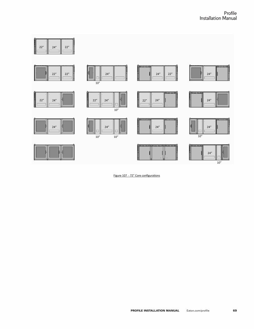
69
ProfileInstallation Manual
PROFILE INSTALLATION MANUAL Eaton.com/profile
P a g e | 67
Eaton’s Profile Command Console Installation Manual
22”
10”
24”
22” 22” 24”
22”
24” 24” 24” 24”
24” 24” 24”
24” 24” 24”
24”
10”
22”
22” 22” 22”
10”
10”
10”
10”
Figure 107 - 72” Core configurations

Eaton160 Gold Star BoulevardWorcester, MA 01606United States800-225-7348508-852-4300Eaton�com/compass
Eaton1000 Eaton BoulevardCleveland, OH 44122United StatesEaton�com
© 2018 EatonAll Rights ReservedPrinted in USAPublication No� IB210002EN May 2018
Follow us on social media to get the latest product and support information.
Eaton is a registered trademark�
* All trademarks are property of their respective owners�
Profile Installation Manual