Embed Size (px)
Citation preview
EFwww.controltechniques.com
Technical Data
Commander SKAC variable speed drive for 3 phase induction motors from 0.25kW to 4kW, 0.33hp to 5hp
Part Number: 0472-0002-01Issue: 1

General InformationThe manufacturer accepts no liability for any consequences resulting from inappropriate, negligent or incorrect installation or adjustment of the optional parameters of the equipment or from mismatching the variable speed drive with the motor.
The contents of this guide are believed to be correct at the time of printing. In the interests of commitment to a policy of continuous development and improvement, the manufacturer reserves the right to change the specification of the product or its performance, or the content of the guide without notice.
All rights reserved. No parts of this guide may be reproduced or transmitted in any form or by any means, electrical or mechanical including, photocopying, recording or by an information storage or retrieval system, without permission in writing from the publisher.
Drive software versionThis product is supplied with the latest version of user-interface and machine control software. If this product is to be used in a new or existing system with other drives, there may be some differences between their software and the software in this product. These differences may cause the product to function differently. This may also apply to drives returned from the Control Techniques Service Centre.
If there is any doubt, please contact your local Control Techniques Drive Centre or Distributor.
Environmental StatementControl Techniques is committed to minimising the environmental impacts of its manufacturing operations and of its products throughout their life cycle. To this end, we operate an Environmental Management System (EMS) which is certified to the International Standard ISO 14001. Further information on the EMS, our Environment Policy and other relevant information is available on request, or can be found at www.greendrives.com.
The electronic variable speed drives manufactured by Control Techniques have the potential to save energy and (through increased machine/process efficiency) reduce raw material consumption and scrap throughout their long working lifetime. In typical applications, these positive environmental effects far outweigh the negative impacts of product manufacture and end-of-life disposal.
Nevertheless, when the products eventually reach the end of their useful life, they can very easily be dismantled into their major component parts for efficient recycling. Many parts snap together and can be separated without the use of tools, while other parts are secured with conventional screws. Virtually all parts of the product are suitable for recycling.
Product packaging is of good quality and can be re-used. Large products are packed in wooden crates, while smaller products come in strong cardboard cartons which themselves have a high-recycled fibre content. If not re-used, these containers can be recycled. Polythene, used on the protective film and bags from wrapping product, can be recycled in the same way. Control Techniques' packaging strategy favours easily recyclable materials of low environmental impact, and regular reviews identify opportunities for improvement.
When preparing to recycle or dispose of any product or packaging, please observe local legislation and best practice.
Copyright © December 2004 Control Techniques Drives Ltd
Issue:1

Contents1 Technical data................................................................................................................5
1.1 Commander SK 200V units ...................................................................................................................51.2 Commander SK 400V units ...................................................................................................................6
2 Derating curves..............................................................................................................83 Drive voltage levels .......................................................................................................9
3.1 Input voltage ........................................................................................................................................10
4 DC bus design..............................................................................................................115 Mechanical installation ...............................................................................................12
5.1 Mechanical dimensions .......................................................................................................................125.2 Minimum mounting clearances ............................................................................................................15
6 EMC filters ....................................................................................................................166.1 Filter data .............................................................................................................................................166.2 Conformity ...........................................................................................................................................17
7 AC line reactor values .................................................................................................187.1 Line reactors ........................................................................................................................................187.2 Reactor current ratings ........................................................................................................................187.3 Input line reactors for harmonics standards EN61000-3-2 and IEC61000-3-2 ....................................197.4 Voltage fluctuation (Flicker) standard EN61000-3-3 (IEC61000-3-3) ..................................................19
8 Motor cable lengths.....................................................................................................219 General data .................................................................................................................22
9.1 Ratings ................................................................................................................................................229.2 Input phase imbalance .........................................................................................................................229.3 Ambient temperature ...........................................................................................................................229.4 Storage temperature ............................................................................................................................229.5 Altitude .................................................................................................................................................229.6 Humidity ...............................................................................................................................................229.7 Storage humidity ..................................................................................................................................229.8 Pollution degree ...................................................................................................................................229.9 Materials ..............................................................................................................................................229.10 Vibration ..............................................................................................................................................229.11 Frequency accuracy ............................................................................................................................239.12 Resolution ............................................................................................................................................239.13 Output frequency range .......................................................................................................................239.14 Starts per hour .....................................................................................................................................239.15 Start-up time ........................................................................................................................................239.16 Serial communications .........................................................................................................................239.17 Switching frequencies ..........................................................................................................................239.18 EMC .....................................................................................................................................................239.19 Harmonics ............................................................................................................................................239.20 Acoustic noise ......................................................................................................................................23
10 I/O specification ...........................................................................................................2410.1 Drive reset ...........................................................................................................................................2510.2 Sample/update times ...........................................................................................................................2610.3 Task routine times ...............................................................................................................................26
11 Supply types ................................................................................................................2711.1 AC supply requirements ......................................................................................................................2711.2 Safety .................................................................................................................................................2711.3 Cables .................................................................................................................................................2711.4 Fuses ...................................................................................................................................................2811.5 Ground connections .............................................................................................................................2811.6 Ground leakage ...................................................................................................................................2811.7 Use of earth leakage circuit breakers (ELCB)/residual current device (RCD) .....................................29
Commander SK Technical Data 3Issue Number: 1 www.controltechniques.com

12 Options ........................................................................................................................ 30
4 Commander SK Technical Datawww.controltechniques.com Issue Number: 1

Technical data
Derating curves
Drive voltage levels
DC bus design
Mechanical installation EMC filters AC line
reactor valuesMotor cable
lengths General data I/O specification Supply types Options
1 Technical dataFigure 1-1 Model code explanation
1.1 Commander SK 200V unitsTable 1-1 Ratings
* For 3ph input only at 2% negative phase sequence.
Table 1-2 Cables
Table 1-3 Braking resistor
MODELSKA12 SKBD2 SKCD2
00025 00037 00055 0007500110 00150 00220
1ph 3ph 1ph 3ph 1ph 3ph
AC supply voltage and frequency Single phase 200 to 240V ±10% 48Hz to 62Hz Single or 3 phase 200 to 240V ±10% 48Hz to 62Hz
Input displacement factor (cos∅ ) >0.97Nominal motor power (kW) 0.25 0.37 0.55 0.75 1.1 1.5 2.2Nominal motor power (hp) 0.33 0.50 0.75 1.0 1.5 2.0 3.0Output voltage and frequency 3 phase, 0 to drive rating (240), 0 to 1500Hz100% RMS output current (A) 1.7 2.2 3.0 4.0 5.2 7.0 9.6150% overload current for 60s (A) 2.6 3.3 4.5 6 7.8 10.5 14.4Typical full load input current (A) 4.3 5.8 8.1 10.5 14.2 6.7 17.4 8.7 23.2 11.9Maximum continuous input current (A)* 9.2 12.6 17
Typical inrush current (A) (<10mS) 17.9 8.9 6.0
Drive power losses at 230Vac at 3kHz switching frequency (W)Weight (kg) 0.95 1.0 1.3 1.4 2.1Weight (Ib) 2.1 2.2 2.9 3.1 4.6Internal EMC filter YesDC bus terminals No YesDin rail mounting Yes No
MODEL
SKA12 SKBD2 SKCD2
00025 00037 00055 0007500110 00150 00220
1ph 3ph 1ph 3ph 1ph 3phRecommended input supply fuse (A) 6 10 16 20 16 25 16 32 20
Control cable (mm2) ≥0.5 ≥0.5(AWG) 20 20
Recommended input cable (mm2) 1.0 1.5 2.5 1.5 2.5 1.5 4.0 2.5(AWG) 16 14 12 14 12 14 10 12
Recommended motor cable (mm2) 1.0 1.0 1.5(AWG) 16 16 14
Recommended brake resistor (mm2) 1.0 1.0 1.5(AWG) 16 16 14
MODELSKA12 SKBD2 SKCD2
00025 00037 00055 00075 00110 00150 00220Minimum braking resistor value (Ω) 68 28 28Recommended braking resistor value (Ω) 200 150 100 50Resistor peak power rating (kW) 0.9 1.1 1.7 3.4Maximum braking current (A) 6.1 14.8 14.8
SK A 1 2 XXXXXDrive kilowatt rating: 00025 = 0.25kWDrive voltage rating: 2 = 230V, 4 = 400VNumber of input phases: 1 = 1phase, 3 = 3phase, D = 1 and 3phaseFrame sizeModel: Commander SK
Commander SK Technical Data 5Issue Number: 1 www.controltechniques.com
Technical data
Derating curves
Drive voltage levels
DC bus design
Mechanical installation EMC filters AC line
reactor valuesMotor cable
lengths General data I/O specification Supply types Options
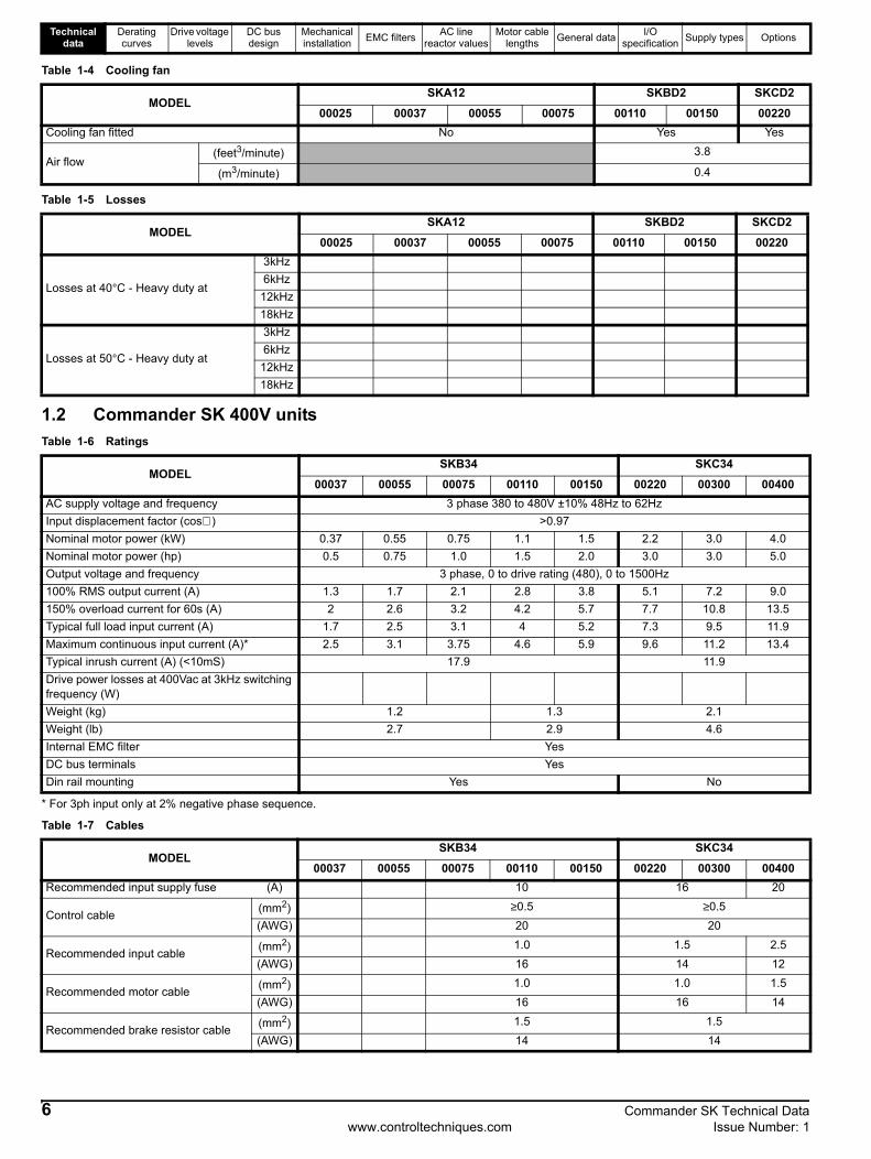
Table 1-4 Cooling fan
Table 1-5 Losses
1.2 Commander SK 400V unitsTable 1-6 Ratings
* For 3ph input only at 2% negative phase sequence.
Table 1-7 Cables
MODELSKA12 SKBD2 SKCD2
00025 00037 00055 00075 00110 00150 00220Cooling fan fitted No Yes Yes
Air flow(feet3/minute) 3.8
(m3/minute) 0.4
MODELSKA12 SKBD2 SKCD2
00025 00037 00055 00075 00110 00150 00220
Losses at 40°C - Heavy duty at
3kHz6kHz
12kHz18kHz
Losses at 50°C - Heavy duty at
3kHz6kHz
12kHz18kHz
MODELSKB34 SKC34
00037 00055 00075 00110 00150 00220 00300 00400AC supply voltage and frequency 3 phase 380 to 480V ±10% 48Hz to 62HzInput displacement factor (cos∅ ) >0.97Nominal motor power (kW) 0.37 0.55 0.75 1.1 1.5 2.2 3.0 4.0Nominal motor power (hp) 0.5 0.75 1.0 1.5 2.0 3.0 3.0 5.0Output voltage and frequency 3 phase, 0 to drive rating (480), 0 to 1500Hz100% RMS output current (A) 1.3 1.7 2.1 2.8 3.8 5.1 7.2 9.0150% overload current for 60s (A) 2 2.6 3.2 4.2 5.7 7.7 10.8 13.5Typical full load input current (A) 1.7 2.5 3.1 4 5.2 7.3 9.5 11.9Maximum continuous input current (A)* 2.5 3.1 3.75 4.6 5.9 9.6 11.2 13.4Typical inrush current (A) (<10mS) 17.9 11.9Drive power losses at 400Vac at 3kHz switching frequency (W)Weight (kg) 1.2 1.3 2.1Weight (lb) 2.7 2.9 4.6Internal EMC filter YesDC bus terminals YesDin rail mounting Yes No
MODELSKB34 SKC34
00037 00055 00075 00110 00150 00220 00300 00400Recommended input supply fuse (A) 10 16 20
Control cable (mm2) ≥0.5 ≥0.5(AWG) 20 20
Recommended input cable (mm2) 1.0 1.5 2.5(AWG) 16 14 12
Recommended motor cable (mm2) 1.0 1.0 1.5(AWG) 16 16 14
Recommended brake resistor cable (mm2) 1.5 1.5(AWG) 14 14
6 Commander SK Technical Datawww.controltechniques.com Issue Number: 1

Technical data
Derating curves
Drive voltage levels
DC bus design
Mechanical installation EMC filters AC line
reactor valuesMotor cable
lengths General data I/O specification Supply types Options
Table 1-8 Braking resistor
Table 1-9 Cooling fan
Table 1-10 Losses
MODELSKB34 SKC34
00037 00055 00075 00110 00150 00220 00300 00400Minimum braking resistor value (Ω)** 100 100 55Recommended braking resistor value (Ω) 200 200 150 100Resistor peak power rating (kW)* 3.4 3.4 4.6 6.9Maximum braking current (A) 8.3 8.3 15.1
MODELSKB34 SKC34
00037 00055 00075 00110 00150 00220 00300 00400Cooling fan fitted No Yes Yes
Air flow(feet3/minute) 3.8
(m3/minute) 0.4
MODELSKB34 SKC34
00037 00055 00075 00110 00150 00220 00300 00400
Losses at 40°C - Heavy duty at
3kHz6kHz
12kHz18kHz
Losses at 50°C - Heavy duty at
3kHz6kHz
12kHz18kHz
Commander SK Technical Data 7Issue Number: 1 www.controltechniques.com

Technical data
Derating curves
Drive voltage levels
DC bus design
Mechanical installation EMC filters AC line
reactor valuesMotor cable
lengths General data I/O specification Supply types Options
8 Commander SK Technical Datawww.controltechniques.com Issue Number: 1
2 Derating curves

Technical data
Derating curves
Drive voltage levels
DC bus design
Mechanical installation EMC filters AC line
reactor valuesMotor cable
lengths General data I/O specification Supply types Options
3 Drive voltage levels
* These are the absolute minimum DC voltages that the drive can be supplied with. If the drive is not supplied with at least this voltage, it will not reset out of a UU trip at power up.Output frequency: 0 to 1500HzOutput voltage: 3 phase, 0 to drive rating (240 or 480Vac maximum set by Pr 08).
Low DC bus operation (Pr 6.10)0 Low DC bus operation disabled1 Low DC bus operation enabled
The Low DC bus operation is designed to enable 3 phase 400VAC (medium voltage) Commander SKs to be run off a single phase 200VAC (low voltage) supply in the event of a primary 400VAC supply failure. When the primary supply fails, the back up supply can be switched in. This will allow the drive to control the motor at a reduced power, for example to move an elevator up or down to the next floor.There is no de-rating as such when low DC bus operation is enabled however the power will be limited by the reduced voltage and ripple generated on the DC bus of the drive.Figure 3-1 Low DC bus operation
When Pr 6.10 is enabled and the DC bus voltage is less than 330VDC, the drives display will flash LoAC (Low AC) to indicate that it is running off the low voltage back up supply.
NThis mode is designed for use with a backup power supply and not for using a 400VAC (medium voltage) Commander SK in a 200VAC (low voltage) application. As shown in the above diagram, the drives power down save parameters are saved at point 2. If the drive was to be used on a 200VAC supply, the DC bus will never fall through point 2 and power down save parameters will not be saved.
Low DC bus operation voltage levels (Pr 6.10 enabled)>425VDC - normal operation<330VDC - LoAC operation<230VDC - UV trip
Condition 200V drives 400V drivesOV trip level 415 830Braking level 390 780
Rated upper level (AC mains +10% x 1.4142) 373 747Rated lower level (AC mains -10% x 1.4142) 255 484
*UV reset level 215 425UV trip level 175 330
Standard ramp voltage 375 EUR: 750USA: 775
DCBus(VDC)
600
200
400
0
NOTE
Commander SK Technical Data 9Issue Number: 1 www.controltechniques.com

Technical data
Derating curves
Drive voltage levels
DC bus design
Mechanical installation EMC filters AC line
reactor valuesMotor cable
lengths General data I/O specification Supply types Options
3.1 Input voltage3.1.1 Single phase200V to 240V ±10%48Hz to 62Hz
3.1.2 Three phase 200V200V to 240V ±10%48Hz to 62HzPhase imbalance 3% (between phases) or 2% negative phase sequence (IEC 146-1-1 Immunity class C)
3.1.3 Three phase 400V380V to 480V ±10%48Hz to 62HzPhase imbalance 3% (between phases) or 2% negative phase sequence (IEC 146-1-1 Immunity class C)
It is possible to run the drives on lower supply voltages than those specified above (up to -20%) but only with de-rating of the product. Running a 400V product on a 230V single phase supply (at a very much reduced output power) is possible on frame sizes B & C.On products without a DC bus choke (up to 4kW), the maximum supply capacity connected to the drive without using external line chokes will be 5kA short circuit current.
10 Commander SK Technical Datawww.controltechniques.com Issue Number: 1

Technical data
Derating curves
Drive voltage levels
DC bus design
Mechanical installation EMC filters AC line
reactor valuesMotor cable
lengths General data I/O specification Supply types Options
Commander SK Technical Data 11Issue Number: 1 www.controltechniques.com
4 DC bus designTable 4-1 Commander SK 200V units
Table 4-2 Commander SK 400V units
Table 4-3 Inrush resistor
Model DC Bus CapacitanceµF
DC bus inductancemH
Inrush resistanceΩ at 25oC
SKA1200025 330 22SKA1200037 390 22SKA1200055 660 22SKA1200075 780 22SKBD200110 940 44SKBD200150 1410 44SKCD200220 1880 66
Model DC Bus CapacitanceµF
DC bus inductancemH
Inrush resistanceΩ at 25oC
SKB3400037 165 44SKB3400055 165 44SKB3400075 165 44SKB3400110 195 44SKB3400150 235 44SKC3400220 470 66SKC3400300 470 66SKC3400400 470 66
Frame VoltagePowerRating(kW)
InrushResistor
(Ω)
Numberin series
EffectiveInrush
Resistance(Ω)
PkInrush
Current(A)
A 200 0.25 22 1 22 17.9A 200 0.37 22 1 22 17.9A 200 0.55 22 1 22 17.9A 200 0.75 22 1 22 17.9B 200 1.1 22 2 44 8.9B 200 1.5 22 2 44 8.9B 400 0.37 22 2 44 17.9B 400 0.55 22 2 44 17.9B 400 0.75 22 2 44 17.9B 400 1.1 22 2 44 17.9B 400 1.5 22 2 44 17.9C 200 2.2 22 3 66 6.0C 400 2.2 22 3 66 11.9C 400 3 22 3 66 11.9C 400 4 22 3 66 11.9

Technical data
Derating curves
Drive voltage levels
DC bus design
Mechanical installation EMC filters AC line
reactor valuesMotor cable
lengths General data I/O specification Supply types Options
5 Mechanical installation5.1 Mechanical dimensionsFigure 5-1 Size A mounting dimensions
NIf DIN rail mounting is used in an installation where the drive is to be subjected to shock or vibration, it is recommended that the bottom mounting screws are used to secure the drive to the back plate. If the installation is going to be subjected to heavy shock and vibration, then it is recommended that the drive is surface mounted rather than DIN rail mounted
A B F
C
D
E
G
Ca Cb
Dimension mm in A
BC
CaCbDEFG
14015453
26.526.57514514386.3
5.516.062.091.041.042.955.715.633.40
Ca Cb
E
Holesize 4 x M4
NOTE
12 Commander SK Technical Datawww.controltechniques.com Issue Number: 1

Technical data
Derating curves
Drive voltage levels
DC bus design
Mechanical installation EMC filters AC line
reactor valuesMotor cable
lengths General data I/O specification Supply types Options
Figure 5-2 Size B mounting dimensions
NIf DIN rail mounting is used in an installation where the drive is to be subjected to shock or vibration, it is recommended that the bottom mounting screws are used to secure the drive to the back plate. If the installation is going to be subjected to heavy shock and vibration, then it is recommended that the drive is surface mounted rather than DIN rail mounted
A B F
E
CD
Ca Cb
G
Dimension mm in A
BCCaCbDEFG
19020555
23.531.585156194
155.5
7.488.072.170.931.243.356.147.646.12
D
Ca Cb
E
Holesize 4 x M4
NOTE
Commander SK Technical Data 13Issue Number: 1 www.controltechniques.com

Technical data
Derating curves
Drive voltage levels
DC bus design
Mechanical installation EMC filters AC line
reactor valuesMotor cable
lengths General data I/O specification Supply types Options
Figure 5-3 Size C mounting dimensions
Size C is not DIN rail mountable.
A B F
CD
ECa Cb
Dimension mm in A
BCCaCbDEF
24025870.531
39.5100173244
9.4510.162.781.221.563.946.819.61
D
Ca Cb
E
Holesize 4 x M4
14 Commander SK Technical Datawww.controltechniques.com Issue Number: 1

Technical data
Derating curves
Drive voltage levels
DC bus design
Mechanical installation EMC filters AC line
reactor valuesMotor cable
lengths General data I/O specification Supply types Options
5.2 Minimum mounting clearancesFigure 5-4 Minimum mounting clearances (size A only)
100mm(3.94in)
100mm(3.94in)
Commander SK Technical Data 15Issue Number: 1 www.controltechniques.com

Technical data
Derating curves
Drive voltage levels
DC bus design
Mechanical installation EMC filters AC line
reactor valuesMotor cable
lengths General data I/O specification Supply types Options
6 EMC filtersEMC filters are available as optional extra parts where required.
Table 6-1 EMC filters
6.1 Filter dataTable 6-2 EMC filter data
Used withNumber
of phases
Filter part number Filter type Mounting Max motor cable length (m)CT Schaffner Standard Low leakage Footprint Side
SKA1200025 toSKA1200075 1
4200-6122 FS6512-12-07 Y Y Y 100m4200-6123 FS6512-12-07-LL Y Y Y
SKBD200110 toSKBD200150
14200-6212 FS6513-20-07 Y Y Y
SKBD200110 toSKBD200150
3
SKB3400037 toSKB3400150 3
4200-6213 FS6513-10-07 Y Y Y
SKCD200110 14200-6310 FS6514-27-07 Y Y Y
SKCD200110 3
SKC3400220 to SKC3400400 3
4200-6311 FS6514-14-07 Y Y Y
Used withNumber
of phases
Filter part numberMax.
power losses
IP rating
WeightOperational leakage
current
Worst case leakage current
Filter terminal tightening
torque
Filter current rating
CT Schaffner W Kg lb mA mA Nm lb ft A
SKA1200025 toSKA1200075 1
4200-6122 FS6512-12-07 3.7W 0.75 1.7 51.2 96 0.8 0.6 124200-6123 FS6512-12-07-LL 0.6 1.4 2.5 5 0.8 0.6 12
SKBD200110 toSKBD200150
1
SKBD200110 toSKBD200150
3
SKB3400037 toSKB3400150 3
SKCD200110 1
SKCD200110 3
SKC3400220 to SKC3400400
3
16 Commander SK Technical Datawww.controltechniques.com Issue Number: 1

Technical data
Derating curves
Drive voltage levels
DC bus design
Mechanical installation EMC filters AC line
reactor valuesMotor cable
lengths General data I/O specification Supply types Options
6.2 ConformityTable 6-3 Conformity
Used with Number of phases
Motor cable length
m
Filter and switching frequency
Internal Standard Low leakage
3kHz 6kHz 12kHz 18kHz 3kHz 6kHz 12kHz 18kHz 3kHz 6kHz 12kHz 18kHz
SKA1200025 toSKA1200075 1
515205080
SKBD200110 toSKBD200150 1
515205080
SKBD200110 toSKBD200150 3
515205080
SKB3400037 toSKB3400150 3
515205080
SKCD200110 1
515205080
SKCD200110 3
515205080
SKC3400220 to SKC3400400 3
515205080
Commander SK Technical Data 17Issue Number: 1 www.controltechniques.com

Technical data
Derating curves
Drive voltage levels
DC bus design
Mechanical installation EMC filters AC line
reactor valuesMotor cable
lengths General data I/O specification Supply types Options
7 AC line reactor valuesTable 7-1 AC line reactor values
7.1 Line reactorsInput line reactors reduce the risk of damage to the drive resulting from poor phase balance or severe disturbances on the supply network.Where line reactors are to be used, reactance values of approximately 2% are recommended. Higher values may be used if necessary, but may result in a loss of drive output voltage because of voltage drop. This may reduce torque at high speed.For all drive ratings, 2% line reactors permit drives to be used with a supply imbalance of up to 3.5% negative phase sequence (equivalent to 5% voltage imbalance between phases).A line reactor should be connected in each phase of the supply. Each drive should have its own line reactor. Three individual reactors or a single three phase reactor can be used. Single phase drives only require one single phase line reactor.Severe disturbances may be caused by the following factors:• Power factor correction equipment connected close to the drive• Large DC drives having no or inadequate line reactors connected to the supply• Direct-on-line started motor(s) connected to the supply such that when any of these motors are started, the voltage dip exceeds 20%.• Supply capacity exceeds 200kVA• Fault current exceeds 5kASuch disturbances may cause excessive peak currents to flow in the input power circuit of the drive. This may cause nuisance tripping and in extreme cases, failure of the drive.Low power drives may also be susceptible to disturbance when connected to supplies with high rated capacity.
NRFI filters (for EMC purposes) do not give adequate protection against these conditions.
7.2 Reactor current ratingsContinuous current:Not less than the continuous input current rating of the drive.Repetitive peak current rating:Not less than twice the continuous input current rating of the drive.Voltage fluctuation (Flicker) standard EN61000-3-3 (IEC61000-3-3)Those models that fall within the scope of EN61000-3-3, as stated in the declaration of Conformity, conform to the requirements for manual switching, i.e. the voltage dip caused when a drive at room temperature is switched on is within the permitted limits.The drive does not of itself cause periodic voltage fluctuation in normal operation. The installer must ensure that the control of the drive is such that periodic fluctuations in supply current do not infringe the flicker requirements where applicable. Note that large periodic load fluctuations in the frequency range of between 1Hz and 30Hz are particularly inclined to cause irritating lighting flicker and are subject to stringent limits under EN61000-3-3.
Drives used with Reactor part number
Input phases
Inductance Continuous rms current
Peak current Weight Dimensions
mH A A Kg L D HSKA1200025 4402-0224 1 2.25 6.5 13 0.8 72 65 90SKA1200037 4402-0224 1 2.25 6.5 13 0.8 72 65 90SKA1200055 4402-0225 1 1.0 15.1 30.2 1.1 82 75 100SKA1200075 4402-0225 1 1.0 15.1 30.2 1.1 82 75 100SKBD200110SKBD200150SKCD200220SKB3400037SKB3400055SKB3400075SKB3400110SKB3400150SKC3400220SKC3400300SKC3400400
NOTE
18 Commander SK Technical Datawww.controltechniques.com Issue Number: 1

Technical data
Derating curves
Drive voltage levels
DC bus design
Mechanical installation EMC filters AC line
reactor valuesMotor cable
lengths General data I/O specification Supply types Options
7.3 Input line reactors for harmonics standards EN61000-3-2 and IEC61000-3-2The following input line reactors allow the Commander SK 0.25 - 0.55kW drives to conform to harmonic standards EN61000-3-2 and IEC61000-3-2.Table 7-2 Input line reactors for harmonics standards EN61000-3-2 and IEC61000-3-2
EN61000-3-2 and IEC61000-3-2 applies to equipment with a supply voltage of 230VAC and a line current up to 16A, single or three phase. Professional equipment with rated input power exceeding 1kW has no limits - this applies to the 0.75kW drive. Further information on EN61000-3-2 and IEC61000-3-2 is included on the EMC data sheets available from your local Control Techniques drive centre or distributor.
7.4 Voltage fluctuation (Flicker) standard EN61000-3-3 (IEC61000-3-3)Those models which fall within the scope of EN61000-3-3, as stated in the Declaration of Conformity, conform to the requirements for manual switching, i.e. the voltage dip caused when a drive at room temperature is switched on is within the permitted limits.The drive does not of itself cause periodic voltage fluctuation in normal operation. The installer must ensure that the control of the drive is such that periodic fluctuations in supply current do not infringe the flicker requirements where applicable. Note that large periodic load fluctuations in the frequency range of between 1Hz and 30Hz are particularly inclined to cause irritating lighting flicker and are subject to stringent limits under EN61000-3-3.
Figure 7-1 Input line reactor 4402-0224
All dimensions in mm
Drive Reactor part number
Drive power de-rating
Input power Inductance Continuous
rms currentW mH
SKA12200025 4400-0239 None 374 4.5 2.4SKA12200037 4400-0238 None 553 9.75 3.2SKA12200055 4400-0237 18% 715 16.25 4.5
Commander SK Technical Data 19Issue Number: 1 www.controltechniques.com

Technical data
Derating curves
Drive voltage levels
DC bus design
Mechanical installation EMC filters AC line
reactor valuesMotor cable
lengths General data I/O specification Supply types Options
Figure 7-2 Input line reactor 4402-0225
All dimensions in mm
20 Commander SK Technical Datawww.controltechniques.com Issue Number: 1

Technical data
Derating curves
Drive voltage levels
DC bus design
Mechanical installation EMC filters AC line reactor
valuesMotor cable
lengths General data I/O specification Supply types Options
Commander SK Technical Data 21Issue Number: 1 www.controltechniques.com
8 Motor cable lengthsTable 8-1 Motor cable lengths
The capacitive loading of the drive by the motor cable means that the cable length limits shown in table 8-1 must be observed. Failure to do so can result in spurious OI.AC tripping of the drive. If longer cable lengths are required, consult your local Drive Centre or Distributor.The maximum cable lengths were measured using cable with capacitance of 130pF/m.This capacitance was measured by taking one phase as one node and the screen (shield) and earth (ground) (if any) as the other node, then measuring the capacitance between the two points.
Drive frame sizeMaximum motor cable length
At 3kHz switching frequency
At 6kHz switching frequency
At 12kHz switching frequency
At 18kHz switching frequency
A 75mB 100mC 100m

Technical data
Derating curves
Drive voltage levels
DC bus design
Mechanical installation EMC filters AC line reactor
valuesMotor cable
lengthsGeneral
dataI/O
specification Supply types Options
9 General data9.1 Ratings9.1.1 IP ratingIP20First digit: Protection against contact and ingress of foreign bodies.2 - Protection against medium size foreign bodies ∅ > 12mm (finger)Second digit: protection against ingress of water.0 - No protection
9.1.2 NEMA ratingCommander SK sizes A to CNEMA 1 with optional NEMA 1 kit
9.1.3 NEMA Type 1 enclosure ratingEnclosures are intended for indoor use, primarily to provide a degree of protection against contact with the enclosed equipment or locations where unusual service conditions do not exist.
9.2 Input phase imbalance3% between phases or 2% negative phase sequence.
9.3 Ambient temperature-10°C (14°F) to 40°C (104°F) at 3kHzOperation up to 55°C (131°F) with de-rating.(see de-rating curves for further information)
9.4 Storage temperature-40 to +60°C (-40 to +140°F) for 12 months max
9.5 AltitudeRated altitude: 1000m (3250 ft)Reduce the normal full load current by 1% for every 100m (325 ft) above 1000m (3250 ft) up to a maximum of 3000m (9750 ft).
9.6 HumidityMaximum relative humidity 95% (non-condensing).
9.7 Storage humidityMaximum relative humidity 93%, 40°C, 4 days.
9.8 Pollution degreeDesigned for operation in Pollution degree 2 environments (dry, non-conductive contamination only)
9.9 Materials
9.10 Vibration9.10.1 RandomStandard: In accordance with IEC68-2-64 and IEC68-2-36: Test Fh
Severity: 1.0 m2/s3 (0.01g2/Hz) ASD from 5 to 20Hz, -3dB/octave from 20 to 200HzDuration: 30 minutes in each of 3 mutually perpendicular axes.
9.10.2 SinusiodalStandard: IEC68-2-6: Test FcFrequency range: 2 to 500HzSeverity: 3.5mm peak displacement from 2 to 9Hz
10m/s2 peak displacement from 9 to 200Hz
15m/s2 peak displacement from 200 to 500HzSweep rate: 1 octave/minuteDuration: 15 minutes in each of 3 mutually perpendicular axes.
22 Commander SK Technical Datawww.controltechniques.com Issue Number: 1

Technical data
Derating curves
Drive voltage levels
DC bus design
Mechanical installation EMC filters AC line reactor
valuesMotor cable
lengthsGeneral
dataI/O
specification Supply types Options
9.10.3 BumpStandard: IEC68-2-29: Test EbSeverity: 18g, 6ms, half sineNumber of bumps: 600 (100 in each direction of axes)
9.11 Frequency accuracy0.01%
9.12 Resolution0.1Hz
9.13 Output frequency range0 to 1500Hz
9.14 Starts per hourElectric startsWith the supply permanently connected the number of electronic motor starts per hour is only limited by motor and drive thermal limits. Power startsThe number of starts by connection of the ac supply is limited. The start up circuit will allow for three consecutive starts at 3-second intervals on initial power up. Exceeding the rated number of starts per hour, presented in the table below, could result in damage to the start up circuit.
9.15 Start-up time The soft-start circuit must charge the dc bus and SMPS outputs and stabilise to allow the control processor to start operation in the following times:-
9.16 Serial communicationsModbus RTU
9.17 Switching frequenciesThe software allows for the following switching frequencies:3, 6, 12, 18kHz
9.18 EMC
9.19 HarmonicsThe Commander SK industrial AC variable speed drives are classified as class A professional equipment as defined in BS EN61000-3-2: 1995. Drives with input power equal to or below 1kW that do not meet the requirements of EN61000-3-2 are to be corrected, to ensure compliance, at the point of installation using suitable AC line chokes. See 7.2 (Reactor current ratings)
9.20 Acoustic noise
Drive frame size Maximum AC line starts per hourevenly spaced in time
A, B & C 20
Drive frame size Maximum time taken to charge DC busand SMPS outputs to stabilise
A, B & C 1s
Frame Power ratings Condition Max SPL measurement (dBA)A All ratings N/A None contributed by drive (no fan).B <0.75kW MV N/A None contributed by drive (no fan).
B >0.75kW MVRdy mode fan off 42Rdy mode fan on 50
C All ratingsRdy mode fan off 42Rdy mode fan on 53
Commander SK Technical Data 23Issue Number: 1 www.controltechniques.com

Technical data
Derating curves
Drive voltage levels
DC bus design
Mechanical installation EMC filters AC line
reactor valuesMotor cable
lengths General data I/O specification Supply types Options
10 I/O specification
The control circuits are isolated from the power circuits in the drive by basic insulation (single insulation) only. The installer must ensure that the external control circuits are insulated from human contact by at least one layer of insulation (supplementary insulation) rated for use at the AC supply voltage.
If the control circuits are to be connected to other circuits classified as Safety Extra Low Voltage (SELV) (e.g. to personal computer), an additional isolating barrier must be included in order to maintain the SELV classification.
T1 0V common
T2 Analog input 1 (A1), either voltage or currentVoltage : Current input 0 to 10V : mA as parameter rangeParameter range 4-20, 20-4, 0-20, 20-0, 4-.20, 20-.4, Volt
Scaling Input range automatically scaled to Pr 01 (Minimum set speed) to Pr 02 (Maximum set speed)
Input impedance 200Ω (current) : 100kΩ (voltage)Resolution 0.1%Accuracy ± 2% Sample time 6mS Absolute maximum voltage range +35V to -18V with respect to 0V common
T3 +10V reference outputMaximum output current 5mAProtection Tolerates continuous short circuit to 0VAccuracy ± 2%
T4 Analog input 2 (A2), either voltage or digital inputVoltage : Digital input 0 to +10V : 0 to +24V
Scaling (as voltage input) Input range automatically scaled to Pr 01 Minimum set speed / Pr 02 Maximum set speed
Input impedance 100kΩ (voltage) : 6k8 (digital input)Resolution 0.1%Accuracy ± 2% Sample time 6mS Nominal threshold voltage +10V (positive logic only)Absolute maximum voltage range +35V to -18V with respect to 0V common
T5T6 Status relay - Drive healthy (Normally open)
Voltage rating 240Vac/30DCCurrent rating 2A/6A (resistive)Contact isolation 1.5kVac (over voltage category II)Update time 1.5ms
Operation of contact
OPEN- AC supply removed from drive.- AC supply applied to drive with drive in tripped condition.CLOSED- AC supply applied to drive with drive in a 'ready to run' or 'running' condition (not tripped)
WARNING
WARNING
24 Commander SK Technical Datawww.controltechniques.com Issue Number: 1

Technical data
Derating curves
Drive voltage levels
DC bus design
Mechanical installation EMC filters AC line
reactor valuesMotor cable
lengths General data I/O specification Supply types Options
NThe total available current from the digital output plus the +24V output is 100mA
NIf the drives enable terminal is opened, the drives output is disabled and the motor will coast to a stop. The drive will not re-enable for 1.0s after the enable terminal is closed again.
10.1 Drive resetIf the enable terminal is opened, the drive’s output is disabled and the motor will coast to a stop. The drive will not re-enable for 1.0s after the enable terminal is closed again.*Following a drive trip, opening and closing the enable terminal will reset the drive. If the run forward or run reverse terminal is closed, the drive will run straight away.**Following a drive trip and a reset via the stop/reset key, the enable, run forward or run reverse terminals will need to be opened and closed to allow the drive to run. This ensures that the drive does not run when the stop/reset key is pressed. The enable, run forward and run reverse terminals are level triggered apart from after a trip where they become edge triggered. See * and ** above.If the enable and run forward or enable and run reverse terminals are closed when the drive is powered up, the drive will run straight away up to a set speed.If both the run forward and run reverse terminals are closed, the drive will stop under the control of the ramp and stopping modes set in Pr 30 and Pr 31
Provide fuse or other over-current protection in status relay circuit.
B1 Analog voltage output - Motor speedVoltage output 0 to +10V
Scaling 0V represents 0Hz/rpm output+10V represents the value in Pr 02, maximum set speed
Maximum output current 5mAResolution 0.4%Accuracy ± 5% Update time 6msProtection Tolerates continuous short circuit to 0V
B2 +24V outputMaximum output current 100mAProtection Tolerates continuous short circuit to 0VAccuracy ± 15%
B3 Digital output - Zero speedVoltage range 0 to +24VMaximum output current 50mA at +24V (current source)Output impedance 6.8kΩ Update time 1.5msAbsolute maximum voltage range +35V to -1V with respect to 0V common
B4B5B6B7
Digital Input - Enable/Reset */**Digital Input - Run Forward **Digital Input - Run Reverse **Digital Input - Local/Remote speed reference select (A1/A2)
Logic Positive logic onlyVoltage range 0 to +24VInput impedance 6.8kΩ Sample time 1.5msNominal threshold voltage +10VAbsolute maximum voltage range +35V to -18V with respect to 0V common
WARNING
NOTE
NOTE
Commander SK Technical Data 25Issue Number: 1 www.controltechniques.com

Technical data
Derating curves
Drive voltage levels
DC bus design
Mechanical installation EMC filters AC line
reactor valuesMotor cable
lengths General data I/O specification Supply types Options
10.2 Sample/update timesThe sample/update times shown in the control terminal specification within the Commander SK Technical Guide are the default sample/update times for the default terminal set-up. The sample/update time depends on the destination/source parameter of the digital or analog inputs/outputs.These sample/update times are the sample or update times for the control microprocessor. The actual sample/update time maybe slightly longer due to the design of the Commander SK.
10.3 Task routine timesAt the beginning of each menu, there is a single line parameter description and this contains the update rate for each parameter. This time signifies the task routine time in the software that the parameter is updated on. For a background task, the time depends on processor loading i.e. what functions the drive is carrying out and what advanced menus are being used.
From practical tests carried out:
Update rate Microprocessor update time Comments2ms 2ms Updated every 2ms5ms 5ms Updated every 5ms21ms 21ms Updated every 21ms128ms 128ms Updated every 128msReset N/A Destination/source parameter changed on a ResetB Background
Updated as a background task. Update rate depends on processor loading.BR Background read
BW Background write
Condition Minimum Maximum AverageTime for drive to respond to a run command 4.1ms 5.62ms 5.02msTime for the drive to respond to a stop command 2.82ms 3.94ms 3.31msTime for the drive to respond to a step change in analog input voltage 7.93ms
26 Commander SK Technical Datawww.controltechniques.com Issue Number: 1

Technical data
Derating curves
Drive voltage levels
DC bus design
Mechanical installation EMC filters AC line
reactor valuesMotor cable
lengths General data I/O specification
Supply types Options
11 Supply typesCommander SK is suitable for use with any supply type, i.e. TN-S, TN-C-S, TT, IT, with a grounding at any potential, i.e. neutral, centre or corner ('grounded-delta').Drives are suitable for use on supplies of installation category III and lower, according to IEC60664-1. This means they may be connected permanently to the supply at its origin in a building, but for outdoor installation, additional over-voltage suppression (transient voltage surge suppression) must be provided to reduce category IV to category III.
11.1 AC supply requirements Single phase drivesSingle phase - Between one phase and neutral of a star connected three phase supply.
- Between two phases of a three phase supply.Three phase modelsThree-phase star or delta supply of the correct voltage.Dual rated modelsAny of the above supplies can be used.
11.2 Safety
11.3 CablesRecommended cable sizes are given in tables 1-2 & 1-7. They are only a guide; refer to local wiring regulations for correct size of cables. In some cases, a larger cable size is required to avoid excessive voltage drop.Use 105°C (221°F) (UL 60/75°C temp rise) PVC-insulated cable with copper conductors having a suitable voltage rating, for the following power connectors:
• AC supply to external EMC filter (when used)• AC supply (or external EMC filter) to drive• Drive to motor• Drive to braking resistor
Motor cablesThe recommended output cable sizes assume that the motor maximum current matches that of the drive. Where a motor of reduced rating is used,
Electric shock risk The voltages present in the following locations can cause severe electric shock and may be lethal:• AC supply cables and connections• DC and brake cables and connections• Output cables and connections• Many internal parts of the drive, and external option unitsUnless otherwise indicated, control terminals are single insulated and must not be touched.
Isolation deviceThe AC supply must be disconnected from the drive using an approved isolation device before any cover is removed from the drive or before any servicing work is performed.
STOP functionThe STOP function does not remove dangerous voltages from the drive, the motor orany external option units.
Stored chargeThe drive contains capacitors that remain charged to a potentially lethal voltage after the AC supply has been disconnected. If the drive has been energized, the AC supply must be isolated at least ten minutes before work may continue.Normally, the capacitors are discharged by an internal resistor. Under certain, unusual fault conditions, it is possible that the capacitors may fail to discharge, or be prevented from being discharged by a voltage applied to the output terminals. If the drive has failed in a manner that causes the display to go blank immediately, it is possible the capacitors will not be discharged. In this case, consult Control Techniques or their authorized distributor.
Equipment supplied by plug and socketSpecial attention must be given if the drive is installed in equipment which is connected to the AC supply by a plug and socket. The AC supply terminals of the drive are connected to the internal capacitors through rectifier diodes which are not intended to give safety isolation. If the plug terminals can be touched when the plug is disconnected from the socket, a means of automatically isolating the plug from the drive must be used (e.g. a latching relay).
WARNING
WARNING
WARNING
WARNING
WARNING
Commander SK Technical Data 27Issue Number: 1 www.controltechniques.com

Technical data
Derating curves
Drive voltage levels
DC bus design
Mechanical installation EMC filters AC line
reactor valuesMotor cable
lengths General data I/O specification
Supply types Options
the cable rating may be chosen to match that of the motor. To ensure that the motor and cable are protected against overload, the drive must be programmed with the correct motor rated voltage.
11.4 FusesThe AC supply to the drive must be fitted with suitable protection against overload and short circuits. Tables 1-2 & 1-7 show the recommended fuse ratings. Failure to observe this requirement will cause risk of fire.A fuse or other protection device must be included in all live connectors to the AC supply.An MCB (miniature circuit breaker) or MCCB (moulded case circuit breaker) with type C tripping characteristics maybe used in place of fuses as long as the fault clearing capacity is sufficient for the installation.Fuse typesEurope: Type gG HRC fuses complying with EN60269 parts 1 and 2 (BS88)USA: Bussman Limitron KTK series, class CC fast acting fuses up to 30A, class J above 30A.
11.5 Ground connectionsThe drive must be connected to the system ground of the AC supply. The ground wiring must conform to local regulations and codes of practice.The ground loop impedance must conform to the requirements of local safety regulations. The ground connections must be inspected and tested at appropriate intervals.Use of RCDs - residual current deviceThere are three common types of RCD/ELCBType AC - detects AC fault currentsType A - detects AC and pulsating DC fault currents (provided the DC current reaches zero at least once every half cycle)Type B - detects AC, pulsating DC, and smooth DC fault currents
• Type AC should never be used with inverter drives• Type A can only be used with single phase drives• Type B must be used with three phase drives.It is recommended that only Type B RCDs be used with inverter drivesIf an external EMC filter is used, a delay of at least 50ms should be incorporated in the RCD to ensure spurious trips are not seen. The leakage current is likely to exceed the trip level if all of the phases are not energised simultaneously.
11.6 Ground leakageThe ground leakage current depends upon the internal EMC filter is fitted. The drive is supplied with the filter fitted. Instructions for removal of the internal EMC filter are given in Section 4.3.1 of the getting started guide.With internal EMC filter fittedSize A10mA AC at 230V, 50Hz (proportional to supply voltage and frequency)
Size B and C1 phase 200V product20mA AC at 230V, 50Hz (proportional to supply voltage and frequency)3-phase 200V product7mA AC at 230V, 50Hz (proportional to supply voltage and frequency)3-phase 400V product8.2mA AC at 415V, 50Hz (proportional to supply voltage and frequency)30uA DC (10Ω)
NThe above leakage currents are just the leakage currents of the drive with the internal EMC filter connected and do not take into account any leakage currents of the motor or motor cable.
With internal EMC filter removed<1mA
NIn both cases, there is an internal voltage surge suppression device connected to ground. Under normal circumstances, this carries negligible current.
When the internal EMC filter is fitted, the leakage current is high. In this case, a permanent fixed ground connection must be provided using two independent conductors each with a cross-section equal to or exceeding that of the supply conductors. The drive is provided with two earth terminals to facilitate this. The purpose is to prevent a safety hazard occurring if the connection is lost.
NOTE
NOTE
WARNING
28 Commander SK Technical Datawww.controltechniques.com Issue Number: 1

Technical data
Derating curves
Drive voltage levels
DC bus design
Mechanical installation EMC filters AC line
reactor valuesMotor cable
lengths General data I/O specification
Supply types Options
11.7 Use of earth leakage circuit breakers (ELCB)/residual current device (RCD)There are three common types of ELCB/RCD:Type AC - detects AC fault currentsType A - detects AC and pulsating DC fault currents (provided the DC current reaches zero at least once every half cycle)Type B - detects AC, pulsating DC and smooth DC fault currents
• Type AC should never be used with drives• Type A can only be used with single phase drives• Type B must be used with three phase drives
Commander SK Technical Data 29Issue Number: 1 www.controltechniques.com

Technical data
Derating curves
Drive voltage levels
DC bus design
Mechanical installation EMC filters AC line
reactor valuesMotor cable
lengths General data I/O specification Supply types Options
12 OptionsAll Commander SK Solutions Modules are colour-coded, in order to make identification easy. The following table shows the colour-code key and gives further details on their function.* Only used on sizes B & C (not compatible with size A)
Type Option Colour Name Further details
Minimum option
firmware version
Unidrive SP compatable
?
Fieldbus*
Purple SM-PROFIBUS-DPPROFIBUS-DP optionPROFIBUS-DP adapter for communication with Commander SK
03.00.00 Yes
Medium Grey SM-DeviceNet
DeviceNet optionDeviceNet adapter for communication with Commander SK
03.00.00 Yes
Dark Grey SM-INTERBUS
INTERBUS optionINTERBUS adapter for communication with Commander SK
03.00.00 Yes
Light Grey SM-CANopen
CANopen optionCANopen adapter for communication with Commander SK
03.00.00 Yes
Beige SM-EthernetEthernet optionEthernet adapter for communication with Commander SK
03.00.00 Yes
Extended IO
Dark Yellow SM-I/O Lite
I/O Lite optionIncreases the I/O capability by adding the following to the existing I/O in the drive:• ±10V bi-polar / 4-20mA analog input• 1.0-10V / 4-20mA analog output• Digital inputs x 3• Encoder speed reference input (A, /A, B, /B)• Relay x 1
Yes
Dark Red SM-I/O TimerTimer I/O optionSame features is I/O Lite, but with the addition of a battery backed-up real time clock.
Yes
Turquoise SM-PELVPELV optionIsolated digital I/O to NAMUR NE37 (for chemical industry).
Yes
Automation
Black SmartStick
SmartStick optionUpload drive parameters to the SmartStick for storage or for easy set-up of identical drives or downloading to replacement drives
No
White LogicStick
LogicStick optionThe LogicStick plugs into the front of the drive and enables the user to program PLC functions within the drive
No
Keypad
SM-Keypad Plus
LCD keypad display optionRemote panel mounting LCD multilingual text keypad display to IP54 (NEMA 12) with additional help key
TBA Yes
SK-Keypad RemoteLED keypad display optionRemote panel mounting LED display to IP54 (NEMA 12) with additional function key
No
30 Commander SK Technical Datawww.controltechniques.com Issue Number: 1

Technical data
Derating curves
Drive voltage levels
DC bus design
Mechanical installation EMC filters AC line
reactor valuesMotor cable
lengths General data I/O specification Supply types Options
EMC
EMC FiltersThese additional filters are designed to operate together with the drive’s own integral EMC filter in areas of sensitive equipment
No
AC input line reactors To reduce supply harmonics
Cable management
SK-Bracket Cable management bracket
Gland cover Bottom metal gland plate cover for installations using conduit entry No
NEMA 1 NEMA 1 cover Top and side covers to allow the drive to meet NEMA 1 standards No
Communications
CT Comms cableCable with isolation RS232 to RS485 converter. For connecting PC/Laptop to the drive when using CTSoft or SyPTLite
Yes
CTSoftSoftware for PC or Laptop which allows the user to commission and store parameter settings
01.04.00 Yes
SyPTLite Software for PC or Laptop which allows the user to program PLC functions within the drive 02.00.07 Yes
Type Option Colour Name Further details
Minimum option
firmware version
Unidrive SP compatable
?
Commander SK Technical Data 31Issue Number: 1 www.controltechniques.com

0472-0002-01