Embed Size (px)
Citation preview

Describing Use-Case Relationships
with Sequence Diagrams
JESUS M. ALMENDROS-JIMENEZ* AND LUIS IRIBARNE
Departamento de Lenguajes y Computacion, Information Systems Group, University of Almeria,
04120 Almeria, Spain
*Corresponding author: [email protected]
One of the key tools of the unified modelling language for behaviour modelling is the use-case
model. The behaviour of a use case can be described by means of interaction diagrams (sequence
and collaboration diagrams), activity charts and state diagrams or by pre-conditions and post-
conditions, as well as natural language text, where appropriate. This article explains a technique
to describe use cases by means of sequence diagrams. It compares sequence diagrams in order to
define sequence-diagram relationships for identifying and defining use-case relationships. This
article uses an automatic teller machine system case study to illustrate our proposal.
Keywords: UML, uses cases, activity diagrams, software modeling
Received 16 December 2005; revised 24 July 2006
1. INTRODUCTION
The unified modelling language (UML) [1] provides system
architects working on analysis and design with one consistent
language for specifying, visualizing, constructing and docu-
menting the artefacts of software systems, as well as for
business modelling.
In UML, one of the key tools for behaviour modelling is the
use-case model, caused by OOSE [2]. Use cases are a way of
specifying required usages of a system. Typically, they are
used to capture the requirements of a system, that is, what a
system is supposed to do. The key concepts associated with
the use-case model are actors and use cases. The users and
any other systems that may interact with the system are rep-
resented as actors. Actors always model entities that are
outside the system. The required behaviour of the system is
specified by one or more use cases, which are defined accord-
ing to the actors’ needs. Each use case specifies some beha-
viour, possibly including variants, which the system can
perform in collaboration with one or more actors.
Use cases define the offered behaviour of the system
without reference to its internal structure. These behaviours,
involving interactions between the actor and the system,
may result due to the changes of the state of the system
and communications with their environment. A use case
can include possible variations of its basic behaviour,
including exceptional behaviour and error handling. Each
use case specifies a unit of useful functionality that the
system provides its users, i.e. a specific way of interacting
with the system.
The behaviour of a use case can be described by means of
interaction diagrams (sequence and collaboration diagrams),
activity charts and state diagrams or by pre-conditions and
post-conditions, as well as natural language text, where appro-
priate. Which of these techniques to use will depend on the
nature of the use-case behaviour as well as the intended reader.
From a pragmatic point of view, use cases can be used for
the specification of the (external) requirements of an entity
and for the specification of the functionality offered by an
(already realized) entity. Moreover, the use cases also
indirectly state the requirements that the specified entity
poses to its users, i.e. how they should interact so that the
entity can perform its services.
One actor can communicate with several use cases of an
entity, i.e. the actor may request several services of the
entity, or one use case may communicate with one or several
actors when providing its service. If subsystems are used to
model the system’s containment hierarchy, the system can be
specified with use cases at all levels, and use cases can be
used to specify subsystems and classes. In addition, actors
representing potential users describe the particular system
view of each user and inheritance between actors is used to
specify a common view of the developed system.
One of the most controversial elements of the use-case
model along the UML development has been the use-case
THE COMPUTER JOURNAL Vol. 50 No. 1, 2007
# The Author 2006. Published by Oxford University Press on behalf of The British Computer Society. All rights reserved.For Permissions, please email: [email protected]
Advance Access published on September 20, 2006 doi:10.1093/comjnl/bxl053

relationships called inclusion, generalization and extension,
introduced by Jacobson [3]. These relations have some
unstable semantics along the UML development. They have
received several interpretations [3–18], reflecting a great
deal of confusion among developers.
This article explains a technique to describe use cases by
means of sequence diagrams. It compares sequence diagrams
in order to define sequence-diagram relationships for identify-
ing and defining use-case relationships.
Sequence-diagram relationships are defined according to
the most accepted semantics for use-case relationships. In
fact, we believe that our proposal could be useful for a
better understanding of the cited semantics. We believe that
one of the contributions of our work is to provide a semantics
of use-case relationships by means of sequence diagrams. So
far, most of the works concerning use cases and their relation-
ships have used the UML metamodel or pseudocode to
describe the semantics. However, for practical reasons, and
in order to fulfil the UML philosophy, use-case modelling
should be integrated into other UML models to support the
detection of mistakes and missing details in use cases and to
facilitate the proper formulation of their relationships. In
addition, we also present a discussion on how the development
process and, in general, the developer decisions affect both
use-case modelling and sequence-diagram modelling, in par-
ticular, in the identification of use-case relationships.
Our proposal involves that each use case is described by
means of a sequence diagram. However, it is well known
that use cases can be specified or refined in several ways:
with some other UML models, pre–post conditions or
natural language. In addition, some use cases may not rep-
resent sequences of interaction steps in the developed
system but represent human tasks, services required to existent
software and so on. Therefore, our proposal could seem to
require a sort of tight coupling between use-cases modelling
and sequence-diagram modelling. However, this is not our
aim, instead we describe a specific method for specifying
use cases by means of sequence diagrams which can be
adopted in some other parts of the developed system. In
summary, the developer is still free to use the use-case
model for the other cited purposes.
However, the requirement analysis technique presented in
our proposal may still be used for other parts of the system.
In our opinion, similar relationships could be defined for
other notations such as activity diagrams and statecharts. As
future work, we might consider the study of such relationships
for other notations.
This work is organized as follows. In Section 2, we present
the most accepted semantics of use cases and their relations.
Section 3 describes our technique: how to describe use cases
by means of sequence diagrams and how to make the corre-
spondence between the inclusion, extension and generalization
relationships and the sequence-diagram relationships. Finally,
Section 4 discusses some conclusions and future work.
2. USE CASES AND USE-CASE RELATIONSHIPS
In spite of many attempts to clarify the use-case relationships,
there are many objections against how the UML development
has defined the semantics of use cases and their relationships.
Some authors [3, 13] and the UML reference manual [1]
agree that a use case is a high-level description of what the
system is supposed to do, whose aim is to capture the
system requirements. However, use cases have to be specified,
that is, many particular cases of a use case can be described. In
other words, if a use case represents a user interaction, many
variants of this user interaction can be described.
The variants of a use case can correspond to alternative
courses or fragments of behaviour [7, 8, 14] inserted in the
main behaviour, describing additional behaviour for particu-
lar cases or exception handling. In this respect, there are two
kinds of use cases [3, 6–10]. The first one consists of the
so-called abstract use cases, which are fragments of beha-
viour of another use case (called base use case) and are sep-
arately specified. Their aim is to factor out common flows of
use cases [3], but they cannot be instantiated, that is, they do
not completely do an operation, and they cannot be run indi-
vidually [8]. It is supposed that these abstract use cases are
inserted in the running of the base use case at a certain
position.
In addition, some authors [3, 13] agree that an ‘include’
relationship is not functional decomposition, i.e. inclusion
should not be used for decomposing the behaviour of a use
case in steps. Some other authors [3, 8, 13] claim that inclusion
corresponds to fragments of interaction steps which are
inserted in the base use case. Therefore, included use cases
are abstract use cases, whereas base use cases are concrete
use cases. In other words, whenever a use case includes
another use case, the included use case is inserted into the
main use case description. The second kind of use cases is
the concrete use cases, which has a complete behaviour and
is separately runnable.
In addition, some authors [7, 8] claim that the fragment of
interaction, represented by an included use case, should be
encapsulated and that inclusion does not have interleaving
semantics. Interleaving means the access from the base use
case to the abstract use-case space (attributes, methods and
so on) and/or from the abstract to the base use case.
However, throughout the UML development, the generaliz-
ation relationship has been confused with the ‘extend’
relationship. However, most experts on UML [3, 5] agree
that generalization is a way of describing particular cases of
use cases. In other words, generalization/specialization is
related to the concept of substitution or replacement of a use
case by another with at least the same behaviour.
According to this, some authors [6–8] have found out that
the UML semantics (expressed in the UML metamodel) is
confusing regarding the ‘extend’ relationships. It is clarified
in Metz et al. [14, 15], assuming that ‘extend’ should be
USE-CASE RELATIONSHIPS WITH SEQUENCE DIAGRAMS 117
THE COMPUTER JOURNAL Vol. 50 No. 1, 2007
used for expressing alternative courses: variants of the same
behaviour, exception handling and so on.
With regard to the difference between ‘inclusion’ and
‘extension’ relationships, some authors [6] stated that exten-
sion is conditioned to the occurrence of a boolean condition,
something like ‘if this condition occurs then’, but inclusion
is not conditioned, that is, an inclusion is something like ‘if
true then’. But, the problem is the direction of the arrow repre-
senting both inclusion and extension, a problem found by
some authors [6–8].
The arrow of inclusion is supposed to go from the base use
case to the included use case. But in the extension relation-
ships, the arrow goes in the opposite direction. It can be
explained as follows: an included use case is a piece of beha-
viour of the base use case, and therefore, the base use case
depends on the included use case. However, in the extension
relationships, the base use case does not need the extension,
that is, it is completely defined and the extension adds new
behaviour in some specific point; in fact, the extension
needs the base use case for it to make sense and therefore it
depends on the base use case.
Finally, some authors [14, 15] have deeply studied the
extension points of extended use cases. Moreover, they have
introduced a new concept called rejoint point, which defines
the point on which an alternative course can rejoin to the
base use case.
This interpretation can be considered as the most accepted
one for use cases and use-case relationships. The proposed
technique will use these intended properties and will clarify
some of these concepts by means of sequence diagrams.
Sequence diagrams describe use cases, and use-case relation-
ships are extracted from them.
3. DESCRIBING USE CASES BY MEANS OF
SEQUENCE DIAGRAMS
This section explains a technique to describe use cases by
means of sequence diagrams. In fact, we will compare
sequence diagrams in order to define sequence-diagram
relationships, which will be used for identifying and defining
use-case relationships.
Regarding the model-driven development, we also show a
discussion on how the development process and, in general,
the developer decisions affect both use-case modelling and
sequence-diagram modelling, in particular, the identification
of use-case relationships.
Our technique can be summarized as follows.
(i) A use-case model is built and the actors are connected
to use cases. Each use case represents a task in which
the actor participates.
(ii) For each use case, a sequence diagram is built. Each
sequence diagram specifies the main interaction
steps to be achieved for each task (i.e. use case).
Some of the interaction steps in a sequence diagram
can be deployed in another sequence diagram (or
subdiagram).
(iii) From the sequence diagrams, use-case relationships
are identified. Sequence subdiagrams are identified
with new use cases. Then, the inclusion relationships
are identified between the use cases specified and
the new use cases.
(iv) The sequence diagrams are refined: some interaction
steps are added as extensions to the original sequence
diagrams. These extensions are represented as new
sequence (sub)diagrams. These new subdiagrams are
identified with new use cases. Sometimes, new
abstract use cases can be defined representing
generic sequence diagrams, and particular cases of
abstract use cases are identified in which interaction
steps are added or rewritten.
(v) From the refined sequence diagrams, new use-case
relationships are discovered: new generalization/specialization and extension relationships. Generali-
zation/specialization relationships between abstract
and particular use cases are identified. Extension
relationships are identified between old use cases
and their extending use cases.
(vi) Some of the previous steps might be applied incre-
mentally in the development process.
Next sections take as a running example the description of
an automatic teller machine (ATM) system. During the expla-
nation, we will focus on some specific parts of the ATM
system. A complete version of the modelling technique
applied to this ATM system is available at http://indalog.ual.
es/mdd.
3.1. Use cases
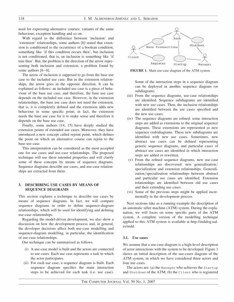
We assume that a use-case diagram is a high-level description
of actor interactions with the system to be developed. Figure 1
shows an initial description of the use-cases diagram of the
ATM system, in which we have considered three actors and
four use cases.
The actors are: (a) the Manager who achieves the Startup
and Shutdown of the ATM; (b) the Client who is registered
FIGURE 1. Main use-case diagram of the ATM system.
118 J. M. ALMENDROS-JIMENEZ AND L. IRIBARNE
THE COMPUTER JOURNAL Vol. 50 No. 1, 2007

(i.e. Register use case) in the ATM and can Make Trans-
actions once registered; (c) finally, the Bank, an external
system that interacts with the ATM in order to carry out the
bank operations.
Now, in our technique, each use case is described by means
of a unique sequence of behaviour in which the developers can
decide whether they includes all the steps and variants. That is,
pieces of behaviour could separately be described by means of
another sequence diagram. Here, a sequence should be
understood as a juxtaposition of steps which can be con-
ditioned, that is, the sequence can include steps such as ‘if
something happens then’ or even repetition structures such
as ‘for each element do’.
In UML 2.0, there exist constructors to specify these kinds
of ‘programming flow structures’ such as opt and loop.
Given that a use case has a unique specification, specifications
(i.e. sequence diagrams) are identified with use cases. In other
words, use cases are specified by several scenarios described
FIGURE 2. A sequence diagram of the Register use case.
USE-CASE RELATIONSHIPS WITH SEQUENCE DIAGRAMS 119
THE COMPUTER JOURNAL Vol. 50 No. 1, 2007

in a single diagram. Included use cases, use-case extensions
and generalizations can thus uniformly be handled. This will
be explained later on.
In Figure 2, the Register use case is specified by means of
a sequence diagram in which a successful behaviour is
described, that is, both the card number and the pin are
valid. It is supposed that the developer has decided to
include both validations in order to describe the basic beha-
viour. However, whenever the card is not valid or the pin is
incorrect, the alternative course should be separately described
from other use cases, in particular, they will correspond to
extensions of this base use case.
Alternatively, the developer could include all the alternative
courses in a unique sequence diagram handling the invalid
card and invalid pin cases inside the opt constructor. This
depends on the number of alternative branches and also
whether the system designer is still in a step of development,
which will be refined later.
3.2. Associations between use cases and actors
Now, an association between a use case and an actor means
that an actor participates in the behaviour described by the
use case. This participation involves interaction: an observable
result by the actor. In addition, if a use case includes another
one, the actor necessarily interacts with the included use
case. The same happens with use-case extensions and
use-case specializations.
In Figure 3, the Client actor interacts with the Make
Transactions use case. As we can see, this includes two
other use cases, Withdraw Cash and Recharge Phone-
Card. Although there is no association directly connecting
the actors (Client and Bank) and the included use cases,
the actors can observe and therefore interact with the
system to withdraw cash or recharge a phone card.
However, the Mobile actor interacts only in the Recharge
PhoneCard use case, given that it is directly connected to
this use case.
One of the reasons why the actor interaction with the use
case is required is to prevent the inclusion from corresponding
to functional decomposition referring to internal processing.
The use-case model shows an external view of the system
[3], and therefore, each use case should interact with the
actors representing the system boundaries.
3.3. Included use cases
An included use case specifies a fragment of the base use-case
behaviour. In this fragment, the actor connected to the base use
case participates. The included use case is inserted in the spe-
cification of the base use-case behaviour. In fact, the name of
the included use case is inserted as one of the sequence steps of
the base.
The included use case can be either mandatory or optional,
occurring in sentences such as ‘if this condition occurs then
,name of use case.’ or ‘for each element do ,name of
the use case.’. The included use case is encapsulated and
there is no interleaving with the base use case.
The base use case cannot access the included use case,
except for the retrieval of the observable result by the actor.
Therefore, included use cases are encapsulated by means of
‘methods’ which can specify the data input as parameters
and the data output as a return parameter. In addition, the
actor connected to the base use case also interacts with the
included use-case specification.
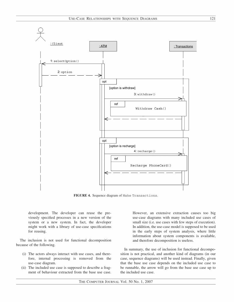
Figure 4 shows the behaviour description of the Make
Transactions use case by means of a sequence diagram.
The Withdraw Cash and Recharge PhoneCard use cases
have been introduced in the base sequence diagram (the
base use case) using the UML 2.0 notation. Both the
inclusions are conditioned if in, the first case, the user
option is ‘withdraw’, and in the second case, the user option
is ‘recharge’. Let us remark that included use cases can be
out of ‘opt’ boxes when the running of included use cases is
mandatory.
Included use cases are used for the following two main
reasons.
(i) The base use case is too big, and it is specified by
means of fragments of specification, that is, the beha-
viour is decomposed into several steps. However, the
specification of the base use case describes how these
steps are combined in order to obtain a unique
behaviour.
(ii) A use case was specified in a previous step of the
development process and now it is reused. The
reuse of specifications is a good practice in software
FIGURE 3. Deployment of the interactions for the Client actor
into the ATM system.
120 J. M. ALMENDROS-JIMENEZ AND L. IRIBARNE
THE COMPUTER JOURNAL Vol. 50 No. 1, 2007
development. The developer can reuse the pre-
viously specified processes in a new version of the
system or a new system. In fact, the developer
might work with a library of use-case specifications
for reusing.
The inclusion is not used for functional decomposition
because of the following.
(i) The actors always interact with use cases, and there-
fore, internal processing is removed from the
use-case diagram.
(ii) The included use case is supposed to describe a frag-
ment of behaviour extracted from the base use case.
However, an extensive extraction causes too big
use-case diagrams with many included use cases of
small size (i.e. use cases with few steps of execution).
In addition, the use-case model is supposed to be used
in the early steps of system analysis, where little
information about system components is available,
and therefore decomposition is useless.
In summary, the use of inclusion for functional decompo-
sition is not practical, and another kind of diagrams (in our
case, sequence diagrams) will be used instead. Finally, given
that the base use case depends on the included use case to
be runnable, the arrow will go from the base use case up to
the included use case.
FIGURE 4. Sequence diagram of Make Transactions.
USE-CASE RELATIONSHIPS WITH SEQUENCE DIAGRAMS 121
THE COMPUTER JOURNAL Vol. 50 No. 1, 2007

3.4. Generalization
A specialization of a use case is a use case whose sequence of
steps have been specialized. There are two cases in our
technique.
(i) The specialized use case replaces some steps by
specialized steps.
(ii) The specialized use case introduces new steps of
execution but without interleaving.
For instance, in Figure 3, all ATM transactions that a client
can make have been generalized. The Transaction use case
is a general or abstract use case and each specific type of trans-
action is a particular case. The behaviour of the abstract use
case (Transaction) is described by means of a general
sequence diagram (Figure 5). The specialized Withdraw
Cash use case (Figure 6) replaces some steps of the Trans-
action sequence diagram and modifies the general name of
the methods. For instance, the operation() method in the
FIGURE 5. A generalized sequence diagram of the Transaction use case.
122 J. M. ALMENDROS-JIMENEZ AND L. IRIBARNE
THE COMPUTER JOURNAL Vol. 50 No. 1, 2007

abstract sequence diagram has been rewritten by the with-
draw() method in the specialized sequence. Methods 2, 7
and 8 have also been modified to implement Withdrawing
cash. Besides, method 11 has been rewritten as an optional
operation to deliver cash when the transaction has been
successful.
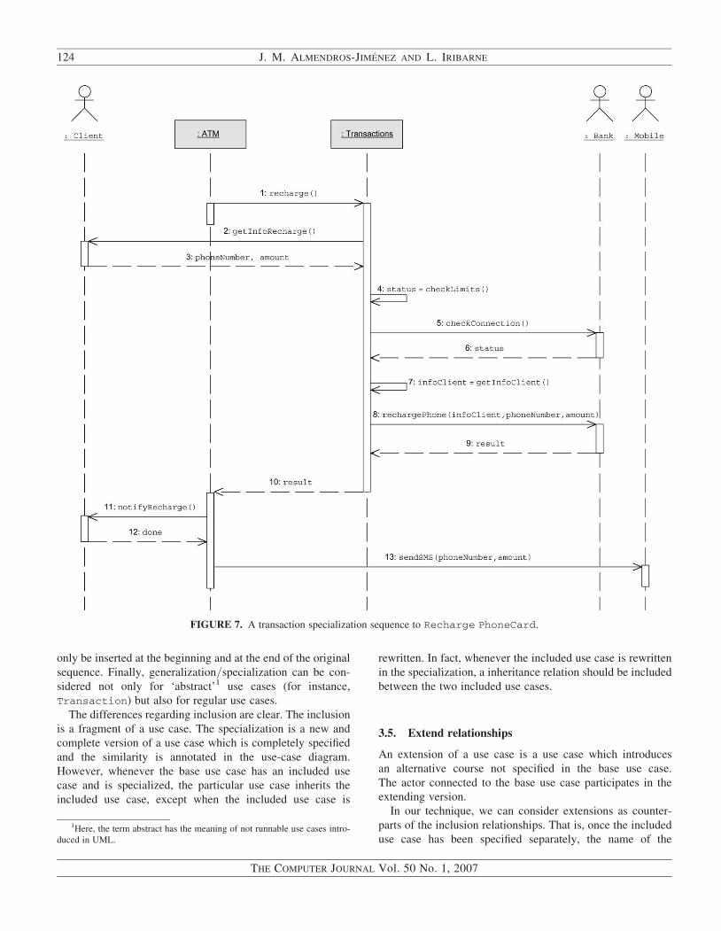
However, Figure 7 shows the specialized sequence to
recharge a phone card. The specialization replaces some
steps of the generalization, and it also introduces a new and
last step of execution to send an SMS to the client’s mobile
notifying the result of the recharge transaction.
The idea is that specialized use cases correspond to the
concept of inheritance of object-oriented programming. That
is, assuming that the designers have a use case previously
specified, they would like to have a new and complete use
case with some slight modifications which consist of adding
new interaction steps (conditioned or not) or modifying
some existent ones. However, interaction steps can only be
modified when they specialize the old version. In other
words, the specialized use case adds new steps and rewrites
the existing ones.
In general, methods can be replaced whenever the developer
knows they represent similar operations. Boolean conditions
can also be replaced by more restrictive ones, and finally,
new interactions can be introduced. However, in order to
avoid interleaving semantics, the introduced interactions can
FIGURE 6. A transaction specialization sequence to Withdraw Cash.
USE-CASE RELATIONSHIPS WITH SEQUENCE DIAGRAMS 123
THE COMPUTER JOURNAL Vol. 50 No. 1, 2007
only be inserted at the beginning and at the end of the original
sequence. Finally, generalization/specialization can be con-
sidered not only for ‘abstract’1 use cases (for instance,
Transaction) but also for regular use cases.
The differences regarding inclusion are clear. The inclusion
is a fragment of a use case. The specialization is a new and
complete version of a use case which is completely specified
and the similarity is annotated in the use-case diagram.
However, whenever the base use case has an included use
case and is specialized, the particular use case inherits the
included use case, except when the included use case is
rewritten. In fact, whenever the included use case is rewritten
in the specialization, a inheritance relation should be included
between the two included use cases.
3.5. Extend relationships
An extension of a use case is a use case which introduces
an alternative course not specified in the base use case.
The actor connected to the base use case participates in the
extending version.
In our technique, we can consider extensions as counter-
parts of the inclusion relationships. That is, once the included
use case has been specified separately, the name of the
FIGURE 7. A transaction specialization sequence to Recharge PhoneCard.
1Here, the term abstract has the meaning of not runnable use cases intro-
duced in UML.
124 J. M. ALMENDROS-JIMENEZ AND L. IRIBARNE
THE COMPUTER JOURNAL Vol. 50 No. 1, 2007

included use case is inserted in the specification of the base use
case, and then, we know where the included use case is
inserted.
However, the extension is omitted from the specification of
the base use case, and now, an alternative course is specified at
some point of the base use case (called extension point) repre-
senting the extension. In addition, a rejoint point is specified.
The reason why the developers may use inclusions and
extensions is because the sequence diagram of the base use
case is too big and they would like to specify it with several
sequence diagrams.
Thus, the developer uses the inclusion to specify alternative
courses or exception handling, except when some alternative
courses require to break the main sequence and require to
abuse of ‘optional’ branches in the sequence diagram. In the
latter case, the use of extensions seems to be more suitable,
once the alternative courses and exception handling have
separately been specified.
In addition, following Metz et al. [14, 15], in our technique,
we have considered the extension and rejoint points establish-
ing at which point the main sequence is broken and where the
extension point rejoins the main sequence. We have
FIGURE 8. A more detailed use-case description of the ATM system.
USE-CASE RELATIONSHIPS WITH SEQUENCE DIAGRAMS 125
THE COMPUTER JOURNAL Vol. 50 No. 1, 2007

distinguished four kinds of extensions, which will be dis-
cussed later.
According to the UML semantics and Jacobson [3], the
arrow goes from the extending use case up to the base use
case, because the base use case defines a complete sequence
of behaviour, but the extension cannot be runnable without
the base use case. Let us remark that this is the opposite
case of the inclusion in which the base use case contains in
its specification the included use case and therefore is not
runnable without the included use case.
Finally, there exists an additional reason for using exten-
sions. Let us suppose that we have a general use case in
which we would like to use the specialization in order to
define a new use case, but the new use case should modify
the main sequence by adding new branches. We have con-
sidered that specialization can add new interactions but
without modifying the main sequence. However, we can use
the extension over an abstract-specialized use case in which
the extension inserts the new interactions.
Let us now pay attention to Figure 8 to illustrate the extend
relationship.
Figure 8 shows a more detailed description of the use cases
of the ATM system. We have used again the UML 2.0 notation
to describe the ,,extend.. relationship between two use
cases. An extension is complemented by a UML note. The
note introduces a boolean condition and an extension point
where the fragment of behaviour extends the base use case.
The extension points are defined by means of a tuple:
,after, before.. For instance, a tuple ,4,9. means
that the extension point where the extending use case is
inserted in the base use case is after the method 4 and
rejoins in method 9.
Using tuples for extensions points, we can consider the fol-
lowing four kinds of extensions.
(i) ‘Same point’. Whenever after=before, that is, the
extension and rejoint points are the same. In other
words, the extension breaks the main sequence but it
returns to the same point. It can be considered as an
invocation.
(ii) ‘After that’. Whenever after,before, that is, the
main sequence is broken and some interactions are
removed from the main sequence. It can be considered
as a bifurcation.
(iii) ‘Before that’. Whenever after.before, that is, the
main sequence is broken and the extension returns to a
previous step in the main sequence. It can be con-
sidered as a loop.
(iv) ‘No return’. Whenever before=no return, that is,
the main sequence is broken, but the extension never
returns to the main sequence. It is used for exception
handling.
For example, the Withdraw Cash use case has an ’after
that’ extension point when the connection with the bank is
not possible and the ATM system operates with the amount
available in stock (Withdraw in stock).
The extended behaviour is described by the Withdraw in
stock sequence diagram shown in Figure 9a. As we can see
in the use-case model, the extended use case has an extension
point when the condition (status is not connected)
occurs. If it happens, the behaviour sequence of the With-
draw in stock use case, shown in Figure 9a, is run
between methods 4 and 9 in the base sequence diagram
(Figure 6).
Figure 9d and b shows two sequence examples of the
before that and no return extension points, respectively.
(i) In the first one, if the amount is out of the required
limits, then an exception, modelled by a before
that extension point occurs. A before that exten-
sion point is similar to a loop sequence.
(ii) In the second one, if the card is not valid, the ATM
definitively rejects the ATM operation and the main
sequence is broken. Thus, this is the case of a no
return extension point.
Finally, we have a case of the same point extension in
Figure 9c, when the clients request their account movements
before the new transaction is achieved.
Extensions are encapsulated, that is, the base use case
cannot access the extending use case. This does not make
sense given that the base use case does not include the exten-
sion in its specification.
3.6. Abstract and concrete use cases
Base use cases and specializations are concrete use cases.
Included use cases and extensions are abstract use cases,
except when they are connected to an actor.
For instance, in our running example, there is an included use
case which is connected to an actor. In Figure 8, the actor
Mobile is connected to the Recharge PhoneCard use case,
which is included in the Make Transactions use case. Sup-
posing that an actor is connected to the included use case, it
defines a concrete use case instead of an abstract one.
4. CONCLUSIONS AND FUTURE WORK
In this article, we have suggested a technique for describing
use cases by means of sequence diagrams, according to the
most accepted semantics of use cases and use-case relation-
ships. The use-case diagrams help the developer to identify
the requirements of the system to be developed. Sequence dia-
grams allow the developer to discover behavioural details of
the system or to better describe the already existing ones.
In this article, we have shown that a direct correspondence
between the requirements identified in the use cases with UML
sequence diagrams is feasible.
126 J. M. ALMENDROS-JIMENEZ AND L. IRIBARNE
THE COMPUTER JOURNAL Vol. 50 No. 1, 2007

As a future work, we would firstly like to provide a frame-
work for specifying pattern design, once generalization/specialization can be combined with inclusions and exten-
sions in order to define generic patterns of components,
tasks and so on. Secondly, we could study the same kind of
relationships in other notations such as activity diagrams
and statecharts. Thirdly, we plan to extend our proposal to
deal with automated code generation and component-based
development, by parsing and translating use cases, relation-
ships and specifications into a class diagram and code.
Finally, we would like to incorporate all these ideas into a
CASE tool and integrate our technique into the whole devel-
opment process, especially into our previous works about use
cases and activity diagrams [18] and use cases and graphical
user interfaces design [17].
ACKNOWLEDGEMENTS
The authors would like to thank the anonymous referees for
their insightful comments and suggestions, which greatly
helped them improve the contents and readability of the
article. This work has been partially supported by the EU
(FEDER) and the Spanish MEC under grants
TIN2005-09207-C03-02 and TIN2006- 06698.
REFERENCES
[1] UML 2. (2005) Unified modeling language specification. Object
Management Group, Needham, USA.
[2] Jacobson, I., Jonsson, P., Christerson, M. and Overgaard, G.
(1992) Object-Oriented Software Engineering: A Use Case
Driven Approach. Addison-Wesley, MA, USA.
FIGURE 9. The four kinds of use-case extensions.
USE-CASE RELATIONSHIPS WITH SEQUENCE DIAGRAMS 127
THE COMPUTER JOURNAL Vol. 50 No. 1, 2007

[3] Jacobson, I. (2004) Use cases—yesterday, today, and tomorrow.
Software Syst. Model., 3, 210–220.
[4] Simons, A. and Graham, I. (1999) 30 things that go wrong in
object modelling with UML 1.3. In Kilov, H., Rumpe, B.
and Simmonds, I. (eds), Behavioral Specifications of
Businesses and Systems. Kluwer Academic Publishers,
Norwell, MA, USA.
[5] Overgaard, G. and Palmkvist, K. (1999) A formal approach to
use cases and their relationships. Proc. UML’98: Beyond the
Notation, Mulhouse, France, June 3–4, pp. 406–418. LNCS
1618, Springer-Verlag, London, UK.
[6] Genova, G., Llorens, J. and Quintana, V. (2002) Digging into
use case relationships. Proc. UML’2002, Dresden, Germany,
September 30–October 4, pp. 115–127. LNCS 2460,
Springer-Verlag, London, UK.
[7] Simons, A. J. H. (1999) Use cases considered harmful. Proc.
TOOLS/Europe’99, Nancy, France, June 7–10, pp. 194–203.
IEEE Computer Society, Washington, DC, USA.
[8] Metz, P. (2001) Against use case interleaving. Proc. UML’2001,
Toronto, Ontario, Canada, October 1–5, pp. 472–486. LNCS
2185, Springer-Verlag, London, UK.
[9] Isoda, S. (2005) On UML2.0’s abandonment of the
actors-call-use-cases conjecture. J. Object Technol., 4, 69–80.
[10] Isoda, S. (2003) A critique of UML’s definition of the use-case
class. Proc. UML 2003, San Francisco, CA, USA, October 20–
24, pp. 280–294. LNCS 2863, Springer-Verlag, London, UK.
[11] Williams, C., Kaplan, M., Klinger, T. and Paradkar, A. (2005)
Toward engineered, useful use cases. J. Object Technol., 4,
45–57.
[12] Genova, G. and Llorens, J. (2005) The emperor’s new use case.
J. Object Technol., 4, 81–94.
[13] Genilloud, G. and Frank, W.F. (2005) Use case concepts using a
clear, consistent, concise ontology. J. Object Technol., 4, 95–
107.
[14] Metz, P., O’Brien, J. and Weber, W. (2003) Specifying use case
interaction: types of alternative courses. J. Object Technol., 2,
111–131.
[15] Metz, P., O’Brien, J. and Weber, W. (2004) Specifying use case
interaction: clarifying extension points and rejoin points.
J. Object Technol., 3, 87–102.
[16] Wegmann, A. and Genilloud, G. (2000) The role of ‘Roles’
in use case diagrams. Proc. UML’2000, York, UK,
October 2–6, pp. 210–224. LNCS 1939, Springer-Verlag,
London, UK.
[17] Almendros-Jimenez, J.M. and Iribarne, L. (2005) Designing
GUI components for UML use cases. Proc. ECBS’05,
Greenbelt, Maryland, USA, April 4–5, pp. 210–217. IEEE
Computer Society Press, Washington, DC, USA.
[18] Almendros-Jimenez, J.M. and Iribarne, L. (2005) Describing
use cases with activity diagrams. Proc. MIS’04, Salzburg,
Austria, September 15–18, pp. 141–159. LNCS 3511,
Springer-Verlag, London, UK.
128 J. M. ALMENDROS-JIMENEZ AND L. IRIBARNE
THE COMPUTER JOURNAL Vol. 50 No. 1, 2007