Embed Size (px)
Citation preview
Isı Bilimi ve Tekniği Dergisi, 30, 2, 57-68, 2010 J. of Thermal Science and Technology
©2010 TIBTD Printed in Turkey ISSN 1300-3615
COMBUSTION IN A RAMJET COMBUSTOR WITH CAVITY FLAME HOLDER
Onur TUNÇER İstanbul Technical University Faculty of Aeronautics and Astronautics Department of Aeronautical Engineering
Maslak, İstanbul 34469, [email protected]
(Geliş Tarihi: 10. 09. 2009, Kabul Tarihi: 08. 12. 2009)
Abstract: Combustion characteristics in a ramjet combustor with cavity flame-holder is studied numerically. Combustor follows a constant area isolator section and comprises of hydrogen fuel injected sonically upstream of the cavity. Secondary fuel injection is performed at the cavity back wall. A diverging section follows the cavity. These concepts are utilized in many designs. Simulations were performed for an entrance Mach number of 1.4. Stagnation temperature is 702 K, corresponding to a flight Mach number of 3.3. Detailed chemical kinetics is taken into account with a reaction mechanism comprising of 9 species and 25 reaction steps. Turbulence is modeled using Menter's
shear stress transport model, which is suitable for high speed internal flows. It is observed that flame anchors at the leading edge of the cavity, and the flame is stabilized in the cavity mode rather than the jet-wake mode. Simulation captures all the essential features of the reacting flow field. Keywords:Ramjet, Combustion, Cavity, Computational fluid dynamics
KAVİTE ALEV TUTUCULU BİR RAMJET YAKICISINDA YANMA Özet: Alevin kavite yardımı ile tutulduğu bir ramjet yanma odasında alev davranışı sayısal olarak incelenmiştir. Yanma odası sabit kesit alanlı bir izolatörün hemen ardındadır. Hidrojen yakıtı kavitenin akış yukarı yönünde ses hızında enjekte edilmektedir. İkincil yakıt enjeksiyonu ise kavitenin arka duvarından sağlanmaktadır. Kavitenin ardında kesit alanı genişleyen bir kesim bulunur. Bu yaklaşım birçok tasarımda kullanılır. Sayısal hesaplamalar giriş Mach sayısı 1.4 için yapılmıştır. Durma noktası sıcaklığı 702 K olup, bu koşullar uçuş Mach sayısı olarak 3.3’e karşılık gelmektedir. Hesaplamalarda ayrıntılı kimyasal kinetik 9 tür ve 25 tepkime basamağından oluşan bir mekanizma ile göz önüne alınmıştır. Türbülans ise yüksek hızlı iç akışlar için uygun olan Menter’in kayma gerilimi taşınımı modeli ile modellenmiştir. Sonuçta alevin kavitenin ön kenarına tutunduğu ve alevin jet ardındaki anafordan ziyade kavite içerisinde kararlı hale geldiği gözlemlenmiştir. Sayısal hesaplamalar tepkimeli akış alanının bütün önemli özelliklerini açığa çıkartabilmektedir. Anahtar Kelimeler: Ramjet, Yanma, Kavite, Hesaplamalı akışkanlar dinamiği NOMENCLATURE A Pre-exponential constant a1 Modelling constant C Species concentration D Molecular diffusion coefficient D Depth of the cavity [m] Ea Activation energy [cal] F1, F2 Blending functions h Static enthalpy [J/kg] H Total enthalpy [J/kg] J Diffused species flux [kg/(m2.s)] k Turbulent kinetic energy [m2/s2] L Length of the cavity [m] M Mach number P Pressure [Pa] Pk Production term [kg/(m.s3)] Rk,m Reaction source term [kg/(m3.s)] S Strain rate [s-1] Sct Turbulent Schmidt number t Time [s]
T Temperature [K] u Velocity [m/s] x Distance [m] y Distance to the nearest surface [m] Ym Mass fraction of the mth species Greek Symbols α Modelling constant β* Modelling constant β1, β2 Modelling constants δij Kronecker delta λ Thermal conductivity [W/(m.K)] µ Dynamic viscosity [N.s/m2] νt Kinematic eddy viscosity [m2/s] ρ Density [kg/m3] σk Modelling constant σω Modelling constant Φ Modelling constant ω Inverse time scale of eddy
dissipation, [s-1]
57
58
Subscripts i, j, k, l Directions eff Effective ign Ignition m mth species 0 Stagnation Superscripts - Time averaged value ~ Favre averaged value INTRODUCTION Supersonic air breathing propulsion systems are crucial for the demands of today's defense industry and future's high speed civilian transportation vehicles. On the other hand, as a direct consequence of high flow speeds, time necessary for injection, mixing, and subsequent combustion is minimal, and is typically around 1 ms (Benyakar and Hanson, 2001). This poses significant challenges in the design of such propulsion systems. In order to successfully develop advanced air breathing propulsion systems capable of high speed flight it is necessary to understand the fundamentals of mixing and combustion processes within the combustor. Flame stabilization in high speed flows is a significant challenge that needs to be overcome. Studies performed primarily in the United States have demonstrated that “cavity” flame holders could effectively be used both for ramjet and scramjet combustors. The idea behind is that the cavity traps a strong and stable vortex within and thereby provides favorable conditions for ignition (free radicals and temperature) resulting in a much decreased ignition delay time.
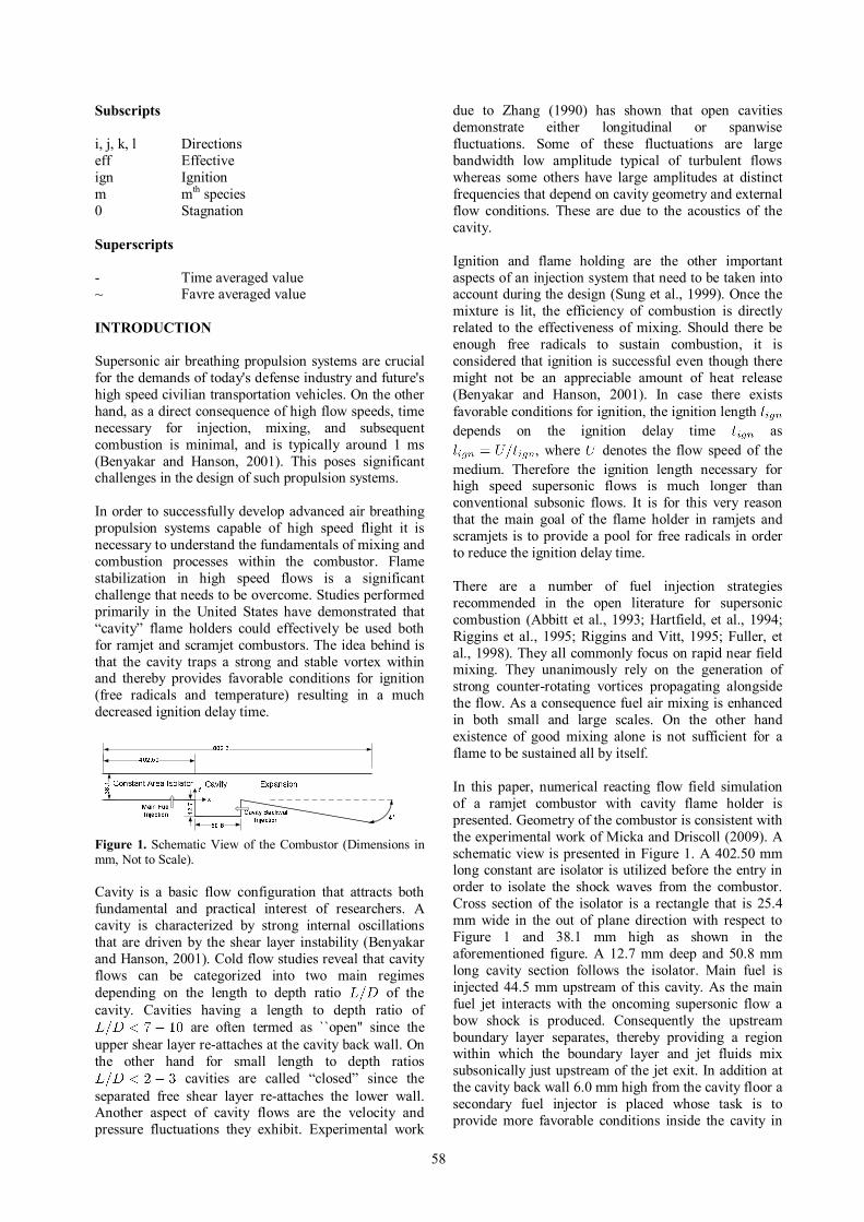
Figure 1. Schematic View of the Combustor (Dimensions in mm, Not to Scale). Cavity is a basic flow configuration that attracts both fundamental and practical interest of researchers. A cavity is characterized by strong internal oscillations that are driven by the shear layer instability (Benyakar and Hanson, 2001). Cold flow studies reveal that cavity flows can be categorized into two main regimes depending on the length to depth ratio of the cavity. Cavities having a length to depth ratio of
are often termed as ``open'' since the upper shear layer re-attaches at the cavity back wall. On the other hand for small length to depth ratios
cavities are called “closed” since the separated free shear layer re-attaches the lower wall. Another aspect of cavity flows are the velocity and pressure fluctuations they exhibit. Experimental work
due to Zhang (1990) has shown that open cavities demonstrate either longitudinal or spanwise fluctuations. Some of these fluctuations are large bandwidth low amplitude typical of turbulent flows whereas some others have large amplitudes at distinct frequencies that depend on cavity geometry and external flow conditions. These are due to the acoustics of the cavity. Ignition and flame holding are the other important aspects of an injection system that need to be taken into account during the design (Sung et al., 1999). Once the mixture is lit, the efficiency of combustion is directly related to the effectiveness of mixing. Should there be enough free radicals to sustain combustion, it is considered that ignition is successful even though there might not be an appreciable amount of heat release (Benyakar and Hanson, 2001). In case there exists favorable conditions for ignition, the ignition length depends on the ignition delay time as
, where denotes the flow speed of the medium. Therefore the ignition length necessary for high speed supersonic flows is much longer than conventional subsonic flows. It is for this very reason that the main goal of the flame holder in ramjets and scramjets is to provide a pool for free radicals in order to reduce the ignition delay time. There are a number of fuel injection strategies recommended in the open literature for supersonic combustion (Abbitt et al., 1993; Hartfield, et al., 1994; Riggins et al., 1995; Riggins and Vitt, 1995; Fuller, et al., 1998). They all commonly focus on rapid near field mixing. They unanimously rely on the generation of strong counter-rotating vortices propagating alongside the flow. As a consequence fuel air mixing is enhanced in both small and large scales. On the other hand existence of good mixing alone is not sufficient for a flame to be sustained all by itself. In this paper, numerical reacting flow field simulation of a ramjet combustor with cavity flame holder is presented. Geometry of the combustor is consistent with the experimental work of Micka and Driscoll (2009). A schematic view is presented in Figure 1. A 402.50 mm long constant are isolator is utilized before the entry in order to isolate the shock waves from the combustor. Cross section of the isolator is a rectangle that is 25.4 mm wide in the out of plane direction with respect to Figure 1 and 38.1 mm high as shown in the aforementioned figure. A 12.7 mm deep and 50.8 mm long cavity section follows the isolator. Main fuel is injected 44.5 mm upstream of this cavity. As the main fuel jet interacts with the oncoming supersonic flow a bow shock is produced. Consequently the upstream boundary layer separates, thereby providing a region within which the boundary layer and jet fluids mix subsonically just upstream of the jet exit. In addition at the cavity back wall 6.0 mm high from the cavity floor a secondary fuel injector is placed whose task is to provide more favorable conditions inside the cavity in
59
order to assist in flame holding. Just after the cavity a 349 mm long diverging section follows. This section provides the area enlargement necessary to prevent thermal choking. When numerically solving chemically reacting flows, the accuracy of the chemical kinetic mechanism is yet another issue that cannot be overlooked through unphysical over-simplifying assumptions such as quasi steady-state reaction assumptions. Especially for high speed reacting flows, characteristic time scales for the fluid flow are ever so much closer to the characteristic time scales associated with combustion. Combustion mechanism proceeds only as fast as the slowest oxidation step within the mechanism. Therefore, for these high-speed reacting flows within ramjet/scramjet combustors, Damköhler numbers are much smaller in comparison to other combustion systems such as gas turbine combustors wherein typical flow speeds are on the order of Mach 0.2 or so. For example Liu et al. (2006) used reduced chemical kinetic mechanisms for cavity stabilized ethylene-air flames to predict flame stability limits in supersonic flows based on experimental study. They have used 3, 10 and 15 step reduced chemical kinetic mechanisms respectively. In conclusion their results show that 15-step reduced model predicts experimental data much better than the 3 and 10-step models. Therefore the importance of including accurate chemical kinetics is demonstrated. Based on this observation, in this paper when modeling hydrogen oxidation, extensive care is taken to include all important reactions and species so as to get accurate results. More detail about the reaction mechanism is provided in the following section. MATHEMATICAL MODELLING It is possible to describe the flow within the ramjet combustor as a chemically reacting, single phase, multi-species flow. Then the governing equations for such a flow are Navier-Stokes equations coupled with species conservation equations with being the number of species considered. In order to solve the flow the following set of equations need to be solved simultaneously. Discretization and solution schemes are later discussed at the end of this section. Conservation Equations Here the set of conservation equations (mass, momentum, species and energy) that need to be accounted for are presented. Global continuity equation for compressible flow can be written as in Eq. 1 using tensor notation.
(1)
Similarly the momentum equation is written as in Eq. 2,
(2)
where,
(3) In Eq. 3 is a modelling parameter referred to as eddy viscosity. Its calculation is further discussed in turbulence modelling section. The following nine species are considered within the flow field; N2, H, H2, O, O2, OH, H2O, HO2 and H2O2. For each species, Eq. 4 needs to be solved separately. Chemical source term appearing in this equation is obtained from the kinetic model. Turbulent Schmidt number is taken as 1.0.
(4)
Conservation of energy equation is provided in Eq. 5 with viscous dissipation being neglected. Turbulent Prandtl number is also assumed to be unity like the Schmidt number. Species enthalpies are computed using Joint Army Navy Air Force (JANAF) thermodynamic tables (Stull and Prophet, 1971).
(5)
Using ideal gas law Eq. 6 as the equation of state, conservation equations can now be closed. Here is the gas constant of the mixture.
(6) Turbulence Modelling In order to model eddy viscosity and other turbulent parameters, a turbulence model is necessary. For this purpose Menter's SST (shear stress transport) model is utilized (Menter, 1994). This particular model is suitable for high speed internal flows such as the one studied here (Javed and Chakraborty, 2006). Montgomery et al. (2003) and Liu et al. (2006) also used this model to investigate similar high speed reacting flows for ramjet/scramjet combustors. Tam et al. (1999) used this turbulence model to jets in supersonic cross flows. This is precisely the case for the main fuel jet injection in the present paper. Furthermore,

60
experimental evidence about the validity of this model and comparison with other models is provided by Tong and Luke (2004). On the other hand, a known drawback of this model is that it tends to exaggerate turbulence levels in regions with large normal strain, such as stagnation regions or regions of high acceleration. Yet this tendency is not as severe as it is in the original underlying model. The SST turbulence model is derived by blending the
model applied to the inner region of the turbulent boundary layer with a high Reynolds number form of the turbulence model (Shih et al., 1995) by transforming it into and variables which are applied to the outer portion of the turbulent boundary layer (Menter, 1994). A weight of is first assigned to the inner model, while a weight of is applied to the outer high Reynolds number model. This approach incorporates advantages of each model into the new SST model. Derivation of the model equations are skipped and the final form of the transport equations for the turbulent kinetic energy , and inverse time scale of eddy dissipation are provided in Eq. 7 and in Eq. 8 respectively.
(7)
(8)
The production term appearing in the above equations is given in Eq. 9.
(9)
Coefficients of this new model are a linear combination of the corresponding coefficients of the original underlying models. Therefore these new coefficients are obtained simply as in Eq. 10.
(10) All modelling constants are listed in Table 1 for convenience.
Table 1. Modelling Constants for the SST Turbulence Model.
5/9 0.44 3/40 0.0828 0.09 2 1 2 0.856
By using a limiter function for the formulation of eddy viscosity the proper transport behavior to predict separation is obtained as per Eq. 11. The value of constant equals to .
(11)
with,
(12)
is also a blending function like , whose purpose is to confine the limiter to the wall boundary layer since the underlying assumptions are incorrect for free shear flows. in Eq. 13 is an invariant measure of strain rate.
(13)
Blending functions determine the success of this method. They depend both on the distance to the nearest surface and also on the flow variables. First blending function is provided in Eq. 14.
(14) where,
(15)
with,
(16)
Second blending function is provided in Eq.17.
(17) where,
(18)
61
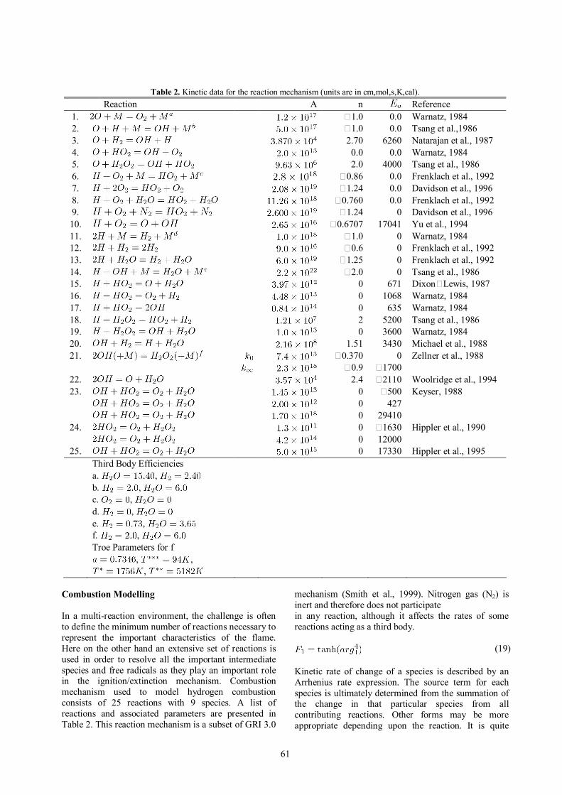
Table 2. Kinetic data for the reaction mechanism (units are in cm,mol,s,K,cal). Reaction A n Reference
1. 1.0 0.0 Warnatz, 1984 2. 1.0 0.0 Tsang et al.,1986 3. 2.70 6260 Natarajan et al., 1987 4. 0.0 0.0 Warnatz, 1984 5. 2.0 4000 Tsang et al., 1986 6. 0.86 0.0 Frenklach et al., 1992 7. 1.24 0.0 Davidson et al., 1996 8. 0.760 0.0 Frenklach et al., 1992 9. 1.24 0 Davidson et al., 1996 10. 0.6707 17041 Yu et al., 1994 11. 1.0 0 Warnatz, 1984 12. 0.6 0 Frenklach et al., 1992 13. 1.25 0 Frenklach et al., 1992 14. 2.0 0 Tsang et al., 1986 15. 0 671 Dixon Lewis, 1987 16. 0 1068 Warnatz, 1984 17. 0 635 Warnatz, 1984 18. 2 5200 Tsang et al., 1986 19. 0 3600 Warnatz, 1984 20. 1.51 3430 Michael et al., 1988 21. 0.370 0 Zellner et al., 1988
0.9 1700 22. 2.4 2110 Woolridge et al., 1994 23. 0 500 Keyser, 1988
0 427 0 29410
24. 0 1630 Hippler et al., 1990 0 12000
25. 0 17330 Hippler et al., 1995 Third Body Efficiencies a. , b. , c. , d. , e. , f. , Troe Parameters for f , , ,
Combustion Modelling In a multi-reaction environment, the challenge is often to define the minimum number of reactions necessary to represent the important characteristics of the flame. Here on the other hand an extensive set of reactions is used in order to resolve all the important intermediate species and free radicals as they play an important role in the ignition/extinction mechanism. Combustion mechanism used to model hydrogen combustion consists of 25 reactions with 9 species. A list of reactions and associated parameters are presented in Table 2. This reaction mechanism is a subset of GRI 3.0
mechanism (Smith et al., 1999). Nitrogen gas (N2) is inert and therefore does not participate in any reaction, although it affects the rates of some reactions acting as a third body.
(19) Kinetic rate of change of a species is described by an Arrhenius rate expression. The source term for each species is ultimately determined from the summation of the change in that particular species from all contributing reactions. Other forms may be more appropriate depending upon the reaction. It is quite
62
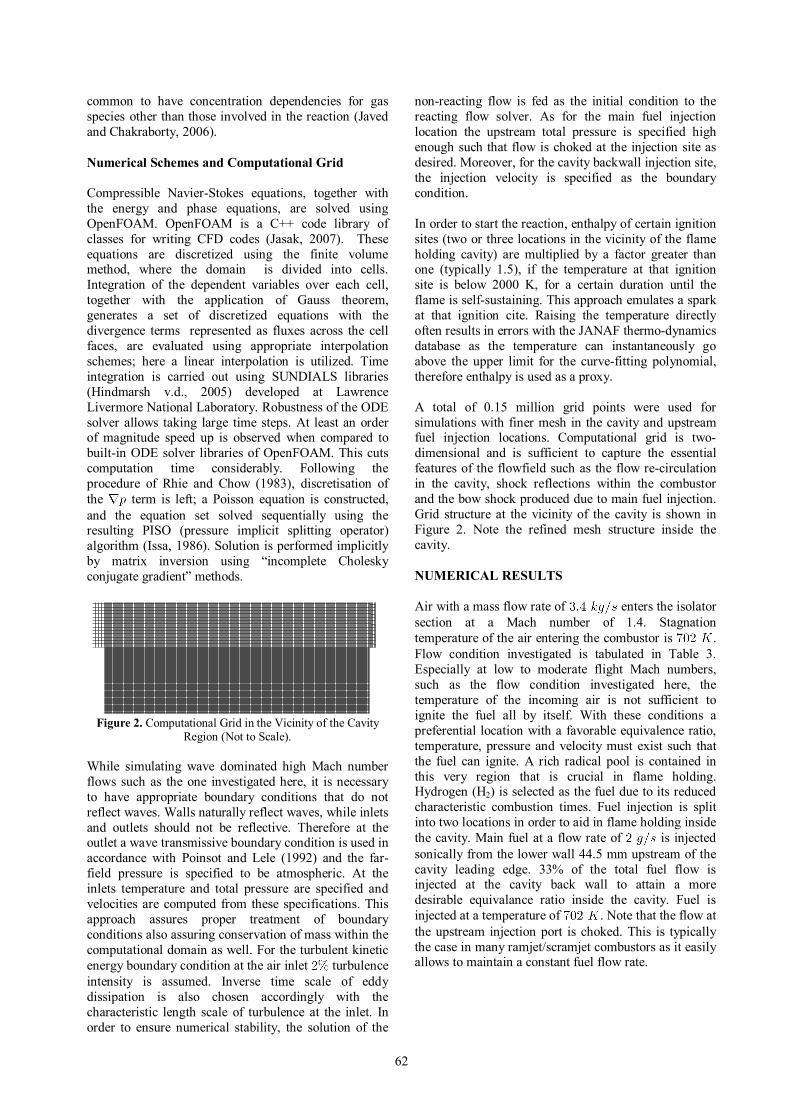
common to have concentration dependencies for gas species other than those involved in the reaction (Javed and Chakraborty, 2006). Numerical Schemes and Computational Grid Compressible Navier-Stokes equations, together with the energy and phase equations, are solved using OpenFOAM. OpenFOAM is a C++ code library of classes for writing CFD codes (Jasak, 2007). These equations are discretized using the finite volume method, where the domain is divided into cells. Integration of the dependent variables over each cell, together with the application of Gauss theorem, generates a set of discretized equations with the divergence terms represented as fluxes across the cell faces, are evaluated using appropriate interpolation schemes; here a linear interpolation is utilized. Time integration is carried out using SUNDIALS libraries (Hindmarsh v.d., 2005) developed at Lawrence Livermore National Laboratory. Robustness of the ODE solver allows taking large time steps. At least an order of magnitude speed up is observed when compared to built-in ODE solver libraries of OpenFOAM. This cuts computation time considerably. Following the procedure of Rhie and Chow (1983), discretisation of the term is left; a Poisson equation is constructed, and the equation set solved sequentially using the resulting PISO (pressure implicit splitting operator) algorithm (Issa, 1986). Solution is performed implicitly by matrix inversion using “incomplete Cholesky conjugate gradient” methods.
Figure 2. Computational Grid in the Vicinity of the Cavity
Region (Not to Scale). While simulating wave dominated high Mach number flows such as the one investigated here, it is necessary to have appropriate boundary conditions that do not reflect waves. Walls naturally reflect waves, while inlets and outlets should not be reflective. Therefore at the outlet a wave transmissive boundary condition is used in accordance with Poinsot and Lele (1992) and the far-field pressure is specified to be atmospheric. At the inlets temperature and total pressure are specified and velocities are computed from these specifications. This approach assures proper treatment of boundary conditions also assuring conservation of mass within the computational domain as well. For the turbulent kinetic energy boundary condition at the air inlet turbulence intensity is assumed. Inverse time scale of eddy dissipation is also chosen accordingly with the characteristic length scale of turbulence at the inlet. In order to ensure numerical stability, the solution of the
non-reacting flow is fed as the initial condition to the reacting flow solver. As for the main fuel injection location the upstream total pressure is specified high enough such that flow is choked at the injection site as desired. Moreover, for the cavity backwall injection site, the injection velocity is specified as the boundary condition. In order to start the reaction, enthalpy of certain ignition sites (two or three locations in the vicinity of the flame holding cavity) are multiplied by a factor greater than one (typically 1.5), if the temperature at that ignition site is below 2000 K, for a certain duration until the flame is self-sustaining. This approach emulates a spark at that ignition cite. Raising the temperature directly often results in errors with the JANAF thermo-dynamics database as the temperature can instantaneously go above the upper limit for the curve-fitting polynomial, therefore enthalpy is used as a proxy. A total of 0.15 million grid points were used for simulations with finer mesh in the cavity and upstream fuel injection locations. Computational grid is two-dimensional and is sufficient to capture the essential features of the flowfield such as the flow re-circulation in the cavity, shock reflections within the combustor and the bow shock produced due to main fuel injection. Grid structure at the vicinity of the cavity is shown in Figure 2. Note the refined mesh structure inside the cavity. NUMERICAL RESULTS Air with a mass flow rate of enters the isolator section at a Mach number of 1.4. Stagnation temperature of the air entering the combustor is . Flow condition investigated is tabulated in Table 3. Especially at low to moderate flight Mach numbers, such as the flow condition investigated here, the temperature of the incoming air is not sufficient to ignite the fuel all by itself. With these conditions a preferential location with a favorable equivalence ratio, temperature, pressure and velocity must exist such that the fuel can ignite. A rich radical pool is contained in this very region that is crucial in flame holding. Hydrogen (H2) is selected as the fuel due to its reduced characteristic combustion times. Fuel injection is split into two locations in order to aid in flame holding inside the cavity. Main fuel at a flow rate of is injected sonically from the lower wall 44.5 mm upstream of the cavity leading edge. 33% of the total fuel flow is injected at the cavity back wall to attain a more desirable equivalance ratio inside the cavity. Fuel is injected at a temperature of . Note that the flow at the upstream injection port is choked. This is typically the case in many ramjet/scramjet combustors as it easily allows to maintain a constant fuel flow rate.
63
Table 3. Flow Parameters for Air and Hydrogen. Air Hydrogen
(Upstream) Hydrogen (Cavity)
3.4 0.002 0.001 702 300 300
1.4 1.0 0.5 0.8 3.9 3.9
The reacting flow field in the ramjet combustor has been simulated by solving two-dimensional Navier-
Stokes equations with shear stress transport (SST) turbulence model using open source CFD software OpenFOAM (Jasak, 2007). Other open source numerical libraries, such as SUNDIALS (Hindmarsh et al., 2005) for the integration of ordinary differential equations (ODEs), are also used for the solution. Detailed chemistry with 9 species and 25 reaction steps is taken into account for the combustion of hydrogen fuel.
0.87
0.8 7
0.87
0.975
0.975
0 .975
1.08
1.08
1.08
1.185
1.185
1.185
1.29
1.29
1 . 29
1.395
1. 39 5
1.395
1 .5
1.5
1.605
1.605
X (mm)-50 0 50 100
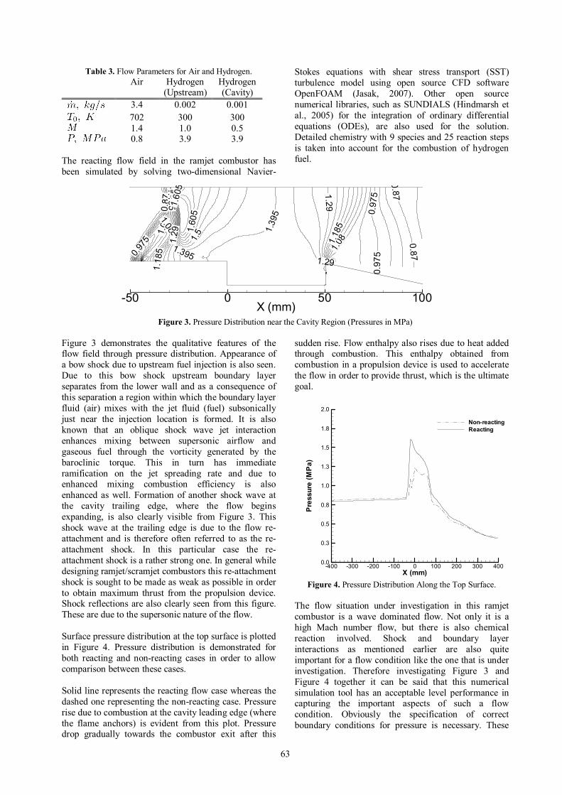
Figure 3. Pressure Distribution near the Cavity Region (Pressures in MPa)
Figure 3 demonstrates the qualitative features of the flow field through pressure distribution. Appearance of a bow shock due to upstream fuel injection is also seen. Due to this bow shock upstream boundary layer separates from the lower wall and as a consequence of this separation a region within which the boundary layer fluid (air) mixes with the jet fluid (fuel) subsonically just near the injection location is formed. It is also known that an oblique shock wave jet interaction enhances mixing between supersonic airflow and gaseous fuel through the vorticity generated by the baroclinic torque. This in turn has immediate ramification on the jet spreading rate and due to enhanced mixing combustion efficiency is also enhanced as well. Formation of another shock wave at the cavity trailing edge, where the flow begins expanding, is also clearly visible from Figure 3. This shock wave at the trailing edge is due to the flow re-attachment and is therefore often referred to as the re-attachment shock. In this particular case the re-attachment shock is a rather strong one. In general while designing ramjet/scramjet combustors this re-attachment shock is sought to be made as weak as possible in order to obtain maximum thrust from the propulsion device. Shock reflections are also clearly seen from this figure. These are due to the supersonic nature of the flow. Surface pressure distribution at the top surface is plotted in Figure 4. Pressure distribution is demonstrated for both reacting and non-reacting cases in order to allow comparison between these cases. Solid line represents the reacting flow case whereas the dashed one representing the non-reacting case. Pressure rise due to combustion at the cavity leading edge (where the flame anchors) is evident from this plot. Pressure drop gradually towards the combustor exit after this
sudden rise. Flow enthalpy also rises due to heat added through combustion. This enthalpy obtained from combustion in a propulsion device is used to accelerate the flow in order to provide thrust, which is the ultimate goal.
X (mm)
Pressure(M
Pa)
-400 -300 -200 -100 0 100 200 300 4000.0
0.3
0.5
0.8
1.0
1.3
1.5
1.8
2.0
Non-reactingReacting
Figure 4. Pressure Distribution Along the Top Surface.
The flow situation under investigation in this ramjet combustor is a wave dominated flow. Not only it is a high Mach number flow, but there is also chemical reaction involved. Shock and boundary layer interactions as mentioned earlier are also quite important for a flow condition like the one that is under investigation. Therefore investigating Figure 3 and Figure 4 together it can be said that this numerical simulation tool has an acceptable level performance in capturing the important aspects of such a flow condition. Obviously the specification of correct boundary conditions for pressure is necessary. These
64
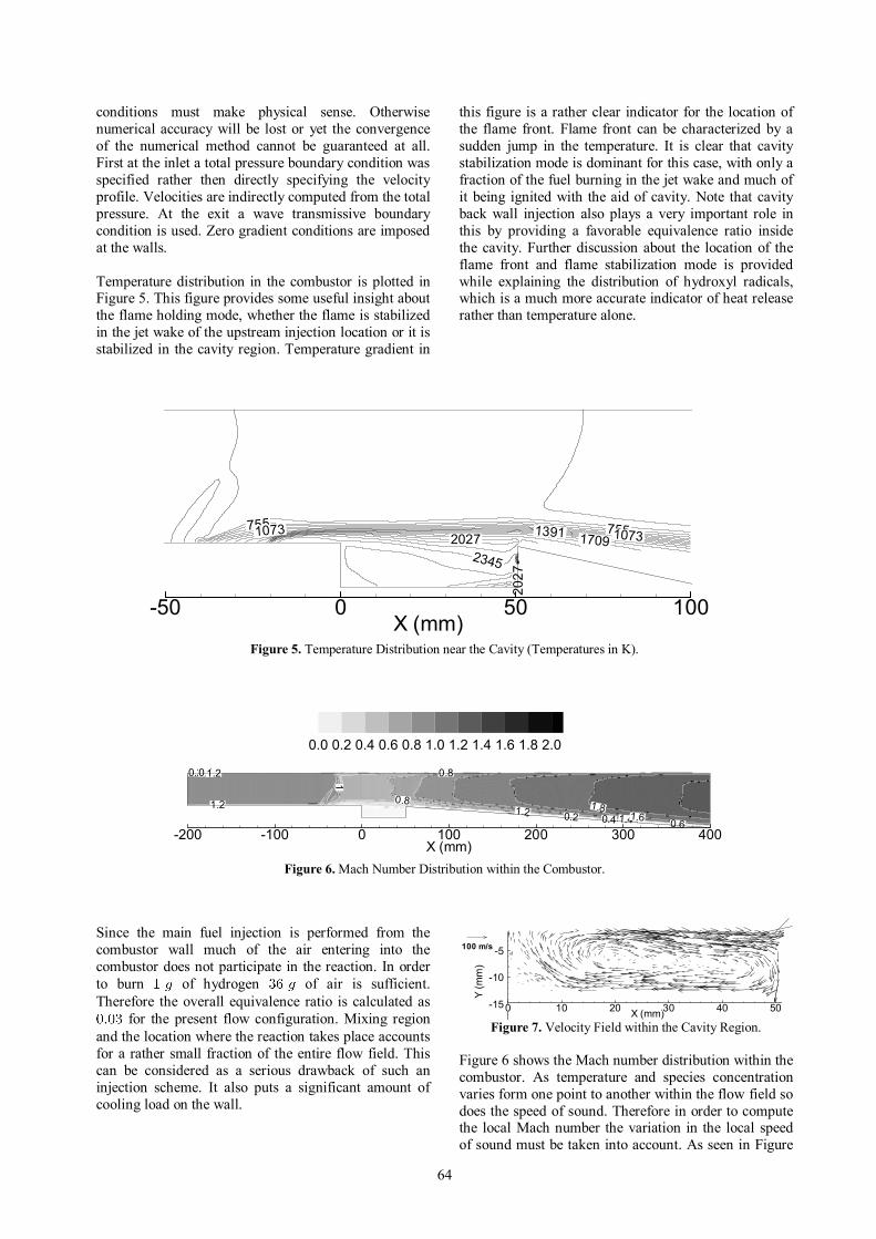
conditions must make physical sense. Otherwise numerical accuracy will be lost or yet the convergence of the numerical method cannot be guaranteed at all. First at the inlet a total pressure boundary condition was specified rather then directly specifying the velocity profile. Velocities are indirectly computed from the total pressure. At the exit a wave transmissive boundary condition is used. Zero gradient conditions are imposed at the walls. Temperature distribution in the combustor is plotted in Figure 5. This figure provides some useful insight about the flame holding mode, whether the flame is stabilized in the jet wake of the upstream injection location or it is stabilized in the cavity region. Temperature gradient in
this figure is a rather clear indicator for the location of the flame front. Flame front can be characterized by a sudden jump in the temperature. It is clear that cavity stabilization mode is dominant for this case, with only a fraction of the fuel burning in the jet wake and much of it being ignited with the aid of cavity. Note that cavity back wall injection also plays a very important role in this by providing a favorable equivalence ratio inside the cavity. Further discussion about the location of the flame front and flame stabilization mode is provided while explaining the distribution of hydroxyl radicals, which is a much more accurate indicator of heat release rather than temperature alone.
755 7551073 10731391 1709
2027
20272345
X (mm)-50 0 50 100
Figure 5. Temperature Distribution near the Cavity (Temperatures in K).
0.2
0.2 0.4
0.4
0.6
0.8
0.8
1
11.2
1.2
1.2 1.41.61.8
X (mm)-200 -100 0 100 200 300 400
0.0 0.2 0.4 0.6 0.8 1.0 1.2 1.4 1.6 1.8 2.0
Figure 6. Mach Number Distribution within the Combustor.
Since the main fuel injection is performed from the combustor wall much of the air entering into the combustor does not participate in the reaction. In order to burn of hydrogen of air is sufficient. Therefore the overall equivalence ratio is calculated as
for the present flow configuration. Mixing region and the location where the reaction takes place accounts for a rather small fraction of the entire flow field. This can be considered as a serious drawback of such an injection scheme. It also puts a significant amount of cooling load on the wall.
X (mm)
Y(m
m)
0 10 20 30 40 50-15
-10
-5100 m/s
Figure 7. Velocity Field within the Cavity Region.
Figure 6 shows the Mach number distribution within the combustor. As temperature and species concentration varies form one point to another within the flow field so does the speed of sound. Therefore in order to compute the local Mach number the variation in the local speed of sound must be taken into account. As seen in Figure
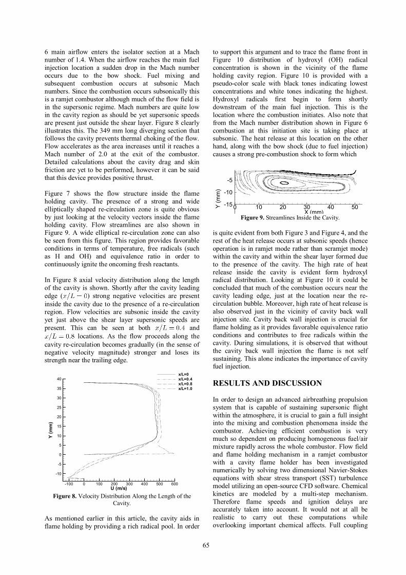
65
6 main airflow enters the isolator section at a Mach number of 1.4. When the airflow reaches the main fuel injection location a sudden drop in the Mach number occurs due to the bow shock. Fuel mixing and subsequent combustion occurs at subsonic Mach numbers. Since the combustion occurs subsonically this is a ramjet combustor although much of the flow field is in the supersonic regime. Mach numbers are quite low in the cavity region as should be yet supersonic speeds are present just outside the shear layer. Figure 8 clearly illustrates this. The 349 mm long diverging section that follows the cavity prevents thermal choking of the flow. Flow accelerates as the area increases until it reaches a Mach number of 2.0 at the exit of the combustor. Detailed calculations about the cavity drag and skin friction are yet to be performed, however it can be said that this device provides positive thrust. Figure 7 shows the flow structure inside the flame holding cavity. The presence of a strong and wide elliptically shaped re-circulation zone is quite obvious by just looking at the velocity vectors inside the flame holding cavity. Flow streamlines are also shown in Figure 9. A wide elliptical re-circulation zone can also be seen from this figure. This region provides favorable conditions in terms of temperature, free radicals (such as H and OH) and equivalence ratio in order to continuously ignite the oncoming fresh reactants. In Figure 8 axial velocity distribution along the length of the cavity is shown. Shortly after the cavity leading edge ( ) strong negative velocities are present inside the cavity due to the presence of a re-circulation region. Flow velocities are subsonic inside the cavity yet just above the shear layer supersonic speeds are present. This can be seen at both and
locations. As the flow proceeds along the cavity re-circulation becomes gradually (in the sense of negative velocity magnitude) stronger and loses its strength near the trailing edge.
U (m/s)
Y(m
m)
-100 0 100 200 300 400 500 600
-10
-5
0
5
10
15
20
25
30
35
40x/L=0x/L=0.4x/L=0.8x/L=1.0
Figure 8. Velocity Distribution Along the Length of the
Cavity. As mentioned earlier in this article, the cavity aids in flame holding by providing a rich radical pool. In order
to support this argument and to trace the flame front in Figure 10 distribution of hydroxyl (OH) radical concentration is shown in the vicinity of the flame holding cavity region. Figure 10 is provided with a pseudo-color scale with black tones indicating lowest concentrations and white tones indicating the highest. Hydroxyl radicals first begin to form shortly downstream of the main fuel injection. This is the location where the combustion initiates. Also note that from the Mach number distribution shown in Figure 6 combustion at this initiation site is taking place at subsonic. The heat release at this location on the other hand, along with the bow shock (due to fuel injection) causes a strong pre-combustion shock to form which
X (mm)Y(m
m)
0 10 20 30 40 50-20
-15
-10
-5
Figure 9. Streamlines Inside the Cavity.
is quite evident from both Figure 3 and Figure 4, and the rest of the heat release occurs at subsonic speeds (hence operation is in ramjet mode rather than scramjet mode) within the cavity and within the shear layer formed due to the presence of the cavity. The high rate of heat release inside the cavity is evident form hydroxyl radical distribution. Looking at Figure 10 it could be concluded that much of the combustion occurs near the cavity leading edge, just at the location near the re-circulation bubble. Moreover, high rate of heat release is also observed just in the vicinity of cavity back wall injection site. Cavity back wall injection is crucial for flame holding as it provides favorable equivalence ratio conditions and contributes to free radicals within the cavity. During simulations, it is observed that without the cavity back wall injection the flame is not self sustaining. This alone indicates the importance of cavity fuel injection. RESULTS AND DISCUSSION In order to design an advanced airbreathing propulsion system that is capable of sustaining supersonic flight within the atmosphere, it is crucial to gain a full insight into the mixing and combustion phenomena inside the combustor. Achieving efficient combustion is very much so dependent on producing homogeneous fuel/air mixture rapidly across the whole combustor. Flow field and flame holding mechanism in a ramjet combustor with a cavity flame holder has been investigated numerically by solving two dimensional Navier-Stokes equations with shear stress transport (SST) turbulence model utilizing an open-source CFD software. Chemical kinetics are modeled by a multi-step mechanism. Therefore flame speeds and ignition delays are accurately taken into account. It would not at all be realistic to carry out these computations while overlooking important chemical affects. Full coupling
66
between chemistry and the flow field needs to be taken into consideration.
X (mm)-40 -30 -20 -10 0 10 20 30 40 50 60
Figure 10. Hydroxyl Radical Distribution Near the Cavity.
The stagnation temperature considered here corresponds to a flight Mach number of 3.3. From the flow, temperature and radical distribution it is evident that the combustion occurs as a flame rather than the auto-ignition of the fuel. Furthermore, it is observed that the flame is successfully stabilized by the cavity with the aid of some cavity back wall fuel injection. For this flow condition cavity back wall injection is crucial for flame holding as without the aid of back wall injection the flame is not self-sustaining. Therefore using a cavity as a flame holder is a viable solution for ramjet combustors. Numerical data confirms this observation as well. Furthermore the cavity flame holding mode observed in this paper numerically is in qualitative agreement with the flame holding mode observed by Micka and Driscoll (2009) experimentally. Inclusion of an accurate and detailed chemical kinetic model by no doubt aided in achieving this agreement. Although computational cost is tremendously higher when solving detailed chemistry the accuracy of flame stability prediction justifies the cost. Inaccurate chemistry on the other hand can easily provide the propulsion engineer with falsifying results. Flame anchors at the leading edge of the cavity shear layer and spreads into the main flow. Numerical data suggests that the reaction zone occupies only a small fraction of the flow field. Consequently not all the oxygen supplied by the main airstream entering the combustor can participate the reaction. Since wall injection is used for the main fuel much of the air does not participate in the reaction. This might cause excessive thermal loading at the lower wall. Injection with a pylon could be considered as an alternative to avoid this situation. Further studies are also required to design an optimal cavity shape for flame holding. Ideally a cavity would not only sustain a stable but at the same time should have minimum drag penalty. It is observed that the numerical simulation effectively captures all the essential features of the reacting flow-field. In conclusion the open-source software can be used as an effective design tool for the development of ramjet combustors. ACKNOWLEDGEMENTS Support received from ITU-ROTAM research center is gratefully acknowledged.
REFERENCES Abbitt, J. D., Segal, C., McDaniel, J.C., Krauss, R.H., Whitehurst, R.B., “Experimental Supersonic Hydrogen Combustion Employing Staged Injection Behind a Rearward Facing Step”, Journal of Propulsion and Power, 9, 472-479, 1993. Ben-Yakar, A., Hanson, R. K., “Cavity Flame Holders for Ignition and Flame Stabilization in Scramjets: An Overview”, J. Propulsion and Power, 17, 869-877, 2001. Davidson, D. F., Petersen, E. L., Rohrig, M., Hanson, R.K., Bowman, C.T., “Measurement of the Rate Coefficient of for M=Ar and N2 at High Pressures”, 26 th Symposium (Int'l.) on Combustion, 481-488, 1996. Dixon-Lewis, G., “Complex Chemical Reactions Systems. Mathematical Modelling and Simulation”, J. Warnatz, W. Jager, Eds., Springer-Verlag, Berlin, 1987. Frenklach, M., Wang, H., Rabinowitz, M. J.,”Optimization and Analysis of Large Chemical Kinetic Mechanisms Using the Solution Mapping Method - Combustion of Methane”, Prog. Energy Combust. Sci., 18, 47-73, 1992. Fuller, R. P., Wu, P., Nejad, A. S., Schetz, J. A., "Comparison of Physical and Aerodynamic Ramps as Fuel Injectors in Supersonic Flow", Journal of Propulsion and Power, 14, 135-145, 1998. Hartfield, R. J.,Hollo, S. D., McDaniel, J. C.,”Experimental Investigation of a Supersonic Swept Ramp Injector Using Laser Induced Fluorescenc”, Journal of Propulsion and Power, 10, 129-135, 1994. Hindmarsh, A. C., Broen, P. N., Grant, K. E.,Lee, S. L., Serban, R., Shumaker, D. E., Woodward, C. S., “SUNDIALS: Suite of Nonlinear and Differential/Algebraic Equation Solvers”, ACM Transactions on Mathematical Software, 31, 363-396, 2005. Hippler, H., Neunaber, H., Troe, J., “Shock Wave Studies of the Reactions
and Between 930 and 1680 K”,
J. Chem. Phys., 103, 3510-3516, 1995. Hippler, H., Troe, J., Willner, J., “Shock Wave Study of the Reaction Confirmation of a Rate Constant Minimum Near 700 K”, J. Chem. Phys., 93, 1755-1760, 1990. Issa, R. I., “Solution of the Implicitly Discretized Fluid Flow Equations by Operator-Splitting”, J. Comp. Phys., 62, 40-65, 1986.
67
Jasak, H., http://www.openfoam.org, 2007. Javed, A., Chakraborty, D., “Numerical Simulation of Supersonic Combustion of Pylon Injected Hydrogen Fuel in Scramjet Combustor”, IE(I) Journal-AS, 87, 1-6, 2006. Keyser, L. F., “Kinetics of the Reaction
from 254 K to 382 K”, J. Phys. Chem., 92, 1193-1200, 1988. Liu, J., Tam, C. J., Lu, T., Law, C. K., “Simulations of Cavity Stabilized Flames in Supersonic Flows Using Reduced Chemical Kinetic Mechanisms”, 42nd AIAA/ASME/SAE/ASEE Joint Propulsion Conference and Exhibit, Sacramento, California, AIAA Paper No: 2006-4862, 2006. Menter, F. R., “Two-Equation Eddy-Viscosity Turbulence Models for Engineering Applications”, AIAA Journal, 32, 269-289, 1994. Michael, J. V., Sutherland, J. W., “Rate-Constant for the reaction of H with H2O and OH with H2 by the Flash-Photolysis Shock-Tube Technique Over the Temperature Range 1246-2297 K”, J. Physical Chemistry, 92, 3853-3857, 1988. Micka, D. J., Driscoll, J. F., “Combustion Characteristics of a Dual-Mode Scramjet Combustor with Cavity Flameholder'”, Proceedings of the Combustion Institute, 32, 2397-2404, 2009. Montgomery, J. M., Zhao, W., Adams, B. R., Eklund, D.R., Chen, J.Y., “Supersonic Combustion Simulations Using Reduced Chemical Kinetic Mechanisms and ISAT”, AIAA Computational Fluid Dynamics Conference, Orlando, Florida, AIAA Paper No: 2003-3547, 2003. Natarajan, K., Roth, P., ”High Temperature Rate Coefficient of O(3P) with H2 Obtained by the Resonance Absorption of O and H Atoms”, Combustion and Flame, 70, 267-279, 1987. Poinsot, T. J., Lele, S. K., “Boundary Conditions for Direct Simulations of Compressible Viscous Reacting Flows”, J. of Computational Physics, 101, 1992, 104-129, 1992. Rhie, C., Chow, W., “A Numerical Study of the Turbulent Flow Past an Isolated Airfoil with Trailing Edge Separation”, AIAA Journal, 21, 1225-1232, 1983. Riggins, D. W., McClinton, C. R., Rogers, R. C., Bittner, R. D., “Investigation of Scramjet Injection Strategies for High Mach Number Flows”, Journal of Propulsion and Power, 11, 409-418, 1995. Riggins, D. W., Vitt, P. H., “Vortex Generation and Mixing In Three Dimensional Supersonic Combustors”, Journal of Propulsion and Power, 11, 419-426, 1995.
Shih, T. H., Liou, W. W., Shabbir, A., Tang, Z., Zhu, J., “A New Eddy Viscosity Model for High Reynolds Number Turbulent Flows”, Computers and Fluids, 24, 227-238, 1995. Smith, G. P., Golden, D. M., Frenklach, M. Moriarty, N.W., Eiteneer, B., Goldenberg, M., Bowman, C. T., Hanson, R. K. Song, S., Gardiner, W. C. Jr., Lissianski, V. V., Qin, Z., GRI-Mech 3.0, http://www.me.berkeley.edu/gri_mech/, 1999. Stull, D.R. , Prophet, H., “JANAF Thermodynamic Tables”, 2nd Edition, US Government Printing Office, Washington DC, 1971. Sung, C. J., Li, J. G., Yu, G., Law, C. K., “Influence of Chemical Kinetics on the Self-Ignition of a Model Supersonic Hydrogen-Air Combusto”, AIAA Journal, 37, 208-214, 1999. Tam, C. J., Baurle, R. A., Gruber, M. R., “Numerical Study of a Supersonic Cross Flow”, 35th AIAA/ASME/SAE/ASEE Joint Propulsion Conference and Exhibit, Los Angeles, California, AIAA Paper No: 1999-2254, 1999. Tong, X. L., Luke, E., “Turbulence Models and Heat Transfer in Nozzle Flows”, AIAA Journal, 42, 2391-2393, 2004. Tsang, W., Hampson, R. F., “Chemical Kinetic Database for Combustion Chemistry 1. Methane and Related Compounds”, J. Physical and Chemical Reference Data, 15, 1087-1279, 1986. Warnatz, J., “Rate Coefficients in the C/H/O System”, Combustion Chemistry, edited by W.C. Gardiner, Springer, 197, 1984. Wooldridge, M. S., Hanson, R.K., Bowman, C.T., “A Shock Tube Study of Reaction”, International Journal of Chemical Kinetics, 26, 389-401, 1994. Yu, C. L., Frenklach, M., Masten, D. A., Hanson, R. K., Bowman, C. T., “Re-examination of Shock-Tube Measurements of The Rate Coefficients of
“, J. Phys. Chem., 98, 4770-4771, 1994. Zellner, R. E., Ewig, F., Paschke, R., Wagner, H. G., “Pressure and Temperature Dependence of the Gas Phase Recombination of Hydroxyl Radicals”, J. Phys. Chem., 92, 4184-4190, 1988. Zhang, X., Edwards, J. A., “An Investigation of Supersonic Oscillatory Cavity Flows Driven by Thick Shear Layer”, Aeronautical Journal, 355-364, 1990.

68
ONUR TUNÇER was born in İzmir in 1979. He graduated from İzmir Science Branch High School in 1997. In 2001 he recevied his BS degree in mechanical engineering from Middle East Technical University. He obtained his PhD degree in the same field from Louisiana State University in 2006. Currently he is an assistant professor at İstanbul Technical University Department of Aeronautical Engineering.


![MJTM 11 (2009–2010) 68–88] T€¦ · [MJTM 11 (2009–2010) 68–88] FIRST TIMOTHY 2:8–15. Noel Bullock . Elkford, B.C., Canada . Introduction . First Timothy 2:8 is one of](https://img.pdfslide.us/doc/110x75/5f4e85b45c3d7379a813d568/mjtm-11-2009a2010-68a88-t-mjtm-11-2009a2010-68a88-first-timothy-28a15.jpg)


![Untitled-2 [] · FS 78 FS 68 , FOCUS ÉkJ ËFOCUS FS 78 FS 68 FS 68 , , , FS 68 Foundation FS 68 , FS 68 68 fi , FOCUS F-s 688 , , 68 , 688 FOCUS FS , FS 68 , , , 688 ,](https://img.pdfslide.us/doc/110x75/5b75f9b67f8b9a3b7e8b5e04/untitled-2-fs-78-fs-68-focus-ekj-efocus-fs-78-fs-68-fs-68-fs-68.jpg)